Embed Size (px)
Citation preview
IAEA Tech. Meeting at Padova, May 9-11 ’05 T. Inoue
- 1 -
1 MeV, AMPERE CLASS ACCELERATOR R&D FOR ITER
T. INOUE, M. TANIGUCHI, M. KASHIWAGI, M. DAIRAKU, M. HANADA, K. WATANABE, K. SAKAMOTO
Japan Atomic Energy Research Institute, Naka
801-1 Mukouyama, Naka 311-0193, Japan The present objective of the 1 MeV electrostatic accelerator R&D for the ITER NB system is
acceleration of ampere class negative ion beams up to the beam energy of 1 MeV. However,
there was no attempt of such high current and high energy acceleration in the past. The JAERI
MeV accelerator has been designed extrapolating available vacuum insulation design
guidelines (the clump theory and Paschen law) to Mega Volt and long vacuum gap. It was
effective to reduce electric field concentration at triple junction by a large stress ring to
prevent flashover along insulator surface. By the vacuum insulation technology above, the
accelerator sustained 1 MV for 8,500 s continuously. Operating the KAMABOKO source
with high power arc discharge (≤40 kW), H- ion beams of 146 A/m2 (total ion current: 0.206
A) have been obtained stably at the beam energy of 836 keV (pulse length: ≥ 0.2 s). Strong
enhancement of negative ion surface production has been attained by stopping vacuum leaks
due to SF6 permeation through Viton and O ring damages by backstream ions, followed by
increase of the H- ion current density toward 200 A/m2 without saturation. The paper reports
recent progress of the accelerator development at JAERI. Bremsstrahlung generation in the
accelerator is also estimated from EGS4 analysis, and then discussion on the breakdown
possibility follows.

IAEA Tech. Meeting at Padova, May 9-11 ’05 T. Inoue
- 2 -
1. Introduction
The ITER NB system has been designed to inject 33 MW of D0 beams from two NB
systems at the beam energy of 1 MeV [1]. To fulfill the requirement, the ITER beam source
(ion source and accelerator) generates 1 MeV, 40 A (ion current density: 200 A/m2) of D- ion
beams.
R&D on high current and high current density ion sources has been carried out at JAERI to
realize the ITER NB system. The KAMABOKO negative ion source [2] demonstrated
production of high current density (300 A/m2) H- ions at low operating pressure (0.3 Pa, at the
beam energy of 50 keV) [3], which fulfilled the ITER requirement. In addition, uniformity
issue of large negative ion sources has been tackled extensively, under collaboration with
universities in Japan. The studies revealed that 1) the uniformity of large negative ion beam is
degraded by local destruction of the ions with fast electrons penetrating magnetic filter in pure
volume operation [4]. 2) However, in Cesium seeded operation, negative ion current increases
locally in the area where the electron temperature is high (Te > 1 eV). Thus it seems that the
surface production of negative ions is strongly affected by local density of atomic hydrogen
and/or proton [5].
As for the 1 MeV accelerator development, the key issues are, of course, to demonstrate
acceleration of high current negative ion beams up to 1 MeV, though there was no attempt of
such high current ion beam acceleration at the MeV range energy in the past. The objective of
the present R&D is acceleration of ampere class negative ion beams up to the beam energy of
1 MeV. In 1998, nuclear analyses of the ITER NB system [6] clarified that the radiation
environment around the beam source was too high to allow use of conventional insulation gas,
such as SF6, due to radiation induced conductivity (RIC) [7, 8]. And then, the design of the
ITER beam source was changed so as to utilize vacuum insulation [9] instead of original gas
insulation beam source. Considerable R&D has been carried out to achieve 1 MV high voltage
insulation by vacuum [10]. As the result, the JAERI MeV accelerator succeeded in holding 1
MV for 8,500 s (≈ more than 2 hours) without any breakdown [11]. Since then, the
experiments are in progress to accelerate high current H- ion beams at the current density
required for ITER (200 A/m2).
Difficulty of voltage holding in such high current accelerator has been pointed out due to
irradiation of insulation materials by Bremsstrahlung, followed by photoelectron production in
the insulator and breakdowns [12]. The present paper reports recent progress of the MeV level
H- ion beam acceleration together with an estimate on Bremsstrahlung generation in the

IAEA Tech. Meeting at Padova, May 9-11 ’05 T. Inoue
- 3 -
accelerator, followed by discussion of possible high voltage breakdown due to the
photoelectron effect.
2. MeV accelerator
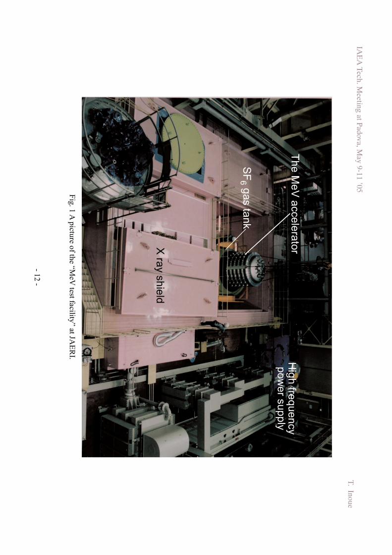
Figure 1 shows a picture of the “MeV test facility [13]” constructed in 1994 at JAERI to
carry out the R&D of the 1 MeV, 1 A class negative ion accelerator. The high voltage power
supply is a conventional Cockroft Walton type, as an extension of electron beam irradiation
devices widely utilized in industries, for example, for rubber and polythin production. The
power supply and the accelerator are contained in gas tanks, since the 1 MV high voltage is
insulated by SF6 insulation gas of 6 bar during operation. The gas tanks are located in
underground pit of which wall and ceiling are made of 0.5 ~ 1 m thick concrete to shield
Bremsstrahrung generated upon electron beam acceleration.
In the beam source design of the ITER NB system, the accelerator is installed inside
vacuum vessel, and the HV bushing mounted on the vessel, above the accelerator, forms a
vacuum boundary. In the JAERI MeV accelerator, as shown in Fig. 2, the insulator column
forms the vacuum boundary against the SF6 insulation gas in the tank, simulating the HV
bushing of the ITER design. The insulator column (1.9 m high in total for 1 MV insulation)
consists of a stack of 5 FRP rings made of fiber-reinforced epoxy, each 1.8 m diameter and
0.33 m in height. The accelerator main structure (assembly of acceleration grids and their
support structure) is inserted in vacuum inside the insulator column, utilizing the insulator
column as the HV bushing.
A cross sectional view of the accelerator is shown in Fig. 3. There is a vacuum gap of 50
mm wide all around between the insulator column and the accelerator main structure. The
acceleration grid support structures are suspended from the flange at top of the accelerator (–1
MV potential) via. several post insulators (made of Al2O3 ceramic), and only the parts
connecting between the accelerator and the insulator column are current feedthroughs
(stainless steel) of 10 mm dia. Thus the accelerator main structure is isolated from the
insulator column, and immersed in vacuum to simulate the ITER vacuum insulated beam
source.
In conventional accelerators of universities and industries, the clump theory [14], in which
the sustainable voltage is proportional to square root of vacuum insulation distance, is applied
as the insulation design guideline. By inserting many gradient grids to reduce voltage
differences in between, gap length is reduced for compact design of the accelerator. Moreover
IAEA Tech. Meeting at Padova, May 9-11 ’05 T. Inoue
- 4 -
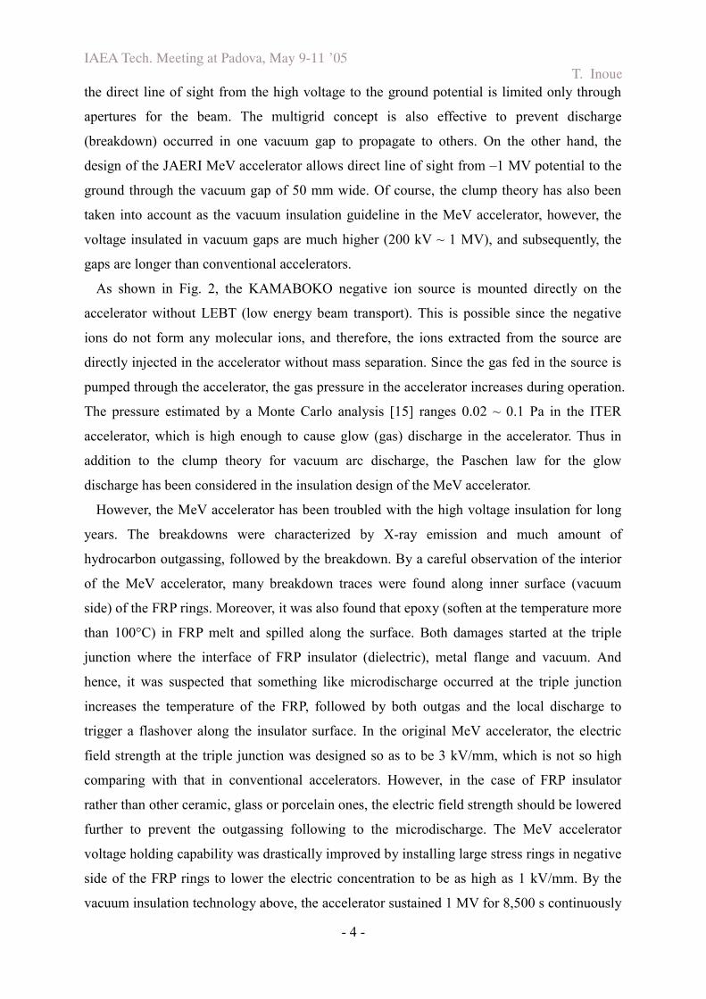
the direct line of sight from the high voltage to the ground potential is limited only through
apertures for the beam. The multigrid concept is also effective to prevent discharge
(breakdown) occurred in one vacuum gap to propagate to others. On the other hand, the
design of the JAERI MeV accelerator allows direct line of sight from –1 MV potential to the
ground through the vacuum gap of 50 mm wide. Of course, the clump theory has also been
taken into account as the vacuum insulation guideline in the MeV accelerator, however, the
voltage insulated in vacuum gaps are much higher (200 kV ~ 1 MV), and subsequently, the
gaps are longer than conventional accelerators.
As shown in Fig. 2, the KAMABOKO negative ion source is mounted directly on the
accelerator without LEBT (low energy beam transport). This is possible since the negative
ions do not form any molecular ions, and therefore, the ions extracted from the source are
directly injected in the accelerator without mass separation. Since the gas fed in the source is
pumped through the accelerator, the gas pressure in the accelerator increases during operation.
The pressure estimated by a Monte Carlo analysis [15] ranges 0.02 ~ 0.1 Pa in the ITER
accelerator, which is high enough to cause glow (gas) discharge in the accelerator. Thus in
addition to the clump theory for vacuum arc discharge, the Paschen law for the glow
discharge has been considered in the insulation design of the MeV accelerator.
However, the MeV accelerator has been troubled with the high voltage insulation for long
years. The breakdowns were characterized by X-ray emission and much amount of
hydrocarbon outgassing, followed by the breakdown. By a careful observation of the interior
of the MeV accelerator, many breakdown traces were found along inner surface (vacuum
side) of the FRP rings. Moreover, it was also found that epoxy (soften at the temperature more
than 100°C) in FRP melt and spilled along the surface. Both damages started at the triple
junction where the interface of FRP insulator (dielectric), metal flange and vacuum. And
hence, it was suspected that something like microdischarge occurred at the triple junction
increases the temperature of the FRP, followed by both outgas and the local discharge to
trigger a flashover along the insulator surface. In the original MeV accelerator, the electric
field strength at the triple junction was designed so as to be 3 kV/mm, which is not so high
comparing with that in conventional accelerators. However, in the case of FRP insulator
rather than other ceramic, glass or porcelain ones, the electric field strength should be lowered
further to prevent the outgassing following to the microdischarge. The MeV accelerator
voltage holding capability was drastically improved by installing large stress rings in negative
side of the FRP rings to lower the electric concentration to be as high as 1 kV/mm. By the
vacuum insulation technology above, the accelerator sustained 1 MV for 8,500 s continuously

IAEA Tech. Meeting at Padova, May 9-11 ’05 T. Inoue
- 5 -
[11].
The negative ions produced in the KAMABOKO negative ion source is extracted through 9
apertures (each 14 mm in diameter) drilled in 3 x 3 lattice pattern in the plasma grid (PLG,
first grid illuminated by the source plasma). The extraction grid (EXG, second grid) has small
permanent magnets embedded between the aperture rows for suppression of co-extracted
electrons [16]. The accelerator has 4 intermediate girds (A1G ~ A4G) at every 200 kV
potential difference, and grounded grid (GRG). The beamlets extracted are accelerated
electrostatically through the apertures each of which is aligned with respect to corresponding
apertures in the PLG and EXG. The grid spacing becomes progressively shorter at each
downstream gap. Thus the electric field increases at each gap, and each aperture forms a
convergent electrostatic lens counteracting the space charge expansion of the beamlets.
The beam current was measured by an inertia cooled calorimeter located downstream of the
GRG in vacuum chamber in short pulse (≥ 0.2 s) operation. The bottom of the vacuum
chamber is a beam dump consisting of an array of swirl tubes at the incident angle of 60°, of
which allowable heat load is 80 MW/m2, corresponding to 0.8 MeV 140 A/m2 H- ion beam at
the divergence angle of 7 mrad.
3. Progress of MeV level H- ion beams
The present experiment is in progress to accelerate the H- ion beams of high current density,
toward the ITER requirement of 200 A/m2, up to 1 MeV. Parameters of the H- ion beams
accelerated to MeV range energy are summarized in Table 1. The H- beams of 18 A/m2 (total
ion current of 70 mA) were accelerated up to 1 MeV for 1 s in pure volume operation. At
present, the ion source is running under Cesium seeded operation to enhance the surface
process of negative ion production. So far, H- ion beams of 836 keV and 146 A/m2 (total ion
current: 0.206 A) have been obtained, and such high current (accelerator power supply current
~ 200 mA including electrons) beams are stably obtained several tens shots (pulse length ≥
0.2 s) stably even under the cesiated operation of the source.
The beam current as a function of the extraction voltage is shown in Fig. 4, for all the beam
shots obtained in the experimental campaign in April 2005. Note that the beams were
accelerated stably in wide operation window at under perveance conditions. The accelerated
beam current does not show clear saturation tendency, suggesting that enough amount of H-
ions are produced in the source. Since the KAMABOKO source itself has already achieved
300 A/m2 H- ion productions, further increase of the current/current density is expected

IAEA Tech. Meeting at Padova, May 9-11 ’05 T. Inoue
- 6 -
toward the ITER required current density.
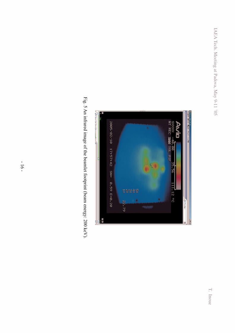
Figure 5 shows a picture of a low energy beam footprint taken by an infrared camera at 3 m
downstream from the grounded grid. The beamlets extracted from 3 x 3 aperture array are
clearly identified at a perveance-matched condition for the low current beam at 200 keV in
pure volume operation. A picture of the high-energy beam taken at 2 m downstream is shown
in Fig. 6. As is shown in the figure, the beamlets are distinguished for the H- ion beam of 146
A/m2 even after the acceleration to 836 keV.
Recent increase of the beam current density has been achieved after stopping following
vacuum leakages:
1) SF6 leaks through Viton O-rings
The gas is fed in the ion source continuously during operation when the high voltage of
more than 700 kV is applied to the accelerator, so that the accelerator sustain the voltage at
the pressure in which the best voltage holding capability is achieved. Thus solenoid valves in
the gas feed line are kept open during the high-energy beam experiment. The valve
temperature increased to about 100°C during the operation, and the Viton O-rings used at
interface to the inlet/outlet gas pipes started to allow SF6 permeation from outside of the
valves to the gas line, followed by contamination of the Cs inside the ion source. It was not
easy to imagine the permeation of huge SF6 molecules through popular Viton O-ring, however,
a data sheet [17] noticed the possibility of SF6 permeation through fluorocarbon rubber, such
as Viton, if the fluorine content was less. The o-rings in the solenoid valves were all removed
and the interfaces were welded.
2) O-ring damage due to backstream ions
The KAMABOKO negative ion source has a port on the top, on the extension of the beam
center axis, normally closed by a stainless steel plug with piston O-ring seal. Long pulse
experiment of the source at Cadarache reported the port plug melt by backstream ions,
followed by air leak due to damage of the O-ring [18]. As the current density and the beam
energy of the beam was increased, the same air leak occurred in the KAMABOKO source of
the MeV accelerator. The leak was stopped replacing the port and the plug with a flange made
of brass closely attached to the water-cooled source body. Although the heat load on the
source due to the backstream ions were briefly estimated for the ITER beam source, and the
MeV accelerator is running similar condition, further analyses of backstream ions seem to be
necessary in detail.

IAEA Tech. Meeting at Padova, May 9-11 ’05 T. Inoue
- 7 -
Figure 7 shows the progress of the MeV accelerator R&D, by plotting the achieved beam
current density as a function of the energy. After success in the 1 MV holding, the beam
current density increased gradually, according to the source operation tuning such as Cs
seeding condition and high power operations. Note that the beams obtained at present have a
very high power density; i.e. 836 keV x 146 A/m2 = 122 MW/m2. This power density is more
than twice higher than those of negative ion sources in existing NB systems [19, 20]. Thus the
beam energy and current density of the JAERI MeV accelerator are approaching to the ITER
relevant regime.
4. Bremsstrahrung and photoelectron generation
Bremsstrahrung is generated upon collision of energetic electrons on a copper target
(accelerator grid or beam dump). The Bremsstahrung generation process was analyzed using
EGS4 code [21] for electron cascade reaction in solid. Figure 8 and 9 shows the angular
distribution of generated photons and their energy spectrum, respectively. The result shows
the maximum number of photons generated in a case of 1 MeV electron incident is 0.0386
photon/electron Sr-1 (per unit solid angle). Whilst the energy spectrum shows quick decrease
of photons with the energy higher than 200 keV.
Figure 10 is the line attenuation coefficient of photons in Lead as a function of the photon
energy [22]. As is well known, low energy photons are attenuated by photoelectron effect,
MeV range photons by Compton scattering, and further high-energy photons by electron pair
formation. For light elements, such as Carbon used in the FRP, the line attenuation
coefficients were estimated considering the atomic number dependence, as shown in the
figure in solid lines. Since the photoelectron effect has strong atomic number dependence, the
attenuation by the photoelectron effect in light elements becomes weaker than Compton
scattering even for the low energy photons of < 100 keV.
Here we estimate the photon density on the inner surface of FRP rings, assuming 1)
electron current of 0.1 A (a typical electron current in the present experiment), 2) isotopic
photon emission (0.0386 photon/electron Sr-1) from center of the insulator column, and 3) at the
photon energy of 100 keV. Then the photon density is estimated as follows on the FRP rings
of 1.8 m diameter and 0.33 m high:
2.37 x 10¹¹ photon/cm2 s (1)

IAEA Tech. Meeting at Padova, May 9-11 ’05 T. Inoue
- 8 -
From Fig.10, taking the line attenuation coefficient for the photoelectron effect to be 1 x
10-4/cm, the number of photons attenuated in the FRP ring (54 mm thick) is:
1.28 x 10⁸ photon/cm2 s (2)
Here if we assume that the number of photons absorbed is the number of electrons generated
in the insulation material, then the electron current flowed in a beam pulse is estimated to be
0.38 µA. On the other hand, from the cataloged data on [23], surface and volume resistance of
the FRP ring are 1011 Ω and 1010~1014 Ωm, respectively. And hence, the dark current
flowed In the FRP during the rated voltage of 200 kV/FRP ring would be
(surface current) 34 µA (3)
(volume current) 0.02 ~ 200 µA (4)
Thus the photoelectron current is 2 – 3 orders of magnitude smaller than the dark
current flowed by the inherent conductivity of the insulation material.
In the estimation above, only the current by the primary photoelectrons was considered.
In the reality, the electrons are energetic (<100 keV), and many secondary electrons are to be
generated in the insulation material from the primary electron. However, the estimate above
suggests that secondary electron emission coefficient of 100-1000 is still acceptable,
considering the dark current in the FRP.
In the case of ITER accelerator with much higher current, the possibility of breakdown
by the photoelectron effect is not clear at present. However, from the discussion above, it
could be suppressed by additional shield around the accelerator or near the HV bushing, since
low energy X-ray is attenuated to 1/10 only by a 1 cm thick lead.
5. Conclusion and future issue
The vacuum insulation technologies have been established for the MeV accelerator. 1 MV
stable holding was achieve by reducing the electric field concentration at the triple junction.
The beam acceleration is in progress toward the ITER relevant beams of the current density

IAEA Tech. Meeting at Padova, May 9-11 ’05 T. Inoue
- 9 -
of 200 A/m2 at 1 MeV. At present, we have obtained 146 A/m2 (206 mA) H- ion beams at 836
keV (pulse length: 0.2 s). The beam power density (energy x current density) is more than
twice higher than the beams of the existing NB systems. For further increase of the beam
power and pulse length, a new beam dump has already been prepared for the heat load
corresponding to 1 MeV 200 A/m2 beam. The beam optics study and demonstration of long
pulse operation are to be carried out after replacement of the beam dump. Stability of the
accelerator in long pulse operation might reveal the behavior of the breakdowns due to the
photoelectron effect. The EGS will again be utilized for the analyses of the photoelectron and
secondary electron behavior in the insulator.
[1] ITER-FEAT, Final Design Report, IAEA 2001.
[2] T, Inoue et al., Rev. Sci. Instrum. 66 (7), pp. 3859-3863 (1995).
[3] M. Taniguchi, M. Hanada, T. Iga, T. Inoue, M. Kashiwagi, T. Morishita et al., Nucl. Fusion 43,
665-669 (2003).
[4] M. Hanada et al., to be published in Fusion Eng. and Design.
[5] M. Hanada et al., in this proceeding.
[6] T. Inoue et al., FUSION TECHNOLOGY Vol. 1, 411-414 (1998).
[7] E. Hodgson et al.. FUSION TECHNOLOGY Vol. 1, 295-297 (1998).
[8] Y. Fujiwara et al. Fusion Eng. and Des. 55 (1) 1-8 (2001).
[9] E. Di Pietro et al., FUSION TECHNOLOGY Vol. 1, 407-410 (1998).
[10] T. Inoue et al., Fusion Eng. and Des. 66-68, 597-602 (2003).
[11] T. Inoue et al., Rev. Sci. Instrum. 75 (5), 1819-1921 (2004).
[12] M. Fumelli, F. Jaquier, J. Pamela, A. Simonin, American Inst. of Phys. Conf. Proc. No. 287, (6th Int.
Symp. on the Production and Neutralization of the Negative Ions and Beams, Upton NY, pp.
934-949 (1992).
[13] T. Inoue et al., “Design study of prototype accelerator and MeV test facility for demonstration of 1
MeV, 1A negative ion beam production”, Japan Atomic Energy Research Institute Report
JAERI-Tech 94-007 (1994).
[14] L. Cranberg, J. Appl. Phys. 23/5, 518-522 (1952).
[15] M. Hanada et al., M. Hanada et al., Fusion Eng. and Design 56-57, 505-509 (2001).
[16] Y. Okumura, H. Horiike, H. Inami, S. Matsuda, Y. Ohara, T. Shibata and S. Tanaka, Proc. 11th Symp.
on Fusion Eng. Vol. I, 113-117, Austin, Texas, Nov. 18-22, (1985).
[17] DICHTOMATIK O-RING HANDBOOK,
http://www.dichtomatikusa.com/Products/O-Ring-Handbook/4.pdf.
[18] R. S. Hemsworth, private communication.
[19] M. Kuriyama et al., Rev. Sci. Instrum. 71/2 751-754 (2000).

IAEA Tech. Meeting at Padova, May 9-11 ’05 T. Inoue
- 10 -
[20] K. Tsumori et al., Proc. IAEA Fusion Energy Conf. FT-1-2Rb, Vilamoura Protugal, Nov. 1-6 (2004).
[21] W. R. Nelson, H. Hirayama, and D. W. Rogers, “The EGS-4 code system”, SLAC-265 (1985).
[22] in many text books, for example, T. Ishikawa (editor) “Houshasen Gairon”, Tsuushou Sangyou Sha
(1986) in Japanese.
[23] Isola Werke AG, Technical Information, filament winding FRP (fiber reinforced plastic),
VETRONIT-FW Quality EP405, Type DRN.
IAEA Tech. Meeting at Padova, May 9-11 ’05 T. Inoue
- 11 -
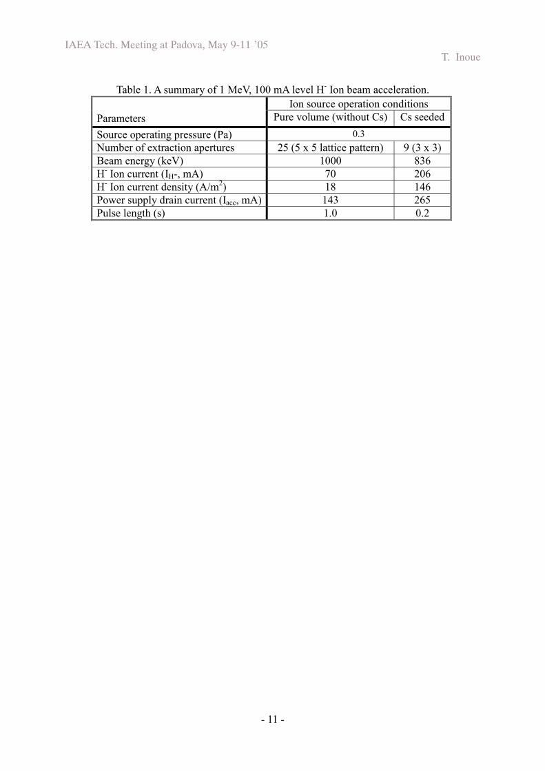
Table 1. A summary of 1 MeV, 100 mA level H- Ion beam acceleration. Ion source operation conditions
Parameters Pure volume (without Cs) Cs seeded Source operating pressure (Pa) 0.3 Number of extraction apertures 25 (5 x 5 lattice pattern) 9 (3 x 3) Beam energy (keV) 1000 836 H- Ion current (IH-, mA) 70 206 H- Ion current density (A/m2) 18 146 Power supply drain current (Iacc, mA) 143 265 Pulse length (s) 1.0 0.2
IAE
A Tech. M
eeting at Padova, May 9-11 ’05
T. Inoue
- 12 -
X ra
y shie
ld
Th
e M
eV
acce
lera
tor
Hig
h fre
qu
en
cy p
ow
er su
pp
ly
SF
6 ga
s tan
k
Fig. 1 A
picture of the “MeV
test facility” at JAER
I.

IAE
A Tech. M
eeting at Padova, May 9-11 ’05
T. Inoue
- 13 -
vacuum gap
50
mm
Vacuum
insulated accelerator
Insulator column
Fig. 2
The JAER
I MeV
accelerator. The insulator column form
s the vacuum boundary against the SF
6 insulation gas in the tank.

IAE
A Tech. M
eeting at Padova, May 9-11 ’05
T. Inoue
- 14 -
Po
st insu
lato
r (A
l 2O3 ce
ram
ic)
KA
MA
BO
KO
n
eg
ative
ion
sou
rce
Gro
un
d
1 M
V
80
0 kV
60
0 kV
40
0 kV
20
0 kV
Vacuum insulated
acceleratorV
acu
um
ga
p
from
-1 M
V to
gro
un
d
Acce
lera
tor
grid
s
Insu
lato
r colu
mn
00
.51
.00
.15
2.0 S
cale
(m)
Fig. 3
A cross sectional illustration of the M
eV accelerator.

IAE
A Tech. M
eeting at Padova, May 9-11 ’05
T. Inoue
- 15 -
Fig. 4 The beam
current as a function of the extraction voltage, for all the shots obtained in April 2005.
IAE
A Tech. M
eeting at Padova, May 9-11 ’05
T. Inoue
- 16 -
Fig. 5 An infrared im
age of the beamlet footprint (beam
energy: 200 keV).

IAE
A Tech. M
eeting at Padova, May 9-11 ’05
T. Inoue
- 17 -
Fig. 6 A
picture of the 800 keV H
- ion beam taken at 2 m
downstream
.

IAE
A Tech. M
eeting at Padova, May 9-11 ’05
T. Inoue
- 18 -
Fig. 7 The progress of the M
eV accelerator R
&D
, by plotting the achieved beam current density as a function of the energy.

IAE
A Tech. M
eeting at Padova, May 9-11 ’05
T. Inoue
- 19 -
Fig. 8
A result of the B
remsstrahrung analysis by EG
S4code, phton generation angular distribution.

IAE
A Tech. M
eeting at Padova, May 9-11 ’05
T. Inoue
- 20 -
Fig. 9
A result of the B
remsstrahrung analysis by EG
S4code, energy spectrum.

IAE
A Tech. M
eeting at Padova, May 9-11 ’05
T. Inoue
- 21 -
Fig. 10 The line attenuation coefficient of photons in solid.