Embed Size (px)
Citation preview

INTERNATIONAL ATOMIC ENERGY AGENCYVIENNA
ISBN 978–92–0–120610–7ISSN 2074–7667
Status of Computed Tomography Dosimetry for Wide Cone
Beam Scanners
@
IAEA
HUM
AN H
EALT
H RE
PORT
S No
. 5
P1528_cover.indd 1 2011-10-10 09:20:05

IAEA HUMAN HEALTH SERIES PUBLICATIONS
The mandate of the IAEA human health programme originates from Article II of its Statute, which states that the “Agency shall seek to accelerate and enlarge the contribution of atomic energy to peace, health and prosperity throughout the world”. The main objective of the human health programme is to enhance the capabilities of IAEA Member States in addressing issues related to the prevention, diagnosis and treatment of health problems through the development and application of nuclear techniques, within a framework of quality assurance.
Publications in the IAEA Human Health Series provide information in the areas of: radiation medicine, including diagnostic radiology, diagnostic and therapeutic nuclear medicine, and radiation therapy; dosimetry and medical radiation physics; and stable isotope techniques and other nuclear applications in nutrition. The publications have a broad readership and are aimed at medical practitioners, researchers and other professionals. International experts assist the IAEA Secretariat in drafting and reviewing these publications. Some of the publications in this series may also be endorsed or co-sponsored by international organizations and professional societies active in the relevant fields. There are two categories of publications in this series:
IAEA HUMAN HEALTH SERIESPublications in this category present analyses or provide information of an
advisory nature, for example guidelines, codes and standards of practice, and quality assurance manuals. Monographs and high level educational material, such as graduate texts, are also published in this series.
IAEA HUMAN HEALTH REPORTSHuman Health Reports complement information published in the IAEA Human
Health Series in areas of radiation medicine, dosimetry and medical radiation physics, and nutrition. These publications include reports of technical meetings, the results of IAEA coordinated research projects, interim reports on IAEA projects, and educational material compiled for IAEA training courses dealing with human health related subjects. In some cases, these reports may provide supporting material relating to publications issued in the IAEA Human Health Series.
All of these publications can be downloaded cost free from the IAEA web site:http://www.iaea.org/Publications/index.html
Further information is available from:Marketing and Sales UnitInternational Atomic Energy AgencyVienna International CentrePO Box 1001400 Vienna, Austria
Readers are invited to provide their impressions on these publications. Information may be provided via the IAEA web site, by mail at the address given above, or by email to:
P1528_cover.indd 2 2011-10-10 09:20:06

STATUS OF COMPUTED TOMOGRAPHY DOSIMETRY
FOR WIDE CONE BEAM SCANNERS

AFGHANISTANALBANIAALGERIAANGOLAARGENTINAARMENIAAUSTRALIAAUSTRIAAZERBAIJANBAHRAINBANGLADESHBELARUSBELGIUMBELIZEBENINBOLIVIABOSNIA AND HERZEGOVINABOTSWANABRAZILBULGARIABURKINA FASOBURUNDICAMBODIACAMEROONCANADACENTRAL AFRICAN REPUBLICCHADCHILECHINACOLOMBIACONGOCOSTA RICACÔTE D�IVOIRECROATIACUBACYPRUSCZECH REPUBLICDEMOCRATIC REPUBLIC OF THE CONGODENMARKDOMINICAN REPUBLICECUADOREGYPTEL SALVADORERITREAESTONIAETHIOPIAFINLANDFRANCEGABONGEORGIAGERMANY
GHANAGREECEGUATEMALAHAITIHOLY SEEHONDURASHUNGARYICELANDINDIAINDONESIAIRAN, ISLAMIC REPUBLIC OF IRAQIRELANDISRAELITALYJAMAICAJAPANJORDANKAZAKHSTANKENYAKOREA, REPUBLIC OFKUWAITKYRGYZSTANLATVIALEBANONLESOTHOLIBERIALIBYALIECHTENSTEINLITHUANIALUXEMBOURGMADAGASCARMALAWIMALAYSIAMALIMALTAMARSHALL ISLANDSMAURITANIAMAURITIUSMEXICOMONACOMONGOLIAMONTENEGROMOROCCOMOZAMBIQUEMYANMARNAMIBIANEPALNETHERLANDSNEW ZEALANDNICARAGUANIGERNIGERIA
NORWAYOMANPAKISTANPALAUPANAMAPARAGUAYPERUPHILIPPINESPOLANDPORTUGALQATARREPUBLIC OF MOLDOVAROMANIARUSSIAN FEDERATIONSAUDI ARABIASENEGALSERBIASEYCHELLESSIERRA LEONESINGAPORESLOVAKIASLOVENIASOUTH AFRICASPAINSRI LANKASUDANSWEDENSWITZERLANDSYRIAN ARAB REPUBLICTAJIKISTANTHAILANDTHE FORMER YUGOSLAV REPUBLIC OF MACEDONIATUNISIATURKEYUGANDAUKRAINEUNITED ARAB EMIRATESUNITED KINGDOM OF GREAT BRITAIN AND NORTHERN IRELANDUNITED REPUBLIC OF TANZANIAUNITED STATES OF AMERICAURUGUAYUZBEKISTANVENEZUELAVIETNAMYEMENZAMBIAZIMBABWE
The Agency’s Statute was approved on 23 October 1956 by the Conference on the Statute of the IAEA held at United Nations Headquarters, New York; it entered into force on 29 July 1957. The Headquarters of the Agency are situated in Vienna. Its principal objective is “to accelerate and enlarge the contribution of atomic energy to peace, health and prosperity throughout the world’’.
The following States are Members of the International Atomic Energy Agency:

IAEA HUMAN HEALTH REPORTS No. 5
STATUS OF COMPUTED TOMOGRAPHY DOSIMETRY
FOR WIDE CONE BEAM SCANNERS
INTERNATIONAL ATOMIC ENERGY AGENCY VIENNA, 2011

COPYRIGHT NOTICE
All IAEA scientific and technical publications are protected by the terms of the Universal Copyright Convention as adopted in 1952 (Berne) and as revised in 1972 (Paris). The copyright has since been extended by the World Intellectual Property Organization (Geneva) to include electronic and virtual intellectual property. Permission to use whole or parts of texts contained in IAEA publications in printed or electronic form must be obtained and is usually subject to royalty agreements. Proposals for non-commercial reproductions and translations are welcomed and considered on a case-by-case basis. Enquiries should be addressed to the IAEA Publishing Section at:
Marketing and Sales Unit, Publishing Section International Atomic Energy Agency Vienna International Centre PO Box 100 1400 Vienna, Austria fax: +43 1 2600 29302 tel.: +43 1 2600 22417 email: [email protected] http://www.iaea.org/books
© IAEA, 2011
Printed by the IAEA in Austria October 2011
STI/PUB/1528
IAEA Library Cataloguing in Publication Data Status of computed tomography dosimetry for wide cone beam scanners. – Vienna : International Atomic Energy Agency, 2011. p. ; 24 cm. – (IAEA human health reports, ISSN 2074-7667 ; no. 5) STI/PUB/1528 ISBN 978-92-0-120610-7 Includes bibliographical references. 1.Tomography. 2. Radiation dosimetry – Computer programs. 3. Nuclear medicine. I. International Atomic Energy Agency. II. Series. IAEAL 11-00707

FOREWORD
International standardization in dosimetry is essential for the successful exploitation of radiation technology. To provide such standardization in diagnostic radiology, the IAEA published Code of Practice entitled Dosimetry in Diagnostic Radiology: An International Code of Practice (IAEA Technical Reports Series No. 457; 2007), which recommends procedures for calibration and dosimetric measurement both in standards dosimetry laboratories, especially Secondary Standards Dosimetry Laboratories (SSDLs), and in clinical centres for radiology, as found in most hospitals. These standards address the main dosimetric methodologies needed in clinical diagnostic radiology, with the calibration of associated dosimetric equipment, including the measurement methodologies for computed tomography (CT).
For some time now there has been a growing awareness that radiation dose originating from medical diagnostic procedures in radiology, is contributing an increasing proportion to the total population dose, with a large component coming from CT examinations. This is accompanied by rapid developments in CT technology, including the use of increasingly wide X ray scanning beams, which are presenting problems in dosimetry that currently cannot be adequately addressed by existing standards. This situation has received attention from a number of professional bodies, and institutions have proposed and are investigating new and adapted dosimetric models in order to find robust solutions to these problems that are critically affecting clinical application of CT dosimetry.
In view of these concerns, and as a response to a recommendation from a coordinated research project that reviewed the implementation of IAEA Technical Reports Series No. 457, a meeting was held to review current dosimetric methodologies and to determine if a practical solution for dosimetry for wide X ray beam CT scanners was currently available. The meeting rapidly formed the view that there was an interim solution that could be utilized. The current publication was subsequently drafted under the chairmanship of M. McNitt-Gray (USA), with S. Edyvean (United Kingdom) and J. Geleijns (Netherlands), followed by intensive external review.
The IAEA expresses its gratitude to the drafting committee and all reviewers of this publication.
The IAEA officer responsible for this publication was I.D. McLean of the Division of Human Health.

EDITORIAL NOTE
The use of particular designations of countries or territories does not imply any judgement by the publisher, the IAEA, as to the legal status of such countries or territories, of their authorities and institutions or of the delimitation of their boundaries.
The mention of names of specific companies or products (whether or not indicated as registered) does not imply any intention to infringe proprietary rights, nor should it be construed as an endorsement or recommendation on the part of the IAEA.

CONTENTS
1. INTRODUCTION ............................................................................................................ 1 1.1. CT dosimetry in general .......................................................................................... 1 1.2. CTDI under-reports even now ................................................................................. 2 1.3. Evolution of current dosimetry for wide beams ...................................................... 4 1.4. Current approach for dosimetry for wide beams ..................................................... 5
2. PRACTICAL APPROACH TO DOSIMETRY OF WIDE BEAMS ............................... 7 2.1. General discussion on calculating a CTDI .............................................................. 7 2.2. CTDI100 in standard CTDI dose phantoms ............................................................ 8
2.2.1. Nominal beam widths less than or equal to 40 mm ....................................... 8 2.2.2. Nominal beam widths greater than 40 mm .................................................... 8 2.2.3. Practical measurement in standard CTDI phantoms. ..................................... 9
2.3. CTDI measured free-in-air (CTDIfree-in-air) ............................................................ 10 2.3.1. Revised definition of CTDIfree-in-air ............................................................... 10 2.3.2. Practical measurement of CTDIfree-in-air ........................................................ 11
2.4. Detectors that can be used ..................................................................................... 16
APPENDIX I. THEORY TO SUPPORT THE APPROACH TO WIDE BEAM DOSIMETRY .............................................................................................. 21
APPENDIX II. SUMMARY POINTS AND RECOMMENDATION FOR CT DOSIMETRY ............................................................................... 31
APPENDIX III. QUANTITIES AND UNITS FOR CT DOSIMETRY ................................ 33
APPENDIX IV. DOSIMETER CALIBRATION................................................................... 35
REFERENCES ...................................................................................................................... 37
CONTRIBUTORS TO DRAFTING AND REVIEW ............................................................. 39


1. Introduction
1.1. CT dosimetry in general
When preparing any dosimetric assessment of a CT scanner it is essential to have a good knowledge of the production of X rays and the characteristics of the CT scanner. Factors that influence the X ray beam intensity and photon spectrum are the tube voltage, the anode material, and anode angle, the filtration of the X ray tube, and the tube current.
The spectral characteristics of the X ray beam are generally optimized by adding a flat filter, and by modifying the dose profile in the axial (x-y) plane by using a bow tie filter. The bow tie filter is usually adapted for different body parts (head or body) and different body sizes (adults or children). This bow tie filter modifies the X ray beam profile in the axial plane. Along the z axis, the beam dimension is limited by a collimator.
CT acquisition is either an axial (step and shoot (sequential), or one single wide cone beam rotation), or helical. Step and shoot acquisition uses couch translation between successive axial acquisitions to achieve sufficient coverage. Wide cone beam acquisition allows coverage of entire organs (heart or brain) within one single rotation. Helical acquisition occurs simultaneously with couch translation and may allow whole body coverage within a breath hold.
The properties of the radiation field for CT dose considerations can be characterized by free in air measurements of air kerma (absorbed dose in air)1. These measurements can be either a point measurement for estimation of absorbed dose at one specific position, a succession of point measurements along a line to create a dose profile, a kerma (dose) length product (from which the computed tomography dose index, CTDIfree- in-air, is derived), or a kerma (dose) area product measurement. The latter approach (dose area product) is not common in CT but it is the current standard in radiography and fluoroscopy.
Measurements in standard cylindrical phantoms yield dosimetric quantities such as CTDI that can be considered as a patient dose index, and are also useful for quality assurance purposes, however they should not be interpreted as patient dose [3]. The computed tomography dose index (CTDI) measured in phantoms provides just a dose index (in mGy) that relates to the dosimetric phantom used (see later text and Appendix III for discussion on current dosimetric units).
Patient dose assessment may involve assessment of the skin (or surface) dose (including backscatter), the absorbed doses in various organs (mGy), and the equivalent dose in various organs (mSv) (for X rays the numerical value of the absorbed- and equivalent organ dose are equal). Patient dose, particularly equivalent doses in the patients’ organs, can be used for assessment of the associated carcinogenic risk of radiation [4]. Effective dose [5] is often used as an expression of population patient risk, however it is correctly applicable only for limited conditions. Differences between the patient age and sex distributions for various examinations as compared to those used for the determination of effective dose need to be considered [6].
1 Note for the purposes of this publication the symbolism of the International Electrotechnical Commission (IEC) is generally used. Alternative symbols for essentially analogous concepts has been used by the International Commission on Radiation Units and measurement (ICRU) [1] and the IAEA [2] and are discussed further in Appendix III
1

1.2. CTDI under-reports even now
There is no fundamental controversy with regard to free-in-air dosimetry for fan beam CT scanners for nominal beam width smaller than 60 mm at the isocentre. Further most of the concepts that have been applied for fan beam CT dosimetry free-in-air can, at least theoretically, be easily translated into concepts for wide beam (volumetric) CT free-in-air. However, some serious practical problems may arise when the 100 mm pencil CT ionization chamber is used to measure CTDI free-in-air for wide cone beams, for example when the beam width becomes 160 mm as illustrated in Fig. 1.
FIG. 1. Progression of typical clinical scan configurations (N x T mm e.g. 320 x 0.5 mm = 16 cm beam width)) shown with the year of the introduction of associated new technology.
Assessment of CTDI in phantoms has been the subject of much discussion and many revisions since its initial definition. The original definition of CTDI by Shope et al. [7] was based on an integration from -∞ to +∞. Later, in the United States of America, the FDA standardized the integration to be from -7T to 7T, where T is the nominal slice width. This integration length of 14 slices was typical of head CT scans at the time. The concept of CTDI with a 100 mm integration length and a 100 mm pencil ionization chamber emerged around the same time. Furthermore, since this adaptation; the CTDI, whilst being measured in a polymethylmethacrylate (PMMA) phantom, is now expressed in absorbed dose in air instead of absorbed dose in PMMA.
The five CTDI measurements, one in the centre and four in the periphery of the CT dose phantom, were later used to yield one CTDI value, called the weighted CTDI (CTDIw), with the weighting factors for deriving CTDIw being respectively 1/3 for the centre CTDI and 2/3 for the averaged peripheral CTDI [8]. With the introduction of helical CT scanners, the volume CTDI (CTDIvol), (defined as CTDIw divided by the helical pitch) was developed to take into account the effect of couch translation during irradiation and the associated helical pitch. Conceptually CTDIvol represents the average dose in the central z-axis region of a scanned volume whose length is equivalent to the integration length in the CTDI equation. The region is defined by the couch increment per rotation (or couch incrementation for axial scanning).
2

The most common definition of CTDI is [9]:
∫+
−×=
mm
mm
dzzDTN
CTDI50
50100 )(1
(1) where D(z) is the dose profile originating from one axial rotation, along a line that is perpendicular to the tomographic plane, dose being expressed as absorbed dose in air. The measured integration has the units of dose and length. N is the number of active acquisition channels (detector rows), and T is the nominal thickness of each acquisition channel (detector row, or group of detector rows). The CTDI is usually obtained using a single axial scan.
When CTDI is measured in a CT dose head or body phantom (16 cm and 32 cm in diameter), both the primary beam, and the resulting scattered radiation contribute to the measurement. During the axial scan the primary beam width varies at different peripheral positions within the CT phantom due to the divergence of the beam. This effect is most prominent for the larger CT dose body phantom. With a 100 mm pencil chamber, assuming a focus to isocentre distance of 600 mm, the primary beam does not exceed the chamber length during the axial scan at any peripheral position of the CT dose body phantom only when the actual beam width does not exceed 80 mm at the isocentre.
Additionally, a field of scattered radiation extends throughout the entire 150 mm long CT dose phantoms, and even further into the surrounding air. Thus a 100 mm CT pencil chamber only includes part of all the scattered radiation, and so for measurements within a CT dose phantom, there is always a discrepancy between the CTDI100 and the CTDI∞, where the latter incorporates all the scattered radiation2. This ratio is referred to as the CTDI measurement efficiency3.
Boone [11] reported that for the CT dose head phantom, even with a 10 mm beam width, the CTDI100 measurement is low compared to CTDI∞, with efficiency values of about 82% at the centre, and 90% at the periphery of the phantom (Fig. 2). For the CT dose body phantom it is even lower, with an efficiency of 64% at the centre and 88% at the periphery. The efficiency of CTDI100 depends strongly on the phantom size and on the position of measurement (centre or periphery) within the phantom. Fortunately the efficiency of CTDI100 remains rather constant for beam widths up to 40 mm. Therefore for CT scanners with up to 64 active detector rows, that typically have beam widths of 40 mm or below, the CTDI100 metric, while not an accurate representation of dose for a typical scanned volume, is at least constant and consistent in its inaccuracy of total integral dose. For beams wider than 40 mm the efficiency of CTDI100 starts to drop gradually, until at 80 mm the efficiency begins to drop rapidly. In conclusion, the current CTDI100 metric is not an accurate representation of dose (for scan lengths other than 100 mm), for all beam widths. However, for beam widths less than 40 mm, the inaccuracies are at least consistent.
Conceptually CTDI∞ represents the average dose in the central part of a scanned phantom whose length is infinity. The CTDI measurement efficiency is then the ratio of the dose at the centre of a 100 mm scan length compared to that at the centre of an infinitely long scanned length. CTDI100, as a descriptor of the average dose at the central z-axis position of a scanned
2 CTDI∞ is the value given by a pencil chamber of sufficient length (∞) to capture the full contribution of scattered radiation generated within a phantom, from a CT axial exposure. Further, CTDI∞ is in principle analogous to the concept of equilibrium dose, (Deq), as described by AAPM report no. 111 [10]. 3 CTDI measurement efficiency is the ratio of the dose integral as limited by the measurement from 100 mm chamber against the total dose integral of a chamber with sufficient length (∞).
3
volume, under-reports for long scan lengths (CTDI∞), however it must be noted that conversely the CTDI100 over-reports for scan lengths shorter than 100 mm.
1.3. Evolution of current dosimetry for wide beams
Figure 1 shows the progression of typical scan configurations as used in regular clinical practice with the year of the introduction of associated new technology, ranging from single slice techniques, through multi-slice CT, to wide cone beam CT.
When the first wide cone beam CT scanner was introduced4 there was a need to find an appropriate way of measuring CTDI for this scanner. Research groups used very long CT dose phantoms, and very long pencil ionization chambers [12, 13] and they were able to measure the CTDI for these situations, for example CTDIw,300
5, the CTDI with a dose integral over 300 mm. However the measurements were not practical for general implementation, since the phantoms were impractical to handle (very heavy, and very large), and the 300 mm ionization chamber was not readily available. In addition, it would be expensive to replace the already available phantoms and ionization chambers, with new, longer CT dose phantoms and CT ionization chambers.
For a wide cone beam scanner such as shown in Fig. 1 with a nominal beam width of 160 mm (320 detectors x 0.5 mm), the denominator (N×T) in the formula for CTDI100 (Eq. 1) exceeds the integration length for the dose profile D(z) of 100 mm. This is fundamentally inconsistent with the concept of CTDI100. Therefore in 2009 the IEC adapted the definition of CTDI (Eq. 1) for use in wide cone beam scanners, by limiting the denominator to 100 mm, even when the product N×T exceeds 100 mm [14]:
{ } ∫+
−×=
mm
mm
dzzDmmTN
CTDI50
50100 )(
100,min1 (2)
where min{} is the ‘min operation’ which gives the smallest of the two numbers N×T (mm) or 100 (mm).
A major shortcoming of this definition of CTDI for a 160 mm wide cone beam CT scanner was that it only captured a part of the primary radiation, and only a small part of the scattered radiation. In fact, for a beam width of 160 mm, this dose quantity should not be referred to as CTDI but as average dose (D100,w,avg) [12].
Note that differences between the nominal beam width (N×T) and the actual beam width generally occur6 and need to be considered. Nevertheless, when applied to the 320 detector row Toshiba Aquilion ONE scanner, the CTDI100 according to Eq. 2 (or better D100,w,avg) was found to be a promising predictor of CTDIw,300. For different acquisition conditions (bow tie filter, tube voltage) the ratio of D100,w,avg and CTDIw,300 ranged between 0.98 and 1.08 for the CT dose body phantom, and between 1.08 and 1.11 for the CT dose head phantom [12].
Later it was proposed that a metric with a more predictable and constant relationship to CTDI∞ should be found. It was observed that Boone’s CTDI100 efficiency parameter (Fig. 2) was more or less constant for narrow collimations (curves are more or less flat for nominal
4 Toshiba Aquilion ONE with a 320 x 0.5 mm acquisition configuration and a (nominal) beam width of 160 mm or its prototype predecessor which used 256x0.5 mm configuration with a nominal beam width of 128 mm. 5 Note that the subscript 300 refers to the integration length of the detector. 6 The Aquilion ONE wide cone beam scanner has a maximum nominal beam width of 320 x 0.5 or 160 mm, however the actual measured full width half maximum is 170 mm.
4

beam widths ≤ 40 mm). It was also noted that CTDI in a phantom is proportional to the free in air measurements (see Appendix I for a more detailed description).
FIG. 2 Illustrative plots of the percentage weighted CTDI100 efficiency versus beam width for the 150-mm long CT dose head and body phantoms as a function of beam width, for 120 kV (the percentage weighted CTDI100 efficiency is the weighted CTDI100 as a percentage of its equilibrium value weighted CTDI∞). Adapted from Boone [11].
1.4. Current approach for dosimetry for wide beams
As a development to overcome the shortcomings described in the previous section, the latest proposed IEC 60601-2-44 document (Amendment 1 of version 3) describes a two tiered approach to the definition of CTDI.
The first tier is for beam widths ≤ 40 mm and uses the conventional definition of CTDI100. In the second tier for beam widths > 40mm, it is proposed to measure a reference value for CTDI in the standard CT dose phantoms, for a nominal beam width of about 20 mm. This value is then scaled up by the ratio of free in air measurements of CTDI for the wide beam condition and the reference condition. This was predicted to flatten the curve of the CTDI100 efficiency parameter as a function of beam width to infinity. In this approach, for N×T ≤ 40 mm, the existing CTDI formula as presented in Equation 1 is still valid, thus:
∫+
−× ×=
mm
mmTN dzzD
TNCTDI
50
50,100 )(1 (3)
Where the subscripts7, to TNCTDI ×,100 , indicate an integration length of 100 mm, and a nominal irradiation beam width of N×T.
But for wider beams, N×T > 40 mm, a new approach was described based on the ratio of CTDIfree-in-air measurements at different collimation settings.
7 Note the subscript N × T has been added to designate the nominal irradiation beam. In this document this is adopted for both phantom and in air measurements. This is additional to the IEC notation where the irradiation beam width is only subscripted for the free in air measurements. Note also that the IEC convention of replacing N x T by ref for the irradiation beam width of the reference beam width has also been adopted.
5

⎟⎟⎠
⎞⎜⎜⎝
⎛×⎟⎟⎠
⎞⎜⎜⎝
⎛×
×=
−−
×−−+
−× ∫
refairinfree
TNairinfreemm
mmref
refTN CTDI
CTDIdzzD
TNCTDI
,
,50
50,100 )(
)(1
(4)
where ref refers to the reference beam width condition of 20 mm, or closest value below this.
The rationale of the IEC’s recommendation on the proposed methodology for dosimetry in wide cone beam CT is illustrated in Fig. 3. When using Eqs. 3 or 4, values of the CTDI100 efficiency parameter can be achieved that are consistent for any beam width (Fig. 3, solid line). Therefore the strength of this approach is that even for wide cone beams, the graph of CTDI100 efficiency becomes flat as a function of the beam width. The weakness is that Eq. 4 still underestimates CTDI∞, noting that weighted CTDI100 efficiency is still approximately 75% in a CT dose body phantom, and far from the ‘ideal’ 100%.
FIG. 3 Illustrative plots of the percentage weighted CTDI100 efficiency versus beam width for CT dose body phantom as a function of beam width, for 120 kV and according to three different versions of IEC standards, respectively the IEC ED.2 (Eq. 1), IEC 60601-2-44 ED.3 (Eq. 2), and IEC ED. 3 Amendment 1 (Eq. 4). The plots are estimated from measurements and from Monte Carlo simulations modelling 100% geometric efficiency in the z direction. Solid curves: results for long (500-mm length) phantoms. Dashed curves: results for short (150-mm length) phantoms. The plots are consistent with published data (e.g., Boone 2007 [11], Mori 2005 [13]). Graph according to [15].
6

2. PRACTICAL APPROACH TO DOSIMETRY OF WIDE BEAMS
This document follows the proposed IEC 60601-2-44, Ed 3 amendment 1[15], as outlined in the previous section, and given in the recommendations in Appendix II. The IEC document has adapted the CTDI100 metric in order to accommodate wider beam scanners. The CTDI100 metric is measured using a CT pencil chamber with an integration length of 100 mm.
The definition of CTDI100, as measured in standard phantoms, remains unchanged for nominal beam widths which are less than or equal to 40 mm. However, for beams greater than 40 mm, the phantom CTDI100 is calculated, based on a reference CTDI100 measured in the CT dose phantom using a relatively narrow (reference) beam width. This value is corrected by the ratio of CTDIfree-in-air for the wide beam width and the reference beam width to give the CTDI100 for larger beam width.
The definition of CTDIfree-in-air, has become a generic definition, adapted in order to accommodate the wider beam widths whilst encompassing the original definition which applies for beams less than or equal to 60 mm (Section 2.3).
In this chapter, practical methods to obtain CTDI values are outlined.
2.1. General discussion on calculating a CTDI
There are some general principles that apply to the measurement and calculation of the CTDI whether it is calculated from measurements in phantom or in air.
The general form of the CTDI, whether measured in phantoms or air, consists of three components; the dose (D) integral, the integration limits (+/-L/2) (where L is length of the detectors active volume) and the nominal beam width (N× T):
dz (z) DT N
= CTDI+L
L-∫×
2/
2/
1 (5)
The dose integral (∫ D(z)dz)
The dose integral in the CTDI equation is usually acquired from a measurement of a single axial rotation with the standard 100 mm pencil ion chamber, directed along the z-axis.
When the pencil ion chamber is used the measurement integration limits are defined by the length of the chamber, usually 100 mm.
The measurement values obtained from a CT ion chamber (and the associated dose meter) may be presented as values in units of charge (nC), exposure (Roentgen), air kerma (dose) (mGy), or air kerma (dose) length (mGy.cm). The air kerma (dose) length approach has become more common due to current methods of calibration of the ion chambers. The measurement values, obtained from the ion chamber and dose meter combination, also all need the appropriate correction factors to be applied (air pressure, temperature). A detailed discussion of this is given in Appendix IV.
In this chapter, it will be assumed that the readings from the ion chamber dose meter system already have the appropriate calibration factors applied.
7

Confiden
There will be two situations discussed each time, one where the measurement system presents the air kerma (dose) length integral, in units of mGy.cm (equation 6). This will be called (IntD).
)(50
50
IntDdz (z) D+
-
=∫ (6)
The other will be where the measurement system (after appropriate calibration factors) gives dose, D, in mGy. This represents an average dose to the ion chamber, and to obtain the integration the dose value must be multiplied by the length (Lc) of the chamber (equation 7).
c
+
-
LDdz (z) D ×=∫ )(50
50
(7)
The dose integral distance (L)
As stated above, where the 100 mm ion chamber is used in a single measurement, the integration length L = Lc which is 100 mm. Other integration lengths are required for free-in-air measurements for wide beams, and this is addressed later in the chapter.
The nominal beam width (N × T)
The nominal beam width is defined by N × T, where N is the number of active data channels in a stationary axial scan, and T is the nominal thickness of each data channel. For example; a four slice scanner, acquiring 5 mm slices would be written as 4 x 5 mm. In this instance, N x T is the nominal beam width of 20 mm8. Currently there are several CT scanner models with beams greater than 40 mm.
.2. CTDI 100 in standard CTDI dose phantoms
2.2.1 Nominal beam widths less than or equal to 40 mm
For a nominal beam width (defined by N × T) less than or equal to 40 mm, and CTDI measurements in a CT dose phantom, the definition of CTDI100 remains unchanged from the accepted definition of CTDI100 (Eq.8):
∫+
−≤× ×
=mm
mmTN dzzD
TNCTDI
50
5040)(,100 )(1 (8)
2.2.2. Nominal beam widths greater than 40 mm
For a nominal beam width greater than 40 mm, the CTDI100 is calculated using the measured CTDI100 in a phantom for a reference beam width, corrected by a ratio of CTDI free-in-air values for the wide beam condition relative to the reference condition. The reference beam width should be 20 mm (or the nearest beam width available less than 20 mm). It is described by Eq. 4, which can be written more simply as:
8 Due to the requirement of having equal photon flux to all detector rows the actual beam width would be measured as a few millimetres more, for example 23 mm, to ensure the penumbra is beyond the outer detector rows.
8
2

⎟⎟⎠
⎞⎜⎜⎝
⎛×=
−−
×−−>×
refairinfree
TNairinfreerefTN CTDI
CTDICTDICTDI
,
,,10040)(,100 (9)
where
CTDI100,ref is the CTDI measured in a phantom for the reference beam width of (N×T)ref; using an integration length of 100 mm;
CTDIfree-in-air, N×T is the CTDIfree-in-air for a desired specific value of N×T (see table 1 for specification of required minimum integration length);
CTDIfree-in-air, ref is the CTDIfree-in-air for the reference beam width of (N×T)ref; using an integration length of 100 mm.
For example, the CTDI100 for a scanner with a nominal beam width of 80 mm can be calculated. The reference beam used is 20 mm (it is assumed the scanner has this as an option). The CTDI100 can then be derived from:
⎟⎟⎠
⎞⎜⎜⎝
⎛×=
−−
−−
20,
80,20,10080,100
airinfree
airinfree
CTDICTDI
CTDICTDI (10)
2.2.3. Practical measurement in standard CTDI phantoms.
The phantoms to be used are the standard 16 cm and 32 cm diameter, approximately 150 mm long PMMA dosimetry phantoms (Table B.2.80 in [16]) (Fig. 4). The CTDI100 in phantom is measured with a 100 mm long ionization chamber using the standard approach, since, from the definitions given above the requirement is always for the CTDI100 to be measured for a beam less than 40 mm.
The standard approach is for the measurement to be made for a single axial acquisition, with the phantom at the isocentre of the scanner, and the beam centred relative to both the CT dose phantom and the ionization chamber in the z-direction (Fig. 4).
The measurements are made at the phantom centre position, and the phantom periphery positions. They are combined together to give the CTDIw as described in 1.2, and when expressed for a helical scanning protocol, the value is multiplied by the pitch factor to give CTDIvol.
FIG. 4. Demonstrating positioning of CTDI phantom within the scan field.
detectors
X-ray tube
X-ray beam
Iso-centre(position of ion
chamber)
phantom
x-axis
y-axis
detectors
X-ray tube
X-ray beam
Iso-centre(position of ion
chamber)
phantom
x-axis
y-axis
scanner z-axis
detectors
x- ray tube
x- ray beam
Scanner couch
electrometerion chamber
CTDI phantom
9

As described in 2.1 and appendix IV, the measurement from the ion chamber dose meter combination is multiplied by the appropriate calibration coefficient and conversion factors. If the chamber has been calibrated in terms of mGy (rather than mGy.cm) the measurement has also to be multiplied by the length of the chamber (Lc, generally 100 mm) before being divided by the nominal beam width (N x T).
The practical expression of CTDI100 for a chamber giving the dose integral (mGy.cm), after correction factors, is thus:
)()(
100 TNIntDCTDI×
= (11)
The practical expression of CTDI100 for a chamber giving air kerma (‘dose’) (mGy), after correction factors, is:
)()(
100 TNLDCTDI c
××
= (12)
FIG. 5. Standard sized CTDI PMMA phantoms (Diameters: 16 cm head, and 32 cm body), also showing 100 mm ion chamber and electrometer. (This body phantom is made up of the head phantom and an additional annulus to form the body phantom.)
2.3. CTDI measured free-in-air (CTDIfree-in-air)
2.3.1. Revised definition of CTDIfree-in-air
General revised definition The IEC has modified the definition for CTDIfree-in-air, specifically with more general integration limits, as opposed to being fixed at 100 mm, as in previous definitions. It has been adapted to apply to wider beam widths, to ensure that the integration of the dose profile free-in-air always extends beyond the extent of the beam. The IEC specifies that the integration length must be 100 mm or more, depending on the nominal beam width. For the wider beams it must be at least 40 mm beyond the nominal beam width (i.e. 20 mm at each side of the dose profile), but not less than 100 mm. Therefore all beams less than 60 mm are required to have an integration length of 100 mm.
10
This revised definition of CTDIfree-in-air is given by IEC [15] as:
dz (z) DT N
= CTDI+L
L-airinfree ∫×−−
2/
2/
1 (13)
where
D(z) is the dose profile along the axis of rotation, z, and thus perpendicular to the tomographic plane. It is reported as absorbed dose in air, and is evaluated free-in-air in the absence of a phantom and the patient support;
L is the integration length and is at least (N x T) + 40 mm, but not less than 100 mm.
Specific case for beam widths less than 60 mm The general rule above therefore means that for beam widths up to or equal to 60 mm, an integration length of at least 100 mm is required. This length is conveniently provided by the standard 100 mm long ionization chamber, a single measurement is made with the ion chamber positioned at the central z-axis position of the beam.
With an integration limit of 100 mm, the general equation becomes the more familiar statement of CTDIfree in air, as given in earlier versions of IEC.
dz (z) D T N
= CTDI+
-airinfree ∫×−−
50
50
1 (14)
Specific case beam widths greater than 60 mm For beam widths greater than 60 mm, the general equation applies, however, an alternative approach to measurement must be considered as the required integration length is longer than the standard chamber distance of 100 mm.
The integration length required is at least (N x T) + 40 mm. Since it is assumed that the contribution of scattered radiation to the CTDIfree-in-air can be neglected, even a longer integration length will not change the measurement, and may be used.
The suggested approach to measuring this is with the use of the standard 100 mm CT pencil ion chamber, and stepping through the beam at regular intervals, usually at a distance equal to the chamber length. A measurement is made at each position. Measurement uncertainties, especially those associated with estimation of the active length of the measurement detector should be considered. More precise estimations of CTDIfree-in-air might perhaps be obtained by employing step sizes much smaller than the chamber length or by uniformly translating the entire chamber through the beam [15].
2.3.2. Practical measurement of CTDI free-in-air
Ion chamber set-up The standard 100 mm long ionization chamber can be used for all beam widths. This is advantageous as most physicists supporting CT scanners have the 100 mm ionisation chamber widely available and in use for many years.
The CT pencil ionization chamber is positioned at the centre of the x-y (scan) plane (Fig. 6).
11

FIG. 6. Demonstrating position of ion chamber in x-y plane for all CTDIfree-in-air measurements.
Along the z-axis, it is necessary to ensure that the ion chamber is fixed at a distance away from the supporting couch. The IEC [15] suggests that the active length of the detector must extend a distance greater than half the integration length (L/2) beyond the end of the patient support (couch top). For example, for a beam width of 80 mm, a gap of 40 mm is required. The z-axis scan position of the ion chamber depends on the measurement being carried out.
FIG. 7. Distance between end of couch and edge of active detector length of detector must be
greater than half the integration length (L).
For the wider beam widths this might entail using a different fixing device than used for previously. The IEC suggest a means of achieving this is by attaching the ion chamber to a long minimally attenuating support, such as a meter stick or plastic rod. An example is given in Fig. 8.
FIG. 8. Demonstrating a supporting tool that keeps the ion chamber away from the end of the couch top,
this is essential for wider beam measurements.
detectors
X-ray tube
X-ray beam
Iso-centre(position of ion
chamber)
field of view
detectors
X-ray tube
X-ray beam
Iso-centre(position of ion
chamber)
field of view
scanner z- axis
Scanner couch
electrometer
Ion chamber (Lc)Chamber stand
‘gap’ > L/2)‘gap’
scanner z- axis
Scanner couch
electrometer
Ion chamber (Lc)Chamber stand
‘gap’ > L/2)‘gap’
12
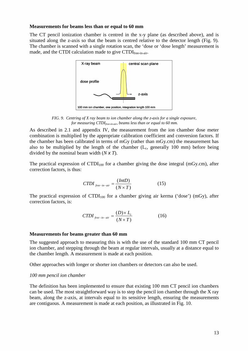
Measurements for beams less than or equal to 60 mm The CT pencil ionization chamber is centred in the x-y plane (as described above), and is situated along the z-axis so that the beam is centred relative to the detector length (Fig. 9). The chamber is scanned with a single rotation scan, the ‘dose or ‘dose length’ measurement is made, and the CTDI calculation made to give CTDIfree-in-air.
FIG. 9. Centring of X ray beam to ion chamber along the z-axis for a single exposure, for measuring CTDIfree-in-air, beams less than or equal to 60 mm.
As described in 2.1 and appendix IV, the measurement from the ion chamber dose meter combination is multiplied by the appropriate calibration coefficient and conversion factors. If the chamber has been calibrated in terms of mGy (rather than mGy.cm) the measurement has also to be multiplied by the length of the chamber (Lc, generally 100 mm) before being divided by the nominal beam width (N x T).
The practical expression of CTDI100 for a chamber giving the dose integral (mGy.cm), after correction factors, is thus:
)()(
TNIntDCTDI airinfree ×
=−− (15)
The practical expression of CTDI100 for a chamber giving air kerma (‘dose’) (mGy), after correction factors, is:
)()(
TNLDCTDI c
airinfree ××
=−− (16)
Measurements for beams greater than 60 mm The suggested approach to measuring this is with the use of the standard 100 mm CT pencil ion chamber, and stepping through the beam at regular intervals, usually at a distance equal to the chamber length. A measurement is made at each position.
Other approaches with longer or shorter ion chambers or detectors can also be used.
100 mm pencil ion chamber
The definition has been implemented to ensure that existing 100 mm CT pencil ion chambers can be used. The most straightforward way is to step the pencil ion chamber through the X ray beam, along the z-axis, at intervals equal to its sensitive length, ensuring the measurements are contiguous. A measurement is made at each position, as illustrated in Fig. 10.
100 mm ion chamber, one position, integration length 100 mm
dose profile
X-ray beam
z-axis
central scan plane
100 mm ion chamber, one position, integration length 100 mm
dose profile
X-ray beam
z-axis
central scan plane
13

Table 1 demonstrates the minimum integration length required for different beam widths in order to satisfy the integration length requirement of (N x T) + 40 mm. The numbers of contiguous positions of the 100 mm pencil ion chamber are also shown.
Measurements could also be made by using incremental steps of the ion chamber that are less than its length. In this instance the increment distance, delta (Δ), needs to be considered in the final calculation.
FIG. 10. Diagram demonstrating practical measurements of CTDIfree-in-air for a beam width of 160 mm with a 100 mm ion chamber, and step increments equal to the ion chamber length. Two integration lengths are shown. The 200 mm integration length is sufficient according to the minimum requirement of IEC; however the 300 mm integration length can also be used.
TABLE 1. EXAMPLES OF INTEGRATION LENGTHS AND NUMBER OF MEASUREMENTS REQUIRED FOR CTDIFREE-IN-AIR, ACCORDING TO THE PROPOSED IEC DEFINITION [15] WITH A 100 MM CHAMBER
Nominal beam width (mm)
Minimum integration length
(mm)^
Number of incremented measurements of 100
mm ion chamber
Associated Integration length
(mm) 20 100 1 100 40 100 1 100 60 100 1 100 80 120 2 200 160 200 2* 200 160 200 3* 300
^ At least, 100 mm or (N x T) +40 mm, whichever is the greater * The 200 mm integration length is sufficient according to the requirement of IEC, however the 300 mm
integration length can also be used since the length is a minimum requirement stated.
1 2
z-axis
position, i
a. 100 mm ion chamber: two contiguous positions, integration length 200 mm
1 2 3
X-ray tube
dose profile
X-ray beam
b. 100 mm ion chamber: three contiguous positions, integration length 300 mm
position, i
central scan plane
1 2
z-axis
position, i
a. 100 mm ion chamber: two contiguous positions, integration length 200 mm
1 2 3
X-ray tube
dose profile
X-ray beam
b. 100 mm ion chamber: three contiguous positions, integration length 300 mm
position, i
central scan plane
14

Alternative ion chambers lengths or /dosimeters
Alternative detectors can also be used, either shorter or longer detectors (Fig. 11). With shorter detectors, many more steps are required to acquire the dose along the length of the whole beam. Taking this concept further, a small (point) detector could be used to record the dose profile9 from which the integral dose can be obtained, or by uniformly translating the entire chamber through the beam.
Though not widely available, longer ionisation chambers could satisfy the integration length requirements in one measurement.
FIG. 11. Demonstrating possibilities for measurement of long integration lengths with a
smaller chamber and with a longer chamber.
Calculation: for chamber-dose meter systems presenting the dose integral (mGy.cm)
Where the steps are contiguous, i.e. the step distance equals the chamber length (Δ = Lc) (Fig. 10), the total integration length required can be thought of as a sum of a series of integrations over a length equal to the chamber length.
∑ ∫=
=−−
⎥⎥⎦
⎤
⎢⎢⎣
⎡×
×
ni
ii
Lairinfree dz (z) D
T N = CTDI
c1
1 (17)
Therefore, for steps equal to the chamber length, and for dose meter measurements presenting the dose integral directly (mGy.cm), the readings at each position (multiplied by the appropriate calibration factor) are simply summed together, and then divided by N×T to give the CTDI free in air.
[ ]∑=
=−− ×
×
ni
iiairinfree IntD
T N = CTDI
1)(1 (18)
where n = the number of steps required to cover the integration distance.
Calculation: for chamber-dose meter systems reading in ‘dose’
It is convenient to transform the integral in the CTDI equation into a summation when the dose measurements were performed in two or more steps:
9 The IEC methodology uses a 100 mm chamber length. In principle smaller or longer chamber can be used, but the use of smaller chambers for free in air measurements is not advocated as uncertainty increases with the number of measurements taken to measure the dose length across the beam.
1 2 3 4…… nPosition
Position 1
‘smaller’ ion chamber – contiguous measurements
‘longer’ 300 mm ion chamber – single measurement
1 2 3 4…… nPosition
Position 1
‘smaller’ ion chamber – contiguous measurements
‘longer’ 300 mm ion chamber – single measurement
15

∑=
=×−− ×
=ni
ii
cTNairinfree D
TNL
CTDI1
)(, (19)
where n is the total number of ‘steps’, or measurements, that are made to cover the desired integration length, Di is the recorded dose n air for position i, and the step increments are equal to Lc
Calculation examples
Table 2 illustrates the readings for different length detectors and different integration lengths, for detector systems presenting dose (mGy), and for those giving the dose integral directly. This is for a beam width of 160 mm. It is worth noting that the simplest solution, according to the IEC definition, is to use the 100 mm ion chamber, and a minimum of 2 positions of the ion chamber.
TABLE 2. ILLUSTRATION OF THE DERIVATION OF CTDI FREE-IN-AIR FOR A WIDE CONE BEAM OF 320 X 0.5 MM (160 MM) WITH FIVE DIFFERENT DETECTORS WITH SENSITIVE LENGTHS RANGING FROM 25 MM TO 400 MM. IN EACH CASE THE STEP DISTANCE IS EQUAL TO THE DETECTOR LENGTH (a) Chamber / dose meter systems giving dose integral (mGy.cm) readings
Sensitive length of
the detector (Lc)
Number of steps
Chamber ‘readings’: Dose integral values
(IntD)i Σ(IntD)i l/N×T CTDI
Free in air
mm N mGy.cm * mGy.cm cm-1 * mGy 400 1 320 320 0.00625 20 200 1 320 320 0.00625 20 100 2 160, 160 320 0.00625 20 100 3 60, 200, 60 320 0.00625 20
* Note consistency of distance units required (cm)
(b) Chamber / dose meter systems giving dose readings (mGy)
Sensitive length of the detector (Lc)
Number of steps
Chamber ‘readings’: Dose values Di
ΣDi Δ/N×T CTDI free-in-air
mm N mGy mGy - mGy 400 1 8 8 2.5 20 200 1 16 16 1.25 20 100 2 16, 16 32 0.625 20 100 3 6, 20, 6 32 0.625 20 50 4 12, 20, 20, 12 64 0.3125 20 25 8 4, 20, 20, 20, 20, 20, 20, 4 128 0.15625 20
2.4. Detectors that can be used
Any ionization chamber used for CT dosimetry is recommended to be calibrated at the appropriate X ray spectra, e.g., using IEC RQT beam qualities [2, 17]. Calibration should be done in a calibration laboratory following international guidelines [2] (Appendix III).
The 100 mm standard pencil CT ion chamber can be used for all of the measurements described in section 2.3. This chamber has been in routine use and is widely available, and
16

can be purchased from several manufacturers (Fig. 12). Longer chambers are available (Fig. 13), but are not necessary to implement this description of CTDI.
FIG. 12. 100 mm long CT ionization chamber. This chamber is commonly used for assessment of CTDI.
FIG.13. 300 mm long CT ionization chamber, sometimes used, mainly for research purposes.
As mentioned above, theoretically it may be possible to use smaller ionization chambers, providing that they have been calibrated at appropriate energies and the response over the required CT X ray energies is flat. To this end the 0.6 cc Farmer style chamber (Fig. 14), often used in radiotherapy10, can be used, once calibrated for appropriate CT X ray spectra. However, it cannot be meaningfully used for phantom measurements of CTDI100, but is rather used to determine localised dose.
10 Note radiotherapy Farmer chambers, such as the one shown in fig. 14, have a long aluminium stem that perturbates the X ray field and adds additional scatter. Ionization chambers of 0.6 cm3 are available with PMMA stems that overcome such problems.
17
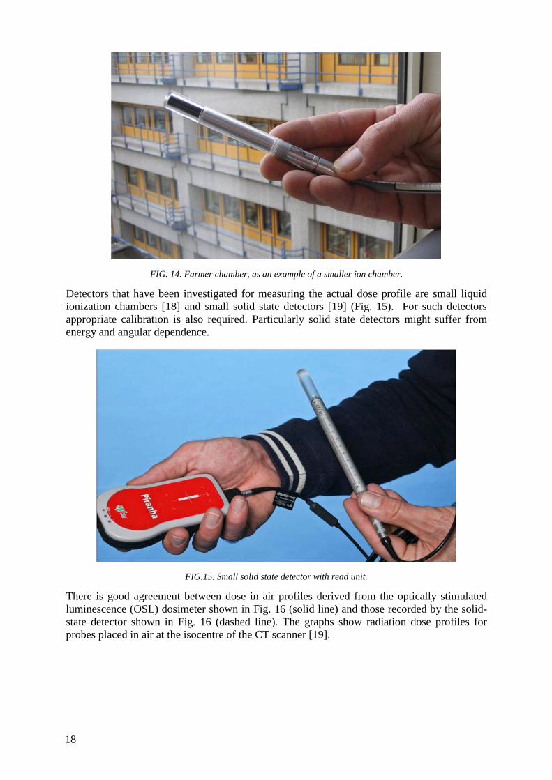
FIG. 14. Farmer chamber, as an example of a smaller ion chamber.
Detectors that have been investigated for measuring the actual dose profile are small liquid ionization chambers [18] and small solid state detectors [19] (Fig. 15). For such detectors appropriate calibration is also required. Particularly solid state detectors might suffer from energy and angular dependence.
FIG.15. Small solid state detector with read unit.
There is good agreement between dose in air profiles derived from the optically stimulated luminescence (OSL) dosimeter shown in Fig. 16 (solid line) and those recorded by the solid-state detector shown in Fig. 16 (dashed line). The graphs show radiation dose profiles for probes placed in air at the isocentre of the CT scanner [19].
18

FIG.16. Radiation dose profiles measured using an OSL dosimeter and a solid state detector.
19


APPENDIX I THEORY TO SUPPORT THE APPROACH TO WIDE BEAM DOSIMETRY
The purpose of this appendix is to describe some of the theoretical support for the approaches to wide beam dosimetry described in the previous section. This section will start with some basic descriptions of CT system X ray beams and then progress to descriptions relevant to CT dosimetry.
I.1. The basic X ray beam output of a CT scanner for a stationary scan (no source movement and no table movement) (in air)
The purpose of this section is to describe the CT scanner X ray output under simplest possible conditions – with no source motion, no table motion and no phantom. A CT system uses an X ray source, filtration, bowtie filtration and collimation as seen in fig 17. If one were to examine the output of that beam in a horizontal plane though the isocentre of the scanner in air (with no attenuation at all), as the result of a full rotation of the X ray source, the shape would be as described in Fig. 18 where the height of the curve indicates the intensity at a given point and the plot shows how that intensity changes in the x and z-axes. Figure 18 then shows a plot of this beam along the x-direction (showing the influence of the bowtie filter) and Fig. 19 shows a plot of this beam along the z-direction (showing the influence of the collimation).
From these profiles in air, the actual radiation profile widths in air can be determined. This can be done by measuring the spatial profile seen in Fig. 20 using a spatially sensitive radiation detector (such as photographic film, OSL, GafChromic Film or solid state probe) and then calculating the Full Width at Half Maximum (FWHM) of that profile. In addition, using a pencil ionization chamber (as described above in Section 2.2) one can also measure absorbed dose to air (or exposure, depending on the meter being used) and calculate a CTDIfree-in-air,N x T. This will be used in the calculation of CTDI100 for beam widths > 40mm.
FIG.17. X ray source for a CT scanner with anode, flat filter, bow tie (body shaping) filter and collimation.
21

FIG.18. X ray output intensity in a horizontal plane through the CT scanner isocentre as a function of x and z-axes.
FIG. 19. X ray intensity along the x-axis.
FIG. 20. X ray intensity along the z-axis.
I.2. The X ray beam output of a CT scanner for a single axial scan in phantom
The purpose of this section is to introduce both source rotation and a phantom into the X ray beam (still with no table motion). Measurements are made for a single axial scan (using a full rotation) with a standard CTDI phantom to take into account the effects of the bowtie filter and scatter from an attenuating medium. The measurements are usually taken at least two locations: the centre of the phantom and the periphery. When these phantoms are introduced, the X ray beam at any location is now influenced by both primary and scattered photons. The resulting beam along the z-axis is now not so sharply defined (because of scatter) and is
0.0
0.2
0.4
0.6
0.8
1.0
-220 -170 -120 -70 -20 30 80 130 180
x-axis, mm
Dos
e, u
nitle
ss
120 kV - Large FOV80 kV - Large FOV120 kV - Medium FOV80 kV - Medium FOV120 kV - L mirrorred80 kV - L mirrorred120 kV - M mirrorred80 kV - M mirrorred
22

shown in Fig. 21 for a head (16 cm diameter) phantom and in Fig. 22 for a body (32 cm diameter) phantom. These figures show that at the periphery (e.g. 12:00) position, the beam is less broad, more peaked, has scatter tails that are a smaller portion of the total and generally more influenced by primary photons than scattered photons. These figures also show that for the centre position, the beam is less peaked, broader, has scatter tails that are a larger portion of the total and is generally more influenced by scatter than the periphery position; this is especially true for the centre position of the body (32 cm diameter) phantom as there is much more scattering material.
FIG. 21. X ray intensity along the z-axis is now for a head (16 cm diameter) phantom.
FIG. 22. X ray intensity along the z-axis is now for a body (32 cm diameter) phantom.
When the 100 mm pencil ionization chamber is used, it is collecting the radiation ONLY from the central 100 mm of this radiation profile (as indicated by the vertical lines in Fig. 21 and Fig. 22) and it is this exposure that is being used to calculate CTDI100. Clearly, even for nominal beam widths that are less than 20 mm (as shown in Fig. 21), it is evident that the 100 mm chamber will NOT be captured by all of the extent of these profiles.
I.3. Radiation profiles for a series of scans in phantom
In section I.2, the radiation profiles in phantom that result from a single axial scan were described. However, most CT scanning is performed as either a series of axial scans or helical scans that cover a volume of the patient. Therefore, it is important to describe the radiation profiles that result from a series of scans in phantom. Figure 23 shows conceptually the scanning of a volume of the patient and that at each location, there is a radiation profile.
23

Figure 24 demonstrates that each radiation profile contributes radiation dose to the location where the primary radiation was absorbed, but that the tails of the radiation profile (due to scatter, etc.) also contribute to radiation dose to adjacent locations. When examining a given location, (say location 120 in Fig. 24), the light blue curve shows the radiation profiles for the scan that occurred at that location and the dark blue curve shows the sum of those radiation profiles (including the contributions from adjacent locations, from scatter, etc.). This figure shows that when all contributions are added, that the sum can be much higher than the value of the single scan radiation profile, especially at the centre of the phantom (or patient) where there is significant scatter.
FIG. 23. Concept of scanning a volume of the patient and the radiation profile at each location.
FIG.24. X ray intensity along the z-axis is now for a body (32 cm diameter) phantom.
To obtain an estimate of the average absorbed dose to the central slice that results from a series of scans, Shope et al [7] showed that this is mathematically equivalent to calculating the integral of the radiation profile of a single axial scan profile (i.e. the profiles shown in Fig. 21 and 22 and this was the basis for CTDI.
However, to obtain the integral of the dose profile, there are a number of issues to consider, including: (a) the length over which the integral is taken, (b) the length of the scan, and (c) the length of the phantom. Each of these will be discussed in the following sections.
I.4. Estimating average dose to the central slice from a series of scans – integration length
While Shope et al [7] showed that the integration of the single axial scan radiation profile was mathematically equivalent to the average absorbed dose to the central slice in the idealized case of infinite data and contiguous slices, Jucius and Kambic [20] indicated that this integration could be achieved physically by using the 100 mm pencil ionization chamber. However, it is clear from Fig. 21 and 22 that the 100 mm pencil chamber will NOT be able to
24

integrate the entire radiation dose profile within the phantom. Therefore, the calculation of CTDI100 using the 100 mm chamber will be an underestimate of the integration of the radiation profile and therefore an underestimate of the average dose to the centre slice for any scan length over 100 mm. CTDI∞, where the integration is over the full dose profile, is more likely representative of the average dose to the central slice for a long scan length.
To obtain an estimate of CTDI∞, which would be a complete integration of the radiation profiles from -∞ to +∞, there are two possible approaches, either:
(a) use a single axial scan, but with a longer (> 100mm) pencil ionization chamber and a longer CTDI phantom (140 mm), or
(b) perform the series of scans and use a small point ionization chamber (e.g. a Farmer chamber) to perform the integration of the cumulative dose profile (i.e. the profile shown in Fig. 24) that results from the series of scans. This approach would still need a longer CTDI phantom.
The former approach is difficult as longer pencil ionization chambers are not common. The latter approach is that described in AAPM Task Group Report 111 [10].
I.5. Estimating average dose to the central slice from a series of scans – effect of scan length
Figure 25 demonstrates the cumulative dose profile and its relationship to individual single axial scan profiles, but that figure only used a limited number of dose profiles to illustrate that point. This corresponds to a relatively short scan length. Because the scatter tails of the individual dose profiles extend for a significant distance (as illustrated in Fig. 21 and 22), the contributions from even distant scans (those > 100 mm away) can contribute to the dose of the central slice. Thus, the length of the scan should be sufficiently large to include all of the contributions, even from slices acquired at a significant distance from the central slice.
Nackonechny [21] demonstrated that as the scan length was increased, the cumulative dose profile increases and broadens; this is again due to the contributions from scatter from adjacent regions. As the scanning length increases, the average dose to the central slice rises to an equilibrium value (denoted as Deq in AAPM report 111 [10]).
FIG. 25. Cumulative dose profiles for different scan lengths [16].
25

Just as the scan length influences the average dose to the central slice of the scan region, the length of the phantom can also influence this average dose. This is to be expected (and is somewhat implicit in Fig. 25 in that the phantom extends at least 400 mm). With a phantom longer than the 140 mm of the standard CTDI phantoms, there is more scattering material and therefore more opportunity for scatter to contribute to the dose of the central slice; this is especially true for the body phantom with its larger diameter.
I.6. CTDI100 and the underestimation of CTDI∞ and the effect of beam width
The above sections have demonstrated that CTDI using a 100 mm chamber provides an underestimate of the ideal CTDI∞ because of the limitations of: (a) integration length being limited to 100 mm, (b) limited scan length and (c) limited phantom length. Boone [11] performed an analysis of the degree of resulting underestimation as a function of nominal beam width, which is shown in Fig. 26. This figure demonstrates that for relatively narrow beam widths (those less than 40 mm) that the efficiency of CTDI100 (which Boone denoted as ε and defined as the ratio of CTDI100 to CTDI∞) is relatively constant, but less than 100%. As the beam width increases beyond 40 mm (and especially beyond 100 mm which is the active length of the chamber), then the efficiency declines noticeably.
FIG. 26. (a) The CTDI100 measurement efficiency for the 16 cm diameter (head) phantom is illustrated as a function of beam width. The value of CTDI100 measurement efficiency is the ratio of the accumulated dose integral measured using the 100 mm chamber measurement to the total dose integral (including that beyond the edges of the 100 mm measurement chamber). Also equal to the ratio of accumulated dose at z=0 for a scan length L=100 mm, to the equilibrium dose at z=0 approached asymptotically for large L. (b) The CTDI100 measurement efficiency for the 32 cm (body) phantom is illustrated as a function of beam width.
I.7. Differences between nominal and actual beam width, and the use of the CTDIaperture in obtaining CTDI100 at various collimation settings.
The approach to calculating the CTDI100 for wide beam widths as given in IEC Edition 3, Amendment 1[15], and adopted in this document, is based on the premise that the ratio of CTDI100 values at any two collimations is equal to the ratio of their free-in-air CTDI values. This section presents some of the theory behind this premise.
Background
There is a difference between the nominal beam width (N×T) and the actual width of the radiation profile measured along the z-axis at that nominal beam width, or collimation, setting. This difference is illustrated in Fig. 27 which shows a z-axis dose profile (“D(z)”) for
26
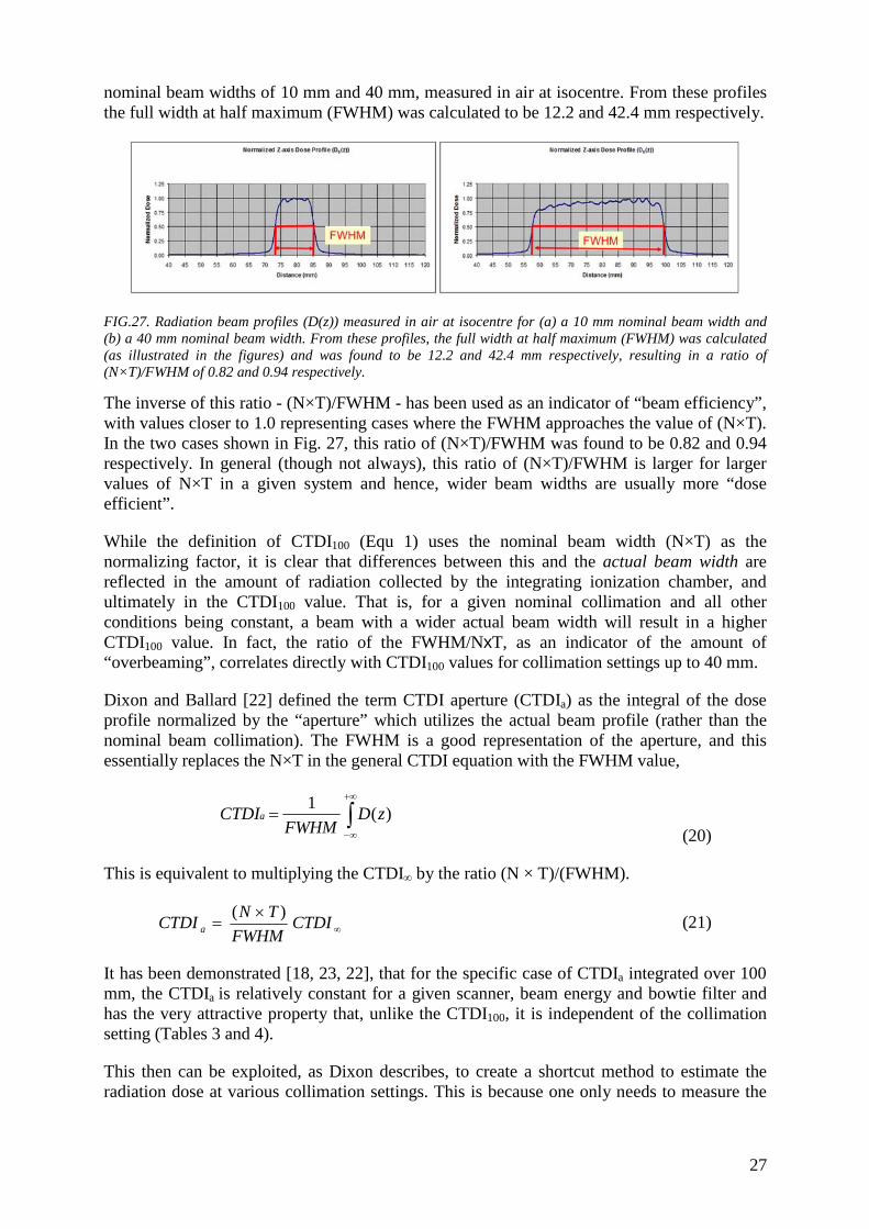
nominal beam widths of 10 mm and 40 mm, measured in air at isocentre. From these profiles the full width at half maximum (FWHM) was calculated to be 12.2 and 42.4 mm respectively.
FIG.27. Radiation beam profiles (D(z)) measured in air at isocentre for (a) a 10 mm nominal beam width and (b) a 40 mm nominal beam width. From these profiles, the full width at half maximum (FWHM) was calculated (as illustrated in the figures) and was found to be 12.2 and 42.4 mm respectively, resulting in a ratio of (N×T)/FWHM of 0.82 and 0.94 respectively.
The inverse of this ratio - (N×T)/FWHM - has been used as an indicator of “beam efficiency”, with values closer to 1.0 representing cases where the FWHM approaches the value of (N×T). In the two cases shown in Fig. 27, this ratio of (N×T)/FWHM was found to be 0.82 and 0.94 respectively. In general (though not always), this ratio of (N×T)/FWHM is larger for larger values of N×T in a given system and hence, wider beam widths are usually more “dose efficient”.
While the definition of CTDI100 (Equ 1) uses the nominal beam width (N×T) as the normalizing factor, it is clear that differences between this and the actual beam width are reflected in the amount of radiation collected by the integrating ionization chamber, and ultimately in the CTDI100 value. That is, for a given nominal collimation and all other conditions being constant, a beam with a wider actual beam width will result in a higher CTDI100 value. In fact, the ratio of the FWHM/NxT, as an indicator of the amount of “overbeaming”, correlates directly with CTDI100 values for collimation settings up to 40 mm.
Dixon and Ballard [22] defined the term CTDI aperture (CTDIa) as the integral of the dose profile normalized by the “aperture” which utilizes the actual beam profile (rather than the nominal beam collimation). The FWHM is a good representation of the aperture, and this essentially replaces the N×T in the general CTDI equation with the FWHM value,
∫+∞
∞−
= )(1 zDFWHM
CTDIa
(20)
This is equivalent to multiplying the CTDI∞ by the ratio (N × T)/(FWHM).
∞×
= CTDIFWHM
TNCTDI a)( (21)
It has been demonstrated [18, 23, 22], that for the specific case of CTDIa integrated over 100 mm, the CTDIa is relatively constant for a given scanner, beam energy and bowtie filter and has the very attractive property that, unlike the CTDI100, it is independent of the collimation setting (Tables 3 and 4).
This then can be exploited, as Dixon describes, to create a shortcut method to estimate the radiation dose at various collimation settings. This is because one only needs to measure the
27

integral dose for one nominal beam setting, “one known value of the aperture” (FWHM) in order to calculate the CTDIa.
From this CTDIa, the CTDI values for all other collimation settings may be estimated very well using
aCTDITN
FWHMCTDI)( ×
=∞
(22)
where a is the aperture, approximated by the FWHM, and N x T is the nominal beam width for the desired collimation setting.
Therefore, rather than measuring CTDI in phantom at all collimation settings (including those > 40 mm and especially for those greater than the l00 mm length of the ionization chamber), the CTDI at each collimation setting can be obtained from: (1) the CTDIa value, (2) the nominal beam width value N×T, and (3) an estimate of the aperture.
Some example data, for CTDIfree-in-air and CTDI100 (expressed as CTDIw i.e. the weighted average of the centre and periphery phantom CTDI100 values) from one scanner are illustrated in Tables 3 and 4 below based on data from McNitt-Gray [22]. These tables show the nominal and actual measured beam widths (apertures) for several collimation settings from one scanner. They also show the CTDIair and CTDIw (in 32 cm phantom here) for a given set of exposure conditions (kVp, mAs, bowtie filter) for each collimation. These tables also show the CTDIa for each collimation setting and then normalize those CTDIa values to that of the largest nominal collimation setting (40 mm) to show how similar (within 10%) these CTDIa values are across collimations.
Application in IEC Version 3, amendment 1
These concepts are utilized in the IEC approach to CT dosimetry (Version 3, Amendment 1) to obtain the adjustment necessary to determine the CTDI100 values for larger beams. Specifically, this relationship between CTDI∞ and CTDIa is exploited to determine the CTDI∞ for various collimation settings, especially for very wide beam widths including those beam widths larger than that of the measuring apparatus.
If CTDIa is a constant, then to obtain the CTDI∞ of a specific nominal beam width setting, N x T, all that is needed are the CTDIa, N x T and FWHM values. While this could be accomplished by measuring radiation profiles as described above and in Fig. 22, this may also be accomplished by measuring the ratio of CTDIfree-in-air for two collimation settings (this is the approach outlined in IEC Amendment 1 of edition 3).
That is, if CTDIa is a constant, and numbers 1 and 2 represent two different collimations i.e. nominal beam width settings
aCTDITN
FWHMCTDI ×⎥⎦
⎤⎢⎣
⎡×
=∞1
11, )( (23)
aCTDITN
FWHMCTDI ×⎥⎦
⎤⎢⎣
⎡×
=∞2
22, )(
(24)
28

Expressing CTDIa in terms of CTDI∞,1
⎥⎦
⎤⎢⎣
⎡ ××= ∞
1
11,
)(FHWM
TNCTDICTDIa
(25) Then the ratio of CTDI∞,1 and CTDI∞,2 gives:
⎥⎦
⎤⎢⎣
⎡×⎥
⎦
⎤⎢⎣
⎡×
×= ∞∞1
1
2
21,2, )(
/)( TN
FWHMTN
FWHMCTDICTDI (26)
This means that if one measures the CTDI∞,1, then the CTDI∞,2 can be obtained by calculation if the ratio of FWHM to (N x T) for both collimations is known. This ratio could be measured directly by evaluating the radiation profile (D(z)) for each collimation setting.
This ratio can also be obtained by measuring CTDIair (in air at isocentre) for both collimation settings. This is because the CTDIair measurement essentially takes into account the ratio of FWHM/ (N x T) for each collimation setting (note that when measured in air, there is little or no scatter and so the under-reporting of the dose profile can be managed, even with wider beams – by moving the ionization chamber and making multiple measurements if required; See Chapter 2 for details). This means that CTDI∞,2 could be calculated by:
⎥⎥⎦
⎤
⎢⎢⎣
⎡×=
−−
−−∞∞
1,
2,1,2,
airinfree
airinfree
CTDICTDI
CTDICTDI (27)
It is this relationship that IEC version 3, Amendment 1 [15] proposes to exploit for use in calculating CTDI100 for all beam widths, including those greater than 40 mm (up to 160 mm).
When the modified definition of CTDI100 is employed (Equ 4), then a more consistent relationship between CTDI100 and scan length is observed, such as described in Fig. 3. This approach overcomes some of the limitations of using a single 100 mm long ionization chamber for all beam widths (even if the nominal beam width is > 100 mm) and resolves some of the inconsistencies seen in previous approaches.
A few important issues can be noted in Fig. 3 for the proposed IEC definition of CTDI (Amendment 1, edition 3):
(a) even at small or very large collimation beam widths, the efficiency (CTDIw/ CTDIw,∞ ) does not reach 1.0, indicating that even at small collimations, there is scatter that is not being recorded by the ionization chamber;
(b) the solid line in Fig. 3 represents the results from a long - 500 mm – phantom while the dashed line represents the results from a standard length – 150 mm – long phantom; therefore, the length of the phantom does have some impact here, but it is not a large difference.
Therefore, this approach represents a reasonable methodology for CT dosimetry, even for very large beam widths.
29

TABLE 3. CTDI APERTURE IN AIR: NOMINAL BEAM WIDTH, ACTUAL BEAM WIDTH AND THEIR RATIO AS WELL AS CTDIAIR, CTDIAPERTURE,AIR, AND THE CTDIAPERTURE,AIR NORMALISED TO THE VALUE AT 40 MM FOR SEVERAL COLLIMATION SETTINGS. CTDIAIR IS MEASURED FOR ALL COLLIMATION SETTINGS AT THE SAME KV, BOWTIE FILTER, AND MAS VALUES.
CTDIAPERTURE,AIR = CTDIAIR × (N×T) /(FWHM). DATA FROM [22]
Nominal Beam Width (N×T)
Aperture - Measured Beam Width (FWHM)
Ratio of (N×T/(FWHM)
CTDIair CTDIa, air
CTDIa, air normalized to 40 mm
40 mm 42.4 mm 0.94 27.8 mGy 26.2 mGy 1.00 20 mm 21.5 mm 0.93 28.9 mGy 26.9 mGy 1.03 10 mm 12.2 mm 0.82 33.3 mGy 27.3 mGy 1.04 TABLE 4. CTDI APERTURE IN PHANTOM: NOMINAL BEAM WIDTH, ACTUAL BEAM WIDTH AND THEIR RATIO AS WELL AS CTDIAIR , CTDIAPERTURE,W, AND THE CTDIAPERTURE,W NORMALISED TO THE VALUE AT 40 MM FOR SEVERAL COLLIMATION SETTINGS. CTDIW IS MEASURED FOR ALL COLLIMATION SETTINGS AT SAME KV, BOWTIE FILTER, AND MAS VALUES FOR THE 32 CM PHANTOM.
CTDIAPERTURE,W = CTDIW × (N×T)/(FWHM). DATA FROM [22].
Nominal Beam Width (N×T)
Aperture - Measured Beam Width(FWHM)
Ratio of (N×T)/(FWHM)
CTDIw
CTDIa, w
CTDIa, w normalized to 40 mm
40 mm 42.4 mm 0.94 8.5 mGy 8.0 mGy 1.00 20 mm 21.5 mm 0.93 9.0 mGy 8.3 mGy 1.04 10 mm 12.2 mm 0.82 10.5 mGy 8.6 mGy 1.07
30

APPENDIX II SUMMARY POINTS AND RECOMMENDATION FOR CT DOSIMETRY
The following summary points and recommendations were made at the IAEA consultants meeting.
II.1. Summary points
• CT dose parameters should be appropriate for their intended use, which includes; - Scanner performance (QA measure) - To assist in the consideration for the justification of CT examinations - An index for the optimization of protection [5]
for CT examination protocols (trade-off between image quality and dose)
to support the use of diagnostic reference levels [5] (DRLs) in CT - As an input for patient risk assessment.
• It is difficult for a single dose metric to fulfil all the above. • The CDTI100 concept does not adequately address
- The over estimation of dose for a stationary (no table incrementation) scan - The under estimation of central slice position dose from a long volumetric scan - The measurement of all the scatter radiation generated from a scan even with a
small slice width - Beam widths that approach or exceed the length of pencil chamber.
• The status of CT dosimetry is rapidly evolving to meet the challenges of - Wide beam CT - Patient size - Organ dose estimation - Use of automatic exposure control.
• There are evolving formalisms from work of various working parties (ICRU image quality and patient dose in computed tomography, AAPM TG200) that are expected to provide a more comprehensive and robust approach. These approaches may involve the use of
- Smaller chamber sizes, - Longer phantoms and - New dose parameters
II.2. Recommendations
• Though not ideal, an interim pragmatic solution for CT dosimetry is best described, for conventional and wide beam width scanners, in terms of
- The proposed modifications to CTDI, as described in IEC safety standard [15] (still in draft), together with:
The use of a pencil ionization and The use of the standard CT dosimetry head and body phantoms.
• That the subscripting of the CTDI index be standardised. A suggested configuration is CTDImedium,detector-integration-length,nominal-beam-width giving for instance CTDIbody,100,4 x 5 or CTDIfree-in-air,100,N x T.
• The consistent use of phantoms for dose indicator estimation, and the possible consolidation of one size of phantom, is an important area requiring ongoing discussion.
31

• CT dose parameters should be scaled for patient size to reflect patient dose. Activities in this area have been identified (e.g. AAPM TG 204, ICRU). Applications include protocol comparisons (adjustments for patient size).
• Relevant dose parameters should be - Displayed on the operators console with other examination parameters
(without additional navigation) - Recorded in a dose report (including DICOM structures)
• Caution must be applied in the use of the dose parameters that are included in dose reporting structures required increasingly by many bodies. It should be emphasised that the current parameters of CTDI and DLP are not patient dose quantities, but dose indexes.
32

APPENDIX III QUANTITIES AND UNITS FOR CT DOSIMETRY
In general the recommendations of ICRU Report 74, ‘Patient Dosimetry for X Rays Used in Medical Imaging’ [1] were also adopted in the IAEA Report TRS 457 ‘Dosimetry in Diagnostic Radiology: An International Code of Practice’, [2], utilizing air kerma as a basis for diagnostic radiology dosimetry.
Table 5 shows the nomenclature used by the IAEA for the dosimetry applications for CT in comparison to those used by the IEC. The universal acceptance of IEC nomenclature by the CT scanner manufacturers has guaranteed its common usage amongst clinical users of CT dosimetry. The nomenclature adopted in this publication reflects what is currently used clinically and in the literature and to aid clarity has not been transcribed to any new terminology.
TABLE 5. COMPARISON OF IAEA TRS 457 AND IEC 60601-2-44 DOSIMETRY TERMINOLOGY USED IN COMPUTED TOMOGRAPHY
Quantity IAEA IEC
Measured free-in-air:
CT air kerma index ( ) zzK
TNCa d
.1 50
50100, ∫+
−=
The general equation:
dz T N
(z) D = CTDI+L
L-airfree ×∫
2/
2/
For beam widths less than 60 mm:
dz T N
(z) D = CTDI+
-airfree ×∫
50
50
Measured in standard phantom:
Weighted CT air kerma index ( )p100,PMMA,c,100PMMA,W 2
31 CCC += CTDIw =1/3 CTDI100,c + 2/3 CTDI100,p
Normalized weighted CT air kerma index nCW nCTDIw
Volume CT air kerma index CVOL CTDIVOL
CT air kerma-length product jj
PLCP jj
n ItVOLCTKL, ∑= DLP= CTDIVOL . L
From the above it is clear that the critical equations from section 2 can be rewritten in conformity with the nomenclature of TRS 457. In this case Cw for a beam width > 40 mm can be written as:
⎟⎟⎠
⎞⎜⎜⎝
⎛×=
fa
TNafwTNw C
CCC
Re,100,
.,100,Re,., (28)
where Cw,N.T is the weighted CT air kerma index for a beam width of N.T mm (if N.T is > 40 mm), Cw,Ref is the weighted CT air kerma index for a reference beam width of 20 mm (or closest possible below 20 mm), and similarly Ca,100,N.T is the CT air kerma index measured free in air with a 100 mm integration length for a beam width of N.T mm and Ca,100,Ref is a
33

similar quantity at the reference beam width. The methodology to measure Ca,100,N.T is an identical to that described in 2.2.2.
34

APPENDIX IV DOSIMETER CALIBRATION
Calibration of a dosimeter The determination of dosimetric quantities relies on accurate radiation measurements with a dosimeter, consistent with IEC standards [24], and with a calibration traceable to a standards laboratory. Typically an ionization chamber detector connected to an electrometer is used for radiation measurement in CT11. The measurement uncertainty should be determined by the user through an analysis of measurement errors including the calibration uncertainty12[25].
As seen in the formulation from TRS457 [2] air kerma can be determined from a measurement using the equation
iiQKQ kNMKoΠ= , (29)
Where MQ is the instrument reading for a beam quality, Q, and factors ki represent a correction for the effect of the i-th influence quantity and NK,Qo is the calibration coefficient of the dosimeter (system) in terms of the air kerma obtained from a standards laboratory. One important correction factor kTP corrects for the effect of temperature and pressure and should be applied for ionization chambers, except in cases where such corrections are made automatically [25].
⎜⎜⎝
⎛⎟⎠⎞
⎜⎝⎛⎟⎟⎠
⎞++
=PP
TTkTP
0
02.2732.273 (30)
From Eq. 31 it is seen that NK,Qo had the units of mGy/MQ units. MQ may have the units of charge (in a standards laboratory for example), or more commonly clinically in units of mGy, rads, or Roentgens for example, depending on the dosimeter make and calibration.
Importantly, in general, this measurement process assumes that the irradiation beam is uniform and that the detector is fully covered.
Calibration of CT chamber dosimetry system The output quantity of a pencil chamber as used in CT dosimetry is, for some chambers, the kerma (dose in air) length product (PKL) as can also be verified from the dimensions of the quantities from Eq.1. To be consistent with accepted metrology standards the calibration of such a chamber in a standards laboratory utilises an aperture of defined length to irradiate the central section of the chamber and is described in TRS 457 [2]. The calibration coefficient for radiation quality Q is then defined as
a
rP dM
dwKNQKL=
, (31)
where M is the reading of the chamber corrected to reference temperature and pressure; K is the air kerma at the point of test; w is aperture width; dr is distance between the focal spot and
11 Semi-conductor dosimeters are commonly used clinically in primary beam scatter free situations where the significant intrinsic energy dependence of the detector is controlled through calibration. 12 In CT phantom measurements it can be difficult to determine the measurement error due to detector energy sensitivity. This is especially the case for detectors with a high intrinsic energy dependence due to the significant differences in X ray spectra between measurement and calibration conditions.
35

the point of test; da is distance between the focal spot and the plane of the aperture. The units of the coefficient are then seen to be kerma length product divided by the measurement units.
Calculation of CTDI from a pencil ion chamber measurement It should be noted that a significant number of CT dosimetry systems have not been calibrated in terms of kerma length, but instead are calibrated in terms of air kerma (dose). In this case it is essential, when calculating the CTDI that the measurement be converted to a kerma (dose) length measurement by multiplying the reading by the chamber length used for the measurement.
Since CT pencil chamber dosimeters are known to use a variety of measurement units, it is essential that users of these instruments understand the quantity and units displayed by the dosimeter and can apply calibration coefficients with the correct units to determine the kerma length product from the measurement which will in turn give a C (CTDI) value (mGy) when divided by the CT beam width.
The CTDI measured in the standard phantoms is referred to as CTDI100, (and subsequently when averaged over the scan plane and allowing pitch, this becomes CTDIw, and CTDIvol). The CTDI measured in air is referred to as CTDIfree-in-air.
Generic calculations for CT dosimeter systems calibrated in ‘dose length’ (mGy.cm) For a CT ion chamber dosimeter systems which is calibrated to give a dosimetric outcome in terms of the product of dose and length (PKL) or (IntD), the recorded reading (M) is multiplied by the calibration coefficient13 NPKL. The resulting units are mGy.cm. This is the integral in the CTDI equation, therefore to obtain the CTDI, this value is divided by the nominal beam width, given by (N x T).
∫+
−×=
mm
mm
dzzDTN
CTDI50
50100 )(1
(32)
The practical expression of CTDI100 or CTDIfree-in-air, for a chamber recording the dose integral, ‘dose length’, is therefore:
)()(
)()(
100 TNIntD
TNNM
CTDI KLPairinfreeor ×
=×
×=−− (33)
Generic calculations for CT dose meter systems calibrated in ‘dose’ (mGy) In the case where the CT pencil ion chamber and dose meter system is calibrated in mGy, the reading (M) is multiplied by the calibration coefficient Nk to give the dose (D) (mGy). To obtain the CTDI value, this is further multiplied by the detector length (Lc, generally 100 mm), before being divided by the nominal beam width (N × T).
The practical expression of CTDI100 or CTDIfree-in-air, for a chamber recording ‘dose’ is therefore:
)()()(
100 TNLD
TNLNMCTDI ccK
airinfreeor ××
=×
××=−− (34)
13 In many clinical cases the calibration factor will be ‘hard wired’ into the dosimeter and so no calibration routinely has to be applied. Calibration documentation however should be checked to verify that effectively applying a calibration factor of 1 is valid.
36

REFERENCES
[1] INTERNATIONAL COMMISSION ON RADIATION UNITS AND MEASUREMENTS, Patient Dosimetry for X Rays Used in Medical Imaging, ICRU Rep. 74 Bethesda, MD (2006).
[2] INTERNATIONAL ATOMIC ENERGY AGENCY, Dosimetry in Diagnostic Radiology: An International Code of Practice, Technical Reports Series No. 457, IAEA Vienna (2007).
[3] MCCOLLOUGH, C.H., et al., CT Dose Index (CTDI) and Patient Dose: They Are Not The Same Thing, (2011).
[4] NATIONAL RESEARCH COUNCIL OF THE NATIONAL ACADEMIES, Health risks from exposure to low levels of ionizing radiation; BEIR VII phase 2, Committee to Assess Health Risks from Exposure to Low Levels of Ionizing Radiation, National Academies Press, Washington, DC (2006).
[5] INTERNATIONAL COMMISSION ON RADIOLOGICAL PROTECTION, The 2007 Recommendations of the International Commission on Radiological Protection, ICRP Publication 103, Annals of the ICRP Volume 37/2-4, Elsevier (2008). via
[6] EUROPEAN COMMISSION, Radiation Protection 154: European Guidance on Estimating Population Doses from Medical X-Ray Procedures Luxembourg (2008). http://ec.europa.eu/energy/nuclear/radiation_protection/publications_en.htm.
[7] SHOPE, T.B., GAGNE, R.M., JOHNSON, G.C., A method for describing the doses delivered by transmission x-ray computed tomography, Medical Physics 8 (1981) 488-495.
[8] LEITZ, W., AXELSSON, B., SZENDRO, G., Computed Tomography Dose Assessment -- A Practical Approach, Radiation Protection Dosimetry (1995) 57.
[9] INTERNATIONAL ELECTROTECHNICAL COMMISSION, Medical Electrical Equipment - Part 2-44: Particular Requirements for the Safety of X-Ray Equipment for Computed Tomography, IEC-60601-2-44 - Ed. 2.1 (incl. amendment1), IEC Geneva (2002).
[10] AMERICAN ASSOCIATION OF PHYSICISTS IN MEDICINE, Comprehensive Methodology for the Evaluation of Radiation Dose in X-Ray Computed Tomography, AAPM Rep. 111 New York (2010). http://www.aapm.org/pubs/reports/RPT_111.pdf.
[11] BOONE, J., The Trouble with CTDI100, Medical Physics 34 4 (2007). [12] GELEIJNS, J., et al., Computed tomography dose assessment for a 160 mm wide, 320
detector row, cone beam CT scanner, Phys Med Biol 54 10 (2009) 3141-59. [13] MORI, S., et al., Enlarged longitudinal dose profiles in cone-beam CT and the need
for modified dosimetry, Med Phys 32 4 (2005) 1061-9. [14] INTERNATIONAL ELECTROTECHNICAL COMMISSION, Medical Electrical
Equipment - Part 2-44 Edition 3: Particular requirements for basic safety and essential performance of X-ray equipment for computed tomography, IEC-60601-2-44 - Edition 3, IEC Geneva (2009).
[15] INTERNATIONAL ELECTROTECHNICAL COMMISSION, Medical Electrical Equipment - Part 2-44 Edition 3, Amendment 1: Particular requirements for basic safety and essential performance of X-ray equipment for computed tomography, IEC-60601-2-44 - Edition 3, Amendment 1; 62B/804/CD, COMMITTEE DRAFT (CD), IEC Geneva (2010).
[16] INTERNATIONAL COMMISSION ON RADIATION UNITS AND MEASUREMENTS, Phantoms and Calculational Models in Therapy, Diagnosis and Protection, ICRU Rep. 48 Bethesda, MD (1992).
[17] INTERNATIONAL ELECTROTECHNICAL COMMISSION, Medical Diagnostic X-Ray Equipment - Radiation Conditions for Use in the Determination of Characteristics, IEC-61267, IEC Geneva (2005).
37

[18] BAHAR GOGANI, J., HÄGGLUND, P., WICKMAN, G., Assessment of correlated dose and sensitivity profiles on a multi-slice CT scanner, Radiation Protection Dosimetry 114(1-3) (2005) 332-336.
[19] BAUHS, J.A., VRIEZE, T.J., PRIMAK, A.N., BRUESEWITZ, M.R., MCCOLLOUGH, C.H., CT dosimetry: comparison of measurement techniques and devices, Radiographics 28 1 (2008) 245-53. http://radiographics.rsnajnls.org/content/28/1/245.full.pdf+html.
[20] JUCIUS, R.A., KAMBIC, G.X., Radiation dosimetry in computed tomography, Appl. Opt. Instrum. Eng. Med. 127 (1977) 286-295.
[21] NAKONECHNY, K.D., FALLONE, B.G., RATHEE, S., Novel methods of measuring single scan dose profiles and cumulative dose in CT, Med Phys 32 1 (2005) 98-109.
[22] MCNITT-GRAY, M.F., et al., "CTDI Normalized to Measured Beam Width as an Accurate Predictor of Dose Variations for Multidetector Row CT (MDCT) Scanners Across all Manufacturers", RSNA (Proc. Conf. Chicago, 2008), http://rsna2008.rsna.org/event_display.cfm?em_id=6022485.
[23] DIXON, R.L., BALLARD, A.C., Experimental validation of a versatile system of CT dosimetry using a conventional ion chamber: Beyond CTDI100 Med Phys 34 8 (2007) 3399-3413.
[24] INTERNATIONAL ELECTROTECHNICAL COMMISSION, Medical Electrical Equipment - Dosimeters with Ionization Chambers and/or Semi-conductor Detectors as used in X-Ray Diagnostic Imaging, IEC-61674, IEC Geneva (1997).
[25] INTERNATIONAL ATOMIC ENERGY AGENCY, Implementation of the International Code of Practice on Dosimetry in Diagnostic Radiology, Technical Reports Series No. 457: Review of testing results, Human Health Report 4, IAEA Vienna (2011).
38

CONTRIBUTORS TO DRAFTING AND REVIEW
Edyvean, S. ImPACT, St Georges Hospital London, United Kingdom
Geleijns, J. Leiden University Medical Centre, Netherlands
Jansen, J. Health Protection Agency, United Kingdom
Järvinen, H. Radiation and Nuclear Safety Authority, Helsinki, Finland
Le Heron, J. International Atomic Energy Agency
Lewis, M. ImPACT, St Georges Hospital London, United Kingdom
McNitt-Gray, M. University of California Los Angeles, USA
McLean, I. D. International Atomic Energy Agency
Merimaa, K. Radiation and Nuclear Safety Authority, Helsinki, Finland
Tapiovaara, M. Radiation and Nuclear Safety Authority, Helsinki, Finland
CONSULTANTS MEETING Vienna, Austria: 17–19 November 2010
39


@������
��������� ���������������� ��������������������������������� �������������������������� ������������ ���������
����������������������������������� �������������������������������� ����� !"����������
������ �#��������� ��� ��$�����%&'�(� �������)�����*�+!,�*�-.-/��
+�������0�1%.�-�2/.3�4444�5�6�70�1%.�-�2/.3�44''��
���0����$��8������ ��������5�(���� �0�� �099���������� ��������
!� " �#:�������;��������$��������)��/3/��<=..23�<��������
+�������0�1-/�/�>-'�&-�3'�5�6�70�1-/�/�>-'�3'�&.��
���0��������������8������������5�(���� �0�� �099��������=��=���������
$���%�<������������ ����&>3.�6������<$��� � ��/33��;�������*#�/343%=&-&%��� ���
+�������0�.='33='%>=-&>4�5�6�70�.='33='%>=-&>3��
���0���� ��������8�����������5�(���� �0�� �099���������������
)������������?�!�������; ����.=>-%2�!��� ���)����" �����"� �����@.:�2:-��
+�������0�1%.-�4&>�/%%>�5�6�70�1%.-�4&>�4%%3��
���0���������� 8����������������5�(���� �0�� �099��������������������
$& ������������ ������!�����0�!���������������?������� ���!������ ����+����� ��� �� ������"��<�7�/.3-��<���?�
$'�$&���(�! $ ������!A�� �)�"���@�����$��-&4��.'3�/.�������2��
+�������0�1&/3�/%%3-�>-%&�5�6�70�1&/3�/'&'/�.%&%��
���0������8��������B�5�(���� �0�� �099������������B�
) � ��%��� �������@������������"�<"C�./'�D@������� ��.E��6��=33.3.�,������
+�������0�1->'�2�./.�&.�5�6�70�1->'�2�./.�&&>3��
���0���� ���8��� �����������5�(���� �0�� �099������� �����������
)���$�6���=�� ��>������:����������"��<�7�/>��6=4>2/.������!���7�.2��
+�������0�1--�.�&/�3.�&2�&2�5�6�70�1--�.�&/�3.�23�23��
���0������� 8������ ����5�(���� �0�� �099����������� ����
;�$����� � ��.&>�����������$?����2&/-%�!������!���7��
+�������0�1�--�.�&4�&3�%4�3/�5�6�7�1--�.�&4�&3�%4�3/��
���0��������$�����8�$��������5�(���� �0�� �099�����$��������
"��#��*��"=F���?��F�� ����=�����F���?��G��,�����,��?�� ���.3��#=>-..-�<�����
+�������0�1�&2�//'�2&�23�/3�5�6�70�1&2�//'�2&�23�/3����1&2�//'�2&�23�///��
���0���� ���?8���=$���?����5�(���� �0�� �099�������=$���?����
&��"��*;��� �����; ����<��������� ����"��<�7�./%��,=.%>%�<������ ��
+�������0�1-%�.�/>4�4444�5�6�70�1-%�.�/>4�4&4/�5����0������8��� ��������
�% ��������������G������.� �6�����#������,������.>��:�����,������*��?��<������� � ���*�����&33�33.���
+�������0�12.�//�//%.42/%9/4�5�6�70�12.�//�//%.42/'��
���0�����8$�������5�(���� �0�� �099��������������������
<�������/94/����������!������#���..3332��
+�������0�12.�..�/-/%'4'%��12.�..�/-/>4/%&�5�6�70�12.�..�/-/'.-.>��
���0�������8$����� �
�� *;������ ��� ����#� ��;������<����H���"�I��F��!������%���=/3.&%�*����
+�������0�1-2�3/�&'�2>�&>�>/����&'�2>�&>�%/�5�6�70�1-2�3/�&'�2>�&>�&'��
���0����8�������������5�(��� �0�����������������

+�(��*���B���!��������; ����.-=%�����������-��������!���=����+�����.3-=33/4��
+�������0�1'.�-�-/4>�'>'/�5�6�70�1'.�-�-/4>�234/��
���0�������8����B���������5�(���� �0�� �099��������B���������
��(�! $�,)�-,���@�� �������������� ���<�������#�� �� �����<�?��/���6�����/4>=.�J��?�:��=���?� ��!��=G�� ����.-4=.-3�
+�������0�13/�>'2�.4&3�5�6�70�13/�>'2�.4&%�5�(���� �0�� �099��������������
���&�� ��%�#��;���������� ���� ���������� ���<�F���*�������)�� ��� ��� �/3����;=4&'/�<A�,�������?����
+�������0�1-.�D3E�>-�>4&333&�5�6�70�1-.�D3E�>-�>4/2/2%��
���0������8��������������5�(���� �0�� �099������������������
*�� ������������� ���� �����@���������>3����"��<�7�.'>-��/433�!A�A�� ��������
+�������0�1-.�42-�%'&�&33�5�6�70�1-.�42-�%.>�%2'��
���0����8���������5�(���� �0�� �099�������������
�� ������A� �?�����$�����"��<�7�'-3��/.%3� A�;�����
+�������0�1-.�/>/�&->�...�5�6�70�1-.�/>/�&.>�'''��
���0������8��� ����5�(���� �0�� �099������� ����
����'�� ��%#��������� ��� ��$�����%&'�(� �������)�����*�+!,�*�-.-/����� �����
+�������0�1%.�-�2/.3�4444�5�6�70�1%.�-�2/.3�44''��
���0����$��8������ ��������5�(���� �0�� �099���������� ��������
� ,.�� �!�������$��A��B���������@�� ����$��/�� �=.>./�;���������
+�������0�1-'%�.�&-/�-.�&&�5�6�70�1-'%�.�/-3�.&�->��
���0����� ������8��������$�=B���5�(���� �0�� �099������������$�=B��9�$�B�
�(� �#K�B���� �� ���� ������9�:����<��$���-����=/'33%�*������
+�������0�1-&�2.�4'.�2&�'3�5�6�70�1-&�2.�>4>�>>�%-��
���0��������8��B����� �������������8��B����� ���������������8��B����� ����������8��B����� �����
(���� �0�� �099������B����� ������
�� ��%�- �"%,#+��� � ������"�����; ����� ���� ���� �����?�������"�<�7�/2�����������)-�.�G���
+��������D������E0�1&&�'43�%33�>>>/�5�D��L����E0�1&&�/34�'4-�'-4/�5�6�70�1&&�/34�'4-�'/3-��
����D������E0������������8 ���������5�D��L����E0��������L����8 ���������5�(���� �0�� �099���� ���������
"�=�����������
#�;+���� ��<����(���������; ����-2���7������)���������� ����� �������@+.>�/�M��
���0����8��������������5�(���� �0�� �099������������������
<�������� �����$������ ��
��� ���� �; ������"��<�7�..2�� �$���?�� G.�&+���
+�������0�1&&�.&-'4&'...�5�6�70�1&&�.&-'4&''&&��
���0�������8��� ���� �����5�(���� �0�� �099������� ���� ����
�� ��%���� ,��#�� ���33&��)����#!/=3'>-��6�� ��$������ �&% �� ��� ������J�������J��.33.4��� ���
D��E�+�������0�1'33�/>-=2%&%����1/./�2%-='-3/�5�6�70�1/./�2%-=-&'2��
���0������ ���8�����?�5�(���� �0�� �099���������?�
�� ��%��������,)��#�� $�<������������ ����&>3.�6������<$���� � ��/33��;�������*#�/343%=&-&%�
+�������0�.='33='%>=-&>4�5�6�70�.='33='%>=-&>3��
���0���� ��������8�����������N�(���� �0�� �099���������������
)������������?�!�������; ����'./����� ����$����"?�������?���J��.-%%2��
+�������0�1'''�>>.�4&43�D �=����E�5�6�70�1'''�>%'�'>&%�D �=����E��
���0���������� 8����������������5�(���� �0�� �099��������������������
,�������/������������0������������������������������� �� �0�
#�1������������������2� ��������������0������3�����3��
F������� ���� ����!�� �����"�<�7�.33��.&33�F��������� ���
+�������0�1&-�.�/%33�//>/2�D���//>-3E�5�6�70�1&-�.�/%33�/2-3/�
���0����������� ���8������?�5�(���� �0�� �099����������?9�����


11-39191

INTERNATIONAL ATOMIC ENERGY AGENCYVIENNA
ISBN 978–92–0–120610–7ISSN 2074–7667
Status of Computed Tomography Dosimetry for Wide Cone
Beam Scanners
@
IAEA
HUM
AN H
EALT
H RE
PORT
S No
. 5
P1528_cover.indd 1 2011-10-10 09:20:05