Embed Size (px)
Citation preview
IAD-801Integrated Access Device
Installation and User’s Guide
Release 2.2.5
JS6003030
May 2000
JS6003030
Copyright
© 1999, 2000 Jetstream Communications, Inc. All rights reserved.
Jetstream logo is a registered trademark of Jetstream Communications.
All other brand or corporate names are trademarks of their respective owners.
Product Limited Warranty
Jetstream Communications, Inc. warrants to buyer that any unit shipped to buyer, under normal and proper use, will be free from defects in material and workmanship for a period of 24 months from the date of shipment to buyer. This warranty does not apply to any unit repaired by anyone other than Jetstream Communications, Inc. or its authorized agents.
The foregoing warranty is exclusive and in lieu of all other warranties, expressed or implied, including, but not limited to, any implied warranties of merchantability or fitness for a particular purpose.
Remedies and Limitations of Liabilities
All claims for breach of the foregoing warranty shall be deemed waived unless notice of such claim is received by Jetstream Communications, Inc. during the applicable warranty period, and unless the items claimed to be defective are returned to Jetstream Communications, Inc. within thirty (30) days after such claim. Failure of Jetstream Communications, Inc. to receive written notice within the specific period shall constitute a waiver by buyer of any such claim irrespective of whether the facts giving rise to such a claim shall have then been discovered or whether processing, further manufacturing, other use or resale of such items shall have taken place.
Buyer's exclusive remedy and Jetstream Communications, Inc. total liability for any and all losses and damages arising out of any cause whatsoever (whether such cause is based in contract negligence, strict liability, other tort or otherwise), shall in no event exceed the repair price of the unit from which such cause arises. In no event shall Jetstream Communications, Inc. be liable for incidental, indirect, special or consequential damages resulting from any such cause, even if Jetstream Communications, Inc. is aware of the possibility of such damages. Jetstream Communications, Inc. may, at its sole option, either repair or replace defective goods or work and shall have no further obligation to buyer. Return of the defective items to Jetstream Communications, Inc. shall be at buyer's risk and expense.
Jetstream Communications, Inc. shall not be liable for failure to perform its obligations if such results directly or indirectly from, or is contributed to by, any act of God or of buyer; riot; fire; explosion; accident; flood; sabotage; epidemics; delays in transportation; lack of or inability to obtain raw materials, components, labor, fuel or supplies; governmental laws, regulations or orders; or labor trouble, strike, or lockout (whether or not such labor event is within the reasonable control of Jetstream Communications, Inc.); other
ii May 2000
JS6003030
circumstances beyond the reasonable control of Jetstream Communications, Inc. whether similar or dissimilar to any of the foregoing.
FCC Compliance Statement
This equipment has been tested and found to comply with the limits for a Class A digital device, pursuant to Part 15 of the FCC Rules. These limits are designed to provide reasonable protection against harmful interference when the equipment is operated in a commercial environment. This equipment generates, uses and can radiate radio frequency energy and, if not installed and used in accordance with manufacturer's instructions, may cause harmful interference to radio communications.
Operation of this equipment in a residential area is likely to cause harmful interference, in which case the user will be required to correct the interference at his or her own expense.
Note: The use of shielded interface cables is required to assure compliance with FCC regulations.
Caution: Any modifications to the unit not expressly approved by the manufacturer could void compliance to the FCC rules.
Canada Requirements
This Class A digital apparatus complies with Canadian ICES-03.
Cet appareil numérique de la classe A est comforme à la norme MNB-003 du Canada.
Statement of Y2K Compliance
Jetstream Communications, Inc. certifies that the Jetstream 800, 800a and 801 products operate correctly with respect to date and time as follows:
These products have no Real Time Clock and thus are not affected by any date and time data, including but not limited to calculation, comparison, and sequencing from, into, and between the 20th and 21st centuries, and the 1999 and 2000, and leap year calculations.
When used in combination with information technology products from other suppliers, these products will accurately process data and time to the extent that the other supplier’s information technology products.
Disclaimer
Jetstream Communications, Inc. makes no representation of warranties with respect to the contents of this document and specifically disclaims any implied warranties of merchantability or fitness for any particular purpose. Further, Jetstream Communications, Inc. reserves the right to revise this publication and to make changes in it from time to time without obligation to notify any person or organization of such revision or changes.
May 2000 iii
JS6003030
Need Help?
If you need a Jetstream product serviced or repaired, or simply have a question about a Jetstream product, you can contact us at the address, phone number, and URL (Web address) below.
If you have product that you need to return for any reason, call Jetstream Technical Assistance Center (JTAC) first, and ask for a Return Material Authorization (RMA) number. Carefully package the product you are returning, include a note about the problem, and plainly mark the RMA number on the outside of the package. We will return any equipment sent to Jetstream Communications, Inc. without an RMA.
When calling JTAC, if no one is immediately available to answer your call, please leave a message. One of our JTAC support engineers will return your call within 20 minutes.
Order number: JS6003030
Part number: 060–000030-003
Manual written by Doris Lok PiperIllustrations prepared by Michael Firnalski and Michael RuggGraphic design and page layout by Doris Lok Piper
Jetstream Communications, Inc.983 University Ave., Bldg. A
Los Gatos, CA 95032
1 . 8 8 8 . 4 3 5 . 7 5 3 8
www.jetstream.comE-mail: [email protected]
iv May 2000
Table of Contents
Preface
Chapter 1 About the IAD-801
Features ..............................................................................1-2
Panel Switches and Indicators ........................................1-5
Chapter 2 IAD-801 InstallationStandard Shipped Components .....................................2-2
Mounting Surface .............................................................2-3
AC Power Connection .....................................................2-4
Uninterruptible Power Supply Requirement................2-5
Ethernet LAN Connection ..............................................2-6
Telephone Line Connections ..........................................2-6
WAN Connections ...........................................................2-7
SDSL and ADSL Modules .........................................2-7
ATM-25 Module .........................................................2-7
T1/E1 Module .............................................................2-8
Chapter 3 IAD-801 User InterfaceData Interfaces Supported ..............................................3-1
Terminal Connection ........................................................3-2
v
JS6003030 Table of Contents
IAD-801 Power Up............................................................3-2
IAD-801 IP Address .........................................................3-2
Users Access ......................................................................3-3
IAD-801 Login ...................................................................3-4
IAD-801 Menus and Navigation.....................................3-6
Auto Logoff......................................................................3-10
IAD-801 Log Out.............................................................3-10
Chapter 4 Administration and Management
Provisioning Users............................................................4-1
Changing the User ID.................................................4-2
Changing Passwords ..................................................4-3
Configuring SNMP ...........................................................4-4
Enabling/Disabling SNMP .......................................4-6
Configuring System Contact .....................................4-6
Configuring System Name ........................................4-7
Configuring System Location....................................4-7
Configuring SNMP Write Community....................4-8
Configuring SNMP Trap Host IP Address..............4-8
Customizing IAD-801 Defaults.......................................4-9
Chapter 5 WAN ConfigurationATM-25 and ADSL Modules ...........................................5-2
SDSL Module.....................................................................5-3
WAN Configuration Menu..............................................5-5
Selecting Quick Configuration..................................5-5
Configuring ATM PVCs.............................................5-6
Configuring ATM Options ...................................... 5-11
Configuring Frame Relay DLCIs ............................5-14
Setting the Maintenance Protocol ...........................5-18
Modifying SDSL Physical Interface........................5-19
vi May 2000
Table of Contents JS6003030
T1/E1 Module .................................................................5-21
Setting the Datalink Protocol...................................5-21
Setting the Physical Interface .................................5-22
Configuring PVCs.....................................................5-26
Configuring ATM Options ......................................5-31
Configuring DLCIs ...................................................5-33
Setting the Maintenance Protocol ...........................5-38
Voice Path Configuration...............................................5-39
Setting Jitter Delay ....................................................5-40
Setting Start Mode.....................................................5-41
Setting SLIC Control Mode......................................5-42
Setting Ground Start On-Hook Transmission.......5-43
Configuring Echo Cancellation...............................5-44
Setting Loop Gain .....................................................5-45
Chapter 6 Data Networking ConfigurationConfiguring the IAD-801 as a Router ............................6-2
Assigning an IP Address ...........................................6-3
Adding a Static Route ................................................6-5
Adding or Changing the Default Route .................6-6
Deleting an IP Address .............................................6-6
Deleting a Static Route ..............................................6-8
Deleting the Default Route ........................................6-8
Configuring RIP ..........................................................6-9
Enabling or Disabling RIP ..................................6-9
Selecting the RIP Version for a Port..................6-10
Enabling RIP Poisoned Reverse on a Port ...... 6-11
Configuring NAT ............................................................ 6-11
Enabling/Disabling NAT Translation by Port......6-13
Configuring NAT Local Server ...............................6-14
Configuring Timeouts ..............................................6-15
Configuring NAT Port Range .................................6-15
May 2000 vii
JS6003030 Table of Contents
Deleting NAT Local Server Entry ...........................6-16
Configuring DHCP Server.............................................6-17
Enabling/Disabling DHCP .....................................6-18
Configuring DHCP Server Parameters..................6-19
Configuring DHCP Address Range Pool ..............6-20
Configuring DHCP Client Entry ............................6-20
Deleting DHCP Client Entry ...................................6-21
Configuring DHCP Client .............................................6-22
Configuring DNS Client ................................................6-23
Configuring the IAD-801 as a Bridge ..........................6-24
Enabling or Disabling Global Bridging ................6-25
Enabling or Disabling Bridging by Port ................6-26
Setting the Bridge Aging Timer .............................6-27
Enabling or Disabling STP Globally.......................6-27
Enabling or Disabling STP by Port.........................6-28
Configuring the Spanning Tree Bridge Priority ..6-29
Configuring the Spanning Tree Port Priority .......6-29
Configuring the Spanning Tree Hello Time .........6-30
Setting the Spanning Tree Maximum Age ............6-30
Setting the Spanning Tree Forward Delay Time ..6-31
Setting the Spanning Tree Path Cost .....................6-31
Deleting a Bridge Database Entry .........................6-32
Chapter 7 Verification and Troubleshooting
Power-Up Test ...................................................................7-1
Operational Verification Test ...........................................7-1
Maintenance.......................................................................7-3
viii May 2000
Table of Contents JS6003030
Reports Menu ....................................................................7-4
Viewing the IAD-801 Configuration ........................7-4
Viewing the Network Statistics ................................7-7
Viewing the Interface Statistics ................................7-7
Viewing the Media Statistics ....................................7-8
Viewing the Route Table ...........................................7-8
Viewing the Current Bridge Status...........................7-8
Reviewing Bridge Database Entry............................7-9
Restoring Default IP Address..........................................7-9
Troubleshooting............................................................... 7-11
Appendix A Installation and Configuration Checklist
Appendix B Configuration Settings
Appendix C Configuration Summary
Appendix D Menu Map
Glossary
Index
May 2000 ix

JS6003030 Table of Contents
x May 2000
List of Figures
Figure 1–1. IAD-801 Integrated Access Device...........................1-1
Figure 1–2. Front and Rear Controls and Indicators .................1-7
Figure 2–1. IAD-801 Interfaces at a Subscriber Location ........2-2
Figure 2–2. IAD-801 Mounting Surface .......................................2-4
Figure 2–3. IAD-801 Rear Panel Connectors ..............................2-4
Figure 3–1. IAD-801 crafts Terminal Interface Ports ................3-2
Figure 3–2. IAD-801 Main Menu with Supervisor Access .......3-6
Figure 3–3. IAD-801 Main Menu with Network Administrator Access ..................................................................3-7
Figure 3–4. IAD-801 Main Menu with User Access...................3-7
Figure 5–1. SDSL WAN Configuration Tasks Flowchart .........5-4
Figure 5–2. T1/E1 WAN Configuration Tasks Flowchart........5-21
Figure 7–1. Current IAD-801 Configuration Display................7-5
Figure 7–2. Display for Slot 1– Ethernet Port .............................7-5
Figure 7–3. Display for Slot 3 – SDSL Module ..........................7-6
Figure 7–4. Routing Table Display ...............................................7-8
Figure 7–5. Bridging Status Display.............................................7-8
Figure D–1. IAD-801 Menu Map...................................................D-2
xi
List of Tables
Table 1–1. IAD-801 Features .........................................................1-2Table 1–2. IAD-801 Data Rates Supported ................................1-3Table 1–3. IAD-801 Hardware Characteristics ..........................1-4Table 1–4. IAD-801 POTS Characteristics..................................1-5Table 1–5. IAD-801 Front Panel Status Indicators....................1-5Table 2–1. Clearance Requirements............................................2-3Table 2–2. Instantaneous Power Consumption ........................2-5Table 2–3. Power Requirement ....................................................2-5Table 2–4. Ethernet LAN Jack Pin Assignments .....................2-6Table 2–5. SDSL/ADSL Jack Pin Assignments ........................2-7Table 2–6. ATM-25 Jack Pin Assignments ................................2-8Table 2–7. T1/E1 Jack Pin Assignments .....................................2-8Table 3–1. Access Level Summary ..............................................3-3Table 3–2. Default Login IDs and Passwords ...........................3-4Table 3–3. IAD-801 Main Menu...................................................3-8Table 4–1. Default Login IDs and Passwords ...........................4-2Table 4–2. Privileges ......................................................................4-3Table 4–3. Default Settings for SNMP .......................................4-4Table 5–1. Configuration Summary............................................5-3Table 5–2. Default Settings for Voice Path Configuration ...5-39Table 6–1. NAT Configuration Parameters and Default
Settings .......................................................................................6-12Table 6–2. Default Settings for Bridge Operation..................6-24Table 7–1. Troubleshooting ........................................................7-12Table 7–2. IAD Provisioning Parameters.................................7-14Table C–1. Configuration Summary.......................................... C-2Table C–2. JS82008300 Configuration Summary..................... C-2
xii
Preface
The IAD-801 Integrated Access Device Installation and User’s Guide includes information you need to install the Jetstream IAD-801 Integrated Access Device at a customer’s premise. If you need information for configuring the voice capabilities of the IAD-801, refer to the JetCraft User’s Guide.
Audience The IAD-801 Integrated Access Device Installation and User’s Guide is written for crafts personnel responsible for installing customer premise equipment (CPE) and to acquaint the end user with the IAD-801.
Organization The IAD-801 Integrated Access Device Installation and User’s Guide is organized as follows:
Chapter 1, About the IAD-801, describes the IAD-801 and its electrical and physical characteristics. You need these characteristics to physically locate and connect the unit at a customer’s premise.
Chapter 2, IAD-801 Installation, provides procedures for installing the IAD-801. Use these procedures in conjunction with the procedures listed in the CPX-1000 Installation to complete the installation of the IAD-801.
Chapter 3, IAD-801 User Interface, provides information for navigating the IAD-801 menu system. It also has instructions for logging into the IAD-801.
Chapter 4, Administration and Management, provides instructions for changing the user ID and password. This chapter also provides detailed instructions to configure the IAD-801 for management operations.
xiii
Preface JS6003030
Chapter 5, WAN Configuration, provides detailed instructions for configuring ADSL, ATM-25, and SDSLT1/E1 modules for voice and data operation.
Chapter 6, Data Networking Configuration, provides detailed instructions for configuring the IAD-801 as a router or as a bridge. This chapter also provides detailed instructions for configuring NAT and DHCP.
Chapter 7, Verification and Troubleshooting, has a procedure for testing the IAD-801 to verify that it is operating properly after you have installed it. This chapter also provides instruction to restore the default IP information. It also provides information to troubleshoot the IAD-801.
Appendix A, Installation and Configuration Checklist, has a convenient checklist for you to use when installing and configuring the IAD-801.
Appendix B, Configuration Settings, lists the configuration parameters for the IAD-801 and provides their factory-default settings.
Appendix C, Configuration Summary, provides the factory-default settings for different part numbers of the IAD-801.
Appendix D, Menu Map, provides an overview of the menu and submenus associated with the IAD-801.
Glossary contains an alphabetical listing of common telecommunications acronyms, abbreviations, and terms.
Index
Symbols Pay special attention to symbols with text next to them, because they contain important information. This document uses the following special symbol:
CautionThis symbol alerts you to configuration that disrupts voice traffic. Configure the IAD-801 during low usage hours if possible.
xiv May 2000

JS6003030 Preface
We’d Like to Hear From You
You can be instrumental in helping us in the on-going process of improving our technical literature. So, if you find anything about our documentation that is errant or does not completely suit your needs, please forward your comments to:
We would really like to hear from you!
NoteThroughout this guide, the pointing finger highlights important information. Be sure to read this information before continuing.
Need Assistance?This telephone highlights the phone number of Jetstream Technical Assistance Center (JTAC).
Manager, Technical Communications
Jetstream Communications, Inc.
983 University Ave., Bldg. A
Los Gatos, CA 95032
1-(408)-399-1300
May 2000 xv

Preface JS6003030
xvi May 2000
C H A P T E R 1
About the IAD-801
This chapter introduces the IAD-801 and describes its software and hardware characteristics. You need these characteristics to physically locate and connect the unit at a customer premise.
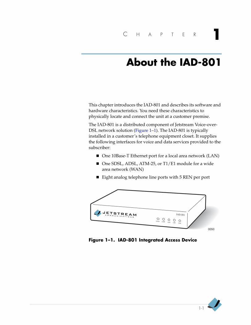
The IAD-801 is a distributed component of Jetstream Voice-over-DSL network solution (Figure 1–1). The IAD-801 is typically installed in a customer’s telephone equipment closet. It supplies the following interfaces for voice and data services provided to the subscriber:
One 10Base-T Ethernet port for a local area network (LAN)
One SDSL, ADSL, ATM-25, or T1/E1 module for a wide area network (WAN)
Eight analog telephone line ports with 5 REN per port
Figure 1–1. IAD-801 Integrated Access Device
0050
VOICE LANR LANT LINK PWR
IAD-801
1-1
About the IAD-801 JS6003030
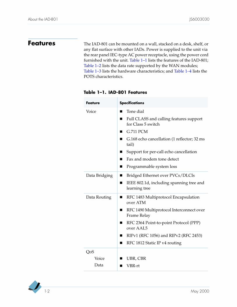
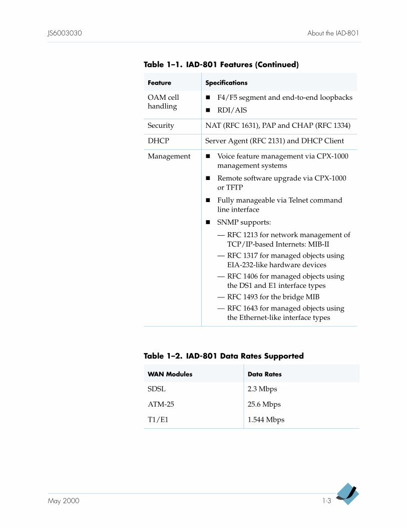
Features The IAD-801 can be mounted on a wall, stacked on a desk, shelf, or any flat surface with other IADs. Power is supplied to the unit via the rear panel IEC-type AC power receptacle, using the power cord furnished with the unit. Table 1–1 lists the features of the IAD-801; Table 1–2 lists the data rate supported by the WAN modules; Table 1–3 lists the hardware characteristics; and Table 1–4 lists the POTS characteristics.
Table 1–1. IAD-801 Features
Feature Specifications
Voice Tone dial
Full CLASS and calling features support for Class 5 switch
G.711 PCM
G.168 echo cancellation (1 reflector; 32 ms tail)
Support for per-call echo cancellation
Fax and modem tone detect
Programmable system loss
Data Bridging Bridged Ethernet over PVCs/DLCIs
IEEE 802.1d, including spanning tree and learning tree
Data Routing RFC 1483 Multiprotocol Encapsulation over ATM
RFC 1490 Multiprotocol Interconnect over Frame Relay
RFC 2364 Point-to-point Protocol (PPP) over AAL5
RIPv1 (RFC 1056) and RIPv2 (RFC 2453)
RFC 1812 Static IP v4 routing
QoS
Voice
Data
UBR, CBR
VBR-rt
1-2 May 2000
JS6003030 About the IAD-801
OAM cell handling
F4/F5 segment and end-to-end loopbacks
RDI/AIS
Security NAT (RFC 1631), PAP and CHAP (RFC 1334)
DHCP Server Agent (RFC 2131) and DHCP Client
Management Voice feature management via CPX-1000 management systems
Remote software upgrade via CPX-1000 or TFTP
Fully manageable via Telnet command line interface
SNMP supports:
— RFC 1213 for network management of TCP/IP-based Internets: MIB-II
— RFC 1317 for managed objects using EIA-232-like hardware devices
— RFC 1406 for managed objects using the DS1 and E1 interface types
— RFC 1493 for the bridge MIB
— RFC 1643 for managed objects using the Ethernet-like interface types
Table 1–2. IAD-801 Data Rates Supported
WAN Modules Data Rates
SDSL 2.3 Mbps
ATM-25 25.6 Mbps
T1/E1 1.544 Mbps
Table 1–1. IAD-801 Features (Continued)
Feature Specifications
May 2000 1-3
About the IAD-801 JS6003030
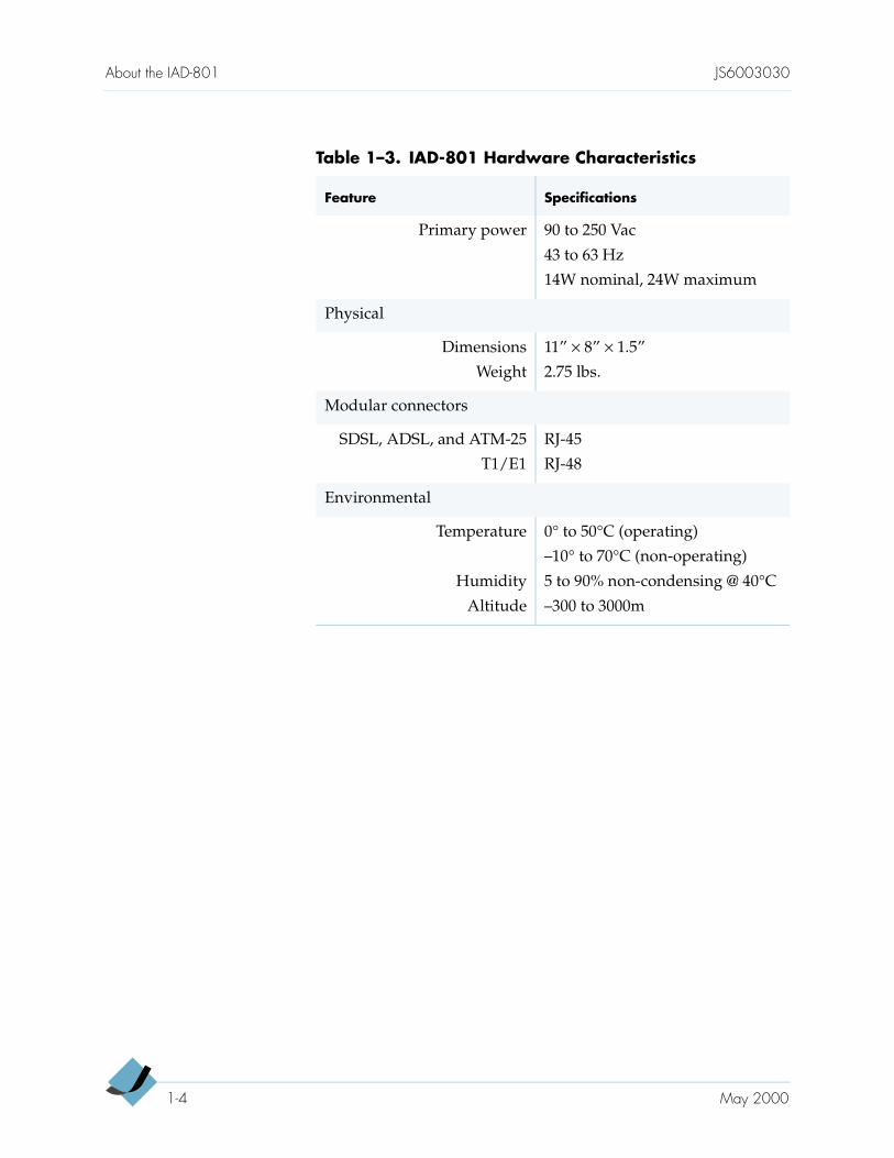
Table 1–3. IAD-801 Hardware Characteristics
Feature Specifications
Primary power 90 to 250 Vac
43 to 63 Hz
14W nominal, 24W maximum
Physical
Dimensions
Weight
11” × 8” × 1.5”
2.75 lbs.
Modular connectors
SDSL, ADSL, and ATM-25
T1/E1
RJ-45
RJ-48
Environmental
Temperature
Humidity
Altitude
0° to 50°C (operating)
–10° to 70°C (non-operating)
5 to 90% non-condensing @ 40°C
–300 to 3000m
1-4 May 2000
JS6003030 About the IAD-801
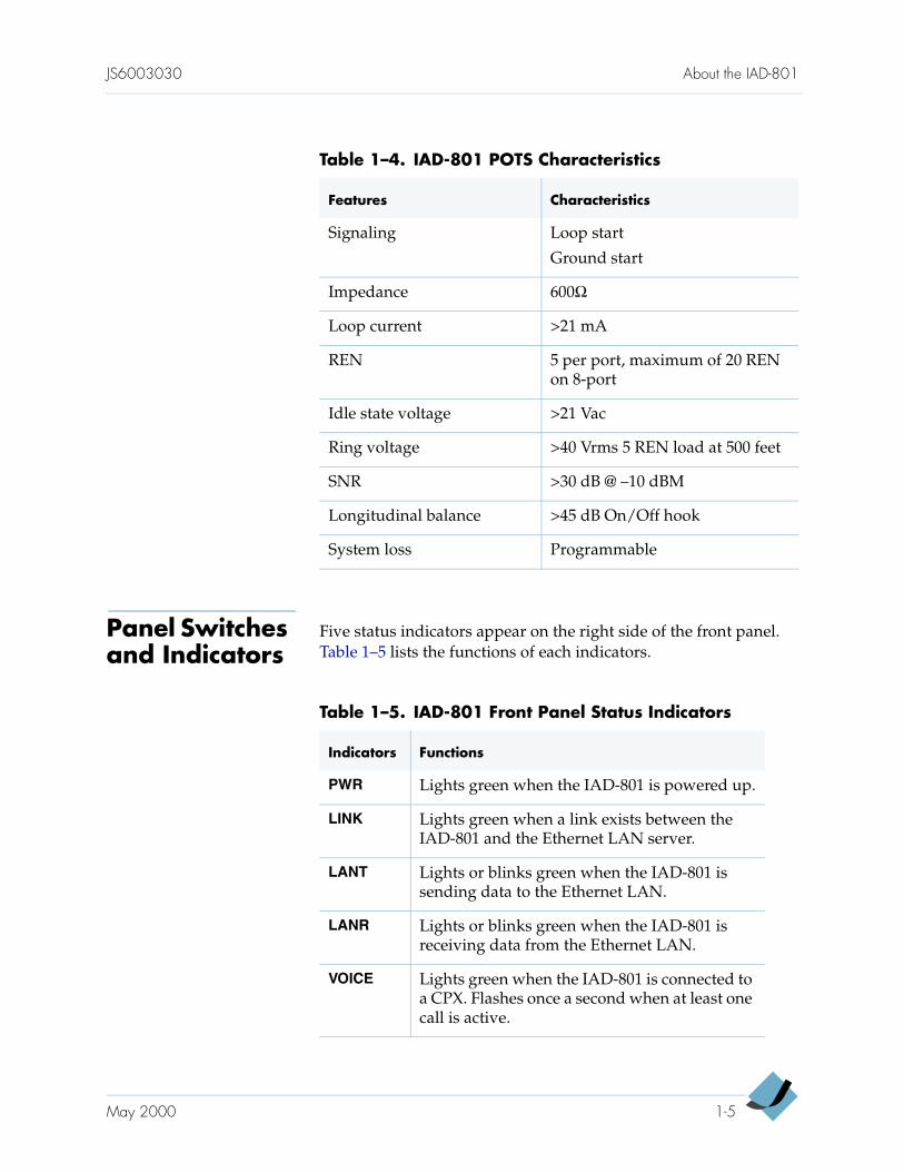
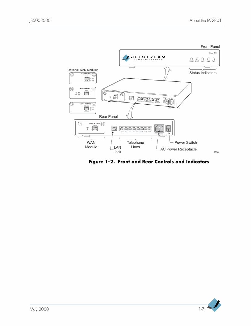
Panel Switches and Indicators
Five status indicators appear on the right side of the front panel. Table 1–5 lists the functions of each indicators.
Table 1–4. IAD-801 POTS Characteristics
Features Characteristics
Signaling Loop start
Ground start
Impedance 600Ω
Loop current >21 mA
REN 5 per port, maximum of 20 REN on 8-port
Idle state voltage >21 Vac
Ring voltage >40 Vrms 5 REN load at 500 feet
SNR >30 dB @ –10 dBM
Longitudinal balance >45 dB On/Off hook
System loss Programmable
Table 1–5. IAD-801 Front Panel Status Indicators
Indicators Functions
PWR Lights green when the IAD-801 is powered up.
LINK Lights green when a link exists between the IAD-801 and the Ethernet LAN server.
LANT Lights or blinks green when the IAD-801 is sending data to the Ethernet LAN.
LANR Lights or blinks green when the IAD-801 is receiving data from the Ethernet LAN.
VOICE Lights green when the IAD-801 is connected to a CPX. Flashes once a second when at least one call is active.
May 2000 1-5
About the IAD-801 JS6003030
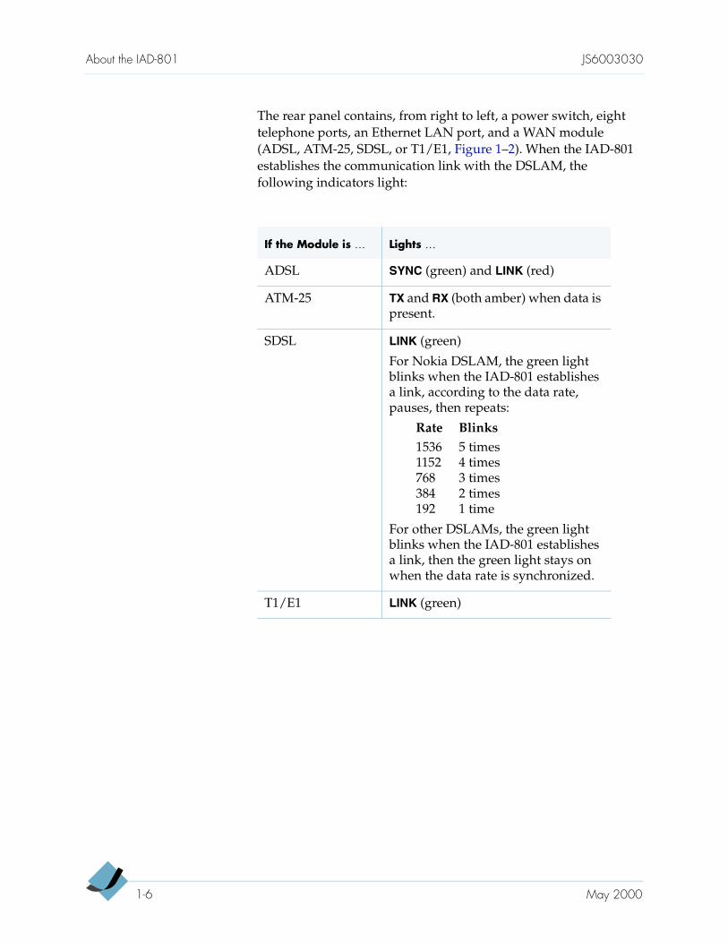
The rear panel contains, from right to left, a power switch, eight telephone ports, an Ethernet LAN port, and a WAN module (ADSL, ATM-25, SDSL, or T1/E1, Figure 1–2). When the IAD-801 establishes the communication link with the DSLAM, the following indicators light:
If the Module is … Lights …
ADSL SYNC (green) and LINK (red)
ATM-25 TX and RX (both amber) when data is present.
SDSL LINK (green)
For Nokia DSLAM, the green light blinks when the IAD-801 establishes a link, according to the data rate, pauses, then repeats:
Rate Blinks1536 5 times1152 4 times768 3 times384 2 times192 1 time
For other DSLAMs, the green light blinks when the IAD-801 establishes a link, then the green light stays on when the data rate is synchronized.
T1/E1 LINK (green)
1-6 May 2000
JS6003030 About the IAD-801
Figure 1–2. Front and Rear Controls and Indicators
0052
WAN
Module
Telephone
LinesAC Power Receptacle
Power Switch
Line 1Line 2Line 3Line 4Line 5
VOICE LANR LANT LINK PWR
Line 6Line 7Line 8
AC POWER INPUT90-250V/43-63 Hz
SDSL LINE
LINK
Status Indicators
Front Panel
Rear Panel
IAD-801
SDSL ELINK
LINK
Line 1Line 2
Line 3Line 4
Line 5Line 6
Line 7Line 8
LAN
Jack
ATM25
RXTX RX
SDSL MODULE
ATM25 MODULE
T1/E1
LINK
T1/E1 MODULE
ERR
ADSL Line
ADSL MODULE
LINK
SYNC
Optional WAN Modules
May 2000 1-7

About the IAD-801 JS6003030
1-8 May 2000
C H A P T E R 2
IAD-801 Installation
This chapter provides procedures for installing the IAD-801. Use these procedures in conjunction with the procedures listed in the CPX-1000 Installation to complete the installation of the equipment. The CPX-1000 must be installed and provisioned before the IAD-801 can provide voice service.
This chapter includes these topics:
Standard shipped components (page 2-2)
Mounting surface (page 2-3)
AC power connection (page 2-4)
Uninterruptible power supply requirement (page 2-5)
Ethernet LAN connection (page 2-6)
Telephone line connection (page 2-6)
WAN connection (page 2-7)
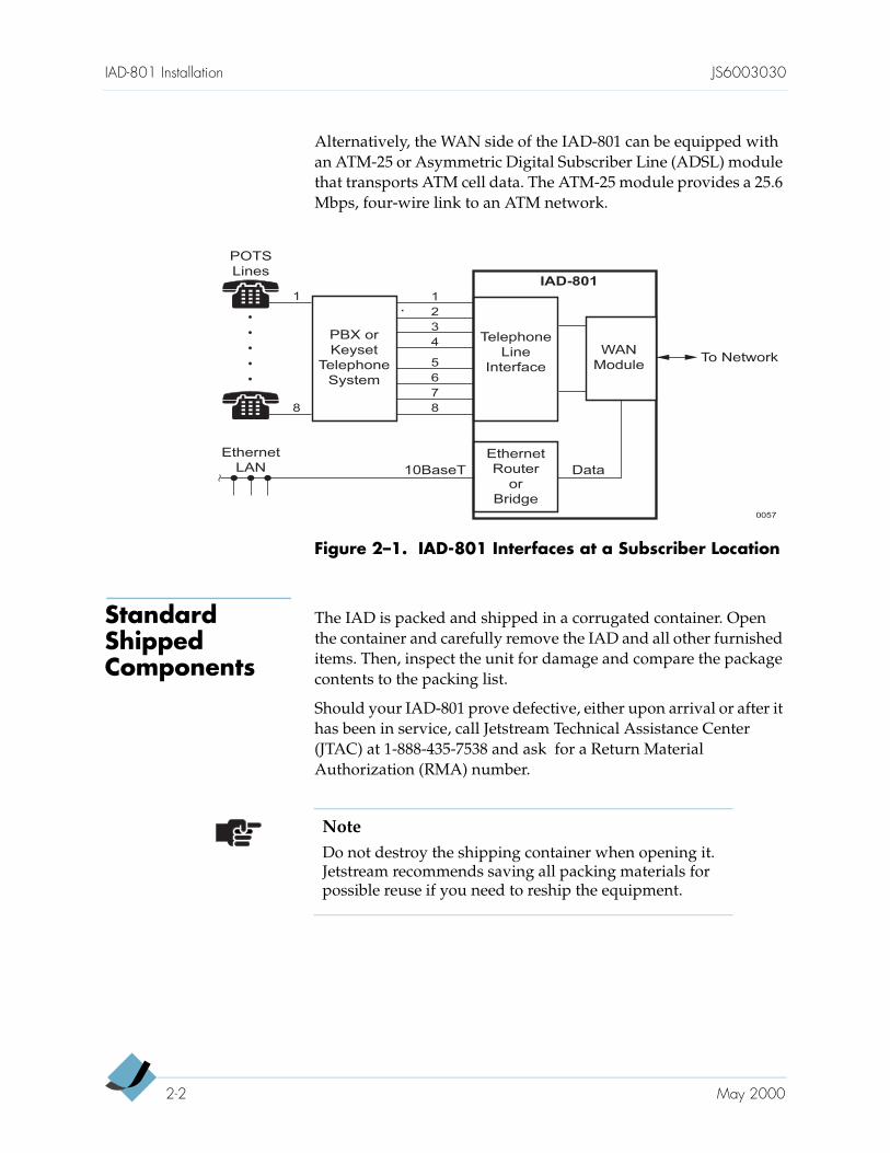
Figure 2–1 shows how the IAD-801 is used at a typical subscriber site. The LAN connects to the Ethernet port of the IAD-801. The IAD-801 has eight RJ-11 ports to which eight telephone lines from a PBX or keyset phone system can be connected.
On the WAN side, the IAD-801 interfaces with either a Digital Subscriber Line Access Multiplexer (DSLAM) or an Asychronous Transfer Mode (ATM) network. The Symmetric Digital Subscriber Line (SDSL) and T1/E1 modules can transport either ATM cell data or frame relay packets. The SDSL module provides 2.3 Mbps, and uses an unshielded, twisted-pair cable connection to the DSLAM. The T1/E1 module provides a 1.544 Mbps, four-wire link to an ATM network.
2-1
IAD-801 Installation JS6003030
Alternatively, the WAN side of the IAD-801 can be equipped with an ATM-25 or Asymmetric Digital Subscriber Line (ADSL) module that transports ATM cell data. The ATM-25 module provides a 25.6 Mbps, four-wire link to an ATM network.
Figure 2–1. IAD-801 Interfaces at a Subscriber Location
Standard Shipped Components
The IAD is packed and shipped in a corrugated container. Open the container and carefully remove the IAD and all other furnished items. Then, inspect the unit for damage and compare the package contents to the packing list.
Should your IAD-801 prove defective, either upon arrival or after it has been in service, call Jetstream Technical Assistance Center (JTAC) at 1-888-435-7538 and ask for a Return Material Authorization (RMA) number.
0057
Telephone
Line
Interface
Ethernet
Router
or
Bridge
Ethernet
LAN
POTS
Lines
PBX or
Keyset
Telephone
System
To Network
Data10BaseT
1
2
3
4
1
8
IAD-801
5
6
7
8
WAN
Module
NoteDo not destroy the shipping container when opening it. Jetstream recommends saving all packing materials for possible reuse if you need to reship the equipment.
2-2 May 2000
JS6003030 IAD-801 Installation
In addition to the IAD-801, other shipped components include:
AC power cord, 6 feet long.
Ethernet cable.
DSL cable terminated in an RJ-11 plug at one end and an RJ-45 plug at the other end. This cable is provided only if the IAD-801 is shipped with an SDSL or ADSL module.
ATM-25 crossover cable if the IAD-801 is shipped with an ATM-25 WAN module.
T1/E1 straight-through cable if the IAD-801 is shipped with an T1/E1 WAN module.
Mounting Surface
After unpacking the IAD-801, place it on a tabletop, shelf, or other flat surface, or mount it on a wall. When using multiple IADs, to ensure adequate ventilation, space them as listed in Table 2–1.
The IAD-801 requires AC power, so be sure the mounting location is within 6 feet of a nearby power outlet.
To mount the IAD-801, you will need
½-inch plywood for the mounting surface
Two #10 pan-head wood screws
Align and secure the mounting screws on 5 -in. centers, horizontally (Figure 2–2). Then slide the IAD-801 mounting slots onto the screws.
Need Assistance?Call Jetstream Technical Assistance Center (JTAC) at 1-888-435-7538 to order a copy of the IAD-801 Installation and User’s Guide (order number JS6003030).
Table 2–1. Clearance Requirements
If Positioned… Space Needed
Horizontally 1 inch
Vertically 2 inches
38
May 2000 2-3
IAD-801 Installation JS6003030
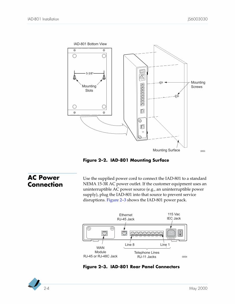
Figure 2–2. IAD-801 Mounting Surface
AC Power Connection
Use the supplied power cord to connect the IAD-801 to a standard NEMA 15-3R AC power outlet. If the customer equipment uses an uninterruptible AC power source (e.g., an uninterruptible power supply), plug the IAD-801 into that source to prevent service disruptions. Figure 2–3 shows the IAD-801 power pack.
Figure 2–3. IAD-801 Rear Panel Connectors
0053
IAD-801 Bottom View
Mounting Surface
Mounting
ScrewsMounting
Slots
SDSLELINK
LINK
Line1
Line2
Line3
Line4
Line5
Line6
Line7
Line8
5-3/8"
0054
WAN
Module
RJ-45 or RJ-48C JackTelephone Lines
RJ-11 Jacks
Line 1Line 2Line 3Line 4Line 5Line 6Line 7Line 8
AC POWER INPUT90-250V/43-63 Hz
Line 1Line 8
Ethernet
RJ-45 Jack
115 Vac
IEC Jack
2-4 May 2000
JS6003030 IAD-801 Installation
Uninterruptible Power Supply Requirement
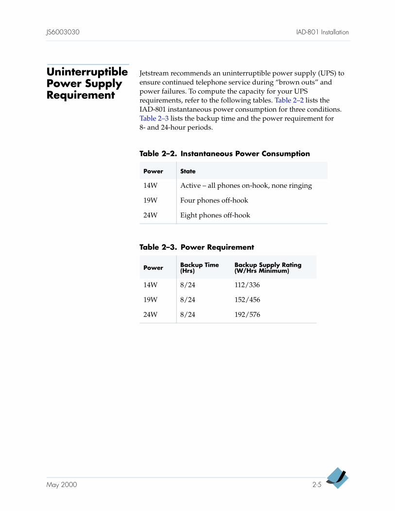
Jetstream recommends an uninterruptible power supply (UPS) to ensure continued telephone service during “brown outs” and power failures. To compute the capacity for your UPS requirements, refer to the following tables. Table 2–2 lists the IAD-801 instantaneous power consumption for three conditions. Table 2–3 lists the backup time and the power requirement for 8- and 24-hour periods.
Table 2–2. Instantaneous Power Consumption
Power State
14W Active – all phones on-hook, none ringing
19W Four phones off-hook
24W Eight phones off-hook
Table 2–3. Power Requirement
Power Backup Time (Hrs)
Backup Supply Rating(W/Hrs Minimum)
14W 8/24 112/336
19W 8/24 152/456
24W 8/24 192/576
May 2000 2-5
IAD-801 Installation JS6003030
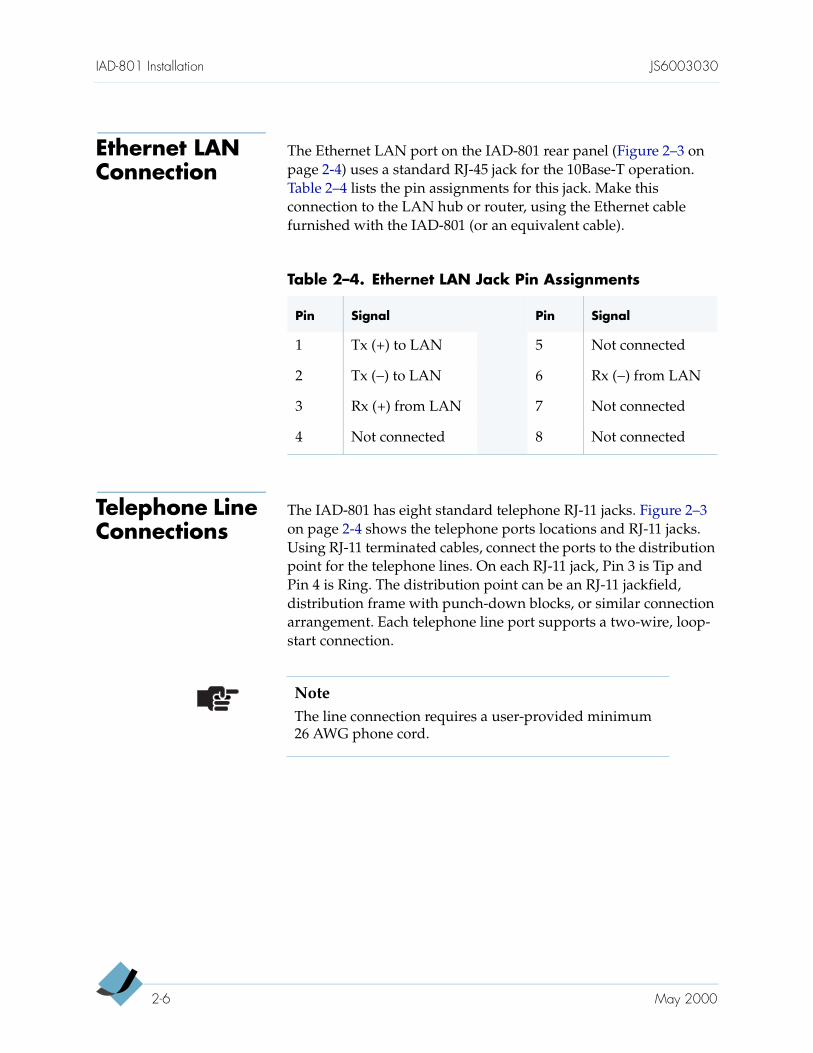
Ethernet LAN Connection
The Ethernet LAN port on the IAD-801 rear panel (Figure 2–3 on page 2-4) uses a standard RJ-45 jack for the 10Base-T operation. Table 2–4 lists the pin assignments for this jack. Make this connection to the LAN hub or router, using the Ethernet cable furnished with the IAD-801 (or an equivalent cable).
Telephone Line Connections
The IAD-801 has eight standard telephone RJ-11 jacks. Figure 2–3 on page 2-4 shows the telephone ports locations and RJ-11 jacks. Using RJ-11 terminated cables, connect the ports to the distribution point for the telephone lines. On each RJ-11 jack, Pin 3 is Tip and Pin 4 is Ring. The distribution point can be an RJ-11 jackfield, distribution frame with punch-down blocks, or similar connection arrangement. Each telephone line port supports a two-wire, loop-start connection.
Table 2–4. Ethernet LAN Jack Pin Assignments
Pin Signal Pin Signal
1 Tx (+) to LAN 5 Not connected
2 Tx (−) to LAN 6 Rx (−) from LAN
3 Rx (+) from LAN 7 Not connected
4 Not connected 8 Not connected
NoteThe line connection requires a user-provided minimum 26 AWG phone cord.
2-6 May 2000
JS6003030 IAD-801 Installation
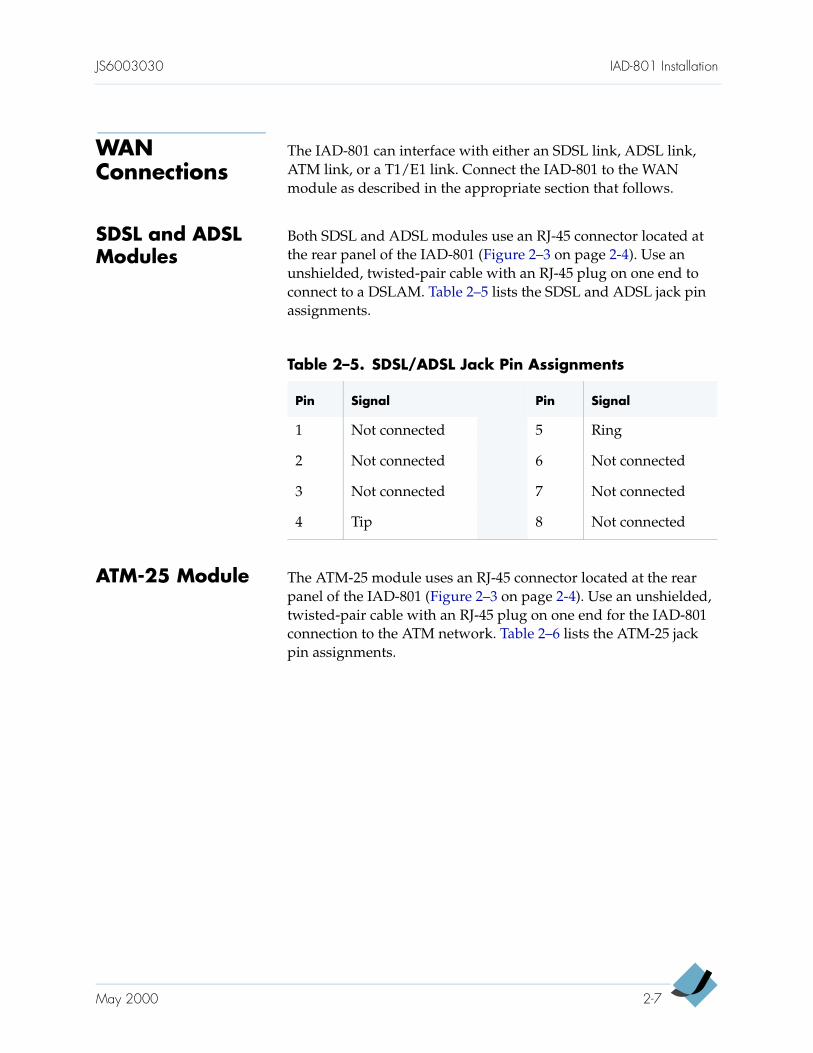
WAN Connections
The IAD-801 can interface with either an SDSL link, ADSL link, ATM link, or a T1/E1 link. Connect the IAD-801 to the WAN module as described in the appropriate section that follows.
SDSL and ADSL Modules
Both SDSL and ADSL modules use an RJ-45 connector located at the rear panel of the IAD-801 (Figure 2–3 on page 2-4). Use an unshielded, twisted-pair cable with an RJ-45 plug on one end to connect to a DSLAM. Table 2–5 lists the SDSL and ADSL jack pin assignments.
ATM-25 Module The ATM-25 module uses an RJ-45 connector located at the rear panel of the IAD-801 (Figure 2–3 on page 2-4). Use an unshielded, twisted-pair cable with an RJ-45 plug on one end for the IAD-801 connection to the ATM network. Table 2–6 lists the ATM-25 jack pin assignments.
Table 2–5. SDSL/ADSL Jack Pin Assignments
Pin Signal Pin Signal
1 Not connected 5 Ring
2 Not connected 6 Not connected
3 Not connected 7 Not connected
4 Tip 8 Not connected
May 2000 2-7
IAD-801 Installation JS6003030
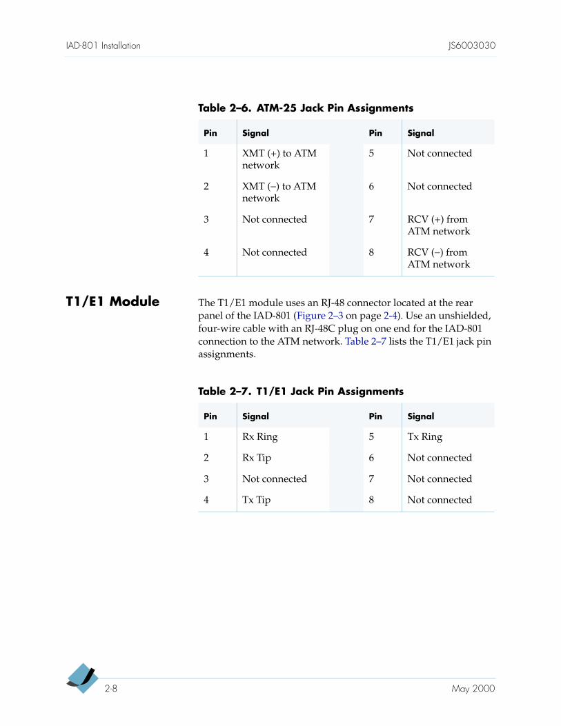
T1/E1 Module The T1/E1 module uses an RJ-48 connector located at the rear panel of the IAD-801 (Figure 2–3 on page 2-4). Use an unshielded, four-wire cable with an RJ-48C plug on one end for the IAD-801 connection to the ATM network. Table 2–7 lists the T1/E1 jack pin assignments.
Table 2–6. ATM-25 Jack Pin Assignments
Pin Signal Pin Signal
1 XMT (+) to ATM network
5 Not connected
2 XMT (−) to ATM network
6 Not connected
3 Not connected 7 RCV (+) from ATM network
4 Not connected 8 RCV (−) from ATM network
Table 2–7. T1/E1 Jack Pin Assignments
Pin Signal Pin Signal
1 Rx Ring 5 Tx Ring
2 Rx Tip 6 Not connected
3 Not connected 7 Not connected
4 Tx Tip 8 Not connected
2-8 May 2000
C H A P T E R 3
IAD-801 User Interface
This chapter describes the basic IAD-801 operation. It also describes the menu and management features available for the IAD-801. This chapter provides this information:
Data interfaces supported by the IAD-801 (page 3-1)
Terminal connection (page 3-2)
Power to the IAD-801 (page 3-2)
IAD-801 IP address (page 3-2)
User access control (page 3-3)
IAD-801 login (page 3-4)
IAD-801 Main Menu and navigation (page 3-6)
Auto log off (page 3-10)
IAD-801 log out (page 3-10)
Data Interfaces Supported
The data connection through the IAD-801 supports IEEE 802.1-compliant bridging and routing.
When the IAD-801 is configured for routing, it supports Routing Information Protocol version 1 (RIPv1), version 2 (RIPv2), or static IP routing. The IAD-801 complies with RFC-1812 when interfacing with Version 4 IP routers.
The WAN side of the IAD-801 supports the following types of interfaces:
ATM data transport via SDSL, ADSL, and T1/E1 in accordance with RFC 1483 or RFC 2364
Frame relay data transport via SDSL and T1/E1 (alternative to ATM cells), in accordance with RFC 1490
Frame relay data transport per RFC 1483 wrapped in Q.922 frames
3-1
IAD-801 User Interface JS6003030
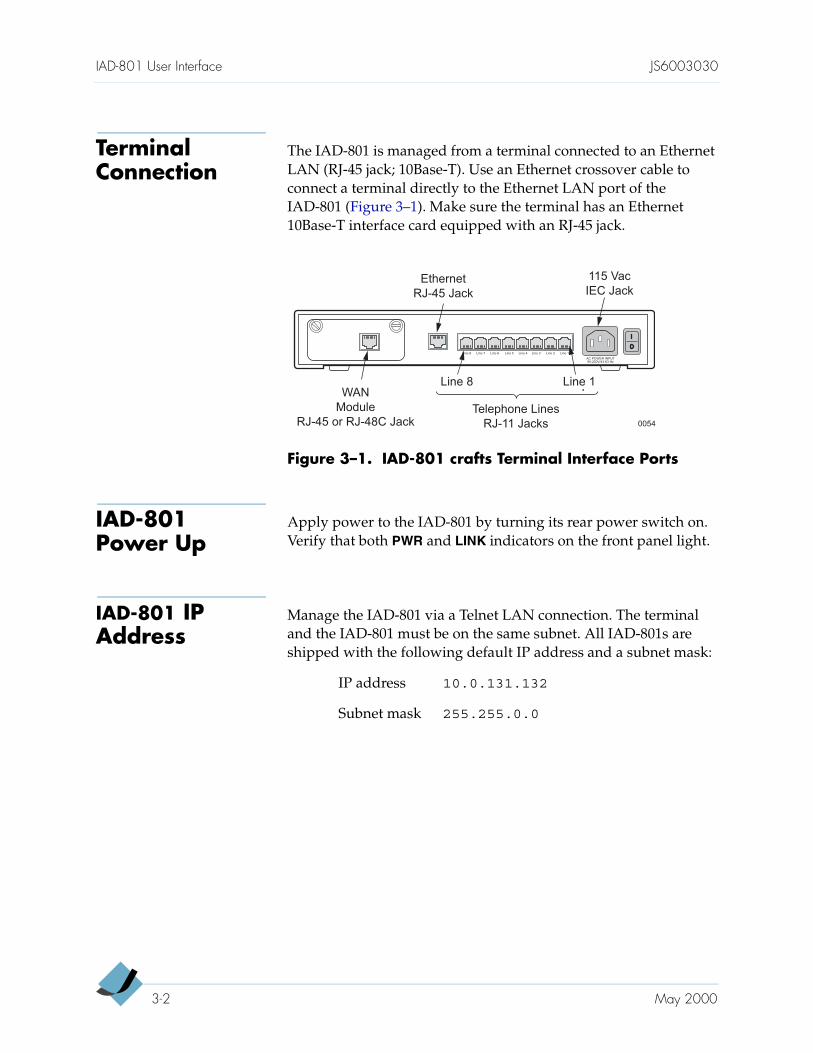
Terminal Connection
The IAD-801 is managed from a terminal connected to an Ethernet LAN (RJ-45 jack; 10Base-T). Use an Ethernet crossover cable to connect a terminal directly to the Ethernet LAN port of the IAD-801 (Figure 3–1). Make sure the terminal has an Ethernet 10Base-T interface card equipped with an RJ-45 jack.
Figure 3–1. IAD-801 crafts Terminal Interface Ports
IAD-801 Power Up
Apply power to the IAD-801 by turning its rear power switch on. Verify that both PWR and LINK indicators on the front panel light.
IAD-801 IP Address
Manage the IAD-801 via a Telnet LAN connection. The terminal and the IAD-801 must be on the same subnet. All IAD-801s are shipped with the following default IP address and a subnet mask:
0054
WAN
Module
RJ-45 or RJ-48C JackTelephone Lines
RJ-11 Jacks
Line 1Line 2Line 3Line 4Line 5Line 6Line 7Line 8
AC POWER INPUT90-250V/43-63 Hz
Line 1Line 8
Ethernet
RJ-45 Jack
115 Vac
IEC Jack
IP address 10.0.131.132
Subnet mask 255.255.0.0
3-2 May 2000
JS6003030 IAD-801 User Interface
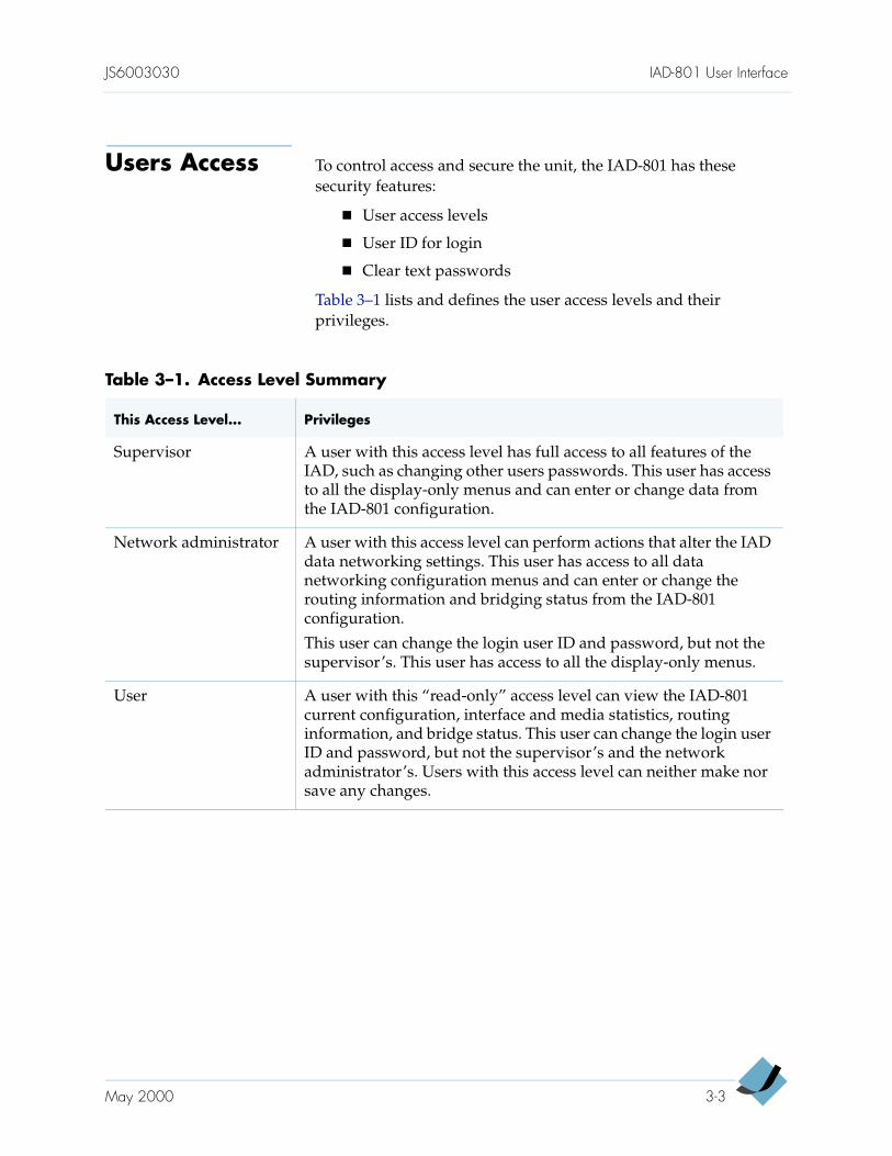
Users Access To control access and secure the unit, the IAD-801 has these security features:
User access levels
User ID for login
Clear text passwords
Table 3–1 lists and defines the user access levels and their privileges.
Table 3–1. Access Level Summary
This Access Level... Privileges
Supervisor A user with this access level has full access to all features of the IAD, such as changing other users passwords. This user has access to all the display-only menus and can enter or change data from the IAD-801 configuration.
Network administrator A user with this access level can perform actions that alter the IAD data networking settings. This user has access to all data networking configuration menus and can enter or change the routing information and bridging status from the IAD-801 configuration.
This user can change the login user ID and password, but not the supervisor’s. This user has access to all the display-only menus.
User A user with this “read-only” access level can view the IAD-801 current configuration, interface and media statistics, routing information, and bridge status. This user can change the login user ID and password, but not the supervisor’s and the network administrator’s. Users with this access level can neither make nor save any changes.
May 2000 3-3
IAD-801 User Interface JS6003030
IAD-801 Login The IAD-801 provides security by requiring the user to enter a user ID and a password, both of which are case-sensitive and can be changed (Chapter 4, Administration and Management). The IAD-801s are configured with the following default logins and passwords when shipped (Table 3–2):
To log into the IAD-801, do these steps:
Step 1 Open the Telnet program.
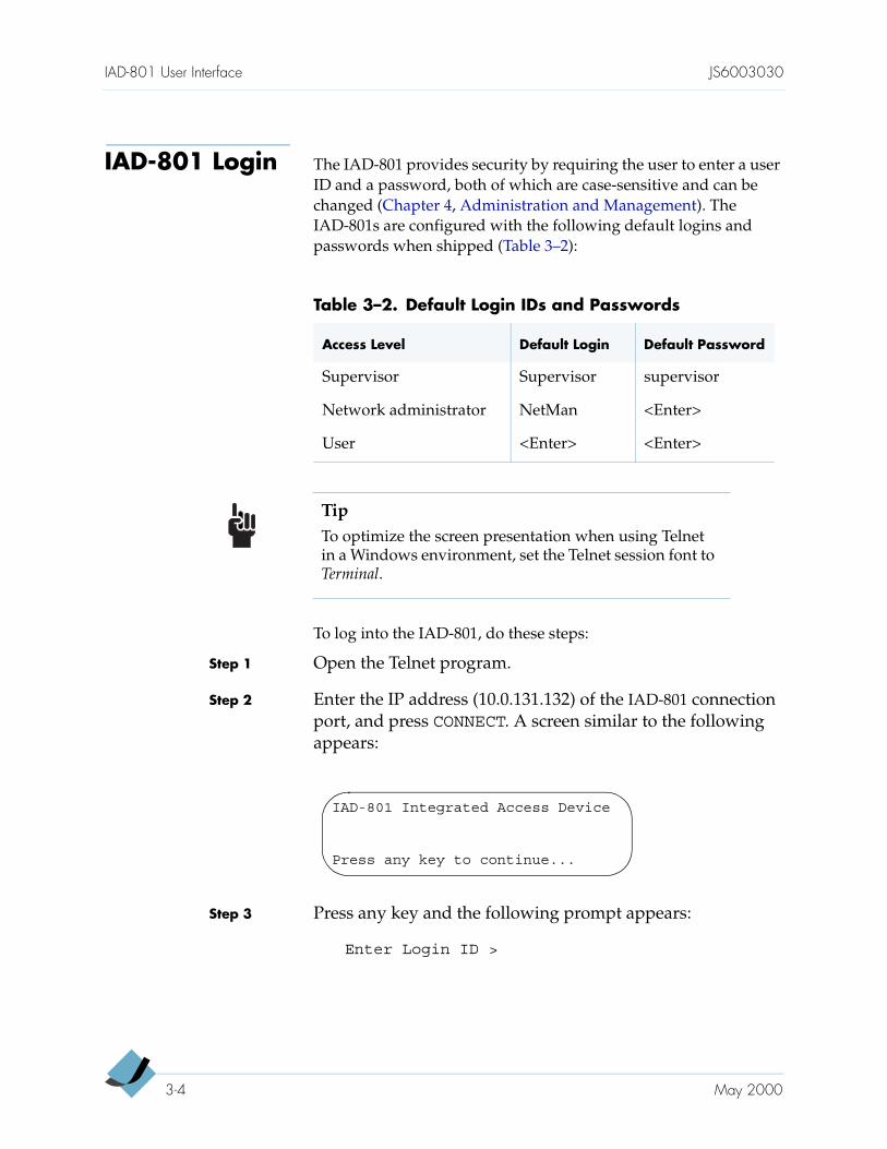
Step 2 Enter the IP address (10.0.131.132) of the IAD-801 connection port, and press CONNECT. A screen similar to the following appears:
Step 3 Press any key and the following prompt appears:
Enter Login ID >
Table 3–2. Default Login IDs and Passwords
Access Level Default Login Default Password
Supervisor Supervisor supervisor
Network administrator NetMan <Enter>
User <Enter> <Enter>
TipTo optimize the screen presentation when using Telnet in a Windows environment, set the Telnet session font to Terminal.
IAD-801 Integrated Access Device
Press any key to continue...
3-4 May 2000
JS6003030 IAD-801 User Interface
Step 4 Enter your login ID and press <Enter>. The following prompt appears:
Enter Password >
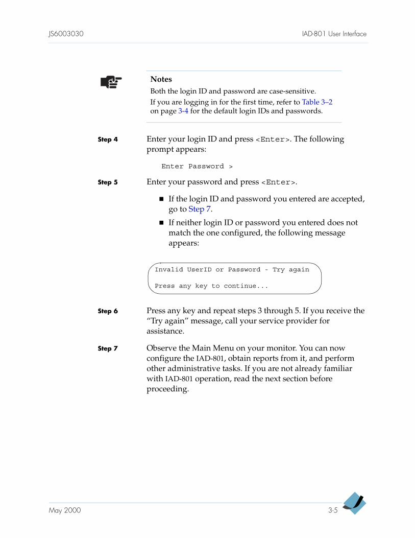
Step 5 Enter your password and press <Enter>.
If the login ID and password you entered are accepted, go to Step 7.
If neither login ID or password you entered does not match the one configured, the following message appears:
Step 6 Press any key and repeat steps 3 through 5. If you receive the “Try again” message, call your service provider for assistance.
Step 7 Observe the Main Menu on your monitor. You can now configure the IAD-801, obtain reports from it, and perform other administrative tasks. If you are not already familiar with IAD-801 operation, read the next section before proceeding.
NotesBoth the login ID and password are case-sensitive. If you are logging in for the first time, refer to Table 3–2 on page 3-4 for the default login IDs and passwords.
Invalid UserID or Password - Try again
Press any key to continue...
May 2000 3-5

IAD-801 User Interface JS6003030
IAD-801 Menus and Navigation
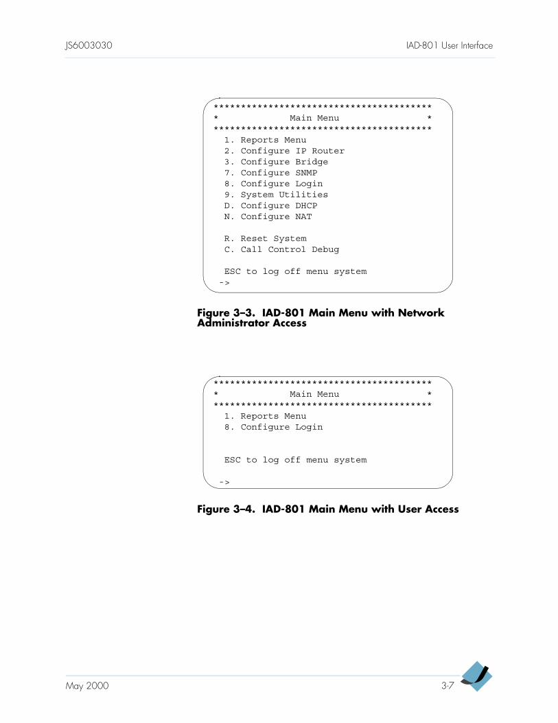
The IAD-801 user interface is a menu-driven application. The Main Menu displayed depends on the user access level. Figure 3–2 shows the Main Menu with the supervisor access level, Figure 3–3 shows the Main Menu with the network administrator access level, and Figure 3–4 shows the Main Menu with the user access level. For a complete menu listing, refer to Appendix D, Menu Map.
The Main Menu with the supervisor access level is divided into 13 major submenus while the network administrator access level is 10. Use these submenus to configure the IAD-801 and display your current configuration settings.
Though the submenus between the supervisor and network administrator are basically the same, the options available in the submenus are different. Your login privilege determines the configuration options available to you.
Figure 3–2. IAD-801 Main Menu with Supervisor Access
***************************************** Main Menu *****************************************
1. Reports Menu2. Configure IP Router3. Configure Bridge5. Configure WAN6. Configure LAN7. Configure SNMP8. Configure Login9. System UtilitiesD. Configure DHCPN. Configure NAT
R. Reset SystemP. VoicePath ConfigureC. Call Control Debug
ESC to log off menu system->
3-6 May 2000
JS6003030 IAD-801 User Interface
Figure 3–3. IAD-801 Main Menu with Network Administrator Access
Figure 3–4. IAD-801 Main Menu with User Access
***************************************** Main Menu *****************************************
1. Reports Menu2. Configure IP Router3. Configure Bridge7. Configure SNMP8. Configure Login9. System UtilitiesD. Configure DHCPN. Configure NAT
R. Reset SystemC. Call Control Debug
ESC to log off menu system->
***************************************** Main Menu *****************************************
1. Reports Menu8. Configure Login
ESC to log off menu system
->
May 2000 3-7
IAD-801 User Interface JS6003030
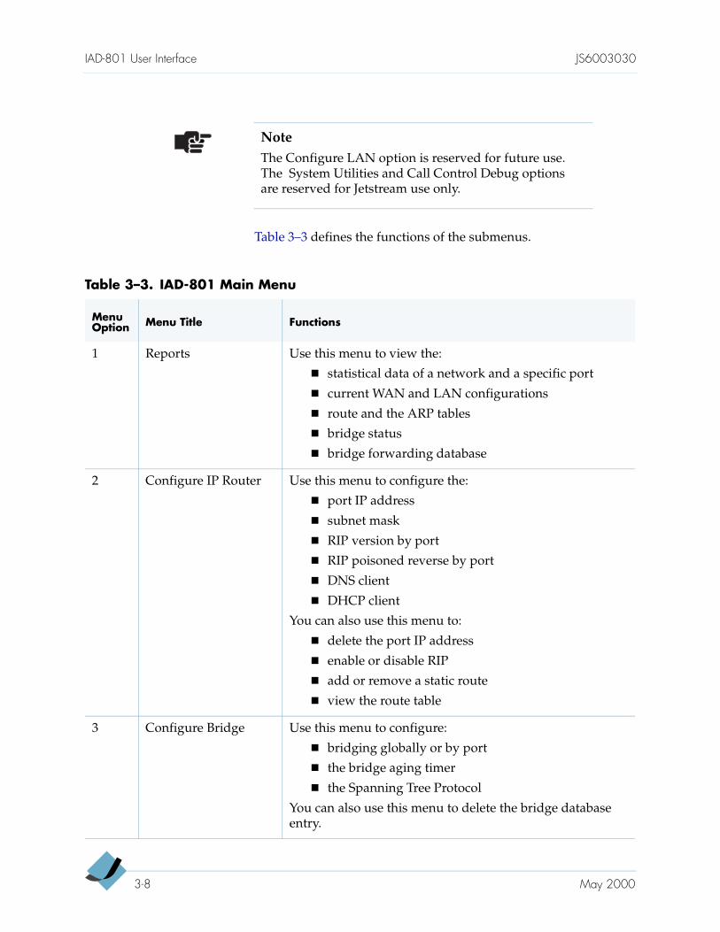
Table 3–3 defines the functions of the submenus.
NoteThe Configure LAN option is reserved for future use. The System Utilities and Call Control Debug options are reserved for Jetstream use only.
Table 3–3. IAD-801 Main Menu
Menu Option Menu Title Functions
1 Reports Use this menu to view the:
statistical data of a network and a specific port
current WAN and LAN configurations
route and the ARP tables
bridge status
bridge forwarding database
2 Configure IP Router Use this menu to configure the:
port IP address
subnet mask
RIP version by port
RIP poisoned reverse by port
DNS client
DHCP client
You can also use this menu to:
delete the port IP address
enable or disable RIP
add or remove a static route
view the route table
3 Configure Bridge Use this menu to configure:
bridging globally or by port
the bridge aging timer
the Spanning Tree Protocol
You can also use this menu to delete the bridge database entry.
3-8 May 2000
JS6003030 IAD-801 User Interface
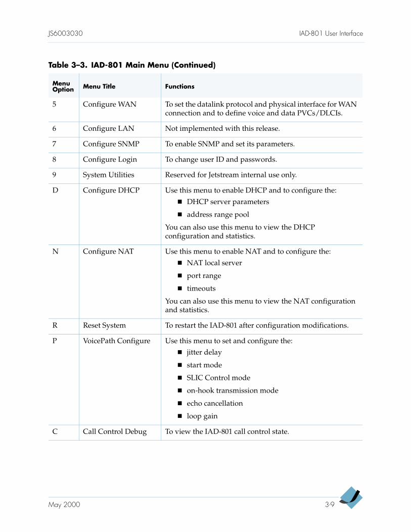
5 Configure WAN To set the datalink protocol and physical interface for WAN connection and to define voice and data PVCs/DLCIs.
6 Configure LAN Not implemented with this release.
7 Configure SNMP To enable SNMP and set its parameters.
8 Configure Login To change user ID and passwords.
9 System Utilities Reserved for Jetstream internal use only.
D Configure DHCP Use this menu to enable DHCP and to configure the:
DHCP server parameters
address range pool
You can also use this menu to view the DHCP configuration and statistics.
N Configure NAT Use this menu to enable NAT and to configure the:
NAT local server
port range
timeouts
You can also use this menu to view the NAT configuration and statistics.
R Reset System To restart the IAD-801 after configuration modifications.
P VoicePath Configure Use this menu to set and configure the:
jitter delay
start mode
SLIC Control mode
on-hook transmission mode
echo cancellation
loop gain
C Call Control Debug To view the IAD-801 call control state.
Table 3–3. IAD-801 Main Menu (Continued)
Menu Option Menu Title Functions
May 2000 3-9
IAD-801 User Interface JS6003030
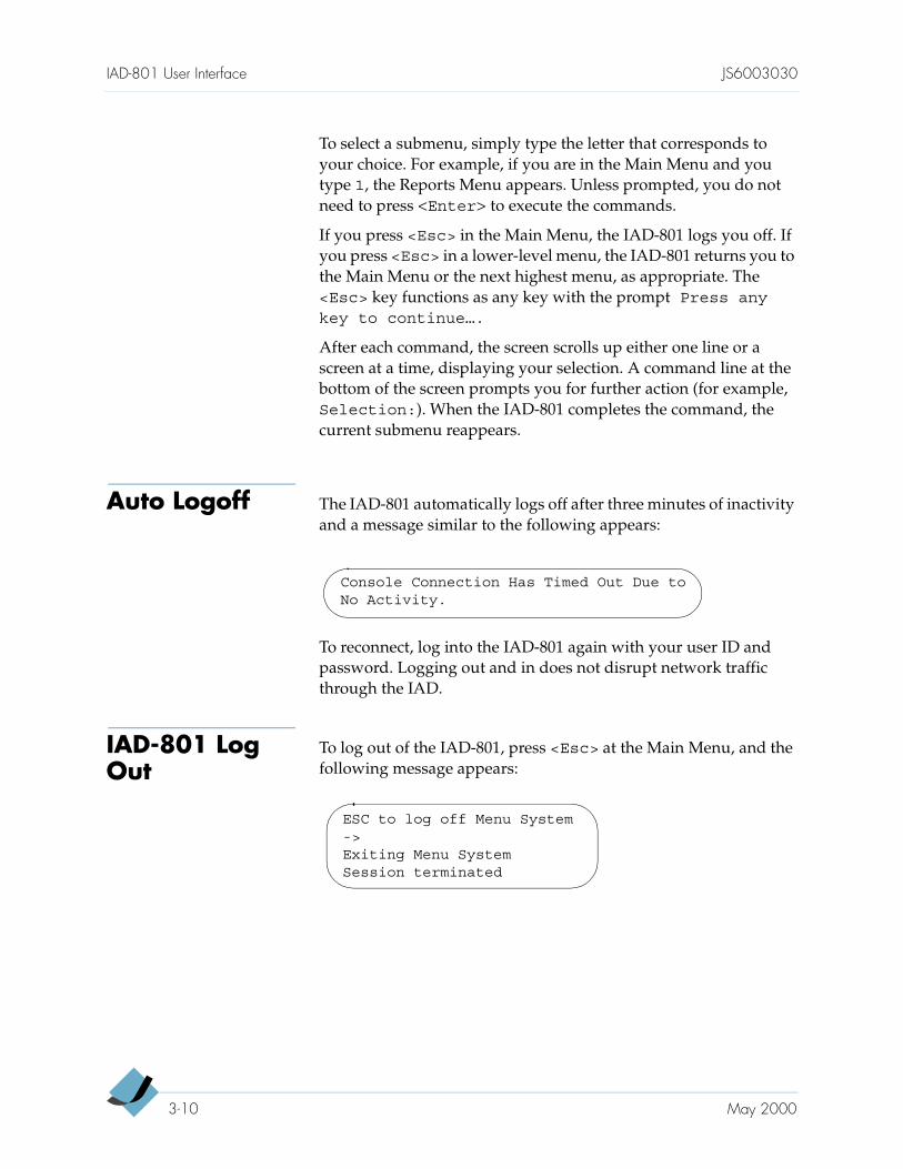
To select a submenu, simply type the letter that corresponds to your choice. For example, if you are in the Main Menu and you type 1, the Reports Menu appears. Unless prompted, you do not need to press <Enter> to execute the commands.
If you press <Esc> in the Main Menu, the IAD-801 logs you off. If you press <Esc> in a lower-level menu, the IAD-801 returns you to the Main Menu or the next highest menu, as appropriate. The <Esc> key functions as any key with the prompt Press anykey to continue….
After each command, the screen scrolls up either one line or a screen at a time, displaying your selection. A command line at the bottom of the screen prompts you for further action (for example, Selection:). When the IAD-801 completes the command, the current submenu reappears.
Auto Logoff The IAD-801 automatically logs off after three minutes of inactivity and a message similar to the following appears:
To reconnect, log into the IAD-801 again with your user ID and password. Logging out and in does not disrupt network traffic through the IAD.
IAD-801 Log Out
To log out of the IAD-801, press <Esc> at the Main Menu, and the following message appears:
Console Connection Has Timed Out Due toNo Activity.
ESC to log off Menu System->Exiting Menu SystemSession terminated
3-10 May 2000
C H A P T E R 4
Administration andManagement
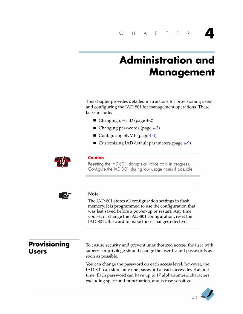
This chapter provides detailed instructions for provisioning users and configuring the IAD-801 for management operations. These tasks include:
Changing user ID (page 4-2)
Changing passwords (page 4-3)
Configuring SNMP (page 4-4)
Customizing IAD default parameters (page 4-9)
Provisioning Users
To ensure security and prevent unauthorized access, the user with supervisor privilege should change the user ID and passwords as soon as possible.
You can change the password on each access level; however, the IAD-801 can store only one password at each access level at one time. Each password can have up to 17 alphanumeric characters, excluding space and punctuation, and is case-sensitive.
CautionResetting the IAD-801 disrupts all voice calls in progress. Configure the IAD-801 during low usage hours if possible.
NoteThe IAD-801 stores all configuration settings in flash memory. It is programmed to use the configuration that was last saved before a power-up or restart. Any time you set or change the IAD-801 configuration, reset the IAD-801 afterward to make those changes effective.
4-1
Administration and Management JS6003030
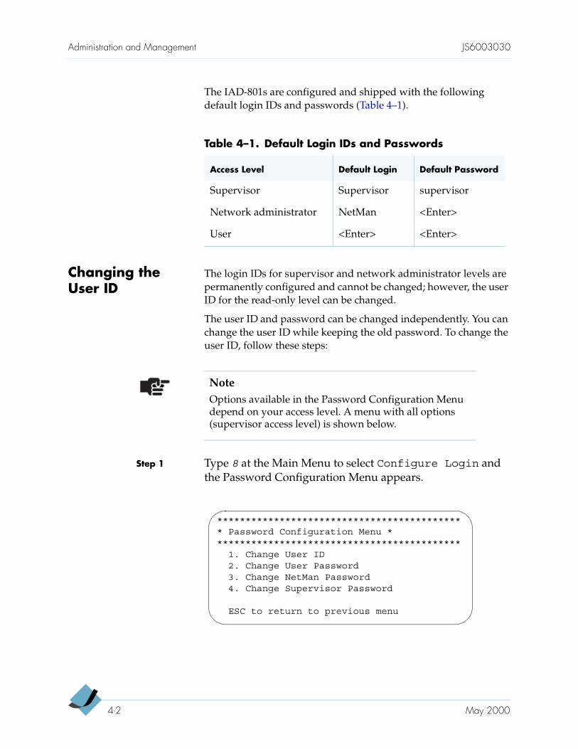
The IAD-801s are configured and shipped with the following default login IDs and passwords (Table 4–1).
Changing the User ID
The login IDs for supervisor and network administrator levels are permanently configured and cannot be changed; however, the user ID for the read-only level can be changed.
The user ID and password can be changed independently. You can change the user ID while keeping the old password. To change the user ID, follow these steps:
Step 1 Type 8 at the Main Menu to select Configure Login and the Password Configuration Menu appears.
Table 4–1. Default Login IDs and Passwords
Access Level Default Login Default Password
Supervisor Supervisor supervisor
Network administrator NetMan <Enter>
User <Enter> <Enter>
NoteOptions available in the Password Configuration Menu depend on your access level. A menu with all options (supervisor access level) is shown below.
******************************************** Password Configuration Menu ********************************************
1. Change User ID2. Change User Password3. Change NetMan Password4. Change Supervisor Password
ESC to return to previous menu
4-2 May 2000
JS6003030 Administration and Management
Step 2 Type 1 to select Change User ID. This prompt appears:
->Enter new User ID (up to 17 characters)>
Step 3 Type the new user ID and press <Enter>. The IAD-801 informs you that the user ID has been changed and the Password Configuration Menu reappears.
Step 4 Continue to change passwords or press <Esc> to return to the Main Menu.
Step 5 Press Reset when you finish changing the IAD-801 configuration.
Changing Passwords
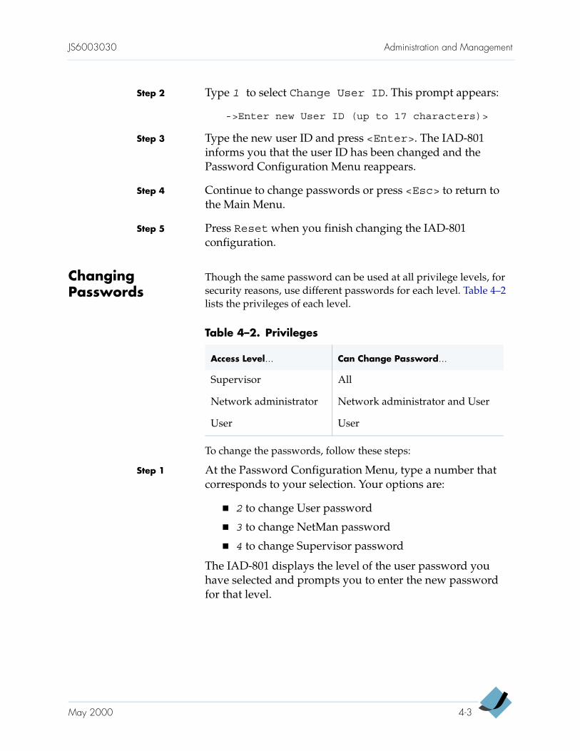
Though the same password can be used at all privilege levels, for security reasons, use different passwords for each level. Table 4–2 lists the privileges of each level.
To change the passwords, follow these steps:
Step 1 At the Password Configuration Menu, type a number that corresponds to your selection. Your options are:
2 to change User password
3 to change NetMan password
4 to change Supervisor password
The IAD-801 displays the level of the user password you have selected and prompts you to enter the new password for that level.
Table 4–2. Privileges
Access Level… Can Change Password…
Supervisor All
Network administrator Network administrator and User
User User
May 2000 4-3
Administration and Management JS6003030
Step 2 Type the new password (up to 17 alphanumeric characters with no spaces or punctuation) and press <Enter>. The following prompt appears:
Re-enter new Password for verification >
Step 3 Retype the new password to confirm its entry. The IAD-801 informs you that the password has been changed and the Password Configuration Menu reappears.
Step 4 Continue with steps 1 through 3 to change additional passwords or press <Esc> to return to the Main Menu.
Step 5 Press Reset when you finish changing the IAD-801 configuration.
Configuring SNMP
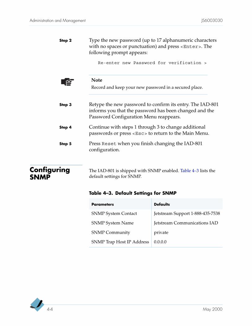
The IAD-801 is shipped with SNMP enabled. Table 4–3 lists the default settings for SNMP.
NoteRecord and keep your new password in a secured place.
Table 4–3. Default Settings for SNMP
Parameters Defaults
SNMP System Contact Jetstream Support 1-888-435-7538
SNMP System Name Jetstream Communications IAD
SNMP Community private
SNMP Trap Host IP Address 0.0.0.0
4-4 May 2000
JS6003030 Administration and Management
When the SNMP (Simple Network Management Protocol) option is configured, you can remotely manage the IAD-801 by getting and setting the IAD-801 values and monitoring the IAD-801 events. The IAD-801 currently supports SNMP traps for the following events:
system reset
attempting to access SNMP with an invalid community name
starting/stopping TFTP from within SNMP
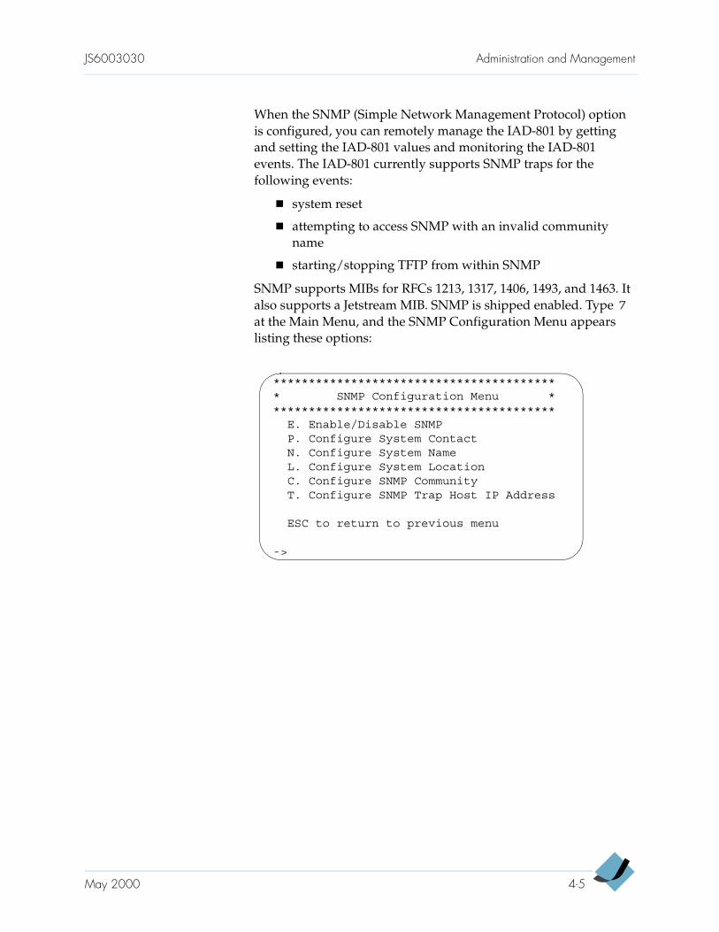
SNMP supports MIBs for RFCs 1213, 1317, 1406, 1493, and 1463. It also supports a Jetstream MIB. SNMP is shipped enabled. Type 7 at the Main Menu, and the SNMP Configuration Menu appears listing these options:
***************************************** SNMP Configuration Menu *****************************************
E. Enable/Disable SNMPP. Configure System ContactN. Configure System NameL. Configure System LocationC. Configure SNMP CommunityT. Configure SNMP Trap Host IP Address
ESC to return to previous menu
->
May 2000 4-5
Administration and Management JS6003030
Enabling/Disabling SNMP
To enable or disable SNMP, follow these steps:
Step 1 Type E at the SNMP Configuration Menu to select the Enable/Disable SNMP option. The IAD-801 displays the current setting and asks if you want to change it.
Step 2 Type Y to change the setting. The IAD-801 displays the new setting. If you type N, the IAD-801 displays the SNMPConfiguration unchanged message and returns you to the SNMP Configuration Menu.
Step 3 Continue with other SNMP configurations or press <Esc> to return to the Main Menu.
Step 4 Press Reset when you finish the IAD-801 configuration.
Configuring System Contact
The system contact can have up to 39 alphanumeric characters and is not case-sensitive. To configure the system contact, follow these steps:
Step 1 Type P at the SNMP Configuration Menu to select the Configure System Contact option. The IAD-801 displays the current system contact and prompts for a new contact.
Step 2 Enter the new name of the system contact (default is Jetstream Support 1-888-435-7538) and press <Enter>. The message Saving Configuration… appears and the IAD-801 tells you that the system contact is changed.
Step 3 Press any key to return to the SNMP Configuration Menu for other SNMP configurations or press <Esc> to return to the Main Menu.
Step 4 Press Reset when you finish the IAD-801 configuration.
4-6 May 2000
JS6003030 Administration and Management
Configuring System Name
The system name can have up to 39 alphanumeric characters and is not case-sensitive. To configure the system name, follow these steps:
Step 1 Type N at the SNMP Configuration Menu to select the Configure System Name option. The IAD-801 displays the current system name and prompts for a new name.
Step 2 Enter the new system name (default is Jetstream Communications IAD-801) and press <Enter>. The message Saving Configuration… appears and the IAD-801 tells you that the system name is changed.
Step 3 Press any key to return to the SNMP Configuration Menu for other SNMP configurations or press <Esc> to return to the Main Menu.
Step 4 Press Reset when you finish the IAD-801 configuration.
Configuring System Location
The system location can have up to 39 alphanumeric characters and is not case-sensitive. To define the system location, follow these steps:
Step 1 Type L at the SNMP Configuration Menu to select the Configure System Location option. The IAD-801 displays the current system location and prompts for a new location.
Step 2 Enter the new location for the system and press <Enter>. The message Saving Configuration… appears and the IAD-801 tells you that the system location is changed.
Step 3 Press any key to return to the SNMP Configuration Menu for other SNMP configurations or press <Esc> to return to the Main Menu.
Step 4 Press Reset when you finish the IAD-801 configuration.
May 2000 4-7

Administration and Management JS6003030
Configuring SNMP Write Community
This entry must match the write community name of the SNMP host to enable the SNMP Set operation. If SNMP is enabled and the community name is null, SNMP goes into read-only mode. To define the community name, follow these steps:
Step 1 Type C at the SNMP Configuration Menu to select theConfigure SNMP Community option. The IAD-801 displays the current SNMP community and prompts for a new one.
Step 2 Enter the name of the SNMP write community (default is private) and press <Enter>. The message SavingConfiguration… appears and the IAD-801 tells you that the SNMP community is changed.
Step 3 Press any key to return to the SNMP Configuration Menu for other SNMP configuration or press <Esc> to return to the Main Menu.
Step 4 Press Reset when you finish the IAD-801 configuration.
Configuring SNMP Trap Host IP Address
This entry can have up to 39 alphanumeric characters and it’s not case-sensitive. To configure the SNMP trap host IP address, follow these steps:
Step 1 Type T at the SNMP Configuration Menu to select the Configure SNMP Trap Host IP Address option. The IAD-801 displays the current SNMP trap host address and prompts for a new one.
Step 2 Enter the new SNMP trap host IP address (default is 0.0.0.0) and press <Enter>. The message SavingConfiguration… appears and the IAD-801 tells you that the SNMP trap host address is changed.
Step 3 Press any key to return to the SNMP Configuration Menu for other SNMP configurations or press <Esc> to return to the Main Menu.
Step 4 Press Reset when you finish the IAD-801 configuration.
4-8 May 2000
JS6003030 Administration and Management
Customizing IAD-801 Defaults
Each IAD is shipped with a set of default parameters. You can customize these parameters to suit your needs.
To customize your default parameters, follow these steps:
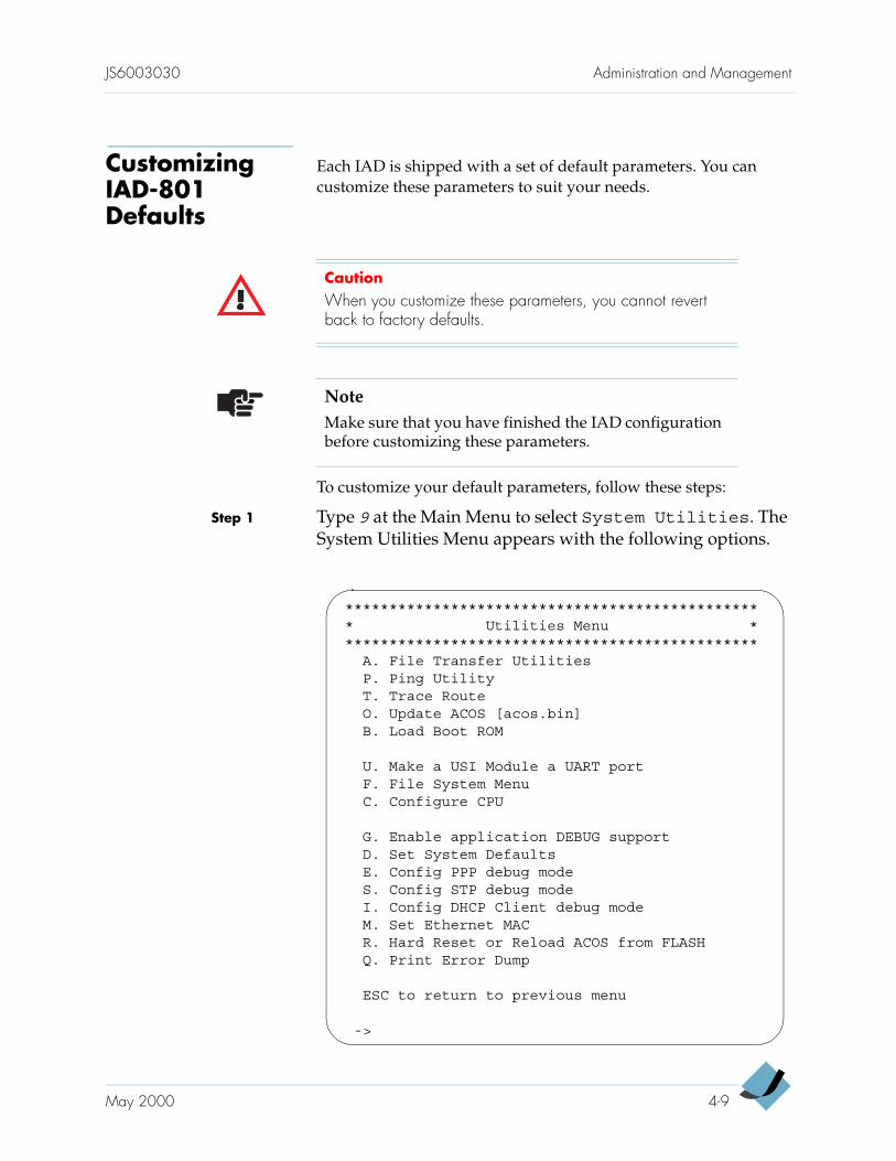
Step 1 Type 9 at the Main Menu to select System Utilities. The System Utilities Menu appears with the following options.
CautionWhen you customize these parameters, you cannot revert back to factory defaults.
NoteMake sure that you have finished the IAD configuration before customizing these parameters.
************************************************ Utilities Menu ************************************************
A. File Transfer UtilitiesP. Ping UtilityT. Trace RouteO. Update ACOS [acos.bin]B. Load Boot ROM
U. Make a USI Module a UART portF. File System MenuC. Configure CPU
G. Enable application DEBUG supportD. Set System DefaultsE. Config PPP debug modeS. Config STP debug modeI. Config DHCP Client debug modeM. Set Ethernet MACR. Hard Reset or Reload ACOS from FLASHQ. Print Error Dump
ESC to return to previous menu
->
May 2000 4-9
Administration and Management JS6003030
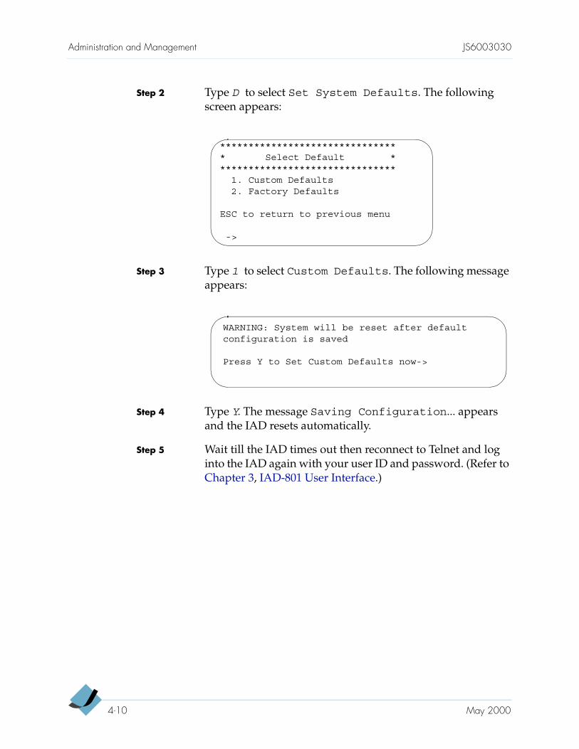
Step 2 Type D to select Set System Defaults. The following screen appears:
Step 3 Type 1 to select Custom Defaults. The following message appears:
Step 4 Type Y. The message Saving Configuration... appears and the IAD resets automatically.
Step 5 Wait till the IAD times out then reconnect to Telnet and log into the IAD again with your user ID and password. (Refer to Chapter 3, IAD-801 User Interface.)
******************************** Select Default ********************************
1. Custom Defaults2. Factory Defaults
ESC to return to previous menu
->
WARNING: System will be reset after defaultconfiguration is saved
Press Y to Set Custom Defaults now->
4-10 May 2000
C H A P T E R 5
WAN Configuration
This chapter provides detailed instructions to configure the IAD-801 for voice and data operation. The WAN module can be either an ADSL, ATM-25, SDSL, or T1/E1. SDSL and T1/E1 modules can be configured for ATM or Frame Relay protocols; ADSL and ATM-25 modules can be configured for ATM protocol only.
For data and voice configuration, go to
— page 5-2 for ADSL and ATM-25 modules
— page 5-3 for SDSL module
— page 5-21 for TI/E1 module
For voice path configuration, go to page 5-39
Provisioning involves setting the IAD-801 parameters and assigning specific port information at the associated CPX-1000. For detailed provisioning procedures, refer to the JetCraft User’s Guide.
Voice and data traffic are each carried in their own PVCs/DLCIs. The voice ports (i.e., CRV or directory number, which is similar to a data address) are identified within the data payload itself in the PVC/DLCIs. Up to eight (seven data, one voice) PVCs/DLCIs can be defined.
CautionResetting the IAD-801 disrupts all voice calls in progress. Configure the IAD-801 during low usage hours if possible.
5-1
WAN Configuration JS6003030
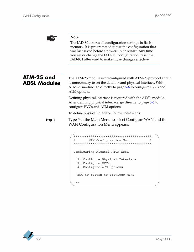
ATM-25 and ADSL Modules
The ATM-25 module is preconfigured with ATM-25 protocol and it is unnecessary to set the datalink and physical interface. With ATM-25 module, go directly to page 5-6 to configure PVCs and ATM options.
Defining physical interface is required with the ADSL module. After defining physical interface, go directly to page 5-6 to configure PVCs and ATM options.
To define physical interface, follow these steps:
Step 1 Type 5 at the Main Menu to select Configure WAN and the WAN Configuration Menu appears:
NoteThe IAD-801 stores all configuration settings in flash memory. It is programmed to use the configuration that was last saved before a power-up or restart. Any time you set or change the IAD-801 configuration, reset the IAD-801 afterward to make those changes effective.
****************************************** WAN Configuration Menu ******************************************
Configuring Alcatel ATUR-ADSL
2. Configure Physical Interface3. Configure PVCs4. Configure ATM Options
ESC to return to previous menu
->
5-2 May 2000
JS6003030 WAN Configuration
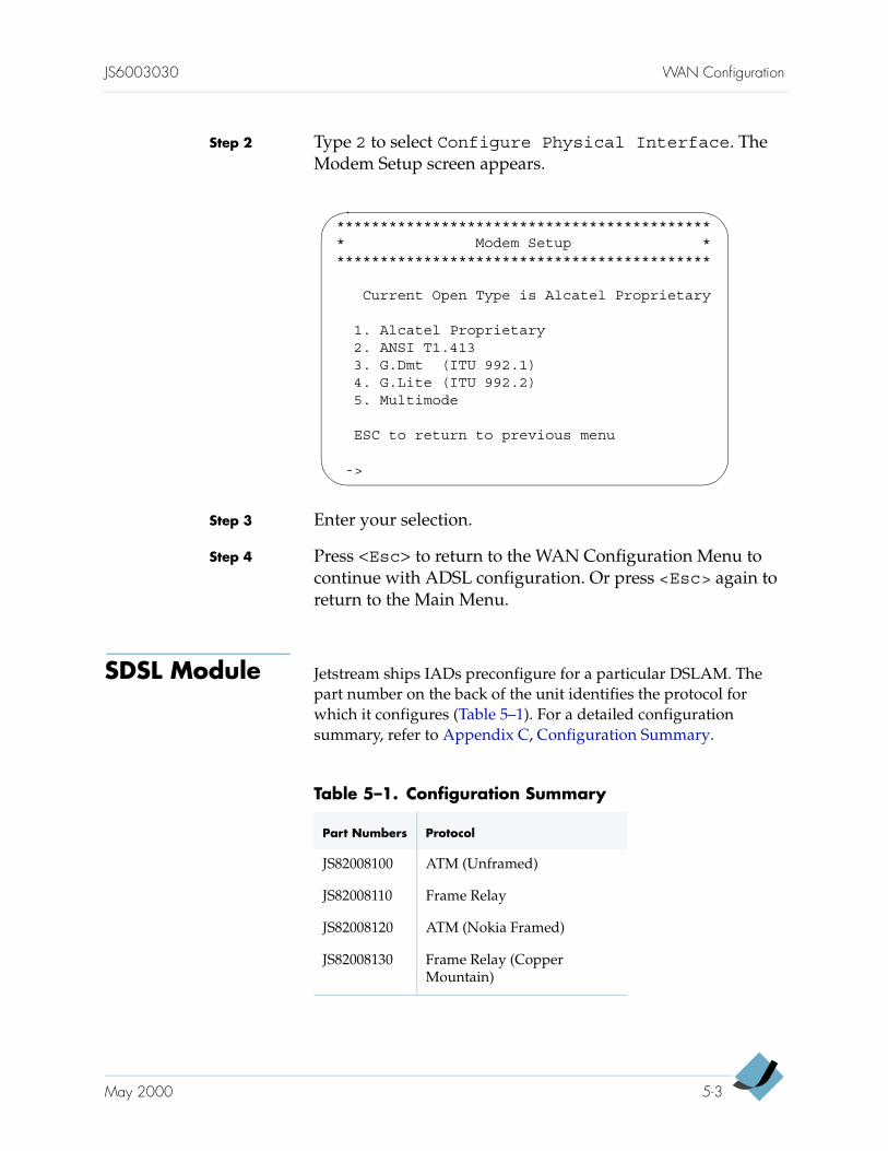
Step 2 Type 2 to select Configure Physical Interface. The Modem Setup screen appears.
Step 3 Enter your selection.
Step 4 Press <Esc> to return to the WAN Configuration Menu to continue with ADSL configuration. Or press <Esc> again to return to the Main Menu.
SDSL Module Jetstream ships IADs preconfigure for a particular DSLAM. The part number on the back of the unit identifies the protocol for which it configures (Table 5–1). For a detailed configuration summary, refer to Appendix C, Configuration Summary.
******************************************** Modem Setup ********************************************
Current Open Type is Alcatel Proprietary
1. Alcatel Proprietary2. ANSI T1.4133. G.Dmt (ITU 992.1)4. G.Lite (ITU 992.2)5. Multimode
ESC to return to previous menu
->
Table 5–1. Configuration Summary
Part Numbers Protocol
JS82008100 ATM (Unframed)
JS82008110 Frame Relay
JS82008120 ATM (Nokia Framed)
JS82008130 Frame Relay (Copper Mountain)
May 2000 5-3
WAN Configuration JS6003030
If your IAD connects to a DSLAM that differs from that for which your IAD was originally configured, use the Quick Configuration option. The Quick Configuration option includes the following preset configurations and provides a convenient way to configure your IAD:
Lucent Stinger with Conexant autobaud and payload scrambling
Nokia with Auto Cycle
Copper Mountain with Auto Sense
ATM with 1152 Kbps fixed
Frame Relay with 784 Kbps fixed
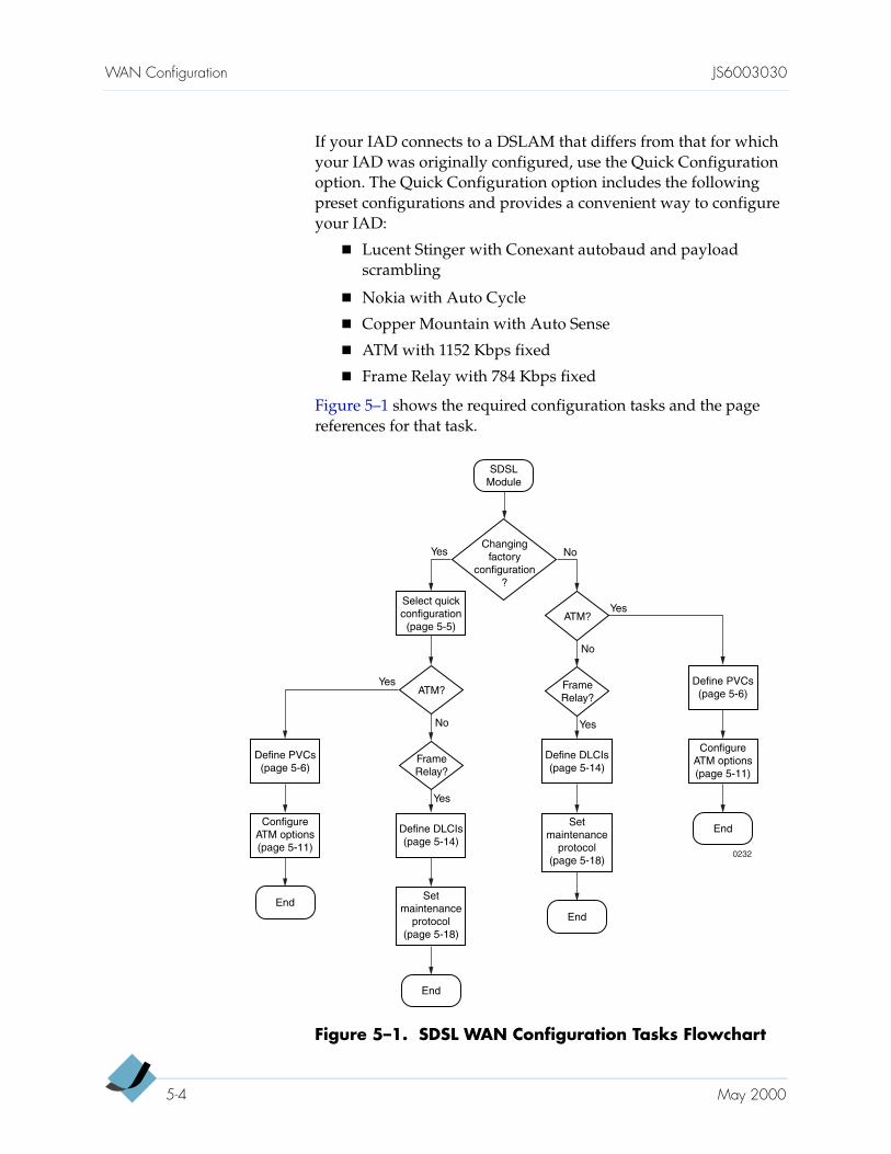
Figure 5–1 shows the required configuration tasks and the page references for that task.
Figure 5–1. SDSL WAN Configuration Tasks Flowchart
SDSLModule
End
Changingfactory
configuration?
Yes
ATM?Yes
Yes
No
No
Select quickconfiguration(page 5-5)
Define PVCs(page 5-6)
Define DLCIs(page 5-14)
ConfigureATM options(page 5-11)
End
ConfigureATM options(page 5-11)
End
Setmaintenance
protocol(page 5-18)
FrameRelay?
Yes
ATM?
No
Define DLCIs(page 5-14)
End
Setmaintenance
protocol(page 5-18)
Define PVCs(page 5-6)
FrameRelay?
Yes
0232
5-4 May 2000
JS6003030 WAN Configuration
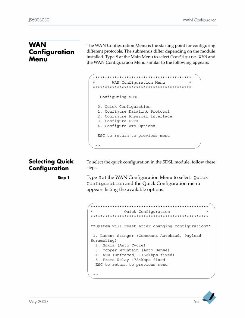
WAN Configuration Menu
The WAN Configuration Menu is the starting point for configuring different protocols. The submenus differ depending on the module installed. Type 5 at the Main Menu to select Configure WAN and the WAN Configuration Menu similar to the following appears:
Selecting Quick Configuration
To select the quick configuration in the SDSL module, follow these steps:
Step 1 Type 0 at the WAN Configuration Menu to select QuickConfiguration and the Quick Configuration menu appears listing the available options.
****************************************** WAN Configuration Menu ******************************************
Configuring SDSL
0. Quick Configuration1. Configure Datalink Protocol2. Configure Physical Interface3. Configure PVCs4. Configure ATM Options
ESC to return to previous menu
->
************************************************** Quick Configuration **************************************************
**System will reset after changing configuration**
1. Lucent Stinger (Conexant Autobaud, PayloadScrambling)
2. Nokia (Auto Cycle)3. Copper Mountain (Auto Sense)4. ATM (Unframed, 1152kbps fixed)5. Frame Relay (784kbps fixed)ESC to return to previous menu
->
May 2000 5-5
WAN Configuration JS6003030
Step 2 Select the DSLAMs to which your IAD is connecting. The message Saving Configuration... appears and the IAD resets automatically after your selected configuration replaces the factory defaults.
Step 3 Wait till the IAD times out then reconnect to Telnet and log into the IAD again with your user ID and password. (Refer to Chapter 3, IAD-801 User Interface.)
Step 4 Continue to configure PVCs (page 5-6) or DLCIs (page 5-14).
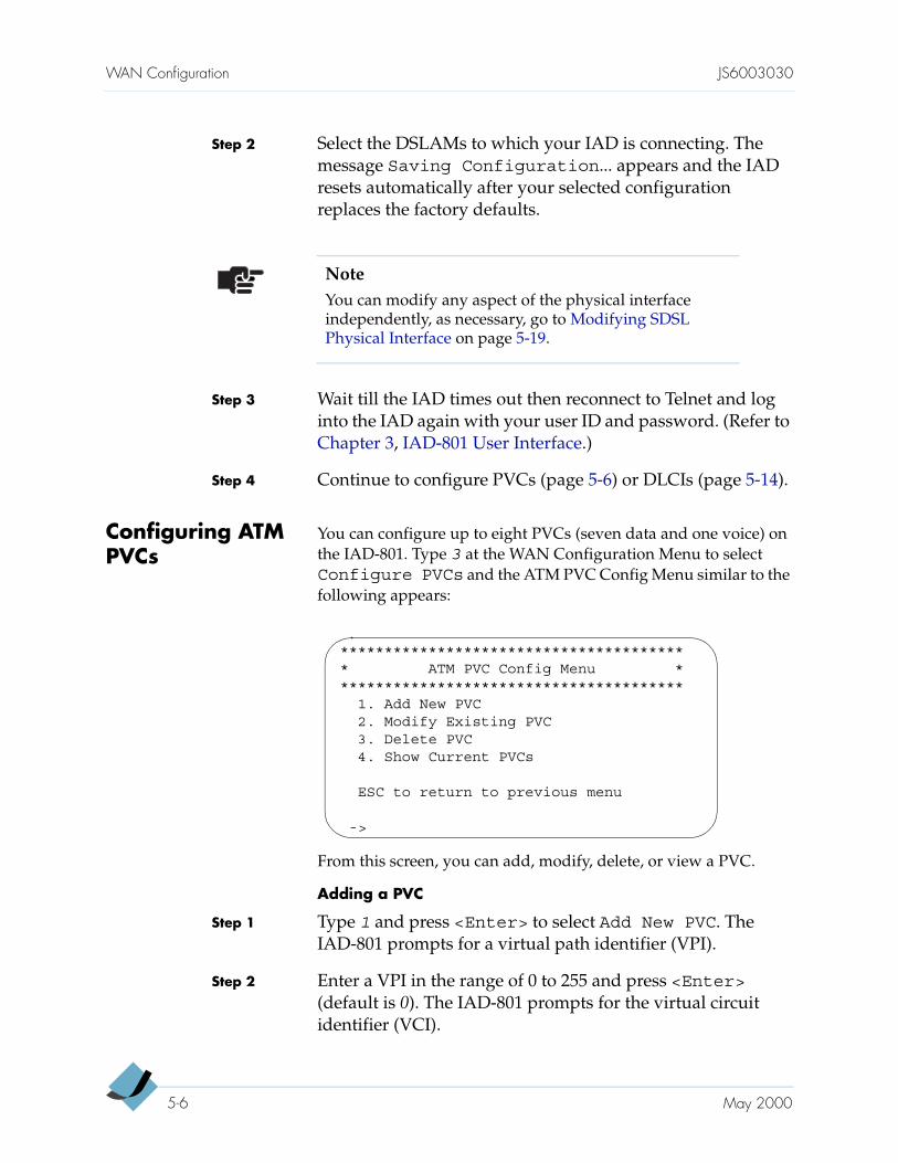
Configuring ATM PVCs
You can configure up to eight PVCs (seven data and one voice) on the IAD-801. Type 3 at the WAN Configuration Menu to selectConfigure PVCs and the ATM PVC Config Menu similar to the following appears:
From this screen, you can add, modify, delete, or view a PVC.
Adding a PVC
Step 1 Type 1 and press <Enter> to select Add New PVC. The IAD-801 prompts for a virtual path identifier (VPI).
Step 2 Enter a VPI in the range of 0 to 255 and press <Enter> (default is 0). The IAD-801 prompts for the virtual circuit identifier (VCI).
NoteYou can modify any aspect of the physical interface independently, as necessary, go to Modifying SDSL Physical Interface on page 5-19.
**************************************** ATM PVC Config Menu ****************************************
1. Add New PVC2. Modify Existing PVC3. Delete PVC4. Show Current PVCs
ESC to return to previous menu
->
5-6 May 2000
JS6003030 WAN Configuration
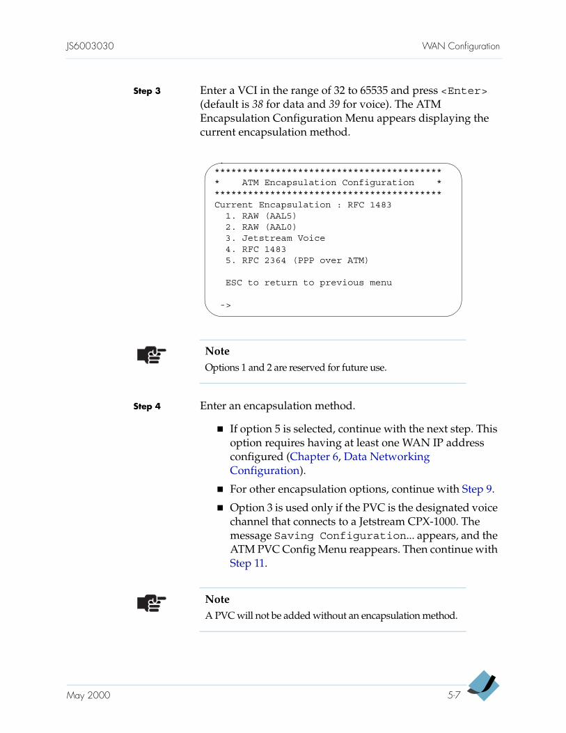
Step 3 Enter a VCI in the range of 32 to 65535 and press <Enter> (default is 38 for data and 39 for voice). The ATM Encapsulation Configuration Menu appears displaying the current encapsulation method.
Step 4 Enter an encapsulation method.
If option 5 is selected, continue with the next step. This option requires having at least one WAN IP address configured (Chapter 6, Data Networking Configuration).
For other encapsulation options, continue with Step 9.
Option 3 is used only if the PVC is the designated voice channel that connects to a Jetstream CPX-1000. The message Saving Configuration... appears, and the ATM PVC Config Menu reappears. Then continue with Step 11.
****************************************** ATM Encapsulation Configuration ******************************************Current Encapsulation : RFC 1483
1. RAW (AAL5)2. RAW (AAL0)3. Jetstream Voice4. RFC 14835. RFC 2364 (PPP over ATM)
ESC to return to previous menu
->
NoteOptions 1 and 2 are reserved for future use.
NoteA PVC will not be added without an encapsulation method.
May 2000 5-7

WAN Configuration JS6003030
Step 5 Type 5 and the following screen appears displaying the current setting:
Step 6 Type the number that corresponds to your choice. The IAD-801 displays the current user ID and prompts for a new one.
Step 7 Enter a new user ID and press <Enter>. (The user ID can be a name or an IP address.) The IAD-801 displays the current password and prompts for a new one.
Step 8 Enter a new password and press <Enter>. (The password can be a name or an IP address.) The ATM Service Category Configuration screen appears.
PPP Authorization is currently NoneEnter New Authorization type
0. None1. PAP Client2. PAP Server3. CHAP Client4. CHAP Server
->
NoteIf no WAN IP address is configured, a message Unable tocompute Physical Port number appears instead of the above screen. You can continue with the WAN configuration. When done, go to the Configure IP Router Menu to assign an WAN IP address, then return to the Configure WAN menu to modify the encapsulation method (page 5-9).
****************************************** ATM Service Category Configuration ******************************************
1. CBR2. UBR
ESC to return to previous menu
->
5-8 May 2000
JS6003030 WAN Configuration
Step 9 Enter your selection.
Type 1 to select CBR for high priority data.
Type 2 to select UBR for low priority data.
The ATM PCR Configuration screens appears displaying the current line speed. The IAD prompts you to enter the Peak Cell Rate (PCR).
Step 10 Enter a PCR value or press <Enter> to accept the maximum allowed PCR valued (displayed in square brackets). The message Saving Configuration... appears, and the ATM PVC Config Menu reappears.
Step 11 Repeat Step 1 through Step 10 to add another PVC, or press <Esc> to return to the WAN Configuration Menu to continue with ATM configuration. Or press <Esc> again to return to the Main Menu.
Step 12 Press Reset when you finish the IAD-801 configuration.
Modifying a PVC
Step 1 Type 2 at the ATM PVC Config Menu to select ModifyExisting PVC. The IAD-801 prompts for a port number.
Step 2 Enter the port number you want to modify and press <Enter>. The IAD-801 prompts for a VPI.
Step 3 Enter a new VPI in the range of 0 to 255 (default is 0) and press <Enter>. The IAD-801 prompts for a VCI.
NoteA PVC will not be added if a service category is not specified.
NoteThe <Esc> key is inoperative during steps 2 through 4.
May 2000 5-9
WAN Configuration JS6003030
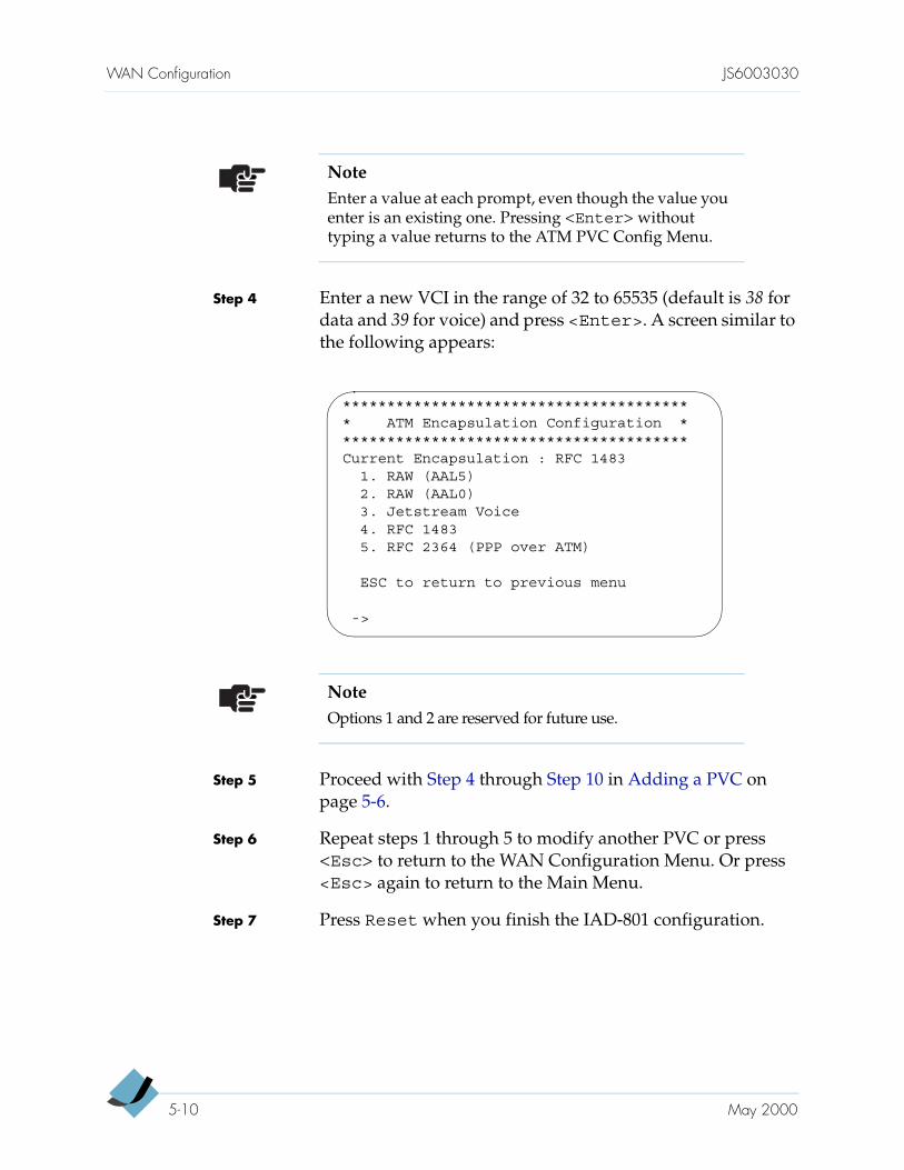
Step 4 Enter a new VCI in the range of 32 to 65535 (default is 38 for data and 39 for voice) and press <Enter>. A screen similar to the following appears:
Step 5 Proceed with Step 4 through Step 10 in Adding a PVC on page 5-6.
Step 6 Repeat steps 1 through 5 to modify another PVC or press <Esc> to return to the WAN Configuration Menu. Or press <Esc> again to return to the Main Menu.
Step 7 Press Reset when you finish the IAD-801 configuration.
NoteEnter a value at each prompt, even though the value you enter is an existing one. Pressing <Enter> without typing a value returns to the ATM PVC Config Menu.
**************************************** ATM Encapsulation Configuration ****************************************Current Encapsulation : RFC 1483
1. RAW (AAL5)2. RAW (AAL0)3. Jetstream Voice4. RFC 14835. RFC 2364 (PPP over ATM)
ESC to return to previous menu
->
NoteOptions 1 and 2 are reserved for future use.
5-10 May 2000
JS6003030 WAN Configuration
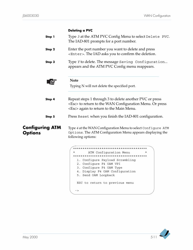
Deleting a PVC
Step 1 Type 3 at the ATM PVC Config Menu to select Delete PVC. The IAD-801 prompts for a port number.
Step 2 Enter the port number you want to delete and press<Enter>. The IAD asks you to confirm the deletion.
Step 3 Type Y to delete. The message Saving Configuration... appears and the ATM PVC Config menu reappears.
Step 4 Repeat steps 1 through 3 to delete another PVC or press <Esc> to return to the WAN Configuration Menu. Or press <Esc> again to return to the Main Menu.
Step 5 Press Reset when you finish the IAD-801 configuration.
Configuring ATM Options
Type 4 at the WAN Configuration Menu to select Configure ATMOptions. The ATM Configuration Menu appears displaying the following options:
NoteTyping N will not delete the specified port.
**************************************** ATM Configuration Menu ****************************************
1. Configure Payload Scrambling2. Configure F4 OAM VPI3. Configure F4 OAM Type4. Display F4 OAM Configuration5. Send OAM Loopback
ESC to return to previous menu
->
May 2000 5-11
WAN Configuration JS6003030
Configuring Payload Scrambling
The payload scrambling default is disabled. To “talk” to a DSLAM that uses payload scrambling (e.g., a Lucent DSLAM), enable the option on the IAD-801.
Step 1 Type 1 at the ATM Configuration Menu to select the Configure Payload Scrambling option. A message states the current payload scrambling status and the IAD-801 prompts for selection.
Step 2 Press E to enable or D to disable the payload scrambling as required. The message Saving Configuration... appears and the ATM Configuration Menu reappears.
Step 3 Continue with the ATM configuration or press <Esc> to return to the Main Menu.
Step 4 Press Reset when you finish the IAD-801 configuration.
Configuring F4 OAM Cell
Step 1 Type 2 at the ATM Configuration Menu to select the Configure F4 OAM VPI option. A message states the current F4 OAM status and the IAD-801 prompts for a VPI.
Step 2 Enter the VPI. (This entry must match one of the WAN PVCs.) The message Saving Configuration... appears and the ATM Configuration Menu reappears.
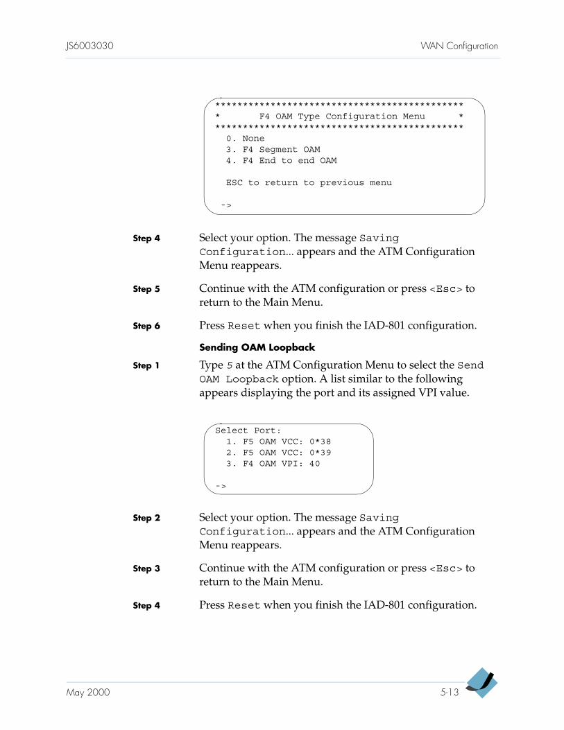
Step 3 Type 3 at the ATM Configuration Menu to select the Configure F4 OAM Type option. The following screen appears:
NoteIf you configure the F4 OAM VPI option, you will also need to configure the F4 OAM Type option.
5-12 May 2000
JS6003030 WAN Configuration
Step 4 Select your option. The message SavingConfiguration... appears and the ATM Configuration Menu reappears.
Step 5 Continue with the ATM configuration or press <Esc> to return to the Main Menu.
Step 6 Press Reset when you finish the IAD-801 configuration.
Sending OAM Loopback
Step 1 Type 5 at the ATM Configuration Menu to select the SendOAM Loopback option. A list similar to the following appears displaying the port and its assigned VPI value.
Step 2 Select your option. The message SavingConfiguration... appears and the ATM Configuration Menu reappears.
Step 3 Continue with the ATM configuration or press <Esc> to return to the Main Menu.
Step 4 Press Reset when you finish the IAD-801 configuration.
********************************************** F4 OAM Type Configuration Menu **********************************************
0. None3. F4 Segment OAM4. F4 End to end OAM
ESC to return to previous menu
->
Select Port:1. F5 OAM VCC: 0*382. F5 OAM VCC: 0*393. F4 OAM VPI: 40
->
May 2000 5-13
WAN Configuration JS6003030
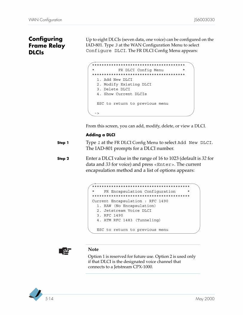
Configuring Frame Relay DLCIs
Up to eight DLCIs (seven data, one voice) can be configured on the IAD-801. Type 3 at the WAN Configuration Menu to select Configure DLCI. The FR DLCI Config Menu appears:
From this screen, you can add, modify, delete, or view a DLCI.
Adding a DLCI
Step 1 Type 1 at the FR DLCI Config Menu to select Add New DLCI. The IAD-801 prompts for a DLCI number.
Step 2 Enter a DLCI value in the range of 16 to 1023 (default is 32 for data and 33 for voice) and press <Enter>. The current encapsulation method and a list of options appears:
**************************************** FR DLCI Config Menu ****************************************
1. Add New DLCI2. Modify Existing DLCI3. Delete DLCI4. Show Current DLCIs
ESC to return to previous menu
->
****************************************** FR Encapsulation Configuration ******************************************Current Encapsulation : RFC 1490
1. RAW (No Encapsulation)2. Jetstream Voice DLCI3. RFC 14904. ATM RFC 1483 (Tunneling)
ESC to return to previous menu
NoteOption 1 is reserved for future use. Option 2 is used only if that DLCI is the designated voice channel that connects to a Jetstream CPX-1000.
5-14 May 2000
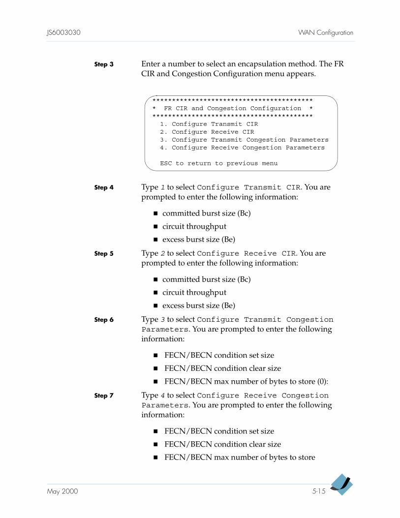
JS6003030 WAN Configuration
Step 3 Enter a number to select an encapsulation method. The FR CIR and Congestion Configuration menu appears.
Step 4 Type 1 to select Configure Transmit CIR. You are prompted to enter the following information:
committed burst size (Bc)
circuit throughput
excess burst size (Be)
Step 5 Type 2 to select Configure Receive CIR. You are prompted to enter the following information:
committed burst size (Bc)
circuit throughput
excess burst size (Be)
Step 6 Type 3 to select Configure Transmit CongestionParameters. You are prompted to enter the following information:
FECN/BECN condition set size
FECN/BECN condition clear size
FECN/BECN max number of bytes to store (0):
Step 7 Type 4 to select Configure Receive CongestionParameters. You are prompted to enter the following information:
FECN/BECN condition set size
FECN/BECN condition clear size
FECN/BECN max number of bytes to store
****************************************** FR CIR and Congestion Configuration ******************************************
1. Configure Transmit CIR2. Configure Receive CIR3. Configure Transmit Congestion Parameters4. Configure Receive Congestion Parameters
ESC to return to previous menu
May 2000 5-15
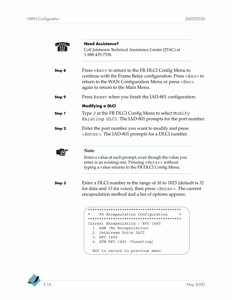
WAN Configuration JS6003030
Step 8 Press <Esc> to return to the FR DLCI Config Menu to continue with the Frame Relay configuration. Press <Esc> to return to the WAN Configuration Menu or press <Esc> again to return to the Main Menu.
Step 9 Press Reset when you finish the IAD-801 configuration.
Modifying a DLCI
Step 1 Type 2 at the FR DLCI Config Menu to select ModifyExisting DLCI. The IAD-801 prompts for the port number.
Step 2 Enter the port number you want to modify and press <Enter>. The IAD-801 prompts for a DLCI number.
Step 3 Enter a DLCI number in the range of 16 to 1023 (default is 32 for data and 33 for voice), then press <Enter>. The current encapsulation method and a list of options appears:
Need Assistance?Call Jetstream Technical Assistance Center (JTAC) at 1-888-435-7538.
NoteEnter a value at each prompt, even though the value you enter is an existing one. Pressing <Enter> without typing a value returns to the FR DLCI Config Menu.
****************************************** FR Encapsulation Configuration ******************************************Current Encapsulation : RFC 1490
1. RAW (No Encapsulation)2. Jetstream Voice DLCI3. RFC 14904. ATM RFC 1483 (Tunneling)
ESC to return to previous menu
5-16 May 2000
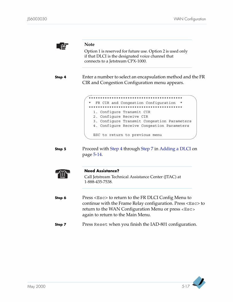
JS6003030 WAN Configuration
Step 4 Enter a number to select an encapsulation method and the FR CIR and Congestion Configuration menu appears.
Step 5 Proceed with Step 4 through Step 7 in Adding a DLCI on page 5-14.
Step 6 Press <Esc> to return to the FR DLCI Config Menu to continue with the Frame Relay configuration. Press <Esc> to return to the WAN Configuration Menu or press <Esc> again to return to the Main Menu.
Step 7 Press Reset when you finish the IAD-801 configuration.
NoteOption 1 is reserved for future use. Option 2 is used only if that DLCI is the designated voice channel that connects to a Jetstream CPX-1000.
****************************************** FR CIR and Congestion Configuration ******************************************
1. Configure Transmit CIR2. Configure Receive CIR3. Configure Transmit Congestion Parameters4. Configure Receive Congestion Parameters
ESC to return to previous menu
Need Assistance?Call Jetstream Technical Assistance Center (JTAC) at 1-888-435-7538.
May 2000 5-17
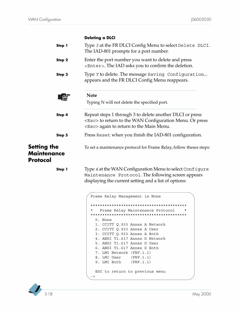
WAN Configuration JS6003030
Deleting a DLCI
Step 1 Type 3 at the FR DLCI Config Menu to select Delete DLCI. The IAD-801 prompts for a port number.
Step 2 Enter the port number you want to delete and press <Enter>. The IAD asks you to confirm the deletion.
Step 3 Type Y to delete. The message Saving Configuration... appears and the FR DLCI Config Menu reappears.
Step 4 Repeat steps 1 through 3 to delete another DLCI or press <Esc> to return to the WAN Configuration Menu. Or press <Esc> again to return to the Main Menu.
Step 5 Press Reset when you finish the IAD-801 configuration.
Setting the Maintenance Protocol
To set a maintenance protocol for Frame Relay, follow theses steps:
Step 1 Type 4 at the WAN Configuration Menu to select ConfigureMaintenance Protocol. The following screen appears displaying the current setting and a list of options:
NoteTyping N will not delete the specified port.
Frame Relay Management is None
****************************************** Frame Relay Maintenance Protocol ******************************************
0. None1. CCITT Q.933 Annex A Network2. CCITT Q.933 Annex A User3. CCITT Q.933 Annex A Both4. ANSI T1.617 Annex D Network5. ANSI T1.617 Annex D User6. ANSI T1.617 Annex D Both7. LMI Network (FRF.1.1)8. LMI User (FRF.1.1)9. LMI Both (FRF.1.1)
ESC to return to previous menu->
5-18 May 2000
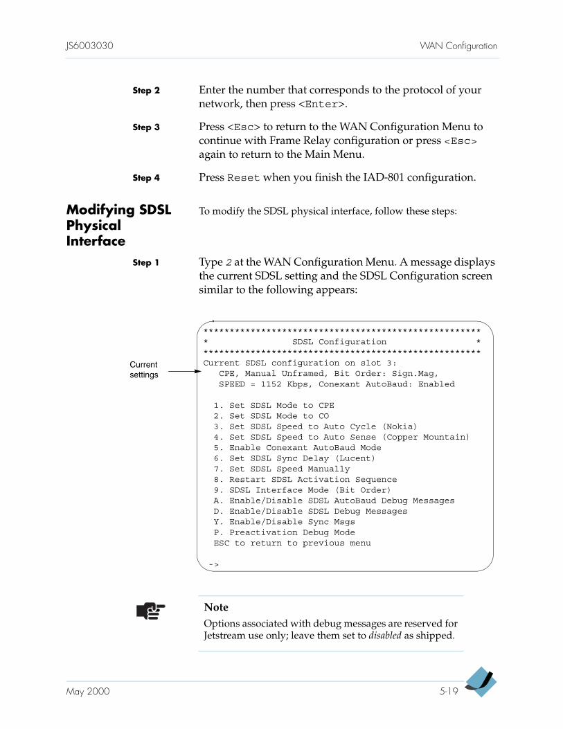
JS6003030 WAN Configuration
Step 2 Enter the number that corresponds to the protocol of your network, then press <Enter>.
Step 3 Press <Esc> to return to the WAN Configuration Menu to continue with Frame Relay configuration or press <Esc> again to return to the Main Menu.
Step 4 Press Reset when you finish the IAD-801 configuration.
Modifying SDSL Physical Interface
To modify the SDSL physical interface, follow these steps:
Step 1 Type 2 at the WAN Configuration Menu. A message displays the current SDSL setting and the SDSL Configuration screen similar to the following appears:
NoteOptions associated with debug messages are reserved for Jetstream use only; leave them set to disabled as shipped.
****************************************************** SDSL Configuration ******************************************************Current SDSL configuration on slot 3:
CPE, Manual Unframed, Bit Order: Sign.Mag,SPEED = 1152 Kbps, Conexant AutoBaud: Enabled
1. Set SDSL Mode to CPE2. Set SDSL Mode to CO3. Set SDSL Speed to Auto Cycle (Nokia)4. Set SDSL Speed to Auto Sense (Copper Mountain)5. Enable Conexant AutoBaud Mode6. Set SDSL Sync Delay (Lucent)7. Set SDSL Speed Manually8. Restart SDSL Activation Sequence9. SDSL Interface Mode (Bit Order)A. Enable/Disable SDSL AutoBaud Debug MessagesD. Enable/Disable SDSL Debug MessagesY. Enable/Disable Sync MsgsP. Preactivation Debug ModeESC to return to previous menu
->
Current settings
May 2000 5-19
WAN Configuration JS6003030
Step 2 Modify any aspect of the physical interface, if necessary.
data rate — For a user-defined speed, the data rate you enter must be between 144 Kbps and 2320 Kbps, in 8 Kbps increments.
bit order — Specifying bit order is required to support the different options of the 2B1Q line coding used by DSLAMs.
Step 3 Press <Esc> to return to the WAN Configuration Menu or press <Esc> again to return to the Main Menu.
Step 4 Press Reset when you finish the IAD-801 configuration.
5-20 May 2000
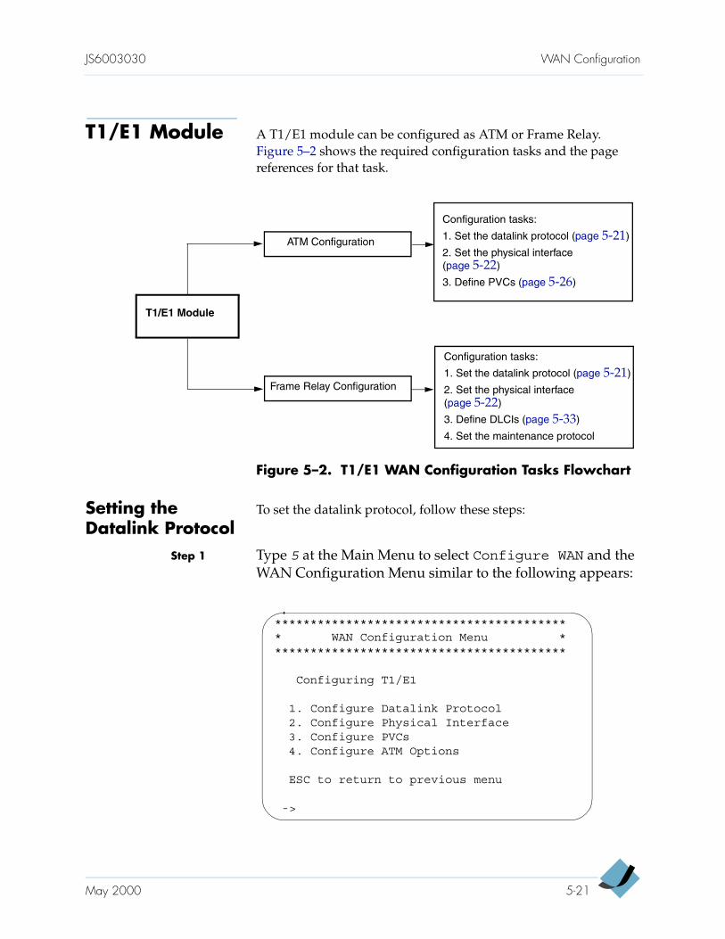
JS6003030 WAN Configuration
T1/E1 Module A T1/E1 module can be configured as ATM or Frame Relay. Figure 5–2 shows the required configuration tasks and the page references for that task.
Figure 5–2. T1/E1 WAN Configuration Tasks Flowchart
Setting the Datalink Protocol
To set the datalink protocol, follow these steps:
Step 1 Type 5 at the Main Menu to select Configure WAN and the WAN Configuration Menu similar to the following appears:
Frame Relay Configuration
ATM Configuration
T1/E1 Module
Configuration tasks:
1. Set the datalink protocol (page 5-21)
2. Set the physical interface (page 5-22)
3. Define DLCIs (page 5-33)
4. Set the maintenance protocol
Configuration tasks:
1. Set the datalink protocol (page 5-21)
2. Set the physical interface (page 5-22)
3. Define PVCs (page 5-26)
****************************************** WAN Configuration Menu ******************************************
Configuring T1/E1
1. Configure Datalink Protocol2. Configure Physical Interface3. Configure PVCs4. Configure ATM Options
ESC to return to previous menu
->
May 2000 5-21
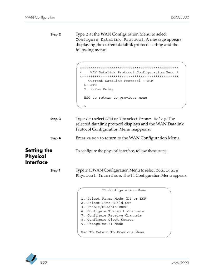
WAN Configuration JS6003030
Step 2 Type 1 at the WAN Configuration Menu to select Configure Datalink Protocol. A message appears displaying the current datalink protocol setting and the following menu:
Step 3 Type 6 to select ATM or 7 to select Frame Relay. The selected datalink protocol displays and the WAN Datalink Protocol Configuration Menu reappears.
Step 4 Press <Esc> to return to the WAN Configuration Menu.
Setting the Physical Interface
To configure the physical interface, follow these steps:
Step 1 Type 2 at WAN Configuration Menu to select ConfigurePhysical Interface. The T1 Configuration Menu appears.
************************************************ WAN Datalink Protocol Configuration Menu ************************************************
Current DataLink Protocol : ATM6. ATM7. Frame Relay
ESC to return to previous menu
->
T1 Configuration Menu
1. Select Frame Mode (D4 or ESF)2. Select Line Build Out3. Enable/Disable B8ZS6. Configure Transmit Channels7. Configure Receive Channels8. Configure Clock Source9. Change to E1 Mode
Esc To Return To Previous Menu
5-22 May 2000
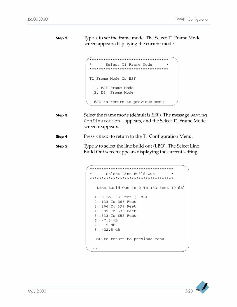
JS6003030 WAN Configuration
Step 2 Type 1 to set the frame mode. The Select T1 Frame Mode screen appears displaying the current mode.
Step 3 Select the frame mode (default is ESF). The message SavingConfiguration... appears, and the Select T1 Frame Mode screen reappears.
Step 4 Press <Esc> to return to the T1 Configuration Menu.
Step 5 Type 2 to select the line build out (LBO). The Select Line Build Out screen appears displaying the current setting.
*********************************** Select T1 Frame Mode ***********************************
T1 Frame Mode Is ESF
1. ESF Frame Mode2. D4 Frame Mode
ESC to return to previous menu
************************************* Select Line Build Out *************************************
Line Build Out Is 0 To 133 Feet (0 dB)
1. 0 To 133 Feet (0 dB)2. 133 To 266 Feet3. 266 To 399 Feet4. 399 To 533 Feet5. 533 To 655 Feet6. -7.5 dB7. -15 dB8. -22.5 dB
ESC to return to previous menu
->
May 2000 5-23
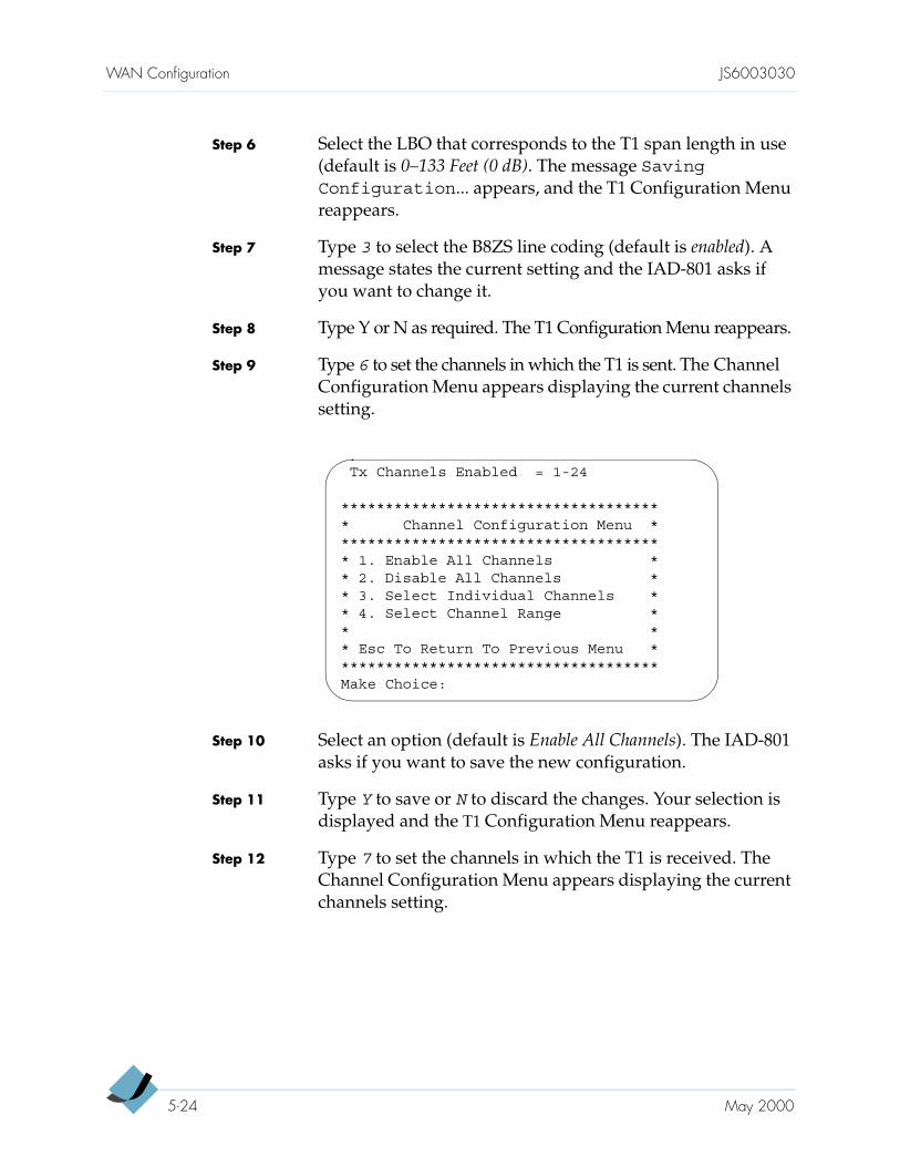
WAN Configuration JS6003030
Step 6 Select the LBO that corresponds to the T1 span length in use (default is 0–133 Feet (0 dB). The message SavingConfiguration... appears, and the T1 Configuration Menu reappears.
Step 7 Type 3 to select the B8ZS line coding (default is enabled). A message states the current setting and the IAD-801 asks if you want to change it.
Step 8 Type Y or N as required. The T1 Configuration Menu reappears.
Step 9 Type 6 to set the channels in which the T1 is sent. The Channel Configuration Menu appears displaying the current channels setting.
Step 10 Select an option (default is Enable All Channels). The IAD-801 asks if you want to save the new configuration.
Step 11 Type Y to save or N to discard the changes. Your selection is displayed and the T1 Configuration Menu reappears.
Step 12 Type 7 to set the channels in which the T1 is received. The Channel Configuration Menu appears displaying the current channels setting.
Tx Channels Enabled = 1-24
************************************* Channel Configuration Menu ************************************** 1. Enable All Channels ** 2. Disable All Channels ** 3. Select Individual Channels ** 4. Select Channel Range ** ** Esc To Return To Previous Menu *************************************Make Choice:
5-24 May 2000
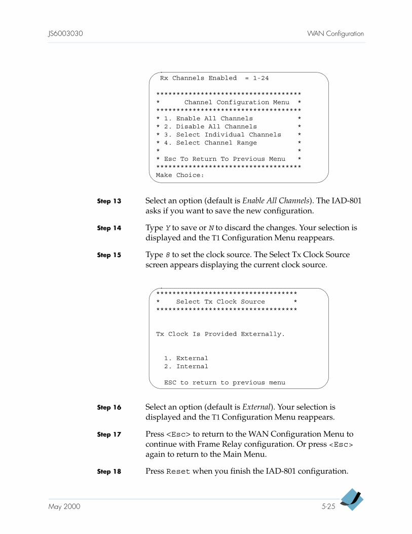
JS6003030 WAN Configuration
Step 13 Select an option (default is Enable All Channels). The IAD-801 asks if you want to save the new configuration.
Step 14 Type Y to save or N to discard the changes. Your selection is displayed and the T1 Configuration Menu reappears.
Step 15 Type 8 to set the clock source. The Select Tx Clock Source screen appears displaying the current clock source.
Step 16 Select an option (default is External). Your selection is displayed and the T1 Configuration Menu reappears.
Step 17 Press <Esc> to return to the WAN Configuration Menu to continue with Frame Relay configuration. Or press <Esc> again to return to the Main Menu.
Step 18 Press Reset when you finish the IAD-801 configuration.
Rx Channels Enabled = 1-24
************************************* Channel Configuration Menu ************************************** 1. Enable All Channels ** 2. Disable All Channels ** 3. Select Individual Channels ** 4. Select Channel Range ** ** Esc To Return To Previous Menu *************************************Make Choice:
************************************ Select Tx Clock Source ************************************
Tx Clock Is Provided Externally.
1. External2. Internal
ESC to return to previous menu
May 2000 5-25
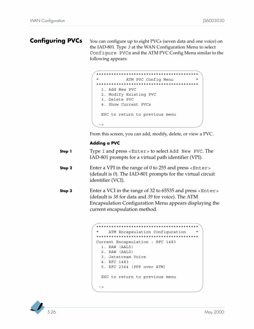
WAN Configuration JS6003030
Configuring PVCs You can configure up to eight PVCs (seven data and one voice) on the IAD-801. Type 3 at the WAN Configuration Menu to selectConfigure PVCs and the ATM PVC Config Menu similar to the following appears:
From this screen, you can add, modify, delete, or view a PVC.
Adding a PVC
Step 1 Type 1 and press <Enter> to select Add New PVC. The IAD-801 prompts for a virtual path identifier (VPI).
Step 2 Enter a VPI in the range of 0 to 255 and press <Enter> (default is 0). The IAD-801 prompts for the virtual circuit identifier (VCI).
Step 3 Enter a VCI in the range of 32 to 65535 and press <Enter> (default is 38 for data and 39 for voice). The ATM Encapsulation Configuration Menu appears displaying the current encapsulation method.
****************************************** ATM PVC Config Menu ******************************************
1. Add New PVC2. Modify Existing PVC3. Delete PVC4. Show Current PVCs
ESC to return to previous menu
->
****************************************** ATM Encapsulation Configuration ******************************************Current Encapsulation : RFC 1483
1. RAW (AAL5)2. RAW (AAL0)3. Jetstream Voice4. RFC 14835. RFC 2364 (PPP over ATM)
ESC to return to previous menu
->
5-26 May 2000
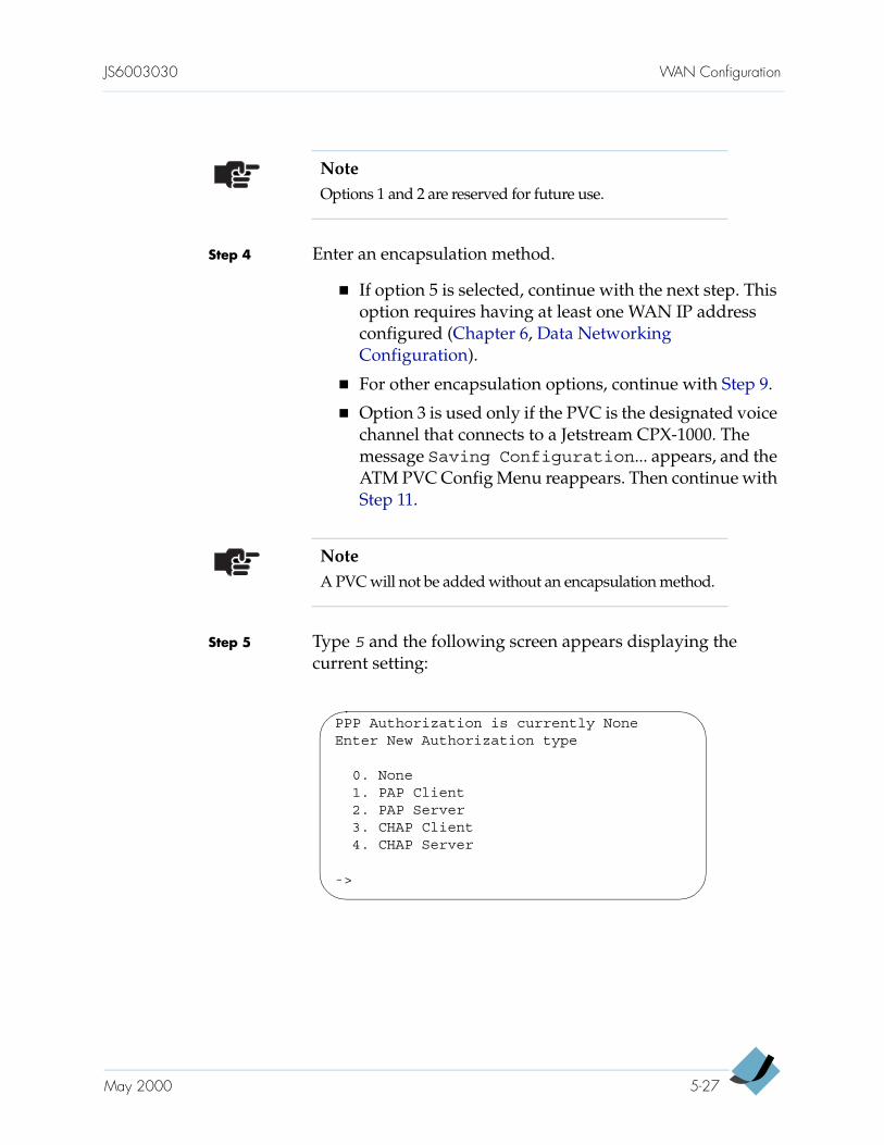
JS6003030 WAN Configuration
Step 4 Enter an encapsulation method.
If option 5 is selected, continue with the next step. This option requires having at least one WAN IP address configured (Chapter 6, Data Networking Configuration).
For other encapsulation options, continue with Step 9.
Option 3 is used only if the PVC is the designated voice channel that connects to a Jetstream CPX-1000. The message Saving Configuration... appears, and the ATM PVC Config Menu reappears. Then continue with Step 11.
Step 5 Type 5 and the following screen appears displaying the current setting:
NoteOptions 1 and 2 are reserved for future use.
NoteA PVC will not be added without an encapsulation method.
PPP Authorization is currently NoneEnter New Authorization type
0. None1. PAP Client2. PAP Server3. CHAP Client4. CHAP Server
->
May 2000 5-27
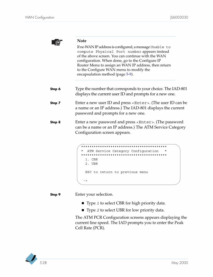
WAN Configuration JS6003030
Step 6 Type the number that corresponds to your choice. The IAD-801 displays the current user ID and prompts for a new one.
Step 7 Enter a new user ID and press <Enter>. (The user ID can be a name or an IP address.) The IAD-801 displays the current password and prompts for a new one.
Step 8 Enter a new password and press <Enter>. (The password can be a name or an IP address.) The ATM Service Category Configuration screen appears.
Step 9 Enter your selection.
Type 1 to select CBR for high priority data.
Type 2 to select UBR for low priority data.
The ATM PCR Configuration screens appears displaying the current line speed. The IAD prompts you to enter the Peak Cell Rate (PCR).
NoteIf no WAN IP address is configured, a message Unable tocompute Physical Port number appears instead of the above screen. You can continue with the WAN configuration. When done, go to the Configure IP Router Menu to assign an WAN IP address, then return to the Configure WAN menu to modify the encapsulation method (page 5-9).
****************************************** ATM Service Category Configuration ******************************************
1. CBR2. UBR
ESC to return to previous menu
->
5-28 May 2000
JS6003030 WAN Configuration
Step 10 Enter a PCR value or press <Enter> to accept the maximum allowed PCR valued (displayed in square brackets). The message Saving Configuration... appears, and the ATM PVC Config Menu reappears.
Step 11 Repeat Step 1 through Step 10 to add another PVC, or press <Esc> to return to the WAN Configuration Menu to continue with ATM configuration. Or press <Esc> again to return to the Main Menu.
Step 12 Press Reset when you finish the IAD-801 configuration.
Modifying a PVC
Step 1 Type 2 at the ATM PVC Config Menu to select ModifyExisting PVC. The IAD-801 prompts for a port number.
Step 2 Enter the port number you want to modify and press <Enter>. The IAD-801 prompts for a VPI.
Step 3 Enter a new VPI in the range of 0 to 255 (default is 0) and press <Enter>. The IAD-801 prompts for a VCI.
NoteA PVC will not be added if a service category is not specified.
NoteThe <Esc> key is inoperative during steps 2 through 4.
NoteEnter a value at each prompt, even though the value you enter is an existing one. Pressing <Enter> without typing a value returns to the ATM PVC Config Menu.
May 2000 5-29
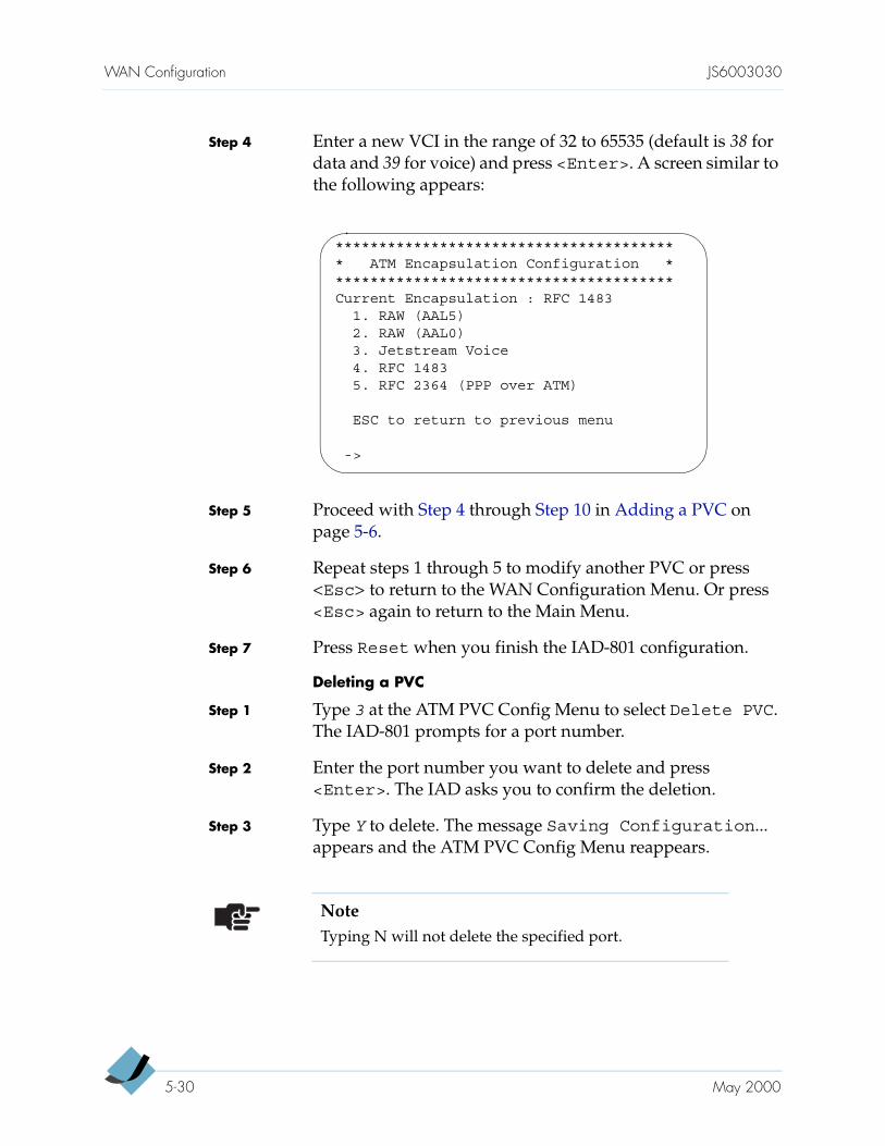
WAN Configuration JS6003030
Step 4 Enter a new VCI in the range of 32 to 65535 (default is 38 for data and 39 for voice) and press <Enter>. A screen similar to the following appears:
Step 5 Proceed with Step 4 through Step 10 in Adding a PVC on page 5-6.
Step 6 Repeat steps 1 through 5 to modify another PVC or press <Esc> to return to the WAN Configuration Menu. Or press <Esc> again to return to the Main Menu.
Step 7 Press Reset when you finish the IAD-801 configuration.
Deleting a PVC
Step 1 Type 3 at the ATM PVC Config Menu to select Delete PVC. The IAD-801 prompts for a port number.
Step 2 Enter the port number you want to delete and press<Enter>. The IAD asks you to confirm the deletion.
Step 3 Type Y to delete. The message Saving Configuration... appears and the ATM PVC Config Menu reappears.
**************************************** ATM Encapsulation Configuration ****************************************Current Encapsulation : RFC 1483
1. RAW (AAL5)2. RAW (AAL0)3. Jetstream Voice4. RFC 14835. RFC 2364 (PPP over ATM)
ESC to return to previous menu
->
NoteTyping N will not delete the specified port.
5-30 May 2000
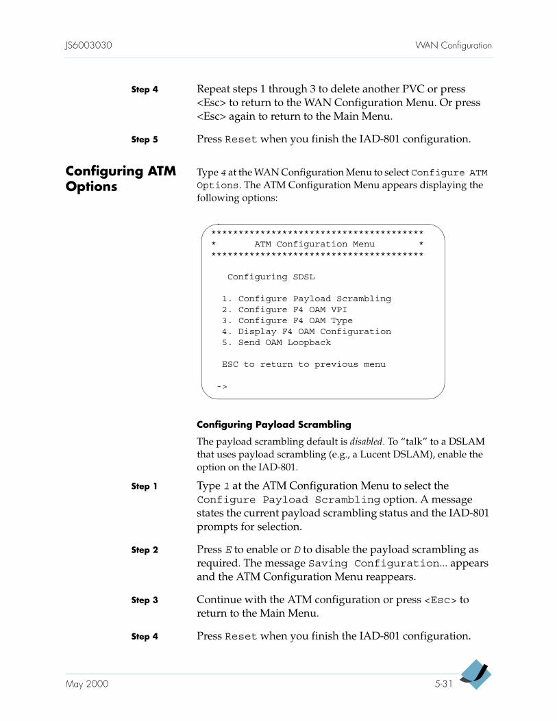
JS6003030 WAN Configuration
Step 4 Repeat steps 1 through 3 to delete another PVC or press <Esc> to return to the WAN Configuration Menu. Or press <Esc> again to return to the Main Menu.
Step 5 Press Reset when you finish the IAD-801 configuration.
Configuring ATM Options
Type 4 at the WAN Configuration Menu to select Configure ATMOptions. The ATM Configuration Menu appears displaying the following options:
Configuring Payload Scrambling
The payload scrambling default is disabled. To “talk” to a DSLAM that uses payload scrambling (e.g., a Lucent DSLAM), enable the option on the IAD-801.
Step 1 Type 1 at the ATM Configuration Menu to select the Configure Payload Scrambling option. A message states the current payload scrambling status and the IAD-801 prompts for selection.
Step 2 Press E to enable or D to disable the payload scrambling as required. The message Saving Configuration... appears and the ATM Configuration Menu reappears.
Step 3 Continue with the ATM configuration or press <Esc> to return to the Main Menu.
Step 4 Press Reset when you finish the IAD-801 configuration.
**************************************** ATM Configuration Menu ****************************************
Configuring SDSL
1. Configure Payload Scrambling2. Configure F4 OAM VPI3. Configure F4 OAM Type4. Display F4 OAM Configuration5. Send OAM Loopback
ESC to return to previous menu
->
May 2000 5-31
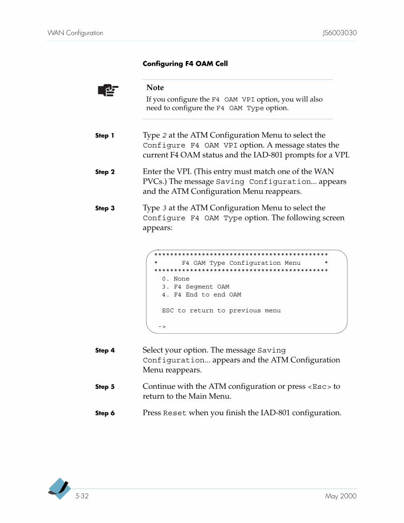
WAN Configuration JS6003030
Configuring F4 OAM Cell
Step 1 Type 2 at the ATM Configuration Menu to select the Configure F4 OAM VPI option. A message states the current F4 OAM status and the IAD-801 prompts for a VPI.
Step 2 Enter the VPI. (This entry must match one of the WAN PVCs.) The message Saving Configuration... appears and the ATM Configuration Menu reappears.
Step 3 Type 3 at the ATM Configuration Menu to select the Configure F4 OAM Type option. The following screen appears:
Step 4 Select your option. The message SavingConfiguration... appears and the ATM Configuration Menu reappears.
Step 5 Continue with the ATM configuration or press <Esc> to return to the Main Menu.
Step 6 Press Reset when you finish the IAD-801 configuration.
NoteIf you configure the F4 OAM VPI option, you will also need to configure the F4 OAM Type option.
********************************************* F4 OAM Type Configuration Menu *********************************************
0. None3. F4 Segment OAM4. F4 End to end OAM
ESC to return to previous menu
->
5-32 May 2000
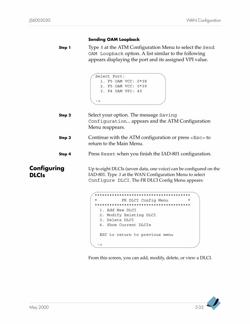
JS6003030 WAN Configuration
Sending OAM Loopback
Step 1 Type 5 at the ATM Configuration Menu to select the SendOAM Loopback option. A list similar to the following appears displaying the port and its assigned VPI value.
Step 2 Select your option. The message SavingConfiguration... appears and the ATM Configuration Menu reappears.
Step 3 Continue with the ATM configuration or press <Esc> to return to the Main Menu.
Step 4 Press Reset when you finish the IAD-801 configuration.
Configuring DLCIs
Up to eight DLCIs (seven data, one voice) can be configured on the IAD-801. Type 3 at the WAN Configuration Menu to select Configure DLCI. The FR DLCI Config Menu appears:
From this screen, you can add, modify, delete, or view a DLCI.
Select Port:1. F5 OAM VCC: 0*382. F5 OAM VCC: 0*393. F4 OAM VPI: 40
->
**************************************** FR DLCI Config Menu ****************************************
1. Add New DLCI2. Modify Existing DLCI3. Delete DLCI4. Show Current DLCIs
ESC to return to previous menu
->
May 2000 5-33
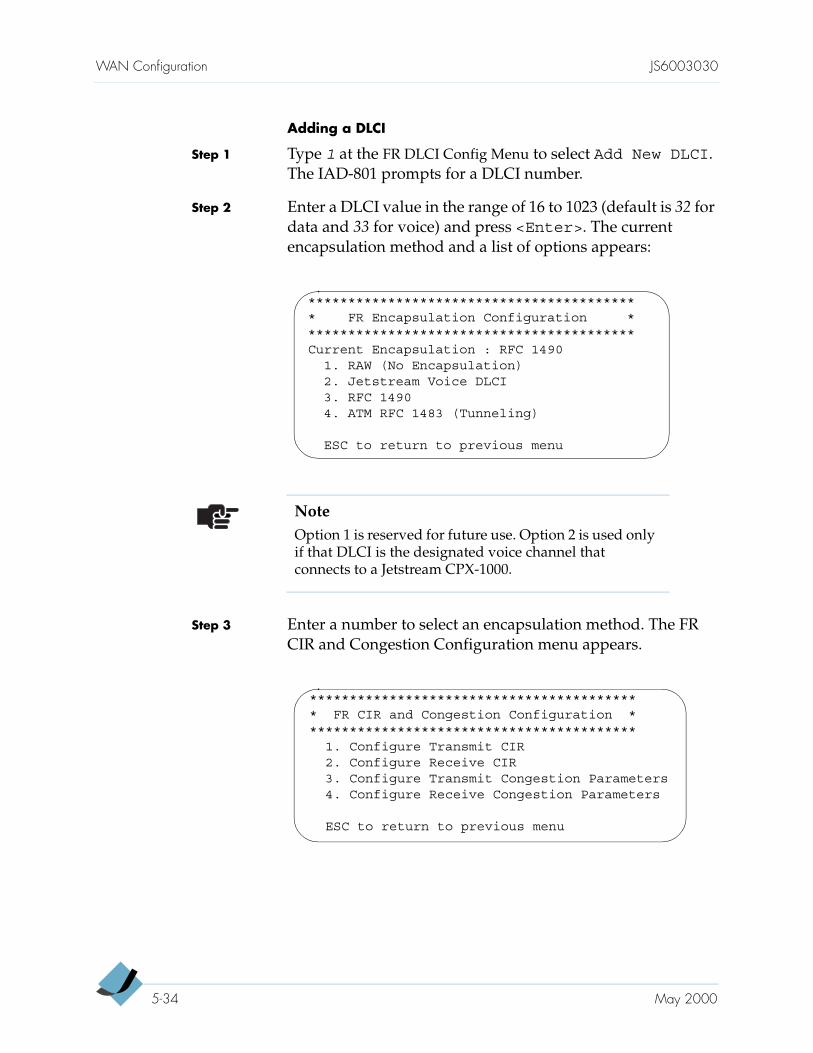
WAN Configuration JS6003030
Adding a DLCI
Step 1 Type 1 at the FR DLCI Config Menu to select Add New DLCI. The IAD-801 prompts for a DLCI number.
Step 2 Enter a DLCI value in the range of 16 to 1023 (default is 32 for data and 33 for voice) and press <Enter>. The current encapsulation method and a list of options appears:
Step 3 Enter a number to select an encapsulation method. The FR CIR and Congestion Configuration menu appears.
****************************************** FR Encapsulation Configuration ******************************************Current Encapsulation : RFC 1490
1. RAW (No Encapsulation)2. Jetstream Voice DLCI3. RFC 14904. ATM RFC 1483 (Tunneling)
ESC to return to previous menu
NoteOption 1 is reserved for future use. Option 2 is used only if that DLCI is the designated voice channel that connects to a Jetstream CPX-1000.
****************************************** FR CIR and Congestion Configuration ******************************************
1. Configure Transmit CIR2. Configure Receive CIR3. Configure Transmit Congestion Parameters4. Configure Receive Congestion Parameters
ESC to return to previous menu
5-34 May 2000
JS6003030 WAN Configuration
Step 4 Type 1 to select Configure Transmit CIR. You are prompted to enter the following information:
committed burst size (Bc)
circuit throughput
excess burst size (Be)
Step 5 Type 2 to select Configure Receive CIR. You are prompted to enter the following information:
committed burst size (Bc)
circuit throughput
excess burst size (Be)
Step 6 Type 3 to select Configure Transmit CongestionParameters. You are prompted to enter the following information:
FECN/BECN condition set size
FECN/BECN condition clear size
FECN/BECN max number of bytes to store
Step 7 Type 4 to select Configure Receive CongestionParameters. You are prompted to enter the following information:
FECN/BECN condition set size
FECN/BECN condition clear size
FECN/BECN max number of bytes to store
Step 8 Press <Esc> to return to the FR DLCI Config Menu to continue with the Frame Relay configuration. Press <Esc> to return to the WAN Configuration Menu or press <Esc> again to return to the Main Menu.
Step 9 Press Reset when you finish the IAD-801 configuration.
Need Assistance?Call Jetstream Technical Assistance Center (JTAC) at 1-888-435-7538.
May 2000 5-35
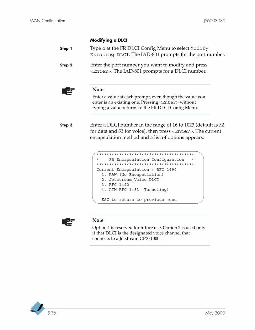
WAN Configuration JS6003030
Modifying a DLCI
Step 1 Type 2 at the FR DLCI Config Menu to select ModifyExisting DLCI. The IAD-801 prompts for the port number.
Step 2 Enter the port number you want to modify and press <Enter>. The IAD-801 prompts for a DLCI number.
Step 3 Enter a DLCI number in the range of 16 to 1023 (default is 32 for data and 33 for voice), then press <Enter>. The current encapsulation method and a list of options appears:
NoteEnter a value at each prompt, even though the value you enter is an existing one. Pressing <Enter> without typing a value returns to the FR DLCI Config Menu.
**************************************** FR Encapsulation Configuration ****************************************Current Encapsulation : RFC 1490
1. RAW (No Encapsulation)2. Jetstream Voice DLCI3. RFC 14904. ATM RFC 1483 (Tunneling)
ESC to return to previous menu
NoteOption 1 is reserved for future use. Option 2 is used only if that DLCI is the designated voice channel that connects to a Jetstream CPX-1000.
5-36 May 2000
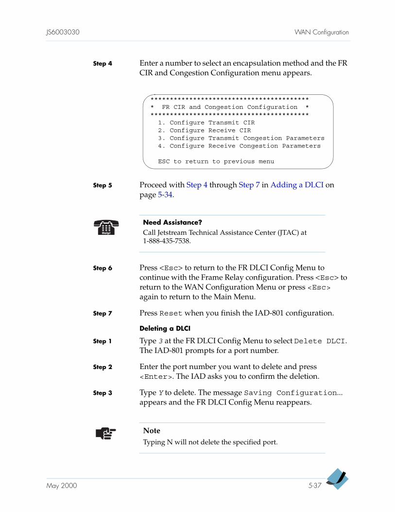
JS6003030 WAN Configuration
Step 4 Enter a number to select an encapsulation method and the FR CIR and Congestion Configuration menu appears.
Step 5 Proceed with Step 4 through Step 7 in Adding a DLCI on page 5-34.
Step 6 Press <Esc> to return to the FR DLCI Config Menu to continue with the Frame Relay configuration. Press <Esc> to return to the WAN Configuration Menu or press <Esc> again to return to the Main Menu.
Step 7 Press Reset when you finish the IAD-801 configuration.
Deleting a DLCI
Step 1 Type 3 at the FR DLCI Config Menu to select Delete DLCI. The IAD-801 prompts for a port number.
Step 2 Enter the port number you want to delete and press <Enter>. The IAD asks you to confirm the deletion.
Step 3 Type Y to delete. The message Saving Configuration... appears and the FR DLCI Config Menu reappears.
****************************************** FR CIR and Congestion Configuration ******************************************
1. Configure Transmit CIR2. Configure Receive CIR3. Configure Transmit Congestion Parameters4. Configure Receive Congestion Parameters
ESC to return to previous menu
Need Assistance?Call Jetstream Technical Assistance Center (JTAC) at 1-888-435-7538.
NoteTyping N will not delete the specified port.
May 2000 5-37
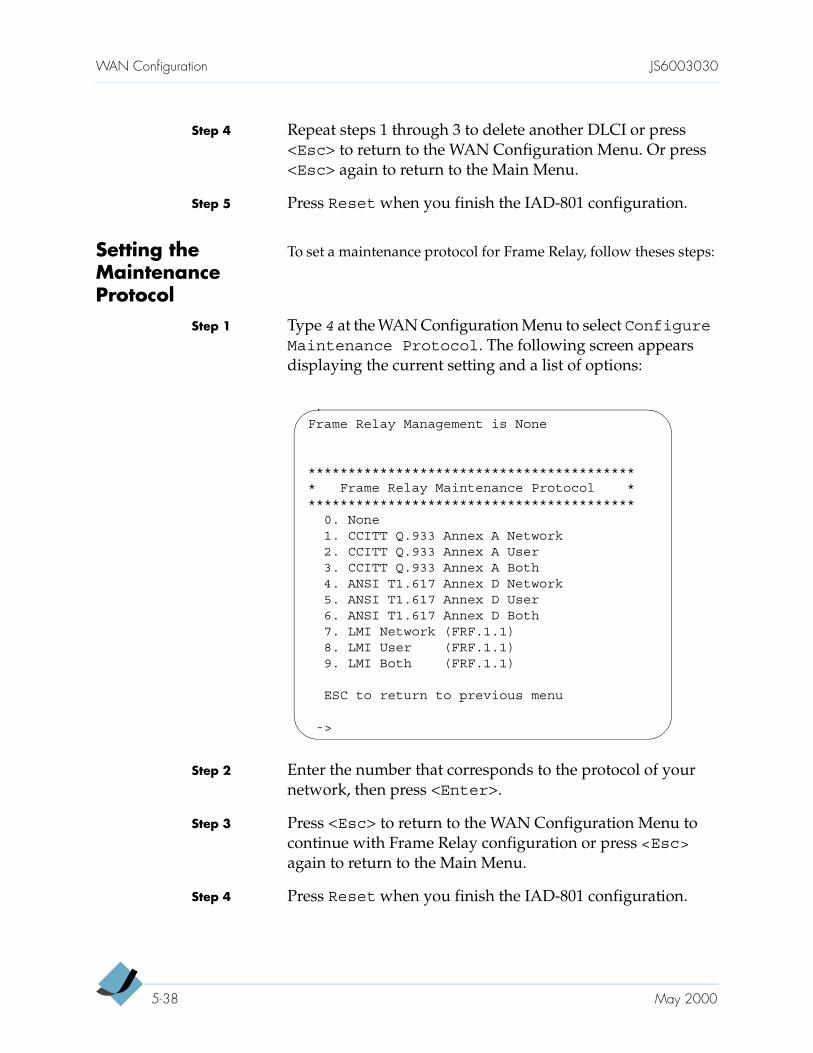
WAN Configuration JS6003030
Step 4 Repeat steps 1 through 3 to delete another DLCI or press <Esc> to return to the WAN Configuration Menu. Or press <Esc> again to return to the Main Menu.
Step 5 Press Reset when you finish the IAD-801 configuration.
Setting the Maintenance Protocol
To set a maintenance protocol for Frame Relay, follow theses steps:
Step 1 Type 4 at the WAN Configuration Menu to select ConfigureMaintenance Protocol. The following screen appears displaying the current setting and a list of options:
Step 2 Enter the number that corresponds to the protocol of your network, then press <Enter>.
Step 3 Press <Esc> to return to the WAN Configuration Menu to continue with Frame Relay configuration or press <Esc> again to return to the Main Menu.
Step 4 Press Reset when you finish the IAD-801 configuration.
Frame Relay Management is None
****************************************** Frame Relay Maintenance Protocol ******************************************
0. None1. CCITT Q.933 Annex A Network2. CCITT Q.933 Annex A User3. CCITT Q.933 Annex A Both4. ANSI T1.617 Annex D Network5. ANSI T1.617 Annex D User6. ANSI T1.617 Annex D Both7. LMI Network (FRF.1.1)8. LMI User (FRF.1.1)9. LMI Both (FRF.1.1)
ESC to return to previous menu
->
5-38 May 2000
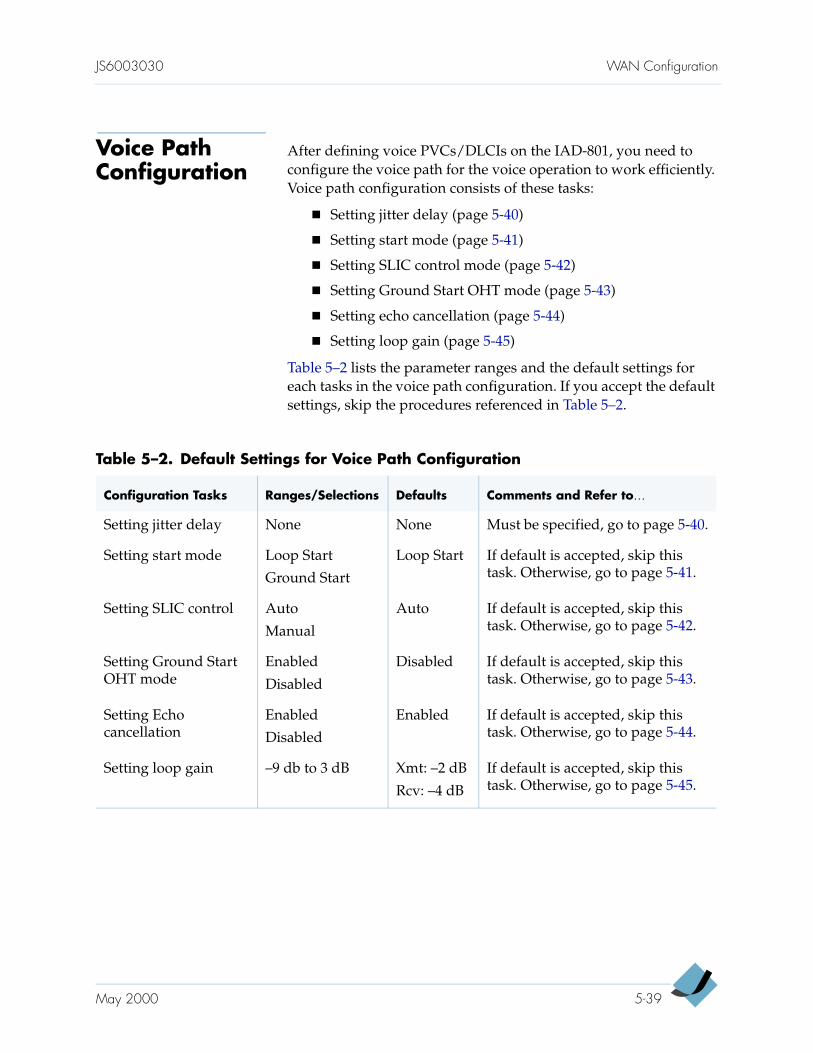
JS6003030 WAN Configuration
Voice Path Configuration
After defining voice PVCs/DLCIs on the IAD-801, you need to configure the voice path for the voice operation to work efficiently. Voice path configuration consists of these tasks:
Setting jitter delay (page 5-40)
Setting start mode (page 5-41)
Setting SLIC control mode (page 5-42)
Setting Ground Start OHT mode (page 5-43)
Setting echo cancellation (page 5-44)
Setting loop gain (page 5-45)
Table 5–2 lists the parameter ranges and the default settings for each tasks in the voice path configuration. If you accept the default settings, skip the procedures referenced in Table 5–2.
Table 5–2. Default Settings for Voice Path Configuration
Configuration Tasks Ranges/Selections Defaults Comments and Refer to…
Setting jitter delay None None Must be specified, go to page 5-40.
Setting start mode Loop Start
Ground Start
Loop Start If default is accepted, skip this task. Otherwise, go to page 5-41.
Setting SLIC control Auto
Manual
Auto If default is accepted, skip this task. Otherwise, go to page 5-42.
Setting Ground Start OHT mode
Enabled
Disabled
Disabled If default is accepted, skip this task. Otherwise, go to page 5-43.
Setting Echo cancellation
Enabled
Disabled
Enabled If default is accepted, skip this task. Otherwise, go to page 5-44.
Setting loop gain –9 db to 3 dB Xmt: –2 dB
Rcv: –4 dB
If default is accepted, skip this task. Otherwise, go to page 5-45.
May 2000 5-39
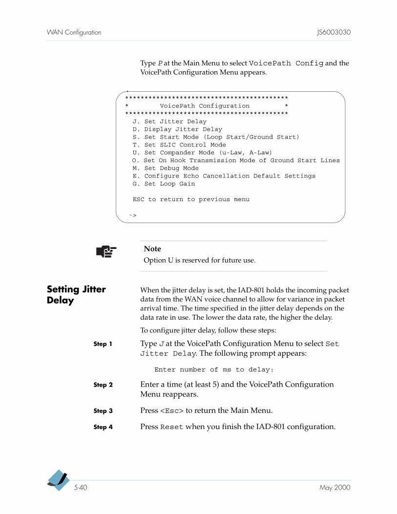
WAN Configuration JS6003030
Type P at the Main Menu to select VoicePath Config and the VoicePath Configuration Menu appears.
Setting Jitter Delay
When the jitter delay is set, the IAD-801 holds the incoming packet data from the WAN voice channel to allow for variance in packet arrival time. The time specified in the jitter delay depends on the data rate in use. The lower the data rate, the higher the delay.
To configure jitter delay, follow these steps:
Step 1 Type J at the VoicePath Configuration Menu to select SetJitter Delay. The following prompt appears:
Enter number of ms to delay:
Step 2 Enter a time (at least 5) and the VoicePath Configuration Menu reappears.
Step 3 Press <Esc> to return the Main Menu.
Step 4 Press Reset when you finish the IAD-801 configuration.
NoteOption U is reserved for future use.
******************************************* VoicePath Configuration *******************************************
J. Set Jitter DelayD. Display Jitter DelayS. Set Start Mode (Loop Start/Ground Start)T. Set SLIC Control ModeU. Set Compander Mode (u-Law, A-Law)O. Set On Hook Transmission Mode of Ground Start LinesM. Set Debug ModeE. Configure Echo Cancellation Default SettingsG. Set Loop Gain
ESC to return to previous menu
->
5-40 May 2000
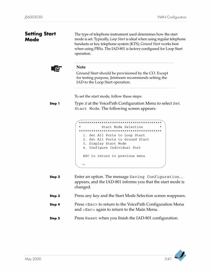
JS6003030 WAN Configuration
Setting Start Mode
The type of telephone instrument used determines how the start mode is set. Typically, Loop Start is ideal when using regular telephone handsets or key telephone system (KTS); Ground Start works best when using PBXs. The IAD-801 is factory-configured for Loop Start operation.
To set the start mode, follow these steps:
Step 1 Type S at the VoicePath Configuration Menu to select SetStart Mode. The following screen appears:
Step 2 Enter an option. The message Saving Configuration… appears, and the IAD-801 informs you that the start mode is changed.
Step 3 Press any key and the Start Mode Selection screen reappears.
Step 4 Press <Esc> to return to the VoicePath Configuration Menu and <Esc> again to return to the Main Menu.
Step 5 Press Reset when you finish the IAD-801 configuration.
NoteGround Start should be provisioned by the CO. Except for testing purpose, Jetstream recommends setting the IAD to the Loop Start operation.
***************************************** Start Mode Selection *****************************************
1. Set All Ports to Loop Start2. Set All Ports to Ground Start3. Display Start Mode4. Configure Individual Port
ESC to return to previous menu
->
May 2000 5-41
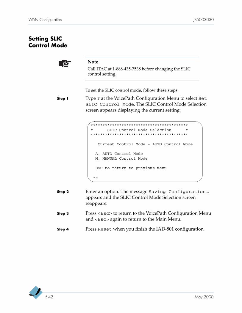
WAN Configuration JS6003030
Setting SLIC Control Mode
To set the SLIC control mode, follow these steps:
Step 1 Type T at the VoicePath Configuration Menu to select SetSLIC Control Mode. The SLIC Control Mode Selection screen appears displaying the current setting:
Step 2 Enter an option. The message Saving Configuration... appears and the SLIC Control Mode Selection screen reappears.
Step 3 Press <Esc> to return to the VoicePath Configuration Menu and <Esc> again to return to the Main Menu.
Step 4 Press Reset when you finish the IAD-801 configuration.
NoteCall JTAC at 1-888-435-7538 before changing the SLIC control setting.
****************************************** SLIC Control Mode Selection ******************************************
Current Control Mode = AUTO Control Mode
A. AUTO Control ModeM. MANUAL Control Mode
ESC to return to previous menu
->
5-42 May 2000
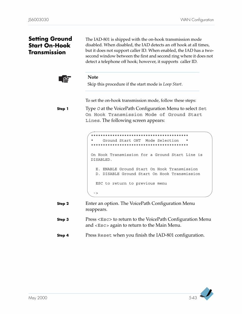
JS6003030 WAN Configuration
Setting Ground Start On-Hook Transmission
The IAD-801 is shipped with the on-hook transmission mode disabled. When disabled, the IAD detects an off hook at all times, but it does not support caller ID. When enabled, the IAD has a two-second window between the first and second ring where it does not detect a telephone off hook; however, it supports caller ID.
To set the on-hook transmission mode, follow these steps:
Step 1 Type O at the VoicePath Configuration Menu to select SetOn Hook Transmission Mode of Ground StartLines. The following screen appears:
Step 2 Enter an option. The VoicePath Configuration Menu reappears.
Step 3 Press <Esc> to return to the VoicePath Configuration Menu and <Esc> again to return to the Main Menu.
Step 4 Press Reset when you finish the IAD-801 configuration.
NoteSkip this procedure if the start mode is Loop Start.
****************************************** Ground Start OHT Mode Selection ******************************************
On Hook Transmission for a Ground Start Line isDISABLED.
E. ENABLE Ground Start On Hook TransmissionD. DISABLE Ground Start On Hook Transmission
ESC to return to previous menu
->
May 2000 5-43
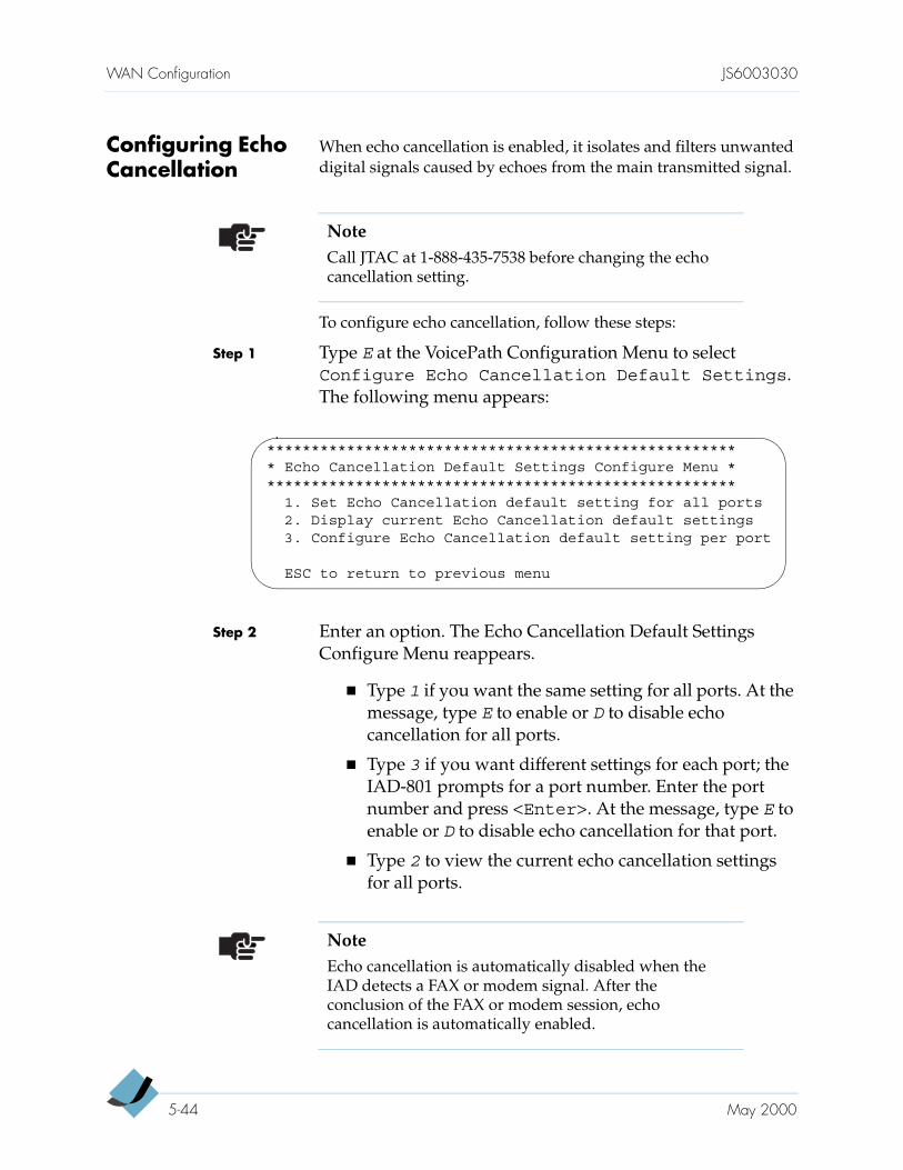
WAN Configuration JS6003030
Configuring Echo Cancellation
When echo cancellation is enabled, it isolates and filters unwanted digital signals caused by echoes from the main transmitted signal.
To configure echo cancellation, follow these steps:
Step 1 Type E at the VoicePath Configuration Menu to select Configure Echo Cancellation Default Settings. The following menu appears:
Step 2 Enter an option. The Echo Cancellation Default Settings Configure Menu reappears.
Type 1 if you want the same setting for all ports. At the message, type E to enable or D to disable echo cancellation for all ports.
Type 3 if you want different settings for each port; the IAD-801 prompts for a port number. Enter the port number and press <Enter>. At the message, type E to enable or D to disable echo cancellation for that port.
Type 2 to view the current echo cancellation settings for all ports.
NoteCall JTAC at 1-888-435-7538 before changing the echo cancellation setting.
****************************************************** Echo Cancellation Default Settings Configure Menu ******************************************************
1. Set Echo Cancellation default setting for all ports2. Display current Echo Cancellation default settings3. Configure Echo Cancellation default setting per port
ESC to return to previous menu
NoteEcho cancellation is automatically disabled when the IAD detects a FAX or modem signal. After the conclusion of the FAX or modem session, echo cancellation is automatically enabled.
5-44 May 2000
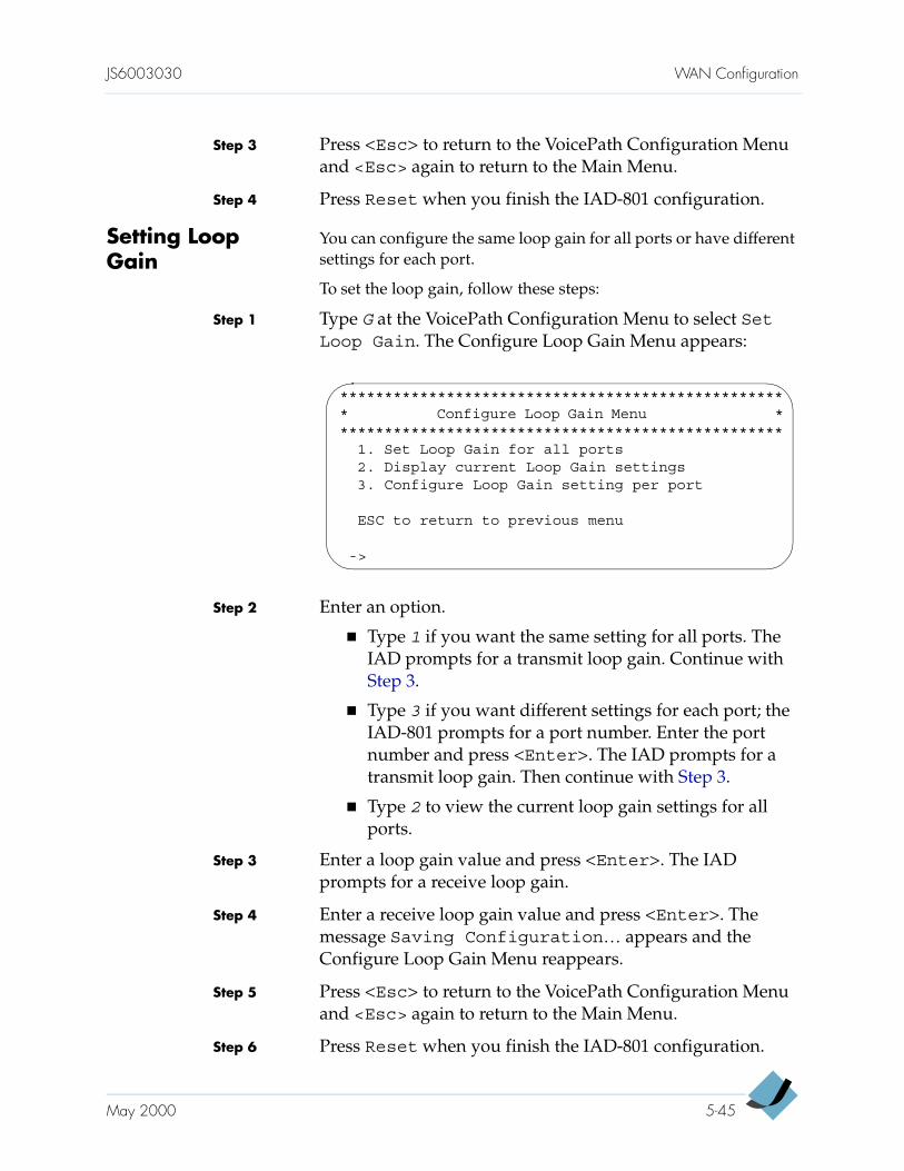
JS6003030 WAN Configuration
Step 3 Press <Esc> to return to the VoicePath Configuration Menu and <Esc> again to return to the Main Menu.
Step 4 Press Reset when you finish the IAD-801 configuration.
Setting Loop Gain
You can configure the same loop gain for all ports or have different settings for each port.
To set the loop gain, follow these steps:
Step 1 Type G at the VoicePath Configuration Menu to select SetLoop Gain. The Configure Loop Gain Menu appears:
Step 2 Enter an option.
Type 1 if you want the same setting for all ports. The IAD prompts for a transmit loop gain. Continue with Step 3.
Type 3 if you want different settings for each port; the IAD-801 prompts for a port number. Enter the port number and press <Enter>. The IAD prompts for a transmit loop gain. Then continue with Step 3.
Type 2 to view the current loop gain settings for all ports.
Step 3 Enter a loop gain value and press <Enter>. The IAD prompts for a receive loop gain.
Step 4 Enter a receive loop gain value and press <Enter>. The message Saving Configuration… appears and the Configure Loop Gain Menu reappears.
Step 5 Press <Esc> to return to the VoicePath Configuration Menu and <Esc> again to return to the Main Menu.
Step 6 Press Reset when you finish the IAD-801 configuration.
*************************************************** Configure Loop Gain Menu ***************************************************
1. Set Loop Gain for all ports2. Display current Loop Gain settings3. Configure Loop Gain setting per port
ESC to return to previous menu
->
May 2000 5-45

WAN Configuration JS6003030
5-46 May 2000
C H A P T E R 6
Data NetworkingConfiguration
This chapter provides detailed procedures for configuring the IAD-801 as a router or as a bridge. The IAD-801 is shipped from the factory configured as a bridge.
You can configure a router and a bridge on the same IAD. Configuring the IAD-801 as a bridge or as a router depends on your application. In a more complex network, a router may improve overall efficiency; on the other hand, a bridge provides better speed and flexibility for the overall network.
For router configuration, go to page 6-2
For NAT configuration, go to page 6-11
For DHCP Server configuration, go to page 6-17
For DHCP Client configuration, go to page 6-22
For DNS Client configuration, go to page 6-23
For bridge configuration, go to page 6-24
CautionResetting the IAD-801 disrupts all voice calls in progress. Configure the IAD-801 during low usage hours if possible.
NoteThe IAD-801 stores all configuration settings in flash memory. It is programmed to use the configuration that was last saved before a power-up or restart. Any time you set or change the IAD-801 configuration, reset it afterward to make those changes effective.
6-1
Data Networking Configuration JS6003030
Configuring the IAD-801 as a Router
Routers filter network data by specific protocol rather than by packet address. Routers also divide networks logically instead of physically. A router divides a network into various subnets so that only data destined for particular IP addresses can pass between segments. Generally, such filtering takes more time to forward data than that exercised in a bridge.
Configuring a router requires these tasks:
Assigning IP addresses (page 6-3)
(Preferred) Enabling RIP (page 6-9), adding s static route (page 6-5), or adding a default route (page 6-5)
Disabling bridging globally (page 6-25)
Disabling bridging by port (page 6-26)
Disabling STP globally (page 6-27)
Disabling STP by port (page 6-28)
This section also provides these topics:
Deleting an IP address (page 6-6)
Deleting a static route (page 6-8)
Deleting a default route (page 6-8)
Selecting a RIP version for a port (page 6-10)
Enabling RIP poisoned reversed on a port (page 6-11)
The Router Configuration Menu is the starting point for configuring the IAD-801 as a router. Type 2 at the Main Menu. The Router Configuration Menu appears, listing the following options:
NoteThe IAD-801 is preconfigured at the factory with bridging enabled and Spanning Tree Protocol (STP) disabled. Bridging must be disabled (both globally and by port) before routing can be configured.
6-2 May 2000
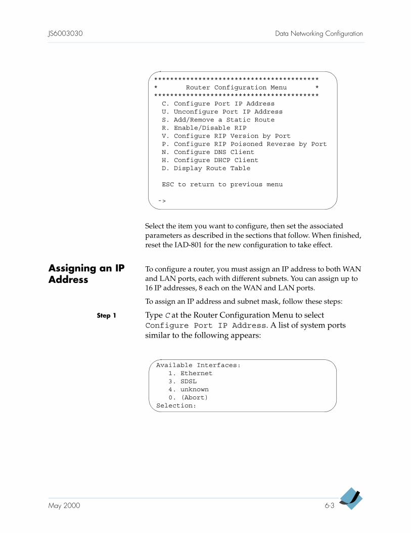
JS6003030 Data Networking Configuration
Select the item you want to configure, then set the associated parameters as described in the sections that follow. When finished, reset the IAD-801 for the new configuration to take effect.
Assigning an IP Address
To configure a router, you must assign an IP address to both WAN and LAN ports, each with different subnets. You can assign up to 16 IP addresses, 8 each on the WAN and LAN ports.
To assign an IP address and subnet mask, follow these steps:
Step 1 Type C at the Router Configuration Menu to select Configure Port IP Address. A list of system ports similar to the following appears:
****************************************** Router Configuration Menu ******************************************
C. Configure Port IP AddressU. Unconfigure Port IP AddressS. Add/Remove a Static RouteR. Enable/Disable RIPV. Configure RIP Version by PortP. Configure RIP Poisoned Reverse by PortN. Configure DNS ClientH. Configure DHCP ClientD. Display Route Table
ESC to return to previous menu
->
Available Interfaces:1. Ethernet3. SDSL4. unknown0. (Abort)
Selection:
May 2000 6-3
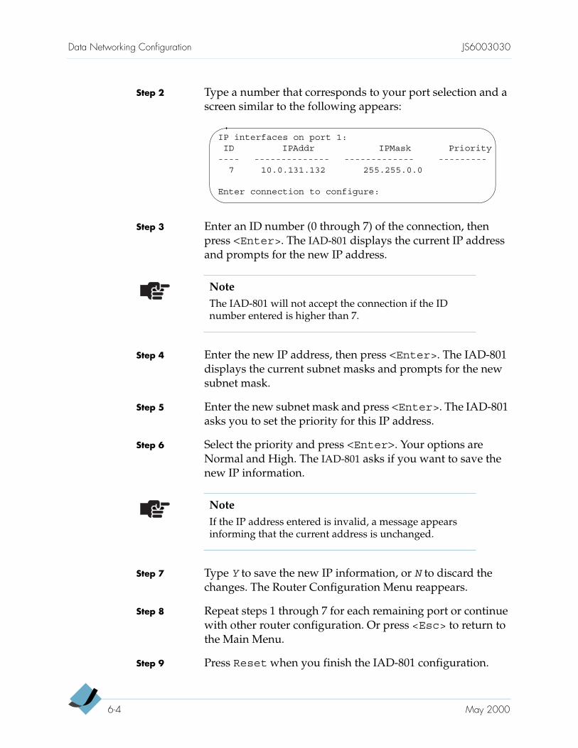
Data Networking Configuration JS6003030
Step 2 Type a number that corresponds to your port selection and a screen similar to the following appears:
Step 3 Enter an ID number (0 through 7) of the connection, then press <Enter>. The IAD-801 displays the current IP address and prompts for the new IP address.
Step 4 Enter the new IP address, then press <Enter>. The IAD-801 displays the current subnet masks and prompts for the new subnet mask.
Step 5 Enter the new subnet mask and press <Enter>. The IAD-801 asks you to set the priority for this IP address.
Step 6 Select the priority and press <Enter>. Your options are Normal and High. The IAD-801 asks if you want to save the new IP information.
Step 7 Type Y to save the new IP information, or N to discard the changes. The Router Configuration Menu reappears.
Step 8 Repeat steps 1 through 7 for each remaining port or continue with other router configuration. Or press <Esc> to return to the Main Menu.
Step 9 Press Reset when you finish the IAD-801 configuration.
IP interfaces on port 1:ID IPAddr IPMask Priority---- -------------- ------------- ---------7 10.0.131.132 255.255.0.0
Enter connection to configure:
NoteThe IAD-801 will not accept the connection if the ID number entered is higher than 7.
NoteIf the IP address entered is invalid, a message appears informing that the current address is unchanged.
6-4 May 2000
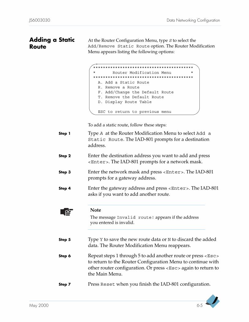
JS6003030 Data Networking Configuration
Adding a Static Route
At the Router Configuration Menu, type S to select the Add/Remove Static Route option. The Router Modification Menu appears listing the following options:
To add a static route, follow these steps:
Step 1 Type A at the Router Modification Menu to select Add aStatic Route. The IAD-801 prompts for a destination address.
Step 2 Enter the destination address you want to add and press <Enter>. The IAD-801 prompts for a network mask.
Step 3 Enter the network mask and press <Enter>. The IAD-801 prompts for a gateway address.
Step 4 Enter the gateway address and press <Enter>. The IAD-801 asks if you want to add another route.
Step 5 Type Y to save the new route data or N to discard the added data. The Router Modification Menu reappears.
Step 6 Repeat steps 1 through 5 to add another route or press <Esc> to return to the Router Configuration Menu to continue with other router configuration. Or press <Esc> again to return to the Main Menu.
Step 7 Press Reset when you finish the IAD-801 configuration.
****************************************** Router Modification Menu ******************************************
A. Add a Static RouteR. Remove a RouteF. Add/Change the Default RouteT. Remove the Default RouteD. Display Route Table
ESC to return to previous menu
NoteThe message Invalid route! appears if the address you entered is invalid.
May 2000 6-5
Data Networking Configuration JS6003030
Adding or Changing the Default Route
To add or change a default static route, follow these steps:
Step 1 Type F at the Router Modification Menu to add a default route or to change the default setting. The IAD-801 prompts for an IP address.
Step 2 Type the default IP address for the static route and press <Enter>. This prompt appears:
Step 3 Type Y to save this address as the new default route. The Router Modification Menu reappears.
Step 4 Press <Esc> to return to the Router Configuration Menu to continue with other router configuration or press <Esc> again to return to the Main Menu.
Step 5 Press Reset when you finish the IAD-801 configuration.
Deleting an IP Address
To delete an IP address, follow these steps:
Step 1 Type U at the Router Configuration Menu to select Unconfigure Port IP Address. A list of system ports similar to the following appears:
Save this as the default route in thestatic configuration (Y)?
NoteThe message Invalid route! appears if the address you entered is invalid.
NoteDo not delete the last IP address; otherwise, you will be unable to log on to the IAD. Refer to Chapter 7, Verification and Troubleshooting, for a procedure to restore the default IP address.
6-6 May 2000
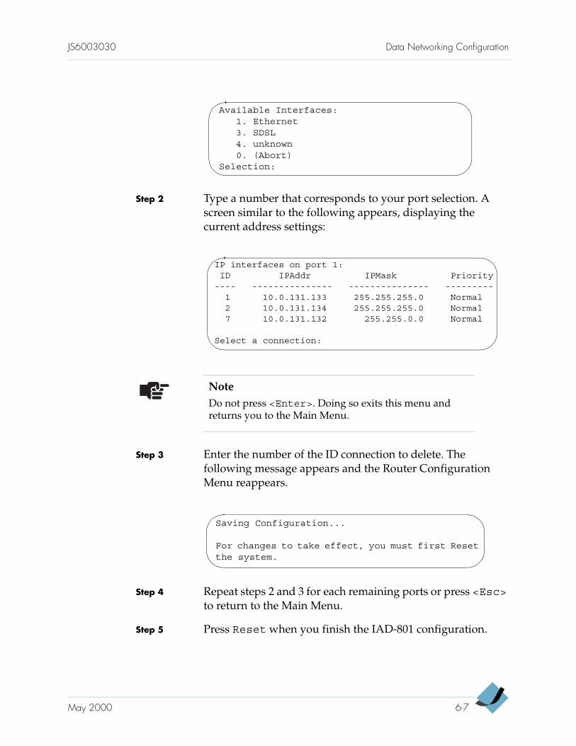
JS6003030 Data Networking Configuration
Step 2 Type a number that corresponds to your port selection. A screen similar to the following appears, displaying the current address settings:
Step 3 Enter the number of the ID connection to delete. The following message appears and the Router Configuration Menu reappears.
Step 4 Repeat steps 2 and 3 for each remaining ports or press <Esc> to return to the Main Menu.
Step 5 Press Reset when you finish the IAD-801 configuration.
Available Interfaces:1. Ethernet3. SDSL4. unknown0. (Abort)
Selection:
IP interfaces on port 1:ID IPAddr IPMask Priority---- --------------- --------------- ---------1 10.0.131.133 255.255.255.0 Normal2 10.0.131.134 255.255.255.0 Normal7 10.0.131.132 255.255.0.0 Normal
Select a connection:
NoteDo not press <Enter>. Doing so exits this menu and returns you to the Main Menu.
Saving Configuration...
For changes to take effect, you must first Resetthe system.
May 2000 6-7
Data Networking Configuration JS6003030
Deleting a Static Route
To delete a static route, follow these steps:
Step 1 Type R at the Router Modification Menu to select Remove aRoute. The IAD-801 prompts for an IP address.
Step 2 Type the IP address of the route you want to delete, then press <Enter>. The route is deleted and the Router Modification Menu reappears.
Step 3 Repeat steps 1 and 2 to remove another route or press <Esc> to return to the Router Configuration Menu to continue with other router configuration. Or press <Esc> again to return to the Main Menu.
Step 4 Press Reset when you finish the IAD-801 configuration.
Deleting the Default Route
To delete a default static route, follow these steps:
Step 1 Type T at the Router Modification Menu to remove the default route. The IAD-801 prompts for an IP address.
Step 2 Type the IP address of the route you want to delete, then press <Enter>. The route is deleted and the Router Modification Menu reappears.
Step 3 Press <Esc> to return to the Router Configuration Menu to continue with other router configuration, or press <Esc> again to return to the Main Menu.
Step 4 Press Reset when you finish the IAD-801 configuration.
NoteIf the address you entered is invalid, this message appears: Static Route not found!
NoteIf no default route is defined, this message appears: Default Route not defined.
6-8 May 2000
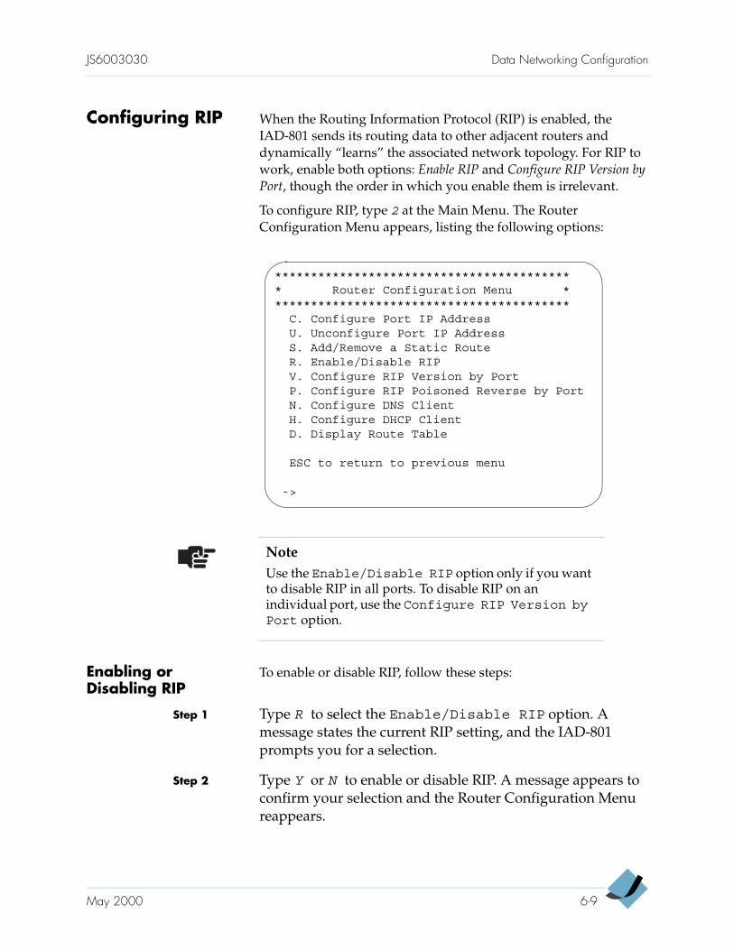
JS6003030 Data Networking Configuration
Configuring RIP When the Routing Information Protocol (RIP) is enabled, the IAD-801 sends its routing data to other adjacent routers and dynamically “learns” the associated network topology. For RIP to work, enable both options: Enable RIP and Configure RIP Version by Port, though the order in which you enable them is irrelevant.
To configure RIP, type 2 at the Main Menu. The Router Configuration Menu appears, listing the following options:
Enabling or Disabling RIP
To enable or disable RIP, follow these steps:
Step 1 Type R to select the Enable/Disable RIP option. A message states the current RIP setting, and the IAD-801 prompts you for a selection.
Step 2 Type Y or N to enable or disable RIP. A message appears to confirm your selection and the Router Configuration Menu reappears.
****************************************** Router Configuration Menu ******************************************
C. Configure Port IP AddressU. Unconfigure Port IP AddressS. Add/Remove a Static RouteR. Enable/Disable RIPV. Configure RIP Version by PortP. Configure RIP Poisoned Reverse by PortN. Configure DNS ClientH. Configure DHCP ClientD. Display Route Table
ESC to return to previous menu
->
NoteUse the Enable/Disable RIP option only if you want to disable RIP in all ports. To disable RIP on an individual port, use the Configure RIP Version byPort option.
May 2000 6-9
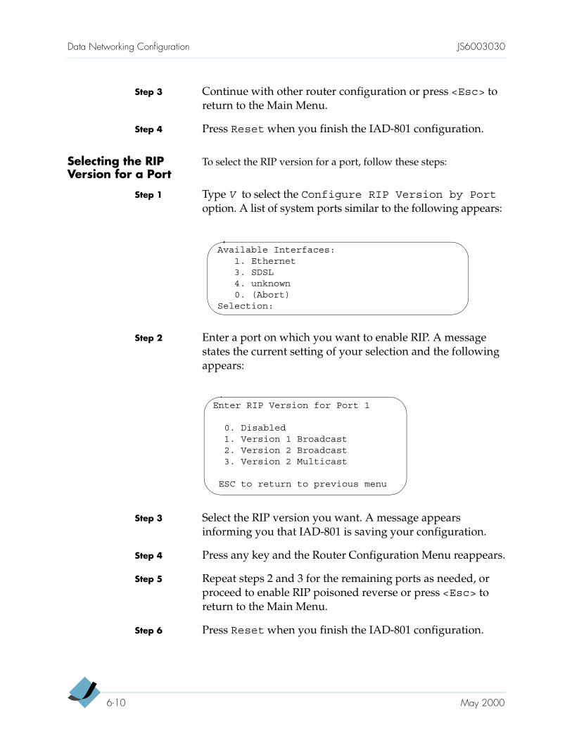
Data Networking Configuration JS6003030
Step 3 Continue with other router configuration or press <Esc> to return to the Main Menu.
Step 4 Press Reset when you finish the IAD-801 configuration.
Selecting the RIP Version for a Port
To select the RIP version for a port, follow these steps:
Step 1 Type V to select the Configure RIP Version by Port option. A list of system ports similar to the following appears:
Step 2 Enter a port on which you want to enable RIP. A message states the current setting of your selection and the following appears:
Step 3 Select the RIP version you want. A message appears informing you that IAD-801 is saving your configuration.
Step 4 Press any key and the Router Configuration Menu reappears.
Step 5 Repeat steps 2 and 3 for the remaining ports as needed, or proceed to enable RIP poisoned reverse or press <Esc> to return to the Main Menu.
Step 6 Press Reset when you finish the IAD-801 configuration.
Available Interfaces:1. Ethernet3. SDSL4. unknown0. (Abort)
Selection:
Enter RIP Version for Port 1
0. Disabled1. Version 1 Broadcast2. Version 2 Broadcast3. Version 2 Multicast
ESC to return to previous menu
6-10 May 2000
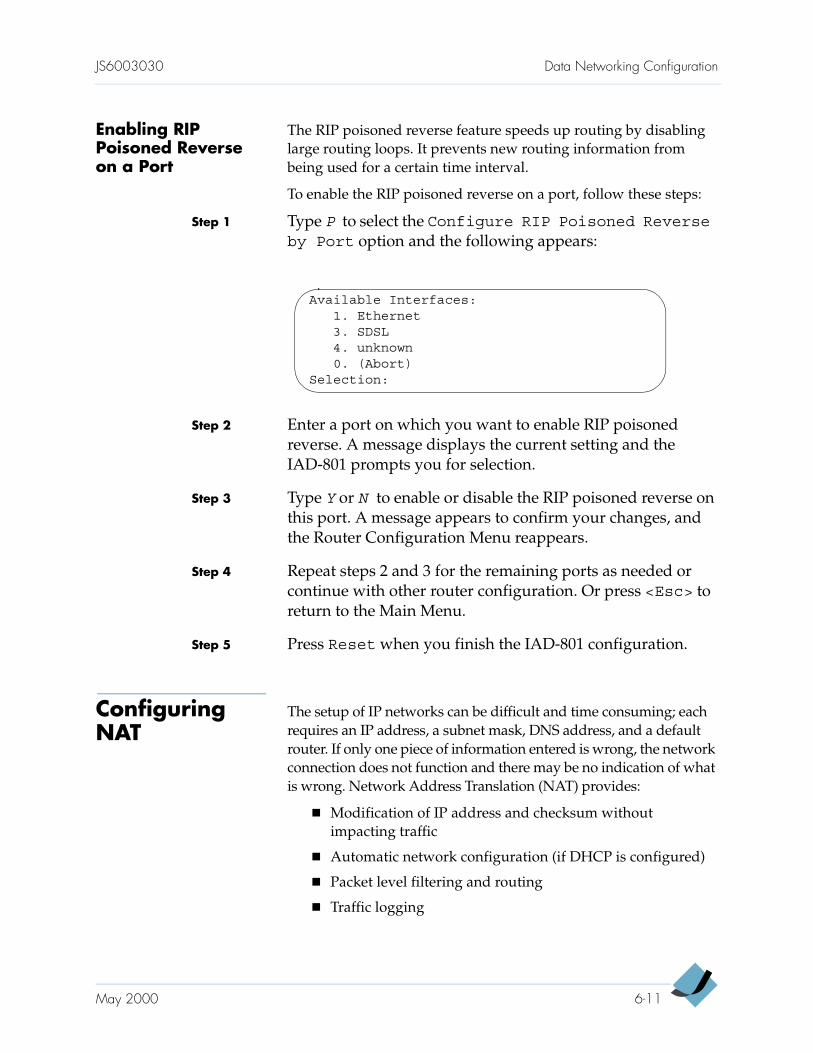
JS6003030 Data Networking Configuration
Enabling RIP Poisoned Reverse on a Port
The RIP poisoned reverse feature speeds up routing by disabling large routing loops. It prevents new routing information from being used for a certain time interval.
To enable the RIP poisoned reverse on a port, follow these steps:
Step 1 Type P to select the Configure RIP Poisoned Reverseby Port option and the following appears:
Step 2 Enter a port on which you want to enable RIP poisoned reverse. A message displays the current setting and the IAD-801 prompts you for selection.
Step 3 Type Y or N to enable or disable the RIP poisoned reverse on this port. A message appears to confirm your changes, and the Router Configuration Menu reappears.
Step 4 Repeat steps 2 and 3 for the remaining ports as needed or continue with other router configuration. Or press <Esc> to return to the Main Menu.
Step 5 Press Reset when you finish the IAD-801 configuration.
Configuring NAT
The setup of IP networks can be difficult and time consuming; each requires an IP address, a subnet mask, DNS address, and a default router. If only one piece of information entered is wrong, the network connection does not function and there may be no indication of what is wrong. Network Address Translation (NAT) provides:
Modification of IP address and checksum without impacting traffic
Automatic network configuration (if DHCP is configured)
Packet level filtering and routing
Traffic logging
Available Interfaces:1. Ethernet3. SDSL4. unknown0. (Abort)
Selection:
May 2000 6-11
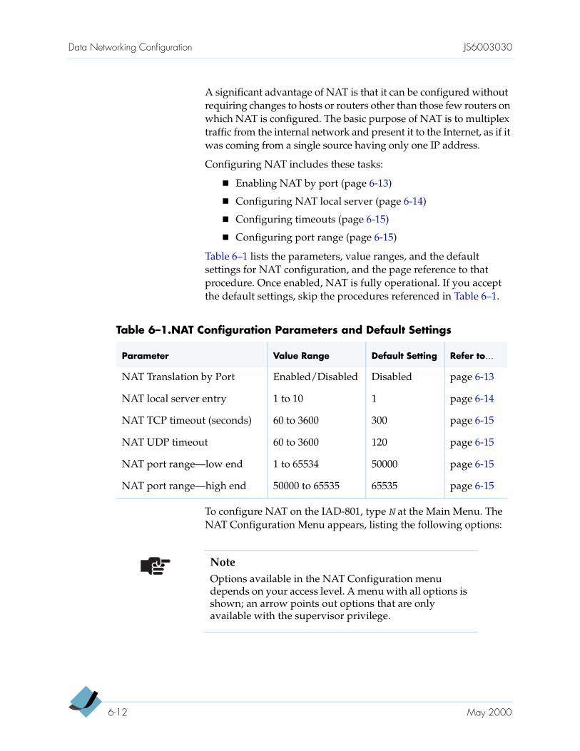
Data Networking Configuration JS6003030
A significant advantage of NAT is that it can be configured without requiring changes to hosts or routers other than those few routers on which NAT is configured. The basic purpose of NAT is to multiplex traffic from the internal network and present it to the Internet, as if it was coming from a single source having only one IP address.
Configuring NAT includes these tasks:
Enabling NAT by port (page 6-13)
Configuring NAT local server (page 6-14)
Configuring timeouts (page 6-15)
Configuring port range (page 6-15)
Table 6–1 lists the parameters, value ranges, and the default settings for NAT configuration, and the page reference to that procedure. Once enabled, NAT is fully operational. If you accept the default settings, skip the procedures referenced in Table 6–1.
To configure NAT on the IAD-801, type N at the Main Menu. The NAT Configuration Menu appears, listing the following options:
Table 6–1.NAT Configuration Parameters and Default Settings
Parameter Value Range Default Setting Refer to…
NAT Translation by Port Enabled/Disabled Disabled page 6-13
NAT local server entry 1 to 10 1 page 6-14
NAT TCP timeout (seconds) 60 to 3600 300 page 6-15
NAT UDP timeout 60 to 3600 120 page 6-15
NAT port range—low end 1 to 65534 50000 page 6-15
NAT port range—high end 50000 to 65535 65535 page 6-15
NoteOptions available in the NAT Configuration menu depends on your access level. A menu with all options is shown; an arrow points out options that are only available with the supervisor privilege.
6-12 May 2000
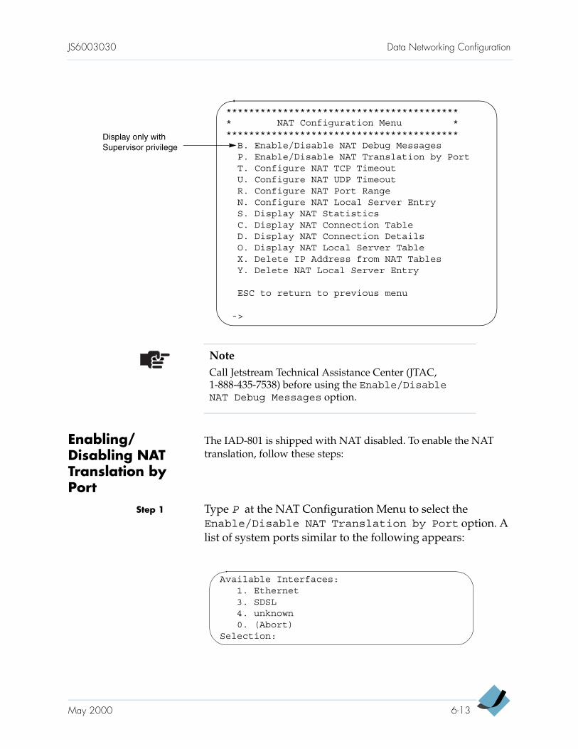
JS6003030 Data Networking Configuration
Enabling/Disabling NAT Translation by Port
The IAD-801 is shipped with NAT disabled. To enable the NAT translation, follow these steps:
Step 1 Type P at the NAT Configuration Menu to select the Enable/Disable NAT Translation by Port option. A list of system ports similar to the following appears:
NoteCall Jetstream Technical Assistance Center (JTAC, 1-888-435-7538) before using the Enable/DisableNAT Debug Messages option.
****************************************** NAT Configuration Menu ******************************************
B. Enable/Disable NAT Debug MessagesP. Enable/Disable NAT Translation by PortT. Configure NAT TCP TimeoutU. Configure NAT UDP TimeoutR. Configure NAT Port RangeN. Configure NAT Local Server EntryS. Display NAT StatisticsC. Display NAT Connection TableD. Display NAT Connection DetailsO. Display NAT Local Server TableX. Delete IP Address from NAT TablesY. Delete NAT Local Server Entry
ESC to return to previous menu
->
Display only with Supervisor privilege
Available Interfaces:1. Ethernet3. SDSL4. unknown0. (Abort)
Selection:
May 2000 6-13
Data Networking Configuration JS6003030
Step 2 Enter a port on which you want to enable NAT. A message states the current NAT setting and the IAD-801 asks if you want to change it.
Step 3 Type Y. A message appears to confirm the new setting and the NAT Configuration Menu reappears.
Step 4 Continue with other NAT configuration or press <Esc> to return to the Main Menu.
Step 5 Press Reset when you finish the IAD-801 configuration.
Configuring NAT Local Server
When a NAT local server is configured, your local server IP address is visible to the Internet.
To configure a NAT local server, follow these steps:
Step 1 Type N at the NAT Configuration Menu to select the Configure NAT Local Server Entry option. The IAD-801 prompts for a local server identification.
Step 2 Enter a number between 1 to 10 (default is 1) and press <Enter>. A message displays the current local server translated IP address, and the IAD-801 prompts for a new local server translated IP address.
Step 3 Enter the new local server translated IP address and press <Enter>. The IAD-801 prompts for a local server translated port number.
Step 4 Enter a number in the range of 1 to 65535 (default is 0) and press <Enter>. The IAD-801 prompts for a local server standard port number.
Step 5 Enter a number in the range of 1 to 65535 (default is 0) and press <Enter>. The IAD-801 prompts for a local server protocol.
Step 6 Enter 1 for TCP or 2 for UDP and press <Enter>. The IAD-801 displays the new configuration and the message Saving Configuration… appears.
Step 7 Press any key and the NAT Configuration Menu reappears.
Step 8 Continue with other NAT configuration or press <Esc> to return to the Main Menu.
6-14 May 2000
JS6003030 Data Networking Configuration
Step 9 Press Reset when you finish the IAD-801 configuration.
Configuring Timeouts
Under “normal” circumstances, this timeout default setting is adequate; however, if you are interacting with multiple-player IP games or video conferencing, you will need to configure the timeout setting.
The local server protocol you selected determines which timeout to configure. Both Transmission Control Protocol (TCP) and User Datagram Protocol (UDP) timeouts are similar but with this exception: while TCP tracks on a per-connection basis, UDP does not. The TCP timeout tracks TCP clients on a per-connection basis and removes them from the table as soon as the connection is closed.
To configure the timeouts, follow these steps:
Step 1 At the NAT Configuration Menu, type a letter that corresponds to your timeout selection: T for TCP connections and U for UDP connections.
Step 2 At the prompt, enter the time in seconds.
For TCP connections: enter between 60 to 3600 seconds (default is 300), then press <Enter>.
For UDP connections: enter between 60 to 3600 seconds (default is 120), then press <Enter>.
Step 3 Press any key and the NAT Configuration Menu reappears.
Step 4 Continue with other NAT configuration or press <Esc> to return to the Main Menu.
Step 5 Press Reset when you finish the IAD-801 configuration.
Configuring NAT Port Range
Under “normal” circumstances, this port range default setting is adequate; however, if you are interacting with multiple-player IP games or video conferencing, you will need to configure the port range setting.
To multiplex several connections to a single destination, all packets are label with unique “port numbers.” Each IP packet starts with a header containing the source and destination addresses and port numbers. The addresses specify the two routers at each end, and the two port numbers ensure that each connection between this pair of routers can be uniquely identified.
May 2000 6-15
Data Networking Configuration JS6003030
When a TCP or UDP connection is sent from a local port to an Internet port, the sender’s IP address is changed to the IP address of the Internet port, and the connection’s TCP or UDP port number is changed to a unique value within the NAT port range.
To configure the port range, follow these steps:
Step 1 Type R at the NAT Configuration Menu to select the Configure NAT Port Range option. The IAD-801 prompts for the low end of the NAT port range.
Step 2 Enter a number between 1 to 65534 (default is 50000) and press <Enter>. The IAD-801 prompts for the high end of NAT port range.
Step 3 Enter a number between 50000 to 65535 (default is 65535) and press <Enter>. A message Saving Configuration… appears, and the NAT Configuration Menu reappears.
Step 4 Continue with other NAT configuration or press <Esc> to return to the Main Menu.
Step 5 Press Reset when you finish the IAD-801 configuration.
Deleting NAT Local Server Entry
To delete a NAT local server entry, follow these steps:
Step 1 Type Y at the NAT Configuration Menu to select the Deleting NAT Local Server Entry option. The IAD-801 prompts for the local server number you want to delete.
Step 2 Enter the local server ID number and press <Enter>. The IAD-801 deletes the configuration of that server.
NoteEnsure that the configured port range does not include any ports that use applications, such as HTTP, TFTP, and so forth.
6-16 May 2000
JS6003030 Data Networking Configuration
Step 3 Press any key and the NAT Configuration Menu reappears.
Step 4 Continue with other NAT configuration or press <Esc> to return to the Main Menu.
Step 5 Press Reset when you finish the IAD-801 configuration.
Configuring DHCP Server
Dynamic Host Configuration Protocol (DHCP) allows for dynamic allocation of network addresses and configurations to newly attached hosts. The purpose of DHCP is to reduce the work necessary to administer a large IP network. The most significant piece of information distributed in this manner is the IP address.
Configuring DHCP includes these tasks:
Enabling DHCP (page 6-18)
Configuring DHCP server parameters (page 6-19)
Configuring DHCP address range pool (page 6-20)
Configuring DHCP client entry (page 6-20)
To configure DHCP on the IAD-801, type D at the Main Menu. The DHCP Configuration Menu appears, listing the following options:
NoteThe IAD-801 provides no prompts for confirmation. Once you press <Enter>, the server is deleted. If an unintentional deletion occurs, refer to page 6-14 to configure a local server.
NoteOptions available in the DHCP Configuration Menu depend on your access level. A menu with all options is shown; arrows are used to point out options that are available with the Supervisor privilege.
May 2000 6-17
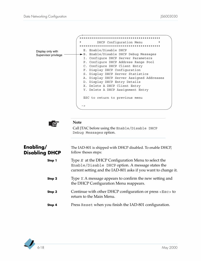
Data Networking Configuration JS6003030
Enabling/Disabling DHCP
The IAD-801 is shipped with DHCP disabled. To enable DHCP, follow theses steps:
Step 1 Type E at the DHCP Configuration Menu to select the Enable/Disable DHCP option. A message states the current setting and the IAD-801 asks if you want to change it.
Step 2 Type Y. A message appears to confirm the new setting and the DHCP Configuration Menu reappears.
Step 3 Continue with other DHCP configuration or press <Esc> to return to the Main Menu.
Step 4 Press Reset when you finish the IAD-801 configuration.
NoteCall JTAC before using the Enable/Disable DHCPDebug Messages option.
****************************************** DHCP Configuration Menu ******************************************
E. Enable/Disable DHCPB. Enable/Disable DHCP Debug MessagesI. Configure DHCP Server ParametersP. Configure DHCP Address Range PoolC. Configure DHCP Client EntryF. Display DHCP ConfigurationS. Display DHCP Server StatisticsA. Display DHCP Server Assigned AddressesD. Display DHCP Entry DetailsX. Delete A DHCP Client EntryY. Delete A DHCP Assignment Entry
ESC to return to previous menu
->
Display only with Supervisor privilege
6-18 May 2000
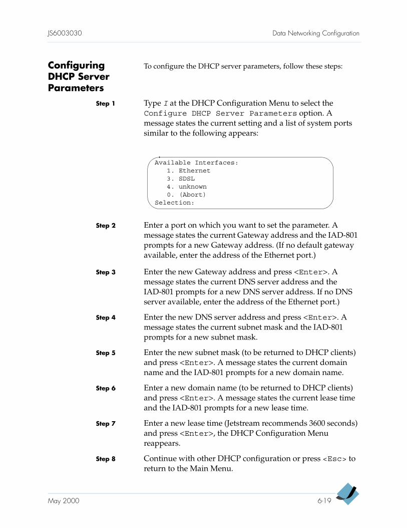
JS6003030 Data Networking Configuration
Configuring DHCP Server Parameters
To configure the DHCP server parameters, follow these steps:
Step 1 Type I at the DHCP Configuration Menu to select the Configure DHCP Server Parameters option. A message states the current setting and a list of system ports similar to the following appears:
Step 2 Enter a port on which you want to set the parameter. A message states the current Gateway address and the IAD-801 prompts for a new Gateway address. (If no default gateway available, enter the address of the Ethernet port.)
Step 3 Enter the new Gateway address and press <Enter>. A message states the current DNS server address and the IAD-801 prompts for a new DNS server address. If no DNS server available, enter the address of the Ethernet port.)
Step 4 Enter the new DNS server address and press <Enter>. A message states the current subnet mask and the IAD-801 prompts for a new subnet mask.
Step 5 Enter the new subnet mask (to be returned to DHCP clients) and press <Enter>. A message states the current domain name and the IAD-801 prompts for a new domain name.
Step 6 Enter a new domain name (to be returned to DHCP clients) and press <Enter>. A message states the current lease time and the IAD-801 prompts for a new lease time.
Step 7 Enter a new lease time (Jetstream recommends 3600 seconds) and press <Enter>, the DHCP Configuration Menu reappears.
Step 8 Continue with other DHCP configuration or press <Esc> to return to the Main Menu.
Available Interfaces:1. Ethernet3. SDSL4. unknown0. (Abort)
Selection:
May 2000 6-19
Data Networking Configuration JS6003030
Step 9 Press Reset when you finish the IAD-801 configuration.
Configuring DHCP Address Range Pool
When configured, the range of IP addresses return to DHCP clients. To configure the DHCP address range pool, follow these steps:
Step 1 Type P at the DHCP Configuration Menu to select the Configure DHCP Address Range Pool option. A message states the current setting and the IAD-801 prompts for the new high IP address.
Step 2 Enter the new high IP address and press <Enter>. A message states the current low IP address and the IAD-801 prompts for the new low IP address.
Step 3 Enter the new low IP address, press <Enter>, and the DHCP Configuration reappears.
Step 4 Continue with other DHCP configuration or press <Esc> to return to the Main Menu.
Step 5 Press Reset when you finish the IAD-801 configuration.
Configuring DHCP Client Entry
Use the DHCP Client entry to set up an identifier, such as an unique subnet mask, for a client whose parameters do not fall into the range specified in the server parameters. The MAC address of the Client must be specified. Jetstream supports up to 10 subnet masks.
To configure the client entry, follow these steps:
Step 1 Type C at the DHCP Configuration Menu to select the Configure DHCP Client Entry option. The IAD-801 prompts for the Client entry number.
Step 2 Enter the Client entry number (ranges 1 to 10). A message states the current Client MAC address and the IAD-801 prompts for a new MAC address.
Step 3 Enter the new Client MAC address and press <Enter>. The IAD-801 confirms the new MAC address and the DHCP Configuration menu reappears.
6-20 May 2000
JS6003030 Data Networking Configuration
Step 4 Continue with other DHCP configuration or press <Esc> to return to the Main Menu.
Step 5 Press Reset when you finish the IAD-801 configuration.
Deleting DHCP Client Entry
To delete a DHCP Client entry, follow these steps:
Step 1 Type X at the DHCP Configuration Menu to select the Delete A DHCP Client Entry option. The IAD-801 prompts for the Client entry number you want to delete.
Step 2 Enter the Client entry number and press <Enter>. The IAD-801 deletes the configuration of that server.
Step 3 Press any key and the DHCP Configuration Menu reappears.
Step 4 Continue with other DHCP configuration or press <Esc> to return to the Main Menu.
Step 5 Press Reset when you finish the IAD-801 configuration.
NoteEnter the MAC address in this format: 00E075001755; the IAD-801 does not accept colons or dashes.
NoteThe IAD-801 provides no prompts for confirmation. Once you press <Enter>, the server is deleted. If an unintentional deletion occurs, refer to page 6-20 to configure a Client entry.
May 2000 6-21
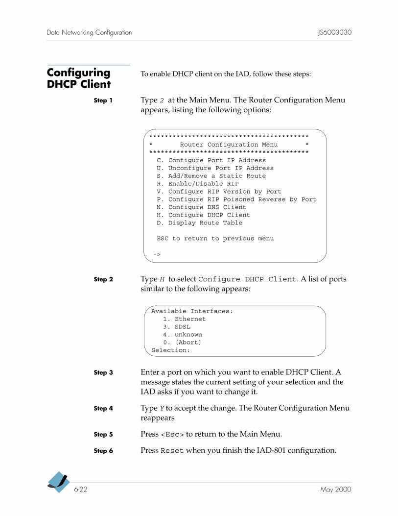
Data Networking Configuration JS6003030
Configuring DHCP Client
To enable DHCP client on the IAD, follow these steps:
Step 1 Type 2 at the Main Menu. The Router Configuration Menu appears, listing the following options:
Step 2 Type H to select Configure DHCP Client. A list of ports similar to the following appears:
Step 3 Enter a port on which you want to enable DHCP Client. A message states the current setting of your selection and the IAD asks if you want to change it.
Step 4 Type Y to accept the change. The Router Configuration Menu reappears
Step 5 Press <Esc> to return to the Main Menu.
Step 6 Press Reset when you finish the IAD-801 configuration.
****************************************** Router Configuration Menu ******************************************
C. Configure Port IP AddressU. Unconfigure Port IP AddressS. Add/Remove a Static RouteR. Enable/Disable RIPV. Configure RIP Version by PortP. Configure RIP Poisoned Reverse by PortN. Configure DNS ClientH. Configure DHCP ClientD. Display Route Table
ESC to return to previous menu
->
Available Interfaces:1. Ethernet3. SDSL4. unknown0. (Abort)
Selection:
6-22 May 2000
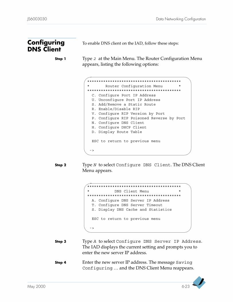
JS6003030 Data Networking Configuration
Configuring DNS Client
To enable DNS client on the IAD, follow these steps:
Step 1 Type 2 at the Main Menu. The Router Configuration Menu appears, listing the following options:
Step 2 Type N to select Configure DNS Client. The DNS Client Menu appears.
Step 3 Type A to select Configure DNS Server IP Address. The IAD displays the current setting and prompts you to enter the new server IP address.
Step 4 Enter the new server IP address. The message SavingConfiguring … and the DNS Client Menu reappears.
****************************************** Router Configuration Menu ******************************************
C. Configure Port IP AddressU. Unconfigure Port IP AddressS. Add/Remove a Static RouteR. Enable/Disable RIPV. Configure RIP Version by PortP. Configure RIP Poisoned Reverse by PortN. Configure DNS ClientH. Configure DHCP ClientD. Display Route Table
ESC to return to previous menu
->
****************************************** DNS Client Menu ******************************************
A. Configure DNS Server IP AddressT. Configure DNS Server TimeoutS. Display DNS Cache and Statistics
ESC to return to previous menu
->
May 2000 6-23
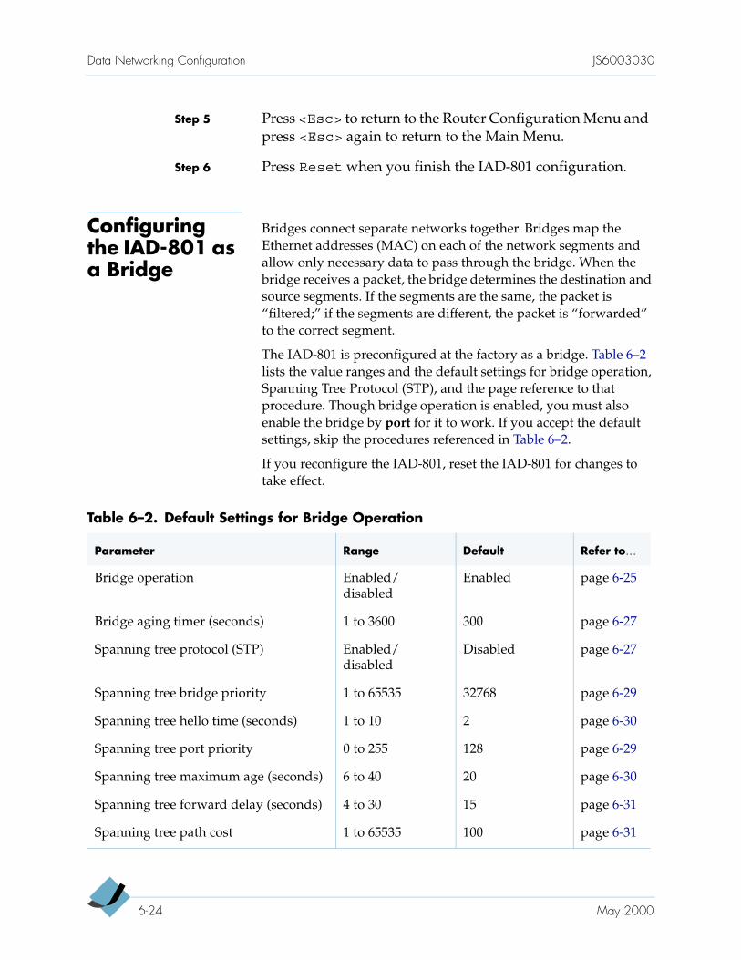
Data Networking Configuration JS6003030
Step 5 Press <Esc> to return to the Router Configuration Menu and press <Esc> again to return to the Main Menu.
Step 6 Press Reset when you finish the IAD-801 configuration.
Configuring the IAD-801 as a Bridge
Bridges connect separate networks together. Bridges map the Ethernet addresses (MAC) on each of the network segments and allow only necessary data to pass through the bridge. When the bridge receives a packet, the bridge determines the destination and source segments. If the segments are the same, the packet is “filtered;” if the segments are different, the packet is “forwarded” to the correct segment.
The IAD-801 is preconfigured at the factory as a bridge. Table 6–2 lists the value ranges and the default settings for bridge operation, Spanning Tree Protocol (STP), and the page reference to that procedure. Though bridge operation is enabled, you must also enable the bridge by port for it to work. If you accept the default settings, skip the procedures referenced in Table 6–2.
If you reconfigure the IAD-801, reset the IAD-801 for changes to take effect.
Table 6–2. Default Settings for Bridge Operation
Parameter Range Default Refer to…
Bridge operation Enabled/disabled
Enabled page 6-25
Bridge aging timer (seconds) 1 to 3600 300 page 6-27
Spanning tree protocol (STP) Enabled/disabled
Disabled page 6-27
Spanning tree bridge priority 1 to 65535 32768 page 6-29
Spanning tree hello time (seconds) 1 to 10 2 page 6-30
Spanning tree port priority 0 to 255 128 page 6-29
Spanning tree maximum age (seconds) 6 to 40 20 page 6-30
Spanning tree forward delay (seconds) 4 to 30 15 page 6-31
Spanning tree path cost 1 to 65535 100 page 6-31
6-24 May 2000
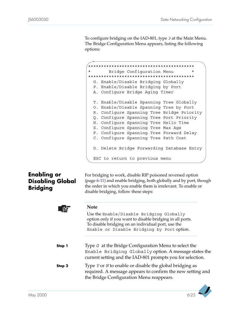
JS6003030 Data Networking Configuration
To configure bridging on the IAD-801, type 3 at the Main Menu. The Bridge Configuration Menu appears, listing the following options:
Enabling or Disabling Global Bridging
For bridging to work, disable RIP poisoned reversed option (page 6-11) and enable bridging, both globally and by port, though the order in which you enable them is irrelevant. To enable or disable bridging, follow these steps:
Step 1 Type G at the Bridge Configuration Menu to select the Enable Bridging Globally option. A message states the current setting and the IAD-801 prompts you for selection.
Step 2 Type Y or N to enable or disable the global bridging as required. A message appears to confirm the new setting and the Bridge Configuration Menu reappears.
****************************************** Bridge Configuration Menu ******************************************
G. Enable/Disable Bridging GloballyP. Enable/Disable Bridging by PortA. Configure Bridge Aging Timer
T. Enable/Disable Spanning Tree GloballyO. Enable/Disable Spanning Tree by PortR. Configure Spanning Tree Bridge PriorityQ. Configure Spanning Tree Port PriorityH. Configure Spanning Tree Hello TimeS. Configure Spanning Tree Max AgeF. Configure Spanning Tree Forward DelayC. Configure Spanning Tree Path Cost
D. Delete Bridge Forwarding Database Entry
ESC to return to previous menu
NoteUse the Enable/Disable Bridging Globally option only if you want to disable bridging in all ports. To disable bridging on an individual port, use the Enable or Disable Bridging by Port option.
May 2000 6-25
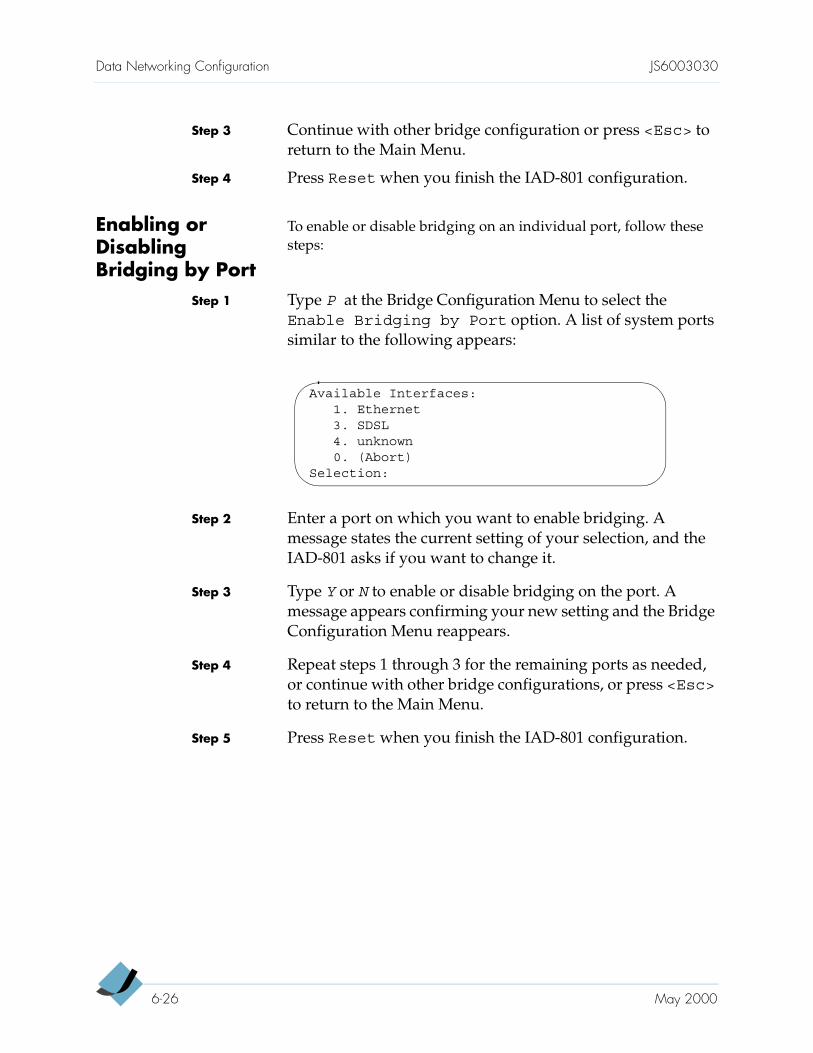
Data Networking Configuration JS6003030
Step 3 Continue with other bridge configuration or press <Esc> to return to the Main Menu.
Step 4 Press Reset when you finish the IAD-801 configuration.
Enabling or Disabling Bridging by Port
To enable or disable bridging on an individual port, follow these steps:
Step 1 Type P at the Bridge Configuration Menu to select the Enable Bridging by Port option. A list of system ports similar to the following appears:
Step 2 Enter a port on which you want to enable bridging. A message states the current setting of your selection, and the IAD-801 asks if you want to change it.
Step 3 Type Y or N to enable or disable bridging on the port. A message appears confirming your new setting and the Bridge Configuration Menu reappears.
Step 4 Repeat steps 1 through 3 for the remaining ports as needed, or continue with other bridge configurations, or press <Esc> to return to the Main Menu.
Step 5 Press Reset when you finish the IAD-801 configuration.
Available Interfaces:1. Ethernet3. SDSL4. unknown0. (Abort)
Selection:
6-26 May 2000
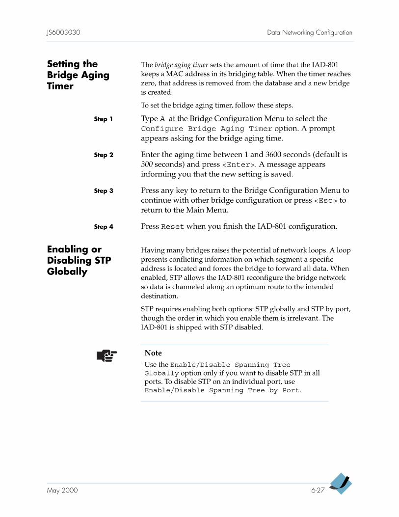
JS6003030 Data Networking Configuration
Setting the Bridge Aging Timer
The bridge aging timer sets the amount of time that the IAD-801 keeps a MAC address in its bridging table. When the timer reaches zero, that address is removed from the database and a new bridge is created.
To set the bridge aging timer, follow these steps.
Step 1 Type A at the Bridge Configuration Menu to select the Configure Bridge Aging Timer option. A prompt appears asking for the bridge aging time.
Step 2 Enter the aging time between 1 and 3600 seconds (default is 300 seconds) and press <Enter>. A message appears informing you that the new setting is saved.
Step 3 Press any key to return to the Bridge Configuration Menu to continue with other bridge configuration or press <Esc> to return to the Main Menu.
Step 4 Press Reset when you finish the IAD-801 configuration.
Enabling or Disabling STP Globally
Having many bridges raises the potential of network loops. A loop presents conflicting information on which segment a specific address is located and forces the bridge to forward all data. When enabled, STP allows the IAD-801 reconfigure the bridge network so data is channeled along an optimum route to the intended destination.
STP requires enabling both options: STP globally and STP by port, though the order in which you enable them is irrelevant. The IAD-801 is shipped with STP disabled.
NoteUse the Enable/Disable Spanning TreeGlobally option only if you want to disable STP in all ports. To disable STP on an individual port, use Enable/Disable Spanning Tree by Port.
May 2000 6-27
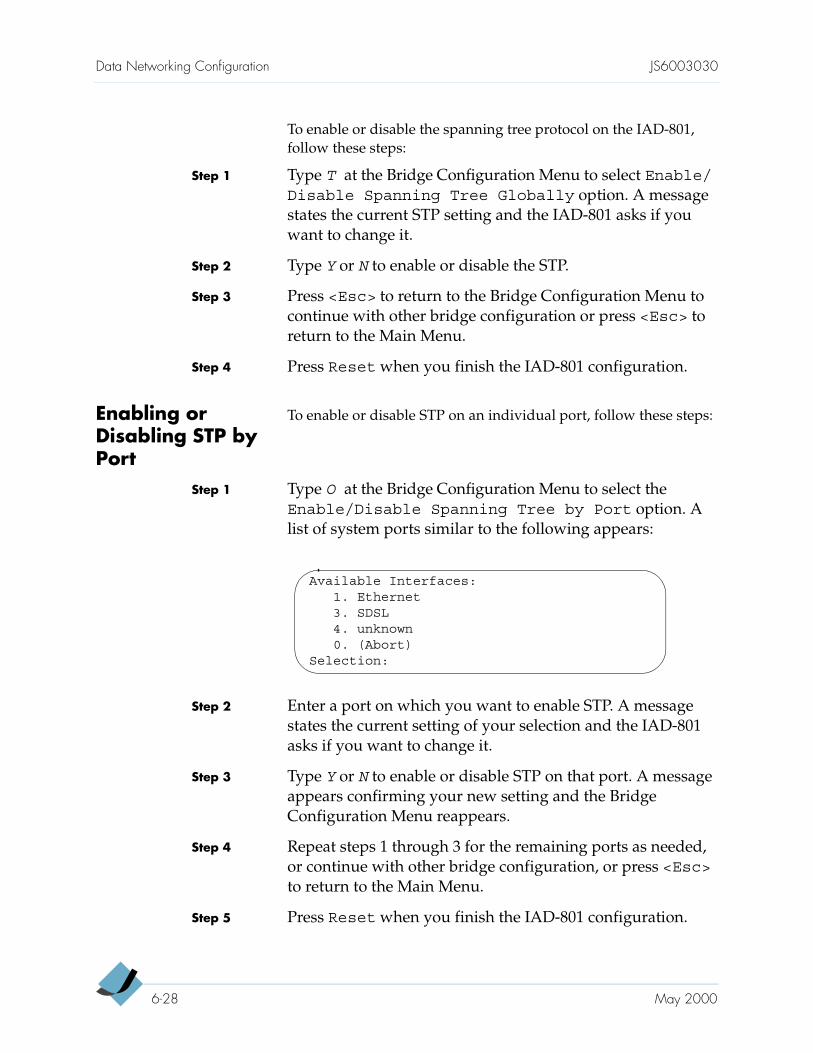
Data Networking Configuration JS6003030
To enable or disable the spanning tree protocol on the IAD-801, follow these steps:
Step 1 Type T at the Bridge Configuration Menu to select Enable/Disable Spanning Tree Globally option. A message states the current STP setting and the IAD-801 asks if you want to change it.
Step 2 Type Y or N to enable or disable the STP.
Step 3 Press <Esc> to return to the Bridge Configuration Menu to continue with other bridge configuration or press <Esc> to return to the Main Menu.
Step 4 Press Reset when you finish the IAD-801 configuration.
Enabling or Disabling STP by Port
To enable or disable STP on an individual port, follow these steps:
Step 1 Type O at the Bridge Configuration Menu to select the Enable/Disable Spanning Tree by Port option. A list of system ports similar to the following appears:
Step 2 Enter a port on which you want to enable STP. A message states the current setting of your selection and the IAD-801 asks if you want to change it.
Step 3 Type Y or N to enable or disable STP on that port. A message appears confirming your new setting and the Bridge Configuration Menu reappears.
Step 4 Repeat steps 1 through 3 for the remaining ports as needed, or continue with other bridge configuration, or press <Esc> to return to the Main Menu.
Step 5 Press Reset when you finish the IAD-801 configuration.
Available Interfaces:1. Ethernet3. SDSL4. unknown0. (Abort)
Selection:
6-28 May 2000
JS6003030 Data Networking Configuration
Configuring the Spanning Tree Bridge Priority
The spanning tree bridge priority setting allows the spanning tree algorithm to decide which bridge should be used as the Ethernet LAN’s destination bridge when two or more bridges are bridging between the same LANs. If two bridges have the same priority, the lower MAC address determines the root bridge.
To set the spanning tree bridge priority level, follow these steps:
Step 1 Type R at the Bridge Configuration Menu to select the Configure Spanning Tree Bridge Priority option. The IAD-801 prompts for a priority number.
Step 2 Type the priority number in the range of 1 to 65535 (default is 32768) and press <Enter>. The message SavingConfiguration… appears.
Step 3 Press any key to return to the Bridge Configuration Menu to continue with other bridge configuration or press <Esc> to return to the Main Menu.
Step 4 Press Reset when you finish the IAD-801 configuration.
Configuring the Spanning Tree Port Priority
Generally, the spanning tree port priority is determined by the spanning tree algorithm. The lower the value, the higher the priority. To set the spanning tree priority individually, follow these steps:
Step 1 Type Q at the Bridge Configuration Menu to select the Configure Spanning Tree Port Priority option. A list of system ports similar to the following appears:
NoteThe square bracket contains the default value. Press <Enter> to accept the default value.
Available Interfaces:1. Ethernet3. SDSL4. unknown0. (Abort)
Selection:
May 2000 6-29
Data Networking Configuration JS6003030
Step 2 Enter a port on which you want to configure the STP priority. The IAD-801 prompts for a priority number.
Step 3 Type the priority number for the port in the range of 0 to 255 (default is 128) and press <Enter>. The message SavingConfiguration… appears.
Step 4 Press any key to return to the Bridge Configuration Menu to continue with other bridge configurations or press <Esc> to return to the Main Menu.
Step 5 Press Reset when you finish the IAD-801 configuration.
Configuring the Spanning Tree Hello Time
To set the time interval between the generation of bridging protocol data unit (PDU) by the IAD-801, follow these steps:
Step 1 Type H at the Bridge Configuration Menu to select the Configure Spanning Tree Hello Time option. The IAD-801 prompts for a time interval.
Step 2 Type the time interval between 1 and 10 seconds (default is 2 seconds) and press <Enter>. The message SavingConfiguration… appears.
Step 3 Press any key to return to the Bridge Configuration Menu to continue with other bridge configurations, or press <Esc> to return to the Main Menu.
Step 4 Press Reset when you finish the IAD-801 configuration.
Setting the Spanning Tree Maximum Age
The maximum age is a timeout value which, if exceeded, allows the IAD-801 to recalculate the spanning tree.
To set the maximum spanning tree age, follow these steps:
Step 1 Type S at the Bridge Configuration Menu to select the Configure Spanning Tree Maximum Age option. The IAD-801 prompts for a maximum age.
Step 2 Type the maximum age between 6 and 40 seconds (default = 20 seconds) and press <Enter>. The message Saving Configuration… appears.
6-30 May 2000
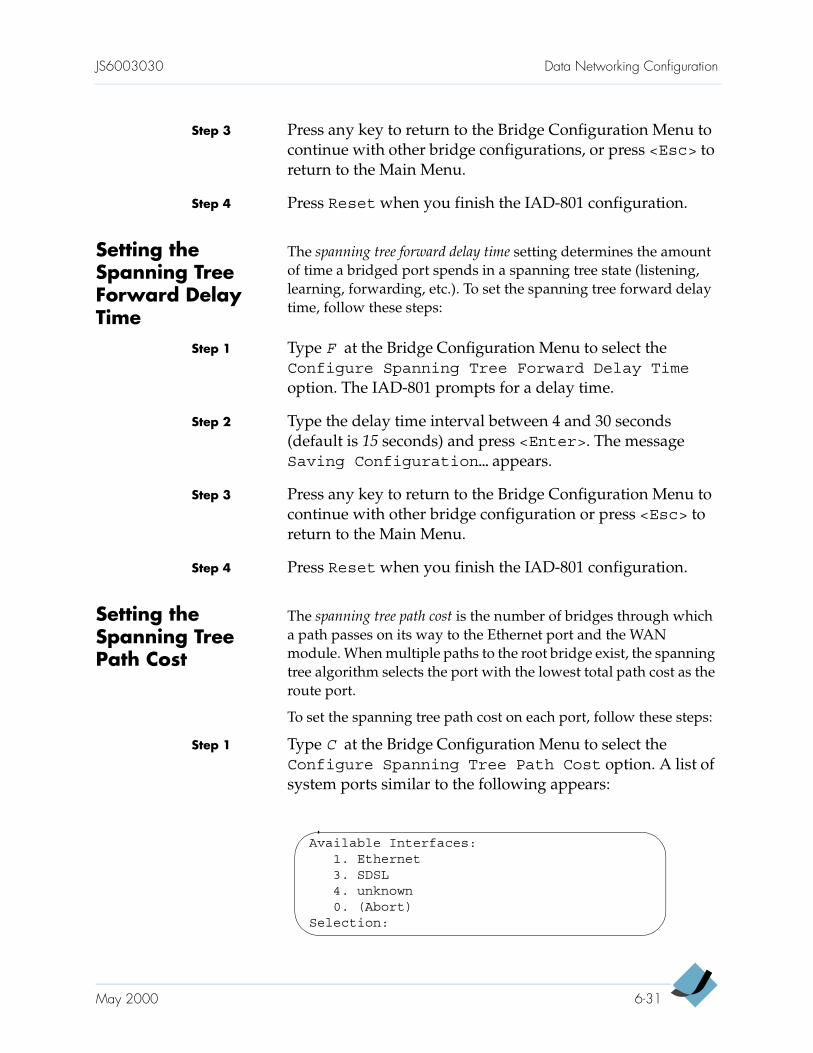
JS6003030 Data Networking Configuration
Step 3 Press any key to return to the Bridge Configuration Menu to continue with other bridge configurations, or press <Esc> to return to the Main Menu.
Step 4 Press Reset when you finish the IAD-801 configuration.
Setting the Spanning Tree Forward Delay Time
The spanning tree forward delay time setting determines the amount of time a bridged port spends in a spanning tree state (listening, learning, forwarding, etc.). To set the spanning tree forward delay time, follow these steps:
Step 1 Type F at the Bridge Configuration Menu to select the Configure Spanning Tree Forward Delay Time option. The IAD-801 prompts for a delay time.
Step 2 Type the delay time interval between 4 and 30 seconds (default is 15 seconds) and press <Enter>. The message Saving Configuration… appears.
Step 3 Press any key to return to the Bridge Configuration Menu to continue with other bridge configuration or press <Esc> to return to the Main Menu.
Step 4 Press Reset when you finish the IAD-801 configuration.
Setting the Spanning Tree Path Cost
The spanning tree path cost is the number of bridges through which a path passes on its way to the Ethernet port and the WAN module. When multiple paths to the root bridge exist, the spanning tree algorithm selects the port with the lowest total path cost as the route port.
To set the spanning tree path cost on each port, follow these steps:
Step 1 Type C at the Bridge Configuration Menu to select the Configure Spanning Tree Path Cost option. A list of system ports similar to the following appears:
Available Interfaces:1. Ethernet3. SDSL4. unknown0. (Abort)
Selection:
May 2000 6-31
Data Networking Configuration JS6003030
Step 2 Enter a port on which you want to set the spanning tree path cost. The IAD-801 prompts for a path cost value.
Step 3 Type the path cost value in the range of 1 to 65535 (default is 100) and press <Enter>. The message SavingConfiguration… appears.
Step 4 Press any key and the Bridge Configuration Menu reappears.
Step 5 Repeat steps 1 through 4 for the remaining ports as needed or continue with other bridge configuration. Or press <Esc> to return to the Main Menu.
Step 6 Press Reset when you finish the IAD-801 configuration.
Deleting a Bridge Database Entry
To delete an Ethernet MAC address from the bridge database, follow these steps:
Step 1 Type D at the Bridge Configuration Menu to select the Delete Bridge Database Entry option. The IAD-801 prompts for the MAC address.
Step 2 Type the Ethernet MAC address to be deleted, then press <Enter>.
Step 3 Press <Esc> to return to the Bridge Configuration Menu to continue with other bridge configurations, or press <Esc> again to return to the Main Menu.
Step 4 Press Reset when you finish the IAD-801 configuration.
NotePressing the spacebar or arrow keys returns you to the Bridge Configuration Menu without deleting the entry.
6-32 May 2000
C H A P T E R 7
Verification andTroubleshooting
This chapter includes a procedure for testing the IAD-801 to verify that it is operating properly after you have installed it. However, before you can test the voice capabilities of the unit, you must provision it at the CPX-1000, using a JetCraft terminal. This chapter also provides these topics:
Maintenance (page 7-3)
Reports Menu (page 7-4)
Restoring default IP address (page 7-9)
Troubleshooting (page 7-11)
Power-Up Test The IAD-801 shows some brief indications of normal operation when you first turn it on. After applying power to the IAD-801, verify that both PWR and LINK indicators on the front panel light green.
Operational Verification Test
Use the following procedure to verify that the IAD-801 is operating properly after you have installed it. This procedure is based on the following assumptions:
Directory numbers have been provisioned in the Class 5 switch for the associated POTS ports on the IAD.
Permanent Virtual Circuits (PVCs) are provisioned at the Digital Subscriber Line Access Multiplexer (DSLAM) for the IAD-801 (defaults are 0, 38 for data and 0, 39 for voice).
A data network is provisioned.
For purposes of testing and turn-up, a dedicated communications circuit is available between yourself and a counterpart who is connected via the JetCraft terminal to the
7-1
Verification and Troubleshooting JS6003030
associated CPX-1000 (e.g., a two-way radio, a line reserved for emergencies, or a cell phone).
An SDSL, ADSL, or T1 link is connected and provisioned at the associated DSLAM. Or, an ATM link is connected and provisioned across the ATM network.
A PC is available with an Ethernet 10Base-T adapter and running a TCP/IP stack.
To test the IAD-801, follow these steps:
Step 1 Verify the WAN link status:
SDSL module—the LINK indicator blinks while the IAD-801 synchronizes itself to the DLSAM and lights continuously when a link is established.
ADSL module—the SYNC indicator lights green continuously when a link is established.
ATM-25 module—its TX and RX indicators blink on and off while it sends data to and receives data from the ATM network.
T1/E1 module—its LINK indicator blinks while the IAD-801 synchronizes itself to the DLSAM and lights continuously when a link is established.
Step 2 Connect a standard voice telephone set to one of the provisioned line ports of the IAD-801.
Step 3 Pick up the telephone receiver and wait for a dial tone. If you hear it, proceed to Step 5.
If no dial tone is present, troubleshoot as required (Table 7–1 on page 7-12).
Step 4 Repeat Step 3 for each provisioned line.
NoteThe IAD-801 must be provisioned at the CPX-1000 (via the JetCraft terminal) before the voice capabilities of the IAD-801 can be successfully tested. If this has not yet been done, you cannot test the IAD-801’s voice functions.
7-2 May 2000
JS6003030 Verification and Troubleshooting
Step 5 Disconnect the telephone when you are done testing the analog telephone ports.
Step 6 Using a crossover cable, connect the PC of Step 5 to the Ethernet LAN port of the IAD-801.
Step 7 From the PC, ping a known good address of the IAD and wait for an acknowledgment. If the acknowledgment is received, proceed to the next step. If a timeout occurs, troubleshoot the LAN path to the IAD-801 as required.
Step 8 Ping a known good address on the network and wait for an acknowledgment. If the acknowledgment is received, proceed to the next step. If a timeout occurs, troubleshoot the LAN path to the IAD-801 as required.
Step 9 Disconnect the PC from the Ethernet LAN port of the IAD-801. Use a straight-through cable to connect that port to the local LAN patch panel or hub.
Step 10 Connect the IAD-801 telephone ports to the local distribution frame or patch panel, as appropriate.
The IAD-801 is now ready for service.
Maintenance The IAD-801 is equipped with built-in utilities for maintenance and development. Before accessing these utilities at the System Utilities Menu, first call the Jetstream Technical Assistance Center (JTAC) at 1-888-435-7538.
WarningDo not use these utilities without assistance from a Jetstream technical support representative. Doing so can render the IAD-801 inoperable and disrupt traffic transmission.
May 2000 7-3
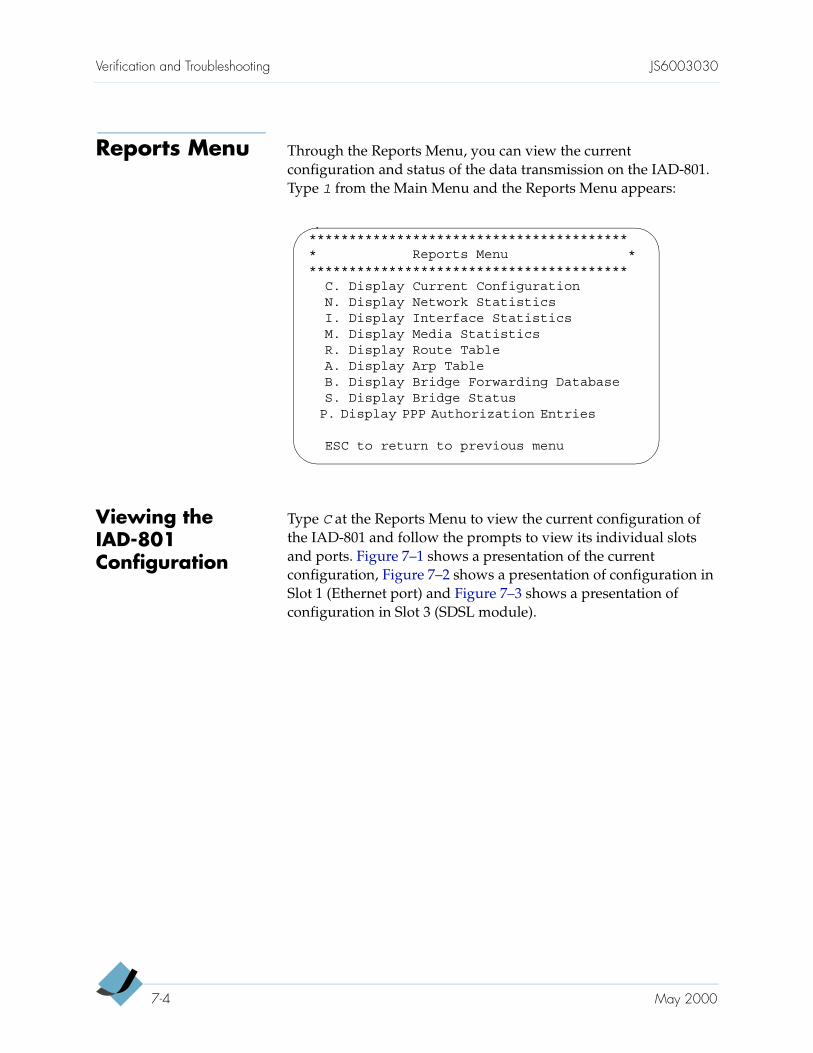
Verification and Troubleshooting JS6003030
Reports Menu Through the Reports Menu, you can view the current configuration and status of the data transmission on the IAD-801. Type 1 from the Main Menu and the Reports Menu appears:
Viewing the IAD-801 Configuration
Type C at the Reports Menu to view the current configuration of the IAD-801 and follow the prompts to view its individual slots and ports. Figure 7–1 shows a presentation of the current configuration, Figure 7–2 shows a presentation of configuration in Slot 1 (Ethernet port) and Figure 7–3 shows a presentation of configuration in Slot 3 (SDSL module).
***************************************** Reports Menu *****************************************
C. Display Current ConfigurationN. Display Network StatisticsI. Display Interface StatisticsM. Display Media StatisticsR. Display Route TableA. Display Arp TableB. Display Bridge Forwarding DatabaseS. Display Bridge StatusP. Display PPP Authorization Entries
ESC to return to previous menu
7-4 May 2000
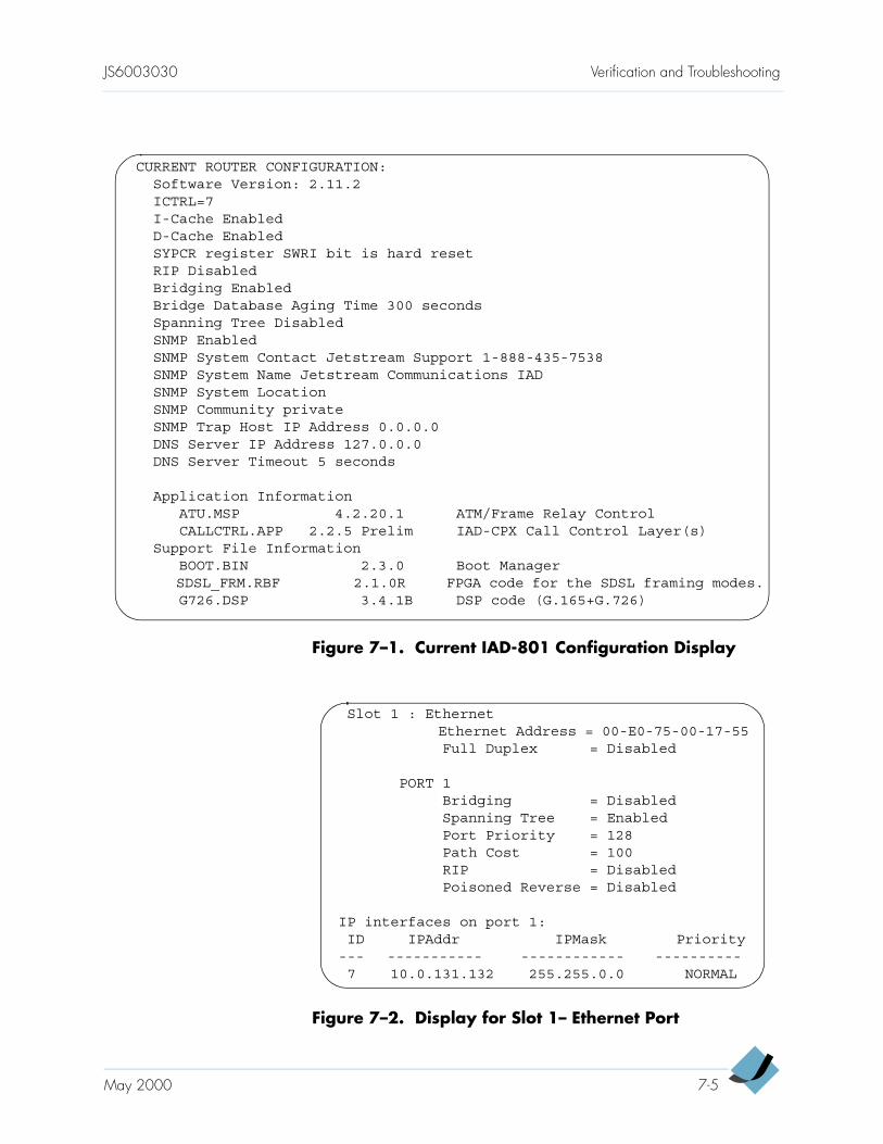
JS6003030 Verification and Troubleshooting
Figure 7–1. Current IAD-801 Configuration Display
Figure 7–2. Display for Slot 1– Ethernet Port
CURRENT ROUTER CONFIGURATION:Software Version: 2.11.2ICTRL=7I-Cache EnabledD-Cache EnabledSYPCR register SWRI bit is hard resetRIP DisabledBridging EnabledBridge Database Aging Time 300 secondsSpanning Tree DisabledSNMP EnabledSNMP System Contact Jetstream Support 1-888-435-7538SNMP System Name Jetstream Communications IADSNMP System LocationSNMP Community privateSNMP Trap Host IP Address 0.0.0.0DNS Server IP Address 127.0.0.0DNS Server Timeout 5 seconds
Application InformationATU.MSP 4.2.20.1 ATM/Frame Relay ControlCALLCTRL.APP 2.2.5 Prelim IAD-CPX Call Control Layer(s)
Support File InformationBOOT.BIN 2.3.0 Boot ManagerSDSL_FRM.RBF 2.1.0R FPGA code for the SDSL framing modes.G726.DSP 3.4.1B DSP code (G.165+G.726)
Slot 1 : EthernetEthernet Address = 00-E0-75-00-17-55Full Duplex = Disabled
PORT 1Bridging = DisabledSpanning Tree = EnabledPort Priority = 128Path Cost = 100RIP = DisabledPoisoned Reverse = Disabled
IP interfaces on port 1:ID IPAddr IPMask Priority
--- ----------- ------------ ----------7 10.0.131.132 255.255.0.0 NORMAL
May 2000 7-5
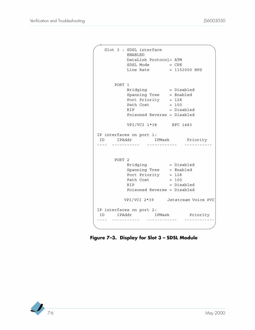
Verification and Troubleshooting JS6003030
Figure 7–3. Display for Slot 3 – SDSL Module
Slot 3 : SDSL interfaceENABLEDDataLink Protocol= ATMSDSL Mode = CPELine Rate = 1152000 BPS
PORT 1Bridging = DisabledSpanning Tree = EnabledPort Priority = 128Path Cost = 100RIP = DisabledPoisoned Reverse = Disabled
VPI/VCI 1*38 RFC 1483
IP interfaces on port 1:ID IPAddr IPMask Priority
---- ----------- ------------ -----------
PORT 2Bridging = DisabledSpanning Tree = EnabledPort Priority = 128Path Cost = 100RIP = DisabledPoisoned Reverse = Disabled
VPI/VCI 2*39 Jetstream Voice PVC
IP interfaces on port 2:ID IPAddr IPMask Priority
---- ----------- ------------ ------------
7-6 May 2000
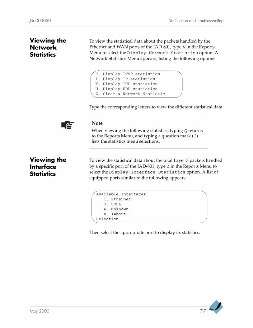
JS6003030 Verification and Troubleshooting
Viewing the Network Statistics
To view the statistical data about the packets handled by the Ethernet and WAN ports of the IAD-801, type N in the Reports Menu to select the Display Network Statistics option. A Network Statistics Menu appears, listing the following options:
Type the corresponding letters to view the different statistical data.
Viewing the Interface Statistics
To view the statistical data about the total Layer 3 packets handled by a specific port of the IAD-801, type I in the Reports Menu to select the Display Interface Statistics option. A list of equipped ports similar to the following appears:
Then select the appropriate port to display its statistics.
C. Display ICMP statisticsI. Display IP statisticsT. Display TCP statisticsU. Display UDP statisticsZ. Clear a Network Statistic
NoteWhen viewing the following statistics, typing Q returns to the Reports Menu, and typing a question mark (?) lists the statistics menu selections.
Available Interfaces:1. Ethernet3. SDSL4. unknown0. (Abort)
Selection:
May 2000 7-7
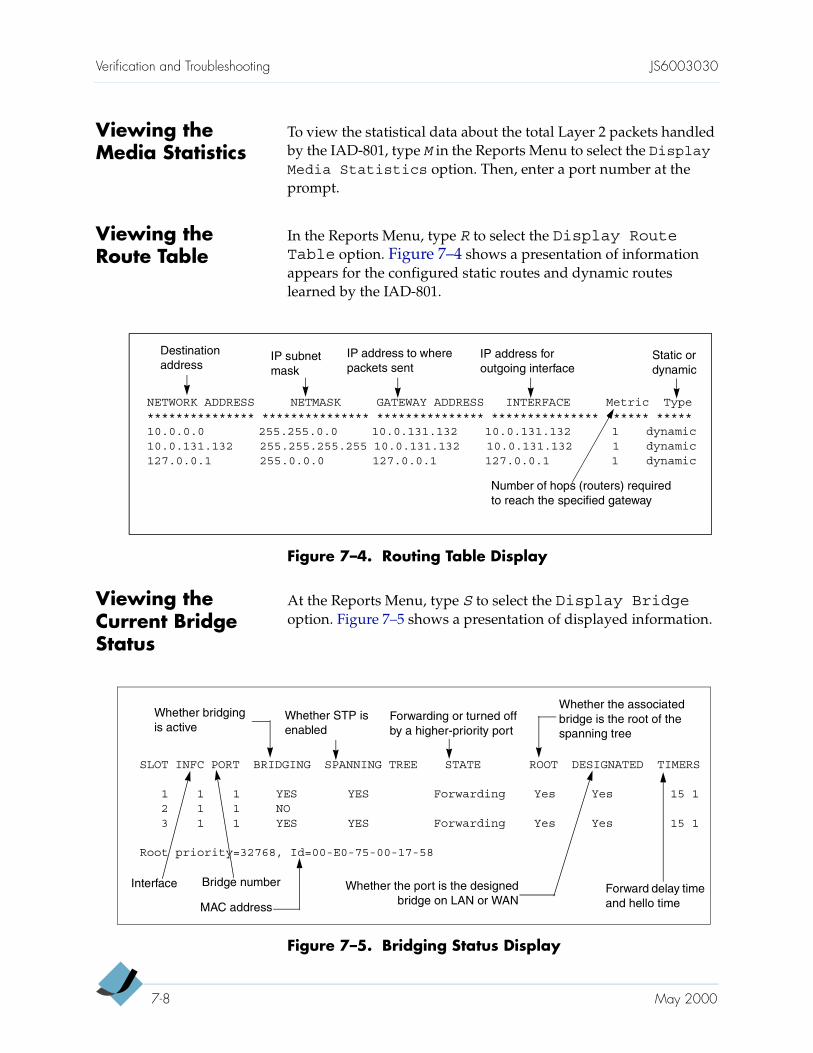
Verification and Troubleshooting JS6003030
Viewing the Media Statistics
To view the statistical data about the total Layer 2 packets handled by the IAD-801, type M in the Reports Menu to select the DisplayMedia Statistics option. Then, enter a port number at the prompt.
Viewing the Route Table
In the Reports Menu, type R to select the Display RouteTable option. Figure 7–4 shows a presentation of information appears for the configured static routes and dynamic routes learned by the IAD-801.
Figure 7–4. Routing Table Display
Viewing the Current Bridge Status
At the Reports Menu, type S to select the Display Bridgeoption. Figure 7–5 shows a presentation of displayed information.
Figure 7–5. Bridging Status Display
NETWORK ADDRESS NETMASK GATEWAY ADDRESS INTERFACE Metric Type*************** *************** *************** *************** ****** *****10.0.0.0 255.255.0.0 10.0.131.132 10.0.131.132 1 dynamic10.0.131.132 255.255.255.255 10.0.131.132 10.0.131.132 1 dynamic127.0.0.1 255.0.0.0 127.0.0.1 127.0.0.1 1 dynamic
Destination address
IP subnet mask
IP address to where packets sent
IP address for outgoing interface
Static or dynamic
Number of hops (routers) required to reach the specified gateway
SLOT INFC PORT BRIDGING SPANNING TREE STATE ROOT DESIGNATED TIMERS
1 1 1 YES YES Forwarding Yes Yes 15 12 1 1 NO3 1 1 YES YES Forwarding Yes Yes 15 1
Root priority=32768, Id=00-E0-75-00-17-58
Whether bridging is active
Whether STP is enabled
Forwarding or turned off by a higher-priority port
Whether the associated bridge is the root of the spanning tree
Whether the port is the designedbridge on LAN or WAN
Forward delay time and hello time
Bridge numberInterface
MAC address
7-8 May 2000
JS6003030 Verification and Troubleshooting
Reviewing Bridge Database Entry
At the Reports Menu, type B to select the Display BridgeForwarding Database option. The following information appears about mapping between Ethernet (MAC) addresses and the devices connected to the LAN.
ETHERNET ADDRESS—MAC address of the device; assigned by the manufacturer
SLOT—slot number
INFC—interface port for the MAC address
TIMER—number of seconds until this entry is deleted from the database. The time counts down from the Bridge database aging time value, in one-second intervals. When the timer reaches zero, the entry is removed from the database.
Restoring Default IP Address
To restore the default IP address on the IAD, follow these steps:
Step 1 Turn the IAD power off.
Step 2 Unfasten the screws securing the WAN module and pull out the module half way from the slot.
Step 3 Turn the IAD power on with the WAN module out.
Step 4 Use Telnet to log on to the IAD. The IAD-801 prompts for a login ID.
Step 5 Enter your login ID and press <Enter>. The IAD-801 prompts for a password.
Step 6 Enter your password and the Main Menu appears.
Step 7 Select 2. Configure IP Router. The Router Configuration Menu appears, listing the following options:
NoteThe MAC address is the same as the serial number of the IAD.
May 2000 7-9
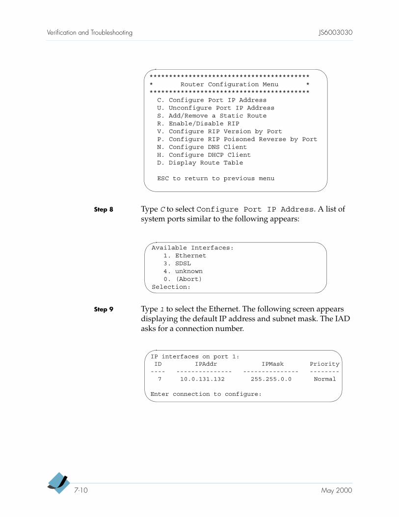
Verification and Troubleshooting JS6003030
Step 8 Type C to select Configure Port IP Address. A list of system ports similar to the following appears:
Step 9 Type 1 to select the Ethernet. The following screen appears displaying the default IP address and subnet mask. The IAD asks for a connection number.
****************************************** Router Configuration Menu ******************************************
C. Configure Port IP AddressU. Unconfigure Port IP AddressS. Add/Remove a Static RouteR. Enable/Disable RIPV. Configure RIP Version by PortP. Configure RIP Poisoned Reverse by PortN. Configure DNS ClientH. Configure DHCP ClientD. Display Route Table
ESC to return to previous menu
Available Interfaces:1. Ethernet3. SDSL4. unknown0. (Abort)
Selection:
IP interfaces on port 1:ID IPAddr IPMask Priority---- --------------- --------------- --------7 10.0.131.132 255.255.0.0 Normal
Enter connection to configure:
7-10 May 2000
JS6003030 Verification and Troubleshooting
Step 10 Type 7 as the ID number of the connection, then press <Enter>. The IAD-801 displays the default IP address and prompts for the new IP address.
Step 11 Press <Enter> to accept the default IP address. The IAD-801 displays the default subnet masks and prompts for the new subnet mask.
Step 12 Press <Enter> to accept the default subnet mask. The IAD-801 asks you to set the priority for this IP address.
Step 13 Type N to set the priority to Normal. The IAD-801 asks if you want to save the IP information.
Step 14 Type Y to save the IP information. The Router Configuration Menu reappears.
Step 15 Press <Esc> to return to the Main Menu.
Step 16 Press Reset for the change to take effect.
Step 17 Use Telnet to log on to the IAD again to verify that the default IP information has been restored.
Step 18 Turn the IAD power off.
Step 19 Slide the WAN module into its slot and fasten the screws that secure the module.
Step 20 Turn the IAD power on.
You are now ready to log on to the IAD.
Troubleshooting This section provides information to troubleshoot the IAD-801. Table 7–1 lists actions to solve typical symptoms associated with the IAD-801.
NoteThough the screen displays the default IP address and subnet mask, you must reenter them on the IAD.
May 2000 7-11
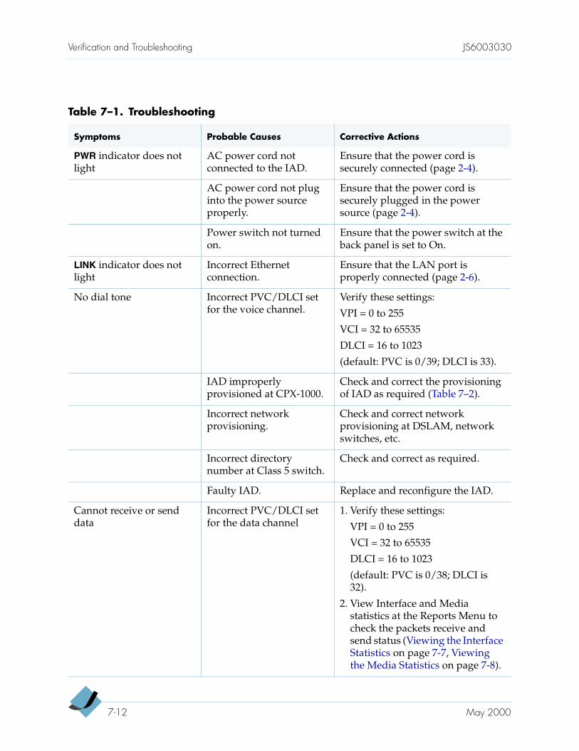
Verification and Troubleshooting JS6003030
Table 7–1. Troubleshooting
Symptoms Probable Causes Corrective Actions
PWR indicator does not light
AC power cord not connected to the IAD.
Ensure that the power cord is securely connected (page 2-4).
AC power cord not plug into the power source properly.
Ensure that the power cord is securely plugged in the power source (page 2-4).
Power switch not turned on.
Ensure that the power switch at the back panel is set to On.
LINK indicator does not light
Incorrect Ethernet connection.
Ensure that the LAN port is properly connected (page 2-6).
No dial tone Incorrect PVC/DLCI set for the voice channel.
Verify these settings:
VPI = 0 to 255
VCI = 32 to 65535
DLCI = 16 to 1023
(default: PVC is 0/39; DLCI is 33).
IAD improperly provisioned at CPX-1000.
Check and correct the provisioning of IAD as required (Table 7–2).
Incorrect network provisioning.
Check and correct network provisioning at DSLAM, network switches, etc.
Incorrect directory number at Class 5 switch.
Check and correct as required.
Faulty IAD. Replace and reconfigure the IAD.
Cannot receive or send data
Incorrect PVC/DLCI set for the data channel
1. Verify these settings:
VPI = 0 to 255
VCI = 32 to 65535
DLCI = 16 to 1023
(default: PVC is 0/38; DLCI is 32).
2. View Interface and Media statistics at the Reports Menu to check the packets receive and send status (Viewing the Interface Statistics on page 7-7, Viewing the Media Statistics on page 7-8).
7-12 May 2000
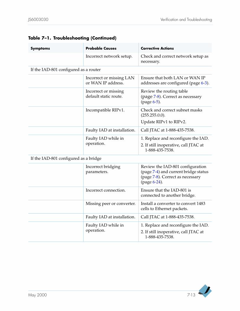
JS6003030 Verification and Troubleshooting
Incorrect network setup. Check and correct network setup as necessary.
If the IAD-801 configured as a router
Incorrect or missing LAN or WAN IP address.
Ensure that both LAN or WAN IP addresses are configured (page 6-3).
Incorrect or missing default static route.
Review the routing table (page 7-8). Correct as necessary (page 6-5).
Incompatible RIPv1. Check and correct subnet masks (255.255.0.0).
Update RIPv1 to RIPv2.
Faulty IAD at installation. Call JTAC at 1-888-435-7538.
Faulty IAD while in operation.
1. Replace and reconfigure the IAD.
2. If still inoperative, call JTAC at 1-888-435-7538.
If the IAD-801 configured as a bridge
Incorrect bridging parameters.
Review the IAD-801 configuration (page 7-4) and current bridge status (page 7-8). Correct as necessary (page 6-24).
Incorrect connection. Ensure that the IAD-801 is connected to another bridge.
Missing peer or converter. Install a converter to convert 1483 cells to Ethernet packets.
Faulty IAD at installation. Call JTAC at 1-888-435-7538.
Faulty IAD while in operation.
1. Replace and reconfigure the IAD.
2. If still inoperative, call JTAC at 1-888-435-7538.
Table 7–1. Troubleshooting (Continued)
Symptoms Probable Causes Corrective Actions
May 2000 7-13
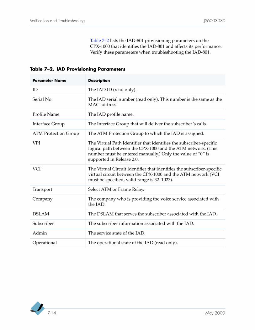
Verification and Troubleshooting JS6003030
Table 7–2 lists the IAD-801 provisioning parameters on the CPX-1000 that identifies the IAD-801 and affects its performance. Verify these parameters when troubleshooting the IAD-801.
Table 7–2. IAD Provisioning Parameters
Parameter Name Description
ID The IAD ID (read only).
Serial No. The IAD serial number (read only). This number is the same as the MAC address.
Profile Name The IAD profile name.
Interface Group The Interface Group that will deliver the subscriber’s calls.
ATM Protection Group The ATM Protection Group to which the IAD is assigned.
VPI The Virtual Path Identifier that identifies the subscriber-specific logical path between the CPX-1000 and the ATM network. (This number must be entered manually.) Only the value of “0” is supported in Release 2.0.
VCI The Virtual Circuit Identifier that identifies the subscriber-specific virtual circuit between the CPX-1000 and the ATM network (VCI must be specified, valid range is 32–1023).
Transport Select ATM or Frame Relay.
Company The company who is providing the voice service associated with the IAD.
DSLAM The DSLAM that serves the subscriber associated with the IAD.
Subscriber The subscriber information associated with the IAD.
Admin The service state of the IAD.
Operational The operational state of the IAD (read only).
7-14 May 2000
A P P E N D I X A
Installation andConfiguration Checklist
This appendix has a convenient checklist for you to use when installing the IAD-801. You can use it to ensure that you have made all the connections required and configured voice and data PVCs/DLCIs as necessary for your IAD-801.
A-1
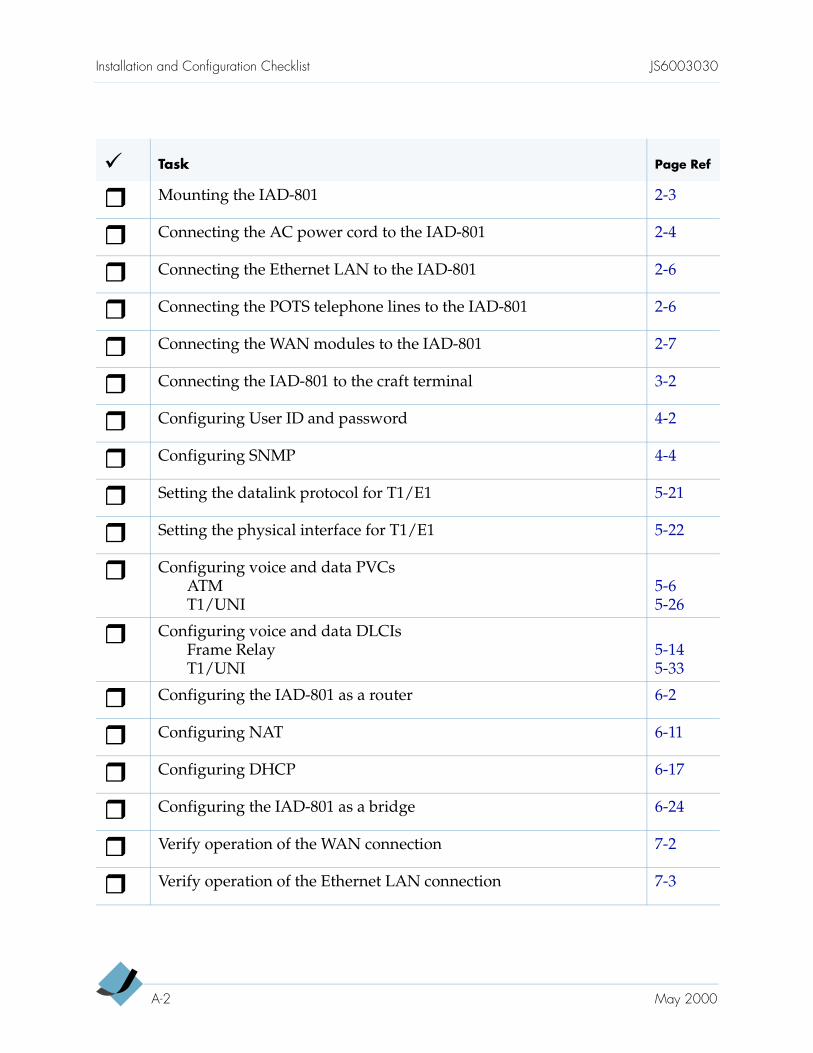
Installation and Configuration Checklist JS6003030
Task Page Ref
Mounting the IAD-801 2-3
Connecting the AC power cord to the IAD-801 2-4
Connecting the Ethernet LAN to the IAD-801 2-6
Connecting the POTS telephone lines to the IAD-801 2-6
Connecting the WAN modules to the IAD-801 2-7
Connecting the IAD-801 to the craft terminal 3-2
Configuring User ID and password 4-2
Configuring SNMP 4-4
Setting the datalink protocol for T1/E1 5-21
Setting the physical interface for T1/E1 5-22
Configuring voice and data PVCsATMT1/UNI
5-65-26
Configuring voice and data DLCIsFrame RelayT1/UNI
5-145-33
Configuring the IAD-801 as a router 6-2
Configuring NAT 6-11
Configuring DHCP 6-17
Configuring the IAD-801 as a bridge 6-24
Verify operation of the WAN connection 7-2
Verify operation of the Ethernet LAN connection 7-3
A-2 May 2000
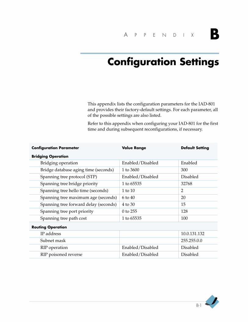
A P P E N D I X B
Configuration Settings
This appendix lists the configuration parameters for the IAD-801 and provides their factory-default settings. For each parameter, all of the possible settings are also listed.
Refer to this appendix when configuring your IAD-801 for the first time and during subsequent reconfigurations, if necessary.
Configuration Parameter Value Range Default Setting
Bridging Operation
Bridging operation Enabled/Disabled Enabled
Bridge database aging time (seconds) 1 to 3600 300
Spanning tree protocol (STP) Enabled/Disabled Disabled
Spanning tree bridge priority 1 to 65535 32768
Spanning tree hello time (seconds) 1 to 10 2
Spanning tree maximum age (seconds) 6 to 40 20
Spanning tree forward delay (seconds) 4 to 30 15
Spanning tree port priority 0 to 255 128
Spanning tree path cost 1 to 65535 100
Routing Operation
IP address 10.0.131.132
Subnet mask 255.255.0.0
RIP operation Enabled/Disabled Disabled
RIP poisoned reverse Enabled/Disabled Disabled
B-1
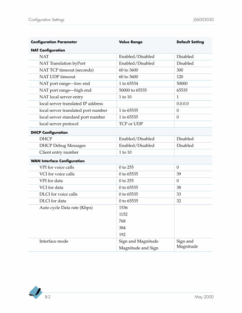
Configuration Settings JS6003030
NAT Configuration
NAT Enabled/Disabled Disabled
NAT Translation byPort Enabled/Disabled Disabled
NAT TCP timeout (seconds) 60 to 3600 300
NAT UDP timeout 60 to 3600 120
NAT port range—low end 1 to 65534 50000
NAT port range—high end 50000 to 65535 65535
NAT local server entry 1 to 10 1
local server translated IP address 0.0.0.0
local server translated port number 1 to 65535 0
local server standard port number 1 to 65535 0
local server protocol TCP or UDP
DHCP Configuration
DHCP Enabled/Disabled Disabled
DHCP Debug Messages Enabled/Disabled Disabled
Client entry number 1 to 10
WAN Interface Configuration
VPI for voice calls 0 to 255 0
VCI for voice calls 0 to 65535 39
VPI for data 0 to 255 0
VCI for data 0 to 65535 38
DLCI for voice calls 0 to 65535 33
DLCI for data 0 to 65535 32
Auto cycle Data rate (Kbps) 1536
1152
768
384
192
Interface mode Sign and Magnitude
Magnitude and Sign
Sign and Magnitude
Configuration Parameter Value Range Default Setting
B-2 May 2000
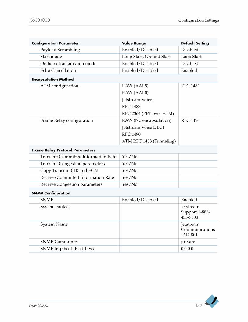
JS6003030 Configuration Settings
Payload Scrambling Enabled/Disabled Disabled
Start mode Loop Start, Ground Start Loop Start
On hook transmission mode Enabled/Disabled Disabled
Echo Cancellation Enabled/Disabled Enabled
Encapsulation Method
ATM configuration RAW (AAL5)
RAW (AAL0)
Jetstream Voice
RFC 1483
RFC 2364 (PPP over ATM)
RFC 1483
Frame Relay configuration RAW (No encapsulation)
Jetstream Voice DLCI
RFC 1490
ATM RFC 1483 (Tunneling)
RFC 1490
Frame Relay Protocol Parameters
Transmit Committed Information Rate Yes/No
Transmit Congestion parameters Yes/No
Copy Transmit CIR and ECN Yes/No
Receive Committed Information Rate Yes/No
Receive Congestion parameters Yes/No
SNMP Configuration
SNMP Enabled/Disabled Enabled
System contact Jetstream Support 1-888-435-7538
System Name Jetstream Communications IAD-801
SNMP Community private
SNMP trap host IP address 0.0.0.0
Configuration Parameter Value Range Default Setting
May 2000 B-3
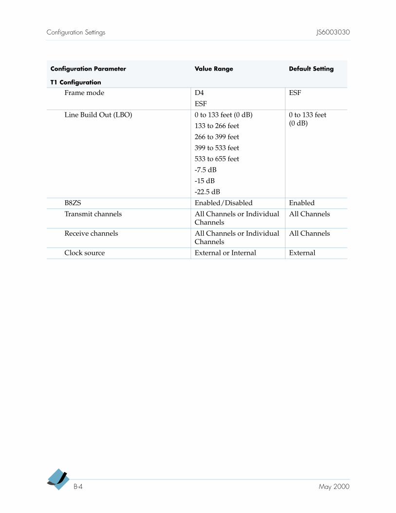
Configuration Settings JS6003030
T1 Configuration
Frame mode D4
ESF
ESF
Line Build Out (LBO) 0 to 133 feet (0 dB)
133 to 266 feet
266 to 399 feet
399 to 533 feet
533 to 655 feet
-7.5 dB
-15 dB
-22.5 dB
0 to 133 feet (0 dB)
B8ZS Enabled/Disabled Enabled
Transmit channels All Channels or Individual Channels
All Channels
Receive channels All Channels or Individual Channels
All Channels
Clock source External or Internal External
Configuration Parameter Value Range Default Setting
B-4 May 2000
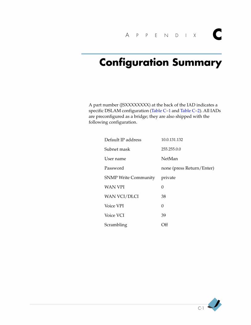
A P P E N D I X C
Configuration Summary
A part number (JSXXXXXXXX) at the back of the IAD indicates a specific DSLAM configuration (Table C–1 and Table C–2). All IADs are preconfigured as a bridge; they are also shipped with the following configuration.
Default IP address 10.0.131.132
Subnet mask 255.255.0.0
User name NetMan
Password none (press Return/Enter)
SNMP Write Community private
WAN VPI 0
WAN VCI/DLCI 38
Voice VPI 0
Voice VCI 39
Scrambling Off
C-1
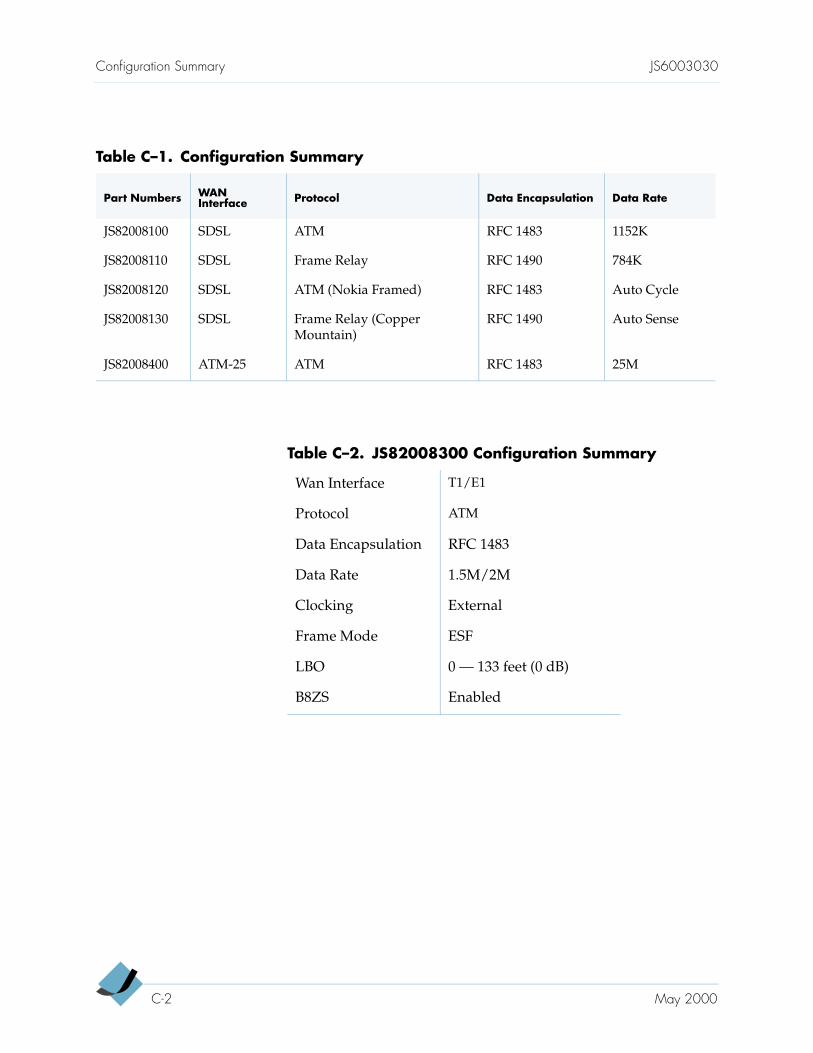
Configuration Summary JS6003030
Table C–1. Configuration Summary
Part Numbers WAN Interface Protocol Data Encapsulation Data Rate
JS82008100 SDSL ATM RFC 1483 1152K
JS82008110 SDSL Frame Relay RFC 1490 784K
JS82008120 SDSL ATM (Nokia Framed) RFC 1483 Auto Cycle
JS82008130 SDSL Frame Relay (Copper Mountain)
RFC 1490 Auto Sense
JS82008400 ATM-25 ATM RFC 1483 25M
Table C–2. JS82008300 Configuration Summary
Wan Interface T1/E1
Protocol ATM
Data Encapsulation RFC 1483
Data Rate 1.5M/2M
Clocking External
Frame Mode ESF
LBO 0 — 133 feet (0 dB)
B8ZS Enabled
C-2 May 2000

A P P E N D I X D
Menu Map
The following menu map provides a linear, hierarchical overview of the menu and submenus associated with the IAD-801.
D-1
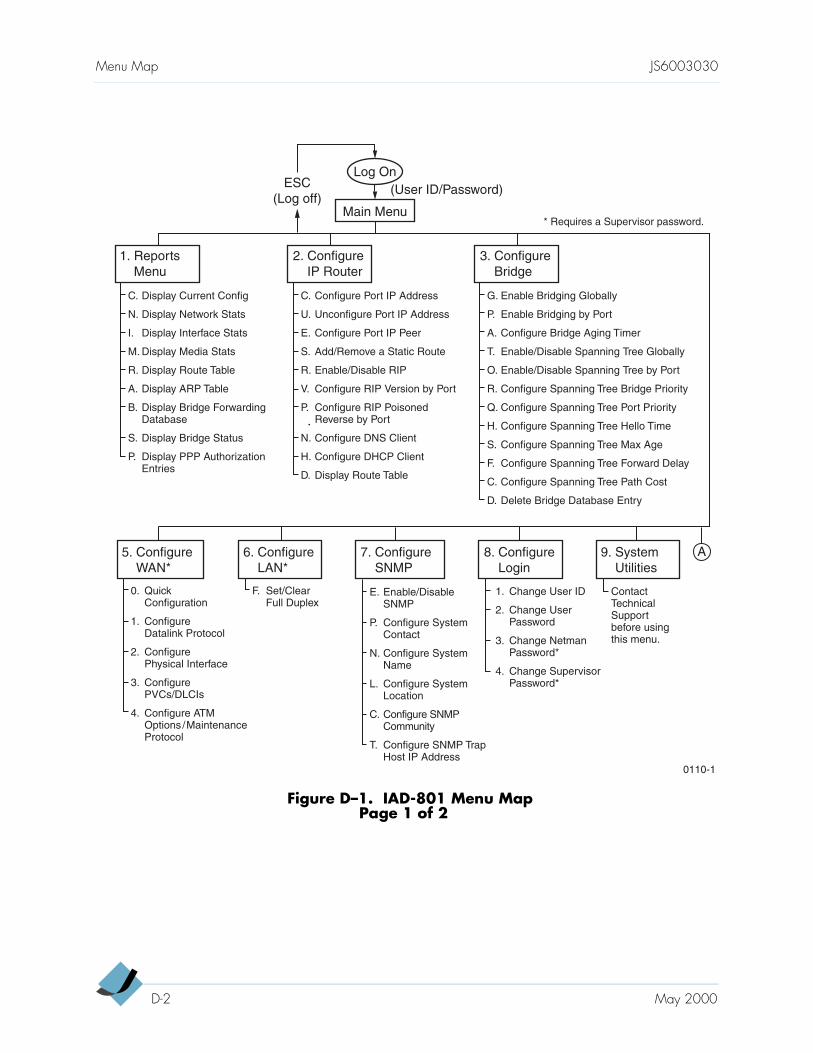
Menu Map JS6003030
Figure D–1. IAD-801 Menu MapPage 1 of 2
Log On
Main Menu
ESC(Log off)
(User ID/Password)
1. ReportsMenu
2. ConfigureIP Router
3. ConfigureBridge
C. Display Current Config
N. Display Network Stats
I. Display Interface Stats
M. Display Media Stats
R. Display Route Table
A. Display ARP Table
B. Display Bridge ForwardingDatabase
S. Display Bridge Status
P. Display PPP AuthorizationEntries
6. ConfigureLAN*
F. Set/ClearFull Duplex
5. ConfigureWAN*
0. QuickConfiguration
1. ConfigureDatalink Protocol
2. ConfigurePhysical Interface
3. ConfigurePVCs/DLCIs
4. Configure ATMOptions /MaintenanceProtocol
8. ConfigureLogin
1. Change User ID
2. Change User Password
3. Change NetmanPassword*
4. Change SupervisorPassword*
7. ConfigureSNMP
E. Enable/DisableSNMP
P. Configure SystemContact
N. Configure SystemName
L. Configure SystemLocation
C. Configure SNMPCommunity
T. Configure SNMP Trap Host IP Address
9. SystemUtilities
Contact Technical Support before using this menu.
C. Configure Port IP Address
U. Unconfigure Port IP Address
E. Configure Port IP Peer
S. Add/Remove a Static Route
R. Enable/Disable RIP
V. Configure RIP Version by Port
P. Configure RIP Poisoned Reverse by Port
N. Configure DNS Client
H. Configure DHCP Client
D. Display Route Table
G. Enable Bridging Globally
P. Enable Bridging by Port
A. Configure Bridge Aging Timer
T. Enable/Disable Spanning Tree Globally
O. Enable/Disable Spanning Tree by Port
R. Configure Spanning Tree Bridge Priority
Q. Configure Spanning Tree Port Priority
H. Configure Spanning Tree Hello Time
S. Configure Spanning Tree Max Age
F. Configure Spanning Tree Forward Delay
C. Configure Spanning Tree Path Cost
D. Delete Bridge Database Entry
0110-1
* Requires a Supervisor password.
A
D-2 May 2000
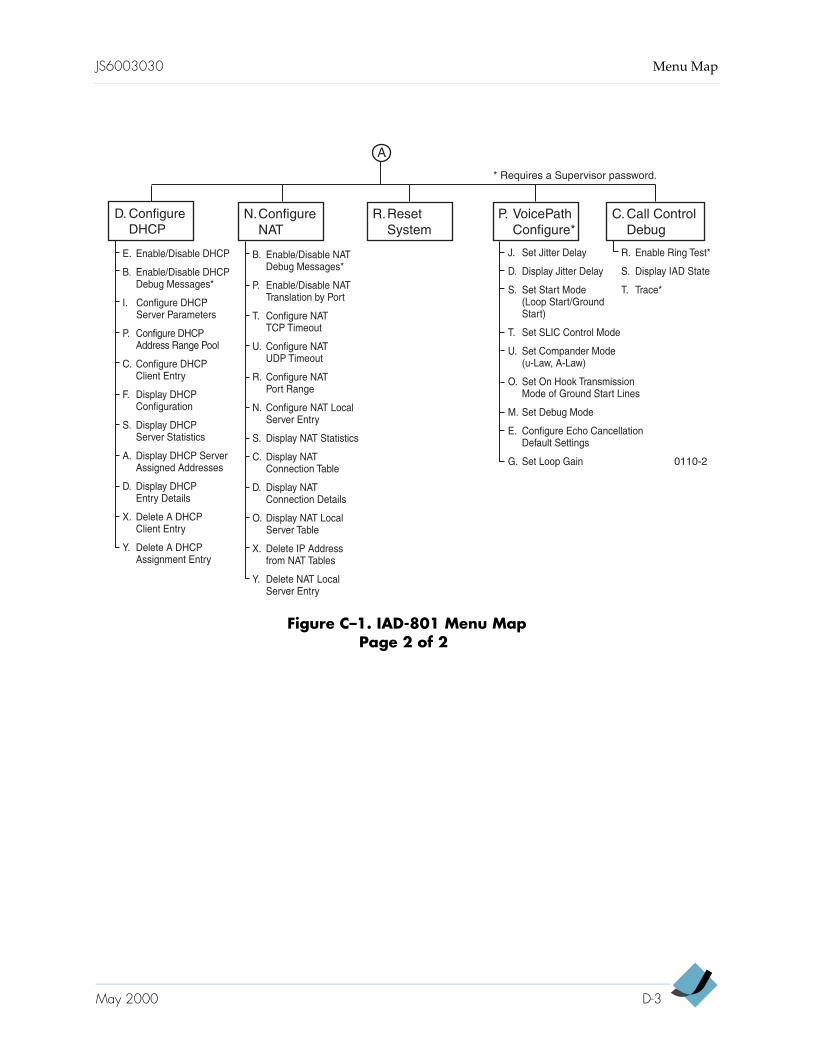
JS6003030 Menu Map
Figure C–1. IAD-801 Menu MapPage 2 of 2
P. VoicePathConfigure*
C.Call ControlDebug
J. Set Jitter Delay
D. Display Jitter Delay
S. Set Start Mode(Loop Start/GroundStart)
T. Set SLIC Control Mode
U. Set Compander Mode(u-Law, A-Law)
O. Set On Hook TransmissionMode of Ground Start Lines
M. Set Debug Mode
E. Configure Echo CancellationDefault Settings
G. Set Loop Gain
R. Enable Ring Test*
S. Display IAD State
T. Trace*
N.ConfigureNAT
R.ResetSystem
0110-2
B. Enable/Disable NATDebug Messages*
P. Enable/Disable NATTranslation by Port
T. Configure NATTCP Timeout
U. Configure NATUDP Timeout
R. Configure NATPort Range
N. Configure NAT LocalServer Entry
S. Display NAT Statistics
C. Display NATConnection Table
D. Display NATConnection Details
O. Display NAT LocalServer Table
X. Delete IP Addressfrom NAT Tables
Y. Delete NAT LocalServer Entry
* Requires a Supervisor password.
A
D. ConfigureDHCP
E. Enable/Disable DHCP
B. Enable/Disable DHCP Debug Messages*
I. Configure DHCPServer Parameters
P. Configure DHCPAddress Range Pool
C. Configure DHCPClient Entry
F. Display DHCPConfiguration
S. Display DHCPServer Statistics
A. Display DHCP Server Assigned Addresses
D. Display DHCPEntry Details
X. Delete A DHCPClient Entry
Y. Delete A DHCPAssignment Entry
May 2000 D-3

Menu Map JS6003030
D-4 May 2000
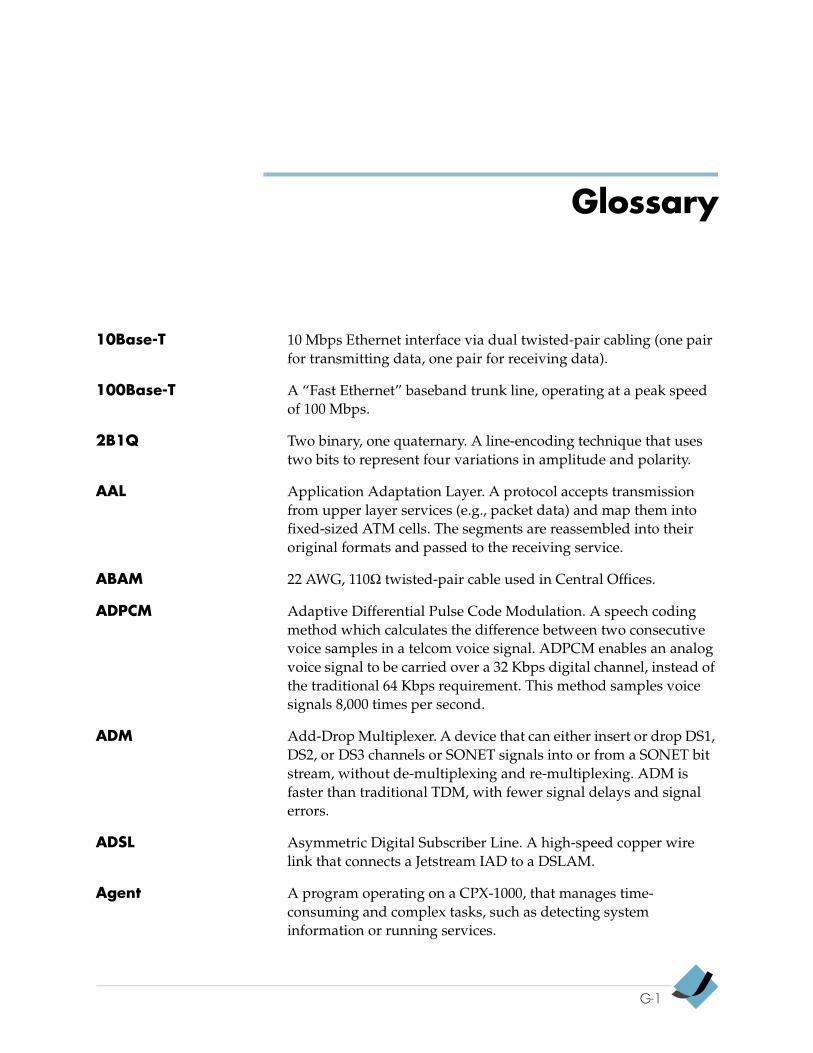
Glossary
10Base-T 10 Mbps Ethernet interface via dual twisted-pair cabling (one pair for transmitting data, one pair for receiving data).
100Base-T A “Fast Ethernet” baseband trunk line, operating at a peak speed of 100 Mbps.
2B1Q Two binary, one quaternary. A line-encoding technique that uses two bits to represent four variations in amplitude and polarity.
AAL Application Adaptation Layer. A protocol accepts transmission from upper layer services (e.g., packet data) and map them into fixed-sized ATM cells. The segments are reassembled into their original formats and passed to the receiving service.
ABAM 22 AWG, 110Ω twisted-pair cable used in Central Offices.
ADPCM Adaptive Differential Pulse Code Modulation. A speech coding method which calculates the difference between two consecutive voice samples in a telcom voice signal. ADPCM enables an analog voice signal to be carried over a 32 Kbps digital channel, instead of the traditional 64 Kbps requirement. This method samples voice signals 8,000 times per second.
ADM Add-Drop Multiplexer. A device that can either insert or drop DS1, DS2, or DS3 channels or SONET signals into or from a SONET bit stream, without de-multiplexing and re-multiplexing. ADM is faster than traditional TDM, with fewer signal delays and signal errors.
ADSL Asymmetric Digital Subscriber Line. A high-speed copper wire link that connects a Jetstream IAD to a DSLAM.
Agent A program operating on a CPX-1000, that manages time-consuming and complex tasks, such as detecting system information or running services.
G-1
Glossary
AIS Alarm Indication Signal.
AM Accounting Management (TMN functional area). A set of network management functions for measuring network service use, and determining its cost.
APS Automatic Protection Switching. A means of ensuring network resiliency, by automatically switching to a secondary circuit when a primary circuit either fails or has an error rate.
ARP Address Resolution Protocol. A means by which a networking device determines the physical (MAC) address of another device when only the logical (IP) address of the target device is known. See also ARP table.
ARP table A table containing the IP addresses and corresponding MAC addresses of all network devices to which the IAD is connected. See also MAC address.
ATM Asynchronous Transfer Mode. A technology used for high-speed packet switching and transmission on a Broadband Integrated Services Digital Network (B-ISDN). Five overhead (octets) bytes and 48 payload bytes comprise ATM packets (“cells”). ATM is designed to intermix and prioritize audio, data, imaging, and video data for fast, cell-based networks.
ATM Card Also called the ATM Cell Engine (ACE). In the CPX-1000, it performs real-time switched circuit-to-packet and packet-to-switched circuit conversion, enabling the DSL network to deliver local telephone service. Connects the CPX-1000 Voice Gateway to the ATM network, using either an OC-3 fiber optic interface (to support up to 1024 simultaneous telephone calls), or a DS-3 coaxial interface (to support up to 512 simultaneous telephone calls).
ATM OC3 (or DS3) The call-processing engine of the CPX-1000 Voice Gateway. This module connects a CPX-1000 shelf to an ATM access network, using an OC3 fiber optic or DS3 coaxial interface. It performs real time circuit-to-packet conversion.
B8ZS Binary 8 Zero Substitution. A coding technique used to accommodate the ones density requirement for digital T-carrier facilities in the public network, while allowing 64 Kbps clear data per channel. Rather than inserting a one for every seven consecutive zeros, B8ZS inserts two violations of the bipolar line encoding technique for digital transmission links.
G-2 January 2000
Glossary
Bc committed Burst size. The maximum bits the network provider agrees to transfer under normal network conditions during a time interval.
Be excess Burst size. The maximum bits of uncommitted data in excess of committed burst size that the network attempts to deliver during a time interval.
BECN Backward Explicit Congestion Notification. See also ECN.
Bridge A data communication device that connects two or more network segments together and sends data packets between them.
Bridge Card Also called Hot Swap Controller (HSC). Enables installing or replacing CP modules while the CPX-1000 Voice GateWay is running. Because the 16-slot PCI bus is divided into two 8-slot segments, and each CP is on a different half of the PCI bus, the bridge card also allows each CP to communicate with cards on the other half of the bus.
Broadcast Stations broadcast packet transmission on shared media (i.e., the common network). Other stations listen to these broadcasts, but receive only data packets addressed to them.
CBR Constant Bit Rate. A type of telecommunication service characterized by a service bit rate specified by a constant value. The periodic bit-oriented DS-1 and above signals generated by customer applications and transported in the ATM network using AAL Type 1 protocol. See also CES.
CCS Common Channel Signaling. A signaling technique where multiple circuits share a common channel for signaling. Signaling can be in or out of band.
CES Circuit Emulation Service. A specification supports emulation of existing TDM modules over ATM networks.
CHAP Challenge Handshake Authentication Protocol. A three-way authentication method used for PPP connections. See also PPP.
CIR Committed Information Rate. The maximum average data rate of a Frame Relay circuit.
CIT Craft Interface Terminal (JetCraft). Used in the primary installation of the CPX-1000.
January 2000 G-3
Glossary
CLASS Custom Local Area Signaling Services. CLASS services include call forwarding, call waiting, caller identification, automatic callback, automatic recall, and selective call rejection.
Class 5 Office The local central office (end office) that provides dial tone to subscribers.
CLEC Competitive (or Certified) Local Exchange Carrier. A company that offers local exchange services to end users.
CM Configuration Management (TMN functional area)
CME CPX Management Entity: The CME is the software entity that runs on the CPX (specifically on the MP card) and is responsible for all Equipment Management functions for the CPX system and the attached IADs. It handles all requests from both the Jetstream management applications (JetVision and JetCraft) as well as from the embedded operation channel (EOC) of the Class 5 phone switch.
CMIS Common Management Information Service
CMISE Common Management Information Service Element
CO Central Office
CORBA Common Object Request Broker Architecture. A standard for managing message traffic between application software and computer/software platforms. CORBA provides portability of software across platforms.
CP A CP (Call Processor) scans the trunk and/or station ports for service requests, checks its stored instructions, and sets up the intended connection in a switching system. The two CPs in a CPX-1000 Voice GateWay use a real-time operating system to perform call processing, where one CP is active or primary, and the other CP is standby or redundant. Each CP is paired with a Bridge Card, with one pair occupying slots 7 and 10, and the other pair in slots 8 and 9. If one CP develops a fault or failure, the redundant CP handles the load for both call processors. The active CP handles real call-control signaling, managing connections from the CPX-1000 Voice GateWay to the IADs at the customer sites; after establishing a call, the CP manages the ATE Interface via the T1 processing and transition cards, which in turn interconnect the CPX-1000 Voice GateWay with the Class 5 switch.
CP-3 Call Processing Module, Ver 3
G-4 January 2000
Glossary
cPCI An Intel designed, compact PCI (peripheral component interconnect) 32-bit local bus inside PCs. A PCI bus can transfer data at 132 MB/second.
CPE Customer Premises Equipment. Any telecommunications equipment (telephones, PBXs, answering machines, and so on) physically located at a customer’s location, or “premises.”
CPX Circuit Packet eXchange. The host processor and communications complex associated with a Unity system installation.
CPX Shelf “Shelf” is a telecommunications term that describes a complete chassis unit that mounts in an equipment rack. The CPX shelf is the fundamental unit of a CPX-1000 installation. Each shelf operates independently.
CPX-1000 The Jetstream switched voice network-to-packet network gateway (Circuit Packet eXchange).
Crafts personnel A term used in the telcom industry to describe personnel whose primary work duty can be subscriber telephone installation, outside plant service and repair, or inside plant service and repair.
Craft terminal A PC or laptop loaded with the JetCraft software, to allow human interaction with the CPX-1000 equipment for purposes of installation, upgrading, troubleshooting, and repair.
CRV Call Reference Value. CRVs are used between the CPX and the host switch to identify the destination of a call.
CSC Common Signaling Channel (GR-303 term). Used by the integrated digital terminal and remote digital terminal for call processing. See CCS.
DCE Distributed Computing Environment (OSF client/server framework). A vendor-neutral set of distributed computing technologies. DCE provides data security, controls data access, locates shared resources, and organizes widely-scattered users, services, and data.
DCN Data Communications Network
DCS Digital Cross-connect System. A device that switches and rearranges private line voice, private line data, and T-1 lines, setting up the lines before switching circuits to receive calls.
January 2000 G-5
Glossary
DLC Digital Loop Carrier. Network transmission equipment that derives multiple channels from a single four-wire distribution cabling running from the central office to a remote site.
DLCI Data Link Connection Identifier. A value that specifies a PVC in a Frame Relay protocol.
DS-1 (DS-1 line) Digital Signal level 1 (1.544 Mbps). See also T-1 line.
DS-3 Digital Signal level 3. DS-3 is the equivalent of 28 T-1 channels, operating at a total signaling rate of 44.736 Mbps. Typically transported by coaxial cable.
DSL Digital Subscriber Line. A technology that uses copper wire pairs for high-speed transmission of voice and data.
DSLAM Digital Subscriber Line Access Multiplexer. Located at the end of a subscriber loop in a telephone company’s central switching office, a DSLAM connects the central office to equipment at the customer’s premises, which in turn connects to the customer’s PCs and telephones.
DS-0 Digital Signal, level 0 (64 Kbps), equivalent to one digitized voice conversation.
DSX Digital Signal Cross-connect frame. A panel to which T1 lines and DS1 circuit packs are wired, which you can use to hand-connect plugs.
DTMF Dual Tone, Multi-Frequency. The tones that a Touch-Tone telephone makes when you press the buttons.
EC-1 Echo Cancellation Module, Ver 1 (ATM only)
ECAC-1 Echo Cancellation and Compression Module, 768 DS0, 64ms, ADPCM 32, Ver 1.
Echo Canceller Isolates and filters unwanted signals caused by echoes from the main transmitted signal. An echo canceller sends a signal on the return transmission path, which is equal and opposite to the echo signal. Echo cancellation allows the CPX-1000 Voice GateWay to send and receive signals on the same frequency.
ECI Explicit Congestion Instruction. In the event of network congestion, sends a message forward or backward to the source or destination of a data transmission, alerting it that data might become lost in the congestion.
G-6 January 2000
Glossary
ECN Explicit Congestion Notification. When the network becomes congested so that it cannot process new data transmission, it begins to discard frames. These discarded frames are retransmitted, thus causing more congestion. A parameter used in the Frame Relay configuration.
EFD Event Forwarding Discriminator.
EML Element Management Layer (TMN).
EMS Element Management System. See NMS and JetVision
EMS Client The name of the pull-down menu for the graphical user interface to JetVision Server. See JetVision Client
EMS Server See JetVision Server.
EOC Embedded Operations Channel.
ESD Electro-Static Discharge. What occurs when the static electricity that naturally builds up on your body discharges.
ESF Extended Super Frame or Extended Superframe Format, a T-1 framing method that uses 192-bit frames and sends 8,000 frames per second.
Ethernet A Local-Area Network (LAN) that connects devices such as CPX-1000s, IADs, and other systems within a building. Ethernet operates over twisted wire and coaxial cable, at speeds up to 10 million bits per second (Mbps).
FA TMN functional area.
FECN Forward Explicit Congestion Notification. See also ECN.
FM Fault Management (TMN functional area)
GR-303 A Bellcore requirements specification for the interface between a voice gateway (such as the CPX-1000) and a Class 5 Host Switch. GR-303 is a specification for a digital loop carrier (DLC) system that concentrates telephone traffic on a set of T-1 circuits.
GR-303 IG A GR-303 Interface Group, consisting of up to 28 DS1 lines.
GUI Graphical User Interface.
HDSL High-bit-rate Digital Subscriber Line
January 2000 G-7
Glossary
Host Switch A switching system at a central telephone company office, providing some of the functions to a smaller switch located remotely. Specifically, the Class 5 switch to which CPX-1000(s) are connected.
Hot Swappable The ability of a component (such as a redundant power supply) to be added to or removed from a device (such as a CPX-1000) without powering down the device. Hot-swappable components provide maximum up-time.
HSC-3 Hot Swap Controller Module, Ver. 3 (HA/Lynx).
IAD Integrated Access Device. A device that supports voice, data, and video streams over a single, high-capacity circuit. Specifically, the equipment located at the subscriber location that connects the CPX network and the subscriber's telephone equipment.
IEC International Electro-technical Commission.
ICP Integrated Communications Provider.
IDSL ISDN Digital Subscriber Line.
IEEE Institute of Electrical and Electronics Engineers.
ILEC Incumbent Local Exchange Carrier. A company from which a CLEC leases local loops for resale to end users.
INA Information Networking Architecture, Bellcore developed to facilitate inter-operability between proprietary software.
IP Internet Protocol.
ISDN Integrated Services Digital Network
ISP Internet Service Provider. A company that provides Internet and World Wide Web access services to private users and businesses.
ITU International Telecommunications Union.
JetCraft Jetstream Craft interface terminal software.
JetVision Jetstream’s Element Management System.
G-8 January 2000
Glossary
JetVision Client The JetVision client communicates with the JetVision server software over your local area network (LAN). The client software transforms the information it receives from the server into the graphical user interface (GUI) windows on your computer. Also, it translates the GUI requests to the server, which will in turn execute the commands. As a user, you only interact directly with the JetVision client software.
JetVision Server Contains the database that operates JetVision Client and the JetVision Gateway Server, thereby providing functionality to the JetVision GUI.
JetMonitor A single-window Jetstream application that enables management/marketing personnel to view either an operating Jetstream system or a demonstration (simulated) Jetstream system.
JetStat A single-window Jetstream application program installed on any PC that enables crafts personnel to view the Jetstream system operations (one system at a time, and the ability to change IP addresses to view other Jetstream systems), as viewed from the CPX-1000 viewpoint.
JetWay An application that provisions IADs and integrates JetVision into a customer's NMS after the CPX-1000 managed domains have been configured in JetVision.
KTS Key Telephone System. A telephone on which pressing different buttons directly selects separate central telephone office lines, without going through a PBX switch. Generally has fewer lines, features, and functions than a telephone that switches through a PBX. Typically used in a small office requiring fewer than 50 telephone lines.
LAN Local Area Network. A short-distance data communications network, typically located within a single building or a campus of buildings. See also Ethernet.
Lease time Lease time represents the maximum amount of time the client can use the assigned IP address.
LEC Local Exchange Carrier. A local telephone company. See also CLEC and ILEC.
January 2000 G-9
Glossary
MAC address Media Access Control address. A 48-bit number that identifies a specific hardware module on a network. The IAD-801's Ethernet LAN, SDSL, and ATM modules each have unique MAC addresses, which are factory-programmed. Bridges use the MAC addresses to forward data packets.
MBS Maximum Burst Size. At ATM term for a traffic parameter specifying maximum number of cells transmitted at the peak cell rate (PCR).
MF Mediation Function (TMN functional block). The three mediation functions for transporting data from one device to another are protocol conversion, message routing, and store-and-forward processing.
MIB Management Information Base. A database of network performance information (such as error counts and on/off information), stored on a Network Agent, and retrieved by a Network Management Station (NMS).
MMF Multi Mode Fiber. A fiber optic cable in which the signal or light propagates in more than one mode or path
MOA Managed Object Agent (INA building block). A program operating on a CPX-1000, that creates and processes managed object, which are abstract representations of physical or logical resources on a network.
Module Set of processing cards and a transmission card.
MP Management Processor. Provides the communication link to the two Call Processors (CPs), and to Jetstream’s two management systems (JetCraft and JetVision). Both of these management systems send instructions to the CPX-1000 Voice GateWay via either a direct 10/100Base-T interface, or a remote modem.
The MP is located in slot 16 of the front compartment of the midplane, with its transition card directly behind it, on the opposite side of the midplane. The MP runs Windows NT, and is supported by a hard drive, so that JetCraft and JetVision users can login and perform normal management activities. The MP also creates and manages a database that archives the most recent three days of statistics, performance, and alarms on the CPX-1000 Voice GateWay.
MP-1 Management Processing Module, Ver 1.
G-10 January 2000
Glossary
Multicast The broadcast of messages to a selected group of workstations on a LAN, WAN, or the Internet. Multicast is a communication between a single device and multiple members of a device group.
NE Network Element. A single piece of telecommunications equipment that performs a function or service integral to the network.
NEBS Network Equipment Building Standards. A Telcordia (formerly, Bellcore) comprehensive set of telecommunications performance, quality, environmental, and safety requirements. NEBS standards include such diverse requirements as fire containability and extinguishability; ability to withstand earthquake, thermal, and mechanical shock; operating temperature ranges; and resistance to electro-static discharge (ESD).
NEF Network Element Function (TMN functional block). A function within an ATM entity, that supports ATM network-based transport services (such as multiplexing or cross-connection).
NIC Network Interface Card. A device that executes the code needed to connect a piece of equipment to a shared network cable.
NIM Network Interface Module. Electronic circuitry that connects a system (such as a PC) to the telephone network.
NMA Network Monitoring and Analysis (Telcordia).
NMS Network Management System. A means of administering, maintaining, and provisioning CPX-1000s and other devices on a network. Also sometimes referred to as an “Element Management System (EMS, see JetVision).”
OAM Operation, Administration, and Maintenance. It is typically a group of network management functions that provide network fault indication, performance information, and data and diagnosis functions.
OC-3 Optical Carrier 3. A 155 Mbps optical (fiber optic) data path used by the CPX-1000 for ATM transmission. Equivalent to three DS-3s.
OS Operating System (such as NT or UNIX).
OSF Open Software Foundation. An industry organization that sets standards of inter-operability, scalability, portability, and usability for technological innovations in distributed computing.
OSI Open Systems Interconnect.
January 2000 G-11
Glossary
OSMINE Operations Systems Management Integration for Network Elements.
OSS Operations Support System. Methods and procedures that directly support the daily operation of the telecommunications infrastructure.
Packet Includes the ATM and IP modules.
PAP Password Authentication Protocol. A protocol that supports data sequencing, flow control, accountability, and error detection and recovery.
PCM Pulse Code Modulation. A method of encoding an analog voice signal into a digital bit stream.
PCR Peak Cell Rate in cells/sec. which the source may never exceed.
Persistence Persistence refers to database components, or distributed objects that must maintain their state long after the program that creates them terminates. To be persistent, the object’s state must be stored in a non-volatile database. Persistence allows the state of an object to be saved in a persistent data storages and it doesn’t matter if the storage is SQL database or a simple file system; it is one big virtual store, where memory and persistent storage are the same thing.
PING Packet InterNet Groper, a test analogous to a voice “hello, hello” test where a computer on a network sends a test message to another computer on a network that, when a complete path is set up, elicits a response from the second computer. The PING test is particularly useful for verifying that a path exists between intelligent devices on a network.
PM Performance management (TMN functional area).
POTS Plain Old Telephone Service. The type of voice telephone service provided by local exchange carriers and supported by Jetstream-compliant integrated access device CPE. POTS generally refers to two-wire, loop-start phone lines.
PPP Point-to-point protocol. It provides router-to-router and host-to-network connections over synchronous and asynchronous circuits.
Pre-provisioning A process by which resources can be provisioned before the hardware is actually located in the shelf. This allows the system to discover resources that have not yet been administratively created (provisioned). For example, an ATM card could be pre-provisioned
G-12 January 2000
Glossary
before actually being put into the CPX-1000 shelf, then services could be activated so that the card could be provisioned.
Processing Card The front card in cPCI design.
PSTN Public Switched Telephone Network. An international telephone system based on copper wires, carrying analog voice data.
PVC Permanent Virtual Circuit. A shared circuit that provides the equivalent of a dedicated private line service between two data terminals, over a packet-switched network.
QAF Q-adapter function (TMN functional block)
Resource Modules Another name for the Echo Canceller. Applies to both EC-1 and ECAC-1 modules.
RIP Routing Information Protocol. A protocol that allows the IAD to determine the shortest distance between two points for data routing. The IAD periodically broadcasts its routing table contents to other routers for network database synchronization. See also Routing table.
RFI Request for information. A notification to service or equipment vendors, of intent to purchase services or equipment.
RFP Request for proposal. A buyer’s written definition of services or equipment required, sent to one or several vendors. Usually contains extensive and specific details (specifications) for the services or equipment required.
RFQ Request For Quotation. A buyer’s request for price quotations on services or equipment, sent to one or several vendors. Generally more detailed than an RFI, but less detailed than an RFP.
RFX A generic term for request for information (RFI)/proposal (RFP)/quote (RFQ).
RMA Return Material Authorization. A code number provided by the seller, as a prerequisite to returning a product for repair, replacement, or refund.
Router A device that connects LANs together and passes (routes) data from one LAN device to another.
Routing table A table in routers that keeps track of data routes to network destinations. The information in this table is used to determine the best path for data routing through a network.
January 2000 G-13
Glossary
RSC Regional Switching Center or Remote Switching Center.
RDI Remote Defect Indication. An indication that a failure has occurred at the far end of an ATM network; however, the alarm indication does not identify the specific circuit in a failure condition.
RU Rack Units. Describes the vertical dimension of an available area for installing rack-mounted telecommunications equipment. One rack unit equals a height of 1.75 inches (4.45 cm).
SCR Sustainable Cell Rate, defined by the ATM forum for traffic management. SCR is an upper bound to the conforming average rate of an ATM connection over time scales relative to the PCR definition.
SDCC Section Data Communications Channel.
SDSL Symmetric Digital Subscriber Line. This type of DSL line connects a Jetstream IAD to a DSLAM.
SLIC Subscriber Line Interface Circuit. A device used to interface with local subscriber pair gain or multiplexing devices.
SM Security Management (TMN functional area). A standard set by the International Standards Organization (ISO) to protect a network from invalid access.
SML Service Management Layer (TMN). The network layer that provisions and administers data about network services.
SNMP Simple Network Management Protocol. A network management protocol used in TCP/IP networks.
SONET Synchronous Optical NETwork. A set of fiber optic transmission rates, ranging from 51.84 Mbits to 13.27 gigabits per second. This wide range of transmission rates allows a single fiber optic cable the flexibility to transport many digital signals with different capacities, originating from equipment of different vendors.
Spanning tree A means by which the IAD can automatically reconfigure a bridge network to use an alternate path for data forwarding. See also STP.
Static routing A data path manually programmed into the router by a network administrator.
STP Spanning Tree Protocol. A bridging protocol that deactivates links between networks so information packets can be sent along a single route to a destination.
G-14 January 2000
Glossary
STSX Synchronous Transport Signal. Converts electrical signals to and from SONET fiber-optic signals.
STS X1 Synchronous Transport Signal -- electrical, level 1 (51.84 Mpbs)
Subnet mask A 32-bit address mask that indicates the bits of an IP address.
Subscriber The end user connected to an IAD.
T-1 line Trunk level 1. A 1.544 Mbps connection between a voice gateway (such as the CPX-1000) and a Class 5 Host Switch, supporting up to 24 voice conversations, each encoded at 64 Kbps. See also DS-1 (DS-1 line).
T-1 DS1-rate facility (in TL1 object model).
TBOS Telemetry byte-oriented signaling. Transmits alarm, status, and control points between NE and OS.
TCA Threshold Crossing Alerts. Notifies a transmitting source that its transmitted signal has dropped below a pre-defined level.
TDM Time-division multiplexing (also called GR-303). A technique for transmitting multiple data, voice, and/or video signals simultaneously, by quickly interleaving a piece of each signal, one after another.
TFTP Trivial File Transfer Protocol. A simplified version of FTP, which transfers files from one computer to another over a network.
TL1 Transaction Language 1 (Telcordia). A machine-to-machine communications language.
TMC Timeslot management channel (GR-303). A dedicated channel for sending control messages, used to set-up and tear-down calls in a T-1 frame. In a GR-303 interface group, the primary TMC is usually channel 24 of the first DS1.
TMN ITU-T Telecommunications Management Network.
TNM Total Network Management ® (Lucent EMS/NMS product).
TR Technical requirements (Telcordia). Published standards for products, new technologies, services, or interfaces.
Transition Card Transition cards are the cards that install in the rear of the CPX-1000 shelf. A function of the compact PCI (cPCI) mid-plane motherboard design, these cards extend interfaces from their
January 2000 G-15
Glossary
corresponding cards installed in the front of the card cage (e.g., the T1 Transition Card with its eight RJ-48C connector sockets).
UBR and UBR+ Undefined or unspecified bit rate. An ATM service category which does not specify traffic related service guarantee.
UI User interface.
UID User IDentification (login).
U-law A voice amplitude compression/expansion quasi-logarithmic curve, based on the approximation with 15 linear segmentation. Used for PCM encoding/decoding in North America. See PCM.
UNI User Network Interface.
VC Virtual Circuit. In packet switching, network facilities that appear to be an actual end-to-end circuit. Virtual circuits allow multiple users to share switches and transmission facilities, while temporarily or permanently appearing to each user as a private, dedicated circuit.
VCI Virtual Circuit Identifier. A unique numeric identifier for the Virtual Circuit carrying a specific stream of cells between specific network devices during a specific session. The VCI is represented by a 16-bit field in the ATM cell header.
VMWI Visual Message Waiting Indication.
VBR Variable Bit Rate. The bursty signals generated by customer applications and transported in the ATM network using AAL Type 3/4 (AAL3/4) or AAL Type 5 (AAL5) protocol.
VPI Virtual Path Identifier. A specific stream of cells routed during a specific session. The VPI is identified by an 8-bit field in the ATM cell header.
WAN Wide Area Network. A network providing communications between telephones, PCs, and other equipment in diverse locations, both within a city and in multiple cities.
WFQ Weighted Fair Queuing. Separates voice and data traffic into multiple queues, based on traffic class definitions, so that all traffic is guaranteed a portion of a network’s total available bandwidth. If one queue is not using all of its allocated bandwidth, WFQ temporarily allocates the unused bandwidth to other voice and data traffic queues.
G-16 January 2000

Glossary
WSF Work Station Function (TMN functional block).
X.25 ITU-T (formerly CCITT) Recommendation X.25 (network protocol). An internationally-accepted standard governing the operation of packet-switched networks. The X.25 standard defines setup times, how data streams are assembled into packets, and how packets are controlled, routed, and protected as they move across the network.
January 2000 G-17

Glossary
G-18 January 2000
Index
A
AC power 1-2, 2-3, 2-4
AC power connection 2-4
AC power cord 2-3
access levels 3-3
access levels and privilegesSupervisor 4-1
access levels and privilegesnetwork administrator 3-3
Supervisor 3-3
user 3-3
addingdefault route 6-6
IP address 6-3, 6-4, 7-11
port 5-6, 5-26
PVC 5-6, 5-26
static route 6-5
adding subnet mask 6-4, 7-11
ADSL connection 2-7
ADSL module 7-2
application, typical 2-1, 2-2, 2-4
applying power 3-2
assigning IP address 6-3
ATM configurationencapsulation 5-7, 5-10, 5-26, 5-30
ATM connection 2-7
ATM-25 module 7-2
pin assignments 2-8
auto timeout 3-10
B
B8ZS 5-24
bridge 6-24
aging timer 6-27
default settings 6-24, B-1
bridge configurationaging timer 6-27
database entry deletion 6-32
enable/disable by port 6-26
enable/disable global 6-25
enable/disable STP globally 6-27
spanning tree bridge priority 6-29
spanning tree forward delay 6-31
spanning tree hello time 6-30
spanning tree maximum age 6-30
spanning tree path cost 6-31
spanning tree port priority 6-29
Bridge Configuration Menu 6-25
bridge priority 6-29
bridging 3-1
bridging compliance 3-1
C
cablesADSL module 2-3
ATM-25 module 2-3
Ethernet 2-3
RJ-11 2-3, 2-6
RJ-45 2-3, 2-6, 3-2
RJ-48 2-8
SDSL module 2-3
T1/E1module 2-3
CBR 5-9, 5-28
changingpasswords 4-3
user ID 4-2
changing default route 6-6
CHAP 5-8, 5-27
Client entrydeleting 6-21
MAC address 6-20
I-1
Index JS6003030
number 6-20
clock source 5-25
complianceATM-25 3-1
bridging 3-1
Frame Relay 3-1
routing 3-1
configurationas bridge 6-24
physical SDSL interface 5-22
router 6-2
configuringADSL module 5-2
DLCIs 5-14, 5-33
IP address 6-4, 7-11
local server protocol 6-14
NAT local server 6-14
NAT port range 6-15
NAT timeouts 6-15
passwords 4-3
physical interface for ATM 5-5
physical interface for Frame Relay 5-19
PVCs 5-6, 5-26
SNMP 4-4
subnet mask 6-4, 7-11
T1/E1 module 5-22
T1/UNI configuration 5-22
T1/UNI protocol 5-22
user ID 4-2
Configuring PVCs for ADSL and ATM-25 5-6
connectors, rear 2-4
controls and indicators 1-5, 1-6
craft terminal ports 3-2
custom defaults 4-9
D
data interfaces 3-1
data rate 5-40
data traffic 5-1
default IP address 3-2, 7-9
default parameterscustomizing 4-9
default route 6-6
deleting 6-8
defaultscustom 4-9
factory 4-9
deletingbridge database 6-32
default route 6-8
DHCP Client entry 6-21
DLCI 5-18, 5-37
IP address 6-6
MAC address 6-32
NAT local server 6-16
port 5-11, 5-18, 5-30, 5-37
PVC 5-11, 5-30
static route 6-8
DHCPclient configuration 6-22
Client entry 6-20
default settings B-2
high IP address 6-20
low IP address 6-20
server configuration 6-19
DHCP address range pool 6-20
high IP address 6-20
low IP address 6-20
DHCP Configuration Menu 6-18
DHCP server parameters, settingDNS 6-19
domain name 6-19
Gateway address 6-19
lease time 6-19
subnet mask 6-19
dial tone 7-2
disablingbridging globally 6-25
bridging individually 6-26
DHCP 6-18
NAT translation 6-13
RIP 6-9
STP globally 6-27
STP individually 6-28
displaying the route table 7-8
DLCIdeleting 5-18, 5-37
modifying 5-16, 5-36
DNSclient configuration 6-23
DNS server address 6-19
domain name 6-19
DSLAMCopper Mountain 5-4
Lucent 5-12, 5-31
I-2 May 2000
JS6003030 Index
Lucent Stinger 5-4
Nokia 5-4
E
echo cancellation 5-44
enablingbridging globally 6-25
bridging individually 6-26
DHCP 6-18
NAT translation 6-13
RIP 6-9
RIP poisoned reverse 6-11
STP globally 6-27
STP individually 6-28
encapsulationATM configuration 5-7, 5-10, 5-26, 5-30
Frame Relay configuration 5-14, 5-16, 5-34, 5-36
Ethernet LAN connection 2-6
Ethernet modulepin assignments 2-6
F
F4 OAM cell configuration 5-12, 5-32
F4 OAM configurationend-to-end 5-12, 5-32
segment 5-12, 5-32
factory-supplied components 2-2
flash memory 4-1, 5-2, 6-1
forward delay time 6-31
frame mode 5-23
Frame Relay configurationencapsulation 5-14, 5-16, 5-34, 5-36
G
Gateway address 6-19
global bridging 6-25
Ground Start 5-41
H
hello time 6-30
high IP address 6-20
I
IAD parameterscustomizing 4-9
IAD-801auto log off 3-10
bridge 6-1, 6-24
IP address 3-4
logging off 3-10
logging on 3-4
menus 3-6, 3-7
power-up 7-1
router 6-1
security 3-3, 4-1
serial number 7-9
submenus functions 3-8
timeout 3-10
installationAC power connection 2-4
ADSL connection 2-7
ATM WAN connection 2-7
connectors used 2-4
Ethernet connection 2-6
mounting 2-3
SDSL connection 2-7
T1/E1 connection 2-8
telephone line connections 2-6
IP address 3-4, 6-3, 6-11, 6-14, 6-17
adding 6-4, 7-11
deleting 6-6
restoring 7-9
IP address assignment 6-3
IP routers 3-1
J
jitter buffer 5-40
jitter delay 5-40
L
LBO setting 5-23
lease time 6-19
line build out setting 5-23
line codingB8ZS 5-24
local server protocol 6-15
login IDnetwork administrator 3-4, 4-2
supervisor 3-4, 4-2
user 3-4, 4-2
logout timer 3-10
loop gain 5-45
Loop Start 5-41
loopback 5-13, 5-33
May 2000 I-3
Index JS6003030
low IP address 6-20
M
MAC address 6-20, 6-24, 6-27, 6-29, 6-32
format 6-21
Main Menufor network administrator 3-7
for Supervisor 3-6
for user 3-7
maintenance protocol for frame relay 5-18, 5-38
maximum age 6-30
modifyingDLCI 5-16, 5-36
port 5-9, 5-16, 5-29, 5-36
PVC 5-9, 5-29
mounting 2-3
dimension 2-3
location 2-3
screws size 2-3
surface 2-3
mounting screws 2-3
N
NAT 6-11
default settings B-2
local server protocol 6-15
port range 6-15
timeouts 6-15
NAT Configuration Menu 6-13
NAT local serverdeleting 6-16
local server protocol 6-14
port numbers 6-14
translated IP address 6-14
Network Address Translator 6-11
network loops 6-27
network statistics 7-7
O
OAM loopback 5-13, 5-33
on hook transmission mode 5-43
P
PAP 5-8, 5-27
passwords 4-3
path cost 6-31
payload scrambling 5-12, 5-31
physical interfaceATM configuration 5-5
Frame Relay configuration 5-19
SDSL module 5-5, 5-19
T1/E1 module 5-22
T1/UNI configuration 5-22
pin assignmentsADSL module 2-7
ATM-25 module 2-8
Ethernet connection 2-6
SDSL module 2-7
T1/E1 module 2-8
port priority 6-29
port rangehigh end 6-16
low end 6-16
power consumption 2-5
power requirement 2-5
power source 2-4
powering up 3-2
PPP authorizationCHAP 5-8, 5-27
PAP 5-8, 5-27
PVCadding 5-6, 5-26
deleting 5-11, 5-30
modifying 5-9, 5-29
R
receive channels 5-24
reportsinterface statistics 7-7
media statistics 7-8
Reports Menu 7-4
restoring default IP address 7-9
Return Material Authorization 2-2
returning IAD-801 2-2
RIP 6-9
RIP poisoned reverse 6-11
RIP version 6-10
RMA 2-2
router configurationdefault route assignments 6-6
display route table 7-8
IP address assignments 6-3
IP address deleting 6-6
static route assignments 6-5
static route deleting 6-8
I-4 May 2000
JS6003030 Index
routing 3-1
compliance 3-1
default settings B-1
Routing Information Protocol 6-9
S
screw size 2-3
SDSL connection 2-7
SDSL module 7-2
pin assignments 2-7
setting mode and speed 5-22
securityaccess levels 3-3
selectingB8ZS 5-24
clock source 5-25
line coding 5-24
receive channels 5-24
transmit channels 5-24
serial number 7-9
SLIC control mode 5-42
SNMPcommunity name 4-8
disabling 4-6
enabling 4-6
system contact 4-6
system location 4-7
system name 4-7
trap host address 4-8
SNMP supported events 4-5
spanning treebridge priority 6-29
forward delay time 6-31
hello time 6-30
maximum age 6-30
path cost 6-31
port priority 6-29
spanning tree algorithm 6-29, 6-31
Spanning Tree Protocol 6-27
static route 6-5
deleting 6-8
statisticsnetwork 7-7
STP 6-27
bridge priority 6-29
forward delay time 6-31
hello time 6-30
maximum age 6-30
path cost 6-31
port priority 6-29
STP (spanning tree protocol) 6-27
subnet mask 3-2, 6-3, 6-11, 6-19
adding 6-4, 7-11
T
T1 span length 5-24
T1/E1 connection 2-8
T1/E1 module 7-2
TCP 6-14, 6-15
TCP/IP stack 7-2
telephone line connections 2-6
Telnet session font 3-4
timeoutsTCP 6-15
UDP 6-15
transmit channels 5-24
transmission mode 5-43
U
UDP 6-14, 6-15
uninterruptible power supplyconsumption 2-5
requirement 2-5
UPSconsumption 2-5
requirement 2-5
user access levels 3-3
user ID 4-2
V
VBR 5-9, 5-28
VCI 5-7, 5-9, 5-26, 5-29
verifying IP addresses 3-2
voice operation 7-2
VPI 5-6, 5-9, 5-26, 5-29
W
WAN configurationdatalink protocol 5-21
WAN connections 2-7
WAN modulesADSL 2-1, 2-7, 5-1
ATM-25 2-1, 2-7, 5-1
SDSL 2-1, 2-7, 5-1
T1/E1 2-1, 2-8, 5-1
May 2000 I-5