Embed Size (px)
Citation preview

IA-32 Intel® ArchitectureSoftware Developer’s
Manual
Volume 2:Instruction Set Reference
NOTE: The IA-32 Intel Architecture Software Developer’s Manualconsists of three volumes: Basic Architecture, Order Number 245470-012;
Instruction Set Reference, Order Number 245471-012; and the SystemProgramming Guide, Order Number 245472-012.
Please refer to all three volumes when evaluating your design needs.
2003

INFORMATION IN THIS DOCUMENT IS PROVIDED IN CONNECTION WITH INTEL PRODUCTS. NO LICENSE,EXPRESS OR IMPLIED, BY ESTOPPEL OR OTHERWISE, TO ANY INTELLECTUAL PROPERTY RIGHTS ISGRANTED BY THIS DOCUMENT. EXCEPT AS PROVIDED IN INTEL’S TERMS AND CONDITIONS OF SALE FORSUCH PRODUCTS, INTEL ASSUMES NO LIABILITY WHATSOEVER, AND INTEL DISCLAIMS ANY EXPRESS ORIMPLIED WARRANTY, RELATING TO SALE AND/OR USE OF INTEL PRODUCTS INCLUDING LIABILITY ORWARRANTIES RELATING TO FITNESS FOR A PARTICULAR PURPOSE, MERCHANTABILITY, OR INFRINGEMENTOF ANY PATENT, COPYRIGHT OR OTHER INTELLECTUAL PROPERTY RIGHT. INTEL PRODUCTS ARE NOTINTENDED FOR USE IN MEDICAL, LIFE SAVING, OR LIFE SUSTAINING APPLICATIONS.
Intel may make changes to specifications and product descriptions at any time, without notice.
Designers must not rely on the absence or characteristics of any features or instructions marked “reserved” or“undefined.” Intel reserves these for future definition and shall have no responsibility whatsoever for conflicts orincompatibilities arising from future changes to them.
The Intel® IA-32 architecture processors (e.g., Pentium® 4 and Pentium III processors) may contain design defects orerrors known as errata. Current characterized errata are available on request.
Intel, Intel386, Intel486, Pentium, Intel Xeon, Intel NetBurst, Intel SpeedStep, OverDrive, MMX, Celeron, and Itaniumare trademarks or registered trademarks of Intel Corporation and its subsidiaries in the United States and othercountries.
*Other names and brands may be claimed as the property of others.
Contact your local Intel sales office or your distributor to obtain the latest specifications and before placing yourproduct order.
Copies of documents which have an ordering number and are referenced in this document, or other Intel literature,may be obtained from:
Intel CorporationP.O. Box 5937 Denver, CO 80217-9808
or call 1-800-548-4725or visit Intel’s website at http://www.intel.com
Copyright © 1997 - 2003 Intel Corporation

CONTENTSPAGE
CHAPTER 1ABOUT THIS MANUAL1.1. IA-32 PROCESSORS COVERED IN THIS MANUAL . . . . . . . . . . . . . . . . . . . . . . . 1-11.2. OVERVIEW OF THE IA-32 INTEL ARCHITECTURE SOFTWARE
DEVELOPER’S MANUAL, VOLUME 2: INSTRUCTION SET REFERENCE . . . . . 1-21.3. NOTATIONAL CONVENTIONS. . . . . . . . . . . . . . . . . . . . . . . . . . . . . . . . . . . . . . . . 1-21.3.1. Bit and Byte Order . . . . . . . . . . . . . . . . . . . . . . . . . . . . . . . . . . . . . . . . . . . . . . . . .1-21.3.2. Reserved Bits and Software Compatibility . . . . . . . . . . . . . . . . . . . . . . . . . . . . . .1-31.3.3. Instruction Operands . . . . . . . . . . . . . . . . . . . . . . . . . . . . . . . . . . . . . . . . . . . . . . .1-41.3.4. Hexadecimal and Binary Numbers . . . . . . . . . . . . . . . . . . . . . . . . . . . . . . . . . . . .1-41.3.5. Segmented Addressing . . . . . . . . . . . . . . . . . . . . . . . . . . . . . . . . . . . . . . . . . . . . .1-41.3.6. Exceptions. . . . . . . . . . . . . . . . . . . . . . . . . . . . . . . . . . . . . . . . . . . . . . . . . . . . . . .1-51.4. RELATED LITERATURE . . . . . . . . . . . . . . . . . . . . . . . . . . . . . . . . . . . . . . . . . . . . . 1-6
CHAPTER 2INSTRUCTION FORMAT2.1. GENERAL INSTRUCTION FORMAT . . . . . . . . . . . . . . . . . . . . . . . . . . . . . . . . . . . 2-12.2. INSTRUCTION PREFIXES . . . . . . . . . . . . . . . . . . . . . . . . . . . . . . . . . . . . . . . . . . . 2-12.3. OPCODE . . . . . . . . . . . . . . . . . . . . . . . . . . . . . . . . . . . . . . . . . . . . . . . . . . . . . . . . . 2-32.4. MODR/M AND SIB BYTES . . . . . . . . . . . . . . . . . . . . . . . . . . . . . . . . . . . . . . . . . . . 2-32.5. DISPLACEMENT AND IMMEDIATE BYTES. . . . . . . . . . . . . . . . . . . . . . . . . . . . . . 2-42.6. ADDRESSING-MODE ENCODING OF MODR/M AND SIB BYTES. . . . . . . . . . . . 2-4
iii
CHAPTER 3INSTRUCTION SET REFERENCE3.1. INTERPRETING THE INSTRUCTION REFERENCE PAGES . . . . . . . . . . . . . . . . 3-13.1.1. Instruction Format . . . . . . . . . . . . . . . . . . . . . . . . . . . . . . . . . . . . . . . . . . . . . . . . .3-13.1.1.1. Opcode Column . . . . . . . . . . . . . . . . . . . . . . . . . . . . . . . . . . . . . . . . . . . . . . . .3-23.1.1.2. Instruction Column . . . . . . . . . . . . . . . . . . . . . . . . . . . . . . . . . . . . . . . . . . . . . .3-33.1.1.3. Description Column . . . . . . . . . . . . . . . . . . . . . . . . . . . . . . . . . . . . . . . . . . . . .3-53.1.1.4. Description . . . . . . . . . . . . . . . . . . . . . . . . . . . . . . . . . . . . . . . . . . . . . . . . . . . .3-63.1.2. Operation. . . . . . . . . . . . . . . . . . . . . . . . . . . . . . . . . . . . . . . . . . . . . . . . . . . . . . . .3-63.1.3. Intel® C/C++ Compiler Intrinsics Equivalents . . . . . . . . . . . . . . . . . . . . . . . . . . . .3-93.1.3.1. The Intrinsics API . . . . . . . . . . . . . . . . . . . . . . . . . . . . . . . . . . . . . . . . . . . . . .3-103.1.3.2. MMX™ Technology Intrinsics . . . . . . . . . . . . . . . . . . . . . . . . . . . . . . . . . . . . .3-103.1.3.3. SSE and SSE2 Intrinsics . . . . . . . . . . . . . . . . . . . . . . . . . . . . . . . . . . . . . . . .3-103.1.4. Flags Affected . . . . . . . . . . . . . . . . . . . . . . . . . . . . . . . . . . . . . . . . . . . . . . . . . . .3-123.1.5. FPU Flags Affected . . . . . . . . . . . . . . . . . . . . . . . . . . . . . . . . . . . . . . . . . . . . . . .3-123.1.6. Protected Mode Exceptions. . . . . . . . . . . . . . . . . . . . . . . . . . . . . . . . . . . . . . . . .3-123.1.7. Real-Address Mode Exceptions . . . . . . . . . . . . . . . . . . . . . . . . . . . . . . . . . . . . .3-143.1.8. Virtual-8086 Mode Exceptions. . . . . . . . . . . . . . . . . . . . . . . . . . . . . . . . . . . . . . .3-143.1.9. Floating-Point Exceptions . . . . . . . . . . . . . . . . . . . . . . . . . . . . . . . . . . . . . . . . . .3-143.1.10. SIMD Floating-Point Exceptions . . . . . . . . . . . . . . . . . . . . . . . . . . . . . . . . . . . . .3-143.2. INSTRUCTION REFERENCE . . . . . . . . . . . . . . . . . . . . . . . . . . . . . . . . . . . . . . . . 3-15
AAA—ASCII Adjust After Addition. . . . . . . . . . . . . . . . . . . . . . . . . . . . . . . . . . . .3-16AAD—ASCII Adjust AX Before Division . . . . . . . . . . . . . . . . . . . . . . . . . . . . . . .3-17AAM—ASCII Adjust AX After Multiply . . . . . . . . . . . . . . . . . . . . . . . . . . . . . . . . .3-18AAS—ASCII Adjust AL After Subtraction . . . . . . . . . . . . . . . . . . . . . . . . . . . . . .3-19

CONTENTS
PAGE
ADC—Add with Carry . . . . . . . . . . . . . . . . . . . . . . . . . . . . . . . . . . . . . . . . . . . . .3-20ADD—Add. . . . . . . . . . . . . . . . . . . . . . . . . . . . . . . . . . . . . . . . . . . . . . . . . . . . . .3-22ADDPD—Add Packed Double-Precision Floating-Point Values . . . . . . . . . . . . .3-24ADDPS—Add Packed Single-Precision Floating-Point Values . . . . . . . . . . . . . .3-26ADDSD—Add Scalar Double-Precision Floating-Point Values . . . . . . . . . . . . . .3-28ADDSS—Add Scalar Single-Precision Floating-Point Values. . . . . . . . . . . . . . .3-30AND—Logical AND . . . . . . . . . . . . . . . . . . . . . . . . . . . . . . . . . . . . . . . . . . . . . . .3-32ANDPD—Bitwise Logical AND of Packed Double-Precision Floating-
Point Values. . . . . . . . . . . . . . . . . . . . . . . . . . . . . . . . . . . . . . . . . . . . . . . .3-34ANDPS—Bitwise Logical AND of Packed Single-Precision Floating-Point
Values . . . . . . . . . . . . . . . . . . . . . . . . . . . . . . . . . . . . . . . . . . . . . . . . . . . .3-36ANDNPD—Bitwise Logical AND NOT of Packed Double-Precision
Floating-Point Values. . . . . . . . . . . . . . . . . . . . . . . . . . . . . . . . . . . . . . . . .3-38ANDNPS—Bitwise Logical AND NOT of Packed Single-Precision Floating-
Point Values. . . . . . . . . . . . . . . . . . . . . . . . . . . . . . . . . . . . . . . . . . . . . . . .3-40ARPL—Adjust RPL Field of Segment Selector . . . . . . . . . . . . . . . . . . . . . . . . . .3-42BOUND—Check Array Index Against Bounds . . . . . . . . . . . . . . . . . . . . . . . . . .3-44BSF—Bit Scan Forward . . . . . . . . . . . . . . . . . . . . . . . . . . . . . . . . . . . . . . . . . . .3-46BSR—Bit Scan Reverse . . . . . . . . . . . . . . . . . . . . . . . . . . . . . . . . . . . . . . . . . . .3-48BSWAP—Byte Swap. . . . . . . . . . . . . . . . . . . . . . . . . . . . . . . . . . . . . . . . . . . . . .3-50BT—Bit Test . . . . . . . . . . . . . . . . . . . . . . . . . . . . . . . . . . . . . . . . . . . . . . . . . . . .3-51
iv
BTC—Bit Test and Complement . . . . . . . . . . . . . . . . . . . . . . . . . . . . . . . . . . . . .3-53BTR—Bit Test and Reset . . . . . . . . . . . . . . . . . . . . . . . . . . . . . . . . . . . . . . . . . .3-55BTS—Bit Test and Set . . . . . . . . . . . . . . . . . . . . . . . . . . . . . . . . . . . . . . . . . . . .3-57CALL—Call Procedure . . . . . . . . . . . . . . . . . . . . . . . . . . . . . . . . . . . . . . . . . . . .3-59CBW/CWDE—Convert Byte to Word/Convert Word to Doubleword. . . . . . . . . .3-70CDQ—Convert Double to Quad . . . . . . . . . . . . . . . . . . . . . . . . . . . . . . . . . . . . .3-71CLC—Clear Carry Flag . . . . . . . . . . . . . . . . . . . . . . . . . . . . . . . . . . . . . . . . . . . .3-72CLD—Clear Direction Flag . . . . . . . . . . . . . . . . . . . . . . . . . . . . . . . . . . . . . . . . .3-73CLFLUSH—Flush Cache Line. . . . . . . . . . . . . . . . . . . . . . . . . . . . . . . . . . . . . . .3-74CLI — Clear Interrupt Flag . . . . . . . . . . . . . . . . . . . . . . . . . . . . . . . . . . . . . . . . .3-76CLTS—Clear Task-Switched Flag in CR0. . . . . . . . . . . . . . . . . . . . . . . . . . . . . .3-79CMC—Complement Carry Flag. . . . . . . . . . . . . . . . . . . . . . . . . . . . . . . . . . . . . .3-80CMOVcc—Conditional Move. . . . . . . . . . . . . . . . . . . . . . . . . . . . . . . . . . . . . . . .3-81CMP—Compare Two Operands . . . . . . . . . . . . . . . . . . . . . . . . . . . . . . . . . . . . .3-85CMPPD—Compare Packed Double-Precision Floating-Point Values. . . . . . . . .3-87CMPPS—Compare Packed Single-Precision Floating-Point Values . . . . . . . . .3-92CMPS/CMPSB/CMPSW/CMPSD—Compare String Operands . . . . . . . . . . . . .3-96CMPSD—Compare Scalar Double-Precision Floating-Point Values . . . . . . . . .3-99CMPSS—Compare Scalar Single-Precision Floating-Point Values . . . . . . . . .3-103CMPXCHG—Compare and Exchange . . . . . . . . . . . . . . . . . . . . . . . . . . . . . . .3-107CMPXCHG8B—Compare and Exchange 8 Bytes . . . . . . . . . . . . . . . . . . . . . .3-109COMISD—Compare Scalar Ordered Double-Precision Floating-Point
Values and Set EFLAGS . . . . . . . . . . . . . . . . . . . . . . . . . . . . . . . . . . . . .3-111COMISS—Compare Scalar Ordered Single-Precision Floating-Point
Values and Set EFLAGS . . . . . . . . . . . . . . . . . . . . . . . . . . . . . . . . . . . . .3-114CPUID—CPU Identification . . . . . . . . . . . . . . . . . . . . . . . . . . . . . . . . . . . . . . . .3-117

CONTENTS
PAGE
CVTDQ2PD—Convert Packed Doubleword Integers to Packed Double-Precision Floating-Point Values. . . . . . . . . . . . . . . . . . . . . . . . . 3-136
CVTDQ2PS—Convert Packed Doubleword Integers to Packed Single-Precision Floating-Point Values . . . . . . . . . . . . . . . . . . . . . . . . . 3-138
CVTPD2DQ—Convert Packed Double-Precision Floating-Point Values to Packed Doubleword Integers . . . . . . . . . . . . . . . . . . . . . . . . . 3-140
CVTPD2PI—Convert Packed Double-Precision Floating-Point Values to Packed Doubleword Integers . . . . . . . . . . . . . . . . . . . . . . . . . . . . . . . 3-142
CVTPD2PS—Covert Packed Double-Precision Floating-Point Values to Packed Single-Precision Floating-Point Values . . . . . . . . . . . . . . . . . 3-144
CVTPI2PD—Convert Packed Doubleword Integers to Packed Double-Precision Floating-Point Values. . . . . . . . . . . . . . . . . . . . . . . . . 3-146
CVTPI2PS—Convert Packed Doubleword Integers to Packed Single-Precision Floating-Point Values . . . . . . . . . . . . . . . . . . . . . . . . . 3-148
CVTPS2DQ—Convert Packed Single-Precision Floating-Point Values to Packed Doubleword Integers . . . . . . . . . . . . . . . . . . . . . . . . . . . . . . . 3-150
CVTPS2PD—Covert Packed Single-Precision Floating-Point Valuesto Packed Double-Precision Floating-Point Values . . . . . . . . . . . . . . . . 3-152
CVTPS2PI—Convert Packed Single-Precision Floating-Point Values to Packed Doubleword Integers . . . . . . . . . . . . . . . . . . . . . . . . . . . . . . . 3-154
CVTSD2SI—Convert Scalar Double-Precision Floating-Point Value to
v
Doubleword Integer . . . . . . . . . . . . . . . . . . . . . . . . . . . . . . . . . . . . . . . . 3-156CVTSD2SS—Convert Scalar Double-Precision Floating-Point Value
to Scalar Single-Precision Floating-Point Value. . . . . . . . . . . . . . . . . . . 3-158CVTSI2SD—Convert Doubleword Integer to Scalar Double-Precision
Floating-Point Value. . . . . . . . . . . . . . . . . . . . . . . . . . . . . . . . . . . . . . . . 3-160CVTSI2SS—Convert Doubleword Integer to Scalar Single-Precision
Floating-Point Value. . . . . . . . . . . . . . . . . . . . . . . . . . . . . . . . . . . . . . . . 3-162CVTSS2SD—Convert Scalar Single-Precision Floating-Point Value
to Scalar Double-Precision Floating-Point Value . . . . . . . . . . . . . . . . . . 3-164CVTSS2SI—Convert Scalar Single-Precision Floating-Point Value
to Doubleword Integer . . . . . . . . . . . . . . . . . . . . . . . . . . . . . . . . . . . . . . 3-166CVTTPD2PI—Convert with Truncation Packed Double-Precision
Floating-Point Values to Packed Doubleword Integers . . . . . . . . . . . . . 3-168CVTTPD2DQ—Convert with Truncation Packed Double-Precision
Floating-Point Values to Packed Doubleword Integers . . . . . . . . . . . . . 3-170CVTTPS2DQ—Convert with Truncation Packed Single-Precision
Floating-Point Values to Packed Doubleword Integers . . . . . . . . . . . . . 3-172CVTTPS2PI—Convert with Truncation Packed Single-Precision
Floating-Point Values to Packed Doubleword Integers . . . . . . . . . . . . . 3-174CVTTSD2SI—Convert with Truncation Scalar Double-Precision
Floating-Point Value to Signed Doubleword Integer . . . . . . . . . . . . . . . 3-176CVTTSS2SI—Convert with Truncation Scalar Single-Precision
Floating-Point Value to Doubleword Integer . . . . . . . . . . . . . . . . . . . . . 3-178CWD/CDQ—Convert Word to Doubleword/Convert Doubleword
to Quadword. . . . . . . . . . . . . . . . . . . . . . . . . . . . . . . . . . . . . . . . . . . . . . 3-180CWDE—Convert Word to Doubleword . . . . . . . . . . . . . . . . . . . . . . . . . . . . . . 3-181

CONTENTS
PAGE
DAA—Decimal Adjust AL after Addition . . . . . . . . . . . . . . . . . . . . . . . . . . . . . .3-182DAS—Decimal Adjust AL after Subtraction. . . . . . . . . . . . . . . . . . . . . . . . . . . .3-184DEC—Decrement by 1 . . . . . . . . . . . . . . . . . . . . . . . . . . . . . . . . . . . . . . . . . . .3-186DIV—Unsigned Divide. . . . . . . . . . . . . . . . . . . . . . . . . . . . . . . . . . . . . . . . . . . .3-188DIVPD—Divide Packed Double-Precision Floating-Point Values . . . . . . . . . . .3-191DIVPS—Divide Packed Single-Precision Floating-Point Values . . . . . . . . . . . .3-193DIVSD—Divide Scalar Double-Precision Floating-Point Values . . . . . . . . . . . .3-195DIVSS—Divide Scalar Single-Precision Floating-Point Values. . . . . . . . . . . . .3-197EMMS—Empty MMX Technology State . . . . . . . . . . . . . . . . . . . . . . . . . . . . . .3-199ENTER—Make Stack Frame for Procedure Parameters . . . . . . . . . . . . . . . . .3-200F2XM1—Compute 2x–1 . . . . . . . . . . . . . . . . . . . . . . . . . . . . . . . . . . . . . . . . . .3-203FABS—Absolute Value . . . . . . . . . . . . . . . . . . . . . . . . . . . . . . . . . . . . . . . . . . .3-205FADD/FADDP/FIADD—Add . . . . . . . . . . . . . . . . . . . . . . . . . . . . . . . . . . . . . . .3-206FBLD—Load Binary Coded Decimal . . . . . . . . . . . . . . . . . . . . . . . . . . . . . . . . .3-209FBSTP—Store BCD Integer and Pop . . . . . . . . . . . . . . . . . . . . . . . . . . . . . . . .3-211FCHS—Change Sign . . . . . . . . . . . . . . . . . . . . . . . . . . . . . . . . . . . . . . . . . . . .3-214FCLEX/FNCLEX—Clear Exceptions . . . . . . . . . . . . . . . . . . . . . . . . . . . . . . . . .3-215FCMOVcc—Floating-Point Conditional Move . . . . . . . . . . . . . . . . . . . . . . . . . .3-217FCOM/FCOMP/FCOMPP—Compare Floating Point Values . . . . . . . . . . . . . .3-219FCOMI/FCOMIP/ FUCOMI/FUCOMIP—Compare Floating Point
Values and Set EFLAGS . . . . . . . . . . . . . . . . . . . . . . . . . . . . . . . . . . . . .3-222
vi
FCOS—Cosine . . . . . . . . . . . . . . . . . . . . . . . . . . . . . . . . . . . . . . . . . . . . . . . . .3-225FDECSTP—Decrement Stack-Top Pointer. . . . . . . . . . . . . . . . . . . . . . . . . . . .3-227FDIV/FDIVP/FIDIV—Divide . . . . . . . . . . . . . . . . . . . . . . . . . . . . . . . . . . . . . . . .3-228FDIVR/FDIVRP/FIDIVR—Reverse Divide. . . . . . . . . . . . . . . . . . . . . . . . . . . . .3-232FFREE—Free Floating-Point Register . . . . . . . . . . . . . . . . . . . . . . . . . . . . . . .3-236FICOM/FICOMP—Compare Integer . . . . . . . . . . . . . . . . . . . . . . . . . . . . . . . . .3-237FILD—Load Integer . . . . . . . . . . . . . . . . . . . . . . . . . . . . . . . . . . . . . . . . . . . . . .3-239FINCSTP—Increment Stack-Top Pointer . . . . . . . . . . . . . . . . . . . . . . . . . . . . .3-241FINIT/FNINIT—Initialize Floating-Point Unit . . . . . . . . . . . . . . . . . . . . . . . . . . .3-242FIST/FISTP—Store Integer . . . . . . . . . . . . . . . . . . . . . . . . . . . . . . . . . . . . . . . .3-244FLD—Load Floating Point Value . . . . . . . . . . . . . . . . . . . . . . . . . . . . . . . . . . . .3-247FLD1/FLDL2T/FLDL2E/FLDPI/FLDLG2/FLDLN2/FLDZ—Load Constant . . . .3-249FLDCW—Load x87 FPU Control Word . . . . . . . . . . . . . . . . . . . . . . . . . . . . . . .3-251FLDENV—Load x87 FPU Environment. . . . . . . . . . . . . . . . . . . . . . . . . . . . . . .3-253FMUL/FMULP/FIMUL—Multiply . . . . . . . . . . . . . . . . . . . . . . . . . . . . . . . . . . . .3-255FNOP—No Operation . . . . . . . . . . . . . . . . . . . . . . . . . . . . . . . . . . . . . . . . . . . .3-258FPATAN—Partial Arctangent . . . . . . . . . . . . . . . . . . . . . . . . . . . . . . . . . . . . . .3-259FPREM—Partial Remainder . . . . . . . . . . . . . . . . . . . . . . . . . . . . . . . . . . . . . . .3-261FPREM1—Partial Remainder . . . . . . . . . . . . . . . . . . . . . . . . . . . . . . . . . . . . . .3-264FPTAN—Partial Tangent. . . . . . . . . . . . . . . . . . . . . . . . . . . . . . . . . . . . . . . . . .3-267FRNDINT—Round to Integer . . . . . . . . . . . . . . . . . . . . . . . . . . . . . . . . . . . . . .3-269FRSTOR—Restore x87 FPU State . . . . . . . . . . . . . . . . . . . . . . . . . . . . . . . . . .3-270FSAVE/FNSAVE—Store x87 FPU State. . . . . . . . . . . . . . . . . . . . . . . . . . . . . .3-272FSCALE—Scale . . . . . . . . . . . . . . . . . . . . . . . . . . . . . . . . . . . . . . . . . . . . . . . .3-275FSIN—Sine . . . . . . . . . . . . . . . . . . . . . . . . . . . . . . . . . . . . . . . . . . . . . . . . . . . .3-277FSINCOS—Sine and Cosine. . . . . . . . . . . . . . . . . . . . . . . . . . . . . . . . . . . . . . .3-279

CONTENTS
PAGE
FSQRT—Square Root . . . . . . . . . . . . . . . . . . . . . . . . . . . . . . . . . . . . . . . . . . . 3-281FST/FSTP—Store Floating Point Value. . . . . . . . . . . . . . . . . . . . . . . . . . . . . . 3-283FSTCW/FNSTCW—Store x87 FPU Control Word . . . . . . . . . . . . . . . . . . . . . 3-286FSTENV/FNSTENV—Store x87 FPU Environment. . . . . . . . . . . . . . . . . . . . . 3-288FSTSW/FNSTSW—Store x87 FPU Status Word . . . . . . . . . . . . . . . . . . . . . . 3-291FSUB/FSUBP/FISUB—Subtract . . . . . . . . . . . . . . . . . . . . . . . . . . . . . . . . . . . 3-294FSUBR/FSUBRP/FISUBR—Reverse Subtract . . . . . . . . . . . . . . . . . . . . . . . . 3-297FTST—TEST . . . . . . . . . . . . . . . . . . . . . . . . . . . . . . . . . . . . . . . . . . . . . . . . . . 3-300FUCOM/FUCOMP/FUCOMPP—Unordered Compare Floating Point
Values . . . . . . . . . . . . . . . . . . . . . . . . . . . . . . . . . . . . . . . . . . . . . . . . . . 3-302FWAIT—Wait . . . . . . . . . . . . . . . . . . . . . . . . . . . . . . . . . . . . . . . . . . . . . . . . . . 3-305FXAM—Examine . . . . . . . . . . . . . . . . . . . . . . . . . . . . . . . . . . . . . . . . . . . . . . . 3-306FXCH—Exchange Register Contents . . . . . . . . . . . . . . . . . . . . . . . . . . . . . . . 3-308FXRSTOR—Restore x87 FPU, MMX Technology, SSE, and SSE2 State . . . 3-310FXSAVE—Save x87 FPU, MMX Technology, SSE, and SSE2 State . . . . . . . 3-312FXTRACT—Extract Exponent and Significand . . . . . . . . . . . . . . . . . . . . . . . . 3-318FYL2X—Compute y * log2x . . . . . . . . . . . . . . . . . . . . . . . . . . . . . . . . . . . . . . . 3-320FYL2XP1—Compute y * log2(x +1) . . . . . . . . . . . . . . . . . . . . . . . . . . . . . . . . . 3-322HLT—Halt . . . . . . . . . . . . . . . . . . . . . . . . . . . . . . . . . . . . . . . . . . . . . . . . . . . . 3-324IDIV—Signed Divide . . . . . . . . . . . . . . . . . . . . . . . . . . . . . . . . . . . . . . . . . . . . 3-325IMUL—Signed Multiply . . . . . . . . . . . . . . . . . . . . . . . . . . . . . . . . . . . . . . . . . . 3-328
vii
IN—Input from Port . . . . . . . . . . . . . . . . . . . . . . . . . . . . . . . . . . . . . . . . . . . . . 3-332INC—Increment by 1 . . . . . . . . . . . . . . . . . . . . . . . . . . . . . . . . . . . . . . . . . . . . 3-334INS/INSB/INSW/INSD—Input from Port to String . . . . . . . . . . . . . . . . . . . . . . 3-336INT n/INTO/INT 3—Call to Interrupt Procedure. . . . . . . . . . . . . . . . . . . . . . . . 3-339INVD—Invalidate Internal Caches . . . . . . . . . . . . . . . . . . . . . . . . . . . . . . . . . . 3-351INVLPG—Invalidate TLB Entry . . . . . . . . . . . . . . . . . . . . . . . . . . . . . . . . . . . . 3-353IRET/IRETD—Interrupt Return . . . . . . . . . . . . . . . . . . . . . . . . . . . . . . . . . . . . 3-354Jcc—Jump if Condition Is Met . . . . . . . . . . . . . . . . . . . . . . . . . . . . . . . . . . . . . 3-362JMP—Jump . . . . . . . . . . . . . . . . . . . . . . . . . . . . . . . . . . . . . . . . . . . . . . . . . . . 3-366LAHF—Load Status Flags into AH Register . . . . . . . . . . . . . . . . . . . . . . . . . . 3-373LAR—Load Access Rights Byte . . . . . . . . . . . . . . . . . . . . . . . . . . . . . . . . . . . 3-374LDMXCSR—Load MXCSR Register . . . . . . . . . . . . . . . . . . . . . . . . . . . . . . . . 3-377LDS/LES/LFS/LGS/LSS—Load Far Pointer . . . . . . . . . . . . . . . . . . . . . . . . . . 3-379LEA—Load Effective Address . . . . . . . . . . . . . . . . . . . . . . . . . . . . . . . . . . . . . 3-382LEAVE—High Level Procedure Exit . . . . . . . . . . . . . . . . . . . . . . . . . . . . . . . . 3-384LES—Load Full Pointer . . . . . . . . . . . . . . . . . . . . . . . . . . . . . . . . . . . . . . . . . . 3-386LFENCE—Load Fence . . . . . . . . . . . . . . . . . . . . . . . . . . . . . . . . . . . . . . . . . . 3-387LFS—Load Full Pointer . . . . . . . . . . . . . . . . . . . . . . . . . . . . . . . . . . . . . . . . . . 3-388LGDT/LIDT—Load Global/Interrupt Descriptor Table Register . . . . . . . . . . . . 3-389LGS—Load Full Pointer . . . . . . . . . . . . . . . . . . . . . . . . . . . . . . . . . . . . . . . . . . 3-391LLDT—Load Local Descriptor Table Register . . . . . . . . . . . . . . . . . . . . . . . . . 3-392LIDT—Load Interrupt Descriptor Table Register . . . . . . . . . . . . . . . . . . . . . . . 3-394LMSW—Load Machine Status Word . . . . . . . . . . . . . . . . . . . . . . . . . . . . . . . . 3-395LOCK—Assert LOCK# Signal Prefix . . . . . . . . . . . . . . . . . . . . . . . . . . . . . . . . 3-397LODS/LODSB/LODSW/LODSD—Load String . . . . . . . . . . . . . . . . . . . . . . . . 3-399LOOP/LOOPcc—Loop According to ECX Counter . . . . . . . . . . . . . . . . . . . . . 3-402

CONTENTS
PAGE
LSL—Load Segment Limit. . . . . . . . . . . . . . . . . . . . . . . . . . . . . . . . . . . . . . . . .3-405LSS—Load Full Pointer . . . . . . . . . . . . . . . . . . . . . . . . . . . . . . . . . . . . . . . . . . .3-408LTR—Load Task Register . . . . . . . . . . . . . . . . . . . . . . . . . . . . . . . . . . . . . . . . .3-409MASKMOVDQU—Store Selected Bytes of Double Quadword . . . . . . . . . . . . .3-411MASKMOVQ—Store Selected Bytes of Quadword. . . . . . . . . . . . . . . . . . . . . .3-413MAXPD—Return Maximum Packed Double-Precision Floating-Point
Values . . . . . . . . . . . . . . . . . . . . . . . . . . . . . . . . . . . . . . . . . . . . . . . . . . .3-416MAXPS—Return Maximum Packed Single-Precision Floating-Point
Values . . . . . . . . . . . . . . . . . . . . . . . . . . . . . . . . . . . . . . . . . . . . . . . . . . .3-419MAXSD—Return Maximum Scalar Double-Precision Floating-Point
Value . . . . . . . . . . . . . . . . . . . . . . . . . . . . . . . . . . . . . . . . . . . . . . . . . . . .3-422MAXSS—Return Maximum Scalar Single-Precision Floating-Point Value . . . .3-425MFENCE—Memory Fence . . . . . . . . . . . . . . . . . . . . . . . . . . . . . . . . . . . . . . . .3-428MINPD—Return Minimum Packed Double-Precision Floating-Point Values . .3-429MINPS—Return Minimum Packed Single-Precision Floating-Point Values . . .3-432MINSD—Return Minimum Scalar Double-Precision Floating-Point Value . . . .3-435MINSS—Return Minimum Scalar Single-Precision Floating-Point Value . . . . .3-438MOV—Move . . . . . . . . . . . . . . . . . . . . . . . . . . . . . . . . . . . . . . . . . . . . . . . . . . .3-441MOV—Move to/from Control Registers . . . . . . . . . . . . . . . . . . . . . . . . . . . . . . .3-446MOV—Move to/from Debug Registers . . . . . . . . . . . . . . . . . . . . . . . . . . . . . . .3-448MOVAPD—Move Aligned Packed Double-Precision Floating-Point Values . . .3-450
viii
MOVAPS—Move Aligned Packed Single-Precision Floating-Point Values. . . .3-452MOVD—Move Doubleword . . . . . . . . . . . . . . . . . . . . . . . . . . . . . . . . . . . . . . . .3-454MOVDQA—Move Aligned Double Quadword . . . . . . . . . . . . . . . . . . . . . . . . . .3-457MOVDQU—Move Unaligned Double Quadword. . . . . . . . . . . . . . . . . . . . . . . .3-459MOVDQ2Q—Move Quadword from XMM to MMX Technology Register . . . . .3-461MOVHLPS— Move Packed Single-Precision Floating-Point Values High
to Low . . . . . . . . . . . . . . . . . . . . . . . . . . . . . . . . . . . . . . . . . . . . . . . . . . .3-462MOVHPD—Move High Packed Double-Precision Floating-Point Value . . . . . .3-463MOVHPS—Move High Packed Single-Precision Floating-Point Values . . . . . .3-465MOVLHPS—Move Packed Single-Precision Floating-Point Values Low
to High . . . . . . . . . . . . . . . . . . . . . . . . . . . . . . . . . . . . . . . . . . . . . . . . . . .3-467MOVLPD—Move Low Packed Double-Precision Floating-Point Value. . . . . . .3-468MOVLPS—Move Low Packed Single-Precision Floating-Point Values . . . . . .3-470MOVMSKPD—Extract Packed Double-Precision Floating-Point Sign Mask . .3-472MOVMSKPS—Extract Packed Single-Precision Floating-Point Sign Mask . . .3-474MOVNTDQ—Store Double Quadword Using Non-Temporal Hint . . . . . . . . . .3-476MOVNTI—Store Doubleword Using Non-Temporal Hint. . . . . . . . . . . . . . . . . .3-478MOVNTPD—Store Packed Double-Precision Floating-Point Values
Using Non-Temporal Hint . . . . . . . . . . . . . . . . . . . . . . . . . . . . . . . . . . . .3-480MOVNTPS—Store Packed Single-Precision Floating-Point Values
Using Non-Temporal Hint . . . . . . . . . . . . . . . . . . . . . . . . . . . . . . . . . . . .3-482MOVNTQ—Store of Quadword Using Non-Temporal Hint . . . . . . . . . . . . . . . .3-484MOVQ—Move Quadword . . . . . . . . . . . . . . . . . . . . . . . . . . . . . . . . . . . . . . . . .3-486MOVQ2DQ—Move Quadword from MMX Technology to XMM Register . . . . .3-488MOVS/MOVSB/MOVSW/MOVSD—Move Data from String to String. . . . . . . .3-489MOVSD—Move Scalar Double-Precision Floating-Point Value . . . . . . . . . . . .3-492

CONTENTS
PAGE
MOVSS—Move Scalar Single--Precision Floating-Point Values . . . . . . . . . . . 3-495MOVSX—Move with Sign-Extension. . . . . . . . . . . . . . . . . . . . . . . . . . . . . . . . 3-498MOVUPD—Move Unaligned Packed Double-Precision Floating-Point
Values . . . . . . . . . . . . . . . . . . . . . . . . . . . . . . . . . . . . . . . . . . . . . . . . . . 3-499MOVUPS—Move Unaligned Packed Single-Precision Floating-Point
Values . . . . . . . . . . . . . . . . . . . . . . . . . . . . . . . . . . . . . . . . . . . . . . . . . . 3-501MOVZX—Move with Zero-Extend . . . . . . . . . . . . . . . . . . . . . . . . . . . . . . . . . . 3-503MUL—Unsigned Multiply . . . . . . . . . . . . . . . . . . . . . . . . . . . . . . . . . . . . . . . . . 3-504MULPD—Multiply Packed Double-Precision Floating-Point Values . . . . . . . . 3-506MULPS—Multiply Packed Single-Precision Floating-Point Values . . . . . . . . . 3-508MULSD—Multiply Scalar Double-Precision Floating-Point Values . . . . . . . . . 3-510MULSS—Multiply Scalar Single-Precision Floating-Point Values . . . . . . . . . . 3-512NEG—Two's Complement Negation . . . . . . . . . . . . . . . . . . . . . . . . . . . . . . . . 3-514NOP—No Operation . . . . . . . . . . . . . . . . . . . . . . . . . . . . . . . . . . . . . . . . . . . . 3-516NOT—One's Complement Negation . . . . . . . . . . . . . . . . . . . . . . . . . . . . . . . . 3-517OR—Logical Inclusive OR . . . . . . . . . . . . . . . . . . . . . . . . . . . . . . . . . . . . . . . . 3-519ORPD—Bitwise Logical OR of Double-Precision Floating-Point Values . . . . . 3-521ORPS—Bitwise Logical OR of Single-Precision Floating-Point Values. . . . . . 3-523OUT—Output to Port . . . . . . . . . . . . . . . . . . . . . . . . . . . . . . . . . . . . . . . . . . . . 3-525OUTS/OUTSB/OUTSW/OUTSD—Output String to Port . . . . . . . . . . . . . . . . . 3-527PACKSSWB/PACKSSDW—Pack with Signed Saturation . . . . . . . . . . . . . . . 3-530
ix
PACKUSWB—Pack with Unsigned Saturation . . . . . . . . . . . . . . . . . . . . . . . . 3-534PADDB/PADDW/PADDD—Add Packed Integers . . . . . . . . . . . . . . . . . . . . . . 3-537PADDQ—Add Packed Quadword Integers . . . . . . . . . . . . . . . . . . . . . . . . . . . 3-541PADDSB/PADDSW—Add Packed Signed Integers with Signed
Saturation. . . . . . . . . . . . . . . . . . . . . . . . . . . . . . . . . . . . . . . . . . . . . . . . 3-543PADDUSB/PADDUSW—Add Packed Unsigned Integers with Unsigned
Saturation. . . . . . . . . . . . . . . . . . . . . . . . . . . . . . . . . . . . . . . . . . . . . . . . 3-546PAND—Logical AND . . . . . . . . . . . . . . . . . . . . . . . . . . . . . . . . . . . . . . . . . . . . 3-549PANDN—Logical AND NOT . . . . . . . . . . . . . . . . . . . . . . . . . . . . . . . . . . . . . . 3-551PAUSE—Spin Loop Hint . . . . . . . . . . . . . . . . . . . . . . . . . . . . . . . . . . . . . . . . . 3-553PAVGB/PAVGW—Average Packed Integers . . . . . . . . . . . . . . . . . . . . . . . . . 3-554PCMPEQB/PCMPEQW/PCMPEQD— Compare Packed Data for Equal . . . . 3-557PCMPGTB/PCMPGTW/PCMPGTD—Compare Packed Signed Integers
for Greater Than. . . . . . . . . . . . . . . . . . . . . . . . . . . . . . . . . . . . . . . . . . . 3-561PEXTRW—Extract Word . . . . . . . . . . . . . . . . . . . . . . . . . . . . . . . . . . . . . . . . . 3-565PINSRW—Insert Word . . . . . . . . . . . . . . . . . . . . . . . . . . . . . . . . . . . . . . . . . . 3-568PMADDWD—Multiply and Add Packed Integers. . . . . . . . . . . . . . . . . . . . . . . 3-571PMAXSW—Maximum of Packed Signed Word Integers . . . . . . . . . . . . . . . . 3-574PMAXUB—Maximum of Packed Unsigned Byte Integers . . . . . . . . . . . . . . . . 3-577PMINSW—Minimum of Packed Signed Word Integers . . . . . . . . . . . . . . . . . . 3-580PMINUB—Minimum of Packed Unsigned Byte Integers . . . . . . . . . . . . . . . . . 3-583PMOVMSKB—Move Byte Mask . . . . . . . . . . . . . . . . . . . . . . . . . . . . . . . . . . . 3-586PMULHUW—Multiply Packed Unsigned Integers and Store High Result . . . . 3-588PMULHW—Multiply Packed Signed Integers and Store High Result . . . . . . . 3-591PMULLW—Multiply Packed Signed Integers and Store Low Result . . . . . . . . 3-594PMULUDQ—Multiply Packed Unsigned Doubleword Integers . . . . . . . . . . . . 3-597

CONTENTS
PAGE
POP—Pop a Value from the Stack . . . . . . . . . . . . . . . . . . . . . . . . . . . . . . . . . .3-599POPA/POPAD—Pop All General-Purpose Registers . . . . . . . . . . . . . . . . . . . .3-604POPF/POPFD—Pop Stack into EFLAGS Register . . . . . . . . . . . . . . . . . . . . . .3-606POR—Bitwise Logical OR. . . . . . . . . . . . . . . . . . . . . . . . . . . . . . . . . . . . . . . . .3-609PREFETCHh—Prefetch Data Into Caches . . . . . . . . . . . . . . . . . . . . . . . . . . . .3-611PSADBW—Compute Sum of Absolute Differences . . . . . . . . . . . . . . . . . . . . .3-613PSHUFD—Shuffle Packed Doublewords . . . . . . . . . . . . . . . . . . . . . . . . . . . . .3-616PSHUFHW—Shuffle Packed High Words. . . . . . . . . . . . . . . . . . . . . . . . . . . . .3-618PSHUFLW—Shuffle Packed Low Words . . . . . . . . . . . . . . . . . . . . . . . . . . . . .3-620PSHUFW—Shuffle Packed Words . . . . . . . . . . . . . . . . . . . . . . . . . . . . . . . . . .3-622PSLLDQ—Shift Double Quadword Left Logical . . . . . . . . . . . . . . . . . . . . . . . .3-624PSLLW/PSLLD/PSLLQ—Shift Packed Data Left Logical . . . . . . . . . . . . . . . . .3-625PSRAW/PSRAD—Shift Packed Data Right Arithmetic . . . . . . . . . . . . . . . . . . .3-630PSRLDQ—Shift Double Quadword Right Logical . . . . . . . . . . . . . . . . . . . . . . .3-634PSRLW/PSRLD/PSRLQ—Shift Packed Data Right Logical . . . . . . . . . . . . . . .3-635PSUBB/PSUBW/PSUBD—Subtract Packed Integers. . . . . . . . . . . . . . . . . . . .3-640PSUBQ—Subtract Packed Quadword Integers . . . . . . . . . . . . . . . . . . . . . . . .3-644PSUBSB/PSUBSW—Subtract Packed Signed Integers with Signed
Saturation. . . . . . . . . . . . . . . . . . . . . . . . . . . . . . . . . . . . . . . . . . . . . . . . .3-647PSUBUSB/PSUBUSW—Subtract Packed Unsigned Integers with
Unsigned Saturation . . . . . . . . . . . . . . . . . . . . . . . . . . . . . . . . . . . . . . . .3-650
x
PUNPCKHBW/PUNPCKHWD/PUNPCKHDQ/PUNPCKHQDQ—Unpack High Data . . . . . . . . . . . . . . . . . . . . . . . . . . . . . . . . . . . . . . . . . .3-653
PUNPCKLBW/PUNPCKLWD/PUNPCKLDQ/PUNPCKLQDQ—Unpack Low Data. . . . . . . . . . . . . . . . . . . . . . . . . . . . . . . . . . . . . . . . . . .3-658
PUSH—Push Word or Doubleword Onto the Stack . . . . . . . . . . . . . . . . . . . . .3-663PUSHA/PUSHAD—Push All General-Purpose Registers. . . . . . . . . . . . . . . . .3-666PUSHF/PUSHFD—Push EFLAGS Register onto the Stack . . . . . . . . . . . . . . .3-668PXOR—Logical Exclusive OR. . . . . . . . . . . . . . . . . . . . . . . . . . . . . . . . . . . . . .3-670RCL/RCR/ROL/ROR-—Rotate . . . . . . . . . . . . . . . . . . . . . . . . . . . . . . . . . . . . .3-672RCPPS—Compute Reciprocals of Packed Single-Precision Floating-
Point Values. . . . . . . . . . . . . . . . . . . . . . . . . . . . . . . . . . . . . . . . . . . . . . .3-677RCPSS—Compute Reciprocal of Scalar Single-Precision Floating-
Point Values . . . . . . . . . . . . . . . . . . . . . . . . . . . . . . . . . . . . . . . . . . . . . .3-679RDMSR—Read from Model Specific Register . . . . . . . . . . . . . . . . . . . . . . . . .3-681RDPMC—Read Performance-Monitoring Counters . . . . . . . . . . . . . . . . . . . . .3-682RDTSC—Read Time-Stamp Counter . . . . . . . . . . . . . . . . . . . . . . . . . . . . . . . .3-685RDTSC—Read Time-Stamp Counter (Continued) . . . . . . . . . . . . . . . . . . . . . .3-686REP/REPE/REPZ/REPNE /REPNZ—Repeat String Operation Prefix . . . . . . .3-687RET—Return from Procedure . . . . . . . . . . . . . . . . . . . . . . . . . . . . . . . . . . . . . .3-690ROL/ROR—Rotate . . . . . . . . . . . . . . . . . . . . . . . . . . . . . . . . . . . . . . . . . . . . . .3-696RSM—Resume from System Management Mode . . . . . . . . . . . . . . . . . . . . . .3-697RSQRTPS—Compute Reciprocals of Square Roots of Packed
Single-Precision Floating-Point Values . . . . . . . . . . . . . . . . . . . . . . . . . .3-698RSQRTSS—Compute Reciprocal of Square Root of Scalar Single-
Precision Floating-Point Value. . . . . . . . . . . . . . . . . . . . . . . . . . . . . . . . .3-700SAHF—Store AH into Flags . . . . . . . . . . . . . . . . . . . . . . . . . . . . . . . . . . . . . . .3-702

CONTENTS
PAGE
SAL/SAR/SHL/SHR—Shift . . . . . . . . . . . . . . . . . . . . . . . . . . . . . . . . . . . . . . . 3-703SBB—Integer Subtraction with Borrow . . . . . . . . . . . . . . . . . . . . . . . . . . . . . . 3-708SCAS/SCASB/SCASW/SCASD—Scan String . . . . . . . . . . . . . . . . . . . . . . . . 3-710SETcc—Set Byte on Condition . . . . . . . . . . . . . . . . . . . . . . . . . . . . . . . . . . . . 3-713SFENCE—Store Fence . . . . . . . . . . . . . . . . . . . . . . . . . . . . . . . . . . . . . . . . . . 3-716SGDT/SIDT—Store Global/Interrupt Descriptor Table Register . . . . . . . . . . . 3-717SHL/SHR—Shift Instructions . . . . . . . . . . . . . . . . . . . . . . . . . . . . . . . . . . . . . . 3-720SHLD—Double Precision Shift Left . . . . . . . . . . . . . . . . . . . . . . . . . . . . . . . . . 3-721SHRD—Double Precision Shift Right . . . . . . . . . . . . . . . . . . . . . . . . . . . . . . . 3-723SHUFPD—Shuffle Packed Double-Precision Floating-Point Values. . . . . . . . 3-725SHUFPS—Shuffle Packed Single-Precision Floating-Point Values . . . . . . . . 3-728SIDT—Store Interrupt Descriptor Table Register . . . . . . . . . . . . . . . . . . . . . . 3-731SLDT—Store Local Descriptor Table Register . . . . . . . . . . . . . . . . . . . . . . . . 3-732SMSW—Store Machine Status Word . . . . . . . . . . . . . . . . . . . . . . . . . . . . . . . 3-734SQRTPD—Compute Square Roots of Packed Double-Precision
Floating-Point Values . . . . . . . . . . . . . . . . . . . . . . . . . . . . . . . . . . . . . . . 3-736SQRTPS—Compute Square Roots of Packed Single-Precision
Floating-Point Values . . . . . . . . . . . . . . . . . . . . . . . . . . . . . . . . . . . . . . 3-738SQRTSD—Compute Square Root of Scalar Double-Precision
Floating-Point Value. . . . . . . . . . . . . . . . . . . . . . . . . . . . . . . . . . . . . . . . 3-740SQRTSS—Compute Square Root of Scalar Single-Precision
xi
Floating-Point Value. . . . . . . . . . . . . . . . . . . . . . . . . . . . . . . . . . . . . . . . 3-742STC—Set Carry Flag . . . . . . . . . . . . . . . . . . . . . . . . . . . . . . . . . . . . . . . . . . . . 3-744STD—Set Direction Flag . . . . . . . . . . . . . . . . . . . . . . . . . . . . . . . . . . . . . . . . . 3-745STI—Set Interrupt Flag . . . . . . . . . . . . . . . . . . . . . . . . . . . . . . . . . . . . . . . . . . 3-746STMXCSR—Store MXCSR Register State . . . . . . . . . . . . . . . . . . . . . . . . . . . 3-750STOS/STOSB/STOSW/STOSD—Store String . . . . . . . . . . . . . . . . . . . . . . . . 3-752STR—Store Task Register . . . . . . . . . . . . . . . . . . . . . . . . . . . . . . . . . . . . . . . 3-755SUB—Subtract. . . . . . . . . . . . . . . . . . . . . . . . . . . . . . . . . . . . . . . . . . . . . . . . . 3-756SUBPD—Subtract Packed Double-Precision Floating-Point Values . . . . . . . . 3-758SUBPS—Subtract Packed Single-Precision Floating-Point Values. . . . . . . . . 3-760SUBSD—Subtract Scalar Double-Precision Floating-Point Values. . . . . . . . . 3-762SUBSS—Subtract Scalar Single-Precision Floating-Point Values . . . . . . . . . 3-764SYSENTER—Fast System Call. . . . . . . . . . . . . . . . . . . . . . . . . . . . . . . . . . . . 3-766SYSEXIT—Fast Return from Fast System Call . . . . . . . . . . . . . . . . . . . . . . . . 3-770TEST—Logical Compare . . . . . . . . . . . . . . . . . . . . . . . . . . . . . . . . . . . . . . . . . 3-773UCOMISD—Unordered Compare Scalar Double-Precision Floating-
Point Values and Set EFLAGS . . . . . . . . . . . . . . . . . . . . . . . . . . . . . . . 3-775UCOMISS—Unordered Compare Scalar Single-Precision Floating-
Point Values and Set EFLAGS . . . . . . . . . . . . . . . . . . . . . . . . . . . . . . . 3-778UD2—Undefined Instruction . . . . . . . . . . . . . . . . . . . . . . . . . . . . . . . . . . . . . . 3-781UNPCKHPD—Unpack and Interleave High Packed Double-Precision
Floating-Point Values . . . . . . . . . . . . . . . . . . . . . . . . . . . . . . . . . . . . . . . 3-782UNPCKHPS—Unpack and Interleave High Packed Single-Precision
loating-Point Values . . . . . . . . . . . . . . . . . . . . . . . . . . . . . . . . . . . . . . . . 3-785UNPCKLPD—Unpack and Interleave Low Packed Double-Precision
Floating-Point Values . . . . . . . . . . . . . . . . . . . . . . . . . . . . . . . . . . . . . . . 3-788

CONTENTS
PAGE
UNPCKLPS—Unpack and Interleave Low Packed Single-Precision Floating-Point Values . . . . . . . . . . . . . . . . . . . . . . . . . . . . . . . . . . . . . . .3-791
VERR, VERW—Verify a Segment for Reading or Writing. . . . . . . . . . . . . . . . .3-794WAIT/FWAIT—Wait. . . . . . . . . . . . . . . . . . . . . . . . . . . . . . . . . . . . . . . . . . . . . .3-796WBINVD—Write Back and Invalidate Cache . . . . . . . . . . . . . . . . . . . . . . . . . .3-797WRMSR—Write to Model Specific Register . . . . . . . . . . . . . . . . . . . . . . . . . . .3-799XADD—Exchange and Add. . . . . . . . . . . . . . . . . . . . . . . . . . . . . . . . . . . . . . . .3-801XCHG—Exchange Register/Memory with Register . . . . . . . . . . . . . . . . . . . . .3-803XLAT/XLATB—Table Look-up Translation . . . . . . . . . . . . . . . . . . . . . . . . . . . .3-805XOR—Logical Exclusive OR . . . . . . . . . . . . . . . . . . . . . . . . . . . . . . . . . . . . . . .3-807XORPD—Bitwise Logical XOR for Double-Precision Floating-Point Values. . .3-809XORPS—Bitwise Logical XOR for Single-Precision Floating-Point Values . . .3-811
APPENDIX AOPCODE MAPA.1. KEY TO ABBREVIATIONS . . . . . . . . . . . . . . . . . . . . . . . . . . . . . . . . . . . . . . . . . . . A-1A.1.1. Codes for Addressing Method . . . . . . . . . . . . . . . . . . . . . . . . . . . . . . . . . . . . . . . A-1A.1.2. Codes for Operand Type. . . . . . . . . . . . . . . . . . . . . . . . . . . . . . . . . . . . . . . . . . . A-3A.1.3. Register Codes . . . . . . . . . . . . . . . . . . . . . . . . . . . . . . . . . . . . . . . . . . . . . . . . . . A-3A.2. OPCODE LOOK-UP EXAMPLES . . . . . . . . . . . . . . . . . . . . . . . . . . . . . . . . . . . . . . A-3A.2.1. One-Byte Opcode Instructions . . . . . . . . . . . . . . . . . . . . . . . . . . . . . . . . . . . . . . A-4A.2.2. Two-Byte Opcode Instructions . . . . . . . . . . . . . . . . . . . . . . . . . . . . . . . . . . . . . . A-4
xii
A.2.3. Opcode Map Notes . . . . . . . . . . . . . . . . . . . . . . . . . . . . . . . . . . . . . . . . . . . . . . . A-5A.2.4. Opcode Extensions For One- And Two-byte Opcodes . . . . . . . . . . . . . . . . . . . A-12A.2.5. Escape Opcode Instructions . . . . . . . . . . . . . . . . . . . . . . . . . . . . . . . . . . . . . . . A-14A.2.5.1. Opcodes with ModR/M Bytes in the 00H through BFH Range. . . . . . . . . . . A-14A.2.5.2. Opcodes with ModR/M Bytes outside the 00H through BFH Range . . . . . . A-14A.2.5.3. Escape Opcodes with D8 as First Byte . . . . . . . . . . . . . . . . . . . . . . . . . . . . A-14A.2.5.4. Escape Opcodes with D9 as First Byte . . . . . . . . . . . . . . . . . . . . . . . . . . . . A-16A.2.5.5. Escape Opcodes with DA as First Byte . . . . . . . . . . . . . . . . . . . . . . . . . . . . A-17A.2.5.6. Escape Opcodes with DB as First Byte . . . . . . . . . . . . . . . . . . . . . . . . . . . . A-18A.2.5.7. Escape Opcodes with DC as First Byte . . . . . . . . . . . . . . . . . . . . . . . . . . . . A-20A.2.5.8. Escape Opcodes with DD as First Byte . . . . . . . . . . . . . . . . . . . . . . . . . . . . A-21A.2.5.9. Escape Opcodes with DE as First Byte . . . . . . . . . . . . . . . . . . . . . . . . . . . . A-23A.2.5.10. Escape Opcodes with DF As First Byte . . . . . . . . . . . . . . . . . . . . . . . . . . . . A-24
APPENDIX BINSTRUCTION FORMATS AND ENCODINGSB.1. MACHINE INSTRUCTION FORMAT. . . . . . . . . . . . . . . . . . . . . . . . . . . . . . . . . . . . B-1B.1.1. Reg Field (reg). . . . . . . . . . . . . . . . . . . . . . . . . . . . . . . . . . . . . . . . . . . . . . . . . . . B-2B.1.2. Encoding of Operand Size Bit (w) . . . . . . . . . . . . . . . . . . . . . . . . . . . . . . . . . . . . B-3B.1.3. Sign Extend (s) Bit. . . . . . . . . . . . . . . . . . . . . . . . . . . . . . . . . . . . . . . . . . . . . . . . B-3B.1.4. Segment Register Field (sreg). . . . . . . . . . . . . . . . . . . . . . . . . . . . . . . . . . . . . . . B-4B.1.5. Special-Purpose Register (eee) Field . . . . . . . . . . . . . . . . . . . . . . . . . . . . . . . . . B-4B.1.6. Condition Test Field (tttn) . . . . . . . . . . . . . . . . . . . . . . . . . . . . . . . . . . . . . . . . . . B-5B.1.7. Direction (d) Bit . . . . . . . . . . . . . . . . . . . . . . . . . . . . . . . . . . . . . . . . . . . . . . . . . . B-5B.2. GENERAL-PURPOSE INSTRUCTION FORMATS AND ENCODINGS . . . . . . . . . B-6B.3. PENTIUM FAMILY INSTRUCTION FORMATS AND ENCODINGS . . . . . . . . . . . B-19B.4. MMX INSTRUCTION FORMATS AND ENCODINGS . . . . . . . . . . . . . . . . . . . . . . B-20B.4.1. Granularity Field (gg). . . . . . . . . . . . . . . . . . . . . . . . . . . . . . . . . . . . . . . . . . . . . B-20

CONTENTS
PAGE
B.4.2. MMX Technology and General-Purpose Register Fields (mmxreg and reg) . . . B-20B.4.3. MMX Instruction Formats and Encodings Table . . . . . . . . . . . . . . . . . . . . . . . . B-20B.5. P6 FAMILY INSTRUCTION FORMATS AND ENCODINGS . . . . . . . . . . . . . . . . . B-24B.6. SSE INSTRUCTION FORMATS AND ENCODINGS. . . . . . . . . . . . . . . . . . . . . . . B-25B.7. SSE2 INSTRUCTION FORMATS AND ENCODINGS. . . . . . . . . . . . . . . . . . . . . . B-33B.7.1. Granularity Field (gg) . . . . . . . . . . . . . . . . . . . . . . . . . . . . . . . . . . . . . . . . . . . . . B-33B.8. FLOATING-POINT INSTRUCTION FORMATS AND ENCODINGS. . . . . . . . . . . B-46
APPENDIX CINTEL C/C++ COMPILER INTRINSICS AND FUNCTIONAL EQUIVALENTSC.1. SIMPLE INTRINSICS . . . . . . . . . . . . . . . . . . . . . . . . . . . . . . . . . . . . . . . . . . . . . . . . C-3C.2. COMPOSITE INTRINSICS. . . . . . . . . . . . . . . . . . . . . . . . . . . . . . . . . . . . . . . . . . . C-31
xiii

CONTENTS
xiv

xv
FIGURESPAGE
Figure 1-1. Bit and Byte Order . . . . . . . . . . . . . . . . . . . . . . . . . . . . . . . . . . . . . . . . . . . . . .1-3Figure 2-1. IA-32 Instruction Format . . . . . . . . . . . . . . . . . . . . . . . . . . . . . . . . . . . . . . . . . .2-1Figure 3-1. Bit Offset for BIT[EAX,21] . . . . . . . . . . . . . . . . . . . . . . . . . . . . . . . . . . . . . . . . .3-9Figure 3-2. Memory Bit Indexing . . . . . . . . . . . . . . . . . . . . . . . . . . . . . . . . . . . . . . . . . . . . .3-9Figure 3-3. Version Information in the EAX Register . . . . . . . . . . . . . . . . . . . . . . . . . . .3-120Figure 3-4. Extended Feature Flags Returned in ECX Register . . . . . . . . . . . . . . . . . . .3-122Figure 3-5. Feature Information in the EDX Register . . . . . . . . . . . . . . . . . . . . . . . . . . .3-123Figure 3-6. Operation of the PACKSSDW Instruction Using 64-bit Operands.. . . . . . . .3-530Figure 3-7. PMADDWD Execution Model Using 64-bit Operands . . . . . . . . . . . . . . . . .3-571Figure 3-8. PMULHUW and PMULHW Instruction Operation Using 64-bit Operands . .3-588Figure 3-9. PMULLU Instruction Operation Using 64-bit Operands . . . . . . . . . . . . . . . .3-594Figure 3-10. PSADBW Instruction Operation Using 64-bit Operands. . . . . . . . . . . . . . . .3-613Figure 3-11. PSHUFD Instruction Operation. . . . . . . . . . . . . . . . . . . . . . . . . . . . . . . . . . .3-616Figure 3-12. PSLLW, PSLLD, and PSLLQ Instruction Operation Using 64-bit
Operand . . . . . . . . . . . . . . . . . . . . . . . . . . . . . . . . . . . . . . . . . . . . . . . . . . . .3-625Figure 3-13. PSRAW and PSRAD Instruction Operation Using a 64-bit Operand . . . . . .3-630Figure 3-14. PSRLW, PSRLD, and PSRLQ Instruction Operation Using 64-bit
Operand . . . . . . . . . . . . . . . . . . . . . . . . . . . . . . . . . . . . . . . . . . . . . . . . . . . .3-635Figure 3-15. PUNPCKHBW Instruction Operation Using 64-bit Operands. . . . . . . . . . . .3-653Figure 3-16. PUNPCKLBW Instruction Operation Using 64-bit Operands . . . . . . . . . . . .3-658Figure 3-17. SHUFPD Shuffle Operation . . . . . . . . . . . . . . . . . . . . . . . . . . . . . . . . . . . . .3-725Figure 3-18. SHUFPS Shuffle Operation . . . . . . . . . . . . . . . . . . . . . . . . . . . . . . . . . . . . .3-728Figure 3-19. UNPCKHPD Instruction High Unpack and Interleave Operation . . . . . . . . .3-782Figure 3-20. UNPCKHPS Instruction High Unpack and Interleave Operation . . . . . . . . .3-785Figure 3-21. UNPCKLPD Instruction Low Unpack and Interleave Operation . . . . . . . . . .3-788Figure 3-22. UNPCKLPS Instruction Low Unpack and Interleave Operation . . . . . . . . . .3-791Figure A-1. ModR/M Byte nnn Field (Bits 5, 4, and 3). . . . . . . . . . . . . . . . . . . . . . . . . . . A-12Figure B-1. General Machine Instruction Format . . . . . . . . . . . . . . . . . . . . . . . . . . . . . . . B-1

TABLESPAGE
Table 2-1. 16-Bit Addressing Forms with the ModR/M Byte . . . . . . . . . . . . . . . . . . . . . . 2-5Table 2-2. 32-Bit Addressing Forms with the ModR/M Byte . . . . . . . . . . . . . . . . . . . . . . 2-6Table 2-3. 32-Bit Addressing Forms with the SIB Byte . . . . . . . . . . . . . . . . . . . . . . . . . . 2-7Table 3-1. Register Encodings Associated with the +rb, +rw, and +rd Nomenclature . . . 3-3Table 3-2. IA-32 General Exceptions . . . . . . . . . . . . . . . . . . . . . . . . . . . . . . . . . . . . . . . 3-13Table 3-3. x87 FPU Floating-Point Exceptions . . . . . . . . . . . . . . . . . . . . . . . . . . . . . . . 3-14Table 3-4. SIMD Floating-Point Exceptions . . . . . . . . . . . . . . . . . . . . . . . . . . . . . . . . . . 3-15Table 3-5. Decision Table for CLI Results . . . . . . . . . . . . . . . . . . . . . . . . . . . . . . . . . . . 3-76Table 3-6. Comparison Predicate for CMPPD and CMPPS Instructions . . . . . . . . . . . . 3-87Table 3-7. Information Returned by CPUID Instruction . . . . . . . . . . . . . . . . . . . . . . . . 3-118Table 3-8. Highest CPUID Source Operand for IA-32 Processors. . . . . . . . . . . . . . . . 3-119Table 3-9. Processor Type Field . . . . . . . . . . . . . . . . . . . . . . . . . . . . . . . . . . . . . . . . . 3-120Table 3-10. Extended Feature Flags Returned in ECX Register . . . . . . . . . . . . . . . . . . 3-122Table 3-11. CPUID Feature Flags Returned in EDX Register . . . . . . . . . . . . . . . . . . . . 3-124Table 3-12. Encoding of Cache and TLB Descriptors . . . . . . . . . . . . . . . . . . . . . . . . . . 3-127Table 3-13. Mapping of Brand Indices and IA-32 Processor Brand Strings. . . . . . . . . . 3-131Table 3-14. Processor Brand String Returned with First Pentium 4 Processor . . . . . . . 3-133Table 3-15. Layout of FXSAVE and FXRSTOR Memory Region. . . . . . . . . . . . . . . . . . 3-312Table 3-16. Decision Table for STI Results . . . . . . . . . . . . . . . . . . . . . . . . . . . . . . . . . . 3-747Table 3-17. MSRs Used By the SYSENTER and SYSEXIT Instructions. . . . . . . . . . . . 3-766Table A-1. Notes on Instruction Set Encoding Tables . . . . . . . . . . . . . . . . . . . . . . . . . . . A-5Table A-2. One-byte Opcode Map: 00H — F7H†. . . . . . . . . . . . . . . . . . . . . . . . . . . . . . . A-6Table A-3. Two-byte Opcode Map: 00H — 77H (First Byte is 0FH)† . . . . . . . . . . . . . . . . A-8
xvi
Table A-4. Opcode Extensions for One- and Two-byte Opcodes by Group Number . . . A-13Table A-5. D8 Opcode Map When ModR/M Byte is Within 00H to BFH1 . . . . . . . . . . . A-14Table A-6. D8 Opcode Map When ModR/M Byte is Outside 00H to BFH1 . . . . . . . . . . A-15Table A-7. D9 Opcode Map When ModR/M Byte is Within 00H to BFH1. . . . . . . . . . . . A-16Table A-8. D9 Opcode Map When ModR/M Byte is Outside 00H to BFH1 . . . . . . . . . . A-17Table A-9. DA Opcode Map When ModR/M Byte is Within 00H to BFH1 . . . . . . . . . . . A-17Table A-10. DA Opcode Map When ModR/M Byte is Outside 00H to BFH1 . . . . . . . . . . A-18Table A-11. DB Opcode Map When ModR/M Byte is Within 00H to BFH1 . . . . . . . . . . . A-19Table A-12. DB Opcode Map When ModR/M Byte is Outside 00H to BFH1 . . . . . . . . . . A-19Table A-13. DC Opcode Map When ModR/M Byte is Within 00H to BFH1 . . . . . . . . . . . A-20Table A-14. DC Opcode Map When ModR/M Byte is Outside 00H to BFH4 . . . . . . . . . . A-21Table A-15. DD Opcode Map When ModR/M Byte is Within 00H to BFH1 . . . . . . . . . . . A-22Table A-16. DD Opcode Map When ModR/M Byte is Outside 00H to BFH1 . . . . . . . . . . A-22Table A-17. DE Opcode Map When ModR/M Byte is Within 00H to BFH1 . . . . . . . . . . . A-23Table A-18. DE Opcode Map When ModR/M Byte is Outside 00H to BFH1 . . . . . . . . . . A-24Table A-19. DF Opcode Map When ModR/M Byte is Within 00H to BFH1 . . . . . . . . . . . A-25Table A-20. DF Opcode Map When ModR/M Byte is Outside 00H to BFH1 . . . . . . . . . . A-25Table B-1. Special Fields Within Instruction Encodings . . . . . . . . . . . . . . . . . . . . . . . . . . B-2Table B-2. Encoding of reg Field When w Field is Not Present in Instruction . . . . . . . . . B-2Table B-3. Encoding of reg Field When w Field is Present in Instruction. . . . . . . . . . . . . B-3Table B-4. Encoding of Operand Size (w) Bit . . . . . . . . . . . . . . . . . . . . . . . . . . . . . . . . . . B-3Table B-5. Encoding of Sign-Extend (s) Bit . . . . . . . . . . . . . . . . . . . . . . . . . . . . . . . . . . . B-3Table B-6. Encoding of the Segment Register (sreg) Field . . . . . . . . . . . . . . . . . . . . . . . B-4Table B-7. Encoding of Special-Purpose Register (eee) Field . . . . . . . . . . . . . . . . . . . . . B-4Table B-8. Encoding of Conditional Test (tttn) Field . . . . . . . . . . . . . . . . . . . . . . . . . . . . . B-5Table B-9. Encoding of Operation Direction (d) Bit . . . . . . . . . . . . . . . . . . . . . . . . . . . . . B-6Table B-10. General Purpose Instruction Formats and Encodings . . . . . . . . . . . . . . . . . . B-6Table B-11. Pentium Family Instruction Formats and Encodings. . . . . . . . . . . . . . . . . . . B-19Table B-12. Encoding of Granularity of Data Field (gg) . . . . . . . . . . . . . . . . . . . . . . . . . . B-20

TABLE OF TABLES
PAGE
Table B-13. MMX Instruction Formats and Encodings . . . . . . . . . . . . . . . . . . . . . . . . . . . B-20Table B-14. Formats and Encodings of P6 Family Instructions . . . . . . . . . . . . . . . . . . . . B-24Table B-15. Formats and Encodings of SSE SIMD Floating-Point Instructions . . . . . . . . B-25Table B-16. Formats and Encodings of SSE SIMD Integer Instructions . . . . . . . . . . . . . B-31Table B-17. Format and Encoding of the SSE Cacheability and Memory Ordering
Instructions . . . . . . . . . . . . . . . . . . . . . . . . . . . . . . . . . . . . . . . . . . . . . . . . . . B-32Table B-18. Encoding of Granularity of Data Field (gg) . . . . . . . . . . . . . . . . . . . . . . . . . . B-33Table B-19. Formats and Encodings of the SSE2 SIMD Floating-Point
Instructions . . . . . . . . . . . . . . . . . . . . . . . . . . . . . . . . . . . . . . . . . . . . . . . . . . B-33Table B-20. Formats and Encodings of the SSE2 SIMD Integer Instructions . . . . . . . . . B-40Table B-21. Format and Encoding of the SSE2 Cacheability Instructions . . . . . . . . . . . . B-45Table B-22. General Floating-Point Instruction Formats . . . . . . . . . . . . . . . . . . . . . . . . . B-46Table B-23. Floating-Point Instruction Formats and Encodings . . . . . . . . . . . . . . . . . . . . B-47Table C-1. Simple Intrinsics . . . . . . . . . . . . . . . . . . . . . . . . . . . . . . . . . . . . . . . . . . . . . . . C-3Table C-2. Composite Intrinsics . . . . . . . . . . . . . . . . . . . . . . . . . . . . . . . . . . . . . . . . . . . C-31
xvii


1About This Manual


CHAPTER 1ABOUT THIS MANUAL
The IA-32 Intel® Architecture Software Developer’s Manual, Volume 2: Instruction Set Refer-ence (Order Number 245471) is part of a three-volume set that describes the architecture andprogramming environment of all IA-32 Intel Architecture processors. The other two volumes inthis set are:
• The IA-32 Intel Architecture Software Developer’s Manual, Volume 1: Basic Architecture(Order Number 245470).
• The IA-32 Intel Architecture Software Developer’s Manual, Volume 3: System ProgramingGuide (Order Number 245472).
The IA-32 Intel Architecture Software Developer’s Manual, Volume 1, describes the basic archi-tecture and programming environment of an IA-32 processor; the IA-32 Intel Architecture Soft-ware Developer’s Manual, Volume 2, describes the instructions set of the processor and theopcode structure. These two volumes are aimed at application programmers who are writingprograms to run under existing operating systems or executives. The IA-32 Intel Architecture
1-1
Software Developer’s Manual, Volume 3, describes the operating-system support environmentof an IA-32 processor, including memory management, protection, task management, interruptand exception handling, and system management mode. It also provides IA-32 processorcompatibility information. This volume is aimed at operating-system and BIOS designers andprogrammers.
1.1. IA-32 PROCESSORS COVERED IN THIS MANUAL
This manual includes information pertaining primarily to the most recent IA-32 processors,which include the Pentium® processors, the P6 family processors, the Pentium 4 processors, theIntel® Xeon™ processors, and the Pentium M processors. The P6 family processors are thoseIA-32 processors based on the P6 family micro-architecture, which include the Pentium Pro,Pentium II, and Pentium III processors. The Pentium 4 and Intel Xeon processors are based onthe Intel® NetBurst™ micro-architecture.

ABOUT THIS MANUAL
1.2. OVERVIEW OF THE IA-32 INTEL ARCHITECTURE SOFTWARE DEVELOPER’S MANUAL, VOLUME 2: INSTRUCTION SET REFERENCE
The contents of the IA-32 Intel Architecture Software Developer’s Manual, Volume 2 are asfollows:
Chapter 1 — About This Manual. Gives an overview of all three volumes of the IA-32 IntelArchitecture Software Developer’s Manual. It also describes the notational conventions in thesemanuals and lists related Intel manuals and documentation of interest to programmers and hard-ware designers.
Chapter 2 — Instruction Format. Describes the machine-level instruction format used for allIA-32 instructions and gives the allowable encodings of prefixes, the operand-identifier byte(ModR/M byte), the addressing-mode specifier byte (SIB byte), and the displacement andimmediate bytes.
Chapter 3 — Instruction Set Reference. Describes each of the IA-32 instructions in detail,including an algorithmic description of operations, the effect on flags, the effect of operand- andaddress-size attributes, and the exceptions that may be generated. The instructions are arrangedin alphabetical order. The general-purpose, x87 FPU, Intel MMX™ technology, StreamingSIMD Extensions (SSE), Streaming SIMD Extensions 2 (SSE2), and system instructions are
1-2
included in this chapter.
Appendix A — Opcode Map. Gives an opcode map for the IA-32 instruction set.
Appendix B — Instruction Formats and Encodings. Gives the binary encoding of each formof each IA-32 instruction.
Appendix C — Intel C/C++ Compiler Intrinsics and Functional Equivalents. Lists the IntelC/C++ compiler intrinsics and their assembly code equivalents for each of the IA-32 MMX,SSE, and SSE2 instructions.
1.3. NOTATIONAL CONVENTIONS
This manual uses specific notation for data-structure formats, for symbolic representation ofinstructions, and for hexadecimal and binary numbers. A review of this notation makes themanual easier to read.
1.3.1. Bit and Byte Order
In illustrations of data structures in memory, smaller addresses appear toward the bottom of thefigure; addresses increase toward the top. Bit positions are numbered from right to left. Thenumerical value of a set bit is equal to two raised to the power of the bit position. IA-32 proces-sors are “little endian” machines; this means the bytes of a word are numbered starting from theleast significant byte. Figure 1-1 illustrates these conventions.

ABOUT THIS MANUAL
1.3.2. Reserved Bits and Software Compatibility
In many register and memory layout descriptions, certain bits are marked as reserved. When
Figure 1-1. Bit and Byte Order
Byte 3
HighestData Structure
Byte 1Byte 2 Byte 0
31 24 23 16 15 8 7 0Address
Lowest
Bit offset28
24201612840 Address
Byte Offset
1-3
bits are marked as reserved, it is essential for compatibility with future processors that softwaretreat these bits as having a future, though unknown, effect. The behavior of reserved bits shouldbe regarded as not only undefined, but unpredictable. Software should follow these guidelinesin dealing with reserved bits:
• Do not depend on the states of any reserved bits when testing the values of registers whichcontain such bits. Mask out the reserved bits before testing.
• Do not depend on the states of any reserved bits when storing to memory or to a register.
• Do not depend on the ability to retain information written into any reserved bits.
• When loading a register, always load the reserved bits with the values indicated in thedocumentation, if any, or reload them with values previously read from the same register.
NOTE
Avoid any software dependence upon the state of reserved bits in IA-32registers. Depending upon the values of reserved register bits will makesoftware dependent upon the unspecified manner in which the processorhandles these bits. Programs that depend upon reserved values risk incompat-ibility with future processors.

ABOUT THIS MANUAL
1.3.3. Instruction Operands
When instructions are represented symbolically, a subset of the IA-32 assembly language isused. In this subset, an instruction has the following format:label: mnemonic argument1, argument2, argument3
where:
• A label is an identifier which is followed by a colon.
• A mnemonic is a reserved name for a class of instruction opcodes which have the samefunction.
• The operands argument1, argument2, and argument3 are optional. There may be from zeroto three operands, depending on the opcode. When present, they take the form of eitherliterals or identifiers for data items. Operand identifiers are either reserved names ofregisters or are assumed to be assigned to data items declared in another part of theprogram (which may not be shown in the example).
When two operands are present in an arithmetic or logical instruction, the right operand is thesource and the left operand is the destination.
For example:
1-4
LOADREG: MOV EAX, SUBTOTAL
In this example, LOADREG is a label, MOV is the mnemonic identifier of an opcode, EAX isthe destination operand, and SUBTOTAL is the source operand. Some assembly languages putthe source and destination in reverse order.
1.3.4. Hexadecimal and Binary Numbers
Base 16 (hexadecimal) numbers are represented by a string of hexadecimal digits followed bythe character H (for example, F82EH). A hexadecimal digit is a character from the followingset: 0, 1, 2, 3, 4, 5, 6, 7, 8, 9, A, B, C, D, E, and F.
Base 2 (binary) numbers are represented by a string of 1s and 0s, sometimes followed by thecharacter B (for example, 1010B). The “B” designation is only used in situations where confu-sion as to the type of number might arise.
1.3.5. Segmented Addressing
The processor uses byte addressing. This means memory is organized and accessed as asequence of bytes. Whether one or more bytes are being accessed, a byte address is used tolocate the byte or bytes in memory. The range of memory that can be addressed is called anaddress space.

ABOUT THIS MANUAL
The processor also supports segmented addressing. This is a form of addressing where aprogram may have many independent address spaces, called segments. For example, a programcan keep its code (instructions) and stack in separate segments. Code addresses would alwaysrefer to the code space, and stack addresses would always refer to the stack space. The followingnotation is used to specify a byte address within a segment:
Segment-register:Byte-address
For example, the following segment address identifies the byte at address FF79H in the segmentpointed by the DS register:
DS:FF79H
The following segment address identifies an instruction address in the code segment. The CSregister points to the code segment and the EIP register contains the address of the instruction.
CS:EIP
1.3.6. Exceptions
An exception is an event that typically occurs when an instruction causes an error. For example,an attempt to divide by zero generates an exception. However, some exceptions, such as break-
1-5
points, occur under other conditions. Some types of exceptions may provide error codes. Anerror code reports additional information about the error. An example of the notation used toshow an exception and error code is shown below.
#PF(fault code)
This example refers to a page-fault exception under conditions where an error code naming atype of fault is reported. Under some conditions, exceptions which produce error codes may notbe able to report an accurate code. In this case, the error code is zero, as shown below for ageneral-protection exception.
#GP(0)
See Chapter 5, Interrupt and Exception Handling, in the IA-32 Intel Architecture SoftwareDeveloper’s Manual, Volume 3, for a list of exception mnemonics and their descriptions.

ABOUT THIS MANUAL
1.4. RELATED LITERATURE
Literature related to IA-32 processors is listed on-line at the following Intel web site:
http://developer.intel.com/design/processors/
Some of the documents listed at this web site can be viewed on-line; others can be ordered on-line. The literature available is listed by Intel processor and then by the following literaturetypes: applications notes, data sheets, manuals, papers, and specification updates. The followingliterature may be of interest:
• Data Sheet for a particular Intel IA-32 processor.
• Specification Update for a particular Intel IA-32 processor.
• AP-485, Intel Processor Identification and the CPUID Instruction, Order Number 241618.
• Intel® Pentium® 4 and Intel® Xeon™ Processor Optimization Reference Manual, OrderNumber 248966.
1-6

2Instruction Format


CHAPTER 2INSTRUCTION FORMAT
This chapter describes the instruction format for all IA-32 processors.
2.1. GENERAL INSTRUCTION FORMAT
All IA-32 instruction encodings are subsets of the general instruction format shown in Figure2-1. Instructions consist of optional instruction prefixes (in any order), one or two primaryopcode bytes, an addressing-form specifier (if required) consisting of the ModR/M byte andsometimes the SIB (Scale-Index-Base) byte, a displacement (if required), and an immediate datafield (if required).
InstructionPrefixes Opcode ModR/M SIB Displacement Immediate
2-1
2.2. INSTRUCTION PREFIXES
The instruction prefixes are divided into four groups, each with a set of allowable prefix codes:
• Group 1
— Lock and repeat prefixes:
• F0H—LOCK.
• F2H—REPNE/REPNZ (used only with string instructions).
• F3H—REP or REPE/REPZ (use only with string instructions).
• Group 2
— Segment override prefixes:
• 2EH—CS segment override (use with any branch instruction is reserved).
Figure 2-1. IA-32 Instruction Format
Mod R/MReg/Opcode
027 6 5 3
Scale Base
027 6 5 3
Index
Immediatedata of
1, 2, or 4bytes or none
Addressdisplacementof 1, 2, or 4
bytes or none
1 byte(if required)
1 byte(if required)
1-, 2-, or 3-byteopcode
Up to fourprefixes of
1-byte each(optional)

INSTRUCTION FORMAT
• 36H—SS segment override prefix (use with any branch instruction is reserved).
• 3EH—DS segment override prefix (use with any branch instruction is reserved).
• 26H—ES segment override prefix (use with any branch instruction is reserved).
• 64H—FS segment override prefix (use with any branch instruction is reserved).
• 65H—GS segment override prefix (use with any branch instruction is reserved).
— Branch hints:
• 2EH—Branch not taken (used only with Jcc instructions).
• 3EH—Branch taken (used only with Jcc instructions).
• Group 3
— 66H—Operand-size override prefix.
• Group 4
— 67H—Address-size override prefix.
For each instruction, one prefix may be used from each of these groups and be placed in anyorder. Using redundant prefixes (more than one prefix from a group) is reserved and may causeunpredictable behavior.
2-2
The LOCK prefix forces an atomic operation to insure exclusive use of shared memory in amultiprocessor environment. See “LOCK—Assert LOCK# Signal Prefix” in Chapter 3, Instruc-tion Set Reference, for a detailed description of this prefix and the instructions with which it canbe used.
The repeat prefixes cause an instruction to be repeated for each element of a string. They can beused only with the string instructions: MOVS, CMPS, SCAS, LODS, STOS, INS, and OUTS.Use of the repeat prefixes with other IA-32 instructions is reserved and may cause unpredictablebehavior (see the note below).
The branch hint prefixes allow a program to give a hint to the processor about the most likelycode path that will be taken at a branch. These prefixes can only be used with the conditionalbranch instructions (Jcc). Use of these prefixes with other IA-32 instructions is reserved andmay cause unpredictable behavior. The branch hint prefixes were introduced in the Pentium 4and Intel Xeon processors as part of the SSE2 extensions.
The operand-size override prefix allows a program to switch between 16- and 32-bit operandsizes. Either operand size can be the default. This prefix selects the non-default size. Use of thisprefix with MMX, SSE, and/or SSE2 instructions is reserved and may cause unpredictablebehavior (see the note below).
The address-size override prefix allows a program to switch between 16- and 32-bit addressing.Either address size can be the default. This prefix selects the non-default size. Using this prefixwhen the operands for an instruction do not reside in memory is reserved and may cause unpre-dictable behavior.

INSTRUCTION FORMAT
NOTE
Some of the SSE and SSE2 instructions have three-byte opcodes. For thesethree-byte opcodes, the third opcode byte may be F2H, F3H, or 66H. Forexample, the SSE2 instruction CVTDQ2PD has the three-byte opcode F3 OFE6. The third opcode byte of these three-byte opcodes should not be thoughtof as a prefix, even though it has the same encoding as the operand size prefix(66H) or one of the repeat prefixes (F2H and F3H). As described above,using the operand size and repeat prefixes with SSE and SSE2 instructions isreserved. It should also be noted that execution of SSE2 instructions on anIntel processor that does not support SSE2 (CPUID Feature flag register EDXbit 26 is clear) will result in unpredictable code execution.
2.3. OPCODE
The primary opcode is 1, 2, or 3 bytes. An additional 3-bit opcode field is sometimes encodedin the ModR/M byte. Smaller encoding fields can be defined within the primary opcode. Thesefields define the direction of the operation, the size of displacements, the register encoding,condition codes, or sign extension. The encoding of fields in the opcode varies, depending onthe class of operation.
2-3
2.4. MODR/M AND SIB BYTES
Most instructions that refer to an operand in memory have an addressing-form specifier byte(called the ModR/M byte) following the primary opcode. The ModR/M byte contains threefields of information:
• The mod field combines with the r/m field to form 32 possible values: eight registers and24 addressing modes.
• The reg/opcode field specifies either a register number or three more bits of opcode infor-mation. The purpose of the reg/opcode field is specified in the primary opcode.
• The r/m field can specify a register as an operand or can be combined with the mod field toencode an addressing mode.
Certain encodings of the ModR/M byte require a second addressing byte, the SIB byte, to fullyspecify the addressing form. The base-plus-index and scale-plus-index forms of 32-bitaddressing require the SIB byte. The SIB byte includes the following fields:
• The scale field specifies the scale factor.
• The index field specifies the register number of the index register.
• The base field specifies the register number of the base register.
See Section 2.6., “Addressing-Mode Encoding of ModR/M and SIB Bytes”, for the encodingsof the ModR/M and SIB bytes.

INSTRUCTION FORMAT
2.5. DISPLACEMENT AND IMMEDIATE BYTES
Some addressing forms include a displacement immediately following the ModR/M byte (or theSIB byte if one is present). If a displacement is required, it can be 1, 2, or 4 bytes.
If the instruction specifies an immediate operand, the operand always follows any displacementbytes. An immediate operand can be 1, 2 or 4 bytes.
2.6. ADDRESSING-MODE ENCODING OF MODR/M AND SIB BYTES
The values and the corresponding addressing forms of the ModR/M and SIB bytes are shown inTables 2-1 through 2-3. The 16-bit addressing forms specified by the ModR/M byte are in Table2-1, and the 32-bit addressing forms specified by the ModR/M byte are in Table 2-2. Table 2-3shows the 32-bit addressing forms specified by the SIB byte.
In Tables 2-1 and 2-2, the first column (labeled “Effective Address”) lists 32 different effectiveaddresses that can be assigned to one operand of an instruction by using the Mod and R/M fieldsof the ModR/M byte. The first 24 effective addresses give the different ways of specifying amemory location; the last eight (specified by the Mod field encoding 11B) give the ways of spec-ifying the general-purpose, MMX technology, and XMM registers. Each of the register encod-
2-4
ings list five possible registers. For example, the first register-encoding (selected by the R/Mfield encoding of 000B) indicates the general-purpose registers EAX, AX or AL, MMX tech-nology register MM0, or XMM register XMM0. Which of these five registers is used is deter-mined by the opcode byte and the operand-size attribute, which select either the EAX register(32 bits) or AX register (16 bits).
The second and third columns in Tables 2-1 and 2-2 gives the binary encodings of the Mod andR/M fields in the ModR/M byte, respectively, required to obtain the associated effective addresslisted in the first column. All 32 possible combinations of the Mod and R/M fields are listed.
Across the top of Tables 2-1 and 2-2, the eight possible values of the 3-bit Reg/Opcode field arelisted, in decimal (sixth row from top) and in binary (seventh row from top). The seventh row islabeled “REG=”, which represents the use of these 3 bits to give the location of a secondoperand, which must be a general-purpose, MMX technology, or XMM register. If the instruc-tion does not require a second operand to be specified, then the 3 bits of the Reg/Opcode fieldmay be used as an extension of the opcode, which is represented by the sixth row, labeled “/digit(Opcode)”. The five rows above give the byte, word, and doubleword general-purpose registers,the MMX technology registers, and the XMM registers that correspond to the register numbers,with the same assignments as for the R/M field when Mod field encoding is 11B. As with theR/M field register options, which of the five possible registers is used is determined by theopcode byte along with the operand-size attribute.
The body of Tables 2-1 and 2-2 (under the label “Value of ModR/M Byte (in Hexadecimal)”)contains a 32 by 8 array giving all of the 256 values of the ModR/M byte, in hexadecimal. Bits3, 4 and 5 are specified by the column of the table in which a byte resides, and the row specifiesbits 0, 1 and 2, and also bits 6 and 7.

INSTRUCTION FORMAT
Table 2-1. 16-Bit Addressing Forms with the ModR/M Byte
r8(/r)r16(/r)r32(/r)mm(/r)xmm(/r)/digit (Opcode)REG =
ALAXEAXMM0XMM00000
CLCXECXMM1XMM11001
DLDXEDXMM2XMM22010
BLBXEBXMM3XMM33011
AHSPESPMM4XMM44100
CHBP1
EBPMM5XMM55101
DHSIESIMM6XMM66110
BHDIEDIMM7XMM77111
EffectiveAddress Mod R/M Value of ModR/M Byte (in Hexadecimal)
[BX+SI][BX+DI][BP+SI][BP+DI][SI][DI]disp162
[BX]
00 000001010011100101110111
0001020304050607
08090A0B0C0D0E0F
1011121314151617
18191A1B1C1D1E1F
2021222324252627
28292A2B2C2D2E2F
3031323334353637
38393A3B3C3D3E3F
[BX+SI]+disp83
[BX+DI]+disp8[BP+SI]+disp8[BP+DI]+disp8[SI]+disp8[DI]+disp8
01 000001010011100101
404142434445
48494A4B4C4D
505152535455
58595A5B5C5D
606162636465
68696A6B6C6D
707172737475
78797A7B7C7D
2-5
NOTES:
1. The default segment register is SS for the effective addresses containing a BP index, DS for other effec-tive addresses.
2. The disp16 nomenclature denotes a 16-bit displacement that follows the ModR/M byte and that is addedto the index.
3. The disp8 nomenclature denotes an 8-bit displacement that follows the ModR/M byte and that is sign-extended and added to the index.
[BP]+disp8[BX]+disp8
110111
4647
4E4F
5657
5E5F
6667
6E6F
7677
7E7F
[BX+SI]+disp16[BX+DI]+disp16[BP+SI]+disp16[BP+DI]+disp16[SI]+disp16[DI]+disp16[BP]+disp16[BX]+disp16
10 000001010011100101110111
8081828384858687
88898A8B8C8D8E8F
9091929394959697
98999A9B9C9D9E9F
A0A1A2A3A4A5A6A7
A8A9AAABACADAEAF
B0B1B2B3B4B5B6B7
B8B9BABBBCBDBEBF
EAX/AX/AL/MM0/XMM0ECX/CX/CL/MM1/XMM1EDX/DX/DL/MM2/XMM2EBX/BX/BL/MM3/XMM3ESP/SP/AHMM4/XMM4EBP/BP/CH/MM5/XMM5ESI/SI/DH/MM6/XMM6EDI/DI/BH/MM7/XMM7
11 000001010011100101110111
C0C1C2C3C4C5C6C7
C8C9CACBCCCDCECF
D0D1D2D3D4D5D6D7
D8D9DADBDCDDDEDF
E0EQE2E3E4E5E6E7
E8E9EAEBECEDEEEF
F0F1F2F3F4F5F6F7
F8F9FAFBFCFDFEFF

INSTRUCTION FORMAT
Table 2-2. 32-Bit Addressing Forms with the ModR/M Byter8(/r)r16(/r)r32(/r)mm(/r)xmm(/r)/digit (Opcode)REG =
ALAXEAXMM0XMM00000
CLCXECXMM1XMM11001
DLDXEDXMM2XMM22010
BLBXEBXMM3XMM33011
AHSPESPMM4XMM44100
CHBPEBPMM5XMM55101
DHSIESIMM6XMM66110
BHDIEDIMM7XMM77111
EffectiveAddress Mod R/M Value of ModR/M Byte (in Hexadecimal)
[EAX][ECX][EDX][EBX][--][--]1
disp322
[ESI][EDI]
00 000001010011100101110111
0001020304050607
08090A0B0C0D0E0F
1011121314151617
18191A1B1C1D1E1F
2021222324252627
28292A2B2C2D2E2F
3031323334353637
38393A3B3C3D3E3F
[EAX]+disp83
[ECX]+disp8[EDX]+disp8[EBX]+disp8[--][--]+disp8[EBP]+disp8
01 000001010011100101
404142434445
48494A4B4C4D
505152535455
58595A5B5C5D
606162636465
68696A6B6C6D
707172737475
78797A7B7C7D
2-6
NOTES:
1. The [--][--] nomenclature means a SIB follows the ModR/M byte.
2. The disp32 nomenclature denotes a 32-bit displacement that follows ModR/M byte (or the SIB byte if oneis present) and that is added to the index.
3. The disp8 nomenclature denotes an 8-bit displacement that follows ModR/M byte (or the SIB byte if oneis present) and that is sign-extended and added to the index.
[ESI]+disp8[EDI]+disp8
110111
4647
4E4F
5657
5E5F
6667
6E6F
7677
7E7F
[EAX]+disp32[ECX]+disp32[EDX]+disp32[EBX]+disp32[--][--]+disp32[EBP]+disp32[ESI]+disp32[EDI]+disp32
10 000001010011100101110111
8081828384858687
88898A8B8C8D8E8F
9091929394959697
98999A9B9C9D9E9F
A0A1A2A3A4A5A6A7
A8A9AAABACADAEAF
B0B1B2B3B4B5B6B7
B8B9BABBBCBDBEBF
EAX/AX/AL/MM0/XMM0ECX/CX/CL/MM/XMM1EDX/DX/DL/MM2/XMM2EBX/BX/BL/MM3/XMM3ESP/SP/AH/MM4/XMM4EBP/BP/CH/MM5/XMM5ESI/SI/DH/MM6/XMM6EDI/DI/BH/MM7/XMM7
11 000001010011100101110111
C0C1C2C3C4C5C6C7
C8C9CACBCCCDCECF
D0D1D2D3D4D5D6D7
D8D9DADBDCDDDEDF
E0E1E2E3E4E5E6E7
E8E9EAEBECEDEEEF
F0F1F2F3F4F5F6F7
F8F9FAFBFCFDFEFF

INSTRUCTION FORMAT
Table 2-3 is organized similarly to Tables 2-1 and 2-2, except that its body gives the 256 possiblevalues of the SIB byte, in hexadecimal. Which of the 8 general-purpose registers will be used asbase is indicated across the top of the table, along with the corresponding values of the base field(bits 0, 1 and 2) in decimal and binary. The rows indicate which register is used as the index(determined by bits 3, 4 and 5) along with the scaling factor (determined by bits 6 and 7).
Table 2-3. 32-Bit Addressing Forms with the SIB Byter32Base =Base =
EAX0000
ECX1001
EDX2010
EBX3011
ESP4100
[*]5101
ESI6110
EDI7111
Scaled Index SS Index Value of SIB Byte (in Hexadecimal)
[EAX][ECX][EDX][EBX]none[EBP][ESI][EDI]
00 000001010011100101110111
0008101820283038
0109111921293139
020A121A222A323A
030B131B232B333B
040C141C242C343C
050D151D252D353D
060E161E262E363E
070F171F272F373F
[EAX*2][ECX*2][EDX*2]
01 000001010
404850
414951
424A52
434B53
444C54
454D55
464E56
474F57
2-7
NOTE:
1. The [*] nomenclature means a disp32 with no base if the MOD is 00B. Otherwise, [*] means disp8 ordisp32 + [EBP]. This provides the following address modes:
MOD bits Effective Address00 [scaled index] + disp32 01 [scaled index] + disp8 + [EBP]10 [scaled index] + disp32 + [EBP]
[EBX*2]none[EBP*2][ESI*2][EDI*2]
011100101110111
5860687078
5961697179
5A626A727A
5B636B737B
5C646C747C
5D656D757D
5E666E767E
5F676F777F
[EAX*4][ECX*4][EDX*4][EBX*4]none[EBP*4][ESI*4][EDI*4]
10 000001010011100101110111
80889098A0A8B0B8
81899189A1A9B1B9
828A929AA2AAB2BA
838B939BA3ABB3BB
848C949CA4ACB4BC
858D959DA5ADB5BD
868E969EA6AEB6BE
878F979FA7AFB7BF
[EAX*8][ECX*8][EDX*8][EBX*8]none[EBP*8][ESI*8][EDI*8]
11 000001010011100101110111
C0C8D0D8E0E8F0F8
C1C9D1D9E1E9F1F9
C2CAD2DAE2EAF2FA
C3CBD3DBE3EBF3FB
C4CCD4DCE4ECF4FC
C5CDD5DDE5EDF5FD
C6CED6DEE6EEF6FE
C7CFD7DFE7EFF7FF

INSTRUCTION FORMAT
.
2-8

3Instruction Set Reference


CHAPTER 3INSTRUCTION SET REFERENCE
This chapter describes the complete IA-32 instruction set, including the general-purpose, x87FPU, MMX, SSE, SSE2, and system instructions. The instruction descriptions are arranged inalphabetical order. For each instruction, the forms are given for each operand combination,including the opcode, operands required, and a description. Also given for each instruction area description of the instruction and its operands, an operational description, a description of theeffect of the instructions on flags in the EFLAGS register, and a summary of the exceptions thatcan be generated.
3.1. INTERPRETING THE INSTRUCTION REFERENCE PAGES
This section describes the information contained in the various sections of the instruction refer-ence pages that make up the majority of this chapter. It also explains the notational conventionsand abbreviations used in these sections.
3-1
3.1.1. Instruction Format
The following is an example of the format used for each IA-32 instruction description in thischapter:

INSTRUCTION SET REFERENCE
CMC—Complement Carry Flag
3.1.1.1. OPCODE COLUMN
The “Opcode” column gives the complete object code produced for each form of the instruction.When possible, the codes are given as hexadecimal bytes, in the same order in which they appearin memory. Definitions of entries other than hexadecimal bytes are as follows:
• /digit—A digit between 0 and 7 indicates that the ModR/M byte of the instruction usesonly the r/m (register or memory) operand. The reg field contains the digit that provides anextension to the instruction's opcode.
• /r—Indicates that the ModR/M byte of the instruction contains both a register operand andan r/m operand.
• cb, cw, cd, cp—A 1-byte (cb), 2-byte (cw), 4-byte (cd), or 6-byte (cp) value following theopcode that is used to specify a code offset and possibly a new value for the code segmentregister.
Opcode Instruction Description
F5 CMC Complement carry flag
3-2
• ib, iw, id—A 1-byte (ib), 2-byte (iw), or 4-byte (id) immediate operand to the instructionthat follows the opcode, ModR/M bytes or scale-indexing bytes. The opcode determines ifthe operand is a signed value. All words and doublewords are given with the low-orderbyte first.
• +rb, +rw, +rd—A register code, from 0 through 7, added to the hexadecimal byte given atthe left of the plus sign to form a single opcode byte. The register codes are given in Table3-3.
• +i—A number used in floating-point instructions when one of the operands is ST(i) fromthe FPU register stack. The number i (which can range from 0 to 7) is added to thehexadecimal byte given at the left of the plus sign to form a single opcode byte.

INSTRUCTION SET REFERENCE
3.1.1.2. INSTRUCTION COLUMN
The “Instruction” column gives the syntax of the instruction statement as it would appear in anASM386 program. The following is a list of the symbols used to represent operands in theinstruction statements:
Table 3-1. Register Encodings Associated with the +rb, +rw, and +rd Nomenclature
rb rw rd
AL = 0 AX = 0 EAX = 0
CL = 1 CX = 1 ECX = 1
DL = 2 DX = 2 EDX = 2
BL = 3 BX = 3 EBX = 3
rb rw rd
AH = 4 SP = 4 ESP = 4
CH = 5 BP = 5 EBP = 5
DH = 6 SI = 6 ESI = 6
BH = 7 DI = 7 EDI = 7
3-3
• rel8—A relative address in the range from 128 bytes before the end of the instruction to127 bytes after the end of the instruction.
• rel16 and rel32—A relative address within the same code segment as the instructionassembled. The rel16 symbol applies to instructions with an operand-size attribute of 16bits; the rel32 symbol applies to instructions with an operand-size attribute of 32 bits.
• ptr16:16 and ptr16:32—A far pointer, typically in a code segment different from that ofthe instruction. The notation 16:16 indicates that the value of the pointer has two parts. Thevalue to the left of the colon is a 16-bit selector or value destined for the code segmentregister. The value to the right corresponds to the offset within the destination segment.The ptr16:16 symbol is used when the instruction's operand-size attribute is 16 bits; theptr16:32 symbol is used when the operand-size attribute is 32 bits.
• r8—One of the byte general-purpose registers AL, CL, DL, BL, AH, CH, DH, or BH.
• r16—One of the word general-purpose registers AX, CX, DX, BX, SP, BP, SI, or DI.
• r32—One of the doubleword general-purpose registers EAX, ECX, EDX, EBX, ESP, EBP,ESI, or EDI.
• imm8—An immediate byte value. The imm8 symbol is a signed number between –128and +127 inclusive. For instructions in which imm8 is combined with a word ordoubleword operand, the immediate value is sign-extended to form a word or doubleword.The upper byte of the word is filled with the topmost bit of the immediate value.
• imm16—An immediate word value used for instructions whose operand-size attribute is16 bits. This is a number between –32,768 and +32,767 inclusive.

INSTRUCTION SET REFERENCE
• imm32—An immediate doubleword value used for instructions whose operand-size attribute is 32 bits. It allows the use of a number between +2,147,483,647 and–2,147,483,648 inclusive.
• r/m8—A byte operand that is either the contents of a byte general-purpose register (AL,BL, CL, DL, AH, BH, CH, and DH), or a byte from memory.
• r/m16—A word general-purpose register or memory operand used for instructions whoseoperand-size attribute is 16 bits. The word general-purpose registers are: AX, BX, CX,DX, SP, BP, SI, and DI. The contents of memory are found at the address provided by theeffective address computation.
• r/m32—A doubleword general-purpose register or memory operand used for instructionswhose operand-size attribute is 32 bits. The doubleword general-purpose registers are:EAX, EBX, ECX, EDX, ESP, EBP, ESI, and EDI. The contents of memory are found at theaddress provided by the effective address computation.
• m—A 16- or 32-bit operand in memory.
• m8—A byte operand in memory, usually expressed as a variable or array name, butpointed to by the DS:(E)SI or ES:(E)DI registers. This nomenclature is used only with thestring instructions and the XLAT instruction.
• m16—A word operand in memory, usually expressed as a variable or array name, but
3-4
pointed to by the DS:(E)SI or ES:(E)DI registers. This nomenclature is used only with thestring instructions.
• m32—A doubleword operand in memory, usually expressed as a variable or array name,but pointed to by the DS:(E)SI or ES:(E)DI registers. This nomenclature is used only withthe string instructions.
• m64—A memory quadword operand in memory. This nomenclature is used only with theCMPXCHG8B instruction.
• m128—A memory double quadword operand in memory. This nomenclature is used onlywith the SSE and SSE2 instructions.
• m16:16, m16:32—A memory operand containing a far pointer composed of two numbers.The number to the left of the colon corresponds to the pointer's segment selector. Thenumber to the right corresponds to its offset.
• m16&32, m16&16, m32&32—A memory operand consisting of data item pairs whosesizes are indicated on the left and the right side of the ampersand. All memory addressingmodes are allowed. The m16&16 and m32&32 operands are used by the BOUNDinstruction to provide an operand containing an upper and lower bounds for array indices.The m16&32 operand is used by LIDT and LGDT to provide a word with which to loadthe limit field, and a doubleword with which to load the base field of the correspondingGDTR and IDTR registers.
• moffs8, moffs16, moffs32—A simple memory variable (memory offset) of type byte,word, or doubleword used by some variants of the MOV instruction. The actual address isgiven by a simple offset relative to the segment base. No ModR/M byte is used in the

INSTRUCTION SET REFERENCE
instruction. The number shown with moffs indicates its size, which is determined by theaddress-size attribute of the instruction.
• Sreg—A segment register. The segment register bit assignments are ES=0, CS=1, SS=2,DS=3, FS=4, and GS=5.
• m32fp, m64fp, m80fp—A single-precision, double-precision, and double extended-precision (respectively) floating-point operand in memory. These symbols designatefloating-point values that are used as operands for x87 FPU floating-point instructions.
• m16int, m32int, m64int—A word, doubleword, and quadword integer (respectively)operand in memory. These symbols designate integers that are used as operands for x87FPU integer instructions.
• ST or ST(0)—The top element of the FPU register stack.
• ST(i)—The ith element from the top of the FPU register stack. (i ← 0 through 7)
• mm—An MMX technology register. The 64-bit MMX technology registers are: MM0through MM7.
• mm/m32—The low order 32 bits of an MMX technology register or a 32-bit memoryoperand. The 64-bit MMX technology registers are: MM0 through MM7. The contents ofmemory are found at the address provided by the effective address computation.
3-5
• mm/m64—An MMX technology register or a 64-bit memory operand. The 64-bit MMXtechnology registers are: MM0 through MM7. The contents of memory are found at theaddress provided by the effective address computation.
• xmm—An XMM register. The 128-bit XMM registers are: XMM0 through XMM7.
• xmm/m32—An XMM register or a 32-bit memory operand. The 128-bit XMM registersare XMM0 through XMM7. The contents of memory are found at the address provided bythe effective address computation.
• xmm/m64—An XMM register or a 64-bit memory operand. The 128-bit SIMD floating-point registers are XMM0 through XMM7. The contents of memory are found at theaddress provided by the effective address computation.
• xmm/m128—An XMM register or a 128-bit memory operand. The 128-bit XMMregisters are XMM0 through XMM7. The contents of memory are found at the addressprovided by the effective address computation.
3.1.1.3. DESCRIPTION COLUMN
The “Description” column following the “Instruction” column briefly explains the variousforms of the instruction. The following “Description” and “Operation” sections contain moredetails of the instruction's operation.

INSTRUCTION SET REFERENCE
3.1.1.4. DESCRIPTION
The “Description” section describes the purpose of the instructions and the required operands.It also discusses the effect of the instruction on flags.
3.1.2. Operation
The “Operation” section contains an algorithmic description (written in pseudo-code) of theinstruction. The pseudo-code uses a notation similar to the Algol or Pascal language. The algo-rithms are composed of the following elements:
• Comments are enclosed within the symbol pairs “(*” and “*)”.
• Compound statements are enclosed in keywords, such as IF, THEN, ELSE, and FI for an ifstatement, DO and OD for a do statement, or CASE ... OF and ESAC for a case statement.
• A register name implies the contents of the register. A register name enclosed in bracketsimplies the contents of the location whose address is contained in that register. Forexample, ES:[DI] indicates the contents of the location whose ES segment relative addressis in register DI. [SI] indicates the contents of the address contained in register SI relativeto the SI register’s default segment (DS) or overridden segment.
3-6
• Parentheses around the “E” in a general-purpose register name, such as (E)SI, indicatesthat an offset is read from the SI register if the current address-size attribute is 16 or is readfrom the ESI register if the address-size attribute is 32.
• Brackets are also used for memory operands, where they mean that the contents of thememory location is a segment-relative offset. For example, [SRC] indicates that thecontents of the source operand is a segment-relative offset.
• A ← B; indicates that the value of B is assigned to A.
• The symbols =, ≠, ≥, and ≤ are relational operators used to compare two values, meaningequal, not equal, greater or equal, less or equal, respectively. A relational expression suchas A = B is TRUE if the value of A is equal to B; otherwise it is FALSE.
• The expression “<< COUNT” and “>> COUNT” indicates that the destination operandshould be shifted left or right, respectively, by the number of bits indicated by the countoperand.
The following identifiers are used in the algorithmic descriptions:
• OperandSize and AddressSize—The OperandSize identifier represents the operand-sizeattribute of the instruction, which is either 16 or 32 bits. The AddressSize identifierrepresents the address-size attribute, which is either 16 or 32 bits. For example, thefollowing pseudo-code indicates that the operand-size attribute depends on the form of theCMPS instruction used.
IF instruction = CMPSWTHEN OperandSize ← 16;ELSE
IF instruction = CMPSD

INSTRUCTION SET REFERENCE
THEN OperandSize ← 32;FI;
FI;
See “Operand-Size and Address-Size Attributes” in Chapter 3 of the IA-32 Intel Archi-tecture Software Developer’s Manual, Volume 1, for general guidelines on how theseattributes are determined.
• StackAddrSize—Represents the stack address-size attribute associated with theinstruction, which has a value of 16 or 32 bits (see “Address-Size Attribute for Stack” inChapter 6 of the IA-32 Intel Architecture Software Developer’s Manual, Volume 1).
• SRC—Represents the source operand.
• DEST—Represents the destination operand.
The following functions are used in the algorithmic descriptions:
• ZeroExtend(value)—Returns a value zero-extended to the operand-size attribute of theinstruction. For example, if the operand-size attribute is 32, zero extending a byte value of–10 converts the byte from F6H to a doubleword value of 000000F6H. If the value passedto the ZeroExtend function and the operand-size attribute are the same size, ZeroExtendreturns the value unaltered.
3-7
• SignExtend(value)—Returns a value sign-extended to the operand-size attribute of theinstruction. For example, if the operand-size attribute is 32, sign extending a bytecontaining the value –10 converts the byte from F6H to a doubleword value ofFFFFFFF6H. If the value passed to the SignExtend function and the operand-size attributeare the same size, SignExtend returns the value unaltered.
• SaturateSignedWordToSignedByte—Converts a signed 16-bit value to a signed 8-bitvalue. If the signed 16-bit value is less than –128, it is represented by the saturated value –128 (80H); if it is greater than 127, it is represented by the saturated value 127 (7FH).
• SaturateSignedDwordToSignedWord—Converts a signed 32-bit value to a signed 16-bitvalue. If the signed 32-bit value is less than –32768, it is represented by the saturated value–32768 (8000H); if it is greater than 32767, it is represented by the saturated value 32767(7FFFH).

INSTRUCTION SET REFERENCE
• SaturateSignedWordToUnsignedByte—Converts a signed 16-bit value to an unsigned8-bit value. If the signed 16-bit value is less than zero, it is represented by the saturatedvalue zero (00H); if it is greater than 255, it is represented by the saturated value 255(FFH).
• SaturateToSignedByte—Represents the result of an operation as a signed 8-bit value. Ifthe result is less than –128, it is represented by the saturated value –128 (80H); if it isgreater than 127, it is represented by the saturated value 127 (7FH).
• SaturateToSignedWord—Represents the result of an operation as a signed 16-bit value.If the result is less than –32768, it is represented by the saturated value –32768 (8000H); ifit is greater than 32767, it is represented by the saturated value 32767 (7FFFH).
• SaturateToUnsignedByte—Represents the result of an operation as a signed 8-bit value.If the result is less than zero it is represented by the saturated value zero (00H); if it isgreater than 255, it is represented by the saturated value 255 (FFH).
• SaturateToUnsignedWord—Represents the result of an operation as a signed 16-bitvalue. If the result is less than zero it is represented by the saturated value zero (00H); if itis greater than 65535, it is represented by the saturated value 65535 (FFFFH).
• RoundTowardsZero()—Returns the operand rounded towards zero to the nearest integralvalue.
3-8
• LowOrderWord(DEST * SRC)—Multiplies a word operand by a word operand andstores the least significant word of the doubleword result in the destination operand.
• HighOrderWord(DEST * SRC)—Multiplies a word operand by a word operand andstores the most significant word of the doubleword result in the destination operand.
• Push(value)—Pushes a value onto the stack. The number of bytes pushed is determined bythe operand-size attribute of the instruction. See the “Operation” section in “PUSH—PushWord or Doubleword Onto the Stack” in this chapter for more information on the pushoperation.
• Pop() removes the value from the top of the stack and returns it. The statement EAX ←Pop(); assigns to EAX the 32-bit value from the top of the stack. Pop will return either aword or a doubleword depending on the operand-size attribute. See the “Operation”section in Chapter 3, “POP—Pop a Value from the Stack” for more information on the popoperation.
• PopRegisterStack—Marks the FPU ST(0) register as empty and increments the FPUregister stack pointer (TOP) by 1.
• Switch-Tasks—Performs a task switch.
• Bit(BitBase, BitOffset)—Returns the value of a bit within a bit string, which is a sequenceof bits in memory or a register. Bits are numbered from low-order to high-order withinregisters and within memory bytes. If the base operand is a register, the offset can be in therange 0..31. This offset addresses a bit within the indicated register. An example, thefunction Bit[EAX, 21] is illustrated in Figure 3-1.

INSTRUCTION SET REFERENCE
If BitBase is a memory address, BitOffset can range from –2 GBits to 2 GBits. Theaddressed bit is numbered (Offset MOD 8) within the byte at address (BitBase + (BitOffsetDIV 8)), where DIV is signed division with rounding towards negative infinity, and MODreturns a positive number. This operation is illustrated in Figure 3-2.
Figure 3-1. Bit Offset for BIT[EAX,21]
02131
BitOffset ← 21
0777 5 0 0
3-9
3.1.3. Intel® C/C++ Compiler Intrinsics Equivalents
The Intel C/C++ compiler intrinsics equivalents are special C/C++ coding extensions that allowusing the syntax of C function calls and C variables instead of hardware registers. Using theseintrinsics frees programmers from having to manage registers and assembly programming.Further, the compiler optimizes the instruction scheduling so that executables runs faster.
The following sections discuss the intrinsics API and the MMX technology and SIMD floating-point intrinsics. Each intrinsic equivalent is listed with the instruction description. There may beadditional intrinsics that do not have an instruction equivalent. It is strongly recommended thatthe reader reference the compiler documentation for the complete list of supported intrinsics.
Figure 3-2. Memory Bit Indexing
BitBase + 1
BitBase − 2
0777 50 0
BitBase BitBase − 1
BitOffset ← +13
BitOffset ← −11
BitBase − 1BitBase

INSTRUCTION SET REFERENCE
Please refer to the Intel C/C++ Compiler User’s Guide With Support for the Streaming SIMDExtensions 2 (Order Number 718195-2001). See Appendix C, Intel C/C++ Compiler Intrinsicsand Functional Equivalents for more information on using intrinsics.
3.1.3.1. THE INTRINSICS API
The benefit of coding with MMX technology intrinsics and the SSE and SSE2 intrinsics is thatyou can use the syntax of C function calls and C variables instead of hardware registers. Thisfrees you from managing registers and programming assembly. Further, the compiler optimizesthe instruction scheduling so that your executable runs faster. For each computational and datamanipulation instruction in the new instruction set, there is a corresponding C intrinsic thatimplements it directly. The intrinsics allow you to specify the underlying implementation(instruction selection) of an algorithm yet leave instruction scheduling and register allocation tothe compiler.
3.1.3.2. MMX™ TECHNOLOGY INTRINSICS
The MMX technology intrinsics are based on a new __m64 data type to represent the specificcontents of an MMX technology register. You can specify values in bytes, short integers, 32-bitvalues, or a 64-bit object. The __m64 data type, however, is not a basic ANSI C data type, andtherefore you must observe the following usage restrictions:
3-10
• Use __m64 data only on the left-hand side of an assignment, as a return value, or as aparameter. You cannot use it with other arithmetic expressions (“+”, “>>”, and so on).
• Use __m64 objects in aggregates, such as unions to access the byte elements andstructures; the address of an __m64 object may be taken.
• Use __m64 data only with the MMX technology intrinsics described in this guide and theIntel C/C++ Compiler User’s Guide With Support for the Streaming SIMD Extensions 2(Order Number 718195-2001). Refer to Appendix C, Intel C/C++ Compiler Intrinsics andFunctional Equivalents for more information on using intrinsics.
3.1.3.3. SSE AND SSE2 INTRINSICS
The SSE and SSE2 intrinsics all make use of the XMM registers of the Pentium III, Pentium 4,and Intel Xeon processors. There are three data types supported by these intrinsics: __m128,__m128d, and __m128i.
• The __m128 data type is used to represent the contents of an XMM register used by anSSE intrinsic. This is either four packed single-precision floating-point values or a scalarsingle-precision floating-point value.
• The __m128d data type holds two packed double-precision floating-point values or ascalar double-precision floating-point value.
• The __m128i data type can hold sixteen byte, eight word, or four doubleword, or twoquadword integer values.

INSTRUCTION SET REFERENCE
The compiler aligns __m128, __m128d, and __m128i local and global data to 16-byte bound-aries on the stack. To align integer, float, or double arrays, you can use the declspec statementas described in the Intel C/C++ Compiler User’s Guide With Support for the Streaming SIMDExtensions 2 (Order Number 718195-2001).
The __m128, __m128d, and __m128i data types are not basic ANSI C data types and thereforesome restrictions are placed on its usage:
• Use __m128, __m128d, and __m128i only on the left-hand side of an assignment, as areturn value, or as a parameter. Do not use it in other arithmetic expressions such as “+” and“>>”.
• Do not initialize __m128, __m128d, and __m128i with literals; there is no way to express128-bit constants.
• Use __m128, __m128d, and __m128i objects in aggregates, such as unions (for example,to access the float elements) and structures. The address of these objects may be taken.
• Use __m128, __m128d, and __m128i data only with the intrinsics described in this user’sguide. Refer to Appendix C, Intel C/C++ Compiler Intrinsics and Functional Equivalentsfor more information on using intrinsics.
The compiler aligns __m128, __m128d, and __m128i local data to 16-byte boundaries on thestack. Global __m128 data is also aligned on 16-byte boundaries. (To align float arrays, you can
3-11
use the alignment declspec described in the following section.) Because the new instruction settreats the SIMD floating-point registers in the same way whether you are using packed or scalardata, there is no __m32 data type to represent scalar data as you might expect. For scalar oper-ations, you should use the __m128 objects and the “scalar” forms of the intrinsics; the compilerand the processor implement these operations with 32-bit memory references.
The suffixes ps and ss are used to denote “packed single” and “scalar single” precision opera-tions. The packed floats are represented in right-to-left order, with the lowest word (right-most)being used for scalar operations: [z, y, x, w]. To explain how memory storage reflects this,consider the following example.
The operation
float a[4] ← { 1.0, 2.0, 3.0, 4.0 };__m128 t ← _mm_load_ps(a);
produces the same result as follows:
__m128 t ← _mm_set_ps(4.0, 3.0, 2.0, 1.0);
In other words,
t ← [ 4.0, 3.0, 2.0, 1.0 ]
where the “scalar” element is 1.0.
Some intrinsics are “composites” because they require more than one instruction to implementthem. You should be familiar with the hardware features provided by the SSE, SSE2, and MMXtechnology when writing programs with the intrinsics.

INSTRUCTION SET REFERENCE
Keep the following three important issues in mind:
• Certain intrinsics, such as _mm_loadr_ps and _mm_cmpgt_ss, are not directly supportedby the instruction set. While these intrinsics are convenient programming aids, be mindfulof their implementation cost.
• Data loaded or stored as __m128 objects must generally be 16-byte-aligned.
• Some intrinsics require that their argument be immediates, that is, constant integers(literals), due to the nature of the instruction.
• The result of arithmetic operations acting on two NaN (Not a Number) arguments isundefined. Therefore, floating-point operations using NaN arguments may not match theexpected behavior of the corresponding assembly instructions.
For a more detailed description of each intrinsic and additional information related to its usage,refer to the Intel C/C++ Compiler User’s Guide With Support for the Streaming SIMD Extensions2 (Order Number 718195-2001). Refer to Appendix C, Intel C/C++ Compiler Intrinsics andFunctional Equivalents for more information on using intrinsics.
3.1.4. Flags Affected
3-12
The “Flags Affected” section lists the flags in the EFLAGS register that are affected by theinstruction. When a flag is cleared, it is equal to 0; when it is set, it is equal to 1. The arithmeticand logical instructions usually assign values to the status flags in a uniform manner (seeAppendix A, EFLAGS Cross-Reference, in the IA-32 Intel Architecture Software Developer’sManual, Volume 1). Non-conventional assignments are described in the “Operation” section.The values of flags listed as undefined may be changed by the instruction in an indeterminatemanner. Flags that are not listed are unchanged by the instruction.
3.1.5. FPU Flags Affected
The floating-point instructions have an “FPU Flags Affected” section that describes how eachinstruction can affect the four condition code flags of the FPU status word.
3.1.6. Protected Mode Exceptions
The “Protected Mode Exceptions” section lists the exceptions that can occur when the instruc-tion is executed in protected mode and the reasons for the exceptions. Each exception is givena mnemonic that consists of a pound sign (#) followed by two letters and an optional error codein parentheses. For example, #GP(0) denotes a general protection exception with an error codeof 0. Table 3-2 associates each two-letter mnemonic with the corresponding interrupt vectornumber and exception name. See Chapter 5, Interrupt and Exception Handling, in the IA-32Intel Architecture Software Developer’s Manual, Volume 3, for a detailed description of theexceptions.

INSTRUCTION SET REFERENCE
Application programmers should consult the documentation provided with their operatingsystems to determine the actions taken when exceptions occur.
Table 3-2. IA-32 General Exceptions
Vector No. Name Source
Protected Mode
Real Address
Mode
Virtual 8086 Mode
0 #DE—Divide Error DIV and IDIV instructions. Yes Yes Yes
1 #DB—Debug Any code or data reference. Yes Yes Yes
3 #BP—Breakpoint INT 3 instruction. Yes Yes Yes
4 #OF—Overflow INTO instruction. Yes Yes Yes
5 #BR—BOUND Range Exceeded
BOUND instruction. Yes Yes Yes
6 #UD—Invalid Opcode (Undefined Opcode)
UD2 instruction or reserved opcode.
Yes Yes Yes
7 #NM—Device Not Available (No Math Coprocessor)
Floating-point or WAIT/FWAIT instruction.
Yes Yes Yes
3-13
NOTE:
* In the real-address mode, vector 13 is the segment overrun exception.
8 #DF—Double Fault Any instruction that can generate an exception, an NMI, or an INTR.
Yes Yes Yes
10 #TS—Invalid TSS Task switch or TSS access. Yes Reserved Yes
11 #NP—Segment Not Present
Loading segment registers or accessing system segments.
Yes Reserved Yes
12 #SS—Stack Segment Fault
Stack operations and SS register loads.
Yes Yes Yes
13 #GP—General Protection*
Any memory reference and other protection checks.
Yes Yes Yes
14 #PF—Page Fault Any memory reference. Yes Reserved Yes
16 #MF—Floating-Point Error (Math Fault)
Floating-point or WAIT/FWAIT instruction.
Yes Yes Yes
17 #AC—Alignment Check
Any data reference in memory. Yes Reserved Yes
18 #MC—Machine Check
Model dependent machine check errors.
Yes Yes Yes
19 #XF—SIMD Floating-Point Numeric Error
SSE and SSE2 floating-point instructions.
Yes Yes Yes

INSTRUCTION SET REFERENCE
3.1.7. Real-Address Mode Exceptions
The “Real-Address Mode Exceptions” section lists the exceptions that can occur when theinstruction is executed in real-address mode (see Table 3-2).
3.1.8. Virtual-8086 Mode Exceptions
The “Virtual-8086 Mode Exceptions” section lists the exceptions that can occur when theinstruction is executed in virtual-8086 mode (see Table 3-2).
3.1.9. Floating-Point Exceptions
The “Floating-Point Exceptions” section lists exceptions that can occur when an x87 FPUfloating-point instruction is executed. All of these exception conditions result in a floating-pointerror exception (#MF, vector number 16) being generated. Table 3-3 associates a one- or two-letter mnemonic with the corresponding exception name. See “Floating-Point Exception Condi-tions” in Chapter 8 of the IA-32 Intel Architecture Software Developer’s Manual, Volume 1, fora detailed description of these exceptions.
3-14
3.1.10. SIMD Floating-Point Exceptions
The “SIMD Floating-Point Exceptions” section lists exceptions that can occur when an SSE andSSE2 floating-point instruction is executed. All of these exception conditions result in a SIMDfloating-point error exception (#XF, vector number 19) being generated. Table 3-4 associates aone-letter mnemonic with the corresponding exception name. For a detailed description of theseexceptions, refer to ”SSE and SSE2 Exceptions”, in Chatper 11 of the IA-32 Intel ArchitectureSoftware Developer’s Manual, Volume 1.
Table 3-3. x87 FPU Floating-Point Exceptions
Mnemonic Name Source
#IS#IA
Floating-point invalid operation:- Stack overflow or underflow- Invalid arithmetic operation
- x87 FPU stack overflow or underflow- Invalid FPU arithmetic operation
#Z Floating-point divide-by-zero Divide-by-zero
#D Floating-point denormal operand Source operand that is a denormal number
#O Floating-point numeric overflow Overflow in result
#U Floating-point numeric underflow Underflow in result
#P Floating-point inexact result (precision) Inexact result (precision)

INSTRUCTION SET REFERENCE
3.2. INSTRUCTION REFERENCE
The remainder of this chapter provides detailed descriptions of each of the IA-32 instructions.
Table 3-4. SIMD Floating-Point Exceptions
Mnemonic Name Source
#I Floating-point invalid operation Invalid arithmetic operation or source operand
#Z Floating-point divide-by-zero Divide-by-zero
#D Floating-point denormal operand Source operand that is a denormal number
#O Floating-point numeric overflow Overflow in result
#U Floating-point numeric underflow Underflow in result
#P Floating-point inexact result Inexact result (precision)
3-15

INSTRUCTION SET REFERENCE
AAA—ASCII Adjust After Addition
Description
Adjusts the sum of two unpacked BCD values to create an unpacked BCD result. The ALregister is the implied source and destination operand for this instruction. The AAA instructionis only useful when it follows an ADD instruction that adds (binary addition) two unpackedBCD values and stores a byte result in the AL register. The AAA instruction then adjusts thecontents of the AL register to contain the correct 1-digit unpacked BCD result.
If the addition produces a decimal carry, the AH register increments by 1, and the CF and AFflags are set. If there was no decimal carry, the CF and AF flags are cleared and the AH registeris unchanged. In either case, bits 4 through 7 of the AL register are set to 0.
Operation
IF ((AL AND 0FH) > 9) OR (AF = 1)THEN
Opcode Instruction Description
37 AAA ASCII adjust AL after addition
3-16
AL ← AL + 6;AH ← AH + 1;AF ← 1;CF ← 1;
ELSEAF ← 0;CF ← 0;
FI;AL ← AL AND 0FH;
Flags Affected
The AF and CF flags are set to 1 if the adjustment results in a decimal carry; otherwise they areset to 0. The OF, SF, ZF, and PF flags are undefined.
Exceptions (All Operating Modes)
None.

INSTRUCTION SET REFERENCE
AAD—ASCII Adjust AX Before Division
Description
Adjusts two unpacked BCD digits (the least-significant digit in the AL register and the most-significant digit in the AH register) so that a division operation performed on the result will yielda correct unpacked BCD value. The AAD instruction is only useful when it precedes a DIVinstruction that divides (binary division) the adjusted value in the AX register by an unpackedBCD value.
The AAD instruction sets the value in the AL register to (AL + (10 * AH)), and then clears theAH register to 00H. The value in the AX register is then equal to the binary equivalent of theoriginal unpacked two-digit (base 10) number in registers AH and AL.
The generalized version of this instruction allows adjustment of two unpacked digits of anynumber base (see the “Operation” section below), by setting the imm8 byte to the selectednumber base (for example, 08H for octal, 0AH for decimal, or 0CH for base 12 numbers). The
Opcode Instruction Description
D5 0A AAD ASCII adjust AX before division
D5 ib (No mnemonic) Adjust AX before division to number base imm8
3-17
AAD mnemonic is interpreted by all assemblers to mean adjust ASCII (base 10) values. Toadjust values in another number base, the instruction must be hand coded in machine code (D5imm8).
Operation
tempAL ← AL;tempAH ← AH;AL ← (tempAL + (tempAH ∗ imm8)) AND FFH; (* imm8 is set to 0AH for the AAD mnemonic *)AH ← 0
The immediate value (imm8) is taken from the second byte of the instruction.
Flags Affected
The SF, ZF, and PF flags are set according to the resulting binary value in the AL register; theOF, AF, and CF flags are undefined.
Exceptions (All Operating Modes)
None.

INSTRUCTION SET REFERENCE
AAM—ASCII Adjust AX After Multiply
Description
Adjusts the result of the multiplication of two unpacked BCD values to create a pair of unpacked(base 10) BCD values. The AX register is the implied source and destination operand for thisinstruction. The AAM instruction is only useful when it follows an MUL instruction that multi-plies (binary multiplication) two unpacked BCD values and stores a word result in the AXregister. The AAM instruction then adjusts the contents of the AX register to contain the correct2-digit unpacked (base 10) BCD result.
The generalized version of this instruction allows adjustment of the contents of the AX to createtwo unpacked digits of any number base (see the “Operation” section below). Here, the imm8byte is set to the selected number base (for example, 08H for octal, 0AH for decimal, or 0CHfor base 12 numbers). The AAM mnemonic is interpreted by all assemblers to mean adjust toASCII (base 10) values. To adjust to values in another number base, the instruction must be hand
Opcode Instruction Description
D4 0A AAM ASCII adjust AX after multiply
D4 ib (No mnemonic) Adjust AX after multiply to number base imm8
3-18
coded in machine code (D4 imm8).
Operation
tempAL ← AL;AH ← tempAL / imm8; (* imm8 is set to 0AH for the AAM mnemonic *)AL ← tempAL MOD imm8;
The immediate value (imm8) is taken from the second byte of the instruction.
Flags Affected
The SF, ZF, and PF flags are set according to the resulting binary value in the AL register. TheOF, AF, and CF flags are undefined.
Exceptions (All Operating Modes)
None with the default immediate value of 0AH. If, however, an immediate value of 0 is used, itwill cause a #DE (divide error) exception.

INSTRUCTION SET REFERENCE
AAS—ASCII Adjust AL After Subtraction
Description
Adjusts the result of the subtraction of two unpacked BCD values to create a unpacked BCDresult. The AL register is the implied source and destination operand for this instruction. TheAAS instruction is only useful when it follows a SUB instruction that subtracts (binary subtrac-tion) one unpacked BCD value from another and stores a byte result in the AL register. The AAAinstruction then adjusts the contents of the AL register to contain the correct 1-digit unpackedBCD result.
If the subtraction produced a decimal carry, the AH register decrements by 1, and the CF andAF flags are set. If no decimal carry occurred, the CF and AF flags are cleared, and the AHregister is unchanged. In either case, the AL register is left with its top nibble set to 0.
Operation
Opcode Instruction Description
3F AAS ASCII adjust AL after subtraction
3-19
IF ((AL AND 0FH) > 9) OR (AF = 1)THEN
AL ← AL – 6;AH ← AH – 1;AF ← 1;CF ← 1;
ELSECF ← 0;AF ← 0;
FI;AL ← AL AND 0FH;
Flags Affected
The AF and CF flags are set to 1 if there is a decimal borrow; otherwise, they are set to 0. TheOF, SF, ZF, and PF flags are undefined.
Exceptions (All Operating Modes)
None.

INSTRUCTION SET REFERENCE
ADC—Add with Carry
Opcode Instruction Description
14 ib ADC AL,imm8 Add with carry imm8 to AL
15 iw ADC AX,imm16 Add with carry imm16 to AX
15 id ADC EAX,imm32 Add with carry imm32 to EAX
80 /2 ib ADC r/m8,imm8 Add with carry imm8 to r/m8
81 /2 iw ADC r/m16,imm16 Add with carry imm16 to r/m16
81 /2 id ADC r/m32,imm32 Add with CF imm32 to r/m32
83 /2 ib ADC r/m16,imm8 Add with CF sign-extended imm8 to r/m16
83 /2 ib ADC r/m32,imm8 Add with CF sign-extended imm8 into r/m32
10 /r ADC r/m8,r8 Add with carry byte register to r/m8
11 /r ADC r/m16,r16 Add with carry r16 to r/m16
11 /r ADC r/m32,r32 Add with CF r32 to r/m32
12 /r ADC r8,r/m8 Add with carry r/m8 to byte register
13 /r ADC r16,r/m16 Add with carry r/m16 to r16
13 /r ADC r32,r/m32 Add with CF r/m32 to r32
3-20
Description
Adds the destination operand (first operand), the source operand (second operand), and the carry(CF) flag and stores the result in the destination operand. The destination operand can be aregister or a memory location; the source operand can be an immediate, a register, or a memorylocation. (However, two memory operands cannot be used in one instruction.) The state of theCF flag represents a carry from a previous addition. When an immediate value is used as anoperand, it is sign-extended to the length of the destination operand format.
The ADC instruction does not distinguish between signed or unsigned operands. Instead, theprocessor evaluates the result for both data types and sets the OF and CF flags to indicate a carryin the signed or unsigned result, respectively. The SF flag indicates the sign of the signed result.
The ADC instruction is usually executed as part of a multibyte or multiword addition in whichan ADD instruction is followed by an ADC instruction.
This instruction can be used with a LOCK prefix to allow the instruction to be executed atomi-cally.
Operation
DEST ← DEST + SRC + CF;
Flags Affected
The OF, SF, ZF, AF, CF, and PF flags are set according to the result.

INSTRUCTION SET REFERENCE
ADC—Add with Carry (Continued)
Protected Mode Exceptions
#GP(0) If the destination is located in a non-writable segment.
If a memory operand effective address is outside the CS, DS, ES, FS, orGS segment limit.
If the DS, ES, FS, or GS register is used to access memory and it containsa null segment selector.
#SS(0) If a memory operand effective address is outside the SS segment limit.
#PF(fault-code) If a page fault occurs.
#AC(0) If alignment checking is enabled and an unaligned memory reference ismade while the current privilege level is 3.
Real-Address Mode Exceptions
#GP If a memory operand effective address is outside the CS, DS, ES, FS, orGS segment limit.
3-21
#SS If a memory operand effective address is outside the SS segment limit.
Virtual-8086 Mode Exceptions
#GP(0) If a memory operand effective address is outside the CS, DS, ES, FS, orGS segment limit.
#SS(0) If a memory operand effective address is outside the SS segment limit.
#PF(fault-code) If a page fault occurs.
#AC(0) If alignment checking is enabled and an unaligned memory reference ismade.

INSTRUCTION SET REFERENCE
ADD—Add
Opcode Instruction Description
04 ib ADD AL,imm8 Add imm8 to AL
05 iw ADD AX,imm16 Add imm16 to AX
05 id ADD EAX,imm32 Add imm32 to EAX
80 /0 ib ADD r/m8,imm8 Add imm8 to r/m8
81 /0 iw ADD r/m16,imm16 Add imm16 to r/m16
81 /0 id ADD r/m32,imm32 Add imm32 to r/m32
83 /0 ib ADD r/m16,imm8 Add sign-extended imm8 to r/m16
83 /0 ib ADD r/m32,imm8 Add sign-extended imm8 to r/m32
00 /r ADD r/m8,r8 Add r8 to r/m8
01 /r ADD r/m16,r16 Add r16 to r/m16
01 /r ADD r/m32,r32 Add r32 to r/m32
02 /r ADD r8,r/m8 Add r/m8 to r8
03 /r ADD r16,r/m16 Add r/m16 to r16
03 /r ADD r32,r/m32 Add r/m32 to r32
3-22
Description
Adds the first operand (destination operand) and the second operand (source operand) and storesthe result in the destination operand. The destination operand can be a register or a memorylocation; the source operand can be an immediate, a register, or a memory location. (However,two memory operands cannot be used in one instruction.) When an immediate value is used asan operand, it is sign-extended to the length of the destination operand format.
The ADD instruction performs integer addition. It evaluates the result for both signed andunsigned integer operands and sets the OF and CF flags to indicate a carry (overflow) in thesigned or unsigned result, respectively. The SF flag indicates the sign of the signed result.
This instruction can be used with a LOCK prefix to allow the instruction to be executed atomi-cally.
Operation
DEST ← DEST + SRC;
Flags Affected
The OF, SF, ZF, AF, CF, and PF flags are set according to the result.

INSTRUCTION SET REFERENCE
ADD—Add (Continued)
Protected Mode Exceptions
#GP(0) If the destination is located in a non-writable segment.
If a memory operand effective address is outside the CS, DS, ES, FS, orGS segment limit.
If the DS, ES, FS, or GS register is used to access memory and it containsa null segment selector.
#SS(0) If a memory operand effective address is outside the SS segment limit.
#PF(fault-code) If a page fault occurs.
#AC(0) If alignment checking is enabled and an unaligned memory reference ismade while the current privilege level is 3.
Real-Address Mode Exceptions
#GP If a memory operand effective address is outside the CS, DS, ES, FS, orGS segment limit.
3-23
#SS If a memory operand effective address is outside the SS segment limit.
Virtual-8086 Mode Exceptions
#GP(0) If a memory operand effective address is outside the CS, DS, ES, FS, orGS segment limit.
#SS(0) If a memory operand effective address is outside the SS segment limit.
#PF(fault-code) If a page fault occurs.
#AC(0) If alignment checking is enabled and an unaligned memory reference ismade.

INSTRUCTION SET REFERENCE
ADDPD—Add Packed Double-Precision Floating-Point Values
Description
Performs a SIMD add of the two packed double-precision floating-point values from the sourceoperand (second operand) and the destination operand (first operand), and stores the packeddouble-precision floating-point results in the destination operand. The source operand can be anXMM register or a 128-bit memory location. The destination operand is an XMM register. SeeFigure 11-3 in the IA-32 Intel Architecture Software Developer’s Manual, Volume 1 for an illus-tration of a SIMD double-precision floating-point operation.
Operation
DEST[63-0] ← DEST[63-0] + SRC[63-0];DEST[127-64] ← DEST[127-64] + SRC[127-64];
Opcode Instruction Description
66 0F 58 /r ADDPD xmm1, xmm2/m128 Add packed double-precision floating-point values from xmm2/m128 to xmm1.
3-24
Intel C/C++ Compiler Intrinsic Equivalent
ADDPD __m128d _mm_add_pd (m128d a, m128d b)
SIMD Floating-Point Exceptions
Overflow, Underflow, Invalid, Precision, Denormal.
Protected Mode Exceptions
#GP(0) For an illegal memory operand effective address in the CS, DS, ES, FS orGS segments.
If memory operand is not aligned on a 16-byte boundary, regardless ofsegment.
#SS(0) For an illegal address in the SS segment.
#PF(fault-code) For a page fault.
#NM If TS in CR0 is set.
#XM If an unmasked SIMD floating-point exception and OSXMMEXCPT inCR4 is 1.

INSTRUCTION SET REFERENCE
ADDPD—Add Packed Double-Precision Floating-Point Values (Continued)
#UD If an unmasked SIMD floating-point exception and OSXMMEXCPT inCR4 is 0.
If EM in CR0 is set.
If OSFXSR in CR4 is 0.
If CPUID feature flag SSE2 is 0.
Real-Address Mode Exceptions
#GP(0) If memory operand is not aligned on a 16-byte boundary, regardless ofsegment.
Interrupt 13 If any part of the operand lies outside the effective address space from 0to FFFFH.
#NM If TS in CR0 is set.
#XM If an unmasked SIMD floating-point exception and OSXMMEXCPT in
3-25
CR4 is 1.
#UD If an unmasked SIMD floating-point exception and OSXMMEXCPT inCR4 is 0.
If EM in CR0 is set.
If OSFXSR in CR4 is 0.
If CPUID feature flag SSE2 is 0.
Virtual-8086 Mode Exceptions
Same exceptions as in Real Address Mode
#PF(fault-code) For a page fault

INSTRUCTION SET REFERENCE
ADDPS—Add Packed Single-Precision Floating-Point Values
Description
Performs a SIMD add of the four packed single-precision floating-point values from the sourceoperand (second operand) and the destination operand (first operand), and stores the packedsingle-precision floating-point results in the destination operand. The source operand can be anXMM register or a 128-bit memory location. The destination operand is an XMM register. SeeFigure 10-5 in the IA-32 Intel Architecture Software Developer’s Manual, Volume 1 for an illus-tration of a SIMD single-precision floating-point operation.
Operation
DEST[31-0] ← DEST[31-0] + SRC[31-0];DEST[63-32] ← DEST[63-32] + SRC[63-32];DEST[95-64] ← DEST[95-64] + SRC[95-64];
Opcode Instruction Description
0F 58 /r ADDPS xmm1, xmm2/m128 Add packed single-precision floating-point values from xmm2/m128 to xmm1.
3-26
DEST[127-96] ← DEST[127-96] + SRC[127-96];
Intel C/C++ Compiler Intrinsic Equivalent
ADDPS __m128 _mm_add_ps(__m128 a, __m128 b)
SIMD Floating-Point Exceptions
Overflow, Underflow, Invalid, Precision, Denormal.
Protected Mode Exceptions
#GP(0) For an illegal memory operand effective address in the CS, DS, ES, FS orGS segments.
If memory operand is not aligned on a 16-byte boundary, regardless ofsegment.
#SS(0) For an illegal address in the SS segment.
#PF(fault-code) For a page fault.
#NM If TS in CR0 is set.
#XM If an unmasked SIMD floating-point exception and OSXMMEXCPT inCR4 is 1.

INSTRUCTION SET REFERENCE
ADDPS—Add Packed Single-Precision Floating-Point Values (Continued)
#UD If an unmasked SIMD floating-point exception and OSXMMEXCPT inCR4 is 0.
If EM in CR0 is set.
If OSFXSR in CR4 is 0.
If CPUID feature flag SSE is 0.
Real-Address Mode Exceptions
#GP(0) If memory operand is not aligned on a 16-byte boundary, regardless ofsegment.
Interrupt 13 If any part of the operand lies outside the effective address space from 0to FFFFH.
#NM If TS in CR0 is set.
#XM If an unmasked SIMD floating-point exception and OSXMMEXCPT in
3-27
CR4 is 1.
#UD If an unmasked SIMD floating-point exception and OSXMMEXCPT inCR4 is 0.
If EM in CR0 is set.
If OSFXSR in CR4 is 0.
If CPUID feature flag SSE is 0.
Virtual-8086 Mode Exceptions
Same exceptions as in Real Address Mode
#PF(fault-code) For a page fault.

INSTRUCTION SET REFERENCE
ADDSD—Add Scalar Double-Precision Floating-Point Values
Description
Adds the low double-precision floating-point values from the source operand (second operand)and the destination operand (first operand), and stores the double-precision floating-point resultin the destination operand. The source operand can be an XMM register or a 64-bit memorylocation. The destination operand is an XMM register. The high quadword of the destinationoperand remains unchanged. See Figure 11-4 in the IA-32 Intel Architecture Software Devel-oper’s Manual, Volume 1 for an illustration of a scalar double-precision floating-point operation.
OperationDEST[63-0] ← DEST[63-0] + SRC[63-0];* DEST[127-64] remains unchanged *;
Intel C/C++ Compiler Intrinsic Equivalent
Opcode Instruction Description
F2 0F 58 /r ADDSD xmm1, xmm2/m64 Add the low double-precision floating-point value from xmm2/m64 to xmm1.
3-28
ADDSD __m128d _mm_add_sd (m128d a, m128d b)
SIMD Floating-Point Exceptions
Overflow, Underflow, Invalid, Precision, Denormal.
Protected Mode Exceptions
#GP(0) For an illegal memory operand effective address in the CS, DS, ES, FS orGS segments.
#SS(0) For an illegal address in the SS segment.
#PF(fault-code) For a page fault.
#NM If TS in CR0 is set.
#XM If an unmasked SIMD floating-point exception and OSXMMEXCPT inCR4 is 1.
#UD If an unmasked SIMD floating-point exception and OSXMMEXCPT inCR4 is 0.
If EM in CR0 is set.
If OSFXSR in CR4 is 0.
If CPUID feature flag SSE2 is 0.

INSTRUCTION SET REFERENCE
ADDSD—Add Scalar Double-Precision Floating-Point Values (Continued)
#AC(0) If alignment checking is enabled and an unaligned memory reference ismade while the current privilege level is 3.
Real-Address Mode Exceptions
Interrupt 13 If any part of the operand lies outside the effective address space from 0to FFFFH.
#NM If TS in CR0 is set.
#XM If an unmasked SIMD floating-point exception and OSXMMEXCPT inCR4 is 1.
#UD If an unmasked SIMD floating-point exception and OSXMMEXCPT inCR4 is 0.
If EM in CR0 is set.
If OSFXSR in CR4 is 0.
3-29
If CPUID feature flag SSE2 is 0.
Virtual-8086 Mode Exceptions
Same exceptions as in Real Address Mode
#PF(fault-code) For a page fault.
#AC(0) If alignment checking is enabled and an unaligned memory reference ismade.

INSTRUCTION SET REFERENCE
ADDSS—Add Scalar Single-Precision Floating-Point Values
Description
Adds the low single-precision floating-point values from the source operand (second operand)and the destination operand (first operand), and stores the single-precision floating-point resultin the destination operand. The source operand can be an XMM register or a 32-bit memorylocation. The destination operand is an XMM register. The three high-order doublewords of thedestination operand remain unchanged. See Figure 10-6 in the IA-32 Intel Architecture SoftwareDeveloper’s Manual, Volume 1 for an illustration of a scalar single-precision floating-point oper-ation.
Operation
DEST[31-0] ← DEST[31-0] + SRC[31-0];* DEST[127-32] remain unchanged *;
Opcode Instruction Description
F3 0F 58 /r ADDSS xmm1, xmm2/m32 Add the low single-precision floating-point value from xmm2/m32 to xmm1.
3-30
Intel C/C++ Compiler Intrinsic Equivalent
ADDSS __m128 _mm_add_ss(__m128 a, __m128 b)
SIMD Floating-Point Exceptions
Overflow, Underflow, Invalid, Precision, Denormal.
Protected Mode Exceptions
#GP(0) For an illegal memory operand effective address in the CS, DS, ES, FS orGS segments.
#SS(0) For an illegal address in the SS segment.
#PF(fault-code) For a page fault.
#NM If TS in CR0 is set.
#XM If an unmasked SIMD floating-point exception and OSXMMEXCPT inCR4 is 1.
#UD If an unmasked SIMD floating-point exception and OSXMMEXCPT inCR4 is 0.
If EM in CR0 is set.
If OSFXSR in CR4 is 0.
If CPUID feature flag SSE is 0.

INSTRUCTION SET REFERENCE
ADDSS—Add Scalar Single-Precision Floating-Point Values (Continued)
#AC(0) If alignment checking is enabled and an unaligned memory reference ismade while the current privilege level is 3.
Real-Address Mode Exceptions
Interrupt 13 If any part of the operand lies outside the effective address space from 0to FFFFH.
#NM If TS in CR0 is set.
#XM If an unmasked SIMD floating-point exception and OSXMMEXCPT inCR4 is 1.
#UD If an unmasked SIMD floating-point exception and OSXMMEXCPT inCR4 is 0.
If EM in CR0 is set.
If OSFXSR in CR4 is 0.
3-31
If CPUID feature flag SSE is 0.
Virtual-8086 Mode Exceptions
Same exceptions as in Real Address Mode
#PF(fault-code) For a page fault.
#AC(0) If alignment checking is enabled and an unaligned memory reference ismade.

INSTRUCTION SET REFERENCE
AND—Logical AND
Opcode Instruction Description
24 ib AND AL,imm8 AL AND imm8
25 iw AND AX,imm16 AX AND imm16
25 id AND EAX,imm32 EAX AND imm32
80 /4 ib AND r/m8,imm8 r/m8 AND imm8
81 /4 iw AND r/m16,imm16 r/m16 AND imm16
81 /4 id AND r/m32,imm32 r/m32 AND imm32
83 /4 ib AND r/m16,imm8 r/m16 AND imm8 (sign-extended)
83 /4 ib AND r/m32,imm8 r/m32 AND imm8 (sign-extended)
20 /r AND r/m8,r8 r/m8 AND r8
21 /r AND r/m16,r16 r/m16 AND r16
21 /r AND r/m32,r32 r/m32 AND r32
22 /r AND r8,r/m8 r8 AND r/m8
23 /r AND r16,r/m16 r16 AND r/m16
23 /r AND r32,r/m32 r32 AND r/m32
3-32
Description
Performs a bitwise AND operation on the destination (first) and source (second) operands andstores the result in the destination operand location. The source operand can be an immediate, aregister, or a memory location; the destination operand can be a register or a memory location.(However, two memory operands cannot be used in one instruction.) Each bit of the result is set to1 if both corresponding bits of the first and second operands are 1; otherwise, it is set to 0.
This instruction can be used with a LOCK prefix to allow the instruction to be executed atomi-cally.
Operation
DEST ← DEST AND SRC;
Flags Affected
The OF and CF flags are cleared; the SF, ZF, and PF flags are set according to the result. Thestate of the AF flag is undefined.

INSTRUCTION SET REFERENCE
AND—Logical AND (Continued)
Protected Mode Exceptions
#GP(0) If the destination operand points to a non-writable segment.
If a memory operand effective address is outside the CS, DS, ES, FS, orGS segment limit.
If the DS, ES, FS, or GS register contains a null segment selector.
#SS(0) If a memory operand effective address is outside the SS segment limit.
#PF(fault-code) If a page fault occurs.
#AC(0) If alignment checking is enabled and an unaligned memory reference ismade while the current privilege level is 3.
Real-Address Mode Exceptions
#GP If a memory operand effective address is outside the CS, DS, ES, FS, orGS segment limit.
#SS If a memory operand effective address is outside the SS segment limit.
3-33
Virtual-8086 Mode Exceptions
#GP(0) If a memory operand effective address is outside the CS, DS, ES, FS, orGS segment limit.
#SS(0) If a memory operand effective address is outside the SS segment limit.
#PF(fault-code) If a page fault occurs.
#AC(0) If alignment checking is enabled and an unaligned memory reference ismade.

INSTRUCTION SET REFERENCE
ANDPD—Bitwise Logical AND of Packed Double-Precision Floating-Point Values
Description
Performs a bitwise logical AND of the two packed double-precision floating-point values fromthe source operand (second operand) and the destination operand (first operand), and stores theresult in the destination operand. The source operand can be an XMM register or a 128-bitmemory location. The destination operand is an XMM register.
Operation
DEST[127-0] ← DEST[127-0] BitwiseAND SRC[127-0];
Intel C/C++ Compiler Intrinsic Equivalent
ANDPD __m128d _mm_and_pd(__m128d a, __m128d b)
Opcode Instruction Description
66 0F 54 /r ANDPD xmm1, xmm2/m128 Bitwise logical AND of xmm2/m128 and xmm1.
3-34
SIMD Floating-Point Exceptions
None.
Protected Mode Exceptions
#GP(0) For an illegal memory operand effective address in the CS, DS, ES, FS orGS segments.
If memory operand is not aligned on a 16-byte boundary, regardless ofsegment.
#SS(0) For an illegal address in the SS segment.
#PF(fault-code) For a page fault.
#NM If TS in CR0 is set.
#XM If an unmasked SIMD floating-point exception and OSXMMEXCPT inCR4 is 1.
#UD If an unmasked SIMD floating-point exception and OSXMMEXCPT inCR4 is 0.
If EM in CR0 is set.
If OSFXSR in CR4 is 0.
If CPUID feature flag SSE2 is 0.

INSTRUCTION SET REFERENCE
ANDPD—Bitwise Logical AND of Packed Double-Precision Floating-Point Values (Continued)
Real-Address Mode Exceptions
#GP(0) If memory operand is not aligned on a 16-byte boundary, regardless ofsegment.
Interrupt 13 If any part of the operand lies outside the effective address space from 0to FFFFH.
#NM If TS in CR0 is set.
#XM If an unmasked SIMD floating-point exception and OSXMMEXCPT inCR4 is 1.
#UD If an unmasked SIMD floating-point exception and OSXMMEXCPT inCR4 is 0.
If EM in CR0 is set.
If OSFXSR in CR4 is 0.
If CPUID feature flag SSE2 is 0.
3-35
Virtual-8086 Mode Exceptions
Same exceptions as in Real Address Mode
#PF(fault-code) For a page fault.

INSTRUCTION SET REFERENCE
ANDPS—Bitwise Logical AND of Packed Single-Precision Floating-Point Values
Description
Performs a bitwise logical AND of the four packed single-precision floating-point values fromthe source operand (second operand) and the destination operand (first operand), and stores theresult in the destination operand. The source operand can be an XMM register or a 128-bitmemory location. The destination operand is an XMM register.
Operation
DEST[127-0] ← DEST[127-0] BitwiseAND SRC[127-0];
Intel C/C++ Compiler Intrinsic Equivalent
ANDPS __m128 _mm_and_ps(__m128 a, __m128 b)
Opcode Instruction Description
0F 54 /r ANDPS xmm1, xmm2/m128 Bitwise logical AND of xmm2/m128 and xmm1.
3-36
SIMD Floating-Point Exceptions
None.
Protected Mode Exceptions
#GP(0) For an illegal memory operand effective address in the CS, DS, ES, FS orGS segments.
If memory operand is not aligned on a 16-byte boundary, regardless ofsegment.
#SS(0) For an illegal address in the SS segment.
#PF(fault-code) For a page fault.
#NM If TS in CR0 is set.
#XM If an unmasked SIMD floating-point exception and OSXMMEXCPT inCR4 is 1.
#UD If an unmasked SIMD floating-point exception and OSXMMEXCPT inCR4 is 0.
If EM in CR0 is set.
If OSFXSR in CR4 is 0.
If CPUID feature flag SSE is 0.

INSTRUCTION SET REFERENCE
ANDPS—Bitwise Logical AND of Packed Single-Precision Floating-Point Values (Continued)
Real-Address Mode Exceptions
#GP(0) If memory operand is not aligned on a 16-byte boundary, regardless ofsegment.
Interrupt 13 If any part of the operand lies outside the effective address space from 0to FFFFH.
#NM If TS in CR0 is set.
#XM If an unmasked SIMD floating-point exception and OSXMMEXCPT inCR4 is 1.
#UD If an unmasked SIMD floating-point exception and OSXMMEXCPT inCR4 is 0.
If EM in CR0 is set.
If OSFXSR in CR4 is 0.
If CPUID feature flag SSE is 0.
3-37
Virtual-8086 Mode Exceptions
Same exceptions as in Real Address Mode
#PF(fault-code) For a page fault.

INSTRUCTION SET REFERENCE
ANDNPD—Bitwise Logical AND NOT of Packed Double-Precision Floating-Point Values
Description
Inverts the bits of the two packed double-precision floating-point values in the destinationoperand (first operand), performs a bitwise logical AND of the two packed double-precisionfloating-point values in the source operand (second operand) and the temporary inverted result,and stores the result in the destination operand. The source operand can be an XMM register ora 128-bit memory location. The destination operand is an XMM register.
Operation
DEST[127-0] ← (NOT(DEST[127-0])) BitwiseAND (SRC[127-0]);
Intel C/C++ Compiler Intrinsic Equivalent
Opcode Instruction Description
66 0F 55 /r ANDNPD xmm1, xmm2/m128 Bitwise logical AND NOT of xmm2/m128 and xmm1.
3-38
ANDNPD __m128d _mm_andnot_pd(__m128d a, __m128d b)
SIMD Floating-Point Exceptions
None.
Protected Mode Exceptions
#GP(0) For an illegal memory operand effective address in the CS, DS, ES, FS orGS segments.
If memory operand is not aligned on a 16-byte boundary, regardless ofsegment.
#SS(0) For an illegal address in the SS segment.
#PF(fault-code) For a page fault.
#NM If TS in CR0 is set.
#XM If an unmasked SIMD floating-point exception and OSXMMEXCPT inCR4 is 1.
#UD If an unmasked SIMD floating-point exception and OSXMMEXCPT inCR4 is 0.
If EM in CR0 is set.
If OSFXSR in CR4 is 0.

INSTRUCTION SET REFERENCE
ANDNPD—Bitwise Logical AND NOT of Packed Double-Precision Floating-Point Values (Continued)
If CPUID feature flag SSE2 is 0.
Real-Address Mode Exceptions
#GP(0) If memory operand is not aligned on a 16-byte boundary, regardless ofsegment.
Interrupt 13 If any part of the operand lies outside the effective address space from 0to FFFFH.
#NM If TS in CR0 is set.
#XM If an unmasked SIMD floating-point exception and OSXMMEXCPT inCR4 is 1.
#UD If an unmasked SIMD floating-point exception and OSXMMEXCPT inCR4 is 0.
If EM in CR0 is set.
3-39
If OSFXSR in CR4 is 0.
If CPUID feature flag SSE2 is 0.
Virtual-8086 Mode Exceptions
Same exceptions as in Real Address Mode
#PF(fault-code) For a page fault.

INSTRUCTION SET REFERENCE
ANDNPS—Bitwise Logical AND NOT of Packed Single-Precision Floating-Point Values
Description
Inverts the bits of the four packed single-precision floating-point values in the destinationoperand (first operand), performs a bitwise logical AND of the four packed single-precisionfloating-point values in the source operand (second operand) and the temporary inverted result,and stores the result in the destination operand. The source operand can be an XMM register ora 128-bit memory location. The destination operand is an XMM register.
Operation
DEST[127-0] ← (NOT(DEST[127-0])) BitwiseAND (SRC[127-0]);
Intel C/C++ Compiler Intrinsic Equivalent
Opcode Instruction Description
0F 55 /r ANDNPS xmm1, xmm2/m128 Bitwise logical AND NOT of xmm2/m128 and xmm1.
3-40
ANDNPS __m128 _mm_andnot_ps(__m128 a, __m128 b)
SIMD Floating-Point Exceptions
None.
Protected Mode Exceptions
#GP(0) For an illegal memory operand effective address in the CS, DS, ES, FS orGS segments.
If memory operand is not aligned on a 16-byte boundary, regardless ofsegment.
#SS(0) For an illegal address in the SS segment.
#PF(fault-code) For a page fault.
#NM If TS in CR0 is set.
#XM If an unmasked SIMD floating-point exception and OSXMMEXCPT inCR4 is 1.
#UD If an unmasked SIMD floating-point exception and OSXMMEXCPT inCR4 is 0.
If EM in CR0 is set.
If OSFXSR in CR4 is 0.

INSTRUCTION SET REFERENCE
ANDNPS—Bitwise Logical AND NOT of Packed Single-Precision Floating-Point Values (Continued)
If CPUID feature flag SSE is 0.
Real-Address Mode Exceptions
#GP(0) If memory operand is not aligned on a 16-byte boundary, regardless ofsegment.
Interrupt 13 If any part of the operand lies outside the effective address space from 0to FFFFH.
#NM If TS in CR0 is set.
#XM If an unmasked SIMD floating-point exception and OSXMMEXCPT inCR4 is 1.
#UD If an unmasked SIMD floating-point exception and OSXMMEXCPT inCR4 is 0.
If EM in CR0 is set.
3-41
If OSFXSR in CR4 is 0.
If CPUID feature flag SSE is 0.
Virtual-8086 Mode Exceptions
Same exceptions as in Real Address Mode
#PF(fault-code) For a page fault.

INSTRUCTION SET REFERENCE
ARPL—Adjust RPL Field of Segment Selector
Description
Compares the RPL fields of two segment selectors. The first operand (the destination operand)contains one segment selector and the second operand (source operand) contains the other. (TheRPL field is located in bits 0 and 1 of each operand.) If the RPL field of the destination operandis less than the RPL field of the source operand, the ZF flag is set and the RPL field of the desti-nation operand is increased to match that of the source operand. Otherwise, the ZF flag is clearedand no change is made to the destination operand. (The destination operand can be a wordregister or a memory location; the source operand must be a word register.)
The ARPL instruction is provided for use by operating-system procedures (however, it can alsobe used by applications). It is generally used to adjust the RPL of a segment selector that hasbeen passed to the operating system by an application program to match the privilege level ofthe application program. Here the segment selector passed to the operating system is placed inthe destination operand and segment selector for the application program’s code segment is
Opcode Instruction Description
63 /r ARPL r/m16,r16 Adjust RPL of r/m16 to not less than RPL of r16
3-42
placed in the source operand. (The RPL field in the source operand represents the privilege levelof the application program.) Execution of the ARPL instruction then insures that the RPL of thesegment selector received by the operating system is no lower (does not have a higher privilege)than the privilege level of the application program. (The segment selector for the applicationprogram’s code segment can be read from the stack following a procedure call.)
See “Checking Caller Access Privileges” in Chapter 4 of the IA-32 Intel Architecture SoftwareDeveloper’s Manual, Volume 3, for more information about the use of this instruction.
Operation
IF DEST[RPL) < SRC[RPL)THEN
ZF ← 1;DEST[RPL) ← SRC[RPL);
ELSEZF ← 0;
FI;
Flags Affected
The ZF flag is set to 1 if the RPL field of the destination operand is less than that of the sourceoperand; otherwise, is set to 0.

INSTRUCTION SET REFERENCE
ARPL—Adjust RPL Field of Segment Selector (Continued)
Protected Mode Exceptions
#GP(0) If the destination is located in a non-writable segment.
If a memory operand effective address is outside the CS, DS, ES, FS, orGS segment limit.
If the DS, ES, FS, or GS register is used to access memory and it containsa null segment selector.
#SS(0) If a memory operand effective address is outside the SS segment limit.
#PF(fault-code) If a page fault occurs.
#AC(0) If alignment checking is enabled and an unaligned memory reference ismade while the current privilege level is 3.
Real-Address Mode Exceptions
#UD The ARPL instruction is not recognized in real-address mode.
3-43
Virtual-8086 Mode Exceptions
#UD The ARPL instruction is not recognized in virtual-8086 mode.

INSTRUCTION SET REFERENCE
BOUND—Check Array Index Against Bounds
Description
Determines if the first operand (array index) is within the bounds of an array specified thesecond operand (bounds operand). The array index is a signed integer located in a register. Thebounds operand is a memory location that contains a pair of signed doubleword-integers (whenthe operand-size attribute is 32) or a pair of signed word-integers (when the operand-sizeattribute is 16). The first doubleword (or word) is the lower bound of the array and the seconddoubleword (or word) is the upper bound of the array. The array index must be greater than orequal to the lower bound and less than or equal to the upper bound plus the operand size in bytes.If the index is not within bounds, a BOUND range exceeded exception (#BR) is signaled. (Whena this exception is generated, the saved return instruction pointer points to the BOUNDinstruction.)
Opcode Instruction Description
62 /r BOUND r16, m16&16 Check if r16 (array index) is within bounds specified by m16&16
62 /r BOUND r32, m32&32 Check if r32 (array index) is within bounds specified by m32&32
3-44
The bounds limit data structure (two words or doublewords containing the lower and upperlimits of the array) is usually placed just before the array itself, making the limits addressablevia a constant offset from the beginning of the array. Because the address of the array alreadywill be present in a register, this practice avoids extra bus cycles to obtain the effective addressof the array bounds.
Operation
IF (ArrayIndex < LowerBound OR ArrayIndex > UpperBound)(* Below lower bound or above upper bound *)THEN
#BR;FI;
Flags Affected
None.
Protected Mode Exceptions
#BR If the bounds test fails.
#UD If second operand is not a memory location.
#GP(0) If a memory operand effective address is outside the CS, DS, ES, FS, orGS segment limit.
If the DS, ES, FS, or GS register contains a null segment selector.

INSTRUCTION SET REFERENCE
BOUND—Check Array Index Against Bounds (Continued)
#SS(0) If a memory operand effective address is outside the SS segment limit.
#PF(fault-code) If a page fault occurs.
#AC(0) If alignment checking is enabled and an unaligned memory reference ismade while the current privilege level is 3.
Real-Address Mode Exceptions
#BR If the bounds test fails.
#UD If second operand is not a memory location.
#GP If a memory operand effective address is outside the CS, DS, ES, FS, orGS segment limit.
#SS If a memory operand effective address is outside the SS segment limit.
Virtual-8086 Mode Exceptions
#BR If the bounds test fails.
3-45
#UD If second operand is not a memory location.
#GP(0) If a memory operand effective address is outside the CS, DS, ES, FS, orGS segment limit.
#SS(0) If a memory operand effective address is outside the SS segment limit.
#PF(fault-code) If a page fault occurs.
#AC(0) If alignment checking is enabled and an unaligned memory reference ismade.

INSTRUCTION SET REFERENCE
BSF—Bit Scan Forward
Description
Searches the source operand (second operand) for the least significant set bit (1 bit). If a leastsignificant 1 bit is found, its bit index is stored in the destination operand (first operand). Thesource operand can be a register or a memory location; the destination operand is a register. Thebit index is an unsigned offset from bit 0 of the source operand. If the contents source operandare 0, the contents of the destination operand is undefined.
Operation
IF SRC = 0THEN
ZF ← 1;DEST is undefined;
Opcode Instruction Description
0F BC BSF r16,r/m16 Bit scan forward on r/m16
0F BC BSF r32,r/m32 Bit scan forward on r/m32
3-46
ELSEZF ← 0;temp ← 0;
WHILE Bit(SRC, temp) = 0DO
temp ← temp + 1;DEST ← temp;
OD;FI;
Flags Affected
The ZF flag is set to 1 if all the source operand is 0; otherwise, the ZF flag is cleared. The CF,OF, SF, AF, and PF, flags are undefined.
Protected Mode Exceptions
#GP(0) If a memory operand effective address is outside the CS, DS, ES, FS, orGS segment limit.
If the DS, ES, FS, or GS register contains a null segment selector.
#SS(0) If a memory operand effective address is outside the SS segment limit.
#PF(fault-code) If a page fault occurs.
#AC(0) If alignment checking is enabled and an unaligned memory reference ismade while the current privilege level is 3.

INSTRUCTION SET REFERENCE
BSF—Bit Scan Forward (Continued)
Real-Address Mode Exceptions
#GP If a memory operand effective address is outside the CS, DS, ES, FS, orGS segment limit.
#SS If a memory operand effective address is outside the SS segment limit.
Virtual-8086 Mode Exceptions
#GP(0) If a memory operand effective address is outside the CS, DS, ES, FS, orGS segment limit.
#SS(0) If a memory operand effective address is outside the SS segment limit.
#PF(fault-code) If a page fault occurs.
#AC(0) If alignment checking is enabled and an unaligned memory reference ismade.
3-47

INSTRUCTION SET REFERENCE
BSR—Bit Scan Reverse
Description
Searches the source operand (second operand) for the most significant set bit (1 bit). If a mostsignificant 1 bit is found, its bit index is stored in the destination operand (first operand). Thesource operand can be a register or a memory location; the destination operand is a register. Thebit index is an unsigned offset from bit 0 of the source operand. If the contents source operandare 0, the contents of the destination operand is undefined.
Operation
IF SRC = 0THEN
ZF ← 1;DEST is undefined;
Opcode Instruction Description
0F BD BSR r16,r/m16 Bit scan reverse on r/m16
0F BD BSR r32,r/m32 Bit scan reverse on r/m32
3-48
ELSEZF ← 0;temp ← OperandSize – 1;
WHILE Bit(SRC, temp) = 0DO
temp ← temp − 1;DEST ← temp;
OD;FI;
Flags Affected
The ZF flag is set to 1 if all the source operand is 0; otherwise, the ZF flag is cleared. The CF,OF, SF, AF, and PF, flags are undefined.
Protected Mode Exceptions
#GP(0) If a memory operand effective address is outside the CS, DS, ES, FS, orGS segment limit.
If the DS, ES, FS, or GS register contains a null segment selector.
#SS(0) If a memory operand effective address is outside the SS segment limit.
#PF(fault-code) If a page fault occurs.
#AC(0) If alignment checking is enabled and an unaligned memory reference ismade while the current privilege level is 3.

INSTRUCTION SET REFERENCE
BSR—Bit Scan Reverse (Continued)
Real-Address Mode Exceptions
#GP If a memory operand effective address is outside the CS, DS, ES, FS, orGS segment limit.
#SS If a memory operand effective address is outside the SS segment limit.
Virtual-8086 Mode Exceptions
#GP(0) If a memory operand effective address is outside the CS, DS, ES, FS, orGS segment limit.
#SS(0) If a memory operand effective address is outside the SS segment limit.
#PF(fault-code) If a page fault occurs.
#AC(0) If alignment checking is enabled and an unaligned memory reference ismade.
3-49

INSTRUCTION SET REFERENCE
BSWAP—Byte Swap
Description
Reverses the byte order of a 32-bit (destination) register: bits 0 through 7 are swapped with bits24 through 31, and bits 8 through 15 are swapped with bits 16 through 23. This instruction isprovided for converting little-endian values to big-endian format and vice versa.
To swap bytes in a word value (16-bit register), use the XCHG instruction. When the BSWAPinstruction references a 16-bit register, the result is undefined.
IA-32 Architecture Compatibility
The BSWAP instruction is not supported on IA-32 processors earlier than the Intel486processor family. For compatibility with this instruction, include functionally equivalentcode for execution on Intel processors earlier than the Intel486 processor family.
Opcode Instruction Description
0F C8+rd BSWAP r32 Reverses the byte order of a 32-bit register.
3-50
Operation
TEMP ← DESTDEST[7..0] ← TEMP(31..24]DEST[15..8] ← TEMP(23..16]DEST[23..16] ← TEMP(15..8]DEST[31..24] ← TEMP(7..0]
Flags Affected
None.
Exceptions (All Operating Modes)
None.

INSTRUCTION SET REFERENCE
BT—Bit Test
Description
Selects the bit in a bit string (specified with the first operand, called the bit base) at the bit-position designated by the bit offset operand (second operand) and stores the value of the bit inthe CF flag. The bit base operand can be a register or a memory location; the bit offset operandcan be a register or an immediate value. If the bit base operand specifies a register, the instruc-tion takes the modulo 16 or 32 (depending on the register size) of the bit offset operand, allowingany bit position to be selected in a 16- or 32-bit register, respectively (see Figure 3-1). If the bitbase operand specifies a memory location, it represents the address of the byte in memory thatcontains the bit base (bit 0 of the specified byte) of the bit string (see Figure 3-2). The offsetoperand then selects a bit position within the range −231 to 231 − 1 for a register offset and 0 to31 for an immediate offset.
Opcode Instruction Description
0F A3 BT r/m16,r16 Store selected bit in CF flag
0F A3 BT r/m32,r32 Store selected bit in CF flag
0F BA /4 ib BT r/m16,imm8 Store selected bit in CF flag
0F BA /4 ib BT r/m32,imm8 Store selected bit in CF flag
3-51
Some assemblers support immediate bit offsets larger than 31 by using the immediate bit offsetfield in combination with the displacement field of the memory operand. In this case, the low-order 3 or 5 bits (3 for 16-bit operands, 5 for 32-bit operands) of the immediate bit offset arestored in the immediate bit offset field, and the high-order bits are shifted and combined withthe byte displacement in the addressing mode by the assembler. The processor will ignore thehigh order bits if they are not zero.
When accessing a bit in memory, the processor may access 4 bytes starting from the memoryaddress for a 32-bit operand size, using by the following relationship:
Effective Address + (4 ∗ (BitOffset DIV 32))
Or, it may access 2 bytes starting from the memory address for a 16-bit operand, using this rela-tionship:
Effective Address + (2 ∗ (BitOffset DIV 16))
It may do so even when only a single byte needs to be accessed to reach the given bit. Whenusing this bit addressing mechanism, software should avoid referencing areas of memory closeto address space holes. In particular, it should avoid references to memory-mapped I/O registers.Instead, software should use the MOV instructions to load from or store to these addresses, anduse the register form of these instructions to manipulate the data.
Operation
CF ← Bit(BitBase, BitOffset)

INSTRUCTION SET REFERENCE
BT—Bit Test (Continued)
Flags Affected
The CF flag contains the value of the selected bit. The OF, SF, ZF, AF, and PF flags areundefined.
Protected Mode Exceptions
#GP(0) If a memory operand effective address is outside the CS, DS, ES, FS, orGS segment limit.
If the DS, ES, FS, or GS register contains a null segment selector.
#SS(0) If a memory operand effective address is outside the SS segment limit.
#PF(fault-code) If a page fault occurs.
#AC(0) If alignment checking is enabled and an unaligned memory reference ismade while the current privilege level is 3.
Real-Address Mode Exceptions
3-52
#GP If a memory operand effective address is outside the CS, DS, ES, FS, orGS segment limit.
#SS If a memory operand effective address is outside the SS segment limit.
Virtual-8086 Mode Exceptions
#GP(0) If a memory operand effective address is outside the CS, DS, ES, FS, orGS segment limit.
#SS(0) If a memory operand effective address is outside the SS segment limit.
#PF(fault-code) If a page fault occurs.
#AC(0) If alignment checking is enabled and an unaligned memory reference ismade.

INSTRUCTION SET REFERENCE
BTC—Bit Test and Complement
Description
Selects the bit in a bit string (specified with the first operand, called the bit base) at the bit-position designated by the bit offset operand (second operand), stores the value of the bit in theCF flag, and complements the selected bit in the bit string. The bit base operand can be a registeror a memory location; the bit offset operand can be a register or an immediate value. If the bitbase operand specifies a register, the instruction takes the modulo 16 or 32 (depending on theregister size) of the bit offset operand, allowing any bit position to be selected in a 16- or 32-bitregister, respectively (see Figure 3-1). If the bit base operand specifies a memory location, itrepresents the address of the byte in memory that contains the bit base (bit 0 of the specifiedbyte) of the bit string (see Figure 3-2). The offset operand then selects a bit position within therange −231 to 231 − 1 for a register offset and 0 to 31 for an immediate offset.
Opcode Instruction Description
0F BB BTC r/m16,r16 Store selected bit in CF flag and complement
0F BB BTC r/m32,r32 Store selected bit in CF flag and complement
0F BA /7 ib BTC r/m16,imm8 Store selected bit in CF flag and complement
0F BA /7 ib BTC r/m32,imm8 Store selected bit in CF flag and complement
3-53
Some assemblers support immediate bit offsets larger than 31 by using the immediate bit offsetfield in combination with the displacement field of the memory operand. See “BT—Bit Test” inthis chapter for more information on this addressing mechanism.
This instruction can be used with a LOCK prefix to allow the instruction to be executed atomi-cally.
Operation
CF ← Bit(BitBase, BitOffset)Bit(BitBase, BitOffset) ← NOT Bit(BitBase, BitOffset);
Flags Affected
The CF flag contains the value of the selected bit before it is complemented. The OF, SF, ZF,AF, and PF flags are undefined.
Protected Mode Exceptions
#GP(0) If the destination operand points to a non-writable segment.
If a memory operand effective address is outside the CS, DS, ES, FS, orGS segment limit.
If the DS, ES, FS, or GS register contains a null segment selector.
#SS(0) If a memory operand effective address is outside the SS segment limit.

INSTRUCTION SET REFERENCE
BTC—Bit Test and Complement (Continued)
#PF(fault-code) If a page fault occurs.
#AC(0) If alignment checking is enabled and an unaligned memory reference ismade while the current privilege level is 3.
Real-Address Mode Exceptions
#GP If a memory operand effective address is outside the CS, DS, ES, FS, orGS segment limit.
#SS If a memory operand effective address is outside the SS segment limit.
Virtual-8086 Mode Exceptions
#GP(0) If a memory operand effective address is outside the CS, DS, ES, FS, orGS segment limit.
#SS(0) If a memory operand effective address is outside the SS segment limit.
#PF(fault-code) If a page fault occurs.
3-54
#AC(0) If alignment checking is enabled and an unaligned memory reference ismade.

INSTRUCTION SET REFERENCE
BTR—Bit Test and Reset
Description
Selects the bit in a bit string (specified with the first operand, called the bit base) at the bit-position designated by the bit offset operand (second operand), stores the value of the bit in theCF flag, and clears the selected bit in the bit string to 0. The bit base operand can be a registeror a memory location; the bit offset operand can be a register or an immediate value. If the bitbase operand specifies a register, the instruction takes the modulo 16 or 32 (depending on theregister size) of the bit offset operand, allowing any bit position to be selected in a 16- or 32-bitregister, respectively (see Figure 3-1). If the bit base operand specifies a memory location, itrepresents the address of the byte in memory that contains the bit base (bit 0 of the specifiedbyte) of the bit string (see Figure 3-2). The offset operand then selects a bit position within therange −231 to 231 − 1 for a register offset and 0 to 31 for an immediate offset.
Opcode Instruction Description
0F B3 BTR r/m16,r16 Store selected bit in CF flag and clear
0F B3 BTR r/m32,r32 Store selected bit in CF flag and clear
0F BA /6 ib BTR r/m16,imm8 Store selected bit in CF flag and clear
0F BA /6 ib BTR r/m32,imm8 Store selected bit in CF flag and clear
3-55
Some assemblers support immediate bit offsets larger than 31 by using the immediate bit offsetfield in combination with the displacement field of the memory operand. See “BT—Bit Test” inthis chapter for more information on this addressing mechanism.
This instruction can be used with a LOCK prefix to allow the instruction to be executed atomi-cally.
Operation
CF ← Bit(BitBase, BitOffset)Bit(BitBase, BitOffset) ← 0;
Flags Affected
The CF flag contains the value of the selected bit before it is cleared. The OF, SF, ZF, AF, andPF flags are undefined.
Protected Mode Exceptions
#GP(0) If the destination operand points to a non-writable segment.
If a memory operand effective address is outside the CS, DS, ES, FS, orGS segment limit.
If the DS, ES, FS, or GS register contains a null segment selector.
#SS(0) If a memory operand effective address is outside the SS segment limit.

INSTRUCTION SET REFERENCE
BTR—Bit Test and Reset (Continued)
#PF(fault-code) If a page fault occurs.
#AC(0) If alignment checking is enabled and an unaligned memory reference ismade while the current privilege level is 3.
Real-Address Mode Exceptions
#GP If a memory operand effective address is outside the CS, DS, ES, FS, orGS segment limit.
#SS If a memory operand effective address is outside the SS segment limit.
Virtual-8086 Mode Exceptions
#GP(0) If a memory operand effective address is outside the CS, DS, ES, FS, orGS segment limit.
#SS(0) If a memory operand effective address is outside the SS segment limit.
#PF(fault-code) If a page fault occurs.
3-56
#AC(0) If alignment checking is enabled and an unaligned memory reference ismade.

INSTRUCTION SET REFERENCE
BTS—Bit Test and Set
Description
Selects the bit in a bit string (specified with the first operand, called the bit base) at the bit-position designated by the bit offset operand (second operand), stores the value of the bit in theCF flag, and sets the selected bit in the bit string to 1. The bit base operand can be a register ora memory location; the bit offset operand can be a register or an immediate value. If the bit baseoperand specifies a register, the instruction takes the modulo 16 or 32 (depending on the registersize) of the bit offset operand, allowing any bit position to be selected in a 16- or 32-bit register,respectively (see Figure 3-1). If the bit base operand specifies a memory location, it representsthe address of the byte in memory that contains the bit base (bit 0 of the specified byte) of thebit string (see Figure 3-2). The offset operand then selects a bit position within the range −231 to231 − 1 for a register offset and 0 to 31 for an immediate offset.
Opcode Instruction Description
0F AB BTS r/m16,r16 Store selected bit in CF flag and set
0F AB BTS r/m32,r32 Store selected bit in CF flag and set
0F BA /5 ib BTS r/m16,imm8 Store selected bit in CF flag and set
0F BA /5 ib BTS r/m32,imm8 Store selected bit in CF flag and set
3-57
Some assemblers support immediate bit offsets larger than 31 by using the immediate bit offsetfield in combination with the displacement field of the memory operand. See “BT—Bit Test” inthis chapter for more information on this addressing mechanism.
This instruction can be used with a LOCK prefix to allow the instruction to be executed atomi-cally.
Operation
CF ← Bit(BitBase, BitOffset)Bit(BitBase, BitOffset) ← 1;
Flags Affected
The CF flag contains the value of the selected bit before it is set. The OF, SF, ZF, AF, and PFflags are undefined.
Protected Mode Exceptions
#GP(0) If the destination operand points to a non-writable segment.
If a memory operand effective address is outside the CS, DS, ES, FS, orGS segment limit.
If the DS, ES, FS, or GS register contains a null segment selector.
#SS(0) If a memory operand effective address is outside the SS segment limit.

INSTRUCTION SET REFERENCE
BTS—Bit Test and Set (Continued)
#PF(fault-code) If a page fault occurs.
#AC(0) If alignment checking is enabled and an unaligned memory reference ismade while the current privilege level is 3.
Real-Address Mode Exceptions
#GP If a memory operand effective address is outside the CS, DS, ES, FS, orGS segment limit.
#SS If a memory operand effective address is outside the SS segment limit.
Virtual-8086 Mode Exceptions
#GP If a memory operand effective address is outside the CS, DS, ES, FS, orGS segment limit.
#SS If a memory operand effective address is outside the SS segment limit.
#PF(fault-code) If a page fault occurs.
3-58
#AC(0) If alignment checking is enabled and an unaligned memory reference ismade.

INSTRUCTION SET REFERENCE
CALL—Call Procedure
Description
Saves procedure linking information on the stack and branches to the procedure (called proce-dure) specified with the destination (target) operand. The target operand specifies the address ofthe first instruction in the called procedure. This operand can be an immediate value, a general-purpose register, or a memory location.
This instruction can be used to execute four different types of calls:
Opcode Instruction Description
E8 cw CALL rel16 Call near, relative, displacement relative to next instruction
E8 cd CALL rel32 Call near, relative, displacement relative to next instruction
FF /2 CALL r/m16 Call near, absolute indirect, address given in r/m16
FF /2 CALL r/m32 Call near, absolute indirect, address given in r/m32
9A cd CALL ptr16:16 Call far, absolute, address given in operand
9A cp CALL ptr16:32 Call far, absolute, address given in operand
FF /3 CALL m16:16 Call far, absolute indirect, address given in m16:16
FF /3 CALL m16:32 Call far, absolute indirect, address given in m16:32
3-59
• Near call—A call to a procedure within the current code segment (the segment currentlypointed to by the CS register), sometimes referred to as an intrasegment call.
• Far call—A call to a procedure located in a different segment than the current codesegment, sometimes referred to as an intersegment call.
• Inter-privilege-level far call—A far call to a procedure in a segment at a different privilegelevel than that of the currently executing program or procedure.
• Task switch—A call to a procedure located in a different task.
The latter two call types (inter-privilege-level call and task switch) can only be executed inprotected mode. See the section titled “Calling Procedures Using Call and RET” in Chapter 6 ofthe IA-32 Intel Architecture Software Developer’s Manual, Volume 1, for additional informationon near, far, and inter-privilege-level calls. See Chapter 6, Task Management, in the IA-32 IntelArchitecture Software Developer’s Manual, Volume 3, for information on performing taskswitches with the CALL instruction.
Near Call. When executing a near call, the processor pushes the value of the EIP register(which contains the offset of the instruction following the CALL instruction) onto the stack (foruse later as a return-instruction pointer). The processor then branches to the address in thecurrent code segment specified with the target operand. The target operand specifies either anabsolute offset in the code segment (that is an offset from the base of the code segment) or arelative offset (a signed displacement relative to the current value of the instruction pointer inthe EIP register, which points to the instruction following the CALL instruction). The CSregister is not changed on near calls.

INSTRUCTION SET REFERENCE
CALL—Call Procedure (Continued)
For a near call, an absolute offset is specified indirectly in a general-purpose register or amemory location (r/m16 or r/m32). The operand-size attribute determines the size of the targetoperand (16 or 32 bits). Absolute offsets are loaded directly into the EIP register. If the operand-size attribute is 16, the upper two bytes of the EIP register are cleared, resulting in a maximuminstruction pointer size of 16 bits. (When accessing an absolute offset indirectly using the stackpointer [ESP] as a base register, the base value used is the value of the ESP before the instructionexecutes.)
A relative offset (rel16 or rel32) is generally specified as a label in assembly code, but at themachine code level, it is encoded as a signed, 16- or 32-bit immediate value. This value is addedto the value in the EIP register. As with absolute offsets, the operand-size attribute determinesthe size of the target operand (16 or 32 bits).
Far Calls in Real-Address or Virtual-8086 Mode. When executing a far call in real-address or virtual-8086 mode, the processor pushes the current value of both the CS and EIPregisters onto the stack for use as a return-instruction pointer. The processor then performs a “farbranch” to the code segment and offset specified with the target operand for the called proce-dure. Here the target operand specifies an absolute far address either directly with a pointer(ptr16:16 or ptr16:32) or indirectly with a memory location (m16:16 or m16:32). With the
3-60
pointer method, the segment and offset of the called procedure is encoded in the instruction,using a 4-byte (16-bit operand size) or 6-byte (32-bit operand size) far address immediate. Withthe indirect method, the target operand specifies a memory location that contains a 4-byte (16-bitoperand size) or 6-byte (32-bit operand size) far address. The operand-size attribute determinesthe size of the offset (16 or 32 bits) in the far address. The far address is loaded directly into theCS and EIP registers. If the operand-size attribute is 16, the upper two bytes of the EIP registerare cleared.
Far Calls in Protected Mode. When the processor is operating in protected mode, the CALLinstruction can be used to perform the following three types of far calls:
• Far call to the same privilege level.
• Far call to a different privilege level (inter-privilege level call).
• Task switch (far call to another task).
In protected mode, the processor always uses the segment selector part of the far address toaccess the corresponding descriptor in the GDT or LDT. The descriptor type (code segment, callgate, task gate, or TSS) and access rights determine the type of call operation to be performed.
If the selected descriptor is for a code segment, a far call to a code segment at the same privilegelevel is performed. (If the selected code segment is at a different privilege level and the codesegment is non-conforming, a general-protection exception is generated.) A far call to the sameprivilege level in protected mode is very similar to one carried out in real-address or virtual-8086mode. The target operand specifies an absolute far address either directly with a pointer(ptr16:16 or ptr16:32) or indirectly with a memory location (m16:16 or m16:32). The operand-size attribute determines the size of the offset (16 or 32 bits) in the far address. The new codesegment selector and its descriptor are loaded into CS register, and the offset from the instructionis loaded into the EIP register.

INSTRUCTION SET REFERENCE
CALL—Call Procedure (Continued)
Note that a call gate (described in the next paragraph) can also be used to perform far call to acode segment at the same privilege level. Using this mechanism provides an extra level of indi-rection and is the preferred method of making calls between 16-bit and 32-bit code segments.
When executing an inter-privilege-level far call, the code segment for the procedure being calledmust be accessed through a call gate. The segment selector specified by the target operand iden-tifies the call gate. Here again, the target operand can specify the call gate segment selectoreither directly with a pointer (ptr16:16 or ptr16:32) or indirectly with a memory location(m16:16 or m16:32). The processor obtains the segment selector for the new code segment andthe new instruction pointer (offset) from the call gate descriptor. (The offset from the targetoperand is ignored when a call gate is used.) On inter-privilege-level calls, the processorswitches to the stack for the privilege level of the called procedure. The segment selector for thenew stack segment is specified in the TSS for the currently running task. The branch to the newcode segment occurs after the stack switch. (Note that when using a call gate to perform a farcall to a segment at the same privilege level, no stack switch occurs.) On the new stack, theprocessor pushes the segment selector and stack pointer for the calling procedure’s stack, an(optional) set of parameters from the calling procedures stack, and the segment selector andinstruction pointer for the calling procedure’s code segment. (A value in the call gate descriptordetermines how many parameters to copy to the new stack.) Finally, the processor branches to
3-61
the address of the procedure being called within the new code segment.
Executing a task switch with the CALL instruction, is somewhat similar to executing a callthrough a call gate. Here the target operand specifies the segment selector of the task gate forthe task being switched to (and the offset in the target operand is ignored.) The task gate in turnpoints to the TSS for the task, which contains the segment selectors for the task’s code and stacksegments. The TSS also contains the EIP value for the next instruction that was to be executedbefore the task was suspended. This instruction pointer value is loaded into EIP register so thatthe task begins executing again at this next instruction.
The CALL instruction can also specify the segment selector of the TSS directly, which elimi-nates the indirection of the task gate. See Chapter 6, Task Management, in the IA-32 Intel Archi-tecture Software Developer’s Manual, Volume 3, for detailed information on the mechanics of atask switch.
Note that when you execute at task switch with a CALL instruction, the nested task flag (NT) isset in the EFLAGS register and the new TSS’s previous task link field is loaded with the oldtasks TSS selector. Code is expected to suspend this nested task by executing an IRET instruc-tion, which, because the NT flag is set, will automatically use the previous task link to return tothe calling task. (See “Task Linking” in Chapter 6 of the IA-32 Intel Architecture SoftwareDeveloper’s Manual, Volume 3, for more information on nested tasks.) Switching tasks with theCALL instruction differs in this regard from the JMP instruction which does not set the NT flagand therefore does not expect an IRET instruction to suspend the task.

INSTRUCTION SET REFERENCE
CALL—Call Procedure (Continued)
Mixing 16-Bit and 32-Bit Calls. When making far calls between 16-bit and 32-bit codesegments, the calls should be made through a call gate. If the far call is from a 32-bit codesegment to a 16-bit code segment, the call should be made from the first 64 KBytes of the 32-bit code segment. This is because the operand-size attribute of the instruction is set to 16, so onlya 16-bit return address offset is saved. Also, the call should be made using a 16-bit call gate sothat 16-bit values will be pushed on the stack. See Chapter 17, Mixing 17-Bit and 32-Bit Code,in the IA-32 Intel Architecture Software Developer’s Manual, Volume 3, for more informationon making calls between 16-bit and 32-bit code segments.
Operation
IF near callTHEN IF near relative call
IF the instruction pointer is not within code segment limit THEN #GP(0); FI;THEN IF OperandSize = 32
THENIF stack not large enough for a 4-byte return address THEN #SS(0); FI;Push(EIP);EIP ← EIP + DEST; (* DEST is rel32 *)
3-62
ELSE (* OperandSize = 16 *)IF stack not large enough for a 2-byte return address THEN #SS(0); FI;Push(IP);EIP ← (EIP + DEST) AND 0000FFFFH; (* DEST is rel16 *)
FI; FI;
ELSE (* near absolute call *)IF the instruction pointer is not within code segment limit THEN #GP(0); FI;IF OperandSize = 32
THENIF stack not large enough for a 4-byte return address THEN #SS(0); FI;Push(EIP); EIP ← DEST; (* DEST is r/m32 *)
ELSE (* OperandSize = 16 *) IF stack not large enough for a 2-byte return address THEN #SS(0); FI;Push(IP);EIP ← DEST AND 0000FFFFH; (* DEST is r/m16 *)
FI; FI:
FI;
IF far call AND (PE = 0 OR (PE = 1 AND VM = 1)) (* real-address or virtual-8086 mode *)THEN
IF OperandSize = 32THEN
IF stack not large enough for a 6-byte return address THEN #SS(0); FI;IF the instruction pointer is not within code segment limit THEN #GP(0); FI;

INSTRUCTION SET REFERENCE
CALL—Call Procedure (Continued)
Push(CS); (* padded with 16 high-order bits *)Push(EIP);CS ← DEST[47:32]; (* DEST is ptr16:32 or [m16:32] *)EIP ← DEST[31:0]; (* DEST is ptr16:32 or [m16:32] *)
ELSE (* OperandSize = 16 *)IF stack not large enough for a 4-byte return address THEN #SS(0); FI;IF the instruction pointer is not within code segment limit THEN #GP(0); FI;Push(CS);Push(IP);CS ← DEST[31:16]; (* DEST is ptr16:16 or [m16:16] *)EIP ← DEST[15:0]; (* DEST is ptr16:16 or [m16:16] *)EIP ← EIP AND 0000FFFFH; (* clear upper 16 bits *)
FI;FI;
IF far call AND (PE = 1 AND VM = 0) (* Protected mode, not virtual-8086 mode *)THEN
IF segment selector in target operand null THEN #GP(0); FI;IF segment selector index not within descriptor table limits
3-63
THEN #GP(new code segment selector);FI;Read type and access rights of selected segment descriptor;IF segment type is not a conforming or nonconforming code segment, call gate,
task gate, or TSS THEN #GP(segment selector); FI;Depending on type and access rights
GO TO CONFORMING-CODE-SEGMENT;GO TO NONCONFORMING-CODE-SEGMENT;GO TO CALL-GATE;GO TO TASK-GATE;GO TO TASK-STATE-SEGMENT;
FI;
CONFORMING-CODE-SEGMENT:IF DPL > CPL THEN #GP(new code segment selector); FI;IF segment not present THEN #NP(new code segment selector); FI;IF OperandSize = 32
THENIF stack not large enough for a 6-byte return address THEN #SS(0); FI;IF the instruction pointer is not within code segment limit THEN #GP(0); FI;Push(CS); (* padded with 16 high-order bits *)Push(EIP);CS ← DEST[NewCodeSegmentSelector); (* segment descriptor information also loaded *)CS(RPL) ← CPLEIP ← DEST[offset);

INSTRUCTION SET REFERENCE
CALL—Call Procedure (Continued)
ELSE (* OperandSize = 16 *)IF stack not large enough for a 4-byte return address THEN #SS(0); FI;IF the instruction pointer is not within code segment limit THEN #GP(0); FI;Push(CS);Push(IP);CS ← DEST[NewCodeSegmentSelector); (* segment descriptor information also loaded *)CS(RPL) ← CPLEIP ← DEST[offset) AND 0000FFFFH; (* clear upper 16 bits *)
FI;END;
NONCONFORMING-CODE-SEGMENT:IF (RPL > CPL) OR (DPL ≠ CPL) THEN #GP(new code segment selector); FI;IF segment not present THEN #NP(new code segment selector); FI;IF stack not large enough for return address THEN #SS(0); FI;tempEIP ← DEST[offset)IF OperandSize=16
THEN
3-64
tempEIP ← tempEIP AND 0000FFFFH; (* clear upper 16 bits *)FI;IF tempEIP outside code segment limit THEN #GP(0); FI;IF OperandSize = 32
THENPush(CS); (* padded with 16 high-order bits *)Push(EIP);CS ← DEST[NewCodeSegmentSelector); (* segment descriptor information also loaded *)CS(RPL) ← CPL;EIP ← tempEIP;
ELSE (* OperandSize = 16 *)Push(CS);Push(IP);CS ← DEST[NewCodeSegmentSelector); (* segment descriptor information also loaded *)CS(RPL) ← CPL;EIP ← tempEIP;
FI;END;
CALL-GATE:IF call gate DPL < CPL or RPL THEN #GP(call gate selector); FI;IF call gate not present THEN #NP(call gate selector); FI;IF call gate code-segment selector is null THEN #GP(0); FI;

INSTRUCTION SET REFERENCE
CALL—Call Procedure (Continued)
IF call gate code-segment selector index is outside descriptor table limitsTHEN #GP(code segment selector); FI;
Read code segment descriptor;IF code-segment segment descriptor does not indicate a code segmentOR code-segment segment descriptor DPL > CPL
THEN #GP(code segment selector); FI;IF code segment not present THEN #NP(new code segment selector); FI;IF code segment is non-conforming AND DPL < CPL
THEN go to MORE-PRIVILEGE;ELSE go to SAME-PRIVILEGE;
FI;END;
MORE-PRIVILEGE:IF current TSS is 32-bit TSS
THEN TSSstackAddress ← new code segment (DPL ∗ 8) + 4IF (TSSstackAddress + 7) > TSS limit
THEN #TS(current TSS selector); FI;
3-65
newSS ← TSSstackAddress + 4;newESP ← stack address;
ELSE (* TSS is 16-bit *)TSSstackAddress ← new code segment (DPL ∗ 4) + 2IF (TSSstackAddress + 4) > TSS limit
THEN #TS(current TSS selector); FI;newESP ← TSSstackAddress;newSS ← TSSstackAddress + 2;
FI;IF stack segment selector is null THEN #TS(stack segment selector); FI;IF stack segment selector index is not within its descriptor table limits
THEN #TS(SS selector); FIRead code segment descriptor;IF stack segment selector’s RPL ≠ DPL of code segment
OR stack segment DPL ≠ DPL of code segment OR stack segment is not a writable data segment
THEN #TS(SS selector); FIIF stack segment not present THEN #SS(SS selector); FI;IF CallGateSize = 32
THENIF stack does not have room for parameters plus 16 bytes
THEN #SS(SS selector); FI;IF CallGate(InstructionPointer) not within code segment limit THEN #GP(0); FI;SS ← newSS; (* segment descriptor information also loaded *)

INSTRUCTION SET REFERENCE
CALL—Call Procedure (Continued)
ESP ← newESP; CS:EIP ← CallGate(CS:InstructionPointer); (* segment descriptor information also loaded *)Push(oldSS:oldESP); (* from calling procedure *)temp ← parameter count from call gate, masked to 5 bits;Push(parameters from calling procedure’s stack, temp)Push(oldCS:oldEIP); (* return address to calling procedure *)
ELSE (* CallGateSize = 16 *)IF stack does not have room for parameters plus 8 bytes
THEN #SS(SS selector); FI;IF (CallGate(InstructionPointer) AND FFFFH) not within code segment limit
THEN #GP(0); FI;SS ← newSS; (* segment descriptor information also loaded *)ESP ← newESP; CS:IP ← CallGate(CS:InstructionPointer);(* segment descriptor information also loaded *)Push(oldSS:oldESP); (* from calling procedure *)temp ← parameter count from call gate, masked to 5 bits;
3-66
Push(parameters from calling procedure’s stack, temp)Push(oldCS:oldEIP); (* return address to calling procedure *)
FI;CPL ← CodeSegment(DPL)CS(RPL) ← CPL
END;
SAME-PRIVILEGE:IF CallGateSize = 32
THENIF stack does not have room for 8 bytes
THEN #SS(0); FI;IF EIP not within code segment limit then #GP(0); FI;CS:EIP ← CallGate(CS:EIP) (* segment descriptor information also loaded *)Push(oldCS:oldEIP); (* return address to calling procedure *)
ELSE (* CallGateSize = 16 *)IF stack does not have room for 4 bytes
THEN #SS(0); FI;IF IP not within code segment limit THEN #GP(0); FI;CS:IP ← CallGate(CS:instruction pointer) (* segment descriptor information also loaded *)Push(oldCS:oldIP); (* return address to calling procedure *)
FI;CS(RPL) ← CPL
END;

INSTRUCTION SET REFERENCE
CALL—Call Procedure (Continued)
TASK-GATE:IF task gate DPL < CPL or RPL
THEN #GP(task gate selector); FI;IF task gate not present
THEN #NP(task gate selector); FI;Read the TSS segment selector in the task-gate descriptor;IF TSS segment selector local/global bit is set to local
OR index not within GDT limitsTHEN #GP(TSS selector);
FI;Access TSS descriptor in GDT;
IF TSS descriptor specifies that the TSS is busy (low-order 5 bits set to 00001)THEN #GP(TSS selector);
FI;IF TSS not present
THEN #NP(TSS selector);
3-67
FI;SWITCH-TASKS (with nesting) to TSS;IF EIP not within code segment limit
THEN #GP(0); FI;
END;
TASK-STATE-SEGMENT:IF TSS DPL < CPL or RPLOR TSS descriptor indicates TSS not available
THEN #GP(TSS selector);FI;IF TSS is not present
THEN #NP(TSS selector); FI;SWITCH-TASKS (with nesting) to TSSIF EIP not within code segment limit
THEN #GP(0); FI;
END;
Flags Affected
All flags are affected if a task switch occurs; no flags are affected if a task switch does not occur.

INSTRUCTION SET REFERENCE
CALL—Call Procedure (Continued)
Protected Mode Exceptions
#GP(0) If target offset in destination operand is beyond the new code segmentlimit.
If the segment selector in the destination operand is null.
If the code segment selector in the gate is null.
If a memory operand effective address is outside the CS, DS, ES, FS, orGS segment limit.
If the DS, ES, FS, or GS register is used to access memory and it containsa null segment selector.
#GP(selector) If code segment or gate or TSS selector index is outside descriptor tablelimits.
If the segment descriptor pointed to by the segment selector in thedestination operand is not for a conforming-code segment, noncon-forming-code segment, call gate, task gate, or task state segment.
3-68
If the DPL for a nonconforming-code segment is not equal to the CPL orthe RPL for the segment’s segment selector is greater than the CPL.
If the DPL for a conforming-code segment is greater than the CPL.
If the DPL from a call-gate, task-gate, or TSS segment descriptor is lessthan the CPL or than the RPL of the call-gate, task-gate, or TSS’s segmentselector.
If the segment descriptor for a segment selector from a call gate does notindicate it is a code segment.
If the segment selector from a call gate is beyond the descriptor tablelimits.
If the DPL for a code-segment obtained from a call gate is greater than theCPL.
If the segment selector for a TSS has its local/global bit set for local.
If a TSS segment descriptor specifies that the TSS is busy or not available.
#SS(0) If pushing the return address, parameters, or stack segment pointer ontothe stack exceeds the bounds of the stack segment, when no stack switchoccurs.
If a memory operand effective address is outside the SS segment limit.

INSTRUCTION SET REFERENCE
CALL—Call Procedure (Continued)
#SS(selector) If pushing the return address, parameters, or stack segment pointer ontothe stack exceeds the bounds of the stack segment, when a stack switchoccurs.
If the SS register is being loaded as part of a stack switch and the segmentpointed to is marked not present.
If stack segment does not have room for the return address, parameters, orstack segment pointer, when stack switch occurs.
#NP(selector) If a code segment, data segment, stack segment, call gate, task gate, orTSS is not present.
#TS(selector) If the new stack segment selector and ESP are beyond the end of the TSS.
If the new stack segment selector is null.
If the RPL of the new stack segment selector in the TSS is not equal to theDPL of the code segment being accessed.
If DPL of the stack segment descriptor for the new stack segment is notequal to the DPL of the code segment descriptor.
3-69
If the new stack segment is not a writable data segment.
If segment-selector index for stack segment is outside descriptor tablelimits.
#PF(fault-code) If a page fault occurs.
#AC(0) If alignment checking is enabled and an unaligned memory reference ismade while the current privilege level is 3.
Real-Address Mode Exceptions
#GP If a memory operand effective address is outside the CS, DS, ES, FS, orGS segment limit.
If the target offset is beyond the code segment limit.
Virtual-8086 Mode Exceptions
#GP(0) If a memory operand effective address is outside the CS, DS, ES, FS, orGS segment limit.
If the target offset is beyond the code segment limit.
#PF(fault-code) If a page fault occurs.
#AC(0) If alignment checking is enabled and an unaligned memory reference ismade.

INSTRUCTION SET REFERENCE
CBW/CWDE—Convert Byte to Word/Convert Word to Doubleword
Description
Double the size of the source operand by means of sign extension (see Figure 7-6 in the IA-32Intel Architecture Software Developer’s Manual, Volume 1). The CBW (convert byte to word)instruction copies the sign (bit 7) in the source operand into every bit in the AH register. TheCWDE (convert word to doubleword) instruction copies the sign (bit 15) of the word in the AXregister into the higher 16 bits of the EAX register.
The CBW and CWDE mnemonics reference the same opcode. The CBW instruction is intendedfor use when the operand-size attribute is 16 and the CWDE instruction for when the operand-size attribute is 32. Some assemblers may force the operand size to 16 when CBW is used andto 32 when CWDE is used. Others may treat these mnemonics as synonyms (CBW/CWDE) anduse the current setting of the operand-size attribute to determine the size of values to beconverted, regardless of the mnemonic used.
Opcode Instruction Description
98 CBW AX ← sign-extend of AL
98 CWDE EAX ← sign-extend of AX
3-70
The CWDE instruction is different from the CWD (convert word to double) instruction. TheCWD instruction uses the DX:AX register pair as a destination operand; whereas, the CWDEinstruction uses the EAX register as a destination.
Operation
IF OperandSize = 16 (* instruction = CBW *)THEN AX ← SignExtend(AL);ELSE (* OperandSize = 32, instruction = CWDE *)
EAX ← SignExtend(AX);FI;
Flags Affected
None.
Exceptions (All Operating Modes)
None.

INSTRUCTION SET REFERENCE
CDQ—Convert Double to Quad
See entry for CWD/CDQ — Convert Word to Doubleword/Convert Doubleword to Quadword.
3-71

INSTRUCTION SET REFERENCE
CLC—Clear Carry Flag
Description
Clears the CF flag in the EFLAGS register.
Operation
CF ← 0;
Flags Affected
The CF flag is set to 0. The OF, ZF, SF, AF, and PF flags are unaffected.
Exceptions (All Operating Modes)
None.
Opcode Instruction Description
F8 CLC Clear CF flag
3-72

INSTRUCTION SET REFERENCE
CLD—Clear Direction Flag
Description
Clears the DF flag in the EFLAGS register. When the DF flag is set to 0, string operations incre-ment the index registers (ESI and/or EDI).
Operation
DF ← 0;
Flags Affected
The DF flag is set to 0. The CF, OF, ZF, SF, AF, and PF flags are unaffected.
Exceptions (All Operating Modes)
Opcode Instruction Description
FC CLD Clear DF flag
3-73
None.

INSTRUCTION SET REFERENCE
CLFLUSH—Flush Cache Line
Description
Invalidates the cache line that contains the linear address specified with the source operand fromall levels of the processor cache hierarchy (data and instruction). The invalidation is broadcastthroughout the cache coherence domain. If, at any level of the cache hierarchy, the line is incon-sistent with memory (dirty) it is written to memory before invalidation. The source operand is abyte memory location.
The availability of the CLFLUSH is indicated by the presence of the CPUID feature flag CLFSH(bit 19 of the EDX register, see Section , CPUID—CPU Identification). The aligned cache linesize affected is also indicated with the CPUID instruction (bits 8 through 15 of the EBX registerwhen the initial value in the EAX register is 1).
The memory attribute of the page containing the affected line has no effect on the behavior ofthis instruction. It should be noted that processors are free to speculatively fetch and cache datafrom system memory regions assigned a memory-type allowing for speculative reads (such as,
Opcode Instruction Description
0F AE /7 CLFLUSH m8 Flushes cache line containing m8.
3-74
the WB, WC, WT memory types). PREFETCHh instructions can be used to provide theprocessor with hints for this speculative behavior. Because this speculative fetching can occurat any time and is not tied to instruction execution, the CLFLUSH instruction is not ordered withrespect to PREFETCHh instructions or any of the speculative fetching mechanisms (that is, datacan be speculatively loaded into a cache line just before, during, or after the execution of aCLFLUSH instruction that references the cache line).
CLFLUSH is only ordered by the MFENCE instruction. It is not guaranteed to be ordered byany other fencing or serializing instructions or by another CLFLUSH instruction. For example,software can use an MFENCE instruction to insure that previous stores are included in the write-back.
The CLFLUSH instruction can be used at all privilege levels and is subject to all permissionchecking and faults associated with a byte load (and in addition, a CLFLUSH instruction isallowed to flush a linear address in an execute-only segment). Like a load, the CLFLUSHinstruction sets the A bit but not the D bit in the page tables.
The CLFLUSH instruction was introduced with the SSE2 extensions; however, because it hasits own CPUID feature flag, it can be implemented in IA-32 processors that do not include theSSE2 extensions. Also, detecting the presence of the SSE2 extensions with the CPUID instruc-tion does not guarantee that the CLFLUSH instruction is implemented in the processor.
Operation
Flush_Cache_Line(SRC)

INSTRUCTION SET REFERENCE
CLFLUSH—Cache Line Flush (Continued)
Intel C/C++ Compiler Intrinsic Equivalents
CLFLUSH void_mm_clflush(void const *p)
Protected Mode Exceptions
#GP(0) For an illegal memory operand effective address in the CS, DS, ES, FS orGS segments.
#SS(0) For an illegal address in the SS segment.
#PF(fault-code) For a page fault.
#UD If CPUID feature flag CLFSH is 0.
Real-Address Mode Exceptions
Interrupt 13 If any part of the operand lies outside the effective address space from 0to FFFFH.
#UD If CPUID feature flag CLFSH is 0.
3-75
Virtual-8086 Mode Exceptions
Same exceptions as in Real Address Mode
#PF(fault-code) For a page fault.

INSTRUCTION SET REFERENCE
CLI — Clear Interrupt Flag
Description
If protected-mode virtual interrupts are not enabled, CLI clears the IF flag in the EFLAGSregister. No other flags are affected. Clearing the IF flag causes the processor to ignore maskableexternal interrupts. The IF flag and the CLI and STI instruction have no affect on the generationof exceptions and NMI interrupts.
When protected-mode virtual interrupts are enabled, CPL is 3, and IOPL is less than 3; CLIclears the VIF flag in the EFLAGS register, leaving IF unaffected.
Table 3-5 indicates the action of the CLI instruction depending on the processor operating modeand the CPL/IOPL of the running program or procedure.
Opcode Instruction Description
FA CLI Clear interrupt flag; interrupts disabled when interrupt flag cleared
Table 3-5. Decision Table for CLI Results
3-76
PE VM IOPL CPL PVI VIP VME CLI Result
0 X X X X X X IF = 01 0 ≥ CPL X X X X IF = 0
1 0 < CPL 3 1 X X VIF = 0
1 0 < CPL < 3 X X X GP Fault
1 0 < CPL X 0 X X GP Fault
1 1 3 X X X X IF = 0
1 1 < 3 X X X 1 VIF = 01 1 < 3 X X X 0 GP Fault
X = This setting has no impact.

INSTRUCTION SET REFERENCE
CLI — Clear Interrupt Flag (Continued)
OperationIF PE = 0
THENIF ← 0; (* Reset Interrupt Flag *)
ELSEIF VM = 0;
THENIF IOPL ≥ CPL
THENIF ← 0; (* Reset Interrupt Flag *)
ELSEIF ((IOPL < CPL) AND (CPL < 3) AND (PVI = 1))
THENVIF ← 0; (* Reset Virtual Interrupt Flag *)
ELSE#GP(0);
FI;FI;
3-77
ELSEIF IOPL = 3
THENIF ← 0; (* Reset Interrupt Flag *)
ELSE IF (IOPL < 3) AND (VME = 1)
THENVIF ← 0; (* Reset Virtual Interrupt Flag *)
ELSE#GP(0);
FI;FI;
FI;FI;

INSTRUCTION SET REFERENCE
CLI — Clear Interrupt Flag (Continued)
Flags Affected
If protected-mode virtual interrupts are not enabled, IF is set to 0 if the CPL is equal to or lessthan the IOPL; otherwise, it is not affected. The other flags in the EFLAGS register are unaf-fected.
When protected-mode virtual interrupts are enabled, CPL is 3, and IOPL is less than 3; CLIclears the VIF flag in the EFLAGS register, leaving IF unaffected.
Protected Mode Exceptions
#GP(0) If the CPL is greater (has less privilege) than the IOPL of the currentprogram or procedure.
Real-Address Mode Exceptions
None.
Virtual-8086 Mode Exceptions
3-78
#GP(0) If the CPL is greater (has less privilege) than the IOPL of the currentprogram or procedure.

INSTRUCTION SET REFERENCE
CLTS—Clear Task-Switched Flag in CR0
Description
Clears the task-switched (TS) flag in the CR0 register. This instruction is intended for use inoperating-system procedures. It is a privileged instruction that can only be executed at a CPL of0. It is allowed to be executed in real-address mode to allow initialization for protected mode.
The processor sets the TS flag every time a task switch occurs. The flag is used to synchronizethe saving of FPU context in multitasking applications. See the description of the TS flag in thesection titled “Control Registers” in Chapter 2 of the IA-32 Intel Architecture Software Devel-oper’s Manual, Volume 3, for more information about this flag.
Operation
CR0(TS) ← 0;
Opcode Instruction Description
0F 06 CLTS Clears TS flag in CR0
3-79
Flags Affected
The TS flag in CR0 register is cleared.
Protected Mode Exceptions
#GP(0)
Real-Address Mode Exceptions
None.
Virtual-8086 Mode Exceptions
#GP(0)

INSTRUCTION SET REFERENCE
CMC—Complement Carry Flag
Description
Complements the CF flag in the EFLAGS register.
Operation
CF ← NOT CF;
Flags Affected
The CF flag contains the complement of its original value. The OF, ZF, SF, AF, and PF flags areunaffected.
Exceptions (All Operating Modes)
Opcode Instruction Description
F5 CMC Complement CF flag
3-80
None.

INSTRUCTION SET REFERENCE
CMOVcc—Conditional Move
Opcode Instruction Description
0F 47 /r CMOVA r16, r/m16 Move if above (CF=0 and ZF=0)
0F 47 /r CMOVA r32, r/m32 Move if above (CF=0 and ZF=0)
0F 43 /r CMOVAE r16, r/m16 Move if above or equal (CF=0)
0F 43 /r CMOVAE r32, r/m32 Move if above or equal (CF=0)
0F 42 /r CMOVB r16, r/m16 Move if below (CF=1)
0F 42 /r CMOVB r32, r/m32 Move if below (CF=1)
0F 46 /r CMOVBE r16, r/m16 Move if below or equal (CF=1 or ZF=1)
0F 46 /r CMOVBE r32, r/m32 Move if below or equal (CF=1 or ZF=1)
0F 42 /r CMOVC r16, r/m16 Move if carry (CF=1)
0F 42 /r CMOVC r32, r/m32 Move if carry (CF=1)
0F 44 /r CMOVE r16, r/m16 Move if equal (ZF=1)
0F 44 /r CMOVE r32, r/m32 Move if equal (ZF=1)
0F 4F /r CMOVG r16, r/m16 Move if greater (ZF=0 and SF=OF)
0F 4F /r CMOVG r32, r/m32 Move if greater (ZF=0 and SF=OF)
0F 4D /r CMOVGE r16, r/m16 Move if greater or equal (SF=OF)
0F 4D /r CMOVGE r32, r/m32 Move if greater or equal (SF=OF)
3-81
0F 4C /r CMOVL r16, r/m16 Move if less (SF<>OF)
0F 4C /r CMOVL r32, r/m32 Move if less (SF<>OF)
0F 4E /r CMOVLE r16, r/m16 Move if less or equal (ZF=1 or SF<>OF)
0F 4E /r CMOVLE r32, r/m32 Move if less or equal (ZF=1 or SF<>OF)
0F 46 /r CMOVNA r16, r/m16 Move if not above (CF=1 or ZF=1)
0F 46 /r CMOVNA r32, r/m32 Move if not above (CF=1 or ZF=1)
0F 42 /r CMOVNAE r16, r/m16 Move if not above or equal (CF=1)
0F 42 /r CMOVNAE r32, r/m32 Move if not above or equal (CF=1)
0F 43 /r CMOVNB r16, r/m16 Move if not below (CF=0)
0F 43 /r CMOVNB r32, r/m32 Move if not below (CF=0)
0F 47 /r CMOVNBE r16, r/m16 Move if not below or equal (CF=0 and ZF=0)
0F 47 /r CMOVNBE r32, r/m32 Move if not below or equal (CF=0 and ZF=0)
0F 43 /r CMOVNC r16, r/m16 Move if not carry (CF=0)
0F 43 /r CMOVNC r32, r/m32 Move if not carry (CF=0)
0F 45 /r CMOVNE r16, r/m16 Move if not equal (ZF=0)
0F 45 /r CMOVNE r32, r/m32 Move if not equal (ZF=0)
0F 4E /r CMOVNG r16, r/m16 Move if not greater (ZF=1 or SF<>OF)
0F 4E /r CMOVNG r32, r/m32 Move if not greater (ZF=1 or SF<>OF)
0F 4C /r CMOVNGE r16, r/m16 Move if not greater or equal (SF<>OF)
0F 4C /r CMOVNGE r32, r/m32 Move if not greater or equal (SF<>OF)
0F 4D /r CMOVNL r16, r/m16 Move if not less (SF=OF)
0F 4D /r CMOVNL r32, r/m32 Move if not less (SF=OF)
0F 4F /r CMOVNLE r16, r/m16 Move if not less or equal (ZF=0 and SF=OF)
0F 4F /r CMOVNLE r32, r/m32 Move if not less or equal (ZF=0 and SF=OF)

INSTRUCTION SET REFERENCE
CMOVcc—Conditional Move (Continued)
Opcode Instruction Description
0F 41 /r CMOVNO r16, r/m16 Move if not overflow (OF=0)
0F 41 /r CMOVNO r32, r/m32 Move if not overflow (OF=0)
0F 4B /r CMOVNP r16, r/m16 Move if not parity (PF=0)
0F 4B /r CMOVNP r32, r/m32 Move if not parity (PF=0)
0F 49 /r CMOVNS r16, r/m16 Move if not sign (SF=0)
0F 49 /r CMOVNS r32, r/m32 Move if not sign (SF=0)
0F q5 /r CMOVNZ r16, r/m16 Move if not zero (ZF=0)
0F 45 /r CMOVNZ r32, r/m32 Move if not zero (ZF=0)
0F 40 /r CMOVO r16, r/m16 Move if overflow (OF=1)
0F 40 /r CMOVO r32, r/m32 Move if overflow (OF=1)
0F 4A /r CMOVP r16, r/m16 Move if parity (PF=1)
0F 4A /r CMOVP r32, r/m32 Move if parity (PF=1)
0F 4A /r CMOVPE r16, r/m16 Move if parity even (PF=1)
0F 4A /r CMOVPE r32, r/m32 Move if parity even (PF=1)
0F 4B /r CMOVPO r16, r/m16 Move if parity odd (PF=0)
0F 4B /r CMOVPO r32, r/m32 Move if parity odd (PF=0)
3-82
Description
The CMOVcc instructions check the state of one or more of the status flags in the EFLAGSregister (CF, OF, PF, SF, and ZF) and perform a move operation if the flags are in a specifiedstate (or condition). A condition code (cc) is associated with each instruction to indicate thecondition being tested for. If the condition is not satisfied, a move is not performed and execu-tion continues with the instruction following the CMOVcc instruction.
These instructions can move a 16- or 32-bit value from memory to a general-purpose register orfrom one general-purpose register to another. Conditional moves of 8-bit register operands arenot supported.
The conditions for each CMOVcc mnemonic is given in the description column of the abovetable. The terms “less” and “greater” are used for comparisons of signed integers and the terms“above” and “below” are used for unsigned integers.
Because a particular state of the status flags can sometimes be interpreted in two ways, twomnemonics are defined for some opcodes. For example, the CMOVA (conditional move ifabove) instruction and the CMOVNBE (conditional move if not below or equal) instruction arealternate mnemonics for the opcode 0F 47H.
0F 48 /r CMOVS r16, r/m16 Move if sign (SF=1)
0F 48 /r CMOVS r32, r/m32 Move if sign (SF=1)
0F 44 /r CMOVZ r16, r/m16 Move if zero (ZF=1)
0F 44 /r CMOVZ r32, r/m32 Move if zero (ZF=1)

INSTRUCTION SET REFERENCE
CMOVcc—Conditional Move (Continued)
The CMOVcc instructions were introduced in the P6 family processors; however, these instruc-tions may not be supported by all IA-32 processors. Software can determine if the CMOVccinstructions are supported by checking the processor’s feature information with the CPUIDinstruction (see “COMISS—Compare Scalar Ordered Single-Precision Floating-Point Valuesand Set EFLAGS” in this chapter).
Operation
temp ← SRCIF condition TRUE
THENDEST ← temp
FI;
Flags Affected
None.
Protected Mode Exceptions
3-83
#GP(0) If a memory operand effective address is outside the CS, DS, ES, FS, orGS segment limit.
If the DS, ES, FS, or GS register contains a null segment selector.
#SS(0) If a memory operand effective address is outside the SS segment limit.
#PF(fault-code) If a page fault occurs.
#AC(0) If alignment checking is enabled and an unaligned memory reference ismade while the current privilege level is 3.
Real-Address Mode Exceptions
#GP If a memory operand effective address is outside the CS, DS, ES, FS, orGS segment limit.
#SS If a memory operand effective address is outside the SS segment limit.

INSTRUCTION SET REFERENCE
CMOVcc—Conditional Move (Continued)
Virtual-8086 Mode Exceptions
#GP(0) If a memory operand effective address is outside the CS, DS, ES, FS, orGS segment limit.
#SS(0) If a memory operand effective address is outside the SS segment limit.
#PF(fault-code) If a page fault occurs.
#AC(0) If alignment checking is enabled and an unaligned memory reference ismade.
3-84

INSTRUCTION SET REFERENCE
CMP—Compare Two Operands
Opcode Instruction Description
3C ib CMP AL, imm8 Compare imm8 with AL
3D iw CMP AX, imm16 Compare imm16 with AX
3D id CMP EAX, imm32 Compare imm32 with EAX
80 /7 ib CMP r/m8, imm8 Compare imm8 with r/m8
81 /7 iw CMP r/m16, imm16 Compare imm16 with r/m16
81 /7 id CMP r/m32,imm32 Compare imm32 with r/m32
83 /7 ib CMP r/m16,imm8 Compare imm8 with r/m16
83 /7 ib CMP r/m32,imm8 Compare imm8 with r/m32
38 /r CMP r/m8,r8 Compare r8 with r/m8
39 /r CMP r/m16,r16 Compare r16 with r/m16
39 /r CMP r/m32,r32 Compare r32 with r/m32
3A /r CMP r8,r/m8 Compare r/m8 with r8
3B /r CMP r16,r/m16 Compare r/m16 with r16
3B /r CMP r32,r/m32 Compare r/m32 with r32
3-85
Description
Compares the first source operand with the second source operand and sets the status flags inthe EFLAGS register according to the results. The comparison is performed by subtracting thesecond operand from the first operand and then setting the status flags in the same manner as theSUB instruction. When an immediate value is used as an operand, it is sign-extended to thelength of the first operand.
The CMP instruction is typically used in conjunction with a conditional jump (Jcc), conditionmove (CMOVcc), or SETcc instruction. The condition codes used by the Jcc, CMOVcc, andSETcc instructions are based on the results of a CMP instruction. Appendix B, EFLAGS Condi-tion Codes, in the IA-32 Intel Architecture Software Developer’s Manual, Volume 1, shows therelationship of the status flags and the condition codes.
Operation
temp ← SRC1 − SignExtend(SRC2); ModifyStatusFlags; (* Modify status flags in the same manner as the SUB instruction*)
Flags Affected
The CF, OF, SF, ZF, AF, and PF flags are set according to the result.

INSTRUCTION SET REFERENCE
CMP—Compare Two Operands (Continued)
Protected Mode Exceptions
#GP(0) If a memory operand effective address is outside the CS, DS, ES, FS, orGS segment limit.
If the DS, ES, FS, or GS register contains a null segment selector.
#SS(0) If a memory operand effective address is outside the SS segment limit.
#PF(fault-code) If a page fault occurs.
#AC(0) If alignment checking is enabled and an unaligned memory reference ismade while the current privilege level is 3.
Real-Address Mode Exceptions
#GP If a memory operand effective address is outside the CS, DS, ES, FS, orGS segment limit.
#SS If a memory operand effective address is outside the SS segment limit.
3-86
Virtual-8086 Mode Exceptions
#GP(0) If a memory operand effective address is outside the CS, DS, ES, FS, orGS segment limit.
#SS(0) If a memory operand effective address is outside the SS segment limit.
#PF(fault-code) If a page fault occurs.
#AC(0) If alignment checking is enabled and an unaligned memory reference ismade.

INSTRUCTION SET REFERENCE
CMPPD—Compare Packed Double-Precision Floating-Point Values
Description
Performs a SIMD compare of the two packed double-precision floating-point values in thesource operand (second operand) and the destination operand (first operand) and returns theresults of the comparison to the destination operand. The comparison predicate operand (thirdoperand) specifies the type of comparison performed on each of the pairs of packed values. Theresult of each comparison is a quadword mask of all 1s (comparison true) or all 0s (comparisonfalse). The source operand can be an XMM register or a 128-bit memory location. The destina-tion operand is an XMM register. The comparison predicate operand is an 8-bit immediate thefirst 3 bits of which define the type of comparison to be made (see Table 3-6); bits 4 through 7of the immediate are reserved.
Opcode Instruction Description
66 0F C2 /r ib CMPPD xmm1, xmm2/m128, imm8 Compare packed double-precision floating-point values in xmm2/m128 and xmm1 using imm8 as comparison predicate.
Table 3-6. Comparison Predicate for CMPPD and CMPPS Instructions
3-87
Predi-cate
imm8 Encod-ing Description
Relation where:A Is 1st OperandB Is 2nd Operand
Emula-tion
Result if NaN Operand
QNaN Oper-and Signals Invalid
EQ 000B Equal A = B False No
LT 001B Less-than A < B False Yes
LE 010B Less-than-or-equal A ≤ B False Yes
Greater than A > B Swap Operands, Use LT
False Yes
Greater-than-or-equal A ≥ B Swap Operands, Use LE
False Yes
UNORD 011B Unordered A, B = Unordered True No
NEQ 100B Not-equal A ≠ B True No
NLT 101B Not-less-than NOT(A < B) True Yes
NLE 110B Not-less-than-or-equal
NOT(A ≤ B) True Yes
Not-greater-than NOT(A > B) Swap Operands, Use NLT
True Yes
Not-greater-than-or-equal
NOT(A ≥ B) Swap Operands, Use NLE
True Yes
ORD 111B Ordered A , B = Ordered False No

INSTRUCTION SET REFERENCE
CMPPD—Compare Packed Double-Precision Floating-Point Values (Continued)
The unordered relationship is true when at least one of the two source operands being comparedis a NaN; the ordered relationship is true when neither source operand is a NaN.
A subsequent computational instruction that uses the mask result in the destination operand asan input operand will not generate an exception, because a mask of all 0s corresponds to afloating-point value of +0.0 and a mask of all 1s corresponds to a QNaN.
Note that the processor does not implement the greater-than, greater-than-or-equal, not-greater-than, and not-greater-than-or-equal relations. These comparisons can be made either by usingthe inverse relationship (that is, use the “not-less-than-or-equal” to make a “greater-than”comparison) or by using software emulation. When using software emulation, the program mustswap the operands (copying registers when necessary to protect the data that will now be in thedestination), and then perform the compare using a different predicate. The predicate to be usedfor these emulations is listed in Table 3-6 under the heading Emulation.
Compilers and assemblers may implement the following two-operand pseudo-ops in addition tothe three-operand CMPPD instruction.
:
3-88
The greater-than relations that the processor does not implement require more than one instruc-tion to emulate in software and therefore should not be implemented as pseudo-ops. (For these,the programmer should reverse the operands of the corresponding less than relations and usemove instructions to ensure that the mask is moved to the correct destination register and thatthe source operand is left intact.)
Pseudo-Op CMPPD Implementation
CMPEQPD xmm1, xmm2 CMPPD xmm1, xmm2, 0
CMPLTPD xmm1, xmm2 CMPPD xmm1, xmm2, 1
CMPLEPD xmm1, xmm2 CMPPD xmm1, xmm2, 2
CMPUNORDPD xmm1, xmm2 CMPPD xmm1, xmm2, 3
CMPNEQPD xmm1, xmm2 CMPPD xmm1, xmm2, 4
CMPNLTPD xmm1, xmm2 CMPPD xmm1, xmm2, 5
CMPNLEPD xmm1, xmm2 CMPPD xmm1, xmm2, 6
CMPORDPD xmm1, xmm2 CMPPD xmm1, xmm2, 7

INSTRUCTION SET REFERENCE
CMPPD—Compare Packed Double-Precision Floating-Point Values (Continued)
Operation
CASE (COMPARISON PREDICATE) OF0: OP ← EQ;1: OP ← LT;2: OP ← LE;3: OP ← UNORD;
4: OP ← NEQ;5: OP ← NLT;6: OP ← NLE;7: OP ← ORD;DEFAULT: Reserved;
CMP0 ← DEST[63-0] OP SRC[63-0];CMP1 ← DEST[127-64] OP SRC[127-64];IF CMP0 = TRUE
THEN DEST[63-0] ← FFFFFFFFFFFFFFFFHELSE DEST[63-0] ← 0000000000000000H; FI;
3-89
IF CMP1 = TRUETHEN DEST[127-64] ← FFFFFFFFFFFFFFFFHELSE DEST[127-64] ← 0000000000000000H; FI;
Intel C/C++ Compiler Intrinsic Equivalents
CMPPD for equality __m128d _mm_cmpeq_pd(__m128d a, __m128d b)
CMPPD for less-than __m128d _mm_cmplt_pd(__m128d a, __m128d b)
CMPPD for less-than-or-equal __m128d _mm_cmple_pd(__m128d a, __m128d b)
CMPPD for greater-than __m128d _mm_cmpgt_pd(__m128d a, __m128d b)
CMPPD for greater-than-or-equal __m128d _mm_cmpge_pd(__m128d a, __m128d b)
CMPPD for inequality __m128d _mm_cmpneq_pd(__m128d a, __m128d b)
CMPPD for not-less-than __m128d _mm_cmpnlt_pd(__m128d a, __m128d b)
CMPPD for not-greater-than __m128d _mm_cmpngt_pd(__m128d a, __m128d b)
CMPPD for not-greater-than-or-equal __m128d _mm_cmpnge_pd(__m128d a, __m128d b)
CMPPD for ordered __m128d _mm_cmpord_pd(__m128d a, __m128d b)
CMPPD for unordered __m128d _mm_cmpunord_pd(__m128d a, __m128d b)
CMPPD for not-less-than-or-equal __m128d _mm_cmpnle_pd(__m128d a, __m128d b)
SIMD Floating-Point Exceptions
Invalid if SNaN operand and invalid if QNaN and predicate as listed in above table, Denormal.

INSTRUCTION SET REFERENCE
CMPPD—Compare Packed Double-Precision Floating-Point Values (Continued)
Protected Mode Exceptions
#GP(0) For an illegal memory operand effective address in the CS, DS, ES, FS orGS segments.
If memory operand is not aligned on a 16-byte boundary, regardless ofsegment.
#SS(0) For an illegal address in the SS segment. #PF(fault-code) For a page fault.
#NM If TS in CR0 is set.
#XM If an unmasked SIMD floating-point exception and OSXMMEXCPT inCR4 is 1.
#UD If an unmasked SIMD floating-point exception and OSXMMEXCPT inCR4 is 0.
If EM in CR0 is set.
3-90
If OSFXSR in CR4 is 0.
If CPUID feature flag SSE2 is 0.
Real-Address Mode Exceptions
#GP(0) If memory operand is not aligned on a 16-byte boundary, regardless ofsegment.
Interrupt 13 If any part of the operand lies outside the effective address space from 0to FFFFH.
#NM If TS in CR0 is set.
#XM If an unmasked SIMD floating-point exception and OSXMMEXCPT inCR4 is 1.
#UD If an unmasked SIMD floating-point exception and OSXMMEXCPT inCR4 is 0.
If EM in CR0 is set.
If OSFXSR in CR4 is 0.
If CPUID feature flag SSE2 is 0.

INSTRUCTION SET REFERENCE
CMPPD—Compare Packed Double-Precision Floating-Point Values (Continued)
Virtual-8086 Mode Exceptions
Same exceptions as in Real Address Mode
#PF(fault-code) For a page fault.
3-91

INSTRUCTION SET REFERENCE
CMPPS—Compare Packed Single-Precision Floating-Point Values
Description
Performs a SIMD compare of the four packed single-precision floating-point values in thesource operand (second operand) and the destination operand (first operand) and returns theresults of the comparison to the destination operand. The comparison predicate operand (thirdoperand) specifies the type of comparison performed on each of the pairs of packed values. Theresult of each comparison is a doubleword mask of all 1s (comparison true) or all 0s (comparisonfalse). The source operand can be an XMM register or a 128-bit memory location. The destina-tion operand is an XMM register. The comparison predicate operand is an 8-bit immediate thefirst 3 bits of which define the type of comparison to be made (see Table 3-6); bits 4 through 7of the immediate are reserved.
The unordered relationship is true when at least one of the two source operands being comparedis a NaN; the ordered relationship is true when neither source operand is a NaN.
Opcode Instruction Description
0F C2 /r ib CMPPS xmm1, xmm2/m128, imm8 Compare packed single-precision floating-point values in xmm2/mem and xmm1 using imm8 as comparison predicate.
3-92
A subsequent computational instruction that uses the mask result in the destination operand asan input operand will not generate a fault, because a mask of all 0s corresponds to a floating-point value of +0.0 and a mask of all 1s corresponds to a QNaN.
Some of the comparisons listed in Table 3-6 (such as the greater-than, greater-than-or-equal, not-greater-than, and not-greater-than-or-equal relations) can be made only through software emula-tion. For these comparisons the program must swap the operands (copying registers when neces-sary to protect the data that will now be in the destination), and then perform the compare usinga different predicate. The predicate to be used for these emulations is listed in Table 3-6 underthe heading Emulation.
Compilers and assemblers may implement the following two-operand pseudo-ops in addition tothe three-operand CMPPS instruction:
Pseudo-Op Implementation
CMPEQPS xmm1, xmm2 CMPPS xmm1, xmm2, 0
CMPLTPS xmm1, xmm2 CMPPS xmm1, xmm2, 1
CMPLEPS xmm1, xmm2 CMPPS xmm1, xmm2, 2
CMPUNORDPS xmm1, xmm2 CMPPS xmm1, xmm2, 3
CMPNEQPS xmm1, xmm2 CMPPS xmm1, xmm2, 4
CMPNLTPS xmm1, xmm2 CMPPS xmm1, xmm2, 5
CMPNLEPS xmm1, xmm2 CMPPS xmm1, xmm2, 6
CMPORDPS xmm1, xmm2 CMPPS xmm1, xmm2, 7

INSTRUCTION SET REFERENCE
CMPPS—Compare Packed Single-Precision Floating-Point Values (Continued)
The greater-than relations not implemented by the processor require more than one instructionto emulate in software and therefore should not be implemented as pseudo-ops. (For these, theprogrammer should reverse the operands of the corresponding less than relations and use moveinstructions to ensure that the mask is moved to the correct destination register and that thesource operand is left intact.)
Operation
CASE (COMPARISON PREDICATE) OF0: OP ← EQ;1: OP ← LT;2: OP ← LE;3: OP ← UNORD;4: OP ← NE;5: OP ← NLT;6: OP ← NLE;7: OP ← ORD;
3-93
EASCCMP0 ← DEST[31-0] OP SRC[31-0];CMP1 ← DEST[63-32] OP SRC[63-32];CMP2 ← DEST [95-64] OP SRC[95-64];CMP3 ← DEST[127-96] OP SRC[127-96];IF CMP0 = TRUE
THEN DEST[31-0] ← FFFFFFFFHELSE DEST[31-0] ← 00000000H; FI;
IF CMP1 = TRUETHEN DEST[63-32] ← FFFFFFFFHELSE DEST[63-32] ← 00000000H; FI;
IF CMP2 = TRUETHEN DEST95-64] ← FFFFFFFFHELSE DEST[95-64] ← 00000000H; FI;
IF CMP3 = TRUETHEN DEST[127-96] ← FFFFFFFFHELSE DEST[127-96] ← 00000000H; FI;
Intel C/C++ Compiler Intrinsic Equivalents
CMPPS for equality __m128 _mm_cmpeq_ps(__m128 a, __m128 b)
CMPPS for less-than __m128 _mm_cmplt_ps(__m128 a, __m128 b)
CMPPS for less-than-or-equal __m128 _mm_cmple_ps(__m128 a, __m128 b)
CMPPS for greater-than __m128 _mm_cmpgt_ps(__m128 a, __m128 b)
CMPPS for greater-than-or-equal __m128 _mm_cmpge_ps(__m128 a, __m128 b)

INSTRUCTION SET REFERENCE
CMPPS—Compare Packed Single-Precision Floating-Point Values (Continued)
CMPPS for inequality __m128 _mm_cmpneq_ps(__m128 a, __m128 b)
CMPPS for not-less-than __m128 _mm_cmpnlt_ps(__m128 a, __m128 b)
CMPPS for not-greater-than __m128 _mm_cmpngt_ps(__m128 a, __m128 b)
CMPPS for not-greater-than-or-equal __m128 _mm_cmpnge_ps(__m128 a, __m128 b)
CMPPS for ordered __m128 _mm_cmpord_ps(__m128 a, __m128 b)
CMPPS for unordered __m128 _mm_cmpunord_ps(__m128 a, __m128 b)
CMPPS for not-less-than-or-equal __m128 _mm_cmpnle_ps(__m128 a, __m128 b)
SIMD Floating-Point Exceptions
Invalid if SNaN operand and invalid if QNaN and predicate as listed in above table, Denormal.
Protected Mode Exceptions
#GP(0) For an illegal memory operand effective address in the CS, DS, ES, FS or
3-94
GS segments.
If memory operand is not aligned on a 16-byte boundary, regardless ofsegment.
#SS(0) For an illegal address in the SS segment.
#PF(fault-code) For a page fault.
#NM If TS in CR0 is set.
#XM If an unmasked SIMD floating-point exception and OSXMMEXCPT inCR4 is 1.
#UD If an unmasked SIMD floating-point exception and OSXMMEXCPT inCR4 is 0.
If EM in CR0 is set.
If OSFXSR in CR4 is 0.
If CPUID feature flag SSE is 0.

INSTRUCTION SET REFERENCE
CMPPS—Compare Packed Single-Precision Floating-Point Values (Continued)
Real-Address Mode Exceptions
#GP(0) If memory operand is not aligned on a 16-byte boundary, regardless ofsegment.
Interrupt 13 If any part of the operand lies outside the effective address space from 0to FFFFH.
#NM If TS in CR0 is set.
#XM If an unmasked SIMD floating-point exception and OSXMMEXCPT inCR4 is 1.
#UD If an unmasked SIMD floating-point exception and OSXMMEXCPT inCR4 is 0.
If EM in CR0 is set.
If OSFXSR in CR4 is 0.
If CPUID feature flag SSE is 0.
3-95
Virtual-8086 Mode Exceptions
Same exceptions as in Real Address Mode
#PF(fault-code) For a page fault.

INSTRUCTION SET REFERENCE
CMPS/CMPSB/CMPSW/CMPSD—Compare String Operands
Description
Compares the byte, word, or double word specified with the first source operand with the byte,word, or double word specified with the second source operand and sets the status flags in the
Opcode Instruction Description
A6 CMPS m8, m8 Compares byte at address DS:(E)SI with byte at address ES:(E)DI and sets the status flags accordingly
A7 CMPS m16, m16 Compares word at address DS:(E)SI with word at address ES:(E)DI and sets the status flags accordingly
A7 CMPS m32, m32 Compares doubleword at address DS:(E)SI with doubleword at address ES:(E)DI and sets the status flags accordingly
A6 CMPSB Compares byte at address DS:(E)SI with byte at address ES:(E)DI and sets the status flags accordingly
A7 CMPSW Compares word at address DS:(E)SI with word at address ES:(E)DI and sets the status flags accordingly
A7 CMPSD Compares doubleword at address DS:(E)SI with doubleword at address ES:(E)DI and sets the status flags accordingly
3-96
EFLAGS register according to the results. Both the source operands are located in memory. Theaddress of the first source operand is read from either the DS:ESI or the DS:SI registers(depending on the address-size attribute of the instruction, 32 or 16, respectively). The addressof the second source operand is read from either the ES:EDI or the ES:DI registers (againdepending on the address-size attribute of the instruction). The DS segment may be overriddenwith a segment override prefix, but the ES segment cannot be overridden.
At the assembly-code level, two forms of this instruction are allowed: the “explicit-operands”form and the “no-operands” form. The explicit-operands form (specified with the CMPSmnemonic) allows the two source operands to be specified explicitly. Here, the source operandsshould be symbols that indicate the size and location of the source values. This explicit-operandsform is provided to allow documentation; however, note that the documentation provided by thisform can be misleading. That is, the source operand symbols must specify the correct type (size)of the operands (bytes, words, or doublewords), but they do not have to specify the correct loca-tion. The locations of the source operands are always specified by the DS:(E)SI and ES:(E)DIregisters, which must be loaded correctly before the compare string instruction is executed.
The no-operands form provides “short forms” of the byte, word, and doubleword versions of theCMPS instructions. Here also the DS:(E)SI and ES:(E)DI registers are assumed by the processorto specify the location of the source operands. The size of the source operands is selected withthe mnemonic: CMPSB (byte comparison), CMPSW (word comparison), or CMPSD (double-word comparison).

INSTRUCTION SET REFERENCE
CMPS/CMPSB/CMPSW/CMPSD—Compare String Operands (Continued)
After the comparison, the (E)SI and (E)DI registers increment or decrement automaticallyaccording to the setting of the DF flag in the EFLAGS register. (If the DF flag is 0, the (E)SI and(E)DI register increment; if the DF flag is 1, the (E)SI and (E)DI registers decrement.) The regis-ters increment or decrement by 1 for byte operations, by 2 for word operations, or by 4 fordoubleword operations.
The CMPS, CMPSB, CMPSW, and CMPSD instructions can be preceded by the REP prefix forblock comparisons of ECX bytes, words, or doublewords. More often, however, these instruc-tions will be used in a LOOP construct that takes some action based on the setting of the statusflags before the next comparison is made. See “REP/REPE/REPZ/REPNE /REPNZ—RepeatString Operation Prefix” in this chapter for a description of the REP prefix.
Operation
temp ←SRC1 − SRC2;SetStatusFlags(temp);IF (byte comparison)
THEN IF DF = 0
3-97
THEN (E)SI ← (E)SI + 1; (E)DI ← (E)DI + 1;
ELSE (E)SI ← (E)SI – 1; (E)DI ← (E)DI – 1;
FI;ELSE IF (word comparison)
THEN IF DF = 0(E)SI ← (E)SI + 2; (E)DI ← (E)DI + 2;
ELSE (E)SI ← (E)SI – 2; (E)DI ← (E)DI – 2;
FI;ELSE (* doubleword comparison*)
THEN IF DF = 0(E)SI ← (E)SI + 4; (E)DI ← (E)DI + 4;
ELSE (E)SI ← (E)SI – 4; (E)DI ← (E)DI – 4;
FI;FI;

INSTRUCTION SET REFERENCE
CMPS/CMPSB/CMPSW/CMPSD—Compare String Operands (Continued)
Flags Affected
The CF, OF, SF, ZF, AF, and PF flags are set according to the temporary result of the comparison.
Protected Mode Exceptions
#GP(0) If a memory operand effective address is outside the CS, DS, ES, FS, orGS segment limit.
If the DS, ES, FS, or GS register contains a null segment selector.
#SS(0) If a memory operand effective address is outside the SS segment limit.
#PF(fault-code) If a page fault occurs.
#AC(0) If alignment checking is enabled and an unaligned memory reference ismade while the current privilege level is 3.
Real-Address Mode Exceptions
3-98
#GP If a memory operand effective address is outside the CS, DS, ES, FS, orGS segment limit.
#SS If a memory operand effective address is outside the SS segment limit.
Virtual-8086 Mode Exceptions
#GP(0) If a memory operand effective address is outside the CS, DS, ES, FS, orGS segment limit.
#SS(0) If a memory operand effective address is outside the SS segment limit.
#PF(fault-code) If a page fault occurs.
#AC(0) If alignment checking is enabled and an unaligned memory reference ismade.

INSTRUCTION SET REFERENCE
CMPSD—Compare Scalar Double-Precision Floating-Point Values
Description
Compares the low double-precision floating-point values in the source operand (secondoperand) and the destination operand (first operand) and returns the results of the comparison tothe destination operand. The comparison predicate operand (third operand) specifies the type ofcomparison performed. The comparison result is a quadword mask of all 1s (comparison true)or all 0s (comparison false). The source operand can be an XMM register or a 64-bit memorylocation. The destination operand is an XMM register. The result is stored in the low quadwordof the destination operand; the high quadword remains unchanged. The comparison predicateoperand is an 8-bit immediate the first 3 bits of which define the type of comparison to be made(see Table 3-6); bits 4 through 7 of the immediate are reserved.
The unordered relationship is true when at least one of the two source operands being comparedis a NaN; the ordered relationship is true when neither source operand is a NaN.
Opcode Instruction Description
F2 0F C2 /r ib CMPSD xmm1, xmm2/m64, imm8 Compare low double-precision floating-point value in xmm2/m64 and xmm1 using imm8 as comparison predicate.
3-99
A subsequent computational instruction that uses the mask result in the destination operand asan input operand will not generate a fault, because a mask of all 0s corresponds to a floating-point value of +0.0 and a mask of all 1s corresponds to a QNaN.
Some of the comparisons listed in Table 3-6 can be achieved only through software emulation.For these comparisons the program must swap the operands (copying registers when necessaryto protect the data that will now be in the destination operand), and then perform the compareusing a different predicate. The predicate to be used for these emulations is listed in Table 3-6under the heading Emulation.
Compilers and assemblers may implement the following two-operand pseudo-ops in addition tothe three-operand CMPSD instruction.
.
Pseudo-Op Implementation
CMPEQSD xmm1, xmm2 CMPSD xmm1,xmm2, 0
CMPLTSD xmm1, xmm2 CMPSD xmm1,xmm2, 1
CMPLESD xmm1, xmm2 CMPSD xmm1,xmm2, 2
CMPUNORDSD xmm1, xmm2 CMPSD xmm1,xmm2, 3
CMPNEQSD xmm1, xmm2 CMPSD xmm1,xmm2, 4
CMPNLTSD xmm1, xmm2 CMPSD xmm1,xmm2, 5
CMPNLESD xmm1, xmm2 CMPSD xmm1,xmm2, 6
CMPORDSD xmm1, xmm2 CMPSD xmm1,xmm2, 7

INSTRUCTION SET REFERENCE
CMPSD—Compare Scalar Double-Precision Floating-Point Values (Continued)
The greater-than relations not implemented in the processor require more than one instructionto emulate in software and therefore should not be implemented as pseudo-ops. (For these, theprogrammer should reverse the operands of the corresponding less than relations and use moveinstructions to ensure that the mask is moved to the correct destination register and that thesource operand is left intact.)
Operation
CASE (COMPARISON PREDICATE) OF0: OP ← EQ;1: OP ← LT;2: OP ← LE;3: OP ← UNORD;4: OP ← NEQ;5: OP ← NLT;6: OP ← NLE;7: OP ← ORD;
3-100
DEFAULT: Reserved;CMP0 ← DEST[63-0] OP SRC[63-0];IF CMP0 = TRUE
THEN DEST[63-0] ← FFFFFFFFFFFFFFFFHELSE DEST[63-0] ← 0000000000000000H; FI;
* DEST[127-64] remains unchanged *;
Intel C/C++ Compiler Intrinsic Equivalents
CMPSD for equality __m128d _mm_cmpeq_sd(__m128d a, __m128d b)
CMPSD for less-than __m128d _mm_cmplt_sd(__m128d a, __m128d b)
CMPSD for less-than-or-equal __m128d _mm_cmple_sd(__m128d a, __m128d b)
CMPSD for greater-than __m128d _mm_cmpgt_sd(__m128d a, __m128d b)
CMPSD for greater-than-or-equal __m128d _mm_cmpge_sd(__m128d a, __m128d b)
CMPSD for inequality __m128d _mm_cmpneq_sd(__m128d a, __m128d b)
CMPSD for not-less-than __m128d _mm_cmpnlt_sd(__m128d a, __m128d b)
CMPSD for not-greater-than __m128d _mm_cmpngt_sd(__m128d a, __m128d b)
CMPSD for not-greater-than-or-equal __m128d _mm_cmpnge_sd(__m128d a, __m128d b)
CMPSD for ordered __m128d _mm_cmpord_sd(__m128d a, __m128d b)
CMPSD for unordered __m128d _mm_cmpunord_sd(__m128d a, __m128d b)
CMPSD for not-less-than-or-equal __m128d _mm_cmpnle_sd(__m128d a, __m128d b)

INSTRUCTION SET REFERENCE
CMPSD—Compare Scalar Double-Precision Floating-Point Values (Continued)
SIMD Floating-Point Exceptions
Invalid if SNaN operand, Invalid if QNaN and predicate as listed in above table, Denormal.
Protected Mode Exceptions
#GP(0) For an illegal memory operand effective address in the CS, DS, ES, FS orGS segments.
#SS(0) For an illegal address in the SS segment.
#PF(fault-code) For a page fault.
#NM If TS in CR0 is set.
#XM If an unmasked SIMD floating-point exception and OSXMMEXCPT inCR4 is 1.
#UD If an unmasked SIMD floating-point exception and OSXMMEXCPT inCR4 is 0.
3-101
If EM in CR0 is set.
If OSFXSR in CR4 is 0.
If CPUID feature flag SSE2 is 0.
#AC(0) If alignment checking is enabled and an unaligned memory reference ismade while the current privilege level is 3.
Real-Address Mode Exceptions
#GP(0) If memory operand is not aligned on a 16-byte boundary, regardless ofsegment.
Interrupt 13 If any part of the operand lies outside the effective address space from 0to FFFFH.
#NM If TS in CR0 is set.
#XM If an unmasked SIMD floating-point exception and OSXMMEXCPT inCR4 is 1.
#UD If an unmasked SIMD floating-point exception and OSXMMEXCPT inCR4 is 0.
If EM in CR0 is set.
If OSFXSR in CR4 is 0.
If CPUID feature flag SSE2 is 0.

INSTRUCTION SET REFERENCE
CMPSD—Compare Scalar Double-Precision Floating-Point Values (Continued)
Virtual-8086 Mode Exceptions
Same exceptions as in Real Address Mode
#PF(fault-code) For a page fault.
#AC(0) If alignment checking is enabled and an unaligned memory reference ismade.
3-102

INSTRUCTION SET REFERENCE
CMPSS—Compare Scalar Single-Precision Floating-Point Values
Description
Compares the low single-precision floating-point values in the source operand (second operand)and the destination operand (first operand) and returns the results of the comparison to the desti-nation operand. The comparison predicate operand (third operand) specifies the type of compar-ison performed. The comparison result is a doubleword mask of all 1s (comparison true) or all0s (comparison false). The source operand can be an XMM register or a 32-bit memory location.The destination operand is an XMM register. The result is stored in the low doubleword of thedestination operand; the 3 high-order doublewords remain unchanged. The comparison predi-cate operand is an 8-bit immediate the first 3 bits of which define the type of comparison to bemade (see Table 3-6); bits 4 through 7 of the immediate are reserved.
The unordered relationship is true when at least one of the two source operands being comparedis a NaN; the ordered relationship is true when neither source operand is a NaN
Opcode Instruction Description
F3 0F C2 /r ib CMPSS xmm1, xmm2/m32, imm8 Compare low single-precision floating-point value in xmm2/m32 and xmm1 using imm8 as comparison predicate.
3-103
A subsequent computational instruction that uses the mask result in the destination operand asan input operand will not generate a fault, since a mask of all 0s corresponds to a floating-pointvalue of +0.0 and a mask of all 1s corresponds to a QNaN.
Some of the comparisons listed in Table 3-6 can be achieved only through software emulation.For these comparisons the program must swap the operands (copying registers when necessaryto protect the data that will now be in the destination operand), and then perform the compareusing a different predicate. The predicate to be used for these emulations is listed in Table 3-6under the heading Emulation.
Compilers and assemblers may implement the following two-operand pseudo-ops in addition tothe three-operand CMPSS instruction.
Pseudo-Op CMPSS Implementation
CMPEQSS xmm1, xmm2 CMPSS xmm1, xmm2, 0
CMPLTSS xmm1, xmm2 CMPSS xmm1, xmm2, 1
CMPLESS xmm1, xmm2 CMPSS xmm1, xmm2, 2
CMPUNORDSS xmm1, xmm2 CMPSS xmm1, xmm2, 3
CMPNEQSS xmm1, xmm2 CMPSS xmm1, xmm2, 4
CMPNLTSS xmm1, xmm2 CMPSS xmm1, xmm2, 5
CMPNLESS xmm1, xmm2 CMPSS xmm1, xmm2, 6
CMPORDSS xmm1, xmm2 CMPSS xmm1, xmm2, 7

INSTRUCTION SET REFERENCE
CMPSS—Compare Scalar Single-Precision Floating-Point Values (Continued)
The greater-than relations not implemented in the processor require more than one instructionto emulate in software and therefore should not be implemented as pseudo-ops. (For these, theprogrammer should reverse the operands of the corresponding less than relations and use moveinstructions to ensure that the mask is moved to the correct destination register and that thesource operand is left intact.)
Operation
CASE (COMPARISON PREDICATE) OF0: OP ← EQ;1: OP ← LT;2: OP ← LE;3: OP ← UNORD;4: OP ← NEQ;5: OP ← NLT;6: OP ← NLE;7: OP ← ORD;
3-104
DEFAULT: Reserved;CMP0 ← DEST[31-0] OP SRC[31-0];IF CMP0 = TRUE
THEN DEST[31-0] ← FFFFFFFFHELSE DEST[31-0] ← 00000000H; FI;
* DEST[127-32] remains unchanged *;
Intel C/C++ Compiler Intrinsic Equivalents
CMPSS for equality __m128 _mm_cmpeq_ss(__m128 a, __m128 b)
CMPSS for less-than __m128 _mm_cmplt_ss(__m128 a, __m128 b)
CMPSS for less-than-or-equal __m128 _mm_cmple_ss(__m128 a, __m128 b)
CMPSS for greater-than __m128 _mm_cmpgt_ss(__m128 a, __m128 b)
CMPSS for greater-than-or-equal __m128 _mm_cmpge_ss(__m128 a, __m128 b)
CMPSS for inequality __m128 _mm_cmpneq_ss(__m128 a, __m128 b)
CMPSS for not-less-than __m128 _mm_cmpnlt_ss(__m128 a, __m128 b)
CMPSS for not-greater-than __m128 _mm_cmpngt_ss(__m128 a, __m128 b)
CMPSS for not-greater-than-or-equal __m128 _mm_cmpnge_ss(__m128 a, __m128 b)
CMPSS for ordered __m128 _mm_cmpord_ss(__m128 a, __m128 b)
CMPSS for unordered __m128 _mm_cmpunord_ss(__m128 a, __m128 b)
CMPSS for not-less-than-or-equal __m128 _mm_cmpnle_ss(__m128 a, __m128 b)

INSTRUCTION SET REFERENCE
CMPSS—Compare Scalar Single-Precision Floating-Point Values (Continued)
SIMD Floating-Point Exceptions
Invalid if SNaN operand, Invalid if QNaN and predicate as listed in above table, Denormal.
Protected Mode Exceptions
#GP(0) For an illegal memory operand effective address in the CS, DS, ES, FS orGS segments.
#SS(0) For an illegal address in the SS segment.
#PF(fault-code) For a page fault.
#NM If TS in CR0 is set.
#XM If an unmasked SIMD floating-point exception and OSXMMEXCPT inCR4 is 1.
#UD If an unmasked SIMD floating-point exception and OSXMMEXCPT inCR4 is 0.
3-105
If EM in CR0 is set.
If OSFXSR in CR4 is 0.
If CPUID feature flag SSE2 is 0.
#AC(0) If alignment checking is enabled and an unaligned memory reference ismade while the current privilege level is 3.
Real-Address Mode Exceptions
#GP(0) If memory operand is not aligned on a 16-byte boundary, regardless ofsegment.
Interrupt 13 If any part of the operand lies outside the effective address space from 0to FFFFH.
#NM If TS in CR0 is set.
#XM If an unmasked SIMD floating-point exception and OSXMMEXCPT inCR4 is 1.
#UD If an unmasked SIMD floating-point exception and OSXMMEXCPT inCR4 is 0.
If EM in CR0 is set.
If OSFXSR in CR4 is 0.
If CPUID feature flag SSE2 is 0.

INSTRUCTION SET REFERENCE
CMPSS—Compare Scalar Single-Precision Floating-Point Values (Continued)
Virtual-8086 Mode Exceptions
Same exceptions as in Real Address Mode
#PF(fault-code) For a page fault.
#AC(0) If alignment checking is enabled and an unaligned memory reference ismade.
3-106

INSTRUCTION SET REFERENCE
CMPXCHG—Compare and Exchange
Description
Compares the value in the AL, AX, or EAX register (depending on the size of the operand) withthe first operand (destination operand). If the two values are equal, the second operand (sourceoperand) is loaded into the destination operand. Otherwise, the destination operand is loadedinto the AL, AX, or EAX register.
This instruction can be used with a LOCK prefix to allow the instruction to be executed atomi-cally. To simplify the interface to the processor’s bus, the destination operand receives a writecycle without regard to the result of the comparison. The destination operand is written back ifthe comparison fails; otherwise, the source operand is written into the destination. (The
Opcode Instruction Description
0F B0/r CMPXCHG r/m8,r8 Compare AL with r/m8. If equal, ZF is set and r8 is loaded into r/m8. Else, clear ZF and load r/m8 into AL.
0F B1/r CMPXCHG r/m16,r16 Compare AX with r/m16. If equal, ZF is set and r16 is loaded into r/m16. Else, clear ZF and load r/m16 into AX
0F B1/r CMPXCHG r/m32,r32 Compare EAX with r/m32. If equal, ZF is set and r32 is loaded into r/m32. Else, clear ZF and load r/m32 into EAX
3-107
processor never produces a locked read without also producing a locked write.)
IA-32 Architecture Compatibility
This instruction is not supported on Intel processors earlier than the Intel486 processors.
Operation
(* accumulator = AL, AX, or EAX, depending on whether *)(* a byte, word, or doubleword comparison is being performed*)IF accumulator = DEST
THENZF ← 1DEST ← SRC
ELSEZF ← 0accumulator ← DEST
FI;
Flags Affected
The ZF flag is set if the values in the destination operand and register AL, AX, or EAX are equal;otherwise it is cleared. The CF, PF, AF, SF, and OF flags are set according to the results of thecomparison operation.

INSTRUCTION SET REFERENCE
CMPXCHG—Compare and Exchange (Continued)
Protected Mode Exceptions
#GP(0) If the destination is located in a non-writable segment.
If a memory operand effective address is outside the CS, DS, ES, FS, orGS segment limit.
If the DS, ES, FS, or GS register contains a null segment selector.
#SS(0) If a memory operand effective address is outside the SS segment limit.
#PF(fault-code) If a page fault occurs.
#AC(0) If alignment checking is enabled and an unaligned memory reference ismade while the current privilege level is 3.
Real-Address Mode Exceptions
#GP If a memory operand effective address is outside the CS, DS, ES, FS, orGS segment limit.
#SS If a memory operand effective address is outside the SS segment limit.
3-108
Virtual-8086 Mode Exceptions
#GP(0) If a memory operand effective address is outside the CS, DS, ES, FS, orGS segment limit.
#SS(0) If a memory operand effective address is outside the SS segment limit.
#PF(fault-code) If a page fault occurs.
#AC(0) If alignment checking is enabled and an unaligned memory reference ismade.

INSTRUCTION SET REFERENCE
CMPXCHG8B—Compare and Exchange 8 Bytes
Description
Compares the 64-bit value in EDX:EAX with the operand (destination operand). If the valuesare equal, the 64-bit value in ECX:EBX is stored in the destination operand. Otherwise, thevalue in the destination operand is loaded into EDX:EAX. The destination operand is an 8-bytememory location. For the EDX:EAX and ECX:EBX register pairs, EDX and ECX contain thehigh-order 32 bits and EAX and EBX contain the low-order 32 bits of a 64-bit value.
This instruction can be used with a LOCK prefix to allow the instruction to be executed atomi-cally. To simplify the interface to the processor’s bus, the destination operand receives a writecycle without regard to the result of the comparison. The destination operand is written back ifthe comparison fails; otherwise, the source operand is written into the destination. (Theprocessor never produces a locked read without also producing a locked write.)
Opcode Instruction Description
0F C7 /1 m64 CMPXCHG8B m64 Compare EDX:EAX with m64. If equal, set ZF and load ECX:EBX into m64. Else, clear ZF and load m64 into EDX:EAX.
3-109
IA-32 Architecture Compatibility
This instruction is not supported on Intel processors earlier than the Pentium processors.
Operation
IF (EDX:EAX = DEST)ZF ← 1DEST ← ECX:EBX
ELSEZF ← 0EDX:EAX ← DEST
Flags Affected
The ZF flag is set if the destination operand and EDX:EAX are equal; otherwise it is cleared.The CF, PF, AF, SF, and OF flags are unaffected.

INSTRUCTION SET REFERENCE
CMPXCHG8B—Compare and Exchange 8 Bytes (Continued)
Protected Mode Exceptions
#UD If the destination operand is not a memory location.
#GP(0) If the destination is located in a non-writable segment.
If a memory operand effective address is outside the CS, DS, ES, FS, orGS segment limit.
If the DS, ES, FS, or GS register contains a null segment selector.
#SS(0) If a memory operand effective address is outside the SS segment limit.
#PF(fault-code) If a page fault occurs.
#AC(0) If alignment checking is enabled and an unaligned memory reference ismade while the current privilege level is 3.
Real-Address Mode Exceptions
#UD If the destination operand is not a memory location.
3-110
#GP If a memory operand effective address is outside the CS, DS, ES, FS, orGS segment limit.
#SS If a memory operand effective address is outside the SS segment limit.
Virtual-8086 Mode Exceptions
#UD If the destination operand is not a memory location.
#GP(0) If a memory operand effective address is outside the CS, DS, ES, FS, orGS segment limit.
#SS(0) If a memory operand effective address is outside the SS segment limit.
#PF(fault-code) If a page fault occurs.
#AC(0) If alignment checking is enabled and an unaligned memory reference ismade.

INSTRUCTION SET REFERENCE
COMISD—Compare Scalar Ordered Double-Precision Floating-Point Values and Set EFLAGS
Description
Compares the double-precision floating-point values in the low quadwords of source operand 1(first operand) and source operand 2 (second operand), and sets the ZF, PF, and CF flags in theEFLAGS register according to the result (unordered, greater than, less than, or equal). The OF,SF and AF flags in the EFLAGS register are set to 0. The unordered result is returned if eithersource operand is a NaN (QNaN or SNaN).
Source operand 1 is an XMM register; source operand 2 can be an XMM register or a 64 bitmemory location.
The COMISD instruction differs from the UCOMISD instruction in that it signals a SIMDfloating-point invalid operation exception (#I) when a source operand is either a QNaN or
Opcode Instruction Description
66 0F 2F /r COMISD xmm1, xmm2/m64 Compare low double-precision floating-point values in xmm1 and xmm2/mem64 and set the EFLAGS flags accordingly.
3-111
SNaN. The UCOMISD instruction signals an invalid numeric exception only if a source operandis an SNaN.
The EFLAGS register is not updated if an unmasked SIMD floating-point exception is gener-ated.
Operation
RESULT ← OrderedCompare(DEST[63-0] <> SRC[63-0]) {* Set EFLAGS *CASE (RESULT) OF
UNORDERED: ZF,PF,CF ← 111;GREATER_THAN: ZF,PF,CF ← 000;LESS_THAN: ZF,PF,CF ← 001;EQUAL: ZF,PF,CF ← 100;
ESAC;OF,AF,SF ← 0;
Intel C/C++ Compiler Intrinsic Equivalents
int_mm_comieq_sd(__m128d a, __m128d b)
int_mm_comilt_sd(__m128d a, __m128d b)
int_mm_comile_sd(__m128d a, __m128d b)
int_mm_comigt_sd(__m128d a, __m128d b)
int_mm_comige_sd(__m128d a, __m128d b)
int_mm_comineq_sd(__m128d a, __m128d b)

INSTRUCTION SET REFERENCE
COMISD—Compare Scalar Ordered Double-Precision Floating-Point Values and Set EFLAGS (Continued)
SIMD Floating-Point Exceptions
Invalid (if SNaN or QNaN operands), Denormal.
Protected Mode Exceptions
#GP(0) For an illegal memory operand effective address in the CS, DS, ES, FS orGS segments.
#SS(0) For an illegal address in the SS segment.
#PF(fault-code) For a page fault.
#NM If TS in CR0 is set.
#XM If an unmasked SIMD floating-point exception and OSXMMEXCPT inCR4 is 1.
#UD If an unmasked SIMD floating-point exception and OSXMMEXCPT inCR4 is 0.
3-112
If EM in CR0 is set.
If OSFXSR in CR4 is 0.
If CPUID feature flag SSE2 is 0.
#AC(0) If alignment checking is enabled and an unaligned memory reference ismade while the current privilege level is 3.
Real-Address Mode Exceptions
Interrupt 13 If any part of the operand lies outside the effective address space from 0to FFFFH.
#NM If TS in CR0 is set.
#XM If an unmasked SIMD floating-point exception and OSXMMEXCPT inCR4 is 1.
#UD If an unmasked SIMD floating-point exception and OSXMMEXCPT inCR4 is 0.
If EM in CR0 is set.
If OSFXSR in CR4 is 0.
If CPUID feature flag SSE2 is 0.

INSTRUCTION SET REFERENCE
COMISD—Compare Scalar Ordered Double-Precision Floating-Point Values and Set EFLAGS (Continued)
Virtual-8086 Mode Exceptions
Same exceptions as in Real Address Mode
#PF(fault-code) For a page fault.
#AC(0) If alignment checking is enabled and an unaligned memory reference ismade.
3-113

INSTRUCTION SET REFERENCE
COMISS—Compare Scalar Ordered Single-Precision Floating-Point Values and Set EFLAGS
Description
Compares the single-precision floating-point values in the low doublewords of source operand1 (first operand) and the source operand 2 (second operand), and sets the ZF, PF, and CF flagsin the EFLAGS register according to the result (unordered, greater than, less than, or equal). TheOF, SF and AF flags in the EFLAGS register are set to 0. The unordered result is returned ifeither source operand is a NaN (QNaN or SNaN).
Source operand 1 is an XMM register; source operand 2 can be an XMM register or a 32 bitmemory location.
The COMISS instruction differs from the UCOMISS instruction in that it signals a SIMDfloating-point invalid operation exception (#I) when a source operand is either a QNaN or
Opcode Instruction Description
0F 2F /r COMISS xmm1, xmm2/m32 Compare low single-precision floating-point values in xmm1 and xmm2/mem32 and set the EFLAGS flags accordingly.
3-114
SNaN. The UCOMISS instruction signals an invalid numeric exception only if a source operandis an SNaN.
The EFLAGS register is not updated if an unmasked SIMD floating-point exception is gener-ated.
Operation
RESULT ← OrderedCompare(SRC1[31-0] <> SRC2[31-0]) {* Set EFLAGS *CASE (RESULT) OF
UNORDERED: ZF,PF,CF ← 111;GREATER_THAN: ZF,PF,CF ← 000;LESS_THAN: ZF,PF,CF ← 001;EQUAL: ZF,PF,CF ← 100;
ESAC;OF,AF,SF ← 0;
Intel C/C++ Compiler Intrinsic Equivalents
int_mm_comieq_ss(__m128 a, __m128 b)
int_mm_comilt_ss(__m128 a, __m128 b)
int_mm_comile_ss(__m128 a, __m128 b)
int_mm_comigt_ss(__m128 a, __m128 b)
int_mm_comige_ss(__m128 a, __m128 b)
int_mm_comineq_ss(__m128 a, __m128 b)

INSTRUCTION SET REFERENCE
COMISS—Compare Scalar Ordered Single-Precision Floating-Point Values and Set EFLAGS (Continued)
SIMD Floating-Point Exceptions
Invalid (if SNaN or QNaN operands), Denormal.
Protected Mode Exceptions
#GP(0) For an illegal memory operand effective address in the CS, DS, ES, FS orGS segments.
#SS(0) For an illegal address in the SS segment.
#PF(fault-code) For a page fault.
#NM If TS in CR0 is set.
#XM If an unmasked SIMD floating-point exception and OSXMMEXCPT inCR4 is 1.
#UD If an unmasked SIMD floating-point exception and OSXMMEXCPT inCR4 is 0.
3-115
If EM in CR0 is set.
If OSFXSR in CR4 is 0.
If CPUID feature flag SSE is 0.
#AC(0) If alignment checking is enabled and an unaligned memory reference ismade while the current privilege level is 3.
Real-Address Mode Exceptions
Interrupt 13 If any part of the operand lies outside the effective address space from 0to FFFFH.
#NM If TS in CR0 is set.
#XM If an unmasked SIMD floating-point exception and OSXMMEXCPT inCR4 is 1.
#UD If an unmasked SIMD floating-point exception and OSXMMEXCPT inCR4 is 0.
If EM in CR0 is set.
If OSFXSR in CR4 is 0.
If CPUID feature flag SSE is 0.

INSTRUCTION SET REFERENCE
COMISS—Compare Scalar Ordered Single-Precision Floating-Point Values and Set EFLAGS (Continued)
Virtual-8086 Mode Exceptions
Same exceptions as in Real Address Mode
#PF(fault-code) For a page fault.
#AC(0) If alignment checking is enabled and an unaligned memory reference ismade.
3-116

INSTRUCTION SET REFERENCE
CPUID—CPU Identification
Description
Returns processor identification and feature information in the EAX, EBX, ECX, and EDXregisters. The information returned is selected by entering a value in the EAX register before theinstruction is executed. Table 3-7 shows the information returned, depending on the initial valueloaded into the EAX register.
The ID flag (bit 21) in the EFLAGS register indicates support for the CPUID instruction. If asoftware procedure can set and clear this flag, the processor executing the procedure supportsthe CPUID instruction.
The information returned with the CPUID instruction is divided into two groups: basic informa-tion and extended function information. Basic information is returned by entering an input valueof from 0 to 3 in the EAX register depending on the IA-32 processor type; extended function
Opcode Instruction Description
0F A2 CPUID Returns processor identification and feature information to the EAX, EBX, ECX, and EDX registers, according to the input value entered initially in the EAX register
3-117
information is returned by entering an input value of from 80000000H to 80000004H. Theextended function CPUID information was introduced in the Pentium 4 processor and is notavailable in earlier IA-32 processors. Table 3-8 shows the maximum input value that theprocessor recognizes for the CPUID instruction for basic information and for extended functioninformation, for each family of IA-32 processors on which the CPUID instruction is imple-mented.
If a higher value than is shown in Table 3-7 is entered for a particular processor, the informationfor the highest useful basic information value is returned. For example, if an input value of 5 isentered in EAX for a Pentium 4 processor, the information for an input value of 2 is returned.The exception to this rule is the input values that return extended function information(currently, the values 80000000H through 80000004H). For a Pentium 4 processor, entering aninput value of 80000005H or above, returns the information for an input value of 2.
The CPUID instruction can be executed at any privilege level to serialize instruction execution.Serializing instruction execution guarantees that any modifications to flags, registers, andmemory for previous instructions are completed before the next instruction is fetched andexecuted (see “Serializing Instructions” in Chapter 7 of the IA-32 Intel Architecture SoftwareDeveloper’s Manual, Volume 3).
When the input value in the EAX register is 0, the processor returns the highest value the CPUIDinstruction recognizes in the EAX register for returning basic CPUID information (see Table3-8). A vendor identification string is returned in the EBX, EDX, and ECX registers. For Intelprocessors, the vendor identification string is “GenuineIntel” as follows:
EBX ← 756e6547h (* "Genu", with G in the low nibble of BL *)
EDX ← 49656e69h (* "ineI", with i in the low nibble of DL *)
ECX ← 6c65746eh (* "ntel", with n in the low nibble of CL *)

INSTRUCTION SET REFERENCE
CPUID—CPU Identification (Continued)
Table 3-7. Information Returned by CPUID Instruction
Initial EAX Value Information Provided about the Processor
Basic CPUID Information
0H EAXEBXECXEDX
Maximum Input Value for Basic CPUID Information (see Table 3-8).“Genu”“ntel”“ineI”
1H EAXEBX
ECXEDX
Version Information (Type, Family, Model, and Stepping ID)Bits 7-0: Brand IndexBits 15-8: CLFLUSH line size. (Value ∗ 8 = cache line size in bytes)Bits 23-16: Number of logical processors per physical processor. Bits 31-24: Local APIC IDExtended Feature Information (see Figure 3-4 and Table 3-10)Feature Information (see Figure 3-5 and Table 3-11)
2H EAXEBXECXEDX
Cache and TLB InformationCache and TLB InformationCache and TLB InformationCache and TLB Information
3-118
3H EAXEBXECX
EDX
Reserved.Reserved.Bits 00-31 of 96 bit processor serial number. (Available in Pentium III processor only; otherwise, the value in this register is reserved.)Bits 32-63 of 96 bit processor serial number. (Available in Pentium III processor only; otherwise, the value in this register is reserved.)
Extended Function CPUID Information
80000000H EAX
EBXECXEDX
Maximum Input Value for Extended Function CPUID Information (see Table 3-8).Reserved.Reserved.Reserved.
80000001H EAX
EBXECXEDX
Extended Processor Signature and Extended Feature Bits. (Currently Reserved.)Reserved.Reserved.Reserved.
80000002H EAXEBXECXEDX
Processor Brand String.Processor Brand String Continued.Processor Brand String Continued.Processor Brand String Continued.
80000003H EAXEBXECXEDX
Processor Brand String Continued.Processor Brand String Continued.Processor Brand String Continued.Processor Brand String Continued.

INSTRUCTION SET REFERENCE
CPUID—CPU Identification (Continued)
Table 3-7. Information Returned by CPUID Instruction (Contd.)
Initial EAX Value Information Provided about the Processor
80000004H EAXEBXECXEDX
Processor Brand String Continued.Processor Brand String Continued.Processor Brand String Continued.Processor Brand String Continued.
Table 3-8. Highest CPUID Source Operand for IA-32 Processors
IA-32 ProcessorsHighest Value in EAX
Basic Information Extended Function Information
Earlier Intel486 Processors CPUID Not Implemented CPUID Not Implemented
Later Intel486 Processors and Pentium Processors
01H Not Implemented
Pentium Pro and Pentium II Processors, Intel® Celeron™
02H Not Implemented
3-119
Processors
Pentium III Processors 03H Not Implemented
Pentium 4 Processors 02H 80000004H
Intel Xeon Processors 02H 80000004H
Pentium M Processor 02H 80000004H

INSTRUCTION SET REFERENCE
CPUID—CPU Identification (Continued)
When the input value is 1, the processor returns version information in the EAX register (seeFigure 3-3). The version information consists of an IA-32 processor family identifier, a modelidentifier, a stepping ID, and a processor type. The model, family, and processor type for the firstprocessor in the Intel Pentium 4 family is as follows:
• Model—0000B
• Family—1111B
• Processor Type—00B
The available processor types are given in Table 3-9. Intel releases information on stepping IDsas needed.
31 12 11 8 7 4 3 0
EAX
1314
Processor Type
ModelFamilyStepping
ID
15
ModelExtendedExtended
Family
1619202728
3-120
NOTE:
* Not applicable to Intel486 processors.
If the values in the family and/or model fields reach or exceed FH, the CPUID instruction willgenerate two additional fields in the EAX register: the extended family field and the extendedmodel field. Here, a value of FH in either the model field or the family field indicates that theextended model or family field, respectively, is valid. Family and model numbers beyond FHrange from 0FH to FFH, with the least significant hexadecimal digit always FH.
See AP-485, Intel Processor Identification and the CPUID Instruction (Order Number 241618)and Chapter 13 in the IA-32 Intel Architecture Software Developer’s Manual, Volume 1, for moreinformation on identifying earlier IA-32 processors.
Figure 3-3. Version Information in the EAX Register
Table 3-9. Processor Type Field
Type Encoding
Original OEM Processor 00B
Intel OverDrive® Processor 01B
Dual processor* 10B
Intel reserved. 11B
Family (1111B for the Pentium 4 Processor Family)Model (Beginning with 0000B)

INSTRUCTION SET REFERENCE
CPUID—CPU Identification (Continued)
When the input value in EAX is 1, three unrelated pieces of information are returned to the EBXregister:
• Brand index (low byte of EBX)—this number provides an entry into a brand string tablethat contains brand strings for IA-32 processors. See “Brand Identification” later in thedescription of this instruction for information about the intended use of brand indices. Thisfield was introduced in the Pentium® III Xeon™ processors.
• CLFLUSH instruction cache line size (second byte of EBX)—this number indicates thesize of the cache line flushed with CLFLUSH instruction in 8-byte increments. This fieldwas introduced in the Pentium 4 processor.
• Local APIC ID (high byte of EBX)—this number is the 8-bit ID that is assigned to thelocal APIC on the processor during power up. This field was introduced in the Pentium 4processor.
When the input value in EAX is 1, feature information is also returned in ECX and EDX. Figure3-4 and Table 3-10 show encodings for the ECX register. Figure 3-5 and Table 3-11 show encod-ings for EDX. For all the feature flags currently returned in ECX and EDX, a 1 indicates that thefeature is supported. Software should identify Intel as the vendor to properly interpret the feature
3-121
flags. (Software should not depend on a 1 indicating the presence of a feature for future featureflags.)

INSTRUCTION SET REFERENCE
CPUID—CPU Identification (Continued)
Table 3-10. Extended Feature Flags Returned in ECX Register
Figure 3-4. Extended Feature Flags Returned in ECX Register
CNXT-ID — L1 Context ID
012345678910111213141516171819202122232425262728293031
ECX
TM2 — Thermal Monitor 2
Reserv ed
EST — Enhanced Intel Speedstep Technology
3-122
Bit # Mnemonic Description
7 EST Enhanced Intel® SpeedStep® Technology. A value of 1 indicates the processor supports the Enhanced Intel SpeedStep technology.
8 TM2 Thermal Monitor 2. A value of 1 indicates the processor supports the new Theraml Monitor 2 technology.
10 CNXT-ID Context ID. A value of 1 indicates the L1 data cache mode can be set to either adaptive mode or shared mode. A value of 0 indicate this feature is not supported. See definition of the IA32_MISC_ENABLE MSR Bit 24 (L1 Data Cache Context Mode) for more details.

INSTRUCTION SET REFERENCE
CPUID—CPU Identification (Continued)
31
CMOV—Conditional Move/Compare Instruction
15 1314 12 9 8 7 6 5 4 3 2 1 0
EDX
11 101623 1718192021222425262728
SS—Self SnoopSSE2—SSE2 ExtensionsSSE—SSE ExtensionsFXSR—FXSAVE/FXRSTORMMX—MMX TechnologyACPI—Thermal Monitor and Clock CtrlDS—Debug StoreCLFSH—CFLUSH instructionPSN—Processor Serial NumberPSE-36 — Page Size ExtensionPAT—Page Attribute Table
30 29
TM—Therm. Monitor
7
PBE—Pend. Brk. En.
HTT—Hyper-Threading Tech.
3-123
Figure 3-5. Feature Information in the EDX Register
APIC—APIC on ChipCX8—CMPXCHG8B Inst.MCE—Machine Check ExceptionPAE—Physical Address ExtensionsMSR—RDMSR and WRMSR SupportTSC—Time Stamp Counter
MTRR—Memory Type Range Registers
MCA—Machine Check ArchitecturePGE—PTE Global Bit
PSE—Page Size ExtensionsDE—Debugging ExtensionsVME—Virtual-8086 Mode EnhancementFPU—x87 FPU on Chip
Reserved
SEP—SYSENTER and SYSEXIT

INSTRUCTION SET REFERENCE
CPUID—CPU Identification (Continued)
Table 3-11. CPUID Feature Flags Returned in EDX Register
Bit # Mnemonic Description
0 FPU Floating Point Unit On-Chip. The processor contains an x87 FPU.
1 VME Virtual 8086 Mode Enhancements. Virtual 8086 mode enhancements, including CR4.VME for controlling the feature, CR4.PVI for protected mode virtual interrupts, software interrupt indirection, expansion of the TSS with the software indirection bitmap, and EFLAGS.VIF and EFLAGS.VIP flags.
2 DE Debugging Extensions. Support for I/O breakpoints, including CR4.DE for controlling the feature, and optional trapping of accesses to DR4 and DR5.
3 PSE Page Size Extension. Large pages of size 4Mbyte are supported, including CR4.PSE for controlling the feature, the defined dirty bit in PDE (Page Directory Entries), optional reserved bit trapping in CR3, PDEs, and PTEs.
4 TSC Time Stamp Counter. The RDTSC instruction is supported, including CR4.TSD for controlling privilege.
5 MSR Model Specific Registers RDMSR and WRMSR Instructions. The RDMSR and WRMSR instructions are supported. Some of the MSRs are implementation dependent.
3-124
6 PAE Physical Address Extension. Physical addresses greater than 32 bits are supported: extended page table entry formats, an extra level in the page translation tables is defined, 2 Mbyte pages are supported instead of 4 Mbyte pages if PAE bit is 1. The actual number of address bits beyond 32 is not defined, and is implementation specific.
7 MCE Machine Check Exception. Exception 18 is defined for Machine Checks, including CR4.MCE for controlling the feature. This feature does not define the model-specific implementations of machine-check error logging, reporting, and processor shutdowns. Machine Check exception handlers may have to depend on processor version to do model specific processing of the exception, or test for the presence of the Machine Check feature.
8 CX8 CMPXCHG8B Instruction. The compare-and-exchange 8 bytes (64 bits) instruction is supported (implicitly locked and atomic).
9 APIC APIC On-Chip. The processor contains an Advanced Programmable Interrupt Controller (APIC), responding to memory mapped commands in the physical address range FFFE0000H to FFFE0FFFH (by default - some processors permit the APIC to be relocated).
10 Reserved Reserved
11 SEP SYSENTER and SYSEXIT Instructions. The SYSENTER and SYSEXIT and associated MSRs are supported.
12 MTRR Memory Type Range Registers. MTRRs are supported. The MTRRcap MSR contains feature bits that describe what memory types are supported, how many variable MTRRs are supported, and whether fixed MTRRs are supported.
13 PGE PTE Global Bit. The global bit in page directory entries (PDEs) and page table entries (PTEs) is supported, indicating TLB entries that are common to different processes and need not be flushed. The CR4.PGE bit controls this feature.

INSTRUCTION SET REFERENCE
CPUID—CPU Identification (Continued)
Table 3-11. CPUID Feature Flags Returned in EDX Register (Contd.)
Bit # Mnemonic Description
14 MCA Machine Check Architecture. The Machine Check Architecture, which provides a compatible mechanism for error reporting in P6 family, Pentium 4, and Intel Xeon processors, and future processors, is supported. The MCG_CAP MSR contains feature bits describing how many banks of error reporting MSRs are supported.
15 CMOV Conditional Move Instructions. The conditional move instruction CMOV is supported. In addition, if x87 FPU is present as indicated by the CPUID.FPU feature bit, then the FCOMI and FCMOV instructions are supported
16 PAT Page Attribute Table. Page Attribute Table is supported. This feature augments the Memory Type Range Registers (MTRRs), allowing an operating system to specify attributes of memory on a 4K granularity through a linear address.
17 PSE-36 36-Bit Page Size Extension. Extended 4-MByte pages that are capable of addressing physical memory beyond 4 GBytes are supported. This feature indicates that the upper four bits of the physical address of the 4-MByte page is encoded by bits 13-16 of the page directory entry.
18 PSN Processor Serial Number. The processor supports the 96-bit processor
3-125
identification number feature and the feature is enabled.
19 CLFSH CLFLUSH Instruction. CLFLUSH Instruction is supported.
20 Reserved Reserved
21 DS Debug Store. The processor supports the ability to write debug information into a memory resident buffer. This feature is used by the branch trace store (BTS) and precise event-based sampling (PEBS) facilities (see Chapter 15, Debugging and Performance Monitoring, in the IA-32 Intel Architecture Software Developer’s Manual, Volume 3).
22 ACPI Thermal Monitor and Software Controlled Clock Facilities. The processor implements internal MSRs that allow processor temperature to be monitored and processor performance to be modulated in predefined duty cycles under software control.
23 MMX Intel MMX Technology. The processor supports the Intel MMX technology.
24 FXSR FXSAVE and FXRSTOR Instructions. The FXSAVE and FXRSTOR instructions are supported for fast save and restore of the floating point context. Presence of this bit also indicates that CR4.OSFXSR is available for an operating system to indicate that it supports the FXSAVE and FXRSTOR instructions
25 SSE SSE. The processor supports the SSE extensions.
26 SSE2 SSE2. The processor supports the SSE2 extensions.
27 SS Self Snoop. The processor supports the management of conflicting memory types by performing a snoop of its own cache structure for transactions issued to the bus

INSTRUCTION SET REFERENCE
CPUID—CPU Identification (Continued)
Table 3-11. CPUID Feature Flags Returned in EDX Register (Contd.)
Bit # Mnemonic Description
28 HTT Hyper-Threading Technology. The processor supports Hyper-ThreadingTechnology.
29 TM Thermal Monitor. The processor implements the thermal monitor automatic thermal control circuitry (TCC).
30 Reserved Reserved
31 PBE Pending Break Enable. The processor supports the use of the FERR#/PBE# pin when the processor is in the stop-clock state (STPCLK# is asserted) to signal the processor that an interrupt is pending and that the processor should return to normal operation to handle the interrupt. Bit 10 (PBE enable) in the IA32_MISC_ENABLE MSR enables this capability.
30 Reserved Reserved
31 PBE Pending Break Enable. The processor supports the use of the FERR#/PBE# pin when the processor is in the stop-clock state (STPCLK# is asserted) to signal the processor that an interrupt is pending and that the processor should return to normal operation to handle the interrupt. Bit 10 (PBE enable) in the
3-126
When the input value is 2, the processor returns information about the processor’s internalcaches and TLBs in the EAX, EBX, ECX, and EDX registers. The encoding of these registersis as follows:
• The least-significant byte in register EAX (register AL) indicates the number of times theCPUID instruction must be executed with an input value of 2 to get a complete descriptionof the processor’s caches and TLBs. The first member of the family of Pentium 4processors will return a 1.
• The most significant bit (bit 31) of each register indicates whether the register containsvalid information (set to 0) or is reserved (set to 1).
• If a register contains valid information, the information is contained in 1 byte descriptors.Table 3-12 shows the encoding of these descriptors. Note that the order of descriptors inthe EAX, EBX, ECX, and EDX registers is not defined; that is, specific bytes are notdesignated to contain descriptors for specific cache or TLB types. The descriptors mayappear in any order.
IA32_MISC_ENABLE MSR enables this capability.

INSTRUCTION SET REFERENCE
CPUID—CPU Identification (Continued)
Table 3-12. Encoding of Cache and TLB Descriptors
Descriptor Value Cache or TLB Description
00H Null descriptor
01H Instruction TLB: 4K-Byte Pages, 4-way set associative, 32 entries
02H Instruction TLB: 4M-Byte Pages, 4-way set associative, 2 entries
03H Data TLB: 4K-Byte Pages, 4-way set associative, 64 entries
04H Data TLB: 4M-Byte Pages, 4-way set associative, 8 entries
06H 1st-level instruction cache: 8K Bytes, 4-way set associative, 32 byte line size
08H 1st-level instruction cache: 16K Bytes, 4-way set associative, 32 byte line size
0AH 1st-level data cache: 8K Bytes, 2-way set associative, 32 byte line size
0CH 1st-level data cache: 16K Bytes, 4-way set associative, 32 byte line size
22H 3rd-level cache: 512K Bytes, 4-way set associative, 64 byte line size, 128 byte sector size
23H 3rd-level cache: 1M Bytes, 8-way set associative, 64 byte line size, 128 byte sector
3-127
size
25H 3rd-level cache: 2M Bytes, 8-way set associative, 64 byte line size, 128 byte sector size
2CH 1st-level data cache: 32K Bytes, 8-way set associative, 64 byte line size
30H 1st-level instruction cache: 32K Bytes, 8-way set associative, 64 byte line size
40H No 2nd-level cache or, if processor contains a valid 2nd-level cache, no 3rd-level cache
41H 2nd-level cache: 128K Bytes, 4-way set associative, 32 byte line size
42H 2nd-level cache: 256K Bytes, 4-way set associative, 32 byte line size
43H 2nd-level cache: 512K Bytes, 4-way set associative, 32 byte line size
44H 2nd-level cache: 1M Byte, 4-way set associative, 32 byte line size
45H 2nd-level cache: 2M Byte, 4-way set associative, 32 byte line size
50H Instruction TLB: 4-KByte and 2-MByte or 4-MByte pages, 64 entries
51H Instruction TLB: 4-KByte and 2-MByte or 4-MByte pages, 128 entries
52H Instruction TLB: 4-KByte and 2-MByte or 4-MByte pages, 256 entries
5BH Data TLB: 4-KByte and 4-MByte pages, 64 entries
5CH Data TLB: 4-KByte and 4-MByte pages,128 entries
5DH Data TLB: 4-KByte and 4-MByte pages,256 entries

INSTRUCTION SET REFERENCE
CPUID—CPU Identification (Continued)
Table 3-12. Encoding of Cache and TLB Descriptors (Contd.)
Descriptor Value Cache or TLB Description
66H 1st-level data cache: 8KB, 4-way set associative, 64 byte line size
67H 1st-level data cache: 16KB, 4-way set associative, 64 byte line size
68H 1st-level data cache: 32KB, 4-way set associative, 64 byte line size
70H Trace cache: 12K-µop, 8-way set associative
71H Trace cache: 16K-µop, 8-way set associative
72H Trace cache: 32K-µop, 8-way set associative
78H 2nd-level cache: 1M Byte, 8-way set associative, 64byte line size
79H 2nd-level cache: 128KB, 8-way set associative, 64 byte line size, 128 byte sector size
7AH 2nd-level cache: 256KB, 8-way set associative, 64 byte line size, 128 byte sector size
7BH 2nd-level cache: 512KB, 8-way set associative, 64 byte line size, 128 byte sector size
3-128
7CH 2nd-level cache: 1MB, 8-way set associative, 64 byte line size, 128 byte sector size
7DH 2nd-level cache: 2M Byte, 8-way set associative, 64byte line size
82H 2nd-level cache: 256K Byte, 8-way set associative, 32 byte line size
83H 2nd-level cache: 512K Byte, 8-way set associative, 32 byte line size
84H 2nd-level cache: 1M Byte, 8-way set associative, 32 byte line size
85H 2nd-level cache: 2M Byte, 8-way set associative, 32 byte line size
86H 2nd-level cache: 512K Byte, 4-way set associative, 64 byte line size
87H 2nd-level cache: 1M Byte, 8-way set associative, 64 byte line size
B0H Instruction TLB: 4M-Byte Pages, 4-way set associative, 128 entries
B3H Data TLB: 4M-Byte Pages, 4-way set associative, 128 entries

INSTRUCTION SET REFERENCE
CPUID—CPU Identification (Continued)
The first member of the family of Pentium 4 processors will return the following informationabout caches and TLBs when the CPUID instruction is executed with an input value of 2:
EAX 66 5B 50 01HEBX 0HECX 0HEDX 00 7A 70 00H
These values are interpreted as follows:
• The least-significant byte (byte 0) of register EAX is set to 01H, indicating that the CPUIDinstruction needs to be executed only once with an input value of 2 to retrieve completeinformation about the processor’s caches and TLBs.
• The most-significant bit of all four registers (EAX, EBX, ECX, and EDX) is set to 0,indicating that each register contains valid 1-byte descriptors.
• Bytes 1, 2, and 3 of register EAX indicate that the processor contains the following:
— 50H—A 64-entry instruction TLB, for mapping 4-KByte and 2-MByte or 4-MBytepages.
3-129
— 5BH—A 64-entry data TLB, for mapping 4-KByte and 4-MByte pages.
— 66H—An 8-KByte 1st level data cache, 4-way set associative, with a 64-byte cacheline size.
• The descriptors in registers EBX and ECX are valid, but contain null descriptors.
• Bytes 0, 1, 2, and 3 of register EDX indicate that the processor contains the following:
— 00H—Null descriptor.
— 70H—A 12-KByte 1st level code cache, 4-way set associative, with a 64-byte cacheline size.
— 7AH—A 256-KByte 2nd level cache, 8-way set associative, with a sectored, 64-bytecache line size.
— 00H—Null descriptor.

INSTRUCTION SET REFERENCE
CPUID—CPU Identification (Continued)
Brand Identification
To facilitate brand identification of IA-32 processors with the CPUID instruction, two featuresare provided: brand index and brand string.
The brand index was added to the CPUID instruction with the Pentium III Xeon processor andwill be included on all future IA-32 processors, including the Pentium 4 processors. The brandindex provides an entry point into a brand identification table that is maintained in memory bysystem software and is accessible from system- and user-level code. In this table, each brandindex is associate with an ASCII brand identification string that identifies the official Intelfamily and model number of a processor (for example, “Intel Pentium III processor”).
When executed with a value of 1 in the EAX register, the CPUID instruction returns the brandindex to the low byte in EBX. Software can then use this index to locate the brand identificationstring for the processor in the brand identification table. The first entry (brand index 0) in thistable is reserved, allowing for backward compatibility with processors that do not support thebrand identification feature. Table 3-13 shows those brand indices that currently have processorbrand identification strings associated with them.
It is recommended that (1) all reserved entries included in the brand identification table be asso-
3-130
ciated with a brand string that indicates that the index is reserved for future Intel processors and(2) that software be prepared to handle reserved brand indices gracefully.

INSTRUCTION SET REFERENCE
Table 3-13. Mapping of Brand Indices and IA-32 Processor Brand Strings
Brand Index Brand String
0H This processor does not support the brand identification feature
01H Intel® Celeron® processor†
02H Intel® Pentium® III processor†
03H Intel® Pentium® III XeonTM processor; If processor signature = 000006B1h, then “Intel® Celeron® processor”
04H Intel® Pentium® III processor
06H Mobile Intel® Pentium® III processor-M
07H Mobile Intel® Celeron® processor†
08H Intel® Pentium® 4 processor
09H Intel® Pentium® 4 processor
0AH Intel® Celeron® processor†
0BH Intel® XeonTM processor; If processor signature = 00000F13h, then “Intel® XeonTM processor MP”
0CH Intel® XeonTM processor MP
3-131
Note † Indicates versions of these processors that were introduced after the Pentium III Xeon processor.
The brand string feature is an extension to the CPUID instruction introduced in the Pentium 4processors. With this feature, the CPUID instruction returns the ASCII brand identificationstring and the maximum operating frequency of the processor to the EAX, EBX, ECX, and EDXregisters. (Note that the frequency returned is the maximum operating frequency that theprocessor has been qualified for and not the current operating frequency of the processor.)
0EH Mobile Intel® Pentium® 4 processor-M; If processor signature = 00000F13h, then “Intel® XeonTM processor”
0FH Mobile Intel® Celeron® processor†
13H Mobile Intel® Celeron® processor†
16H Intel® Pentium® M processor
17 – 255 Reserved for future processor

INSTRUCTION SET REFERENCE
CPUID—CPU Identification (Continued)
To use the brand string feature, the CPUID instructions must be executed three times, once withan input value of 8000002H in the EAX register, and a second time an input value of 80000003,and a third time with a value of 80000004H.
The brand string is architecturally defined to be 48 byte long: the first 47 bytes contain ASCIIcharacters and the 48th byte is defined to be null (0). The string may be right justified (withleading spaces) for implementation simplicity. For each input value (EAX is 80000002H,80000003H, or 80000004H), the CPUID instruction returns 16 bytes of the brand string to theEAX, EBX, ECX, and EDX registers. Processor implementations may return less than the 47ASCII characters, in which case the string will be null terminated and the processor will returnvalid data for each of the CPUID input values of 80000002H, 80000003H, and 80000004H.
Table 3-14 shows the brand string that is returned by the first processor in the family of Pentium4 processors.
NOTE
When a frequency is given in a brand string, it is the maximum qualifiedfrequency of the processor, not the actual frequency the processor is running
3-132
at.
The following procedure can be used for detection of the brand string feature:
1. Execute the CPUID instruction with input value in EAX of 80000000H.
2. If ((EAX_Return_Value) AND (80000000H) ≠ 0) then the processor supports the extendedCPUID functions and EAX contains the largest extended function input value supported.
3. If EAX_Return_Value ≥ 80000004H, then the CPUID instruction supports the brand stringfeature.

INSTRUCTION SET REFERENCE
CPUID—CPU Identification (Continued)
To identify an IA-32 processor using the CPUID instruction, brand identification softwareshould use the following brand identification techniques ordered by decreasing priority:
• Processor brand string
Table 3-14. Processor Brand String Returned with First Pentium 4 Processor
EAX Input Value Return Values ASCII Equivalent
80000002H EAX = 20202020HEBX = 20202020HECX = 20202020HEDX = 6E492020H;
“ ” “ ”“ ”“nI ”
80000003H EAX = 286C6574HEBX = 50202952HECX = 69746E65HEDX = 52286D75H
“(let”“P )R”“itne”“R(mu”
80000004H EAX = 20342029H;EBX = 20555043H;ECX = 30303531HEDX = 007A484DH
“ 4 )”“ UPC”“0051”“\0zHM”
3-133
• Processor brand index and a software supplied brand string table.
• Table based mechanism using type, family, model, stepping, and cache informationreturned by the CPUID instruction.
IA-32 Architecture Compatibility
The CPUID instruction is not supported in early models of the Intel486 processor or in any IA-32 processor earlier than the Intel486 processor.

INSTRUCTION SET REFERENCE
CPUID—CPU Identification (Continued)
Operation
CASE (EAX) OFEAX = 0:
EAX ← highest basic function input value understood by CPUID;EBX ← Vendor identification string;EDX ← Vendor identification string;ECX ← Vendor identification string;
BREAK;EAX = 1H:
EAX[3:0] ← Stepping ID; EAX[7:4] ← Model; EAX[11:8] ← Family; EAX[13:12] ← Processor type; EAX[15:14] ← Reserved;EAX[19:16] ← Extended Model;EAX[23:20] ← Extended Family;EAX[31:24] ← Reserved;EBX[7:0] ← Brand Index;
3-134
EBX[15:8] ← CLFLUSH Line Size;EBX[16:23] ← Reserved;EBX[24:31] ← Initial APIC ID;ECX ← Feature flags; (* See Figure 3-4 *)EDX ← Feature flags; (* See Figure 3-5 *)
BREAK;EAX = 2H:
EAX ← Cache and TLB information; EBX ← Cache and TLB information; ECX ← Cache and TLB information;
EDX ← Cache and TLB information; BREAK;EAX = 3H:
EAX ← Reserved; EBX ← Reserved; ECX ← ProcessorSerialNumber[31:0];
(* Pentium III processors only, otherwise reserved *)EDX ← ProcessorSerialNumber[63:32]; (* Pentium III processors only, otherwise reserved *
BREAK;EAX = 80000000H:
EAX ← highest extended function input value understood by CPUID;EBX ← Reserved; ECX ← Reserved; EDX ← Reserved;
BREAK;

INSTRUCTION SET REFERENCE
CPUID—CPU Identification (Continued)
EAX = 80000001H:EAX ← Extended Processor Signature and Feature Bits (*Currently Reserved*); EBX ← Reserved; ECX ← Reserved; EDX ← Reserved;
BREAK;EAX = 80000002H:
EAX ← Processor Name; EBX ← Processor Name; ECX ← Processor Name; EDX ← Processor Name;
BREAK;EAX = 80000003H:
EAX ← Processor Name; EBX ← Processor Name; ECX ← Processor Name; EDX ← Processor Name;
BREAK;EAX = 80000004H:
3-135
EAX ← Processor Name; EBX ← Processor Name; ECX ← Processor Name; EDX ← Processor Name;
BREAK;DEFAULT: (* EAX > highest value recognized by CPUID *)
EAX ← Reserved; (* undefined*) EBX ← Reserved; (* undefined*) ECX ← Reserved; (* undefined*)EDX ← Reserved; (* undefined*)
BREAK;ESAC;
Flags Affected
None.
Exceptions (All Operating Modes)
None.
NOTE
In earlier IA-32 processors that do not support the CPUID instruction,execution of the instruction results in an invalid opcode (#UD) exceptionbeing generated.

INSTRUCTION SET REFERENCE
CVTDQ2PD—Convert Packed Doubleword Integers to Packed Double-Precision Floating-Point Values
Description
Converts two packed signed doubleword integers in the source operand (second operand) to twopacked double-precision floating-point values in the destination operand (first operand). Thesource operand can be an XMM register or a 64-bit memory location. The destination operandis an XMM register. When the source operand is an XMM register, the packed integers arelocated in the low quadword of the register.
Operation
DEST[63-0] ← Convert_Integer_To_Double_Precision_Floating_Point(SRC[31-0]);DEST[127-64] ← Convert_Integer_To_Double_Precision_Floating_Point(SRC[63-32]);
Opcode Instruction Description
F3 0F E6 CVTDQ2PD xmm1, xmm2/m64 Convert two packed signed doubleword integers from xmm2/m128 to two packed double-precision floating-point values in xmm1.
3-136
Intel C/C++ Compiler Intrinsic Equivalent
CVTDQ2PD __m128d _mm_cvtepi32_pd(__m128di a)
SIMD Floating-Point Exceptions
None.
Protected Mode Exceptions
#GP(0) For an illegal memory operand effective address in the CS, DS, ES, FS orGS segments.
#SS(0) For an illegal address in the SS segment.
#PF(fault-code) For a page fault.
#NM If TS in CR0 is set.
#XM If an unmasked SIMD floating-point exception and OSXMMEXCPT inCR4 is 1.
#UD If an unmasked SIMD floating-point exception and OSXMMEXCPT inCR4 is 0.
If EM in CR0 is set.
If OSFXSR in CR4 is 0.
If CPUID feature flag SSE2 is 0.

INSTRUCTION SET REFERENCE
CVTDQ2PD—Convert Packed Doubleword Integers to Packed Double-Precision Floating-Point Values (Continued)
#AC(0) If alignment checking is enabled and an unaligned memory reference ismade while the current privilege level is 3.
Real-Address Mode Exceptions
Interrupt 13 If any part of the operand lies outside the effective address space from 0to FFFFH.
#NM If TS in CR0 is set.
#XM If an unmasked SIMD floating-point exception and OSXMMEXCPT inCR4 is 1.
#UD If an unmasked SIMD floating-point exception and OSXMMEXCPT inCR4 is 0.
If EM in CR0 is set.
If OSFXSR in CR4 is 0.
3-137
If CPUID feature flag SSE2 is 0.
Virtual-8086 Mode Exceptions
Same exceptions as in Real Address Mode
#PF(fault-code) For a page fault.
#AC(0) If alignment checking is enabled and an unaligned memory reference ismade.

INSTRUCTION SET REFERENCE
CVTDQ2PS—Convert Packed Doubleword Integers to Packed Single-Precision Floating-Point Values
Description
Converts four packed signed doubleword integers in the source operand (second operand) tofour packed single-precision floating-point values in the destination operand (first operand). Thesource operand can be an XMM register or a 128-bit memory location. The destination operandis an XMM register. When a conversion is inexact, rounding is performed according to therounding control bits in the MXCSR register.
Operation
DEST[31-0] ← Convert_Integer_To_Single_Precision_Floating_Point(SRC[31-0]);DEST[63-32] ← Convert_Integer_To_Single_Precision_Floating_Point(SRC[63-32]);DEST[95-64] ← Convert_Integer_To_Single_Precision_Floating_Point(SRC[95-64]);
Opcode Instruction Description
0F 5B /r CVTDQ2PS xmm1, xmm2/m128 Convert four packed signed doubleword integers from xmm2/m128 to four packed single-precision floating-point values in xmm1.
3-138
DEST[127-96] ← Convert_Integer_To_Single_Precision_Floating_Point(SRC[127-96]);
Intel C/C++ Compiler Intrinsic Equivalent
CVTDQ2PS __m128d _mm_cvtepi32_ps(__m128di a)
SIMD Floating-Point Exceptions
Precision.
Protected Mode Exceptions
#GP(0) For an illegal memory operand effective address in the CS, DS, ES, FS orGS segments.
If memory operand is not aligned on a 16-byte boundary, regardless ofsegment.
#SS(0) For an illegal address in the SS segment.
#PF(fault-code) For a page fault.
#NM If TS in CR0 is set.
#XM If an unmasked SIMD floating-point exception and OSXMMEXCPT inCR4 is 1.

INSTRUCTION SET REFERENCE
CVTDQ2PS—Convert Packed Doubleword Integers to Packed Single-Precision Floating-Point Values (Continued)
#UD If an unmasked SIMD floating-point exception and OSXMMEXCPT inCR4 is 0.
If EM in CR0 is set.
If OSFXSR in CR4 is 0.
If CPUID feature flag SSE2 is 0.
Real-Address Mode Exceptions
#GP(0) If memory operand is not aligned on a 16-byte boundary, regardless ofsegment.
Interrupt 13 If any part of the operand lies outside the effective address space from 0to FFFFH.
#NM If TS in CR0 is set.
#XM If an unmasked SIMD floating-point exception and OSXMMEXCPT in
3-139
CR4 is 1.
#UD If an unmasked SIMD floating-point exception and OSXMMEXCPT inCR4 is 0.
If EM in CR0 is set.
If OSFXSR in CR4 is 0.
If CPUID feature flag SSE2 is 0.
Virtual-8086 Mode Exceptions
Same exceptions as in Real Address Mode
#PF(fault-code) For a page fault.

INSTRUCTION SET REFERENCE
CVTPD2DQ—Convert Packed Double-Precision Floating-Point Values to Packed Doubleword Integers
Converts two packed double-precision floating-point values in the source operand (secondoperand) to two packed signed doubleword integers in the destination operand (first operand).The source operand can be an XMM register or a 128-bit memory location. The destinationoperand is an XMM register. The result is stored in the low quadword of the destination operandand the high quadword is cleared to all 0s.
When a conversion is inexact, the value returned is rounded according to the rounding controlbits in the MXCSR register. If a converted result is larger than the maximum signed doublewordinteger, the floating-point invalid exception is raised, and if this exception is masked, the indef-inite integer value (80000000H) is returned.
Operation
Opcode Instruction Description
F2 0F E6 CVTPD2DQ xmm1, xmm2/m128 Convert two packed double-precision floating-point values from xmm2/m128 to two packed signed doubleword integers in xmm1.
3-140
DEST[31-0] ← Convert_Double_Precision_Floating_Point_To_Integer(SRC[63-0]);DEST[63-32] ← Convert_Double_Precision_Floating_Point_To_Integer(SRC[127-64]);DEST[127-64] ← 0000000000000000H;
Intel C/C++ Compiler Intrinsic Equivalent
CVTPD2DQ __m128d _mm_cvtpd_epi32(__m128d a)
SIMD Floating-Point Exceptions
Invalid, Precision.
Protected Mode Exceptions
#GP(0) For an illegal memory operand effective address in the CS, DS, ES, FS orGS segments.segments.
If memory operand is not aligned on a 16-byte boundary, regardless ofsegment.
#SS(0) For an illegal address in the SS segment.
#PF(fault-code) For a page fault.
#NM If TS in CR0 is set.
#XM If an unmasked SIMD floating-point exception and OSXMMEXCPT inCR4 is 1.

INSTRUCTION SET REFERENCE
CVTPD2DQ—Convert Packed Double-Precision Floating-Point Values to Packed Doubleword Integers (Continued)
#UD If an unmasked SIMD floating-point exception and OSXMMEXCPT inCR4 is 0.
If EM in CR0 is set.
If OSFXSR in CR4 is 0.
If CPUID feature flag SSE2 is 0.
Real-Address Mode Exceptions
#GP(0) If memory operand is not aligned on a 16-byte boundary, regardless ofsegment.
Interrupt 13 If any part of the operand lies outside the effective address space from 0to FFFFH.
#NM If TS in CR0 is set.
#XM If an unmasked SIMD floating-point exception and OSXMMEXCPT in
3-141
CR4 is 1.
#UD If an unmasked SIMD floating-point exception and OSXMMEXCPT inCR4 is 0.
If EM in CR0 is set.
If OSFXSR in CR4 is 0.
If CPUID feature flag SSE2 is 0.
Virtual-8086 Mode Exceptions
Same exceptions as in Real Address Mode
#PF(fault-code) For a page fault.

INSTRUCTION SET REFERENCE
CVTPD2PI—Convert Packed Double-Precision Floating-Point Values to Packed Doubleword Integers
Description
Converts two packed double-precision floating-point values in the source operand (secondoperand) to two packed signed doubleword integers in the destination operand (first operand).The source operand can be an XMM register or a 128-bit memory location. The destinationoperand is an MMX technology register.
When a conversion is inexact, the value returned is rounded according to the rounding controlbits in the MXCSR register. If a converted result is larger than the maximum signed doublewordinteger, the floating-point invalid exception is raised, and if this exception is masked, the indef-inite integer value (80000000H) is returned.
This instruction causes a transition from x87 FPU to MMX technology operation (that is, the
Opcode Instruction Description
66 0F 2D /r CVTPD2PI mm, xmm/m128 Convert two packed double-precision floating-point values from xmm/m128 to two packed signed doubleword integers in mm.
3-142
x87 FPU top-of-stack pointer is set to 0 and the x87 FPU tag word is set to all 0s [valid]). If thisinstruction is executed while an x87 FPU floating-point exception is pending, the exception ishandled before the CVTPD2PI instruction is executed.
Operation
DEST[31-0] ← Convert_Double_Precision_Floating_Point_To_Integer(SRC[63-0]);DEST[63-32] ← Convert_Double_Precision_Floating_Point_To_Integer(SRC[127-64]);
Intel C/C++ Compiler Intrinsic Equivalent
CVTPD1PI __m64 _mm_cvtpd_pi32(__m128d a)
SIMD Floating-Point Exceptions
Invalid, Precision.
Protected Mode Exceptions
#GP(0) For an illegal memory operand effective address in the CS, DS, ES, FS orGS segments.
If memory operand is not aligned on a 16-byte boundary, regardless ofsegment.
#SS(0) For an illegal address in the SS segment.
#PF(fault-code) For a page fault.

INSTRUCTION SET REFERENCE
CVTPD2PI—Convert Packed Double-Precision Floating-Point Values to Packed Doubleword Integers (Continued)
#MF If there is a pending x87 FPU exception.
#NM If TS in CR0 is set.
#XM If an unmasked SIMD floating-point exception and OSXMMEXCPT inCR4 is 1.
#UD If an unmasked SIMD floating-point exception and OSXMMEXCPT inCR4 is 0.
If EM in CR0 is set.
If OSFXSR in CR4 is 0.
If CPUID feature flag SSE2 is 0.
Real-Address Mode Exceptions
#GP(0) If memory operand is not aligned on a 16-byte boundary, regardless ofsegment.
3-143
Interrupt 13 If any part of the operand lies outside the effective address space from 0to FFFFH.
#NM If TS in CR0 is set.
#MF If there is a pending x87 FPU exception.
#XM If an unmasked SIMD floating-point exception and OSXMMEXCPT inCR4 is 1.
#UD If an unmasked SIMD floating-point exception and OSXMMEXCPT inCR4 is 0.
If EM in CR0 is set.
If OSFXSR in CR4 is 0.
If CPUID feature flag SSE2 is 0.
Virtual-8086 Mode Exceptions
Same exceptions as in Real Address Mode
#PF(fault-code) For a page fault.

INSTRUCTION SET REFERENCE
CVTPD2PS—Covert Packed Double-Precision Floating-Point Values to Packed Single-Precision Floating-Point Values
Description
Converts two packed double-precision floating-point values in the source operand (secondoperand) to two packed single-precision floating-point values in the destination operand (firstoperand). The source operand can be an XMM register or a 128-bit memory location. The desti-nation operand is an XMM register. The result is stored in the low quadword of the destinationoperand, and the high quadword is cleared to all 0s. When a conversion is inexact, the valuereturned is rounded according to the rounding control bits in the MXCSR register.
Operation
DEST[31-0] ← Convert_Double_Precision_To_Single_Precision_Floating_Point(SRC[63-0]);DEST[63-32] ← Convert_Double_Precision_To_Single_Precision_
Opcode Instruction Description
66 0F 5A /r CVTPD2PS xmm1, xmm2/m128 Convert two packed double-precision floating-point values in xmm2/m128 to two packed single-precision floating-point values in xmm1.
3-144
Floating_Point(SRC[127-64]);DEST[127-64] ← 0000000000000000H;
Intel C/C++ Compiler Intrinsic Equivalent
CVTPD2PS __m128d _mm_cvtpd_ps(__m128d a)
SIMD Floating-Point Exceptions
Overflow, Underflow, Invalid, Precision, Denormal.
Protected Mode Exceptions
#GP(0) For an illegal memory operand effective address in the CS, DS, ES, FS orGS segments.
If memory operand is not aligned on a 16-byte boundary, regardless ofsegment.
#SS(0) For an illegal address in the SS segment.
#PF(fault-code) For a page fault.
#NM If TS in CR0 is set.
#XM If an unmasked SIMD floating-point exception and OSXMMEXCPT inCR4 is 1.

INSTRUCTION SET REFERENCE
CVTPD2PS—Covert Packed Double-Precision Floating-Point Values to Packed Single-Precision Floating-Point Values (Continued)
#UD If an unmasked SIMD floating-point exception and OSXMMEXCPT inCR4 is 0.
If EM in CR0 is set.
If OSFXSR in CR4 is 0.
If CPUID feature flag SSE2 is 0.
Real-Address Mode Exceptions
#GP(0) If memory operand is not aligned on a 16-byte boundary, regardless ofsegment.
Interrupt 13 If any part of the operand lies outside the effective address space from 0to FFFFH.
#NM If TS in CR0 is set.
3-145
#XM If an unmasked SIMD floating-point exception and OSXMMEXCPT inCR4 is 1.
#UD If an unmasked SIMD floating-point exception and OSXMMEXCPT inCR4 is 0.
If EM in CR0 is set.
If OSFXSR in CR4 is 0.
If CPUID feature flag SSE2 is 0.
Virtual-8086 Mode Exceptions
Same exceptions as in Real Address Mode
#PF(fault-code) For a page fault.

INSTRUCTION SET REFERENCE
CVTPI2PD—Convert Packed Doubleword Integers to Packed Double-Precision Floating-Point Values
Description
Converts two packed signed doubleword integers in the source operand (second operand) to twopacked double-precision floating-point values in the destination operand (first operand). Thesource operand can be an MMX technology register or a 64-bit memory location. The destina-tion operand is an XMM register.
This instruction causes a transition from x87 FPU to MMX technology operation (that is, thex87 FPU top-of-stack pointer is set to 0 and the x87 FPU tag word is set to all 0s [valid]). If thisinstruction is executed while an x87 FPU floating-point exception is pending, the exception ishandled before the CVTPI2PD instruction is executed.
Operation
Opcode Instruction Description
66 0F 2A /r CVTPI2PD xmm, mm/m64 Convert two packed signed doubleword integers from mm/mem64 to two packed double-precision floating-point values in xmm.
3-146
DEST[63-0] ← Convert_Integer_To_Double_Precision_Floating_Point(SRC[31-0]);DEST[127-64] ← Convert_Integer_To_Double_Precision_Floating_Point(SRC[63-32]);
Intel C/C++ Compiler Intrinsic Equivalent
CVTPI2PD __m128d _mm_cvtpi32_pd(__m64 a)
SIMD Floating-Point Exceptions
None.
Protected Mode Exceptions
#GP(0) For an illegal memory operand effective address in the CS, DS, ES, FS orGS segments.
#SS(0) For an illegal address in the SS segment.
#PF(fault-code) For a page fault.
#NM If TS in CR0 is set.
#MF If there is a pending x87 FPU exception.
#XM If an unmasked SIMD floating-point exception and OSXMMEXCPT inCR4 is 1.

INSTRUCTION SET REFERENCE
CVTPI2PD—Convert Packed Doubleword Integers to Packed Double-Precision Floating-Point Values (Continued)
#UD If an unmasked SIMD floating-point exception and OSXMMEXCPT inCR4 is 0.
If EM in CR0 is set.
If OSFXSR in CR4 is 0.
If CPUID feature flag SSE2 is 0.
#AC(0) If alignment checking is enabled and an unaligned memory reference ismade while the current privilege level is 3.
Real-Address Mode Exceptions
Interrupt 13 If any part of the operand lies outside the effective address space from 0to FFFFH.
#NM If TS in CR0 is set.
#MF If there is a pending x87 FPU exception.
3-147
#XM If an unmasked SIMD floating-point exception and OSXMMEXCPT inCR4 is 1.
#UD If an unmasked SIMD floating-point exception and OSXMMEXCPT inCR4 is 0.
If EM in CR0 is set.
If OSFXSR in CR4 is 0.
If CPUID feature flag SSE2 is 0.
Virtual-8086 Mode Exceptions
Same exceptions as in Real Address Mode
#PF(fault-code) For a page fault.
#AC(0) If alignment checking is enabled and an unaligned memory reference ismade.

INSTRUCTION SET REFERENCE
CVTPI2PS—Convert Packed Doubleword Integers to Packed Single-Precision Floating-Point Values
Description
Converts two packed signed doubleword integers in the source operand (second operand) to twopacked single-precision floating-point values in the destination operand (first operand). Thesource operand can be an MMX technology register or a 64-bit memory location. The destina-tion operand is an XMM register. The results are stored in the low quadword of the destinationoperand, and the high quadword remains unchanged. When a conversion is inexact, the valuereturned is rounded according to the rounding control bits in the MXCSR register.
This instruction causes a transition from x87 FPU to MMX technology operation (that is, thex87 FPU top-of-stack pointer is set to 0 and the x87 FPU tag word is set to all 0s [valid]). If thisinstruction is executed while an x87 FPU floating-point exception is pending, the exception ishandled before the CVTPI2PS instruction is executed.
Opcode Instruction Description
0F 2A /r CVTPI2PS xmm, mm/m64 Convert two signed doubleword integers from mm/m64 to two single-precision floating-point values in xmm.
3-148
Operation
DEST[31-0] ← Convert_Integer_To_Single_Precision_Floating_Point(SRC[31-0]);DEST[63-32] ← Convert_Integer_To_Single_Precision_Floating_Point(SRC[63-32]);* high quadword of destination remains unchanged *;
Intel C/C++ Compiler Intrinsic Equivalent
CVTPI2PS __m128 _mm_cvtpi32_ps(__m128 a, __m64 b)
SIMD Floating-Point Exceptions
Precision.
Protected Mode Exceptions
#GP(0) For an illegal memory operand effective address in the CS, DS, ES, FS orGS segments.
#SS(0) For an illegal address in the SS segment.
#PF(fault-code) For a page fault.
#NM If TS in CR0 is set.
#MF If there is a pending x87 FPU exception.

INSTRUCTION SET REFERENCE
CVTPI2PS—Convert Packed Doubleword Integers to Packed Single-Precision Floating-Point Values (Continued)
#XM If an unmasked SIMD floating-point exception and OSXMMEXCPT inCR4 is 1.
#UD If an unmasked SIMD floating-point exception and OSXMMEXCPT inCR4 is 0.
If EM in CR0 is set.
If OSFXSR in CR4 is 0.
If CPUID feature flag SSE2 is 0.
#AC(0) If alignment checking is enabled and an unaligned memory reference ismade while the current privilege level is 3.
Real-Address Mode Exceptions
Interrupt 13 If any part of the operand lies outside the effective address space from 0to FFFFH.
3-149
#NM If TS in CR0 is set.
#MF If there is a pending x87 FPU exception.
#XM If an unmasked SIMD floating-point exception and OSXMMEXCPT inCR4 is 1.
#UD If an unmasked SIMD floating-point exception and OSXMMEXCPT inCR4 is 0.
If EM in CR0 is set.
If OSFXSR in CR4 is 0.
If CPUID feature flag SSE is 0.
Virtual-8086 Mode Exceptions
Same exceptions as in Real Address Mode
#PF(fault-code) For a page fault.
#AC(0) If alignment checking is enabled and an unaligned memory reference ismade.

INSTRUCTION SET REFERENCE
CVTPS2DQ—Convert Packed Single-Precision Floating-Point Values to Packed Doubleword Integers
Description
Converts four packed single-precision floating-point values in the source operand (secondoperand) to four packed signed doubleword integers in the destination operand (first operand).The source operand can be an XMM register or a 128-bit memory location. The destinationoperand is an XMM register.
When a conversion is inexact, the value returned is rounded according to the rounding controlbits in the MXCSR register. If a converted result is larger than the maximum signed doublewordinteger, the floating-point invalid exception is raised, and if this exception is masked, the indef-inite integer value (80000000H) is returned.
Operation
Opcode Instruction Description
66 0F 5B /r CVTPS2DQ xmm1, xmm2/m128 Convert four packed single-precision floating-point values from xmm2/m128 to four packed signed doubleword integers in xmm1.
3-150
DEST[31-0] ← Convert_Single_Precision_Floating_Point_To_Integer(SRC[31-0]);DEST[63-32] ← Convert_Single_Precision_Floating_Point_To_Integer(SRC[63-32]);DEST[95-64] ← Convert_Single_Precision_Floating_Point_To_Integer(SRC[95-64]);DEST[127-96] ← Convert_Single_Precision_Floating_Point_To_Integer(SRC[127-96]);
Intel C/C++ Compiler Intrinsic Equivalent
__m128d _mm_cvtps_epi32(__m128d a)
SIMD Floating-Point Exceptions
Invalid, Precision.
Protected Mode Exceptions
#GP(0) For an illegal memory operand effective address in the CS, DS, ES, FS orGS segments.
If memory operand is not aligned on a 16-byte boundary, regardless ofsegment.
#SS(0) For an illegal address in the SS segment.
#PF(fault-code) For a page fault.
#MF If there is a pending x87 FPU exception.
#NM If TS in CR0 is set.

INSTRUCTION SET REFERENCE
CVTPS2DQ—Convert Packed Single-Precision Floating-Point Values to Packed Doubleword Integers (Continued)
#XM If an unmasked SIMD floating-point exception and OSXMMEXCPT inCR4 is 1.
#UD If an unmasked SIMD floating-point exception and OSXMMEXCPT inCR4 is 0.
If EM in CR0 is set.
If OSFXSR in CR4 is 0.
If CPUID feature flag SSE2 is 0.
Real-Address Mode Exceptions
#GP(0) If memory operand is not aligned on a 16-byte boundary, regardless ofsegment.
Interrupt 13 If any part of the operand lies outside the effective address space from 0to FFFFH.
3-151
#NM If TS in CR0 is set.
#MF If there is a pending x87 FPU exception.
#XM If an unmasked SIMD floating-point exception and OSXMMEXCPT inCR4 is 1.
#UD If an unmasked SIMD floating-point exception and OSXMMEXCPT inCR4 is 0.
If EM in CR0 is set.
If OSFXSR in CR4 is 0.
If CPUID feature flag SSE2 is 0.
Virtual-8086 Mode Exceptions
Same exceptions as in Real Address Mode
#PF(fault-code) For a page fault.

INSTRUCTION SET REFERENCE
CVTPS2PD—Covert Packed Single-Precision Floating-Point Values to Packed Double-Precision Floating-Point Values
Description
Converts two packed single-precision floating-point values in the source operand (secondoperand) to two packed double-precision floating-point values in the destination operand (firstoperand). The source operand can be an XMM register or a 64-bit memory location. The desti-nation operand is an XMM register. When the source operand is an XMM register, the packedsingle-precision floating-point values are contained in the low quadword of the register.
Operation
DEST[63-0] ← Convert_Single_Precision_To_Double_Precision_Floating_Point(SRC[31-0]);DEST[127-64] ← Convert_Single_Precision_To_Double_Precision_
Floating_Point(SRC[63-32]);
Opcode Instruction Description
0F 5A /r CVTPS2PD xmm1, xmm2/m64 Convert two packed single-precision floating-point values in xmm2/m64 to two packed double-precision floating-point values in xmm1.
3-152
Intel C/C++ Compiler Intrinsic Equivalent
CVTPS2PD __m128d _mm_cvtps_pd(__m128 a)
SIMD Floating-Point Exceptions
Invalid, Denormal.
Protected Mode Exceptions
#GP(0) For an illegal memory operand effective address in the CS, DS, ES, FS orGS segments.
#SS(0) For an illegal address in the SS segment.
#PF(fault-code) For a page fault.
#NM If TS in CR0 is set.
#XM If an unmasked SIMD floating-point exception and OSXMMEXCPT inCR4 is 1.
#UD If an unmasked SIMD floating-point exception and OSXMMEXCPT inCR4 is 0.
If EM in CR0 is set.
If OSFXSR in CR4 is 0.

INSTRUCTION SET REFERENCE
CVTPS2PD—Covert Packed Single-Precision Floating-Point Values to Packed Double-Precision Floating-Point Values (Continued)
If CPUID feature flag SSE2 is 0.
#AC(0) If alignment checking is enabled and an unaligned memory reference ismade while the current privilege level is 3.
Real-Address Mode Exceptions
Interrupt 13 If any part of the operand lies outside the effective address space from 0to FFFFH.
#NM If TS in CR0 is set.
#XM If an unmasked SIMD floating-point exception and OSXMMEXCPT inCR4 is 1.
#UD If an unmasked SIMD floating-point exception and OSXMMEXCPT inCR4 is 0.
3-153
If EM in CR0 is set.
If OSFXSR in CR4 is 0.
If CPUID feature flag SSE2 is 0.
Virtual-8086 Mode Exceptions
Same exceptions as in Real Address Mode
#PF(fault-code) For a page fault.
#AC(0) If alignment checking is enabled and an unaligned memory reference ismade.

INSTRUCTION SET REFERENCE
CVTPS2PI—Convert Packed Single-Precision Floating-Point Values to Packed Doubleword Integers
Description
Converts two packed single-precision floating-point values in the source operand (secondoperand) to two packed signed doubleword integers in the destination operand (first operand).The source operand can be an XMM register or a 128-bit memory location. The destinationoperand is an MMX technology register. When the source operand is an XMM register, the twosingle-precision floating-point values are contained in the low quadword of the register.
When a conversion is inexact, the value returned is rounded according to the rounding controlbits in the MXCSR register. If a converted result is larger than the maximum signed doublewordinteger, the floating-point invalid exception is raised, and if this exception is masked, the indef-inite integer value (80000000H) is returned.
Opcode Instruction Description
0F 2D /r CVTPS2PI mm, xmm/m64 Convert two packed single-precision floating-point values from xmm/m64 to two packed signed doubleword integers in mm.
3-154
This instruction causes a transition from x87 FPU to MMX technology operation (that is, thex87 FPU top-of-stack pointer is set to 0 and the x87 FPU tag word is set to all 0s [valid]). If thisinstruction is executed while an x87 FPU floating-point exception is pending, the exception ishandled before the CVTPS2PI instruction is executed.
Operation
DEST[31-0] ← Convert_Single_Precision_Floating_Point_To_Integer(SRC[31-0]);DEST[63-32] ← Convert_Single_Precision_Floating_Point_To_Integer(SRC[63-32]);
Intel C/C++ Compiler Intrinsic Equivalent
__m64 _mm_cvtps_pi32(__m128 a)
SIMD Floating-Point Exceptions
Invalid, Precision.
Protected Mode Exceptions
#GP(0) For an illegal memory operand effective address in the CS, DS, ES, FS orGS segments.
#SS(0) For an illegal address in the SS segment.
#PF(fault-code) For a page fault.
#MF If there is a pending x87 FPU exception.

INSTRUCTION SET REFERENCE
CVTPS2PI—Convert Packed Single-Precision Floating-Point Values to Packed Doubleword Integers (Continued)
#NM If TS in CR0 is set.
#XM If an unmasked SIMD floating-point exception and OSXMMEXCPT inCR4 is 1.
#UD If an unmasked SIMD floating-point exception and OSXMMEXCPT inCR4 is 0.
If EM in CR0 is set.
If OSFXSR in CR4 is 0.
If CPUID feature flag SSE is 0.
#AC(0) If alignment checking is enabled and an unaligned memory reference ismade while the current privilege level is 3.
Real-Address Mode Exceptions
Interrupt 13 If any part of the operand lies outside the effective address space from 0
3-155
to FFFFH.
#NM If TS in CR0 is set.
#MF If there is a pending x87 FPU exception.
#XM If an unmasked SIMD floating-point exception and OSXMMEXCPT inCR4 is 1.
#UD If an unmasked SIMD floating-point exception and OSXMMEXCPT inCR4 is 0.
If EM in CR0 is set.
If OSFXSR in CR4 is 0.
If CPUID feature flag SSE is 0.
Virtual-8086 Mode Exceptions
Same exceptions as in Real Address Mode
#PF(fault-code) For a page fault.
#AC(0) If alignment checking is enabled and an unaligned memory reference ismade.

INSTRUCTION SET REFERENCE
CVTSD2SI—Convert Scalar Double-Precision Floating-Point Value to Doubleword Integer
Description
Converts a double-precision floating-point value in the source operand (second operand) to asigned doubleword integer in the destination operand (first operand). The source operand can bean XMM register or a 64-bit memory location. The destination operand is a general-purposeregister. When the source operand is an XMM register, the double-precision floating-point valueis contained in the low quadword of the register.
When a conversion is inexact, the value returned is rounded according to the rounding controlbits in the MXCSR register. If a converted result is larger than the maximum signed doublewordinteger, the floating-point invalid exception is raised, and if this exception is masked, the indef-inite integer value (80000000H) is returned.
Opcode Instruction Description
F2 0F 2D /r CVTSD2SI r32, xmm/m64 Convert one double-precision floating-point value from xmm/m64 to one signed doubleword integer r32.
3-156
Operation
DEST[31-0] ← Convert_Double_Precision_Floating_Point_To_Integer(SRC[63-0]);
Intel C/C++ Compiler Intrinsic Equivalent
int_mm_cvtsd_si32(__m128d a)
SIMD Floating-Point Exceptions
Invalid, Precision.
Protected Mode Exceptions
#GP(0) For an illegal memory operand effective address in the CS, DS, ES, FS orGS segments.
#SS(0) For an illegal address in the SS segment.
#PF(fault-code) For a page fault.
#NM If TS in CR0 is set.
#XM If an unmasked SIMD floating-point exception and OSXMMEXCPT inCR4 is 1.
#UD If an unmasked SIMD floating-point exception and OSXMMEXCPT inCR4 is 0.
If EM in CR0 is set.

INSTRUCTION SET REFERENCE
CVTSD2SI—Convert Scalar Double-Precision Floating-Point Value to Doubleword Integer (Continued)
If OSFXSR in CR4 is 0.
If CPUID feature flag SSE2 is 0.
#AC(0) If alignment checking is enabled and an unaligned memory reference ismade while the current privilege level is 3.
Real-Address Mode Exceptions
Interrupt 13 If any part of the operand lies outside the effective address space from 0to FFFFH.
#NM If TS in CR0 is set.
#XM If an unmasked SIMD floating-point exception and OSXMMEXCPT inCR4 is 1.
#UD If an unmasked SIMD floating-point exception and OSXMMEXCPT inCR4 is 0.
3-157
If EM in CR0 is set.
If OSFXSR in CR4 is 0.
If CPUID feature flag SSE2 is 0.
Virtual-8086 Mode Exceptions
Same exceptions as in Real Address Mode
#PF(fault-code) For a page fault.
#AC(0) If alignment checking is enabled and an unaligned memory reference ismade.

INSTRUCTION SET REFERENCE
CVTSD2SS—Convert Scalar Double-Precision Floating-Point Value to Scalar Single-Precision Floating-Point Value
Description
Converts a double-precision floating-point value in the source operand (second operand) to asingle-precision floating-point value in the destination operand (first operand). The sourceoperand can be an XMM register or a 64-bit memory location. The destination operand is anXMM register. When the source operand is an XMM register, the double-precision floating-point value is contained in the low quadword of the register. The result is stored in the lowdoubleword of the destination operand, and the upper 3 doublewords are left unchanged. Whenthe conversion is inexact, the value returned is rounded according to the rounding control bits inthe MXCSR register.
Operation
Opcode Instruction Description
F2 0F 5A /r CVTSD2SS xmm1, xmm2/m64 Convert one double-precision floating-point value in xmm2/m64 to one single-precision floating-point value in xmm1.
3-158
DEST[31-0] ← Convert_Double_Precision_To_Single_Precision_Floating_Point(SRC[63-0]);* DEST[127-32] remains unchanged *;
Intel C/C++ Compiler Intrinsic Equivalent
CVTSD2SS __m128_mm_cvtsd_ss(__m128d a, __m128d b)
SIMD Floating-Point Exceptions
Overflow, Underflow, Invalid, Precision, Denormal.
Protected Mode Exceptions
#GP(0) For an illegal memory operand effective address in the CS, DS, ES, FS orGS segments.
#SS(0) For an illegal address in the SS segment.
#PF(fault-code) For a page fault.
#NM If TS in CR0 is set.
#XM If an unmasked SIMD floating-point exception and OSXMMEXCPT inCR4 is 1.
#UD If an unmasked SIMD floating-point exception and OSXMMEXCPT inCR4 is 0.
If EM in CR0 is set.

INSTRUCTION SET REFERENCE
CVTSD2SS—Convert Scalar Double-Precision Floating-Point Value to Scalar Single-Precision Floating-Point Value (Continued)
If OSFXSR in CR4 is 0.
If CPUID feature flag SSE2 is 0.
#AC(0) If alignment checking is enabled and an unaligned memory reference ismade while the current privilege level is 3.
Real-Address Mode Exceptions
Interrupt 13 If any part of the operand lies outside the effective address space from 0to FFFFH.
#NM If TS in CR0 is set.
#XM If an unmasked SIMD floating-point exception and OSXMMEXCPT inCR4 is 1.
#UD If an unmasked SIMD floating-point exception and OSXMMEXCPT inCR4 is 0.
3-159
If EM in CR0 is set.
If OSFXSR in CR4 is 0.
If CPUID feature flag SSE2 is 0.
Virtual-8086 Mode Exceptions
Same exceptions as in Real Address Mode
#PF(fault-code) For a page fault.
#AC(0) If alignment checking is enabled and an unaligned memory reference ismade.

INSTRUCTION SET REFERENCE
CVTSI2SD—Convert Doubleword Integer to Scalar Double-Precision Floating-Point Value
Description
Converts a signed doubleword integer in the source operand (second operand) to a double-preci-sion floating-point value in the destination operand (first operand). The source operand can bea general-purpose register or a 32-bit memory location. The destination operand is an XMMregister. The result is stored in the low quadword of the destination operand, and the high quad-word left unchanged.
Operation
DEST[63-0] ← Convert_Integer_To_Double_Precision_Floating_Point(SRC[31-0]);* DEST[127-64] remains unchanged *;
Opcode Instruction Description
F2 0F 2A /r CVTSI2SD xmm, r/m32 Convert one signed doubleword integer from r/m32 to one double-precision floating-point value in xmm.
3-160
Intel C/C++ Compiler Intrinsic Equivalent
int_mm_cvtsd_si32(__m128d a)
SIMD Floating-Point Exceptions
None.
Protected Mode Exceptions
#GP(0) For an illegal memory operand effective address in the CS, DS, ES, FS orGS segments.
#SS(0) For an illegal address in the SS segment.
#PF(fault-code) For a page fault.
#NM If TS in CR0 is set.
#XM If an unmasked SIMD floating-point exception and OSXMMEXCPT inCR4 is 1.
#UD If an unmasked SIMD floating-point exception and OSXMMEXCPT inCR4 is 0.
If EM in CR0 is set.
If OSFXSR in CR4 is 0.
If CPUID feature flag SSE2 is 0.

INSTRUCTION SET REFERENCE
CVTSI2SD—Convert Doubleword Integer to Scalar Double-Precision Floating-Point Value (Continued)
#AC(0) If alignment checking is enabled and an unaligned memory reference ismade while the current privilege level is 3.
Real-Address Mode Exceptions
Interrupt 13 If any part of the operand lies outside the effective address space from 0to FFFFH.
#NM If TS in CR0 is set.
#XM If an unmasked SIMD floating-point exception and OSXMMEXCPT inCR4 is 1.
#UD If an unmasked SIMD floating-point exception and OSXMMEXCPT inCR4 is 0.
If EM in CR0 is set.
If OSFXSR in CR4 is 0.
3-161
If CPUID feature flag SSE2 is 0.
Virtual-8086 Mode Exceptions
Same exceptions as in Real Address Mode
#PF(fault-code) For a page fault.
#AC(0) If alignment checking is enabled and an unaligned memory reference ismade.

INSTRUCTION SET REFERENCE
CVTSI2SS—Convert Doubleword Integer to Scalar Single-Precision Floating-Point Value
Description
Converts a signed doubleword integer in the source operand (second operand) to a single-preci-sion floating-point value in the destination operand (first operand). The source operand can bea general-purpose register or a 32-bit memory location. The destination operand is an XMMregister. The result is stored in the low doubleword of the destination operand, and the upperthree doublewords are left unchanged. When a conversion is inexact, the value returned isrounded according to the rounding control bits in the MXCSR register.
Operation
DEST[31-0] ← Convert_Integer_To_Single_Precision_Floating_Point(SRC[31-0]);* DEST[127-32] remains unchanged *;
Opcode Instruction Description
F3 0F 2A /r CVTSI2SS xmm, r/m32 Convert one signed doubleword integer from r/m32 to one single-precision floating-point value in xmm.
3-162
Intel C/C++ Compiler Intrinsic Equivalent
__m128_mm_cvtsi32_ss(__m128d a, int b)
SIMD Floating-Point Exceptions
Precision.
Protected Mode Exceptions
#GP(0) For an illegal memory operand effective address in the CS, DS, ES, FS orGS segments.
#SS(0) For an illegal address in the SS segment.
#PF(fault-code) For a page fault.
#NM If TS in CR0 is set.
#XM If an unmasked SIMD floating-point exception and OSXMMEXCPT inCR4 is 1.
#UD If an unmasked SIMD floating-point exception and OSXMMEXCPT inCR4 is 0.
If EM in CR0 is set.
If OSFXSR in CR4 is 0.

INSTRUCTION SET REFERENCE
CVTSI2SS—Convert Doubleword Integer to Scalar Single-Precision Floating-Point Value (Continued)
If CPUID feature flag SSE is 0.
#AC(0) If alignment checking is enabled and an unaligned memory reference ismade while the current privilege level is 3.
Real-Address Mode Exceptions
Interrupt 13 If any part of the operand lies outside the effective address space from 0to FFFFH.
#NM If TS in CR0 is set.
#XM If an unmasked SIMD floating-point exception and OSXMMEXCPT inCR4 is 1.
#UD If an unmasked SIMD floating-point exception and OSXMMEXCPT inCR4 is 0.
If EM in CR0 is set.
3-163
If OSFXSR in CR4 is 0.
If CPUID feature flag SSE is 0.
Virtual-8086 Mode Exceptions
Same exceptions as in Real Address Mode
#PF(fault-code) For a page fault.
#AC(0) If alignment checking is enabled and an unaligned memory reference ismade.

INSTRUCTION SET REFERENCE
CVTSS2SD—Convert Scalar Single-Precision Floating-Point Value to Scalar Double-Precision Floating-Point Value
Description
Converts a single-precision floating-point value in the source operand (second operand) to adouble-precision floating-point value in the destination operand (first operand). The sourceoperand can be an XMM register or a 32-bit memory location. The destination operand is anXMM register. When the source operand is an XMM register, the single-precision floating-pointvalue is contained in the low doubleword of the register. The result is stored in the low quadwordof the destination operand, and the high quadword is left unchanged.
Operation
DEST[63-0] ← Convert_Single_Precision_To_Double_Precision_Floating_Point(SRC[31-0]);* DEST[127-64] remains unchanged *;
Opcode Instruction Description
F3 0F 5A /r CVTSS2SD xmm1, xmm2/m32 Convert one single-precision floating-point value in xmm2/m32 to one double-precision floating-point value in xmm1.
3-164
Intel C/C++ Compiler Intrinsic Equivalent
CVTSS2SD __m128d_mm_cvtss_sd(__m128d a, __m128 b)
SIMD Floating-Point Exceptions
Invalid, Denormal.
Protected Mode Exceptions
#GP(0) For an illegal memory operand effective address in the CS, DS, ES, FS orGS segments.
#SS(0) For an illegal address in the SS segment.
#PF(fault-code) For a page fault.
#NM If TS in CR0 is set.
#XM If an unmasked SIMD floating-point exception and OSXMMEXCPT inCR4 is 1.
#UD If an unmasked SIMD floating-point exception and OSXMMEXCPT inCR4 is 0.
If EM in CR0 is set.

INSTRUCTION SET REFERENCE
CVTSS2SD—Convert Scalar Single-Precision Floating-Point Value to Scalar Double-Precision Floating-Point Value (Continued)
If OSFXSR in CR4 is 0.
If CPUID feature flag SSE2 is 0.
#AC(0) If alignment checking is enabled and an unaligned memory reference ismade while the current privilege level is 3.
Real-Address Mode Exceptions
Interrupt 13 If any part of the operand lies outside the effective address space from 0to FFFFH.
#NM If TS in CR0 is set.
#XM If an unmasked SIMD floating-point exception and OSXMMEXCPT inCR4 is 1.
#UD If an unmasked SIMD floating-point exception and OSXMMEXCPT inCR4 is 0.
3-165
If EM in CR0 is set.
If OSFXSR in CR4 is 0.
If CPUID feature flag SSE2 is 0.
Virtual-8086 Mode Exceptions
Same exceptions as in Real Address Mode
#PF(fault-code) For a page fault.
#AC(0) If alignment checking is enabled and an unaligned memory reference ismade.

INSTRUCTION SET REFERENCE
CVTSS2SI—Convert Scalar Single-Precision Floating-Point Value to Doubleword Integer
Description
Converts a single-precision floating-point value in the source operand (second operand) to asigned doubleword integer in the destination operand (first operand). The source operand can bean XMM register or a 32-bit memory location. The destination operand is a general-purposeregister. When the source operand is an XMM register, the single-precision floating-point valueis contained in the low doubleword of the register.
When a conversion is inexact, the value returned is rounded according to the rounding controlbits in the MXCSR register. If a converted result is larger than the maximum signed doublewordinteger, the floating-point invalid exception is raised, and if this exception is masked, the indef-inite integer value (80000000H) is returned.
Opcode Instruction Description
F3 0F 2D /r CVTSS2SI r32, xmm/m32 Convert one single-precision floating-point value from xmm/m32 to one signed doubleword integer in r32.
3-166
Operation
DEST[31-0] ← Convert_Single_Precision_Floating_Point_To_Integer(SRC[31-0]);
Intel C/C++ Compiler Intrinsic Equivalent
int_mm_cvtss_si32(__m128d a)
SIMD Floating-Point Exceptions
Invalid, Precision.
Protected Mode Exceptions
#GP(0) For an illegal memory operand effective address in the CS, DS, ES, FS orGS segments.
#SS(0) For an illegal address in the SS segment.
#PF(fault-code) For a page fault.
#NM If TS in CR0 is set.
#XM If an unmasked SIMD floating-point exception and OSXMMEXCPT inCR4 is 1.
#UD If an unmasked SIMD floating-point exception and OSXMMEXCPT inCR4 is 0.
If EM in CR0 is set.

INSTRUCTION SET REFERENCE
CVTSS2SI—Convert Scalar Single-Precision Floating-Point Value to Doubleword Integer (Continued)
If OSFXSR in CR4 is 0.
If CPUID feature flag SSE is 0.
#AC(0) If alignment checking is enabled and an unaligned memory reference ismade while the current privilege level is 3.
Real-Address Mode Exceptions
Interrupt 13 If any part of the operand lies outside the effective address space from 0to FFFFH.
#NM If TS in CR0 is set.
#XM If an unmasked SIMD floating-point exception and OSXMMEXCPT inCR4 is 1.
#UD If an unmasked SIMD floating-point exception and OSXMMEXCPT inCR4 is 0.
3-167
If EM in CR0 is set.
If OSFXSR in CR4 is 0.
If CPUID feature flag SSE is 0.
Virtual-8086 Mode Exceptions
Same exceptions as in Real Address Mode
#PF(fault-code) For a page fault.
#AC(0) If alignment checking is enabled and an unaligned memory reference ismade.

INSTRUCTION SET REFERENCE
CVTTPD2PI—Convert with Truncation Packed Double-Precision Floating-Point Values to Packed Doubleword Integers
Description
Converts two packed double-precision floating-point values in the source operand (secondoperand) to two packed signed doubleword integers in the destination operand (first operand).The source operand can be an XMM register or a 128-bit memory location. The destinationoperand is an MMX technology register.
When a conversion is inexact, a truncated (round toward zero) result is returned. If a convertedresult is larger than the maximum signed doubleword integer, the floating-point invalid excep-tion is raised, and if this exception is masked, the indefinite integer value (80000000H) isreturned.
This instruction causes a transition from x87 FPU to MMX technology operation (that is, the
Opcode Instruction Description
66 0F 2C /r CVTTPD2PI mm, xmm/m128 Convert two packer double-precision floating-point values from xmm/m128 to two packed signed doubleword integers in mm using truncation.
3-168
x87 FPU top-of-stack pointer is set to 0 and the x87 FPU tag word is set to all 0s [valid]). If thisinstruction is executed while an x87 FPU floating-point exception is pending, the exception ishandled before the CVTTPD2PI instruction is executed.
Operation
DEST[31-0] ← Convert_Double_Precision_Floating_Point_To_Integer_Truncate(SRC[63-0]);DEST[63-32] ← Convert_Double_Precision_Floating_Point_To_Integer_
Truncate(SRC[127-64]);
Intel C/C++ Compiler Intrinsic Equivalent
CVTTPD1PI __m64 _mm_cvttpd_pi32(__m128d a)
SIMD Floating-Point Exceptions
Invalid, Precision.
Protected Mode Exceptions
#GP(0) For an illegal memory operand effective address in the CS, DS, ES, FS orGS segments.
If memory operand is not aligned on a 16-byte boundary, regardless ofsegment.
#SS(0) For an illegal address in the SS segment.

INSTRUCTION SET REFERENCE
CVTTPD2PI—Convert with Truncation Packed Double-Precision Floating-Point Values to Packed Doubleword Integers (Continued)
#PF(fault-code) For a page fault.
#MF If there is a pending x87 FPU exception.
#NM If TS in CR0 is set.
#XM If an unmasked SIMD floating-point exception and OSXMMEXCPT inCR4 is 1.
#UD If an unmasked SIMD floating-point exception and OSXMMEXCPT inCR4 is 0.
If EM in CR0 is set.
If OSFXSR in CR4 is 0.
If CPUID feature flag SSE2 is 0.
Real-Address Mode Exceptions
3-169
#GP(0) If memory operand is not aligned on a 16-byte boundary, regardless ofsegment.
Interrupt 13 If any part of the operand lies outside the effective address space from 0to FFFFH.
#NM If TS in CR0 is set.
#MF If there is a pending x87 FPU exception.
#XM If an unmasked SIMD floating-point exception and OSXMMEXCPT inCR4 is 1.
#UD If an unmasked SIMD floating-point exception and OSXMMEXCPT inCR4 is 0.
If EM in CR0 is set.
If OSFXSR in CR4 is 0.
If CPUID feature flag SSE2 is 0.
Virtual-8086 Mode Exceptions
Same exceptions as in Real Address Mode
#PF(fault-code) For a page fault.

INSTRUCTION SET REFERENCE
CVTTPD2DQ—Convert with Truncation Packed Double-Precision Floating-Point Values to Packed Doubleword Integers
Converts two packed double-precision floating-point values in the source operand (secondoperand) to two packed signed doubleword integers in the destination operand (first operand).The source operand can be an XMM register or a 128-bit memory location. The destinationoperand is an XMM register. The result is stored in the low quadword of the destination operandand the high quadword is cleared to all 0s.
When a conversion is inexact, a truncated (round toward zero) result is returned. If a convertedresult is larger than the maximum signed doubleword integer, the floating-point invalid excep-tion is raised, and if this exception is masked, the indefinite integer value (80000000H) isreturned.
Operation
Opcode Instruction Description
66 0F E6 CVTTPD2DQ xmm1, xmm2/m128 Convert two packed double-precision floating-point values from xmm2/m128 to two packed signed doubleword integers in xmm1 using truncation.
3-170
DEST[31-0] ← Convert_Double_Precision_Floating_Point_To_Integer_Truncate(SRC[63-0]);DEST[63-32] ← Convert_Double_Precision_Floating_Point_To_Integer_
Truncate(SRC[127-64]);DEST[127-64] ← 0000000000000000H;
Intel C/C++ Compiler Intrinsic Equivalent
CVTTPD2DQ __m128i _mm_cvttpd_epi32(__m128d a)
SIMD Floating-Point Exceptions
Invalid, Precision.
Protected Mode Exceptions
#GP(0) For an illegal memory operand effective address in the CS, DS, ES, FS orGS segments.
If memory operand is not aligned on a 16-byte boundary, regardless ofsegment.
#SS(0) For an illegal address in the SS segment.
#PF(fault-code) For a page fault.
#NM If TS in CR0 is set.

INSTRUCTION SET REFERENCE
CVTTPD2DQ—Convert with Truncation Packed Double-Precision Floating-Point Values to Packed Doubleword Integers (Continued)
#XM If an unmasked SIMD floating-point exception and OSXMMEXCPT inCR4 is 1.
#UD If an unmasked SIMD floating-point exception and OSXMMEXCPT inCR4 is 0.
If EM in CR0 is set.
If OSFXSR in CR4 is 0.
If CPUID feature flag SSE2 is 0.
Real-Address Mode Exceptions
#GP(0) If memory operand is not aligned on a 16-byte boundary, regardless ofsegment.
Interrupt 13 If any part of the operand lies outside the effective address space from 0to FFFFH.
3-171
#NM If TS in CR0 is set.
#XM If an unmasked SIMD floating-point exception and OSXMMEXCPT inCR4 is 1.
#UD If an unmasked SIMD floating-point exception and OSXMMEXCPT inCR4 is 0.
If EM in CR0 is set.
If OSFXSR in CR4 is 0.
If CPUID feature flag SSE2 is 0.
Virtual-8086 Mode Exceptions
Same exceptions as in Real Address Mode
#PF(fault-code) For a page fault.

INSTRUCTION SET REFERENCE
CVTTPS2DQ—Convert with Truncation Packed Single-Precision Floating-Point Values to Packed Doubleword Integers
Converts four packed single-precision floating-point values in the source operand (secondoperand) to four packed signed doubleword integers in the destination operand (first operand).The source operand can be an XMM register or a 128-bit memory location. The destinationoperand is an XMM register.
When a conversion is inexact, a truncated (round toward zero) result is returned. If a convertedresult is larger than the maximum signed doubleword integer, the floating-point invalid excep-tion is raised, and if this exception is masked, the indefinite integer value (80000000H) isreturned.
Operation
DEST[31-0] ← Convert_Single_Precision_Floating_Point_To_Integer_Truncate(SRC[31-0]);
Opcode Instruction Description
F3 0F 5B /r CVTTPS2DQ xmm1, xmm2/m128 Convert four single-precision floating-point values from xmm2/m128 to four signed doubleword integers in xmm1 using truncation.
3-172
DEST[63-32] ← Convert_Single_Precision_Floating_Point_To_Integer_Truncate(SRC[63-32]);DEST[95-64] ← Convert_Single_Precision_Floating_Point_To_Integer_Truncate(SRC[95-64]);DEST[127-96] ← Convert_Single_Precision_Floating_Point_To_Integer_
Truncate(SRC[127-96]);
Intel C/C++ Compiler Intrinsic Equivalent
__m128d _mm_cvttps_epi32(__m128d a)
SIMD Floating-Point Exceptions
Invalid, Precision.
Protected Mode Exceptions
#GP(0) For an illegal memory operand effective address in the CS, DS, ES, FS orGS segments.
If memory operand is not aligned on a 16-byte boundary, regardless ofsegment.
#SS(0) For an illegal address in the SS segment.
#PF(fault-code) For a page fault.
#NM If TS in CR0 is set.
#XM If an unmasked SIMD floating-point exception and OSXMMEXCPT inCR4 is 1.

INSTRUCTION SET REFERENCE
CVTTPS2DQ—Convert with Truncation Packed Single-Precision Floating-Point Values to Packed Doubleword Integers (Continued)
#UD If an unmasked SIMD floating-point exception and OSXMMEXCPT inCR4 is 0.
If EM in CR0 is set.
If OSFXSR in CR4 is 0.
If CPUID feature flag SSE2 is 0.
Real-Address Mode Exceptions
#GP(0) If memory operand is not aligned on a 16-byte boundary, regardless ofsegment.
Interrupt 13 If any part of the operand lies outside the effective address space from 0to FFFFH.
#NM If TS in CR0 is set.
#XM If an unmasked SIMD floating-point exception and OSXMMEXCPT in
3-173
CR4 is 1.
#UD If an unmasked SIMD floating-point exception and OSXMMEXCPT inCR4 is 0.
If EM in CR0 is set.
If OSFXSR in CR4 is 0.
If CPUID feature flag SSE2 is 0.
Virtual-8086 Mode Exceptions
Same exceptions as in Real Address Mode
#PF(fault-code) For a page fault.

INSTRUCTION SET REFERENCE
CVTTPS2PI—Convert with Truncation Packed Single-Precision Floating-Point Values to Packed Doubleword Integers
Description
Converts two packed single-precision floating-point values in the source operand (secondoperand) to two packed signed doubleword integers in the destination operand (first operand).The source operand can be an XMM register or a 64-bit memory location. The destinationoperand is an MMX technology register. When the source operand is an XMM register, the twosingle-precision floating-point values are contained in the low quadword of the register.
When a conversion is inexact, a truncated (round toward zero) result is returned. If a convertedresult is larger than the maximum signed doubleword integer, the floating-point invalid excep-tion is raised, and if this exception is masked, the indefinite integer value (80000000H) isreturned.
Opcode Instruction Description
0F 2C /r CVTTPS2PI mm, xmm/m64 Convert two single-precision floating-point values from xmm/m64 to two signed doubleword signed integers in mm using truncation.
3-174
This instruction causes a transition from x87 FPU to MMX technology operation (that is, thex87 FPU top-of-stack pointer is set to 0 and the x87 FPU tag word is set to all 0s [valid]). If thisinstruction is executed while an x87 FPU floating-point exception is pending, the exception ishandled before the CVTTPS2PI instruction is executed.
Operation
DEST[31-0] ← Convert_Single_Precision_Floating_Point_To_Integer_Truncate(SRC[31-0]);DEST[63-32] ← Convert_Single_Precision_Floating_Point_To_Integer_Truncate(SRC[63-32]);
Intel C/C++ Compiler Intrinsic Equivalent
__m64 _mm_cvttps_pi32(__m128 a)
SIMD Floating-Point Exceptions
Invalid, Precision.
Protected Mode Exceptions
#GP(0) For an illegal memory operand effective address in the CS, DS, ES, FS orGS segments.
#SS(0) For an illegal address in the SS segment.
#PF(fault-code) For a page fault.
#MF If there is a pending x87 FPU exception.

INSTRUCTION SET REFERENCE
CVTTPS2PI—Convert with Truncation Packed Single-Precision Floating-Point Values to Packed Doubleword Integers (Continued)
#NM If TS in CR0 is set.
#XM If an unmasked SIMD floating-point exception and OSXMMEXCPT inCR4 is 1.
#UD If an unmasked SIMD floating-point exception and OSXMMEXCPT inCR4 is 0.
If EM in CR0 is set.
If OSFXSR in CR4 is 0.
If CPUID feature flag SSE is 0.
#AC(0) If alignment checking is enabled and an unaligned memory reference ismade while the current privilege level is 3.
Real-Address Mode Exceptions
Interrupt 13 If any part of the operand lies outside the effective address space from 0
3-175
to FFFFH.
#NM If TS in CR0 is set.
#MF If there is a pending x87 FPU exception.
#XM If an unmasked SIMD floating-point exception and OSXMMEXCPT inCR4 is 1.
#UD If an unmasked SIMD floating-point exception and OSXMMEXCPT inCR4 is 0.
If EM in CR0 is set.
If OSFXSR in CR4 is 0.
If CPUID feature flag SSE is 0.
Virtual-8086 Mode Exceptions
Same exceptions as in Real Address Mode
#PF(fault-code) For a page fault.
#AC(0) If alignment checking is enabled and an unaligned memory reference ismade.

INSTRUCTION SET REFERENCE
CVTTSD2SI—Convert with Truncation Scalar Double-Precision Floating-Point Value to Signed Doubleword Integer
Description
Converts a double-precision floating-point value in the source operand (second operand) to asigned doubleword integer in the destination operand (first operand). The source operand can bean XMM register or a 64-bit memory location. The destination operand is a general-purposeregister. When the source operand is an XMM register, the double-precision floating-point valueis contained in the low quadword of the register.
When a conversion is inexact, a truncated (round toward zero) result is returned. If a convertedresult is larger than the maximum signed doubleword integer, the floating-point invalid excep-tion is raised, and if this exception is masked, the indefinite integer value (80000000H) isreturned.
Opcode Instruction Description
F2 0F 2C /r CVTTSD2SI r32, xmm/m64 Convert one double-precision floating-point value from xmm/m64 to one signed doubleword integer in r32 using truncation.
3-176
Operation
DEST[31-0] ← Convert_Double_Precision_Floating_Point_To_Integer_Truncate(SRC[63-0]);
Intel C/C++ Compiler Intrinsic Equivalent
int_mm_cvttsd_si32(__m128d a)
SIMD Floating-Point Exceptions
Invalid, Precision.
Protected Mode Exceptions
#GP(0) For an illegal memory operand effective address in the CS, DS, ES, FS orGS segments.
#SS(0) For an illegal address in the SS segment.
#PF(fault-code) For a page fault.
#NM If TS in CR0 is set.
#XM If an unmasked SIMD floating-point exception and OSXMMEXCPT inCR4 is 1.

INSTRUCTION SET REFERENCE
CVTTSD2SI—Convert with Truncation Scalar Double-Precision Floating-Point Value to Doubleword Integer (Continued)
#UD If an unmasked SIMD floating-point exception and OSXMMEXCPT inCR4 is 0.
If EM in CR0 is set.
If OSFXSR in CR4 is 0.
If CPUID feature flag SSE2 is 0.
#AC(0) If alignment checking is enabled and an unaligned memory reference ismade while the current privilege level is 3.
Real-Address Mode Exceptions
Interrupt 13 If any part of the operand lies outside the effective address space from 0to FFFFH.
#NM If TS in CR0 is set.
#XM If an unmasked SIMD floating-point exception and OSXMMEXCPT in
3-177
CR4 is 1.
#UD If an unmasked SIMD floating-point exception and OSXMMEXCPT inCR4 is 0.
If EM in CR0 is set.
If OSFXSR in CR4 is 0.
If CPUID feature flag SSE2 is 0.
Virtual-8086 Mode Exceptions
Same exceptions as in Real Address Mode
#PF(fault-code) For a page fault.
#AC(0) If alignment checking is enabled and an unaligned memory reference ismade.

INSTRUCTION SET REFERENCE
CVTTSS2SI—Convert with Truncation Scalar Single-Precision Floating-Point Value to Doubleword Integer
Description
Converts a single-precision floating-point value in the source operand (second operand) to asigned doubleword integer in the destination operand (first operand). The source operand can bean XMM register or a 32-bit memory location. The destination operand is a general-purposeregister. When the source operand is an XMM register, the single-precision floating-point valueis contained in the low doubleword of the register.
When a conversion is inexact, a truncated (round toward zero) result is returned. If a convertedresult is larger than the maximum signed doubleword integer, the floating-point invalid excep-tion is raised, and if this exception is masked, the indefinite integer value (80000000H) isreturned.
Opcode Instruction Description
F3 0F 2C /r CVTTSS2SI r32, xmm/m32 Convert one single-precision floating-point value from xmm/m32 to one signed doubleword integer in r32 using truncation.
3-178
Operation
DEST[31-0] ← Convert_Single_Precision_Floating_Point_To_Integer_Truncate(SRC[31-0]);
Intel C/C++ Compiler Intrinsic Equivalent
int_mm_cvttss_si32(__m128d a)
SIMD Floating-Point Exceptions
Invalid, Precision.
Protected Mode Exceptions
#GP(0) For an illegal memory operand effective address in the CS, DS, ES, FS orGS segments.
#SS(0) For an illegal address in the SS segment.
#PF(fault-code) For a page fault.
#NM If TS in CR0 is set.
#XM If an unmasked SIMD floating-point exception and OSXMMEXCPT inCR4 is 1.

INSTRUCTION SET REFERENCE
CVTTSS2SI—Convert with Truncation Scalar Single-Precision Floating-Point Value to Doubleword Integer (Continued)
#UD If an unmasked SIMD floating-point exception and OSXMMEXCPT inCR4 is 0.
If EM in CR0 is set.
If OSFXSR in CR4 is 0.
If CPUID feature flag SSE is 0.
#AC(0) If alignment checking is enabled and an unaligned memory reference ismade while the current privilege level is 3.
Real-Address Mode Exceptions
Interrupt 13 If any part of the operand lies outside the effective address space from 0to FFFFH.
#NM If TS in CR0 is set.
#XM If an unmasked SIMD floating-point exception and OSXMMEXCPT in
3-179
CR4 is 1.
#UD If an unmasked SIMD floating-point exception and OSXMMEXCPT inCR4 is 0.
If EM in CR0 is set.
If OSFXSR in CR4 is 0.
If CPUID feature flag SSE is 0.
Virtual-8086 Mode Exceptions
Same exceptions as in Real Address Mode
#PF(fault-code) For a page fault.
#AC(0) If alignment checking is enabled and an unaligned memory reference ismade.

INSTRUCTION SET REFERENCE
CWD/CDQ—Convert Word to Doubleword/Convert Doubleword to Quadword
Description
Doubles the size of the operand in register AX or EAX (depending on the operand size) bymeans of sign extension and stores the result in registers DX:AX or EDX:EAX, respectively.The CWD instruction copies the sign (bit 15) of the value in the AX register into every bit posi-tion in the DX register (see Figure 7-6 in the IA-32 Intel Architecture Software Developer’sManual, Volume 1). The CDQ instruction copies the sign (bit 31) of the value in the EAXregister into every bit position in the EDX register.
The CWD instruction can be used to produce a doubleword dividend from a word before a worddivision, and the CDQ instruction can be used to produce a quadword dividend from a double-word before doubleword division.
Opcode Instruction Description
99 CWD DX:AX ← sign-extend of AX
99 CDQ EDX:EAX ← sign-extend of EAX
3-180
The CWD and CDQ mnemonics reference the same opcode. The CWD instruction is intendedfor use when the operand-size attribute is 16 and the CDQ instruction for when the operand-sizeattribute is 32. Some assemblers may force the operand size to 16 when CWD is used and to 32when CDQ is used. Others may treat these mnemonics as synonyms (CWD/CDQ) and use thecurrent setting of the operand-size attribute to determine the size of values to be converted,regardless of the mnemonic used.
Operation
IF OperandSize = 16 (* CWD instruction *)THEN DX ← SignExtend(AX);ELSE (* OperandSize = 32, CDQ instruction *)
EDX ← SignExtend(EAX);FI;
Flags Affected
None.
Exceptions (All Operating Modes)
None.

INSTRUCTION SET REFERENCE
CWDE—Convert Word to Doubleword
See entry for CBW/CWDE—Convert Byte to Word/Convert Word to Doubleword.
3-181

INSTRUCTION SET REFERENCE
DAA—Decimal Adjust AL after Addition
Description
Adjusts the sum of two packed BCD values to create a packed BCD result. The AL register isthe implied source and destination operand. The DAA instruction is only useful when it followsan ADD instruction that adds (binary addition) two 2-digit, packed BCD values and stores a byteresult in the AL register. The DAA instruction then adjusts the contents of the AL register tocontain the correct 2-digit, packed BCD result. If a decimal carry is detected, the CF and AFflags are set accordingly.
Operation
old_AL ← AL;old_CF ← CF;CF ← 0;
Opcode Instruction Description
27 DAA Decimal adjust AL after addition
3-182
IF (((AL AND 0FH) > 9) OR AF = 1) THEN AL ← AL + 6; CF ← old_CF OR (Carry from AL ← AL + 6); AF ← 1; ELSE AF ← 0;FI;IF ((old_AL > 99H) OR (old_CF = 1)) THEN AL ← AL + 60H; CF ← 1; ELSE CF ← 0;FI;
Example
ADD AL, BL Before: AL=79H BL=35H EFLAGS(OSZAPC)=XXXXXXAfter: AL=AEH BL=35H EFLAGS(0SZAPC)=110000
DAA Before: AL=AEH BL=35H EFLAGS(OSZAPC)=110000After: AL=14H BL=35H EFLAGS(0SZAPC)=X00111
DAA Before: AL=2EH BL=35H EFLAGS(OSZAPC)=110000After: AL=34H BL=35H EFLAGS(0SZAPC)=X00101

INSTRUCTION SET REFERENCE
DAA—Decimal Adjust AL after Addition (Continued)
Flags Affected
The CF and AF flags are set if the adjustment of the value results in a decimal carry in eitherdigit of the result (see the “Operation” section above). The SF, ZF, and PF flags are set accordingto the result. The OF flag is undefined.
Exceptions (All Operating Modes)
None.
3-183

INSTRUCTION SET REFERENCE
DAS—Decimal Adjust AL after Subtraction
Description
Adjusts the result of the subtraction of two packed BCD values to create a packed BCD result.The AL register is the implied source and destination operand. The DAS instruction is onlyuseful when it follows a SUB instruction that subtracts (binary subtraction) one 2-digit, packedBCD value from another and stores a byte result in the AL register. The DAS instruction thenadjusts the contents of the AL register to contain the correct 2-digit, packed BCD result. If adecimal borrow is detected, the CF and AF flags are set accordingly.
Operation
old_AL ← AL;old_CF ← CF;CF ← 0;
Opcode Instruction Description
2F DAS Decimal adjust AL after subtraction
3-184
IF (((AL AND 0FH) > 9) OR AF = 1) THEN AL ← AL − 6; CF ← old_CF OR (Borrow from AL ← AL − 6); AF ← 1; ELSE AF ← 0;FI;IF ((old_AL > 99H) OR (old_CF = 1)) THEN AL ← AL − 60H; CF ← 1; ELSE CF ← 0;FI;
ExampleSUB AL, BL Before: AL=35H BL=47H EFLAGS(OSZAPC)=XXXXXX
After: AL=EEH BL=47H EFLAGS(0SZAPC)=010111DAA Before: AL=EEH BL=47H EFLAGS(OSZAPC)=010111
After: AL=88H BL=47H EFLAGS(0SZAPC)=X10111

INSTRUCTION SET REFERENCE
DAS—Decimal Adjust AL after Subtraction (Continued)
Flags Affected
The CF and AF flags are set if the adjustment of the value results in a decimal borrow in eitherdigit of the result (see the “Operation” section above). The SF, ZF, and PF flags are set accordingto the result. The OF flag is undefined.
Exceptions (All Operating Modes)
None.
3-185

INSTRUCTION SET REFERENCE
DEC—Decrement by 1
Description
Subtracts 1 from the destination operand, while preserving the state of the CF flag. The destina-tion operand can be a register or a memory location. This instruction allows a loop counter to beupdated without disturbing the CF flag. (To perform a decrement operation that updates the CFflag, use a SUB instruction with an immediate operand of 1.)
This instruction can be used with a LOCK prefix to allow the instruction to be executed atomi-cally.
Operation
Opcode Instruction Description
FE /1 DEC r/m8 Decrement r/m8 by 1
FF /1 DEC r/m16 Decrement r/m16 by 1
FF /1 DEC r/m32 Decrement r/m32 by 1
48+rw DEC r16 Decrement r16 by 1
48+rd DEC r32 Decrement r32 by 1
3-186
DEST ← DEST – 1;
Flags Affected
The CF flag is not affected. The OF, SF, ZF, AF, and PF flags are set according to the result.
Protected Mode Exceptions
#GP(0) If the destination operand is located in a non-writable segment.
If a memory operand effective address is outside the CS, DS, ES, FS, orGS segment limit.
If the DS, ES, FS, or GS register contains a null segment selector.
#SS(0) If a memory operand effective address is outside the SS segment limit.
#PF(fault-code) If a page fault occurs.
#AC(0) If alignment checking is enabled and an unaligned memory reference ismade while the current privilege level is 3.
Real-Address Mode Exceptions
#GP If a memory operand effective address is outside the CS, DS, ES, FS, orGS segment limit.
#SS If a memory operand effective address is outside the SS segment limit.

INSTRUCTION SET REFERENCE
DEC—Decrement by 1 (Continued)
Virtual-8086 Mode Exceptions
#GP(0) If a memory operand effective address is outside the CS, DS, ES, FS, orGS segment limit.
#SS(0) If a memory operand effective address is outside the SS segment limit.
#PF(fault-code) If a page fault occurs.
#AC(0) If alignment checking is enabled and an unaligned memory reference ismade.
3-187

INSTRUCTION SET REFERENCE
DIV—Unsigned Divide
Description
Divides (unsigned) the value in the AX, DX:AX, or EDX:EAX registers (dividend) by thesource operand (divisor) and stores the result in the AX (AH:AL), DX:AX, or EDX:EAX regis-ters. The source operand can be a general-purpose register or a memory location. The action ofthis instruction depends on the operand size (dividend/divisor), as shown in the following table:
Opcode Instruction Description
F6 /6 DIV r/m8 Unsigned divide AX by r/m8, with result stored inAL ← Quotient, AH ← Remainder
F7 /6 DIV r/m16 Unsigned divide DX:AX by r/m16, with result stored inAX ← Quotient, DX ← Remainder
F7 /6 DIV r/m32 Unsigned divide EDX:EAX by r/m32, with result stored inEAX ← Quotient, EDX ← Remainder
Operand Size Dividend Divisor Quotient RemainderMaximum Quotient
3-188
Non-integral results are truncated (chopped) towards 0. The remainder is always less than thedivisor in magnitude. Overflow is indicated with the #DE (divide error) exception rather thanwith the CF flag.
Operation
IF SRC = 0THEN #DE; (* divide error *)
FI;IF OperandSize = 8 (* word/byte operation *)
THENtemp ← AX / SRC;IF temp > FFH
THEN #DE; (* divide error *) ;ELSE
AL ← temp;AH ← AX MOD SRC;
FI;
Word/byte AX r/m8 AL AH 255
Doubleword/word DX:AX r/m16 AX DX 65,535
Quadword/doubleword EDX:EAX r/m32 EAX EDX 232 − 1

INSTRUCTION SET REFERENCE
DIV—Unsigned Divide (Continued)
ELSEIF OperandSize = 16 (* doubleword/word operation *)
THENtemp ← DX:AX / SRC;
IF temp > FFFFHTHEN #DE; (* divide error *) ;ELSE
AX ← temp;DX ← DX:AX MOD SRC;
FI;ELSE (* quadword/doubleword operation *)
temp ← EDX:EAX / SRC;IF temp > FFFFFFFFH
THEN #DE; (* divide error *) ;ELSE
EAX ← temp;EDX ← EDX:EAX MOD SRC;
FI;
3-189
FI;FI;
Flags Affected
The CF, OF, SF, ZF, AF, and PF flags are undefined.
Protected Mode Exceptions
#DE If the source operand (divisor) is 0
If the quotient is too large for the designated register.
#GP(0) If a memory operand effective address is outside the CS, DS, ES, FS, orGS segment limit.
If the DS, ES, FS, or GS register contains a null segment selector.
#SS(0) If a memory operand effective address is outside the SS segment limit.
#PF(fault-code) If a page fault occurs.
#AC(0) If alignment checking is enabled and an unaligned memory reference ismade while the current privilege level is 3.

INSTRUCTION SET REFERENCE
DIV—Unsigned Divide (Continued)
Real-Address Mode Exceptions
#DE If the source operand (divisor) is 0.
If the quotient is too large for the designated register.
#GP If a memory operand effective address is outside the CS, DS, ES, FS, orGS segment limit.
If the DS, ES, FS, or GS register contains a null segment selector.
#SS(0) If a memory operand effective address is outside the SS segment limit.
Virtual-8086 Mode Exceptions
#DE If the source operand (divisor) is 0.
If the quotient is too large for the designated register.
#GP(0) If a memory operand effective address is outside the CS, DS, ES, FS, orGS segment limit.
3-190
#SS If a memory operand effective address is outside the SS segment limit.
#PF(fault-code) If a page fault occurs.
#AC(0) If alignment checking is enabled and an unaligned memory reference ismade.

INSTRUCTION SET REFERENCE
DIVPD—Divide Packed Double-Precision Floating-Point Values
Description
Performs a SIMD divide of the four packed double-precision floating-point values in the desti-nation operand (first operand) by the four packed double-precision floating-point values in thesource operand (second operand), and stores the packed double-precision floating-point resultsin the destination operand. The source operand can be an XMM register or a 128-bit memorylocation. The destination operand is an XMM register. See Figure 11-3 in the IA-32 Intel Archi-tecture Software Developer’s Manual, Volume 1 for an illustration of a SIMD double-precisionfloating-point operation.
Operation
DEST[63-0] ← DEST[63-0] / (SRC[63-0]);DEST[127-64] ← DEST[127-64] / (SRC[127-64]);
Opcode Instruction Description
66 0F 5E /r DIVPD xmm1, xmm2/m128 Divide packed double-precision floating-point values in xmm1 by packed double-precision floating-point values xmm2/m128.
3-191
Intel C/C++ Compiler Intrinsic Equivalent
DIVPD __m128 _mm_div_pd(__m128 a, __m128 b)
SIMD Floating-Point Exceptions
Overflow, Underflow, Invalid, Divide-by-Zero, Precision, Denormal.
Protected Mode Exceptions
#GP(0) For an illegal memory operand effective address in the CS, DS, ES, FS orGS segments.
If memory operand is not aligned on a 16-byte boundary, regardless ofsegment.
#SS(0) For an illegal address in the SS segment.
#PF(fault-code) For a page fault.
#NM If TS in CR0 is set.
#XM If an unmasked SIMD floating-point exception and OSXMMEXCPT inCR4 is 1.

INSTRUCTION SET REFERENCE
DIVPD—Divide Packed Double-Precision Floating-Point Values (Continued)
#UD If an unmasked SIMD floating-point exception and OSXMMEXCPT inCR4 is 0.
If EM in CR0 is set.
If OSFXSR in CR4 is 0.
If CPUID feature flag SSE2 is 0.
Real-Address Mode Exceptions
#GP(0) If memory operand is not aligned on a 16-byte boundary, regardless ofsegment.
Interrupt 13 If any part of the operand lies outside the effective address space from 0to FFFFH.
#NM If TS in CR0 is set.
#XM If an unmasked SIMD floating-point exception and OSXMMEXCPT in
3-192
CR4 is 1.
#UD If an unmasked SIMD floating-point exception and OSXMMEXCPT inCR4 is 0.
If EM in CR0 is set.
If OSFXSR in CR4 is 0.
If CPUID feature flag SSE2 is 0.
Virtual-8086 Mode Exceptions
Same exceptions as in Real Address Mode
#PF(fault-code) For a page fault.

INSTRUCTION SET REFERENCE
DIVPS—Divide Packed Single-Precision Floating-Point Values
Description
Performs a SIMD divide of the two packed single-precision floating-point values in the destina-tion operand (first operand) by the two packed single-precision floating-point values in thesource operand (second operand), and stores the packed single-precision floating-point resultsin the destination operand. The source operand can be an XMM register or a 128-bit memorylocation. The destination operand is an XMM register. See Figure 10-5 in the IA-32 Intel Archi-tecture Software Developer’s Manual, Volume 1 for an illustration of a SIMD single-precisionfloating-point operation.
Operation
DEST[31-0] ← DEST[31-0] / (SRC[31-0]);
Opcode Instruction Description
0F 5E /r DIVPS xmm1, xmm2/m128 Divide packed single-precision floating-point values in xmm1 by packed single-precision floating-point values xmm2/m128.
3-193
DEST[63-32] ← DEST[63-32] / (SRC[63-32]);DEST[95-64] ← DEST[95-64] / (SRC[95-64]);DEST[127-96] ← DEST[127-96] / (SRC[127-96]);
Intel C/C++ Compiler Intrinsic Equivalent
DIVPS __m128 _mm_div_ps(__m128 a, __m128 b)
SIMD Floating-Point Exceptions
Overflow, Underflow, Invalid, Divide-by-Zero, Precision, Denormal.
Protected Mode Exceptions
#GP(0) For an illegal memory operand effective address in the CS, DS, ES, FS orGS segments.
If memory operand is not aligned on a 16-byte boundary, regardless ofsegment.
#SS(0) For an illegal address in the SS segment.
#PF(fault-code) For a page fault.
#NM If TS in CR0 is set.
#XM If an unmasked SIMD floating-point exception and OSXMMEXCPT inCR4 is 1.

INSTRUCTION SET REFERENCE
DIVPS—Divide Packed Single-Precision Floating-Point Values (Continued)
#UD If an unmasked SIMD floating-point exception and OSXMMEXCPT inCR4 is 0.
If EM in CR0 is set.
If OSFXSR in CR4 is 0.
If CPUID feature flag SSE is 0.
Real-Address Mode Exceptions
#GP(0) If memory operand is not aligned on a 16-byte boundary, regardless ofsegment.
Interrupt 13 If any part of the operand lies outside the effective address space from 0to FFFFH.
#NM If TS in CR0 is set.
#XM If an unmasked SIMD floating-point exception and OSXMMEXCPT in
3-194
CR4 is 1.
#UD If an unmasked SIMD floating-point exception and OSXMMEXCPT inCR4 is 0.
If EM in CR0 is set.
If OSFXSR in CR4 is 0.
If CPUID feature flag SSE is 0.
Virtual-8086 Mode Exceptions
Same exceptions as in Real Address Mode
#PF(fault-code) For a page fault.

INSTRUCTION SET REFERENCE
DIVSD—Divide Scalar Double-Precision Floating-Point Values
Description
Divides the low double-precision floating-point value in the destination operand (first operand)by the low double-precision floating-point value in the source operand (second operand), andstores the double-precision floating-point result in the destination operand. The source operandcan be an XMM register or a 64-bit memory location. The destination operand is an XMMregister. The high quadword of the destination operand remains unchanged. See Figure 11-4 inthe IA-32 Intel Architecture Software Developer’s Manual, Volume 1 for an illustration of ascalar double-precision floating-point operation.
OperationDEST[63-0] ← DEST[63-0] / SRC[63-0];* DEST[127-64] remains unchanged *;
Opcode Instruction Description
F2 0F 5E /r DIVSD xmm1, xmm2/m64 Divide low double-precision floating-point value n xmm1 by low double-precision floating-point value in xmm2/mem64.
3-195
Intel C/C++ Compiler Intrinsic Equivalent
DIVSD __m128d _mm_div_sd (m128d a, m128d b)
SIMD Floating-Point Exceptions
Overflow, Underflow, Invalid, Divide-by-Zero, Precision, Denormal.
Protected Mode Exceptions
#GP(0) For an illegal memory operand effective address in the CS, DS, ES, FS orGS segments.
#SS(0) For an illegal address in the SS segment.
#PF(fault-code) For a page fault.
#NM If TS in CR0 is set.
#XM If an unmasked SIMD floating-point exception and OSXMMEXCPT inCR4 is 1.
#UD If an unmasked SIMD floating-point exception and OSXMMEXCPT inCR4 is 0.
If EM in CR0 is set.
If OSFXSR in CR4 is 0.
If CPUID feature flag SSE2 is 0.

INSTRUCTION SET REFERENCE
DIVSD—Divide Scalar Double-Precision Floating-Point Values (Continued)
#AC(0) If alignment checking is enabled and an unaligned memory reference ismade while the current privilege level is 3.
Real-Address Mode Exceptions
Interrupt 13 If any part of the operand lies outside the effective address space from 0to FFFFH.
#NM If TS in CR0 is set.
#XM If an unmasked SIMD floating-point exception and OSXMMEXCPT inCR4 is 1.
#UD If an unmasked SIMD floating-point exception and OSXMMEXCPT inCR4 is 0.
If EM in CR0 is set.
If OSFXSR in CR4 is 0.
3-196
If CPUID feature flag SSE2 is 0.
Virtual-8086 Mode Exceptions
Same exceptions as in Real Address Mode
#PF(fault-code) For a page fault.
#AC(0) If alignment checking is enabled and an unaligned memory reference ismade.

INSTRUCTION SET REFERENCE
DIVSS—Divide Scalar Single-Precision Floating-Point Values
Description
Divides the low single-precision floating-point value in the destination operand (first operand)by the low single-precision floating-point value in the source operand (second operand), andstores the single-precision floating-point result in the destination operand. The source operandcan be an XMM register or a 32-bit memory location. The destination operand is an XMMregister. The three high-order doublewords of the destination operand remain unchanged. SeeFigure 10-6 in the IA-32 Intel Architecture Software Developer’s Manual, Volume 1 for an illus-tration of a scalar single-precision floating-point operation.
OperationDEST[31-0] ← DEST[31-0] / SRC[31-0];* DEST[127-32] remains unchanged *;
Opcode Instruction Description
F3 0F 5E /r DIVSS xmm1, xmm2/m32 Divide low single-precision floating-point value in xmm1 by low single-precision floating-point value in xmm2/m32
3-197
Intel C/C++ Compiler Intrinsic Equivalent
DIVSS __m128 _mm_div_ss(__m128 a, __m128 b)
SIMD Floating-Point Exceptions
Overflow, Underflow, Invalid, Divide-by-Zero, Precision, Denormal.
Protected Mode Exceptions
#GP(0) For an illegal memory operand effective address in the CS, DS, ES, FS orGS segments.
#SS(0) For an illegal address in the SS segment.
#PF(fault-code) For a page fault.
#NM If TS in CR0 is set.
#XM If an unmasked SIMD floating-point exception and OSXMMEXCPT inCR4 is 1.
#UD If an unmasked SIMD floating-point exception and OSXMMEXCPT inCR4 is 0.
If EM in CR0 is set.
If OSFXSR in CR4 is 0.
If CPUID feature flag SSE is 0.

INSTRUCTION SET REFERENCE
DIVSS—Divide Scalar Single-Precision Floating-Point Values (Continued)
#AC(0) If alignment checking is enabled and an unaligned memory reference ismade while the current privilege level is 3.
Real-Address Mode Exceptions
Interrupt 13 If any part of the operand lies outside the effective address space from 0to FFFFH.
#NM If TS in CR0 is set.
#XM If an unmasked SIMD floating-point exception and OSXMMEXCPT inCR4 is 1.
#UD If an unmasked SIMD floating-point exception and OSXMMEXCPT inCR4 is 0.
If EM in CR0 is set.
If OSFXSR in CR4 is 0.
3-198
If CPUID feature flag SSE is 0.
Virtual-8086 Mode Exceptions
Same exceptions as in Real Address Mode
#PF(fault-code) For a page fault.
#AC(0) If alignment checking is enabled and an unaligned memory reference ismade.

INSTRUCTION SET REFERENCE
EMMS—Empty MMX Technology State
Description
Sets the values of all the tags in the x87 FPU tag word to empty (all 1s). This operation marksthe x87 FPU data registers (which are aliased to the MMX technology registers) as available foruse by x87 FPU floating-point instructions. (See Figure 8-7 in the IA-32 Intel Architecture Soft-ware Developer’s Manual, Volume 1, for the format of the x87 FPU tag word.) All other MMXinstructions (other than the EMMS instruction) set all the tags in x87 FPU tag word to valid (all0s).
The EMMS instruction must be used to clear the MMX technology state at the end of all MMXtechnology procedures or subroutines and before calling other procedures or subroutines thatmay execute x87 floating-point instructions. If a floating-point instruction loads one of the regis-ters in the x87 FPU data register stack before the x87 FPU tag word has been reset by the EMMSinstruction, an x87 floating-point register stack overflow can occur that will result in an x87floating-point exception or incorrect result.
Opcode Instruction Description
0F 77 EMMS Set the x87 FPU tag word to empty.
3-199
Operation
x87FPUTagWord ← FFFFH;
Intel C/C++ Compiler Intrinsic Equivalent
void_mm_empty()
Flags Affected
None.
Protected Mode Exceptions
#UD If EM in CR0 is set.
#NM If TS in CR0 is set.
#MF If there is a pending FPU exception.
Real-Address Mode Exceptions
Same as for protected mode exceptions.
Virtual-8086 Mode Exceptions
Same as for protected mode exceptions.

INSTRUCTION SET REFERENCE
ENTER—Make Stack Frame for Procedure Parameters
Description
Creates a stack frame for a procedure. The first operand (size operand) specifies the size of thestack frame (that is, the number of bytes of dynamic storage allocated on the stack for the proce-dure). The second operand (nesting level operand) gives the lexical nesting level (0 to 31) of theprocedure. The nesting level determines the number of stack frame pointers that are copied intothe “display area” of the new stack frame from the preceding frame. Both of these operands areimmediate values.
The stack-size attribute determines whether the BP (16 bits) or EBP (32 bits) register specifiesthe current frame pointer and whether SP (16 bits) or ESP (32 bits) specifies the stack pointer.
The ENTER and companion LEAVE instructions are provided to support block structuredlanguages. The ENTER instruction (when used) is typically the first instruction in a procedure
Opcode Instruction Description
C8 iw 00 ENTER imm16,0 Create a stack frame for a procedure
C8 iw 01 ENTER imm16,1 Create a nested stack frame for a procedure
C8 iw ib ENTER imm16,imm8 Create a nested stack frame for a procedure
3-200
and is used to set up a new stack frame for a procedure. The LEAVE instruction is then used atthe end of the procedure (just before the RET instruction) to release the stack frame.
If the nesting level is 0, the processor pushes the frame pointer from the EBP register onto thestack, copies the current stack pointer from the ESP register into the EBP register, and loads theESP register with the current stack-pointer value minus the value in the size operand. For nestinglevels of 1 or greater, the processor pushes additional frame pointers on the stack beforeadjusting the stack pointer. These additional frame pointers provide the called procedure withaccess points to other nested frames on the stack. See “Procedure Calls for Block-StructuredLanguages” in Chapter 6 of the IA-32 Intel Architecture Software Developer’s Manual, Volume1, for more information about the actions of the ENTER instruction.
Operation
NestingLevel ← NestingLevel MOD 32IF StackSize = 32
THEN Push(EBP) ;FrameTemp ← ESP;
ELSE (* StackSize = 16*)Push(BP); FrameTemp ← SP;
FI;IF NestingLevel = 0
THEN GOTO CONTINUE;FI;

INSTRUCTION SET REFERENCE
ENTER—Make Stack Frame for Procedure Parameters (Continued)
IF (NestingLevel > 0) FOR i ← 1 TO (NestingLevel − 1)
DO IF OperandSize = 32
THENIF StackSize = 32
EBP ← EBP − 4;Push([EBP]); (* doubleword push *)
ELSE (* StackSize = 16*)BP ← BP − 4;Push([BP]); (* doubleword push *)
FI;ELSE (* OperandSize = 16 *)
IF StackSize = 32THEN
EBP ← EBP − 2;Push([EBP]); (* word push *)
ELSE (* StackSize = 16*)BP ← BP − 2;
3-201
Push([BP]); (* word push *)FI;
FI;OD;IF OperandSize = 32
THEN Push(FrameTemp); (* doubleword push *)
ELSE (* OperandSize = 16 *)Push(FrameTemp); (* word push *)
FI;GOTO CONTINUE;
FI;CONTINUE:IF StackSize = 32
THENEBP ← FrameTempESP ← EBP − Size;
ELSE (* StackSize = 16*)BP ← FrameTempSP ← BP − Size;
FI;END;
Flags Affected
None.

INSTRUCTION SET REFERENCE
ENTER—Make Stack Frame for Procedure Parameters (Continued)
Protected Mode Exceptions
#SS(0) If the new value of the SP or ESP register is outside the stack segmentlimit.
#PF(fault-code) If a page fault occurs.
Real-Address Mode Exceptions
#SS(0) If the new value of the SP or ESP register is outside the stack segmentlimit.
Virtual-8086 Mode Exceptions
#SS(0) If the new value of the SP or ESP register is outside the stack segmentlimit.
#PF(fault-code) If a page fault occurs.
3-202

INSTRUCTION SET REFERENCE
F2XM1—Compute 2x–1
Description
Computes the exponential value of 2 to the power of the source operand minus 1. The sourceoperand is located in register ST(0) and the result is also stored in ST(0). The value of the sourceoperand must lie in the range –1.0 to +1.0. If the source value is outside this range, the result isundefined.
The following table shows the results obtained when computing the exponential value of variousclasses of numbers, assuming that neither overflow nor underflow occurs.
Opcode Instruction Description
D9 F0 F2XM1 Replace ST(0) with (2ST(0) – 1)
ST(0) SRC ST(0) DEST
−1.0 to −0 −0.5 to −0
−0 −0
3-203
Values other than 2 can be exponentiated using the following formula:
xy ← 2(y ∗ log2x)
Operation
ST(0) ← (2ST(0) − 1);
FPU Flags Affected
C1 Set to 0 if stack underflow occurred.
Set if result was rounded up; cleared otherwise.
C0, C2, C3 Undefined.
+0 +0
+0 to +1.0 +0 to 1.0

INSTRUCTION SET REFERENCE
F2XM1—Compute 2x–1 (Continued)
Floating-Point Exceptions
#IS Stack underflow occurred.
#IA Source operand is an SNaN value or unsupported format.
#D Source is a denormal value.
#U Result is too small for destination format.
#P Value cannot be represented exactly in destination format.
Protected Mode Exceptions
#NM EM or TS in CR0 is set.
Real-Address Mode Exceptions
#NM EM or TS in CR0 is set.
Virtual-8086 Mode Exceptions
3-204
#NM EM or TS in CR0 is set.

INSTRUCTION SET REFERENCE
FABS—Absolute Value
Description
Clears the sign bit of ST(0) to create the absolute value of the operand. The following tableshows the results obtained when creating the absolute value of various classes of numbers.
Opcode Instruction Description
D9 E1 FABS Replace ST with its absolute value.
ST(0) SRC ST(0) DEST
−∞ +∞
−F +F
−0 +0
+0 +0
+F +F
+∞ +∞
3-205
NOTE:
F Means finite floating-point value.
Operation
ST(0) ← |ST(0)|
FPU Flags Affected
C1 Set to 0 if stack underflow occurred; otherwise, set to 0.
C0, C2, C3 Undefined.
Floating-Point Exceptions
#IS Stack underflow occurred.
Protected Mode Exceptions
#NM EM or TS in CR0 is set.
Real-Address Mode Exceptions
#NM EM or TS in CR0 is set.
Virtual-8086 Mode Exceptions
#NM EM or TS in CR0 is set.
NaN NaN

INSTRUCTION SET REFERENCE
FADD/FADDP/FIADD—Add
Description
Adds the destination and source operands and stores the sum in the destination location. Thedestination operand is always an FPU register; the source operand can be a register or a memorylocation. Source operands in memory can be in single-precision or double-precision floating-point format or in word or doubleword integer format.
Opcode Instruction Description
D8 /0 FADD m32fp Add m32fp to ST(0) and store result in ST(0)
DC /0 FADD m64fp Add m64fp to ST(0) and store result in ST(0)
D8 C0+i FADD ST(0), ST(i) Add ST(0) to ST(i) and store result in ST(0)
DC C0+i FADD ST(i), ST(0) Add ST(i) to ST(0) and store result in ST(i)
DE C0+i FADDP ST(i), ST(0) Add ST(0) to ST(i), store result in ST(i), and pop the register stack
DE C1 FADDP Add ST(0) to ST(1), store result in ST(1), and pop the register stack
DA /0 FIADD m32int Add m32int to ST(0) and store result in ST(0)
DE /0 FIADD m16int Add m16int to ST(0) and store result in ST(0)
3-206
The no-operand version of the instruction adds the contents of the ST(0) register to the ST(1)register. The one-operand version adds the contents of a memory location (either a floating-pointor an integer value) to the contents of the ST(0) register. The two-operand version, adds thecontents of the ST(0) register to the ST(i) register or vice versa. The value in ST(0) can bedoubled by coding:
FADD ST(0), ST(0);
The FADDP instructions perform the additional operation of popping the FPU register stackafter storing the result. To pop the register stack, the processor marks the ST(0) register as emptyand increments the stack pointer (TOP) by 1. (The no-operand version of the floating-point addinstructions always results in the register stack being popped. In some assemblers, themnemonic for this instruction is FADD rather than FADDP.)
The FIADD instructions convert an integer source operand to double extended-precisionfloating-point format before performing the addition.
The table on the following page shows the results obtained when adding various classes ofnumbers, assuming that neither overflow nor underflow occurs.
When the sum of two operands with opposite signs is 0, the result is +0, except for the roundtoward −∞ mode, in which case the result is −0. When the source operand is an integer 0, it istreated as a +0.
When both operand are infinities of the same sign, the result is ∞ of the expected sign. If bothoperands are infinities of opposite signs, an invalid-operation exception is generated.

INSTRUCTION SET REFERENCE
FADD/FADDP/FIADD—Add (Continued)
.
NOTES:
F Means finite floating-point value.
I Means integer.
* Indicates floating-point invalid-arithmetic-operand (#IA) exception.
DEST
−∞ −F −0 +0 +F +∞ NaN
-∞ -∞ -∞ -∞ -∞ -∞ * NaN
−F or −I -∞ −F SRC SRC ±F or ±0 +∞ NaN
SRC −0 -∞ DEST −0 ±0 DEST +∞ NaN
+0 -∞ DEST ±0 +0 DEST +∞ NaN
+F or +I -∞ ±F or ±0 SRC SRC +F +∞ NaN
+∞ * +∞ +∞ +∞ +∞ +∞ NaN
NaN NaN NaN NaN NaN NaN NaN NaN
3-207
Operation
IF instruction is FIADDTHEN
DEST ← DEST + ConvertToDoubleExtendedPrecisionFP(SRC);ELSE (* source operand is floating-point value *)
DEST ← DEST + SRC;FI;IF instruction = FADDP
THEN PopRegisterStack;
FI;
FPU Flags Affected
C1 Set to 0 if stack underflow occurred.
Set if result was rounded up; cleared otherwise.
C0, C2, C3 Undefined.
Floating-Point Exceptions
#IS Stack underflow occurred.

INSTRUCTION SET REFERENCE
FADD/FADDP/FIADD—Add (Continued)
#IA Operand is an SNaN value or unsupported format.
Operands are infinities of unlike sign.
#D Source operand is a denormal value.
#U Result is too small for destination format.
#O Result is too large for destination format.
#P Value cannot be represented exactly in destination format.
Protected Mode Exceptions
#GP(0) If a memory operand effective address is outside the CS, DS, ES, FS, orGS segment limit.
If the DS, ES, FS, or GS register contains a null segment selector.
#SS(0) If a memory operand effective address is outside the SS segment limit.
#NM EM or TS in CR0 is set.
3-208
#PF(fault-code) If a page fault occurs.
#AC(0) If alignment checking is enabled and an unaligned memory reference ismade while the current privilege level is 3.
Real-Address Mode Exceptions
#GP If a memory operand effective address is outside the CS, DS, ES, FS, orGS segment limit.
#SS If a memory operand effective address is outside the SS segment limit.
#NM EM or TS in CR0 is set.
Virtual-8086 Mode Exceptions
#GP(0) If a memory operand effective address is outside the CS, DS, ES, FS, orGS segment limit.
#SS(0) If a memory operand effective address is outside the SS segment limit.
#NM EM or TS in CR0 is set.
#PF(fault-code) If a page fault occurs.
#AC(0) If alignment checking is enabled and an unaligned memory reference ismade.

INSTRUCTION SET REFERENCE
FBLD—Load Binary Coded Decimal
Description
Converts the BCD source operand into double extended-precision floating-point format andpushes the value onto the FPU stack. The source operand is loaded without rounding errors. Thesign of the source operand is preserved, including that of −0.
The packed BCD digits are assumed to be in the range 0 through 9; the instruction does notcheck for invalid digits (AH through FH). Attempting to load an invalid encoding produces anundefined result.
Operation
TOP ← TOP − 1;ST(0) ← ConvertToDoubleExtendedPrecisionFP(SRC);
Opcode Instruction Description
DF /4 FBLD m80 dec Convert BCD value to floating-point and push onto the FPU stack.
3-209
FPU Flags Affected
C1 Set to 1 if stack overflow occurred; otherwise, set to 0.
C0, C2, C3 Undefined.
Floating-Point Exceptions
#IS Stack overflow occurred.
Protected Mode Exceptions
#GP(0) If a memory operand effective address is outside the CS, DS, ES, FS, orGS segment limit.
If the DS, ES, FS, or GS register contains a null segment selector.
#SS(0) If a memory operand effective address is outside the SS segment limit.
#NM EM or TS in CR0 is set.
#PF(fault-code) If a page fault occurs.
#AC(0) If alignment checking is enabled and an unaligned memory reference ismade while the current privilege level is 3.

INSTRUCTION SET REFERENCE
FBLD—Load Binary Coded Decimal (Continued)
Real-Address Mode Exceptions
#GP If a memory operand effective address is outside the CS, DS, ES, FS, orGS segment limit.
#SS If a memory operand effective address is outside the SS segment limit.
#NM EM or TS in CR0 is set.
Virtual-8086 Mode Exceptions
#GP(0) If a memory operand effective address is outside the CS, DS, ES, FS, orGS segment limit.
#SS(0) If a memory operand effective address is outside the SS segment limit.
#NM EM or TS in CR0 is set.
#PF(fault-code) If a page fault occurs.
#AC(0) If alignment checking is enabled and an unaligned memory reference ismade.
3-210

INSTRUCTION SET REFERENCE
FBSTP—Store BCD Integer and Pop
Description
Converts the value in the ST(0) register to an 18-digit packed BCD integer, stores the result inthe destination operand, and pops the register stack. If the source value is a non-integral value,it is rounded to an integer value, according to rounding mode specified by the RC field of theFPU control word. To pop the register stack, the processor marks the ST(0) register as emptyand increments the stack pointer (TOP) by 1.
The destination operand specifies the address where the first byte destination value is to bestored. The BCD value (including its sign bit) requires 10 bytes of space in memory.
The following table shows the results obtained when storing various classes of numbers inpacked BCD format.
Opcode Instruction Description
DF /6 FBSTP m80bcd Store ST(0) in m80bcd and pop ST(0).
ST(0) DEST
3-211
NOTES:
F Means finite floating-point value.
D Means packed-BCD number.
* Indicates floating-point invalid-operation (#IA) exception.
** ±0 or ±1, depending on the rounding mode.
If the converted value is too large for the destination format, or if the source operand is an ∞,SNaN, QNAN, or is in an unsupported format, an invalid-arithmetic-operand condition issignaled. If the invalid-operation exception is not masked, an invalid-arithmetic-operand excep-tion (#IA) is generated and no value is stored in the destination operand. If the invalid-operationexception is masked, the packed BCD indefinite value is stored in memory.
-∞ or Value Too Large for DEST Format *
F ≤ −1 −D
−1 < F < −0 **
−0 −0
+0 +0
+0 < F < +1 **
F ≥ +1 +D
+∞ or Value Too Large for DEST Format *
NaN *

INSTRUCTION SET REFERENCE
FBSTP—Store BCD Integer and Pop (Continued)
Operation
DEST ← BCD(ST(0));PopRegisterStack;
FPU Flags Affected
C1 Set to 0 if stack underflow occurred.
Set if result was rounded up; cleared otherwise.
C0, C2, C3 Undefined.
Floating-Point Exceptions
#IS Stack underflow occurred.
#IA Converted value that exceeds 18 BCD digits in length.
Source operand is an SNaN, QNaN, ±∞, or in an unsupported format.
#P Value cannot be represented exactly in destination format.
3-212
Protected Mode Exceptions
#GP(0) If a segment register is being loaded with a segment selector that points toa non-writable segment.
If a memory operand effective address is outside the CS, DS, ES, FS, orGS segment limit.
If the DS, ES, FS, or GS register contains a null segment selector.
#SS(0) If a memory operand effective address is outside the SS segment limit.
#NM EM or TS in CR0 is set.
#PF(fault-code) If a page fault occurs.
#AC(0) If alignment checking is enabled and an unaligned memory reference ismade while the current privilege level is 3.
Real-Address Mode Exceptions
#GP If a memory operand effective address is outside the CS, DS, ES, FS, orGS segment limit.
#SS If a memory operand effective address is outside the SS segment limit.
#NM EM or TS in CR0 is set.

INSTRUCTION SET REFERENCE
FBSTP—Store BCD Integer and Pop (Continued)
Virtual-8086 Mode Exceptions
#GP(0) If a memory operand effective address is outside the CS, DS, ES, FS, orGS segment limit.
#SS(0) If a memory operand effective address is outside the SS segment limit.
#NM EM or TS in CR0 is set.
#PF(fault-code) If a page fault occurs.
#AC(0) If alignment checking is enabled and an unaligned memory reference ismade.
3-213

INSTRUCTION SET REFERENCE
FCHS—Change Sign
Description
Complements the sign bit of ST(0). This operation changes a positive value into a negative valueof equal magnitude or vice versa. The following table shows the results obtained when changingthe sign of various classes of numbers.
Opcode Instruction Description
D9 E0 FCHS Complements sign of ST(0)
ST(0) SRC ST(0) DEST
−∞ +∞
−F +F
−0 +0
+0 −0
+F −F
3-214
NOTE:
F Means finite floating-point value.
OperationSignBit(ST(0)) ← NOT (SignBit(ST(0)))
FPU Flags Affected
C1 Set to 0 if stack underflow occurred; otherwise, set to 0.
C0, C2, C3 Undefined.
Floating-Point Exceptions
#IS Stack underflow occurred.
Protected Mode Exceptions
#NM EM or TS in CR0 is set.
Real-Address Mode Exceptions
#NM EM or TS in CR0 is set.
Virtual-8086 Mode Exceptions
#NM EM or TS in CR0 is set.
+∞ −∞
NaN NaN

INSTRUCTION SET REFERENCE
FCLEX/FNCLEX—Clear Exceptions
NOTE:
* See “IA-32 Architecture Compatibility” below.
Description
Clears the floating-point exception flags (PE, UE, OE, ZE, DE, and IE), the exception summarystatus flag (ES), the stack fault flag (SF), and the busy flag (B) in the FPU status word. TheFCLEX instruction checks for and handles any pending unmasked floating-point exceptionsbefore clearing the exception flags; the FNCLEX instruction does not.
The assembler issues two instructions for the FCLEX instruction (an FWAIT instructionfollowed by an FNCLEX instruction), and the processor executes each of these instructionsseparately. If an exception is generated for either of these instructions, the save EIP points to theinstruction that caused the exception.
Opcode Instruction Description
9B DB E2 FCLEX Clear floating-point exception flags after checking for pending unmasked floating-point exceptions.
DB E2 FNCLEX* Clear floating-point exception flags without checking for pending unmasked floating-point exceptions.
3-215
IA-32 Architecture Compatibility
When operating a Pentium or Intel486 processor in MS-DOS* compatibility mode, it is possible(under unusual circumstances) for an FNCLEX instruction to be interrupted prior to beingexecuted to handle a pending FPU exception. See the section titled “No-Wait FPU InstructionsCan Get FPU Interrupt in Window” in Appendix D of the IA-32 Intel Architecture SoftwareDeveloper’s Manual, Volume 1, for a description of these circumstances. An FNCLEX instruc-tion cannot be interrupted in this way on a Pentium 4, Intel Xeon, or P6 family processor.
This instruction affects only the x87 FPU floating-point exception flags. It does not affect theSIMD floating-point exception flags in the MXCRS register.
Operation
FPUStatusWord[0..7] ← 0;FPUStatusWord[15] ← 0;
FPU Flags Affected
The PE, UE, OE, ZE, DE, IE, ES, SF, and B flags in the FPU status word are cleared. The C0,C1, C2, and C3 flags are undefined.
Floating-Point Exceptions
None.

INSTRUCTION SET REFERENCE
FCLEX/FNCLEX—Clear Exceptions (Continued)
Protected Mode Exceptions
#NM EM or TS in CR0 is set.
Real-Address Mode Exceptions
#NM EM or TS in CR0 is set.
Virtual-8086 Mode Exceptions
#NM EM or TS in CR0 is set.
3-216

INSTRUCTION SET REFERENCE
FCMOVcc—Floating-Point Conditional Move
Description
Tests the status flags in the EFLAGS register and moves the source operand (second operand)to the destination operand (first operand) if the given test condition is true. The conditions foreach mnemonic are given in the Description column above and in Table 7-4 in the IA-32 IntelArchitecture Software Developer’s Manual, Volume 1. The source operand is always in the ST(i)register and the destination operand is always ST(0).
Opcode Instruction Description
DA C0+i FCMOVB ST(0), ST(i) Move if below (CF=1)
DA C8+i FCMOVE ST(0), ST(i) Move if equal (ZF=1)
DA D0+i FCMOVBE ST(0), ST(i) Move if below or equal (CF=1 or ZF=1)
DA D8+i FCMOVU ST(0), ST(i) Move if unordered (PF=1)
DB C0+i FCMOVNB ST(0), ST(i) Move if not below (CF=0)
DB C8+i FCMOVNE ST(0), ST(i) Move if not equal (ZF=0)
DB D0+i FCMOVNBE ST(0), ST(i) Move if not below or equal (CF=0 and ZF=0)
DB D8+i FCMOVNU ST(0), ST(i) Move if not unordered (PF=0)
3-217
The FCMOVcc instructions are useful for optimizing small IF constructions. They also helpeliminate branching overhead for IF operations and the possibility of branch mispredictions bythe processor.
A processor may not support the FCMOVcc instructions. Software can check if the FCMOVccinstructions are supported by checking the processor’s feature information with the CPUIDinstruction (see “COMISS—Compare Scalar Ordered Single-Precision Floating-Point Valuesand Set EFLAGS” in this chapter). If both the CMOV and FPU feature bits are set, theFCMOVcc instructions are supported.
IA-32 Architecture Compatibility
The FCMOVcc instructions were introduced to the IA-32 Architecture in the P6 family proces-sors and are not available in earlier IA-32 processors.
Operation
IF condition TRUEST(0) ← ST(i)
FI;
FPU Flags Affected
C1 Set to 0 if stack underflow occurred.
C0, C2, C3 Undefined.

INSTRUCTION SET REFERENCE
FCMOVcc—Floating-Point Conditional Move (Continued)
Floating-Point Exceptions
#IS Stack underflow occurred.
Integer Flags Affected
None.
Protected Mode Exceptions
#NM EM or TS in CR0 is set.
Real-Address Mode Exceptions
#NM EM or TS in CR0 is set.
Virtual-8086 Mode Exceptions
#NM EM or TS in CR0 is set.
3-218

INSTRUCTION SET REFERENCE
FCOM/FCOMP/FCOMPP—Compare Floating Point Values
Description
Compares the contents of register ST(0) and source value and sets condition code flags C0, C2,and C3 in the FPU status word according to the results (see the table below). The source operandcan be a data register or a memory location. If no source operand is given, the value in ST(0) iscompared with the value in ST(1). The sign of zero is ignored, so that –0.0 is equal to +0.0.
Opcode Instruction Description
D8 /2 FCOM m32fp Compare ST(0) with m32fp.
DC /2 FCOM m64fp Compare ST(0) with m64fp.
D8 D0+i FCOM ST(i) Compare ST(0) with ST(i).
D8 D1 FCOM Compare ST(0) with ST(1).
D8 /3 FCOMP m32fp Compare ST(0) with m32fp and pop register stack.
DC /3 FCOMP m64fp Compare ST(0) with m64fp and pop register stack.
D8 D8+i FCOMP ST(i) Compare ST(0) with ST(i) and pop register stack.
D8 D9 FCOMP Compare ST(0) with ST(1) and pop register stack.
DE D9 FCOMPP Compare ST(0) with ST(1) and pop register stack twice.
3-219
NOTE:
* Flags not set if unmasked invalid-arithmetic-operand (#IA) exception is generated.
This instruction checks the class of the numbers being compared (see “FXAM—Examine” inthis chapter). If either operand is a NaN or is in an unsupported format, an invalid-arithmetic-operand exception (#IA) is raised and, if the exception is masked, the condition flags are set to“unordered.” If the invalid-arithmetic-operand exception is unmasked, the condition code flagsare not set.
The FCOMP instruction pops the register stack following the comparison operation and theFCOMPP instruction pops the register stack twice following the comparison operation. To popthe register stack, the processor marks the ST(0) register as empty and increments the stackpointer (TOP) by 1.
Condition C3 C2 C0
ST(0) > SRC 0 0 0
ST(0) < SRC 0 0 1
ST(0) = SRC 1 0 0
Unordered* 1 1 1

INSTRUCTION SET REFERENCE
FCOM/FCOMP/FCOMPP—Compare Floating Point Values (Continued)
The FCOM instructions perform the same operation as the FUCOM instructions. The onlydifference is how they handle QNaN operands. The FCOM instructions raise an invalid-arith-metic-operand exception (#IA) when either or both of the operands is a NaN value or is in anunsupported format. The FUCOM instructions perform the same operation as the FCOMinstructions, except that they do not generate an invalid-arithmetic-operand exception forQNaNs.
Operation
CASE (relation of operands) OFST > SRC: C3, C2, C0 ← 000;ST < SRC: C3, C2, C0 ← 001;ST = SRC: C3, C2, C0 ← 100;
ESAC;IF ST(0) or SRC = NaN or unsupported format
THEN #IA
3-220
IF FPUControlWord.IM = 1THEN
C3, C2, C0 ← 111;FI;
FI;IF instruction = FCOMP
THEN PopRegisterStack;
FI;IF instruction = FCOMPP
THEN PopRegisterStack;PopRegisterStack;
FI;
FPU Flags Affected
C1 Set to 0 if stack underflow occurred; otherwise, set to 0.
C0, C2, C3 See table on previous page.

INSTRUCTION SET REFERENCE
FCOM/FCOMP/FCOMPP—Compare Floating Point Values (Continued)
Floating-Point Exceptions
#IS Stack underflow occurred.
#IA One or both operands are NaN values or have unsupported formats.
Register is marked empty.
#D One or both operands are denormal values.
Protected Mode Exceptions
#GP(0) If a memory operand effective address is outside the CS, DS, ES, FS, orGS segment limit.
If the DS, ES, FS, or GS register contains a null segment selector.
#SS(0) If a memory operand effective address is outside the SS segment limit.
#NM EM or TS in CR0 is set.
3-221
#PF(fault-code) If a page fault occurs.
#AC(0) If alignment checking is enabled and an unaligned memory reference ismade while the current privilege level is 3.
Real-Address Mode Exceptions
#GP If a memory operand effective address is outside the CS, DS, ES, FS, orGS segment limit.
#SS If a memory operand effective address is outside the SS segment limit.
#NM EM or TS in CR0 is set.
Virtual-8086 Mode Exceptions
#GP(0) If a memory operand effective address is outside the CS, DS, ES, FS, orGS segment limit.
#SS(0) If a memory operand effective address is outside the SS segment limit.
#NM EM or TS in CR0 is set.
#PF(fault-code) If a page fault occurs.
#AC(0) If alignment checking is enabled and an unaligned memory reference ismade.

INSTRUCTION SET REFERENCE
FCOMI/FCOMIP/ FUCOMI/FUCOMIP—Compare Floating Point Values and Set EFLAGS
Description
Performs an unordered comparison of the contents of registers ST(0) and ST(i) and sets thestatus flags ZF, PF, and CF in the EFLAGS register according to the results (see the table below).The sign of zero is ignored for comparisons, so that –0.0 is equal to +0.0.
Opcode Instruction Description
DB F0+i FCOMI ST, ST(i) Compare ST(0) with ST(i) and set status flags accordingly
DF F0+i FCOMIP ST, ST(i) Compare ST(0) with ST(i), set status flags accordingly, and pop register stack
DB E8+i FUCOMI ST, ST(i) Compare ST(0) with ST(i), check for ordered values, and set status flags accordingly
DF E8+i FUCOMIP ST, ST(i) Compare ST(0) with ST(i), check for ordered values, set status flags accordingly, and pop register stack
Comparison Results ZF PF CF
3-222
NOTE:
* Flags not set if unmasked invalid-arithmetic-operand (#IA) exception is generated.
An unordered comparison checks the class of the numbers being compared (see“FXAM—Examine” in this chapter). The FUCOMI/FUCOMIP instructions perform the sameoperations as the FCOMI/FCOMIP instructions. The only difference is that theFUCOMI/FUCOMIP instructions raise the invalid-arithmetic-operand exception (#IA) onlywhen either or both operands are an SNaN or are in an unsupported format; QNaNs cause thecondition code flags to be set to unordered, but do not cause an exception to be generated. TheFCOMI/FCOMIP instructions raise an invalid-operation exception when either or both of theoperands are a NaN value of any kind or are in an unsupported format.
If the operation results in an invalid-arithmetic-operand exception being raised, the status flagsin the EFLAGS register are set only if the exception is masked.
The FCOMI/FCOMIP and FUCOMI/FUCOMIP instructions clear the OF flag in the EFLAGSregister (regardless of whether an invalid-operation exception is detected).
ST0 > ST(i) 0 0 0
ST0 < ST(i) 0 0 1
ST0 = ST(i) 1 0 0
Unordered* 1 1 1

INSTRUCTION SET REFERENCE
FCOMI/FCOMIP/ FUCOMI/FUCOMIP—Compare Floating Point Values and Set EFLAGS (Continued)
The FCOMIP and FUCOMIP instructions also pop the register stack following the comparisonoperation. To pop the register stack, the processor marks the ST(0) register as empty and incre-ments the stack pointer (TOP) by 1.
IA-32 Architecture Compatibility
The FCOMI/FCOMIP/FUCOMI/FUCOMIP instructions were introduced to the IA-32 Archi-tecture in the P6 family processors and are not available in earlier IA-32 processors.
Operation
CASE (relation of operands) OFST(0) > ST(i): ZF, PF, CF ← 000;ST(0) < ST(i): ZF, PF, CF ← 001;ST(0) = ST(i): ZF, PF, CF ← 100;
ESAC;IF instruction is FCOMI or FCOMIP
THEN
3-223
IF ST(0) or ST(i) = NaN or unsupported formatTHEN
#IAIF FPUControlWord.IM = 1
THEN ZF, PF, CF ← 111;
FI;FI;
FI;IF instruction is FUCOMI or FUCOMIP
THENIF ST(0) or ST(i) = QNaN, but not SNaN or unsupported format
THEN ZF, PF, CF ← 111;
ELSE (* ST(0) or ST(i) is SNaN or unsupported format *) #IA;IF FPUControlWord.IM = 1
THEN ZF, PF, CF ← 111;
FI;FI;
FI;IF instruction is FCOMIP or FUCOMIP
THEN PopRegisterStack;
FI;

INSTRUCTION SET REFERENCE
FCOMI/FCOMIP/ FUCOMI/FUCOMIP—Compare Floating Point Values and Set EFLAGS (Continued)
FPU Flags Affected
C1 Set to 0 if stack underflow occurred; otherwise, set to 0.
C0, C2, C3 Not affected.
Floating-Point Exceptions
#IS Stack underflow occurred.
#IA (FCOMI or FCOMIP instruction) One or both operands are NaN values orhave unsupported formats.
(FUCOMI or FUCOMIP instruction) One or both operands are SNaNvalues (but not QNaNs) or have undefined formats. Detection of a QNaNvalue does not raise an invalid-operand exception.
Protected Mode Exceptions
#NM EM or TS in CR0 is set.
3-224
Real-Address Mode Exceptions
#NM EM or TS in CR0 is set.
Virtual-8086 Mode Exceptions
#NM EM or TS in CR0 is set.

INSTRUCTION SET REFERENCE
FCOS—Cosine
Description
Computes the cosine of the source operand in register ST(0) and stores the result in ST(0). Thesource operand must be given in radians and must be within the range −263 to +263. The followingtable shows the results obtained when taking the cosine of various classes of numbers.
Opcode Instruction Description
D9 FF FCOS Replace ST(0) with its cosine
ST(0) SRC ST(0) DEST
−∞ *
−F −1 to +1
−0 +1
+0 +1
+F −1 to +1
3-225
NOTES:
F Means finite floating-point value.
* Indicates floating-point invalid-arithmetic-operand (#IA) exception.
If the source operand is outside the acceptable range, the C2 flag in the FPU status word is set,and the value in register ST(0) remains unchanged. The instruction does not raise an exceptionwhen the source operand is out of range. It is up to the program to check the C2 flag for out-of-range conditions. Source values outside the range −263 to +263 can be reduced to the range of theinstruction by subtracting an appropriate integer multiple of 2π or by using the FPREM instruc-tion with a divisor of 2π. See the section titled “Pi” in Chapter 8 of the IA-32 Intel ArchitectureSoftware Developer’s Manual, Volume 1, for a discussion of the proper value to use for π inperforming such reductions.
Operation
IF |ST(0)| < 263
THENC2 ← 0;ST(0) ← cosine(ST(0));
ELSE (*source operand is out-of-range *)C2 ← 1;
FI;
+∞ *
NaN NaN

INSTRUCTION SET REFERENCE
FCOS—Cosine (Continued)
FPU Flags Affected
C1 Set to 0 if stack underflow occurred.
Set if result was rounded up; cleared otherwise.
Undefined if C2 is 1.
C2 Set to 1 if outside range ( −263 < source operand < +263 ); otherwise, set to 0.
C0, C3 Undefined.
Floating-Point Exceptions
#IS Stack underflow occurred.
#IA Source operand is an SNaN value, ∞, or unsupported format.
#D Source is a denormal value.
#P Value cannot be represented exactly in destination format.
3-226
Protected Mode Exceptions
#NM EM or TS in CR0 is set.
Real-Address Mode Exceptions
#NM EM or TS in CR0 is set.
Virtual-8086 Mode Exceptions
#NM EM or TS in CR0 is set.

INSTRUCTION SET REFERENCE
FDECSTP—Decrement Stack-Top Pointer
Description
Subtracts one from the TOP field of the FPU status word (decrements the top-of-stack pointer).If the TOP field contains a 0, it is set to 7. The effect of this instruction is to rotate the stack byone position. The contents of the FPU data registers and tag register are not affected.
Operation
IF TOP = 0THEN TOP ← 7;ELSE TOP ← TOP – 1;
FI;
FPU Flags Affected
Opcode Instruction Description
D9 F6 FDECSTP Decrement TOP field in FPU status word.
3-227
The C1 flag is set to 0. The C0, C2, and C3 flags are undefined.
Floating-Point Exceptions
None.
Protected Mode Exceptions
#NM EM or TS in CR0 is set.
Real-Address Mode Exceptions
#NM EM or TS in CR0 is set.
Virtual-8086 Mode Exceptions
#NM EM or TS in CR0 is set.

INSTRUCTION SET REFERENCE
FDIV/FDIVP/FIDIV—Divide
Description
Divides the destination operand by the source operand and stores the result in the destinationlocation. The destination operand (dividend) is always in an FPU register; the source operand(divisor) can be a register or a memory location. Source operands in memory can be in single-precision or double-precision floating-point format or in word or doubleword integer format.
Opcode Instruction Description
D8 /6 FDIV m32fp Divide ST(0) by m32fp and store result in ST(0)
DC /6 FDIV m64fp Divide ST(0) by m64fp and store result in ST(0)
D8 F0+i FDIV ST(0), ST(i) Divide ST(0) by ST(i) and store result in ST(0)
DC F8+i FDIV ST(i), ST(0) Divide ST(i) by ST(0) and store result in ST(i)
DE F8+i FDIVP ST(i), ST(0) Divide ST(i) by ST(0), store result in ST(i), and pop the register stack
DE F9 FDIVP Divide ST(1) by ST(0), store result in ST(1), and pop the register stack
DA /6 FIDIV m32int Divide ST(0) by m32int and store result in ST(0)
DE /6 FIDIV m16int Divide ST(0) by m64int and store result in ST(0)
3-228
The no-operand version of the instruction divides the contents of the ST(1) register by thecontents of the ST(0) register. The one-operand version divides the contents of the ST(0) registerby the contents of a memory location (either a floating-point or an integer value). The two-operand version, divides the contents of the ST(0) register by the contents of the ST(i) registeror vice versa.
The FDIVP instructions perform the additional operation of popping the FPU register stack afterstoring the result. To pop the register stack, the processor marks the ST(0) register as empty andincrements the stack pointer (TOP) by 1. The no-operand version of the floating-point divideinstructions always results in the register stack being popped. In some assemblers, themnemonic for this instruction is FDIV rather than FDIVP.
The FIDIV instructions convert an integer source operand to double extended-precisionfloating-point format before performing the division. When the source operand is an integer 0,it is treated as a +0.
If an unmasked divide-by-zero exception (#Z) is generated, no result is stored; if the exceptionis masked, an ∞ of the appropriate sign is stored in the destination operand.
The following table shows the results obtained when dividing various classes of numbers,assuming that neither overflow nor underflow occurs.

INSTRUCTION SET REFERENCE
FDIV/FDIVP/FIDIV—Divide (Continued)
NOTES:
F Means finite floating-point value.
DEST
−∞ −F −0 +0 +F +∞ NaN
-∞ * +0 +0 −0 −0 * NaN
−F +∞ +F +0 −0 −F −∞ NaN
−I +∞ +F +0 −0 −F −∞ NaN
SRC −0 +∞ ** * * ** −∞ NaN
+0 −∞ ** * * ** +∞ NaN
+I −∞ −F −0 +0 +F +∞ NaN
+F −∞ −F −0 +0 +F +∞ NaN
+∞ * −0 −0 +0 +0 * NaN
NaN NaN NaN NaN NaN NaN NaN NaN
3-229
I Means integer.
* Indicates floating-point invalid-arithmetic-operand (#IA) exception.
** Indicates floating-point zero-divide (#Z) exception.
Operation
IF SRC = 0THEN
#ZELSE
IF instruction is FIDIVTHEN
DEST ← DEST / ConvertToDoubleExtendedPrecisionFP(SRC);ELSE (* source operand is floating-point value *)
DEST ← DEST / SRC;FI;
FI;IF instruction = FDIVP
THEN PopRegisterStack
FI;

INSTRUCTION SET REFERENCE
FDIV/FDIVP/FIDIV—Divide (Continued)
FPU Flags Affected
C1 Set to 0 if stack underflow occurred.
Set if result was rounded up; cleared otherwise.
C0, C2, C3 Undefined.
Floating-Point Exceptions
#IS Stack underflow occurred.
#IA Operand is an SNaN value or unsupported format.
±∞ / ±∞; ±0 / ±0
#D Source is a denormal value.
#Z DEST / ±0, where DEST is not equal to ±0.
#U Result is too small for destination format.
#O Result is too large for destination format.
3-230
#P Value cannot be represented exactly in destination format.
Protected Mode Exceptions
#GP(0) If a memory operand effective address is outside the CS, DS, ES, FS, orGS segment limit.
If the DS, ES, FS, or GS register contains a null segment selector.
#SS(0) If a memory operand effective address is outside the SS segment limit.
#NM EM or TS in CR0 is set.
#PF(fault-code) If a page fault occurs.
#AC(0) If alignment checking is enabled and an unaligned memory reference ismade while the current privilege level is 3.
Real-Address Mode Exceptions
#GP If a memory operand effective address is outside the CS, DS, ES, FS, orGS segment limit.
#SS If a memory operand effective address is outside the SS segment limit.
#NM EM or TS in CR0 is set.

INSTRUCTION SET REFERENCE
FDIV/FDIVP/FIDIV—Divide (Continued)
Virtual-8086 Mode Exceptions
#GP(0) If a memory operand effective address is outside the CS, DS, ES, FS, orGS segment limit.
#SS(0) If a memory operand effective address is outside the SS segment limit.
#NM EM or TS in CR0 is set.
#PF(fault-code) If a page fault occurs.
#AC(0) If alignment checking is enabled and an unaligned memory reference ismade.
3-231

INSTRUCTION SET REFERENCE
FDIVR/FDIVRP/FIDIVR—Reverse Divide
Description
Divides the source operand by the destination operand and stores the result in the destinationlocation. The destination operand (divisor) is always in an FPU register; the source operand(dividend) can be a register or a memory location. Source operands in memory can be in single-precision or double-precision floating-point format or in word or doubleword integer format.
Opcode Instruction Description
D8 /7 FDIVR m32fp Divide m32fp by ST(0) and store result in ST(0)
DC /7 FDIVR m64fp Divide m64fp by ST(0) and store result in ST(0)
D8 F8+i FDIVR ST(0), ST(i) Divide ST(i) by ST(0) and store result in ST(0)
DC F0+i FDIVR ST(i), ST(0) Divide ST(0) by ST(i) and store result in ST(i)
DE F0+i FDIVRP ST(i), ST(0) Divide ST(0) by ST(i), store result in ST(i), and pop the register stack
DE F1 FDIVRP Divide ST(0) by ST(1), store result in ST(1), and pop the register stack
DA /7 FIDIVR m32int Divide m32int by ST(0) and store result in ST(0)
DE /7 FIDIVR m16int Divide m16int by ST(0) and store result in ST(0)
3-232
These instructions perform the reverse operations of the FDIV, FDIVP, and FIDIV instructions.They are provided to support more efficient coding.
The no-operand version of the instruction divides the contents of the ST(0) register by thecontents of the ST(1) register. The one-operand version divides the contents of a memory loca-tion (either a floating-point or an integer value) by the contents of the ST(0) register. The two-operand version, divides the contents of the ST(i) register by the contents of the ST(0) registeror vice versa.
The FDIVRP instructions perform the additional operation of popping the FPU register stackafter storing the result. To pop the register stack, the processor marks the ST(0) register as emptyand increments the stack pointer (TOP) by 1. The no-operand version of the floating-pointdivide instructions always results in the register stack being popped. In some assemblers, themnemonic for this instruction is FDIVR rather than FDIVRP.
The FIDIVR instructions convert an integer source operand to double extended-precisionfloating-point format before performing the division.
If an unmasked divide-by-zero exception (#Z) is generated, no result is stored; if the exceptionis masked, an ∞ of the appropriate sign is stored in the destination operand.
The following table shows the results obtained when dividing various classes of numbers,assuming that neither overflow nor underflow occurs.

INSTRUCTION SET REFERENCE
FDIVR/FDIVRP/FIDIVR—Reverse Divide (Continued)
NOTES:
F Means finite floating-point value.
DEST
−∞ −F −0 +0 +F +∞ NaN
−∞ * +∞ +∞ −∞ −∞ * NaN
SRC −F +0 +F ** ** -F −0 NaN
−I +0 +F ** ** -F −0 NaN
−0 +0 +0 * * −0 −0 NaN
+0 −0 −0 * * +0 +0 NaN
+I −0 -F ** ** +F +0 NaN
+F −0 -F ** ** +F +0 NaN
+∞ * −∞ −∞ +∞ +∞ * NaN
NaN NaN NaN NaN NaN NaN NaN NaN
3-233
I Means integer.
* Indicates floating-point invalid-arithmetic-operand (#IA) exception.
** Indicates floating-point zero-divide (#Z) exception.
When the source operand is an integer 0, it is treated as a +0.
Operation
IF DEST = 0THEN
#ZELSE
IF instruction is FIDIVRTHEN
DEST ← ConvertToDoubleExtendedPrecisionFP(SRC) / DEST;ELSE (* source operand is floating-point value *)
DEST ← SRC / DEST;FI;
FI;IF instruction = FDIVRP
THEN PopRegisterStack
FI;

INSTRUCTION SET REFERENCE
FDIVR/FDIVRP/FIDIVR—Reverse Divide (Continued)
FPU Flags Affected
C1 Set to 0 if stack underflow occurred.
Set if result was rounded up; cleared otherwise.
C0, C2, C3 Undefined.
Floating-Point Exceptions
#IS Stack underflow occurred.
#IA Operand is an SNaN value or unsupported format.
±∞ / ±∞; ±0 / ±0
#D Source is a denormal value.
#Z SRC / ±0, where SRC is not equal to ±0.
#U Result is too small for destination format.
#O Result is too large for destination format.
3-234
#P Value cannot be represented exactly in destination format.
Protected Mode Exceptions
#GP(0) If a memory operand effective address is outside the CS, DS, ES, FS, orGS segment limit.
If the DS, ES, FS, or GS register contains a null segment selector.
#SS(0) If a memory operand effective address is outside the SS segment limit.
#NM EM or TS in CR0 is set.
#PF(fault-code) If a page fault occurs.
#AC(0) If alignment checking is enabled and an unaligned memory reference ismade while the current privilege level is 3.
Real-Address Mode Exceptions
#GP If a memory operand effective address is outside the CS, DS, ES, FS, orGS segment limit.
#SS If a memory operand effective address is outside the SS segment limit.
#NM EM or TS in CR0 is set.

INSTRUCTION SET REFERENCE
FDIVR/FDIVRP/FIDIVR—Reverse Divide (Continued)
Virtual-8086 Mode Exceptions
#GP(0) If a memory operand effective address is outside the CS, DS, ES, FS, orGS segment limit.
#SS(0) If a memory operand effective address is outside the SS segment limit.
#NM EM or TS in CR0 is set.
#PF(fault-code) If a page fault occurs.
#AC(0) If alignment checking is enabled and an unaligned memory reference ismade.
3-235

INSTRUCTION SET REFERENCE
FFREE—Free Floating-Point Register
Description
Sets the tag in the FPU tag register associated with register ST(i) to empty (11B). The contentsof ST(i) and the FPU stack-top pointer (TOP) are not affected.
Operation
TAG(i) ← 11B;
FPU Flags Affected
C0, C1, C2, C3 undefined.
Floating-Point Exceptions
Opcode Instruction Description
DD C0+i FFREE ST(i) Sets tag for ST(i) to empty
3-236
None.
Protected Mode Exceptions
#NM EM or TS in CR0 is set.
Real-Address Mode Exceptions
#NM EM or TS in CR0 is set.
Virtual-8086 Mode Exceptions
#NM EM or TS in CR0 is set.

INSTRUCTION SET REFERENCE
FICOM/FICOMP—Compare Integer
Description
Compares the value in ST(0) with an integer source operand and sets the condition code flagsC0, C2, and C3 in the FPU status word according to the results (see table below). The integervalue is converted to double extended-precision floating-point format before the comparison ismade.
Opcode Instruction Description
DE /2 FICOM m16int Compare ST(0) with m16int
DA /2 FICOM m32int Compare ST(0) with m32int
DE /3 FICOMP m16int Compare ST(0) with m16int and pop stack register
DA /3 FICOMP m32int Compare ST(0) with m32int and pop stack register
Condition C3 C2 C0
ST(0) > SRC 0 0 0
ST(0) < SRC 0 0 1
3-237
These instructions perform an “unordered comparison.” An unordered comparison also checksthe class of the numbers being compared (see “FXAM—Examine” in this chapter). If eitheroperand is a NaN or is in an undefined format, the condition flags are set to “unordered.”
The sign of zero is ignored, so that –0.0 ← +0.0.
The FICOMP instructions pop the register stack following the comparison. To pop the registerstack, the processor marks the ST(0) register empty and increments the stack pointer (TOP) by 1.
Operation
CASE (relation of operands) OFST(0) > SRC: C3, C2, C0 ← 000;ST(0) < SRC: C3, C2, C0 ← 001;ST(0) = SRC: C3, C2, C0 ← 100;Unordered: C3, C2, C0 ← 111;
ESAC;IF instruction = FICOMP
THEN PopRegisterStack;
FI;
ST(0) = SRC 1 0 0
Unordered 1 1 1

INSTRUCTION SET REFERENCE
FICOM/FICOMP—Compare Integer (Continued)
FPU Flags Affected
C1 Set to 0 if stack underflow occurred; otherwise, set to 0.
C0, C2, C3 See table on previous page.
Floating-Point Exceptions
#IS Stack underflow occurred.
#IA One or both operands are NaN values or have unsupported formats.
#D One or both operands are denormal values.
Protected Mode Exceptions
#GP(0) If a memory operand effective address is outside the CS, DS, ES, FS, orGS segment limit.
If the DS, ES, FS, or GS register contains a null segment selector.
3-238
#SS(0) If a memory operand effective address is outside the SS segment limit.
#NM EM or TS in CR0 is set.
#PF(fault-code) If a page fault occurs.
#AC(0) If alignment checking is enabled and an unaligned memory reference ismade while the current privilege level is 3.
Real-Address Mode Exceptions
#GP If a memory operand effective address is outside the CS, DS, ES, FS, orGS segment limit.
#SS If a memory operand effective address is outside the SS segment limit.
#NM EM or TS in CR0 is set.
Virtual-8086 Mode Exceptions
#GP(0) If a memory operand effective address is outside the CS, DS, ES, FS, orGS segment limit.
#SS(0) If a memory operand effective address is outside the SS segment limit.
#NM EM or TS in CR0 is set.
#PF(fault-code) If a page fault occurs.
#AC(0) If alignment checking is enabled and an unaligned memory reference ismade.

INSTRUCTION SET REFERENCE
FILD—Load Integer
Description
Converts the signed-integer source operand into double extended-precision floating-pointformat and pushes the value onto the FPU register stack. The source operand can be a word,doubleword, or quadword integer. It is loaded without rounding errors. The sign of the sourceoperand is preserved.
Operation
TOP ← TOP − 1;ST(0) ← ConvertToDoubleExtendedPrecisionFP(SRC);
FPU Flags Affected
Opcode Instruction Description
DF /0 FILD m16int Push m16int onto the FPU register stack.
DB /0 FILD m32int Push m32int onto the FPU register stack.
DF /5 FILD m64int Push m64int onto the FPU register stack.
3-239
C1 Set to 1 if stack overflow occurred; set to 0 otherwise.
C0, C2, C3 Undefined.
Floating-Point Exceptions
#IS Stack overflow occurred.
Protected Mode Exceptions
#GP(0) If a memory operand effective address is outside the CS, DS, ES, FS, orGS segment limit.
If the DS, ES, FS, or GS register contains a null segment selector.
#SS(0) If a memory operand effective address is outside the SS segment limit.
#NM EM or TS in CR0 is set.
#PF(fault-code) If a page fault occurs.
#AC(0) If alignment checking is enabled and an unaligned memory reference ismade while the current privilege level is 3.

INSTRUCTION SET REFERENCE
FILD—Load Integer (Continued)
Real-Address Mode Exceptions
#GP If a memory operand effective address is outside the CS, DS, ES, FS, orGS segment limit.
#SS If a memory operand effective address is outside the SS segment limit.
#NM EM or TS in CR0 is set.
Virtual-8086 Mode Exceptions
#GP(0) If a memory operand effective address is outside the CS, DS, ES, FS, orGS segment limit.
#SS(0) If a memory operand effective address is outside the SS segment limit.
#NM EM or TS in CR0 is set.
#PF(fault-code) If a page fault occurs.
#AC(0) If alignment checking is enabled and an unaligned memory reference ismade.
3-240

INSTRUCTION SET REFERENCE
FINCSTP—Increment Stack-Top Pointer
Description
Adds one to the TOP field of the FPU status word (increments the top-of-stack pointer). If theTOP field contains a 7, it is set to 0. The effect of this instruction is to rotate the stack by oneposition. The contents of the FPU data registers and tag register are not affected. This operationis not equivalent to popping the stack, because the tag for the previous top-of-stack register isnot marked empty.
Operation
IF TOP = 7THEN TOP ← 0;ELSE TOP ← TOP + 1;
FI;
Opcode Instruction Description
D9 F7 FINCSTP Increment the TOP field in the FPU status register
3-241
FPU Flags Affected
The C1 flag is set to 0. The C0, C2, and C3 flags are undefined.
Floating-Point Exceptions
None.
Protected Mode Exceptions
#NM EM or TS in CR0 is set.
Real-Address Mode Exceptions
#NM EM or TS in CR0 is set.
Virtual-8086 Mode Exceptions
#NM EM or TS in CR0 is set.

INSTRUCTION SET REFERENCE
FINIT/FNINIT—Initialize Floating-Point Unit
NOTE:
* See “IA-32 Architecture Compatibility” below.
Description
Sets the FPU control, status, tag, instruction pointer, and data pointer registers to their defaultstates. The FPU control word is set to 037FH (round to nearest, all exceptions masked, 64-bitprecision). The status word is cleared (no exception flags set, TOP is set to 0). The data registersin the register stack are left unchanged, but they are all tagged as empty (11B). Both the instruc-tion and data pointers are cleared.
The FINIT instruction checks for and handles any pending unmasked floating-point exceptionsbefore performing the initialization; the FNINIT instruction does not.
Opcode Instruction Description
9B DB E3 FINIT Initialize FPU after checking for pending unmasked floating-point exceptions.
DB E3 FNINIT* Initialize FPU without checking for pending unmasked floating-point exceptions.
3-242
The assembler issues two instructions for the FINIT instruction (an FWAIT instruction followedby an FNINIT instruction), and the processor executes each of these instructions in separately.If an exception is generated for either of these instructions, the save EIP points to the instructionthat caused the exception.
IA-32 Architecture Compatibility
When operating a Pentium or Intel486 processor in MS-DOS compatibility mode, it is possible(under unusual circumstances) for an FNINIT instruction to be interrupted prior to beingexecuted to handle a pending FPU exception. See the section titled “No-Wait FPU InstructionsCan Get FPU Interrupt in Window” in Appendix D of the IA-32 Intel Architecture SoftwareDeveloper’s Manual, Volume 1, for a description of these circumstances. An FNINIT instructioncannot be interrupted in this way on a Pentium 4, Intel Xeon, or P6 family processor.
In the Intel387 math coprocessor, the FINIT/FNINIT instruction does not clear the instructionand data pointers.
This instruction affects only the x87 FPU. It does not affect the XMM and MXCSR registers.
Operation
FPUControlWord ← 037FH;FPUStatusWord ← 0;FPUTagWord ← FFFFH;FPUDataPointer ← 0;FPUInstructionPointer ← 0;FPULastInstructionOpcode ← 0;

INSTRUCTION SET REFERENCE
FINIT/FNINIT—Initialize Floating-Point Unit (Continued)
FPU Flags Affected
C0, C1, C2, C3 set to 0.
Floating-Point Exceptions
None.
Protected Mode Exceptions
#NM EM or TS in CR0 is set.
Real-Address Mode Exceptions
#NM EM or TS in CR0 is set.
Virtual-8086 Mode Exceptions
#NM EM or TS in CR0 is set.
3-243

INSTRUCTION SET REFERENCE
FIST/FISTP—Store Integer
Description
The FIST instruction converts the value in the ST(0) register to a signed integer and stores theresult in the destination operand. Values can be stored in word or doubleword integer format.The destination operand specifies the address where the first byte of the destination value is tobe stored.
The FISTP instruction performs the same operation as the FIST instruction and then pops theregister stack. To pop the register stack, the processor marks the ST(0) register as empty andincrements the stack pointer (TOP) by 1. The FISTP instruction can also stores values in quad-word-integer format.
Opcode Instruction Description
DF /2 FIST m16int Store ST(0) in m16int
DB /2 FIST m32int Store ST(0) in m32int
DF /3 FISTP m16int Store ST(0) in m16int and pop register stack
DB /3 FISTP m32int Store ST(0) in m32int and pop register stack
DF /7 FISTP m64int Store ST(0) in m64int and pop register stack
3-244
The following table shows the results obtained when storing various classes of numbers ininteger format.
NOTES:
F Means finite floating-point value.
I Means integer.
* Indicates floating-point invalid-operation (#IA) exception.
** 0 or ±1, depending on the rounding mode.
ST(0) DEST
−∞ or Value Too Large for DEST Format *
F ≤ −1 −I
−1 < F < −0 **
−0 0
+0 0
+0 < F < +1 **
F ≥ +1 +I
+∞ or Value Too Large for DEST Format *
NaN *

INSTRUCTION SET REFERENCE
FIST/FISTP—Store Integer (Continued)
If the source value is a non-integral value, it is rounded to an integer value, according to therounding mode specified by the RC field of the FPU control word.
If the converted value is too large for the destination format, or if the source operand is an ∞,SNaN, QNAN, or is in an unsupported format, an invalid-arithmetic-operand condition issignaled. If the invalid-operation exception is not masked, an invalid-arithmetic-operand excep-tion (#IA) is generated and no value is stored in the destination operand. If the invalid-operationexception is masked, the integer indefinite value is stored in memory.
Operation
DEST ← Integer(ST(0));IF instruction = FISTP
THEN PopRegisterStack;
FI;
FPU Flags Affected
3-245
C1 Set to 0 if stack underflow occurred.
Indicates rounding direction of if the inexact exception (#P) is generated:0 ← not roundup; 1 ← roundup.
Set to 0 otherwise.
C0, C2, C3 Undefined.
Floating-Point Exceptions
#IS Stack underflow occurred.
#IA Converted value is too large for the destination format.
Source operand is an SNaN, QNaN, ±∞, or unsupported format.
#P Value cannot be represented exactly in destination format.
Protected Mode Exceptions
#GP(0) If the destination is located in a non-writable segment.
If a memory operand effective address is outside the CS, DS, ES, FS, orGS segment limit.
If the DS, ES, FS, or GS register is used to access memory and it containsa null segment selector.
#SS(0) If a memory operand effective address is outside the SS segment limit.

INSTRUCTION SET REFERENCE
FIST/FISTP—Store Integer (Continued)
#NM EM or TS in CR0 is set.
#PF(fault-code) If a page fault occurs.
#AC(0) If alignment checking is enabled and an unaligned memory reference ismade while the current privilege level is 3.
Real-Address Mode Exceptions
#GP If a memory operand effective address is outside the CS, DS, ES, FS, orGS segment limit.
#SS If a memory operand effective address is outside the SS segment limit.
#NM EM or TS in CR0 is set.
Virtual-8086 Mode Exceptions
#GP(0) If a memory operand effective address is outside the CS, DS, ES, FS, orGS segment limit.
3-246
#SS(0) If a memory operand effective address is outside the SS segment limit.
#NM EM or TS in CR0 is set.
#PF(fault-code) If a page fault occurs.
#AC(0) If alignment checking is enabled and an unaligned memory reference ismade.

INSTRUCTION SET REFERENCE
FLD—Load Floating Point Value
Description
Pushes the source operand onto the FPU register stack. The source operand can be in single-precision, double-precision, or double extended-precision floating-point format. If the sourceoperand is in single-precision or double-precision floating-point format, it is automaticallyconverted to the double extended-precision floating-point format before being pushed on thestack.
The FLD instruction can also push the value in a selected FPU register [ST(i)] onto the stack.Here, pushing register ST(0) duplicates the stack top.
Operation
Opcode Instruction Description
D9 /0 FLD m32fp Push m32fp onto the FPU register stack.
DD /0 FLD m64fp Push m64fp onto the FPU register stack.
DB /5 FLD m80fp Push m80fp onto the FPU register stack.
D9 C0+i FLD ST(i) Push ST(i) onto the FPU register stack.
3-247
IF SRC is ST(i)THEN
temp ← ST(i)FI;TOP ← TOP − 1;IF SRC is memory-operand
THENST(0) ← ConvertToDoubleExtendedPrecisionFP(SRC);
ELSE (* SRC is ST(i) *)ST(0) ← temp;
FI;
FPU Flags Affected
C1 Set to 1 if stack overflow occurred; otherwise, set to 0.
C0, C2, C3 Undefined.
Floating-Point Exceptions
#IS Stack overflow occurred.
#IA Source operand is an SNaN. Does not occur if the source operand is indouble extended-precision floating-point format (FLD m80fp or FLDST(i)).

INSTRUCTION SET REFERENCE
FLD—Load Floating Point Value (Continued)
Protected Mode Exceptions
#D Source operand is a denormal value. Does not occur if the source operandis in double extended-precision floating-point format.
#GP(0) If destination is located in a non-writable segment.
If a memory operand effective address is outside the CS, DS, ES, FS, orGS segment limit.
If the DS, ES, FS, or GS register is used to access memory and it containsa null segment selector.
#SS(0) If a memory operand effective address is outside the SS segment limit.
#NM EM or TS in CR0 is set.
#PF(fault-code) If a page fault occurs.
#AC(0) If alignment checking is enabled and an unaligned memory reference ismade while the current privilege level is 3.
3-248
Real-Address Mode Exceptions
#GP If a memory operand effective address is outside the CS, DS, ES, FS, orGS segment limit.
#SS If a memory operand effective address is outside the SS segment limit.
#NM EM or TS in CR0 is set.
Virtual-8086 Mode Exceptions
#GP(0) If a memory operand effective address is outside the CS, DS, ES, FS, orGS segment limit.
#SS(0) If a memory operand effective address is outside the SS segment limit.
#NM EM or TS in CR0 is set.
#PF(fault-code) If a page fault occurs.
#AC(0) If alignment checking is enabled and an unaligned memory reference ismade.

INSTRUCTION SET REFERENCE
FLD1/FLDL2T/FLDL2E/FLDPI/FLDLG2/FLDLN2/FLDZ—Load Constant
Description
Push one of seven commonly used constants (in double extended-precision floating-pointformat) onto the FPU register stack. The constants that can be loaded with these instructionsinclude +1.0, +0.0, log210, log2e, π, log102, and loge2. For each constant, an internal 66-bitconstant is rounded (as specified by the RC field in the FPU control word) to double extended-precision floating-point format. The inexact-result exception (#P) is not generated as a result of
Opcode Instruction Description
D9 E8 FLD1 Push +1.0 onto the FPU register stack.
D9 E9 FLDL2T Push log210 onto the FPU register stack.
D9 EA FLDL2E Push log2e onto the FPU register stack.
D9 EB FLDPI Push π onto the FPU register stack.
D9 EC FLDLG2 Push log102 onto the FPU register stack.
D9 ED FLDLN2 Push loge2 onto the FPU register stack.
D9 EE FLDZ Push +0.0 onto the FPU register stack.
3-249
the rounding, nor is the C1 flag set in the x87 FPU status word if the value is rounded up.
See the section titled “Pi” in Chapter 8 of the IA-32 Intel Architecture Software Developer’sManual, Volume 1, for a description of the π constant.
Operation
TOP ← TOP − 1;ST(0) ← CONSTANT;
FPU Flags Affected
C1 Set to 1 if stack overflow occurred; otherwise, set to 0.
C0, C2, C3 Undefined.
Floating-Point Exceptions
#IS Stack overflow occurred.
Protected Mode Exceptions
#NM EM or TS in CR0 is set.
Real-Address Mode Exceptions
#NM EM or TS in CR0 is set.

INSTRUCTION SET REFERENCE
FLD1/FLDL2T/FLDL2E/FLDPI/FLDLG2/FLDLN2/FLDZ—Load Constant (Continued)
Virtual-8086 Mode Exceptions
#NM EM or TS in CR0 is set.
IA-32 Architecture Compatibility
When the RC field is set to round-to-nearest, the FPU produces the same constants that isproduced by the Intel 8087 and Intel 287 math coprocessors.
3-250

INSTRUCTION SET REFERENCE
FLDCW—Load x87 FPU Control Word
Description
Loads the 16-bit source operand into the FPU control word. The source operand is a memorylocation. This instruction is typically used to establish or change the FPU’s mode of operation.
If one or more exception flags are set in the FPU status word prior to loading a new FPU controlword and the new control word unmasks one or more of those exceptions, a floating-pointexception will be generated upon execution of the next floating-point instruction (except for theno-wait floating-point instructions, see the section titled “Software Exception Handling” inChapter 8 of the IA-32 Intel Architecture Software Developer’s Manual, Volume 1). To avoidraising exceptions when changing FPU operating modes, clear any pending exceptions (usingthe FCLEX or FNCLEX instruction) before loading the new control word.
Operation
Opcode Instruction Description
D9 /5 FLDCW m2byte Load FPU control word from m2byte.
3-251
FPUControlWord ← SRC;
FPU Flags Affected
C0, C1, C2, C3 undefined.
Floating-Point Exceptions
None; however, this operation might unmask a pending exception in the FPU status word. Thatexception is then generated upon execution of the next “waiting” floating-point instruction.
Protected Mode Exceptions
#GP(0) If a memory operand effective address is outside the CS, DS, ES, FS, orGS segment limit.
If the DS, ES, FS, or GS register is used to access memory and it containsa null segment selector.
#SS(0) If a memory operand effective address is outside the SS segment limit.
#NM EM or TS in CR0 is set.
#PF(fault-code) If a page fault occurs.
#AC(0) If alignment checking is enabled and an unaligned memory reference ismade while the current privilege level is 3.

INSTRUCTION SET REFERENCE
FLDCW—Load x87 FPU Control Word (Continued)
Real-Address Mode Exceptions
#GP If a memory operand effective address is outside the CS, DS, ES, FS, orGS segment limit.
#SS If a memory operand effective address is outside the SS segment limit.
#NM EM or TS in CR0 is set.
Virtual-8086 Mode Exceptions
#GP(0) If a memory operand effective address is outside the CS, DS, ES, FS, orGS segment limit.
#SS(0) If a memory operand effective address is outside the SS segment limit.
#NM EM or TS in CR0 is set.
#PF(fault-code) If a page fault occurs.
#AC(0) If alignment checking is enabled and an unaligned memory reference ismade.
3-252

INSTRUCTION SET REFERENCE
FLDENV—Load x87 FPU Environment
Description
Loads the complete x87 FPU operating environment from memory into the FPU registers. Thesource operand specifies the first byte of the operating-environment data in memory. This datais typically written to the specified memory location by a FSTENV or FNSTENV instruction.
The FPU operating environment consists of the FPU control word, status word, tag word,instruction pointer, data pointer, and last opcode. Figures 8-9 through 8-12 in the IA-32 IntelArchitecture Software Developer’s Manual, Volume 1, show the layout in memory of the loadedenvironment, depending on the operating mode of the processor (protected or real) and thecurrent operand-size attribute (16-bit or 32-bit). In virtual-8086 mode, the real mode layouts areused.
The FLDENV instruction should be executed in the same operating mode as the correspondingFSTENV/FNSTENV instruction.
Opcode Instruction Description
D9 /4 FLDENV m14/28byte Load FPU environment from m14byte or m28byte.
3-253
If one or more unmasked exception flags are set in the new FPU status word, a floating-pointexception will be generated upon execution of the next floating-point instruction (except for theno-wait floating-point instructions, see the section titled “Software Exception Handling” inChapter 8 of the IA-32 Intel Architecture Software Developer’s Manual, Volume 1). To avoidgenerating exceptions when loading a new environment, clear all the exception flags in the FPUstatus word that is being loaded.
If a page or limit fault occurs during the execution of this instruction, the state of the x87 FPUregisters as seen by the fault handler may be different than the state being loaded from memory.In such situations, the fault handler should ignore the status of the x87 FPU registers, handle thefault, and return. The FLDENV instruction will then complete the loading of the x87 FPU regis-ters with no resulting context inconsistency.
Operation
FPUControlWord ← SRC[FPUControlWord);FPUStatusWord ← SRC[FPUStatusWord);FPUTagWord ← SRC[FPUTagWord);FPUDataPointer ← SRC[FPUDataPointer);FPUInstructionPointer ← SRC[FPUInstructionPointer);FPULastInstructionOpcode ← SRC[FPULastInstructionOpcode);
FPU Flags Affected
The C0, C1, C2, C3 flags are loaded.

INSTRUCTION SET REFERENCE
FLDENV—Load x87 FPU Environment (Continued)
Floating-Point Exceptions
None; however, if an unmasked exception is loaded in the status word, it is generated uponexecution of the next “waiting” floating-point instruction.
Protected Mode Exceptions
#GP(0) If a memory operand effective address is outside the CS, DS, ES, FS, orGS segment limit.
If the DS, ES, FS, or GS register is used to access memory and it containsa null segment selector.
#SS(0) If a memory operand effective address is outside the SS segment limit.
#NM EM or TS in CR0 is set.
#PF(fault-code) If a page fault occurs.
#AC(0) If alignment checking is enabled and an unaligned memory reference ismade while the current privilege level is 3.
3-254
Real-Address Mode Exceptions
#GP If a memory operand effective address is outside the CS, DS, ES, FS, orGS segment limit.
#SS If a memory operand effective address is outside the SS segment limit.
#NM EM or TS in CR0 is set.
Virtual-8086 Mode Exceptions
#GP(0) If a memory operand effective address is outside the CS, DS, ES, FS, orGS segment limit.
#SS(0) If a memory operand effective address is outside the SS segment limit.
#NM EM or TS in CR0 is set.
#PF(fault-code) If a page fault occurs.
#AC(0) If alignment checking is enabled and an unaligned memory reference ismade.

INSTRUCTION SET REFERENCE
FMUL/FMULP/FIMUL—Multiply
Description
Multiplies the destination and source operands and stores the product in the destination location.The destination operand is always an FPU data register; the source operand can be an FPU dataregister or a memory location. Source operands in memory can be in single-precision or double-precision floating-point format or in word or doubleword integer format.
Opcode Instruction Description
D8 /1 FMUL m32fp Multiply ST(0) by m32fp and store result in ST(0)
DC /1 FMUL m64fp Multiply ST(0) by m64fp and store result in ST(0)
D8 C8+i FMUL ST(0), ST(i) Multiply ST(0) by ST(i) and store result in ST(0)
DC C8+i FMUL ST(i), ST(0) Multiply ST(i) by ST(0) and store result in ST(i)
DE C8+i FMULP ST(i), ST(0) Multiply ST(i) by ST(0), store result in ST(i), and pop the register stack
DE C9 FMULP Multiply ST(1) by ST(0), store result in ST(1), and pop the register stack
DA /1 FIMUL m32int Multiply ST(0) by m32int and store result in ST(0)
DE /1 FIMUL m16int Multiply ST(0) by m16int and store result in ST(0)
3-255
The no-operand version of the instruction multiplies the contents of the ST(1) register by thecontents of the ST(0) register and stores the product in the ST(1) register. The one-operandversion multiplies the contents of the ST(0) register by the contents of a memory location (eithera floating point or an integer value) and stores the product in the ST(0) register. The two-operandversion, multiplies the contents of the ST(0) register by the contents of the ST(i) register, or viceversa, with the result being stored in the register specified with the first operand (the destinationoperand).
The FMULP instructions perform the additional operation of popping the FPU register stackafter storing the product. To pop the register stack, the processor marks the ST(0) register asempty and increments the stack pointer (TOP) by 1. The no-operand version of the floating-point multiply instructions always results in the register stack being popped. In some assem-blers, the mnemonic for this instruction is FMUL rather than FMULP.
The FIMUL instructions convert an integer source operand to double extended-precisionfloating-point format before performing the multiplication.
The sign of the result is always the exclusive-OR of the source signs, even if one or more of thevalues being multiplied is 0 or ∞. When the source operand is an integer 0, it is treated as a +0.
The following table shows the results obtained when multiplying various classes of numbers,assuming that neither overflow nor underflow occurs.

INSTRUCTION SET REFERENCE
FMUL/FMULP/FIMUL—Multiply (Continued)
NOTES:
F Means finite floating-point value.
DEST
−∞ −F −0 +0 +F +∞ NaN
−∞ +∞ +∞ * * −∞ −∞ NaN
−F +∞ +F +0 −0 −F −∞ NaN
−I +∞ +F +0 −0 −F −∞ NaN
SRC −0 * +0 +0 −0 −0 * NaN
+0 * −0 −0 +0 +0 * NaN
+I −∞ −F −0 +0 +F +∞ NaN
+F −∞ −F −0 +0 +F +∞ NaN
+∞ −∞ −∞ * * +∞ +∞ NaN
NaN NaN NaN NaN NaN NaN NaN NaN
3-256
I Means Integer.
* Indicates invalid-arithmetic-operand (#IA) exception.
Operation
IF instruction is FIMULTHEN
DEST ← DEST ∗ ConvertToDoubleExtendedPrecisionFP(SRC);ELSE (* source operand is floating-point value *)
DEST ← DEST ∗ SRC;FI;IF instruction = FMULP
THEN PopRegisterStack
FI;
FPU Flags Affected
C1 Set to 0 if stack underflow occurred.
Set if result was rounded up; cleared otherwise.
C0, C2, C3 Undefined.
Floating-Point Exceptions
#IS Stack underflow occurred.

INSTRUCTION SET REFERENCE
FMUL/FMULP/FIMUL—Multiply (Continued)
#IA Operand is an SNaN value or unsupported format.
One operand is ±0 and the other is ±∞.
#D Source operand is a denormal value.
#U Result is too small for destination format.
#O Result is too large for destination format.
#P Value cannot be represented exactly in destination format.
Protected Mode Exceptions
#GP(0) If a memory operand effective address is outside the CS, DS, ES, FS, orGS segment limit.
If the DS, ES, FS, or GS register is used to access memory and it containsa null segment selector.
#SS(0) If a memory operand effective address is outside the SS segment limit.
3-257
#NM EM or TS in CR0 is set.
#PF(fault-code) If a page fault occurs.
#AC(0) If alignment checking is enabled and an unaligned memory reference ismade while the current privilege level is 3.
Real-Address Mode Exceptions
#GP If a memory operand effective address is outside the CS, DS, ES, FS, orGS segment limit.
#SS If a memory operand effective address is outside the SS segment limit.
#NM EM or TS in CR0 is set.
Virtual-8086 Mode Exceptions
#GP(0) If a memory operand effective address is outside the CS, DS, ES, FS, orGS segment limit.
#SS(0) If a memory operand effective address is outside the SS segment limit.
#NM EM or TS in CR0 is set.
#PF(fault-code) If a page fault occurs.
#AC(0) If alignment checking is enabled and an unaligned memory reference ismade.

INSTRUCTION SET REFERENCE
FNOP—No Operation
Description
Performs no FPU operation. This instruction takes up space in the instruction stream but doesnot affect the FPU or machine context, except the EIP register.
FPU Flags Affected
C0, C1, C2, C3 undefined.
Floating-Point Exceptions
None.
Protected Mode Exceptions
Opcode Instruction Description
D9 D0 FNOP No operation is performed.
3-258
#NM EM or TS in CR0 is set.
Real-Address Mode Exceptions
#NM EM or TS in CR0 is set.
Virtual-8086 Mode Exceptions
#NM EM or TS in CR0 is set.

INSTRUCTION SET REFERENCE
FPATAN—Partial Arctangent
Description
Computes the arctangent of the source operand in register ST(1) divided by the source operandin register ST(0), stores the result in ST(1), and pops the FPU register stack. The result in registerST(0) has the same sign as the source operand ST(1) and a magnitude less than +π.
The FPATAN instruction returns the angle between the X axis and the line from the origin to thepoint (X,Y), where Y (the ordinate) is ST(1) and X (the abscissa) is ST(0). The angle dependson the sign of X and Y independently, not just on the sign of the ratio Y/X. This is because apoint (−X,Y) is in the second quadrant, resulting in an angle between π/2 and π, while a point(X,−Y) is in the fourth quadrant, resulting in an angle between 0 and −π/2. A point (−X,−Y) is inthe third quadrant, giving an angle between −π/2 and −π.
The following table shows the results obtained when computing the arctangent of variousclasses of numbers, assuming that underflow does not occur.
Opcode Instruction Description
D9 F3 FPATAN Replace ST(1) with arctan(ST(1)/ST(0)) and pop the register stack
3-259
NOTES:
F Means finite floating-point value.
* Table 8-10 in the IA-32 Intel Architecture Software Developer’s Manual, Volume 1, specifies that theratios 0/0 and ∞/∞ generate the floating-point invalid arithmetic-operation exception and, if this exceptionis masked, the floating-point QNaN indefinite value is returned. With the FPATAN instruction, the 0/0 or∞/∞ value is actually not calculated using division. Instead, the arctangent of the two variables is derivedfrom a standard mathematical formulation that is generalized to allow complex numbers as arguments. Inthis complex variable formulation, arctangent(0,0) etc. has well defined values. These values are neededto develop a library to compute transcendental functions with complex arguments, based on the FPUfunctions that only allow floating-point values as arguments.
There is no restriction on the range of source operands that FPATAN can accept.
ST(0)
−∞ −F −0 +0 +F +∞ NaN
−∞ −3π/4* −π/2 −π/2 −π/2 −π/2 −π/4* NaN
ST(1) −F −π −π to −π/2 −π/2 −π/2 −π/2 to −0 -0 NaN
−0 −π −π −π* −0* −0 −0 NaN
+0 +π +π +π* +0* +0 +0 NaN
+F +π +π to +π/2 +π/2 +π/2 +π/2 to +0 +0 NaN
+∞ +3π/4* +π/2 +π/2 +π/2 +π/2 +π/4* NaN
NaN NaN NaN NaN NaN NaN NaN NaN

INSTRUCTION SET REFERENCE
FPATAN—Partial Arctangent (Continued)
IA-32 Architecture Compatibility
The source operands for this instruction are restricted for the 80287 math coprocessor to thefollowing range:
0 ≤ |ST(1)| < |ST(0)| < +∞
Operation
ST(1) ← arctan(ST(1) / ST(0));PopRegisterStack;
FPU Flags Affected
C1 Set to 0 if stack underflow occurred.
Set if result was rounded up; cleared otherwise.
C0, C2, C3 Undefined.
3-260
Floating-Point Exceptions
#IS Stack underflow occurred.
#IA Source operand is an SNaN value or unsupported format.
#D Source operand is a denormal value.
#U Result is too small for destination format.
#P Value cannot be represented exactly in destination format.
Protected Mode Exceptions
#NM EM or TS in CR0 is set.
Real-Address Mode Exceptions
#NM EM or TS in CR0 is set.
Virtual-8086 Mode Exceptions
#NM EM or TS in CR0 is set.

INSTRUCTION SET REFERENCE
FPREM—Partial Remainder
Description
Computes the remainder obtained from dividing the value in the ST(0) register (the dividend)by the value in the ST(1) register (the divisor or modulus), and stores the result in ST(0). Theremainder represents the following value:
Remainder ← ST(0) − (Q ∗ ST(1))
Here, Q is an integer value that is obtained by truncating the floating-point number quotient of[ST(0) / ST(1)] toward zero. The sign of the remainder is the same as the sign of the dividend.The magnitude of the remainder is less than that of the modulus, unless a partial remainder wascomputed (as described below).
This instruction produces an exact result; the inexact-result exception does not occur and therounding control has no effect. The following table shows the results obtained when computing
Opcode Instruction Description
D9 F8 FPREM Replace ST(0) with the remainder obtained from dividing ST(0) by ST(1)
3-261
the remainder of various classes of numbers, assuming that underflow does not occur.
NOTES:
F Means finite floating-point value.
* Indicates floating-point invalid-arithmetic-operand (#IA) exception.
** Indicates floating-point zero-divide (#Z) exception.
When the result is 0, its sign is the same as that of the dividend. When the modulus is ∞, the resultis equal to the value in ST(0).
The FPREM instruction does not compute the remainder specified in IEEE Std 754. The IEEEspecified remainder can be computed with the FPREM1 instruction. The FPREM instruction isprovided for compatibility with the Intel 8087 and Intel287 math coprocessors.
ST(1)
−∞ −F −0 +0 +F +∞ NaN
−∞ * * * * * * NaN
ST(0) −F ST(0) −F or −0 ** ** −F or −0 ST(0) NaN
−0 −0 −0 * * −0 −0 NaN
+0 +0 +0 * * +0 +0 NaN
+F ST(0) +F or +0 ** ** +F or +0 ST(0) NaN
+∞ * * * * * * NaN
NaN NaN NaN NaN NaN NaN NaN NaN

INSTRUCTION SET REFERENCE
FPREM—Partial Remainder (Continued)
The FPREM instruction gets its name “partial remainder” because of the way it computes theremainder. This instructions arrives at a remainder through iterative subtraction. It can, however,reduce the exponent of ST(0) by no more than 63 in one execution of the instruction. If theinstruction succeeds in producing a remainder that is less than the modulus, the operation iscomplete and the C2 flag in the FPU status word is cleared. Otherwise, C2 is set, and the resultin ST(0) is called the partial remainder. The exponent of the partial remainder will be less thanthe exponent of the original dividend by at least 32. Software can re-execute the instruction(using the partial remainder in ST(0) as the dividend) until C2 is cleared. (Note that whileexecuting such a remainder-computation loop, a higher-priority interrupting routine that needsthe FPU can force a context switch in-between the instructions in the loop.)
An important use of the FPREM instruction is to reduce the arguments of periodic functions.When reduction is complete, the instruction stores the three least-significant bits of the quotientin the C3, C1, and C0 flags of the FPU status word. This information is important in argumentreduction for the tangent function (using a modulus of π/4), because it locates the original anglein the correct one of eight sectors of the unit circle.
Operation
3-262
D ← exponent(ST(0)) – exponent(ST(1));IF D < 64
THENQ ← Integer(TruncateTowardZero(ST(0) / ST(1)));ST(0) ← ST(0) – (ST(1) ∗ Q);C2 ← 0;C0, C3, C1 ← LeastSignificantBits(Q); (* Q2, Q1, Q0 *)
ELSEC2 ← 1;N ← an implementation-dependent number between 32 and 63;QQ ← Integer(TruncateTowardZero((ST(0) / ST(1)) / 2(D − N)));ST(0) ← ST(0) – (ST(1) ∗ QQ ∗ 2(D − N));
FI;
FPU Flags Affected
C0 Set to bit 2 (Q2) of the quotient.
C1 Set to 0 if stack underflow occurred; otherwise, set to least significant bitof quotient (Q0).
C2 Set to 0 if reduction complete; set to 1 if incomplete.
C3 Set to bit 1 (Q1) of the quotient.
Floating-Point Exceptions
#IS Stack underflow occurred.

INSTRUCTION SET REFERENCE
FPREM—Partial Remainder (Continued)
#IA Source operand is an SNaN value, modulus is 0, dividend is ∞, or unsup-ported format.
#D Source operand is a denormal value.
#U Result is too small for destination format.
Protected Mode Exceptions
#NM EM or TS in CR0 is set.
Real-Address Mode Exceptions
#NM EM or TS in CR0 is set.
Virtual-8086 Mode Exceptions
#NM EM or TS in CR0 is set.
3-263

INSTRUCTION SET REFERENCE
FPREM1—Partial Remainder
Description
Computes the IEEE remainder obtained from dividing the value in the ST(0) register (the divi-dend) by the value in the ST(1) register (the divisor or modulus), and stores the result in ST(0).The remainder represents the following value:
Remainder ← ST(0) − (Q ∗ ST(1))
Here, Q is an integer value that is obtained by rounding the floating-point number quotient of[ST(0) / ST(1)] toward the nearest integer value. The magnitude of the remainder is less than orequal to half the magnitude of the modulus, unless a partial remainder was computed (asdescribed below).
This instruction produces an exact result; the precision (inexact) exception does not occur andthe rounding control has no effect. The following table shows the results obtained when
Opcode Instruction Description
D9 F5 FPREM1 Replace ST(0) with the IEEE remainder obtained from dividing ST(0) by ST(1)
3-264
computing the remainder of various classes of numbers, assuming that underflow does notoccur.
NOTES:
F Means finite floating-point value.
* Indicates floating-point invalid-arithmetic-operand (#IA) exception.
** Indicates floating-point zero-divide (#Z) exception.
When the result is 0, its sign is the same as that of the dividend. When the modulus is ∞, the resultis equal to the value in ST(0).
ST(1)
−∞ −F −0 +0 +F +∞ NaN
−∞ * * * * * * NaN
ST(0) −F ST(0) ±F or −0 ** ** ±F or −0 ST(0) NaN
−0 −0 −0 * * −0 −0 NaN
+0 +0 +0 * * +0 +0 NaN
+F ST(0) ±F or +0 ** ** ±F or +0 ST(0) NaN
+∞ * * * * * * NaN
NaN NaN NaN NaN NaN NaN NaN NaN

INSTRUCTION SET REFERENCE
FPREM1—Partial Remainder (Continued)
The FPREM1 instruction computes the remainder specified in IEEE Standard 754. This instruc-tion operates differently from the FPREM instruction in the way that it rounds the quotient ofST(0) divided by ST(1) to an integer (see the “Operation” section below).
Like the FPREM instruction, the FPREM1 computes the remainder through iterative subtrac-tion, but can reduce the exponent of ST(0) by no more than 63 in one execution of the instruc-tion. If the instruction succeeds in producing a remainder that is less than one half the modulus,the operation is complete and the C2 flag in the FPU status word is cleared. Otherwise, C2 isset, and the result in ST(0) is called the partial remainder. The exponent of the partialremainder will be less than the exponent of the original dividend by at least 32. Software can re-execute the instruction (using the partial remainder in ST(0) as the dividend) until C2 is cleared.(Note that while executing such a remainder-computation loop, a higher-priority interruptingroutine that needs the FPU can force a context switch in-between the instructions in the loop.)
An important use of the FPREM1 instruction is to reduce the arguments of periodic functions.When reduction is complete, the instruction stores the three least-significant bits of the quotientin the C3, C1, and C0 flags of the FPU status word. This information is important in argumentreduction for the tangent function (using a modulus of π/4), because it locates the original anglein the correct one of eight sectors of the unit circle.
3-265
Operation
D ← exponent(ST(0)) – exponent(ST(1));IF D < 64
THENQ ← Integer(RoundTowardNearestInteger(ST(0) / ST(1)));ST(0) ← ST(0) – (ST(1) ∗ Q);C2 ← 0;C0, C3, C1 ← LeastSignificantBits(Q); (* Q2, Q1, Q0 *)
ELSEC2 ← 1;N ← an implementation-dependent number between 32 and 63;QQ ← Integer(TruncateTowardZero((ST(0) / ST(1)) / 2(D − N)));ST(0) ← ST(0) – (ST(1) ∗ QQ ∗ 2(D − N));
FI;
FPU Flags Affected
C0 Set to bit 2 (Q2) of the quotient.
C1 Set to 0 if stack underflow occurred; otherwise, set to least significant bitof quotient (Q0).
C2 Set to 0 if reduction complete; set to 1 if incomplete.
C3 Set to bit 1 (Q1) of the quotient.

INSTRUCTION SET REFERENCE
FPREM1—Partial Remainder (Continued)
Floating-Point Exceptions
#IS Stack underflow occurred.
#IA Source operand is an SNaN value, modulus (divisor) is 0, dividend is ∞, orunsupported format.
#D Source operand is a denormal value.
#U Result is too small for destination format.
Protected Mode Exceptions
#NM EM or TS in CR0 is set.
Real-Address Mode Exceptions
#NM EM or TS in CR0 is set.
Virtual-8086 Mode Exceptions
3-266
#NM EM or TS in CR0 is set.

INSTRUCTION SET REFERENCE
FPTAN—Partial Tangent
Description
Computes the tangent of the source operand in register ST(0), stores the result in ST(0), andpushes a 1.0 onto the FPU register stack. The source operand must be given in radians and mustbe less than ±263. The following table shows the unmasked results obtained when computing thepartial tangent of various classes of numbers, assuming that underflow does not occur.
Opcode Instruction Description
D9 F2 FPTAN Replace ST(0) with its tangent and push 1 onto the FPU stack.
ST(0) SRC ST(0) DEST
−∞ *
−F −F to +F
−0 −0
+0 +0
3-267
NOTES:
F Means finite floating-point value.
* Indicates floating-point invalid-arithmetic-operand (#IA) exception.
If the source operand is outside the acceptable range, the C2 flag in the FPU status word is set,and the value in register ST(0) remains unchanged. The instruction does not raise an exceptionwhen the source operand is out of range. It is up to the program to check the C2 flag for out-of-range conditions. Source values outside the range −263 to +263 can be reduced to the range of theinstruction by subtracting an appropriate integer multiple of 2π or by using the FPREM instruc-tion with a divisor of 2π. See the section titled “Pi” in Chapter 8 of the IA-32 Intel ArchitectureSoftware Developer’s Manual, Volume 1, for a discussion of the proper value to use for π inperforming such reductions.
The value 1.0 is pushed onto the register stack after the tangent has been computed to maintaincompatibility with the Intel 8087 and Intel287 math coprocessors. This operation also simplifiesthe calculation of other trigonometric functions. For instance, the cotangent (which is the recip-rocal of the tangent) can be computed by executing a FDIVR instruction after the FPTANinstruction.
+F −F to +F
+∞ *
NaN NaN

INSTRUCTION SET REFERENCE
FPTAN—Partial Tangent (Continued)
Operation
IF ST(0) < 263
THENC2 ← 0;ST(0) ← tan(ST(0));TOP ← TOP − 1;ST(0) ← 1.0;
ELSE (*source operand is out-of-range *)C2 ← 1;
FI;
FPU Flags Affected
C1 Set to 0 if stack underflow occurred; set to 1 if stack overflow occurred.
Set if result was rounded up; cleared otherwise.
C2 Set to 1 if outside range ( −263 < source operand < +263 ); otherwise, set to 0.
C0, C3 Undefined.
3-268
Floating-Point Exceptions
#IS Stack underflow or overflow occurred.
#IA Source operand is an SNaN value, ∞, or unsupported format.
#D Source operand is a denormal value.
#U Result is too small for destination format.
#P Value cannot be represented exactly in destination format.
Protected Mode Exceptions
#NM EM or TS in CR0 is set.
Real-Address Mode Exceptions
#NM EM or TS in CR0 is set.
Virtual-8086 Mode Exceptions
#NM EM or TS in CR0 is set.

INSTRUCTION SET REFERENCE
FRNDINT—Round to Integer
Description
Rounds the source value in the ST(0) register to the nearest integral value, depending on thecurrent rounding mode (setting of the RC field of the FPU control word), and stores the resultin ST(0).
If the source value is ∞, the value is not changed. If the source value is not an integral value, thefloating-point inexact-result exception (#P) is generated.
Operation
ST(0) ← RoundToIntegralValue(ST(0));
FPU Flags Affected
C1 Set to 0 if stack underflow occurred.
Opcode Instruction Description
D9 FC FRNDINT Round ST(0) to an integer.
3-269
Set if result was rounded up; cleared otherwise.
C0, C2, C3 Undefined.
Floating-Point Exceptions
#IS Stack underflow occurred.
#IA Source operand is an SNaN value or unsupported format.
#D Source operand is a denormal value.
#P Source operand is not an integral value.
Protected Mode Exceptions
#NM EM or TS in CR0 is set.
Real-Address Mode Exceptions
#NM EM or TS in CR0 is set.
Virtual-8086 Mode Exceptions
#NM EM or TS in CR0 is set.

INSTRUCTION SET REFERENCE
FRSTOR—Restore x87 FPU State
Description
Loads the FPU state (operating environment and register stack) from the memory area specifiedwith the source operand. This state data is typically written to the specified memory location bya previous FSAVE/FNSAVE instruction.
The FPU operating environment consists of the FPU control word, status word, tag word,instruction pointer, data pointer, and last opcode. Figures 8-9 through 8-12 in the IA-32 IntelArchitecture Software Developer’s Manual, Volume 1, show the layout in memory of the storedenvironment, depending on the operating mode of the processor (protected or real) and thecurrent operand-size attribute (16-bit or 32-bit). In virtual-8086 mode, the real mode layouts areused. The contents of the FPU register stack are stored in the 80 bytes immediately follow theoperating environment image.
The FRSTOR instruction should be executed in the same operating mode as the correspondingFSAVE/FNSAVE instruction.
Opcode Instruction Description
DD /4 FRSTOR m94/108byte Load FPU state from m94byte or m108byte.
3-270
If one or more unmasked exception bits are set in the new FPU status word, a floating-pointexception will be generated. To avoid raising exceptions when loading a new operating environ-ment, clear all the exception flags in the FPU status word that is being loaded.
Operation
FPUControlWord ← SRC[FPUControlWord);FPUStatusWord ← SRC[FPUStatusWord);FPUTagWord ← SRC[FPUTagWord);FPUDataPointer ← SRC[FPUDataPointer);FPUInstructionPointer ← SRC[FPUInstructionPointer);FPULastInstructionOpcode ← SRC[FPULastInstructionOpcode);ST(0) ← SRC[ST(0));ST(1) ← SRC[ST(1));ST(2) ← SRC[ST(2));ST(3) ← SRC[ST(3));ST(4) ← SRC[ST(4));ST(5) ← SRC[ST(5));ST(6) ← SRC[ST(6));ST(7) ← SRC[ST(7));
FPU Flags Affected
The C0, C1, C2, C3 flags are loaded.

INSTRUCTION SET REFERENCE
FRSTOR—Restore x87 FPU State (Continued)
Floating-Point Exceptions
None; however, this operation might unmask an existing exception that has been detected butnot generated, because it was masked. Here, the exception is generated at the completion of theinstruction.
Protected Mode Exceptions
#GP(0) If a memory operand effective address is outside the CS, DS, ES, FS, orGS segment limit.
If the DS, ES, FS, or GS register is used to access memory and it containsa null segment selector.
#SS(0) If a memory operand effective address is outside the SS segment limit.
#NM EM or TS in CR0 is set.
#PF(fault-code) If a page fault occurs.
#AC(0) If alignment checking is enabled and an unaligned memory reference is
3-271
made while the current privilege level is 3.
Real-Address Mode Exceptions
#GP If a memory operand effective address is outside the CS, DS, ES, FS, orGS segment limit.
#SS If a memory operand effective address is outside the SS segment limit.
#NM EM or TS in CR0 is set.
Virtual-8086 Mode Exceptions
#GP(0) If a memory operand effective address is outside the CS, DS, ES, FS, orGS segment limit.
#SS(0) If a memory operand effective address is outside the SS segment limit.
#NM EM or TS in CR0 is set.
#PF(fault-code) If a page fault occurs.
#AC(0) If alignment checking is enabled and an unaligned memory reference ismade.

INSTRUCTION SET REFERENCE
FSAVE/FNSAVE—Store x87 FPU State
NOTE:
* See “IA-32 Architecture Compatibility” below.
Description
Stores the current FPU state (operating environment and register stack) at the specified destina-tion in memory, and then re-initializes the FPU. The FSAVE instruction checks for and handlespending unmasked floating-point exceptions before storing the FPU state; the FNSAVE instruc-tion does not.
The FPU operating environment consists of the FPU control word, status word, tag word,instruction pointer, data pointer, and last opcode. Figures 8-9 through 8-12 in the IA-32 Intel
Opcode Instruction Description
9B DD /6 FSAVE m94/108byte Store FPU state to m94byte or m108byte after checking for pending unmasked floating-point exceptions. Then re-initialize the FPU.
DD /6 FNSAVE* m94/108byte Store FPU environment to m94byte or m108byte without checking for pending unmasked floating-point exceptions. Then re-initialize the FPU.
3-272
Architecture Software Developer’s Manual, Volume 1, show the layout in memory of the storedenvironment, depending on the operating mode of the processor (protected or real) and thecurrent operand-size attribute (16-bit or 32-bit). In virtual-8086 mode, the real mode layouts areused. The contents of the FPU register stack are stored in the 80 bytes immediately follow theoperating environment image.
The saved image reflects the state of the FPU after all floating-point instructions preceding theFSAVE/FNSAVE instruction in the instruction stream have been executed.
After the FPU state has been saved, the FPU is reset to the same default values it is set to withthe FINIT/FNINIT instructions (see “FINIT/FNINIT—Initialize Floating-Point Unit” in thischapter).
The FSAVE/FNSAVE instructions are typically used when the operating system needs toperform a context switch, an exception handler needs to use the FPU, or an application programneeds to pass a “clean” FPU to a procedure.
The assembler issues two instructions for the FSAVE instruction (an FWAIT instructionfollowed by an FNSAVE instruction), and the processor executes each of these instructions inseparately. If an exception is generated for either of these instructions, the save EIP points to theinstruction that caused the exception.
IA-32 Architecture Compatibility
For Intel math coprocessors and FPUs prior to the Intel Pentium processor, an FWAIT instruc-tion should be executed before attempting to read from the memory image stored with a priorFSAVE/FNSAVE instruction. This FWAIT instruction helps insure that the storage operationhas been completed.

INSTRUCTION SET REFERENCE
FSAVE/FNSAVE—Store x87 FPU State (Continued)
When operating a Pentium or Intel486 processor in MS-DOS compatibility mode, it is possible(under unusual circumstances) for an FNSAVE instruction to be interrupted prior to beingexecuted to handle a pending FPU exception. See the section titled “No-Wait FPU InstructionsCan Get FPU Interrupt in Window” in Appendix D of the IA-32 Intel Architecture SoftwareDeveloper’s Manual, Volume 1, for a description of these circumstances. An FNSAVE instruc-tion cannot be interrupted in this way on a Pentium 4, Intel Xeon, or P6 family processor.
Operation
(* Save FPU State and Registers *)DEST[FPUControlWord) ← FPUControlWord;DEST[FPUStatusWord) ← FPUStatusWord;DEST[FPUTagWord) ← FPUTagWord;DEST[FPUDataPointer) ← FPUDataPointer;DEST[FPUInstructionPointer) ← FPUInstructionPointer;DEST[FPULastInstructionOpcode) ← FPULastInstructionOpcode;DEST[ST(0)) ← ST(0);DEST[ST(1)) ← ST(1);DEST[ST(2)) ← ST(2);
3-273
DEST[ST(3)) ← ST(3);DEST[ST(4)) ← ST(4);DEST[ST(5)) ← ST(5);DEST[ST(6)) ← ST(6);DEST[ST(7)) ← ST(7);(* Initialize FPU *)FPUControlWord ← 037FH;FPUStatusWord ← 0;FPUTagWord ← FFFFH;FPUDataPointer ← 0;FPUInstructionPointer ← 0;FPULastInstructionOpcode ← 0;
FPU Flags Affected
The C0, C1, C2, and C3 flags are saved and then cleared.
Floating-Point Exceptions
None.

INSTRUCTION SET REFERENCE
FSAVE/FNSAVE—Store x87 FPU State (Continued)
Protected Mode Exceptions
#GP(0) If destination is located in a non-writable segment.
If a memory operand effective address is outside the CS, DS, ES, FS, orGS segment limit.
If the DS, ES, FS, or GS register is used to access memory and it containsa null segment selector.
#SS(0) If a memory operand effective address is outside the SS segment limit.
#NM EM or TS in CR0 is set.
#PF(fault-code) If a page fault occurs.
#AC(0) If alignment checking is enabled and an unaligned memory reference ismade while the current privilege level is 3.
Real-Address Mode Exceptions
#GP If a memory operand effective address is outside the CS, DS, ES, FS, or
3-274
GS segment limit.
#SS If a memory operand effective address is outside the SS segment limit.
#NM EM or TS in CR0 is set.
Virtual-8086 Mode Exceptions
#GP(0) If a memory operand effective address is outside the CS, DS, ES, FS, orGS segment limit.
#SS(0) If a memory operand effective address is outside the SS segment limit.
#NM EM or TS in CR0 is set.
#PF(fault-code) If a page fault occurs.
#AC(0) If alignment checking is enabled and an unaligned memory reference ismade.

INSTRUCTION SET REFERENCE
FSCALE—Scale
Description
Truncates the value in the source operand (toward 0) to an integral value and adds that value tothe exponent of the destination operand. The destination and source operands are floating-pointvalues located in registers ST(0) and ST(1), respectively. This instruction provides rapid multi-plication or division by integral powers of 2. The following table shows the results obtainedwhen scaling various classes of numbers, assuming that neither overflow nor underflow occurs.
Opcode Instruction Description
D9 FD FSCALE Scale ST(0) by ST(1).
ST(1)
−∞ −F −0 +0 +F +∞ NaN
−∞ NaN −∞ −∞ −∞ −∞ −∞ NaN
ST(0) −F −0 −F −F −F −F −∞ NaN
−0 −0 −0 −0 −0 −0 NaN NaN
3-275
NOTES:
F Means finite floating-point value.
In most cases, only the exponent is changed and the mantissa (significand) remains unchanged.However, when the value being scaled in ST(0) is a denormal value, the mantissa is also changedand the result may turn out to be a normalized number. Similarly, if overflow or underflowresults from a scale operation, the resulting mantissa will differ from the source’s mantissa.
The FSCALE instruction can also be used to reverse the action of the FXTRACT instruction, asshown in the following example:
FXTRACT;
FSCALE;
FSTP ST(1);
+0 +0 +0 +0 +0 +0 NaN NaN
+F +0 +F +F +F +F +∞ NaN
+∞ NaN +∞ +∞ +∞ +∞ +∞ NaN
NaN NaN NaN NaN NaN NaN NaN NaN

INSTRUCTION SET REFERENCE
FSCALE—Scale (Continued)
In this example, the FXTRACT instruction extracts the significand and exponent from the valuein ST(0) and stores them in ST(0) and ST(1) respectively. The FSCALE then scales the signifi-cand in ST(0) by the exponent in ST(1), recreating the original value before the FXTRACToperation was performed. The FSTP ST(1) instruction overwrites the exponent (extracted by theFXTRACT instruction) with the recreated value, which returns the stack to its original state withonly one register [ST(0)] occupied.
Operation
ST(0) ← ST(0) ∗ 2RoundTowardZero(ST(1));
FPU Flags Affected
C1 Set to 0 if stack underflow occurred.
Set if result was rounded up; cleared otherwise.
C0, C2, C3 Undefined.
3-276
Floating-Point Exceptions
#IS Stack underflow occurred.
#IA Source operand is an SNaN value or unsupported format.
#D Source operand is a denormal value.
#U Result is too small for destination format.
#O Result is too large for destination format.
#P Value cannot be represented exactly in destination format.
Protected Mode Exceptions
#NM EM or TS in CR0 is set.
Real-Address Mode Exceptions
#NM EM or TS in CR0 is set.
Virtual-8086 Mode Exceptions
#NM EM or TS in CR0 is set.

INSTRUCTION SET REFERENCE
FSIN—Sine
Description
Computes the sine of the source operand in register ST(0) and stores the result in ST(0). Thesource operand must be given in radians and must be within the range −263 to +263. The followingtable shows the results obtained when taking the sine of various classes of numbers, assumingthat underflow does not occur.
Opcode Instruction Description
D9 FE FSIN Replace ST(0) with its sine.
SRC (ST(0)) DEST (ST(0))
−∞ *
−F −1 to +1
−0 −0
+0 +0
3-277
NOTES:
F Means finite floating-point value.
* Indicates floating-point invalid-arithmetic-operand (#IA) exception.
If the source operand is outside the acceptable range, the C2 flag in the FPU status word is set,and the value in register ST(0) remains unchanged. The instruction does not raise an exceptionwhen the source operand is out of range. It is up to the program to check the C2 flag for out-of-range conditions. Source values outside the range −263 to +263 can be reduced to the range of theinstruction by subtracting an appropriate integer multiple of 2π or by using the FPREM instruc-tion with a divisor of 2π. See the section titled “Pi” in Chapter 8 of the IA-32 Intel ArchitectureSoftware Developer’s Manual, Volume 1, for a discussion of the proper value to use for π inperforming such reductions.
Operation
IF ST(0) < 263
THENC2 ← 0;ST(0) ← sin(ST(0));
ELSE (* source operand out of range *)C2 ← 1;
FI:
+F −1 to +1
+∞ *
NaN NaN

INSTRUCTION SET REFERENCE
FSIN—Sine (Continued)
FPU Flags Affected
C1 Set to 0 if stack underflow occurred.
Set if result was rounded up; cleared otherwise.
C2 Set to 1 if outside range ( −263 < source operand < +263 ); otherwise, set to 0.
C0, C3 Undefined.
Floating-Point Exceptions
#IS Stack underflow occurred.
#IA Source operand is an SNaN value, ∞, or unsupported format.
#D Source operand is a denormal value.
#P Value cannot be represented exactly in destination format.
Protected Mode Exceptions
3-278
#NM EM or TS in CR0 is set.
Real-Address Mode Exceptions
#NM EM or TS in CR0 is set.
Virtual-8086 Mode Exceptions
#NM EM or TS in CR0 is set.

INSTRUCTION SET REFERENCE
FSINCOS—Sine and Cosine
Description
Computes both the sine and the cosine of the source operand in register ST(0), stores the sine inST(0), and pushes the cosine onto the top of the FPU register stack. (This instruction is fasterthan executing the FSIN and FCOS instructions in succession.)
The source operand must be given in radians and must be within the range −263 to +263. Thefollowing table shows the results obtained when taking the sine and cosine of various classes ofnumbers, assuming that underflow does not occur.
Opcode Instruction Description
D9 FB FSINCOS Compute the sine and cosine of ST(0); replace ST(0) with the sine, and push the cosine onto the register stack.
SRC DEST
ST(0) ST(1) Cosine ST(0) Sine
−∞ * *
3-279
NOTES:
F Means finite floating-point value.
* Indicates floating-point invalid-arithmetic-operand (#IA) exception.
If the source operand is outside the acceptable range, the C2 flag in the FPU status word is set,and the value in register ST(0) remains unchanged. The instruction does not raise an exceptionwhen the source operand is out of range. It is up to the program to check the C2 flag for out-of-range conditions. Source values outside the range −263 to +263 can be reduced to the range of theinstruction by subtracting an appropriate integer multiple of 2π or by using the FPREM instruc-tion with a divisor of 2π. See the section titled “Pi” in Chapter 8 of the IA-32 Intel ArchitectureSoftware Developer’s Manual, Volume 1, for a discussion of the proper value to use for π inperforming such reductions.
−F −1 to +1 −1 to +1
−0 +1 −0
+0 +1 +0
+F −1 to +1 −1 to +1
+∞ * *
NaN NaN NaN

INSTRUCTION SET REFERENCE
FSINCOS—Sine and Cosine (Continued)
Operation
IF ST(0) < 263
THENC2 ← 0;TEMP ← cosine(ST(0));ST(0) ← sine(ST(0));
TOP ← TOP − 1;ST(0) ← TEMP;
ELSE (* source operand out of range *)C2 ← 1;
FI:
FPU Flags Affected
C1 Set to 0 if stack underflow occurred; set to 1 of stack overflow occurs.
Set if result was rounded up; cleared otherwise.
3-280
C2 Set to 1 if outside range ( −263 < source operand < +263 ); otherwise, set to 0.
C0, C3 Undefined.
Floating-Point Exceptions
#IS Stack underflow or overflow occurred.
#IA Source operand is an SNaN value, ∞, or unsupported format.
#D Source operand is a denormal value.
#U Result is too small for destination format.
#P Value cannot be represented exactly in destination format.
Protected Mode Exceptions
#NM EM or TS in CR0 is set.
Real-Address Mode Exceptions
#NM EM or TS in CR0 is set.
Virtual-8086 Mode Exceptions
#NM EM or TS in CR0 is set.

INSTRUCTION SET REFERENCE
FSQRT—Square Root
Description
Computes the square root of the source value in the ST(0) register and stores the result in ST(0).
The following table shows the results obtained when taking the square root of various classes ofnumbers, assuming that neither overflow nor underflow occurs.
Opcode Instruction Description
D9 FA FSQRT Computes square root of ST(0) and stores the result in ST(0)
SRC (ST(0)) DEST (ST(0))
−∞ *
−F *
−0 −0
+0 +0
3-281
NOTES:
F Means finite floating-point value.
* Indicates floating-point invalid-arithmetic-operand (#IA) exception.
Operation
ST(0) ← SquareRoot(ST(0));
FPU Flags Affected
C1 Set to 0 if stack underflow occurred.
Set if result was rounded up; cleared otherwise.
C0, C2, C3 Undefined.
+F +F
+∞ +∞
NaN NaN

INSTRUCTION SET REFERENCE
FSQRT—Square Root (Continued)
Floating-Point Exceptions
#IS Stack underflow occurred.
#IA Source operand is an SNaN value or unsupported format.
Source operand is a negative value (except for −0).
#D Source operand is a denormal value.
#P Value cannot be represented exactly in destination format.
Protected Mode Exceptions
#NM EM or TS in CR0 is set.
Real-Address Mode Exceptions
#NM EM or TS in CR0 is set.
Virtual-8086 Mode Exceptions
3-282
#NM EM or TS in CR0 is set.

INSTRUCTION SET REFERENCE
FST/FSTP—Store Floating Point Value
Description
The FST instruction copies the value in the ST(0) register to the destination operand, which canbe a memory location or another register in the FPU register stack. When storing the value inmemory, the value is converted to single-precision or double-precision floating-point format.
The FSTP instruction performs the same operation as the FST instruction and then pops theregister stack. To pop the register stack, the processor marks the ST(0) register as empty andincrements the stack pointer (TOP) by 1. The FSTP instruction can also store values in memory
Opcode Instruction Description
D9 /2 FST m32fp Copy ST(0) to m32fp
DD /2 FST m64fp Copy ST(0) to m64fp
DD D0+i FST ST(i) Copy ST(0) to ST(i)
D9 /3 FSTP m32fp Copy ST(0) to m32fp and pop register stack
DD /3 FSTP m64fp Copy ST(0) to m64fp and pop register stack
DB /7 FSTP m80fp Copy ST(0) to m80fp and pop register stack
DD D8+i FSTP ST(i) Copy ST(0) to ST(i) and pop register stack
3-283
in double extended-precision floating-point format.
If the destination operand is a memory location, the operand specifies the address where the firstbyte of the destination value is to be stored. If the destination operand is a register, the operandspecifies a register in the register stack relative to the top of the stack.
If the destination size is single-precision or double-precision, the significand of the value beingstored is rounded to the width of the destination (according to rounding mode specified by theRC field of the FPU control word), and the exponent is converted to the width and bias of thedestination format. If the value being stored is too large for the destination format, a numericoverflow exception (#O) is generated and, if the exception is unmasked, no value is stored in thedestination operand. If the value being stored is a denormal value, the denormal exception (#D)is not generated. This condition is simply signaled as a numeric underflow exception (#U)condition.
If the value being stored is ±0, ±∞, or a NaN, the least-significant bits of the significand and theexponent are truncated to fit the destination format. This operation preserves the value’s identityas a 0, ∞, or NaN.
If the destination operand is a non-empty register, the invalid-operation exception is notgenerated.
Operation
DEST ← ST(0);IF instruction = FSTP
THEN PopRegisterStack; FI;

INSTRUCTION SET REFERENCE
FST/FSTP—Store Floating Point Value (Continued)
FPU Flags Affected
C1 Set to 0 if stack underflow occurred.
Indicates rounding direction of if the floating-point inexact exception (#P)is generated: 0 ← not roundup; 1 ← roundup.
C0, C2, C3 Undefined.
Floating-Point Exceptions
#IS Stack underflow occurred.
#IA Source operand is an SNaN value or unsupported format. Does not occurif the source operand is in double extended-precision floating-pointformat.
#U Result is too small for the destination format.
#O Result is too large for the destination format.
#P Value cannot be represented exactly in destination format.
3-284
Protected Mode Exceptions
#GP(0) If the destination is located in a non-writable segment.
If a memory operand effective address is outside the CS, DS, ES, FS, orGS segment limit.
If the DS, ES, FS, or GS register is used to access memory and it containsa null segment selector.
#SS(0) If a memory operand effective address is outside the SS segment limit.
#NM EM or TS in CR0 is set.
#PF(fault-code) If a page fault occurs.
#AC(0) If alignment checking is enabled and an unaligned memory reference ismade while the current privilege level is 3.
Real-Address Mode Exceptions
#GP If a memory operand effective address is outside the CS, DS, ES, FS, orGS segment limit.
#SS If a memory operand effective address is outside the SS segment limit.
#NM EM or TS in CR0 is set.

INSTRUCTION SET REFERENCE
FST/FSTP—Store Floating Point Value (Continued)
Virtual-8086 Mode Exceptions
#GP(0) If a memory operand effective address is outside the CS, DS, ES, FS, orGS segment limit.
#SS(0) If a memory operand effective address is outside the SS segment limit.
#NM EM or TS in CR0 is set.
#PF(fault-code) If a page fault occurs.
#AC(0) If alignment checking is enabled and an unaligned memory reference ismade.
3-285

INSTRUCTION SET REFERENCE
FSTCW/FNSTCW—Store x87 FPU Control Word
NOTE:
* See “IA-32 Architecture Compatibility” below.
Description
Stores the current value of the FPU control word at the specified destination in memory. TheFSTCW instruction checks for and handles pending unmasked floating-point exceptions beforestoring the control word; the FNSTCW instruction does not.
The assembler issues two instructions for the FSTCW instruction (an FWAIT instructionfollowed by an FNSTCW instruction), and the processor executes each of these instructions inseparately. If an exception is generated for either of these instructions, the save EIP points to theinstruction that caused the exception.
Opcode Instruction Description
9B D9 /7 FSTCW m2byte Store FPU control word to m2byte after checking for pending unmasked floating-point exceptions.
D9 /7 FNSTCW* m2byte Store FPU control word to m2byte without checking for pending unmasked floating-point exceptions.
3-286
IA-32 Architecture Compatibility
When operating a Pentium or Intel486 processor in MS-DOS compatibility mode, it is possible(under unusual circumstances) for an FNSTCW instruction to be interrupted prior to beingexecuted to handle a pending FPU exception. See the section titled “No-Wait FPU InstructionsCan Get FPU Interrupt in Window” in Appendix D of the IA-32 Intel Architecture SoftwareDeveloper’s Manual, Volume 1, for a description of these circumstances. An FNSTCW instruc-tion cannot be interrupted in this way on a Pentium 4, Intel Xeon, or P6 family processor.
Operation
DEST ← FPUControlWord;
FPU Flags Affected
The C0, C1, C2, and C3 flags are undefined.
Floating-Point Exceptions
None.

INSTRUCTION SET REFERENCE
FSTCW/FNSTCW—Store x87 FPU Control Word (Continued)
Protected Mode Exceptions
#GP(0) If the destination is located in a non-writable segment.
If a memory operand effective address is outside the CS, DS, ES, FS, orGS segment limit.
If the DS, ES, FS, or GS register is used to access memory and it containsa null segment selector.
#SS(0) If a memory operand effective address is outside the SS segment limit.
#NM EM or TS in CR0 is set.
#PF(fault-code) If a page fault occurs.
#AC(0) If alignment checking is enabled and an unaligned memory reference ismade while the current privilege level is 3.
Real-Address Mode Exceptions
#GP If a memory operand effective address is outside the CS, DS, ES, FS, or
3-287
GS segment limit.
#SS If a memory operand effective address is outside the SS segment limit.
#NM EM or TS in CR0 is set.
Virtual-8086 Mode Exceptions
#GP(0) If a memory operand effective address is outside the CS, DS, ES, FS, orGS segment limit.
#SS(0) If a memory operand effective address is outside the SS segment limit.
#NM EM or TS in CR0 is set.
#PF(fault-code) If a page fault occurs.
#AC(0) If alignment checking is enabled and an unaligned memory reference ismade.

INSTRUCTION SET REFERENCE
FSTENV/FNSTENV—Store x87 FPU Environment
NOTE:
* See “IA-32 Architecture Compatibility” below.
Description
Saves the current FPU operating environment at the memory location specified with the desti-nation operand, and then masks all floating-point exceptions. The FPU operating environmentconsists of the FPU control word, status word, tag word, instruction pointer, data pointer, andlast opcode. Figures 8-9 through 8-12 in the IA-32 Intel Architecture Software Developer’sManual, Volume 1, show the layout in memory of the stored environment, depending on theoperating mode of the processor (protected or real) and the current operand-size attribute (16-
Opcode Instruction Description
9B D9 /6 FSTENV m14/28byte Store FPU environment to m14byte or m28byte after checking for pending unmasked floating-point exceptions. Then mask all floating-point exceptions.
D9 /6 FNSTENV* m14/28byte Store FPU environment to m14byte or m28byte without checking for pending unmasked floating-point exceptions. Then mask all floating-point exceptions.
3-288
bit or 32-bit). In virtual-8086 mode, the real mode layouts are used.
The FSTENV instruction checks for and handles any pending unmasked floating-point excep-tions before storing the FPU environment; the FNSTENV instruction does not. The savedimage reflects the state of the FPU after all floating-point instructions preceding theFSTENV/FNSTENV instruction in the instruction stream have been executed.
These instructions are often used by exception handlers because they provide access to the FPUinstruction and data pointers. The environment is typically saved in the stack. Masking allexceptions after saving the environment prevents floating-point exceptions from interrupting theexception handler.
The assembler issues two instructions for the FSTENV instruction (an FWAIT instructionfollowed by an FNSTENV instruction), and the processor executes each of these instructions inseparately. If an exception is generated for either of these instructions, the save EIP points to theinstruction that caused the exception.
IA-32 Architecture Compatibility
When operating a Pentium or Intel486 processor in MS-DOS compatibility mode, it is possible(under unusual circumstances) for an FNSTENV instruction to be interrupted prior to beingexecuted to handle a pending FPU exception. See the section titled “No-Wait FPU InstructionsCan Get FPU Interrupt in Window” in Appendix D of the IA-32 Intel Architecture SoftwareDeveloper’s Manual, Volume 1, for a description of these circumstances. An FNSTENV instruc-tion cannot be interrupted in this way on a Pentium 4, Intel Xeon, or P6 family processor.

INSTRUCTION SET REFERENCE
FSTENV/FNSTENV—Store x87 FPU Environment (Continued)
Operation
DEST[FPUControlWord) ← FPUControlWord;DEST[FPUStatusWord) ← FPUStatusWord;DEST[FPUTagWord) ← FPUTagWord;DEST[FPUDataPointer) ← FPUDataPointer;DEST[FPUInstructionPointer) ← FPUInstructionPointer;DEST[FPULastInstructionOpcode) ← FPULastInstructionOpcode;
FPU Flags Affected
The C0, C1, C2, and C3 are undefined.
Floating-Point Exceptions
None.
Protected Mode Exceptions
3-289
#GP(0) If the destination is located in a non-writable segment.
If a memory operand effective address is outside the CS, DS, ES, FS, orGS segment limit.
If the DS, ES, FS, or GS register is used to access memory and it containsa null segment selector.
#SS(0) If a memory operand effective address is outside the SS segment limit.
#NM EM or TS in CR0 is set.
#PF(fault-code) If a page fault occurs.
#AC(0) If alignment checking is enabled and an unaligned memory reference ismade while the current privilege level is 3.
Real-Address Mode Exceptions
#GP If a memory operand effective address is outside the CS, DS, ES, FS, orGS segment limit.
#SS If a memory operand effective address is outside the SS segment limit.
#NM EM or TS in CR0 is set.

INSTRUCTION SET REFERENCE
FSTENV/FNSTENV—Store x87 FPU Environment (Continued)
Virtual-8086 Mode Exceptions
#GP(0) If a memory operand effective address is outside the CS, DS, ES, FS, orGS segment limit.
#SS(0) If a memory operand effective address is outside the SS segment limit.
#NM EM or TS in CR0 is set.
#PF(fault-code) If a page fault occurs.
#AC(0) If alignment checking is enabled and an unaligned memory reference ismade.
3-290

INSTRUCTION SET REFERENCE
FSTSW/FNSTSW—Store x87 FPU Status Word
NOTE:
* See “IA-32 Architecture Compatibility” below.
Description
Stores the current value of the x87 FPU status word in the destination location. The destinationoperand can be either a two-byte memory location or the AX register. The FSTSW instructionchecks for and handles pending unmasked floating-point exceptions before storing the statusword; the FNSTSW instruction does not.
Opcode Instruction Description
9B DD /7 FSTSW m2byte Store FPU status word at m2byte after checking for pending unmasked floating-point exceptions.
9B DF E0 FSTSW AX Store FPU status word in AX register after checking for pending unmasked floating-point exceptions.
DD /7 FNSTSW* m2byte Store FPU status word at m2byte without checking for pending unmasked floating-point exceptions.
DF E0 FNSTSW* AX Store FPU status word in AX register without checking for pending unmasked floating-point exceptions.
3-291
The FNSTSW AX form of the instruction is used primarily in conditional branching (forinstance, after an FPU comparison instruction or an FPREM, FPREM1, or FXAM instruction),where the direction of the branch depends on the state of the FPU condition code flags. (See thesection titled “Branching and Conditional Moves on FPU Condition Codes” in Chapter 8 of theIA-32 Intel Architecture Software Developer’s Manual, Volume 1.) This instruction can also beused to invoke exception handlers (by examining the exception flags) in environments that donot use interrupts. When the FNSTSW AX instruction is executed, the AX register is updatedbefore the processor executes any further instructions. The status stored in the AX register isthus guaranteed to be from the completion of the prior FPU instruction.
The assembler issues two instructions for the FSTSW instruction (an FWAIT instructionfollowed by an FNSTSW instruction), and the processor executes each of these instructions inseparately. If an exception is generated for either of these instructions, the save EIP points to theinstruction that caused the exception.
IA-32 Architecture Compatibility
When operating a Pentium or Intel486 processor in MS-DOS compatibility mode, it is possible(under unusual circumstances) for an FNSTSW instruction to be interrupted prior to beingexecuted to handle a pending FPU exception. See the section titled “No-Wait FPU InstructionsCan Get FPU Interrupt in Window” in Appendix D of the IA-32 Intel Architecture SoftwareDeveloper’s Manual, Volume 1, for a description of these circumstances. An FNSTSW instruc-tion cannot be interrupted in this way on a Pentium 4, Intel Xeon, or P6 family processor.

INSTRUCTION SET REFERENCE
FSTSW/FNSTSW—Store x87 FPU Status Word (Continued)
Operation
DEST ← FPUStatusWord;
FPU Flags Affected
The C0, C1, C2, and C3 are undefined.
Floating-Point Exceptions
None.
Protected Mode Exceptions
#GP(0) If the destination is located in a non-writable segment.
If a memory operand effective address is outside the CS, DS, ES, FS, orGS segment limit.
If the DS, ES, FS, or GS register is used to access memory and it contains
3-292
a null segment selector.
#SS(0) If a memory operand effective address is outside the SS segment limit.
#NM EM or TS in CR0 is set.
#PF(fault-code) If a page fault occurs.
#AC(0) If alignment checking is enabled and an unaligned memory reference ismade while the current privilege level is 3.
Real-Address Mode Exceptions
#GP If a memory operand effective address is outside the CS, DS, ES, FS, orGS segment limit.
#SS If a memory operand effective address is outside the SS segment limit.
#NM EM or TS in CR0 is set.

INSTRUCTION SET REFERENCE
FSTSW/FNSTSW—Store x87 FPU Status Word (Continued)
Virtual-8086 Mode Exceptions
#GP(0) If a memory operand effective address is outside the CS, DS, ES, FS, orGS segment limit.
#SS(0) If a memory operand effective address is outside the SS segment limit.
#NM EM or TS in CR0 is set.
#PF(fault-code) If a page fault occurs.
#AC(0) If alignment checking is enabled and an unaligned memory reference ismade.
3-293

INSTRUCTION SET REFERENCE
FSUB/FSUBP/FISUB—Subtract
Description
Subtracts the source operand from the destination operand and stores the difference in the desti-nation location. The destination operand is always an FPU data register; the source operand canbe a register or a memory location. Source operands in memory can be in single-precision ordouble-precision floating-point format or in word or doubleword integer format.
Opcode Instruction Description
D8 /4 FSUB m32fp Subtract m32fp from ST(0) and store result in ST(0)
DC /4 FSUB m64fp Subtract m64fp from ST(0) and store result in ST(0)
D8 E0+i FSUB ST(0), ST(i) Subtract ST(i) from ST(0) and store result in ST(0)
DC E8+i FSUB ST(i), ST(0) Subtract ST(0) from ST(i) and store result in ST(i)
DE E8+i FSUBP ST(i), ST(0) Subtract ST(0) from ST(i), store result in ST(i), and pop register stack
DE E9 FSUBP Subtract ST(0) from ST(1), store result in ST(1), and pop register stack
DA /4 FISUB m32int Subtract m32int from ST(0) and store result in ST(0)
DE /4 FISUB m16int Subtract m16int from ST(0) and store result in ST(0)
3-294
The no-operand version of the instruction subtracts the contents of the ST(0) register from theST(1) register and stores the result in ST(1). The one-operand version subtracts the contents ofa memory location (either a floating-point or an integer value) from the contents of the ST(0)register and stores the result in ST(0). The two-operand version, subtracts the contents of theST(0) register from the ST(i) register or vice versa.
The FSUBP instructions perform the additional operation of popping the FPU register stackfollowing the subtraction. To pop the register stack, the processor marks the ST(0) register asempty and increments the stack pointer (TOP) by 1. The no-operand version of the floating-point subtract instructions always results in the register stack being popped. In some assemblers,the mnemonic for this instruction is FSUB rather than FSUBP.
The FISUB instructions convert an integer source operand to double extended-precisionfloating-point format before performing the subtraction.
The following table shows the results obtained when subtracting various classes of numbersfrom one another, assuming that neither overflow nor underflow occurs. Here, the SRC value issubtracted from the DEST value (DEST − SRC = result).
When the difference between two operands of like sign is 0, the result is +0, except for the roundtoward −∞ mode, in which case the result is −0. This instruction also guarantees that +0 − (−0) = +0,and that −0 − (+0) = −0. When the source operand is an integer 0, it is treated as a +0.
When one operand is ∞, the result is ∞ of the expected sign. If both operands are ∞ of the samesign, an invalid-operation exception is generated.

INSTRUCTION SET REFERENCE
FSUB/FSUBP/FISUB—Subtract (Continued)
NOTES:
F Means finite floating-point value.
I Means integer.
* Indicates floating-point invalid-arithmetic-operand (#IA) exception.
SRC
−∞ −F or −I −0 +0 +F or +I +∞ NaN
−∞ * −∞ −∞ −∞ −∞ −∞ NaN
−F +∞ ±F or ±0 DEST DEST −F −∞ NaN
DEST −0 +∞ −SRC ±0 −0 −SRC −∞ NaN
+0 +∞ −SRC +0 ±0 −SRC −∞ NaN
+F +∞ +F DEST DEST ±F or ±0 −∞ NaN
+∞ +∞ +∞ +∞ +∞ +∞ * NaN
NaN NaN NaN NaN NaN NaN NaN NaN
3-295
Operation
IF instruction is FISUBTHEN
DEST ← DEST − ConvertToDoubleExtendedPrecisionFP(SRC);ELSE (* source operand is floating-point value *)
DEST ← DEST − SRC;FI;IF instruction is FSUBP
THEN PopRegisterStack
FI;
FPU Flags Affected
C1 Set to 0 if stack underflow occurred.
Set if result was rounded up; cleared otherwise.
C0, C2, C3 Undefined.
Floating-Point Exceptions
#IS Stack underflow occurred.
#IA Operand is an SNaN value or unsupported format.
Operands are infinities of like sign.

INSTRUCTION SET REFERENCE
FSUB/FSUBP/FISUB—Subtract (Continued)
#D Source operand is a denormal value.
#U Result is too small for destination format.
#O Result is too large for destination format.
#P Value cannot be represented exactly in destination format.
Protected Mode Exceptions
#GP(0) If a memory operand effective address is outside the CS, DS, ES, FS, orGS segment limit.
If the DS, ES, FS, or GS register is used to access memory and it containsa null segment selector.
#SS(0) If a memory operand effective address is outside the SS segment limit.
#NM EM or TS in CR0 is set.
#PF(fault-code) If a page fault occurs.
3-296
#AC(0) If alignment checking is enabled and an unaligned memory reference ismade while the current privilege level is 3.
Real-Address Mode Exceptions
#GP If a memory operand effective address is outside the CS, DS, ES, FS, orGS segment limit.
#SS If a memory operand effective address is outside the SS segment limit.
#NM EM or TS in CR0 is set.
Virtual-8086 Mode Exceptions
#GP(0) If a memory operand effective address is outside the CS, DS, ES, FS, orGS segment limit.
#SS(0) If a memory operand effective address is outside the SS segment limit.
#NM EM or TS in CR0 is set.
#PF(fault-code) If a page fault occurs.
#AC(0) If alignment checking is enabled and an unaligned memory reference ismade.

INSTRUCTION SET REFERENCE
FSUBR/FSUBRP/FISUBR—Reverse Subtract
Description
Subtracts the destination operand from the source operand and stores the difference in the desti-nation location. The destination operand is always an FPU register; the source operand can be aregister or a memory location. Source operands in memory can be in single-precision or double-precision floating-point format or in word or doubleword integer format.
Opcode Instruction Description
D8 /5 FSUBR m32fp Subtract ST(0) from m32fp and store result in ST(0)
DC /5 FSUBR m64fp Subtract ST(0) from m64fp and store result in ST(0)
D8 E8+i FSUBR ST(0), ST(i) Subtract ST(0) from ST(i) and store result in ST(0)
DC E0+i FSUBR ST(i), ST(0) Subtract ST(i) from ST(0) and store result in ST(i)
DE E0+i FSUBRP ST(i), ST(0) Subtract ST(i) from ST(0), store result in ST(i), and pop register stack
DE E1 FSUBRP Subtract ST(1) from ST(0), store result in ST(1), and pop register stack
DA /5 FISUBR m32int Subtract ST(0) from m32int and store result in ST(0)
DE /5 FISUBR m16int Subtract ST(0) from m16int and store result in ST(0)
3-297
These instructions perform the reverse operations of the FSUB, FSUBP, and FISUB instruc-tions. They are provided to support more efficient coding.
The no-operand version of the instruction subtracts the contents of the ST(1) register from theST(0) register and stores the result in ST(1). The one-operand version subtracts the contents ofthe ST(0) register from the contents of a memory location (either a floating-point or an integervalue) and stores the result in ST(0). The two-operand version, subtracts the contents of theST(i) register from the ST(0) register or vice versa.
The FSUBRP instructions perform the additional operation of popping the FPU register stackfollowing the subtraction. To pop the register stack, the processor marks the ST(0) register asempty and increments the stack pointer (TOP) by 1. The no-operand version of the floating-point reverse subtract instructions always results in the register stack being popped. In someassemblers, the mnemonic for this instruction is FSUBR rather than FSUBRP.
The FISUBR instructions convert an integer source operand to double extended-precisionfloating-point format before performing the subtraction.
The following table shows the results obtained when subtracting various classes of numbersfrom one another, assuming that neither overflow nor underflow occurs. Here, the DEST valueis subtracted from the SRC value (SRC − DEST = result).
When the difference between two operands of like sign is 0, the result is +0, except for the roundtoward −∞ mode, in which case the result is −0. This instruction also guarantees that +0 − (−0) = +0,and that −0 − (+0) = −0. When the source operand is an integer 0, it is treated as a +0.
When one operand is ∞, the result is ∞ of the expected sign. If both operands are ∞ of the samesign, an invalid-operation exception is generated.

INSTRUCTION SET REFERENCE
FSUBR/FSUBRP/FISUBR—Reverse Subtract (Continued)
NOTES:
F Means finite floating-point value.
I Means integer.
* Indicates floating-point invalid-arithmetic-operand (#IA) exception.
SRC
−∞ −F or −I −0 +0 +F or +I +∞ NaN
−∞ * +∞ +∞ +∞ +∞ +∞ NaN
−F −∞ ±F or ±0 −DEST −DEST +F +∞ NaN
DEST −0 −∞ SRC ±0 +0 SRC +∞ NaN
+0 −∞ SRC −0 ±0 SRC +∞ NaN
+F −∞ −F −DEST −DEST ±F or ±0 +∞ NaN
+∞ −∞ −∞ −∞ −∞ −∞ * NaN
NaN NaN NaN NaN NaN NaN NaN NaN
3-298
Operation
IF instruction is FISUBRTHEN
DEST ← ConvertToDoubleExtendedPrecisionFP(SRC) − DEST;ELSE (* source operand is floating-point value *)
DEST ← SRC − DEST;FI;IF instruction = FSUBRP
THEN PopRegisterStack
FI;
FPU Flags Affected
C1 Set to 0 if stack underflow occurred.
Set if result was rounded up; cleared otherwise.
C0, C2, C3 Undefined.
Floating-Point Exceptions
#IS Stack underflow occurred.
#IA Operand is an SNaN value or unsupported format.
Operands are infinities of like sign.

INSTRUCTION SET REFERENCE
FSUBR/FSUBRP/FISUBR—Reverse Subtract (Continued)
#D Source operand is a denormal value.
#U Result is too small for destination format.
#O Result is too large for destination format.
#P Value cannot be represented exactly in destination format.
Protected Mode Exceptions
#GP(0) If a memory operand effective address is outside the CS, DS, ES, FS, orGS segment limit.
If the DS, ES, FS, or GS register is used to access memory and it containsa null segment selector.
#SS(0) If a memory operand effective address is outside the SS segment limit.
#NM EM or TS in CR0 is set.
#PF(fault-code) If a page fault occurs.
3-299
#AC(0) If alignment checking is enabled and an unaligned memory reference ismade while the current privilege level is 3.
Real-Address Mode Exceptions
#GP If a memory operand effective address is outside the CS, DS, ES, FS, orGS segment limit.
#SS If a memory operand effective address is outside the SS segment limit.
#NM EM or TS in CR0 is set.
Virtual-8086 Mode Exceptions
#GP(0) If a memory operand effective address is outside the CS, DS, ES, FS, orGS segment limit.
#SS(0) If a memory operand effective address is outside the SS segment limit.
#NM EM or TS in CR0 is set.
#PF(fault-code) If a page fault occurs.
#AC(0) If alignment checking is enabled and an unaligned memory reference ismade.

INSTRUCTION SET REFERENCE
FTST—TEST
Description
Compares the value in the ST(0) register with 0.0 and sets the condition code flags C0, C2, andC3 in the FPU status word according to the results (see table below).
This instruction performs an “unordered comparison.” An unordered comparison also checks
Opcode Instruction Description
D9 E4 FTST Compare ST(0) with 0.0.
Condition C3 C2 C0
ST(0) > 0.0 0 0 0
ST(0) < 0.0 0 0 1
ST(0) = 0.0 1 0 0
Unordered 1 1 1
3-300
the class of the numbers being compared (see “FXAM—Examine” in this chapter). If the valuein register ST(0) is a NaN or is in an undefined format, the condition flags are set to “unordered”and the invalid operation exception is generated.
The sign of zero is ignored, so that –0.0 ← +0.0.
Operation
CASE (relation of operands) OFNot comparable: C3, C2, C0 ← 111;ST(0) > 0.0: C3, C2, C0 ← 000;ST(0) < 0.0: C3, C2, C0 ← 001;ST(0) = 0.0: C3, C2, C0 ← 100;
ESAC;
FPU Flags Affected
C1 Set to 0 if stack underflow occurred; otherwise, set to 0.
C0, C2, C3 See above table.
Floating-Point Exceptions
#IS Stack underflow occurred.
#IA The source operand is a NaN value or is in an unsupported format.
#D The source operand is a denormal value.

INSTRUCTION SET REFERENCE
FTST—TEST (Continued)
Protected Mode Exceptions
#NM EM or TS in CR0 is set.
Real-Address Mode Exceptions
#NM EM or TS in CR0 is set.
Virtual-8086 Mode Exceptions
#NM EM or TS in CR0 is set.
3-301

INSTRUCTION SET REFERENCE
FUCOM/FUCOMP/FUCOMPP—Unordered Compare Floating Point Values
Description
Performs an unordered comparison of the contents of register ST(0) and ST(i) and sets conditioncode flags C0, C2, and C3 in the FPU status word according to the results (see the table below).If no operand is specified, the contents of registers ST(0) and ST(1) are compared. The sign ofzero is ignored, so that –0.0 is equal to +0.0.
Opcode Instruction Description
DD E0+i FUCOM ST(i) Compare ST(0) with ST(i)
DD E1 FUCOM Compare ST(0) with ST(1)
DD E8+i FUCOMP ST(i) Compare ST(0) with ST(i) and pop register stack
DD E9 FUCOMP Compare ST(0) with ST(1) and pop register stack
DA E9 FUCOMPP Compare ST(0) with ST(1) and pop register stack twice
Comparison Results C3 C2 C0
3-302
NOTE:
* Flags not set if unmasked invalid-arithmetic-operand (#IA) exception is generated.
An unordered comparison checks the class of the numbers being compared (see“FXAM—Examine” in this chapter). The FUCOM/FUCOMP/FUCOMPP instructions performthe same operations as the FCOM/FCOMP/FCOMPP instructions. The only difference is thatthe FUCOM/FUCOMP/FUCOMPP instructions raise the invalid-arithmetic-operand exception(#IA) only when either or both operands are an SNaN or are in an unsupported format; QNaNscause the condition code flags to be set to unordered, but do not cause an exception to be gener-ated. The FCOM/FCOMP/FCOMPP instructions raise an invalid-operation exception wheneither or both of the operands are a NaN value of any kind or are in an unsupported format.
As with the FCOM/FCOMP/FCOMPP instructions, if the operation results in an invalid-arith-metic-operand exception being raised, the condition code flags are set only if the exception ismasked.
The FUCOMP instruction pops the register stack following the comparison operation and theFUCOMPP instruction pops the register stack twice following the comparison operation. To popthe register stack, the processor marks the ST(0) register as empty and increments the stackpointer (TOP) by 1.
ST0 > ST(i) 0 0 0
ST0 < ST(i) 0 0 1
ST0 = ST(i) 1 0 0
Unordered 1 1 1

INSTRUCTION SET REFERENCE
FUCOM/FUCOMP/FUCOMPP—Unordered Compare Floating Point Values (Continued)
Operation
CASE (relation of operands) OFST > SRC: C3, C2, C0 ← 000;ST < SRC: C3, C2, C0 ← 001;ST = SRC: C3, C2, C0 ← 100;
ESAC;IF ST(0) or SRC = QNaN, but not SNaN or unsupported format
THEN C3, C2, C0 ← 111;
ELSE (* ST(0) or SRC is SNaN or unsupported format *) #IA;IF FPUControlWord.IM = 1
THEN C3, C2, C0 ← 111;
FI;FI;IF instruction = FUCOMP
3-303
THEN PopRegisterStack;
FI;IF instruction = FUCOMPP
THEN PopRegisterStack; PopRegisterStack;
FI;
FPU Flags Affected
C1 Set to 0 if stack underflow occurred.
C0, C2, C3 See table on previous page.
Floating-Point Exceptions
#IS Stack underflow occurred.
#IA One or both operands are SNaN values or have unsupported formats.Detection of a QNaN value in and of itself does not raise an invalid-operand exception.
#D One or both operands are denormal values.
Protected Mode Exceptions
#NM EM or TS in CR0 is set.

INSTRUCTION SET REFERENCE
FUCOM/FUCOMP/FUCOMPP—Unordered Compare Floating Point Values (Continued)
Real-Address Mode Exceptions
#NM EM or TS in CR0 is set.
Virtual-8086 Mode Exceptions
#NM EM or TS in CR0 is set.
3-304

INSTRUCTION SET REFERENCE
FWAIT—Wait
See entry for WAIT/FWAIT—Wait.
3-305

INSTRUCTION SET REFERENCE
FXAM—Examine
Description
Examines the contents of the ST(0) register and sets the condition code flags C0, C2, and C3 inthe FPU status word to indicate the class of value or number in the register (see the table below).
.
Opcode Instruction Description
D9 E5 FXAM Classify value or number in ST(0)
Class C3 C2 C0
Unsupported 0 0 0
NaN 0 0 1
Normal finite number 0 1 0
Infinity 0 1 1
Zero 1 0 0
Empty 1 0 1
3-306
The C1 flag is set to the sign of the value in ST(0), regardless of whether the register is emptyor full.
Operation
C1 ← sign bit of ST; (* 0 for positive, 1 for negative *)CASE (class of value or number in ST(0)) OF
Unsupported:C3, C2, C0 ← 000;NaN: C3, C2, C0 ← 001;Normal: C3, C2, C0 ← 010;Infinity: C3, C2, C0 ← 011;Zero: C3, C2, C0 ← 100;Empty: C3, C2, C0 ← 101;Denormal: C3, C2, C0 ← 110;
ESAC;
FPU Flags Affected
C1 Sign of value in ST(0).
C0, C2, C3 See table above.
Denormal number 1 1 0

INSTRUCTION SET REFERENCE
FXAM—Examine (Continued)
Floating-Point Exceptions
None.
Protected Mode Exceptions
#NM EM or TS in CR0 is set.
Real-Address Mode Exceptions
#NM EM or TS in CR0 is set.
Virtual-8086 Mode Exceptions
#NM EM or TS in CR0 is set.
3-307

INSTRUCTION SET REFERENCE
FXCH—Exchange Register Contents
Description
Exchanges the contents of registers ST(0) and ST(i). If no source operand is specified, thecontents of ST(0) and ST(1) are exchanged.
This instruction provides a simple means of moving values in the FPU register stack to the topof the stack [ST(0)], so that they can be operated on by those floating-point instructions that canonly operate on values in ST(0). For example, the following instruction sequence takes thesquare root of the third register from the top of the register stack:
FXCH ST(3);
FSQRT;
FXCH ST(3);
Opcode Instruction Description
D9 C8+i FXCH ST(i) Exchange the contents of ST(0) and ST(i)
D9 C9 FXCH Exchange the contents of ST(0) and ST(1)
3-308
Operation
IF number-of-operands is 1THEN
temp ← ST(0);ST(0) ← SRC;SRC ← temp;
ELSEtemp ← ST(0);ST(0) ← ST(1);ST(1) ← temp;
FPU Flags Affected
C1 Set to 0 if stack underflow occurred; otherwise, set to 0.
C0, C2, C3 Undefined.
Floating-Point Exceptions
#IS Stack underflow occurred.
Protected Mode Exceptions
#NM EM or TS in CR0 is set.

INSTRUCTION SET REFERENCE
FXCH—Exchange Register Contents (Continued)
Real-Address Mode Exceptions
#NM EM or TS in CR0 is set.
Virtual-8086 Mode Exceptions
#NM EM or TS in CR0 is set.
3-309

INSTRUCTION SET REFERENCE
FXRSTOR—Restore x87 FPU, MMX Technology, SSE, and SSE2 State
Description
Reloads the x87 FPU, MMX technology, XMM, and MXCSR registers from the 512-bytememory image specified in the source operand. This data should have been written to memorypreviously using the FXSAVE instruction, and the first byte of the data should be located on a16-byte boundary. Table 3-15 shows the layout of the state information in memory and describesthe fields in the memory image for the FXRSTOR and FXSAVE instructions.
The state image referenced with an FXRSTOR instruction must have been saved using anFXSAVE instruction or be in the same format as that shown in Table 3-15. Referencing a stateimage saved with an FSAVE or FNSAVE instruction will result in an incorrect state restoration.
The FXRSTOR instruction does not flush pending x87 FPU exceptions. To check and raiseexceptions when loading x87 FPU state information with the FXRSTOR instruction, use an
Opcode Instruction Description
0F AE /1 FXRSTOR m512byte Restore the x87 FPU, MMX technology, XMM, and MXCSR register state from m512byte.
3-310
FWAIT instruction after the FXRSTOR instruction.
If the OSFXSR bit in control register CR4 is not set, the FXRSTOR instruction may not restorethe states of the XMM and MXCSR registers. This behavior is implementation dependent.
If the MXCSR state contains an unmasked exception with a corresponding status flag also set,loading the register with the FXRSTOR instruction will not result in a SIMD floating-point errorcondition being generated. Only the next occurrence of this unmasked exception will result inthe exception being generated.
Bit 6 and bits 16 through 32 of the MXCSR register are defined as reserved and should be set to0. Attempting to write a 1 in any of these bits from the saved state image will result in a generalprotection exception (#GP) being generated.
Operation
(x87 FPU, MMX, XMM7-XMM0, MXCSR) ← Load(SRC);
x87 FPU and SIMD Floating-Point Exceptions
None.
Protected Mode Exceptions
#GP(0) For an illegal memory operand effective address in the CS, DS, ES, FS orGS segments.
If memory operand is not aligned on a 16-byte boundary, regardless ofsegment. (See alignment check exception [#AC] below.)

INSTRUCTION SET REFERENCE
FXRSTOR—Restore x87 FPU, MMX Technology, SSE, and SSE2 State (Continued)
#SS(0) For an illegal address in the SS segment.
#PF(fault-code) For a page fault.
#NM If TS in CR0 is set.
#UD If EM in CR0 is set.
If CPUID feature flag FXSR is 0.
If instruction is preceded by a LOCK prefix.
#AC If this exception is disabled a general protection exception (#GP) issignaled if the memory operand is not aligned on a 16-byte boundary, asdescribed above. If the alignment check exception (#AC) is enabled (andthe CPL is 3), signaling of #AC is not guaranteed and may vary withimplementation, as follows. In all implementations where #AC is notsignaled, a general protection exception is signaled in its place. In addi-tion, the width of the alignment check may also vary with implementation.For instance, for a given implementation, an alignment check exception
3-311
might be signaled for a 2-byte misalignment, whereas a general protectionexception might be signaled for all other misalignments (4-, 8-, or 16-bytemisalignments).
Real-Address Mode Exceptions
#GP(0) If memory operand is not aligned on a 16-byte boundary, regardless ofsegment.
Interrupt 13 If any part of the operand lies outside the effective address space from 0to FFFFH.
#NM If TS in CR0 is set.
#UD If EM in CR0 is set.
If CPUID feature flag SSE2 is 0.
If instruction is preceded by a LOCK override prefix.
Virtual-8086 Mode Exceptions
Same exceptions as in Real Address Mode
#PF(fault-code) For a page fault.
#AC For unaligned memory reference.

INSTRUCTION SET REFERENCE
FXSAVE—Save x87 FPU, MMX Technology, SSE, and SSE2 State
Description
Saves the current state of the x87 FPU, MMX technology, XMM, and MXCSR registers to a512-byte memory location specified in the destination operand. Table 3-15 shows the layout ofthe state information in memory.
Opcode Instruction Description
0F AE /0 FXSAVE m512byte Save the x87 FPU, MMX technology, XMM, and MXCSR register state to m512byte.
Table 3-15. Layout of FXSAVE and FXRSTOR Memory Region15 14 13 12 11 10 9 8 7 6 5 4 3 2 1 0
Rsrvd CS FPU IP FOP FTW FSW FCW 0
MXCSR_MASK MXCSR Rsrvd DS FPU DP 16
Reserved ST0/MM0 32
Reserved ST1/MM1 48
Reserved ST2/MM2 64
Reserved ST3/MM3 80
3-312
Reserved ST4/MM4 96
Reserved ST5/MM5 112
Reserved ST6/MM6 128
Reserved ST7/MM7 144
XMM0 160
XMM1 176
XMM2 192
XMM3 208
XMM4 224
XMM5 240
XMM6 256
XMM7 272
Reserved 288
Reserved 304
Reserved 320
Reserved 336
Reserved 352
Reserved 368
Reserved 384
Reserved 400
Reserved 416
Reserved 432
Reserved 448
Reserved 464
Reserved 480
Reserved 496

INSTRUCTION SET REFERENCE
FXSAVE—Save x87 FPU, MMX Technology, SSE, and SSE2 State (Continued)
The destination operand contains the first byte of the memory image, and it must be aligned ona 16-byte boundary. A misaligned destination operand will result in a general-protection (#GP)exception being generated (or in some cases, an alignment check exception [#AC]).
The FXSAVE instruction is used when an operating system needs to perform a context switchor when an exception handler needs to save and examine the current state of the x87 FPU, MMXtechnology, and/or XMM and MXCSR registers.
The fields in Table 3-15 are as follows:
FCW x87 FPU Control Word (16 bits). See Figure 8-6 in the IA-32 Intel Architec-ture Software Developer’s Manual, Volume 1, for the layout of the x87 FPUcontrol word.
FSW x87 FPU Status Word (16 bits). See Figure 8-4 in the IA-32 Intel Architec-ture Software Developer’s Manual, Volume 1, for the layout of the x87 FPUstatus word.
FTW x87 FPU Tag Word (8 bits). The tag information saved here is abridged, as
3-313
described in the following paragraphs. See Figure 8-7 in the IA-32 IntelArchitecture Software Developer’s Manual, Volume 1, for the layout of thex87 FPU tag word.
FOP x87 FPU Opcode (16 bits). The lower 11 bits of this field contain theopcode, upper 5 bits are reserved. See Figure 8-8 in the IA-32 Intel Archi-tecture Software Developer’s Manual, Volume 1, for the layout of the x87FPU opcode field.
FPU IP x87 FPU Instruction Pointer Offset (32 bits). The contents of this field differdepending on the current addressing mode (32-bit or 16-bit) of theprocessor when the FXSAVE instruction was executed:
• 32-bit mode—32-bit IP offset.
• 16-bit mode—low 16 bits are IP offset; high 16 bits are reserved.
See “x87 FPU Instruction and Operand (Data) Pointers” in Chapter 8 of theIA-32 Intel Architecture Software Developer’s Manual, Volume 1, for adescription of the x87 FPU instruction pointer.
CS x87 FPU Instruction Pointer Selector (16 bits).

INSTRUCTION SET REFERENCE
FXSAVE—Save x87 FPU, MMX Technology, SSE, and SSE2 State (Continued)
FPU DP x87 FPU Instruction Operand (Data) Pointer Offset (32 bits). The contentsof this field differ depending on the current addressing mode (32-bit or 16-bit) of the processor when the FXSAVE instruction was executed:
• 32-bit mode—32-bit IP offset.
• 16-bit mode—low 16 bits are IP offset; high 16 bits are reserved.
See “x87 FPU Instruction and Operand (Data) Pointers” in Chapter 8 of theIA-32 Intel Architecture Software Developer’s Manual, Volume 1, for adescription of the x87 FPU operand pointer.
DS x87 FPU Instruction Operand (Data) Pointer Selector (16 bits).
MXCSR MXCSR Register State (32 bits). See Figure 10-3 in the IA-32 Intel Archi-tecture Software Developer’s Manual, Volume 1, for the layout of theMXCSR register. If the OSFXSR bit in control register CR4 is not set, theFXSAVE instruction may not save this register. This behavior is implemen-tation dependent.
3-314
MXCSR_MASK
MXCSR_MASK (32 bits). This mask can be used to adjust values writtento the MXCSR register, ensuring that reserved bits are set to 0. Set the maskbits and flags in MXCSR to the mode of operation desired for SSE andSSE2 SIMD floating-point instructions. See “Guidelines for Writing to theMXCSR Register” in Chapter 11 of the IA-32 Intel Architecture SoftwareDeveloper’s Manual, Volume 1, for instructions for how to determine anduse the MXCSR_MASK value.
ST0/MM0 through ST7/MM7
x87 FPU or MMX technology registers. These 80-bit fields contain the x87FPU data registers or the MMX technology registers, depending on the stateof the processor prior to the execution of the FXSAVE instruction. If theprocessor had been executing x87 FPU instruction prior to the FXSAVEinstruction, the x87 FPU data registers are saved; if it had been executingMMX instructions (or SSE or SSE2 instructions that operated on the MMXtechnology registers), the MMX technology registers are saved. When theMMX technology registers are saved, the high 16-bits of the field arereserved.
XMM0 through XMM7
XMM registers (128 bits per field). If the OSFXSR bit in control registerCR4 is not set, the FXSAVE instruction may not save these registers. Thisbehavior is implementation dependent.

INSTRUCTION SET REFERENCE
FXSAVE—Save x87 FPU, MMX Technology, SSE, and SSE2 State (Continued)
The FXSAVE instruction saves an abridged version of the x87 FPU tag word in the FTW field(unlike the FSAVE instruction, which saves the complete tag word). The tag information issaved in physical register order (R0 through R7), rather than in top-of-stack (TOS) order. Withthe FXSAVE instruction, however, only a single bit (1 for valid or 0 for empty) is saved for eachtag. For example, assume that the tag word is currently set as follows:
R7 R6 R5 R4 R3 R2 R1 R0
11 xx xx xx 11 11 11 11
Here, 11B indicates empty stack elements and “xx” indicates valid (00B), zero (01B), or special(10B).
For this example, the FXSAVE instruction saves only the following 8-bits of information:
R7 R6 R5 R4 R3 R2 R1 R0
0 1 1 1 0 0 0 0
Here, a 1 is saved for any valid, zero, or special tag, and a 0 is saved for any empty tag.
3-315
The operation of the FXSAVE instruction differs from that of the FSAVE instruction, the asfollows:
• FXSAVE instruction does not check for pending unmasked floating-point exceptions. (TheFXSAVE operation in this regard is similar to the operation of the FNSAVE instruction).
• After the FXSAVE instruction has saved the state of the x87 FPU, MMX technology,XMM, and MXCSR registers, the processor retains the contents of the registers. Becauseof this behavior, the FXSAVE instruction cannot be used by an application program to passa “clean” x87 FPU state to a procedure, since it retains the current state. To clean the x87FPU state, an application must explicitly execute an FINIT instruction after an FXSAVEinstruction to reinitialize the x87 FPU state.
• The format of the memory image saved with the FXSAVE instruction is the sameregardless of the current addressing mode (32-bit or 16-bit) and operating mode (protected,real address, or system management). This behavior differs from the FSAVE instructions,where the memory image format is different depending on the addressing mode andoperating mode. Because of the different image formats, the memory image saved with theFXSAVE instruction cannot be restored correctly with the FRSTOR instruction, andlikewise the state saved with the FSAVE instruction cannot be restored correctly with theFXRSTOR instruction.
Note that The FSAVE format for FTW can be recreated from the FTW valid bits and the stored80-bit FP data (assuming the stored data was not the contents of MMX technology registers)using the following table:

INSTRUCTION SET REFERENCE
FXSAVE—Save x87 FPU, MMX Technology, SSE, and SSE2 State (Continued)
Exponentall 1’s
Exponentall 0’s
Fractionall 0’s
J and Mbits
FTW valid bit
x87 FTW
0 0 0 0x 1 Special 10
0 0 0 1x 1 Valid 00
0 0 1 00 1 Special 10
0 0 1 10 1 Valid 00
0 1 0 0x 1 Special 10
0 1 0 1x 1 Special 10
0 1 1 00 1 Zero 01
0 1 1 10 1 Special 10
1 0 0 1x 1 Special 10
1 0 0 1x 1 Special 10
1 0 1 00 1 Special 10
1 0 1 10 1 Special 10
For all legal combinations above 0 Empty 11
3-316
The J-bit is defined to be the 1-bit binary integer to the left of the decimal place in the signifi-cand. The M-bit is defined to be the most significant bit of the fractional portion of the signifi-cand (i.e., the bit immediately to the right of the decimal place).
When the M- bit is the most significant bit of the fractional portion of the significand, it must be0 if the fraction is all 0’s.
Operation
DEST ← Save(x87 FPU, MMX, XMM7-XMM0, MXCSR);
Protected Mode Exceptions
#GP(0) For an illegal memory operand effective address in the CS, DS, ES, FS orGS segments.
If memory operand is not aligned on a 16-byte boundary, regardless ofsegment. (See the description of the alignment check exception [#AC]below.)
#SS(0) For an illegal address in the SS segment.
#PF(fault-code) For a page fault.
#NM If TS in CR0 is set.

INSTRUCTION SET REFERENCE
FXSAVE—Save x87 FPU, MMX Technology, SSE, and SSE2 State (Continued)
#UD If EM in CR0 is set.
If CPUID feature flag FXSR is 0.
If instruction is preceded by a LOCK override prefix.
#AC If this exception is disabled a general protection exception (#GP) issignaled if the memory operand is not aligned on a 16-byte boundary, asdescribed above. If the alignment check exception (#AC) is enabled (andthe CPL is 3), signaling of #AC is not guaranteed and may vary withimplementation, as follows. In all implementations where #AC is notsignaled, a general protection exception is signaled in its place. In addi-tion, the width of the alignment check may also vary with implementation.For instance, for a given implementation, an alignment check exceptionmight be signaled for a 2-byte misalignment, whereas a general protectionexception might be signaled for all other misalignments (4-, 8-, or 16-bytemisalignments).
3-317
Real-Address Mode Exceptions
#GP(0) If memory operand is not aligned on a 16-byte boundary, regardless ofsegment.
Interrupt 13 If any part of the operand lies outside the effective address space from 0to FFFFH.
#NM If TS in CR0 is set.
#UD If EM in CR0 is set.
If CPUID feature flag FXSR is 0.
If instruction is preceded by a LOCK override prefix.
Virtual-8086 Mode Exceptions
Same exceptions as in Real Address Mode
#PF(fault-code) For a page fault.
#AC For unaligned memory reference.
Implementation Note
The order in which the processor signals general-protection (#GP) and page-fault (#PF) excep-tions when they both occur on an instruction boundary is given in Table 5-2 in the IA-32 IntelArchitecture Software Developer’s Manual, Volume 3. This order vary for the FXSAVE instruc-tion for different IA-32 processor implementations.

INSTRUCTION SET REFERENCE
FXTRACT—Extract Exponent and Significand
Description
Separates the source value in the ST(0) register into its exponent and significand, stores theexponent in ST(0), and pushes the significand onto the register stack. Following this operation,the new top-of-stack register ST(0) contains the value of the original significand expressed as afloating-point value. The sign and significand of this value are the same as those found in thesource operand, and the exponent is 3FFFH (biased value for a true exponent of zero). The ST(1)register contains the value of the original operand’s true (unbiased) exponent expressed as afloating-point value. (The operation performed by this instruction is a superset of the IEEE-recommended logb(x) function.)
This instruction and the F2XM1 instruction are useful for performing power and range scalingoperations. The FXTRACT instruction is also useful for converting numbers in doubleextended-precision floating-point format to decimal representations (e.g., for printing or
Opcode Instruction Description
D9 F4 FXTRACT Separate value in ST(0) into exponent and significand, store exponent in ST(0), and push the significand onto the register stack.
3-318
displaying).
If the floating-point zero-divide exception (#Z) is masked and the source operand is zero, anexponent value of –∞ is stored in register ST(1) and 0 with the sign of the source operand isstored in register ST(0).
Operation
TEMP ← Significand(ST(0));ST(0) ← Exponent(ST(0));TOP← TOP − 1;ST(0) ← TEMP;
FPU Flags Affected
C1 Set to 0 if stack underflow occurred; set to 1 if stack overflow occurred.
C0, C2, C3 Undefined.
Floating-Point Exceptions
#IS Stack underflow or overflow occurred.
#IA Source operand is an SNaN value or unsupported format.
#Z ST(0) operand is ±0.
#D Source operand is a denormal value.

INSTRUCTION SET REFERENCE
FXTRACT—Extract Exponent and Significand (Continued)
Protected Mode Exceptions
#NM EM or TS in CR0 is set.
Real-Address Mode Exceptions
#NM EM or TS in CR0 is set.
Virtual-8086 Mode Exceptions
#NM EM or TS in CR0 is set.
3-319

INSTRUCTION SET REFERENCE
FYL2X—Compute y ∗ log2x
Description
Computes (ST(1) ∗ log2 (ST(0))), stores the result in resister ST(1), and pops the FPU registerstack. The source operand in ST(0) must be a non-zero positive number.
The following table shows the results obtained when taking the log of various classes ofnumbers, assuming that neither overflow nor underflow occurs.
Opcode Instruction Description
D9 F1 FYL2X Replace ST(1) with (ST(1) ∗ log2ST(0)) and pop the register stack
ST(0)
−∞ −F ±0 +0 < +F < +1 +1 +F > +1 +∞ NaN
−∞ * * +∞ +∞ * −∞ −∞ NaN
ST(1) −F * * ** +F −0 −F −∞ NaN
3-320
NOTES:
F Means finite floating-point value.
* Indicates floating-point invalid-operation (#IA) exception.
** Indicates floating-point zero-divide (#Z) exception.
If the divide-by-zero exception is masked and register ST(0) contains ±0, the instruction returns∞ with a sign that is the opposite of the sign of the source operand in register ST(1).
The FYL2X instruction is designed with a built-in multiplication to optimize the calculation oflogarithms with an arbitrary positive base (b):
logbx ← (log2b)–1 ∗ log2x
Operation
ST(1) ← ST(1) ∗ log2ST(0);PopRegisterStack;
−0 * * * +0 −0 −0 * NaN
+0 * * * −0 +0 +0 * NaN
+F * * ** −F +0 +F +∞ NaN
+∞ * * −∞ −∞ ∗ +∞ +∞ NaN
NaN NaN NaN NaN NaN NaN NaN NaN NaN

INSTRUCTION SET REFERENCE
FYL2X—Compute y ∗ log2x (Continued)
FPU Flags Affected
C1 Set to 0 if stack underflow occurred.
Set if result was rounded up; cleared otherwise.
C0, C2, C3 Undefined.
Floating-Point Exceptions
#IS Stack underflow occurred.
#IA Either operand is an SNaN or unsupported format.
Source operand in register ST(0) is a negative finite value (not −0).
#Z Source operand in register ST(0) is ±0.
#D Source operand is a denormal value.
#U Result is too small for destination format.
#O Result is too large for destination format.
3-321
#P Value cannot be represented exactly in destination format.
Protected Mode Exceptions
#NM EM or TS in CR0 is set.
Real-Address Mode Exceptions
#NM EM or TS in CR0 is set.
Virtual-8086 Mode Exceptions
#NM EM or TS in CR0 is set.

INSTRUCTION SET REFERENCE
FYL2XP1—Compute y ∗ log2(x +1)
Description
Computes (ST(1) ∗ log2(ST(0) + 1.0)), stores the result in register ST(1), and pops the FPUregister stack. The source operand in ST(0) must be in the range:
The source operand in ST(1) can range from −∞ to +∞. If the ST(0) operand is outside of its accept-able range, the result is undefined and software should not rely on an exception being generated.Under some circumstances exceptions may be generated when ST(0) is out of range, but thisbehavior is implementation specific and not guaranteed.
The following table shows the results obtained when taking the log epsilon of various classes ofnumbers, assuming that underflow does not occur.
Opcode Instruction Description
D9 F9 FYL2XP1 Replace ST(1) with ST(1) ∗ log2(ST(0) + 1.0) and pop the register stack
1 2 2⁄–( ) )to 1 2 2⁄–( )–
3-322
NOTES:
F Means finite floating-point value.
* Indicates floating-point invalid-operation (#IA) exception.
This instruction provides optimal accuracy for values of epsilon [the value in register ST(0)] thatare close to 0. For small epsilon (ε) values, more significant digits can be retained by using theFYL2XP1 instruction than by using (ε+1) as an argument to the FYL2X instruction. The (ε+1)expression is commonly found in compound interest and annuity calculations. The result can besimply converted into a value in another logarithm base by including a scale factor in the ST(1)source operand. The following equation is used to calculate the scale factor for a particular loga-rithm base, where n is the logarithm base desired for the result of the FYL2XP1 instruction:
scale factor ← logn 2
ST(0)
−(1 − ( )) to −0 −0 +0 +0 to +(1 − ( )) NaN
−∞ +∞ * * −∞ NaN
ST(1) −F +F +0 −0 −F NaN
−0 +0 +0 −0 −0 NaN
+0 −0 −0 +0 +0 NaN
+F −F −0 +0 +F NaN
+∞ −∞ * * +∞ NaN
NaN NaN NaN NaN NaN NaN
2 2⁄ 2 2⁄

INSTRUCTION SET REFERENCE
FYL2XP1—Compute y ∗ log2(x +1) (Continued)
Operation
ST(1) ← ST(1) ∗ log2(ST(0) + 1.0);PopRegisterStack;
FPU Flags Affected
C1 Set to 0 if stack underflow occurred.
Set if result was rounded up; cleared otherwise.
C0, C2, C3 Undefined.
Floating-Point Exceptions
#IS Stack underflow occurred.
#IA Either operand is an SNaN value or unsupported format.
#D Source operand is a denormal value.
#U Result is too small for destination format.
3-323
#O Result is too large for destination format.
#P Value cannot be represented exactly in destination format.
Protected Mode Exceptions
#NM EM or TS in CR0 is set.
Real-Address Mode Exceptions
#NM EM or TS in CR0 is set.
Virtual-8086 Mode Exceptions
#NM EM or TS in CR0 is set.

INSTRUCTION SET REFERENCE
HLT—Halt
Description
Stops instruction execution and places the processor in a HALT state. An enabled interrupt(including NMI and SMI), a debug exception, the BINIT# signal, the INIT# signal, or theRESET# signal will resume execution. If an interrupt (including NMI) is used to resume execu-tion after a HLT instruction, the saved instruction pointer (CS:EIP) points to the instructionfollowing the HLT instruction.
When a HLT instruction is executed on an IA-32 processor with Hyper-Threading Technology,only the logical processor that executes the instruction is halted. The other logical processors inthe physical processor remain active, unless they are each individually halted by executing aHLT instruction.
The HLT instruction is a privileged instruction. When the processor is running in protected orvirtual-8086 mode, the privilege level of a program or procedure must be 0 to execute the HLTinstruction.
Opcode Instruction Description
F4 HLT Halt
3-324
Operation
Enter Halt state;
Flags Affected
None.
Protected Mode Exceptions
#GP(0)
Real-Address Mode Exceptions
None.
Virtual-8086 Mode Exceptions
#GP(0)

INSTRUCTION SET REFERENCE
IDIV—Signed Divide
Description
Divides (signed) the value in the AX, DX:AX, or EDX:EAX registers (dividend) by the sourceoperand (divisor) and stores the result in the AX (AH:AL), DX:AX, or EDX:EAX registers. Thesource operand can be a general-purpose register or a memory location. The action of thisinstruction depends on the operand size (dividend/divisor), as shown in the following table:
Opcode Instruction Description
F6 /7 IDIV r/m8 Signed divide AX by r/m8, with result stored inAL ← Quotient, AH ← Remainder
F7 /7 IDIV r/m16 Signed divide DX:AX by r/m16, with result stored inAX ← Quotient, DX ← Remainder
F7 /7 IDIV r/m32 Signed divide EDX:EAX by r/m32, with result stored inEAX ← Quotient, EDX ← Remainder
Operand Size Dividend Divisor Quotient Remainder Quotient Range
Word/byte AX r/m8 AL AH −128 to +127
3-325
Non-integral results are truncated (chopped) towards 0. The sign of the remainder is always thesame as the sign of the dividend. The absolute value of the remainder is always less than theabsolute value of the divisor. Overflow is indicated with the #DE (divide error) exception ratherthan with the OF (overflow) flag.
Operation
IF SRC = 0THEN #DE; (* divide error *)
FI;IF OperandSize = 8 (* word/byte operation *)
THENtemp ← AX / SRC; (* signed division *)IF (temp > 7FH) OR (temp < 80H) (* if a positive result is greater than 7FH or a negative result is less than 80H *)
THEN #DE; (* divide error *) ;ELSE
AL ← temp;AH ← AX SignedModulus SRC;
FI;
Doubleword/word DX:AX r/m16 AX DX −32,768 to +32,767
Quadword/doubleword EDX:EAX r/m32 EAX EDX −231 to 232 − 1

INSTRUCTION SET REFERENCE
IDIV—Signed Divide (Continued)
ELSEIF OperandSize = 16 (* doubleword/word operation *)
THENtemp ← DX:AX / SRC; (* signed division *)IF (temp > 7FFFH) OR (temp < 8000H) (* if a positive result is greater than 7FFFH *)(* or a negative result is less than 8000H *)
THEN #DE; (* divide error *) ;ELSE
AX ← temp;DX ← DX:AX SignedModulus SRC;
FI;ELSE (* quadword/doubleword operation *)
temp ← EDX:EAX / SRC; (* signed division *)IF (temp > 7FFFFFFFH) OR (temp < 80000000H) (* if a positive result is greater than 7FFFFFFFH *)(* or a negative result is less than 80000000H *)
THEN #DE; (* divide error *) ;ELSE
3-326
EAX ← temp;EDX ← EDXE:AX SignedModulus SRC;
FI;FI;
FI;
Flags Affected
The CF, OF, SF, ZF, AF, and PF flags are undefined.
Protected Mode Exceptions
#DE If the source operand (divisor) is 0.
The signed result (quotient) is too large for the destination.
#GP(0) If a memory operand effective address is outside the CS, DS, ES, FS, orGS segment limit.
If the DS, ES, FS, or GS register is used to access memory and it containsa null segment selector.
#SS(0) If a memory operand effective address is outside the SS segment limit.
#PF(fault-code) If a page fault occurs.
#AC(0) If alignment checking is enabled and an unaligned memory reference ismade while the current privilege level is 3.

INSTRUCTION SET REFERENCE
IDIV—Signed Divide (Continued)
Real-Address Mode Exceptions
#DE If the source operand (divisor) is 0.
The signed result (quotient) is too large for the destination.
#GP If a memory operand effective address is outside the CS, DS, ES, FS, orGS segment limit.
#SS If a memory operand effective address is outside the SS segment limit.
Virtual-8086 Mode Exceptions
#DE If the source operand (divisor) is 0.
The signed result (quotient) is too large for the destination.
#GP(0) If a memory operand effective address is outside the CS, DS, ES, FS, orGS segment limit.
#SS(0) If a memory operand effective address is outside the SS segment limit.
3-327
#PF(fault-code) If a page fault occurs.
#AC(0) If alignment checking is enabled and an unaligned memory reference ismade.

INSTRUCTION SET REFERENCE
IMUL—Signed Multiply
Opcode Instruction Description
F6 /5 IMUL r/m8 AX← AL ∗ r/m byte
F7 /5 IMUL r/m16 DX:AX ← AX ∗ r/m word
F7 /5 IMUL r/m32 EDX:EAX ← EAX ∗ r/m doubleword
0F AF /r IMUL r16,r/m16 word register ← word register ∗ r/m word
0F AF /r IMUL r32,r/m32 doubleword register ← doubleword register ∗ r/m doubleword
6B /r ib IMUL r16,r/m16,imm8 word register ← r/m16 ∗ sign-extended immediate byte
6B /r ib IMUL r32,r/m32,imm8 doubleword register ← r/m32 ∗ sign-extended immediate byte
6B /r ib IMUL r16,imm8 word register ← word register ∗ sign-extended immediate byte
6B /r ib IMUL r32,imm8 doubleword register ← doubleword register ∗ sign-extended immediate byte
69 /r iw IMUL r16,r/m16,imm16
word register ← r/m16 ∗ immediate word
69 /r id IMUL r32,r/m32,imm32
doubleword register ← r/m32 ∗ immediate doubleword
3-328
Description
Performs a signed multiplication of two operands. This instruction has three forms, dependingon the number of operands.
• One-operand form. This form is identical to that used by the MUL instruction. Here, thesource operand (in a general-purpose register or memory location) is multiplied by thevalue in the AL, AX, or EAX register (depending on the operand size) and the product isstored in the AX, DX:AX, or EDX:EAX registers, respectively.
• Two-operand form. With this form the destination operand (the first operand) ismultiplied by the source operand (second operand). The destination operand is a general-purpose register and the source operand is an immediate value, a general-purpose register,or a memory location. The product is then stored in the destination operand location.
• Three-operand form. This form requires a destination operand (the first operand) and twosource operands (the second and the third operands). Here, the first source operand (whichcan be a general-purpose register or a memory location) is multiplied by the second sourceoperand (an immediate value). The product is then stored in the destination operand (ageneral-purpose register).
When an immediate value is used as an operand, it is sign-extended to the length of the destina-tion operand format.
69 /r iw IMUL r16,imm16 word register ← r/m16 ∗ immediate word
69 /r id IMUL r32,imm32 doubleword register ← r/m32 ∗ immediate doubleword

INSTRUCTION SET REFERENCE
IMUL—Signed Multiply (Continued)
The CF and OF flags are set when significant bit (including the sign bit) are carried into theupper half of the result. The CF and OF flags are cleared when the result (including the sign bit)fits exactly in the lower half of the result.
The three forms of the IMUL instruction are similar in that the length of the product is calculatedto twice the length of the operands. With the one-operand form, the product is stored exactly inthe destination. With the two- and three- operand forms, however, result is truncated to thelength of the destination before it is stored in the destination register. Because of this truncation,the CF or OF flag should be tested to ensure that no significant bits are lost.
The two- and three-operand forms may also be used with unsigned operands because the lowerhalf of the product is the same regardless if the operands are signed or unsigned. The CF and OFflags, however, cannot be used to determine if the upper half of the result is non-zero.
Operation
IF (NumberOfOperands = 1)THEN IF (OperandSize = 8)
THENAX ← AL ∗ SRC (* signed multiplication *)
3-329
IF AL = AXTHEN CF ← 0; OF ← 0;ELSE CF ← 1; OF ← 1;
FI;ELSE IF OperandSize = 16
THEN DX:AX ← AX ∗ SRC (* signed multiplication *)IF sign_extend_to_32 (AX) = DX:AX
THEN CF ← 0; OF ← 0;ELSE CF ← 1; OF ← 1;
FI;ELSE (* OperandSize = 32 *)
EDX:EAX ← EAX ∗ SRC (* signed multiplication *)IF EAX = EDX:EAX
THEN CF ← 0; OF ← 0;ELSE CF ← 1; OF ← 1;
FI;FI;

INSTRUCTION SET REFERENCE
IMUL—Signed Multiply (Continued)
ELSE IF (NumberOfOperands = 2)THEN
temp ← DEST ∗ SRC (* signed multiplication; temp is double DEST size*)DEST ← DEST ∗ SRC (* signed multiplication *)IF temp ≠ DEST
THEN CF ← 1; OF ← 1;ELSE CF ← 0; OF ← 0;
FI;
ELSE (* NumberOfOperands = 3 *)DEST ← SRC1 ∗ SRC2 (* signed multiplication *)temp ← SRC1 ∗ SRC2 (* signed multiplication; temp is double SRC1 size *)IF temp ≠ DEST
THEN CF ← 1; OF ← 1;ELSE CF ← 0; OF ← 0;
FI;FI;
FI;
3-330
Flags Affected
For the one operand form of the instruction, the CF and OF flags are set when significant bitsare carried into the upper half of the result and cleared when the result fits exactly in the lowerhalf of the result. For the two- and three-operand forms of the instruction, the CF and OF flagsare set when the result must be truncated to fit in the destination operand size and cleared whenthe result fits exactly in the destination operand size. The SF, ZF, AF, and PF flags are undefined.
Protected Mode Exceptions
#GP(0) If a memory operand effective address is outside the CS, DS, ES, FS, orGS segment limit.
If the DS, ES, FS, or GS register is used to access memory and it containsa null segment selector.
#SS(0) If a memory operand effective address is outside the SS segment limit.
#PF(fault-code) If a page fault occurs.
#AC(0) If alignment checking is enabled and an unaligned memory reference ismade while the current privilege level is 3.
Real-Address Mode Exceptions
#GP If a memory operand effective address is outside the CS, DS, ES, FS, orGS segment limit.
#SS If a memory operand effective address is outside the SS segment limit.

INSTRUCTION SET REFERENCE
IMUL—Signed Multiply (Continued)
Virtual-8086 Mode Exceptions
#GP(0) If a memory operand effective address is outside the CS, DS, ES, FS, orGS segment limit.
#SS(0) If a memory operand effective address is outside the SS segment limit.
#PF(fault-code) If a page fault occurs.
#AC(0) If alignment checking is enabled and an unaligned memory reference ismade.
3-331

INSTRUCTION SET REFERENCE
IN—Input from Port
Description
Copies the value from the I/O port specified with the second operand (source operand) to thedestination operand (first operand). The source operand can be a byte-immediate or the DXregister; the destination operand can be register AL, AX, or EAX, depending on the size of theport being accessed (8, 16, or 32 bits, respectively). Using the DX register as a source operandallows I/O port addresses from 0 to 65,535 to be accessed; using a byte immediate allows I/Oport addresses 0 to 255 to be accessed.
When accessing an 8-bit I/O port, the opcode determines the port size; when accessing a 16- and
Opcode Instruction Description
E4 ib IN AL,imm8 Input byte from imm8 I/O port address into AL
E5 ib IN AX,imm8 Input byte from imm8 I/O port address into AX
E5 ib IN EAX,imm8 Input byte from imm8 I/O port address into EAX
EC IN AL,DX Input byte from I/O port in DX into AL
ED IN AX,DX Input word from I/O port in DX into AX
ED IN EAX,DX Input doubleword from I/O port in DX into EAX
3-332
32-bit I/O port, the operand-size attribute determines the port size.
At the machine code level, I/O instructions are shorter when accessing 8-bit I/O ports. Here, theupper eight bits of the port address will be 0.
This instruction is only useful for accessing I/O ports located in the processor’s I/O addressspace. See Chapter 12, Input/Output, in the IA-32 Intel Architecture Software Developer’sManual, Volume 1, for more information on accessing I/O ports in the I/O address space.
Operation
IF ((PE = 1) AND ((CPL > IOPL) OR (VM = 1)))THEN (* Protected mode with CPL > IOPL or virtual-8086 mode *)
IF (Any I/O Permission Bit for I/O port being accessed = 1)THEN (* I/O operation is not allowed *)
#GP(0);ELSE ( * I/O operation is allowed *)
DEST ← SRC; (* Reads from selected I/O port *)FI;
ELSE (Real Mode or Protected Mode with CPL ≤ IOPL *)DEST ← SRC; (* Reads from selected I/O port *)
FI;
Flags Affected
None.

INSTRUCTION SET REFERENCE
IN—Input from Port (Continued)
Protected Mode Exceptions
#GP(0) If the CPL is greater than (has less privilege) the I/O privilege level (IOPL)and any of the corresponding I/O permission bits in TSS for the I/O portbeing accessed is 1.
Real-Address Mode Exceptions
None.
Virtual-8086 Mode Exceptions
#GP(0) If any of the I/O permission bits in the TSS for the I/O port being accessedis 1.
3-333

INSTRUCTION SET REFERENCE
INC—Increment by 1
Description
Adds 1 to the destination operand, while preserving the state of the CF flag. The destinationoperand can be a register or a memory location. This instruction allows a loop counter to beupdated without disturbing the CF flag. (Use a ADD instruction with an immediate operand of1 to perform an increment operation that does updates the CF flag.)
This instruction can be used with a LOCK prefix to allow the instruction to be executed atomi-cally.
Operation
Opcode Instruction Description
FE /0 INC r/m8 Increment r/m byte by 1
FF /0 INC r/m16 Increment r/m word by 1
FF /0 INC r/m32 Increment r/m doubleword by 1
40+ rw INC r16 Increment word register by 1
40+ rd INC r32 Increment doubleword register by 1
3-334
DEST ← DEST + 1;
Flags Affected
The CF flag is not affected. The OF, SF, ZF, AF, and PF flags are set according to the result.
Protected Mode Exceptions
#GP(0) If the destination operand is located in a non-writable segment.
If a memory operand effective address is outside the CS, DS, ES, FS, orGS segment limit.
If the DS, ES, FS, or GS register is used to access memory and it containsa null segment selector.
#SS(0) If a memory operand effective address is outside the SS segment limit.
#PF(fault-code) If a page fault occurs.
#AC(0) If alignment checking is enabled and an unaligned memory reference ismade while the current privilege level is 3.

INSTRUCTION SET REFERENCE
INC—Increment by 1 (Continued)
Real-Address Mode Exceptions
#GP If a memory operand effective address is outside the CS, DS, ES, FS, orGS segment limit.
#SS If a memory operand effective address is outside the SS segment limit.
Virtual-8086 Mode Exceptions
#GP(0) If a memory operand effective address is outside the CS, DS, ES, FS, orGS segment limit.
#SS(0) If a memory operand effective address is outside the SS segment limit.
#PF(fault-code) If a page fault occurs.
#AC(0) If alignment checking is enabled and an unaligned memory reference ismade.
3-335

INSTRUCTION SET REFERENCE
INS/INSB/INSW/INSD—Input from Port to String
Description
Copies the data from the I/O port specified with the source operand (second operand) to thedestination operand (first operand). The source operand is an I/O port address (from 0 to 65,535)
Opcode Instruction Description
6C INS m8, DX Input byte from I/O port specified in DX into memory location specified in ES:(E)DI
6D INS m16, DX Input word from I/O port specified in DX into memory location specified in ES:(E)DI
6D INS m32, DX Input doubleword from I/O port specified in DX into memory location specified in ES:(E)DI
6C INSB Input byte from I/O port specified in DX into memory location specified with ES:(E)DI
6D INSW Input word from I/O port specified in DX into memory location specified in ES:(E)DI
6D INSD Input doubleword from I/O port specified in DX into memory location specified in ES:(E)DI
3-336
that is read from the DX register. The destination operand is a memory location, the address ofwhich is read from either the ES:EDI or the ES:DI registers (depending on the address-sizeattribute of the instruction, 32 or 16, respectively). (The ES segment cannot be overridden witha segment override prefix.) The size of the I/O port being accessed (that is, the size of the sourceand destination operands) is determined by the opcode for an 8-bit I/O port or by the operand-size attribute of the instruction for a 16- or 32-bit I/O port.
At the assembly-code level, two forms of this instruction are allowed: the “explicit-operands”form and the “no-operands” form. The explicit-operands form (specified with the INSmnemonic) allows the source and destination operands to be specified explicitly. Here, thesource operand must be “DX,” and the destination operand should be a symbol that indicates thesize of the I/O port and the destination address. This explicit-operands form is provided to allowdocumentation; however, note that the documentation provided by this form can be misleading.That is, the destination operand symbol must specify the correct type (size) of the operand (byte,word, or doubleword), but it does not have to specify the correct location. The location is alwaysspecified by the ES:(E)DI registers, which must be loaded correctly before the INS instructionis executed.
The no-operands form provides “short forms” of the byte, word, and doubleword versions of theINS instructions. Here also DX is assumed by the processor to be the source operand andES:(E)DI is assumed to be the destination operand. The size of the I/O port is specified with thechoice of mnemonic: INSB (byte), INSW (word), or INSD (doubleword).
After the byte, word, or doubleword is transfer from the I/O port to the memory location, the(E)DI register is incremented or decremented automatically according to the setting of the DFflag in the EFLAGS register. (If the DF flag is 0, the (E)DI register is incremented; if the DFflag is 1, the (E)DI register is decremented.) The (E)DI register is incremented or decrementedby 1 for byte operations, by 2 for word operations, or by 4 for doubleword operations.

INSTRUCTION SET REFERENCE
INS/INSB/INSW/INSD—Input from Port to String (Continued)
The INS, INSB, INSW, and INSD instructions can be preceded by the REP prefix for block inputof ECX bytes, words, or doublewords. See “REP/REPE/REPZ/REPNE /REPNZ—RepeatString Operation Prefix” in this chapter for a description of the REP prefix.
These instructions are only useful for accessing I/O ports located in the processor’s I/O addressspace. See Chapter 12, Input/Output, in the IA-32 Intel Architecture Software Developer’sManual, Volume 1, for more information on accessing I/O ports in the I/O address space.
Operation
IF ((PE = 1) AND ((CPL > IOPL) OR (VM = 1)))THEN (* Protected mode with CPL > IOPL or virtual-8086 mode *)
IF (Any I/O Permission Bit for I/O port being accessed = 1)THEN (* I/O operation is not allowed *)
#GP(0);ELSE ( * I/O operation is allowed *)
DEST ← SRC; (* Reads from I/O port *)FI;
ELSE (Real Mode or Protected Mode with CPL ≤ IOPL *)
3-337
DEST ← SRC; (* Reads from I/O port *)FI;IF (byte transfer)
THEN IF DF = 0THEN (E)DI ← (E)DI + 1; ELSE (E)DI ← (E)DI – 1;
FI;ELSE IF (word transfer)
THEN IF DF = 0THEN (E)DI ← (E)DI + 2; ELSE (E)DI ← (E)DI – 2;
FI;ELSE (* doubleword transfer *)
THEN IF DF = 0THEN (E)DI ← (E)DI + 4; ELSE (E)DI ← (E)DI – 4;
FI;FI;
FI;
Flags Affected
None.

INSTRUCTION SET REFERENCE
INS/INSB/INSW/INSD—Input from Port to String (Continued)
Protected Mode Exceptions
#GP(0) If the CPL is greater than (has less privilege) the I/O privilege level (IOPL)and any of the corresponding I/O permission bits in TSS for the I/O portbeing accessed is 1.
If the destination is located in a non-writable segment.
If an illegal memory operand effective address in the ES segments isgiven.
#PF(fault-code) If a page fault occurs.
#AC(0) If alignment checking is enabled and an unaligned memory reference ismade while the current privilege level is 3.
Real-Address Mode Exceptions
#GP If a memory operand effective address is outside the CS, DS, ES, FS, orGS segment limit.
3-338
#SS If a memory operand effective address is outside the SS segment limit.
Virtual-8086 Mode Exceptions
#GP(0) If any of the I/O permission bits in the TSS for the I/O port being accessedis 1.
#PF(fault-code) If a page fault occurs.
#AC(0) If alignment checking is enabled and an unaligned memory reference ismade.

INSTRUCTION SET REFERENCE
INT n/INTO/INT 3—Call to Interrupt Procedure
Description
The INT n instruction generates a call to the interrupt or exception handler specified with thedestination operand (see the section titled “Interrupts and Exceptions” in Chapter 6 of the IA-32Intel Architecture Software Developer’s Manual, Volume 1). The destination operand specifiesan interrupt vector number from 0 to 255, encoded as an 8-bit unsigned intermediate value. Eachinterrupt vector number provides an index to a gate descriptor in the IDT. The first 32 interruptvector numbers are reserved by Intel for system use. Some of these interrupts are used for inter-nally generated exceptions.
The INT n instruction is the general mnemonic for executing a software-generated call to aninterrupt handler. The INTO instruction is a special mnemonic for calling overflow exception(#OF), interrupt vector number 4. The overflow interrupt checks the OF flag in the EFLAGS
Opcode Instruction Description
CC INT 3 Interrupt 3—trap to debugger
CD ib INT imm8 Interrupt vector number specified by immediate byte
CE INTO Interrupt 4—if overflow flag is 1
3-339
register and calls the overflow interrupt handler if the OF flag is set to 1.
The INT 3 instruction generates a special one byte opcode (CC) that is intended for calling thedebug exception handler. (This one byte form is valuable because it can be used to replace thefirst byte of any instruction with a breakpoint, including other one byte instructions, withoutover-writing other code). To further support its function as a debug breakpoint, the interruptgenerated with the CC opcode also differs from the regular software interrupts as follows:
• Interrupt redirection does not happen when in VME mode; the interrupt is handled by aprotected-mode handler.
• The virtual-8086 mode IOPL checks do not occur. The interrupt is taken without faulting atany IOPL level.
Note that the “normal” 2-byte opcode for INT 3 (CD03) does not have these special features.Intel and Microsoft assemblers will not generate the CD03 opcode from any mnemonic, but thisopcode can be created by direct numeric code definition or by self-modifying code.
The action of the INT n instruction (including the INTO and INT 3 instructions) is similar to thatof a far call made with the CALL instruction. The primary difference is that with the INT ninstruction, the EFLAGS register is pushed onto the stack before the return address. (The returnaddress is a far address consisting of the current values of the CS and EIP registers.) Returnsfrom interrupt procedures are handled with the IRET instruction, which pops the EFLAGSinformation and return address from the stack.

INSTRUCTION SET REFERENCE
INT n/INTO/INT 3—Call to Interrupt Procedure (Continued)
The interrupt vector number specifies an interrupt descriptor in the interrupt descriptor table(IDT); that is, it provides index into the IDT. The selected interrupt descriptor in turn contains apointer to an interrupt or exception handler procedure. In protected mode, the IDT containsan array of 8-byte descriptors, each of which is an interrupt gate, trap gate, or task gate. In real-address mode, the IDT is an array of 4-byte far pointers (2-byte code segment selector anda 2-byte instruction pointer), each of which point directly to a procedure in the selected segment.(Note that in real-address mode, the IDT is called the interrupt vector table, and it’s pointersare called interrupt vectors.)
The following decision table indicates which action in the lower portion of the table is takengiven the conditions in the upper portion of the table. Each Y in the lower section of the decisiontable represents a procedure defined in the “Operation” section for this instruction (except #GP).
PE 0 1 1 1 1 1 1 1
VM – – – – – 0 1 1
IOPL – – – – – – <3 =3
DPL/CPL – DPL< – DPL> DPL= DPL< – –
3-340
NOTES:
− Don’t Care.
Y Yes, Action Taken.
Blank Action Not Taken.
RELATIONSHIP CPL CPL CPL or C CPL & NC
INTERRUPT TYPE – S/W – – – – – –
GATE TYPE – – Task Trap or Interrupt
Trap or Interrupt
Trap or Interrupt
Trap or Interrupt
Trap or Interrupt
REAL-ADDRESS-MODE
Y
PROTECTED-MODE Y Y Y Y Y Y Y
TRAP-OR-INTERRUPT-GATE
Y Y Y Y Y
INTER-PRIVILEGE-LEVEL-INTERRUPT
Y
INTRA-PRIVILEGE-LEVEL-INTERRUPT
Y
INTERRUPT-FROM-VIRTUAL-8086-MODE
Y
TASK-GATE Y
#GP Y Y Y

INSTRUCTION SET REFERENCE
INT n/INTO/INT 3—Call to Interrupt Procedure (Continued)
When the processor is executing in virtual-8086 mode, the IOPL determines the action of theINT n instruction. If the IOPL is less than 3, the processor generates a general protection excep-tion (#GP); if the IOPL is 3, the processor executes a protected mode interrupt to privilege level0. The interrupt gate’s DPL must be set to three and the target CPL of the interrupt handler proce-dure must be 0 to execute the protected mode interrupt to privilege level 0.
The interrupt descriptor table register (IDTR) specifies the base linear address and limit of theIDT. The initial base address value of the IDTR after the processor is powered up or reset is 0.
Operation
The following operational description applies not only to the INT n and INTO instructions, butalso to external interrupts and exceptions.
IF PE = 0THEN
GOTO REAL-ADDRESS-MODE;ELSE (* PE = 1 *)
IF (VM = 1 AND IOPL < 3 AND INT n) THEN
3-341
#GP(0);ELSE (* protected mode or virtual-8086 mode interrupt *)
GOTO PROTECTED-MODE;FI;
FI;
REAL-ADDRESS-MODE:IF ((DEST ∗ 4) + 3) is not within IDT limit THEN #GP; FI;IF stack not large enough for a 6-byte return information THEN #SS; FI;Push (EFLAGS[15:0]);IF ← 0; (* Clear interrupt flag *)TF ← 0; (* Clear trap flag *)AC ← 0; (*Clear AC flag*)Push(CS);Push(IP);(* No error codes are pushed *)CS ← IDT(Descriptor (vector_number ∗ 4), selector));EIP ← IDT(Descriptor (vector_number ∗ 4), offset)); (* 16 bit offset AND 0000FFFFH *)
END;
PROTECTED-MODE:IF ((DEST ∗ 8) + 7) is not within IDT limits
OR selected IDT descriptor is not an interrupt-, trap-, or task-gate typeTHEN #GP((DEST ∗ 8) + 2 + EXT);(* EXT is bit 0 in error code *)
FI;

INSTRUCTION SET REFERENCE
INT n/INTO/INT 3—Call to Interrupt Procedure (Continued)
IF software interrupt (* generated by INT n, INT 3, or INTO *)THEN
IF gate descriptor DPL < CPLTHEN #GP((vector_number ∗ 8) + 2 ); (* PE = 1, DPL<CPL, software interrupt *)
FI;FI;IF gate not present THEN #NP((vector_number ∗ 8) + 2 + EXT); FI;IF task gate (* specified in the selected interrupt table descriptor *)
THEN GOTO TASK-GATE;ELSE GOTO TRAP-OR-INTERRUPT-GATE; (* PE = 1, trap/interrupt gate *)
FI;END;
TASK-GATE: (* PE = 1, task gate *)Read segment selector in task gate (IDT descriptor);
IF local/global bit is set to localOR index not within GDT limits
THEN #GP(TSS selector);
3-342
FI;Access TSS descriptor in GDT;IF TSS descriptor specifies that the TSS is busy (low-order 5 bits set to 00001)
THEN #GP(TSS selector); FI;IF TSS not present
THEN #NP(TSS selector); FI;
SWITCH-TASKS (with nesting) to TSS;IF interrupt caused by fault with error code
THENIF stack limit does not allow push of error code
THEN #SS(0);FI;Push(error code);
FI;IF EIP not within code segment limit
THEN #GP(0); FI;
END;TRAP-OR-INTERRUPT-GATE
Read segment selector for trap or interrupt gate (IDT descriptor);IF segment selector for code segment is null
THEN #GP(0H + EXT); (* null selector with EXT flag set *)FI;

INSTRUCTION SET REFERENCE
INT n/INTO/INT 3—Call to Interrupt Procedure (Continued)
IF segment selector is not within its descriptor table limits THEN #GP(selector + EXT);
FI;Read trap or interrupt handler descriptor;IF descriptor does not indicate a code segment
OR code segment descriptor DPL > CPLTHEN #GP(selector + EXT);
FI;IF trap or interrupt gate segment is not present,
THEN #NP(selector + EXT);FI;IF code segment is non-conforming AND DPL < CPL
THEN IF VM=0THEN
GOTO INTER-PRIVILEGE-LEVEL-INTERRUPT; (* PE = 1, interrupt or trap gate, nonconforming *)(* code segment, DPL<CPL, VM = 0 *)
ELSE (* VM = 1 *)IF code segment DPL ≠ 0 THEN #GP(new code segment selector); FI;
3-343
GOTO INTERRUPT-FROM-VIRTUAL-8086-MODE; (* PE = 1, interrupt or trap gate, DPL<CPL, VM = 1 *)
FI;ELSE (* PE = 1, interrupt or trap gate, DPL ≥ CPL *)
IF VM = 1 THEN #GP(new code segment selector); FI;IF code segment is conforming OR code segment DPL = CPL
THEN GOTO INTRA-PRIVILEGE-LEVEL-INTERRUPT;
ELSE #GP(CodeSegmentSelector + EXT); (* PE = 1, interrupt or trap gate, nonconforming *)(* code segment, DPL>CPL *)
FI;FI;
END;
INTER-PREVILEGE-LEVEL-INTERRUPT(* PE=1, interrupt or trap gate, non-conforming code segment, DPL<CPL *)(* Check segment selector and descriptor for stack of new privilege level in current TSS *)IF current TSS is 32-bit TSS
THEN TSSstackAddress ← (new code segment DPL ∗ 8) + 4IF (TSSstackAddress + 7) > TSS limit
THEN #TS(current TSS selector); FI;NewSS ← TSSstackAddress + 4;NewESP ← stack address;

INSTRUCTION SET REFERENCE
INT n/INTO/INT 3—Call to Interrupt Procedure (Continued)
ELSE (* TSS is 16-bit *)TSSstackAddress ← (new code segment DPL ∗ 4) + 2IF (TSSstackAddress + 4) > TSS limit
THEN #TS(current TSS selector); FI;NewESP ← TSSstackAddress;NewSS ← TSSstackAddress + 2;
FI;IF segment selector is null THEN #TS(EXT); FI;IF segment selector index is not within its descriptor table limits
OR segment selector’s RPL ≠ DPL of code segment, THEN #TS(SS selector + EXT);
FI;Read segment descriptor for stack segment in GDT or LDT;
IF stack segment DPL ≠ DPL of code segment, OR stack segment does not indicate writable data segment,
THEN #TS(SS selector + EXT);FI;IF stack segment not present THEN #SS(SS selector+EXT); FI;IF 32-bit gate
3-344
THENIF new stack does not have room for 24 bytes (error code pushed)
OR 20 bytes (no error code pushed)THEN #SS(segment selector + EXT);
FI;ELSE (* 16-bit gate *)
IF new stack does not have room for 12 bytes (error code pushed) OR 10 bytes (no error code pushed);
THEN #SS(segment selector + EXT); FI;
FI;IF instruction pointer is not within code segment limits THEN #GP(0); FI;SS:ESP ← TSS(NewSS:NewESP) (* segment descriptor information also loaded *)IF 32-bit gate
THEN CS:EIP ← Gate(CS:EIP); (* segment descriptor information also loaded *)
ELSE (* 16-bit gate *)CS:IP ← Gate(CS:IP); (* segment descriptor information also loaded *)
FI;IF 32-bit gate
THENPush(far pointer to old stack); (* old SS and ESP, 3 words padded to 4 *);Push(EFLAGS);Push(far pointer to return instruction); (* old CS and EIP, 3 words padded to 4*);Push(ErrorCode); (* if needed, 4 bytes *)

INSTRUCTION SET REFERENCE
INT n/INTO/INT 3—Call to Interrupt Procedure (Continued)
ELSE(* 16-bit gate *)Push(far pointer to old stack); (* old SS and SP, 2 words *);Push(EFLAGS(15..0]);Push(far pointer to return instruction); (* old CS and IP, 2 words *);Push(ErrorCode); (* if needed, 2 bytes *)
FI;CPL ← CodeSegmentDescriptor(DPL);CS(RPL) ← CPL;IF interrupt gate
THEN IF ← 0 (*interrupt flag set to 0: disabled*); FI;TF ← 0;VM ← 0;RF ← 0;NT ← 0;
END;
INTERRUPT-FROM-VIRTUAL-8086-MODE:(* Check segment selector and descriptor for privilege level 0 stack in current TSS *)
3-345
IF current TSS is 32-bit TSSTHEN
TSSstackAddress ← (new code segment DPL ∗ 8) + 4IF (TSSstackAddress + 7) > TSS limit
THEN #TS(current TSS selector); FI;NewSS ← TSSstackAddress + 4;NewESP ← stack address;
ELSE (* TSS is 16-bit *)TSSstackAddress ← (new code segment DPL ∗ 4) + 2IF (TSSstackAddress + 4) > TSS limit
THEN #TS(current TSS selector); FI;NewESP ← TSSstackAddress;NewSS ← TSSstackAddress + 2;
FI;IF segment selector is null THEN #TS(EXT); FI;IF segment selector index is not within its descriptor table limits
OR segment selector’s RPL ≠ DPL of code segment, THEN #TS(SS selector + EXT);
FI;Access segment descriptor for stack segment in GDT or LDT;IF stack segment DPL ≠ DPL of code segment,
OR stack segment does not indicate writable data segment, THEN #TS(SS selector + EXT);
FI;

INSTRUCTION SET REFERENCE
INT n/INTO/INT 3—Call to Interrupt Procedure (Continued)
IF stack segment not present THEN #SS(SS selector+EXT);
FI;IF 32-bit gate
THENIF new stack does not have room for 40 bytes (error code pushed)
OR 36 bytes (no error code pushed);THEN #SS(segment selector + EXT);
FI;ELSE (* 16-bit gate *)
IF new stack does not have room for 20 bytes (error code pushed) OR 18 bytes (no error code pushed);
THEN #SS(segment selector + EXT); FI;
FI;IF instruction pointer is not within code segment limits
THEN #GP(0); FI;tempEFLAGS ← EFLAGS;
3-346
VM ← 0;TF ← 0;RF ← 0;IF service through interrupt gate
THEN IF = 0; FI;TempSS ← SS;TempESP ← ESP;SS:ESP ← TSS(SS0:ESP0); (* Change to level 0 stack segment *)(* Following pushes are 16 bits for 16-bit gate and 32 bits for 32-bit gates *)(* Segment selector pushes in 32-bit mode are padded to two words *)Push(GS);Push(FS);Push(DS);Push(ES);Push(TempSS);Push(TempESP);Push(TempEFlags);Push(CS);Push(EIP);GS ← 0; (*segment registers nullified, invalid in protected mode *)FS ← 0;DS ← 0;ES ← 0;CS ← Gate(CS);IF OperandSize = 32

INSTRUCTION SET REFERENCE
INT n/INTO/INT 3—Call to Interrupt Procedure (Continued)
THENEIP ← Gate(instruction pointer);
ELSE (* OperandSize is 16 *)EIP ← Gate(instruction pointer) AND 0000FFFFH;
FI;(* Starts execution of new routine in Protected Mode *)
END;
INTRA-PRIVILEGE-LEVEL-INTERRUPT:(* PE=1, DPL = CPL or conforming segment *)IF 32-bit gate
THENIF current stack does not have room for 16 bytes (error code pushed)
OR 12 bytes (no error code pushed); THEN #SS(0);FI;
ELSE (* 16-bit gate *)IF current stack does not have room for 8 bytes (error code pushed)
OR 6 bytes (no error code pushed); THEN #SS(0);FI;
3-347
FI;IF instruction pointer not within code segment limit
THEN #GP(0); FI;IF 32-bit gate
THENPush (EFLAGS);Push (far pointer to return instruction); (* 3 words padded to 4 *)CS:EIP ← Gate(CS:EIP); (* segment descriptor information also loaded *)Push (ErrorCode); (* if any *)
ELSE (* 16-bit gate *)Push (FLAGS);Push (far pointer to return location); (* 2 words *)CS:IP ← Gate(CS:IP); (* segment descriptor information also loaded *)Push (ErrorCode); (* if any *)
FI;CS(RPL) ← CPL;IF interrupt gate
THEN IF ← 0; (*interrupt flag set to 0: disabled*)FI;TF ← 0;NT ← 0;VM ← 0;RF ← 0;
END;

INSTRUCTION SET REFERENCE
INT n/INTO/INT 3—Call to Interrupt Procedure (Continued)
Flags Affected
The EFLAGS register is pushed onto the stack. The IF, TF, NT, AC, RF, and VM flags may becleared, depending on the mode of operation of the processor when the INT instruction isexecuted (see the “Operation” section). If the interrupt uses a task gate, any flags may be set orcleared, controlled by the EFLAGS image in the new task’s TSS.
Protected Mode Exceptions
#GP(0) If the instruction pointer in the IDT or in the interrupt-, trap-, or task gateis beyond the code segment limits.
#GP(selector) If the segment selector in the interrupt-, trap-, or task gate is null.
If a interrupt-, trap-, or task gate, code segment, or TSS segment selectorindex is outside its descriptor table limits.
If the interrupt vector number is outside the IDT limits.
If an IDT descriptor is not an interrupt-, trap-, or task-descriptor.
3-348
If an interrupt is generated by the INT n, INT 3, or INTO instruction andthe DPL of an interrupt-, trap-, or task-descriptor is less than the CPL.
If the segment selector in an interrupt- or trap-gate does not point to asegment descriptor for a code segment.
If the segment selector for a TSS has its local/global bit set for local.
If a TSS segment descriptor specifies that the TSS is busy or not available.
#SS(0) If pushing the return address, flags, or error code onto the stack exceedsthe bounds of the stack segment and no stack switch occurs.
#SS(selector) If the SS register is being loaded and the segment pointed to is marked notpresent.
If pushing the return address, flags, error code, or stack segment pointerexceeds the bounds of the new stack segment when a stack switch occurs.
#NP(selector) If code segment, interrupt-, trap-, or task gate, or TSS is not present.

INSTRUCTION SET REFERENCE
INT n/INTO/INT 3—Call to Interrupt Procedure (Continued)
#TS(selector) If the RPL of the stack segment selector in the TSS is not equal to the DPLof the code segment being accessed by the interrupt or trap gate.
If DPL of the stack segment descriptor pointed to by the stack segmentselector in the TSS is not equal to the DPL of the code segment descriptorfor the interrupt or trap gate.
If the stack segment selector in the TSS is null.
If the stack segment for the TSS is not a writable data segment.
If segment-selector index for stack segment is outside descriptor tablelimits.
#PF(fault-code) If a page fault occurs.
Real-Address Mode Exceptions
#GP If a memory operand effective address is outside the CS, DS, ES, FS, orGS segment limit.
If the interrupt vector number is outside the IDT limits.
3-349
#SS If stack limit violation on push.
If pushing the return address, flags, or error code onto the stack exceedsthe bounds of the stack segment.
Virtual-8086 Mode Exceptions
#GP(0) (For INT n, INTO, or BOUND instruction) If the IOPL is less than 3or the DPL of the interrupt-, trap-, or task-gate descriptor is not equalto 3.
If the instruction pointer in the IDT or in the interrupt-, trap-, or task gateis beyond the code segment limits.
#GP(selector) If the segment selector in the interrupt-, trap-, or task gate is null.
If a interrupt-, trap-, or task gate, code segment, or TSS segment selectorindex is outside its descriptor table limits.
If the interrupt vector number is outside the IDT limits.
If an IDT descriptor is not an interrupt-, trap-, or task-descriptor.
If an interrupt is generated by the INT n instruction and the DPL ofan interrupt-, trap-, or task-descriptor is less than the CPL.
If the segment selector in an interrupt- or trap-gate does not point to asegment descriptor for a code segment.
If the segment selector for a TSS has its local/global bit set for local.

INSTRUCTION SET REFERENCE
INT n/INTO/INT 3—Call to Interrupt Procedure (Continued)
#SS(selector) If the SS register is being loaded and the segment pointed to is marked notpresent.
If pushing the return address, flags, error code, stack segment pointer, ordata segments exceeds the bounds of the stack segment.
#NP(selector) If code segment, interrupt-, trap-, or task gate, or TSS is not present.
#TS(selector) If the RPL of the stack segment selector in the TSS is not equal to the DPLof the code segment being accessed by the interrupt or trap gate.
If DPL of the stack segment descriptor for the TSS’s stack segment is notequal to the DPL of the code segment descriptor for the interrupt or trapgate.
If the stack segment selector in the TSS is null.
If the stack segment for the TSS is not a writable data segment.
If segment-selector index for stack segment is outside descriptor tablelimits.
3-350
#PF(fault-code) If a page fault occurs.
#BP If the INT 3 instruction is executed.
#OF If the INTO instruction is executed and the OF flag is set.

INSTRUCTION SET REFERENCE
INVD—Invalidate Internal Caches
Description
Invalidates (flushes) the processor’s internal caches and issues a special-function bus cycle thatdirects external caches to also flush themselves. Data held in internal caches is not written backto main memory.
After executing this instruction, the processor does not wait for the external caches to completetheir flushing operation before proceeding with instruction execution. It is the responsibility ofhardware to respond to the cache flush signal.
The INVD instruction is a privileged instruction. When the processor is running in protectedmode, the CPL of a program or procedure must be 0 to execute this instruction.
Use this instruction with care. Data cached internally and not written back to main memory willbe lost. Unless there is a specific requirement or benefit to flushing caches without writing backmodified cache lines (for example, testing or fault recovery where cache coherency with main
Opcode Instruction Description
0F 08 INVD Flush internal caches; initiate flushing of external caches.
3-351
memory is not a concern), software should use the WBINVD instruction.
IA-32 Architecture Compatibility
The INVD instruction is implementation dependent, and its function may be implementeddifferently on future IA-32 processors. This instruction is not supported on IA-32 processorsearlier than the Intel486 processor.
Operation
Flush(InternalCaches);SignalFlush(ExternalCaches);Continue (* Continue execution);
Flags Affected
None.
Protected Mode Exceptions
#GP(0) If the current privilege level is not 0.
Real-Address Mode Exceptions
None.

INSTRUCTION SET REFERENCE
INVD—Invalidate Internal Caches (Continued)
Virtual-8086 Mode Exceptions
#GP(0) The INVD instruction cannot be executed in virtual-8086 mode.
3-352

INSTRUCTION SET REFERENCE
INVLPG—Invalidate TLB Entry
Description
Invalidates (flushes) the translation lookaside buffer (TLB) entry specified with the sourceoperand. The source operand is a memory address. The processor determines the page thatcontains that address and flushes the TLB entry for that page.
The INVLPG instruction is a privileged instruction. When the processor is running in protectedmode, the CPL of a program or procedure must be 0 to execute this instruction.
The INVLPG instruction normally flushes the TLB entry only for the specified page; however,in some cases, it flushes the entire TLB. See “MOV—Move to/from Control Registers” in thischapter for further information on operations that flush the TLB.
IA-32 Architecture Compatibility
The INVLPG instruction is implementation dependent, and its function may be implemented
Opcode Instruction Description
0F 01/7 INVLPG m Invalidate TLB Entry for page that contains m
3-353
differently on future IA-32 processors. This instruction is not supported on IA-32 processorsearlier than the Intel486 processor.
Operation
Flush(RelevantTLBEntries);Continue (* Continue execution);
Flags Affected
None.
Protected Mode Exceptions
#GP(0) If the current privilege level is not 0.
#UD Operand is a register.
Real-Address Mode Exceptions
#UD Operand is a register.
Virtual-8086 Mode Exceptions
#GP(0) The INVLPG instruction cannot be executed at the virtual-8086 mode.

INSTRUCTION SET REFERENCE
IRET/IRETD—Interrupt Return
Description
Returns program control from an exception or interrupt handler to a program or procedure thatwas interrupted by an exception, an external interrupt, or a software-generated interrupt. Theseinstructions are also used to perform a return from a nested task. (A nested task is created whena CALL instruction is used to initiate a task switch or when an interrupt or exception causes atask switch to an interrupt or exception handler.) See the section titled “Task Linking” inChapter 6 of the IA-32 Intel Architecture Software Developer’s Manual, Volume 3.
IRET and IRETD are mnemonics for the same opcode. The IRETD mnemonic (interrupt returndouble) is intended for use when returning from an interrupt when using the 32-bit operand size;however, most assemblers use the IRET mnemonic interchangeably for both operand sizes.
In Real-Address Mode, the IRET instruction preforms a far return to the interrupted program orprocedure. During this operation, the processor pops the return instruction pointer, return code
Opcode Instruction Description
CF IRET Interrupt return (16-bit operand size)
CF IRETD Interrupt return (32-bit operand size)
3-354
segment selector, and EFLAGS image from the stack to the EIP, CS, and EFLAGS registers,respectively, and then resumes execution of the interrupted program or procedure.
In Protected Mode, the action of the IRET instruction depends on the settings of the NT (nestedtask) and VM flags in the EFLAGS register and the VM flag in the EFLAGS image stored onthe current stack. Depending on the setting of these flags, the processor performs the followingtypes of interrupt returns:
• Return from virtual-8086 mode.
• Return to virtual-8086 mode.
• Intra-privilege level return.
• Inter-privilege level return.
• Return from nested task (task switch).
If the NT flag (EFLAGS register) is cleared, the IRET instruction performs a far return from theinterrupt procedure, without a task switch. The code segment being returned to must be equallyor less privileged than the interrupt handler routine (as indicated by the RPL field of the codesegment selector popped from the stack). As with a real-address mode interrupt return, the IRETinstruction pops the return instruction pointer, return code segment selector, and EFLAGSimage from the stack to the EIP, CS, and EFLAGS registers, respectively, and then resumesexecution of the interrupted program or procedure. If the return is to another privilege level, theIRET instruction also pops the stack pointer and SS from the stack, before resuming programexecution. If the return is to virtual-8086 mode, the processor also pops the data segment regis-ters from the stack.

INSTRUCTION SET REFERENCE
IRET/IRETD—Interrupt Return (Continued)
If the NT flag is set, the IRET instruction performs a task switch (return) from a nested task (atask called with a CALL instruction, an interrupt, or an exception) back to the calling or inter-rupted task. The updated state of the task executing the IRET instruction is saved in its TSS. Ifthe task is re-entered later, the code that follows the IRET instruction is executed.
Operation
IF PE = 0THEN
GOTO REAL-ADDRESS-MODE:;ELSE
GOTO PROTECTED-MODE;FI;
REAL-ADDRESS-MODE;IF OperandSize = 32
THENIF top 12 bytes of stack not within stack limits THEN #SS; FI;IF instruction pointer not within code segment limits THEN #GP(0); FI;
3-355
EIP ← Pop();CS ← Pop(); (* 32-bit pop, high-order 16 bits discarded *)tempEFLAGS ← Pop();EFLAGS ← (tempEFLAGS AND 257FD5H) OR (EFLAGS AND 1A0000H);
ELSE (* OperandSize = 16 *)IF top 6 bytes of stack are not within stack limits THEN #SS; FI;IF instruction pointer not within code segment limits THEN #GP(0); FI;EIP ← Pop();EIP ← EIP AND 0000FFFFH;CS ← Pop(); (* 16-bit pop *)EFLAGS[15:0] ← Pop();
FI;END;
PROTECTED-MODE:IF VM = 1 (* Virtual-8086 mode: PE=1, VM=1 *)
THEN GOTO RETURN-FROM-VIRTUAL-8086-MODE; (* PE=1, VM=1 *)
FI;IF NT = 1
THEN GOTO TASK-RETURN;( *PE=1, VM=0, NT=1 *)
FI;IF OperandSize=32
THENIF top 12 bytes of stack not within stack limits

INSTRUCTION SET REFERENCE
IRET/IRETD—Interrupt Return (Continued)
THEN #SS(0)FI;tempEIP ← Pop();tempCS ← Pop();tempEFLAGS ← Pop();
ELSE (* OperandSize = 16 *)IF top 6 bytes of stack are not within stack limits
THEN #SS(0);FI;tempEIP ← Pop();tempCS ← Pop();tempEFLAGS ← Pop();tempEIP ← tempEIP AND FFFFH;tempEFLAGS ← tempEFLAGS AND FFFFH;
FI;IF tempEFLAGS(VM) = 1 AND CPL=0
THEN GOTO RETURN-TO-VIRTUAL-8086-MODE; (* PE=1, VM=1 in EFLAGS image *)
3-356
ELSE GOTO PROTECTED-MODE-RETURN;(* PE=1, VM=0 in EFLAGS image *)
FI;
RETURN-FROM-VIRTUAL-8086-MODE: (* Processor is in virtual-8086 mode when IRET is executed and stays in virtual-8086 mode *)
IF IOPL=3 (* Virtual mode: PE=1, VM=1, IOPL=3 *)THEN IF OperandSize = 32
THENIF top 12 bytes of stack not within stack limits THEN #SS(0); FI;IF instruction pointer not within code segment limits THEN #GP(0); FI;EIP ← Pop();CS ← Pop(); (* 32-bit pop, high-order 16 bits discarded *)EFLAGS ← Pop();(*VM,IOPL,VIP,and VIF EFLAGS bits are not modified by pop *)
ELSE (* OperandSize = 16 *)IF top 6 bytes of stack are not within stack limits THEN #SS(0); FI;IF instruction pointer not within code segment limits THEN #GP(0); FI;EIP ← Pop();EIP ← EIP AND 0000FFFFH;CS ← Pop(); (* 16-bit pop *)EFLAGS[15:0] ← Pop(); (* IOPL in EFLAGS is not modified by pop *)
FI;ELSE
#GP(0); (* trap to virtual-8086 monitor: PE=1, VM=1, IOPL<3 *)

INSTRUCTION SET REFERENCE
IRET/IRETD—Interrupt Return (Continued)
FI;END;
RETURN-TO-VIRTUAL-8086-MODE: (* Interrupted procedure was in virtual-8086 mode: PE=1, VM=1 in flags image *)
IF top 24 bytes of stack are not within stack segment limitsTHEN #SS(0);
FI;IF instruction pointer not within code segment limits
THEN #GP(0);FI;CS ← tempCS;EIP ← tempEIP;EFLAGS ← tempEFLAGSTempESP ← Pop();TempSS ← Pop();ES ← Pop(); (* pop 2 words; throw away high-order word *)DS ← Pop(); (* pop 2 words; throw away high-order word *)FS ← Pop(); (* pop 2 words; throw away high-order word *)
3-357
GS ← Pop(); (* pop 2 words; throw away high-order word *)SS:ESP ← TempSS:TempESP;CPL ← 3;(* Resume execution in Virtual-8086 mode *)
END;
TASK-RETURN: (* PE=1, VM=1, NT=1 *)Read segment selector in link field of current TSS;IF local/global bit is set to local
OR index not within GDT limitsTHEN #TS (TSS selector);
FI;Access TSS for task specified in link field of current TSS;IF TSS descriptor type is not TSS or if the TSS is marked not busy
THEN #TS (TSS selector); FI;IF TSS not present
THEN #NP(TSS selector); FI;SWITCH-TASKS (without nesting) to TSS specified in link field of current TSS;Mark the task just abandoned as NOT BUSY;IF EIP is not within code segment limit
THEN #GP(0);FI;
END;

INSTRUCTION SET REFERENCE
IRET/IRETD—Interrupt Return (Continued)
PROTECTED-MODE-RETURN: (* PE=1, VM=0 in flags image *)IF return code segment selector is null THEN GP(0); FI;IF return code segment selector addrsses descriptor beyond descriptor table limit
THEN GP(selector; FI;Read segment descriptor pointed to by the return code segment selectorIF return code segment descriptor is not a code segment THEN #GP(selector); FI;IF return code segment selector RPL < CPL THEN #GP(selector); FI;IF return code segment descriptor is conforming
AND return code segment DPL > return code segment selector RPLTHEN #GP(selector); FI;
IF return code segment descriptor is not present THEN #NP(selector); FI:IF return code segment selector RPL > CPL
THEN GOTO RETURN-OUTER-PRIVILEGE-LEVEL;ELSE GOTO RETURN-TO-SAME-PRIVILEGE-LEVEL
FI;END;
RETURN-TO-SAME-PRIVILEGE-LEVEL: (* PE=1, VM=0 in flags image, RPL=CPL *)IF EIP is not within code segment limits THEN #GP(0); FI;
3-358
EIP ← tempEIP;CS ← tempCS; (* segment descriptor information also loaded *)EFLAGS (CF, PF, AF, ZF, SF, TF, DF, OF, NT) ← tempEFLAGS;IF OperandSize=32
THENEFLAGS(RF, AC, ID) ← tempEFLAGS;
FI;IF CPL ≤ IOPL
THENEFLAGS(IF) ← tempEFLAGS;
FI;IF CPL = 0
THENEFLAGS(IOPL) ← tempEFLAGS;IF OperandSize=32
THEN EFLAGS(VM, VIF, VIP) ← tempEFLAGS;FI;
FI;END;
RETURN-TO-OUTER-PRIVILGE-LEVEL:IF OperandSize=32
THENIF top 8 bytes on stack are not within limits THEN #SS(0); FI;
ELSE (* OperandSize=16 *)IF top 4 bytes on stack are not within limits THEN #SS(0); FI;

INSTRUCTION SET REFERENCE
IRET/IRETD—Interrupt Return (Continued)
FI;Read return segment selector;IF stack segment selector is null THEN #GP(0); FI;IF return stack segment selector index is not within its descriptor table limits
THEN #GP(SSselector); FI;Read segment descriptor pointed to by return segment selector;IF stack segment selector RPL ≠ RPL of the return code segment selector
IF stack segment selector RPL ≠ RPL of the return code segment selectorOR the stack segment descriptor does not indicate a a writable data segment;OR stack segment DPL ≠ RPL of the return code segment selector
THEN #GP(SS selector); FI;IF stack segment is not present THEN #SS(SS selector); FI;
IF tempEIP is not within code segment limit THEN #GP(0); FI;EIP ← tempEIP;CS ← tempCS;EFLAGS (CF, PF, AF, ZF, SF, TF, DF, OF, NT) ← tempEFLAGS;IF OperandSize=32
THEN
3-359
EFLAGS(RF, AC, ID) ← tempEFLAGS;FI;IF CPL ≤ IOPL
THENEFLAGS(IF) ← tempEFLAGS;
FI;IF CPL = 0
THENEFLAGS(IOPL) ← tempEFLAGS;IF OperandSize=32
THEN EFLAGS(VM, VIF, VIP) ← tempEFLAGS;FI;
FI;CPL ← RPL of the return code segment selector;FOR each of segment register (ES, FS, GS, and DS)
DO;IF segment register points to data or non-conforming code segmentAND CPL > segment descriptor DPL (* stored in hidden part of segment register *)
THEN (* segment register invalid *)SegmentSelector ← 0; (* null segment selector *)
FI;OD;
END:

INSTRUCTION SET REFERENCE
IRET/IRETD—Interrupt Return (Continued)
Flags Affected
All the flags and fields in the EFLAGS register are potentially modified, depending on the modeof operation of the processor. If performing a return from a nested task to a previous task, theEFLAGS register will be modified according to the EFLAGS image stored in the previous task’sTSS.
Protected Mode Exceptions
#GP(0) If the return code or stack segment selector is null.
If the return instruction pointer is not within the return code segment limit.
#GP(selector) If a segment selector index is outside its descriptor table limits.
If the return code segment selector RPL is greater than the CPL.
If the DPL of a conforming-code segment is greater than the return codesegment selector RPL.
If the DPL for a nonconforming-code segment is not equal to the RPL of
3-360
the code segment selector.
If the stack segment descriptor DPL is not equal to the RPL of the returncode segment selector.
If the stack segment is not a writable data segment.
If the stack segment selector RPL is not equal to the RPL of the return codesegment selector.
If the segment descriptor for a code segment does not indicate it is a codesegment.
If the segment selector for a TSS has its local/global bit set for local.
If a TSS segment descriptor specifies that the TSS is not busy
If a TSS segment descriptor specifies that the TSS is not available.
#SS(0) If the top bytes of stack are not within stack limits.
#NP(selector) If the return code or stack segment is not present.
#PF(fault-code) If a page fault occurs.
#AC(0) If an unaligned memory reference occurs when the CPL is 3 and alignmentchecking is enabled.

INSTRUCTION SET REFERENCE
IRET/IRETD—Interrupt Return (Continued)
Real-Address Mode Exceptions
#GP If the return instruction pointer is not within the return code segment limit.
#SS If the top bytes of stack are not within stack limits.
Virtual-8086 Mode Exceptions
#GP(0) If the return instruction pointer is not within the return code segment limit.
IF IOPL not equal to 3
#PF(fault-code) If a page fault occurs.
#SS(0) If the top bytes of stack are not within stack limits.
#AC(0) If an unaligned memory reference occurs and alignment checking isenabled.
3-361

INSTRUCTION SET REFERENCE
Jcc—Jump if Condition Is Met
Opcode Instruction Description
77 cb JA rel8 Jump short if above (CF=0 and ZF=0)
73 cb JAE rel8 Jump short if above or equal (CF=0)
72 cb JB rel8 Jump short if below (CF=1)
76 cb JBE rel8 Jump short if below or equal (CF=1 or ZF=1)
72 cb JC rel8 Jump short if carry (CF=1)
E3 cb JCXZ rel8 Jump short if CX register is 0
E3 cb JECXZ rel8 Jump short if ECX register is 0
74 cb JE rel8 Jump short if equal (ZF=1)
7F cb JG rel8 Jump short if greater (ZF=0 and SF=OF)
7D cb JGE rel8 Jump short if greater or equal (SF=OF)
7C cb JL rel8 Jump short if less (SF<>OF)
7E cb JLE rel8 Jump short if less or equal (ZF=1 or SF<>OF)
76 cb JNA rel8 Jump short if not above (CF=1 or ZF=1)
72 cb JNAE rel8 Jump short if not above or equal (CF=1)
73 cb JNB rel8 Jump short if not below (CF=0)
77 cb JNBE rel8 Jump short if not below or equal (CF=0 and ZF=0)
3-362
73 cb JNC rel8 Jump short if not carry (CF=0)
75 cb JNE rel8 Jump short if not equal (ZF=0)
7E cb JNG rel8 Jump short if not greater (ZF=1 or SF<>OF)
7C cb JNGE rel8 Jump short if not greater or equal (SF<>OF)
7D cb JNL rel8 Jump short if not less (SF=OF)
7F cb JNLE rel8 Jump short if not less or equal (ZF=0 and SF=OF)
71 cb JNO rel8 Jump short if not overflow (OF=0)
7B cb JNP rel8 Jump short if not parity (PF=0)
79 cb JNS rel8 Jump short if not sign (SF=0)
75 cb JNZ rel8 Jump short if not zero (ZF=0)
70 cb JO rel8 Jump short if overflow (OF=1)
7A cb JP rel8 Jump short if parity (PF=1)
7A cb JPE rel8 Jump short if parity even (PF=1)
7B cb JPO rel8 Jump short if parity odd (PF=0)
78 cb JS rel8 Jump short if sign (SF=1)
74 cb JZ rel8 Jump short if zero (ZF = 1)
0F 87 cw/cd JA rel16/32 Jump near if above (CF=0 and ZF=0)
0F 83 cw/cd JAE rel16/32 Jump near if above or equal (CF=0)
0F 82 cw/cd JB rel16/32 Jump near if below (CF=1)
0F 86 cw/cd JBE rel16/32 Jump near if below or equal (CF=1 or ZF=1)
0F 82 cw/cd JC rel16/32 Jump near if carry (CF=1)
0F 84 cw/cd JE rel16/32 Jump near if equal (ZF=1)
0F 84 cw/cd JZ rel16/32 Jump near if 0 (ZF=1)
0F 8F cw/cd JG rel16/32 Jump near if greater (ZF=0 and SF=OF)

INSTRUCTION SET REFERENCE
Jcc—Jump if Condition Is Met (Continued)
Opcode Instruction Description
0F 8D cw/cd JGE rel16/32 Jump near if greater or equal (SF=OF)
0F 8C cw/cd JL rel16/32 Jump near if less (SF<>OF)
0F 8E cw/cd JLE rel16/32 Jump near if less or equal (ZF=1 or SF<>OF)
0F 86 cw/cd JNA rel16/32 Jump near if not above (CF=1 or ZF=1)
0F 82 cw/cd JNAE rel16/32 Jump near if not above or equal (CF=1)
0F 83 cw/cd JNB rel16/32 Jump near if not below (CF=0)
0F 87 cw/cd JNBE rel16/32 Jump near if not below or equal (CF=0 and ZF=0)
0F 83 cw/cd JNC rel16/32 Jump near if not carry (CF=0)
0F 85 cw/cd JNE rel16/32 Jump near if not equal (ZF=0)
0F 8E cw/cd JNG rel16/32 Jump near if not greater (ZF=1 or SF<>OF)
0F 8C cw/cd JNGE rel16/32 Jump near if not greater or equal (SF<>OF)
0F 8D cw/cd JNL rel16/32 Jump near if not less (SF=OF)
0F 8F cw/cd JNLE rel16/32 Jump near if not less or equal (ZF=0 and SF=OF)
0F 81 cw/cd JNO rel16/32 Jump near if not overflow (OF=0)
0F 8B cw/cd JNP rel16/32 Jump near if not parity (PF=0)
0F 89 cw/cd JNS rel16/32 Jump near if not sign (SF=0)
3-363
Description
Checks the state of one or more of the status flags in the EFLAGS register (CF, OF, PF, SF, andZF) and, if the flags are in the specified state (condition), performs a jump to the target instruc-tion specified by the destination operand. A condition code (cc) is associated with each instruc-tion to indicate the condition being tested for. If the condition is not satisfied, the jump is notperformed and execution continues with the instruction following the Jcc instruction.
The target instruction is specified with a relative offset (a signed offset relative to the currentvalue of the instruction pointer in the EIP register). A relative offset (rel8, rel16, or rel32) isgenerally specified as a label in assembly code, but at the machine code level, it is encoded as asigned, 8-bit or 32-bit immediate value, which is added to the instruction pointer. Instructioncoding is most efficient for offsets of –128 to +127. If the operand-size attribute is 16, the uppertwo bytes of the EIP register are cleared, resulting in a maximum instruction pointer size of 16bits.
0F 85 cw/cd JNZ rel16/32 Jump near if not zero (ZF=0)
0F 80 cw/cd JO rel16/32 Jump near if overflow (OF=1)
0F 8A cw/cd JP rel16/32 Jump near if parity (PF=1)
0F 8A cw/cd JPE rel16/32 Jump near if parity even (PF=1)
0F 8B cw/cd JPO rel16/32 Jump near if parity odd (PF=0)
0F 88 cw/cd JS rel16/32 Jump near if sign (SF=1)
0F 84 cw/cd JZ rel16/32 Jump near if 0 (ZF=1)

INSTRUCTION SET REFERENCE
Jcc—Jump if Condition Is Met (Continued)
The conditions for each Jcc mnemonic are given in the “Description” column of the table on thepreceding page. The terms “less” and “greater” are used for comparisons of signed integers andthe terms “above” and “below” are used for unsigned integers.
Because a particular state of the status flags can sometimes be interpreted in two ways, twomnemonics are defined for some opcodes. For example, the JA (jump if above) instruction andthe JNBE (jump if not below or equal) instruction are alternate mnemonics for the opcode 77H.
The Jcc instruction does not support far jumps (jumps to other code segments). When the targetfor the conditional jump is in a different segment, use the opposite condition from the conditionbeing tested for the Jcc instruction, and then access the target with an unconditional far jump(JMP instruction) to the other segment. For example, the following conditional far jump isillegal:
JZ FARLABEL;
To accomplish this far jump, use the following two instructions:
JNZ BEYOND;
JMP FARLABEL;
BEYOND:
3-364
The JECXZ and JCXZ instructions differs from the other Jcc instructions because they do notcheck the status flags. Instead they check the contents of the ECX and CX registers, respectively,for 0. Either the CX or ECX register is chosen according to the address-size attribute. Theseinstructions are useful at the beginning of a conditional loop that terminates with a conditionalloop instruction (such as LOOPNE). They prevent entering the loop when the ECX or CXregister is equal to 0, which would cause the loop to execute 232 or 64K times, respectively,instead of zero times.
All conditional jumps are converted to code fetches of one or two cache lines, regardlessof jump address or cacheability.
Operation
IF conditionTHEN
EIP ← EIP + SignExtend(DEST);IF OperandSize = 16
THEN EIP ← EIP AND 0000FFFFH;
FI;ELSE (* OperandSize = 32 *)
IF EIP < CS.Base OR EIP > CS.Limit#GP
FI;FI;

INSTRUCTION SET REFERENCE
Jcc—Jump if Condition Is Met (Continued)
Flags Affected
None.
Protected Mode Exceptions
#GP(0) If the offset being jumped to is beyond the limits of the CS segment.
Real-Address Mode Exceptions
#GP If the offset being jumped to is beyond the limits of the CS segment or isoutside of the effective address space from 0 to FFFFH. This condition canoccur if a 32-bit address size override prefix is used.
Virtual-8086 Mode Exceptions
Same exceptions as in Real Address Mode
3-365

INSTRUCTION SET REFERENCE
JMP—Jump
Description
Transfers program control to a different point in the instruction stream without recording returninformation. The destination (target) operand specifies the address of the instruction beingjumped to. This operand can be an immediate value, a general-purpose register, or a memorylocation.
Opcode Instruction Description
EB cb JMP rel8 Jump short, relative, displacement relative to next instruction
E9 cw JMP rel16 Jump near, relative, displacement relative to next instruction
E9 cd JMP rel32 Jump near, relative, displacement relative to next instruction
FF /4 JMP r/m16 Jump near, absolute indirect, address given in r/m16
FF /4 JMP r/m32 Jump near, absolute indirect, address given in r/m32
EA cd JMP ptr16:16 Jump far, absolute, address given in operand
EA cp JMP ptr16:32 Jump far, absolute, address given in operand
FF /5 JMP m16:16 Jump far, absolute indirect, address given in m16:16
FF /5 JMP m16:32 Jump far, absolute indirect, address given in m16:32
3-366
This instruction can be used to execute four different types of jumps:
• Near jump—A jump to an instruction within the current code segment (the segmentcurrently pointed to by the CS register), sometimes referred to as an intrasegment jump.
• Short jump—A near jump where the jump range is limited to –128 to +127 from the currentEIP value.
• Far jump—A jump to an instruction located in a different segment than the current codesegment but at the same privilege level, sometimes referred to as an intersegment jump.
• Task switch—A jump to an instruction located in a different task.
A task switch can only be executed in protected mode (see Chapter 6, Task Management, in theIA-32 Intel Architecture Software Developer’s Manual, Volume 3, for information onperforming task switches with the JMP instruction).
Near and Short Jumps. When executing a near jump, the processor jumps to the address(within the current code segment) that is specified with the target operand. The target operandspecifies either an absolute offset (that is an offset from the base of the code segment) or a rela-tive offset (a signed displacement relative to the current value of the instruction pointer in theEIP register). A near jump to a relative offset of 8-bits (rel8) is referred to as a short jump. TheCS register is not changed on near and short jumps.
An absolute offset is specified indirectly in a general-purpose register or a memory location(r/m16 or r/m32). The operand-size attribute determines the size of the target operand (16 or 32bits). Absolute offsets are loaded directly into the EIP register. If the operand-size attribute is16, the upper two bytes of the EIP register are cleared, resulting in a maximum instructionpointer size of 16 bits.

INSTRUCTION SET REFERENCE
JMP—Jump (Continued)
A relative offset (rel8, rel16, or rel32) is generally specified as a label in assembly code, but atthe machine code level, it is encoded as a signed 8-, 16-, or 32-bit immediate value. This valueis added to the value in the EIP register. (Here, the EIP register contains the address of theinstruction following the JMP instruction). When using relative offsets, the opcode (for short vs.near jumps) and the operand-size attribute (for near relative jumps) determines the size of thetarget operand (8, 16, or 32 bits).
Far Jumps in Real-Address or Virtual-8086 Mode. When executing a far jump in real-address or virtual-8086 mode, the processor jumps to the code segment and offset specified withthe target operand. Here the target operand specifies an absolute far address either directly witha pointer (ptr16:16 or ptr16:32) or indirectly with a memory location (m16:16 or m16:32). Withthe pointer method, the segment and address of the called procedure is encoded in the instruc-tion, using a 4-byte (16-bit operand size) or 6-byte (32-bit operand size) far address immediate.With the indirect method, the target operand specifies a memory location that contains a 4-byte(16-bit operand size) or 6-byte (32-bit operand size) far address. The far address is loadeddirectly into the CS and EIP registers. If the operand-size attribute is 16, the upper two bytes ofthe EIP register are cleared.
Far Jumps in Protected Mode. When the processor is operating in protected mode, the JMP
3-367
instruction can be used to perform the following three types of far jumps:
• A far jump to a conforming or non-conforming code segment.
• A far jump through a call gate.
• A task switch.
(The JMP instruction cannot be used to perform inter-privilege-level far jumps.)
In protected mode, the processor always uses the segment selector part of the far address toaccess the corresponding descriptor in the GDT or LDT. The descriptor type (code segment, callgate, task gate, or TSS) and access rights determine the type of jump to be performed.
If the selected descriptor is for a code segment, a far jump to a code segment at the same privi-lege level is performed. (If the selected code segment is at a different privilege level and the codesegment is non-conforming, a general-protection exception is generated.) A far jump to the sameprivilege level in protected mode is very similar to one carried out in real-address or virtual-8086mode. The target operand specifies an absolute far address either directly with a pointer(ptr16:16 or ptr16:32) or indirectly with a memory location (m16:16 or m16:32). The operand-size attribute determines the size of the offset (16 or 32 bits) in the far address. The new codesegment selector and its descriptor are loaded into CS register, and the offset from the instruc-tion is loaded into the EIP register. Note that a call gate (described in the next paragraph) canalso be used to perform far call to a code segment at the same privilege level. Using this mech-anism provides an extra level of indirection and is the preferred method of making jumpsbetween 16-bit and 32-bit code segments.

INSTRUCTION SET REFERENCE
JMP—Jump (Continued)
When executing a far jump through a call gate, the segment selector specified by the targetoperand identifies the call gate. (The offset part of the target operand is ignored.) The processorthen jumps to the code segment specified in the call gate descriptor and begins executing theinstruction at the offset specified in the call gate. No stack switch occurs. Here again, the targetoperand can specify the far address of the call gate either directly with a pointer (ptr16:16 orptr16:32) or indirectly with a memory location (m16:16 or m16:32).
Executing a task switch with the JMP instruction, is somewhat similar to executing a jumpthrough a call gate. Here the target operand specifies the segment selector of the task gate forthe task being switched to (and the offset part of the target operand is ignored). The task gate inturn points to the TSS for the task, which contains the segment selectors for the task’s code andstack segments. The TSS also contains the EIP value for the next instruction that was to beexecuted before the task was suspended. This instruction pointer value is loaded into EIPregister so that the task begins executing again at this next instruction.
The JMP instruction can also specify the segment selector of the TSS directly, which eliminatesthe indirection of the task gate. See Chapter 6, Task Management, in IA-32 Intel ArchitectureSoftware Developer’s Manual, Volume 3, for detailed information on the mechanics of a taskswitch.
3-368
Note that when you execute at task switch with a JMP instruction, the nested task flag (NT) isnot set in the EFLAGS register and the new TSS’s previous task link field is not loaded with theold task’s TSS selector. A return to the previous task can thus not be carried out by executingthe IRET instruction. Switching tasks with the JMP instruction differs in this regard from theCALL instruction which does set the NT flag and save the previous task link information,allowing a return to the calling task with an IRET instruction.
Operation
IF near jumpTHEN IF near relative jump
THENtempEIP ← EIP + DEST; (* EIP is instruction following JMP instruction*)
ELSE (* near absolute jump *)tempEIP ← DEST;
FI;IF tempEIP is beyond code segment limit THEN #GP(0); FI;IF OperandSize = 32
THEN EIP ← tempEIP;
ELSE (* OperandSize=16 *)EIP ← tempEIP AND 0000FFFFH;
FI;FI:
IF far jump AND (PE = 0 OR (PE = 1 AND VM = 1)) (* real-address or virtual-8086 mode *)

INSTRUCTION SET REFERENCE
JMP—Jump (Continued)
THENtempEIP ← DEST[offset); (* DEST is ptr16:32 or [m16:32] *)IF tempEIP is beyond code segment limit THEN #GP(0); FI;CS ← DEST[segment selector); (* DEST is ptr16:32 or [m16:32] *)IF OperandSize = 32
THENEIP ← tempEIP; (* DEST is ptr16:32 or [m16:32] *)
ELSE (* OperandSize = 16 *)EIP ← tempEIP AND 0000FFFFH; (* clear upper 16 bits *)
FI;FI;IF far jump AND (PE = 1 AND VM = 0) (* Protected mode, not virtual-8086 mode *)
THENIF effective address in the CS, DS, ES, FS, GS, or SS segment is illegal
OR segment selector in target operand nullTHEN #GP(0);
FI;IF segment selector index not within descriptor table limits
THEN #GP(new selector);
3-369
FI;Read type and access rights of segment descriptor;IF segment type is not a conforming or nonconforming code segment, call gate,
task gate, or TSS THEN #GP(segment selector); FI;Depending on type and access rights
GO TO CONFORMING-CODE-SEGMENT;GO TO NONCONFORMING-CODE-SEGMENT;GO TO CALL-GATE;GO TO TASK-GATE;GO TO TASK-STATE-SEGMENT;
ELSE #GP(segment selector);
FI;
CONFORMING-CODE-SEGMENT:IF DPL > CPL THEN #GP(segment selector); FI;IF segment not present THEN #NP(segment selector); FI;tempEIP ← DEST[offset);IF OperandSize=16
THEN tempEIP ← tempEIP AND 0000FFFFH; FI;IF tempEIP not in code segment limit THEN #GP(0); FI;CS ← DEST[SegmentSelector); (* segment descriptor information also loaded *)CS(RPL) ← CPLEIP ← tempEIP;
END;

INSTRUCTION SET REFERENCE
JMP—Jump (Continued)
NONCONFORMING-CODE-SEGMENT:IF (RPL > CPL) OR (DPL ≠ CPL) THEN #GP(code segment selector); FI;IF segment not present THEN #NP(segment selector); FI;IF instruction pointer outside code segment limit THEN #GP(0); FI;tempEIP ← DEST[offset);IF OperandSize=16
THEN tempEIP ← tempEIP AND 0000FFFFH; FI;IF tempEIP not in code segment limit THEN #GP(0); FI;CS ← DEST[SegmentSelector); (* segment descriptor information also loaded *)CS(RPL) ← CPLEIP ← tempEIP;
END;
CALL-GATE:IF call gate DPL < CPL
OR call gate DPL < call gate segment-selector RPL THEN #GP(call gate selector); FI;
IF call gate not present THEN #NP(call gate selector); FI;
3-370
IF call gate code-segment selector is null THEN #GP(0); FI;IF call gate code-segment selector index is outside descriptor table limits
THEN #GP(code segment selector); FI;Read code segment descriptor;IF code-segment segment descriptor does not indicate a code segment
OR code-segment segment descriptor is conforming and DPL > CPLOR code-segment segment descriptor is non-conforming and DPL ≠ CPL
THEN #GP(code segment selector); FI;IF code segment is not present THEN #NP(code-segment selector); FI;IF instruction pointer is not within code-segment limit THEN #GP(0); FI;tempEIP ← DEST[offset);IF GateSize=16
THEN tempEIP ← tempEIP AND 0000FFFFH; FI;IF tempEIP not in code segment limit THEN #GP(0); FI;CS ← DEST[SegmentSelector); (* segment descriptor information also loaded *)CS(RPL) ← CPLEIP ← tempEIP;
END;
TASK-GATE:IF task gate DPL < CPL
OR task gate DPL < task gate segment-selector RPL THEN #GP(task gate selector); FI;
IF task gate not present THEN #NP(gate selector); FI;Read the TSS segment selector in the task-gate descriptor;

INSTRUCTION SET REFERENCE
JMP—Jump (Continued)
IF TSS segment selector local/global bit is set to localOR index not within GDT limitsOR TSS descriptor specifies that the TSS is busy
THEN #GP(TSS selector); FI;IF TSS not present THEN #NP(TSS selector); FI;SWITCH-TASKS to TSS;IF EIP not within code segment limit THEN #GP(0); FI;
END;
TASK-STATE-SEGMENT:IF TSS DPL < CPL
OR TSS DPL < TSS segment-selector RPL OR TSS descriptor indicates TSS not available
THEN #GP(TSS selector); FI;IF TSS is not present THEN #NP(TSS selector); FI;SWITCH-TASKS to TSSIF EIP not within code segment limit THEN #GP(0); FI;
END;
3-371
Flags Affected
All flags are affected if a task switch occurs; no flags are affected if a task switch does not occur.
Protected Mode Exceptions
#GP(0) If offset in target operand, call gate, or TSS is beyond the code segmentlimits.
If the segment selector in the destination operand, call gate, task gate, orTSS is null.
If a memory operand effective address is outside the CS, DS, ES, FS, orGS segment limit.
If the DS, ES, FS, or GS register is used to access memory and it containsa null segment selector.
#GP(selector) If segment selector index is outside descriptor table limits.
If the segment descriptor pointed to by the segment selector in thedestination operand is not for a conforming-code segment, noncon-forming-code segment, call gate, task gate, or task state segment.
If the DPL for a nonconforming-code segment is not equal to the CPL
(When not using a call gate.) If the RPL for the segment’s segment selectoris greater than the CPL.
If the DPL for a conforming-code segment is greater than the CPL.

INSTRUCTION SET REFERENCE
JMP—Jump (Continued)
If the DPL from a call-gate, task-gate, or TSS segment descriptor is lessthan the CPL or than the RPL of the call-gate, task-gate, or TSS’s segmentselector.
If the segment descriptor for selector in a call gate does not indicate it is acode segment.
If the segment descriptor for the segment selector in a task gate does notindicate available TSS.
If the segment selector for a TSS has its local/global bit set for local.
If a TSS segment descriptor specifies that the TSS is busy or not available.
#SS(0) If a memory operand effective address is outside the SS segment limit.
#NP (selector) If the code segment being accessed is not present.
If call gate, task gate, or TSS not present.
#PF(fault-code) If a page fault occurs.
#AC(0) If alignment checking is enabled and an unaligned memory reference is
3-372
made while the current privilege level is 3. (Only occurs when fetchingtarget from memory.)
Real-Address Mode Exceptions
#GP If a memory operand effective address is outside the CS, DS, ES, FS, orGS segment limit.
If a memory operand effective address is outside the CS, DS, ES, FS, orGS segment limit.
#SS If a memory operand effective address is outside the SS segment limit.
Virtual-8086 Mode Exceptions
#GP(0) If the target operand is beyond the code segment limits.
If a memory operand effective address is outside the CS, DS, ES, FS, orGS segment limit.
#SS(0) If a memory operand effective address is outside the SS segment limit.
#PF(fault-code) If a page fault occurs.
#AC(0) If alignment checking is enabled and an unaligned memory reference ismade. (Only occurs when fetching target from memory.)

INSTRUCTION SET REFERENCE
LAHF—Load Status Flags into AH Register
Description
Moves the low byte of the EFLAGS register (which includes status flags SF, ZF, AF, PF, andCF) to the AH register. Reserved bits 1, 3, and 5 of the EFLAGS register are set in the AHregister as shown in the “Operation” section below.
Operation
AH ← EFLAGS(SF:ZF:0:AF:0:PF:1:CF);
Flags Affected
None (that is, the state of the flags in the EFLAGS register is not affected).
Exceptions (All Operating Modes)
Opcode Instruction Description
9F LAHF Load: AH ← EFLAGS(SF:ZF:0:AF:0:PF:1:CF)
3-373
None.

INSTRUCTION SET REFERENCE
LAR—Load Access Rights Byte
Description
Loads the access rights from the segment descriptor specified by the second operand (sourceoperand) into the first operand (destination operand) and sets the ZF flag in the EFLAGSregister. The source operand (which can be a register or a memory location) contains thesegment selector for the segment descriptor being accessed. The destination operand is ageneral-purpose register.
The processor performs access checks as part of the loading process. Once loaded in the desti-nation register, software can perform additional checks on the access rights information.
When the operand size is 32 bits, the access rights for a segment descriptor include the type andDPL fields and the S, P, AVL, D/B, and G flags, all of which are located in the second double-word (bytes 4 through 7) of the segment descriptor. The doubleword is masked by 00FXFF00Hbefore it is loaded into the destination operand. When the operand size is 16 bits, the access
Opcode Instruction Description
0F 02 /r LAR r16,r/m16 r16 ← r/m16 masked by FF00H
0F 02 /r LAR r32,r/m32 r32 ← r/m32 masked by 00FxFF00H
3-374
rights include the type and DPL fields. Here, the two lower-order bytes of the doubleword aremasked by FF00H before being loaded into the destination operand.
This instruction performs the following checks before it loads the access rights in the destinationregister:
• Checks that the segment selector is not null.
• Checks that the segment selector points to a descriptor that is within the limits of the GDTor LDT being accessed
• Checks that the descriptor type is valid for this instruction. All code and data segmentdescriptors are valid for (can be accessed with) the LAR instruction. The valid systemsegment and gate descriptor types are given in the following table.
• If the segment is not a conforming code segment, it checks that the specified segmentdescriptor is visible at the CPL (that is, if the CPL and the RPL of the segment selector areless than or equal to the DPL of the segment selector).
If the segment descriptor cannot be accessed or is an invalid type for the instruction, the ZF flagis cleared and no access rights are loaded in the destination operand.
The LAR instruction can only be executed in protected mode.

INSTRUCTION SET REFERENCE
LAR—Load Access Rights Byte (Continued)
Type Name Valid
0 Reserved No
1 Available 16-bit TSS Yes
2 LDT Yes
3 Busy 16-bit TSS Yes
4 16-bit call gate Yes
5 16-bit/32-bit task gate Yes
6 16-bit interrupt gate No
7 16-bit trap gate No
8 Reserved No
9 Available 32-bit TSS Yes
A Reserved No
B Busy 32-bit TSS Yes
3-375
OperationIF SRC[Offset) > descriptor table limit THEN ZF = 0; FI;Read segment descriptor;IF SegmentDescriptor(Type) ≠ conforming code segment
AND (CPL > DPL) OR (RPL > DPL)OR Segment type is not valid for instruction
THENZF ← 0
ELSEIF OperandSize = 32
THENDEST ← [SRC] AND 00FxFF00H;
ELSE (*OperandSize = 16*)DEST ← [SRC] AND FF00H;
FI;FI;
C 32-bit call gate Yes
D Reserved No
E 32-bit interrupt gate No
F 32-bit trap gate No

INSTRUCTION SET REFERENCE
LAR—Load Access Rights Byte (Continued)
Flags Affected
The ZF flag is set to 1 if the access rights are loaded successfully; otherwise, it is set to 0.
Protected Mode Exceptions
#GP(0) If a memory operand effective address is outside the CS, DS, ES, FS, orGS segment limit.
If the DS, ES, FS, or GS register is used to access memory and it containsa null segment selector.
#SS(0) If a memory operand effective address is outside the SS segment limit.
#PF(fault-code) If a page fault occurs.
#AC(0) If alignment checking is enabled and an unaligned memory reference ismade while the current privilege level is 3. (Only occurs when fetchingtarget from memory.)
3-376
Real-Address Mode Exceptions
#UD The LAR instruction is not recognized in real-address mode.
Virtual-8086 Mode Exceptions
#UD The LAR instruction cannot be executed in virtual-8086 mode.

INSTRUCTION SET REFERENCE
LDMXCSR—Load MXCSR Register
Description
Loads the source operand into the MXCSR control/status register. The source operand is a 32-bit memory location. See “MXCSR Control and Status Register” in Chapter 10, of the IA-32Intel Architecture Software Developer’s Manual, Volume 1, for a description of the MXCSRregister and its contents.
The LDMXCSR instruction is typically used in conjunction with the STMXCSR instruction,which stores the contents of the MXCSR register in memory.
The default MXCSR value at reset is 1F80H.
If a LDMXCSR instruction clears a SIMD floating-point exception mask bit and sets the corre-sponding exception flag bit, a SIMD floating-point exception will not be immediately generated.The exception will be generated only upon the execution of the next SSE or SSE2 instructionthat causes that particular SIMD floating-point exception to be reported.
Opcode Instruction Description
0F AE /2 LDMXCSR m32 Load MXCSR register from m32.
3-377
Operation
MXCSR ← m32;
C/C++ Compiler Intrinsic Equivalent
_mm_setcsr(unsigned int i)
Numeric Exceptions
None.
Protected Mode Exceptions
#GP(0) For an illegal memory operand effective address in the CS, DS, ES, FS, orGS segments.
#SS(0) For an illegal address in the SS segment.
#PF(fault-code) For a page fault.
#NM If TS in CR0 is set.

INSTRUCTION SET REFERENCE
LDMXCSR—Load MXCSR Register (Continued)
#UD If EM in CR0 is set.
If OSFXSR in CR4 is 0.
If CPUID feature flag SSE is 0.
#AC(0) If alignment checking is enabled and an unaligned memory reference ismade while the current privilege level is 3.
Real Address Mode Exceptions
Interrupt 13 If any part of the operand would lie outside of the effective address spacefrom 0 to FFFFH.
#NM If TS in CR0 is set.
#UD If EM in CR0 is set.
If OSFXSR in CR4 is 0.
If CPUID feature flag SSE is 0.
3-378
Virtual 8086 Mode Exceptions
Same exceptions as in Real Address Mode.
#PF(fault-code) For a page fault.
#AC(0) If alignment checking is enabled and an unaligned memory reference ismade.

INSTRUCTION SET REFERENCE
LDS/LES/LFS/LGS/LSS—Load Far Pointer
Description
Loads a far pointer (segment selector and offset) from the second operand (source operand) intoa segment register and the first operand (destination operand). The source operand specifies a48-bit or a 32-bit pointer in memory depending on the current setting of the operand-size
Opcode Instruction Description
C5 /r LDS r16,m16:16 Load DS:r16 with far pointer from memory
C5 /r LDS r32,m16:32 Load DS:r32 with far pointer from memory
0F B2 /r LSS r16,m16:16 Load SS:r16 with far pointer from memory
0F B2 /r LSS r32,m16:32 Load SS:r32 with far pointer from memory
C4 /r LES r16,m16:16 Load ES:r16 with far pointer from memory
C4 /r LES r32,m16:32 Load ES:r32 with far pointer from memory
0F B4 /r LFS r16,m16:16 Load FS:r16 with far pointer from memory
0F B4 /r LFS r32,m16:32 Load FS:r32 with far pointer from memory
0F B5 /r LGS r16,m16:16 Load GS:r16 with far pointer from memory
0F B5 /r LGS r32,m16:32 Load GS:r32 with far pointer from memory
3-379
attribute (32 bits or 16 bits, respectively). The instruction opcode and the destination operandspecify a segment register/general-purpose register pair. The 16-bit segment selector from thesource operand is loaded into the segment register specified with the opcode (DS, SS, ES, FS,or GS). The 32-bit or 16-bit offset is loaded into the register specified with the destinationoperand.
If one of these instructions is executed in protected mode, additional information from thesegment descriptor pointed to by the segment selector in the source operand is loaded in thehidden part of the selected segment register.
Also in protected mode, a null selector (values 0000 through 0003) can be loaded into DS, ES,FS, or GS registers without causing a protection exception. (Any subsequent reference to asegment whose corresponding segment register is loaded with a null selector, causes a general-protection exception (#GP) and no memory reference to the segment occurs.)
Operation
IF ProtectedModeTHEN IF SS is loaded
THEN IF SegementSelector = nullTHEN #GP(0);
FI;ELSE IF Segment selector index is not within descriptor table limitsOR Segment selector RPL ≠ CPLOR Access rights indicate nonwritable data segmentOR DPL ≠ CPL

INSTRUCTION SET REFERENCE
LDS/LES/LFS/LGS/LSS—Load Far Pointer (Continued)
THEN #GP(selector);FI;ELSE IF Segment marked not present
THEN #SS(selector);FI;SS ← SegmentSelector(SRC);SS ← SegmentDescriptor([SRC]);
ELSE IF DS, ES, FS, or GS is loaded with non-null segment selectorTHEN IF Segment selector index is not within descriptor table limitsOR Access rights indicate segment neither data nor readable code segmentOR (Segment is data or nonconforming-code segment
AND both RPL and CPL > DPL)THEN #GP(selector);
FI;ELSE IF Segment marked not present
THEN #NP(selector);FI;SegmentRegister ← SegmentSelector(SRC) AND RPL;SegmentRegister ← SegmentDescriptor([SRC]);
3-380
ELSE IF DS, ES, FS, or GS is loaded with a null selector:SegmentRegister ← NullSelector;SegmentRegister(DescriptorValidBit) ← 0; (*hidden flag; not accessible by software*)
FI;FI;IF (Real-Address or Virtual-8086 Mode)
THENSegmentRegister ← SegmentSelector(SRC);
FI;DEST ← Offset(SRC);
Flags Affected
None.
Protected Mode Exceptions
#UD If source operand is not a memory location.
#GP(0) If a null selector is loaded into the SS register.
If a memory operand effective address is outside the CS, DS, ES, FS, orGS segment limit.
If the DS, ES, FS, or GS register is used to access memory and it containsa null segment selector.

INSTRUCTION SET REFERENCE
LDS/LES/LFS/LGS/LSS—Load Far Pointer (Continued)
#GP(selector) If the SS register is being loaded and any of the following is true: thesegment selector index is not within the descriptor table limits, thesegment selector RPL is not equal to CPL, the segment is a non-writabledata segment, or DPL is not equal to CPL.
If the DS, ES, FS, or GS register is being loaded with a non-null segmentselector and any of the following is true: the segment selector index is notwithin descriptor table limits, the segment is neither a data nor a readablecode segment, or the segment is a data or nonconforming-code segmentand both RPL and CPL are greater than DPL.
#SS(0) If a memory operand effective address is outside the SS segment limit.
#SS(selector) If the SS register is being loaded and the segment is marked not present.
#NP(selector) If DS, ES, FS, or GS register is being loaded with a non-null segmentselector and the segment is marked not present.
#PF(fault-code) If a page fault occurs.
#AC(0) If alignment checking is enabled and an unaligned memory reference is
3-381
made while the current privilege level is 3.
Real-Address Mode Exceptions
#GP If a memory operand effective address is outside the CS, DS, ES, FS, orGS segment limit.
#SS If a memory operand effective address is outside the SS segment limit.
#UD If source operand is not a memory location.
Virtual-8086 Mode Exceptions
#UD If source operand is not a memory location.
#GP(0) If a memory operand effective address is outside the CS, DS, ES, FS, orGS segment limit.
#SS(0) If a memory operand effective address is outside the SS segment limit.
#PF(fault-code) If a page fault occurs.
#AC(0) If alignment checking is enabled and an unaligned memory reference ismade.

INSTRUCTION SET REFERENCE
LEA—Load Effective Address
Description
Computes the effective address of the second operand (the source operand) and stores it in thefirst operand (destination operand). The source operand is a memory address (offset part) spec-ified with one of the processors addressing modes; the destination operand is a general-purposeregister. The address-size and operand-size attributes affect the action performed by this instruc-tion, as shown in the following table. The operand-size attribute of the instruction is determinedby the chosen register; the address-size attribute is determined by the attribute of the codesegment.
Opcode Instruction Description
8D /r LEA r16,m Store effective address for m in register r16
8D /r LEA r32,m Store effective address for m in register r32
Operand Size Address Size Action Performed
16 16 16-bit effective address is calculated and stored in requested 16-bit register destination.
3-382
Different assemblers may use different algorithms based on the size attribute and symbolicreference of the source operand.
Operation
IF OperandSize = 16 AND AddressSize = 16THEN
DEST ← EffectiveAddress(SRC); (* 16-bit address *)ELSE IF OperandSize = 16 AND AddressSize = 32
THENtemp ← EffectiveAddress(SRC); (* 32-bit address *)DEST ← temp[0..15]; (* 16-bit address *)
ELSE IF OperandSize = 32 AND AddressSize = 16THEN
temp ← EffectiveAddress(SRC); (* 16-bit address *)DEST ← ZeroExtend(temp); (* 32-bit address *)
ELSE IF OperandSize = 32 AND AddressSize = 32THEN
16 32 32-bit effective address is calculated. The lower 16 bits of the address are stored in the requested 16-bit register destination.
32 16 16-bit effective address is calculated. The 16-bit address is zero-extended and stored in the requested 32-bit register destination.
32 32 32-bit effective address is calculated and stored in the requested 32-bit register destination.

INSTRUCTION SET REFERENCE
LEA—Load Effective Address (Continued)
DEST ← EffectiveAddress(SRC); (* 32-bit address *)FI;
FI;
Flags Affected
None.
Protected Mode Exceptions
#UD If source operand is not a memory location.
Real-Address Mode Exceptions
#UD If source operand is not a memory location.
Virtual-8086 Mode Exceptions
#UD If source operand is not a memory location.
3-383

INSTRUCTION SET REFERENCE
LEAVE—High Level Procedure Exit
Description
Releases the stack frame set up by an earlier ENTER instruction. The LEAVE instruction copiesthe frame pointer (in the EBP register) into the stack pointer register (ESP), which releases thestack space allocated to the stack frame. The old frame pointer (the frame pointer for the callingprocedure that was saved by the ENTER instruction) is then popped from the stack into the EBPregister, restoring the calling procedure’s stack frame.
A RET instruction is commonly executed following a LEAVE instruction to return programcontrol to the calling procedure.
See “Procedure Calls for Block-Structured Languages” in Chapter 6 of the IA-32 Intel Architec-ture Software Developer’s Manual, Volume 1, for detailed information on the use of the ENTERand LEAVE instructions.
Opcode Instruction Description
C9 LEAVE Set SP to BP, then pop BP
C9 LEAVE Set ESP to EBP, then pop EBP
3-384
Operation
IF StackAddressSize = 32THEN
ESP ← EBP;ELSE (* StackAddressSize = 16*)
SP ← BP;FI;IF OperandSize = 32
THENEBP ← Pop();
ELSE (* OperandSize = 16*)BP ← Pop();
FI;
Flags Affected
None.
Protected Mode Exceptions
#SS(0) If the EBP register points to a location that is not within the limits of thecurrent stack segment.
#PF(fault-code) If a page fault occurs.

INSTRUCTION SET REFERENCE
LEAVE—High Level Procedure Exit (Continued)
#AC(0) If alignment checking is enabled and an unaligned memory reference ismade while the current privilege level is 3.
Real-Address Mode Exceptions
#GP If the EBP register points to a location outside of the effective addressspace from 0 to FFFFH.
Virtual-8086 Mode Exceptions
#GP(0) If the EBP register points to a location outside of the effective addressspace from 0 to FFFFH.
#PF(fault-code) If a page fault occurs.
#AC(0) If alignment checking is enabled and an unaligned memory reference ismade.
3-385

INSTRUCTION SET REFERENCE
LES—Load Full Pointer
See entry for LDS/LES/LFS/LGS/LSS—Load Far Pointer.
3-386

INSTRUCTION SET REFERENCE
LFENCE—Load Fence
Description
Performs a serializing operation on all load-from-memory instructions that were issued prior theLFENCE instruction. This serializing operation guarantees that every load instruction thatprecedes in program order the LFENCE instruction is globally visible before any load instruc-tion that follows the LFENCE instruction is globally visible. The LFENCE instruction isordered with respect to load instructions, other LFENCE instructions, any MFENCE instruc-tions, and any serializing instructions (such as the CPUID instruction). It is not ordered withrespect to store instructions or the SFENCE instruction.
Weakly ordered memory types can be used to achieve higher processor performance throughsuch techniques as out-of-order issue and speculative reads. The degree to which a consumer ofdata recognizes or knows that the data is weakly ordered varies among applications and may beunknown to the producer of this data. The LFENCE instruction provides a performance-efficientway of insuring load ordering between routines that produce weakly-ordered results androutines that consume that data.
Opcode Instruction Description
0F AE /5 LFENCE Serializes load operations.
3-387
It should be noted that processors are free to speculatively fetch and cache data from systemmemory regions that are assigned a memory-type that permits speculative reads (that is, the WB,WC, and WT memory types). The PREFETCHh instruction is considered a hint to this specula-tive behavior. Because this speculative fetching can occur at any time and is not tied to instruc-tion execution, the LFENCE instruction is not ordered with respect to PREFETCHh instructionsor any other speculative fetching mechanism (that is, data could be speculative loaded into thecache just before, during, or after the execution of an LFENCE instruction).
Operation
Wait_On_Following_Loads_Until(preceding_loads_globally_visible);
Intel C/C++ Compiler Intrinsic Equivalent
void_mm_lfence(void)
Exceptions (All Modes of Operation)
None.

INSTRUCTION SET REFERENCE
LFS—Load Full Pointer
See entry for LDS/LES/LFS/LGS/LSS—Load Far Pointer.
3-388

INSTRUCTION SET REFERENCE
LGDT/LIDT—Load Global/Interrupt Descriptor Table Register
Description
Loads the values in the source operand into the global descriptor table register (GDTR) or theinterrupt descriptor table register (IDTR). The source operand specifies a 6-byte memory loca-tion that contains the base address (a linear address) and the limit (size of table in bytes) of theglobal descriptor table (GDT) or the interrupt descriptor table (IDT). If operand-size attribute is32 bits, a 16-bit limit (lower 2 bytes of the 6-byte data operand) and a 32-bit base address (upper4 bytes of the data operand) are loaded into the register. If the operand-size attribute is 16bits, a 16-bit limit (lower 2 bytes) and a 24-bit base address (third, fourth, and fifth byte) areloaded. Here, the high-order byte of the operand is not used and the high-order byte of the baseaddress in the GDTR or IDTR is filled with zeros.
The LGDT and LIDT instructions are used only in operating-system software; they are not usedin application programs. They are the only instructions that directly load a linear address (that
Opcode Instruction Description
0F 01 /2 LGDT m16&32 Load m into GDTR
0F 01 /3 LIDT m16&32 Load m into IDTR
3-389
is, not a segment-relative address) and a limit in protected mode. They are commonly executedin real-address mode to allow processor initialization prior to switching to protected mode.
See “SGDT/SIDT—Store Global/Interrupt Descriptor Table Register” in this chapter for infor-mation on storing the contents of the GDTR and IDTR.
Operation
IF instruction is LIDTTHEN
IF OperandSize = 16THEN
IDTR(Limit) ← SRC[0:15];IDTR(Base) ← SRC[16:47] AND 00FFFFFFH;
ELSE (* 32-bit Operand Size *)IDTR(Limit) ← SRC[0:15];IDTR(Base) ← SRC[16:47];
FI;ELSE (* instruction is LGDT *)
IF OperandSize = 16THEN
GDTR(Limit) ← SRC[0:15];GDTR(Base) ← SRC[16:47] AND 00FFFFFFH;
ELSE (* 32-bit Operand Size *)GDTR(Limit) ← SRC[0:15];GDTR(Base) ← SRC[16:47];
FI; FI;

INSTRUCTION SET REFERENCE
LGDT/LIDT—Load Global/Interrupt Descriptor Table Register (Continued)
Flags Affected
None.
Protected Mode Exceptions
#UD If source operand is not a memory location.
#GP(0) If the current privilege level is not 0.
If a memory operand effective address is outside the CS, DS, ES, FS, orGS segment limit.
If the DS, ES, FS, or GS register is used to access memory and it containsa null segment selector.
#SS(0) If a memory operand effective address is outside the SS segment limit.
#PF(fault-code) If a page fault occurs.
3-390
Real-Address Mode Exceptions
#UD If source operand is not a memory location.
#GP If a memory operand effective address is outside the CS, DS, ES, FS, orGS segment limit.
#SS If a memory operand effective address is outside the SS segment limit.
Virtual-8086 Mode Exceptions
#GP(0) The LGDT and LIDT instructions are not recognized in virtual-8086mode.
#GP If the current privilege level is not 0.

INSTRUCTION SET REFERENCE
LGS—Load Full Pointer
See entry for LDS/LES/LFS/LGS/LSS—Load Far Pointer.
3-391

INSTRUCTION SET REFERENCE
LLDT—Load Local Descriptor Table Register
Description
Loads the source operand into the segment selector field of the local descriptor table register(LDTR). The source operand (a general-purpose register or a memory location) contains asegment selector that points to a local descriptor table (LDT). After the segment selector isloaded in the LDTR, the processor uses to segment selector to locate the segment descriptor forthe LDT in the global descriptor table (GDT). It then loads the segment limit and base addressfor the LDT from the segment descriptor into the LDTR. The segment registers DS, ES, SS, FS,GS, and CS are not affected by this instruction, nor is the LDTR field in the task state segment(TSS) for the current task.
If the source operand is 0, the LDTR is marked invalid and all references to descriptors in theLDT (except by the LAR, VERR, VERW or LSL instructions) cause a general protection excep-tion (#GP).
The operand-size attribute has no effect on this instruction.
Opcode Instruction Description
0F 00 /2 LLDT r/m16 Load segment selector r/m16 into LDTR
3-392
The LLDT instruction is provided for use in operating-system software; it should not be used inapplication programs. Also, this instruction can only be executed in protected mode.
OperationIF SRC[Offset) > descriptor table limit THEN #GP(segment selector); FI;Read segment descriptor;IF SegmentDescriptor(Type) ≠ LDT THEN #GP(segment selector); FI;IF segment descriptor is not present THEN #NP(segment selector);LDTR(SegmentSelector) ← SRC;LDTR(SegmentDescriptor) ← GDTSegmentDescriptor;
Flags Affected
None.
Protected Mode Exceptions
#GP(0) If the current privilege level is not 0.
If a memory operand effective address is outside the CS, DS, ES, FS, orGS segment limit.
If the DS, ES, FS, or GS register contains a null segment selector.
#GP(selector) If the selector operand does not point into the Global Descriptor Table orif the entry in the GDT is not a Local Descriptor Table.

INSTRUCTION SET REFERENCE
LLDT—Load Local Descriptor Table Register (Continued)
Segment selector is beyond GDT limit.
#SS(0) If a memory operand effective address is outside the SS segment limit.
#NP(selector) If the LDT descriptor is not present.
#PF(fault-code) If a page fault occurs.
Real-Address Mode Exceptions
#UD The LLDT instruction is not recognized in real-address mode.
Virtual-8086 Mode Exceptions
#UD The LLDT instruction is not recognized in virtual-8086 mode.
3-393

INSTRUCTION SET REFERENCE
LIDT—Load Interrupt Descriptor Table Register
See entry for LGDT/LIDT—Load Global/Interrupt Descriptor Table Register.
3-394

INSTRUCTION SET REFERENCE
LMSW—Load Machine Status Word
Description
Loads the source operand into the machine status word, bits 0 through 15 of register CR0. Thesource operand can be a 16-bit general-purpose register or a memory location. Only the low-order 4 bits of the source operand (which contains the PE, MP, EM, and TS flags) are loadedinto CR0. The PG, CD, NW, AM, WP, NE, and ET flags of CR0 are not affected. The operand-size attribute has no effect on this instruction.
If the PE flag of the source operand (bit 0) is set to 1, the instruction causes the processor toswitch to protected mode. While in protected mode, the LMSW instruction cannot be used toclear the PE flag and force a switch back to real-address mode.
The LMSW instruction is provided for use in operating-system software; it should not be usedin application programs. In protected or virtual-8086 mode, it can only be executed at CPL 0.
This instruction is provided for compatibility with the Intel 286™ processor; programs and
Opcode Instruction Description
0F 01 /6 LMSW r/m16 Loads r/m16 in machine status word of CR0
3-395
procedures intended to run on the Pentium 4, Intel Xeon, P6 family, Pentium, Intel486, andIntel386 processors should use the MOV (control registers) instruction to load the whole CR0register. The MOV CR0 instruction can be used to set and clear the PE flag in CR0, allowing aprocedure or program to switch between protected and real-address modes.
This instruction is a serializing instruction.
Operation
CR0[0:3] ← SRC[0:3];
Flags Affected
None.
Protected Mode Exceptions
#GP(0) If the current privilege level is not 0.
If a memory operand effective address is outside the CS, DS, ES, FS, orGS segment limit.
If the DS, ES, FS, or GS register is used to access memory and it containsa null segment selector.
#SS(0) If a memory operand effective address is outside the SS segment limit.
#PF(fault-code) If a page fault occurs.

INSTRUCTION SET REFERENCE
LMSW—Load Machine Status Word (Continued)
Real-Address Mode Exceptions
#GP If a memory operand effective address is outside the CS, DS, ES, FS, orGS segment limit.
Virtual-8086 Mode Exceptions
#GP(0) If a memory operand effective address is outside the CS, DS, ES, FS, orGS segment limit.
#SS(0) If a memory operand effective address is outside the SS segment limit.
#PF(fault-code) If a page fault occurs.
3-396

INSTRUCTION SET REFERENCE
LOCK—Assert LOCK# Signal Prefix
Description
Causes the processor’s LOCK# signal to be asserted during execution of the accompanyinginstruction (turns the instruction into an atomic instruction). In a multiprocessor environment,the LOCK# signal insures that the processor has exclusive use of any shared memory while thesignal is asserted.
Note that in later IA-32 processors (including the Pentium 4, Intel Xeon, and P6 family proces-sors), locking may occur without the LOCK# signal being asserted. See IA-32 ArchitectureCompatibility below.
The LOCK prefix can be prepended only to the following instructions and only to those formsof the instructions where the destination operand is a memory operand: ADD, ADC, AND,BTC, BTR, BTS, CMPXCHG, CMPXCH8B, DEC, INC, NEG, NOT, OR, SBB, SUB, XOR,XADD, and XCHG. If the LOCK prefix is used with one of these instructions and the source
Opcode Instruction Description
F0 LOCK Asserts LOCK# signal for duration of the accompanying instruction
3-397
operand is a memory operand, an undefined opcode exception (#UD) may be generated. Anundefined opcode exception will also be generated if the LOCK prefix is used with any instruc-tion not in the above list. The XCHG instruction always asserts the LOCK# signal regardless ofthe presence or absence of the LOCK prefix.
The LOCK prefix is typically used with the BTS instruction to perform a read-modify-writeoperation on a memory location in shared memory environment.
The integrity of the LOCK prefix is not affected by the alignment of the memory field. Memorylocking is observed for arbitrarily misaligned fields.
IA-32 Architecture Compatibility
Beginning with the P6 family processors, when the LOCK prefix is prefixed to an instructionand the memory area being accessed is cached internally in the processor, the LOCK# signal isgenerally not asserted. Instead, only the processor’s cache is locked. Here, the processor’s cachecoherency mechanism insures that the operation is carried out atomically with regards tomemory. See “Effects of a Locked Operation on Internal Processor Caches” in Chapter 7 of IA-32 Intel Architecture Software Developer’s Manual, Volume 3, the for more information onlocking of caches.
Operation
AssertLOCK#(DurationOfAccompaningInstruction)

INSTRUCTION SET REFERENCE
LOCK—Assert LOCK# Signal Prefix (Continued)
Flags Affected
None.
Protected Mode Exceptions
#UD If the LOCK prefix is used with an instruction not listed in the “Descrip-tion” section above. Other exceptions can be generated by the instructionthat the LOCK prefix is being applied to.
Real-Address Mode Exceptions
#UD If the LOCK prefix is used with an instruction not listed in the “Descrip-tion” section above. Other exceptions can be generated by the instructionthat the LOCK prefix is being applied to.
Virtual-8086 Mode Exceptions
#UD If the LOCK prefix is used with an instruction not listed in the “Descrip-
3-398
tion” section above. Other exceptions can be generated by the instructionthat the LOCK prefix is being applied to.

INSTRUCTION SET REFERENCE
LODS/LODSB/LODSW/LODSD—Load String
Description
Loads a byte, word, or doubleword from the source operand into the AL, AX, or EAX register,respectively. The source operand is a memory location, the address of which is read from theDS:EDI or the DS:SI registers (depending on the address-size attribute of the instruction, 32 or16, respectively). The DS segment may be overridden with a segment override prefix.
At the assembly-code level, two forms of this instruction are allowed: the “explicit-operands”form and the “no-operands” form. The explicit-operands form (specified with the LODSmnemonic) allows the source operand to be specified explicitly. Here, the source operand should
Opcode Instruction Description
AC LODS m8 Load byte at address DS:(E)SI into AL
AD LODS m16 Load word at address DS:(E)SI into AX
AD LODS m32 Load doubleword at address DS:(E)SI into EAX
AC LODSB Load byte at address DS:(E)SI into AL
AD LODSW Load word at address DS:(E)SI into AX
AD LODSD Load doubleword at address DS:(E)SI into EAX
3-399
be a symbol that indicates the size and location of the source value. The destination operand isthen automatically selected to match the size of the source operand (the AL register for byteoperands, AX for word operands, and EAX for doubleword operands). This explicit-operandsform is provided to allow documentation; however, note that the documentation provided by thisform can be misleading. That is, the source operand symbol must specify the correct type (size)of the operand (byte, word, or doubleword), but it does not have to specify the correct location.The location is always specified by the DS:(E)SI registers, which must be loaded correctlybefore the load string instruction is executed.
The no-operands form provides “short forms” of the byte, word, and doubleword versions of theLODS instructions. Here also DS:(E)SI is assumed to be the source operand and the AL, AX, orEAX register is assumed to be the destination operand. The size of the source and destinationoperands is selected with the mnemonic: LODSB (byte loaded into register AL), LODSW (wordloaded into AX), or LODSD (doubleword loaded into EAX).
After the byte, word, or doubleword is transferred from the memory location into the AL, AX,or EAX register, the (E)SI register is incremented or decremented automatically according to thesetting of the DF flag in the EFLAGS register. (If the DF flag is 0, the (E)SI register is incre-mented; if the DF flag is 1, the ESI register is decremented.) The (E)SI register is incrementedor decremented by 1 for byte operations, by 2 for word operations, or by 4 for doubleword oper-ations.
The LODS, LODSB, LODSW, and LODSD instructions can be preceded by the REP prefix forblock loads of ECX bytes, words, or doublewords. More often, however, these instructionsare used within a LOOP construct because further processing of the data moved into the registeris usually necessary before the next transfer can be made. See “REP/REPE/REPZ/REPNE/REPNZ—Repeat String Operation Prefix” in this chapter for a description of the REP prefix.

INSTRUCTION SET REFERENCE
LODS/LODSB/LODSW/LODSD—Load String (Continued)
Operation
IF (byte load)THEN
AL ← SRC; (* byte load *)THEN IF DF = 0
THEN (E)SI ← (E)SI + 1; ELSE (E)SI ← (E)SI – 1;
FI;ELSE IF (word load)
THENAX ← SRC; (* word load *)
THEN IF DF = 0THEN (E)SI ← (E)SI + 2; ELSE (E)SI ← (E)SI – 2;
FI;ELSE (* doubleword transfer *)
EAX ← SRC; (* doubleword load *)THEN IF DF = 0
3-400
THEN (E)SI ← (E)SI + 4; ELSE (E)SI ← (E)SI – 4;
FI;FI;
FI;
Flags Affected
None.
Protected Mode Exceptions
#GP(0) If a memory operand effective address is outside the CS, DS, ES, FS, orGS segment limit.
If the DS, ES, FS, or GS register contains a null segment selector.
#SS(0) If a memory operand effective address is outside the SS segment limit.
#PF(fault-code) If a page fault occurs.
#AC(0) If alignment checking is enabled and an unaligned memory reference ismade while the current privilege level is 3.

INSTRUCTION SET REFERENCE
LODS/LODSB/LODSW/LODSD—Load String (Continued)
Real-Address Mode Exceptions
#GP If a memory operand effective address is outside the CS, DS, ES, FS, orGS segment limit.
#SS If a memory operand effective address is outside the SS segment limit.
Virtual-8086 Mode Exceptions
#GP(0) If a memory operand effective address is outside the CS, DS, ES, FS, orGS segment limit.
#SS(0) If a memory operand effective address is outside the SS segment limit.
#PF(fault-code) If a page fault occurs.
#AC(0) If alignment checking is enabled and an unaligned memory reference ismade.
3-401

INSTRUCTION SET REFERENCE
LOOP/LOOPcc—Loop According to ECX Counter
Description
Performs a loop operation using the ECX or CX register as a counter. Each time the LOOPinstruction is executed, the count register is decremented, then checked for 0. If the count is 0,the loop is terminated and program execution continues with the instruction following the LOOPinstruction. If the count is not zero, a near jump is performed to the destination (target) operand,which is presumably the instruction at the beginning of the loop. If the address-size attribute is32 bits, the ECX register is used as the count register; otherwise the CX register is used.
The target instruction is specified with a relative offset (a signed offset relative to the currentvalue of the instruction pointer in the EIP register). This offset is generally specified as a label
Opcode Instruction Description
E2 cb LOOP rel8 Decrement count; jump short if count ≠ 0
E1 cb LOOPE rel8 Decrement count; jump short if count ≠ 0 and ZF=1
E1 cb LOOPZ rel8 Decrement count; jump short if count ≠ 0 and ZF=1
E0 cb LOOPNE rel8 Decrement count; jump short if count ≠ 0 and ZF=0
E0 cb LOOPNZ rel8 Decrement count; jump short if count ≠ 0 and ZF=0
3-402
in assembly code, but at the machine code level, it is encoded as a signed, 8-bit immediate value,which is added to the instruction pointer. Offsets of –128 to +127 are allowed with this instruc-tion.
Some forms of the loop instruction (LOOPcc) also accept the ZF flag as a condition for termi-nating the loop before the count reaches zero. With these forms of the instruction, a conditioncode (cc) is associated with each instruction to indicate the condition being tested for. Here, theLOOPcc instruction itself does not affect the state of the ZF flag; the ZF flag is changed by otherinstructions in the loop.
Operation
IF AddressSize = 32THEN
Count is ECX; ELSE (* AddressSize = 16 *)
Count is CX;FI;Count ← Count – 1;
IF instruction is not LOOPTHEN
IF (instruction ← LOOPE) OR (instruction ← LOOPZ)THEN
IF (ZF =1) AND (Count ≠ 0)THEN BranchCond ← 1;ELSE BranchCond ← 0;

INSTRUCTION SET REFERENCE
LOOP/LOOPcc—Loop According to ECX Counter (Continued)
FI;FI;IF (instruction = LOOPNE) OR (instruction = LOOPNZ)
THEN IF (ZF =0 ) AND (Count ≠ 0)
THEN BranchCond ← 1;ELSE BranchCond ← 0;
FI;FI;
ELSE (* instruction = LOOP *)IF (Count ≠ 0)
THEN BranchCond ← 1;ELSE BranchCond ← 0;
FI;FI;IF BranchCond = 1
THEN EIP ← EIP + SignExtend(DEST);
IF OperandSize = 16
3-403
THEN EIP ← EIP AND 0000FFFFH;
ELSE (* OperandSize = 32 *)IF EIP < CS.Base OR EIP > CS.Limit
#GPFI;
ELSETerminate loop and continue program execution at EIP;
FI;
Flags Affected
None.
Protected Mode Exceptions
#GP(0) If the offset being jumped to is beyond the limits of the CS segment.

INSTRUCTION SET REFERENCE
LOOP/LOOPcc—Loop According to ECX Counter (Continued)
Real-Address Mode Exceptions
#GP If the offset being jumped to is beyond the limits of the CS segment or isoutside of the effective address space from 0 to FFFFH. This condition canoccur if a 32-bit address size override prefix is used.
Virtual-8086 Mode Exceptions
Same exceptions as in Real Address Mode
3-404

INSTRUCTION SET REFERENCE
LSL—Load Segment Limit
Description
Loads the unscrambled segment limit from the segment descriptor specified with the secondoperand (source operand) into the first operand (destination operand) and sets the ZF flag in theEFLAGS register. The source operand (which can be a register or a memory location) containsthe segment selector for the segment descriptor being accessed. The destination operand is ageneral-purpose register.
The processor performs access checks as part of the loading process. Once loaded in the desti-nation register, software can compare the segment limit with the offset of a pointer.
The segment limit is a 20-bit value contained in bytes 0 and 1 and in the first 4 bits of byte 6 ofthe segment descriptor. If the descriptor has a byte granular segment limit (the granularity flagis set to 0), the destination operand is loaded with a byte granular value (byte limit). If thedescriptor has a page granular segment limit (the granularity flag is set to 1), the LSL instruction
Opcode Instruction Description
0F 03 /r LSL r16,r/m16 Load: r16 ← segment limit, selector r/m16
0F 03 /r LSL r32,r/m32 Load: r32 ← segment limit, selector r/m32)
3-405
will translate the page granular limit (page limit) into a byte limit before loading it into the desti-nation operand. The translation is performed by shifting the 20-bit “raw” limit left 12 bits andfilling the low-order 12 bits with 1s.
When the operand size is 32 bits, the 32-bit byte limit is stored in the destination operand. Whenthe operand size is 16 bits, a valid 32-bit limit is computed; however, the upper 16 bits are trun-cated and only the low-order 16 bits are loaded into the destination operand.
This instruction performs the following checks before it loads the segment limit into the desti-nation register:
• Checks that the segment selector is not null.
• Checks that the segment selector points to a descriptor that is within the limits of the GDTor LDT being accessed
• Checks that the descriptor type is valid for this instruction. All code and data segmentdescriptors are valid for (can be accessed with) the LSL instruction. The valid specialsegment and gate descriptor types are given in the following table.
• If the segment is not a conforming code segment, the instruction checks that the specifiedsegment descriptor is visible at the CPL (that is, if the CPL and the RPL of the segmentselector are less than or equal to the DPL of the segment selector).
If the segment descriptor cannot be accessed or is an invalid type for the instruction, the ZF flagis cleared and no value is loaded in the destination operand.

INSTRUCTION SET REFERENCE
LSL—Load Segment Limit (Continued)
Type Name Valid
0 Reserved No
1 Available 16-bit TSS Yes
2 LDT Yes
3 Busy 16-bit TSS Yes
4 16-bit call gate No
5 16-bit/32-bit task gate No
6 16-bit interrupt gate No
7 16-bit trap gate No
8 Reserved No
9 Available 32-bit TSS Yes
A Reserved No
B Busy 32-bit TSS Yes
3-406
OperationIF SRC[Offset) > descriptor table limit
THEN ZF ← 0; FI;Read segment descriptor;IF SegmentDescriptor(Type) ≠ conforming code segment
AND (CPL > DPL) OR (RPL > DPL)OR Segment type is not valid for instruction
THENZF ← 0
ELSEtemp ← SegmentLimit([SRC]);IF (G ← 1)
THENtemp ← ShiftLeft(12, temp) OR 00000FFFH;
FI;IF OperandSize = 32
THENDEST ← temp;
ELSE (*OperandSize = 16*)
C 32-bit call gate No
D Reserved No
E 32-bit interrupt gate No
F 32-bit trap gate No

INSTRUCTION SET REFERENCE
LSL—Load Segment Limit (Continued)
DEST ← temp AND FFFFH;FI;
FI;
Flags Affected
The ZF flag is set to 1 if the segment limit is loaded successfully; otherwise, it is set to 0.
Protected Mode Exceptions
#GP(0) If a memory operand effective address is outside the CS, DS, ES, FS, orGS segment limit.
If the DS, ES, FS, or GS register is used to access memory and it containsa null segment selector.
#SS(0) If a memory operand effective address is outside the SS segment limit.
#PF(fault-code) If a page fault occurs.
#AC(0) If alignment checking is enabled and an unaligned memory reference is
3-407
made while the current privilege level is 3.
Real-Address Mode Exceptions
#UD The LSL instruction is not recognized in real-address mode.
Virtual-8086 Mode Exceptions
#UD The LSL instruction is not recognized in virtual-8086 mode.

INSTRUCTION SET REFERENCE
LSS—Load Full Pointer
See entry for LDS/LES/LFS/LGS/LSS—Load Far Pointer.
3-408

INSTRUCTION SET REFERENCE
LTR—Load Task Register
Description
Loads the source operand into the segment selector field of the task register. The source operand(a general-purpose register or a memory location) contains a segment selector that points to atask state segment (TSS). After the segment selector is loaded in the task register, the processoruses the segment selector to locate the segment descriptor for the TSS in the global descriptortable (GDT). It then loads the segment limit and base address for the TSS from the segmentdescriptor into the task register. The task pointed to by the task register is marked busy, but aswitch to the task does not occur.
The LTR instruction is provided for use in operating-system software; it should not be used inapplication programs. It can only be executed in protected mode when the CPL is 0. It iscommonly used in initialization code to establish the first task to be executed.
The operand-size attribute has no effect on this instruction.
Opcode Instruction Description
0F 00 /3 LTR r/m16 Load r/m16 into task register
3-409
OperationIF SRC[Offset) > descriptor table limit OR IF SRC[type) ≠ global
THEN #GP(segment selector); FI;Read segment descriptor;IF segment descriptor is not for an available TSS THEN #GP(segment selector); FI;IF segment descriptor is not present THEN #NP(segment selector);TSSsegmentDescriptor(busy) ← 1; (* Locked read-modify-write operation on the entire descriptor when setting busy flag *)TaskRegister(SegmentSelector) ← SRC;TaskRegister(SegmentDescriptor) ← TSSSegmentDescriptor;
Flags Affected
None.
Protected Mode Exceptions
#GP(0) If the current privilege level is not 0.
If a memory operand effective address is outside the CS, DS, ES, FS, orGS segment limit.
If the DS, ES, FS, or GS register is used to access memory and it containsa null segment selector.

INSTRUCTION SET REFERENCE
LTR—Load Task Register (Continued)
#GP(selector) If the source selector points to a segment that is not a TSS or to one for atask that is already busy.
If the selector points to LDT or is beyond the GDT limit.
#NP(selector) If the TSS is marked not present.
#SS(0) If a memory operand effective address is outside the SS segment limit.
#PF(fault-code) If a page fault occurs.
Real-Address Mode Exceptions
#UD The LTR instruction is not recognized in real-address mode.
Virtual-8086 Mode Exceptions
#UD The LTR instruction is not recognized in virtual-8086 mode.
3-410

INSTRUCTION SET REFERENCE
MASKMOVDQU—Store Selected Bytes of Double Quadword
Description
Stores selected bytes from the source operand (first operand) into an 128-bit memory location.The mask operand (second operand) selects which bytes from the source operand are written tomemory. The source and mask operands are XMM registers. The location of the first byte of thememory location is specified by DI/EDI and DS registers. The memory location does not needto be aligned on a natural boundary. (The size of the store address depends on the address-sizeattribute.)
The most significant bit in each byte of the mask operand determines whether the correspondingbyte in the source operand is written to the corresponding byte location in memory: 0 indicatesno write and 1 indicates write.
The MASKMOVEDQU instruction generates a non-temporal hint to the processor to minimizecache pollution. The non-temporal hint is implemented by using a write combining (WC)
Opcode Instruction Description
66 0F F7 /r MASKMOVDQU xmm1, xmm2 Selectively write bytes from xmm1 to memory location using the byte mask in xmm2.
3-411
memory type protocol (see “Caching of Temporal vs. Non-Temporal Data” in Chapter 10, of theIA-32 Intel Architecture Software Developer’s Manual, Volume 1). Because the WC protocoluses a weakly-ordered memory consistency model, a fencing operation implemented with theSFENCE or MFENCE instruction should be used in conjunction with MASKMOVEDQUinstructions if multiple processors might use different memory types to read/write the destina-tion memory locations.
Behavior with a mask of all 0s is as follows:
• No data will be written to memory.
• Signaling of breakpoints (code or data) is not guaranteed; different processor implementa-tions may signal or not signal these breakpoints.
• Exceptions associated with addressing memory and page faults may still be signaled(implementation dependent).
• If the destination memory region is mapped as UC or WP, enforcement of associatedsemantics for these memory types is not guaranteed (that is, is reserved) and is implemen-tation-specific.
The MASKMOVDQU instruction can be used to improve performance of algorithms that needto merge data on a byte-by-byte basis. MASKMOVDQU should not cause a read for ownership;doing so generates unnecessary bandwidth since data is to be written directly using the byte-mask without allocating old data prior to the store.

INSTRUCTION SET REFERENCE
MASKMOVDQU—Store Selected Bytes of Double Quadword (Continued)
Operation
IF (MASK[7] = 1) THEN DEST[DI/EDI] ← SRC[7-0] ELSE * memory location unchanged *; FI;
IF (MASK[15] = 1) THEN DEST[DI/EDI+1] ← SRC[15-8] ELSE * memory location unchanged *; FI;* Repeat operation for 3rd through 14th bytes in source operand *;
IF (MASK[127] = 1) THEN DEST[DI/EDI+15] ← SRC[127-120] ELSE * memory location unchanged *; FI;
Intel C/C++ Compiler Intrinsic Equivalent
void_mm_maskmoveu_si128(__m128i d, __m128i n, char * p)
Protected Mode Exceptions
#GP(0) For an illegal memory operand effective address in the CS, DS, ES, FS orGS segments. (even if mask is all 0s).
3-412
#SS(0) For an illegal address in the SS segment (even if mask is all 0s).
#PF(fault-code) For a page fault (implementation specific).
#NM If TS in CR0 is set.
#UD If EM in CR0 is set.
If OSFXSR in CR4 is 0.
If CPUID feature flag SSE2 is 0.
Real-Address Mode Exceptions
Interrupt 13 If any part of the operand lies outside the effective address space from 0to FFFFH. (even if mask is all 0s).
#NM If TS in CR0 is set.
#UD If EM in CR0 is set.
If OSFXSR in CR4 is 0.
If CPUID feature flag SSE2 is 0.
Virtual-8086 Mode Exceptions
Same exceptions as in Real Address Mode
#PF(fault-code) For a page fault (implementation specific).

INSTRUCTION SET REFERENCE
MASKMOVQ—Store Selected Bytes of Quadword
Description
Stores selected bytes from the source operand (first operand) into a 64-bit memory location. Themask operand (second operand) selects which bytes from the source operand are written tomemory. The source and mask operands are MMX technology registers. The location of the firstbyte of the memory location is specified by DI/EDI and DS registers. (The size of the storeaddress depends on the address-size attribute.)
The most significant bit in each byte of the mask operand determines whether the correspondingbyte in the source operand is written to the corresponding byte location in memory: 0 indicatesno write and 1 indicates write.
The MASKMOVQ instruction generates a non-temporal hint to the processor to minimize cachepollution. The non-temporal hint is implemented by using a write combining (WC) memorytype protocol (see “Caching of Temporal vs. Non-Temporal Data” in Chapter 10, of the IA-32
Opcode Instruction Description
0F F7 /r MASKMOVQ mm1, mm2 Selectively write bytes from mm1 to memory location using the byte mask in mm2
3-413
Intel Architecture Software Developer’s Manual, Volume 1). Because the WC protocol uses aweakly-ordered memory consistency model, a fencing operation implemented with theSFENCE or MFENCE instruction should be used in conjunction with MASKMOVEDQUinstructions if multiple processors might use different memory types to read/write the destina-tion memory locations.
This instruction causes a transition from x87 FPU to MMX technology state (that is, the x87FPU top-of-stack pointer is set to 0 and the x87 FPU tag word is set to all 0s [valid]).
The behavior of the MASKMOVQ instruction with a mask of all 0s is as follows:
• No data will be written to memory.
• Transition from x87 FPU to MMX technology state will occur.
• Exceptions associated with addressing memory and page faults may still be signaled(implementation dependent).
• Signaling of breakpoints (code or data) is not guaranteed (implementations dependent).
• If the destination memory region is mapped as UC or WP, enforcement of associatedsemantics for these memory types is not guaranteed (that is, is reserved) and is implemen-tation-specific.
The MASKMOVQ instruction can be used to improve performance for algorithms that need tomerge data on a byte-by-byte basis. It should not cause a read for ownership; doing so generatesunnecessary bandwidth since data is to be written directly using the byte-mask without allo-cating old data prior to the store.

INSTRUCTION SET REFERENCE
MASKMOVQ—Store Selected Bytes of Quadword (Continued)
Operation
IF (MASK[7] = 1) THEN DEST[DI/EDI] ← SRC[7-0] ELSE * memory location unchanged *; FI;
IF (MASK[15] = 1) THEN DEST[DI/EDI+1] ← SRC[15-8] ELSE * memory location unchanged *; FI;* Repeat operation for 3rd through 6th bytes in source operand *;
IF (MASK[63] = 1) THEN DEST[DI/EDI+15] ← SRC[63-56] ELSE * memory location unchanged *; FI;
Intel C/C++ Compiler Intrinsic Equivalent
void_mm_maskmove_si64(__m64d, __m64n, char * p)
Protected Mode Exceptions
#GP(0) For an illegal memory operand effective address in the CS, DS, ES, FS orGS segments. (even if mask is all 0s).
#SS(0) For an illegal address in the SS segment (even if mask is all 0s).
3-414
#PF(fault-code) For a page fault (implementation specific).
#NM If TS in CR0 is set.
#MF If there is a pending FPU exception.
#UD If EM in CR0 is set.
If OSFXSR in CR4 is 0.
If CPUID feature flag SSE is 0.
If Mod field of the ModR/M byte not 11B
#AC(0) If alignment checking is enabled and an unaligned memory reference ismade while the current privilege level is 3.
Real-Address Mode Exceptions
Interrupt 13 If any part of the operand lies outside the effective address space from 0to FFFFH. (even if mask is all 0s).
#NM If TS in CR0 is set.
#MF If there is a pending FPU exception.
#UD If EM in CR0 is set.
If OSFXSR in CR4 is 0.
If CPUID feature flag SSE is 0.

INSTRUCTION SET REFERENCE
MASKMOVQ—Store Selected Bytes of Quadword (Continued)
Virtual-8086 Mode Exceptions
Same exceptions as in Real Address Mode
#PF(fault-code) For a page fault (implementation specific).
#AC(0) If alignment checking is enabled and an unaligned memory reference ismade.
3-415

INSTRUCTION SET REFERENCE
MAXPD—Return Maximum Packed Double-Precision Floating-Point Values
Description
Performs a SIMD compare of the packed double-precision floating-point values in the destina-tion operand (first operand) and the source operand (second operand), and returns the maximumvalue for each pair of values to the destination operand. The source operand can be an XMMregister or a 128-bit memory location. The destination operand is an XMM register.
If the values being compared are both 0.0s (of either sign), the value in the second operand(source operand) is returned. If a value in the second operand is an SNaN, that SNaN isforwarded unchanged to the destination (that is, a QNaN version of the SNaN is not returned).
If only one value is a NaN (SNaN or QNaN) for this instruction, the second operand (sourceoperand), either a NaN or a valid floating-point value, is written to the result. If instead of thisbehavior, it is required that the NaN source operand (from either the first or second operand) be
Opcode Instruction Description
66 0F 5F /r MAXPD xmm1, xmm2/m128 Return the maximum double-precision floating-point values between xmm2/m128 and xmm1.
3-416
returned, the action of the MAXPD can be emulated using a sequence of instructions, such as,a comparison followed by AND, ANDN and OR.
Operation
DEST[63-0] ← IF ((DEST[63-0] = 0.0) AND (SRC[63-0] = 0.0)) THEN SRC[63-0]ELSE IF (DEST[63-0] = SNaN) THEN SRC[63-0];
ELSE IF SRC[63-0] = SNaN) THEN SRC[63-0]; ELSE IF (DEST[63-0] > SRC[63-0])
THEN DEST[63-0] ELSE SRC[63-0];
FI;DEST[127-64] ← IF ((DEST[127-64] = 0.0) AND (SRC[127-64] = 0.0))
THEN SRC[127-64]ELSE IF (DEST[127-64] = SNaN) THEN SRC[127-64];
ELSE IF SRC[127-64] = SNaN) THEN SRC[127-64]; ELSE IF (DEST[127-64] > SRC[63-0])
THEN DEST[127-64] ELSE SRC[127-64];
FI;
Intel C/C++ Compiler Intrinsic Equivalent
__m128d _mm_max_pd(__m128d a, __m128d b)

INSTRUCTION SET REFERENCE
MAXPD—Return Maximum Packed Double-Precision Floating-Point Values (Continued)
SIMD Floating-Point Exceptions
Invalid (including QNaN source operand), Denormal.
Protected Mode Exceptions
#GP(0) For an illegal memory operand effective address in the CS, DS, ES, FS orGS segments.
If memory operand is not aligned on a 16-byte boundary, regardless ofsegment.
#SS(0) If a memory operand effective address is outside the SS segment limit.
#PF(fault-code) For a page fault.
#NM If TS in CR0 is set.
#XM If an unmasked SIMD floating-point exception and OSXMMEXCPT inCR4 is 1.
3-417
#UD If an unmasked SIMD floating-point exception and OSXMMEXCPT inCR4 is 0.
If EM in CR0 is set.
If OSFXSR in CR4 is 0.
If CPUID feature flag SSE2 is 0.
Real-Address Mode Exceptions
#GP(0) If memory operand is not aligned on a 16-byte boundary, regardless ofsegment.
Interrupt 13 If any part of the operand lies outside the effective address space from 0to FFFFH.
#NM If TS in CR0 is set.
#XM If an unmasked SIMD floating-point exception and OSXMMEXCPT inCR4 is 1.
#UD If an unmasked SIMD floating-point exception and OSXMMEXCPT inCR4 is 0.
If EM in CR0 is set.
If OSFXSR in CR4 is 0.
If CPUID feature flag SSE2 is 0.

INSTRUCTION SET REFERENCE
MAXPD—Return Maximum Packed Double-Precision Floating-Point Values (Continued)
Virtual-8086 Mode Exceptions
Same exceptions as in Real Address Mode
#PF(fault-code) For a page fault.
3-418

INSTRUCTION SET REFERENCE
MAXPS—Return Maximum Packed Single-Precision Floating-Point Values
Description
Performs a SIMD compare of the packed single-precision floating-point values in the destina-tion operand (first operand) and the source operand (second operand), and returns the maximumvalue for each pair of values to the destination operand. The source operand can be an XMMregister or a 128-bit memory location. The destination operand is an XMM register.
If the values being compared are both 0.0s (of either sign), the value in the second operand(source operand) is returned. If a value in the second operand is an SNaN, that SNaN is returnedunchanged to the destination (that is, a QNaN version of the SNaN is not returned).
If only one value is a NaN (SNaN or QNaN) for this instruction, the second operand (sourceoperand), either a NaN or a valid floating-point value, is written to the result. If instead of thisbehavior, it is required that the NaN source operand (from either the first or second operand) be
Opcode Instruction Description
0F 5F /r MAXPS xmm1, xmm2/m128 Return the maximum single-precision floating-point values between xmm2/m128 and xmm1.
3-419
returned, the action of the MAXPS can be emulated using a sequence of instructions, such as, acomparison followed by AND, ANDN and OR.
Operation
DEST[31-0] ← IF ((DEST[31-0] = 0.0) AND (SRC[31-0] = 0.0)) THEN SRC[31-0]ELSE IF (DEST[31-0] = SNaN) THEN SRC[31-0];
ELSE IF SRC[31-0] = SNaN) THEN SRC[31-0]; ELSE IF (DEST[31-0] > SRC[31-0])
THEN DEST[31-0] ELSE SRC[31-0];
FI;* repeat operation for 2nd and 3rd doublewords *;DEST[127-64] ← IF ((DEST[127-96] = 0.0) AND (SRC[127-96] = 0.0))
THEN SRC[127-96]ELSE IF (DEST[127-96] = SNaN) THEN SRC[127-96];
ELSE IF SRC[127-96] = SNaN) THEN SRC[127-96]; ELSE IF (DEST[127-96] > SRC[127-96])
THEN DEST[127-96] ELSE SRC[127-96];
FI;
Intel C/C++ Compiler Intrinsic Equivalent
__m128d _mm_max_ps(__m128d a, __m128d b)

INSTRUCTION SET REFERENCE
MAXPS—Return Maximum Packed Single-Precision Floating-Point Values (Continued)
SIMD Floating-Point Exceptions
Invalid (including QNaN source operand), Denormal.
Protected Mode Exceptions
#GP(0) For an illegal memory operand effective address in the CS, DS, ES, FS orGS segments.
If memory operand is not aligned on a 16-byte boundary, regardless ofsegment.
#SS(0) If a memory operand effective address is outside the SS segment limit.
#PF(fault-code) For a page fault.
#NM If TS in CR0 is set.
#XM If an unmasked SIMD floating-point exception and OSXMMEXCPT inCR4 is 1.
3-420
#UD If an unmasked SIMD floating-point exception and OSXMMEXCPT inCR4 is 0.
If EM in CR0 is set.
If OSFXSR in CR4 is 0.
If CPUID feature flag SSE2 is 0.
Real-Address Mode Exceptions
#GP(0) If memory operand is not aligned on a 16-byte boundary, regardless ofsegment.
Interrupt 13 If any part of the operand lies outside the effective address space from 0to FFFFH.
#NM If TS in CR0 is set.
#XM If an unmasked SIMD floating-point exception and OSXMMEXCPT inCR4 is 1.
#UD If an unmasked SIMD floating-point exception and OSXMMEXCPT inCR4 is 0.
If EM in CR0 is set.
If OSFXSR in CR4 is 0.
If CPUID feature flag SSE2 is 0.

INSTRUCTION SET REFERENCE
MAXPS—Return Maximum Packed Single-Precision Floating-Point Values (Continued)
Virtual-8086 Mode Exceptions
Same exceptions as in Real Address Mode
#PF(fault-code) For a page fault.
3-421

INSTRUCTION SET REFERENCE
MAXSD—Return Maximum Scalar Double-Precision Floating-Point Value
Description
Compares the low double-precision floating-point values in the destination operand (firstoperand) and the source operand (second operand), and returns the maximum value to the lowquadword of the destination operand. The source operand can be an XMM register or a 64-bitmemory location. The destination operand is an XMM register. When the source operand is amemory operand, only 64 bits are accessed. The high quadword of the destination operandremains unchanged.
If the values being compared are both 0.0s (of either sign), the value in the second operand(source operand) is returned. If a value in the second operand is an SNaN, that SNaN is returnedunchanged to the destination (that is, a QNaN version of the SNaN is not returned).
If only one value is a NaN (SNaN or QNaN) for this instruction, the second operand (source
Opcode Instruction Description
F2 0F 5F /r MAXSD xmm1, xmm2/m64 Return the maximum scalar double-precision floating-point value between xmm2/mem64 and xmm1.
3-422
operand), either a NaN or a valid floating-point value, is written to the result. If instead of thisbehavior, it is required that the NaN source operand (from either the first or second operand) bereturned, the action of the MAXSD can be emulated using a sequence of instructions, such as,a comparison followed by AND, ANDN and OR.
Operation
DEST[63-0] ← IF ((DEST[63-0] = 0.0) AND (SRC[63-0] = 0.0)) THEN SRC[63-0]IF (DEST[63-0] = SNaN) THEN SRC[63-0];
ELSE IF SRC[63-0] = SNaN) THEN SRC[63-0]; ELSE IF (DEST[63-0] > SRC[63-0])
THEN DEST[63-0] ELSE SRC[63-0];
FI;* DEST[127-64] is unchanged *;
Intel C/C++ Compiler Intrinsic Equivalent
__m128d _mm_max_sd(__m128d a, __m128d b)
SIMD Floating-Point Exceptions
Invalid (including QNaN source operand), Denormal.

INSTRUCTION SET REFERENCE
MAXSD—Return Maximum Scalar Double-Precision Floating-Point Value (Continued)
Protected Mode Exceptions
#GP(0) For an illegal memory operand effective address in the CS, DS, ES, FS orGS segments.
#SS(0) If a memory operand effective address is outside the SS segment limit.
#PF(fault-code) For a page fault.
#NM If TS in CR0 is set.
#XM If an unmasked SIMD floating-point exception and OSXMMEXCPT inCR4 is 1.
#UD If an unmasked SIMD floating-point exception and OSXMMEXCPT inCR4 is 0.
If EM in CR0 is set.
If OSFXSR in CR4 is 0.
3-423
If CPUID feature flag SSE2 is 0.
#AC(0) If alignment checking is enabled and an unaligned memory reference ismade while the current privilege level is 3.
Real-Address Mode Exceptions
Interrupt 13 If any part of the operand lies outside the effective address space from 0to FFFFH.
#NM If TS in CR0 is set.
#XM If an unmasked SIMD floating-point exception and OSXMMEXCPT inCR4 is 1.
#UD If an unmasked SIMD floating-point exception and OSXMMEXCPT inCR4 is 0.
If EM in CR0 is set.
If OSFXSR in CR4 is 0.
If CPUID feature flag SSE2 is 0.

INSTRUCTION SET REFERENCE
MAXSD—Return Maximum Scalar Double-Precision Floating-Point Value (Continued)
Virtual-8086 Mode Exceptions
Same exceptions as in Real Address Mode
#PF(fault-code) For a page fault.
#AC(0) If alignment checking is enabled and an unaligned memory reference ismade.
3-424

INSTRUCTION SET REFERENCE
MAXSS—Return Maximum Scalar Single-Precision Floating-Point Value
Description
Compares the low single-precision floating-point values in the destination operand (firstoperand) and the source operand (second operand), and returns the maximum value to the lowdoubleword of the destination operand. The source operand can be an XMM register or a 32-bitmemory location. The destination operand is an XMM register. When the source operand is amemory operand, only 32 bits are accessed. The three high-order doublewords of the destinationoperand remain unchanged.
If the values being compared are both 0.0s (of either sign), the value in the second operand(source operand) is returned. If a value in the second operand is an SNaN, that SNaN is returnedunchanged to the destination (that is, a QNaN version of the SNaN is not returned).
If only one value is a NaN (SNaN or QNaN) for this instruction, the second operand (source
Opcode Instruction Description
F3 0F 5F /r MAXSS xmm1, xmm2/m32 Return the maximum scalar single-precision floating-point value between xmm2/mem32 and xmm1.
3-425
operand), either a NaN or a valid floating-point value, is written to the result. If instead of thisbehavior, it is required that the NaN source operand (from either the first or second operand) bereturned, the action of the MAXSS can be emulated using a sequence of instructions, such as, acomparison followed by AND, ANDN and OR.
Operation
DEST[63-0] ← IF ((DEST[31-0] = 0.0) AND (SRC[31-0] = 0.0)) THEN SRC[31-0]ELSE IF (DEST[31-0] = SNaN) THEN SRC[31-0];
ELSE IF SRC[31-0] = SNaN) THEN SRC[31-0]; ELSE IF (DEST[31-0] > SRC[31-0])
THEN DEST[31-0] ELSE SRC[31-0];
FI;* DEST[127-32] is unchanged *;
Intel C/C++ Compiler Intrinsic Equivalent
__m128d _mm_max_ss(__m128d a, __m128d b)
SIMD Floating-Point Exceptions
Invalid (including QNaN source operand), Denormal.

INSTRUCTION SET REFERENCE
MAXSS—Return Maximum Scalar Single-Precision Floating-Point Value (Continued)
Protected Mode Exceptions
#GP(0) For an illegal memory operand effective address in the CS, DS, ES, FS orGS segments.
#SS(0) If a memory operand effective address is outside the SS segment limit.
#PF(fault-code) For a page fault.
#NM If TS in CR0 is set.
#XM If an unmasked SIMD floating-point exception and OSXMMEXCPT inCR4 is 1.
#UD If an unmasked SIMD floating-point exception and OSXMMEXCPT inCR4 is 0.
If EM in CR0 is set.
If OSFXSR in CR4 is 0.
3-426
If CPUID feature flag SSE2 is 0.
#AC(0) If alignment checking is enabled and an unaligned memory reference ismade while the current privilege level is 3.
Real-Address Mode Exceptions
Interrupt 13 If any part of the operand lies outside the effective address space from 0to FFFFH.
#NM If TS in CR0 is set.
#XM If an unmasked SIMD floating-point exception and OSXMMEXCPT inCR4 is 1.
#UD If an unmasked SIMD floating-point exception and OSXMMEXCPT inCR4 is 0.
If EM in CR0 is set.
If OSFXSR in CR4 is 0.
If CPUID feature flag SSE2 is 0.

INSTRUCTION SET REFERENCE
MAXSS—Return Maximum Scalar Single-Precision Floating-Point Value (Continued)
Virtual-8086 Mode Exceptions
Same exceptions as in Real Address Mode
#PF(fault-code) For a page fault.
#AC(0) If alignment checking is enabled and an unaligned memory reference ismade.
3-427

INSTRUCTION SET REFERENCE
MFENCE—Memory Fence
Description
Performs a serializing operation on all load-from-memory and store-to-memory instructions thatwere issued prior the MFENCE instruction. This serializing operation guarantees that every loadand store instruction that precedes in program order the MFENCE instruction is globally visiblebefore any load or store instruction that follows the MFENCE instruction is globally visible. TheMFENCE instruction is ordered with respect to all load and store instructions, other MFENCEinstructions, any SFENCE and LFENCE instructions, and any serializing instructions (such asthe CPUID instruction).
Weakly ordered memory types can be used to achieve higher processor performance throughsuch techniques as out-of-order issue, speculative reads, write-combining, and write-collapsing.The degree to which a consumer of data recognizes or knows that the data is weakly orderedvaries among applications and may be unknown to the producer of this data. The MFENCEinstruction provides a performance-efficient way of ensuring load and store ordering betweenroutines that produce weakly-ordered results and routines that consume that data.
Opcode Instruction Description
0F AE /6 MFENCE Serializes load and store operations.
3-428
It should be noted that processors are free to speculatively fetch and cache data from systemmemory regions that are assigned a memory-type that permits speculative reads (that is, the WB,WC, and WT memory types). The PREFETCHh instruction is considered a hint to this specula-tive behavior. Because this speculative fetching can occur at any time and is not tied to instruc-tion execution, the MFENCE instruction is not ordered with respect to PREFETCHhinstructions or any other speculative fetching mechanism (that is, data could be speculativeloaded into the cache just before, during, or after the execution of an MFENCE instruction).
Operation
Wait_On_Following_Loads_And_Stores_Until(preceding_loads_and_stores_globally_visible);
Intel C/C++ Compiler Intrinsic Equivalent
void_mm_mfence(void)
Exceptions (All Modes of Operation)
None.

INSTRUCTION SET REFERENCE
MINPD—Return Minimum Packed Double-Precision Floating-Point Values
Description
Performs a SIMD compare of the packed double-precision floating-point values in the destina-tion operand (first operand) and the source operand (second operand), and returns the minimumvalue for each pair of values to the destination operand. The source operand can be an XMMregister or a 128-bit memory location. The destination operand is an XMM register.
If the values being compared are both 0.0s (of either sign), the value in the second operand(source operand) is returned. If a value in the second operand is an SNaN, that SNaN is returnedunchanged to the destination (that is, a QNaN version of the SNaN is not returned).
If only one value is a NaN (SNaN or QNaN) for this instruction, the second operand (sourceoperand), either a NaN or a valid floating-point value, is written to the result. If instead of thisbehavior, it is required that the NaN source operand (from either the first or second operand) be
Opcode Instruction Description
66 0F 5D /r MINPD xmm1, xmm2/m128 Return the minimum double-precision floating-point values between xmm2/m128 and xmm1.
3-429
returned, the action of the MINPD can be emulated using a sequence of instructions, such as, acomparison followed by AND, ANDN and OR.
Operation
DEST[63-0] ← IF ((DEST[63-0] = 0.0) AND (SRC[63-0] = 0.0)) THEN SRC[63-0]ELSE IF (DEST[63-0] = SNaN) THEN SRC[63-0];
ELSE IF SRC[63-0] = SNaN) THEN SRC[63-0]; ELSE IF (DEST[63-0] < SRC[63-0])
THEN DEST[63-0] ELSE SRC[63-0];
FI;DEST[127-64] ← IF ((DEST[127-64] = 0.0) AND (SRC[127-64] = 0.0))
THEN SRC[127-64]ELSE IF (DEST[127-64] = SNaN) THEN SRC[127-64];
ELSE IF SRC[127-64] = SNaN) THEN SRC[127-64]; ELSE IF (DEST[127-64] < SRC[63-0])
THEN DEST[127-64] ELSE SRC[127-64];
FI;
Intel C/C++ Compiler Intrinsic Equivalent
__m128d _mm_min_pd(__m128d a, __m128d b)

INSTRUCTION SET REFERENCE
MINPD—Return Minimum Packed Double-Precision Floating-Point Values (Continued)
SIMD Floating-Point Exceptions
Invalid (including QNaN source operand), Denormal.
Protected Mode Exceptions
#GP(0) For an illegal memory operand effective address in the CS, DS, ES, FS orGS segments.
If memory operand is not aligned on a 16-byte boundary, regardless ofsegment.
#SS(0) If a memory operand effective address is outside the SS segment limit.
#PF(fault-code) For a page fault.
#NM If TS in CR0 is set.
#XM If an unmasked SIMD floating-point exception and OSXMMEXCPT inCR4 is 1.
3-430
#UD If an unmasked SIMD floating-point exception and OSXMMEXCPT inCR4 is 0.
If EM in CR0 is set.
If OSFXSR in CR4 is 0.
If CPUID feature flag SSE2 is 0.
Real-Address Mode Exceptions
#GP(0) If memory operand is not aligned on a 16-byte boundary, regardless ofsegment.
Interrupt 13 If any part of the operand lies outside the effective address space from 0to FFFFH.
#NM If TS in CR0 is set.
#XM If an unmasked SIMD floating-point exception and OSXMMEXCPT inCR4 is 1.
#UD If an unmasked SIMD floating-point exception and OSXMMEXCPT inCR4 is 0.
If EM in CR0 is set.
If OSFXSR in CR4 is 0.
If CPUID feature flag SSE2 is 0.

INSTRUCTION SET REFERENCE
MINPD—Return Minimum Packed Double-Precision Floating-Point Values (Continued)
Virtual-8086 Mode Exceptions
Same exceptions as in Real Address Mode
#PF(fault-code) For a page fault.
3-431

INSTRUCTION SET REFERENCE
MINPS—Return Minimum Packed Single-Precision Floating-Point Values
Description
Performs a SIMD compare of the packed single-precision floating-point values in the destina-tion operand (first operand) and the source operand (second operand), and returns the minimumvalue for each pair of values to the destination operand. The source operand can be an XMMregister or a 128-bit memory location. The destination operand is an XMM register.
If the values being compared are both 0.0s (of either sign), the value in the second operand(source operand) is returned. If a value in the second operand is an SNaN, that SNaN is returnedunchanged to the destination (that is, a QNaN version of the SNaN is not returned).
If only one value is a NaN (SNaN or QNaN) for this instruction, the second operand (sourceoperand), either a NaN or a valid floating-point value, is written to the result. If instead of thisbehavior, it is required that the NaN source operand (from either the first or second operand) be
Opcode Instruction Description
0F 5D /r MINPS xmm1, xmm2/m128 Return the minimum single-precision floating-point values between xmm2/m128 and xmm1.
3-432
returned, the action of the MINPS can be emulated using a sequence of instructions, such as, acomparison followed by AND, ANDN and OR.
Operation
DEST[63-0] ← IF ((DEST[31-0] = 0.0) AND (SRC[31-0] = 0.0)) THEN SRC[31-0]ELSE IF (DEST[31-0] = SNaN) THEN SRC[31-0];
ELSE IF SRC[31-0] = SNaN) THEN SRC[31-0]; ELSE IF (DEST[31-0] > SRC[31-0])
THEN DEST[31-0] ELSE SRC[31-0];
FI;* repeat operation for 2nd and 3rd doublewords *;DEST[127-64] ← IF ((DEST127-96] = 0.0) AND (SRC[127-96] = 0.0))
THEN SRC[127-96]ELSE IF (DEST[127-96] = SNaN) THEN SRC[127-96];
ELSE IF SRC[127-96] = SNaN) THEN SRC[127-96]; ELSE IF (DEST[127-96] < SRC[127-96])
THEN DEST[127-96] ELSE SRC[127-96];
FI;
Intel C/C++ Compiler Intrinsic Equivalent
__m128d _mm_min_ps(__m128d a, __m128d b)

INSTRUCTION SET REFERENCE
MINPS—Return Minimum Packed Single-Precision Floating-Point Values (Continued)
SIMD Floating-Point Exceptions
Invalid (including QNaN source operand), Denormal.
Protected Mode Exceptions
#GP(0) For an illegal memory operand effective address in the CS, DS, ES, FS orGS segments.
If memory operand is not aligned on a 16-byte boundary, regardless ofsegment.
#SS(0) If a memory operand effective address is outside the SS segment limit.
#PF(fault-code) For a page fault.
#NM If TS in CR0 is set.
#XM If an unmasked SIMD floating-point exception and OSXMMEXCPT inCR4 is 1.
3-433
#UD If an unmasked SIMD floating-point exception and OSXMMEXCPT inCR4 is 0.
If EM in CR0 is set.
If OSFXSR in CR4 is 0.
If CPUID feature flag SSE2 is 0.
Real-Address Mode Exceptions
#GP(0) If memory operand is not aligned on a 16-byte boundary, regardless ofsegment.
Interrupt 13 If any part of the operand lies outside the effective address space from 0to FFFFH.
#NM If TS in CR0 is set.
#XM If an unmasked SIMD floating-point exception and OSXMMEXCPT inCR4 is 1.
#UD If an unmasked SIMD floating-point exception and OSXMMEXCPT inCR4 is 0.
If EM in CR0 is set.
If OSFXSR in CR4 is 0.
If CPUID feature flag SSE2 is 0.

INSTRUCTION SET REFERENCE
MINPS—Minimum Packed Single-Precision Floating-Point Values (Continued)
Virtual-8086 Mode Exceptions
Same exceptions as in Real Address Mode
#PF(fault-code) For a page fault.
3-434

INSTRUCTION SET REFERENCE
MINSD—Return Minimum Scalar Double-Precision Floating-Point Value
Description
Compares the low double-precision floating-point values in the destination operand (firstoperand) and the source operand (second operand), and returns the minimum value to the lowquadword of the destination operand. The source operand can be an XMM register or a 64-bitmemory location. The destination operand is an XMM register. When the source operand is amemory operand, only the 64 bits are accessed. The high quadword of the destination operandremains unchanged.
If the values being compared are both 0.0s (of either sign), the value in the second operand(source operand) is returned. If a value in the second operand is an SNaN, that SNaN is returnedunchanged to the destination (that is, a QNaN version of the SNaN is not returned).
If only one value is a NaN (SNaN or QNaN) for this instruction, the second operand (source
Opcode Instruction Description
F2 0F 5D /r MINSD xmm1, xmm2/m64 Return the minimum scalar double-precision floating-point value between xmm2/mem64 and xmm1.
3-435
operand), either a NaN or a valid floating-point value, is written to the result. If instead of thisbehavior, it is required that the NaN source operand (from either the first or second operand) bereturned, the action of the MINSD can be emulated using a sequence of instructions, such as, acomparison followed by AND, ANDN and OR.
Operation
DEST[63-0] ← IF ((DEST[63-0] = 0.0) AND (SRC[63-0] = 0.0)) THEN SRC[63-0]ELSE IF (DEST[63-0] = SNaN) THEN SRC[63-0];
ELSE IF SRC[63-0] = SNaN) THEN SRC[63-0]; ELSE IF (DEST[63-0] < SRC[63-0])
THEN DEST[63-0] ELSE SRC[63-0];
FI;* DEST[127-64] is unchanged *;
Intel C/C++ Compiler Intrinsic Equivalent
__m128d _mm_min_sd(__m128d a, __m128d b)
SIMD Floating-Point Exceptions
Invalid (including QNaN source operand), Denormal.

INSTRUCTION SET REFERENCE
MINSD—Return Minimum Scalar Double-Precision Floating-Point Value (Continued)
Protected Mode Exceptions
#GP(0) For an illegal memory operand effective address in the CS, DS, ES, FS orGS segments.
#SS(0) If a memory operand effective address is outside the SS segment limit.
#PF(fault-code) For a page fault.
#NM If TS in CR0 is set.
#XM If an unmasked SIMD floating-point exception and OSXMMEXCPT inCR4 is 1.
#UD If an unmasked SIMD floating-point exception and OSXMMEXCPT inCR4 is 0.
If EM in CR0 is set.
If OSFXSR in CR4 is 0.
3-436
If CPUID feature flag SSE2 is 0.
#AC(0) If alignment checking is enabled and an unaligned memory reference ismade while the current privilege level is 3.
Real-Address Mode Exceptions
Interrupt 13 If any part of the operand lies outside the effective address space from 0to FFFFH.
#NM If TS in CR0 is set.
#XM If an unmasked SIMD floating-point exception and OSXMMEXCPT inCR4 is 1.
#UD If an unmasked SIMD floating-point exception and OSXMMEXCPT inCR4 is 0.
If EM in CR0 is set.
If OSFXSR in CR4 is 0.
If CPUID feature flag SSE2 is 0.

INSTRUCTION SET REFERENCE
MINSD—Return Minimum Scalar Double-Precision Floating-Point Value (Continued)
Virtual-8086 Mode Exceptions
Same exceptions as in Real Address Mode
#PF(fault-code) For a page fault.
#AC(0) If alignment checking is enabled and an unaligned memory reference ismade.
3-437

INSTRUCTION SET REFERENCE
MINSS—Return Minimum Scalar Single-Precision Floating-Point Value
Description
Compares the low single-precision floating-point values in the destination operand (firstoperand) and the source operand (second operand), and returns the minimum value to the lowdoubleword of the destination operand. The source operand can be an XMM register or a 32-bitmemory location. The destination operand is an XMM register. When the source operand is amemory operand, only 32 bits are accessed. The three high-order doublewords of the destinationoperand remain unchanged.
If the values being compared are both 0.0s (of either sign), the value in the second operand(source operand) is returned. If a value in the second operand is an SNaN, that SNaN is returnedunchanged to the destination (that is, a QNaN version of the SNaN is not returned).
If only one value is a NaN (SNaN or QNaN) for this instruction, the second operand (source
Opcode Instruction Description
F3 0F 5D /r MINSS xmm1, xmm2/m32 Return the minimum scalar single-precision floating-point value between xmm2/mem32 and xmm1.
3-438
operand), either a NaN or a valid floating-point value, is written to the result. If instead of thisbehavior, it is required that the NaN source operand (from either the first or second operand) bereturned, the action of the MINSD can be emulated using a sequence of instructions, such as, acomparison followed by AND, ANDN and OR.
Operation
DEST[63-0] ← IF ((DEST[31-0] = 0.0) AND (SRC[31-0] = 0.0)) THEN SRC[31-0]ELSE IF (DEST[31-0] = SNaN) THEN SRC[31-0];
ELSE IF SRC[31-0] = SNaN) THEN SRC[31-0]; ELSE IF (DEST[31-0] < SRC[31-0])
THEN DEST[31-0] ELSE SRC[31-0];
FI;* DEST[127-32] is unchanged *;
Intel C/C++ Compiler Intrinsic Equivalent
__m128d _mm_min_ss(__m128d a, __m128d b)
SIMD Floating-Point Exceptions
Invalid (including QNaN source operand), Denormal.

INSTRUCTION SET REFERENCE
MINSS—Return Minimum Scalar Single-Precision Floating-Point Value (Continued)
Protected Mode Exceptions
#GP(0) For an illegal memory operand effective address in the CS, DS, ES, FS orGS segments.
#SS(0) If a memory operand effective address is outside the SS segment limit.
#PF(fault-code) For a page fault.
#NM If TS in CR0 is set.
#XM If an unmasked SIMD floating-point exception and OSXMMEXCPT inCR4 is 1.
#UD If an unmasked SIMD floating-point exception and OSXMMEXCPT inCR4 is 0.
If EM in CR0 is set.
If OSFXSR in CR4 is 0.
3-439
If CPUID feature flag SSE2 is 0.
#AC(0) If alignment checking is enabled and an unaligned memory reference ismade while the current privilege level is 3.
Real-Address Mode Exceptions
Interrupt 13 If any part of the operand lies outside the effective address space from 0to FFFFH.
#NM If TS in CR0 is set.
#XM If an unmasked SIMD floating-point exception and OSXMMEXCPT inCR4 is 1.
#UD If an unmasked SIMD floating-point exception and OSXMMEXCPT inCR4 is 0.
If EM in CR0 is set.
If OSFXSR in CR4 is 0.
If CPUID feature flag SSE2 is 0.

INSTRUCTION SET REFERENCE
MINSS—Return Minimum Scalar Single-Precision Floating-Point Value (Continued)
Virtual-8086 Mode Exceptions
Same exceptions as in Real Address Mode
#PF(fault-code) For a page fault.
#AC(0) If alignment checking is enabled and an unaligned memory reference ismade.
3-440

INSTRUCTION SET REFERENCE
MOV—Move
Opcode Instruction Description
88 /r MOV r/m8,r8 Move r8 to r/m8
89 /r MOV r/m16,r16 Move r16 to r/m16
89 /r MOV r/m32,r32 Move r32 to r/m32
8A /r MOV r8,r/m8 Move r/m8 to r8
8B /r MOV r16,r/m16 Move r/m16 to r16
8B /r MOV r32,r/m32 Move r/m32 to r32
8C /r MOV r/m16,Sreg** Move segment register to r/m16
8E /r MOV Sreg,r/m16** Move r/m16 to segment register
A0 MOV AL,moffs8* Move byte at (seg:offset) to AL
A1 MOV AX,moffs16* Move word at (seg:offset) to AX
A1 MOV EAX,moffs32* Move doubleword at (seg:offset) to EAX
A2 MOV moffs8*,AL Move AL to (seg:offset)
A3 MOV moffs16*,AX Move AX to (seg:offset)
A3 MOV moffs32*,EAX Move EAX to (seg:offset)
B0+ rb MOV r8,imm8 Move imm8 to r8
B8+ rw MOV r16,imm16 Move imm16 to r16
3-441
NOTES:
* The moffs8, moffs16, and moffs32 operands specify a simple offset relative to the segment base, where8, 16, and 32 refer to the size of the data. The address-size attribute of the instruction determines the sizeof the offset, either 16 or 32 bits.
** In 32-bit mode, the assembler may insert the 16-bit operand-size prefix with this instruction (see the fol-lowing “Description” section for further information).
Description
Copies the second operand (source operand) to the first operand (destination operand). Thesource operand can be an immediate value, general-purpose register, segment register, ormemory location; the destination register can be a general-purpose register, segment register, ormemory location. Both operands must be the same size, which can be a byte, a word, or adoubleword.
The MOV instruction cannot be used to load the CS register. Attempting to do so results in aninvalid opcode exception (#UD). To load the CS register, use the far JMP, CALL, or RETinstruction.
B8+ rd MOV r32,imm32 Move imm32 to r32
C6 /0 MOV r/m8,imm8 Move imm8 to r/m8
C7 /0 MOV r/m16,imm16 Move imm16 to r/m16
C7 /0 MOV r/m32,imm32 Move imm32 to r/m32

INSTRUCTION SET REFERENCE
MOV—Move (Continued)
If the destination operand is a segment register (DS, ES, FS, GS, or SS), the source operand mustbe a valid segment selector. In protected mode, moving a segment selector into a segmentregister automatically causes the segment descriptor information associated with that segmentselector to be loaded into the hidden (shadow) part of the segment register. While loading thisinformation, the segment selector and segment descriptor information is validated (see the“Operation” algorithm below). The segment descriptor data is obtained from the GDT or LDTentry for the specified segment selector.
A null segment selector (values 0000-0003) can be loaded into the DS, ES, FS, and GS registerswithout causing a protection exception. However, any subsequent attempt to reference asegment whose corresponding segment register is loaded with a null value causes a generalprotection exception (#GP) and no memory reference occurs.
Loading the SS register with a MOV instruction inhibits all interrupts until after the executionof the next instruction. This operation allows a stack pointer to be loaded into the ESP registerwith the next instruction (MOV ESP, stack-pointer value) before an interrupt occurs1. The LSSinstruction offers a more efficient method of loading the SS and ESP registers.
When operating in 32-bit mode and moving data between a segment register and a general-purpose register, the 32-bit IA-32 processors do not require the use of the 16-bit operand-size
3-442
prefix (a byte with the value 66H) with this instruction, but most assemblers will insert it if thestandard form of the instruction is used (for example, MOV DS, AX). The processor willexecute this instruction correctly, but it will usually require an extra clock. With most assem-blers, using the instruction form MOV DS, EAX will avoid this unneeded 66H prefix. When theprocessor executes the instruction with a 32-bit general-purpose register, it assumes that the 16least-significant bits of the general-purpose register are the destination or source operand. If theregister is a destination operand, the resulting value in the two high-order bytes of the registeris implementation dependent. For the Pentium 4, Intel Xeon, and P6 family processors, the twohigh-order bytes are filled with zeros; for earlier 32-bit IA-32 processors, the two high orderbytes are undefined.
1. Note that in a sequence of instructions that individually delay interrupts past the following instruction, onlythe first instruction in the sequence is guaranteed to delay the interrupt, but subsequent interrupt-delayinginstructions may not delay the interrupt. Thus, in the following instruction sequence:STIMOV SS, EAXMOV ESP, EBPinterrupts may be recognized before MOV ESP, EBP executes, because STI also delays interrupts forone instruction.

INSTRUCTION SET REFERENCE
MOV—Move (Continued)
Operation
DEST ← SRC;
Loading a segment register while in protected mode results in special checks and actions, asdescribed in the following listing. These checks are performed on the segment selector and thesegment descriptor it points to.
IF SS is loaded;
THENIF segment selector is null
THEN #GP(0);FI;IF segment selector index is outside descriptor table limits
OR segment selector’s RPL ≠ CPL OR segment is not a writable data segmentOR DPL ≠ CPL
THEN #GP(selector);FI;IF segment not marked present
3-443
THEN #SS(selector);ELSE
SS ← segment selector;SS ← segment descriptor;
FI;FI;IF DS, ES, FS, or GS is loaded with non-null selector;THEN
IF segment selector index is outside descriptor table limitsOR segment is not a data or readable code segmentOR ((segment is a data or nonconforming code segment)
AND (both RPL and CPL > DPL))THEN #GP(selector);
IF segment not marked presentTHEN #NP(selector);
ELSESegmentRegister ← segment selector;SegmentRegister ← segment descriptor;
FI;FI;IF DS, ES, FS, or GS is loaded with a null selector;
THENSegmentRegister ← segment selector;SegmentRegister ← segment descriptor;
FI;

INSTRUCTION SET REFERENCE
MOV—Move (Continued)
Flags Affected
None.
Protected Mode Exceptions
#GP(0) If attempt is made to load SS register with null segment selector.
If the destination operand is in a non-writable segment.
If a memory operand effective address is outside the CS, DS, ES, FS, orGS segment limit.
If the DS, ES, FS, or GS register contains a null segment selector.
#GP(selector) If segment selector index is outside descriptor table limits.
If the SS register is being loaded and the segment selector’s RPL and thesegment descriptor’s DPL are not equal to the CPL.
If the SS register is being loaded and the segment pointed to is a non-writable data segment.
3-444
If the DS, ES, FS, or GS register is being loaded and the segment pointedto is not a data or readable code segment.
If the DS, ES, FS, or GS register is being loaded and the segment pointedto is a data or nonconforming code segment, but both the RPL and the CPLare greater than the DPL.
#SS(0) If a memory operand effective address is outside the SS segment limit.
#SS(selector) If the SS register is being loaded and the segment pointed to is marked notpresent.
#NP If the DS, ES, FS, or GS register is being loaded and the segment pointedto is marked not present.
#PF(fault-code) If a page fault occurs.
#AC(0) If alignment checking is enabled and an unaligned memory reference ismade while the current privilege level is 3.
#UD If attempt is made to load the CS register.
Real-Address Mode Exceptions
#GP If a memory operand effective address is outside the CS, DS, ES, FS, orGS segment limit.
#SS If a memory operand effective address is outside the SS segment limit.
#UD If attempt is made to load the CS register.

INSTRUCTION SET REFERENCE
MOV—Move (Continued)
Virtual-8086 Mode Exceptions
#GP(0) If a memory operand effective address is outside the CS, DS, ES, FS, orGS segment limit.
#SS(0) If a memory operand effective address is outside the SS segment limit.
#PF(fault-code) If a page fault occurs.
#AC(0) If alignment checking is enabled and an unaligned memory reference ismade.
#UD If attempt is made to load the CS register.
3-445

INSTRUCTION SET REFERENCE
MOV—Move to/from Control Registers
Description
Moves the contents of a control register (CR0, CR2, CR3, or CR4) to a general-purpose registeror vice versa. The operand size for these instructions is always 32 bits, regardless of the operand-size attribute. (See “Control Registers” in Chapter 2 of the IA-32 Intel Architecture SoftwareDeveloper’s Manual, Volume 3, for a detailed description of the flags and fields in the controlregisters.) This instruction can be executed only when the current privilege level is 0.
Opcode Instruction Description
0F 22 /r MOV CR0,r32 Move r32 to CR0
0F 22 /r MOV CR2,r32 Move r32 to CR2
0F 22 /r MOV CR3,r32 Move r32 to CR3
0F 22 /r MOV CR4,r32 Move r32 to CR4
0F 20 /r MOV r32,CR0 Move CR0 to r32
0F 20 /r MOV r32,CR2 Move CR2 to r32
0F 20 /r MOV r32,CR3 Move CR3 to r32
0F 20 /r MOV r32,CR4 Move CR4 to r32
3-446
When loading control registers, programs should not attempt to change the reserved bits; that is,always set reserved bits to the value previously read. An attempt to change CR4’s reserved bitswill cause a general protection fault. Reserved bits in CR0 and CR3 remain clear after any loadof those registers; attempts to set them have no impact. On Pentium 4, Intel Xeon and P6 familyprocessors, CR0.ET remains set after any load of CR0; attempts to clear this bit have no impact.
At the opcode level, the reg field within the ModR/M byte specifies which of the control regis-ters is loaded or read. The 2 bits in the mod field are always 11B. The r/m field specifies thegeneral-purpose register loaded or read.
These instructions have the following side effect:
• When writing to control register CR3, all non-global TLB entries are flushed (see “Trans-lation Lookaside Buffers (TLBs)” in Chapter 3 of the IA-32 Intel Architecture SoftwareDeveloper’s Manual, Volume 3).
The following side effects are implementation specific for the Pentium 4, Intel Xeon, and P6family processors. Software should not depend on this functionality in future or previous IA-32processors:
• When modifying any of the paging flags in the control registers (PE and PG in registerCR0 and PGE, PSE, and PAE in register CR4), all TLB entries are flushed, includingglobal entries.
• If the PG flag is set to 1 and control register CR4 is written to set the PAE flag to 1 (toenable the physical address extension mode), the pointers in the page-directory pointerstable (PDPT) are loaded into the processor (into internal, non-architectural registers).

INSTRUCTION SET REFERENCE
MOV—Move to/from Control Registers (Continued)
• If the PAE flag is set to 1 and the PG flag set to 1, writing to control register CR3 willcause the PDPTRs to be reloaded into the processor. If the PAE flag is set to 1 and controlregister CR0 is written to set the PG flag, the PDPTRs are reloaded into the processor.
Operation
DEST ← SRC;
Flags Affected
The OF, SF, ZF, AF, PF, and CF flags are undefined.
Protected Mode Exceptions
#GP(0) If the current privilege level is not 0.
If an attempt is made to write invalid bit combinations in CR0 (such assetting the PG flag to 1 when the PE flag is set to 0, or setting the CD flagto 0 when the NW flag is set to 1).
3-447
If an attempt is made to write a 1 to any reserved bit in CR4.
If any of the reserved bits are set in the page-directory pointers table(PDPT) and the loading of a control register causes the PDPT to be loadedinto the processor.
Real-Address Mode Exceptions
#GP If an attempt is made to write a 1 to any reserved bit in CR4.
If an attempt is made to write invalid bit combinations in CR0 (such assetting the PG flag to 1 when the PE flag is set to 0).
Virtual-8086 Mode Exceptions
#GP(0) These instructions cannot be executed in virtual-8086 mode.

INSTRUCTION SET REFERENCE
MOV—Move to/from Debug Registers
Description
Moves the contents of a debug register (DR0, DR1, DR2, DR3, DR4, DR5, DR6, or DR7) to ageneral-purpose register or vice versa. The operand size for these instructions is always 32 bits,regardless of the operand-size attribute. (See Chapter 15, Debugging and Performance Moni-toring, of the IA-32 Intel Architecture Software Developer’s Manual, Volume 3, for a detaileddescription of the flags and fields in the debug registers.)
The instructions must be executed at privilege level 0 or in real-address mode.
When the debug extension (DE) flag in register CR4 is clear, these instructions operate on debugregisters in a manner that is compatible with Intel386 and Intel486 processors. In this mode,references to DR4 and DR5 refer to DR6 and DR7, respectively. When the DE set in CR4 is set,attempts to reference DR4 and DR5 result in an undefined opcode (#UD) exception. (The CR4register was added to the IA-32 Architecture beginning with the Pentium processor.)
Opcode Instruction Description
0F 21/r MOV r32, DR0-DR7 Move debug register to r32
0F 23 /r MOV DR0-DR7,r32 Move r32 to debug register
3-448
At the opcode level, the reg field within the ModR/M byte specifies which of the debug registersis loaded or read. The two bits in the mod field are always 11. The r/m field specifies the general-purpose register loaded or read.
Operation
IF ((DE = 1) and (SRC or DEST = DR4 or DR5))THEN
#UD;ELSE
DEST ← SRC;
Flags Affected
The OF, SF, ZF, AF, PF, and CF flags are undefined.
Protected Mode Exceptions
#GP(0) If the current privilege level is not 0.
#UD If the DE (debug extensions) bit of CR4 is set and a MOV instruction isexecuted involving DR4 or DR5.
#DB If any debug register is accessed while the GD flag in debug register DR7is set.

INSTRUCTION SET REFERENCE
MOV—Move to/from Debug Registers (Continued)
Real-Address Mode Exceptions
#UD If the DE (debug extensions) bit of CR4 is set and a MOV instruction isexecuted involving DR4 or DR5.
#DB If any debug register is accessed while the GD flag in debug register DR7is set.
Virtual-8086 Mode Exceptions
#GP(0) The debug registers cannot be loaded or read when in virtual-8086 mode.
3-449

INSTRUCTION SET REFERENCE
MOVAPD—Move Aligned Packed Double-Precision Floating-Point Values
Description
Moves a double quadword containing two packed double-precision floating-point values fromthe source operand (second operand) to the destination operand (first operand). This instructioncan be used to load an XMM register from a 128-bit memory location, to store the contents ofan XMM register into a 128-bit memory location, or to move data between two XMM registers.When the source or destination operand is a memory operand, the operand must be aligned ona 16-byte boundary or a general-protection exception (#GP) will be generated.
To move double-precision floating-point values to and from unaligned memory locations, usethe MOVUPD instruction.
Opcode Instruction Description
66 0F 28 /r MOVAPD xmm1, xmm2/m128 Move packed double-precision floating-point values from xmm2/m128 to xmm1.
66 0F 29 /r MOVAPD xmm2/m128, xmm1 Move packed double-precision floating-point values from xmm1 to xmm2/m128.
3-450
Operation
DEST ← SRC;* #GP if SRC or DEST unaligned memory operand *;
Intel C/C++ Compiler Intrinsic Equivalent
__m128 _mm_load_pd(double * p)
void_mm_store_pd(double *p, __m128 a)
SIMD Floating-Point Exceptions
None.
Protected Mode Exceptions
#GP(0) For an illegal memory operand effective address in the CS, DS, ES, FS orGS segments.
If memory operand is not aligned on a 16-byte boundary, regardless ofsegment.
#SS(0) For an illegal address in the SS segment.
#PF(fault-code) For a page fault.
#NM If TS in CR0 is set.

INSTRUCTION SET REFERENCE
MOVAPD—Move Aligned Packed Double-Precision Floating-Point Values (Continued)
#XM If an unmasked SIMD floating-point exception and OSXMMEXCPT inCR4 is 1.
#UD If an unmasked SIMD floating-point exception and OSXMMEXCPT inCR4 is 0.
If EM in CR0 is set.
If OSFXSR in CR4 is 0.
If CPUID feature flag SSE2 is 0.
Real-Address Mode Exceptions
#GP(0) If memory operand is not aligned on a 16-byte boundary, regardless ofsegment.
Interrupt 13 If any part of the operand lies outside the effective address space from 0to FFFFH.
3-451
#NM If TS in CR0 is set.
#XM If an unmasked SIMD floating-point exception and OSXMMEXCPT inCR4 is 1.
#UD If an unmasked SIMD floating-point exception and OSXMMEXCPT inCR4 is 0.
If EM in CR0 is set.
If OSFXSR in CR4 is 0.
If CPUID feature flag SSE2 is 0.
Virtual-8086 Mode Exceptions
Same exceptions as in Real Address Mode
#PF(fault-code) For a page fault.
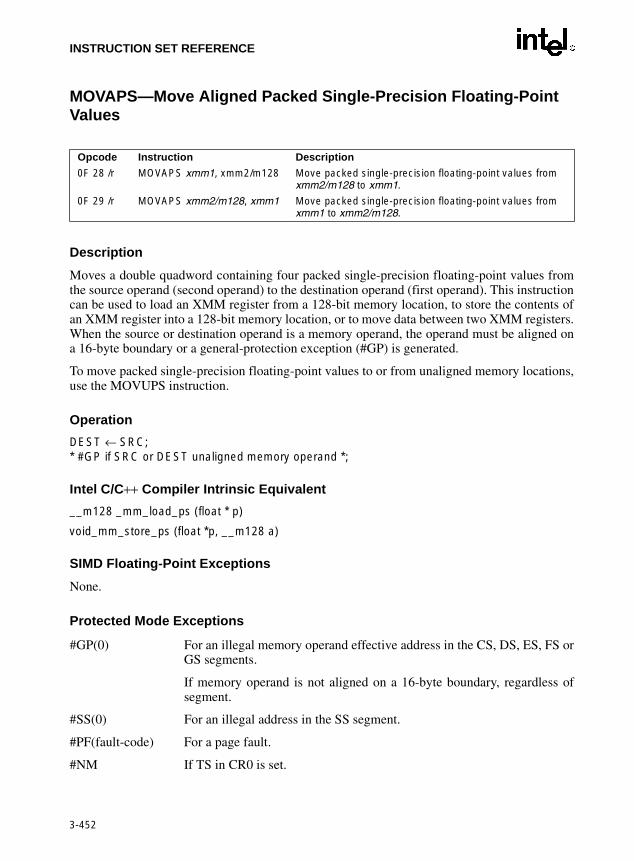
INSTRUCTION SET REFERENCE
MOVAPS—Move Aligned Packed Single-Precision Floating-Point Values
Description
Moves a double quadword containing four packed single-precision floating-point values fromthe source operand (second operand) to the destination operand (first operand). This instructioncan be used to load an XMM register from a 128-bit memory location, to store the contents ofan XMM register into a 128-bit memory location, or to move data between two XMM registers.When the source or destination operand is a memory operand, the operand must be aligned ona 16-byte boundary or a general-protection exception (#GP) is generated.
To move packed single-precision floating-point values to or from unaligned memory locations,use the MOVUPS instruction.
Opcode Instruction Description
0F 28 /r MOVAPS xmm1, xmm2/m128 Move packed single-precision floating-point values from xmm2/m128 to xmm1.
0F 29 /r MOVAPS xmm2/m128, xmm1 Move packed single-precision floating-point values from xmm1 to xmm2/m128.
3-452
Operation
DEST ← SRC;* #GP if SRC or DEST unaligned memory operand *;
Intel C/C++ Compiler Intrinsic Equivalent
__m128 _mm_load_ps (float * p)
void_mm_store_ps (float *p, __m128 a)
SIMD Floating-Point Exceptions
None.
Protected Mode Exceptions
#GP(0) For an illegal memory operand effective address in the CS, DS, ES, FS orGS segments.
If memory operand is not aligned on a 16-byte boundary, regardless ofsegment.
#SS(0) For an illegal address in the SS segment.
#PF(fault-code) For a page fault.
#NM If TS in CR0 is set.

INSTRUCTION SET REFERENCE
MOVAPS—Move Aligned Packed Single-Precision Floating-Point Values (Continued)
#XM If an unmasked SIMD floating-point exception and OSXMMEXCPT inCR4 is 1.
#UD If an unmasked SIMD floating-point exception and OSXMMEXCPT inCR4 is 0.
If EM in CR0 is set.
If OSFXSR in CR4 is 0.
If CPUID feature flag SSE is 0.
Real-Address Mode Exceptions
#GP(0) If memory operand is not aligned on a 16-byte boundary, regardless ofsegment.
Interrupt 13 If any part of the operand lies outside the effective address space from 0to FFFFH.
3-453
#NM If TS in CR0 is set.
#XM If an unmasked SIMD floating-point exception and OSXMMEXCPT inCR4 is 1.
#UD If an unmasked SIMD floating-point exception and OSXMMEXCPT inCR4 is 0.
If EM in CR0 is set.
If OSFXSR in CR4 is 0.
If CPUID feature flag SSE is 0.
Virtual-8086 Mode Exceptions
Same exceptions as in Real Address Mode
#PF(fault-code) For a page fault.

INSTRUCTION SET REFERENCE
MOVD—Move Doubleword
Description
Copies a doubleword from the source operand (second operand) to the destination operand (firstoperand). The source and destination operands can be general-purpose registers, MMX tech-nology registers, XMM registers, or 32-bit memory locations. This instruction can be used tomove a doubleword to and from the low doubleword an MMX technology register and ageneral-purpose register or a 32-bit memory location, or to and from the low doubleword of anXMM register and a general-purpose register or a 32-bit memory location. The instructioncannot be used to transfer data between MMX technology registers, between XMM registers,between general-purpose registers, or between memory locations.
When the destination operand is an MMX technology register, the source operand is written to
Opcode Instruction Description
0F 6E /r MOVD mm, r/m32 Move doubleword from r/m32 to mm.
0F 7E /r MOVD r/m32, mm Move doubleword from mm to r/m32.
66 0F 6E /r MOVD xmm, r/m32 Move doubleword from r/m32 to xmm.
66 0F 7E /r MOVD r/m32, xmm Move doubleword from xmm register to r/m32.
3-454
the low doubleword of the register, and the register is zero-extended to 64 bits. When the desti-nation operand is an XMM register, the source operand is written to the low doubleword of theregister, and the register is zero-extended to 128 bits.
Operation
MOVD instruction when destination operand is MMX technology register:DEST[31-0] ← SRC;DEST[63-32] ← 00000000H;
MOVD instruction when destination operand is XMM register:DEST[31-0] ← SRC;DEST[127-32] ← 000000000000000000000000H;
MOVD instruction when source operand is MMX technology or XMM register:DEST ← SRC[31-0];
Intel C/C++ Compiler Intrinsic Equivalent
MOVD __m64 _mm_cvtsi32_si64 (int i )
MOVD int _mm_cvtsi64_si32 ( __m64m )
MOVD __m128i _mm_cvtsi32_si128 (int a)
MOVD int _mm_cvtsi128_si32 ( __m128i a)
Flags Affected
None.

INSTRUCTION SET REFERENCE
MOVD—Move Doubleword (Continued)
SIMD Floating-Point Exceptions
None.
Protected Mode Exceptions
#GP(0) If the destination operand is in a non-writable segment.
If a memory operand effective address is outside the CS, DS, ES, FS, orGS segment limit.
#SS(0) If a memory operand effective address is outside the SS segment limit.
#UD If EM in CR0 is set.
128-bit operations will generate #UD only if OSFXSR in CR4 is 0. Execu-tion of 128-bit instructions on a non-SSE2 capable processor (one that isMMX technology capable) will result in the instruction operating on themm registers, not #UD.
#NM If TS in CR0 is set.
3-455
#MF (MMX technology register operations only.) If there is a pending FPUexception.
#PF(fault-code) If a page fault occurs.
#AC(0) If alignment checking is enabled and an unaligned memory reference ismade while the current privilege level is 3.
Real-Address Mode Exceptions
#GP If any part of the operand lies outside of the effective address space from0 to FFFFH.
#UD If EM in CR0 is set.
128-bit operations will generate #UD only if OSFXSR in CR4 is 0. Execu-tion of 128-bit instructions on a non-SSE2 capable processor (one that isMMX technology capable) will result in the instruction operating on themm registers, not #UD.
#NM If TS in CR0 is set.
#MF (MMX technology register operations only.) If there is a pending FPUexception.

INSTRUCTION SET REFERENCE
MOVD—Move Doubleword (Continued)
Virtual-8086 Mode Exceptions
Same exceptions as in Real Address Mode
#PF(fault-code) If a page fault occurs.
#AC(0) If alignment checking is enabled and an unaligned memory reference ismade.
3-456

INSTRUCTION SET REFERENCE
MOVDQA—Move Aligned Double Quadword
Description
Moves a double quadword from the source operand (second operand) to the destination operand(first operand). This instruction can be used to load an XMM register from a 128-bit memorylocation, to store the contents of an XMM register into a 128-bit memory location, or to movedata between two XMM registers. When the source or destination operand is a memory operand,the operand must be aligned on a 16-byte boundary or a general-protection exception (#GP) willbe generated.
To move a double quadword to or from unaligned memory locations, use the MOVDQU instruc-tion.
Operation
Opcode Instruction Description
66 0F 6F /r MOVDQA xmm1, xmm2/m128 Move aligned double quadword from xmm2/m128 to xmm1.
66 0F 7F /r MOVDQA xmm2/m128, xmm1 Move aligned double quadword from xmm1 to xmm2/m128.
3-457
DEST ← SRC;* #GP if SRC or DEST unaligned memory operand *;
Intel C/C++ Compiler Intrinsic Equivalent
MOVDQA __m128i _mm_load_si128 ( __m128i *p)
MOVDQA void _mm_store_si128 ( __m128i *p, __m128i a)
SIMD Floating-Point Exceptions
None.
Protected Mode Exceptions
#PF(fault-code) If a page fault occurs.
#GP(0) If a memory operand effective address is outside the CS, DS, ES, FS, orGS segment limit.
If memory operand is not aligned on a 16-byte boundary, regardless ofsegment.
#SS(0) If a memory operand effective address is outside the SS segment limit.
#NM If TS in CR0 is set.

INSTRUCTION SET REFERENCE
MOVDQA—Move Aligned Double Quadword (Continued)
#UD If EM in CR0 is set.
128-bit operations will generate #UD only if OSFXSR in CR4 is 0. Execu-tion of 128-bit instructions on a non-SSE2 capable processor (one that isMMX technology capable) will result in the instruction operating on themm registers, not #UD.
Real-Address Mode Exceptions
#GP(0) If memory operand is not aligned on a 16-byte boundary, regardless ofsegment.
If any part of the operand lies outside of the effective address space from0 to FFFFH.
#NM If TS in CR0 is set.
#UD If EM in CR0 is set.
128-bit operations will generate #UD only if OSFXSR in CR4 is 0. Execu-
3-458
tion of 128-bit instructions on a non-SSE2 capable processor (one that isMMX technology capable) will result in the instruction operating on themm registers, not #UD.
Virtual-8086 Mode Exceptions
Same exceptions as in Real Address Mode
#PF(fault-code) For a page fault.

INSTRUCTION SET REFERENCE
MOVDQU—Move Unaligned Double Quadword
Description
Moves a double quadword from the source operand (second operand) to the destination operand(first operand). This instruction can be used to load an XMM register from a 128-bit memorylocation, to store the contents of an XMM register into a 128-bit memory location, or to movedata between two XMM registers. When the source or destination operand is a memory operand,the operand may be unaligned on a 16-byte boundary without causing a general-protectionexception (#GP) to be generated.
To move a double quadword to or from memory locations that are known to be aligned on 16-byte boundaries, use the MOVDQA instruction.
While executing in 16-bit addressing mode, a linear address for a 128-bit data access that over-laps the end of a 16-bit segment is not allowed and is defined as reserved behavior. A specific
Opcode Instruction Description
F3 0F 6F /r MOVDQU xmm1, xmm2/m128 Move unaligned double quadword from xmm2/m128 to xmm1.
F3 0F 7F /r MOVDQU xmm2/m128, xmm1 Move unaligned double quadword from xmm1 to xmm2/m128.
3-459
processor implementation may or may not generate a general-protection exception (#GP) in thissituation, and the address that spans the end of the segment may or may not wrap around to thebeginning of the segment.
Operation
DEST ← SRC;
Intel C/C++ Compiler Intrinsic Equivalent
MOVDQU void _mm_storeu_si128 ( __m128i *p, __m128i a)
MOVDQU __m128i _mm_loadu_si128 ( __m128i *p)
SIMD Floating-Point Exceptions
None.
Protected Mode Exceptions
#GP(0) If a memory operand effective address is outside the CS, DS, ES, FS, orGS segment limit.
#SS(0) If a memory operand effective address is outside the SS segment limit.
#NM If TS in CR0 is set.

INSTRUCTION SET REFERENCE
MOVDQU—Move Unaligned Double Quadword (Continued)
#UD If EM in CR0 is set.
128-bit operations will generate #UD only if OSFXSR in CR4 is 0. Execu-tion of 128-bit instructions on a non-SSE2 capable processor (one that isMMX technology capable) will result in the instruction operating on themm registers, not #UD.
#PF(fault-code) If a page fault occurs.
Real-Address Mode Exceptions
#GP(0) If any part of the operand lies outside of the effective address space from0 to FFFFH.
#NM If TS in CR0 is set.
#UD If EM in CR0 is set.
128-bit operations will generate #UD only if OSFXSR in CR4 is 0. Execu-tion of 128-bit instructions on a non-SSE2 capable processor (one that is
3-460
MMX technology capable) will result in the instruction operating on themm registers, not #UD.
Virtual-8086 Mode Exceptions
Same exceptions as in Real Address Mode
#PF(fault-code) For a page fault.

INSTRUCTION SET REFERENCE
MOVDQ2Q—Move Quadword from XMM to MMX Technology Register
Description
Moves the low quadword from the source operand (second operand) to the destination operand(first operand). The source operand is an XMM register and the destination operand is an MMXtechnology register.
This instruction causes a transition from x87 FPU to MMX technology operation (that is, thex87 FPU top-of-stack pointer is set to 0 and the x87 FPU tag word is set to all 0s [valid]). If thisinstruction is executed while an x87 FPU floating-point exception is pending, the exception ishandled before the MOVDQ2Q instruction is executed.
Operation
DEST ← SRC[63-0]
Opcode Instruction Description
F2 0F D6 MOVDQ2Q mm, xmm Move low quadword from xmm to MMX technology register.
3-461
Intel C/C++ Compiler Intrinsic Equivalent
MOVDQ2Q __m64 _mm_movepi64_pi64 ( __m128i a)
SIMD Floating-Point Exceptions
None.
Protected Mode Exceptions
#NM If TS in CR0 is set.
#UD If EM in CR0 is set.
If OSFXSR in CR4 is 0.
If CPUID feature flag SSE2 is 0.
#MF If there is a pending x87 FPU exception.
Real-Address Mode Exceptions
Same exceptions as in Protected Mode
Virtual-8086 Mode Exceptions
Same exceptions as in Protected Mode

INSTRUCTION SET REFERENCE
MOVHLPS— Move Packed Single-Precision Floating-Point Values High to Low
Description
Moves two packed single-precision floating-point values from the high quadword of the sourceoperand (second operand) to the low quadword of the destination operand (first operand). Thehigh quadword of the destination operand is left unchanged.
Operation
DEST[63-0] ← SRC[127-64];* DEST[127-64] unchanged *;
Intel C/C++ Compiler Intrinsic Equivalent
Opcode Instruction Description
OF 12 /r MOVHLPS xmm1, xmm2 Move two packed single-precision floating-point values from high quadword of xmm2 to low quadword of xmm1.
3-462
MOVHLPS __m128 _mm_movehl_ps(__m128 a, __m128 b)
SIMD Floating-Point Exceptions
None.
Protected Mode Exceptions
#NM If TS in CR0 is set.
#UD If EM in CR0 is set.
If OSFXSR in CR4 is 0.
If CPUID feature flag SSE is 0.
Real Address Mode Exceptions
Same exceptions as in Protected Mode.
Virtual 8086 Mode Exceptions
Same exceptions as in Protected Mode.

INSTRUCTION SET REFERENCE
MOVHPD—Move High Packed Double-Precision Floating-Point Value
Description
Moves a double-precision floating-point value from the source operand (second operand) to thedestination operand (first operand). The source and destination operands can be an XMMregister or a 64-bit memory location. This instruction allows a double-precision floating-pointvalue to be moved to and from the high quadword of an XMM register and memory. It cannotbe used for register to register or memory to memory moves. When the destination operand isan XMM register, the low quadword of the register remains unchanged.
Operation
Opcode Instruction Description
66 0F 16 /r MOVHPD xmm, m64 Move double-precision floating-point value from m64 to high quadword of xmm.
66 0F 17 /r MOVHPD m64, xmm Move double-precision floating-point value from high quadword of xmm to m64.
3-463
MOVHPD instruction for memory to XMM move:DEST[127-64] ← SRC ;* DEST[63-0] unchanged *;
MOVHPD instruction for XMM to memory move:DEST ← SRC[127-64] ;
Intel C/C++ Compiler Intrinsic Equivalent
MOVHPD __m128d _mm_loadh_pd ( __m128d a, double *p)
MOVHPD void _mm_storeh_pd (double *p, __m128d a)
SIMD Floating-Point Exceptions
None.
Protected Mode Exceptions
#GP(0) For an illegal memory operand effective address in the CS, DS, ES, FS orGS segments.
#SS(0) For an illegal address in the SS segment.
#PF(fault-code) For a page fault.
#NM If TS in CR0 is set.
#UD If EM in CR0 is set.

INSTRUCTION SET REFERENCE
MOVHPD—Move High Packed Double-Precision Floating-Point Value (Continued)
If OSFXSR in CR4 is 0.
If CPUID feature flag SSE is 0.
#AC(0) If alignment checking is enabled and an unaligned memory reference ismade while the current privilege level is 3.
Real-Address Mode Exceptions
Interrupt 13 If any part of the operand lies outside the effective address space from 0to FFFFH.
#NM If TS in CR0 is set.
#UD If EM in CR0 is set.
If OSFXSR in CR4 is 0.
If CPUID feature flag SSE is 0.
3-464
Virtual-8086 Mode Exceptions
Same exceptions as in Real Address Mode
#PF(fault-code) For a page fault.
#AC(0) If alignment checking is enabled and an unaligned memory reference ismade.

INSTRUCTION SET REFERENCE
MOVHPS—Move High Packed Single-Precision Floating-Point Values
Description
Moves two packed single-precision floating-point values from the source operand (secondoperand) to the destination operand (first operand). The source and destination operands can bean XMM register or a 64-bit memory location. This instruction allows two single-precisionfloating-point values to be moved to and from the high quadword of an XMM register andmemory. It cannot be used for register to register or memory to memory moves. When the desti-nation operand is an XMM register, the low quadword of the register remains unchanged.
Operation
Opcode Instruction Description
0F 16 /r MOVHPS xmm, m64 Move two packed single-precision floating-point values from m64 to high quadword of xmm.
0F 17 /r MOVHPS m64, xmm Move two packed single-precision floating-point values from high quadword of xmm to m64.
3-465
MOVHPD instruction for memory to XMM move:DEST[127-64] ← SRC ;* DEST[63-0] unchanged *;
MOVHPD instruction for XMM to memory move:DEST ← SRC[127-64] ;
Intel C/C++ Compiler Intrinsic Equivalent
MOVHPS __m128d _mm_loadh_pi ( __m128d a, __m64 *p)
MOVHPS void _mm_storeh_pi (__m64 *p, __m128d a)
SIMD Floating-Point Exceptions
None.
Protected Mode Exceptions
#GP(0) For an illegal memory operand effective address in the CS, DS, ES, FS orGS segments.
#SS(0) For an illegal address in the SS segment.
#PF(fault-code) For a page fault.
#NM If TS in CR0 is set.

INSTRUCTION SET REFERENCE
MOVHPS—Move High Packed Single-Precision Floating-Point Values (Continued)
#UD If EM in CR0 is set.
If OSFXSR in CR4 is 0.
If CPUID feature flag SSE is 0.
#AC(0) If alignment checking is enabled and an unaligned memory reference ismade while the current privilege level is 3.
Real-Address Mode Exceptions
Interrupt 13 If any part of the operand lies outside the effective address space from 0to FFFFH.
#NM If TS in CR0 is set.
#UD If EM in CR0 is set.
If OSFXSR in CR4 is 0.
3-466
If CPUID feature flag SSE is 0.
Virtual-8086 Mode Exceptions
Same exceptions as in Real Address Mode
#PF(fault-code) For a page fault.
#AC(0) If alignment checking is enabled and an unaligned memory reference ismade.

INSTRUCTION SET REFERENCE
MOVLHPS—Move Packed Single-Precision Floating-Point Values Low to High
Description
Moves two packed single-precision floating-point values from the low quadword of the sourceoperand (second operand) to the high quadword of the destination operand (first operand). Thelow quadword of the destination operand is left unchanged.
Operation
DEST[127-64] ← SRC[63-0];* DEST[63-0] unchanged *;
Intel C/C++ Compiler Intrinsic Equivalent
Opcode Instruction Description
OF 16 /r MOVLHPS xmm1, xmm2 Move two packed single-precision floating-point values from low quadword of xmm2 to high quadword of xmm1.
3-467
MOVHLPS __m128 _mm_movelh_ps(__m128 a, __m128 b)
SIMD Floating-Point Exceptions
None.
Protected Mode Exceptions
#NM If TS in CR0 is set.
#UD If EM in CR0 is set.
If OSFXSR in CR4 is 0.
If CPUID feature flag SSE is 0.
Real Address Mode Exceptions
Same exceptions as in Protected Mode.
Virtual 8086 Mode Exceptions
Same exceptions as in Protected Mode.

INSTRUCTION SET REFERENCE
MOVLPD—Move Low Packed Double-Precision Floating-Point Value
Description
Moves a double-precision floating-point value from the source operand (second operand) to thedestination operand (first operand). The source and destination operands can be an XMMregister or a 64-bit memory location. This instruction allows a double-precision floating-pointvalue to be moved to and from the low quadword of an XMM register and memory. It cannot beused for register to register or memory to memory moves. When the destination operand is anXMM register, the high quadword of the register remains unchanged.
Operation
Opcode Instruction Description
66 0F 12 /r MOVLPD xmm, m64 Move double-precision floating-point value from m64 to low quadword of xmm register.
66 0F 13 /r MOVLPD m64, xmm Move double-precision floating-point nvalue from low quadword of xmm register to m64.
3-468
MOVLPD instruction for memory to XMM move:DEST[63-0] ← SRC ;* DEST[127-64] unchanged *;
MOVLPD instruction for XMM to memory move:DEST ← SRC[63-0] ;
Intel C/C++ Compiler Intrinsic Equivalent
MOVLPD __m128d _mm_loadl_pd ( __m128d a, double *p)
MOVLPD void _mm_storel_pd (double *p, __m128d a)
SIMD Floating-Point Exceptions
None.
Protected Mode Exceptions
#GP(0) For an illegal memory operand effective address in the CS, DS, ES, FS orGS segments.
#SS(0) For an illegal address in the SS segment.
#PF(fault-code) For a page fault.
#NM If TS in CR0 is set.

INSTRUCTION SET REFERENCE
MOVLPD—Move Low Packed Double-Precision Floating-Point Value (Continued)
#UD If EM in CR0 is set.
If OSFXSR in CR4 is 0.
If CPUID feature flag SSE is 0.
#AC(0) If alignment checking is enabled and an unaligned memory reference ismade while the current privilege level is 3.
Real-Address Mode Exceptions
Interrupt 13 If any part of the operand lies outside the effective address space from 0to FFFFH.
#NM If TS in CR0 is set.
#UD If EM in CR0 is set.
If OSFXSR in CR4 is 0.
3-469
If CPUID feature flag SSE is 0.
Virtual-8086 Mode Exceptions
Same exceptions as in Real Address Mode
#PF(fault-code) For a page fault.
#AC(0) If alignment checking is enabled and an unaligned memory reference ismade.

INSTRUCTION SET REFERENCE
MOVLPS—Move Low Packed Single-Precision Floating-Point Values
Description
Moves two packed single-precision floating-point values from the source operand (secondoperand) and the destination operand (first operand). The source and destination operands canbe an XMM register or a 64-bit memory location. This instruction allows two single-precisionfloating-point values to be moved to and from the low quadword of an XMM register andmemory. It cannot be used for register to register or memory to memory moves. When the desti-nation operand is an XMM register, the high quadword of the register remains unchanged.
Operation
Opcode Instruction Description
0F 12 /r MOVLPS xmm, m64 Move two packed single-precision floating-point values from m64 to low quadword of xmm.
0F 13 /r MOVLPS m64, xmm Move two packed single-precision floating-point values from low quadword of xmm to m64.
3-470
MOVLPD instruction for memory to XMM move:DEST[63-0] ← SRC ;* DEST[127-64] unchanged *;
MOVLPD instruction for XMM to memory move:DEST ← SRC[63-0] ;
Intel C/C++ Compiler Intrinsic Equivalent
MOVLPS __m128 _mm_loadl_pi ( __m128 a, __m64 *p)
MOVLPS void _mm_storel_pi (__m64 *p, __m128 a)
SIMD Floating-Point Exceptions
None.
Protected Mode Exceptions
#GP(0) For an illegal memory operand effective address in the CS, DS, ES, FS orGS segments.
#SS(0) For an illegal address in the SS segment.
#PF(fault-code) For a page fault.
#NM If TS in CR0 is set.

INSTRUCTION SET REFERENCE
MOVLPS—Move Low Packed Single-Precision Floating-Point Values (Continued)
#UD If EM in CR0 is set.
If OSFXSR in CR4 is 0.
If CPUID feature flag SSE is 0.
#AC(0) If alignment checking is enabled and an unaligned memory reference ismade while the current privilege level is 3.
Real-Address Mode Exceptions
Interrupt 13 If any part of the operand lies outside the effective address space from 0to FFFFH.
#NM If TS in CR0 is set.
#UD If EM in CR0 is set.
If OSFXSR in CR4 is 0.
3-471
If CPUID feature flag SSE is 0.
Virtual-8086 Mode Exceptions
Same exceptions as in Real Address Mode
#PF(fault-code) For a page fault.
#AC(0) If alignment checking is enabled and an unaligned memory reference ismade.

INSTRUCTION SET REFERENCE
MOVMSKPD—Extract Packed Double-Precision Floating-Point Sign Mask
Description
Extracts the sign bits from the packed double-precision floating-point values in the sourceoperand (second operand), formats them into a 2-bit mask, and stores the mask in the destinationoperand (first operand). The source operand is an XMM register, and the destination operand isa general-purpose register. The mask is stored in the 2 low-order bits of the destination operand.
Operation
DEST[0] ← SRC[63]; DEST[1] ← SRC[127]; DEST[3-2] ← 00B; DEST[31-4] ← 0000000H;
Opcode Instruction Description
66 0F 50 /r MOVMSKPD r32, xmm Extract 2-bit sign mask of from xmm and store in r32.
3-472
Intel C/C++ Compiler Intrinsic Equivalent
MOVMSKPD int _mm_movemask_pd ( __m128 a)
SIMD Floating-Point Exceptions
None.
Protected Mode Exceptions
#NM If TS in CR0 is set.
#XM If an unmasked SIMD floating-point exception and OSXMMEXCPT inCR4 is 1.
#UD If an unmasked SIMD floating-point exception and OSXMMEXCPT inCR4 is 0.
If EM in CR0 is set.
If OSFXSR in CR4 is 0.
If CPUID feature flag SSE2 is 0.
Real-Address Mode Exceptions
Same exceptions as in Protected Mode

INSTRUCTION SET REFERENCE
MOVMSKPD—Extract Packed Double-Precision Floating-Point Sign Mask (Continued)
Virtual-8086 Mode Exceptions
Same exceptions as in Protected Mode
3-473

INSTRUCTION SET REFERENCE
MOVMSKPS—Extract Packed Single-Precision Floating-Point Sign Mask
Description
Extracts the sign bits from the packed single-precision floating-point values in the sourceoperand (second operand), formats them into a 4-bit mask, and stores the mask in the destinationoperand (first operand). The source operand is an XMM register, and the destination operand isa general-purpose register. The mask is stored in the 4 low-order bits of the destination operand.
Operation
DEST[0] ← SRC[31]; DEST[1] ← SRC[63]; DEST[2] ← SRC[95]; DEST[3] ← SRC[127]; DEST[31-4] ← 000000H;
Opcode Instruction Description
0F 50 /r MOVMSKPS r32, xmm Extract 4-bit sign mask of from xmm and store in r32.
3-474
Intel C/C++ Compiler Intrinsic Equivalent
int_mm_movemask_ps(__m128 a)
SIMD Floating-Point Exceptions
None.
Protected Mode Exceptions
#NM If TS in CR0 is set.
#XM If an unmasked SIMD floating-point exception and OSXMMEXCPT inCR4 is 1.
#UD If an unmasked SIMD floating-point exception and OSXMMEXCPT inCR4 is 0.
If EM in CR0 is set.
If OSFXSR in CR4 is 0.
If CPUID feature flag SSE is 0.

INSTRUCTION SET REFERENCE
MOVMSKPS—Extract Packed Single-Precision Floating-Point Sign Mask (Continued)
Real-Address Mode Exceptions
Same exceptions as in Protected Mode
Virtual 8086 Mode Exceptions
Same exceptions as in Protected Mode.
3-475

INSTRUCTION SET REFERENCE
MOVNTDQ—Store Double Quadword Using Non-Temporal Hint
Description
Moves the double quadword in the source operand (second operand) to the destination operand(first operand) using a non-temporal hint to prevent caching of the data during the write tomemory. The source operand is an XMM register, which is assumed to contain integer data(packed bytes, words, doublewords, or quadwords). The destination operand is a 128-bitmemory location.
The non-temporal hint is implemented by using a write combining (WC) memory type protocolwhen writing the data to memory. Using this protocol, the processor does not write the data intothe cache hierarchy, nor does it fetch the corresponding cache line from memory into the cachehierarchy. The memory type of the region being written to can override the non-temporal hint,if the memory address specified for the non-temporal store is in an uncacheable (UC) or writeprotected (WP) memory region. For more information on non-temporal stores, see “Caching ofTemporal vs. Non-Temporal Data” in Chapter 10 in the IA-32 Intel Architecture Software Devel-
Opcode Instruction Description
66 0F E7 /r MOVNTDQ m128, xmm Move double quadword from xmm to m128 using non-temporal hint.
3-476
oper’s Manual, Volume 1.
Because the WC protocol uses a weakly-ordered memory consistency model, a fencing opera-tion implemented with the SFENCE or MFENCE instruction should be used in conjunction withMOVNTDQ instructions if multiple processors might use different memory types to read/writethe destination memory locations.
Operation
DEST ← SRC;
Intel C/C++ Compiler Intrinsic Equivalent
MOVNTDQ void_mm_stream_si128 ( __m128i *p, __m128i a)
SIMD Floating-Point Exceptions
None.
Protected Mode Exceptions
#GP(0) For an illegal memory operand effective address in the CS, DS, ES, FS orGS segments.
If memory operand is not aligned on a 16-byte boundary, regardless ofsegment.
#SS(0) For an illegal address in the SS segment.

INSTRUCTION SET REFERENCE
MOVNTDQ—Store Double Quadword Using Non-Temporal Hint (Continued)
#PF(fault-code) For a page fault.
#NM If TS in CR0 is set.
#UD If EM in CR0 is set.
If OSFXSR in CR4 is 0.
If CPUID feature flag SSE2 is 0.
Real-Address Mode Exceptions
#GP(0) If memory operand is not aligned on a 16-byte boundary, regardless ofsegment.
Interrupt 13 If any part of the operand lies outside the effective address space from 0to FFFFH.
#NM If TS in CR0 is set.
3-477
#UD If EM in CR0 is set.
If OSFXSR in CR4 is 0.
If CPUID feature flag SSE2 is 0.
Virtual-8086 Mode Exceptions
Same exceptions as in Real Address Mode
#PF(fault-code) For a page fault.

INSTRUCTION SET REFERENCE
MOVNTI—Store Doubleword Using Non-Temporal Hint
Description
Moves the doubleword integer in the source operand (second operand) to the destinationoperand (first operand) using a non-temporal hint to minimize cache pollution during the writeto memory. The source operand is a general-purpose register. The destination operand is a 32-bit memory location.
The non-temporal hint is implemented by using a write combining (WC) memory type protocolwhen writing the data to memory. Using this protocol, the processor does not write the data intothe cache hierarchy, nor does it fetch the corresponding cache line from memory into the cachehierarchy. The memory type of the region being written to can override the non-temporal hint,if the memory address specified for the non-temporal store is in an uncacheable (UC) or writeprotected (WP) memory region. For more information on non-temporal stores, see “Caching ofTemporal vs. Non-Temporal Data” in Chapter 10 in the IA-32 Intel Architecture Software Devel-oper’s Manual, Volume 1.
Opcode Instruction Description
0F C3 /r MOVNTI m32, r32 Move doubleword from r32 to m32 using non-temporal hint.
3-478
Because the WC protocol uses a weakly-ordered memory consistency model, a fencing opera-tion implemented with the SFENCE or MFENCE instruction should be used in conjunction withMOVNTI instructions if multiple processors might use different memory types to read/write thedestination memory locations.
Operation
DEST ← SRC;
Intel C/C++ Compiler Intrinsic Equivalent
MOVNTDQ void_mm_stream_si32 (int *p, int a)
SIMD Floating-Point Exceptions
None.
Protected Mode Exceptions
#GP(0) For an illegal memory operand effective address in the CS, DS, ES, FS orGS segments.
#SS(0) For an illegal address in the SS segment.
#PF(fault-code) For a page fault.
#UD If CPUID feature flag SSE2 is 0.

INSTRUCTION SET REFERENCE
MOVNTI—Store Doubleword Using Non-Temporal Hint (Continued)
Real-Address Mode Exceptions
#GP(0) If memory operand is not aligned on a 16-byte boundary, regardless ofsegment.
Interrupt 13 If any part of the operand lies outside the effective address space from 0to FFFFH.
#UD If CPUID feature flag SSE2 is 0.
Virtual-8086 Mode Exceptions
Same exceptions as in Real Address Mode
#PF(fault-code) For a page fault.
3-479

INSTRUCTION SET REFERENCE
MOVNTPD—Store Packed Double-Precision Floating-Point Values Using Non-Temporal Hint
Description
Moves the double quadword in the source operand (second operand) to the destination operand(first operand) using a non-temporal hint to minimize cache pollution during the write tomemory. The source operand is an XMM register, which is assumed to contain two packeddouble-precision floating-point values. The destination operand is a 128-bit memory location.
The non-temporal hint is implemented by using a write combining (WC) memory type protocolwhen writing the data to memory. Using this protocol, the processor does not write the data intothe cache hierarchy, nor does it fetch the corresponding cache line from memory into the cachehierarchy. The memory type of the region being written to can override the non-temporal hint,if the memory address specified for the non-temporal store is in an uncacheable (UC) or writeprotected (WP) memory region. For more information on non-temporal stores, see “Caching ofTemporal vs. Non-Temporal Data” in Chapter 10 in the IA-32 Intel Architecture Software Devel-
Opcode Instruction Description
66 0F 2B /r MOVNTPD m128, xmm Move packed double-precision floating-point values from xmm to m128 using non-temporal hint.
3-480
oper’s Manual, Volume 1.
Because the WC protocol uses a weakly-ordered memory consistency model, a fencing opera-tion implemented with the SFENCE or MFENCE instruction should be used in conjunction withMOVNTPD instructions if multiple processors might use different memory types to read/writethe destination memory locations.
Operation
DEST ← SRC;
Intel C/C++ Compiler Intrinsic Equivalent
MOVNTDQ void_mm_stream_pd(double *p, __m128i a)
SIMD Floating-Point Exceptions
None.
Protected Mode Exceptions
#GP(0) For an illegal memory operand effective address in the CS, DS, ES, FS orGS segments.
If memory operand is not aligned on a 16-byte boundary, regardless ofsegment.
#SS(0) For an illegal address in the SS segment.

INSTRUCTION SET REFERENCE
MOVNTPD—Store Packed Double-Precision Floating-Point Values Using Non-Temporal Hint (Continued)
#PF(fault-code) For a page fault.
#NM If TS in CR0 is set.
#UD If EM in CR0 is set.
If OSFXSR in CR4 is 0.
If CPUID feature flag SSE2 is 0.
Real-Address Mode Exceptions
#GP(0) If memory operand is not aligned on a 16-byte boundary, regardless ofsegment.
Interrupt 13 If any part of the operand lies outside the effective address space from 0to FFFFH.
#NM If TS in CR0 is set.
3-481
#UD If EM in CR0 is set.
If OSFXSR in CR4 is 0.
If CPUID feature flag SSE2 is 0.
Virtual-8086 Mode Exceptions
Same exceptions as in Real Address Mode
#PF(fault-code) For a page fault.

INSTRUCTION SET REFERENCE
MOVNTPS—Store Packed Single-Precision Floating-Point Values Using Non-Temporal Hint
Description
Moves the double quadword in the source operand (second operand) to the destination operand(first operand) using a non-temporal hint to minimize cache pollution during the write tomemory. The source operand is an XMM register, which is assumed to contain four packedsingle-precision floating-point values. The destination operand is a 128-bit memory location.
The non-temporal hint is implemented by using a write combining (WC) memory type protocolwhen writing the data to memory. Using this protocol, the processor does not write the data intothe cache hierarchy, nor does it fetch the corresponding cache line from memory into the cachehierarchy. The memory type of the region being written to can override the non-temporal hint,if the memory address specified for the non-temporal store is in an uncacheable (UC) or writeprotected (WP) memory region. For more information on non-temporal stores, see “Caching of
Opcode Instruction Description
0F 2B /r MOVNTPS m128, xmm Move packed single-precision floating-point values from xmm to m128 using non-temporal hint.
3-482
Temporal vs. Non-Temporal Data” in Chapter 10 in the IA-32 Intel Architecture Software Devel-oper’s Manual, Volume 1.
Because the WC protocol uses a weakly-ordered memory consistency model, a fencing opera-tion implemented with the SFENCE or MFENCE instruction should be used in conjunction withMOVNTPS instructions if multiple processors might use different memory types to read/writethe destination memory locations.
Operation
DEST ← SRC;
Intel C/C++ Compiler Intrinsic Equivalent
MOVNTDQ void_mm_stream_ps(float * p, __m128 a)
SIMD Floating-Point Exceptions
None.
Protected Mode Exceptions
#GP(0) For an illegal memory operand effective address in the CS, DS, ES, FS orGS segments.

INSTRUCTION SET REFERENCE
MOVNTPS—Store Packed Single-Precision Floating-Point Values Using Non-Temporal Hint (Continued)
If memory operand is not aligned on a 16-byte boundary, regardless ofsegment.
#SS(0) For an illegal address in the SS segment.
#PF(fault-code) For a page fault.
#NM If TS in CR0 is set.
#UD If EM in CR0 is set.
If OSFXSR in CR4 is 0.
If CPUID feature flag SSE is 0.
Real-Address Mode Exceptions
#GP(0) If memory operand is not aligned on a 16-byte boundary, regardless ofsegment.
3-483
Interrupt 13 If any part of the operand lies outside the effective address space from 0to FFFFH.
#NM If TS in CR0 is set.
#UD If EM in CR0 is set.
If OSFXSR in CR4 is 0.
If CPUID feature flag SSE2 is 0.
Virtual-8086 Mode Exceptions
Same exceptions as in Real Address Mode
#PF(fault-code) For a page fault.

INSTRUCTION SET REFERENCE
MOVNTQ—Store of Quadword Using Non-Temporal Hint
Description
Moves the quadword in the source operand (second operand) to the destination operand (firstoperand) using a non-temporal hint to minimize cache pollution during the write to memory. Thesource operand is an MMX technology register, which is assumed to contain packed integer data(packed bytes, words, or doublewords). The destination operand is a 64-bit memory location.
The non-temporal hint is implemented by using a write combining (WC) memory type protocolwhen writing the data to memory. Using this protocol, the processor does not write the data intothe cache hierarchy, nor does it fetch the corresponding cache line from memory into the cachehierarchy. The memory type of the region being written to can override the non-temporal hint,if the memory address specified for the non-temporal store is in an uncacheable (UC) or writeprotected (WP) memory region. For more information on non-temporal stores, see “Caching ofTemporal vs. Non-Temporal Data” in Chapter 10 in the IA-32 Intel Architecture Software Devel-oper’s Manual, Volume 1.
Opcode Instruction Description
0F E7 /r MOVNTQ m64, mm Move quadword from mm to m64 using non-temporal hint.
3-484
Because the WC protocol uses a weakly-ordered memory consistency model, a fencing opera-tion implemented with the SFENCE or MFENCE instruction should be used in conjunction withMOVNTQ instructions if multiple processors might use different memory types to read/writethe destination memory locations.
Operation
DEST ← SRC;
Intel C/C++ Compiler Intrinsic Equivalent
MOVNTQ void_mm_stream_pi(__m64 * p, __m64 a)
SIMD Floating-Point Exceptions
None.
Protected Mode Exceptions
#GP(0) For an illegal memory operand effective address in the CS, DS, ES, FS orGS segments.
#SS(0) For an illegal address in the SS segment.
#PF(fault-code) For a page fault.
#NM If TS in CR0 is set.

INSTRUCTION SET REFERENCE
MOVNTQ—Store of Quadword Using Non-Temporal Hint (Continued)
#MF If there is a pending x87 FPU exception.
#UD If EM in CR0 is set.
If CPUID feature flag SSE is 0.
#AC(0) If alignment checking is enabled and an unaligned memory reference ismade while the current privilege level is 3.
Real-Address Mode Exceptions
#GP(0) If memory operand is not aligned on a 16-byte boundary, regardless ofsegment.
Interrupt 13 If any part of the operand lies outside the effective address space from 0to FFFFH.
#NM If TS in CR0 is set.
#MF If there is a pending x87 FPU exception.
3-485
#UD If EM in CR0 is set.
If CPUID feature flag SSE2 is 0.
Virtual-8086 Mode Exceptions
Same exceptions as in Real Address Mode
#PF(fault-code) For a page fault.
#AC(0) If alignment checking is enabled and an unaligned memory reference ismade.

INSTRUCTION SET REFERENCE
MOVQ—Move Quadword
Description
Copies a quadword from the source operand (second operand) to the destination operand (firstoperand). The source and destination operands can be MMX technology registers, XMM regis-ters, or 64-bit memory locations. This instruction can be used to move a quadword between twoMMX technology registers or between an MMX technology register and a 64-bit memory loca-tion, or to move data between two XMM registers or between an XMM register and a 64-bitmemory location. The instruction cannot be used to transfer data between memory locations.
When the source operand is an XMM register, the low quadword is moved; when the destinationoperand is an XMM register, the quadword is stored to the low quadword of the register, and thehigh quadword is cleared to all 0s.
Opcode Instruction Description
0F 6F /r MOVQ mm, mm/m64 Move quadword from mm/m64 to mm.
0F 7F /r MOVQ mm/m64, mm Move quadword from mm to mm/m64.
F3 0F 7E MOVQ xmm1, xmm2/m64 Move quadword from xmm2/mem64 to xmm1.
66 0F D6 MOVQ xmm2/m64, xmm1 Move quadword from xmm1 to xmm2/mem64.
3-486
Operation
MOVQ instruction when operating on MMX technology registers and memory locations:DEST ← SRC;
MOVQ instruction when source and destination operands are XMM registers:DEST[63-0] ← SRC[63-0];
MOVQ instruction when source operand is XMM register and destinationoperand is memory location:
DEST ← SRC[63-0];MOVQ instruction when source operand is memory location and destinationoperand is XMM register:
DEST[63-0] ← SRC;DEST[127-64] ← 0000000000000000H;
Flags Affected
None.
SIMD Floating-Point Exceptions
None.

INSTRUCTION SET REFERENCE
MOVQ—Move Quadword (Continued)
Protected Mode Exceptions
#GP(0) If the destination operand is in a non-writable segment.
If a memory operand effective address is outside the CS, DS, ES, FS, orGS segment limit.
#SS(0) If a memory operand effective address is outside the SS segment limit.
#UD If EM in CR0 is set.
128-bit operations will generate #UD only if OSFXSR in CR4 is 0. Execu-tion of 128-bit instructions on a non-SSE2 capable processor (one that isMMX technology capable) will result in the instruction operating on themm registers, not #UD.
#NM If TS in CR0 is set.
#MF (MMX technology register operations only.) If there is a pending FPUexception.
#PF(fault-code) If a page fault occurs.
3-487
#AC(0) If alignment checking is enabled and an unaligned memory reference ismade while the current privilege level is 3.
Real-Address Mode Exceptions
#GP If any part of the operand lies outside of the effective address space from0 to FFFFH.
#UD If EM in CR0 is set.
128-bit operations will generate #UD only if OSFXSR in CR4 is 0. Execu-tion of 128-bit instructions on a non-SSE2 capable processor (one that isMMX technology capable) will result in the instruction operating on themm registers, not #UD.
#NM If TS in CR0 is set.
#MF (MMX technology register operations only.) If there is a pending FPUexception.
Virtual-8086 Mode Exceptions
Same exceptions as in Real Address Mode
#PF(fault-code) If a page fault occurs.
#AC(0) If alignment checking is enabled and an unaligned memory reference ismade.

INSTRUCTION SET REFERENCE
MOVQ2DQ—Move Quadword from MMX Technology to XMM Register
Description
Moves the quadword from the source operand (second operand) to the low quadword of thedestination operand (first operand). The source operand is an MMX technology register and thedestination operand is an XMM register.
This instruction causes a transition from x87 FPU to MMX technology operation (that is, thex87 FPU top-of-stack pointer is set to 0 and the x87 FPU tag word is set to all 0s [valid]). If thisinstruction is executed while an x87 FPU floating-point exception is pending, the exception ishandled before the MOVQ2DQ instruction is executed.
Operation
DEST[63-0] ← SRC[63-0];DEST[127-64] ← 00000000000000000H;
Opcode Instruction Description
F3 0F D6 MOVQ2DQ xmm, mm Move quadword from mmx to low quadword of xmm.
3-488
Intel C/C++ Compiler Intrinsic Equivalent
MOVQ2DQ __128i _mm_movpi64_pi64 ( __m64 a)
SIMD Floating-Point Exceptions
None.
Protected Mode Exceptions
#NM If TS in CR0 is set.
#UD If EM in CR0 is set.
If OSFXSR in CR4 is 0.
If CPUID feature flag SSE2 is 0.
#MF If there is a pending x87 FPU exception.
Real-Address Mode Exceptions
Same exceptions as in Protected Mode
Virtual-8086 Mode Exceptions
Same exceptions as in Protected Mode

INSTRUCTION SET REFERENCE
MOVS/MOVSB/MOVSW/MOVSD—Move Data from String to String
Description
Moves the byte, word, or doubleword specified with the second operand (source operand) to thelocation specified with the first operand (destination operand). Both the source and destinationoperands are located in memory. The address of the source operand is read from the DS:ESI orthe DS:SI registers (depending on the address-size attribute of the instruction, 32 or 16, respec-tively). The address of the destination operand is read from the ES:EDI or the ES:DI registers(again depending on the address-size attribute of the instruction). The DS segment may be over-
Opcode Instruction Description
A4 MOVS m8, m8 Move byte at address DS:(E)SI to address ES:(E)DI
A5 MOVS m16, m16 Move word at address DS:(E)SI to address ES:(E)DI
A5 MOVS m32, m32 Move doubleword at address DS:(E)SI to address ES:(E)DI
A4 MOVSB Move byte at address DS:(E)SI to address ES:(E)DI
A5 MOVSW Move word at address DS:(E)SI to address ES:(E)DI
A5 MOVSD Move doubleword at address DS:(E)SI to address ES:(E)DI
3-489
ridden with a segment override prefix, but the ES segment cannot be overridden.
At the assembly-code level, two forms of this instruction are allowed: the “explicit-operands”form and the “no-operands” form. The explicit-operands form (specified with the MOVSmnemonic) allows the source and destination operands to be specified explicitly. Here, thesource and destination operands should be symbols that indicate the size and location of thesource value and the destination, respectively. This explicit-operands form is provided to allowdocumentation; however, note that the documentation provided by this form can be misleading.That is, the source and destination operand symbols must specify the correct type (size) of theoperands (bytes, words, or doublewords), but they do not have to specify the correct location.The locations of the source and destination operands are always specified by the DS:(E)SI andES:(E)DI registers, which must be loaded correctly before the move string instruction isexecuted.
The no-operands form provides “short forms” of the byte, word, and doubleword versions of theMOVS instructions. Here also DS:(E)SI and ES:(E)DI are assumed to be the source and desti-nation operands, respectively. The size of the source and destination operands is selected withthe mnemonic: MOVSB (byte move), MOVSW (word move), or MOVSD (doubleword move).
After the move operation, the (E)SI and (E)DI registers are incremented or decremented auto-matically according to the setting of the DF flag in the EFLAGS register. (If the DF flag is 0, the(E)SI and (E)DI register are incremented; if the DF flag is 1, the (E)SI and (E)DI registers aredecremented.) The registers are incremented or decremented by 1 for byte operations, by 2 forword operations, or by 4 for doubleword operations.
The MOVS, MOVSB, MOVSW, and MOVSD instructions can be preceded by the REP prefix(see “REP/REPE/REPZ/REPNE /REPNZ—Repeat String Operation Prefix” in this chapter) forblock moves of ECX bytes, words, or doublewords.

INSTRUCTION SET REFERENCE
MOVS/MOVSB/MOVSW/MOVSD—Move Data from String to String (Continued)
Operation
DEST ←SRC;IF (byte move)
THEN IF DF = 0THEN
(E)SI ← (E)SI + 1; (E)DI ← (E)DI + 1;
ELSE (E)SI ← (E)SI – 1; (E)DI ← (E)DI – 1;
FI;ELSE IF (word move)
THEN IF DF = 0(E)SI ← (E)SI + 2; (E)DI ← (E)DI + 2;
ELSE (E)SI ← (E)SI – 2;
3-490
(E)DI ← (E)DI – 2; FI;
ELSE (* doubleword move*)THEN IF DF = 0
(E)SI ← (E)SI + 4; (E)DI ← (E)DI + 4;
ELSE (E)SI ← (E)SI – 4; (E)DI ← (E)DI – 4;
FI;FI;
Flags Affected
None.

INSTRUCTION SET REFERENCE
MOVS/MOVSB/MOVSW/MOVSD—Move Data from String to String (Continued)
Protected Mode Exceptions
#GP(0) If the destination is located in a non-writable segment.
If a memory operand effective address is outside the CS, DS, ES, FS, orGS segment limit.
If the DS, ES, FS, or GS register contains a null segment selector.
#SS(0) If a memory operand effective address is outside the SS segment limit.
#PF(fault-code) If a page fault occurs.
#AC(0) If alignment checking is enabled and an unaligned memory reference ismade while the current privilege level is 3.
Real-Address Mode Exceptions
#GP If a memory operand effective address is outside the CS, DS, ES, FS, orGS segment limit.
3-491
#SS If a memory operand effective address is outside the SS segment limit.
Virtual-8086 Mode Exceptions
#GP(0) If a memory operand effective address is outside the CS, DS, ES, FS, orGS segment limit.
#SS(0) If a memory operand effective address is outside the SS segment limit.
#PF(fault-code) If a page fault occurs.
#AC(0) If alignment checking is enabled and an unaligned memory reference ismade.

INSTRUCTION SET REFERENCE
MOVSD—Move Scalar Double-Precision Floating-Point Value
Description
Moves a scalar double-precision floating-point value from the source operand (second operand)to the destination operand (first operand). The source and destination operands can be XMMregisters or 64-bit memory locations. This instruction can be used to move a double-precisionfloating-point value to and from the low quadword of an XMM register and a 64-bit memorylocation, or to move a double-precision floating-point value between the low quadwords of twoXMM registers. The instruction cannot be used to transfer data between memory locations.
When the source and destination operands are XMM registers, the high quadword of the desti-nation operand remains unchanged. When the source operand is a memory location and desti-nation operand is an XMM registers, the high quadword of the destination operand is cleared toall 0s.
Opcode Instruction Description
F2 0F 10 /r MOVSD xmm1, xmm2/m64 Move scalar double-precision floating-point value from xmm2/m64 to xmm1 register.
F2 0F 11 /r MOVSD xmm2/m64, xmm Move scalar double-precision floating-point value from xmm1 register to xmm2/m64.
3-492
OperationMOVSD instruction when source and destination operands are XMM registers:
DEST[63-0] ← SRC[63-0];* DEST[127-64] remains unchanged *;
MOVSD instruction when source operand is XMM register and destinationoperand is memory location:
DEST ← SRC[63-0];MOVSD instruction when source operand is memory location and destinationoperand is XMM register:
DEST[63-0] ← SRC;DEST[127-64] ← 0000000000000000H;
Intel C/C++ Compiler Intrinsic Equivalent
MOVSD __m128d _mm_load_sd (double *p)
MOVSD void _mm_store_sd (double *p, __m128d a)
MOVSD __m128d _mm_store_sd (__m128d a, __m128d b)
SIMD Floating-Point Exceptions
None.

INSTRUCTION SET REFERENCE
MOVSD—Move Scalar Double-Precision Floating-Point Value (Continued)
Protected Mode Exceptions
#GP(0) For an illegal memory operand effective address in the CS, DS, ES, FS orGS segments.
#SS(0) For an illegal address in the SS segment.
#PF(fault-code) For a page fault.
#NM If TS in CR0 is set.
#XM If an unmasked SIMD floating-point exception and OSXMMEXCPT inCR4 is 1.
#UD If an unmasked SIMD floating-point exception and OSXMMEXCPT inCR4 is 0.
If EM in CR0 is set.
If OSFXSR in CR4 is 0.
3-493
If CPUID feature flag SSE2 is 0.
#AC(0) If alignment checking is enabled and an unaligned memory reference ismade while the current privilege level is 3.
Real-Address Mode Exceptions
Interrupt 13 If any part of the operand lies outside the effective address space from 0to FFFFH.
#NM If TS in CR0 is set.
#XM If an unmasked SIMD floating-point exception and OSXMMEXCPT inCR4 is 1.
#UD If an unmasked SIMD floating-point exception and OSXMMEXCPT inCR4 is 0.
If EM in CR0 is set.
If OSFXSR in CR4 is 0.
If CPUID feature flag SSE2 is 0.

INSTRUCTION SET REFERENCE
MOVSD—Move Scalar Double-Precision Floating-Point Value (Continued)
Virtual-8086 Mode Exceptions
Same exceptions as in Real Address Mode
#PF(fault-code) For a page fault.
#AC(0) If alignment checking is enabled and an unaligned memory reference ismade.
3-494

INSTRUCTION SET REFERENCE
MOVSS—Move Scalar Single--Precision Floating-Point Values
Description
Moves a scalar single-precision floating-point value from the source operand (second operand)to the destination operand (first operand). The source and destination operands can be XMMregisters or 32-bit memory locations. This instruction can be used to move a single-precisionfloating-point value to and from the low doubleword of an XMM register and a 32-bit memorylocation, or to move a single-precision floating-point value between the low doublewords of twoXMM registers. The instruction cannot be used to transfer data between memory locations.
When the source and destination operands are XMM registers, the three high-order doublewordsof the destination operand remain unchanged. When the source operand is a memory locationand destination operand is an XMM registers, the three high-order doublewords of the destina-tion operand are cleared to all 0s.
Opcode Instruction Description
F3 0F 10 /r MOVSS xmm1, xmm2/m32 Move scalar single-precision floating-point value from xmm2/m64 to xmm1 register.
F3 0F 11 /r MOVSS xmm2/m32, xmm Move scalar single-precision floating-point value from xmm1 register to xmm2/m64.
3-495
OperationMOVSS instruction when source and destination operands are XMM registers:
DEST[31-0] ← SRC[31-0];* DEST[127-32] remains unchanged *;
MOVSS instruction when source operand is XMM register and destinationoperand is memory location:
DEST ← SRC[31-0];MOVSS instruction when source operand is memory location and destinationoperand is XMM register:
DEST[31-0] ← SRC;DEST[127-32] ← 000000000000000000000000H;
Intel C/C++ Compiler Intrinsic Equivalent
MOVSS __m128 _mm_load_ss(float * p)
MOVSS void_mm_store_ss(float * p, __m128 a)
MOVSS __m128 _mm_move_ss(__m128 a, __m128 b)
SIMD Floating-Point Exceptions
None.

INSTRUCTION SET REFERENCE
MOVSS—Move Scalar Single-Precision Floating-Point Value (Continued)
Protected Mode Exceptions
#GP(0) For an illegal memory operand effective address in the CS, DS, ES, FS orGS segments.
#SS(0) For an illegal address in the SS segment.
#PF(fault-code) For a page fault.
#NM If TS in CR0 is set.
#XM If an unmasked SIMD floating-point exception and OSXMMEXCPT inCR4 is 1.
#UD If an unmasked SIMD floating-point exception and OSXMMEXCPT inCR4 is 0.
If EM in CR0 is set.
If OSFXSR in CR4 is 0.
3-496
If CPUID feature flag SSE is 0.
#AC(0) If alignment checking is enabled and an unaligned memory reference ismade while the current privilege level is 3.
Real-Address Mode Exceptions
Interrupt 13 If any part of the operand lies outside the effective address space from 0to FFFFH.
#NM If TS in CR0 is set.
#XM If an unmasked SIMD floating-point exception and OSXMMEXCPT inCR4 is 1.
#UD If an unmasked SIMD floating-point exception and OSXMMEXCPT inCR4 is 0.
If EM in CR0 is set.
If OSFXSR in CR4 is 0.
If CPUID feature flag SSE is 0.

INSTRUCTION SET REFERENCE
MOVSS—Move Scalar Single-Precision Floating-Point Value (Continued)
Virtual-8086 Mode Exceptions
Same exceptions as in Real Address Mode
#PF(fault-code) For a page fault.
#AC(0) If alignment checking is enabled and an unaligned memory reference ismade.
3-497

INSTRUCTION SET REFERENCE
MOVSX—Move with Sign-Extension
Description
Copies the contents of the source operand (register or memory location) to the destinationoperand (register) and sign extends the value to 16 or 32 bits (see Figure 7-6 in the IA-32 IntelArchitecture Software Developer’s Manual, Volume 1). The size of the converted value dependson the operand-size attribute.
Operation
DEST ← SignExtend(SRC);
Flags Affected
None.
Opcode Instruction Description
0F BE /r MOVSX r16,r/m8 Move byte to word with sign-extension
0F BE /r MOVSX r32,r/m8 Move byte to doubleword, sign-extension
0F BF /r MOVSX r32,r/m16 Move word to doubleword, sign-extension
3-498
Protected Mode Exceptions
#GP(0) If a memory operand effective address is outside the CS, DS, ES, FS, orGS segment limit.
If the DS, ES, FS, or GS register contains a null segment selector.
#SS(0) If a memory operand effective address is outside the SS segment limit.
#PF(fault-code) If a page fault occurs.
#AC(0) If alignment checking is enabled and an unaligned memory reference ismade while the current privilege level is 3.
Real-Address Mode Exceptions
#GP If a memory operand effective address is outside the CS, DS, ES, FS, orGS segment limit.
#SS If a memory operand effective address is outside the SS segment limit.
Virtual-8086 Mode Exceptions
#GP(0) If a memory operand effective address is outside the CS, DS, ES, FS, orGS segment limit.
#SS(0) If a memory operand effective address is outside the SS segment limit.
#PF(fault-code) If a page fault occurs.

INSTRUCTION SET REFERENCE
MOVUPD—Move Unaligned Packed Double-Precision Floating-Point Values
Description
Moves a double quadword containing two packed double-precision floating-point values fromthe source operand (second operand) to the destination operand (first operand). This instructioncan be used to load an XMM register from a 128-bit memory location, to store the contents ofan XMM register into a 128-bit memory location, or move data between two XMM registers.When the source or destination operand is a memory operand, the operand may be unaligned ona 16-byte boundary without causing a general-protection exception (#GP) to be generated.
To move double-precision floating-point values to and from memory locations that are knownto be aligned on 16-byte boundaries, use the MOVAPD instruction.
Opcode Instruction Description
66 0F 10 /r MOVUPD xmm1, xmm2/m128 Move packed double-precision floating-point values from xmm2/m128 to xmm1.
66 0F 11 /r MOVUPD xmm2/m128, xmm Move packed double-precision floating-point values from xmm1 to xmm2/m128.
3-499
While executing in 16-bit addressing mode, a linear address for a 128-bit data access that over-laps the end of a 16-bit segment is not allowed and is defined as reserved behavior. A specificprocessor implementation may or may not generate a general-protection exception (#GP) in thissituation, and the address that spans the end of the segment may or may not wrap around to thebeginning of the segment.
Operation
DEST ← SRC;
Intel C/C++ Compiler Intrinsic Equivalent
MOVUPD __m128 _mm_loadu_pd(double * p)
MOVUPD void_mm_storeu_pd(double *p, __m128 a)
SIMD Floating-Point Exceptions
None.
Protected Mode Exceptions
#GP(0) For an illegal memory operand effective address in the CS, DS, ES, FS orGS segments.
#SS(0) For an illegal address in the SS segment.

INSTRUCTION SET REFERENCE
MOVUPD—Move Unaligned Packed Double-Precision Floating-Point Values (Continued)
#PF(fault-code) For a page fault.
#NM If TS in CR0 is set.
#XM If an unmasked SIMD floating-point exception and OSXMMEXCPT inCR4 is 1.
#UD If an unmasked SIMD floating-point exception and OSXMMEXCPT inCR4 is 0.
If EM in CR0 is set.
If OSFXSR in CR4 is 0.
If CPUID feature flag SSE2 is 0.
Real-Address Mode Exceptions
Interrupt 13 If any part of the operand lies outside the effective address space from 0to FFFFH.
3-500
#NM If TS in CR0 is set.
#XM If an unmasked SIMD floating-point exception and OSXMMEXCPT inCR4 is 1.
#UD If an unmasked SIMD floating-point exception and OSXMMEXCPT inCR4 is 0.
If EM in CR0 is set.
If OSFXSR in CR4 is 0.
If CPUID feature flag SSE2 is 0.
Virtual-8086 Mode Exceptions
Same exceptions as in Real Address Mode
#PF(fault-code) For a page fault.

INSTRUCTION SET REFERENCE
MOVUPS—Move Unaligned Packed Single-Precision Floating-Point Values
Description
Moves a double quadword containing four packed single-precision floating-point values fromthe source operand (second operand) to the destination operand (first operand). This instructioncan be used to load an XMM register from a 128-bit memory location, to store the contents ofan XMM register into a 128-bit memory location, or move data between two XMM registers.When the source or destination operand is a memory operand, the operand may be unaligned ona 16-byte boundary without causing a general-protection exception (#GP) to be generated.
To move packed single-precision floating-point values to and from memory locations that areknown to be aligned on 16-byte boundaries, use the MOVAPS instruction.
Opcode Instruction Description
0F 10 /r MOVUPS xmm1, xmm2/m128 Move packed single-precision floating-point values from xmm2/m128 to xmm1.
0F 11 /r MOVUPS xmm2/m128, xmm1 Move packed single-precision floating-point values from xmm1 to xmm2/m128.
3-501
While executing in 16-bit addressing mode, a linear address for a 128-bit data access that over-laps the end of a 16-bit segment is not allowed and is defined as reserved behavior. A specificprocessor implementation may or may not generate a general-protection exception (#GP) in thissituation, and the address that spans the end of the segment may or may not wrap around to thebeginning of the segment.
Operation
DEST ← SRC;
Intel C/C++ Compiler Intrinsic Equivalent
MOVUPS __m128 _mm_loadu_ps(double * p)
MOVUPS void_mm_storeu_ps(double *p, __m128 a)
SIMD Floating-Point Exceptions
None.
Protected Mode Exceptions
#GP(0) For an illegal memory operand effective address in the CS, DS, ES, FS orGS segments.

INSTRUCTION SET REFERENCE
MOVUPS—Move Unaligned Packed Single-Precision Floating-Point Values (Continued)
#SS(0) For an illegal address in the SS segment.
#PF(fault-code) For a page fault.
#NM If TS in CR0 is set.
#XM If an unmasked SIMD floating-point exception and OSXMMEXCPT inCR4 is 1.
#UD If an unmasked SIMD floating-point exception and OSXMMEXCPT inCR4 is 0.
If EM in CR0 is set.
If OSFXSR in CR4 is 0.
If CPUID feature flag SSE is 0.
Real-Address Mode Exceptions
3-502
Interrupt 13 If any part of the operand lies outside the effective address space from 0to FFFFH.
#NM If TS in CR0 is set.
#XM If an unmasked SIMD floating-point exception and OSXMMEXCPT inCR4 is 1.
#UD If an unmasked SIMD floating-point exception and OSXMMEXCPT inCR4 is 0.
If EM in CR0 is set.
If OSFXSR in CR4 is 0.
If CPUID feature flag SSE is 0.
Virtual-8086 Mode Exceptions
Same exceptions as in Real Address Mode
#PF(fault-code) For a page fault.

INSTRUCTION SET REFERENCE
MOVZX—Move with Zero-Extend
Description
Copies the contents of the source operand (register or memory location) to the destinationoperand (register) and zero extends the value to 16 or 32 bits. The size of the converted valuedepends on the operand-size attribute.
Operation
DEST ← ZeroExtend(SRC);
Flags Affected
None.
Opcode Instruction Description
0F B6 /r MOVZX r16,r/m8 Move byte to word with zero-extension
0F B6 /r MOVZX r32,r/m8 Move byte to doubleword, zero-extension
0F B7 /r MOVZX r32,r/m16 Move word to doubleword, zero-extension
3-503
Protected Mode Exceptions
#GP(0) If a memory operand effective address is outside the CS, DS, ES, FS, orGS segment limit.
If the DS, ES, FS, or GS register contains a null segment selector.
#SS(0) If a memory operand effective address is outside the SS segment limit.
#PF(fault-code) If a page fault occurs.
#AC(0) If alignment checking is enabled and an unaligned memory reference ismade while the current privilege level is 3.
Real-Address Mode Exceptions
#GP If a memory operand effective address is outside the CS, DS, ES, FS, orGS segment limit.
#SS If a memory operand effective address is outside the SS segment limit.
Virtual-8086 Mode Exceptions
#GP(0) If a memory operand effective address is outside the CS, DS, ES, FS, orGS segment limit.
#SS(0) If a memory operand effective address is outside the SS segment limit.
#PF(fault-code) If a page fault occurs.
#AC(0) If alignment checking is enabled and an unaligned memory reference ismade.

INSTRUCTION SET REFERENCE
MUL—Unsigned Multiply
Description
Performs an unsigned multiplication of the first operand (destination operand) and the secondoperand (source operand) and stores the result in the destination operand. The destinationoperand is an implied operand located in register AL, AX or EAX (depending on the size of theoperand); the source operand is located in a general-purpose register or a memory location. Theaction of this instruction and the location of the result depends on the opcode and the operandsize as shown in the following table.
:
Opcode Instruction Description
F6 /4 MUL r/m8 Unsigned multiply (AX ← AL ∗ r/m8)
F7 /4 MUL r/m16 Unsigned multiply (DX:AX ← AX ∗ r/m16)
F7 /4 MUL r/m32 Unsigned multiply (EDX:EAX ← EAX ∗ r/m32)
Operand Size Source 1 Source 2 Destination
Byte AL r/m8 AX
3-504
The result is stored in register AX, register pair DX:AX, or register pair EDX:EAX (dependingon the operand size), with the high-order bits of the product contained in register AH, DX, orEDX, respectively. If the high-order bits of the product are 0, the CF and OF flags are cleared;otherwise, the flags are set.
Operation
IF byte operationTHEN
AX ← AL ∗ SRCELSE (* word or doubleword operation *)
IF OperandSize = 16THEN
DX:AX ← AX ∗ SRCELSE (* OperandSize = 32 *)
EDX:EAX ← EAX ∗ SRCFI;
FI;
Flags Affected
The OF and CF flags are set to 0 if the upper half of the result is 0; otherwise, they are set to 1.The SF, ZF, AF, and PF flags are undefined.
Word AX r/m16 DX:AX
Doubleword EAX r/m32 EDX:EAX

INSTRUCTION SET REFERENCE
MUL—Unsigned Multiply (Continued)
Protected Mode Exceptions
#GP(0) If a memory operand effective address is outside the CS, DS, ES, FS, orGS segment limit.
If the DS, ES, FS, or GS register contains a null segment selector.
#SS(0) If a memory operand effective address is outside the SS segment limit.
#PF(fault-code) If a page fault occurs.
#AC(0) If alignment checking is enabled and an unaligned memory reference ismade while the current privilege level is 3.
Real-Address Mode Exceptions
#GP If a memory operand effective address is outside the CS, DS, ES, FS, orGS segment limit.
#SS If a memory operand effective address is outside the SS segment limit.
3-505
Virtual-8086 Mode Exceptions
#GP(0) If a memory operand effective address is outside the CS, DS, ES, FS, orGS segment limit.
#SS(0) If a memory operand effective address is outside the SS segment limit.
#PF(fault-code) If a page fault occurs.
#AC(0) If alignment checking is enabled and an unaligned memory reference ismade.

INSTRUCTION SET REFERENCE
MULPD—Multiply Packed Double-Precision Floating-Point Values
Description
Performs a SIMD multiply of the two packed double-precision floating-point values from thesource operand (second operand) and the destination operand (first operand), and stores thepacked double-precision floating-point results in the destination operand. The source operandcan be an XMM register or a 128-bit memory location. The destination operand is an XMMregister. See Figure 11-3 in the IA-32 Intel Architecture Software Developer’s Manual, Volume1 for an illustration of a SIMD double-precision floating-point operation.
Operation
DEST[63-0] ← DEST[63-0] ∗ SRC[63-0];DEST[127-64] ← DEST[127-64] ∗ SRC[127-64];
Intel C/C++ Compiler Intrinsic Equivalent
Opcode Instruction Description
66 0F 59 /r MULPD xmm1, xmm2/m128 Multiply packed double-precision floating-point values in xmm2/m128 by xmm1.
3-506
MULPD __m128d _mm_mul_pd (m128d a, m128d b)
SIMD Floating-Point Exceptions
Overflow, Underflow, Invalid, Precision, Denormal.
Protected Mode Exceptions
#GP(0) For an illegal memory operand effective address in the CS, DS, ES, FS orGS segments.
If memory operand is not aligned on a 16-byte boundary, regardless ofsegment.
#SS(0) For an illegal address in the SS segment.
#PF(fault-code) For a page fault.
#NM If TS in CR0 is set.
#XM If an unmasked SIMD floating-point exception and OSXMMEXCPT inCR4 is 1.

INSTRUCTION SET REFERENCE
MULPD—Multiply Packed Double-Precision Floating-Point Values (Continued)
#UD If an unmasked SIMD floating-point exception and OSXMMEXCPT inCR4 is 0.
If EM in CR0 is set.
If OSFXSR in CR4 is 0.
If CPUID feature flag SSE2 is 0.
Real-Address Mode Exceptions
#GP(0) If memory operand is not aligned on a 16-byte boundary, regardless ofsegment.
Interrupt 13 If any part of the operand lies outside the effective address space from 0to FFFFH.
#NM If TS in CR0 is set.
#XM If an unmasked SIMD floating-point exception and OSXMMEXCPT in
3-507
CR4 is 1.
#UD If an unmasked SIMD floating-point exception and OSXMMEXCPT inCR4 is 0.
If EM in CR0 is set.
If OSFXSR in CR4 is 0.
If CPUID feature flag SSE2 is 0.
Virtual-8086 Mode Exceptions
Same exceptions as in Real Address Mode
#PF(fault-code) For a page fault.

INSTRUCTION SET REFERENCE
MULPS—Multiply Packed Single-Precision Floating-Point Values
Description
Performs a SIMD multiply of the four packed single-precision floating-point values from thesource operand (second operand) and the destination operand (first operand), and stores thepacked single-precision floating-point results in the destination operand. The source operandcan be an XMM register or a 128-bit memory location. The destination operand is an XMMregister. See Figure 10-5 in the IA-32 Intel Architecture Software Developer’s Manual, Volume1 for an illustration of a SIMD single-precision floating-point operation.
Operation
DEST[31-0] ← DEST[31-0] ∗ SRC[31-0];DEST[63-32] ← DEST[63-32] ∗ SRC[63-32];DEST[95-64] ← DEST[95-64] ∗ SRC[95-64];
Opcode Instruction Description
0F 59 /r MULPS xmm1, xmm2/m128 Multiply packed single-precision floating-point values in xmm2/mem by xmm1.
3-508
DEST[127-96] ← DEST[127-96] ∗ SRC[127-96];
Intel C/C++ Compiler Intrinsic Equivalent
MULPS __m128 _mm_mul_ps(__m128 a, __m128 b)
SIMD Floating-Point Exceptions
Overflow, Underflow, Invalid, Precision, Denormal.
Protected Mode Exceptions
#GP(0) For an illegal memory operand effective address in the CS, DS, ES, FS orGS segments.
If memory operand is not aligned on a 16-byte boundary, regardless ofsegment.
#SS(0) For an illegal address in the SS segment.
#PF(fault-code) For a page fault.
#NM If TS in CR0 is set.
#XM If an unmasked SIMD floating-point exception and OSXMMEXCPT inCR4 is 1.

INSTRUCTION SET REFERENCE
MULPS—Multiply Packed Single-Precision Floating-Point Values (Continued)
#UD If an unmasked SIMD floating-point exception and OSXMMEXCPT inCR4 is 0.
If EM in CR0 is set.
If OSFXSR in CR4 is 0.
If CPUID feature flag SSE is 0.
Real-Address Mode Exceptions
#GP(0) If memory operand is not aligned on a 16-byte boundary, regardless ofsegment.
Interrupt 13 If any part of the operand lies outside the effective address space from 0to FFFFH.
#NM If TS in CR0 is set.
#XM If an unmasked SIMD floating-point exception and OSXMMEXCPT in
3-509
CR4 is 1.
#UD If an unmasked SIMD floating-point exception and OSXMMEXCPT inCR4 is 0.
If EM in CR0 is set.
If OSFXSR in CR4 is 0.
If CPUID feature flag SSE is 0.
Virtual-8086 Mode Exceptions
Same exceptions as in Real Address Mode
#PF(fault-code) For a page fault.

INSTRUCTION SET REFERENCE
MULSD—Multiply Scalar Double-Precision Floating-Point Values
Description
Multiplies the low double-precision floating-point value in the source operand (second operand)by the low double-precision floating-point value in the destination operand (first operand), andstores the double-precision floating-point result in the destination operand. The source operandcan be an XMM register or a 64-bit memory location. The destination operand is an XMMregister. The high quadword of the destination operand remains unchanged. See Figure 11-4 inthe IA-32 Intel Architecture Software Developer’s Manual, Volume 1 for an illustration of ascalar double-precision floating-point operation.
Operation
DEST[63-0] ← DEST[63-0] * xmm2/m64[63-0];* DEST[127-64] remains unchanged *;
Opcode Instruction Description
F2 0F 59 /r MULSD xmm1, xmm2/m64 Multiply the low double-precision floating-point value in xmm2/mem64 by low double-precision floating-point value in xmm1.
3-510
Intel C/C++ Compiler Intrinsic Equivalent
MULSD __m128d _mm_mul_sd (m128d a, m128d b)
SIMD Floating-Point Exceptions
Overflow, Underflow, Invalid, Precision, Denormal.
Protected Mode Exceptions
#GP(0) For an illegal memory operand effective address in the CS, DS, ES, FS orGS segments.
#SS(0) For an illegal address in the SS segment.
#PF(fault-code) For a page fault.
#NM If TS in CR0 is set.
#XM If an unmasked SIMD floating-point exception and OSXMMEXCPT inCR4 is 1.

INSTRUCTION SET REFERENCE
MULSD—Multiply Scalar Double-Precision Floating-Point Values (Continued)
#UD If an unmasked SIMD floating-point exception and OSXMMEXCPT inCR4 is 0.
If EM in CR0 is set.
If OSFXSR in CR4 is 0.
If CPUID feature flag SSE2 is 0.
#AC(0) If alignment checking is enabled and an unaligned memory reference ismade while the current privilege level is 3.
Real-Address Mode Exceptions
Interrupt 13 If any part of the operand lies outside the effective address space from 0to FFFFH.
#NM If TS in CR0 is set.
#XM If an unmasked SIMD floating-point exception and OSXMMEXCPT in
3-511
CR4 is 1.
#UD If an unmasked SIMD floating-point exception and OSXMMEXCPT inCR4 is 0.
If EM in CR0 is set.
If OSFXSR in CR4 is 0.
If CPUID feature flag SSE2 is 0.
Virtual-8086 Mode Exceptions
Same exceptions as in Real Address Mode
#PF(fault-code) For a page fault.
#AC For unaligned memory reference.

INSTRUCTION SET REFERENCE
MULSS—Multiply Scalar Single-Precision Floating-Point Values
Description
Multiplies the low single-precision floating-point value from the source operand (secondoperand) by the low single-precision floating-point value in the destination operand (firstoperand), and stores the single-precision floating-point result in the destination operand. Thesource operand can be an XMM register or a 32-bit memory location. The destination operandis an XMM register. The three high-order doublewords of the destination operand remainunchanged. See Figure 10-6 in the IA-32 Intel Architecture Software Developer’s Manual,Volume 1 for an illustration of a scalar single-precision floating-point operation.
Operation
DEST[31-0] ← DEST[31-0] ∗ SRC[31-0];
Opcode Instruction Description
F3 0F 59 /r MULSS xmm1, xmm2/m32 Multiply the low single-precision floating-point value in xmm2/mem by the low single-precision floating-point value in xmm1.
3-512
* DEST[127-32] remains unchanged *;
Intel C/C++ Compiler Intrinsic Equivalent
MULSS __m128 _mm_mul_ss(__m128 a, __m128 b)
SIMD Floating-Point Exceptions
Overflow, Underflow, Invalid, Precision, Denormal.
Protected Mode Exceptions
#GP(0) For an illegal memory operand effective address in the CS, DS, ES, FS orGS segments.
#SS(0) For an illegal address in the SS segment.
#PF(fault-code) For a page fault.
#NM If TS in CR0 is set.
#XM If an unmasked SIMD floating-point exception and OSXMMEXCPT inCR4 is 1.

INSTRUCTION SET REFERENCE
MULSS—Multiply Scalar Single-Precision Floating-Point Values (Continued)
#UD If an unmasked SIMD floating-point exception and OSXMMEXCPT inCR4 is 0.
If EM in CR0 is set.
If OSFXSR in CR4 is 0.
If CPUID feature flag SSE is 0.
#AC(0) If alignment checking is enabled and an unaligned memory reference ismade while the current privilege level is 3.
Real-Address Mode Exceptions
Interrupt 13 If any part of the operand lies outside the effective address space from 0to FFFFH.
#NM If TS in CR0 is set.
#XM If an unmasked SIMD floating-point exception and OSXMMEXCPT in
3-513
CR4 is 1.
#UD If an unmasked SIMD floating-point exception and OSXMMEXCPT inCR4 is 0.
If EM in CR0 is set.
If OSFXSR in CR4 is 0.
If CPUID feature flag SSE is 0.
Virtual-8086 Mode Exceptions
Same exceptions as in Real Address Mode
#PF(fault-code) For a page fault.
#AC For unaligned memory reference.

INSTRUCTION SET REFERENCE
NEG—Two's Complement Negation
Description
Replaces the value of operand (the destination operand) with its two’s complement. (This oper-ation is equivalent to subtracting the operand from 0.) The destination operand is located in ageneral-purpose register or a memory location.
This instruction can be used with a LOCK prefix to allow the instruction to be executed atomi-cally.
Operation
IF DEST = 0 THEN CF ← 0
Opcode Instruction Description
F6 /3 NEG r/m8 Two’s complement negate r/m8
F7 /3 NEG r/m16 Two’s complement negate r/m16
F7 /3 NEG r/m32 Two’s complement negate r/m32
3-514
ELSE CF ← 1; FI;DEST ← – (DEST)
Flags Affected
The CF flag set to 0 if the source operand is 0; otherwise it is set to 1. The OF, SF, ZF, AF, andPF flags are set according to the result.
Protected Mode Exceptions
#GP(0) If the destination is located in a non-writable segment.
If a memory operand effective address is outside the CS, DS, ES, FS, orGS segment limit.
If the DS, ES, FS, or GS register contains a null segment selector.
#SS(0) If a memory operand effective address is outside the SS segment limit.
#PF(fault-code) If a page fault occurs.
#AC(0) If alignment checking is enabled and an unaligned memory reference ismade while the current privilege level is 3.

INSTRUCTION SET REFERENCE
NEG—Two's Complement Negation (Continued)
Real-Address Mode Exceptions
#GP If a memory operand effective address is outside the CS, DS, ES, FS, orGS segment limit.
#SS If a memory operand effective address is outside the SS segment limit.
Virtual-8086 Mode Exceptions
#GP(0) If a memory operand effective address is outside the CS, DS, ES, FS, orGS segment limit.
#SS(0) If a memory operand effective address is outside the SS segment limit.
#PF(fault-code) If a page fault occurs.
#AC(0) If alignment checking is enabled and an unaligned memory reference ismade.
3-515

INSTRUCTION SET REFERENCE
NOP—No Operation
Description
Performs no operation. This instruction is a one-byte instruction that takes up space in theinstruction stream but does not affect the machine context, except the EIP register.
The NOP instruction is an alias mnemonic for the XCHG (E)AX, (E)AX instruction.
Flags Affected
None.
Exceptions (All Operating Modes)
None.
Opcode Instruction Description
90 NOP No operation
3-516

INSTRUCTION SET REFERENCE
NOT—One's Complement Negation
Description
Performs a bitwise NOT operation (each 1 is set to 0, and each 0 is set to 1) on the destinationoperand and stores the result in the destination operand location. The destination operand can bea register or a memory location.
This instruction can be used with a LOCK prefix to allow the instruction to be executed atomi-cally.
Operation
DEST ← NOT DEST;
Opcode Instruction Description
F6 /2 NOT r/m8 Reverse each bit of r/m8
F7 /2 NOT r/m16 Reverse each bit of r/m16
F7 /2 NOT r/m32 Reverse each bit of r/m32
3-517
Flags Affected
None.
Protected Mode Exceptions
#GP(0) If the destination operand points to a non-writable segment.
If a memory operand effective address is outside the CS, DS, ES, FS, orGS segment limit.
If the DS, ES, FS, or GS register contains a null segment selector.
#SS(0) If a memory operand effective address is outside the SS segment limit.
#PF(fault-code) If a page fault occurs.
#AC(0) If alignment checking is enabled and an unaligned memory reference ismade while the current privilege level is 3.
Real-Address Mode Exceptions
#GP If a memory operand effective address is outside the CS, DS, ES, FS, orGS segment limit.
#SS If a memory operand effective address is outside the SS segment limit.

INSTRUCTION SET REFERENCE
NOT—One's Complement Negation (Continued)
Virtual-8086 Mode Exceptions
#GP(0) If a memory operand effective address is outside the CS, DS, ES, FS, orGS segment limit.
#SS(0) If a memory operand effective address is outside the SS segment limit.
#PF(fault-code) If a page fault occurs.
#AC(0) If alignment checking is enabled and an unaligned memory reference ismade.
3-518

INSTRUCTION SET REFERENCE
OR—Logical Inclusive OR
Opcode Instruction Description
0C ib OR AL,imm8 AL OR imm8
0D iw OR AX,imm16 AX OR imm16
0D id OR EAX,imm32 EAX OR imm32
80 /1 ib OR r/m8,imm8 r/m8 OR imm8
81 /1 iw OR r/m16,imm16 r/m16 OR imm16
81 /1 id OR r/m32,imm32 r/m32 OR imm32
83 /1 ib OR r/m16,imm8 r/m16 OR imm8 (sign-extended)
83 /1 ib OR r/m32,imm8 r/m32 OR imm8 (sign-extended)
08 /r OR r/m8,r8 r/m8 OR r8
09 /r OR r/m16,r16 r/m16 OR r16
09 /r OR r/m32,r32 r/m32 OR r32
0A /r OR r8,r/m8 r8 OR r/m8
0B /r OR r16,r/m16 r16 OR r/m16
0B /r OR r32,r/m32 r32 OR r/m32
3-519
Description
Performs a bitwise inclusive OR operation between the destination (first) and source (second)operands and stores the result in the destination operand location. The source operand can be animmediate, a register, or a memory location; the destination operand can be a register or amemory location. (However, two memory operands cannot be used in one instruction.) Each bitof the result of the OR instruction is set to 0 if both corresponding bits of the first and secondoperands are 0; otherwise, each bit is set to 1.
This instruction can be used with a LOCK prefix to allow the instruction to be executed atomi-cally.
Operation
DEST ← DEST OR SRC;
Flags Affected
The OF and CF flags are cleared; the SF, ZF, and PF flags are set according to the result. Thestate of the AF flag is undefined.

INSTRUCTION SET REFERENCE
OR—Logical Inclusive OR (Continued)
Protected Mode Exceptions
#GP(0) If the destination operand points to a non-writable segment.
If a memory operand effective address is outside the CS, DS, ES, FS, orGS segment limit.
If the DS, ES, FS, or GS register contains a null segment selector.
#SS(0) If a memory operand effective address is outside the SS segment limit.
#PF(fault-code) If a page fault occurs.
#AC(0) If alignment checking is enabled and an unaligned memory reference ismade while the current privilege level is 3.
Real-Address Mode Exceptions
#GP If a memory operand effective address is outside the CS, DS, ES, FS, orGS segment limit.
#SS If a memory operand effective address is outside the SS segment limit.
3-520
Virtual-8086 Mode Exceptions
#GP(0) If a memory operand effective address is outside the CS, DS, ES, FS, orGS segment limit.
#SS(0) If a memory operand effective address is outside the SS segment limit.
#PF(fault-code) If a page fault occurs.
#AC(0) If alignment checking is enabled and an unaligned memory reference ismade.

INSTRUCTION SET REFERENCE
ORPD—Bitwise Logical OR of Double-Precision Floating-Point Values
Description
Performs a bitwise logical OR of the two packed double-precision floating-point values fromthe source operand (second operand) and the destination operand (first operand), and stores theresult in the destination operand. The source operand can be an XMM register or a 128-bitmemory location. The destination operand is an XMM register.
Operation
DEST[127-0] ← DEST[127-0] BitwiseOR SRC[127-0];
Intel C/C++ Compiler Intrinsic Equivalent
ORPD __m128d _mm_or_pd(__m128d a, __m128d b)
Opcode Instruction Description
66 0F 56 /r ORPD xmm1, xmm2/m128 Bitwise OR of xmm2/m128 and xmm1.
3-521
SIMD Floating-Point Exceptions
None.
Protected Mode Exceptions
#GP(0) For an illegal memory operand effective address in the CS, DS, ES, FS orGS segments.
If memory operand is not aligned on a 16-byte boundary, regardless ofsegment.
#SS(0) For an illegal address in the SS segment.
#PF(fault-code) For a page fault.
#NM If TS in CR0 is set.
#XM If an unmasked SIMD floating-point exception and OSXMMEXCPT inCR4 is 1.
#UD If an unmasked SIMD floating-point exception and OSXMMEXCPT inCR4 is 0.
If EM in CR0 is set.
If OSFXSR in CR4 is 0.
If CPUID feature flag SSE2 is 0.

INSTRUCTION SET REFERENCE
ORPD—Bitwise Logical OR of Packed Double-Precision Floating-Point Values (Continued)
Real-Address Mode Exceptions
#GP(0) If memory operand is not aligned on a 16-byte boundary, regardless ofsegment.
Interrupt 13 If any part of the operand lies outside the effective address space from 0to FFFFH.
#NM If TS in CR0 is set.
#XM If an unmasked SIMD floating-point exception and OSXMMEXCPT inCR4 is 1.
#UD If an unmasked SIMD floating-point exception and OSXMMEXCPT inCR4 is 0.
If EM in CR0 is set.
If OSFXSR in CR4 is 0.
If CPUID feature flag SSE2 is 0.
3-522
Virtual-8086 Mode Exceptions
Same exceptions as in Real Address Mode
#PF(fault-code) For a page fault.

INSTRUCTION SET REFERENCE
ORPS—Bitwise Logical OR of Single-Precision Floating-Point Values
Description
Performs a bitwise logical OR of the four packed single-precision floating-point values from thesource operand (second operand) and the destination operand (first operand), and stores theresult in the destination operand. The source operand can be an XMM register or a 128-bitmemory location. The destination operand is an XMM register.
Operation
DEST[127-0] ← DEST[127-0] BitwiseOR SRC[127-0];
Intel C/C++ Compiler Intrinsic Equivalent
ORPS __m128 _mm_or_ps(__m128 a, __m128 b)
Opcode Instruction Description
0F 56 /r ORPS xmm1, xmm2/m128 Bitwise OR of xmm2/m128 and xmm1
3-523
SIMD Floating-Point Exceptions
None.
Protected Mode Exceptions
#GP(0) For an illegal memory operand effective address in the CS, DS, ES, FS orGS segments.
If memory operand is not aligned on a 16-byte boundary, regardless ofsegment.
#SS(0) For an illegal address in the SS segment.
#PF(fault-code) For a page fault.
#NM If TS in CR0 is set.
#XM If an unmasked SIMD floating-point exception and OSXMMEXCPT inCR4 is 1.
#UD If an unmasked SIMD floating-point exception and OSXMMEXCPT inCR4 is 0.
If EM in CR0 is set.
If OSFXSR in CR4 is 0.
If CPUID feature flag SSE is 0.

INSTRUCTION SET REFERENCE
ORPS—Bitwise Logical OR of Packed Single-Precision Floating-Point Values (Continued)
Real-Address Mode Exceptions
#GP(0) If memory operand is not aligned on a 16-byte boundary, regardless ofsegment.
Interrupt 13 If any part of the operand lies outside the effective address space from 0to FFFFH.
#NM If TS in CR0 is set.
#XM If an unmasked SIMD floating-point exception and OSXMMEXCPT inCR4 is 1.
#UD If an unmasked SIMD floating-point exception and OSXMMEXCPT inCR4 is 0.
If EM in CR0 is set.
If OSFXSR in CR4 is 0.
If CPUID feature flag SSE is 0.
3-524
Virtual-8086 Mode Exceptions
Same exceptions as in Real Address Mode
#PF(fault-code) For a page fault.

INSTRUCTION SET REFERENCE
OUT—Output to Port
Description
Copies the value from the second operand (source operand) to the I/O port specified with thedestination operand (first operand). The source operand can be register AL, AX, or EAX,depending on the size of the port being accessed (8, 16, or 32 bits, respectively); the destinationoperand can be a byte-immediate or the DX register. Using a byte immediate allows I/O portaddresses 0 to 255 to be accessed; using the DX register as a source operand allows I/O portsfrom 0 to 65,535 to be accessed.
The size of the I/O port being accessed is determined by the opcode for an 8-bit I/O port or by
Opcode Instruction Description
E6 ib OUT imm8, AL Output byte in AL to I/O port address imm8
E7 ib OUT imm8, AX Output word in AX to I/O port address imm8
E7 ib OUT imm8, EAX Output doubleword in EAX to I/O port address imm8
EE OUT DX, AL Output byte in AL to I/O port address in DX
EF OUT DX, AX Output word in AX to I/O port address in DX
EF OUT DX, EAX Output doubleword in EAX to I/O port address in DX
3-525
the operand-size attribute of the instruction for a 16- or 32-bit I/O port.
At the machine code level, I/O instructions are shorter when accessing 8-bit I/O ports. Here, theupper eight bits of the port address will be 0.
This instruction is only useful for accessing I/O ports located in the processor’s I/O addressspace. See Chapter 12, Input/Output, in the IA-32 Intel Architecture Software Developer’sManual, Volume 1, for more information on accessing I/O ports in the I/O address space.
IA-32 Architecture Compatibility
After executing an OUT instruction, the Pentium processor insures that the EWBE# pin has beensampled active before it begins to execute the next instruction. (Note that the instruction can beprefetched if EWBE# is not active, but it will not be executed until the EWBE# pin is sampledactive.) Only the Pentium processor family has the EWBE# pin; the other IA-32 processors donot.
Operation
IF ((PE = 1) AND ((CPL > IOPL) OR (VM = 1)))THEN (* Protected mode with CPL > IOPL or virtual-8086 mode *)
IF (Any I/O Permission Bit for I/O port being accessed = 1)THEN (* I/O operation is not allowed *)
#GP(0);ELSE ( * I/O operation is allowed *)
DEST ← SRC; (* Writes to selected I/O port *)FI;

INSTRUCTION SET REFERENCE
OUT—Output to Port (Continued)
ELSE (Real Mode or Protected Mode with CPL ≤ IOPL *)DEST ← SRC; (* Writes to selected I/O port *)
FI;
Flags Affected
None.
Protected Mode Exceptions
#GP(0) If the CPL is greater than (has less privilege) the I/O privilege level (IOPL)and any of the corresponding I/O permission bits in TSS for the I/O portbeing accessed is 1.
Real-Address Mode Exceptions
None.
Virtual-8086 Mode Exceptions
3-526
#GP(0) If any of the I/O permission bits in the TSS for the I/O port being accessedis 1.

INSTRUCTION SET REFERENCE
OUTS/OUTSB/OUTSW/OUTSD—Output String to Port
Description
Copies data from the source operand (second operand) to the I/O port specified with the desti-nation operand (first operand). The source operand is a memory location, the address of which
Opcode Instruction Description
6E OUTS DX, m8 Output byte from memory location specified in DS:(E)SI to I/O port specified in DX
6F OUTS DX, m16 Output word from memory location specified in DS:(E)SI to I/O port specified in DX
6F OUTS DX, m32 Output doubleword from memory location specified in DS:(E)SI to I/O port specified in DX
6E OUTSB Output byte from memory location specified in DS:(E)SI to I/O port specified in DX
6F OUTSW Output word from memory location specified in DS:(E)SI to I/O port specified in DX
6F OUTSD Output doubleword from memory location specified in DS:(E)SI to I/O port specified in DX
3-527
is read from either the DS:EDI or the DS:DI registers (depending on the address-size attributeof the instruction, 32 or 16, respectively). (The DS segment may be overridden with a segmentoverride prefix.) The destination operand is an I/O port address (from 0 to 65,535) that is readfrom the DX register. The size of the I/O port being accessed (that is, the size of the source anddestination operands) is determined by the opcode for an 8-bit I/O port or by the operand-sizeattribute of the instruction for a 16- or 32-bit I/O port.
At the assembly-code level, two forms of this instruction are allowed: the “explicit-operands”form and the “no-operands” form. The explicit-operands form (specified with the OUTSmnemonic) allows the source and destination operands to be specified explicitly. Here, thesource operand should be a symbol that indicates the size of the I/O port and the source address,and the destination operand must be DX. This explicit-operands form is provided to allow docu-mentation; however, note that the documentation provided by this form can be misleading. Thatis, the source operand symbol must specify the correct type (size) of the operand (byte, word,or doubleword), but it does not have to specify the correct location. The location is always spec-ified by the DS:(E)SI registers, which must be loaded correctly before the OUTS instruction isexecuted.
The no-operands form provides “short forms” of the byte, word, and doubleword versions of theOUTS instructions. Here also DS:(E)SI is assumed to be the source operand and DX is assumedto be the destination operand. The size of the I/O port is specified with the choice of mnemonic:OUTSB (byte), OUTSW (word), or OUTSD (doubleword).
After the byte, word, or doubleword is transferred from the memory location to the I/O port, the(E)SI register is incremented or decremented automatically according to the setting of the DFflag in the EFLAGS register. (If the DF flag is 0, the (E)SI register is incremented; if the DF flagis 1, the (E)SI register is decremented.) The (E)SI register is incremented or decremented by 1for byte operations, by 2 for word operations, or by 4 for doubleword operations.

INSTRUCTION SET REFERENCE
OUTS/OUTSB/OUTSW/OUTSD—Output String to Port (Continued)
The OUTS, OUTSB, OUTSW, and OUTSD instructions can be preceded by the REP prefix forblock input of ECX bytes, words, or doublewords. See “REP/REPE/REPZ/REPNE/REPNZ—Repeat String Operation Prefix” in this chapter for a description of the REP prefix.This instruction is only useful for accessing I/O ports located in the processor’s I/O addressspace. See Chapter 12, Input/Output, in the IA-32 Intel Architecture Software Developer’sManual, Volume 1, for more information on accessing I/O ports in the I/O address space.
IA-32 Architecture Compatibility
After executing an OUTS, OUTSB, OUTSW, or OUTSD instruction, the Pentium processorinsures that the EWBE# pin has been sampled active before it begins to execute the next instruc-tion. (Note that the instruction can be prefetched if EWBE# is not active, but it will not beexecuted until the EWBE# pin is sampled active.) Only the Pentium processor family has theEWBE# pin; the other IA-32 processors do not. For the Pentium 4, Intel Xeon, and P6 familyprocessors, upon execution of an OUTS, OUTSB, OUTSW, or OUTSD instruction, theprocessor will not execute the next instruction until the data phase of the transaction is complete.
Operation
3-528
IF ((PE = 1) AND ((CPL > IOPL) OR (VM = 1)))THEN (* Protected mode with CPL > IOPL or virtual-8086 mode *)
IF (Any I/O Permission Bit for I/O port being accessed = 1)THEN (* I/O operation is not allowed *)
#GP(0);ELSE ( * I/O operation is allowed *)
DEST ← SRC; (* Writes to I/O port *)FI;
ELSE (Real Mode or Protected Mode with CPL ≤ IOPL *)DEST ← SRC; (* Writes to I/O port *)
FI;IF (byte transfer)
THEN IF DF = 0THEN (E)SI ← (E)SI + 1; ELSE (E)SI ← (E)SI – 1;
FI;ELSE IF (word transfer)
THEN IF DF = 0THEN (E)SI ← (E)SI + 2; ELSE (E)SI ← (E)SI – 2;
FI;ELSE (* doubleword transfer *)
THEN IF DF = 0THEN (E)SI ← (E)SI + 4; ELSE (E)SI ← (E)SI – 4;
FI; FI; FI;

INSTRUCTION SET REFERENCE
OUTS/OUTSB/OUTSW/OUTSD—Output String to Port (Continued)
Flags Affected
None.
Protected Mode Exceptions
#GP(0) If the CPL is greater than (has less privilege) the I/O privilege level (IOPL)and any of the corresponding I/O permission bits in TSS for the I/O portbeing accessed is 1.
If a memory operand effective address is outside the limit of the CS, DS,ES, FS, or GS segment.
If the segment register contains a null segment selector.
#PF(fault-code) If a page fault occurs.
#AC(0) If alignment checking is enabled and an unaligned memory reference ismade while the current privilege level is 3.
3-529
Real-Address Mode Exceptions
#GP If a memory operand effective address is outside the CS, DS, ES, FS, orGS segment limit.
#SS If a memory operand effective address is outside the SS segment limit.
Virtual-8086 Mode Exceptions
#GP(0) If any of the I/O permission bits in the TSS for the I/O port being accessedis 1.
#PF(fault-code) If a page fault occurs.
#AC(0) If alignment checking is enabled and an unaligned memory reference ismade.

INSTRUCTION SET REFERENCE
PACKSSWB/PACKSSDW—Pack with Signed Saturation
Description
Converts packed signed word integers into packed signed byte integers (PACKSSWB) or
Opcode Instruction Description
0F 63 /r PACKSSWB mm1, mm2/m64 Converts 4 packed signed word integers from mm1 and from mm2/m64 into 8 packed signed byte integers in mm1 using signed saturation.
66 0F 63 /r PACKSSWB xmm1, xmm2/m128 Converts 8 packed signed word integers from xmm1 and from xmm2/m128 into 16 packed signed byte integers in xmm1 using signed saturation.
0F 6B /r PACKSSDW mm1, mm2/m64 Converts 2 packed signed doubleword integers from mm1 and from mm2/m64 into 4 packed signed word integers in mm1 using signed saturation.
66 0F 6B /r PACKSSDW xmm1, xmm2/m128 Converts 4 packed signed doubleword integers from xmm1 and from xmm2/m128 into 8 packed signed word integers in xmm1 using signed saturation.
3-530
converts packed signed doubleword integers into packed signed word integers (PACKSSDW),using saturation to handle overflow conditions. See Figure 3-6 for an example of the packingoperation.
The PACKSSWB instruction converts 4 or 8 signed word integers from the destination operand(first operand) and 4 or 8 signed word integers from the source operand (second operand) into8 or 16 signed byte integers and stores the result in the destination operand. If a signed wordinteger value is beyond the range of a signed byte integer (that is, greater than 7FH for a positiveinteger or greater than 80H for a negative integer), the saturated signed byte integer value of 7FHor 80H, respectively, is stored in the destination.
Figure 3-6. Operation of the PACKSSDW Instruction Using 64-bit Operands.
D C
64-Bit DEST
64-Bit DEST
D’ C’ B’ A’
64-Bit SRC
B A

INSTRUCTION SET REFERENCE
PACKSSWB/PACKSSDW—Pack with Signed Saturation (Continued)
The PACKSSDW instruction packs 2 or 4 signed doublewords from the destination operand(first operand) and 2 or 4 signed doublewords from the source operand (second operand) into 4or 8 signed words in the destination operand (see Figure 3-6). If a signed doubleword integervalue is beyond the range of a signed word (that is, greater than 7FFFH for a positive integer orgreater than 8000H for a negative integer), the saturated signed word integer value of 7FFFH or8000H, respectively, is stored into the destination.
The PACKSSWB and PACKSSDW instructions operate on either 64-bit or 128-bit operands.When operating on 64-bit operands, the destination operand must be an MMX technologyregister and the source operand can be either an MMX technology register or a 64-bit memorylocation. When operating on 128-bit operands, the destination operand must be an XMMregister and the source operand can be either an XMM register or a 128-bit memory location.
Operation
PACKSSWB instruction with 64-bit operandsDEST[7..0] ← SaturateSignedWordToSignedByte DEST[15..0]; DEST[15..8] ← SaturateSignedWordToSignedByte DEST[31..16];
3-531
DEST[23..16] ← SaturateSignedWordToSignedByte DEST[47..32];DEST[31..24] ← SaturateSignedWordToSignedByte DEST[63..48];DEST[39..32] ← SaturateSignedWordToSignedByte SRC[15..0];DEST[47..40] ← SaturateSignedWordToSignedByte SRC[31..16];DEST[55..48] ← SaturateSignedWordToSignedByte SRC[47..32];DEST[63..56] ← SaturateSignedWordToSignedByte SRC[63..48];
PACKSSDW instruction with 64-bit operandsDEST[15..0] ← SaturateSignedDoublewordToSignedWord DEST[31..0];DEST[31..16] ← SaturateSignedDoublewordToSignedWord DEST[63..32];DEST[47..32] ← SaturateSignedDoublewordToSignedWord SRC[31..0];DEST[63..48] ← SaturateSignedDoublewordToSignedWord SRC[63..32];
PACKSSWB instruction with 128-bit operandsDEST[7-0] ← SaturateSignedWordToSignedByte (DEST[15-0]);DEST[15-8] ← SaturateSignedWordToSignedByte (DEST[31-16]); DEST[23-16] ← SaturateSignedWordToSignedByte (DEST[47-32]);DEST[31-24] ← SaturateSignedWordToSignedByte (DEST[63-48]);DEST[39-32] ← SaturateSignedWordToSignedByte (DEST[79-64]);DEST[47-40] ← SaturateSignedWordToSignedByte (DEST[95-80]);DEST[55-48] ← SaturateSignedWordToSignedByte (DEST[111-96]);DEST[63-56] ← SaturateSignedWordToSignedByte (DEST[127-112]);DEST[71-64] ← SaturateSignedWordToSignedByte (SRC[15-0]);DEST[79-72] ← SaturateSignedWordToSignedByte (SRC[31-16]);DEST[87-80] ← SaturateSignedWordToSignedByte (SRC[47-32]);DEST[95-88] ← SaturateSignedWordToSignedByte (SRC[63-48]);

INSTRUCTION SET REFERENCE
PACKSSWB/PACKSSDW—Pack with Signed Saturation (Continued)
DEST[103-96] ← SaturateSignedWordToSignedByte (SRC[79-64]);DEST[111-104] ← SaturateSignedWordToSignedByte (SRC[95-80]);DEST[119-112] ← SaturateSignedWordToSignedByte (SRC[111-96]);DEST[127-120] ← SaturateSignedWordToSignedByte (SRC[127-112]);
PACKSSDW instruction with 128-bit operandsDEST[15-0] ← SaturateSignedDwordToSignedWord (DEST[31-0]);DEST[31-16] ← SaturateSignedDwordToSignedWord (DEST[63-32]);DEST[47-32] ← SaturateSignedDwordToSignedWord (DEST[95-64]);DEST[63-48] ← SaturateSignedDwordToSignedWord (DEST[127-96]);DEST[79-64] ← SaturateSignedDwordToSignedWord (SRC[31-0]);DEST[95-80] ← SaturateSignedDwordToSignedWord (SRC[63-32]);DEST[111-96] ← SaturateSignedDwordToSignedWord (SRC[95-64]);DEST[127-112] ← SaturateSignedDwordToSignedWord (SRC[127-96]);
Intel C/C++ Compiler Intrinsic Equivalents
__m64 _mm_packs_pi16(__m64 m1, __m64 m2)
3-532
__m64 _mm_packs_pi32 (__m64 m1, __m64 m2)
Flags Affected
None.
Protected Mode Exceptions
#GP(0) If a memory operand effective address is outside the CS, DS, ES, FS, orGS segment limit.
(128-bit operations only.) If memory operand is not aligned on a 16-byteboundary, regardless of segment.
#SS(0) If a memory operand effective address is outside the SS segment limit.
#UD If EM in CR0 is set.
(128-bit operations only.) If OSFXSR in CR4 is 0.
#NM If TS in CR0 is set.
#MF (64-bit operations only.) If there is a pending x87 FPU exception.
#PF(fault-code) If a page fault occurs.
#AC(0) (64-bit operations only.) If alignment checking is enabled and anunaligned memory reference is made while the current privilege level is 3.

INSTRUCTION SET REFERENCE
PACKSSWB/PACKSSDW—Pack with Signed Saturation (Continued)
Real-Address Mode Exceptions
#GP(0) (128-bit operations only.) If memory operand is not aligned on a 16-byteboundary, regardless of segment.
If any part of the operand lies outside of the effective address space from0 to FFFFH.
#UD If EM in CR0 is set.
(128-bit operations only.) If OSFXSR in CR4 is 0.
#NM If TS in CR0 is set.
#MF (64-bit operations only.) If there is a pending x87 FPU exception.
Virtual-8086 Mode Exceptions
Same exceptions as in Real Address Mode
3-533
#PF(fault-code) For a page fault.
#AC(0) (64-bit operations only.) If alignment checking is enabled and anunaligned memory reference is made.

INSTRUCTION SET REFERENCE
PACKUSWB—Pack with Unsigned Saturation
Description
Converts 4 or 8 signed word integers from the destination operand (first operand) and 4 or 8signed word integers from the source operand (second operand) into 8 or 16 unsigned byte inte-gers and stores the result in the destination operand. (See Figure 3-6 for an example of thepacking operation.) If a signed word integer value is beyond the range of an unsigned byteinteger (that is, greater than FFH or less than 00H), the saturated unsigned byte integer value ofFFH or 00H, respectively, is stored in the destination.
The PACKUSWB instruction operates on either 64-bit or 128-bit operands. When operating on
Opcode Instruction Description
0F 67 /r PACKUSWB mm, mm/m64 Converts 4 signed word integers from mm and 4 signed word integers from mm/m64 into 8 unsigned byte integers in mm using unsigned saturation.
66 0F 67 /r PACKUSWB xmm1, xmm2/m128 Converts 8 signed word integers from xmm1 and 8 signed word integers from xmm2/m128 into 16 unsigned byte integers in xmm1 using unsigned saturation.
3-534
64-bit operands, the destination operand must be an MMX technology register and the sourceoperand can be either an MMX technology register or a 64-bit memory location. When oper-ating on 128-bit operands, the destination operand must be an XMM register and the sourceoperand can be either an XMM register or a 128-bit memory location.
Operation
PACKUSWB instruction with 64-bit operands:DEST[7..0] ← SaturateSignedWordToUnsignedByte DEST[15..0]; DEST[15..8] ← SaturateSignedWordToUnsignedByte DEST[31..16];DEST[23..16] ← SaturateSignedWordToUnsignedByte DEST[47..32];DEST[31..24] ← SaturateSignedWordToUnsignedByte DEST[63..48];DEST[39..32] ← SaturateSignedWordToUnsignedByte SRC[15..0];DEST[47..40] ← SaturateSignedWordToUnsignedByte SRC[31..16];DEST[55..48] ← SaturateSignedWordToUnsignedByte SRC[47..32];DEST[63..56] ← SaturateSignedWordToUnsignedByte SRC[63..48];
PACKUSWB instruction with 128-bit operands:DEST[7-0] ← SaturateSignedWordToUnsignedByte (DEST[15-0]);DEST[15-8] ← SaturateSignedWordToUnsignedByte (DEST[31-16]);DEST[23-16] ← SaturateSignedWordToUnsignedByte (DEST[47-32]);DEST[31-24] ← SaturateSignedWordToUnsignedByte (DEST[63-48]);DEST[39-32] ← SaturateSignedWordToUnsignedByte (DEST[79-64]);DEST[47-40] ← SaturateSignedWordToUnsignedByte (DEST[95-80]);DEST[55-48] ← SaturateSignedWordToUnsignedByte (DEST[111-96]);DEST[63-56] ← SaturateSignedWordToUnsignedByte (DEST[127-112]);DEST[71-64] ← SaturateSignedWordToUnsignedByte (SRC[15-0]);

INSTRUCTION SET REFERENCE
PACKUSWB—Pack with Unsigned Saturation (Continued)
DEST[79-72] ← SaturateSignedWordToUnsignedByte (SRC[31-16]);DEST[87-80] ← SaturateSignedWordToUnsignedByte (SRC[47-32]);DEST[95-88] ← SaturateSignedWordToUnsignedByte (SRC[63-48]);DEST[103-96] ← SaturateSignedWordToUnsignedByte (SRC[79-64]);DEST[111-104] ← SaturateSignedWordToUnsignedByte (SRC[95-80]);DEST[119-112] ← SaturateSignedWordToUnsignedByte (SRC[111-96]);DEST[127-120] ← SaturateSignedWordToUnsignedByte (SRC[127-112]);
Intel C/C++ Compiler Intrinsic Equivalent
__m64 _mm_packs_pu16(__m64 m1, __m64 m2)
Flags Affected
None.
Protected Mode Exceptions
#GP(0) If a memory operand effective address is outside the CS, DS, ES, FS, or
3-535
GS segment limit.
(128-bit operations only.) If memory operand is not aligned on a 16-byteboundary, regardless of segment.
#SS(0) If a memory operand effective address is outside the SS segment limit.
#UD If EM in CR0 is set.
128-bit operations will generate #UD only if OSFXSR in CR4 is 0. Execu-tion of 128-bit instructions on a non-SSE2 capable processor (one that isMMX technology capable) will result in the instruction operating on themm registers, not #UD.
#NM If TS in CR0 is set.
#MF (64-bit operations only.) If there is a pending x87 FPU exception.
#PF(fault-code) If a page fault occurs.
#AC(0) (64-bit operations only.) If alignment checking is enabled and anunaligned memory reference is made while the current privilege level is 3.
Real-Address Mode Exceptions
#GP(0) (128-bit operations only.) If memory operand is not aligned on a 16-byteboundary, regardless of segment.
If any part of the operand lies outside of the effective address space from0 to FFFFH.

INSTRUCTION SET REFERENCE
PACKUSWB—Pack with Unsigned Saturation (Continued)
#UD If EM in CR0 is set.
128-bit operations will generate #UD only if OSFXSR in CR4 is 0. Execu-tion of 128-bit instructions on a non-SSE2 capable processor (one that isMMX technology capable) will result in the instruction operating on themm registers, not #UD.
#NM If TS in CR0 is set.
#MF (64-bit operations only.) If there is a pending x87 FPU exception.
Virtual-8086 Mode Exceptions
Same exceptions as in Real Address Mode
#PF(fault-code) For a page fault.
#AC(0) (64-bit operations only.) If alignment checking is enabled and anunaligned memory reference is made.
3-536

INSTRUCTION SET REFERENCE
PADDB/PADDW/PADDD—Add Packed Integers
Description
Performs a SIMD add of the packed integers from the source operand (second operand) and thedestination operand (first operand), and stores the packed integer results in the destinationoperand. See Figure 9-4 in the IA-32 Intel Architecture Software Developer’s Manual, Volume 1for an illustration of a SIMD operation. Overflow is handled with wraparound, as described in
Opcode Instruction Description
0F FC /r PADDB mm, mm/m64 Add packed byte integers from mm/m64 and mm.
66 0F FC /r PADDB xmm1,xmm2/m128 Add packed byte integers from xmm2/m128 and xmm1.
0F FD /r PADDW mm, mm/m64 Add packed word integers from mm/m64 and mm.
66 0F FD /r PADDW xmm1, xmm2/m128 Add packed word integers from xmm2/m128 and xmm1.
0F FE /r PADDD mm, mm/m64 Add packed doubleword integers from mm/m64 and mm.
66 0F FE /r PADDD xmm1, xmm2/m128 Add packed doubleword integers from xmm2/m128 and xmm1.
3-537
the following paragraphs.
These instructions can operate on either 64-bit or 128-bit operands. When operating on 64-bitoperands, the destination operand must be an MMX technology register and the source operandcan be either an MMX technology register or a 64-bit memory location. When operating on 128-bit operands, the destination operand must be an XMM register and the source operand can beeither an XMM register or a 128-bit memory location.
The PADDB instruction adds packed byte integers. When an individual result is too large to berepresented in 8 bits (overflow), the result is wrapped around and the low 8 bits are written tothe destination operand (that is, the carry is ignored).
The PADDW instruction adds packed word integers. When an individual result is too large tobe represented in 16 bits (overflow), the result is wrapped around and the low 16 bits are writtento the destination operand.
The PADDD instruction adds packed doubleword integers. When an individual result is toolarge to be represented in 32 bits (overflow), the result is wrapped around and the low 32 bitsare written to the destination operand.
Note that the PADDB, PADDW, and PADDD instructions can operate on either unsigned orsigned (two’s complement notation) packed integers; however, it does not set bits in theEFLAGS register to indicate overflow and/or a carry. To prevent undetected overflow condi-tions, software must control the ranges of values operated on.

INSTRUCTION SET REFERENCE
PADDB/PADDW/PADDD—Add Packed Integers (Continued)
Operation
PADDB instruction with 64-bit operands:DEST[7..0] ← DEST[7..0] + SRC[7..0]; * repeat add operation for 2nd through 7th byte *;DEST[63..56] ← DEST[63..56] + SRC[63..56];
PADDB instruction with 128-bit operands:DEST[7-0] ← DEST[7-0] + SRC[7-0]; * repeat add operation for 2nd through 14th byte *;DEST[127-120] ← DEST[111-120] + SRC[127-120];
PADDW instruction with 64-bit operands:DEST[15..0] ← DEST[15..0] + SRC[15..0];* repeat add operation for 2nd and 3th word *;DEST[63..48] ← DEST[63..48] + SRC[63..48];
PADDW instruction with 128-bit operands:DEST[15-0] ← DEST[15-0] + SRC[15-0];
3-538
* repeat add operation for 2nd through 7th word *;DEST[127-112] ← DEST[127-112] + SRC[127-112];
PADDD instruction with 64-bit operands:DEST[31..0] ← DEST[31..0] + SRC[31..0];DEST[63..32] ← DEST[63..32] + SRC[63..32];
PADDD instruction with 128-bit operands:DEST[31-0] ← DEST[31-0] + SRC[31-0];* repeat add operation for 2nd and 3th doubleword *;DEST[127-96] ← DEST[127-96] + SRC[127-96];
Intel C/C++ Compiler Intrinsic Equivalents
PADDB __m64 _mm_add_pi8(__m64 m1, __m64 m2)
PADDB __m128i_mm_add_epi8 (__m128ia,__m128ib )
PADDW __m64 _mm_addw_pi16(__m64 m1, __m64 m2)
PADDW __m128i _mm_add_epi16 ( __m128i a, __m128i b)
PADDD __m64 _mm_add_pi32(__m64 m1, __m64 m2)
PADDD __m128i _mm_add_epi32 ( __m128i a, __m128i b)
Flags Affected
None.

INSTRUCTION SET REFERENCE
PADDB/PADDW/PADDD—Add Packed Integers (Continued)
Protected Mode Exceptions
#GP(0) If a memory operand effective address is outside the CS, DS, ES, FS, orGS segment limit.
(128-bit operations only.) If memory operand is not aligned on a 16-byteboundary, regardless of segment.
#SS(0) If a memory operand effective address is outside the SS segment limit.
#UD If EM in CR0 is set.
128-bit operations will generate #UD only if OSFXSR in CR4 is 0. Execu-tion of 128-bit instructions on a non-SSE2 capable processor (one that isMMX technology capable) will result in the instruction operating on themm registers, not #UD.
#NM If TS in CR0 is set.
#MF (64-bit operations only.) If there is a pending x87 FPU exception.
#PF(fault-code) If a page fault occurs.
3-539
#AC(0) (64-bit operations only.) If alignment checking is enabled and anunaligned memory reference is made while the current privilege level is 3.
Real-Address Mode Exceptions
#GP(0) (128-bit operations only.) If memory operand is not aligned on a 16-byteboundary, regardless of segment.
If any part of the operand lies outside of the effective address space from0 to FFFFH.
#UD If EM in CR0 is set.
128-bit operations will generate #UD only if OSFXSR in CR4 is 0. Execu-tion of 128-bit instructions on a non-SSE2 capable processor (one that isMMX technology capable) will result in the instruction operating on themm registers, not #UD.
#NM If TS in CR0 is set.
#MF (64-bit operations only.) If there is a pending x87 FPU exception.

INSTRUCTION SET REFERENCE
PADDB/PADDW/PADDD—Add Packed Integers (Continued)
Virtual-8086 Mode Exceptions
Same exceptions as in Real Address Mode
#PF(fault-code) For a page fault.
#AC(0) (64-bit operations only.) If alignment checking is enabled and anunaligned memory reference is made.
3-540

INSTRUCTION SET REFERENCE
PADDQ—Add Packed Quadword Integers
Description
Adds the first operand (destination operand) to the second operand (source operand) and storesthe result in the destination operand. The source operand can be a quadword integer stored in anMMX technology register or a 64-bit memory location, or it can be two packed quadword inte-gers stored in an XMM register or an 128-bit memory location. The destination operand can bea quadword integer stored in an MMX technology register or two packed quadword integersstored in an XMM register. When packed quadword operands are used, a SIMD add isperformed. When a quadword result is too large to be represented in 64 bits (overflow), the resultis wrapped around and the low 64 bits are written to the destination element (that is, the carry isignored).
Note that the PADDQ instruction can operate on either unsigned or signed (two’s complementnotation) integers; however, it does not set bits in the EFLAGS register to indicate overflowand/or a carry. To prevent undetected overflow conditions, software must control the ranges of
Opcode Instruction Description
0F D4 /r PADDQ mm1,mm2/m64 Add quadword integer mm2/m64 to mm1
66 0F D4 /r PADDQ xmm1,xmm2/m128 Add packed quadword integers xmm2/m128 to xmm1
3-541
the values operated on.
Operation
PADDQ instruction with 64-Bit operands:DEST[63-0] ¨ DEST[63-0] + SRC[63-0];
PADDQ instruction with 128-Bit operands:DEST[63-0] ¨ DEST[63-0] + SRC[63-0];DEST[127-64] ¨ DEST[127-64] + SRC[127-64];
Intel C/C++ Compiler Intrinsic Equivalents
PADDQ __m64 _mm_add_si64 (__m64 a, __m64 b)
PADDQ __m128i _mm_add_epi64 ( __m128i a, __m128i b)
Flags Affected
None.
Protected Mode Exceptions
#GP(0) If a memory operand effective address is outside the CS, DS, ES, FS, orGS segment limit.
(128-bit operations only.) If memory operand is not aligned on a 16-byteboundary, regardless of segment.

INSTRUCTION SET REFERENCE
PADDQ—Add Packed Quadword Integers (Continued)
#SS(0) If a memory operand effective address is outside the SS segment limit.
#UD If EM in CR0 is set.
(128-bit operations only.) If OSFXSR in CR4 is 0.
(128-bit operations only.) If CPUID feature flag SSE2 is 0.
#NM If TS in CR0 is set.
#MF (64-bit operations only.) If there is a pending x87 FPU exception.
#PF(fault-code) If a page fault occurs.
#AC(0) (64-bit operations only.) If alignment checking is enabled and anunaligned memory reference is made while the current privilege level is 3.
Real-Address Mode Exceptions
#GP(0) (128-bit operations only.) If memory operand is not aligned on a 16-byteboundary, regardless of segment.
3-542
If any part of the operand lies outside of the effective address space from0 to FFFFH.
#UD If EM in CR0 is set.
(128-bit operations only.) If OSFXSR in CR4 is 0.
(128-bit operations only.) If CPUID feature flag SSE2 is 0.
#NM If TS in CR0 is set.
#MF (64-bit operations only.) If there is a pending x87 FPU exception.
Virtual-8086 Mode Exceptions
Same exceptions as in Real Address Mode
#PF(fault-code) For a page fault.
#AC(0) (64-bit operations only.) If alignment checking is enabled and anunaligned memory reference is made.
Numeric Exceptions
None.

INSTRUCTION SET REFERENCE
PADDSB/PADDSW—Add Packed Signed Integers with Signed Saturation
Description
Performs a SIMD add of the packed signed integers from the source operand (second operand)and the destination operand (first operand), and stores the packed integer results in the destina-tion operand. See Figure 9-4 in the IA-32 Intel Architecture Software Developer’s Manual,Volume 1 for an illustration of a SIMD operation. Overflow is handled with signed saturation,as described in the following paragraphs.
Opcode Instruction Description
0F EC /r PADDSB mm, mm/m64 Add packed signed byte integers from mm/m64 and mm and saturate the results.
66 0F EC /r PADDSB xmm1, Add packed signed byte integers from xmm2/m128 and xmm1 saturate the results.
0F ED /r PADDSW mm, mm/m64 Add packed signed word integers from mm/m64 and mm and saturate the results.
66 0F ED /r PADDSW xmm1, xmm2/m128 Add packed signed word integers from xmm2/m128 and xmm1 and saturate the results.
3-543
These instructions can operate on either 64-bit or 128-bit operands. When operating on 64-bitoperands, the destination operand must be an MMX technology register and the source operandcan be either an MMX technology register or a 64-bit memory location. When operating on 128-bit operands, the destination operand must be an XMM register and the source operand can beeither an XMM register or a 128-bit memory location.
The PADDSB instruction adds packed signed byte integers. When an individual byte result isbeyond the range of a signed byte integer (that is, greater than 7FH or less than 80H), the satu-rated value of 7FH or 80H, respectively, is written to the destination operand.
The PADDSW instruction adds packed signed word integers. When an individual word result isbeyond the range of a signed word integer (that is, greater than 7FFFH or less than 8000H), thesaturated value of 7FFFH or 8000H, respectively, is written to the destination operand.
Operation
PADDSB instruction with 64-bit operands:DEST[7..0] ← SaturateToSignedByte(DEST[7..0] + SRC (7..0]) ;* repeat add operation for 2nd through 7th bytes *;DEST[63..56] ← SaturateToSignedByte(DEST[63..56] + SRC[63..56] );
PADDSB instruction with 128-bit operands:DEST[7-0] ← SaturateToSignedByte (DEST[7-0] + SRC[7-0]);* repeat add operation for 2nd through 14th bytes *;DEST[127-120] ← SaturateToSignedByte (DEST[111-120] + SRC[127-120]);

INSTRUCTION SET REFERENCE
PADDSB/PADDSW—Add Packed Signed Integers with Signed Saturation (Continued)
PADDSW instruction with 64-bit operandsDEST[15..0] ¨ SaturateToSignedWord(DEST[15..0] + SRC[15..0] );
* repeat add operation for 2nd and 7th words *;DEST[63..48] ¨ SaturateToSignedWord(DEST[63..48] + SRC[63..48] );
PADDSW instruction with 128-bit operandsDEST[15-0] ← SaturateToSignedWord (DEST[15-0] + SRC[15-0]);* repeat add operation for 2nd through 7th words *;DEST[127-112] ← SaturateToSignedWord (DEST[127-112] + SRC[127-112]);
Intel C/C++ Compiler Intrinsic Equivalents
PADDSB __m64 _mm_adds_pi8(__m64 m1, __m64 m2)
PADDSB __m128i _mm_adds_epi8 ( __m128i a, __m128i b)
PADDSW __m64 _mm_adds_pi16(__m64 m1, __m64 m2)
PADDSW __m128i _mm_adds_epi16 ( __m128i a, __m128i b)
3-544
Flags Affected
None.
Protected Mode Exceptions
#GP(0) If a memory operand effective address is outside the CS, DS, ES, FS, orGS segment limit.
(128-bit operations only.) If memory operand is not aligned on a 16-byteboundary, regardless of segment.
#SS(0) If a memory operand effective address is outside the SS segment limit.
#UD If EM in CR0 is set.
128-bit operations will generate #UD only if OSFXSR in CR4 is 0. Execu-tion of 128-bit instructions on a non-SSE2 capable processor (one that isMMX technology capable) will result in the instruction operating on themm registers, not #UD.
#NM If TS in CR0 is set.
#MF (64-bit operations only.) If there is a pending x87 FPU exception.
#PF(fault-code) If a page fault occurs.

INSTRUCTION SET REFERENCE
PADDSB/PADDSW—Add Packed Signed Integers with Signed Saturation (Continued)
#AC(0) (64-bit operations only.) If alignment checking is enabled and anunaligned memory reference is made while the current privilege level is 3.
Real-Address Mode Exceptions
#GP(0) (128-bit operations only.) If memory operand is not aligned on a 16-byteboundary, regardless of segment.
If any part of the operand lies outside of the effective address space from0 to FFFFH.
#UD If EM in CR0 is set.
128-bit operations will generate #UD only if OSFXSR in CR4 is 0. Execu-tion of 128-bit instructions on a non-SSE2 capable processor (one that isMMX technology capable) will result in the instruction operating on themm registers, not #UD.
#NM If TS in CR0 is set.
3-545
#MF (64-bit operations only.) If there is a pending x87 FPU exception.
Virtual-8086 Mode Exceptions
Same exceptions as in Real Address Mode
#PF(fault-code) For a page fault.
#AC(0) (64-bit operations only.) If alignment checking is enabled and anunaligned memory reference is made.

INSTRUCTION SET REFERENCE
PADDUSB/PADDUSW—Add Packed Unsigned Integers with Unsigned Saturation
Description
Performs a SIMD add of the packed unsigned integers from the source operand (secondoperand) and the destination operand (first operand), and stores the packed integer results in thedestination operand. See Figure 9-4 in the IA-32 Intel Architecture Software Developer’sManual, Volume 1 for an illustration of a SIMD operation. Overflow is handled with unsignedsaturation, as described in the following paragraphs.
Opcode Instruction Description
0F DC /r PADDUSB mm, mm/m64 Add packed unsigned byte integers from mm/m64 and mm and saturate the results.
66 0F DC /r PADDUSB xmm1, xmm2/m128 Add packed unsigned byte integers from xmm2/m128 and xmm1 saturate the results.
0F DD /r PADDUSW mm, mm/m64 Add packed unsigned word integers from mm/m64 and mm and saturate the results.
66 0F DD /r PADDUSW xmm1, xmm2/m128 Add packed unsigned word integers from xmm2/m128 to xmm1 and saturate the results.
3-546
These instructions can operate on either 64-bit or 128-bit operands. When operating on 64-bitoperands, the destination operand must be an MMX technology register and the source operandcan be either an MMX technology register or a 64-bit memory location. When operating on 128-bit operands, the destination operand must be an XMM register and the source operand can beeither an XMM register or a 128-bit memory location.
The PADDUSB instruction adds packed unsigned byte integers. When an individual byte resultis beyond the range of an unsigned byte integer (that is, greater than FFH), the saturated valueof FFH is written to the destination operand.
The PADDUSW instruction adds packed unsigned word integers. When an individual wordresult is beyond the range of an unsigned word integer (that is, greater than FFFFH), the satu-rated value of FFFFH is written to the destination operand.
Operation
PADDUSB instruction with 64-bit operands:DEST[7..0] ← SaturateToUnsignedByte(DEST[7..0] + SRC (7..0] );* repeat add operation for 2nd through 7th bytes *:DEST[63..56] ← SaturateToUnsignedByte(DEST[63..56] + SRC[63..56]
PADDUSB instruction with 128-bit operands:DEST[7-0] ← SaturateToUnsignedByte (DEST[7-0] + SRC[7-0]);* repeat add operation for 2nd through 14th bytes *:DEST[127-120] ← SaturateToUnSignedByte (DEST[127-120] + SRC[127-120]);

INSTRUCTION SET REFERENCE
PADDUSB/PADDUSW—Add Packed Unsigned Integers with Unsigned Saturation (Continued)
PADDUSW instruction with 64-bit operands:DEST[15..0] ¨ SaturateToUnsignedWord(DEST[15..0] + SRC[15..0] );* repeat add operation for 2nd and 3rd words *:DEST[63..48] ¨ SaturateToUnsignedWord(DEST[63..48] + SRC[63..48] );
PADDUSW instruction with 128-bit operands:DEST[15-0] ¨ SaturateToUnsignedWord (DEST[15-0] + SRC[15-0]);* repeat add operation for 2nd through 7th words *:DEST[127-112] ← SaturateToUnSignedWord (DEST[127-112] + SRC[127-112]);
Intel C/C++ Compiler Intrinsic Equivalents
PADDUSB __m64 _mm_adds_pu8(__m64 m1, __m64 m2)
PADDUSW __m64 _mm_adds_pu16(__m64 m1, __m64 m2)
PADDUSB __m128i _mm_adds_epu8 ( __m128i a, __m128i b)
PADDUSW __m128i _mm_adds_epu16 ( __m128i a, __m128i b)
3-547
Flags Affected
None.
Protected Mode Exceptions
#GP(0) If a memory operand effective address is outside the CS, DS, ES, FS, orGS segment limit.
(128-bit operations only.) If memory operand is not aligned on a 16-byteboundary, regardless of segment.
#SS(0) If a memory operand effective address is outside the SS segment limit.
#UD If EM in CR0 is set.
128-bit operations will generate #UD only if OSFXSR in CR4 is 0. Execu-tion of 128-bit instructions on a non-SSE2 capable processor (one that isMMX technology capable) will result in the instruction operating on themm registers, not #UD.
#NM If TS in CR0 is set.
#MF (64-bit operations only.) If there is a pending x87 FPU exception.
#PF(fault-code) If a page fault occurs.
#AC(0) (64-bit operations only.) If alignment checking is enabled and anunaligned memory reference is made while the current privilege level is 3.

INSTRUCTION SET REFERENCE
PADDUSB/PADDUSW—Add Packed Unsigned Integers with Unsigned Saturation (Continued)
Real-Address Mode Exceptions
#GP(0) (128-bit operations only.) If memory operand is not aligned on a 16-byteboundary, regardless of segment.
If any part of the operand lies outside of the effective address space from0 to FFFFH.
#UD If EM in CR0 is set.
128-bit operations will generate #UD only if OSFXSR in CR4 is 0. Execu-tion of 128-bit instructions on a non-SSE2 capable processor (one that isMMX technology capable) will result in the instruction operating on themm registers, not #UD.
#NM If TS in CR0 is set.
#MF (64-bit operations only.) If there is a pending x87 FPU exception.
3-548
Virtual-8086 Mode Exceptions
Same exceptions as in Real Address Mode
#PF(fault-code) For a page fault.
#AC(0) (64-bit operations only.) If alignment checking is enabled and anunaligned memory reference is made.
Numeric Exceptions
None.

INSTRUCTION SET REFERENCE
PAND—Logical AND
Description
Performs a bitwise logical AND operation on the source operand (second operand) and the desti-nation operand (first operand) and stores the result in the destination operand. The sourceoperand can be an MMX technology register or a 64-bit memory location or it can be an XMMregister or a 128-bit memory location. The destination operand can be an MMX technologyregister or an XMM register. Each bit of the result is set to 1 if the corresponding bits of the firstand second operands are 1; otherwise, it is set to 0.
Operation
DEST ← DEST AND SRC;
Intel C/C++ Compiler Intrinsic Equivalent
Opcode Instruction Description
0F DB /r PAND mm, mm/m64 Bitwise AND mm/m64 and mm.
66 0F DB /r PAND xmm1, xmm2/m128 Bitwise AND of xmm2/m128 and xmm1.
3-549
PAND __m64 _mm_and_si64 (__m64 m1, __m64 m2)
PAND __m128i _mm_and_si128 ( __m128i a, __m128i b)
Flags Affected
None.
Protected Mode Exceptions
#GP(0) If a memory operand effective address is outside the CS, DS, ES, FS, orGS segment limit.
(128-bit operations only.) If memory operand is not aligned on a 16-byteboundary, regardless of segment.
#SS(0) If a memory operand effective address is outside the SS segment limit.
#UD If EM in CR0 is set.
128-bit operations will generate #UD only if OSFXSR in CR4 is 0. Execu-tion of 128-bit instructions on a non-SSE2 capable processor (one that isMMX technology capable) will result in the instruction operating on themm registers, not #UD.
#NM If TS in CR0 is set.
#MF (64-bit operations only.) If there is a pending x87 FPU exception.

INSTRUCTION SET REFERENCE
PAND—Logical AND (Continued)
#PF(fault-code) If a page fault occurs.
#AC(0) (64-bit operations only.) If alignment checking is enabled and anunaligned memory reference is made while the current privilege level is 3.
Real-Address Mode Exceptions
#GP(0) (128-bit operations only.) If memory operand is not aligned on a 16-byteboundary, regardless of segment.
If any part of the operand lies outside of the effective address space from0 to FFFFH.
#UD If EM in CR0 is set.
128-bit operations will generate #UD only if OSFXSR in CR4 is 0. Execu-tion of 128-bit instructions on a non-SSE2 capable processor (one that isMMX technology capable) will result in the instruction operating on themm registers, not #UD.
3-550
#NM If TS in CR0 is set.
#MF (64-bit operations only.) If there is a pending x87 FPU exception.
Virtual-8086 Mode Exceptions
Same exceptions as in Real Address Mode
#PF(fault-code) For a page fault.
#AC(0) (64-bit operations only.) If alignment checking is enabled and anunaligned memory reference is made.
Numeric Exceptions
None.

INSTRUCTION SET REFERENCE
PANDN—Logical AND NOT
Description
Performs a bitwise logical NOT of the destination operand (first operand), then performs abitwise logical AND of the source operand (second operand) and the inverted destinationoperand. The result is stored in the destination operand. The source operand can be an MMXtechnology register or a 64-bit memory location or it can be an XMM register or a 128-bitmemory location. The destination operand can be an MMX technology register or an XMMregister. Each bit of the result is set to 1 if the corresponding bit in the first operand is 0 and thecorresponding bit in the second operand is 1; otherwise, it is set to 0.
Operation
DEST ← (NOT DEST) AND SRC;
Opcode Instruction Description
0F DF /r PANDN mm, mm/m64 Bitwise AND NOT of mm/m64 and mm.
66 0F DF /r PANDN xmm1, xmm2/m128 Bitwise AND NOT of xmm2/m128 and xmm1.
3-551
Intel C/C++ Compiler Intrinsic Equivalent
PANDN __m64 _mm_andnot_si64 (__m64 m1, __m64 m2)
PANDN __m128i _mm_andnot_si128 ( __m128i a, __m128i b)
Flags Affected
None.
Protected Mode Exceptions
#GP(0) If a memory operand effective address is outside the CS, DS, ES, FS, orGS segment limit.
(128-bit operations only.) If memory operand is not aligned on a 16-byteboundary, regardless of segment.
#SS(0) If a memory operand effective address is outside the SS segment limit.
#UD If EM in CR0 is set.
128-bit operations will generate #UD only if OSFXSR in CR4 is 0. Execu-tion of 128-bit instructions on a non-SSE2 capable processor (one that isMMX technology capable) will result in the instruction operating on themm registers, not #UD.
#NM If TS in CR0 is set.
#MF (64-bit operations only.) If there is a pending x87 FPU exception.

INSTRUCTION SET REFERENCE
PANDN—Logical AND NOT (Continued)
#PF(fault-code) If a page fault occurs.
#AC(0) (64-bit operations only.) If alignment checking is enabled and anunaligned memory reference is made while the current privilege level is 3.
Real-Address Mode Exceptions
#GP(0) (128-bit operations only.) If memory operand is not aligned on a 16-byteboundary, regardless of segment.
If any part of the operand lies outside of the effective address space from0 to FFFFH.
#UD If EM in CR0 is set.
128-bit operations will generate #UD only if OSFXSR in CR4 is 0. Execu-tion of 128-bit instructions on a non-SSE2 capable processor (one that isMMX technology capable) will result in the instruction operating on themm registers, not #UD.
3-552
#NM If TS in CR0 is set.
#MF (64-bit operations only.) If there is a pending x87 FPU exception.
Virtual-8086 Mode Exceptions
Same exceptions as in Real Address Mode
#PF(fault-code) For a page fault.
#AC(0) (64-bit operations only.) If alignment checking is enabled and anunaligned memory reference is made.
Numeric Exceptions
None.

INSTRUCTION SET REFERENCE
PAUSE—Spin Loop Hint
Description
Improves the performance of spin-wait loops. When executing a “spin-wait loop,” a Pentium 4or Intel Xeon processor suffers a severe performance penalty when exiting the loop because itdetects a possible memory order violation. The PAUSE instruction provides a hint to theprocessor that the code sequence is a spin-wait loop. The processor uses this hint to avoid thememory order violation in most situations, which greatly improves processor performance. Forthis reason, it is recommended that a PAUSE instruction be placed in all spin-wait loops.
An additional function of the PAUSE instruction is to reduce the power consumed by a Pentium4 processor while executing a spin loop. The Pentium 4 processor can execute a spin-wait loopextremely quickly, causing the processor to consume a lot of power while it waits for theresource it is spinning on to become available. Inserting a pause instruction in a spin-wait loopgreatly reduces the processor’s power consumption.
Opcode Instruction Description
F3 90 PAUSE Gives hint to processor that improves performance of spin-wait loops.
3-553
This instruction was introduced in the Pentium 4 processors, but is backward compatible withall IA-32 processors. In earlier IA-32 processors, the PAUSE instruction operates like a NOPinstruction. The Pentium 4 and Intel Xeon processors implement the PAUSE instruction as apre-defined delay. The delay is finite and can be zero for some processors. This instruction doesnot change the architectural state of the processor (that is, it performs essentially a delaying no-op operation).
Operation
Execute_Next_Instruction(DELAY);
Protected Mode Exceptions
None.
Real-Address Mode Exceptions
None.
Virtual-8086 Mode Exceptions
None.
Numeric Exceptions
None.

INSTRUCTION SET REFERENCE
PAVGB/PAVGW—Average Packed Integers
Description
Performs a SIMD average of the packed unsigned integers from the source operand (secondoperand) and the destination operand (first operand), and stores the results in the destinationoperand. For each corresponding pair of data elements in the first and second operands, theelements are added together, a 1 is added to the temporary sum, and that result is shifted rightone bit position. The source operand can be an MMX technology register or a 64-bit memorylocation or it can be an XMM register or a 128-bit memory location. The destination operand
Opcode Instruction Description
0F E0 /r PAVGB mm1, mm2/m64 Average packed unsigned byte integers from mm2/m64 and mm1 with rounding.
66 0F E0, /r PAVGB xmm1, xmm2/m128 Average packed unsigned byte integers from xmm2/m128 and xmm1 with rounding.
0F E3 /r PAVGW mm1, mm2/m64 Average packed unsigned word integers from mm2/m64 and mm1 with rounding.
66 0F E3 /r PAVGW xmm1, xmm2/m128 Average packed unsigned word integers from xmm2/m128 and xmm1 with rounding.
3-554
can be an MMX technology register or an XMM register.
The PAVGB instruction operates on packed unsigned bytes and the PAVGW instruction operateson packed unsigned words.
Operation
PAVGB instruction with 64-bit operands:SRC[7-0) ← (SRC[7-0) + DEST[7-0) + 1) >> 1; * temp sum before shifting is 9 bits ** repeat operation performed for bytes 2 through 6;SRC[63-56) ← (SRC[63-56) + DEST[63-56) + 1) >> 1;
PAVGW instruction with 64-bit operands:SRC[15-0) ← (SRC[15-0) + DEST[15-0) + 1) >> 1; * temp sum before shifting is 17 bits ** repeat operation performed for words 2 and 3;SRC[63-48) ← (SRC[63-48) + DEST[63-48) + 1) >> 1;
PAVGB instruction with 128-bit operands:SRC[7-0) ← (SRC[7-0) + DEST[7-0) + 1) >> 1; * temp sum before shifting is 9 bits ** repeat operation performed for bytes 2 through 14;SRC[63-56) ← (SRC[63-56) + DEST[63-56) + 1) >> 1;
PAVGW instruction with 128-bit operands:SRC[15-0) ← (SRC[15-0) + DEST[15-0) + 1) >> 1; * temp sum before shifting is 17 bits ** repeat operation performed for words 2 through 6;SRC[127-48) ← (SRC[127-112) + DEST[127-112) + 1) >> 1;

INSTRUCTION SET REFERENCE
PAVGB/PAVGW—Average Packed Integers (Continued)
Intel C/C++ Compiler Intrinsic Equivalent
PAVGB __m64_mm_avg_pu8 (__m64 a, __m64 b)
PAVGW __m64_mm_avg_pu16 (__m64 a, __m64 b)
PAVGB __m128i _mm_avg_epu8 ( __m128i a, __m128i b)
PAVGW __m128i _mm_avg_epu16 ( __m128i a, __m128i b)
Flags Affected
None.
Protected Mode Exceptions
#GP(0) If a memory operand effective address is outside the CS, DS, ES, FS, orGS segment limit.
(128-bit operations only.) If memory operand is not aligned on a 16-byteboundary, regardless of segment.
3-555
#SS(0) If a memory operand effective address is outside the SS segment limit.
#UD If EM in CR0 is set.
(128-bit operations only.) If OSFXSR in CR4 is 0.
(128-bit operations only.) If CPUID feature flag SSE2 is 0.
#NM If TS in CR0 is set.
#MF (64-bit operations only.) If there is a pending x87 FPU exception.
#PF(fault-code) If a page fault occurs.
#AC(0) (64-bit operations only.) If alignment checking is enabled and anunaligned memory reference is made while the current privilege level is 3.
Real-Address Mode Exceptions
#GP(0) (128-bit operations only.) If memory operand is not aligned on a 16-byteboundary, regardless of segment.
If any part of the operand lies outside of the effective address space from0 to FFFFH.
#UD If EM in CR0 is set.
(128-bit operations only.) If OSFXSR in CR4 is 0.
(128-bit operations only.) If CPUID feature flag SSE2 is 0.
#NM If TS in CR0 is set.

INSTRUCTION SET REFERENCE
PAVGB/PAVGW—Average Packed Integers (Continued)
#MF (64-bit operations only.) If there is a pending x87 FPU exception.
Virtual-8086 Mode Exceptions
Same exceptions as in Real Address Mode
#PF(fault-code) For a page fault.
#AC(0) (64-bit operations only.) If alignment checking is enabled and anunaligned memory reference is made.
Numeric Exceptions
None.
3-556

INSTRUCTION SET REFERENCE
PCMPEQB/PCMPEQW/PCMPEQD— Compare Packed Data for Equal
Description
Performs a SIMD compare for equality of the packed bytes, words, or doublewords in the desti-
Opcode Instruction Description
0F 74 /r PCMPEQB mm, mm/m64 Compare packed bytes in mm/m64 and mm for equality.
66 0F 74 /r PCMPEQB xmm1, xmm2/m128 Compare packed bytes in xmm2/m128 and xmm1 for equality.
0F 75 /r PCMPEQW mm, mm/m64 Compare packed words in mm/m64 and mm for equality.
66 0F 75 /r PCMPEQW xmm1, xmm2/m128 Compare packed words in xmm2/m128 and xmm1 for equality.
0F 76 /r PCMPEQD mm, mm/m64 Compare packed doublewords in mm/m64 and mm for equality.
66 0F 76 /r PCMPEQD xmm1, xmm2/m128 Compare packed doublewords in xmm2/m128 and xmm1 for equality.
3-557
nation operand (first operand) and the source operand (second operand). If a pair of dataelements is equal, the corresponding data element in the destination operand is set to all 1s;otherwise, it is set to all 0s. The source operand can be an MMX technology register or a 64-bitmemory location, or it can be an XMM register or a 128-bit memory location. The destinationoperand can be an MMX technology register or an XMM register.
The PCMPEQB instruction compares the corresponding bytes in the destination and sourceoperands; the PCMPEQW instruction compares the corresponding words in the destination andsource operands; and the PCMPEQD instruction compares the corresponding doublewords inthe destination and source operands.
Operation
PCMPEQB instruction with 64-bit operands:IF DEST[7..0] = SRC[7..0]
THEN DEST[7 0) ← FFH; ELSE DEST[7..0] ← 0;
* Continue comparison of 2nd through 7th bytes in DEST and SRC *IF DEST[63..56] = SRC[63..56]
THEN DEST[63..56] ← FFH;ELSE DEST[63..56] ← 0;
PCMPEQB instruction with 128-bit operands:IF DEST[7..0] = SRC[7..0]
THEN DEST[7 0) ← FFH; ELSE DEST[7..0] ← 0;

INSTRUCTION SET REFERENCE
PCMPEQB/PCMPEQW/PCMPEQD—Compare Packed Data for Equal (Continued)
* Continue comparison of 2nd through 15th bytes in DEST and SRC *IF DEST[63..56] = SRC[63..56]
THEN DEST[63..56] ← FFH;ELSE DEST[63..56] ← 0;
PCMPEQW instruction with 64-bit operands:IF DEST[15..0] = SRC[15..0]
THEN DEST[15..0] ← FFFFH;ELSE DEST[15..0] ← 0;
* Continue comparison of 2nd and 3rd words in DEST and SRC *IF DEST[63..48] = SRC[63..48]
THEN DEST[63..48] ← FFFFH;ELSE DEST[63..48] ← 0;
PCMPEQW instruction with 128-bit operands:IF DEST[15..0] = SRC[15..0]
THEN DEST[15..0] ← FFFFH;
3-558
ELSE DEST[15..0] ← 0;* Continue comparison of 2nd through 7th words in DEST and SRC *IF DEST[63..48] = SRC[63..48]
THEN DEST[63..48] ← FFFFH;ELSE DEST[63..48] ← 0;
PCMPEQD instruction with 64-bit operands:IF DEST[31..0] = SRC[31..0]
THEN DEST[31..0] ← FFFFFFFFH; ELSE DEST[31..0] ← 0;
IF DEST[63..32] = SRC[63..32]THEN DEST[63..32] ← FFFFFFFFH;ELSE DEST[63..32] ← 0;
PCMPEQD instruction with 128-bit operands:IF DEST[31..0] = SRC[31..0]
THEN DEST[31..0] ← FFFFFFFFH; ELSE DEST[31..0] ← 0;
* Continue comparison of 2nd and 3rd doublewords in DEST and SRC *IF DEST[63..32] = SRC[63..32]
THEN DEST[63..32] ← FFFFFFFFH;ELSE DEST[63..32] ← 0;

INSTRUCTION SET REFERENCE
PCMPEQB/PCMPEQW/PCMPEQD—Compare Packed Data for Equal (Continued)
Intel C/C++ Compiler Intrinsic Equivalents
PCMPEQB __m64 _mm_cmpeq_pi8 (__m64 m1, __m64 m2)
PCMPEQW __m64 _mm_cmpeq_pi16 (__m64 m1, __m64 m2)
PCMPEQD __m64 _mm_cmpeq_pi32 (__m64 m1, __m64 m2)
PCMPEQB __m128i _mm_cmpeq_epi8 ( __m128i a, __m128i b)
PCMPEQW __m128i _mm_cmpeq_epi16 ( __m128i a, __m128i b)
PCMPEQD __m128i _mm_cmpeq_epi32 ( __m128i a, __m128i b)
Flags Affected
None.
Protected Mode Exceptions
#GP(0) If a memory operand effective address is outside the CS, DS, ES, FS, or
3-559
GS segment limit.
(128-bit operations only.) If memory operand is not aligned on a 16-byteboundary, regardless of segment.
#SS(0) If a memory operand effective address is outside the SS segment limit.
#UD If EM in CR0 is set.
128-bit operations will generate #UD only if OSFXSR in CR4 is 0. Execu-tion of 128-bit instructions on a non-SSE2 capable processor (one that isMMX technology capable) will result in the instruction operating on themm registers, not #UD.
#NM If TS in CR0 is set.
#MF (64-bit operations only.) If there is a pending x87 FPU exception.
#PF(fault-code) If a page fault occurs.
#AC(0) (64-bit operations only.) If alignment checking is enabled and anunaligned memory reference is made while the current privilege level is 3.
Real-Address Mode Exceptions
#GP(0) (128-bit operations only.) If memory operand is not aligned on a 16-byteboundary, regardless of segment.
If any part of the operand lies outside of the effective address space from0 to FFFFH.

INSTRUCTION SET REFERENCE
PCMPEQB/PCMPEQW/PCMPEQD—Compare Packed Data for Equal (Continued)
#UD If EM in CR0 is set.
128-bit operations will generate #UD only if OSFXSR in CR4 is 0. Execu-tion of 128-bit instructions on a non-SSE2 capable processor (one that isMMX technology capable) will result in the instruction operating on themm registers, not #UD.
#NM If TS in CR0 is set.
#MF (64-bit operations only.) If there is a pending x87 FPU exception.
Virtual-8086 Mode Exceptions
Same exceptions as in Real Address Mode
#PF(fault-code) For a page fault.
#AC(0) (64-bit operations only.) If alignment checking is enabled and anunaligned memory reference is made.
3-560
Numeric Exceptions
None.

INSTRUCTION SET REFERENCE
PCMPGTB/PCMPGTW/PCMPGTD—Compare Packed Signed Integers for Greater Than
Description
Performs a SIMD signed compare for the greater value of the packed byte, word, or doubleword
Opcode Instruction Description
0F 64 /r PCMPGTB mm, mm/m64 Compare packed signed byte integers in mm and mm/m64 for greater than.
66 0F 64 /r PCMPGTB xmm1, xmm2/m128 Compare packed signed byte integers in xmm1 and xmm2/m128 for greater than.
0F 65 /r PCMPGTW mm, mm/m64 Compare packed signed word integers in mm and mm/m64 for greater than.
66 0F 65 /r PCMPGTW xmm1, xmm2/m128 Compare packed signed word integers in xmm1 and xmm2/m128 for greater than.
0F 66 /r PCMPGTD mm, mm/m64 Compare packed signed doubleword integers in mm and mm/m64 for greater than.
66 0F 66 /r PCMPGTD xmm1, xmm2/m128 Compare packed signed doubleword integers in xmm1 and xmm2/m128 for greater than.
3-561
integers in the destination operand (first operand) and the source operand (second operand). Ifa data element in the destination operand is greater than the corresponding date element in thesource operand, the corresponding data element in the destination operand is set to all 1s; other-wise, it is set to all 0s. The source operand can be an MMX technology register or a 64-bitmemory location, or it can be an XMM register or a 128-bit memory location. The destinationoperand can be an MMX technology register or an XMM register.
The PCMPGTB instruction compares the corresponding signed byte integers in the destinationand source operands; the PCMPGTW instruction compares the corresponding signed word inte-gers in the destination and source operands; and the PCMPGTD instruction compares the corre-sponding signed doubleword integers in the destination and source operands.
Operation
PCMPGTB instruction with 64-bit operands:IF DEST[7..0] > SRC[7..0]
THEN DEST[7 0) ← FFH; ELSE DEST[7..0] ← 0;
* Continue comparison of 2nd through 7th bytes in DEST and SRC *IF DEST[63..56] > SRC[63..56]
THEN DEST[63..56] ← FFH;ELSE DEST[63..56] ← 0;

INSTRUCTION SET REFERENCE
PCMPGTB/PCMPGTW/PCMPGTD—Compare Packed Signed Integers for Greater Than (Continued)
PCMPGTB instruction with 128-bit operands:IF DEST[7..0] > SRC[7..0]
THEN DEST[7 0) ← FFH; ELSE DEST[7..0] ← 0;
* Continue comparison of 2nd through 15th bytes in DEST and SRC *IF DEST[63..56] > SRC[63..56]
THEN DEST[63..56] ← FFH;ELSE DEST[63..56] ← 0;
PCMPGTW instruction with 64-bit operands:IF DEST[15..0] > SRC[15..0]
THEN DEST[15..0] ← FFFFH;ELSE DEST[15..0] ← 0;
* Continue comparison of 2nd and 3rd words in DEST and SRC *IF DEST[63..48] > SRC[63..48]
THEN DEST[63..48] ← FFFFH;ELSE DEST[63..48] ← 0;
3-562
PCMPGTW instruction with 128-bit operands:IF DEST[15..0] > SRC[15..0]
THEN DEST[15..0] ← FFFFH;ELSE DEST[15..0] ← 0;
* Continue comparison of 2nd through 7th words in DEST and SRC *IF DEST[63..48] > SRC[63..48]
THEN DEST[63..48] ← FFFFH;ELSE DEST[63..48] ← 0;
PCMPGTD instruction with 64-bit operands:IF DEST[31..0] > SRC[31..0]
THEN DEST[31..0] ← FFFFFFFFH; ELSE DEST[31..0] ← 0;
IF DEST[63..32] > SRC[63..32]THEN DEST[63..32] ← FFFFFFFFH;ELSE DEST[63..32] ← 0;
PCMPGTD instruction with 128-bit operands:IF DEST[31..0] > SRC[31..0]
THEN DEST[31..0] ← FFFFFFFFH; ELSE DEST[31..0] ← 0;
* Continue comparison of 2nd and 3rd doublewords in DEST and SRC *IF DEST[63..32] > SRC[63..32]
THEN DEST[63..32] ← FFFFFFFFH;ELSE DEST[63..32] ← 0;

INSTRUCTION SET REFERENCE
PCMPGTB/PCMPGTW/PCMPGTD—Compare Packed Signed Integers for Greater Than (Continued)
Intel C/C++ Compiler Intrinsic Equivalents
PCMPGTB __m64 _mm_cmpgt_pi8 (__m64 m1, __m64 m2)
PCMPGTW __m64 _mm_pcmpgt_pi16 (__m64 m1, __m64 m2)
DCMPGTD __m64 _mm_pcmpgt_pi32 (__m64 m1, __m64 m2)
PCMPGTB __m128i _mm_cmpgt_epi8 ( __m128i a, __m128i b
PCMPGTW __m128i _mm_cmpgt_epi16 ( __m128i a, __m128i b
DCMPGTD __m128i _mm_cmpgt_epi32 ( __m128i a, __m128i b
Flags Affected
None.
Protected Mode Exceptions
#GP(0) If a memory operand effective address is outside the CS, DS, ES, FS, or
3-563
GS segment limit.
(128-bit operations only.) If memory operand is not aligned on a 16-byteboundary, regardless of segment.
#SS(0) If a memory operand effective address is outside the SS segment limit.
#UD If EM in CR0 is set.
128-bit operations will generate #UD only if OSFXSR in CR4 is 0. Execu-tion of 128-bit instructions on a non-SSE2 capable processor (one that isMMX technology capable) will result in the instruction operating on themm registers, not #UD.
#NM If TS in CR0 is set.
#MF (64-bit operations only.) If there is a pending x87 FPU exception.
#PF(fault-code) If a page fault occurs.
#AC(0) (64-bit operations only.) If alignment checking is enabled and anunaligned memory reference is made while the current privilege level is 3.
Real-Address Mode Exceptions
#GP(0) (128-bit operations only.) If memory operand is not aligned on a 16-byteboundary, regardless of segment.
If any part of the operand lies outside of the effective address space from0 to FFFFH.

INSTRUCTION SET REFERENCE
PCMPGTB/PCMPGTW/PCMPGTD—Compare Packed Signed Integers for Greater Than (Continued)
#UD If EM in CR0 is set.
128-bit operations will generate #UD only if OSFXSR in CR4 is 0. Execu-tion of 128-bit instructions on a non-SSE2 capable processor (one that isMMX technology capable) will result in the instruction operating on themm registers, not #UD.
#NM If TS in CR0 is set.
#MF (64-bit operations only.) If there is a pending x87 FPU exception.
Virtual-8086 Mode Exceptions
Same exceptions as in Real Address Mode
#PF(fault-code) For a page fault.
#AC(0) (64-bit operations only.) If alignment checking is enabled and anunaligned memory reference is made.
3-564
Numeric Exceptions
None.

INSTRUCTION SET REFERENCE
PEXTRW—Extract Word
Description
Copies the word in the source operand (second operand) specified by the count operand (thirdoperand) to the destination operand (first operand). The source operand can be an MMX tech-nology or an XMM register. The destination operand is the low word of a general-purposeregister. The count operand is an 8-bit immediate. When specifying a word location in an MMXtechnology register, the 2 least-significant bits of the count operand specify the location; for anXMM register, the 3 least-significant bits specify the location. The high word of the destinationoperand is cleared (set to all 0s).
Operation
Opcode Instruction Description
0F C5 /r ib PEXTRW r32, mm, imm8 Extract the word specified by imm8 from mm and move it to r32.
66 0F C5 /r ib PEXTRW r32, xmm, imm8 Extract the word specified by imm8 from xmm and move it to a r32.
3-565
PEXTRW instruction with 64-bit source operand:SEL ← COUNT AND 3H;TEMP ← (SRC >> (SEL ∗ 16)) AND FFFFH;r32[15-0] ← TEMP[15-0];r32[31-16] ← 0000H;
PEXTRW instruction with 128-bit source operand:SEL ← COUNT AND 7H;TEMP ← (SRC >> (SEL ∗ 16)) AND FFFFH;r32[15-0] ← TEMP[15-0];r32[31-16] ← 0000H;
Intel C/C++ Compiler Intrinsic Equivalent
PEXTRW int_mm_extract_pi16 (__m64 a, int n)
PEXTRW int _mm_extract_epi16 ( __m128i a, int imm)
Flags Affected
None.

INSTRUCTION SET REFERENCE
PEXTRW—Extract Word (Continued)
Protected Mode Exceptions
#GP(0) If a memory operand effective address is outside the CS, DS, ES, FS, orGS segment limit.
(128-bit operations only.) If memory operand is not aligned on a 16-byteboundary, regardless of segment.
#SS(0) If a memory operand effective address is outside the SS segment limit.
#UD If EM in CR0 is set.
(128-bit operations only.) If OSFXSR in CR4 is 0.
(128-bit operations only.) If CPUID feature flag SSE2 is 0.
#NM If TS in CR0 is set.
#MF (64-bit operations only.) If there is a pending x87 FPU exception.
#PF(fault-code) If a page fault occurs.
#AC(0) (64-bit operations only.) If alignment checking is enabled and an
3-566
unaligned memory reference is made while the current privilege level is 3.
Real-Address Mode Exceptions
#GP(0) (128-bit operations only.) If memory operand is not aligned on a 16-byteboundary, regardless of segment.
If any part of the operand lies outside of the effective address space from0 to FFFFH.
#UD If EM in CR0 is set.
(128-bit operations only.) If OSFXSR in CR4 is 0.
(128-bit operations only.) If CPUID feature flag SSE2 is 0.
#NM If TS in CR0 is set.
#MF (64-bit operations only.) If there is a pending x87 FPU exception.
Virtual-8086 Mode Exceptions
Same exceptions as in Real Address Mode
#PF(fault-code) For a page fault.
#AC(0) (64-bit operations only.) If alignment checking is enabled and anunaligned memory reference is made.

INSTRUCTION SET REFERENCE
PEXTRW—Extract Word (Continued)
Numeric Exceptions
None.
3-567

INSTRUCTION SET REFERENCE
PINSRW—Insert Word
Description
Copies a word from the source operand (second operand) and inserts it in the destinationoperand (first operand) at the location specified with the count operand (third operand). (Theother words in the destination register are left untouched.) The source operand can be a general-purpose register or a 16-bit memory location. (When the source operand is a general-purposeregister, the low word of the register is copied.) The destination operand can be an MMX tech-nology register or an XMM register. The count operand is an 8-bit immediate. When specifyinga word location in an MMX technology register, the 2 least-significant bits of the count operandspecify the location; for an XMM register, the 3 least-significant bits specify the location.
Operation
Opcode Instruction Description
0F C4 /r ib PINSRW mm, r32/m16, imm8 Insert the low word from r32 or from m16 into mm at the word position specified by imm8
66 0F C4 /r ib PINSRW xmm, r32/m16, imm8 Move the low word of r32 or from m16 into xmm at the word position specified by imm8.
3-568
PINSRW instruction with 64-bit source operand:SEL ← COUNT AND 3H;
CASE (determine word position) OFSEL ← 0: MASK ← 000000000000FFFFH;SEL ← 1: MASK ← 00000000FFFF0000H;SEL ← 2: MASK ← 0000FFFF00000000H;SEL ← 3: MASK ← FFFF000000000000H;
DEST ← (DEST AND NOT MASK) OR (((SRC << (SEL ∗ 16)) AND MASK);
PINSRW instruction with 128-bit source operand:SEL ← COUNT AND 7H;
CASE (determine word position) OFSEL ← 0: MASK ← 0000000000000000000000000000FFFFH;SEL ← 1: MASK ← 000000000000000000000000FFFF0000H;SEL ← 2: MASK ← 00000000000000000000FFFF00000000H;SEL ← 3: MASK ← 0000000000000000FFFF000000000000H;SEL ← 4: MASK ← 000000000000FFFF0000000000000000H;SEL ← 5: MASK ← 00000000FFFF00000000000000000000H;SEL ← 6: MASK ← 0000FFFF000000000000000000000000H;SEL ← 7: MASK ← FFFF0000000000000000000000000000H;
DEST ← (DEST AND NOT MASK) OR (((SRC << (SEL ∗ 16)) AND MASK);

INSTRUCTION SET REFERENCE
PINSRW—Insert Word (Continued)
Intel C/C++ Compiler Intrinsic Equivalent
PINSRW __m64 _mm_insert_pi16 (__m64 a, int d, int n)
PINSRW __m128i _mm_insert_epi16 ( __m128i a, int b, int imm)
Flags Affected
None.
Protected Mode Exceptions
#GP(0) If a memory operand effective address is outside the CS, DS, ES, FS, orGS segment limit.
(128-bit operations only.) If memory operand is not aligned on a 16-byteboundary, regardless of segment.
#SS(0) If a memory operand effective address is outside the SS segment limit.
#UD If EM in CR0 is set.
3-569
(128-bit operations only.) If OSFXSR in CR4 is 0.
(128-bit operations only.) If CPUID feature flag SSE2 is 0.
#NM If TS in CR0 is set.
#MF (64-bit operations only.) If there is a pending x87 FPU exception.
#PF(fault-code) If a page fault occurs.
#AC(0) (64-bit operations only.) If alignment checking is enabled and anunaligned memory reference is made while the current privilege level is 3.
Real-Address Mode Exceptions
#GP(0) (128-bit operations only.) If memory operand is not aligned on a 16-byteboundary, regardless of segment.
If any part of the operand lies outside of the effective address space from0 to FFFFH.
#UD If EM in CR0 is set.
(128-bit operations only.) If OSFXSR in CR4 is 0.
(128-bit operations only.) If CPUID feature flag SSE2 is 0.
#NM If TS in CR0 is set.
#MF (64-bit operations only.) If there is a pending x87 FPU exception.

INSTRUCTION SET REFERENCE
PINSRW—Insert Word (Continued)
Virtual-8086 Mode Exceptions
Same exceptions as in Real Address Mode
#PF(fault-code) For a page fault.
#AC(0) (64-bit operations only.) If alignment checking is enabled and anunaligned memory reference is made.
Numeric Exceptions
None.
3-570

INSTRUCTION SET REFERENCE
PMADDWD—Multiply and Add Packed Integers
Description
Multiplies the individual signed words of the destination operand (first operand) by the corre-sponding signed words of the source operand (second operand), producing temporary signed,doubleword results. The adjacent doubleword results are then summed and stored in the desti-nation operand. For example, the corresponding low-order words (15-0) and (31-16) in thesource and destination operands are multiplied by one another and the doubleword results areadded together and stored in the low doubleword of the destination register (31-0). The sameoperation is performed on the other pairs of adjacent words. (Figure 3-7 shows this operationwhen using 64-bit operands.) The source operand can be an MMX technology register or a 64-bit memory location, or it can be an XMM register or a 128-bit memory location. The destina-
Opcode Instruction Description
0F F5 /r PMADDWD mm, mm/m64 Multiply the packed words in mm by the packed words in mm/m64, add adjacent doubleword results, and store in mm.
66 0F F5 /r PMADDWD xmm1, xmm2/m128 Multiply the packed word integers in xmm1 by the packed word integers in xmm2/m128, add adjacent doubleword results, and store in xmm1.
3-571
tion operand can be an MMX technology register or an XMM register.
The PMADDWD instruction wraps around only in one situation: when the 2 pairs of wordsbeing operated on in a group are all 8000H. In this case, the result wraps around to 80000000H.
Operation
PMADDWD instruction with 64-bit operands:DEST[31..0] ← (DEST[15..0] ∗ SRC[15..0]) + (DEST[31..16] ∗ SRC[31..16]);DEST[63..32] ← (DEST[47..32] ∗ SRC[47..32]) + (DEST[63..48] ∗ SRC[63..48]);
Figure 3-7. PMADDWD Execution Model Using 64-bit Operands
X3 X2 X1 X0
X3 ∗ Y3 X2 ∗ Y2 X1 ∗ Y1 X0 ∗ Y0
SRC
DEST
DEST
Y3 Y2 Y1 Y0
(X1∗Y1) + X0∗Y0)(X3∗Y3) + X2∗Y2)
TEMP

INSTRUCTION SET REFERENCE
PMADDWD—Multiply and Add Packed Integers (Continued)
PMADDWD instruction with 128-bit operands:DEST[31..0] ← (DEST[15..0] ∗ SRC[15..0]) + (DEST[31..16] ∗ SRC[31..16]);DEST[63..32] ← (DEST[47..32] ∗ SRC[47..32]) + (DEST[63..48] ∗ SRC[63..48]);DEST[95..64) ← (DEST[79..64) ∗ SRC[79..64)) + (DEST[95..80) ∗ SRC[95..80));DEST[127..96) ← (DEST[111..96) ∗ SRC[111..96)) + (DEST[127..112) ∗ SRC[127..112));
Intel C/C++ Compiler Intrinsic Equivalent
PMADDWD __m64 _mm_madd_pi16(__m64 m1, __m64 m2)
PMADDWD __m128i _mm_madd_epi16 ( __m128i a, __m128i b)
Flags Affected
None.
Protected Mode Exceptions
#GP(0) If a memory operand effective address is outside the CS, DS, ES, FS, orGS segment limit.
3-572
(128-bit operations only.) If memory operand is not aligned on a 16-byteboundary, regardless of segment.
#SS(0) If a memory operand effective address is outside the SS segment limit.
#UD If EM in CR0 is set.
128-bit operations will generate #UD only if OSFXSR in CR4 is 0. Execu-tion of 128-bit instructions on a non-SSE2 capable processor (one that isMMX technology capable) will result in the instruction operating on themm registers, not #UD.
#NM If TS in CR0 is set.
#MF (64-bit operations only.) If there is a pending x87 FPU exception.
#PF(fault-code) If a page fault occurs.
#AC(0) (64-bit operations only.) If alignment checking is enabled and anunaligned memory reference is made while the current privilege level is 3.
Real-Address Mode Exceptions
#GP(0) (128-bit operations only.) If memory operand is not aligned on a 16-byteboundary, regardless of segment.
If any part of the operand lies outside of the effective address space from0 to FFFFH.

INSTRUCTION SET REFERENCE
PMADDWD—Multiply and Add Packed Integers (Continued)
#UD If EM in CR0 is set.
128-bit operations will generate #UD only if OSFXSR in CR4 is 0. Execu-tion of 128-bit instructions on a non-SSE2 capable processor (one that isMMX technology capable) will result in the instruction operating on themm registers, not #UD.
#NM If TS in CR0 is set.
#MF (64-bit operations only.) If there is a pending x87 FPU exception.
Virtual-8086 Mode Exceptions
Same exceptions as in Real Address Mode
#PF(fault-code) For a page fault.
#AC(0) (64-bit operations only.) If alignment checking is enabled and anunaligned memory reference is made.
3-573
Numeric Exceptions
None.

INSTRUCTION SET REFERENCE
PMAXSW—Maximum of Packed Signed Word Integers
Description
Performs a SIMD compare of the packed signed word integers in the destination operand (firstoperand) and the source operand (second operand), and returns the maximum value for each pairof word integers to the destination operand. The source operand can be an MMX technologyregister or a 64-bit memory location, or it can be an XMM register or a 128-bit memory location.The destination operand can be an MMX technology register or an XMM register.
Operation
PMAXSW instruction for 64-bit operands:IF DEST[15-0] > SRC[15-0]) THEN
Opcode Instruction Description
0F EE /r PMAXSW mm1, mm2/m64 Compare signed word integers in mm2/m64 and mm1 and return maximum values.
66 0F EE /r PMAXSW xmm1, xmm2/m128 Compare signed word integers in xmm2/m128 and xmm1 and return maximum values.
3-574
(DEST[15-0] ← DEST[15-0];ELSE
(DEST[15-0] ← SRC[15-0];FI* repeat operation for 2nd and 3rd words in source and destination operands *IF DEST[63-48] > SRC[63-48]) THEN
(DEST[63-48] ← DEST[63-48];ELSE
(DEST[63-48] ← SRC[63-48];FI
PMAXSW instruction for 128-bit operands:IF DEST[15-0] > SRC[15-0]) THEN
(DEST[15-0] ← DEST[15-0];ELSE
(DEST[15-0] ← SRC[15-0];FI* repeat operation for 2nd through 7th words in source and destination operands *IF DEST[127-112] > SRC[127-112]) THEN
(DEST[127-112] ← DEST[127-112];ELSE
(DEST[127-112] ← SRC[127-112];FI

INSTRUCTION SET REFERENCE
PMAXSW—Maximum of Packed Signed Word Integers (Continued)
Intel C/C++ Compiler Intrinsic Equivalent
PMAXSW __m64 _mm_max_pi16(__m64 a, __m64 b)
PMAXSW __m128i _mm_max_epi16 ( __m128i a, __m128i b)
Flags Affected
None.
Protected Mode Exceptions
#GP(0) If a memory operand effective address is outside the CS, DS, ES, FS, orGS segment limit.
(128-bit operations only.) If memory operand is not aligned on a 16-byteboundary, regardless of segment.
#SS(0) If a memory operand effective address is outside the SS segment limit.
#UD If EM in CR0 is set.
3-575
(128-bit operations only.) If OSFXSR in CR4 is 0.
(128-bit operations only.) If CPUID feature flag SSE2 is 0.
#NM If TS in CR0 is set.
#MF (64-bit operations only.) If there is a pending x87 FPU exception.
#PF(fault-code) If a page fault occurs.
#AC(0) (64-bit operations only.) If alignment checking is enabled and anunaligned memory reference is made while the current privilege level is 3.
Real-Address Mode Exceptions
#GP(0) (128-bit operations only.) If memory operand is not aligned on a 16-byteboundary, regardless of segment.
If any part of the operand lies outside of the effective address space from0 to FFFFH.
#UD If EM in CR0 is set.
(128-bit operations only.) If OSFXSR in CR4 is 0.
(128-bit operations only.) If CPUID feature flag SSE2 is 0.
#NM If TS in CR0 is set.
#MF (64-bit operations only.) If there is a pending x87 FPU exception.

INSTRUCTION SET REFERENCE
PMAXSW—Maximum of Packed Signed Word Integers (Continued)
Virtual-8086 Mode Exceptions
Same exceptions as in Real Address Mode
#PF(fault-code) For a page fault.
#AC(0) (64-bit operations only.) If alignment checking is enabled and anunaligned memory reference is made.
Numeric Exceptions
None.
3-576

INSTRUCTION SET REFERENCE
PMAXUB—Maximum of Packed Unsigned Byte Integers
Description
Performs a SIMD compare of the packed unsigned byte integers in the destination operand (firstoperand) and the source operand (second operand), and returns the maximum value for each pairof byte integers to the destination operand. The source operand can be an MMX technologyregister or a 64-bit memory location, or it can be an XMM register or a 128-bit memory location.The destination operand can be an MMX technology register or an XMM register.
Operation
PMAXUB instruction for 64-bit operands:IF DEST[7-0] > SRC[17-0]) THEN
Opcode Instruction Description
0F DE /r PMAXUB mm1, mm2/m64 Compare unsigned byte integers in mm2/m64 and mm1 and returns maximum values.
66 0F DE /r PMAXUB xmm1, xmm2/m128 Compare unsigned byte integers in xmm2/m128 and xmm1 and returns maximum values.
3-577
(DEST[7-0] ← DEST[7-0];ELSE
(DEST[7-0] ← SRC[7-0];FI* repeat operation for 2nd through 7th bytes in source and destination operands *IF DEST[63-56] > SRC[63-56]) THEN
(DEST[63-56] ← DEST[63-56];ELSE
(DEST[63-56] ← SRC[63-56];FI
PMAXUB instruction for 128-bit operands:IF DEST[7-0] > SRC[17-0]) THEN
(DEST[7-0] ← DEST[7-0];ELSE
(DEST[7-0] ← SRC[7-0];FI* repeat operation for 2nd through 15th bytes in source and destination operands *IF DEST[127-120] > SRC[127-120]) THEN
(DEST[127-120] ← DEST[127-120];ELSE
(DEST[127-120] ← SRC[127-120];FI

INSTRUCTION SET REFERENCE
PMAXUB—Maximum of Packed Unsigned Byte Integers (Continued)
Intel C/C++ Compiler Intrinsic Equivalent
PMAXUB __m64 _mm_max_pu8(__m64 a, __m64 b)
PMAXUB __m128i _mm_max_epu8 ( __m128i a, __m128i b)
Flags Affected
None.
Protected Mode Exceptions
#GP(0) If a memory operand effective address is outside the CS, DS, ES, FS, orGS segment limit.
(128-bit operations only.) If memory operand is not aligned on a 16-byteboundary, regardless of segment.
#SS(0) If a memory operand effective address is outside the SS segment limit.
3-578
#UD If EM in CR0 is set.
(128-bit operations only.) If OSFXSR in CR4 is 0.
(128-bit operations only.) If CPUID feature flag SSE2 is 0.
#NM If TS in CR0 is set.
#MF (64-bit operations only.) If there is a pending x87 FPU exception.
#PF(fault-code) If a page fault occurs.
#AC(0) (64-bit operations only.) If alignment checking is enabled and anunaligned memory reference is made while the current privilege level is 3.
Real-Address Mode Exceptions
#GP(0) (128-bit operations only.) If memory operand is not aligned on a 16-byteboundary, regardless of segment.
If any part of the operand lies outside of the effective address space from0 to FFFFH.
#UD If EM in CR0 is set.
(128-bit operations only.) If OSFXSR in CR4 is 0.
(128-bit operations only.) If CPUID feature flag SSE2 is 0.
#NM If TS in CR0 is set.
#MF (64-bit operations only.) If there is a pending x87 FPU exception.

INSTRUCTION SET REFERENCE
PMAXUB—Maximum of Packed Unsigned Byte Integers (Continued)
Virtual-8086 Mode Exceptions
Same exceptions as in Real Address Mode
#PF(fault-code) For a page fault.
#AC(0) (64-bit operations only.) If alignment checking is enabled and anunaligned memory reference is made.
Numeric Exceptions
None.
3-579

INSTRUCTION SET REFERENCE
PMINSW—Minimum of Packed Signed Word Integers
Description
Performs a SIMD compare of the packed signed word integers in the destination operand (firstoperand) and the source operand (second operand), and returns the minimum value for each pairof word integers to the destination operand. The source operand can be an MMX technologyregister or a 64-bit memory location, or it can be an XMM register or a 128-bit memory location.The destination operand can be an MMX technology register or an XMM register.
Operation
PMINSW instruction for 64-bit operands:IF DEST[15-0] < SRC[15-0]) THEN
Opcode Instruction Description
0F EA /r PMINSW mm1, mm2/m64 Compare signed word integers in mm2/m64 and mm1 and return minimum values.
66 0F EA /r PMINSW xmm1, xmm2/m128 Compare signed word integers in xmm2/m128 and xmm1 and return minimum values.
3-580
(DEST[15-0] ← DEST[15-0];ELSE
(DEST[15-0] ← SRC[15-0];FI* repeat operation for 2nd and 3rd words in source and destination operands *IF DEST[63-48] < SRC[63-48]) THEN
(DEST[63-48] ← DEST[63-48];ELSE
(DEST[63-48] ← SRC[63-48];FI
MINSW instruction for 128-bit operands:IF DEST[15-0] < SRC[15-0]) THEN
(DEST[15-0] ← DEST[15-0];ELSE
(DEST[15-0] ← SRC[15-0];FI* repeat operation for 2nd through 7th words in source and destination operands *IF DEST[127-112] < SRC/m64[127-112]) THEN
(DEST[127-112] ← DEST[127-112];ELSE
(DEST[127-112] ← SRC[127-112];FI

INSTRUCTION SET REFERENCE
PMINSW—Minimum of Packed Signed Word Integers (Continued)
Intel C/C++ Compiler Intrinsic Equivalent
PMINSW __m64 _mm_min_pi16 (__m64 a, __m64 b)
PMINSW __m128i _mm_min_epi16 ( __m128i a, __m128i b)
Flags Affected
None.
Protected Mode Exceptions
#GP(0) If a memory operand effective address is outside the CS, DS, ES, FS, orGS segment limit.
(128-bit operations only.) If memory operand is not aligned on a 16-byteboundary, regardless of segment.
#SS(0) If a memory operand effective address is outside the SS segment limit.
#UD If EM in CR0 is set.
3-581
(128-bit operations only.) If OSFXSR in CR4 is 0.
(128-bit operations only.) If CPUID feature flag SSE2 is 0.
#NM If TS in CR0 is set.
#MF (64-bit operations only.) If there is a pending x87 FPU exception.
#PF(fault-code) If a page fault occurs.
#AC(0) (64-bit operations only.) If alignment checking is enabled and anunaligned memory reference is made while the current privilege level is 3.
Real-Address Mode Exceptions
#GP(0) (128-bit operations only.) If memory operand is not aligned on a 16-byteboundary, regardless of segment.
If any part of the operand lies outside of the effective address space from0 to FFFFH.
#UD If EM in CR0 is set.
(128-bit operations only.) If OSFXSR in CR4 is 0.
(128-bit operations only.) If CPUID feature flag SSE2 is 0.
#NM If TS in CR0 is set.
#MF (64-bit operations only.) If there is a pending x87 FPU exception.

INSTRUCTION SET REFERENCE
PMINSW—Minimum of Packed Signed Word Integers (Continued)
Virtual-8086 Mode Exceptions
Same exceptions as in Real Address Mode
#PF(fault-code) For a page fault.
#AC(0) (64-bit operations only.) If alignment checking is enabled and anunaligned memory reference is made.
Numeric Exceptions
None.
3-582

INSTRUCTION SET REFERENCE
PMINUB—Minimum of Packed Unsigned Byte Integers
Description
Performs a SIMD compare of the packed unsigned byte integers in the destination operand (firstoperand) and the source operand (second operand), and returns the minimum value for each pairof byte integers to the destination operand. The source operand can be an MMX technologyregister or a 64-bit memory location, or it can be an XMM register or a 128-bit memory location.The destination operand can be an MMX technology register or an XMM register.
Operation
PMINUB instruction for 64-bit operands:IF DEST[7-0] < SRC[17-0]) THEN
Opcode Instruction Description
0F DA /r PMINUB mm1, mm2/m64 Compare unsigned byte integers in mm2/m64 and mm1 and returns minimum values.
66 0F DA /r PMINUB xmm1, xmm2/m128 Compare unsigned byte integers in xmm2/m128 and xmm1 and returns minimum values.
3-583
(DEST[7-0] ← DEST[7-0];ELSE
(DEST[7-0] ← SRC[7-0];FI* repeat operation for 2nd through 7th bytes in source and destination operands *IF DEST[63-56] < SRC[63-56]) THEN
(DEST[63-56] ← DEST[63-56];ELSE
(DEST[63-56] ← SRC[63-56];FI
PMINUB instruction for 128-bit operands:IF DEST[7-0] < SRC[17-0]) THEN
(DEST[7-0] ← DEST[7-0];ELSE
(DEST[7-0] ← SRC[7-0];FI* repeat operation for 2nd through 15th bytes in source and destination operands *IF DEST[127-120] < SRC[127-120]) THEN
(DEST[127-120] ← DEST[127-120];ELSE
(DEST[127-120] ← SRC[127-120];FI

INSTRUCTION SET REFERENCE
PMINUB—Minimum of Packed Unsigned Byte Integers (Continued)
Intel C/C++ Compiler Intrinsic Equivalent
PMINUB __m64 _m_min_pu8 (__m64 a, __m64 b)
PMINUB ___m128i _mm_min_epu8 ( __m128i a, __m128i b)
Flags Affected
None.
Protected Mode Exceptions
#GP(0) If a memory operand effective address is outside the CS, DS, ES, FS, orGS segment limit.
(128-bit operations only.) If memory operand is not aligned on a 16-byteboundary, regardless of segment.
#SS(0) If a memory operand effective address is outside the SS segment limit.
#UD If EM in CR0 is set.
3-584
(128-bit operations only.) If OSFXSR in CR4 is 0.
(128-bit operations only.) If CPUID feature flag SSE2 is 0.
#NM If TS in CR0 is set.
#MF (64-bit operations only.) If there is a pending x87 FPU exception.
#PF(fault-code) If a page fault occurs.
#AC(0) (64-bit operations only.) If alignment checking is enabled and anunaligned memory reference is made while the current privilege level is 3.
Real-Address Mode Exceptions
#GP(0) (128-bit operations only.) If memory operand is not aligned on a 16-byteboundary, regardless of segment.
If any part of the operand lies outside of the effective address space from0 to FFFFH.
#UD If EM in CR0 is set.
(128-bit operations only.) If OSFXSR in CR4 is 0.
(128-bit operations only.) If CPUID feature flag SSE2 is 0.
#NM If TS in CR0 is set.
#MF (64-bit operations only.) If there is a pending x87 FPU exception.

INSTRUCTION SET REFERENCE
PMINUB—Minimum of Packed Unsigned Byte Integers (Continued)
Virtual-8086 Mode Exceptions
Same exceptions as in Real Address Mode
#PF(fault-code) For a page fault.
#AC(0) (64-bit operations only.) If alignment checking is enabled and anunaligned memory reference is made.
Numeric Exceptions
None.
3-585

INSTRUCTION SET REFERENCE
PMOVMSKB—Move Byte Mask
Description
Creates a mask made up of the most significant bit of each byte of the source operand (secondoperand) and stores the result in the low byte or word of the destination operand (first operand).The source operand is an MMX technology register or an XMM register; the destinationoperand is a general-purpose register. When operating on 64-bit operands, the byte mask is 8bits; when operating on 128-bit operands, the byte mask is 16-bits.
Operation
PMOVMSKB instruction with 64-bit source operand:r32[0] ← SRC[7];r32[1] ← SRC[15];* repeat operation for bytes 2 through 6;
Opcode Instruction Description
0F D7 /r PMOVMSKB r32, mm Move a byte mask of mm to r32.
66 0F D7 /r PMOVMSKB r32, xmm Move a byte mask of xmm to r32.
3-586
r32[7] ← SRC[63]; r32[31-8] ← 000000H;
PMOVMSKB instruction with 128-bit source operand:r32[0] ← SRC[7];r32[1] ← SRC[15];* repeat operation for bytes 2 through 14;r32[15] ← SRC[127]; r32[31-16] ← 0000H;
Intel C/C++ Compiler Intrinsic Equivalent
PMOVMSKB int_mm_movemask_pi8(__m64 a)
PMOVMSKB int _mm_movemask_epi8 ( __m128i a)
Flags Affected
None.

INSTRUCTION SET REFERENCE
PMOVMSKB—Move Byte Mask to General-Purpose Register (Continued)
Protected Mode Exceptions
#UD If EM in CR0 is set.
(128-bit operations only.) If OSFXSR in CR4 is 0.
(128-bit operations only.) If CPUID feature flag SSE2 is 0.
#NM If TS in CR0 is set.
#MF (64-bit operations only.) If there is a pending x87 FPU exception.
Real-Address Mode Exceptions
Same exceptions as in Protected Mode
Virtual-8086 Mode Exceptions
Same exceptions as in Protected Mode
3-587
Numeric Exceptions
None.
Numeric Exceptions
None.

INSTRUCTION SET REFERENCE
PMULHUW—Multiply Packed Unsigned Integers and Store High Result
Description
Performs a SIMD unsigned multiply of the packed unsigned word integers in the destinationoperand (first operand) and the source operand (second operand), and stores the high 16 bits ofeach 32-bit intermediate results in the destination operand. (Figure 3-8 shows this operationwhen using 64-bit operands.) The source operand can be an MMX technology register or a 64-bit memory location, or it can be an XMM register or a 128-bit memory location. The destina-tion operand can be an MMX technology register or an XMM register.
Opcode Instruction Description
0F E4 /r PMULHUW mm1, mm2/m64 Multiply the packed unsigned word integers in mm1 register and mm2/m64, and store the high 16 bits of the results in mm1.
66 0F E4 /r PMULHUW xmm1, xmm2/m128 Multiply the packed unsigned word integers in xmm1 and xmm2/m128, and store the high 16 bits of the results in xmm1.
3-588
Operation
PMULHUW instruction with 64-bit operands:
TEMP0[31-0] ← DEST[15-0] ∗ SRC[15-0]; * Unsigned multiplication *TEMP1[31-0] ← DEST[31-16] ∗ SRC[31-16];TEMP2[31-0] ← DEST[47-32] ∗ SRC[47-32];TEMP3[31-0] ← DEST[63-48] ∗ SRC[63-48];DEST[15-0] ← TEMP0[31-16];DEST[31-16] ← TEMP1[31-16];DEST[47-32] ← TEMP2[31-16];DEST[63-48] ← TEMP3[31-16];
Figure 3-8. PMULHUW and PMULHW Instruction Operation Using 64-bit Operands
X3 X2 X1 X0
Z3 = X3 ∗ Y3 Z2 = X2 ∗ Y2 Z1 = X1 ∗ Y1 Z0 = X0 ∗ Y0
SRC
DEST
DEST
Y3 Y2 Y1 Y0
TEMP
Z3[31-16] Z2[31-16] Z1[31-16] Z0[31-16]

INSTRUCTION SET REFERENCE
PMULHUW—Multiply Packed Unsigned Integers High (Continued)
PMULHUW instruction with 128-bit operands:TEMP0[31-0] ← DEST[15-0] ∗ SRC[15-0]; * Unsigned multiplication *TEMP1[31-0] ← DEST[31-16] ∗ SRC[31-16];TEMP2[31-0] ← DEST[47-32] ∗ SRC[47-32];TEMP3[31-0] ← DEST[63-48] ∗ SRC[63-48];TEMP4[31-0] ← DEST[79-64] ∗ SRC[79-64];TEMP5[31-0] ← DEST[95-80] ∗ SRC[95-80];TEMP6[31-0] ← DEST[111-96] ∗ SRC[111-96];TEMP7[31-0] ← DEST[127-112] ∗ SRC[127-112];DEST[15-0] ← TEMP0[31-16];DEST[31-16] ← TEMP1[31-16];DEST[47-32] ← TEMP2[31-16];DEST[63-48] ← TEMP3[31-16];DEST[79-64] ← TEMP4[31-16];DEST[95-80] ← TEMP5[31-16];DEST[111-96] ← TEMP6[31-16];DEST[127-112] ← TEMP7[31-16];
3-589
Intel C/C++ Compiler Intrinsic Equivalent
PMULHUW __m64 _mm_mulhi_pu16(__m64 a, __m64 b)
PMULHUW __m128i _mm_mulhi_epu16 ( __m128i a, __m128i b)
Flags Affected
None.
Protected Mode Exceptions
#GP(0) If a memory operand effective address is outside the CS, DS, ES, FS, orGS segment limit.
(128-bit operations only.) If memory operand is not aligned on a 16-byteboundary, regardless of segment.
#SS(0) If a memory operand effective address is outside the SS segment limit.
#UD If EM in CR0 is set.
(128-bit operations only.) If OSFXSR in CR4 is 0.
(128-bit operations only.) If CPUID feature flag SSE2 is 0.
#NM If TS in CR0 is set.
#MF (64-bit operations only.) If there is a pending x87 FPU exception.
#PF(fault-code) If a page fault occurs.

INSTRUCTION SET REFERENCE
PMULHUW—Multiply Packed Unsigned Integers High (Continued)
#AC(0) (64-bit operations only.) If alignment checking is enabled and anunaligned memory reference is made while the current privilege level is 3.
Real-Address Mode Exceptions
#GP(0) (128-bit operations only.) If memory operand is not aligned on a 16-byteboundary, regardless of segment.
If any part of the operand lies outside of the effective address space from0 to FFFFH.
#UD If EM in CR0 is set.
(128-bit operations only.) If OSFXSR in CR4 is 0.
(128-bit operations only.) If CPUID feature flag SSE2 is 0.
#NM If TS in CR0 is set.
#MF (64-bit operations only.) If there is a pending x87 FPU exception.
3-590
Virtual-8086 Mode Exceptions
Same exceptions as in Real Address Mode
#PF(fault-code) For a page fault.
#AC(0) (64-bit operations only.) If alignment checking is enabled and anunaligned memory reference is made.
Numeric Exceptions
None.

INSTRUCTION SET REFERENCE
PMULHW—Multiply Packed Signed Integers and Store High Result
Description
Performs a SIMD signed multiply of the packed signed word integers in the destination operand(first operand) and the source operand (second operand), and stores the high 16 bits of eachintermediate 32-bit result in the destination operand. (Figure 3-8 shows this operation whenusing 64-bit operands.) The source operand can be an MMX technology register or a 64-bitmemory location, or it can be an XMM register or a 128-bit memory location. The destinationoperand can be an MMX technology register or an XMM register.
Operation
Opcode Instruction Description
0F E5 /r PMULHW mm, mm/m64 Multiply the packed signed word integers in mm1 register and mm2/m64, and store the high 16 bits of the results in mm1.
66 0F E5 /r PMULHW xmm1, xmm2/m128 Multiply the packed signed word integers in xmm1 and xmm2/m128, and store the high 16 bits of the results in xmm1.
3-591
PMULHW instruction with 64-bit operands:TEMP0[31-0] ← DEST[15-0] ∗ SRC[15-0]; * Signed multiplication *TEMP1[31-0] ← DEST[31-16] ∗ SRC[31-16];TEMP2[31-0] ← DEST[47-32] ∗ SRC[47-32];TEMP3[31-0] ← DEST[63-48] ∗ SRC[63-48];DEST[15-0] ← TEMP0[31-16];DEST[31-16] ← TEMP1[31-16];DEST[47-32] ← TEMP2[31-16];DEST[63-48] ← TEMP3[31-16];
PMULHW instruction with 128-bit operands:TEMP0[31-0] ← DEST[15-0] ∗ SRC[15-0]; * Signed multiplication *TEMP1[31-0] ← DEST[31-16] ∗ SRC[31-16];TEMP2[31-0] ← DEST[47-32] ∗ SRC[47-32];TEMP3[31-0] ← DEST[63-48] ∗ SRC[63-48];TEMP4[31-0] ← DEST[79-64] ∗ SRC[79-64];TEMP5[31-0] ← DEST[95-80] ∗ SRC[95-80];TEMP6[31-0] ← DEST[111-96] ∗ SRC[111-96];TEMP7[31-0] ← DEST[127-112] ∗ SRC[127-112];DEST[15-0] ← TEMP0[31-16];DEST[31-16] ← TEMP1[31-16];DEST[47-32] ← TEMP2[31-16];DEST[63-48] ← TEMP3[31-16];DEST[79-64] ← TEMP4[31-16];DEST[95-80] ← TEMP5[31-16];

INSTRUCTION SET REFERENCE
PMULHW—Multiply Packed Signed Integers and Store High Result (Continued)
DEST[111-96] ← TEMP6[31-16];DEST[127-112] ← TEMP7[31-16];
Intel C/C++ Compiler Intrinsic Equivalent
PMULHW __m64 _mm_mulhi_pi16 (__m64 m1, __m64 m2)
PMULHW __m128i _mm_mulhi_epi16 ( __m128i a, __m128i b)
Flags Affected
None.
Protected Mode Exceptions
#GP(0) If a memory operand effective address is outside the CS, DS, ES, FS, orGS segment limit.
(128-bit operations only.) If memory operand is not aligned on a 16-byte
3-592
boundary, regardless of segment.
#SS(0) If a memory operand effective address is outside the SS segment limit.
#UD If EM in CR0 is set.
128-bit operations will generate #UD only if OSFXSR in CR4 is 0. Execu-tion of 128-bit instructions on a non-SSE2 capable processor (one that isMMX technology capable) will result in the instruction operating on themm registers, not #UD.
#NM If TS in CR0 is set.
#MF (64-bit operations only.) If there is a pending x87 FPU exception.
#PF(fault-code) If a page fault occurs.
#AC(0) (64-bit operations only.) If alignment checking is enabled and anunaligned memory reference is made while the current privilege level is 3.
Real-Address Mode Exceptions
#GP(0) (128-bit operations only.) If memory operand is not aligned on a 16-byteboundary, regardless of segment.
If any part of the operand lies outside of the effective address space from0 to FFFFH.

INSTRUCTION SET REFERENCE
PMULHW—Multiply Packed Signed Integers and Store High Result (Continued)
#UD If EM in CR0 is set.
128-bit operations will generate #UD only if OSFXSR in CR4 is 0. Execu-tion of 128-bit instructions on a non-SSE2 capable processor (one that isMMX technology capable) will result in the instruction operating on themm registers, not #UD.
#NM If TS in CR0 is set.
#MF (64-bit operations only.) If there is a pending x87 FPU exception.
Virtual-8086 Mode Exceptions
Same exceptions as in Real Address Mode
#PF(fault-code) For a page fault.
#AC(0) (64-bit operations only.) If alignment checking is enabled and anunaligned memory reference is made.
3-593
Numeric Exceptions
None.

INSTRUCTION SET REFERENCE
PMULLW—Multiply Packed Signed Integers and Store Low Result
Description
Performs a SIMD signed multiply of the packed signed word integers in the destination operand(first operand) and the source operand (second operand), and stores the low 16 bits of each inter-mediate 32-bit result in the destination operand. (Figure 3-8 shows this operation when using64-bit operands.) The source operand can be an MMX technology register or a 64-bit memorylocation, or it can be an XMM register or a 128-bit memory location. The destination operandcan be an MMX technology register or an XMM register.
Opcode Instruction Description
0F D5 /r PMULLW mm, mm/m64 Multiply the packed signed word integers in mm1 register and mm2/m64, and store the low 16 bits of the results in mm1.
66 0F D5 /r PMULLW xmm1, xmm2/m128 Multiply the packed signed word integers in xmm1 and xmm2/m128, and store the low 16 bits of the results in xmm1.
3-594
Operation
PMULLW instruction with 64-bit operands:TEMP0[31-0] ← DEST[15-0] ∗ SRC[15-0]; * Signed multiplication *TEMP1[31-0] ← DEST[31-16] ∗ SRC[31-16];TEMP2[31-0] ← DEST[47-32] ∗ SRC[47-32];TEMP3[31-0] ← DEST[63-48] ∗ SRC[63-48];DEST[15-0] ← TEMP0[15-0];DEST[31-16] ← TEMP1[15-0];DEST[47-32] ← TEMP2[15-0];DEST[63-48] ← TEMP3[15-0];
PMULLW instruction with 64-bit operands:TEMP0[31-0] ← DEST[15-0] ∗ SRC[15-0]; * Signed multiplication *
Figure 3-9. PMULLU Instruction Operation Using 64-bit Operands
X3 X2 X1 X0
Z3 = X3 ∗ Y3 Z2 = X2 ∗ Y2 Z1 = X1 ∗ Y1 Z0 = X0 ∗ Y0
SRC
DEST
DEST
Y3 Y2 Y1 Y0
TEMP
Z3[15-0] Z2[15-0] Z1[15-0] Z0[15-0]

INSTRUCTION SET REFERENCE
PMULLW—Multiply Packed Signed Integers and Store Low Result (Continued)
TEMP1[31-0] ← DEST[31-16] ∗ SRC[31-16];TEMP2[31-0] ← DEST[47-32] ∗ SRC[47-32];TEMP3[31-0] ← DEST[63-48] ∗ SRC[63-48];TEMP4[31-0] ← DEST[79-64] ∗ SRC[79-64];TEMP5[31-0] ← DEST[95-80] ∗ SRC[95-80];TEMP6[31-0] ← DEST[111-96] ∗ SRC[111-96];TEMP7[31-0] ← DEST[127-112] ∗ SRC[127-112];DEST[15-0] ← TEMP0[15-0];DEST[31-16] ← TEMP1[15-0];DEST[47-32] ← TEMP2[15-0];DEST[63-48] ← TEMP3[15-0];DEST[79-64] ← TEMP4[15-0];DEST[95-80] ← TEMP5[15-0];DEST[111-96] ← TEMP6[15-0];DEST[127-112] ← TEMP7[15-0];
Intel C/C++ Compiler Intrinsic Equivalent
3-595
PMULLW __m64 _mm_mullo_pi16(__m64 m1, __m64 m2)
PMULLW __m128i _mm_mullo_epi16 ( __m128i a, __m128i b)
Flags Affected
None.
Protected Mode Exceptions
#GP(0) If a memory operand effective address is outside the CS, DS, ES, FS, orGS segment limit.
(128-bit operations only.) If memory operand is not aligned on a 16-byteboundary, regardless of segment.
#SS(0) If a memory operand effective address is outside the SS segment limit.
#UD If EM in CR0 is set.
128-bit operations will generate #UD only if OSFXSR in CR4 is 0. Execu-tion of 128-bit instructions on a non-SSE2 capable processor (one that isMMX technology capable) will result in the instruction operating on themm registers, not #UD.
#NM If TS in CR0 is set.
#MF (64-bit operations only.) If there is a pending x87 FPU exception.

INSTRUCTION SET REFERENCE
PMULLW—Multiply Packed Signed Integers and Store Low Result (Continued)
#PF(fault-code) If a page fault occurs.
#AC(0) (64-bit operations only.) If alignment checking is enabled and anunaligned memory reference is made while the current privilege level is 3.
Real-Address Mode Exceptions
#GP(0) (128-bit operations only.) If memory operand is not aligned on a 16-byteboundary, regardless of segment.
If any part of the operand lies outside of the effective address space from0 to FFFFH.
#UD If EM in CR0 is set.
128-bit operations will generate #UD only if OSFXSR in CR4 is 0. Execu-tion of 128-bit instructions on a non-SSE2 capable processor (one that isMMX technology capable) will result in the instruction operating on themm registers, not #UD.
3-596
#NM If TS in CR0 is set.
#MF (64-bit operations only.) If there is a pending x87 FPU exception.
Virtual-8086 Mode Exceptions
Same exceptions as in Real Address Mode
#PF(fault-code) For a page fault.
#AC(0) (64-bit operations only.) If alignment checking is enabled and anunaligned memory reference is made.
Numeric Exceptions
None.

INSTRUCTION SET REFERENCE
PMULUDQ—Multiply Packed Unsigned Doubleword Integers
Description
Multiplies the first operand (destination operand) by the second operand (source operand) andstores the result in the destination operand. The source operand can be a unsigned doublewordinteger stored in the low doubleword of an MMX technology register or a 64-bit memory loca-tion, or it can be two packed unsigned doubleword integers stored in the first (low) and thirddoublewords of an XMM register or an 128-bit memory location. The destination operand canbe a unsigned doubleword integer stored in the low doubleword an MMX technology registeror two packed doubleword integers stored in the first and third doublewords of an XMMregister. The result is an unsigned quadword integer stored in the destination an MMX tech-
Opcode Instruction Description
0F F4 /r PMULUDQ mm1, mm2/m64 Multiply unsigned doubleword integer in mm1 by unsigned doubleword integer in mm2/m64, and store the quadword result in mm1.
66 0F F4 /r PMULUDQ xmm1, xmm2/m128 Multiply packed unsigned doubleword integers in xmm1 by packed unsigned doubleword integers in xmm2/m128, and store the quadword results in xmm1.
3-597
nology register or two packed unsigned quadword integers stored in an XMM register. When aquadword result is too large to be represented in 64 bits (overflow), the result is wrapped aroundand the low 64 bits are written to the destination element (that is, the carry is ignored).
For 64-bit memory operands, 64 bits are fetched from memory, but only the low doubleword isused in the computation; for 128-bit memory operands, 128 bits are fetched from memory, butonly the first and third doublewords are used in the computation.
Operation
PMULUDQ instruction with 64-Bit operands:DEST[63-0] ← DEST[31-0] ∗ SRC[31-0];
PMULUDQ instruction with 128-Bit operands:DEST[63-0] ← DEST[31-0] ∗ SRC[31-0];DEST[127-64] ← DEST[95-64] ∗ SRC[95-64];
Intel C/C++ Compiler Intrinsic Equivalent
PMULUDQ __m64 _mm_mul_su32 (__m64 a, __m64 b)
PMULUDQ __m128i _mm_mul_epu32 ( __m128i a, __m128i b)
Flags Affected
None.

INSTRUCTION SET REFERENCE
PMULUDQ—Multiply Packed Unsigned Doubleword Integers (Continued)
Protected Mode Exceptions
#GP(0) If a memory operand effective address is outside the CS, DS, ES, FS, orGS segment limit.
(128-bit operations only.) If memory operand is not aligned on a 16-byteboundary, regardless of segment.
#SS(0) If a memory operand effective address is outside the SS segment limit.
#UD If EM in CR0 is set.
(128-bit operations only.) If OSFXSR in CR4 is 0.
(128-bit operations only.) If CPUID feature flag SSE2 is 0.
#NM If TS in CR0 is set.
#MF (64-bit operations only.) If there is a pending x87 FPU exception.
#PF(fault-code) If a page fault occurs.
3-598
#AC(0) (64-bit operations only.) If alignment checking is enabled and anunaligned memory reference is made while the current privilege level is 3.
Real-Address Mode Exceptions
#GP(0) (128-bit operations only.) If memory operand is not aligned on a 16-byteboundary, regardless of segment.
If any part of the operand lies outside of the effective address space from0 to FFFFH.
#UD If EM in CR0 is set.
(128-bit operations only.) If OSFXSR in CR4 is 0.
(128-bit operations only.) If CPUID feature flag SSE2 is 0.
#NM If TS in CR0 is set.
#MF (64-bit operations only.) If there is a pending x87 FPU exception.
Virtual-8086 Mode Exceptions
Same exceptions as in Real Address Mode
#PF(fault-code) For a page fault.
#AC(0) (64-bit operations only.) If alignment checking is enabled and anunaligned memory reference is made.

INSTRUCTION SET REFERENCE
POP—Pop a Value from the Stack
Description
Loads the value from the top of the stack to the location specified with the destination operandand then increments the stack pointer. The destination operand can be a general-purpose register,memory location, or segment register.
The address-size attribute of the stack segment determines the stack pointer size (16 bits or 32
Opcode Instruction Description
8F /0 POP r/m16 Pop top of stack into m16; increment stack pointer
8F /0 POP r/m32 Pop top of stack into m32; increment stack pointer
58+ rw POP r16 Pop top of stack into r16; increment stack pointer
58+ rd POP r32 Pop top of stack into r32; increment stack pointer
1F POP DS Pop top of stack into DS; increment stack pointer
07 POP ES Pop top of stack into ES; increment stack pointer
17 POP SS Pop top of stack into SS; increment stack pointer
0F A1 POP FS Pop top of stack into FS; increment stack pointer
0F A9 POP GS Pop top of stack into GS; increment stack pointer
3-599
bits—the source address size), and the operand-size attribute of the current code segment deter-mines the amount the stack pointer is incremented (2 bytes or 4 bytes). For example, if theseaddress- and operand-size attributes are 32, the 32-bit ESP register (stack pointer) is incre-mented by 4 and, if they are 16, the 16-bit SP register is incremented by 2. (The B flag in thestack segment’s segment descriptor determines the stack’s address-size attribute, and the D flagin the current code segment’s segment descriptor, along with prefixes, determines the operand-size attribute and also the address-size attribute of the destination operand.)
If the destination operand is one of the segment registers DS, ES, FS, GS, or SS, the value loadedinto the register must be a valid segment selector. In protected mode, popping a segment selectorinto a segment register automatically causes the descriptor information associated with thatsegment selector to be loaded into the hidden (shadow) part of the segment register and causesthe selector and the descriptor information to be validated (see the “Operation” section below).
A null value (0000-0003) may be popped into the DS, ES, FS, or GS register without causing ageneral protection fault. However, any subsequent attempt to reference a segment whose corre-sponding segment register is loaded with a null value causes a general protection exception(#GP). In this situation, no memory reference occurs and the saved value of the segment registeris null.
The POP instruction cannot pop a value into the CS register. To load the CS register from thestack, use the RET instruction.
If the ESP register is used as a base register for addressing a destination operand in memory, thePOP instruction computes the effective address of the operand after it increments the ESPregister. For the case of a 16-bit stack where ESP wraps to 0h as a result of the POP instruction,the resulting location of the memory write is processor-family-specific.

INSTRUCTION SET REFERENCE
POP—Pop a Value from the Stack (Continued)
The POP ESP instruction increments the stack pointer (ESP) before data at the old top of stackis written into the destination.
A POP SS instruction inhibits all interrupts, including the NMI interrupt, until after executionof the next instruction. This action allows sequential execution of POP SS and MOV ESP, EBPinstructions without the danger of having an invalid stack during an interrupt1. However, use ofthe LSS instruction is the preferred method of loading the SS and ESP registers.
Operation
IF StackAddrSize = 32THEN
IF OperandSize = 32THEN
DEST ← SS:ESP; (* copy a doubleword *)ESP ← ESP + 4;
ELSE (* OperandSize = 16*)DEST ← SS:ESP; (* copy a word *)
ESP ← ESP + 2;
3-600
FI;ELSE (* StackAddrSize = 16* )
IF OperandSize = 16THEN
DEST ← SS:SP; (* copy a word *)SP ← SP + 2;
ELSE (* OperandSize = 32 *)DEST ← SS:SP; (* copy a doubleword *)SP ← SP + 4;
FI;FI;
1. Note that in a sequence of instructions that individually delay interrupts past the following instruction, onlythe first instruction in the sequence is guaranteed to delay the interrupt, but subsequent interrupt-delayinginstructions may not delay the interrupt. Thus, in the following instruction sequence:
STIPOP SSPOP ESP
interrupts may be recognized before the POP ESP executes, because STI also delays interrupts for oneinstruction.

INSTRUCTION SET REFERENCE
POP—Pop a Value from the Stack (Continued)
Loading a segment register while in protected mode results in special actions, as described inthe following listing. These checks are performed on the segment selector and the segmentdescriptor it points to.
IF SS is loaded;THEN
IF segment selector is null THEN #GP(0);
FI;IF segment selector index is outside descriptor table limits
OR segment selector’s RPL ≠ CPL OR segment is not a writable data segmentOR DPL ≠ CPL
THEN #GP(selector);FI;IF segment not marked present
THEN #SS(selector);ELSE
SS ← segment selector;
3-601
SS ← segment descriptor;FI;
FI;IF DS, ES, FS, or GS is loaded with non-null selector;THEN
IF segment selector index is outside descriptor table limitsOR segment is not a data or readable code segmentOR ((segment is a data or nonconforming code segment)
AND (both RPL and CPL > DPL))THEN #GP(selector);
IF segment not marked presentTHEN #NP(selector);
ELSESegmentRegister ← segment selector;SegmentRegister ← segment descriptor;
FI;FI;IF DS, ES, FS, or GS is loaded with a null selector;
THENSegmentRegister ← segment selector;SegmentRegister ← segment descriptor;
FI;
Flags Affected
None.

INSTRUCTION SET REFERENCE
POP—Pop a Value from the Stack (Continued)
Protected Mode Exceptions
#GP(0) If attempt is made to load SS register with null segment selector.
If the destination operand is in a non-writable segment.
If a memory operand effective address is outside the CS, DS, ES, FS, orGS segment limit.
If the DS, ES, FS, or GS register is used to access memory and it containsa null segment selector.
#GP(selector) If segment selector index is outside descriptor table limits.
If the SS register is being loaded and the segment selector’s RPL and thesegment descriptor’s DPL are not equal to the CPL.
If the SS register is being loaded and the segment pointed to is anon-writable data segment.
If the DS, ES, FS, or GS register is being loaded and the segment pointedto is not a data or readable code segment.
3-602
If the DS, ES, FS, or GS register is being loaded and the segment pointedto is a data or nonconforming code segment, but both the RPL and the CPLare greater than the DPL.
#SS(0) If the current top of stack is not within the stack segment.
If a memory operand effective address is outside the SS segment limit.
#SS(selector) If the SS register is being loaded and the segment pointed to is marked notpresent.
#NP If the DS, ES, FS, or GS register is being loaded and the segment pointedto is marked not present.
#PF(fault-code) If a page fault occurs.
#AC(0) If an unaligned memory reference is made while the current privilege levelis 3 and alignment checking is enabled.

INSTRUCTION SET REFERENCE
POP—Pop a Value from the Stack (Continued)
Real-Address Mode Exceptions
#GP If a memory operand effective address is outside the CS, DS, ES, FS, orGS segment limit.
Virtual-8086 Mode Exceptions
#GP(0) If a memory operand effective address is outside the CS, DS, ES, FS, orGS segment limit.
#PF(fault-code) If a page fault occurs.
#AC(0) If an unaligned memory reference is made while alignment checking isenabled.
3-603

INSTRUCTION SET REFERENCE
POPA/POPAD—Pop All General-Purpose Registers
Description
Pops doublewords (POPAD) or words (POPA) from the stack into the general-purpose registers.The registers are loaded in the following order: EDI, ESI, EBP, EBX, EDX, ECX, and EAX (ifthe operand-size attribute is 32) and DI, SI, BP, BX, DX, CX, and AX (if the operand-sizeattribute is 16). (These instructions reverse the operation of the PUSHA/PUSHAD instructions.)The value on the stack for the ESP or SP register is ignored. Instead, the ESP or SP register isincremented after each register is loaded.
The POPA (pop all) and POPAD (pop all double) mnemonics reference the same opcode. ThePOPA instruction is intended for use when the operand-size attribute is 16 and the POPADinstruction for when the operand-size attribute is 32. Some assemblers may force the operandsize to 16 when POPA is used and to 32 when POPAD is used (using the operand-size overrideprefix [66H] if necessary). Others may treat these mnemonics as synonyms (POPA/POPAD) and
Opcode Instruction Description
61 POPA Pop DI, SI, BP, BX, DX, CX, and AX
61 POPAD Pop EDI, ESI, EBP, EBX, EDX, ECX, and EAX
3-604
use the current setting of the operand-size attribute to determine the size of values to be poppedfrom the stack, regardless of the mnemonic used. (The D flag in the current code segment’ssegment descriptor determines the operand-size attribute.)
Operation
IF OperandSize = 32 (* instruction = POPAD *)THEN
EDI ← Pop();ESI ← Pop();EBP ← Pop();increment ESP by 4 (* skip next 4 bytes of stack *)EBX ← Pop();EDX ← Pop();ECX ← Pop();EAX ← Pop();
ELSE (* OperandSize = 16, instruction = POPA *)DI ← Pop();SI ← Pop();BP ← Pop();increment ESP by 2 (* skip next 2 bytes of stack *)BX ← Pop();DX ← Pop();CX ← Pop();AX ← Pop();
FI;

INSTRUCTION SET REFERENCE
POPA/POPAD—Pop All General-Purpose Registers (Continued)
Flags Affected
None.
Protected Mode Exceptions
#SS(0) If the starting or ending stack address is not within the stack segment.
#PF(fault-code) If a page fault occurs.
#AC(0) If an unaligned memory reference is made while the current privilege levelis 3 and alignment checking is enabled.
Real-Address Mode Exceptions
#SS If the starting or ending stack address is not within the stack segment.
Virtual-8086 Mode Exceptions
#SS(0) If the starting or ending stack address is not within the stack segment.
3-605
#PF(fault-code) If a page fault occurs.
#AC(0) If an unaligned memory reference is made while alignment checking isenabled.

INSTRUCTION SET REFERENCE
POPF/POPFD—Pop Stack into EFLAGS Register
Description
Pops a doubleword (POPFD) from the top of the stack (if the current operand-size attribute is32) and stores the value in the EFLAGS register, or pops a word from the top of the stack (if theoperand-size attribute is 16) and stores it in the lower 16 bits of the EFLAGS register (that is,the FLAGS register). These instructions reverse the operation of the PUSHF/PUSHFD instruc-tions.
The POPF (pop flags) and POPFD (pop flags double) mnemonics reference the same opcode.The POPF instruction is intended for use when the operand-size attribute is 16 and the POPFDinstruction for when the operand-size attribute is 32. Some assemblers may force the operandsize to 16 when POPF is used and to 32 when POPFD is used. Others may treat these mnemonicsas synonyms (POPF/POPFD) and use the current setting of the operand-size attribute to deter-mine the size of values to be popped from the stack, regardless of the mnemonic used.
Opcode Instruction Description
9D POPF Pop top of stack into lower 16 bits of EFLAGS
9D POPFD Pop top of stack into EFLAGS
3-606
The effect of the POPF/POPFD instructions on the EFLAGS register changes slightly,depending on the mode of operation of the processor. When the processor is operating inprotected mode at privilege level 0 (or in real-address mode, which is equivalent to privilegelevel 0), all the non-reserved flags in the EFLAGS register except the VIP, VIF, and VM flagscan be modified. The VIP and VIF flags are cleared, and the VM flag is unaffected.
When operating in protected mode, with a privilege level greater than 0, but less than or equalto IOPL, all the flags can be modified except the IOPL field and the VIP, VIF, and VM flags.Here, the IOPL flags are unaffected, the VIP and VIF flags are cleared, and the VM flag is unaf-fected. The interrupt flag (IF) is altered only when executing at a level at least as privileged asthe IOPL. If a POPF/POPFD instruction is executed with insufficient privilege, an exceptiondoes not occur, but the privileged bits do not change.
When operating in virtual-8086 mode, the I/O privilege level (IOPL) must be equal to 3 to usePOPF/POPFD instructions and the VM, RF, IOPL, VIP, and VIF flags are unaffected. If theIOPL is less than 3, the POPF/POPFD instructions cause a general-protection exception (#GP).
See the section titled “EFLAGS Register” in Chapter 3 of the IA-32 Intel Architecture SoftwareDeveloper’s Manual, Volume 1, for information about the EFLAGS registers.
Operation
IF VM=0 (* Not in Virtual-8086 Mode *)THEN IF CPL=0
THENIF OperandSize = 32;
THEN

INSTRUCTION SET REFERENCE
POPF/POPFD—Pop Stack into EFLAGS Register (Continued)
EFLAGS ← Pop(); (* All non-reserved flags except VIP, VIF, and VM can be modified; *)(* VIP and VIF are cleared; VM is unaffected*)
ELSE (* OperandSize = 16 *)EFLAGS[15:0] ← Pop(); (* All non-reserved flags can be modified; *)
FI;ELSE (* CPL > 0 *)
IF OperandSize = 32;THEN
EFLAGS ← Pop()(* All non-reserved bits except IOPL, VIP, and VIF can be modified; *)(* IOPL is unaffected; VIP and VIF are cleared; VM is unaffected *)
ELSE (* OperandSize = 16 *)EFLAGS[15:0] ← Pop();(* All non-reserved bits except IOPL can be modified *)(* IOPL is unaffected *)
FI;FI;ELSE (* In Virtual-8086 Mode *)
3-607
IF IOPL=3 THEN IF OperandSize=32
THEN EFLAGS ← Pop()(* All non-reserved bits except VM, RF, IOPL, VIP, and VIF *)(* can be modified; VM, RF, IOPL, VIP, and VIF are unaffected *)
ELSE EFLAGS[15:0] ← Pop()(* All non-reserved bits except IOPL can be modified *)(* IOPL is unaffected *)
FI;ELSE (* IOPL < 3 *)
#GP(0); (* trap to virtual-8086 monitor *)FI;
FI;FI;
Flags Affected
All flags except the reserved bits and the VM bit.

INSTRUCTION SET REFERENCE
POPF/POPFD—Pop Stack into EFLAGS Register (Continued)
Protected Mode Exceptions
#SS(0) If the top of stack is not within the stack segment.
#PF(fault-code) If a page fault occurs.
#AC(0) If an unaligned memory reference is made while the current privilege levelis 3 and alignment checking is enabled.
Real-Address Mode Exceptions
#SS If the top of stack is not within the stack segment.
Virtual-8086 Mode Exceptions
#GP(0) If the I/O privilege level is less than 3.
If an attempt is made to execute the POPF/POPFD instruction with anoperand-size override prefix.
#SS(0) If the top of stack is not within the stack segment.
3-608
#PF(fault-code) If a page fault occurs.
#AC(0) If an unaligned memory reference is made while alignment checking isenabled.

INSTRUCTION SET REFERENCE
POR—Bitwise Logical OR
Description
Performs a bitwise logical OR operation on the source operand (second operand) and the desti-nation operand (first operand) and stores the result in the destination operand. The sourceoperand can be an MMX technology register or a 64-bit memory location or it can be an XMMregister or a 128-bit memory location. The destination operand can be an MMX technologyregister or an XMM register. Each bit of the result is set to 1 if either or both of the correspondingbits of the first and second operands are 1; otherwise, it is set to 0.
Operation
DEST ← DEST OR SRC;
Intel C/C++ Compiler Intrinsic Equivalent
Opcode Instruction Description
0F EB /r POR mm, mm/m64 Bitwise OR of mm/m64 and mm.
66 0F EB /r POR xmm1, xmm2/m128 Bitwise OR of xmm2/m128 and xmm1.
3-609
POR __m64 _mm_or_si64(__m64 m1, __m64 m2)
POR __m128i _mm_or_si128(__m128i m1, __m128i m2)
Flags Affected
None.
Protected Mode Exceptions
#GP(0) If a memory operand effective address is outside the CS, DS, ES, FS, orGS segment limit.
(128-bit operations only.) If memory operand is not aligned on a 16-byteboundary, regardless of segment.
#SS(0) If a memory operand effective address is outside the SS segment limit.
#UD If EM in CR0 is set.
128-bit operations will generate #UD only if OSFXSR in CR4 is 0. Execu-tion of 128-bit instructions on a non-SSE2 capable processor (one that isMMX technology capable) will result in the instruction operating on themm registers, not #UD.

INSTRUCTION SET REFERENCE
POR—Bitwise Logical OR (Continued)
#NM If TS in CR0 is set.
#MF (64-bit operations only.) If there is a pending x87 FPU exception.
#PF(fault-code) If a page fault occurs.
#AC(0) (64-bit operations only.) If alignment checking is enabled and anunaligned memory reference is made while the current privilege level is 3.
Real-Address Mode Exceptions
#GP(0) (128-bit operations only.) If memory operand is not aligned on a 16-byteboundary, regardless of segment.
If any part of the operand lies outside of the effective address space from0 to FFFFH.
#UD If EM in CR0 is set.
128-bit operations will generate #UD only if OSFXSR in CR4 is 0. Execu-tion of 128-bit instructions on a non-SSE2 capable processor (one that is
3-610
MMX technology capable) will result in the instruction operating on themm registers, not #UD.
#NM If TS in CR0 is set.
#MF (64-bit operations only.) If there is a pending x87 FPU exception.
Virtual-8086 Mode Exceptions
Same exceptions as in Real Address Mode
#PF(fault-code) For a page fault.
#AC(0) (64-bit operations only.) If alignment checking is enabled and anunaligned memory reference is made.
Numeric Exceptions
None.

INSTRUCTION SET REFERENCE
PREFETCHh—Prefetch Data Into Caches
Description
Fetches the line of data from memory that contains the byte specified with the source operandto a location in the cache hierarchy specified by a locality hint:
• T0 (temporal data)—prefetch data into all levels of the cache hierarchy.
— Pentium III processor—1st- or 2nd-level cache.
— Pentium 4 and Intel Xeon processors—2nd-level cache.
• T1 (temporal data with respect to first level cache)—prefetch data into level 2 cache andhigher.
Opcode Instruction Description
0F 18 /1 PREFETCHT0 m8 Move data from m8 closer to the processor using T0 hint.
0F 18 /2 PREFETCHT1 m8 Move data from m8 closer to the processor using T1 hint.
0F 18 /3 PREFETCHT2 m8 Move data from m8 closer to the processor using T2 hint.
0F 18 /0 PREFETCHNTA m8 Move data from m8 closer to the processor using NTA hint.
3-611
— Pentium III processor—2nd-level cache.
— Pentium 4 and Intel Xeon processors—2nd-level cache.
• T2 (temporal data with respect to second level cache)—prefetch data into level 2 cache andhigher.
— Pentium III processor—2nd-level cache.
— Pentium 4 and Intel Xeon processors—2nd-level cache.
• NTA (non-temporal data with respect to all cache levels)—prefetch data into non-temporalcache structure and into a location close to the processor, minimizing cache pollution.
— Pentium III processor—1st-level cache
— Pentium 4 and Intel Xeon processors—2nd-level cache
The source operand is a byte memory location. (The locality hints are encoded into the machinelevel instruction using bits 3 through 5 of the ModR/M byte. Use of any ModR/M value otherthan the specified ones will lead to unpredictable behavior.)
If the line selected is already present in the cache hierarchy at a level closer to the processor, nodata movement occurs. Prefetches from uncacheable or WC memory are ignored.
The PREFETCHh instruction is merely a hint and does not affect program behavior. If executed,this instruction moves data closer to the processor in anticipation of future use.
The implementation of prefetch locality hints is implementation-dependent, and can be over-loaded or ignored by a processor implementation. The amount of data prefetched is alsoprocessor implementation-dependent. It will, however, be a minimum of 32 bytes.

INSTRUCTION SET REFERENCE
PREFETCHh—Prefetch (Continued)
It should be noted that processors are free to speculatively fetch and cache data from systemmemory regions that are assigned a memory-type that permits speculative reads (that is, the WB,WC, and WT memory types). A PREFETCHh instruction is considered a hint to this speculativebehavior. Because this speculative fetching can occur at any time and is not tied to instructionexecution, a PREFETCHh instruction is not ordered with respect to the fence instructions(MFENCE, SFENCE, and LFENCE) or locked memory references. A PREFETCHh instructionis also unordered with respect to CLFLUSH instructions, other PREFETCHh instructions, orany other general instruction. It is ordered with respect to serializing instructions such asCPUID, WRMSR, and OUT, and MOV CR.
Operation
FETCH (m8);
Intel C/C++ Compiler Intrinsic Equivalent
void_mm_prefetch(char *p, int i)
The argument “*p” gives the address of the byte (and corresponding cache line) to be prefetched.The value “i” gives a constant (_MM_HINT_T0, _MM_HINT_T1, _MM_HINT_T2, or
3-612
_MM_HINT_NTA) that specifies the type of prefetch operation to be performed.
Numeric Exceptions
None.
Protected Mode Exceptions
None.
Real Address Mode Exceptions
None.
Virtual 8086 Mode Exceptions
None.

INSTRUCTION SET REFERENCE
PSADBW—Compute Sum of Absolute Differences
Description
Computes the absolute value of the difference of 8 unsigned byte integers from the sourceoperand (first operand) and from the destination operand (second operand). These 8 differencesare then summed to produce an unsigned word integer result that is stored in the destinationoperand. The source operand can be an MMX technology register or a 64-bit memory locationor it can be an XMM register or a 128-bit memory location. The destination operand can be anMMX technology register or an XMM register. Figure 3-10 shows the operation of the
Opcode Instruction Description
0F F6 /r PSADBW mm1, mm2/m64 Computes the absolute differences of the packed unsigned byte integers from mm2 /m64 and mm1; differences are then summed to produce an unsigned word integer result.
66 0F F6 /r PSADBW xmm1, xmm2/m128 Computes the absolute differences of the packed unsigned byte integers from xmm2 /m128 and xmm1; the 8 low differences and 8 high differences are then summed separately to produce two unsigned word integer results.
3-613
PSADBW instruction when using 64-bit operands.
When operating on 64-bit operands, the word integer result is stored in the low word of the desti-nation operand, and the remaining bytes in the destination operand are cleared to all 0s.
When operating on 128-bit operands, two packed results are computed. Here, the 8 low-orderbytes of the source and destination operands are operated on to produce a word result that isstored in the low word of the destination operand, and the 8 high-order bytes are operated on toproduce a word result that is stored in bits 64 through 79 of the destination operand. Theremaining bytes of the destination operand are cleared.
Figure 3-10. PSADBW Instruction Operation Using 64-bit Operands
X3 X2 X1 X0SRC
DEST
TEMP
X4X5X6X7
Y3 Y2 Y1 Y0Y4Y5Y6Y7
ABS(X0-Y0)ABS(X7-Y7) ABS(X6-Y6) ABS(X5-Y5) ABS(X4-Y4) ABS(X3-Y3) ABS(X2-Y2) ABS(X1-Y1)
DEST 00H 00H00H00H00H00H SUM(TEMP7...TEMP0)

INSTRUCTION SET REFERENCE
PSADBW—Compute Sum of Absolute Differences (Continued)
Operation
PSADBW instructions when using 64-bit operands:TEMP0 ← ABS(DEST[7-0] − SRC[7-0]);* repeat operation for bytes 2 through 6 *;TEMP7 ← ABS(DEST[63-56] − SRC[63-56]);DEST[15:0] ← SUM(TEMP0...TEMP7);DEST[63:16] ← 000000000000H;
PSADBW instructions when using 128-bit operands:TEMP0 ← ABS(DEST[7-0] − SRC[7-0]);* repeat operation for bytes 2 through 14 *;TEMP15 ← ABS(DEST[127-120] − SRC[127-120]);DEST[15-0] ← SUM(TEMP0...TEMP7);DEST[63-6] ← 000000000000H;DEST[79-64] ← SUM(TEMP8...TEMP15);DEST[127-80] ← 000000000000H;
Intel C/C++ Compiler Intrinsic Equivalent
3-614
PSADBW __m64_mm_sad_pu8(__m64 a,__m64 b)
PSADBW __m128i _mm_sad_epu8(__m128i a, __m128i b)
Flags Affected
None.
Protected Mode Exceptions
#GP(0) If a memory operand effective address is outside the CS, DS, ES, FS, orGS segment limit.
(128-bit operations only.) If memory operand is not aligned on a 16-byteboundary, regardless of segment.
#SS(0) If a memory operand effective address is outside the SS segment limit.
#UD If EM in CR0 is set.
(128-bit operations only.) If OSFXSR in CR4 is 0.
(128-bit operations only.) If CPUID feature flag SSE2 is 0.
#NM If TS in CR0 is set.
#MF (64-bit operations only.) If there is a pending x87 FPU exception.
#PF(fault-code) If a page fault occurs.

INSTRUCTION SET REFERENCE
PSADBW—Compute Sum of Absolute Differences (Continued)
#AC(0) (64-bit operations only.) If alignment checking is enabled and anunaligned memory reference is made while the current privilege level is 3.
Real-Address Mode Exceptions
#GP(0) (128-bit operations only.) If memory operand is not aligned on a 16-byteboundary, regardless of segment.
If any part of the operand lies outside of the effective address space from0 to FFFFH.
#UD If EM in CR0 is set.
(128-bit operations only.) If OSFXSR in CR4 is 0.
(128-bit operations only.) If CPUID feature flag SSE2 is 0.
#NM If TS in CR0 is set.
#MF (64-bit operations only.) If there is a pending x87 FPU exception.
3-615
Virtual-8086 Mode Exceptions
Same exceptions as in Real Address Mode
#PF(fault-code) For a page fault.
#AC(0) (64-bit operations only.) If alignment checking is enabled and anunaligned memory reference is made.
Numeric Exceptions
None.

INSTRUCTION SET REFERENCE
PSHUFD—Shuffle Packed Doublewords
Description
Copies doublewords from source operand (second operand) and inserts them in the destinationoperand (first operand) at locations selected with the order operand (third operand). Figure 3-11shows the operation of the PSHUFD instruction and the encoding of the order operand. Each 2-bit field in the order operand selects the contents of one doubleword location in the destinationoperand. For example, bits 0 and 1 of the order operand selects the contents of doubleword 0 ofthe destination operand. The encoding of bits 0 and 1 of the order operand (see the field encodingin Figure 3-11) determines which doubleword from the source operand will be copied to double-word 0 of the destination operand.
Opcode Instruction Description
66 0F 70 /r ib PSHUFD xmm1, xmm2/m128, imm8 Shuffle the doublewords in xmm2/m128 based on the encoding in imm8 and store the result in xmm1.
X3 X2 X1 X0SRC
3-616
The source operand can be an XMM register or a 128-bit memory location. The destinationoperand is an XMM register. The order operand is an 8-bit immediate.
Note that this instruction permits a doubleword in the source operand to be copied to more thanone doubleword location in the destination operand.
Operation
DEST[31-0] ← (SRC >> (ORDER[1-0] ∗ 32) )[31-0]DEST[63-32] ← (SRC >> (ORDER[3-2] ∗ 32) )[31-0]DEST[95-64] ← (SRC >> (ORDER[5-4] ∗ 32) )[31-0]DEST[127-96] ← (SRC >> (ORDER[7-6] ∗ 32) )[31-0]
Figure 3-11. PSHUFD Instruction Operation
DEST Y3 Y2 Y1 Y0
ORDER00B - X001B - X110B - X211B - X3
Encodingof Fields in
ORDER01234567Operand

INSTRUCTION SET REFERENCE
PSHUFD—Shuffle Packed Doublewords (Continued)
Intel C/C++ Compiler Intrinsic EquivalentPSHUFD __m128i _mm_shuffle_epi32(__m128i a, int n)
Flags Affected
None.
Protected Mode Exceptions
#GP(0) If a memory operand effective address is outside the CS, DS, ES, FS, orGS segment limit.
If memory operand is not aligned on a 16-byte boundary, regardless ofsegment.
#SS(0) If a memory operand effective address is outside the SS segment limit.
#UD If EM in CR0 is set.
If OSFXSR in CR4 is 0.
If CPUID feature flag SSE2 is 0.
3-617
#NM If TS in CR0 is set.
#PF(fault-code) If a page fault occurs.
Real-Address Mode Exceptions
#GP(0) If memory operand is not aligned on a 16-byte boundary, regardless ofsegment.
If any part of the operand lies outside of the effective address space from0 to FFFFH.
#UD If EM in CR0 is set.
If OSFXSR in CR4 is 0.
If CPUID feature flag SSE2 is 0.
#NM If TS in CR0 is set.
Virtual-8086 Mode Exceptions
Same exceptions as in Real Address Mode
#PF(fault-code) For a page fault.
Numeric Exceptions
None.

INSTRUCTION SET REFERENCE
PSHUFHW—Shuffle Packed High Words
Description
Copies words from the high quadword of the source operand (second operand) and inserts themin the high quadword of the destination operand (first operand) at word locations selected withthe order operand (third operand). This operation is similar to the operation used by thePSHUFD instruction, which is illustrated in Figure 3-11. For the PSHUFHW instruction, each2-bit field in the order operand selects the contents of one word location in the high quadwordof the destination operand. The binary encodings of the order operand fields select words (0, 1,2, or 3 4) from the high quadword of the source operand to be copied to the destination operand.The low quadword of the source operand is copied to the low quadword of the destinationoperand.
The source operand can be an XMM register or a 128-bit memory location. The destinationoperand is an XMM register. The order operand is an 8-bit immediate.
Opcode Instruction Description
F3 0F 70 /r ib PSHUFHW xmm1, xmm2/m128, imm8 Shuffle the high words in xmm2/m128 based on the encoding in imm8 and store the result in xmm1.
3-618
Note that this instruction permits a word in the high quadword of the source operand to be copiedto more than one word location in the high quadword of the destination operand.
Operation
DEST[63-0] ← (SRC[63-0]DEST[79-64] ← (SRC >> (ORDER[1-0] ∗ 16) )[79-64]DEST[95-80] ← (SRC >> (ORDER[3-2] ∗ 16) )[79-64]DEST[111-96] ← (SRC >> (ORDER[5-4] ∗ 16) )[79-64]DEST[127-112] ← (SRC >> (ORDER[7-6] ∗ 16) )[79-64]
Intel C/C++ Compiler Intrinsic Equivalent
PSHUFHW __m128i _mm_shufflehi_epi16(__m128i a, int n)
Flags Affected
None.
Protected Mode Exceptions
#GP(0) If a memory operand effective address is outside the CS, DS, ES, FS, orGS segment limit.
If memory operand is not aligned on a 16-byte boundary, regardless ofsegment.
#SS(0) If a memory operand effective address is outside the SS segment limit.

INSTRUCTION SET REFERENCE
PSHUFHW—Shuffle Packed High Words (Continued)
#UD If EM in CR0 is set.
If OSFXSR in CR4 is 0.
If CPUID feature flag SSE2 is 0.
#NM If TS in CR0 is set.
#PF(fault-code) If a page fault occurs.
Real-Address Mode Exceptions
#GP(0) If memory operand is not aligned on a 16-byte boundary, regardless ofsegment.
If any part of the operand lies outside of the effective address space from0 to FFFFH.
#UD If EM in CR0 is set.
If OSFXSR in CR4 is 0.
3-619
If CPUID feature flag SSE2 is 0.
#NM If TS in CR0 is set.
Virtual-8086 Mode Exceptions
Same exceptions as in Real Address Mode
#PF(fault-code) For a page fault.
Numeric Exceptions
None.

INSTRUCTION SET REFERENCE
PSHUFLW—Shuffle Packed Low Words
Description
Copies words from the low quadword of the source operand (second operand) and inserts themin the low quadword of the destination operand (first operand) at word locations selected withthe order operand (third operand). This operation is similar to the operation used by thePSHUFD instruction, which is illustrated in Figure 3-11. For the PSHUFLW instruction, each2-bit field in the order operand selects the contents of one word location in the low quadword ofthe destination operand. The binary encodings of the order operand fields select words (0, 1, 2,or 3) from the low quadword of the source operand to be copied to the destination operand. Thehigh quadword of the source operand is copied to the high quadword of the destination operand.
The source operand can be an XMM register or a 128-bit memory location. The destinationoperand is an XMM register. The order operand is an 8-bit immediate.
Note that this instruction permits a word in the low quadword of the source operand to be copied
Opcode Instruction Description
F2 0F 70 /r ib PSHUFLW xmm1, xmm2/m128, imm8 Shuffle the low words in xmm2/m128 based on the encoding in imm8 and store the result in xmm1.
3-620
to more than one word location in the low quadword of the destination operand.
Operation
DEST[15-0] ← (SRC >> (ORDER[1-0] ∗ 16) )[15-0]DEST[31-16] ← (SRC >> (ORDER[3-2] ∗ 16) )[15-0]DEST[47-32] ← (SRC >> (ORDER[5-4] ∗ 16) )[15-0]DEST[63-48] ← (SRC >> (ORDER[7-6] ∗ 16) )[15-0]DEST[127-64] ← (SRC[127-64]
Intel C/C++ Compiler Intrinsic Equivalent
PSHUFLW __m128i _mm_shufflelo_epi16(__m128i a, int n)
Flags Affected
None.
Protected Mode Exceptions
#GP(0) If a memory operand effective address is outside the CS, DS, ES, FS, orGS segment limit.
If memory operand is not aligned on a 16-byte boundary, regardless ofsegment.
#SS(0) If a memory operand effective address is outside the SS segment limit.

INSTRUCTION SET REFERENCE
PSHUFLW—Shuffle Packed Low Words (Continued)
#UD If EM in CR0 is set.
If OSFXSR in CR4 is 0.
If CPUID feature flag SSE2 is 0.
#NM If TS in CR0 is set.
#PF(fault-code) If a page fault occurs.
Real-Address Mode Exceptions
#GP(0) If memory operand is not aligned on a 16-byte boundary, regardless ofsegment.
If any part of the operand lies outside of the effective address space from0 to FFFFH.
#UD If EM in CR0 is set.
If OSFXSR in CR4 is 0.
3-621
If CPUID feature flag SSE2 is 0.
#NM If TS in CR0 is set.
Virtual-8086 Mode Exceptions
Same exceptions as in Real Address Mode
#PF(fault-code) For a page fault.
Numeric Exceptions
None.

INSTRUCTION SET REFERENCE
PSHUFW—Shuffle Packed Words
Description
Copies words from the source operand (second operand) and inserts them in the destinationoperand (first operand) at word locations selected with the order operand (third operand). Thisoperation is similar to the operation used by the PSHUFD instruction, which is illustrated inFigure 3-11. For the PSHUFW instruction, each 2-bit field in the order operand selects thecontents of one word location in the destination operand. The encodings of the order operandfields select words from the source operand to be copied to the destination operand.
The source operand can be an MMX technology register or a 64-bit memory location. The desti-nation operand is an MMX technology register. The order operand is an 8-bit immediate.
Note that this instruction permits a word in the source operand to be copied to more than oneword location in the destination operand.
Opcode Instruction Description
0F 70 /r ib PSHUFW mm1, mm2/m64, imm8 Shuffle the words in mm2/m64 based on the encoding in imm8 and store the result in mm1.
3-622
Operation
DEST[15-0] ← (SRC >> (ORDER[1-0] ∗ 16) )[15-0]DEST[31-16] ← (SRC >> (ORDER[3-2] ∗ 16) )[15-0]DEST[47-32] ← (SRC >> (ORDER[5-4] ∗ 16) )[15-0]DEST[63-48] ← (SRC >> (ORDER[7-6] ∗ 16) )[15-0]
Intel C/C++ Compiler Intrinsic Equivalent
PSHUFW __m64 _mm_shuffle_pi16(__m64 a, int n)
Flags Affected
None.
Protected Mode Exceptions
#GP(0) If a memory operand effective address is outside the CS, DS, ES, FS, orGS segment limit.
#SS(0) If a memory operand effective address is outside the SS segment limit.
#UD If EM in CR0 is set.
#NM If TS in CR0 is set.
#MF If there is a pending x87 FPU exception.

INSTRUCTION SET REFERENCE
PSHUFW—Shuffle Packed Words (Continued)
#PF(fault-code) If a page fault occurs.
#AC(0) If alignment checking is enabled and an unaligned memory reference ismade while the current privilege level is 3.
Real-Address Mode Exceptions
#GP(0) If any part of the operand lies outside of the effective address space from0 to FFFFH.
#UD If EM in CR0 is set.
#NM If TS in CR0 is set.
#MF If there is a pending x87 FPU exception.
Virtual-8086 Mode Exceptions
Same exceptions as in Real Address Mode
#PF(fault-code) For a page fault.
3-623
#AC(0) If alignment checking is enabled and an unaligned memory reference ismade.
Numeric Exceptions
None.

INSTRUCTION SET REFERENCE
PSLLDQ—Shift Double Quadword Left Logical
Description
Shifts the destination operand (first operand) to the left by the number of bytes specified in thecount operand (second operand). The empty low-order bytes are cleared (set to all 0s). If thevalue specified by the count operand is greater than 15, the destination operand is set to all 0s.The destination operand is an XMM register. The count operand is an 8-bit immediate.
Operation
TEMP ← COUNT;if (TEMP > 15) TEMP ← 16;DEST ← DEST << (TEMP ∗ 8);
Intel C/C++ Compiler Intrinsic Equivalent
PSLLDQ __m128i _mm_slli_si128 ( __m128i a, int imm)
Opcode Instruction Description
66 0F 73 /7 ib PSLLDQ xmm1, imm8 Shift xmm1 left by imm8 bytes while shifting in 0s.
3-624
Flags Affected
None.
Protected Mode Exceptions
#UD If EM in CR0 is set.
If OSFXSR in CR4 is 0.
If CPUID feature flag SSE2 is 0.
#NM If TS in CR0 is set.
Real-Address Mode Exceptions
Same exceptions as in Protected Mode
Virtual-8086 Mode Exceptions
Same exceptions as in Protected Mode
Numeric Exceptions
None.

INSTRUCTION SET REFERENCE
PSLLW/PSLLD/PSLLQ—Shift Packed Data Left Logical
Opcode Instruction Description
0F F1 /r PSLLW mm, mm/m64 Shift words in mm left mm/m64 while shifting in 0s.
66 0F F1 /r PSLLW xmm1, xmm2/m128 Shift words in xmm1 left by xmm2/m128 while shifting in 0s.
0F 71 /6 ib PSLLW mm, imm8 Shift words in mm left by imm8 while shifting in 0s.
66 0F 71 /6 ib PSLLW xmm1, imm8 Shift words in xmm1 left by imm8 while shifting in 0s.
0F F2 /r PSLLD mm, mm/m64 Shift doublewords in mm left by mm/m64 while shifting in 0s.
66 0F F2 /r PSLLD xmm1, xmm2/m128 Shift doublewords in xmm1 left by xmm2/m128 while shifting in 0s.
0F 72 /6 ib PSLLD mm, imm8 Shift doublewords in mm left by imm8 while shifting in 0s.
66 0F 72 /6 ib PSLLD xmm1, imm8 Shift doublewords in xmm1 left by imm8 while shifting in 0s.
0F F3 /r PSLLQ mm, mm/m64 Shift quadword in mm left by mm/m64 while shifting in 0s.
66 0F F3 /r PSLLQ xmm1, xmm2/m128 Shift quadwords in xmm1 left by xmm2/m128 while shifting in 0s.
3-625
Description
Shifts the bits in the individual data elements (words, doublewords, or quadword) in the desti-nation operand (first operand) to the left by the number of bits specified in the count operand(second operand). As the bits in the data elements are shifted left, the empty low-order bits arecleared (set to 0). If the value specified by the count operand is greater than 15 (for words), 31(for doublewords), or 63 (for a quadword), then the destination operand is set to all 0s. (Figure3-12 gives an example of shifting words in a 64-bit operand.) The destination operand may bean MMX technology register or an XMM register; the count operand can be either an MMXtechnology register or an 64-bit memory location, an XMM register or a 128-bit memory loca-tion, or an 8-bit immediate.
0F 73 /6 ib PSLLQ mm, imm8 Shift quadword in mm left by imm8 while shifting in 0s.
66 0F 73 /6 ib PSLLQ xmm1, imm8 Shift quadwords in xmm1 left by imm8 while shifting in 0s.
Figure 3-12. PSLLW, PSLLD, and PSLLQ Instruction Operation Using 64-bit Operand
DEST
DESTPre-Shift
Post-Shift
Shift Left
X0
X0 << COUNT
X3 X2 X1
X1 << COUNTX2 << COUNTX3 << COUNT
with ZeroExtension

INSTRUCTION SET REFERENCE
PSLLW/PSLLD/PSLLQ—Shift Packed Data Left Logical (Continued)
The PSLLW instruction shifts each of the words in the destination operand to the left by thenumber of bits specified in the count operand; the PSLLD instruction shifts each of the double-words in the destination operand; and the PSLLQ instruction shifts the quadword (or quad-words) in the destination operand.
Operation
PSLLW instruction with 64-bit operand:IF (COUNT > 15)THEN
DEST[64..0] ← 0000000000000000HELSE
DEST[15..0] ← ZeroExtend(DEST[15..0] << COUNT);* repeat shift operation for 2nd and 3rd words *;DEST[63..48] ← ZeroExtend(DEST[63..48] << COUNT);
FI;
PSLLD instruction with 64-bit operand:IF (COUNT > 31)
3-626
THEN DEST[64..0] ← 0000000000000000H
ELSEDEST[31..0] ← ZeroExtend(DEST[31..0] << COUNT);DEST[63..32] ← ZeroExtend(DEST[63..32] << COUNT);
FI;
PSLLQ instruction with 64-bit operand:IF (COUNT > 63)THEN
DEST[64..0] ← 0000000000000000HELSE
DEST ← ZeroExtend(DEST << COUNT);FI;
PSLLW instruction with 128-bit operand:IF (COUNT > 15)THEN
DEST[128..0] ← 00000000000000000000000000000000HELSE
DEST[15-0] ← ZeroExtend(DEST[15-0] << COUNT);* repeat shift operation for 2nd through 7th words *;DEST[127-112] ← ZeroExtend(DEST[127-112] << COUNT);
FI;

INSTRUCTION SET REFERENCE
PSLLW/PSLLD/PSLLQ—Shift Packed Data Left Logical (Continued)
PSLLD instruction with 128-bit operand:IF (COUNT > 31)THEN
DEST[128..0] ← 00000000000000000000000000000000HELSE
DEST[31-0] ← ZeroExtend(DEST[31-0] << COUNT);* repeat shift operation for 2nd and 3rd doublewords *;DEST[127-96] ← ZeroExtend(DEST[127-96] << COUNT);
FI;
PSLLQ instruction with 128-bit operand:IF (COUNT > 63)THEN
DEST[128..0] ← 00000000000000000000000000000000HELSE
DEST[63-0] ← ZeroExtend(DEST[63-0] << COUNT);DEST[127-64] ← ZeroExtend(DEST[127-64] << COUNT);
FI;
3-627
Intel C/C++ Compiler Intrinsic Equivalents
PSLLW __m64 _mm_slli_pi16 (__m64 m, int count)
PSLLW __m64 _mm_sll_pi16(__m64 m, __m64 count)
PSLLW __m128i _mm_slli_pi16(__m64 m, int count)
PSLLW __m128i _mm_slli_pi16(__m128i m, __m128i count)
PSLLD __m64 _mm_slli_pi32(__m64 m, int count)
PSLLD __m64 _mm_sll_pi32(__m64 m, __m64 count)
PSLLD __m128i _mm_slli_epi32(__m128i m, int count)
PSLLD __m128i _mm_sll_epi32(__m128i m, __m128i count)
PSLLQ __m64 _mm_slli_si64(__m64 m, int count)
PSLLQ __m64 _mm_sll_si64(__m64 m, __m64 count)
PSLLQ __m128i _mm_slli_si64(__m128i m, int count)
PSLLQ __m128i _mm_sll_si64(__m128i m, __m128i count)
Flags Affected
None.

INSTRUCTION SET REFERENCE
PSLLW/PSLLD/PSLLQ—Shift Packed Data Left Logical (Continued)
Protected Mode Exceptions
#GP(0) If a memory operand effective address is outside the CS, DS, ES, FS, orGS segment limit.
(128-bit operations only.) If memory operand is not aligned on a 16-byteboundary, regardless of segment.
#SS(0) If a memory operand effective address is outside the SS segment limit.
#UD If EM in CR0 is set.
128-bit operations will generate #UD only if OSFXSR in CR4 is 0. Execu-tion of 128-bit instructions on a non-SSE2 capable processor (one that isMMX technology capable) will result in the instruction operating on themm registers, not #UD.
#NM If TS in CR0 is set.
#MF (64-bit operations only.) If there is a pending x87 FPU exception.
#PF(fault-code) If a page fault occurs.
3-628
#AC(0) (64-bit operations only.) If alignment checking is enabled and anunaligned memory reference is made while the current privilege level is 3.
Real-Address Mode Exceptions
#GP(0) (128-bit operations only.) If memory operand is not aligned on a 16-byteboundary, regardless of segment.
If any part of the operand lies outside of the effective address space from0 to FFFFH.
#UD If EM in CR0 is set.
128-bit operations will generate #UD only if OSFXSR in CR4 is 0. Execu-tion of 128-bit instructions on a non-SSE2 capable processor (one that isMMX technology capable) will result in the instruction operating on themm registers, not #UD.
#NM If TS in CR0 is set.
#MF (64-bit operations only.) If there is a pending x87 FPU exception.

INSTRUCTION SET REFERENCE
PSLLW/PSLLD/PSLLQ—Shift Packed Data Left Logical (Continued)
Virtual-8086 Mode Exceptions
Same exceptions as in Real Address Mode
#PF(fault-code) For a page fault.
#AC(0) (64-bit operations only.) If alignment checking is enabled and anunaligned memory reference is made.
Numeric Exceptions
None.
3-629

INSTRUCTION SET REFERENCE
PSRAW/PSRAD—Shift Packed Data Right Arithmetic
Opcode Instruction Description
0F E1 /r PSRAW mm, mm/m64 Shift words in mm right by mm/m64 while shifting in sign bits.
66 0F E1 /r PSRAW xmm1, xmm2/m128 Shift words in xmm1 right by xmm2/m128 while shifting in sign bits.
0F 71 /4 ib PSRAW mm, imm8 Shift words in mm right by imm8 while shifting in sign bits
66 0F 71 /4 ib PSRAW xmm1, imm8 Shift words in xmm1 right by imm8 while shifting in sign bits
0F E2 /r PSRAD mm, mm/m64 Shift doublewords in mm right by mm/m64 while shifting in sign bits.
66 0F E2 /r PSRAD xmm1, xmm2/m128 Shift doubleword in xmm1 right by xmm2 /m128 while shifting in sign bits.
0F 72 /4 ib PSRAD mm, imm8 Shift doublewords in mm right by imm8 while shifting in sign bits.
66 0F 72 /4 ib PSRAD xmm1, imm8 Shift doublewords in xmm1 right by imm8 while shifting in sign bits.
3-630
Description
Shifts the bits in the individual data elements (words or doublewords) in the destination operand(first operand) to the right by the number of bits specified in the count operand (second operand).As the bits in the data elements are shifted right, the empty high-order bits are filled with theinitial value of the sign bit of the data element. If the value specified by the count operand isgreater than 15 (for words) or 31 (for doublewords), each destination data element is filled withthe initial value of the sign bit of the element. (Figure 3-13 gives an example of shifting wordsin a 64-bit operand.)
The destination operand may be an MMX technology register or an XMM register; the countoperand can be either an MMX technology register or an 64-bit memory location, an XMMregister or a 128-bit memory location, or an 8-bit immediate.
Figure 3-13. PSRAW and PSRAD Instruction Operation Using a 64-bit Operand
DEST
DESTPre-Shift
Post-Shift
Shift Right
X0
X0 >> COUNT
X3 X2 X1
X1 >> COUNTX2 >> COUNTX3 >> COUNT
with SignExtension

INSTRUCTION SET REFERENCE
PSRAW/PSRAD—Shift Packed Data Right Arithmetic (Continued)
The PSRAW instruction shifts each of the words in the destination operand to the right by thenumber of bits specified in the count operand, and the PSRAD instruction shifts each of thedoublewords in the destination operand.
Operation
PSRAW instruction with 64-bit operand:IF (COUNT > 15)
THEN COUNT ← 16;FI;
DEST[15..0] ← SignExtend(DEST[15..0] >> COUNT);* repeat shift operation for 2nd and 3rd words *;DEST[63..48] ← SignExtend(DEST[63..48] >> COUNT);
PSRAD instruction with 64-bit operand:IF (COUNT > 31)
THEN COUNT ← 32;FI;ELSE
3-631
DEST[31..0] ← SignExtend(DEST[31..0] >> COUNT);DEST[63..32] ← SignExtend(DEST[63..32] >> COUNT);
PSRAW instruction with 128-bit operand:IF (COUNT > 15)
THEN COUNT ← 16;FI;ELSE
DEST[15-0] ← SignExtend(DEST[15-0] >> COUNT);* repeat shift operation for 2nd through 7th words *;DEST[127-112] ← SignExtend(DEST[127-112] >> COUNT);
PSRAD instruction with 128-bit operand:IF (COUNT > 31)
THEN COUNT ← 32;FI;ELSE
DEST[31-0] ← SignExtend(DEST[31-0] >> COUNT);* repeat shift operation for 2nd and 3rd doublewords *;DEST[127-96] ← SignExtend(DEST[127-96] >>COUNT);

INSTRUCTION SET REFERENCE
PSRAW/PSRAD—Shift Packed Data Right Arithmetic (Continued)
Intel C/C++ Compiler Intrinsic Equivalents
PSRAW __m64 _mm_srai_pi16 (__m64 m, int count)
PSRAW __m64 _mm_sraw_pi16 (__m64 m, __m64 count)
PSRAD __m64 _mm_srai_pi32 (__m64 m, int count)
PSRAD __m64 _mm_sra_pi32 (__m64 m, __m64 count)
PSRAW __m128i _mm_srai_epi16(__m128i m, int count)
PSRAW __m128i _mm_sra_epi16(__m128i m, __m128i count))
PSRAD __m128i _mm_srai_epi32 (__m128i m, int count)
PSRAD __m128i _mm_sra_epi32 (__m128i m, __m128i count)
Flags Affected
None.
Protected Mode Exceptions
3-632
#GP(0) If a memory operand effective address is outside the CS, DS, ES, FS, orGS segment limit.
(128-bit operations only.) If memory operand is not aligned on a 16-byteboundary, regardless of segment.
#SS(0) If a memory operand effective address is outside the SS segment limit.
#UD If EM in CR0 is set.
128-bit operations will generate #UD only if OSFXSR in CR4 is 0. Execu-tion of 128-bit instructions on a non-SSE2 capable processor (one that isMMX technology capable) will result in the instruction operating on themm registers, not #UD.
#NM If TS in CR0 is set.
#MF (64-bit operations only.) If there is a pending x87 FPU exception.
#PF(fault-code) If a page fault occurs.
#AC(0) (64-bit operations only.) If alignment checking is enabled and anunaligned memory reference is made while the current privilege level is 3.

INSTRUCTION SET REFERENCE
PSRAW/PSRAD—Shift Packed Data Right Arithmetic (Continued)
Real-Address Mode Exceptions
#GP(0) (128-bit operations only.) If memory operand is not aligned on a 16-byteboundary, regardless of segment.
If any part of the operand lies outside of the effective address space from0 to FFFFH.
#UD If EM in CR0 is set.
128-bit operations will generate #UD only if OSFXSR in CR4 is 0. Execu-tion of 128-bit instructions on a non-SSE2 capable processor (one that isMMX technology capable) will result in the instruction operating on themm registers, not #UD.
#NM If TS in CR0 is set.
#MF (64-bit operations only.) If there is a pending x87 FPU exception.
Virtual-8086 Mode Exceptions
3-633
Same exceptions as in Real Address Mode
#PF(fault-code) For a page fault.
#AC(0) (64-bit operations only.) If alignment checking is enabled and anunaligned memory reference is made.
Numeric Exceptions
None.

INSTRUCTION SET REFERENCE
PSRLDQ—Shift Double Quadword Right Logical
Description
Shifts the destination operand (first operand) to the right by the number of bytes specified in thecount operand (second operand). The empty high-order bytes are cleared (set to all 0s). If thevalue specified by the count operand is greater than 15, the destination operand is set to all 0s.The destination operand is an XMM register. The count operand is an 8-bit immediate.
Operation
TEMP ← COUNT;if (TEMP > 15) TEMP ← 16;DEST ← DEST >> (temp ∗ 8);
Intel C/C++ Compiler Intrinsic Equivalents
PSRLDQ __m128i _mm_srli_si128 ( __m128i a, int imm)
Opcode Instruction Description
66 0F 73 /3 ib PSRLDQ xmm1, imm8 Shift xmm1 right by imm8 while shifting in 0s.
3-634
Flags Affected
None.
Protected Mode Exceptions
#UD If EM in CR0 is set.
If OSFXSR in CR4 is 0.
If CPUID feature flag SSE2 is 0.
#NM If TS in CR0 is set.
Real-Address Mode Exceptions
Same exceptions as in Protected Mode
Virtual-8086 Mode Exceptions
Same exceptions as in Protected Mode
Numeric Exceptions
None.

INSTRUCTION SET REFERENCE
PSRLW/PSRLD/PSRLQ—Shift Packed Data Right Logical
Opcode Instruction Description
0F D1 /r PSRLW mm, mm/m64 Shift words in mm right by amount specified in mm/m64 while shifting in 0s.
66 0F D1 /r PSRLW xmm1, xmm2/m128 Shift words in xmm1 right by amount specified in xmm2/m128 while shifting in 0s.
0F 71 /2 ib PSRLW mm, imm8 Shift words in mm right by imm8 while shifting in 0s.
66 0F 71 /2 ib PSRLW xmm1, imm8 Shift words in xmm1 right by imm8 while shifting in 0s.
0F D2 /r PSRLD mm, mm/m64 Shift doublewords in mm right by amount specified in mm/m64 while shifting in 0s.
66 0F D2 /r PSRLD xmm1, xmm2/m128 Shift doublewords in xmm1 right by amount specified in xmm2 /m128 while shifting in 0s.
0F 72 /2 ib PSRLD mm, imm8 Shift doublewords in mm right by imm8 while shifting in 0s.
66 0F 72 /2 ib PSRLD xmm1, imm8 Shift doublewords in xmm1 right by imm8 while shifting in 0s.
0F D3 /r PSRLQ mm, mm/m64 Shift mm right by amount specified in mm/m64 while shifting in 0s.
66 0F D3 /r PSRLQ xmm1, xmm2/m128 Shift quadwords in xmm1 right by amount specified in xmm2/m128 while shifting in 0s.
3-635
Description
Shifts the bits in the individual data elements (words, doublewords, or quadword) in the desti-nation operand (first operand) to the right by the number of bits specified in the count operand(second operand). As the bits in the data elements are shifted right, the empty high-order bits arecleared (set to 0). If the value specified by the count operand is greater than 15 (for words), 31(for doublewords), or 63 (for a quadword), then the destination operand is set to all 0s. (Figure3-14 gives an example of shifting words in a 64-bit operand.) The destination operand may bean MMX technology register or an XMM register; the count operand can be either an MMXtechnology register or an 64-bit memory location, an XMM register or a 128-bit memory loca-tion, or an 8-bit immediate.
0F 73 /2 ib PSRLQ mm, imm8 Shift mm right by imm8 while shifting in 0s.
66 0F 73 /2 ib PSRLQ xmm1, imm8 Shift quadwords in xmm1 right by imm8 while shifting in 0s.
Figure 3-14. PSRLW, PSRLD, and PSRLQ Instruction Operation Using 64-bit Operand
DEST
DESTPre-Shift
Post-Shift
Shift Right
X0
X0 >> COUNT
X3 X2 X1
X1 >> COUNTX2 >> COUNTX3 >> COUNT
with ZeroExtension

INSTRUCTION SET REFERENCE
PSRLW/PSRLD/PSRLQ—Shift Packed Data Right Logical (Continued)
The PSRLW instruction shifts each of the words in the destination operand to the right by thenumber of bits specified in the count operand; the PSRLD instruction shifts each of the double-words in the destination operand; and the PSRLQ instruction shifts the quadword (or quad-words) in the destination operand.
Operation
PSRLW instruction with 64-bit operand:IF (COUNT > 15)THEN
DEST[64..0] ← 0000000000000000HELSE
DEST[15..0] ← ZeroExtend(DEST[15..0] >> COUNT);* repeat shift operation for 2nd and 3rd words *;DEST[63..48] ← ZeroExtend(DEST[63..48] >> COUNT);
FI;
3-636
PSRLD instruction with 64-bit operand:IF (COUNT > 31)THEN
DEST[64..0] ← 0000000000000000HELSE
DEST[31..0] ← ZeroExtend(DEST[31..0] >> COUNT);DEST[63..32] ← ZeroExtend(DEST[63..32] >> COUNT);
FI;
PSRLQ instruction with 64-bit operand:IF (COUNT > 63)THEN
DEST[64..0] ← 0000000000000000HELSE
DEST ← ZeroExtend(DEST >> COUNT);FI;
PSRLW instruction with 128-bit operand:IF (COUNT > 15)THEN
DEST[128..0] ← 00000000000000000000000000000000HELSE
DEST[15-0] ← ZeroExtend(DEST[15-0] >> COUNT);* repeat shift operation for 2nd through 7th words *;DEST[127-112] ← ZeroExtend(DEST[127-112] >> COUNT);
FI;

INSTRUCTION SET REFERENCE
PSRLW/PSRLD/PSRLQ—Shift Packed Data Right Logical (Continued)
PSRLD instruction with 128-bit operand:IF (COUNT > 31)THEN
DEST[128..0] ← 00000000000000000000000000000000HELSE
DEST[31-0] ← ZeroExtend(DEST[31-0] >> COUNT);* repeat shift operation for 2nd and 3rd doublewords *;DEST[127-96] ← ZeroExtend(DEST[127-96] >> COUNT);
FI;
PSRLQ instruction with 128-bit operand:IF (COUNT > 15)THEN
DEST[128..0] ← 00000000000000000000000000000000HELSE
DEST[63-0] ← ZeroExtend(DEST[63-0] >> COUNT);DEST[127-64] ← ZeroExtend(DEST[127-64] >> COUNT);
3-637
FI;
Intel C/C++ Compiler Intrinsic Equivalents
PSRLW __m64 _mm_srli_pi16(__m64 m, int count)
PSRLW __m64 _mm_srl_pi16 (__m64 m, __m64 count)
PSRLW __m128i _mm_srli_epi16 (__m128i m, int count)
PSRLW __m128i _mm_srl_epi16 (__m128i m, __m128i count)
PSRLD __m64 _mm_srli_pi32 (__m64 m, int count)
PSRLD __m64 _mm_srl_pi32 (__m64 m, __m64 count)
PSRLD __m128i _mm_srli_epi32 (__m128i m, int count)
PSRLD __m128i _mm_srl_epi32 (__m128i m, __m128i count)
PSRLQ __m64 _mm_srli_si64 (__m64 m, int count)
PSRLQ __m64 _mm_srl_si64 (__m64 m, __m64 count)
PSRLQ __m128i _mm_srli_epi64 (__m128i m, int count)
PSRLQ __m128i _mm_srl_epi64 (__m128i m, __m128i count)
Flags Affected
None.

INSTRUCTION SET REFERENCE
PSRLW/PSRLD/PSRLQ—Shift Packed Data Right Logical (Continued)
Protected Mode Exceptions
#GP(0) If a memory operand effective address is outside the CS, DS, ES, FS, orGS segment limit.
(128-bit operations only.) If memory operand is not aligned on a 16-byteboundary, regardless of segment.
#SS(0) If a memory operand effective address is outside the SS segment limit.
#UD If EM in CR0 is set.
128-bit operations will generate #UD only if OSFXSR in CR4 is 0. Execu-tion of 128-bit instructions on a non-SSE2 capable processor (one that isMMX technology capable) will result in the instruction operating on themm registers, not #UD.
#NM If TS in CR0 is set.
#MF (64-bit operations only.) If there is a pending x87 FPU exception.
3-638
#PF(fault-code) If a page fault occurs.
#AC(0) (64-bit operations only.) If alignment checking is enabled and anunaligned memory reference is made while the current privilege level is 3.
Real-Address Mode Exceptions
#GP(0) (128-bit operations only.) If memory operand is not aligned on a 16-byteboundary, regardless of segment.
If any part of the operand lies outside of the effective address space from0 to FFFFH.
#UD If EM in CR0 is set.
128-bit operations will generate #UD only if OSFXSR in CR4 is 0. Execu-tion of 128-bit instructions on a non-SSE2 capable processor (one that isMMX technology capable) will result in the instruction operating on themm registers, not #UD.
#NM If TS in CR0 is set.
#MF (64-bit operations only.) If there is a pending x87 FPU exception.

INSTRUCTION SET REFERENCE
PSRLW/PSRLD/PSRLQ—Shift Packed Data Right Logical (Continued)
Virtual-8086 Mode Exceptions
Same exceptions as in Real Address Mode
#PF(fault-code) For a page fault.
#AC(0) (64-bit operations only.) If alignment checking is enabled and anunaligned memory reference is made.
Numeric Exceptions
None.
3-639

INSTRUCTION SET REFERENCE
PSUBB/PSUBW/PSUBD—Subtract Packed Integers
Description
Performs a SIMD subtract of the packed integers of the source operand (second operand) fromthe packed integers of the destination operand (first operand), and stores the packed integerresults in the destination operand. See Figure 9-4 in the IA-32 Intel Architecture Software Devel-
Opcode Instruction Description
0F F8 /r PSUBB mm, mm/m64 Subtract packed byte integers in mm/m64 from packed byte integers in mm.
66 0F F8 /r PSUBB xmm1, xmm2/m128 Subtract packed byte integers in xmm2/m128 from packed byte integers in xmm1.
0F F9 /r PSUBW mm, mm/m64 Subtract packed word integers in mm/m64 from packed word integers in mm.
66 0F F9 /r PSUBW xmm1, xmm2/m128 Subtract packed word integers in xmm2/m128 from packed word integers in xmm1.
0F FA /r PSUBD mm, mm/m64 Subtract packed doubleword integers in mm/m64 from packed doubleword integers in mm.
66 0F FA /r PSUBD xmm1, xmm2/m128 Subtract packed doubleword integers in xmm2/mem128 from packed doubleword integers in xmm1.
3-640
oper’s Manual, Volume 1 for an illustration of a SIMD operation. Overflow is handled withwraparound, as described in the following paragraphs.
These instructions can operate on either 64-bit or 128-bit operands. When operating on 64-bitoperands, the destination operand must be an MMX technology register and the source operandcan be either an MMX technology register or a 64-bit memory location. When operating on 128-bit operands, the destination operand must be an XMM register and the source operand can beeither an XMM register or a 128-bit memory location.
The PSUBB instruction subtracts packed byte integers. When an individual result is too large ortoo small to be represented in a byte, the result is wrapped around and the low 8 bits are writtento the destination element.
The PSUBW instruction subtracts packed word integers. When an individual result is too largeor too small to be represented in a word, the result is wrapped around and the low 16 bits arewritten to the destination element.
The PSUBD instruction subtracts packed doubleword integers. When an individual result is toolarge or too small to be represented in a doubleword, the result is wrapped around and the low32 bits are written to the destination element.
Note that the PSUBB, PSUBW, and PSUBD instructions can operate on either unsigned orsigned (two’s complement notation) packed integers; however, it does not set bits in theEFLAGS register to indicate overflow and/or a carry. To prevent undetected overflow condi-tions, software must control the ranges of values operated on.

INSTRUCTION SET REFERENCE
PSUBB/PSUBW/PSUBD—Subtract Packed Integers (Continued)
Operation
PSUBB instruction with 64-bit operands:DEST[7..0] ← DEST[7..0] − SRC[7..0]; * repeat subtract operation for 2nd through 7th byte *;DEST[63..56] ← DEST[63..56] − SRC[63..56];
PSUBB instruction with 128-bit operands:DEST[7-0] ← DEST[7-0] − SRC[7-0]; * repeat subtract operation for 2nd through 14th byte *;DEST[127-120] ← DEST[111-120] − SRC[127-120];
PSUBW instruction with 64-bit operands:DEST[15..0] ← DEST[15..0] − SRC[15..0];* repeat subtract operation for 2nd and 3rd word *;DEST[63..48] ← DEST[63..48] − SRC[63..48];
PSUBW instruction with 128-bit operands:DEST[15-0] ← DEST[15-0] − SRC[15-0];
3-641
* repeat subtract operation for 2nd through 7th word *;DEST[127-112] ← DEST[127-112] − SRC[127-112];
PSUBD instruction with 64-bit operands:DEST[31..0] ← DEST[31..0] − SRC[31..0];DEST[63..32] ← DEST[63..32] − SRC[63..32];
PSUBD instruction with 128-bit operands:DEST[31-0] ← DEST[31-0] − SRC[31-0];* repeat subtract operation for 2nd and 3rd doubleword *;DEST[127-96] ← DEST[127-96] − SRC[127-96];
Intel C/C++ Compiler Intrinsic Equivalents
PSUBB __m64 _mm_sub_pi8(__m64 m1, __m64 m2)
PSUBW __m64 _mm_sub_pi16(__m64 m1, __m64 m2)
PSUBD __m64 _mm_sub_pi32(__m64 m1, __m64 m2)
PSUBB __m128i _mm_sub_epi8 ( __m128i a, __m128i b)
PSUBW __m128i _mm_sub_epi16 ( __m128i a, __m128i b)
PSUBD __m128i _mm_sub_epi32 ( __m128i a, __m128i b)
Flags Affected
None.

INSTRUCTION SET REFERENCE
PSUBB/PSUBW/PSUBD—Subtract Packed Integers (Continued)
Protected Mode Exceptions
#GP(0) If a memory operand effective address is outside the CS, DS, ES, FS, orGS segment limit.
(128-bit operations only.) If memory operand is not aligned on a 16-byteboundary, regardless of segment.
#SS(0) If a memory operand effective address is outside the SS segment limit.
#UD If EM in CR0 is set.
128-bit operations will generate #UD only if OSFXSR in CR4 is 0. Execu-tion of 128-bit instructions on a non-SSE2 capable processor (one that isMMX technology capable) will result in the instruction operating on themm registers, not #UD.
#NM If TS in CR0 is set.
#MF (64-bit operations only.) If there is a pending x87 FPU exception.
#PF(fault-code) If a page fault occurs.
3-642
#AC(0) (64-bit operations only.) If alignment checking is enabled and anunaligned memory reference is made while the current privilege level is 3.
Real-Address Mode Exceptions
#GP(0) (128-bit operations only.) If memory operand is not aligned on a 16-byteboundary, regardless of segment.
If any part of the operand lies outside of the effective address space from0 to FFFFH.
#UD If EM in CR0 is set.
128-bit operations will generate #UD only if OSFXSR in CR4 is 0. Execu-tion of 128-bit instructions on a non-SSE2 capable processor (one that isMMX technology capable) will result in the instruction operating on themm registers, not #UD.
#NM If TS in CR0 is set.
#MF (64-bit operations only.) If there is a pending x87 FPU exception.

INSTRUCTION SET REFERENCE
PSUBB/PSUBW/PSUBD—Subtract Packed Integers (Continued)
Virtual-8086 Mode Exceptions
Same exceptions as in Real Address Mode
#PF(fault-code) For a page fault.
#AC(0) (64-bit operations only.) If alignment checking is enabled and anunaligned memory reference is made.
Numeric Exceptions
None.
3-643

INSTRUCTION SET REFERENCE
PSUBQ—Subtract Packed Quadword Integers
Description
Subtracts the second operand (source operand) from the first operand (destination operand) andstores the result in the destination operand. The source operand can be a quadword integer storedin an MMX technology register or a 64-bit memory location, or it can be two packed quadwordintegers stored in an XMM register or an 128-bit memory location. The destination operand canbe a quadword integer stored in an MMX technology register or two packed quadword integersstored in an XMM register. When packed quadword operands are used, a SIMD subtract isperformed. When a quadword result is too large to be represented in 64 bits (overflow), the resultis wrapped around and the low 64 bits are written to the destination element (that is, the carry isignored).
Note that the PSUBQ instruction can operate on either unsigned or signed (two’s complementnotation) integers; however, it does not set bits in the EFLAGS register to indicate overflow
Opcode Instruction Description
0F FB /r PSUBQ mm1, mm2/m64 Subtract quadword integer in mm1 from mm2 /m64.
66 0F FB /r PSUBQ xmm1, xmm2/m128 Subtract packed quadword integers in xmm1 from xmm2 /m128.
3-644
and/or a carry. To prevent undetected overflow conditions, software must control the ranges ofthe values operated on.
Operation
PSUBQ instruction with 64-Bit operands:DEST[63-0] ← DEST[63-0] − SRC[63-0];
PSUBQ instruction with 128-Bit operands:DEST[63-0] ← DEST[63-0] − SRC[63-0];DEST[127-64] ← DEST[127-64] − SRC[127-64];
Intel C/C++ Compiler Intrinsic Equivalents
PSUBQ __m64 _mm_sub_si64(__m64 m1, __m64 m2)
PSUBQ __m128i _mm_sub_epi64(__m128i m1, __m128i m2)
Flags Affected
None.

INSTRUCTION SET REFERENCE
PSUBQ—Subtract Packed Quadword Integers (Continued)
Protected Mode Exceptions
#GP(0) If a memory operand effective address is outside the CS, DS, ES, FS, orGS segment limit.
(128-bit operations only.) If memory operand is not aligned on a 16-byteboundary, regardless of segment.
#SS(0) If a memory operand effective address is outside the SS segment limit.
#UD If EM in CR0 is set.
(128-bit operations only.) If OSFXSR in CR4 is 0.
(128-bit operations only.) If CPUID feature flag SSE2 is 0.
#NM If TS in CR0 is set.
#MF (64-bit operations only.) If there is a pending x87 FPU exception.
#PF(fault-code) If a page fault occurs.
#AC(0) (64-bit operations only.) If alignment checking is enabled and an
3-645
unaligned memory reference is made while the current privilege level is 3.
Real-Address Mode Exceptions
#GP(0) (128-bit operations only.) If memory operand is not aligned on a 16-byteboundary, regardless of segment.
If any part of the operand lies outside of the effective address space from0 to FFFFH.
#UD If EM in CR0 is set.
(128-bit operations only.) If OSFXSR in CR4 is 0.
(128-bit operations only.) If CPUID feature flag SSE2 is 0.
#NM If TS in CR0 is set.
#MF (64-bit operations only.) If there is a pending x87 FPU exception.

INSTRUCTION SET REFERENCE
PSUBQ—Subtract Packed Quadword Integers (Continued)
Virtual-8086 Mode Exceptions
Same exceptions as in Real Address Mode
#PF(fault-code) For a page fault.
#AC(0) (64-bit operations only.) If alignment checking is enabled and anunaligned memory reference is made.
Numeric Exceptions
None.
3-646

INSTRUCTION SET REFERENCE
PSUBSB/PSUBSW—Subtract Packed Signed Integers with Signed Saturation
Description
Performs a SIMD subtract of the packed signed integers of the source operand (second operand)from the packed signed integers of the destination operand (first operand), and stores the packedinteger results in the destination operand. See Figure 9-4 in the IA-32 Intel Architecture Software
Opcode Instruction Description
0F E8 /r PSUBSB mm, mm/m64 Subtract signed packed bytes in mm/m64 from signed packed bytes in mm and saturate results.
66 0F E8 /r PSUBSB xmm1, xmm2/m128 Subtract packed signed byte integers in xmm2/m128 from packed signed byte integers in xmm1 and saturate results.
0F E9 /r PSUBSW mm, mm/m64 Subtract signed packed words in mm/m64 from signed packed words in mm and saturate results.
66 0F E9 /r PSUBSW xmm1, xmm2/m128 Subtract packed signed word integers in xmm2/m128 from packed signed word integers in xmm1 and saturate results.
3-647
Developer’s Manual, Volume 1 for an illustration of a SIMD operation. Overflow is handled withsigned saturation, as described in the following paragraphs.
These instructions can operate on either 64-bit or 128-bit operands. When operating on 64-bitoperands, the destination operand must be an MMX technology register and the source operandcan be either an MMX technology register or a 64-bit memory location. When operating on 128-bit operands, the destination operand must be an XMM register and the source operand can beeither an XMM register or a 128-bit memory location.
The PSUBSB instruction subtracts packed signed byte integers. When an individual byte resultis beyond the range of a signed byte integer (that is, greater than 7FH or less than 80H), the satu-rated value of 7FH or 80H, respectively, is written to the destination operand.
The PSUBSW instruction subtracts packed signed word integers. When an individual wordresult is beyond the range of a signed word integer (that is, greater than 7FFFH or less than8000H), the saturated value of 7FFFH or 8000H, respectively, is written to the destinationoperand.
Operation
PSUBSB instruction with 64-bit operands:DEST[7..0] ← SaturateToSignedByte(DEST[7..0] − SRC (7..0]) ;* repeat subtract operation for 2nd through 7th bytes *;DEST[63..56] ← SaturateToSignedByte(DEST[63..56] − SRC[63..56] );

INSTRUCTION SET REFERENCE
PSUBSB/PSUBSW—Subtract Packed Signed Integers with Signed Saturation (Continued)
PSUBSB instruction with 128-bit operands:DEST[7-0] ← SaturateToSignedByte (DEST[7-0] − SRC[7-0]);* repeat subtract operation for 2nd through 14th bytes *;DEST[127-120] ← SaturateToSignedByte (DEST[111-120] − SRC[127-120]);
PSUBSW instruction with 64-bit operandsDEST[15..0] ← SaturateToSignedWord(DEST[15..0] − SRC[15..0] );* repeat subtract operation for 2nd and 7th words *;DEST[63..48] ← SaturateToSignedWord(DEST[63..48] − SRC[63..48] );
PSUBSW instruction with 128-bit operandsDEST[15-0] ← SaturateToSignedWord (DEST[15-0] − SRC[15-0]);* repeat subtract operation for 2nd through 7th words *;DEST[127-112] ← SaturateToSignedWord (DEST[127-112] − SRC[127-112]);
Intel C/C++ Compiler Intrinsic Equivalents
PSUBSB __m64 _mm_subs_pi8(__m64 m1, __m64 m2)
3-648
PSUBSB __m128i _mm_subs_epi8(__m128i m1, __m128i m2)
PSUBSW __m64 _mm_subs_pi16(__m64 m1, __m64 m2)
PSUBSW __m128i _mm_subs_epi16(__m128i m1, __m128i m2)
Flags Affected
None.
Protected Mode Exceptions
#GP(0) If a memory operand effective address is outside the CS, DS, ES, FS, orGS segment limit.
(128-bit operations only.) If memory operand is not aligned on a 16-byteboundary, regardless of segment.
#SS(0) If a memory operand effective address is outside the SS segment limit.
#UD If EM in CR0 is set.
128-bit operations will generate #UD only if OSFXSR in CR4 is 0. Execu-tion of 128-bit instructions on a non-SSE2 capable processor (one that isMMX technology capable) will result in the instruction operating on themm registers, not #UD.

INSTRUCTION SET REFERENCE
PSUBSB/PSUBSW—Subtract Packed Signed Integers with Signed Saturation (Continued)
#NM If TS in CR0 is set.
#MF (64-bit operations only.) If there is a pending x87 FPU exception.
#PF(fault-code) If a page fault occurs.
#AC(0) (64-bit operations only.) If alignment checking is enabled and anunaligned memory reference is made while the current privilege level is 3.
Real-Address Mode Exceptions
#GP(0) (128-bit operations only.) If memory operand is not aligned on a 16-byteboundary, regardless of segment.
If any part of the operand lies outside of the effective address space from0 to FFFFH.
#UD If EM in CR0 is set.
128-bit operations will generate #UD only if OSFXSR in CR4 is 0. Execu-
3-649
tion of 128-bit instructions on a non-SSE2 capable processor (one that isMMX technology capable) will result in the instruction operating on themm registers, not #UD.
#NM If TS in CR0 is set.
#MF (64-bit operations only.) If there is a pending x87 FPU exception.
Virtual-8086 Mode Exceptions
Same exceptions as in Real Address Mode
#PF(fault-code) For a page fault.
#AC(0) (64-bit operations only.) If alignment checking is enabled and anunaligned memory reference is made.
Numeric Exceptions
None.

INSTRUCTION SET REFERENCE
PSUBUSB/PSUBUSW—Subtract Packed Unsigned Integers with Unsigned Saturation
Description
Performs a SIMD subtract of the packed unsigned integers of the source operand (secondoperand) from the packed unsigned integers of the destination operand (first operand), andstores the packed unsigned integer results in the destination operand. See Figure 9-4 in the IA-
Opcode Instruction Description
0F D8 /r PSUBUSB mm, mm/m64 Subtract unsigned packed bytes in mm/m64 from unsigned packed bytes in mm and saturate result.
66 0F D8 /r PSUBUSB xmm1, xmm2/m128 Subtract packed unsigned byte integers in xmm2/m128 from packed unsigned byte integers in xmm1 and saturate result.
0F D9 /r PSUBUSW mm, mm/m64 Subtract unsigned packed words in mm/m64 from unsigned packed words in mm and saturate result.
66 0F D9 /r PSUBUSW xmm1, xmm2/m128 Subtract packed unsigned word integers in xmm2/m128 from packed unsigned word integers in xmm1 and saturate result.
3-650
32 Intel Architecture Software Developer’s Manual, Volume 1 for an illustration of a SIMD oper-ation. Overflow is handled with unsigned saturation, as described in the following paragraphs.
These instructions can operate on either 64-bit or 128-bit operands. When operating on 64-bitoperands, the destination operand must be an MMX technology register and the source operandcan be either an MMX technology register or a 64-bit memory location. When operating on 128-bit operands, the destination operand must be an XMM register and the source operand can beeither an XMM register or a 128-bit memory location.
The PSUBUSB instruction subtracts packed unsigned byte integers. When an individual byteresult is less than zero, the saturated value of 00H is written to the destination operand.
The PSUBUSW instruction subtracts packed unsigned word integers. When an individual wordresult is less than zero, the saturated value of 0000H is written to the destination operand.
Operation
PSUBUSB instruction with 64-bit operands:DEST[7..0] ← SaturateToUnsignedByte(DEST[7..0] − SRC (7..0] );* repeat add operation for 2nd through 7th bytes *:DEST[63..56] ← SaturateToUnsignedByte(DEST[63..56] − SRC[63..56]
PSUBUSB instruction with 128-bit operands:DEST[7-0] ← SaturateToUnsignedByte (DEST[7-0] − SRC[7-0]);* repeat add operation for 2nd through 14th bytes *:DEST[127-120] ← SaturateToUnSignedByte (DEST[127-120] − SRC[127-120]);

INSTRUCTION SET REFERENCE
PSUBUSB/PSUBUSW—Subtract Packed Unsigned Integers with Unsigned Saturation (Continued)
PSUBUSW instruction with 64-bit operands:DEST[15..0] ← SaturateToUnsignedWord(DEST[15..0] − SRC[15..0] );* repeat add operation for 2nd and 3rd words *:DEST[63..48] ← SaturateToUnsignedWord(DEST[63..48] − SRC[63..48] );
PSUBUSW instruction with 128-bit operands:DEST[15-0] ← SaturateToUnsignedWord (DEST[15-0] − SRC[15-0]);* repeat add operation for 2nd through 7th words *:DEST[127-112] ← SaturateToUnSignedWord (DEST[127-112] − SRC[127-112]);
Intel C/C++ Compiler Intrinsic Equivalents
PSUBUSB __m64 _mm_sub_pu8(__m64 m1, __m64 m2)
PSUBUSB __m128i _mm_sub_epu8(__m128i m1, __m128i m2)
PSUBUSW __m64 _mm_sub_pu16(__m64 m1, __m64 m2)
PSUBUSW __m128i _mm_sub_epu16(__m128i m1, __m128i m2)
3-651
Flags Affected
None.
Protected Mode Exceptions
#GP(0) If a memory operand effective address is outside the CS, DS, ES, FS, orGS segment limit.
(128-bit operations only.) If memory operand is not aligned on a 16-byteboundary, regardless of segment.
#SS(0) If a memory operand effective address is outside the SS segment limit.
#UD If EM in CR0 is set.
128-bit operations will generate #UD only if OSFXSR in CR4 is 0. Execu-tion of 128-bit instructions on a non-SSE2 capable processor (one that isMMX technology capable) will result in the instruction operating on themm registers, not #UD.
#NM If TS in CR0 is set.
#MF (64-bit operations only.) If there is a pending x87 FPU exception.
#PF(fault-code) If a page fault occurs.
#AC(0) (64-bit operations only.) If alignment checking is enabled and anunaligned memory reference is made while the current privilege level is 3.

INSTRUCTION SET REFERENCE
PSUBUSB/PSUBUSW—Subtract Packed Unsigned Integers with Unsigned Saturation (Continued)
Real-Address Mode Exceptions
#GP(0) (128-bit operations only.) If memory operand is not aligned on a 16-byteboundary, regardless of segment.
If any part of the operand lies outside of the effective address space from0 to FFFFH.
#UD If EM in CR0 is set.
128-bit operations will generate #UD only if OSFXSR in CR4 is 0. Execu-tion of 128-bit instructions on a non-SSE2 capable processor (one that isMMX technology capable) will result in the instruction operating on themm registers, not #UD.
#NM If TS in CR0 is set.
#MF (64-bit operations only.) If there is a pending x87 FPU exception.
3-652
Virtual-8086 Mode Exceptions
Same exceptions as in Real Address Mode
#PF(fault-code) For a page fault.
#AC(0) (64-bit operations only.) If alignment checking is enabled and anunaligned memory reference is made.
Numeric Exceptions
None.

INSTRUCTION SET REFERENCE
PUNPCKHBW/PUNPCKHWD/PUNPCKHDQ/PUNPCKHQDQ—Unpack High Data
Description
Opcode Instruction Description
0F 68 /r PUNPCKHBW mm, mm/m64 Unpack and interleave high-order bytes from mm and mm/m64 into mm.
66 0F 68 /r PUNPCKHBW xmm1, xmm2/m128 Unpack and interleave high-order bytes from xmm1 and xmm2/m128 into xmm1.
0F 69 /r PUNPCKHWD mm, mm/m64 Unpack and interleave high-order words from mm and mm/m64 into mm.
66 0F 69 /r PUNPCKHWD xmm1, xmm2/m128 Unpack and interleave high-order words from xmm1 and xmm2/m128 into xmm1.
0F 6A /r PUNPCKHDQ mm, mm/m64 Unpack and interleave high-order doublewords from mm and mm/m64 into mm.
66 0F 6A /r PUNPCKHDQ xmm1, xmm2/m128 Unpack and interleave high-order doublewords from xmm1 and xmm2/m128 into xmm1.
66 0F 6D /r PUNPCKHQDQ xmm1, xmm2/m128 Unpack and interleave high-order quadwords from xmm1 and xmm2/m128 into xmm1
3-653
Unpacks and interleaves the high-order data elements (bytes, words, doublewords, or quad-words) of the destination operand (first operand) and source operand (second operand) into thedestination operand. (Figure 3-15 shows the unpack operation for bytes in 64-bit operands.). Thelow-order data elements are ignored.
The source operand can be an MMX technology register or a 64-bit memory location, or it canbe an XMM register or a 128-bit memory location. The destination operand can be an MMXtechnology register or an XMM register. When the source data comes from a 64-bit memoryoperand, the full 64-bit operand is accessed from memory, but the instruction uses only the high-order 32 bits. When the source data comes from a 128-bit memory operand, an implementationmay fetch only the appropriate 64 bits; however, alignment to a 16-byte boundary and normalsegment checking will still be enforced.
Figure 3-15. PUNPCKHBW Instruction Operation Using 64-bit Operands
X4X7 X6 X5 Y4Y7 Y6 Y5
X0X3 X2 X1Y0Y3 Y2 Y1 X4X7 X6 X5Y4Y7 Y6 Y5SRC DEST
DEST

INSTRUCTION SET REFERENCE
PUNPCKHBW/PUNPCKHWD/PUNPCKHDQ/PUNPCKHQDQ—Unpack High Data (Continued)
The PUNPCKHBW instruction interleaves the high-order bytes of the source and destinationoperands, the PUNPCKHWD instruction interleaves the high-order words of the source anddestination operands, the PUNPCKHDQ instruction interleaves the high-order doubleword (ordoublewords) of the source and destination operands, and the PUNPCKHQDQ instruction inter-leaves the high-order quadwords of the source and destination operands.
These instructions can be used to convert bytes to words, words to doublewords, doublewordsto quadwords, and quadwords to double quadwords, respectively, by placing all 0s in the sourceoperand. Here, if the source operand contains all 0s, the result (stored in the destination operand)contains zero extensions of the high-order data elements from the original value in the destina-tion operand. For example, with the PUNPCKHBW instruction the high-order bytes are zeroextended (that is, unpacked into unsigned word integers), and with the PUNPCKHWD instruc-tion, the high-order words are zero extended (unpacked into unsigned doubleword integers).
Operation
PUNPCKHBW instruction with 64-bit operands:DEST[7..0] ← DEST[39..32];
3-654
DEST[15..8] ← SRC[39..32];DEST[23..16] ← DEST[47..40];DEST[31..24] ← SRC[47..40];DEST[39..32] ← DEST[55..48];DEST[47..40] ← SRC[55..48];DEST[55..48] ← DEST[63..56];DEST[63..56] ← SRC[63..56];
PUNPCKHW instruction with 64-bit operands:DEST[15..0] ← DEST[47..32]; DEST[31..16] ← SRC[47..32];DEST[47..32] ← DEST[63..48];DEST[63..48] ← SRC[63..48];
PUNPCKHDQ instruction with 64-bit operands:DEST[31..0] ← DEST[63..32]DEST[63..32] ← SRC[63..32];
PUNPCKHBW instruction with 128-bit operands:DEST[7-0] ← DEST[71-64];DEST[15-8] ← SRC[71-64];DEST[23-16] ← DEST[79-72];DEST[31-24] ← SRC[79-72];DEST[39-32] ← DEST[87-80];DEST[47-40] ← SRC[87-80];DEST[55-48] ← DEST[95-88];

INSTRUCTION SET REFERENCE
PUNPCKHBW/PUNPCKHWD/PUNPCKHDQ/PUNPCKHQDQ—Unpack High Data (Continued)
DEST[63-56] ← SRC[95-88];DEST[71-64] ← DEST[103-96];DEST[79-72] ← SRC[103-96];DEST[87-80] ← DEST[111-104];DEST[95-88] ← SRC[111-104];DEST[103-96] ← DEST[119-112];DEST[111-104] ← SRC[119-112];DEST[119-112] ← DEST[127-120];DEST[127-120] ← SRC[127-120];
PUNPCKHWD instruction with 128-bit operands:DEST[15-0] ← DEST[79-64];DEST[31-16] ← SRC[79-64];DEST[47-32] ← DEST[95-80];DEST[63-48] ← SRC[95-80];DEST[79-64] ← DEST[111-96];DEST[95-80] ← SRC[111-96];
3-655
DEST[111-96] ← DEST[127-112];DEST[127-112] ← SRC[127-112];
PUNPCKHDQ instruction with 128-bit operands:DEST[31-0] ← DEST[95-64];DEST[63-32] ← SRC[95-64];DEST[95-64] ← DEST[127-96];DEST[127-96] ← SRC[127-96];
PUNPCKHQDQ instruction:DEST[63-0] ← DEST[127-64];DEST[127-64] ← SRC[127-64];
Intel C/C++ Compiler Intrinsic Equivalents
PUNPCKHBW __m64 _mm_unpackhi_pi8(__m64 m1, __m64 m2)
PUNPCKHBW __m128i _mm_unpackhi_epi8(__m128i m1, __m128i m2)
PUNPCKHWD __m64 _mm_unpackhi_pi16(__m64 m1,__m64 m2)
PUNPCKHWD __m128i _mm_unpackhi_epi16(__m128i m1,__m128i m2)
PUNPCKHDQ __m64 _mm_unpackhi_pi32(__m64 m1, __m64 m2)
PUNPCKHDQ __m128i _mm_unpackhi_epi32(__m128i m1, __m128i m2)
PUNPCKHQDQ __m128i _mm_unpackhi_epi64 ( __m128i a, __m128i b)

INSTRUCTION SET REFERENCE
PUNPCKHBW/PUNPCKHWD/PUNPCKHDQ/PUNPCKHQDQ—Unpack High Data (Continued)
Flags Affected
None.
Protected Mode Exceptions
#GP(0) If a memory operand effective address is outside the CS, DS, ES, FS, orGS segment limit.
If memory operand is not aligned on a 16-byte boundary, regardless ofsegment.
#SS(0) If a memory operand effective address is outside the SS segment limit.
#UD If EM in CR0 is set.
128-bit operations will generate #UD only if OSFXSR in CR4 is 0. Execu-tion of 128-bit instructions on a non-SSE2 capable processor (one that isMMX technology capable) will result in the instruction operating on the
3-656
mm registers, not #UD.
#NM If TS in CR0 is set.
#MF If there is a pending x87 FPU exception.
#PF(fault-code) If a page fault occurs.
#AC(0) If alignment checking is enabled and an unaligned memory reference ismade while the current privilege level is 3.
Real-Address Mode Exceptions
#GP(0) If memory operand is not aligned on a 16-byte boundary, regardless ofsegment.
Interrupt 13 If any part of the operand lies outside of the effective address space from0 to FFFFH.
#UD If EM in CR0 is set.
128-bit operations will generate #UD only if OSFXSR in CR4 is 0. Execu-tion of 128-bit instructions on a non-SSE2 capable processor (one that isMMX technology capable) will result in the instruction operating on themm registers, not #UD.
#NM If TS in CR0 is set.
#MF If there is a pending x87 FPU exception.

INSTRUCTION SET REFERENCE
PUNPCKHBW/PUNPCKHWD/PUNPCKHDQ/PUNPCKHQDQ—Unpack High Data (Continued)
Virtual-8086 Mode Exceptions
Same exceptions as in Real Address Mode
#PF(fault-code) For a page fault.
#AC(0) If alignment checking is enabled and an unaligned memory reference ismade.
Numeric Exceptions
None.
3-657

INSTRUCTION SET REFERENCE
PUNPCKLBW/PUNPCKLWD/PUNPCKLDQ/PUNPCKLQDQ—Unpack Low Data
Description
Opcode Instruction Description
0F 60 /r PUNPCKLBW mm, mm/m32 Interleave low-order bytes from mm and mm/m32 into mm.
66 0F 60 /r PUNPCKLBW xmm1, xmm2/m128 Interleave low-order bytes from xmm1 and xmm2/m128 into xmm1.
0F 61 /r PUNPCKLWD mm, mm/m32 Interleave low-order words from mm and mm/m32 into mm.
66 0F 61 /r PUNPCKLWD xmm1, xmm2/m128 Interleave low-order words from xmm1 and xmm2/m128 into xmm1.
0F 62 /r PUNPCKLDQ mm, mm/m32 Interleave low-order doublewords from mm and mm/m32 into mm.
66 0F 62 /r PUNPCKLDQ xmm1, xmm2/m128 Interleave low-order doublewords from xmm1 and xmm2/m128 into xmm1.
66 0F 6C /r PUNPCKLQDQ xmm1, xmm2/m128 Interleave low-order quadwords from xmm1 and xmm2/m128 into xmm1 register
3-658
Unpacks and interleaves the low-order data elements (bytes, words, doublewords, and quad-words) of the destination operand (first operand) and source operand (second operand) into thedestination operand. (Figure 3-16 shows the unpack operation for bytes in 64-bit operands.). Thehigh-order data elements are ignored.
The source operand can be an MMX technology register or a 32-bit memory location, or it canbe an XMM register or a 128-bit memory location. The destination operand can be an MMXtechnology register or an XMM register. When the source data comes from a 128-bit memoryoperand, an implementation may fetch only the appropriate 64 bits; however, alignment to a 16-byte boundary and normal segment checking will still be enforced.
Figure 3-16. PUNPCKLBW Instruction Operation Using 64-bit Operands
X0X3 X2 X1 Y0Y3 Y2 Y1
X0X3 X2 X1Y0Y3 Y2 Y1 X4X7 X6 X5Y4Y7 Y6 Y5SRC DEST
DEST

INSTRUCTION SET REFERENCE
PUNPCKLBW/PUNPCKLWD/PUNPCKLDQ/PUNPCKLQDQ—Unpack Low Data (Continued)
The PUNPCKLBW instruction interleaves the low-order bytes of the source and destinationoperands, the PUNPCKLWD instruction interleaves the low-order words of the source anddestination operands, the PUNPCKLDQ instruction interleaves the low-order doubleword (ordoublewords) of the source and destination operands, and the PUNPCKLQDQ instruction inter-leaves the low-order quadwords of the source and destination operands.
These instructions can be used to convert bytes to words, words to doublewords, doublewordsto quadwords, and quadwords to double quadwords, respectively, by placing all 0s in the sourceoperand. Here, if the source operand contains all 0s, the result (stored in the destination operand)contains zero extensions of the high-order data elements from the original value in the destina-tion operand. For example, with the PUNPCKLBW instruction the high-order bytes are zeroextended (that is, unpacked into unsigned word integers), and with the PUNPCKLWD instruc-tion, the high-order words are zero extended (unpacked into unsigned doubleword integers).
Operation
PUNPCKLBW instruction with 64-bit operands:DEST[63..56] ← SRC[31..24];
3-659
DEST[55..48] ← DEST[31..24];DEST[47..40] ← SRC[23..16];DEST[39..32] ← DEST[23..16];DEST[31..24] ← SRC[15..8];DEST[23..16] ← DEST[15..8];DEST[15..8] ← SRC[7..0];DEST[7..0] ← DEST[7..0];
PUNPCKLWD instruction with 64-bit operands:DEST[63..48] ← SRC[31..16];DEST[47..32] ← DEST[31..16];DEST[31..16] ← SRC[15..0];DEST[15..0] ← DEST[15..0];
PUNPCKLDQ instruction with 64-bit operands:DEST[63..32] ← SRC[31..0];DEST[31..0] ← DEST[31..0];
PUNPCKLBW instruction with 128-bit operands:DEST[7-0] ← DEST[7-0];DEST[15-8] ← SRC[7-0];DEST[23-16] ← DEST[15-8];DEST[31-24] ← SRC[15-8];DEST[39-32] ← DEST[23-16];DEST[47-40] ← SRC[23-16];DEST[55-48] ← DEST[31-24];

INSTRUCTION SET REFERENCE
PUNPCKLBW/PUNPCKLWD/PUNPCKLDQ/PUNPCKLQDQ—Unpack Low Data (Continued)
DEST[63-56] ← SRC[31-24];DEST[71-64] ← DEST[39-32];DEST[79-72] ← SRC[39-32];DEST[87-80] ← DEST[47-40];DEST[95-88] ← SRC[47-40];DEST[103-96] ← DEST[55-48];DEST[111-104] ← SRC[55-48];DEST[119-112] ← DEST[63-56];DEST[127-120] ← SRC[63-56];
PUNPCKLWD instruction with 128-bit operands:DEST[15-0] ← DEST[15-0];DEST[31-16] ← SRC[15-0];DEST[47-32] ← DEST[31-16];DEST[63-48] ← SRC[31-16];DEST[79-64] ← DEST[47-32];DEST[95-80] ← SRC[47-32];
3-660
DEST[111-96] ← DEST[63-48];DEST[127-112] ← SRC[63-48];
PUNPCKLDQ instruction with 128-bit operands:DEST[31-0] ← DEST[31-0];DEST[63-32] ← SRC[31-0];DEST[95-64] ← DEST[63-32];DEST[127-96] ← SRC[63-32];
PUNPCKLQDQDEST[63-0] ← DEST[63-0];DEST[127-64] ← SRC[63-0];
Intel C/C++ Compiler Intrinsic Equivalents
PUNPCKLBW __m64 _mm_unpacklo_pi8 (__m64 m1, __m64 m2)
PUNPCKLBW __m128i _mm_unpacklo_epi8 (__m128i m1, __m128i m2)
PUNPCKLWD __m64 _mm_unpacklo_pi16 (__m64 m1, __m64 m2)
PUNPCKLWD __m128i _mm_unpacklo_epi16 (__m128i m1, __m128i m2)
PUNPCKLDQ __m64 _mm_unpacklo_pi32 (__m64 m1, __m64 m2)
PUNPCKLDQ __m128i _mm_unpacklo_epi32 (__m128i m1, __m128i m2)
PUNPCKLQDQ __m128i _mm_unpacklo_epi64 (__m128i m1, __m128i m2)
Flags Affected
None.

INSTRUCTION SET REFERENCE
PUNPCKLBW/PUNPCKLWD/PUNPCKLDQ/PUNPCKLQDQ—Unpack Low Data (Continued)
Protected Mode Exceptions
#GP(0) If a memory operand effective address is outside the CS, DS, ES, FS, orGS segment limit.
If memory operand is not aligned on a 16-byte boundary, regardless ofsegment.
#SS(0) If a memory operand effective address is outside the SS segment limit.
#UD If EM in CR0 is set.
128-bit operations will generate #UD only if OSFXSR in CR4 is 0. Execu-tion of 128-bit instructions on a non-SSE2 capable processor (one that isMMX technology capable) will result in the instruction operating on themm registers, not #UD.
#NM If TS in CR0 is set.
#MF If there is a pending x87 FPU exception.
3-661
#PF(fault-code) If a page fault occurs.
#AC(0) If alignment checking is enabled and an unaligned memory reference ismade while the current privilege level is 3.
Real-Address Mode Exceptions
#GP(0) If memory operand is not aligned on a 16-byte boundary, regardless ofsegment.
Interrupt 13 If any part of the operand lies outside of the effective address space from0 to FFFFH.
#UD If EM in CR0 is set.
128-bit operations will generate #UD only if OSFXSR in CR4 is 0. Execu-tion of 128-bit instructions on a non-SSE2 capable processor (one that isMMX technology capable) will result in the instruction operating on themm registers, not #UD.
#NM If TS in CR0 is set.
#MF If there is a pending x87 FPU exception.

INSTRUCTION SET REFERENCE
PUNPCKLBW/PUNPCKLWD/PUNPCKLDQ/PUNPCKLQDQ—Unpack Low Data (Continued)
Virtual-8086 Mode Exceptions
Same exceptions as in Real Address Mode
#PF(fault-code) For a page fault.
#AC(0) If alignment checking is enabled and an unaligned memory reference ismade.
Numeric Exceptions
None.
3-662

INSTRUCTION SET REFERENCE
PUSH—Push Word or Doubleword Onto the Stack
Description
Opcode Instruction Description
FF /6 PUSH r/m16 Push r/m16
FF /6 PUSH r/m32 Push r/m32
50+rw PUSH r16 Push r16
50+rd PUSH r32 Push r32
6A PUSH imm8 Push imm8
68 PUSH imm16 Push imm16
68 PUSH imm32 Push imm32
0E PUSH CS Push CS
16 PUSH SS Push SS
1E PUSH DS Push DS
06 PUSH ES Push ES
0F A0 PUSH FS Push FS
0F A8 PUSH GS Push GS
3-663
Decrements the stack pointer and then stores the source operand on the top of the stack. Theaddress-size attribute of the stack segment determines the stack pointer size (16 bits or 32 bits),and the operand-size attribute of the current code segment determines the amount the stackpointer is decremented (2 bytes or 4 bytes). For example, if these address- and operand-sizeattributes are 32, the 32-bit ESP register (stack pointer) is decremented by 4 and, if they are 16,the 16-bit SP register is decremented by 2. (The B flag in the stack segment’s segment descriptordetermines the stack’s address-size attribute, and the D flag in the current code segment’ssegment descriptor, along with prefixes, determines the operand-size attribute and also theaddress-size attribute of the source operand.) Pushing a 16-bit operand when the stack address-size attribute is 32 can result in a misaligned the stack pointer (that is, the stack pointer is notaligned on a doubleword boundary).
The PUSH ESP instruction pushes the value of the ESP register as it existed before the instruc-tion was executed. Thus, if a PUSH instruction uses a memory operand in which the ESPregister is used as a base register for computing the operand address, the effective address of theoperand is computed before the ESP register is decremented.
In the real-address mode, if the ESP or SP register is 1 when the PUSH instruction is executed,the processor shuts down due to a lack of stack space. No exception is generated to indicate thiscondition.
IA-32 Architecture Compatibility
For IA-32 processors from the Intel 286 on, the PUSH ESP instruction pushes the value of theESP register as it existed before the instruction was executed. (This is also true in the real-address and virtual-8086 modes.) For the Intel 8086 processor, the PUSH SP instruction pushesthe new value of the SP register (that is the value after it has been decremented by 2).

INSTRUCTION SET REFERENCE
PUSH—Push Word or Doubleword Onto the Stack (Continued)
Operation
IF StackAddrSize = 32THEN
IF OperandSize = 32THEN
ESP ← ESP − 4;SS:ESP ← SRC; (* push doubleword *)
ELSE (* OperandSize = 16*)ESP ← ESP − 2;SS:ESP ← SRC; (* push word *)
FI;ELSE (* StackAddrSize = 16*)
IF OperandSize = 16THEN
SP ← SP − 2; SS:SP ← SRC; (* push word *)
ELSE (* OperandSize = 32*)SP ← SP − 4;
3-664
SS:SP ← SRC; (* push doubleword *)FI;
FI;
Flags Affected
None.
Protected Mode Exceptions
#GP(0) If a memory operand effective address is outside the CS, DS, ES, FS, orGS segment limit.
If the DS, ES, FS, or GS register is used to access memory and it containsa null segment selector.
#SS(0) If a memory operand effective address is outside the SS segment limit.
#PF(fault-code) If a page fault occurs.
#AC(0) If alignment checking is enabled and an unaligned memory reference ismade while the current privilege level is 3.
Real-Address Mode Exceptions
#GP If a memory operand effective address is outside the CS, DS, ES, FS, orGS segment limit.

INSTRUCTION SET REFERENCE
PUSH—Push Word or Doubleword Onto the Stack (Continued)
#SS If a memory operand effective address is outside the SS segment limit.
If the new value of the SP or ESP register is outside the stack segmentlimit.
Virtual-8086 Mode Exceptions
#GP(0) If a memory operand effective address is outside the CS, DS, ES, FS, orGS segment limit.
#SS(0) If a memory operand effective address is outside the SS segment limit.
#PF(fault-code) If a page fault occurs.
#AC(0) If alignment checking is enabled and an unaligned memory reference ismade.
3-665

INSTRUCTION SET REFERENCE
PUSHA/PUSHAD—Push All General-Purpose Registers
Description
Pushes the contents of the general-purpose registers onto the stack. The registers are stored onthe stack in the following order: EAX, ECX, EDX, EBX, EBP, ESP (original value), EBP, ESI,and EDI (if the current operand-size attribute is 32) and AX, CX, DX, BX, SP (original value),BP, SI, and DI (if the operand-size attribute is 16). These instructions perform the reverse oper-ation of the POPA/POPAD instructions. The value pushed for the ESP or SP register is its valuebefore prior to pushing the first register (see the “Operation” section below).
The PUSHA (push all) and PUSHAD (push all double) mnemonics reference the same opcode.The PUSHA instruction is intended for use when the operand-size attribute is 16 and thePUSHAD instruction for when the operand-size attribute is 32. Some assemblers may force theoperand size to 16 when PUSHA is used and to 32 when PUSHAD is used. Others may treatthese mnemonics as synonyms (PUSHA/PUSHAD) and use the current setting of the operand-
Opcode Instruction Description
60 PUSHA Push AX, CX, DX, BX, original SP, BP, SI, and DI
60 PUSHAD Push EAX, ECX, EDX, EBX, original ESP, EBP, ESI, and EDI
3-666
size attribute to determine the size of values to be pushed from the stack, regardless of themnemonic used.
In the real-address mode, if the ESP or SP register is 1, 3, or 5 when the PUSHA/PUSHADinstruction is executed, the processor shuts down due to a lack of stack space. No exception isgenerated to indicate this condition.
Operation
IF OperandSize = 32 (* PUSHAD instruction *)THEN
Temp ← (ESP);Push(EAX);Push(ECX);Push(EDX);Push(EBX);Push(Temp);Push(EBP);Push(ESI);Push(EDI);
ELSE (* OperandSize = 16, PUSHA instruction *)Temp ← (SP);Push(AX);Push(CX);Push(DX);Push(BX);Push(Temp);

INSTRUCTION SET REFERENCE
PUSHA/PUSHAD—Push All General-Purpose Register (Continued)
Push(BP);Push(SI);Push(DI);
FI;
Flags Affected
None.
Protected Mode Exceptions
#SS(0) If the starting or ending stack address is outside the stack segment limit.
#PF(fault-code) If a page fault occurs.
#AC(0) If an unaligned memory reference is made while the current privilege levelis 3 and alignment checking is enabled.
Real-Address Mode Exceptions
3-667
#GP If the ESP or SP register contains 7, 9, 11, 13, or 15.
Virtual-8086 Mode Exceptions
#GP(0) If the ESP or SP register contains 7, 9, 11, 13, or 15.
#PF(fault-code) If a page fault occurs.
#AC(0) If an unaligned memory reference is made while alignment checking isenabled.

INSTRUCTION SET REFERENCE
PUSHF/PUSHFD—Push EFLAGS Register onto the Stack
Description
Decrements the stack pointer by 4 (if the current operand-size attribute is 32) and pushes theentire contents of the EFLAGS register onto the stack, or decrements the stack pointer by 2 (ifthe operand-size attribute is 16) and pushes the lower 16 bits of the EFLAGS register (that is,the FLAGS register) onto the stack. (These instructions reverse the operation of thePOPF/POPFD instructions.) When copying the entire EFLAGS register to the stack, the VM andRF flags (bits 16 and 17) are not copied; instead, the values for these flags are cleared in theEFLAGS image stored on the stack. See the section titled “EFLAGS Register” in Chapter 3 ofthe IA-32 Intel Architecture Software Developer’s Manual, Volume 1, for information about theEFLAGS registers.
The PUSHF (push flags) and PUSHFD (push flags double) mnemonics reference the sameopcode. The PUSHF instruction is intended for use when the operand-size attribute is 16 and the
Opcode Instruction Description
9C PUSHF Push lower 16 bits of EFLAGS
9C PUSHFD Push EFLAGS
3-668
PUSHFD instruction for when the operand-size attribute is 32. Some assemblers may force theoperand size to 16 when PUSHF is used and to 32 when PUSHFD is used. Others may treat thesemnemonics as synonyms (PUSHF/PUSHFD) and use the current setting of the operand-sizeattribute to determine the size of values to be pushed from the stack, regardless of the mnemonicused.
When in virtual-8086 mode and the I/O privilege level (IOPL) is less than 3, thePUSHF/PUSHFD instruction causes a general protection exception (#GP).
In the real-address mode, if the ESP or SP register is 1, 3, or 5 when the PUSHA/PUSHADinstruction is executed, the processor shuts down due to a lack of stack space. No exception isgenerated to indicate this condition.
Operation
IF (PE=0) OR (PE=1 AND ((VM=0) OR (VM=1 AND IOPL=3)))(* Real-Address Mode, Protected mode, or Virtual-8086 mode with IOPL equal to 3 *)
THENIF OperandSize = 32
THEN push(EFLAGS AND 00FCFFFFH);(* VM and RF EFLAG bits are cleared in image stored on the stack*)
ELSE push(EFLAGS); (* Lower 16 bits only *)
FI;

INSTRUCTION SET REFERENCE
PUSHF/PUSHFD—Push EFLAGS Register onto the Stack (Continued)
ELSE (* In Virtual-8086 Mode with IOPL less than 3 *)#GP(0); (* Trap to virtual-8086 monitor *)
FI;
Flags Affected
None.
Protected Mode Exceptions
#SS(0) If the new value of the ESP register is outside the stack segment boundary.
#PF(fault-code) If a page fault occurs.
#AC(0) If an unaligned memory reference is made while the current privilege levelis 3 and alignment checking is enabled.
Real-Address Mode Exceptions
3-669
None.
Virtual-8086 Mode Exceptions
#GP(0) If the I/O privilege level is less than 3.
#PF(fault-code) If a page fault occurs.
#AC(0) If an unaligned memory reference is made while alignment checking isenabled.

INSTRUCTION SET REFERENCE
PXOR—Logical Exclusive OR
Description
Performs a bitwise logical exclusive-OR (XOR) operation on the source operand (secondoperand) and the destination operand (first operand) and stores the result in the destinationoperand. The source operand can be an MMX technology register or a 64-bit memory locationor it can be an XMM register or a 128-bit memory location. The destination operand can be anMMX technology register or an XMM register. Each bit of the result is 1 if the correspondingbits of the two operands are different; each bit is 0 if the corresponding bits of the operands arethe same.
Operation
DEST ← DEST XOR SRC;
Opcode Instruction Description
0F EF /r PXOR mm, mm/m64 Bitwise XOR of mm/m64 and mm.
66 0F EF /r PXOR xmm1, xmm2/m128 Bitwise XOR of xmm2/m128 and xmm1.
3-670
Intel C/C++ Compiler Intrinsic Equivalent
PXOR __m64 _mm_xor_si64 (__m64 m1, __m64 m2)
PXOR __m128i _mm_xor_si128 ( __m128i a, __m128i b)
Flags Affected
None.
Protected Mode Exceptions
#GP(0) If a memory operand effective address is outside the CS, DS, ES, FS, orGS segment limit.
(128-bit operations only.) If memory operand is not aligned on a 16-byteboundary, regardless of segment.
#SS(0) If a memory operand effective address is outside the SS segment limit.
#UD If EM in CR0 is set.
128-bit operations will generate #UD only if OSFXSR in CR4 is 0. Execu-tion of 128-bit instructions on a non-SSE2 capable processor (one that isMMX technology capable) will result in the instruction operating on themm registers, not #UD.
#NM If TS in CR0 is set.

INSTRUCTION SET REFERENCE
PXOR—Logical Exclusive OR (Continued)
#MF (64-bit operations only.) If there is a pending x87 FPU exception.
#PF(fault-code) If a page fault occurs.
#AC(0) (64-bit operations only.) If alignment checking is enabled and anunaligned memory reference is made while the current privilege level is 3.
Real-Address Mode Exceptions
#GP(0) (128-bit operations only.) If memory operand is not aligned on a 16-byteboundary, regardless of segment.
If any part of the operand lies outside of the effective address space from0 to FFFFH.
#UD If EM in CR0 is set.
128-bit operations will generate #UD only if OSFXSR in CR4 is 0. Execu-tion of 128-bit instructions on a non-SSE2 capable processor (one that isMMX technology capable) will result in the instruction operating on the
3-671
mm registers, not #UD.
#NM If TS in CR0 is set.
#MF (64-bit operations only.) If there is a pending x87 FPU exception.
Virtual-8086 Mode Exceptions
Same exceptions as in Real Address Mode
#PF(fault-code) For a page fault.
#AC(0) (64-bit operations only.) If alignment checking is enabled and anunaligned memory reference is made.
Numeric Exceptions
None.

INSTRUCTION SET REFERENCE
RCL/RCR/ROL/ROR-—Rotate
Opcode Instruction Description
D0 /2 RCL r/m8, 1 Rotate 9 bits (CF, r/m8) left once
D2 /2 RCL r/m8, CL Rotate 9 bits (CF, r/m8) left CL times
C0 /2 ib RCL r/m8, imm8 Rotate 9 bits (CF, r/m8) left imm8 times
D1 /2 RCL r/m16, 1 Rotate 17 bits (CF, r/m16) left once
D3 /2 RCL r/m16, CL Rotate 17 bits (CF, r/m16) left CL times
C1 /2 ib RCL r/m16, imm8 Rotate 17 bits (CF, r/m16) left imm8 times
D1 /2 RCL r/m32, 1 Rotate 33 bits (CF, r/m32) left once
D3 /2 RCL r/m32, CL Rotate 33 bits (CF, r/m32) left CL times
C1 /2 ib RCL r/m32,i mm8 Rotate 33 bits (CF, r/m32) left imm8 times
D0 /3 RCR r/m8, 1 Rotate 9 bits (CF, r/m8) right once
D2 /3 RCR r/m8, CL Rotate 9 bits (CF, r/m8) right CL times
C0 /3 ib RCR r/m8, imm8 Rotate 9 bits (CF, r/m8) right imm8 times
D1 /3 RCR r/m16, 1 Rotate 17 bits (CF, r/m16) right once
D3 /3 RCR r/m16, CL Rotate 17 bits (CF, r/m16) right CL times
C1 /3 ib RCR r/m16, imm8 Rotate 17 bits (CF, r/m16) right imm8 times
D1 /3 RCR r/m32, 1 Rotate 33 bits (CF, r/m32) right once
3-672
D3 /3 RCR r/m32, CL Rotate 33 bits (CF, r/m32) right CL times
C1 /3 ib RCR r/m32, imm8 Rotate 33 bits (CF, r/m32) right imm8 times
D0 /0 ROL r/m8, 1 Rotate 8 bits r/m8 left once
D2 /0 ROL r/m8, CL Rotate 8 bits r/m8 left CL times
C0 /0 ib ROL r/m8, imm8 Rotate 8 bits r/m8 left imm8 times
D1 /0 ROL r/m16, 1 Rotate 16 bits r/m16 left once
D3 /0 ROL r/m16, CL Rotate 16 bits r/m16 left CL times
C1 /0 ib ROL r/m16, imm8 Rotate 16 bits r/m16 left imm8 times
D1 /0 ROL r/m32, 1 Rotate 32 bits r/m32 left once
D3 /0 ROL r/m32, CL Rotate 32 bits r/m32 left CL times
C1 /0 ib ROL r/m32, imm8 Rotate 32 bits r/m32 left imm8 times
D0 /1 ROR r/m8, 1 Rotate 8 bits r/m8 right once
D2 /1 ROR r/m8, CL Rotate 8 bits r/m8 right CL times
C0 /1 ib ROR r/m8, imm8 Rotate 8 bits r/m16 right imm8 times
D1 /1 ROR r/m16, 1 Rotate 16 bits r/m16 right once
D3 /1 ROR r/m16, CL Rotate 16 bits r/m16 right CL times
C1 /1 ib ROR r/m16, imm8 Rotate 16 bits r/m16 right imm8 times
D1 /1 ROR r/m32, 1 Rotate 32 bits r/m32 right once
D3 /1 ROR r/m32, CL Rotate 32 bits r/m32 right CL times
C1 /1 ib ROR r/m32, imm8 Rotate 32 bits r/m32 right imm8 times

INSTRUCTION SET REFERENCE
RCL/RCR/ROL/ROR-—Rotate (Continued)
Description
Shifts (rotates) the bits of the first operand (destination operand) the number of bit positionsspecified in the second operand (count operand) and stores the result in the destination operand.The destination operand can be a register or a memory location; the count operand is an unsignedinteger that can be an immediate or a value in the CL register. The processor restricts the countto a number between 0 and 31 by masking all the bits in the count operand except the 5 least-significant bits.
The rotate left (ROL) and rotate through carry left (RCL) instructions shift all the bits towardmore-significant bit positions, except for the most-significant bit, which is rotated to the least-significant bit location (see Figure 7-11 in the IA-32 Intel Architecture Software Developer’sManual, Volume 1). The rotate right (ROR) and rotate through carry right (RCR) instructionsshift all the bits toward less significant bit positions, except for the least-significant bit, whichis rotated to the most-significant bit location (see Figure 7-11 in the IA-32 Intel ArchitectureSoftware Developer’s Manual, Volume 1).
The RCL and RCR instructions include the CF flag in the rotation. The RCL instruction shiftsthe CF flag into the least-significant bit and shifts the most-significant bit into the CF flag (seeFigure 7-11 in the IA-32 Intel Architecture Software Developer’s Manual, Volume 1). The RCR
3-673
instruction shifts the CF flag into the most-significant bit and shifts the least-significant bit intothe CF flag (see Figure 7-11 in the IA-32 Intel Architecture Software Developer’s Manual,Volume 1). For the ROL and ROR instructions, the original value of the CF flag is not a part ofthe result, but the CF flag receives a copy of the bit that was shifted from one end to the other.
The OF flag is defined only for the 1-bit rotates; it is undefined in all other cases (except that azero-bit rotate does nothing, that is affects no flags). For left rotates, the OF flag is set to theexclusive OR of the CF bit (after the rotate) and the most-significant bit of the result. For rightrotates, the OF flag is set to the exclusive OR of the two most-significant bits of the result.
IA-32 Architecture Compatibility
The 8086 does not mask the rotation count. However, all other IA-32 processors (starting withthe Intel 286 processor) do mask the rotation count to 5 bits, resulting in a maximum count of31. This masking is done in all operating modes (including the virtual-8086 mode) to reduce themaximum execution time of the instructions.
Operation
(* RCL and RCR instructions *)SIZE ← OperandSizeCASE (determine count) OF
SIZE ← 8: tempCOUNT ← (COUNT AND 1FH) MOD 9;SIZE ← 16: tempCOUNT ← (COUNT AND 1FH) MOD 17;SIZE ← 32: tempCOUNT ← COUNT AND 1FH;
ESAC;

INSTRUCTION SET REFERENCE
RCL/RCR/ROL/ROR-—Rotate (Continued)
(* RCL instruction operation *)WHILE (tempCOUNT ≠ 0)
DOtempCF ← MSB(DEST);DEST ← (DEST ∗ 2) + CF;CF ← tempCF;tempCOUNT ← tempCOUNT – 1;
OD;ELIHW;IF COUNT = 1
THEN OF ← MSB(DEST) XOR CF;ELSE OF is undefined;
FI;(* RCR instruction operation *)IF COUNT = 1
THEN OF ← MSB(DEST) XOR CF;ELSE OF is undefined;
FI;WHILE (tempCOUNT ≠ 0)
3-674
DOtempCF ← LSB(SRC);DEST ← (DEST / 2) + (CF * 2SIZE);CF ← tempCF;tempCOUNT ← tempCOUNT – 1;
OD;(* ROL and ROR instructions *)SIZE ← OperandSizeCASE (determine count) OF
SIZE ← 8: tempCOUNT ← COUNT MOD 8;SIZE ← 16: tempCOUNT ← COUNT MOD 16;SIZE ← 32: tempCOUNT ← COUNT MOD 32;
ESAC;(* ROL instruction operation *)WHILE (tempCOUNT ≠ 0)
DOtempCF ← MSB(DEST);DEST ← (DEST ∗ 2) + tempCF;tempCOUNT ← tempCOUNT – 1;
OD;ELIHW;CF ← LSB(DEST);IF COUNT = 1
THEN OF ← MSB(DEST) XOR CF;ELSE OF is undefined;
FI;

INSTRUCTION SET REFERENCE
RCL/RCR/ROL/ROR-—Rotate (Continued)
(* ROR instruction operation *)WHILE (tempCOUNT ≠ 0)
DOtempCF ← LSB(SRC);DEST ← (DEST / 2) + (tempCF ∗ 2SIZE);tempCOUNT ← tempCOUNT – 1;
OD;ELIHW;CF ← MSB(DEST);IF COUNT = 1
THEN OF ← MSB(DEST) XOR MSB − 1(DEST);ELSE OF is undefined;
FI;
Flags Affected
The CF flag contains the value of the bit shifted into it. The OF flag is affected only for single-bit rotates (see “Description” above); it is undefined for multi-bit rotates. The SF, ZF, AF, andPF flags are not affected.
3-675
Protected Mode Exceptions
#GP(0) If the source operand is located in a non-writable segment.
If a memory operand effective address is outside the CS, DS, ES, FS, orGS segment limit.
If the DS, ES, FS, or GS register contains a null segment selector.
#SS(0) If a memory operand effective address is outside the SS segment limit.
#PF(fault-code) If a page fault occurs.
#AC(0) If alignment checking is enabled and an unaligned memory reference ismade while the current privilege level is 3.
Real-Address Mode Exceptions
#GP If a memory operand effective address is outside the CS, DS, ES, FS, orGS segment limit.
#SS If a memory operand effective address is outside the SS segment limit.

INSTRUCTION SET REFERENCE
RCL/RCR/ROL/ROR-—Rotate (Continued)
Virtual-8086 Mode Exceptions
#GP(0) If a memory operand effective address is outside the CS, DS, ES, FS, orGS segment limit.
#SS(0) If a memory operand effective address is outside the SS segment limit.
#PF(fault-code) If a page fault occurs.
#AC(0) If alignment checking is enabled and an unaligned memory reference ismade.
3-676

INSTRUCTION SET REFERENCE
RCPPS—Compute Reciprocals of Packed Single-Precision Floating-Point Values
Description
Performs a SIMD computation of the approximate reciprocals of the four packed single-preci-sion floating-point values in the source operand (second operand) stores the packed single-preci-sion floating-point results in the destination operand. The source operand can be an XMMregister or a 128-bit memory location. The destination operand is an XMM register. See Figure10-5 in the IA-32 Intel Architecture Software Developer’s Manual, Volume 1 for an illustrationof a SIMD single-precision floating-point operation.
The relative error for this approximation is:
|Relative Error| ≤ 1.5 ∗ 2−12
Opcode Instruction Description
0F 53 /r RCPPS xmm1, xmm2/m128 Computes the approximate reciprocals of the packed single-precision floating-point values in xmm2/m128 and stores the results in xmm1.
3-677
The RCPPS instruction is not affected by the rounding control bits in the MXCSR register.When a source value is a 0.0, an ∞ of the sign of the source value is returned. A denormal sourcevalue is treated as a 0.0 (of the same sign). Tiny results are always flushed to 0.0, with the signof the operand. (Input values greater than or equal to |1.11111111110100000000000B∗2125| areguaranteed to not produce tiny results; input values less than or equal to|1.00000000000110000000001B*2126| are guaranteed to produce tiny results, which are in turnflushed to 0.0; and input values in between this range may or may not produce tiny results,depending on the implementation.) When a source value is an SNaN or QNaN, the SNaN isconverted to a QNaN or the source QNaN is returned.
Operation
DEST[31-0] ← APPROXIMATE(1.0/(SRC[31-0]));DEST[63-32] ← APPROXIMATE(1.0/(SRC[63-32]));DEST[95-64] ← APPROXIMATE(1.0/(SRC[95-64]));DEST[127-96] ← APPROXIMATE(1.0/(SRC[127-96]));
Intel C/C++ Compiler Intrinsic Equivalent
RCCPS __m128 _mm_rcp_ps(__m128 a)
SIMD Floating-Point Exceptions
None.

INSTRUCTION SET REFERENCE
RCPPS—Compute Reciprocals of Packed Single-Precision Floating-Point Values (Continued)
Protected Mode Exceptions
#GP(0) For an illegal memory operand effective address in the CS, DS, ES, FS orGS segments.
If memory operand is not aligned on a 16-byte boundary, regardless ofsegment.
#SS(0) For an illegal address in the SS segment.
#PF(fault-code) For a page fault.
#NM If TS in CR0 is set.
#XM If an unmasked SIMD floating-point exception and OSXMMEXCPT inCR4 is 1.
#UD If an unmasked SIMD floating-point exception and OSXMMEXCPT inCR4 is 0.
If EM in CR0 is set.
If OSFXSR in CR4 is 0.
3-678
If CPUID feature flag SSE is 0.
Real-Address Mode Exceptions
#GP(0) If memory operand is not aligned on a 16-byte boundary, regardless ofsegment.
Interrupt 13 If any part of the operand lies outside the effective address space from 0to FFFFH.
#NM If TS in CR0 is set.
#XM If an unmasked SIMD floating-point exception and OSXMMEXCPT inCR4 is 1.
#UD If an unmasked SIMD floating-point exception and OSXMMEXCPT inCR4 is 0.
If EM in CR0 is set.
If OSFXSR in CR4 is 0.
If CPUID feature flag SSE is 0.
Virtual-8086 Mode Exceptions
Same exceptions as in Real Address Mode
#PF(fault-code) For a page fault.

INSTRUCTION SET REFERENCE
RCPSS—Compute Reciprocal of Scalar Single-Precision Floating-Point Values
Description
Computes of an approximate reciprocal of the low single-precision floating-point value in thesource operand (second operand) stores the single-precision floating-point result in the destina-tion operand. The source operand can be an XMM register or a 32-bit memory location. Thedestination operand is an XMM register. The three high-order doublewords of the destinationoperand remain unchanged. See Figure 10-6 in the IA-32 Intel Architecture Software Devel-oper’s Manual, Volume 1 for an illustration of a scalar single-precision floating-point operation.
The relative error for this approximation is:
|Relative Error| ≤ 1.5 ∗ 2−12
Opcode Instruction Description
F3 0F 53 /r RCPSS xmm1, xmm2/m32 Computes the approximate reciprocal of the scalar single-precision floating-point value in xmm2/m32 and stores the result in xmm1.
3-679
The RCPSS instruction is not affected by the rounding control bits in the MXCSR register.When a source value is a 0.0, an ∞ of the sign of the source value is returned. A denormal sourcevalue is treated as a 0.0 (of the same sign). Tiny results are always flushed to 0.0, with the signof the operand. (Input values greater than or equal to |1.11111111110100000000000B∗2125| areguaranteed to not produce tiny results; input values less than or equal to|1.00000000000110000000001B*2126| are guaranteed to produce tiny results, which are in turnflushed to 0.0; and input values in between this range may or may not produce tiny results,depending on the implementation.) When a source value is an SNaN or QNaN, the SNaN isconverted to a QNaN or the source QNaN is returned.
Operation
DEST[31-0] ← APPROX (1.0/(SRC[31-0]));* DEST[127-32] remains unchanged *;
Intel C/C++ Compiler Intrinsic Equivalent
RCPSS __m128 _mm_rcp_ss(__m128 a)
SIMD Floating-Point Exceptions
None.
Protected Mode Exceptions
#GP(0) For an illegal memory operand effective address in the CS, DS, ES, FS orGS segments.

INSTRUCTION SET REFERENCE
RCPSS—Compute Reciprocal of Scalar Single-Precision Floating-Point Values (Continued)
#SS(0) For an illegal address in the SS segment.
#PF(fault-code) For a page fault.
#NM If TS in CR0 is set.
#XM If an unmasked SIMD floating-point exception and OSXMMEXCPT inCR4 is 1.
#UD If an unmasked SIMD floating-point exception and OSXMMEXCPT inCR4 is 0.
If EM in CR0 is set.
If OSFXSR in CR4 is 0.
If CPUID feature flag SSE is 0.
#AC(0) If alignment checking is enabled and an unaligned memory reference ismade while the current privilege level is 3.
3-680
Real-Address Mode Exceptions
Interrupt 13 If any part of the operand lies outside the effective address space from 0to FFFFH.
#NM If TS in CR0 is set.
#XM If an unmasked SIMD floating-point exception and OSXMMEXCPT inCR4 is 1.
#UD If an unmasked SIMD floating-point exception and OSXMMEXCPT inCR4 is 0.
If EM in CR0 is set.
If OSFXSR in CR4 is 0.
If CPUID feature flag SSE is 0.
Virtual-8086 Mode Exceptions
Same exceptions as in Real Address Mode
#PF(fault-code) For a page fault.
#AC(0) For unaligned memory reference.

INSTRUCTION SET REFERENCE
RDMSR—Read from Model Specific Register
Description
Loads the contents of a 64-bit model specific register (MSR) specified in the ECX register intoregisters EDX:EAX. The input value loaded into the ECX register is the address of the MSR tobe read. The EDX register is loaded with the high-order 32 bits of the MSR and the EAX registeris loaded with the low-order 32 bits. If less than 64 bits are implemented in the MSR being read,the values returned to EDX:EAX in unimplemented bit locations are undefined.
This instruction must be executed at privilege level 0 or in real-address mode; otherwise, ageneral protection exception #GP(0) will be generated. Specifying a reserved or unimplementedMSR address in ECX will also cause a general protection exception.
The MSRs control functions for testability, execution tracing, performance-monitoring andmachine check errors. Appendix B, Model-Specific Registers (MSRs), in the IA-32 Intel Archi-tecture Software Developer’s Manual, Volume 3, lists all the MSRs that can be read with thisinstruction and their addresses. Note that each processor family has its own set of MSRs.
Opcode Instruction Description
0F 32 RDMSR Load MSR specified by ECX into EDX:EAX
3-681
The CPUID instruction should be used to determine whether MSRs are supported (EDX[5]=1)before using this instruction.
IA-32 Architecture Compatibility
The MSRs and the ability to read them with the RDMSR instruction were introduced into theIA-32 Architecture with the Pentium processor. Execution of this instruction by an IA-32processor earlier than the Pentium processor results in an invalid opcode exception #UD.
OperationEDX:EAX ← MSR[ECX];
Flags Affected
None.
Protected Mode Exceptions
#GP(0) If the current privilege level is not 0.
If the value in ECX specifies a reserved or unimplemented MSR address.
Real-Address Mode Exceptions
#GP If the value in ECX specifies a reserved or unimplemented MSR address.
Virtual-8086 Mode Exceptions
#GP(0) The RDMSR instruction is not recognized in virtual-8086 mode.

INSTRUCTION SET REFERENCE
RDPMC—Read Performance-Monitoring Counters
Description
Loads the contents of the 40-bit performance-monitoring counter specified in the ECX registerinto registers EDX:EAX. The EDX register is loaded with the high-order 8 bits of the counterand the EAX register is loaded with the low-order 32 bits. The counter to be read is specifiedwith an unsigned integer placed in the ECX register. The P6 family processors and Pentiumprocessors with MMX technology have two performance-monitoring counters (0 and 1), whichare specified by placing 0000H or 0001H, respectively, in the ECX register. The Pentium 4 andIntel Xeon processors have 18 counters (0 through 17), which are specified with 0000H through0011H, respectively
The Pentium 4 and Intel Xeon processors also support “fast” (32-bit) and “slow” (40-bit) readsof the performance counters, selected with bit 31 of the ECX register. If bit 31 is set, the RDPMCinstruction reads only the low 32 bits of the selected performance counter; if bit 31 is clear, all
Opcode Instruction Description
0F 33 RDPMC Read performance-monitoring counter specified by ECX into EDX:EAX
3-682
40 bits of the counter are read. The 32-bit counter result is returned in the EAX register, and theEDX register is set to 0. A 32-bit read executes faster on a Pentium 4 or Intel Xeon processorthan a full 40-bit read.
When in protected or virtual 8086 mode, the performance-monitoring counters enabled (PCE)flag in register CR4 restricts the use of the RDPMC instruction as follows. When the PCE flagis set, the RDPMC instruction can be executed at any privilege level; when the flag is clear, theinstruction can only be executed at privilege level 0. (When in real-address mode, the RDPMCinstruction is always enabled.)
The performance-monitoring counters can also be read with the RDMSR instruction, whenexecuting at privilege level 0.
The performance-monitoring counters are event counters that can be programmed to countevents such as the number of instructions decoded, number of interrupts received, or number ofcache loads. Appendix A, Performance-Monitoring Events, in the IA-32 Intel Architecture Soft-ware Developer’s Manual, Volume 3, lists the events that can be counted for the Pentium 4, IntelXeon, and earlier IA-32 processors.
The RDPMC instruction is not a serialize instruction; that is, it does not imply that all the eventscaused by the preceding instructions have been completed or that events caused by subsequentinstructions have not begun. If an exact event count is desired, software must insert a serializinginstruction (such as the CPUID instruction) before and/or after the RDPCM instruction.
In the Pentium 4 and Intel Xeon processors, performing back-to-back fast reads are not guaran-teed to be monotonic. To guarantee monotonicity on back-to-back reads, a serializing instructionmust be placed between the tow RDPMC instructions.

INSTRUCTION SET REFERENCE
RDPMC—Read Performance-Monitoring Counters (Continued)
The RDPMC instruction can execute in 16-bit addressing mode or virtual-8086 mode; however,the full contents of the ECX register are used to select the counter, and the event count is storedin the full EAX and EDX registers.
The RDPMC instruction was introduced into the IA-32 Architecture in the Pentium Proprocessor and the Pentium processor with MMX technology. The earlier Pentium processorshave performance-monitoring counters, but they must be read with the RDMSR instruction.
Operation
(* P6 family processors and Pentium processor with MMX technology *)IF (ECX=0 OR 1) AND ((CR4.PCE=1) OR (CPL=0) OR (CR0.PE=0))
THEN EAX ← PMC(ECX)[31:0];EDX ← PMC(ECX)[39:32];
ELSE (* ECX is not 0 or 1 or CR4.PCE is 0 and CPL is 1, 2, or 3 and CR0.PE is 1*)#GP(0); FI;
(* Pentium 4 and Intel Xeon processor *)IF (ECX[30:0]=0 ... 17) AND ((CR4.PCE=1) OR (CPL=0) OR (CR0.PE=0))
3-683
THEN IF ECX[31] = 0THEN
EAX ← PMC(ECX[30:0])[31:0]; (* 40-bit read *);EDX ← PMC(ECX[30:0])[39:32];
ELSE IF ECX[31] = 1THEN
EAX ← PMC(ECX[30:0])[31:0]; (* 32-bit read *);EDX ← 0;
FI; FI;
ELSE (* ECX[30:0] is not 0...17 or CR4.PCE is 0 and CPL is 1, 2, or 3 and CR0.PE is 1 *)#GP(0); FI;
Flags Affected
None.

INSTRUCTION SET REFERENCE
RDPMC—Read Performance-Monitoring Counters (Continued)
Protected Mode Exceptions
#GP(0) If the current privilege level is not 0 and the PCE flag in the CR4 registeris clear.
(P6 family processors and Pentium processors with MMX technology) Ifthe value in the ECX register is not 0 or 1.
(Pentium 4 and Intel Xeon processors) If the value in ECX[30:0] is notwithin the range of 0 through 17.
Real-Address Mode Exceptions
#GP (P6 family processors and Pentium processors with MMX technology) Ifthe value in the ECX register is not 0 or 1.
(Pentium 4 and Intel Xeon processors) If the value in ECX[30:0] is notwithin the range of 0 through 17.
Virtual-8086 Mode Exceptions
3-684
#GP(0) If the PCE flag in the CR4 register is clear.
(P6 family processors and Pentium processors with MMX technology) Ifthe value in the ECX register is not 0 or 1.
(Pentium 4 and Intel Xeon processors) If the value in ECX[30:0] is notwithin the range of 0 through 17.

INSTRUCTION SET REFERENCE
RDTSC—Read Time-Stamp Counter
Description
Loads the current value of the processor’s time-stamp counter into the EDX:EAX registers. Thetime-stamp counter is contained in a 64-bit MSR. The high-order 32 bits of the MSR are loadedinto the EDX register, and the low-order 32 bits are loaded into the EAX register. The processormonotonically increments the time-stamp counter MSR every clock cycle and resets it to 0whenever the processor is reset. See “Time Stamp Counter” in Chapter 15 of the IA-32 IntelArchitecture Software Developer’s Manual, Volume 3 for specific details of the time stampcounter behavior.
When in protected or virtual 8086 mode, the time stamp disable (TSD) flag in register CR4restricts the use of the RDTSC instruction as follows. When the TSD flag is clear, the RDTSCinstruction can be executed at any privilege level; when the flag is set, the instruction can onlybe executed at privilege level 0. (When in real-address mode, the RDTSC instruction is alwaysenabled.)
Opcode Instruction Description
0F 31 RDTSC Read time-stamp counter into EDX:EAX
3-685
The time-stamp counter can also be read with the RDMSR instruction, when executing at priv-ilege level 0.
The RDTSC instruction is not a serializing instruction. Thus, it does not necessarily wait untilall previous instructions have been executed before reading the counter. Similarly, subsequentinstructions may begin execution before the read operation is performed.
This instruction was introduced into the IA-32 Architecture in the Pentium processor.
Operation
IF (CR4.TSD=0) OR (CPL=0) OR (CR0.PE=0) THEN
EDX:EAX ← TimeStampCounter;ELSE (* CR4.TSD is 1 and CPL is 1, 2, or 3 and CR0.PE is 1 *)
#GP(0)FI;
Flags Affected
None.
Protected Mode Exceptions
#GP(0) If the TSD flag in register CR4 is set and the CPL is greater than 0.

INSTRUCTION SET REFERENCE
RDTSC—Read Time-Stamp Counter (Continued)
Real-Address Mode Exceptions
None.
Virtual-8086 Mode Exceptions
#GP(0) If the TSD flag in register CR4 is set.
3-686

INSTRUCTION SET REFERENCE
REP/REPE/REPZ/REPNE /REPNZ—Repeat String Operation Prefix
Opcode Instruction Description
F3 6C REP INS r/m8, DX Input (E)CX bytes from port DX into ES:[(E)DI]
F3 6D REP INS r/m16, DX Input (E)CX words from port DX into ES:[(E)DI]
F3 6D REP INS r/m32, DX Input (E)CX doublewords from port DX into ES:[(E)DI]
F3 A4 REP MOVS m8, m8 Move (E)CX bytes from DS:[(E)SI] to ES:[(E)DI]
F3 A5 REP MOVS m16, m16 Move (E)CX words from DS:[(E)SI] to ES:[(E)DI]
F3 A5 REP MOVS m32, m32 Move (E)CX doublewords from DS:[(E)SI] to ES:[(E)DI]
F3 6E REP OUTS DX, r/m8 Output (E)CX bytes from DS:[(E)SI] to port DX
F3 6F REP OUTS DX, r/m16 Output (E)CX words from DS:[(E)SI] to port DX
F3 6F REP OUTS DX, r/m32 Output (E)CX doublewords from DS:[(E)SI] to port DX
F3 AC REP LODS AL Load (E)CX bytes from DS:[(E)SI] to AL
F3 AD REP LODS AX Load (E)CX words from DS:[(E)SI] to AX
F3 AD REP LODS EAX Load (E)CX doublewords from DS:[(E)SI] to EAX
F3 AA REP STOS m8 Fill (E)CX bytes at ES:[(E)DI] with AL
F3 AB REP STOS m16 Fill (E)CX words at ES:[(E)DI] with AX
F3 AB REP STOS m32 Fill (E)CX doublewords at ES:[(E)DI] with EAX
F3 A6 REPE CMPS m8, m8 Find nonmatching bytes in ES:[(E)DI] and DS:[(E)SI]
3-687
Description
Repeats a string instruction the number of times specified in the count register ((E)CX) or untilthe indicated condition of the ZF flag is no longer met. The REP (repeat), REPE (repeat whileequal), REPNE (repeat while not equal), REPZ (repeat while zero), and REPNZ (repeat whilenot zero) mnemonics are prefixes that can be added to one of the string instructions. The REPprefix can be added to the INS, OUTS, MOVS, LODS, and STOS instructions, and the REPE,REPNE, REPZ, and REPNZ prefixes can be added to the CMPS and SCAS instructions. (TheREPZ and REPNZ prefixes are synonymous forms of the REPE and REPNE prefixes, respec-tively.) The behavior of the REP prefix is undefined when used with non-string instructions.
The REP prefixes apply only to one string instruction at a time. To repeat a block of instructions,use the LOOP instruction or another looping construct.
F3 A7 REPE CMPS m16, m16 Find nonmatching words in ES:[(E)DI] and DS:[(E)SI]
F3 A7 REPE CMPS m32, m32 Find nonmatching doublewords in ES:[(E)DI] and DS:[(E)SI]
F3 AE REPE SCAS m8 Find non-AL byte starting at ES:[(E)DI]
F3 AF REPE SCAS m16 Find non-AX word starting at ES:[(E)DI]
F3 AF REPE SCAS m32 Find non-EAX doubleword starting at ES:[(E)DI]
F2 A6 REPNE CMPS m8, m8 Find matching bytes in ES:[(E)DI] and DS:[(E)SI]
F2 A7 REPNE CMPS m16, m16 Find matching words in ES:[(E)DI] and DS:[(E)SI]
F2 A7 REPNE CMPS m32, m32 Find matching doublewords in ES:[(E)DI] and DS:[(E)SI]
F2 AE REPNE SCAS m8 Find AL, starting at ES:[(E)DI]
F2 AF REPNE SCAS m16 Find AX, starting at ES:[(E)DI]
F2 AF REPNE SCAS m32 Find EAX, starting at ES:[(E)DI]

INSTRUCTION SET REFERENCE
REP/REPE/REPZ/REPNE /REPNZ—Repeat String Operation Prefix (Continued)
All of these repeat prefixes cause the associated instruction to be repeated until the count inregister (E)CX is decremented to 0 (see the following table). (If the current address-size attributeis 32, register ECX is used as a counter, and if the address-size attribute is 16, the CX register isused.) The REPE, REPNE, REPZ, and REPNZ prefixes also check the state of the ZF flag aftereach iteration and terminate the repeat loop if the ZF flag is not in the specified state. When bothtermination conditions are tested, the cause of a repeat termination can be determined either bytesting the (E)CX register with a JECXZ instruction or by testing the ZF flag with a JZ, JNZ,and JNE instruction.
When the REPE/REPZ and REPNE/REPNZ prefixes are used, the ZF flag does not require
Repeat Prefix Termination Condition 1 Termination Condition 2
REP ECX=0 None
REPE/REPZ ECX=0 ZF=0
REPNE/REPNZ ECX=0 ZF=1
3-688
initialization because both the CMPS and SCAS instructions affect the ZF flag according to theresults of the comparisons they make.
A repeating string operation can be suspended by an exception or interrupt. When this happens,the state of the registers is preserved to allow the string operation to be resumed upon a returnfrom the exception or interrupt handler. The source and destination registers point to the nextstring elements to be operated on, the EIP register points to the string instruction, and the ECXregister has the value it held following the last successful iteration of the instruction. This mech-anism allows long string operations to proceed without affecting the interrupt response time ofthe system.
When a fault occurs during the execution of a CMPS or SCAS instruction that is prefixed withREPE or REPNE, the EFLAGS value is restored to the state prior to the execution of the instruc-tion. Since the SCAS and CMPS instructions do not use EFLAGS as an input, the processor canresume the instruction after the page fault handler.
Use the REP INS and REP OUTS instructions with caution. Not all I/O ports can handle the rateat which these instructions execute.
A REP STOS instruction is the fastest way to initialize a large block of memory.

INSTRUCTION SET REFERENCE
REP/REPE/REPZ/REPNE /REPNZ—Repeat String Operation Prefix (Continued)
Operation
IF AddressSize = 16THEN
use CX for CountReg;ELSE (* AddressSize = 32 *)
use ECX for CountReg;FI;WHILE CountReg ≠ 0
DOservice pending interrupts (if any);execute associated string instruction;CountReg ← CountReg – 1;IF CountReg = 0
THEN exit WHILE loopFI;IF (repeat prefix is REPZ or REPE) AND (ZF=0)OR (repeat prefix is REPNZ or REPNE) AND (ZF=1)
3-689
THEN exit WHILE loopFI;
OD;
Flags Affected
None; however, the CMPS and SCAS instructions do set the status flags in the EFLAGSregister.
Exceptions (All Operating Modes)
None; however, exceptions can be generated by the instruction a repeat prefix is associated with.

INSTRUCTION SET REFERENCE
RET—Return from Procedure
Description
Transfers program control to a return address located on the top of the stack. The address isusually placed on the stack by a CALL instruction, and the return is made to the instruction thatfollows the CALL instruction.
The optional source operand specifies the number of stack bytes to be released after the returnaddress is popped; the default is none. This operand can be used to release parameters from thestack that were passed to the called procedure and are no longer needed. It must be used whenthe CALL instruction used to switch to a new procedure uses a call gate with a non-zero word
Opcode Instruction Description
C3 RET Near return to calling procedure
CB RET Far return to calling procedure
C2 iw RET imm16 Near return to calling procedure and pop imm16 bytes from stack
CA iw RET imm16 Far return to calling procedure and pop imm16 bytes from stack
3-690
count to access the new procedure. Here, the source operand for the RET instruction mustspecify the same number of bytes as is specified in the word count field of the call gate.
The RET instruction can be used to execute three different types of returns:
• Near return—A return to a calling procedure within the current code segment (the segmentcurrently pointed to by the CS register), sometimes referred to as an intrasegment return.
• Far return—A return to a calling procedure located in a different segment than the currentcode segment, sometimes referred to as an intersegment return.
• Inter-privilege-level far return—A far return to a different privilege level than that of thecurrently executing program or procedure.
The inter-privilege-level return type can only be executed in protected mode. See the sectiontitled “Calling Procedures Using Call and RET” in Chapter 6 of the IA-32 Intel ArchitectureSoftware Developer’s Manual, Volume 1, for detailed information on near, far, and inter-privi-lege-level returns.
When executing a near return, the processor pops the return instruction pointer (offset) from thetop of the stack into the EIP register and begins program execution at the new instruction pointer.The CS register is unchanged.
When executing a far return, the processor pops the return instruction pointer from the top of thestack into the EIP register, then pops the segment selector from the top of the stack into the CSregister. The processor then begins program execution in the new code segment at the newinstruction pointer.

INSTRUCTION SET REFERENCE
RET—Return from Procedure (Continued)
The mechanics of an inter-privilege-level far return are similar to an intersegment return, exceptthat the processor examines the privilege levels and access rights of the code and stack segmentsbeing returned to determine if the control transfer is allowed to be made. The DS, ES, FS, andGS segment registers are cleared by the RET instruction during an inter-privilege-level return ifthey refer to segments that are not allowed to be accessed at the new privilege level. Since astack switch also occurs on an inter-privilege level return, the ESP and SS registers are loadedfrom the stack.
If parameters are passed to the called procedure during an inter-privilege level call, the optionalsource operand must be used with the RET instruction to release the parameters on the return.Here, the parameters are released both from the called procedure’s stack and the calling proce-dure’s stack (that is, the stack being returned to).
Operation
(* Near return *)IF instruction = near return
THEN;IF OperandSize = 32
3-691
THENIF top 12 bytes of stack not within stack limits THEN #SS(0); FI;EIP ← Pop();
ELSE (* OperandSize = 16 *)IF top 6 bytes of stack not within stack limits
THEN #SS(0)FI;tempEIP ← Pop();tempEIP ← tempEIP AND 0000FFFFH;IF tempEIP not within code segment limits THEN #GP(0); FI;EIP ← tempEIP;
FI;IF instruction has immediate operand
THEN IF StackAddressSize=32THEN
ESP ← ESP + SRC; (* release parameters from stack *)ELSE (* StackAddressSize=16 *)
SP ← SP + SRC; (* release parameters from stack *)FI;
FI;
(* Real-address mode or virtual-8086 mode *)IF ((PE = 0) OR (PE = 1 AND VM = 1)) AND instruction = far return
THEN;

INSTRUCTION SET REFERENCE
RET—Return from Procedure (Continued)
IF OperandSize = 32THEN
IF top 12 bytes of stack not within stack limits THEN #SS(0); FI;EIP ← Pop();CS ← Pop(); (* 32-bit pop, high-order 16 bits discarded *)
ELSE (* OperandSize = 16 *)IF top 6 bytes of stack not within stack limits THEN #SS(0); FI;tempEIP ← Pop();tempEIP ← tempEIP AND 0000FFFFH;IF tempEIP not within code segment limits THEN #GP(0); FI;EIP ← tempEIP;CS ← Pop(); (* 16-bit pop *)
FI;IF instruction has immediate operand
THEN SP ← SP + (SRC AND FFFFH); (* release parameters from stack *)
FI;FI;
3-692
(* Protected mode, not virtual-8086 mode *)IF (PE = 1 AND VM = 0) AND instruction = far RET
THENIF OperandSize = 32
THEN IF second doubleword on stack is not within stack limits THEN #SS(0); FI;
ELSE (* OperandSize = 16 *)IF second word on stack is not within stack limits THEN #SS(0); FI;
FI;IF return code segment selector is null THEN GP(0); FI;IF return code segment selector addrsses descriptor beyond diescriptor table limit
THEN GP(selector; FI;Obtain descriptor to which return code segment selector points from descriptor tableIF return code segment descriptor is not a code segment THEN #GP(selector); FI;if return code segment selector RPL < CPL THEN #GP(selector); FI;IF return code segment descriptor is conforming
AND return code segment DPL > return code segment selector RPLTHEN #GP(selector); FI;
IF return code segment descriptor is not present THEN #NP(selector); FI:IF return code segment selector RPL > CPL
THEN GOTO RETURN-OUTER-PRIVILEGE-LEVEL;ELSE GOTO RETURN-TO-SAME-PRIVILEGE-LEVEL
FI;END;FI;

INSTRUCTION SET REFERENCE
RET—Return from Procedure (Continued)
RETURN-SAME-PRIVILEGE-LEVEL:IF the return instruction pointer is not within ther return code segment limit
THEN #GP(0); FI;IF OperandSize=32
THENEIP ← Pop();CS ← Pop(); (* 32-bit pop, high-order 16 bits discarded *)ESP ← ESP + SRC; (* release parameters from stack *)
ELSE (* OperandSize=16 *)EIP ← Pop();EIP ← EIP AND 0000FFFFH;CS ← Pop(); (* 16-bit pop *)ESP ← ESP + SRC; (* release parameters from stack *)
FI;
RETURN-OUTER-PRIVILEGE-LEVEL:IF top (16 + SRC) bytes of stack are not within stack limits (OperandSize=32)
OR top (8 + SRC) bytes of stack are not within stack limits (OperandSize=16)
3-693
THEN #SS(0); FI;FI;Read return segment selector;IF stack segment selector is null THEN #GP(0); FI;IF return stack segment selector index is not within its descriptor table limits
THEN #GP(selector); FI;Read segment descriptor pointed to by return segment selector;IF stack segment selector RPL ≠ RPL of the return code segment selector
OR stack segment is not a writable data segmentOR stack segment descriptor DPL ≠ RPL of the return code segment selector
THEN #GP(selector); FI;IF stack segment not present THEN #SS(StackSegmentSelector); FI;
IF the return instruction pointer is not within the return code segment limit THEN #GP(0); FI: CPL ← ReturnCodeSegmentSelector(RPL);IF OperandSize=32
THENEIP ← Pop();CS ← Pop(); (* 32-bit pop, high-order 16 bits discarded *) (* segment descriptor information also loaded *)CS(RPL) ← CPL;ESP ← ESP + SRC; (* release parameters from called procedure’s stack *)tempESP ← Pop();tempSS ← Pop(); (* 32-bit pop, high-order 16 bits discarded *) (* segment descriptor information also loaded *)ESP ← tempESP;SS ← tempSS;

INSTRUCTION SET REFERENCE
RET—Return from Procedure (Continued)
ELSE (* OperandSize=16 *)EIP ← Pop();EIP ← EIP AND 0000FFFFH;CS ← Pop(); (* 16-bit pop; segment descriptor information also loaded *)CS(RPL) ← CPL;ESP ← ESP + SRC; (* release parameters from called procedure’s stack *)tempESP ← Pop();tempSS ← Pop(); (* 16-bit pop; segment descriptor information also loaded *) (* segment descriptor information also loaded *)ESP ← tempESP;SS ← tempSS;
FI;FOR each of segment register (ES, FS, GS, and DS)
DO;IF segment register points to data or non-conforming code segmentAND CPL > segment descriptor DPL; (* DPL in hidden part of segment register *)
THEN (* segment register invalid *)SegmentSelector ← 0; (* null segment selector *)
FI;
3-694
OD;For each of ES, FS, GS, and DSDO
IF segment selector index is not within descriptor table limitsOR segment descriptor indicates the segment is not a data or
readable code segmentOR if the segment is a data or non-conforming code segment and the segment
descriptor’s DPL < CPL or RPL of code segment’s segment selectorTHEN
segment selector register ← null selector;OD;ESP ← ESP + SRC; (* release parameters from calling procedure’s stack *)
Flags Affected
None.
Protected Mode Exceptions
#GP(0) If the return code or stack segment selector null.
If the return instruction pointer is not within the return code segment limit
#GP(selector) If the RPL of the return code segment selector is less then the CPL.
If the return code or stack segment selector index is not within itsdescriptor table limits.

INSTRUCTION SET REFERENCE
RET—Return from Procedure (Continued)
If the return code segment descriptor does not indicate a code segment.
If the return code segment is non-conforming and the segment selector’sDPL is not equal to the RPL of the code segment’s segment selector
If the return code segment is conforming and the segment selector’s DPLgreater than the RPL of the code segment’s segment selector
If the stack segment is not a writable data segment.
If the stack segment selector RPL is not equal to the RPL of the return codesegment selector.
If the stack segment descriptor DPL is not equal to the RPL of the returncode segment selector.
#SS(0) If the top bytes of stack are not within stack limits.
If the return stack segment is not present.
#NP(selector) If the return code segment is not present.
#PF(fault-code) If a page fault occurs.
3-695
#AC(0) If an unaligned memory access occurs when the CPL is 3 and alignmentchecking is enabled.
Real-Address Mode Exceptions
#GP If the return instruction pointer is not within the return code segment limit
#SS If the top bytes of stack are not within stack limits.
Virtual-8086 Mode Exceptions
#GP(0) If the return instruction pointer is not within the return code segment limit
#SS(0) If the top bytes of stack are not within stack limits.
#PF(fault-code) If a page fault occurs.
#AC(0) If an unaligned memory access occurs when alignment checking isenabled.

INSTRUCTION SET REFERENCE
ROL/ROR—Rotate
See entry for RCL/RCR/ROL/ROR—Rotate.
3-696

INSTRUCTION SET REFERENCE
RSM—Resume from System Management Mode
Description
Returns program control from system management mode (SMM) to the application program oroperating-system procedure that was interrupted when the processor received an SSM interrupt.The processor’s state is restored from the dump created upon entering SMM. If the processordetects invalid state information during state restoration, it enters the shutdown state. Thefollowing invalid information can cause a shutdown:
• Any reserved bit of CR4 is set to 1.
• Any illegal combination of bits in CR0, such as (PG=1 and PE=0) or (NW=1 and CD=0).
• (Intel Pentium and Intel486 processors only.) The value stored in the state dump base fieldis not a 32-KByte aligned address.
The contents of the model-specific registers are not affected by a return from SMM.
Opcode Instruction Description
0F AA RSM Resume operation of interrupted program
3-697
See Chapter 13, System Management Mode (SMM), in the IA-32 Intel Architecture SoftwareDeveloper’s Manual, Volume 3, for more information about SMM and the behavior of the RSMinstruction.
Operation
ReturnFromSSM;ProcessorState ← Restore(SSMDump);
Flags Affected
All.
Protected Mode Exceptions
#UD If an attempt is made to execute this instruction when the processor is notin SMM.
Real-Address Mode Exceptions
#UD If an attempt is made to execute this instruction when the processor is notin SMM.
Virtual-8086 Mode Exceptions
#UD If an attempt is made to execute this instruction when the processor is notin SMM.

INSTRUCTION SET REFERENCE
RSQRTPS—Compute Reciprocals of Square Roots of Packed Single-Precision Floating-Point Values
Description
Performs a SIMD computation of the approximate reciprocals of the square roots of the fourpacked single-precision floating-point values in the source operand (second operand) and storesthe packed single-precision floating-point results in the destination operand. The source operandcan be an XMM register or a 128-bit memory location. The destination operand is an XMMregister. See Figure 10-5 in the IA-32 Intel Architecture Software Developer’s Manual, Volume1 for an illustration of a SIMD single-precision floating-point operation.
The relative error for this approximation is:
|Relative Error| ≤ 1.5 ∗ 2−12
Opcode Instruction Description
0F 52 /r RSQRTPS xmm1, xmm2/m128 Computes the approximate reciprocals of the square roots of the packed single-precision floating-point values in xmm2/m128 and stores the results in xmm1.
3-698
The RSQRTPS instruction is not affected by the rounding control bits in the MXCSR register.When a source value is a 0.0, an ∞ of the sign of the source value is returned. A denormal sourcevalue is treated as a 0.0 (of the same sign). When a source value is a negative value (other than−0.0), a floating-point indefinite is returned. When a source value is an SNaN or QNaN, theSNaN is converted to a QNaN or the source QNaN is returned.
Operation
DEST[31-0] ← APPROXIMATE(1.0/SQRT(SRC[31-0]));DEST[63-32] ← APPROXIMATE(1.0/SQRT(SRC[63-32]));DEST[95-64] ← APPROXIMATE(1.0/SQRT(SRC[95-64]));DEST[127-96] ← APPROXIMATE(1.0/SQRT(SRC[127-96]));
Intel C/C++ Compiler Intrinsic Equivalent
RSQRTPS __m128 _mm_rsqrt_ps(__m128 a)
SIMD Floating-Point Exceptions
None.
Protected Mode Exceptions
#GP(0) For an illegal memory operand effective address in the CS, DS, ES, FS orGS segments.

INSTRUCTION SET REFERENCE
RSQRTPS—Compute Reciprocals of Square Roots of Packed Single-Precision Floating-Point Values (Continued)
If memory operand is not aligned on a 16-byte boundary, regardless ofsegment.
#SS(0) For an illegal address in the SS segment.
#PF(fault-code) For a page fault.
#NM If TS in CR0 is set.
#XM If an unmasked SIMD floating-point exception and OSXMMEXCPT inCR4 is 1.
#UD If an unmasked SIMD floating-point exception and OSXMMEXCPT inCR4 is 0.
If EM in CR0 is set.
If OSFXSR in CR4 is 0.
If CPUID feature flag SSE is 0.
3-699
Real-Address Mode Exceptions
#GP(0) If memory operand is not aligned on a 16-byte boundary, regardless ofsegment.
Interrupt 13 If any part of the operand lies outside the effective address space from 0to FFFFH.
#NM If TS in CR0 is set.
#XM If an unmasked SIMD floating-point exception and OSXMMEXCPT inCR4 is 1.
#UD If an unmasked SIMD floating-point exception and OSXMMEXCPT inCR4 is 0.
If EM in CR0 is set.
If OSFXSR in CR4 is 0.
If CPUID feature flag SSE is 0.
Virtual-8086 Mode Exceptions
Same exceptions as in Real Address Mode
#PF(fault-code) For a page fault.

INSTRUCTION SET REFERENCE
RSQRTSS—Compute Reciprocal of Square Root of Scalar Single-Precision Floating-Point Value
Description
Computes an approximate reciprocal of the square root of the low single-precision floating-point value in the source operand (second operand) stores the single-precision floating-pointresult in the destination operand. The source operand can be an XMM register or a 32-bitmemory location. The destination operand is an XMM register. The three high-order double-words of the destination operand remain unchanged. See Figure 10-6 in the IA-32 Intel Archi-tecture Software Developer’s Manual, Volume 1 for an illustration of a scalar single-precisionfloating-point operation.
The relative error for this approximation is:
|Relative Error| ≤ 1.5 ∗ 2−12
Opcode Instruction Description
F3 0F 52 /r RSQRTSS xmm1, xmm2/m32
Computes the approximate reciprocal of the square root of the low single-precision floating-point value in xmm2/m32 and stores the results in xmm1.
3-700
The RSQRTSS instruction is not affected by the rounding control bits in the MXCSR register.When a source value is a 0.0, an ∞ of the sign of the source value is returned. A denormal sourcevalue is treated as a 0.0 (of the same sign). When a source value is a negative value (other than−0.0), a floating-point indefinite is returned. When a source value is an SNaN or QNaN, theSNaN is converted to a QNaN or the source QNaN is returned.
Operation
DEST[31-0] ← APPROXIMATE(1.0/SQRT(SRC[31-0]));* DEST[127-32] remains unchanged *;
Intel C/C++ Compiler Intrinsic Equivalent
RSQRTSS __m128 _mm_rsqrt_ss(__m128 a)
SIMD Floating-Point Exceptions
None.
Protected Mode Exceptions
#GP(0) For an illegal memory operand effective address in the CS, DS, ES, FS orGS segments.
#SS(0) For an illegal address in the SS segment.
#PF(fault-code) For a page fault.

INSTRUCTION SET REFERENCE
RSQRTSS—Compute Reciprocal of Square Root of Scalar Single-Precision Floating-Point Value (Continued)
#NM If TS in CR0 is set.
#XM If an unmasked SIMD floating-point exception and OSXMMEXCPT inCR4 is 1.
#UD If an unmasked SIMD floating-point exception and OSXMMEXCPT inCR4 is 0.
If EM in CR0 is set.
If OSFXSR in CR4 is 0.
If CPUID feature flag SSE is 0.
#AC(0) If alignment checking is enabled and an unaligned memory reference ismade while the current privilege level is 3.
Real-Address Mode Exceptions
Interrupt 13 If any part of the operand lies outside the effective address space from 0
3-701
to FFFFH.
#NM If TS in CR0 is set.
#XM If an unmasked SIMD floating-point exception and OSXMMEXCPT inCR4 is 1.
#UD If an unmasked SIMD floating-point exception and OSXMMEXCPT inCR4 is 0.
If EM in CR0 is set.
If OSFXSR in CR4 is 0.
If CPUID feature flag SSE is 0.
Virtual-8086 Mode Exceptions
Same exceptions as in Real Address Mode
#PF(fault-code) For a page fault.
#AC(0) If alignment checking is enabled and an unaligned memory reference ismade.

INSTRUCTION SET REFERENCE
SAHF—Store AH into Flags
Description
Loads the SF, ZF, AF, PF, and CF flags of the EFLAGS register with values from the corre-sponding bits in the AH register (bits 7, 6, 4, 2, and 0, respectively). Bits 1, 3, and 5 of registerAH are ignored; the corresponding reserved bits (1, 3, and 5) in the EFLAGS register remain asshown in the “Operation” section below.
Operation
EFLAGS(SF:ZF:0:AF:0:PF:1:CF) ← AH;
Flags Affected
The SF, ZF, AF, PF, and CF flags are loaded with values from the AH register. Bits 1, 3, and 5of the EFLAGS register are unaffected, with the values remaining 1, 0, and 0, respectively.
Opcode Instruction Description
9E SAHF Loads SF, ZF, AF, PF, and CF from AH into EFLAGS register
3-702
Exceptions (All Operating Modes)
None.

INSTRUCTION SET REFERENCE
SAL/SAR/SHL/SHR—Shift
Opcode Instruction Description
D0 /4 SAL r/m8 Multiply r/m8 by 2, 1 time
D2 /4 SAL r/m8,CL Multiply r/m8 by 2, CL times
C0 /4 ib SAL r/m8,imm8 Multiply r/m8 by 2, imm8 times
D1 /4 SAL r/m16 Multiply r/m16 by 2, 1 time
D3 /4 SAL r/m16,CL Multiply r/m16 by 2, CL times
C1 /4 ib SAL r/m16,imm8 Multiply r/m16 by 2, imm8 times
D1 /4 SAL r/m32 Multiply r/m32 by 2, 1 time
D3 /4 SAL r/m32,CL Multiply r/m32 by 2, CL times
C1 /4 ib SAL r/m32,imm8 Multiply r/m32 by 2, imm8 times
D0 /7 SAR r/m8 Signed divide* r/m8 by 2, 1 time
D2 /7 SAR r/m8,CL Signed divide* r/m8 by 2, CL times
C0 /7 ib SAR r/m8,imm8 Signed divide* r/m8 by 2, imm8 times
D1 /7 SAR r/m16 Signed divide* r/m16 by 2, 1 time
D3 /7 SAR r/m16,CL Signed divide* r/m16 by 2, CL times
C1 /7 ib SAR r/m16,imm8 Signed divide* r/m16 by 2, imm8 times
D1 /7 SAR r/m32 Signed divide* r/m32 by 2, 1 time
3-703
NOTE:
* Not the same form of division as IDIV; rounding is toward negative infinity.
D3 /7 SAR r/m32,CL Signed divide* r/m32 by 2, CL times
C1 /7 ib SAR r/m32,imm8 Signed divide* r/m32 by 2, imm8 times
D0 /4 SHL r/m8 Multiply r/m8 by 2, 1 time
D2 /4 SHL r/m8,CL Multiply r/m8 by 2, CL times
C0 /4 ib SHL r/m8,imm8 Multiply r/m8 by 2, imm8 times
D1 /4 SHL r/m16 Multiply r/m16 by 2, 1 time
D3 /4 SHL r/m16,CL Multiply r/m16 by 2, CL times
C1 /4 ib SHL r/m16,imm8 Multiply r/m16 by 2, imm8 times
D1 /4 SHL r/m32 Multiply r/m32 by 2, 1 time
D3 /4 SHL r/m32,CL Multiply r/m32 by 2, CL times
C1 /4 ib SHL r/m32,imm8 Multiply r/m32 by 2, imm8 times
D0 /5 SHR r/m8 Unsigned divide r/m8 by 2, 1 time
D2 /5 SHR r/m8,CL Unsigned divide r/m8 by 2, CL times
C0 /5 ib SHR r/m8,imm8 Unsigned divide r/m8 by 2, imm8 times
D1 /5 SHR r/m16 Unsigned divide r/m16 by 2, 1 time
D3 /5 SHR r/m16,CL Unsigned divide r/m16 by 2, CL times
C1 /5 ib SHR r/m16,imm8 Unsigned divide r/m16 by 2, imm8 times
D1 /5 SHR r/m32 Unsigned divide r/m32 by 2, 1 time
D3 /5 SHR r/m32,CL Unsigned divide r/m32 by 2, CL times
C1 /5 ib SHR r/m32,imm8 Unsigned divide r/m32 by 2, imm8 times

INSTRUCTION SET REFERENCE
SAL/SAR/SHL/SHR—Shift (Continued)
Description
Shifts the bits in the first operand (destination operand) to the left or right by the number of bitsspecified in the second operand (count operand). Bits shifted beyond the destination operandboundary are first shifted into the CF flag, then discarded. At the end of the shift operation, theCF flag contains the last bit shifted out of the destination operand.
The destination operand can be a register or a memory location. The count operand can be animmediate value or register CL. The count is masked to 5 bits, which limits the count range to0 to 31. A special opcode encoding is provided for a count of 1.
The shift arithmetic left (SAL) and shift logical left (SHL) instructions perform the same oper-ation; they shift the bits in the destination operand to the left (toward more significant bit loca-tions). For each shift count, the most significant bit of the destination operand is shifted into theCF flag, and the least significant bit is cleared (see Figure 7-7 in the IA-32 Intel ArchitectureSoftware Developer’s Manual, Volume 1).
The shift arithmetic right (SAR) and shift logical right (SHR) instructions shift the bits of thedestination operand to the right (toward less significant bit locations). For each shift count, theleast significant bit of the destination operand is shifted into the CF flag, and the most significant
3-704
bit is either set or cleared depending on the instruction type. The SHR instruction clears the mostsignificant bit (see Figure 7-8 in the IA-32 Intel Architecture Software Developer’s Manual,Volume 1); the SAR instruction sets or clears the most significant bit to correspond to the sign(most significant bit) of the original value in the destination operand. In effect, the SAR instruc-tion fills the empty bit position’s shifted value with the sign of the unshifted value (see Figure7-9 in the IA-32 Intel Architecture Software Developer’s Manual, Volume 1).
The SAR and SHR instructions can be used to perform signed or unsigned division, respectively,of the destination operand by powers of 2. For example, using the SAR instruction to shift asigned integer 1 bit to the right divides the value by 2.
Using the SAR instruction to perform a division operation does not produce the same result asthe IDIV instruction. The quotient from the IDIV instruction is rounded toward zero, whereasthe “quotient” of the SAR instruction is rounded toward negative infinity. This difference isapparent only for negative numbers. For example, when the IDIV instruction is used to divide-9 by 4, the result is -2 with a remainder of -1. If the SAR instruction is used to shift -9 right bytwo bits, the result is -3 and the “remainder” is +3; however, the SAR instruction stores only themost significant bit of the remainder (in the CF flag).
The OF flag is affected only on 1-bit shifts. For left shifts, the OF flag is set to 0 if the most-significant bit of the result is the same as the CF flag (that is, the top two bits of the originaloperand were the same); otherwise, it is set to 1. For the SAR instruction, the OF flag is clearedfor all 1-bit shifts. For the SHR instruction, the OF flag is set to the most-significant bit of theoriginal operand.

INSTRUCTION SET REFERENCE
SAL/SAR/SHL/SHR—Shift (Continued)
IA-32 Architecture Compatibility
The 8086 does not mask the shift count. However, all other IA-32 processors (starting with theIntel 286 processor) do mask the shift count to 5 bits, resulting in a maximum count of 31. Thismasking is done in all operating modes (including the virtual-8086 mode) to reduce themaximum execution time of the instructions.
Operation
tempCOUNT ← (COUNT AND 1FH);tempDEST ← DEST;WHILE (tempCOUNT ≠ 0)DO
IF instruction is SAL or SHLTHEN
CF ← MSB(DEST);ELSE (* instruction is SAR or SHR *)
CF ← LSB(DEST);FI;
3-705
IF instruction is SAL or SHLTHEN
DEST ← DEST ∗ 2;ELSE
IF instruction is SARTHEN
DEST ← DEST / 2 (*Signed divide, rounding toward negative infinity*);ELSE (* instruction is SHR *)
DEST ← DEST / 2 ; (* Unsigned divide *);FI;
FI;tempCOUNT ← tempCOUNT – 1;
OD;(* Determine overflow for the various instructions *)IF (COUNT and 1FH) = 1
THENIF instruction is SAL or SHL
THEN OF ← MSB(DEST) XOR CF;
ELSE IF instruction is SAR
THEN OF ← 0;
ELSE (* instruction is SHR *)OF ← MSB(tempDEST);
FI;

INSTRUCTION SET REFERENCE
SAL/SAR/SHL/SHR—Shift (Continued)
FI;ELSE IF (COUNT AND 1FH) = 0
THENAll flags remain unchanged;
ELSE (* COUNT neither 1 or 0 *)OF ← undefined;
FI;FI;
Flags Affected
The CF flag contains the value of the last bit shifted out of the destination operand; it is unde-fined for SHL and SHR instructions where the count is greater than or equal to the size (in bits)of the destination operand. The OF flag is affected only for 1-bit shifts (see “Description”above); otherwise, it is undefined. The SF, ZF, and PF flags are set according to the result. If thecount is 0, the flags are not affected. For a non-zero count, the AF flag is undefined.
Protected Mode Exceptions
3-706
#GP(0) If the destination is located in a non-writable segment.
If a memory operand effective address is outside the CS, DS, ES, FS, orGS segment limit.
If the DS, ES, FS, or GS register contains a null segment selector.
#SS(0) If a memory operand effective address is outside the SS segment limit.
#PF(fault-code) If a page fault occurs.
#AC(0) If alignment checking is enabled and an unaligned memory reference ismade while the current privilege level is 3.
Real-Address Mode Exceptions
#GP If a memory operand effective address is outside the CS, DS, ES, FS, orGS segment limit.
#SS If a memory operand effective address is outside the SS segment limit.

INSTRUCTION SET REFERENCE
SAL/SAR/SHL/SHR—Shift (Continued)
Virtual-8086 Mode Exceptions
#GP(0) If a memory operand effective address is outside the CS, DS, ES, FS, orGS segment limit.
#SS(0) If a memory operand effective address is outside the SS segment limit.
#PF(fault-code) If a page fault occurs.
#AC(0) If alignment checking is enabled and an unaligned memory reference ismade.
3-707

INSTRUCTION SET REFERENCE
SBB—Integer Subtraction with Borrow
Opcode Instruction Description
1C ib SBB AL,imm8 Subtract with borrow imm8 from AL
1D iw SBB AX,imm16 Subtract with borrow imm16 from AX
1D id SBB EAX,imm32 Subtract with borrow imm32 from EAX
80 /3 ib SBB r/m8,imm8 Subtract with borrow imm8 from r/m8
81 /3 iw SBB r/m16,imm16 Subtract with borrow imm16 from r/m16
81 /3 id SBB r/m32,imm32 Subtract with borrow imm32 from r/m32
83 /3 ib SBB r/m16,imm8 Subtract with borrow sign-extended imm8 from r/m16
83 /3 ib SBB r/m32,imm8 Subtract with borrow sign-extended imm8 from r/m32
18 /r SBB r/m8,r8 Subtract with borrow r8 from r/m8
19 /r SBB r/m16,r16 Subtract with borrow r16 from r/m16
19 /r SBB r/m32,r32 Subtract with borrow r32 from r/m32
1A /r SBB r8,r/m8 Subtract with borrow r/m8 from r8
1B /r SBB r16,r/m16 Subtract with borrow r/m16 from r16
1B /r SBB r32,r/m32 Subtract with borrow r/m32 from r32
3-708
Description
Adds the source operand (second operand) and the carry (CF) flag, and subtracts the result fromthe destination operand (first operand). The result of the subtraction is stored in the destinationoperand. The destination operand can be a register or a memory location; the source operand canbe an immediate, a register, or a memory location. (However, two memory operands cannot beused in one instruction.) The state of the CF flag represents a borrow from a previous subtrac-tion.
When an immediate value is used as an operand, it is sign-extended to the length of the destina-tion operand format.
The SBB instruction does not distinguish between signed or unsigned operands. Instead, theprocessor evaluates the result for both data types and sets the OF and CF flags to indicate aborrow in the signed or unsigned result, respectively. The SF flag indicates the sign of the signedresult.
The SBB instruction is usually executed as part of a multibyte or multiword subtraction in whicha SUB instruction is followed by a SBB instruction.
This instruction can be used with a LOCK prefix to allow the instruction to be executed atomi-cally.
Operation
DEST ← DEST – (SRC + CF);

INSTRUCTION SET REFERENCE
SBB—Integer Subtraction with Borrow (Continued)
Flags Affected
The OF, SF, ZF, AF, PF, and CF flags are set according to the result.
Protected Mode Exceptions
#GP(0) If the destination is located in a non-writable segment.
If a memory operand effective address is outside the CS, DS, ES, FS, orGS segment limit.
If the DS, ES, FS, or GS register contains a null segment selector.
#SS(0) If a memory operand effective address is outside the SS segment limit.
#PF(fault-code) If a page fault occurs.
#AC(0) If alignment checking is enabled and an unaligned memory reference ismade while the current privilege level is 3.
Real-Address Mode Exceptions
3-709
#GP If a memory operand effective address is outside the CS, DS, ES, FS, orGS segment limit.
#SS If a memory operand effective address is outside the SS segment limit.
Virtual-8086 Mode Exceptions
#GP(0) If a memory operand effective address is outside the CS, DS, ES, FS, orGS segment limit.
#SS(0) If a memory operand effective address is outside the SS segment limit.
#PF(fault-code) If a page fault occurs.
#AC(0) If alignment checking is enabled and an unaligned memory reference ismade.

INSTRUCTION SET REFERENCE
SCAS/SCASB/SCASW/SCASD—Scan String
Description
Compares the byte, word, or double word specified with the memory operand with the value inthe AL, AX, or EAX register, and sets the status flags in the EFLAGS register according to theresults. The memory operand address is read from either the ES:EDI or the ES:DI registers(depending on the address-size attribute of the instruction, 32 or 16, respectively). The ESsegment cannot be overridden with a segment override prefix.
At the assembly-code level, two forms of this instruction are allowed: the “explicit-operands”form and the “no-operands” form. The explicit-operand form (specified with the SCAS
Opcode Instruction Description
AE SCAS m8 Compare AL with byte at ES:(E)DI and set status flags
AF SCAS m16 Compare AX with word at ES:(E)DI and set status flags
AF SCAS m32 Compare EAX with doubleword at ES(E)DI and set status flags
AE SCASB Compare AL with byte at ES:(E)DI and set status flags
AF SCASW Compare AX with word at ES:(E)DI and set status flags
AF SCASD Compare EAX with doubleword at ES:(E)DI and set status flags
3-710
mnemonic) allows the memory operand to be specified explicitly. Here, the memory operandshould be a symbol that indicates the size and location of the operand value. The registeroperand is then automatically selected to match the size of the memory operand (the AL registerfor byte comparisons, AX for word comparisons, and EAX for doubleword comparisons). Thisexplicit-operand form is provided to allow documentation; however, note that the documenta-tion provided by this form can be misleading. That is, the memory operand symbol must specifythe correct type (size) of the operand (byte, word, or doubleword), but it does not have to specifythe correct location. The location is always specified by the ES:(E)DI registers, which must beloaded correctly before the compare string instruction is executed.
The no-operands form provides “short forms” of the byte, word, and doubleword versions of theSCAS instructions. Here also ES:(E)DI is assumed to be the memory operand and the AL, AX,or EAX register is assumed to be the register operand. The size of the two operands is selectedwith the mnemonic: SCASB (byte comparison), SCASW (word comparison), or SCASD(doubleword comparison).
After the comparison, the (E)DI register is incremented or decremented automatically accordingto the setting of the DF flag in the EFLAGS register. (If the DF flag is 0, the (E)DI register isincremented; if the DF flag is 1, the (E)DI register is decremented.) The (E)DI register is incre-mented or decremented by 1 for byte operations, by 2 for word operations, or by 4 for double-word operations.
The SCAS, SCASB, SCASW, and SCASD instructions can be preceded by the REP prefix forblock comparisons of ECX bytes, words, or doublewords. More often, however, these instruc-tions will be used in a LOOP construct that takes some action based on the setting of the statusflags before the next comparison is made. See “REP/REPE/REPZ/REPNE /REPNZ—RepeatString Operation Prefix” in this chapter for a description of the REP prefix.

INSTRUCTION SET REFERENCE
SCAS/SCASB/SCASW/SCASD—Scan String (Continued)
Operation
IF (byte cmparison)THEN
temp ← AL − SRC;SetStatusFlags(temp);
THEN IF DF = 0THEN (E)DI ← (E)DI + 1; ELSE (E)DI ← (E)DI – 1;
FI;ELSE IF (word comparison)
THENtemp ← AX − SRC;SetStatusFlags(temp)
THEN IF DF = 0THEN (E)DI ← (E)DI + 2; ELSE (E)DI ← (E)DI – 2;
FI;ELSE (* doubleword comparison *)
3-711
temp ← EAX − SRC;SetStatusFlags(temp)
THEN IF DF = 0THEN (E)DI ← (E)DI + 4; ELSE (E)DI ← (E)DI – 4;
FI;FI;
FI;
Flags Affected
The OF, SF, ZF, AF, PF, and CF flags are set according to the temporary result of the comparison.
Protected Mode Exceptions
#GP(0) If a memory operand effective address is outside the limit of the ESsegment.
If the ES register contains a null segment selector.
If an illegal memory operand effective address in the ES segment is given.
#PF(fault-code) If a page fault occurs.
#AC(0) If alignment checking is enabled and an unaligned memory reference ismade while the current privilege level is 3.

INSTRUCTION SET REFERENCE
SCAS/SCASB/SCASW/SCASD—Scan String (Continued)
Real-Address Mode Exceptions
#GP If a memory operand effective address is outside the CS, DS, ES, FS, orGS segment limit.
#SS If a memory operand effective address is outside the SS segment limit.
Virtual-8086 Mode Exceptions
#GP(0) If a memory operand effective address is outside the CS, DS, ES, FS, orGS segment limit.
#SS(0) If a memory operand effective address is outside the SS segment limit.
#PF(fault-code) If a page fault occurs.
#AC(0) If alignment checking is enabled and an unaligned memory reference ismade.
3-712

INSTRUCTION SET REFERENCE
SETcc—Set Byte on Condition
Opcode Instruction Description
0F 97 SETA r/m8 Set byte if above (CF=0 and ZF=0)
0F 93 SETAE r/m8 Set byte if above or equal (CF=0)
0F 92 SETB r/m8 Set byte if below (CF=1)
0F 96 SETBE r/m8 Set byte if below or equal (CF=1 or ZF=1)
0F 92 SETC r/m8 Set if carry (CF=1)
0F 94 SETE r/m8 Set byte if equal (ZF=1)
0F 9F SETG r/m8 Set byte if greater (ZF=0 and SF=OF)
0F 9D SETGE r/m8 Set byte if greater or equal (SF=OF)
0F 9C SETL r/m8 Set byte if less (SF<>OF)
0F 9E SETLE r/m8 Set byte if less or equal (ZF=1 or SF<>OF)
0F 96 SETNA r/m8 Set byte if not above (CF=1 or ZF=1)
0F 92 SETNAE r/m8 Set byte if not above or equal (CF=1)
0F 93 SETNB r/m8 Set byte if not below (CF=0)
0F 97 SETNBE r/m8 Set byte if not below or equal (CF=0 and ZF=0)
0F 93 SETNC r/m8 Set byte if not carry (CF=0)
0F 95 SETNE r/m8 Set byte if not equal (ZF=0)
3-713
Description
Set the destination operand to 0 or 1 depending on the settings of the status flags (CF, SF, OF,ZF, and PF) in the EFLAGS register. The destination operand points to a byte register or a bytein memory. The condition code suffix (cc) indicates the condition being tested for.
The terms “above” and “below” are associated with the CF flag and refer to the relationshipbetween two unsigned integer values. The terms “greater” and “less” are associated with the SFand OF flags and refer to the relationship between two signed integer values.
0F 9E SETNG r/m8 Set byte if not greater (ZF=1 or SF<>OF)
0F 9C SETNGE r/m8 Set if not greater or equal (SF<>OF)
0F 9D SETNL r/m8 Set byte if not less (SF=OF)
0F 9F SETNLE r/m8 Set byte if not less or equal (ZF=0 and SF=OF)
0F 91 SETNO r/m8 Set byte if not overflow (OF=0)
0F 9B SETNP r/m8 Set byte if not parity (PF=0)
0F 99 SETNS r/m8 Set byte if not sign (SF=0)
0F 95 SETNZ r/m8 Set byte if not zero (ZF=0)
0F 90 SETO r/m8 Set byte if overflow (OF=1)
0F 9A SETP r/m8 Set byte if parity (PF=1)
0F 9A SETPE r/m8 Set byte if parity even (PF=1)
0F 9B SETPO r/m8 Set byte if parity odd (PF=0)
0F 98 SETS r/m8 Set byte if sign (SF=1)
0F 94 SETZ r/m8 Set byte if zero (ZF=1)

INSTRUCTION SET REFERENCE
SETcc—Set Byte on Condition (Continued)
Many of the SETcc instruction opcodes have alternate mnemonics. For example, SETG (set byteif greater) and SETNLE (set if not less or equal) have the same opcode and test for the samecondition: ZF equals 0 and SF equals OF. These alternate mnemonics are provided to make codemore intelligible. Appendix B, EFLAGS Condition Codes, in the IA-32 Intel Architecture Soft-ware Developer’s Manual, Volume 1, shows the alternate mnemonics for various test conditions.
Some languages represent a logical one as an integer with all bits set. This representation can beobtained by choosing the logically opposite condition for the SETcc instruction, then decre-menting the result. For example, to test for overflow, use the SETNO instruction, then decre-ment the result.
Operation
IF conditionTHEN DEST ← 1 ELSE DEST ← 0;
FI;
Flags Affected
3-714
None.
Protected Mode Exceptions
#GP(0) If the destination is located in a non-writable segment.
If a memory operand effective address is outside the CS, DS, ES, FS, orGS segment limit.
If the DS, ES, FS, or GS register contains a null segment selector.
#SS(0) If a memory operand effective address is outside the SS segment limit.
#PF(fault-code) If a page fault occurs.
Real-Address Mode Exceptions
#GP If a memory operand effective address is outside the CS, DS, ES, FS, orGS segment limit.
#SS If a memory operand effective address is outside the SS segment limit.

INSTRUCTION SET REFERENCE
SETcc—Set Byte on Condition (Continued)
Virtual-8086 Mode Exceptions
#GP(0) If a memory operand effective address is outside the CS, DS, ES, FS, orGS segment limit.
#SS(0) If a memory operand effective address is outside the SS segment limit.
#PF(fault-code) If a page fault occurs.
3-715

INSTRUCTION SET REFERENCE
SFENCE—Store Fence
Description
Performs a serializing operation on all store-to-memory instructions that were issued prior theSFENCE instruction. This serializing operation guarantees that every store instruction thatprecedes in program order the SFENCE instruction is globally visible before any store instruc-tion that follows the SFENCE instruction is globally visible. The SFENCE instruction is orderedwith respect store instructions, other SFENCE instructions, any MFENCE instructions, and anyserializing instructions (such as the CPUID instruction). It is not ordered with respect to loadinstructions or the LFENCE instruction.
Weakly ordered memory types can be used to achieve higher processor performance throughsuch techniques as out-of-order issue, write-combining, and write-collapsing. The degree towhich a consumer of data recognizes or knows that the data is weakly ordered varies amongapplications and may be unknown to the producer of this data. The SFENCE instructionprovides a performance-efficient way of insuring store ordering between routines that produce
Opcode Instruction Description
0F AE /7 SFENCE Serializes store operations.
3-716
weakly-ordered results and routines that consume this data.
Operation
Wait_On_Following_Stores_Until(preceding_stores_globally_visible);
Intel C/C++ Compiler Intrinsic Equivalent
void_mm_sfence(void)
Protected Mode Exceptions
None.
Real-Address Mode Exceptions
None.
Virtual-8086 Mode Exceptions
None.

INSTRUCTION SET REFERENCE
SGDT/SIDT—Store Global/Interrupt Descriptor Table Register
Description
Stores the contents of the global descriptor table register (GDTR) or the interrupt descriptortable register (IDTR) in the destination operand. The destination operand specifies a 6-bytememory location. If the operand-size attribute is 32 bits, the 16-bit limit field of the register isstored in the low 2 bytes of the memory location and the 32-bit base address is stored in the high4 bytes. If the operand-size attribute is 16 bits, the limit is stored in the low 2 bytes and the 24-bit base address is stored in the third, fourth, and fifth byte, with the sixth byte filled with 0s.
The SGDT and SIDT instructions are only useful in operating-system software; however, theycan be used in application programs without causing an exception to be generated.
See “LGDT/LIDT—Load Global/Interrupt Descriptor Table Register” in this chapter for infor-mation on loading the GDTR and IDTR.
Opcode Instruction Description
0F 01 /0 SGDT m Store GDTR to m
0F 01 /1 SIDT m Store IDTR to m
3-717
IA-32 Architecture Compatibility
The 16-bit forms of the SGDT and SIDT instructions are compatible with the Intel 286processor, if the upper 8 bits are not referenced. The Intel 286 processor fills these bits with 1s;the Pentium 4, Intel Xeon, P6 family, Pentium, Intel486, and Intel386 processors fill these bitswith 0s.
Operation
IF instruction is IDTRTHEN
IF OperandSize = 16THEN
DEST[0:15] ← IDTR(Limit);DEST[16:39] ← IDTR(Base); (* 24 bits of base address loaded; *)DEST[40:47] ← 0;
ELSE (* 32-bit Operand Size *)DEST[0:15] ← IDTR(Limit);DEST[16:47] ← IDTR(Base); (* full 32-bit base address loaded *)
FI;ELSE (* instruction is SGDT *)
IF OperandSize = 16THEN
DEST[0:15] ← GDTR(Limit);DEST[16:39] ← GDTR(Base); (* 24 bits of base address loaded; *)DEST[40:47] ← 0;

INSTRUCTION SET REFERENCE
SGDT/SIDT—Store Global/Interrupt Descriptor Table Register (Continued)
ELSE (* 32-bit Operand Size *)DEST[0:15] ← GDTR(Limit);DEST[16:47] ← GDTR(Base); (* full 32-bit base address loaded *)
FI; FI;
Flags Affected
None.
Protected Mode Exceptions
#UD If the destination operand is a register.
#GP(0) If the destination is located in a non-writable segment.
If a memory operand effective address is outside the CS, DS, ES, FS, orGS segment limit.
If the DS, ES, FS, or GS register is used to access memory and it contains
3-718
a null segment selector.
#SS(0) If a memory operand effective address is outside the SS segment limit.
#PF(fault-code) If a page fault occurs.
#AC(0) If alignment checking is enabled and an unaligned memory reference ismade while the current privilege level is 3.
Real-Address Mode Exceptions
#UD If the destination operand is a register.
#GP If a memory operand effective address is outside the CS, DS, ES, FS, orGS segment limit.
#SS If a memory operand effective address is outside the SS segment limit.

INSTRUCTION SET REFERENCE
SGDT/SIDT—Store Global/Interrupt Descriptor Table Register (Continued)
Virtual-8086 Mode Exceptions
#UD If the destination operand is a register.
#GP(0) If a memory operand effective address is outside the CS, DS, ES, FS, orGS segment limit.
#SS(0) If a memory operand effective address is outside the SS segment limit.
#PF(fault-code) If a page fault occurs.
#AC(0) If alignment checking is enabled and an unaligned memory reference ismade.
3-719

INSTRUCTION SET REFERENCE
SHL/SHR—Shift Instructions
See entry for SAL/SAR/SHL/SHR—Shift.
3-720

INSTRUCTION SET REFERENCE
SHLD—Double Precision Shift Left
Description
Shifts the first operand (destination operand) to the left the number of bits specified by the thirdoperand (count operand). The second operand (source operand) provides bits to shift in from theright (starting with bit 0 of the destination operand). The destination operand can be a registeror a memory location; the source operand is a register. The count operand is an unsigned integerthat can be an immediate byte or the contents of the CL register. Only bits 0 through 4 of thecount are used, which masks the count to a value between 0 and 31. If the count is greater than
Opcode Instruction Description
0F A4 SHLD r/m16, r16, imm8 Shift r/m16 to left imm8 places while shifting bits from r16 in from the right
0F A5 SHLD r/m16, r16, CL Shift r/m16 to left CL places while shifting bits from r16 in from the right
0F A4 SHLD r/m32, r32, imm8 Shift r/m32 to left imm8 places while shifting bits from r32 in from the right
0F A5 SHLD r/m32, r32, CL Shift r/m32 to left CL places while shifting bits from r32 in from the right
3-721
the operand size, the result in the destination operand is undefined.
If the count is 1 or greater, the CF flag is filled with the last bit shifted out of the destinationoperand. For a 1-bit shift, the OF flag is set if a sign change occurred; otherwise, it is cleared. Ifthe count operand is 0, the flags are not affected.
The SHLD instruction is useful for multi-precision shifts of 64 bits or more.
Operation
COUNT ← COUNT MOD 32;SIZE ← OperandSizeIF COUNT = 0
THEN no operation
ELSEIF COUNT > SIZE
THEN (* Bad parameters *)DEST is undefined;CF, OF, SF, ZF, AF, PF are undefined;
ELSE (* Perform the shift *)CF ← BIT[DEST, SIZE – COUNT];(* Last bit shifted out on exit *)FOR i ← SIZE – 1 DOWNTO COUNTDO
Bit(DEST, i) ← Bit(DEST, i – COUNT);OD;

INSTRUCTION SET REFERENCE
SHLD—Double Precision Shift Left (Continued)
FOR i ← COUNT – 1 DOWNTO 0DO
BIT[DEST, i] ← BIT[SRC, i – COUNT + SIZE];OD;
FI;FI;
Flags Affected
If the count is 1 or greater, the CF flag is filled with the last bit shifted out of the destinationoperand and the SF, ZF, and PF flags are set according to the value of the result. For a 1-bit shift,the OF flag is set if a sign change occurred; otherwise, it is cleared. For shifts greater than 1 bit,the OF flag is undefined. If a shift occurs, the AF flag is undefined. If the count operand is 0, theflags are not affected. If the count is greater than the operand size, the flags are undefined.
Protected Mode Exceptions
#GP(0) If the destination is located in a non-writable segment.
3-722
If a memory operand effective address is outside the CS, DS, ES, FS, orGS segment limit.
If the DS, ES, FS, or GS register contains a null segment selector.
#SS(0) If a memory operand effective address is outside the SS segment limit.
#PF(fault-code) If a page fault occurs.
#AC(0) If alignment checking is enabled and an unaligned memory reference ismade while the current privilege level is 3.
Real-Address Mode Exceptions
#GP If a memory operand effective address is outside the CS, DS, ES, FS, orGS segment limit.
#SS If a memory operand effective address is outside the SS segment limit.
Virtual-8086 Mode Exceptions
#GP(0) If a memory operand effective address is outside the CS, DS, ES, FS, orGS segment limit.
#SS(0) If a memory operand effective address is outside the SS segment limit.
#PF(fault-code) If a page fault occurs.
#AC(0) If alignment checking is enabled and an unaligned memory reference ismade.

INSTRUCTION SET REFERENCE
SHRD—Double Precision Shift Right
Description
Shifts the first operand (destination operand) to the right the number of bits specified by the thirdoperand (count operand). The second operand (source operand) provides bits to shift in from theleft (starting with the most significant bit of the destination operand). The destination operandcan be a register or a memory location; the source operand is a register. The count operand is anunsigned integer that can be an immediate byte or the contents of the CL register. Only bits 0through 4 of the count are used, which masks the count to a value between 0 and 31. If the count
Opcode Instruction Description
0F AC SHRD r/m16, r16, imm8 Shift r/m16 to right imm8 places while shifting bits from r16 in from the left
0F AD SHRD r/m16, r16, CL Shift r/m16 to right CL places while shifting bits from r16 in from the left
0F AC SHRD r/m32, r32, mm8 Shift r/m32 to right imm8 places while shifting bits from r32 in from the left
0F AD SHRD r/m32, r32, CL Shift r/m32 to right CL places while shifting bits from r32 in from the left
3-723
is greater than the operand size, the result in the destination operand is undefined.
If the count is 1 or greater, the CF flag is filled with the last bit shifted out of the destinationoperand. For a 1-bit shift, the OF flag is set if a sign change occurred; otherwise, it is cleared. Ifthe count operand is 0, the flags are not affected.
The SHRD instruction is useful for multiprecision shifts of 64 bits or more.
Operation
COUNT ← COUNT MOD 32;SIZE ← OperandSizeIF COUNT = 0
THEN no operation
ELSEIF COUNT > SIZE
THEN (* Bad parameters *)DEST is undefined;CF, OF, SF, ZF, AF, PF are undefined;
ELSE (* Perform the shift *)CF ← BIT[DEST, COUNT – 1]; (* last bit shifted out on exit *)FOR i ← 0 TO SIZE – 1 – COUNT
DOBIT[DEST, i] ← BIT[DEST, i + COUNT];
OD;

INSTRUCTION SET REFERENCE
SHRD—Double Precision Shift Right (Continued)
FOR i ← SIZE – COUNT TO SIZE – 1DO
BIT[DEST,i] ← BIT[SRC, i + COUNT – SIZE];OD;
FI;FI;
Flags Affected
If the count is 1 or greater, the CF flag is filled with the last bit shifted out of the destinationoperand and the SF, ZF, and PF flags are set according to the value of the result. For a 1-bit shift,the OF flag is set if a sign change occurred; otherwise, it is cleared. For shifts greater than 1 bit,the OF flag is undefined. If a shift occurs, the AF flag is undefined. If the count operand is 0, theflags are not affected. If the count is greater than the operand size, the flags are undefined.
Protected Mode Exceptions
#GP(0) If the destination is located in a non-writable segment.
3-724
If a memory operand effective address is outside the CS, DS, ES, FS, orGS segment limit.
If the DS, ES, FS, or GS register contains a null segment selector.
#SS(0) If a memory operand effective address is outside the SS segment limit.
#PF(fault-code) If a page fault occurs.
#AC(0) If alignment checking is enabled and an unaligned memory reference ismade while the current privilege level is 3.
Real-Address Mode Exceptions
#GP If a memory operand effective address is outside the CS, DS, ES, FS, orGS segment limit.
#SS If a memory operand effective address is outside the SS segment limit.
Virtual-8086 Mode Exceptions
#GP(0) If a memory operand effective address is outside the CS, DS, ES, FS, orGS segment limit.
#SS(0) If a memory operand effective address is outside the SS segment limit.
#PF(fault-code) If a page fault occurs.
#AC(0) If alignment checking is enabled and an unaligned memory reference ismade.

INSTRUCTION SET REFERENCE
SHUFPD—Shuffle Packed Double-Precision Floating-Point Values
Description
Moves either of the two packed double-precision floating-point values from destination operand(first operand) into the low quadword of the destination operand; moves either of the two packeddouble-precision floating-point values from the source operand into to the high quadword of thedestination operand (see Figure 3-17). The select operand (third operand) determines whichvalues are moved to the destination operand.
Opcode Instruction Description
66 0F C6 /r ib SHUFPD xmm1, xmm2/m128, imm8 Shuffle packed double-precision floating-point values selected by imm8 from xmm1 and xmm1/m128 to xmm1.
X1 X0DEST
3-725
The source operand can be an XMM register or a 128-bit memory location. The destinationoperand is an XMM register. The select operand is an 8-bit immediate: bit 0 selects which valueis moved from the destination operand to the result (where 0 selects the low quadword and 1selects the high quadword) and bit 1 selects which value is moved from the source operand tothe result. Bits 2 through 7 of the select operand are reserved and must be set to 0.
Operation
IF SELECT[0] = 0THEN DEST[63-0] ← DEST[63-0];ELSE DEST[63-0] ← DEST[127-64]; FI;
IF SELECT[1] = 0THEN DEST[127-64] ← SRC[63-0];ELSE DEST[127-64] ← SRC[127-64]; FI;
Figure 3-17. SHUFPD Shuffle Operation
Y1 Y0
Y1 or Y0 X1 or X0
SRC
DEST

INSTRUCTION SET REFERENCE
SHUFPD—Shuffle Packed Double-Precision Floating-Point Values (Continued)
Intel C/C++ Compiler Intrinsic Equivalent
SHUFPD __m128d _mm_shuffle_pd(__m128d a, __m128d b, unsigned int imm8)
SIMD Floating-Point Exceptions
None.
Protected Mode Exceptions
#GP(0) For an illegal memory operand effective address in the CS, DS, ES, FS orGS segments.
If memory operand is not aligned on a 16-byte boundary, regardless ofsegment.
#SS(0) For an illegal address in the SS segment.
#PF(fault-code) For a page fault.
3-726
#NM If TS in CR0 is set.
#XM If an unmasked SIMD floating-point exception and OSXMMEXCPT inCR4 is 1.
#UD If an unmasked SIMD floating-point exception and OSXMMEXCPT inCR4 is 0.
If EM in CR0 is set.
If OSFXSR in CR4 is 0.
If CPUID feature flag SSE2 is 0.

INSTRUCTION SET REFERENCE
SHUFPD—Shuffle Packed Double-Precision Floating-Point Values (Continued)
Real-Address Mode Exceptions
#GP(0) If memory operand is not aligned on a 16-byte boundary, regardless ofsegment.
Interrupt 13 If any part of the operand lies outside the effective address space from 0to FFFFH.
#NM If TS in CR0 is set.
#XM If an unmasked SIMD floating-point exception and OSXMMEXCPT inCR4 is 1.
#UD If an unmasked SIMD floating-point exception and OSXMMEXCPT inCR4 is 0.
If EM in CR0 is set.
If OSFXSR in CR4 is 0.
If CPUID feature flag SSE2 is 0.
3-727
Virtual-8086 Mode Exceptions
Same exceptions as in Real Address Mode
#PF(fault-code) For a page fault.

INSTRUCTION SET REFERENCE
SHUFPS—Shuffle Packed Single-Precision Floating-Point Values
Description
Moves two of the four packed single-precision floating-point values from the destinationoperand (first operand) into the low quadword of the destination operand; moves two of the fourpacked single-precision floating-point values from the source operand (second operand) into tothe high quadword of the destination operand (see Figure 3-18). The select operand (thirdoperand) determines which values are moved to the destination operand.
Opcode Instruction Description
0F C6 /r ib SHUFPS xmm1, xmm2/m128, imm8 Shuffle packed single-precision floating-point values selected by imm8 from xmm1 and xmm1/m128 to xmm1.
X3 X2 X1 X0DEST
3-728
The source operand can be an XMM register or a 128-bit memory location. The destination operand is an XMM register. The select operand is an 8-bit immediate: bits 0 and 1 select the value to be moved from the destination operand the low doubleword of the result, bits 2 and 3 select the value to be moved from the destination operand the second doubleword of the result, bits 4 and 5 select the value to be moved from the source operand the third doubleword of the result, and bits 6 and 7 select the value to be moved from the source operand the high double-word of the result.
Operation
CASE (SELECT[1-0]) OF0: DEST[31-0] ← DEST[31-0];1: DEST[31-0] ← DEST[63-32];2: DEST[31-0] ← DEST[95-64];3: DEST[31-0] ← DEST[127-96];
Figure 3-18. SHUFPS Shuffle Operation
Y3 Y2 Y1 Y0
Y3 ... Y0 Y3 ... Y0 X3 ... X0 X3 ... X0
SRC
DEST

INSTRUCTION SET REFERENCE
SHUFPS—Shuffle Packed Single-Precision Floating-Point Values (Continued)
ESAC;CASE (SELECT[3-2]) OF
0: DEST[63-32] ← DEST[31-0];1: DEST[63-32] ← DEST[63-32];2: DEST[63-32] ← DEST[95-64];3: DEST[63-32] ← DEST[127-96];
ESAC;CASE (SELECT[5-4]) OF
0: DEST[95-64] ← SRC[31-0];1: DEST[95-64] ← SRC[63-32];2: DEST[95-64] ← SRC[95-64];3: DEST[95-64] ← SRC[127-96];
ESAC;CASE (SELECT[7-6]) OF
0: DEST[127-96] ← SRC[31-0];1: DEST[127-96] ← SRC[63-32];2: DEST[127-96] ← SRC[95-64];
3-729
3: DEST[127-96] ← SRC[127-96];ESAC;
Intel C/C++ Compiler Intrinsic Equivalent
SHUFPS __m128 _mm_shuffle_ps(__m128 a, __m128 b, unsigned int imm8)
SIMD Floating-Point Exceptions
None.
Protected Mode Exceptions
#GP(0) For an illegal memory operand effective address in the CS, DS, ES, FS orGS segments.
If memory operand is not aligned on a 16-byte boundary, regardless ofsegment.
#SS(0) For an illegal address in the SS segment.
#PF(fault-code) For a page fault.
#NM If TS in CR0 is set.
#XM If an unmasked SIMD floating-point exception and OSXMMEXCPT inCR4 is 1.
#UD If an unmasked SIMD floating-point exception and OSXMMEXCPT inCR4 is 0.

INSTRUCTION SET REFERENCE
SHUFPS—Shuffle Packed Single-Precision Floating-Point Values (Continued)
If EM in CR0 is set.
If OSFXSR in CR4 is 0.
If CPUID feature flag SSE is 0.
Real-Address Mode Exceptions
#GP(0) If memory operand is not aligned on a 16-byte boundary, regardless ofsegment.
Interrupt 13 If any part of the operand lies outside the effective address space from 0to FFFFH.
#NM If TS in CR0 is set.
#XM If an unmasked SIMD floating-point exception and OSXMMEXCPT inCR4 is 1.
#UD If an unmasked SIMD floating-point exception and OSXMMEXCPT in
3-730
CR4 is 0.
If EM in CR0 is set.
If OSFXSR in CR4 is 0.
If CPUID feature flag SSE is 0.
Virtual-8086 Mode Exceptions
Same exceptions as in Real Address Mode
#PF(fault-code) For a page fault.

INSTRUCTION SET REFERENCE
SIDT—Store Interrupt Descriptor Table Register
See entry for SGDT/SIDT—Store Global/Interrupt Descriptor Table Register.
3-731

INSTRUCTION SET REFERENCE
SLDT—Store Local Descriptor Table Register
Description
Stores the segment selector from the local descriptor table register (LDTR) in the destinationoperand. The destination operand can be a general-purpose register or a memory location. Thesegment selector stored with this instruction points to the segment descriptor (located in theGDT) for the current LDT. This instruction can only be executed in protected mode.
When the destination operand is a 32-bit register, the 16-bit segment selector is copied into thelower-order 16 bits of the register. The high-order 16 bits of the register are cleared for thePentium 4, Intel Xeon, and P6 family processors and are undefined for Pentium, Intel486, andIntel386 processors. When the destination operand is a memory location, the segment selectoris written to memory as a 16-bit quantity, regardless of the operand size.
The SLDT instruction is only useful in operating-system software; however, it can be used in
Opcode Instruction Description
0F 00 /0 SLDT r/m16 Stores segment selector from LDTR in r/m16
0F 00 /0 SLDT r32 Store segment selector from LDTR in low-order 16 bits of r32
3-732
application programs.
Operation
DEST ← LDTR(SegmentSelector);
Flags Affected
None.
Protected Mode Exceptions
#GP(0) If the destination is located in a non-writable segment.
If a memory operand effective address is outside the CS, DS, ES, FS, orGS segment limit.
If the DS, ES, FS, or GS register is used to access memory and it containsa null segment selector.
#SS(0) If a memory operand effective address is outside the SS segment limit.
#PF(fault-code) If a page fault occurs.
#AC(0) If alignment checking is enabled and an unaligned memory reference ismade while the current privilege level is 3.

INSTRUCTION SET REFERENCE
SLDT—Store Local Descriptor Table Register (Continued)
Real-Address Mode Exceptions
#UD The SLDT instruction is not recognized in real-address mode.
Virtual-8086 Mode Exceptions
#UD The SLDT instruction is not recognized in virtual-8086 mode.
3-733

INSTRUCTION SET REFERENCE
SMSW—Store Machine Status Word
Description
Stores the machine status word (bits 0 through 15 of control register CR0) into the destinationoperand. The destination operand can be a 16-bit general-purpose register or a memory location.
When the destination operand is a 32-bit register, the low-order 16 bits of register CR0 arecopied into the low-order 16 bits of the register and the upper 16 bits of the register are unde-fined. When the destination operand is a memory location, the low-order 16 bits of register CR0are written to memory as a 16-bit quantity, regardless of the operand size.
The SMSW instruction is only useful in operating-system software; however, it is not a privi-leged instruction and can be used in application programs.
This instruction is provided for compatibility with the Intel 286 processor. Programs and proce-
Opcode Instruction Description
0F 01 /4 SMSW r/m16 Store machine status word to r/m16
0F 01 /4 SMSW r32/m16 Store machine status word in low-order 16 bits of r32/m16; high-order 16 bits of r32 are undefined
3-734
dures intended to run on the Pentium 4, Intel Xeon, P6 family, Pentium, Intel486, and Intel386processors should use the MOV (control registers) instruction to load the machine status word.
Operation
DEST ← CR0[15:0]; (* Machine status word *);
Flags Affected
None.
Protected Mode Exceptions
#GP(0) If the destination is located in a non-writable segment.
If a memory operand effective address is outside the CS, DS, ES, FS, orGS segment limit.
If the DS, ES, FS, or GS register is used to access memory and it containsa null segment selector.
#SS(0) If a memory operand effective address is outside the SS segment limit.
#PF(fault-code) If a page fault occurs.
#AC(0) If alignment checking is enabled and an unaligned memory reference ismade while the current privilege level is 3.

INSTRUCTION SET REFERENCE
SMSW—Store Machine Status Word (Continued)
Real-Address Mode Exceptions
#GP If a memory operand effective address is outside the CS, DS, ES, FS, orGS segment limit.
#SS(0) If a memory operand effective address is outside the SS segment limit.
Virtual-8086 Mode Exceptions
#GP(0) If a memory operand effective address is outside the CS, DS, ES, FS, orGS segment limit.
#SS(0) If a memory operand effective address is outside the SS segment limit.
#PF(fault-code) If a page fault occurs.
#AC(0) If alignment checking is enabled and an unaligned memory reference ismade.
3-735

INSTRUCTION SET REFERENCE
SQRTPD—Compute Square Roots of Packed Double-Precision Floating-Point Values
Description
Performs a SIMD computation of the square roots of the two packed double-precision floating-point values in the source operand (second operand) stores the packed double-precision floating-point results in the destination operand. The source operand can be an XMM register or a 128-bit memory location. The destination operand is an XMM register. See Figure 11-3 in the IA-32Intel Architecture Software Developer’s Manual, Volume 1 for an illustration of a SIMD double-precision floating-point operation.
Operation
DEST[63-0] ← SQRT(SRC[63-0]);DEST[127-64] ← SQRT(SRC[127-64]);
Opcode Instruction Description
66 0F 51 /r SQRTPD xmm1, xmm2/m128 Computes square roots of the packed double-precision floating-point values in xmm2/m128 and stores the results in xmm1.
3-736
Intel C/C++ Compiler Intrinsic Equivalent
SQRTPD __m128d _mm_sqrt_pd (m128d a)
SIMD Floating-Point Exceptions
Invalid, Precision, Denormal.
Protected Mode Exceptions
#GP(0) For an illegal memory operand effective address in the CS, DS, ES, FS orGS segments.
If memory operand is not aligned on a 16-byte boundary, regardless ofsegment.
#SS(0) For an illegal address in the SS segment.
#PF(fault-code) For a page fault.
#NM If TS in CR0 is set.
#XM If an unmasked SIMD floating-point exception and OSXMMEXCPT inCR4 is 1.

INSTRUCTION SET REFERENCE
SQRTPD—Compute Square Roots of Packed Double-Precision Floating-Point Values (Continued)
#UD If an unmasked SIMD floating-point exception and OSXMMEXCPT inCR4 is 0.
If EM in CR0 is set.
If OSFXSR in CR4 is 0.
If CPUID feature flag SSE2 is 0.
Real-Address Mode Exceptions
#GP(0) If memory operand is not aligned on a 16-byte boundary, regardless ofsegment.
Interrupt 13 If any part of the operand lies outside the effective address space from 0to FFFFH.
#NM If TS in CR0 is set.
#XM If an unmasked SIMD floating-point exception and OSXMMEXCPT in
3-737
CR4 is 1.
#UD If an unmasked SIMD floating-point exception and OSXMMEXCPT inCR4 is 0.
If EM in CR0 is set.
If OSFXSR in CR4 is 0.
If CPUID feature flag SSE2 is 0.
Virtual-8086 Mode Exceptions
Same exceptions as in Real Address Mode
#PF(fault-code) For a page fault.

INSTRUCTION SET REFERENCE
SQRTPS—Compute Square Roots of Packed Single-Precision Floating-Point Values
Description
Performs a SIMD computation of the square roots of the four packed single-precision floating-point values in the source operand (second operand) stores the packed single-precision floating-point results in the destination operand. The source operand can be an XMM register or a 128-bit memory location. The destination operand is an XMM register. See Figure 10-5 in the IA-32Intel Architecture Software Developer’s Manual, Volume 1 for an illustration of a SIMD single-precision floating-point operation.
Operation
DEST[31-0] ← SQRT(SRC[31-0]);
Opcode Instruction Description
0F 51 /r SQRTPS xmm1, xmm2/m128 Computes square roots of the packed single-precision floating-point values in xmm2/m128 and stores the results in xmm1.
3-738
DEST[63-32] ← SQRT(SRC[63-32]);DEST[95-64] ← SQRT(SRC[95-64]);DEST[127-96] ← SQRT(SRC[127-96]);
Intel C/C++ Compiler Intrinsic Equivalent
SQRTPS __m128 _mm_sqrt_ps(__m128 a)
SIMD Floating-Point Exceptions
Invalid, Precision, Denormal.
Protected Mode Exceptions
#GP(0) For an illegal memory operand effective address in the CS, DS, ES, FS orGS segments.
If memory operand is not aligned on a 16-byte boundary, regardless ofsegment.
#SS(0) For an illegal address in the SS segment.
#PF(fault-code) For a page fault.
#NM If TS in CR0 is set.
#XM If an unmasked SIMD floating-point exception and OSXMMEXCPT inCR4 is 1.

INSTRUCTION SET REFERENCE
SQRTPS—Compute Square Roots of Packed Single-Precision Floating-Point Values (Continued)
#UD If an unmasked SIMD floating-point exception and OSXMMEXCPT inCR4 is 0.
If EM in CR0 is set.
If OSFXSR in CR4 is 0.
If CPUID feature flag SSE is 0.
Real-Address Mode Exceptions
#GP(0) If memory operand is not aligned on a 16-byte boundary, regardless ofsegment.
Interrupt 13 If any part of the operand lies outside the effective address space from 0to FFFFH.
#NM If TS in CR0 is set.
#XM If an unmasked SIMD floating-point exception and OSXMMEXCPT in
3-739
CR4 is 1.
#UD If an unmasked SIMD floating-point exception and OSXMMEXCPT inCR4 is 0.
If EM in CR0 is set.
If OSFXSR in CR4 is 0.
If CPUID feature flag SSE is 0.
Virtual-8086 Mode Exceptions
Same exceptions as in Real Address Mode
#PF(fault-code) For a page fault.

INSTRUCTION SET REFERENCE
SQRTSD—Compute Square Root of Scalar Double-Precision Floating-Point Value
Description
Computes the square root of the low double-precision floating-point value in the source operand(second operand) and stores the double-precision floating-point result in the destinationoperand. The source operand can be an XMM register or a 64-bit memory location. The desti-nation operand is an XMM register. The high quadword of the destination operand remainsunchanged. See Figure 11-4 in the IA-32 Intel Architecture Software Developer’s Manual,Volume 1 for an illustration of a scalar double-precision floating-point operation.
Operation
DEST[63-0] ← SQRT(SRC[63-0]);* DEST[127-64] remains unchanged *;
Opcode Instruction Description
F2 0F 51 /r SQRTSD xmm1, xmm2/m64 Computes square root of the low double-precision floating-point value in xmm2/m64 and stores the results in xmm1.
3-740
Intel C/C++ Compiler Intrinsic Equivalent
SQRTSD __m128d _mm_sqrt_sd (m128d a)
SIMD Floating-Point Exceptions
Invalid, Precision, Denormal.
Protected Mode Exceptions
#GP(0) For an illegal memory operand effective address in the CS, DS, ES, FS orGS segments.
#SS(0) For an illegal address in the SS segment.
#PF(fault-code) For a page fault.
#NM If TS in CR0 is set.
#XM If an unmasked SIMD floating-point exception and OSXMMEXCPT inCR4 is 1.
#UD If an unmasked SIMD floating-point exception and OSXMMEXCPT inCR4 is 0.
If EM in CR0 is set.
If OSFXSR in CR4 is 0.

INSTRUCTION SET REFERENCE
SQRTSD—Compute Square Root of Scalar Double-Precision Floating-Point Value (Continued)
If CPUID feature flag SSE2 is 0.
#AC(0) If alignment checking is enabled and an unaligned memory reference ismade while the current privilege level is 3.
Real-Address Mode Exceptions
Interrupt 13 If any part of the operand lies outside the effective address space from 0to FFFFH.
#NM If TS in CR0 is set.
#XM If an unmasked SIMD floating-point exception and OSXMMEXCPT inCR4 is 1.
#UD If an unmasked SIMD floating-point exception and OSXMMEXCPT inCR4 is 0.
If EM in CR0 is set.
3-741
If OSFXSR in CR4 is 0.
If CPUID feature flag SSE2 is 0.
Virtual-8086 Mode Exceptions
Same exceptions as in Real Address Mode
#PF(fault-code) For a page fault.
#AC(0) If alignment checking is enabled and an unaligned memory reference ismade.

INSTRUCTION SET REFERENCE
SQRTSS—Compute Square Root of Scalar Single-Precision Floating-Point Value
Description
Computes the square root of the low single-precision floating-point value in the source operand(second operand) and stores the single-precision floating-point result in the destination operand.The source operand can be an XMM register or a 32-bit memory location. The destinationoperand is an XMM register. The three high-order doublewords of the destination operandremains unchanged. See Figure 10-6 in the IA-32 Intel Architecture Software Developer’sManual, Volume 1 for an illustration of a scalar single-precision floating-point operation.
Operation
DEST[31-0] ← SQRT (SRC[31-0]);
Opcode Instruction Description
F3 0F 51 /r SQRTSS xmm1, xmm2/m32 Computes square root of the low single-precision floating-point value in xmm2/m32 and stores the results in xmm1.
3-742
* DEST[127-64] remains unchanged *;
Intel C/C++ Compiler Intrinsic Equivalent
SQRTSS __m128 _mm_sqrt_ss(__m128 a)
SIMD Floating-Point Exceptions
Invalid, Precision, Denormal.
Protected Mode Exceptions
#GP(0) For an illegal memory operand effective address in the CS, DS, ES, FS orGS segments.
#SS(0) For an illegal address in the SS segment.
#PF(fault-code) For a page fault.
#NM If TS in CR0 is set.
#XM If an unmasked SIMD floating-point exception and OSXMMEXCPT inCR4 is 1.
#UD If an unmasked SIMD floating-point exception and OSXMMEXCPT inCR4 is 0.
If EM in CR0 is set.
If OSFXSR in CR4 is 0.

INSTRUCTION SET REFERENCE
SQRTSS—Compute Square Root of Scalar Single-Precision Floating-Point Value (Continued)
If CPUID feature flag SSE is 0.
#AC(0) If alignment checking is enabled and an unaligned memory reference ismade while the current privilege level is 3.
Real-Address Mode Exceptions
Interrupt 13 If any part of the operand lies outside the effective address space from 0to FFFFH.
#NM If TS in CR0 is set.
#XM If an unmasked SIMD floating-point exception and OSXMMEXCPT inCR4 is 1.
#UD If an unmasked SIMD floating-point exception and OSXMMEXCPT inCR4 is 0.
If EM in CR0 is set.
3-743
If OSFXSR in CR4 is 0.
If CPUID feature flag SSE is 0.
Virtual-8086 Mode Exceptions
Same exceptions as in Real Address Mode
#PF(fault-code) For a page fault.
#AC(0) If alignment checking is enabled and an unaligned memory reference ismade.

INSTRUCTION SET REFERENCE
STC—Set Carry Flag
Description
Sets the CF flag in the EFLAGS register.
Operation
CF ← 1;
Flags Affected
The CF flag is set. The OF, ZF, SF, AF, and PF flags are unaffected.
Exceptions (All Operating Modes)
None.
Opcode Instruction Description
F9 STC Set CF flag
3-744

INSTRUCTION SET REFERENCE
STD—Set Direction Flag
Description
Sets the DF flag in the EFLAGS register. When the DF flag is set to 1, string operations decre-ment the index registers (ESI and/or EDI).
Operation
DF ← 1;
Flags Affected
The DF flag is set. The CF, OF, ZF, SF, AF, and PF flags are unaffected.
Exceptions (All Operating Modes)
Opcode Instruction Description
FD STD Set DF flag
3-745
None.

INSTRUCTION SET REFERENCE
STI—Set Interrupt Flag
Description
If protected-mode virtual interrupts are not enabled, STI sets the interrupt flag (IF) in theEFLAGS register. After the IF flag is set, the processor begins responding to external, maskableinterrupts after the next instruction is executed. The delayed effect of this instruction is providedto allow interrupts to be enabled just before returning from a procedure (or subroutine). Forinstance, if an STI instruction is followed by an RET instruction, the RET instruction is allowedto execute before external interrupts are recognized1. If the STI instruction is followed by a CLIinstruction (which clears the IF flag), the effect of the STI instruction is negated.
The IF flag and the STI and CLI instructions do not prohibit the generation of exceptions andNMI interrupts. NMI interrupts may be blocked for one macroinstruction following an STI.
When protected-mode virtual interrupts are enabled, CPL is 3, and IOPL is less than 3; STI setsthe VIF flag in the EFLAGS register, leaving IF unaffected.
Opcode Instruction Description
FB STI Set interrupt flag; external, maskable interrupts enabled at the end of the next instruction
3-746
Table 3-16 indicates the action of the STI instruction depending on the processor’s mode ofoperation and the CPL/IOPL settings of the running program or procedure.
1. Note that in a sequence of instructions that individually delay interrupts past the following instruction, onlythe first instruction in the sequence is guaranteed to delay the interrupt, but subsequent interrupt-delayinginstructions may not delay the interrupt. Thus, in the following instruction sequence: STI
MOV SS, AXMOV ESP, EBP
interrupts may be recognized before MOV ESP, EBP executes, even though MOV SS, AX normallydelays interrupts for one instruction.

INSTRUCTION SET REFERENCE
STI—Set Interrupt Flag (Continued)
Table 3-16. Decision Table for STI Results
PE VM IOPL CPL PVI VIP VME STI Result
0 X X X X X X IF = 11 0 ≥ CPL X X X X IF = 1
1 0 < CPL 3 1 0 X VIF = 1
1 0 < CPL < 3 X X X GP Fault
1 0 < CPL X 0 X X GP Fault
1 0 < CPL X X 1 X GP Fault
1 1 3 X X X X IF = 11 1 < 3 X X 0 1 VIF = 1
1 1 < 3 X X 1 X GP Fault
1 1 < 3 X X X 0 GP Fault
X = This setting has no impact.
3-747

INSTRUCTION SET REFERENCE
STI—Set Interrupt Flag (Continued)
Operation
IF PE = 0 (* Executing in real-address mode *)THEN
IF ← 1; (* Set Interrupt Flag *)ELSE (* Executing in protected mode or virtual-8086 mode *)
IF VM = 0 (* Executing in protected mode*)THEN
IF IOPL ≥ CPLTHEN
IF ← 1; (* Set Interrupt Flag *)ELSE
IF (IOPL < CPL) AND (CPL = 3) AND (VIP = 0)THEN
VIF ← 1; (* Set Virtual Interrupt Flag *)ELSE
#GP(0);FI;
FI;
3-748
ELSE (* Executing in Virtual-8086 mode *)IF IOPL = 3
THENIF ← 1; (* Set Interrupt Flag *)
ELSE IF ((IOPL < 3) AND (VIP = 0) AND (VME = 1))
THENVIF ← 1; (* Set Virtual Interrupt Flag *)
ELSE#GP(0); (* Trap to virtual-8086 monitor *)
FI;)FI;
FI; FI;

INSTRUCTION SET REFERENCE
STI—Set Interrupt Flag (Continued)
Flags Affected
The IF flag is set to 1; or the VIF flag is set to 1.
Protected Mode Exceptions
#GP(0) If the CPL is greater (has less privilege) than the IOPL of the currentprogram or procedure.
Real-Address Mode Exceptions
None.
Virtual-8086 Mode Exceptions
#GP(0) If the CPL is greater (has less privilege) than the IOPL of the currentprogram or procedure.
3-749

INSTRUCTION SET REFERENCE
STMXCSR—Store MXCSR Register State
Description
Stores the contents of the MXCSR control and status register to the destination operand. Thedestination operand is a 32-bit memory location. The reserved bits in the MXCSR register arestored as 0s.
Operation
m32 ← MXCSR;
Intel C/C++ Compiler Intrinsic Equivalent
_mm_getcsr(void)
Exceptions
Opcode Instruction Description
0F AE /3 STMXCSR m32 Store contents of MXCSR register to m32.
3-750
None.
Numeric Exceptions
None.
Protected Mode Exceptions
#GP(0) For an illegal memory operand effective address in the CS, DS, ES, FS, orGS segments.
#SS(0) For an illegal address in the SS segment.
#PF(fault-code) For a page fault.
#UD If CR0.EM = 1.
#NM If TS bit in CR0 is set.
#AC For unaligned memory reference. To enable #AC exceptions, three condi-tions must be true(CR0.AM is set; EFLAGS.AC is set; current CPL is 3).
#UD If CR4.OSFXSR(bit 9) = 0.
#UD If CPUID.XMM(EDX bit 25) = 0.

INSTRUCTION SET REFERENCE
STMXCSR—Store MXCSR Register State (Continued)
Real Address Mode Exceptions
Interrupt 13 If any part of the operand would lie outside of the effective address spacefrom 0 to 0FFFFH.
#UD If CR0.EM = 1.
#NM If TS bit in CR0 is set.
#UD If CR4.OSFXSR(bit 9) = 0.
#UD If CPUID.XMM(EDX bit 25) = 0.
Virtual 8086 Mode Exceptions
Same exceptions as in Real Address Mode.
#PF(fault-code) For a page fault.
#AC For unaligned memory reference.
3-751

INSTRUCTION SET REFERENCE
STOS/STOSB/STOSW/STOSD—Store String
Description
Stores a byte, word, or doubleword from the AL, AX, or EAX register, respectively, into thedestination operand. The destination operand is a memory location, the address of which is readfrom either the ES:EDI or the ES:DI registers (depending on the address-size attribute of theinstruction, 32 or 16, respectively). The ES segment cannot be overridden with a segment over-ride prefix.
At the assembly-code level, two forms of this instruction are allowed: the “explicit-operands”form and the “no-operands” form. The explicit-operands form (specified with the STOS
Opcode Instruction Description
AA STOS m8 Store AL at address ES:(E)DI
AB STOS m16 Store AX at address ES:(E)DI
AB STOS m32 Store EAX at address ES:(E)DI
AA STOSB Store AL at address ES:(E)DI
AB STOSW Store AX at address ES:(E)DI
AB STOSD Store EAX at address ES:(E)DI
3-752
mnemonic) allows the destination operand to be specified explicitly. Here, the destinationoperand should be a symbol that indicates the size and location of the destination value. Thesource operand is then automatically selected to match the size of the destination operand (theAL register for byte operands, AX for word operands, and EAX for doubleword operands). Thisexplicit-operands form is provided to allow documentation; however, note that the documenta-tion provided by this form can be misleading. That is, the destination operand symbol mustspecify the correct type (size) of the operand (byte, word, or doubleword), but it does not haveto specify the correct location. The location is always specified by the ES:(E)DI registers, whichmust be loaded correctly before the store string instruction is executed.
The no-operands form provides “short forms” of the byte, word, and doubleword versions of theSTOS instructions. Here also ES:(E)DI is assumed to be the destination operand and the AL,AX, or EAX register is assumed to be the source operand. The size of the destination and sourceoperands is selected with the mnemonic: STOSB (byte read from register AL), STOSW (wordfrom AX), or STOSD (doubleword from EAX).
After the byte, word, or doubleword is transferred from the AL, AX, or EAX register to thememory location, the (E)DI register is incremented or decremented automatically according tothe setting of the DF flag in the EFLAGS register. (If the DF flag is 0, the (E)DI register is incre-mented; if the DF flag is 1, the (E)DI register is decremented.) The (E)DI register is incrementedor decremented by 1 for byte operations, by 2 for word operations, or by 4 for doubleword oper-ations.

INSTRUCTION SET REFERENCE
STOS/STOSB/STOSW/STOSD—Store String (Continued)
The STOS, STOSB, STOSW, and STOSD instructions can be preceded by the REP prefix forblock loads of ECX bytes, words, or doublewords. More often, however, these instructions areused within a LOOP construct because data needs to be moved into the AL, AX, or EAX registerbefore it can be stored. See “REP/REPE/REPZ/REPNE /REPNZ—Repeat String OperationPrefix” in this chapter for a description of the REP prefix.
Operation
IF (byte store)THEN
DEST ← AL;THEN IF DF = 0
THEN (E)DI ← (E)DI + 1; ELSE (E)DI ← (E)DI – 1;
FI;ELSE IF (word store)
THENDEST ← AX;
THEN IF DF = 0
3-753
THEN (E)DI ← (E)DI + 2; ELSE (E)DI ← (E)DI – 2;
FI;ELSE (* doubleword store *)
DEST ← EAX;THEN IF DF = 0
THEN (E)DI ← (E)DI + 4; ELSE (E)DI ← (E)DI – 4;
FI;FI;
FI;
Flags Affected
None.

INSTRUCTION SET REFERENCE
STOS/STOSB/STOSW/STOSD—Store String (Continued)
Protected Mode Exceptions
#GP(0) If the destination is located in a non-writable segment.
If a memory operand effective address is outside the limit of the ESsegment.
If the ES register contains a null segment selector.
#PF(fault-code) If a page fault occurs.
#AC(0) If alignment checking is enabled and an unaligned memory reference ismade while the current privilege level is 3.
Real-Address Mode Exceptions
#GP If a memory operand effective address is outside the ES segment limit.
Virtual-8086 Mode Exceptions
#GP(0) If a memory operand effective address is outside the ES segment limit.
3-754
#PF(fault-code) If a page fault occurs.
#AC(0) If alignment checking is enabled and an unaligned memory reference ismade.

INSTRUCTION SET REFERENCE
STR—Store Task Register
Description
Stores the segment selector from the task register (TR) in the destination operand. The destina-tion operand can be a general-purpose register or a memory location. The segment selectorstored with this instruction points to the task state segment (TSS) for the currently running task.
When the destination operand is a 32-bit register, the 16-bit segment selector is copied into thelower 16 bits of the register and the upper 16 bits of the register are cleared. When the destina-tion operand is a memory location, the segment selector is written to memory as a 16-bitquantity, regardless of operand size.
The STR instruction is useful only in operating-system software. It can only be executed inprotected mode.
Operation
Opcode Instruction Description
0F 00 /1 STR r/m16 Stores segment selector from TR in r/m16
3-755
DEST ← TR(SegmentSelector);
Flags Affected
None.
Protected Mode Exceptions
#GP(0) If the destination is a memory operand that is located in a non-writablesegment or if the effective address is outside the CS, DS, ES, FS, or GSsegment limit.
If the DS, ES, FS, or GS register is used to access memory and it containsa null segment selector.
#SS(0) If a memory operand effective address is outside the SS segment limit.
#PF(fault-code) If a page fault occurs.
#AC(0) If alignment checking is enabled and an unaligned memory reference ismade while the current privilege level is 3.
Real-Address Mode Exceptions
#UD The STR instruction is not recognized in real-address mode.
Virtual-8086 Mode Exceptions
#UD The STR instruction is not recognized in virtual-8086 mode.

INSTRUCTION SET REFERENCE
SUB—Subtract
Opcode Instruction Description
2C ib SUB AL,imm8 Subtract imm8 from AL
2D iw SUB AX,imm16 Subtract imm16 from AX
2D id SUB EAX,imm32 Subtract imm32 from EAX
80 /5 ib SUB r/m8,imm8 Subtract imm8 from r/m8
81 /5 iw SUB r/m16,imm16 Subtract imm16 from r/m16
81 /5 id SUB r/m32,imm32 Subtract imm32 from r/m32
83 /5 ib SUB r/m16,imm8 Subtract sign-extended imm8 from r/m16
83 /5 ib SUB r/m32,imm8 Subtract sign-extended imm8 from r/m32
28 /r SUB r/m8,r8 Subtract r8 from r/m8
29 /r SUB r/m16,r16 Subtract r16 from r/m16
29 /r SUB r/m32,r32 Subtract r32 from r/m32
2A /r SUB r8,r/m8 Subtract r/m8 from r8
2B /r SUB r16,r/m16 Subtract r/m16 from r16
2B /r SUB r32,r/m32 Subtract r/m32 from r32
3-756
Description
Subtracts the second operand (source operand) from the first operand (destination operand) andstores the result in the destination operand. The destination operand can be a register or amemory location; the source operand can be an immediate, register, or memory location.(However, two memory operands cannot be used in one instruction.) When an immediate valueis used as an operand, it is sign-extended to the length of the destination operand format.
The SUB instruction performs integer subtraction. It evaluates the result for both signed andunsigned integer operands and sets the OF and CF flags to indicate an overflow in the signed orunsigned result, respectively. The SF flag indicates the sign of the signed result.
This instruction can be used with a LOCK prefix to allow the instruction to be executed atomi-cally.
Operation
DEST ← DEST – SRC;
Flags Affected
The OF, SF, ZF, AF, PF, and CF flags are set according to the result.

INSTRUCTION SET REFERENCE
SUB—Subtract (Continued)
Protected Mode Exceptions
#GP(0) If the destination is located in a non-writable segment.
If a memory operand effective address is outside the CS, DS, ES, FS, orGS segment limit.
If the DS, ES, FS, or GS register contains a null segment selector.
#SS(0) If a memory operand effective address is outside the SS segment limit.
#PF(fault-code) If a page fault occurs.
#AC(0) If alignment checking is enabled and an unaligned memory reference ismade while the current privilege level is 3.
Real-Address Mode Exceptions
#GP If a memory operand effective address is outside the CS, DS, ES, FS, orGS segment limit.
#SS If a memory operand effective address is outside the SS segment limit.
3-757
Virtual-8086 Mode Exceptions
#GP(0) If a memory operand effective address is outside the CS, DS, ES, FS, orGS segment limit.
#SS(0) If a memory operand effective address is outside the SS segment limit.
#PF(fault-code) If a page fault occurs.
#AC(0) If alignment checking is enabled and an unaligned memory reference ismade.

INSTRUCTION SET REFERENCE
SUBPD—Subtract Packed Double-Precision Floating-Point Values
Description
Performs a SIMD subtract of the two packed double-precision floating-point values in thesource operand (second operand) from the two packed double-precision floating-point values inthe destination operand (first operand), and stores the packed double-precision floating-pointresults in the destination operand. The source operand can be an XMM register or a 128-bitmemory location. The destination operand is an XMM register. See Figure 11-3 in the IA-32Intel Architecture Software Developer’s Manual, Volume 1 for an illustration of a SIMD double-precision floating-point operation.
Operation
DEST[63-0] ← DEST[63-0] − SRC[63-0];DEST[127-64] ← DEST[127-64] − SRC[127-64];
Opcode Instruction Description
66 0F 5C /r SUBPD xmm1, xmm2/m128 Subtract packed double-precision floating-point values in xmm2/m128 from xmm1.
3-758
Intel C/C++ Compiler Intrinsic Equivalent
SUBPD __m128d _mm_sub_pd (m128d a, m128d b)
SIMD Floating-Point Exceptions
Overflow, Underflow, Invalid, Precision, Denormal.
Protected Mode Exceptions
#GP(0) For an illegal memory operand effective address in the CS, DS, ES, FS orGS segments.
If memory operand is not aligned on a 16-byte boundary, regardless ofsegment.
#SS(0) For an illegal address in the SS segment.
#PF(fault-code) For a page fault.
#NM If TS in CR0 is set.
#XM If an unmasked SIMD floating-point exception and OSXMMEXCPT inCR4 is 1.

INSTRUCTION SET REFERENCE
SUBPD—Subtract Packed Double-Precision Floating-Point Values (Continued)
#UD If an unmasked SIMD floating-point exception and OSXMMEXCPT inCR4 is 0.
If EM in CR0 is set.
If OSFXSR in CR4 is 0.
If CPUID feature flag SSE2 is 0.
Real-Address Mode Exceptions
#GP(0) If memory operand is not aligned on a 16-byte boundary, regardless ofsegment.
Interrupt 13 If any part of the operand lies outside the effective address space from 0to FFFFH.
#NM If TS in CR0 is set.
#XM If an unmasked SIMD floating-point exception and OSXMMEXCPT in
3-759
CR4 is 1.
#UD If an unmasked SIMD floating-point exception and OSXMMEXCPT inCR4 is 0.
If EM in CR0 is set.
If OSFXSR in CR4 is 0.
If CPUID feature flag SSE2 is 0.
Virtual-8086 Mode Exceptions
Same exceptions as in Real Address Mode
#PF(fault-code) For a page fault.

INSTRUCTION SET REFERENCE
SUBPS—Subtract Packed Single-Precision Floating-Point Values
Description
Performs a SIMD subtract of the four packed single-precision floating-point values in the sourceoperand (second operand) from the four packed single-precision floating-point values in thedestination operand (first operand), and stores the packed single-precision floating-point resultsin the destination operand. The source operand can be an XMM register or a 128-bit memorylocation. The destination operand is an XMM register. See Figure 10-5 in the IA-32 Intel Archi-tecture Software Developer’s Manual, Volume 1 for an illustration of a SIMD double-precisionfloating-point operation.
Operation
DEST[31-0] ← DEST[31-0] − SRC[31-0];DEST[63-32] ← DEST[63-32] − SRC[63-32];
Opcode Instruction Description
0F 5C /r SUBPS xmm1 xmm2/m128 Subtract packed single-precision floating-point values in xmm2/mem from xmm1.
3-760
DEST[95-64] ← DEST[95-64] − SRC[95-64];DEST[127-96] ← DEST[127-96] − SRC[127-96];
Intel C/C++ Compiler Intrinsic Equivalent
SUBPS __m128 _mm_sub_ps(__m128 a, __m128 b)
SIMD Floating-Point Exceptions
Overflow, Underflow, Invalid, Precision, Denormal.
Protected Mode Exceptions
#GP(0) For an illegal memory operand effective address in the CS, DS, ES, FS orGS segments.
If memory operand is not aligned on a 16-byte boundary, regardless ofsegment.
#SS(0) For an illegal address in the SS segment.
#PF(fault-code) For a page fault.
#NM If TS in CR0 is set.
#XM If an unmasked SIMD floating-point exception and OSXMMEXCPT inCR4 is 1.

INSTRUCTION SET REFERENCE
SUBPS—Subtract Packed Single-Precision Floating-Point Values (Continued)
#UD If an unmasked SIMD floating-point exception and OSXMMEXCPT inCR4 is 0.
If EM in CR0 is set.
If OSFXSR in CR4 is 0.
If CPUID feature flag SSE is 0.
Real-Address Mode Exceptions
#GP(0) If memory operand is not aligned on a 16-byte boundary, regardless ofsegment.
Interrupt 13 If any part of the operand lies outside the effective address space from 0to FFFFH.
#NM If TS in CR0 is set.
#XM If an unmasked SIMD floating-point exception and OSXMMEXCPT in
3-761
CR4 is 1.
#UD If an unmasked SIMD floating-point exception and OSXMMEXCPT inCR4 is 0.
If EM in CR0 is set.
If OSFXSR in CR4 is 0.
If CPUID feature flag SSE is 0.
Virtual-8086 Mode Exceptions
Same exceptions as in Real Address Mode
#PF(fault-code) For a page fault.

INSTRUCTION SET REFERENCE
SUBSD—Subtract Scalar Double-Precision Floating-Point Values
Description
Subtracts the low double-precision floating-point value in the source operand (second operand)from the low double-precision floating-point value in the destination operand (first operand),and stores the double-precision floating-point result in the destination operand. The sourceoperand can be an XMM register or a 64-bit memory location. The destination operand is anXMM register. The high quadword of the destination operand remains unchanged. See Figure11-4 in the IA-32 Intel Architecture Software Developer’s Manual, Volume 1 for an illustrationof a scalar double-precision floating-point operation.
Operation
DEST[63-0] ← DEST[63-0] − SRC[63-0];* DEST[127-64] remains unchanged *;
Opcode Instruction Description
F2 0F 5C /r SUBSD xmm1, xmm2/m64 Subtracts the low double-precision floating-point values in xmm2/mem64 from xmm1.
3-762
Intel C/C++ Compiler Intrinsic Equivalent
SUBSD __m128d _mm_sub_sd (m128d a, m128d b)
SIMD Floating-Point Exceptions
Overflow, Underflow, Invalid, Precision, Denormal.
Protected Mode Exceptions
#GP(0) For an illegal memory operand effective address in the CS, DS, ES, FS orGS segments.
#SS(0) For an illegal address in the SS segment.
#PF(fault-code) For a page fault.
#NM If TS in CR0 is set.
#XM If an unmasked SIMD floating-point exception and OSXMMEXCPT inCR4 is 1.
#UD If an unmasked SIMD floating-point exception and OSXMMEXCPT inCR4 is 0.
If EM in CR0 is set.
If OSFXSR in CR4 is 0.
If CPUID feature flag SSE2 is 0.

INSTRUCTION SET REFERENCE
SUBSD—Subtract Scalar Double-Precision Floating-Point Values (Continued)
#AC(0) If alignment checking is enabled and an unaligned memory reference ismade while the current privilege level is 3.
Real-Address Mode Exceptions
Interrupt 13 If any part of the operand lies outside the effective address space from 0to FFFFH.
#NM If TS in CR0 is set.
#XM If an unmasked SIMD floating-point exception and OSXMMEXCPT inCR4 is 1.
#UD If an unmasked SIMD floating-point exception and OSXMMEXCPT inCR4 is 0.
If EM in CR0 is set.
If OSFXSR in CR4 is 0.
3-763
If CPUID feature flag SSE2 is 0.
Virtual-8086 Mode Exceptions
Same exceptions as in Real Address Mode
#PF(fault-code) For a page fault.
#AC(0) If alignment checking is enabled and an unaligned memory reference ismade.

INSTRUCTION SET REFERENCE
SUBSS—Subtract Scalar Single-Precision Floating-Point Values
Description
Subtracts the low single-precision floating-point value in the source operand (second operand)from the low single-precision floating-point value in the destination operand (first operand), andstores the single-precision floating-point result in the destination operand. The source operandcan be an XMM register or a 32-bit memory location. The destination operand is an XMMregister. The three high-order doublewords of the destination operand remain unchanged. SeeFigure 10-6 in the IA-32 Intel Architecture Software Developer’s Manual, Volume 1 for an illus-tration of a scalar single-precision floating-point operation.
Operation
DEST[31-0] ← DEST[31-0] - SRC[31-0];* DEST[127-96] remains unchanged *;
Opcode Instruction Description
F3 0F 5C /r SUBSS xmm1, xmm2/m32 Subtract the lower single-precision floating-point values in xmm2/m32 from xmm1.
3-764
Intel C/C++ Compiler Intrinsic Equivalent
SUBSS __m128 _mm_sub_ss(__m128 a, __m128 b)
SIMD Floating-Point Exceptions
Overflow, Underflow, Invalid, Precision, Denormal.
Protected Mode Exceptions
#GP(0) For an illegal memory operand effective address in the CS, DS, ES, FS orGS segments.
#SS(0) For an illegal address in the SS segment.
#PF(fault-code) For a page fault.
#NM If TS in CR0 is set.
#XM If an unmasked SIMD floating-point exception and OSXMMEXCPT inCR4 is 1.
#UD If an unmasked SIMD floating-point exception and OSXMMEXCPT inCR4 is 0.
If EM in CR0 is set.
If OSFXSR in CR4 is 0.
If CPUID feature flag SSE is 0.

INSTRUCTION SET REFERENCE
SUBSS—Subtract Scalar Single-Precision Floating-Point Values (Continued)
#AC(0) If alignment checking is enabled and an unaligned memory reference ismade while the current privilege level is 3.
Real-Address Mode Exceptions
Interrupt 13 If any part of the operand lies outside the effective address space from 0to FFFFH.
#NM If TS in CR0 is set.
#XM If an unmasked SIMD floating-point exception and OSXMMEXCPT inCR4 is 1.
#UD If an unmasked SIMD floating-point exception and OSXMMEXCPT inCR4 is 0.
If EM in CR0 is set.
If OSFXSR in CR4 is 0.
3-765
If CPUID feature flag SSE is 0.
Virtual-8086 Mode Exceptions
Same exceptions as in Real Address Mode
#PF(fault-code) For a page fault.
#AC(0) If alignment checking is enabled and an unaligned memory reference ismade.

INSTRUCTION SET REFERENCE
SYSENTER—Fast System Call
Description
Executes a fast call to a level 0 system procedure or routine. This instruction is a companioninstruction to the SYSEXIT instruction. The SYSENTER instruction is optimized to provide themaximum performance for system calls from user code running at privilege level 3 to operatingsystem or executive procedures running at privilege level 0.
Prior to executing the SYSENTER instruction, software must specify the privilege level 0 codesegment and code entry point, and the privilege level 0 stack segment and stack pointer bywriting values into the following MSRs:
• SYSENTER_CS_MSR—Contains the 32-bit segment selector for the privilege level 0code segment. (This value is also used to compute the segment selector of the privilegelevel 0 stack segment.)
• SYSENTER_EIP_MSR—Contains the 32-bit offset into the privilege level 0 code
Opcode Instruction Description
0F 34 SYSENTER Fast call to privilege level 0 system procedures
3-766
segment to the first instruction of the selected operating procedure or routine.
• SYSENTER_ESP_MSR—Contains the 32-bit stack pointer for the privilege level 0 stack.
These MSRs can be read from and written to using the RDMSR and WRMSR instructions. Theregister addresses are listed in Table 3-17. These addresses are defined to remain fixed for futureIA-32 processors.
When the SYSENTER instruction is executed, the processor does the following:
1. Loads the segment selector from the SYSENTER_CS_MSR into the CS register.
2. Loads the instruction pointer from the SYSENTER_EIP_MSR into the EIP register.
3. Adds 8 to the value in SYSENTER_CS_MSR and loads it into the SS register.
4. Loads the stack pointer from the SYSENTER_ESP_MSR into the ESP register.
5. Switches to privilege level 0.
6. Clears the VM flag in the EFLAGS register, if the flag is set.
7. Begins executing the selected system procedure.
Table 3-17. MSRs Used By the SYSENTER and SYSEXIT Instructions
MSR Address
SYSENTER_CS_MSR 174H
SYSENTER_ESP_MSR 175H
SYSENTER_EIP_MSR 176H

INSTRUCTION SET REFERENCE
SYSENTER—Fast System Call (Continued)
The processor does not save a return IP or other state information for the calling procedure.
The SYSENTER instruction always transfers program control to a protected-mode codesegment with a DPL of 0. The instruction requires that the following conditions are met by theoperating system:
• The segment descriptor for the selected system code segment selects a flat, 32-bit codesegment of up to 4 GBytes, with execute, read, accessed, and non-conforming permissions.
• The segment descriptor for selected system stack segment selects a flat 32-bit stacksegment of up to 4 GBytes, with read, write, accessed, and expand-up permissions.
The SYSENTER can be invoked from all operating modes except real-address mode.
The SYSENTER and SYSEXIT instructions are companion instructions, but they do not consti-tute a call/return pair. When executing a SYSENTER instruction, the processor does not savestate information for the user code, and neither the SYSENTER nor the SYSEXIT instructionsupports passing parameters on the stack.
To use the SYSENTER and SYSEXIT instructions as companion instructions for transitionsbetween privilege level 3 code and privilege level 0 operating system procedures, the following
3-767
conventions must be followed:
• The segment descriptors for the privilege level 0 code and stack segments and for theprivilege level 3 code and stack segments must be contiguous in the global descriptor table.This convention allows the processor to compute the segment selectors from the valueentered in the SYSENTER_CS_MSR MSR.
• The fast system call “stub” routines executed by user code (typically in shared libraries orDLLs) must save the required return IP and processor state information if a return to thecalling procedure is required. Likewise, the operating system or executive procedurescalled with SYSENTER instructions must have access to and use this saved return andstate information when returning to the user code.
The SYSENTER and SYSEXIT instructions were introduced into the IA-32 architecture in thePentium II processor. The availability of these instructions on a processor is indicated with theSYSENTER/SYSEXIT present (SEP) feature flag returned to the EDX register by the CPUIDinstruction. An operating system that qualifies the SEP flag must also qualify the processorfamily and model to ensure that the SYSENTER/SYSEXIT instructions are actually present.For example:
IF (CPUID SEP bit is set)THEN IF (Family = 6) AND (Model < 3) AND (Stepping < 3)
THENSYSENTER/SYSEXIT_Not_Supported
FI;ELSE SYSENTER/SYSEXIT_Supported
FI;

INSTRUCTION SET REFERENCE
SYSENTER—Fast System Call (Continued)
When the CPUID instruction is executed on the Pentium Pro processor (model 1), the processorreturns a the SEP flag as set, but does not support the SYSENTER/SYSEXIT instructions.
Operation
IF CR0.PE = 0 THEN #GP(0); FI;IF SYSENTER_CS_MSR = 0 THEN #GP(0); FI;
EFLAGS.VM ← 0 (* Insures protected mode execution *)EFLAGS.IF ← 0 (* Mask interrupts *)EFLAGS.RF ← 0
CS.SEL ← SYSENTER_CS_MSR (* Operating system provides CS *)(* Set rest of CS to a fixed value *)CS.SEL.CPL ← 0CS.BASE ← 0 (* Flat segment *)
CS.LIMIT ← FFFFH (* 4 GByte limit *)CS.ARbyte.G ← 1 (* 4 KByte granularity *)
3-768
CS.ARbyte.S ← 1CS.ARbyte.TYPE ← 1011B (* Execute + Read, Accessed *)CS.ARbyte.D ← 1 (* 32-bit code segment*)CS.ARbyte.DPL ← 0CS.ARbyte.RPL ← 0CS.ARbyte.P ← 1
SS.SEL ← CS.SEL + 8(* Set rest of SS to a fixed value *)SS.BASE ← 0 (* Flat segment *)SS.LIMIT ← FFFFH (* 4 GByte limit *)SS.ARbyte.G ← 1 (* 4 KByte granularity *)SS.ARbyte.S ← SS.ARbyte.TYPE ← 0011B (* Read/Write, Accessed *)SS.ARbyte.D ← 1 (* 32-bit stack segment*)SS.ARbyte.DPL ← 0SS.ARbyte.RPL ← 0SS.ARbyte.P ← 1
ESP ← SYSENTER_ESP_MSREIP ← SYSENTER_EIP_MSR
Flags Affected
VM, IF, RF (see Operation above)

INSTRUCTION SET REFERENCE
SYSENTER—Fast System Call (Continued)
Protected Mode Exceptions
#GP(0) If SYSENTER_CS_MSR contains zero.
Real-Address Mode Exceptions
#GP(0) If protected mode is not enabled.
Virtual-8086 Mode Exceptions
#GP(0) If SYSENTER_CS_MSR contains zero.
3-769

INSTRUCTION SET REFERENCE
SYSEXIT—Fast Return from Fast System Call
Description
Executes a fast return to privilege level 3 user code. This instruction is a companion instructionto the SYSENTER instruction. The SYSEXIT instruction is optimized to provide the maximumperformance for returns from system procedures executing at protections levels 0 to user proce-dures executing at protection level 3. This instruction must be executed from code executing atprivilege level 0.
Prior to executing the SYSEXIT instruction, software must specify the privilege level 3 codesegment and code entry point, and the privilege level 3 stack segment and stack pointer bywriting values into the following MSR and general-purpose registers:
• SYSENTER_CS_MSR—Contains the 32-bit segment selector for the privilege level 0code segment in which the processor is currently executing. (This value is used to computethe segment selectors for the privilege level 3 code and stack segments.)
Opcode Instruction Description
0F 35 SYSEXIT Fast return to privilege level 3 user code.
3-770
• EDX—Contains the 32-bit offset into the privilege level 3 code segment to the firstinstruction to be executed in the user code.
• ECX—Contains the 32-bit stack pointer for the privilege level 3 stack.
The SYSENTER_CS_MSR MSR can be read from and written to using the RDMSR andWRMSR instructions. The register address is listed in Table 3-17. This address is defined toremain fixed for future IA-32 processors.
When the SYSEXIT instruction is executed, the processor does the following:
1. Adds 16 to the value in SYSENTER_CS_MSR and loads the sum into the CS selectorregister.
2. Loads the instruction pointer from the EDX register into the EIP register.
3. Adds 24 to the value in SYSENTER_CS_MSR and loads the sum into the SS selectorregister.
4. Loads the stack pointer from the ECX register into the ESP register.
5. Switches to privilege level 3.
6. Begins executing the user code at the EIP address.
See “SYSENTER—Fast System Call” for information about using the SYSENTER andSYSEXIT instructions as companion call and return instructions.

INSTRUCTION SET REFERENCE
SYSEXIT—Fast Return from Fast System Call (Continued)
The SYSEXIT instruction always transfers program control to a protected-mode code segmentwith a DPL of 3. The instruction requires that the following conditions are met by the operatingsystem:
• The segment descriptor for the selected user code segment selects a flat, 32-bit codesegment of up to 4 GBytes, with execute, read, accessed, and non-conforming permissions.
• The segment descriptor for selected user stack segment selects a flat, 32-bit stack segmentof up to 4 GBytes, with expand-up, read, write, and accessed permissions.
The SYSENTER can be invoked from all operating modes except real-address mode.
The SYSENTER and SYSEXIT instructions were introduced into the IA-32 architecture in thePentium II processor. The availability of these instructions on a processor is indicated with theSYSENTER/SYSEXIT present (SEP) feature flag returned to the EDX register by the CPUIDinstruction. An operating system that qualifies the SEP flag must also qualify the processorfamily and model to ensure that the SYSENTER/SYSEXIT instructions are actually present.For example:
IF (CPUID SEP bit is set)THEN IF (Family = 6) AND (Model < 3) AND (Stepping < 3)
3-771
THENSYSENTER/SYSEXIT_Not_Supported
FI;ELSE SYSENTER/SYSEXIT_Supported
FI;
When the CPUID instruction is executed on the Pentium Pro processor (model 1), the processorreturns a the SEP flag as set, but does not support the SYSENTER/SYSEXIT instructions.
Operation
IF SYSENTER_CS_MSR = 0 THEN #GP(0); FI;IF CR0.PE = 0 THEN #GP(0); FI;IF CPL ≠ 0 THEN #GP(0)
CS.SEL ← (SYSENTER_CS_MSR + 16) (* Segment selector for return CS *)(* Set rest of CS to a fixed value *)CS.BASE ← 0 (* Flat segment *)CS.LIMIT ← FFFFH (* 4 GByte limit *)CS.ARbyte.G ← 1 (* 4 KByte granularity *)CS.ARbyte.S ← 1CS.ARbyte.TYPE ← 1011B (* Execute, Read, Non-Conforming Code *)CS.ARbyte.D ← 1 (* 32-bit code segment*)CS.ARbyte.DPL ← 3CS.ARbyte.RPL ← 3CS.ARbyte.P ← 1

INSTRUCTION SET REFERENCE
SYSEXIT—Fast Return from Fast System Call (Continued)
SS.SEL ← (SYSENTER_CS_MSR + 24) (* Segment selector for return SS *)(* Set rest of SS to a fixed value *)SS.BASE ← 0 (* Flat segment *)SS.LIMIT ← FFFFH (* 4 GByte limit *)SS.ARbyte.G ← 1 (* 4 KByte granularity *)SS.ARbyte.S ← SS.ARbyte.TYPE ← 0011B (* Expand Up, Read/Write, Data *)SS.ARbyte.D ← 1 (* 32-bit stack segment*)SS.ARbyte.DPL ← 3SS.ARbyte.RPL ← 3SS.ARbyte.P ← 1
ESP ← ECXEIP ← EDX
Flags Affected
None.
3-772
Protected Mode Exceptions
#GP(0) If SYSENTER_CS_MSR contains zero.
Real-Address Mode Exceptions
#GP(0) If protected mode is not enabled.
Virtual-8086 Mode Exceptions
#GP(0) If SYSENTER_CS_MSR contains zero.

INSTRUCTION SET REFERENCE
TEST—Logical Compare
Description
Computes the bit-wise logical AND of first operand (source 1 operand) and the second operand(source 2 operand) and sets the SF, ZF, and PF status flags according to the result. The result isthen discarded.
Opcode Instruction Description
A8 ib TEST AL,imm8 AND imm8 with AL; set SF, ZF, PF according to result
A9 iw TEST AX,imm16 AND imm16 with AX; set SF, ZF, PF according to result
A9 id TEST EAX,imm32 AND imm32 with EAX; set SF, ZF, PF according to result
F6 /0 ib TEST r/m8,imm8 AND imm8 with r/m8; set SF, ZF, PF according to result
F7 /0 iw TEST r/m16,imm16 AND imm16 with r/m16; set SF, ZF, PF according to result
F7 /0 id TEST r/m32,imm32 AND imm32 with r/m32; set SF, ZF, PF according to result
84 /r TEST r/m8,r8 AND r8 with r/m8; set SF, ZF, PF according to result
85 /r TEST r/m16,r16 AND r16 with r/m16; set SF, ZF, PF according to result
85 /r TEST r/m32,r32 AND r32 with r/m32; set SF, ZF, PF according to result
3-773
Operation
TEMP ← SRC1 AND SRC2;SF ← MSB(TEMP);IF TEMP = 0
THEN ZF ← 1;ELSE ZF ← 0;
FI:PF ← BitwiseXNOR(TEMP[0:7]);CF ← 0;OF ← 0;(*AF is Undefined*)
Flags Affected
The OF and CF flags are set to 0. The SF, ZF, and PF flags are set according to the result (seethe “Operation” section above). The state of the AF flag is undefined.
Protected Mode Exceptions
#GP(0) If a memory operand effective address is outside the CS, DS, ES, FS, orGS segment limit.
If the DS, ES, FS, or GS register contains a null segment selector.
#SS(0) If a memory operand effective address is outside the SS segment limit.
#PF(fault-code) If a page fault occurs.

INSTRUCTION SET REFERENCE
TEST—Logical Compare (Continued)
#AC(0) If alignment checking is enabled and an unaligned memory reference ismade while the current privilege level is 3.
Real-Address Mode Exceptions
#GP If a memory operand effective address is outside the CS, DS, ES, FS, orGS segment limit.
#SS If a memory operand effective address is outside the SS segment limit.
Virtual-8086 Mode Exceptions
#GP(0) If a memory operand effective address is outside the CS, DS, ES, FS, orGS segment limit.
#SS(0) If a memory operand effective address is outside the SS segment limit.
#PF(fault-code) If a page fault occurs.
#AC(0) If alignment checking is enabled and an unaligned memory reference ismade.
3-774

INSTRUCTION SET REFERENCE
UCOMISD—Unordered Compare Scalar Double-Precision Floating-Point Values and Set EFLAGS
Description
Performs and unordered compare of the double-precision floating-point values in the low quad-words of source operand 1 (first operand) and source operand 2 (second operand), and sets theZF, PF, and CF flags in the EFLAGS register according to the result (unordered, greater than,less than, or equal). The OF, SF and AF flags in the EFLAGS register are set to 0. The unorderedresult is returned if either source operand is a NaN (QNaN or SNaN).
Source operand 1 is an XMM register; source operand 2 can be an XMM register or a 64 bitmemory location.
The UCOMISD instruction differs from the COMISD instruction in that it signals a SIMDfloating-point invalid operation exception (#I) only when a source operand is an SNaN. The
Opcode Instruction Description
66 0F 2E /r UCOMISD xmm1, xmm2/m64 Compares (unordered) the low double-precision floating-point values in xmm1 and xmm2/m64 and set the EFLAGS accordingly.
3-775
COMISD instruction signals an invalid operation exception if a source operand is either a QNaNor an SNaN.
The EFLAGS register is not updated if an unmasked SIMD floating-point exception is gener-ated.
Operation
RESULT ← UnorderedCompare(SRC1[63-0] <> SRC2[63-0]) {* Set EFLAGS *CASE (RESULT) OF
UNORDERED: ZF,PF,CF ← 111;GREATER_THAN: ZF,PF,CF ← 000;LESS_THAN: ZF,PF,CF ← 001;EQUAL: ZF,PF,CF ← 100;
ESAC;OF,AF,SF ← 0;
Intel C/C++ Compiler Intrinsic Equivalent
int_mm_ucomieq_sd(__m128d a, __m128d b)
int_mm_ucomilt_sd(__m128d a, __m128d b)
int_mm_ucomile_sd(__m128d a, __m128d b)
int_mm_ucomigt_sd(__m128d a, __m128d b)
int_mm_ucomige_sd(__m128d a, __m128d b)
int_mm_ucomineq_sd(__m128d a, __m128d b)

INSTRUCTION SET REFERENCE
UCOMISD—Unordered Compare Scalar Double-Precision Floating-Point Values and Set EFLAGS (Continued)
SIMD Floating-Point Exceptions
Invalid (if SNaN operands), Denormal.
Protected Mode Exceptions
#GP(0) For an illegal memory operand effective address in the CS, DS, ES, FS orGS segments.
#SS(0) For an illegal address in the SS segment.
#PF(fault-code) For a page fault.
#NM If TS in CR0 is set.
#XM If an unmasked SIMD floating-point exception and OSXMMEXCPT inCR4 is 1.
#UD If an unmasked SIMD floating-point exception and OSXMMEXCPT inCR4 is 0.
3-776
If EM in CR0 is set.
If OSFXSR in CR4 is 0.
If CPUID feature flag SSE2 is 0.
#AC(0) If alignment checking is enabled and an unaligned memory reference ismade while the current privilege level is 3.
Real-Address Mode Exceptions
Interrupt 13 If any part of the operand lies outside the effective address space from 0to FFFFH.
#NM If TS in CR0 is set.
#XM If an unmasked SIMD floating-point exception and OSXMMEXCPT inCR4 is 1.
#UD If an unmasked SIMD floating-point exception and OSXMMEXCPT inCR4 is 0.
If EM in CR0 is set.
If OSFXSR in CR4 is 0.
If CPUID feature flag SSE2 is 0.

INSTRUCTION SET REFERENCE
UCOMISD—Unordered Compare Scalar Double-Precision Floating-Point Values and Set EFLAGS (Continued)
Virtual-8086 Mode Exceptions
Same exceptions as in Real Address Mode
#PF(fault-code) For a page fault.
#AC(0) If alignment checking is enabled and an unaligned memory reference ismade.
3-777

INSTRUCTION SET REFERENCE
UCOMISS—Unordered Compare Scalar Single-Precision Floating-Point Values and Set EFLAGS
Description
Performs and unordered compare of the single-precision floating-point values in the low double-words of the source operand 1 (first operand) and the source operand 2 (second operand), andsets the ZF, PF, and CF flags in the EFLAGS register according to the result (unordered, greaterthan, less than, or equal). In The OF, SF and AF flags in the EFLAGS register are set to 0. Theunordered result is returned if either source operand is a NaN (QNaN or SNaN).
Source operand 1 is an XMM register; source operand 2 can be an XMM register or a 32 bitmemory location.
The UCOMISS instruction differs from the COMISS instruction in that it signals a SIMDfloating-point invalid operation exception (#I) only when a source operand is an SNaN. The
Opcode Instruction Description
0F 2E /r UCOMISS xmm1, xmm2/m32
Compare lower single-precision floating-point value in xmm1 register with lower single-precision floating-point value in xmm2/mem and set the status flags accordingly.
3-778
COMISS instruction signals an invalid operation exception if a source operand is either a QNaNor an SNaN.
The EFLAGS register is not updated if an unmasked SIMD floating-point exception is gener-ated.
Operation
RESULT ← UnorderedCompare(SRC1[63-0] <> SRC2[63-0]) {* Set EFLAGS *CASE (RESULT) OF
UNORDERED: ZF,PF,CF ← 111;GREATER_THAN: ZF,PF,CF ← 000;LESS_THAN: ZF,PF,CF ← 001;EQUAL: ZF,PF,CF ← 100;
ESAC;OF,AF,SF ← 0;
Intel C/C++ Compiler Intrinsic Equivalent
int_mm_ucomieq_ss(__m128 a, __m128 b)
int_mm_ucomilt_ss(__m128 a, __m128 b)
int_mm_ucomile_ss(__m128 a, __m128 b)
int_mm_ucomigt_ss(__m128 a, __m128 b)
int_mm_ucomige_ss(__m128 a, __m128 b)
int_mm_ucomineq_ss(__m128 a, __m128 b)

INSTRUCTION SET REFERENCE
UCOMISS—Unordered Compare Scalar Single-Precision Floating-Point Values and Set EFLAGS (Continued)
SIMD Floating-Point Exceptions
Invalid (if SNaN operands), Denormal.
Protected Mode Exceptions
#GP(0) For an illegal memory operand effective address in the CS, DS, ES, FS orGS segments.
#SS(0) For an illegal address in the SS segment.
#PF(fault-code) For a page fault.
#NM If TS in CR0 is set.
#XM If an unmasked SIMD floating-point exception and OSXMMEXCPT inCR4 is 1.
#UD If an unmasked SIMD floating-point exception and OSXMMEXCPT inCR4 is 0.
3-779
If EM in CR0 is set.
If OSFXSR in CR4 is 0.
If CPUID feature flag SSE is 0.
#AC(0) If alignment checking is enabled and an unaligned memory reference ismade while the current privilege level is 3.
Real-Address Mode Exceptions
Interrupt 13 If any part of the operand lies outside the effective address space from 0to FFFFH.
#NM If TS in CR0 is set.
#XM If an unmasked SIMD floating-point exception and OSXMMEXCPT inCR4 is 1.
#UD If an unmasked SIMD floating-point exception and OSXMMEXCPT inCR4 is 0.
If EM in CR0 is set.
If OSFXSR in CR4 is 0.
If CPUID feature flag SSE is 0.

INSTRUCTION SET REFERENCE
UCOMISS—Unordered Compare Scalar Single-Precision Floating-Point Values and Set EFLAGS (Continued)
Virtual-8086 Mode Exceptions
Same exceptions as in Real Address Mode
#PF(fault-code) For a page fault.
#AC(0) If alignment checking is enabled and an unaligned memory reference ismade.
3-780

INSTRUCTION SET REFERENCE
UD2—Undefined Instruction
Description
Generates an invalid opcode. This instruction is provided for software testing to explicitlygenerate an invalid opcode. The opcode for this instruction is reserved for this purpose.
Other than raising the invalid opcode exception, this instruction is the same as the NOP instruc-tion.
Operation
#UD (* Generates invalid opcode exception *);
Flags Affected
None.
Opcode Instruction Description
0F 0B UD2 Raise invalid opcode exception
3-781
Exceptions (All Operating Modes)
#UD Instruction is guaranteed to raise an invalid opcode exception in all oper-ating modes).

INSTRUCTION SET REFERENCE
UNPCKHPD—Unpack and Interleave High Packed Double-Precision Floating-Point Values
Description
Performs an interleaved unpack of the high double-precision floating-point values from thesource operand (second operand) and the destination operand (first operand). See Figure 3-19.The source operand can be an XMM register or a 128-bit memory location; the destinationoperand is an XMM register.
Opcode Instruction Description
66 0F 15 /r UNPCKHPD xmm1, xmm2/m128 Unpacks and Interleaves double-precision floating-point values from high quadwords of xmm1 and xmm2/m128.
X1 X0DEST
3-782
When unpacking from a memory operand, an implementation may fetch only the appropriate 64bits; however, alignment to 16-byte boundary and normal segment checking will still beenforced.
Operation
DEST[63-0] ← DEST[127-64];DEST[127-64] ← SRC[127-64];
Intel C/C++ Compiler Intrinsic Equivalent
UNPCKHPD __m128d _mm_unpackhi_pd(__m128d a, __m128d b)
Figure 3-19. UNPCKHPD Instruction High Unpack and Interleave Operation
Y1 Y0
Y1 X1
SRC
DEST

INSTRUCTION SET REFERENCE
UNPCKHPD—Unpack and Interleave High Packed Double-Precision Floating-Point Values (Continued)
SIMD Floating-Point Exceptions
None.
Protected Mode Exceptions
#GP(0) For an illegal memory operand effective address in the CS, DS, ES, FS orGS segments.
If memory operand is not aligned on a 16-byte boundary, regardless ofsegment.
#SS(0) For an illegal address in the SS segment.
#PF(fault-code) For a page fault.
#NM If TS in CR0 is set.
#XM If an unmasked SIMD floating-point exception and OSXMMEXCPT inCR4 is 1.
#UD If an unmasked SIMD floating-point exception and OSXMMEXCPT in
3-783
CR4 is 0.
If EM in CR0 is set.
If OSFXSR in CR4 is 0.
If CPUID feature flag SSE2 is 0.
Real-Address Mode Exceptions
#GP(0) If memory operand is not aligned on a 16-byte boundary, regardless ofsegment.
Interrupt 13 If any part of the operand lies outside the effective address space from 0to FFFFH.
#NM If TS in CR0 is set.
#XM If an unmasked SIMD floating-point exception and OSXMMEXCPT inCR4 is 1.
#UD If an unmasked SIMD floating-point exception and OSXMMEXCPT inCR4 is 0.
If EM in CR0 is set.
If OSFXSR in CR4 is 0.
If CPUID feature flag SSE2 is 0.

INSTRUCTION SET REFERENCE
UNPCKHPD—Unpack and Interleave High Packed Double-Precision Floating-Point Values (Continued)
Virtual-8086 Mode Exceptions
Same exceptions as in Real Address Mode
#PF(fault-code) For a page fault.
3-784

INSTRUCTION SET REFERENCE
UNPCKHPS—Unpack and Interleave High Packed Single-Precision Floating-Point Values
Description
Performs an interleaved unpack of the high-order single-precision floating-point values from thesource operand (second operand) and the destination operand (first operand). See Figure 3-20.The source operand can be an XMM register or a 128-bit memory location; the destinationoperand is an XMM register.
Opcode Instruction Description
0F 15 /r UNPCKHPS xmm1, xmm2/m128 Unpacks and Interleaves single-precision floating-point values from high quadwords of xmm1 and xmm2/mem into xmm1.
X3 X2 X1 X0DEST
3-785
When unpacking from a memory operand, an implementation may fetch only the appropriate 64bits; however, alignment to 16-byte boundary and normal segment checking will still beenforced.
Operation
DEST[31-0] ← DEST[95-64];DEST[63-32] ← SRC[95-64];DEST[95-64] ← DEST[127-96];DEST[127-96] ← SRC[127-96];
Intel C/C++ Compiler Intrinsic Equivalent
UNPCKHPS __m128 _mm_unpackhi_ps(__m128 a, __m128 b)
Figure 3-20. UNPCKHPS Instruction High Unpack and Interleave Operation
Y3 Y2 Y1 Y0
Y3 X3 Y2 X2
SRC
DEST

INSTRUCTION SET REFERENCE
UNPCKHPS—Unpack and Interleave High Packed Single-Precision Floating-Point Values (Continued)
SIMD Floating-Point Exceptions
None.
Protected Mode Exceptions
#GP(0) For an illegal memory operand effective address in the CS, DS, ES, FS orGS segments.
If memory operand is not aligned on a 16-byte boundary, regardless ofsegment.
#SS(0) For an illegal address in the SS segment.
#PF(fault-code) For a page fault.
#NM If TS in CR0 is set.
#XM If an unmasked SIMD floating-point exception and OSXMMEXCPT inCR4 is 1.
3-786
#UD If an unmasked SIMD floating-point exception and OSXMMEXCPT inCR4 is 0.
If EM in CR0 is set.
If OSFXSR in CR4 is 0.
If CPUID feature flag SSE2 is 0.
Real-Address Mode Exceptions
#GP(0) If memory operand is not aligned on a 16-byte boundary, regardless ofsegment.
Interrupt 13 If any part of the operand lies outside the effective address space from 0to FFFFH.
#NM If TS in CR0 is set.
#XM If an unmasked SIMD floating-point exception and OSXMMEXCPT inCR4 is 1.
#UD If an unmasked SIMD floating-point exception and OSXMMEXCPT inCR4 is 0.
If EM in CR0 is set.
If OSFXSR in CR4 is 0.
If CPUID feature flag SSE2 is 0.

INSTRUCTION SET REFERENCE
UNPCKHPS—Unpack and Interleave High Packed Single-Precision Floating-Point Values (Continued)
Virtual-8086 Mode Exceptions
Same exceptions as in Real Address Mode
#PF(fault-code) For a page fault.
3-787

INSTRUCTION SET REFERENCE
UNPCKLPD—Unpack and Interleave Low Packed Double-Precision Floating-Point Values
Description
Performs an interleaved unpack of the low double-precision floating-point values from thesource operand (second operand) and the destination operand (first operand). See Figure 3-21.The source operand can be an XMM register or a 128-bit memory location; the destinationoperand is an XMM register.
Opcode Instruction Description
66 0F 14 /r UNPCKLPD xmm1, xmm2/m128 Unpacks and Interleaves double-precision floating-point values from low quadwords of xmm1 and xmm2/m128.
X1 X0DEST
3-788
When unpacking from a memory operand, an implementation may fetch only the appropriate 64bits; however, alignment to 16-byte boundary and normal segment checking will still beenforced.
Operation
DEST[63-0] ← DEST[63-0];DEST[127-64] ← SRC[63-0];
Intel C/C++ Compiler Intrinsic Equivalent
UNPCKHPD __m128d _mm_unpacklo_pd(__m128d a, __m128d b)
Figure 3-21. UNPCKLPD Instruction Low Unpack and Interleave Operation
Y1 Y0
Y0 X0
SRC
DEST

INSTRUCTION SET REFERENCE
UNPCKLPD—Unpack and Interleave Low Packed Double-Precision Floating-Point Values (Continued)
SIMD Floating-Point Exceptions
None.
Protected Mode Exceptions
#GP(0) For an illegal memory operand effective address in the CS, DS, ES, FS orGS segments.
If memory operand is not aligned on a 16-byte boundary, regardless ofsegment.
#SS(0) For an illegal address in the SS segment.
#PF(fault-code) For a page fault.
#NM If TS in CR0 is set.
#XM If an unmasked SIMD floating-point exception and OSXMMEXCPT inCR4 is 1.
3-789
#UD If an unmasked SIMD floating-point exception and OSXMMEXCPT inCR4 is 0.
If EM in CR0 is set.
If OSFXSR in CR4 is 0.
If CPUID feature flag SSE2 is 0.
Real-Address Mode Exceptions
#GP(0) If memory operand is not aligned on a 16-byte boundary, regardless ofsegment.
Interrupt 13 If any part of the operand lies outside the effective address space from 0to FFFFH.
#NM If TS in CR0 is set.
#XM If an unmasked SIMD floating-point exception and OSXMMEXCPT inCR4 is 1.
#UD If an unmasked SIMD floating-point exception and OSXMMEXCPT inCR4 is 0.
If EM in CR0 is set.
If OSFXSR in CR4 is 0.
If CPUID feature flag SSE2 is 0.

INSTRUCTION SET REFERENCE
UNPCKLPD—Unpack and Interleave Low Packed Double-Precision Floating-Point Values (Continued)
Virtual-8086 Mode Exceptions
Same exceptions as in Real Address Mode
#PF(fault-code) For a page fault.
3-790

INSTRUCTION SET REFERENCE
UNPCKLPS—Unpack and Interleave Low Packed Single-Precision Floating-Point Values
Performs an interleaved unpack of the low-order single-precision floating-point values from thesource operand (second operand) and the destination operand (first operand). See Figure 3-22.The source operand can be an XMM register or a 128-bit memory location; the destinationoperand is an XMM register.
Opcode Instruction Description
0F 14 /r UNPCKLPS xmm1, xmm2/m128 Unpacks and Interleaves single-precision floating-point values from low quadwords of xmm1 and xmm2/mem into xmm1.
X3 X2 X1 X0
Y3 Y2 Y1 Y0
DEST
SRC
3-791
When unpacking from a memory operand, an implementation may fetch only the appropriate 64bits; however, alignment to 16-byte boundary and normal segment checking will still beenforced.
Operation
DEST[31-0] ← DEST[31-0];DEST[63-32] ← SRC[31-0];DEST[95-64] ← DEST[63-32];DEST[127-96] ← SRC[63-32];
Intel C/C++ Compiler Intrinsic Equivalent
UNPCKLPS __m128 _mm_unpacklo_ps(__m128 a, __m128 b)
Figure 3-22. UNPCKLPS Instruction Low Unpack and Interleave Operation
Y3 X3 Y2 X2DEST

INSTRUCTION SET REFERENCE
UNPCKLPS—Unpack and Interleave Low Packed Single-Precision Floating-Point Values (Continued)
SIMD Floating-Point Exceptions
None.
Protected Mode Exceptions
#GP(0) For an illegal memory operand effective address in the CS, DS, ES, FS orGS segments.
If memory operand is not aligned on a 16-byte boundary, regardless ofsegment.
#SS(0) For an illegal address in the SS segment.
#PF(fault-code) For a page fault.
#NM If TS in CR0 is set.
#XM If an unmasked SIMD floating-point exception and OSXMMEXCPT inCR4 is 1.
3-792
#UD If an unmasked SIMD floating-point exception and OSXMMEXCPT inCR4 is 0.
If EM in CR0 is set.
If OSFXSR in CR4 is 0.
If CPUID feature flag SSE2 is 0.
Real-Address Mode Exceptions
#GP(0) If memory operand is not aligned on a 16-byte boundary, regardless ofsegment.
Interrupt 13 If any part of the operand lies outside the effective address space from 0to FFFFH.
#NM If TS in CR0 is set.
#XM If an unmasked SIMD floating-point exception and OSXMMEXCPT inCR4 is 1.
#UD If an unmasked SIMD floating-point exception and OSXMMEXCPT inCR4 is 0.
If EM in CR0 is set.
If OSFXSR in CR4 is 0.
If CPUID feature flag SSE2 is 0.

INSTRUCTION SET REFERENCE
UNPCKLPS—Unpack and Interleave Low Packed Single-Precision Floating-Point Values (Continued)
Virtual-8086 Mode Exceptions
Same exceptions as in Real Address Mode
#PF(fault-code) For a page fault.
3-793

INSTRUCTION SET REFERENCE
VERR, VERW—Verify a Segment for Reading or Writing
Description
Verifies whether the code or data segment specified with the source operand is readable (VERR)or writable (VERW) from the current privilege level (CPL). The source operand is a 16-bitregister or a memory location that contains the segment selector for the segment to be verified.If the segment is accessible and readable (VERR) or writable (VERW), the ZF flag is set; other-wise, the ZF flag is cleared. Code segments are never verified as writable. This check cannot beperformed on system segments.
To set the ZF flag, the following conditions must be met:
• The segment selector is not null.
• The selector must denote a descriptor within the bounds of the descriptor table (GDT orLDT).
Opcode Instruction Description
0F 00 /4 VERR r/m16 Set ZF=1 if segment specified with r/m16 can be read
0F 00 /5 VERW r/m16 Set ZF=1 if segment specified with r/m16 can be written
3-794
• The selector must denote the descriptor of a code or data segment (not that of a systemsegment or gate).
• For the VERR instruction, the segment must be readable.
• For the VERW instruction, the segment must be a writable data segment.
• If the segment is not a conforming code segment, the segment’s DPL must be greater thanor equal to (have less or the same privilege as) both the CPL and the segment selector'sRPL.
The validation performed is the same as is performed when a segment selector is loaded into theDS, ES, FS, or GS register, and the indicated access (read or write) is performed. The segmentselector's value cannot result in a protection exception, enabling the software to anticipatepossible segment access problems.
Operation
IF SRC[Offset) > (GDTR(Limit) OR (LDTR(Limit))THEN
ZF ← 0Read segment descriptor;IF SegmentDescriptor(DescriptorType) = 0 (* system segment *)
OR (SegmentDescriptor(Type) ≠ conforming code segment) AND (CPL > DPL) OR (RPL > DPL)
THENZF ← 0

INSTRUCTION SET REFERENCE
VERR, VERW—Verify a Segment for Reading or Writing (Continued)
ELSEIF ((Instruction = VERR) AND (segment = readable))
OR ((Instruction = VERW) AND (segment = writable))THEN
ZF ← 1;FI;
FI;
Flags Affected
The ZF flag is set to 1 if the segment is accessible and readable (VERR) or writable (VERW);otherwise, it is set to 0.
Protected Mode Exceptions
The only exceptions generated for these instructions are those related to illegal addressing of thesource operand.
3-795
#GP(0) If a memory operand effective address is outside the CS, DS, ES, FS, orGS segment limit.
If the DS, ES, FS, or GS register is used to access memory and it containsa null segment selector.
#SS(0) If a memory operand effective address is outside the SS segment limit.
#PF(fault-code) If a page fault occurs.
#AC(0) If alignment checking is enabled and an unaligned memory reference ismade while the current privilege level is 3.
Real-Address Mode Exceptions
#UD The VERR and VERW instructions are not recognized in real-addressmode.
Virtual-8086 Mode Exceptions
#UD The VERR and VERW instructions are not recognized in virtual-8086mode.

INSTRUCTION SET REFERENCE
WAIT/FWAIT—Wait
Description
Causes the processor to check for and handle pending, unmasked, floating-point exceptionsbefore proceeding. (FWAIT is an alternate mnemonic for the WAIT).
This instruction is useful for synchronizing exceptions in critical sections of code. Coding aWAIT instruction after a floating-point instruction insures that any unmasked floating-pointexceptions the instruction may raise are handled before the processor can modify the instruc-tion’s results. See the section titled “Floating-Point Exception Synchronization” in Chapter 8 ofthe IA-32 Intel Architecture Software Developer’s Manual, Volume 1, for more information onusing the WAIT/FWAIT instruction.
OperationCheckForPendingUnmaskedFloatingPointExceptions;
Opcode Instruction Description
9B WAIT Check pending unmasked floating-point exceptions.
9B FWAIT Check pending unmasked floating-point exceptions.
3-796
FPU Flags Affected
The C0, C1, C2, and C3 flags are undefined.
Floating-Point Exceptions
None.
Protected Mode Exceptions
#NM MP and TS in CR0 is set.
Real-Address Mode Exceptions
#NM MP and TS in CR0 is set.
Virtual-8086 Mode Exceptions
#NM MP and TS in CR0 is set.

INSTRUCTION SET REFERENCE
WBINVD—Write Back and Invalidate Cache
Description
Writes back all modified cache lines in the processor’s internal cache to main memory and inval-idates (flushes) the internal caches. The instruction then issues a special-function bus cycle thatdirects external caches to also write back modified data and another bus cycle to indicate thatthe external caches should be invalidated.
After executing this instruction, the processor does not wait for the external caches to completetheir write-back and flushing operations before proceeding with instruction execution. It is theresponsibility of hardware to respond to the cache write-back and flush signals.
The WBINVD instruction is a privileged instruction. When the processor is running in protectedmode, the CPL of a program or procedure must be 0 to execute this instruction. This instructionis also a serializing instruction (see “Serializing Instructions” in Chapter 8 of the IA-32 IntelArchitecture Software Developer’s Manual, Volume 3).
Opcode Instruction Description
0F 09 WBINVD Write back and flush Internal caches; initiate writing-back and flushing of external caches.
3-797
In situations where cache coherency with main memory is not a concern, software can use theINVD instruction.
IA-32 Architecture Compatibility
The WBINVD instruction is implementation dependent, and its function may be implementeddifferently on future IA-32 processors. The instruction is not supported on IA-32 processorsearlier than the Intel486 processor.
Operation
WriteBack(InternalCaches);Flush(InternalCaches);SignalWriteBack(ExternalCaches);SignalFlush(ExternalCaches);Continue (* Continue execution);
Flags Affected
None.
Protected Mode Exceptions
#GP(0) If the current privilege level is not 0.

INSTRUCTION SET REFERENCE
WBINVD—Write Back and Invalidate Cache (Continued)
Real-Address Mode Exceptions
None.
Virtual-8086 Mode Exceptions
#GP(0) The WBINVD instruction cannot be executed at the virtual-8086 mode.
3-798

INSTRUCTION SET REFERENCE
WRMSR—Write to Model Specific Register
Description
Writes the contents of registers EDX:EAX into the 64-bit model specific register (MSR) speci-fied in the ECX register. The input value loaded into the ECX register is the address of the MSRto be written to. The contents of the EDX register are copied to high-order 32 bits of the selectedMSR and the contents of the EAX register are copied to low-order 32 bits of the MSR. Unde-fined or reserved bits in an MSR should be set to the values previously read.
This instruction must be executed at privilege level 0 or in real-address mode; otherwise, ageneral protection exception #GP(0) will be generated. Specifying a reserved or unimplementedMSR address in ECX will also cause a general protection exception. The processor may alsogenerate a general protection exception if software attempts to write to bits in an MSR markedas Reserved.
When the WRMSR instruction is used to write to an MTRR, the TLBs are invalidated, includingthe global entries (see “Translation Lookaside Buffers (TLBs)” in Chapter 3 of the IA-32 Intel
Opcode Instruction Description
0F 30 WRMSR Write the value in EDX:EAX to MSR specified by ECX
3-799
Architecture Software Developer’s Manual, Volume 3).
The MSRs control functions for testability, execution tracing, performance-monitoring andmachine check errors. Appendix B, Model-Specific Registers (MSRs), in the IA-32 Intel Archi-tecture Software Developer’s Manual, Volume 3, lists all the MSRs that can be read with thisinstruction and their addresses. Note that each processor family has its own set of MSRs.
The WRMSR instruction is a serializing instruction (see “Serializing Instructions” in Chapter 8of the IA-32 Intel Architecture Software Developer’s Manual, Volume 3).
The CPUID instruction should be used to determine whether MSRs are supported (EDX[5]=1)before using this instruction.
IA-32 Architecture Compatibility
The MSRs and the ability to read them with the WRMSR instruction were introduced into theIA-32 architecture with the Pentium processor. Execution of this instruction by an IA-32processor earlier than the Pentium processor results in an invalid opcode exception #UD.
Operation
MSR[ECX] ← EDX:EAX;
Flags Affected
None.

INSTRUCTION SET REFERENCE
WRMSR—Write to Model Specific Register (Continued)
Protected Mode Exceptions
#GP(0) If the current privilege level is not 0.
If the value in ECX specifies a reserved or unimplemented MSR address.
Real-Address Mode Exceptions
#GP If the value in ECX specifies a reserved or unimplemented MSR address.
Virtual-8086 Mode Exceptions
#GP(0) The WRMSR instruction is not recognized in virtual-8086 mode.
3-800

INSTRUCTION SET REFERENCE
XADD—Exchange and Add
Description
Exchanges the first operand (destination operand) with the second operand (source operand),then loads the sum of the two values into the destination operand. The destination operand canbe a register or a memory location; the source operand is a register.
This instruction can be used with a LOCK prefix to allow the instruction to be executed atomi-cally.
IA-32 Architecture Compatibility
IA-32 processors earlier than the Intel486 processor do not recognize this instruction. If thisinstruction is used, you should provide an equivalent code sequence that runs on earlier proces-
Opcode Instruction Description
0F C0 /r XADD r/m8, r8 Exchange r8 and r/m8; load sum into r/m8.
0F C1 /r XADD r/m16, r16 Exchange r16 and r/m16; load sum into r/m16.
0F C1 /r XADD r/m32, r32 Exchange r32 and r/m32; load sum into r/m32.
3-801
sors.
Operation
TEMP ← SRC + DESTSRC ← DESTDEST ← TEMP
Flags Affected
The CF, PF, AF, SF, ZF, and OF flags are set according to the result of the addition, which isstored in the destination operand.
Protected Mode Exceptions
#GP(0) If the destination is located in a non-writable segment.
If a memory operand effective address is outside the CS, DS, ES, FS, orGS segment limit.
If the DS, ES, FS, or GS register contains a null segment selector.
#SS(0) If a memory operand effective address is outside the SS segment limit.
#PF(fault-code) If a page fault occurs.
#AC(0) If alignment checking is enabled and an unaligned memory reference ismade while the current privilege level is 3.

INSTRUCTION SET REFERENCE
XADD—Exchange and Add (Continued)
Real-Address Mode Exceptions
#GP If a memory operand effective address is outside the CS, DS, ES, FS, orGS segment limit.
#SS If a memory operand effective address is outside the SS segment limit.
Virtual-8086 Mode Exceptions
#GP(0) If a memory operand effective address is outside the CS, DS, ES, FS, orGS segment limit.
#SS(0) If a memory operand effective address is outside the SS segment limit.
#PF(fault-code) If a page fault occurs.
#AC(0) If alignment checking is enabled and an unaligned memory reference ismade.
3-802

INSTRUCTION SET REFERENCE
XCHG—Exchange Register/Memory with Register
Description
Exchanges the contents of the destination (first) and source (second) operands. The operandscan be two general-purpose registers or a register and a memory location. If a memory operandis referenced, the processor’s locking protocol is automatically implemented for the duration of
Opcode Instruction Description
90+rw XCHG AX, 16 Exchange r16 with AX
90+rw XCHG r16, X Exchange AX with r16
90+rd XCHG EAX, r32 Exchange r32 with EAX
90+rd XCHG r32, EAX Exchange EAX with r32
86 /r XCHG r/m8, r8 Exchange r8 (byte register) with byte from r/m8
86 /r XCHG r8, r/m8 Exchange byte from r/m8 with r8 (byte register)
87 /r XCHG r/m16, r16 Exchange r16 with word from r/m16
87 /r XCHG r16, r/m16 Exchange word from r/m16 with r16
87 /r XCHG r/m32, r32 Exchange r32 with doubleword from r/m32
87 /r XCHG r32, r/m32 Exchange doubleword from r/m32 with r32
3-803
the exchange operation, regardless of the presence or absence of the LOCK prefix or of the valueof the IOPL. (See the LOCK prefix description in this chapter for more information on thelocking protocol.)
This instruction is useful for implementing semaphores or similar data structures for processsynchronization. (See “Bus Locking” in Chapter 7 of the IA-32 Intel Architecture SoftwareDeveloper’s Manual, Volume 3, for more information on bus locking.)
The XCHG instruction can also be used instead of the BSWAP instruction for 16-bit operands.
Operation
TEMP ← DESTDEST ← SRCSRC ← TEMP
Flags Affected
None.
Protected Mode Exceptions
#GP(0) If either operand is in a non-writable segment.
If a memory operand effective address is outside the CS, DS, ES, FS, orGS segment limit.
If the DS, ES, FS, or GS register contains a null segment selector.

INSTRUCTION SET REFERENCE
XCHG—Exchange Register/Memory with Register (Continued)
#SS(0) If a memory operand effective address is outside the SS segment limit.
#PF(fault-code) If a page fault occurs.
#AC(0) If alignment checking is enabled and an unaligned memory reference ismade while the current privilege level is 3.
Real-Address Mode Exceptions
#GP If a memory operand effective address is outside the CS, DS, ES, FS, orGS segment limit.
#SS If a memory operand effective address is outside the SS segment limit.
Virtual-8086 Mode Exceptions
#GP(0) If a memory operand effective address is outside the CS, DS, ES, FS, orGS segment limit.
#SS(0) If a memory operand effective address is outside the SS segment limit.
3-804
#PF(fault-code) If a page fault occurs.
#AC(0) If alignment checking is enabled and an unaligned memory reference ismade.

INSTRUCTION SET REFERENCE
XLAT/XLATB—Table Look-up Translation
Description
Locates a byte entry in a table in memory, using the contents of the AL register as a table index,then copies the contents of the table entry back into the AL register. The index in the AL registeris treated as an unsigned integer. The XLAT and XLATB instructions get the base address of thetable in memory from either the DS:EBX or the DS:BX registers (depending on the address-sizeattribute of the instruction, 32 or 16, respectively). (The DS segment may be overridden with asegment override prefix.)
At the assembly-code level, two forms of this instruction are allowed: the “explicit-operand”form and the “no-operand” form. The explicit-operand form (specified with the XLATmnemonic) allows the base address of the table to be specified explicitly with a symbol. Thisexplicit-operands form is provided to allow documentation; however, note that the documenta-tion provided by this form can be misleading. That is, the symbol does not have to specify the
Opcode Instruction Description
D7 XLAT m8 Set AL to memory byte DS:[(E)BX + unsigned AL]
D7 XLATB Set AL to memory byte DS:[(E)BX + unsigned AL]
3-805
correct base address. The base address is always specified by the DS:(E)BX registers, whichmust be loaded correctly before the XLAT instruction is executed.
The no-operands form (XLATB) provides a “short form” of the XLAT instructions. Here alsothe processor assumes that the DS:(E)BX registers contain the base address of the table.
Operation
IF AddressSize = 16THEN
AL ← (DS:BX + ZeroExtend(AL))ELSE (* AddressSize = 32 *)
AL ← (DS:EBX + ZeroExtend(AL));FI;
Flags Affected
None.
Protected Mode Exceptions
#GP(0) If a memory operand effective address is outside the CS, DS, ES, FS, orGS segment limit.
If the DS, ES, FS, or GS register contains a null segment selector.
#SS(0) If a memory operand effective address is outside the SS segment limit.
#PF(fault-code) If a page fault occurs.

INSTRUCTION SET REFERENCE
XLAT/XLATB—Table Look-up Translation (Continued)
Real-Address Mode Exceptions
#GP If a memory operand effective address is outside the CS, DS, ES, FS, orGS segment limit.
#SS If a memory operand effective address is outside the SS segment limit.
Virtual-8086 Mode Exceptions
#GP(0) If a memory operand effective address is outside the CS, DS, ES, FS, orGS segment limit.
#SS(0) If a memory operand effective address is outside the SS segment limit.
#PF(fault-code) If a page fault occurs.
3-806

INSTRUCTION SET REFERENCE
XOR—Logical Exclusive OR
Opcode Instruction Description
34 ib XOR AL,imm8 AL XOR imm8
35 iw XOR AX,imm16 AX XOR imm16
35 id XOR EAX,imm32 EAX XOR imm32
80 /6 ib XOR r/m8,imm8 r/m8 XOR imm8
81 /6 iw XOR r/m16,imm16 r/m16 XOR imm16
81 /6 id XOR r/m32,imm32 r/m32 XOR imm32
83 /6 ib XOR r/m16,imm8 r/m16 XOR imm8 (sign-extended)
83 /6 ib XOR r/m32,imm8 r/m32 XOR imm8 (sign-extended)
30 /r XOR r/m8,r8 r/m8 XOR r8
31 /r XOR r/m16,r16 r/m16 XOR r16
31 /r XOR r/m32,r32 r/m32 XOR r32
32 /r XOR r8,r/m8 r8 XOR r/m8
33 /r XOR r16,r/m16 r16 XOR r/m16
33 /r XOR r32,r/m32 r32 XOR r/m32
3-807
Description
Performs a bitwise exclusive OR (XOR) operation on the destination (first) and source (second)operands and stores the result in the destination operand location. The source operand can be animmediate, a register, or a memory location; the destination operand can be a register or amemory location. (However, two memory operands cannot be used in one instruction.) Each bitof the result is 1 if the corresponding bits of the operands are different; each bit is 0 if the corre-sponding bits are the same.
This instruction can be used with a LOCK prefix to allow the instruction to be executed atomi-cally.
Operation
DEST ← DEST XOR SRC;
Flags Affected
The OF and CF flags are cleared; the SF, ZF, and PF flags are set according to the result. Thestate of the AF flag is undefined.

INSTRUCTION SET REFERENCE
XOR—Logical Exclusive OR (Continued)
Protected Mode Exceptions
#GP(0) If the destination operand points to a non-writable segment.
If a memory operand effective address is outside the CS, DS, ES, FS, orGS segment limit.
If the DS, ES, FS, or GS register contains a null segment selector.
#SS(0) If a memory operand effective address is outside the SS segment limit.
#PF(fault-code) If a page fault occurs.
#AC(0) If alignment checking is enabled and an unaligned memory reference ismade while the current privilege level is 3.
Real-Address Mode Exceptions
#GP If a memory operand effective address is outside the CS, DS, ES, FS, orGS segment limit.
#SS If a memory operand effective address is outside the SS segment limit.
3-808
Virtual-8086 Mode Exceptions
#GP(0) If a memory operand effective address is outside the CS, DS, ES, FS, orGS segment limit.
#SS(0) If a memory operand effective address is outside the SS segment limit.
#PF(fault-code) If a page fault occurs.
#AC(0) If alignment checking is enabled and an unaligned memory reference ismade.

INSTRUCTION SET REFERENCE
XORPD—Bitwise Logical XOR for Double-Precision Floating-Point Values
Description
Performs a bitwise logical exclusive-OR of the two packed double-precision floating-pointvalues from the source operand (second operand) and the destination operand (first operand),and stores the result in the destination operand. The source operand can be an XMM register ora 128-bit memory location. The destination operand is an XMM register.
Operation
DEST[127-0] ← DEST[127-0] BitwiseXOR SRC[127-0];
Intel C/C++ Compiler Intrinsic Equivalent
XORPD __m128d _mm_xor_pd(__m128d a, __m128d b)
Opcode Instruction Description
66 0F 57 /r XORPD xmm1, xmm2/m128 Bitwise exclusive-OR of xmm2/m128 and xmm1
3-809
SIMD Floating-Point Exceptions
None.
Protected Mode Exceptions
#GP(0) For an illegal memory operand effective address in the CS, DS, ES, FS orGS segments.
If memory operand is not aligned on a 16-byte boundary, regardless ofsegment.
#SS(0) For an illegal address in the SS segment.
#PF(fault-code) For a page fault.
#NM If TS in CR0 is set.
#XM If an unmasked SIMD floating-point exception and OSXMMEXCPT inCR4 is 1.
#UD If an unmasked SIMD floating-point exception and OSXMMEXCPT inCR4 is 0.
If EM in CR0 is set.
If OSFXSR in CR4 is 0.
If CPUID feature flag SSE2 is 0.

INSTRUCTION SET REFERENCE
XORPD—Bitwise Logical XOR of Packed Double-Precision Floating-Point Values (Continued)
Real-Address Mode Exceptions
#GP(0) If memory operand is not aligned on a 16-byte boundary, regardless ofsegment.
Interrupt 13 If any part of the operand lies outside the effective address space from 0to FFFFH.
#NM If TS in CR0 is set.
#XM If an unmasked SIMD floating-point exception and OSXMMEXCPT inCR4 is 1.
#UD If an unmasked SIMD floating-point exception and OSXMMEXCPT inCR4 is 0.
If EM in CR0 is set.
If OSFXSR in CR4 is 0.
If CPUID feature flag SSE2 is 0.
3-810
Virtual-8086 Mode Exceptions
Same exceptions as in Real Address Mode
#PF(fault-code) For a page fault.

INSTRUCTION SET REFERENCE
XORPS—Bitwise Logical XOR for Single-Precision Floating-Point Values
Description
Performs a bitwise logical exclusive-OR of the four packed single-precision floating-pointvalues from the source operand (second operand) and the destination operand (first operand),and stores the result in the destination operand. The source operand can be an XMM register ora 128-bit memory location. The destination operand is an XMM register.
Operation
DEST[127-0] ← DEST[127-0] BitwiseXOR SRC[127-0];
Intel C/C++ Compiler Intrinsic Equivalent
XORPS __m128 _mm_xor_ps(__m128 a, __m128 b)
Opcode Instruction Description
0F 57 /r XORPS xmm1, xmm2/m128 Bitwise exclusive-OR of xmm2/m128 and xmm1.
3-811
SIMD Floating-Point Exceptions
None.
Protected Mode Exceptions
#GP(0) For an illegal memory operand effective address in the CS, DS, ES, FS orGS segments.
If memory operand is not aligned on a 16-byte boundary, regardless ofsegment.
#SS(0) For an illegal address in the SS segment.
#PF(fault-code) For a page fault.
#NM If TS in CR0 is set.
#XM If an unmasked SIMD floating-point exception and OSXMMEXCPT inCR4 is 1.
#UD If an unmasked SIMD floating-point exception and OSXMMEXCPT inCR4 is 0.
If EM in CR0 is set.
If OSFXSR in CR4 is 0.
If CPUID feature flag SSE is 0.

INSTRUCTION SET REFERENCE
XORPS—Bitwise Logical XOR for Single-Precision Floating-Point Values (Continued)
Real-Address Mode Exceptions
#GP(0) If memory operand is not aligned on a 16-byte boundary, regardless ofsegment.
Interrupt 13 If any part of the operand lies outside the effective address space from 0to FFFFH.
#NM If TS in CR0 is set.
#XM If an unmasked SIMD floating-point exception and OSXMMEXCPT inCR4 is 1.
#UD If an unmasked SIMD floating-point exception and OSXMMEXCPT inCR4 is 0.
If EM in CR0 is set.
If OSFXSR in CR4 is 0.
If CPUID feature flag SSE is 0.
3-812
Virtual-8086 Mode Exceptions
Same exceptions as in Real Address Mode
#PF(fault-code) For a page fault.

AOpcode Map


APPENDIX AOPCODE MAP
The opcode tables in this chapter are provided to aid in interpreting IA-32 architecture objectcode. The instructions are divided into three encoding groups: 1-byte opcode encoding, 2-byteopcode encoding, and escape (floating-point) encoding. One and 2-byte opcode encoding isused to encode integer, system, MMX technology, SSE, and SSE2 instructions. The opcodemaps for these instructions are given in Tables A-2 and A-3. Section A.2.1., “One-Byte OpcodeInstructions” through Section A.2.4., “Opcode Extensions For One- And Two-byte Opcodes”give instructions for interpreting 1- and 2-byte opcode maps. Escape encoding is used to encodefloating-point instructions. The opcode maps for these instructions are given in Table A-5through A-20. Section A.2.5., “Escape Opcode Instructions” gives instructions for interpretingthe escape opcode maps.
The opcode tables in this section aid in interpreting IA-32 processor object code. Use the fourhigh-order bits of the opcode as an index to a row of the opcode table; use the four low-orderbits as an index to a column of the table. If the opcode is 0FH, refer to the 2-byte opcode tableand use the second byte of the opcode to index the rows and columns of that table.
A-1
The escape (ESC) opcode tables for floating-point instructions identify the eight high-order bitsof the opcode at the top of each page. If the accompanying ModR/M byte is in the range 00Hthrough BFH, bits 3 through 5 identified along the top row of the third table on each page, alongwith the REG bits of the ModR/M, determine the opcode. ModR/M bytes outside the range 00Hthrough BFH are mapped by the bottom two tables on each page.
Refer to Chapter 2, Instruction Format for detailed information on the ModR/M byte, registervalues, and the various addressing forms.
A.1. KEY TO ABBREVIATIONS
Operands are identified by a two-character code of the form Zz. The first character, an uppercaseletter, specifies the addressing method; the second character, a lowercase letter, specifies thetype of operand.
A.1.1. Codes for Addressing Method
The following abbreviations are used for addressing methods:
A Direct address. The instruction has no ModR/M byte; the address of the operand is en-coded in the instruction; and no base register, index register, or scaling factor can beapplied (for example, far JMP (EA)).
C The reg field of the ModR/M byte selects a control register (for example, MOV (0F20, 0F22)).

OPCODE MAP
D The reg field of the ModR/M byte selects a debug register (for example, MOV (0F21,0F23)).
E A ModR/M byte follows the opcode and specifies the operand. The operand is either ageneral-purpose register or a memory address. If it is a memory address, the address iscomputed from a segment register and any of the following values: a base register, anindex register, a scaling factor, a displacement.
F EFLAGS Register.
G The reg field of the ModR/M byte selects a general register (for example, AX (000)).
I Immediate data. The operand value is encoded in subsequent bytes of the instruction.
J The instruction contains a relative offset to be added to the instruction pointer register(for example, JMP (0E9), LOOP).
M The ModR/M byte may refer only to memory (for example, BOUND, LES, LDS, LSS,LFS, LGS, CMPXCHG8B).
O The instruction has no ModR/M byte; the offset of the operand is coded as a word ordouble word (depending on address size attribute) in the instruction. No base register,index register, or scaling factor can be applied (for example, MOV (A0–A3)).
P The reg field of the ModR/M byte selects a packed quadword MMX technology regis-
A-2
ter.
Q A ModR/M byte follows the opcode and specifies the operand. The operand is eitheran MMX technology register or a memory address. If it is a memory address, the ad-dress is computed from a segment register and any of the following values: a base reg-ister, an index register, a scaling factor, and a displacement.
R The mod field of the ModR/M byte may refer only to a general register (for example,MOV (0F20-0F24, 0F26)).
S The reg field of the ModR/M byte selects a segment register (for example, MOV(8C,8E)).
T The reg field of the ModR/M byte selects a test register (for example, MOV(0F24,0F26)).
V The reg field of the ModR/M byte selects a 128-bit XMM register.
W A ModR/M byte follows the opcode and specifies the operand. The operand is either a128-bit XMM register or a memory address. If it is a memory address, the address iscomputed from a segment register and any of the following values: a base register, anindex register, a scaling factor, and a displacement
X Memory addressed by the DS:SI register pair (for example, MOVS, CMPS, OUTS, orLODS).
Y Memory addressed by the ES:DI register pair (for example, MOVS, CMPS, INS,STOS, or SCAS).

OPCODE MAP
A.1.2. Codes for Operand Type
The following abbreviations are used for operand types:
a Two one-word operands in memory or two double-word operands in memory, depend-ing on operand-size attribute (used only by the BOUND instruction).
b Byte, regardless of operand-size attribute.
c Byte or word, depending on operand-size attribute.
d Doubleword, regardless of operand-size attribute.
dq Double-quadword, regardless of operand-size attribute.
p 32-bit or 48-bit pointer, depending on operand-size attribute.
pi Quadword MMX technology register (e.g. mm0)
ps 128-bit packed single-precision floating-point data.
q Quadword, regardless of operand-size attribute.
s 6-byte pseudo-descriptor.
ss Scalar element of a 128-bit packed single-precision floating data.
A-3
si Doubleword integer register (e.g., eax)
v Word or doubleword, depending on operand-size attribute.
w Word, regardless of operand-size attribute.
A.1.3. Register Codes
When an operand is a specific register encoded in the opcode, the register is identified by itsname (for example, AX, CL, or ESI). The name of the register indicates whether the register is32, 16, or 8 bits wide. A register identifier of the form eXX is used when the width of the registerdepends on the operand-size attribute. For example, eAX indicates that the AX register is usedwhen the operand-size attribute is 16, and the EAX register is used when the operand-size at-tribute is 32.
A.2. OPCODE LOOK-UP EXAMPLES
This section provides several examples to demonstrate how the following opcode maps are used.Refer to the introduction to Chapter 3, Instruction Set Reference, for detailed information on theModR/M byte, register values, and the various addressing forms.

OPCODE MAP
A.2.1. One-Byte Opcode Instructions
The opcode maps for 1-byte opcodes are shown in Table A-2. Looking at the 1-byte opcodemaps, the instruction and its operands can be determined from the hexadecimal opcode. For ex-ample:
Opcode: 030500000000H
Opcode 030500000000H for an ADD instruction can be interpreted from the 1-byte opcode mapas follows. The first digit (0) of the opcode indicates the row, and the second digit (3) indicatesthe column in the opcode map tables. The first operand (type Gv) indicates a general registerthat is a word or doubleword depending on the operand-size attribute. The second operand (typeEv) indicates that a ModR/M byte follows that specifies whether the operand is a word or dou-bleword general-purpose register or a memory address. The ModR/M byte for this instruction is05H, which indicates that a 32-bit displacement follows (00000000H). The reg/opcode portionof the ModR/M byte (bits 3 through 5) is 000, indicating the EAX register. Thus, it can be de-termined that the instruction for this opcode is ADD EAX, mem_op, and the offset of mem_opis 00000000H.
LSB address MSB address
03 05 00 00 00 00
A-4
Some 1- and 2-byte opcodes point to “group” numbers. These group numbers indicate that theinstruction uses the reg/opcode bits in the ModR/M byte as an opcode extension (refer to SectionA.2.4., “Opcode Extensions For One- And Two-byte Opcodes”).
A.2.2. Two-Byte Opcode Instructions
Instructions that begin with 0FH can be found in the two-byte opcode maps given in Table A-3.The second opcode byte is used to reference a particular row and column in the tables. For ex-ample, the opcode 0FA4050000000003H is located on the two-byte opcode map in row A, col-umn 4. This opcode indicates a SHLD instruction with the operands Ev, Gv, and Ib. Theseoperands are defined as follows:
Ev The ModR/M byte follows the opcode to specify a word or doubleword operand
Gv The reg field of the ModR/M byte selects a general-purpose register
Ib Immediate data is encoded in the subsequent byte of the instruction.
The third byte is the ModR/M byte (05H). The mod and opcode/reg fields indicate that a 32-bitdisplacement follows, located in the EAX register, and is the source.
The next part of the opcode is the 32-bit displacement for the destination memory operand(00000000H), and finally the immediate byte representing the count of the shift (03H).
By this breakdown, it has been shown that this opcode represents the instruction:
SHLD DS:00000000H, EAX, 3

OPCODE MAP
The next part of the SHLD opcode is the 32-bit displacement for the destination memory oper-and (00000000H), which is followed by the immediate byte representing the count of the shift(03H). By this breakdown, it has been shown that the opcode 0FA4050000000003H representsthe instruction:
SHLD DS:00000000H, EAX, 3.
Lower case is used in the following tables to highlight the mnemonics added by MMX technol-ogy, SSE, and SSE2 instructions.
A.2.3. Opcode Map Notes
Table A-1 contains notes on particular encodings. These notes are indicated in the following Op-code Maps (Tables A-2 and A-3) by superscripts.
For the One-byte Opcode Maps (Table A-2) grey shading indicates instruction groupings.
Table A-1. Notes on Instruction Set Encoding Tables
Symbol Note
A-5
1A Bits 5, 4, and 3 of ModR/M byte used as an opcode extension (refer to Section A.2.4., “Opcode Extensions For One- And Two-byte Opcodes”).
1B Use the 0F0B opcode (UD2 instruction) or the 0FB9H opcode when deliberately trying to generate an invalid opcode exception (#UD).
1C Some instructions added in the Pentium III processor may use the same two-byte opcode. If the instruction has variations, or the opcode represents different instructions, the ModR/M byte will be used to differentiate the instruction. For the value of the ModR/M byte needed to completely decode the instruction, see Table A-4. (These instructions include SFENCE, STMXCSR, LDMXCSR, FXRSTOR, and FXSAVE, as well as PREFETCH and its variations.)

OPCODE MAP
Table A-2. One-byte Opcode Map† ††
0 1 2 3 4 5 6 7
0 ADD PUSHES
POPES
Eb, Gb Ev, Gv Gb, Eb Gv, Ev AL, Ib eAX, Iv
1 ADC PUSHSS
POPSS
Eb, Gb Ev, Gv Gb, Eb Gv, Ev AL, Ib eAX, Iv
2 AND SEG=ES DAA
Eb, Gb Ev, Gv Gb, Eb Gv, Ev AL, Ib eAX, Iv
3 XOR SEG=SS AAA
Eb, Gb Ev, Gv Gb, Eb Gv, Ev AL, Ib eAX, Iv
4 INC general register
eAX eCX eDX eBX eSP eBP eSI eDI
5 PUSH general register
eAX eCX eDX eBX eSP eBP eSI eDI
6 PUSHA/PUSHAD
POPA/POPAD
BOUNDGv, Ma
ARPLEw, Gw
SEG=FS SEG=GS OpdSize
AddrSize
7 Jcc, Jb - Short-displacement jump on condition
O NO B/NAE/C NB/AE/NC Z/E NZ/NE BE/NA NBE/A
A-6
NOTE:
† All blanks in the opcode map shown in Table A-2 are reserved and should not be used. Do not dependon the operation of these undefined opcodes.
†† To use the table, take the opcode’s first Hex character from the row designation and the second charac-ter from the column designation. For example: 07H for [ POP ES ].
8 Immediate Grp 11A TEST XCHG
Eb, Ib Ev, Iv Eb, Ib Ev, Ib Eb, Gb Ev, Gv Eb, Gb Ev, Gv
9 NOP XCHG word or double-word register with eAX
eCX eDX eBX eSP eBP eSI eDI
A MOV MOVS/MOVSBYb, Xb
MOVS/MOVSW/MOVSDYv, Xv
CMPS/CMPSBYb, Xb
CMPS/CMPSW/CMPSDXv, Yv
AL, Ob eAX, Ov Ob, AL Ov, eAX
B MOV immediate byte into byte register
AL CL DL BL AH CH DH BH
C Shift Grp 21A RETIw
RET LESGv, Mp
LDSGv, Mp
Grp 111A - MOV
Eb, Ib Ev, Ib Eb, Ib Ev, Iv
D Shift Grp 21A AAMIb
AADIb
XLAT/XLATB
Eb, 1 Ev, 1 Eb, CL Ev, CL
E LOOPNE/LOOPNZ
Jb
LOOPE/LOOPZ
Jb
LOOPJb
JCXZ/JECXZ
Jb
IN OUT
AL, Ib eAX, Ib Ib, AL Ib, eAX
F LOCK REPNE REP/REPE
HLT CMC Unary Grp 31A
Eb Ev

OPCODE MAP
Table A-2. One-byte Opcode Map
8 9 A B C D E F
0 OR PUSHCS
2-byteescape
Eb, Gb Ev, Gv Gb, Eb Gv, Ev AL, Ib eAX, Iv
1 SBB PUSHDS
POPDS
Eb, Gb Ev, Gv Gb, Eb Gv, Ev AL, Ib eAX, Iv
2 SUB SEG=CS DAS
Eb, Gb Ev, Gv Gb, Eb Gv, Ev AL, Ib eAX, Iv
3 CMP SEG=DS AAS
Eb, Gb Ev, Gv Gb, Eb Gv, Ev AL, Ib eAX, Iv
4 DEC general register
eAX eCX eDX eBX eSP eBP eSI eDI
5 POP into general register
eAX eCX eDX eBX eSP eBP eSI eDI
6 PUSHIv
IMULGv, Ev, Iv
PUSHIb
IMULGv, Ev, Ib
INS/INSB
Yb, DX
INS/INSW/INSD
Yv, DX
OUTS/OUTSBDX, Xb
OUTS/OUTSW/OUTSDDX, Xv
7 Jcc, Jb- Short displacement jump on condition
S NS P/PE NP/PO L/NGE NL/GE LE/NG NLE/G
A-7
8 MOV MOVEw, Sw
LEAGv, M
MOVSw, Ew
POPEv
Eb, Gb Ev, Gv Gb, Eb Gv, Ev
9 CBW/CWDE
CWD/CDQ
CALLFAp
FWAIT/WAIT
PUSHF/PUSHFD
Fv
POPF/POPFD
Fv
SAHF LAHF
A TEST STOS/STOSBYb, AL
STOS/STOSW/STOSDYv, eAX
LODS/LODSBAL, Xb
LODS/LODSW/LODSDeAX, Xv
SCAS/SCASBAL, Yb
SCAS/SCASW/SCASDeAX, Yv
AL, Ib eAX, Iv
B MOV immediate word or double into word or double register
eAX eCX eDX eBX eSP eBP eSI eDI
C ENTER LEAVE RETF RETF INT 3 INT INTO IRET
Iw, Ib Iw Ib
D ESC (Escape to coprocessor instruction set)
E CALL JMP IN OUT
Jv nearJv
farAp
shortJb
AL, DX eAX, DX DX, AL DX, eAX
F CLC STC CLI STI CLD STD INC/DEC INC/DEC
Grp 41A Grp 51A

OPCODE MAP
Table A-3. Two-byte Opcode Map (First Byte is 0FH)† ††
0 1 2 3 4 5 6 7
0 Grp 61A Grp 71A LARGv, Ew
LSLGv, Ew
CLTS
1 MOVUPSVps, Wps
MOVSS (F3)Vss, Wss
MOVUPD (66)Vpd, Wpd
MOVSD (F2)Vsd, Wsd
MOVUPSWps, Vps
MOVSS (F3)Wss, Vss
MOVUPD (66)Wpd, Vpd
MOVSD (F2)Wsd, Vsd
MOVLPSWq, Vq
MOVLPD (66)Vq, Ws
MOVHLPSVq, Vq
MOVLPSVq, Wq
MOVLPD (66)Vq, Wq
UNPCKLPSVps, Wq
UNPCKLPD (66)
Vpd, Wq
UNPCKHPSVps, Wq
UNPCKHPD (66)
Vpd, Wq
MOVHPSVq, Wq
MOVHPD (66)Vq, Wq
MOVLHPSVq, Vq
MOVHPSWq, Vq
MOVHPD (66)Wq, Vq
2 MOVRd, Cd
MOVRd, Dd
MOVCd, Rd
MOVDd, Rd
MOVRd, Td†††
MOVTd, Rd†††
3 WRMSR RDTSC RDMSR RDPMC SYSENTER SYSEXIT
4 CMOVcc, (Gv, Ev) - Conditional Move
O NO B/C/NAE AE/NB/NC E/Z NE/NZ BE/NA A/NBE
5 MOVMSKPSEd, Vps
MOVMSKPD (66)
Ed, Vpd
SQRTPSVps, Wps
SQRTSS (F3)Vss, Wss
SQRTPD (66)Vpd, Wpd
SQRTSD (F2)
RSQRTPSVps, Wps
RSQRTSS (F3)
Vss, Wss
RCPPSVps, Wps
RCPSS (F3)Vss, Wss
ANDPSVps, Wps
ANDPD (66)Vpd, Wpd
ANDNPSVps, Wps
ANDNPD (66)Vpd, Wpd
ORPSVps, Wps
ORPD (66)Vpd, Wpd
XORPSVps, Wps
XORPD (66)Vpd, Wpd
A-8
NOTE:† All blanks in the opcode map shown in Table A-3 are reserved and should not be used. Do not depend
on the operation of these undefined opcodes.†† To use the table, use 0FH for the first byte of the opcode. For the second byte, take the first Hex char-
acter from the row designation and the second character from the column designation. For example:0F03H for [ LSL GV, EW ].
††† Not currently supported after Pentium Pro and Pentium II families. Using this opcode on the currentgeneration of processors will generate a #UD. For future processors, this value is reserved.
Vsd, Wsd
6 PUNPCKLBWPq, Qd
PUNPCKLBW (66)
Vdq, Wdq
PUNPCKLWDPq, Qd
PUNPCKLWD (66)
Vdq, Wdq
PUNPCKLDQPq, Qd
PUNPCKLDQ (66)
Vdq, Wdq
PACKSSWBPq, Qq
PACKSSWB (66)
Vdq, Wdq
PCMPGTBPq, Qq
PCMPGTB (66)
Vdq, Wdq
PCMPGTWPq, Qq
PCMPGTW (66)
Vdq, Wdq
PCMPGTDPq, Qq
PCMPGTD (66)
Vdq, Wdq
PACKUSWBPq, Qq
PACKUSWB (66)
Vdq, Wdq
7 PSHUFWPq, Qq, Ib
PSHUFD (66)Vdq, Wdq, IbPSHUFHW
(F3)Vdq, Wdq, Ib
PSHUFLW (F2)Vdq, Wdq, Ib
(Grp 121A) (Grp 131A) (Grp 141A) PCMPEQBPq, Qq
PCMPEQB (66)
Vdq, Wdq
PCMPEQWPq, Qq
PCMPEQW (66)
Vdq, Wdq
PCMPEQDPq, Qq
PCMPEQD (66)
Vdq, Wdq
EMMS

OPCODE MAP
Table A-3. Two-byte Opcode Map (First Byte is 0FH)
8 9 A B C D E F
0 INVD WBINVD 2-byte IllegalOpcodesUD21B
1 PREFETCH1C
(Grp 161A)
2 MOVAPSVps, Wps
MOVAPD (66)Vpd, Wpd
MOVAPSWps, Vps
MOVAPD (66)Wpd, Vpd
CVTPI2PSVps, Qq
CVTSI2SS (F3)
Vss, EdCVTPI2PD
(66)Vpd, Qdq
CVTSI2SD (F2)
Vsd, Ed
MOVNTPSWps, Vps
MOVNTPD (66)
Wpd, Vpd
CVTTPS2PIQq, Wps
CVTTSS2SI (F3)
Gd, WssCVTTPD2PI
(66)Qdq, Wpd
CVTTSD2SI (F2)
Gd, Wsd
CVTPS2PIQq, Wps
CVTSS2SI (F3)
Gd, WssCVTPD2PI
(66)Qdq, WpdCVTSD2SI
(F2)Gd, Wsd
UCOMISSVss, WssUCOMISD
(66)Vsd, Wsd
COMISSVps, Wps
COMISD (66)Vsd, Wsd
3 MOVNTIGv, Ev
4 CMOVcc(Gv, Ev) - Conditional Move
S NS P/PE NP/PO L/NGE NL/GE LE/NG NLE/G
A-9
5 ADDPSVps, Wps
ADDSS (F3)Vss, Wss
ADDPD (66)Vpd, Wpd
ADDSD (F2)Vsd, Wsd
MULPSVps, Wps
MULSS (F3)Vss, Wss
MULPD (66)Vpd, Wpd
MULSD (F2)Vsd, Wsd
CVTPS2PDVpd, Wps
CVTSS2SD (F3)
Vss, WssCVTPD2PS
(66)Vps, Wpd
CVTSD2SS (F2)
Vsd, Wsd
CVTDQ2PSVps, Wdq
CVTPS2DQ (66)
Vdq, WpsCVTTPS2DQ
(F3)Vdq, Wps
SUBPSVps, Wps
SUBSS (F3)Vss, Wss
SUBPD (66)Vpd, Wpd
SUBSD (F2)Vsd, Wsd
MINPSVps, Wps
MINSS (F3)Vss, Wss
MINPD (66)Vpd, Wpd
MINSD (F2)Vsd, Wsd
DIVPSVps, Wps
DIVSS (F3)Vss, Wss
DIVPD (66)Vpd, Wpd
DIVSD (F2)Vsd, Wsd
MAXPSVps, Wps
MAXSS (F3)Vss, Wss
MAXPD (66)Vpd, Wpd
MAXSD (F2)Vsd, Wsd
6 PUNPCKHBWPq, Qd
PUNPCKHBW (66)
Pdq, Qdq
PUNPCKHWDPq, Qd
PUNPCKHWD (66)
Pdq, Qdq
PUNPCKHDQPq, Qd
PUNPCKHDQ (66)
Pdq, Qdq
PACKSSDWPq, Qd
PACKSSDW (66)
Pdq, Qdq
PUNPCKLQDQ (66)
Vdq, Wdq
PUNPCKHQDQ (66)
Vdq, Wdq
MOVDPd, Ed
MOVD (66)Vdq, Ed
MOVQPq, Qq
MOVDQA (66)Vdq, Wdq
MOVDQU (F3)Vdq, Wdq
7 MMX UD MOVDEd, Pd
MOVD (66)Ed, Vdq
MOVQ (F3)Vq, Wq
MOVQQq, Pq
MOVDQA (66)Wdq, Vdq
MOVDQU (F3)Wdq, Vdq

OPCODE MAP
Table A-3. Two-byte Opcode Map (First Byte is 0FH)
0 1 2 3 4 5 6 7
8 Jcc, Jv - Long-displacement jump on condition
O NO B/C/NAE AE/NB/NC E/Z NE/NZ BE/NA A/NBE
9 SETcc, Eb - Byte Set on condition
O NO B/C/NAE AE/NB/NC E/Z NE/NZ BE/NA A/NBE
A PUSHFS
POPFS
CPUID BTEv, Gv
SHLDEv, Gv, Ib
SHLDEv, Gv, CL
B CMPXCHG LSSMp
BTREv, Gv
LFSMp
LGSMp
MOVZX
Eb, Gb Ev, Gv Gv, Eb Gv, Ew
C XADDEb, Gb
XADDEv, Gv
CMPPSVps, Wps, IbCMPSS (F3)Vss, Wss, IbCMPPD (66)Vpd, Wpd, IbCMPSD (F2)Vsd, Wsd, Ib
MOVNTIEd, Gd
PINSRWPq, Ed, Ib
PINSRW (66)Vdq, Ed, Ib
PEXTRWGd, Pq, Ib
PEXTRW (66)Gd, Vdq, Ib
SHUFPSVps, Wps, IbSHUFPD (66)Vpd, Wpd, Ib
Grp 91A
D PSRLWPq, Qq
PSRLW (66)Vdq, Wdq
PSRLDPq, Qq
PSRLD (66)Vdq, Wdq
PSRLQPq, Qq
PSRLQ (66)Vdq, Wdq
PADDQPq, Qq
PADDQ (66)Vdq, Wdq
PMULLWPq, Qq
PMULLW (66)Vdq, Wdq
MOVQ (66)Wq, Vq
MOVQ2DQ (F3)
Vdq, Qq
PMOVMSKBGd, Pq
PMOVMSKB (66)
Gd, Vdq
A-10
MOVDQ2Q (F2)
Pq, Wq
E PAVGBPq, Qq
PAVGB (66)Vdq, Wdq
PSRAWPq, Qq
PSRAW (66)Vdq, Wdq
PSRADPq, Qq
PSRAD (66)Vdq, Wdq
PAVGWPq, Qq
PAVGW (66)Vdq, Wdq
PMULHUWPq, Qq
PMULHUW (66)
Vdq, Wdq
PMULHWPq, Qq
PMULHW (66)Vdq, Wdq
CVTPD2DQ (F2)
Vdq, WpdCVTTPD2DQ
(66)Vdq, Wpd
CVTDQ2PD (F3)
Vpd, Wdq
MOVNTQWq, Vq
MOVNTDQ (66)
Wdq, Vdq
F PSLLWPq, Qq
PSLLW (66)Vdq, Wdq
PSLLDPq, Qq
PSLLD (66)Vdq, Wdq
PSLLQPq, Qq
PSLLQ (66)Vdq, Wdq
PMULUDQPq, Qq
PMULUDQ (66)
Vdq, Wdq
PMADDWDPq, Qq
PMADDWD (66)
Vdq, Wdq
PSADBWPq, Qq
PSADBW (66)Vdq, Wdq
MASKMOVQPpi, Qpi
MASKMOV-DQU (66)Vdq, Wdq

OPCODE MAP
Table A-3. Two-byte Opcode Map (First Byte is 0FH)
8 9 A B C D E F
8 Jcc, Jv - Long-displacement jump on condition
S NS P/PE NP/PO L/NGE NL/GE LE/NG NLE/G
9 SETcc, Eb - Byte Set on condition
S NS P/PE NP/PO L/NGE NL/GE LE/NG NLE/G
A PUSHGS
POPGS
RSM BTSEv, Gv
SHRDEv, Gv, Ib
SHRDEv, Gv, CL
(Grp 151A)1C IMULGv, Ev
B Grp 101A
InvalidOpcode1B
Grp 81A
Ev, IbBTC
Ev, GvBSF
Gv, EvBSR
Gv, EvMOVSX
Gv, Eb Gv, Ew
C BSWAP
EAX ECX EDX EBX ESP EBP ESI EDI
D PSUBUSBPq, Qq
PSUBUSB (66)
Vdq, Wdq
PSUBUSWPq, Qq
PSUBUSW (66)
Vdq, Wdq
PMINUBPq, Qq
PMINUB (66)Vdq, Wdq
PANDPq, Qq
PAND (66)Vdq, Wdq
PADDUSBPq, Qq
PADDUSB (66)
Vdq, Wdq
PADDUSWPq, Qq
PADDUSW (66)
Vdq, Wdq
PMAXUBPq, Qq
PMAXUB (66)Vdq, Wdq
PANDNPq, Qq
PANDN (66)Vdq, Wdq
A-11
E PSUBSBPq, Qq
PSUBSB (66)Vdq, Wdq
PSUBSWPq, Qq
PSUBSW (66)Vdq, Wdq
PMINSWPq, Qq
PMINSW (66)Vdq, Wdq
PORPq, Qq
POR (66)Vdq, Wdq
PADDSBPq, Qq
PADDSB (66)Vdq, Wdq
PADDSWPq, Qq
PADDSW (66)Vdq, Wdq
PMAXSWPq, Qq
PMAXSW (66)Vdq, Wdq
PXORPq, Qq
PXOR (66)Vdq, Wdq
F PSUBBPq, Qq
PSUBB (66)Vdq, Wdq
PSUBWPq, Qq
PSUBW (66)Vdq, Wdq
PSUBDPq, Qq
PSUBD (66)Vdq, Wdq
PSUBQPq, Qq
PSUBQ (66)Vdq, Wdq
PADDBPq, Qq
PADDB (66)Vdq, Wdq
PADDWPq, Qq
PADDW (66)Vdq, Wdq
PADDDPq, Qq
PADDD (66)Vdq, Wdq

OPCODE MAP
A.2.4. Opcode Extensions For One- And Two-byte Opcodes
Some of the 1-byte and 2-byte opcodes use bits 5, 4, and 3 of the ModR/M byte (the nnn fieldin Figure A-1) as an extension of the opcode. Those opcodes that have opcode extensions areindicated in Table A-4 with group numbers (Group 1, Group 2, etc.). The group numbers (rang-ing from 1 to 16) provide an entry point into Table A-4 where the encoding of the opcode exten-sion field can be found. For example, the ADD instruction with a 1-byte opcode of 80H is aGroup 1 instruction. Table A-4 indicates that the opcode extension that must be encoded in theModR/M byte for this instruction is 000B.
mod nnn R/M
Figure A-1. ModR/M Byte nnn Field (Bits 5, 4, and 3)
A-12

OPCODE MAP
Table A-4. Opcode Extensions for One- and Two-byte Opcodes by Group Number
Opcode Group Mod 7,6
Encoding of Bits 5,4,3 of the ModR/M Byte
000 001 010 011 100 101 110 111
80-83 1 mem, 11B ADD OR ADC SBB AND SUB XOR CMP
C0, C1 reg, immD0, D1 reg, 1
D2, D3 reg, CL2 mem, 11B
ROL ROR RCL RCR SHL/SAL SHR SAR
F6, F7 3 mem, 11B TESTIb/Iv
NOT NEG MULAL/eAX
IMULAL/eAX
DIVAL/eAX
IDIVAL/eAX
FE 4 mem, 11B INCEb
DECEb
FF 5 mem, 11B INCEv
DECEv
CALLNEv
CALLFEp
JMPNEv
JMPFEp
PUSHEv
OF OO 6 mem, 11B SLDTEw
STREv
LLDTEw
LTREw
VERREw
VERWEw
OF O1 7 mem, 11B SGDTMs
SIDTMs
LGDTMs
LIDTMs
SMSWEw
LMSWEw
INVLPGMb
OF BA 8 mem, 11B BT BTS BTR BTC
OF C7 9mem CMPXCH8B
Mq
11B
OF B9 10mem
A-13
GENERAL NOTE:
All blanks in the opcode map are reserved and should not be used. Do not depend on the operation ofthese undefined opcodes.
11B
C6
11
mem, 11B MOVEb, Ib
C7 mem, 11B MOVEv, Iv
OF 71 12
mem
11B
PSRLWPq, Ib
PSRLW (66)Pdq, Ib
PSRAWPq, Ib
PSRAW (66)Pdq, Ib
PSLLWPq, Ib
PSLLW (66)Pdq, Ib
OF 72 13
mem
11B
PSRLDPq, Ib
PSRLD (66)Wdq, Ib
PSRADPq, Ib
PSRAD (66)Wdq, Ib
PSLLDPq, Ib
PSLLD (66)Wdq, Ib
OF 73 14
mem
11B
PSRLQPq, Ib
PSRLQ (66)Wdq, Ib
PSRLDQ (66)
Wdq, Ib
PSLLQPq, Ib
PSLLQ (66)Wdq, Ib
PSLLDQ (66)
Wdq, Ib
OF AE 15mem FXSAVE FXRSTOR LDMXCSR STMXCSR CLFLUSH
11B LFENCE MFENCE SFENCE
OF 18 16mem PREFETCH-
NTAPREFETCH-
T0PREFETCH-
T1PREFETCH-
T2
11B

OPCODE MAP
A.2.5. Escape Opcode Instructions
The opcode maps for the escape instruction opcodes (floating-point instruction opcodes) aregiven in Table A-5 through A-20. These opcode maps are grouped by the first byte of the opcodefrom D8 through DF. Each of these opcodes has a ModR/M byte. If the ModR/M byte is withinthe range of 00H through BFH, bits 5, 4, and 3 of the ModR/M byte are used as an opcode ex-tension, similar to the technique used for 1-and 2-byte opcodes (refer to Section A.2.4., “OpcodeExtensions For One- And Two-byte Opcodes”). If the ModR/M byte is outside the range of 00Hthrough BFH, the entire ModR/M byte is used as an opcode extension.
A.2.5.1. OPCODES WITH MODR/M BYTES IN THE 00H THROUGH BFH RANGE
The opcode DD0504000000H can be interpreted as follows. The instruction encoded with thisopcode can be located in Section A.2.5.8., “Escape Opcodes with DD as First Byte”. Since theModR/M byte (05H) is within the 00H through BFH range, bits 3 through 5 (000) of this byteindicate the opcode to be for an FLD double-real instruction (refer to Table A-7). The double-real value to be loaded is at 00000004H, which is the 32-bit displacement that follows and be-longs to this opcode.
A-14
A.2.5.2. OPCODES WITH MODR/M BYTES OUTSIDE THE 00H THROUGH BFH RANGE
The opcode D8C1H illustrates an opcode with a ModR/M byte outside the range of 00H throughBFH. The instruction encoded here, can be located in Section A.2.4., “Opcode Extensions ForOne- And Two-byte Opcodes”. In Table A-6, the ModR/M byte C1H indicates row C, column1, which is an FADD instruction using ST(0), ST(1) as the operands.
A.2.5.3. ESCAPE OPCODES WITH D8 AS FIRST BYTE
Table A-5 and A-6 contain the opcodes maps for the escape instruction opcodes that begin withD8H. Table A-5 shows the opcode map if the accompanying ModR/M byte within the range of00H through BFH. Here, the value of bits 5, 4, and 3 (the nnn field in Figure A-1) selects theinstruction.
NOTE:
1. All blanks in the opcode map are reserved and should not be used. Do not depend on the operation ofthese undefined opcodes.
Table A-5. D8 Opcode Map When ModR/M Byte is Within 00H to BFH1
nnn Field of ModR/M Byte (refer to Figure A.2.4.)
000B 001B 010B 011B 100B 101B 110B 111B
FADD single-real
FMUL single-real
FCOM single-real
FCOMP single-real
FSUB single-real
FSUBR single-real
FDIV single-real
FDIVR single-real

OPCODE MAP
Table A-6 shows the opcode map if the accompanying ModR/M byte is outside the range of 00Hto BFH. In this case the first digit of the ModR/M byte selects the row in the table and the seconddigit selects the column.
Table A-6. D8 Opcode Map When ModR/M Byte is Outside 00H to BFH1
0 1 2 3 4 5 6 7
C FADD
ST(0),ST(0) ST(0),ST(1) ST(0),ST(2) ST(0),ST(3) ST(0),ST(4) ST(0),ST(5) ST(0),ST(6) ST(0),ST(7)
D FCOM
ST(0),ST(0) ST(0),ST(1) ST(0),T(2) ST(0),ST(3) ST(0),ST(4) ST(0),ST(5) ST(0),ST(6) ST(0),ST(7)
E FSUB
ST(0),ST(0) ST(0),ST(1) ST(0),ST(2) ST(0),ST(3) ST(0),ST(4) ST(0),ST(5) ST(0),ST(6) ST(0),ST(7)
F FDIV
ST(0),ST(0) ST(0),ST(1) ST(0),ST(2) ST(0),ST(3) ST(0),ST(4) ST(0),ST(5) ST(0),ST(6) ST(0),ST(7)
8 9 A B C D E F
A-15
NOTE:
1. All blanks in the opcode map are reserved and should not be used. Do not depend on the operation ofthese undefined opcodes.
C FMUL
ST(0),ST(0) ST(0),ST(1) ST(0),ST(2) ST(0),ST(3) ST(0),ST(4) ST(0),ST(5) ST(0),ST(6) ST(0),ST(7)
D FCOMP
ST(0),ST(0) ST(0),ST(1) ST(0),T(2) ST(0),ST(3) ST(0),ST(4) ST(0),ST(5) ST(0),ST(6) ST(0),ST(7)
E FSUBR
ST(0),ST(0) ST(0),ST(1) ST(0),ST(2) ST(0),ST(3) ST(0),ST(4) ST(0),ST(5) ST(0),ST(6) ST(0),ST(7)
F FDIVR
ST(0),ST(0) ST(0),ST(1) ST(0),ST(2) ST(0),ST(3) ST(0),ST(4) ST(0),ST(5) ST(0),ST(6) ST(0),ST(7)

OPCODE MAP
A.2.5.4. ESCAPE OPCODES WITH D9 AS FIRST BYTE
Table A-7 and A-8 contain opcodes maps for escape instruction opcodes that begin with D9H.Table A-7 shows the opcode map if the accompanying ModR/M byte is within the range of 00Hthrough BFH. Here, the value of bits 5, 4, and 3 (the Figure A-1 nnn field) selects the instruction.
Table A-7. D9 Opcode Map When ModR/M Byte is Within 00H to BFH1.
NOTE:
1. All blanks in the opcode map are reserved and should not be used. Do not depend on the operation ofthese undefined opcodes.
Table A-8 shows the opcode map if the accompanying ModR/M byte is outside the range of 00Hto BFH. In this case the first digit of the ModR/M byte selects the row in the table and the seconddigit selects the column.
nnn Field of ModR/M Byte (refer to Figure A-1)
000B 001B 010B 011B 100B 101B 110B 111B
FLDsingle-real
FSTsingle-real
FSTPsingle-real
FLDENV14/28 bytes
FLDCW2 bytes
FSTENV14/28 bytes
FSTCW2 bytes
A-16

OPCODE MAP
Table A-8. D9 Opcode Map When ModR/M Byte is Outside 00H to BFH1
0 1 2 3 4 5 6 7
C FLD
ST(0),ST(0) ST(0),ST(1) ST(0),ST(2) ST(0),ST(3) ST(0),ST(4) ST(0),ST(5) ST(0),ST(6) ST(0),ST(7)
D FNOP
E FCHS FABS FTST FXAM
F F2XM1 FYL2X FPTAN FPATAN FXTRACT FPREM1 FDECSTP FINCSTP
8 9 A B C D E F
C FXCH
ST(0),ST(0) ST(0),ST(1) ST(0),ST(2) ST(0),ST(3) ST(0),ST(4) ST(0),ST(5) ST(0),ST(6) ST(0),ST(7)
D
E FLD1 FLDL2T FLDL2E FLDPI FLDLG2 FLDLN2 FLDZ
A-17
NOTE:
1. All blanks in the opcode map are reserved and should not be used. Do not depend on the operation ofthese undefined opcodes.
A.2.5.5. ESCAPE OPCODES WITH DA AS FIRST BYTE
Table A-9 and A-10 contain the opcodes maps for the escape instruction opcodes that begin withDAH. Table A-9 shows the opcode map if the accompanying ModR/M byte within the range of00H through BFH. Here, the value of bits 5, 4, and 3 (the nnn field in Figure A-1) selects theinstruction.
Table A-9. DA Opcode Map When ModR/M Byte is Within 00H to BFH1
NOTE:
1. All blanks in the opcode map are reserved and should not be used. Do not depend on the operation ofthese undefined opcodes.
F FPREM FYL2XP1 FSQRT FSINCOS FRNDINT FSCALE FSIN FCOS
nnn Field of ModR/M Byte (refer to Figure A-1)
000B 001B 010B 011B 100B 101B 110B 111B
FIADDdword-integer
FIMULdword-integer
FICOMdword-integer
FICOMPdword-integer
FISUBdword-integer
FISUBRdword-integer
FIDIVdword-integer
FIDIVRdword-integer

OPCODE MAP
Table A-10 shows the opcode map if the accompanying ModR/M byte is outside the range of00H to BFH. In this case the first digit of the ModR/M byte selects the row in the table and thesecond digit selects the column.
Table A-10. DA Opcode Map When ModR/M Byte is Outside 00H to BFH1
0 1 2 3 4 5 6 7
C FCMOVB
ST(0),ST(0) ST(0),ST(1) ST(0),ST(2) ST(0),ST(3) ST(0),ST(4) ST(0),ST(5) ST(0),ST(6) ST(0),ST(7)
D FCMOVBE
ST(0),ST(0) ST(0),ST(1) ST(0),ST(2) ST(0),ST(3) ST(0),ST(4) ST(0),ST(5) ST(0),ST(6) ST(0),ST(7)
E
F
8 9 A B C D E F
A-18
NOTE:
1. All blanks in the opcode map are reserved and should not be used. Do not depend on the operation ofthese undefined opcodes.
A.2.5.6. ESCAPE OPCODES WITH DB AS FIRST BYTE
Table A-11 and A-12 contain the opcodes maps for the escape instruction opcodes that beginwith DBH. Table A-11 shows the opcode map if the accompanying ModR/M byte within therange of 00H through BFH. Here, the value of bits 5, 4, and 3 (the nnn field in Figure A-1) se-lects the instruction.
C FCMOVE
ST(0),ST(0) ST(0),ST(1) ST(0),ST(2) ST(0),ST(3) ST(0),ST(4) ST(0),ST(5) ST(0),ST(6) ST(0),ST(7)
D FCMOVU
ST(0),ST(0) ST(0),ST(1) ST(0),ST(2) ST(0),ST(3) ST(0),ST(4) ST(0),ST(5) ST(0),ST(6) ST(0),ST(7)
E FUCOMPP
F

OPCODE MAP
Table A-11. DB Opcode Map When ModR/M Byte is Within 00H to BFH1
NOTE:
1. All blanks in the opcode map are reserved and should not be used. Do not depend on the operation ofthese undefined opcodes.
Table A-12 shows the opcode map if the accompanying ModR/M byte is outside the range of00H to BFH. In this case the first digit of the ModR/M byte selects the row in the table and thesecond digit selects the column.
Table A-12. DB Opcode Map When ModR/M Byte is Outside 00H to BFH1
nnn Field of ModR/M Byte (refer to Figure A-1)
000B 001B 010B 011B 100B 101B 110B 111B
FILDdword-integer
FISTdword-integer
FISTPdword-integer
FLDextended-real
FSTPextended-real
0 1 2 3 4 5 6 7
C FCMOVNB
ST(0),ST(0) ST(0),ST(1) ST(0),ST(2) ST(0),ST(3) ST(0),ST(4) ST(0),ST(5) ST(0),ST(6) ST(0),ST(7)
D FCMOVNBE
A-19
NOTE:
1. All blanks in the opcode map are reserved and should not be used. Do not depend on the operation ofthese undefined opcodes.
ST(0),ST(0) ST(0),ST(1) ST(0),ST(2) ST(0),ST(3) ST(0),ST(4) ST(0),ST(5) ST(0),ST(6) ST(0),ST(7)
E FCLEX FINIT
F FCOMI
ST(0),ST(0) ST(0),ST(1) ST(0),ST(2) ST(0),ST(3) ST(0),ST(4) ST(0),ST(5) ST(0),ST(6) ST(0),ST(7)
8 9 A B C D E F
C FCMOVNE
ST(0),ST(0) ST(0),ST(1) ST(0),ST(2) ST(0),ST(3) ST(0),ST(4) ST(0),ST(5) ST(0),ST(6) ST(0),ST(7)
D FCMOVNU
ST(0),ST(0) ST(0),ST(1) ST(0),ST(2) ST(0),ST(3) ST(0),ST(4) ST(0),ST(5) ST(0),ST(6) ST(0),ST(7)
E FUCOMI
ST(0),ST(0) ST(0),ST(1) ST(0),ST(2) ST(0),ST(3) ST(0),ST(4) ST(0),ST(5) ST(0),ST(6) ST(0),ST(7)
F

OPCODE MAP
A.2.5.7. ESCAPE OPCODES WITH DC AS FIRST BYTE
Table A-13 and A-14 contain the opcodes maps for the escape instruction opcodes that beginwith DCH. Table A-13 shows the opcode map if the accompanying ModR/M byte within therange of 00H through BFH. Here, the value of bits 5, 4, and 3 (the nnn field in Figure A-1) se-lects the instruction.
Table A-13. DC Opcode Map When ModR/M Byte is Within 00H to BFH1
NOTE:
1. All blanks in the opcode map are reserved and should not be used. Do not depend on the operation ofthese undefined opcodes.
Table A-14 shows the opcode map if the accompanying ModR/M byte is outside the range of00H to BFH. In this case the first digit of the ModR/M byte selects the row in the table and thesecond digit selects the column.
nnn Field of ModR/M Byte (refer to Figure A-1)
000B 001B 010B 011B 100B 101B 110B 111B
FADD double-real
FMUL double-real
FCOM double-real
FCOMP double-real
FSUB double-real
FSUBR double-real
FDIV double-real
FDIVR double-real
A-20

OPCODE MAP
Table A-14. DC Opcode Map When ModR/M Byte is Outside 00H to BFH4
0 1 2 3 4 5 6 7
C FADD
ST(0),ST(0) ST(1),ST(0) ST(2),ST(0) ST(3),ST(0) ST(4),ST(0) ST(5),ST(0) ST(6),ST(0) ST(7),ST(0)
D
E FSUBR
ST(0),ST(0) ST(1),ST(0) ST(2),ST(0) ST(3),ST(0) ST(4),ST(0) ST(5),ST(0) ST(6),ST(0) ST(7),ST(0)
F FDIVR
ST(0),ST(0) ST(1),ST(0) ST(2),ST(0) ST(3),ST(0) ST(4),ST(0) ST(5),ST(0) ST(6),ST(0) ST(7),ST(0)
8 9 A B C D E F
C FMUL
ST(0),ST(0) ST(1),ST(0) ST(2),ST(0) ST(3),ST(0) ST(4),ST(0) ST(5),ST(0) ST(6),ST(0) ST(7),ST(0)
D
A-21
NOTE:
1. All blanks in the opcode map are reserved and should not be used. Do not depend on the operation ofthese undefined opcodes.
A.2.5.8. ESCAPE OPCODES WITH DD AS FIRST BYTE
Table A-15 and A-16 contain the opcodes maps for the escape instruction opcodes that beginwith DDH. Table A-15 shows the opcode map if the accompanying ModR/M byte within therange of 00H through BFH. Here, the value of bits 5, 4, and 3 (the nnn field in Figure A-1) selectsthe instruction.
E FSUB
ST(0),ST(0) ST(1),ST(0) ST(2),ST(0) ST(3),ST(0) ST(4),ST(0) ST(5),ST(0) ST(6),ST(0) ST(7),ST(0)
F FDIV
ST(0),ST(0) ST(1),ST(0) ST(2),ST(0) ST(3),ST(0) ST(4),ST(0) ST(5),ST(0) ST(6),ST(0) ST(7),ST(0)

OPCODE MAP
Table A-15. DD Opcode Map When ModR/M Byte is Within 00H to BFH1
NOTE:
1. All blanks in the opcode map are reserved and should not be used. Do not depend on the operation ofthese undefined opcodes.
Table A-16 shows the opcode map if the accompanying ModR/M byte is outside the range of00H to BFH. In this case the first digit of the ModR/M byte selects the row in the table and thesecond digit selects the column.
Table A-16. DD Opcode Map When ModR/M Byte is Outside 00H to BFH1
nnn Field of ModR/M Byte (refer to Figure A-1)
000B 001B 010B 011B 100B 101B 110B 111B
FLD double-real
FST double-real
FSTP double-real
FRSTOR 98/108bytes
FSAVE 98/108bytes
FSTSW 2 bytes
0 1 2 3 4 5 6 7
C FFREE
ST(0) ST(1) ST(2) ST(3) ST(4) ST(5) ST(6) ST(7)
A-22
NOTE:
1. All blanks in the opcode map are reserved and should not be used. Do not depend on the operation ofthese undefined opcodes.
D FST
ST(0) ST(1) ST(2) ST(3) ST(4) ST(5) ST(6) ST(7)
E FUCOM
ST(0),ST(0) ST(1),ST(0) ST(2),ST(0) ST(3),ST(0) ST(4),ST(0) ST(5),ST(0) ST(6),ST(0) ST(7),ST(0)
F
8 9 A B C D E F
C
D FSTP
ST(0) ST(1) ST(2) ST(3) ST(4) ST(5) ST(6) ST(7)
E FUCOMP
ST(0) ST(1) ST(2) ST(3) ST(4) ST(5) ST(6) ST(7)
F

OPCODE MAP
A.2.5.9. ESCAPE OPCODES WITH DE AS FIRST BYTE
Table A-17 and A-18 contain the opcodes maps for the escape instruction opcodes that beginwith DEH. Table A-17 shows the opcode map if the accompanying ModR/M byte within therange of 00H through BFH. Here, the value of bits 5, 4, and 3 (the nnn field in Figure A-1) se-lects the instruction.
Table A-17. DE Opcode Map When ModR/M Byte is Within 00H to BFH1
NOTE:
1. All blanks in the opcode map are reserved and should not be used. Do not depend on the operation ofthese undefined opcodes.
Table A-18 shows the opcode map if the accompanying ModR/M byte is outside the range of00H to BFH. In this case the first digit of the ModR/M byte selects the row in the table and thesecond digit selects the column.
nnn Field of ModR/M Byte (refer to Figure A-1)
000B 001B 010B 011B 100B 101B 110B 111B
FIADD word-integer
FIMUL word-integer
FICOM word-integer
FICOMP word-integer
FISUB word-integer
FISUBR word-integer
FIDIV word-integer
FIDIVR word-integer
A-23

OPCODE MAP
Table A-18. DE Opcode Map When ModR/M Byte is Outside 00H to BFH1
0 1 2 3 4 5 6 7
C FADDP
ST(0),ST(0) ST(1),ST(0) ST(2),ST(0) ST(3),ST(0) ST(4),ST(0) ST(5),ST(0) ST(6),ST(0) ST(7),ST(0)
D
E FSUBRP
ST(0),ST(0) ST(1),ST(0) ST(2),ST(0) ST(3),ST(0) ST(4),ST(0) ST(5),ST(0) ST(6),ST(0) ST(7),ST(0)
F FDIVRP
ST(0),ST(0) ST(1),ST(0) ST(2),ST(0) ST(3),ST(0) ST(4),ST(0) ST(5),ST(0) ST(6),ST(0) ST(7),ST(0)
8 9 A B C D E F
C FMULP
ST(0),ST(0) ST(1),ST(0) ST(2),ST(0) ST(3),ST(0) ST(4),ST(0) ST(5),ST(0) ST(6),ST(0) ST(7),ST(0)
D FCOMPP
A-24
NOTE:
1. All blanks in the opcode map are reserved and should not be used. Do not depend on the operation ofthese undefined opcodes.
A.2.5.10. ESCAPE OPCODES WITH DF AS FIRST BYTE
Table A-19 and A-20 contain the opcodes maps for the escape instruction opcodes that beginwith DFH. Table A-19 shows the opcode map if the accompanying ModR/M byte within therange of 00H through BFH. Here, the value of bits 5, 4, and 3 (the nnn field in Figure A-1) se-lects the instruction.
E FSUBP
ST(0),ST(0) ST(1),ST(0) ST(2),ST(0) ST(3),ST(0) ST(4),ST(0) ST(5),ST(0) ST(6),ST(0) ST(7),ST(0)
F FDIVP
ST(0),ST(0) ST(1),ST(0) ST(2),ST(0). ST(3),ST(0) ST(4),ST(0) ST(5),ST(0) ST(6),ST(0) ST(7),ST(0)

OPCODE MAP
Table A-19. DF Opcode Map When ModR/M Byte is Within 00H to BFH1
NOTE:
1. All blanks in the opcode map are reserved and should not be used. Do not depend on the operation ofthese undefined opcodes.
Table A-20 shows the opcode map if the accompanying ModR/M byte is outside the range of00H to BFH. In this case the first digit of the ModR/M byte selects the row in the table and thesecond digit selects the column.
Table A-20. DF Opcode Map When ModR/M Byte is Outside 00H to BFH1
nnn Field of ModR/M Byte (refer to Figure A-1)
000B 001B 010B 011B 100B 101B 110B 111B
FILDword-integer
FIST word-integer
FISTP word-integer
FBLD packed-BCD
FILD qword-integer
FBSTP packed-BCD
FISTP qword-integer
0 1 2 3 4 5 6 7
C
A-25
NOTE:
1. All blanks in the opcode map are reserved and should not be used. Do not depend on the operation ofthese undefined opcodes.
D
E FSTSWAX
F FCOMIP
ST(0),ST(0) ST(0),ST(1) ST(0),ST(2) ST(0),ST(3) ST(0),ST(4) ST(0),ST(5) ST(0),ST(6) ST(0),ST(7)
8 9 A B C D E F
C
D
E FUCOMIP
ST(0),ST(0) ST(0),ST(1) ST(0),ST(2) ST(0),ST(3) ST(0),ST(4) ST(0),ST(5) ST(0),ST(6) ST(0),ST(7)
F

OPCODE MAP
A-26

BInstruction Formats and Encodings


APPENDIX BINSTRUCTION FORMATS AND ENCODINGS
This appendix shows the machine instruction formats and encodings of the IA-32 architectureinstructions. The first section describes in detail the IA-32 architecture’s machine instructionformat. The following sections show the formats and encoding of the general-purpose, MMX,P6 family, SSE, SSE2, and x87 FPU instructions.
B.1. MACHINE INSTRUCTION FORMAT
All Intel Architecture instructions are encoded using subsets of the general machine instructionformat shown in Figure B-1. Each instruction consists of an opcode, a register and/or addressmode specifier (if required) consisting of the ModR/M byte and sometimes the scale-index-base(SIB) byte, a displacement (if required), and an immediate data field (if required).
7 6 5 4 3 2 1 0 7 6 5 4 3 2 1 0 7-6 5-3 2-07-6 5-3 2-0
B-1
The primary opcode for an instruction is encoded in one or two bytes of the instruction. Someinstructions also use an opcode extension field encoded in bits 5, 4, and 3 of the ModR/M byte.Within the primary opcode, smaller encoding fields may be defined. These fields vary accordingto the class of operation being performed. The fields define such information as register encod-ing, conditional test performed, or sign extension of immediate byte.
Almost all instructions that refer to a register and/or memory operand have a register and/or ad-dress mode byte following the opcode. This byte, the ModR/M byte, consists of the mod field,the reg field, and the R/M field. Certain encodings of the ModR/M byte indicate that a secondaddress mode byte, the SIB byte, must be used.
If the selected addressing mode specifies a displacement, the displacement value is placed im-mediately following the ModR/M byte or SIB byte. If a displacement is present, the possible siz-es are 8, 16, or 32 bits.
If the instruction specifies an immediate operand, the immediate value follows any displacementbytes. An immediate operand, if specified, is always the last field of the instruction.
Figure B-1. General Machine Instruction Format
ModR/M Byte
T T T T T T T T T T T T T T T T Mod Reg* R/M Scale Index Base d32 | 16 | 8 | Noned32 | 16 | 8 | None
Opcode1 or 2 Bytes
(T Represents an Opcode Bit)
SIB Byte Address Displacement(4, 2, 1 Bytes or None)
Immediate Data(4,2,1 Bytes or None)
Register and/or AddressMode Specifier
* Reg Field is sometimes used asan opcode extension field (TTT).

INSTRUCTION FORMATS AND ENCODINGS
Table B-1 lists several smaller fields or bits that appear in certain instructions, sometimes withinthe opcode bytes themselves. The following tables describe these fields and bits and list the al-lowable values. All of these fields (except the d bit) are shown in the general-purpose instructionformats given in Table B-10.
Table B-1. Special Fields Within Instruction Encodings
Field Name DescriptionNumber of
Bits
reg General-register specifier (see Table B-2 or B-3) 3
w Specifies if data is byte or full-sized, where full-sized is either 16 or 32 bits (see Table B-4)
1
s Specifies sign extension of an immediate data field (see Table B-5) 1
sreg2 Segment register specifier for CS, SS, DS, ES (see Table B-6) 2
sreg3 Segment register specifier for CS, SS, DS, ES, FS, GS (see Table B-6) 3
eee Specifies a special-purpose (control or debug) register (see Table B-7)
3
tttn For conditional instructions, specifies a condition asserted or a condition negated (see Table B-8)
4
B-2
B.1.1. Reg Field (reg)
The reg field in the ModR/M byte specifies a general-purpose register operand. The group ofregisters specified is modified by the presence of and state of the w bit in an encoding (see TableB-4). Table B-2 shows the encoding of the reg field when the w bit is not present in an encoding,and Table B-3 shows the encoding of the reg field when the w bit is present.
d Specifies direction of data operation (see Table B-9) 1
Table B-2. Encoding of reg Field When w Field is Not Present in Instruction
reg FieldRegister Selected during16-Bit Data Operations
Register Selected during32-Bit Data Operations
000 AX EAX
001 CX ECX
010 DX EDX
011 BX EBX
100 SP ESP
101 BP EBP
110 SI ESI
111 DI EDI

INSTRUCTION FORMATS AND ENCODINGS
B.1.2. Encoding of Operand Size Bit (w)
Table B-3. Encoding of reg Field When w Field is Present in Instruction
Register Specified by reg Fieldduring 16-Bit Data Operations
Register Specified by reg Fieldduring 32-Bit Data Operations
Function of w Field Function of w Field
reg When w = 0 When w = 1 reg When w = 0 When w = 1
000 AL AX 000 AL EAX
001 CL CX 001 CL ECX
010 DL DX 010 DL EDX
011 BL BX 011 BL EBX
100 AH SP 100 AH ESP
101 CH BP 101 CH EBP
110 DH SI 110 DH ESI
111 BH DI 111 BH EDI
B-3
The current operand-size attribute determines whether the processor is performing 16-or 32-bitoperations. Within the constraints of the current operand-size attribute, the operand-size bit (w)can be used to indicate operations on 8-bit operands or the full operand size specified with theoperand-size attribute (16 bits or 32 bits). Table B-4 shows the encoding of the w bit dependingon the current operand-size attribute.
B.1.3. Sign Extend (s) Bit
The sign-extend (s) bit occurs primarily in instructions with immediate data fields that are beingextended from 8 bits to 16 or 32 bits. Table B-5 shows the encoding of the s bit.
Table B-4. Encoding of Operand Size (w) Bit
w BitOperand Size When
Operand-Size Attribute is 16 bitsOperand Size When
Operand-Size Attribute is 32 bits
0 8 Bits 8 Bits
1 16 Bits 32 Bits
Table B-5. Encoding of Sign-Extend (s) Bit
sEffect on 8-Bit
Immediate DataEffect on 16- or 32-Bit
Immediate Data
0 None None
1 Sign-extend to fill 16-bit or 32-bit destination None

INSTRUCTION FORMATS AND ENCODINGS
B.1.4. Segment Register Field (sreg)
When an instruction operates on a segment register, the reg field in the ModR/M byte is calledthe sreg field and is used to specify the segment register. Table B-6 shows the encoding of thesreg field. This field is sometimes a 2-bit field (sreg2) and other times a 3-bit field (sreg3).
Table B-6. Encoding of the Segment Register (sreg) Field
2-Bit sreg2 FieldSegment Register
Selected 3-Bit sreg3 FieldSegment Register
Selected
00 ES 000 ES
01 CS 001 CS
10 SS 010 SS
11 DS 011 DS
100 FS
101 GS
110 Reserved*
111 Reserved*
B-4
* Do not use reserved encodings.
B.1.5. Special-Purpose Register (eee) Field
When the control or debug registers are referenced in an instruction they are encoded in the eeefield, which is located in bits 5, 4, and 3 of the ModR/M byte. Table B-7 shows the encoding ofthe eee field.
* Do not use reserved encodings.
Table B-7. Encoding of Special-Purpose Register (eee) Field
eee Control Register Debug Register
000 CR0 DR0
001 Reserved* DR1
010 CR2 DR2
011 CR3 DR3
100 CR4 Reserved*
101 Reserved* Reserved*
110 Reserved* DR6
111 Reserved* DR7

INSTRUCTION FORMATS AND ENCODINGS
B.1.6. Condition Test Field (tttn)
For conditional instructions (such as conditional jumps and set on condition), the condition testfield (tttn) is encoded for the condition being tested for. The ttt part of the field gives the condi-tion to test and the n part indicates whether to use the condition (n = 0) or its negation (n = 1).For 1-byte primary opcodes, the tttn field is located in bits 3,2,1, and 0 of the opcode byte; for2-byte primary opcodes, the tttn field is located in bits 3,2,1, and 0 of the second opcode byte.Table B-8 shows the encoding of the tttn field.
Table B-8. Encoding of Conditional Test (tttn) Field
t t t n Mnemonic Condition
0000 O Overflow
0001 NO No overflow
0010 B, NAE Below, Not above or equal
0011 NB, AE Not below, Above or equal
0100 E, Z Equal, Zero
0101 NE, NZ Not equal, Not zero
0110 BE, NA Below or equal, Not above
B-5
B.1.7. Direction (d) Bit
In many two-operand instructions, a direction bit (d) indicates which operand is considered thesource and which is the destination. Table B-9 shows the encoding of the d bit. When used forinteger instructions, the d bit is located at bit 1 of a 1-byte primary opcode. This bit does notappear as the symbol “d” in Table B-10; instead, the actual encoding of the bit as 1 or 0 is given.When used for floating-point instructions (in Table B-16), the d bit is shown as bit 2 of the firstbyte of the primary opcode.
0111 NBE, A Not below or equal, Above
1000 S Sign
1001 NS Not sign
1010 P, PE Parity, Parity Even
1011 NP, PO Not parity, Parity Odd
1100 L, NGE Less than, Not greater than or equal to
1101 NL, GE Not less than, Greater than or equal to
1110 LE, NG Less than or equal to, Not greater than
1111 NLE, G Not less than or equal to, Greater than

INSTRUCTION FORMATS AND ENCODINGS
.
B.2. GENERAL-PURPOSE INSTRUCTION FORMATS AND ENCODINGS
Table B-10 shows the machine instruction formats and encodings of the general purpose instruc-tions.
Table B-9. Encoding of Operation Direction (d) Bit
d Source Destination
0 reg Field ModR/M or SIB Byte
1 ModR/M or SIB Byte reg Field
Table B-10. General Purpose Instruction Formats and Encodings
Instruction and Format Encoding
AAA – ASCII Adjust after Addition 0011 0111
AAD – ASCII Adjust AX before Division 1101 0101 : 0000 1010
AAM – ASCII Adjust AX after Multiply 1101 0100 : 0000 1010
AAS – ASCII Adjust AL after Subtraction 0011 1111
B-6
ADC – ADD with Carry
register1 to register2 0001 000w : 11 reg1 reg2
register2 to register1 0001 001w : 11 reg1 reg2
memory to register 0001 001w : mod reg r/m
register to memory 0001 000w : mod reg r/m
immediate to register 1000 00sw : 11 010 reg : immediate data
immediate to AL, AX, or EAX 0001 010w : immediate data
immediate to memory 1000 00sw : mod 010 r/m : immediate data
ADD – Add
register1 to register2 0000 000w : 11 reg1 reg2
register2 to register1 0000 001w : 11 reg1 reg2
memory to register 0000 001w : mod reg r/m
register to memory 0000 000w : mod reg r/m
immediate to register 1000 00sw : 11 000 reg : immediate data
immediate to AL, AX, or EAX 0000 010w : immediate data
immediate to memory 1000 00sw : mod 000 r/m : immediate data
AND – Logical AND
register1 to register2 0010 000w : 11 reg1 reg2
register2 to register1 0010 001w : 11 reg1 reg2

INSTRUCTION FORMATS AND ENCODINGS
memory to register 0010 001w : mod reg r/m
register to memory 0010 000w : mod reg r/m
immediate to register 1000 00sw : 11 100 reg : immediate data
immediate to AL, AX, or EAX 0010 010w : immediate data
immediate to memory 1000 00sw : mod 100 r/m : immediate data
ARPL – Adjust RPL Field of Selector
from register 0110 0011 : 11 reg1 reg2
from memory 0110 0011 : mod reg r/m
BOUND – Check Array Against Bounds 0110 0010 : mod reg r/m
BSF – Bit Scan Forward
register1, register2 0000 1111 : 1011 1100 : 11 reg1 reg2
memory, register 0000 1111 : 1011 1100 : mod reg r/m
BSR – Bit Scan Reverse
register1, register2 0000 1111 : 1011 1101 : 11 reg1 reg2
Table B-10. General Purpose Instruction Formats and Encodings (Contd.)
Instruction and Format Encoding
B-7
memory, register 0000 1111 : 1011 1101 : mod reg r/m
BSWAP – Byte Swap 0000 1111 : 1100 1 reg
BT – Bit Test
register, immediate 0000 1111 : 1011 1010 : 11 100 reg: imm8 data
memory, immediate 0000 1111 : 1011 1010 : mod 100 r/m : imm8 data
register1, register2 0000 1111 : 1010 0011 : 11 reg2 reg1
memory, reg 0000 1111 : 1010 0011 : mod reg r/m
BTC – Bit Test and Complement
register, immediate 0000 1111 : 1011 1010 : 11 111 reg: imm8 data
memory, immediate 0000 1111 : 1011 1010 : mod 111 r/m : imm8 data
register1, register2 0000 1111 : 1011 1011 : 11 reg2 reg1
memory, reg 0000 1111 : 1011 1011 : mod reg r/m
BTR – Bit Test and Reset
register, immediate 0000 1111 : 1011 1010 : 11 110 reg: imm8 data
memory, immediate 0000 1111 : 1011 1010 : mod 110 r/m : imm8 data
register1, register2 0000 1111 : 1011 0011 : 11 reg2 reg1
memory, reg 0000 1111 : 1011 0011 : mod reg r/m

INSTRUCTION FORMATS AND ENCODINGS
BTS – Bit Test and Set
register, immediate 0000 1111 : 1011 1010 : 11 101 reg: imm8 data
memory, immediate 0000 1111 : 1011 1010 : mod 101 r/m : imm8 data
register1, register2 0000 1111 : 1010 1011 : 11 reg2 reg1
memory, reg 0000 1111 : 1010 1011 : mod reg r/m
CALL – Call Procedure (in same segment)
direct 1110 1000 : full displacement
register indirect 1111 1111 : 11 010 reg
memory indirect 1111 1111 : mod 010 r/m
CALL – Call Procedure (in other segment)
direct 1001 1010 : unsigned full offset, selector
indirect 1111 1111 : mod 011 r/m
CBW – Convert Byte to Word 1001 1000
CDQ – Convert Doubleword to Qword 1001 1001
Table B-10. General Purpose Instruction Formats and Encodings (Contd.)
Instruction and Format Encoding
B-8
CLC – Clear Carry Flag 1111 1000
CLD – Clear Direction Flag 1111 1100
CLI – Clear Interrupt Flag 1111 1010
CLTS – Clear Task-Switched Flag in CR0 0000 1111 : 0000 0110
CMC – Complement Carry Flag 1111 0101
CMP – Compare Two Operands
register1 with register2 0011 100w : 11 reg1 reg2
register2 with register1 0011 101w : 11 reg1 reg2
memory with register 0011 100w : mod reg r/m
register with memory 0011 101w : mod reg r/m
immediate with register 1000 00sw : 11 111 reg : immediate data
immediate with AL, AX, or EAX 0011 110w : immediate data
immediate with memory 1000 00sw : mod 111 r/m : immediate data
CMPS/CMPSB/CMPSW/CMPSD – Compare String Operands
1010 011w

INSTRUCTION FORMATS AND ENCODINGS
CMPXCHG – Compare and Exchange
register1, register2 0000 1111 : 1011 000w : 11 reg2 reg1
memory, register 0000 1111 : 1011 000w : mod reg r/m
CPUID – CPU Identification 0000 1111 : 1010 0010
CWD – Convert Word to Doubleword 1001 1001
CWDE – Convert Word to Doubleword 1001 1000
DAA – Decimal Adjust AL after Addition 0010 0111
DAS – Decimal Adjust AL after Subtraction 0010 1111
DEC – Decrement by 1
register 1111 111w : 11 001 reg
register (alternate encoding) 0100 1 reg
memory 1111 111w : mod 001 r/m
DIV – Unsigned Divide
AL, AX, or EAX by register 1111 011w : 11 110 reg
Table B-10. General Purpose Instruction Formats and Encodings (Contd.)
Instruction and Format Encoding
B-9
AL, AX, or EAX by memory 1111 011w : mod 110 r/m
ENTER – Make Stack Frame for High Level Procedure
1100 1000 : 16-bit displacement : 8-bit level (L)
HLT – Halt 1111 0100
IDIV – Signed Divide
AL, AX, or EAX by register 1111 011w : 11 111 reg
AL, AX, or EAX by memory 1111 011w : mod 111 r/m
IMUL – Signed Multiply
AL, AX, or EAX with register 1111 011w : 11 101 reg
AL, AX, or EAX with memory 1111 011w : mod 101 reg
register1 with register2 0000 1111 : 1010 1111 : 11 : reg1 reg2
register with memory 0000 1111 : 1010 1111 : mod reg r/m
register1 with immediate to register2 0110 10s1 : 11 reg1 reg2 : immediate data
memory with immediate to register 0110 10s1 : mod reg r/m : immediate data
IN – Input From Port
fixed port 1110 010w : port number
variable port 1110 110w

INSTRUCTION FORMATS AND ENCODINGS
INC – Increment by 1
reg 1111 111w : 11 000 reg
reg (alternate encoding) 0100 0 reg
memory 1111 111w : mod 000 r/m
INS – Input from DX Port 0110 110w
INT n – Interrupt Type n 1100 1101 : type
INT – Single-Step Interrupt 3 1100 1100
INTO – Interrupt 4 on Overflow 1100 1110
INVD – Invalidate Cache 0000 1111 : 0000 1000
INVLPG – Invalidate TLB Entry 0000 1111 : 0000 0001 : mod 111 r/m
IRET/IRETD – Interrupt Return 1100 1111
Jcc – Jump if Condition is Met
8-bit displacement 0111 tttn : 8-bit displacement
full displacement 0000 1111 : 1000 tttn : full displacement
Table B-10. General Purpose Instruction Formats and Encodings (Contd.)
Instruction and Format Encoding
B-10
JCXZ/JECXZ – Jump on CX/ECX Zero Address-size prefix differentiates JCXZ and JECXZ
1110 0011 : 8-bit displacement
JMP – Unconditional Jump (to same segment)
short 1110 1011 : 8-bit displacement
direct 1110 1001 : full displacement
register indirect 1111 1111 : 11 100 reg
memory indirect 1111 1111 : mod 100 r/m
JMP – Unconditional Jump (to other segment)
direct intersegment 1110 1010 : unsigned full offset, selector
indirect intersegment 1111 1111 : mod 101 r/m
LAHF – Load Flags into AHRegister 1001 1111
LAR – Load Access Rights Byte
from register 0000 1111 : 0000 0010 : 11 reg1 reg2
from memory 0000 1111 : 0000 0010 : mod reg r/m
LDS – Load Pointer to DS 1100 0101 : mod reg r/m
LEA – Load Effective Address 1000 1101 : mod reg r/m
LEAVE – High Level Procedure Exit 1100 1001
LES – Load Pointer to ES 1100 0100 : mod reg r/m
LFS – Load Pointer to FS 0000 1111 : 1011 0100 : mod reg r/m

INSTRUCTION FORMATS AND ENCODINGS
LGDT – Load Global Descriptor Table Register 0000 1111 : 0000 0001 : mod 010 r/m
LGS – Load Pointer to GS 0000 1111 : 1011 0101 : mod reg r/m
LIDT – Load Interrupt Descriptor Table Register
LLDT – Load Local Descriptor Table Register
LDTR from register 0000 1111 : 0000 0000 : 11 010 reg
LDTR from memory 0000 1111 : 0000 0000 : mod 010 r/m
LMSW – Load Machine Status Word
from register 0000 1111 : 0000 0001 : 11 110 reg
from memory 0000 1111 : 0000 0001 : mod 110 r/m
LOCK – Assert LOCK# Signal Prefix 1111 0000
LODS/LODSB/LODSW/LODSD – Load String Operand
1010 110w
LOOP – Loop Count 1110 0010 : 8-bit displacement
LOOPZ/LOOPE – Loop Count while Zero/Equal 1110 0001 : 8-bit displacement
Table B-10. General Purpose Instruction Formats and Encodings (Contd.)
Instruction and Format Encoding
B-11
LOOPNZ/LOOPNE – Loop Count while not Zero/Equal
1110 0000 : 8-bit displacement
LSL – Load Segment Limit
from register 0000 1111 : 0000 0011 : 11 reg1 reg2
from memory 0000 1111 : 0000 0011 : mod reg r/m
LSS – Load Pointer to SS 0000 1111 : 1011 0010 : mod reg r/m
LTR – Load Task Register
from register 0000 1111 : 0000 0000 : 11 011 reg
from memory 0000 1111 : 0000 0000 : mod 011 r/m
MOV – Move Data
register1 to register2 1000 100w : 11 reg1 reg2
register2 to register1 1000 101w : 11 reg1 reg2
memory to reg 1000 101w : mod reg r/m
reg to memory 1000 100w : mod reg r/m
immediate to register 1100 011w : 11 000 reg : immediate data
immediate to register (alternate encoding) 1011 w reg : immediate data
immediate to memory 1100 011w : mod 000 r/m : immediate data
memory to AL, AX, or EAX 1010 000w : full displacement
AL, AX, or EAX to memory 1010 001w : full displacement

INSTRUCTION FORMATS AND ENCODINGS
MOV – Move to/from Control Registers
CR0 from register 0000 1111 : 0010 0010 : 11 000 reg
CR2 from register 0000 1111 : 0010 0010 : 11 010reg
CR3 from register 0000 1111 : 0010 0010 : 11 011 reg
CR4 from register 0000 1111 : 0010 0010 : 11 100 reg
register from CR0-CR4 0000 1111 : 0010 0000 : 11 eee reg
MOV – Move to/from Debug Registers
DR0-DR3 from register 0000 1111 : 0010 0011 : 11 eee reg
DR4-DR5 from register 0000 1111 : 0010 0011 : 11 eee reg
DR6-DR7 from register 0000 1111 : 0010 0011 : 11 eee reg
register from DR6-DR7 0000 1111 : 0010 0001 : 11 eee reg
register from DR4-DR5 0000 1111 : 0010 0001 : 11 eee reg
register from DR0-DR3 0000 1111 : 0010 0001 : 11 eee reg
MOV – Move to/from Segment Registers
Table B-10. General Purpose Instruction Formats and Encodings (Contd.)
Instruction and Format Encoding
B-12
register to segment register 1000 1110 : 11 sreg3 reg
register to SS 1000 1110 : 11 sreg3 reg
memory to segment reg 1000 1110 : mod sreg3 r/m
memory to SS 1000 1110 : mod sreg3 r/m
segment register to register 1000 1100 : 11 sreg3 reg
segment register to memory 1000 1100 : mod sreg3 r/m
MOVS/MOVSB/MOVSW/MOVSD – Move Data from String to String
1010 010w
MOVSX – Move with Sign-Extend
register2 to register1 0000 1111 : 1011 111w : 11 reg1 reg2
memory to reg 0000 1111 : 1011 111w : mod reg r/m
MOVZX – Move with Zero-Extend
register2 to register1 0000 1111 : 1011 011w : 11 reg1 reg2
memory to register 0000 1111 : 1011 011w : mod reg r/m
MUL – Unsigned Multiply
AL, AX, or EAX with register 1111 011w : 11 100 reg
AL, AX, or EAX with memory 1111 011w : mod 100 reg

INSTRUCTION FORMATS AND ENCODINGS
NEG – Two's Complement Negation
register 1111 011w : 11 011 reg
memory 1111 011w : mod 011 r/m
NOP – No Operation 1001 0000
NOT – One's Complement Negation
register 1111 011w : 11 010 reg
memory 1111 011w : mod 010 r/m
OR – Logical Inclusive OR
register1 to register2 0000 100w : 11 reg1 reg2
register2 to register1 0000 101w : 11 reg1 reg2
memory to register 0000 101w : mod reg r/m
register to memory 0000 100w : mod reg r/m
immediate to register 1000 00sw : 11 001 reg : immediate data
immediate to AL, AX, or EAX 0000 110w : immediate data
Table B-10. General Purpose Instruction Formats and Encodings (Contd.)
Instruction and Format Encoding
B-13
immediate to memory 1000 00sw : mod 001 r/m : immediate data
OUT – Output to Port
fixed port 1110 011w : port number
variable port 1110 111w
OUTS – Output to DX Port 0110 111w
POP – Pop a Word from the Stack
register 1000 1111 : 11 000 reg
register (alternate encoding) 0101 1 reg
memory 1000 1111 : mod 000 r/m
POP – Pop a Segment Register from the Stack(Note: CS can not be sreg2 in this usage.)
segment register DS, ES 000 sreg2 111
segment register SS 000 sreg2 111
segment register FS, GS 0000 1111: 10 sreg3 001
POPA/POPAD – Pop All General Registers 0110 0001
POPF/POPFD – Pop Stack into FLAGS or EFLAGS Register
1001 1101

INSTRUCTION FORMATS AND ENCODINGS
PUSH – Push Operand onto the Stack
register 1111 1111 : 11 110 reg
register (alternate encoding) 0101 0 reg
memory 1111 1111 : mod 110 r/m
immediate 0110 10s0 : immediate data
PUSH – Push Segment Register onto the Stack
segment register CS,DS,ES,SS 000 sreg2 110
segment register FS,GS 0000 1111: 10 sreg3 000
PUSHA/PUSHAD – Push All General Registers 0110 0000
PUSHF/PUSHFD – Push Flags Register onto the Stack
1001 1100
RCL – Rotate thru Carry Left
register by 1 1101 000w : 11 010 reg
memory by 1 1101 000w : mod 010 r/m
Table B-10. General Purpose Instruction Formats and Encodings (Contd.)
Instruction and Format Encoding
B-14
register by CL 1101 001w : 11 010 reg
memory by CL 1101 001w : mod 010 r/m
register by immediate count 1100 000w : 11 010 reg : imm8 data
memory by immediate count 1100 000w : mod 010 r/m : imm8 data
RCR – Rotate thru Carry Right
register by 1 1101 000w : 11 011 reg
memory by 1 1101 000w : mod 011 r/m
register by CL 1101 001w : 11 011 reg
memory by CL 1101 001w : mod 011 r/m
register by immediate count 1100 000w : 11 011 reg : imm8 data
memory by immediate count 1100 000w : mod 011 r/m : imm8 data
RDMSR – Read from Model-Specific Register 0000 1111 : 0011 0010
RDPMC – Read Performance Monitoring Counters
0000 1111 : 0011 0011
RDTSC – Read Time-Stamp Counter 0000 1111 : 0011 0001
REP INS – Input String 1111 0011 : 0110 110w
REP LODS – Load String 1111 0011 : 1010 110w
REP MOVS – Move String 1111 0011 : 1010 010w
REP OUTS – Output String 1111 0011 : 0110 111w
REP STOS – Store String 1111 0011 : 1010 101w

INSTRUCTION FORMATS AND ENCODINGS
REPE CMPS – Compare String 1111 0011 : 1010 011w
REPE SCAS – Scan String 1111 0011 : 1010 111w
REPNE CMPS – Compare String 1111 0010 : 1010 011w
REPNE SCAS – Scan String 1111 0010 : 1010 111w
RET – Return from Procedure (to same segment)
no argument 1100 0011
adding immediate to SP 1100 0010 : 16-bit displacement
RET – Return from Procedure (to other segment)
intersegment 1100 1011
adding immediate to SP 1100 1010 : 16-bit displacement
ROL – Rotate Left
register by 1 1101 000w : 11 000 reg
memory by 1 1101 000w : mod 000 r/m
register by CL 1101 001w : 11 000 reg
Table B-10. General Purpose Instruction Formats and Encodings (Contd.)
Instruction and Format Encoding
B-15
memory by CL 1101 001w : mod 000 r/m
register by immediate count 1100 000w : 11 000 reg : imm8 data
memory by immediate count 1100 000w : mod 000 r/m : imm8 data
ROR – Rotate Right
register by 1 1101 000w : 11 001 reg
memory by 1 1101 000w : mod 001 r/m
register by CL 1101 001w : 11 001 reg
memory by CL 1101 001w : mod 001 r/m
register by immediate count 1100 000w : 11 001 reg : imm8 data
memory by immediate count 1100 000w : mod 001 r/m : imm8 data
RSM – Resume from System Management Mode 0000 1111 : 1010 1010
SAHF – Store AH into Flags 1001 1110
SAL – Shift Arithmetic Left same instruction as SHL

INSTRUCTION FORMATS AND ENCODINGS
SAR – Shift Arithmetic Right
register by 1 1101 000w : 11 111 reg
memory by 1 1101 000w : mod 111 r/m
register by CL 1101 001w : 11 111 reg
memory by CL 1101 001w : mod 111 r/m
register by immediate count 1100 000w : 11 111 reg : imm8 data
memory by immediate count 1100 000w : mod 111 r/m : imm8 data
SBB – Integer Subtraction with Borrow
register1 to register2 0001 100w : 11 reg1 reg2
register2 to register1 0001 101w : 11 reg1 reg2
memory to register 0001 101w : mod reg r/m
register to memory 0001 100w : mod reg r/m
immediate to register 1000 00sw : 11 011 reg : immediate data
immediate to AL, AX, or EAX 0001 110w : immediate data
Table B-10. General Purpose Instruction Formats and Encodings (Contd.)
Instruction and Format Encoding
B-16
immediate to memory 1000 00sw : mod 011 r/m : immediate data
SCAS/SCASB/SCASW/SCASD – Scan String 1010 111w
SETcc – Byte Set on Condition
register 0000 1111 : 1001 tttn : 11 000 reg
memory 0000 1111 : 1001 tttn : mod 000 r/m
SGDT – Store Global Descriptor Table Register 0000 1111 : 0000 0001 : mod 000 r/m
SHL – Shift Left
register by 1 1101 000w : 11 100 reg
memory by 1 1101 000w : mod 100 r/m
register by CL 1101 001w : 11 100 reg
memory by CL 1101 001w : mod 100 r/m
register by immediate count 1100 000w : 11 100 reg : imm8 data
memory by immediate count 1100 000w : mod 100 r/m : imm8 data

INSTRUCTION FORMATS AND ENCODINGS
SHLD – Double Precision Shift Left
register by immediate count 0000 1111 : 1010 0100 : 11 reg2 reg1 : imm8
memory by immediate count 0000 1111 : 1010 0100 : mod reg r/m : imm8
register by CL 0000 1111 : 1010 0101 : 11 reg2 reg1
memory by CL 0000 1111 : 1010 0101 : mod reg r/m
SHR – Shift Right
register by 1 1101 000w : 11 101 reg
memory by 1 1101 000w : mod 101 r/m
register by CL 1101 001w : 11 101 reg
memory by CL 1101 001w : mod 101 r/m
register by immediate count 1100 000w : 11 101 reg : imm8 data
memory by immediate count 1100 000w : mod 101 r/m : imm8 data
SHRD – Double Precision Shift Right
register by immediate count 0000 1111 : 1010 1100 : 11 reg2 reg1 : imm8
Table B-10. General Purpose Instruction Formats and Encodings (Contd.)
Instruction and Format Encoding
B-17
memory by immediate count 0000 1111 : 1010 1100 : mod reg r/m : imm8
register by CL 0000 1111 : 1010 1101 : 11 reg2 reg1
memory by CL 0000 1111 : 1010 1101 : mod reg r/m
SIDT – Store Interrupt Descriptor Table Register 0000 1111 : 0000 0001 : mod 001 r/m
SLDT – Store Local Descriptor Table Register
to register 0000 1111 : 0000 0000 : 11 000 reg
to memory 0000 1111 : 0000 0000 : mod 000 r/m
SMSW – Store Machine Status Word
to register 0000 1111 : 0000 0001 : 11 100 reg
to memory 0000 1111 : 0000 0001 : mod 100 r/m
STC – Set Carry Flag 1111 1001
STD – Set Direction Flag 1111 1101
STI – Set Interrupt Flag 1111 1011
STOS/STOSB/STOSW/STOSD – Store String Data 1010 101w
STR – Store Task Register
to register 0000 1111 : 0000 0000 : 11 001 reg
to memory 0000 1111 : 0000 0000 : mod 001 r/m

INSTRUCTION FORMATS AND ENCODINGS
SUB – Integer Subtraction
register1 to register2 0010 100w : 11 reg1 reg2
register2 to register1 0010 101w : 11 reg1 reg2
memory to register 0010 101w : mod reg r/m
register to memory 0010 100w : mod reg r/m
immediate to register 1000 00sw : 11 101 reg : immediate data
immediate to AL, AX, or EAX 0010 110w : immediate data
immediate to memory 1000 00sw : mod 101 r/m : immediate data
TEST – Logical Compare
register1 and register2 1000 010w : 11 reg1 reg2
memory and register 1000 010w : mod reg r/m
immediate and register 1111 011w : 11 000 reg : immediate data
immediate and AL, AX, or EAX 1010 100w : immediate data
immediate and memory 1111 011w : mod 000 r/m : immediate data
Table B-10. General Purpose Instruction Formats and Encodings (Contd.)
Instruction and Format Encoding
B-18
UD2 – Undefined instruction 0000 FFFF : 0000 1011
VERR – Verify a Segment for Reading
register 0000 1111 : 0000 0000 : 11 100 reg
memory 0000 1111 : 0000 0000 : mod 100 r/m
VERW – Verify a Segment for Writing
register 0000 1111 : 0000 0000 : 11 101 reg
memory 0000 1111 : 0000 0000 : mod 101 r/m
WAIT – Wait 1001 1011
WBINVD – Writeback and Invalidate Data Cache 0000 1111 : 0000 1001
WRMSR – Write to Model-Specific Register 0000 1111 : 0011 0000
XADD – Exchange and Add
register1, register2 0000 1111 : 1100 000w : 11 reg2 reg1
memory, reg 0000 1111 : 1100 000w : mod reg r/m
XCHG – Exchange Register/Memory with Register
register1 with register2 1000 011w : 11 reg1 reg2
AX or EAX with reg 1001 0 reg
memory with reg 1000 011w : mod reg r/m
XLAT/XLATB – Table Look-up Translation 1101 0111

INSTRUCTION FORMATS AND ENCODINGS
XOR – Logical Exclusive OR
register1 to register2 0011 000w : 11 reg1 reg2
register2 to register1 0011 001w : 11 reg1 reg2
memory to register 0011 001w : mod reg r/m
register to memory 0011 000w : mod reg r/m
immediate to register 1000 00sw : 11 110 reg : immediate data
immediate to AL, AX, or EAX 0011 010w : immediate data
immediate to memory 1000 00sw : mod 110 r/m : immediate data
Prefix Bytes
address size 0110 0111
LOCK 1111 0000
operand size 0110 0110
CS segment override 0010 1110
DS segment override 0011 1110
Table B-10. General Purpose Instruction Formats and Encodings (Contd.)
Instruction and Format Encoding
B-19
B.3. PENTIUM FAMILY INSTRUCTION FORMATS AND ENCODINGS
The following table shows formats and encodings introduced by the Pentium Family.
ES segment override 0010 0110
FS segment override 0110 0100
GS segment override 0110 0101
SS segment override 0011 0110
Table B-11. Pentium Family Instruction Formats and Encodings
Instruction and Format Encoding
CMPXCHG8B – Compare and Exchange 8 Bytes
memory, register 0000 1111 : 1100 0111 : mod 001 r/m

INSTRUCTION FORMATS AND ENCODINGS
B.4. MMX INSTRUCTION FORMATS AND ENCODINGS
All MMX instructions, except the EMMS instruction, use the a format similar to the 2-byte IntelArchitecture integer format. Details of subfield encodings within these formats are presentedbelow.
B.4.1. Granularity Field (gg)
The granularity field (gg) indicates the size of the packed operands that the instruction is op-erating on. When this field is used, it is located in bits 1 and 0 of the second opcode byte. TableB-12 shows the encoding of this gg field.
Table B-12. Encoding of Granularity of Data Field (gg)
gg Granularity of Data
00 Packed Bytes
01 Packed Words
10 Packed Doublewords
11 Quadword
B-20
B.4.2. MMX Technology and General-Purpose Register Fields (mmxreg and reg)
When MMX technology registers (mmxreg) are used as operands, they are encoded in theModR/M byte in the reg field (bits 5, 4, and 3) and/or the R/M field (bits 2, 1, and 0). Tables 2-1and 2-2 show the 3-bit encodings used for mmxreg fields.
If an MMX instruction operates on a general-purpose register (reg), the register is encoded inthe R/M field of the ModR/M byte. Tables 2-1 and 2-2 show the encoding of general-purposeregisters when used in MMX instructions.
B.4.3. MMX Instruction Formats and Encodings Table
Table B-13 shows the formats and encodings of the integer instructions.
.
Table B-13. MMX Instruction Formats and Encodings
Instruction and Format Encoding
EMMS - Empty MMX technology state 0000 1111:01110111
MOVD - Move doubleword
reg to mmreg 0000 1111:01101110: 11 mmxreg reg
reg from mmxreg 0000 1111:01111110: 11 mmxreg reg

INSTRUCTION FORMATS AND ENCODINGS
mem to mmxreg 0000 1111:01101110: mod mmxreg r/m
mem from mmxreg 0000 1111:01111110: mod mmxreg r/m
MOVQ - Move quadword
mmxreg2 to mmxreg1 0000 1111:01101111: 11 mmxreg1 mmxreg2
mmxreg2 from mmxreg1 0000 1111:01111111: 11 mmxreg1 mmxreg2
mem to mmxreg 0000 1111:01101111: mod mmxreg r/m
mem from mmxreg 0000 1111:01111111: mod mmxreg r/m
PACKSSDW1 - Pack dword to word data (signed with saturation)
mmxreg2 to mmxreg1 0000 1111:01101011: 11 mmxreg1 mmxreg2
memory to mmxreg 0000 1111:01101011: mod mmxreg r/m
PACKSSWB1 - Pack word to byte data (signed with saturation)
mmxreg2 to mmxreg1 0000 1111:01100011: 11 mmxreg1 mmxreg2
Table B-13. MMX Instruction Formats and Encodings (Contd.)
Instruction and Format Encoding
B-21
memory to mmxreg 0000 1111:01100011: mod mmxreg r/m
PACKUSWB1 - Pack word to byte data (unsigned with saturation)
mmxreg2 to mmxreg1 0000 1111:01100111: 11 mmxreg1 mmxreg2
memory to mmxreg 0000 1111:01100111: mod mmxreg r/m
PADD - Add with wrap-around
mmxreg2 to mmxreg1 0000 1111: 111111gg: 11 mmxreg1 mmxreg2
memory to mmxreg 0000 1111: 111111gg: mod mmxreg r/m
PADDS - Add signed with saturation
mmxreg2 to mmxreg1 0000 1111: 111011gg: 11 mmxreg1 mmxreg2
memory to mmxreg 0000 1111: 111011gg: mod mmxreg r/m
PADDUS - Add unsigned with saturation
mmxreg2 to mmxreg1 0000 1111: 110111gg: 11 mmxreg1 mmxreg2
memory to mmxreg 0000 1111: 110111gg: mod mmxreg r/m
PAND - Bitwise And
mmxreg2 to mmxreg1 0000 1111:11011011: 11 mmxreg1 mmxreg2
memory to mmxreg 0000 1111:11011011: mod mmxreg r/m
PANDN - Bitwise AndNot
mmxreg2 to mmxreg1 0000 1111:11011111: 11 mmxreg1 mmxreg2
memory to mmxreg 0000 1111:11011111: mod mmxreg r/m

INSTRUCTION FORMATS AND ENCODINGS
PCMPEQ - Packed compare for equality
mmxreg1 with mmxreg2 0000 1111:011101gg: 11 mmxreg1 mmxreg2
mmxreg with memory 0000 1111:011101gg: mod mmxreg r/m
PCMPGT - Packed compare greater (signed)
mmxreg1 with mmxreg2 0000 1111:011001gg: 11 mmxreg1 mmxreg2
mmxreg with memory 0000 1111:011001gg: mod mmxreg r/m
PMADDWD - Packed multiply add
mmxreg2 to mmxreg1 0000 1111:11110101: 11 mmxreg1 mmxreg2
memory to mmxreg 0000 1111:11110101: mod mmxreg r/m
PULLHUW - Packed multiplication, store high word (unsigned)
mmxreg2 to mmxreg1 0000 1111: 1110 0100: 11 mmxreg1 mmxreg2
memory to mmxreg 0000 1111: 1110 0100: mod mmxreg r/m
PMULHW - Packed multiplication, store high
Table B-13. MMX Instruction Formats and Encodings (Contd.)
Instruction and Format Encoding
B-22
word
mmxreg2 to mmxreg1 0000 1111:11100101: 11 mmxreg1 mmxreg2
memory to mmxreg 0000 1111:11100101: mod mmxreg r/m
PMULLW - Packed multiplication, store low word
mmxreg2 to mmxreg1 0000 1111:11010101: 11 mmxreg1 mmxreg2
memory to mmxreg 0000 1111:11010101: mod mmxreg r/m
POR - Bitwise Or
mmxreg2 to mmxreg1 0000 1111:11101011: 11 mmxreg1 mmxreg2
memory to mmxreg 0000 1111:11101011: mod mmxreg r/m
PSLL2 - Packed shift left logical
mmxreg1 by mmxreg2 0000 1111:111100gg: 11 mmxreg1 mmxreg2
mmxreg by memory 0000 1111:111100gg: mod mmxreg r/m
mmxreg by immediate 0000 1111:011100gg: 11 110 mmxreg: imm8 data
PSRA2 - Packed shift right arithmetic
mmxreg1 by mmxreg2 0000 1111:111000gg: 11 mmxreg1 mmxreg2
mmxreg by memory 0000 1111:111000gg: mod mmxreg r/m
mmxreg by immediate 0000 1111:011100gg: 11 100 mmxreg: imm8 data

INSTRUCTION FORMATS AND ENCODINGS
PSRL2 - Packed shift right logical
mmxreg1 by mmxreg2 0000 1111:110100gg: 11 mmxreg1 mmxreg2
mmxreg by memory 0000 1111:110100gg: mod mmxreg r/m
mmxreg by immediate 0000 1111:011100gg: 11 010 mmxreg: imm8 data
PSUB - Subtract with wrap-around
mmxreg2 from mmxreg1 0000 1111:111110gg: 11 mmxreg1 mmxreg2
memory from mmxreg 0000 1111:111110gg: mod mmxreg r/m
PSUBS - Subtract signed with saturation
mmxreg2 from mmxreg1 0000 1111:111010gg: 11 mmxreg1 mmxreg2
memory from mmxreg 0000 1111:111010gg: mod mmxreg r/m
PSUBUS - Subtract unsigned with saturation
mmxreg2 from mmxreg1 0000 1111:110110gg: 11 mmxreg1 mmxreg2
memory from mmxreg 0000 1111:110110gg: mod mmxreg r/m
PUNPCKH - Unpack high data to next larger
Table B-13. MMX Instruction Formats and Encodings (Contd.)
Instruction and Format Encoding
B-23
NOTES:
1 The pack instructions perform saturation from signed packed data of one type to signed or unsigneddata of the next smaller type.
2 The format of the shift instructions has one additional format to support shifting by immediate shift-counts. The shift operations are not supported equally for all data types.
type
mmxreg2 to mmxreg1 0000 1111:011010gg: 11 mmxreg1 mmxreg2
memory to mmxreg 0000 1111:011010gg: mod mmxreg r/m
PUNPCKL - Unpack low data to next larger type
mmxreg2 to mmxreg1 0000 1111:011000gg: 11 mmxreg1 mmxreg2
memory to mmxreg 0000 1111:011000gg: mod mmxreg r/m
PXOR - Bitwise Xor
mmxreg2 to mmxreg1 0000 1111:11101111: 11 mmxreg1 mmxreg2
memory to mmxreg 0000 1111:11101111: mod mmxreg r/m

INSTRUCTION FORMATS AND ENCODINGS
B.5. P6 FAMILY INSTRUCTION FORMATS AND ENCODINGS
Table B-14 shows the formats and encodings for several instructions that were introduced intothe IA-32 architecture in the P6 family processors.
Table B-14. Formats and Encodings of P6 Family Instructions
Instruction and Format Encoding
CMOVcc – Conditional Move
register2 to register1 0000 1111: 0100 tttn : 11 reg1 reg2
memory to register 0000 1111 : 0100 tttn : mod reg r/m
FCMOVcc – Conditional Move on EFLAG Register Condition Codes
move if below (B) 11011 010 : 11 000 ST(i)
move if equal (E) 11011 010 : 11 001 ST(i)
move if below or equal (BE) 11011 010 : 11 010 ST(i)
move if unordered (U) 11011 010 : 11 011 ST(i)
move if not below (NB) 11011 011 : 11 000 ST(i)
B-24
move if not equal (NE) 11011 011 : 11 001 ST(i)
move if not below or equal (NBE) 11011 011 : 11 010 ST(i)
move if not unordered (NU) 11011 011 : 11 011 ST(i)
FCOMI – Compare Real and Set EFLAGS 11011 011 : 11 110 ST(i)
FXRSTOR—Restore x87 FPU, MMX, SSE, and SSE2 State
00001111:10101110:01 m512
FXSAVE—Save x87 FPU, MMX, SSE, and SSE2 State
00001111:10101110:00 m512
SYSENTER—Fast System Call 00001111:01011111:11
SYSEXIT—Fast Return from Fast System Call 00001111:01011111:11

INSTRUCTION FORMATS AND ENCODINGS
B.6. SSE INSTRUCTION FORMATS AND ENCODINGS
The SSE instructions use the ModR/M format and are preceded by the 0FH prefix byte. In gen-eral, operations are not duplicated to provide two directions (that is, separate load and storevariants).
The following three tables (Tables B-15, B-16, and B-17) show the formats and encodings forthe SSE SIMD floating-point, SIMD integer, and cacheability and memory ordering instruc-tions, respectively.
Table B-15. Formats and Encodings of SSE SIMD Floating-Point Instructions
Instruction and Format Encoding
ADDPS—Add Packed Single-Precision Floating-Point Values
xmmreg to xmmreg 00001111:01011000:11 xmmreg1 xmmreg2
mem to xmmreg 00001111:01011000: mod xmmreg r/m
ADDSS—Add Scalar Single-Precision Floating-Point Values
xmmreg to xmmreg 11110011:00001111:01011000:11 xmmreg1 xmmreg2
B-25
mem to xmmreg 11110011:00001111:01011000: mod xmmreg r/m
ANDNPS—Bitwise Logical AND NOT of Packed Single-Precision Floating-Point Values
xmmreg to xmmreg 00001111:01010101:11 xmmreg1 xmmreg2
mem to xmmreg 00001111:01010101: mod xmmreg r/m
ANDPS—Bitwise Logical AND of Packed Single-Precision Floating-Point Values
xmmreg to xmmreg 00001111:01010100:11 xmmreg1 xmmreg2
mem to xmmreg 00001111:01010100: mod xmmreg r/m
CMPPS—Compare Packed Single-Precision Floating-Point Values
xmmreg to xmmreg, imm8 00001111:11000010:11 xmmreg1 xmmreg2: imm8
mem to xmmreg, imm8 00001111:11000010: mod xmmreg r/m: imm8
CMPSS—Compare Scalar Single-Precision Floating-Point Values
xmmreg to xmmreg, imm8 11110011:00001111:11000010:11 xmmreg1 xmmreg2: imm8
mem to xmmreg, imm8 11110011:00001111:11000010: mod xmmreg r/m: imm8

INSTRUCTION FORMATS AND ENCODINGS
COMISS—Compare Scalar Ordered Single-Precision Floating-Point Values and Set EFLAGS
xmmreg to xmmreg 00001111:00101111:11 xmmreg1 xmmreg2
mem to xmmreg 00001111:00101111: mod xmmreg r/m
CVTPI2PS—Convert Packed Doubleword Integers to Packed Single-Precision Floating-Point Values
mmreg to xmmreg 00001111:00101010:11 xmmreg1 mmreg1
mem to xmmreg 00001111:00101010: mod xmmreg r/m
CVTPS2PI—Convert Packed Single-Precision Floating-Point Values to Packed Doubleword Integers
xmmreg to mmreg 00001111:00101101:11 mmreg1 xmmreg1
mem to mmreg 00001111:00101101: mod mmreg r/m
CVTSI2SS—Convert Doubleword Integer
Table B-15. Formats and Encodings of SSE SIMD Floating-Point Instructions (Contd.)
Instruction and Format Encoding
B-26
to Scalar Single-Precision Floating-Point Value
r32 to xmmreg1 11110011:00001111:00101010:11 xmmreg r32
mem to xmmreg 11110011:00001111:00101010: mod xmmreg r/m
CVTSS2SI—Convert Scalar Single-Precision Floating-Point Value to Doubleword Integer
xmmreg to r32 11110011:00001111:00101101:11 r32 xmmreg
mem to r32 11110011:00001111:00101101: mod r32 r/m
CVTTPS2PI—Convert with Truncation Packed Single-Precision Floating-Point Values to Packed Doubleword Integers
xmmreg to mmreg 00001111:00101100:11 mmreg1 xmmreg1
mem to mmreg 00001111:00101100: mod mmreg r/m
CVTTSS2SI—Convert with Truncation Scalar Single-Precision Floating-Point Value to Doubleword Integer
xmmreg to r32 11110011:00001111:00101100:11 r32 xmmreg1
mem to r32 11110011:00001111:00101100: mod r32 r/m
DIVPS—Divide Packed Single-Precision Floating-Point Values
xmmreg to xmmreg 00001111:01011110:11 xmmreg1 xmmreg2
mem to xmmreg 00001111:01011110: mod xmmreg r/m

INSTRUCTION FORMATS AND ENCODINGS
DIVSS—Divide Scalar Single-Precision Floating-Point Values
xmmreg to xmmreg 11110011:00001111:01011110:11 xmmreg1 xmmreg2
mem to xmmreg 11110011:00001111:01011110: mod xmmreg r/m
LDMXCSR—Load MXCSR Register State
m32 to MXCSR 00001111:10101110:10 m32
MAXPS—Return Maximum Packed Single-Precision Floating-Point Values
xmmreg to xmmreg 00001111:01011111:11 xmmreg1 xmmreg2
mem to xmmreg 00001111:01011111: mod xmmreg r/m
MAXSS—Return Maximum Scalar Double-Precision Floating-Point Value
xmmreg to xmmreg 11110011:00001111:01011111:11 xmmreg1 xmmreg2
mem to xmmreg 11110011:00001111:01011111: mod xmmreg r/m
MINPS—Return Minimum Packed Double-
Table B-15. Formats and Encodings of SSE SIMD Floating-Point Instructions (Contd.)
Instruction and Format Encoding
B-27
Precision Floating-Point Values
xmmreg to xmmreg 00001111:01011101:11 xmmreg1 xmmreg2
mem to xmmreg 00001111:01011101: mod xmmreg r/m
MINSS—Return Minimum Scalar Double-Precision Floating-Point Value
xmmreg to xmmreg 11110011:00001111:01011101:11 xmmreg1 xmmreg2
mem to xmmreg 11110011:00001111:01011101: mod xmmreg r/m
MOVAPS—Move Aligned Packed Single-Precision Floating-Point Values
xmmreg2 to xmmreg1 00001111:00101000:11 xmmreg2 xmmreg1
mem to xmmreg1 00001111:00101000: mod xmmreg r/m
xmmreg1 to xmmreg2 00001111:00101001:11 xmmreg1 xmmreg2
xmmreg1 to mem 00001111:00101001: mod xmmreg r/m
MOVHLPS—Move Packed Single-Precision Floating-Point Values High to Low
xmmreg to xmmreg 00001111:00010010:11 xmmreg1 xmmreg2
MOVHPS—Move High Packed Single-Precision Floating-Point Values
mem to xmmreg 00001111:00010110: mod xmmreg r/m
xmmreg to mem 00001111:00010111: mod xmmreg r/m

INSTRUCTION FORMATS AND ENCODINGS
MOVLHPS—Move Packed Single-Precision Floating-Point Values Low to High
xmmreg to xmmreg 00001111:00010110:11 xmmreg1 xmmreg2
MOVLPS—Move Low Packed Single-Precision Floating-Point Values
mem to xmmreg 00001111:00010010: mod xmmreg r/m
xmmreg to mem 00001111:00010011: mod xmmreg r/m
MOVMSKPS—Extract Packed Single-Precision Floating-Point Sign Mask
xmmreg to r32 00001111:01010000:11 r32 xmmreg
MOVSS—Move Scalar Single-Precision Floating-Point Values
xmmreg2 to xmmreg1 11110011:00001111:00010000:11 xmmreg2 xmmreg1
mem to xmmreg1 11110011:00001111:00010000: mod xmmreg r/m
xmmreg1 to xmmreg2 11110011:00001111:00010001:11 xmmreg1 xmmreg2
Table B-15. Formats and Encodings of SSE SIMD Floating-Point Instructions (Contd.)
Instruction and Format Encoding
B-28
xmmreg1 to mem 11110011:00001111:00010001: mod xmmreg r/m
MOVUPS—Move Unaligned Packed Single-Precision Floating-Point Values
xmmreg2 to xmmreg1 00001111:00010000:11 xmmreg2 xmmreg1
mem to xmmreg1 00001111:00010000: mod xmmreg r/m
xmmreg1 to xmmreg2 00001111:00010001:11 xmmreg1 xmmreg2
xmmreg1 to mem 00001111:00010001: mod xmmreg r/m
MULPS—Multiply Packed Single-Precision Floating-Point Values
xmmreg to xmmreg 00001111:01011001:11 xmmreg1 xmmreg2
mem to xmmreg 00001111:01011001: mod xmmreg rm
MULSS—Multiply Scalar Single-Precision Floating-Point Values
xmmreg to xmmreg 11110011:00001111:01011001:11 xmmreg1 xmmreg2
mem to xmmreg 11110011:00001111:01011001: mod xmmreg r/m
ORPS—Bitwise Logical OR of Single-Precision Floating-Point Values
xmmreg to xmmreg 00001111:01010110:11 xmmreg1 xmmreg2
mem to xmmreg 00001111:01010110 mod xmmreg r/m

INSTRUCTION FORMATS AND ENCODINGS
RCPPS—Compute Reciprocals of Packed Single-Precision Floating-Point Values
xmmreg to xmmreg 00001111:01010011:11 xmmreg1 xmmreg2
mem to xmmreg 00001111:01010011: mod xmmreg r/m
RCPSS—Compute Reciprocals of Scalar Single-Precision Floating-Point Value
xmmreg to xmmreg 11110011:00001111:01010011:11 xmmreg1 xmmreg2
mem to xmmreg 11110011:00001111:01010011: mod xmmreg r/m
RSQRTPS—Compute Reciprocals of Square Roots of Packed Single-Precision Floating-Point Values
xmmreg to xmmreg 00001111:01010010:11 xmmreg1 xmmreg2
mem to xmmreg 00001111:01010010 mode xmmreg r/m
RSQRTSS—Compute Reciprocals of Square Roots of Scalar Single-Precision Floating-Point Value
Table B-15. Formats and Encodings of SSE SIMD Floating-Point Instructions (Contd.)
Instruction and Format Encoding
B-29
xmmreg to xmmreg 11110011:00001111:01010010:11 xmmreg1 xmmreg2
mem to xmmreg 11110011:00001111:01010010 mod xmmreg r/m
SHUFPS—Shuffle Packed Single-Precision Floating-Point Values
xmmreg to xmmreg, imm8 00001111:11000110:11 xmmreg1 xmmreg2: imm8
mem to xmmreg, imm8 00001111:11000110: mod xmmreg r/m: imm8
SQRTPS—Compute Square Roots of Packed Single-Precision Floating-Point Values
xmmreg to xmmreg 00001111:01010001:11 xmmreg1 xmmreg 2
mem to xmmreg 00001111:01010001 mod xmmreg r/m
SQRTSS—Compute Square Root of Scalar Single-Precision Floating-Point Value
xmmreg to xmmreg 11110011:00001111:01010001:11 xmmreg1 xmmreg 2
mem to xmmreg 11110011:00001111:01010001:mod xmmreg r/m
STMXCSR—Store MXCSR Register State
MXCSR to mem 00001111:10101110:11 m32
SUBPS—Subtract Packed Single-Precision Floating-Point Values
xmmreg to xmmreg 00001111:01011100:11 xmmreg1 xmmreg2
mem to xmmreg 00001111:01011100:mod xmmreg r/m

INSTRUCTION FORMATS AND ENCODINGS
SUBSS—Subtract Scalar Single-Precision Floating-Point Values
xmmreg to xmmreg 11110011:00001111:01011100:11 xmmreg1 xmmreg2
mem to xmmreg 11110011:00001111:01011100:mod xmmreg r/m
UCOMISS—Unordered Compare Scalar Ordered Single-Precision Floating-Point Values and Set EFLAGS
xmmreg to xmmreg 00001111:00101110:11 xmmreg1 xmmreg2
mem to xmmreg 00001111:00101110 mod xmmreg r/m
UNPCKHPS—Unpack and Interleave High Packed Single-Precision Floating-Point Values
xmmreg to xmmreg 00001111:00010101:11 xmmreg1 xmmreg2
mem to xmmreg 00001111:00010101 mod xmmreg r/m
UNPCKLPS—Unpack and Interleave Low Packed Single-Precision Floating-Point
Table B-15. Formats and Encodings of SSE SIMD Floating-Point Instructions (Contd.)
Instruction and Format Encoding
B-30
Values
xmmreg to xmmreg 00001111:00010100:11 xmmreg1 xmmreg2
mem to xmmreg 00001111:00010100 mod xmmreg r/m
XORPS—Bitwise Logical XOR of Single-Precision Floating-Point Values
xmmreg to xmmreg 00001111:01010111:11 xmmreg1 xmmreg2
mem to xmmreg 00001111:01010111 mod xmmreg r/m

INSTRUCTION FORMATS AND ENCODINGS
Table B-16. Formats and Encodings of SSE SIMD Integer Instructions
Instruction and Format Encoding
PAVGB/PAVGW—Average Packed Integers
mmreg to mmreg 00001111:11100000:11 mmreg1 mmreg2
00001111:11100011:11 mmreg1 mmreg2
mem to mmreg 00001111:11100000 mod mmreg r/m
00001111:11100011 mod mmreg r/m
PEXTRW—Extract Word
mmreg to reg32, imm8 00001111:11000101:11 r32 mmreg: imm8
PINSRW - Insert Word
reg32 to mmreg, imm8 00001111:11000100:11 mmreg r32: imm8
m16 to mmreg, imm8 00001111:11000100 mod mmreg r/m: imm8
PMAXSW—Maximum of Packed Signed Word Integers
mmreg to mmreg 00001111:11101110:11 mmreg1 mmreg2
mem to mmreg 00001111:11101110 mod mmreg r/m
B-31
PMAXUB—Maximum of Packed Unsigned Byte Integers
mmreg to mmreg 00001111:11011110:11 mmreg1 mmreg2
mem to mmreg 00001111:11011110 mod mmreg r/m
PMINSW—Minimum of Packed Signed Word Integers
mmreg to mmreg 00001111:11101010:11 mmreg1 mmreg2
mem to mmreg 00001111:11101010 mod mmreg r/m
PMINUB—Minimum of Packed Unsigned Byte Integers
mmreg to mmreg 00001111:11011010:11 mmreg1 mmreg2
mem to mmreg 00001111:11011010 mod mmreg r/m
PMOVMSKB - Move Byte Mask To Integer
mmreg to reg32 00001111:11010111:11 r32 mmreg
PMULHUW—Multiply Packed Unsigned Integers and Store High Result
mmreg to mmreg 00001111:11100100:11 mmreg1 mmreg2
mem to mmreg 00001111:11100100 mod mmreg r/m
PSADBW—Compute Sum of Absolute Differences
mmreg to mmreg 00001111:11110110:11 mmreg1 mmreg2
mem to mmreg 00001111:11110110 mod mmreg r/m

INSTRUCTION FORMATS AND ENCODINGS
PSHUFW—Shuffle Packed Words
mmreg to mmreg, imm8 00001111:01110000:11 mmreg1 mmreg2: imm8
mem to mmreg, imm8 00001111:01110000:11 mod mmreg r/m: imm8
Table B-17. Format and Encoding of the SSE Cacheability and Memory Ordering Instructions
Instruction and Format Encoding
MASKMOVQ—Store Selected Bytes of Quadword
mmreg to mmreg 00001111:11110111:11 mmreg1 mmreg2
MOVNTPS—Store Packed Single-Precision Floating-Point Values Using Non-Temporal Hint
xmmreg to mem 00001111:00101011: mod xmmreg r/m
MOVNTQ—Store Quadword Using Non-Temporal Hint
mmreg to mem 00001111:11100111: mod mmreg r/m
PREFETCHT0—Prefetch Temporal to All Cache Levels 00001111:00011000:01 mem
Table B-16. Formats and Encodings of SSE SIMD Integer Instructions (Contd.)
Instruction and Format Encoding
B-32
PREFETCHT1—Prefetch Temporal to First Level Cache 00001111:00011000:10 mem
PREFETCHT2—Prefetch Temporal to Second Level Cache
00001111:00011000:11 mem
PREFETCHNTA—Prefetch Non-Temporal to All Cache Levels
00001111:00011000:00 mem
SFENCE—Store Fence 00001111:10101110:11111000

INSTRUCTION FORMATS AND ENCODINGS
B.7. SSE2 INSTRUCTION FORMATS AND ENCODINGS
The SSE2 instructions use the ModR/M format and are preceded by the 0FH prefix byte. In gen-eral, operations are not duplicated to provide two directions (that is, separate load and store vari-ants).
The following three tables show the formats and encodings for the SSE2 SIMD floating-point,SIMD integer, and cacheability instructions, respectively.
B.7.1. Granularity Field (gg)
The granularity field (gg) indicates the size of the packed operands that the instruction is op-erating on. When this field is used, it is located in bits 1 and 0 of the second opcode byte. TableB-18 shows the encoding of this gg field.
Table B-18. Encoding of Granularity of Data Field (gg)
gg Granularity of Data
00 Packed Bytes
01 Packed Words
B-33
10 Packed Doublewords
11 Quadword
Table B-19. Formats and Encodings of the SSE2 SIMD Floating-Point Instructions
Instruction and Format Encoding
ADDPD - Add Packed Double-Precision Floating-Point Values
xmmreg to xmmreg 01100110:00001111:01011000:11 xmmreg1 xmmreg2
mem to xmmreg 01100110:00001111:01011000: mod xmmreg r/m
ADDSD - Add Scalar Double-Precision Floating-Point Values
xmmreg to xmmreg 11110010:00001111:01011000:11 xmmreg1 xmmreg2
mem to xmmreg 11110010:00001111:01011000: mod xmmreg r/m
ANDNPD—Bitwise Logical AND NOT of Packed Double-Precision Floating-Point Values
xmmreg to xmmreg 01100110:00001111:01010101:11 xmmreg1 xmmreg2
mem to xmmreg 01100110:00001111:01010101: mod xmmreg r/m

INSTRUCTION FORMATS AND ENCODINGS
ANDPD—Bitwise Logical AND of Packed Double-Precision Floating-Point Values
xmmreg to xmmreg 01100110:00001111:01010100:11 xmmreg1 xmmreg2
mem to xmmreg 01100110:00001111:01010100: mod xmmreg r/m
CMPPD—Compare Packed Double-Precision Floating-Point Values
xmmreg to xmmreg, imm8 01100110:00001111:11000010:11 xmmreg1 xmmreg2: imm8
mem to xmmreg, imm8 01100110:00001111:11000010: mod xmmreg r/m: imm8
CMPSD—Compare Scalar Double-Precision Floating-Point Values
xmmreg to xmmreg, imm8 11110010:00001111:11000010:11 xmmreg1 xmmreg2: imm8
mem to xmmreg, imm8 11110010:00001111:11000010: mod xmmreg r/m: imm8
Table B-19. Formats and Encodings of the SSE2 SIMD Floating-Point Instructions (Contd.)
Instruction and Format Encoding
B-34
COMISD—Compare Scalar Ordered Double-Precision Floating-Point Values and Set EFLAGS
xmmreg to xmmreg 01100110:00001111:00101111:11 xmmreg1 xmmreg2
mem to xmmreg 01100110:00001111:00101111: mod xmmreg r/m
CVTPI2PD—Convert Packed Doubleword Integers to Packed Double-Precision Floating-Point Values
mmreg to xmmreg 01100110:00001111:00101010:11 xmmreg1 mmreg1
mem to xmmreg 01100110:00001111:00101010: mod xmmreg r/m
CVTPD2PI—Convert Packed Double-Precision Floating-Point Values to Packed Doubleword Integers
xmmreg to mmreg 01100110:00001111:00101101:11 mmreg1 xmmreg1
mem to mmreg 01100110:00001111:00101101: mod mmreg r/m
CVTSI2SD—Convert Doubleword Integer to Scalar Double-Precision Floating-Point Value
r32 to xmmreg1 11110010:00001111:00101010:11 xmmreg r32
mem to xmmreg 11110010:00001111:00101010: mod xmmreg r/m

INSTRUCTION FORMATS AND ENCODINGS
CVTSD2SI—Convert Scalar Double-Precision Floating-Point Value to Doubleword Integer
xmmreg to r32 11110010:00001111:00101101:11 r32 xmmreg
mem to r32 11110010:00001111:00101101: mod r32 r/m
CVTTPD2PI—Convert with Truncation Packed Double-Precision Floating-Point Values to Packed Doubleword Integers
xmmreg to mmreg 01100110:00001111:00101100:11 mmreg xmmreg
mem to mmreg 01100110:00001111:00101100: mod mmreg r/m
CVTTSD2SI—Convert with Truncation Scalar Double-Precision Floating-Point Value to Doubleword Integer
xmmreg to r32 11110010:00001111:00101100:11 r32 xmmreg
mem to r32 11110010:00001111:00101100: mod r32 r/m
Table B-19. Formats and Encodings of the SSE2 SIMD Floating-Point Instructions (Contd.)
Instruction and Format Encoding
B-35
CVTPD2PS—Covert Packed Double-Precision Floating-Point Values to Packed Single-Precision Floating-Point Values
xmmreg to xmmreg 01100110:00001111:01011010:11 xmmreg1 xmmreg2
mem to xmmreg 01100110:00001111:01011010: mod xmmreg r/m
CVTPS2PD—Covert Packed Single-Precision Floating-Point Values to Packed Double-Precision Floating-Point Values
xmmreg to xmmreg 00001111:01011010:11 xmmreg1 xmmreg2
mem to xmmreg 00001111:01011010: mod xmmreg r/m
CVTSD2SS—Covert Scalar Double-Precision Floating-Point Value to Scalar Single-Precision Floating-Point Value
xmmreg to xmmreg 11110010:00001111:01011010:11 xmmreg1 xmmreg2
mem to xmmreg 11110010:00001111:01011010: mod xmmreg r/m
CVTSS2SD—Covert Scalar Single-Precision Floating-Point Value to Scalar Double-Precision Floating-Point Value
xmmreg to xmmreg 11110011:00001111:01011010:11 xmmreg1 xmmreg2
mem to xmmreg 11110011:00001111:01011010: mod xmmreg r/m

INSTRUCTION FORMATS AND ENCODINGS
CVTPD2DQ—Convert Packed Double-Precision Floating-Point Values to Packed Doubleword Integers
xmmreg to xmmreg 11110010:00001111:11100110:11 xmmreg1 xmmreg2
mem to xmmreg 11110010:00001111:11100110: mod xmmreg r/m
CVTTPD2DQ—Convert With Truncation Packed Double-Precision Floating-Point Values to Packed Doubleword Integers
xmmreg to xmmreg 01100110:00001111:11100110:11 xmmreg1 xmmreg2
mem to xmmreg 01100110:00001111:11100110: mod xmmreg r/m
CVTDQ2PD—Convert Packed Doubleword Integers to Packed Single-Precision Floating-Point Values
xmmreg to xmmreg 11110011:00001111:11100110:11 xmmreg1 xmmreg2
mem to xmmreg 11110011:00001111:11100110: mod xmmreg r/m
Table B-19. Formats and Encodings of the SSE2 SIMD Floating-Point Instructions (Contd.)
Instruction and Format Encoding
B-36
CVTPS2DQ—Convert Packed Single-Precision Floating-Point Values to Packed Doubleword Integers
xmmreg to xmmreg 01100110:00001111:01011011:11 xmmreg1 xmmreg2
mem to xmmreg 01100110:00001111:01011011: mod xmmreg r/m
CVTTPS2DQ—Convert With Truncation Packed Single-Precision Floating-Point Values to Packed Doubleword Integers
xmmreg to xmmreg 11110011:00001111:01011011:11 xmmreg1 xmmreg2
mem to xmmreg 11110011:00001111:01011011: mod xmmreg r/m
CVTDQ2PS—Convert Packed Doubleword Integers to Packed Double-Precision Floating-Point Values
xmmreg to xmmreg 00001111:01011011:11 xmmreg1 xmmreg2
mem to xmmreg 00001111:01011011: mod xmmreg r/m
DIVPD—Divide Packed Double-Precision Floating-Point Values
xmmreg to xmmreg 01100110:00001111:01011110:11 xmmreg1 xmmreg2
mem to xmmreg 01100110:00001111:01011110: mod xmmreg r/m
DIVSD—Divide Scalar Double-Precision Floating-Point Values
xmmreg to xmmreg 11110010:00001111:01011110:11 xmmreg1 xmmreg2
mem to xmmreg 11110010:00001111:01011110: mod xmmreg r/m

INSTRUCTION FORMATS AND ENCODINGS
MAXPD—Return Maximum Packed Double-Precision Floating-Point Values
xmmreg to xmmreg 01100110:00001111:01011111:11 xmmreg1 xmmreg2
mem to xmmreg 01100110:00001111:01011111: mod xmmreg r/m
MAXSD—Return Maximum Scalar Double-Precision Floating-Point Value
xmmreg to xmmreg 11110010:00001111:01011111:11 xmmreg1 xmmreg2
mem to xmmreg 11110010:00001111:01011111: mod xmmreg r/m
MINPD—Return Minimum Packed Double-Precision Floating-Point Values
xmmreg to xmmreg 01100110:00001111:01011101:11 xmmreg1 xmmreg2
mem to xmmreg 01100110:00001111:01011101: mod xmmreg r/m
MINSD—Return Minimum Scalar Double-Precision Floating-Point Value
xmmreg to xmmreg 11110010:00001111:01011101:11 xmmreg1 xmmreg2
Table B-19. Formats and Encodings of the SSE2 SIMD Floating-Point Instructions (Contd.)
Instruction and Format Encoding
B-37
mem to xmmreg 11110010:00001111:01011101: mod xmmreg r/m
MOVAPD—Move Aligned Packed Double-Precision Floating-Point Values
xmmreg2 to xmmreg1 01100110:00001111:00101001:11 xmmreg2 xmmreg1
mem to xmmreg1 01100110:00001111:00101001: mod xmmreg r/m
xmmreg1 to xmmreg2 01100110:00001111:00101000:11 xmmreg1 xmmreg2
xmmreg1 to mem 01100110:00001111:00101000: mod xmmreg r/m
MOVHPD—Move High Packed Double-Precision Floating-Point Values
mem to xmmreg 01100110:00001111:00010111: mod xmmreg r/m
xmmreg to mem 01100110:00001111:00010110: mod xmmreg r/m
MOVLPD—Move Low Packed Double-Precision Floating-Point Values
mem to xmmreg 01100110:00001111:00010011: mod xmmreg r/m
xmmreg to mem 01100110:00001111:00010010: mod xmmreg r/m
MOVMSKPD—Extract Packed Double-Precision Floating-Point Sign Mask
xmmreg to r32 01100110:00001111:01010000:11 r32 xmmreg

INSTRUCTION FORMATS AND ENCODINGS
MOVSD—Move Scalar Double-Precision Floating-Point Values
xmmreg2 to xmmreg1 11110010:00001111:00010001:11 xmmreg2 xmmreg1
mem to xmmreg1 11110010:00001111:00010001: mod xmmreg r/m
xmmreg1 to xmmreg2 11110010:00001111:00010000:11 xmmreg1 xmmreg2
xmmreg1 to mem 11110010:00001111:00010000: mod xmmreg r/m
MOVUPD—Move Unaligned Packed Double-Precision Floating-Point Values
xmmreg2 to xmmreg1 01100110:00001111:00010001:11 xmmreg2 xmmreg1
mem to xmmreg1 01100110:00001111:00010001: mod xmmreg r/m
xmmreg1 to xmmreg2 01100110:00001111:00010000:11 xmmreg1 xmmreg2
xmmreg1 to mem 01100110:00001111:00010000: mod xmmreg r/m
MULPD—Multiply Packed Double-Precision Floating-Point Values
Table B-19. Formats and Encodings of the SSE2 SIMD Floating-Point Instructions (Contd.)
Instruction and Format Encoding
B-38
xmmreg to xmmreg 01100110:00001111:01011001:11 xmmreg1 xmmreg2
mem to xmmreg 01100110:00001111:01011001: mod xmmreg rm
MULSD—Multiply Scalar Double-Precision Floating-Point Values
xmmreg to xmmreg 11110010:00001111:01011001:11 xmmreg1 xmmreg2
mem to xmmreg 11110010:00001111:01011001: mod xmmreg r/m
ORPD—Bitwise Logical OR of Double-Precision Floating-Point Values
xmmreg to xmmreg 01100110:00001111:01010110:11 xmmreg1 xmmreg2
mem to xmmreg 01100110:00001111:01010110: mod xmmreg r/m
SHUFPD—Shuffle Packed Double-Precision Floating-Point Values
xmmreg to xmmreg, imm8 01100110:00001111:11000110:11 xmmreg1 xmmreg2: imm8
mem to xmmreg, imm8 01100110:00001111:11000110: mod xmmreg r/m: imm8
SQRTPD—Compute Square Roots of Packed Double-Precision Floating-Point Values
xmmreg to xmmreg 01100110:00001111:01010001:11 xmmreg1 xmmreg 2
mem to xmmreg 01100110:00001111:01010001: mod xmmreg r/m

INSTRUCTION FORMATS AND ENCODINGS
SQRTSD—Compute Square Root of Scalar Double-Precision Floating-Point Value
xmmreg to xmmreg 11110010:00001111:01010001:11 xmmreg1 xmmreg 2
mem to xmmreg 11110010:00001111:01010001: mod xmmreg r/m
SUBPD—Subtract Packed Double-Precision Floating-Point Values
xmmreg to xmmreg 01100110:00001111:01011100:11 xmmreg1 xmmreg2
mem to xmmreg 01100110:00001111:01011100: mod xmmreg r/m
SUBSD—Subtract Scalar Double-Precision Floating-Point Values
xmmreg to xmmreg 11110010:00001111:01011100:11 xmmreg1 xmmreg2
mem to xmmreg 11110010:00001111:01011100: mod xmmreg r/m
UCOMISD—Unordered Compare Scalar Ordered Double-Precision Floating-
Table B-19. Formats and Encodings of the SSE2 SIMD Floating-Point Instructions (Contd.)
Instruction and Format Encoding
B-39
Point Values and Set EFLAGS
xmmreg to xmmreg 01100110:00001111:00101110:11 xmmreg1 xmmreg2
mem to xmmreg 01100110:00001111:00101110: mod xmmreg r/m
UNPCKHPD—Unpack and Interleave High Packed Double-Precision Floating-Point Values
xmmreg to xmmreg 01100110:00001111:00010101:11 xmmreg1 xmmreg2
mem to xmmreg 01100110:00001111:00010101: mod xmmreg r/m
UNPCKLPD—Unpack and Interleave Low Packed Double-Precision Floating-Point Values
xmmreg to xmmreg 01100110:00001111:00010100:11 xmmreg1 xmmreg2
mem to xmmreg 01100110:00001111:00010100: mod xmmreg r/m
XORPD—Bitwise Logical OR of Double-Precision Floating-Point Values
xmmreg to xmmreg 01100110:00001111:01010111:11 xmmreg1 xmmreg2
mem to xmmreg 01100110:00001111:01010111: mod xmmreg r/m

INSTRUCTION FORMATS AND ENCODINGS
Table B-20. Formats and Encodings of the SSE2 SIMD Integer Instructions
Instruction and Format Encoding
MOVD - Move Doubleword
reg to xmmeg 01100110:0000 1111:01101110: 11 xmmreg reg
reg from xmmreg 01100110:0000 1111:01111110: 11 xmmreg reg
mem to xmmreg 01100110:0000 1111:01101110: mod xmmreg r/m
mem from xmmreg 01100110:0000 1111:01111110: mod xmmreg r/m
MOVDQA—Move Aligned Double Quadword
xmmreg to xmmreg 01100110:00001111:01101111:11 xmmreg1 xmmreg2
01100110:00001111:01111111:11 xmmreg1 xmmreg2
mem to xmmreg 01100110:00001111:01101111: mod xmmreg r/m
mem from xmmreg 01100110:00001111:01111111: mod xmmreg r/m
MOVDQU—Move Unaligned Double Quadword
xmmreg to xmmreg 11110011:00001111:01101111:11 xmmreg1 xmmreg2
B-40
11110011:00001111:01111111:11 xmmreg1 xmmreg2
mem to xmmreg 11110011:00001111:01101111: mod xmmreg r/m
mem from xmmreg 11110011:00001111:01111111: mod xmmreg r/m
MOVQ2DQ—Move Quadword from MMX to XMM Register
mmreg to xmmreg 11110011:00001111:11010110:11 mmreg1 mmreg2
MOVDQ2Q—Move Quadword from XMM to MMX Register
xmmreg to mmreg 11110010:00001111:11010110:11 mmreg1 mmreg2
MOVQ - Move Quadword
mmxreg2 to mmxreg1 01100110:00001111:01111110: 11 xmmreg1 xmmreg2
mmxreg2 from mmxreg1 01100110:00001111:11010110: 11 xmmreg1 xmmreg2
mem to xmmreg 01100110:00001111:01111110: mod xmmreg r/m
mem from xmmreg 01100110:00001111:11010110: mod xmmreg r/m
PACKSSDW1 - Pack Dword To Word Data (signed with saturation)
xmmreg2 to xmmreg1 01100110:0000 1111:01101011: 11 xmmreg1 xmmreg2
memory to xmmreg 01100110:0000 1111:01101011: mod xmmreg r/m

INSTRUCTION FORMATS AND ENCODINGS
PACKSSWB - Pack Word To Byte Data (signed with saturation)
xmmreg2 to xmmreg1 01100110:0000 1111:01100011: 11 xmmreg1 xmmreg2
memory to xmmreg 01100110:0000 1111:01100011: mod xmmreg r/m
PACKUSWB - Pack Word To Byte Data (unsigned with saturation)
xmmreg2 to xmmreg1 01100110:0000 1111:01100111: 11 xmmreg1 xmmreg2
memory to xmmreg 01100110:0000 1111:01100111: mod xmmreg r/m
PADDQ—Add Packed Quadword Integers
mmreg to mmreg 00001111:11010100:11 mmreg1 mmreg2
mem to mmreg 00001111:11010100: mod mmreg r/m
xmmreg to xmmreg 01100110:00001111:11010100:11 xmmreg1 xmmreg2
mem to xmmreg 01100110:00001111:11010100: mod xmmreg r/m
PADD - Add With Wrap-around
Table B-20. Formats and Encodings of the SSE2 SIMD Integer Instructions (Contd.)
Instruction and Format Encoding
B-41
xmmreg2 to xmmreg1 01100110:0000 1111: 111111gg: 11 xmmreg1 xmmreg2
memory to xmmreg 01100110:0000 1111: 111111gg: mod xmmreg r/m
PADDS - Add Signed With Saturation
xmmreg2 to xmmreg1 01100110:0000 1111: 111011gg: 11 xmmreg1 xmmreg2
memory to xmmreg 01100110:0000 1111: 111011gg: mod xmmreg r/m
PADDUS - Add Unsigned With Saturation
xmmreg2 to xmmreg1 01100110:0000 1111: 110111gg: 11 xmmreg1 xmmreg2
memory to xmmreg 01100110:0000 1111: 110111gg: mod xmmreg r/m
PAND - Bitwise And
xmmreg2 to xmmreg1 01100110:0000 1111:11011011: 11 xmmreg1 xmmreg2
memory to xmmreg 01100110:0000 1111:11011011: mod xmmreg r/m
PANDN - Bitwise AndNot
xmmreg2 to xmmreg1 01100110:0000 1111:11011111: 11 xmmreg1 xmmreg2
memory to xmmreg 01100110:0000 1111:11011111: mod xmmreg r/m
PAVGB—Average Packed Integers
xmmreg to xmmreg 01100110:00001111:11100000:11 xmmreg1 xmmreg2
mem to xmmreg 01100110:00001111:11100000 mod xmmreg r/m

INSTRUCTION FORMATS AND ENCODINGS
PAVGW—Average Packed Integers
xmmreg to xmmreg 01100110:00001111:11100011:11 xmmreg1 xmmreg2
mem to xmmreg 01100110:00001111:11100011 mod xmmreg r/m
PCMPEQ - Packed Compare For Equality
xmmreg1 with xmmreg2 01100110:0000 1111:011101gg: 11 xmmreg1 xmmreg2
xmmreg with memory 01100110:0000 1111:011101gg: mod xmmreg r/m
PCMPGT - Packed Compare Greater (signed)
xmmreg1 with xmmreg2 01100110:0000 1111:011001gg: 11 xmmreg1 xmmreg2
xmmreg with memory 01100110:0000 1111:011001gg: mod xmmreg r/m
PEXTRW—Extract Word
xmmreg to reg32, imm8 01100110:00001111:11000101:11 r32 xmmreg: imm8
PINSRW - Insert Word
Table B-20. Formats and Encodings of the SSE2 SIMD Integer Instructions (Contd.)
Instruction and Format Encoding
B-42
reg32 to xmmreg, imm8 01100110:00001111:11000100:11 xmmreg r32: imm8
m16 to xmmreg, imm8 01100110:00001111:11000100 mod xmmreg r/m: imm8
PMADDWD - Packed Multiply Add
xmmreg2 to xmmreg1 01100110:0000 1111:11110101: 11 xmmreg1 xmmreg2
memory to xmmreg 01100110:0000 1111:11110101: mod xmmreg r/m
PMAXSW—Maximum of Packed Signed Word Integers
xmmreg to xmmreg 01100110:00001111:11101110:11 xmmreg1 xmmreg2
mem to xmmreg 01100110:00001111:11101110 mod xmmreg r/m
PMAXUB—Maximum of Packed Unsigned Byte Integers
xmmreg to xmmreg 01100110:00001111:11011110:11 xmmreg1 xmmreg2
mem to xmmreg 01100110:00001111:11011110 mod xmmreg r/m
PMINSW—Minimum of Packed Signed Word Integers
xmmreg to xmmreg 01100110:00001111:11101010:11 xmmreg1 xmmreg2
mem to xmmreg 01100110:00001111:11101010 mod xmmreg r/m
PMINUB—Minimum of Packed Unsigned Byte Integers
xmmreg to xmmreg 01100110:00001111:11011010:11 xmmreg1 xmmreg2
mem to xmmreg 01100110:00001111:11011010 mod xmmreg r/m

INSTRUCTION FORMATS AND ENCODINGS
PMOVMSKB - Move Byte Mask To Integer
xmmreg to reg32 01100110:00001111:11010111:11 r32 xmmreg
PMULHUW - Packed multiplication, store high word (unsigned)
xmmreg2 to xmmreg1 0110 0110:0000 1111:1110 0100: 11 xmmreg1 xmmreg2
memory to xmmreg 0110 0110:0000 1111:1110 0100: mod xmmreg r/m
PMULHW - Packed Multiplication, store high word
xmmreg2 to xmmreg1 01100110:0000 1111:11100101: 11 xmmreg1 xmmreg2
memory to xmmreg 01100110:0000 1111:11100101: mod xmmreg r/m
PMULLW - Packed Multiplication, store low word
xmmreg2 to xmmreg1 01100110:0000 1111:11010101: 11 xmmreg1 xmmreg2
memory to xmmreg 01100110:0000 1111:11010101: mod xmmreg r/m
Table B-20. Formats and Encodings of the SSE2 SIMD Integer Instructions (Contd.)
Instruction and Format Encoding
B-43
PMULUDQ—Multiply Packed Unsigned Doubleword Integers
mmreg to mmreg 00001111:11110100:11 mmreg1 mmreg2
mem to mmreg 00001111:11110100: mod mmreg r/m
xmmreg to xmmreg 01100110:00001111:11110100:11 xmmreg1 xmmreg2
mem to xmmreg 01100110:00001111:11110100: mod xmmreg r/m
POR - Bitwise Or
xmmreg2 to xmmreg1 01100110:0000 1111:11101011: 11 xmmreg1 xmmreg2
xmemory to xmmreg 01100110:0000 1111:11101011: mod xmmreg r/m
PSADBW—Compute Sum of Absolute Differences
xmmreg to xmmreg 01100110:00001111:11110110:11 xmmreg1 xmmreg2
mem to xmmreg 01100110:00001111:11110110: mod xmmreg r/m
PSHUFLW—Shuffle Packed Low Words
xmmreg to xmmreg, imm8 11110010:00001111:01110000:11 xmmreg1 xmmreg2: imm8
mem to xmmreg, imm8 11110010:00001111:01110000:11 mod xmmreg r/m: imm8
PSHUFHW—Shuffle Packed High Words
xmmreg to xmmreg, imm8 11110011:00001111:01110000:11 xmmreg1 xmmreg2: imm8
mem to xmmreg, imm8 11110011:00001111:01110000:11 mod xmmreg r/m: imm8

INSTRUCTION FORMATS AND ENCODINGS
PSHUFD—Shuffle Packed Doublewords
xmmreg to xmmreg, imm8 01100110:00001111:01110000:11 xmmreg1 xmmreg2: imm8
mem to xmmreg, imm8 01100110:00001111:01110000:11 mod xmmreg r/m: imm8
PSLLDQ—Shift Double Quadword Left Logical
xmmreg, imm8 01100110:00001111:01110011:11 111 xmmreg: imm8
PSLL - Packed Shift Left Logical
xmmreg1 by xmmreg2 01100110:0000 1111:111100gg: 11 xmmreg1 xmmreg2
xmmreg by memory 01100110:0000 1111:111100gg: mod xmmreg r/m
xmmreg by immediate 01100110:0000 1111:011100gg: 11 110 xmmreg: imm8 data
PSRA - Packed Shift Right Arithmetic
xmmreg1 by xmmreg2 01100110:0000 1111:111000gg: 11 xmmreg1 xmmreg2
xmmreg by memory 01100110:0000 1111:111000gg: mod xmmreg r/m
Table B-20. Formats and Encodings of the SSE2 SIMD Integer Instructions (Contd.)
Instruction and Format Encoding
B-44
xmmreg by immediate 01100110:0000 1111:011100gg: 11 100 xmmreg: imm8 data
PSRLDQ—Shift Double Quadword Right Logical
xmmreg, imm8 01100110:00001111:01110011:11 011 xmmreg: imm8
PSRL - Packed Shift Right Logical
xmmxreg1 by xmmxreg2 01100110:0000 1111:110100gg: 11 xmmreg1 xmmreg2
xmmxreg by memory 01100110:0000 1111:110100gg: mod xmmreg r/m
xmmxreg by immediate 01100110:0000 1111:011100gg: 11 010 xmmreg: imm8 data
PSUBQ—Subtract Packed Quadword Integers
mmreg to mmreg 00001111:11111011:11 mmreg1 mmreg2
mem to mmreg 00001111:11111011: mod mmreg r/m
xmmreg to xmmreg 01100110:00001111:11111011:11 xmmreg1 xmmreg2
mem to xmmreg 01100110:00001111:11111011: mod xmmreg r/m
PSUB - Subtract With Wrap-around
xmmreg2 from xmmreg1 01100110:0000 1111:111110gg: 11 xmmreg1 xmmreg2
memory from xmmreg 01100110:0000 1111:111110gg: mod xmmreg r/m
PSUBS - Subtract Signed With Saturation
xmmreg2 from xmmreg1 01100110:0000 1111:111010gg: 11 xmmreg1 xmmreg2
memory from xmmreg 01100110:0000 1111:111010gg: mod xmmreg r/m

INSTRUCTION FORMATS AND ENCODINGS
PSUBUS - Subtract Unsigned With Saturation
xmmreg2 from xmmreg1 0000 1111:110110gg: 11 xmmreg1 xmmreg2
memory from xmmreg 0000 1111:110110gg: mod xmmreg r/m
PUNPCKH—Unpack High Data To Next Larger Type
xmmreg to xmmreg 01100110:00001111:011010gg:11 xmmreg1 Xmmreg2
mem to xmmreg 01100110:00001111:011010gg: mod xmmreg r/m
PUNPCKHQDQ—Unpack High Data
xmmreg to xmmreg 01100110:00001111:01101101:11 xmmreg1 xmmreg2
mem to xmmreg 01100110:00001111:01101101: mod xmmreg r/m
PUNPCKL—Unpack Low Data To Next Larger Type
xmmreg to xmmreg 01100110:00001111:011000gg:11 xmmreg1 xmmreg2
mem to xmmreg 01100110:00001111:011000gg: mod xmmreg r/m
Table B-20. Formats and Encodings of the SSE2 SIMD Integer Instructions (Contd.)
Instruction and Format Encoding
B-45
PUNPCKLQDQ—Unpack Low Data
xmmreg to xmmreg 01100110:00001111:01101100:11 xmmreg1 xmmreg2
mem to xmmreg 01100110:00001111:01101100: mod xmmreg r/m
PXOR - Bitwise Xor
xmmreg2 to xmmreg1 01100110:0000 1111:11101111: 11 xmmreg1 xmmreg2
memory to xmmreg 01100110:0000 1111:11101111: mod xmmreg r/m
Table B-21. Format and Encoding of the SSE2 Cacheability Instructions
Instruction and Format Encoding
MASKMOVDQU—Store Selected Bytes of Double Quadword
xmmreg to xmmreg 01100110:00001111:11110111:11 xmmreg1 xmmreg2
CLFLUSH—Flush Cache Line
mem 00001111:10101110:mod r/m
MOVNTPD—Store Packed Double-Precision Floating-Point Values Using Non-Temporal Hint
xmmreg to mem 01100110:00001111:00101011: mod xmmreg r/m
MOVNTDQ—Store Double Quadword Using Non-Temporal Hint
xmmreg to mem 01100110:00001111:11100111: mod xmmreg r/m

INSTRUCTION FORMATS AND ENCODINGS
B.8. FLOATING-POINT INSTRUCTION FORMATS AND ENCODINGS
Table B-22 shows the five different formats used for floating-point instructions In all cases, in-structions are at least two bytes long and begin with the bit pattern 11011.
MOVNTI—Store Doubleword Using Non-Temporal Hint
reg to mem 00001111:11000011: mod reg r/m
PAUSE—Spin Loop Hint 11110011:10010000
LFENCE—Load Fence 00001111:10101110: 11 101 000
MFENCE—Memory Fence 00001111:10101110: 11 110 000
Table B-22. General Floating-Point Instruction Formats
Instruction
Table B-21. Format and Encoding of the SSE2 Cacheability Instructions (Contd.)
Instruction and Format Encoding
B-46
First Byte Second Byte Optional Fields
1 11011 OPA 1 mod 1 OPB r/m s-i-b disp
2 11011 MF OPA mod OPB r/m s-i-b disp
3 11011 d P OPA 1 1 OPB R ST(i)
4 11011 0 0 1 1 1 1 OP
5 11011 0 1 1 1 1 1 OP
15–11 10 9 8 7 6 5 4 3 2 1 0
MF = Memory Format00 — 32-bit real01 — 32-bit integer10 — 64-bit real11 — 16-bit integer
P = Pop0 — Do not pop stack1 — Pop stack after operation
d = Destination0 — Destination is ST(0)1 — Destination is ST(i)
R XOR d = 0 — Destination OP SourceR XOR d = 1 — Source OP Destination
ST(i) = Register stack element i000 = Stack Top001 = Second stack element ⋅ ⋅ ⋅111 = Eighth stack element

INSTRUCTION FORMATS AND ENCODINGS
The Mod and R/M fields of the ModR/M byte have the same interpretation as the correspondingfields of the integer instructions. The SIB byte and disp (displacement) are optionally present ininstructions that have Mod and R/M fields. Their presence depends on the values of Mod andR/M, as for integer instructions.
Table B-23 shows the formats and encodings of the floating-point instructions.
Table B-23. Floating-Point Instruction Formats and Encodings
Instruction and Format Encoding
F2XM1 – Compute 2ST(0) – 1 11011 001 : 1111 0000
FABS – Absolute Value 11011 001 : 1110 0001
FADD – Add
ST(0) ← ST(0) + 32-bit memory 11011 000 : mod 000 r/m
ST(0) ← ST(0) + 64-bit memory 11011 100 : mod 000 r/m
ST(d) ← ST(0) + ST(i) 11011 d00 : 11 000 ST(i)
FADDP – Add and Pop
ST(0) ← ST(0) + ST(i) 11011 110 : 11 000 ST(i)
FBLD – Load Binary Coded Decimal 11011 111 : mod 100 r/m
B-47
FBSTP – Store Binary Coded Decimal and Pop 11011 111 : mod 110 r/m
FCHS – Change Sign 11011 001 : 1110 0000
FCLEX – Clear Exceptions 11011 011 : 1110 0010
FCOM – Compare Real
32-bit memory 11011 000 : mod 010 r/m
64-bit memory 11011 100 : mod 010 r/m
ST(i) 11011 000 : 11 010 ST(i)
FCOMP – Compare Real and Pop
32-bit memory 11011 000 : mod 011 r/m
64-bit memory 11011 100 : mod 011 r/m
ST(i) 11011 000 : 11 011 ST(i)
FCOMPP – Compare Real and Pop Twice 11011 110 : 11 011 001
FCOMIP – Compare Real, Set EFLAGS, and Pop 11011 111 : 11 110 ST(i)
FCOS – Cosine of ST(0) 11011 001 : 1111 1111
FDECSTP – Decrement Stack-Top Pointer 11011 001 : 1111 0110
FDIV – Divide
ST(0) ← ST(0) ÷ 32-bit memory 11011 000 : mod 110 r/m
ST(0) ← ST(0) ÷ 64-bit memory 11011 100 : mod 110 r/m
ST(d) ← ST(0) ÷ ST(i) 11011 d00 : 1111 R ST(i)

INSTRUCTION FORMATS AND ENCODINGS
FDIVP – Divide and Pop
ST(0) ← ST(0) ÷ ST(i) 11011 110 : 1111 1 ST(i)
FDIVR – Reverse Divide
ST(0) ← 32-bit memory ÷ ST(0) 11011 000 : mod 111 r/m
ST(0) ← 64-bit memory ÷ ST(0) 11011 100 : mod 111 r/m
ST(d) ← ST(i) ÷ ST(0) 11011 d00 : 1111 R ST(i)
FDIVRP – Reverse Divide and Pop
ST(0) ¨ ST(i) ÷ ST(0) 11011 110 : 1111 0 ST(i)
FFREE – Free ST(i) Register 11011 101 : 1100 0 ST(i)
FIADD – Add Integer
ST(0) ← ST(0) + 16-bit memory 11011 110 : mod 000 r/m
ST(0) ← ST(0) + 32-bit memory 11011 010 : mod 000 r/m
FICOM – Compare Integer
16-bit memory 11011 110 : mod 010 r/m
Table B-23. Floating-Point Instruction Formats and Encodings (Contd.)
Instruction and Format Encoding
B-48
32-bit memory 11011 010 : mod 010 r/m
FICOMP – Compare Integer and Pop
16-bit memory 11011 110 : mod 011 r/m
32-bit memory 11011 010 : mod 011 r/m
FIDIV
ST(0) ← ST(0) ÷ 16-bit memory 11011 110 : mod 110 r/m
ST(0) ← ST(0) ÷ 32-bit memory 11011 010 : mod 110 r/m
FIDIVR
ST(0) ← 16-bit memory ÷ ST(0) 11011 110 : mod 111 r/m
ST(0) ← 32-bit memory ÷ ST(0) 11011 010 : mod 111 r/m
FILD – Load Integer
16-bit memory 11011 111 : mod 000 r/m
32-bit memory 11011 011 : mod 000 r/m
64-bit memory 11011 111 : mod 101 r/m
FIMUL
ST(0) ← ST(0) × 16-bit memory 11011 110 : mod 001 r/m
ST(0) ← ST(0) × 32-bit memory 11011 010 : mod 001 r/m
FINCSTP – Increment Stack Pointer 11011 001 : 1111 0111
FINIT – Initialize Floating-Point Unit

INSTRUCTION FORMATS AND ENCODINGS
FIST – Store Integer
16-bit memory 11011 111 : mod 010 r/m
32-bit memory 11011 011 : mod 010 r/m
FISTP – Store Integer and Pop
16-bit memory 11011 111 : mod 011 r/m
32-bit memory 11011 011 : mod 011 r/m
64-bit memory 11011 111 : mod 111 r/m
FISUB
ST(0) ← ST(0) - 16-bit memory 11011 110 : mod 100 r/m
ST(0) ← ST(0) - 32-bit memory 11011 010 : mod 100 r/m
FISUBR
ST(0) ← 16-bit memory − ST(0) 11011 110 : mod 101 r/m
ST(0) ← 32-bit memory − ST(0) 11011 010 : mod 101 r/m
FLD – Load Real
Table B-23. Floating-Point Instruction Formats and Encodings (Contd.)
Instruction and Format Encoding
B-49
32-bit memory 11011 001 : mod 000 r/m
64-bit memory 11011 101 : mod 000 r/m
80-bit memory 11011 011 : mod 101 r/m
ST(i) 11011 001 : 11 000 ST(i)
FLD1 – Load +1.0 into ST(0) 11011 001 : 1110 1000
FLDCW – Load Control Word 11011 001 : mod 101 r/m
FLDENV – Load FPU Environment 11011 001 : mod 100 r/m
FLDL2E – Load log2(ε) into ST(0) 11011 001 : 1110 1010
FLDL2T – Load log2(10) into ST(0) 11011 001 : 1110 1001
FLDLG2 – Load log10(2) into ST(0) 11011 001 : 1110 1100
FLDLN2 – Load logε(2) into ST(0) 11011 001 : 1110 1101
FLDPI – Load π into ST(0) 11011 001 : 1110 1011

INSTRUCTION FORMATS AND ENCODINGS
FLDZ – Load +0.0 into ST(0) 11011 001 : 1110 1110
FMUL – Multiply
ST(0) ← ST(0) × 32-bit memory 11011 000 : mod 001 r/m
ST(0) ← ST(0) × 64-bit memory 11011 100 : mod 001 r/m
ST(d) ← ST(0) × ST(i) 11011 d00 : 1100 1 ST(i)
FMULP – Multiply
ST(i) ← ST(0) × ST(i) 11011 110 : 1100 1 ST(i)
FNOP – No Operation 11011 001 : 1101 0000
FPATAN – Partial Arctangent 11011 001 : 1111 0011
FPREM – Partial Remainder 11011 001 : 1111 1000
FPREM1 – Partial Remainder (IEEE) 11011 001 : 1111 0101
FPTAN – Partial Tangent 11011 001 : 1111 0010
FRNDINT – Round to Integer 11011 001 : 1111 1100
FRSTOR – Restore FPU State 11011 101 : mod 100 r/m
Table B-23. Floating-Point Instruction Formats and Encodings (Contd.)
Instruction and Format Encoding
B-50
FSAVE – Store FPU State 11011 101 : mod 110 r/m
FSCALE – Scale 11011 001 : 1111 1101
FSIN – Sine 11011 001 : 1111 1110
FSINCOS – Sine and Cosine 11011 001 : 1111 1011
FSQRT – Square Root 11011 001 : 1111 1010
FST – Store Real
32-bit memory 11011 001 : mod 010 r/m
64-bit memory 11011 101 : mod 010 r/m
ST(i) 11011 101 : 11 010 ST(i)
FSTCW – Store Control Word 11011 001 : mod 111 r/m
FSTENV – Store FPU Environment 11011 001 : mod 110 r/m
FSTP – Store Real and Pop
32-bit memory 11011 001 : mod 011 r/m
64-bit memory 11011 101 : mod 011 r/m
80-bit memory 11011 011 : mod 111 r/m
ST(i) 11011 101 : 11 011 ST(i)
FSTSW – Store Status Word into AX 11011 111 : 1110 0000
FSTSW – Store Status Word into Memory 11011 101 : mod 111 r/m

INSTRUCTION FORMATS AND ENCODINGS
FSUB – Subtract
ST(0) ← ST(0) – 32-bit memory 11011 000 : mod 100 r/m
ST(0) ← ST(0) – 64-bit memory 11011 100 : mod 100 r/m
ST(d) ← ST(0) – ST(i) 11011 d00 : 1110 R ST(i)
FSUBP – Subtract and Pop
ST(0) ← ST(0) – ST(i) 11011 110 : 1110 1 ST(i)
FSUBR – Reverse Subtract
ST(0) ← 32-bit memory – ST(0) 11011 000 : mod 101 r/m
ST(0) ← 64-bit memory – ST(0) 11011 100 : mod 101 r/m
ST(d) ← ST(i) – ST(0) 11011 d00 : 1110 R ST(i)
FSUBRP – Reverse Subtract and Pop
ST(i) ← ST(i) – ST(0) 11011 110 : 1110 0 ST(i)
FTST – Test 11011 001 : 1110 0100
FUCOM – Unordered Compare Real 11011 101 : 1110 0 ST(i)
Table B-23. Floating-Point Instruction Formats and Encodings (Contd.)
Instruction and Format Encoding
B-51
FUCOMP – Unordered Compare Real and Pop 11011 101 : 1110 1 ST(i)
FUCOMPP – Unordered Compare Real and Pop Twice
11011 010 : 1110 1001
FUCOMI – Unorderd Compare Real and Set EFLAGS
11011 011 : 11 101 ST(i)
FUCOMIP – Unorderd Compare Real, Set EFLAGS, and Pop
11011 111 : 11 101 ST(i)
FXAM – Examine 11011 001 : 1110 0101
FXCH – Exchange ST(0) and ST(i) 11011 001 : 1100 1 ST(i)
FXTRACT – Extract Exponent and Significand 11011 001 : 1111 0100
FYL2X – ST(1) × log2(ST(0)) 11011 001 : 1111 0001
FYL2XP1 – ST(1) × log2(ST(0) + 1.0) 11011 001 : 1111 1001
FWAIT – Wait until FPU Ready 1001 1011

INSTRUCTION FORMATS AND ENCODINGS
B-52

CIntel C/C++ Compiler Intrinsics and Functional Equivalents


APPENDIX CINTEL C/C++ COMPILER INTRINSICS AND
FUNCTIONAL EQUIVALENTS
The two tables in this chapter itemize the Intel C/C++ compiler intrinsics and functional equiv-alents for the Intel MMX technology instructions and SSE and SSE2 instructions.
There may be additional intrinsics that do not have an instruction equivalent. It is strongly rec-ommended that the reader reference the compiler documentation for the complete list of sup-ported intrinsics. Please refer to the Intel C/C++ Compiler User’s Guide With Support for theStreaming SIMD Extensions 2 (Order Number 718195-2001). Appendix C catalogs use of these in-trinsics.
The Section 3.1.3., “Intel® C/C++ Compiler Intrinsics Equivalents” has more general support-ing information for the following tables.
Table C-1 presents simple intrinsics, and Table C-2 presents composite intrinsics. Some intrin-sics are “composites” because they require more than one instruction to implement them.
C-1
Intel C/C++ Compiler intrinsic names reflect the following naming conventions:
_mm_<intrin_op>_<suffix>
where:
<intrin_op> Indicates the intrinsics basic operation; for example, add for additionand sub for subtraction
<suffix> Denotes the type of data operated on by the instruction. The first oneor two letters of each suffix denotes whether the data is packed (p),extended packed (ep), or scalar (s). The remaining letters denote thetype:
s single-precision floating point
d double-precision floating point
i128 signed 128-bit integer
i64 signed 64-bit integer
u64 unsigned 64-bit integer
i32 signed 32-bit integer
u32 unsigned 32-bit integer

INTEL C/C++ COMPILER INTRINSICS AND FUNCTIONAL
i16 signed 16-bit integer
u16 unsigned 16-bit integer
i8 signed 8-bit integer
u8 unsigned 8-bit integer
The variable r is generally used for the intrinsic’s return value. A number appended to a variablename indicates the element of a packed object. For example, r0 is the lowest word of r. Someintrinsics are “composites” because they require more than one instruction to implement them.
The packed values are represented in right-to-left order, with the lowest value being used forscalar operations. Consider the following example operation:
double a[2] = {1.0, 2.0};__m128d t = _mm_load_pd(a);
The result is the same as either of the following:
__m128d t = _mm_set_pd(2.0, 1.0);__m128d t = _mm_setr_pd(1.0, 2.0);
In other words, the XMM register that holds the value t will look as follows:
C-2
The “scalar” element is 1.0. Due to the nature of the instruction, some intrinsics require theirarguments to be immediates (constant integer literals).
To use an intrinsic in your code, insert a line with the following syntax:
data_type intrinsic_name (parameters)
Where:
data_type Is the return data type, which can be either void, int, __m64,__m128, __m128d, __m128i. Only the _mm_empty intrinsic returnsvoid.
intrinsic_name Is the name of the intrinsic, which behaves like a function that youcan use in your C/C++ code instead of in-lining the actual instruc-tion.
parameters Represents the parameters required by each intrinsic.
0127 64 63
2.0 1.0

INTEL C/C++ COMPILER INTRINSICS AND FUNCTIONAL
C.1. SIMPLE INTRINSICS
Table C-1. Simple Intrinsics
Mnemonic Intrinsic Description
ADDPD __m128d _mm_add_pd(__m128d a, __m128d b) Adds the two DP FP (double-precision, floating-point) values of a and b.
ADDPS __m128 _mm_add_ps(__m128 a, __m128 b) Adds the four SP FP (single-precision, floating-point) values of a and b.
ADDSD __m128d _mm_add_sd(__m128d a, __m128d b) Adds the lower DP FP values of a and b; the upper three DP FP values are passed through from a.
ADDSS __m128 _mm_add_ss(__m128 a, __m128 b) Adds the lower SP FP values of a and b; the upper three SP FP values are passed through from a.
ANDNPD __m128d _mm_andnot_pd(__m128d a, __m128d b) Computes the bitwise AND-NOT of the two DP FP values
C-3
of a and b.
ANDNPS __m128 _mm_andnot_ps(__m128 a, __m128 b) Computes the bitwise AND-NOT of the four SP FP values of a and b.
ANDPD __m128d _mm_and_pd(__m128d a, __m128d b) Computes the bitwise AND of the two DP FP values of a and b.
ANDPS __m128 _mm_and_ps(__m128 a, __m128 b) Computes the bitwise AND of the four SP FP values of a and b.
CLFLUSH void _mm_clflush(void const *p) Cache line containing p is flushed and invalidated from all caches in the coherency domain.
CMPPD __m128d _mm_cmpeq_pd(__m128d a, __m128d b) Compare for equality.
__m128d _mm_cmplt_pd(__m128d a, __m128d b) Compare for less-than.
__m128d _mm_cmple_pd(__m128d a, __m128d b) Compare for less-than-or-equal.
__m128d _mm_cmpgt_pd(__m128d a, __m128d b) Compare for greater-than.
__m128d _mm_cmpge_pd(__m128d a, __m128d b) Compare for greater-than-or-equal.
__m128d _mm_cmpneq_pd(__m128d a, __m128d b) Compare for inequality.
__m128d _mm_cmpnlt_pd(__m128d a, __m128d b) Compare for not-less-than.
__m128d _mm_cmpngt_pd(__m128d a, __m128d b) Compare for not-greater-than.

INTEL C/C++ COMPILER INTRINSICS AND FUNCTIONAL
__m128d _mm_cmpnge_pd(__m128d a, __m128d b) Compare for not-greater-than-or-equal.
__m128d _mm_cmpord_pd(__m128d a, __m128d b) Compare for ordered.
__m128d _mm_cmpunord_pd(__m128d a, __m128d b)
Compare for unordered.
__m128d _mm_cmpnle_pd(__m128d a, __m128d b) Compare for not-less-than-or-equal.
CMPPS __m128 _mm_cmpeq_ps(__m128 a, __m128 b) Compare for equality.
__m128 _mm_cmplt_ps(__m128 a, __m128 b) Compare for less-than.
__m128 _mm_cmple_ps(__m128 a, __m128 b) Compare for less-than-or-equal.
__m128 _mm_cmpgt_ps(__m128 a, __m128 b) Compare for greater-than.
__m128 _mm_cmpge_ps(__m128 a, __m128 b) Compare for greater-than-or-equal.
__m128 _mm_cmpneq_ps(__m128 a, __m128 b) Compare for inequality.
__m128 _mm_cmpnlt_ps(__m128 a, __m128 b) Compare for not-less-than.
Table C-1. Simple Intrinsics (Contd.)
Mnemonic Intrinsic Description
C-4
__m128 _mm_cmpngt_ps(__m128 a, __m128 b) Compare for not-greater-than.
__m128 _mm_cmpnge_ps(__m128 a, __m128 b) Compare for not-greater-than-or-equal.
__m128 _mm_cmpord_ps(__m128 a, __m128 b) Compare for ordered.
__m128 _mm_cmpunord_ps(__m128 a, __m128 b) Compare for unordered.
__m128 _mm_cmpnle_ps(__m128 a, __m128 b) Compare for not-less-than-or-equal.
CMPSD __m128d _mm_cmpeq_sd(__m128d a, __m128d b) Compare for equality.
__m128d _mm_cmplt_sd(__m128d a, __m128d b) Compare for less-than.
__m128d _mm_cmple_sd(__m128d a, __m128d b) Compare for less-than-or-equal.
__m128d _mm_cmpgt_sd(__m128d a, __m128d b) Compare for greater-than.
__m128d _mm_cmpge_sd(__m128d a, __m128d b) Compare for greater-than-or-equal.
__m128 _mm_cmpneq_sd(__m128d a, __m128d b) Compare for inequality.
__m128 _mm_cmpnlt_sd(__m128d a, __m128d b) Compare for not-less-than.
__m128d _mm_cmpnle_sd(__m128d a, __m128d b) Compare for not-greater-than.
__m128d _mm_cmpngt_sd(__m128d a, __m128d b) Compare for not-greater-than-or-equal.
__m128d _mm_cmpnge_sd(__m128d a, __m128d b) Compare for ordered.
__m128d _mm_cmpord_sd(__m128d a, __m128d b) Compare for unordered.

INTEL C/C++ COMPILER INTRINSICS AND FUNCTIONAL
__m128d _mm_cmpunord_sd(__m128d a, __m128d b)
Compare for not-less-than-or-equal.
CMPSS __m128 _mm_cmpeq_ss(__m128 a, __m128 b) Compare for equality.
__m128 _mm_cmplt_ss(__m128 a, __m128 b) Compare for less-than.
__m128 _mm_cmple_ss(__m128 a, __m128 b) Compare for less-than-or-equal.
__m128 _mm_cmpgt_ss(__m128 a, __m128 b) Compare for greater-than.
__m128 _mm_cmpge_ss(__m128 a, __m128 b) Compare for greater-than-or-equal.
__m128 _mm_cmpneq_ss(__m128 a, __m128 b) Compare for inequality.
__m128 _mm_cmpnlt_ss(__m128 a, __m128 b) Compare for not-less-than.
__m128 _mm_cmpnle_ss(__m128 a, __m128 b) Compare for not-greater-than.
__m128 _mm_cmpngt_ss(__m128 a, __m128 b) Compare for not-greater-than-or-equal.
__m128 _mm_cmpnge_ss(__m128 a, __m128 b) Compare for ordered.
Table C-1. Simple Intrinsics (Contd.)
Mnemonic Intrinsic Description
C-5
__m128 _mm_cmpord_ss(__m128 a, __m128 b) Compare for unordered.
__m128 _mm_cmpunord_ss(__m128 a, __m128 b) Compare for not-less-than-or-equal.
COMISD int _mm_comieq_sd(__m128d a, __m128d b) Compares the lower DP FP value of a and b for a equal to b. If a and b are equal, 1 is returned. Otherwise 0 is returned.
int _mm_comilt_sd(__m128d a, __m128d b) Compares the lower DP FP value of a and b for a less than b. If a is less than b, 1 is returned. Otherwise 0 is returned.
int _mm_comile_sd(__m128d a, __m128d b) Compares the lower DP FP value of a and b for a less than or equal to b. If a is less than or equal to b, 1 is returned. Otherwise 0 is returned.
int _mm_comigt_sd(__m128d a, __m128d b) Compares the lower DP FP value of a and b for a greater than b. If a is greater than b are equal, 1 is returned. Otherwise 0 is returned.

INTEL C/C++ COMPILER INTRINSICS AND FUNCTIONAL
int _mm_comige_sd(__m128d a, __m128d b) Compares the lower DP FP value of a and b for a greater than or equal to b. If a is greater than or equal to b, 1 is returned. Otherwise 0 is returned.
int _mm_comineq_sd(__m128d a, __m128d b) Compares the lower SDP FP value of a and b for a not equal to b. If a and b are not equal, 1 is returned. Otherwise 0 is returned.
COMISS int _mm_comieq_ss(__m128 a, __m128 b) Compares the lower SP FP value of a and b for a equal to b. If a and b are equal, 1 is returned. Otherwise 0 is returned.
int _mm_comilt_ss(__m128 a, __m128 b) Compares the lower SP FP value of a and b for a less than b. If a is less than b, 1 is returned. Otherwise 0 is
Table C-1. Simple Intrinsics (Contd.)
Mnemonic Intrinsic Description
C-6
returned.
int _mm_comile_ss(__m128 a, __m128 b) Compares the lower SP FP value of a and b for a less than or equal to b. If a is less than or equal to b, 1 is returned. Otherwise 0 is returned.
int _mm_comigt_ss(__m128 a, __m128 b) Compares the lower SP FP value of a and b for a greater than b. If a is greater than b are equal, 1 is returned. Otherwise 0 is returned.
int _mm_comige_ss(__m128 a, __m128 b) Compares the lower SP FP value of a and b for a greater than or equal to b. If a is greater than or equal to b, 1 is returned. Otherwise 0 is returned.
int _mm_comineq_ss(__m128 a, __m128 b) Compares the lower SP FP value of a and b for a not equal to b. If a and b are not equal, 1 is returned. Otherwise 0 is returned.
CVTDQ2PD __m128d _mm_cvtepi32_pd(__m128i a) Convert the lower two 32-bit signed integer values in packed form in a to two DP FP values.

INTEL C/C++ COMPILER INTRINSICS AND FUNCTIONAL
CVTDQ2PS __m128 _mm_cvtepi32_ps(__m128i a) Convert the four 32-bit signed integer values in packed form in a to four SP FP values.
CVTPD2DQ __m128i _mm_cvtpd_epi32(__m128d a) Convert the two DP FP values in a to two 32-bit signed integer values.
CVTPD2PI __m64 _mm_cvtpd_pi32(__m128d a) Convert the two DP FP values in a to two 32-bit signed integer values.
CVTPD2PS __m128 _mm_cvtpd_ps(__m128d a) Convert the two DP FP values in a to two SP FP values.
CVTPI2PD __m128d _mm_cvtpi32_pd(__m64 a) Convert the two 32-bit integer values in a to two DP FP values
CVTPI2PS __m128 _mm_cvt_pi2ps(__m128 a, __m64 b)__m128 _mm_cvtpi32_ps(__m128 a, __m64 b)
Convert the two 32-bit integer values in packed form in b to two SP FP values; the upper two SP FP values are passed through from a.
Table C-1. Simple Intrinsics (Contd.)
Mnemonic Intrinsic Description
C-7
CVTPS2DQ __m128i _mm_cvtps_epi32(__m128 a) Convert four SP FP values in a to four 32-bit signed integers according to the current rounding mode.
CVTPS2PD __m128d _mm_cvtps_pd(__m128 a) Convert the lower two SP FP values in a to DP FP values.
CVTPS2PI __m64 _mm_cvt_ps2pi(__m128 a)__m64 _mm_cvtps_pi32(__m128 a)
Convert the two lower SP FP values of a to two 32-bit integers according to the current rounding mode, returning the integers in packed form.
CVTSD2SI int _mm_cvtsd_si32(__m128d a) Convert the lower DP FP value in a to a 32-bit integer value.
CVTSD2SS __m128 _mm_cvtsd_ss(__m128 a, __m128d b) Convert the lower DP FP value in b to a SP FP value; the upper three SP FP values of a are passed through.
CVTSI2SD __m128d _mm_cvtsi32_sd(__m128d a, int b) Convert the 32-bit integer value b to a DP FP value; the upper DP FP values are passed through from a.
CVTSI2SS __m128 _mm_cvt_si2ss(__m128 a, int b)__m128 _mm_cvtsi32_ss(__m128a, int b)
Convert the 32-bit integer value b to an SP FP value; the upper three SP FP values are passed through from a.

INTEL C/C++ COMPILER INTRINSICS AND FUNCTIONAL
CVTSS2SD __m128d _mm_cvtss_sd(__m128d a, __m128 b) Convert the lower SP FP value of b to DP FP value, the upper DP FP value is passed through from a.
CVTSS2SI int _mm_cvt_ss2si(__m128 a)int _mm_cvtss_si32(__m128 a)
Convert the lower SP FP value of a to a 32-bit integer.
CVTTPD2DQ __m128i _mm_cvttpd_epi32(__m128d a) Convert the two DP FP values of a to two 32-bit signed integer values with truncation, the upper two integer values are 0.
CVTTPD2PI __m64 _mm_cvttpd_pi32(__m128d a) Convert the two DP FP values of a to 32-bit signed integer values with truncation.
CVTTPS2DQ __m128i _mm_cvttps_epi32(__m128 a) Convert four SP FP values of a to four 32-bit integer with truncation.
CVTTPS2PI __m64 _mm_cvtt_ps2pi(__m128 a)__m64 _mm_cvttps_pi32(__m128 a)
Convert the two lower SP FP values of a to two 32-bit
Table C-1. Simple Intrinsics (Contd.)
Mnemonic Intrinsic Description
C-8
integer with truncation, returning the integers in packed form.
CVTTSD2SI int _mm_cvttsd_si32(__m128d a) Convert the lower DP FP value of a to a 32-bit signed integer using truncation.
CVTTSS2SI int _mm_cvtt_ss2si(__m128 a)int _mm_cvttss_si32(__m128 a)
Convert the lower SP FP value of a to a 32-bit integer according to the current rounding mode.
__m64 _mm_cvtsi32_si64(int i) Convert the integer object i to a 64-bit __m64 object. The integer value is zero extended to 64 bits.
int _mm_cvtsi64_si32(__m64 m) Convert the lower 32 bits of the __m64 object m to an integer.
DIVPD __m128d _mm_div_pd(__m128d a, __m128d b) Divides the two DP FP values of a and b.
DIVPS __m128 _mm_div_ps(__m128 a, __m128 b) Divides the four SP FP values of a and b.
DIVSD __m128d _mm_div_sd(__m128d a, __m128d b) Divides the lower DP FP values of a and b; the upper three DP FP values are passed through from a.

INTEL C/C++ COMPILER INTRINSICS AND FUNCTIONAL
DIVSS __m128 _mm_div_ss(__m128 a, __m128 b) Divides the lower SP FP values of a and b; the upper three SP FP values are passed through from a.
EMMS void _mm_empty() Clears the MMX technology state.
LDMXCSR _mm_setcsr(unsigned int i) Sets the control register to the value specified.
LFENCE void _mm_lfence(void) Guaranteed that every load that proceeds, in program order, the load fence instruction is globally visible before any load instruction that follows the fence in program order.
MASKMOVDQU void _mm_maskmoveu_si128(__m128i d, __m128i n, char *p)
Conditionally store byte elements of d to address p. The high bit of each byte in the selector n determines whether the corresponding
Table C-1. Simple Intrinsics (Contd.)
Mnemonic Intrinsic Description
C-9
byte in d will be stored.
MASKMOVQ void _mm_maskmove_si64(__m64 d, __m64 n, char *p)
Conditionally store byte elements of d to address p. The high bit of each byte in the selector n determines whether the corresponding byte in d will be stored.
MAXPD __m128d _mm_max_pd(__m128d a, __m128d b) Computes the maximums of the two DP FP values of a and b.
MAXPS __m128 _mm_max_ps(__m128 a, __m128 b) Computes the maximums of the four SP FP values of a and b.
MAXSD __m128d _mm_max_sd(__m128d a, __m128d b) Computes the maximum of the lower DP FP values of a and b; the upper DP FP values are passed through from a.
MAXSS __m128 _mm_max_ss(__m128 a, __m128 b) Computes the maximum of the lower SP FP values of a and b; the upper three SP FP values are passed through from a.

INTEL C/C++ COMPILER INTRINSICS AND FUNCTIONAL
MFENCE void _mm_mfence(void) Guaranteed that every memory access that proceeds, in program order, the memory fence instruction is globally visible before any memory instruction that follows the fence in program order.
MINPD __m128d _mm_min_pd(__m128d a, __m128d b) Computes the minimums of the two DP FP values of a and b.
MINPS __m128 _mm_min_ps(__m128 a, __m128 b) Computes the minimums of the four SP FP values of a and b.
MINSD __m128d _mm_min_sd(__m128d a, __m128d b) Computes the minimum of the lower DP FP values of a and b; the upper DP FP values are passed through from a.
MINSS __m128 _mm_min_ss(__m128 a, __m128 b) Computes the minimum of the lower SP FP values of a and
Table C-1. Simple Intrinsics (Contd.)
Mnemonic Intrinsic Description
C-10
b; the upper three SP FP values are passed through from a.
MOVAPD __m128d _mm_load_pd(double * p) Loads two DP FP values. The address p must be 16-byte-aligned.
void_mm_store_pd(double *p, __m128d a) Stores two DP FP values to address p. The address p must be 16-byte-aligned.
MOVAPS __m128 _mm_load_ps(float * p) Loads four SP FP values. The address p must be 16-byte-aligned.
void_mm_store_ps(float *p, __m128 a) Stores four SP FP values. The address p must be 16-byte-aligned.
MOVD __m128i _mm_cvtsi32_si128(int a) Moves 32-bit integer a to the lower 32-bit of the 128-bit destination, while zero-extending he upper bits.
int _mm_cvtsi128_si32(__m128i a) Moves lower 32-bit integer of a to a 32-bit signed integer.
__m64 _mm_cvtsi32_si64(int a) Moves 32-bit integer a to the lower 32-bit of the 64-bit destination, while zero-extending he upper bits.

INTEL C/C++ COMPILER INTRINSICS AND FUNCTIONAL
int _mm_cvtsi64_si32(__m64 a) Moves lower 32-bit integer of a to a 32-bit signed integer.
MOVDQA __m128i _mm_load_si128(__m128i * p) Loads 128-bit values from p. The address p must be 16-byte-aligned.
void_mm_store_si128(__m128i *p, __m128i a) Stores 128-bit value in a to address p. The address p must be 16-byte-aligned.
MOVDQU __m128i _mm_loadu_si128(__m128i * p) Loads 128-bit values from p. The address p need not be 16-byte-aligned.
void_mm_storeu_si128(__m128i *p, __m128i a) Stores 128-bit value in a to address p. The address p need not be 16-byte-aligned.
MOVDQ2Q __m64 _mm_movepi64_pi64(__m128i a) Return the lower 64-bits in a as __m64 type.
MOVHLPS __m128 _mm_movehl_ps(__m128 a, __m128 b) Moves the upper 2 SP FP values of b to the lower 2 SP
Table C-1. Simple Intrinsics (Contd.)
Mnemonic Intrinsic Description
C-11
FP values of the result. The upper 2 SP FP values of a are passed through to the result.
MOVHPD __m128d _mm_loadh_pd(__m128d a, double * p) load a DP FP value from the address p to the upper 64 bits of destination; the lower 64 bits are passed through from a.
void _mm_storeh_pd(double * p, __m128d a) Stores the upper DP FP value of a to the address p.
MOVHPS __m128 _mm_loadh_pi(__m128 a, __m64 * p) Sets the upper two SP FP values with 64 bits of data loaded from the address p; the lower two values are passed through from a.
void _mm_storeh_pi(__m64 * p, __m128 a) Stores the upper two SP FP values of a to the address p.
MOVLPD __m128d _mm_loadl_pd(__m128d a, double * p) load a DP FP value from the address p to the lower 64 bits of destination; the upper 64 bits are passed through from a.
void _mm_storel_pd(double * p, __m128d a) Stores the lower DP FP value of a to the address p.

INTEL C/C++ COMPILER INTRINSICS AND FUNCTIONAL
MOVLPS __m128 _mm_loadl_pi(__m128 a, __m64 *p) Sets the lower two SP FP values with 64 bits of data loaded from the address p; the upper two values are passed through from a.
void_mm_storel_pi(__m64 * p, __m128 a) Stores the lower two SP FP values of a to the address p.
MOVLHPS __m128 _mm_movelh_ps(__m128 a, __m128 b) Moves the lower 2 SP FP values of b to the upper 2 SP FP values of the result. The lower 2 SP FP values of a are passed through to the result.
MOVMSKPD int _mm_movemask_pd(__m128d a) Creates a 2-bit mask from the sign bits of the two DP FP values of a.
MOVMSKPS int _mm_movemask_ps(__m128 a) Creates a 4-bit mask from the most significant bits of the four SP FP values.
MOVNTDQ void_mm_stream_si128(__m128i * p, __m128i a) Stores the data in a to the
Table C-1. Simple Intrinsics (Contd.)
Mnemonic Intrinsic Description
C-12
address p without polluting the caches. If the cache line containing p is already in the cache, the cache will be updated. The address must be 16-byte-aligned.
MOVNTPD void_mm_stream_pd(double * p, __m128d a) Stores the data in a to the address p without polluting the caches. The address must be 16-byte-aligned.
MOVNTPS void_mm_stream_ps(float * p, __m128 a) Stores the data in a to the address p without polluting the caches. The address must be 16-byte-aligned.
MOVNTI void_mm_stream_si32(int * p, int a) Stores the data in a to the address p without polluting the caches.
MOVNTQ void_mm_stream_pi(__m64 * p, __m64 a) Stores the data in a to the address p without polluting the caches.
MOVQ __m128i _mm_loadl_epi64(__m128i * p) Loads the lower 64 bits from p into the lower 64 bits of destination and zero-extend the upper 64 bits.
void_mm_storel_epi64(_m128i * p, __m128i a) Stores the lower 64 bits of a to the lower 64 bits at p.

INTEL C/C++ COMPILER INTRINSICS AND FUNCTIONAL
__m128i _mm_move_epi64(__m128i a) Moves the lower 64 bits of a to the lower 64 bits of destination. The upper 64 bits are cleared.
MOVQ2DQ __m128i _mm_movpi64_epi64(__m64 a) Move the 64 bits of a into the lower 64-bits, while zero-extending the upper bits.
MOVSD __m128d _mm_load_sd(double * p) Loads a DP FP value from p into the lower DP FP value and clears the upper DP FP value. The address P need not be 16-byte aligned.
void_mm_store_sd(double * p, __m128d a) Stores the lower DP FP value of a to address p. The address P need not be 16-byte aligned.
__m128d _mm_move_sd(__m128d a, __m128d b) Sets the lower DP FP values of b to destination. The upper DP FP value is passed through from a.
Table C-1. Simple Intrinsics (Contd.)
Mnemonic Intrinsic Description
C-13
MOVSS __m128 _mm_load_ss(float * p) Loads an SP FP value into the low word and clears the upper three words.
void_mm_store_ss(float * p, __m128 a) Stores the lower SP FP value.
__m128 _mm_move_ss(__m128 a, __m128 b) Sets the low word to the SP FP value of b. The upper 3 SP FP values are passed through from a.
MOVUPD __m128d _mm_loadu_pd(double * p) Loads two DP FP values from p. The address p need not be 16-byte-aligned.
void_mm_storeu_pd(double *p, __m128d a) Stores two DP FP values in a to p. The address p need not be 16-byte-aligned.
MOVUPS __m128 _mm_loadu_ps(float * p) Loads four SP FP values. The address need not be 16-byte-aligned.
void_mm_storeu_ps(float *p, __m128 a) Stores four SP FP values. The address need not be 16-byte-aligned.
MULPD __m128d _mm_mul_pd(__m128d a, __m128d b) Multiplies the two DP FP values of a and b.
MULPS __m128 _mm_mul_ss(__m128 a, __m128 b) Multiplies the four SP FP value of a and b.

INTEL C/C++ COMPILER INTRINSICS AND FUNCTIONAL
MULSD __m128d _mm_mul_sd(__m128d a, __m128d b) Multiplies the lower DP FP value of a and b; the upper DP FP value are passed through from a.
MULSS __m128 _mm_mul_ss(__m128 a, __m128 b) Multiplies the lower SP FP value of a and b; the upper three SP FP values are passed through from a.
ORPD __m128d _mm_or_pd(__m128d a, __m128d b) Computes the bitwise OR of the two DP FP values of a and b.
ORPS __m128 _mm_or_ps(__m128 a, __m128 b) Computes the bitwise OR of the four SP FP values of a and b.
PACKSSWB __m128i _mm_packs_epi16(__m128i m1, __m128i m2)
Pack the eight 16-bit values from m1 into the lower eight 8-bit values of the result with signed saturation, and pack the eight 16-bit values from m2 into the upper eight 8-bit
Table C-1. Simple Intrinsics (Contd.)
Mnemonic Intrinsic Description
C-14
values of the result with signed saturation.
PACKSSWB __m64 _mm_packs_pi16(__m64 m1, __m64 m2) Pack the four 16-bit values from m1 into the lower four 8-bit values of the result with signed saturation, and pack the four 16-bit values from m2 into the upper four 8-bit values of the result with signed saturation.
PACKSSDW __m128i _mm_packs_epi32 (__m128i m1, __m128i m2)
Pack the four 32-bit values from m1 into the lower four 16-bit values of the result with signed saturation, and pack the four 32-bit values from m2 into the upper four 16-bit values of the result with signed saturation.
PACKSSDW __m64 _mm_packs_pi32 (__m64 m1, __m64 m2) Pack the two 32-bit values from m1 into the lower two 16-bit values of the result with signed saturation, and pack the two 32-bit values from m2 into the upper two 16-bit values of the result with signed saturation.

INTEL C/C++ COMPILER INTRINSICS AND FUNCTIONAL
PACKUSWB __m128i _mm_packus_epi16(__m128i m1, __m128i m2)
Pack the eight 16-bit values from m1 into the lower eight 8-bit values of the result with unsigned saturation, and pack the eight 16-bit values from m2 into the upper eight 8-bit values of the result with unsigned saturation.
PACKUSWB __m64 _mm_packs_pu16(__m64 m1, __m64 m2) Pack the four 16-bit values from m1 into the lower four 8-bit values of the result with unsigned saturation, and pack the four 16-bit values from m2 into the upper four 8-bit values of the result with unsigned saturation.
PADDB __m128i _mm_add_epi8(__m128i m1, __m128i m2) Add the 16 8-bit values in m1 to the 16 8-bit values in m2.
PADDB __m64 _mm_add_pi8(__m64 m1, __m64 m2) Add the eight 8-bit values in m1 to the eight 8-bit values in
Table C-1. Simple Intrinsics (Contd.)
Mnemonic Intrinsic Description
C-15
m2.
PADDW __m128i _mm_addw_epi16(__m128i m1, __m128i m2)
Add the 8 16-bit values in m1 to the 8 16-bit values in m2.
PADDW __m64 _mm_addw_pi16(__m64 m1, __m64 m2) Add the four 16-bit values in m1 to the four 16-bit values in m2.
PADDD __m128i _mm_add_epi32(__m128i m1, __m128i m2)
Add the 4 32-bit values in m1 to the 4 32-bit values in m2.
PADDD __m64 _mm_add_pi32(__m64 m1, __m64 m2) Add the two 32-bit values in m1 to the two 32-bit values in m2.
PADDQ __m128i _mm_add_epi64(__m128i m1, __m128i m2)
Add the 2 64-bit values in m1 to the 2 64-bit values in m2.
PADDQ __m64 _mm_add_si64(__m64 m1, __m64 m2) Add the 64-bit value in m1 to the 64-bit value in m2.
PADDSB __m128i _mm_adds_epi8(__m128i m1, __m128i m2) Add the 16 signed 8-bit values in m1 to the 16 signed 8-bit values in m2 and saturate.
PADDSB __m64 _mm_adds_pi8(__m64 m1, __m64 m2) Add the eight signed 8-bit values in m1 to the eight signed 8-bit values in m2 and saturate.

INTEL C/C++ COMPILER INTRINSICS AND FUNCTIONAL
PADDSW __m128i _mm_adds_epi16(__m128i m1, __m128i m2)
Add the 8 signed 16-bit values in m1 to the 8 signed 16-bit values in m2 and saturate.
PADDSW __m64 _mm_adds_pi16(__m64 m1, __m64 m2) Add the four signed 16-bit values in m1 to the four signed 16-bit values in m2 and saturate.
PADDUSB __m128i _mm_adds_epu8(__m128i m1, __m128i m2)
Add the 16 unsigned 8-bit values in m1 to the 16 unsigned 8-bit values in m2 and saturate.
PADDUSB __m64 _mm_adds_pu8(__m64 m1, __m64 m2) Add the eight unsigned 8-bit values in m1 to the eight unsigned 8-bit values in m2 and saturate.
PADDUSW __m128i _mm_adds_epu16(__m128i m1, __m128i m2)
Add the 8 unsigned 16-bit values in m1 to the 8 unsigned 16-bit values in m2 and saturate.
Table C-1. Simple Intrinsics (Contd.)
Mnemonic Intrinsic Description
C-16
PADDUSW __m64 _mm_adds_pu16(__m64 m1, __m64 m2) Add the four unsigned 16-bit values in m1 to the four unsigned 16-bit values in m2 and saturate.
PAND __m128i _mm_and_si128(__m128i m1, __m128i m2) Perform a bitwise AND of the 128-bit value in m1 with the 128-bit value in m2.
PAND __m64 _mm_and_si64(__m64 m1, __m64 m2) Perform a bitwise AND of the 64-bit value in m1 with the 64-bit value in m2.
PANDN __m128i _mm_andnot_si128(__m128i m1, __m128i m2)
Perform a logical NOT on the 128-bit value in m1 and use the result in a bitwise AND with the 128-bit value in m2.
PANDN __m64 _mm_andnot_si64(__m64 m1, __m64 m2) Perform a logical NOT on the 64-bit value in m1 and use the result in a bitwise AND with the 64-bit value in m2.
PAUSE void _mm_pause(void) The execution of the next instruction is delayed by an implementation-specific amount of time. No architectural state is modified.
PAVGB __m128i _mm_avg_epu8(__m128i a, __m128i b) Perform the packed average on the 16 8-bit values of the two operands.

INTEL C/C++ COMPILER INTRINSICS AND FUNCTIONAL
PAVGB __m64 _mm_avg_pu8(__m64 a, __m64 b) Perform the packed average on the eight 8-bit values of the two operands.
PAVGW __m128i _mm_avg_epu16(__m128i a, __m128i b) Perform the packed average on the 8 16-bit values of the two operands.
PAVGW __m64 _mm_avg_pu16(__m64 a, __m64 b) Perform the packed average on the four 16-bit values of the two operands.
PCMPEQB __m128i _mm_cmpeq_epi8(__m128i m1, __m128i m2)
If the respective 8-bit values in m1 are equal to the respective 8-bit values in m2 set the respective 8-bit resulting values to all ones, otherwise set them to all zeroes.
PCMPEQB __m64 _mm_cmpeq_pi8(__m64 m1, __m64 m2) If the respective 8-bit values in m1 are equal to the respective 8-bit values in m2 set the respective 8-bit
Table C-1. Simple Intrinsics (Contd.)
Mnemonic Intrinsic Description
C-17
resulting values to all ones, otherwise set them to all zeroes.
PCMPEQW __m128i _mm_cmpeq_epi16 (__m128i m1, __m128i m2)
If the respective 16-bit values in m1 are equal to the respective 16-bit values in m2 set the respective 16-bit resulting values to all ones, otherwise set them to all zeroes.
PCMPEQW __m64 _mm_cmpeq_pi16 (__m64 m1, __m64 m2) If the respective 16-bit values in m1 are equal to the respective 16-bit values in m2 set the respective 16-bit resulting values to all ones, otherwise set them to all zeroes.
PCMPEQD __m128i _mm_cmpeq_epi32(__m128i m1, __m128i m2)
If the respective 32-bit values in m1 are equal to the respective 32-bit values in m2 set the respective 32-bit resulting values to all ones, otherwise set them to all zeroes.

INTEL C/C++ COMPILER INTRINSICS AND FUNCTIONAL
PCMPEQD __m64 _mm_cmpeq_pi32(__m64 m1, __m64 m2) If the respective 32-bit values in m1 are equal to the respective 32-bit values in m2 set the respective 32-bit resulting values to all ones, otherwise set them to all zeroes.
PCMPGTB __m128i _mm_cmpgt_epi8 (__m128i m1, __m128i m2)
If the respective 8-bit values in m1 are greater than the respective 8-bit values in m2 set the respective 8-bit resulting values to all ones, otherwise set them to all zeroes.
PCMPGTB __m64 _mm_cmpgt_pi8 (__m64 m1, __m64 m2) If the respective 8-bit values in m1 are greater than the respective 8-bit values in m2 set the respective 8-bit resulting values to all ones, otherwise set them to all zeroes.
Table C-1. Simple Intrinsics (Contd.)
Mnemonic Intrinsic Description
C-18
PCMPGTW __m128i _mm_cmpgt_epi16(__m128i m1, __m128i m2)
If the respective 16-bit values in m1 are greater than the respective 16-bit values in m2 set the respective 16-bit resulting values to all ones, otherwise set them to all zeroes.
PCMPGTW __m64 _mm_cmpgt_pi16 (__m64 m1, __m64 m2) If the respective 16-bit values in m1 are greater than the respective 16-bit values in m2 set the respective 16-bit resulting values to all ones, otherwise set them to all zeroes.
PCMPGTD __m128i _mm_cmpgt_epi32(__m128i m1, __m128i m2)
If the respective 32-bit values in m1 are greater than the respective 32-bit values in m2 set the respective 32-bit resulting values to all ones, otherwise set them all to zeroes.
PCMPGTD __m64 _mm_cmpgt_pi32(__m64 m1, __m64 m2) If the respective 32-bit values in m1 are greater than the respective 32-bit values in m2 set the respective 32-bit resulting values to all ones, otherwise set them all to zeroes.

INTEL C/C++ COMPILER INTRINSICS AND FUNCTIONAL
PEXTRW int _mm_extract_epi16(__m128i a, int n) Extracts one of the 8 words of a. The selector n must be an immediate.
PEXTRW int _mm_extract_pi16(__m64 a, int n) Extracts one of the four words of a. The selector n must be an immediate.
PINSRW __m128i _mm_insert_epi16(__m128i a, int d, int n) Inserts word d into one of 8 words of a. The selector n must be an immediate.
PINSRW __m64 _mm_insert_pi16(__m64 a, int d, int n) Inserts word d into one of four words of a. The selector n must be an immediate.
PMADDWD __m128i _mm_madd_epi16(__m128i m1 __m128i m2)
Multiply 8 16-bit values in m1 by 8 16-bit values in m2 producing 8 32-bit intermediate results, which are then summed by pairs to produce 4 32-bit results.
PMADDWD __m64 _mm_madd_pi16(__m64 m1, __m64 m2) Multiply four 16-bit values in
Table C-1. Simple Intrinsics (Contd.)
Mnemonic Intrinsic Description
C-19
m1 by four 16-bit values in m2 producing four 32-bit intermediate results, which are then summed by pairs to produce two 32-bit results.
PMAXSW __m128i _mm_max_epi16(__m128i a, __m128i b) Computes the element-wise maximum of the 16-bit integers in a and b.
PMAXSW __m64 _mm_max_pi16(__m64 a, __m64 b) Computes the element-wise maximum of the words in a and b.
PMAXUB __m128i _mm_max_epu8(__m128i a, __m128i b) Computes the element-wise maximum of the unsigned bytes in a and b.
PMAXUB __m64 _mm_max_pu8(__m64 a, __m64 b) Computes the element-wise maximum of the unsigned bytes in a and b.
PMINSW __m128i _mm_min_epi16(__m128i a, __m128i b) Computes the element-wise minimum of the 16-bit integers in a and b.
PMINSW __m64 _mm_min_pi16(__m64 a, __m64 b) Computes the element-wise minimum of the words in a and b.
PMINUB __m128i _mm_min_epu8(__m128i a, __m128i b) Computes the element-wise minimum of the unsigned bytes in a and b.

INTEL C/C++ COMPILER INTRINSICS AND FUNCTIONAL
PMINUB __m64 _mm_min_pu8(__m64 a, __m64 b) Computes the element-wise minimum of the unsigned bytes in a and b.
PMOVMSKB int _mm_movemask_epi8(__m128i a) Creates an 16-bit mask from the most significant bits of the bytes in a.
PMOVMSKB int _mm_movemask_pi8(__m64 a) Creates an 8-bit mask from the most significant bits of the bytes in a.
PMULHUW __m128i _mm_mulhi_epu16(__m128i a, __m128i b) Multiplies the 8 unsigned words in a and b, returning the upper 16 bits of the eight 32-bit intermediate results in packed form.
PMULHUW __m64 _mm_mulhi_pu16(__m64 a, __m64 b) Multiplies the 4 unsigned words in a and b, returning the upper 16 bits of the four 32-bit intermediate results in packed form.
Table C-1. Simple Intrinsics (Contd.)
Mnemonic Intrinsic Description
C-20
PMULHW __m128i _mm_mulhi_epi16(__m128i m1, __m128i m2)
Multiply 8 signed 16-bit values in m1 by 8 signed 16-bit values in m2 and produce the high 16 bits of the 8 results.
PMULHW __m64 _mm_mulhi_pi16(__m64 m1, __m64 m2) Multiply four signed 16-bit values in m1 by four signed 16-bit values in m2 and produce the high 16 bits of the four results.
PMULLW __m128i _mm_mullo_epi16(__m128i m1, __m128i m2)
Multiply 8 16-bit values in m1 by 8 16-bit values in m2 and produce the low 16 bits of the 8 results.
PMULLW __m64 _mm_mullo_pi16(__m64 m1, __m64 m2) Multiply four 16-bit values in m1 by four 16-bit values in m2 and produce the low 16 bits of the four results.
PMULUDQ __m64 _mm_mul_su32(__m64 m1, __m64 m2) Multiply lower 32-bit unsigned value in m1 by the lower 32-bit unsigned value in m2 and store the 64 bit results.
__m128i _mm_mul_epu32(__m128i m1, __m128i m2)
Multiply lower two 32-bit unsigned value in m1 by the lower two 32-bit unsigned value in m2 and store the two 64 bit results.

INTEL C/C++ COMPILER INTRINSICS AND FUNCTIONAL
POR __m64 _mm_or_si64(__m64 m1, __m64 m2) Perform a bitwise OR of the 64-bit value in m1 with the 64-bit value in m2.
POR __m128i _mm_or_si128(__m128i m1, __m128i m2) Perform a bitwise OR of the 128-bit value in m1 with the 128-bit value in m2.
PREFETCHh void _mm_prefetch(char *a, int sel) Loads one cache line of data from address p to a location “closer” to the processor. The value sel specifies the type of prefetch operation.
PSADBW __m128i _mm_sad_epu8(__m128i a, __m128i b) Compute the absolute differences of the16 unsigned 8-bit values of a and b; sum the upper and lower 8 differences and store the two 16-bit result into the upper and lower 64 bit.
PSADBW __m64 _mm_sad_pu8(__m64 a, __m64 b) Compute the absolute differences of the 8 unsigned
Table C-1. Simple Intrinsics (Contd.)
Mnemonic Intrinsic Description
C-21
8-bit values of a and b; sum the 8 differences and store the 16-bit result, the upper 3 words are cleared.
PSHUFD __m128i _mm_shuffle_epi32(__m128i a, int n) Returns a combination of the four doublewords of a. The selector n must be an immediate.
PSHUFHW __m128i _mm_shufflehi_epi16(__m128i a, int n) Shuffle the upper four 16-bit words in a as specified by n. The selector n must be an immediate.
PSHUFLW __m128i _mm_shufflelo_epi16(__m128i a, int n) Shuffle the lower four 16-bit words in a as specified by n. The selector n must be an immediate.
PSHUFW __m64 _mm_shuffle_pi16(__m64 a, int n) Returns a combination of the four words of a. The selector n must be an immediate.
PSLLW __m128i _mm_sll_epi16(__m128i m, __m128i count) Shift each of 8 16-bit values in m left the amount specified by count while shifting in zeroes.
PSLLW __m128i _mm_slli_epi16(__m128i m, int count) Shift each of 8 16-bit values in m left the amount specified by count while shifting in zeroes.

INTEL C/C++ COMPILER INTRINSICS AND FUNCTIONAL
PSLLW __m64 _mm_sll_pi16(__m64 m, __m64 count) Shift four 16-bit values in m left the amount specified by count while shifting in zeroes. For the best performance, count should be a constant.
__m64 _mm_slli_pi16(__m64 m, int count) Shift four 16-bit values in m left the amount specified by count while shifting in zeroes. For the best performance, count should be a constant.
PSLLD __m128i _mm_slli_epi32(__m128i m, int count) Shift each of 4 32-bit values in m left the amount specified by count while shifting in zeroes.
__m128i _mm_sll_epi32(__m128i m, __m128i count) Shift each of 4 32-bit values in m left the amount specified by count while shifting in zeroes. For the best performance, count should be a constant.
PSLLD __m64 _mm_slli_pi32(__m64 m, int count) Shift two 32-bit values in m left the amount specified by
Table C-1. Simple Intrinsics (Contd.)
Mnemonic Intrinsic Description
C-22
count while shifting in zeroes.
__m64 _mm_sll_pi32(__m64 m, __m64 count) Shift two 32-bit values in m left the amount specified by count while shifting in zeroes. For the best performance, count should be a constant.
PSLLQ __m64 _mm_sll_si64(__m64 m, __m64 count) Shift the 64-bit value in m left the amount specified by count while shifting in zeroes.
__m64 _mm_slli_si64(__m64 m, int count) Shift the 64-bit value in m left the amount specified by count while shifting in zeroes. For the best performance, count should be a constant.
PSLLQ __m128i _mm_sll_epi64(__m128i m, __m128i count) Shift each of two 64-bit values in m left by the amount specified by count while shifting in zeroes.
__m128i _mm_slli_epi64(__m128i m, int count) Shift each of two 64-bit values in m left by the amount specified by count while shifting in zeroes. For the best performance, count should be a constant.
PSLLDQ __m128i _mm_slli_si128(__m128i m, int imm) Shift 128 bit in m left by imm bytes while shifting in zeroes.

INTEL C/C++ COMPILER INTRINSICS AND FUNCTIONAL
PSRAW __m128i _mm_sra_epi16(__m128i m, __m128i count)
Shift each of 8 16-bit values in m right the amount specified by count while shifting in the sign bit.
__m128i _mm_srai_epi16(__m128i m, int count) Shift each of 8 16-bit values in m right the amount specified by count while shifting in the sign bit. For the best performance, count should be a constant.
PSRAW __m64 _mm_sra_pi16(__m64 m, __m64 count) Shift four 16-bit values in m right the amount specified by count while shifting in the sign bit.
__m64 _mm_srai_pi16(__m64 m, int count) Shift four 16-bit values in m right the amount specified by count while shifting in the sign bit. For the best performance, count should be a constant.
PSRAD __m128i _mm_sra_epi32 (__m128i m, __m128i Shift each of 4 32-bit values in
Table C-1. Simple Intrinsics (Contd.)
Mnemonic Intrinsic Description
C-23
count) m right the amount specified by count while shifting in the sign bit.
__m128i _mm_srai_epi32 (__m128i m, int count) Shift each of 4 32-bit values in m right the amount specified by count while shifting in the sign bit. For the best performance, count should be a constant.
PSRAD __m64 _mm_sra_pi32 (__m64 m, __m64 count) Shift two 32-bit values in m right the amount specified by count while shifting in the sign bit.
__m64 _mm_srai_pi32 (__m64 m, int count) Shift two 32-bit values in m right the amount specified by count while shifting in the sign bit. For the best performance, count should be a constant.
PSRLW _m128i _mm_srl_epi16 (__m128i m, __m128i count) Shift each of 8 16-bit values in m right the amount specified by count while shifting in zeroes.
__m128i _mm_srli_epi16 (__m128i m, int count) Shift each of 8 16-bit values in m right the amount specified by count while shifting in zeroes.

INTEL C/C++ COMPILER INTRINSICS AND FUNCTIONAL
PSRLW __m64 _mm_srl_pi16 (__m64 m, __m64 count) Shift four 16-bit values in m right the amount specified by count while shifting in zeroes.
__m64 _mm_srli_pi16(__m64 m, int count) Shift four 16-bit values in m right the amount specified by count while shifting in zeroes. For the best performance, count should be a constant.
PSRLD __m128i _mm_srl_epi32 (__m128i m, __m128i count)
Shift each of 4 32-bit values in m right the amount specified by count while shifting in zeroes.
__m128i _mm_srli_epi32 (__m128i m, int count) Shift each of 4 32-bit values in m right the amount specified by count while shifting in zeroes. For the best performance, count should be a constant.
PSRLD __m64 _mm_srl_pi32 (__m64 m, __m64 count) Shift two 32-bit values in m right the amount specified by
Table C-1. Simple Intrinsics (Contd.)
Mnemonic Intrinsic Description
C-24
count while shifting in zeroes.
__m64 _mm_srli_pi32 (__m64 m, int count) Shift two 32-bit values in m right the amount specified by count while shifting in zeroes. For the best performance, count should be a constant.
PSRLQ __m128i _mm_srl_epi64 (__m128i m, __m128i count)
Shift the 2 64-bit value in m right the amount specified by count while shifting in zeroes.
__m128i _mm_srli_epi64 (__m128i m, int count) Shift the 2 64-bit value in m right the amount specified by count while shifting in zeroes. For the best performance, count should be a constant.
PSRLQ __m64 _mm_srl_si64 (__m64 m, __m64 count) Shift the 64-bit value in m right the amount specified by count while shifting in zeroes.
__m64 _mm_srli_si64 (__m64 m, int count) Shift the 64-bit value in m right the amount specified by count while shifting in zeroes. For the best performance, count should be a constant.
PSRLDQ __m128i _mm_srli_si128(__m128i m, int imm) Shift 128 bit in m right by imm bytes while shifting in zeroes.
PSUBB __m128i _mm_sub_epi8(__m128i m1, __m128i m2) Subtract the 16 8-bit values in m2 from the 16 8-bit values in m1.

INTEL C/C++ COMPILER INTRINSICS AND FUNCTIONAL
PSUBB __m64 _mm_sub_pi8(__m64 m1, __m64 m2) Subtract the eight 8-bit values in m2 from the eight 8-bit values in m1.
PSUBW __m128i _mm_sub_epi16(__m128i m1, __m128i m2) Subtract the 8 16-bit values in m2 from the 8 16-bit values in m1.
PSUBW __m64 _mm_sub_pi16(__m64 m1, __m64 m2) Subtract the four 16-bit values in m2 from the four 16-bit values in m1.
PSUBD __m128i _mm_sub_epi32(__m128i m1, __m128i m2) Subtract the 4 32-bit values in m2 from the 4 32-bit values in m1.
PSUBD __m64 _mm_sub_pi32(__m64 m1, __m64 m2) Subtract the two 32-bit values in m2 from the two 32-bit values in m1.
PSUBQ __m128i _mm_sub_epi64(__m128i m1, __m128i m2) Subtract the 2 64-bit values in m2 from the 2 64-bit values in m1.
Table C-1. Simple Intrinsics (Contd.)
Mnemonic Intrinsic Description
C-25
PSUBQ __m64 _mm_sub_si64(__m64 m1, __m64 m2) Subtract the 64-bit values in m2 from the 64-bit values in m1.
PSUBSB __m128i _mm_subs_epi8(__m128i m1, __m128i m2) Subtract the 16 signed 8-bit values in m2 from the 16 signed 8-bit values in m1 and saturate.
PSUBSB __m64 _mm_subs_pi8(__m64 m1, __m64 m2) Subtract the eight signed 8-bit values in m2 from the eight signed 8-bit values in m1 and saturate.
PSUBSW __m128i _mm_subs_epi16(__m128i m1, __m128i m2)
Subtract the 8 signed 16-bit values in m2 from the 8 signed 16-bit values in m1 and saturate.
PSUBSW __m64 _mm_subs_pi16(__m64 m1, __m64 m2) Subtract the four signed 16-bit values in m2 from the four signed 16-bit values in m1 and saturate.
PSUBUSB __m128i _mm_sub_epu8(__m128i m1, __m128i m2) Subtract the 16 unsigned 8-bit values in m2 from the 16 unsigned 8-bit values in m1 and saturate.
PSUBUSB __m64 _mm_sub_pu8(__m64 m1, __m64 m2) Subtract the eight unsigned 8-bit values in m2 from the eight unsigned 8-bit values in m1 and saturate.

INTEL C/C++ COMPILER INTRINSICS AND FUNCTIONAL
PSUBUSW __m128i _mm_sub_epu16(__m128i m1, __m128i m2)
Subtract the 8 unsigned 16-bit values in m2 from the 8 unsigned 16-bit values in m1 and saturate.
PSUBUSW __m64 _mm_sub_pu16(__m64 m1, __m64 m2) Subtract the four unsigned 16-bit values in m2 from the four unsigned 16-bit values in m1 and saturate.
PUNPCKHBW __m64 _mm_unpackhi_pi8(__m64 m1, __m64 m2) Interleave the four 8-bit values from the high half of m1 with the four values from the high half of m2 and take the least significant element from m1.
PUNPCKHBW __m128i _mm_unpackhi_epi8(__m128i m1, __m128i m2)
Interleave the 8 8-bit values from the high half of m1 with the 8 values from the high half of m2.
PUNPCKHWD __m64 _mm_unpackhi_pi16(__m64 m1,__m64 m2) Interleave the two 16-bit values from the high half of
Table C-1. Simple Intrinsics (Contd.)
Mnemonic Intrinsic Description
C-26
m1 with the two values from the high half of m2 and take the least significant element from m1.
PUNPCKHWD __m128i _mm_unpackhi_epi16(__m128i m1, __m128i m2)
Interleave the 4 16-bit values from the high half of m1 with the 4 values from the high half of m2.
PUNPCKHDQ ___m64 _mm_unpackhi_pi32(__m64 m1, __m64 m2)
Interleave the 32-bit value from the high half of m1 with the 32-bit value from the high half of m2 and take the least significant element from m1.
PUNPCKHDQ __m128i _mm_unpackhi_epi32(__m128i m1, __m128i m2)
Interleave two 32-bit value from the high half of m1 with the two 32-bit value from the high half of m2.
PUNPCKHQDQ __m128i _mm_unpackhi_epi64(__m128i m1, __m128i m2)
Interleave the 64-bit value from the high half of m1 with the 64-bit value from the high half of m2.
PUNPCKLBW __m64 _mm_unpacklo_pi8 (__m64 m1, __m64 m2) Interleave the four 8-bit values from the low half of m1 with the four values from the low half of m2 and take the least significant element from m1.

INTEL C/C++ COMPILER INTRINSICS AND FUNCTIONAL
PUNPCKLBW __m128i _mm_unpacklo_epi8 (__m128i m1, __m128i m2)
Interleave the 8 8-bit values from the low half of m1 with the 8 values from the low half of m2.
PUNPCKLWD __m64 _mm_unpacklo_pi16(__m64 m1, __m64 m2) Interleave the two 16-bit values from the low half of m1 with the two values from the low half of m2 and take the least significant element from m1.
PUNPCKLWD __m128i _mm_unpacklo_epi16(__m128i m1, __m128i m2)
Interleave the 4 16-bit values from the low half of m1 with the 4 values from the low half of m2.
PUNPCKLDQ __m64 _mm_unpacklo_pi32(__m64 m1, __m64 m2) Interleave the 32-bit value from the low half of m1 with the 32-bit value from the low half of m2 and take the least significant element from m1.
PUNPCKLDQ __m128i _mm_unpacklo_epi32(__m128i m1, Interleave two 32-bit value
Table C-1. Simple Intrinsics (Contd.)
Mnemonic Intrinsic Description
C-27
__m128i m2) from the low half of m1 with the two 32-bit value from the low half of m2.
PUNPCKLQDQ __m128i _mm_unpacklo_epi64(__m128i m1, __m128i m2)
Interleave the 64-bit value from the low half of m1 with the 64-bit value from the low half of m2.
PXOR __m64 _mm_xor_si64(__m64 m1, __m64 m2) Perform a bitwise XOR of the 64-bit value in m1 with the 64-bit value in m2.
PXOR __m128i _mm_xor_si128(__m128i m1, __m128i m2) Perform a bitwise XOR of the 128-bit value in m1 with the 128-bit value in m2.
RCPPS __m128 _mm_rcp_ps(__m128 a) Computes the approximations of the reciprocals of the four SP FP values of a.
RCPSS __m128 _mm_rcp_ss(__m128 a) Computes the approximation of the reciprocal of the lower SP FP value of a; the upper three SP FP values are passed through.
RSQRTPS __m128 _mm_rsqrt_ps(__m128 a) Computes the approximations of the reciprocals of the square roots of the four SP FP values of a.

INTEL C/C++ COMPILER INTRINSICS AND FUNCTIONAL
RSQRTSS __m128 _mm_rsqrt_ss(__m128 a) Computes the approximation of the reciprocal of the square root of the lower SP FP value of a; the upper three SP FP values are passed through.
SFENCE void_mm_sfence(void) Guarantees that every preceding store is globally visible before any subsequent store.
SHUFPD __m128d _mm_shuffle_pd(__m128d a, __m128d b, unsigned int imm8)
Selects two specific DP FP values from a and b, based on the mask imm8. The mask must be an immediate.
SHUFPS __m128 _mm_shuffle_ps(__m128 a, __m128 b, unsigned int imm8)
Selects four specific SP FP values from a and b, based on the mask imm8. The mask must be an immediate.
SQRTPD __m128d _mm_sqrt_pd(__m128d a) Computes the square roots of the two DP FP values of a.
Table C-1. Simple Intrinsics (Contd.)
Mnemonic Intrinsic Description
C-28
SQRTPS __m128 _mm_sqrt_ps(__m128 a) Computes the square roots of the four SP FP values of a.
SQRTSD __m128d _mm_sqrt_sd(__m128d a) Computes the square root of the lower DP FP value of a; the upper DP FP values are passed through.
SQRTSS __m128 _mm_sqrt_ss(__m128 a) Computes the square root of the lower SP FP value of a; the upper three SP FP values are passed through.
STMXCSR _mm_getcsr(void) Returns the contents of the control register.
SUBPD __m128d _mm_sub_pd(__m128d a, __m128d b) Subtracts the two DP FP values of a and b.
SUBPS __m128 _mm_sub_ps(__m128 a, __m128 b) Subtracts the four SP FP values of a and b.
SUBSD __m128d _mm_sub_sd(__m128d a, __m128d b) Subtracts the lower DP FP values of a and b. The upper DP FP values are passed through from a.
SUBSS __m128 _mm_sub_ss(__m128 a, __m128 b) Subtracts the lower SP FP values of a and b. The upper three SP FP values are passed through from a.

INTEL C/C++ COMPILER INTRINSICS AND FUNCTIONAL
UCOMISD int _mm_ucomieq_sd(__m128d a, __m128d b) Compares the lower DP FP value of a and b for a equal to b. If a and b are equal, 1 is returned. Otherwise 0 is returned.
int _mm_ucomilt_sd(__m128d a, __m128d b) Compares the lower DP FP value of a and b for a less than b. If a is less than b, 1 is returned. Otherwise 0 is returned.
int _mm_ucomile_sd(__m128d a, __m128d b) Compares the lower DP FP value of a and b for a less than or equal to b. If a is less than or equal to b, 1 is returned. Otherwise 0 is returned.
int _mm_ucomigt_sd(__m128d a, __m128d b) Compares the lower DP FP value of a and b for a greater than b. If a is greater than b are equal, 1 is returned.
Table C-1. Simple Intrinsics (Contd.)
Mnemonic Intrinsic Description
C-29
Otherwise 0 is returned.
int _mm_ucomige_sd(__m128d a, __m128d b) Compares the lower DP FP value of a and b for a greater than or equal to b. If a is greater than or equal to b, 1 is returned. Otherwise 0 is returned.
int _mm_ucomineq_sd(__m128d a, __m128d b) Compares the lower DP FP value of a and b for a not equal to b. If a and b are not equal, 1 is returned. Otherwise 0 is returned.
UCOMISS int _mm_ucomieq_ss(__m128 a, __m128 b) Compares the lower SP FP value of a and b for a equal to b. If a and b are equal, 1 is returned. Otherwise 0 is returned.
int _mm_ucomilt_ss(__m128 a, __m128 b) Compares the lower SP FP value of a and b for a less than b. If a is less than b, 1 is returned. Otherwise 0 is returned.
int _mm_ucomile_ss(__m128 a, __m128 b) Compares the lower SP FP value of a and b for a less than or equal to b. If a is less than or equal to b, 1 is returned. Otherwise 0 is returned.

INTEL C/C++ COMPILER INTRINSICS AND FUNCTIONAL
int _mm_ucomigt_ss(__m128 a, __m128 b) Compares the lower SP FP value of a and b for a greater than b. If a is greater than b are equal, 1 is returned. Otherwise 0 is returned.
int _mm_ucomige_ss(__m128 a, __m128 b) Compares the lower SP FP value of a and b for a greater than or equal to b. If a is greater than or equal to b, 1 is returned. Otherwise 0 is returned.
int _mm_ucomineq_ss(__m128 a, __m128 b) Compares the lower SP FP value of a and b for a not equal to b. If a and b are not equal, 1 is returned. Otherwise 0 is returned.
UNPCKHPD __m128d _mm_unpackhi_pd(__m128d a, __m128d b)
Selects and interleaves the upper DP FP values from a and b.
UNPCKHPS __m128 _mm_unpackhi_ps(__m128 a, __m128 b) Selects and interleaves the
Table C-1. Simple Intrinsics (Contd.)
Mnemonic Intrinsic Description
C-30
upper two SP FP values from a and b.
UNPCKLPD __m128d _mm_unpacklo_pd(__m128d a, __m128d b)
Selects and interleaves the lower DP FP values from a and b.
UNPCKLPS __m128 _mm_unpacklo_ps(__m128 a, __m128 b) Selects and interleaves the lower two SP FP values from a and b.
XORPD __m128d _mm_xor_pd(__m128d a, __m128d b) Computes bitwise EXOR (exclusive-or) of the two DP FP values of a and b.
XORPS __m128 _mm_xor_ps(__m128 a, __m128 b) Computes bitwise EXOR (exclusive-or) of the four SP FP values of a and b.

INTEL C/C++ COMPILER INTRINSICS AND FUNCTIONAL
C.2. COMPOSITE INTRINSICS
Table C-2. Composite Intrinsics
Mnemonic Intrinsic Description
(composite) __m128i _mm_set_epi64(__m64 q1, __m64 q0) Sets the two 64-bit values to the two inputs.
(composite) __m128i _mm_set_epi32(int i3, int i2, int i1, int i0) Sets the 4 32-bit values to the 4 inputs.
(composite) __m128i _mm_set_epi16(short w7,short w6, short w5, short w4, short w3, short w2, short w1,short w0)
Sets the 8 16-bit values to the 8 inputs.
(composite) __m128i _mm_set_epi8(char w15,char w14, char w13, char w12, char w11, char w10, char w9,char w8,char w7,char w6,char w5, char w4, char w3, char w2,char w1,char w0)
Sets the 16 8-bit values to the 16 inputs.
(composite) __m128i _mm_set1_epi64(__m64 q) Sets the 2 64-bit values to the input.
(composite) __m128i _mm_set1_epi32(int a) Sets the 4 32-bit values to the input.
(composite) __m128i _mm_set1_epi16(short a) Sets the 8 16-bit values to the input.
C-31
(composite) __m128i _mm_set1_epi8(char a) Sets the 16 8-bit values to the input.
(composite) __m128i _mm_setr_epi64(__m64 q1, __m64 q0) Sets the two 64-bit values to the two inputs in reverse order.
(composite) __m128i _mm_setr_epi32(int i3, int i2, int i1, int i0) Sets the 4 32-bit values to the 4 inputs in reverse order.
(composite) __m128i _mm_setr_epi16(short w7,short w6, short w5, short w4, short w3, short w2, short w, short w0)
Sets the 8 16-bit values to the 8 inputs in reverse order.
(composite) __m128i _mm_setr_epi8(char w15,char w14, char w13, char w12, char w11, char w10, char w9,char w8,char w7,char w6,char w5, char w4, char w3, char w2,char w1,char w0)
Sets the 16 8-bit values to the 16 inputs in reverse order.
(composite) __m128i _mm_setzero_si128() Sets all bits to 0.
(composite) __m128 _mm_set_ps1(float w)__m128 _mm_set1_ps(float w)
Sets the four SP FP values to w.
(composite) __m128cmm_set1_pd(double w) Sets the two DP FP values to w.
(composite) __m128d _mm_set_sd(double w) Sets the lower DP FP values to w.
(composite) __m128d _mm_set_pd(double z, double y) Sets the two DP FP values to the two inputs.
(composite) __m128 _mm_set_ps(float z, float y, float x, float w) Sets the four SP FP values to the four inputs.
(composite) __m128d _mm_setr_pd(double z, double y) Sets the two DP FP values to the two inputs in reverse order.

INTEL C/C++ COMPILER INTRINSICS AND FUNCTIONAL
(composite) __m128 _mm_setr_ps(float z, float y, float x, float w) Sets the four SP FP values to the four inputs in reverse order.
(composite) __m128d _mm_setzero_pd(void) Clears the two DP FP values.
(composite) __m128 _mm_setzero_ps(void) Clears the four SP FP values.
MOVSD + shuffle
__m128d _mm_load_pd(double * p)__m128d _mm_load1_pd(double *p)
Loads a single DP FP value, copying it into both DP FP values.
MOVSS + shuffle
__m128 _mm_load_ps1(float * p)__m128 _mm_load1_ps(float *p)
Loads a single SP FP value, copying it into all four words.
MOVAPD + shuffle
__m128d _mm_loadr_pd(double * p) Loads two DP FP values in reverse order. The address must be 16-byte-aligned.
MOVAPS + shuffle
__m128 _mm_loadr_ps(float * p) Loads four SP FP values in reverse order. The address must be 16-byte-aligned.
MOVSD + shuffle
void _mm_store1_pd(double *p, __m128d a) Stores the lower DP FP value across both DP FP values.
MOVSS + void _mm_store_ps1(float * p, __m128 a) Stores the lower SP FP value across
Table C-2. Composite Intrinsics (Contd.)
Mnemonic Intrinsic Description
C-32
shuffle void _mm_store1_ps(float *p, __m128 a) four words.
MOVAPD + shuffle
_mm_storer_pd(double * p, __m128d a) Stores two DP FP values in reverse order. The address must be 16-byte-aligned.
MOVAPS + shuffle
_mm_storer_ps(float * p, __m128 a) Stores four SP FP values in reverse order. The address must be 16-byte-aligned.

Index


INDEX
AAAA instruction . . . . . . . . . . . . . . . . . . . . . . . . . . . 3-16AAD instruction . . . . . . . . . . . . . . . . . . . . . . . . . . . 3-17AAM instruction. . . . . . . . . . . . . . . . . . . . . . . . . . . 3-18AAS instruction . . . . . . . . . . . . . . . . . . . . . . . . . . . 3-19Abbreviations, opcode key . . . . . . . . . . . . . . . . . . A-1Access rights, segment descriptor. . . . . . . . . . 3-374ADC instruction. . . . . . . . . . . . . . . . . . . . . 3-20, 3-397ADD instruction. . . . . .3-16, 3-20, 3-22, 3-182, 3-397ADDPD instruction . . . . . . . . . . . . . . . . . . . . . . . . 3-24ADDPS instruction . . . . . . . . . . . . . . . . . . . . . . . . 3-26Addressing methods
codes . . . . . . . . . . . . . . . . . . . . . . . . . . . . . . . . . A-1operand codes . . . . . . . . . . . . . . . . . . . . . . . . . A-3register codes . . . . . . . . . . . . . . . . . . . . . . . . . . A-3
Addressing, segments . . . . . . . . . . . . . . . . . . . . . . 1-4ADDSD instruction . . . . . . . . . . . . . . . . . . . . . . . . 3-28ADDSS instruction . . . . . . . . . . . . . . . . . . . . . . . . 3-30Advanced programmable interrupt controller
(see APIC)AND instruction. . . . . . . . . . . . . . . . . . . . . 3-32, 3-397ANDNPD instruction . . . . . . . . . . . . . . . . . . . . . . 3-38ANDNPS instruction. . . . . . . . . . . . . . . . . . . . . . . 3-40ANDPD instruction . . . . . . . . . . . . . . . . . . . . . . . . 3-34ANDPS instruction . . . . . . . . . . . . . . . . . . . . . . . . 3-36
CCaches, invalidating (flushing) . . . . . . . 3-351, 3-797Call gate . . . . . . . . . . . . . . . . . . . . . . . . . . . . . . . . 3-370CALL instruction . . . . . . . . . . . . . . . . . . . . . . . . . . 3-59Calls (see Procedure calls)CBW instruction. . . . . . . . . . . . . . . . . . . . . . . . . . . 3-70CDQ instruction . . . . . . . . . . . . . . . . . . . . . . . . . . 3-180CF (carry) flag, EFLAGS register . .3-20, 3-22, 3-51,
3-53, 3-55, 3-57, 3-72, 3-80, 3-186, 3-329, 3-334, 3-504, 3-673, 3-708, 3-721, 3-723, 3-744, 3-756
Classify floating-point value, x87 FPU operation. . . . . . . . . . . . . . . . . . . . . . . 3-306
CLC instruction . . . . . . . . . . . . . . . . . . . . . . . . . . . 3-72CLD instruction . . . . . . . . . . . . . . . . . . . . . . . . . . . 3-73CLFLUSH instruction . . . . . . . . . . . . . . . . . . . . . . 3-74CLI instruction . . . . . . . . . . . . . . . . . . . . . . . . . . . . 3-76CLTS instruction . . . . . . . . . . . . . . . . . . . . . . . . . . 3-79CMC instruction. . . . . . . . . . . . . . . . . . . . . . . . . . . 3-80CMOVcc instructions . . . . . . . . . . . . . . . . . . . . . . 3-81CMP instruction . . . . . . . . . . . . . . . . . . . . . . . . . . . 3-85CMPPD instruction . . . . . . . . . . . . . . . . . . 3-87, 3-101CMPPS instruction . . . . . . . . . . . . . . . . . . . . . . . . 3-92CMPS instruction . . . . . . . . . . . . . . . . . . . 3-96, 3-687CMPSB instruction . . . . . . . . . . . . . . . . . . . . . . . . 3-96
INDEX-1
Arctangent, x87 FPU operation . . . . . . . . . . . . 3-259ARPL instruction. . . . . . . . . . . . . . . . . . . . . . . . . . 3-42
BB (default stack size) flag, segment
descriptor . . . . . . . . . . . . . . . . 3-599, 3-663Base (operand addressing) . . . . . . . . . . . . . . . . . 2-3BCD integers
packed . . . . . . . . . . . . .3-182, 3-184, 3-209, 3-211unpacked . . . . . . . . . . . . . . .3-16, 3-17, 3-18, 3-19
Binary numbers. . . . . . . . . . . . . . . . . . . . . . . . . . . . 1-4Binary-coded decimal (see BCD)Bit order . . . . . . . . . . . . . . . . . . . . . . . . . . . . . . . . . . 1-2BOUND instruction. . . . . . . . . . . . . . . . . . . . . . . . 3-44BOUND range exceeded exception (#BR). . . . 3-44Branch hints . . . . . . . . . . . . . . . . . . . . . . . . . . . . . . 2-2BSF instruction . . . . . . . . . . . . . . . . . . . . . . . . . . . 3-46BSR instruction . . . . . . . . . . . . . . . . . . . . . . . . . . . 3-48BSWAP instruction. . . . . . . . . . . . . . . . . . . . . . . . 3-50BT instruction . . . . . . . . . . . . . . . . . . . . . . . . . . . . 3-51BTC instruction . . . . . . . . . . . . . . . . . . . . . 3-53, 3-397BTR instruction . . . . . . . . . . . . . . . . . . . . . 3-55, 3-397BTS instruction . . . . . . . . . . . . . . . . . . . . . 3-57, 3-397Byte order . . . . . . . . . . . . . . . . . . . . . . . . . . . . . . . . 1-2
CMPSD instruction . . . . . . . . . . . . . . . . . . . 3-96, 3-99CMPSS instruction . . . . . 3-103, 3-104, 3-105, 3-106CMPSW instruction. . . . . . . . . . . . . . . . . . . . . . . . 3-96CMPXCHG instruction . . . . . . . . . . . . . . 3-107, 3-397CMPXCHG8B instruction. . . . . . . . . . . . . . . . . . 3-109COMISD instruction . . . . . . . . . . . . . . . . . . . . . . 3-111COMISS instruction . . . . . . . . . . . . . . . . . . . . . . 3-114Compatibility software . . . . . . . . . . . . . . . . . . . . . . 1-3Compiler functional equivalents . . . . . . . . . . . . . . 1-1Compiler intrinsics. . . . . . . . . . . . . . . . . . . . . . . . . . 1-1Condition code flags, EFLAGS register . . . . . . 3-81Condition code flags, x87 FPU status word
flags affected by instructions. . . . . . . . . . . . . 3-12setting . . . . . . . . . . . . . . . . . . . 3-300, 3-302, 3-306
Conditional jump . . . . . . . . . . . . . . . . . . . . . . . . . 3-362Conforming code segment . . . . . . . . . . 3-369, 3-374Constants (floating point), loading . . . . . . . . . . 3-249Control registers, moving values to and from. 3-446Cosine, x87 FPU operation . . . . . . . . . . 3-225, 3-279CPL . . . . . . . . . . . . . . . . . . . . . . . . . . . . . . . 3-76, 3-794CPUID instruction . . . . . . . . . . . . . . . . . . . . . . . . 3-117
brand identification . . . . . . . . . . . . . . . . . . . . 3-130brand index . . . . . . . . . . . . . . . . . . . . . . . . . . 3-121cache and TLB characteristics . . . . 3-118, 3-127CLFLUSH instruction cache line size . . . . 3-121extended function CPUID information . . . . 3-118feature flags . . . . . . . . . . . . . . . . . . . . . . . . . . 3-122feature information . . . . . . . . . . . . . . . . . . . . 3-123

INDEX
local APIC physical ID . . . . . . . . . . . . . . . . . 3-121processor brand string. . . . . . . . . . . . . . . . . 3-118processor type fields . . . . . . . . . . . . . . . . . . 3-120version information. . . . . . . . . . . . . . 3-118, 3-120
CR0 control register . . . . . . . . . . . . . . . . . . . . . . 3-734CS register. . 3-59, 3-339, 3-354, 3-366, 3-441, 3-599Current privilege level (see CPL)CVTDQ2PD instruction . . . . . . . . . . . . . . . . . . . 3-136CVTDQ2PS instruction . . . . . . . . . . . . . . . . . . . 3-138CVTPD2DQ instruction . . . . . . . . . . . . . . . . . . . 3-140CVTPD2PI instruction . . . . . . . . . . . . . . . . . . . . 3-142CVTPD2PS instruction . . . . . . . . . . . . . . . . . . . 3-144CVTPI2PD instruction . . . . . . . . . . . . . . . . . . . . 3-146CVTPI2PS instruction . . . . . . . . . . . . . . . . . . . . 3-148CVTPS2DQ instruction . . . . . . . . . . . . . . . . . . . 3-150CVTPS2PD instruction . . . . . . . . . . . . . . . . . . . 3-152CVTPS2PI instruction . . . . . . . . . . . . . . . . . . . . 3-154CVTSD2SI instruction . . . . . . . . . . . . . . . . . . . . 3-156CVTSD2SS instruction . . . . . . . . . . . . . . . . . . . 3-158CVTSI2SD instruction . . . . . . . . . . . . . . . . . . . . 3-160CVTSI2SS instruction . . . . . . . . . . . . . . . . . . . . 3-162CVTSS2SD instruction . . . . . . . . . . . . . . . . . . . 3-164CVTSS2SI instruction . . . . . . . . . . . . . . . . . . . . 3-166CVTTPD2DQ instruction . . . . . . . . . . . . . . . . . . 3-170CVTTPD2PI instruction . . . . . . . . . . . . . . . . . . . 3-168CVTTPS2DQ instruction . . . . . . . . . . . . . . . . . . 3-172
DIVSS instruction . . . . . . . . . . . . . . . . . . . . . . . . 3-197DS register . . . . . . . 3-96, 3-379, 3-399, 3-489, 3-527
EEDI register . . . . . . . . . . . . . . . . . 3-710, 3-745, 3-752Effective address. . . . . . . . . . . . . . . . . . . . . . . . . 3-382EFLAGS register
condition codes . . . . . . . . . . . . 3-82, 3-217, 3-222flags affected by instructions. . . . . . . . . . . . . 3-12loading . . . . . . . . . . . . . . . . . . . . . . . . . . . . . . 3-373popping . . . . . . . . . . . . . . . . . . . . . . . . . . . . . . 3-606popping on return from interrupt . . . . . . . . . 3-354pushing . . . . . . . . . . . . . . . . . . . . . . . . . . . . . . 3-668pushing on interrupts . . . . . . . . . . . . . . . . . . 3-339saving . . . . . . . . . . . . . . . . . . . . . . . . . . . . . . . 3-702status flags . . . . . . . . . . 3-85, 3-363, 3-713, 3-773
EIP register . . . . . . . . . . . . 3-59, 3-339, 3-354, 3-366EMMS instruction . . . . . . . . . . . . . . . . . . . . . . . . 3-199Encoding
cacheability and memory ordering instructions . . . . . . . . . . . . . . . . . . . . . . . . .B-32
cacheability instructions . . . . . . . . . . . . . . . . .B-45SIMD-integer register field. . . . . . . . . B-31, B-40
ENTER instruction . . . . . . . . . . . . . . . . . . . . . . . 3-200ES register . . . . . . . . . . . . 3-379, 3-527, 3-710, 3-752
INDEX-2
CVTTPS2PI instruction . . . . . . . . . . . . . . . . . . . 3-174CVTTSD2SI instruction . . . . . . . . . . . . . . . . . . . 3-176CVTTSS2SI instruction . . . . . . . . . . . . . . . . . . . 3-178CWD instruction . . . . . . . . . . . . . . . . . . . . . . . . . 3-180CWDE instruction . . . . . . . . . . . . . . . . . . . . . . . . . 3-70C/C++ compiler intrinsics
compiler functional equivalents . . . . . . . . . . . C-1composite . . . . . . . . . . . . . . . . . . . . . . . . . . . . C-31description of. . . . . . . . . . . . . . . . . . . . . . . . . . . 3-9lists of . . . . . . . . . . . . . . . . . . . . . . . . . . . . . . . . . C-1simple . . . . . . . . . . . . . . . . . . . . . . . . . . . . . . . . . C-3
DD (default operation size) flag, segment
descriptor . . . . . . . . . . .3-599, 3-604, 3-663DAA instruction . . . . . . . . . . . . . . . . . . . . . . . . . . 3-182DAS instruction . . . . . . . . . . . . . . . . . . . . . . . . . . 3-184Debug registers, moving value to and from . . 3-448DEC instruction. . . . . . . . . . . . . . . . . . . . 3-186, 3-397Denormal number (see Denormalized finite
number)Denormalized finite number . . . . . . . . . . . . . . . 3-306DF (direction) flag, EFLAGS register . . . 3-73, 3-97,
3-336, 3-399, 3-489, 3-527, 3-710, 3-745Displacement (operand addressing) . . . . . . . . . . 2-4DIV instruction. . . . . . . . . . . . . . . . . . . . . . . . . . . 3-188Divide error exception (#DE) . . . . . . . . . . . . . . 3-188DIVPD instruction . . . . . . . . . . . . . . . . . . . . . . . . 3-191DIVPS instruction . . . . . . . . . . . . . . . . . . . . . . . . 3-193DIVSD instruction . . . . . . . . . . . . . . . . . . . . . . . . 3-195
ESI register . . . . . . 3-96, 3-399, 3-489, 3-527, 3-745ESP register. . . . . . . . . . . . . . . . . . . . . . . . 3-60, 3-600Exceptions
BOUND range exceeded (#BR) . . . . . . . . . . 3-44notation . . . . . . . . . . . . . . . . . . . . . . . . . . . . . . . . 1-5overflow exception (#OF). . . . . . . . . . . . . . . 3-339returning from . . . . . . . . . . . . . . . . . . . . . . . . 3-354
Exponent, extracting from floating-point number . . . . . . . . . . . . . . . . . . . . . . . . 3-318
Extract exponent and significand, x87 FPU operation. . . . . . . . . . . . . . . . . . . . . . . 3-318
FF2XM1 instruction . . . . . . . . . . . . . . . . . . 3-203, 3-318FABS instruction . . . . . . . . . . . . . . . . . . . . . . . . . 3-205FADD instruction . . . . . . . . . . . . . . . . . . . . . . . . . 3-206FADDP instruction . . . . . . . . . . . . . . . . . . . . . . . 3-206Far call, CALL instruction. . . . . . . . . . . . . . . . . . . 3-59Far pointer, loading. . . . . . . . . . . . . . . . . . . . . . . 3-379Far return, RET instruction . . . . . . . . . . . . . . . . 3-690FBLD instruction . . . . . . . . . . . . . . . . . . . . . . . . . 3-209FBSTP instruction . . . . . . . . . . . . . . . . . . . . . . . . 3-211FCHS instruction . . . . . . . . . . . . . . . . . . . . . . . . . 3-214FCLEX/FNCLEX instructions . . . . . . . . . . . . . . 3-215FCMOVcc instructions . . . . . . . . . . . . . . . . . . . . 3-217FCOM instruction . . . . . . . . . . . . . . . . . . . . . . . . 3-219FCOMI instruction . . . . . . . . . . . . . . . . . . . . . . . . 3-222FCOMIP instruction . . . . . . . . . . . . . . . . . . . . . . 3-222FCOMP instruction . . . . . . . . . . . . . . . . . . . . . . . 3-219FCOMPP instruction. . . . . . . . . . . . . . . . . . . . . . 3-219FCOS instruction. . . . . . . . . . . . . . . . . . . . . . . . . 3-225

INDEX
FDECSTP instruction. . . . . . . . . . . . . . . . . . . . . 3-227FDIV instruction . . . . . . . . . . . . . . . . . . . . . . . . . 3-228FDIVP instruction . . . . . . . . . . . . . . . . . . . . . . . . 3-228FDIVR instruction . . . . . . . . . . . . . . . . . . . . . . . . 3-232FDIVRP instruction. . . . . . . . . . . . . . . . . . . . . . . 3-232Feature flags, returned by CPUID
instruction . . . . . . . . . . . . . . . . . . . . . 3-122Feature information, processor 3-117, 3-125, 3-126,
3-127FFREE instruction . . . . . . . . . . . . . . . . . . . . . . . 3-236FIADD instruction . . . . . . . . . . . . . . . . . . . . . . . . 3-206FICOM instruction . . . . . . . . . . . . . . . . . . . . . . . 3-237FICOMP instruction . . . . . . . . . . . . . . . . . . . . . . 3-237FIDIV instruction . . . . . . . . . . . . . . . . . . . . . . . . . 3-228FIDIVR instruction . . . . . . . . . . . . . . . . . . . . . . . 3-232FILD instruction. . . . . . . . . . . . . . . . . . . . . . . . . . 3-239FIMUL instruction . . . . . . . . . . . . . . . . . . . . . . . . 3-255FINCSTP instruction . . . . . . . . . . . . . . . . . . . . . 3-241FINIT/FNINIT instructions . . . . . . . . . . . 3-242, 3-272FIST instruction. . . . . . . . . . . . . . . . . . . . . . . . . . 3-244FISTP instruction . . . . . . . . . . . . . . . . . . . . . . . . 3-244FISUB instruction . . . . . . . . . . . . . . . . . . . . . . . . 3-294FISUBR instruction. . . . . . . . . . . . . . . . . . . . . . . 3-297FLD instruction . . . . . . . . . . . . . . . . . . . . . . . . . . 3-247FLD1 instruction . . . . . . . . . . . . . . . . . . . . . . . . . 3-249FLDCW instruction . . . . . . . . . . . . . . . . . . . . . . . 3-251
FSTSW/FNSTSW instructions . . . . . . . . . . . . . 3-291FSUB instruction . . . . . . . . . . . . . . . . . . . . . . . . . 3-294FSUBP instruction. . . . . . . . . . . . . . . . . . . . . . . . 3-294FSUBR instruction . . . . . . . . . . . . . . . . . . . . . . . 3-297FSUBRP instruction . . . . . . . . . . . . . . . . . . . . . . 3-297FTST instruction . . . . . . . . . . . . . . . . . . . . . . . . . 3-300FUCOM instruction . . . . . . . . . . . . . . . . . . . . . . . 3-302FUCOMI instruction . . . . . . . . . . . . . . . . . . . . . . 3-222FUCOMIP instruction . . . . . . . . . . . . . . . . . . . . . 3-222FUCOMP instruction. . . . . . . . . . . . . . . . . . . . . . 3-302FUCOMPP instruction . . . . . . . . . . . . . . . . . . . . 3-302FXAM instruction. . . . . . . . . . . . . . . . . . . . . . . . . 3-306FXCH instruction . . . . . . . . . . . . . . . . . . . . . . . . . 3-308FXRSTOR instruction. . . . . . . . . . . . . . . . . . . . . 3-310FXSAVE instruction . . . . . . . . . . . . . . . . . . . . . . 3-312FXTRACT instruction . . . . . . . . . . . . . . . 3-275, 3-318FYL2X instruction . . . . . . . . . . . . . . . . . . . . . . . . 3-320FYL2XP1 instruction. . . . . . . . . . . . . . . . . . . . . . 3-322
GGDT (global descriptor table) . . . . . . . . 3-389, 3-392GDTR (global descriptor table register)3-389, 3-717General-purpose registers
moving value to and from . . . . . . . . . . . . . . 3-441popping all . . . . . . . . . . . . . . . . . . . . . . . . . . . 3-604
INDEX-3
FLDENV instruction . . . . . . . . . . . . . . . . . . . . . . 3-253FLDL2E instruction. . . . . . . . . . . . . . . . . . . . . . . 3-249FLDL2T instruction. . . . . . . . . . . . . . . . . . . . . . . 3-249FLDLG2 instruction . . . . . . . . . . . . . . . . . . . . . . 3-249FLDLN2 instruction . . . . . . . . . . . . . . . . . . . . . . 3-249FLDPI instruction . . . . . . . . . . . . . . . . . . . . . . . . 3-249FLDZ instruction . . . . . . . . . . . . . . . . . . . . . . . . . 3-249Floating-point exceptions
SSE and SSE2 SIMD . . . . . . . . . . . . . 3-14, 3-15x87 FPU . . . . . . . . . . . . . . . . . . . . . . . . . . . . . . 3-14
Flushingcaches . . . . . . . . . . . . . . . . . . . . . . . . 3-351, 3-797TLB entry . . . . . . . . . . . . . . . . . . . . . . . . . . . . 3-353
FMUL instruction . . . . . . . . . . . . . . . . . . . . . . . . 3-255FMULP instruction . . . . . . . . . . . . . . . . . . . . . . . 3-255FNOP instruction . . . . . . . . . . . . . . . . . . . . . . . . 3-258FNSTENV instruction. . . . . . . . . . . . . . . . . . . . . 3-253FPATAN instruction . . . . . . . . . . . . . . . . . . . . . . 3-259FPREM1 instruction . . . . . . . . . . . . . . . . . . . . . . 3-264FPTAN instruction . . . . . . . . . . . . . . . . . . . . . . . 3-267FRNDINT instruction . . . . . . . . . . . . . . . . . . . . . 3-269FRSTOR instruction. . . . . . . . . . . . . . . . . . . . . . 3-270FS register . . . . . . . . . . . . . . . . . . . . . . . . . . . . . . 3-379FSAVE/FNSAVE instructions . . . . . . . . 3-270, 3-272FSCALE instruction . . . . . . . . . . . . . . . . . . . . . . 3-275FSIN instruction . . . . . . . . . . . . . . . . . . . . . . . . . 3-277FSINCOS instruction . . . . . . . . . . . . . . . . . . . . . 3-279FSQRT instruction . . . . . . . . . . . . . . . . . . . . . . . 3-281FST instruction . . . . . . . . . . . . . . . . . . . . . . . . . . 3-283FSTCW/FNSTCW instructions. . . . . . . . . . . . . 3-286FSTENV/FNSTENV instructions . . . . . . . . . . . 3-288FSTP instruction . . . . . . . . . . . . . . . . . . . . . . . . . 3-283
pushing all . . . . . . . . . . . . . . . . . . . . . . . . . . . 3-666GS register . . . . . . . . . . . . . . . . . . . . . . . . . . . . . . 3-379
HHexadecimal numbers . . . . . . . . . . . . . . . . . . . . . . 1-4HLT instruction . . . . . . . . . . . . . . . . . . . . . . . . . . 3-324
IIDIV instruction . . . . . . . . . . . . . . . . . . . . . . . . . . 3-325IDT (interrupt descriptor table) . . . . . . . 3-340, 3-389IDTR (interrupt descriptor table register). . . . 3-389,
3-717IF (interrupt enable) flag, EFLAGS register . . 3-76,
3-746Immediate operands. . . . . . . . . . . . . . . . . . . . . . . . 2-4IMUL instruction . . . . . . . . . . . . . . . . . . . . . . . . . 3-328IN instruction . . . . . . . . . . . . . . . . . . . . . . . . . . . . 3-332INC instruction . . . . . . . . . . . . . . . . . . . . . 3-334, 3-397Index (operand addressing) . . . . . . . . . . . . . . . . . 2-3Initialization x87 FPU . . . . . . . . . . . . . . . . . . . . . 3-242Input/output (see I/O)INS instruction . . . . . . . . . . . . . . . . . . . . . 3-336, 3-687INSB instruction. . . . . . . . . . . . . . . . . . . . . . . . . . 3-336INSD instruction . . . . . . . . . . . . . . . . . . . . . . . . . 3-336Instruction format
base field . . . . . . . . . . . . . . . . . . . . . . . . . . . . . . 2-3description of reference information . . . . . . . 3-1displacement . . . . . . . . . . . . . . . . . . . . . . . . . . . 2-4illustration of. . . . . . . . . . . . . . . . . . . . . . . . . . . . 2-1immediate. . . . . . . . . . . . . . . . . . . . . . . . . . . . . . 2-4index field . . . . . . . . . . . . . . . . . . . . . . . . . . . . . . 2-3

INDEX
Mod field . . . . . . . . . . . . . . . . . . . . . . . . . . . . . . 2-3ModR/M byte. . . . . . . . . . . . . . . . . . . . . . . . . . . 2-3opcode . . . . . . . . . . . . . . . . . . . . . . . . . . . . . . . . 2-3prefixes. . . . . . . . . . . . . . . . . . . . . . . . . . . . . . . . 2-1reg/opcode field . . . . . . . . . . . . . . . . . . . . . . . . 2-3r/m field . . . . . . . . . . . . . . . . . . . . . . . . . . . . . . . 2-3scale field. . . . . . . . . . . . . . . . . . . . . . . . . . . . . . 2-3SIB byte . . . . . . . . . . . . . . . . . . . . . . . . . . . . . . . 2-3
Instruction operands . . . . . . . . . . . . . . . . . . . . . . . 1-4Instruction prefixes (see Prefixes)Instruction reference, nomenclature . . . . . . . . . . 3-1Instruction set, reference. . . . . . . . . . . . . . . . . . . . 3-1INSW instruction. . . . . . . . . . . . . . . . . . . . . . . . . 3-336INT 3 instruction . . . . . . . . . . . . . . . . . . . . . . . . . 3-339Integer, storing, x87 FPU data type. . . . . . . . . 3-244Intel NetBurst micro-architecture . . . . . . . . . . . . . 1-1Intel Xeon processor . . . . . . . . . . . . . . . . . . . . . . . 1-1Inter-privilege level
call, CALL instruction . . . . . . . . . . . . . . . . . . . 3-59return, RET instruction. . . . . . . . . . . . . . . . . 3-690
Interruptsinterrupt vector 4. . . . . . . . . . . . . . . . . . . . . . 3-339returning from . . . . . . . . . . . . . . . . . . . . . . . . 3-354software . . . . . . . . . . . . . . . . . . . . . . . . . . . . . 3-339
INTn instruction. . . . . . . . . . . . . . . . . . . . . . . . . . 3-339INTO instruction . . . . . . . . . . . . . . . . . . . . . . . . . 3-339
LFS instruction. . . . . . . . . . . . . . . . . . . . . . . . . . . 3-379LGDT instruction . . . . . . . . . . . . . . . . . . . . . . . . . 3-389LGS instruction . . . . . . . . . . . . . . . . . . . . . . . . . . 3-379LIDT instruction . . . . . . . . . . . . . . . . . . . . . . . . . . 3-389LLDT instruction . . . . . . . . . . . . . . . . . . . . . . . . . 3-392LMSW instruction . . . . . . . . . . . . . . . . . . . . . . . . 3-395Load effective address operation . . . . . . . . . . . 3-382LOCK prefix3-20, 3-22, 3-32, 3-53, 3-55, 3-57, 3-107,
3-109, 3-186, 3-334, 3-397, 3-514, 3-517, 3-519, 3-708, 3-756, 3-801, 3-803, 3-807
Locking operation . . . . . . . . . . . . . . . . . . . . . . . . 3-397LODS instruction . . . . . . . . . . . . . . . . . . . 3-399, 3-687LODSB instruction . . . . . . . . . . . . . . . . . . . . . . . 3-399LODSD instruction . . . . . . . . . . . . . . . . . . . . . . . 3-399LODSW instruction . . . . . . . . . . . . . . . . . . . . . . . 3-399Log epsilon, x87 FPU operation . . . . . . . . . . . . 3-320Log (base 2), x87 FPU operation . . . . . . . . . . . 3-322LOOP instructions. . . . . . . . . . . . . . . . . . . . . . . . 3-402LOOPcc instructions. . . . . . . . . . . . . . . . . . . . . . 3-402LSL instruction. . . . . . . . . . . . . . . . . . . . . . . . . . . 3-405LSS instruction . . . . . . . . . . . . . . . . . . . . . . . . . . 3-379LTR instruction . . . . . . . . . . . . . . . . . . . . . . . . . . 3-409
MMachine status word, CR0 register . . . 3-395, 3-734
INDEX-4
Intrinsics. . . . . . . . . . . . . . . . . . . . . . . . . . . . . . . . . . 1-1compiler functional equivalents . . . . . . . . . . . C-1composite . . . . . . . . . . . . . . . . . . . . . . . . . . . . C-31description of. . . . . . . . . . . . . . . . . . . . . . . . . . . 3-9list of . . . . . . . . . . . . . . . . . . . . . . . . . . . . . . . . . . C-1simple . . . . . . . . . . . . . . . . . . . . . . . . . . . . . . . . . C-3
INVD instruction . . . . . . . . . . . . . . . . . . . . . . . . . 3-351INVLPG instruction. . . . . . . . . . . . . . . . . . . . . . . 3-353IOPL (I/O privilege level) field, EFLAGS
register . . . . . . . . . . . . . .3-76, 3-668, 3-746IRET instruction . . . . . . . . . . . . . . . . . . . . . . . . . 3-354IRETD instruction . . . . . . . . . . . . . . . . . . . . . . . . 3-354I/O privilege level (see IOPL)
JJcc instructions . . . . . . . . . . . . . . . . . . . . . . . . . . 3-362JMP instruction . . . . . . . . . . . . . . . . . . . . . . . . . . 3-366Jump operation . . . . . . . . . . . . . . . . . . . . . . . . . . 3-366
LLAHF instruction . . . . . . . . . . . . . . . . . . . . . . . . . 3-373LAR instruction . . . . . . . . . . . . . . . . . . . . . . . . . . 3-374LDMXCSR instruction . . . . . . . . . . . . . . . . . . . . 3-377LDS instruction . . . . . . . . . . . . . . . . . . . . . . . . . . 3-379LDT (local descriptor table). . . . . . . . . . . . . . . . 3-392LDTR (local descriptor table register) . 3-392, 3-732LEA instruction . . . . . . . . . . . . . . . . . . . . . . . . . . 3-382LEAVE instruction . . . . . . . . . . . . . . . . . . . . . . . 3-384LES instruction . . . . . . . . . . . . . . . . . . . . . . . . . . 3-379LFENCE instruction . . . . . . . . . . . . . . . . . . . . . . 3-387
MASKMOVDQU instruction. . . . . . . . . . . . . . . . 3-411MASKMOVQ instruction . . . . . . . . . . . . . . . . . . 3-413MAXPD instruction . . . . . . . . . . . . . . . . . . . . . . . 3-416MAXPS instruction . . . . . . . . . . . . . . . . . . . . . . . 3-419MAXSD instruction . . . . . . . . . . . . . . . . . . . . . . . 3-422MAXSS instruction . . . . . . . . . . . . . . . . . . . . . . . 3-425MFENCE instruction . . . . . . . . . . . . . . . . . . . . . . 3-428MINPD instruction . . . . . . . . . . . . . . . . . . . . . . . . 3-429MINPS. . . . . . . . . . . . . . . . . . . . . . . . . . . . . . . . . . 3-432MINPS instruction . . . . . . . . . . . . . . . . . . . . . . . . 3-432MINSD instruction . . . . . . . . . . . . . . . . . . . . . . . . 3-435MINSS instruction . . . . . . . . . . . . . . . . . . . . . . . . 3-438Mod field, instruction format . . . . . . . . . . . . . . . . . 2-3ModR/M byte
16-bit addressing forms . . . . . . . . . . . . . . . . . . 2-532-bit addressing forms of . . . . . . . . . . . . . . . . 2-6description of . . . . . . . . . . . . . . . . . . . . . . . . . . . 2-3format of . . . . . . . . . . . . . . . . . . . . . . . . . . . . . . . 2-1
MOV instruction. . . . . . . . . . . . . . . . . . . . . . . . . . 3-441MOV instruction (control registers). . . . . . . . . . 3-446MOV instruction (debug registers) . . . . . . . . . . 3-448MOVAPD instruction. . . . . . . . . . . . . . . . . . . . . . 3-450MOVAPS instruction. . . . . . . . . . . . . . . . . . . . . . 3-452MOVD instruction . . . . . . . . . . . . . . . . . . . . . . . . 3-454MOVDQ2Q instruction . . . . . . . . . . . . . . . . . . . . 3-461MOVDQA instruction . . . . . . . . . . . . . . . . . . . . . 3-457MOVDQU instruction . . . . . . . . . . . . . . . . . . . . . 3-459MOVHLPS instruction . . . . . . . . . . . . . . . . . . . . 3-462MOVHPD instruction . . . . . . . . . . . . . . . . . . . . . 3-463MOVHPS instruction. . . . . . . . . . . . . . . . . . . . . . 3-465MOVLHPS instruction . . . . . . . . . . . . . . . . . . . . 3-467MOVLPD instruction . . . . . . . . . . . . . . . . . . . . . . 3-468

INDEX
MOVLPS instruction. . . . . . . . . . . . . . . . . . . . . . 3-470MOVMSKPD instruction . . . . . . . . . . . . . . . . . . 3-472MOVMSKPS instruction . . . . . . . . . . . . . . . . . . 3-474MOVNTDQ instruction. . . . . . . . . . . . . . . . . . . . 3-476MOVNTI instruction . . . . . . . . . . . . . . . . . . . . . . 3-478MOVNTPD instruction . . . . . . . . . . . . . . . . . . . . 3-480MOVNTPS instruction . . . . . . . . . . . . . . . . . . . . 3-482MOVNTQ instruction . . . . . . . . . . . . . . . . . . . . . 3-484MOVQ instruction . . . . . . . . . . . . . . . . . . . . . . . . 3-486MOVQ2DQ instruction. . . . . . . . . . . . . . . . . . . . 3-488MOVS instruction . . . . . . . . . . . . . . . . . . 3-489, 3-687MOVSB instruction. . . . . . . . . . . . . . . . . . . . . . . 3-489MOVSD instruction. . . . . . . . . . . . . . . . . 3-489, 3-492MOVSS instruction. . . . . . . . . . . . . . . . . . . . . . . 3-495MOVSW instruction . . . . . . . . . . . . . . . . . . . . . . 3-489MOVSX instruction. . . . . . . . . . . . . . . . . . . . . . . 3-498MOVUPD instruction . . . . . . . . . . . . . . . . . . . . . 3-499MOVUPS instruction . . . . . . . . . . . . . . . . . . . . . 3-501MOVZX instruction . . . . . . . . . . . . . . . . . . . . . . . 3-503MSRs (model specific registers)
reading . . . . . . . . . . . . . . . . . . . . . . . . . . . . . . 3-681writing . . . . . . . . . . . . . . . . . . . . . . . . . . . . . . . 3-799
MUL instruction. . . . . . . . . . . . . . . . . . . . . 3-18, 3-504MULPD instruction . . . . . . . . . . . . . . . . . . . . . . . 3-506MULPS instruction . . . . . . . . . . . . . . . . . . . . . . . 3-508MULSD instruction . . . . . . . . . . . . . . . . . . . . . . . 3-510
Opcodeescape instructions . . . . . . . . . . . . . . . . . . . . .A-14map . . . . . . . . . . . . . . . . . . . . . . . . . . . . . . . . . . .A-1
Opcode extensionsdescription . . . . . . . . . . . . . . . . . . . . . . . . . . . .A-12table. . . . . . . . . . . . . . . . . . . . . . . . . . . . . . . . . .A-13
Opcode format. . . . . . . . . . . . . . . . . . . . . . . . . . . . . 2-3Opcode integer instructions
one-byte . . . . . . . . . . . . . . . . . . . . . . . . . . . . . . .A-4one-byte opcode map . . . . . . . . . . . . . . A-6, A-7two-byte . . . . . . . . . . . . . . . . . . . . . . . . . . . . . . .A-4two-byte opcode map . . . . A-8, A-9, A-10, A-11
Opcode key abbreviations . . . . . . . . . . . . . . . . . . .A-1Operand, instruction . . . . . . . . . . . . . . . . . . . . . . . . 1-4OR instruction . . . . . . . . . . . . . . . . . . . . . 3-397, 3-519ORPD instruction . . . . . . . . . . . . . . . . . . . . . . . . 3-521ORPS instruction. . . . . . . . . . . . . . . . . . . . . . . . . 3-523OUT instruction . . . . . . . . . . . . . . . . . . . . . . . . . . 3-525OUTS instruction. . . . . . . . . . . . . . . . . . . 3-527, 3-687OUTSB instruction . . . . . . . . . . . . . . . . . . . . . . . 3-527OUTSD instruction . . . . . . . . . . . . . . . . . . . . . . . 3-527OUTSW instruction . . . . . . . . . . . . . . . . . . . . . . . 3-527Overflow exception (#OF) . . . . . . . . . . . . . . . . . 3-339Overflow, FPU exception (see Numeric overflow
exception)
INDEX-5
MULSS instruction . . . . . . . . . . . . . . . . . . . . . . . 3-512
NNaN. testing for. . . . . . . . . . . . . . . . . . . . . . . . . . 3-300Near
call, CALL instruction . . . . . . . . . . . . . . . . . . . 3-59return, RET instruction. . . . . . . . . . . . . . . . . 3-690
NEG instruction. . . . . . . . . . . . . . . . . . . . 3-397, 3-514NetBurst micro-architecture (see Intel NetBurst
micro-architecture)Nomenclature, used in instruction reference pages . . . . . . . . . . . . . . . . . . . . . . . . . . . . . . . . . . . . 3-1Nonconforming code segment . . . . . . . . . . . . . 3-370NOP instruction. . . . . . . . . . . . . . . . . . . . . . . . . . 3-516NOT instruction. . . . . . . . . . . . . . . . . . . . 3-397, 3-517Notation
bit and byte order . . . . . . . . . . . . . . . . . . . . . . . 1-2exceptions . . . . . . . . . . . . . . . . . . . . . . . . . . . . . 1-5hexadecimal and binary numbers . . . . . . . . . 1-4instruction operands. . . . . . . . . . . . . . . . . . . . . 1-4reserved bits . . . . . . . . . . . . . . . . . . . . . . . . . . . 1-3segmented addressing . . . . . . . . . . . . . . . . . . 1-4
Notational conventions . . . . . . . . . . . . . . . . . . . . . 1-2NT (nested task) flag, EFLAGS register . . . . . 3-354
OOF (carry) flag, EFLAGS register . . . . . . . . . . 3-329OF (overflow) flag, EFLAGS register . . . 3-20, 3-22,
3-339, 3-504, 3-708, 3-721, 3-723, 3-756
PP6 family processors
description of . . . . . . . . . . . . . . . . . . . . . . . . . . . 1-1PACKSSDW instruction . 3-530, 3-531, 3-532, 3-533PACKSSWB instruction . 3-530, 3-531, 3-532, 3-533PACKUSWB instruction . . . . . . . 3-534, 3-535, 3-536PADDQ instruction . . . . . . . . . . . . . . . . . . . . . . . 3-541PADDSB instruction . . . . . . . . . . . . . . . . . . . . . . 3-543PADDSW instruction . . . . . . . . . . . . . . . . . . . . . 3-543PADDUSB instruction. . . . . . . . . . . . . . . . . . . . . 3-546PADDUSW instruction . . . . . . . . . . . . . . . . . . . . 3-546PAND instruction. . . . . . . . . . . . . . . . . . . . . . . . . 3-549PANDN instruction . . . . . . . . . . . . . . . . . . . . . . . 3-551PAUSE instruction . . . . . . . . . . . . . . . . . . . . . . . 3-553PAVGB instruction . . . . . . . . . . . . . . . . . . . . . . . 3-554PAVGW instruction . . . . . . . . . . . . . . . . . . . . . . . 3-554PCE flag, CR4 register. . . . . . . . . . . . . . . . . . . . 3-682PCMPEQB instruction . . . . . . . . . . . . . . . . . . . . 3-557PCMPEQD instruction . . . . . . . . . . . . . . . . . . . . 3-557PCMPEQW instruction. . . . . . . . . . . . . . . . . . . . 3-557PCMPGTB instruction . . . . . . . . . . . . . . . . . . . . 3-561PCMPGTD instruction . . . . . . . . . . . . . . . . . . . . 3-561PCMPGTW instruction . . . . . . . . . . . . . . . . . . . . 3-561PE (protection enable) flag, CR0 register . . . . 3-395Pentium 4 processor. . . . . . . . . . . . . . . . . . . . . . . . 1-1Pentium II processor. . . . . . . . . . . . . . . . . . . . . . . . 1-1Pentium III processor . . . . . . . . . . . . . . . . . . . . . . . 1-1Pentium M processor . . . . . . . . . . . . . . . . . . . . . . . 1-1Pentium Pro processor. . . . . . . . . . . . . . . . . . . . . . 1-1Pentium processor . . . . . . . . . . . . . . . . . . . . . . . . . 1-1

INDEX
Performance-monitoring countersreading . . . . . . . . . . . . . . . . . . . . . . . . . . . . . . 3-682
PEXTRW instruction . . . . . . . . . .3-565, 3-566, 3-567Pi
loading . . . . . . . . . . . . . . . . . . . . . . . . . . . . . . 3-249PINSRW instruction . . . . . . . . . . .3-568, 3-569, 3-570PMADDWD instruction . . . . . . . .3-571, 3-572, 3-573PMAXSW instruction . . . . . . . . . . . . . . . . . . . . . 3-574PMAXUB instruction . . . . . . . . . . . . . . . . . . . . . 3-577PMINSW instruction. . . . . . . . . . .3-580, 3-581, 3-582PMINUB instruction . . . . . . . . . . . . . . . . . . . . . . 3-583PMOVMSKB instruction . . . . . . . . . . . . . . . . . . 3-586PMULHUW instruction. . . . . . . . . . . . . . . . . . . . 3-588PMULHW instruction . . . . . . . . . . . . . . . . . . . . . 3-591PMULLW instruction . . . . . . . . . . . . . . . . . . . . . 3-594PMULUDQ instruction . . . . . . . . . . . . . . . . . . . . 3-597POP instruction. . . . . . . . . . . . . . . . . . . . . . . . . . 3-599POPA instruction . . . . . . . . . . . . . . . . . . . . . . . . 3-604POPAD instruction . . . . . . . . . . . . . . . . . . . . . . . 3-604POPF instruction . . . . . . . . . . . . . . . . . . . . . . . . 3-606POPFD instruction . . . . . . . . . . . . . . . . . . . . . . . 3-606POR instruction. . . . . . . . . . . . . . . . . . . . . . . . . . 3-609PREFETCHh instruction . . . . . . . . . . . . . . . . . . 3-611Prefixes
branch hints. . . . . . . . . . . . . . . . . . . . . . . . . . . . 2-2instruction, description of . . . . . . . . . . . . . . . . 2-1
PUNPCKLDQ instruction . . . . . . . . . . . . . . . . . . 3-658PUNPCKLWD instruction . . . . . . . . . . . . . . . . . 3-658PUSH instruction. . . . . . . . . . . . . . . . . . . . . . . . . 3-663PUSHA instruction . . . . . . . . . . . . . . . . . . . . . . . 3-666PUSHAD instruction . . . . . . . . . . . . . . . . . . . . . . 3-666PUSHF instruction . . . . . . . . . . . . . . . . . . . . . . . 3-668PUSHFD instruction . . . . . . . . . . . . . . . . . . . . . . 3-668PXOR instruction. . . . . . . . . . . . . . . . . . . . . . . . . 3-670
QQuiet NaN (see QNaN)
RRC (rounding control) field, x87 FPU control word. . . . . . . . . . . . . . . . . . . . . . . . 3-245, 3-249, 3-283RCL instruction . . . . . . . . . . . . . . . . . . . . . . . . . . 3-672RCPPS instruction . . . . . . . . . . . . . . . . . . . . . . . 3-677RCPSS instruction . . . . . . . . . . . . . . . . . . . . . . . 3-679RCR instruction . . . . . . . . . . . . . . . . . . . . . . . . . . 3-672RDMSR instruction . . . . . . . . . . . 3-681, 3-682, 3-685RDPMC instruction . . . . . . . . . . . . . . . . . . . . . . . 3-682RDTSC instruction . . . . . . . . . . . . . . . . . 3-685, 3-686Reg/opcode field, instruction format . . . . . . . . . . 2-3Related literature. . . . . . . . . . . . . . . . . . . . . . . . . . . 1-6
INDEX-6
LOCK . . . . . . . . . . . . . . . . . . . . . . . . . . . . . . . 3-397REP/REPE/REPZ/REPNE/REPNZ . . . . . . 3-687
PSADBW instruction . . . . . . . . . . . . . . . . . . . . . 3-613PSHUFD instruction. . . . . . . . . . . . . . . . . . . . . . 3-616PSHUFHW instruction . . . . . . . . . . . . . . . . . . . . 3-618PSHUFW instruction . . . . . . . . . . . . . . . . . . . . . 3-622PSLLD instruction. . . . . . . . . . . . . . . . . . . . . . . . 3-625PSLLDQ instruction . . . . . . . . . . . . . . . . . . . . . . 3-624PSLLQ instruction . . . . . . . . . . . . . . . . . . . . . . . 3-625PSLLW instruction . . . . . . . . . . . . . . . . . . . . . . . 3-625PSRAD instruction . . . . . . . . . . . . . . . . . . . . . . . 3-630PSRAW instruction. . . . . . . . . . . . . . . . . . . . . . . 3-630PSRLD instruction . . . . . . . . . . . . . . . . . . . . . . . 3-635PSRLDQ instruction. . . . . . . . . . . . . . . . . . . . . . 3-634PSRLQ instruction . . . . . . . . . . . . . . . . . . . . . . . 3-635PSRLW instruction . . . . . . . . . . . . . . . . . . . . . . . 3-635PSUBB instruction . . . . . . . . . . . . . . . . . . . . . . . 3-640PSUBD instruction . . . . . . . . . . . . . . . . . . . . . . . 3-640PSUBQ instruction . . . . . . . . . . . . . . . . . . . . . . . 3-644PSUBSB instruction . . . . . . . . . . . . . . . . . . . . . . 3-647PSUBSW instruction . . . . . . . . . . . . . . . . . . . . . 3-647PSUBUSB instruction . . . . . . . . . . . . . . . . . . . . 3-650PSUBUSW instruction . . . . . . . . . . . . . . . . . . . . 3-650PSUBW instruction. . . . . . . . . . . . . . . . . . . . . . . 3-640PUNPCKHBW instruction . . . . . 3-653, 3-654, 3-655,
3-656, 3-657PUNPCKHDQ instruction3-653, 3-654, 3-655, 3-656,
3-657PUNPCKHWD instruction . . . . . 3-653, 3-654, 3-655,
3-656, 3-657PUNPCKLBW instruction . . . . . . . . . . . . . . . . . 3-658
Remainder, x87 FPU operation . . . . . . . . . . . . 3-264REP/REPE/REPZ/REPNE/REPNZ prefixes. . 3-97,
3-337, 3-528, 3-687Reserved bits. . . . . . . . . . . . . . . . . . . . . . . . . . . . . . 1-3RET instruction . . . . . . . . . . . . . . . . . . . . . . . . . . 3-690ROL instruction . . . . . . . . . . . . . . . . . . . . . . . . . . 3-672ROR instruction . . . . . . . . . . . . . . . . . . . . . . . . . . 3-672Rotate operation . . . . . . . . . . . . . . . . . . . . . . . . . 3-672Rounding, round to integer, x87 FPU operation . .
3-269RPL field . . . . . . . . . . . . . . . . . . . . . . . . . . . . . . . . . 3-42RSM instruction . . . . . . . . . . . . . . . . . . . . . . . . . . 3-697RSQRTPS instruction. . . . . . . . . . . . . . . . . . . . . 3-698RSQRTSS instruction. . . . . . . . . . . . . . . . . . . . . 3-700R/m field, instruction format. . . . . . . . . . . . . . . . . . 2-3
SSAL instruction . . . . . . . . . . . . . . . . . . . . . . . . . . 3-703SAR instruction . . . . . . . . . . . . . . . . . . . . . . . . . . 3-703SBB instruction . . . . . . . . . . . . . . . . . . . . 3-397, 3-708Scale (operand addressing) . . . . . . . . . . . . . . . . . 2-3Scale, x87 FPU operation . . . . . . . . . . . . . . . . . 3-275SCAS instruction . . . . . . . . . . . . . . . . . . . 3-687, 3-710SCASB instruction . . . . . . . . . . . . . . . . . . . . . . . 3-710SCASD instruction . . . . . . . . . . . . . . . . . . . . . . . 3-710SCASW instruction . . . . . . . . . . . . . . . . . . . . . . . 3-710Segment
descriptor, segment limit . . . . . . . . . . . . . . . 3-405limit . . . . . . . . . . . . . . . . . . . . . . . . . . . . . . . . . 3-405registers, moving values to and from. . . . . 3-441selector, RPL field. . . . . . . . . . . . . . . . . . . . . . 3-42

INDEX
Segmented addressing . . . . . . . . . . . . . . . . . . . . . 1-4SETcc instructions . . . . . . . . . . . . . . . . . . . . . . . 3-713SF (sign) flag, EFLAGS register . . . . . . . 3-20, 3-22SFENCE instruction . . . . . . . . . . . . . . . . . . . . . . 3-716SGDT instruction . . . . . . . . . . . . . . . . . . . . . . . . 3-717SHAF instruction. . . . . . . . . . . . . . . . . . . . . . . . . 3-702SHL instruction . . . . . . . . . . . . . . . . . . . . . . . . . . 3-703SHLD instruction. . . . . . . . . . . . . . . . . . . . . . . . . 3-721SHR instruction. . . . . . . . . . . . . . . . . . . . . . . . . . 3-703SHRD instruction . . . . . . . . . . . . . . . . . . . . . . . . 3-723SHUFPD instruction. . . . . . . . . . . . . . . . . . . . . . 3-725SHUFPS instruction . . . . . . . . . . . . . . . . . . . . . . 3-728SIB byte
32-bit addressing forms of . . . . . . . . . . . . . . . 2-7description of. . . . . . . . . . . . . . . . . . . . . . . . . . . 2-3format of. . . . . . . . . . . . . . . . . . . . . . . . . . . . . . . 2-1
SIDT instruction . . . . . . . . . . . . . . . . . . . . . . . . . 3-717Signaling NaN (see SNaN)Significand, extracting from floating-point
number . . . . . . . . . . . . . . . . . . . . . . . . 3-318SIMD floating-point exceptions, unmasking,
effects of . . . . . . . . . . . . . . . . . . . . . . 3-377Sine, x87 FPU operation . . . . . . . . . . . . 3-277, 3-279SLDT instruction . . . . . . . . . . . . . . . . . . . . . . . . . 3-732SMSW instruction . . . . . . . . . . . . . . . . . . . . . . . . 3-734SQRTPD instruction. . . . . . . . . . . . . . . . . . . . . . 3-736
TTangent, x87 FPU operation . . . . . . . . . . . . . . . 3-267Task gate . . . . . . . . . . . . . . . . . . . . . . . . . . . . . . . 3-370Task register
loading . . . . . . . . . . . . . . . . . . . . . . . . . . . . . . 3-409storing . . . . . . . . . . . . . . . . . . . . . . . . . . . . . . . 3-755
Task state segment (see TSS)Task switch
CALL instruction . . . . . . . . . . . . . . . . . . . . . . . 3-59return from nested task, IRET instruction . 3-354
TEST instruction . . . . . . . . . . . . . . . . . . . . . . . . . 3-773Time-stamp counter, reading . . . . . . . . . . . . . . 3-685TLB entry, invalidating (flushing) . . . . . . . . . . . 3-353TS (task switched) flag, CR0 register . . . . . . . . 3-79TSD flag, CR4 register . . . . . . . . . . . . . . . . . . . . 3-685TSS, relationship to task register . . . . . . . . . . . 3-755
UUCOMISD instruction . . . . . . . . . . . . . . . . . . . . . 3-775UCOMISS instruction . . . . . . . . . . . . . . . . . . . . . 3-778UD2 instruction . . . . . . . . . . . . . . . . . . . . . . . . . . 3-781Undefined, format opcodes . . . . . . . . . . . . . . . . 3-300Underflow, FPU exception (see Numeric
underflow exception)Unordered values . . . . . . . . . . . . 3-219, 3-300, 3-302
INDEX-7
SQRTPS instruction. . . . . . . . . . . . . . . . . . . . . . 3-738SQRTSD instruction. . . . . . . . . . . . . . . . . . . . . . 3-740SQRTSS instruction. . . . . . . . . . . . . . . . . . . . . . 3-742Square root, Fx87 PU operation . . . . . . . . . . . 3-281SS register . . . . . . . . . . . . . . . . . . .3-379, 3-442, 3-600SSE extensions
encoding cacheability and memory ordering instructions. . . . . . . . . . . . . . . . . B-32
encoding SIMD-integer register field. . . . . . B-31SSE2 extensions
encoding cacheability instructions . . . . . . . . B-45encoding SIMD-integer register field. . . . . . B-40
Stack (see Procedure stack)Stack, pushing values on . . . . . . . . . . . . . . . . . 3-663Status flags, EFLAGS register . . . 3-82, 3-85, 3-217,
3-222, 3-363, 3-713, 3-773STC instruction . . . . . . . . . . . . . . . . . . . . . . . . . . 3-744STD instruction . . . . . . . . . . . . . . . . . . . . . . . . . . 3-745STI instruction . . . . . . . . . . . . . . . . . . . . . . . . . . . 3-746STMXCSR instruction . . . . . . . . . . . . . . . . . . . . 3-750STOS instruction . . . . . . . . . . . . . . . . . . 3-687, 3-752STOSB instruction . . . . . . . . . . . . . . . . . . . . . . . 3-752STOSD instruction . . . . . . . . . . . . . . . . . . . . . . . 3-752STOSW instruction. . . . . . . . . . . . . . . . . . . . . . . 3-752STR instruction . . . . . . . . . . . . . . . . . . . . . . . . . . 3-755String instructions . 3-96, 3-336, 3-399, 3-489, 3-527,
3-710, 3-752SUB instruction . . . . . . . . . .3-19, 3-184, 3-397, 3-756SUBPD instruction . . . . . . . . . . . . . . . . . . . . . . . 3-758SUBSS instruction . . . . . . . . . . . . . . . . . . . . . . . 3-764SYSENTER instruction . . . . . . . . . . . . . . . . . . . 3-766SYSEXIT instruction . . . . . . . . . . . . . . . . . . . . . 3-770
UNPCKHPD instruction . . . . . . . . . . . . . . . . . . . 3-782UNPCKHPS instruction . . . . . . . . . . . . . . . . . . . 3-785UNPCKLPD instruction . . . . . . . . . . . . . . . . . . . 3-788UNPCKLPS instruction . . . . . . . . . . . . . . . . . . . 3-791
VVector (see Interrupt vector)VERR instruction. . . . . . . . . . . . . . . . . . . . . . . . . 3-794Version information, processor .3-117, 3-125, 3-126,
3-127VERW instruction . . . . . . . . . . . . . . . . . . . . . . . . 3-794VM (virtual 8086 mode) flag, EFLAGS
register . . . . . . . . . . . . . . . . . . . . . . . . 3-354
WWAIT/FWAIT instructions . . . . . . . . . . . . . . . . . 3-796WBINVD instruction . . . . . . . . . . . . . . . . . . . . . . 3-797Write-back and invalidate caches. . . . . . . . . . . 3-797WRMSR instruction . . . . . . . . . . . . . . . . . . . . . . 3-799
Xx87 FPU
checking for pending x87 FPU exceptions 3-796constants . . . . . . . . . . . . . . . . . . . . . . . . . . . . 3-249initialization. . . . . . . . . . . . . . . . . . . . . . . . . . . 3-242
x87 FPU control wordloading . . . . . . . . . . . . . . . . . . . . . . . . 3-251, 3-253RC field . . . . . . . . . . . . . . . . . . 3-245, 3-249, 3-283restoring . . . . . . . . . . . . . . . . . . . . . . . . . . . . . 3-270

INDEX
saving . . . . . . . . . . . . . . . . . . . . . . . . . 3-272, 3-288storing. . . . . . . . . . . . . . . . . . . . . . . . . . . . . . . 3-286
x87 FPU data pointer. . . .3-253, 3-270, 3-272, 3-288x87 FPU instruction pointer . . . 3-253, 3-270, 3-272,
3-288x87 FPU last opcode . . . .3-253, 3-270, 3-272, 3-288x87 FPU status word
condition code flags . 3-219, 3-237, 3-300, 3-302, 3-306
loading . . . . . . . . . . . . . . . . . . . . . . . . . . . . . . 3-253restoring . . . . . . . . . . . . . . . . . . . . . . . . . . . . . 3-270saving . . . . . . . . . . . . . . . . . . . .3-272, 3-288, 3-291TOP field . . . . . . . . . . . . . . . . . . . . . . . . . . . . 3-241x87 FPU flags affected by instructions . . . . 3-12
x87 FPU tag word . . . . . . 3-253, 3-270, 3-272, 3-288XADD instruction. . . . . . . . . . . . . . . . . . . 3-397, 3-801XCHG instruction . . . . . . . . . . . . . . . . . . 3-397, 3-803XLAT/XLATB instruction . . . . . . . . . . . . . . . . . . 3-805XOR instruction . . . . . . . . . . . . . . . . . . . . 3-397, 3-807XORPD instruction . . . . . . . . . . . . . . . . . . . . . . . 3-809XORPS instruction . . . . . . . . . . . . . . . . . . . . . . . 3-811
ZZF (zero) flag, EFLAGS register. . . . . 3-107, 3-109,
3-374, 3-402, 3-405, 3-687, 3-794
INDEX-8

INTEL SALES OFFICESASIA PACIFICAustraliaIntel Corp.Level 2448 St Kilda Road Melbourne VIC3004AustraliaFax:613-9862 5599
ChinaIntel Corp.Rm 709, Shaanxi Zhongda Int’l BldgNo.30 Nandajie Street Xian AX710002ChinaFax:(86 29) 7203356
Intel Corp.Rm 2710, Metropolian Tower68 Zourong Rd Chongqing CQ400015China
Intel Corp.C1, 15 Flr, Fujian Oriental HotelNo. 96 East Street Fuzhou FJ350001China
Intel Corp.Rm 5803 CITIC Plaza233 Tianhe Rd Guangzhou GD
Intel Corp.Room 0724, White Rose HotelNo 750, MinZhu Road WuChang DistrictWuhan UB430071China
IndiaIntel Corp.Paharpur Business Centre21 Nehru Place New Delhi DH110019India
Intel Corp.Hotel Rang Sharda, 6th FloorBandra Reclamation Mumbai MH400050IndiaFax:91-22-6415578
Intel Corp.DBS Corporate Club31A Cathedral Garden Road Chennai TD600034India
Intel Corp.DBS Corporate Club2nd Floor, 8 A.A.C. Bose Road
Viet NamIntel Corp.Hanoi Tung Shing Square, Ste #11062 Ngo Quyen St Hoan Kiem DistrictHanoi Viet Nam
EUROPE & AFRICABelgiumIntel Corp.Woluwelaan 158Diegem 1831Belgium
Czech RepIntel Corp.Nahorni 14Brno 61600Czech Rep
DenmarkIntel Corp.Soelodden 13Maaloev DK2760Denmark
GermanyIntel Corp.Sandstrasse 4Aichner 86551Germany
Intel Corp.
NetherlandIntel Corp.Strausslaan 31Heesch 5384CWNetherland
PolandIntel Poland Developments, IncJerozolimskie Business ParkJerozolimskie 146c Warsaw 2305PolandFax:+48-22-570 81 40
PortugalIntel Corp.PO Box 20Alcabideche 2765Portugal
SpainIntel Corp.Calle Rioja, 9Bajo F Izquierda Madrid 28042Spain
South AfricaIntel SA CorporationBldg 14, South Wing, 2nd FloorUplands, The Woodlands Western Services Road
LATIN AMERICA & CANADAArgentinaIntel Corp.Dock IV - Bldg 3 - Floor 3Olga Cossentini 240Buenos AiresC1107BVAArgentina
BrazilIntel Corp.Rua Carlos Gomez 111/403Porto Alegre 90480-003Brazil
Intel Corp.Av. Dr. Chucri Zaidan940 - 10th FloorSan Paulo04583-904Brazil
Intel Corp.Av. Rio Branco,1 - Sala 1804Rio de Janeiro20090-003Brazil
ColumbiaIntel Corp.Carrera 7 No. 71021Torre B, Oficina 603Santefe de BogotaColumbia
510613China
Intel Corp.Rm 1003, Orient PlazaNo. 235 Huayuan Street Nangang DistrictHarbin HL150001China
Intel Corp.Rm 1751 World Trade Center, No 2Han Zhong Rd Nanjing JS210009China
Intel Corp.Hua Xin International Tower215 Qing Nian St. ShenYang LN110015China
Intel Corp.Suite 1128 CITIC Plaza Jinan150 Luo Yuan St. Jinan SNChina
Intel Corp.Suite 412, Holiday Inn Crowne Plaza31, Zong Fu Street Chengdu SU610041ChinaFax:86-28-6785965
Calcutta WB700017India
JapanIntel Corp.Kokusai Bldg 5F, 3-1-1, MarunouchiChiyoda-Ku, Tokyo 1000005Japan
Intel Corp.2-4-1 TerauchiToyonaka-Shi Osaka 5600872Japan
MalaysiaIntel Corp.Lot 102 1/F Block A Wisma Semantan12 Jalan Gelenggang Damansara HeightsKuala Lumpur SL50490Malaysia
ThailandIntel Corp.87 M. Thai Tower, 9th Fl.All Seasons Place, Wireless Road Lumpini, PatumwanBangkok 10330Thailand
Dr Weyerstrasse 2Juelich 52428Germany
Intel Corp.Buchenweg 4Wildberg 72218Germany
Intel Corp.Kemnader Strasse 137Bochum 44797Germany
Intel Corp.Klaus-Schaefer Strasse 16-18Erfstadt NW50374Germany
Intel Corp.Heldmanskamp 37Lemgo NW32657Germany
ItalyIntel Corp Italia SpaMilanofiori Palazzo E/4Assago Milan 20094ItalyFax:39-02-57501221
Woodmead 2052Sth AfricaFax:+27 11 806 4549
Intel Corp.19 Summit Place, Halfway HouseCnr 5th and Harry Galaun Streets Midrad 1685Sth Africa
United KingdomIntel Corp.The ManseSilver Lane Needingworth CAMBSPE274SLUK
Intel Corp.2 Cameron CloseLong Melford SUFFKCO109TSUK
IsraelIntel Corp.MTM Industrial Center, P.O.Box 498Haifa 31000IsraelFax:972-4-8655444
MexicoIntel Corp.Av. Mexico No. 2798-9B, S.H.Guadalajara 44680Mexico
Intel Corp.Torre Esmeralda II, 7th FloorBlvd. Manuel Avila Comacho #36Mexico Cith DF11000Mexico
Intel Corp.Piso 19, Suite 4Av. Batallon de San Patricio No 111Monterrey, Nuevo le66269Mexico
CanadaIntel Corp.168 Bonis Ave, Suite 202Scarborough MIT3V6CanadaFax:416-335-7695
Intel Corp.3901 Highway #7, Suite 403Vaughan L4L 8L5CanadaFax:905-856-8868

Intel Corp.999 CANADA PLACE, Suite 404,#11Vancouver BCV6C 3E2CanadaFax:604-844-2813
Intel Corp.2650 Queensview Drive, Suite 250Ottawa ONK2B 8H6CanadaFax:613-820-5936
Intel Corp.190 Attwell Drive, Suite 500Rexcdale ONM9W 6H8CanadaFax:416-675-2438
Intel Corp.171 St. Clair Ave. E, Suite 6Toronto ONCanada
Intel Corp.1033 Oak Meadow RoadOakville ONL6M 1J6Canada
USACaliforniaIntel Corp.
Intel Corp.28202 Cabot Road, Suite #363 & #371Laguna Niguel CA92677USA
Intel Corp.657 S Cendros AvenueSolana Beach CA90075USA
Intel Corp.43769 Abeloe TerraceFremont CA94539USA
Intel Corp.1721 Warburton, #6Santa Clara CA95050USA
ColoradoIntel Corp.600 S. Cherry Street, Suite 700Denver CO80222USAFax:303-322-8670
ConnecticutIntel Corp.Lee Farm Corporate Pk83 Wooster Heights Road
IllinoisIntel Corp.425 N. Martingale Road Suite 1500Schaumburg IL60173USAFax:847-605-9762
Intel Corp.999 Plaza Drive Suite 360Schaumburg IL60173USA
Intel Corp.551 Arlington LaneSouth Elgin IL60177USA
IndianaIntel Corp.9465 Counselors Row, Suite 200Indianapolis IN46240USAFax:317-805-4939
MassachusettsIntel Corp.125 Nagog ParkActon MA01720USAFax:978-266-3867
North CarolinaIntel Corp.2000 CentreGreen Way, Suite 190Cary NC27513USAFax:919-678-2818
New HampshireIntel Corp.7 Suffolk ParkNashua NH03063USA
New JerseyIntel Corp.90 Woodbridge Center Dr, Suite. 240Woodbridge NJ07095USAFax:732-602-0096
New YorkIntel Corp.628 Crosskeys Office PkFairport NY14450USAFax:716-223-2561
Intel Corp.888 Veterans Memorial HighwaySuite 530 Hauppauge NY11788
TexasIntel Corp.5000 Quorum Drive, Suite 750Dallas TX75240USAFax:972-233-1325
Intel Corp.20445 State Highway 249, Suite 300Houston TX77070USAFax:281-376-2891
Intel Corp.8911 Capital of Texas Hwy, Suite 4230Austin TX78759USAFax:512-338-9335
Intel Corp.7739 La Verdura DriveDallas TX75248USA
Intel Corp.77269 La Cabeza DriveDallas TX75249USA
Intel Corp.3307 Northland Drive
551 Lundy PlaceMilpitas CA95035-6833USAFax:408-451-8266
Intel Corp.1551 N. Tustin Avenue, Suite 800Santa Ana CA92705USAFax:714-541-9157
Intel Corp.Executive Center del Mar12230 El Camino Real Suite 140San Diego CA92130USAFax:858-794-5805
Intel Corp.1960 E. Grand Avenue, Suite 150El Segundo CA90245USAFax:310-640-7133
Intel Corp.23120 Alicia Parkway, Suite 215Mission Viejo CA92692USAFax:949-586-9499
Intel Corp.30851 Agoura RoadSuite 202 Agoura Hills CA91301USAFax:818-874-1166
Danbury CT6810USAFax:203-778-2168
FloridaIntel Corp.7777 Glades RoadSuite 310BBoca Raton FL33434USAFax:813-367-5452
GeorgiaIntel Corp.20 Technology Park, Suite 150Norcross GA30092USAFax:770-448-0875
Intel Corp.Three Northwinds Center2500 Northwinds Parkway, 4th FloorAlpharetta GA30092USAFax:770-663-6354
IdahoIntel Corp.910 W. Main Street, Suite 236Boise ID83702USAFax:208-331-2295
Intel Corp.59 Composit Waysuite 202Lowell MA01851USA
Intel Corp.800 South Street, Suite 100Waltham MA02154USA
MarylandIntel Corp.131 National Business Parkway, Suite 200Annapolis Junction MD20701USAFax:301-206-3678
MichiganIntel Corp.32255 Northwestern Hwy., Suite 212Farmington Hills MI48334USAFax:248-851-8770
MInnesotaIntel Corp.3600 W 80Th StSuite 450 Bloomington MN55431USAFax:952-831-6497
USAFax:516-234-5093
OhioIntel Corp.3401 Park Center Drive Suite 220Dayton OH45414USAFax:937-890-8658
Intel Corp.56 Milford DriveSuite 205Hudson OH44236USAFax:216-528-1026
OregonIntel Corp.15254 NW Greenbrier Parkway, Building BBeaverton OR97006USAFax:503-645-8181
PennsylvaniaIntel Corp.925 Harvest DriveSuite 200Blue Bell PA19422USAFax:215-641-0785
Intel Corp.7500 BrooktreeSuite 213Wexford PA15090USAFax:714-541-9157
Austin TX78731USA
Intel Corp.15190 Prestonwood Blvd. #925Dallas TX75248USAIntel Corp.
WashingtonIntel Corp.2800 156Th Ave. SESuite 105 Bellevue WA98007USAFax:425-746-4495
Intel Corp.550 Kirkland WaySuite 200Kirkland WA98033USA
WisconsinIntel Corp.405 Forest StreetSuites 109/112Oconomowoc Wi53066USA