Embed Size (px)
Citation preview
Model Mark VII AF Air-Feed AutoFolder™Installation, Operation & Maintenance Instructions
SpecificationsMachine
Feeding Method Continuous Bottom Air/Vacuum
Feed Rate up to 35,000 sheets/hour*
Sheet Capacity 300*
Paper Weights 16 lb. Bond – 80 lb. Index
Max Paper Size 14” x 20” (35.6cm x 50.8cm)
Min Paper Size 3.5” x 4.25” (8.9cm x 10.8cm)
Max Fold Length
1st Fold Plate 14.5” (36.83cm)
2nd Fold Plate 11” (27.94cm)
Min Fold Length
1st & 2nd Fold Plate 2.19” (5.56cm)
Digital Counter job & life count, resettable
Electrical (USA) 115VAC 60 Hz, 4 amps
Dimensions (LxWxH) 49.16” x 23.25” x 19.31”
(124.9cm x 59.1cm x 21.9cm)
Machine Weight 153 lb. (69.4 kg)
Pump
Electrical 115VAC 60 Hz, 15 amps
Dimensions (LxWxH) 21.5” x 13” x 11.5”
(54.6cm x 33cm x 29.2cm)
Pump Weight 87 lb. (39.5 kg)
Total Shipping Weight 293 lb. (132.9 kg)
*8.5” x 11” or A4 20 lb. copy paper
Table of ContentsIntroduction page 1
Important Safety Notes page 1
Initiation page 1
1.0 - Nomenclature page 2
2.0 - Machine Setup page 2
3.0 - Machine Settings page 3
3.1 - Paper Guides page 3
3.2 - Separator Gap page 4
3.3 - Paper Stops page 4
3.4 - Conveyor page 4
3.5 - Fold Roller Gap page 5
3.6 - Folding Speed page 5
3.7 - Accessory Assembly page 5
4.0 - General Operation page 7
4.1 - Single Folds page 7
4.2 - Double Folds page 7
4.3 - Using the Dejam Handle page 8
4.4 - Reversing the Separator page 8
4.5 - Adjust Conveyor Belts page 8
5.0 - Maintenance page 8
5.1 - Fold Rollers page 8
5.2 - Exit Wheels page 9
5.3 – Lubrication page 9
6.0 - Troubleshooting page 10
Serial No. _____________
IntroductionThank you for selecting the Mark VII High-Speed AutoFolder. Your folder and all the components were 100% tested at our factory. We folded, perforated,
and scored paper, performing over 100 individual functional checks.
Please read and understand this manual completely before attempting to operate the folder. This will prevent most common problems and eliminate op-
erator-associated errors. Most performance related problems are due to inexperience with the wide range of machine adjustments which are available to
you. Understanding these instructions is vital to years of excellent performance by a quality-tested machine.
<< The machine may not be operated
by more than one person at any
given time! The machine was de-
signed for safe operation by "one
person only".
<< During the folding process no
other work may be performed on
the machine (for example clean-
ing, etc.).
<< The machine is not a toy, and is
not suitable for use by children!
The overall technical safety concept
of this machine (dimensions, feed
openings, etc.) does not provide for
any guarantee regarding hazard-
free operation by children.
<< Danger of injury! Keep all
loose articles of clothing,
ties, jewelry, long hair or
other loose objects away
from opening!
<< Danger of injury! Never insert
fingers into opening.
<< In case of danger switch the ma-
chine off with the mains switch,
or unplug the machine.
<< Always unplug the machine from
the mains power supply before
opening the machine.
Repairs may only be performed
by trained personnel!
IMPORTANT SAFETY NOTESSCOPE OF APPLICATION:
The Mark VII High-Speed AutoFolderTM is a ma-
chine for the folding, scoring, or perfing of com-
mon sized paper.
The unit should be fed with paper!
Folding other types of materials can
cause injuries or may damage the folder
(e.g. destruction of the folding system).
INSTALLATION:
- Unpack and set machine upright.
- See Section 4.0 Machine Setup
The socket outlet shall be installed
near the equipment and shall be eas-
ily accessible!
Only operate the machine in enclosed
rooms at temperatures between 10°C
and 25°C!
Keep enough distance to the sur-
roundings when installing the ma-
chine.
INITIATION
Warning:
Moving parts can crush and cut!
Warning:
Electrical Hazard!
251 Wedcor Avenue l Wabash, Indiana 46992
Phone (260) 563-0641 l Fax (260) 563-4575
Email: [email protected] l Website: www.martinyale.com
R. 1 7/8/15M-S027933
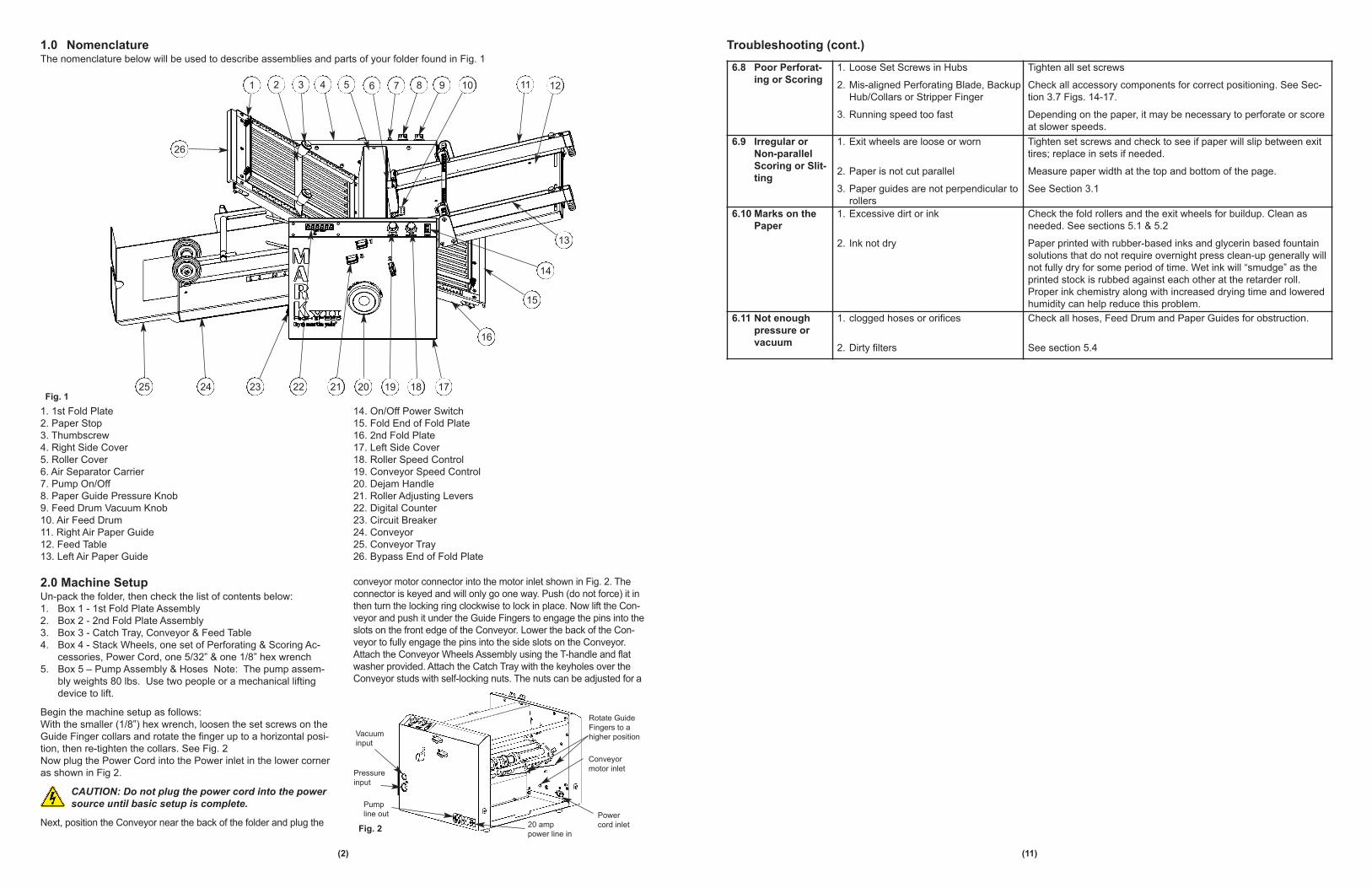
2.0 Machine SetupUn-pack the folder, then check the list of contents below:
1. Box 1 - 1st Fold Plate Assembly
2. Box 2 - 2nd Fold Plate Assembly
3. Box 3 - Catch Tray, Conveyor & Feed Table
4. Box 4 - Stack Wheels, one set of Perforating & Scoring Ac-
cessories, Power Cord, one 5/32” & one 1/8” hex wrench
5. Box 5 – Pump Assembly & Hoses Note: The pump assem-
bly weights 80 lbs. Use two people or a mechanical lifting
device to lift.
Begin the machine setup as follows:
With the smaller (1/8”) hex wrench, loosen the set screws on the
Guide Finger collars and rotate the finger up to a horizontal posi-
tion, then re-tighten the collars. See Fig. 2
Now plug the Power Cord into the Power inlet in the lower corner
as shown in Fig 2.
CAUTION: Do not plug the power cord into the power
source until basic setup is complete.
Next, position the Conveyor near the back of the folder and plug the
conveyor motor connector into the motor inlet shown in Fig. 2. The
connector is keyed and will only go one way. Push (do not force) it in
then turn the locking ring clockwise to lock in place. Now lift the Con-
veyor and push it under the Guide Fingers to engage the pins into the
slots on the front edge of the Conveyor. Lower the back of the Con-
veyor to fully engage the pins into the side slots on the Conveyor.
Attach the Conveyor Wheels Assembly using the T-handle and flat
washer provided. Attach the Catch Tray with the keyholes over the
Conveyor studs with self-locking nuts. The nuts can be adjusted for a
(2)
Fig. 2
Fig. 1
Rotate Guide
Fingers to a
higher position
Power
cord inlet
Conveyor
motor inlet
Vacuum
input
Pump
line out
Pressure
input
20 amp
power line in
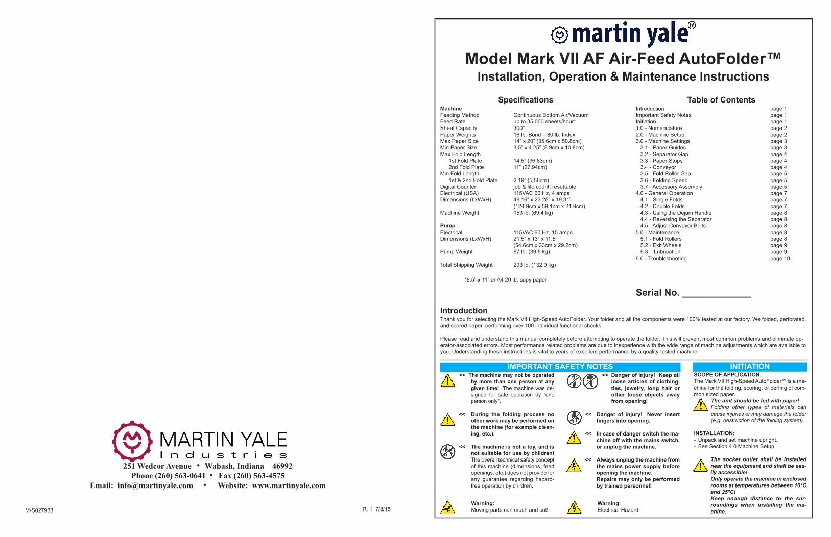
1. 1st Fold Plate
2. Paper Stop
3. Thumbscrew
4. Right Side Cover
5. Roller Cover
6. Air Separator Carrier
7. Pump On/Off
8. Paper Guide Pressure Knob
9. Feed Drum Vacuum Knob
10. Air Feed Drum
11. Right Air Paper Guide
12. Feed Table
13. Left Air Paper Guide
14. On/Off Power Switch
15. Fold End of Fold Plate
16. 2nd Fold Plate
17. Left Side Cover
18. Roller Speed Control
19. Conveyor Speed Control
20. Dejam Handle
21. Roller Adjusting Levers
22. Digital Counter
23. Circuit Breaker
24. Conveyor
25. Conveyor Tray
26. Bypass End of Fold Plate
1.0 NomenclatureThe nomenclature below will be used to describe assemblies and parts of your folder found in Fig. 1
26
10987654321
20 19 18 17
16
15
14
13
1211
25 24 23 22 21
6.8 Poor Perforat-
ing or Scoring
1. Loose Set Screws in Hubs
2. Mis-aligned Perforating Blade, Backup
Hub/Collars or Stripper Finger
3. Running speed too fast
Tighten all set screws
Check all accessory components for correct positioning. See Sec-
tion 3.7 Figs. 14-17.
Depending on the paper, it may be necessary to perforate or score
at slower speeds.
6.9 Irregular or
Non-parallel
Scoring or Slit-
ting
1. Exit wheels are loose or worn
2. Paper is not cut parallel
3. Paper guides are not perpendicular to
rollers
Tighten set screws and check to see if paper will slip between exit
tires; replace in sets if needed.
Measure paper width at the top and bottom of the page.
See Section 3.1
6.10 Marks on the
Paper
1. Excessive dirt or ink
2. Ink not dry
Check the fold rollers and the exit wheels for buildup. Clean as
needed. See sections 5.1 & 5.2
Paper printed with rubber-based inks and glycerin based fountain
solutions that do not require overnight press clean-up generally will
not fully dry for some period of time. Wet ink will “smudge” as the
printed stock is rubbed against each other at the retarder roll.
Proper ink chemistry along with increased drying time and lowered
humidity can help reduce this problem.
6.11 Not enough
pressure or
vacuum
1. clogged hoses or orifices
2. Dirty filters
Check all hoses, Feed Drum and Paper Guides for obstruction.
See section 5.4
Troubleshooting (cont.)
(11)
more desirable fit with a 3/8” wrench (not included). See Fig. 3
The 1st & 2nd Fold Plates and the Feed Table are installed in the
same manner as the Conveyor, on pins and slots. Carefully install the
1st Fold Plate down onto the front pins and lower onto the rear pins,
making sure the side slots fully engage the pins. Both Fold Plates can
be turned around to use in the folding or bypass position. Repeat this
process for the 2nd Fold Plate.
Install the Feed Table onto its pins in the same way. Take care to en-
gage the gear drive on the left side and slide the feed drum under the
separator carrier.
Loosen, but do not remove, the two cross head screws holding
the Hose Lock Plate and slide it to the right. Install the two paper
guide hoses onto the fittings located at the ends of the paper
guides (the longer hose goes on the left side). Insert the opposite
ends with the o-ring fittings into the two lower holes next to the
Lock Plate. Insert the vacuum hose (attached to the Feed Table)
into the smaller hole next to the Lock Plate. Slide the Lock Plate
to the left to capture the o-ring fittings and tighten the two screws.
CAUTION: Be careful not to bump the Feed Table into the
Separator Carrier when installing. This could nick the surface
and prevent proper feeding of the paper stack.
Position the Pump Assembly on the floor near the folder or on the
lower shelf of the MarkVII Folder Cart (provided separately).
Push the vacuum and pressure hoses on to the appropriate fit-
tings provided on the top of the pump. Install the other two fit-
tings into the tapped holes in the Right Side Cover (see fig. 5)
Note: The threads and hoses have been pre-lubricated with a
special silicone sealant. Push the vacuum and pressure hoses
onto the fittings on the Right Side Cover. Plug the Pump Supply
Cord into the male receptacle of the Right Side Cover and the
other end into a 20 amp 115V power outlet.
3.0 Machine SettingsNow that the folder is fully assembled, it is ready for the final set-
ting adjustments to be made before beginning a folding opera-
tion. The procedures below are outlined step-by-step to make this
process as easy as possible.
CAUTION: For personal safety, always unplug the
power cord when making adjustments to the folder.
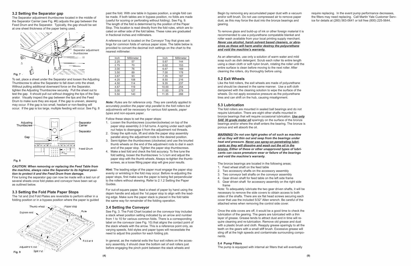
3.1 Setting the Paper GuidesThe two rules on the feed table have been precisely positioned to
allow perpendicular alignment of the paper guides to the fold rollers.
The paper guides are equipped with two locking knobs to give full
control over the feeding system. To move the guides, loosen the
knobs and slide the paper guide along the square shaft and slot.
Align the inside edge of the paper guide clamp block with the corre-
sponding mark on the rule for the desired paper width. Also align the
edge of the Paper Guide Indicator on the same mark on the rule lo-
cated on the back side of the Feed Table. See Fig. 6.
Note: The Paper Guide Indicators are adjustable for squaring pur-
poses but are preset to be perpendicular to the rollers and should
not be moved under normal circumstances.
Lay a sheet of the paper to be folded between the guides to test the
fit. The guides should be parallel to the edges of the paper and
slightly wider. If the guides are too tight, feeding will be interrupted or
stopped. Now place a stack of the paper to be folded between the
guides; it should be able to slide between them without binding. Final
adjustment may be required. Hint: when adjusting the width of the
paper guides, leave one guide fixed and move the opposite side only.
Always jog the paper stack to maximize the accuracy of feeding.
Fig. 6
(3)
Fig. 3
Conveyor wheels
Self locking nuts
Flat washer
T-Handle Conveyor tray
Conveyor
Fig. 5
Fig. 4
Separator Carrier
Feed Table
(10)
6.0 TroubleshootingThe following list of possible problems and resolutions is provided as a guide to the user for self-diagnosis. If your problem
cannot be solved here first, please contact Customer Service for technical assistance at the phone number listed at the
end of this document.
6.1 Folder or Pump
Does Not Run
1. No power
2. Folder or Pump Circuit Breaker
Tripped
3. Loose Wiring
4. Loose or Broken Motor Belt
5. Failed Electrical Component
Check power cord at both ends, building power supply outlet, and
circuit breaker or fuses.
Allow to cool a few minutes, then reset by pushing in the button.
Repeated tripping indicates a more serious problem such as a short
circuit, paper jam or low supply voltage.
If the side cover was removed for service, wiring may have come
loose or disconnected.
Adjust or replace as necessary.
Check speed control, circuit breaker, and motor. Replace if neces-
sary.
6.2 Paper Will Not
Feed
1. Tight Separator Adjustment
2. Worn Separator
3. Feed Drum Clutch
4. Paper Guides Too Tight
5. Vacuum timing is wrong
See Section 3.2
See Section 4.4
With the machine OFF, test the clutch bearing in the Feed Drum by
rotating with your finger. It should spin freely in the feeding direc-
tion and lock in the opposite direction. If the drum turns both ways
or is hard to turn forward, the clutch is worn-out and must be re-
placed.
See Section 3.1
The Vacuum timing is preset and should not require adjustment. If
it is inadvertently changed or you suspect it is wrong, call Martin
Yale customer service for instructions to set timing at (260) 563-
0641 or toll free (800) 225-5644.
6.3 Fold Length
Varies
1. Speed Adjustment
2. Loose Paper Stop
3. Incorrect Roller Gap
4. Dirty Rollers
The length of fold will vary slightly with speed changes. See Section 3.
See Section 3.3
See Section 3.5
See Section 5.1
6.4 Paper Jams or
Tears
1. Double Sheet Feeding
2. Speed Too High
Loose Separator adjustment, see Section 3.2.
See Section 3.6
6.5 Wrinkling Paper 1. Tight Separator Adjustment
2. Feed Drum Clutch
3. Misaligned or Worn Fold Rollers
See Section 3.2
See Section 6.2. #3
Remove the roller cover, feed table, both fold plates and any paper
shims from the adjusting levers. Rotate the rollers while inspecting
the pinch line between each roller. Placing a light behind the rollers
will make this much easier to see any gaps between the rollers.
Gaps in random areas indicate worn rollers while a straight or ta-
pering gap from one end to the other indicates misaligned rollers. If
such gaps are apparent, call for technical assistance.
6.6 Paper Jams at
the Exit
1. Stack Wheels Dislocated
2. Exit Rollers or Guide Strips Dislocated
3. Loose Set Screws in Exit Rollers
4. Conveyor Belts Slipping
5. Paper Sticking to Perforating Blade
See Section 3.4. Always check the stack wheel position before
starting the folding operation!
See Section 3.7
Tighten all set screws
See Section 4.5 Fig. 27
Install the stripper finger provided. See Section 3.7 Fig. 15
6.7 Crooked Folds 1. Paper is not square
2. Loose or Mis-aligned Paper Guides
3. Dirty Rollers
4. #1 Roller Gap too wide
The paper stops can be adjusted to compensate. See Section 3.3
Check paper guides for proper adjustment. See Section 3.1
See Section 5.1
Thin or stiff paper may skew if the gap is not tight enough. See Sec-
tion 3.5
(4)
3.2 Setting the Separator gapThe Separator adjustment thumbscrew located in the middle of
the Separator Carrier (see Fig. #6) adjusts the gap between the
Feed Drum and the Separator. Typically, the gap should be set
at one sheet thickness of the paper being used.
To set, place a sheet under the Separator and loosen the Adjusting
Thumbscrew to allow the Separator to fall down onto the sheet.
Without putting additional downward force on the Separator,
tighten the Adjusting Thumbscrew securely. Pull the sheet out to
test the gap. It should pull out without dragging the tips of the Sep-
arator. Visually inspect the gap between the tips and the Feed
Drum to make sure they are equal. If the gap is uneven, skewing
may occur. If the gap is too small, hesitant or non-feeding will
occur. If the gap is too large, multiple feeding will occur. See Fig. 8
CAUTION: When removing or replacing the Feed Table from
the machine, always raise the Separator to its highest posi-
tion to protect it and the Feed Drum from damage.
Fine tuning the separator gap can now be made with a test run of
several sheets once fold plates and conveyor have been set up
as outlined below.
3.3 Setting the Fold Plate Paper StopsThe 1st and 2nd Fold Plates are reversible to perform either in a
folding position or in a bypass position where the paper is guided
past the fold. With one table in bypass position, a single fold can
be made. If both tables are in bypass position, no folds are made
(useful for scoring or perforating without folding). See Fig. 9.
The length of the fold is determined by the position of the Paper
Stop. This location is read directly from the fold rules, which are lo-
cated on either side of the fold tables. These rules are graduated
in fractional inches and millimeters.
A reference cart is located on the Conveyor Tray that gives set-
tings for common folds of various paper sizes. The table below is
provided to convert the decimal inch settings on the chart to the
nearest millimeter.
Note: Rules are for reference only. They are carefully applied to
accurately position the paper stop parallel to the fold rollers but
adjustments will be necessary for various fold speeds, paper
types and non-square paper.
Follow these steps to set the paper stops:
1. Loosen the thumbscrews (counterclockwise) on top of the
paper stop assembly 2-3 full turns. A spring under each split-
nut helps to disengage it from the adjustment rod threads.
2. Grasp the split-nuts, lift and slide the paper stop assembly
parallel along the adjustment rods to the desired position.
3. Semi-tighten the thumbscrews (clockwise) and use the knurled
thumb wheels on the end of the adjustment rods to dial in each
end of the paper stop. Tighten the paper stop thumbscrews.
4. Make a test fold and check the fold accuracy. To fine tune the
fold setting, loosen the thumbscrews ¼-½ turn and adjust the
paper stop with the thumb wheels. Always re-tighten the thumb-
screws, as a loose fitting paper stop will give poor results.
Hint: The leading edge of the paper must engage the paper stop
evenly or wrinkling in the fold may occur. Before re-adjusting the
paper stops, first make sure the paper is being fed perpendicular
to the rollers without skewing. Refer to 2.1.2 Setting the Paper
Guides.
For out-of-square paper, feed a sheet of paper by hand using the
dejam handle and adjust the 1st paper stop to align with the lead-
ing edge. Make sure the paper stack is placed in the fold table
the same way for remainder of the folding operation.
3.4 Setting the ConveyorSee Fig. 3. The Fold Chart located on the conveyor tray includes
a stack wheel position setting indicated by an arrow and number
from 1 to 10 for various common folds. There is a corresponding
label on the conveyor (see Fig. 10) that aligns the contact point of
the stack wheels with the arrow. This is a reference point only, as
varying speeds, fold styles and paper types will necessitate the
need to adjust this position for each folding job.
In general, as the material exits the four exit rollers on the acces-
sory assembly, it should clear the bottom set of exit rollers just
before engaging the pinch point between the stack wheels and
Fig. 9
Inch Millimeter
2.25 57
2.75 70
3.00 76
3.50 89
3.67 93
4.25 108
4.50 114
4.67 119
5.00 127
5.50 140
Inch Millimeter
5.67 144
6.02 153
6.67 169
7.00 178
7.35 187
8.50 216
9.35 237
10.00 254
11.00 279
11.35 288
Fig. 8
Fig. 7
Separator adjustment
thumbscrew
(9)
Begin by removing any accumulated paper dust with a vacuum
and/or soft brush. Do not use compressed air to remove paper
dust, as this may force the dust into the bronze bearings and
gearing.
To remove glaze and build-up of ink or other foreign material it is
recommended to use a polyurethane compatable blanket and
roller wash available from your local printing supply merchant.
Never use alcohol, harsh solvent based cleaners, or abra-
sives as these will harm and/or destroy the polyurethane
and void the machine’s warranty.
As an alternative, use only a solution of warm water and mild
soap such as dish detergent. Scrub each roller its entire length
using a clean cloth or soft nylon brush, rotating the roller until the
entire surface is clean before moving to the next roller. After
cleaning the rollers, dry thoroughly before using.
5.2 Exit Wheels Like the fold rollers, the exit wheels are made of polyurethane
and should be cleaned in the same manner. Use a soft cloth
dampened with the cleaning solution to wipe the surface of the
wheels. Do not apply excessive pressure as the polyurethane
tires and can shift on the hub, causing misalignment.
5.3 LubricationThe fold rollers are mounted in sealed ball bearings and do not
require lubrication. There are eight other shafts mounted in
bronze bearings that will require occasional lubrication. Use only
SAE 30 grade motor oil sparingly on the surface of the bronze
bearings and/or where the shaft enters the bearing. The bronze is
porous and will absorb the oil.
WARNING! Do not use light grades of oil such as machine
oil as they will thin out and seep from the bearings under
heat and pressure. Never use spray-on penetrating lubri-
cants as they will dissolve and wash out the oil in the
bronze. Either of these or other unapproved types of lubri-
cants can cause premature wear or failure of the bearings
and void the machine’s warranty.
The bronze bearings are located in the following areas;
1. Feed wheel shaft on the feed table
2. Two accessory shafts on the accessory assembly
3. Two conveyor belt shafts on the conveyor assembly
4. Gear driven shaft for feed table on the left side frame
5. Gear driven shaft for accessory assembly on the right side
frame
Note: To adequately lubricate the two gear driven shafts, it will be
necessary to remove the side covers to obtain access to both
sides of the shafts. There are six flat head screws securing each
cover that use the included 5/32” Allen wrench. Be careful of the
attached wires when removing the control side cover.
Once the side coves are off, it would be a good time to check the
lubrication of the gearing. The gears are lubricated with a thin
layer of grease. Grease tends to attract dust and in time will re-
quire cleaning and re-lubrication. Remove old grease and dust
with a plastic brush and cloth. Reapply grease sparingly to all the
teeth on the gears with a small stiff brush. Excessive grease will
sling off at the high speeds and contaminate surrounding compo-
nents.
5.4 Pump Filters
The pump is equipped with internal air filters that will eventually
require replacing. In the event pump performance decreases,
the filters may need replacing. Call Martin Yale Customer Serv-
ice for details at (260) 563-0641 or toll free (800) 225-5644.
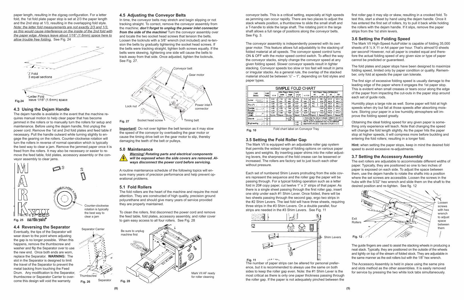
conveyor belts. This is a critical setting, especially at high speeds
as jamming can occur rapidly. There are two places to adjust the
stack wheels position, a thumbscrew to slide the small shaft and
a T-handle to slide the large shaft. The rotating joint in the large
shaft allows a full range of positions along the conveyor belts.
See Fig. 3.
The conveyor assembly is independently powered with its own
gear motor. This feature allows full adjustability to the stacking of
folded material at all speeds. The conveyor speed control turns
ON & OFF with the motor speed control switch. To affect the way
the conveyor stacks, simply change the conveyor speed at any
given folding speed. Slower conveyor speeds result in tighter
stacking. Conveyor speeds too slow or too fast will result in jams
or irregular stacks. As a general rule, the overlap of the stacked
material should be between ½” – 1”, depending on fold styles and
paper types.
3.5 Setting the Fold Roller GapThe Mark VII is equipped with an adjustable roller gap system
that permits the widest range of folding options on various paper
types and weights. By inserting paper shims into the roller adjust-
ing levers, the sharpness of the fold crease can be lessened or
increased. The rollers are factory set to just touch each other
without pressure.
Each set of numbered Shim Levers protruding from the side cov-
ers represent the sequence and the roller gap the paper will be
passing through. For a typical folding operation such as a letter
fold in 20# copy paper, cut twelve 1” x 3” strips of that paper. As
there is a single sheet passing through the first roller gap, insert
one strip under each #1 Shim Lever. Once folded, there will be
two sheets passing through the second gap, ergo two strips in
the #2 Shim Levers. The last fold will have three sheets, requiring
three strips in the #3 Shim Levers. On a double parallel, four
strips are needed in the #3 Shim Levers. See Fig. 11
The number of paper strips can be altered for personal prefer-
ence, but it is recommended to always use the same on both
sides to keep the roller gap even. Note: the #1 Shim Lever is the
most critical as there is only one paper thickness passing through
the roller gap. If the paper is not adequately pinched between the
first roller gap it may slip or skew, resulting in a crooked fold. To
test this, start a sheet by hand using the dejam handle. Once it
has entered the first set of rollers, try to pull it back while holding
the rollers with the dejam handle. If it slips, remove the paper
strips from the 1st shim levers.
3.6 Setting the Folding SpeedThe Mark VII High-Speed AutoFolder is capable of folding 35,000
sheets of 8 ½ X 11 or A4 paper per hour. That’s almost10 sheets
per second! However, not all paper is created equal and there-
fore the actual folding speed of any given size or type of paper
cannot be predicted or guaranteed.
The fold plates and paper stops have been designed to maximize
folding speed, limited only by paper condition or quality. Remem-
ber, only fold at speeds the paper can tolerate.
The first sign of excessive folding speed is usually damage to the
leading edge of the paper where it engages the 1st paper stop.
This is evident when small creases or tears occur along the edge
of the paper from impacting the cut-outs in the paper stop around
each set of guide rods.
Humidity plays a large role as well. Some paper will fold at high
speeds when dry but fail at those speeds after absorbing mois-
ture. Storing your paper in a low humidity atmosphere will im-
prove the folding speed greatly.
Obtaining the ideal folding speed for any given paper is some-
thing only experience will teach. Note that changing the speed
will change the fold length slightly. As the paper hits the paper
stop at higher speeds, it will compress more before buckling and
entering the fold rollers; resulting in a longer fold.
Hint: when setting the paper stops, keep in mind the desired fold
speed to avoid excessive re-adjustments.
3.7 Setting the Accessory AssemblyThe exit rollers are adjustable to accommodate different widths of
paper. Typically, they are positioned so one to two inches of
paper is exposed on each side. To adjust the space between
them, use the dejam handle to rotate the shafts into a position
where the set screws are accessible. Loosen the screws in the
hubs with the 5/32” hex wrench and slide them on the shaft to the
desired position and re-tighten. See fig. 12
The guide fingers are used to assist the stacking wheels in producing a
neat stack. Typically, they are positioned on the outside of the wheels
and lightly on top of the stream of folded stock. They are adjustable in
the same manner as the exit rollers but with the 1/8” hex wrench.
The Accessory Assembly is held in place using the same pins
and slots method as the other assemblies. It is easily removed
for service by pressing the two white lock tabs simultaneously.
Fig. 10
Fig. 11
Shim Levers Fig. 12
Exit
Rollers
Loosen
screws
with hex
wrench
to adjust
space
between
them
paper length, resulting in the zigzag configuration. For a letter
fold, the 1st fold plate paper stop is set at 2/3 the paper length
and the 2nd stop at 1/3, resulting in the overlapping fold style.
Note: the letter fold measurements are not exactly 2/3 and 1/3,
as this would cause interference on the inside of the 2nd fold with
the paper edge. Always leave about 1/16” (1.6mm) space here to
allow trouble free folding. See Fig. 24
4.3 Using the Dejam HandleThe dejam handle is available in the event that the machine re-
quires manual motion to help clear paper that has become
jammed in the rollers or to manually turn the rollers for setup and
maintenance. Before using the dejam handle, first unplug the
power cord. Remove the 1st and 2nd fold plates and feed table if
necessary. Pull the handle outward while turning slightly to en-
gage the gearing on the rollers. Counter-clockwise rotation will
turn the rollers in reverse of normal operation which is typically
the best way to clear a jam. Remove the jammed paper once it is
freed from the rollers. It may also be necessary or easier to re-
move the feed table, fold plates, accessory assembly or the con-
veyor assembly to clear jams.
4.4 Reversing the SeparatorEventually, the tips of the Separator will
wear down to the point where adjusting
the gap is no longer possible. When this
happens, remove the thumbscrew and
washer and flip the Separator over to use
the new end. Once both ends are worn,
replace the Separator. WARNING: The
slot in the Separator is designed to limit
the travel of the Separator to prevent the
metal backing from touching the Feed
Drum. Any modification to the Separator,
thumbscrew or Separator Carrier to over-
come this design will void the warranty.
4.5 Adjusting the Conveyor BeltsIn time, the conveyor belts may stretch and begin slipping or not
tracking straight. To correct, remove the conveyor assembly from
the machine; don’t forget to unplug the power inlet connector
from the side of the machine! Turn the conveyor assembly over
and locate the two socket head screws that tension the belts.
Loosen the locknuts with a 3/8” wrench (not included) and re-ten-
sion the belts by gradually tightening the socket head screws. If
the belts were tracking straight, tighten both screws equally. If the
belts were skewing, tightening one side will cause the belts to
track away from that side. Once adjusted, tighten the locknuts.
See Fig. 27.
Important! Do not over tighten the belt tension as it may slow
the speed of the conveyor by overloading the gear motor or
cause the timing drive belt on the gear motor to slip, thereby
damaging the teeth of the belt or pulleys.
5.0 MaintenanceWarning! Rotating parts and electrical components
will be exposed when the side covers are removed. Al-
ways disconnect the power cord before servicing.
A routine maintenance schedule of the following topics will en-
sure many years of precision performance and help prevent op-
erational problems.
5.1 Fold RollersThe fold rollers are the heart of the machine and require the most
attention. They are constructed of high quality, precision ground
polyurethane and should give many years of service provided
they are properly maintained.
To clean the rollers, first disconnect the power cord and remove
the feed table, fold plates, accessory assembly, and roller cover
to gain easy access to all four rollers. See Fig. 28
(8)
Fig.24
Fig. 27
Conveyor belt
Lock nut
Socket head screw Timing belt
Power inlet
connector
Gear motor
Fig. 25
Fig. 26Separator
Thumbscrew
Separator Carrier
Fold chart label on Conveyor Tray
Fig. 28
Counter-clockwise
rotation is typically
the best way to
clear a jam
Mark VII AF ready
for roller cleaning
Be sure to unplug
machine first
(5)
3.8 Setting the Air Controls
The Pump is provided with Pressure and Vacuum adjustment
knobs that, by default, are set at their maximum value. See Fig. 19
For most folding applications, no further adjustment is necessary.
Located on the Right Side Cover are fine adjustment valves to re-
duce the vacuum and/or pressure to the Feed Drum and Paper
Guides if needed. The Right Side Cover is also equipped with an
ON/OFF switch and circuit breaker for the pump. For the most com-
mon paper sizes and weights, maximum vacuum to the Feed Drum
is desirable. As paper is fed over the holes in the Feed Drum, the
vacuum gauge will peak between 13-15 in/hg. See Fig. 20
Opening the Vacuum Adjustment Knob will cause less vacuum on
the Feed Drum and lower readings on the gauge. When running
without paper on the Feed Drum, the gauge will drop to near 0.
Lower vacuum levels may be desired when feeding light-weight
paper.
Air pressure from the Paper Guides is critical to “floating” the stack
of paper placed upon the Feed Table. This allows the bottom
sheet to be easily pulled by the Feed Drum without the friction of
the remaining stack dragging on it. For best results, a balance
between paper size, weight, and stack height, along with the
amount of air flow, must be met. Hint: for large jobs, use more air
and continually fill the Feed Table. On small jobs, it may be eas-
ier to decrease the air flow and paper stack height as the paper
will flutter more as the stack runs out.
4.0 General OperationWhen the folder has been properly setup and adjusted, turn ON the
main power switch (I/O); the counter will come on with “000000”.
Note: when the main power switch is turned OFF, any pres-
ent counter readings will be reset to zero when turned back
ON. The counter reads the material as it exits the fold rollers and
can be reset to zero at any time by pushing the reset button. By
holding the button down for a few seconds, it will display the total
“life” count times 1,000. For example, until the first 1,000 has
been counted it will read “0”. From 1000 to 1,999 it will read “1”.
Next, turn the fold speed and conveyor speed dials to the desired
setting. The two speed control knobs, folding speed and con-
veyor speed are numbered from 1-8 for reference purpose. The
folding speed control includes an ON/OFF function for both mo-
tors, while the conveyor control only adjusts the speed. Using the
folding speed control ON/OFF function does not reset the counter
if the main power switch is left ON. See Fig. 22
Begin folding by placing a stack of paper onto the feed table with
the roller motor and pump off. Turn the pump on and make sure
the air flow is sufficient to “float” the stack. Place the Paper Back
Stop against the back side of the stack to prevent the bottom
sheets from blowing away from the Separator. Turn on the roller
motor to begin the folding operation. Always check that the stack
wheels are in the correct position before inserting paper! The
paper stock is automatically fed and folded, depending on the fold
plate setup and delivered onto the conveyor in an overlapping row.
4.1 Single Folds(Refer to Section 3.3) Single folds require one fold plate to be in
the fold position and one to be in bypass position. Single folds
are typically made in the 1st Fold Plate as they tend to be more
accurate. Heavier stock may perform better when single folded in
the 2nd Fold Plate if curling becomes an issue, provided the de-
sired fold length is not over 11”. See Fig. 23
4.2 Double Folds(Refer to Section 3.3) Double folds require both fold plates to be
in the fold position. Depending on which fold is made first will de-
termine the configuration of the fold. For example, a Z fold and a
letter fold are basically the same; the sheet being folded into
thirds. For a Z fold, both fold plate paper stops are set to 1/3 the
(7)
Fig. 19
Pressure
adjustment knob
Factory preset at maximum value
Vacuum adjustment
knob
Fig. 20
Fig. 21
Hold reset button
a few seconds to
reveal life count
Digital counter
Vacuum gauge
will peak between
13-15 in/hg
Fig. 22
Use the ‘off’ function of the
Fold Speed control knob to
stop the machine without
resetting the counter
Fig. 23
For a single fold, the 1st
Fold Plate is typically ro-
tated to a bypass position
Bypass end
1st Fold Plate
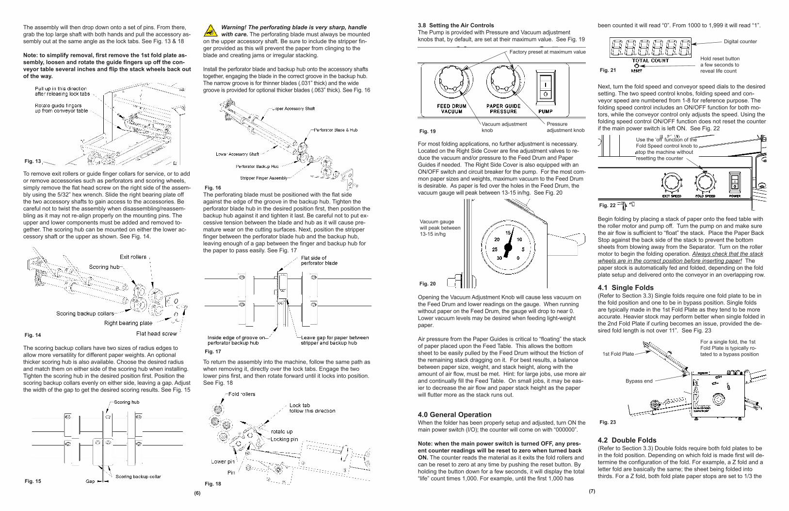
The assembly will then drop down onto a set of pins. From there,
grab the top large shaft with both hands and pull the accessory as-
sembly out at the same angle as the lock tabs. See Fig. 13 & 18
Note: to simplify removal, first remove the 1st fold plate as-
sembly, loosen and rotate the guide fingers up off the con-
veyor table several inches and flip the stack wheels back out
of the way.
To remove exit rollers or guide finger collars for service, or to add
or remove accessories such as perforators and scoring wheels,
simply remove the flat head screw on the right side of the assem-
bly using the 5/32” hex wrench. Slide the right bearing plate off
the two accessory shafts to gain access to the accessories. Be
careful not to twist the assembly when disassembling/reassem-
bling as it may not re-align properly on the mounting pins. The
upper and lower components must be added and removed to-
gether. The scoring hub can be mounted on either the lower ac-
cessory shaft or the upper as shown. See Fig. 14.
The scoring backup collars have two sizes of radius edges to
allow more versatility for different paper weights. An optional
thicker scoring hub is also available. Choose the desired radius
and match them on either side of the scoring hub when installing.
Tighten the scoring hub in the desired position first. Position the
scoring backup collars evenly on either side, leaving a gap. Adjust
the width of the gap to get the desired scoring results. See Fig. 15
Warning! The perforating blade is very sharp, handle
with care. The perforating blade must always be mounted
on the upper accessory shaft. Be sure to include the stripper fin-
ger provided as this will prevent the paper from clinging to the
blade and creating jams or irregular stacking.
Install the perforator blade and backup hub onto the accessory shafts
together, engaging the blade in the correct groove in the backup hub.
The narrow groove is for thinner blades (.031” thick) and the wide
groove is provided for optional thicker blades (.063” thick). See Fig. 16
The perforating blade must be positioned with the flat side
against the edge of the groove in the backup hub. Tighten the
perforator blade hub in the desired position first, then position the
backup hub against it and tighten it last. Be careful not to put ex-
cessive tension between the blade and hub as it will cause pre-
mature wear on the cutting surfaces. Next, position the stripper
finger between the perforator blade hub and the backup hub,
leaving enough of a gap between the finger and backup hub for
the paper to pass easily. See Fig. 17
To return the assembly into the machine, follow the same path as
when removing it, directly over the lock tabs. Engage the two
lower pins first, and then rotate forward until it locks into position.
See Fig. 18
(6)
Fig. 13
Fig. 14
Fig. 15
Fig. 16
Fig. 17
Fig. 18