Embed Size (px)
Citation preview
AD AO 609 CONSOER TOWNSEND AND ASSOCIATES LTD ST LOUIS MO F/S 13/13NATIONAL DAM SAFETY PROGRAM. DAVID R. WILSON DAM (NO 10242). MI--ETC(U)DC 79 W 6 SNIFRIN DACW.3"79-C-0075
LNCLASSIFIED NM.
mmlmEEEEEEEEmEE
I3IEI IIIIIIN :IBBEEEEEEEEEE
MISSISSIPPI-SALT.QUINCY RIVER BASIN
. DAVID R. WILSON DAM
SHELBY COUNTY, MISSOURI
MO. 10242 SE.2 79Bi
PHASE IINSPECTION REPORT
NATIONAL DAM SAFETY PROGRAM'
Ugnited States ArmyCorps of Engineers
-Sening the Army
- ... Serting the Nation
St. Louis District
~TS ~ ~ WETqj.AjJTppRkCTlCAPREPARED YU. s.NTA NLE A/"
$Ipo l FICA- ' n..,.. lr Ea up...
PREPARED BY: U. S. ARMY ENGINEER DISTRICT, ST. LOUIS
FOR: STATE OF MISSOURI I &6' do = bee appm1 '
DECEMBER 1979
.1 9 28 1i6

DISCLAIMER NOTICE
THIS DOCUMENT IS BEST QUALITYPRACTICABLE. THE COPY FURNISHEDTO DTIC CONTAINED A SIGNIFICANTNUMBER OF PAGES WHICH DO NOTREPRODUCE LEGIBLY.
11NCI.&ARTFTFflSECURITY CLASSIFICATION OF THIS PAGE (Wen Dae Entered)
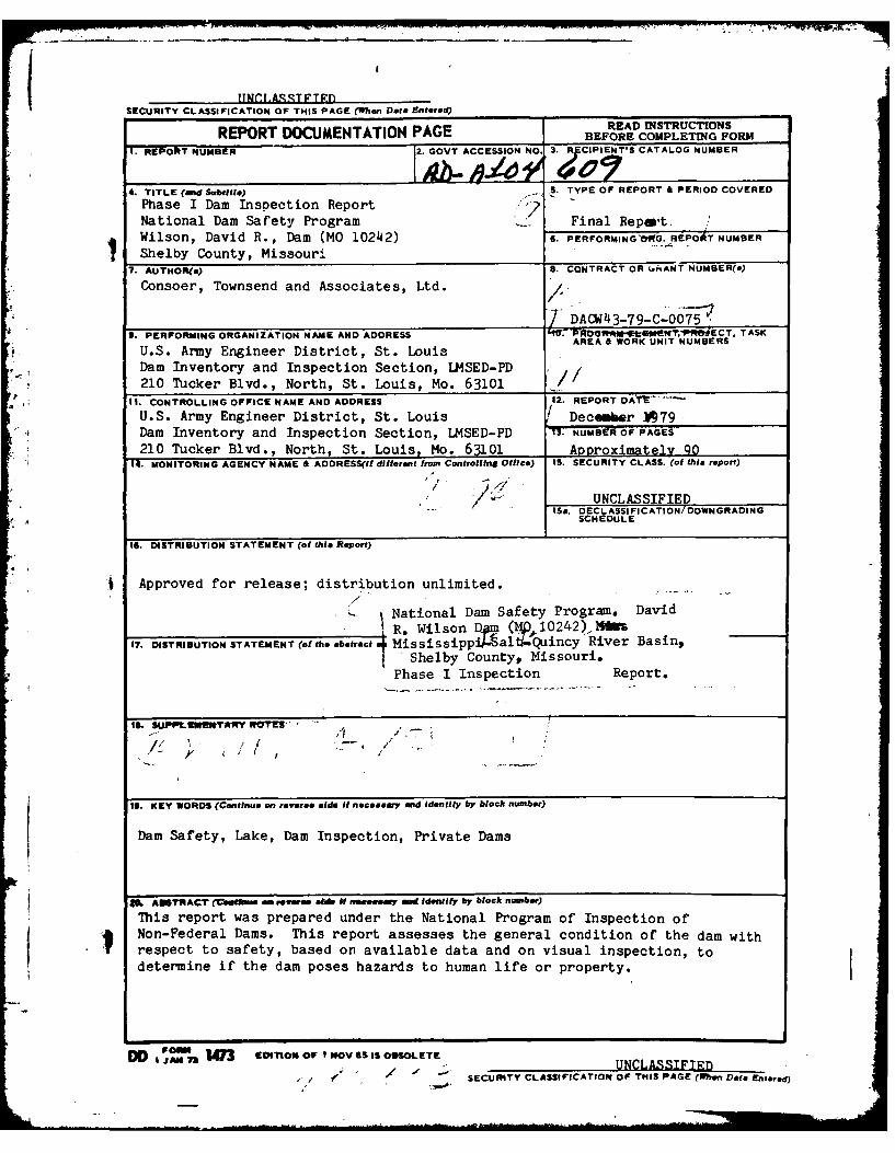
REPORT DOCUMENTATION PAGE BEFORE COMPLETING FORM1. REPORT NUMBER 2. GOVT ACCESSION NO. 3. R CIPIE T'S CATALOG NUMBER
4. TITLE (and Subtitle) . TYPE OF REPORT & PERIOD COVERED
Phase I Dam Inspection Report 7National Dam Safety Program ... Final Repart.Wilson, David R., Dam (MO 10242) 6. PERFORMINGONGd. REPOAT NUMBER
Shelby County, Missouri7. AUTHOR(*) S. CONTRACT OR (,kANT NUMBER(s)
Consoer, Townsend and Associates, Ltd.
________________________________________ 7DACJ143-79-C-OO759. PERFORMING ORGANIZATION NAME AND ADDRESS "' -WROGRm RTI ECT . TASK
AREA & OKUNIT NUMBERSU.S. Army Engineer District, St. LouisDam Inventory and Inspection Section, LMSED-PD210 Tucker Blvd., North, St. Louis, Mo. 63101 1-
11. CONTROLLING OFFICE NAME AND ADDRESS 42. REPORT DA1I.
U.S. Army Engineer District, St. Louis ! December ]79Dam Inventory and Inspection Section, LMSED-PD . NUMB EOR PAGES
210 Tucker Blvd., North, St. Louis, Mo. 63101 ADDroximately 9014. MONITORING AGENCY NAME & AODRESS(If different from Controlling Office) IS. SECURITY CLASS. (of this report)
.*~ " UNCLASSIFIEDIS&. DECL ASSI FICATION/DOWNGRADING
SCHEDULE
16. DISTRIBUTION STATEMENT (of this Report)
Approved for release; distribution unlimited./
National Dam Safety Program. DavidRWilson Dam (1g0,042
17. DISTRIBUTION STATEMENT (of the .btct Mississipp al Quincy River Basing- Shelby County, Missouri.Phase I Inspection Report.
to. SUPPL;IfVYA RY wRi " - '
-'" / -
19. KEY WORDS (Continue on reverse side it necessary md Identify by block number)
Dam Safety, Lake, Dam Inspection, Private Dams
AITRA'CT 6 ernon side N neseonry and ideViify by block number)
This report was prepared under the National Program of Inspection of-' Non-Federal Dams. This report assesses the general condition of the dam with
respect to safety, based on available data and on visual inspection, todetermine if the dam poses hazards to human life or property.
DD Fo. 13 EDITION OF9,OV S5 IS OBSOLETEAN / SC Y UNLASSIFInD/ / "SECURITY CLASSIFICATION OF THIS PAGE (Whe Data Entered)

DEPARTMENT OF THE ARMYST. LOUIS DISTRICT, CORPS OF KGINEKRS;
210 NORTH 12TH STREETST. L.OUIS, MISSOURI 63101
iN PL~ty maPUN TO
SUBJECT: David R. Wilson Dam, Phase I Inspection Report
This report presents the results of field inspection and evalua-tion of the David R. Wilson Dam (MO 10242).
It was prepared under the National Program of Inspection of Non-Federal Dams.
This dam has been classified as unsafe, non-emergency by the St.Louis District and requires prompt remedial action be taken toinsure the stability of the downstream slope.
Also, unsafe conditions exist due to the following:
a. Inadequate spillway that will not pass the ProbableMaximum Flood.
b. Overtopping that could result in dam failure.
Submitted By: SIIJN L 11 JAN 1Chief, Engineering Division Date
Approved By: __ _ __ _ __ _ 14 \N 19OColonel, CE, District Engineer Date
Accession For
DTIC TAB
Justification
Distribut ion/
Availability CodonjAvail and/or-Dist Special
Z A

DAVID R. WILSON DAM
SHELBY COUNTY, MISSOURI
MISSOURI INVENTORY NO. 10242
PHASE I INSPECTION REPORT
NATIONAL DAM SAFETY PROGRAM
PREPARED BY
CONSOER, TOWNSEND AND ASSOCIATES, LTD.
ST. LOUIS, MISSOURI
AND
ENGINEERING CONSULTANTS, INC.
ENGLEWOOD, COLORADO
A JOINT VENTURE
UNDER DIRECTION OF
ST. LOUIS DISTRICT, CORPS OF ENGINEERS
FOR
GOVERNOR OF MISSOURI
DECEMBER 1979
I PHASE I INSPECTION REPORT
NATIONAL DAM SAFETY PROGRAM
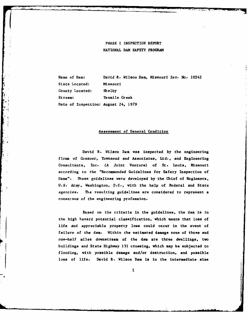
Name of Dam: David R. Wilson Dam, Missouri Inv. No. 10242
State Located: Missouri
County Located: Shelby
Stream: Tenmile Creek
Date of Inspection: August 24, 1979
Assessment of General Condition
David R. Wilson Dam was inspected by the engineering
firms of Consoer, Townsend and Associates, Ltd., and Engineering
Consultants, Inc. (A Joint Venture) of St. Louis, Missouri
according to the "Recommended Guidelines for Safety Inspection of
Dams". These guidelines were developed by the Chief of Engineers,
U.S. Army, Washington, D.C., with the help of Federal and State
agencies. The resulting guidelines are considered to represent a
consersus of the engineering profession.
Based on the criteria in the guidelines, the dam is in
the high hazard potential classification, which means that loss of
life and appreciable property loss could occur in the event of
failure of the dam. Within the estimated damage zone of three and
one-half miles downstream of the dam are three dwellings, two
buildings and State Highway 151 crossing, which may be subjected to
flooding, with possible damage and/or destruction, and possible
loss of life. David R. Wilson Dam is in the intermediate size
classification since it is less than 40 feet high but impounds more
than 1,000 acre-feet of water.
Our inspection and evaluation indicates that the spill-
way of David R. Wilson Dam does not meet the criteria set forth in
the guidelines for a dam having the above size and hazard poten-
tial. David R. Wilson Dam being an intermediate size dam, with a
high hazard potential, is required by the guidelines to pass the
Probable Maximum Flood without overtopping. Since there is high
hazard potential downstream of the dam, the appropriate spillway
design flood for this dam is the Probable Maximum Flood. It was
determined that the reservoir/spillway system can accommodate 27
percent of the Probable Maximum Flood without overtopping the dam.
Our evaluation indicates that the reservoir/spillway system will
accommodate the 100-year flood without overtopping.
The Probable Maximum Flood is defined as the flood
discharge that may be expected from the most severe combination of
critical meteorological and hydrologic conditions that are reason-
ably possible in the region. The 100-year flood is defined as a
flood having a one percent chance of being equalled or exceeded
during any given year.
Another major deficiency with David R. Wilson Dam is the
deteriorating condition of the downstream slope. Numerous longi-
tudinal cracks were observed along the downstream edge of the dam
crest, ranging in width from 1/4-inch to 12-inches and in depth
from 1-inch to 3 feet. Scarps due to past slope movement were
visible on the slope. These observations indicate serious insta-
bility problems that may result in failure of the dam embankment.
II
Other deficiencies noted by the inspection team were:
the erosion and sloughing of the upstream slope; the erosion gully
on the right abutment; the standing water located at the toe of the
dam; the erosion in the downstream channel; the trees and vegeta-
tion on the downstream slope; a need for periodic inspection by a
qualified engineer and a lack of maintenance schedule. The lack of
stability and seepage analyses on record is also a deficiency that
should be corrected.
It is recommended that the owner take immediate action
to correct the deteriorating condition of the downstream embankment
slope, and correct or control the several deficiencies described
above in the near future.
Walter G. Shifrin, P.E.
WALTER " f-.! G. SHIFRIN "-
' -, 8
",,. OFf SS\".
III

0
-4'-4
'-I
~J-40
'-4
S.dQJ
Er

PHASE I INSPECTION REPORT
NATIONAL DAM SAFETY PROGRAM
DAVID R. WILSON DAM, I.D. No. 10242
TABLE OF CONTENTS
Sect. No. Title Page
SECTION 1 PROJECT INFORMATION . . . . . . . . 1
1.1 General . . . . . . . . . . . 1
1.2 Description of Project . . . . 3
1.3 Pertinent Data ...... . . 6
SECTION 2 ENGINEERING DATA . . ....... 8
2.1 Design . . . . . . . . . . . . 8
2.2 Construction . . . . . . . . . 8
2.3 Operation . . . . . . . . . . 8
2.4 Evaluation . . . . . . . . . . 8
SECTION 3 VISUAL INSPECTION . . . . . . . . . 10
3.1 Findings . . . . . . . . . . . 10
3.2 Evaluation . . . . . . . . . . 15
V
TABLE OF CONTENTS
(Continued)
Sect. No. Title e
SECTION 4 OPERATION PROCEDURES . . . . . .. 17
4.1 Procedures . . . . ...... 17
4.2 Maintenance of Dam ........ .17
4.3 Maintenance of Operating
Facilities ........ . . . . 17
4.4 Description of Any Warning
System in Effect ...... . 17
4.5 Evaluation . . . . . . . . . . 18
SECTION 5 HYDRAULIC/HYDROLOGIC . ...... 19
5.1 Evaluation of Features . . . . 19
SECTION 6 STRUCTURAL STABILITY. ...... 23
6.1 Evaluation of Structural
Stability. . . . . . . . . . . 23
SECTION 7 ASSESSMENT/REMEDIAL MEASURES . ... 25
7.1 Dam Assessment ........ 25
7.2 Remedial Measures. . . . . .. 27
VI

TABLE OF CONTENTS
(Continued)
LIST OF PLATES
Plate No.
LOCATION HAP .......... . . . . . . . . . . . . 1PLAN AND ELEVATION OF DAM . . . . . . . . . ...... 2
GEOLOGIC MAP . . . ......... . . . . . . . . . 3SEISMIC ZONE MAP ..... .............. . . . . . . . 4
APPENDICES
APPENDIX A - PHOTOGRAPHS
APPENDIX B - HYDROLOGIC COMPUTATIONS
VII

Ig
PHASE I INSPECTION REPORTNATIONAL DAM SAFETY PROGRAM
DAVID R. WILSON DAM, Missouri Inv. No. 10242
SECTION 1: PROJECT INFORMATION
1.1 General
a. Authority
The Dam Inspection Act, Public Law 92-367 of
August, 1972, authorizes the Secretary of the Army, through
the Corps of Engineers, to initiate a national program of dam
inspections. Inspection for David R. Wilson Dam was carried
out under Contract DACW 43-79-C-0075 between the Department of
the Army, St. Louis District, Corps of Engineers, and the
engineering firms of Consoer, Townsend & Associates, Ltd., and
Engineering Consultants, Inc. (A Joint Venture), of St. Louis,
Missouri.
b. Purpose of Inspection
The visual inspection of David R. Wilson Dam was
made on August 24, 1979. The purpose of the inspection was to
make a general assessment as to the structural integrity and
operational adequacy of the dam embankment and its appurtenant
structures.
k | I 1 1 I-1-

C. Scope of Report
This report summarizes available pertinent data
relating to the project; presents a summary of visual observa-
tions made during the field inspection; presents an assessment
of hydrologic and hydraulic conditions at the site; presents
an assessment as to the structural adequacy of the various
project features; and assesses the general condition of the
dam with respect to safety.
Subsurface investigations, laboratory testing, and
detailed analyses were not within the scope of this study.
The conclusions drawn herein, therefore, are based on the
presence of, or absence of, obvious signs of distress. No
warranty as to the absolute safety of the project features is
implied by the conclusions presented in this report.
It should be noted that reference in this report to
left or right abutments is as viewed looking downstream.
Where left abutment or left side of the dam is used in this
report, this also refers to the northwest abutment or side,
and right to the southeast abutment or side.
d. Evaluation Criteria
Criteria used to evaluate the dam were furnished by
the Department of the Army, Office of the Chief of Engineers,
in the publication "Recommended Guidelines for Safety Inspec-
tion of Dams", Appendix D. These guidelines were developed
with the help of several Federal agencies and many State
agencies, professional engineering organizations, and private
engineers.
-2-
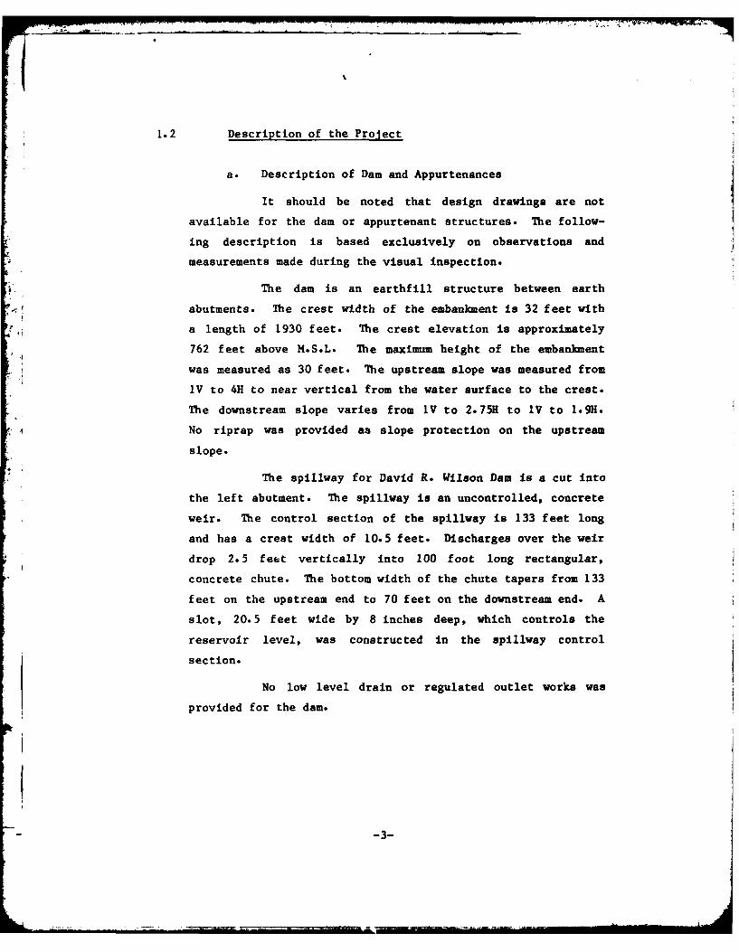
1.2 Description of the Project
a. Description of Dam and Appurtenances
It should be noted that design drawings are not
available for the dam or appurtenant structures. The follow-
ing description is based exclusively on observations and
measurements made during the visual inspection.
The dam is an earthfill structure between earth
abutments. The crest width of the embankment is 32 feet with
a length of 1930 feet. The crest elevation is approximately
762 feet above M.S.L. The maximum height of the embankment
was measured as 30 feet. The upstream slope was measured from
IV to 4H to near vertical from the water surface to the crest.
The downstream slope varies from IV to 2.75H to IV to 1.9H.
No riprap was provided as slope protection on the upstream
slope.
The spillway for David R. Wilson Dam is a cut into
the left abutment. The spillway is an uncontrolled, concrete
weir. The control section of the spillway is 133 feet long
and has a crest width of 10.5 feet. Discharges over the weir
drop 2.5 feet vertically into 100 foot long rectangular,
concrete chute. The bottom width of the chute tapers from 133
feet on the upstream end to 70 feet on the downstream end. A
slot, 20.5 feet wide by 8 inches deep, which controls the
reservoir level, was constructed in the spillway control
section.
No low level drain or regulated outlet works was
provided for the dam.
-3-

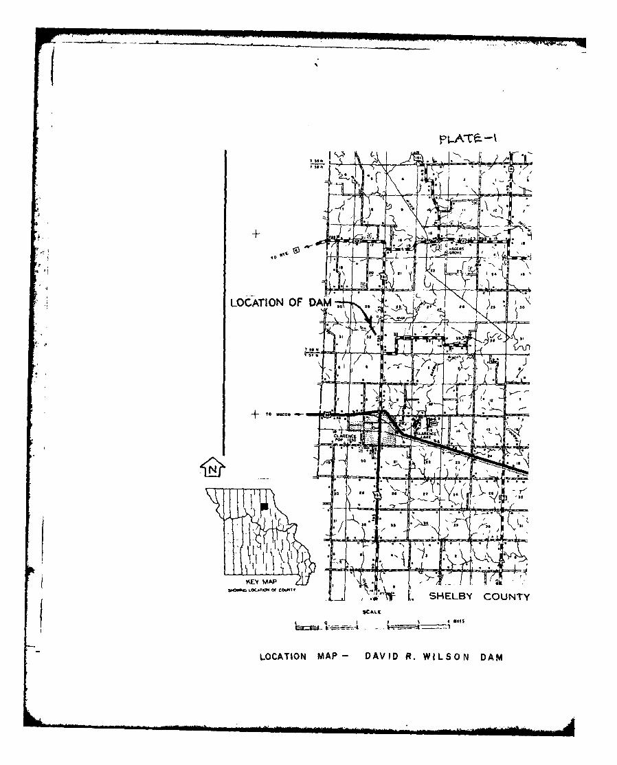
b. Location
The David R. Wilson Dam is located on the Tenmile
Creek in Shelby County, Missouri. Hagers Grove, population
32, is located 3 miles to the north of the dam and Clarence,
population 1,050, is located 3 miles to the south of the dam.
The dam is located in Section 32, Township 58 North, Range 12
West as shown in Missouri Atlanta, Quadrangle Sheet (15 minute
series).
c. Size Classification
According to the "Recomended Guidelines for Safety
Inspection of Dams", by the U.S. Department of the Army,
Office of the Chief Engineer, the dam is classified in the dam
size category as being "Intermediate" since its storage is
less than 50,000 acre-feet but greater than 1,000 acre-feet.
The dam is classified as "Small" in dam size category because
its height is less than 40 feet. The overall size classifica-
tion is "Intermediate" in size.
d. Hazard Classification
The dam has been classified as having "High" hazard
potential by the St. Louis District Corps of Engineers on the
basis that in the event of failure of the dam or its appur-
tenances, excessive damage could occur to downstream property,
together with the possibility of the loss of life. Our
findings concur with the classification. The estimated damage
zone extends approximately 3.5 miles downstream of the dam.
Within the possible damage zone are three dwellings, two
buildings and State Highway 151 crossing.
-4-

e. Ownership
The David R. Wilson Dam is owned by Mr. David R.
Wilson. The mailing address is David R. Wilson, c/o Wilson
Refuse Hauling, Inc., 177C Bourke, Macon, Missouri, 63552.
f. Purpose of Dam
The main purpose of the dam is to impound water for
recreational use.
g. Design and Construction History
David R. Wilson Dam was completed in 1971 by
personnel under the direction of, and employed by Mr. David R.
Wilson, the present owner. According to Mr. John Linton, an
employee of Wilson Refuse & Hauling, the dam was under con-
struction for about two years. In 1973 the reservoir was
drained and its was necessary to rebuild the dam. Further
details are not available at this time due to a lack of
records and the fact that efforts to contact the owner for
questioning were futile.
h. Normal Operational Procedures
Normal procedure is to allow the dam and reservoir
to act entirely on its own. The spillway is an uncontrolled
open chute below a broad crested weir. The dam is used to
impound water for recreational use at this time. Water level
below the spillway crest is controlled by rainfall, runoff and
evaporation.
-5-
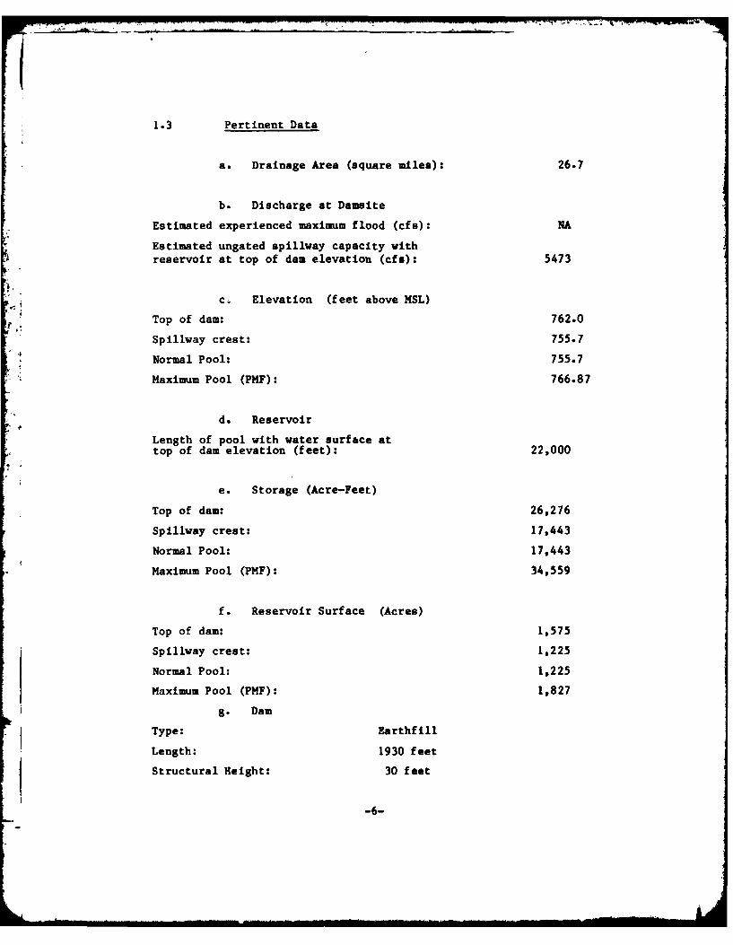
1.3 Pertinent Data
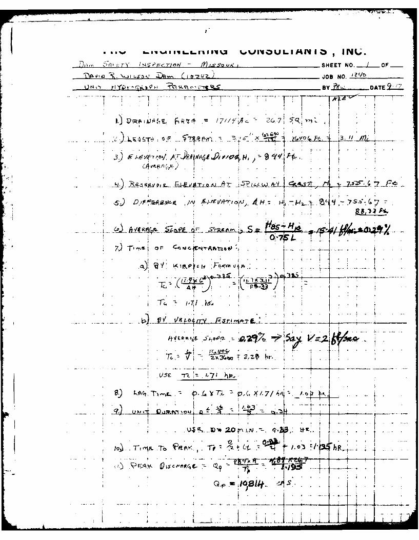
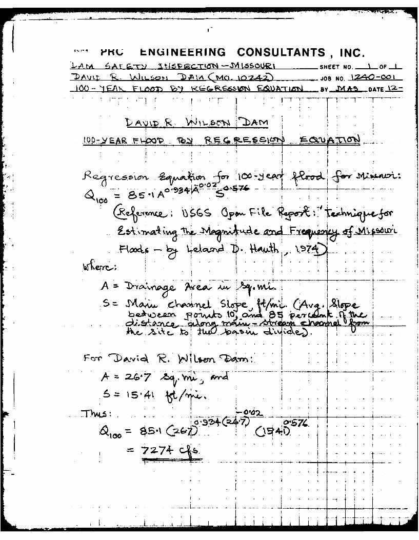
a. Drainage Area (square miles): 26.7
b. Discharge at Damsite
Estimated experienced maximum flood (cfs): NA
Estimated ungated spillway capacity withreservoir at top of dam elevation (cfs): 5473
c. Elevation (feet above MSL)
Top of dam: 762.0
Spillway crest: 755.7
Normal Pool: 755.7
Maximum Pool (PMF): 766.87
d. Reservoir
Length of pool with water surf&ce attop of dam elevation (feet): 22,000
e. Storage (Acre-Feet)
Top of dam: 26,276
Spillway crest: 17,443
Normal Pool: 17,443
Maximum Pool (PMF): 34,559
f. Reservoir Surface (Acres)
Top of dam: 1,575
Spillway crest: 1,225
Normal Pool: 1,225
Maximum Pool (PMF): 1,827
g. Dam
Type: Earthfill
Length: 1930 feet
Structural Height: 30 feet
-6-

Hydraulic Height: 30 feet
Top width: 32 feet
Side slopes:
Downstream Varies from IV to 2.75H toIV to 1.9H
Upstream Varies from IV to 4H to near vertical
Zoning: Unknown
Impervious core: Unknown
Cutoff: Unknown
Grout curtain: Unknown
h. Diversion and Regulating Tunnel None
i. Spillway
Type: Concrete weir, uncontrolled
Length of crest: 133 feet
Crest Elevation (feet above MSL): 755.7
j. Regulating Outlets None
-7-

SECTION 2: ENGINEERING DATA
2.1 Desisn
Design drawings are not available f or the dam and
appurtenant structures. At the time of its construction (1969 thru
1971) there was no formal design performed. The Soil Conservation
Service office of Shelby County, refused to submit a design due to
the extensive size of the proposed dam.
2.2 Construction
According to Mr. John Linton, an employee of Wilson
Refuse and Hauling Co. the dam was built by persons directly
employed by Mr. Wilson.
2.3 Operation
No operational data are available for the David R.
Wilson Dam.
2.4 Evaluation
a. Availability
No design drawings, design computations, construc-
tion data, or operation data were available.
In addition, no pertinent data were available for
review of hydrology, spillway capacity, flood routing through
the reservoir, outlet capacity, slope stability, seepage
analysis, or foundation conditions.
-8-

M7 -. 717.'U
b. Adequacy
The lack of engineering data did not allow for adefinitive review and evaluation. Therefore, the adequacy of
this dam could not be assessed from the standpoint of review-
ing and evaluating design, operation and construction data,
but is based primarily on visual inspection, past performance
history, and sound engineering judgment.
Seepage and stability analyses comparable to the
requirements of tne "Recommended Guidelines for Safety Inspec-
tion of Dams" were not available, which is considered a
deficiency. These seepage and stability analyses should be
performed for appropriate loading conditions and made a matter
of record.
c. Validity
No valid engineering data are available.
=-9-

SECTION 3: VISUAL INSPECTION
3.1 Findings
a. General
A visual inspection of the David R. Wilson Dam was
made on August 24, 1979. The following persons were present
during the inspection:
Name Affiliation Disciplines
Dr. M.A. Samad Engineering Consultants, Inc. Project Engineer,Hydraulics and
Hydrology
Mark R. Haynes Engineering Consultants, Inc. Civil, Structural
and Mechanical
Dawn L. Jacoby Engineering Consultants, Inc. Soils
Peter L. Strauss Engineering Consultants, Inc. Geology
Kevin Blume Consoer, Townsend & Assoc., Ltd. Civil and
Structural
Specific observations are discussed below.
1-10-L.-
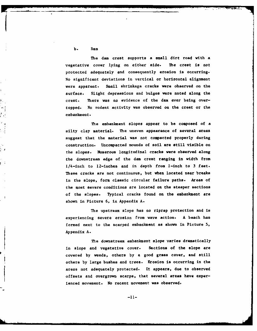
b. Dam
The dam crest supports a small dirt road with a
vegetative cover lying on either side. The crest is not
protected adequately and consequently erosion is occurring.
No significant deviations in vertical or horizontal alignment
were apparent. Small shrinkage cracks were observed on the
surface. Slight depressions and bulges were noted along the
crest. There was no evidence of the dam ever being over-
topped. No rodent activity was observed on the crest or the
embankment.
The embankment slopes appear to be composed of a
silty clay material. The uneven appearance of several areas
suggest that the material was not compacted properly during
construction. Uncompacted mounds of soil are still visible on
the slopes. Numerous longitudinal cracks were observed along
the downstream edge of the dam crest ranging in width from
1/4-inch to 12-inches and in depth from 1-inch to 3 feet.
These cracks are not continuous, but when located near breaks
in the slope, form classic circular failure paths. Areas of
the most severe conditions are located on the steeper sections
of the slopes. Typical cracks found on the embankment are
shown in Picture 6, in Appendix A.
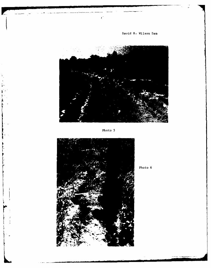
The upstream slope has no riprap protection and is
experiencing severe erosion from wave action. A beach has
formed next to the scarped embankment as shown in Picture 5,
Appendix A.
The downstream embankment slope varies dramatically
in slope and vegetative cover. Sections of the slope are
covered by weeds, others by a good grass cover, and still
others by large bushes and trees. Erosion is occurring in the
areas not adequately protected. It appears, due to observed
offsets and overgrown scarps, that several areas have exper-
ienced movement. No recent movement was observed.
-11-

No flowing seepage was observed on the embankment
or downstream of the toe. A drainage ditch has been cut
downstream from approximately the midsection of the dam to the
right abutment. Bushes growing on the slope above this area
are located on moist soil. The drainage ditch appears to have
been constructed to drain a large pond of water which lies
just downstream of the toe of the left half of the dam.
Picture No. 15, Appendix A, was taken across the pond to the
downstream embankment.
According to the "Missouri General Soil Map and
Soil Association Description" published by the Soil Conserva-
tion Service, the materials in the general area of the dam
belong to the soil series of Mexico-Leonard-Armstrong-Lindley
in the Central Claypan Area forest. The soils are basically
formed from loess and glacial till. The permeability of these
soils range from slow to moderately slow. The Lindley soils
generally are quite erodable and would be particularly suscep-
tible to erosion due to overtopping.
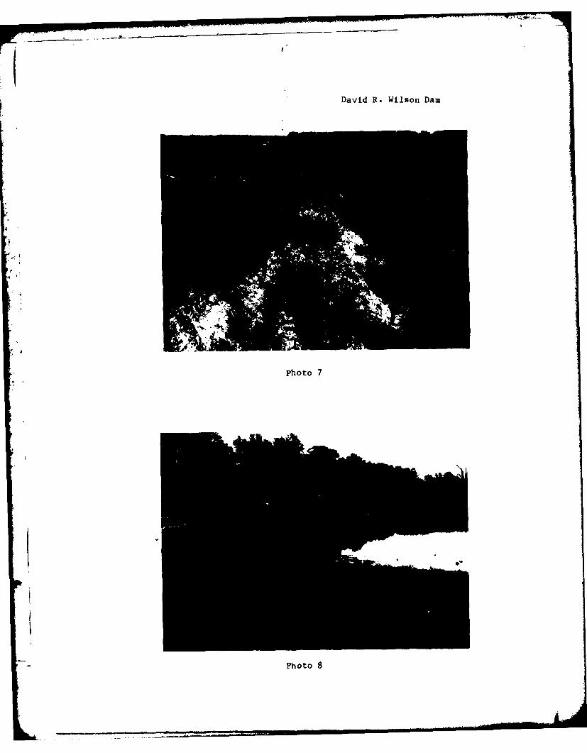
The spillway is a cut into the left abutment which
slopes upward from the crest. The right abutment has a large
erosion gully cut into the downstream side, Picture No. 7,
Appendix A. No signs of instability were apparent on either
abutment.
C. Project Geology
The damsite is physiographically located in the
Dissected Till Plains Section of the Central Lowlands Physio-
graphic Province, according to Nevin Fenneman's "Physiography
of the Eastern United States". This section is distinguished
from the Young Drift section on the north and from the Till
Plains on the east by the stage it has reached in the post-
glacial erosion cycle. Broadly generalized, this section is a
-12-
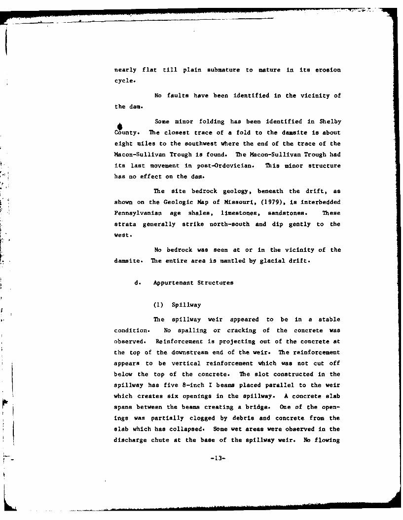
I1nearly flat till plain submature to mature in its erosion
cycle.
No faults have been identified in the vicinity of
the dam.
Some minor folding has been identified in Shelby
County. The closest trace of a fold to the damsite is about
eight miles to the southwest where the end of the trace of the
Macon-Sullivan Trough is found. The Macon-Sullivan Trough had
its last movement in post-Ordovician. This minor structure
has no effect on the dam.
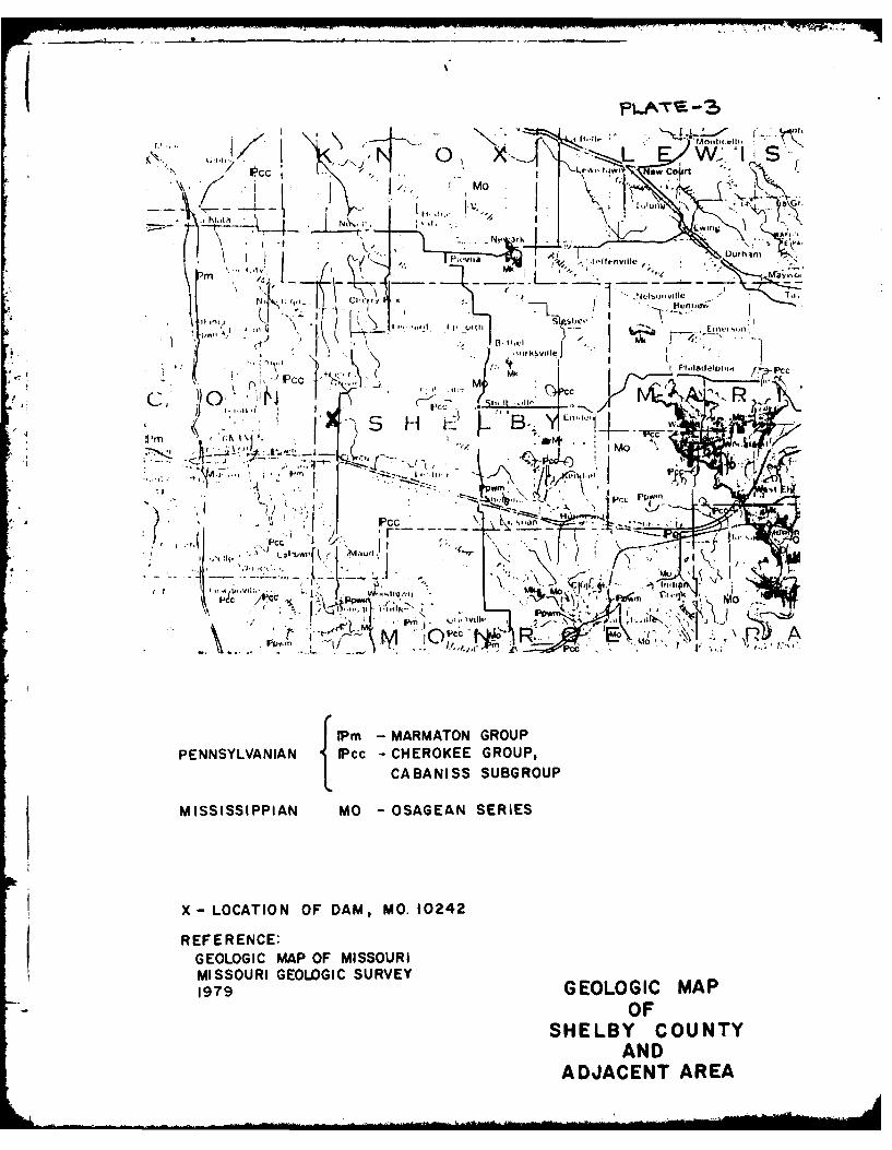
The site bedrock geology, beneath the drift, as
shown on the Geologic Map of Missouri, (1979), is interbedded
Pennsylvanian age shales, limestones, sandstones. These
strata generally strike north-south and dip gently to the
west.
No bedrock was seen at or in the vicinity of the
damsite. The entire area is mantled by glacial drift.
d. Appurtenant Structures
(1) Spillway
The spillway weir appeared to be in a stable
condition. No spalling or cracking of the concrete was
observed. Reinforcement is projecting out of the concrete at
the top of the downstream end of the weir. The reinforcement
appears to be vertical reinforcement which was not cut off
below the top of the concrete. The slot constructed in the
spillway has five 8-inch I beams placed parallel to the weir
which creates six openings in the spillway. A concrete slab
spans between the beams creating a bridge. One of the open-ings was partially clogged by debris and concrete from the
slab which has collapsed. Some wet areas were observed in the
discharge chute at the base of the spillway weir. No flowing
-13-

seepage was observed. The spillway and discharge chute were
not obstructed.
The overall condition of the slab and right retain-
ing wall of the discharge chute was good. There was no
spalling of the concrete, but a few temperature cracks were
observed. The right retaining wall appeared to be stable.
The face of the retaining wall was not properly finished and
formwork ties were still projecting from the concrete. Minor
chemical leaching was observed on the wall.
F ; A portion of the left retaining wall appears to
have collapsed at some time and the collapsed portion was
reconstructed. A large bulge was observed on the recon-
structed portion of the wall, which appears to have been due
to formwork failure. Some formwork was observed between the
contact of the new and old portion of the wall. Some dental
work was performed in one area using concrete block and
mortar. Reinforcement was projecting from the remains of the
collapsed portion of the wall. Two large diagonal temperature
cracks were observed on the wingwall at the downstream end of
the chute, however, the wall appeared to be stable. The
entire left retaining wall appeared to be stable and in good
condition, but the method of construction used for the wall
was less than desirable.
The downstream end of the discharge chute drops 7
feet vertically onto a concrete apron. The apron appears to
have been constructed of waste concrete which was dumped
there. No undermining of the apron was observed.
Slopes above the discharge chute were exhibiting
evidence of severe erosion due to storm runoff.
-14-
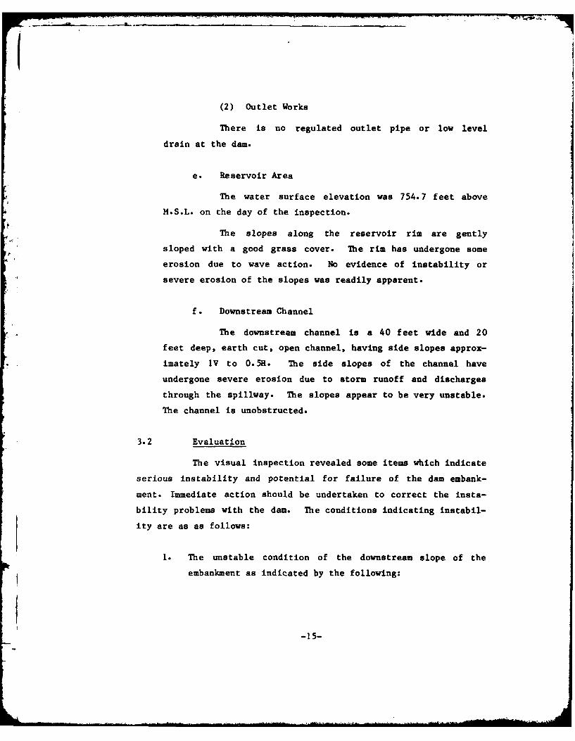
(2) Outlet Works
There is no regulated outlet pipe or low level
drain at the dam.
e. Reservoir Area
The water surface elevation was 754.7 feet above
M.S.L. on the day of the inspection.
The slopes along the reservoir rim are gently
sloped with a good grass cover. The rim has undergone some
erosion due to wave action. No evidence of instability or
severe erosion of the slopes was readily apparent.
f. Downstream Channel
The downstream channel is a 40 feet wide and 20
feet deep, earth cut, open channel, having side slopes approx-
imately 1V to O.5H. The side slopes of the channel have
undergone severe erosion due to storm runoff and discharges
through the spillway. The slopes appear to be very unstable.
The channel is unobstructed.
3.2 Evaluation
The visual inspection revealed some items which indicate
serious instability and potential for failure of the dam embank-
ment. Immediate action should be undertaken to correct the insta-
bility problems with the dam. The conditions indicating instabil-
ity are as as follows:
1. The unstable condition of the downstream slope of the
embankment as indicated by the following:
-15-
(a) Cracks along the crest of the slope.
(b) Visible scarps due to past slides.
(c) Erosion in unprotected areas.
(d) Areas of uncompacted fill.
The following conditions were observed which could
affect the safety of the dam or which will require maintenance
within a reasonable period of time.
1. The conditions observed on the upstream slope of the
embankment:
(a) Beach and scarp caused by wave action.
(b) Erosion gullies on the slope above the sloughing.
(c) No riprap protection.
2. The standing water observed near the toe.
3. The erosion gully observed on the right abutment.
4. The instability and erosion in the downstream channel.
-16-

SECTION 4: OPERATIONAL PROCEDURES
4.1 Procedures
David R. Wilson Dam is used to impound water for recrea-
tional use. Normal procedure is to allow the water level to remain
as high as possible.
4.2 Maintenance of Dam
The dam and appurtenant structures are maintained by the
owner, Mr. David R. Wilson and his employees.
The dam was, at the time of this inspection, in a state
of deterioration. The downstream slope was mostly covered with
trees and dense vegetation. There was extensive wave erosion
present on the upstream slope and ultiple transverse cracks near
the contact of the downstream slope and dam crest. Many areas of
spalling, cracking and exposed reinforcement were observed in the
spillway.
4.3 Maintenance of Operating Facilities
There are no operable facilities connected with the dam
which require any maintenance.
4.4 Description of Any Warning System in Effect
The inspection team is not aware of any existing warning
system in effect.
-17-
4.5 Evaluation
Th,. operation and maintenance of the dam is lacking. To
improve the operEational adequacy of the dam, the corrective mea-
sures outl.ned in Section 7.2 should be undertaken as recommended.
-18-
SECTION 5: HYDRAULIC/HYDROLOGIC
5.1 Evaluation of Features
a. Design
The watershed area of the David R. Wilson Dam
upstream from the dam axis consists of approximately 26.7
square miles. The watershed area is mostly pasture and range
land. Land gradients in the higher regions of the watershed
average roughly 2 percent, and in the lower areas surrounding
the reservoir average about 4 percent. The David R. Wilson
Dam Reservoir is located on the Tenmile Creek, which joins
North Fork of the Salt River approximately 4-1/2 miles down-
stream from the dam. At its longest arm the watershed is
approximately 3 miles long. A drainage map showing the
watershed is presented as Plate 1 in Appendix B.
Evaluation of the hydraulic and hydrologic features
of David R. Wilson Dam was based on criteria set forth in the
Corps of Engineers' "Recommended Guidelines for Safety Inspec-
tion of Dams", and additional guidance provided by the St.
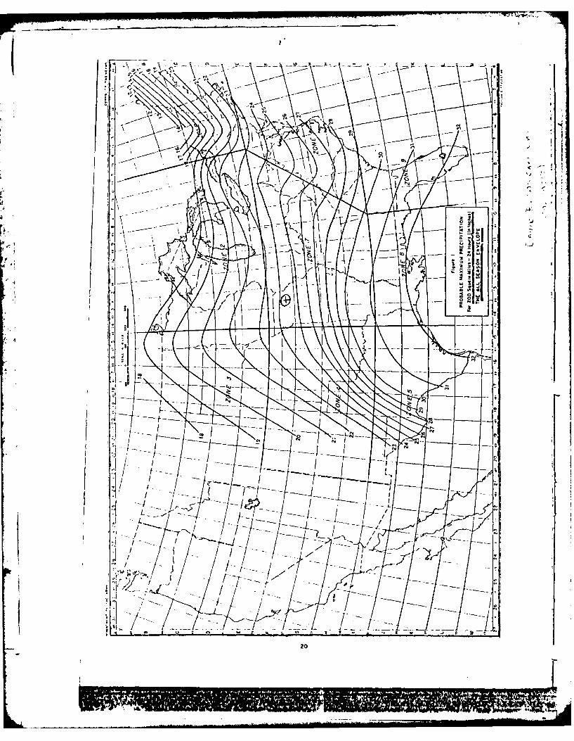
Louis District of the Corps of Engineers. The Probable
Maximum Flood (PMF) was calculated from the Probable Maximum
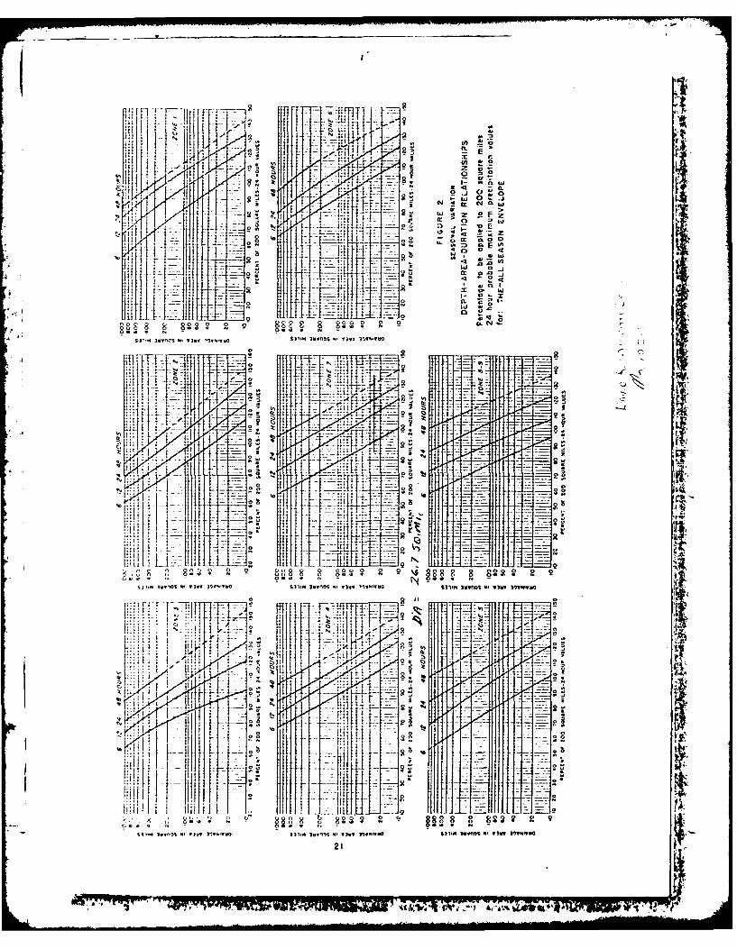
Precipitation (PMP) using the methods outlined in the U.S.
Weather Bureau Publication, Hydrometeorological Report No. 33.
The probable maximum storm duration was set at 24 hours, and
storm rainfall distribution was based on criteria given in the
Corps of Engineers' EM 1110-2-1411 (Standard Project Storm).
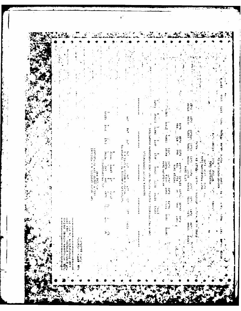
The Soil Conservation Service (SCS) method was used for
deriving the unit hydrograph, utilizing the Corps of Engi-
neers' computer program HEC-1 (Dam Safety Version). The unit
-19-

hydrograph parameters are presented in Appendix B. The SCS
method was also used for determining the loss rate. The
hydrologic soil group of the watershed was determined by use
of published soil maps. The hydrologic soil group of the
watershed and the SCS curve number are presented in Appendix
B. The curve number, the unit hydrograph parameters, the iMP
index rainfall and the percentages for various durations were
directly input to the HEC-1 (Dam Safety Version) computer
program to obtain the PMF hydrograph. The computed peak
inflow of the IMF and one-half of the PMF are 108,696 cfs and
54,348 cfs, respectively.
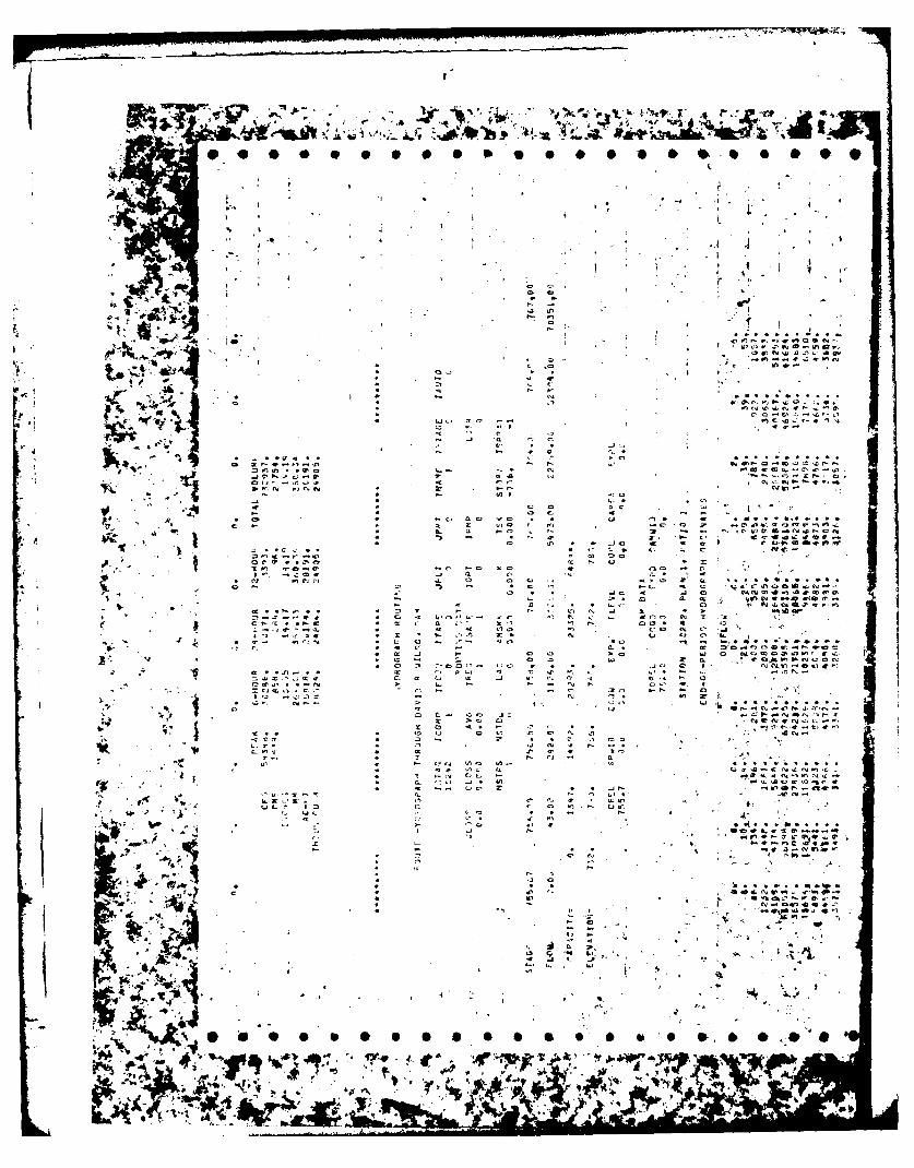
Both the PMF and one-half of the PMF inflow hydro-
graphs were routed through the reservoir by the Modified Puls
Method also utilizing the HEC-1 (Dam Safety Version) computer
program. The reservoir was assumed at the spillway crest
level at the start of the routing computation. The peak
outflow discharges for the PMF and one-half of the PMF are
68,022 and 22,165 cfs, respectively. Both the PMF and one-
half of the PMF when routed through the reservoir resulted in
overtopping of the dam.
The size of physical features utilized to develop
the stage-outflow relation for the spillways and overtopping
of the dam were determined from field notes, and sketches,
prepared during the field inspection. The reservoir stage-
capacity data were based on the U.S.G.S. Missouri Atlanta,
Quadrangle topographic map (15 minute series). The spillway
and dam overtop rating curve and the reservoir capacity curve
are presented in Plates 2 & 3, respectively, in Appendix B.
From the standpoint of dam safety, the hydrologic
design of a dam must aim at avoiding overtopping. Overtopping
is especially dangerous for an earth dam because of its
erosive characteristics. The safe hydrologic design of an
embankment dam requires a spillway discharge capability, in
-20-
Icombination with an embankment crest height that can handle a
very large and exceedingly rare flood without dam overtopping.
The Corps of Engineers design dams to safely pass
the Probable Maximum Flood that is estimated could be gener-
ated from the dam's watershed. This is the generally accepted
criterion for major dams throughout the world, and is the
standard for dam safety where overtopping would pose any
threat to human life. Accordingly, the hydrologic requirement
for safety for this dam is the capability to pass the Probable
Maximum Flood without overtopping.
b. Experience Data
It is believed that records of reservoir stage or
spillway discharge are not maintained for this site.
c. Visual Observations
Observations made of the spillway during the visual
inspection are discussed in Section 3.1.c(1) and evaluated in
Section 3.2.
d. Overtopping Potential
As indicated in Section 5.1.a, both the Probable
Maximum Flood and one-half of the Probable Maximum Flood, when
routed through the reservoir, resulted in overtopping of the
dam. The peak outflow discharges for the PM? and one-half of
the PMF are 68,022 and 22,165 cfs, respectively. The PMF
overtopped the dam crest by 4.87 feet and one-half of the PMF
overtopped the dam crest by 1.93 feet. The total duration of
embankment overflow is 13 hours during the PMF, and 9 hours
during one-half of the PMF. The spillway/reservoir system of
David R. Wilson Dam is capable of accommodating a flood equal
to approximately 27 percent of the PMF before overtopping the
-21-

dam. The spillway/reservoir system of David R. Wilson Dam will
accommodate the 100-year flood without overtopping.
The failure of the dam could cause extensive damage
to the property downstream of the dam and possible loss of
life. The estimated damage zone extends approximately 3-1/2
miles downstream of the dam. Within the damage zone are three
dwellings, two buildings and State Highway 151 crossing.
-
1-22-
SECTION 6: STRUCTURAL STABILITY
6.1 Evaluation of Structural Stability
a. Visual Observations
Visual observations indicate serious instability
and potential for failure of the embankment slopes. Cracks up
to 3 feet deep were observed. The slopes should be cleared,
steeper areas flattened, and then recompacted. Erosion on the
upstream face should be checked by placing adequate riprap on
the slope. Adequate grass cover should be provided for the
embankment slopes. Possible seepage areas should be investi-
gated. The erosion gully observed downstream of the dam on
the right abutment contact does not affect the stability of
the embankment. Nevertheless, if the erosion is allowed to
continue, it could encroach upon the toe of the embankment.
In the absence of seepage and stability analyses, no quanta-
tive evaluation of the structural stability can be made.
There were no signs of structural instability in
the spillway or discharge channel. The structural stability
of the downstream channel appears to be in jeopardy due to the
erosion and steepening of the slopes.
b. Design and Construction Data
No design computations were uncovered during the
report preparation phase. Seepage and stability analyses
comparable to the requirements of the "Recommended Guidelines
for Safety Inspection of Dams" were not available. No embank-
ment or foundation soil parameters were available for carrying
out a conventional stability analysis on the embankment. No
-23-
construction data or specifications relating to the degree of
embankment compaction were available for use in a stability
analysis.
c. Operating Records
No regulated outlet works was provided for the
David R. Wilson Dam. The water level on the day of the
inspection was 4 inches below the crest of the slot in the
10 spillway, and it is assumed that the reservoir remains close
to full at all times.
d. Post Construction Changes
No post construction changes are known to exist
which will affect the structural stability of the dam.
e. Seismic Stability
The dam is located in Seismic Zone 1, as defined in
"Recommended Guidelines For Safety Inspection of Dams" as
prepared by the Corps of Engineers, and therefore, does not
require a seismic stability analysis, provided static stabil-
ity conditions are satisfactory and conventional safety
margins exist.
-24-

SECTION 7: ASSESSMENT/REMEDIAL MEASURES
7.1 Dam Assessment
The assessment of the general condition of the dam is
based upon available data and visual inspections. Detailed inves-
tigations, testing, and detailed computational evaluations are
beyond the scope of a Phase I investigation, however, the investi-
gation is intended to identify any need for such studies.
It should be realized that the reported condition of the
dam is based on observations of field conditions at the time of
inspection along with data available to the inspection team.
It is also important to note that the condition of a dam
depends on numerous and constantly changing internal and external
conditions, and is evolutionary in nature. It would be incorrectto assume that the present condition of the dam will continue to
represent the condition of the dam at some point in the future.
Only through continued care and inspection can there be assurance
that a future unsafe condition could be detected.
a. Safety
The spillway capacity of David R. Wilson Dam was
found to be "Seriously Inadequate". The spillway/reservoir
system will accommodate only 27 percent of the PMF without
overtopping the dam. The surface soils on the dam are quite
silty and very susceptible to erosion if the dam is over-
topped. The dam is overtopped by about 5 feet during the PMF
and the duration of embankment overflow is 13 hours. If the
material in the dam is silty soil, he dam would be suscep-
tible to erosion and possible failure during overtopping.
-25-
f
The overall safety of the dam embankment appears to
be in jeopardy. The current instability of the downstream
slope is serious and may cause failure of this embankment. It
is recommended that remedial measures should be undertaken
immediately. The erosion of the upstream slope due to wave
action and surface runoff should be repaired and the slope
protected by riprap and grass. The erosion on the right
abutment contact should be repaired and protected from surface
runoff. No quantative evaluation of the safety of the embank-
ment can be made in view of the absence of seepage and stabil-
ity analyses. No evidence of the dam ever being overtopped
was observed.
The origin of the standing water observed at the
toe was probably local surface runoff, seepage, or a combina-
tion of both. No flowing seepage was observed. The water
does not appear to affect the safety of the dam in its present
condition.
The erosion and instability of the slopes observed
in the downstream channel does not appear to affect the safety
of the dam. Nevertheless, the condition should be monitored
and corrective measures should be undertaken as required.
b. Adequacy of Information
Pertinent information relating to the design of the
dam and appurtenant structures is completely lacking. The
conclusions presented in this report are based on field
measurements, past performance and the present condition of
the dam. Information on the design hydrology, hydraulic
design, and the operation and maintenance of the dam, as well
as seepage and stability analyses were not available for
review. Lack of seepage and stability analyses comparable to
the requirements of the "Recommended Guidelines for Safety
Inspection of Dams" is considered a deficiency.
-26-

c. Urgency
The instability of the downstream slope requires
immediate remedial work as recommended in Section 7.2b(1).
The remaining remedial measures recommended in Section 7.2
should be accomplished within a reasonable period of time.
d. Necessity for Phase II Inspection
Based on results of the Phase I inspection, and if
the remedial measures described in Paragraph 7.2 are under-
taken, a Phase II inspection is not felt to be necessary.
7.2 Remedial Measures
a. Alternatives
Spillway capacity and/or height of dam should be
increased to accomodate the PMF without overtopping the dam.
b. 0 M Procedures
1. The following corrective measures should be
undertaken immediately:
(a) The downstream slope should be repaired as
follows:
(1) Clear all trees and vegetation from
the slope. Removal of large trees
should be under the guidance of an
engineer experienced in the design
and construction of earthen dams.
Indiscriminate clearing could jeopar-
dize the safety of the dam.
-27-

(2) Rework the slope by regrading,
recompacting and flattening the
steeper sections.
(3) Adequately protect the slope from
surface erosion.
2. The following corrective measures should be
undertaken within a reasonable period of time:
' (a) The erosion and sloughing of the upstream
slope should be repaired and the slope
adequately protected against wave action
and surface runoff by riprap and grass.
(b) Repair the erosion gully on the right
abutment and protect from further damage.
(c) Seepage and stability analyses should be
performed by a professional engineer
experienced in the design and construction
of earthen dams.
3. The following conditions should be monitored:
(a) The standing water located at the toe
should be investigated to determine the
source. Necessary remedial measures
should be undertaken as required.
(b) The erosion in the downstream channel
should be monitored and necessary repairs
made as required.
-28-

I7 7
4. The owner should initiate the following pro-
grams:
(a) Periodic inspection of the dam by a
professional engineer experienced in the
design and construction of earthen dam.
(b) Set up a maintenance schedule and log all
visits to the dam for operation, repairs
and maintenance.
-9
~-29-

PLATES
(IA -o
-FT
Nt It
LOATOCATON DMAP DAI24ISO A
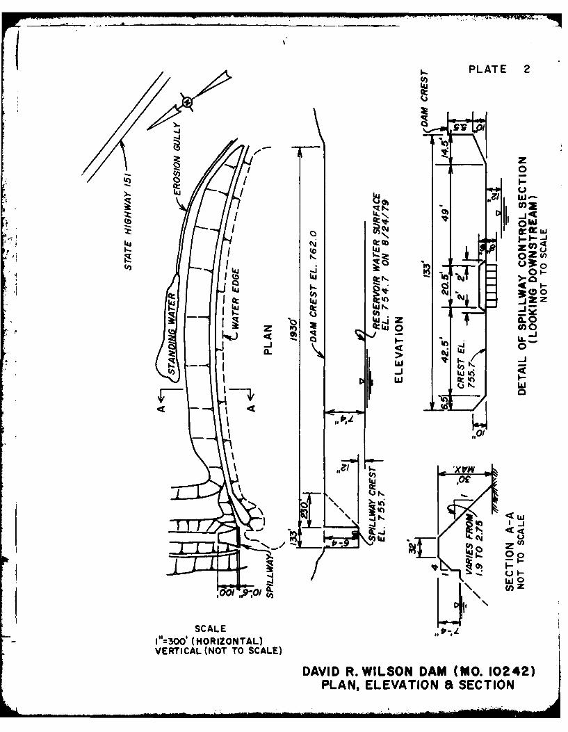
PLATE 2
t C- ' - '
I:i I LaII.-
_ j _j
,U-IN. I- I
OlcnCJ)m >- a )~
cc u
16- Iaz a0z ~ 4 L0 wo)
-
a..,. . 'xLU L,
LU'cI' \iIo
- - 1"=O (HORIZONTAL)VERTICAL (NOT TO SCALE)
IDAVID R. WlLSON DAM (MO. 10242)
PLAN, ELEVATION SECTION
o , Lc W ..hl.
Pc M0sw ow co *c rt
-N
U jI~) I IurkvjI~et OtunIV. 14
~ H _________ Pc
MISSISSIPPIANl, MO OAGANSEIE
X-LOATIO OFDAMMO. 024REFEENCE
GEOLOIC MA OF MSSOURMSOUR GERGI URE
197 GELOGC Ar, I OFSHLB COUNTAll, AND
ADACNmAE

-- --- --
CL0L
I-b
Az
w t
U. I
0~U0
00u
0V
ILL
mil
APPENDIX A
PHOTOGRAPHS TAKEN DURING INS PECT ION
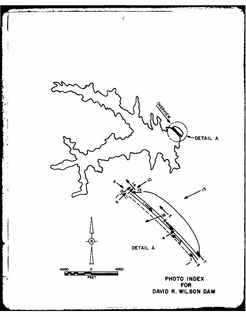
DETAILL A
*13
4000 0 4000
FEETPHOTO I NDEXFOR
DAVID R. WILSON DAM

David R. Wilson Dam
Photo 1. - View of the crest.
Photo 2. - View of the downstream slope of the
embankment.
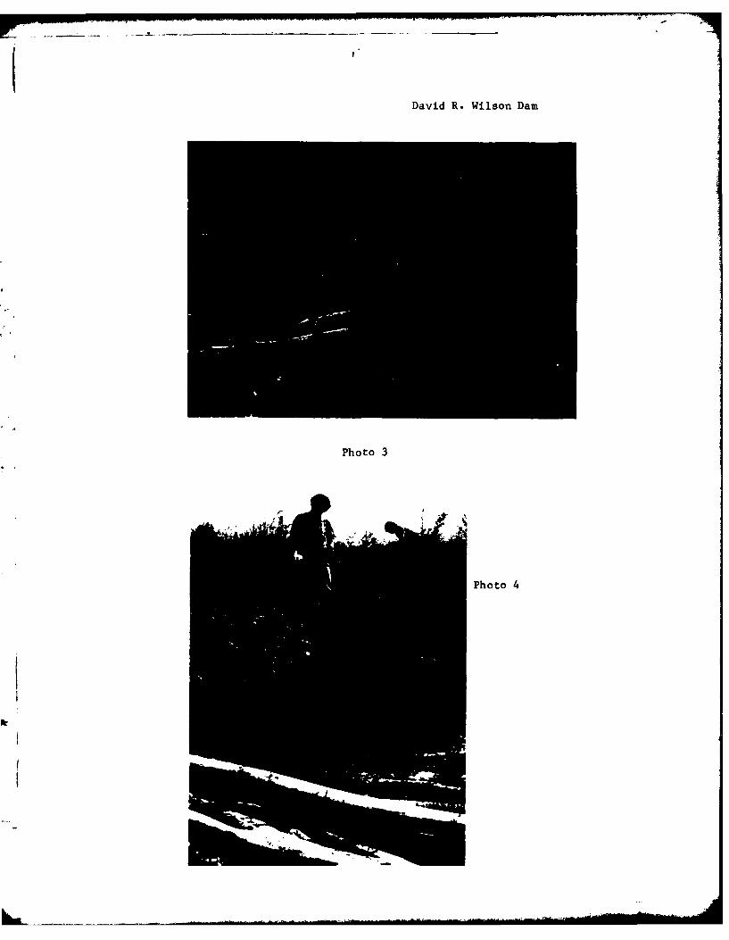
Photo 3. - View of the upstream slope of the embank-ment.
Photo 4. - View of an erosion gully on the upperportion of the upstream slope.
Photo 5. - Closeup of the beech and scarp on theupstream slope.
Photo 6. - View of tension cracks on the crest of the
downstream slope.
Photo 7. - View of the erosion gully on the rightabutment.
Photo 8. - View of the spillway from upstream.
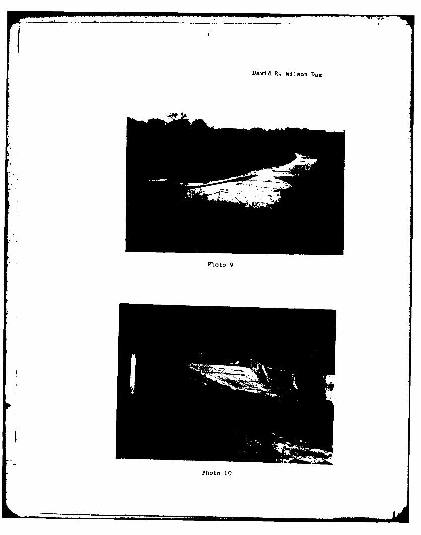
Photo 9. - View of the spillway from the left abut-ment.
Photo 10. - View of the spillway and discharge channelfrom downstream.
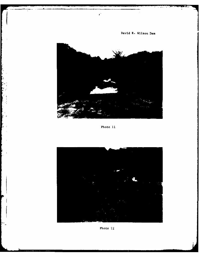
Photo ii. - View of the downstream channel.
Photo 12. - View of the left retaining wall of thedischarge channel. Note poor construc-tion.
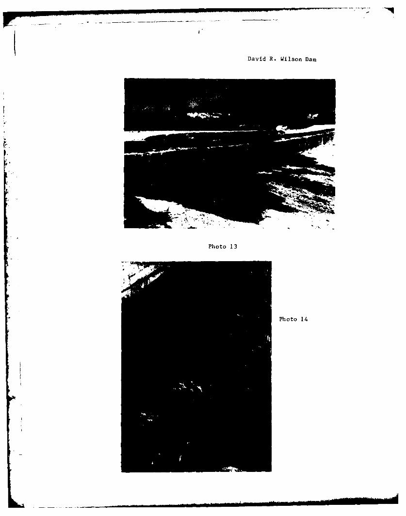
Photo 13. - View of the slot constructed into thespillway.
Photo 14. - Closeup view of the left retaining wall of
the discharge channel. Note the fornmork,
reinforcement, portion of original walland dental work.

Photo 15. - View of standing water just downstream ofthe dami.
Photo 16. - View of the reservoir rim.
David R. Wilson Damn
Photo 1
Photo 2
j1David R. Wilson Dam
Photo 3
Photo 4
David R. Wilson Dam
Photo 5
r Photo 6
KT
-- P-
David R. Wilson Damn
Pht
Photo 8
I7 "1David R. Wilson Dam
Photo 9
Photo 10
David R. Wilson Dam
* . Photo 11
Photo 12
David R. Wilson Dam
Photo 13
Photo 14

David R. Wilson Dam
Photo 15
1 pPhoto 16

I,; APII'NDIx B
.4 DY HYDROLOG(IC COMPUTAT IONS

PLATE 1, APPENDIX B
gr 71 H.4 smissolURIATLANTA QUADRANGLE
V100-t clu~oI -fit 1
QURNGE LOATION1 W 9
4 I d
r!2f III- 1: I 7 ~ : 1( r21- ,, t,, k 1
CONOU NERA 20 EE
1"DVI R.oo WISO A2M. 7J10 a3242DRING BA

L - HU. ENUINEERING CONSULTANTS, INC.0 W.. .... I SHEET NO. OF -
X Z' tj 0AJOB NO. -UL/)
, - .
" -.... ..... ' t. '.7/
* ---- -. - . _ _ I , . - , .
004
. .. . . _. ., •
'\11
I __________ _______
NQ
' ______
qD * o , .
* __ ~~ ;;jcc~
i.

PLATE 2, APPENDIX 8 00
010
-0
0
10t0
5';;
0
CL u
CL U)
00
OD 00 (o (0 (I(n(0
133J (iSH~) NOI±VA3-13
DAVID R. WILSON DAM (MO. 10242)SPILLWAY AND OVERTOP RATING CURVE

E 4PRC ENGINEERING CONSULTANTS, INC.5itoA?, -4-vLf ?- SHEET NO 4 OF.
.,j //o /Z/ JOB NO. ''
- ir~c 1 ~pi r ~By DATE'l-.....
~A,~rtc;J* /O LIN V- M V (_J'-
78o~ ~~~ 31.L3ej
______ 0:3 2,-i

TVR)qTE3, R1 7PENDX~ 0
0.0
0- 0
*~ (0
ow-j crww
0;
000
8 wC4W
NN
0 0 0 0 0 0
1J33A VISIPd) NOIJVAT13
DAVID R. WILSON DAM (MO. 10242)RESERVOIR CAPACITY CURVE

I I'HU hN(GINEERING CONSULTANTS, INC.,941n J ,oTrY r1V5PF C 7-A) - ~SoiSHEET NO. F.
R ~ ~ 4 -"1o~ ~4~ /' -JOB NO. 42'
P,~~~3A~~~3tE~B AM 4-lUf t&, 0 T~,~J~6 DATE
bl7L//o A~ 14)1'1 .o') P'4,V (n qzjfz)
Ta ep
Z -3P
p'crAeI'R1*Sv 09 1 R. rl .
I . Ir
4~
A.. f -A A
12, WP~ Y'_21_
4- 41
Io*
y4 1
I Iv
12 2~ IL~
1 W) -\ /
o zz
IIn w
0oL oJ0 5 E
3 I77:
lu LL LI
0888 8 0000 0 88 00 00
S 31, 310005 I .. 111.11b0 S316" 33001 N. 13v1 30-11,10
pi t : 0
{ Lit
-4rt 2
ill l.00 0
0. 0It R 21 2
11-
., =. "--. e.L ~ llllw % JI'EIOULIMI'dIN II, N ,.
m 5rPt-TY I PipcrI6AI - Ill,.s5'5oJ, , SHEET NO._L OF -_ " ~ v, " . , ) - o .' . w- ( l)' '4z;JOB NO. l
,m ,l t, 0 V "t a I e, DA E9 '
2 __
-u . . . . . . ..* / -. . .
77 .7 ' T /.7 VA-f J 4 H 4
' °O k s M..,....
*7
or v
-~ ~ 2.ZO'h
9) km, -. (aL V~ 7-c ~v,Q(7/. G'~ K. 7/ A4
P" 20 AP*
S , • - . Q cijS, 4 a
4.l

a14PRC ENGINEERING CONSULTANTS, INC.PA~~ q~gY f~( 7 7ev ~6o~i SHEET NO.JOF
DO R.o LJ Id/SO e) OAM7 L"/ 6 . '12) JOB NO. IZ'v oI
S-01L 6.RO-VP "9D C QPV9 NAMCJR D~~2 M& DATE I?
jW4-f l05//e v ,,L5 hI) d4 al~'o c .0 so~
7?#INv S C/. 454
<A 44 . . - . -. .
PHU. tNUiINEERI NG CONSULTANTS, INC.I.AM rA !! t-v lt,6PtT- JAt.S OURI SHEET NO.L.I.OFW
ANJ M W\iOtj 2DI~A (cmcl O2Z JOB NO. ;A0 W
tO IF\ FVLI~T V?) E&VIWZIL' BY l AS..DATE 1-
Of tttRpf+41c~~
la 6s"At. kA V!7+7
A A'e' ~ >LL
4 -
T
A Ft,
T~o$
... ... ... ... ... .. ... . . . . . . . . . .
I I
h.
p.
-1
HEC1DB INPUT DATA

-
e
-.
."
Sr - ., .
•. ," '- •21
* ,,,,
* , I I•
a .-
S . , 4',
! " II.'
I: -:.. -:.
.4,* Co • . • • . • • ° • • •
',./1 c ,,,. :' . ,.,.r ." ". -6/ " .v' , ,
. ,., ,I,.• •'I , ' 'i . P " ' % :.: ), 4-.
• , .
..
.. . ..
4..
. . ....
,-", -
- A> -
V
J.
*1
I
'4 i
INFLOW PMF AND ONE-HALF PMF HYDROGRAPHS
4rI
. , *
Iw
IA
J-9
- cm
- ~. " -. - & AW ~
I~. 4 -,LiLiLi,.*...',* LiLi.~E.-,. . .
'S Li.-. '4. Li .' ,t.d 4. is
Li.
~j,'.Li'
'Li
~Li%
Li':!
. Li Li* ~
It . . Li'..
* ~.J' - .iIt S
* Lil Li CIII
* Li.-) 0 -
* to' I"-. - I
I' .. Li -
- LiiLi~Li .~t. -2
<Ic-
I-c. - rI-c- . Li'
i.iLi (iLi C Li - 10
-. S Lii.' Li- C. Eec.J 'I'.
.- e - - S.
* Li- - tiE. to .1
* Li. LiLi' 'ftLi Li'
* 1 0 4.0 Li0
I-. I"'. I to
.4. . ' a -' V C * Ir. S* -, Li-Li -- l~. II* a ;. .ac. ~, C CCCj C
-. . -, I-c . - 0 Ct.
Li Li LILi Li Lift - Li) ,*..
5 , -Li. It t -, I-- fr Li'-It 'V - ':0 14.15 5 0
.4 t-iI-II.. .. C XC' . Li
Li' 11 I. Li C I' Li)': C. CLi Li) -.
Li, C.' to II *1'Li.' Lii Li Li -
* - LiLi Li- .4 121 -i 12.0 7 I- C.' OS. -i- Li.- 0 ~r-i
.7 Li - Li toIC Lil.'I
CINLi LI
7 Li Cl .- I"; Li 4 1.4 ~ 0
C Li Li .4. C I- I.. a LiC c~i C C~S I-Li ILi a II -. .4
* i. - i':CO Li 00 1011 1.4. -
* I. a to Li ra -r .-.. LLI
* C.. to - elI-I" W4 AL" alt' 1Li.
Li Li - II- I. e~'- teL . I'. tell.) 4>0
to Li C a W4 -.
-. ' 'Li LI LI - '1 LICLi .4. Li .1 LA.') 100
Lii~' ..' to I 1.-c, LiC I) Li-c ~,-,
I-i'. -, -Li-- . 'I Li .'* 10 Li
.4..,, a It, ZI, Li' C AI Li II C -Li
it Li .LitC
.4 I ... - Li" I- .41 II Li..'t
Li - i to t, a..
-~ -) '~? * ,-,~; Lit I- Li' ~
Li .-. Li Li- I.'
C 2? 0 0 LiLi.. 7
A Li LiLiLi 4IV
Li - 'Ic. C - .1Li N
Li Li I- -'.' Li.. Li Li.'.41" C
I). I i.. 'I l' Li
-, I) 4 LiLi Li. Li . . 4LilOc Li ' I I.. 1$" II
Li Li Li.' 'C CCI 'LiLi0Li C SC) C - Ice' .cto. 2 1. .7 IaLi...to .'Li I- to... -c alt* - - I. Li to
* .'Li a 2) - Li Li
LiLi.J~': * *,.. . ' to a -
@0 OLi - a . - IN Li"Li - I WAU
a rLila Li Li Li
0 -
*4 Li.. -I.
* 0.-Li - LiLi I - Li I'. LI- Li -
Li-LiLiLiLiLi .. LIJ Li . *9
* 4 flLi) Li Li .11
.51.4.-Li -- Li Li
Li'..
LiIelO'. Li -
* ~ Li Li
LiLit11 -Lit Li
* a e' 0 Li 'C- I
SO Li
Li J Li 4.
.1.0 Li Li
Se...... SOSS**S* 0 C OS
LiLi I -i '1' ~~ .~ . . Li * Li 4
Li Li ~ Li
Li 4 -L i Li. C 'Li.... ~
1~~ 1' Li. Li
- ~ ~ 1 ~I ~ 4 4 ~~5I A ~ LiLi t~J.LiLMLi Li Li

4fl
J7 a,
.. . . . . . ... .
." . . • . -. . -. . . .. . . . .
e .,. . .. ,..........
* - 4 ."
4 .J- , .V
4
.4 .2. ,n .............. oce otc :-oc ee e..
.. .... ... : C! .. 1.... . . . ... .C. ........ . . . .. .0 4- C." O... . . *LC r..
- - . .
,.- .. ~. .. - - .~4C ,4 r .r .o J C'. C C1CW...C0 0
I,.,
.'. 4L V l 1 l
'4' p 'z w
o,, C,. C4k~4tCl.,Cf0 CCf~t- ~ C t O t

C 4
........ .... .
. . . 4 J1 14
. . .- I . . . ..
I I
c ol
.o-?- -~ . . - . o . . . . . .. .. ... . . .o .. . . -
- - -* - -
Sz C'1
o--c - o - ,.--~- . -C... .............. . .
... .... ... . .. .... .. . . .
C 4- ----
- .... eC'.............. .....o " *," " " * * * * * *o O ' Nec, ,, .- fes 0 0a ,"O L.
,.-, ,. ... ... ....... L.....r ,.S ..... C . S pC2 ' . ,. .r e W .4 ftg C..g..
c '" ......... .cc r " , ' ". -. . . . . ........C c ~ oo ~ o e . o. ,cc-o a r,c ,c,. . . . . . .o. -P
.. N~C~ . .C '..,...t " Ss- C:u. O.r.,... r~p,.s~ .: DC - U'
• , ' . ... . .. . 1; ..... . . ;- ., n,.t" c ' re ~ n o l ~ c ~ e s o-
... .............................. ......... ,"7C AalC •Cc C f C C C .:CaC O '3 0 C-Cuo c A
* . -
.-.. i ' .- .. Ia,'.S *..,,Var..C',-,.." -cp- oar" .. , w-" ,z.... .,. w, .+.c -' a f ,-
: + ' _. ... ...... •.. .... . • o
~~~~~7~~' rz: g~ C~SiAS*S -. * * *
4 , 4* * .'. .0.. 134O'C, .Oi2-iO .-..i; 'ii- i;r-- 1- " 1 I
. . . . . . . ... ...
. z e• . - ,, 0 C . p., 0 O c O - C c c .o . f l , . tg.c+ o ,+,, .. + , . = C . 0 3 4C,' .
'. . . . . . .C ...*44 444.4#4 34 44 4.,-....3.(gg 13 C,. JN-O
.?' .. .. . . . . . .-
13~~e IuC V C
* c0 1,? 4- 13
--- - -... -.---.. ..- - - - - C C;..... ..
f 4,
.. . . .. . . .. ..-.. ... .' C -.
C.,~ .. .,... ,. .... . ..
4~" 0 000 p
-.. 4 43i. "*+ . .. ... + + +o ~ o + ........ C40 CO C ,. og. --oo 3 o. C + .. .. 13,-o+ . o+
- C c. 0. '' ,-0 +; . . .. oo obc ............ LII1 - 'a *
II II I IA I I I I'V ' I fr
. -7 .. C .... 01.f ... .. .-, ..... 4 g C.:. ,: .0....... ,- ,-, I .. .,
YC .
* +t'9. .. ....... ..... . .... .. .C 1 ) ,b. C."13 - - 03 " ' ''
.3 '.I' 7 CN~ C 7' C 0'-(3.ge '. -' 7'
4 +• - . , " - * , . . "- . S. , . . 0 . c 0 - . l '
... 'J,, . (g,',13J.Cg,'-, C,.> .> IVC CC # CC, 44t
C~. IJ

IN,
A
Lo>- •F
i
..
.... . . .. ., .
.
f4 I
,,,1,
.A+
.
,L. .
..... . ,. . . ,.--..-
.-+~'SO 20 .C "00o - o n -.
- *+
16N
s.. * +
-4'. . € "'
,
' t," I,,. t"C
• i C . ' a ' ;C , .
• .• • • • • . .0 • ,- . .
_
-i2
INK.-- VP,0.-
** 0 @ S @ * S* * **** 0*I#
ITI.
~~4 C C IW
1o
AF~
a. n.'L-X * -'I *'C. - 2 .lI
r~~1 4a * -C

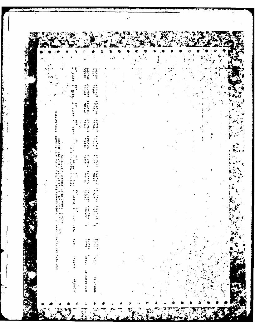
SUMMARY OF PMF AND ONE-HALF PMF FLOOD ROUTING

, ~ ~ I 46 AiP S~ S **~
a I
-tel
r ~ IL
46~~~~ 0 0 4 S 0 00 4

- I •
~~1
'II
*. * * a .:-;
• . , ,-.C_,j
'A. :.. Iq, . ,., ,..
. "' . ".' -; .ti*' :'~.t_"° """""" " ' "
• ,7,".I ... . a-.,d,. , - * . ,"',:,'.,i..' '., 1rlaad t ,, .1
] 'J?"~~~~~~~~~~~~. ,_- " " ,. . - -"- , , ,, I"' I
. . .i. .- - :in ' ' ' • '--I " . ' . '
PERCFNT OF PMF FLOOD ROUTING
EQUAL TO SPILLWAY CAPACITY

4-)qr~
~j &~: AtL*A~ b ~
* . . . . . . . . . . . S 'S 'SO.
I.- ii
. . vI~.4 '~. .q. -4, . "9
* ~,
* .~ . 2 . h I
* . .
~. '
.9. - . 1,9,
. . .. 9.. 1~'t E
,9~iA,a'
9.- 9. 9
U
r 0,
* '9-
V-a .9~
~' I9.- w *
A .'
.-* 9. 94 * - *~., '1
a' ~ 9..
- ~~ **4~
~ C"
I t . . 9. 9 *
9 * 4 9 '.4
I S * * *;'
Iv---'- 9 I 9.-I-,
9 9,1 ~a. /'::
9%
4~; '~w~; ;e~ 2.9, *~ ii ~ :9, ~4,e.* .,t.91 a
* 9
I b
...A ~. s.A.~emr %.&.~4t,. .j'4.. .~ a ~'bA~~ d~ * ~ a~ * * 3 9'A..* f~ V~ * * * *** ~ ~
'7 .
*~. I
* '. - *. . . I - V4 . ".~ .......................................
I 7
..i . . . .I . .-
S t F
*. .. .*
* . 0
AJ -s. - 4 (~0 C
3... ~ ., -oiF - 7'.
*7 *C. 7'.
. ~ .50,~,j;. ~ ~.. ~ *~ a
4 . '7, ('4 .0 -'1 - C, S .. .. jC.
C-' 3 , -~ 3- **.
S .4 Yta .7' 4,4.* I '450 taU
.4 .4. ,.. -I. '7 ,-ta ~O 34 NV -~ - C. -4. 5 -. *.~ S
* S *3. Z. .JC' - . 5$ .3 * CU. I Sb - -
-- . 5 -- I a. 5.9 4C'. a 4 ~L' COO U' S - 4 --s .,cUJc Ow'~:, - ~ .- e eta
S * . ''.4 5 1, U C 3 t~ I-c 4* '7. -~'' -< '7CIC S ' (2 4 0 I' - a./..-. I.. a ,.s. .- a ;.. re. .4 4.-. * C-. 4 (2 ., Cc, z - 4.
* - - a.- . -. t. 40 '00
5~ - C. aO.c 34 *k -* *...A - (.2 .Z 5 2 - 40 * aNt . 5* 7w.C -' F .4'- 5 00S * C .40 545.-. '-I-. 4 .4 t
, t,~ C S C.) F 4. - 4 5 - C-~ -- a . U r o -4*4 4.4. -'a
4.' -Cb. Cs. .4 4 7- ft - CUCs . .4*'CC I - S a. 7 - -r 0. . * *.C*4: a 'a * 0 2 o4.t - 041-C .2.4 40(4 0.3.0 4 ~-.5C'. S -. 4.47' CJ.~0 (IC C C ('Vt1-'V~ Clot-fl ... Z QUO * bC0. C C 0 4.0.
* '4 .4.47 1-1 C CC (.4 *, .5C 01. .4 .5 04
4 . C- - 7... (-0
a " - -. C-) '7 - '-C
.~$C.. ~0C C. * 445 - I4 as'. C '7 .1 3. .4 7' 50 o.C :0
U.t .44. . S CC .CC 4.5jS .4 4. 5. 4' 4.7 ('70 - "4 C, , I.4 - CC' C' I IC'. C'
* , - 7- 7' ~ C. .., C.. *. - U4 'C .~ . 5 .4 U -
'40 '7 0 0'
'-C * C) (~ fl.C 0.5 4 4
* -.
9 -- (32' .44C. .. p -.
--. 4 . C,.- - '7* -- . ,. .- .3
* . - (.2
*O .0. F.- . p a.. ,.* C, , .
(44 4 P.S 0,P.C.) . . - .
* . ii- 9 * I .5' .4 . - 4
4(44 * .5. ..,,~ -VI. g~ 0~ ~* : K i!': ii? J' ~
0
- 34
* U 4~
.~C*1iu~ %J~SeU;~.4.b~~' :.~, ~ *'~'~*'~ U' .4
- ~l4,.. 9?

C 1
4..
4.-
S. .. U
.-. 4 a+. ..
* -". . ,- ., ,
a. ... , I ,,4. C,1-C &( -- .+V.• • .+ +4, ... C l"+'
0 + -+ (. 4. -,, + .. .,+
.4 .. - C (ap .
,.. .. . .. . . "- rP . •
*+++ 4.4. . . .. . . .. + C) l
* - - , .. - .. ' "
.4.. 0 C,,',4 -.
o - . . C ° - " • • I '~* "" • C " * "4 , "'4 .4 ++ ' '.... + • U. .... - : . , ,,.;+ ,,. @+ -Ik J
-~ -- V -
P * - -
' . .. ' -
- .- . *1~~ -* * J 4. -*p 4 v- -
* - - - S *
'
9'.(1
V
I.
*1
d IA
- . 4
I
.4
[1 5.9., d~
9.
Ice..'
1*. * 9
& *U &
~ * * * j - * ; ~ ~ , ~ ~ * * * ~ S 0 9* b -.. ~ ,
4~.
1' * .4' ~4 . a~.44W *~ U0
4 4. 4 4. -: 9 4
44 940 ~ .4.4. * *. 4vs. j,. ,
- -~ Ji'- -, a b
- 4~ .- 4- -444 *(C 414
* 4 ~
-4..-CC ~a
.4 I0 4.~ * I- 4 - 4-o .. 4
4.4** .0J *- 4- 4
44 - '4' -~ -. 4-. 4. -- . C C. t.C. - 4c -.4.4 C C 4
1~-
eN *~C SC
* ., ~- 4.-CW 4~ t-" - a
Et 4 ~ .4 a
4, 4- '. u4
,- ~r *4* 4.4
Cat, - C SC
..4 A~.q;44~ ~j
.44.- 4,,.- ... r. 4.4% CC-
.44.5 e - . 4* .--. ~ .4- 44~- *4.- 4
r..s., C. 1* 9544 99
5.4444~4 -N
C 4-'* . 4Cat '*ZhC
1.4 J~ 0,.C4 4'~.4-. . C.-,...V 14
- .4 .4.0 --4. . i. K(
4 .%4J 4 44 4-4 4 4
4 4. 4. 44 -
- - . .4, 4P 44.-4 a 4-44-' j4~
4 4,' 4 Ii
-~44s4. - - t444 4
a " C 5 4 .- 4.44 4...- C 4.~*
* .4 - - . f4
..t
* 4.- . , 4 4.-4 .4, 4.. 4.
C. .* '4
4- a C

* ~ ~ ~ ~ ~ ~ ~ ~ 7 a kr44. w'V ,' f~j rr
- or
*of-
.* .. .. . .
a ., 4
4 - ~ ~ rC- *erVto=* C -, -

~~I
II