Embed Size (px)
Citation preview
1
1. preface
2. SpecificationS and clearanceS
3. preliminary inStall GUide
4. Zero clearance aSSemBly
5. inStall GUide
6. operation & maintenance
7. teSt report
8. Warranty
I1000 | I1000DS IB ZERO CLEARANCE
inStallation & USer GUide
aXiS
notice to inStaller: these instructions must be left with the owner, who should keep them for future use.

2
ComplianCe plate and serial number.
the instructions in this manual are recommendations only, the distributor and manufacturer bears no liability to the interpretation of these instructions.Please ensure to download the latest version of this manual from our website: www.sculptfireplaces.com.au/installation-manuals/
© copyright 2021 Sculpt fireplaces collection
3
thank you for choosing Sculpt fireplaces as your heater of choice. Your fireplace is the result of careful design, artisan engineering and safety tests. If it is properly installed, used and maintained, you may be sure that you will have an outstanding heating feature in your home for years to come.
We advise you to read through this guide in order to become acquainted with the installation methods specific to your fireplace.
It is recommended that this fireplace be installed by a qualified and licensed trades professional. You will find in this guide the answers to most of your questions, should you require further assistance we recommend you contact your retailer.
Before igniting your fireplace for the first time, please carefully read this manual.
Follow @sculptfireplacecollection on Instagram, Sculptfireplacecollection on Facebook and be sure to post your latest masterpiece installed with the hashtag #sculptfires.
We hope we’ve helped make you the envy of your friends this winter and for years to come.
From all of us,Sculpt Fireplace Collection
Congratulations!

4
iMPortantHeating capacity of the following appliances are a guide only and refers to areas with 2.4m ceilings and 6 or more star rated buildings. Heating output may vary depending on factors such as building characteristics, quality of insulation and type of firewood used and climate zone.
all dimensions shown are approximate. check all dimensions accurately prior to installation. in line with our policy of continuous improvement, we reserve the right to alter specifications without notice.
All units comply and MUST be installed to Australian & New Zealand Standard AS/NZS 2918:2018. When in use some parts may become hot, a suitable fire guard is recommended where very young, elderly or infirm are concerned.
tHe aXis i1000 single & double sided units in tHis manual Conform to australian and new Zealand standards as/nZs 2918:2018 domestiC solid fuel burning applianCes & as/nZs 4012/4013(2014).
the instructions in this manual are recommendations only, the distributor and manufacturer bears no liability to the interpretation of these instructions.
© copyright 2021 Sculpt fireplaces collection

5
2. SpecificationS
aXiS i1000iB Single Sided
Solid steel firebox with firebricksUp to 15-30 Squares*
14.6kW1.2g/kg66%Secure Swing door opening system 4.6m200mm, 250mm, 300mmrecommended for well insulated homes10 year firebrick & 5 year firebox warranty**
180kgWidth: 1220mm depth: 700mm thickness: 25mm***
material Heating Capacity Kw outputavg emissions Avg Efficiencyglass doorminimum flue Heightflue dimensionsoptional outside air Kitwarrantyweightminimum Hearth dimensions
*Heating capacity of the following appliances are a guide only and refers to areas with 2.4m ceilings and 6 or more star rated buildings. Heating output may vary depending on factors such as building characteristics, quality of insulation, type of firewood used and climate zone.**See warranty pg. 29 of the manual.***refer to pg. 7 for further details about the clearances & hearth.
FRONT SIDE
oVerall Zero ClearanCe boX dimensions
1100mm 483mm550mm
720m
m
Ø200
340m
m
830mm
1100mm 485mm
720m
m
Ø200
340m
m
830mm
278m
mTOP
Dimensions of the firebox: 987mm Width; 589.5mm Height; 454mm Depth
6
1100mm 483mm550mm
720m
m
Ø200
340m
m
830mm
1100mm 485mm
720m
m
Ø200
340m
m
830mm
278m
m
material Heating Capacity Kw outputavg emissions Avg Efficiencyglass doorminimum flue Heightflue dimensionsoutside air Kitwarrantyweightminimum Hearth dimensions
oVerall Zero ClearanCe boX dimensions
FRONT SIDE
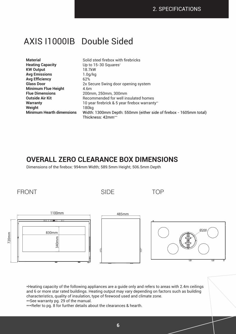
aXiS i1000iB double Sided
*Heating capacity of the following appliances are a guide only and refers to areas with 2.4m ceilings and 6 or more star rated buildings. Heating output may vary depending on factors such as building characteristics, quality of insulation, type of firewood used and climate zone.**See warranty pg. 29 of the manual.***refer to pg. 8 for further details about the clearances & hearth.
2. SpecificationS
Solid steel firebox with firebricksUp to 15-30 Squares*
18.7kW1.0g/kg62%2x Secure Swing door opening system 4.6m 200mm, 250mm, 300mmrecommended for well insulated homes10 year firebrick & 5 year firebox warranty**
180kgWidth: 1300mm Depth: 550mm (either side of firebox - 1605mm total) thickness: 42mm ***
TOP
Dimensions of the firebox: 994mm Width; 589.5mm Height; 506.5mm Depth
7
2. SpecificationS
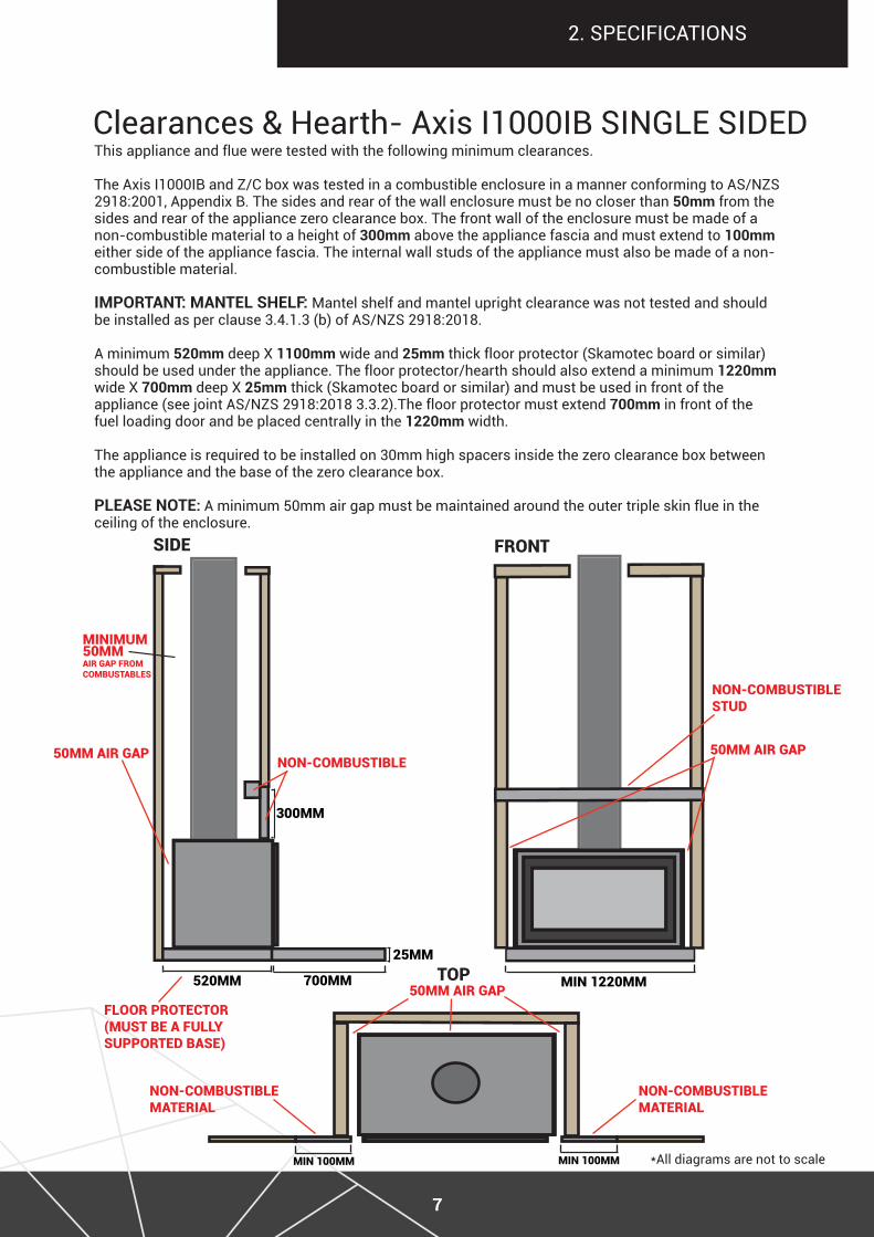
this appliance and flue were tested with the following minimum clearances.
The Axis I1000IB and Z/C box was tested in a combustible enclosure in a manner conforming to AS/NZS 2918:2001, Appendix B. The sides and rear of the wall enclosure must be no closer than 50mm from the sides and rear of the appliance zero clearance box. The front wall of the enclosure must be made of a non-combustible material to a height of 300mm above the appliance fascia and must extend to 100mm either side of the appliance fascia. The internal wall studs of the appliance must also be made of a non-combustible material.
important: mantel sHelf: mantel shelf and mantel upright clearance was not tested and should be installed as per clause 3.4.1.3 (b) of AS/NZS 2918:2018.
a minimum 520mm deep X 1100mm wide and 25mm thick floor protector (Skamotec board or similar) should be used under the appliance. The floor protector/hearth should also extend a minimum 1220mm wide X 700mm deep X 25mm thick (Skamotec board or similar) and must be used in front of the appliance (see joint AS/NZS 2918:2018 3.3.2).The floor protector must extend 700mm in front of the fuel loading door and be placed centrally in the 1220mm width.
The appliance is required to be installed on 30mm high spacers inside the zero clearance box between the appliance and the base of the zero clearance box.
please note: a minimum 50mm air gap must be maintained around the outer triple skin flue in the ceiling of the enclosure.
Clearances & Hearth- Axis I1000IB SINGLE SIDED
siDE Front
toP
*all diagrams are not to scale
50MM air gaP
Min 1220MM520MM 700MM
50MM air gaP
300MM
non-CoMBustiBlE
non-CoMBustiBlE stuD
non-CoMBustiBlE MatErial
non-CoMBustiBlE MatErial
50MM air gaP
25MM
Floor ProtECtor(Must BE a Fully suPPortED BasE)
Min 100MM
MiniMuM50MM air gaP FroM CoMBustaBlEs
Min 100MM
8
2. SpecificationS
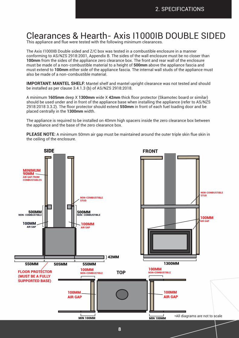
Clearances & Hearth- Axis I1000IB DOUBLE SIDED
siDE Front
toP
1300MM
non-CoMBustiBlE stuD
100MM non-CoMBustiBlE
100MM air gaP
100MM air gaP
100MM air gaP
*all diagrams are not to scale
Floor ProtECtor(Must BE a Fully suPPortED BasE)
this appliance and flue were tested with the following minimum clearances.
The Axis I1000IB Double sided and Z/C box was tested in a combustible enclosure in a manner conforming to AS/NZS 2918:2001, Appendix B. The sides of the wall enclosure must be no closer than 100mm from the sides of the appliance zero clearance box. The front and rear wall of the enclosure must be made of a non-combustible material to a height of 500mm above the appliance fascia and must extend to 100mm either side of the appliance fascia. the internal wall studs of the appliance must also be made of a non-combustible material.
important: mantel sHelf: mantel shelf and mantel upright clearance was not tested and should be installed as per clause 3.4.1.3 (b) of AS/NZS 2918:2018.
a minimum 1605mm deep X 1300mm wide X 42mm thick floor protector (Skamotec board or similar) should be used under and in front of the appliance base when installing the appliance (refer to AS/NZS 2918:2018 3.3.2). The floor protector should extend 550mm in front of each fuel loading door and be placed centrally in the 1300mm width.
The appliance is required to be installed on 40mm high spacers inside the zero clearance box between the appliance and the base of the zero clearance box.
please note: a minimum 50mm air gap must be maintained around the outer triple skin flue skin in the ceiling of the enclosure.
100MM non-CoMBustiBlE
Min 100MM
siDE
505MM 550MM
MiniMuM90MM air gaP FroM CoMBustaBlEs
500MM
non-CoMBustiBlE stuD
non- CoMBustiBlE
550MM
42MM
100MM air gaP
500MMnon- CoMBustiBlE
100MM air gaP
Min 100MM
9
*all diagrams are not to scale
it is the users duty to make themselves aware of and apply all national or more restrictive local standards and instructions (AS/NZS 2918:2018).
iMPortantPrior to unpacking and installation ensure the appliance has not been damaged during transit. Please ensure you check the glass, the door(s), the damper operation and the door locking mechanism
Before any work is carried out, as per local and national regulations and laws, this appliance Must be installed by a licensed professional as per as/nZs 2918:2018.
iMPortant Warningany exception or altercations beyond this manual and as/nZs 2918:2018 is a health and safety hazard which will result in a non-compliant installation and a void of warranties.
Electrical cables and components must not be placed in the vicinity of the appliance as it is a fire hazard.
3. preliminary inStall GUide
10
For the installation and use of this appliance, the fitter and the user should strictly adhere to local and national regulations in addition to AS/NZS 2918:2018. The installer should comply with the instructions and recommendations detailed in this manual. The safety and operation of the fireplace is directly dependent thereon. the liability of the manufacturer can neither be retained nor assured following failure of installation or incorrect use which does not comply with AS/NZS 2918:2018.
As each installation is unique, a qualified and licensed trades professional should take all required preliminary precautions depending on the technical elements inherent to each job.
In-observance of the assembly instructions in conjunction with AS/NZS 2918:2018 entails the liability of the person who carries it out.
as a result of faulty assembly, irrational use of parts or additional components that were not supplied by the manufacturer, and/or modifying of the appliance or components will result in inferior or unsafe operation. should this occur the manufacturer bears no liability, and will result in a null and void product warranty.
PrEliMinary install inForMation
all images and diagrams in this manual are for installation reference purposes only and are not to scale, the distributor and manufacturer bears no accuracy of these images and accepts no liability. the purpose of these images and diagrams is to act as a guide in conjunction with the written components, and are not to be used to instruct independently. the order of steps listed in this manual are recommendation only. it is strongly recommended that the licensed trade professional who is performing the installation of this appliance, completely read and comprehend all instructions in this manual prior to proceeding. Sculpt Fireplaces & Axis reserves the right to change these specifications without prior notice.
PlEasE rEaD Prior to install
aCCeptable VarianCe allowanCeDue to the production of these hand assembled and manufactured fireplaces, there is an acceptable allowance of 3-5mm variance of the unit, including the door frame. This variance in production is non-claimable under any warranties.
Heat resistant & non Combustible materialsHeat resistant materials must meet AS/NZS 2918:2018 clause 1.4.27 a material with an allowable service temperature of 600° celsius or greater.
3. preliminary inStall GUide
11
4. Zero clearance aSSemBly
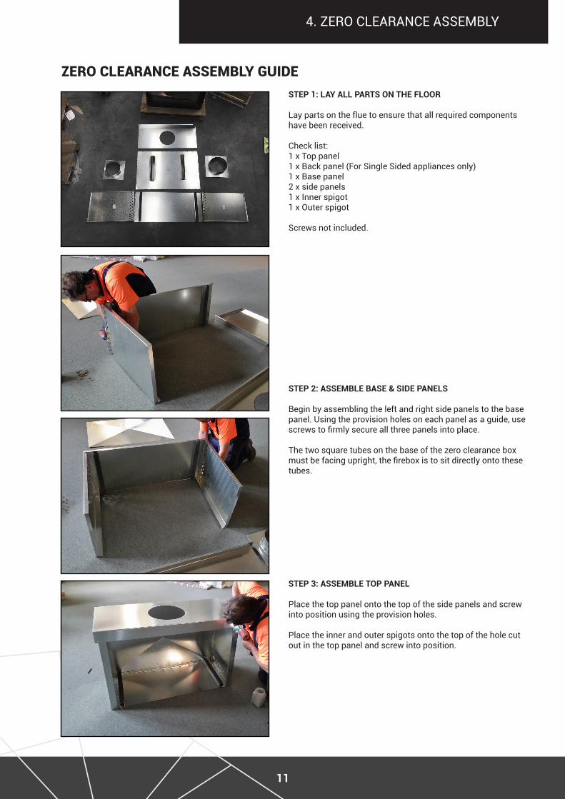
ZEro ClEaranCE assEMBly guiDEstep 1: laY all parts on tHe floor
lay parts on the flue to ensure that all required components have been received.
check list:1 x top panel1 x Back panel (For Single Sided appliances only)1 x Base panel2 x side panels1 x inner spigot1 x outer spigot
Screws not included.
step 2: assemble base & side panels
Begin by assembling the left and right side panels to the base panel. Using the provision holes on each panel as a guide, use screws to firmly secure all three panels into place.
The two square tubes on the base of the zero clearance box must be facing upright, the firebox is to sit directly onto these tubes.
step 3: assemble top panel
place the top panel onto the top of the side panels and screw into position using the provision holes.
place the inner and outer spigots onto the top of the hole cut out in the top panel and screw into position.
12
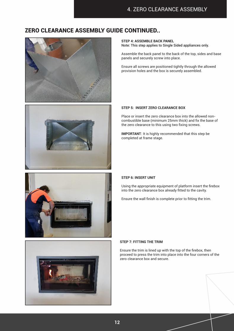
ZEro ClEaranCE assEMBly guiDE ContinuED..step 4: assemble baCK panel Note: This step applies to Single Sided appliances only.
assemble the back panel to the back of the top, sides and base panels and securely screw into place.
ensure all screws are positioned tightly through the allowed provision holes and the box is securely assembled.
step 5: insert Zero ClearanCe boX
Place or insert the zero clearance box into the allowed non-combustible base (minimum 25mm thick) and fix the base of the zero clearance to this using two fixing screws.
important: it is highly recommended that this step be completed at frame stage.
step 6: insert unit
Using the appropriate equipment of platform insert the firebox into the zero clearance box already fitted to the cavity.
Ensure the wall finish is complete prior to fitting the trim.
4. Zero clearance aSSemBly
step 7: fitting tHe trim
Ensure the trim is lined up with the top of the firebox, then proceed to press the trim into place into the four corners of the zero clearance box and secure.
13
5. inStall GUide
step 1. ensure all components required are prepared.step 2. If a floor protector (hearth) is to be used, position now, refer to clearances (pg. 7 & 8) for a guide on the appropriate positioning to accompany clearances and the floor protector (hearth).step 3. Position the appliance, refer to clearances (pg. 7 & 8) for minimum requirements. step 4. Prior to proceeding ensure both the zero clearance, firebox and hearth are fixed in position. step 5. Refer to Flue System Installation (pg. 17) & AS/NZS 2918:2018.
Part a - FirEBox installation
Prior to proceeding with installation thoroughly investigate the materials composing the surrounding back walls, floor and ceiling of the desired position of the firebox. Combustible heat degrading materials, electric wiring or gas piping MUST NOT be located within the distance specified by the clearances (pg. 7 & 8). Ensure the flooring can support the weight of the appliance(see weight in specifications). ALL preparatory work required prior to installing the firebox (external air intake etc) must be completed before proceeding with installation. We strongly recommend installing the appliance in a weather tight room. Dust from works may be deposited on the appliance and burned when it is commissioned, causing ceilings to blacken. it is therefore recommended that all preparatory works be completed prior to installing the appliance.
FirEBox loCation
14
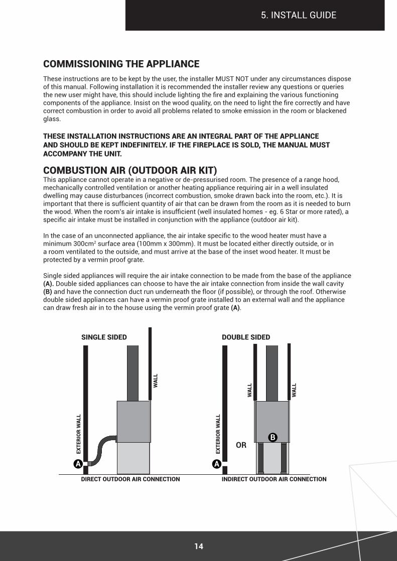
This appliance cannot operate in a negative or de-pressurised room. The presence of a range hood, mechanically controlled ventilation or another heating appliance requiring air in a well insulated dwelling may cause disturbances (incorrect combustion, smoke drawn back into the room, etc.). It is important that there is sufficient quantity of air that can be drawn from the room as it is needed to burn the wood. When the room’s air intake is insufficient (well insulated homes - eg. 6 Star or more rated), a specific air intake must be installed in conjunction with the appliance (outdoor air kit).
In the case of an unconnected appliance, the air intake specific to the wood heater must have a minimum 300cm2 surface area (100mm x 300mm). It must be located either directly outside, or in a room ventilated to the outside, and must arrive at the base of the inset wood heater. it must be protected by a vermin proof grate.
Single sided appliances will require the air intake connection to be made from the base of the appliance (a). double sided appliances can choose to have the air intake connection from inside the wall cavity (b) and have the connection duct run underneath the floor (if possible), or through the roof. Otherwise double sided appliances can have a vermin proof grate installed to an external wall and the appliance can draw fresh air in to the house using the vermin proof grate (a).
5. inStall GUide
these instructions are to be kept by the user, the installer mUSt not under any circumstances dispose of this manual. following installation it is recommended the installer review any questions or queries the new user might have, this should include lighting the fire and explaining the various functioning components of the appliance. Insist on the wood quality, on the need to light the fire correctly and have correct combustion in order to avoid all problems related to smoke emission in the room or blackened glass.
thEsE installation instruCtions arE an intEgral Part oF thE aPPlianCE anD shoulD BE kEPt inDEFinitEly. iF thE FirEPlaCE is solD, thE Manual Must aCCoMPany thE unit.
CoMMissioning thE aPPlianCE
CoMBustion air (outDoor air kit)
DirECt outDoor air ConnECtion inDirECt outDoor air ConnECtion
singlE siDED DouBlE siDED
ExtE
rio
r W
all
ExtE
rio
r W
all
a a
bor
Wal
l
Wal
l
Wal
l
15
6. operation & maintenance
CoMBustion air (outDoor air kit) (ContinuED)
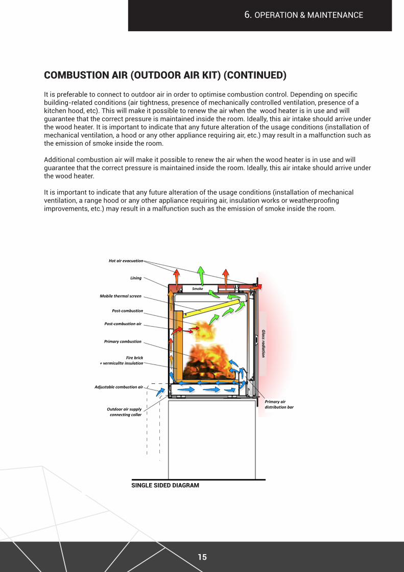
singlE siDED DiagraM
It is preferable to connect to outdoor air in order to optimise combustion control. Depending on specificbuilding-related conditions (air tightness, presence of mechanically controlled ventilation, presence of akitchen hood, etc). This will make it possible to renew the air when the wood heater is in use and will guarantee that the correct pressure is maintained inside the room. ideally, this air intake should arrive under the wood heater. it is important to indicate that any future alteration of the usage conditions (installation of mechanical ventilation, a hood or any other appliance requiring air, etc.) may result in a malfunction such as the emission of smoke inside the room.
additional combustion air will make it possible to renew the air when the wood heater is in use and will guarantee that the correct pressure is maintained inside the room. ideally, this air intake should arrive under the wood heater.
it is important to indicate that any future alteration of the usage conditions (installation of mechanicalventilation, a range hood or any other appliance requiring air, insulation works or weatherproofing improvements, etc.) may result in a malfunction such as the emission of smoke inside the room.
16
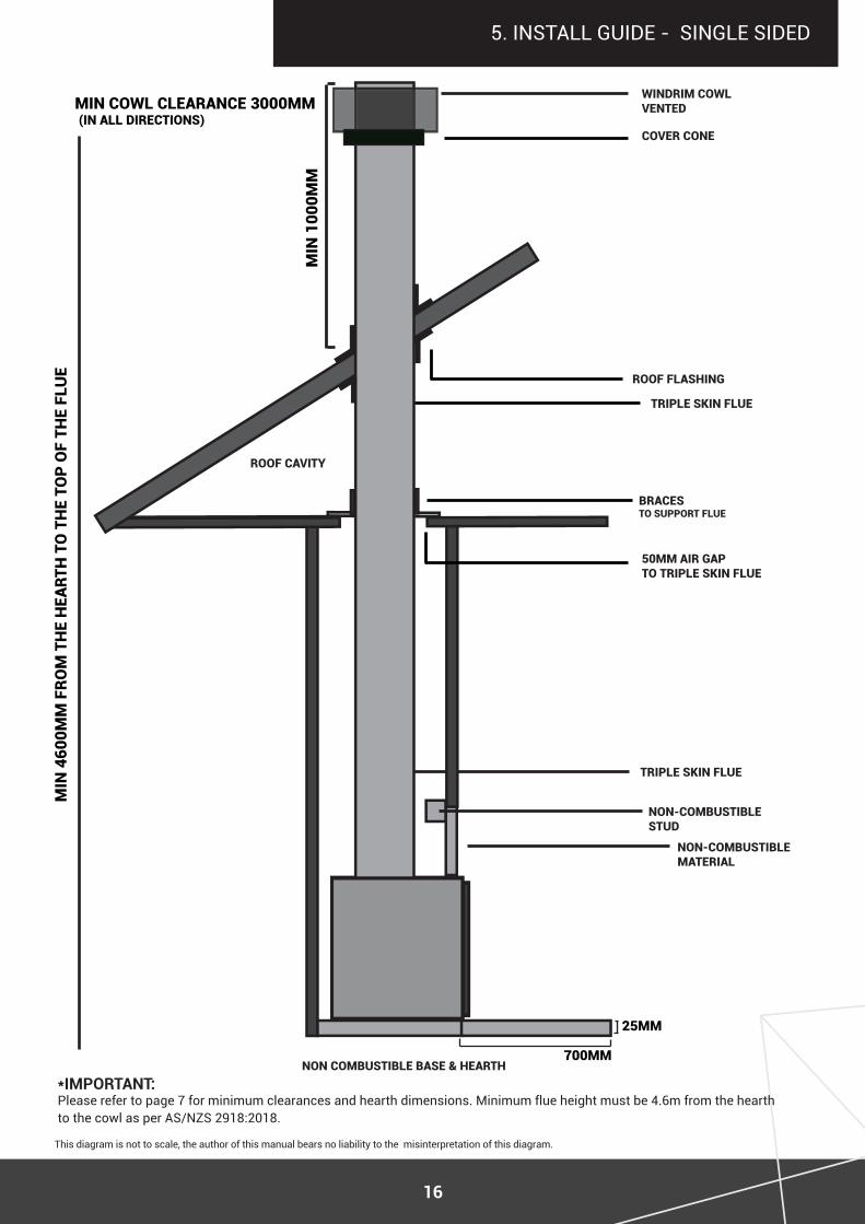
5. INSTALL GUIDE - SINGLE SIDED
axis i1000
BEnCh non CoMBustiBlE BasE & hEarth
rooF Cavity
50MM air gaPto triPlE skin FluE
triPlE skin FluE
BraCEs to suPPort FluE
rooF Flashing
WinDriM CoWlvEntED
CovEr ConE
triPlE skin FluE
rooF linE
intErior rooF
this diagram is not to scale, the author of this manual bears no liability to the misinterpretation of this diagram.
Min CoWl ClEaranCE 3000MM(in all DirECtions)
*important: please refer to page 7 for minimum clearances and hearth dimensions. minimum flue height must be 4.6m from the hearth to the cowl as per AS/NZS 2918:2018.
non-CoMBustiBlE MatErial
non-CoMBustiBlE stuD
Min
460
0MM
Fro
M t
hE
hEa
rth
to
th
E to
P o
F th
E Fl
uE
700MM
Min
100
0MM
25MM
17
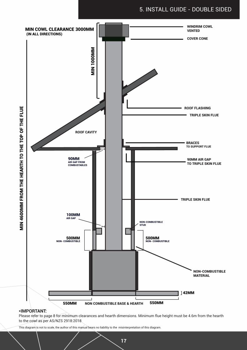
5. INSTALL GUIDE - DOUBLE SIDED
axis i1000
BEnCh non CoMBustiBlE BasE & hEarth
rooF Cavity
90MM air gaPto triPlE skin FluE
triPlE skin FluE
BraCEs to suPPort FluE
rooF Flashing
WinDriM CoWlvEntED
CovEr ConE
triPlE skin FluE
rooF linE
intErior rooF
this diagram is not to scale, the author of this manual bears no liability to the misinterpretation of this diagram.
Min
100
0MM
Min CoWl ClEaranCE 3000MM(in all DirECtions)
*important: please refer to page 8 for minimum clearances and hearth dimensions. minimum flue height must be 4.6m from the hearth to the cowl as per AS/NZS 2918:2018
non-CoMBustiBlE MatErial
550MM
90MM air gaP FroM CoMBustaBlEs
500MM
non-CoMBustiBlE stuD
non- CoMBustiBlE
42MM
100MM air gaP
550MM
Min
460
0MM
Fro
M t
hE
hEa
rth
to
th
E to
P o
F th
E Fl
uE
500MMnon- CoMBustiBlE
18
5. inStall GUide
listed below are the general instructions for flue system install, please refer to these during the flue installation process. • Inner active flue installed crimped/narrow end down.• Outer casing installed crimped/narrow end up (critical when exposed above the roof line). • Flue pipes, seal all joints including at firebox spigot. Fix with minimum fixings required.• Flue pipe spaces, affix to flue pipe.• Flue system termination point (refer to AS/NZS 2918:2018 4.9.1).• Overall flue height (from the hearth to the ceiling extension) must be a minimum of 4.6m as per • AS/NZS 2918:2018 4.9.1(a). • Roof penetration and flashing method refer AS/NZS 2918:2018.
The specifications contain our recommendations for the flue diameter and height values (total height from the wood heater evacuation). the inner surface area of the flue to which the inset wood heater is connected must be equal to the wood heater evacuation surface area.
iMPortant it is the installers duty to check that the flue is compliant with all relevant regulations and standards.
for the appliance to operate at its prime, the draw must be controlled and be between 12 and 20 pascals. In the case of a de-presurised room with a range hood using mechanical extraction, the air-tightness of the connecting flue, including its junction, must be such that smoke cannot be sucked into the flue.
step 1. locate the appliance in position, ensuring the flue pipe is in centre position.iMPortant: Ensure you check that the outer casing is unobstructed prior to proceeding with the installation. step 2. Spike the centre with a nail. transfer this position to the next surface above. step 3. Cut the ceiling penetration (as required), perform the same at the roof penetration. step 4. Frame the penetration with roofing material or timber as required. Refer to minimum requirement for roof penetration AS/NZS 2918:2018.step 5. flash the outer casing to the roof material with the appropriate approved flashing.step 6. If using an outer/inner casing combination, now install the inner casing ensuring it extends a minimum 1000mm above the high side of the roof line. step 7. Extend the flue pipe above the outer casing to suit the casing cover/cowl assembly. step 8. Install the cowl assembly (cover cone and cowl).step 9. position and secure the ceiling plate with the screws and spacers.step 10. Clean the flue pipe to ensure all marks (finger or otherwise) are removed prior to proceeding.step 11. If flue offset is required, refer to AS/NZS 2918:2018 4.1.
iMPortant: the flue should not include more than two bends. the angle of these bends cannot exceed more than 45° and can have no more than one length of 900mm flue between them, as per australian & new Zealand standards as/nZs 2918:2018.
FluE systEM installation
ProCEss For FluE systEM installation
19
5. inStall GUide
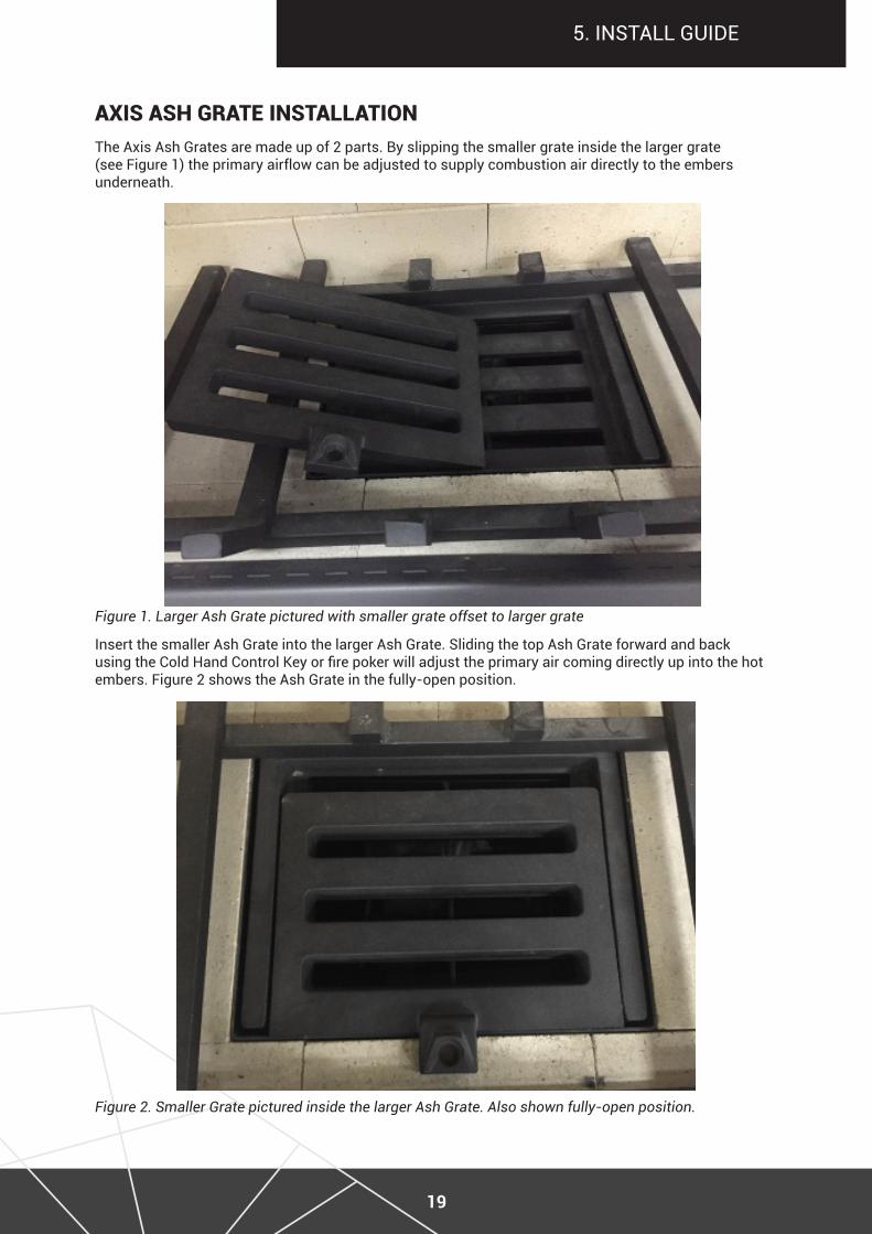
axis ash gratE installationthe axis ash Grates are made up of 2 parts. By slipping the smaller grate inside the larger grate (see Figure 1) the primary airflow can be adjusted to supply combustion air directly to the embers underneath.
Figure 1. Larger Ash Grate pictured with smaller grate offset to larger grate
insert the smaller ash Grate into the larger ash Grate. Sliding the top ash Grate forward and back using the Cold Hand Control Key or fire poker will adjust the primary air coming directly up into the hot embers. Figure 2 shows the Ash Grate in the fully-open position.
Figure 2. Smaller Grate pictured inside the larger Ash Grate. Also shown fully-open position.
20
5. inStall GUide
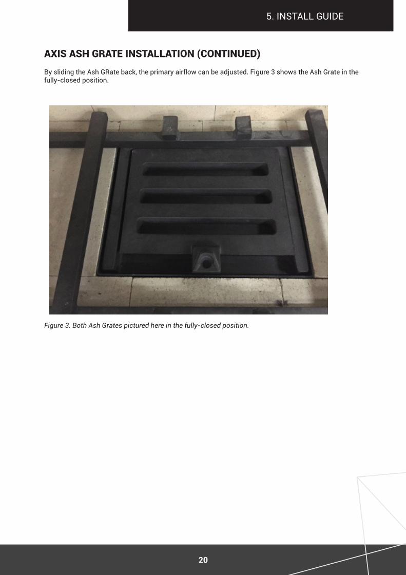
By sliding the ash Grate back, the primary airflow can be adjusted. figure 3 shows the ash Grate in the fully-closed position.
axis ash gratE installation (ContinuED)
Figure 3. Both Ash Grates pictured here in the fully-closed position.
21
operation & user guide
6. operation & maintenance
ignition instruCtionsBefore any ignition ensure the damper and primary air is open in order to accelerate combustion and evacuate the fumes. This adjustment should then be reduced as the fire has stabilised in order to maintain a longer fire term and avoid any possible overheating. The door of the fireplace should be closed in order to avoid any risk of back-flow.
Always slowly and gradually light the fire; split wood and fire starters are recommended. It is strictly forbidden to use any volatile substances including; methylated spirits, gasoline, solvents or the likes as these will result in a risk of explosion or thermal shocks by a sudden rise of temperature.
oPErating thE WooD BurnEr With thE Door oPEn ExPosEs you to MultiPlE haZarDs (Falling EMBErs, sMokE EMissions in thE rooM, EtC.). alWays oPEratE thE aPPlianCE With thE Door ClosED.
preCautions for tHe first ignition - Cure witH 10 small firesThe first ten fires should be light, moderate and not overly loaded with wood. We recommend a small fire consisting of 3-4 logs weighing around 3kg in total.
paintIt is strongly recommended that no person(s) come into contact with the external faces of the appliance without the protective gloves provided, this will avoid any ‘marking’ on the paint surface prior to it being cured. The paint will polymerise after several fires. Do not scrub or clean the fireplace with any rough surface (such as a sponge). In the case of accidental scratches, make several fires until the paint is cured, at which time you can delicately clean the outside of the appliance with a hot sponge. do not scratch or rub the fireplace while it is lit. It is recommended contact with the fireplace should be kept to a minimum. Do not paint the fireplace using products NOT recommended by the supplier, please contact your authorised dealer should you require further assistance.
avoid scratches and markings on your appliance by not placing any objects on your appliance during operation and when not in use.
VentilationA strong burning smoke odour may be smelt during the first several fires, it is therefore recommended to ventilate the premises by opening windows/doors in order for the paint to cure. This phenomenon will disappear after these initial burns cycles.
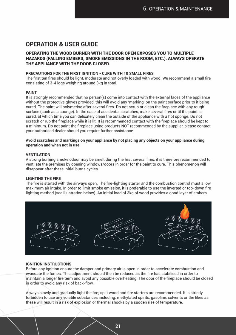
ligHting tHe fireThe fire is started with the airways open. The fire-lighting starter and the combustion control must allow maximum air intake. In order to limit smoke emission, it is preferable to use the inverted or top-down fire lighting method (see illustration below). An initial load of 3kg of wood provides a good layer of embers.
22
6. operation & maintenance
operation & user guide (Continued)
Before establishing the first fire, remove all labels or equipment parts located in the ash box or in the furnace.
While building your first fire, keep the combustion rate at a moderate level to ensure that the sealant binds with the paint. all materials should be seasoned.
please note: Before building a big fire, establish several fires. The curing process is necessary to ensure that the paint is not damaged and that the insert is well seasoned. do not overload the furnace. the optimum amount of fuel should not exceed one third of the insert volume. Before reloading, make sure that the fire has subsided. This will keep the fireplace from over-firing.
Flow of air can be regulated by the air controls at the front of the unit (illustrated in diagram above).
Except for the short time required to build a fire, the fireplace door should be fully closed. If doors are left partly open, flue gas may be drawn out of the opening creating risks from both fire and smoke.
establisHing tHe first fire
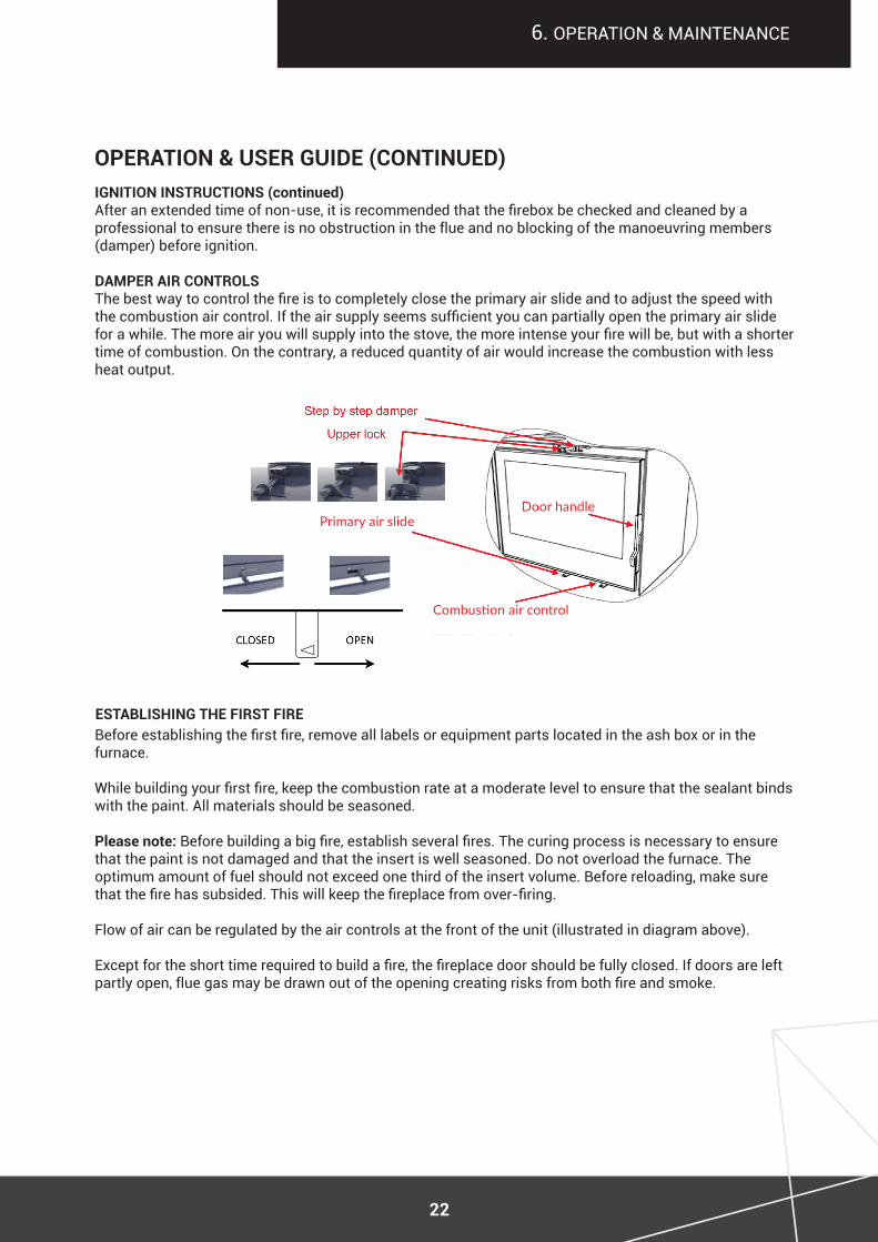
ignition instruCtions (continued)After an extended time of non-use, it is recommended that the firebox be checked and cleaned by a professional to ensure there is no obstruction in the flue and no blocking of the manoeuvring members (damper) before ignition.
damper air ControlsThe best way to control the fire is to completely close the primary air slide and to adjust the speed with the combustion air control. If the air supply seems sufficient you can partially open the primary air slide for a while. The more air you will supply into the stove, the more intense your fire will be, but with a shorter time of combustion. on the contrary, a reduced quantity of air would increase the combustion with less heat output.
Primary air slideDoor handle
Combustion air control
23
6. operation & maintenance
importantVentilation devices which operate with the fireplace on the same premises or on the premises which share the same ventilation shaft may not function properly.
Please ensure the air grate is never blocked.
During installation please allow for access to have the fireplace and the connecting shaft cleaned.
If required, install cut-off and stifling devices.
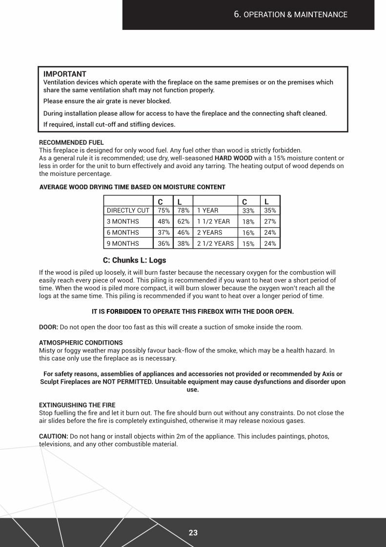
reCommended fuelThis fireplace is designed for only wood fuel. Any fuel other than wood is strictly forbidden. As a general rule it is recommended; use dry, well-seasoned Hard wood with a 15% moisture content or less in order for the unit to burn effectively and avoid any tarring. the heating output of wood depends on the moisture percentage.
directly cUt
3 montHS
6 montHS
9 MONTHS
75%
48%
37%
36%
78%
62%
46%
38%
33%
18%
16%
15%
35%
27%
24%
24%
1 year
1 1/2 YEAR
2 yearS
2 1/2 YEARS
C Cl l
C: Chunks l: logs
avEragE WooD Drying tiME BasED on MoisturE ContEnt
if the wood is piled up loosely, it will burn faster because the necessary oxygen for the combustion will easily reach every piece of wood. this piling is recommended if you want to heat over a short period of time. When the wood is piled more compact, it will burn slower because the oxygen won’t reach all the logs at the same time. this piling is recommended if you want to heat over a longer period of time.
it is ForBiDDEn to oPEratE this FirEBox With thE Door oPEn.
door: do not open the door too fast as this will create a suction of smoke inside the room.
atmospHeriC ConditionsMisty or foggy weather may possibly favour back-flow of the smoke, which may be a health hazard. In this case only use the fireplace as is necessary.
for safety reasons, assemblies of appliances and accessories not provided or recommended by axis or sculpt fireplaces are not permitted. unsuitable equipment may cause dysfunctions and disorder upon
use.
eXtinguisHing tHe fire Stop fuelling the fire and let it burn out. The fire should burn out without any constraints. Do not close the air slides before the fire is completely extinguished, otherwise it may release noxious gases.
Caution: do not hang or install objects within 2m of the appliance. this includes paintings, photos, televisions, and any other combustible material.
24
6. operation & maintenance
operation & user guide (Continued)
iMPortant WarningStoring any flammable materials (paper, linen, furniture, solvents, flammable liquids, spray containers, gas bottle, etc.) close to the fireplace is strictly forbidden.all these products should never be stored even for a short while in wood storages or recesses laid out under or near the appliance. Caution: the window, the front panel of the appliance, as well as all external faces including the facade, will attain high temperatures (above 100°). uninitiated persons, young children and infants should be monitored at all times while in the vicinity of the appliance.
slow burningplease be aware that this method may cause unburnt matter to accumulate in the flue system. this may in the long term cause a chimney fire. Our recommendation is to therefore avoid closing the damper and primary air for an extended length of time. Use only dry hard wood with a maximum moisture content of 15% to assist in reducing creosote build up, and regularly light a high intensity fire to burn off the build up.
a draught is created from the difference in temperature between the interior and the exterior flue. the higher the temperature inside the flue, the more intense the draught is. Before closing the air inlets and reducing the combustion level in the stove for a slow burn, the temperature inside the flue must be high enough to adequately draw all the flue gas. Caution: continuous and intensive slow burn operation may cause early deterioration of the appliance and its components, as well as a chimney fire if the flue has not been regularly cleaned.
transition period, insuffiCient CHimneY draugHt and poor weatHer ConditionsPay attention to the operations of the insert during transition periods and/or when chimney draught is insufficient or when weather conditions are unfavourable, especially during severe cold weather. Such conditions may cause flue gas to flow into the room. to prevent such a situation, you should reduce the intensity of fire by curbing the influx of air into the combustion chamber until smoke disappears. Afterwards you may increase air flow monitoring for any appearance of smoke in the room.
maintenanCeThe vitro-ceramic glass can withstand temperatures of up to 750°C. If the glass breaks following a handling error, it is not recommended to replace it using a material other than that supplied by the manufacturer. the original glass quality must be used to maintain any warranty of the wood stove.
Cleaning tHe glassThe window of the fireplace requires regular cleaning with specific products intended for this use. The use of moist hard wood with a moisture content above 15% causes excessive creosote build up on the glass. once again we recommend only burning very dry hard wood.
We recommend waiting for the glass to cool before cleaning it. the use of products that are too aggressive (eg. abbrasive cleaners) may lead to the deterioration of some of the wood heater parts. An effective and ecological method of cleaning the glass is to use a piece of damp newspaper dipped in ash and then rinsing with clean water. you can also use a commercially available glass cleaning product.
25
maintenanCe (Continued)flue & fireboXflues should be professionally cleaned and checked twice a year, including at least once during the peak period of use and more if required. a professional should also check seals, door ropes, baffle plates and all consumable parts of the firebox and flue to ensure the unit is in safe working order.
do not remoVe tHe baffle eXCept wHen performing a CHimneY sweep
Caution: Cracked and/or broken components (eg. glass panels or baffles) may render the installation/operation unsafe. do not use the appliance if this is the case and contact your dealer.
asH panThe ash pan should be emptied regularly in order to avoid any overflow and clogging of the fire grate. Use the cold handle supplied and pull the ash pan from the appliance. You will find some ashes catching in the cavities between the ribs of the fireplate. This bed of ashes caught between the fireplate is essential as it will create a more effective start up operation of the fire.
forbidden fuels this appliance is not designed for burning the following fuels:
• Solid mineral fuels (all coals or similar)• Liquid mineral fuels (Gasoline, fuel oil, solvents, drainage oils or similar)• methylated spirit• Creosote-treated woods and too moist or green woods• paper or cardboard• Wood workshop residues (Shavings, saw dusts or similar)• other forbidden fuels that may harm the appliance or the environment
CHimneY sweeping prior to using and installing into an existing chimney, it’s necessary to perform a chimney sweep and ensure it’s clear of any build up (cresote, bird’s nest, etc). Chimney sweeps should be performed twice a year, including at least once during the period of use.
CHimneY firesChimney fires can be caused due to incorrect use of the appliance and lack of periodic cleaning.
Visible signs of a chimney fire include:
• abundant fumes• Strong smell of soot• roaring in the flue• Significant increase in the temperatue of the flue• cinders flying out of the top of the flue
6. operation & maintenance
26
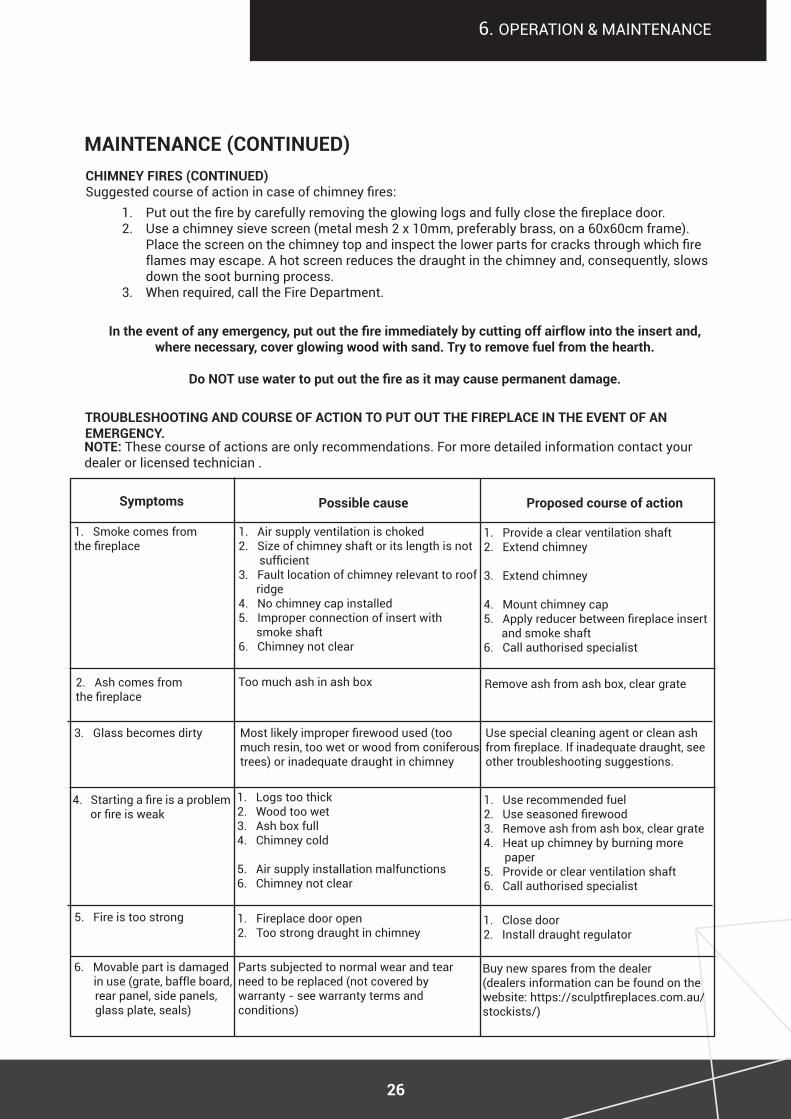
maintenanCe (Continued)
symptoms possible cause proposed course of action
1. Smoke comes from the fireplace
2. ash comes from the fireplace
1. air supply ventilation is choked2. Size of chimney shaft or its length is not sufficient3. fault location of chimney relevant to roof ridge4. no chimney cap installed5. improper connection of insert with smoke shaft6. chimney not clear
1. provide a clear ventilation shaft2. extend chimney
3. extend chimney
4. mount chimney cap5. Apply reducer between fireplace insert and smoke shaft6. call authorised specialist
too much ash in ash box remove ash from ash box, clear grate
3. Glass becomes dirty
4. Starting a fire is a problem or fire is weak
5. fire is too strong
6. movable part is damaged in use (grate, baffle board, rear panel, side panels, glass plate, seals)
1. logs too thick2. Wood too wet3. ash box full4. chimney cold
5. air supply installation malfunctions6. chimney not clear
Most likely improper firewood used (too much resin, too wet or wood from coniferous trees) or inadequate draught in chimney
1. Use recommended fuel2. Use seasoned firewood3. remove ash from ash box, clear grate4. Heat up chimney by burning more paper5. provide or clear ventilation shaft6. call authorised specialist
1. fireplace door open2. too strong draught in chimney
parts subjected to normal wear and tear need to be replaced (not covered by warranty - see warranty terms and conditions)
1. close door2. install draught regulator
Use special cleaning agent or clean ash from fireplace. If inadequate draught, see other troubleshooting suggestions.
Buy new spares from the dealer (dealers information can be found on the website: https://sculptfireplaces.com.au/stockists/)
In the event of any emergency, put out the fire immediately by cutting off airflow into the insert and, where necessary, cover glowing wood with sand. try to remove fuel from the hearth.
Do NOT use water to put out the fire as it may cause permanent damage.
troublesHooting and Course of aCtion to put out tHe fireplaCe in tHe eVent of an emergenCY.
CHimneY fires (Continued)Suggested course of action in case of chimney fires:
1. Put out the fire by carefully removing the glowing logs and fully close the fireplace door. 2. Use a chimney sieve screen (metal mesh 2 x 10mm, preferably brass, on a 60x60cm frame).
Place the screen on the chimney top and inspect the lower parts for cracks through which fire flames may escape. a hot screen reduces the draught in the chimney and, consequently, slows down the soot burning process.
3. When required, call the fire department.
note: these course of actions are only recommendations. for more detailed information contact your dealer or licensed technician .
6. operation & maintenance
27
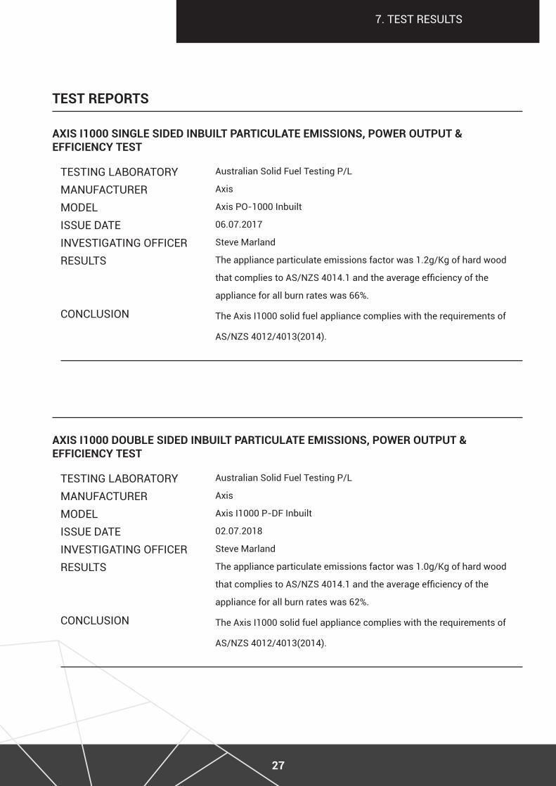
test reports
7. teSt reSUltS
teStinG laBoratorymanUfactUrermodeliSSUe dateinveStiGatinG officerreSUltS
conclUSion
Australian Solid Fuel Testing P/L
axis
Axis PO-1000 Inbuilt
06.07.2017
Steve marland
The appliance particulate emissions factor was 1.2g/Kg of hard wood
that complies to AS/NZS 4014.1 and the average efficiency of the
appliance for all burn rates was 66%.
the axis i1000 solid fuel appliance complies with the requirements of
AS/NZS 4012/4013(2014).
aXis i1000 single sided inbuilt partiCulate emissions, power output & effiCienCY test
teStinG laBoratorymanUfactUrermodeliSSUe dateinveStiGatinG officerreSUltS
conclUSion
Australian Solid Fuel Testing P/L
axis
Axis I1000 P-DF Inbuilt
02.07.2018
Steve marland
The appliance particulate emissions factor was 1.0g/Kg of hard wood
that complies to AS/NZS 4014.1 and the average efficiency of the
appliance for all burn rates was 62%.
the axis i1000 solid fuel appliance complies with the requirements of
AS/NZS 4012/4013(2014).
aXis i1000 double sided inbuilt partiCulate emissions, power output & effiCienCY test
28
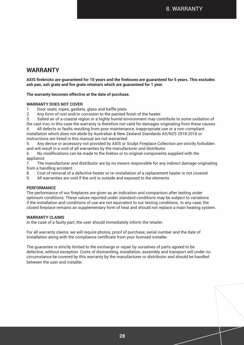
8. Warranty
AXIS firebricks are guaranteed for 10 years and the fireboxes are guaranteed for 5 years. This excludes ash pan, ash grate and fire grate retainers which are guaranteed for 1 year. the warranty becomes effective at the date of purchase. warrantY does not CoVer1. door seals, ropes, gaskets, glass and baffle plate.2. Any form of rust and/or corrosion to the painted finish of the heater3. Salted air of a coastal region or a highly humid environment may contribute to some oxidation of the cast iron, in this case the warranty is therefore not valid for damages originating from these causes4. All defects or faults resulting from poor maintenance, inappropriate use or a non-compliant installation which does not abide by Australian & New Zealand Standards AS/NZS 2918:2018 or instructions are listed in this manual are not warranted5. any device or accessory not provided by aXiS or Sculpt fireplace collection are strictly forbidden and will result in a void of all warranties by the manufacturer and distributor6. No modifications can be made to the firebox or to original components supplied with the appliance7. the manufacturer and distributor are by no means responsible for any indirect damage originating from a handling accident8. Cost of removal of a defective heater or re-installation of a replacement heater is not covered9. All warranties are void if the unit is outside and exposed to the elements performanCeThe performance of our fireplaces are given as an indication and comparison after testing under optimum conditions. these values reported under standard conditions may be subject to variations if the installation and conditions of use are not equivalent to our testing conditions. in any case, the closed fireplace remains an supplementary form of heat and should not replace a main heating system. warrantY Claimsin the case of a faulty part, the user should immediately inform the retailer. for all warranty claims, we will require photos, proof of purchase, serial number and the date of installation along with the compliance certificate from your licensed installer. the guarantee is strictly limited to the exchange or repair by ourselves of parts agreed to be defective, without exception. costs of dismantling, installation, assembly and transport will under no circumstance be covered by this warranty by the manufacturer or distributor and should be handled between the user and installer.
warrantY
29
8. Warranty
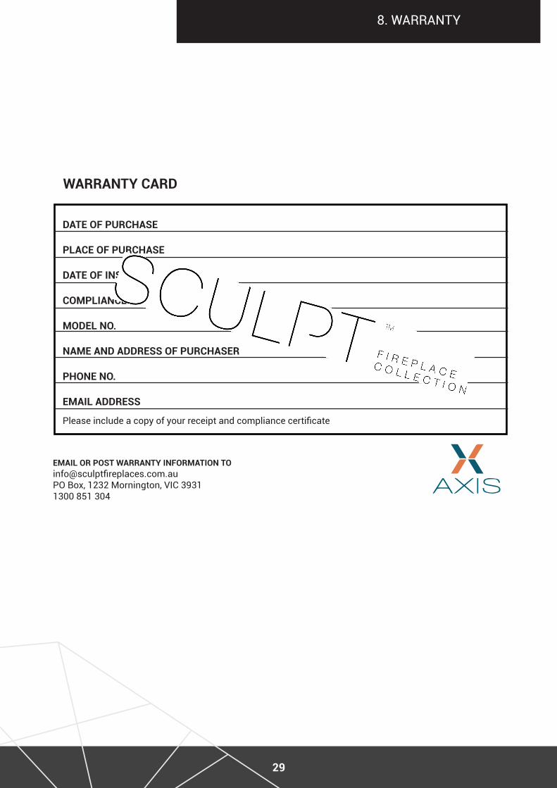
email or post warrantY information [email protected] Box, 1232 Mornington, VIC 39311300 851 304
date of purCHase
plaCe of purCHase
date of installation
ComplianCe CertifiCate no.
model no.
name and address of purCHaser
pHone no.
email address
Please include a copy of your receipt and compliance certificate
warrantY Card

30
Whilst every effort is taken to avoid errors, ScUlpt fireplace collection cannot accept responsibility for the accuracy of any statement, extract or information contained within this manual nor can any of its contributors who have submitted material for inclusion. ScUlpt fireplace collection may change or update this manual and anything described in it without notice. We will endeavour to ensure that information, materials and data on this site are complete, accurate and up-to-date. information on this manual is for guidance only and cannot cover all circumstances. e&oe
©copyright 2021 Sculpt fireplace collection

31
final WordS
Intent on providing Australians with a dynamic collection of designer fires, Sculpt fireplace collection has strategically gathered not only award winning fireplace designs, but also fireplaces that have been manufactured with high quality materials and the best raw steel that is built to last.
Our wood fire manufacturers integrate innovation, technology, environmental impact, operational expertise and quality, whilst holding design at the forefront. We aim to fill homes with the maximum of comfort while capturing the true art and meaning of a sculptural fireplace in any living space.
Sculpt fireplace collection is an australian owned company who exclusively supply some of world’s most sought after high-end luxury fireplaces.
Sculpt Fireplace Collection is proud to be the sole importer of Seguin, Axis and Bordelet fireplaces, with exclusive distribution rights throughout Australia and New Zealand.