Embed Size (px)
Citation preview
!i+--.U. L,/
f!/ '}I)
DOT/FAA/CT-85/1 0
FAA TECHNICAL CENTER Atlantic City Airport N.J. 08405
iKRASH 85 User's Guide Input/Output Format
Max Gamon · Gil Wittlin Bill LaBarge
Prepared by Lockheed-California Company Burbank, California
July 1985 . (Revised March 1986) Users Manual
This document is available to the U.S. public through the National Technical Information Service, Springfield, Virginia 22161.
U.S. Deportment of Transportation
Federal Aviation Adn*listration
NOTICE
This document is disseminated under the sponsorship of the Department of Transportation in the interest of information exchange. The United States Government assumes no liability for the contents or use thereof.
The United States Government does not endorse products or manufacturers. Trade or manufacturer's names appear herein solely because they are considered essential to the object of this report.
l. I{ ~: I f
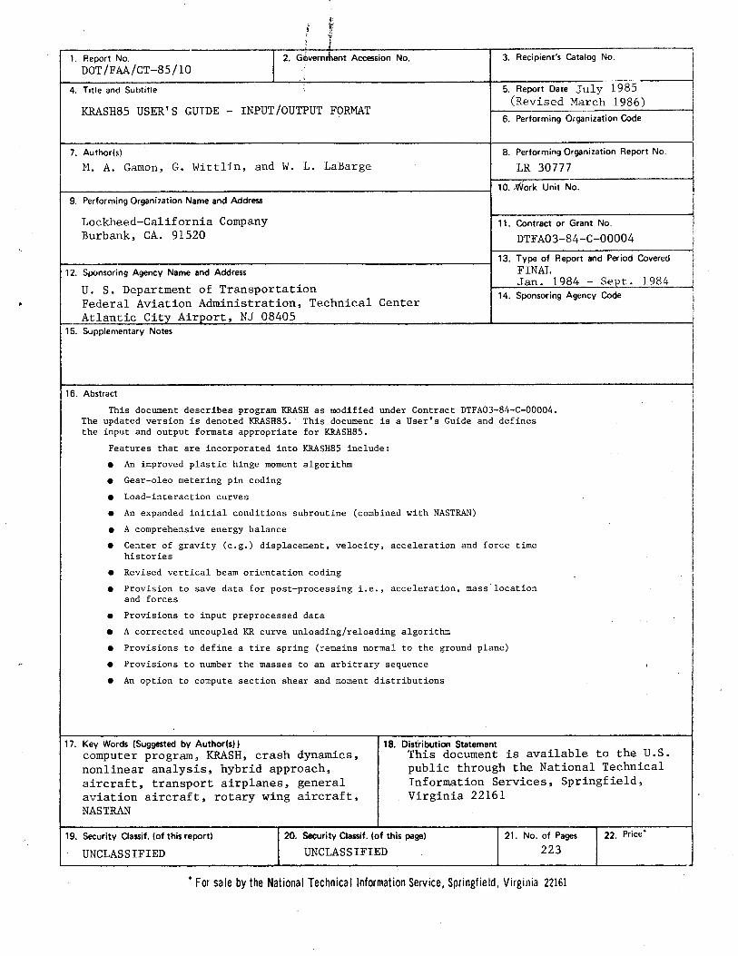
I 1. Report No. G~vernrhent Accession No.
DOT/FAA/CT-85/10
4. Title and Subtitle
KRASH85 USER'S GUIDE - INPUT/OUTPUT FORMAT
7. Author(s)
M. A. Gamon, G. Wittlin, and W. L. LaBarge
9. Performing Organization Name and Address
Lockheed-California Company Burbank, CA. 91520
12. Sponsoring Agency Name and Address
U. S. Department of Transportation Federal Aviation Administration, Technical Center Atlantic City Airport, NJ 08405
15. Supplementary Notes
16. Abstract
3. Recipient's Catalog No.
5. Report Date July 1985 (Revised March 1986)
6. Performing Organization Code
8. Performing Organization Report No.
LR 30777
10 .. Work Unit No.
11. Contract or Grant No.
DTFA03-84-C-00004
13. Type of Report and Period Covered FINAL Jan. 1984 - Sept. 1984
14. Sponsoring Agency Code
This document describes program KRASH as modified under Contract DTFA03-84-C-00004. The updated version is denoted KRASH85. This document is a User's Guide and defines the input and output formats appropriate for KRASH85.
Features that are incorporated into KRASH85 include:
• An improved plastic hinge moment algorithm
• Gear-oleo metering pin coding
e Load-interaction curves
• An expanded initial conditions subroutine (combined with NASTRAN)
e A comprehensive energy balance
e Center of gravity (e.g.) displacement, velocity, acceleration and force time histories
e Revised vertical beam orientation coding
e Provision to save data for post-processing i.e., acceleration, mass-location and forces
• Provisions to input preprocessed data
• A corrected uncoupled KR curve unloading/reloading algorithm
e Provisions to define a tire spring (remains normal to the ground plane)
• Provisions to number the masses to an arbitrary sequence
• An option to compute section shear and moment distributions
18. Distribution Statement 17. Key Words (Suggested by Author(s) I computer program, KRASH, crash dynamics, nonlinear analysis, hybrid approach, aircraft, transport airplanes, general aviation aircraft, rotary wing aircraft, NASTRAN
This document is available to the U.S.
19. Security Classif. (of this report)
UNCLASSIFIED
public through the National Technical Information Services, Springfield, Virginia 22161
20. Security Classif. (of this page)
UNCLASSIFIED 21. No. of Pages
223 22. Price*
*For sale by the National Technical Information Service, Springfield, Virginia 22161
FOREWORD
This report was prepared by the Lockheed-California Company under
Contract DTFA03-84-C-00004. The report contains a description of the effort per
formed as part of Tasks II, III and IV and covers the period from January 1984
to September 1984. The work was administered under the direction of the
Federal Aviation Administration with L. Neri acting as Technical monitor.
The program leader was Gil Wittlin of the Lockheed-California Company.
M. A. Gamon and W. L. LaBarge of the Lockheed-California Company refined pro
gram KRASH. P. Rohrer of the Lockheed-California Company provided valuable
computer programming support. The Lockheed effort was performed in the Flutter
and Dynamics Department.
iii

TECHNICAL SUMMARY
This document describes program KRASH as modified under Contract
DTFAOJ-84-C-00004. The updated version is denoted KRASH35. This document is
a User's Guide and defines the input and output formats appropriate for
KRASH85.
Features that are incorporated into KRASH85 include:
• An improved plastic hinge moment algorithm
• Gear-oleo metering pin coding
• Load-interaction curves
• An expanded initial conditions subroutine (combined with NASTRAN)
• A comprehensive energy balance
• Center of gravity (e.g.) displacement, velocity, acceleration and force time histories
• Revised vertical beam orientation coding
• Provision to save data for post-processing i.e., acceler?tion, mass location and forces
• Provisions to input preprocessed data
• A corrected uncoupled KR curve unloading/reloading algorithm
• Provisions to define a tire spring (remains normal to the ground plane)
• Provisions to number the masses in an arbitrary sequence
• An option to compute section shear and moment distributions
v
Section
1
2
2.1
2.2
2.3
2.3.1
2.3.1.1
2.3.1.2
2.3.1.3
2.3.1.3.1
2.3.1.3.2
2.3.1.3.3
2.3.1.3.4
2.3.2
2.3.2.1
2.3.2.2
2.3.2.3
2.3.2.4
2.3.2.5
2.3.2.6
FOREWORD
SUMMARY
TABLE OF CONTENTS
LIST OF FIGURES
LIST OF TABLES
INTRODUCTION
USER'S GUIDE
OVERALL KRASH85 ANALYSIS SYSTEM
KRASH85 INPUT
OUTPUT AND SAMPLE CASE
KRASHIC Output
Echo of Input Data
Formatted Print-Out of Input Data
Miscellaneous Calculated Data
Model Parameters
Ream Loads and Deflections Corresponding to Yielding
Overall Vehicle Forces/Accelerations at Time Zero
Individual Mass Forces/Accelerations At Time Zero
MSCTRAN Output
Executive Control Deck Echo
Case Control Deck Echo
Input Bulk Data Deck Echo
Sorted Bulk Data Deck Echo
Displacement Vector
Load Vector
vii
Page
iii
v
ix
ix
1-1
2.c..1
2-1
2-8
2-93
2-93
2-93
2-94
2-122
2-123
2-123
2-123
2-124
2-125
2-125
2-125
2-125
2-144
2-144
2-145
Section
2.3.2.7
2.3.2.8
2.3.2.9
2.3.2.10
2.3.3
2.3.3.1
2.3.3.2
2.3.3.2.1
2.3.3.2.2
2.3.3.2.3
2.3.3.2.4
2.3.3.2.5
2.3.3.2.6
2.3.3.2.7
2.3.3.3
2.3.3.4
3.
3 1 . -'-3.2
4.
TABLE OF CONTENTS
Forces of Single-Point Constraint
Forces in Bar Elements
Element Strain Energies
Grid Point Force Balance
KRASH85 Output
Initial Output
Time History Output
Mass and Node Point Data
Internal Beam Data
External Spring Data
DRI and e.g. Velocity Data
Energy Distribution Data
Internal Beam Stress Data
Initial Hass Acceleration Error Output
Summary Output
Time History Plots
ADDITIONAL KRASH85 DATA REQUIREMENTS
LOAD-INTERACTION CURVES
ARBITRARY MASS NUMBERING
COMMON BLOCK REGIONS
REFERENCES
APPENDIX A-SHOCK STRUT ELEMENT DESCRIPTION
APPENDIX B-DISTRIBUTI011 LIST
viii
2-149
2-149
2-150
2-155
2-155
2-155
2-164
2-165
2-176
2-178
2-178
2-179
2-183
2-184
2-187
2-202
3-1
3-1
3-6
4-1
R-1
A-1
B-1
Figure
2-1
2-2
2-3
2-4
2-5
2-6
2-7
2-8
2-9
2-10'
2-11
2-12
2-13
2-14
2-15'
2-16
2-17
2-18
2-19
2.:.,20
2-21
2-22
2-23
2-24
2-25
2-26
LIST OF FIGURES
Overall K~~SH85 Analysis System
Sample KRASH85 Job Submittal
KRASH85 Input Format
KRASH85 Coordinate Systems
Beam Element Coordinate System Orientations
Standard Nonlinear Beam Element Stiffness Reduction Curves
Large Transport Airplane Hodel - Sample Case
Echo of the Input Data
Formatted Printout of Input Data
Miscellaneous Calculated Data
MSC/NASTRAN Executive and Case Control Decks
MSC NASTRAN Input Bulk Data Deck Echo
MSC/NASTRAN Sorted Bulk Deck
MSC/NASTRAN Displacement Vector
MSC/NASTRAN Load Vector
MSC/NASTRAN Single-Point Constraint Forces
MSC/NASTRAN Bar Element Forces
Bar Element Force Sign Conventions, NASTRAN and KRASH
MSC/NASTRAN Element Strain Energies
MSC/NASTRAN Grid Point Force Balance
KRASH85 Output, Initial Mass/Node Point Deflections
KRASH85 Output, Additional Hiscellaneous Calculated Data
KRASH85 Time History Output
KRASH85 Internal Beam Stress Data and Initial Mass Acceleration Error Output
KRASH85 Summary Output Data
KRASH85 Sample Output Time History Plots
ix
2-3
2-5
2-10
2-19
2-46
2-61
2-96
2-97
2-106
2-126
2-131
2-133
2-146
2-147
2-148
2-151
2-152
2-153
2-154
2-157
2-158
2-160
2-166
2-185
2-188
2-203
Figure
3-1
3-2
3-3
Table
2· ·1
2-2
2-3
2-4
2-5
2-6
4-1
------~-~-~~
LIST OF FIGURES
Maximum Allowable Moment and Shear Envelope -Negative Bending
Typical Cross Section with Stiffener Locations -Rear View
Lockheed Load Sign Conventions
LIST OF TABLES
KRASH85 Input Format Sequence
Program Sizing Constants
Standard Material Properties
Relationship for Directional Moments and Input Terms in KRASH85
Shape Factors for Plastic Hinge Beams
Summary KRASH85 Output
KRASH85 Subroutine/Common Region Reference
X
Page
3-2
3-2
3-4
Table
2-9
2-23
2-47
2"""51
2-51
2-93
4-2

EXECUTIVE SUMMARY
Program KRASH, originally developed under Federal Aviation Administration sponsorship for predicting the response of general aviation airplanes to an impact environment, has been enhanced to include features that would facilitate the modeling of transport category airplanes. This document is the User's Guide which defines the input and output formats appropriate for this new version of Program KRASH known as KRASH 85.
xi
SECTION 1
INTRODUCTION
Program KRASH, developed under a previous Federal Aviation Administration
(FAA) sponsored contract DOT-FA75-WA3707 has been in the public domain since
1979. In subsequent years changes to enhance its usage have occurred.
Recently, KRASH has been applied to modeling transport airplanes for impact
conditions. Many of the recent program changes that have occurred are designed
to facilitate modeling transport airplanes. The following modifications have
been incorporated into KRASH85 and used recently to model transport category
aircraft:
• Improved plastic hinge moment algorithm
• Gear oleo metering pin
• Load interaction curves
• Expanded Initial Condition Subroutine
• Arbitrary numbering of lumped mass points
Other modifications provide general enhancement capability and include:
• Comprehensive energy balance
• Computation of c. g.. time histories
• Revised vertical beam orientation coding
• Post Processing of data, i.e., acceleration, mass location and forces
• Corrected uncoupled KR curve unloading/reloading algorithm
In addition, miscellaneous coding corrections have been made. The current
version is denoted KRASH85.
This document is the User's Guide and is limited to a description of the
input-output format for KRASH85.
1-1
SECTION 2
USER'S GUIDE
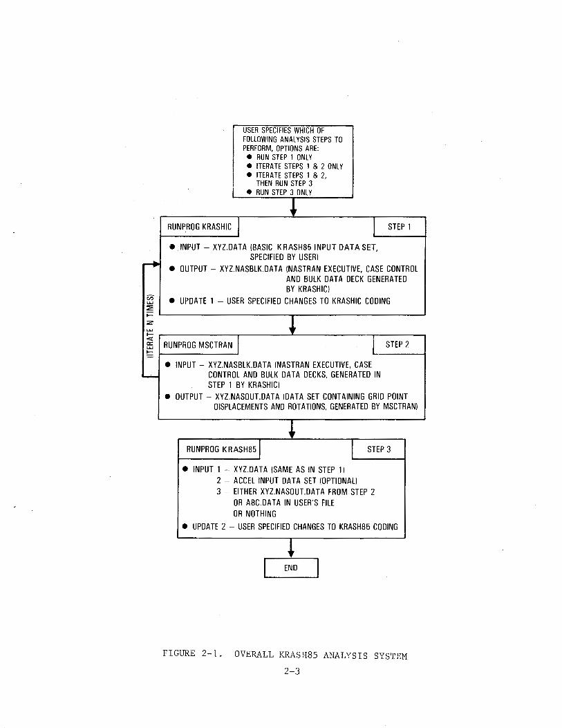
2.1 OVERALL KRASH85 ANALYSIS SYSTEM
The overall KRASH85 analysis system consists of two separate KRASH programs
called KRASHIC and KRASH85, plus a NASTRAN program denoted herein as MSCTRAN.
The NASTRAN program used in this system is MSC/NASTRAN Version 63 (A.ug 1, 1983).
KRASHIC and MSCTRAN are used only if balanced initial conditions are required;
KRASH85 is the normal KRASH time-history program. If KRASHIC and MSCTRAN are
not used, then at time zero the beams in the analytical model will all have
zero internal deflections and loads. The model will be located just above the
ground and in the proper attitude, as specified in the input data. This initial
balance is acceptable for certain types of problems, primarily those in which
the aerodynamic loads on the vehicle are zero. For that situation, the lumped
masses in the model are all accelerating downward at lg .(free-falling), and
the internal beam loads and deflections are actually zero.
If nonzero aerodynamic forces are present, then the initial beam loads
and deflections are not zero. Nevertheless, execution of KRASH85 by itself
will automatically set the beam loads and deflections at zero. If this is
done with nonzero aerodynamic forces, the system will be out of balance at
time zero. In this situation, the dynamic response will be the result of
two phenomena:
• Dynamic response to the ground impact
• Dynamic response to the initial imbalance
The latter response is not desired, and can obscure the desired response
or confuse the interpretation of the output data. The proper solution of this
problem requires that the analytical model be in equilibrium at time zero with
nonzero internal beam loads and compatible deflections.
2-1
This is essentially a straightforward static loads analysis problem.
NASTRAN is used to solve the statics problem, and KRASHIC is used to read
KRASH85 input data and convert it into NASTRAN Executive Case Control and Bulk
Data Decks. Figure 2-1 shows a flow diagram for the overall KRASH85 analys~s
system. The options available to the user include the following:
1. Run step 1 only (program KRASHIC)
..., Lterate steps 1 and 2, N times (user-specified) L. •
3. Iterate steps 1 and 2, N times, then run step 3 (KRASH85)
4. Run step 3 (KRASH85) only
The most general case is option 3. The iterations are required for the
following reasons. The static solution used in MSCTRAN is Rigid Format 24,
which is a small deflection linear static analysis. This method actually
assumes zero deflections for the purposes of calculating transformation
matrices for transforming beam loads from beam element axes to the global
axis system, which in this case are airplane axes. Therefore, if the deflec
tions from MSCTRAN are used to relocate the KRASH85 mass points, the KRASHS5
calculated beam loads will be proper in beam axes, but when resolved to mass
axes will yield a system that is out of balance (since KRASH85 does not assume
the deflections are zero when calculating the transformation matrices)
The solution to this problem is to iterate steps 1 and 2, using the
calculated deflections from MSCTRM~ to relocate the mass and node points in
KRASH at each step. Satisfactory convergence is achieved after about six
iterations, and additional accuracy can be achieved by using up to ten itera
tions. Beyond ten iterations, no further improvement in accuracy can be
achieved due to the limitations in the number of digits that are written to
the data sets that form the input and output of MSCTRAN.
The KRASH analysis system shown in figure 2-1 is implemented through
Job Control Language (JCL). A job submittal using option 3 with six itera
tions causes a total of 13 sequential jobs to be executed (6 KRASHIC, 6 MSCTRAN
and 1 KRASH85). While this may sound rather expensive, a typical case
2-2
"' LU
::2:
RUNPROG KRASHIC I
USER SPECIFIES WHICH OF FOLLOWING ANALYSIS STEPS TO PERFORM, OPTIONS ARE: e RUN STEP 1 ONLY e ITERATE STEPS 1 & 2 ONLY e ITERATE STEPS 1 & 2,
THEN RUN STEP 3 • RUN STEP 3 ONLY
I STEP 1
• INPUT- XYZ.DATA (BASIC KRASH85 INPUT DATA SET, SPECIFIED BY USER)
• OUTPUT- XYZ.NASBLK.DATA (NASTRAN EXECUTIVE, CASE CONTROL AND BULK DATA DECK GENERATED BY KRASHIC)
• UPDATE 1 - USER SPECIFIED CHANGES TO KRASHIC CODING
~ ~--------------------~------------------~ ~ I ~ ~-----------.--------·~------------r-------, ~ RUNPROG MSCTRAN J I STEP 2
• INPUT - XYZ.NASBLK.DAT A (NASTRAN EXECUTIVE, CASE - CONTROL AND BULK DATA DECKS, GENERATED IN
STEP 1 BY KRASHIC) • OUTPUT- XYZ.NASOUT.DATA (DATA SET CONTAINING GRID POINT
DISPLACEMENTS AND ROTATIONS, GENERATED BY MSCTRAN)
RUNPROG KRASH851 STEP 3
• INPUT 1 - XYZ.DATA (SAME AS IN STEP 1) 2 - ACCEL INPUT DATA SET (OPTIONAL) 3 - EITHER XYZ.NASOUT.DATA FROM STEP 2
OR ABC.DAT A IN USER'S FILE OR NOTHING
• UPDATE 2 - USER SPECIFIED CHANGES TO KRASH85 CODING
END
FIGURE 2-1. OVERALL KRASH85 ANALYSIS SYSTEM
2-3
(21 mass/27 beam, ~ airplane model) requires only about seven seconds per
iteration on an IBM 370/3081, so that the iterated balanced loads can be
determined in less than one minute. The JCL is set up so that data sets
XYZ.NASBLK.DATA and XYZ.NASOUT.DATA are generated and :named automatically, so
the process is essentially invisible to the user.
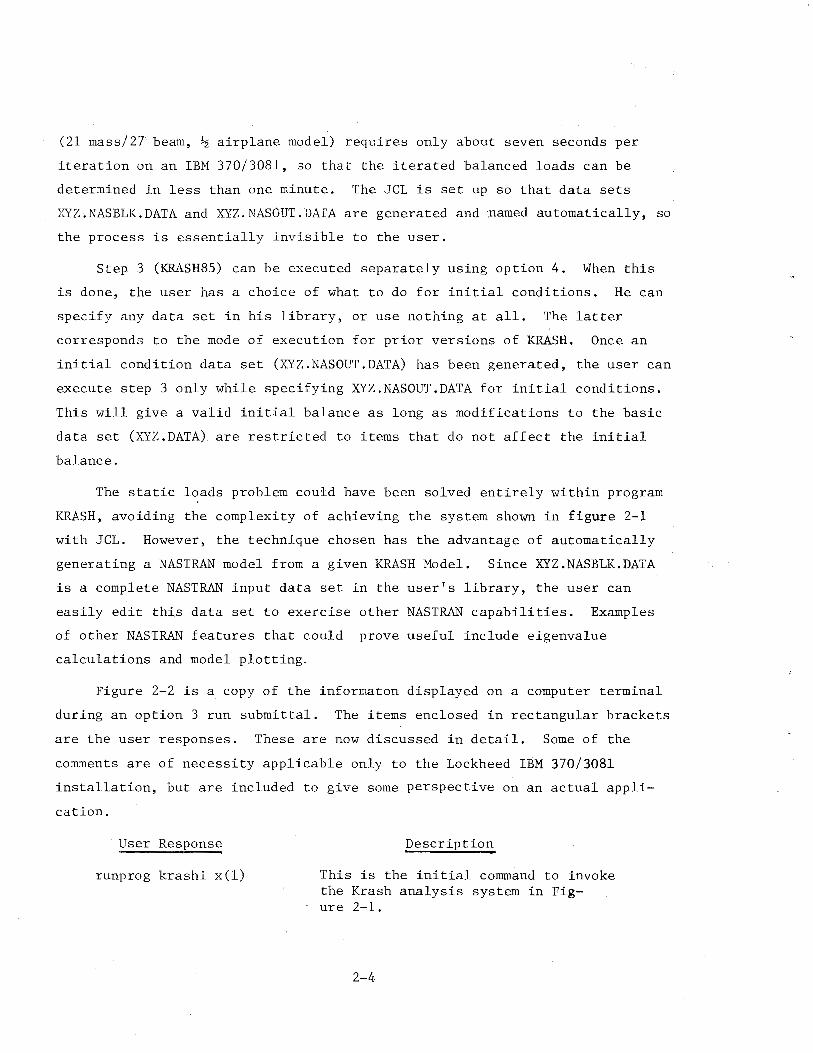
Step 3 (KRASH85) can be executed separately using option 4. When this
is done, the user has a choice of what to do for initial conditions. He can
specify any data set in his library, or use nothing at all. The latter
corresponds to the mode of execution for prior versions of KRASH. Once an
initial condition data set (XYZ.NASOUT.DATA) has been generated, the user can
execute step 3 only while specifying XYZ.NASOUT.DATA for initial conditions.
This will give a valid initial balance as long as modifications to the basic
data set (XYZ.DATA) are restricted to items that do not affect the initial
balance.
The static loads problem could have been solved entirely within program
KRASH, avoiding the complexity of achieving the system shown in figure 2-1
with JCL. However, the technique chosen has the advantage of automatically
generating a NASTRAN model from a given KRASH Model. Since XYZ.NASBLK.DATA
is a complete NASTRAN input data set in the user's library, the user can
easily edit this data set to exercise other NASTRAN capabilities. Examples
of other NASTRAN features that could prove useful include eigenvalue
calculations and model plotting.
Figure 2-2 is a copy of the informaton displayed on a computer terminal
during an option 3 run submittal. The items enclosed in rectangular brackets
are the user responses. These are now discussed in detail. Some of the
comments are of necessity applicable only to the Lockheed IBM 370/3081
installation, but are included to give some perspective on an actual appli-
cation.
User Response
runprog krashi x(l)
Description
This is the initial command to invoke the Krash analysis system in Fig-ure 2-1.
2-4
lrunprog P6489 x(1)
ENTER TIME
~ ENTER LINES
~ WOULD YOU LIKE EXPRESS, STANDARD OR DEFERRED(VERNIGHT) TURNAROUND FOR YOUR JOB? ENTER E, S OR D
0 Enter number
1 run KRASHIC only 2 iterate KRASHIC and MSCTRAN only 3 iterate KRASHIC and MSCTRAN, then run KRASH85 4 run KRASH85 only
m Enter name of input data
jb720 iciter datal
Enter the number of times to cycle through KRASHIC and MSCNASTRAN
print execution results only for the last iteration?. (Y/N)
are you using B720.ICITER.NASOUT.DATA with the input data for the 1st iteration? (Y/N)
KRASHIC ITERATION #1
If temporary source changes then enter name of PAN updata data set. If none hit enter.
jkic.kvb.dataj
Suppress compile listing ? (Y/N)
0 KRASHMSC ITERATION # 1 KRASHIC ITERATION # 2 KRASHMSC ITERATION # 2
FIGURE 2-2. SAMPLE KRASH85 JOB SUBMITTAL (SHEET 1 OF 2)
2-5
KRASHIC ITERATION # 3 KRASHMSC ITERATION # 3 KRASHIC ITERATION # 4 KRASHMSC ITERATION # 4 KRASHIC ITERATION # 5 KRASHMSC ITEP~TION # 5 KRASHIC ITERATION # 6 KRASHMSC ITERATION # 6 KRASHIC ITERATION # 7 KRASHMSC ITERATION # 7 KRASHIC ITERATION # 8 KRASHMSC ITERATION # 8 KRASHIC ITERATION # 9 KRASHMSC ITERATION # 9 KRASHIC ITERATION # 10 KRASHMSC ITERATION # 10
KRASH84
is this a checkpoint/restart run? (Y/N)
If temporary source changes then enter name of update data set If not then hit enter
I k83. icrc. data I HIT "RETURN" KEY IF NO DATA SET:
(A) enter name of 2nd input data set of MASS ACCELERATIONS
IDsAj
(b) enter name of output data set of MASS ACCELERATIONS
IDsBj
(c) enter name of MASS and/or NODE POINT DISPLACEMENTS IDscl (GRAPHICS POST PROCESSOR DATA)
How many copies of the printed output do you want? 1 SUPPRESS COMPILE LISTING ? (Y/N) y JOB E434367L SUBMITTED BY USER E434367 READY
FIGURE 2-2. SAMPLE KRASH85 JOB SUBMITTAL (SHEET 2 OF 2)
2-6
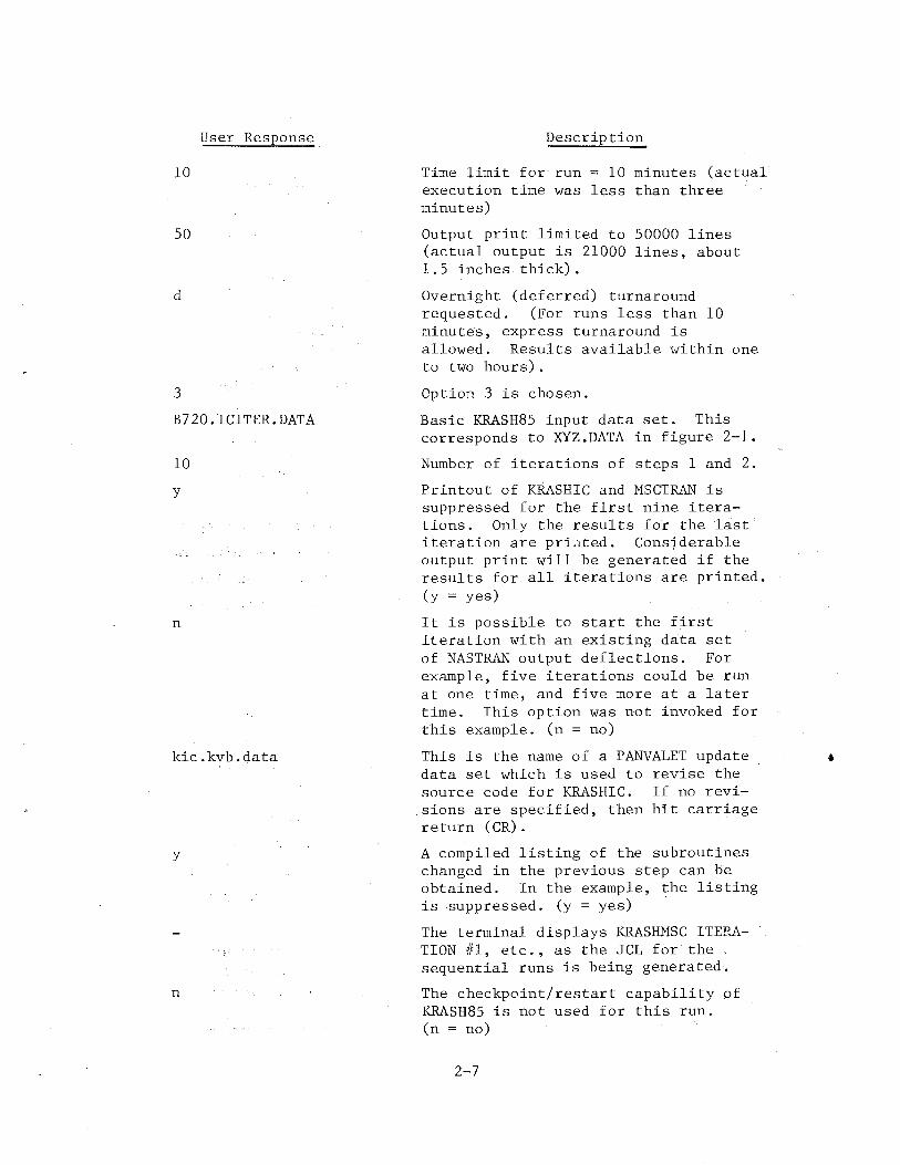
User Response.
10
so
d
3
B720.ICITER.DATA
10
y
n
kic.kvb.data
y
n
Description
Time limit for- run = 10 minutes (actual execution time was less than three minutes)
Output print limited to 50000 lines (actual output is 21000 lines, about 1.5 inches thick).
Overnight (deferred) turnaround requested. (For runs less than 10 minutes, express turnaround is allowed. Results available within one to two hours).
Option 3 is chosen.
Basic KRASH85 input data set. This corresponds to XYZ.DATA in figure 2-1.
Number of iterations of steps 1 and 2.
Printout of KRASHIC and MSCTRAN is suppressed for the first nine iterations. Only the results for the last iteration are printed. Considerable output print will be generated if the results for all iterations are printed. (y = yes)
It is possible to start the first iteration with an existing data set of NASTRAN output deflections. For example, five iterations could be run at one time, and five more at a later time. This option was not invoked for this example. (n = no)
This is the name of a PANVALET update data set which is used to revise the source code for KRASHIC. If no revisions are specified, then hit carriage return (CR).
A compiled listing of the subroutines changed in the previous step can be obtained. In the example, the listing is suppressed. (y = yes)
The terminal displays KRASHMSC ITEP~TION #1, etc., as the JCL for the sequential runs is being generated.
The checkpoint/restart capability of KRASH85 is not used for this run. (n = no)
2-7
•
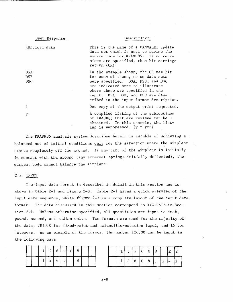
User Response
k83.icrc.data
DSA DSB DSC
1
y
Description
This is the name of a PANVALET update data set which is used to revise the source code for F~SH85. If no revisions are specified, then hit carriage return (CR).
In the example shown, the CR was hit for each of these, so no data sets were specified. DSA, DSB, and DSC are indicated here to illustrate where these are specified in the input. DSA, DSB, and DSC are described in the input format description.
One copy of the output print requested.
A compiled listing of the subroutines of KRASH85 that are revised can be obtained. In this example, the listing is suppressed. (y = yes)
The KRASH85 analysis system described herein is capable of achieving a
balanced set of initial conditions only for the situation where the airplane
starts completely off the ground. If any part of the airplane is initially
in contact with the ground (any external springs initially deflected), the
current code cannot balance the airplane.
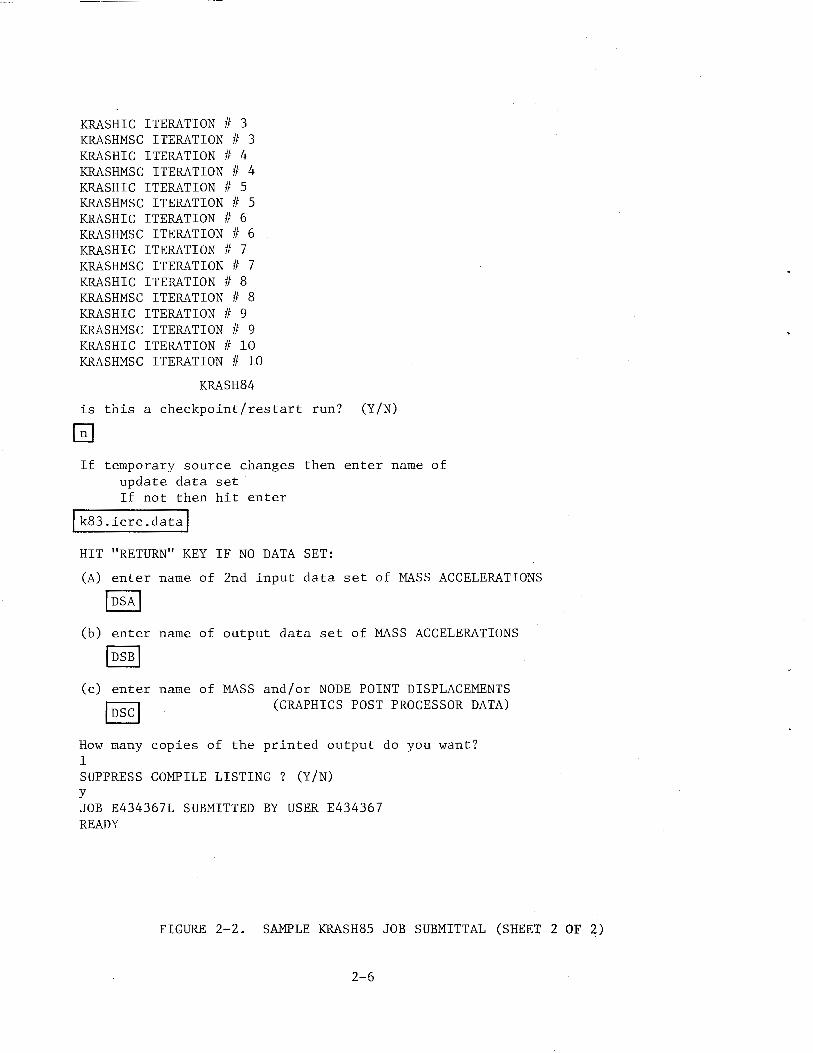
2.2 INPUT
The input data format is described in detail in this section and is
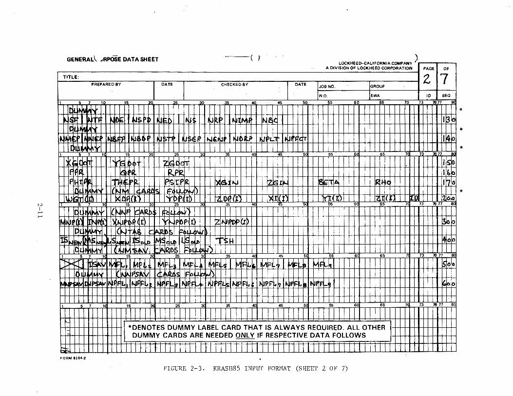
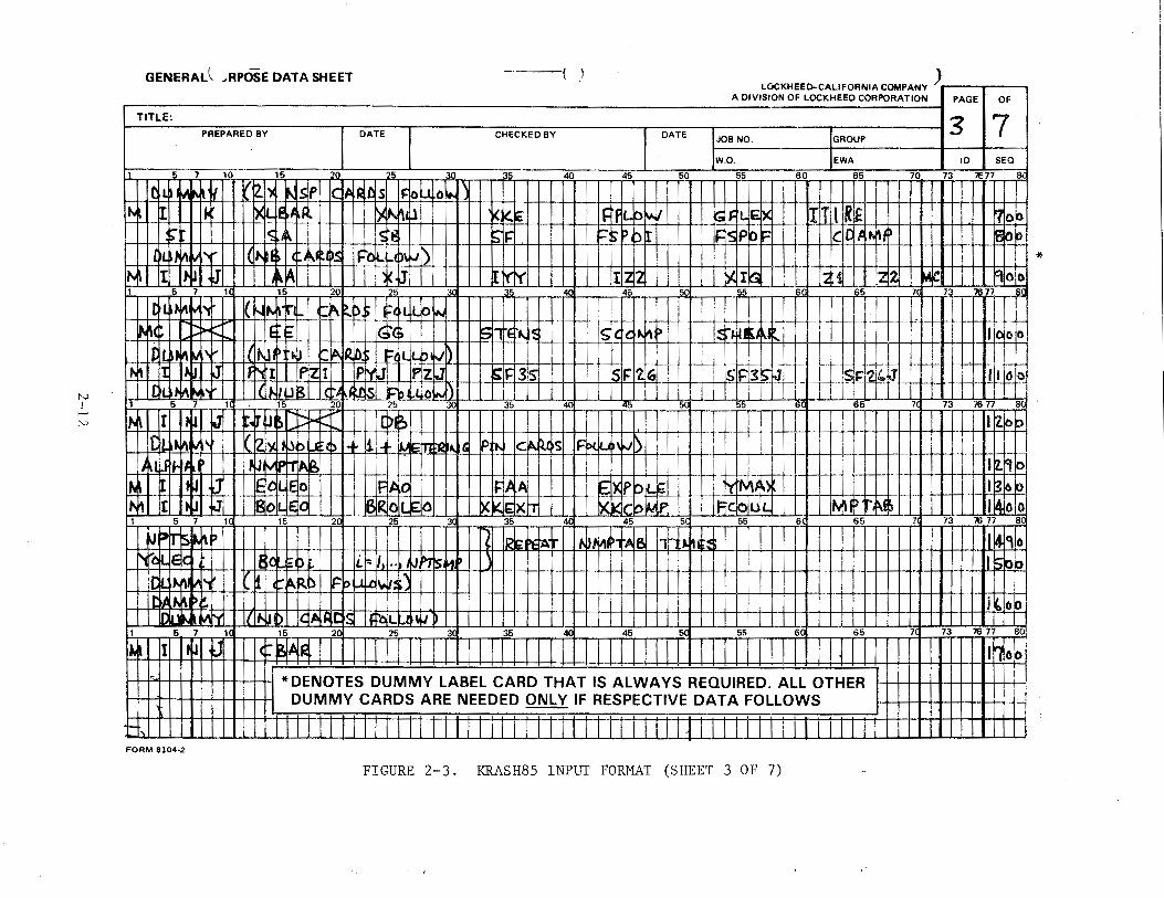
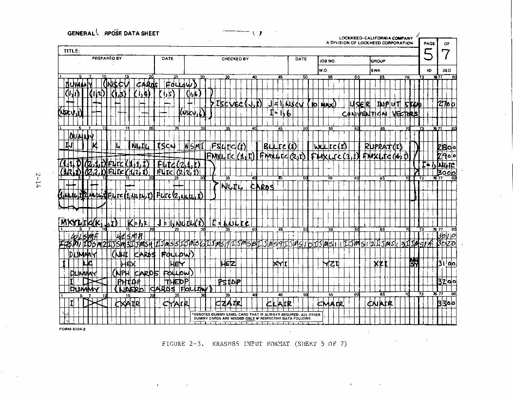
shown in table 2-1 and figure 2-3. Table 2-1 gives a quick overview of the
input data sequence, while figure 2-3 is a complete layout of the input data
format. The data discussed in this section correspond to XYZ.DATA in Sec
tion 2.1. Unless otherwise specified, all quantities are input to inch,
pound, second, and radian units. Two formats are used for the majority of
the data; 7E10.0 for fixed-point and scientific-notation input, and IS for
integers. As an exmaple of the former, the number 126.08 can be input in
the following ways:
1. . 2 6 0 8 E 2
1 2 6 0 8 . E - 2
2-8
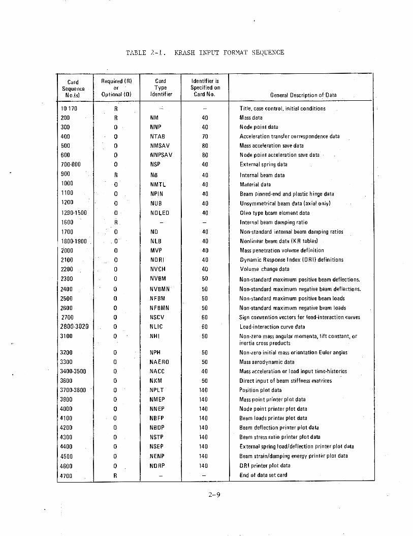
TABLE 2-1. KRASH INPUT FORMAT SEQUENCE
Card Required ( R) Card Identifier is Sequence or Type Specified on
No.(s) Optional (0) Identifier Card No. General Description of Data
10-170 R - - Title, case control, initial conditions
200 R NM 40 Mass data
300 0 NNP 40 Node point data
400 0 NTAB 70 Acceleration transfer correspondence data
500 0 NMSAV 80 Mass acceleration save data
600 0 NNPSAV 80 Node point acceleration save data
700-800 0 NSP 40 External spring data
900 R NB 40 Internal beam data 1000 0 NMTL 40 Material data 1100 0 NPIN 40 Beam pinned-end and plastic hinge data 1200 0 NUB 40 Unsymmetrical beam data (axial only)
1290-1500 0 NO LED 40 Oleo type beam element data
1600 R - - Internal beam damping ratio
1700 0 NO 40 Non-standard internal beam damping ratios
1800-1900 0 NLB 40 Nonlinear beam data (KR tables)
2000 0 MVP 40 Mass penetration volume definition
2100 0 NDRI 40 Dynamic Response Index (DRI) definitions
2200 0 NVCH 40 Volume change data
2300 0 NVBM 50 Non-standard maximum positive beam deflections.
2400 0 NVBMN 50 Non-standard maximum negative beam deflections.
2500 0 NFBM 50 Non-standard maximum positive beam loads
2600 0 NFBMN 50 Non-standard maximum negative beam loads
2700 0 NSCV 60 Sign convention vectors for load-interaction curves
2800-3020 0 NLIC 60 Load-interaction curve data
3100 0 NHI 50 Non-zero mass angular momenta, lift constant, or inertia cross products
3200 0 NPH 50 Non-zero initial mass orientation Euler angles
3300 0 NAERO 50 Mass aerodynamic data
3400-3500 0 NACC 40 Mass acceleration or load input time-histories
3600 0 NKM 50 Direct input of beam stiffness matrices
3700-3800 0 NPLT 140 Position plot data
3900 0 NMEP 140 Mass point printer plot data
4000 0 NNEP 140 Node point printer plot data
4100 0 NBFP 140 Beam loads printer plot data
4200 0 NBDP 140 Beam deflection printer plot data
4300 0 NSTP 140 Beam stress ratio printer plot data
4400 0 NSEP 140 External spring load/deflection printer plot data
4500 0 NENP 140 Beam strain/damping energy printer plot data
4600 0 NDRP 140 DRI printer plot data
4700 R - - End of data set card
2-9
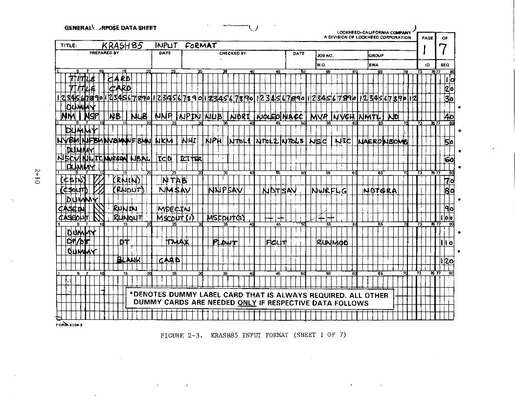
N I
"""' 0
GENERAL\ .~RPOSE DATA SHEET ,- ~.J LOCKHEED-CALIFORNIA COMPANY)
A DIVISION OF LOCKHEED CORPORATION I PAGE I OF I TITLE: J<RASHSS INPuT &:"oeM~T
PREPARED BY I DATE I CHECKED BY DATE JOB NO. GROUP I 7
W.O. EWA ID SEQ
5 7 10. 15 20 25 3( 35 40 45 50 55 6 65 70 73 77 8(
I irtl\1hl.4 I I tiAk.b trt 1t1W.tt I llt±A"12~
IICJ
!z1o 'rzJ~~Iwla1loh tzJ:sl~'rnmiD 1, lzJ3It1 '11h~~lol1 ftJ3~~'17It~~lt~I314Jsl,l7~~112T~~Jr~liliJ~~~'~Is~Ph~ 3k» ld~~~v
l~P1 I Tt.Jus II ~us I ft.J II{JJ'fi.IJ IIIIJiJl?ll IIIIJ~4~ I ijj(f)iji)l ijAt¢ I M\i# I ij\V¢1-!t IN~ti I ~tl ~" 5 7 1
~4~Mfl 15 20 25 3' 35 4ll 45 50 55 6 73 7677
1~\j,t~l ~~J.N "---·IFIBMNI ~kM I ~~rll tiJP~IIt.J-rfa~( 1~-rto~i.l~?jb~~ I ~lslq I ~It~ I l~*~p~sp~ ~ -Itt- (!)NOll ltk:l~ I mt~ jQ]
*
*
*
I I ldtbhM'rl I J I I I I I I I I I jl I I I I I I I U ITIT I I I I U I I I II I I I I J I I I I I I l I I J I I I I I I I I I J I I I I I I I I I J * 1 5 7 . 1 15 20 25 35 45 5 55 6 65 7 73 76 77 8
c¢:f.~~11 V1l1 I ~~rNb I I I I INI tP.Sl I I I I I I I I I I rl I I I I I I I I I I I I I I I I I I I I I I I I I I r I I 111111111 Fn(l (¢~L.trf>Lt:f.t I ~FkbRf) Ill RJM$k\{I[Il!N~r~.._vlll I t1J~I~~ IIIN~~F~GI II l~d>1$~~111111111118c ID!L~~..v
IQ.~gl): t-N llijJ~~ l~tt¢.t~ lftidd,. N-\1 I T~t.ldt.i1 MSc.bu+t•) M~butdl~ H-1+ r::f -1-1-1-1 5 7 1a 15 2 25 35 4' 45 55 6 65
IOLn•a ·~/birt I I I I I I "'-~ tr'MA' ~~ I~Li, 1011 ~...~u~,
It!,~~~
" I d.~~~
1 5 7 1 15 2( 25 31 35 4( 45 5 55 6 65
I In I I II I I 4 I I I II *DENOTES DUMMY LABEL CARD THAT IS ALWAYS REQUIRED. ALL OTHER DUMMY CARDS ARE NEEDED ONLY IF RESPECTIVE DATA FOLLOWS
1 F0~8104·2
FIGURE 2-3. KRASH85 INPUT FORMAT (SHEET 1 OF 7)
'110 IIOIO
7 73 76 77 8' ..,..
Ill~
112lo 1a 73 76 11 so
l
*
*
*
!'-) I ~
~
GENERAL\. JRPOSE DATA SHEET ( t LIJI.,;KHt:t:L;·CALI~UHNIA COMI'ANY
A DIVISION OF LOCKHEED CORPORATION
TITLE: PREPARED BY DATE CHECKED BY DATE JOB NO. GROUP
W.O. EWA
7 1 15 5 5 40 45 50 55 60 65 70
II"~•
t-.l~~ ~·t~ ~!) ~ .~: F» ~~ ) IJI ~t> ~~~ •W ~II:> ~ .Mf Nlelc 'n11 l.1i ....
~~· "l ) ' Jl ~I ~~ ,~IU ~frF #.~1 ~~I' ~ IJ' ~-r-t J'iE J ~~-~~ ~fJI ' t ~j)J ~F •J PL ~ ,.~, ~~'lT
01 ,)1~ ,..~If 7 1 15 20 25 3 35 40 45 5 55 6 7
v ;.IC It'll 'f" (;j )1 )1 Zk; .t>c!T ~~~~' ~p~
IFI~o It ~ ..,,
~~~ p~ lFc.; rPI~ i)C IE·J :~J z t;r,.. 1ilb' IIA I< ~,( ~L . f ir1M' ~~"~ 'I. lc:. ::-.,, 1'\\
k>~ rrtl In )( I,,. [)I I rz .l)f '{'"" )< :t '"" '(l 'I) "2 .II( 1 1 5 7 1 15 20 25 3 35 40 45 5 55 6 65 7
i[>l I I lA~ ~v 1/t-. I~'F ~lA 112.~: tb. 11 11 .. I
~~· JJ f' NAt~ (~JI ~~>I (I ,,.
r--..P 0~· I IZ~ ~·~ p (I~ C~L ~~ ~ ..... ..... I ~f ~A. 12~ 5. =I" ll ~"j) I
l~b ~ !; I, -· 1 oLE l<,c I WI> 1~101 lb ~-. ~~
It~~ 1\· ,.,. u .II"' l ~ :>i ~\I r-~ J<O 5 1-- II ~ :... Li~ 1 5 7 1 15 2 25 3 35 4( 45 5 55 6 65 7
~~~ ·~ ~~ ~~~ 11'11- 1., 1~1-, ~~ t:: .. : ·~ p_ ~ I ~FL~ V1F ~.~, M ;:l.r ~~== 9 ~IF ~" I( ' ~~~ ~~~'1 ~N Ia. t.: :s,,, IC1 f\IU ~s ... ~, ..l~ ~[)
~' I" L. ... ~"' I ~-f F :~i~ Jf'F f-' ~~ PF rLs ... IP ~~ ~ .. UF' "'"
i ... ~f J:"' al~ JfrF~
1 5 7 1~ 15 2~ 25 3( 35 40 45 5( 55 6C 65 7
*DENOTES DUMMY LABEL CARD THAT IS ALWAYS REQUIRED. ALL OTHER DUMMY CARDS ARE NEEDED ONLY IF RESPECTIVE OAT A FOLLOWS
. . t· FORM 8104·2
FIGURE 2-3. KRASH85 INPUT FORMAT (SHEET 2 OF 7)
) PAGE OF
z 7 10 SEQ
73 7677 8(
* I t3 o
* ~~~
* 7 7 sc
liS~ It~ lri 0
* I'Zo~
73 7677 80
~~~
4oo
73 7677 8(
~00
,00
73 76 77 sc !
N I
r-' N
GENERAL~ .-RPOSE DATA SHEET ----{) ) LUI,;J<;HI:I:L>-CALIFOfiNIA COMPANY -
A DIVISION OF LOCKHEED CORPORATION
TITLE:
PREPARED BY DATE CHECKED BY DATE JOB NO. GROUP
W.O. EWA
5 7 10 15 20 5 30 35 40 45 50 55 60 65 70
C1L ~~ ~ I/~ !) t\IS p ir 1, I~ IC s l=o w. o~l\ Ito. I • ~~· ifi ~~ ~' ~lt-- ~Ll k~ 1: IF if:L p~J ~II= tL &;I>< rrt l RE
~ I~ 1~:@ Slj:. ~ I)P b~ IJ=~S Pbl= de I ~~t. ~~b OL ~~~ ~,.., 1(1~1~ ,j p~ I'"" '\\ ) I i I I~ ~ ;I' klJ ~-rc-~ 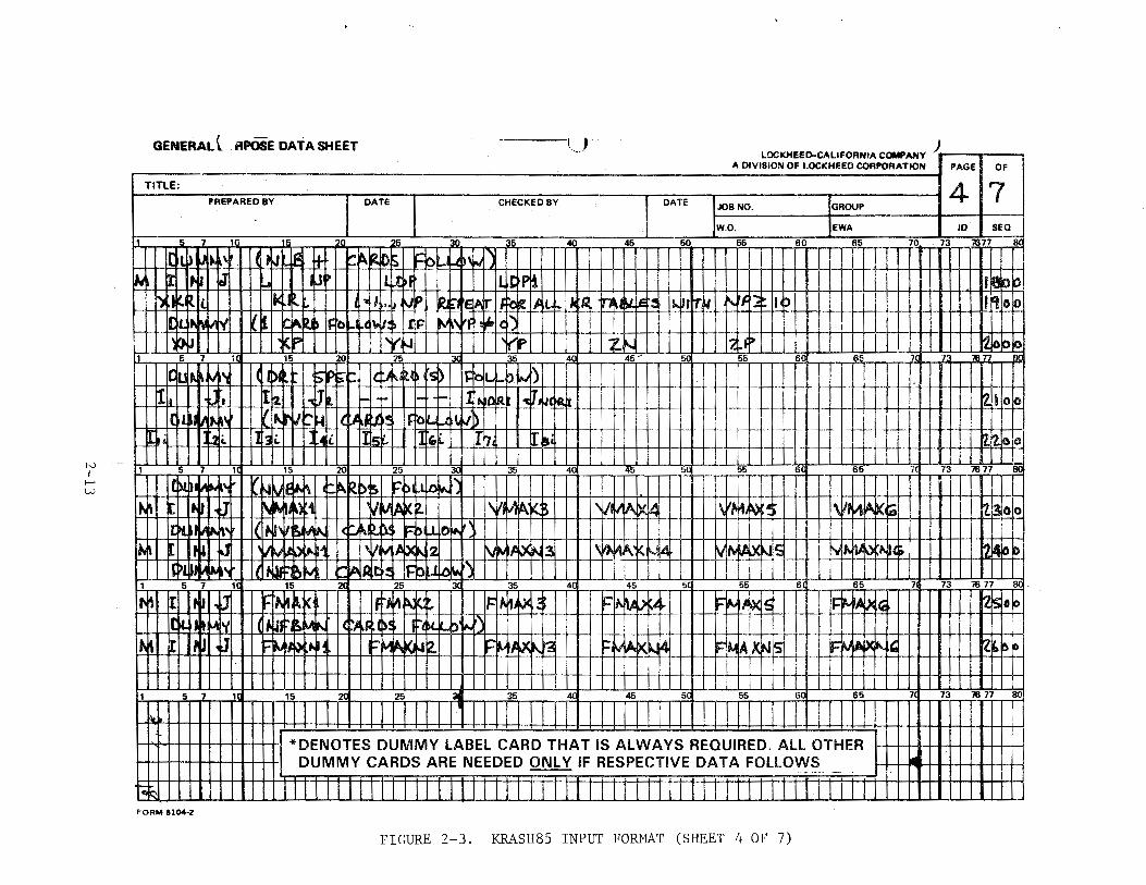
N I
f-' w
GENERAL t _ RPOSE DATA SHEET ( , Lut,;IU11t.t:~t;AL1f"UI'INIA COMI'ANY
A DIVISION OF LOCKHEED CORPORATION
TITLE: PREPARED BY DATE CHECKED BY DATE JOB NO. GROUP
W.O. EWA
t 1 25 36 4C 45 50 55 60 65 70
~u- ~ ~ ~\ u ~ ~ fl- ~~ Rf\ r:~ ''""' I 1.1 ~ It-~ ~~~~ L.t~f Ut tPi
~ ~~ (. t ci-:: I . ~p ft. ~~ If ~~c.. .. I~ :~ 'lll ~.e ~!! 1.. ' ~-~
~rf r~ I :> "' rc lr~, IT ~ r-~ ~~ l~o ~(I \I ~:~ IJF ~~\ rf ~l' l I 1,~~ p :v,fJ ~r "r--. '~~~
7 1 15 20 25 ~ 35 «l 45' 55 6 " 7
I ICtl I'- ~ V~'J (I ~ r p ~I ~~~ 1\1~~ rs ~ it l-1 r. I'J)
!11 :,
'2. ]t r- 1- ll .. '0 Rt I~ T,~, ~Rit I
I('' II iiU\ '" ~J "'I-t It'~ ,,,, ~c: th lLI)
I. l2&. hi. .4 i. Is~ ],· fl7j I~ -I---
'
1 5 7 1 15 20 25 30 35 4 45 5 55 s 65 7
' v .• l~it.. r-~ 21!'\• ;; I=' )l~l o~}"' M r 't J .. ~ ~·~l ~1 ,,V: ~ K~ \l/j .,;1~· ~~- 'VI fl1~ ~~ v~ ~~~~ll \ ll AlA )(,e;i '
:£~ 1'11"~' l(t-~' lr ~
(r ~~ ~p ~0~
it.~ II~ ~ I .l'l'!ri ta..a-1 'VI j~ i2 r...l~ low: 'It, \~ ~~ .. k 14 lA ·~S i .... ~1\li
! rl>l llt ~ ... ll 1''
... lA lair , .. It: I'\ ~it.. ,, ·, I I 1
1 5 7 1 15 25 3( 35 4 45 5 55 ii 65 7
1,~ I It~ .~~ 'M, t.:K In ~.~ C'.:r-- Fl~ ~J~.~ I= ~~~.n ~=""' ~-'~!~ rr.. 1.6!11 l~
ICil ~·~ ~I 'I' (if Jl ~~ N (~,« ~~;.)! £t ~(. .... )' .... r) ~~- ~ [I ~ till ~'~ '-KJ .. g. l':ll i~llC 1'3
,..., lA. .4 FIM AIX t.Jis lr::
1 5 7 l( 15 20 25 3j 35 .- 4( 45 50 55 s 65 7
1 *DENOTES DUMMY LABEL CARD THAT IS ALWAYS REQUIRED. All OTHER
DUMMY CARDS ARE NEEDED ONLY IF RESPECTIVE DATA FOLLOWS ~ -- -·-- .
lo~ II J 1111111 I II I II II II I I I I II I I II I II II II I I II I I Ill I Lll L FORM 8104-2
FIGURE 2-3. K.RASH85 INPUT FORMAT (SHEET 4 OF 7)
)
PAGE OF
4 7 ID SEQ
73 1677
~~ QP ~~ co
~0 Q_~ 7
21 op
2tz 00
73 1677 Be
~~ 00
~., OD
73 1617
!lj5 eo I I
'Zb olo
73 1677 80
1
N I
....... ..,..
GENERAL~ . APOSE DATA SHEET ~ ' LOCKHEED-CALIFORNIA COMPANY j
• ~v•"oN OHOCKH"O """"'"AT"'" I ""' I o•
I DATE ,~ONO IGAOU• 1517
W.O. EWA ID SEQ
45 50 55 60 65 70 73 7677
TITLE:
PREPARED BY DATE CHECKED BY
5 7 10. 15 20 25 30 35 40
llil~HliAN IION!$4:\A ld:~IIFtg'-Mw.l ~~~~•) lld1l,f>l f(Ud I thhlJtb~111<1,,~l 1·-o
I+ f-
+-IS;t\1,~\ 1-
1- f- ll~s@jW tl,ftlt1i1)! ~~~:ttilifrt_ttfl1l~jJ:1Jt~~I!f111 t%rl 5 7 15 20 25 3 35 40, 45 5 55 6 5 7 7 71
11\lillil·~
l!JllJ IIJ( L lt1JU~L tS_gt.. NISIMif'a_m~ilw~iirtf£1ttlti~ttfJj~IM~ti£mm If 1 ~~~ _ ~~~K:IiJ~~t)Uitthkl<tli~;tliJ I~ Ill Ill UJ IIIIIIIIJ IIIIIIIIIJTTTI 11111JEf.I1T~9_QQ. o
' '~ 25 3 35 lt5 . 5 55 6 _ 6_5 __ 7 __ 73 76 77_ . S_Q
1-+- ~~"IN1tl,ll'J I c~~~~ I I I T I I rl r l-n rTTTT fTI r TTl I T I I ! ~)( El~r~ Q:zl.JdL~ J!)
[H\'kYJ,ltJali(l_1~liJJKl1iz.l LJ ~ IIJ~uJrlL~i)l I a~ ~iJ' r. L _ __§_ _7 ·_ ·1<t- 1s 2d -25 Jet 35 4ct 45 set ss· --sd 65 74 73 76 11 s1
itVli.~ltfntlJ lltbtls~JJI !liT l l l II l Ill l II I I I I II I I II I II II II I I I I I I I I TffifTTLlT_ll rm l3WJOJ ~~lfcjs~3ri1J~iltlJlliiTSfsl~Jj~11Jl~TWJ:svnTsJBI9Jffllr:'7!1tri5Jf1s!tpl!1f!M!s!,!t !f!:SM~tl~.asltl4slt J~J!AI~tWI PP~~ I IID~Mtf\b1 l~fJHJ I kbMd llf4L+Libkbl I I I I I I I I I ll.-r-r- I II II II II I I II II I
~I Ill LIH~_LLI LU ~~~ I$; ~[ htatl ktr §IIIII z. 0
lrkt.Julf11li(~PHI ~I~~ II I [J::H:::[I I I FtHlttM I I I I h!HEPP ws~op r& ~MM..Y I I I { Ll~l l~lalis I Roll-~
7d 73 76 77 80
+UPM$ I
i
1 5 7 Hi 15 20L 25 30 35 40 45 50 55 sa 65
II I I]::H::[II ~~~ II I 14:h1AJr~ k=IM*! ll1ll j;M_~~ ~~' I VI I I I I I I I I I I I I I I I I I I I I I I I I !*DENOTES DUMMY lABEl CARD THAT IS AlWAYS REQUIRED. All OTHER I I I I I I I I I I I I I I I I I I I I I I I I I I 1 1 1
1 DUMMY CARDS ARE NEEDED ONlY IF RESPECTIVE DATA FOllOWS 1
FORM 8104·2
FIGURE 2-3. KRASH85 INPUT FORMAT (SHEET 5 OF 7)
N I ,_.
lJl
GENERAL( ... RPOSE DATA SHEET lJ·-LOCKHEED-CALIFORNIA COMI'ANY J r
1 1 A DIVISION OF LOCKHEED CORPORATION PAGE OF
TITLE: 6 17 PREPARED BY CHECKED BY JOB NO. GROUP
W.O. EWA ID I SEQ
1 5 7 1 15 20 ~-- __ 3lL _35_ 4C 45 50 55 60 65 70 73 7677 8C
I01..U,M, r 1 1rlllllt
~~tt 1-fld"-k~$ 1 d'ti.r_b~ I\ JIJJ11Mc.P~ ~~
rt""'~II I_,.¢4¢UUUiJ..lti-4, NFI·~ I eet~friiJ"'p ntf41~lS ~~!ofo ~~if' ldi ~I.J.Jt~ll¢~~dsiiFhllldw~
1~11tll~ l 45 5' 5 7 1CI 15 201 25 3d .. ---- 35---- 40f----45 ____ 5ol -----55 6C 20 1 5 7' 73 7f117 Jro
1 tl 1 ~11111111 ~~ 1111111 ~tlllll ti ~~~ 11111111~~e 11111111 ~tt1111111, 1 , 1 , 1 ,,_, • , , , ~ , , , ,
v1,111 I II II ~illlJJJ IIJt~ill I II II 1143~ II 111 lllK3klTD I I []__~i,i 13(;:o!O
7
k141111111MM_LUJIIIK~ I II II 1~4-k-1 I I II I I IK4lsl LLUUJik.M 1 5 7 1
k'.kd lLU l lJJUiJ LlLL I lM'~1l I I J __ LLJ 1~4Ll l UJJ I ~~LLJ LLJll --~ 15 201 25 301 35 - - 401 ---- ll"5 -5Ql 55 6 65 73 76 77 8(
~· lJLbLLll111Jt~~JJW ll\t41J 1111111 kw.1 I
r~JlA~ IJ~ k fJPJ r t.~,~~t>;~ Fe L'""'D'~~\ 1 ! Tl I I , I ' i i
~~'--1>1~-o ~~~~~P'IiS.ISirwr:. ~::::~~ \'c~.r- ,, ~ rr'SCAI..\: l P·~~-Jt!it"~ f~b·r J)~~o;r~ I - ~~7~~ ~~~~ ~~~~ ~~;~ IMI4 it..~~~ ~~' ,~,, -~ \ "'l- J T l . L ~816 ~-
1 5 7 1 15 2 25 JC 35 4 •l5 5 55 6 65 7 73 76 77 n(1
1 lt}~I\Avl~ I N!M~f CJ.sc.c~c t:-r~• .... "~~) -T -~IH ~lf'Z h~F'3 MFI4 ~IPS ~If'~& ~'117 MrJ1trf4.1 lrfrT TTTtliJJ 111111111111lJ3~
" ~~~ A"t ( Nt.~l~ , ... •• ~" ~ lc~ 111 J ~ llll Jj 1111 I I I I I T I T J . i I I I I I I ~ I HI ' 1111\ I I ~t~ 11W~~ l ~1 Hl\1\Ms~ I Nr~lll I II I II II II I I I I I I I 11-1 I I Ill I 1111111114~~
5 7 1! 15 2_( 25 ~ 35 _1(l 45 5( 55 6 65
I 1·1 I I I II I I I I II *DENOTES DUMMY LABEL CARD THAT IS AlWAYS REQUIRED. All OTHER DUMMY CARDS ARE NEEDED ONLY IF RESPECTIVE DATA FOLLOWS
~~
FORM 8104-2
+' I
FIGURE 2-3. KRASH85 INPUT FORMAT (SHEET 6 OF 7)
7!1 73 76 77 80
!
N I f-' 0'>
GENERAL~ ,RPOSE DATA SHEET ( p LOCKHEED-CALIFORNIA COMPANY ) l
A DIVISION OF LOCKHEED CORPORATION I PAGE I OF
I TITLE: I 7 I 7 PREPARED BY I DATE I CHECKED BY I DATE I I
JOB NO. GROUP
ln•~k1 fQII dMttt l~$1~tllu,~ 36 45 5
W.O.
-66 EWA
60 66 70 7
ID I SEQ
7677 8(
llllt11Bff+1111111111111111111111111111111111111liiiiiiii1Mttt lrJ.~t.AL111TT'(1JJshf~ E~M IFfoWw.
1 5. 7 15 201 25
~~ I I ~P-i I 5ff!Pkl ~trri $+~40 I ms INU..la.LJ:.TT1f6Js&!P! I:AA~ I~Wo~
3' 5 35 45 55 6
Tr ' I
• I ·r I . l 7 7 Rrl
IA:5op I
liiUK~J II tift lfH#~ I J 1111111 W Ill ~1IIIUffi IIIII UtfffftffiR 1 5 7 1 15 20 25 3 35 ~ 5 55 6 65 7 73 7 8(]
~~~ I I t~P~t I <tM.$1 FhWol~)
ijiiiiiiiiiiiiiiiiiiiiiiiiiiiiiiiiiiiii!IIIIIIIIIIIIIIIIIJHIIUUUIJIIIBjE 5 7 1
5 7 1
15 2c 25 3' 35 4' 45 5 55 6 65 ·711 73 76 77
1 1
15 2( 25 3( 35 4c 45 5 55 6 65 7d 73 76 77 80 I
l *DENOTES DUMMY LABEL CARD THAT IS ALWAYS REQUIRED. All OTHER II I II II II Ill I i i
1 DUMMY CARDS ARE NEEDED ONLY IF RESPECTIVE OAT A FOLLOWS
1 1
~111111111111111 I I I I I I I I I I I I II I I I I I I I I I I I I I I I I I I I I I I I I I I I I II I I I I I I Ill I 1111111111 FORM 8104·2
FIGURE 2-3. KRASH85 INPUT FORMAT (SHEET 7 OF 7)
Blank columns are treated as zeros. When the E format is used, the exponent
must be right justified in the field. With the IS integer format, the number
must be right justified. The sequence numbers shown in columns 77 through 80
are only for reference purposes within this document. The actual data cards
can have any numbering scheme, or no numbers at all, as long as the cards are
in the proper order.
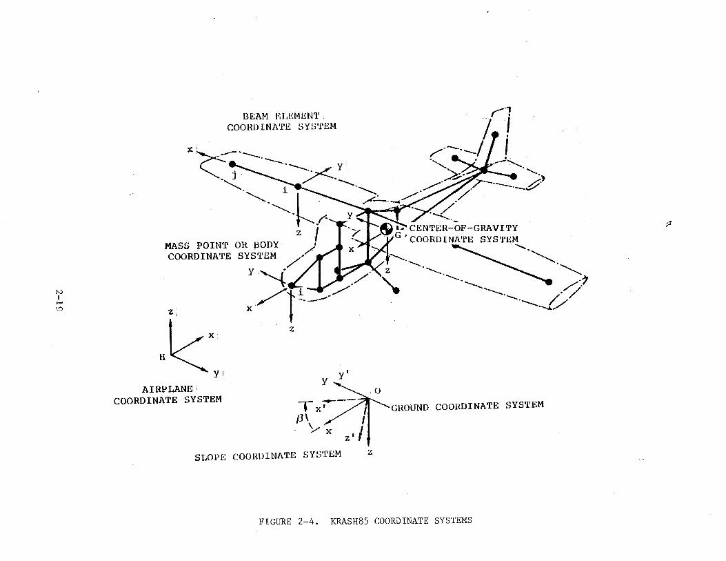
The following coordinate systems (figure 2-4) are established to facili
tate the derivation of equations for the mathematical model. The input data
description specifies the appropriate coordinate systems to be used.
• Ground Coordinate System. - This is a right-handed coordinate system fixed in the ground with the origin at point 0 in figure 2-4. The x-axis is positive forward, the y-axis is positive to the right, and the z-axis is positive downward. The xy-plane (z = 0) corresponds to the ground surface. The ground coordinate system is considered an inertial coordinate system for writing the dynamic equations of motion.
• Slope Coordinate System. - This is a right-handed coordinate system fixed in the ground with the origin at point 0 as shown in figure 2-4. The x-axis is positive forward up the slope, the y-axis is positive to the right, and the z-axis is positive downward and perpendicular to the slope. This coordinate system is the same as the ground coordinate system rotated through an angle 'beta', positive clockwise about the ground y-axis. The xy-plane represents a plane inclined at an angle 'beta' with respect to the horizontal ground plane. • 'Beta' is a constant input angle that can range from zero to ninety degrees.
• Airplane Coordinate System. - This is a left-handed coordinate system fixed with relation to the airplane with the origin at point H in figure 2-4. The x-axis is positive aft, they-axis is positive to the left when looking forward, and the z-axis is positive upward. The origin at point H corresponds to zero fuselage station (FS = 0), zero buttline (BL = 0), and zero waterline (WL = 0). This coordinate system is used only to input the location coordinates of the mass points and massless node points since the coordinates of the points are usually available in terms of fuselage station, buttline, and waterline.
• Center-of-Gravity Coordinate System. - This is a right-handed coord~nate system fixed with relation to the airplane with the origin at the ve-hicle e.g., point G. The x-axis is positive forward, the y-axis is positive to the right when looking forward, and the z-axis is positive downward. These axes are parallel to the airplane coordinate system axes.
2-17
• Mass Point Coordinate System. - Each mass point has its own right-handed coordinate system fixed with relation to the mass point. The initial orientation of each of these coordinate systems is arbitrary and is specified by means of three input Euler angles for each mass point relating its initial orientation to the center-of-gravity coordinate system since the inertia data are generally available about these axes and the three input Euler angles are zero. The mass point coordinate system is the system used to write Euler's equations of motion for each mass point.
• Beam Element Coordinate System. - This is a right-handed coordinate system with the beam element x-axis along a straight line from the mass point at end 'I' to the mass point at end "j". As the mass points move, the beam element coordinate system changes orientation so that the x-axis is always pointing from the mass point at end 'I' to the mass point at end 'J'. If the beam element connects massless node points which are offset from the mass points, then the beam element x-axis always points from the massless node point rigidly attached to the mass point at end 'I' to the massless node point rigidly attached to the mass point at end 'j'.
The beam element y-axis and z-axis are mutually perpendicular. The direction of each is arbitrary and is defined internally within the program. The input data are prepared according to the beam element coordinate systems shown in figure 2-5 (page 2-46).
The following is a detailed description of all the input data
requirements.
2-18
N I
1-' V)
BEAM ELEMENT COORDINATE SYSTEM
xc~-.--------.~ y: - J / ----............. . .............
............... 1 k' -~- -~ .r
MASS POINT OR BODY z I COORDINATE SYSTEM ///
Hl:XY! AIRPLANE·
COORDINATE SYSTEM
y '"(.( I Y./ / i_...., / / l-----x : '
z
y y';
T X-;-/ I IJ\ / I . ' I . Y x z'
SLOP£~ COORDINATE SYS'rEM z
............ z ........... '- ......................
GROUND COORDINATE SYSTEM
FIGURE 2-4. KRASH85 COORDINATE SYSTEMS
p
KRASH* INPUT DATA
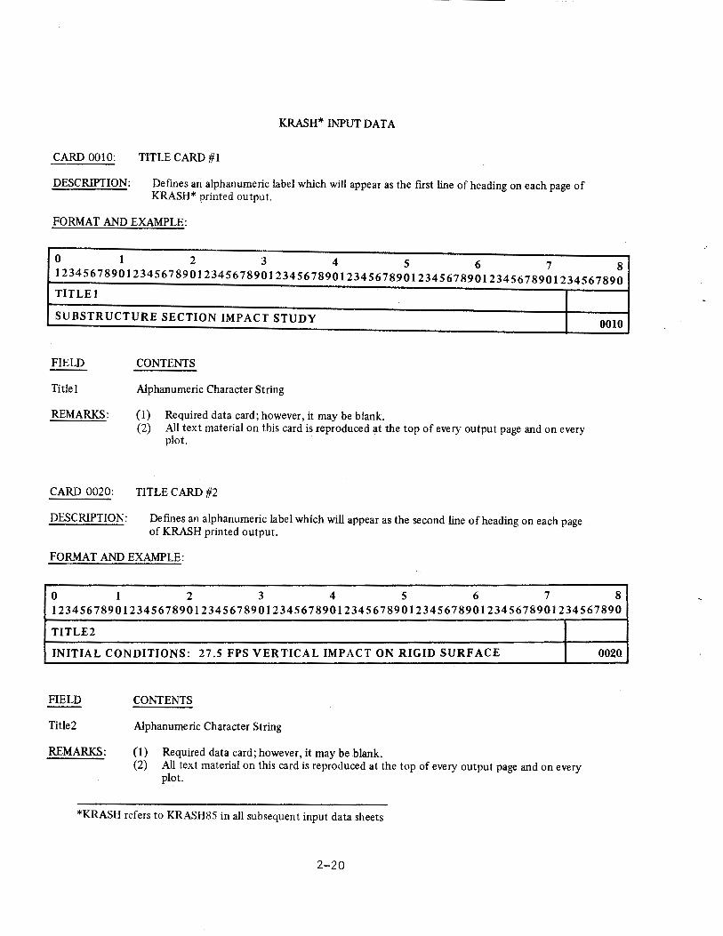
CARD 0010: TITLE CARD #1
DESCRIPTION: Defmes an alphanumeric label which will appear as the first line of heading on each page of KRASH* printed output.
FORMAT AND EXAMPLE:
0 1 2 3 4 5 6 7 8 12345678901234567890123456789012345678901234567890123456789012345678901234567890
TITLE I
SUBSTRUCTURE SECTION IMPACT STUDY
FIELD CONTENTS
Title I Alphanumeric Character String
REMARKS: (I) Required data card; however, it may be blank. (2) All text material on this card is reproduced at the top of every output page and on every
plot.
CARD 0020: TITLE CARD #2
DESCRIPTION: Defmes an alphanumeric label which will appear as the second line of heading on each page . of KRASH printed output.
FORMAT AND EXAMPLE:
0 1 2 3 4 5 6 7
0010
8 12345678901234567890123456789012345678901234567890123456789012345678901234567890
TITLE2
INITIAL CONDITIONS: 27.5 FPS VERTICAL IMPACT ON RIGID SURFACE
FIELD
Title2
REMARKS:
CONTENTS
Alphanumeric Character String
(1) Required data card; however, it may be blank. (2) All text material on this card is reproduced at the top of every output page and on every
plot.
*KRASH refers to KRASH85 in all subsequent input data sheets
2-20
002(1
KRASH INPUT DATA
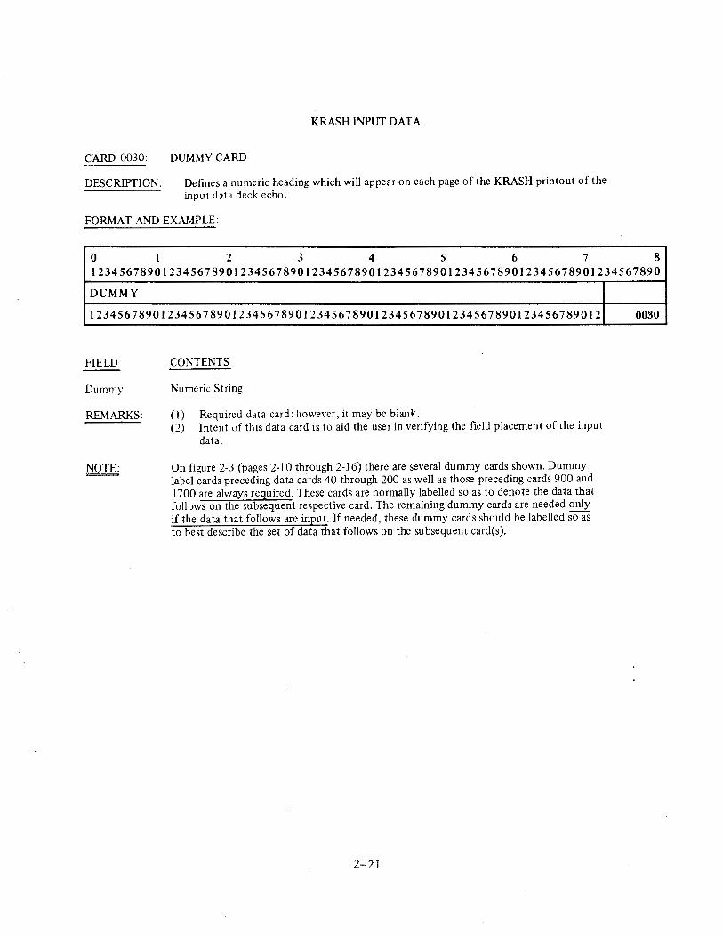
CARD 0030: DUMMY CARD
DESCRIPTION: Defines a numeric heading which will appear on each page of the KRASH printout of the input data deck echo.
FORMAT AND EXAMPLE:
0 1 2 3 4 5 6 7 8 12345678901234567890123456789012345678901234567890123456789012345678901234567890
DUMMY
123456789012345678901234567890123456789012345678901234567890123456789012
FIELD
Dummy
REMARKS:
CONTENTS
Numeric String
(I) Required data card: however, it may be blank. (2) Intent of this data card is to aid the user in verifying the field placement of the input
data.
On figure 2-3 (pages 2-10 through 2-16) there are several dummy cards shown. Dummy label cards preceding data cards 40 through 200 as well as those preceding cards 900 and 1700 are always required. These cards are normally labelled so as to denote the data that follows on the subsequent respective card. The remaining dummy cards are needed only if the data that follows are input. If needed, these dummy cards should be labelled so as to best describe the set of data that follows on the subsequent card(s).
2-21
0030
KRASH INPUT DATA
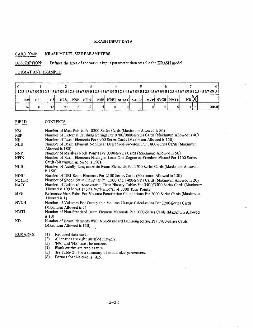
CARD 0040: KRASH MODEL SIZE PARAMETERS
DESCRIPTION: Defines the sizes of the various input parameter data sets for the KRASH model.
FORMAT AND EXAMPLE:
0 I 2 3 4 5 6 7 8 12345678901234567890123456789012345678901234567890123456789012345678901234567890
NM
16
FIELD
NM NSP NB NLB
NNP NPIN
NUB
NDRI NO LEO NACC
MVP
NVCH
NMTL
ND
REMARKS:
NSP
10
NB NLB NNP NPIN NUB NDRI NO LEO NACC MVP NVCH NMTL ND X 32 2 6 0 4 0 0 0 0 0 0 1
CONTENTS
Number of Mass Points Per 0200-Series Cards (Maximum Allowed is 80) Number of External Crushing Springs Per 0700/0800-Series Cards (Maximum Allowed is 40) Number of Beam Elements Per 0900-Series Cards (Maximum Allowed is 150) Number of Beam Element Nonlinear Degrees-of-Freedom Per 1800-Series Cards (Maximum Allowed is 180) Number of Massless Node Points Per 0300-Series Cards (Maximum Allowed is 50) Number of Beam Elements Having at Least One Degree-of-Freedom Pinned Per 1100-Series Cards (Maximum Allowed is 150) Number of Axially Unsymmetric Beam Elements Per 1200-Series Cards (Maximum Allowed is 150) Number of DRI Beam Elements Per 2100-Series Cards (Maximum Allowed is 150) Number of Shock Strut Elements Per 1300 and 1400-Series Cards (Maximum Allowed is 20) Number of Enforced Acceleration Time History Tables Per 3400/3500-Series Cards (Maximum Allowed is 100 Input Tables, With a Total of 5000 Time Points) Reference Mass Point For Volume Penetration Calculations Per 2000-Series Cards (Maximum Allowed is 1) Number of Volumes For Occupiable Volume Change Calculations Per 2200-Series Cards (Maximum Allowed is 5) Number of Non-Standard Beam Element Materials Per 1000-Series Cards (Maximum Allowed is 10) Number of Beam Elements With Non-Standard Damping Ratios Per 1700-Series Cards (Maximum Allowed is 150)
(1) Required data card. (2) All entries are right justified integers. (3) 'NM' and 'NB' must be nonzero. (4) Blank entries are read as zero. (5) See Table 2-1 for a summary of model size parameters. (6) Format for this card is 1415.
2-22
0040
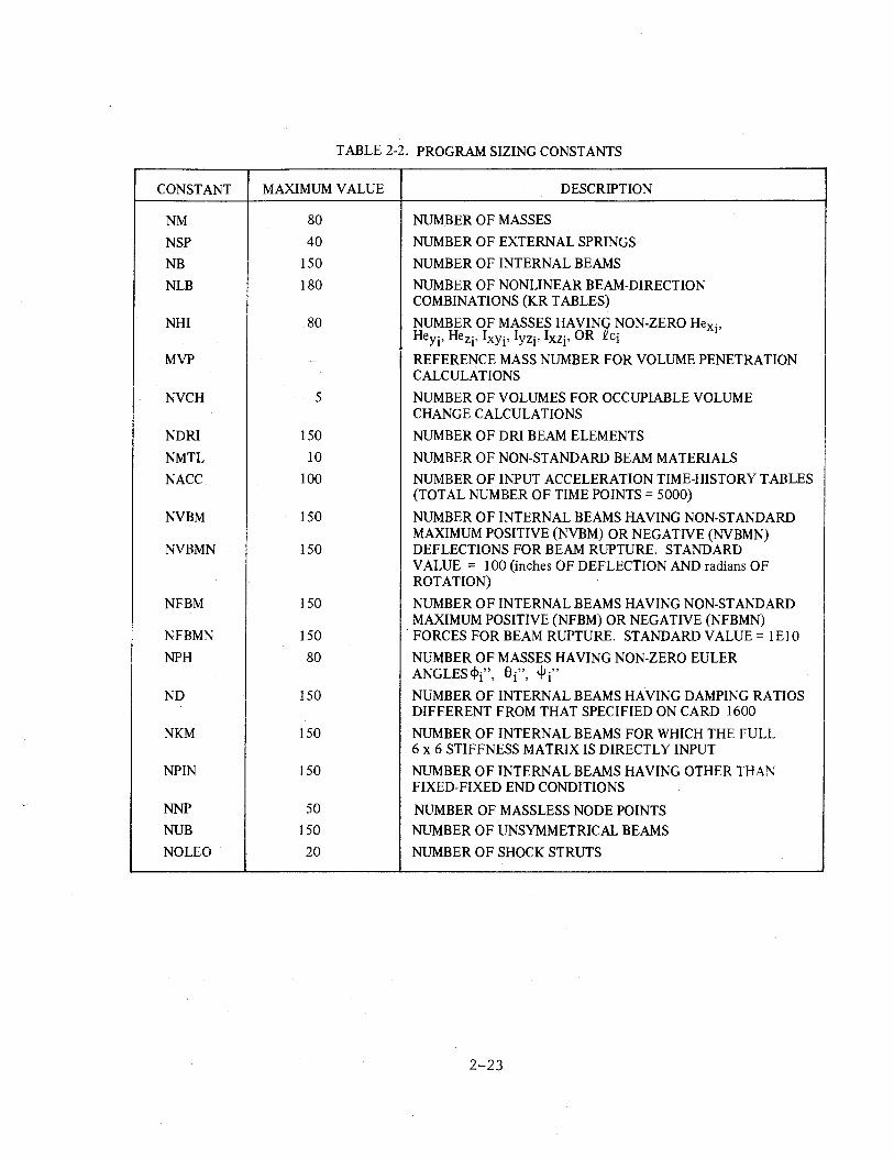
TABLE 2-2. PROGRAM SIZING CONSTANTS
CONSTANT MAXIMUM VALUE DESCRIPTION
NM 80 NUMBER OF MASSES
NSP 40 NUMBER OF EXTERNAL SPRINGS
NB 150 NUMBER OF INTERNAL BEAMS
NLB 180 NUMBER OF NONLINEAR BEAM-DIRECTION COMBINATIONS (KR TABLES)
NHI 80 NUMBER OF MASSES HAVIN~ ~ON-ZERO Hexi' Heyj, Hezj, Ixyi' lyzj, lxzj, OR c1
MVP - REFERENCE MASS NUMBER FOR VOLUME PENETRATION CALCULATIONS
NVCH 5 NUMBER OF VOLUMES FOR OCCUPIABLE VOLUME CHANGE CALCULATIONS
NDRI 150 NUMBER OF DRI BEAM ELEMENTS
NMTL 10 NUMBER OF NON-STANDARD BEAM MATERIALS
NACC 100 NUMBER OF INPUT ACCELERATION TIME-HISTORY TABLES (TOTAL NUMBER OF TIME POINTS= 5000)
NVBM 150 NUMBER OF INTERNAL BEAMS HAVING NON-STANDARD MAXIMUM POSITIVE (1\'VBM) OR NEGATIVE (NVBMN)
NVBMN 150 DEFLECTIONS FOR BEAM RUPTURE. STANDARD VALUE = 100 (inches OF DEFLECTION AND radians OF ROTATION)
NFBM 150 NUMBER 0 F INTERNAL BEAMS HAVING NON-STANDARD MAXIMUM POSITIVE (NFBM) OR NEGATIVE (NFBMN)
NFBMN 150 . FORCES FOR BEAM RUPTURE. STANDARD VALUE= 1El0
NPH 80 NUMBER OF MASSES HAVING NON-ZERO EULER ANGLES<!>·" 6·" lfJ·"
I ' I ' I
ND 150 NUMBER OF INTERNAL BEAMS HAVING DAMPING RATIOS DIFFERENT FROM THAT SPECIFIED ON CARD 1600
NKM 150 NUMBER OF INTERNAL BEAMS FOR WHICH THE FULL 6 x 6 STIFFNESS MATRIX IS DIRECTLY INPUT
NPIN 150 NUMBER 0 F INTERNAL BEAMS HAVING OTHER THAN FIXED-FIXED END CONDITIONS
NNP 50 NUMBER OF MASSLESS NODE POINTS NUB 150 NUMBER OF UNSYMMETRICAL BEAMS
NO LEO 20 NUMBER OF SHOCK STRUTS
2-23
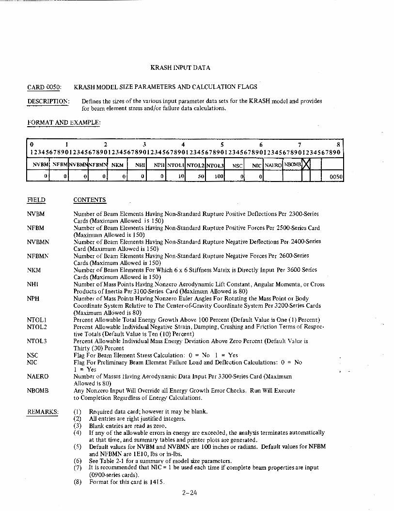
KRASH INPUT DATA
CARD 0050: KRASH MODEL SIZE PARAMETERS AND CALCULATION FLAGS
DESCRIPTION: Defmes the sizes of the various input parameter data sets for the KRASH model and provides for beam element stress and/or failure data calculations.
FORMAT AND EXAMPLE:
0 1 2 3 4 5 6 7 8 123456789012345678901234567890i2345678901234567890123456789012345678901234567890
NVBM
0
FIELD
NVBM
NFBM
NVBMN
NFBMN
NKM
NHJ
NPH
NTOLl NTOL2
NTOL3
NSC NIC
NAERO
NBOMB
NFBM
0
REMARKS:
NVBMI' NFBMN NKM NHI NPH NTOLl NTOL2 NTOL3 NSC NIC NAERO NBOMB ~ 0 0 0 0 0 10 50 100 0 0
CONTENTS
Number of Beam Elements Having Non-Standard Rupture Positive Deflections Per 2300-Series Cards (Maximum Allowed is 150) Number of Beam Elements Having Non .Standard Rupture Positive Forces Per 2500-Series Card (Maximum Allowed is 150) Number of Beam Elements Having Non-Standard Rupture Negative Deflections Per 2400-Series Card (Maximum Allowed is 150) Number of Beam Elements Having Non-Standard Rupture Negative Forces Per 2600-Series Cards (Maximum Allowed is 150) Number of Beam Elements For Which 6 x 6 Stiffness Matrix is Directly Input Per 3600 Series Cards (Maximum Allowed is 150) Number of Mass Points Having Nonzero Aerodynamic Lift Constant, Angular Momenta, or Cross Products of Inertia Per 31 00-Series Card (Maximum Allowed is 80) Number of Mass Points Having Nonzero Euler Angles For Rotating the Mass Point or Body Coordinate System Relative to The Center-of-Gravity Coordinate System Per 3200-Series Cards (Maximum Allowed is 80) Percent Allowable Total Energy Growth Above 100 Percent (Default Value is One (1) Percent) Percent Allowable Individual Negative Strain, Damping, Crushing and Friction Terms of Respective Totals (Default Value is Ten (IO) Percent) Percent Allowable Individual Mass Energy Deviation Above Zero Percent (Default Value is Thirty (30) Percent Flag For Beam Element Stress Calculation: 0 = No 1 = Yes Flag For Preliminary Beam Element Failure Load and Deflection Calculations: 0 = No 1 = Yes Number of Masses Having Aerodynamic Data Input Per 3300-Series Card (Maximum Allowed is 80) Any Nonzero Input Will Override all Energy Growth Error Checks. Run Will Execute to Completion Regardless of Energy Calculations.
(1) Required data card; however it may be blank. (2) All entries are right justified integers. (3) Blank entries are read as zero. ( 4) If any of the allowable errors in energy are exceeded, the analysis terminates automatically
at that time, and summary tables and printer plots are generated. (5) Default values for NVBM and NVBMN are 100 inches or radians. Default values for NFBM
and NFBMN are 1El0, lbs or in-lbs. ( 6) See Table 2-1 for a summary of model size parameters. (7) It is recommended that NIC = 1 be used each time if complete beam properties are input
(0900-series cards). (8) Format for this card is 141 5.
2-24
0050
KRASH INPUT DATA
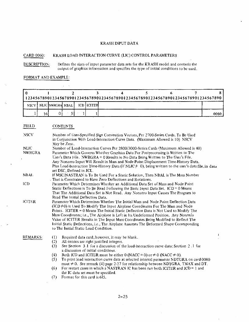
CARD 0060: KRASH LOAD INTERACTION CURVE (LIC) CONTROL PARAMETERS
DESCRIPTION: Defines the sizes of input parameter data sets for the KRASH model and controls the output of graphics information and specifies the type of initial conditions to be used.
FORMAT AND EXAMPLE:
0 1 2 3 4 5 6 7 8 12345678901234567890123456789012345678901234567890123456789012345678901234567890
NSCV NLIC
I
FIELD
NSCV
NLIC NWRGRA
NBAL
lCD
ICITER
REMARKS:
16
NWRGRA NBAL lCD ICITER
0 5 1 1
CONTENTS
Number of User-Specified Sign Convention Vectors, Per 2700-Series Cards, To Be Used in Conjunction With Load-Interaction Curve Data. (Maximum Allowed is I 0) NSCV May be Zero. Number of Load-Interaction Curves Per 2800/3000-Series Cards (Maximum Allowed is 40) Parameter Which Governs Whether Graphics Data For Postprocessing is Written to The User's Data File. NWRGRA = 0 Results in No Data Being Written to The User's File. Any Nonzero Input Will Result in Mass and Node Point Displacement Time-History Data,
0060
Plus Load-Interaction Time-History Data (if NLIC t= 0), being written to the user's data file, in data set DSC, Defined in JCL. If MSC/NASTRAN is To Be Used For a Static Solution, Then NBAL is The Mass Number
. That is Constrained to Have Zero Deflections and Rotations. Parameter Which Determines Whether an Additional Data Set of Mass and Node Point Static Deflections is To Be Read Following the Basic Input Data Set. lCD = 0 Means That The Additional Data Set is Not Read. Any Nonzero Input Causes The Program to Read The Initial Deflection Data. Parameter Which Determines Whether The Initial Mass and Node Point Deflection Data (lCD f=O) is Used To Modify The Input Airplane Coordinates For The Mass and Node Points. ICITER = 0 Means The Initial Static Deflection Data is Not Used to Modify The Mass Coordinates; i.e., The Airplane is Left in Its Undeformed Position. Any Nonzero Value of ICITER Results in The Input Mass Coordinates Being Modified to Reflect The Initial Static Deflections, i.e., The Airplane Assumes The Deformed Shape Corresponding to The Initial Static Load Condition.
(1) Required data card; however, it may be blank. (2) All entries are right justified integers. (3) See Section 3 .I for a discussion of the load-interaction curve data; Section 2 .1 for
a discussion of initial conditions. (4) Both lCD and ICITER must be either 0 (NACC = 0) or-:/= 0 (NACC-:/= 0). (5) To print load interaction curve data at selected interval parameter NDTGRA on card 0080
must-:/= 0. See remark (4) page 2-27 for relationship between NDTGRA, TMAX and DT. (6) For restart cases in which a NASTRAN IC has been run both ICITER and lCD = 1 and
the IC data set must be specified. (7) Format for this card is 615.
2-25
KRASH INPUT DATA
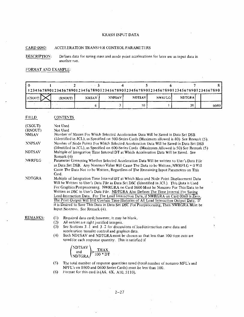
CARD 0080: ACCELERATION TRANSFER CONTROL PARAMETERS
DESCRIPTION: Defines data for saving mass and mode point accelerations for later use as input data in another run.
FORMAT AND EXAMPLE:
0 I 2 3 4 5 6 7 8 123456789QI234567890123456789012345678901234567890123456789012345678901234567890
(Csour~IX
FIELD
(CSOUT) (RNOUT) NMSAV
NNPSAV
NDTSAV
NWRFLG
NDTGRA
REMARKS:
-(RNOUT) NMSAV NNPSAV NDTSAV NWRFLG NDTGRA
CONTENTS
Not Used Not Used
6 3 10 1 20
Number of Masses For Which Selected Acceleration Data Will be Saved in Data Set DSB (Identified i~ JCL), as Specified on 500-Series Cards (Maximum allowed is 80) See Remark (5). Number of Node Points For Which Selected Acceleration Data Will be Saved in Data Set DSB (Identified in JCL), as Specified on 600-Series Cards (Maximum Allowed is 50) See Remark (5) Multiple of Integration Time Interval DT at Which Acceleration Data Will be Saved. See Remark(4) · Parameter Governing Whether Selected Acceleration Data Will be written to User's Data File as Data Set DSB. Any Nonzero Value Will Cause The Data to be Written; NWRFLG = 0 Will Cause The Data Not to be Written, Regardless of The Remaining Input Parameters on This Card. Multiple of Integration Time Interval DT at Which Mass and Node Point Displacement Data Will be Written to User's Data File as Data Set DSC {Identified in JCL). This Data is Used For Graphics Postprocessing. NWRGRA on Card 0600 Must be Nonzero For This Data to be Written as DSC in User's Data File. NDTGRA Also Defines The Time Interval For Saving Load-Interaction Data. For The Load Interaction Data, ifNWRGRA on Card 0060 is Zero, The Print Output Will Still Contain Time-Histories of All Load Interaction Output Data. If it is Desired to Save This Data in Data Set DSC For Postprocessing, Then NWRGRA Must be Input Nonzero. See Remark (4).
(1) Required data card; however, it may be blank. (2) All entries are right justified integers. (3) See Sections 3 .1 and 3. 2 for discussions of load-interaction curve data and
acceleration transfer control and graphics data. (4) Both NDTSAV and NDTGRAmust be chosen so that less than 100 time cuts are
saved for each response quantity. This is satisfied if
(NDTSAV) TMAX
and >100 * DT NDTGRA
{5) The total number of response quantities saved (total number of nonzero MFL's and NPFL's on 0500 and 0600 Series Cards) must be less than 100.
(6) Format for this card is (A6, 4X, AIO, 5110).
2-27
0080
-··--------------------·---·
KRASH INPUT DATA
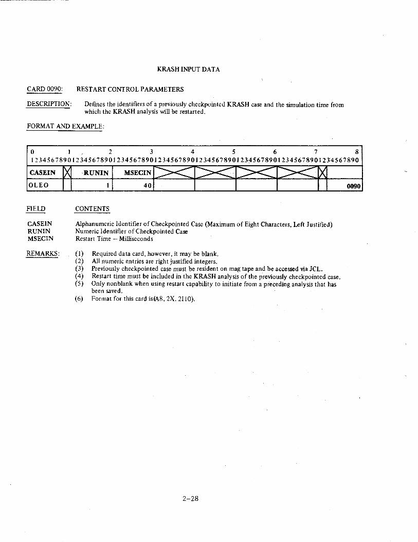
CARD 0090: RESTART CONTROL PARAMETERS
DESCRIPTION: Defines the identifiers of a previously checkpointed KRASH case and the simulation time from which the KRASH analysis will be restarted.
FORMAT AND EXAMPLE:
0 I 2 3 4 5 6 7 8 12345678901234567890123456789012345678901234567890123456789012345678901234567890
CASEIN
OLEO
FIELD
CASEIN RUNIN MSECIN
REMARKS:
IRUNIN MSECIN
1 40
CONTENTS
Alphanumeric Identifier of Checkpointed Case (Maximum of Eight Characters, Left Justified) Numeric Identifier ofCheckpointed Case Restart Time - Milliseconds
(I) Required data card, however, it may be blank. (2) All numeric entries are right justified integers. (3) Previously checkpointed case must be resident on mag tape and be accessed via JCL. ( 4) Restart time must be included in the KRASH analysis of the previously checkpointed case. ( 5) Only non blank when using restart capability to initiate from a preceding analysis that has
been saved. (6) Format for tllis card is(A8, 2X, 2110).
2-28
0090
KRASH INPUT DATA
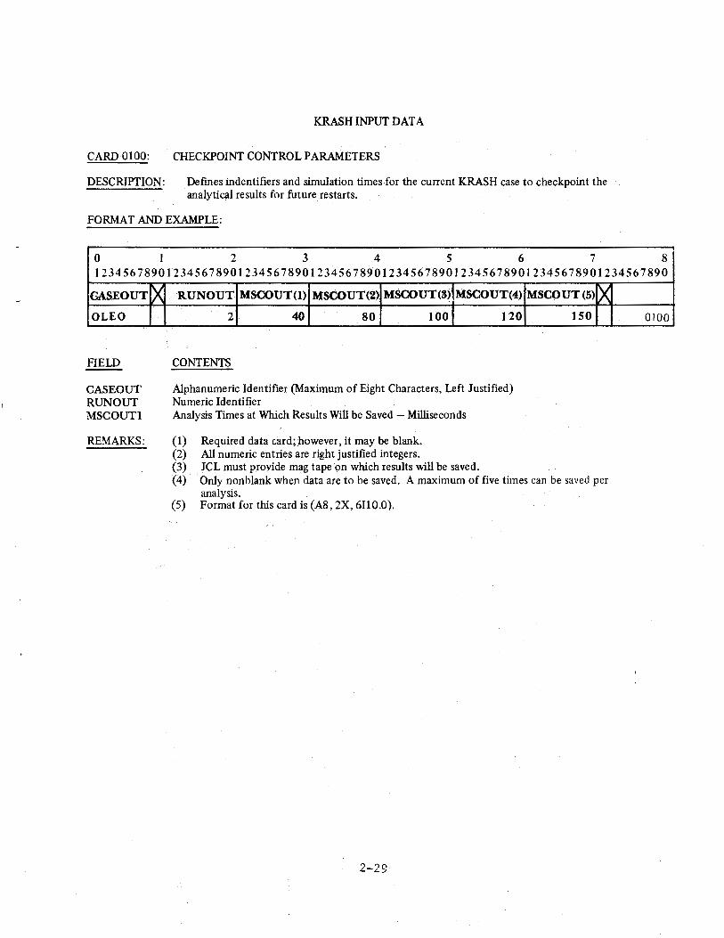
CARD 0100: CHECKPOINT CONTROL PARAMETERS
DESCRIPTION: Defmes indentifiers and simulation times for the current KRASH case to checkpoint the analytical results forfuture restarts.
FORMAT AND EXAMPLE:
0 l 2 3 4 5 6 7 8 12345678901234567890123456789012345678901234567890123456789012345678901234567890
GASEOUT
OLEO
FIELD
CASEOUT RUN OUT MSCOUTI
REMARKS:
X RUN OUT MSCOUT(l) MSCOUT(2) MSCOUT(8) MSCOUT(4)
2 40 80 100 120
CONTENTS
Alphanumeric Identifier (Maximum of Eight Characters, Left Justified) Numeric Identifier Analysis Times at Which Results Will be Saved - Milliseconds
( 1) Required data card; however, it may be blank. (2) All numeric entries are right justified integers. (3) JCL must provide mag tape on which results will be saved.
MSCOUT(5) ~ 150
( 4) Only non blank when data are to be saved. A maximum of five times can be saved per analysis.
(5) Format for this card is (A8, 2X, 6110.0).
2-29
0100
KRASH INPUT DATA
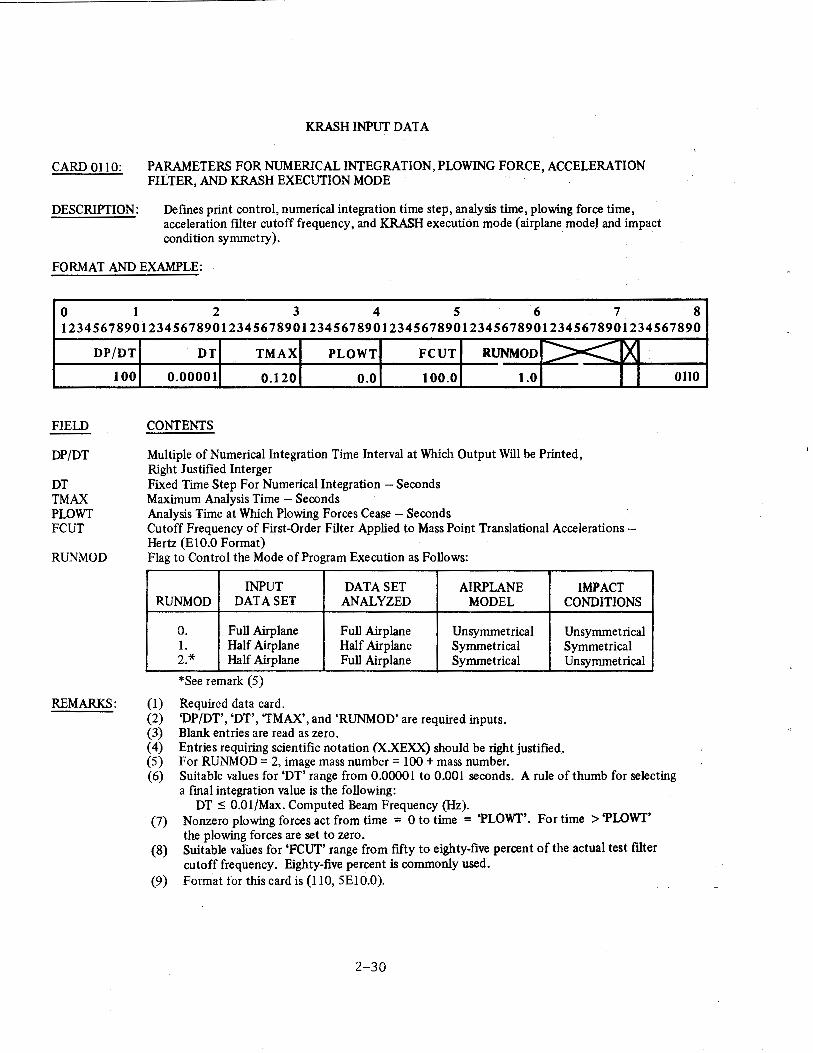
CARD 0110: PARAMETERS FOR NUMERICAL INTEGRATION, PLOWING FORCE, ACCELERATION FILTER, AND KRASH EXECUTION MODE
DESCRIPTION: Defines print control, numerical integration time step, analysis time, plowing force time, acceleration fllter cutoff frequency, and KRASH execution mode (airplane model and impact condition symmetry).
FORMAT AND EXAMPLE:
0 I 2 3 4 5 6 7 8 12345678901234567890123456789012345678901234567890123456789012345678901234567890
FIELD
DP/DT
DT TMAX PLOWT FCUT
DP/DT
100
RUNMOD
REMARKS:
DT TMAX PLOWT FCUT RUNMOD >< ~ 0.00001 0.120 0.0 100.0 1.0
CONTENTS
Multiple of Numerical Integration Time Interval at Which Output Will be Printed, Right Justified Interger Fixed Time Step For Numerical Integration - Seconds Maximum Analysis Time - Seconds Analysis Time at Which Plowing Forces Cease - Seconds Cutoff Frequency of First-Order Filter Applied to Mass Point Translational Accelerations -Hertz (ElO.O Format) Flag to Control the Mode of Program Execution as Follows:
INPUT RUNMOD DATASET
0. Full Airplane 1. Half Airplane 2.* Half Airplane
*See remark (5)
Required data card.
DATASET AIRPLANE ANALYZED MODEL
Full Airplane Unsymmetrical Half Airplane Symmetrical Full Airplane Symmetrical
'DP/DT', 'DT', 'TMAX', and 'RUNMOD' are required inputs. Blank entries are read as zero. Entries requiring scientific notation (X.XEXX) should be right justified. For RUNMOD = 2, image mass number= 100 +mass number.
IMPACT CONDITIONS
Unsymmetrical Symmetrical Unsymmetrical
0110
(1) (2) (3) (4) (5) (6) Suitable values for 'DT' range from 0.00001 to 0.001 seconds. A rule of thumb for selecting
a fmal integration value is the following:
(7)
(8)
(9)
DT ;5; 0.01/Max. Computed Beam Frequency (Hz). Nonzero plowing forces act from time = 0 to time = 'PLOWT'. For time > 'PLOWT' the plowing forces are set to zero. Suitable values for 'FCUT' range from fifty to eighty-five percent of the actual test filter cutoff frequency. Eighty-five percent is commonly used. Format for this card is (110, 5El0.0).
2-30
KRASH INPUT DATA
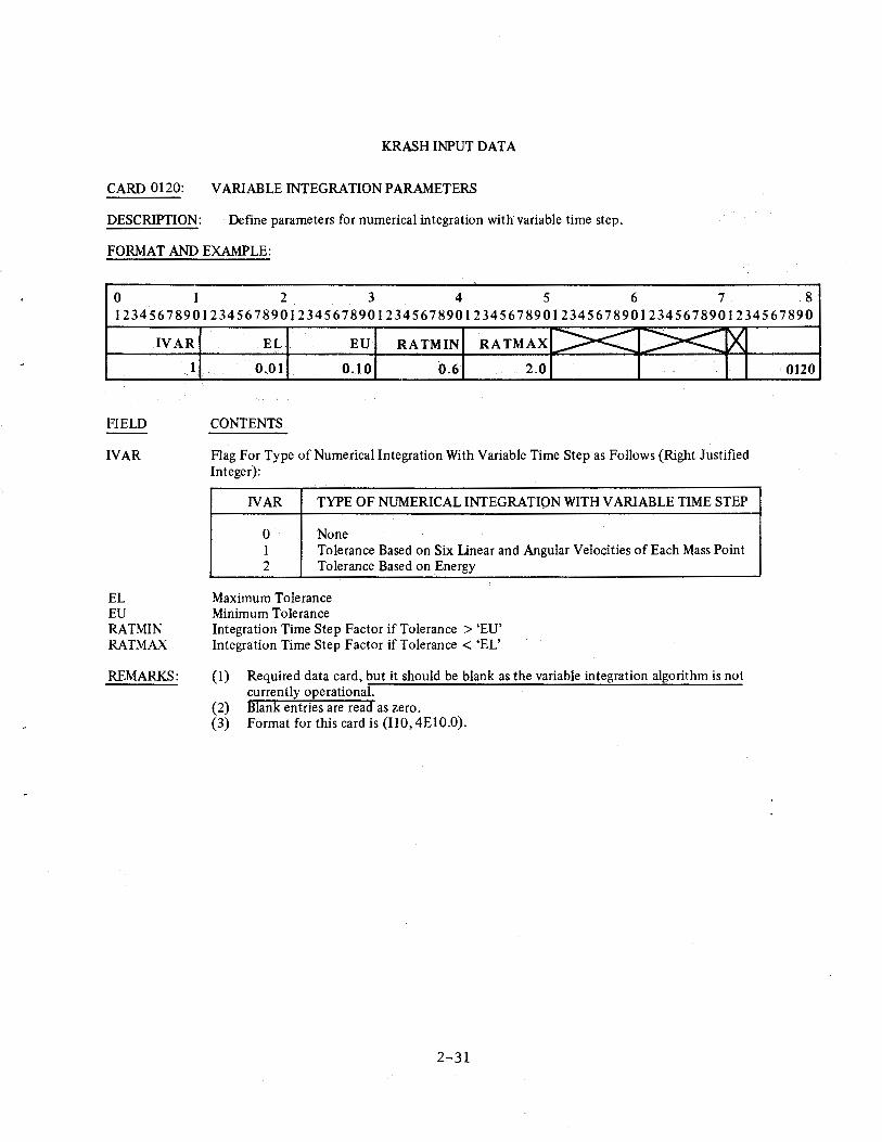
CARD 0120: VARIABLE INTEGRATION PARAMETERS
DESCRIPTION: Define parameters for numerical integration with variable time step.
FORMAT AND EXAMPLE:
-0 1 2 3 4 5 6 7 8 12345678901234567890123456789012345678901234567890123456789012345678901234567890
IVAR
FIELD
IVAR
EL EU RATMIN RATMAX
REMARKS:
1
EL EU RATMIN RATMAX >< >< X 0.01 0.10 0.6 2.0
CONTENTS
Flag For Type of Numerical Integration With Variable Time Step as Follows (Right Justified Integer):
NAR TYPE OF NUMERICAL INTEGRATION WITH VARIABLE TIME STEP
0 None 1 Tolerance Based on Six Unear and Angular Velocities of Each Mass Point 2 Tolerance Based on Energy
Maximum Tolerance Minimum Tolerance Integration Time Step Factor if Tolerance > 'EU' Integration Time Step Factor if Tolerance < 'EL'
(1) Required data card, but it should be blank as the variable integration algorithm is not currently operational.
(2) Blank entries are read as zero. (3) Format for this card is (110, 4El 0.0).
2-31
I 0120
_____ , _____ _
KRASH INPUT DATA
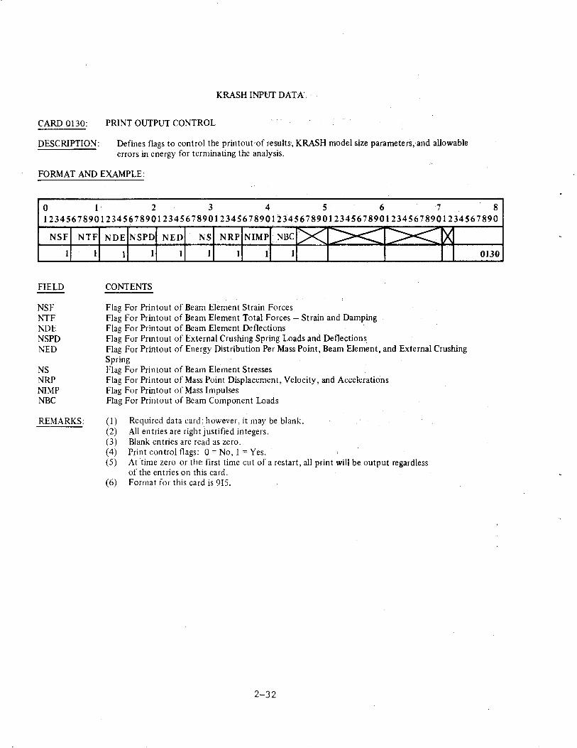
CARD 0130: PRINT OUTPUT CONTROL
DESCRIPTION: Defines flags to control the printout of results, KRASH model size parameters, and allowable errors in energy for terminating the analysis.
FORMAT AND EXAMPLE:
0 1 2 3 4 5 6 7 8 12345678901234567890123456789012345678901234567890123456789012345678901234567890
NSF
FIELD
NSF NTF NDE NSPD r-.;ED
NS NRP NIMP NBC
1
NTF
1
REMARKS:
NDE NSPD NED NS NRP NIMP NBC [>< >< 1 I 1 I 1 1 I
CONTENTS
Flag For Printout of Beam Element Strain Forces Flag For Printout of Beam Element Total Forces -Strain and Damping Flag For Printout of Beam Element Deflections Flag For Printout of External Crushing Spring Loads and Deflection~
>< X
Flag For Printout of Energy Distribution Per Mass Point, Beam Element, and External Crushing Spring Flag For Printout of Beam Element Stresses Flag For Printout of Mass Point Displacement, Velocity, and Accelerations Flag For Printout of Mass Impulses Flag For Printout of Beam Component Loads
(I) Required data card: however, it may be blank. (2) All entries are right justified integers. (3) Blank entries are read as zero. (4) Print control flags: 0 =No, 1 =Yes. (5) At time zero or the: first time cut of a restart, all print will be output regardless
of the entries on this card. (6) Format for this card is 915.
2-32
0130
KRASH INPUT DATA
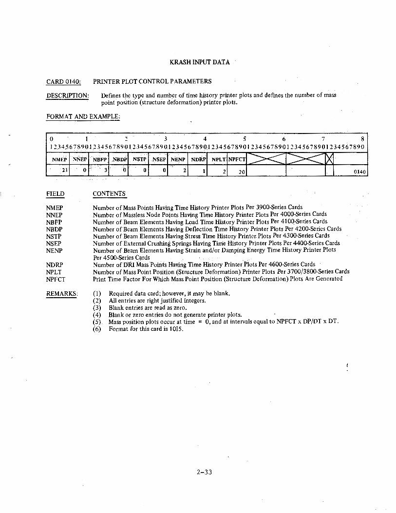
CARD 0140: PRINTER PLOT CONTROL PARAMETERS
DESCRIPTION: Defines the type and number of time history printer plots and defines the number of mass point position (structure deformation) printer plots.
FORMAT AND EXAMPLE:
0 l .,.
3 4 5 6 7 8 l 2 34,56 7 8901234 567 890 l,2 34567.89012.3456 7 890 l 234 56 7 89.0 l 2345 6 7 890 l 234 56 7 890 l 23456 7 890
NMEP
21
FIELD
NMEP NNEP NBFP NBDP NSTP NSEP NENP
NDRP NPLT NPFCT
NNEP
0 ..
REMARKS:
NBFP NBDP NSTP NSEP NENP NDRP NPLT NPFCT :><: >< ~ 3' 0 0 0 2 1 2 20
CONTENTS
Number of Mass Points Having Time History Printer Plots Per 3900-Series Cards Number of Massless Node Points Having Time History Printer Plots Per 4000-Series Cards Number of Beam Elements Having Load Time History Printer Plots Per 410Q-Series Cards Number of Beam Elements Having Deflection Time History Printer Plots Per 4200-Series Cards Number of Beam Elements Having Stress Time History Printer Plots Per 4300-8eries Cards Number of External Crushing Springs Having Tirrie History Printer Plots Per 4400-Series Cards Number of Beam Elements Having Strain and/or Damping Energy Time History Printer Plots Per 4500-Series Cards Number of DRI Mass 'Points Having Time History Printer Plots Per 4600-Series Cards Number of Mass Point Position (Structure Deformation) Printer Plots Per 3700/3800-Series Cards Print Time Factor For Which Mass Point Position (Structure Deformation) Plots Are Generated
(I) Required data card; however, it may be blank. (2) All entries are right justified integers. (3) Blank entries are read as zero. ( 4) Blank or zero entries do not generate printer plots. (5) Mass position plots occur at time = 0, and at intervals equal to NPFCT x DP/DT x DT. (6) Format for this card is 1015.
2-33
0140
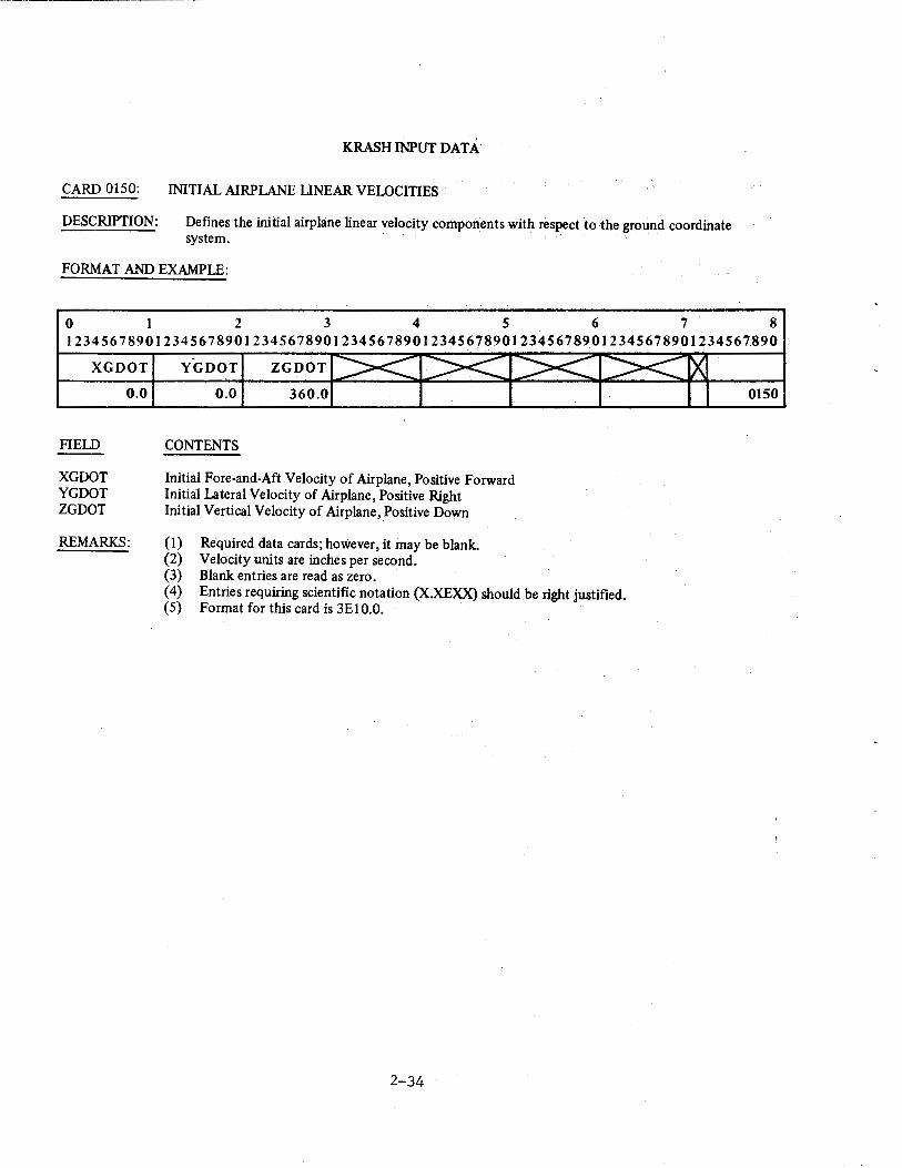
KRASH INPUT DAtA
CARD 0150: INITIAL AIRPLANE UNBAR VELOCITIES
DESCRIPTION: Defmes the initial airplane linear velocity components with respect to the ground coordinate system.
FORMAT AND EXAMPLE:
0 1 2 3 4 5 6 7 8 12345678901234567890123456789012345678901234567890123456789012345678901234.567890
XGDOT YGDOT ZGDOT
FIELD
XGDOT YGDOT ZGDOT
0.0
REMARKS:
0.0 360.0
CONTENTS
Initial Fore-and-Aft Velocity of Airplane, Positive Forward Initial Lateral Velocity of Airplane, Positive Right Initial Vertical Velocity of Airplane, Positive Down
(1) Required data cards; however, it may be blank. (2) Velocity units are inches per second. (3) Blank entries are read as zero. ( 4) Entries requiring scientific notation (X.XEXX) should be right justified. (5) Format for this card is 3E10.0.
2-34
0150
KRASH INPUT DATA
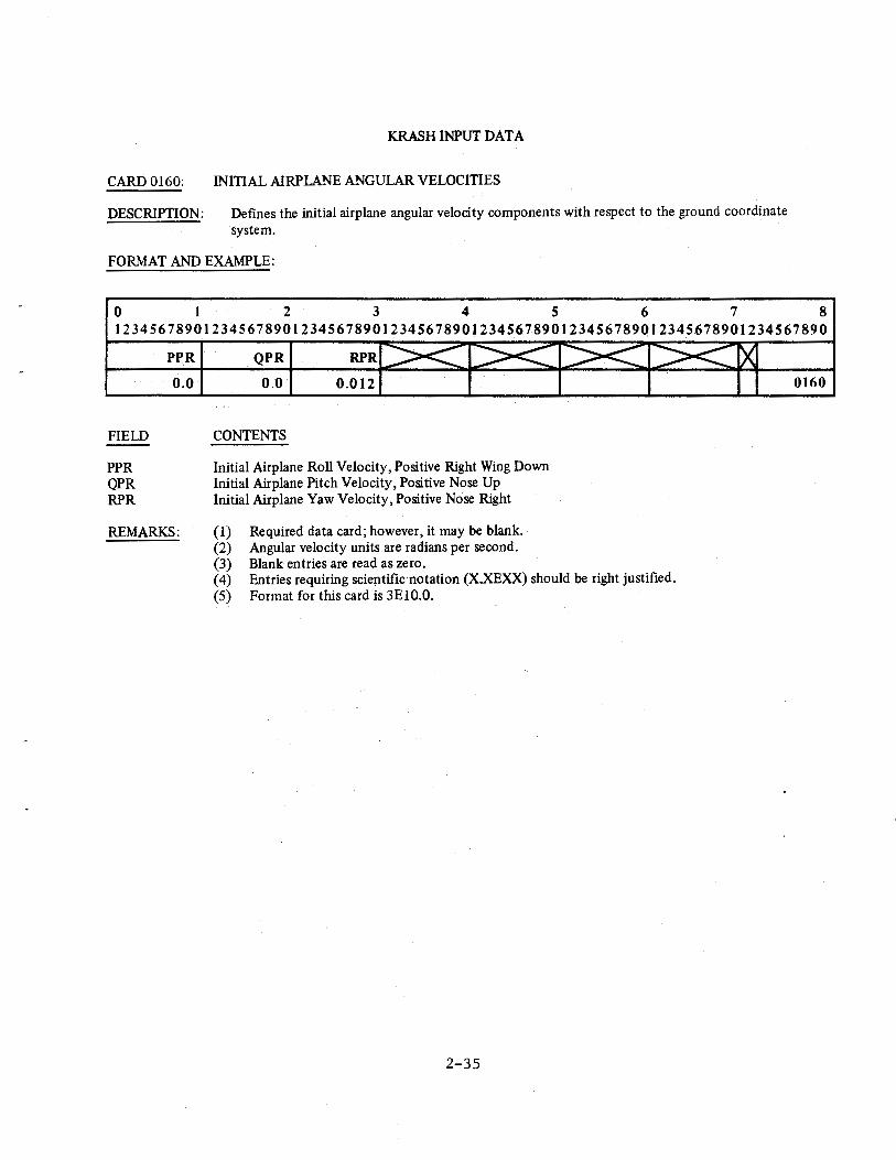
CARD 0160: INITIAL AIRPLANE ANGULAR VELOCITIES
DESCRIPTION: Defines the initial airplane angular velocity components with respect to the ground coordinate system.
FORMAT AND EXAMPLE:
0 1 2 3 4 5 6 7 8 12345678901234567890123456789012345678901234567890123456789012345678901234567890
FIELD
PPR QPR RPR
PPR
0.0
REMARKS:
QPR
0.0 0.012
CONTENTS
Initial Airplane Roll Velocity, Positive Right Wing Down Initial Airplane Pitch Velocity, Positive Nose Up Initial Airplane Yaw Velocity, Positive Nose Right
(I) Required data card; however, it may be blank. (2) Angular velocity units are radians per second. (3) Blank entries are read as zero. ( 4) Entries requiring scientific notation (X.XE:XX) should be right justified. (5) Format for this card is 3El0.0.
2-35
0160
KRASH INPUT DATA
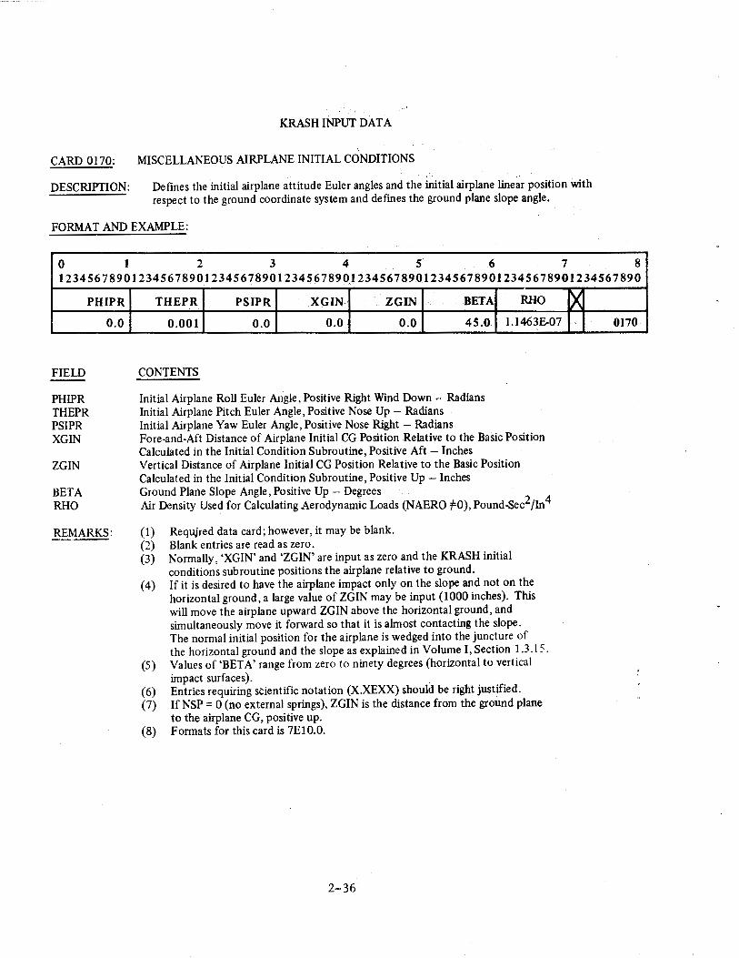
CARD 0170: MISCELLANEOUS AIRPLANE INITIAL CONDITIONS
DESCRIPTION: Defines the initial airplane attitude Euler angles and the initial airplane linear position with respect to the ground coordinate system and defines the ground plane slope angle.
FORMAT AND EXAMPLE:
0 1 2 3 4 5 6 7 8 12345678901234567890123456789012345678901234567890123456789012345678901234567890
PHIPR
FIELD
PHIPR THEPR PSIPR XGIN
ZGIN
BETA RHO
0.0
REMARKS:
THEPR PSIPR .XGIN ZGIN BETA RHO
0.001 0.0 0.0 0.0 45.0 1.1463E-07
CONTENTS
Initial Airplane Roll Euler Angle, Positive Right Wind Down - Radians Initial Airplane Pitch Euler Angle, Positive Nose Up- Radians · Initial Airplane Yaw Euler Angle, Positive Nose Right- Radians Fore-and-Aft Distance of Airplane Initial CG Position Relative to the Basic Position Calculated in the Initial Condition Subroutine, Positive Aft -Inches Vertical Distance of Airplane Initial CG Position Relative to the Basic Position Calculated in the Initial Condition Subroutine, Positive Up- Inches Ground Plane Slope Angle, Positive Up - Degrees Air Density Used for Calculating Aerodynamic Loads (NAERO :f=O), Pound-Sec2/In4
(I) Requjred data card; however, it may be blank. (2) Blank entries are read as zero. (3) Normally, 'XGIN' and 'ZGIN' are input as zero and the KRASH initial
conditions subroutine positions the airplane relative to ground. ( 4) If it is desired to have the airplane impact only on the slope and not on the
horizontal ground, a large value of ZGIN may be input (1000 inches). This will move the airplane upward ZGIN above the horizontal ground, and simultaneously move it forward so that it is almost contacting the slope. The normal initial position for the airplane is wedged into the juncture of the horizontal ground and the slope as explained in Volume I, Section 1.3 .15.
(5) Values of 'BET A' range from zero to ninety degrees (horizontal to vertical impact surfaces).
(6) Entries requiring scientific notation (X.XEXX) should be right justified. (7) If NSP = 0 (no external springs), ZGIN is the distance from the ground plane
to the airplane CG, positive up. (8) Formats for this card is 7EIO.O.
2-36
~ 0170
KRASH INPUT DATA
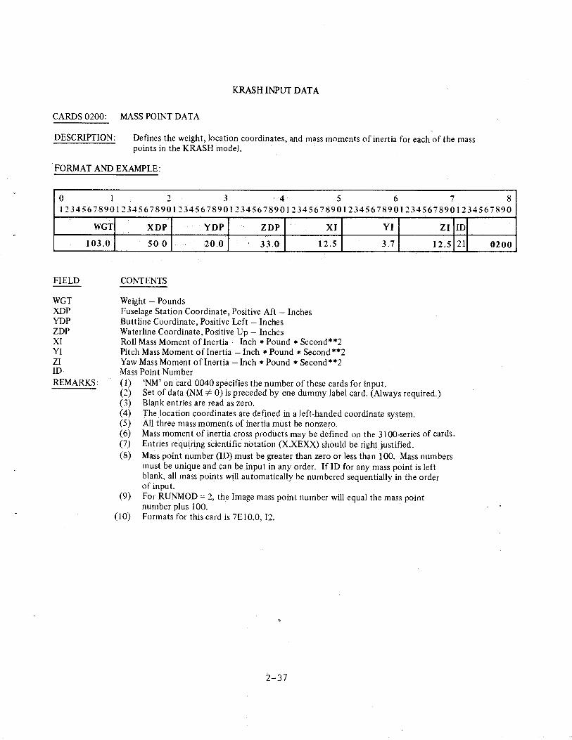
CARDS 0200: MASS POINT DATA
DESCRIPTION: Defines the weight, location coordinates, and mass moments of inertia for each of the mass points in the KRASH model.
FORMAT AND EXAMPLE:
0 I 2 3 4 5 6 7 8 12345678901234567890123456789012345678901234567890123456789012345678901234567890
WGT
103.0
FIELD
WGT XDP YDP ZDP XI YI ZI ID REMARKS:
XDP YDP ZDP
50 0 20.0 33.0
CONTENTS
Weight - Pounds Fuselage Station Coordinate, Positive Aft -Inches Buttline Coordinate, Positive Left- Inches Waterline Coordinate, Positive Up- Inches
XI
12.5
Roll Mass Moment oflnertia- Inch *Pound * Second**2 Pitch Mass Moment of Inertia -Inch *Pound *Second **2 Yaw Mass Moment of Inertia- Inch *Pound *Second **2 Mass Point Number
YI
3.7
( 1) 'NM' oil card 0040 specifies the number of these cards for input.
ZI
12.5
(2) Set of data (NM =I= 0) is preceded by one dummy label card. (Always required.) (3) Blank entries are read as zero. ( 4) The location coordinates are defined in a left-handed coordinate system. (5) All three mass moments of inertia must be nonzero. ( 6) Mass moment of inertia cross products may be defined on the 31 00-series of cards. (7) Entries requiring scientific notation (X.XEXX) should be right justified. (8) Mass point number (ID) must be greater than zero or less than 100. Mass numbers
must be unique and can be input in any order. If ID for any mass point is left blank, ali mass points will automatically be numbered sequentially in the order of input.
(9) For RUNMOD = 2, the Image mass point number will equal the mass point number pius 100.
(10) Formats for this card is 7El0.0, 12.
2-37
ID
21 0200
KRASH INPUT DATA
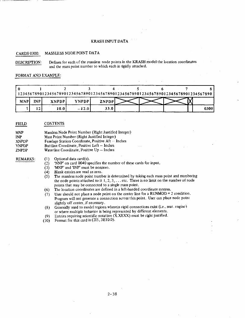
CARDS 0300: MASSLESS NODE POINT DATA
DESCRIPTION: Defmes for each of the massless node points in the KRASH model the location coordinates and the mass point number to which each is rigidly attached.
FORMAT AND EXAMPLE:
0 1 2 3 4 5 6 7 8 12345678901234567890123456789012345678901234567890123456789012345678901234567890
MNP
1
FIELD
MNP INP XNPDP YNPDP ZNPDP
INP
12
REMARKS:
XNPDP YNPDP ZNPDP >< 10.0 -12.0 33.0
CONTENTS
Massless Node Point Number (Right Justified Integer) Mass Point Number (Right Justified Integer) Fuselage Station Coordinate, Positive Aft - Inches Buttline Coordinate, Positive Left- Inches Waterline Coordinate, Positive Up- Inches
(1) Optional data card(s).
><
(2) 'NNP' on card 0040 specifies the number of these cards for input. (3) 'MNP' and 'INP' must be nonzero. ( 4) Blank entries are read as zero.
><.::: ~
(5) The massless node point number is determined by taking each mass point and numbering the node points attached to it 1, 2, 3, ... etc. There is no limit on the number of node points that may be connected to a single mass point.
(6) The location coordinates are defined in a left-handed coordinate system. (7) User should not place a node point on the center line for a RUNMOD = 2 condition.
Program will not generate a connection across this point. User can place node point slightly off center, if necessary.
(8) Generally used to model regions wherein rigid connections exist (i.e., seat. engine) or where multiple behavior is being represented by different elements.
(9) Entries requiring scientific notation (X.XEXX) must be right justified. (10) Format for this card is (215, 3E10.0).
2-38
0300
KRASH INPUT DATA
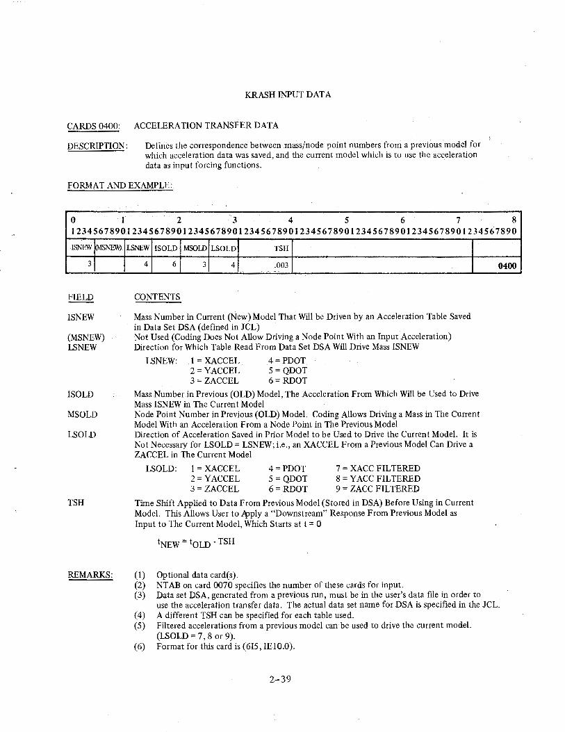
CARDS 0400: ACCELERATION TRANSFER DATA
DESCRIPTION: Defines the correspondence between mass/node point numbers from a previous model for which acceleration data was saved, and the current model which is to use the acceleration data as input forcing functions.
FORMAT AND EXAMPLE:
0 I 2 3 4 5 6 7 8 12345678901234567890123456789012345678901234567890123456789012345678901234567890
ISNEW MS.NE\\?.
3
FIELD
IS NEW
(MSNEW) LSNEW
ISOLD
MSOLD
LSOLD
TSH
REMARKS:
LSNEW !SOLD MSOlD LSOLD TSH
4 6 3 4 .003
CONTENTS
Mass Number in Current (New) Model That Will be Driven by an Acceleration Table Saved in Data Set DSA (defined in JCL) Not Used (Coding Does Not Allow Driving a Node Point With an Input Acceleration) Direction for Which Table Read From Data Set DSA Will Drive Mass ISNEW
LSNEW: 1 = XACCEL 2= YACCEL 3 = ZACCEL
4=PDOT 5 = QDOT 6= RDOT
Mass Number in Previous (OLD) Model, The Acceleration From Which Will be Used to Drive Mass ISNEW in The Current Model Node Point Number in Previous (OLD) Model. Coding Allows Driving a Mass in The Current Model With an Acceleration From a Node Point in The Previous Model Direction of Acceleration Saved in Prior Model to be Used to Drive the Current Model. It is Not Necessary for LSOLD = LSNEW; i.e., an XACCEL From a Previous Model Can Drive a ZACCEL in The Current Model
LSOLD: 1 = XACCEL 2= YACCEL 3 = ZACCEL
4=PDOT 5= QDOT 6= RDOT
7 = XACC FILTERED 8 = Y ACC FILTERED 9 = ZACC FILTERED
Time Shift Applied to Data From Previous Model (Stored in DSA) Before Using in Current Model. This Allows User to ~ply a "Downstream" Response From Previous Model as Input to The Current Model, Which Starts at t = 0
tNEW =toLD- TSH
(1) Optional data card(s ). (2) NT AB on card 0070 specifies the number of these cards for input. (3) Data set DSA, generated from a previous run, must be in the user's data file in order to
0400
use the acceleration transfer data. The actual data set name for DSA is specified in the JCL. ( 4) A different ISH can be specified for each table used. (5) Filtered accelerations from a previous model can be used to drive the current model.
(LSOLD = 7, 8 or 9). (6) Format for this card is (6I5, IE10.0).
2-39
KRASH INPUT DATA
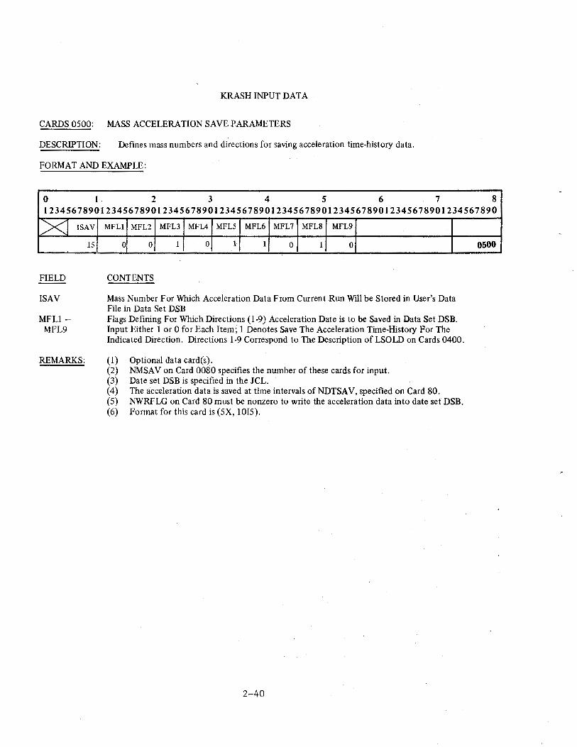
CARDS 0500: MASS ACCELERATION SAVE PARAMETERS
DESCRIPTION: Defines mass numbers and directions for saving acceleration time-history data.
FORMAT AND EXAMPLE:
0 I 2 3 4 5 6 7 8 12345678901234567890123456789012345678901234567890123456789012345678901234567890
X]
FIELD
ISAV
MFL1-MFL9
ISAV
15
REMARKS:
MFLl MFL2 MFL3 MFL4 MFL5 MFL6 MFL7 MFL8 MFL9
0 0 1 0 1 1 0 1 0
CONTENTS
Mass Number For Which Acceleration Data From Current Run Will be Stored in User's Data File in Data Set DSB Flags Defining For Which Directions (1-9) Acceleration Date is to be Saved in Data Set DSB. Input Either 1 or 0 for Each Item; 1 Denotes Save The Acceleration Time-History For The Indicated Direction. Directions 1-9 Correspond to The Description of LSOLD on Cards 0400.
(1) Optional data card(s). (2) NMSA Von Card 0080 specifies the number of these cards for input. (3) Date set DSB is specified in the JCL. ( 4) The acceleration data is saved at time intervals of NDTSA V, specified on Card 80. (5) NWRFLG on Card 80 must be nonzero to write the acceleration data into date set DSB. (6) Format for this card is (SX, lOIS).
2-40
0500
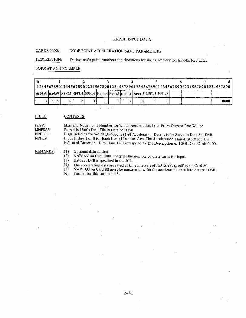
KRASH INPUT DATA
CARDS 0600: NODE POINT ACCELERATION SAVE PARAMETERS
DESCRIPTION: Defines node point numbers and directions for saving acceleration time-history data.
FORMAT AND EXAMPLE:
0 I 2 3 4 5 6 7 8 12345678901234567890123456789012345678901234567890123456789012345678901234567890
:MNPSAV INPSAV
3
FIELD
ISAV, MNPSAV NPFL1-NPFL9
REMARKS:
15
NPFLl NPFL2 NP.FL'3 NPFL4 NP.FLS NPFL6 NPFL7 NPFL8 NPFL9
0 0 1 0 1 1 0 1 0
CONTENTS
Mass and Node Point Number for Which Acceleration Data From Current Run Will be Stored in User's Data File in Data Set DSB Flags Defining for Which Directions (1-9) Acceleration Date is to be Saved in Data Set DSB. Input Either 1 or 0 for Each Item; 1 Denotes Save The Acceleration Time-History for The Indicated Direction. Directions 1-9 Correspond to The Description ofLSOLD on Cards 0400.
(1) Optional data card(s). (2) NNPSA V on Card 0080 specifies the number of these cards for input. (3) Date set DSB is specified in the JCL. ( 4) The acceleration data are saved at time intervals of NDTSA V, specified on Card 80. (5) NWRFLG on Card 80 must be nonzero to write the acceleration data into date set DSB. (6) Format for this card is 1115.
2-41
0600
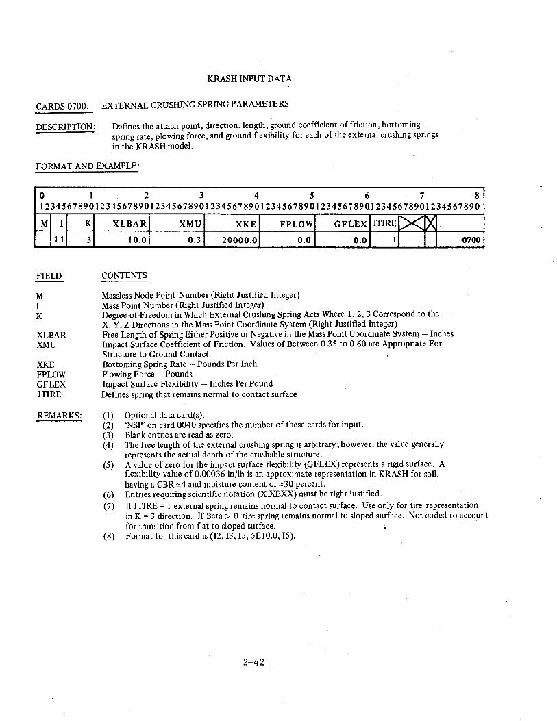
KRASH INPUT DATA
CARDS 0700: EXTERNAL CRUSHING SPRING PARAMETERS
DESCRIPTION: Defines the attach point, direction, length, ground coefficient of friction, bottoming spring rate, plowing force, and ground flexibility for each of the external crushing springs in the KRASH model.
FORMAT AND EXAMPLE:
0 1 2 3 4 5 6 7 8 12345678901234567890123456789012345678901234567890123456789012345678901234567890
M I
11
FIELD
M I K
XLBAR XMU
XKE FPLOW GFLEX ITIRE
REMARKS:
K
3
XL BAR XMU XKE FPLOW
10.0 0.3 20000.0 0.0
CONTENTS
Massless Node Point Number (Right Justified Integer) Mass Point Number (Right Justified Integer)
GFLEX ITIRE [X ~ 0.0 I
Degree-of-Freedom in Which External Crushing Spring Acts Where I, 2, 3 Correspond to the X, Y, Z Directions in the Mass Point Coordinate System (Right Justified Integer) Free Length of Spring Either Positive or Negative in the Mass Point Coordinate System- Inches Impact Surface Coefficient of Friction. Values of Between 0.35 to 0.60 are Appropriate For Structure to Ground Contact. Bottoming Spring Rate -Pounds Per Inch Plowing Force- Pounds Impact Surface Flexibility- Inches Per Pound Defines spring that remains normal to contact surface
(1) Optional data card(s). (2) 'NSP' on card 0040 specifies the number of these cards for input. (3) Blank entries are read as zero. (4) The free length of the external crushing spring is arbitrary;however, the value generally
represents the actual depth of the crushable structure. (5) A value of zero for the impact surface flexibility (GFLEX) represents a rigid surface. A
flexibility value of 0.00036 in/lb is an approximate representation in KRASH for soil. having a CBR "'.4 and moisture content of ~30 percent.
(6) Entries requiring scientific notation (X.XEXX) must be right justified.
10700
(7) If ITIRE = I external spring remains normal to contact surface. Use only for tire representation in K = 3 direction. If Beta > 0 ·tire spring remains normal to sloped surface. Not coded to account for transition from flat to sloped surface.
(8) Format for this card is (12, 13, 15, 5EIO.O, 15).
2-42
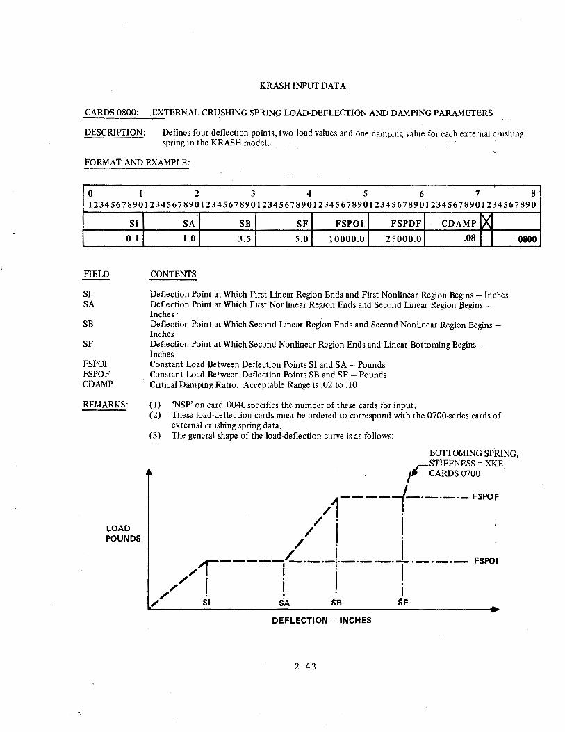
KRASH INPUT DATA
CARDS 0800: EXTERNAL CRUSHING SPRING LOAD-DEFLECTION AND DAMPING PARAMETERS
DESCRIPTION: Defines four deflection points, two load values and one damping value for each external crushing spring in the KRASH model.
FORMAT AND EXAMPLE:
0 1 2 3 4 5 6 7 8 12345678901234567890123456789012345678901234567890123456789012345678901234567890
FIELD
Sl SA
SB
SF
FSPOI FSPOF CD AMP
Sl 0.1
REMARKS:
LOAD POUNDS
SA SB SF FSPOI FSPDF CD AMP X 1.0 3.5 5.0 10000.0 25000.0 .08
CONTENTS
Deflection Point at Which First Linear Region Ends and First Nonlinear Region Begins - Inches Deflection Point at Which First Nonlinear Region Ends and Second Linear Region Begins -Inches · Deflection Point at Which Second Linear Region Ends and Second Nonlinear Region Begins -Inches Deflection Point at Which Second Nonlinear Region Ends and Linear Bottoming Begins -Inches Constant Load Between Deflection Points SI and SA - Pounds Constant Load Bet.ween Denection Points SB and SF - Pounds Critical Damping Ratio. Acceptable Range is .02 to .10
( 1) 'NSP' on card 0040 specifies the number of these cards for input. (2) These load-deflection cards must be ordered to correspond with the 0700-series cards of
external crushing spring data. (3) The general shape of the load-deflection curve is as follows:
10800
BOTTOMING SPRING, rSTIFFNESS == XKE,
I CARDS 0700
I
1----l-·-·-·- FSPOF
/ . / . I -/ I . / . I 1-----~·-·-'·-·-·-·-'-·-·-·- FSPOI /, . I ,. I
// ! ! . j / Sl SA SB SF
DEFLECTION - INCHES
2-43
-------------------------------------------------------------------
KRASH INPUT DATA
CARDS 0800: EXTERNAL CRUSHING SPRING LOAD-DEFLECTION AND DAMPING PARAMETERS (Continued)
( 4) External spring damping in program KRASH is computed as:
2 * CDAMP• j (FSPOI/SI) * WGT / 386.4
where WGT is the weight for mass i.
(5) Entlies requiting scientific notation (X.XEXX) should be light justified. (6) Format for this card is 7E10.0.
2-44 '
KRASH INPUT DATA
CARDS 0900: BEAM ELEMENT PROPERTIES
DESCRIPTION: Defines the end points and cross-sectional properties for each beam element in the KRASH model. .
FORMAT AND EXAMPLE·.
0 I 2 3 4 s 6 7 8 1234S678901234S678901234S6789012345678901234S678901234S678901234S678901234567890
M I N
2 1
FIELD
M I N J AA XJ IYY
IZZ
XIQ
Z1
Z2
MC
REMARKS:
J
5
AA XJ IYY IZZ XIQ Zl Z2 ~t o.s 0.0 3.67 1.54
CONTENTS
Massless Node Point Number At End "I" (Right Justified Integer) Mass Point Number At End "I" (Right Justified Integer) Massless Node Point Number at End "J" (Right Justified Integer) Mass Point Number At End "J" (Right Justified Integer) Cross-Sectional Area- Inches**2. Torsional Stiffness Inertia - Inches**4
0.0 0.0 ·o.o 41
Cross-Sectional Area Moment of inertia About Beam Element Y-Axis For Bending In X-Z Plane - Inches**4 Cross-Sectional Area Moment Of Inertia About Beam Element Z-Axis For Bending In X-Y Plane - Inches**4 Cross-Sectional Shape Factor Relating Torsional Shear Stress To The Applied Moment-1 /Inches**3 Distance From The Neutral Axis To The Extreme Fibers In The Beam Element Z-Direction - Inches Distance From The Neutral Axis To The Extreme Fibers In The Beam Element .¥-Direction - Inches Material Code Number (Right Justified Integer)
(1) (2) (3) (4) (5)
"NB" on card 0040 specifies the number of these cards for input. Blank entries are read as zero. At least one beam element must be defined. The order of these data cards determines the beam element number. If "XJ" is input as zero, KRASH will automatically compute a value for "XJ" as the sum of "IYY" and "IZZ". The beam element coordinate system depends on the geometric orientation as shown
· in Figure 2-5.
900
(6)
(7) (!3)
"XIQ", "Z1 ",and "Z2" are used only for stress calculations (See Section 1.3.17 in Volume I). The torsional stress parameter "XIQ" is equal to the shape factor "1/Q" used in Roark's formulas for stress and strain (Reference 4).
J9) (10) (11)
KRASH has ten standard materials internally defined as shown in Table 2-2. Entries requiring scientific notation (X.XEXX) should be right justified. Format for this card is (2(12, 13), 5E10.0, 2F5.0, 12).
2-b,S
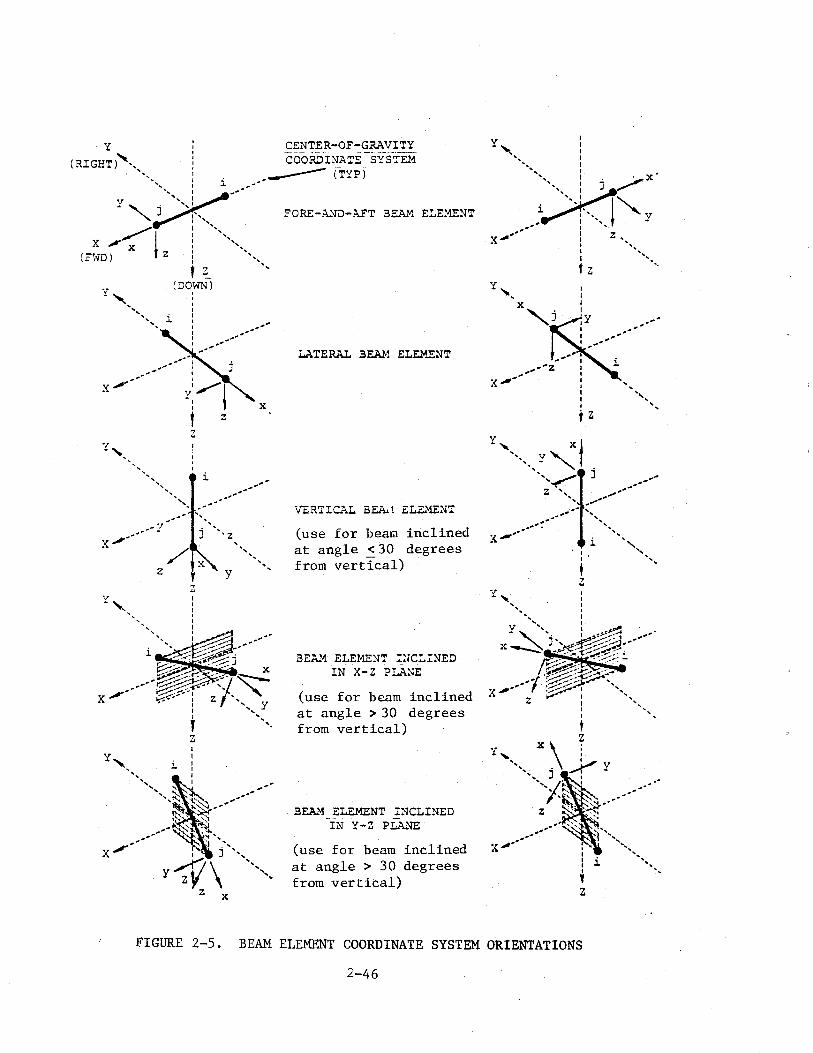
X
'7 ...,.,.-------
z
--
CENTER-OF-GRAVITY COORDINA~E SYS~EM
______ (TYP) i --
I I I I ' ~ . (DO}'ffi) I I I
l. :
---
I I I I
z
--
z
...............
j ', z
z
i
y
' ',
X
..............
FORE-A..'JD-AFT BEAi'1 E:.E~NT
LATERAL BEAl-1 ELE.\f.ENT
VERTICAL BEA...1 ELEME~lT
(use for beata inclined at angle < 30 degrees from vertical)
BE.t\;.'1 ELEMENT WC:.INED IN X-Z PLANE
(use for beam inclined at angle > 30 degrees from vertical)
BEAM ELEMENT I::-lCLINED IN Y-Z PLANE
(use for beam inclined at angle > 30 degrees from vertical)
I
Y,, : '•,,, :
' I
-~: -· t .. • • I z ,,..,• I ' •\. I "',
I ', I ......
t z •.
I
I I I
tz
z
FIGURE 2-5. BEAM ELEMENT COORDINATE SYSTEM ORIENTATIONS
2-46
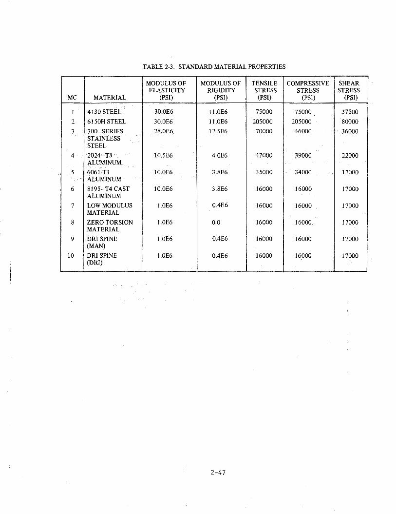
TABLE 2-3. STANDARD MATERIAL PROPERTIES
MODULUS OF MODULUS OF TENSILE COMPRESSIVE SHEAR ELASTICITY RIGIDITY STRESS STRESS STRESS
MC MATERIAL (PSI) (PSI) (PSI) (PSI) (PSI)
1 4130 STEEL 30.0E6 11.0E6 75000 75000 37500
2 6150H STEEL 30.0E6 11.0E6 205000 205000 80000
3 300-SERIES 28.0E6 12.5E6 70000 46000· 36000 STAINLESS STEEL
4 2024-T3 10.5E6 4.0E6 47000 39000 22000 ALUMINUM
5 6061-T3 10.0E6 3.8E6 35000 34000 17000 ALUMINUM·
6 8195-T4 CAST 10.0E6 3.8E6 16000 16000 17000 ALUMINUM
7 LOW MODULUS l.OE6 0.4E6 16000 16000 17000 MATERIAL
8 ZERO TORSION 1.0E6 0.0 16000 16000 17000 MATERIAL
9 DRI SPINE l.OE6 0.4E6 16000 16000 17000 (MAN)
10 DRI SPINE l.OE6 0.4E6 16000 16000 17000 (DRI)
2-47
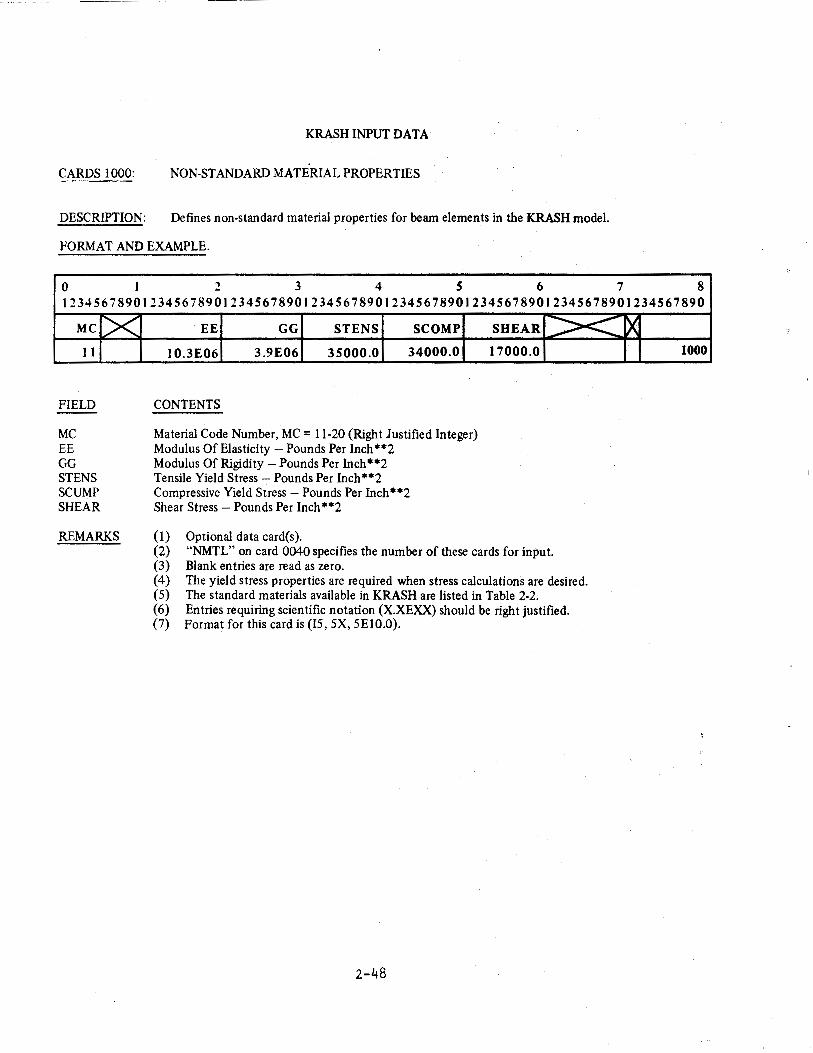
KRASH INPUT DATA
CARDS 1000: NON-STANDARD MATERIAL PROPERTIES
DESCRIPTION: Defines non-standard material properties for beam elements in the KRASH model.
FORMAT AND EXAMPLE.
0 1 2 3 4 5 6 7 8 12345678901234567890123456789012345678901234567890123456789012345678901234567890
MC
11
FIELD
MC EE GG STENS SCUMP SHEAR
C><
REMARKS
EE GG STENS SCOMP
10.3E06 3.9E06 35000.0 34000.0
CONTENTS
Material Code Number, MC = 11-20 (Right Justified Integer) Modulus Of Elasticity- Pounds Per Inch**2 Modulus Of Rigidity -Pounds Per Inch**2 Tensile Yield Stress- Pounds Per Inch**2 Compressive Yield Stress- Pounds Per Inch**2 Shear Stress- Pounds Per Inch**2
(1) Optional data card(s).
SHEAR ~ ~ .............. 17000.0
(2) "NMTL" on card 0040 specifies the number of these cards for input. (3) Blank entries are read as zero. ( 4) The yield stress properties are required when stress calculations are desired. (5) The standard materials available in KRASH are listed in Table 2-2. (6) Entries requiring scientific notation (X.XEXX) should be right justified. (7) Format for this card is (IS, 5X, 5El0.0).
2-48
X 1000
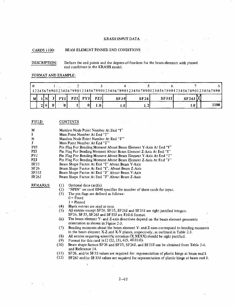
CARDS 1100:
DESCRIPTION:
KRASH INPUT DATA
BEAM ELEMENT PINNED END CONDITIONS
Defines the end points and the degrees-of-freedom for the beam elements with pinned end conditions in the KRASH model.
F0~\1AT AND EXAMPLE:
0 I 2 3 4 5 6 7 8 12345678901234567890123456789012345678901234567890123456789012345678901234567890
M I N
2 6
FIELD
M I N J PYI PZI PYJ PZJ SF35 SF26 SF35J SF26J
REMARKS:
J 0
PYI PZI PYJ PZJ SF35
0 1 0 1.0 1.5
CONTENTS
Massless Node Point Number At End ''I" Mass Point Number At End "I" Massless Node Point Number At End "J'" Mass Point Number At End "J'"
SF26 SF3SJ
1.2
Pin Flag For Bending Moment About Beam Element Y-Axis At End "I" Pin Flag For Bending Moment About Beam Element Z-Axis At End "I" Pin Flag For Bending Moment About Beam Element Y-Axis At End "J" Pin Flag For Bending Moment About Beam Element Z-Axis At End "J" Beam Shape Factor At End "I'' About Beam Y-Axis Beam Shape Factor At End "I", About Beam Z-Axis Beam Shape Factor At End "J" About Beam Y-Axis Beam Shape Factor At End "J" About Beam Z-Axis
(I) Optional data card(s). (2) "NPIN" on card 0040 specifies the number of these cards for input. (3) The pin flags are defined as follows:
0 =Fixed 1 =Pinned
(4) Blank entries are read as zero.
SF26J
1.0
(5) All entries except SF26, SF35, SF26J and SF35J are right justified integers. SF26, SF35, SF26J and SF35J are EIO.O format.
[X
(6) The beam element Y- and Z-axis directions depend on the beam element geometric orientation as shown in Figure 2-3.
(7) Bending moments about the beam element Y- and Z-axes correspond to bending moments in the beam element X-Z and X-Y planes, respectively, as outlined in Table 2-3.
(8) All entries requiring scientific notation (X.XEXX) should be right justified. (9) Format for this card is (2 (12, 13), 4I5, 4E10.0).
(10) Beam shape factors SF26 and SF35, SF26J, and SF35J can be obtained from Table 2-4. and Reference 14.
(11) SF26, and/or SF35 values are required for -representation of plastic hinge at beam end I. (12) SF26J and/or SF35J values are required for representation of plastic hinge at beam end J.
2-49
llOO
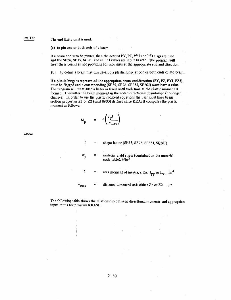
NOTE:
where
The end fixity card is used:
(a) to pin one or both ends of a beam
If a beam end is to be pinned then the desired PY, PZ, PYJ and PZJ flags are used and the SF26, SF35, SF26J and SF35J values are input as zero. The program will treat these beams as not providing for moments at the appropriate end and direction.
(b) to define a beam that can develop a plastic hinge at one or both ends of the beam.
If a plastic hinge is represented the appropriate beam end direction (PY, PZ, PYJ, PZJ) must be flagged and a corresponding (SF35, SF26, SF35J, SF26J) must have a value. The program will treat such a beam as ftxed until such time as the plastic moment is formed. Thereafter the beam moment in the noted direction is maintained (no longer changes). In order to use the plastic moment equations the user must have beam section properties Zl or Z2 (card 0900) deftned since KRASH computes the plastic moment as follows:
Mp = f(~) Ymax
f = shape factor (SF35, SF26, SF35J, SIJ26J)
(fy = material yield stress (contained in the material code table)Jb/in2
= area moment of inertia, either Iyy or Izz ·4 ,m
Ymax distance to neutral axis either Zl or Z2 , in
The following table shows the relationship between directional moments and appropriate input terms for program KRASH.
2-50
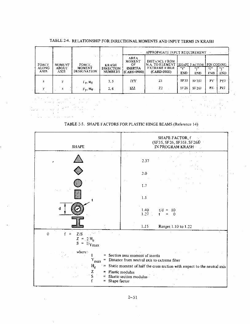
TABLE 2-4. RELATIONSHIP FOR DIRECTIONAL MOMENTS AND INPUT TERMS IN KRASH
APPROPRIATE INPUT REQUIREMENT
AREA MOMENT DISTANCE FROM
FORCE MOMENT FORCE, KRASH OF N.A. TO ELEMENT SHAPE FACTOR PIN CODING ALONG ABOUT MOMENT DIRECTION I INERTIA EXTREME FIBER ''i" "j" "i" ~'j ~,
AXIS AXIS DESIGNATION NUMBERS (CARD 0900) (CARD0900) END END END END
z y Fz, Me 3,5 IYY Zl SF35 SF35J py l>YJ
y z fy. M.p 2,6 IZZ Z2 SF26 SF26J PZ PZJ i
TABLE 2-5. SHAPE FACTORS FOR PLASTIC HINGE BEAMS (Reference 14)
SHAPE FACTOR, f (SF35, SF26, SF35J, SF26J)
SHAPE IN PROGRAM KRASH
, & 2.37
• 2.0
• 1.7
I t 1.5
IO' 1.40 t/d = 10 1.27 t = 0
3: 1.15 Ranges 1.10 to 1.22
0 f = Z/S z = 2 He s = I/Ymax
where: I = Section area moment· of inertia ymax = Distance from neutral axis to extreme fiber
H .- Static moment of half the cross section with respect to the neutral axis e z = Plastic modulus s = Elastic section modulus f = Shape factor
2-51
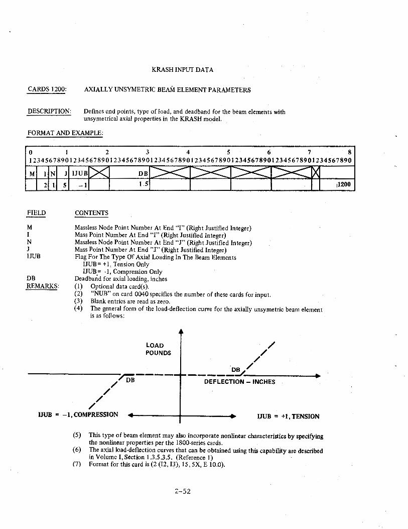
CARDS 1200:
DESCRIPTION:
KRASH INPUT DATA
AXIALLY UNSYMETRIC BEAM ELEMENT PARAMETERS
Defines end points, type of load, and deadband for the beam elements with unsymetrical axial properties in the KRASH model.
FORMAT AND EXAMPLE:
0 I 2 3 4 5 6 7 8 12345678901234567890123456789012345678901234567890123456789012345678901234567890
M I N J
2 I 5
FIELD
M I N J IJUB
DB REMARKS:
DB
-1 1.5
CONTENTS
Massless Node Point Number At End "I" (Right Justified Integer) Mass Point Number At End "I" (Right Justified Integer) Massless Node Point Number At End "J" (Right Justified Integer) Mass Point Number At End "J" (Right Justified Integer) Flag For The Type Of Axial Loading In The Beam Elements
IJUB = + 1, Tension Only IJUB= -1, Compression Only
Dead band for axial loading, inches (1) Optional data card(s). (2) "NUB" on card 0040 specifies the number of these cards for input. (3) Blank entries are read as zero. ( 4) The general form of the load-deflection curve for the axially unsymetric beam element
is as follows:
/ /
/
LOAD POUNDS
~----/ DB
/ /
/ ·Da /
----------~----------------_. DEFLECTION - INCHES
IJUB = -1, COMPRESSION IJUB = +1, TENSION
(5) This type of beam element may also incorporate nonlinear characteristics by specifying the nonlinear properties per the 1800-series cards.
(6) The axial load-deflection curves that can be obtained using this capability are described in Volume !,Section 1.3.5.3.5. (Reference I)
(7) Format for this card is (2(12, 13), 15, SX, E 10.0).
:Z-52
11200
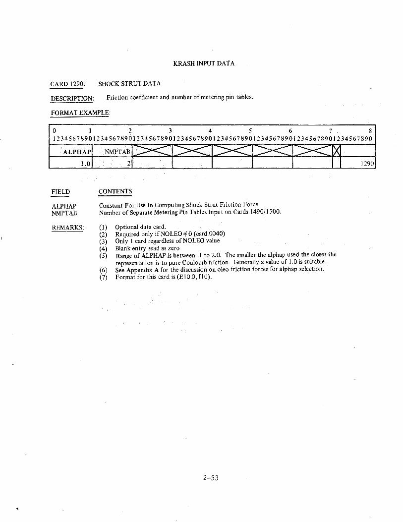
KRASH INPUT DATA
CARD 1290: SHOCK STRUT DATA
DESCRIPTION: Friction coefficient and number of metering pin tables.
FORMAT EXAMPLE:
0 2 3 4 5 6 7 8 12345678901234567890123456789012345678901234567890123456789012345678901234567890
ALP HAP
FIELD
ALP HAP NMPTAB
1.0
REMARKS:
2
CONTENTS
Constant For Use In Computing Shock Strut Friction Force Number of Separate Metering Pin Tables Input on Cards 1490/1500.
(I) (2) (3) (4) (5)
(6) (7)
Optional data card. Required only ifNOLEO =f 0 (card 0040) Only 1 card regardless of NO LEO value Blank entry read as zero Range of ALPHAP is between .1 to 2.0. The smaller the alphap used the closer the representation is to pure Coulomb friction. Generally a value of 1.0 is suitable. See Appendix A for the discussion on oleo friction forces for alphap selection. Format for this card is (ElO.O, 110).
2-53
1290
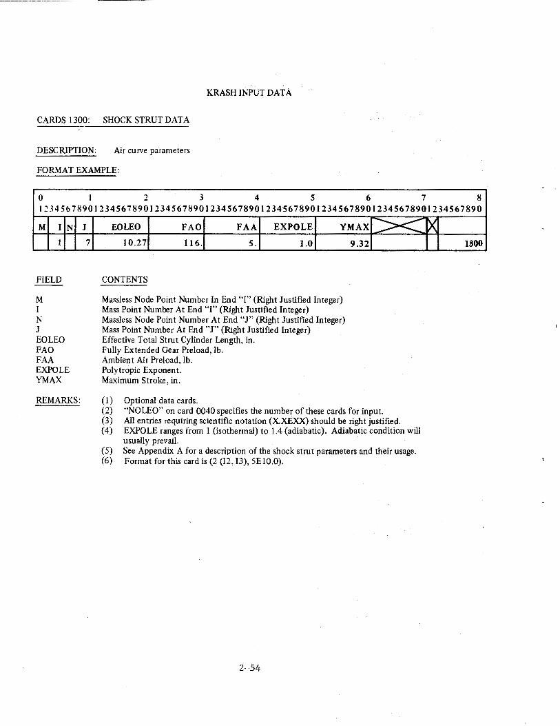
KRASH INPUT DATA
CARDS 1300: SHOCK STRUT DATA
DESCRIPTION: Air curve parameters
FORMAT EXAMPLE:
0 I 2 3 4 5 6 7 8 12345678901234567890123456789012345678901234567890123456789012345678901234567890
M I N
1
FIELD
M I N J EO LEO FAO FAA EXPOLE YMAX
REMARKS:
J
7
EO LEO FAO FAA EX POLE YMAX
10.27 116. 5. 1.0
CONTENTS
Massless Node Point Number In End "I" (Right Justified Integer) Mass Point Number At End "I" (Right Justified Integer) Massless Node Point Number At End "J" (Right Justified Integer) Mass Point Number At End "J" (Right Justified Integer) Effective Total Strut Cylinder Length, in. Fully Extended Gear Preload, lb. Ambient Air Preload, lb. Polytropic Exponent. Maximum Stroke, in.
(1) Optional data cards.
9.32 ~
(2) "NO LEO" on card 0040 specifies the number of these cards for input. (3) All entries requiring scientific notation (X.XEXX) should be right justified. (4) EXPOLE ranges from 1 (isothermal) to 1.4 (adiabatic). Adiabatic condition will
usually prevail. (5) See Appendix A for a description of the shock strut parameters and their usage. (6) Format for this card is (2 (12, 13), 5El0.0).
2· 54
~ 1300
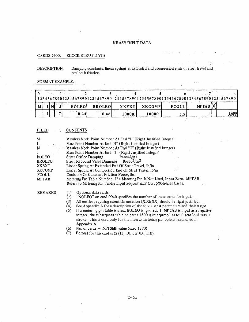
KRASfi INPUT DATA
CARDS 1400: SHOCK STRUT DATA
DESCRIPTION: Damping constants, linear springs at extended and compressed ends of strut travel and coulomb friction.
FORMAT EXAMPLE:
0 I 2 3 4 ·s 6 7 8 t234561S9~t2345~78901234567890123456789012345678901234567890l2345678901234567890
M I N
1
FIELD
M I N J BOLEO BROLEO XKEXT XKCOMP FCOUL MPTAB
REMARKS:
J
7
BOLEO BROLEO XKEXT XKCOMP FCOUL MPTAB
0.24 0.48 10000. 10000.
CONTENTS
Massless Node Point Number At End "I" (Right Justified Integer) Mass Point Number At End "r' (Right Justified Integer) Massless Node Point Number At End "J" (Right JustifiC'd Integer) M;tss Point Number At End "J" (Right Justified Integer) Strut Orifice Damping 1b-sec2fin2 Strut Rebound Valve Damping lb-sec2/in2 Linear Spring At Extended End Of Strut Travel, lb/in. Linear Spring At Compressed End Of Strut Travel, lb/in. Coulomb Or Constant Friction Force, lbs.
5.5
Metering Pin Table Number. If a Metering Pin Is Not Used, Input Zero. MPTAB Refers to Metering Pin Tables Input Sequentially On 1500-Series Cards.
(1) Optional data cards. (2) "NOLEO" on card 0040 specifies the number of these cards for input. (3) All entries requiring scientific notation (X.XEXX) should be right justified.
1
~
( 4) See Appendix A for a description of the shock strut parameters and their usage. (5) If a metering pin table is used, BOLEO is ignored. If MPTAB is input as a negative
integer, the subsequent table on cards 1500 is interpreted as total gear load versus stroke. This is used only for the inverse metering pin option, explained in Appendix A.
(6) No. of cards = NPTSMP value (card 1290) (7) Format for this card is (2 (12, 13), 5EiO.O, 110).
2--55
·1400 ----
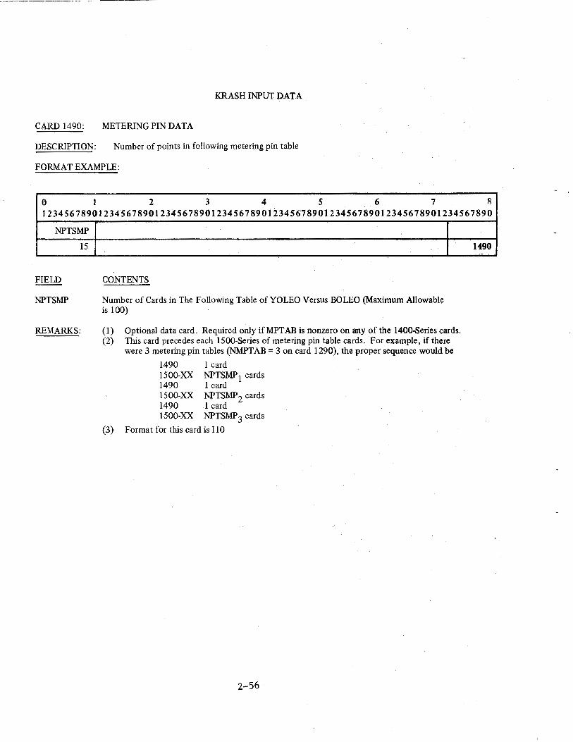
KRASH INPUT DAJ:'A
CARD 1490: METERING PIN DATA
DESCRIPTION: Number of points in following metering pin table
FORMAT EXAMPLE:
0 I 2 3 4 5 6 7 8 12345678901234567890123456789012345678901234567890123456789012345678901234567890
NPTSMP
15
FIELD
NPTSMP
REMARKS:
CONTENTS
Number of Cards in The Following Table of YO LEO Versus BOLEO (Maximum Allowable is 1 00)
(1) Optional data card. Required only ifMPTAB is nonzero on any of the 1400-8eries cards. (2) This card precedes each 1500-Series of metering pin table cards. For example, if there
were 3 metering pin tables (NMPTAB = 3 on card 1290), the proper sequence would be
1490 1 card 1500-XX NPTSMP1 cards 1490 1 card 1500-XX NPTSMP2 cards 1490 J card 1500-XX NPTSMP3 cards
(3) Format for this card is 110
2-56
1490
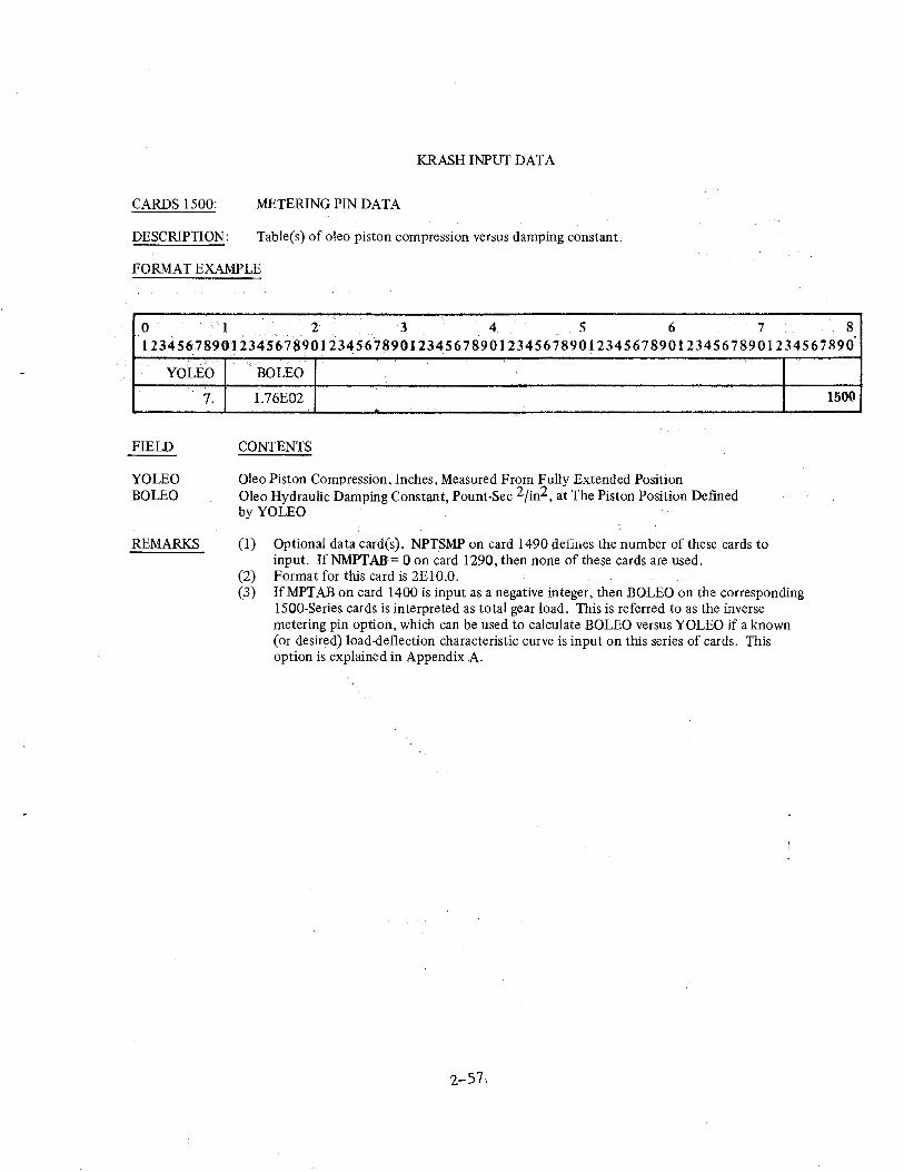
KRASH INPUT DATA
CARDS 1500: METERING PIN DATA
DESCRIPTION: Table(s) of oleo piston compression versus damping constant.
FORMAT EXAMPLE
0 I 2 3 4 5 6 7 8 12345678901234567.90123456789012345678901234567890123456789012345678901234567890
''.
YO LEO
FIELD
YO LEO BOLEO
REMARKS
7.
BOLEO
1.76E02
CONTENTS
Oleo Piston Compression, Inches, Measured From Fully Extended Position Oleo Hydraulic Damping Constant, Pount-Sec 2 /in2, at The Piston Position Defmed byYOLEO
(1) Optional data card(s). NPTSMP on card 1490 defines the number of these cards to input. If NMPTAS:= 0 on card 1290, then none of these cards are used.
(2) Format for this card is 2El0.0. (3) IfMPTAB on card 1400 is input as a negative integer, then BOLEO on the corresponding
1500-Series cards is interpreted as total gear load. This is referred to as the inverse metering pin option, which can be used to calculate BOLEO versus YOLEO if a known (or desired) load-deflection characteristic curve is input on this series of cards. This option is explained in Appendix A.
2-57.
1500
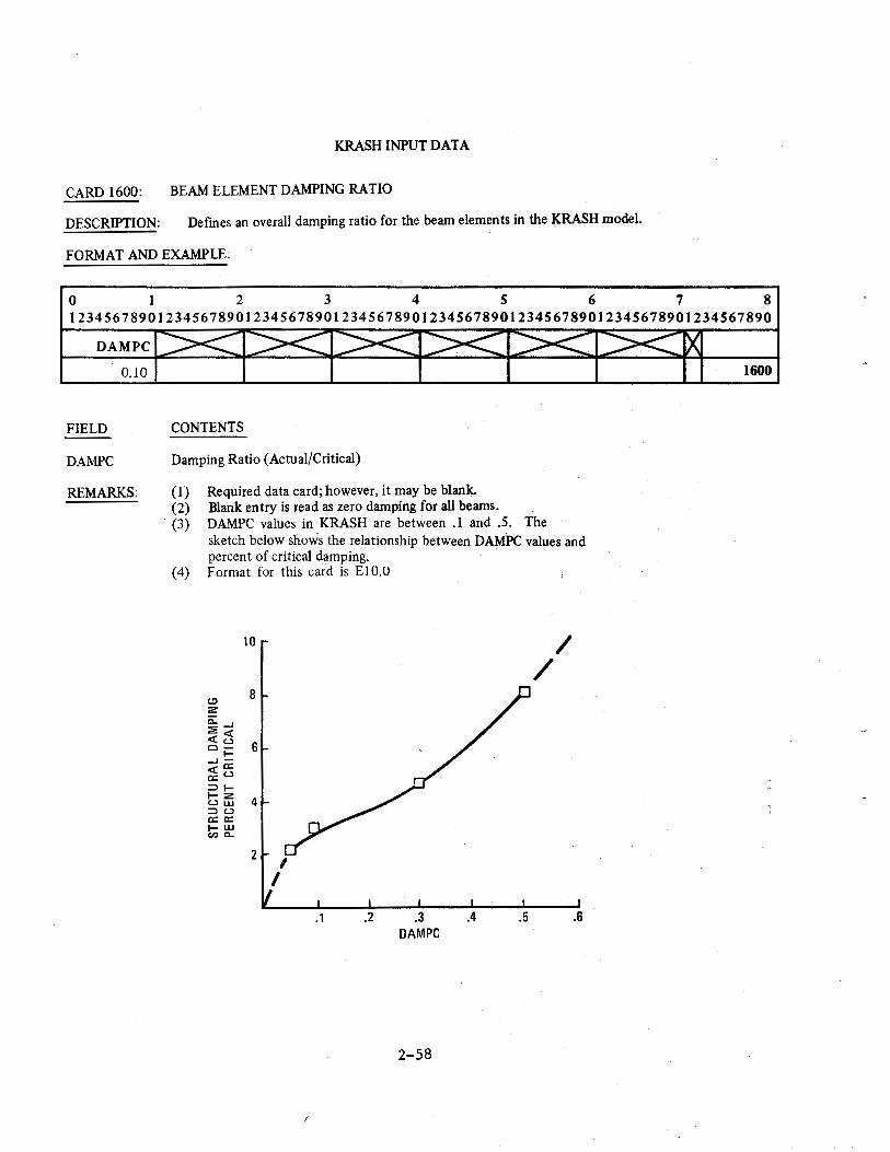
KRASH INPUT DATA
CARD 1600: BEAM ELEMENT DAMPING RATIO
DESCRIPTION: Defines an overall damping ratio for the beam elements in the KRASH model.
FORMAT AND EXAMPLE:
0 1 2 3 4 5 6 7 8 12345678901234567890123456789012345678901234567890123456789012345678901234567890
DAM PC
0.10 1600
FIELD CONTENTS
DAMPC Damping Ratio (Actual/Critical)
REMARKS: (1) Required data card; however, it may be blank. (2) Blank entry is read as zero damping for all beams.
· (3) DAMPC values in KRASH are between .1 and .5. The sketch below shows the relationship between DAMPC values and percent of critical damping.
( 4) Format for this card is E1 0.0
t!l 2
ii:..J 2<( <Cu ci= ..J<(a: a:U ::li-
10
8
6
t; ffi 4 ::lU a: a: 1-W en c..
2 I
I
i
.1 .2 .3 DAM PC
2-58
.4 .5
/ /
.6
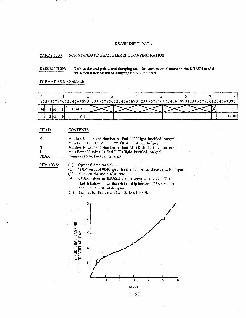
KRASH INPUT DATA
CARDS 1700: NON-STANDARD BEAM ELEMENT DAMPING RATIOS
DESCRIPTION: Defmes the end points and damping ratio for each beam element in the KRASH model for which a non-standard damping ratio is required.
FORMAT AND EXAMPLE:
0 .I 2 3 4 5 6 7 8 12345678901234567890123456789012345678901234567890123456789012345678901234567890
M IN ·J · CBAR
2 1 5
FIELD
M I N J CBAR
REMARKS:
0.10
CONTENTS
Massless Node Point Number At End "I" (Right Justified Integer) Mass Point Number At End "I" (Right Justified Integer) Massless Node Point Number At End "J" (Right Justified Integer) Mass Point Number At End "J'" (Right Justified Integer) Damping Ratio (Actual/Critical)
(1) Optional data card(s). (2) "ND" on card 0040 specifies the number of these cards for input. (3) Blank entries are read as zero. (4) CBAR values in KRASH are between .1 and .5. The
sketch below shows the relationship be.tween CBAR values and percent critical damping .
(5) Format for this card is (2 (12, 13), EIO.O).
10 / /
8 (.!:1
2 c::...J 2<( 6 <(u ci= ...J-<(a: a:'-' :::ll- 4 1-2 uw :::lU a: a: 1-W Cl)· c..
2 I
I
.1 .3 .4 .5 .6
GBAR
2-59
1700
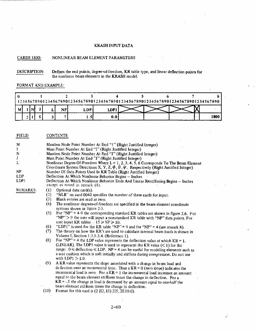
CARDS 1800:
DESCRIPTION:
KRASH INPUT DATA
NONLINEAR BEAM ELEMENT PARAMETERS
Defmes the end points, degree-uf-freedom, KR table type, and linear deflection points for the nonlinear beam elements in the KRASH model.
FORMAT AND EXAMPLE:
I
0 I 2 3 4 5 6 7 8 12345678901234567890123456789012345678901234567890123456789012345678901234567890
M I
2
FIELD
M I N J L
~'P
LDP LDPl
N
I
REMARKS:
J
5
L NP LDP LDPl >< ">< 3 7 1.5 0.0
CONTENTS
Massless Node Point Number At End "I" (Right Justified Integer) Mass Point Number At End "I" (Right Justified Integer) Massless Node Point Number At End "J" (Right Justified Integer) Mass Point Number At End "J" (Right Justified Integer)
>< X
Nonlinear Degree-Of-Freedom Where L = I, 2, 3, 4, 5, 6 Corresponds To The Beam Element Coordinate System Directions X, Y, Z, cp, 8, 1/1. Respectively (Right Justified Integer) Number Of Data Points Used In KR Table (Right Justified Integer) Deflection At Which Nonlinear Behavior Begins - Inches Deflection At Which Nonlinear Behavior Ends And Linear Restiffening Begins - Inches except as noted in remark ( 8). (1) Optional data card(s). (2) "NLB .. on card 0040 specifies the number of these cards for input. (3) Blank entries are read as zero. (4) The nonlinear degrees-of-freedom are specified in the beam element coordinate
systems shown in figure 2-3. (5) For "NP" = 4-9 the corresponding standard KR tables are shown in figure 2.6. For
"NP" > 9 the user will input a nonstandard KR table with "NP" data points. For user input KR tables- 15;;;. NP;;;. 10.
(6) "LDP1" is used for the KR table "NP" = 9 and for "NP" = 4 (see remark 8). (7) The theory on how the KR's are used to calculate internal beam loads is shown in
Volume I, Section 1.3.5.3.4. (Reference I). (8) For "NP" = 4 the LDP value represents the deflection value at which KR = I.
(LINEAR). The LDP1 value is used to represent the KR value(< 1) for the range: 0.;;;; deflection.;;;; LDP. NP = 4 can be useful for modeling elements such as a seat cushion which is soft initially and stiffens during compression. Do not use with LDP1 > 1.0.
(9) A KR value represents the slope associated with a change in beam load and deflection over an incremental time. Thus a KR = 0 (zero slope) indicates the incremental load is zero. For aKR = 1 the incremental load increases an amount equal to the beam element stiffness times the change in deflection. For a KR = -.5 the change in load is decreased by an amount equal to one-half the beam element stiffuess times the change in deflection.
(10) Fonnat for this card is (2 (12, 13) 215, 2E10.0).
2-60
1800
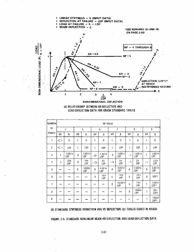
a. 0 Q
ct ...I
0 X ...I =-::
-~ 0 ct 0 ...I _, ct z 0 c;; z w :::5· a z 0 z
1
NUMBER
OF
POINTS
1
2
3
4
5
6
7
8
9
• LINEAR STIFFNESS = K (INPUT DATA) • DEFLECTION AT FAILURE = LOP (INPUT DATA) • LOAD AT FAILURE = K x LOP • BEAM DEFLECJION = 8
*SEE REMARKS (6) AND (8) ON PAGE 2-60
KR
<1.
<1.
1.
1.
-
-
-
-
-
1 2
KR = 0.0
3
INP = 4 THROUGH 91 0)
I <:>/ ..... , ,,
~I
q
~ I
KR = 0 ._ __ NP=6
//DEFLECTION (LDP1)*
AT WHICH ---.....:,K;;,;R :::._0- - V RESTIFFENING OCCURS
X
~ 4
LOP NONDIMENSIONAL DEFLECTION
(A) RELATIONSHIP BETWEEN KR·DEFLECTION AND lOAD-DEFLECTION DATA FOR KRASH STANDARD TABLES
NP VALUE
4 5 6 7 8 9
0 KR 0 KR 0 KR 0 KR 0 KR 0
0 1. 0 1. 0 1. 0 1. 0 1 0
LOP 1. LOP 1. LOP 1. LOP 1. LOP 1 lOP
1.001x 0 1.001x 1.001 X -.5 1.001x -1. 1.001 X -1. 1.001 X lOP lOP -.25 lOP lOP LOP lOP
lOX 0 lOX
-.25 4x -.5
3x -1. 2x -1.
2.0x LOP lOP lOP lOP lOP lOP
- 0 1000X 0 4.001X 0 3.001 X
0 2.001x
0 2.001X
LOP lOP LOP LOP LOP
0 lOX lOx
0 10 X
0 lOPl - - - lOP 0 LOP LOP
- - - - - 0 10.00 X 0
15 X 1. 1.001 X lOP lOP LOPl
- - - - - - 0 1000X
1. 20 X - lOP lOPl
- - - - - - - - - 1. 1000X LOPl
(B) STANDARD STIFFNESS REDUCTION (KR) VS DEFLECTION (8) TABLES CODED IN KRASH
FIGURE 2-6. STANDARD NONLINEAR BEAM KR-OEFLECTION AND LOAD-DEFLECTION DATA
2-61
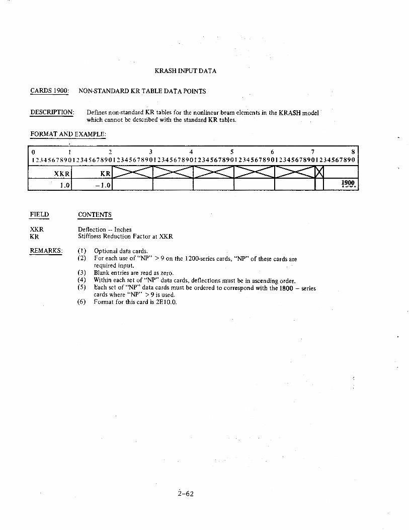
KRASH INPUT DATA
CARDS 1900: NON-STANDARDKR TABLEDATAPOINTS
DESCRIPTION: Defines non-standard KR tables for the nonlinear beam elements in the KRASH model which cannot be described with the standard KR tables.
FORMAT AND EXAMPLE:
0 1 2 3 4 5 6 7 8 12345678901234567890123456789012345678901234567890123456789012345678901234567890
XKR KR
FIELD
XKR KR
1.0
REMARKS:
-1.0
CONTENTS
Deflection - Inches Stiffness Reduction Factor at XKR
(1) Optional data cards. (2) For each use of "NP" > 9 on the 1200-series cards, "NP" of these cards are
required input. (3) Blank en tries are read as zero. (4) Within each set of "NP" data cards, deflections must be in ascending order. (5) Each set of "NP" data cards must be ordered to correspond with the 1800 -series
cards where "NP" > 9 is used. (6) Format for this card is 2E10.0.
2-62
1900 .I...,V&
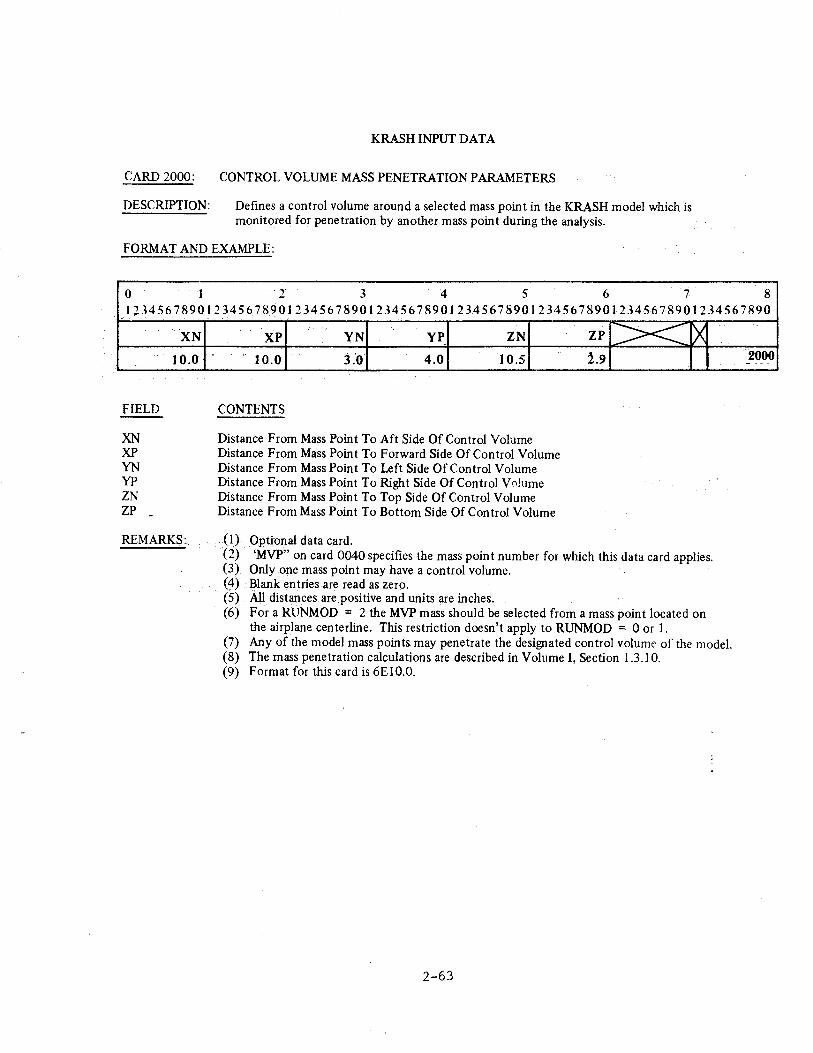
KRASH INPUT DATA
CARD 2000: CONTROL VOLUME MASS PENETRATION PARAMETERS
DESCRIPTION: Defines a control volume around a selected mass point in the KRASH model which is monitored for penetration by another mass point during the analysis.
FORMAT AND EXAMPLE:
0 1 2 3 4 5 6 7 8 l23456789012345678901234567890123456789012345678901234567890123456789Ql234567890
FIELD
XN XP YN yp ZN ZP
XN
10.0
REMARKS:.
XP YN yp ZN ,.
10.0 3.0 4.0 10.5
CONTENTS
Distance From Mass Point To Aft Side Of Control Volume Distance From Mass Point To Forward Side Of Control Volume Distance From Mass Point To Left Side Of Control Volume Distance From Mass Point To Right Side Of Control V 0lume Distance From Mass Point To Top Side Of Control Volume Distance From Mass Point To Bottom Side Of Control Volume
ZP >< ~ 1.9
(I) Optional data card. (2) 'MVP" on card 0040 specifies the mass point number for which this data card applies. (3) Only .one mass point may have a control volume. (4) Blank entries are read as zero. (S) All distances are positive and units are inches. (6) For a RUNMOD = 2 the MVP mass should be selected from a mass point located on
the airplane centerline. This restriction doesn't apply to RUNMOD = 0 or I. (7) Any of the model mass points may penetrate the designated control volume of the modeL (8) The mass penetration calculations are described in Volume I, Section 1.3 .I 0. (9) Format for this card is 6E10.0.
2-63
2000 ---
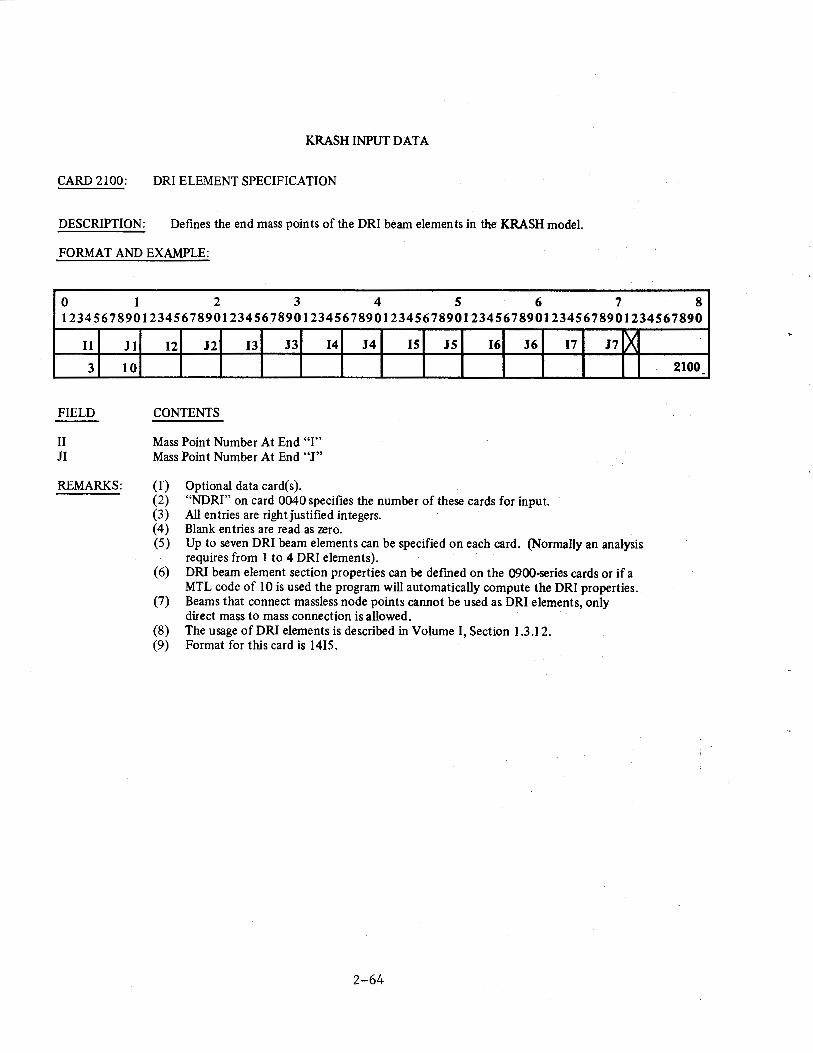
KRASH INPUT DATA
CARD 2100: DRI ELEMENT SPECIFICATION
DESCRIPTION: Defines the end mass points of the DRI beam elements in the KRASH model.
FORMAT AND EXAMPLE:
0 1 2 3 4 5 6 7 8 12345678901234567890123456789012345678901234567890123456789012345678901234567890
11
3
FIELD
II JI
REMARKS:
Jl
10
I2 J2 13 J3 14 J4 IS JS 16 J6 17 J7 lX
CONTENTS
Mass Point Number At End "I'' Mass Point Number At End "J"
(I) (2) {3) (4) (5)
{6)
(7)
(8) (9)
Optional data card(s). "NDRI" on card 0040 specifies the number of these cards for input. All entries are right justified integers. Blank entries are read as zero. Up to seven DRI beam elements can be specified on each card. (Normally an analysis requires from 1 to 4 DRI elements). DRI beam element section properties can be defmed on the 0900-series cards or if a MTL code of 10 is used the program will automatically compute the DRI properties. Beams that connect massless node points cannot be used as DRI elements, only direct mass to mass connection is allowed. The usage of DRI elements is described in Volume I, Section 1.3.12. Format for this card is 1415.
2-64
2100 -
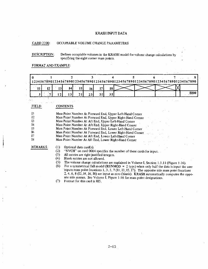
KRASH INPUT DATA
CARD 2200: OCCUPIABLE VOLUME CHANGE PARAMETERS
DESCRIPTION: Defines occupiable volumes in the KRASH model for volume change calculations by specifying the eight corner mass points.
FORMAT AND EXAMPLE:
0 1 2 3 4 5 6 7 8 1234S67a9o1234s~1s9o1234S678901234S67890I234S678901234S67890t234S678901234S6789o
11
3
FIELD
11 I2 13 I4 15 16 17 18
l:t
7
REMARKS:
13 14 IS 16 17 18 >< >< 12 13 21' 23 31 35
CONTENTS
Mass Point Number At Forward End, Upper Left-Hand Corner Mass Point Number At Forward End, Upper Right-Hand Corner Mass Point Number At Aft End, Upper Left-Hand Corner Mass Point Number At Aft End, Upper Right-Hand Corner Mass Point NumberAt Forward End, Lower Left-Hand Corner Mass Point Number At Forward End, Lower Right-Hand Corner Mass Point Number At Aft End, Lower Left-Hand Comer Mass Point Number At Aft End, Lower Right-Hand Corner
(1) Optional data card(s).
><
(2) ''NVCH" on card 0004 specifies the number of these cards for input. (3) All entries are right justified integers. (4) Blank entries are not allowed.
rx :2200
(5) The volume change calculations are explained in Volume I, Section 1.3.11 (Figure 1-16). (6) For a symmetrical full model (RUNMOD = 2 type) when only half the data is input the user
inputs in ass point locations 1, 3; 5, 7 (Il, 13, IS, 17). The opposite side mass point locations 2, 4, 6, 8 (12, 14, I6, I8) are input as zero (blank). KRASH automatically computes the opposite side masses. See Volume I, Figure 1-16 for mass point designations.
(7) Format for this card is 815.
2-65
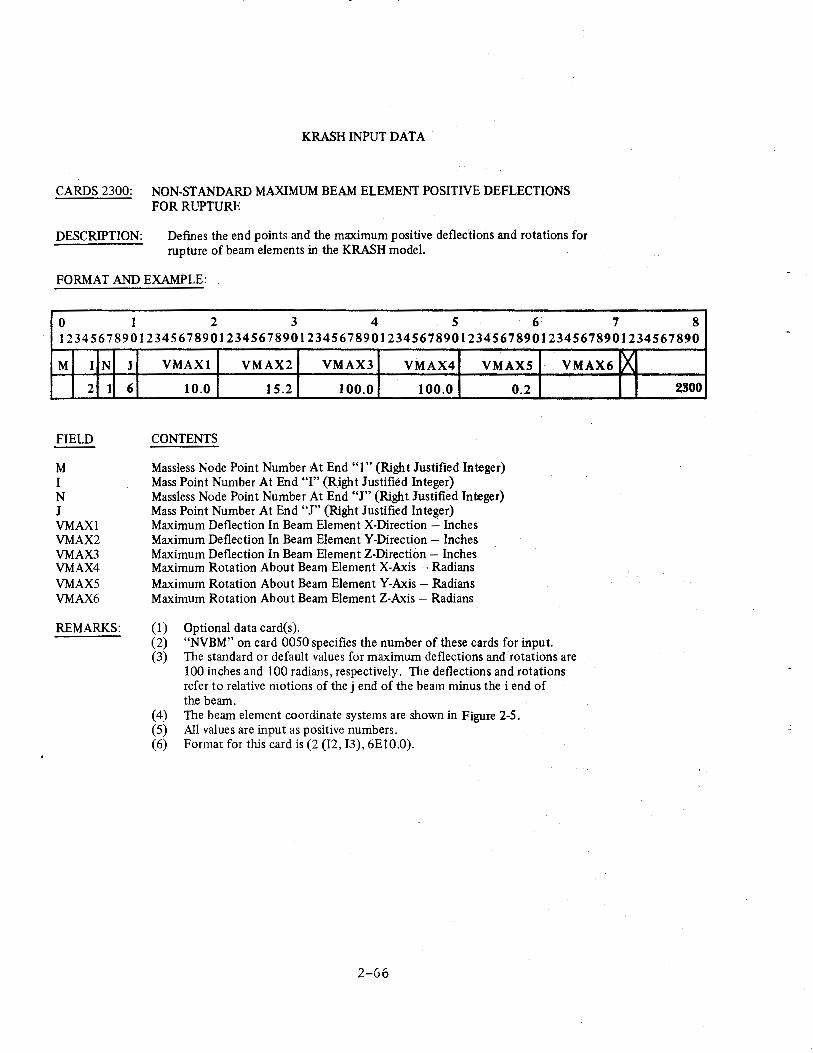
KRASH INPUT DATA
CARDS 2300: NON-STANDARD MAXIMUM BEAM ELEMENT POSITIVE DEFLECTIONS FOR RUPTURE
DESCRIPTION: Defmes the end points and the maximum positive deflections and rotations for rupture of beam elements in the KRASH model.
FORMAT AND EXAMPLE:
0 1 2 3 4 5 6 7 8 12345678901234567890123456789012345678901234567890123456789012345678901234567890
M I N
2
FIELD
M I N J VMAXI VMAX2 VMAX3 VMAX4 VMAXS VMAX6
1
REMARKS:
J
6
VMAXl VMAX2 VMAX3 VMAX4 VMAX5
10.0 15.2 100.0 100.0
CONTENTS
Massless Node Point Number At End "1" (Right Justified Integer) Mass Point Number At End "I" (Right Justified Integer) Massless Node Point Number At End "J" (Right Justified Integer) Mass Point Number At End "J" (Right Justified Integer) Maximum Deflection In Beam Element X-Direction - Inches Maximum Deflection In Beam Element Y-Direction- Inches Maximum Deflection In Beam Element Z-Direction- Inches Maximum Rotation About Beam Element X-Axis- Radians Maximum Rotation About Beam Element Y-Axis- Radians Maximum Rotation About Beam Element Z-Axis -Radians
(I) Optional data card(s).
0.2
(2) "NVBM" on card 0050 specifies the number of these cards for input.
VMAX6
(3) The standard or default values for maximum deflections and rotations are 100 inches and 100 radians, respectively. The deflections and rotations refer to relative motions of the j end of the beam minus the i end of the beam.
(4) The beam element coordinate systems are shown in Figure 2-5. (5) All values are input as positive numbers. (6) Format for this card is (2 (12, 13), 6EIO.O).
2-66
~ 2800
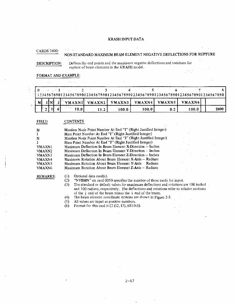
CARDS 2400:
DESCRIPTION:
KRASH INPUT DATA
NON-STANDARD MAXIMUM BEAM ELEMENT NEGATIVE DEFLECTIONS FOR RUPTURE
Defines the end points and the maximum negative deflections and rotations for rupture of beam elements in the KRASH model.
FORMAT AND EXAMPLE:
o· . :- 1 2 3 4 5 6 7 8 1!34567~90113456789012345678901234567890123456789012345678901~345678901234567890
' M I N'
'2 1
FIELD
M I N J VMAXNl VMAXN2 VMAXN3 VMAXN4 VMAXN5 VMAXN6
REMARKS:
J: 6
·vM.AXNl VMAXN2 VMAXN3 VMAXN4 VMAXNS
10.0 15.2 100.0 100.0
CONTENTS
Massless Node Point Number At End "I" (Right Justified Integer) Mass Point Number At End "I" (Right Justified Integer) Massless Node Point Number At End "J" (Right Justified Integer) Mass Point Number At End "J" (Right Justified Integer) Maximum Deflection In Beam Element X-Direction -Inches Maximum Deflection In Beam Element Y-Direction - Inches Maximum Deflection In Beam Element Z-Direction - Inches Maximum Rotation AboutBeam ElementX-Axis- Radians Maximum Rotation About Beam Element Y-Axis - Radians Maximum Rotation About Beam Element Z-Axis - Radians
(1) Optional data card(s ).
0.2
VMAXN6
100.0
(2) "NVBMN" on card 0050 specifies the number of these cards for input. (3) The standard or default values for maximum deflections and rotations are 100 inchd
and 100 radians, respectively. The deflections and rotations refer to relative motions of the j end of the beam minus the i end of the beam.
(4) The beam element coordinate systems 11re shown in Figure 2-5. (5) All values are input as positive numbers. (6) Format for this card is (2 (I2, I3), 6E10.0).
2-67
2400
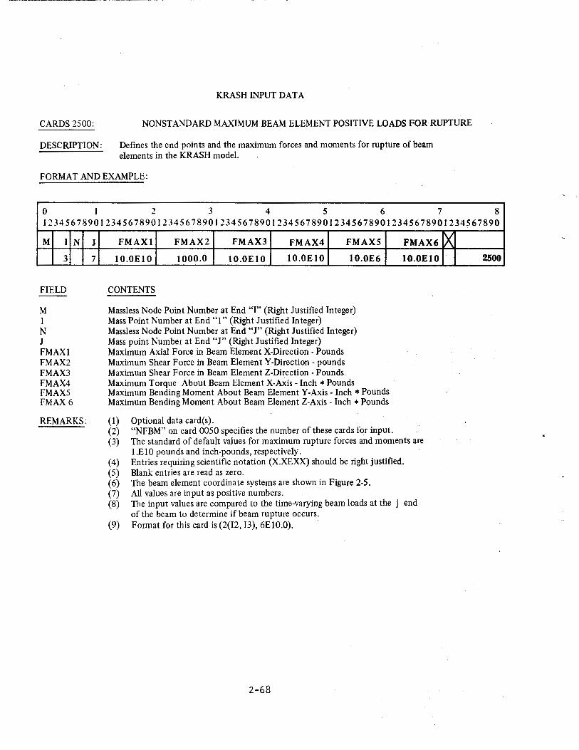
CARDS 2500:
DESCRIPTION:
KRASH INPUT DATA
NONSTANDARD MAXIMUM BEAM ELEMENT POSITIVE LOADS FOR RUPTURE
Defines the end points and the maximum forces and moments for rupture of beam elements in the KRASH model.
FORMAT AND EXAMPLE:
0 I 2 3 4 5 6 7 8 12345678901234567890123456789012345678901234567890123456789012345678901234567890
M I
3
FIELD
M 1 N J FMAXl FMAX2 FMAX3 FMAX4 FMAX5 FMAX6
N
REMARKS:
J
7
FMAXl FMAX2 FMAX3 FMAX4 FMAXS
lO.OElO 1000.0 lO.OElO lO.OElO 10.0E6
CONTENTS
Massless Node Point Number at End "I" (Right Justified Integer) Mass Point Number at End "1" (Right Justified Integer) Massless Node Point Number at End "J" (Right Justified Integer) Mass point Number at End "J" (Right Justified Integer) Maximum Axial Force in Beam Element X-Direction- Pounds Maximum Shear Force in Beam Element Y-Direction- pounds Maximum Shear Force in Beam Element Z-Direction- Pounds Maximum Torque About Beam Element X-Axis- Inch* Pounds Maximum Bending Moment About Beam Element Y-Axis- Inch *Pounds Maximum Bending Moment About Beam Element Z-Axis -Inch *Pounds
(1) Optional data card(s). (2) "NFBM" on card 0050 specifies the number of these cards for input.
FMAX6
lO.OEtO
(3) The standard of default values for maximum rupture forces and moments are l.ElO pounds and inch-pounds, respectively.
( 4) Entries requiring scientific notation (X.XEXX) should be right justified. (5) Blank entries are read as zero. (6) The beam element coordinate systems are shown in Figure 2-5. (7) All values are input as positive numbers. (8) The input values are compared to the time-varying beam loads at the j end
of the beam to determine if beam rupture occurs. (9) Format for this card is(2(12, 13), 6E10.0).
2-68
~ 2500
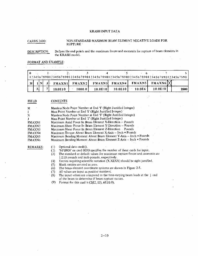
CARDS 2600:
DESCRIPTION:
KRASH INPUT DATA
NON-STANDARD MAXIMUM BEAM ELEMENT NEGATIVE LOADS FOR RUPTURE
Defmes the end points and the maximum forces and moments for rupture of beam elements in the KRASH model.
FORMAT AND EXAMPLE:
0 I 2. 3 4 5 6 7 8 1234567890l23456789012345678901234567890l234567890l234567890l2345678901234567890
M I N
3
FIELD
M I N J FMAXNl FMAXN2 FMAXN3 FMAXN4 FMAXN5 FMAXN6
REMARKS:
J
7
FMAXN1 FMAXN2 FMAXN3 FMAXN4 FMAXNS FMAXN6
lO.OEl 0 1000.0 1 O.OE 10 10.0E10
CONTENTS
Massless Node Point Number at End 'I' (Right Justified Integer) Mass Point Number at End· 'I' (Right Justified Integer) Massless Node Point Number at End 'J' (Right Justified Integer) Mass Point Number at End 'J' (Right Justified Integer)
·Maximum Axial Force In Beam Element X-Direction -Pounds Maximum Shear Force In Beam Element Y-Direction -Pounds Maximum Shear Force In Beam Element Z-Direction - Pounds
tO.OE6
Maximum Torque About Beam Element X-Axis - Inch * Pounds Maximum Bending Moment About Beam Element Y-Axis- Inch *Pounds Maximum Bending Moment About Beam Element Z-Axis - Inch * Pounds
(1) Optional data card(s). (2) 'NFBMN' on card 0050 specifies the number of these cards for input.
10.0E10
(3) The standard or default values for maximum rupture forces and moments are l.E 10 pounds and inch-pounds, respectively.
( 4) Entries requiring scientific notation (X.XEXX) should be right justified. (5) Blank entries are read as zero. (6) The beam element coordinate systems are shown in Figure 2-5. (7) All values are input as positive numbers: (8) The input values are compared to the time-varying beam loads at the j end
of the beam to determine if beam rupture occurs. (9) Format for this card is (2(12, 13), 6E10.0).
2-·69
[X 2600
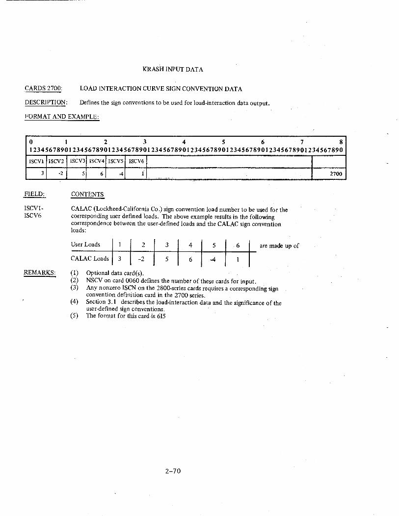
KRASH INPUT DATA
CARDS 2700: LOAD INTERACTION CURVE SIGN CONVENTION DATA
DESCRIPTION: Defines the sign conventions to be used for load-interaction data output.
FORMAT AND EXAMPLE:
0 I 2 3 4 5 6 7 8 12345678901234567890123456789012345678901234567890123456789012345678901234567890
ISCVl
3
FIELD:
ISCV1-ISCV6
ISCV2
-2
REMARKS:
ISCV3 ISCV4 ISCVS ISCV6
5 6 -4 1 -·-·
CONTENTS
CALAC (Lockheed-California Co.) sign convention load number to be used for the corresponding user defined loads. The above example results in the following correspondence between the user-defmed loads and the CALAC sign convention loads:
User Loads 1 2 3 4 5 6 are made up of
CALAC Loads 3 -2 5 6 -4 1
(1) Optional data card(s). (2) NSCV on card 0060 defines the number of these cards for input. (3) Any nonzero ISCN on the 2800-series cards requires a corresponding sign
convention definition card in the 2700 series. (4) Section 3.1 describes the load-interaction data and the significance of the
user-defined sign conventions. (5) The format for this card is 615
2-70
2700
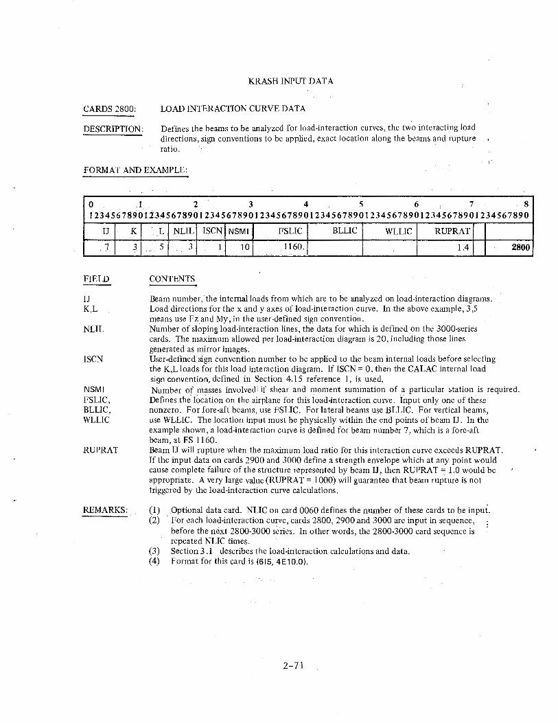
CARDS 2800:
DESCRIPTION:
KRASH INPUT DATA
LOAD INTERACTION CURVE DATA
Defines the beams to be analyzed for load-interaction curves, the two interacting load directions, sign conventions to be applied, exact location along the beams and rupture ratio.
FORMAT AND EXAMPLE:
0 I 2 3 4 5 6 7 8 12345678901234567890123456789012345678901234567890123456789012345678901234567890
IJ
7
FIELD
IJ K,L
NLIL
ISCN
NSMI FSLIC, BLLIC, WLLIC
RUPRAT
REMARKS:
K
3
L NLIL ISCN NSMI' FSLIC BLLIC WLLIC RUPRAT
5 3 1 10 1160. 1.4
CONTENTS
Beam number, the intemalloads from which are to be analyzed on load-interaction diagrams. Load directions for the x andy axes of load-interaction curve. In the above example, 3,5 means use Fz and My, in the user-defined sign convention. Number of sloping load-interaction lines, the data for which is defined on the 3000-series cards. The maximum allowed per load-interaction diagram is 20, including those lines generated as mirror images. User-defined sign convention number to be applied to the beam internal loads before selecting the K,L loads for this load interaction diagram. If ISCN = 0, then the CALAC internal load sign convention, defined in Section 4.15 reference 1, is used.
2800
Number of masses involved! if shear and moment summation of a particular station is required. Defines the location on the airplane for this load-interaction curve. Input only one of these nonzero. For fore-aft beams, use FSLIC. For lateral beams use BLLIC. For vertical beams, use WLLIC. The location input must be physically within the end points of beam IJ. In the example shown, a load-interaction curve is defined for beam number 7, which is a fore-aft beam, at FS 1160. Beam IJ will rupture when the maximum load ratio for this interaction curve exceeds RUPRAT. If the input data on cards 2900 and 3000 define a strength envelope which at any point would cause complete failure of the structure represented by beam IJ, then RUPRAT = 1.0 would be appropriate. A very large value (RUPRAT = 1000) will guarantee that beam rupture is not triggered by the load-interaction curve calculations.
(1) Optional data card. NLIC on card 0060 defines the number of these cards to be input. (2) For each load-interaction curve, cards 2800, 2900 and 3000 are input in sequence,
before the next 2800-3000 series. In other words, the 2800-3000 card sequence is repeated NLIC times.
(3) Section 3 .1 describes the load-interaction calculations and data. (4) Format for this card is (615, 4E10.0).
2-71
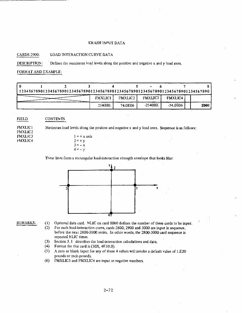
KRASH INPUT DATA
CARDS 2900: LOAD INTERACTION CURVE DATA
DESCRIPTION: Defines the maximum load levels along the positive and negative x and y load axes.
FORMAT AND EXAMPLE:
0 I 2 3 4 5 .. 6 7 8 12345678901234567890123456789012345678901234567890123456789012345678901234567890
FIELD
FMXLICl FMXLIC2 FMXLIC3 FMXLIC4
REMARKS:
FMXLICl FMXUC2 FMXUC3 FMXLIC4
254000. 74.0E06 -254ooo: -74.0E06
CONTENTS
Maximum load levels along the positive and negative x andy load axes. Sequence is as follows:
l=+xaxis 2=+y 3=-x 4=-y
These lines form a rectangular load-interaction strength envelope that looks like:
y 2
3 1 X
4
(1) Optional data card. NLIC on card 0060 defines the number of these cards to be input. (2) For each load-interaction curve, cards 2800, 2900 and 3000 are input in sequence,
before the next 2800-3000 series. In other words, the 2800-3000 card sequence is repeated NLIC times.
(3) Section 3.1 describes the load-interaction calculations and data. (4) Format for this card is (30X, 4E10.0). ( 5) A zero or blank input for any of these 4 values will invoke a default value of l.E20
pounds or inch-pounds. (6) FMXLIC3 and FMXLIC4 are input as negative numbers.
2-72
2900
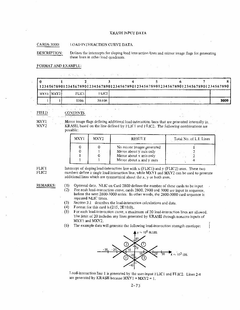
CARDS3000:
DESCRIPTION:
KRASH INPUT DATA
LOAD INTERACTION CURVE DATA
Defines the intercepts for sloping load interaction lines and mirror image flags for generating these lines in other load quadrants.
FORMAT AND EXAMPLE:
0 I 2 3 4 5 6 7 8 12345678901234567890123456789012345678901234567890123456789012345678901234567890
MXYl
1
FIELD
MXYl MXY2
FLICl FLIC2
MXY2
1
REMARKS:
FLICl FLIC2
1500. 30.£06
CONTENTS
Mirror image flags defming additional load-interaction lines that are generated internally in KRASH, based on the line defined by FLICl and FLIC2. The following combinations are possible:
MXYl MXY2 RESULT Total No. of L.I. Lines
0 0 No mirror images generated 1 0 1 Mirror. about y axis only 2 1 0 Mirror about x axis only 2 1 1 Mirror about x andy axes 4
Intercept of sloping load-interaction line with x (FLIC 1) andy (FLIC2) axes. These two numbers define a single load interaction line, while MXY1 and MXY2 can be used to generate additional lines which are symmetrical about the x, y or both axes.
(1) Optional data. NLIC on Card 2800 defines the number of these cards to be input (2) For ecah load-interaction curve, cards 2800, 2900 and 3000 are input in sequence,
before the next 2800-3000 series. In other words, the 2800-3000 card sequence is repeated NLIC times.
(3) Section 3.1 describes the load-interaction calculations and data. (4) Format for this card is (215, 2E10.0) .. (5) For each load-interaction curve, a maximum of 20 load-interaction lines are allowed.
The limit of 20 includes any lines generated by KRASH through nonzero inputs of MXY1 and MXY2.
(6) The example data will generate the following load-interaction strength envelope:
Load-interaction line 1 is generated by the user-input FLIC1 and FLIC2. Lines 2-4 are generated by KRASH because MXY 1 = MXY2 = 1.
2-73
3000
CARDS 3010:
DESCRIPTION:
KRASH INPUT DATA
LOAD INTERACTION CURVE DATA
Defines water line at forward and aft ends of segment for which shear and moment loads are to be summed.
FORMAT AND EXAMPLE:
0 I 2 3 4 s 6 7 8 12345678901234567890123456789012345678901234567890123456789012345678901234567890
WLSMF
215.7
FIELD
WLSMF WLSMA
REMARKS:
WLSMA
206.4
CONTENTS
Water line at beam forward end. Water line at beam aft end.
(I) Optional data card. Use only if NSMI on card 2800 is> 0. (2) Beam number (IJ) is defined. (3) Format for this card is (2EIO.O).
2-74
3010
CARDS 3020:
DESCRIPTION:
KRASH INPUT DATA
LOAD INTERACTION CURVE DATA
Defines masses located at station for which shear and moment loads are to be summed.
FORMAT AND EXAMPLE·
0 I 2 3 4 5 6 7 8 123456789012345678~0123456789012345678901234567890123456789012345678901234567890
IJSM1
33
FIELD
IJSM1 thru
IJSM14
IJSM2
41
REMARKS:
IJSM3 IJSM4 IJSMS IJSM6 IJSM7 IJSM8 IJSM9 JJSM IJSM IJSM IJSM 10 11 12 15
49 57 65 84 104 105 118 119
CONTENTS
Mass Point Number (Right Justified Integer)
(I) Optional data card. Use only if NSMI on card 2800 is> 0. (2) Masses designed. IJSM 1 thru IJSM 14 must all be at same FS or BL station. (3) 14 masses per card. Use NSMI/14 cards. ( 4) . Format for this card is (I 4I5).
2-75
IJSM 14
3020
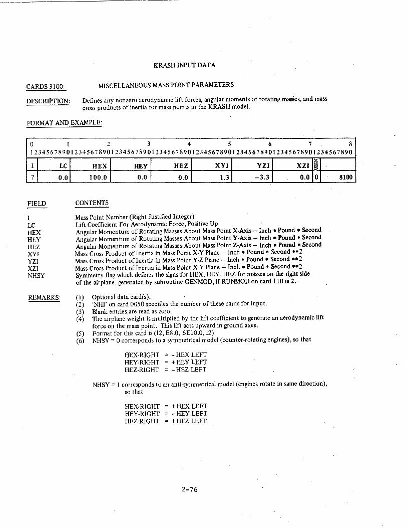
CARDS 3100:
DESCRIPTION:
KRASH INPUT DATA
MISCELLANEOUS MASS POINT PARAMETERS
Defines any nonzero aerodynamic lift forces, angular moments of rotating masses, and mass cross products of inertia for mass points in the KRASH model.
FORMAT AND EXAMPLE:
0 I 2 3 4 5 6 7 8 12345678901234567890123456789012345678901234567890123456789012345678901234567890
I
7
FIELD
I LC HEX HEY HEZ XYI YZI XZI NHSY
LC
0.0
REMARKS:
z· HEX HEY HEZ XYI YZI XZI ~
100.0 0.0 0.0 1.3 -3.3 0.0 0
CONTENTS
Mass Point Number (Right Justified Integer) Lift Coefficient For Aerodynamic Force, Positive Up Angular Momentum of Rotating Masses About Mass Point X-Axis -Inch • Pound * Second Angular Momentum of Rotating Masses About Mass PointY-Axis -Inch • Pound *Second Angular Momentum of Rotating Masses About Mass Point Z-Axis - Inch *Pound * Second Mass Cross Product of Inertia in Mass Point X-Y Plane - Inch * Pound * Second **2 Mass Cross Product of Inertia in Mass Point Y-Z Plane - Inch * Pound * Second **2 Mass Cross Product of Inertia in Mass Point X-Y Plane - Inch * Pound * Second **2 Symmetry flag which defines the signs for HEX, HEY, HEZ for masses on the right side of the airplane, generated by subroutine GENMOD, if RUNMOD on card 110 is 2.
(1) Optional data card(s). (2) 'NHI' on card 0050 specifies the number of these cards for input. (3) Blank entries. are read as zero. (4) The airplane weight is multiplied by the lift coefficient to generate an aerodynamic lift
force on the mass point. This lift acts upward in ground axes. (5) Format for this card is (12, E8.0, 6EIO.O, I2) (6) NHSY = 0 corresponds to a symmetrical model (counter-rotating engines), so that
HEX-RIGHT = -HEX LEFT HEY-RIGHT = +HEY LEFT HEZ-RIGHT = - HEZ LEFT
NHSY = 1 corresponds to an anti-symmetrical model (engines rotate in same direction), so that
HEX-RIGHT = +HEX LEFT HEY-RIGHT = -HEY LEFT HEZ-RIGHT = + HEZ LEFT
2-76
3100
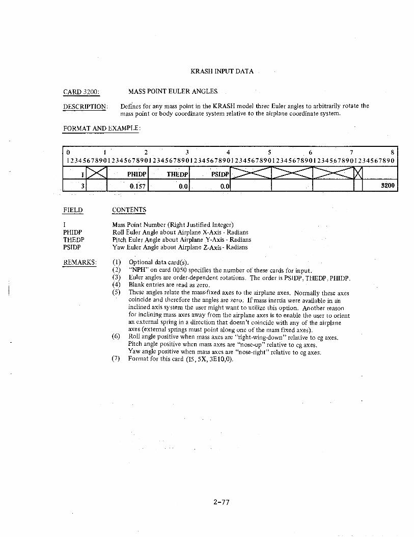
CARD 3200:
DESCRIPTION:
KRASH INPUT DATA
MASS POINT EULER ANGLES
Defines for any mass point in the KRASH model three Euler angles to arbitrarily rotate the mass point or body coordinate system relative to the airplane coordinate system.
FORMAT AND EXAMPLE:
0 1 2 3 4 5 6 7 8 12345678901234567890123456789012345678901234567890123456789012345678901234567890
I
3
FIELD
I PHIDP THEDP PSIDP
REMARKS:
PHIDP THEDP
0.157 0.0 0.0
CONTENTS
Mass Point Number (Right Justified Integer) Roll Euler Angle about Airplane X-Axis -Radians Pitch Euler Angle about Airplane Y-Axis -Radians Yaw Euler Angle about Airplane Z-Axis- Radians
(1) Optional data card(s). (2) "NPH" on card 0050 specifies the number of these cards for input. (3) Euler angles are order-dependent rotations. The order is PSIDP, THEDP, PHIDP. ( 4) Blank entries are read as zero. (5) These angles relate the mass-fixed axes to the airplane axes. Normally these axes
coincide and therefore the angles are zero. Ifmass inertia were available in an inclined axis system the user might want to utilize this option. Another reason for inclining mass axes away from the airplane axes is to enable the user to orient an external spring in a direction that doesn't coincide with any of the airplane axes (external springs must point along one of the mass fixed axes).
(6) Roll angle positive when mass axes are "right-wing-down" relative to cg axes. Pitch angle positive when mass axes are "nose-up" relative to cg axes. Yaw angle positive when mass axes are "nose-right" relative to cg axes.
(7) Format for this card (I5, 5X, 3E10,0).
2-77
3200
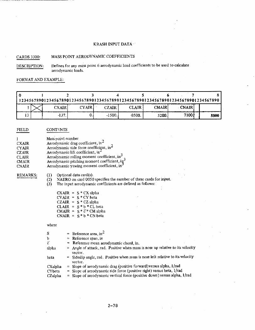
CARDS3300:
DESCRIPTION:
KRASH INPUT DATA
MASS POINT AERODYNAMIC COEFFICIENTS
Defines for any mass point 6 aerodynamic load coefficients to be used to calculate aerodynamic loads.
FORMAT AND EXAMPLE:
0 I 2 3 4 5 6 7 8 12345678901234567890123456789012345678901234567890123456789012345678901234567890
r!X 13
FIELD
I CXAIR CYAIR CZAIR CLAIR CMAIR CNAIR
REMARKS:
CXAIR CYAIR CZAIR
-137. 0. -1500.
CONTENTS
Mass point number Aerodynamic drag coefficient, in2
Aerodynamic side force coeffici~nt, in2 Aerodynamic lift coefficient, in Aerodynamic rolling moment coefficient, in3
Aerodynamic pitching moment coefficient, i~3 Aerodynamic yawing moment coefficient, in
(1) Optional data card(s).
CLAIR CMAIR
•3500. 5200.
(2) NAERO on card 0050 specifies the number of these cards for input. (3) The input aerodynamic coefficients are defmed as follows: ·
where
s b c
CXAIR CYAIR CZAIR CLAIR CMAIR =
CNAIR
s *ex alpha S * CY beta S * CZ alpha S * b * CL beta S * c* CM alpha S * b * CN beta
= Reference area, in2 Reference span, in Reference mean aerodynamic chord, in.
CNAIR
7100
alpha Angle of attack, rad. Positive when mass is nose up relative to its velocity vector.
beta
CXalpha CYbeta CZalpha
Sideslip angle, rad. Positive when mass is nose left relative to its velocity vector. Slope of aerodynamic drag (positive forward)versus alpha, l/rad Slope of aerodynamic side force (positive right) versus beta, 1/rad Slope of aerodynamic vertical force (positive down) versus alpha, l/rad
2-78
3300
REMARKS: (Continued)
CLbeta
CMalpha CNbeta
KRASH INPUT DATA
Slope of aerodynamic roll moment (positive right wing down) versus beta, 1/rad Slope of aerodynamic pitch moment (positive nose up) versus alpha, 1/rad Slope of aerodynamic yaw moment (positive nose right) versus beta, 1/rad
(4) All data refer to the local mass defined by I, not to the entire airplane. (5) Aerodynamic loads at zero ALPHA are not included in the calculations. If
necessary, these can be included as external forces/moments in the 3300 series cards.
(6) Aerodynamic loads using these coefficients are not included in the balanced initial conditions coding.
(7) The format for this card is (IS ,5X,6E10.0).
2-79
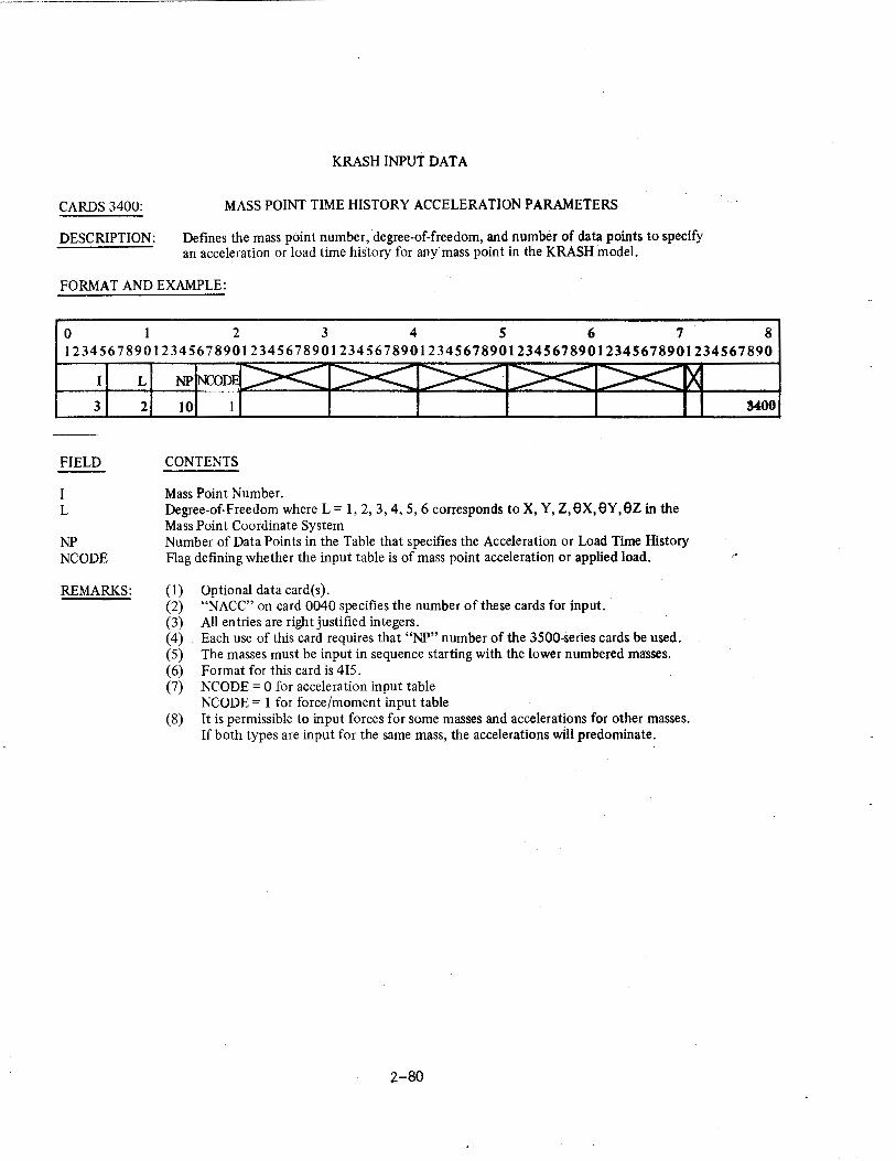
CARDS3400:
DESCRIPTION:
KRASH INPUT DATA
MASS POINT TIME HISTORY ACCELERATION PARAMETERS
Defines the mass point number, degree-of-freedom, and number of data points to specify an acceleration or load time history for any mass point in the KRASH modeL
FORMAT AND EXAMPLE:
0 I 2 3 4 S 6 7 8 l234S67890123456789012345678901234S678901234S678901234S678901234S678901234S67890
I
3
FIELD
I L
NP NCODE
REMARKS:
L
2 10 1
CONTENTS
Mass Point Number. Degree-of-Freedom where L = 1, 2, 3, 4, 5, 6 corresponds to X, Y, z,ex,ev,ez in the Mass Point Coordinate System Number of Data Points in the Table that specifies the Acceleration or Load Time History Flag defining whether the input table is of mass point acceleration or applied load.
(1) Optional data card(s). (2) "NACC" on card 0040 specifies the number of these cards for input. (3) All entries are right justified integers. (4) Each use of this card requires that "NP" number of the 3500-series cards be used. (5) The masses must be input in sequence starting with the lower numbered masses. (6) Format for this card is 415. (7) NCODE = 0 for acceleration input table
NCODE = 1 for force/moment input table (8) It is permissible to input forces for some masses and accelerations for other masses.
If both types are input for the same mass, the accelerations will predominate.
2-80
3400
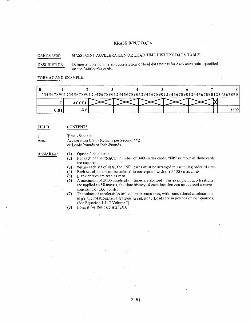
CARDS 3500:
DESCRIPTION:
KRASH INPUT DATA
MASS POINT ACCELERATION OR LOAD TIME HISTORY DATA TABLE
Defines a table of time and acceleration or load data points for each mass point specified on the 3400-series cards.
FORMAT AND EXAMPLE:
0 ~ 3 4 5 6 7 8 1~345678901~345678901~345678901~345678901~3456789012345678901~345678901234567890
FIELD
T Accel
T
0.01
REMARKS:
ACCEL
-0.6
CONTENTS
Time - Seconds Acceleration G's or Radians per Second **2 or Loads Pounds or Inch-Pounds
(1) (2)
(3) (4) (5) (6)
(7)
(8)
Optional data cards. For each of the "NACC" number of 3400-series cards, "NP" number of these cards are required. Within each set of data, the "NP" cards must be arranged in ascending order of time. Each set of data must be ordered to correspond with the 3400 series cards. Blank entries are read as zero. A maximum of 5000 acceleration times are allowed. For example, if accelerations are applied to 50 masses, the time history of each location can not exceed a curve consisting of 100 points. The values of acceleration or load are in mass axes, with translational accelerations in g's and rotational accelerations in rad/sec2. Loads are in pounds or inch-pounds. (See Equation 1-117 Volume I). Format for this card is 2E1 0.0.
2-81
3500
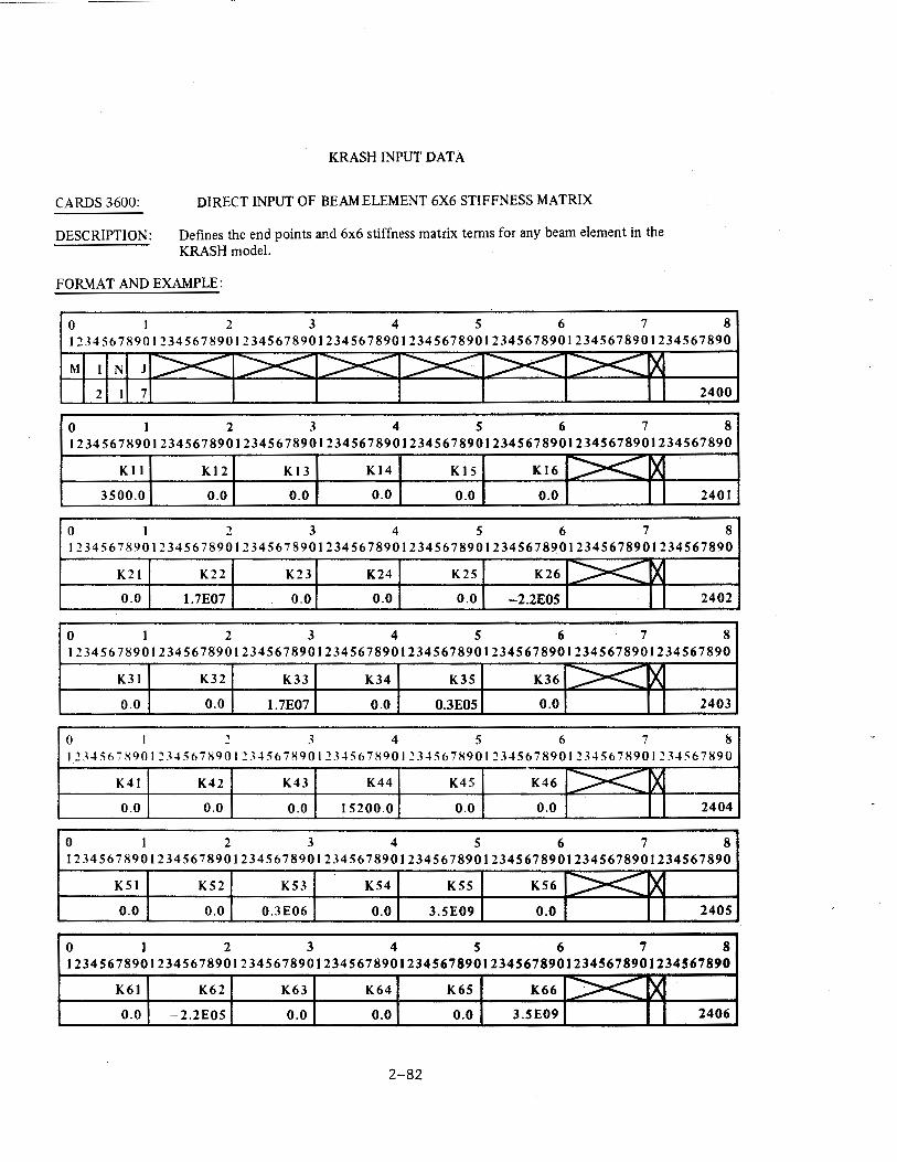
CARDS3600:
DESCRIPTION:
KRASH INPUT DATA
DIRECT INPUT OF BEAM ELEMENT 6X6 STIFFNESS MATRIX
Defines the end points and 6x6 stiffness matrix terms for any beam element in the KRASH model.
FORMAT AND EXAMPLE:
0 2 3 4 5 6 7 8 12345678901234567890123456789012345678901234567890123456789012345678901234567890
M N J
2 7 2400
0 I 2 3 4 5 6 7 8 12345678901234567890123456789012345678901234567890123456789012345678901234567890
K II Kl2 Kl3 Kl4 Kl5 Kl6 >< )( 3500.0 0.0 0.0 0.0 0.0 0.0 2401
0 I 2 3 4 5 6 7 8 12345678901234567890123456789012345678901234567890123456789012345678901234567890
K21 K22 K23 K24 K25 K26 ><::::: tx 0.0 1.7E07 0.0 0.0 0.0 -2.2EOS 2402
0 I 2 3 4 5 6 7 8 12345678901234567890123456789012345678901234567890123456789012345678901234567890
K31 K32 K33 K34 K35 K36 ~ ~ 0.0 0.0 1.7E07 0.0 0.3EOS 0.0 2403
0 I ~ 3 4 5 6 7 8 1~34567S901~34567S901~34567H901~345678901~34567H9012345678901~345678901~34567890
K41 K42 K43 K44 K45 K46 ~ rx 0.0 0.0 0.0 15200.0 0.0 0.0 2404
0 I 2 3 4 5 6 7 8 12345678901234567890123456789012345678901234567890123456789012345678901234567890
K51 K52 K53 K54 K55 K56 >< ~ 0.0 0.0 0.3E06 0.0 3.5E09 0.0 2405
0 I 2 3 4 5 6 7 8 12345678901234567890123456789012345678901234567890123456789012345678901234567890
K61 K62 K63 K64 K65 K66 >< ~ 0.0 -2.2E05 0.0 0.0 0.0 3.5E09 2406
2-82
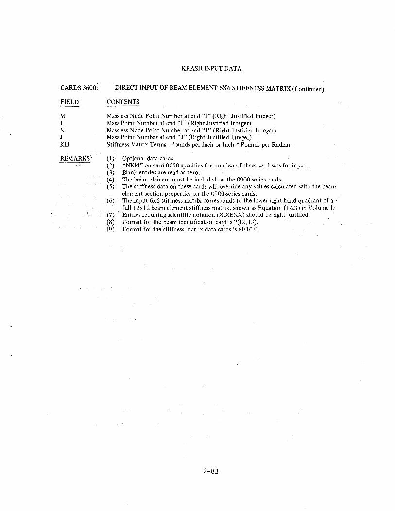
KRASH INPUT DATA
CARDS 3600: DIRECTINPUT OF BEAM ELEMENT 6X6 STIFFNESS MATRIX (Continued)
FIELD CONTENTS
M Massless Node Point Number at end "I" (Right Justified Integer) I Mass Point Number at end "I" (Right Justified Integer) N Massless Node Point Number at end "J" (Right Justified Integer) J Mass Point Number at end "J" (Right Justified Integer) KIJ Stiffness Matrix Terms- Pounds per Inch or Inch * Pounds per Radian
REMARKS: (1) Optional data cards. (2) "NKM" on card 0050 specifies the number of these card sets for input. (3) Blank entries are read as zero. (4) The beam element must be included on the 0900-series cards. (5) The stiffness data on these cards will override any values calculated with the beam
element section properties on the 0900-series cards. (6) The input 6x6 stiffness matrix corresponds to the lower right-hand quadrant of a
fulll2xl2 beam element stiffness matrix, shown as Equation (1-23) in Volume I. (7) Entries requiring scientific notation (X.XEXX) should be right justified. (8) Format for the beam identification card is 2{12, 13). (9) Format for the stiffness matrix data cards is 6E 10.0.
2-83
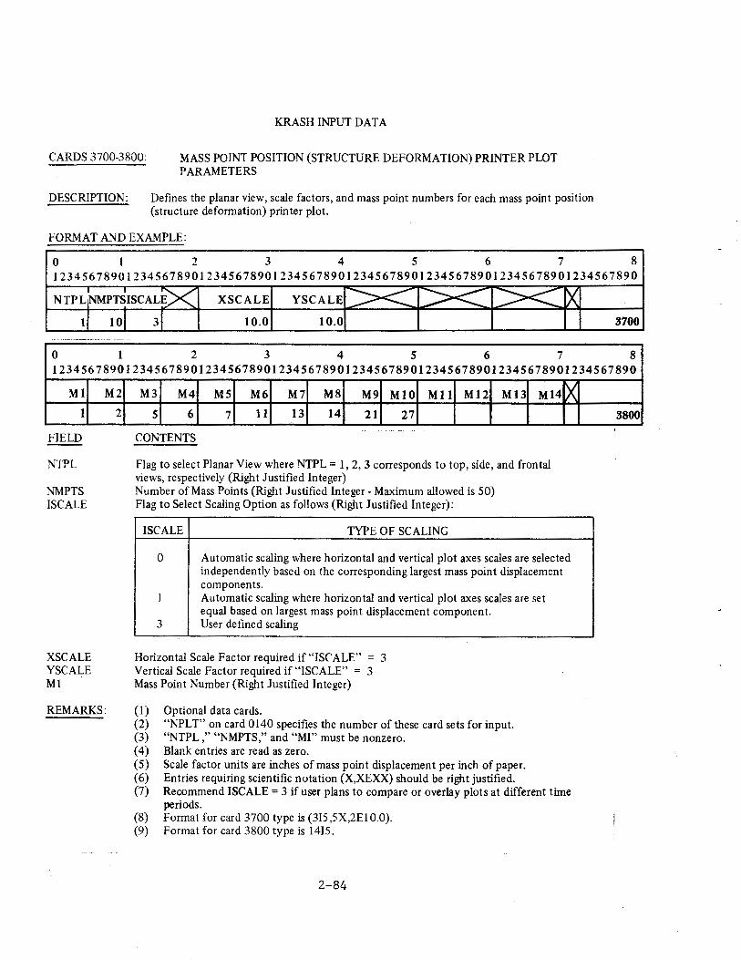
KRASH INPUT DATA
CARDS 3700-3800: MASS POINT POSITION (STRUCTURE DEFORMATION) PRINTER PLOT PARAMETERS
DESCRIPTION: Defines the planar view, scale factors, and mass point numbers for each mass point position (structure deformation) printer plot.
FORMAT AND EXAMPLE:
0 I 2 3 4 5 6 7 8 12345678901234567890123456789012345678901234567890123456789012345678901234567890
X SCALE
1 10.0 10.0 3700 ~------- - ·---- ---
0 1 2 3 4 5 6 7 8 12345678901234567890123456789012345678901234567890123456789012345678901234567890
M1
1
FIELD
NTPL
NMPTS !SCALE
XSCALE YSCALE M1
M2
2
REMARKS:
M3 M4 M5 M6 M7 M8 M9 M10 Mll Ml2 Ml3 M14
5 6 7 11 13 14 21 27
CONTENTS
Flag to select Planar View where NTPL = 1, 2, 3 corresponds to top, side, and frontal views, respectively (Right Justified Integer) Number of Mass Points (Right Justified Integer- Maximum allowed is 50) Flag to Select Scaling Option as follows (Right Justified Integer):
I SCALE TYPE OF SCALING
lX
0 Automatic scaling where horizontal and vertical plot axes scales are selected independently based on the corresponding largest mass point displacement components.
1 Automatic scaling where horizontal and vertical plot axes scales are set equal based on largest mass point displacement component.
3 User defined scaling
Horizontal Scale Factor required if "IS(' ALE" = 3 Vertical Scale Factor required if "!SCALE" = 3 Mass Point Number (Right Justified Integer)
(1) Optional data cards. (2) "NPLT" on card 0140 specifies the number of these card sets for input. (3) "NTPL ," "NMPTS," and "MI" must be nonzero. (4) Blank entries are read as zero. (5) Scale factor units are inches of mass point displacement per inch of paper. (6) Entries requiring scientific notation (X,XEXX) should be right justified. (7) Recommend I SCALE= 3 if user plans to compare or overlay plots at different time
periods. (8) Format for card 3700 type is (315,5X,2El0.0). (9) Format for card 3800 type is 1415.
2-84
3800
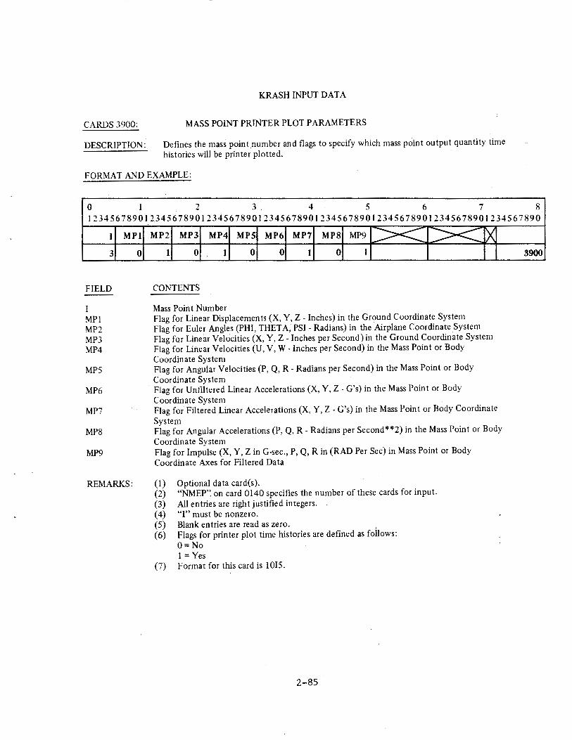
CARDS 3900:
DESCRIPTION:
KRASH INPUT DATA
MASS POINT PRINTER PLOT PARAMETERS
Defines the mass point number and flags to specify which mass point output quantity time histories will be printer plotted.
FORMAT AND EXAMPLE:
0 I 2 3 4 5 6 7 8 12345678901234567890123456789012345678901234567890123456789012345678901234567890
I
3
FIELD
I MPl MP2 MP3 MP4
MPS
MP6
MP7
MP8
MP9
MPI
0
REMARKS:
MP2 MP3 MP4 MPS MP6 MP7 MP8 MP9 >< :::><: rx I 0 1 0 0 1 0 I
CONTENTS
Mass Point Number Flag for Linear Displacements (X, Y, Z- Inches) in the Ground Coordinate System Flag for Euler Angles (PHI, THETA, PSI- Radians) in the Airplane Coordinate System Flag for Linear Velocities (X, Y, Z- Inches per Second) in the Ground Coordinate System Flag for Linear Velocities (U, V, W-Inches per Second) in the Mass Point or Body Coordinate System Flag for Angular Velocities (P, Q, R- Radians per Second) in the Mass Point or Body Coordinate System Flag for Unfiltered Linear Accelerations (X, Y, Z- G's) in the Mass Point or Body Coordinate System Flag for Filtered Linear Accelerations (X, Y, Z- G's) in the Mass Point or Body Coordinate System Flag for Angular Accelerations (P, Q, R- Radians per Second**2) in the Mass Point or Body Coordinate System Flag for Impulse (X, Y, ZinG-sec., P, Q, R in (RAD Per Sec) in Mass Point o~ Body Coordinate Axes for Filtered Data
(1) Optional data card(s). (2) "NMEP'~ on card 0140 specifies the number of these cards for input. (3) All entries are right justified integers. ( 4) "I" must be nonzero. (5) Blank entries are read as zero. (6) Flags for printer plot time histories are defined as follows:
O=No 1 =Yes
(7) Format for this card is 1015.
2-85
3900
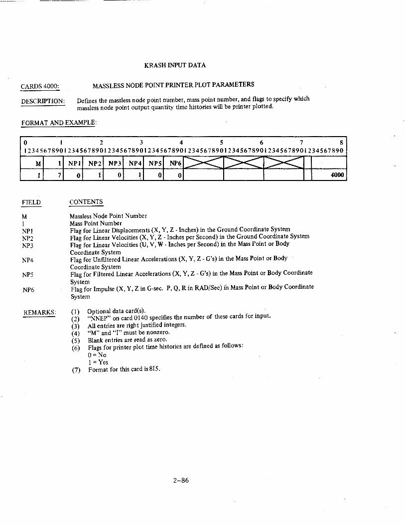
CARDS4000:
DESCRIPTION:
KRASH INPUT DATA
MASSLESS NODE POINT PRINTER PLOT PARAMETERS
Defmes the massless node point number, mass point number, and flags to specify which massless node point output quantity time histories will be printer plotted.
FORMAT AND EXAMPLE:
0 I 2 3 4 5 6 7 8 12345678901234567890123456789012345678901234567890123456789012345678901234567890
M
1
FIELD
M I NPI NP2 NP3
NP4
NP5
NP6
REMARKS:
I
7
NPl NP2 NP3 NP4
0 1 0 1
CONTENTS
Massless Node Point Number Mass Point Number
NPS NP6 >< >< >< 0 0
Flag for Linear Displacements (X, Y, Z- Inches) in the Ground Coordinate System Flag for Linear Velocities (X, Y, Z- Inches per Second) in the Ground Coordinate System Flag for Linear Velocities (U, V, W-Inches per Second) in the Mass Point or Body Coordinate System Flag for Unflltered Linear Accelerations (X, Y, Z- G's) in the Mass Point or Body Coordinate System Flag for Filtered Linear Accelerations (X, Y, Z- G's) in the Mass Point or Body Coordinate System Flag for Impulse (X, Y, ZinG-sec. P, Q, R in RAD/Sec) in Mass Point or Body Coordinate
System
(1) Optional data card(s). · (2) "NNEP" on card 0140 specifies the number of these cards for input. (3) All entries are right justified integers. (4) "M" and "I" must be nonzero. (5) Blank entries are read as zero. (6) Flags for printer plot time histories are defined as follows:
O=No 1 =Yes
(7) Format for this card is 815.
2-86
4000
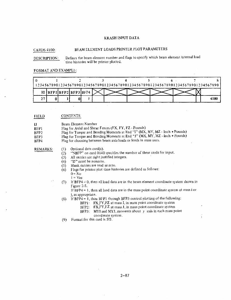
CARDS 4100:
DESCRIPTION:
KRASH INPUT DATA
BEAM ELEMENT LOADS PRINTER PLOT PARAMETERS
Defines the beam element number and flags to specify which beam element internal load time histories will be printer plotted.
FORMAT AND EXAMPLE:
0 2 3 4 5 6 i 8 12345678901234567890123456789012345678901234567890123456789012345678901234567890
IO BFPl BFP2 BFP3 BFP4
27 0 0 1
FIELD
IJ BFPl BFP2 BFP3 BFP4
REMARKS:
CONTENTS
Beam Element Number Flag for Axial and Shear Forces (FX, FY, FZ- Pounds) Flag for Torque and Bending Moments at End "I" (MX, MY, MZ- Inch *Pounds) Flag for Torque and Bending Moments at End "J" (MX, MY, MZ- Inch* Pounds) Flag for choosing between beam axis loads or loads in mass axes.
(1) Optional data card(s). (2) "NBFP" on card 0140 specifies the number of these cards for input. (3) All entries are right justified integers. (4) "IJ" must be nonzero. (5) Blank entries are read as zero. (6) Flags for printer plot time histories are defined as follows:
O=No 1 =Yes
(7) If BFP4 = 0, then all load data are in the beam element coordinate system shown in Figure 2-5. If BFP4 = 1, then all load data are in the mass point coordinate system at mass i or j, as appropriate.
(8) If BFP4 = J, then BFPl through BFP3 control plotting of the following: BFPl: FX,FY,FZ at mass I, in mass point coordinate system BFP2: FX,FY,FZ at mass J, in mass point coordinate system BFP3: MYI and MYJ, moments about y axis in each mass point
coordinate system. (9) Format for this card is SIS.
2-87
4100
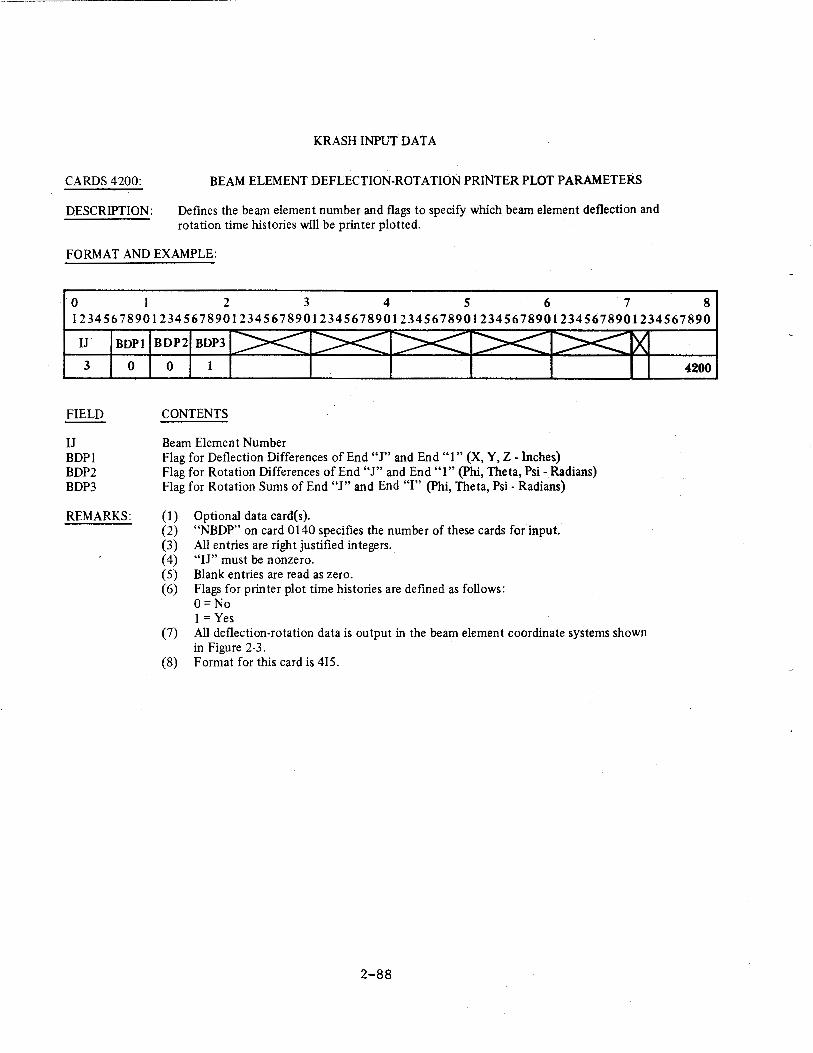
CARDS4200:
DESCRIPTION:
KRASH INPUT DATA
BEAM ELEMENT DEFLECTION-ROTATION PRINTER PLOT PARAMETERS
Defines the beam element number and flags to specify which beam element deflection and rotation time histories will be printer plotted.
FORMAT AND EXAMPLE:
0 2 3 4 5 6 7 8 12345678901234567890123456789012345678901234567890123456789012345678901234567890
IJ
3
FIELD
IJ BDP1 BDP2 BDP3
BDPl BDP2 BDP3
0 0 1
CONTENTS
Beam Element Number Flag for Deflection Differences of End "J" and End "1" (X, Y, Z- Inches) Flag for Rotation Differences of End "J" and End "1" (Phi, Theta, Psi- Radians) Flag for Rotation Sums of End "J" and End "I" (Phi, Theta, Psi - Radians)
REMARKS: (1) Optional data card(s). (2) "NBDP" on card 0140 specifies the number of these cards for input. (3) All entries are right justified integers. ( 4) "IJ" must be nonzero. (5) Blank entries are read as zero. (6) Flags for printer plot time histories are defined as follows:
O=No 1 =Yes
(7) All deflection-rotation data is output in the beam element coordinate systems shown in Figure 2-3.
(8) Format for this card is 4IS.
2-88
4200
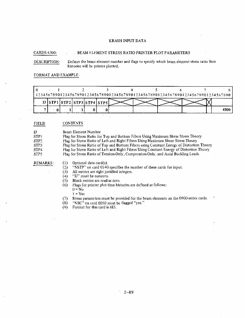
CARDS4300:
DESCRIPTION:
KRASH INPUT DATA
BEAM ELEMENT STRESS RATIO PRINTER PLOT PARAMETERS
Defines the beam element number and flags to specify which beam element stress ratio time histories will be printer plotted.
FORMAT AND EXAMPLE:
0 3 4 5 6 7 8 1~345678901234567890123456789012345678901234567890123456789012345678901234567890
U STPl STP2 STP3 STP4 STPS
7 0
FIELD
IJ STPl STP2 STP3 STP4 STP5
REMARKS:
1 1 0 0
CONTENTS
Beam Element Number Flag for Stress Ratio for Top and Bottom Fibers Using Maximum Shear Stress Theory Flag for Stress Ratio of Left and Right Fibers Using Maximum Shear Stress Theory Flag for Stress Ratio of Top and Bottom Fibers using Constant Energy of Distortion Theory Flag for Stress Ratio of Left and Right Fibers Using Constant Energy of Distortion Theory Flag for Stress Ratio of Tension-Only, Compression-Only, and Axial Buckling Loads
(1) Optional data card(s). (2) "NSTP" on card 0140 specifies the number of these cards for input. (3) All entries are right justified integers. ( 4) "IJ" must be nonzero. (5) Blank entries are read as zero. (6) Flags for printer plot time histories are defined as follows:
0= No 1 =Yes
(7) Stress parameters must be provided for the beam elements on the 0900-series cards. (8) "NSC" on card 0050 must be flagged "yes." (9) Format for this card is 615.
2-89
4300
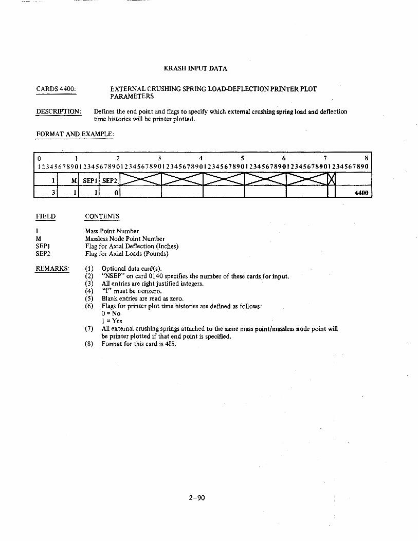
CARDS4400:
DESCRIPTION:
KRASH INPUT DATA
EXTERNAL CRUSHING SPRING LOAD-DEFLECTION PRINTER PLOT PARAMETERS
Defmes the end point and flags to specify which external crushing spring load and deflection time histories will be printer plotted.
FORMAT AND EXAMPLE:
0 I 2 3 4 5 6 7 8 12345678901234567890123456789012345678901234567890123456789012345678901234567890
I M SEPI SEP2
3
FIELD
I M SEPI SEP2
REMARKS:
1 1 0
CONTENTS
Mass Point Number Massless Node Point Number Flag for Axial Deflection (Inches) Flag for Axial Loads (Pounds)
(I) Optional data card{s). (2) "NSEP" on card 0140 specifies the number of these cards for input. {3) All entries are right justified integers. {4) "I" must be nonzero. (5) Blank entries are read as zero. (6) Flags for printer plot time histories are defined as follows:
O=No 1 =Yes
(7) All external crushing springs attached to the same mass point/massless node point will be printer plotted if that end point is specified.
{8) Format for this card is 415.
2-90
4400
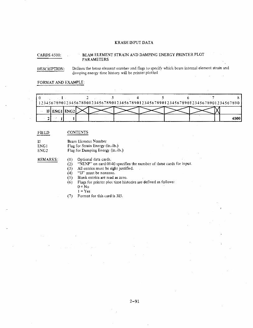
CARDS 4500:
DESCRIPTION:
KRASH INPUT DATA
BEAM ELEMENT STRAIN AND DAMPING ENERGY PRINTER PLOT PARAMETERS
Defines the beam element number and flags to specify which beam internal element strain and damping energy time history will be printer plotted
FORMAT AND EXAMPLE:
0 2 3 4 5 6 7 8 1234567S~Ol234567890123456789012345678901234567890123456789012345678901234567890
U ENGI ENG2
2
FIELD
IJ ENGl ENG2
REMARKS:
1
CONTENTS
Beam Element Number Flag for Strain Energy (in.-lb.) Flag for Damping Energy (in.-lb.)
(1) Optional data cards. (2) "NENP" on card 0140 specifies the number of these cards for input. (3) All entries must be right justified. ( 4) "IJ" must be nonzero. (5) Blank entries are read as zero. (6) Flags for printer plot time histories are defined as follows:
O=No 1 =Yes
(7) Format for this card is 3I5.
2-91
4500
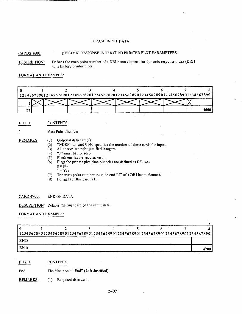
CARDS4600:
DESCRIPTION:
KRASH INPUT DATA
DYNAMIC RESPONSE INDEX (DRI) PRINTER PLOT PARAMETERS
Defines the mass point number of a DRI beam element for dynamic response index (DRI) time history printer plots.
FORMAT AND EXAMPLE:
0 1 2 3 4 s 6 7 8 12345678901234567890123456789012345678901234567890123456789012345678901234567890
27
FIELD
1
REMARKS:
CARD 4700:
CONTENTS
Mass Point Number
(I) Optional data card(s). (2) "NDRP" on card 0140 specifies the number of these cards for input. (3) All entries are right justified integers. ( 4) "J" must be nonzero. (5) Blank entries are read as zero. (6) Flags for printer plot time histories are defined as follows:
0 =No I= Yes
(7) The mass point number must be end "J" of a DRI beam element. (8) Format for this card is 15.
END OF DATA
DESCRIPTION: Defines the final card of the input data.
FORMAT AND EXAMPLE:
0 1 2 3 4 5 6
4600
. 7 8
12345678901234567890123456789012345678901234567890123456789012345678901234567890
END
END 4700
FIELD CONTENTS
End The Mnemonic "End" (Left Justified)
REMARKS: (1) Required data card.
2-92
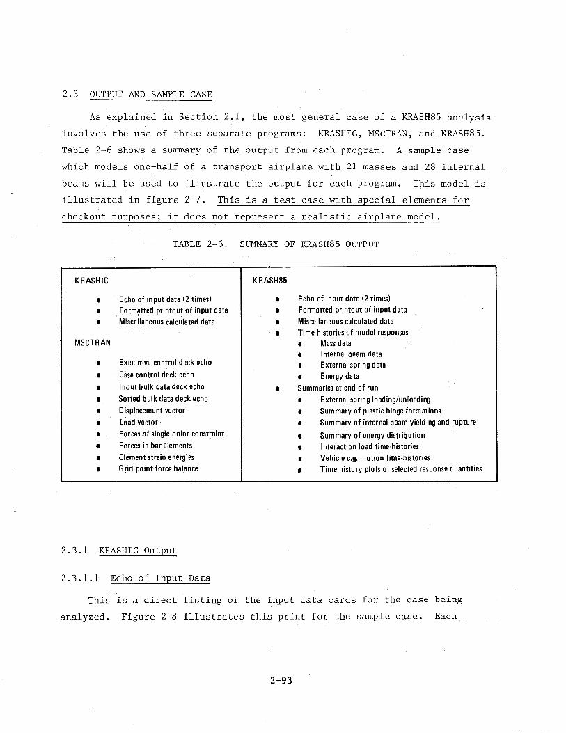
2.3 OUTPUT AND SAMPLE CASE
As explained in Section 2.1, the most general case of a KRASH85 analysis
involves the use of three separate programs: KRASHIC, MSCTRM~, and KRASH85.
Table 2-6 shows a summary of the output from each program. A sample case
which models one-half of a transport airplane with 21 masses and 28 internal
beams will be used to illustrate the output for each program. This model is
illustrated in figure 2-7. This is a test case with special elements for
checkout purposes; it does not represent a realistic airplane model.
TABLE 2-6. SUMMARY OF KRASH85 OUTPUT
KRASHIC KRASH85
I
I
I
MSCTRAN
I
I
I
I
I
I
I
• I
I
Echo of input data (2 times) Formatted printout of input data Miscellaneous calculated data
Executive control deck echo
Case control deck echo Input bulk data deck echo Sorted bulk data deck echo Displacement vector Load vector Forces of single-point constraint Forces in bar elements Element strain energies Grid point force balance
2.3.1 KRASHIC Output
2.3.1.1 Echo of Input Data
I
I
I
I
Echo of input data (2 times) Formatted printout of input data Miscellaneous calculated data Time histories of model responses 1 Mass data 1 Internal beam data 1 External spring data 1 Energy data
1 Summaries at end of run 1 External spring loading/unloading 1 Summary of plastic hinge formations 1 Summary of internal beam yielding and rupture
1 Summary of energy distribution 1 Interaction load time-histories 1 Vehicle c_g_ motion time-histories • Time history plots of selected response quantities
This is a direct listing of the input data cards for the case being
analyzed. Figure 2-8 illustrates this print for the sample case. Each
2-93
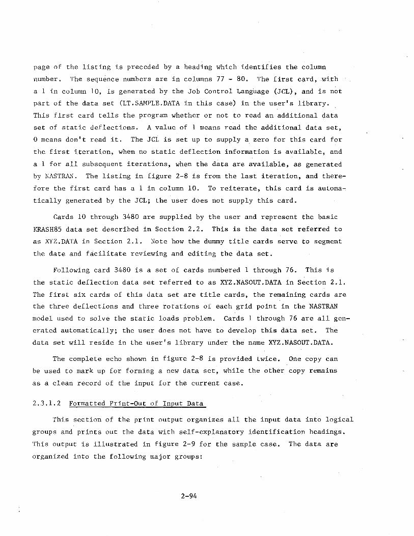
page of the listing is preceded by a heading which identifies the column
number. The sequence numbers are in columns 77 - 80. The first card, with
a 1 in column 10, is generated by the Job Control Language (JCL), and is not
part of the data set (LT.SAMPLE.DATA in this case) in the user's library.
This first card tells the program whether or not to read an additional data
set of static deflections. A value of 1 means read the additional data set,
0 means don't read it. The JCL is set up to supply a zero for this card for
the first iteration, when no static deflection information is available, and
a 1 for all subsequent iterations, when the data are available, as generated
by NASTRAN. The listing in figure 2-8 is from the last iteration, and there
fore the first card has a 1 in column 10. To reiterate, this card is automa
tically generated by the JCL; the user does not supply this card.
Cards 10 through 3480 are supplied by the user and represent the basic
KRASH85 data set described in Section 2.2. This is the data set referred to
as XYZ.DATA in Section 2.1. Note how the dummy title cards serve to segment
the date and facilitate reviewing and editing the data set.
Following card 3480 is a set of cards numbered 1 through 76. This is
the static deflection data set referred to as XYZ.NASOUT.DATA in Section 2.1.
The first six cards of this data set are title cards, the remaining cards are
the three deflections and three rotations of each grid point in the NASTRAN
model used to solve the static loads problem. Cards 1 through 76 are all gen
erated automatically; the user does not have to develop this data set. The
data set will reside in the user's library under the name XYZ.NASOUT.DATA.
The complete echo shown in figure 2-8 is provided twice. One copy can
be used to mark up for forming a new data set, while the other copy remains
as a clean record of the input for the current case.
2.3.1.2 Formatted Print-Out of Input Data
This section of the print output organizes all the input data into logical
groups and prints out the data with self-explanatory identification headings.
This output is illustrated in figure 2-9 for the sample case. The data are
organized into the following major groups:
2-94
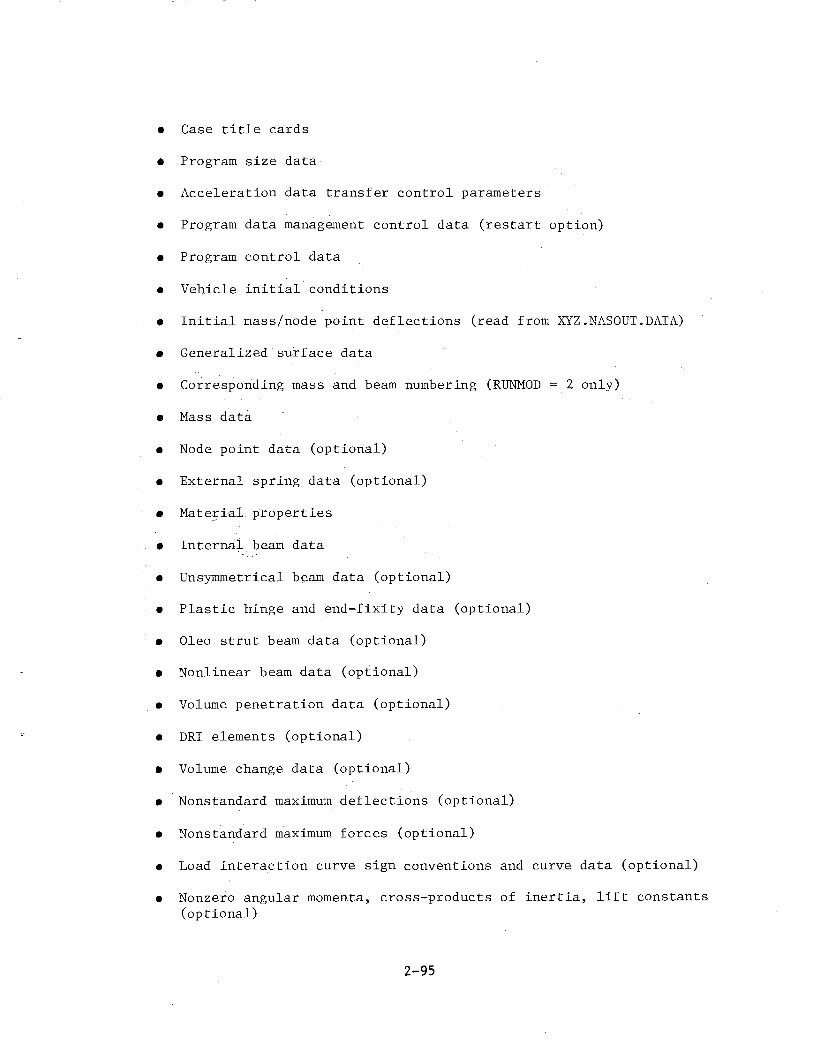
• Case title cards
• Program size data
• Acceleration data transfer control parameters
• Program data management control data (restart option)
• Program control data
• Vehicle initial conditions
• Initial mass/node point deflections (read from XYZ.NASOUT.DATA)
• Generalized surface data
• Corresponding mass and beam numbering (RUNMOD 2 only)
• Mass data
• Node point data (optional)
• External spring data (optional)
• Material properties
• Internal beam data
• Unsymmetrical beam data (optional)
• Plastic hinge and end-fixity data (optional)
• Oleo strut beam data (optional)
• Nonlinear beam data (optional)
• Volume penetration data (optional)
• DRI elements (optional)
• Volume change data (optional)
• Nonstandard maximum deflections (optional)
• Nonstandard maximum forces (optional)
• Load interaction curve sign conventions and curve data (optional)
• Nonzero angular momenta, cross-products of inertia, lift constants (optional)
2-95
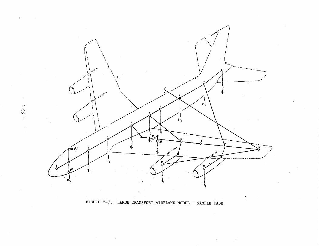
N I
\0 0'\
/""" 1"7 ( ' I
I '\ I \I L )I
I I >--
1!'/ ----
. .- ' I / /i --- ·---__//
///" R / I/ ,/
FIGURE 2-7. LARGE TRANSPORT AIRPLANE MODEL- SAMPLE CASE
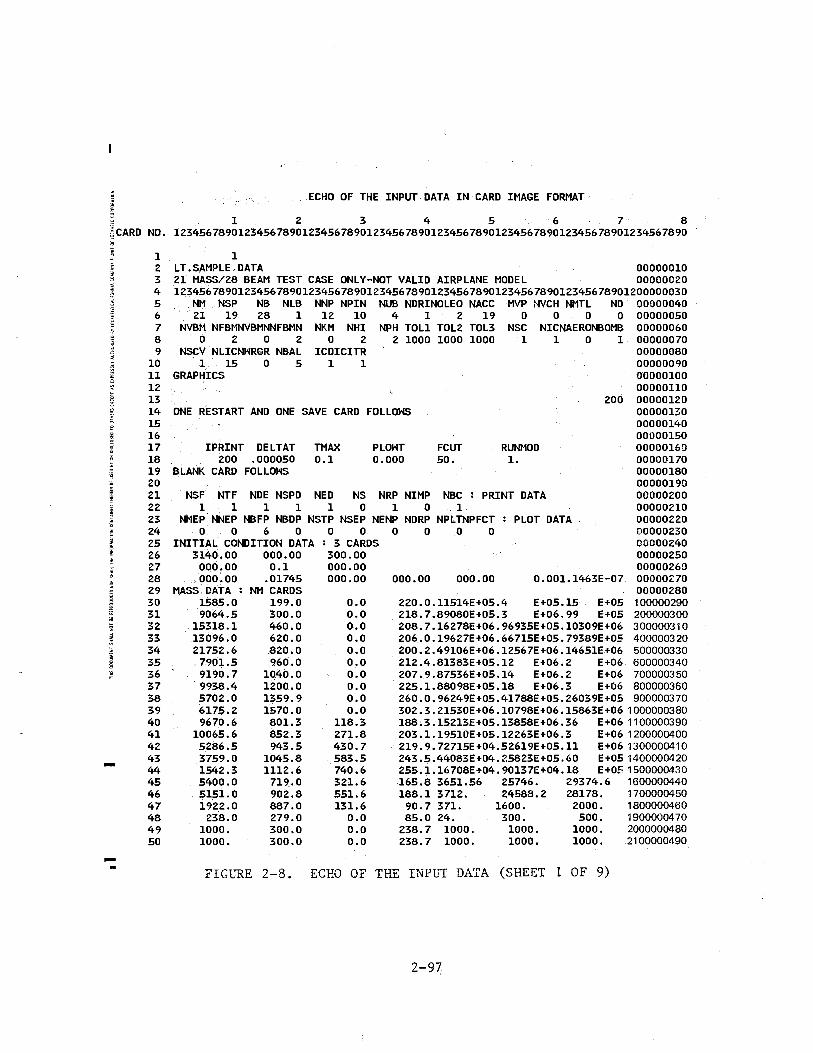
ECHO OF THE INPUT DATA IN CARD IMAGE FORMAT
1 2 3 4 5 6 7 8 ~CARD NO. 12345678901234567890123456789012345678901234567890123456789012345678901234567890
1 1 2 LT.SAMPLE.DATA 00000010 3 21 MASS/28 BEAM TEST CASE ONLY-NOT VALID AIRPLANE MODEL 00000020 4 12345678901234567890123456789012345678901234567890123456789012345678901200000030 5 NM NSP NB NLB NNP NPIN NUB NDRINOLEO NACC MVP NVCH NMTL NO 00000040 6 21 19 28 1 12 10 4 1 2 19 0 0 0 0 00000050 7 NVBM NFBMNVBMNNFBMN NKM NHI NPH TOLl TOL2 TOL3 NSC NICNAERONBOMB 00000060 8 0 2 0 2 0 2 2 1000 1000 1000 1 1 0 1 00000070 9 NSCV NLICNHRGR NBAL ICDICITR 00000080
10 1 15 0 5 1 1 00000090 11 GRAPHICS 00000100 12 00000110 13 200 00000120 14 ONE RESTART AND ONE SAVE CARD FOLLOWS 00000130 15 00000140 16 00000150 17 !PRINT DELTAT TMAX PLOWT FCUT RUNMOD 00000160 18 200 .000050 0.1 o.ooo 50. 1. 00000170 19 BLANK CARD FOLLOWS 00000180 20 00000190 21 NSF .NTF NDE NSPD NED NS NRP NIMP NBC : PRINT DATA 00000200 22 1 1 1 1 1 0 1 0 1 00000210 23 NMEP.NNEP NBFP NBDP NSTP NSEP NENP NDRP NPLTNPFCT : PLOT DATA 00000220 24 0 0 6 0 0 0 0 0 0 0 00000230 25 INITIAL CONDITION DATA : 3 CARDS 00000240 26 3140.00 000.00 300.00 00000250 27 000.00 0.1 000.00 00000260 28 000,00 .01745 000.00 000.00 000.00 0.001.1463E-07 00000270 29 MASS DATA : NM CARDS 00000280 30 1585.0 199.0 0.0 220.0.11514E+05.4 E+05.15 E+05 100000290 31 9064.5 300.0 0.0 218.7.89080E+05.3 E+06.99 E+05 200000300 32 15318.1 460.0 0.0 208.7.16278E+06.96935E+05.10309E+06 300000310 33 13096.0 ~20.0 0.0 206.0.19627E+06.66715E+05.79389E+05 400000320 34 21752.6 .820.0 0.0 200.2.49106E+06.12567E+06.14651E+06 500000330 35 7901.5 9.60.0 0.0 212.4.81383E+05.12 E+06.2 E+06 600000340 36 9190.7 1040.0 0.0 207.9.87536E+05.14 E+06.2 E+06 700000350 37 9938.4 1200.0 0.0 225.1.88098E+05.18 E+06.3 E+06 800000360 38 5702.0 1359.9 0.0 260.0.96249E+05.41788E+05.26039E+05 900000370 39 6175.2 1570.0 0.0 302.3.21530E+06.10798E+06.15863E+06 1000000380 40 9670.6 801.3 118.3 188.3.15213E+05.13858E+06.36 E+06 1100000390 41 10065.6 852.3 271.8 203.1.19510E+05.12263E+06.3 E+06 1200000400 42 5286.5 943.5 430.7 219.9.72715E+04.52619E+05.11 E+06 1300000410 43 3759.0 1045.8 583.5 243.5.44083E+04.25823E+05.60 E+051400000420 44 1542.3 1112.6 740.6 255.1.16708E+04.90137E+04.18 E+051500000430 45 5400.0 719.0 321.6 165.8 3651.56 25746. 29374.6 1600000440 46 5151.0 902.8 551.6 188.1 3712. 24588.2 28178. 1700000450 47 1922.0 887.0 131.6 90.7 371. 1600. 2000. 1800000460 48 238.0 279.0 0.0 85.0 24. 300. 500. 1900000470 49 1000. 300.0 o.o 238.7 1000. 1000. 1000. 2000000480 50 1000. 300.0 0.0 238.7 1000. 1000. 1000. 2100000490
FIGL~E 2-8. ECHO OF THE INPL~ DATA (SHEET 1 OF 9)
2-97
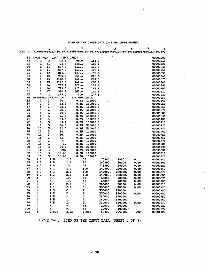
ECHO OF THE INPUT DATA IN CARD IMAGE FORMAT
1 2 3 4 5 6 7 8 CARD NO. 12345678901234567890123456789012345678901234567890123456789012345678901234567890
51 52 53 54 55 56 57 58 59 60 61 62 63 64 65 66 67 68 69 70 71 72 73 74 75 76 77 78 79 80 81 82 83 84 85 86 87 88 89 90 91 92 93 94 95 96 97 98 99
100 101
NODE POINT DATA : NNP CARDS 1 5 775.1 48.0 181.0 1 11 773.9 118.3 186.3 2 11 887.0 131.6 179.7 3 11 887.0 131.6 179.7 1 12 811.8 321.6 199.6 1 14 994.5 551.6 220.5 1 15 1148.0 740.6 261.3 .2 15 1112.6 740.6 255.1 1 16 735.7 321.6 199.6 2 16 719.0 321.6 165.8 1 17 918.4 551.6 220.5 1 2 279.0 0.0 147.5
EXTERNAL SPRING DATA 2 X NSP CARDS 1 3 70. 0.35 175000. 2 3 82.7 0.35 300000.0 3 3 72.7 0.35 100000.0 4 3 70.0 0.35 300000.0 5 3 64.2 0.35 300000.0 6 3 76.4 0.35 300000.0 7 3 69.9 0.35 100000.0 8 3 69.1 0.35 100000.0 9 3 64.0 0.35 300000.0
10 3 82.0 0.35 300000.0 11 3 28. 0.35 100000. 12 3 14. 0.35 100000. 13 3 11. 0.35 100000. 14 3 7. 0.35 100000. 15 3 3. 0.35 100000. 16 3 29.8 0.35 272000. 17 3 28. 0.35 272000. 18 3 19.65 0.30 100000. 19 3 16.45 0.30 100000.
1.3 1.5 1.6 10. 1.3 1.5 1.6 10. 1.0 6.0 10. 21. 1.0 1.1 2.0 3.0 1.0 1.1 2.0 3.0 1.0 1.1 2.0 3.0 1. 6. 10. 21. 1. 6. 10. 21. 1. 1.1 2.0 3. 1. 1.1 2.0 3. 1. 1.5 2. 7. 1. 1.5 2. 7. 1. 1.5 2. 7. 1. 1.5 2. 7. 1. 1.5 2. 7. 1. 8. 9. 16. 1. 8. 9. 16. 2. 2.001 8.05 8.051
70000. 140000. 115000. 340000. 340000. 340000.
60000. 68000.
300000. 300000. 330000. 330000. 330000. 330000. 330000.
10000. 10000. 62200.
7000. 14000. 90000.
200000. 200000. 200000. 48000. 48000. 30000. 30000.
330000. 330000. 330000. 330000. 330000.
30000. 30000.
294700.
o. 0.00 o.oo 0.00 0.00 0.00 0.00 0.00 0.00 o.oo
0.00
o.oo
.02
FIGURE 2-8. ECHO OF THE INPUT DATA (SHEET 2 OF 9)
2-98
00000500 00000510 00000520 00000530 00000540 00000550 00000560 00000570 00000580 00000590 00000600 00000610 00000620 00000630 00000640 00000650 00000660 00000670 00000680 00000690 00000700 00000710 00000720 00000730 00000740 00000750 00000760 00000770 00000780 00000790 00000800 00000810 00000820 00000830 00000840 00000850 00000860 00000870 00000880 00000890 00000900 00000910 00000920 00000930 00000940 00000950 00000960 00000970 00000980 00000990 00001000
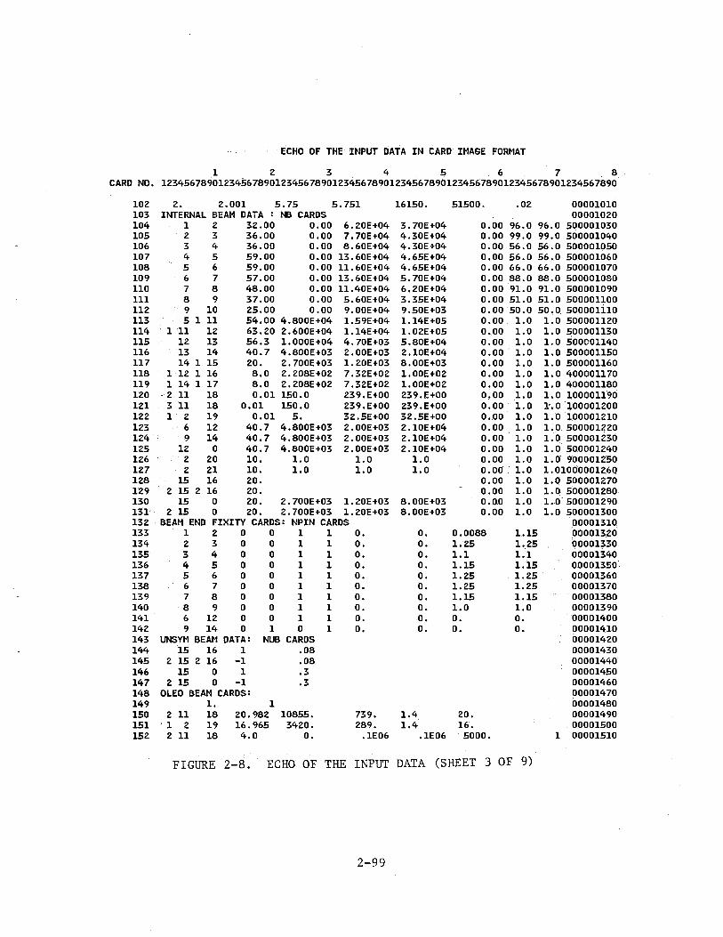
ECHO OF THE INPUT DATA IN CARD IMAGE FORMAT
1 2 3 4 5 6 7 8 CARD NO. 12345678901234567890123456789012345678901234567890123456789012345678901234567890
102 2. 2.001 5.75 5.751 16150. 51500. .02 00001010 103 INTERNAL BEAM DATA : NB CARDS 00001020 104 1 2 32.00 0.00 6.20E+04 3.70E+04 0.00 96.0 96.0 500001030 105 2 3 36.00 0.00 7.70E+04 4.30E+04 0.00 99.0 99.0 500001040 106 3 4 36.00 0.00 8.60E+04 4.30E+04 0.00 56.0 56.0 500001050 107 4 5 59.00 o.oo 13.60E+04 4.65E+04 0.00 56.0 56.0 500001060 108 5 6 59.00 0.00 11.60E+04 4.65E+04 0.00 66.0 66.0 500001070 109 6 7 57.00 0.00 13.60E+04 5.70E+04 0.00 88.0 88.0 500001080 llO 7 8 48.00 o.oo ll.40E+04 6.20E+04 0.00 91.0 91.0 500001090 111 8 9 37.00 0.00 5.60E+04 3.35E+04 0.00 51.0 51.0 500001100 112 9 10 25.00 0.00 9.00E+04 9.50E+03 0.00 50.0 50.0. 500001110 113 5 1 11 54.00 4.800E+04 1.59E+04 1.14E+05 0.00 1.0 1.0 500001120 114 1 11 12 63.20 2.600E+04 1.14E+04 1.02E+05 o.oo 1.0 1.0 500001130 115 12 13 56.3 1.000E+04 4.70E+03 5.80E+04 0.00 1.0 1.0 500001140 116 13 14 40.7 4.800E+03 2.00E+03 2.10E+04 0.00 1.0 1.0 500001150 117 14 1 15 20. 2.700E+03 1.20E+03 8.00E+03 0.00 1.0 1.0 500001160 118 1 12 1 16 8.0 2.208E+02 7.32E+02 l.OOE+02 0.00 1.0 1. 0 400001170 119 1 14 1 17 8.0 2.208E+02 7.32E+02 l.OOE+02 0.00 1.0 1. 0 400001180 120 - 2 11 18 0.01 150.0 239.E+OO 239.E+OO 0,00 1.0 1.0 100001190 121 3 11 18 0.01 150.0 239.E+OO 239.E+OO 0.00 1.0 l:.Q 100001200 122 1 2 19 0.01 5. 32.5E+OO 32.5E+OO o.oo 1.0 1.0 100001210 123 6 12 40.7 4.800E+03 2.00E+03 2.10E+04 0.00 1.0 1.0 500001220 124 9 14 40.7 4.800E+03 2.00E+03 2.10E+04 o.oo 1.0 1.0 500001230 125 12 0 40.7 4.800E+03 2.00E+03 2.10E+04 0.00 1.0 1. 0 500001240 126 2 20 10. 1.0 1.0 1.0 o.oo 1.0 1.0 900001250 127 2 21 10. 1.0 1.0 1.0 0.00 1.0 1.01000001260 128 15 16 20. 0.00 1.0 1.0 500001270 129 2 15 2 16 20. o.oo 1.0 1.(} 500001280 130 15 0 20. 2.700E+03 1.20E+03 8.00E+03 o.oo 1.0 1.0 500001290 131 2 15 0 20. 2.700E+03 1.20E+03 8.00E+03 0.00 1.0 1.0 500001300 132 BEAM END FIXITY CARDS: NPIN CARDS 00001310 133 1 2 0 0 1 1 0. o. 0.0088 1.15 000013.20 134 2 3 0 0 1 1 o. 0. 1.25 1.25 00001330 135 3 4 0 0 1 1 o. 0. 1.1 1.1 ()0001340 136 4 5 0 0 1 1 0. 0. 1.15 1.15 00001350 137 5 6 0 0 1 1 0. o. 1.25 1.25 00001360 138 6 7 0 0 1 1 0. 0. 1.25 1.25 00001370 139 7 8 0 0 1 1 0. o. 1.15 1.15 00001380 140 8 9 0 0 1 1 o. 0. 1.0 1.0 00001390. 141 6 12 0 0 1 1 0. o. 0. 0. 00001400 142 9 14 0 1 (} 1 o. 0. 0. o. 00001410 143 UNSYM BEAM DATA: NUB CARDS 00001420 144 15 16 1 .08 00001430 145 2 15 2 16 -1 .08 00001440 146 15 0 1 .3 00001450 147 2 15 0 -1 .3 00001460 148 OLEO BEAM CARDS: 00001470 149 1. 1 00001480 150 2 11 18 20.982 10855. 739. 1.4 20. 00001490 151 1 2 19 16.965 3420. 289. 1.4 16. 00001500 152 2 11 18 4.0 0. .1E06 • 1E06 5000 • 1 00001510
FIGURE 2-8. ECHO OF THE INPUT DATA (SHEET 3 OF 9)
2-99

ECHO OF THE INPUT DATA IN CARD IMAGE FORMAT
1 2 3 ~ 5 6 7 8 CARD NO. 12345678901234567890123456789012345678901234567890123456789012345~78901234567890
153 154 155 156 157 158 159 160 161 162 163 164 165 166 167 168 169 170 171 172 173 174 175 176 177 178 179 180 181 182 183 184 185 186 187 188 189 190 191 192 193 194 195 196 197 198 199 zoo 201 202 203
1 2 19 45
-o.z -0.0964 -0.0376 0.124 0.341 ().607 0.953 1.46 2.17 3.07 4.13 5.21 6.20 7.05 7.72 8.20 8.53 8.74 8.91 9.12 9.41 9.83
10.39 11.08 11.87 12.71 13.54 14.27 14.83 15.21 15.40 15.4518 15.4539 15.4581 15.494 15.61 15.84 16.18 16.65 17.21 17.82 18.39 18.82 18.97 22.
DAMPC CARD .05
3.4
352.7 352.7
10.24 23.62 22.21 17.90 8.24 3.38 2.13 1.25 1.56 1.79 2.46 3.58 6.26
13.47 31.50 62.40 64.06 34.22 16.03 8.42 5.24 3.68 2.93 2.77 3.38 4.93 9.33
25.53 153.79
1000. 1000. 1000. 403.85
67.70 22.15 9.93 5.31 3.02 2.07 0.92 o.
10. 10.
o.
NONLINEAR BEAM DATA: NLB + CARDS 3 11 18 1 7 2.0
50.E03 50.E03 500.
FIGURE 2-8. ECHO OF THE INPUT DATA (SHEET 4 OF 9)
2-100
00001520 00001530 00001540 00001550 00001560 00001570 00001580 00001590 00001600 00001610 00001620 00001630 00001640 00001650 00001660 00001670 00001680 00001690 00001700 00001710 00001720 00001730 00001740 00001750 00001760 00001770 00001780 00001790 00001800 00001810 00001820 00001830 00001840 00001850 00001860 00001870 00001880 00001890 00001900 00001910 00001920 00001930 00001940 00001950 00001960 00001970 00001980 00001990 00002000 00002010 00002020
....
ECHO OF THE INPUT DATA IN CARD IMAGE FORMAT
1 2 3 4 5 6 7 8 CARD NO. 12345678901234567890123456789012345678901234567890123456789012345678901234567890
204 DRI CARD: 00002030 205 2 21 00002040 206 POS.FORCE CUTOFF:NFBM CARDS 00002050 207 211 18 428000 l.E10 1.0El0 l.ElO l.ElO l.ElO 00002060 208 1 2 19 130000 l.ElO 78000 l.ElO l.E10 l.E10 00002070 209 NEG.FORCE CUTOFF:NFBMN CARDS 00002080 210 211 18 428000 l.ElO l.OElO l.ElO l.ElO 1.El0 00002090 211 1 2 19 130000 l.ElO 78000 l.ElO l.ElO l.ElO 00002100 212 LOAD INTERACTION SIGN CONVENTIONSINSCV CARDS): 00002110 213 1 2 -3 4 5 6 00002120 214 LOAD INTERACTION DATAINLIC+ CARDS): 00002130 215 1 3 5 1 0 300. 1000. 00002140 216 166000. 20.8E+06 -166000. -20.8E+06 00002150 217 1 1 199000. 45.6 E+06 00002160 218 2 3 5 1 0 300. 1000. 00002170 219 166000. 20.8E+06 -166000. -20.8E+06 00002180 220 1 1 199000. 45.6 E+06 00002190 221 2 3 5 2 0 400. 1000. 00002200 222 210000. 23.8E+06 -210000. -23.8E+06 00002210 223 1 1 185000. 60.8 E+06 00002220 224 1 1 674300. 25.4 E+06 00002230 225 3 3 5 2 0 480. 1000. 00002240 226 00002250 227 1 1 195000. 130.3 E+06 00002260 228 1 1 545300. 28.9 E+06 00002270 229 3 3 5 2 0 540. 1000. 00002280 230 00002290 231 1 1 199000. 137.3 E+06 00002300 232 1 11365380. 35.3 E+06 00002310 233 3 3 5 2 0 620. 1000. 00002320 234 274000. 45.0E+06 -274000. -45.0E+06 00002330 235 1 1 286000. 185.6 E+06 00002340 236 1 1 384400. 79.7 E+06 00002350 237 4 3 5 2 0 620. 1000. 00002360 238 274000. 45.0E+06 -274000. -45.0E+06 00002370 239 1 1 286000. 185.6 E+06 • 00002380 240 1 1 384400. 79.7 E+06 00002390 241 5 3 5 2 1 960. 1000. 00002400 242 288000. -288000. 00002410 243 1 0-5.2317E06 71.5E+06 00002420 244 1 1 474500. 152.8E+06 00002430 245 6 3 5 2 1 960. 1000. 00002440 246 288000. -288000. 00002450 247 1 0-5.2317E06 71.5E+06 00002460 248 1 1 474500. 152.8E+06 00002470 249 6 3 5 2 1 1000. 1000. 00002480 250 254000. 74.0E+06 -254000. -74.0E+06 00002490 251 1 1 301000. 228.7E+06 00002500 252 1 11.3581E 06 84.2E+06 00002510 253 7 3 5 3 1 1080. 1000. 00002520 254 00002530
FIGURE 2-8. ECHO OF THE INPUT DATA (SHEET 5 OF 9)
2-101
ECHO OF THE INPUT DATA IN CARD IMAGE FORMAT
1 2 3 4 5 6 7 8 CARD NO. 12345678901234567890123456789012345678901234567890123456789012345678901234567890
255 256 257 258 259 260 261 262 263 264 265 266 267 268 269 270 271 272 273 274 275 276 277 278 279 280 281 282 283 284 285 286 287 288 289 290 291 292 293 294 295 296 297 298 299 300 301 302 303 304 305
0 1 210000. -555.88E06 1 1 327700. 107.75E06 1 1 1.5738E06 64.0 E06 7 3 5 3 1 1160.
0 1 1 8
0 1 1 8
0 1 9
1 239000. 1 372214. 1 804840. 3 5
1 198000. 1 409460. 1 965217. 3 5
1 148000. 1 662500. 3 5
-265.64E06 83.5E 06 49.9E 06
3 1
-217.32E06 50.5E 06 37.0E 06
2 1
-91.818E06 31.8E 06
3 1
0 1 123500. -54.998E06 1 1 350720. 24.2E 06 1 1 914520. 18.9E 06
1240.
1320.
1400.
NONZERO ANGULAR MOMENTA INHI CARDS): 16 .1 E06 17 .1 E06
35.0 E 06
27.2 E 06
NONZERO MASS ORIENTATION ANGLES INPH CARDS): 16 -.0872665 .0349066 .05236 17 -.0872665 .0349066 .05236
FORCE TIME HISTORY DATA: NACC + CARDS 1 3 2 1 2 3 2 1 3 3 2 1 4 3 2 1 5 3 2 1 6 3 2 1 7 3 2 1 8 3 2 1 9 3 2 1
10 3 2 1 11 3 2 1 12 3 2 1 13 3 2 1 14 3 2 1 15 3 2 1 16 3 2 1 17 3 2 1 18 3 2 1 19 3 2 1 o. -95. 1. -95. 0. -624.5
1000.
1000. -35.0E06
1000. -27.2E06
1000.
FIGURE 2-8. ECHO OF THE INPUT DATA (SHEET 6 OF 9)
2-102
00002540 00002550 00002560 00002570 00002580 00002590 00002600 00002610 00002620 00002630 00002640 00002650 00002660 00002670 00002680 00002690 00002700 00002710 00002720 00002730 00002740 00002750 00002760 00002770 00002780 00002790 00002800 00002810 00002820 00002830 00002840 00002850 00002860 00002870 00002880 00002890 00002900 00002910 00002920 00002930 00002940 00002950 00002960 00002970 00002980 00002990 00003000 00003010 00003020 00003030 00003040
ECHO OF THE INPUT DATA IN CARD IMAGE FORMAT
1 2 3 4 5 6 7 8 CARD NO. 12345678901234567890123456789012345678901234567890123456789012345678901234567890
306 307 308 309 310 311 312 313 314 315 316 317 318 319 320 321 322 323 324 325 326 327 328 329 330 331 332 333 334 335 336 337 338 339 340 341 342 343 344 345 346 347 348 349 350 351 352 353 354 355 356
1. -624.5 o. -1861. 1. -1861. o. -4715. 1. -4715. o. -7901. 1. -7901. 0. -1991. 1. -1991. 0. -2316. 1. -2316. 0. -785.4 1. -785.4 0. -450. 1. -450.0 o. 17445.6 1. 17445.6 0. -15419.2 1. -15419.2 0. -28188.2 1. -28188.2 o. -21394.1 1. -21394.1 o. -17818.8 1. -17818.8 o. -6240.9 1. -6240.9 0. -270.8 1. -270.8 0. -258.3 1. -258.3 0. 0. 1. o. 0. 0. 1. 0.
BEAM LOAD PLOT PARAMETERS: NBFP CARDS 3 1 1 1 0 7 1 1 1 1
11 1 1 1 0 11 1 1 1 1 12 1 1 1 1 14 1 1 1 0
END $TITLE =LT.SAMPLE.DATA $SUBTITLE=21 MASS/28 BEAM TEST CASE ONLY-NOT VALID $LABEL =INITIAL CONDITION STATIC SOLUTION $DISPLACEMENTS
AIRPLANE MODEL
$REAL OUTPUT $SUBCASE ID =
100 -CONT-
G 1
-3.089143E-02 o.o
0.0 -2.240265E-03
-9.927106E-Ol o.o
FIGURE 2-8. ECHO OF THE INPUT DATA (SHEET 7 OF 9)
2-103
00003050· 00003060 00003070 00003080 00003090 00003100 00003110 00003120 00003130 00003Fr0 00003150 00003160 00003170 00003180 00003190 00003200 00003210 00003220 00003230 00003240 00003250 00003260 00003270 00003280 00003290 00003300 00003310 00003320 00003330 00003340 00003350 00003360 00003370 00003380 00003390 00003400 00003410 00003420 00003430 00003440 00003450 00003ft60 00003470
1 2 3 4 5 6 7 8
ECHO OF THE INPUT DATA IN CARD IMAGE FORMAT
1 2 3 4 5 6 7 8 CARD NO. 12345678901234567890123456789012345678901234567890123456789012345678901234567890
357 200 G -2.848941E-02 o.o -7.668377E-Ol 9 358 -CONT- o.o -2.228401E-03 0.0 10 359 201 G 1.302763E-Ol o.o -8.132805E-Ol 11 360 -CONT- o.o -2.228401E-03 o.o 12 361 300 G -7.956207E-03 o.o -4.223564E-01 13 362 -CONT- o.o -2.016658E-03 0.0 14 363 400 G -3.881566E-03 o.o -1.467094E-01 15 364 -CONT- o.o -1.310210E-03 0.0 16 365 500 G 0.0 o.o 0.0 17 366 -CONT- 0.0 o.o 0.0 18 367 501 G o.o o.o 0.0 19 368 -CONT- 0.0 o.o o.o 20 369 600 G 3.900044E-04 0.0 -1. 395651E-01 21 370 -CONT- 0.0 1. 905726E-03 o.o 22 371 700 G -1. 741045E-02 0.0 -3.224223E-01 23 372 -CONT- 0.0 2.646158E-03 0.0 24 373 800 G 1. 960037E-02 o.o -8.574680E-01 25 374 -CONT- 0.0 3.925510E-03 o.o 26 375 900 G 1.623369E-01 o.o -1.646019E+OO 27 376 -CONT- o.o 5.791210E-03 0.0 28 377 1000 G 4.121330E-Ol o.o -2.947555E+OO 29 378 -CONT- 0.0 6.380443E-03 0.0 30 379 1100 G -2.376708E-02 -6.204829E-02 4.549811E-Ol 31 380 -CONT- -6.692741E-03 -2.201437E-03 -5.605556E-04 32 381 1101 G -1. 923054E-02 -6.048076E-02 3.946611E-Ol 33 382 -CONT- -6.692741E-03 -2.201437E-03 -5.605556E-04 34 383 1102 G -1.296112E-02 -1.657883E-Ol 7.333756E-Ol 35 384 -CONT- -6.692741E-03 -2.201437E-03 -5.605556E-04 36 385 1103 G -1. 296112E-02 -1.657883E-Ol 7.333756E-Ol 37 386 -CONT- -6. 692741E-03 -2.201437E-03 -5.605556E-04 38 387 1199 G -9.159952E-02 o.o 5.671605E-Ol 39 388 -CONT- 0.0 -6.671570E-03 o.o 40 389 1200 G -2.183183E-Ol 4.138300E-02 2.341778E+OO 41 390 -CONT- -1. 306025E-02 -6. 6 71570E -03 -9.325834E-04 42 391 1201 G -2.439489E-Ol 3.842940E-02 2.721848E+OO 43 392 -CONT- -1.306025E-02 -6.671570E-03 -9.325834E-04 44 393 1300 G -6.008096E-Ol 3.054580E-Ol 6.170235E+OO 45 394 -CONT- -2.241265E-02 -1.032134E-02 -1. 68153 9E -03 46 395 1400 G -1.368592E+OO 6.399863E-Ol 1. 084585E +0 1 47 396 -CONT- -2.562700E-02 -7.394243E-03 -5.296096E-03 48 397 1401 G -1.022668E+OO 2.900483E-01 9.660551E+OO 49 398 -CONT- -2.562700E-02 -7.394243E-03 -5.296096E-03 50 399 1498 G -6.724822E-Ol o.o 8.267696E+OO 51 400 -CONT- 0.0 -9.067804E-03 0.0 52 401 1499 G -6.724822E-Ol o.o 8.267696E+OO 53 402 -CONT- o.o -9.067804E-03 0.0 54 403 1500 G -2.495207E+OO 4.342729E-Ol 1.459589E+Ol 55 404 -CONT- -1. 709940E-02 -9.067804E-03 -4.925180E-03 56 405 1501 G -2.554651E+OO 3.717276E-Ol 1.491743E+Ol 57 406 -CONT- -1. 709940E-02 -9.067804E-03 -4.925180E-03 58 407 1502 G -2.495207E+OO 4.342729E-Ol 1.459589E+Ol 59
FIGURE 2-8. ECHO OF THE INPUT DATA (SHEET 8 OF 9)
2-104
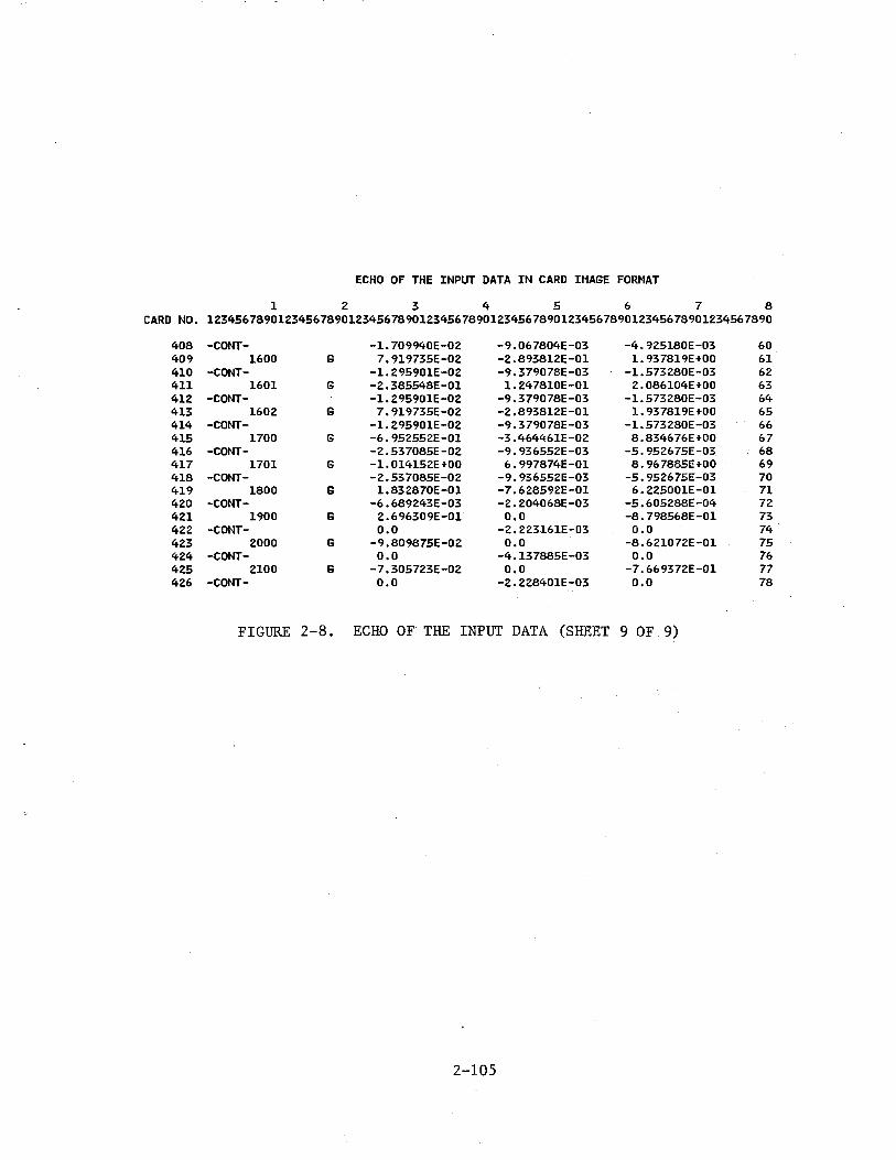
ECHO OF THE INPUT DATA IN CARD II1AGE FORMAT
1 2 3 4 5 6 7 8 CARD NO. 12345678901234567890123456789012345678901234567890123456789012345678901234567890
408 -CONT- -1.709940E-02 -9.067804E-03 -4.925180E-03 60 409 1600 G 7.919735E-02 -2.893812E-01 1.937819E+OO 61 410 -CONT- -1.295901E-02 -9.379078E-03 -1.573280E-03 62 411 1601 G -2.385548E-01 1. 247810E-01 2.086104E+OO 63 412 -CONT- -1. 295901E-02 -9.379078E-03 -1.573280E-03 64 413 1602 G 7.919735E-02 -2.893812E-01 1. 937819E+OO 65 414 -CONT- -1.295901E-02 -9.379078E-03 -1.573280E-03 66 415 1700 G -6.952552E-01 -3.464461E-02 8.834676E+OO 67 416 -CONT- -2.537085E-02 -9.936552E-03 -5. 952675E-03. 68 417 1701 G -1.014152E+OO 6.997874E-01 8.967885E+OO 69 418 -CONT- -2.537085E-02 -9.936552E-03 -5.952675E-03 70 419 1800 G 1.832870E-01 -7.628592E-01 6.225001E-01 71 420 -CONT- -6.689243E-03 -2.204068E-03 -5.605288E-04 72 421 1900 G 2.696309E-01 0.0 -8.798568E-01 73 422 -CONT- 0.0 -2.223161E-03 o.o 74 423 2000 G -9.809875E-02 0.0 -8.621072E-01 75 424 -CONT- o.o -4.137885E-03 0.0 76 425 2100 G -7.305723E-02 0.0 -7.669372E-01 77 426 -CONT- 0.0 -2.228401E-03 o.o 78
FIGURE 2-8. ECHO OF THE INPUT DATA (SHEET 9 OF 9)
2-105
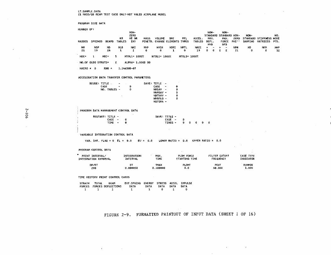
N I .....
0
"'
LT.SAMPLE.OATA 21 MASS/28 BEAM TEST CASE ONLY-NOT VALID AIRPLANE MODEL
PROGRAM SIZE DATA
NUMBER OF: NON- NON-NON
ZERO STANDARD STANDARD NON-KR HE OR MASS VOLUME DRI MTL ACCEL. MAX. MAX. ZERO
MASSES SPRINGS BEAMS TABLES IXY PENETR. CHANGE ELEMENTS TYPES TABLES DEFL. FORCE PHI'' NVB NFB
NM Zl
NSP 19
NB 28
NLB 1
NHI 2
MVP 0
NVCH 0
NDRI NMTL NACC + - + 1 0 19 0 0 2 2
NSC= 1 NIC= 1 NTOll= 1000% NTOL2= 1000%
NO.OF OLEO STRUTS= 2 ALPHA= 1.000D 00
NAERO = 0 RHO = l.14630D-07
ACCELERATION DATA TRANSFER CONTROL PARAMETERS
REUSE: TITLE CASE NO. TABLES -
0 0
PROGRAM DATA MANAGEMENT CONTROL DATA
RESTART: TITLE -CASE - 0
SAVE: TITLE -CASE -NMSAV -NNPSAV -NDTSAV -NWRFLG -NDTGRA -
0 0 0 0 0
NTOL3= 1000%
0 TIME - 0
SAVE: TITLE -CASE -TIMES - 0 0 0 0 0
VARIABLE INTEGRATION CONTROL DATA
VAR. INT. FLAG = 0 EL = 0.0 EU o.o LOHER RATIO 0.0 UPPER RATIO 0.0
PROGRAM CONTROL DATA
• PRINT INTERVAL/ INTEGRATION INTERVAL
DP/DT 200
INTEGRATION INTERVAL
DT 0.000050
MAX. TIME
TMAX 0.100000
PLOH FORCE :"TARTING TIME
PLOHT 0.0
TIME HISTORY PRINT CONTROL CARDS
STRAIN FORCES
1
TOTAL BEAM FORCES DEFLECTIONS
1 1
EXT. SPRING ENERGY STRESS ACCEL IMPULSE DATA DATA DATA DATA DATA 1 1 0 1 0
FILTER CUTOFF FREQUENCY
FCUT 50.000
NPH 21
NON- NO. STANDARD STIFFNESS NODE DAMPING MATRICES PTS.
NO 0
CASE TYPE INDICATOR
RUNMOD 1.000
NKM 0
NNP 12
FIGURE 2-9. FOfu~ATTED PRINTOUT OF INPUT DATA (SHEET 1 OF 16)
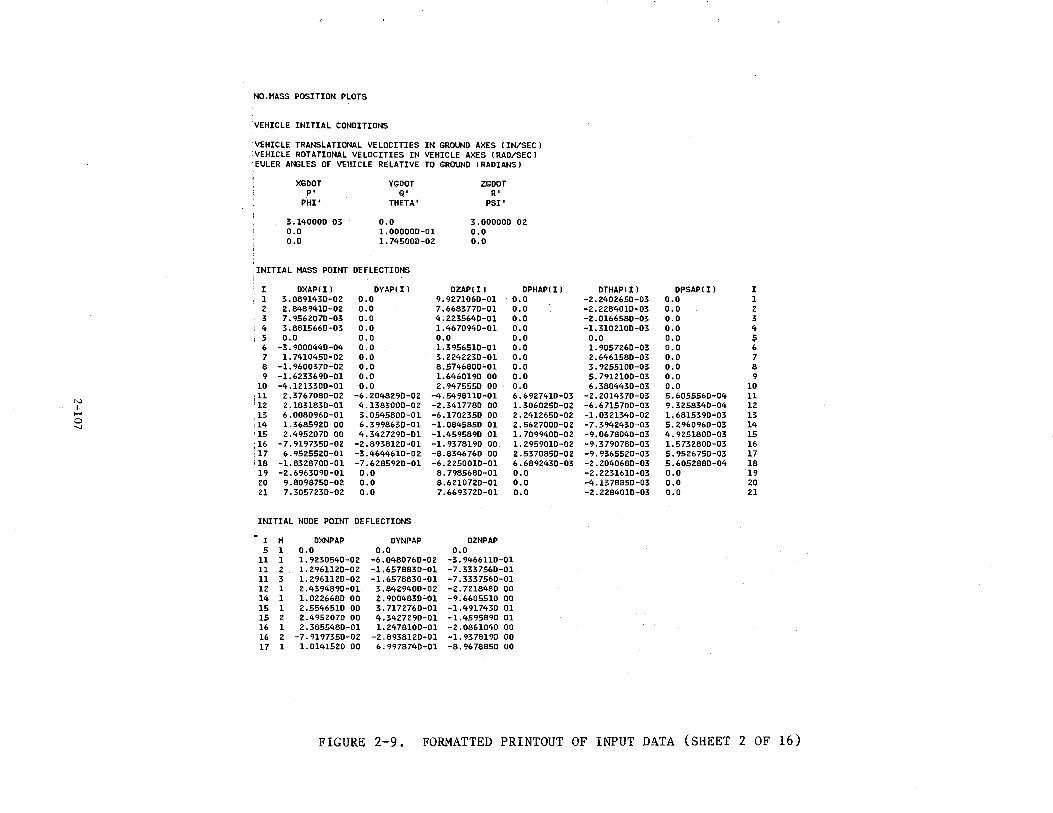
N I -0 .....
,NO.MASS POSITION PLOTS
·vEHICLE INITIAL CONDITIONS
VEHICLE TRANSLATIONAL VELOCITIES IN GROUND AXES liN/SEC) ·vEHICLE ROTATIONAL VELOCITIES IN VEHICLE AXES lRAD/SECl EULER ANGLES OF VEHICLE RELATIVE TO GROUND !RADIANS)
XGDOT YGDOT ZGDOT P' Q' R'
PHI' THETA' PSI'
3.14000D 03 0.0 3.00000D 02 0.0 1.00000D-01 0.0 o.o 1.74500D-02 0.0
'INITIAL MASS POINT DEFLECTIONS
I DXAPl I l DYAPl I l OZAPl I J DPHAPl I J 1 3.089143D-02 0.0 9.927106D-01 0.0 2 2.848941D-02 o.o 7.668377D-01 0.0 3 7.956207D-03 o.o 4.223564D-01 0.0 4 3.8815660-03 0.0 1.467094D-01 0.0 5 o.o 0.0 0.0 0.0 6 -3.900044D-04 0.0 1.395651D-01 0.0 7 1. 741045D-02 o.o 3.2242230-01 o.o 8 -1.9600370-02 0.0 8.574680D~01 o.o 9 -1.623369D-01 0.0 1.6460190 00 o.o
10 -4.121330D-01 o.o 2.947555D 00 0.0 !11 2.376708D-02 -6.2048290-02 -4.549811D-01 6.692741D-03 '12 2.183183D-01 4. 138300D-02 -2. 341778D 00 1.306025D-02 13 6.0080960-01 3.054580D-01 -6.170235D 00 2.241265D-02 14 l. 368592D 00 6.399863D-01 -1. 084585D 01 2.5627000-02 15 2.495207D 00 4.3427290-01 -1.4595890 01 1. 709940D-02 16 -7.919735D-02 -2.893812D-01 -1.937819D 00 1.295901D-02 17 6.952552D-01 -3.464461D-02 -8.834676D 00 2.537085D-02 18 -1.832870D-Ol -7.628592D-01 -6.2250010-01 6.689243D~03 19 -2.69&309D-01 0.0 8.798568D-01 0.0 20 9.809875D-02 0.0 8.621072D-01 0.0 21 7.305723D-02 0.0 7.669372D-01 0.0
INITIAL NODE POINT DEFLECTIONS
I M DXNPAP DYNPAP DZNPAP 5 1 o.o 0.0 0.0
11 1 1.923054D-02 -6.048076D-02 -3. 946611D-01 11 2 1.296112D-02 -l.657883D-01 -7.333756D-01 11 3 1. 296112D-02 -1.657883D-01 -7.333756D-01 12 1 2.439489D-01 3.842940D-02 -2. 72184e.o oo 14 1 1.0226680 00 2.900483D-01 -9.660551D 00 15 1 2.554651D 00 3. 117276D-01 -1.491743D 01 15 2 2. 495207D 00 4. 342729D-01 -1.4595890 01 16 1 2.385548D-01 1.247810D-01 -2.086104D 00 16 2 -7.9197350-02 -2.893812D-01 -1.9378190 00 17 1 1.014152D 00 6.997874D-01 -8.967885D 00
DTHAPl I l DPSAPli l I -2.240265D-03 o.o 1 -2.2284010-03 0.0 2 -2.016658D-03 0.0 3 -1. 310210D-03 o.o 4 0.0 o.o 5 1.905726D-03 0.0 6 2.646158D-03 o.o 7 3. 9255lOD-03 o.o 8 5.7912100-03 o.o 9 6.380443D-03 o.o 10
-2.201437D-03 5.6055560-04 11 -6.611570D-03 9.325834D-04 12 -1. 032134D-02 l. 681539D-03 13 -7.394243D-03 5. 296096D-03 14 -9.0678040-03 4.925180D-03 15 -9.379078D-03 1. 573280D-03 16 -9.936552D-03 5.9526750-03 17 -2.204068D-03 5.605288D-04 18 -2.2231610-03 o.o 19 -4.137885D-03 o.o 20 -2.228401D-03 o.o 21
FIGURE 2-9. FORMATTED PRINTOUT OF INPUT DATA (SHEET 2 OF 16)
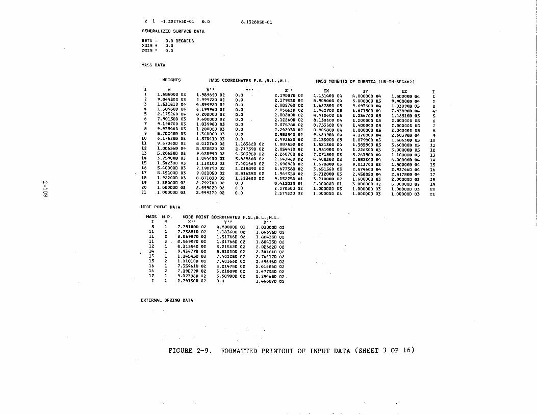
N I
1-'
0 00
2 1 -1.3027630-01 0.0 8.1328050-01
GENERALIZED SURFACE DATA
BETA = 0.0 DEGREES XGIN = 0.0 ZGIN = 0.0
MASS DATA
HEIGHTS MASS COORDINATES F.S.,B.L.,H.L,
I H X', y•. z·' 1 1.58500D 03 1. 98969D 02 0.0 2.19007D 02 2 9.06450D 03 2.99972D 02 o.o 2.17933D 02 3 1.53181D 04 4.599920 02 o.o 2.08278D 02 4 1.309600 04 6.199960 02 o.o 2.05853D 02 5 2.175260 04 8.200000 02 o.o 2.00200D 02 6 7.90150D 03 9.600000 02 0.0 2.12260D 02 7 9.19070D 03 1.039980 03 0.0 2.075780 02 8 9. 938400 03 1. 200020 03 o.o 2.242430 02 9 5.702000 03 1.360060 03 0.0 2.583540 02
10 6.175200 03 1.570410 03 0.0 2.99352D 02 11 9.670600 03 8.012760 02 1.183620 02 1.887550 02 12 1.006560 04 8.520820 02 2.71759D 02 2.054420 02 13 5.28650D 03 9.428990 02 4.303950 02 2.260700 02 14 3. 759000 03 1.044430 03 5.82860D 02 2.54346D 02 15 1.542300 03 1.110100 03 7.401660 02 2.69696D 02 16 5.400000 03 7.190790 02 3.218890 02 1.677380 02 17 5.151000 03 9.021050 02 5.516350 02 1. 969350 02 18 1. 922000 03 8.871830 02 1.323630 02 9.13225D 01 19 2.38000D 02 2.79270D 02 0.0 8.412010 01 20 1.00000D 03 2.999020 02 0.0 2.378380 02 21 l.OOOOOD 03 2.99927D 02 0.0 2.379330 02
NODE POINT DATA
MASS N.P. NODE POINT COORDINATES F.S.,B.L.,H.L. I M X', Y', z•, 5 1 7.75100D 02 4.80000D 01 1.81000D 02
11 1 7.738810 02 1.18360D 02 1.866950 02 11 2 8.869870 02 1.31766D 02 1.80433D 02 11 3 8.86987D 02 1.31766D 02 1.80433D 02 12 1 8.11556D 02 3.215620 02 2.02322D 02 14 1 9. 93477D 02 5.51310D 02 2.30161D 02 15 1 1.14545D 03 7.402280 02 2. 76217D 02 15 2 1.11010D 03 7.40166D 02 2. 69696D 02 16 1 7.35461D 02 3.21475D 02 2.01686D 02 16 2 7.19079D 02 3.21889D 02 1.67738D 02 17 1 9.17386D 02 5.50900D 02 2.29468D 02
2 1 2.791300 02 0.0 1.46687D 02
EXTERNAL SPRING DATA
MASS MOMENTS OF INERTIA !LB-IN-SEC**2l
IX 1.15140D 04 8.90800D 04 1.62780D 05 1. 96270D 05 4. 91060D 05 8.13830D 04 8. 75360D 04 8.80980D 04 9.62490D 04 2.15300D 05 1.521300 04 1.95100D 04 7.271500 03 4.408300 03 1.670800 03 3.651560 03 3. 712000 03 3. 710000 02 2.400000 01 1.000000 03 1.000000 03
IV 4.000000 04 3.000000 05 9.693500 04 6.67150D 04 1. 256700 05 1. 20000D 05 1.40000D 05 1.80000D 05 4.17880D 04 1.07980D 05 1.385800 05 1.226300 05 5.26190D 04 2.582300 04 9.01370D 03 2.574600 04 2.458820 04 1.60000D 03 3.000000 02 1.000000 03 1.000000 03
IZ 1.50000D 04 9.900000 04 1.030900 05 7.938900 04 1.465100 05 2.000000 05 2.000000 05 3.000000 05 2.60390D 04 1.586300 05 3.60000D 05 3.000000 05 1.100000 05 6.000000 04 1.800000 04 2.937460 04 2.817800 04 2.000000 03 5.000000 02 1.000000 03 1.000000 03
FIGURE 2-9. FORMATTED PRINTOUT OF INPUT DATA (SHEET 3 OF 16)
I 1 2 3 4' 5 6 7 8 9
10 11 12 13 14 15 16 17 18 19 20 21
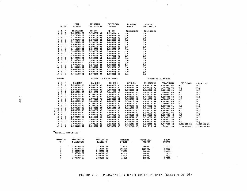
FREE FRICTION BOTT0~1ING PLOWING GROUND SPRING LENGTH COEFFICIENT SPRING FORCE FLEXIBILITY
I K M LBAR! IKM J MU!IKMJ KE!IKMJ FORCE!IKMJ GFLEX!IKMJ 1 3 0 7.00000D 01 3.50000D-01 1. 75000D 05 0.0 0.0 2 3 D B.27000D 01 3.50000D-01 3.00000D 05 0.0 0.0 3 3 0 7.27000D 01 3.50000D-D1 l.OOODOD 05 0.0 0.0 4 3 0 7.00000D 01 3.50000D-01 3.00000D 05 0.0 0.0 5 3 0 6.420000 01 3.50000D-01 3.00000D 05 0.0 o.o 6 3 0 7.64000D 01 3.50000D-01 3.00000D 05 0.0 0.0 7 3 0 6.99000D 01 3.50000D-01 1.000000 05 0.0 0.0 8 3 0 6.91000D 01 3.50000D-01 1.000000 05 0.0 0.0 9 3 0 6.40000D 01 3.50000D-01 3.000000 05 0.0 0.0
10 3 0 8.20000D 01 3.50000D-01 3.00000D 05 0.0 O.D 11 3 0 2.80000D 01 3.50000D-01 l.OOOOOD 05 0.0 0.0 12 3 0 l.40000D 01 3.50000D-01 1.00000D 05 0.0 0.0 13 3 0 1.10000D 01 3.50000D-01 l.OOOOOD 05 0.0 0.0 14 3 0 7.000000 00 3.500000-01 1.000000 05 o.o 0.0 15 3 0 3.000000 00 3.500000-01 1.000000 05 0.0 0.0 16 3 0 2.980000 01 3.500000-01 2.720000 05 0.0 0.0 17 3 0 2.800000 01 3.500000-01 2. 72000D 05 0.0 0.0 18 3 0 1.965000 01 3.000000-01 l.OOOOOD 05 0.0 0.0 19 3 0 1.64500D 01 3.00000D-01 1.00000D 05 0.0 0.0
SPRING DEFLECTION COORDINATES SPRING AXIAL FORCES
I K M SI(IKMJ SA(IKMJ SB!IKMJ SF(IKMJ FSPOI! IKMJ FSPOF( IKM l CRIT.DAMP COAMP!IKMJ 1 3 0 l.30000D 00 1.500000 OD 1.60000D 00 1.000000 01 7.00000D 04 7.0DOOOD 03 o.o D.O 2 3 0 1.30000D 00 1.50000D 00 1.60000D DO 1.00000D 01 1.40000D 05 1.400000 04 0.0 0.0 3 3 0 1.000000 00 6.000000 00 l.OOOOOD 01 2.10000D 01 1.15000D 05 9.00000D 04 0.0 0.0 4 3 0 l.OOOOOD 00 1.100000 00 2.00000D 00 3.00000D 00 3.40000D 05 2.00000D 05 D.O 0.0 5 3 0 l.OOOOOD 00 1.100DOO 00 2.0DOOOD 00 3.000000 00 3.400000 05 2.000000 05 0.0 o.o
"' 6 3 0 1.000000 00 1.100000 00 2.000000 00 3.00000D DO 3.40000D 05 2.00000D 05 0.0 0.0 I 7 3 0 1.000000 00 6.00000D 00 l.OOOOOD 01 2.10000D 01 6.000000 04 4.80000D 04 0.0 0.0 ......
0 8 3 0 1.00000D 00 6.00000D 00 1.00000D 01 2.10000D 01 6.800000 04 4.800000 04 o.o 0.0 '.0 9 3 0 1.000000 00 1.100000 00 2.00000D 00 3.00000D 00 3.000000 05 3.000000 04 0.0 0.0
10 3 0 1.000000 00 1.100000 00 2.00000D 00 3.000DOD 00 3.00000D 05 3.000000 04 o.o 0.0 11 3 0 1.00000D 00 1.50000D 00 2.00000D 00 7.00000D 00 3.300000 05 3.300000 05 0.0 o.o 12 3 0 1.000000 00 1.500000 00 2.00000D 00 7.DOOOOO 00 3.30000D 05 3.300000 05 0.0 0.0 13 3 0 1.000000 00 1.500000 00 2.000000 00 7.000000 00 3.300000 05 3.300000 05 0.0 o.o 14 3 0 1.00000D 00 1.500000 00 2.00000D 00 7.000000 00 3.300000 05 3.30000D 05 0.0 o.o 15 3 0 l.OOOOOD 00 1.50000D 00 2.00000D 00 7.000000 00 3.30000D 05 3.30000D 05 0.0 o.o 16 3 0 1.000000 00 8.000000 00 9.000000 00 1.600000 01 1.000000 04 3.00000D 04 0.0 0.0 17 3 0 l.OOOOOD 00 8.00000D DO 9.000DOD 00 1.600000 01 1.000000 04 3.00000D 04 0.0 0.0 18 3 0 2.00000D 00 2.001000 00 8.05000D 00 8.051000 00 6.22000D 04 2.947000 05 2.00000D-02 1.573250 01 19 3 0 2.00000D 00 2.00100D 00 5.750000 OD 5.751000 00 1.61500D 04 5.150000 04 2.00DOOD-02 2.82099D 00
.. MATERIAL PROPERTIES
MATERIAL MODULUS OF MODULUS OF TENSION COMPRESS. SHEAR NO. ELASTICITY RIGIDITY STRESS STRESS STRESS
1 3.DOOOD 07 1.1000D 07 75000. 75000. 37500. 2 3.00000 07 1.10000 07 205000. 205000. 80000. 3 2.80000 07 1.25000 07 70000. 46000. 36000. 4 1.0500D D7 4.00000 06 47000. 39000. 22000. 5 1.00000 07 3.8DOOO 06 35000. 34000. 17000. 6 1.0000D 07 3.80000 06 16000. 16000. 17000.
FIGURE 2-9. FORMATTED PRINTOUT OF INPUT DATA (SHEET 4 OF 16)
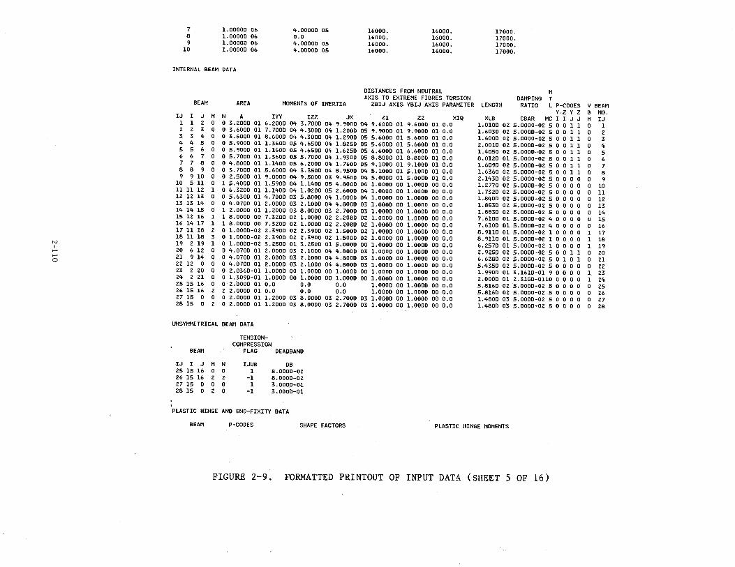
N I
,.... 0
7 8 9
10
l.OOOOD 0& 1.0000D 06 l.OOOOD 06 1.00000 06
INTERNAL BEAM DATA
4.00000 05 o.o 4.00000 05 4.00000 05
16000. 16000. 16000. 16000.
16000. 16000. 16000. 16000.
DISTANCES FROM NEUTRAL AXIS TO EXTREME FIBRES TORSION
17000. 17000. 17000. 17000.
M DAMPING T
BEAM AREA MOMENTS OF INERTIA ZBIJ AXIS YBIJ AXIS PARAMETER LENGTH RATIO L P-COOES y,z v z
IJ I J 1 1 2 2 2 3 3 3 4 4 4 5 5 5 6 6 6 7 7 7 8 8 8 9 9 9 10
10 5 11 11 11 12 12 12 13 13 13 14 14 14 15 15 12 16 16 14 17 17 11 18 18 11 18 19 2 19 20 6 12 21 9 14 22 12 0 23 2 20 24 2 21 25 15 16 26 15 16 27 15 0 28 15 0
M N A IYY IZZ JX Z1 Z2 XIQ o o 3.200D 01 &.200D 04 3.700D 04 9.9ooD n4 9.600D 01 9.600D 01 o.o 0 0 3.&00D 01 7.7000 04 4.300D 04 1.2000 05 9.900D 01 9.900D 01 0.0 0 0 3.600D 01 8.600D 04 4.300D 04 1.290D 05 5.600D 01 5.600D 01 0.0 0 0 5.9000 01 1.3&00 05 4.650D 04 1.8250 05 5.6000 01 5.600D 01 0.0 0 0 5.9000 01 1.1600 05 4.650D 04 1.6250 05 &.&000 01 &.&000 01 0.0 0 0 5.700D 01 1.360D 05 5.700D 04 1.930D 05 8.800D 01 8.8000 01 0.0 0 0 4.8000 01 1.140D 05 &.200D 04 1.7&00 05 9.1000 01 9.1000 01 o.o 0 0 3.7000 01 5.&000 04 3.350D 04 8.9500 04 5.1000 01 5.100D 01 o.o 0 0 2.5000 01 9.0000 04 9.500D 03 9.950D 04 5.000D 01 5.0000 01 o.o 0 1 5.4000 01 1.5900 04 1.1400 05 4.8000 04 1.0000 00 1.0000 00 o.o 1 0 6.320D 01 1.1400 04 1.020D 05 2.600D 04 1.000D 00 1.0000 00 o.o 0 0 5.&300 01 4.700D 03 5.8000 04 1.0000 04 1.0000 00 1.000D 00 o.o 0 0 4.070D 01 2.000D 03 2.100D 04 4.800D 03 1.000D 00 1.000D 00 0.0 0 1 2.0000 01 1.2000 03 8.000D 03 2.700D 03 1.000D 00 1.0000 00 0.0 1 1 8.000D 00 7.3200 02 1.0000 02 2.208D 02 1.0000 00 1.000D 00 0.0 1 1 8.0000 00 7.320D 02 1.0000 02 2.2080 02 1.0000 00 1.000D 00 0.0 2 0 1.000D-02 2.3900 02 2.390D 02 1.5000 02 1.0000 00 1.000D 00 o.o 3 0 1.0000-02 2.390D 02 2.390D 02 1.5000 02 1.000D 00 1.000D 00 o.o 1 0 1.000D-02 3.250D 01 3.250D 01 5.0000 00 1.000D 00 1.000D 00 0.0 0 0 4.0700 01 2.000D 03 2.100D 04 4.800D 03 1.0000 00 1.000D 00 0.0 0 0 4.070D 01 2.000D 03 2.100D 04 4.800D 03 1.000D 00 1.000D 00 0.0 0 0 4.070D 01 2.000D 03 2.100D 04 4.800D 03 1.000D 00 1.000D 00 o.o 0 0 2.036D-01 1.000D 00 1.000D 00 1.000D 00 1.000D 00 1.000D 00 o.o 0 0 1.309D-01 1.000D 00 1.000D 00 1.000D 00 1.000D 00 1.000D 00 o.o 0 0 2.000D 01 0.0 o.o 0.0 1.000D 00 1.000D 00 0.0 2 2 2.000D 01 0.0 0.0 0.0 1.000D 00 1.000D 00 0.0 0 0 2.000D 01 1.200D 03 8.000D 03 2.700D 03 1.000D 00 1.000D 00 o.o 2 0 2.000D 01 1.200D 03 8.000D 03 2.700D 03 l.OOOD 00 1.000D 00 0,0
UNSYMMETRICAL BEAM DATA
TENSIONCot1PRESSION
BEAM FLAG DEADBAND
IJ I J M N 25 15 1& o o 26 15 16 2 2 27 15 0 0 0 28 15 0 2 0
IJUB 1
-1 1
-1
DB 8.000D-02 8.000D-02 3.000D-01 3.0000-01
PLASTIC HINGE AND END-FIXITY DATA
XLB CBAR MC I I J J 1.0100 02 5.000D-02 5 0 0 1 1 1.6030 02 5.0000-02 5 0 0 1 1 1.&00D 02 5.0000-02 5 0 0 1 1 2.0010 02 5.0000-02 5 0 0 1 1 1.405D 02 5.000D-02 5 0 0 1 1 8.012D 01 5.000D-02 5 0 0 1 1 1.6090 02 5.000D-02 5 0 0 1 1 1.6360 02 5.0000-02 5 0 0 1 1 2.143D 02 5.0000-02 5 0 0 0 0 1.277D 02 5.000D-02 50 0 0 0 1.732D 02 5.000D-02 50 0 0 0 1.8400 02 5.0000-02 5 0 0 0 0 1.853D 02 5.0000-02 5 0 0 0 0 1.883D 02 5.000D-02 5 0 0 0 0 7.610D 01 5.000D-02 4 0 0 0 0 7.610D 01 5.000D-02 4 0 0 0 0 8.911D 01 5.000D-02 1 0 0 0 0 8.911D 01 5.000D-02 1 0 0 0 0 6.2570 01 5.000D-02 1 0 0 0 0 2.925D 02 5.0000-02 5 0 0 1 1 6.628D 02 5.000D-02 5 0 1 0 1 5.435D 02 5.000D-02 5 0 0 0 0 1.990D 01 3.161D-01 9 0 0 0 0 2.000D 01 2.318D-0110 0 0 0 0 5.816D 02 5.000D-02 5 0 0 0 0 5.816D 02 5.0000-02 5 0 0 0 0 1.480D 03 5.000D-02 5 0 0 0 0 1.480D 03 5.000D-02 5 0 0 0 0
BEAM P-COOES SHAPE FACTORS PLASTIC HINGE MOMENTS
FIGURE 2-9. FORMATTED PRINTOUT OF INPUT DATA (SHEET 5 OF 16)
V BEAM B NO. M IJ 0 1 0 2 0 3 0 4 0 5 0 6 0 7 0 8 0 9 0 10 0 11 0 12 0 13 0 14 0 15 0 16 1 17 1 18 1 19 0 20 0 21 0 22 1 23 1 24 0 25 0 26 0 27 0 28
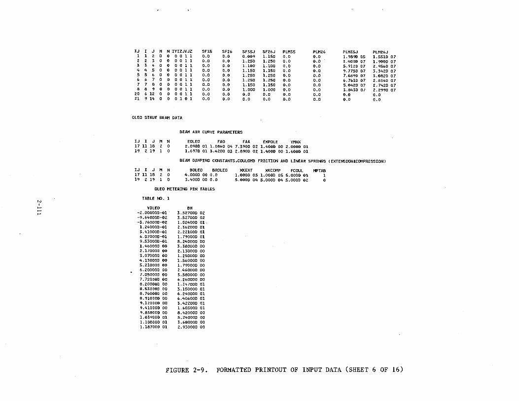
N I
......
IJ I J M N IYIZJYJZ SF35 SF26 SF35J SF26J PLM35 PLM26 PLM35J PLM26J 1 1 2 D 0 0 0 1 1 O.D o.o 0.009 1.150 0.0 0.0 1. 989D D5 1.551D 07 2 2 3 0 0 0 0 1 1 O.D 0.0 1.250 1.250 0.0 o.o 3.4030 D7 1.900D 07 3 3 4 0 0 0 D 1 1 D.D o.o 1.100 1.1DO D.O 0.0 5.912D 07 2.956D 07 4 4 5 0 0 0 0 1 1 O.D 0.0 1.150 1.150 O.D O.D 9.775D 07 3.342D 07 5 5 6 0 0 0 0 1 1 O.D O.D 1.250 1.250 o.o 0.0 7.689D 07 3.0820 07 6 6 7 0 D D D 1 1 D.D D.D 1.25D 1.250 0.0 0.0 6.7610 07 2.8340 D7 7 7 8 0 D 0 0 1 1 0.0 0.0 1.150 1.150 0.0 0.0 5.042D D7 2.7420 D7 8 8 9 0 D D 0 1 1 o.o 0.0 l.ODO 1.DOO 0.0 o.o 3.8430 07 2.2990 07
20 6 12 D 0 0 0 1 1 0.0 o.o 0.0 o.o 0.0 0.0 0.0 o.o 21 9 14 0 0 0 1 0 1 D.O 0.0 o.o 0.0 0.0 0.0 0.0 o.o
OLEO STRUT BEAM DATA
BEAM AIR CURVE PARAMETERS
IJ I J M N EOLEO FAO FAA EXPOLE YMAX 17 11 18 2 0 2.0980 01 1.D86D 04 7.3900 02 1.4000 DO 2.0000 01 19 2 19 1 0 1.6970 01 3.4200 03 2.8900 02 1.4000 00 1.6000 01
BEAM DAMPING CONSTANTS,COULOMB FRICTION AND LINEAR SPRINGS IEXTENSION&COMPRESSIONJ
IJ I J M N BOLEO BROLEO XKEXT XKCOMP FCOUL MPTAB 17 11 18 2 0 4.0DDD 00 D.O 1.DOOD 05 1.0DOD 05 5.DOOD 03 1 19 2 19 1 0 3.4DDD DO D.D 5.DDDD 04 5.0DDD D4 5.0DDD D2 0
OLEO METERING PIN TABLES
TABLE NO. 1
YOLEO BH -2.0DODDD-01 3.527DDD 02 -9.640DDD-D2 3.527DDD D2 -3.76DOOD-D2 1.D24000 01
1.240000-01 2.362000 01 3.410000-01 2.221000 01 6.070000-01 1.790000 01 9.530000-01 8.240000 00 1.460000 DO 3.38DDDD OD 2.17DOOD 00 2.130000 00 3.070000 00 1. 250000 00 4.130000 00 1.560000 00 5.21000D OD 1.790000 00 6.200DOD DO 2.46000D 00 7.05000D 00 3.58000D 00 7.720000 00 6.260000 00 8.200000 00 1.347000 01 8.530000 00 3.150000 01 8.740000 00 6.240000 01 8.910000 00 6.406000 01 9.120000 00 3.422000 01 9.410000 00 1.603000 01 9.830000 00 8.420000 00 1. 039000 01 5.240000 00 1.108000 01 3.680000 00 1.187000 01 2.93000D 00
FIGURE 2-9. FORMATTED PRINTOUT OF INPUT DATA (SHEET 6 OF 16)
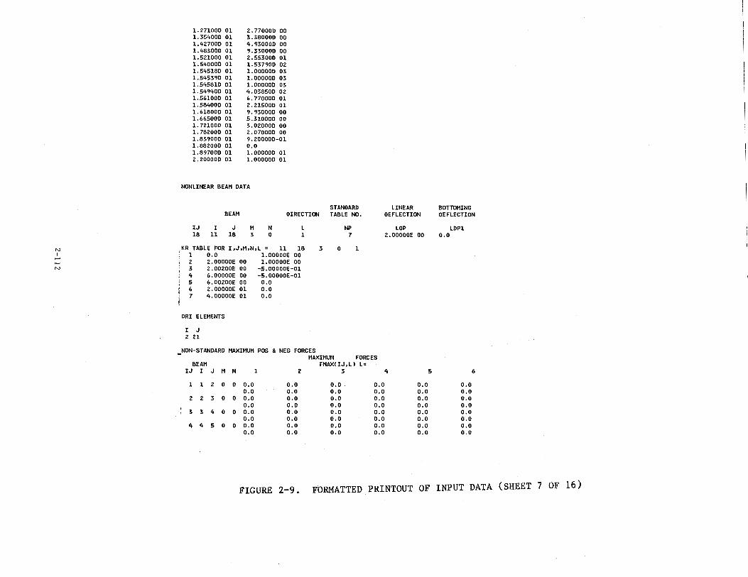
N I
...... N
1.271000 01 1.35400D 01 1.42700D D1 1.48300D 01 1.52100D 01 1.54000D 01 1.54518D 01 1.54539D 01 1.54581D 01 1.54940D 01 1.56100D 01 1.58400D 01 1.61800D 01 1.66500D 01 1. 72100D 01 1. 78200D 01 1.83900D 01 1.882000 01 1.89700D 01 2.200000 01
2. 770000 00 3.380000 00 4.930DOD 00 9.330000 00 2.55300D 01 1.537900 02 1.000000 03 l.OOOOOD 03 1.00000D 03 4.038500 02 6. 770000 01 2.21500D 01 9.930000 00 5.310000 00 3.020000 00 2.070000 00 9.200000-01 o.o 1.000000 01 1.000000 01
NONLINEAR BEAN DATA
BEAN STANDARD
DIRECTION TABLE NO.
IJ I J 18 11 18
N 3
N 0
L 1
KR TABLE FOR I,J,N,N,L = 11 18 1 0.0 1.00000E 00 2 2.00000E 00 l.OOOOOE 00 3 2.00200E 00 -5.00000E-01 4 6.00000E 00 -5.00000E-01 5 6.00200E 00 0.0 6 2.00000E 01 0.0 7 4.00000E 01 0.0
DRI ELEMENTS
I J 221
NON-STANDARD MAXIMUM POS & NEG FORCES
3 0
NP 7
1
• MAXIMUM FORCES BEAM
IJ I J N
1 1 2 0
2 2 3 0
' 3 3 4 0
4 4 5 0
N 1
0 o.o o.o
0 o.o o.o
D O.D o.o
0 o.o o.o
0.0 0.0 o.o 0.0 0.0 o.o 0.0 0.0
FMAX! IJ,LJ L= 2 3
o.o o.o D.O o.o O.D o.o o.o O.D
o.o o.o o.o o.o o.o o.o o.o o.o
LINEAR DEFLECTION
LOP 2.00000E 00
4
o.o D.O 0.0 0.0 0.0 0.0 0.0 0.0
5
BOTTOMING DEFLECTION
LDP1 o.o
0.0 O.D o.o O.D 0.0 0.0 0.0 0.0
6
FIGURE 2-9. FORMATTED PRINTOUT OF INPUT DATA (SHEET 7 OF 16)
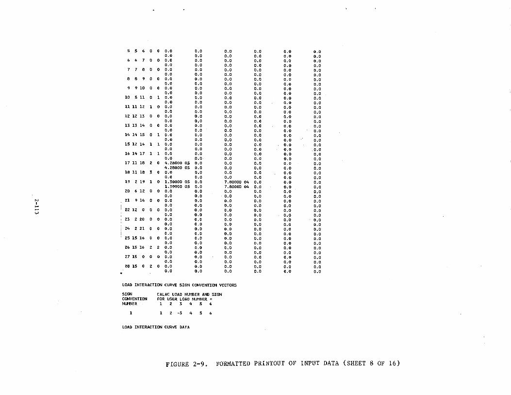
5 5 6 0 0 0.0 0.0 0.0 0.0 0.0 0.0 0.0 0.0 0.0 0.0 0.0 0.0
6 6 7 0 0 o.o 0.0 0.0 0.0 o.o 0.0 0.0 0.0 0.0 0.0 0.0 0.0
7 7 8 0 0 0.0 0.0 0.0 o.o 0.0 0.0 0.0 0.0 0.0 0.0 o.o 0.0
8 8 9 0 0 0.0 0.0 0.0 0.0 0.0 0.0 0.0 0.0 0.0 0.0 o.o 0.0
9 9 10 0 0 0.0 0.0 0.0 0.0 o.o 0.0 0.0 0.0 0.0 0.0 0.0 0.0
10 511 0 1 0.0 0.0 0.0 0.0 0.0 0.0 0.0 0.0 0.0 0.0 0.0 0.0
11 11 12 1 0 0.0 0.0 0.0 0.0 0.0 0.0 0.0 0.0 0.0 0.0 0.0 0.0
12 12 13 0 0 0.0 0.0 0.0 0.0 0.0 0.0 0.0 0.0 0.0 0.0 0.0 0.0
13 13 14 0 0 0.0 o.o 0.0 0.0 0.0 0.0 o.o 0.0 0.0 o.o 0.0 0.0
14 14 15 0 1 o.o 0.0 0.0 o.o 0.0 0.0 0.0 0.0 0.0 0.0 0.0 o.o
15 12 16 1 1 0.0 o.o 0.0 o.o 0.0 0.0 0.0 o.o 0.0 0.0 0.0 o.o
16 14 17 1 1 0.0 0.0 0.0 0.0 0.0 0.0 0.0 0.0 0.0 0.0 0.0 0.0
17 11 18 2 0 4.28000 05 0.0 0.0 0.0 0.0 0.0 4. 28000 05 0.0 o.o 0.0 0.0 0.0
18 11 18 3 0 0.0 0.0 o.o 0.0 0.0 o.o 0.0 0.0 0.0 0.0 0.0 0.0
19 2 19 1 0 1.30000 05 o.o 7.80000 04 0.0 o.o 0.0 1.30000 05 0.0 7.8000D 04 0.0 0.0 0.0
20 6 12 0 0 0.0 0.0 0.0 o.o 0.0 o.o 0.0 o.o 0.0 0.0 o.o 0.0
N 21 9 14 0 0 o.o o.o 0.0 0.0 0.0 0.0 I 0.0 0.0 o.o 0.0 0.0 0.0 -- 22 12 0 0 0 o.o 0.0 0.0 0.0 o.o 0.0
(.;) 0.0 0.0 0.0 0.0 0.0 0.0
23 2 20 0 0 0.0 0.0 0.0 0.0 0.0 0.0 0.0 0.0 0.0 0.0 0.0 0.0
24 2 21 0 0 o.o 0.0 0.0 0.0 0.0 0.0 0.0 0.0 0.0 0.0 0.0 0.0
25 15 16 0 0 0.0 0.0 0.0 0.0 o.o 0.0 0.0 0.0 0.0 0.0 0.0 o.o
26 15 16 2 2 0.0 0.0 0.0 0.0 0.0 o.o 0.0 0.0 0.0 o.o 0.0 0.0
27 15 0 0 0 0.0 0.0 0.0 o.o 0.0 0.0 0.0 0.0 0.0 0.0 0.0 0.0
28 15 0 2 0 0.0 0.0 0.0 0.0 0.0 0.0 0.0 0.0 0.0 0.0 0.0 0.0
LOAD INTERACTION CURVE SIGN CONVENTION VECTORS
SIGN CALAC LOAD NUMBER AND SIGN CONVENTION FOR USER LOAD NUMBER = NUMBER 1 2 3 4 5 6
1 1 2 -3 4 5 6
LOAD INTERACTION CURVE DATA
FIGURE 2-9. FORMATTED PRINTOUT OF INPUT DATA (SHEET 8 OF 16)
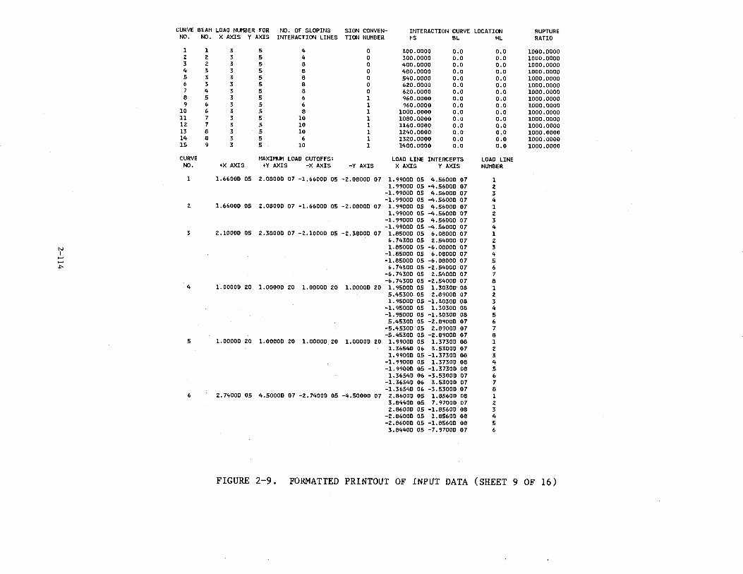
CURVE BEAM LOAD NUMBER FOR NO. OF SLOPING SIGN CONVEN- INTERACTION CURVE LOCATION RUPTURE NO. NO. X AXIS Y AXIS INTERACTION LINES TION NUMBER FS BL WL RATIO
1 1 3 5 4 0 300.0000 0.0 o.o 1000.0000 2 2 3 5 4 0 300.0000 0.0 0.0 1000.0000 3 2 3 5 a 0 400.0000 o.o 0.0 1000.0000 4 3 3 5 a 0 4aO.OOOO 0.0 0.0 1000.0000 5 3 3 5 a 0 540.0000 0.0 0.0 1000.0000 6 3 3 5 a 0 620.0000 o.o 0.0 1000.0000 7 4 3 5 a 0 620.0000 o.o 0.0 1000.0000 a 5 3 5 6 1 960.0000 o.o 0.0 1000.0000 9 6 3 5 6 1 960.0000 o.o 0.0 1000.0000
10 6 3 5 a 1 1000.0000 0.0 0.0 1000.0000 11 7 3 5 10 1 10ao.oooo 0.0 0.0 1000.0000 12 7 3 5 10 1 1160.0000 0.0 0.0 1000.0000 13 a 3 5 10 1 1240.0000 0.0 0.0 1000.0000 14 a 3 5 6 1 1320.0000 0.0 0.0 1000.0000 15 9 3 5 10 1 1400.0000 0.0 0.0 1000.0000
CURVE MAXIMUM LOAD CUTOFFS: LOAD LINE INTERCEPTS LOAD LINE NO. +X AXIS +Y AXIS -X AXIS -Y AXIS X AXIS Y AXIS NUMBER
1 1.66000 05 2.08000 07 -1.6600D 05 -2.0800D 07 1. 9900D 05 4.56000 07 1 1.9900D 05 -4.56000 07 2
-1.99000 05 4.5600D 07 3 -1.9900D 05 -4.56000 07 4
2 1.66000 05 2.08000 07 -1.6600D 05 -2.oaooo 07 1.9900D 05 4.56000 07 1 1.9900D 05 -4.56000 07 2
-1.9900D D5 4.56000 07 3 -1.9900D 05 -4.56000 07 4
3 2.1000D 05 2.3aooo 07 -2.10000 05 -2.3800D 07 1.a500D 05 6.08000 07 1 6. 74300 05 2.5400D 07 2
N 1.a500D 05 -6.08000 07 3 I -1.85000 05 6.0800D 07 4 .....
-1.85000 05 -6.0aOOD 07 5 ..... "" 6.74300 05 -2.5400D 07 6
-6.74300 05 2.5400D 07 7 -6.74300"05 -2.54000 07 a
4 1.0000D 20 1.00000 20 1.00000 20 1.00000 20 1. 9500D 05 1.30300 08 1 5.4530D 05 2.89000 07 2 1.9500D 05 -1.30300 oa 3
-1. 9500D 05 1.3D30D oa 4 -1.95DOD 05 -1.3030D 08 5 5.4530D 05 -2.a900D 07 6
-5.45300 05 2.8900D 07 7 -5.4530D 05 -2.8900D 07 a
5 1.00000 20 l.OOOOD 20 l.OOOOD 2D 1.00000 20 1. 99000 05 1.3730D 08 1 1.36540 06 3.5300D 07 2 1.99000 05 -1.3730D 08 3
-1.99000 05 1.3730D 08 4 -1.9900D 05 -1.37300 08 5 1.36540 06 -3.5300D D7 6
-1.3654D 06 3.5300D 07 7 -1.3654D D6 -3.5300D 07 a
6 2.74000 05 4.5000D 07 -2.7400D 05 -4.50DDO D7 2.a6DOD 05 1.856DO 08 1 3.84400 05 7. 9700D 07 2 2.86000 05 -1.85600 08 3
-2.86000 05 1.85600 08 4 -2.86000 05 -1.85600 08 5 3.84400 05 -7.97000 07 6
FIGURE 2-9. FORMATTED PRINTOUT OF INPUT DATA (SHEET 9 OF 16)
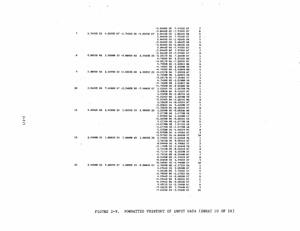
-3.84400 05 7.97000 07 7 -3.84400 05 -7.97000 07 8
7 2.74000 05 4.50000 07 -2.74000 05 -4.50000 07 2.86000 05 1.85600 08 1 3.84400 05 7.97000 07 2 2.86000 05 -1.85600 08 3
-2.86000 05 1.85600 08 4 -2.86000 05 -1.85600 08 5 3.84400 05 -7.97000 07 6
-3.84400 05 7.97000 07 7 -3.84400 05 -7.97000 07 8
8 2.88000 05 1.00000 20 -2.88000 05 1.00000 20 -5.23170 06 7.15000 07 1 4.74500 05 1.52800 08 2
-5.23170 06 -7.15000 07 3 4.74500 05 -1.52800 08 4
-4.74500 05 1.52800 08 5 -4.74500 05 -1.52800 08 6
9 2.88000 05 1.00000 20 -2.88000 05 1.00000 20 -5.23170 06 7.15000 07 1 4.74500 05 1.52800 08 2
-5.23170 06 -7.15000 07 3 4.74500 05 -1.52800 08 4
-4.74500 05 1.52800 08 5 -4.74500 05 -1.52800 08 6
10 2.54000 05 7.40000 07 -2.54000 05 -7.40000 07 3.01000 05 2.28700 08 1 1.35810 06 8.42000 07 2 3.01000 05 -2.28700 08 3
-3.01000 05 2.28700 08 4 -3.01000 05 -2.28700 08 5
1.35810 06 -8.42000 07 6 -1.35810 06 8.42000 07 7 -1.35810 06 -8.42000 07 8
11 1.00000 20 1.00000 20 1.00000 20 1.00000 20 2.10000 05 -5.55880 08 1 3. 27700 05 1.07750 08 2
N 1.57380 06 6.40000 07 3 I -2.10000 05 -5.55880 08 4 - 3.27700 05 -1.07750 08 5 -V1 -3.27700 05 1.07750 08 6
-3.27700 05 -1.07750 08 7 1.57380 06 -6.40000 07 8
-1.57380 06 6.40000 07 9 -1.57380 06 -6.40000 07 10
12 1.00000 20 1.00000 20 1.00000 20 1.00000 20 2.39000 05 -2.65640 08 1 3.72210 05 8.35000 07 2 8.04840 05 4.99000 07 3
-2.39000 05 -2.65640 08 4 3.72210 05 -8.35000 07 5
-3.72210 05 8.35000 07 6 -3.72210 05 -8.35000 07 7 8.04840 05 -4.99000 07 8
-8.04840 05 4.99000 07 9 -8.04840 05 -4.99000 07 10
13 1.00000 20 3.50000 07 1.00000 20 -3.50000 07 1.98000 05 -2.17320 08 1 4.09460 05 5.05000 07 2 9.65220 05 3.70000 07 3
-1.98000 05 -2.17320 08 4 4.09460 05 -5.05000 07 5
-4.09460 05 5.05000 07 6 -4.09460 05 -5.05000 07 7
9.65220 05 -3.70000 07 8 -9.65220 05 3. 70000 07. 9 -9.65220 05 -3.70000 07 10
FIGURE 2-9. FORMATTED PRINTOUT OF INPUT DATA (SHEET 10 OF 16)
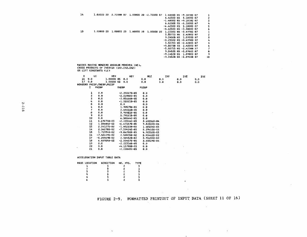
N I .... .... 0'
14
15
1.00000 20 2.72000 07 1.00000 20 -2.72000 07 1.48000 05 -9.18180 07 6.62500 05 3.18000 07
-1.48000 05 -9.18180 07 6.62500 05 -3.18000 07
-6.62500 05 3.18000 07 -6.62500 05 -3.18000 07
1.00000 20 1.00000 20 1.00000 20 1.00000 20 1.23500 05 -5.49980 07 3.50720 05 2.42000 07 9.14520 05 1.89000 07
-1.23500 05 -5.49980 07 3.50720 05 -2.42000 07
-3.50720 05 2.42000 07 -3.50720 05 -2.42000 07
9.14520 05 -1.89000 07 -9.14520 05 1.89000 07 -9.14520 05 -1.89000 07
MASSES HAVING NONZERO ANGULAR MOMENTA IHEJ, CROSS PRODUCTS OF INERTIA IIXY,IYZ,IXZJ OR LIFT CONSTANTS ILCJ
I LC HEX HEY 16 0.0 1.00000 05 o.o 17 0.0 1.00000 05 o.o
NONZERO PHIOP,THEDP,PSIDP I PHIDP THEDP
1 0.0 -2.240270-03 2 0.0 -2.228400-03 3 o.o -2.016660-03 4 0.0 -1.310210-03 5 o.o 0.0 6 0.0 1. 905730-03 7 0.0 2.646160-03 8 0.0 3.925510-03 9 0.0 5.791210-03
10 o.o 6.380440-03 11 6.692740-03 -2.201440-03 12 1.306030-02 -6.6 71570-03 13 2.241270-02 -1.032130-02 14 2.562700-02 -7. 3 94240-03 15 1. 709940-02 -9.067800-03 16 -7.481290-02 2.485950-02 17 -6.244490-02 2.364520-02 18 6.689240-03 -2.204070-03 19 0.0 -2.223160-03 20 0.0 -4.137880-03 21 0.0 -2.228400-03
ACCELERATION INPUT TABLE DATA
o.o o.o
PSIDP
o.o o.o o.o 0.0 o.o 0.0 o.o o.o o.o o.o
HEZ
5.605560-04 9.325830-04 1.681540-03 5.296100-03 4.925180-03 5.436620-02 5.916540-02 5.605290-04 0.0 0.0 0.0
MASS LOCATION DIRECTION NO. PTS. TYPE 1 3 2 1 2 3 2 1 3 3 2 1 4 3 2 1 5 3 2 1 6 3 2 1
0.0 0.0
IXY 0.0 0.0
IYZ 0.0 0.0
IXZ
1 2 3 4 5 6 1 2 3 4 5 6 7 8 9
10
FIGURE 2-9. FORMATTED PRINTOUT OF INPUT DATA (SHEET 11 OF 16)
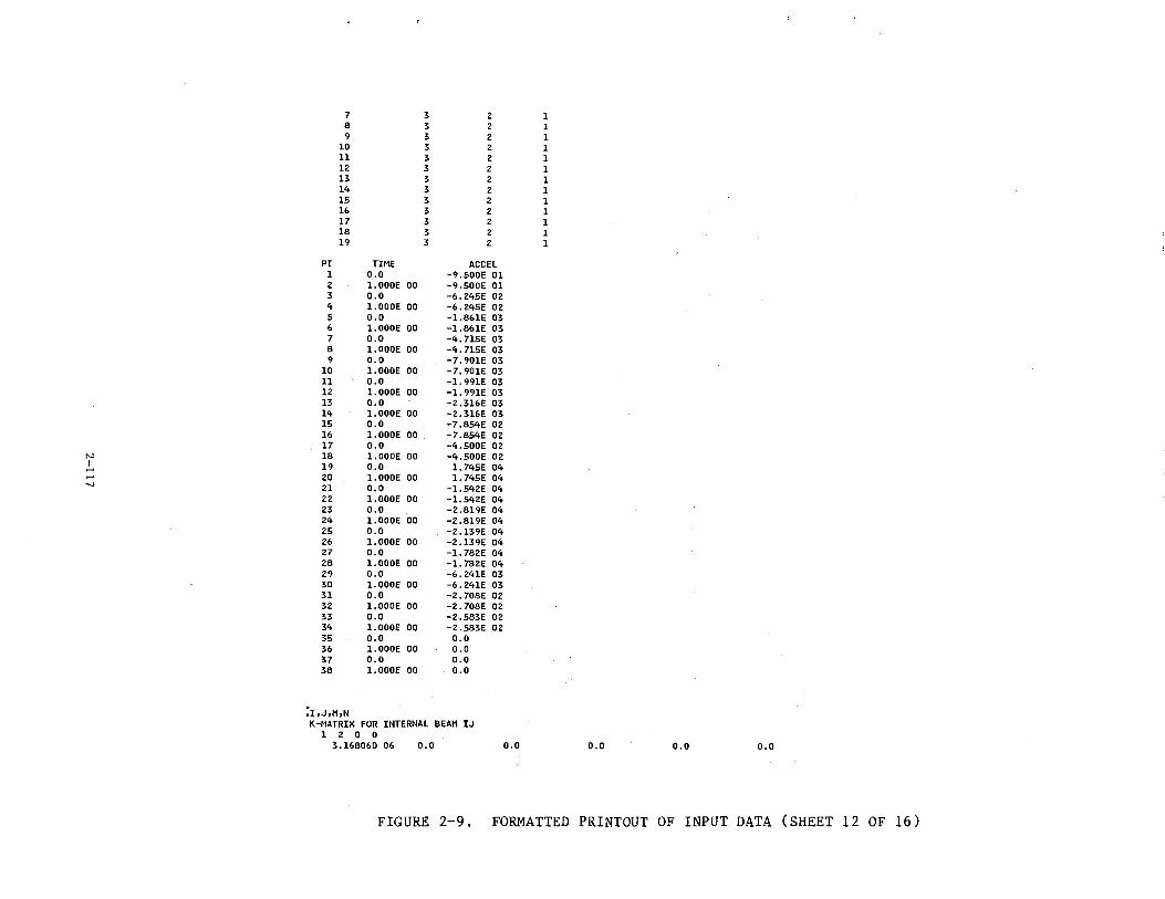
7 3 2 1 8 3 2 1 9 3 2 1
10 3 2 1 11 3 2 1 12 3 2 1 13 3 2 1 14 3 2 1 15 3 2 1 16 3 2 1 17 3 2 1 18 3 2 1 19 3 2 1
PT TIME ACCEL 1 0.0 -9.500E 01 2 l.OOOE 00 -9.500E 01 3 0.0 -6.245E 02 4 l.OOOE 00 -6.245E 02 5 0.0 -l.861E 03 6 1.000E 00 -l.861E 03 7 0.0 -4.7l5E 03 8 1.000E 00 -4. 7l5E 03 9 o.o -7.901E 03
10 l.OOOE 00 -7.901E 03 11 0.0 -1.991E 03 12 l.OOOE 00 -l. 991E 03 l3 o.o -2.316E 03 14 l.OOOE 00 -2.316E 03 15 0.0 -7.854E 02 16 1.000E 00 -7.854E 02 17 0.0 -4.500E 02
N 18 1.000E 00 -4.500E 02 I 19 0.0 1.745E 04 ..... ..... 20 l.OOOE 00 l. 745E 04 ....,
Zl o.o -l.542E 04 22 l.OOOE 00 -l.542E 04 23 o.o -2.819E 04 24 l.OOOE 00 -2.819E 04 25 0.0 -2.139E 04 26 l.OOOE 00 -2.l39E 04 27 o.o -l. 782E 04 28 l.OOOE 00 -l. 782E 04 29 o.o -6.241E 03 30 l.OOOE 00 -6.241E 03 31 0.0 -2.708E 02 32 l. OOOE 00 -2.708E 02 33 0.0 -2.583E 02 34 l.OOOE 00 -2.583E 02 35 0.0 0.0 36 l.OOOE 00 0.0 37 0.0 0.0 38 l.OOOE 00 o.o
:r,J,M,N K-MATRIX FOR INTERNAL BEAM IJ
1 2 0 0 3.168060 06 0.0 0.0 0.0 o.o o.o
FIGURE 2-9. FORMATTED PRINTOUT OF INPUT DATA (SHEET 12 OF 16)
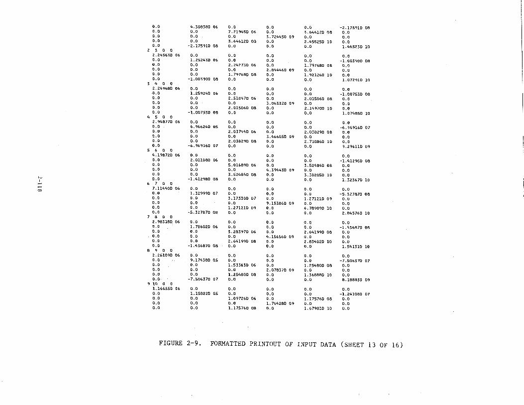
0.0 4.308380 06 0.0 0.0 0.0 -2.175910 08 0.0 0.0 7.219450 06 0.0 3.646120 08 0.0 0.0 0.0 0.0 3.724450 09 0.0 o.o 0.0 0.0 3.646120 08 0.0 2.455250 10 0.0 0.0 -2. 175910 08 0.0 0.0 0.0 1.465230 10
2 3 0 0 2.245630 06 0.0 0.0 0.0 0.0 0.0 0.0 1.252430 06 0.0 0.0 0.0 -1.003900 08 0.0 0.0 2.242730 06 0.0 1.797680 08 0.0 0.0 0.0 0.0 2.844460 09 o.o 0.0 0.0 0.0 1.797680 08 0.0 1. 921260 10 0.0 0.0 -1.003900 08 0.0 0.0 0.0 l. 072910 10
3 4 0 0 2.249680 06 0.0 0.0 0.0 o.o 0.0 0.0 1. 259240 06 0.0 0.0 o.o -1.007530 08 o.o o.u 2.518470 06 0.0 2.015060 08 0.0 0.0 0.0 0.0 3.063320 09 o.o 0.0 0.0 o.o 2.015060 08 0.0 2.149700 10 o.o 0.0 -1.007530 08 0.0 0.0 0.0 1. 074850 10
4 5 0 0 2. 948770 06 0.0 0.0 0.0 o.o 0.0 0.0 6.966240 05 o.o 0.0 o.o -6. 969160 07 0.0 0.0 2.037440 06 0.0 2.038290 08 0.0 0.0 0.0 0.0 3.466050 09 o.o 0.0 0.0 0.0 2.038290 08 0.0 2. 718860 10 0.0 0.0 -6.969160 07 0.0 0.0 0.0 9. 296110 09
5 6 0 0 4.198720 06 0.0 0.0 0.0 o.o 0.0 0.0 2.011080 06 0.0 o.o o.o -1.412980 08 0.0 0.0 5.016890 06 0.0 3.524840 08 o.o 0.0 0.0 0.0 4.394430 09 0.0 0.0 0.0 0.0 3.524840 08 0.0 3.302050 10 0.0
'" 0.0 -1.412980 08 0.0 0.0 0.0 1.323670 10 I 6 7 0 0
00 7.114400 06 0.0 0.0 0.0 o.o 0.0 0.0 1.329990 07 0.0 0.0 o.o -5.327870 08 0.0 0.0 3.17:noo o7 0.0 1. 271210 09 0.0 0.0 0.0 0.0 9.153860 09 o.o 0.0 0.0 0.0 l. 271210 09 0.0 6. 789890 10 0.0 0.0 -5.327870 08 0.0 0.0 0.0 2.845760 10
7 8 0 0 2. 983180 06 0.0 0.0 0.0 0.0 0.0 0.0 1.786020 06 0.0 0.0 o.o -1.436870 08 0.0 0.0 3. 283970 06 0.0 2.641990 08 o.o 0.0 0.0 0.0 4.156560 09 0.0 0.0 0.0 0.0 2.641990 08 0.0 2.834020 10 0.0 0.0 -1.436870 08 0.0 0.0 0.0 1.541310 10
8 9 0 0 2.261090 06 0.0 0.0 0.0 o.o 0.0 0.0 9.174380 05 0.0 0.0 o.o -7.506370 07 0.0 0.0 1.533630 06 0.0 1.254800 08 0.0 0.0 0.0 0.0 2.078370 09 0.0 0.0 0.0 0.0 1. 254800 08 0.0 1.368880 10 0.0 0.0 -7.506370 07 0.0 0.0 0.0 8.188830 09
9 10 0 0 1.166550 06 0.0 0.0 o.o 0.0 0.0 0.0 1.158220 05 0.0 0.0 0.0 -1.241080 07 0.0 0.0 1. 097260 06 0.0 1.175760 08 0.0 o.o o.o 0.0 1.764280 09 0.0 0.0 0.0 0.0 1.175760 08 0.0 1.679830 10 0.0
FIGURE 2-9. FORMATTED PRINTOUT OF INPUT DATA (SHEET 13 OF 16)
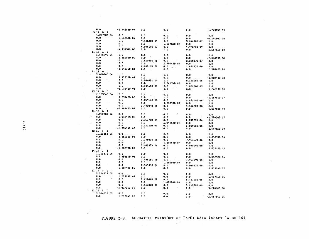
0.0 -1.241080 07 0.0 0.0 o.o 1.773150 09 511 0 1
4.227200 06 0.0 o.o 0.0 o.o 0.0 0.0 6.562400 06 0.0 0.0 o.o -4.191540 08 o.o 0.0 9.152820 05 o.o 5.846100 07 o.o 0.0 0.0 o.o 1.427850 09 o.o 0.0 0.0 o.o 5.846100 07 o.o 4.978700 09 0.0 0.0 -4.191540 08 o.o 0.0 0.0 3.569630 10
11 12 1 0 3.648990 06 o.o 0.0 o.o 0.0 0.0 0.0 2.355850 06 0.0 o.o 0.0 -2.040150 08 o.o 0.0 2.633000 05 o.o 2.280170 07 0.0 o.o 0.0 0.0 5.704430 08 0.0 0.0 o.o 0.0 2.280170 07 o.o 2.632810 09 o.o o.o -2.040150 08 0.0 o.o 0.0 2.355670 10
12 13 0 0 3.060560 06 0.0 o.o o.o o.o 0.0 0.0 1.118120 06 0.0 0.0 0.0 -1.028410 08 0.0 0.0 9.060630 04 0.0 8.333650 06 0.0 0.0 o.o 0.0 2.065740 08 0.0 0.0 o.o o.o 8.333650 06 o.o 1.022000 09 0.0 0.0 -1.028410 08 o.o o.o o.o 1. 261190 10
l3 14 0 0 2.195860 06 0.0 0.0 o.o o.o o.o 0.0 3. 957620 05 0.0 o.o o.o -3.667690 07 0.0 0.0 3.769160 04 o.o 3.493040 06 0.0 0.0 o.o 0.0 9.840930 07 o.o 0.0 o.o o.o 3.493040 06 0.0 4.316200 08 o.o o.o -3.667690 07 0.0 o.o 0.0 4.532010 09
14 15 0 1 1.062280 06 0.0 o.o o.o o.o 0.0 0.0 1.438480 05 o.o o.o 0.0 -1.354140 07 o.o 0.0 2.157720 04 o.o 2.031200 06 0.0
N 0.0 0.0 0.0 5.449520 07 0.0 0.0 I ) 0.0 0.0 2.031200 06 o.o 2.549480 08 0.0 .... .... 0.0 -1.354140 07 o.o o.o 0.0 1.699650 09 <.!) 12 16 1 1
1.103850 06 o.o 0.0 o.o o.o o.o 0.0 2.859320 04 0.0 0.0 o.o -1.087930 06 o.o o.o 2.093020 05 o.o 7.963670 06 0.0 0.0 o.o o.o 1.160620 07 0.0 0.0 0.0 o.o 7. 963670 06 o.o 4.040090 08 0.0 0.0 -1.087930 06 0.0 o.o o.o 5.519250 07
14 17 1 1 1.103870 06 0.0 0.0 o.o 0.0 0.0 o.o 2.859500 04 o.o 0.0 0.0 -1.087980 06 0.0 0.0 2.093150 05 o.o 7.963990 06 0.0 0.0 0.0 0.0 1.160640 07 0.0 o.o 0.0 0.0 7.963990 06 o.o 4. 040170. 08 o.o 0.0 -1.087980 06 0.0 0.0 o.o 5.519360 07
11 18 2 0 3.366510 03 o.o 0.0 0.0 0.0 0.0 0.0 1. 215840 05 o.o 0.0 o.o -5.417360 06 0.0 0.0 1. 215840 05 0.0 5.417360 06 0.0 0.0 o.o o.o 1.851580 07 0.0 0.0 o.o 0.0 5.417360 06 o.o 3.218380 08 0.0 0.0 -5.417360 06 o.o 0.0 0.0 3.218380 08
11 18 3 0 3.366510 03 0.0 0.0 0.0 0.0 0.0 0.0 1. 215840 05 o.o 0.0 o.o -5.417360 06
FIGURE 2-9. FORMATTED PRINTOUT OF INPUT DATA (SHEET 14 OF 16)
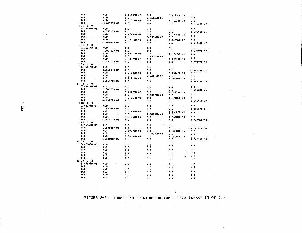
0.0 0.0 1. 215840 05 0.0 5.417360 06 0.0 0.0 0.0 o.o 1.851580 07 o.o 0.0 0.0 0.0 5.417360 06 0.0 3.218380 08 o.o 0.0 -5.417360 06 0.0 o.o o.o 3.218380 08
2 19 1 0 4.794880 03 0.0 0.0 0.0 0.0 0.0 0.0 4.777000 04 0.0 0.0 0.0 -1.494410 06 0.0 0.0 4.777000 04 0.0 1.494410 06 0.0 0.0 0.0 0.0 8.790610 05 o.o 0.0 0.0 0.0 1.494410 06 0.0 6.233340 07 o.o 0.0 -1.494410 06 0.0 0.0 o.o 6.233340 07
6 12 0 0 1.391540 06 0.0 o.o 0.0 0.0 0.0 0.0 1.007170 05 0.0 0.0 0.0 -1.472900 07 0.0 0.0 9.59Zll0 03 o.o 1.402760 06 0.0 0.0 0.0 0.0 6.236280 07 0.0 0.0 0.0 0.0 1.402760 06 o.o 2. 735210 08 0.0 0.0 -1.472900 07 0.0 0.0 0.0 2.871970 09
9 14 0 0 6.140190 05 0.0 0.0 o.o 0.0 0.0 0.0 8.652920 03 0.0 0.0 0.0 -2.867780 06 o.o 0.0 8.240880 02 0.0 2. 731220 05 0.0 o.o 0.0 o.o 2. 751770 07 0.0 0.0 o.o 0.0 2.731220 05 0.0 1.206920 08 o.o 0.0 -2.867780 06 0.0 0.0 o.o 1.267260 09
12 0 0 0 7.488260 05 0.0 o.o 0.0 0.0 0.0 0.0 1.569500 04 0.0 0.0 o.o -4.265240 06 0.0 0.0 1.494760 03 0.0 4.062140 05 0.0 0.0 0.0 0.0 3.355920 07 o.o 0.0 0.0 o.o 4.062140 05 0.0 1.471890 08 0.0 o.o -4.265240 06 0.0 o.o 0.0 1.545490 09
N 2 20 0 0 I
1.022760 04 0.0 o.o o.o 0.0 o.o -N 0.0 1.521610 03 0.0 o.o 0.0 -1.514370 04 0 0.0 0.0 1.521610 03 0.0 1.514370 04 o.o o.o 0.0 0.0 2.009560 04 0.0 0.0 o.o 0.0 1.514370 04 0.0 2.009560 05 0.0 0.0 -1.514370 04 0.0 0.0 0.0 2.009560 05
2 21 0 0 6.545600 03 0.0 0.0 0.0 o.o o.o o.o 1.500010 03 0.0 o.o 0.0 -1.500010 04 o.o 0.0 1.500010 03 0.0 1.500010 04 0.0 0.0 0.0 0.0 2.000000 04 0.0 0.0 0.0 0.0 1.500010 04 0.0 2.000000 05 0.0 0.0 -1.500010 04 0.0 o.o o.o 2.000000 05
15 16 0 0 3.438830 05 o.o o.o 0.0 o.o o.o 0.0 0.0 0.0 0.0 o.o 0.0 0.0 0.0 0.0 o.o o.o o.o 0.0 o.o 0.0 0.0 0.0 o.o 0.0 o.o 0.0 0.0 0.0 0.0 o.o 0.0 0.0 o.o 0.0 o.o
15 16 2 2 3.438830 05 0.0 0.0 0.0 0.0 0.0 o.o 0.0 0.0 0.0 0.0 0.0 0.0 0.0 0.0 0.0 0.0 0.0 0.0 0.0 0.0 0.0 0.0 0.0 0.0 0.0 0.0 o.o 0.0 0.0 0.0 o.o 0.0 0.0 0.0 0.0
FIGURE 2-9. FORMATTED PRINTOUT OF INPUT DATA (SHEET 15 OF 16)
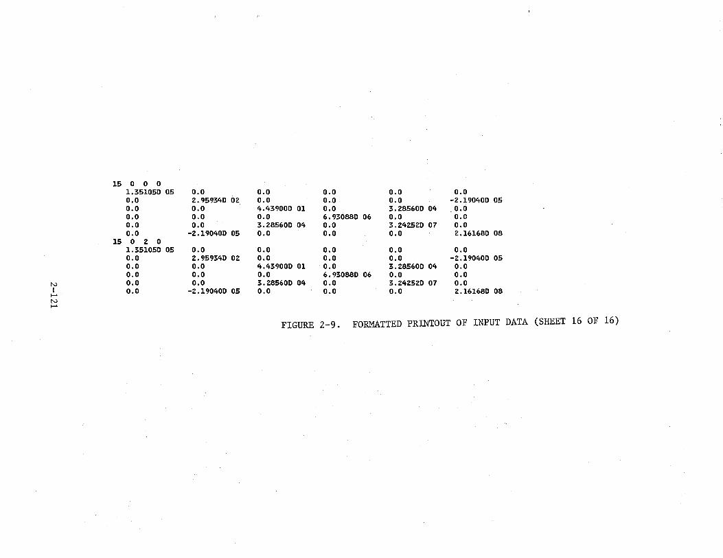
15 0 0 0 1.351050 05 0.0 0.0 0.0 0.0 0.0 o.o 2.959340 02 0.0 o.o 0.0 -2.190400 05 0.0 o.o 4.439000 01 0.0 3.285600 04 o.o 0.0 o.o 0.0 6.930880 06 0.0 0.0 o.o o.o 3.285600 04 0.0 3.242520 07 0.0 0.0 -2.190400 05 o.o o.o o.o 2.161680 08
15 0 2 0 1.351050 05 0.0 0.0 o.o 0.0 0.0 0.0 2.959340 02 0.0 0.0 0.0 -2.190400 05 o.o 0.0 4.439000 01 0.0 3.285600 04 o.o o.o 0.0 0.0 6.930880 06 0.0 0.0
N 0.0 0.0 3.285600 04 0.0 3.242520 07 o.o I 0.0 -2.190400 05
t-o 0.0 o.o o.o 2.161680 08
N t-o
FIGURE 2-9. FORMATTED PRINTOUT OF INPUT DATA (SHEET 16 OF 16)
• Nonzero mass orientation Euler angles (optional) (When a static deflection data set XYZ.NASOUT.DATA is read in, all masses will be rotated and a complete printout of this section of data will occur.)
• Acceleration input table data (optional)
• ~Ki~matrices for all NB internal beams
The nonlinear beam data section prints out all the KR tables, whether
these are user-input or standqrd tables coded into KRASH85. Similarly, the
6 X 6 linear stiffness matrix rKij] is printed for all NB internal beam ele
ments, whether [Kij] is directly input by the user or internally calculated
in KRASH. The printed matrix corresponds to the lower right-hand quandrant
of a full 12 by 12 beam stiffness matrix (figure 1-19, Vol. 1).
Certain items in this formatted printout of the input data provide addi
tional information not directly input by the user. These include the follow
ing:
• External spring data - The actual damping constant used in the KRASHSS calculations of spring damping force is shown (CDAMP(IKM)).
• Internal beam data- Beam lengths are shown (XLB). The item called VBM is a flag denoting which, if any, of the beams the program treats as vertical beams. VBM = 1 corresponds to a vertical beam, and VBM = 0 corresponds to a normal beam. The interpretation of the beam orientation Euler angles, part of the time-history beam deflection output, depends upon whether a normal or vertical beam is noted.
• Plastic hinge and end-fixity data - The actual plastic hinge moments, calculated within the program, are output. (PLM35, ... ,PLM26J)
• Mass data - The coordinates for the mass and node points are not equal to those input by the user in XYZ.DATA. The input coordinates have been modified by the initial mass and node point deflections, also shown in the formatted output of the input data. All calculations in KRASH85 use the modified coordinate data.
2.3.1.3 Miscellaneous Calculated Data
The miscellaneous calculated data are illustrated in figure 2-10, and is
described in the following subsections.
2-122
2.3.1.3.1 Model Parameters. -The overall vehicle weight, e.g. position, and
inertias are shown. These are used to see how well the anlytical model
watches the actual vehicle being analyzed. This output is always for a com
plete airplane, even if only a half-airplane model is input (RUMMOD = 1.0).
The initial position of the vehicle e.g., relative to the ground, is also
shown.
2.3.1.3.2 Beam Loads and Deflections Corresponding to Yielding. -This output
is generated only if NIC on card 50 (figure 2-3) is input nonzero. The beam
loads and deflections corresponding to yielding are used as guidelines for
establishing nonlinear deflection points for internal beam KR curves. The
loads are calculated using the stress and buckling equations discussed in
Volume I, Section 1.3.17, along with the appropriate yield stress for the
beam material given in table 2-3 of this report.
The loads corresponding to yield stress are uncoupled loads (e.g., the
shear forces are those corresonding to yielding without any bending moment
applied.) Similarly, beam deflections are those resulting from the corres
ponding load only without the coupled load being applied. In actual loading
situations, some degree of coupling is always present, so the deflections
corresponding to yield provide only a rough indication of appropriate values
to use for setting up KR curves. Furthermore, no attempt has been made to
include in the analysis the effects of stress concentrations, geometric
shape factors, and end attachment details.
2.3.1.3.3 Overall Vehicle Forces/Accelerations at Time Zerq. -This block of
output data is printed twice. The first time shows the six net loads (pounds
and inch-pounds) at the airplane e.g., and the resulting six rigid body accel
erations. These e.g. accelerations are then used to calculate the rigid body
acceleration at each mass point in the model. These mass point accelerations
yield inertia relief loads at each mass point. If these inertia relief loads
are included in the total airplane force/moment balance, the net e.g. loads
and accelerations should be zero. The second printout shows that the e.g.
loads/accelerations, including inertia relief, are indeed very small (less
than E-16 for all accelerations). The above calculations are performed in
2-123
subroutine NETFOR, the purpose of which is to calculate the net forces acting
on each mass. These forces are used in the NASTRAN static load solution.
Inertia relief loads are included to guarantee that a balanced set of applied
loads is input to the NASTRAN model.
2.3.1.3.4 Individual Mass Forces/Accelerations At Time Zero. -Figure 2-10
a1so shows this list of loads and accelerations for each mass in the model.
The specific data output for each mass is as follows:
Line 1: Gravity loads, e.g. axes
Line 2: External loads, e.g. axes. These are the loads due to input time histories of external loads at specified masses, per the 3500-series cards. This is the method used to input aerodynamic loads into the model for the sample case.
Line 3: Aerodynamic lift, e.g. axes. These data reflects any aerodynamic lift calculated by means of inputting LC on the 3100-series cards. This option is not used in the sample case. The aerodynamic loads calculated using the 3300-series aero data are not included in the load calculations in NETFOR. Therefore, these loads will not get into the NASTRAN model to determine the proper balanced initial conditions.
Line 4: Inertia loads, e.g. axes. The inertia loads are calculated in NETFOR, as described in Section 2.3.1.4 above, to achieve a balanced set of loads for input to NASTRAN.
Line 5: Net loads, e.g. axes. These loads are the sum of all the above loads. The net loads are the input to the NASTRAN static load solution.
Line 6: Accelerations, mass axes. These are the rigid body airplane accelerations at time zero at each mass point. As explained in Section 2.3.1.4, these accelerations are calculated from the airplane e.g. acceleration, which in turn is calculated from all the loads except inertia relief loads. The mass point accelerations in line 6 times the mass point inertia matrix yields the inertia relief loads. These accelerations are output in mass axes to facilitate comparisons with KRASH85 time-history output at time zero. The accelerations for the latter are also in mass axes. The two sets of accelerations should be equal for a properly balanced set of initial conditions.
All quantities shown in this output have the units of pounds or inch
pounds for loads, and g's or rad/sec2 for accelerations. The sign convention
2-124
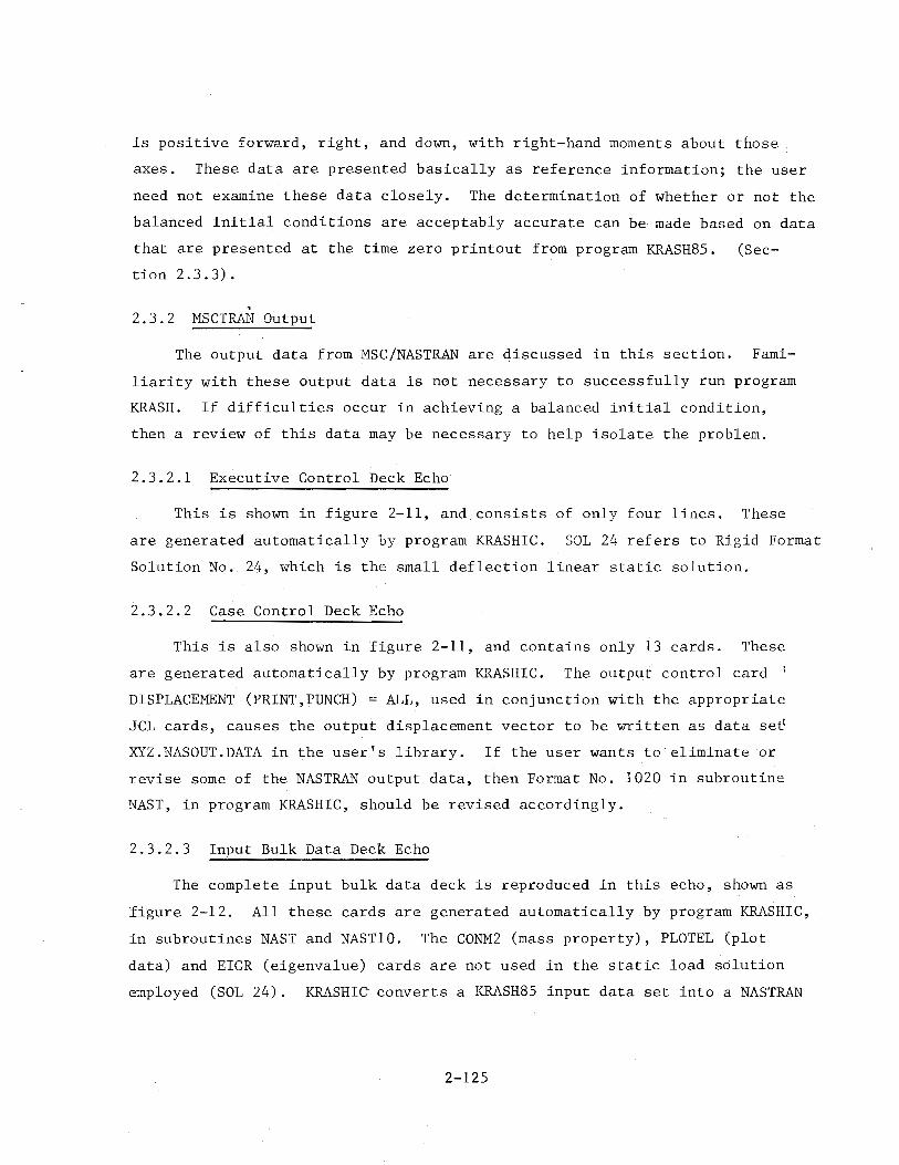
is positive forward, right, and down, with right-hand moments about those.
axes. These data are presented basically as reference information; the user
need not examine these data closely. The determination of whether or not the
balanced initial conditions are acceptably accurate can be made based on data
that are presented at the time zero printout from program KRASH85. (Sec
tion 2.3.3).
. 2. 3. 2 MSCTRPJ·J Output
The output data from MSC/NASTRAN are discussed in this section. Fami
liarity with these output data is not necessary to successfully run program
KRASH. If difficulties occur in achieving a balanced initial condition,
then a review of this data may be necessary to help isolate the problem.
2.3.2.1 Executive Control Deck Echo
This is shown in figure 2-11, and consists of only four lines. These
are generated automatically by program KRASHIC. SOL 24 refers to Rigid Format
Solution No. 24, which is the small deflection linear static solution.
2.3.2.2 Case Control Deck Echo
This is also shown in figure 2-11, and contains only 13 cards. These
are generated automatically by program KRASHIC. The output control card
DISPLACEMENT (PRINT,PUNCH) = ALL, used in conjunction with the appropriate
JCL cards, causes the output displacement vector to be written as data see
XYZ.NASOUT.DATA in the user's library. If the user wants to eliminate or
revise some of the NASTRAN output data, then Format No. 1020 in subroutine
NAST, in program KRASHIC, should be revised accordingly.
2.3.2.3 Input Bulk Data Deck Echo
The complete input bulk data deck is reproduced in this echo, shown as
figure 2-12. All these cards are generated automatically by program KRASHIC,
in subroutines NAST and NAST10. The CONM2 (mass property), PLOTEL (plot
data) and EIGR (eigenvalue) cards are not used in the static load solution
employed (SOL 24). KRASHic· converts a KRASH85 input data set into a NASTRAN
2-125
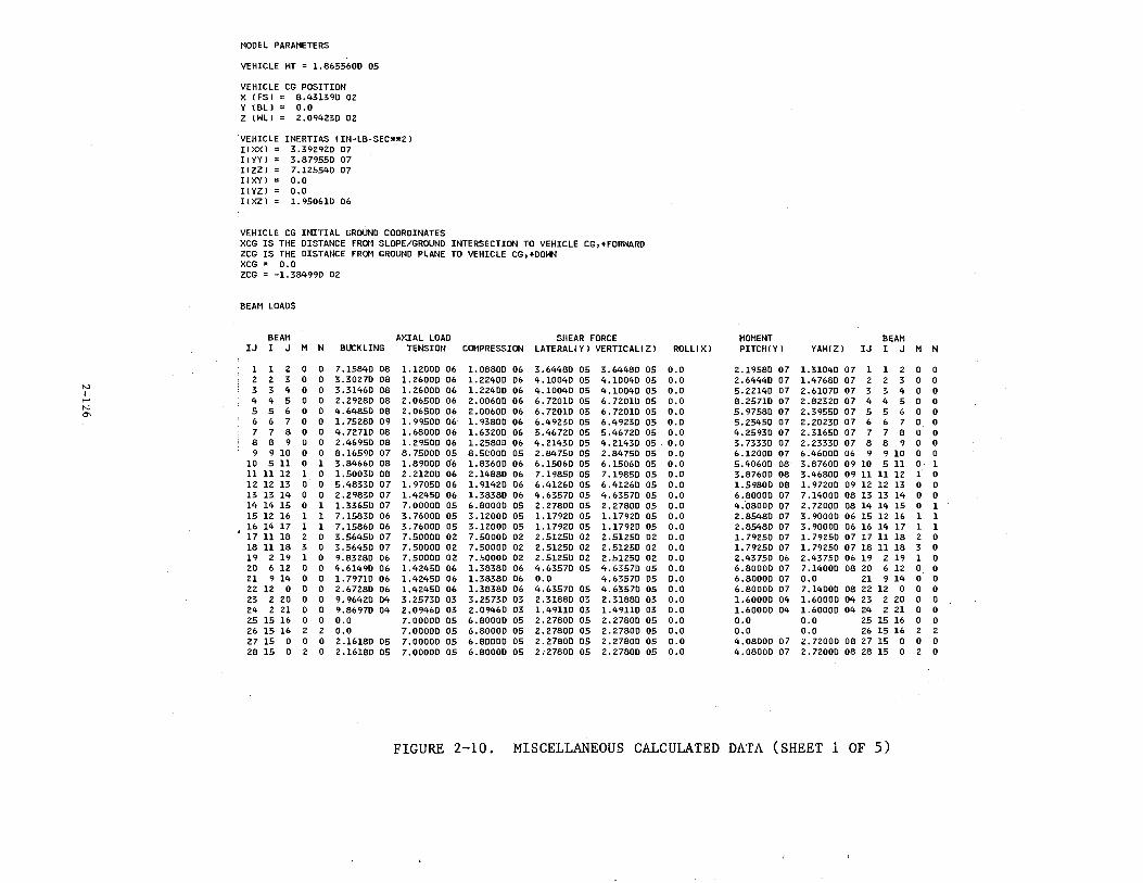
MODEL PARAMETERS
VEHICLE HT = 1.8655600 05
VEHICLE CG POSITION X !FSl = 8.43139D 02 Y 1 Bll = o.o Z !Hll = 2. 09423D 02
VEHICLE INERTIAS !IN-LB-SEC**2l I!XXl = 3. 392920 07 !( yy) = 3.87955D 07 HZZl = 7.12554D 07 I!XY l = o.o I! YZl = 0.0 I!XZl = 1. 95061D 06
VEHICLE CG INITIAL GROUND COORDINATES XCG IS THE DISTANCE FROM SLOPE/GROUND INTERSECTION TO VEHICLE CG,+FORHARD ZCG IS THE DISTANCE FROM GROUND PLANE TO VEHICLE CG,+DOHN XCG = 0.0 ZCG = -1.38499D 02
BEAM LOADS
BEAM AXIAL LOAD SHEAR FORCE Mot1ENT BEAM IJ I J M N BUCKLING TENSION COMPRESSION LATERAL!Yl VERTICAL!Zl ROLL!Xl PITCH!Yl YAH!Zl IJ I J M N
1 1 2 0 0 7.15840 08 1.1200D 06 l.0880D 06 3.6448D 05 3.6448D 05 0.0 2.1958D 07 1.3104D 07 1 1 2 0 0 2 2 3 0 0 3.3027D 08 1.2600D 06 1.22400 06 4.10040 05 4.10040 05 0.0 2.64440 07 1.4768D 07 2 2 3 0 0
N 3 3 4 0 0 3.31460 08 1. 26000 06 1. 22400 06 4.10040 05 4.10040 05 0.0 5.2214D 07 2. 61070 07 3 3 4 0 0 I ...... 4 4 5 0 0 2.29280 08 2.06500 06 2.00600 06 6. 72010 05 6.72010 05 o.o 8.25710 07 2.82320 07 4 4 5 0 0 N 5 5 6 0 0 4.64850 08 2.06500 06 2.00600 06 6. 72010 05 6. 72010 05 0.0 5.97580 07 2.39550 07 5 5 6 0 0 "' 6 6 7 0 0 1. 75280 09 1. 99500 06 1. 9380D 06 6.4923D 05 6.49230 05 0.0 5.25450 07 2.20230 07 6 6 7 0 0
7 7 8 0 0 4.72710 08 1.68000 06 1.63200 06 5.46720 05 5.46720 05 0.0 4.2593D 07 2.31650 07 7 7 8 0 0 8 8 9 0 0 2.46950 08 1.29500 06 1.25800 06 4.2143D 05 4.2143D 05 0.0 3. 73330 07 2.23330 07 8 8 9 0 0 9 9 10 0 0 8.16590 07 8.75000 05 8.5COOO 05 2.84750 05 2.84750 05 0.0 6.12000 07 6.46000 06 9 9 10 0 0
10 511 0 1 3.8466D 08 1.89000 06 1.8360D 06 6.1506D 05 6.1506D 05 o.o 5.40600 08 3.87600 09 10 511 0 1 11 11 12 1 0 1.50030 08 2.21200 06 2.14880 06 7.19850 05 7.1985D 05 o.o 3.8760D 08 3.4680D 09 11 11 12 1 0 12 12 13 0 0 5.48330 07 1.97050 06 1.9142D 06 6.4126D 05 6.4126D 05 o.o 1.5980D 08 1.9720D 09 12 12 13 0 0 13 13 14 0 0 2. 2983D 07 1.4245D 06 l.3838D 06 4.6357D 05 4.6357D 05 o.o 6.8000D 07 7.1400D 08 13 13 14 0 0 14 14 15 0 1 l.3365D 07 7.0000D 05 6.8000D 05 2.2780D 05 2.2780D 05 o.o 4.0800D 07 2.7200D 08 14 14 15 0 1 15 12 16 1 1 7.1583D 06 3.76000 05 3.1200D 05 l.l792D 05 1.1792D 05 o.o 2.8548D 07 3.9000D 06 15 12 16 1 1 16 14 17 1 1 7.1586D 06 3.76000 05 3.1200D 05 l.1792D 05 1.1792D 05 0.0 2.8548D 07 3.9000D 06 16 14 17 1 1 17 11 18 2 0 3.5645D 07 7.5000D 02 7.5000D 02 2.5125D 02 2.5125D 02 0.0 1. 7925D 07 1.7925D 07 17 11 18 2 0 18 11 18 3 0 3.5645D 07 7.5000D 02 7.5000D 02 2.5125D 02 2.5125D 02 0.0 1.7925D 07 1.79250 07 18 11 18 3 0 19 2 19 1 0 9.8328D 06 7.5000D 02 7.5000D 02 2.5125D 02 2.5125D 02 0.0 2.4375D 06 2.43750 06 19 2 19 1 0 20 6 12 0 0 4.6149D 06 1.4245D 06 1.3838D 06 4.6357D 05 4.63570 as o.o 6.8000D 07 7.14000 08 20 6 12 0 0 21 9 14 0 0 1. 79710 06 1.42450 06 1.38380 06 0.0 4.63570 05 o.o 6.80000 07 0.0 21 9 14 0 0 22 12 0 0 0 2.67280 06 1.42450 06 1.3838D 06 4.6357D 05 4.6357D 05 0.0 6.8000D 07 7.1400D 08 22 12 0 0 0 23 2 20 0 0 9.9642D 04 3.2573D 03 3.2573D 03 2.3188D 03 2.31880 03 o.o 1.60000 04 1. 60000 04 23 2 20 0 0 24 2 21 0 0 9.8697D 04 2.09'•6D 03 2.0946D 03 1.49110 03 1.4911D 03 o.o 1.6000D 04 1. 60000 04 24 2 21 0 0 25 15 16 0 0 o.o 7.00000 05 6.80000 05 2.2780D 05 2.27800 05 o.o 0.0 0.0 25 15 16 0 0 26 15 16 2 2 0.0 7.0000D 05 6.8000D 05 2.27800 05 2.27800 05 o.o 0.0 0.0 26 15 16 2 2 27 15 0 0 0 2.1618D 05 7.00000 05 6.80000 05 2.2780D 05 2.27800 05 o.o 4.0800D 07 2.7200D 08 27 15 0 0 0 28 15 0 2 0 2.16180 05 7.00000 05 6.8000D 05 2.27800 05 2.2780D 05 0.0 4.0800D 07 2.72000 08 28 15 0 2 0
FIGURE 2-10. MISCELLANEOUS CALCULATED DATA (SHEET 1 OF 5)
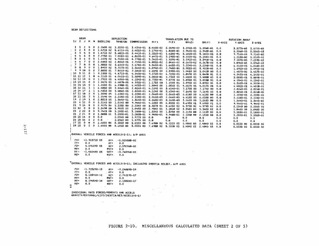
BEAM DEFLECTIONS
BEAM DEFLECTION TRANSLATION DUE TO ROTATION ABOUT IJ I J M N BUCKLING TENSION COMPRESSION FlYl FlZl BMlZl BM!Yl X-AXIS Y-AXIS Z-AXIS
1 1 2 0 0 2.260D 02 3.535D-01 3.434D-01 8.460D-02 5.049D-02 1.204D-01 1.2040-01 0.0 3.5770-03 3.577D-03 2 2 3 0 0 l.471D 02 5.611D-01 5.4510-01 3.274D-01 1.828D-D1 2.942D-D1 2.942D-01 0.0 5.506D-03 5.506D-03 3 3 4 0 0 1.4730 02 5.6010-01 5.4410-01 3.256D-01 1.6280-01 5.182D-01 5.1820-01 0.0 9.7160-03 9.7160-03 4 4 5 0 0 7.7750 01 7.0030-01 6.8030-01 9.6470-01 3.2980-01 8.1020-01 8.1020-01 0.0 1.2150-02 1.2150-02 5 5 6 0 0 1.1070 02 4.9180-01 4.7780-01 3.3420-01 l. 3390-01 3.391D-01 3.3910-01 0.0 7.2390-03 7.2390-03 6 6 7 0 0 2.4640 02 2.8040-01 2. 7240-01 4.8810-02 2.0460-02 8. 2670-02 8.2670-02 0.0 3.0960-03 3.0960-03 7 7 8 0 0 1.5850 02 5.6320-01 5.4710-01 3.0610-01 l. 6650-01 3.224D-01 3.2240-01 0.0 6.0120-03 6.0120-03 8 8 9 0 0 1.0920 02 5. 7270-01 5.5640-01 4.5940-01 2.7480-01 5. 9510-01 5.9510-01 o.o l. 0910-02 l. 0910-02 9 9 10 0 0 7.0000 01 7.5010-01 7.2860-01 2.4590 00 2.5950-01 1.0410 00 1.0410 00 ri.o 1.4570-02 1.4570-02 10 511 0 1 9.1000 01 4.4710-01 4.3430-01 9.3720-02 6.7200-01 1.8490 01 1.8490 01 o.o 4.343D-01 4.3430-01 11 11 12 1 0 4.1120 01 6.0620-01 5.8890-01 3.0560-01 2.7340 00 3.4000 01 3.4000 01 o.o 5.8890-01 5.8890-01 12 12 13 0 0 1.7920 01 6.4380-01 6.2540-01 5.7350-01 7.0770 00 3.8350 01 3.8350 01 o.o 6.2540-01 6.2540-01 13 13 14 0 0 1.0470 01 6. 4870-01 6.3020-01 1.1710 00 l. 2300 01 3.8930 01 3.8930 01 0.0 6.3020-01 6.3020-01 14 14 15 0 1 1.2580 01 6.5900-01 6.4010-01 1.5840 00 1.0560 01 4.0170 01 4.0170 01 0.0 6.4010-01 6.4010-01 15 12 16 1 1 6.4850 00 3.4060-01 2.826D-01 4.1240 00 5.6340-01 7.1700 00 7.1700 00 0.0 2.8260-01 2.8260-01 16 14 17 1 1 6.4850 00 3.4060-01 2.8260-01 4.1240 DO 5.6340-01 7.1690 00 7.1690 00 0.0 2.8260-01 2.8260-01 17 11 18 2 0 1.0590 04 2.2280-01 2.2280-01 2.0660-03 2.0660-03 6.6180 00 6.6180 00 0.0 2.2230-01 2.2280-01 18 11 18 3 0 1.0590 04 2.2280-01 2.2280-01 2.0660-03 2.0660-03 6.6180 00 6.6180 00 0.0 2.2280-01 2.2280-01 19 2 19 1 0 2.0510 03 1.5640-01 1.5640-01 5.2600-03 5.2600-03 3.2620 00 3.2620 00 0.0 l. 5640-01 1.5640-01 20 6 12 0 0 3.3160 00 1.0240 00 9.9440-01 4.6030 00 4.8330 01 9.6950 01 9.6950 01 o.o 9.9440-01 9.9440-01 21 9 14 0 0 2.9270 00 2.3200 00 2.2540 00 5.3570 01 5.6250 02 4.9790 02 4.9790 02 0.0 2.2540 00 2.2540 00 22 12 0 0 0 3.5690 00 l. 9020 00 1.8480 00 2.9540 01 3.1010 02 3.3480 02 3.3480 02 0.0 1.8480 00 1.8480 00 23 2 20 0 0 9.7420 00 3.1850-01 3.1850-01 1.5240 00 1.5240 00 2.1130 00 2.1130 00 0.0 3.1850-01 3.1850-01 24 2 21 0 0 l. 5080 01 3.2000-01 3.2000-01 9.9400-01 9.9400-01 2.1330 00 2.B30 00 0.0 3.2000-01 3.2000-01 25 15 16 0 0 0.0 2.0360 00 1.9770 00 o.o 0.0 o.o 0.0 0.0 0.0 0.0 26 15 16 2 2 0.0 2.0360 00 l. 9770 00 0.0 0.0 0.0 0.0 0.0 0.0 0.0 27 15 0 0 0 1.6000 00 5.1810 00 5.0330 00 7.6980 02 5.1320 03 2.4840 03 2.484D 03 0.0 5.0330 00 5.0330 00 N ~ 28 15 0 2 0 1.6000 00 5.1810 00 5.0330 00 7.6980 02 5.1320 03 2.4840 03 2.4840 03 0.0 5.0330 00 5.0330 00 I ,.... N _,
\OVERALL VEHICLE FORCES AND ACCELSlG-Sl, A/P AXES
FX= -1.915710 03 AX= -1.026880-02 FY= 0.0 AY= 0.0 FZ= 4.091090 03 AZ= 2.192960-02 MX= o.o PDT= o.o HY= -1.452480 05 QDT= -3.743940-03 MZ= o.o ROT= o.o
•ovERALL VEHICLE FORCES AND ACCELSlG-Sl, INCLUDING INERTIA RELIEF, A/P AXES
FX= -1.725290-13 AX= -9.248090-19 FY= 0.0 AY= o.o FZ= 5.115910-12 AZ= 2.742290-17 HX= 0.0 PDT= o.o MY= 8.294590-10 QDT= 2.138030-17 MZ= 0.0 ROT= o.o
INDIVIDUAL t1ASS FORCES/MOMENTS AND ACCE LS GRAVITY/EXTERNAL/LIFT/INERTIA/NET/ACCELSlG-Sl
FIGURE 2-10. MISCELLANEOUS CALCULATED DATA (SHEET 2 OF 5)
ACCELS IN MASS AXES, ALL OTHERS IN A/P AXES
MASS X y z L M N
1 -2.765680 01 0.0 1.584760 03 0.0 0.0 o.o 2.128250-01 0.0 -9.499980 01 0.0 o.o o.o o.o 0.0 0.0 0.0 o.o o.o 4. 257970 01 o.o -4.505500 01 0.0 1.497580 02 o.o 1.513570 01 0.0 1.444700 03 0.0 1.497580 02 o.o
-2.680040-02 0.0 2.848600-02 0.0 -3.743940-03 0.0
2 -1.581670 02 0.0 9.063120 03 0.0 0.0 0.0 1.391640 00 0.0 -6.244980 02 0.0 0.0 o.o 0.0 0.0 o.o 0.0 0.0 o.o 2.198860 02 0.0 -2.485340 02 0.0 1.123180 03 o.o 6.311050 01 0.0 8.190090 03 0.0 1.123180 03 o.o
-2.419680-02 o.o 2.747240-02 0.0 -3.743940-03 0.0
3 -2.672870 02 o.o 1.531580 04 0.0 0.0 o.o 3. 753000 00 o.o -1.861000 03 0.0 o.o 0.0 o.o o.o o.o 0.0 0.0 0.0 3.095180 02 o.o -3.923910 02 0.0 3.629190 02 0.0 4.598340 01 o.o 1.306240 04 o.o 3.629190 02 o.o
-2.015430-02 o.o 2.565690-02 o.o -3.743940-03 o.o
4 -2.285140 02 0.0 1.309400 04 o.o 0.0 0.0 6.177640 00 o.o -4.715000 03 o.o 0.0 0.0 o.o o.o o.o 0.0 0.0 0.0 2.106410 02 o.o -3.143230 02 0.0 2.497770 02 0.0
-1.169550 01 o.o 8.064690 03 0.0 2.497770 02 0.0 -1.605290-02 0.0 2.402250-02 o.o -3.743940-03 0.0
N 5 -3.795640 02 0.0 2.174930 04 0.0 0.0 0.0 I 0.0 0.0 -7.901000 03 o.o 0.0 0.0 ...... o.o o.o 0.0 0.0 0.0 0.0 N
00 2.383590 02 o.o -4. 76 7100 02 0.0 4. 705010 02 0.0 -1.412050 02 0.0 1.337160 04 0.0 4.705010 02 0.0 -1.095770-02 o.o 2.191510-02 o.o -3.743940-03 o.o
6 -1.378740 02 o.o 7.900300 03 o.o 0.0 0.0 -3.794300 00 o.o -1.991000 03 0.0 o.o 0.0 o.o 0.0 o.o o.o 0.0 0.0 5.699980 01 o.o -1.649010 02 0.0 4.492730 02 0.0
-8.466870 01 o.o 5.744400 03 0.0 4.492730 02 0.0 -7.253550-03 0.0 2.085580-02 o.o -3.743940-03 0.0
7 -1.603700 02 o.o 9.189300 03 0.0 0.0 0.0 -6.128490 00 o.o -2.315990 03 0.0 0.0 0.0 0.0 0.0 o.o 0.0 0.0 0.0 4.767340 01 0.0 -1.835610 02 0.0 5.241520 02 0.0
-1.188250 02 0.0 6.689750 03 0.0 5.241520 02 0.0 -5.239970-03 0.0 1.995870-02 o.o -3.743940-03 0.0
8 -1.734160 02 o.o 9.936890 03 0.0 0.0 0.0 -3.083090 00 0.0 -7.853940 02 0.0 0.0 0.0 o.o o.o o.o 0.0 0.0 o.o 8.740430 00 o.o -1.873590 02 0.0 6. 739100 02 0.0
-1.6 77590 02 o.o a. 964130 03 o.o 6. 739100 02 0.0 -9.534570-04 o.o 1.884840-02 0.0 -3.743940-03 0.0
FIGURE 2-10. MISCELLANEOUS CALCULATED DATA (SHEET 3 OF 5)
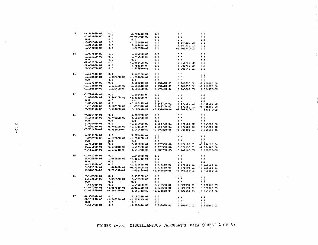
9 -9 0 949490 01 OoO 5o701130 03 OoO OoO OoO -2o606030 00 OoO -4o499920 02 OoO OoO OoO
OoO OoO OoO OoO OoO OoO -2 0 051340 01 OoO -1.036820 02 OoO 1.564520 02 OoO -1.226140 02 OoO 5o147460 03 OoO 1.564520 02 OoO
3o492220-03 OoO 1.820390-02 OoO -3o743940-03 OoO
10 -1.077520 02 OoO 6o174260 03 OoO OoO OoO 1o113100 02 OoO 1. 744520 04 OoO OoO OoO OoO OoO OoO OoO OoO OoO
-5o832300 01 OoO -1.062460 02 OoO 4o042710 02 OoO -50 4 76490 01 OoO 2o351330 04 OoO 4o042710 02 OoO
9o334750-03 OoO 1. 726520-02 OoO -3o743940-03 OoO
11 -1.687430 02 OoO 9o669130 03 OoO OoO OoO 3o388580 01 1o032150 02 -1.541880 04 OoO OoO OoO OoO OoO OoO OoO OoO OoO 1ol17320 02 OoO -2o108210 02 1.457610 01 5o188730 02 -6o208550 00
-2o312540 01 1. 032150 02 -5o960510 03 1.457610 01 5o188730 02 -6o208550 00 -1.150580-02 1.525480-04 2o182500-02 -2o098680-06 -3o743860-03 2o506170-05
12 -1.756360 02 OoO 1o006410 04 OoO OoO OoO 1.876990 02 3o683100 02 -2o818520 04 OoO OoO OoO OoO OoO OoO OoO OoO OoO 1.014180 02 OoO -2o188230 02 2o287700 01 4o592330 02 -9o485500 00 1.134810 02 3o683100 02 -1o833990 04 2o287700 01 4o592330 02 -9o485500 00
-9o930490-03 2o941850-04 2o180440-02 -3o491460-06 -3o743620-03 4o891870-05
13 -9o224470 01 OoO 5o 285700 03 OoO OoO OoO 2o199500 02 4o798290 02 -2o138760 04 OoO OoO OoO OoO OoO OoO OoO OoO OoO
N 3 0 976970 01 OoO -1.130950 02 1.263750 01 1. 971100 02 -5o449880 00 I 1.674750 02 4o 798290 02 -1.621500 04 1o 263750 01 1o971100 02 -5o449880 00 .....
N -7o301670-03 4o938000-04 2o146410-02 -6o295250-06 -3o743000-03 8o396950-05
"' 14 -6 0 559120 01 OoO 3o758430 03 OoO OoO OoO 1. 292920 02 4o572830 02 -1. 781250 04 OoO OoO OoO OoO OoO OoO OoO OoO OoO 1o736000 01 OoO -7o946890 01 8o375350 00 9o676180 01 -4o356140 00 8o106090 01 4o572830 02 -1.413350 04 8o375350 00 9o676180 01 -4o356140 00
-4o461750-03 5o670310-04 2o116700-02 -1. 982760-05 -3o742660-03 9o608070-05
15 -2 o691180 01 OoO 1o542070 03 OoO OoO OoO 5o605590 01 1o069880 02 -6 0 239730 03 OoO OoO OoO OoO OoO OoO OoO OoO OoO 4o269080 00 OoO -3o223660 01 1.413310 00 3o375600 01 -9o256610-0l 3o341320 01 1.069880 02 -4o729900 03 1.413310 00 3o375600 01 -9o256610-01
-2o578320-03 3 0 714340-04 2 0 092260-02 -1o843880-05 -3o743350-03 6o4l8250-05
16 -9 0 422520 01 OoQ 5o399180 03 OoO OoO OoO -5o602650 00 -20057530 01 -2o699590 02 OoO OoO OoO
OoO OoO OoO OoO OoO OoO 7o499040 01 OoO -1.190860 02 2o410580 02 9 0 622590 01 9o971360 03
-2o483740 01 -2 0 057530 01 5o010130 03 2o410580 02 9o622590 01 9o971360 03 -1.441050-02 -8o695270-04 2o169710-02 -2o033810-04 -3 0 727580-03 -2o844630-04
17 -8o988040 01 OoO 5o150220 03 OoO OoO OoO -5o131290 00 -1.645120 01 -2o577240 02 OoO OoO OoO
OoO OoO OoO OoO OoO OoO 4o564990 01 OoO -1.083470 02 2 o292630 02 9o1838~D 01 9o968400 03
FIGURE 2-10. MISCELLANEOUS CALCULATED DATA (SHEET 4 OF 5)
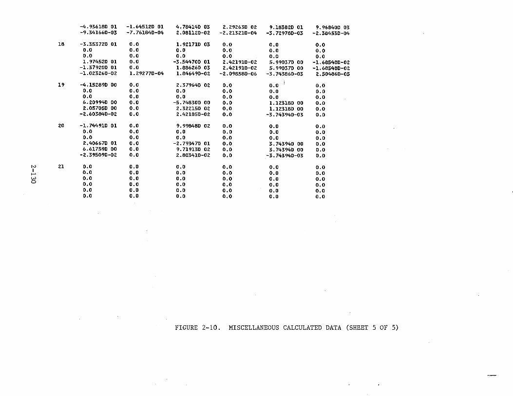
-4.936180 01 -1.645120 01 4.784140 03 2.292630 02 9.183820 01 9.968400 03 -9.341660-03 -7.761840-04 2.081120-02 -2.213210-04 -3.729780-03 -2.384530-04
18 -3.353720 01 0.0 1.921710 03 0.0 o.o o.o o.o 0.0 0.0 0.0 o.o 0.0 o.o o.o 0.0 o.o o.o 0.0 1. 974520 01 0.0 -3.544700 01 2.421910-02 5.990370 00 -1.685480-02
-1.379200 01 o.o 1.886260 03 2.421910-02 5.990370 00 -1.685480-02 -1.023260-02 1. 292770-04 1.846490-02 -2.098580-06 -3.743860-03 2.504860-05
19 -4.152890 00 0.0 2.379640 02 0.0 o.o o.o 0.0 o.o 0.0 o.o o.o 0.0 0.0 0.0 0.0 o.o o.o 0.0 6.209940 00 0.0 -5.748300 00 0.0 1.123180 00 o.o 2.057050 00 0.0 2.322150 02 0.0 1.123180 00 o.o
-2.603840-02 o.o 2.421050-02 0.0 -3.743940-03 o.o 20 -1.744910 01 0.0 9.998480 02 0.0 o.o o.o
o.o 0.0 o.o 0.0 o.o o.o o.o 0.0 0.0 0.0 o.o o.o 2.406670 01 0.0 -2.793470 01 0.0 3.743940 00 0.0 6.617590 00 0.0 9. 719130 02 0.0 3.743940 00 0.0
-2.395090-02 o.o 2.803410-02 0.0 -3.743940-03 0.0
N 21 0.0 0.0 o.o 0.0 o.o 0.0 I o.o 0.0 0.0 0.0 o.o 0.0 ..... w 0.0 0.0 o.o o.o o.o 0.0 0 o.o 0.0 0.0 0.0 o.o 0.0
0.0 0.0 0.0 0.0 o.o 0.0 0.0 0.0 0.0 0.0 0.0 o.o
FIGURE 2-10. MISCELLANEOUS CALCULATED DATA (SHEET 5 OF 5)
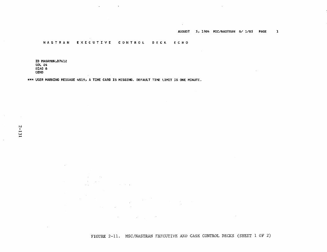
N I ......
w ......
NASTRAN
ID MAGAMON,0761Z SOL Z4 DIAG 8 CEND
E X E C U T I V E
AUGUST 3, 1984 MSC/NASTRAN 8/ 1/83 PAGE 1
C 0 N T R 0 L D E C K E C H 0
*** USER HARNING MESSAGE 4519, A TIME CARD IS MISSING. DEFAULT TIME LIMIT IS ONE MINUTE.
FIGURE 2-11. MSC/NASTRAN EXECUTIVE AND CASE CONTROL DECKS (SHEET 1 OF 2)
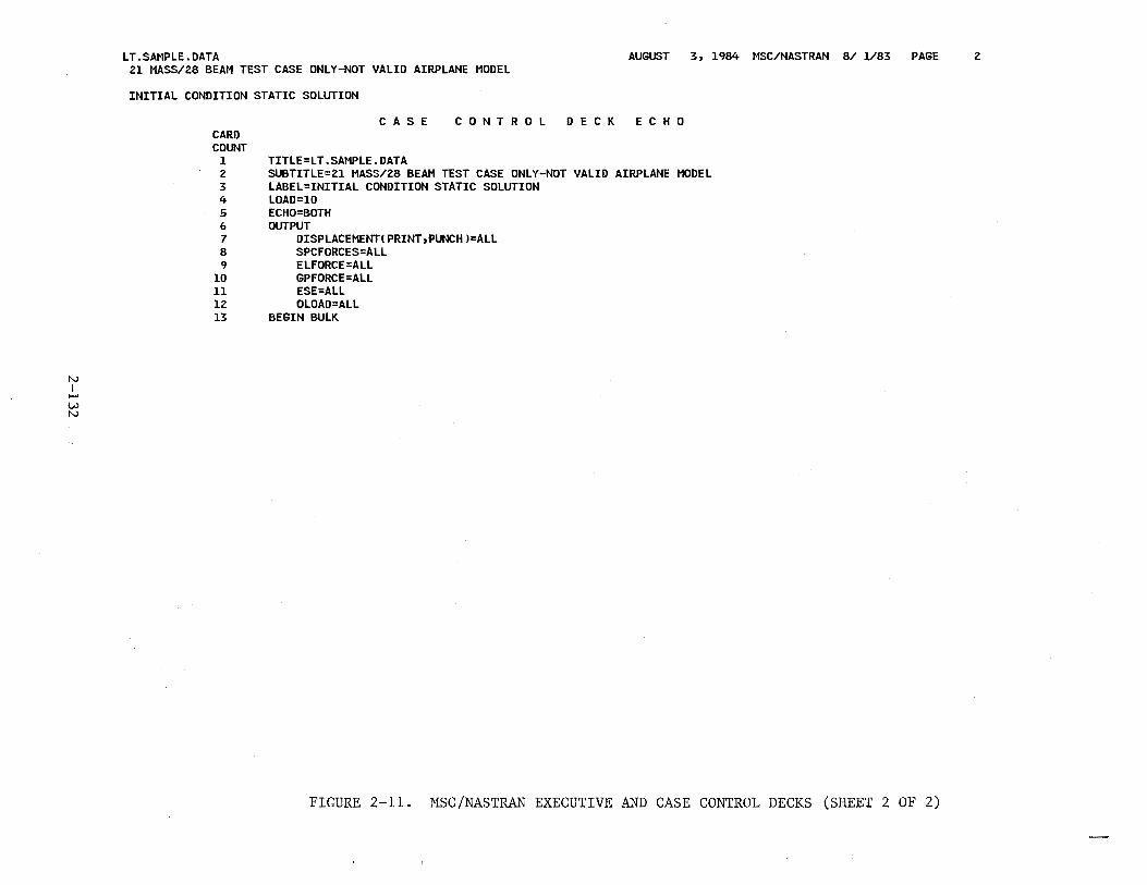
N I ..... w N
LT.SAMPLE.DATA AUGUST 3, 1984 MSC/NASTRAN 8/ 1/83 PAGE 21 MASS/28 BEAM TEST CASE ONLY-NOT VALID AIRPLANE MODEL
INITIAL CONDITION STATIC SOLUTION
CARD COUNT
1 2 3 4 5 6 7 8 9
10 11 12 13
C A S E C 0 N T R 0 L D E C K E C H 0
TITLE=LT.SAMPLE.DATA SUBTITLE=21 MASS/28 BEAM TEST CASE ONLY-NOT VALID AIRPlANE MODEL LABEL=INITIAL CONDITION STATIC SOLUTION LOAD=10 ECHO=BOTH OUTPUT
DISPLACEMENTIPRINT,PUNCHJ=ALL SPCFORCES=ALL ELFORCE=ALL GPFORCE=ALL ESE=ALL OLOAD=ALL
BEGIN BULK
FIGURE 2-11. MSC/NASTRAN EXECUTIVE AND CASE CONTROL DECKS (SHEET 2 OF 2)
2
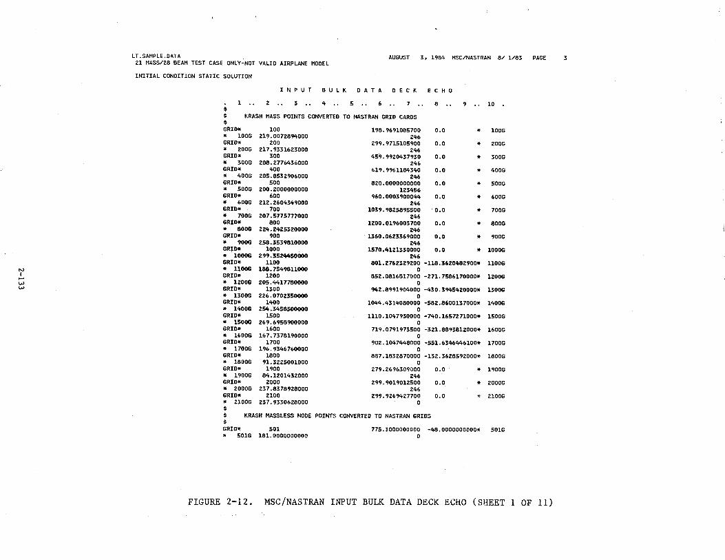
IV I -w w
LT.SAMPLE.OATA AUGUST 3, 1984 MSC/NASTRAN 8/ 1/83 PAGE 3 21 MASS/28 BEAM TEST CASE ONLY-NOT VALID AIRPLANE MODEL
INITIAL CONDITION STATIC SOLUTION
I N P U T B U L K D A T A D E C K E C H 0
1 2 3 4 •• 5 .. 6 7 8 9 • • 10 $ $ KRASH MASS POINTS CONVERTED TO NASTRAN GRID CARDS $ GRID* 100 198.9691085700 o.o * 100G * 100G 219.0072894000 246 GRID* 200 299.9715105900 0.0 * 200G * 200G 217. 9331623000 246 GRID* 300 459.9920437930 o.o * 300G * 300G 208.277643&000 246 GRID* 400 619.9961184340 o.o * 400G * 400G 205.8532906000 246 GRID* 500 820.0000000000 o.o * 500G * 500G 200.2000000000 123456 GRID* 600 960.0003900044 o.o * 600G * 600G 212.2604349000 246 GRID* 700 1039.9825895500 0.0 * 700G * 700G 207.5775777000 246 GRID* 800 1200.0196003700 o.o * 800G * 800G 224.2425320000 246 GRID* 900 1360.0623369000 o.o * 900G * 900G 258.3539810000 246 GRID* 1000 1570.4121330000 o.o * 1000G * 1000G 299.3524450000 246 GRID* 1100 801.2762329200 -118.3620482900* llOOG * llOOG 188.7549811000 0 GRID* 1200 852.0816817000 -271.7586170000* 1200G * lZOOG 205.4417780000 0 GRID* 1300 942.8991904000 -430.3945420000* 1300G * 1300G 226.0702350000 0 GRID* 1400 1044.4314080000 -582.8600137000* 1400G * 1400G 254.3458500000 0 GRID* 1500 1110.1047930000 -740.1657271000* 1500G * 1500G 269.6958900000 0 GRID* 1600 71~.0791973500 -321.8893812000* 1600G * 1600G 167.7378190000 0 GRID* 1700 902.1047448000 -551.6346446100* 1700G * 1700G 196. 9346 760000 0 GRID* 1800 887.1832870000 -132.3628592000* 1800G * l800G 91.3225001000 0 GRID* 1900 279.269&309000 o.o * 1900G * 1900G 84.1201432000 246 GRID* 2000 299.9019012500 o.o * 2000G * ::!OOOG 237.8378928000 246 GRID* 2100 299.9269427700 0.0 * 2lOOG * 2100G 237.9330628000 0 $ $ KRASH MASSLESS NODE POINTS CONVERTED TO NASTRAN GRIDS $ GRID* 501 775.1000000000 -48.0000000000* 501G * 501G 181.0000000000 0
FIGURE 2-12. MSC/NASTRAN INPUT BULK DATA DECK ECHO (SHEET 1 OF 11)
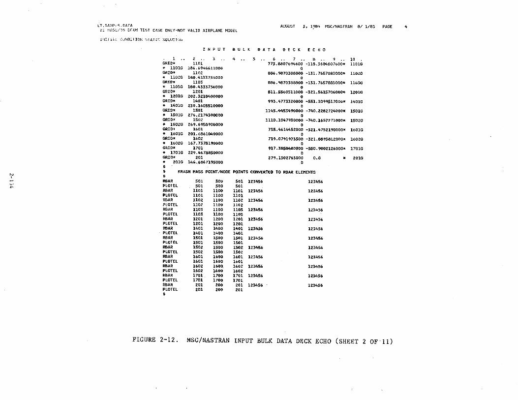
N I .....
V.>
""
LT .SAt1PL~ .DATA AUGUST 3, 1984 MSC/NASTRAN 8/ 1/83 PAGE <l tiA:,::;nn llEAM TEST CASE ONLY-NOT VALID AIRPLANE MODEL
HUTIAi CUNDJ.:T!Ot-; ~:.rAT.(l. SOLUTI\J!~
l GRID* * llOlG GRID* * ll02G GRID* * ll03G GRID* * 1201G GRID* * 1401G GRID* * l501G GRID* * 1502G GRID* * 1601G GRID* * 1&02G GRID* * 1701G GRID* * 201G $
! N P U T B U L K D A T A D E C K E C H 0
z 3 1101.
186.&94&&11000 llOZ
180.4333756000 1103
180.433375&000 1201
202.321&480000 1401
230.1&05510000 1501
27&.2174300000 1502
2&9.&958900000 1&01
201.&8&1040000 1&02
1&7.7378190000 1701
229.4&78850000 201
146. 686 7195000
4 .. 5 & • • 7 • • 8 • • 9 • • 10 773.8807694600 -118.3604807600* llOlG
0 886.9870388800 -131.7657883000* llOZG
0 886.9870388800 -131.7657883000* 1103G
0 811.55&0511000 -321.5615706000* 1201G
0 993.4773320000 -551.3099517000* l401G
0 1145.4453490000 -740.2282724000* 1501G
0 1110.1047930000 -740.1657271000* 150ZG
0 735.4614452000 -321.4752190000* 1601G
0 719.0791973500 -321.8893812000* 1602G
0 917.3858480000 -550.9002126000* l701G
0 279.1302763000
0 o.o * Z01G
$ $
KRASH MASS POINT/NODE POINTS CONVERTED TO R8AR ELEMENTS
RBAR 501 500 501 123456 123456 PLOTEL SOl 500 501 RBAR 1101 1100 1101 123456 123456 PLOTEL 1101 1100 1101 RBAR 1102 1100 1102 123456 1Z3456 PLOTEL 1102 1100 1102 RBAR 1103 1100 1103 123456 123456 PLOTEL 1103 1100 1103 R8AR 1201 1200 1201 123456 123456 PLOTEL 1201 1200 1201 RBAR 1401 1400 1401 123456 12345& PLOTEL 1401 1400 1401 RBAR 1501 1500 1501 123456 123456 PLOTEL 1501 1500 1501 RBAR 1502 1500 1502 123456 123456 PLOTEL 1502 1500 1502 RBAR 1601 1600 1601 123456 123456 PLOTEL 1601 1600 1601 RBAR 1602 1600. 1602 123456 123456 PLOTEL 1602 1600 1602 RBAR 1701 1700 1701 123456 123456 PLOTEL 1701 1700 1701 RBAR 201 200 201 123456 1Z3456 PLOTEL 201 200 201 $
FIGURE 2-12. MSC/NASTRAN INPUT BULK DATA DECK ECHO (SHEET 2 OF·ll)
4
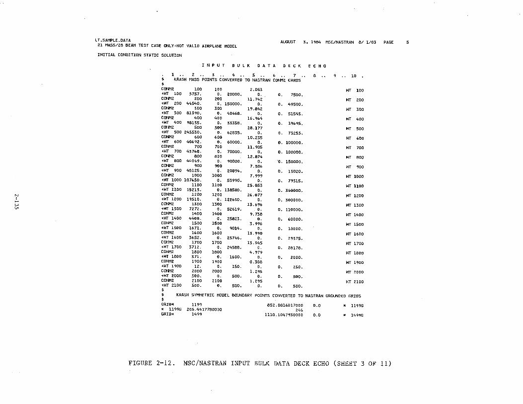
L T.SAMPLE. DATA 21 MASS/28 BEAM TEST CASE ONLY"NOT VALID AIRPLANE MODEL
AUGUST 3, 1984 MSC/NASTRAN 8/ 1/83 PAGE 5
INITIAL CONDITION STATIC SOLUTION
I N P U T B U L K D A T A D E C K E C H 0
1 .. 2 .. 3 .. 4 . . 5 .. 6 . . 7 .. 8 .. 9 .. 10 $ KRASH MASS POINTS CONVERTED TO NASTRAN CONM2 CARDS $ CONM2 100 100 2.053 WT 100 +WT 100 5757. o. 20000. 0. o. 7500. CONM2 200 200 u. 742 WT 200 +WT 200 44540. o. 150000. 0. o. 49500. CONM2 300 300 19.842 WT 300 +HT 300 81390. o. 48468. o. 0. 51545. CONM2 400 400 16.964 WT 400 +HT 400 98135. o. 33358. 0. o. 39695. CO:~M2 500 500 28.177 WT 500 +I~T 500 245530. 0. 62835. o. o. 73255. CONM2 600 600 10.235 WT 600 +WT 600 40692. 0. 60000. o. 0. 100000. CONM2 700 700 11.905 WT 700 +HT 700 43768. o. 70000. o. o. 100000. CONI'I2 800 800 12.874 WT 800 +HT 800 44049. 0. 90000. o. o. 150000. CONM2 900 900 7.386 WT 900 +WT 900 48125. o. 20894. o. o. 13020. CONM2 1000 1000 7.999 WT 1000 +WT 1000 107650. o. 53990. o. o. 79315. CONt12 uoo 1100 25.053 WT 1100 +WT UOO 15213. o. 138580. o. o. 360000.
N CONM2 1200 1200 26.077 WT 1200 I +HT 1200 19510. 0. 122630. 0. o. 300000 . .....
CONM2 1300 1300 13.696 WT 1300 w \.11 +WT 1300 7272. o. 52619. o. o. 110000.
CONM2 1400 1400 9. 738 WT 1400 +WT 1400 4408. 0. 25823. o. o. 60000. CONM2 1500 1500 3.996 HT 1500 +HT 1500 1671. o. 9014. 0. o. 18000. CONM2 1600 1600 13.990 HT 1600 +HT 1600 3652. o. 25746. 0. o. 29375. CONM2 1700 1700 13.345 WT 1700 +HT 1700 3712. o. 24588. 0. o. 28178. CONM2 1800 1800 4.979 WT 1800 +HT 1800 371. 0. 1600. o. o. 2000. CONM2 1900 1900 0.308 HT 1900 +HT 1900 12. o. 150. 0. o. 250. CONH2 2000 2000 l. 295 HT 2000 +HT 2000 500. 0. 500. 0. 0. 500. CONM2 2100 2100 1.295 HT 2100 +HT 2100 500. o. 500. o. o. 500. $ $ KRASH SYMMETRIC MODEL BOUNDARY POINTS CONVERTED TO NASTRAN GROUNDED GRIDS $ GRID* 1199 852.0816817000 0.0 " ll99G
" ll99G 205.4417780000 246 GRID* 1499 1110.1047930000 0.0 * 1499G
FIGURE 2-12. MSC/NASTRAN INPUT BULK DATA DECK ECHO (SHEET 3 OF 11)
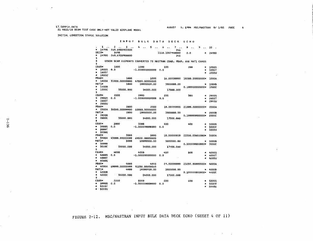
LT.SAMPLE.DATA AUGUST 3, 1984 MSC/NASTRAN 8/ 1/83 PAGE 6 21 MASS/28 BEAM TEST CASE ONLY-NOT VALID AIRPLANE MODEL
INITIAL CONDITION STATIC SOLUTION
I N P U T B U L K D AT A D E C K E C H 0
1 .. 2 .. 3 .. 4 .. 5 .. 6 .. 7 .. 8 . . 9 .. 10
" 1499G 269.6958900000 246 GRID* 1498 1110.1047930000 0.0 " 1498G
" 1498G 269.6958900000 246 $ $ KRASH BEAM ELEMENTS CONVERTED TO NASTRAN CBAR, PBAR, AND ~1AT1 CARDS $ CBAR* 1000 1000 100 200 " 1000S
" 1000S 0.0 -1. 000000000000 0.0 " 1000T
" 1000T " lOOOU
" lOOOU P8AR* 1000 1000 16.00000000 18500.00000000!< 1000A
" 1000A 31000.00000000 49500.00000000 MATl* 1000 10000000,00 3800000.00 " lOOOB
" 1000B 0.100000000000* 1000C * 1000C 35000.000 34000.000 17000.000 $ CBAR* 2000 2000 200 300 * 2000S
" 2000S 0.0 -1. 000000000000 0.0 * 2000T
" 2000T " zooou " 2000U P8AR* 2000 2000 18.00000000 21500.00000000* ZOOOA
" 2000A 38500.00000000 60000.00000000 ~1AT1* 2000 10000000.00 3800000.00 " 2000B
" 20008 0.100000000000* 2000C N * 2000C 35000.000 34000.000 17000.000 I $ - C8AR* 3000 3000 300 400 * 3000$ VJ
"' * 3000$ 0.0 -1. 000000000000 0.0 " 3000T * 3000T " 3000U * 3000U PBAR* 3000 3000 18.00000000 21500.00000000* 3000A
* 3000A 43000.00000000 64500.00000000 MATl* 3000 10000000.00 3800000.00 " 30008
" 3000B 0.100000000000* 3000C * 3000C 35000.000 34000.000 17000.000 $ CBAR* 4000 4000 400 500 * 4000$ * 4000$ 0.0 -1.000000000000 0.0 * 4000T * 4000T * 4000U * 4000U PBAR* 4000 4000 29.50000000 23250.00000000* 4000A * 4000A 68000.00000000 91250.00000000 MATl* 4000 10000000.00 3800000.00 * 4000B * 40008 0.100000000000* 4000C * 4000C 35000.000 ~4000.000 17000.000 $ CBAR* 5000 5000 500 600 * 5000$
" 5000$ o.o -1.000000000000 0.0 " 5000T * 5000T * 5000U * 5000U
FIGURE 2-12. MSC/NASTRAN INPUT BULK DATA DECK ECHO (SHEET 4 OF 11)
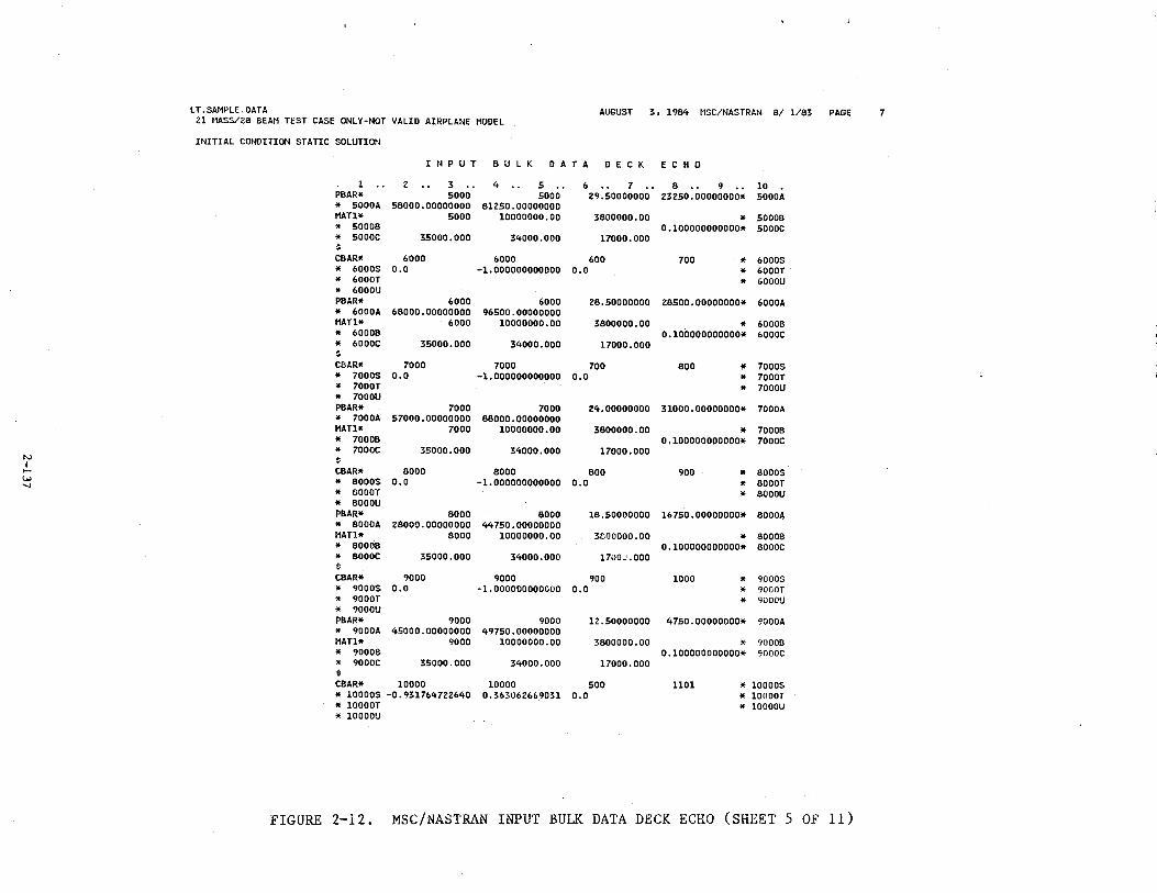
LT.SAMPLE.DATA AUGUST 3, 1984 HSC/NASTRAN 8/ 1/83 PAGE 7 21 MASS/28 BEAM TEST CASE ONLY-NOT VALID AIRPLANE MODEL
INITIAL CONDITION STATIC SOLUTION
I N P U T B U L K D A T A D E C K E C H 0
1 .. 2 .. 3 . . 4 .. 5 . . 6 .. 7 .. 8 . . 9 . . 10 PBAR* 5000 5000 29.50000000 23250.00000000* 5000A
" 5000A 58000.00000000 81250.00000000 MATl* 5000 10000000.00 3800000.00 .. 50008
" 50008 0.100000000000* 5000C
" 5000C 35000.000 34000.000 17000.000 $ C8AR* 6000 6000 600 700 .. 6000S .. 6000$ 0.0 -1.000000000000 0.0 .. 6000T * 6000T .. 6000U * 6000U P8AR* 6000 6000 28.50000000 28500.00000000* 6000A .. 6000A 68000.00000000 96500.00000000 MATl* 6000 10000000.00 3800000.00 .. 60008 .. 60008 0.100000000000* 6000C .. 6000C 35000.000 34000.000 17000.000 $ C8AR* 7000 7000 700 800 .. 7000S .. 7000S 0.0 -1. 000000000000 0.0 * 7000T * 7000T * 7000U * 7000U P8AR* 7000 7000 24.00000000 31000.00000000* 7000A .. 7000A 57000.00000000 88000.00000000 MATl* 7000 10000000.00 3800000.00 * 70008 * 70008 0.100000000000* 7000C .. 7000C 35000.000 34000.000 17000.000
N $ I ..... C8AR* 8000 8000 800 900 * 8000S w .. 8000S 0.0 -1.000000000000 0.0 " 8000T '-I * BOOOT * 8000U .. 8000U P8AR* 8000 8000 18.50000000 16750.00000000* 80004 * 8000A 28000.00000000 44750.00000000 MATl* 8000 10000000.00 3800000 .oo * 80008 .. 80008 0.100000000000* 8000C .. 8000C 35000.000 34000.000 17UOJ. 000 $ CBAR* 9000 9000 900 1000 .. 9000$ .. 9000S o.o -1.000000000000 0.0 .. 9000T
" 9000T " 9UOOU
" 9000U P8AR* 9000 9000 12.50000000 4750.00000000lf 9000A .. 9000A 45000.00000000 49750.00000000 MATl* 9000 10000000.00 38000DO.OO " 90008 .. 90008 0.100000000000* 9000C
" 9000C 35000.000 34000.000 17000.000 $
CSAR* 10000 10000 500 1101 * 100DOS * 10000S -0.931764722640 0.363062669031 o.o * lOOOOT * lOOOOT * lOOOOU * lOOOOU
FIGURE 2-12. MSC/NASTRAN INPUT BULK DATA DECK ECHO (SHEET 5 OF 11)
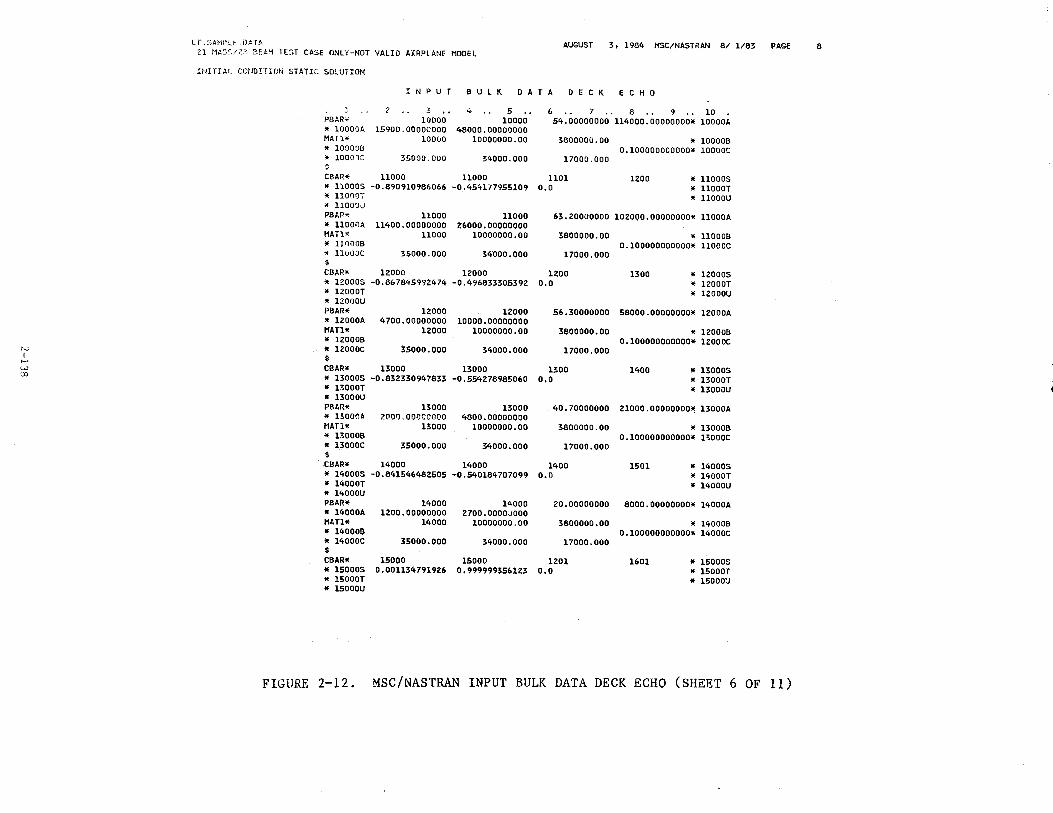
LT.SAMPLf. DATA 21 NA3",/;>[; BEAM TEST CASE ONLY-NOT VALID AIRPLANE MODEL
AUGUST 3, 1984 MSC/NASTRAN 8/ 1/83 PAGE 8
INIT IAI COtiO!TION STATIC SOLUTION
1 N P U T B U l K 0 A T A 0 E C K E C H 0
J ? 3 .. 4 .. 5 .. 6 . . 7 .. 8 .. 9 .. 10 PBAR* 10000 10000 54.00000000 114000.00000000* 10000A * lOOOOA 15900. 00000000 48000.00000000 NATl* 10000 10000000.00 3800000.00 * 100008 * lOOOOB 0.100000000000* lOOOOC * lOOOOC 55000.000 34000.000 17000.000 $
CBAR* 11000 11000 1101 1200 * llOOOS * llOOOS -0.890910986066 -0.454177955109 o.o * llOOOT * llOOOT * 11000U * 110000 PBAR* 11000 11000 63.20000000 102000.00000000* 11000A * llOOOA 11400.00000000 26000.00000000 MATJ.• 11000 10000000.00 3800000.00 * 110008 * 110008 0.100000000000* 11000C ". llUOOC 35000.000 34000.000 17000.000 $ CBAR* 12000 12000 1200 1300 * 120005 * 120005 -0.867845992474 -0.496833305392 o.o * 12000T * 12000T * l2000U * 12000U PBAR* 12000 12000 56.30000000 58000.00000000* l2000A * l2000A 4700.00000000 10000.00000000 MATl* 12000 10000000.00 3800000.00 * 120008 * 120008 0.100000000000* 1ZOOOC
N * 12000C 35000.000 34000.000 17000.000 I $ .....
CBAR* 13000 13000 1300 1400 * l3000S w co * 13000S -0.832330947833 -0,554278985060 o.o * 13000T
* l3000T * 13000U * 13000U P8An* 13000 13000 40. 70000000 21000.00000000* l3000A * BOOOA 2001J.OOODOOOO 4800.00000000 tlATl* 13000 10000000.00 3800000.00 * 130008 * 130008 0.100000000000* 13000C * 13000C 35000.000 34000.000 17000.000 $ C8AR* 14000 14000 1400 1501 * 140005 * 14000$ -0.841546482505 -0.540184707099 o.o * 14000T * 14000T * 14000U * 14000U P8AR* 14000 14000 20.00000000 8000.00000000* 14000A * 14000A 1ZOO.OOOOOOOO 2700.0000JOOO tlATl* 14000 10000000.00 3800000.00 * 140008 * 140008 0.100000000000* 14000C * 14000C 35000.000 34000.000 17000.000 $ CBAR* 15000 15000 1201 1601 * 15000S * 15000S 0. 001134 791926 0.999999356123 o.o * 15000T * lSOOOT * l5000U * l5000U
FIGURE 2-12. MSC/NASTRAN INPUT BULK DATA DECK ECHO (SHEET 6 OF 11)
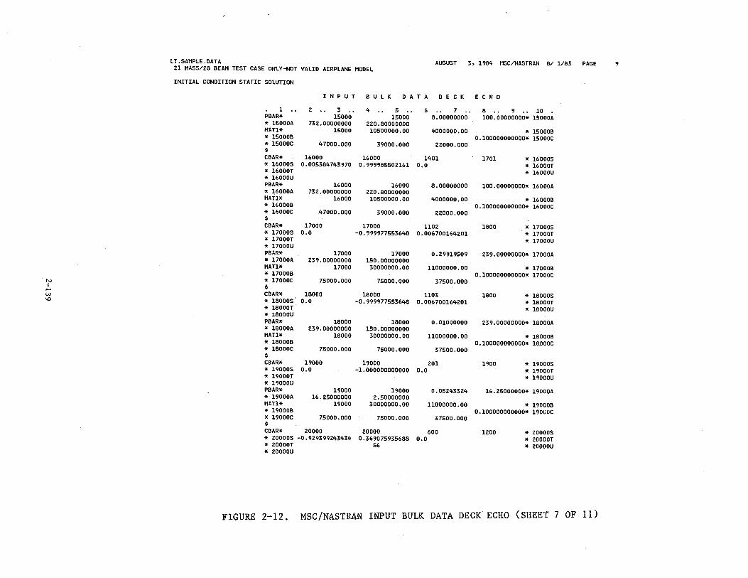
LT. SAMPLE .DATA 21 MASS/28 BEAM TEST CASE ONLY-NOT VALID AIRPLANE MODEL
AUGUST 3, 1984 ~1SC/NASTRAN 8/ 1/83 PAGE 9
INITIAL CONDITION STATIC SOLUTION
I N P U T B U L K D A T A D E C K E C H 0
1 .. 2 .. 3 .. 4 .. 5 .. 6 .. 7 .. 8 . . 9 .. 10 PBAR* 15000 15000 8.00000000 100.00000000* 15000A * 15000A 732.00000000 220.80000000 MATl* 15000 10500000.00 4000000.00 " 150008 " 150008 0.100000000000* 15000C * 15000C 47000.000 39000.000 22000.000 $ CBAR* 16000 16000 1401 1701 * 16000S * 16000S 0.005384743970 0.999985502161 0.0 * 16000T * 16000T * 16000U * 16000U PBAR* 16000 16000 8.00000000 100.00000000* 16000A * 16000A 732.00000000 220.80000000 MATl* 16000 10500000.00 4000000.00 " 160008 " 160008 0.100000000000* 16000C * 16000C 47000.000 39000.000 22000.000 $ CBAR* 17000 17000 1102 1800 * 17000S * 17000S 0.0 -0.999977553648 0.006700164201 * 17000T * 17000T * 17000U * 17000U PBAR* 17000 17000 0.29919509 239.00000000* 17000A * 17000A 239.00000000 150.00000000 MATl* 17000 30000000.00 11000000.00 " 170008 " 170008 0.100000000000* 17000C
N * 17000C 75000.000 75000.000 37500.000 I $ .....
CBAR* 18000 18000 1103 1800 * 18000S w \D * 18000S 0.0 -0.999977553648 0.006700164201 * l8000T
* 18000T * 18000U * 18000U PBAR* 18000 18000 0.01000000 239.00000000* l8000A * 18000A 239.00000000 150.00000000 MATl* 18000 30000000.00 11000000.00 " 180008 " 180008 0.100000000000* 18000C * 18000C 75000.000 75000.000 37500.000 $ CBAR* 19000 19000 201 1900 * 19000S * l9000S 0.0 -1. 000000000000 0.0 * 19000T * l9000T * 19000U * l9000U PBAR* 19000 19000 0.05243324 16.25000000* 19000A * l9000A 16.25000000 2.50000000 MATl* 19000 30000000.00 11000000.00 " 190008 " 190008 0.100000000000* l9000C * 19000C 75000.000 75000.000 37500.000 $ CBAR* 20000 20000 600 1200 " 20000$ " 20000$ -0.929399243434 0.369075935688 0.0 * 20000T * 20000T 56 * 20000U " 20000U
FIGURE 2-12. MSC/NASTRAN INPUT BULK DATA DECK ECHO (SHEET 7 OF 11)
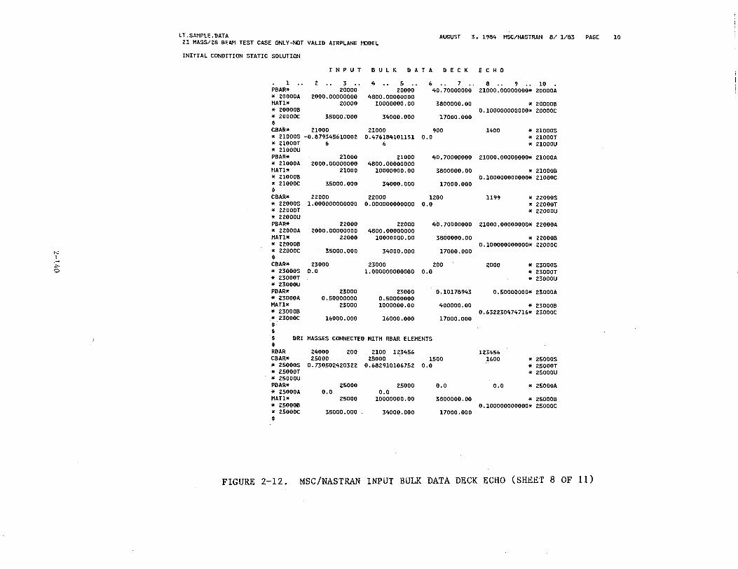
LT.SAMPLE.DATA AUGUST 3, 1984 MSC/NASTRAN 8/ 1/83 PAGE 10 21 MASS/28 BEAM TEST CASE ONLY-NOT VALID AIRPLANE MODEL
INITIAL CONDITION STATIC SOLUTION
I N P U T B U L K D A T A D E C K E C H 0
1 .. 2 .. 3 .. 4 .. 5 . . 6 .. 7 . . 8 .. 9 . . 10 P8AR* 20000 20000 40.70000000 21000.00000000* 20000A * 20000A 2000.00000000 4800.00000000 MATl* 20000 10000000.00 3800000.00 * 200008 " 200008 0.100000000000* 20000C * 20000C 35000.1)00 34000.000 1.7000.000 $ C8AR* 21000 21000 900 1400 * 21000S * 21000S -0.879345610002 0.476184101131 0.0 * 21000T * 21000T 6 6 * 21000U * 21000U P8AR* 21000 21000 40.70000000 21000.00000000* 21000A * 21000A 2000.00000000 4800.00000000 MATl* 21000 10000000.00 3800000.00 * 210008 * 210008 0.100000000000* 21000C * 21000C 35000.000 34000.000 17000.000 $ C8AR* 22000 22000 1200 1199 * 22000S * 22000S 1.000000000000 0.000000000000 0.0 * 22000T * 22000T * 22000U * 22000U P8AR* 22000 22000 40.70000000 21000.00000000* 22000A * 22000A 2000.00000000 4800.00000000 MATl* 22000 10000000.00 3800000.00 " 220008 " 220008 0.100000000000* 22000C
N * 22000C 35000.000 34000.000 17000.000 I $ .- C8AR* 23000 23000 200 2000 * 23000S -1'-
0 * 23000S 0.0 1.000000000000 o.o * 23000T * 23000T * 23000U * 23000U P8AR* 23000 23000 0.10178943 0.50000000* 23000A * 23000A 0.50000000 0.50000000 MATl* 23000 1000000.00 400000.00 " 230008 * 230008 0.632230474716* 23000C * 23000C 16000.000 16000.000 17000.000 $ $ $ DRI MASSES CONNECTED HITH R8AR ELEMENTS $ R8AR 24000 200 2100 123456 123456 C8AR* 25000 25000 1500 1600 * 25000S * 25000S 0.730502420322 0.682910106752 0.0 * 25000T * 25000T * 25000U * 25000U P8AR* 25000 25000 0.0 0.0 * 25000A * 25000A o.o 0.0 MATl* 25000 10000000.00 3800000.00 " 250008 * 250008 0.100000000000* 25000C * 25000C 35000.000 34000.000 17000.000 $
FIGURE 2-12. MSC/NASTRAN INPUT BULK DATA DECK ECHO (SHEET 8 OF 11)
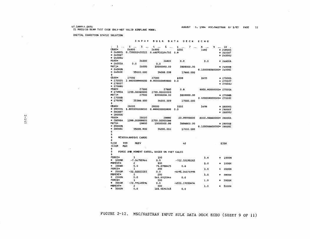
N I
1-' .,..
LT.SAMPLE.DATA AUGUST 3, 1984 MSC/NASTRAN 8/ 1/83 PAGE Z1 MASS/Z8 BEAM TEST CASE ONLY-NOT VALID AIRPLANE MODEL
INITIAL CONDITION STATIC SOLUTION
I N P U T B U L K D A T A D E C K E C H 0
1 CBAR* * Z6000S * Z6000T * Z6000U PBAR* * Z6000A MAT1* * Z6000B * Z6000C $ CBAR* * Z7000S * Z7000T " Z7000U PBAR* * Z7000A MATl* * Z7000B * Z7000C $ CBAR* " Z8ooos * Z8000T * Z8000U PBAR* * Z8000A MATl* " Z8000B " Z8oooc $ $
z .. 3 .. 4 .. 5 .. 6 .. 7 Z6000 Z6000 150Z
0.73050Z4Z03ZZ 0.68Z91010675Z 0.0
Z6000 o.o
Z6000
35000.000
Z6000 0.0
1000000D.OO
34000.000
o.o
3800000.00
17000.000
Z7000 Z7000 1500 1.000000000000 0.000000000000 0.0
Z7000 1ZOO.OOOOOOOO
Z7000
35000.000
Z8000 1.000000000000
Z8000 1ZOO.OOOOOOOO
Z8000
35000.000
Z7000 Z700.00000000
10000000.00
34000.000
Z8000 0.000000000000
Z8000 Z700.00000000
10000000.00
3400D.OOO
o.o
3800000.00
17000.000
150Z 0.0
zo.oooooooo
3800000.00
17000.000
$ MISCELLANEOUS CARDS $ EIGR 999 MGIV 40 +EIGR MAX $ $ FORCE AND MOMENT CARDS, BASED ON FNET CALCS $ FORCE* 1 100 * 1000M -7.56785966 o.o -7ZZ. 35195Z83 MOMENT* z 100 * 1000N 0.0 74.8788473 0.0 FORCE* 1 zoo
" ZOO OM -31.555Z3Z83 o.o -40 95. 043 71998 MOMENT* z zoo
* ZOOON 0.0 561.5913546 0.0 FORCE* 1 300 * 3000M -2Z.99168396 0.0 -6531.19035496 MOMENT* z 300 * 3000N 0.0 181.4595265 o.o
8 . . 9 . . 10 160Z * Z6000S
* Z6000T * Z6000U
0.0 * Z6000A
* Z6000B 0.100000000000* Z6000C
1499 * Z7000S * Z7000T * Z7000U
8000.00000000* Z7000A
* Z7000B 0.100000000000* Z7000C
1498 * Z8000S * Z8000T " Z8ooou
8000.00000000* Z8000A
* Z8000B 0.100000000000* Z8000C
EIGR
1.0 * 1000M
1.0 * 1000N
1.0 " ZOO OM
1.0 * ZOO ON
1.0 * 3000M
1.0 * 3000N
ll
FIGURE 2-12. MSC/NASTRAN INPUT BULK DATA DECK ECHO (SHEET 9 OF 11)
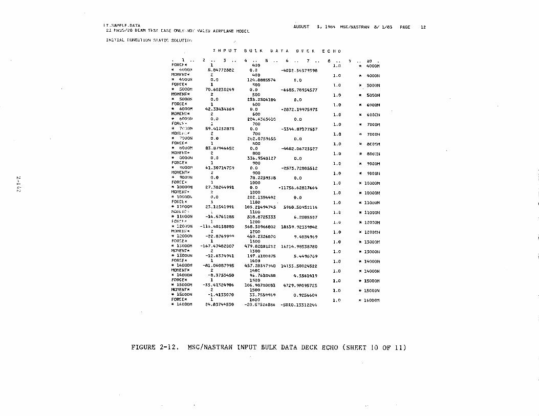
N I ..... +-'"
LT. SA1·•PLE. DATA AUGUST 3, 1984 HSC/NASTRAN 8/ 1/83 PAGE 21 f1ASS/28 BEAM TEST CASE ONLY··NOf VALID AIRPLANE HODEl.
INITIAL CONGITION Sf ATIC SOLUTlOh
l FORCE* * 4000:1 MOr1ENT* * 4000H FORCE'< * 5000M MOMENT* * 5000N FORCE* * 6000!1 MOMENT* * 6000N FORC.f' * 7C,)OM
M0!1D"* * lOOON FORCE* * 8000H M0!1HIT* * 8000N FORCE* " 900011 MOMENT* * 9000N FORCE* * 1000!JH M0!·1ENT"' * lOOOON FORet~
" nooon NOI'itl'n.~
* ll.UOON FOP.~"f,v
* l2000N HDHE!H<t * l2000N FORCE* * BOOOM MO~IENT*
* BOOON FORCE* * 14GOOM MONENT* * 14000N FORCE* * 15000M MOMENT* * 15000N FORCE* * 16000M
I N P U T B U l K D A T A D E C K E C H 0
2 •. 3 1
5.64772882 ~ o.o l
70~ 60Z:IOZ49 2 o.o l
42.33434369 2 0.0 l
59.41232673 2 0.0 l
63.8794&&52 2 o.o 1
&1. 30714759 2 0.0 1
27.38244991
0.0 l
23.12541991
-14.5761285 1
-1B.48B8880 2
-22.8769999 1
-167.47482007 2
-12.6374941 1
-81. 0608 7995 2
-8.3753450 1
-33.41324906 2
-1.4133070 1
24.83744530
4 • • 5 400
0.0 400
6 . • 7
-4032.34379398
124.8885574 o.o 500
0.0 -6685.78934577 500
235.2506184 0.0 600
o.o -2872.19975973 600
224.6365418 o.o 700
o.o -3344.87377537 700
262.0759655 0.0 800
0.0 -4482.06723327 800
336.9548127 0.0 900
0.0 -2573.72885512 900
78.2259318 0.0 1000 0.0 -11756.62617664 1000
202.1354482 0.0 1100
103.21494745 5960.50952114 1100
518.8725333 6.2085507 1200
368.30966802 18339.?2339842 1200
459.2326870 9.4854969 1300
479.82881212 16214.98538780 1300
197.1100875 5.4498769 1400
457.28347940 14133.50024522 1400 96.7618458 4.3561419 1500
106.98780051 4729.90095725 1500 33.7559939 0.9256609 1600
-20.57526066 -5010.13312244
8 . . 9 . . 10 1.0 * 4000M
1.0 * 4000N
1.0 * 5000M
1.0 * 5000N
J..O * 6000M
1.0 * 6000N
1.0 * 7000M
1.0 * 7000N
1.0 * 8000M
1.0 * 8000N
1.0 * 9000M
1.0 * 9000N
1.0 * 10000M
1.0 * 10000N
1.0 * llOOOM
l.O * llOOON
1.0 * 12000M
1.0 * 12000N
l.O * BOOOH
1.0 * l3000N
1.0 * 14000H
1.0 " 14000N
1.0 " 15000!1
1.0 " 15000N
1.0 * l6000M
FIGURE 2-12. MSC/NASTRAN INPUT BULK DATA DECK ECHO (SHEET 10 OF ll)
12
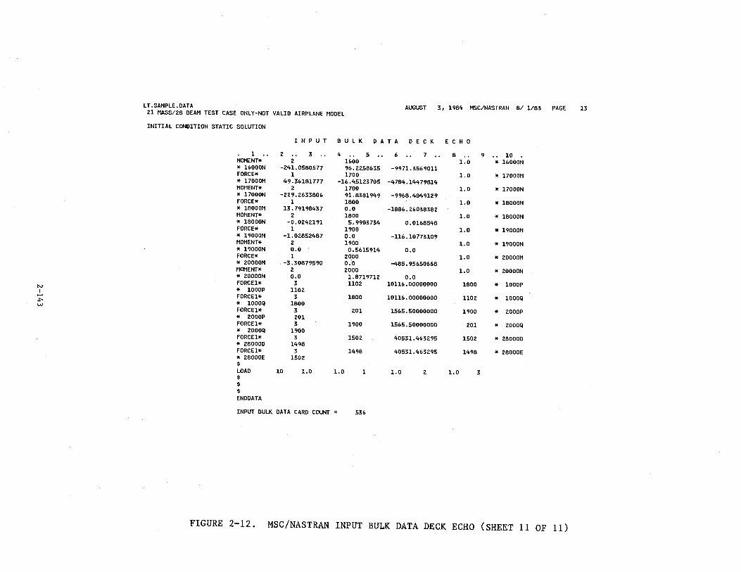
LT. SAMPLE. DATA AUGUST 3, 1984 21 MASS/28 BEAM TEST CASE ONLY-NOT VALID AIRPLANE MODEL
MSC/NASTRAN 8/ 1/83 PAGE 13
INITIAL CONDITION STATIC SOLUTION
N PUT B U L K D A T A D E C K E C H 0
1 .. 2 .. 3 .. 4 .. 5 .. 6 .. 7 .. 8 . . 9 .. 10 MOMENT* 2 1600 1.0 * 1o000N * 16000N -241.0580577 96.2258635 -9971. 35&9011 FORCE* 1 1700 1.0 * 17000M * 17000M 49.30181777 -10.45123705 -4784.14479814 MOHENT* 2 1700 1.0 * 17000N * 17000N -229.263380(, 91.8381949 -9968.4049129 FORCE* 1 1800 1.0 * 18000M * 18000M 13. 7919843 7 0.0 -1886.26038382 MOMENT* 2 1800 1.0 * 18000N * 18000N -0.0242191 5.9903734 0.0168548 FORCE* 1 1900 1.0 * 19000M * 19000M -1.02852487 o.o -116.10773109 MOMENT* 2 1900 1.0 * 19000N * 19000N 0.0 0.5615914 0.0 FORCE* 1 2000 1.0 * 20000M * 20000M -3.30879590 0.0 -485.95650668 MOMENT* 2 2000 1.0 * ZOOOON * 20000N o.o 1.8719712 0.0 FORCEl* 3 1102 10116.00000000 1800 * 1000P N * 1000P 1102 I ..... FORCEl* 3 1800 10116.00000000 1102 * 1000Q ~ * 1000Q 1800 w FORCE1* 3 201 1565.50000000 1900 * 2000P * 2000P 201 FORCEl* 3 1900 1565.50000000 201 * ZOOOQ * 2000Q 1900 FORCEl* 3 1502 40531.463295 1502 * 28000D * 28000D 1498 FORCE1* 3 1498 40531.463295 1498 * 28000E * 28000E 1502 $ LOAD 10 1.0 1.0 1 1.0 2 1.0 3 $ $ $ ENDDATA
INPUT BULK DATA CARD COUNT = 536
FIGURE 2-12. MSC/NASTRAN INPUT BULK DATA DECK ECHO (SHEET 11 OF 11)
input data set, using the following NASTRAN elements.
• GRID points
• CBAR bar elements (with PBAR properties and MATl materials)
• RBAR rigiq bar elements
• FORCE and HOMENT cards for applied loads
Although only a linear model is formed, the following ICRASH85 nonlinearities
are included in the NASTRAN model:
• Oleo beam elements (initial position must be fully extended)
• Unsymmetrical beam elements
A nonlinear KRASH model is acceptable (KR tables), as long as the initial
conditions are in the linear region. The executive and case control decks,
plus the bulk data deck, are all contained in date set XYZ.NASBLK.DATA, which
is generated automatically by program KRASHIC.
2.3.2.4 Sorted Bulk Data Deck Echo
This is just an alphabetically sorted version of the bulk data deck
shown in figure 2-12. The last page of this is shown in figure 2-13. The
EPSILON value shown is a measure of the error in the static solution. Any
value less than E-7 is acceptable. Generally speaking, any significant
error in the model will result in a very large value for EPSILON (>0.1) or
will cause the NASTRAN solution to terminate with an error message.
2.3.2.5 Displacement Vector
Figure 2-14 shows a sample of the displacement vector output. These
data represent the desired solution. The three translations and rotations
at each grid point in the NASTRAN model are shown. The sign convention for
these displacements/rotations ,.Jithin the NASTRAN model is as follows:
Tl Positive deflection aft, inches
T2 Positive deflection right, inches
2-144
T3
Rl
R2
R3
Positive
Positive
Positive
Positive
deflection up,
rotation left
rotation nose
rotation nose
inches
wing down, radians
up, radians
left, radians
All deflections/rotations are measured in an axis system that is parallel to
the e.g. coordinate system defined in Section 2.2.
The grid point identifications within NASTRAN are related to the KRASH85
mass and mode points as follows:
Node point (I, M) becomes grid point (lOO*I + M) e.g. Node point 11, 2
becomes grid point 1102. Mass point 5 becomes grid point 500.
In figure 2-14, grid points 1199, 1498 and 1499 do not correspond to any node
points in the KRASll model. In the KRASH model there are two transverse
beams attached to mass 15 and one to mass 12; i.e., beams which connect
laterally between mass 15 (and 12) and a phantom (unnumbered) point at the
same location on the opposite side of the airplane. For these lateral beams,
a grid point on the airplane plane of symmetry (y = 9) is established in the
NASTRAN model in order to constrain the deflections of lateral beams. Grid
points 1199, 1498, and 1499 are all such constrained grid points.
The deflections and rotations for grid point 500 (mass point 5) are all
zero. This is because mass point 5 was specified by the user to be the con
straint point in the model. This was done by inputting NBAL = 5 on card 60
of the input format (figure 2-3). This can be seen on card sequence num
ber 90 in the input data echo for this sample case (figure 2-8).
2.3.2.6 Load Vector
Figure 2-15 shows the vector of applied loads for the sample case.
These are the NASTRAN input net loads generated by KRASHIC in subroutine
NETFOR. The sign convention for these loads is the same as for the displace
ments, as defined in the previous section. The loads shown for grid points
201, 1102, 1498 and 1502 are the result of using FORCEl type cards in the
2-145
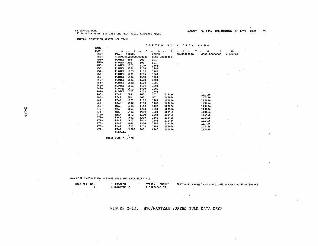
N I ....
-1'-a-
LT.SAMPLE.DATA AUGUST 3, 1984 MSC/NASTRAN 8/ 1/83 PAGE 21 MASS/28 BEAM TEST CASE ONLY-NOT VALID AIRPLANE MODEL
INITIAL CONDITION STATIC SOLUTION
S 0 R T E D B U L K D AT A E C H 0 CARD COUNT l .. 2
·~ 3 .. 4 .. 5 .. 6 .. 7 . . 8 .. 9 .. 10 451- PBAR *Z8000 Z8000 zo.oooooooo 8000.00000000 * 28000A 45Z- * Z8000A1200.00000000 Z700.00000000 453- PLOTEL 201 zoo Z01 454- PLOTEL 501 500 501 455- PLOTEL 1101 1100 1101 456- PLOTEL 110Z 1100 1102 457- PLOTEL 1103 1100 1103 458- PLOTEL lZ01 1ZOO 1Z01 459- PLOTEL 1401 1400 1401 460- PLOTEL 1501 1500 1501 461- PLOTEL 150Z 1500 1502 46Z- PLOTEL 1601 1600 1601 463- PLOTEL 160Z 1600 160Z 464- PLOTEL 1701 1700 1701 465- RBAR 201 zoo Z01 123456 123456 466- RBAR 501 500 501 123456 1Z3456 467- RBAR 1101 1100 1101 123456 1Z3456 468- RBAR 1102 1100 110Z 1Z3456 123456 469- RBAR 1103 1100 1103 1Z3456 1Z3456 470- RBAR 1201 1ZOO 1Z01 123456 1Z3456 471- RBAR 1401 1400 1401 123456 123456 472- RBAR 1501 1500 1501 1Z3456 1Z3456 473- RBAR 150Z 1500 150Z 1Z3456 123456 474- RBAR 1601 1600 1601 1Z3456 123456 475- RBAR 1602 1600 160Z 1Z3456 123456 476- RBAR 1701 1700 1701 123456 123456 477- RBAR Z4000 zoo 2100 1Z3456 1Z3456
END DATA
TOTAL COUNT= 478
*** USER INFORMATION MESSAGE 3035 FOR DATA BLOCK KLL
LOAD SEQ. NO. 1
EPSILON -1.1010772E-13
STRAIN ENERGY 1. 93Z9606E+05
EPSILONS LARGER THAN 0.001 ARE FLAGGED HITH ASTERISKS
FIGURE 2-13. MSC/NASTRAN SORTED BULK DATA DECK
Z3
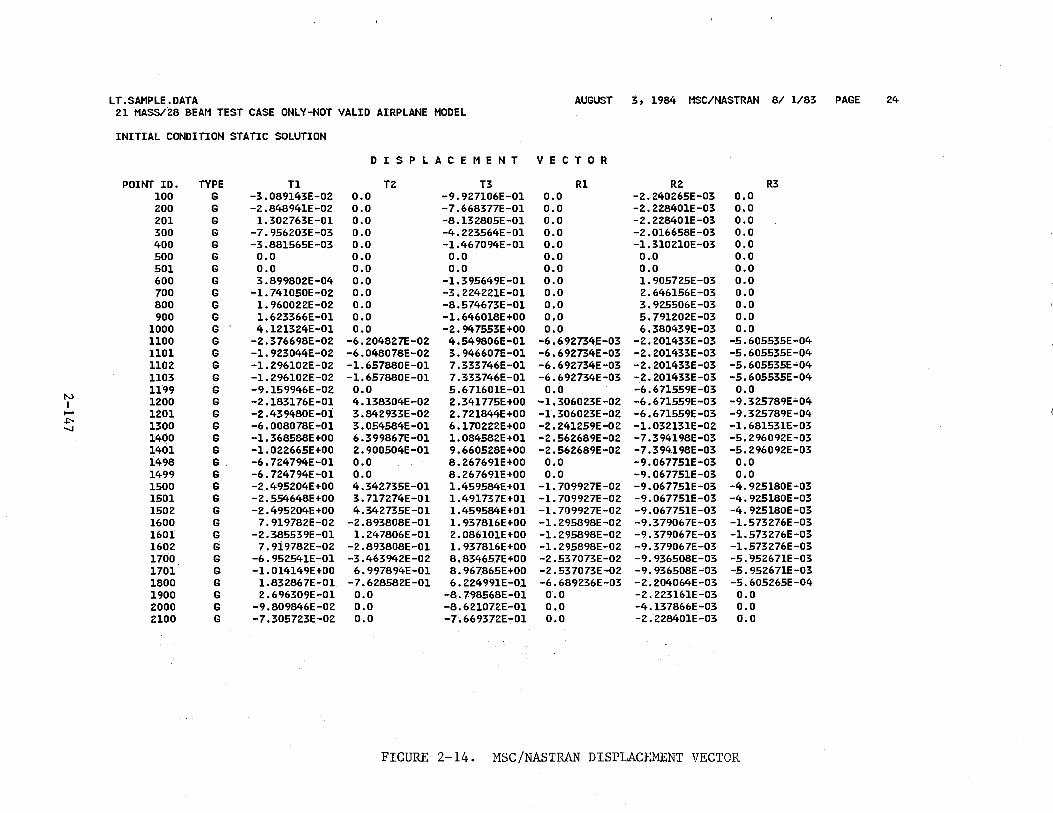
LT.SAMPLE.DATA AUGUST 3, 1984 MSC/NASTRAN 8/ 1/83 PAGE 24 21 MASS/28 BEAM TEST CASE ONLY-NOT VALID AIRPLANE MODEL
INITIAL CONDITION STATIC SOLUTION
D I S P L A C E M E N T VECTOR
POINT ID. TYPE Tl T2 T3 R1 R2 R3 100 G -3.089143E-02 0.0 -9.927106E-01 0.0 -2.240265E-03 0.0 200 G -2.848941E-02 0.0 -7.668377E-01 0.0 -2.228401E-03 0.0 201 G 1.302763E-01 o.o -8.132805E-01 o.o -2.228401E-03 o.o 300 G -7.956203E-03 0.0 -4.223564E-01 0.0 -2.016658E-03 0.0 400 G -3.881565E-03 0.0 -1.467094E-01 0.0 -1. 310210E-03 0.0 500 G 0.0 0.0 0.0 0.0 0.0 o.o 501 G 0.0 0.0 0.0 0.0 0.0 o.o 600 G 3.899802E-04 o.o -1.395649E-01 o.o 1. 905725E-03 0.0 700 G -1. 741050E-02 0.0 -3.224221E-01 0.0 2.646156E-03 o.o 800 G 1.960022E-02 0.0 -8.574673E-01 0.0 3.925506E-03 0.0 900 G 1.623366E-01 0.0 -1.646018E+OO o.o 5.791202E-03 0.0
1000 G 4.121324E-01 0.0 -2.947553E+OO 0.0 6.380439E-03 0.0 1100 G -2.376698E-02 -6.204827E-02 4.549806E-01 -6. 6 92734.E -03 -2.201433E-03 -5.605535E-04 1101 G -1.923044E-02 -6.048078E-02 3.946607E-01 -6.692734E-03 -2.201433E-03 -5.605535E-04 1102 G -1. 296102E-02 -1. 657880E-01 7.333746E-01 -6.692734E-03 -2.201433E-03 -5.605535E-04 1103 G -1.296102E-02 -1.657880E-01 7.333746E-01 -6.692734E-03 -2.201433E-03 -5.605535E-04 1199 G -9.159946E-02 0.0 5.671601E-01 o.o -6.671559E-03 o.o
N 1200 G -2.183176E-01 4.138304E-02 2.341775E+OO -1.306023E-02 -6.671559E-03 -9.325789E"-04 t I-' 1201 G -2.439480E-01 3.842933E-02 2.721844E+OO -1.306023E-02 -6.671559E-03 -9.325789E-04 .j;:-o
1300 G -6.008078E-01 3.054584E-01 6.170222E+OO -2.241259E-02 -1.032131E-02 -1.681531E-03 ....... 1400 G -1.368588E+OO 6.399867E-01 1.084582E+01 -2.562689E-02 -7.394198E-03 -5.296092E-03 1401 G -1.022665E+OO 2.900504E-01 9.660528E+OO -2.562689E-02 -7.394198E-03 -5. 296092E-03 1498 G -6.724794E-01 0.0 8.267691E+OO 0.0 -9.067751E-03 o.o 1499 G -6.724794E-01 o.o 8.267691E+OO 0.0 -9.067751E-03 0.0 1500 G -2.495204E+OO 4.342735E-01 1.459584E+01 -1. 709927E-02 -9.067751E-03 -4.925180E-03 1501 G -2.554648E+OO 3.717274E-01 1.491737E+01 -1. 709927E-02 -9.067751E-03 -4.925180E-03 1502 G -2.495204E+OO 4.342735E-01 1.459584E+01 -1.709927E-02 -9.067751E-03 -4.925180E-03 1600 G 7.919782E-02 -2.893808E-01 1.937816E+OO -1. 295898E-02 -9.379067E-03 -1.573276E-03 1601 G -2.385539E-01 1. 247806E-01 2.086101E+OO -1. 295898E-02 -9.379067E-03 -1.573276E-03 1602 G 7.919782E-02 -2.893808E-01 1. 937816E+OO -1. 295898E-02 -9.379067E-03 -1.573276E-03 1700. G -6.952541E-01 -3.463942E-02 8.834657E+OO -2 .537073E-02 -9.936508E-03 -5.952671E-03 1701 G -1.014149E+OO 6.997894E-01 8.967865E+OO -2.537073E-02 -9.936508E-03 -5.952671E-03 1800 G 1.832867E-01 -7.628582E-01 6.224991E-01 -6.689236E-03 -2.204064E-03 -5.605265E-04 1900 G 2. 696309E-01 o.o -8.7~8568E-01 0.0 -2.223161E-03 o.o 2000 G -9.809846E-02 0.0 -8.621072E-01 o.o -4.137866E-03 o.o 2100 G -7.305723E-02 0.0 -7.669372E-01 0.0 -2.228401E-03 0.0
FIGURE 2-14. MSC/NASTRAN DISPLACEMENT VECTOR
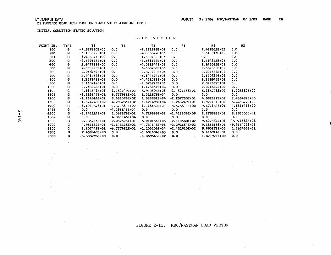
LT.SAMPLE.DATA AUGUST 3, 1984 MSC/NASTRAN 8/ 1/83 PAGE 25 21 MASS/28 BEAM TEST CASE ONLY-NOT VALID AIRPLANE MODEL
INITIAL CONDITION STATIC SOLUTION
L 0 AD V E C T 0 R
POINT IO. TYPE Tl TZ T3 R1 RZ R3 100 G -7.567860E+OO 0.0 -7.223518E+OZ 0.0 7.487885E+01 0.0 zoo G -3.155522E+01 o.o -4.095044E+03 o.o 5.&15913E+02 0.0 201 G -3.488073E+OO 0.0 1.5&5490E+03 0.0 o.o o.o 300 G -2.299lo8E+01 0.0 -6.531187E+03 0.0 1.814595E+02 0.0 400 G 5.847729E+OO 0.0 -4.032344E+03 0.0 1.248885E+OZ 0.0 500 G 7.0&0229E+01 o.o -6.685789E+03 0.0 2.352506E+02 0.0 600 G 4.233434E+01 0.0 -2. 872200E +03 0.0 2.2463&5E+02 0.0 700 G 5.94l232E+01 o.o -3.344874E+03 o.o 2.620759E+02 0.0 800 G 8.38794&E+01 o.o -4.48206&E+03 0.0 3.369546E+02 o.o 900 G 6.130714E+01 o.o -2 .573729E+03 0.0 7.822592E+01 0.0
1000 G 2.738245E+01 0.0 -1.17566ZE+04 0.0 Z.021354E+02 o.o 1100 G 2.312541E+01 1.032149E+OZ 5.9&0508E+03 -1.457613E+01 5.188723E+02 6.208550E+OO 1102 G -2.228247E+01 6.777931E+01 1.011575E+04 0.0 0.0 0.0 1200 G -1.134814E +02 3.68309&E+02 1.833992E+04 -2.287700E+01 4.592327E+02 9.485497E+OO 1300 G -1.&74748E+02 4.79828&E+02 1.621498E+04 -1.263749E+01 1.971101E+02 5.449877E+OO 1400 G -8.106087E+01 4.572834E+02 1.413350E+04 -8.375344E+OO 9.&76184E+01 4.356141E+OO
N 1498 G 0.0 -4.053146E+04 o.o o.o 0.0 0.0
I 1500 G -3.341324E+01 1.0&9878E+02 4.729898E+03 -1.413306E+OO 3.375598E+01 9.256608E-01 f-' 150.2 G 0.0 4.053146E+04 o.o 0.0 0.0 o.o +>- 1600 G 2.483743E+01 -2.057526E+01 -5.010133E+03 -2.410580E+02 9.622586E+01 -9.971355E+03 co
1700 G 4.936182E+01 -1.645123E+01 -4.784145E+03 -2.292634E+02 9.183818E+Ol -9.968402E+03 1800 G 3.607445E+Ol -6.777931E+01 -1. 200200E+04 -2.421910E-02 5.990373E+OO 1.685480E-02 1900 G 2.459549E+OO 0.0 -1.681604E+03 0.0 5.615914E-01 0.0 2000 G -3.308795E+OO 0.0 -4.859563E+02 o.o 1.871971E+OO 0.0
FIGURE 2-15. MSC/NASTP~\N LOAD VECTOR
NASTRAN input. These cards apply a constant axial force between two defined
grid points. The FORCEl cards in the sample case are used to account for
nonlinear effects in oleos and unsymmetrical beams. There are no externally
applied loads at node points, only at mass points.
2.3.2.7 Forces of Single-Point Constraint
Figure 2-16 shows the NASTRAN output that summarizes the forces of
single-point constraint. This shows the forces and moments that are appl:i,.ed
at the model constraint points to balance the model. For point 500, con-
straints are specified in all six directions, so corresponding forces are out
put. Note that the loads for the symmetric degrees of freedom (Tl, T3, R2)
are all very small, indicating that a well balanced set of applied loads is
being used as input. This is the result of including inertia relief loads
in the calculated net loads used as input to NASTRAN. The constraint forces
in the anti-symmetric directions (T2, Rl, R3) result from the geometry of
the model. A half-airplane model is used, and wiag loads come into mass 5.
The constraint loads shown correspond to the missing loads that the right
wing would have supplied. The same is true for grid points 600 and 900.
Grid points 1199, 1498 and 1499 are center-plane grids as explained in
Section 2.3.2.5. The single-point constraint forces shown for these grid
points are the reactions at the center of transverse beams in the KRASH
model.
2.3.2.8 Forces in Bar Elements
Figure 2-17 illustrates the NASTRAN output that summarizes the bar
element static loads. The sign conventions for these loads are shown in
figure 2-18, along with the corresponding KRASH85 beam element sign conven
tions. The I(RASH85 loads that correspond to the NASTRAN bar element loads
shown in figure 2-17 are as follows:
2-149
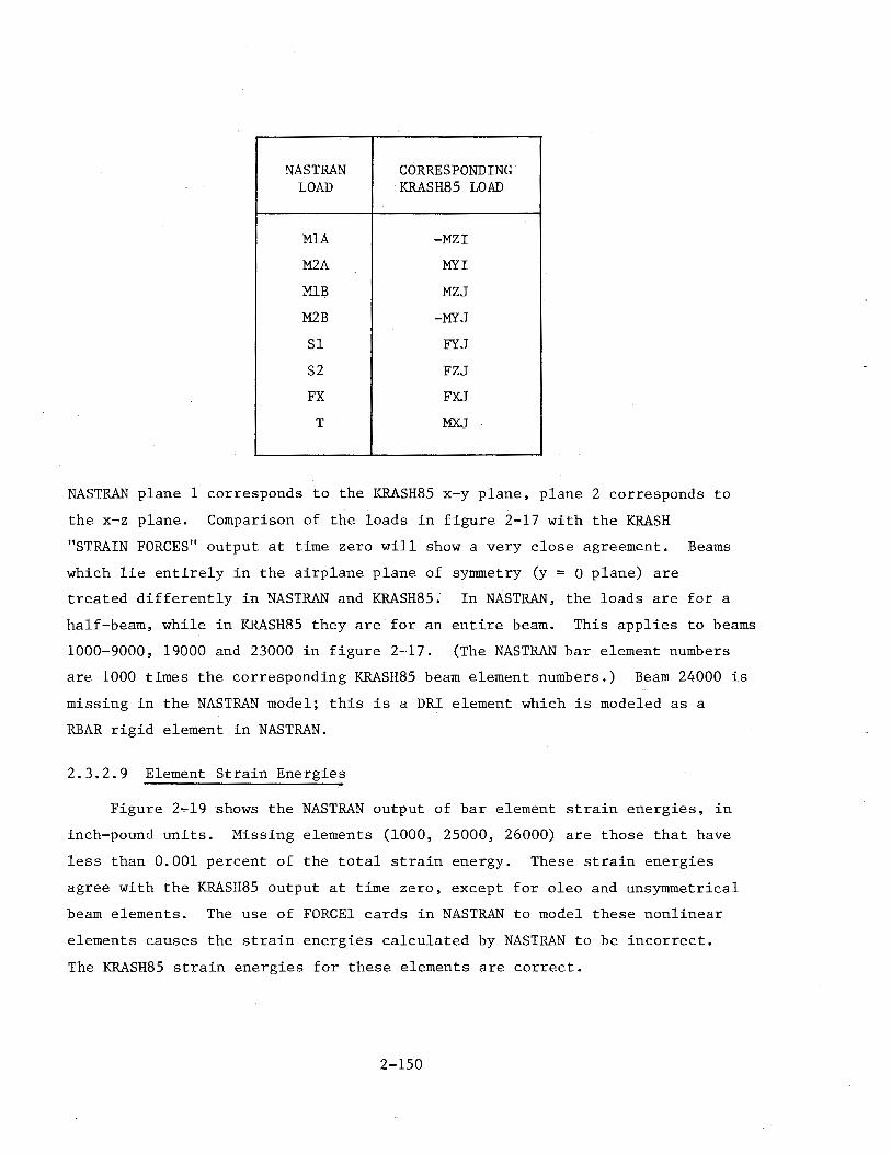
NASTRAN CORRESPONDING LOAD KRASH85 LOAD
MlA -MZI
M2A MYI
MlB MZJ
M2B -MYJ
Sl FYJ
S2 FZJ
FX FXJ
I T MXJ
NASTRAN plane 1 corresponds to the KRASH85 x-y plane, plane 2 corresponds to
the x-z plane. Comparison of the loads in figure 2-17 with the KRASH
"STRAIN FORCES" output at time zero will show a very close agreement. Beams
which lie entirely in the airplane plane of symmetry (y = 0 plane) are
treated differently in NASTRAN and KRASH85. In NASTRAN, the loads are for a
half-beam, while in ICRASH85 they are for an entire beam. This applies to beams
1000-9000, 19000 and 23000 in figure 2-·17. (The NASTRAN bar element numbers
are 1000 times the corresponding KRASH85 beam element numbers.) Beam 24000 is
missing in the NASTRAN model; this is a DRI element which is modeled as a
RBAR rigid element in NASTRAN.
2.3.2.9 Element Strain Energies
Figure 2..,.19 shows the NASTRAN output of bar element strain energies, in
inch-pound units. Missing elements (1000, 25000, 26000) are those that have
less than 0.001 percent of the total strain energy. These strain energies
agree with the KRASH85 output at time zero, except for oleo and unsymmetrical
beam elements. The use of FORCEl cards in NASTRAN to model these nonlinear
elements causes the strain energies calculated by NASTRAN to be incorrect.
The KRASH85 strain energies for these elements are correct.
2-150
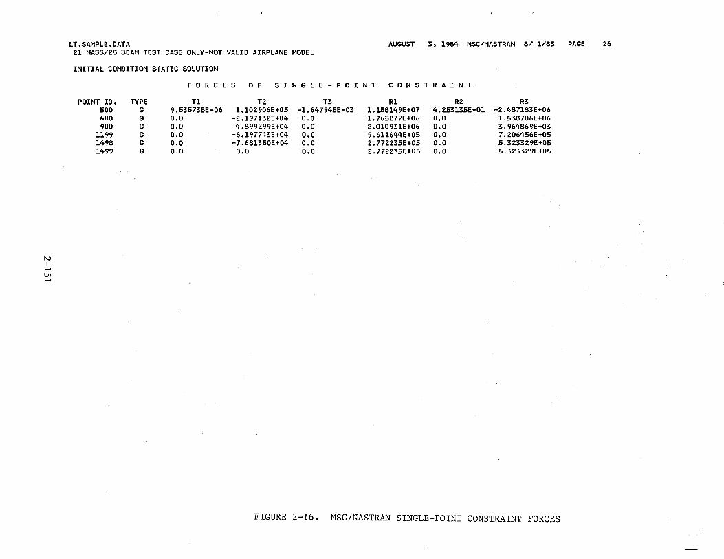
N I
f-' V'1 f-'
LT.SAMPLE.DATA AUGUST 3, 1984 MSC/NASTRAN 8/ 1/83 PAGE 26 21 MASS/28 BEAM TEST CASE ONLY-NOT VALID AIRPLANE MODEL
INITIAL CONDITION STATIC SOLUTION
FORCES 0 F S I N G L E - P 0 I N T C 0 N S T R A I N T
POINT ID. TYPE Tl T2 T3 R1 R2 R3 500 G 9.535735E-06 1.102906E+05 -1. 647945E-03 1.158149E+07 4.253135E-01 -2.487183E+06 600 G 0.0 -2.197132E+04 0.0 1.765277E+06 o.o 1.538706E+06 900 G 0.0 4.899299E+04 o.o 2.010931E+06 o.o 3.964869E+03
1199 G 0.0 -6.197743E+04 0.0 9.611644E+05 0.0 7.206456E+05 1498 G 0.0 -7.681350E+04 0.0 2.772235E+05 0.0 5.323329E+05 1499 G o.o o.o 0.0 2.772235E+05 0.0 5.323329E+05
FIGURE 2-16. MSC/NASTRAN SINGLE-POINT CONSTRAINT FORCES
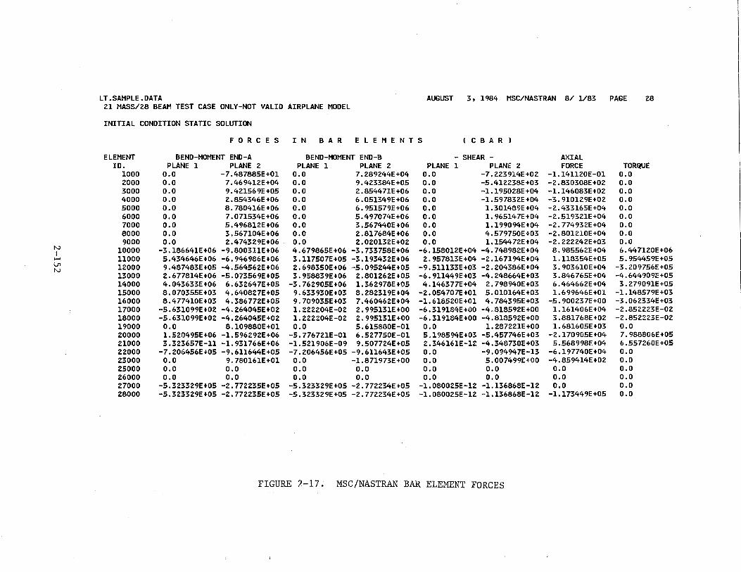
LT.SAMPLE.DATA AUGUST 3, 1984 MSC/NASTRAN 8/ 1/83 PAGE 28 21 MASS/28 BEAM TEST CASE ONLY-NOT VALID AIRPLANE MODEL
INITIAL CONDITION STATIC SOLUTION
F 0 R C E S I N BAR E L E M E N T S ( C B A R )
ELEMENT BEND-MOMENT END-A BEND-MOMENT END-B - SHEAR - AXIAL ID. PLANE 1 PLANE 2 PLANE 1 PLANE 2 PLANE 1 PLANE 2 FORCE TORQUE
1000 o.o -7.487885E+01 0.0 7.289244E+04 0.0 -7.223914E+02 -1.141120E-01 o.o 2000 o.o 7.469412E+04 0.0 9.423384E+05 o.o -5.412238E+03 -2.830308E+02 o.o 3000 o.o 9.421569E+05 o.o 2.854471E+06 0.0 -1.195028E+04 -1.146083E+02 o.o 4000 o.o 2.854346E+06 0.0 6.051349E+06 o.o -l.597832E+04 -3. 910129E+02 o.o 5000 o.o 8.780416E+06 0.0 6.951579E+06 o.o 1. 301489E +04 -2.433165E+04 o.o 6000 o.o 7.071534E+06 o.o 5.497074E+06 0.0 1. 965147E+04 -2.519321E+04 o.o 7000 o.o 5.496812E+06 0.0 3.567440E+06 0.0 1.199094E+04 -2. 774932E+04 o.o 8000 o.o 3.567104E+06 0.0 2.817684E+06 0.0 4.579750E+03 -2.801210E+04 o.o 9000 o.o 2.474329E+06 0.0 2.020132E+02 o.o 1.154472E+04 -2.222242E+03 o.o
N 10000 -3.186641E+06 -9.800311E+06 4.679865E+06 -3.733758E+06 -6.158012E+04 -4.748982E+04 8.985562E+04 6.447120E+06 I I-' 11000 5.434646E+06 -6.946986E+06 3.117507E+05 -3.193432E+06 2.957813E+04 -2.167194E+04 1.118354E+05 5.954459E+05 \J1 12000 9.487483E+05 -4.564562E+06 2.698350E+06 -5.095244E+05 -9.511133E+03 -2.204386E+04 3.903610E+04 -3.209756E+05 N
13000 2.677814E+06 -5.073569E+05 3.958839E+06 2.801262E+05 -6.911449E+03 -4.248664E+03 3.846765E+04 -4.644909E+05 14000 4.043633E+06 6.632647E+05 -3.762905E+06 l.362978E+05 4.146377E+04 2.798940E+03 6.464662E+04 3.279091E+05 15000 8.070355E+03 4.640827E+05 9.633930E+03 8.282319E+04 -2.054707E+01 5.010164E+03 1. 699646E+Ol -1.148579E+03 16000 8.477410E+03 4.386772E+05 9.709035E+03 7.460462E+04 -1.618520E+01 4.784395E+03 -5. 900237E+OO -3.062334E+03 17000 -5.631099E+02 -4.264045E+02 1.222204E-02 2.995131E+OO -6.319184E+00 -4.818592E+OO 1.161406E+04 -2.852223E-02 18000 -5.631099E+02 -4.264045E+02 1.222204E-02 2.995131E+OO -6.319184E+OO -4.818592E+OO 3.881768E+02 -2.852223E-02 19000 o.o 8.109880E+Ol 0.0 5.615880E-Ol 0.0 1. 287221E+OO 1.681605E+03 o.o 20000 1.520495E+06 -1.596292E+06 -5.776721E-01 6.527750E-Ol 5.198594E+03 -5.457746E+03 -2.170905E+04 7.988806E+05 21000 3.323657E-ll -1.931766E+06 -1.521906E-09 9.507724E+05 2.346161E-12 -4.348730E+03 5.568998E+04 6.557260E+05 22000 -7.206456E+05 -9.611644E+05 -7.206456E+05 -9.611643E+05 0.0 -9.094947E-13 -6.197740E+04 0.0 23000 o.o 9.780161E+Ol o.o -1.871973E+OO 0.0 5.007499E+OO -4.859414E+02 0.0 25000 o.o 0.0 0.0 o.o 0.0 o.o o.o 0.0 26000 o.o 0.0 0.0 o.o 0.0 0.0 0.0 o.o 27000 -5.323329E+05 -2.772235E+05 -5.323329E+05 -2.772234E+05 -1.080025E-12 -1.136868E-12 o.o o.o 28000 -5.323329E+05 -2.772235E+05 -5.323329E+05 -2.772234E+05 -l.080025E-12 -1.136868E-12 -1.173449E+05 o.o
FIGURE 2-17. MSC/NASTRAN BAR ELEMENT FORCES
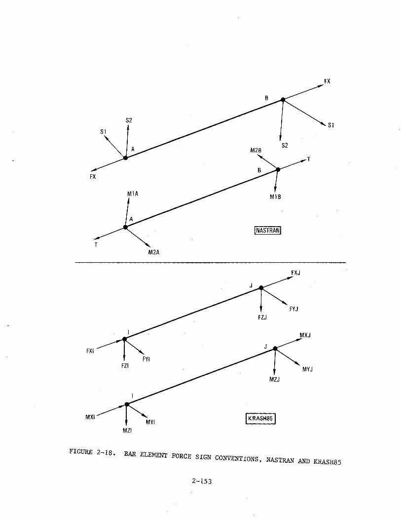
FX
Sl
FX
MlB
INASTRANI
T M2A
FXJ
FYJ
MXJ
FXI FYI
FZI MYJ
MZJ
MYI I KRASH851
MZI
FIGURE 2-18. BAR ELEMENT FORCE SIGN CONVENTIONS, NASTRAN AND KRASH85
2-153
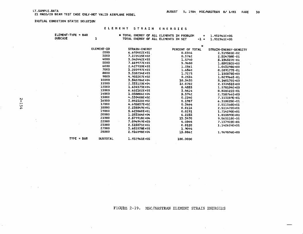
LT.SAMPLE.DATA 21 MASS/28 BEAM TEST CASE ONLY-NOT VALID AIRPLANE MODEL
AUGUST 3, 1984 MSC/NASTRAN 8/ 1/83 PAGE 30
INITIAL CONDITION STATIC SOLUTION
E L E M E N T S T R A I N E N E R G I E S
ELEMENT-TYPE = BAR * TOTAL ENERGY OF ALL ELEMENTS IN PROBLEM = 1.932961E+05 SUBCASE 1 TOTAL ENERGY OF ALL ELEMENTS IN SET -1 = 1. 932961E+05
* ELEMENT-ID STRAIN-ENERGY PERCENT OF TOTAL STRAIN-ENERGY-DENSITY 2000 6.693402E+01 0.0346 2.319581E-02 3000 7.272415E+02 0.3762 2.524788E-01 4000 3.042442E+03 1.5740 5.154527E-01 5000 7.669977E+03 3.9680 1.850282E+OO 6000 2.427930E+03 1.2561 1.063298E+OO 7000 3.200997E+03 1.6560 8.289177E-01 8000 3.338734E+03 1. 7273 1.102878E+OO 9000 4.902207E+02 0.2536 1.829966E-01
10000 3.545786E+04 18.3438 5.140170E+OO 11000 2.333120E+04 12.0702 2.131451E+OO 12000 1. 634373E +04 8.4553 1.578104E+OO 13000 6.652102E+03 3.4414 8.818122E-01 14000 1.038806E+04 5.3742 2.758766E+OO 15000 4.330408E+02 0.2240 7.113289E-01 N 16000 3.841328E+02 0.1987 6.310025E-01 I ...... 17000 6.695837E+02 0.3464 2.511360E+01 Vl 18000 2.238049E+01 0. 0116 2.511472E+01 +:"-19000 5.623860E+01 0.0291 1. 714290E+Ol 20000 1.203364E+04 6.2255 1. 010890E+OO 21000 2.579918E+04 13.3470 9.563110E-Ol 22000 7 .894949E+03 4.0844 7.137922E-01 23000 2.315073E+01 0.0120 1.142624E+01 27000 3.681078E+03 1.9044 28000 2.916098E+04 15.0862 1.969896E+OO
TYPE = BAR SUBTOTAL 1. 932961E+05 100.0000
FIGURE 2-19. MSC/NASTRAN ELEMENT STRAIN ENERGIES
2.3.2.10 Grid Point Force Balance
Figure 2-20 shows the NASTRAN output that tabulates all the forces and
moments acting at the grid points. The totals shown at each grid point are
not always zero; the loads due to RBAR rigid bar elements are not included
in the balance. Therefore, mass points which have node points connected to
them, as well as the corresponding node points, will show nonzero total
loads. (Grid points 200 and 201 in figure 2-20 for example.) Mass points
without node points (such as 500 or 600) will show zero total loads. Due
to this anomaly in the grid point force balance output, these data are only
marginally useful.
2.3.3 KRASH85 Output
2.3.3.1 Initial Output
The initial output of KRASH85 is identical to that of KRASHIC,
described in Section 2.3.1. These data were illustrated in figures 2-8 through
2-10. The only exceptions to this are the mass and node point coordinates,
as well as the initial mass and node point deflections. The values shown in
the KRASHIC input represent the values before the last iteration of KRASHIC/
MSCTRAN. The values shown in the KRASH85 output are those following the
last iteration. There will be slight differences in the deflections between
those two outputs, unless a very large number of iterations are used (>10).
Figure 2-21 shows this section of the output from KRASH85. Note that
the initial deflections and corresponding coordinate positions are slight~y
different from those shown in figure 2-9. As an example, the initial node
point z deflection for node point 11, 1 changes from -.3946611 in figure ~-9
to -.3946607 in figure 2-21. These values represent before and after the
tenth iteration. The corresponding node point z coordinates show no
difference between figures 2-9 and 2-21, since the coordinate values are
shown only to .001 inch. The differences are much finer than that.
Also, the initial deflections are in data set XYZ.NASOUT.DATA, which
is always shown at the botton of the ECHO of input data. If all deflections
2-155
in this data set agree between the KRASHIC and KRASH85 outputs, then further
iterations cannot improve the accuracy of the initial conditions balance. If
the two sets of data do differ, and the user is not satisfied with the quality
of the initial balance, then further iterations could improve the initial balance.
KRASH85 includes some additional miscellaneous calculated data, in addi
tion to that described for KRASHIC in Section 2.3.1.3. Figure 2-22 illustrates
this output, which is calculated prior to time zero in KRASR85. These data
include
• Beam uncoupled, undamped frequencies
"• Beam damping constants
• Euler angles, beam IJ to airplane
L" Load interaction curve load ratios (optional)
The beam frequencies output are the undamped, uncoupled individual beam
frequencies associated with the six degrees of freedom of .each beam. The
frequencies listed under the headings (1), (2), and (3) correspond with the
three translational degrees of freedom (x, y, z) and those listed under the
heading (4), (5), and (6) correspond to the three rotational degrees of
freedom (~, 8, ~). The frequencies are computed using equations l-55(a) and
l-55(b) from Volume I, S'ection 1.3.5.3.6.
The frequency values summarized should be reviewed for indications of
potential stability problems which may occur with the numerical integration
routine used in the program. For example, high frequencies combined with a
relatively coarse integration interval may result in numerical integration
instabilities. In general, beam member frequencies should satisfy the follow
ing criteria:
1) Nember frequencies < 500 Hz
2) The product of the maximum beam member frequency and the integration interval <0.01
2-156
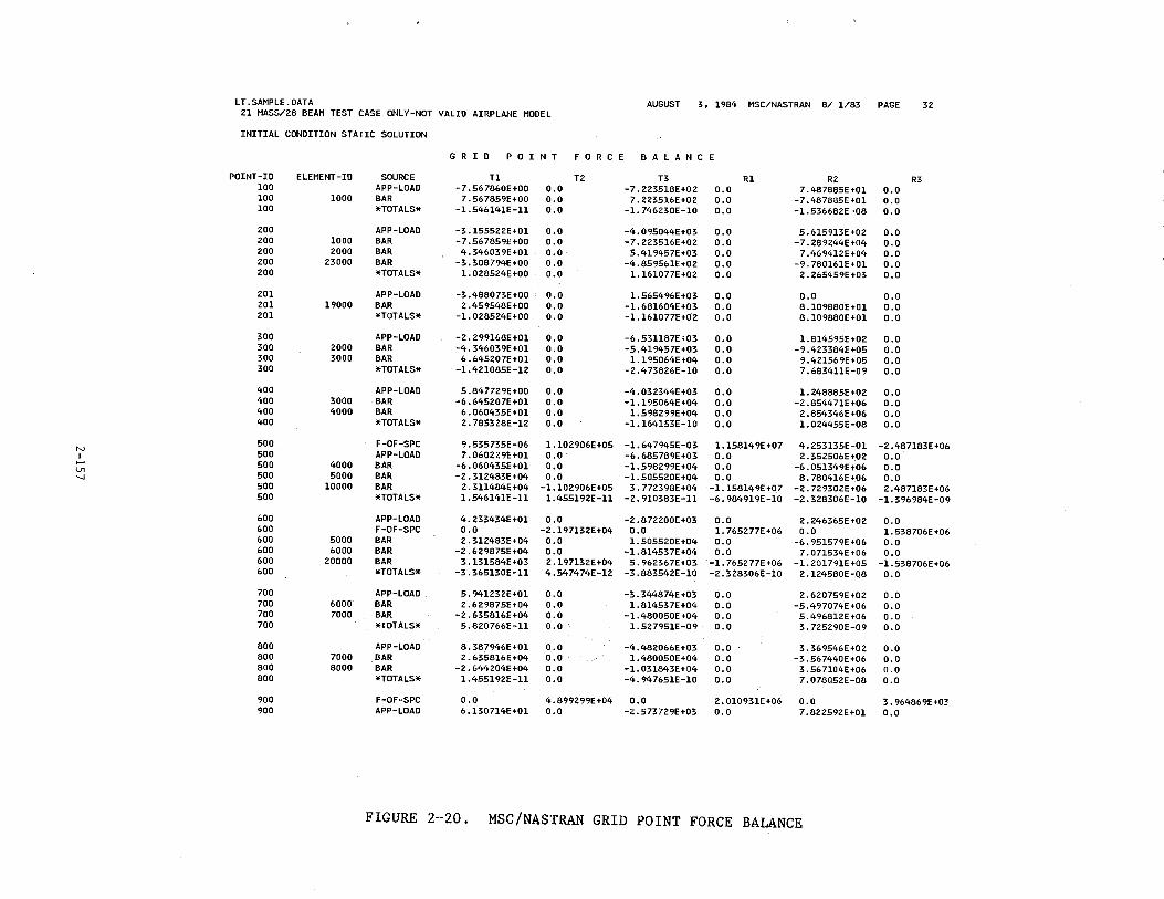
LT.SAMPLE.DATA AUGUST 3, 1984 MSC/NASTRAN 8/ 1/83 PAGE 32 21 MASS/28 BEAM TEST CASE ONLY-NOT VALID AIRPLANE MODEL
INITIAL CONDITION STATIC SOLUTION
G R I D P 0 I NT F 0 R C E B A L A N C E
POINT-ID ELEMENT-ID SOURCE Tl T2 T3 R1 R2 R3 1DO APP-LOAD -7. 56 7860E +00 0.0 -7.223518E+02 0.0 7.487885E+01 0.0 100 1000 BAR 7.567859E+OO 0.0 7.223516E+02 0.0 -7.487885E+01 0.0 100 *TOTALS* -1.546141E-ll 0.0 -1. 746230E-10 o.o -1.536682E-08 0.0
200 APP-LOAD -3.155522E+01 0.0 -4.095044E+03 o.o 5.615913E+02 0.0 200 1000 BAR -7.567859E+OO 0.0 -7.223516E+02 0.0 -7. 289244E+04 0.0 200 2000 BAR 4.346039E+01 0.0 5.419457E+03 0.0 7 .469412E+04 0.0 200 23000 BAR -3.308794E+OO 0.0 -4.859561E+02 0.0 -9.780161E+01 0.0 200 *TOTALS* 1. 028524E +00 0.0 1.161077E+02 0.0 2.265459E+03 o.o 201 APP-LOAD -3.488073E+OO o.o 1.565496E+03 0.0 o.o 0.0 201 19000 BAR 2. 459548E +00 0.0 -1.681604E+03 0.0 8.109880E+01 o.o 201 *TOTALS* -1. 028524E+OO 0.0 -1.161077E+02 0.0 8 .109880E +01 0.0
300 APP-LOAD -2.299168E+01 0.0 -6. 53ll87E < 03 0.0 1. 814595E +02 0.0 300 2000 BAR -4.346039E+01 0.0 -5.419457E+03 0.0 -9.423384E+05 o.o 300 3000 BAR 6.645207E+01 0.0 l.l95064E+04 0.0 9.421569E+05 o.o 300 *TOTALS* -1.421085E-12 o.o -2 .473826E-10 0.0 7.683411E-09 0.0
400 APP-LOAD 5.847729E+OO 0.0 -4.032344E+03 0.0 1. 248885E +02 o.o 400 3000 BAR -6.645207E+Ol 0.0 -l.l95064E+04 0.0 -2.854471E+06 0.0 400 4000 BAR 6.060435E+Ol 0.0 1.598299E+04 0.0 2.854346E+06 0.0 400 *TOTALS* 2.785328E-12 0.0 -l.164153E-10 0.0 l.024455E-08 o.o 500 F-OF-SPC 9.535735E-06 1.102906E +05 -1.647945E-03 1.158149E+07 4.253135E-Ol -2.487183E+06 N 500 APP-LOAD 7.060229E+Ol 0.0 -6.685789E+03 0.0 2.352506E+02 0.0 I ..... 500 4000 BAR -6.060435E+Ol o.o -l.598299E+04 0.0 -6.051349E+06 0.0 Ln 500 5000 BAR -2.312483E+04 0.0 -1.505520E+04 0.0 8.780416E+06 0.0 .._, 500 10000 BAR 2.311484E+04 -1.102906E+05 3. 772398E +04 -1.1581491':+07 -2. 729302E+06 2.487183E+06 500 *TOTALS* l.546141E-ll 1.455192E-ll -2. 910383E-ll -6.984919E-10 -;!:.328306E-10 -1. 396984E-09
600 APP-LOAD 4.233434E+Ol 0.0 -2. 872200E +03 0.0 2.246365E+02 0.0 600 F-OF-SPC 0.0 -2.197132E+04 0.0 1. 765277E+06 o.o 1. 538706E +06 600 5000 BAR 2.312483E+04 0.0 1. 505520E +04 0.0 -6.951579E+06 0.0 600 6000 BAR -2.629875E+04 o.o -1.814537E+04 0.0 7.071534E+06 o.o 600 20000 BAR 3.131584E+03 2.197132E+04 5. 96236 7E+03 -1.765277E+06 -l.201791E+05 -1.538706E+06 600 *TOTALS* -3.365130E-ll 4.547474E-12 -3.883542E-10 -2.328306E-10 2.124580E-08 0.0
700 APP-LOAD 5.941232E+Ol 0.0 -3.344874E+03 0.0 2.620759E+02 0.0 700 6000 BAR 2.629875E+04 0.0 1.814537E+04 0.0 -5.497074E+06 o.o 700 7000 BAR -2.635816E+04 o.o -1. 480050E +04 o.o 5.496812E+06 o.o 700 *TOTALS* 5.820766E-ll 0.0 1.527951E-09 0.0 3. 725290E-09 0.0
800 APP-LOAD 8.387946E+Ol 0.0 -4.482066E+03 0.0 3.369546E+02 0.0 800 7000 BAR 2.635816E+04 0.0 1. 480050E +04 0.0 -3.567440E+06 o.o 800 8000 BAR -2.644204E+04 0.0 -1. 031843E +04 0.0 3.567104E+06 o.o 800 *TOTALS* 1.455192E-ll 0.0 -4.947651E-l0 0.0 7.078052E-08 0.0
900 F-OF-SPC 0.0 4.899299E+04 0.0 2.010931E+06 0.0 3.964869E+03 900 APP-LOAD 6 .130714E +01 0.0 -2 .573729E+03 0.0 7.822592E+Ol 0.0
FIGURE 2-20. MSC/NASTRAN GRID POINT FORCE BALANCE
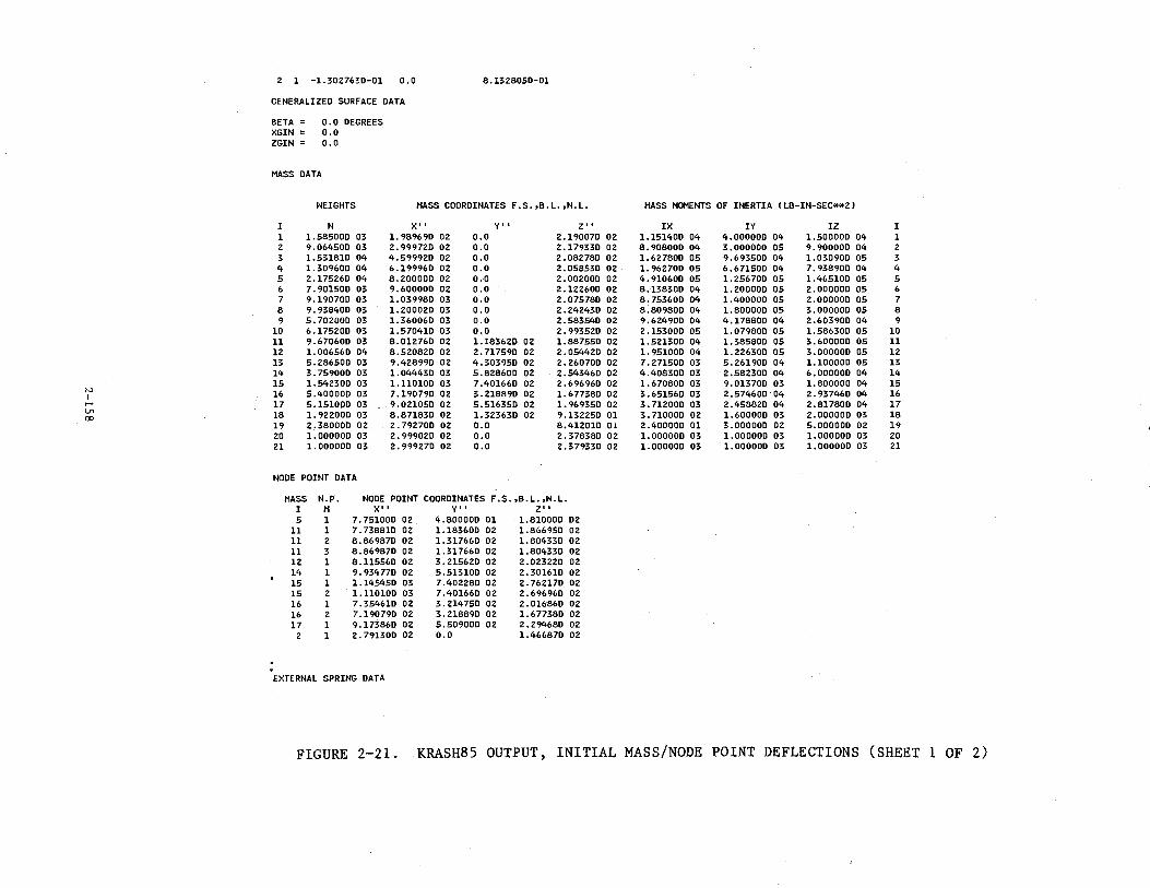
2 1 -1.302763D-01 0.0 8 .13 2805D -01
GENERALIZED SURFACE DATA
BETA = 0.0 DEGREES XGIN = o.o ZGIN = 0.0
MASS DATA
WEIGHTS MASS COORDINATES F.S.,B.L.,W.L. MASS MOMENTS OF INERTIA lLB-IN-SEC**2l
I tl X'' Y', z•' IX IV IZ I 1 l.58500D 03 l. 98969D 02 o.o 2.19007D 02 1.15140D 04 4.00000D 04 l.50000D 04 1 2 9.06450D 03 2.99972D 02 o.o 2.17933D 02 8.90800D 04 3.00000D 05 9.90000D 04 2 3 l.53181D 04 4.59992D 02 o.o 2.08278D 02 l.62780D 05 9.69350D 04 l.03090D 05 3 4 l.30960D 04 6.19996D 02 o.o 2.05853D 02 l. 96270D 05 6.67150D 04 7.93890D 04 4 5 2.17526D 04 8.20000D 02 o.o 2.00200D 02 4.91060D 05 l. 25670D 05 l.46510D 05 5 6 7.90150D 03 9.60000D 02 o.o 2.12260D 02 8.l3830D 04 l.20000D 05 2.00000D 05 6 7 9.19070D 03 l. 03998D 03 o.o 2.07578D 02 8.75360D 04 1.40000D 05 2.00000D 05 7 8 9.93840D 03 1.20002D 03 o.o 2.24243D 02 8.80980D 04 1.80000D 05 3.00000D 05 8 9 5.70200D 03 l.36006D 03 o.o 2.58354D 02 9.62490D 04 4.17880D 04 2.603900 04 9
10 6.17520D 03 l.57041D 03 o.o 2.99352D 02 2.153000 05 1.079800 05 l.58630D 05 10 11 9.67060D 03 8.01276D 02 1.18362D 02 l.88755D 02 1.521300 04 l.38580D 05 3.60000D 05 ll 12 1.006560 04 8.52082D 02 2. 71759D 02 2.054420 02 1.951000 04 l.22630D 05 3.000000 05 12 13 5.286500 03 9.428990 02 4.303950 02 2.260700 02 7.271500 03 5.261900 04 1.100000 05 13 14 3.759000 03 1.044430 03 5.828600 02 2.543460 02 4.40830D 03 2.582300 04 6.00000D 04 14 15 1.542300 03 1.110100 03 7.401660 02 2.696960 02 l.67080D 03 9.013700 03 1.80000D 04 15
N 16 5.400000 03 7.190790 02 3.21889D 02 1.677380 02 3.65156D 03 2.574600 04 2.937460 04 16 ! ...... 17 5.151000 03 9.021050 02 5.516350 02 1.969350 02 3. 71200D 03 2.458820 04 2.81780D 04 17 Ln 18 l.92200D 03 8.87183D 02 1.32363D 02 9.132250 01 3. 71000D 02 l.60000D 03 2.00000D 03 18 (1:>
19 2.380000 02 2.792700 02 o.o 8.412010 Ol 2.40000D 01 3.000000 02 5.000000 02 19 20 l.OOOOOD 03 2.99902D 02 o.o 2.378380 02 l.OOOOOD 03 1.000000 03 l.OOOOOD 03 20 21 l.OOOOOD 03 2.999270 02 o.o 2.379330 02 1.00000D 03 l.OOOOOD 03 1.00000D 03 2l
NODE POINT DATA
MASS N.P. NODE POINT COORDINATES F.S.,B.L.,W.L. I M X', Y'' z•' 5 1 7.75100D 02 4.80000D 01 1.81000D 02 ll 1 7.73881D 02 1.183600 02 1.866950 02 11 2 8.869870 02 1.317660 02 1.804330 02 11 3 8.86987D 02 1.317660 02 1.804330 02 12 1 8.115560 02 3.215620 02 2.023220 02 14 1 9. 934770 02 5.513100 02 2.301610 02 15 1 1.145450 03 7.402280 02 2.762170 02 15 2 1.110100 03 7.401660 02 2.696960 02 16 1 7.354610 02 3.214750 02 2.016860 02 16 2 7.190790 02 3.21889D 02 l.67738D 02 17 1 9.17386D 02 5.50900D 02 2.29468D 02
2 1 2.791300 02 o.o 1.466870 02
EXTERNAL SPRING DATA
FIGURE 2-21. KRASH85 OUTPUT, INITIAL MASS/NODE POINT DEFLECTIONS (SHEET 1 OF 2)
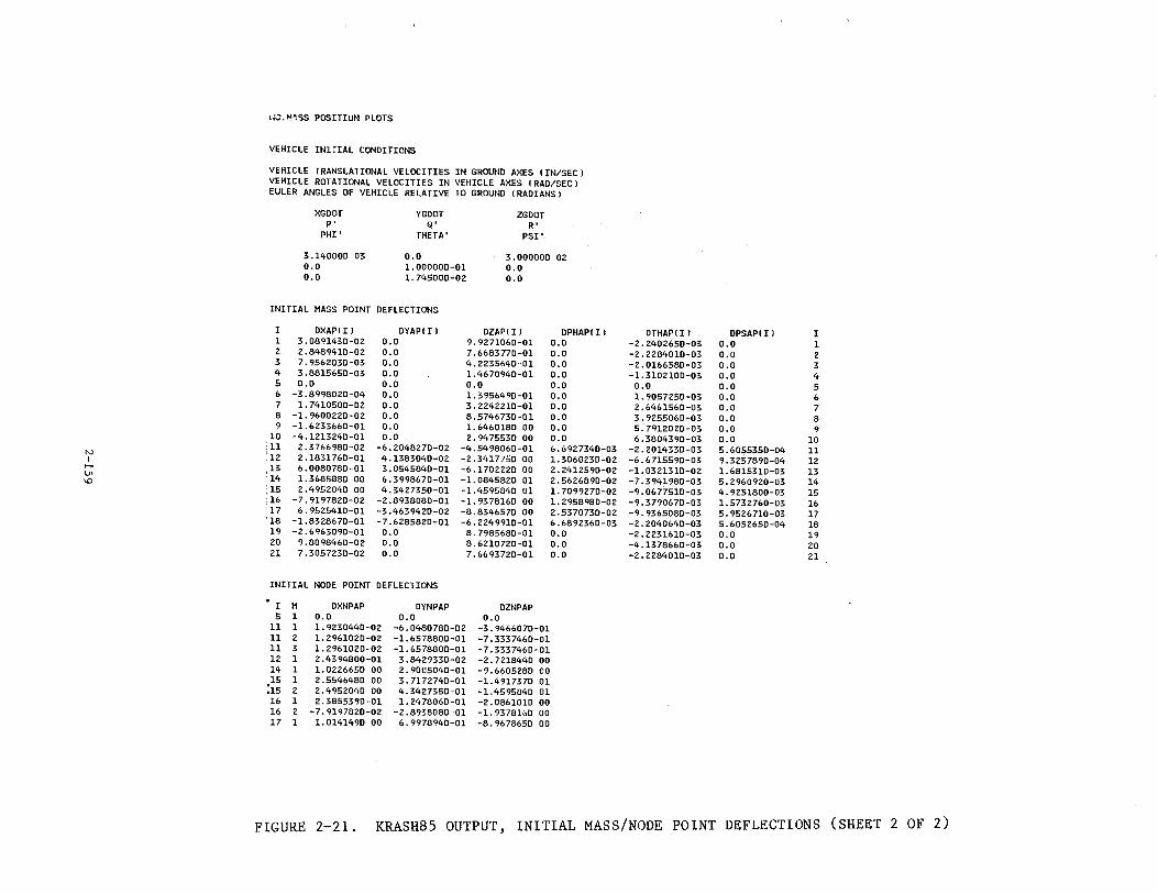
N I -l.l1
\D
1~.::. W. SS POS.ITIU~I PLOTS
VEHICLE IN1riAL CONDITIONS
VEHICLE TRANSLATIONAL VELOCITIES IN GROUND AXES (IN/SEC) VEHICLE ROTATIONAL VELOCITIES IN VEHICLE AXES !RAD/SECJ EULER ANGLES OF VEHICLE RELATIVE TO GROUND !RADIANS!
XGDOT YGOOT ZGOOT p• Q' R'
PHI' THETA' PSI'
3.14000D 03 0.0 3.00000D 02 o.o 1.00000D-01 0.0 0.0 1.74500D-02 0.0
INITIAL MASS POINT DEFLECTIONS
I OXAP!I l DYAP( I l DZAP! I l OPHAP! I l 1 3.089143D-02 0.0 9.927106D-01 0.0 2 2.848941D-02 0.0 7. 668377D-01 o.o 3 7.9562030-03 o.o 4.2235640-01 o.o 4 3.8815650-03 0.0 1. 46 70940-01 o.o 5 0.0 0.0 0.0 o.o 6 -3.899802D-04 o.o 1. 395649D-01 0.0 7 1.741050D-02 0.0 3.224221D-01 0.0 8 -1.9600220-02 0.0 8.5746730-01 o.o 9 -1.6233660-01 0.0 1.6460180 00 0.0
10 -4.1213240-01 0.0 2.9475530 00 0.0 ;11 2.3766980-02 -6.2048270-02 -4.5498060-01 6. 6927340-03 ;12 2.1831760-01 4.1383040-02 -2.3417750 00 1.3060230-02 ;13 6.0080780-01 3.0545840-01 -6.1702220 00 2.2412590-02 14 l. 3685880 00 6.3998670-01 -1. 0845820 01 2.5626890-02 15 2. 49520<tO 00 4. 3427350-01 -1.4595840 01 1. 7099270-02
:16 -7.9197820-02 -2.8938080-01 -1. 93 78160 00 1. 2958980-02 17 6.9525410-01 -3.4639420-02 -8.8346570 00 2.5370730-02 18 -1.8328670-01 -7.6285820-01 -6.2249910-01 6.6892360-03 19 -2.6963090-01 o.o 8.7985680-01 0.0 20 9.8098460-02 0.0 8. 6210720-01 0.0 21 7.3057230-02 0.0 7. 6693720-01 0.0
INITIAL NODE POINT DEFLECTIONS
I M DXNPAP OYNPAP OZNPAP 5 1 o.o o.o 0.0
11 1 1.9230440-02 -6.0480780-02 -3.9466070-01 11 2 1.2961020-02 -1.6578800-01 -7.3337460-01 11 3 1.2961020-02 -1.6578800-01 -7.3337460-01 12 1 2.4394800-01 3.8429330-02 -2.7218440 00 14 1 1.0226650 00 2.9005040-01 -9.6605280 00 15 1 2.5546480 00 3.7172740-01 -1.4917370 01
:15 2 2.4952040 00 4.3427350-01 -1.4595840 01 16 1 2.3855390-01 1.2478060-01 -2.0861010 00 16 2 -7.9197820-02 -2.8938080-01 -1.9378160 00 17 1 1. 0141490 00 6.9978940-01 -8.9678650 00
OTHAP( I l OPSAP!I l I -2.240265D-03 0.0 1 -2.228401D-03 0.0 2 -2.016658D-03 0.0 3 -1.310210D-03 0.0 4 0.0 o.o 5 1.905725D-03 0.0 6 2.646156D-03 0.0 7 3.9255060-03 0.0 8 5.7912020-03 0.0 9 6.3804390-03 0.0 10
-2.2014330-03 5.6055350-04 11 -6. 6 715590-03 9.3257890-04 12 -1.0321310-02 1. 6815310-03 13 -7.3941980-03 5.2960920-03 14 -9.0677510-03 4.9251800-03 15 -9.3790670-03 1.5732760-03 16 -9.9365080-03 5.9526710-03 17 -2.2040640-03 5.6052650-04 18 -2.2231610-03 o.o 19 -4.1378660-03 0.0 20 -2.2284010-03 0.0 21
FIGURE 2-21. KRASH85 OUTPUT, INITIAL MASS/NODE POINT DEFLECTIONS (SHEET 2 OF 2)
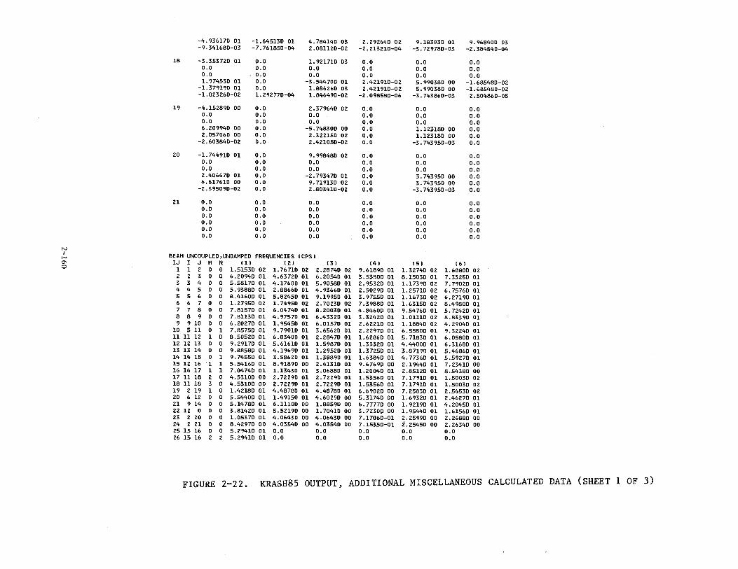
-4.936170 01 -1.645130 01 4.784140 03 2.292640 02 9.183830 01 9.968400 03 -9.341680-03 -7.761850-04 2. 081120-02 -2. 213210-04 -3.729780-03 -2.384540-04
18 -3.353720 01 o.o l. 921710 03 0.0 0.0 o.o 0.0 0.0 0.0 0.0 0.0 o.o 0.0 0.0 0.0 0.0 0.0 0.0 1.974530 01 o.o -3.544700 01 2.421910-02 5.990380 00 -1.685480-02
-1.379190 01 o.o 1.886260 03 2.421910-02 5.990380 00 -1.685480-02 -1.023260-02 1. 292770-04 1. 846490-02 -2.098580-06 -3.743860-03 2.504860-05
19 -4.152890 00 o.o 2.379640 02 0.0 0.0 0.0 0.0 o.o o.o 0.0 0.0 0.0 0.0 o.o o.o 0.0 o:o 0.0 6.209940 00 0.0 -5.748300 00 0.0 1.123180 00 o.o 2.057060 00 0.0 2.322150 02 0.0 1.123180 00 0.0
-2.603840-02 o.o 2.421050-02 0.0 -3.743950-03 0.0
20 -1.744910 01 o.o 9.998480 02 o.o o.o 0.0 o.o o.o o.o 0.0 0.0 o.o 0.0 0.0 0.0 0.0 0.0 o.o 2.406670 01 o.o -2.7934l0 01 o.o 3.743950 00 0.0 6.617610 00 0.0 9. 719130 02 0.0 3. 743950 00 o.o
-2.395090-02 o.o 2.803410-02 o.o -3.743950-03 0.0
21 0.0 o.o 0.0 o.o 0.0 0.0 0.0 o.o 0.0 0.0 0.0 0.0 0.0 o.o 0.0 0.0 0.0 0.0 0.0 o.o 0.0 0.0 0.0 0.0 0.0 0.0 0.0 0.0 0.0 0.0 0.0 o.o o.o 0.0 o.o 0.0
N I BEAM UNCOUPLEO,UNOAMPEO FREQUENCIES ICPSJ 1-'
C'> IJ I J M N ( 1) ( 2 J ( 3) (4) (5) (6) 0 1 1 2 0 0 1.51530 02 1. 76710 02 2.28740 02 9.61890 01 1.32740 02 1.68800 02
2 2 3 0 0 6. 20940 01 4.63720 01 6.20540 01 3.53800 01 8.15030 01 7.33250 01 3 3 4 0 0 5.58170 01 4.17600 01 5.90580 01 2.95320 01 1.17390 02 7.79020 01 4 4 5 0 0 5. 93880 01 2.88660 01 4.93660 01 2.50290 01 1. 25710 02 6. 75760 Ol 5 5 6 0 0 8.41600 01 5.82450 01 9.19950 01 3.97550 01 1.16730 02 6.27190 01 6 6 7 0 0 1.27950 02 1.74950 02 2.70230 02 7.39880 01 1. 63150 02 8.49800 01 7 7 8 0 0 7.81570 01 6.04740 01 8.20030 01 4.84600 01 9.54760 01 5. 72420 01 8 8 9 0 0 7.81130 01 4.97570 01 6.43320 01 3.32420 01 1.01110 02 8.83390 01 9 9 10 0 0 6.20270 01 1.95450 01 6.01570 01 2.62210 01 1.18840 02 4.29040 01
10 511 0 1 7.85750 01 9.79010 01 3.65620 01 2.22970 01 6.55500 01 9.32240 01 11 11 12 1 0 8.50520 01 6.83400 01 2.28470 01 1.62860 01 5.71830 01 6.05800 01 12 12 13 0 0 9.29170 01 5.61610 01 1.59870 01 1.33320 01 4.44000 01 6.31680 01 13 13 14 0 0 9.88580 01 4.19690 01 1.29520 01 1.37250 01 3.87190 01 5.46860 01 14 14 15 0 1 9.74550 01 3.58620 01 1.38890 01 1.63840 01 4.77360 01 5.59270 01 15 12 16 1 1 5.54160 01 8.91890 00 2.41310 01 9.67690 00 2.19440 01 7.23410 00 16 14 17 1 1 7.04740 01 1.13430 01 3.06880 01 1. 20040 01 2.85120 01 8.54380 00 17 11 18 2 0 4.53100 00 2. 72290 01 2.72290 01 1.53560 01 7.17910 01 1.50030 02 18 11 18 3 0 4.53100 00 2. 72290 01 2. 72290 01 1.53560 01 7.17910 01 1.50030 02 19 2 19 1 0 1.42180 01 4.48780 01 4.48780 01 6.69020 00 7.25830 01 2.56530 02 20 6 12 0 0 5.54400 01 1.49150 01 4.60290 00 5.31740 00 1.69320 01 2.46270 01 21 9 14 0 0 5.14780 01 6.11100 00 1.88590 00 6.77770 00 1. 92190 01 4.20450 01 22 12 0 0 0 3.81420 01 5.52190 00 1.70410 00 3.72300 00 1.95440 01 1.61560 01 23 2 20 0 0 1.05370 01 4.06430 00 4.06430 00 7.17060-01 2.25990 00 2.26880 00 24 2 21 0 0 8.42970 00 4.03540 00 4.03540 00 7.15350-01 2.25450 00 2.26340 00 25 15 16 0 0 5.29410 01 0.0 o.o 0.0 o.o 0.0 26 15 16 2 2 5.29410 01 0.0 o.o 0.0 0.0 0.0
FIGURE 2-22. KRASH85 OUTPUT, ADDITIONAL MISCELLANEOUS CALCULATED DATA (SHEET 1 OF 3)
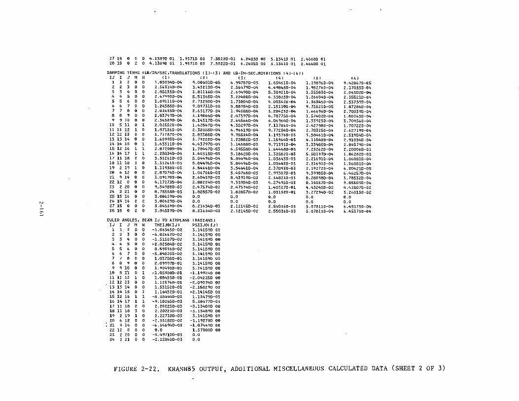
27 15 0 0 0 4.13890 01 1. 93710 00 7.50220-01 6.24050 00 3.13410 01 2.46680 01 28 15 0 2 0 4.13890 01 1. 93710 00 7.50220-01 6.24050 00 3.13410 01 2.46680 01
DAMPING TERMS lLB/IN/SEC,TRANSLATIONS l1l-l3l AND LB-IN-SEC,ROTATIONS l4l-(6ll IJ I J M N lll l2 J ( 3) (4) (5) ( 6)
1 1 2 0 0 1. 050340-04 9.006810-05 6.957870-05 1.654610-04 1.198960-04 9.428670-05 2 2 3 0 0 2.563140-04 3.432130-04 2.564790-04 4.498450-04 1.952760-04 2.170530-04 3 3 4 0 0 2. 851350-04 3.811160-04 2. 694900-04 5.389210-04 1. 355830-04 2.043020-04 4 4 5 0 0 2.679900-04 5.513650-04 3.224010-04 6.358850-04 1. 266040-04 2.355210-04 5 5 6 0 0 1. 891110-04 2.732500-04 1. 730040-04 4.003420-04 1.363450-04 2.537590-04 6 6 7 0 0 1. 243850-04 9.097310-05 5.889540-05 2.151100-04 9.755210-05 1.872860-04 7 7 8 0 0 2. 036350-04 2.631770-04 1. 940850-04 3.284230-04 1. 666960-04 2.780390-04 8 8 9 0 0 2.037490-04 3.198640-04 2.473970-04 4. 787750-04 1.574020-04 1.801650-04 9 9 10 0 0 2.565890-04 8.143170-04 2.645660-04 6.069640-04 1.339230-04 3.709560-04
10 511 0 1 2.025520-04 1.625670-04 4.352970-04 7.13 7860-04 2.427980-04 1.707220-04 11 11 12 1 0 1.871260-04 2.328880-04 6. 966190-04 9.772540-04 2.783250-04 2. 627190-04 12 12 13 0 0 1. 712870-04 2.833880-04 9.955140-04 1.193760-03 3 . 584610-04 2.519540-04 13 13 14 0 0 1.609930-04 3.792220-04 1. 228820-03 1. 159640-03 4.110480-04 2.910340-04 14 14 15 0 1 1. 633110-04 4.437970-04 1.145880-03 9. 713910-04 3.334050-04 2.845790-04 15 12 16 1 1 2.872000-04 1. 784470-03 6.595580-04 1. 64<•680-03 7.252620-04 2.200060-03 16 14 17 1 1 2.258340-04 1.403150-03 5.186200-04 1. 325820-03 5.581970-04 1.862820-03 17 11 18 2 0 3. 512610-03 5. 844960-04 5.844960-04 1.036430-03 2. 216910-04 1.060810-04 18 11 18 3 0 3.512610-03 5.844960-04 5. 844960-04 1.036430-03 2. 216910-04 1. 060810-04 19 2 19 1 0 1.119380-03 3.546410-04 3.546410-04 2.378930-03 2.192720-04 6.204210-05 20 6 12 0 0 2.870740-04 1. 067060-03 3.457680-03 2.993070-03 9.399850-04 6.462570-04 21 9 14 0 0 3.091700-04 2.604390-03 8.439190-03 2.348210-03 8.280980-04 3.785320-04 22 12 0 0 0 4.172730-04 2.882240-03 9.339540-03 4.274950-03 8.143570-04 9.851030-04 23 2 20 0 0 9.549280-03 2.475740-02 2.475740-02 1.403270-01 4.452480-02 4.435070-02 24 2 21 0 0 8.753550-03 1. 828570-02 1. 828570-02 1. 031520-01 3. 272940-02 3.260150-02 25 15 16 0 0 3.006290-04 0.0 0.0 0.0 0.0 0.0
N 26 15 16 2 2 3.006290-04 0.0 0.0 0.0 0.0 0.0 I 27 15 0 0 0 3.845390-04 8.216340-03 2.121450-02 2.550360-03 5.078110-04 6.451750-04
1-' 28 15 0 2 0 3.845390-04 8.216340-03 2.121450-02 2.550360-03 5. 078110-04 6.451750-04 a--1-'
EULER ANGLES, BEAM IJ TO AIRPLANE lRAOIANSl IJ I J M N THEIJOl IJ J PSIIJOl IJ l
1 1 2 0 0 -1.063430-02 3.141590 00 2 2 3 0 0 -6.026620-02 3.141590 00 3 3 4 0 0 -1.515070-02 3.141590 00 4 4 5 0 0 -2.825840-02 3.141590 00 5 5 6 0 0 8.593360-02 3.141590 00 6 6 7 0 0 -5.848200-02 3.141590 00 7 7 8 0 0 1. 037580-01 3.141590 00 8 8 9 0 0 2. 099970-01 3.141590 00 9 9 10 0 0 1. 924930-01 3.141590 00
10 5tl 0 1 -1.059200-01 -1. 199240 00 11 11 12 1 0 1.084530-01 -2.042250 00 12 12 13 0 0 1.123 760-01 -2.090740 00 13 13 14 0 0 1. 531520-01 -2.158290 00 14 14 15 0 l 1.164320-01 -2.141450 00 15 12 16 1 1 -8.35'>440-03 1.134 790-03 16 14 17 1 1 -9.102650-03 5. 384 770-03 17 11 18 2 0 2.202230-03 -3.134890 00 18 11 18 3 0 2.202230-03 -3.134890 00 19 2 19 1 0 2.227300-03 3.141590 00 20 6 12 0 0 -2.331520-02 -1.192780 00 21 9 14 0 0 -6.046940-03 -1.074490 00 22 12 0 0 0 o.o 1.570800 00 23 2 20 0 0 -3.497100-03 0.0 24 2 21 0 0 -2.228400-03 0.0
FIGURE 2-22. KRASH85 OUTPUT, ADDITIONAL MISCELLANEOUS CALCULATED DATA (SHEET 2 OF 3)
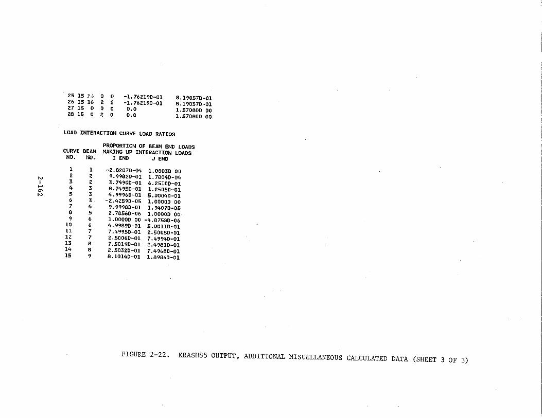
25 15 Ji> 0 0 -1.76219D-01 8.19057D-01 26 15 16 2 2 -1.76219D-01 8 .19057D-01 27 15 0 0 0 o.o 1.57080D 00 28 15 0 2 0 0.0 1.57080D 00
LOAD INTERACTION CURVE LOAD RATIOS
PROPORTION OF BEAM END LOADS CURVE BEAM MAKING UP INTERACTION LOADS
NO. NO. I END .J END
1 1 -2.8207D-04 1.0003D 00 N
2 2 9.9982D-01 1.78040-04 I 3 2 3.7490D-01 6.25100-01 t-' 4 3 8.7495D-01 1.25050-01 0\
5 3 4.99960-01 5.0004D-01 N 6 3 -2.42590-05 1.00000 00 7 4 9.9998D-01 1.94070-05 8 5 2.7856D-06 1.00000 00 9 6 1.00000 00 -4.8758D-06
10 6 4.99890-01 5.0011D-01 11 7 7.4995D-01 2.5005D-01 12 7 2.5006D-01 7.49940-01 13 8 7.5019D-01 2.49810-01 14 8 2.50320-01 7.49680-01 15 9 8.10140-01 1.89860-01
FIGURE 2-22. KRASH85 OUTPUT, ADDITIONAL MISCELLANEOUS CALCULATED DATA (SHEET 3 OF 3)
While these criteria are suggested as guidelines, their exceedance does not
necessarily mean that instability problems will automatically occur.
Beam structural damping coefficients are computed within the program
for each of the six beam degrees of freedom. The damping coefficients are
computed from equations (1-54), Section 1.3.5.3.6, Volume I.
These damping coefficients are printed only to provide a record of the l
actual data used in the calculations. The interpretation of the proper damp
ing values should be based upon inspection of the damping ratios (actual
damping/critical damping) summarized in the section entitled "INTERNAL BEM1
DATA" (Section (2.3.3.2.2)). For typical aircraft constructions, damping
ratios in the range of .01 to .10 are appropriate. Higher values should be
used only to represent mechanical damping devices, such as hydraulic or
friction dampers in landing gears or viscoelastic engine mounts. Values
greater than .05 are probably only justified as representative of the fric
tion damping associated with relative motions of riveted and bolted structure
under conditions of severe loading and deformation.
The Euler angles define the initial orientation of the beam axes relative
to the airplane, according to the convention shown in figure 2-5. These
angles should be interpreted in the following manner. Assume the beam axes
are oriented such that x is forward, y to the right and z down. Then rotate
PSIIJO radians about the z axis, positive nose right, forming a new set of
x' and y' axes. Then rotate. THEIJO radians about the new y' axis, positive
nose up. This final position defines the orientation of the beam axes with
respect to the airplane. For vertical beams, which are denoted by VBM=l in
the beam data formatted output, the above procedure is followed with one
exception. The initial orientation is such that the x axis is positive up,
y axis positive right and z axis positive forward.
It should be noted that during the time history analysis, these angles
vary with time and are part of the print output. Any question regarding the
current beam orientations should be resolved by examining the current values
of the beam orientation Euler angles. These are interpreted the same as the
preceding discussion, except that the initial starting orientation is the
2-163
ground axes rather than the airplane axes. Since the initial attitude of the
vehicle may not be parallel to the ground axes (generally it is not), the
time zero value of the beam orientation Euler angles may differ from the
angles listed in the MODEL PARAMETERS section of the output. The latter is
provided as a definition of beam axes orientations that is independent of
vehicle initial conditions (and hence represents a true model parameter),
whereas the time varying values represent the actual beam orientation during
the analysis.
The load interaction curve load ratios tabulate what proportion of the
I and J end beam loads are used to calculate the intermediate loads at the
location specified for each load interaction curve.
2.3.3.2 Time History Output
This section of the output prints the time varying response quantities
at each print time interval, including time zero. This output consists of
the following groups of data:
• Title cards
• Analysis time
• Mass and node point displacements, velocities and accelerations in six directions for all NM lumped masses and NNP node points, in mass axes and ground axes
• Mass impulses (G-sec) based on filtered accelerations
• Internal beam strain forces, total forces (strain + damping) in both beam and mass axes and displacements in six directions for all NB internal beams
• External spring compressions, ground deflections, axial loads, and ground contact loads (3 directions) in ground axes and mass axes for all NSP external springs
• DRI number for all DRI beam elements
• Overall vehicle e.g. translational velocity (3 directions)
• Volume change data, including current volume, current volume/initial volume, and the changes in length of the three lengths of the volume (optional)
2-164
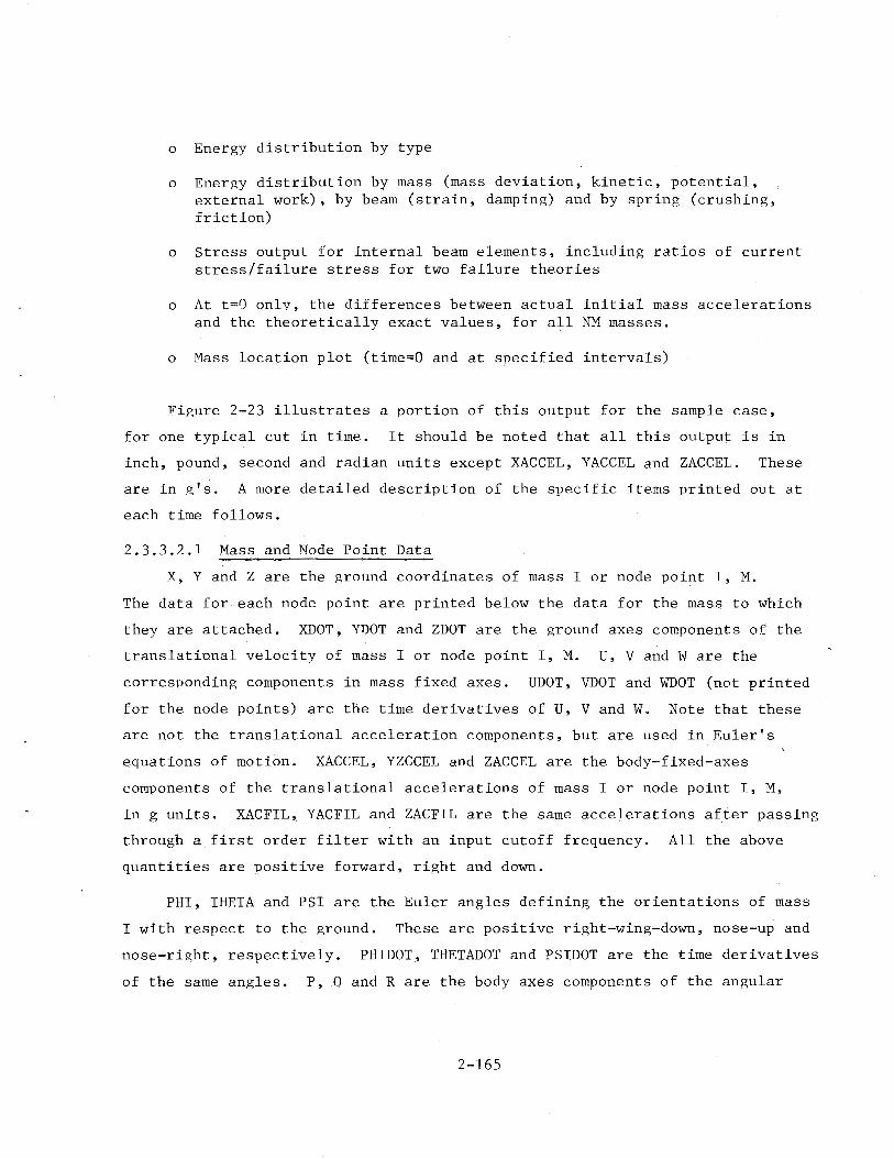
o Energy distribution by type
o Energy distribution by mass (mass deviation, kinetic, potential, external work), by beam (strain, damping) and by spring (crushing, friction)
o Stress output for internal beam elements, including ratios of current stress/failure stress for two failure theories
o At t=O only, the differences between actual initial mass accelerations and the theoretically exact values, for all NM masses.
o Mass location plot (time=O and at specified intervals)
~igure 2-23 illustrates a portion of this output for the sample case,
for one typical cut in time. It should be noted that all this output is in
inch, pound, second and radian units except XACCEL, YACCEL and ZACCEL. These
are in g 1 s. A more detailed description of the specific items printed out at
each time follows.
2.3.3.2.1 Mass and Node Point Data
X, Y and Z are the ground coordinates of mass I or node point I, M.
The data for each node point are printed below the data for the mass to which
they are attached. XDOT, YDOT and ZDOT are the ground axes components of the
translational velocity of mass I or node point I, M. U, V and W are the
corresponding components in mass fixed axes. UDOT, VDOT and WDOT (not printed
for the node points) are the time derivatives of U, V and W. Note that these
are not the translational acceleration components, but are used in Euler's
equations of motion. XACCEL, YZCCEL and ZACCEL are the body-fixed-axes
components of the translational accelerations of mass I or node point I, M,
in g units. XACFIL '· YACFIL and ZACFIL are the same accelerations after passing
through a first order filter with an input cutoff frequency. All the above
quantities are positive forward, right and down.
PHI, THETA and PSI are the Euler angles defining the orientations of mass
I with respect to the ground. These are positive right-wing-down, nose-up and
nose-right, respectively. PHIDOT, THETADOT and PSIDOT are the time derivatives
of the same angles. P, 0 and R are the body axes components of the angular
2-165
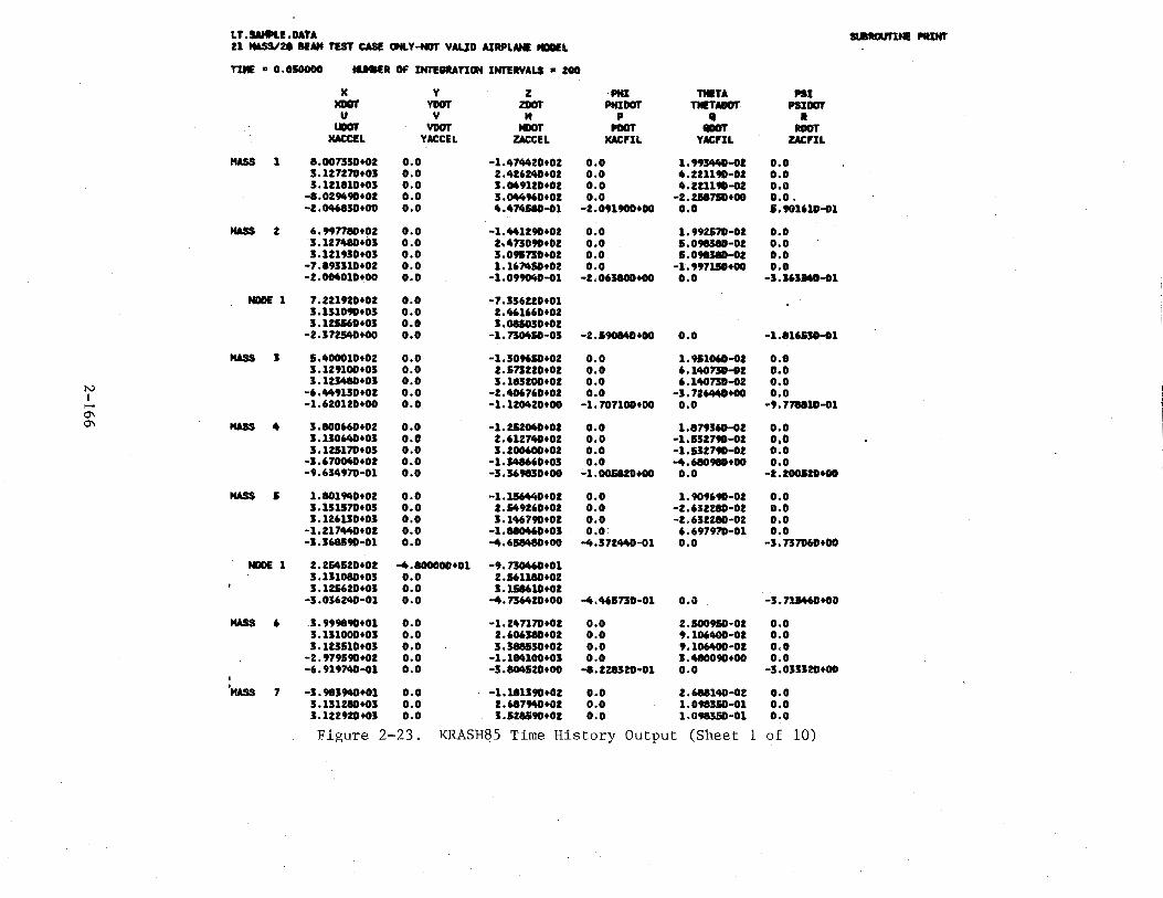
LT.UfltLE.DATA st.8RClll'lNI! NJNr 21 HASS/2a lENt TEST CASI ONLY-fGT YAUO AIRPLANE tiiiDEL
TIME II 0. OSOODO ...... OF INTEIMnON INTERVALS • ZOO
)( y z PHI ntiTA PSI MilOT YDOT ZDOT PHI DOT TIIETADOr PSI DOT u y " p II • UDOI' YDOT MDOT PDOT IIDOT IDOT
MACCIL YACCEL ZACCEL MACFIL YACFIL ZACFIL
MASS 1 8.oon3o+OZ o.o -1.474420+02 o.o 1. 99J44D-GI o.o 3.127270+03 o.o 2.426240+01 o.o ". 221190-01 o.o 3.121810+03 o.o 3.049110+02 o.o 4.211190-GI o.o
-8.02M90+02 o.o 3.044960+02 o.o -2.2587SD+OO o.o. -2. 046830+00 o.o 4.474580-01 -1.091900+00 o.o 1.901610-81
IWSS 2 6. 997780+02 o.o -1. 441190+02 o.o 1. 992570-01 o.o 3.127480+03 o.o 2.47J090+02 o.o 1.098380-01 o.o 3.121930+03 o.o 3.o95no+o2 o.o •• 098380-01 o.o
-7.893310+02 o.o 1.16 7410+02 o.o -1.997110+00 o.o -2.004010+00 o.o -1.099040-01 -Z.06J80D+OO o.o -3.1631MD-D1
NDOE 1 7. 221920+02 o.o -7.336120+01 3.131090+03 o.o 2.461660+02 3.125160+03 o.o 3.0U030+01
-2.372540+00 o.o -1.n0410-03 -2.590140+00 o.o -1.816130-81
MASS 3 1.400010+02 o.o -1.309610+02 o.o 1.911060-81 o.o 3.129100+03 o.o I.SnZZ0+02 o.o 6.140nD-81 o.o 3.123480+03 o.o 3.183100+02 o.o 6.140no-o2 o.o
N -6.449130+02 o.o -1.4D6760+02 o.o -3.726440+00 o.o I ,.... -1.620120+00 o.o -1.120420+00 -1.707100+00 o.o -9.778810-81 0\ 0"1 MASS 4 3.800660+02 o.o -1.252040+02 o.o 1.879360-01 o.o
3.130640+03 o.o 2.612740+02 o.o -1.132790-01 0,0 3.125170+03 o.o 3.200600+02 o.o -1.132790-81 o.o
-3.670040+02 o.o -1.348660+03 o.o -4.68098D+OO o.o -9.634970-01 o.o -3.369830+00 -1.005820+00 o.o •I.ZOOIID+OO
MASS I 1.801MD+02 o.o •1.1S644D+02 o.o 1.909690-02 o.o 3.131570+03 o.o 1 • .&49160+02 o.o -2.632280-01 o.o 3.126130+03 o.o 3.146790+02 o.o -1.632280-02 o.o
-1.217440+02 o.o -1.880460+03 o.o 6.697970-01 o.o -3.368590-01 o.o -4. 618480+00 -4.372440-01 o.o -3.n706D+OO
NODE 1 2.254520+02 -4.800000+01 -9.n046D+01 3 .131080+03 o.o 2.561180+02 3.125620+03 o.o 3.118610+02
-3.036240-01 o.o -4.736420+00 -tt.465no-o1 o.o -3.71.M6D+OO
IWSS 6 3. 999890+01 o.o -1.247170+02 o.o 2.500910-02 o.o 3.131000+03 o.o 2.606380+02 o.o 9.106400-02 o.c 3.123110+03 o.o 3.388530+02 o.o 9.106400-01 o.o
-2.979190+02 o.o -1.184100+03 o.o 3.480090+00 o.o -6. 919740-G1 o.o -3.804520+00 -8.228320·01 o.o -3.033320+00
I
'MASS 7 -3.983940+01 o.o -1.181390+02 o.o 2.688140-02 o.o 3.131280+03 o.o 2.687940+02 o.o 1.098350-01 o.o 3.122920+03 o.o 3 .528590+02 o.o 1.098350-01 o.o
Figure 2-23. KRASH85 Time History Output (Sheet 1 of 10)

-3.8272.0+02 o.o -9.3.M060+02 o.o 9.953320-01 o.o -a. 911090-01 o.o -3.311910+00 -1.0i3100+00 0.0 -2 .874600+00
MASS 8 -2.002150+02 o.o -1.308110+02 o.o 2.91838D-02 o.o 3.129170+03 o.o 2.891010+02 o.o 1 •• 91320-01 o.o 3.119390+03 o.o 3.806860+02 o.o 1.4913to-D1 o.e
-..005790+02 o.o -1.679210+03 o.o -1.01738D+01 o.o -8.906900-01 o.o -5.155460+00 -1.139610+00 o.o -s. 737SID+OO
HASS 9 -3.610tq+02 o.o -1.609320+02 o.o 2. 999740-D2 o.o 3.12Z68D+03 o.o 3.234030+02 o.o 2.683210-01 o.o 3 .111570+05 o.o 4.169160+02 o.o 2.683210-01 o.o
_. ... 51311+02 o.o -2.127990+03 o.o 5.159300+00 0.0 -8.618760-01 o.o -7.671930+00 -1.538870+00 o.o -7 .125230+00
MASS 10 -&.722700+02 o.o -1.969340+02 o.o 2. 96380D-D2 o.o 3.110100+03 o.o 3.861710+02 o.o 3.11"010-01 o.o 3.097690+05 o.o 4.781810+02 o.o 3.1M010-01 o.o
-1.469310+03 o.o 1. 382310+03 o.o 2.622170+01 o.o -3.415780+00 o.o 1. 010090+00 ·5.US.SO+OO o.o 1.426820+00
MASS 11 1.990310+02 -1.18JIOD+02 -1.Ma120+02 7.374770-03 -7.028290-M 5.491340·04 3.130390+05 -2.0.50860-01 2.414MD+02 6.021890-02 -..801040-01 1.218200•02 3.130560+03 -1.60171D-D1 2. 393010+02 6.022710-02 -..807010•01 1.172740-02 1.228260+02 -9.364190+01 -5. US!i4D+03 1.357.90+00 2. 730270+00 1.041030-D1 2.019730-02 -1.513910-01 -.. 'M4770+00 ·1.QU20-01 -3.""'240-01 -s .191270+00
tilDE 1 2.264340+02 -1.183100+02 -1.027920+02 3.129420+03 7. 711590-03 2.M6660+02 5.129600+03 1 •• 99020-01 2.JM720+02
N 1.792980-02 -1.~120-D1 -1.1S9730+00 -1.708710-01 -2.565220-01 -&.469130+00 I ,_. tilDE 2 1.133370+02 -1.517590+02 -9. 637070+01
0'\ 3 .126500+03 -1. 765220+00 1.9MI10+02 -...J 3.126 .. 0+03 -2.026330+00 1. 973040+02
1.611170-01 ·3.Stta560•01 -..39DMD+OO -9 •• 91950-02 -6.76758D-01 -6.17971D+OO
NDDIE 3 1.133370+02 -1.317190+02 -9.637070+01 5.126100+03 -1.763220+00 1.994810+02 3.126640+03 -2.026130+00 1.973040+02 1.611170-01 •3.Stta560-01 ... 390MD+OO -9.498950-02 -6. 76758D-01 -6 .179710+00
MASS u 1.480710+02 -2.717770+02 -1. 20:M30+02 6.521040-03 5.80M80-03 6.5&3300-04 3.1S3900+05 -1.13975D-01 2.470870+02 -5.422310-01 -3.905980-01 -5. 0126 7D-D2 3.152.10+03 -8.377410-01 2. 612970+02 -3.41..00-01 -3.909220-01 ... 827770-0Z
-1.817970+02 3. 330430+01 -3.05038D+03 -1.032170+00 s. 788SID+OO -2. 7870411+00 -7.397620-01 -7.048070-02 -..72M40+00 -a. 312930-01 -1.676340-01 _.. 405090+00
tilDE 1 1.886240+02 -3.215720+02 -1.174030+02 3.150320+03 -1. 488840+00 2.799650+02 3.128640+03 -1.591990+00 2.981AD+02
-1.080210+00 -2.876810-01 ... 690710+00 -1.394220+00 _..137410-01 -2.678810+00
MASS IS 5.686090+01 ... 305160+02 -1.381010+02 1 • ..a3oo-o2 9.561790-03 9.~-04 3.132330+03 -2.661830+00 2.784350+02 -3.305970-01 -1.111900-01 -3.291100-0Z 3.129520+03 -1.2U410+00 3.084370+02 -5.302820-01 -1.130620-01 -3 .126290-DI
-7.198690+02 1 •• 13260+02 -2.529290+03 -. ... 2260+00 -1.323570+01 -2 .llMIO+Ot -1.915590+00 3.765790-01 -J.63U40+00 -1. 701030+00 1.965070-01 -5.687150+00
MASS 14 _..538840+01 -5.829340+02 -1.638260+02 2.528660-02 1 . 441510-01 4.1371.10-05 . l<'igure 2-23. KRASH85 Time History Output (Sheet 2 of 10)
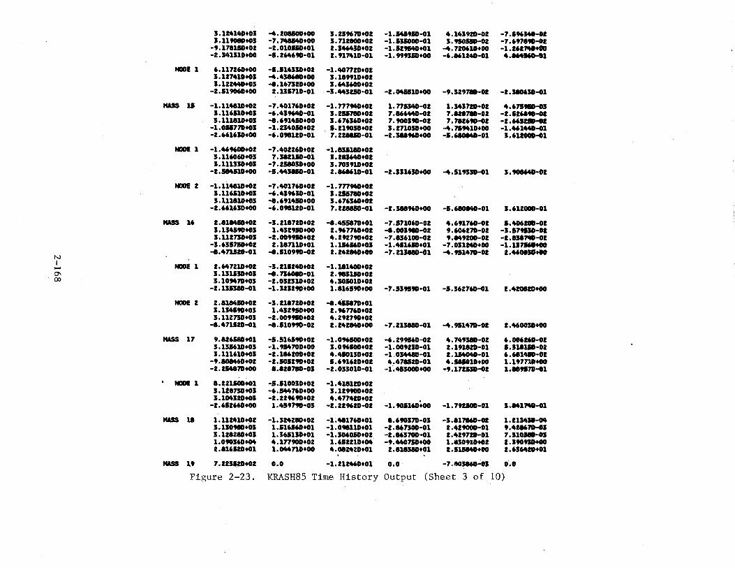
3.124140+03 -4.208100+00 3.259670+02 -1.545910-01 4.143920-02 -7 .596M0-02 3.1190811+03 -7.748140+00 5.712800+02 -1.U.S000-01 3.950510-02 -7.69,.90•02
-9.1781.110+02 -2.010110+01 2.346430+02 -1.529540+01 -4.720610+00 -1.Z61N+OO -2.341310+00 -1.264690-11 2.917410-01 -1. 999310+00 -6.861240-01 4.164160•01
NODI! 1 6.117260+00 -1.114330+02 -1.407720+02 3.127410+03 -4.438610+00 3.189910+02 3.122440+03 -8.167320+00 3.643600+02
-2.519060+00 2.135710-01 -3.443210-01 -2. 045&10+00 -9.329710-02 -2 .380630-DI
MASS 11 -1.114810+02 -7.401760+02 -1.7779411+02 1.771340-02 1.343720-02 4. 6719&0-05 3.116510+03 -6.439640-11 3.255710+02 7.866440-02 7.828710-02 -2.&26890-oz 3.111810+03 -8.691410+00 3.676360+02 7.900390-02 7.782690-12 -2.66121D-02
-1 .• 051770+03 -1.234010+01 •• 219030+02 3. 271030+00 -4.7&9410+00 -1.461440-11 -2.661630+00 -6.098120-01 7.228810-01 -2.388960+00 -1.6801411-01 3.612000-11
NODI! 1 -1.469600+02 -7 .402260+02 -1.831180+02 3.116060+03 7 .512110-Dl 3.285640+02 3.111330+03 -7.258030+00 3.703910+02
•2,5MJ10+00 -1.443UD-01 2.868610-01 -2.331630+00 -4.519330-11 3. 908640-DZ
NDDI! 2 -1.114810+02 -7.401760+02 -1.7779411+02 3.116110+03 -6.439630-01 3.251710+02 3 .111810+03 -8.691450+00 3.676360+02
-z. 661630+00 -6. 098120-01 7.228810-01 -2.388960+00 -5.610MD-01 3.612000-01
MASS 16 2.811410+02 -3.218720+02 -8.455870+01 -7.171060-02 4.691760-12 1.4D620D-D2 3 .134190+03 1.432910+00 2. 96 7760+02 -a.oo598D-02 9. 606270-02 -3.179130-0Z 3.112730+03 -2.009950+02 4.292790+02 -7.836100-02 9.149200-ot -1.8517W-DZ
•3.63171D+02 2.187110+01 1.116160+03 -1.41100+01 -7.031240+00 -1.117160+00 -8.471120-01 -8.110990-D2 2.242140+00
N -7.213880-11 -4.911470-02 2.4600JD+OO
I NODE 1 2.647210+02 -3.215240+02 -1.181400+02 ....... 0"1 3.131130+03 -8.736080•01 2.983110+02 00 3.109470+03 -2.032310+02 4.301010+02
-2.1353811-01 -1. 323290'+00 1.816590+00 -7.539590-01 -5. 362760-11 2.420120+00
NODE 2 2.811410+02 -3.218720+02 -a.U5870+01 3.134590+03 1.432910+00 2.967760+02 3.112730+03 -2.009950+02 4.292790+02
-8.471520-01 -8.510990-02 2. 24ZMD+OO -7.213880-01 -4.911470-02 2. 460030+00
HASS 17 9.826AD+01 -5.516590+02 -1.096500+02 -6.299160-02 4. 74938D·02 6.006260-DZ 3.135610+03 -1.914700+00 3.096100+02 -1.009230-D1 2.191820-01 s.JllliD-oz 3.111610+03 -2 .186200+02 4.410130+02 •1,0344U•01 2.1Ji4041-01 6.681410-DZ
-9 .101460+02 -1.505290+02 1.691620+01 4.478120-01 4.161010+00 1.1 97111+00 -2.254870+00 8.828780-03 -2.013010·01 -1·.413000+00 -9.17WD-DZ 1.889170-D1
NDDI! 1 8.221100+01 -5.510030+02 -1.418120+02 3.128730+03 -6.5447'0+00 3.129900+02 3 .104320+03 -2. 229690+02 4.477420+02
-1.9D516D+oo -2.611660+00 1.459790-03 -2.229620·02 -1.79ZJOD-01 J,M17W-D1
MASS 18 1.112410+02 -1.324280+02 -1.481760+01 8.690370-03 -3.817160,..02 1. Z1:541D·04 3.130980+03 1.516160+01 -1.0te110+01 -2.867300-01 2.429000-01 9. 428670-GJ 3.128280+03 1.36.1130+01 -1.306010+02 -2.a63100-o1 2.429720-01 7.JlOJeD-OJ 1.090360+04 4.177900+02 1. 612210+04 -9.44071D+OO 1.810910+02 z.sto91D+OO 2.816120+01 1.044no+OO 4.082420+01 2.8183811+01 2. 511140+00 2. 636420+01
MASS 19 7.223520+02 o.o -1.212460+01 o.o -7.803860-03 o.o Figure 2-23. KRASH85 Time History Output (Sheet 3 of 10)
3 ... 0 0 3.68590+0ft o.o -5.31630+03 0.0 -4.35SOD+06 3.50ft50+06 o.o o.o ... 5 0 0 ft.7638D+Oft 0.0 -5.85970+04 o.o -3.81680+06 -7. 90780+06 o.o 0.0 5 6 0 0 -1.78610+05 o.o 1.71770+05 o.o 6.10100+07 -3.68740+07 o.o o.o 6 7 0 0 -1.23530+05 o.o 1.68150+05 0.0 3.85310+07 -2.50190+07 0.0 o.o 7 8 0 0 -1.37060+05 o.o 1.09900+05 o.o 2.51990+07 -7.11700+06 o.o o.o 8 9 0 0 -1. 25890+01 o.o 3. 366 70+0ft o.o 5.61380+06 -l.OI:SSD+OS 0.0 o.o 9 10 0 0 -2.38780+04 0.0 1.26750+0ft o.o -l.liMO+OI 2.83140+06 o.o o.o 5 11 0 1 -5.15160+04 -1.07150+01 -1.73600+05 3.05230+07 -1.06ft30+07 -1.1531D+07 2.16680+07 -7.97990+06
11 lZ 1 0 8.53790+03 -6.ft370D+03 3.08170+M -3.01100+06 5.24220+06 9.47220+M J.M720+06 -1.451!10+06 12 13 0 0 -ft.718SD+03 -1.46120+04 1. 78670+03 -1.56 790+06 -1.14450+06 1.47300+06 t.t27111+06 -1.39660+05 13 14 0 0 2.11340+03 -2. 44490+04 -1.1ft820+0ft -1.03410+06 -1.72510+06 -4. 02970+01 3.17110+01 4.17440+06 14 15 0 1 5. 94980+0ft 4. 29770+04 1..39960+03 2.53120+01 4.95380+05 -2.31861+05 -4.ftft30+06 -3.16710+06 12 16 1 1 ft.07810+03 -3.26870+02 -7.1ft060+03 5. 55180+04 -9. 90590+01 4.471ZD+OI 4.41150+03 2.04UO+Oft 1ft 17 1 1 1.15470+04 7.72560+02 ·5.5300D+03 -2.00990+04 1.532ftD+OI 1.67600+05 -6.91161+04 1.04381)+04 11 18 2 0 -2.46260+05 1.81930+03 -5.42990+04 -2.4ft020+03 -5.29000+06 I. 73190+01 -1.14310+01 1.ft89ftD+04 11 18 3 0 -2.99070+01 1.81930+03 -1.42990+04 -2. 4ft020+03 -5.29000+06 5.73590+01 -1.14310+05 1.48MD+Oft
2 19 1 0 -3.68940+04 o.o -9.91880+03 o.o -7 .45200+05 1.11760+05 o.e o.o 6 12 0 0 1.82790+04 5. 71270+03 -5.35780+03 1.32320+06 -1.56710+06 o.o -1.67090+06 o.o 9 14 0 0 9.4M7D+04 0.0 -4.13290+03 7.16060+05 -1.78020+06 -9.59160+05 o.o o.o
12 0 0 0 -3.39770+04 0.0 o.o o.o -3.51930+05 3.51930+05 4.11080+05 -4.31oiO+OI 2 20 0 0 -9.39720+02 o.o 5.28800+02 o.o 5.32330+03 1.21110+03 o.o o.o 2 21 0 0 -1.31860+03 o.o 4.19320+02 o.o 4.07720+03 4.23780+03 o.o o.o
15 16 0 0 o.o 0.0 o.o o.o 0.0 o.o o.o o.o 15 16 2 2 o.o o.o o.o o.o o.o o.o 0.0 o.o 15 0 0 0 o.o o.o 0.0 o.o -2.99910+05 2.99918+05 4.93310+05 -4.93JlD+OI 15 0 2 0 -7.41560+04 o.o o.o o.o -2.99910+01 2.99910+05 4.93310+01 -4. 91310+01
COt4PONEN1'S Of TOTAL BEAM FORCES ACnNiil ON MASSES I AND J LOADS ARE THOBE ACnNiil ON THE MASS, IN ttASS AXES, +FM:),IT,ON FOR EACH BEAM, FIRST LINE IS MASS I, SECOND LINE IS MASS J
N I I J " N FX FY FZ HI< HY MZ ......
(J\ 1 2 0 0 '.0 -3.21260+03 o.o -7.80460+02 o.o -9.03.500+04 o.o
3.21260+03 o.o 7 .804ftD+02 o.o 7.34840+03 o.o 2 3 0 0 -1. 243ftD+Oft o.o 2.59040+04 o.o 2.70720+04 o.o
1.24240+04 o.o -2. 59090+04 o.o 3.99370+06 o.o 3 4 0 0 -3.69420+04 o.o -ft.707ftD+03 o.o -4.35SOD+06 o.o
3.69450+04 0.0 .... 68090+03 o.o 3. 50ft50+06 0.0
... .6 0 0 -ft. 91170+04 o.o -5. 71910+M o.o -3.81680+06 0.0 4.93000+04 o.o 5.72060+04 o.o -7.90780+06 0.0
5 6 0 0 1.63620+05 0.0 1.86100+05 o.o 6.10100+07 0.0 -1.62510+05 o.o -1.87070+05 o.o -3.687ftD+07 o.o
6 7 0 0 1.3294D+05 o.o 1.60810+05 o.o 3.85310+07 o.o -1.326ft0+05 o.o -1.61060+05 o.o -2.50.690+07 o.o
7 8 0 0 1.24700+05 o.o 1.23750+05 o.o 2.51990+07 o.o -1.24ft10+05 0.0 •1,2ft040+05 o.o -7.51700+06 0.0
8 9 0 0 1.15850+05 o.o 5.96750+04 o.o 5.61380+06 o.o -1.15800+05 o.o -5.9769D+Oft o.o -1.05330+05 o.o
9 10 0 0 2.09040+04 o.o 1.71410+04 o.o -1.1504D+OJ o.o -2.09100+04 o.o -1.71340+04 o.o 2,8'lll\ftD+06 0.0
Figure 2-23. KRASH85 Time History Output (Sheet 4 of 10)
3.038630+03 o.o 1.480770+02 o.o -2.381UD+OO o.o 3.039690+03 o.o 1.243600+02 o.o •2,J8101D+OO o.o
-2 .1852!iD+OJ o.o -9.446120+03 o.o -3.910f14D+01 o.o -6.428380+00 o.o -5. 721390+00 -1.101720+01 o.o -6.890780+00
HASS 20 6.9MS7D+02 o.o -1.640510+02 o.o 1.8274611-02 o.o 3.134620+03 o.o 2 • ..a9230+02 o.o 7.007190-02 o.o 3.129150+03 o.o 3.061620+02 o.o 7.0075,.,·02 o.o
-2.31"""+02 o.o 1.420720+02 o.o -·. 213070+00 o.o -1.450110-G1 o.o 5.897760-01 -...190190-01 o.o 1.142810-G1
HASS 21 6.9M360+01 o.o -1.639140+02 o.o 2. 018070-DI o.o 3.UICMD+03 o.o 2. 512190+02 o.o 7.198708-02 o.o 1.129330+03 o.o I .144110+02 o.o 7.5 .. 708-02 o.o
-1.91988D+02 o.o 9 ... 2290+01 o.o -...237760+00 e.o -...314790-01 o.o -3.600141-01 -3.300370-01 o.o -2. 7Z,_.ID-G1
NO MISS ~SI! DATA REIIUUTIO
lEAH F«aCIS
STUIN FOICIS
I J " N FX FY FZ tiC MVI MVJ MZJ MZJ 1 2 0 0 3.22041+03 o.o -8.0977D+Ot .o.o -9.4847D+M 1.101!D+04 o.o o.o 2 3 0 0 1.44790+04 o.o 2.41210+04 o.o -t.M57D+M. 3.96020+06 e.o e.o 3 4 0 0 3.77520+04 o.o -1.47810+13 o.o -..28MD+06 1.40100+06 o.o t.O
" I 0 0 4.86110+04 o.o -J.761JD+M o.o -3. 70260+06 -7.8Z7ZOt06 o.o ••• I 6 0 0 -1.78760+01 ••• 1.70UD+OI o.o 6.07910+07 -3.67190+07 0.1 o.t N 6 7 0 0 -1.2JIID+OI o.o 1.67190+01 o.o 3.84960+07 -I.IMII+07 o.o ••• I 7 I 0 0 -1.37J4D+05 o.o 1.09910+05 o.o 2.11100+17 -7.46J6D+G6 o.o ••• ..... " • 9 0 0 -1.21960+01 o.o 3.JUID+04 o.o J.I220D+06 -S.1MI+04 o.o ••• 0 9 10 0 0 -1.451..0+04 o.o 1.23740+04 o.o -1.86680+05 2.1JU1+06 o.o ••• I 11 0 1 -5.082JD+04 -1.07660+015 -1.71oOD+OI J.0071D+07 -1.01250+07 -1.13101+07 1.100Dt07 -7 •• 9711+06
11 12 1 0 9.01120+03 -6.091JD+OJ 3.01860+04 -3.07150+06 1.05910+06 1.68070+01 3.44090+06 -I.MI7D+16 12 1J 0 0 -...11200+03 -1.462JD+04 1.73060+03 -1.1069D+06 -1.1711D+06 1.49DOD+Ot 1.12JID+06 -l.J.IItfll 1J 14 0 0 2.19960+03 -2.4J11D+M -1.19210+04 -1.00930+06 -1.76010+06 -4.4901+01 1.1700+05 4.l9t11+06 14 11 0 1 5.91010+04 4.1MOD+04 1.I.MID+03 2.61710+05 1.11210+0.1 -2.25470+01 -4.11UD+06 -J.I6t1D+06 12 16 1 1 3.71110+03 -1.49600+02 -1.1 ...... +03 5.06110+04 -9. 91200+05 J.7S04D+OS 1.33418+04 z ......... 14 17 1 1 1.11990+04 1.3ZJOD+02 1.10610+03 -2.07170+04 2.46641+05 1.4199t+H -6.862tD+04 1.17lltft3 11 11 2 0 -1. 92290+04 2.03510+03 -1.477JD+04 -2.23370+03 -5.33100+06 J.7191D+U -2.01MD+H 1.4ftot.O. 11 11 3 0 -2.9907D+01 2.03110+03 -1.477JD+04 -Z.t337D+03 -J.:SJ100+06 1.719JD+U -2.01MO+OJ 1.49101+04 2 19 1 0 -3.12010+03 o.o -9.U.10t03 o.o . -7.26400+05 1.29160 ... o.o o.o 6 u 0 0 1.77410+04 1.66160+03 -5.35110+03 1.26340+06 -1.16130+06 o.o -1.6571D+06 ••• 9 14 0 0 9.371..0+04 o.o· -4.11110t03 7.07170+05 -1.12260+06 -9.13170+01 a.o ••• 11 0 0 0 -3.42910+04 o.o o.o o.o -...79600+01 4. 79600+01 J.0704D+t!S -1.07MD+OS 2 20 0 0 -7.70910+02 o.o '. 01718.+01 o.o 9.1830+02 l.lQGD+02 o.o ••• 2 21 0 0 -1.1Z71Dt03 o.o 1.421JD+01 o.o • 8.11710+02 ....... +02 o.o o.o
11 16 0 0 o.o o.o o.o o.o o.o o.o o.o o.o 11 16 2 ' o.o o.o o.o o.o o.o o.o o.o o.o 15 0 0 0 o.o o.o o.o o.o -2.16060+05 2.16061+05 1.05410+01 -1.0140+01 11 0 2 0 -7.41560+04 o.o. o.o o.o -2 ,1606D+OI t.I606D+U J,IMaD+OJ
-·· 01420+01 TOTAL FORCES ISTRAIN+OAMPIII81 I
I J " N FX FY FZ * MVI MV.J MZJ MZJ 1 2 0 0 3.20230+03 0.0 -1.217JD+02 o.o -9.0UOD+M 7.14Mt+03 o.o ••• 2 I 0 0 1.41230+04 o.o 2.10800+04 o.o 2.70720+04 3.99170+06 o.o •••
Figure 2-23. KRASH85 Time History Output (Sheet 5 of 10)
I 11 0 1 -1.09910+06 -7.91110+05 -1.79UD+OS 1.19650+07 -1.61090+07 -1.81471+07 1.15450+05 9.1&810+05 1. 76970+05 -1.41470+01 2.86160+07 4.71940+06
11 11 1 0 •1.0M60+04 -7. 27460+05 2.98910+04 -5.14650+06 4.11600+06 -5.45090+06 1.10410+04 7.Utl0+05 -2.98140+04 -1.16090+06 -2.8JI70+06 1.12)10+06
12 15 0 0 -1.04110+04 1.11M0+04 1.27690+05 1.89190+06 1.01950+06 -Z.672JD+06 1.04160+04 -1.12190+04 -2.14630+03 -2. 06130+06 -6.31440+05 -1.01780+05
15 14 0 0 -2. 07020+04 1.31320+04 -1.11340+04 2.02920+06 -6.60710+04 -z. 26420+05 2.06010+04 -1.50720+04 1.17740+04 7.24480+04 -6.1108D+OI -4.26940+06
14 11 0 1 5.78260+05 -7.52060+04 -5. 94660+05 -7.UI40+05 -2.85570+05 4.4a1ZD+06 -5.75760+05 7.51760+04 4.10210+05 6.05260+05 -2.82160+04 9.85940+05
12 16 1 1 4.01040+03 -3.11350+02 -7.11710+05 4.13070+05 1.29460+06 1.16610+05 -4.32140+03 -'5.15960+01 7.00:SA+03 -5.30180+04 -1.03920+01 -4.34:SA+04
14 17 1 1 1.11420+04 7.95130+02 5.53710+03 1.3M9D+OI -2. 71850+05 -2.571JD+OI -1.13700+04 3.69390+02 -5.92390+03 1.71410+03 1.19590+05 1.17440+0ft
11 18 2 0 -4.81290+04 -1.61320+03 -2.47140+05 3.48990+06 -2.69180+07 -1.03970+05 5.75700+04 1.94220+03 2.41570+05 -1.49020+04 I. 73590+05 2.54a20+03
11 18 3 0 -1.42820+04 -1.81540+03 -1.38820+03 2.18110+05 -5.87580+06 -1.68470+05 5.42950+04 1.82280+03 -6.49040+02 -1.49020+04 5.75590+01 2.34820+03
2 19 1 0 -9.28820+03 0.0 -3.70610+04 o.o -6.28240+05 o.o 1.03120+04 0.0 3.67890+04 o.o 1.31760+05 o.o
N 6 1Z 0 0 1.21510+04 -1.49740+04 -4.85600+03 1.91380+06 -6.19390+05 1.71820+06 I -1. 20460+04 1.50150+04 4.99070+05 -4.87970+05 1.22960+06 -3.06380+04
>-' -...J 9 14 0 0 4.50760+04 -8.11520+04 -3.19470+03 1.90620+06 2.17980+05 3.00190+04 >-'
-4.46760+04 8.34090+04 1.79330+03 5.07080+05 1.08590+06 -2.99310+04
12 0 0 0 -2.22660+01 -3.39760+04 2.21430+02 -3.51940+05 -2.57880+03 -4.31070+05 THERE JS NO MASS AT J END OF THIS BEAH
2 20 0 0 5.25220+02 o.o 9.41720+02 o.o -5.32330+03 o.o -5.26780+02 0.0 -9.40860+02 o.o -5.21310+03 o.o
2 21 0 0 o.o o.o o.o o.o 0.0 o.o -4.15300+02 o.o -1.35980+03 0.0 -4. 23 780+05 o.o
15 16 0 0 o.o o.o o.o o.o o.o o.o o.o o.o o.o o.o o.o o.o
15 16 2 z o.o o.o 0.0 o.o 0.0 o.o o.o o.o o.o o.o 0.0 o.o
15 0 0 0 o.o o.o 0.0 -2.99910+05 -7.51450+03 -4.93260+05 THERE JS NO MASS AT J END OF THIS BEAH
15 0 2 0 -3.46720+02 -7 .41440+04 1.31180+03 -2.99910+05 -7. 32450+03 -4.93260+05 THERE JS NO MASS AT J END OF THIS BEAH
NAH RELATT\11 iEFLECnONS AND ROTATIONS AND D£AH EULER ANGLES I INCHES ANI '"'GRI!ES)
Figure 2-23. KRASH85 Time History Output (Sheet 6 of 10)
HAM DEFLECTION I J-I J ROTATIONS I J-I I RorA'11118 CJ+I) Y IULEII AHiliS
• I J H N )( y z PHI THETA PSI THETA PSI H tMITA PSI 1 I 0 0 1.01650-05 o.o -1.57010~ o.o 5.05190-M 1.0 -2.84290-01 o.o -1.9 180.0 z 5 0 0 6.44760-05 o.o -I.Z56:S0-02 o.o 2.37910-11 o.o -2 •• ,,. ... 1 o.o ""·7 180.0 5 4 0 0 1.67810-01 o.o -I.MUD-02 o.o 4.10060-02 o.o -1.91190-D1 o.o -2.1 110.0 4 I 0 0 1.64160-02 o.o 2.07090-05 o.o •1,7JUD•02 o.o -1.7117D-11 o.o -2.7 180.0 5 6 0 0 -4.25710-02 o.o 4.4952D-G1 o.o -J.J865D-G1 o.o -1.27610-01 o.o 1.7 110.0 6 7 0 0 -1.74120-01 o.o 8.02110-01 o.o -1.07240-01 o.o -9.7JIOD-01 o.o -4.7 180.0 7 8 0 0 ""'. 60590-01 o.o 1.18710-G1 o.o -1.1181D-G1 o.o -1.21260+00 o.o 4.1 180.0 8 9 0 0 -1.57060-01 o.o 8.uno-oa o.o ""·61000-02 ••• -1.59100+00 o.o 10.6 110.0 9 10 0 0 -2.01410-01 o.o -2.72620-02 o.o 2.06J7D•OI o.o -1.41690+00 o.o 9.7 110.0 I 11 0 1 -1.202JD-GI -1.22150-G1 -1.6641D•01 1.20660+00 •1.12161-02 -9.41161-01 I,IJ61D•OI •7.64410-GI -··· -61.7
11 12 1 0 2.4887D-05 -4.14060-01 4.56J5D-G1 -I.OU1D-G1 -2.12920-01 -I.IMID-ot 1.48410+00 1.90161-01 ••• -117.1 12 15 0 0 -1.47420-0J -1.6197D-OI ""·19990-01 -4.1797D-G1 2.91410-01 •1.61611-GI 1.60910+00 I.Mt?D-01 •.• -llt.t 1J 14 0 0 1.09210-0J 9.69100-02 -8.79360-01 -1.8761D-G1 J,4814W-OI 9.79UD-GI 1.Mtot+" 1.61611-01 8.o -111.9 14 11 0 1 J,601JD-OI 4.0JJ40-G1 6.21210-01 2. 71160-G1 -J,J426D-01 6.JI060-o2 2.18461+00 J.lltOI-01 6.0 -121.9 12 16 1 1 5.19810-0J 1.66710-01 -2.9704W-01 2.49810-G1 1.88610-01 1.14510-GI -9.46441-11 9.8911D-ol 0.6 o.o 14 17 1 1 1.01410-02 1,J100D-G1 4.41100-GI -1.0217D-01 -2.9677D-GI 1.55410-11 -1.96110-11 .... 2.-DI o.8 0.1 11 18 2 0 -7.40610+00 7.15020-01 -2.17110+00 -6.91190-01 1.14800+00 7.51960-02 4.12660+00 t.1919D-o1 1 I.J -179.1 11 18 I 0 -7 • .0610+00 7.11010-GI -1.17210+00 -6.91190-GJ 2.14800+00 7.11960-12 4.ti66D+OO 9.1919D-G1 1 1.1 -179.1 2 It 1 0 -1.2587D+OO o.o -1.06780+00 o.o 1.58610+00 o.o 1.10111+00 o.o 1 -0.1 110.0 6 It 0 0 1.17490-0t 1.21010-01 -2.12610+00 1.1607D+OO -1.891.0-tl 9.91610-GI 2.6086D-tl 1.74810-ti. -o.9 -68.5 9 14 0 0 1.52610-01 1.1811D+OO -9.91110+00 1.47590+00 8.44100-01 1.11110-01 1.1Z86D+DO I.IJ?20·01 t o.s -61.6
1Z 0 0 0 -4.18010-02 •J,J6610-01 -J,J411D+DO o.o 7.46 760-GI ·7 .11890-GI o.o o.o 0 o.o 90.0 2 20 0 0 -7 .U77D-02 o.o 7.17J8D-02 o.o -9.46190-01 o.o 1.89170-DI o.o 1 0.9 o.o I 11 0 0 -1.71200-G1 o.o J,51410-G2 o.o 1.45810-o2 o.o 2.tU7D-tl o.o 1 1.0 o.o
11 16 0 0 7.48110-02 -7.97610-01 1.11150+00 -3.29810-G1 2.10610-G1 -1.39110-G1 -1 • .M01D+t0 I.OJ900-t1 I -9.a .... 11 16 I 2 7 .48110-G2 ·7. 97610-01 1.UliO+DO -3.29UD-G1 1.10650-01 -1.39110-Gl •l,.M07D+DO 1.01911-01 0 -•·* ..... 11 0 0 0 -a.41810-G1 -6.92210+00 -1.61200+01 o.o 2.02190+00 -J,JIIID-Gl o.o e.o 0 ••• .. ..
N 11 0 2 0 -8.48810-G1 -6.92220+00 -2.61100+01 o.o 2.02190+00 -J,JIIID-Gl o.o o.o 0 0.8 90.0 I
1-' -...J EXTEINAI. IPRI..S N
8ROlJII CONTACT POINT t.CMDS _... CCINY'Ac:T IIOINf' LIIADI IN .... OR SlOPf AlCES JNtiYS ...
SIIIIINS tWIS IPIIIN8 SIIIIINS .... catPIII!SSION XC + AI'T OR YC + LEI'T J Zl+ Ut CIR NOll- )( y z
I K H CCIMPAESSION DI!FLECTION LOU DCMf SLOPIJ HAL TO SUift t ....... , l + IIIIHTJ , ..... , 1 3 0 o.o o.o o.o o.o o.o o.o o.o o.o o.t I J 0 o.o o.o o.o o.o o.o o.o o.o o.o o.o 3 3 0 o.o o.o o.o o.o o.o o.o o.o o.o o.&
" J 0 o.o o.o o.o o.o o.o o.o o.o o.o o.t I 5 0 o.o o.o o.o o.o o.o o.o o.o o.o o.e
' 3 0 o.o o.o o.o o:o o.o o.o o.o ••• o.o 7 !S 0 o.o o.o o.o o.o o.o o.o o.o o.c o.o
I 8 3 0 o.o o.o o.o o.o o.o o.o o.o o.o o.o 9 3 0 o.o o.o o.o o.o o.o o.o o.o o.o o.o
10 J 0 o.o o.o o.o o.o o.o o.o o.o o.o o.o u 5 0 o.o o.o o.o o.o o.o o.o o.o o.o o.o 11 J 0 o.o o.o o.o o.o .o.o o.o o.o o.o e.o 13 5 0 o.o o.o o.o o.o o.o o.o o.o o.o ••• 14 s 0 o.o o.o o.o o.o o.o o.o o.o o.o o.o 11 I 0 o.o o.o o.o o.o o.o o.o o.o o.o •••
I 16 5 0 o.o 0.8 o.o o.o o.o o.o o.o o.o o.o I 17 5 0 o.o o..o o.o o.o o.o o.o o.o 0.8 0.0
18 5 0 4.82097D+OO o.o 1.701890+01 1.115640+0. 5.166890+02 1.ro.seD+OI -1.760110 ... •1.773760+05 -1.611710+01 19 3 0 4. 32507D+OO o.o 3.848120+04 1.154400+04 o.o !S.MIOOD+M -1.184!90+04 o.o -5.-+M .
"Figure 2-23. KRASH85 Time History Output (Sheet 7 of 10)
N I ......
-....1 w
DRI IIESULTSr HASS NO. AND DRI VALUE
HASS 21
DRI 1.127900+00
VEHICLE C.&. TRANSLATIONAL VELOCITIES, 8ROtN) AXES, BASED ON SYSTEH LI.-AR t«JHENT\Jt
XDOT I +FNOl
3.129M0+03
YDOT I +RIIilNT) o.o
ZOOT I +DC»ti)
2.67Z20D+02
Figure 2-23. KRASH85 Time History Output (Sheet 8 of 10)
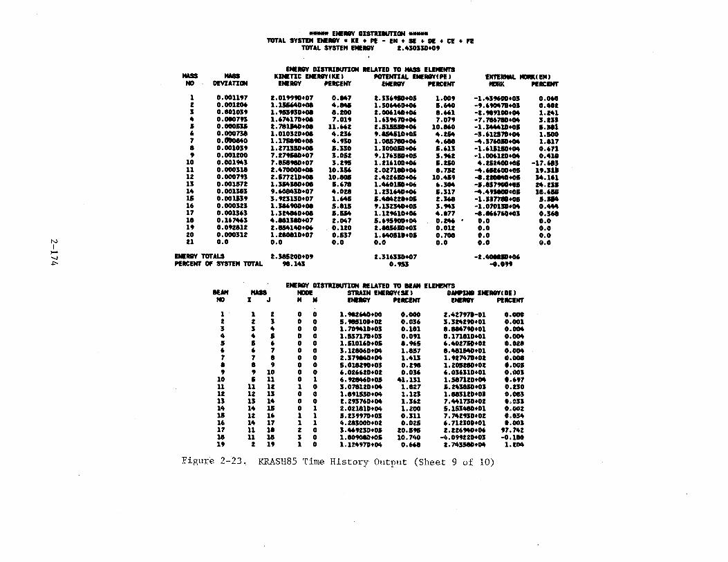
.._ EN!I8Y DJSTRJMITICIN .._ TOTAL SYSTDI ENII8Y • Kl + PI - EM + Sl + 01 + C1! + fl!
TOTAL SYSTEM ENE18Y 2.4JOIJ0+09
ENII5'Y DISTRJ8UTJQN RELATED TO MASS ELEMENT'S MASS MASS KINETIC INE1118YIKE) POTPnlAL INEI5VIPE) ExrEIINAL MORIU EM t
NO DEVIATION ENI!RQY PERCENT ENEI5'Y PERCENT IGIK NRC!Hr
1 0.001197 1.019990+07 O,M7 2.116910+01 1.009 -1.419600+01 0.060 2 0.001206 1.1.156"1)+01 4.MI 1.10M6D+06 S.MO -9.690471+01 0.482 I o.eo1o:st 1.tutiD+OI a.2oo 2. 006140+06 8.661 -2.989100+04 1.241 4 0.000791 1.674170+08 7.019 1.619670+06 7.079 -7. 716710+04 J.2JJ 5 0.000511 2. 711140+08 11.662 2.11U50+06 10.860 -1. 14441D+OI 1.581 6 0.000718 1.010120+01 4.216 9.154510+05 4.ZM -1.612170+04 1.100 7 o.-...o 1.171890+08 4.910 1. 0&5710+06 4.618 -4.176050+04 1.a17 a 0.001019 1.271110+01 5.310 1. 100050+06 .&.613 -1.611110+04 0.671 9 0.001200 7.279AD+07 1.0.&2 9.176310+05 3.962 -1.006120+04 0.418
10 0.001941 7.U8tiD+07 1.29.& 1. 216100+06 .&.ZIO 4.152400+05 -17.611 11 0.000318 2.470000+08 10.156 2.027180+06 8.752 -4.611600+05 19.11S 12 0.000793 2.577210+08 10.805 2.422610+06 10.4.&9 -8.21U40+01 14.161 11 0.001572 1.JMJ80+08 .&.678 1.460110+06 6.104 -1.817900+01 14.111 14 0.001183 9.60MJ0+07 4.028 1. 211640+06 5.117 -4.491800+01 11.651 15 0.001519 1.923110+07 1.645 5.484221+01 2.168 -1.117711+01 1.514 16 0.000121 1.116900+08 5.a15 9 .132140+05 1.941 -1.010110+04 0.444 17 o.001J61 1.124160+08 1.554 1.129610+06 4.877 -8.16670+01 0.161 11 0.167461 4.U138D+07 2.047 5.69.&900+04 0.246 • o.o 0.0 19 o.092a12 2.154140+06 0.120 2.115650+03 0.012 o.o o.o 20 o.ooon2 1.210810+07 0.117 1.640510+05 0.708 o.o o.o
N I
21 o.o o.o o.o o.o o.o o.o o.o )--'
ENI!R8Y TOTALS -....! 2.185200+09 2.116310+07 -2 ....... +06 ~ NIICENT Of SYSTEM TOTAL 98.143 0.955 -o.099
ENEI8Y OISTRJDUTJCIN RELATED TO IIAM ELEMENTS ... MASS NODE STUJN ENER8YI S1 ) DAMIINI EN!II8YI DE ) ND I J M N ENI!I5'Y PERCENT I!N!Il8Y PERCENT
1 1 2 0 D 1.982640+00 0.000 2.427970-01 o.ooo 2 2 I 0 D 5.985100+02 0.016 1.324290+01 0.001 I I 4 0 0 1.709411+01 0.101 a.U4790+01 0.004 4 4 5 0 0 1.517170+03 0.091 a.171810+01 0.004 5 I 6 0 0 1.510160+05 8.965 6.402710+02 o.oza 6 6 7 0 0 1.121060+04 1.857 a.41114D+01 0.004 7 7 a 0 0 2.179840+04 1.411 1.927470+02 o.ooo 8 a 9 0 0 5.018290+03 0.298 1.201210+02 0.005 9 9 10 0 0 6.026620+02 0.016 6.016110+01 0.001
10 5 11 0 1 6.928460+05 41.131 1.587120+04 1.697 11 11 12 1 0 3.078120+04 1.827 5.143850+01 o.zso 12 12 13 0 0 1.891150+04 1.121 1.883120+01 0.083 13 13 14 0 0 2.291760+04 1.162 7.441710+02 o.c:n 14 14 15 0 1 2.021110+04 1.200 5.153480+01 0.002 15 12 16 1 1 1.239970+03 0.311 7.742930+02 0.014 16 14 17 1 1 4.281000+02 0.021 6.712100+01 0.003 17 11 18 2 0 3.469230+05 20.59.& 2.226940+06 97.742 18 11 18 3 0 1.809080+05 10.740 -4.099220+03 -0.110 19 2 19 1 0 1.124970+04 0.668 2.741580+04 1.204
Figure 2-23. KRASH85 Time History Output (Sheet 9 of 10)
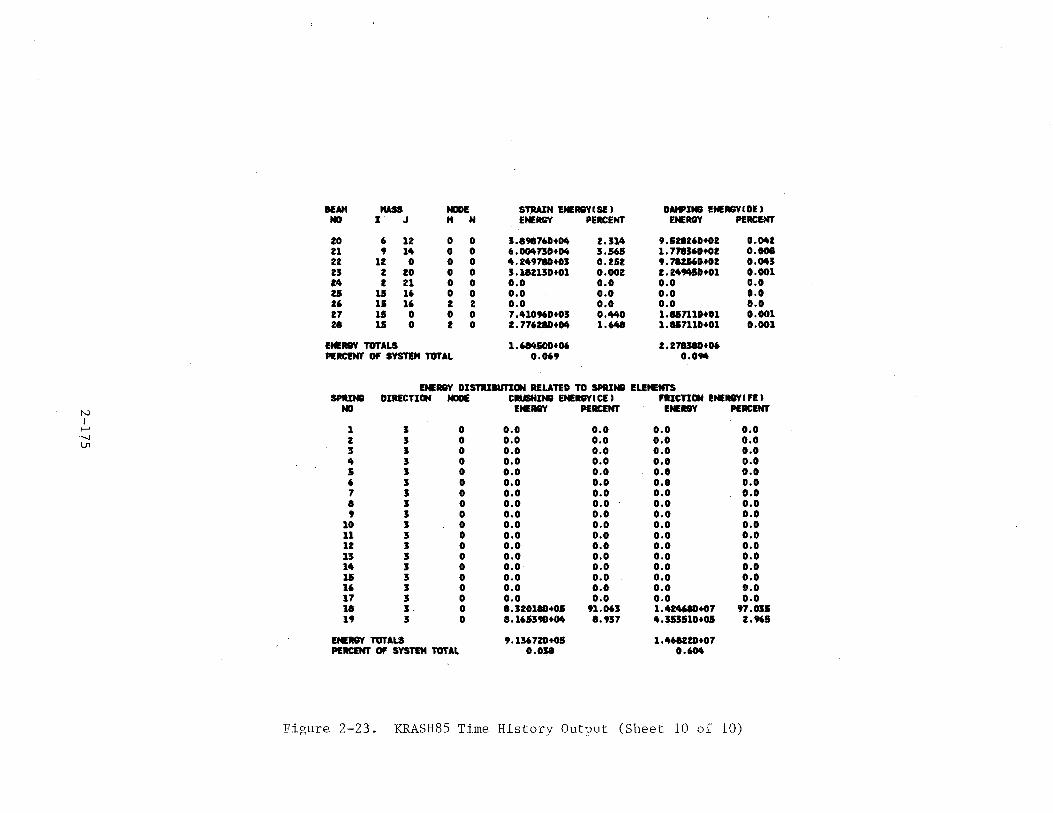
HAM MASS NODE St:fiAIN E.-:15YCSE I DAHPINS ENERGYCDU NO I J M N ENER&Y PERCENT E.-:R&Y PERCENT
20 6 12 0 0 3.89876D+M 2.31. 9.528260+02 O.M2 21 9 1. 0 0 6.00.73D+M 3.565 1. 771160+02 0.008 22 1Z 0 0 0 4.249710+03 0.252 9.71ZJ6Dt02 o.CMJ 23 2 20 0 0 3.182130+01 0.002 2. 24MSD+Ol 0.001 24 2 21 0 0 o.o o.o o.o o.o zs 15 16 0 0 o.o o.o o.o o.o 26 15 16 2 2 o.o o.o o.o o.o 27 15 0 0 0 7.410960+03 0.440 1.e&n1D+Ol 0.001 2t 15 0 2 0 2.77628D+M 1.648 1.857110+01 0.001
EMERGY TOTALS 1.684500+06 2.271380+06 PERCENT Of SYSTE" TOTAL 0.069 O.OM
E.-:RGY DIS11UIUTICIN RELATED TO SPRINiil ELI!~NTS SPIUN8 DIRECTION NODE CIUSHINiil ENERGY( CE I FlliCTICIN I!NERGYC fl! I
N NO 1!.-:AQY PERCENT ENERGY NRCENT I
>--' 1 0 o.o o.o o.o o.o -...,J z 0 o.o o.o o.o o.o V1
3 0 0,0 o.o 0.0 o.o 4 0 o.o o.o o.o o.o 5 0 o.o o.o o.o o.o 6 0 o.o o.o o.o o.o 7 0 o.o o.o o.o o.o 8 0 o.o o.o o.o o.o 9 0 o.o 0.0 o.o o.o
10 0 o.o o.o o.o o.o 11 0 o.o 0.0 o.o o.o 12 0 o.o 0.0 o.o o.o 13 0 o.o 0.0 o.o o.o 14 0 o.o 0.0 o.o o.o 15 0 o.o 0.0 o.o o.o 16 3 0 o.o o.o o.o o.o 17 3 0 o.o o.o o.o o.o 18 3 0 8.320118+05 91.063 1.4Z4618+07 97.035 19 3 0 8.1653911+04 8.937 4.353510+05 2.965
ENEII8Y TOTALS 9.136720+0.5 1.1t68ZZD+07 PERCENT Of SYS~ TOTAL 0.038 0.6M
Figure 2-23. KRASH85 Time History Output (Sheet 10 of 10)
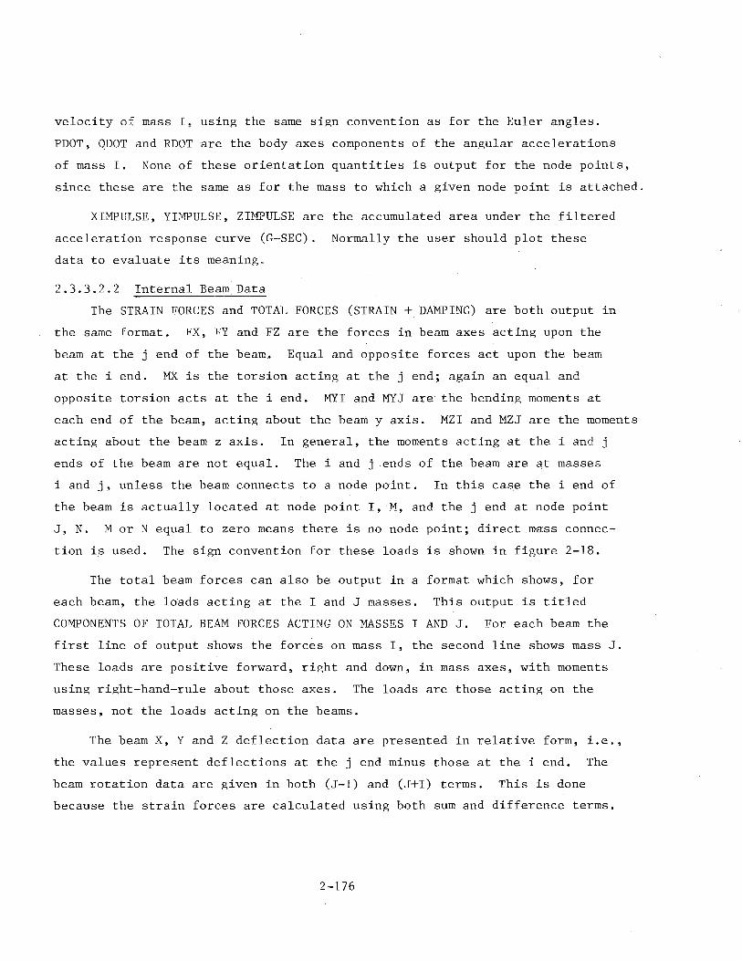
velocity of mass I, using the same sign convention as for the Euler angles.
PDOT, QDOT and RDOT are the body axes components of the angular accelerations
of mass I. None of these orientation quantities is output for the node points,
since these are the same as for the mass to which a given node point is attached.
XIMPULSE, YIMPULSE, ZIMPULSE are the accumulated area under the filtered
acceleration response curve (~-SEC) . Normally the user should plot these
data to evaluate its meaning.
2.3.3.2.2 Internal Beam Data
The STRAIN l<ORCES and TOTAL FORCES (STRAIN + DAMPING) are both output in
the same format. l<X, l<'Y and FZ are the forces in beam axes acting upon the
beam at the j end of the beam. Equal and opposite forces act upon the beam
at the i end. HX is the torsion acting at the j end; again an equal and
opposite torsion acts at the i end. MYI and MYJ are the bending moments at
each end of the beam, acting about the beam y axis. MZI and MZJ are the moments
acting about the beam z axis. In general, the moments acting at the i and j
ends of the beam are not equal. The i and j ends of the beam are at masses
i and j, unless the beam connects to a node point. In this case the i end of
the beam is actually located at node point I, M, and the j end at node point
J, N. MorN equal to zero means there is no node point; direct mass connec
tion is used. The sign convention for these loads is shown in figure 2-18.
The total beam forces can also be output in a format which shows, for
each beam, the loads acting at the I and J masses. This output is titled
COMPONENTS OF TOTAL BEAM FORCES ACTING ON MASSES I AND J. For each beam the
first line of output shows the forces on mass I, the second line shows mass J.
These loads are positive forward, right and down, in mass axes, with moments
using right-hand-rule about those axes. The loads are those acting on the
masses, not the loads acting on the beams.
The beam X, Y and Z deflection data are presented in relative form, i.e.,
the values represent deflections at the j end minus those at the i end. The
beam rotation data are given in both (J-I) and (J+I) terms. This is done
because the strain forces are calculated using both sum and difference terms.
2-176
Note that these angles are all in degrees, rather than radians. If the
actual rotations at the j and i beam ends are desired, they can be calculated
from the output data as
THETA(J)
THETA(I)
Similar equations apply to PSI.
THETA(J+I) + THETACJ-I) 2
THETA(J+I) - THETA(J-I) 2
The beam lateral deflections Y and Z which are printed out are not simply
the (J-I) values. The 8 and ~rotations of mass I cause Z and Y deflections
at end J, which in themselves cause no beam loads. These deflection components
are removed from the output deflections. The output deflections are the
following
y output
z output
(Yj Yi) - 1 ~ i
(Zj- Zi) +1 Si
The Euler angles defining the current orientation of the beam axes are
also output in degrees. The column of integers titled VBM define which beams,
if any, are treated as vertical beams. For vertical beams, VBM=l; for normal
beams, VBM=O. Vor normal beams, the following procedure is used to determine
the current beam axes orientation.
o Start with the ground fixed axis system, with X positive forward, Y positive right and Z positive downward.
o Rotate PSI degrees about the Z axis, using right-hand-rule for positive rotations.
o Rotate THETA degrees about the new rotated Y axis, using right-handrule for positive rotations.
2-177
For vertical beams (VBM=1), the same procedure is used, but the initial
orientation of the X, Y, Z axis is different. In this case, the initial
orientation is X positive up, Y positive right and Z positive forward.
For either axis orientation system, there is actually a final rotation
of PHI about the X axis. PHI is not shown primarily due to output format
line width limitations. However, PHI is normally rather small and will not
affect the user's interpretation of the orientation of the beam axes.
2.3.3.2.3 Exte~nal Spring Data
Por each external spring, the spring compression in inches and compression
load in pounds is output. These are along the spring axis, which is oriented
parallel to one of the mass axes. The ground deflection is also shown; this
deflection will be zero if the ground flexibility is input as zero. The
ground contact point loads are given in two coordinate systems, ground axes
and mass axes. If the spring in question is on a slope, then slope axes are
used instead of ground axes. The output titles for these quantities are self
explanatory.
2.3.3.2.4 DRI and e.g. Velocity Data
Por each beam element which has been defined as a Dynamic Response Index
(DRI) type element, the J mass and DRI number are shown. Volume I, Section
1.3.12 explains the theory and usage of DRI elements.
The overall vehicle e.g. velocities, in ground axes, are always output.
These velocities are calculated such that the total vehicle weight, with
these velocity components, would yield the same linear momentum as that
existing in the total system of NM masses. Section 1.3.9 of Volume I
explains how these values are derived. This output, particularly the time
history ulot of same, is a very useful indicator of the overall vertical
motion of the system. Since the system kinetic energy is a scalar quantity,
there is no way to separate the kinetic energy due to horizontal motion from
that due to vertical motion. Therefore, for analyses in which the horizontal
velocity is much larger than the vertical, system kinetic energy is not very
useful in determining when the vertical impact velocity has been absorbed.
2-178
The vertical component of the overall e.g. velocity can be used for this
purpose.
2.3.3.2.5 Energy Distribution Data
The total system energy is computed for each print time increment by
summing the energy components as following:
TSE = L KE + L PE + L SE + L DE + L CE + L FE - L EW
where
TSE Total System Energy KE Kinetic Energy PE Potential Energy SE Strain Energy DE Damping Energy CE Crushing Energy FE Friction Energy EW External Work
In the above, the kinetic energy, the potential energy and the external work
are summed over the number of masses; the strain energy and damping energy
are summed over the number of beams; and the crushing energy and friction
energy are summed over the number of crushing springs. The total system
energy determined at time zero is used as a reference to evaluate the
acceptability of the numerical integration process used in the analysis.
As long as the total system energy remains within 0.5 percent of the reference
value, the gross effects of the integration process are considered acceptable.
Effects 6f the integration process on ~localized '.regions of the model still
must be evaluated however, see mass energy deviation discussion below. For
analysis cases which do not execute the KRASHIC option, the initial total
system energy is simply the sum of the kinetic energy and the potential energy
at time zero. Vor analyses which do execute the KRASHIC option or which use
an initial condition data set previously generated in a KRASHIC run, the
initial total system energy is the sum of the kinetic and potential energies
at time zero and also the strain energy, the damping energy and the work
associated with any externally applied forces produced while bringing the
model into equilibrium at time zero. Note that the since the energy related
2-179
to the externally applied forces (external work) represents energy which is
added to the system, it must be subtracted from the other energy terms in
the above energy equation in order to maintain the desired energy balance
referenced to time zero.
A summary of the energy components related to mass elements (mass energy
deviation, kinetic energy, potential energy and external work) are tabulated
together. Likewise, energy components related to beam elements (strain energy
and damping energy) and those related to crushing spring elements (crushing
energy and friction energy) are also summarized together for easy reference.
M~ss Element Energies
The mass deviation tabulated in this summary is defined as the variation
in the total energy of each mass from its initial value at time zero, divided
by the initial total energy of the system and expressed as a percentage.
Ideally, the variations should all be zero. In actual practice, however,
errors associated with the numerical integration process result in deviations
from the ideal. The mass deviation values can be used for pinpointing areas
of the model that may be causing numerical accuracy problems and alerting the
program.user to the possible need for a finer integration time step. If the
largest mass deviation occurs in a region of the model that is not of great
interest, the user can elect to accept the inaccuracy indicated by the
deviation. On the other hand, if the deviation occurs in an area that is of
vital interest, the user can use a smaller integration time interval to
achieve the desired accuracy in that region of the model. In typical
applications, a few individual mass energies may deviate 2 to 5 percent
from the 100 percent ideal, while the total energy of the entire system remains
within 0.5 percent or less. This accuracy is generally considered acceptable
for the numerical integration process. However, the program user is free to
adjust the integration time step to suit his or her own personal criterion
for the accuracy of the indivi<iual mass integrations.
The system kinetic energy should reduce to zero at the conclusion of the
analytical run. Prom a practical standpoint, however, one can expect
individual elements to oscillate slightly after the vehicle comes to rest,
2-180
leaving some residual kinetic energy in the system long after the responses
of interest have occurred.
If the vehicle is impacting on a flat surface (no slope) and a substan
tial portion of the initial kinetic energy is due to forward velocity (parallel
to the ground), then a much larger percentage of the initial kinetic energy
may remain after the significant damage phase of the crash. The remaining
energy is accounted for by the vehicle sliding along the ground with a sub-·
stantial forward velocity. In this case, the vehicle e.g. translational
velocities, printed earlier, provide a better indication of whether the major
response phase has been adequately covered. In general, the ZDOT or vertical
vehicle translational velocity should be reduced to zero, indicating that the
vehicle has ceased its downward motion. This situation can also be seen when
the system potential energy reaches a minimum.
The potential energies include only the height effect of the masses
above the ground plane. Positive potential energy results when the mass
element is above the ground plane while negative potential energy results
when the mass element is below the ground plane. This representation is
different than that included in earlier versions of KRASH. In the earlier
versions, the potential energies include both the height effect and the wor!
done by externally applied forces. In the present version of KRASH, the
external work components have been separated from the potential energy
component and are listed separately.
Included in the external work component is the work done by the following
innut external forces and accelerations:
o Applied force time histories defined by cards 3400 - 3500
o Applied acceleration time histories defined by cards 3400 -r'3500
o Aerodynamic forces defined by card 3100
Positive external work results when the applied external force acts in the
same direction as the net deflection increment of the mass element while
ne~ative external work results when the applied external force and net
2-181

deflection increment act in onposite directions.
Beam Element Energies
The individual internal beam strain energies provide the user with
valuable insight into the temporal and spatial flow of energy in the vehicle.
Generally speaking, the strain energy concentrates initially near the point
of imnact, and as the strain energy grows it also becomes diffused throughout
the vehicle. After the peak responses in the system occur, the overall system
strain energy will decrease from its peak value as the internal beam elements
unload.
Certain individual nonlinear beam elements may indicate negative strain
energy. This circumstance may occur when large deflection loading and unload·
ing occurs in the coupled bending degrees of freedom (z-Oor y-~), with non
linear KR curves applied to these directions. This phenomenon is discussed
in Section 1.3.16 of Volume I, and is due to the approximate nature of the
nonlinear element analytical model. In practice, these negative strain
energies are of such small magnitude relative to the overall system strain
energy (usually less than 1 percent) that they do not invalidate the overall
analysis. Furthermore, these negative energies tend to occur toward the end
of the analysis, during the unloading phase, after the primary responses and
damage of interest have been determined. The plastic hinge option should be
used in lieu of KR tables in the counled bending directions; negative strain
energy will not occur with the plastic hinge oPtion. It should also be noted
that negative strain energy does not occur for linear beam elements, or for
those that are nonlinear only in the uncoupled degrees of freedom (axial and
torsion).
The damping energy of the internal beams is usually small in relation
to the strain energy, typically being less than 20 percent of the strain
energy, until late in the run when the strain energy has decreased substan
tially from its neak value. Note that damping energy always increases with
time, since it is a dissipative energy that is not stored and released as
with strain energy.
2-182
Crushing Spring Element Energies
Crushing and friction energies result from the deformation of the
external springs and flexible ground for the former, and from sliding fric
tion along the ground for the latter. The friction energy is also dissipative
and hence monotonically increasing, whereas the crushing energy peaks and
decreases similar to the strain energy. In general, a rather large percen~age
of the total system energy may be represented by the crushing energy. This
situation is only natural since the external springs represent the structure
in immediate contact with the ground that undergoes substantial deformation.
In a typical vehicle crash analysis, the system crushing energy may be larger
than the internal beam strain energy. However, they both represent actual
airPlane structure, the only distinction being location on the vehicle.
2.3.3.2.6 Internal Beam Stress Data.
The stress data output are shown in figure 2-24, which is taken from
the t = 0 output of the sample case. ~Stress data output was not selected for
the sample case, so none was output at t = 0.5 used for figure 2-23. At time
zeuo, all output is printed regardless of what the user requests).
This output consists of ratios of current stress to failure level stress
(corresponding to initial yielding), for four locations on each beam, using
two failure theories. These theories are the maximum shear stress theory and
the theory of constant energy of distortion. Section 1.3.17 of Volume I pre
sents the method of calculating these ratios. Also shown in the output are
the ratios of current compressive/tensile stress to the corresponding yield
stress, and the ratio of current axial compressive load (when it is compressive)
to the critical buckling load.
The stress data can be used as a guide for estimating the time at which 1
the element begins to yield. vThen such a state is reached, a stiffness reduc·-
tion factor (KR) may be developed for the affected member which then can be
used to approximate the nonlinear response characteristics of that member.
The user is cautioned to exercise extreme care in the interpretation of data
presented in the summary since they do not include the effect of stress con-
2-183
centrat~ons, geometric shape factors, and detail attachment practices at ioints.
In addition, limitations of the program require that gross regions of the
vehicle structure be modeled using relatively simple number of structural ele
ments. Thus, the more gross the structural region the less accurate the stress
values. Also monitoring the response of a structural element which may exhibit
a buckling mode of failure will require special consideration. In this case
the critical buckling load becomes significant and a stiffness reduction
factor should be developed which will approximate the buckling characteristics
of the element.
Furthermore, the user should realize that once an element has yielded or
buckled, the failure theories followed become invalid and., consequently, the
most meaningful use of the stress data is to identify which element may fail
and at what point in time such failures are apt to occur.
2.3.3.2.7 Initial Mass Acceleration Error Output
Figure 2-24 shows this output for the sample case. This information is
only output at time zero, and has significance only if balanced initial con
ditions are used (KRASHIC and MSCTRN,l are used to calculate balanced internal
beam loads). For each mass in the system, the difference between the actual
time zero acceleration calculated in KRASH85 and the theoretically correct
value, based on airplane rigid body accelerations at time 3ero, is printed.
A summary at the bottom shows the largest value and corresponding mass number
for each of the siK accelerations.
The reason that the time zero accelerations are not "exactly" equal to
the theoretically corre~t val~es is b~ca~se the accuracy of the KRASHIC/MSCTRAN
iterations is limited by the number of significant figures used in the input
and output data sets used with NASTRAN. The accuracy shown in figure 2-24 is
reoresentative of a typical large transport airplane model, using ten itera
tions of KRASHIC/NASTRAN. In general the results are quite good, with most
translational accelerations accurate to within E-5 g's. Errors of this order
should have no appreciable influence on the subsequent time history results,
particularly for crash impacts which typically involve mass accelerations of
2--184
N I
....... 00 \.J1
H£1i!EN'f $TI!e$S£S
RATlO Of CUR~ENT STRESS / FAILURE SfRFSS RAfiO OF CURKENT llEAM KAXIi'IJM SHEAR STRESS Tll£0ffi THEORY Of CONSTANT ENEiWY OF D!STOI!TX0N lX!Al/fAILURf
X,l ! J 11 N TOP £\OTTOI"i lEfT RIGHT TOP OOTTI.ll'i LEFT RIGHi
1 1 z 0 0 6.6360-03 6.6370 .. 03 3.9810-03 3.9810-03 6.4470-03 6.6370-03 3.4470-03 3.4470-03 2 2 3 0 0 7.0810-02 7.1730-02 2.6530-0?. 2.6530-0Z 6.8700-0Z 7.1730-02 2.2981)-02 2.1!'980 .. 02 3 3 4 0 0 1.0920 .. 01 1.0950-0l 5.8580-0Z 5.8580-0~ 1.0600-01 1.0950-01 5.0730-02 S.O?J0-02 4 4 5 0 0 1.4620-01 1.4700-01 4.77?0-02 4.7790-02 1.4ZOll-01 1.4700-01 4.1390-02 4.1390-02 5 5 b 0 0 Z.69f>D··Ol !.1810-01 4.5870-0Z 4.5870-02 2.61?0-01 3.1810 .. 01 4.1530-02 4.1530-0Z 6 6 ., 0 0 2.43ZO-Ol 2.1520-01 6.6160-02 6.6160-0Z 2.3620-01 2.9520-01 5.8750-02 5.8750-02 7 7 8 0 0 2.2410-01 2.9210-01 5.5680-02 5.5680-02 Z.l77D-01 2.9210-01 5.1130-02 5.1130-02 a 6 9 0 0 1.4660-01 2.3560-01 4.9600-02 4.9600-02 1.4240-01 2.3560-01 4.8390-02 4.8390-02 9 ' 10 0 0 7.5630-02 8.6090-02 8.1660-02 8.1660-02 7.3470-02 8.6090-02 7.0770-02 7.0770-0Z
10 5 11 0 1 1.0520-01 1.2090-01 9.2390-02 9.1100-02 8.9790-02 1.0680-01 8.1450-02 8.0010-02 ll ll 12 1 0 5.3570-02 8.1Z50-02 6.1560-02 5.8850-02 4.8020-0Z 7.6330-02 5.7970-02 5.5250-02 12 12 B 0 0 1.7000-02 5.1180-02 4.0830-02 3.9440-02 1.5280-02 4.9180-02 3.5940-02 3.4440-02 13 13 14 0 0 2.5260-02 3.8310-02 3.4590-02 2.4080-02 2.3430-02 3.6500-02 3.3300-02 2.2960-0£ 14 14 15 0 1 2.1410-Gl 1.9920-01 1.1060-01 8.1150-02 1.8810-01 l. 7190-01 1.07!0-01 7.8600-02 15 12 16 1 1 1.4460·02 1.4360-02 4.Z760-0Z 4.2750-02 1.3530-02 1.6200-02 3.4680-02 4.1790-02 16 14 17 1 1 1.3600-02 1.3640-02 4.0830-0Z 4.0840-02 1.2740-02 1 . .5390-02 3.3120-0Z 3.9920-0Z 17 11 18 z 0 1.9970+00 1.9970+00 1.9970+00 1.9970+00 1.9970+00 1.9970+00 1.9970~0 1.9970+00 18 11 18 3 0 5.18ZO-Ol 5.1820-01 5.1790-01 5.1800-01 5.1800-01 5.1810-01 5.1780-01 .5.1790-01 19 2 19 1 0 3.0960-01 3.0940-01 3.0970-01 3.0970-01 3 •. 0960-01 3. 0940-01 3. 0960-0l 3. 0960-01 20 6 12 0 0 4.0750-0Z 1.3700-02 1.8000-02 2.1390-02 4.0360-02 1.2130-02 1.7000-02 2.0550-02 21 9 14 0 0 1.1830-02 6.8650-02 4.1330-02 4.1330-02 1.1500-02 6.6690-02 3.9890-02 3.9890-02 22 12 0 0 0 5.8920-02 3.0650-02 4.5800-02 4.3780-02 5.8920-02 3.0650-02 4.5800-02 4.3780-02 23 2 20 0 0 1.3470-01 1.4620-01 1.4050-01 1.4050-01 2.8610-01 3.1060-01 2.9850-01 Z.9850-01 24 2 21 0 0 4.1790-07 4.Z020-07 4.1910-07 4.1910-07 8.8810-07 8.9300-07 8.9060-07 8.9060-07 25 15 16 0 0 0.0 0.0 0.0 0.0 o.o 0.0 0.0 o.o 26 1.5 16 2 z 0.0 0.0 o.o 0.0 0.0 0.0 o.o o.o 27 15 0 0 0 6.7950-03 6.7950-03 1.9570-03 1.9570-03 6.7950-03 6.6010-03 1.9570-03 1.9010-03 28 15 0 2 0 1.1980-01 1.0620-01 1.1490-01 1.1100-01 1.1960-01 1.0620-01 1.1490-01 1.1100-01
DIFFERENCE aETNEEN ACCELERATIONS AT T=O AND RIGID BODY ACCELERATIONS FOR 8ALAHCEO INITIAL CONDITIONS C FROI'I SUBROUTINE NETFOR I UNITS AlE G-S AND RAO/SEC-sq C LARGEST VALUES SHOI'tf AT 80TTOI1 EXCLUDE ORI HASSES I
HASS
1 2 3 4 5 6 7 8 9
XACC
-5.7852180-06 2.8571900-06 7.8005290-07
-2.16.50150-06 7.1128400-06
-6. 13 71870-05 3.8429150-05 2.2247390-04
-1.0243380-03
YACC
o.o 0.0 o.o o.o 0.0 0.0 0.0 o.o 0.0
ZACC
7.4488860-04 -1.2787840-04 -3.0187950-05 4.0481160-05
-4.0514660-0.5 -3.5158690-04 5. 8112710-04
-2.1723630-04 2.4881370-04
-1.7166710-04
o.o 0.0 0.0 o.o o.o o.o o.o o.o 0.0 o.o
POOT qoQT
1.4620680-03 2. 4024600-04
-1.5983500-04 -1.4593960-04 -4.5724050-04 -1.5275420-03 1.3764800-05 4. 2898340-04 1.2835770-03 1.0815960-03
ROOT
0.0 0.0 o.o 0.0 o.o o.o o.o 0.0 0.0 0.0
Cct!l>R. STRESS
1.8730-07 4.6.250-(!4 1.8130-04 3.8980-04 2 .4u.o .. o~ 2.6000·02 3 .4010·-02 4.4MD-OZ .S.USIHH
l.3761HI5
1.5690-02
4.4790-02 2.9840-01 8.9060-07 o.o o.o 0.0 1.1300-01
10 11 12
9.1935990-0.5 -2.3239220-05
o.o 2.4686120-05 -4.7529240-05 -8.7091680-05
1.2384060-03 -3.2347510-04 -1.0984190-05
-2.6761070-05 -1.6118370-04 -6.1144380-05 -6.7269710-0S -3.2164170-0!1
Figure 2-24. KRASH85 Internal Beam Stress Data and Initial Mass Acceleration Error Output (Sheet 1 of 2)
TENStLf ZTRI:SS
4.7540-02 5.0560 .. 02 1.'1810-0Z 2.7000-02 9.2360-02 4.4900-05
1.9970+00 5.1760-01 3.0950-01
3.9090-02
BUCK. / CR.BOCK.
LOAD
~.8470-10 1. 7140-06 6.9160-07 3.4110-06 1. 0470-04 2.8750-05 1.1740-04 2.2690-04 5.4420-05
8.1750-07
4.7040-03
2.3190-02 9.7540-03 1.8900-08 o.o o.o 0.0 3.5530-01
N I ......
00 0\
13 2. 1134.590-04 5.8764420-04 1.84.54550-04 8.4142810-04 9.1677460-05 14 -5.4071400-05 -1.8342970-03 -2.7599070-04 -4.2652980-03 8.3622520-04 15 6.5852940-04 1.4230720-03 2 . .5432420-04 1 • .548.54£0-02 -3.4370490-04 16 2.0963020-05 -1.2601480-06 a. 36777£0-06 -1.3025550-04 -7.2319590-05 17 -1. 0414890-05 -3.236!5330-06 3.2085620-05 1.9839740-05 4.2731010-04 18 -1.2570790-06 9. 4303190-06 2.9269050-04 1. 6509890-03 3.6469340-05 19 -3.1295070-06 0.0 4. 0355050-04 o.o 1.87905£0-05 20 1.2124580-06 o.o 3.0285570-07 0.0 -2.3184460-06 21 -1.5221010-02 0.0 9.9988230-01 o.o -3.8758460-08
LARGEST VALUE 1. 0243380-03 1.8342970-03 7.4438860-04 1. .548.54£0-02 1. 527.5420-03
MASS NO. 9 14 1 15 6
Figure 2-24. KRASH85 Internal Beam Stress Data and Initial Mass Acceleration Error Output (Sheet 2 of 2)
-2.74749£0-04 -1.5365170-04 -2.5049030-03 -1.1337930-05 4.0470530-0S
-1.3425420-06 o.o o.o 0.0
2.5049030-03
15
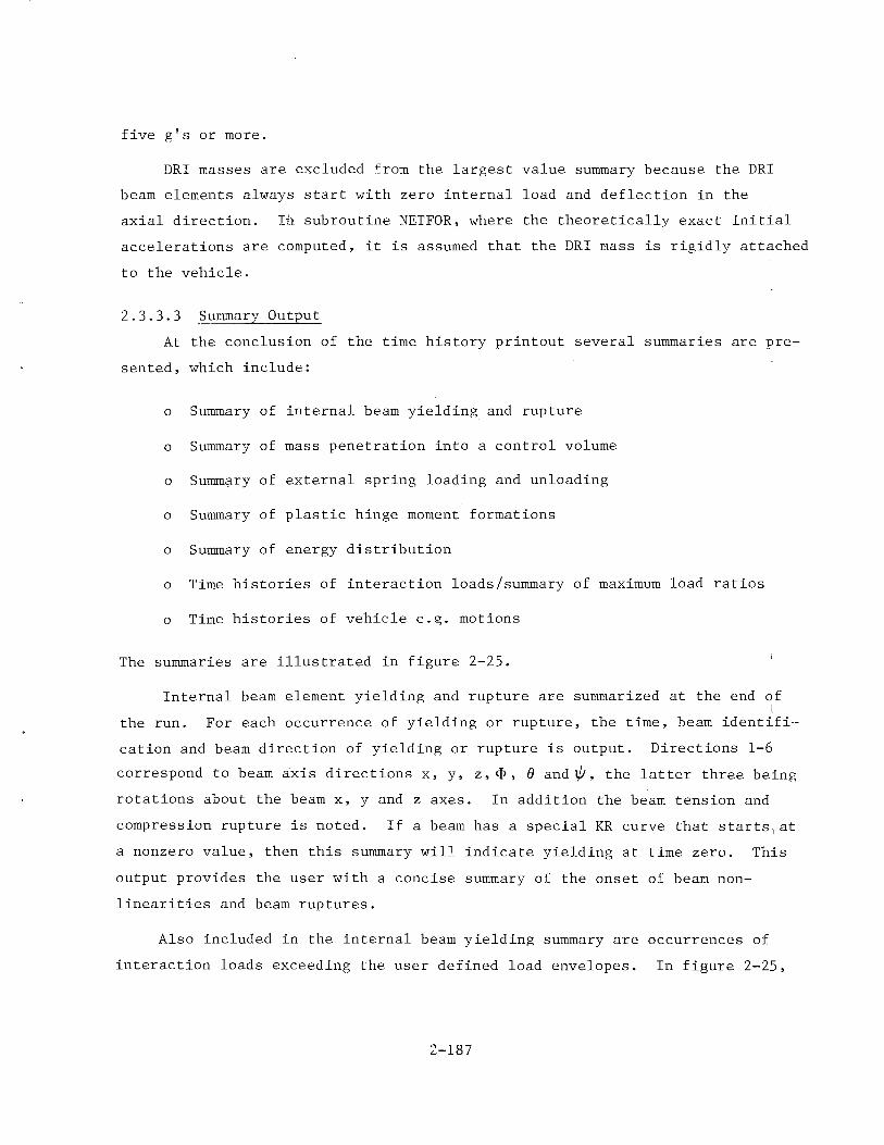
five g's or more.
DRI masses are excluded from the largest value summary because the DRI
beam elements always start with zero internal load and deflection in the
axial direction. Ih subroutine NETFOR, where the theoretically exact initial
accelerations are computed, it is assumed that the DRI mass is rigidly attached
to the vehicle.
2.3.3.3 Summary Output
At the conclusion of the time history printout several summaries are pre
sented, which include:
o Summary of internal beam yielding and rupture
o Summary of mass penetration into a control volume
o Summ?ry of external spring loading and unloading
o Summary of plastic hinge moment formations
o Summary of energy distribution
o Time histories of interaction loads/summary of maximum load ratios
o Time histories of vehicle c.~. motions
The summaries are illustrated in figure 2-25.
Internal beam element yielding and rupture are summarized at the end of
the run. For each occurrence of yielding or rupture, the time, beam identifi
cation and beam direction of yielding or rupture is output. Directions l-6
correspond to beam axis directions x, y, z, ~. e and~' the latter three being
rotations about the beam x, y and z axes. In addition the beam tension and
compression rupture is noted. If a beam has a special KR curve that starts1at
a nonzero value, then this summary will indicate yielding at time zero. This
output provides the user with a concise summary of the onset of beam non
linearities and beam ruptures.
Also included in the internal beam yielding summary are occurrences of
interaction loads exceeding the user defined load envelopes. In figure 2-25,
2-187
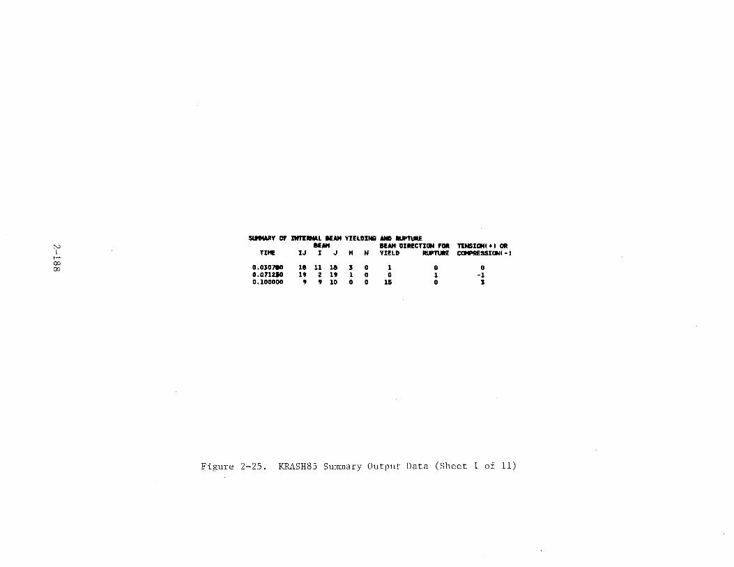
S&MWIY Of Dn'ERNAL lEAH YIELDING AND llUPl\IRE N BUtt BUtt DIRECTION FOI TENSIONI + I OR I TII1E IJ I J " N YIELD AUPTURE CCMtRESSIONI - l .~
00 0,030780 18 11 18 3 0 1 0 0 00 0.071210 19 2 19 1 0 0 1 -1 0.100000 9 9 10 0 0 15 0 3
Figure 2-25. KRASH85 Summary Output Data (Sheet 1 of 11)
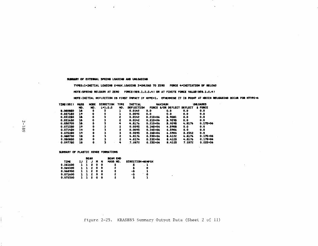
SIMt&RY OF EKTI.UL SPR!N8 LOADIN8 AND t.NLOAD!N8
TYPISJ1•!N!TIAL LOADINa 2t:HAX.LOAD!NI'II 3"'-'fLOAD TO ZERO FoacE "•INITIATION Of HLOAD
NOTE1SPR!NI RfLOADS AT ZERO FORCEISEII.1,2,3,41 OR AT FINITE FoacE YALUIISEII.l,Z,41
NDTE1!NITIAL DEFLECTION IS FIRST ! .. ACT IF NVPE•1, OTHERM!SE IT IS POINr AT tlf!CH Rl!l.OAtiNB oca.. FOil NTYPE~
T!MIISECI KUS NODE DIRECTION TYPE INITIAL tw<!tl.lt lH.OADED NO. NO. L=1,2,3 NO. DEFLECTION FORCE &/OR DEFLECT DEFLECT I FORCE
t.IIOOIIO 18 0 J 1 0.0142 o.o o.o o.o o.o 0.017110 19 0 5 1 0.0093 o.o o.o o.o o.o 0.031210 18 0 3 2 0.0142 0.210+06 5.9281 o.o o.o
N 0.051650 18 0 3 2 0.0142 0.210+06 5.9295 o.o o.o I 0.050700 18 0 3 • 4.1176 0.210+06 5.9291 ft.l176 0.170+06
"""" 0.071350 19 0 3 2 0.0093 0.140+06 6.5908 o.o o.o CXl 0.071450 19 0 3 2 0.0093 0.140+06 6.5906 o.o 0.0
'" 0.075250 19 0 3 3 0.0093 0.140+06 6.5906 5.1342 o.o 0.080700 18 0 3 2 4.1176 0.330+06 1.4122 4.1176 0.170+06 0.080850 18 0 3 2 4.1176 0.330+06 1.4115 4.1176 0.170+06 0.097750 18 0 3 4 7.2872 0.330+06 1.4125 7.2872 O.Z2D+06
SUIWtY OF PLASTIC HINGE FORMATIONS
lEAH BEAHENO TIHE IJ I J " N KUS NO. DIRECTION-HEMP IN
0.061600 1 1 2 0 0 z 5 1 0.064300 1 1 2 0 0 2 5 0 0.068900 1 1 2 0 0 2 -5 1 0.071600 1 1 2 0 0 2 -5 0 0.071500 1 1 2 0 0 I 5 1
Figure 2-25. KRASH85 Summary Output Data (Sheet 2 of 11)
- TEtiiORAL ENERGY DISTRIBUriON SlHfARY -TOTAL SYSTEM ENERGY • KE + P£ - EN + SE + DE + CE + FE
MMMMMMMMM PERCENT ENERGY DISTRIBUTION SUHHARY •••••••••
TIME PERCENT PERCENT PERCENT Of CWRENT TOTAL SYSTEM ENERGY HAX!tUf TOTAL - - - - - - - - - - - - - - - - - - - - - -- - -- -- - - -- - - - - - - --
HASS . SYSTEM KINETIC POtENTIAL EXTERNAL STRAIN D»>IIN8 CIIJSHIN8 FRICTION DEVIATION ENERGY IKE I IP£1 NDRIUENI ISEI IDE I ICE I I FEI
o.o o.o 100.000 98.943 1.063 0.021 0.015 o.ooo o.o o.o 0.01000 0.012838 100.000 98.119 1.040 -o.oo. 0.015 o.ooo o.ou O.MO 0.02000 0.034519 100.001 98.750 1.018 -0.029 0.017 o.oos o.o:ss 0.147 0.03000 0.081947 100.001 98 • .558 0.995 -o.ou 0.029 0.017 0.051 0.296 0.04000 0.140086 100.004 98.351 0.974 -0.077 0.049 0.048 0.045 0.456 0.05000 0.167463 100.004 98.145 0.953 -0.099 0.069 0.094 O.DM 0.604 0.06000 0.204250 100.004 97.930 0.933 -0.120 o.oa2 0.111 o.oJt 0.763 0.07000 0.569966 100.004 97.652 0.913 -o.139 0.080 0.140 0.090 0.985
N 0.08000 0.985395 100.005 97.352 0.895 -0.158 0.079 0.169 o.uz 1.136
I 0.09000 0.985394 100.006 97.069 0.878 -0.176 0.096 o.ns 0.096 1.472 '~ 0.10000 0.985394 100.005 96.835 0.861 -0.193 0.125 0.248 0.087 1.611 1..0 0
••••••••• ENERGY DISTRIBUTION SUHNARY •••••••••
TIME TOTAL ENEil&Y CCHICINENT SYSTEH - - - - - - - - - - - - - - -- - - - ---- - - - - - - - - - - - - -- --- - --- - - - -ENERGY KINETIC POTENTIAL EXTERNAL STRAIN OMI'IN8 CIUSMIN8 FRICTION
IKEl I PEl NDRKCENI CSEI IDE I ICE) fFE)
o.o 1.430220+09 2. 40454E +09 2.58379!+07 5.16481E+05 3.56038£+05 1.25251E-10 o.o o.o 0.01000 1.430231+09 2. 403241! +09 2.52795£+07 -9.05402E+04 3.581186£+05 5.54100!+03 2.88416!+05 9.69700E+05 0.02000 1.430240+09 1.3998.&E+09 2.47285!+07 -6.91591E+05 4. ZZZOJE+OS 1.14150Et05 a.JJ447E+OS J,J749!1E+06 0.03000 2.430270+09 2.39523E+09 Z.41901E+07 -1.28923£+06 6.M896E+05 4.21836E+05 1.14546!+06 7.19JOOE+06 0.04000 2.430310+09 1.390241!+09 2.36692!+07 -1. 86155E +06 1.191711+06 1.17161E+06 1.09362E+06 I.I07UE+07 0.05000 2.430330+09 1.3852DE+09 2.3163SE+07 -2 .... +06 1. 68410E +06 2. Z78JIE +06 9.13672E+OJ 1.46822E+07 0.06000 2.430320+09 2.38001E+09 2.267241!+07 -Z.91209Et06 1.98USE+06 2. 941191 +06 1.UOOR+06 1.813451+07 0.07000 2.430330+09 2.3n2••o9 2.21996E+07 -S.38520E+06 1. 95149E +06 3.48312E+06 2.1161U+06 2.39270!+07 0.08000 2.430310+09 z. 361991+09 2.17513£+07 -3.837891!+06 1.92903!+06 4.10010!+06 1.710541+06 3.00339!+07 0.09000 2.430360+09 2.55913!+09 2.13277!+07 -4.27528!+06 Z .32709Et06 5.186141!+06 z.5387JE+06 3.57727!+07 0.10000 2.430350+09 2. 3534SE +09 2.09247!+07 -4. 70094!+06 S.OSllt7E+06 6. OZUJ!t06 2.12123£+06 4.01212!+07
Figure 2-25. KRASH85 Summary Output Data (Sheet 3 of 11)
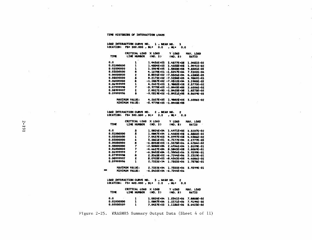
N I -\,0 -
-
TIMI! HISTIIUIS OF INTERACTION LOADS
LQAII INTERACTION CURVE NO. 1 , lfAM NO. 1 LOCATION: FS• 300.000 , IL• 0.0 , .... 0.0
CRITICAL LOAD )( LOAD Y LQAII tiAX •. LOAD TIME LINE tuei!R IND. J) IND. I) RATIO
0.0 0.01000000 0.02000000 0.03000000 O.OltOOOOOO o.osoooooo 0.06000000 0.06999999 0.07999998 0.08999997 0.09999996
1 1 1
• 2 I
• 1 7 2
• tiAXIIUt VALUE 1 MlNIIUt VALUE 1
1.44561+03 1.4177E+O& 1.0411E•OZ 1.4104E+03 1.4605E+OI 1.0491E•02 1.2069E+03 1.1831E+O& 9.1381E•03 4.1Z70E+01 -1.5247E+04 7.J302E-04 5.1026E+OZ -7.15Z6E+04 4.638f)E-03 I.Z173E+02 -7.3250E+03 4.9502E-03
-1.ZI57E+OZ -7.05121+04 3.3900E-OJ 4.Z607E+03 1.9112E+OS 2.5770E•02
-S.9770E+03 -1.1445E+OS J.6006E•02 2.8527E+03 -1.84ZOE+OI 1.1375E-02
-9.0519E+02 -1.8431E!OI 8.1609E-03
4.2607!+03 1.98121+05 3.6006E•02 -5.9770E+03 -1.8445E+OS
LOAD INTERACTION CURVE NO. 2 , lfAM NO. 2 LOCATION: FS• 300.000 , BL= 0.0 , Hl" 0.0
CRITICAL LOAD )( LOAD Y LOAD tiAX. LOAD TIME LINE tuei!R IND. 3) IND. SJ RATIO
o.o 0.01000000 o.ozoooooo 0.03000000 0. OltOOOOOO 0.05000000 0.06000000 0.06999999 0.07999998 0.08999997 0.09999996
5 5 1 6
• 7 7 7
• z 1
HAXIIUt VALUE 1
MlNIIUt VALUE :
1.0124!+04 1.4971E+OI 6.5207E-OZ 1.0117E+04 1.4650E+OS 6.511ZE-02 7.0437!+03 4.0997E+OS 4.4386E•02 3; ZI61E+01 4. 7377E +04 2. 2777E ·03
-6.10321+03 -1.J47SE+06 6.4714!-02 -Z.SOIOE+04 2.6356E+04 1.5109E-01 -4.66Z7E+04 5.384JE+os z.aoa9E-o1 -6.54021+04 -1.38061+06 3.9399E-01 2.5365E+02 -6.7244!+06 3.2329E-01 5.0925E+03 -8.4343E+05 4.4016E-OZ Z.7333E+04 1.75Z3E+06 1.7571E-01
2.7333£+1)4 1.75Z3E+06 3.9399E-01 -6.540ZE+04 -6.7244!+06
LOAD INTERACTION CURVE NO. 3 , BEAM NO. 2 LOCATION: FS• 400.000 , BL• 0.0 , NL• 0.0
CRITICAL LOAD X LOAD Y LOAD HAX. LOAD TIHE
o.o 0.01000000 0.02000000
LINE tuei!R IND. 3) IND. 5) RATIO
1 1 1
1.0124!+04 1.2341E+06 7.8108E-OZ 1.0187!+04 1.2371E+06 7.91~-02 7,0437E+03 1.1156!+06 5.6423E-OZ
Figure 2-25. KRASH85 Summary Output Data (Sheet 4 of 11)
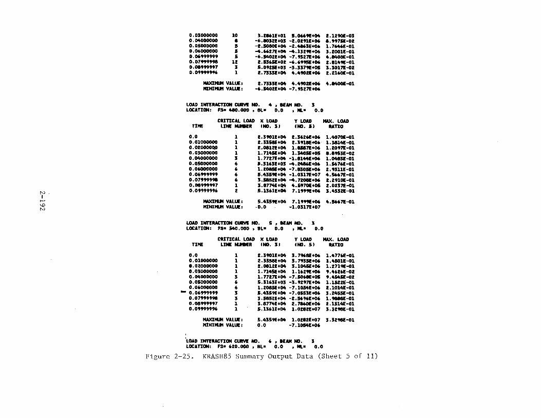
f'-)
I ..... \0 N
0.03000000 0.04000000 0.0.5000000 0.06000000 0.06999999 0.07999998 0.08999997 0.09999996
10
• 5 5 5
lZ 3 1
NAXII'UI VALUE 1 MINII'UI VALUE 1
3.t861E+01 1.0669E+~ 2.1290E-03 -6.10J2E+OJ -1.01911+06 •• 99711-01 -t.SOSOE+~ -2.4863E+06 1.76461-01 -..6627E+~ -..1329E+06 3.2001E-01 -6.5402E+~ -7.9327!+06 4.8400€-01 1.1365E+OI -6.6995E+06 2.8149E-01 J,0925E+03 -3.3379E+OI 3.3017£-02 2.7333!+~ 4.49021+06 2.2160£-01
2.733SE+04 4.4901!+06 4.84001-01 -6.54021+~ -7.9327£+06
LOAD INTERACTION CURYE ND. 4 , lEAH ND. 3 LOCATION: FS• 410.000 , IL• 0.0 , ML• 0.0
CRITICAL LOAD X LOAD Y LOAD tw<. LOAD IND. II RATIO TIME LINE fUe!R IND. J)
o.o 0.01000000 0.02000011.0 0.03000000 o.~oooooo 0.05000000 0.06000000 0.06999999 0.07999998 0.08999997 0.09999996
1 1 1 1 3 6 6 6 6 1 2
NAXII'UI VALUE 1
MINII'UI VALUE 1
2.3901E+~ 1.36261+06 1.4070E-G1 2.3358E+~ 2.3918E+06 1.38141-01 2.08121+~ 1.&117£+06 1.2097£-01 1.714SE+~ 1.340SE+05 8.8953£-02 .1.7727£+~ -1.81441+06 1.~JE-01 S.3163E+03 -4.2486E~06 1.56761-01 1.2081(+04 -7.83011+06 2.9311E-01 J,4359E+04 -1.0317!+07 4.S667E-01 3.1&521+~ -4.7208E+06 2.29101-01 3.8774E+O. 4.S970E+OS 2.0237!-01 S.1361E+04 7.1999E+06 3.43321-01
5.4319E+04 7.1999E+06 4.5667£-01 -0.0 -1.0317!+07
LOAD INTERACTION CURVE ND. 5 , lEAH ND. 3 LOCATION: FS• 540.000 , IL• 0.0 , ML• 0.0
CRITICAL LOAD X LOAD Y LOAD twc. LOAD TIHE LINE tUISER IND. 31 IND. 51 RATIO
o.o 0.01000000 0.02000000 0.03000000 0.04000000 o.osoooooo 0.06000000
- 0. 06999999 0.07999998 0.08999997 0.09999996
1 1 1 1 3 6 6 3 3 1 1
tw<II'UI VALUE 1
HINII'UI VALUE 1
2.39011+04 3.7968E+06 1.47761-01 2.3358E+~ 3.7935E+06 1.4501E-01 2.0812E+04 3.104SE+06 1.2719E-01 1.7145E+04 1.1629E+06 9.46261-02 1.7727!+04 -7.5068E+05 9.4&451-02 5.3163E+03 -3.9297!+06 1.15221-01 1.2081(+04 -7.10&4E+06 2.10141-01 5.4359E+04 -7.0153E+06 3.245SE-01 3.1&521+04 -2.16961+06 1.9888!-01 3.87741+04 2.7860E+06 2.15141-01 5.1361E+04 1.0282!+07 3.32981-01
5.4359E+~ 1.02821+07 3.3298E-01 o.o -7.1054E+06
'LOAD INTERACTION CURYE ND. 6 , lEAH ND. 3 LOCATION: FS• 620.000 , IL• 0.0 , ML= 0.0
Figure 2-25. KRASH85 Summary Output Data (Sheet 5 of 11)
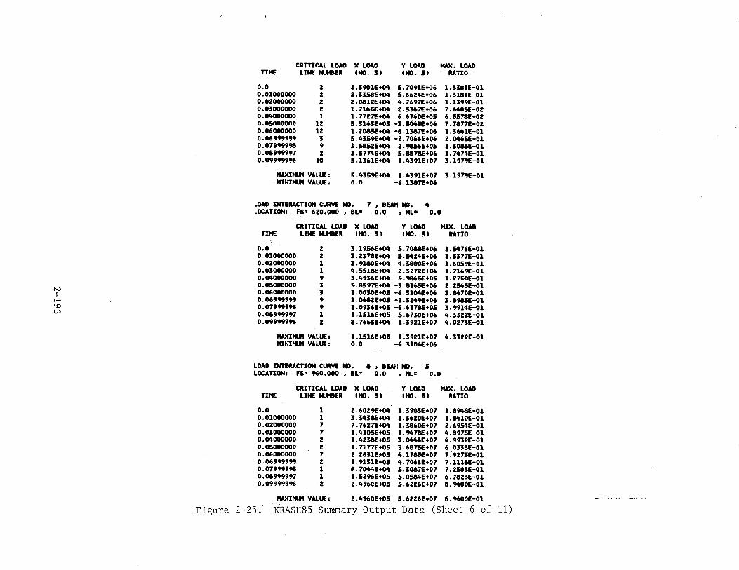
N I >~
\0 w
CRITICAL LOAD X LOAD Y LOAD twC. LOAD TIME LINE IU"BER INO. 3) INO. 5) RATIO
o.o 0.01000000 0.02000000 0.03000000 0.0.000000 0.05000000 0.06000000 0.06999999 0.07999998 0.08999997 0.09999996
2 2 2 2 1
12 12
3 9 2
10
HAXItUt VALUE: HINitUt VALUE:
2.3901E+04 5.7091E+06 1.3381E-01 2.3358E+04 5.662~+06 1.3181E-01 2.0812E+04 4.7697!+06 1.1399E-01 1.714SE+04 2.5347!+06 7.6405E-02 1.7727!+04 6.6760E+05 6.5S78E-02 5.3163E+03 -3.5045E+06 7.7877E-02 1.208SE+04 -6.1387!+06 1.3641E-01 5.4359E+04 -2.7066E+06 2.0465E-01 3.5852E+04 2.9856E+05 1.308SE-01 3.8774E+04 5.8878E+06 1.7474E-Ol 5.1361E+04 1.4391E+07 3.1979E-Ol
5.4359E+04 1.4391E+07 3.1979E-01 o.o -6.1387!+06
lOAD INTERACTION CURVE NO. 7 , BUtt NO. 4 LOCATION: FS= 620.000 , BL• 0.0 , NL= 0.0
CRITICAL LOAD X LOAD Y LOAD twC. LOAD TIHE LINE IU"BER I NO. 3l INO. 5) RATIO
0.0 0.01000000 0.02000000 0.03000000 0.04000000 0.05000000 0.06000000 0.06999999 0.07999998 0.08999997 0.09999996
2 2 1 1 9 3 3 9 9 1 2
HAXItUt VALUE: HINIIUf VALUE:
3.1956E+04 5.7088E+06 1.5476E-01 3.2378E+04 5.1424E+06 1.5377!-01 3.9180E+04 4.3800£+06 1.6059E-01 4.5518E+04 2.3272£+06 1.7169E-01 3.4936£+04 5.9865E+OS 1.2750£-01 5.8597E+04 -3.8165£+06 2.2545£-01 1.0030E+05 -6.3104£+06 3.8470E-01 1.0682E+05 -2.3249E+06 3.8985£-01 1.0936E+05 -6.6178E+05 3.9914E-01 1.1516E+05 5.6730£+06 4.3322E-01 8.7665E+04 1.3921£+07 4.0273E-01
1.1516E+05 1.3921E+07 4.3322£-01 o.o -6.3104E+06
LOAD INTERACTION CURVE NO. 8 , BEAt! NO. 5 LOCATION: FS= 960.000 , BL= 0.0 , NL= 0.0
CRITICAL LOAD X LOAD Y LOAD MAX. LOAD TIHE
0.0 0.01000000 0.02000000 0.03000000 0.04000000 0.05000000 0.06000000 0.06999999 0.07999998 0.08999997 0.09999996
LINE IU"BER INO. 3) INO. 5l RATIO
1 1 7 7 2 2 7 2 1 1 2
2.6029E+04 1.3903E+07 1.8948£-01 3.3438E+04 l.3620E+07 1.8410E-01 7.7627E+04 1.3860E+07 2.6954E-01 1.4105£+05 1.9478£+07 4.8975E-01 1.4238E+05 3.0446£+07 4.9932£-01 1.7177E+05 3.6875E+07 6.0333E-01 2.2831Et05 4.1785E+07 7.9275£-01 1.9131E+05 4.7063E+07 7.1118E-01 8.7044!+04 5.3087E+07 7.2583E-Ol 1.5296E+OS 5.0584E+07 6.7823E-01 2.4960E+05 5.6226E+07 8.9400E-01
HAXIHUH VALUE: 2.4960E+05 5.6226E+07 8.9400E-Ol
Figure 2-25. KRASH85 Summary Output Data (Sheet 6 of 11)
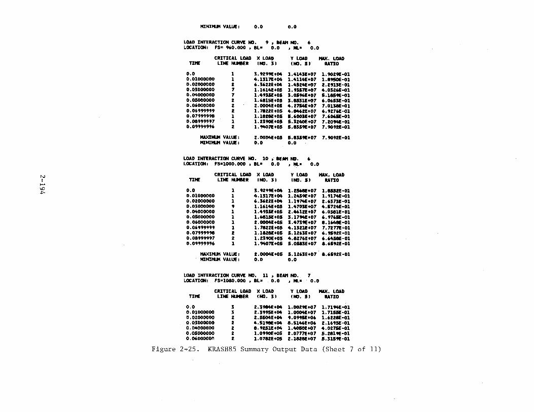
N I
1-' 1..0 +:-
HINIIU4 VALUE : 0.0 o.o
LOAD INTERACTION CURVE NO. 9 • lEAH NO. 6 LOCATION: FS= 960.000 , BL= o.o • HL• 0.0
CRITICAL LOAD X LOAD Y LOAD MAX. LOAD TIME LINE tu18ER INO. 3) fNO. 5) uno
o.o 1 3.9299£+04 1.•U43£+07 1.90291-01 0.01000000 1 4.13171!+04 1.4114£+07 1.8950E-01 0.02000000 2 6.36221!+04 1.4524£+07 2.29131!-01 0.03000000 7 1.1614£+05 1.93571!+07 4.0326£-01 0.04000000 7 1.4935£+05 3.05961!+07 5.1U91-01 0.05000000 2 1.68151!+05 J.U311!+07 6.0653E-01 0.06000000 2 2.00041!+05 4.2754(+07 7.01JaE-01 0.06999999 2 1.78221!+05 4.M62E+07 6.92761!-01 0.07999998 1 1.1821E+OS J.6003E+07 7.60651!-01 0.08999997 1 1.2J90E+OJ 5.32401!+07 7.2094£-01 0.09999996 2 1.94071!+05 5.8J59E+07 7.90921!-01
HAXIIU4 VALUE : 2.0004£+05 5.83591+07 7.90921!-01 HINIIU4 VALUE : o.o o.o
LOAD INTERACTION CURVE NO. 10 i IEM1 NO. 6 LOCATION: FS=1000.000 , BL= o.o , NL• o.o
CRITICAL LOAD X LOAD Y LOAD MAX. LOAD TIME LINE tu18ER fNO. 3) INO. J)
o.o 1 J.9299E+04 1.ZJ68E+07 0.01000000 1 4 .13171!+04 1.24591+07 0.02000000 1 6.36221!+04 1.1974£+07 0.03000000 9 1.1614£+01 1.4703E+07 0.04000000 1 1.4935£+05 2.46121!+07 0.05000000 1 1.6815£+05 3.17941!+07 0.06000000 1 2.00041!+05 3.47391!+07 0.06999999 1 1.78221!+05 4.13211!+07 0.07999998 2 1.18281!+05 5.1263E+07 0.08999997 2 1.2390£+05 4.82761!+07 0.09999996 1 1.94071!+05 5.0583E+07
HAXIIU4 VALUE : 2.00041!+05 5.126JE+07 HINIIU4 VALUE: 0.0 o.o
LOAD INTERACTION CURVE NO. 11 • BEAH NO. 7 LOCATION: FS•1080.000 , BL= 0.0 • HL• 0.0
uno 1.81121!-01 1.9174£-01 2.637JE-01 4.5724£-01 6.03811!-01 6.9765£-01 8.16481!-01 7.72771!-01 6.95921!-01 6.64581!-01 8.65921!-01
8.65921!-01
CRITICAL LOAD X LOAD LINE tu18ER f NO. 3 )
Y LOAD MAX. LOAD TIME IND. 5) RATIO
o.o 3 2.:$9841+04 1.00291+07 1.71941!-01 0.01000000 3 2.39951!+04 1.0004£+07 1.715SE-01 0.02000000 2 2.5504£+04 9.09951!+06 1.6228£-01 0.03000000 2 4.51981!+04 8.51461!+06 2.1695£-01 0.04000000 2 8.92511!+04 1.40101!+07 4.0275£-01 0.05000000 2 1.0990£+0.5 2.07771!+07 5.28191!-01 o.o6ooooon 2 1.07821!+05 2.18281+07 5.31591!-01
Figure 2.,-25. KRASH85 Summary Output Data (Sheet 7 of 11)
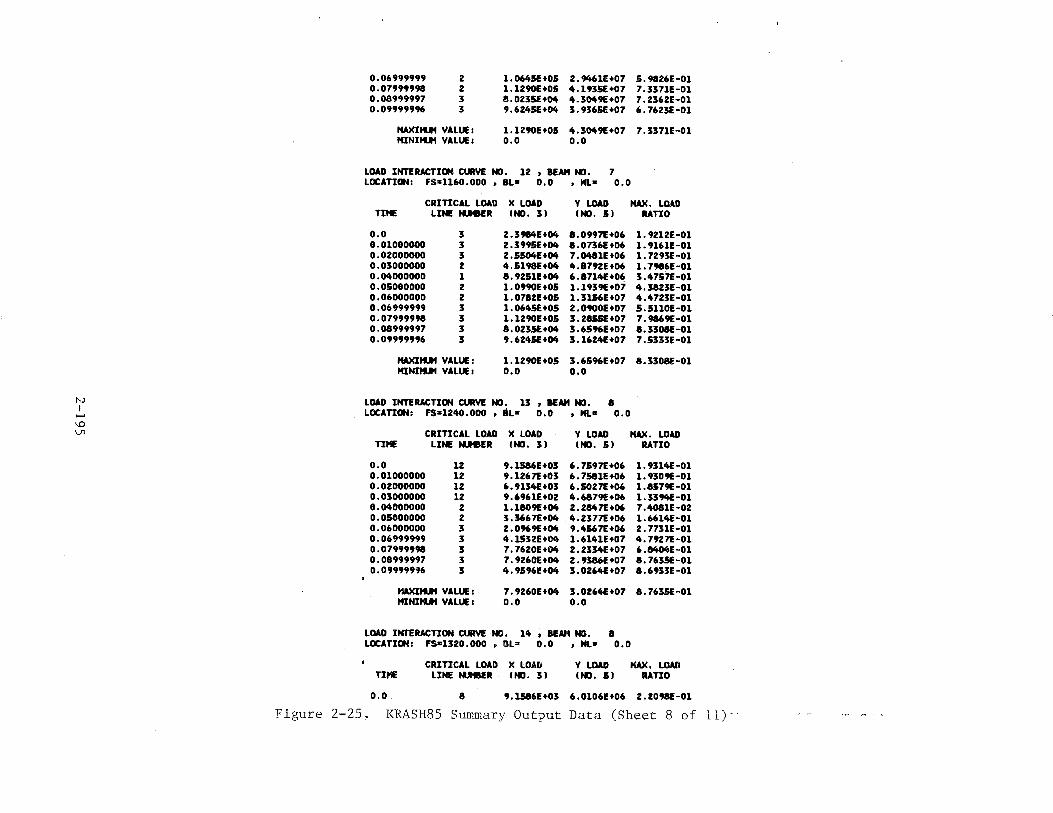
('.)
I ...... ~ lJl
0.06999999 2 1.06/'tSE+OS 2.9t't61E+07 S.9826E-01 0.07999998 2 1.1290£+05 4.1935€+07 7.3371E-Ol 0. 08999997 3 8.0235€+04 4.3049E+07 7 .2362E-01 0.09999996 3 9.6245€+04 3.9365€+07 6.7623£-01
HAXIIUt VALUE 1 1.U90E+O& 4.3049E+07 7.3371E-01 HINIIUt VALUE 1 o.o o.o
LOAD INTERACTION CURVE NO. 12 , BEAM NO. 7 LOCATION: FS=1160.000 , BL= 0.0 , Nl,o: o.o
CRITICAL LOAD )( LOAD y LOAD MAX. LOAD TIHE LINE Nli'BER INO. 3J INO. Sl RATIO
0.0 3 2.3984£+04 8.0997!+06 1.9212E-Ol 0.01000000 3 2.3995E+04 8.0736E+06 1.9161E-01 0.02000000 3 2.5504£+04 7.0481E+06 1.7293E-01 0.03000000 2 4.5198E+Oit 4.8792E+06 1.7986E-01 0.04000000 1 8.9251E+04 6.8714£+06 3.4757!-01 0.05000000 2 1.0990E+OS 1.1939E+07 4.3823E-01 0.06000000 2 1.0782£+05 1.3156E+07 4.4723E-01 0.06999999 3 1.0645€+05 2.0900£+07 S.5110E-01 0.07999998 3 1.1290E+05 3.2855£+07 7.9869E-01 0.08999997 3 8.0235€+04 3.6596E+07 8.3308£-01 0.09999996 3 9.6245€+04 3.1624£+07 7.5333E-01
HAXIIUt VALUE : 1.1290E+05 3.6596E+07 8.3308£-01 ltlNIIUt VALUE : o.o 0.0
LOAD INTERACTION CURVE NO. 13 , BEAM NO. 8 LOCATION: FS•1240.0DO , BL• o.D , NL= 0.0
CRITICAL LOAD X LOAD Y LOAD MAX. LOAD TIHE LINE N.J1BER INO. 3) INO. 5) RATIO
o.o 12 9.1S86E+03 6.7597!+06 1.9314£-01 0.01000000 12 9.1267!+03 6.7S81E+06 1.9309E-01 0.02000000 12 6.9134£+03 6.5027!+06 1.8S79E-D1 0.0300DOOO 12 9.6961E+02 4.6879£+06 1.3394£-01 0.04000000 z 1.1809E+04 2.2847t+D6 7.4081£-02 o.osoooooo 2 3.3667!+04 4.2377!+06 1.6614£-01 0.06000000 3 2.0969E+04 9.4567!+06 2. 7731£-01 0.06999999 3 4.1532£+04 1.6141£+07 4.7927!-01 0.07999998 3 7. 7620E+Il'ft 2.2334£+07 6.8404£-01 0.08999997 3 7.9260£+04 2.9386£+07 8.7635€-01 0.09999996 3 4.9596E+Oit 3.0264£+07 8.6933E-01
MAXIIUt VALUE: 7.9260E+Oit 3.0264£+07 8. 763SE-01 MINIIU'I VALUE 1 o.o o.o
LOAD INTERACTION CURVE NO. 14 , BEAM NO. 8 LOCATION: F$•1320.000 , OL= 0.0 , Hl• 0.0
TIHE
o.o
CRITICAL LOAD )( LOAD Y LOAD MAX. LOAD LINE tuBER INO. 3) INO. SJ RATIO
a 9,1S86E+03 6.0106£+06 2.Z098E-01
Figure 2-25. KRASH85 Summary Output Data (Sheet 8 of 11) · ·
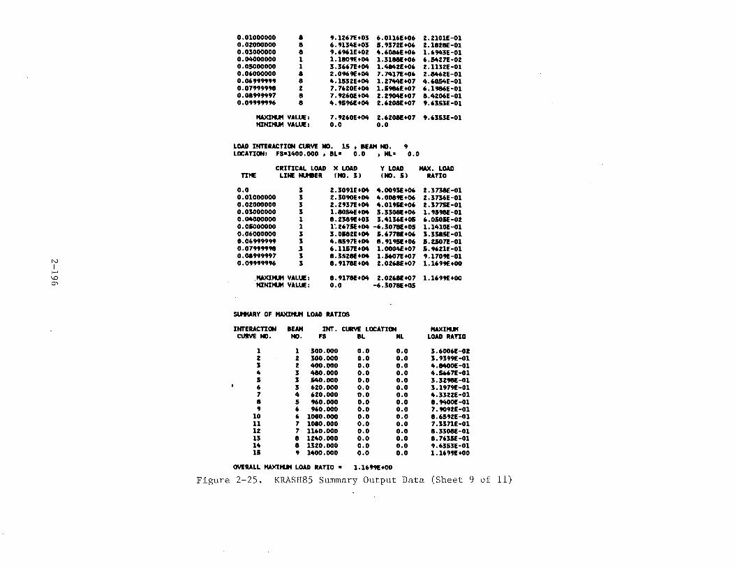
N I r~
\.0 0'\
0.01000000 8 9.1267£+03 6.0116E+06 2.2101E-01 0.02000000 8 6.9134E+03 .& • 93 72E +06 2.1828E-01 0.03000000 8 9.6961E+02 ft.6086E+06 1.69ft3E-01 0.04000000 1 1.1809E+04 1.3188E+06 6 • .&427£-02 0.05000000 1 3.3667£+04 1.4842E+06 2.1132E-01 0.06000000 8 2.0969E+04 7.7417£+06 2.8ft62E-01 0.06999999 8 4.1532E+04 1. 27ft4E+07 4.6854E-01 0.07999998 2 7.7620E+04 1.5986E+07 6.1986E-01 0.08999997 8 7.9260E+04 2.2904!+07 8.4206E-01 0.09999996 8 4.9.&96E+04 2.6208E+07 9.6353E-01
.w<Itl.tl VALUE: 7.9260E+04 2.6208E+07 9.63.&3E-01 HINitl.tl VALUE 1 o.o o.o
LOAD INTERACTION CURVE NO. 15 , BEAM NO. 9 LOCATION: FS•1400.000 , BL= 0.0 • NL= D.O
CRITICAL LOAD X LOAD Y LOAD MAX. LOAD TIHE
o.o 0.01000000 0.02000000 0.03000000 0.04000000 0.05000000 0.06000000 0.06999999 0.07999998 0.08999997 0.09999996
LINE NlftER f NO. 3 ) IND. 5) RATIO
3 3 3 3 1 1 3 3 .3 3 3
2.3091E+04 4.0093E+06 2.3738E-01 2.3090£+04 4.0089E+06 2.3736E-01 2.2937£+04 4.0195E+06 2.377SE-01 1.8054E+04 3.3308E+06 1.9.&98E-01 8.2389E+03 3.4136E+05 6.0505E-02 1·. 2675E+04 -6.3078E+05 1.1410E-01 3.0582E+04 5.6778E+06 3.3385E-01 4.8597£+04 8.9195E+06 5.2507£-01 6.1157£+04 1.000ftE+07 5.9621E-01 8.3528E+04 1.5607£+07 9.1709E-01 8.9178E+04 2.0268E+07 1.1699E+OO
. .w<Itl.tl VALUE: 8.9178E+04 2.0268E+07 1.1699E+OO HINitl.tl VALUE: 0.0 -6.3078E+OS
SlHURY OF MAXItl.tl LOAD RATIOS
INrERACTION BEAM INr. CIIIVE LOCATION MAXItl.tl ctJitVE NO. NO. FS BL NL LOAD RATIO
1 1 300.000 o.o 0.0 3.6006E-02 2 2 300.000 o.o o.o 3.9399E-01 3 2 400.000 o.o o.o 4.8400E-01 4 3 480.000 o.o o.o 4.5667E-01 5 3 .&40.000 0.0 o.o 3.3298E-01 6 3 620.000 0.0 o.o 3.1979E-01 7 4 620.000 '0.0 o.o 4.3322E-01 8 5 960.000 0.0 0.0 8.9ftOOE-01 9 6 960.000 o.o o.o 7.9092E-01
10 6 1000.000 o.o o.o 8.6592E-01 11 7 1080.000 0.0 o.o 7.3371E-01 12 7 1160.000 o.o 0.0 8.3308E-01 13 8 1240.000 o.o o.o 8. 763.&E-01 14 8 1320.000 o.o o.o 9.6353E-01 11 9 1400.000 o.o 0.0 1.1699E+OO
OVERALL HAXItl.tl LOAD RATIO • 1.1699E+OO
Figure 2-25. KRASH85 Summary Output Data (Sheet 9 of 11)
~" I ....... \.0 -....]
..
CORRESPONDING INT, CURVE NO." 15
Figure 2~25. KRASH85 Summary Output Data (Sheet 10 of 11)
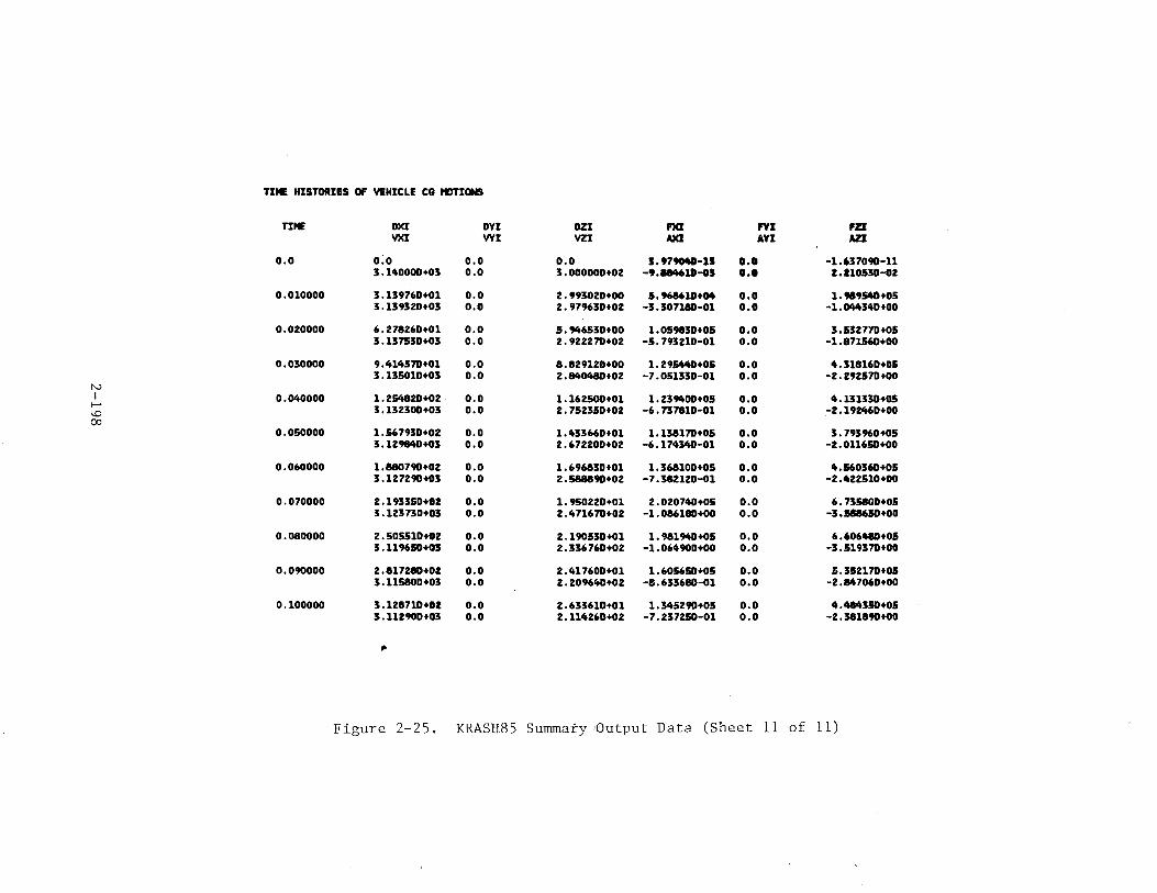
TIME HISTORIES OF VEHICLE CG HDTIONS
TIME OXI OYI DZI I'XI FYI FZI YXI VVI VZI AXI AYI AZI
o.o o:o o.o 0.0 3.979048-11 o.o -1.637090-11 3.1-tOOOD+OS o.o 3.000000+02 -9.184611-o3 o.o Z.ll0530-02
0.010000 3.139760+01 o.o 2.993020+00 5.9686li+M o.o 1.M9.540+05 s .159520+03 0.0 2.97%30+02 -3.307180-01 0.0 -1.044340+00
0.020000 6.278260+01 0.0 5.946530+00 1. 059830+05 o.o 3.532770+05 3 .13 7530+03 o.o 2.922270+02 -5.793210-01 o.o -1.871560+00
0.030000 9.lt14570+01 o.o 8.829120+00 1.29~+05 0.0 4.318160+05 3.135010+03 0.0 2.8lt0480+02 -7.051330-01 o.o -2. 292570+00
N I 0.040000 1.254820+02 0.0 1.162500+01 1. 239400+05 o.o 4 .131330+05 ...... 3.132300+03 o.o 2.752350+02 -6.737810-01 o.o -2.192460+00 1..0
00 0.050000 1.567930+02 o.o 1.433660+01 1.138170+05 o.o 3. 793960+05
3.129840+03 0.0 2.672200+02 -6.1743lt0-01 0.0 -2.011650+00
0.060000 1.880790+02 0.0 1.696830+01 1.368100+05 0.0 lt.560360+05 3.127290+03 o.o 2.588890+02 -7.382120-01 0.0 -2. •U2510+00
0.070000 2.193350+02 o.o 1.950220+01 2.020740+05 0.0 6.735800+05 3.123730+03 0.0 2.471670+02 -1. 086180+00 0.0 -3 .588650+00
0.080000 2.505510+02 o.o 2.190530+01 1.981940+05 0.0 6.606480+01 3.1196SD+OJ o.o 2.336760+02 -1. 06lt900+00 0.0 -3.519370+00
0.090000 2.817280+02 0.0 2.417600+01 1.605650+05 o.o 5.352170+05 3.115800+03 o.o 2.209640+02 -8.633680-01 o.o -2.M7060+00
0.100000 3.128710+02 o.o 2.633610+01 1.345290+05 0.0 4.484350+05 3.112900+03 0.0 2.114260+02 -7.237250-01 0.0 -2. 381890+00
-
Figure 2-25. KRASH85 Summary !Output Data (Sheet 11 of 11)
SUMMARY OF INTERNAL BEAM YIELDING AND RU~TURE, the first item for beam 18 is a
conventional beam yielqing ~p the 1, or axial direction. The second item, for
beam 19, is a conventional beam rupture due to exceeding input maximum load
levels, again in the axial direction. The third line, for beam 9, is an
example of load interaction curve data showing up in this summary. The 15
under YIELD signifies that for load interaction curve number 15, an exceedance
of the defined load envelope has occurred. The 3 in the right hand column means
that load line number 3, for interaction curve 15, was the specific interaction
line that was exceeded. If the input load envelope is exceeded by the factor
RU?RAT (See Section 2.2, figure 2-3, card 2800), then the load interaction
curve number will be printed under the heading RUPTURE. It should be noted
that load interaction curve outputs in the YIELD column have caused nothing
to happen in the time history solution; outputs in the RUPTURE column would
have triggered an actual beam rupture during the time history solution.
Any mass penetrations into the mass penetration control volume are also
summarized. Both the mass penetrating the control volume and time of
occurrence are noted. Since }NP = 0 in the sam~le case, this output is not
illustrated in figure 2-25.
The summary of external spring loading and unloading provides the time o:
occurrence, the spring designations (mass, node, direction), type of event,
initial deflection, maximum force and unloaded deflection and force.
The summary of Plastic hinge formations identifies the time, beam number
and mass number at the end where a plastic hinge formation takes place. In
f~gure 2-25, beam 1 and mass 2 goes through cyclic plastic hinge motion. At
t = .0616, NEWPIN 1 signifies that the coding has changed from fixed at the
j end to Pinned at the~ end (j = 2). This is the technique for forming a
~lastic hinge. At t = .0643, Nm,JPIN = 0 signifies that unloading has occurred,
so that a· fixed end condition is appropriate. Subsequent changes in NEUPIN
define transition points on a hysteresis curve. NEWPIN = 0 always means a
transition to fixed coding has taken ~lace, due to unloading from a plastic
hinge moment. NEWPIN = 1 always means that a transition to pinned coding has
taken place, due to exceeding the input plastic hinge moment. DIRECTION = 5
2--199
in figure 2-23 refers to moments about the y beam axis (6 would be moment
about the z beam axis). DIRECTION= -5 means that the sign of the plastic
hinge moment at that time is negative.
The energy summaries showing the time variation of the different types o:
energy are presented. These summaries faciliatate visualizing the energy flow
time variation; the two summaries are much easier to read than skimming through
the basic time history print, which can run to hundreds of pages. Figure 2-25
shows an example of this output for the sample case. A quick glance at the
"PERCENT TE:t:1PORAL ENERCW DISTRIBUTION SUl\fMARY" tells the user how stable
the solution is. The percent energy should stay within 99-101 percent,
preferably within a ±0.2 percent band. Any significant system instabilities
will quickly manifest themselves in this output.
The column entitled "PERCENT MAXIMUM MASS DEVIATION" shows the maximum
deviation from 100 percent of the total energy for each mass individually,
i.e., at each time the worst deviation of all the masses is shown/ These
numbers will always indicate a greater departure from 100 percent than the
"PERCENT TOTAL SYSTEM ENERGY" column, wherein all the masses constituting
the system are included. The reason for this situation is that some of the
masses have positive and some negative deviations from 100 percent, and
when these are summed over the total system, cancellations occur. Individual
mass total energy deviations in the order of 10 percent may be tolerable, as
long as the total system energy is acceptable. In the example shown in
figure 2-25, the total system energy remains constant within .01 percent,
while the maximum energy deviation is .02 percent at the conclusion of the
analysis.
Time histories of interaction loads follow the energy summary. In the
sample case, there are 15 of these time histories, requiring about 5Yz pages o:
output. For each load interaction curve number, the following information is
presented versus time:
o X load value, pounds or inch-pounds
o Y load value, pounds or inch-pounds
2-200

o Critical load line number. Of all the straight line segments making up the load envelope, the one which is most critical relative to the current X,Y combined loads is indicated. In general, the critical load line number will change with time as the X and Y loads change.
o Maximum load ratio. This is the ratio by which the current load vector length (pt. 0,0 to point X,Y) exceeds a line along this vector but terminating at the intersection of the vector and the critical' load line (input). A ratio greater than 1.0 signifies an excursion outside the load envelope defined in the input data.
Each time history data block also includes the identification of the load )
interaction curve number, beam number and location (FS, BLand WL). Also,
the directions of the X and Y loads are defined. In the sample case, the X
load is always 3 (vertical shear, Fz) and the Y load is always 5 (bending
moment about 7 axis). At the end of each time history data block, the
maximum and minimum values of X load and Y load are shown, as well as the
peak value of MAX.LOAD RATIO.
After the individual load interaction time histories, a summary of the
peak values of the maximum load ratio is shown for all the input curves. This
is followed by the overall maximum load ratio and the corresponding inter
action curve number. For example, in figure 2-25, the overall maximum load !
ratio is 1.1699, which occurs for interaction curve number 15. This output
gives a very quick indication of the severity of the impact being analyzed.
However, maximum load ratios greater than 1.0 do not necessarily imply that
the corresponding structural section would have completely failed. Refer to
Section 3.1 for a discussion of the theory and usage of the load-interaction
data.
If the interaction curves are used to obtain an overall section shear and
moment (summation of all loads acting at a particular station) then the afore
mentioned printed summary is applicable to the sum of the forces acting and
not an individual beam.
The final summary print output is a time history of the overall vehicle
e.g. motions. The quantities included are
2-201
__ ._ ______________________________________ _
0 e.g. translational accelerations, g's
0 e.g. translational velocities, in/sec
0 e.g. translational displacements, in (= 0 at time 0)
0 Net forces acting at the c. g.' pounds
All these data are calculated in the same manner as the e.g. translational
velocities, described in Section 1.3.9 of Volume I. Weighted averages of all
the mass motions are used to arrive at a value for the entire system. The
final results completely define the translational motions of an uncoupled
1-mass, 3 degree-of-freedom system. Rotational loads and motions are not
presented.
These data have been used to determine vertical load-deflection character
istics for a large transport frame structure. Cross plots of DZI vs FZI from
the KRASH analysis of a frame structure form a load-deflection curve that can
be used to determine the external s~ring characteristics of a stick model of
an entire airplane.
2.3.3.4 Time History Plots
The final section of output data consists of time history plots of
selected response quantities. Figure 2-26 illustrates typical output data.
The sequential time history print of the three responses is shown on the left,
while the plots are generated using three separate printer symbols. The scale
factor for all three plots is shown in the upper right corner of the page.
The olot summary is printed on a separate output page as are the various sets
of data.
2-202
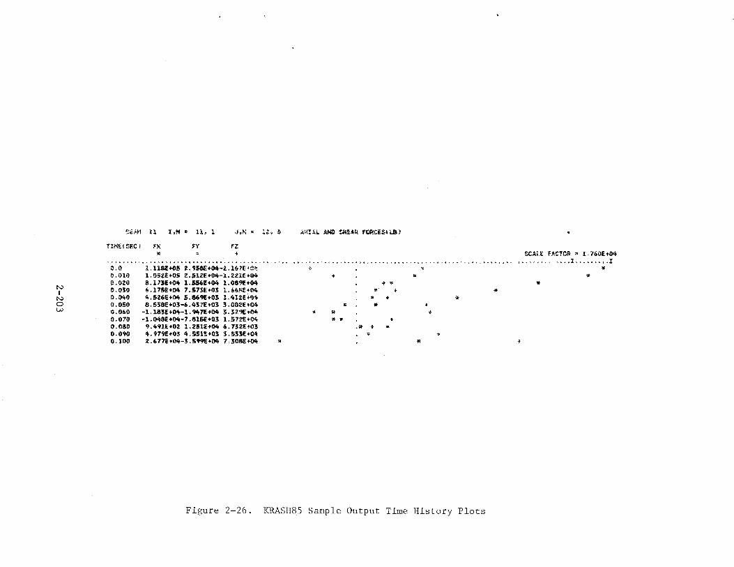
N I
N 0 w
eiAH 11 I,H • 11, 1 .J.N " 1:!, 1i
Tl~!SEC 1 FX FY fZ t
0.0 0.1}10 0.020 1).030 0.040 ().050 1).060 0.070 o.oao 0.090 0.100
ll!
l.ll6l+05 2.9S&E+~-2.l67E~u~ l.052E+05 2.51ZE+04-l.2Zlf+04 8.173!+0~ 1.556£+~ 1.089f.+~ 6.175E+04 7.S73E+03 1.66;E+04 4.526£+~ 5.869£+03 1.412E+O~ 8.538E+G3-6.437E+03 3.082£+04
-l.l83E+04-1.947E+04 3.3?.~+04 -l.048E+04-7.815E+03 l.S72t+04
9.491E+02 l.2SlE+~ 6.73ZE+03 4.979£+03 4.551£+03 3.533£+04 2.677E+04-3.599E+04 7.308E+04
-';<IJ4l i.Nil SHUll FOOCESt LSI
+ .. ,. " ~
" +
" " ,. !t
f! " • ·* ~
"
SCALt FACTOO = l. 760£+04 •• , , •• , ••••.•.. , ..•. , . , ••• .I:., ••••••• I
" " = .. lt
* * +
+
.. * ~
Figure 2-26. KRASH85 Sample Output Time History Plots
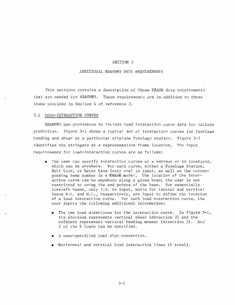
SECTION 3
ADDITIONAL KRASH85 DATA REQUIREMENTS
This sections contains a description of those KRASH data requirements
that are needed for L~SH85. These requirements are in addition to those
items provided in Section 4 of reference 2.
3.1 LOAD-INTERACTION CURVES
KRASH85 has provisions to include load interaction curve data for failure
prediction. Figure 3-1 shows a typical set of interaction curves for fuselage
bending and shear at a particular airplane fuselage station. Figure 3-2
identifies the stringers at a representative frame location. The input
requirements for load-interaction curves are as follows:
• The user can specify interaction curves at a maximum of 40 locations, which can be anywhere. For each curve, either a Fuselage Station, Butt Line, or Water Line (only one) is input, as well as the corresponding beam number in a KRASH model. The location of the interaction curve can be anywhere along a given beam; the user is not restricted to using the end points of the beam. For essentially fore-aft beams, only F.S. is input, while for lateral and vertical beams B.L. and W.L., respectively, are input to define the location of a load interaction curve. For each load interaction curve, the user inputs the following additional information:
• The two load directions for the interaction curve. In figure 3-1, the abscissa represents vertical shear (direction 3) and the ordinate represents vertical bending moment (direction 5). Any 2 of the 6 loads can be specified.
• A user-specified load sign convention.
• Horizontal and vertical load interaction lines (4 total).
3-1
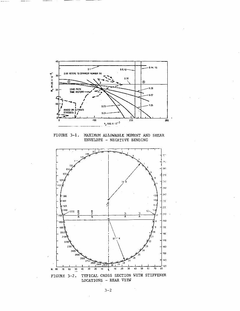
·40r-------------------------------------.--.------------~
Sl__.---
"'- S-XX REFERS TO STRINGER NUMBER XX I 0
LOAD PATH / TIME HISTORY__,..... -- ..
/ ..,..,..,' I
I I #
!BASED ON UlTIMATt STRESSES! I/ S-21----" ---0 .Jp
-------------- _ Yz!lBS X 10-J
·300
FIGURE 3-1. MAXIMUM ALLOWABLE MOMENT AND SHEAR ENVELOPE - NEGATIVE BENDING
180
270
250
14C
~ 10
200
190
lBO
170
160
150
140
Bl BO 70 60 50 40 20 10 \
FIGURE 3-2. TYPICAL CROSS SECTION WITH STIFFENER LOCATIONS - REAR VIEW
3-2
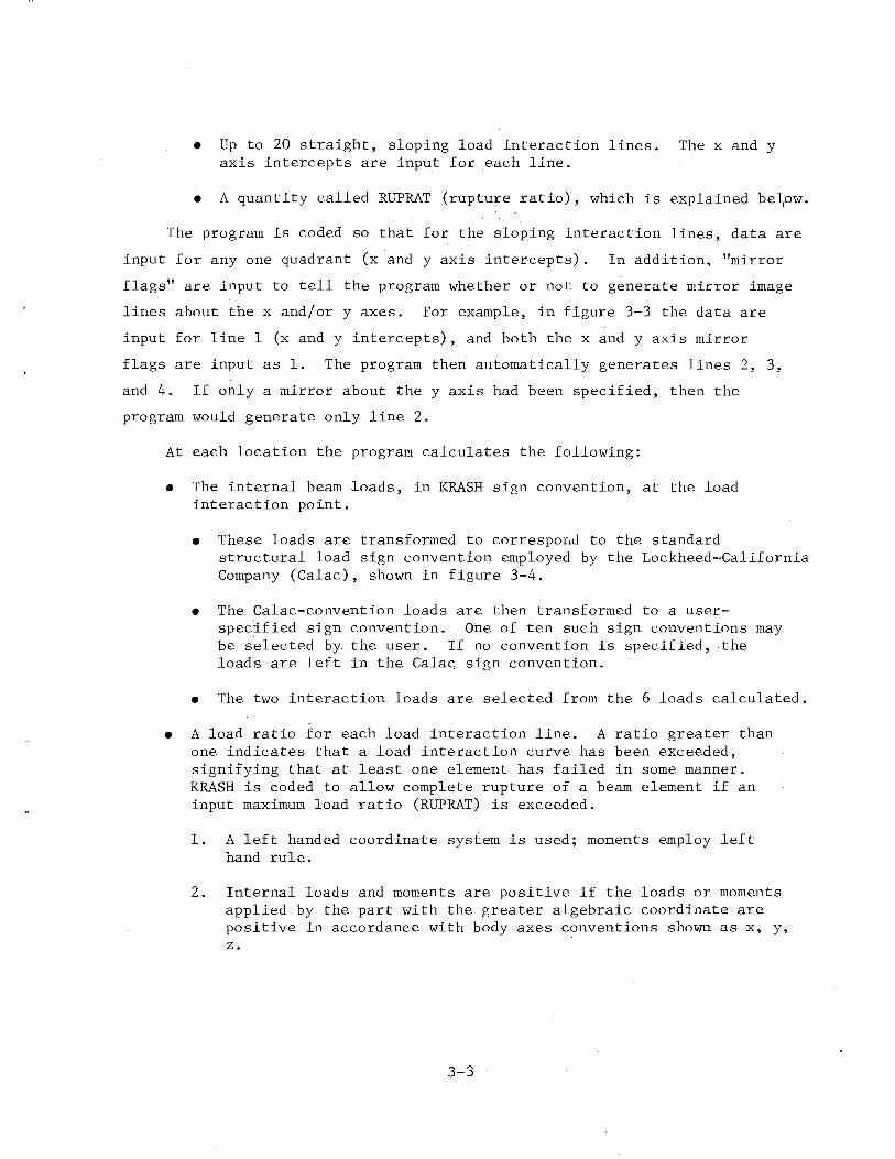
• Up to 20 straight, sloping load interaction lines. The x and y axis intercepts are input for each line.
• A quantity called RUPRAT (rupture ratio), which is explained be~ow.
The program is coded so that for the sloping interaction lines, data are
input for any one quadrant (x andy axis inter-cepts). In addition, "mirror
flags" are input to tell the program whether or not to generate mirror image
lines about the x and/or y axes. For example, in figure 3-3 the data are
input for line 1 (x andy intercepts), and both the x andy axis mirror
flags are input as 1. The program then automatically generates lines 2, 3,
and 4. If only a mirror about the y axis had been specified, then the
program would generate only line 2.
At each location the program calculates the following:
• The internal beam loads, in KRASH sign convention, at the load interaction point.
• These loads are transformed to correspond to the standard structural load sign convention employed by the Lockheed-California Company (Calac), shown in figure 3-4.
• The Calac-convention loads are then transformed to a userspeci_fied sign convention. One of ten such sign conventions may be selected by the user. If no convention is specified, the loads are left in the Calac sign convention.
• The two interaction loads are selected from the 6 loads calculated.
• A load ratio for each load interaction line. A ratio greater than one indicates that a load interaction curve has been exceeded, signifying that at least one element has failed in some manner. KRASH is coded to allow complete rupture of a beam element if an input maximum load ratio (RUPRAT) is exceeded.
1. A left handed coordinate system is used; moments employ left hand rule.
2. Internal loads and moments are positive if the loads or moments applied by the part with the greater algebraic coordinate are positive in accordance with body axes conventions shown as x, y, z.
3-3
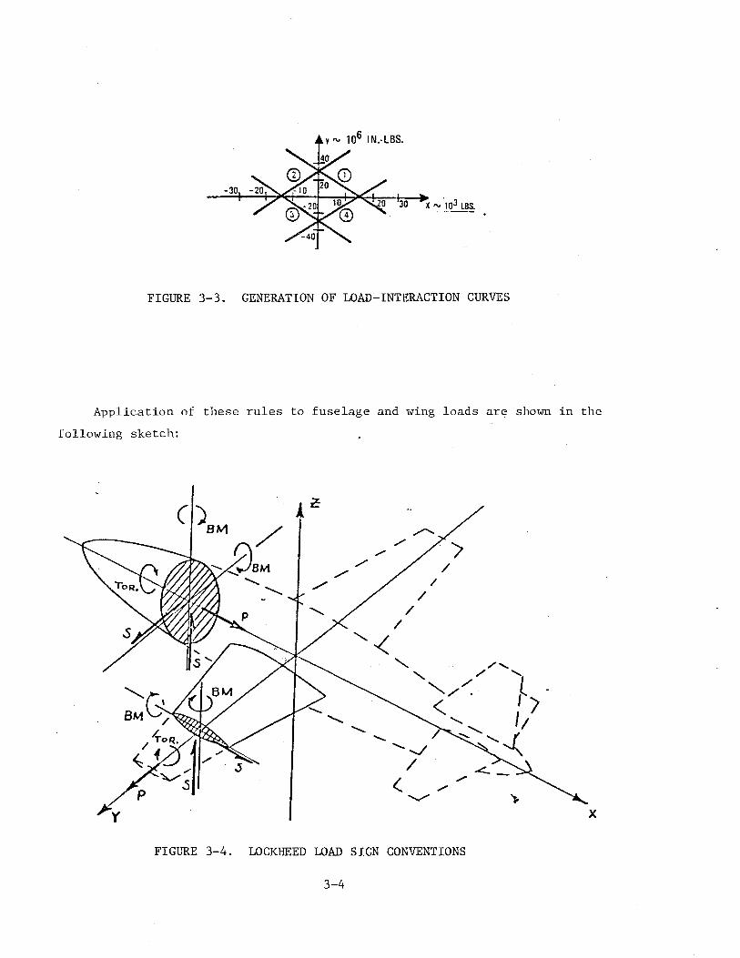
FIGURE 3-3. GENERATION OF LOAD-INTERACTION CURVES
Application of these rules to fuselage and wing loads are shown in the
following sketch:
X
FIGURE 3-4. LOCKHEED LOAD SIGN CONVENTIONS
3-4
Loads shown are those applied to the cutplane by the parts with the
greater algobraic coordinate (station).
At the conclusion of the computer run the following is printed:
• Time histories of the following quantities for each load interaction curve.
• X Load (fuselage vertical shear in figure 3-1).
• Y Load (fuselage vertical bending in figure 3-1).
• Maximum load ratio at each time.
• Input load interaction line number corresponding to the maximum load ratio at that time.
• A summary which shows the peak maximum load ratio for each interaction curve and the overall maximum load ratio.
The user has the option of saving the load-interaction curve time history
data in an output file, which can be used for subsequent post-processing.
These data can be plotted to show the time-varying path of the calculated x-y
loads, superimposed on the load-interaction curve (as illustrated by the
dashed lines in figure 3-1).
While the load interaction data output provides a great deal of useful
information not previously available, considerable caution must be exercised
by the user in its interpretation. A maximum load ratio greater than one
does not, by itself, indicate complete failure of the corresponding fuselage
section. The output data have been used in conjunction with the actual
manufacturer-furnished interaction diagrams to assess the extent of damage at
each location. For example, suppose that the computed combined loads were as
shown by points A or B in figure 3-1. For point A stringers S27 through S30
could fail. For point B several additional stringer elements could fail
(S-9 through S-15 and S-21 through S-30). Usually the input data to KRASH
is the minimum necessary to define the inner boundary in figure 3-1. The
current KRASH85 coding does not define which stringers fail; it only defines
the critical load line at each time out.
3-5
3.2 ARBITRARY MASS NUMBERING
Program KRASH has been modified to accept user supplied mass point
identification numbers. The modification can be thought of conceptually as
a mass point number pre-processor and a mass point number post-processor.
The pre-processor converts external mass point numbers to internal mass
point numbers. The external mass point numbers are supplied by the user as
part of the input while the internal mass point numbers are defined by the
program. The internal mass numbers are consistent with the numbering system
previously used in earlier versions of program KRASH. After conversion pro
gram KRASH85 is executed using the internal mass point numbers. After execu
tion is completed the post-processor converts the internal mass point numbers
to external mass point numbers for output. In the modification, two new
subroutines (INPT and INPTPL) were added. In these subroutines, two arrays
(MASS and IMASS) are defined which cross reference the external mass point
numbers to internal mass point numbers and vice versa.
The external mass point identification numbers are input in column 71
and 72 on Card 200 (MASS POINT DATA). The identification numbers can not be
less than zero or greater than 99. If they are, program execution will be
halted. If any of the numbers are left blank or set equal to zero, the pro
gram will automatically assign sequential identification numbers to all mass
points in the order of input. This option accommodates previously developed
input data sets.
When the RUNMOD=2 option is used, the program automatically assigns an
external mass point identification number to the image mass point generated
under this option. The identification number assigned is 100 greater than the
identification number of the mass point used in defining the image mass point.
For example, if the input mass point identification number is 96 then the image
mass point identification number will be 196.
3-6
SECTION 4
COMMON BLOCK REGIONS
KRASH85 is designed such that data storage and transfer is accomplished
using the many common block regions defined within the program. A cross
reference of the common block names and using subroutines is given in
Table 4-1. Included in the cross reference summary are size requirements
defined by the FORTRAN H/EXTENDED (OPT = 3) compiler.
4-1
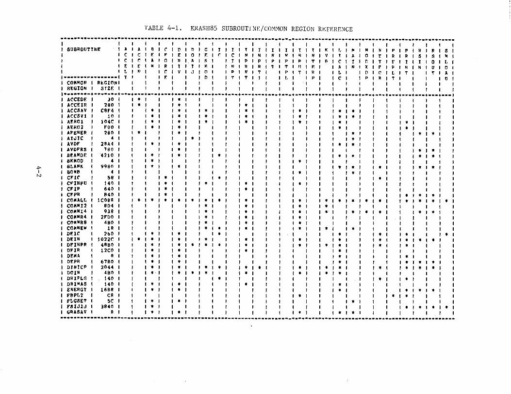
TABLE 4-1. KRASH85 SUBROUTINE/COMMON REGION REFERENCE
········-··-···············---·----------·-·--··----------------------------------·-········----------············----I I I I I I I I I I I I I I I I I I I I I SUBROUTINE I II ' II I 1'1 IC'IDIIliG ' J I T I T I I I T I I I t I T I K I f. I [II I M I N I P I P I R I R I S
C I C I F I F I E I 0 I F I r I C I N I N I N I N I N I N I V I T I A I 0 I F: I R I R I S I S I M C I t" I A I 0 I P I II I N I I J I P I p I P I P I P I T I R I C I T I D I T I F I 1 I I I 0 I L E I E I M I R I T ' I I M I I N I R I R I T I 'T' I 1.1 I F. I I A I N I X I F I P I N I N I U I 0 L I N I I C I V I ,J I 0 I I P I N I T I I P I T I R I I L I I D I 0 I L I T I I 'f I A
t••••••••••••••••l T ' I I F: I I I D I I T I 'T I l ' I {, I I P I I C I I P I P I T I I I I 0 I COMMON I Rt:GIONI I I I I I I I I I I I I I "I I I I I I I I I I REGION I SJZF. I I I I I I I I I I I I I I I I I I I I I I I ··-·····-·-------+-••+•••+•••+•••+•••+•••+•••+•••+•••+•••+•••+•••+••·+-••+•••+•••+•••+•••+·--·-·-····+·•-+•••+•••+•••
ACCEDE I JO I * I I * I I I I I I ACCEIR I 280 I t I I * I I I * I I I ACCSAV I CI!F4 ' I * ' * I * I I * I ' * I I I * I * ACCSV1 I 10 I I * I * ' * I I * I I * I I I * I * A!R01 I 104C I I * I * * I I * I I * I I I * I I I I I • AER02 I FOO I I * I * I I I I I I I * I I I ' I * AFENER I 280 I * I I * I ' I I I I I I * I I I I I t I t AI.JIC I 4 I I I * I I I I I ' I * AVOF I 2SA4 I I • • I I I I I I * I * AVOF'RS I 780 I I • I I I I I I I I I I I I * I * 8!AMOE I 4210 I I * * * I I I I I * I * I I I I I * I * 8KMOO I 4 I I * I I * I
+=-- 1 BLANK 9980 I * * I I I I I * I * I I * I I I * I t
' I 801118 4 I I I I * I I I I • N ' CFIC' 59 I * * I I I I I I I I * CFINPU 140 I I * * • I I * I CF'IP 640 I I * I I * I I I CFPR 840 I I • I I I I I I I I I * I * I * CCI MALL 1C089 I I * * I * * * * * * I I * I * I * I * I * I * I I * I * ' • I * COMMI2 904 I I I * * I * I • I I I CCIJII111I4 938 I I I • • * I •· I I • I * I * I I I * I * COMMR4 2FOO I I I * * * I I I I COMMR8 480 I I I * * * I I I I COM NEW 1 A I I I I * * * * I * I I * I I DP.:lC 2&0 I I * I * I * I I * I I I * I I * I I I * DI!:IN 1022C I I * • I • I * • * I I * I * I I * I * I * Ol!'INPR I 41!80 I I * I • • I • * • * I * I * I • I I t DFIR I 12CO I I * I * I * I • I DENA I A I I * I * I I * I I ' . DF.PR I 6780 I I * I • I I I • I I I * I * I * OYHTCP I 2044 I I • I • I • • • • * I I • * I * I I * I * I • DOIN I 480 I ' • I • * ' * I • I • I I * * I I I I DRIF'LG I 140 I I I ' I • I I I ' * I I * I ORIMAS I 140 I I • I • ' I • I I I • I I I I ENERGY I 1681! I I * I • I I I I I * I I I * ' t I • FBPLT I C8 ' ' I I I I * I I I I * I * I FLGSET I 5C I I • I * I ' I I I * I I I I FSIJlJ I 3840 I I • I I I I I I I I I • I * I • I * GRASAV I 1.1 I I • I * I I I * I I • • I I I '
·······-······--------~----------------------·······-·-------·--···--~------------------- ----------------------------
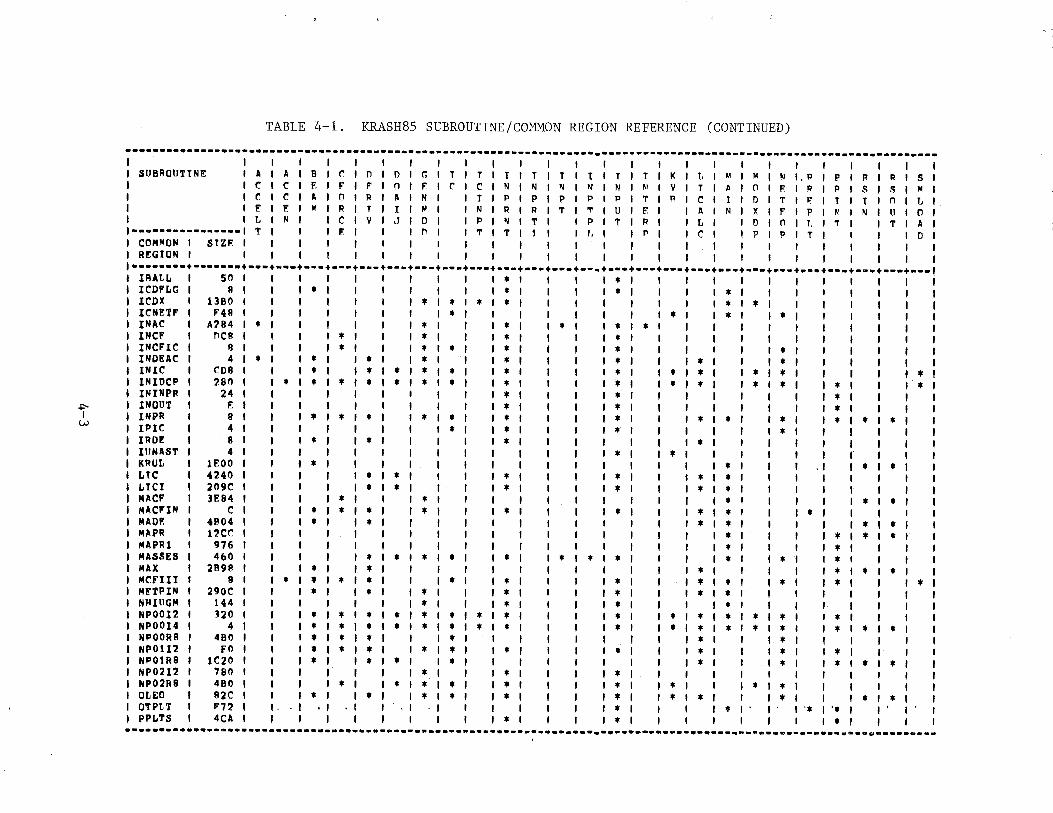
TABLE 4-1. KRASH85 SUBROUTINE/CO~illON REGION REFERENCE (CONTINUED)
··~·-····----~-----·------·-·--------------------------------------------------------------~-------------------------I I I I I I I I I I I I I I I I I I I SUBROUTINE I A I A I B I C' I l'l I n I G I T I T I T I T I T I t I T I y I K 1 r. I M I 1>1 I N I. P I p I R I R I S c I C I F. I F' I F" I 0 I F I C I C I N I 1.1 I 1.1 I "' I N I M I v I T I ~ I n I F I P I P I s I S I M
C I C I A I 0 I R I A I N I I r I P I P I P I P I P I T I 1'1 I C I t I D I T I II' I t I t I n I L F I F I M I R I T I J I M I I N I R I R I T I T I U I F I I A I N I X
' F' I p I II' I N I 11 I 0
L I N I I C I V I J ' 0
I I P I loJ I T I I p I T I R I I L ' I D I n 1 r, I T I I T I A 1••••••••••••••••1 T I I I F. I I I l'l I I T I T I t I I r .• I I P I I C I I p I P I T I I I I D I COMMON I SJZF. I I I I I I I I I I I I I I I I I I I I I I RP.:GION I I I I ' I I I I I I I I I I ' I I I I I I l••••••••+·······+·•-+•••+··-·---·---·---·---·--··---·---·---·-···---+-••+•••+•••+•••+•••+•••+••·+~--·---·--·+·-·+••• IRAti.. I so I I I I I I I * I I I * I I I I I
ICDP'I..G I 9 I I I * I I I * I I I * I I * ' I I ICDX ' 1380 I I ' I * * I * I * I I ' I I * * I I ' ICNETI" I F49 I ' I I * I I I I ' * I I * ' * I I INAC I A?84 I * I I ' * I I * I * ' I * * I I I I I INCF I nee I ' I * I * I * I I I * ' I I I INCFIC I 8 I I I * I * * I * I ' I * I I * I I INDEAC I 4 * I I * I * * I * I I I * I * ' • I I INIC I coe I I • I * * • • I * I ' * * I * I * • I I I I I * INIOCP I ,80 I * I * * * * * • I * I * * I * I * * I I * I I I * ININPR 24 I I I * I * I I I I * +:-- I INOUT E I I I * I * I I I I * I I INPR 8 I I * * * * * ' * I I * I * I * * I I * ' * I * w IPIC 4 I I * I * I I • I I • I I IROP.: 8 I I • * I * I I I * I I I IIINAST 4 I I I I I * • I I I I KRUL lEOO I I * I I I I I I * I , I I * I * LTC 4240 I I I • • I * I I • I * I • I I LTCI 209C I I I * * I I * I I * I * I * I I I MACF 3E84 I I I * * I I I I I * I I I I * I * MACFIN c I I * * • * I * I I • I • I • ' I * I MADE 41!04 I I * • I I I I I * I • I I I I I * I * MAPR 12CC I I I I I I I * I I I I * I * I * MAPRl 976 I I I I I I I * I I I I * MASSES 4&0 I I * * * * * I I * * * I I * I I * I ' * MAX 2898 I I • * I I I I * I I I I I • I • I * MCflii 8 I * I * • * * * I I * I * I * I I * I I * I I I * MFTPIN 290C I I * • • * I I * I * I * ' NHillGM 144 I I * * I I * I I • I NPOOI2 320 I I • * • * * * • * I I * * I * I * I * I * I I * NP0014 4 I I * * • * ·* * * * I I • * I * I * I * I * I I * I • I * NPOORB 480 I I • • • • I I I I * I I I * NP01I2 FO I I * • • • • • I I * I I • I I I * I I * NI'OtR8 1C20 I I * * * I • I I I I I * I I I * I I • I * I * NP02I2 780 I I I • I * I I * I I I I NP02R8 480 I I • * I * * I * I I * I * I I I • I * I I OLEO 82C I I * • I • * I * I I • I * I * I I I • I I I * I * OTPt.T F7?. '. . I . I I I I * I I I * I I I '* I '* PPLTS 4CA I I I I * I I * I I I I I I I *
················-------············----------·-----····-----~----------------·-··-····-----·····-----·-········-····--'
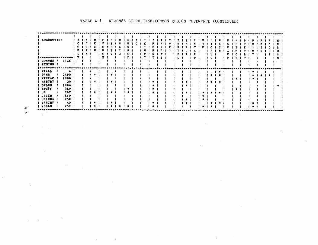
TABLE 4-1. KRASH85 SUBROUTINE/COMMON REGION REFERENCE (CONTINUED)
············-···-·················-·········-··-------------·-·····-----------------·-···-------··-··················-I I I I I I I I I I I I I I I I I
SUBROUTINE I A I A I F! I C I D I D I G I T I t I r 1 t I T I t I I I I I I< I r, I M I M I N I P I I' I R I R I S I CICifi:IFIF.IOIF.IC I C I N I N I 1\1 fNI~IItiiVI I I A ' 0 I F I R I R I S I S I M I c 1 e ' A I 0 I R I A I N I I I I P I P ' " I P I P I T I f\ I C I I I [) I T I F ' T I t I 0 I f, I I! I E I M I R I 1 I T I M I I N I R I R I 'I' I T I U I E I I A I N I X I F I P I ~I I N I IJ I 0 I L I N I I C I V I J I 0 I I P I N I T I I P I T I P I I L I I 0 I 0 I L I T I I T I A I
1••••••••••••••••1 T f I I E I I I D I I T I T I 1 I I L I I P I I C I I P I R I T I I I I l'l I I COMMON I STZE I I I I I I I I I I I I I I I I I ' I I I ' I I I I I R!GION I I I I I I I I I I I I I I I I I I I I I I I I I I I •··········-~···•+•••+•••+•••+•••+•••+•••+•••+•••+•••+•••+•••+•••+•••+•••+•••+•••+•••+•••+•••+•••+•••+•••+•••+•••+···1
PRALL I 4 I I I I I I I I I I I I I I I I I * I I I I * I I I I PRMA I 2490 I I I • I I * I I I I I I I I I I I * I * I I I I * I * I * I I PRNP'AC I 4800 I I I I I I I I I I I I I I I I I I I * I I * I I I I RESTRT I 30 I I I * I I * I I I I • I I I I * I I I * I * I I I I I I I I SMLDS I 1004 I I I I I I ' ' I * ' ' I I * I I I I I I I I I I I * I STUFF I lAO I I I I I I ' * I I • I I I ' I I I I I I * I I I I I I UB I 70C I I I * I I * I I * I I * I I I I * I I * I * I * I I I I I I I I UBI CD I F.10 I ' I I I I I I I I I I I I I * I I I I I I I I I I UBI UNA I 258 I I I I I I I I I I I I I • I I * I I I I I ' I I I I VARINT I 40 I I I • I I * I I I I • I ' I I * I I I * I . ' I ' I * I I I I
• VBEAM I 258 I I I • I I • I * I * I I * I I I I I I * I * I I I I I * I I I I +:- ····-···············-·······-···········•,•··-·-----------------·-············--------------·--·····-·-·········-······ I +:-
REFERENCES
1. Gamon, M. A., "KRASH User's Manual; Theory Volume I," FAA-RD-77-189I, Lockheed-California Company, Sept. 1979
2. Gamon, M.A., Wittlin, G., "KRASH User's Manual, Input-Output, Techniques and Applications," Lockheed-California Company, FAA-RD-77-189II (Revised), Sept. 1979
R-1
APPENDIX A
SHOCK STRUT ELEMENT DESCRIPTION
A.l GENERAL
The use ofa shock strut element in KRASH is available for, but not
limited to, lending gear oleo struts. The following discussion will be
oriented to landing gear oleo strut usage. The axial strut motion is
assumed to be uncoupled from the transverse displacements. Axial forces are
produced by an air spring force, FAi' a hydraulic damping force, F0 i' a
friction force, FFi' and forces produced by elastic stops which limit the
travel of the piston within the cylinder at full extension and full
compression. Each of these forces is discussed separately.
A.2 AIR SPRING FORCE
where
The expression for the air spring force is
E. effective total strut cylinder length (Figure A-1) ]_
strut air preload at yi 0
cylinder load due to ambient air
polytropic exponent
A-1
(A.l)
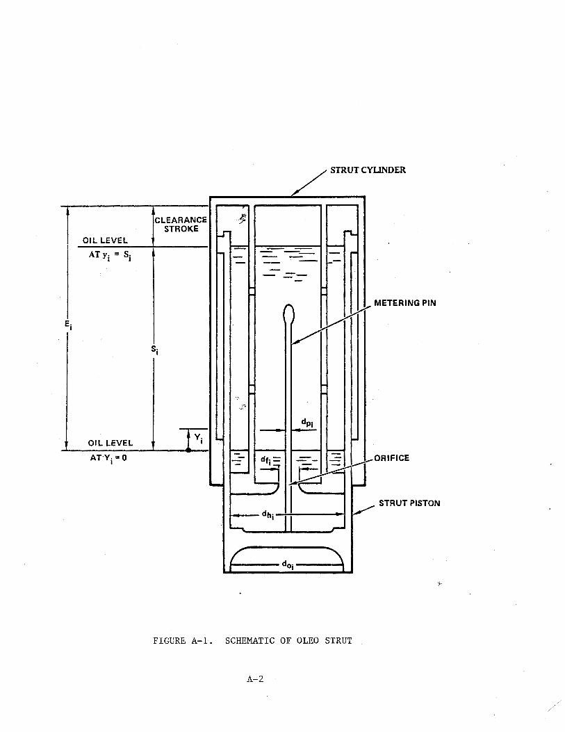
OIL LEVEL
OIL LEVEL
CLEARANCE STROKE
~STRUTCYUNDER
I- 1--===--==--1 --- __ --r-
-----
,.... ,.. METERING PIN
)
-=- 1----f ... ---t -=-df· = - - ORIFICE
--4 [8l4tr ~ I·~ ,_
STRUT PISTON
~-.....__-- dhj I - ~ --
I--f __ doi ---'"""'_1
FIGURE A-1. SCHEMATIC OF OLEO STRUT
A-2
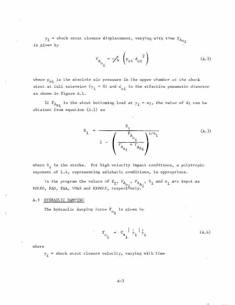
yl. = shock strut closure displacement, varying with time FA oi
is given by
(A. 2)
where p0
i is the absolute air pressure in the upper chamber of the shock
strut at full extension (y. = 0) and d . is the effective pneumatic diameter l Ol
as shown in Figure A.l.
If FAsi is the strut bottoming load at yi
obtained from equation (A.l) as
Si, the value of Ei can be
s. E.
l (A. 3) l
( FA8i FA rni 0.
1 -l
+ F AAi
where S. is the stroke. l
For high velocity impact conditions, a polytropic
exponent of 1.4, representing adiabatic conditions, is appropriate.
In the program the values of EI' FA , FA , Si and ni are input as oi Ai
EOLEO, FAO, FAA, YMAX and EXPOLE, respectlvely.
A.3 HYDRAULIC DAMPING
where
The hydraulic damping force F is given by oi
F o.
l
c z.
l
yi shock strut closure velocity, varying with time
A-3
(A.4)
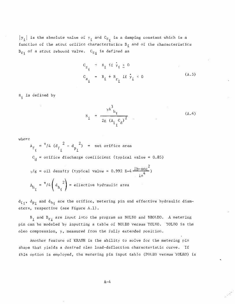
JyiJ is the absolute value of yi and C2 i is a damping constant which is a
function of the strut orifice characteristics Bi and of the characteristics
Br· of a strut rebound valve. C2 . is defined as l l
B. is defined by l
where
c
c
z. l
z. l
B. l
B. l
B. l
if y. l
+ B r:._
3 yA h
i
l
> 0
if y. < 0 l
net orifice area
Cd orifice discharge coefficient (typical value = 0.85)
y/g oil density (typical value 2
0.992 E-4 lb-sec ) . 4 ln
(A. 5)
(A. 6)
df., dp· and dh· are the orifice, metering pin and effective hydraulic diam-l l l
eters, respective (see Figure A.l).
Bi and Bri are input into the program as BOLEO and BROLEO. A metering
pin can be modeled by inputting a table of BOLEO versus YOLEO. YOLEO is the
oleo compression, y, measured from the fully extended position.
Another feature of KRASH is the ability to solve for the metering pin
shape that yields a desired oleo load-deflection characteristic curve. If
this option is employed, the metering pin input table (POLEO versus YOLEO) is
A-4
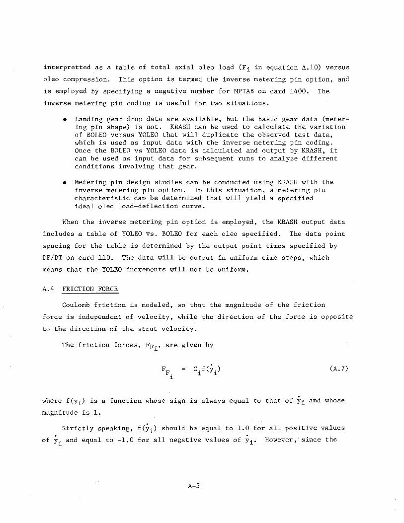
interpretted as a table of total axial oleo load (Fi in equation A.lO) versus
oleo compression. This option is termed the inverse metering pin option, and
is employed by specifying a negative number for MPTAB on card 1400. The
inverse metering pin coding is useful for two situations.
• Landing gear drop data are available, but the basic gear data (metering pin shape) is not. KRASH can be used to calculate the variation of BOLEO versus YOLEO that will duplicate the observed test data, which is used as input data with the inverse metering pin coding. Once the BOLEO vs YOLEO data is calculated and output by KRASH, it can be used as input data for subsequent runs to analyze different conditions involving that gear.
• Metering pin design studies can be conducted using KRASH with the inverse metering pin option. In this situation, a metering pin characteristic can be determined that will yield a specified ideal oleo load-deflection curve.
When the inverse metering pin option is employed, the KRASH output data
includes a table of YOLEO vs. BOLEO for each oleo specified. The data point
spacing for the table is determined by the output point times specified by
DP/DT on card 110. The data will be output in uniform time steps, which
means that the YOLEO increments will not be uniform.
A.4 FRICTION FORCE
Coulomb friction is modeled, so that the magnitude of the friction
force is independent of velocity, while the direction of the force is opposite
to the direction of the strut velocity.
The friction forces, FFi' are given by
C.f(y.) 1 1
(A. 7)
where f(yi) is a function whose sign is always equal to that of Yi and whose
magnitude is 1.
Strictly speaking, f(yi) should be equal to 1.0 for all positive values . . of yi and equal to -1.0 for all negative values of Yi· However,· since the
A-5
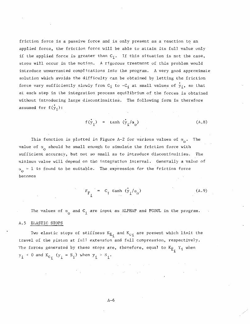
friction force is a passive force and is only present as a reaction to an
applied force, the friction force will be able to attain its full value only
if the applied force is greater than Ci. If this situation is not the case,
stops will occur in the motion. A rigorous treatment of this problem would
introduce unwarranted complications into the program. A very good approximate
solution which avoids the difficulty can be obtained by letting the friction
force vary sufficiently slowly from Ci to -Ci at small values of Yi• so that
at each step in the integration process equilibrium of the forces is obtaiaed
without introducing large discontinuities. The following form is therefore
assumed for f(yi):
f (y.) l
tanh (y./a ) l 0
(A. 8)
This function is plotted in Figure A-2 for various values of a . The 0
value of a should be small enough to simulate the friction force with 0
sufficient accuracy, but not so small as to introduce discontinuities. The
minimum value will depend on the integration interval. Generally a value of
a = 1 is found to be suitable. The expression for the friction force 0
becomes
C. tanh (y. I a ) l l 0
(A. 9)
The values of a and C. are input as ALPHAP and FCOUL in the program. 0 l
A.S ELASTIC STOPS
Two elastic stops of stiffness KEi and Kci are present which limit the
travel of the piston at full extension and full compression, respectively.
The forces generated by these stops are, therefore, equal to KE. Yi when l
A-6
:;I> I
-...J
0'0 = 0.25
1.0 r/=oY -~ ~
0.8 1/ I ao /
~ 0' = 2 I f(yj) 0
0.6 ~I~ v 0.4 rr/ 0 .. 2 v \~ '\ \·~
·4 -3 ·2 -1
A 1 2 3
~-4
-0.2 I
/~ -M
/ / lh -0.6 f(yi) = TANH (y/a0
)
v II -0.8
__.. ~ ~ /__} -LO ---- --
FIGURE A-2. FRICTION FORCE COEFFICIENT AS FUNCTION OF STRUT CLOSURE VELOCITY
Collecting all the above terms the total axial force F. can be l
written as
F. FA. + F + FF. + FEXT. + FCOHP. l o. l l l l l
The terms KE. , Kc.' and s. are input into the program as XKEXT, XKCOHP, l l l
YHAX, respectively.
A-8
(A.lO)
and
APPENDIX B
STANDARD DISTRIBUTION LIST
Region Libraries
Alaska Central Eastern Great Lakes New England Northwest-Mountain Western-Pacific Southern Southwest
Center Libraries
AAL-64 ACE-66 AEA-62 AGL-60 ANE-40 ANM-60 AWP-60 AS0-63d ASW-40
Technical Center ACT-64 Aeronautical Center AAC-44.4
Civil Aviation Authority Aviation House 129 Kingsway London WC2B 6NN England
Embassy of Australia Civil Air Attache 1601 Mass Ave. NW Washington, D. C. 20036
Scientific & Tech. Info FAG Attn: NASA Rep. P.O. Box 8757 BWI Aprt Baltimore, Md. 21240
DOT-FAA AEU-500 American Embassy APO New York, N. Y. 09667
B-1
Headquarters (Wash. DC)
ADL-1 ADL-32 (North) APM-1 APM-13 (Nigro) ALG-300 APA-300 API-19 AAT-1 AWS-1 AES-3
OST Headquarters Library
M-493.2 (Bldg. lOA)
University of California Sers Dpt lost of Trsp Std Lib 412 McLaughlin Hall Berkely, CA 94720
British Embassy Civil Air Attache ATS 3100 Mass Ave. NW Washington, DC 20008
Dir. DuCentre Exp DE LA Navigation Aerineene 941 Orly, France
Northwestern University Trisnet Repository Transportation Center Lib. Evanston, Ill. 60201
Government Activities
FAA, Washington, DC 20591 (Attn: Harold W. Becker, ASF-300; Thomas McSweeny, AWS-100)
FAA, 4344 Donald Douglas Drive, Long Beach, CA 90808 (Attn: Stephen Soltis, ANW-102N)
FAA, Mike Monroney Aeronautical Center, P.O. Box 25082, Oaklohoma City, OK 73125
(Attn: Richard Chandler, AAM-119)
No. of Copies
(2)
(1)
(1)
NASA, Langley Research Center, Hampton, VA 23365 (2) (Attn: Emilio Alfaro-Bou, MA-495; Huey Cardin, MS-495)
U.S. Army Aviation Applied Technology Directorate, USAARTA, (AVSCOM), (2) Fort Eustis, VA 23604
(Attn: Roy Burrows, Code SAVRT-TY-ASV)
U.S. Navy Naval Air Development Center, Warminister, PA 18974 (Attn: Leon Domzalski, Code 60322)
NTSB, 800 Independence Ave. S.E., Washington, DC 20594 (Attn: John C. Clark, TE 60)
Non-Government Activities
Beech Aircraft Corp., P.O. Box 85, Wichita, KS 67201 (Attn: Dayton L. Hartley; James E. Terry; William Schultz)
Bell Helicopter Co., P.O. Box 482, Fort Worth, TX 76101 (Attn: James Cronkite, MS 11; Roy G. Fox)
Boeing Airplane Co., P.O. Box 3707, Seattle, WA 98124 (Attn: Edward Widmayer, MC-9W-22)
(1)
(1)
(3)
(2)
(l)
Boeing Co., Vertol Division, P.O. Box 16858, Philadelphia, PA 91942 (1) (Attn: Denise Vassilakos, MS P30-27)
Cessna Aircraft Co., P.O. Box 7704, Wichita, KS 67277 (Attn: John Berwick; Robert Held; Richard Soloski)
Fairchild Aircraft Corp., P.O. Box 3246, San Antonio, TX 78284 (Attn: Walt Dwyer)
General Dynamics/Convair, P.O. Box 80847, San Diego, CA 92138 (Attn: L. Mastny, MA 80-6030)
Grumman Aerospace Corp., So. Oyster Bay Road,, Bethpage, L . I. , NY ll 7 14
(Attn: Robert Winter, A08-35; Allan B. Difko, A08-35)
B-2
(3)
(1)
(1)
( 2)
Gulfstream Aerospace Corp., P.O. Box 2206, Savannah, GA 31402 (Attn: George Westphal)
(l)
Gulfstream Aerospace Corp., P.O. Box 22500, Oklhoma City, OK 73123 (1) (Attn: Richard Southard)
Lockheed-California Co., Burbank, CA 91503 (Attn: Gil Wittlin, D 76-12, B 63G, PLT A-1)
(1)
McDonnell Douglas Corp., 3855 Lakewood Drive, Long Beach, CA 90846 (2) (Attn: J. Webster; John L. Galligher)
McDonnell Douglas Helicopter, 4645 S. Ash Ave., Tempe, AZ 85182 (Attn: Lyndon Landborne; J.K. Sen)
Piper Aircraft Corp., 2925 Piper Drive, Vera Beach, FL 32960 (Attn: Marion Dees)
Sikorsky Aircraft, North Maint Street, Stratford, CT 06601 (Attn: Brain Cornell, MS 5207A; Pramonik Mukunda, MS 5207A)
B-3
~U.S. GOVERNMENT PRINTING OFFICE: 1986-605-071/40024
(2)
(1)
(2)


![Nastran Error List - [PDF Document] of Error Messages NX Nastran displays User Information, Warning, and Error messages in the printed output. ... LOG FILE DOES NOT CONTAIN ANY PERTINENT](https://img.pdfslide.us/doc/110x75/5a8746a77f8b9a882e8d8ac2/nastran-error-list-pdf-document-of-error-messages-nx-nastran-displays-user-information.jpg)