Embed Size (px)
Citation preview

i
SMART DUSTBIN – SMART GARBAGE MONITORING SYSTEM
(IOT BASED)
MUHAMAD RIDZUAN BIN KAMARUDIN
This Report Is Submitted In Partial Fulfillment Of Requirements For The Bachelor
Degree In Electronic Engineering (Electronic Telecommunication)
Fakulti Kejuruteraan Elektronik dan Kejuruteraan Komputer
Universiti Teknikal Malaysia Melaka
June 2017

ii

iii

iv
“

v
ACKNOWLEDGEMENT
First and foremost, I would like to praise to Allah S.W.T for giving me an ability
and strength to do my final year project succeed and complete my report as required. I
would like to express my gratitude to my supportive and caring supervisor Dr. Syafeeza
binti Ahmad Radzi for providing his insightful knowledge and valuable assistance
throughout this project under his guidance.
I would like to take a chance to thank all the lecturers who taught me in the past
four years and great contribution that qualify me to do my final year project. I would like
to thank Dr. Ahmad Sadhiqin Bin Mohd Isira and Pm. Dr. Kok Swee Leong and the other
lecturers and staff that participated to arrange for iNOTEK and IoT competition, with their
efforts in providing information and cooperation to help students achieving the goals of
final year projects.
At the other side of appreciation is extended to my parents Saodah Binti Osman
and Kamarudin Bin Abu Bakar for their support and encouragement throughout my
studies. Their advice and reminder always give me a strengthen to complete my final year
project and studies. I would like to thank all senior students who helped me to clear out
the questions and guide on the software that I use for this final year project.
Thanks as well to all my friends for their guidance and knowledge they provide to
me. Lastly, my thanks as well extend to whoever supported me and give some inspirational
in doing my final year project and throughout my studies.

vi
ABSTRACT
This project is to design a IoT (Internet of Things) based ‘Smart Garbage
Monitoring System’. The main contribution of this work is the monitoring the level of the
garbage inside the dustbin by using a mobile phone and using the Blynk apps. The problem
that the cleaner face today is that they need to check all the dustbin whether the dustbin is
full or not. Therefore, by doing that will increase the time taken to clean the garbage and
to check all the dustbin. The main objective of this smart dustbin is to monitor the garbage
level inside the dustbin. This dustbin also can notify the cleaner when the dustbin is full.
The output that display to the user through the LCD display is the status of the garbage.
This smart dustbin used the ultrasonic sensor as the main sensor to detect the distance of
the garbage inside the dustbin. The LCD display are used to show the status of the garbage.
At the same time the ESP8266 are used to act as the WiFi module to send the information
to the smartphone. Lastly the Blynk apps are used to get the information from the dustbin
and to notifying the cleaner about the dustbin garbage. The microcontroller Arduino Uno
are used as the brain of this project. For the result, the Blynk will send the notification to
the smartphone and the LCD display will show the status of the garbage inside the dustbin.
In this result, it contains three types of reading there are 0%, 50% and 100%. For the 0%
result the garbage distance must greater than 10cm from the ultrasonic sensor. For 50 %
result the garbage distance must greater than or equal to 5cm but less than 10cm from the
ultrasonic sensor. Lastly for 100% result the garbage distance must less than 5cm from
the ultrasonic sensor.

vii
ABSTRAK
Projek ini bertujuan untuk membina sebuah tong sampah pintar yang mempunyai
sistem pemantauan berdasarkan internet untuk segalanya (IoT). Projek ini adalah untuk
membantu kerja – kerja pembersihan dengan meletakkan sistem pemantauan tenetang
keaadaan sampah di dalam tong sampah dengan menggunakan aplikasi Blynk. Masalah
yang sering dihadapi oleh bahagian pembersihan ialah mereka perlu untuk memeriksa
setiap tong sampah bagi memastikan tong sampah itu penuh atau tidak. Hal ini akan
meningkatkan masa untuk proses – proses pembersihan dijalankan termasuklah dengan
masa yang diambil untuk memeriksa setiap tong sampah. Objektif utama projek ini adalah
untuk melakukan pemantauan keadaan sampah di dalam tong sampah tampa perlu
memeriksa setiap tong sampah. Selain itu, tong sampah ini juga akan menghantar
makluman kepada bahagian pembersihan jika terdapat tong sampah yang telah penuh
melalui aplikasi Blynk. Output untuk pengguna pula akan ditunjukkan melalui paparan
LCD yang telah dipasang pada tong sampah. Paparan LCD akan memaparkan keadaan
semasa sampah yang berada dalam tong sampah. Sensor ultrasonik digunakan sebagai
komponen utama dalam projek ini untuk mengesan jarak sampah dari sensor ultrasonik.
Paparan LCD pula digunakan untuk memaparkan keadaan semasa sampah yang berada di
dalam tong sampah. Pada masa yang sama ESP8266 digunakan sebagai modul WiFi untuk
menghantar informasi kepada telefon pintar. Akhir sekali, aplikasi Blynk digunakan untuk
menerima informasi dari tong sampah pintar dan untuk menghantar makluman kepada
bahagian pembersihan. Tong sampah pintar ini dikawal menggunakan “Arduino Uno”
yang bertindak sebagai otak untuk mengaawal segala proses yang dilakukan. Hasil
keputusan projek ini ialah aplikasi Blynk akan menghantar maklumat mengenai keadaan
sampah di dalam tong sampah pintar melalui telefon pintar dan paparan LCD akan
memaparkan keadaan sampah di dalam tong sampah pintar. Terdapat 3 bacaan yang
dilakukan dalam projek ini iaitu 0%, 50% dan 100%. Untuk 0% jarak diantara sensor
ultrasonik dan sampah mestilah lebih daripada 10cm. Bagi keputusan 50% pula jarak
diantara sensor ultrasonik dan sampah haruslah lebih atau sama dengan 5cm dan kurang

viii
daripada 10cm. Akhir sekali untuk keputusan 100% jarak diantara sensor ultrasonik dan
sampah mestilah kurang daripada 5cm.

ix
TABLE OF CONTENT
CHAPTER CONTENT PAGES
PROJECT TITLE i
VERIFICATION FORM ii
RECOGNITION iii
ACKNOWLEDGEMENT v
ABSTRACT vi
ABSTRAK vii
TABLE OF CONTENT ix
LIST OF TABLE xiii
LIST OF FIGURE xiv
LIST OF ABBREVIATIONS
xvi
I INTRODUCTION
1
1.1 PROJECT BRIEFING 1
1.2 PROBLEM STATEMENT 2
1.3 PROJECT OBJECTIVE 3

x
1.4 SCOPE OF PROJECT 3
1.5 THESIS ORGANIZATION
3
II LITERATURE REVIEW
5
2.1 LITERATURE REVIEW OF CURRENT PROJECT
2.1.1 IOT BASED WASTE MANAGEMENT FOR SMART CITY
2.1.2 IOT BASED SMART GARBAGE AND WASTE COLLECTION BIN
2.1.3 SMART GARBAGE MANAGEMENT SYSTEM
2.1.4 EFFICIENT WASTE COLLECTION SYSTEM
2.1.5 SMART GARBAGE MONITORING SYSTEM
5
5
6
7
9
11
III PROJECT METHODOLOGY
13
3.1 INTRODUCTION 13
3.2 WORK FLOW
3.2.1 STAGE 1
3.2.2 STAGE 2
3.2.3 STAGE 3
14
15
16
17
3.3 COMPONENT OF PROJECT 18

xi
3.4 COMPONENT DESCRIPTION
3.4.1 ARDUINO UNO
3.4.2 ULTRASONIC SENSOR
3.4.3 LCD DISPLAY
3.4.4 ESP8266 WIFI MODULE
18
18
19
20
21
3.5 COMPONENT STRUCTURE
3.5.1 LCD DISPLAY CONNECTION
3.5.2 ULTRASONIC CONNECTION
3.5.3 ESP 8266 CONNECTION
3.5.4 BLYNK APPS
22
22
23
25
26
IV RESULT AND DISCUSSION
28
4.1 EXPERIMENT OF ULTRASONIC SENSOR AND LCD DISPLAY
28
4.2 EXPERIMENT OF ESP 8266 AND THE SMARTPHONE 31
4.3 EXPERIMENT OF USING BLYNK APPS
32
V CONCLUSION AND RECOMMENDATION
35
5.2 CONCLUSION AND RECOMMENDATION 35

xii
REFERENCE 37
APPENDIX 39
xiii
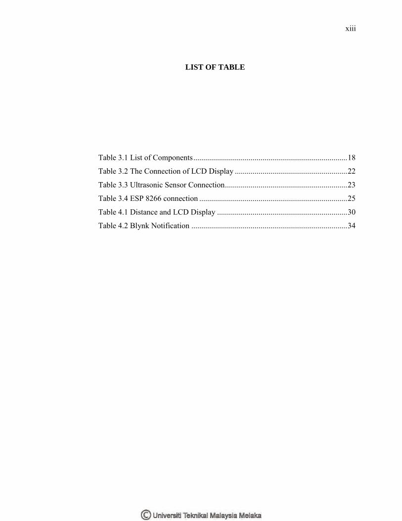
LIST OF TABLE
Table 3.1 List of Components .............................................................................. 18
Table 3.2 The Connection of LCD Display ......................................................... 22
Table 3.3 Ultrasonic Sensor Connection .............................................................. 23
Table 3.4 ESP 8266 connection ........................................................................... 25
Table 4.1 Distance and LCD Display .................................................................. 30
Table 4.2 Blynk Notification ............................................................................... 34

xiv
LIST OF FIGURE
Figure 1.1 Garbage In Office ................................................................................. 2
Figure 1.2 Garbage In Hospital .............................................................................. 2
Figure 2.1 Flow Chart Transmitter and Receiver................................................... 6
Figure 2.2 Information Access Client .................................................................... 6
Figure 2.3 (a) The Receiver ................................................................................... 7
Figure 2.3 (b) The Transmitter ............................................................................... 7
Figure 2.4 (a) Transmitter Section ......................................................................... 8
Figure 2.4 (b) Receiver Section ............................................................................. 8
Figure 2.5 Flow Chart Project ................................................................................ 8
Figure 2.6 GUI Interface on MATLAB ................................................................. 9
Figure 2.7 System Architecture............................................................................ 10
Figure 2.8 Device Architecture ............................................................................ 10
Figure 2.9 Flow Diagram ..................................................................................... 11
Figure 2.10 System Agriculture ........................................................................... 12
Figure 2.11 Dustbin Status ................................................................................... 12
Figure 3.1 Block Diagram .................................................................................... 13
Figure 3.2 Flow chart ........................................................................................... 14
Figure 3.3 Flow Chart Stage 1 ............................................................................. 15
Figure 3.4 Flow Chart Stage 2 ............................................................................. 16
Figure 3.5 Flow Chart Stage 3 ............................................................................. 17
Figure 3.6 Arduino Uno Board ............................................................................ 19
Figure 3.7 Ultrasonic Sensor ................................................................................ 20
Figure 3.8 LCD Display ....................................................................................... 20

xv
Figure 3.9 ESP 8266 module ............................................................................... 21
Figure 3.10 LCD Display Connection ................................................................. 23
Figure 3.11 Connection of Ultrasonic sensor ....................................................... 24
Figure 3.12 ESP8266 Connection ........................................................................ 26
Figure 3.13 Blynk apps in Smartphone ................................................................ 27
Figure 4.1 Reading at LCD Display (0%) ............................................................ 29
Figure 4.2 Empty Dustbin .................................................................................... 29
Figure 4.3 Garbage Half of Dustbin ..................................................................... 29
Figure 4.4 Reading of LCD Display (50%) ......................................................... 29
Figure 4.5 Reading of LCD Display (100%) ....................................................... 30
Figure 4.6 Dustbin Full ........................................................................................ 30
Figure 4.7 ESP 8244 is Connected to Phone ....................................................... 31
Figure 4.8 ESP Connecting with WiFi ................................................................. 32
Figure 4.9 Blynk apps .......................................................................................... 33
Figure 4.10 Notifying through phone................................................................... 34

xvi
LIST OF ABBREVIATIONS
IoT - Internet of Thigs
LCD - Liquid Crystal Display
LED - Light Emitting Diode
HTML - Hypertext Markup Language
IR - Infrared
TSOP - Thin Small Outline Package
DC - Direct Current
AT - ATtention
TCP - Transmission Control Protocol
IP - Internet Protocol
GPIOs - General – Purpose Input/output
PCB - Printed Circuit Board
APSD - Automatic Power Save Delivery
VoIP - Voice Over Internet Protocol
RF - Radio Frequency
1
CHAPTER 1
INTRODCUTION
1 TITLE
This chapter will explain about the project description, problem statement,
objective, scope of project, work scope and description of the methodology.
1.1 Project Briefing
This undertaking of IoT Garbage Monitoring System is a very innovative scheme
which will help to keep the cities clean and jerk. This project is suitable to be used in the
smart city. This arrangement monitors the garbage bin and informs about the spirit level
of the garbage collected in the garbage bins via a web page. For this, the system uses
ultrasonic sensors placed over the bins to detect the garbage level and compare it with the
garbage bins depth. The system brand use of Arduino Uno, LCD Display, ESP8266
module and a LED. The LCD screen is used to present the position of the level of garbage
collected in the bin.
A mobile phone app is used to show the level to the user whose monitoring it. The
apps will provide a graphical view of the garbage bins and highlighting the garbage
collected in order to show the level of garbage collected. It is shown by the LCD screen.
The system will put on the LED when the level of garbage collected crosses the set bound.
Thus, this system helps to keep the city clean by informing about the garbage spirit level
of the bins by providing a graphical image of the bins via mobile app.

2
1.2 Problem Statement
The human resource such as plastic bag always wasted when the cleaner need to
clean up the dustbin although the dustbin is not full. Besides that, when the dustbin is full
the user still throws the garbage at the dustbin. The cleaner cannot monitor the current
level of garbage in the dustbin so the time to check all the dustbin is wasted [1].
Figure 1.1 Garbage In Office
Figure 1.2 Garbage In Hospital

3
1.3 Objective
There are several objectives such as:
1. To design the IoT – based ‘Smart Garbage Monitoring System’ that detect
the level of the garbage in the dustbin.
2. To monitor the level of the garbage at the dustbin through LED.
3. To notify the cleaner about the garbage level of the dustbin by using mobile
apps.
1.4 Scope of The Project
The main function of the prototype of this project is to monitor the garbage in the
dustbin. The reading of the dustbin shown on the smartphone by using mobile apps
displays the level of the dustbin to notify the person in charge when the dustbin is full.
Besides that, the dustbin also has the LED to tell the people when the dustbin is full.
The main components are the Arduino Uno. This Arduino Uno acts as a head for
the ultrasonic sensor, LCD monitor, and the LED. The ultrasonic sensor is made by level
for the dustbin, so it will show the level of the dustbin at the mobile apps. The LCD
monitor also functions the same as the LED that shows when the dustbin is full.
For this project, the prototype constructed is meant for crowded hospital that has
many levels. It also can be applying to the office building that has multilevel.
The hardware required for this project are Arduino Uno, ultrasonic sensor, WiFi
module ESP8266, LED, LCD display, resistor and servo motor. The apps used is the
Blynk. The cost of this project is about RM 170.00.
1.5 Thesis Organization
Chapter 1 explains about the introduction of the project the contains the problems
statements, objectives, and the scope of work. Chapter 2 explains about the literature
review of the other papers that related with this project. Chapter 3 explains about the

4
methodology of this project that contains the flow chart, list of the equipment component
description and component structure. Chapter 4 explains about the result of these project
that get after we are doing several experiments. Lastly, chapter 5 explains about the
conclusion and recommendations of these project.

5
CHAPTER 2
LITERATURE REVIEW
2 INTRODUCTIO
In this chapter reviews from other papers are auditing to identify the research gap.
2.1 Literature Review of Current Project
For every project that has been done successfully, studies and reference have been
done as guidelines. All the guidelines come from various sources and references such as
books, articles, journals, and the internet. These sources play a vital role in making this
project successful. All the information highlights major areas that are related and will be
used in the software and hardware of this project.
2.1.1 IoT Based Waste Management for Smart City
This project is done by Parkash and Prabu from National Institute of Electrical and
Information Technology, Calicut, Kerala, the Republic of India in February 2016. This
project combines 8051 microcontrollers, IR sensor, RF module, Intel Galileo Gen2. In this
projected system, they proposed the low cost embedded system to make the truck located
the dustbin through the city or Campus[2]. The dustbin also has the unique ID that makes
it easy to identify when the garbage is full. The detail can be access by the concern
authorities from their place by using the Internet and they can give the immediate response
to clean the dustbin. Figure 2.1 illustrate the flow chart of the transmitter and receiver of
this project. Figure 2.2 shows the information access of the client in this project.

6
2.1.2 IoT Based Smart Garbage and Waste Collection Bin
This project is done by S.S Navghane, M.S Killedar and Dr.V.M Rohokale. The
article is published in May 2016. These dustbins are interfaced with microcontroller ARM
Figure 2.1 Flow Chart Transmitter and Receiver
Figure 2.2 Information Access Client

7
(LPC2148) based system and having IR wireless systems along with central system
showing the status of garbage, on a mobile web browser with HTML page by Wi-Fi [1].
This project also has used the combination of a weight sensor and IR sensor to detect the
amount of garbage in the dustbin and to give the information about the dustbin status.
Hence the status will be updated on the HTML page. The main part of this project depends
upon the working of the Wi-Fi module; essential for its implementation. Figure 2.3 (a)
shows the transmitter block diagram of this project, while Figure 2.3 (b) shows the
receivers block diagram for this project
.
2.1.3 Smart Garbage Management System
This project is done by Vikrant Bhor, Pankaj Morajkar, Maheshwar Gurav and
Dishant Pandaya. It is published on March 2015. The project is about combining the
Arduino Uno Board as the microcontroller and the IR sensor for the detection of garbage.
For the receiver part, this project has used the TSOP1738 [3]. The output of this
TSOP1738 is connected to the Arduino UNO Board. The GSM is used for the transmitter
section compare to the ZigBee. Figure 2.4 (a) and Figure 2.4 (b) illustrate the transmitter
section and receiver section of these project.
Figure 2.3 (a) The Transmitter Figure 2.3 (b) The Receiver

8
Figure 2.4 (b) Receiver Section
Figure 2.4 (a) Transmitter Section
Figure 2.5 Flow Chart Project