Embed Size (px)
Citation preview
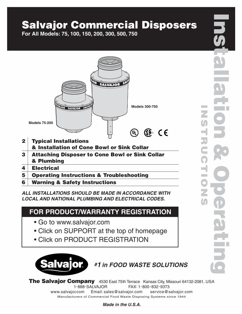
ALL INSTALLATIONS SHOULD BE MADE IN ACCORDANCE WITHLOCAL AND NATIONAL PLUMBING AND ELECTRICAL CODES.
Salvajor Commercial DisposersFor All Models: 75, 100, 150, 200, 300, 500, 750Insta
llatio
n&Operatin
gIN
STRUCTIO
NS
2 Typical Installations& Installation of Cone Bowl or Sink Collar
3 Attaching Disposer to Cone Bowl or Sink Collar& Plumbing
4 Electrical5 Operating Instructions & Troubleshooting6 Warning & Safety Instructions
FOR PRODUCT/WARRANTY REGISTRATION
• Go to www.salvajor.com• Click on SUPPORT at the top of homepage• Click on PRODUCT REGISTRATION
Models 75-200
Models 300-750
The Salvajor Company 4530 East 75th Terrace Kansas City, Missouri 64132-2081, USA1-888-SALVAJOR FAX: 1-800-832-9373
www.salvajor.com Email: [email protected] [email protected] of Commercial Food Waste Disposing Systems since 1944
#1 in FOOD WASTE SOLUTIONS
Made in the U.S.A.
2
Typical Installations
Installation of CONE BOWL or SINK COLLAR
INCOMING POWERCONTROL
SOLENOID VALVEWITH FLOW CONTROL
VACUUMBREAKER
OPTIONALSHORT LEG
SINK
OPTIONALSHORT TOPHOUSING
INCOMING WATER3/4" PLUMBINGREDUCED TO 1/2"
1/2" VALVE(NF)
1/2" PLUMBING
WATERINLET
2" DRAIN(models 75-200)
2" OR 3" DRAIN(models 300-750)
INCOMING POWERCONTROL
SOLENOID VALVEWITH FLOW CONTROL
VACUUMBREAKER
WATERINLET
OPTIONALPRE-RINSE
CONE
INCOMING WATER3/4" PLUMBINGREDUCED TO 1/2"
1/2" VALVE(NF)
1/2" PLUMBING
2" DRAIN(models 75-200)
2" OR 3" DRAIN(models 300-750)
INCOMING POWER
CONTROLWITH (P) OR (PP)
OPTIONALREMOTESTART/STOP
VACUUMBREAKER
WATERINLET
CONE OR SINK
INCOMING WATER3/4" PLUMBINGREDUCED TO 1/2"
1/2" VALVE(NF)
1/2" PLUMBING
(P)(PP)
2" DRAIN (models 75-200)2" OR 3" DRAIN (models 300-750)
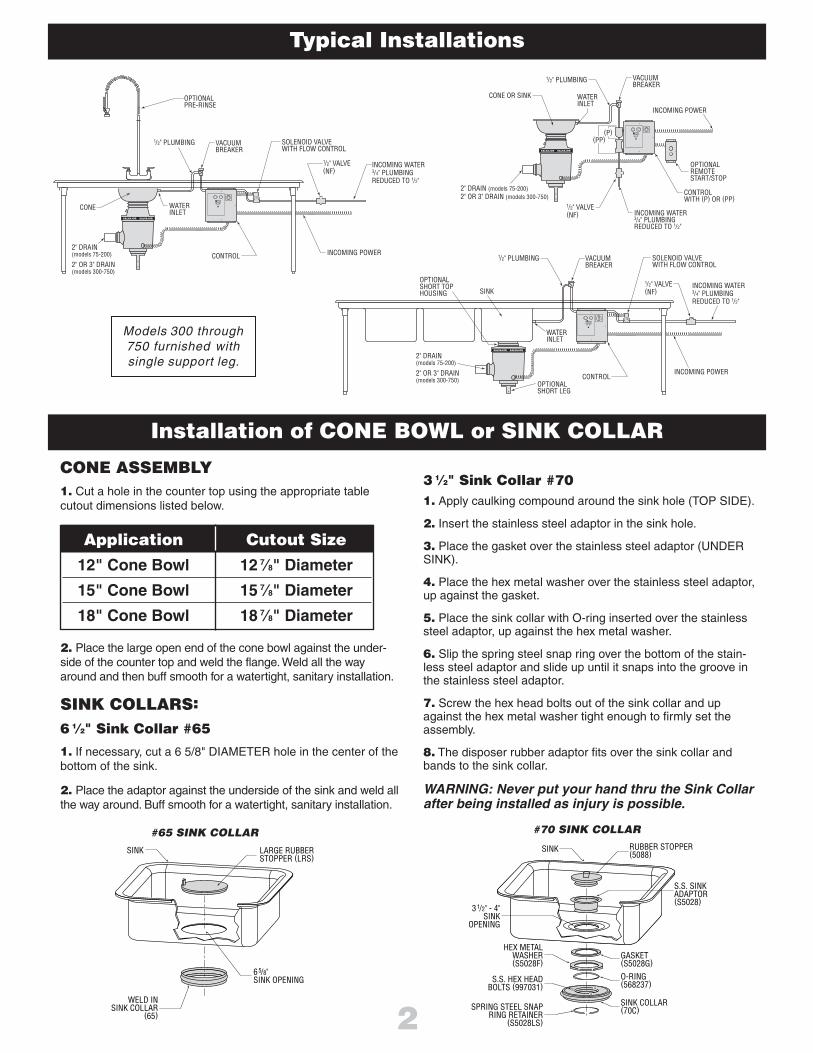
Models 300 through750 furnished withsingle support leg.
CONE ASSEMBLY1. Cut a hole in the counter top using the appropriate tablecutout dimensions listed below.
2. Place the large open end of the cone bowl against the under-side of the counter top and weld the flange.Weld all the wayaround and then buff smooth for a watertight, sanitary installation.
SINK COLLARS:
6 1⁄2" Sink Collar #65
1. If necessary, cut a 6 5/8" DIAMETER hole in the center of thebottom of the sink.
2. Place the adaptor against the underside of the sink and weld allthe way around. Buff smooth for a watertight, sanitary installation.
65/8"SINK OPENING
WELD INSINK COLLAR
(65)
SINK LARGE RUBBERSTOPPER (LRS)
SINK
31/2" - 4"SINK
OPENING
HEX METAL WASHER (S5028F)
SPRING STEEL SNAP RING RETAINER
(S5028LS)
S.S. HEX HEAD BOLTS (997031)
RUBBER STOPPER (5088)
S.S. SINK ADAPTOR (S5028)
GASKET (S5028G)
O-RING (568237)
SINK COLLAR (70C)
#65 SINK COLLAR #70 SINK COLLAR
Application Cutout Size
12" Cone Bowl 12 7⁄8" Diameter
15" Cone Bowl 15 7⁄8" Diameter
18" Cone Bowl 18 7⁄8" Diameter
3 1⁄2" Sink Collar #701. Apply caulking compound around the sink hole (TOP SIDE).
2. Insert the stainless steel adaptor in the sink hole.
3. Place the gasket over the stainless steel adaptor (UNDERSINK).
4. Place the hex metal washer over the stainless steel adaptor,up against the gasket.
5. Place the sink collar with O-ring inserted over the stainlesssteel adaptor, up against the hex metal washer.
6. Slip the spring steel snap ring over the bottom of the stain-less steel adaptor and slide up until it snaps into the groove inthe stainless steel adaptor.
7. Screw the hex head bolts out of the sink collar and upagainst the hex metal washer tight enough to firmly set theassembly.
8. The disposer rubber adaptor fits over the sink collar andbands to the sink collar.
WARNING: Never put your hand thru the Sink Collarafter being installed as injury is possible.
3
Plumbing
Attaching Disposer to CONE BOWL or SINK COLLAR
DRAIN PIPING1. Before installing the Salvajor disposer, the waste line shouldbe properly cleaned out to the connecting main sewer.
2. Use as few elbows, tees and bends as possible when mak-ing connections.
3. All horizontal drain lines should have a minimum slope of1/4" per linear foot.
4. A 3" diameter pipe is recommended for Salvajor disposersmodels 300 thru 750. A 2" adapter is supplied for existing 2"drains. Models 75 thru 200 require a 2” drain.
IMPORTANT!It is imperative to have a proper downward pitch from the disposer outlet to themain sewer line to assure proper gravity flow. Improper drain line installationcan result in drain backups.
5. Do not connect into a grease trap, interceptor or drum trap.
NOTE: Pressure regulators should be installed in areas where pressure exceedsthe recommended maximum of 80 psi.
WATER SUPPLY6. Connect COLDWATER ONLY to disposer.
Water volume can be controlled by a properly rated flow controlvalve or hand operated valve.
(Nos. 7-9 below for NEW INSTALLATIONS ONLY!)
7. Plumb 3/4" IPS line and reduce to 1/2" at the hand valve.Install the factory-supplied solenoid valve with built-in flow control.
8. From the solenoid, plumb 1/2" IPS line above the flood plane ofthe table and install the factory supplied vacuum breaker to localcode.
9. Plumb 1/2" IPS line from the vacuum breaker to either conebowl, sink or top housing inlet on the disposer. If connecting tocone or sink, use 1⁄2" water inlet supplied by the factory.NOTE: CONNECT COLD WATER ONLY TO DISPOSER.Tempered water from pre-rinse or Salvajor scrapping system is acceptable,but only in conjunction with an independent, continuous cold water supply.
TYPICAL CONE LAYOUT TYPICAL SINK LAYOUT
MAKE ALL PLUMBING CONNECTIONSIN ACCORDANCE WITH LOCAL AND
NATIONAL PLUMBING CODES.
Recommended Cold Water Supply
Models 75, 100, 150, 200 5GPM
Models 300, 500, 750 8GPM
STOP! If you have any questions about this installationcall 1-888-SALVAJOR for installation advice.
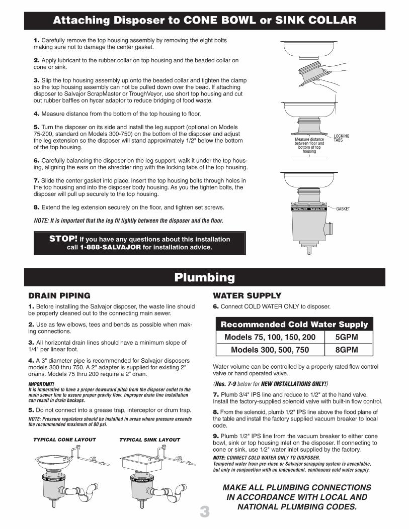
1. Carefully remove the top housing assembly by removing the eight boltsmaking sure not to damage the center gasket.
2. Apply lubricant to the rubber collar on top housing and the beaded collar oncone or sink.
3. Slip the top housing assembly up onto the beaded collar and tighten the clampso the top housing assembly can not be pulled down over the bead. If attachingdisposer to Salvajor ScrapMaster or TroughVeyor, use short top housing and cutout rubber baffles on hycar adaptor to reduce bridging of food waste.
4. Measure distance from the bottom of the top housing to floor.
5. Turn the disposer on its side and install the leg support (optional on Models75-200, standard on Models 300-750) on the bottom of the disposer and adjustthe leg extension so the disposer will stand approximately 1/2" below the bottomof the top housing.
6. Carefully balancing the disposer on the leg support, walk it under the top hous-ing, aligning the ears on the shredder ring with the locking tabs of the top housing.
7. Slide the center gasket into place. Insert the top housing bolts through holes inthe top housing and into the disposer body housing. As you the tighten bolts, thedisposer will pull up securely to the top housing.
8. Extend the leg extension securely on the floor, and tighten set screws.
NOTE: It is important that the leg fit tightly between the disposer and the floor.
LOCKING TABSMeasure distance
between floor and bottom of top
housing
GASKET
4
ElectricalGENERAL INSTRUCTIONSDual voltage disposers are shipped from the factoryNOT connected for a specific voltage. Please refer to thewiring diagrams on the disposer junction box cover.Whenconnecting single phase disposers to a reversing control,refer to the diagram supplied with the control. Salvajordisposer cutting elements are designed to operate ineither direction.
Use water tight conduit and fittings to make connections.
Caution: Be careful not to pinch wires when replacingjunction box cover.
For new installations, an approved control will need to bemounted on or near the dish table with an optional bracket.Power will have to be run to a solenoid for incoming water.
NOTE: The RESET button is located on the bottom of the disposer.
TEST PROCEDURE1. Check to be sure the disposer cutting teeth are free offoreign objects.
2. Turn the disposer on and determine that the cuttingelements rotate freely and that water flows automatically.
3. Check the mounting assembly and plumbing connectionsfor leaks.
4. If disposer fails to operate:A. Turn off power.B. Check wiring connections.C. Determine if the RESET button has tripped.
Reset by hand only.
DANGER: If disposer stops, DO NOT look for the cause until thestarting control is turned OFF and the power is turned OFF.Consult Operating Instructions.
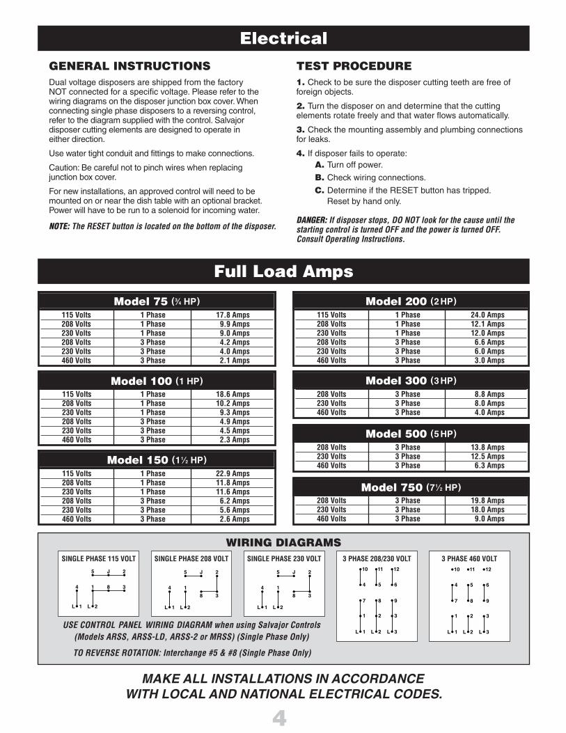
Model 200115 Volts 1 Phase 24.0 Amps208 Volts 1 Phase 12.1 Amps230 Volts 1 Phase 12.0 Amps208 Volts 3 Phase 6.6 Amps230 Volts 3 Phase 6.0 Amps460 Volts 3 Phase 3.0 Amps
Model 300208 Volts 3 Phase 8.8 Amps230 Volts 3 Phase 8.0 Amps460 Volts 3 Phase 4.0 Amps
Model 500208 Volts 3 Phase 13.8 Amps230 Volts 3 Phase 12.5 Amps460 Volts 3 Phase 6.3 Amps
Model 750208 Volts 3 Phase 19.8 Amps230 Volts 3 Phase 18.0 Amps460 Volts 3 Phase 9.0 Amps
Model 75115 Volts 1 Phase 17.8 Amps208 Volts 1 Phase 9.9 Amps230 Volts 1 Phase 9.0 Amps208 Volts 3 Phase 4.2 Amps230 Volts 3 Phase 4.0 Amps460 Volts 3 Phase 2.1 Amps
Model 100115 Volts 1 Phase 18.6 Amps208 Volts 1 Phase 10.2 Amps230 Volts 1 Phase 9.3 Amps208 Volts 3 Phase 4.9 Amps230 Volts 3 Phase 4.5 Amps460 Volts 3 Phase 2.3 Amps
Model 150115 Volts 1 Phase 22.9 Amps208 Volts 1 Phase 11.8 Amps230 Volts 1 Phase 11.6 Amps208 Volts 3 Phase 6.2 Amps230 Volts 3 Phase 5.6 Amps460 Volts 3 Phase 2.6 Amps
Model 75 (3⁄4 HP)
Model 100 (1 HP)
Model 150 (11⁄2 HP)
Model 200 (2HP)
Model 300 (3HP)
Model 500 (5HP)
Model 750 (71⁄2 HP)
Full Load Amps
MAKE ALL INSTALLATIONS IN ACCORDANCEWITH LOCAL AND NATIONAL ELECTRICAL CODES.
WIRING DIAGRAMS
5
L 2L 1
J 2
14 8 3
L 2 L 3L 1
2 31
8 97
5 64
11 1210
L 2 L 3L 1
2 31
8 97
5 64
11 1210
SINGLE PHASE 115 VOLT
5 J 2
8 3
14
L 2L 1
SINGLE PHASE 208 VOLT
5 J 2
8 3
14
L 2L 1
SINGLE PHASE 230 VOLT 3 PHASE 208/230 VOLT
TO REVERSE ROTATION: Interchange #5 & #8 (Single Phase Only)
USE CONTROL PANEL WIRING DIAGRAM when using Salvajor Controls(Models ARSS, ARSS-LD, ARSS-2 or MRSS) (Single Phase Only)
3 PHASE 460 VOLT

5
OPERATING INSTRUCTIONS
Push the START button on the control panel to begin operation. Before you startfeeding food waste into the disposer, make sure that a steady stream of water isflowing into the unit. Do not start feeding food waste into the disposer until theunit is started and the water is running.
1
Push the STOP button on the control panel to stopoperation. To prevent accidents, make sure thedisposer is shut off before you leave it unattended.3
Feed food waste into the disposer in a steady continu-ous flow. Don’t overload the disposer with excessamounts of food waste and water. The disposer willconsume food waste faster when you feed it steadily.
Always keep your hands away from a disposer when it is operating.Don’t stop the disposer with food waste in it. Let it run for approxi-mately 3 minutes to clear itself of all ground waste.This will help tomaintain a clean and odor-free unit and to avoid drain line clogs.
2
The disposer will not startand water does not flow.
PROBLEM POSSIBLE CAUSE SOLUTION
The disposer will not startbut water flows.
No incoming power. Check breaker and disconnect.Turn power on.
The disposer motor stopswhile grinding, but watercontinues to flow.
The disposer is jammed.
The disposer motoroverload is tripped.
See: The disposer is jammed, above.
See: The disposer motor overload is tripped, above.
Turn the disposer control off and press the reset button on the disposer.If the disposer was running, allow the unit to cool for 3-5 minutes beforepressing the reset button. Never strike the reset button with an object.Note: This commercial reset requires a firm push.
The water flowscontinuously before thecontrols are turned on.
Reinstall so that the arrow on the solenoid is pointing in the direction ofthe water flow.
Turn the power off to the disposer and complete the following steps:1. Insert optional dejamming prong through the sink (or cone) opening.Place the prong over the center raised bars found on the top ofthe disposers revolving rotor.
2. Twist the dejamming bar back and forth to free the jam.The revolving rotor should turn freely when the jam is released.
3. Remove all foreign material that caused the stoppage. Do notinsert hand/fingers into the disposer. Use long tongs orpliers to remove objects.
4. Allow the disposer to cool for 3-5 minutes after it stops running.Press the reset button to reset the motor overload protector.Never strike the reset button with an object.
5. If the disposer remains inoperative after following these steps,contact the nearest Salvajor Factory Authorized Service Center, orthe factory direct. You may obtain the telephone number of theService Center nearest you by calling 1-888-SALVAJOR.WARNING: Never put your hand down in to the disposer!
The disposer motoroverload is tripped.
The disposer is jammed.
Motor overload tripsfrequently.
Disposer is overloadedwith food waste.
Hot water used in lieu ofcold.
Incorrect water solenoidinstallation.
Do not overload the disposer with excessive amounts of food waste.Refer to operating instructions above.
Reconnect with cold water.
Reset button location
IMPORTANT!Do NOT use corrosive chemicalsor cleaners in the disposer.
TroubleshootingWARNING! DISCONNECT THE POWER TO THE DISPOSER BEFORE SERVICING.

6
Read all the instructions before using the disposer.
REMEMBER! Always keep hands away from a disposer when it is running.
1
Always keep your hands away from disposer when it is running.3
Keep safety baffle over throat of disposer.2
Push STOP button on control panel and shut off electrical power to the panel before attemptingto clear a jam.4
To reduce risk or injury by materials that may be expelled from the unit, do not put the followingitems into a disposer:
A. Clam or oyster shellsB. Drain cleaner or corrosive detergentsC. Glass, china or plasticsD. Metal such as bottle caps, tin or aluminum cans, etc.
6
When attempting to clear a jam in a disposer use a Salvajor dejamming tool or a long woodenobject to reverse rotation. Remove all foreign material that caused the stoppage. Do not inserthand/fingers into the disposer. Use long tongs or pliers to remove objects.
5
TYPICAL SALVAJOR DISPOSER TO CONE BOWL / DEEP SINK INSTALLATION
NOTE: Above Installation Per UL Standard 430 Height Requirements.
Warning!
SAFETY INSTRUCTIONS
INTERNALTHROATOPENING61/2" ID
CONE BOWL/DEEP SINK
DISPOSERTOP HOUSING
WATER INLET
53/8"MIN.
CONTROLSPer UL 430, install using a UL-listed electrical control panel.
The following Salvajor electrical control panels manufactured as of 11-01-96comply with UL Standard 430 Section 28.3.1 (Exception 1) and 28.3.2:
model numbers MSS, MSS-LD, MRSS, MRSS-LD, ARSS-2, ARSS and ARSS-LD.
HOPPERS, SINKS & CONE BOWLS
Risk of injury to persons from hazardous moving parts.Serious injury possible if not properly installed with aUL-listed hopper, sink or cone.
All Salvajor cone bowls and chutes are designed and builtper UL Standard 430 Section 7 Enclosures, subsection 7.1.2(Exception 1), 7.1.3, and 7.1.6 using 16 Gauge nominalstainless steel sheet.
All replacement cones/ hoppers, sinks and chutes used withSalvajor disposers should be of equal construction per thepreviously listed standard.
The following Salvajor cones manufactured as of 11-01- 96comply with UL Standard 430 Section 28.3.1 (Exception 1)and 28.3.2:P/N CB-12, CB-15, CB-18.
Printed in USAForm No. II-DISP-11-WL


![[American Society of Plumbing Engineers] Plumbing](https://img.pdfslide.us/doc/110x75/577cb1c91a28aba7118bddeb/american-society-of-plumbing-engineers-plumbing.jpg)