Embed Size (px)
Citation preview
i- Pilot Wireless Accessory
Do NOT replace the complete i-Pilot as a boxed marine accessory – trouble shoot and replace the defective part!
Connect motor to the voltage appropriate (12/24/36) for the motor being serviced. For Terrova, Riptide Terrova, Ulterra,
Riptide Ulterra, and Ultrex motors the motor must be deployed and the System Ready light “ON” for the motor and
i-Pilot system to function.
Make sure the i-Pilot remote and controller assemblies have the latest software downloaded.
TROUBLESHOOTING Further information for issues not specific to i-Pilot can be found in the specific model repair manuals.
Part I. General Troubleshooting pages 1 through 6
Part II. Miscellaneous System Information pages 7 through 9
Part III. Remote Quick Reference Guide pages 10 through 16
Please note the differences in the following pictures as they will be referenced throughout this
manual. These are referred to as i-Pilot remotes:
Remote for i-Pilot 1.0 Remote for i-Pilot 1.5 Remote for i-Pilot 1.6
p/n 2994085 p/n 2994170 & p/n 2994171 (Ulterra) p/n 2994075
(Ulterra remote has trim/stow/deploy buttons) (Blue Tooth® enabled i-Pilot system)
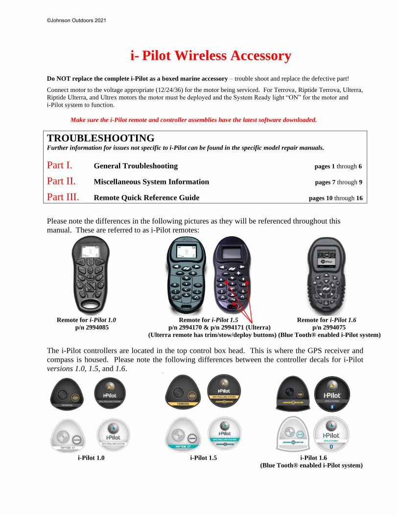
The i-Pilot controllers are located in the top control box head. This is where the GPS receiver and
compass is housed. Please note the following differences between the controller decals for i-Pilot
versions 1.0, 1.5, and 1.6.
i-Pilot 1.0 i-Pilot 1.5 i-Pilot 1.6
(Blue Tooth® enabled i-Pilot system)
©Johnson Outdoors 2021
NOTE: On PowerDrive and Riptide PowerDrive (V2 and newer), once the i-Pilot is installed the
i-Pilot remote will be the only means of steering the PowerDrive motor. The corded footpedal will
no longer steer the motor if the i-Pilot Controller cable is disconnected and the footpedal
reconnected. To recover steering with the corded footpedal, the complete i-Pilot system would need
to be un-installed and, if the motor has an AutoPilot model main control board, an original compass
control board would also need to be installed.
NOTE: Terrova, Riptide Terrova, Ulterra, Riptide Ulterra, and Ultrex motors communicate
with any connected accessory via a microprocessor-based network. The failure of any installed
network accessory can result in motor malfunction. Disconnect all accessories other than the i-Pilot
when diagnosing the motor. If the problem is corrected, then reconnect each accessory one at a time
to isolate which component caused the issue.
Part I. General Troubleshooting
Click on blue Case to jump to the linked discussion/resolution:
Case I. The motor is making erratic steering corrections while in AutoPilot, Spot-
Lock or Track to Start/End.
Case II. The boat doesn’t seem to keep close enough to the recorded Spot-Lock
location.
Case III. When in Advanced AutoPilot in strong winds, there is quite a bit of back
and forth movement in the boat.
Case IV. When in Advanced AutoPilot in strong winds, there is quite a bit of back
and forth movement in the boat.
Case V. i-Pilot won’t let me turn on certain features like Advanced AutoPilot,
Record, Track to Start/End, or Spot-Lock.
Case VI. The i-Pilot GPS-based features drop out when the motor speed setting is
increased.
Case VII. While in Track to Start/End the propeller suddenly stopped.
Case VIII. While in Record mode, the recording suddenly stopped.
Case IX. When a button on the 1.5 remote is pressed no icons are displayed on the
remote LCD screen. (refer to pictures on prior page for remote versions)
Case X. When any button on the 1.0 remote is pressed nothing happens. (refer to pictures
on prior page for remote versions)
Case XI. When buttons on the 1.0 remote are pressed some of them work and others
do not, but all buttons “feel” the same. (refer to pictures on prior page for remote versions)
Case XII. When a specific button on the 1.0 remote is pressed nothing happens. (refer to pictures on prior page for remote versions)
©Johnson Outdoors 2021

Case XIII. The i-Pilot 1.0 or 1.5 remote displays an “F” on the LCD screen OR the i-
Pilot 1.6 remote displays “Motor Error”. (refer to pictures on first page for remote versions)
Case XIV. The screen on the 1.6 remote displays “RF error”. (refer to pictures on first page
for remote versions)
Case XV. Pressing any button on the 1.0 or 1.5 remote causes all the icons to come
on for a few seconds and then turn off, OR the screen on the 1.6 remote reads “Motor
Not Found” when the remote is on. (refer to pictures on first page for remote versions)
Case XVI. The remote LCD backlighting will not come on.
Case XVII. Customer complaint that the battery in the i-Pilot remote drains quickly.
Case XVIII. There is moisture in the LCD window or the remote case.
Case XIX. On PowerDrive / Riptide PowerDrive models, the steering does not work
properly or at all following i-Pilot installation.
Case XX. The heading sensor calibration failed. (i-Pilot 1.6 only)
Part II. Miscellaneous System Information Accuracy
Battery Life
Battery Replacement
Remote Pairing / Learning
Audio Modes
Part III. Remote Quick Reference Guide Quick Reference Guide 1.6
Quick Reference Guide 1.5
Quick Reference Guide 1.0
i-Pilot rev 04/21
1
i- Pilot Wireless Accessory
Part I. General Troubleshooting Case I. The motor is making erratic steering corrections while in AutoPilot,
Spot-Lock, or Track to Start/End. Step 1. Check all electrical connections and battery condition to ensure that the proper voltage is supplied to the motor.
Consistent voltage is critical to ensure the built-in compass is working correctly. (The i-Pilot system uses an
internal compass to know which direction the controller and GPS receiver is pointing.) A load test of the
battery should be performed to verify the battery(s) condition; a simple voltage check is not diagnostic.
Step 2. Be sure to keep all ferrous metallic objects away from the i-Pilot Controller as they will have an impact on the
built-in compass. Such objects include: anchors, metal framework, etc…
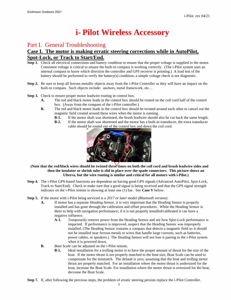
Step 3. Check to ensure proper motor leadwire routing in control box.
A. The red and black motor leads in the control box should be routed on the coil cord half of the control
box. (Away from the compass of the i-Pilot controller.)
B. The red and black motor leads in the control box should be twisted around each other to cancel out the
magnetic field created around these wires when the motor is running.
B-1. If the motor shaft was shortened, the brush leadwire should also be cut back the same length.
B-2. If the motor shaft was shortened and the motor has a built-in transducer, the extra transducer
cable should be routed out of the control box and down the coil cord.
(Note that the red/black wires should be twisted three times on both the coil cord and brush leadwire sides and
then the insulator or shrink tube is slid in place over the spade connectors. This picture shows an
Ulterra, but the wire routing is similar and critical for all motors with i-Pilot.)
Step 4. The i-Pilot GPS-based functions are dependent on having good GPS signals (Advanced AutoPilot, Spot-Lock,
Track to Start/End). Check to make sure that a good signal is being received and that the GPS signal strength
indicator on the i-Pilot remote is showing at least one (1) bar. See Case V below.
Step 5. If the motor with i-Pilot being serviced is a 2017 or later model (Bluetooth version):
A. If motor has a separate Heading Sensor, it is very important that the Heading Sensor is properly
installed and has gone through the calibration and offset procedures. While the Heading Sensor is
there to help with navigation performance; if it is not properly installed/calibrated it can have a
negative influence.
A-1. Temporarily remove power from the Heading Sensor and see how Spot-Lock performance is
impacted. If performance is improved, suspect that the Heading Sensor was improperly
installed. (The Heading Sensor contains a compass that detects a magnetic field so it should
not be installed near ferrous metals or wires that handle large currents, such as batteries,
power cables, or speakers.) The Heading Sensor will not lose it pairing to the i-Pilot system
when it is powered down.
B. Boat Scale can be adjusted on the i-Pilot remote.
B-1. Ideal installation for a trolling motor is to have the proper amount of thrust for the size of the
boat. If the motor thrust is not properly matched to the boat size, Boat Scale can be used to
compensate for the mismatch. The default is zero, assuming that the boat and trolling motor
thrust are properly matched. For an installation where the motor thrust is undersized for the
boat, increase the Boat Scale. For installation where the motor thrust is oversized for the boat,
decrease the Boat Scale.
Step 7. If, after following the previous steps, the problem of erratic steering persists replace the i-Pilot Controller.
©Johnson Outdoors 2021
i-Pilot rev 04/21
2
Case II. The boat doesn’t seem to keep close enough to the recorded Spot-Lock
location. Step 1. Verify the trolling motor batteries are sufficiently charged.
Step 2. Check for weeds wrapped around and under the prop.
Step 3. In more extreme wind and current conditions, the boat will tend to stabilize a little downwind from the intended
location. Relock the location the same distance upwind and expect that the boat will drift some in the
downwind direction.
Step 4. See Case I.
Case III. When in Advanced AutoPilot in strong winds, there is quite a bit of
back and forth movement in the boat. Step 1. While Advanced AutoPilot will keep your boat on a true heading, it may be at the expense of the boat having to
continuously move to get back on the correct course. In these extreme conditions you may be better off using
Legacy AutoPilot and correcting for the wind manually.
Step 2. See Case I.
Case IV. Under AutoPilot mode, I have Advanced selected as the default mode.
However, when I engage AutoPilot, it goes into Legacy AutoPilot instead of
Advanced. Step 1. If the GPS signal strength indicator shows no bars or is flashing, then Link will automatically engage Legacy
AutoPilot regardless of the Mode selected. Wait for your GPS signal strength to reach at least one bar, then re-
engage AutoPilot.
Case V. i-Pilot won’t let me turn on certain features like Advanced AutoPilot,
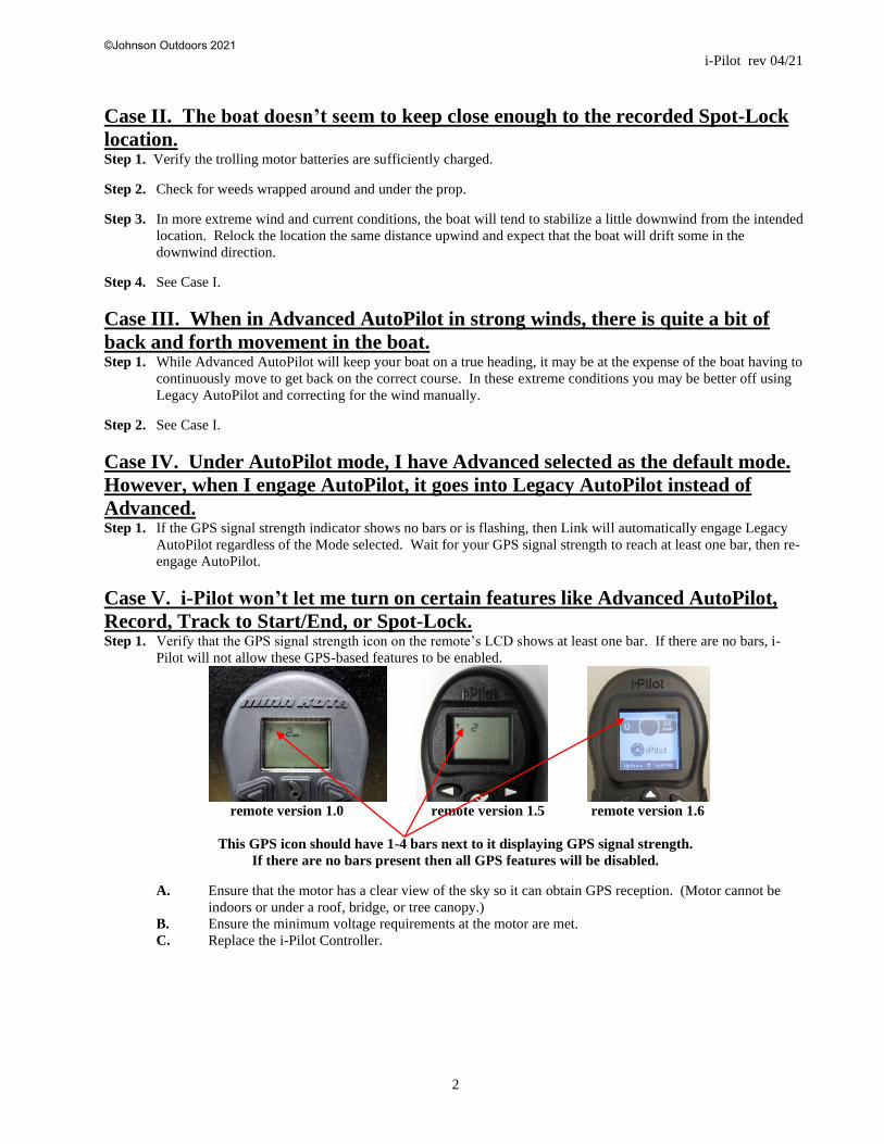
Record, Track to Start/End, or Spot-Lock. Step 1. Verify that the GPS signal strength icon on the remote’s LCD shows at least one bar. If there are no bars, i-
Pilot will not allow these GPS-based features to be enabled.
remote version 1.0 remote version 1.5 remote version 1.6
This GPS icon should have 1-4 bars next to it displaying GPS signal strength.
If there are no bars present then all GPS features will be disabled.
A. Ensure that the motor has a clear view of the sky so it can obtain GPS reception. (Motor cannot be
indoors or under a roof, bridge, or tree canopy.)
B. Ensure the minimum voltage requirements at the motor are met.
C. Replace the i-Pilot Controller.
©Johnson Outdoors 2021
i-Pilot rev 04/21
3
Case VI. The i-Pilot GPS-based features drop out when the motor speed setting
is increased. Step 1. Suspect a low voltage situation.
A. Inspect all battery connections, trolling motor plug (if installed), and any butt splice connections in
battery leadwire for corrosion and security. Use of inadequate gauge wire in boat or any leadwire
extension can result in voltage drop / low voltage to the motor; as can an inadequate or a corroded plug
/ plug receptacle.
B. Ensure the minimum voltage requirements at the motor are met.
Case VII. While in Track to Start/End the propeller suddenly stopped. Step 1. Verify you did not accidentally enable another automatic feature such as AutoPilot or Spot-Lock.
Step 2. The Arrival Mode may be set to OFF. When the End or Start point of an iTrack is reached the i-Pilot Link will
automatically cancel iTrack navigation. Depending on the Arrival Mode chosen, the motor will turn off, go into
Spot-Lock, or go into AutoPilot. See i-Pilot Link User Manual for more information.
Case VIII. While in Record mode, the recording suddenly stopped. Step 1. You may have reached the two-mile limit for recording a track.
Case IX. When a button on the 1.5 remote is pressed no icons are displayed on
the remote LCD screen. Step 1. Use a coin, (a quarter works well), to remove the battery cover on the back side of the remote. Insert coin in
slot and rotate the cover about 60° counterclockwise to disengage the cover locking tabs from the case back.
Turn the remote over and then the cover and CR2450 battery should fall out the back of the remote.
Step 2. Test the remote battery voltage. A good battery will have at least 2.9 volts. Replace the battery, if required, and
reassemble battery and cover into the remote.
A. Retest remote for function and icon display. If no display is noted, replace the remote (p/n 2994170 or
2994171 for Ulterra).
Case X. When any button on the 1.0 remote is pressed nothing happens. Step 1. Open the remote case assembly by removing the six screws on the back side of the remote.
Step 2. Check voltage of the battery in the remote. A good battery will read at least 2.9 volts. Replace the battery and
retest, as necessary.
NOTE: Care must be used when reassembling the remote case. Be sure to re-install the screws using the same
threads initially “cut” when the screws were first installed. The screws should be torqued to about 6 inch-
pounds to ensure proper resealing of the remote assembly.
Step 3. If the battery voltage checked okay, check the security of the battery holder to the remote’s circuit board. If B+
or B- battery connections are loose or if the battery holder is loose from the circuit board replace the remote
assembly.
Step 4. If the customer reported seeing “moisture” in the LCD window and the remote does not respond to any button
press then water may have gotten inside the sealed remote enclosure and shorted out the microcircuit on the
board. Replace remote assembly.
Case XI. When buttons on the 1.0 remote are pressed some of them work and
others do not, but all buttons “feel” the same. Step 1. Open the remote case assembly by removing the six screws on the back side of the remote. Visually inspect the
dome switches on the front side of the remote circuit board. If any dome switch is found to be flattened or
collapsed, replace the remote. If the dome switches are fine, but a plunger array pin is bent or broken, replace
the plunger array (p/n 2378451).
©Johnson Outdoors 2021

i-Pilot rev 04/21
4
Case XII. When a specific button on the 1.0 remote is pressed nothing happens. Step 1. If the button pressed feels “soft” or different from the other buttons, the plunger array (p/n 2378451) has a
broken pin and needs to be replaced. Open the remote case assembly by removing the six screws on the back
side of the remote. When replacing a broken plunger array, visually inspect the dome switches on the front of
the remote circuit board. If any dome switch is flattened or collapsed, replace the remote assembly.
Case XIII. The i-Pilot 1.0 or 1.5 remote displays an “F” on the LCD screen OR
the i-Pilot 1.6 remote displays “Motor Error”. Cause: This indicates that the i-Pilot Controller is not able to communicate with the motor control board. This error
will not display on PowerDrive motors.
Step 1. Cycle Power to the motor.
A. On Terrova/Riptide ST from 2016 and earlier (non-Blue Tooth) the main control board only looks for
accessories when it first powers up; if the i-Pilot began communicating after initial power up or was
installed while powered up, the control board will not recognize it until the next time it powers up.
This step may resolve the issue.
B. Re-test for proper remote function. If the “F” or “Motor Error” is not displayed the i-Pilot is
functioning properly. If the “F” or “Motor Error” is still present proceed to Step 2.
Step 2. Disconnect the i-Pilot system and test the motor for full function using foot pedal.
A. If the motor fails to function properly using a foot pedal, resolve all motor issues then retest remote
function prior to proceeding to Step 3.
B. If the “F” or “Motor Error” message is still present and the motor functions correctly via foot pedal
proceed to Step 3.
Step 3. Disconnect Power to the motor.
A. Check the i-Pilot coil cord network plug connection in the control box/head for corrosion and verify
that is fully connected (connected properly there should be no yellow visible between the male and
female plug ends).
B. Check the network plug(s) at the Control Board; on Terrova/Riptide ST motors that have CoPilot
installed on the alternate network plug disconnect that CoPilot (i-Pilot disables CoPilot function, but if
there is a fault in a connected CoPilot it may disable network communication). Verify that the
connection to the coil cord is fully seated.
C. Reconnect power and retest.
D. If “F” or “Motor Error” is no longer showing a loose connection or faulty CoPilot was the cause for
the error. If the “F” or “Motor Error” message is still displayed Proceed to Step 4. If a network plug
that was previously connected is going to be left disconnected install a 2320203 Cap Plug on that plug
prior to returning the motor to the customer.
Step 4. Disconnect power to the motor.
A. Disconnect the network cable at both ends of the coil cord and test continuity through each of the 5
pins. If no continuity is present end to end, or any pin has continuity to one of the other pins replace
the coil cord.
B. If there is an unused network accessory plug on the control board connect the coil cord to that plug and
retest the system. i-Pilot installed motors will never have a use for a second network plug, if this
connection does not display “F” / “Motor Error” this works as a complete repair.
C. If the “F” or “Motor Error” Message is still displayed replace the i-Pilot Controller (head).
Case XIV. The screen on the 1.6 remote displays “RF error”. Cause: This indicates a fatal error with the remote. The remote needs to be replaced with p/n 2994075.
©Johnson Outdoors 2021
i-Pilot rev 04/21
5
Case XV. Pressing any button on the 1.0 or 1.5 remote causes all the icons to
come on for a few seconds and then turn off, OR the screen on the 1.6 remote
reads “Motor Not Found” when the remote is on. Step 1. Verify power is supplied to the i-Pilot Controller.
A. For PowerDrive Motors press the “Push-to-Test” battery meter to verify voltage to the motor and
check the connection to the footpedal plug is secure
B. For all other motors verify the motor is turned on, a system ready or power light will be illuminated
(on the base of the motor on all Terrova/Ulterra Models, on the footpedal on Ultrex).
Step 2. Re-pair/re-learn the remote to the Controller. (See Part II. Miscellaneous System Information)
Step 3. Turn the system OFF and then back ON (for PowerDrive models, disconnect then reconnect power).
Case XVI. The remote LCD backlighting will not come on. Step 1. Check if the low battery indicator icon is on. Backlighting is disabled when a low battery level is detected.
Replace the battery.
A. The backlight will not come on if the remote is not currently communicating with the i-Pilot
Controller.
Case XVII. Customer complaint that the battery in the i-Pilot remote drains
quickly. NOTE: This cannot be due to a problem with the motor or the i-Pilot Controller.
Step 1. If this is an i-Pilot remote version 1.0, the customer may be misunderstanding the “low battery” icon.
A. This icon is not a gauge showing the voltage left in the battery. It is simply a warning icon.
B. On early models, when a customer “wakes up” the remote by pressing any button, all of the icons were
briefly displayed. The “low battery” icon was included in this start-up display. After the start-up
display, the “low battery” icon was only shown on the LCD if the voltage in the remote’s battery was
actually low. (A software change in later models addressed this by removing the “low battery” icon
from the initial startup display.)
Step 2. Turn the backlight off to significantly increase battery life.
Step 3. Constantly sending signals with the remote will run the battery down. We have heard a few complaints where
the customer sat on the remote (or somehow otherwise engaged a remote button) thus sending constant signals.
Case XVIII. There is moisture in the LCD window or the remote case. Step 1. Remove the battery cover on the back side of the remote to examine the battery cover o-ring/gasket and cover
locking tabs for damage. If either is damaged you will need to replace the cover.
Step 2. Check the battery and battery contact for corrosion.
A. If corrosion is noted on the battery(s) replace it/them.
B. If corrosion is noted on the battery contacts in the remote clean them, as necessary.
Step 3. Prior to installing the cover, allow the remote to dry out by placing it in a warm dry location for several hours.
If necessary use dry, low pressure air to ventilate the remote case.
A. Reassemble the remote and test.
B. If the remote ceases to function after this then the microcircuits or components on the remote circuit
board have shorted out and the remote will need to be replaced.
©Johnson Outdoors 2021
i-Pilot rev 04/21
6
Case XIX. On PowerDrive / Riptide PowerDrive models, the steering does not
work properly or at all following i-Pilot installation. Step 1. Verify that the black and white steering motor wires are properly connected to the black and white wires
coming from the i-Pilot Controller cable.
A. Re-test steering. If steering fails to function, proceed to Step 2.
Step 2. Disconnect black and white steering motor / drive housing leads and connect 12 volts directly to those leads.
A. If the drive housing does not turn, open the drive housing to inspect the steering motor and drive
housing gears for binding and/or lack of lubrication. Service the drive housing as needed to correct the
malfunction.
B. If the drive housing does turn, proceed to Step 3.
Step 3. Test output voltage to the steering motor at the black and white i-Pilot Controller cable wires by connecting a
voltmeter to the wires. With proper voltage supplied to the motor send a steering command from the remote.
Observe the voltmeter for voltage.
A. If no voltage is noted when steer left or right button is pressed, the i-Pilot Controller may be at fault.
Verify that 12 volts is being provided to the i-Pilot Controller by pressing and holding the “learn”
button. If a steady tone is heard, power is being supplied to the i-Pilot Controller, but no steering
output is present when the steering command is sent from the remote. The i-Pilot Controller is at fault
and needs to be replaced.
Case XX. The heading sensor calibration failed. (i-Pilot 1.6 only) Step 1. The heading sensor needs to be located in a place where it is not subject to magnetic interference, as it is an
electronic compass. Ensure that the heading sensor is mounted at least 24 inches from magnetic or ferrous
materials or anything that may create a magnetic interference. Some of which may include: base of the
trolling motor, anchors, metal railings, speakers, radios, and trolling motor battery leadwires. It must be
mounted on a flat, horizontal surface with the arrow on the sensor parallel to the boat’s keel. It should have a
line of sight to the i-Pilot Link Controller for best operation.
©Johnson Outdoors 2021

i-Pilot rev 04/21
7
Part II. Miscellaneous System Information
ACCURACY
The accuracy and responsiveness with which i-Pilot controls your boat is highly dependent upon many variables. A few
of these variables and their general effects on responsiveness and accuracy are given below:
BATTERY LIFE
Remote battery life is subject to frequency of use and is especially impacted by how often and bright the LCD backlight
is used. When the remote battery is low, the “Remote Battery Low” icon will appear on the remote LCD. The
“Backlight” button will be disabled when the “Remote Battery Low” icon is displayed to conserve battery power.
BATTERY REPLACEMENT
For i-Pilot 1.6: The Remote is powered by three alkaline AAA batteries.
For i-Pilot 1.0 & 1.5 systems: NOTE: Panasonic brand batteries will not work with the version 1.0 i-Pilot remote!
Make sure hands are clean, dry and static free. Discharge any static electricity by touching a metal object that is
grounded. Replace with a new CR2450 coin cell battery.
REMOTE PAIRING / LEARNING
For i-Pilot 1.6 systems: An i-Pilot controller may pair up to 5 remotes. These 5 remotes can be a combination is
standard i-Pilot Link remotes and Micro remotes. Any additional remotes can be paired using the following steps. Once
the maximum number of remotes have been paired, the controller will start replacing the oldest paired remote in memory
with the new remote.
Step 1. Power up the trolling motor. Then turn the remote ON by pressing and releasing the button. Agree to the
disclaimer by pressing the Right Softkey . If the remote was already ON, press the Home button.
Step 2. Use the Menu Up and Menu Down buttons to find the System menu at the bottom of the display screen.
NOTE: Make sure the remote stays within range of the Control head during the pairing process.
Step 3. Use the Right Softkey to select the System menu.
Step 4. Use the Menu Up and Menu Down buttons to find the Pair option.
Step 5. Before selecting the Pair Option, locate the Pair Button on the top of the Control Head. Press and hold the Pair
button. A consistent tone will be emitted from the Control Head.
A. If no tone is emitted, ensure motor is connected to appropriate voltage and powered ON, if applicable.
A-1. Test the system with a known good footpedal (on PowerDrive systems this means un-
installing the i-Pilot system).
a. If the system works with the footpedal, replace the i-Pilot Controller (head
assembly).
b. If the system does not work with the footpedal, review the specific chapter of the
repair manual regarding the specific model you are servicing.
Step 6. On the remote, use the Ok button to select the Pair option from the System menu. The Remote will scan for
the motor. Once successfully paired, 3 longer beeps will be emitted from the Control head and the remote will
be paired.
A. If the Pair process does not complete, redo procedure with a known good Remote.
A-1. If the known good remote successfully Pairs with the Controller, replace consumer’s remote
A-2. If the known good remote does not successfully Pair with the Controller, replace Controller.
©Johnson Outdoors 2021

i-Pilot rev 04/21
8
For i-Pilot 1.0 & 1.5 systems: A remote can only be learned to one Controller at a time. A Controller can have an
unlimited number of remotes learned to it. The top of the Controller has a single learn button to allow additional remotes
to be added to the system.
Step 1. Power up the trolling motor. Press and hold the learn button down on the Controller. A steady audio tone will
be heard while holding this button.
A. If no tone is emitted, ensure motor is connected to appropriate voltage and powered ON, if applicable.
A-1. Test the system with a known good footpedal (on PowerDrive systems this means un-
installing the i-Pilot system).
a. If the system works with the footpedal, replace the i-Pilot Controller (head
assembly).
b. If the system does not work with the footpedal, review the specific chapter of the
repair manual regarding the specific model you are servicing.
Step 2. While holding the learn button down push any button on the remote being programmed. Three short chirps will
be heard when the remote is successfully learned.
AUDIO MODES
For i-Pilot 1.6 systems: The i-Pilot controller in the Control Head contains an internal speaker which can be configured
to work in two different audio modes. The unit is factory set to Audio Mode 2. To select the different audio modes
press the Home button, then from the Home screen go to: Settings>Options>Audio Mode
Review the modes below to determine what audio patterns are caused by conditions in each audio mode.
©Johnson Outdoors 2021

i-Pilot rev 04/21
9
For i-Pilot 1.0 & 1.5 systems: The i-Pilot Controller contains an internal speaker which can be programmed to work in
two different audio modes. The speaker is programmed to operate in audio mode 1 from the factory. To enable different
audio modes the hold “+” button and the “-” button down at the same time for three seconds.
For an explanation of each audio mode and their sounds see the table below:
WHAT CONDITION CAUSES IT AUDIO MODE AUDIO PATTERN
Start up Modes 1 and
2 4 short beeps
Manual prop on Mode 2 single beep
Manual prop off Mode 2 double beep
Speed + (when less than max speed) Mode 2 single beep
Speed - (when greater than speed 0) Mode 2 single beep
High speed bypass enable Mode 2 single beep
High speed bypass disable Mode 2 double beep
Button press for any of these (enable or disable): REC,
Pause, Track to Start, Track to End, AutoPilot, Cruise
Control, Spot-Lock, Spot-Lock Recall
Mode 2 single beep
Moving more than a quarter mile from the last track point
while in Record Pause mode Mode 2 error
When GPS signal strength goes to no bars while in a GPS-
based mode Mode 2 error
Attempting to enable a GPS feature when no signal strength
bars are shown Mode 2 error
Attempting to replay a Track or recall a Spot-Lock location
when the boat is beyond the minimum distance Mode 2 error
MOM button on the footpedal is pressed and a remote
button press attempts to override it Mode 2 error
End of track attained during track playback (in conjunction
with canceling mode and turning the prop off) Mode 2
high-low, high-low,
high-low
Switch to audio Mode 1 Modes 1 and
2 single beep
Switch to audio Mode 2 Modes 1 and
2 double beep
Learn button is pressed Modes 1 and
2 steady tone
Learn successfully completed Modes 1 and
2 4 longer beeps
©Johnson Outdoors 2021
i-Pilot rev 04/21
10
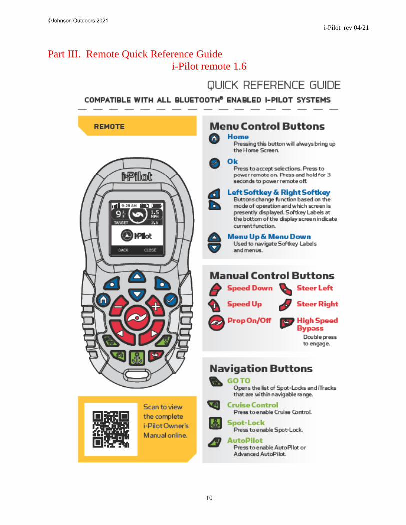
Part III. Remote Quick Reference Guide
i-Pilot remote 1.6
©Johnson Outdoors 2021
i-Pilot rev 04/21
11
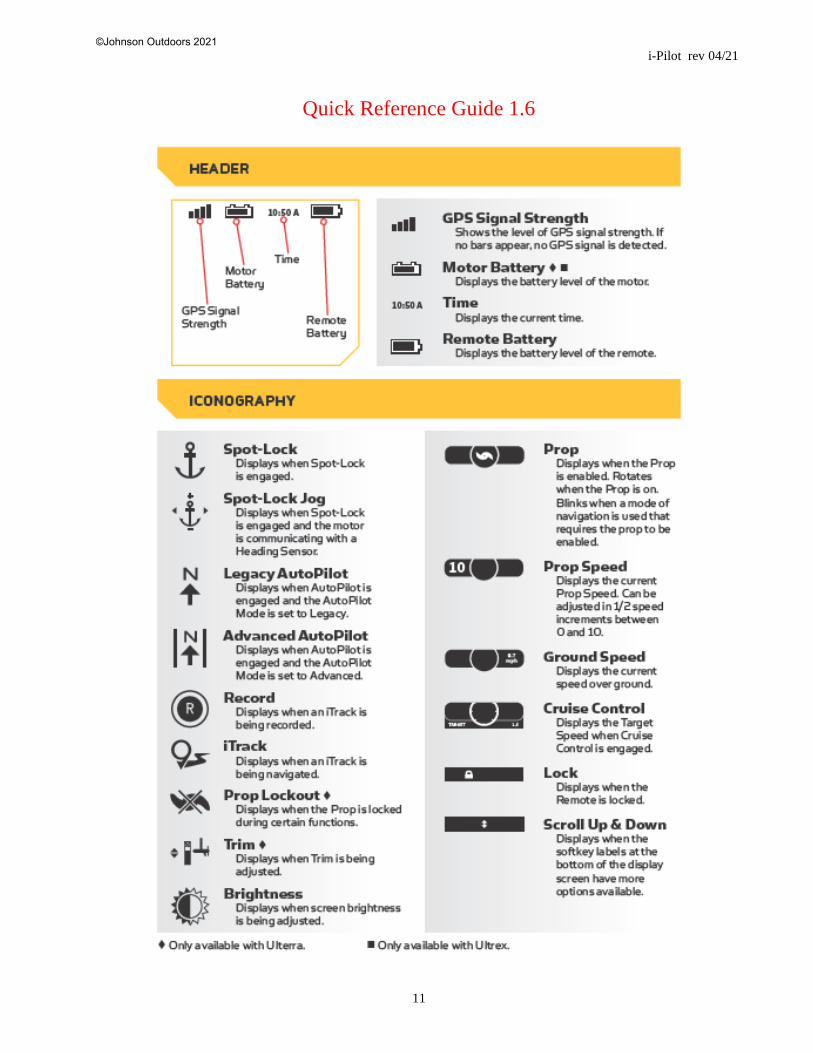
Quick Reference Guide 1.6
©Johnson Outdoors 2021

i-Pilot rev 04/21
12
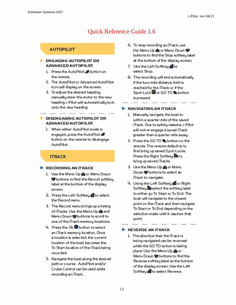
Quick Reference Guide 1.6
©Johnson Outdoors 2021
i-Pilot rev 04/21
13
Quick Reference Guide 1.6
©Johnson Outdoors 2021
i-Pilot rev 04/21
14
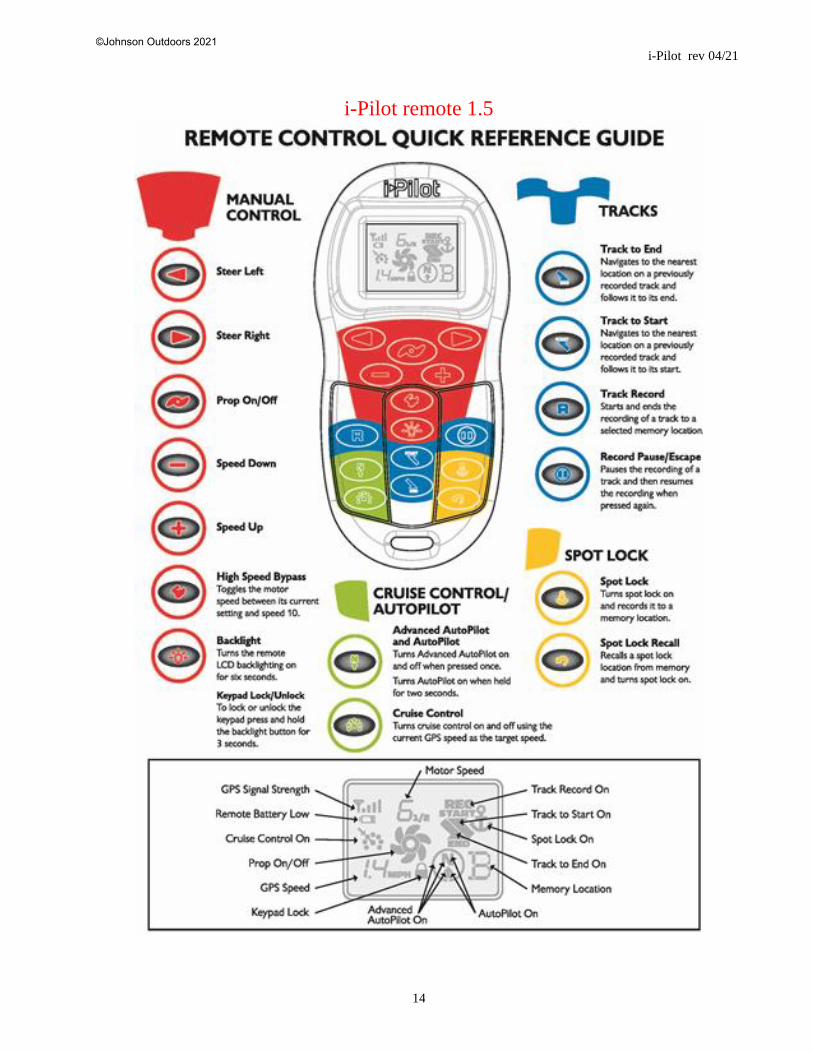
i-Pilot remote 1.5
©Johnson Outdoors 2021

i-Pilot rev 04/21
15
i-Pilot remote 1.0
©Johnson Outdoors 2021

i-Pilot rev 04/21
16
Quick Reference Guide
This refers to both i-Pilot remote 1.5 & 1.0
©Johnson Outdoors 2021