Embed Size (px)
Citation preview

Instruction Manual Three Phase Substation Type Transformers45 kVA through 10,000 kVA | 46 kV 250 BIL Max HV
Transformers | Substation Type | Utility & Industrial | Instruction Manual #ZU+7-8105 | Sep 2021
WEG Transformers USA | Instruction Manual #ZU+7-8105 | Sep 2021 Page 2 | 54
CONTENTS
DISCLAIMER .................................................................................................................... 5
WARRANTIES AND LIMITATION OF LIABILITY ............................................................. 5
SECTION A - INTRODUCTION ........................................................................................ 6
Nomenclatures ............................................................................................................................. 8
SECTION B - IMPORTANT SAFETY INFORMATION ................................................... 11
No Forklift .................................................................................................................................. 11
Grounding .................................................................................................................................. 11
Electrical Loading ...................................................................................................................... 11
Crane Lifting & Rigging .............................................................................................................. 12
Venting ...................................................................................................................................... 12
Internal Inspection...................................................................................................................... 12
Switch, Fuses & Arresters .......................................................................................................... 12
Liquid Level................................................................................................................................ 13
Installation ................................................................................................................................. 13
SECTION C - SHIPMENT, HANDLING, RIGGING & STORAGE ................................... 14
Documentation ........................................................................................................................... 14
Shipment ................................................................................................................................... 14
Acceptance ................................................................................................................................ 15
Crane Lifting .............................................................................................................................. 15
Rigging ...................................................................................................................................... 15
Unloading .................................................................................................................................. 16
Dielectric Fluid Level Check ....................................................................................................... 16
Internal Inspection...................................................................................................................... 17
Storage ...................................................................................................................................... 18
SECTION D - TRANSFORMER INSTALLATION ........................................................... 19
Jack & Skid ................................................................................................................................ 19
Foundation ................................................................................................................................. 20
Grounding .................................................................................................................................. 20
High Voltage Connections .......................................................................................................... 21
Low Voltage Connections .......................................................................................................... 21
Dielectric Fluid ........................................................................................................................... 22
Transformer Pressure ................................................................................................................ 22
SECTION E - PRE-ENERGIZATION .............................................................................. 24
SECTION F - POST-ENERGIZATION ........................................................................... 27
WEG Transformers USA | Instruction Manual #ZU+7-8105 | Sep 2021 Page 3 | 54
SECTION G - SWITCHING OPERATION ...................................................................... 28
Tap Changer .............................................................................................................................. 28
Series Multiple Switch or Delta Wye Switch ............................................................................... 29
Load Break Switch ..................................................................................................................... 30
SECTION H - PROTECTION ......................................................................................... 32
SECTION I - ACCESSORIES ......................................................................................... 33
Liquid Temperature Gauge ........................................................................................................ 33
Pressure Vacuum Gauge ........................................................................................................... 33
Liquid Level Gauge .................................................................................................................... 33
Pressure Relief Device .............................................................................................................. 34
Winding Temperature Indicator .................................................................................................. 34
Internal Fault Detector ............................................................................................................... 34
Drain Valve and Sampling Device .............................................................................................. 34
Small Pressure Relief Valve ....................................................................................................... 35
Rapid Rise Relay ....................................................................................................................... 35
Fans .......................................................................................................................................... 35
Pressure Transducer ................................................................................................................. 36
Resistance Temperature Detector (RTD) ................................................................................... 36
Current Transformers ................................................................................................................. 36
Other Accessories...................................................................................................................... 36
SECTION J - MAINTENANCE ........................................................................................ 37
Bushing Maintenance ................................................................................................................ 38
Detachable Radiators ................................................................................................................ 41
Removal .................................................................................................................................... 42
Refilling after Repairs ................................................................................................................. 43
Dissolved Gas Analysis (DGA)................................................................................................... 43
External Finish Maintenance ...................................................................................................... 45
Spare Parts ................................................................................................................................ 45
SECTION K - FIELD ACCEPTANCE TEST GUIDELINES ............................................. 47
Routine Tests ............................................................................................................................. 47
Field Acceptance Tests .............................................................................................................. 48
Transformer Turns Ratio ............................................................................................................ 48
Winding Resistance ................................................................................................................... 49
Insulation Resistance ................................................................................................................. 50
Insulation Power Factor ............................................................................................................. 50
Single Phase Excitation ............................................................................................................. 51
Oil Quality .................................................................................................................................. 51
WEG Transformers USA | Instruction Manual #ZU+7-8105 | Sep 2021 Page 4 | 54
SECTION L - TABLES AND PROCEDURES ................................................................. 52
External Electrical Connections .................................................................................................. 52
Pressure Variation ..................................................................................................................... 52
Torque Guidelines...................................................................................................................... 53
Cold Start-Up Procedure ............................................................................................................ 54
WEG Transformers USA | Instruction Manual #ZU+7-8105 | Sep 2021 Page 5 | 54
DISCLAIMER WARRANTIES AND LIMITATION OF LIABILITY
The information, recommendations, descriptions and safety notations in this document follow WEG
Transformers USA (WEG) experience and judgment and may not cover all contingencies.
If further information is required or if in doubt, consult with WEG service office.
THERE ARE NO UNDERSTANDINGS, AGREEMENTS, WARRANTIES, EXPRESSED OR IMPLIED, INCLUDING WARRANTIES OF FITNESS FOR A PARTICULAR PURPOSE OR MERCHANTABILITY, OTHER THAN THOSE SPECIFICALLY SET OUT IN ANY EXISTING CONTRACT BETWEEN WEG TRANSFORMERS USA AND THE PURCHASER OF THE TRANSFORMER. ANY SUCH CONTRACT STATES THE ENTIRE OBLIGATION OF WEG TRANSFORMERS USA. THE CONTENTS OF THIS DOCUMENT SHALL NOT BECOME PART OF OR MODIFY ANY CONTRACTUAL AGREEMENT.
In no event will WEG be responsible to the purchaser or user in contract, in tort (including negligence), strict liability or other- wise for any special, indirect, incidental or consequential damage or loss whatsoever, including but not limited to damage or loss of use of equipment, plant or power system, cost of capital, loss of power, additional expenses in the use of existing power facilities, or claims against the purchaser or user by its customers resulting from the use of the information, recommendations and descriptions contained herein. The information contained in this manual is subject to change without notice.
WEG Transformers USA | Instruction Manual #ZU+7-8105 | Sep 2021 Page 6 | 54
SECTION A INTRODUCTION The information contained in this document (“instruction manual”) is subject to change without notice.
This instruction manual is not intended as a substitute for proper training or adequate experience
concerning the safe operation of the transformer described; hence this is the sole responsibility of the
user or purchaser of the transformer.
Only competent technicians who are familiar with this transformer should install, operate, and service
the transformer.
A competent technician must have the following qualifications:
Thoroughly familiar with the instructions as given in the instruction manual.
Fully trained in industry-accepted high and low-voltage operating practices and safety
procedures.
Trained and authorized/certified to energize, de-energize, clear, and ground the transformer.
Well versed in the use and care of personal protective equipment (PPE) such as arc flash
clothing, safety glasses, face shield, hard hat, rubber gloves, clamp-stick, hot-stick, etc. as
prescribed by OSHA or any other national standards applicable to the transformer.
The information included in this manual is fundamental for a proper understanding of the installation,
operation and maintenance for this product.
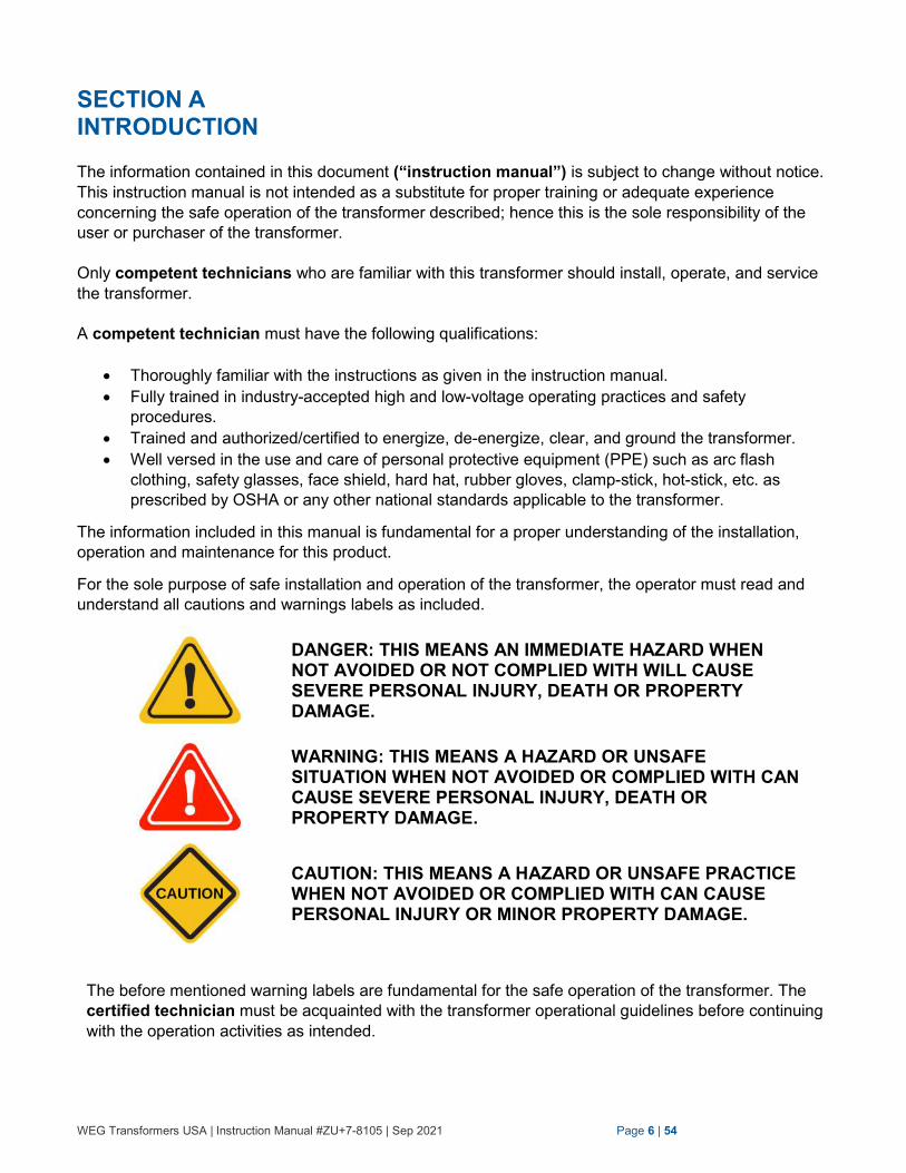
For the sole purpose of safe installation and operation of the transformer, the operator must read and
understand all cautions and warnings labels as included.
DANGER: THIS MEANS AN IMMEDIATE HAZARD WHEN NOT AVOIDED OR NOT COMPLIED WITH WILL CAUSE SEVERE PERSONAL INJURY, DEATH OR PROPERTY DAMAGE.
WARNING: THIS MEANS A HAZARD OR UNSAFE SITUATION WHEN NOT AVOIDED OR COMPLIED WITH CAN CAUSE SEVERE PERSONAL INJURY, DEATH OR PROPERTY DAMAGE.
CAUTION: THIS MEANS A HAZARD OR UNSAFE PRACTICE WHEN NOT AVOIDED OR COMPLIED WITH CAN CAUSE PERSONAL INJURY OR MINOR PROPERTY DAMAGE.
The before mentioned warning labels are fundamental for the safe operation of the transformer. The
certified technician must be acquainted with the transformer operational guidelines before continuing
with the operation activities as intended.
WEG Transformers USA | Instruction Manual #ZU+7-8105 | Sep 2021 Page 7 | 54
Not understanding well the warning labels may bring death or individual injury, and harm to the
person, transformer, and adjacent property or any other connected electrical equipment such
as switchgear or inverters.
The guidelines contained in this instruction manual are considered a general guide for the operator, the
activities related, and intended use of the transformer, as well as the upkeep of this equipment, when
operated in “Normal Operational Conditions” as prescribed in IEEE Standard C57.12.00.
WEG is not responsible for the upkeep of these standards or its liability to change without notice or its
misuse.
Despite the fact that WEG has endeavored to address all major operational aspects of the transformer, the instruction manual does not address each possible application or situation that may be experienced during the installation, operation and maintenance of the transformer.
NOT READING AND COMPLYING WITH ALL SAFETY INFORMATION, INSTRUCTIONS AND WARNINGS LABELS THROUGHOUT THE INSTRUCTION MANUAL BEFORE ATTEMPTING ANY INSTALLATION, OPERATION, OR MAINTENANCE ACTIVITIES MAY LEAD TO DANGEROUS SITUATIONS. IN CASE OF DOUBT CONTACT WEG:
+1 (636)-239-9300
WTU-Service [email protected]
www.weg.us
WEG Transformers USA | Instruction Manual #ZU+7-8105 | Sep 2021 Page 8 | 54
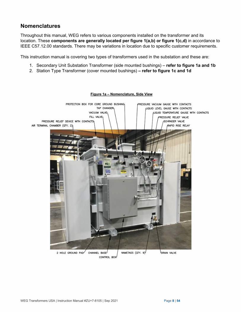
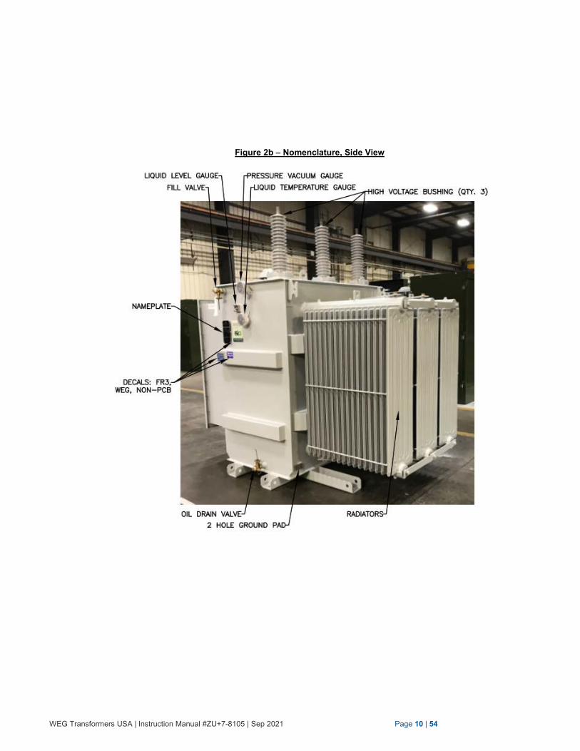
Nomenclatures
Throughout this manual, WEG refers to various components installed on the transformer and its
location. These components are generally located per figure 1(a,b) or figure 1(c,d) in accordance to
IEEE C57.12.00 standards. There may be variations in location due to specific customer requirements.
This instruction manual is covering two types of transformers used in the substation and these are:
1. Secondary Unit Substation Transformer (side mounted bushings) – refer to figure 1a and 1b
2. Station Type Transformer (cover mounted bushings) – refer to figure 1c and 1d
Figure 1a – Nomenclature, Side View
WEG Transformers USA | Instruction Manual #ZU+7-8105 | Sep 2021 Page 9 | 54
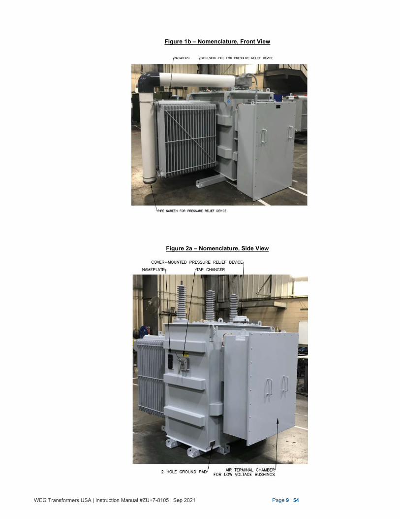
Figure 1b – Nomenclature, Front View
Figure 2a – Nomenclature, Side View
WEG Transformers USA | Instruction Manual #ZU+7-8105 | Sep 2021 Page 10 | 54
Figure 2b – Nomenclature, Side View
WEG Transformers USA | Instruction Manual #ZU+7-8105 | Sep 2021 Page 11 | 54
SECTION B IMPORTANT SAFETY INFORMATION In this section, we are advising the purchaser of important cautions and warnings, which must be
understood for safe operation of the transformer.
Each of these labels and their application are explained in detail in this instruction manual.
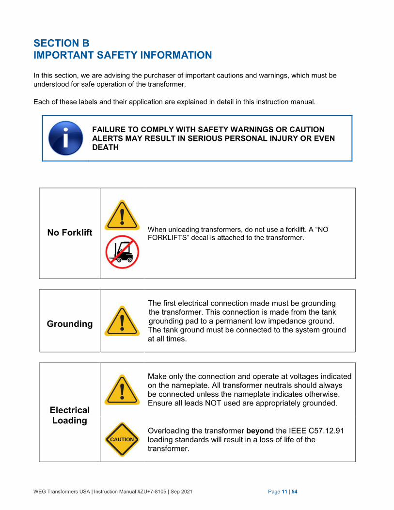
FAILURE TO COMPLY WITH SAFETY WARNINGS OR CAUTION ALERTS MAY RESULT IN SERIOUS PERSONAL INJURY OR EVEN DEATH
No Forklift
When unloading transformers, do not use a forklift. A “NO FORKLIFTS” decal is attached to the transformer.
Grounding
The first electrical connection made must be grounding the transformer. This connection is made from the tank grounding pad to a permanent low impedance ground. The tank ground must be connected to the system ground at all times.
Electrical Loading
Make only the connection and operate at voltages indicated on the nameplate. All transformer neutrals should always be connected unless the nameplate indicates otherwise. Ensure all leads NOT used are appropriately grounded.
Overloading the transformer beyond the IEEE C57.12.91 loading standards will result in a loss of life of the transformer.
WEG Transformers USA | Instruction Manual #ZU+7-8105 | Sep 2021 Page 12 | 54
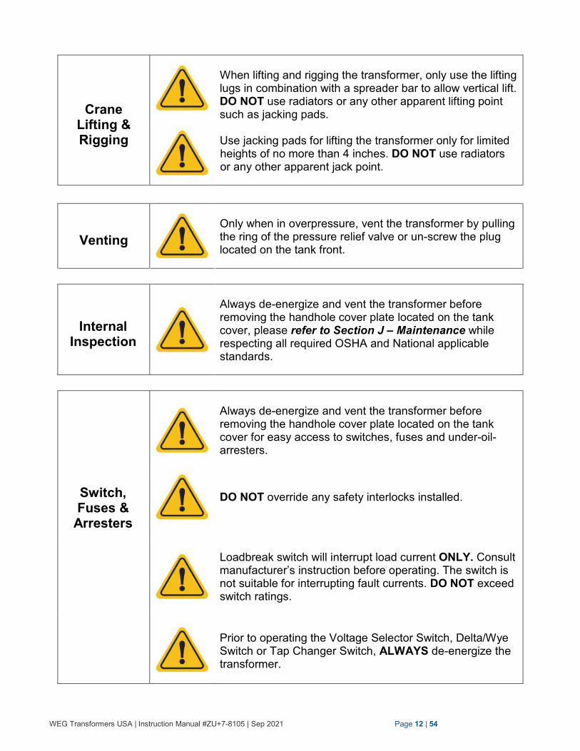
Crane Lifting & Rigging
When lifting and rigging the transformer, only use the lifting lugs in combination with a spreader bar to allow vertical lift. DO NOT use radiators or any other apparent lifting point such as jacking pads.
Use jacking pads for lifting the transformer only for limited heights of no more than 4 inches. DO NOT use radiators or any other apparent jack point.
Venting
Only when in overpressure, vent the transformer by pulling the ring of the pressure relief valve or un-screw the plug located on the tank front.
Internal Inspection
Always de-energize and vent the transformer before removing the handhole cover plate located on the tank cover, please refer to Section J – Maintenance while respecting all required OSHA and National applicable standards.
Switch, Fuses &
Arresters
Always de-energize and vent the transformer before removing the handhole cover plate located on the tank cover for easy access to switches, fuses and under-oil- arresters.
DO NOT override any safety interlocks installed.
Loadbreak switch will interrupt load current ONLY. Consult manufacturer’s instruction before operating. The switch is not suitable for interrupting fault currents. DO NOT exceed switch ratings.
Prior to operating the Voltage Selector Switch, Delta/Wye Switch or Tap Changer Switch, ALWAYS de-energize the transformer.
WEG Transformers USA | Instruction Manual #ZU+7-8105 | Sep 2021 Page 13 | 54
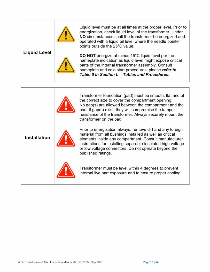
Liquid Level
Liquid level must be at all times at the proper level. Prior to energization, check liquid level of the transformer. Under NO circumstances shall the transformer be energized and operated with a liquid oil level where the needle pointer points outside the 25°C value.
DO NOT energize at minus 15°C liquid level per the nameplate indication as liquid level might expose critical parts of the internal transformer assembly. Consult nameplate and cold start procedures; please refer to Table 5 in Section L – Tables and Procedures.
Installation
Transformer foundation (pad) must be smooth, flat and of the correct size to cover the compartment opening. No gap(s) are allowed between the compartment and the pad. If gap(s) exist, they will compromise the tamper-resistance of the transformer. Always securely mount the transformer on the pad.
Prior to energization always, remove dirt and any foreign material from all bushings installed as well as critical elements inside any compartment. Consult manufacturer instructions for installing separable-insulated high voltage or low voltage connectors. Do not operate beyond the published ratings.
Transformer must be level within 4 degrees to prevent internal live part exposure and to ensure proper cooling.
WEG Transformers USA | Instruction Manual #ZU+7-8105 | Sep 2021 Page 14 | 54
SECTION C SHIPMENT, HANDLING, RIGGING & STORAGE
Prior to receiving the transformer, the purchaser shall make themselves familiar with the transformer
according to the following suggested steps:
Documentation
Gather all documentation related to the transformer such as shipping documents, drawings, and other
appropriate data for the off-loading and use of the respective transformer. Make yourself familiar with
the characteristics that can be found on the transformer drawings and/or nameplate as well as specific
labels or notices given on the transformer itself such as weights and other pertinent characteristics.
Shipment
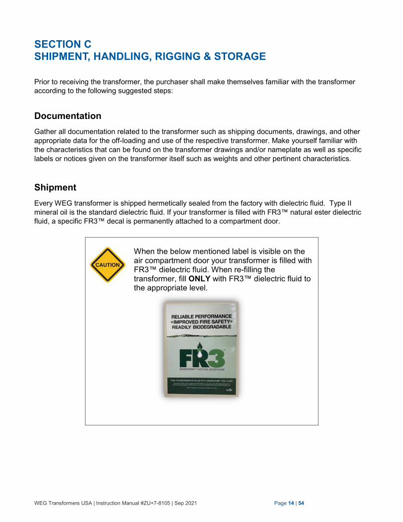
Every WEG transformer is shipped hermetically sealed from the factory with dielectric fluid. Type II
mineral oil is the standard dielectric fluid. If your transformer is filled with FR3™ natural ester dielectric
fluid, a specific FR3™ decal is permanently attached to a compartment door.
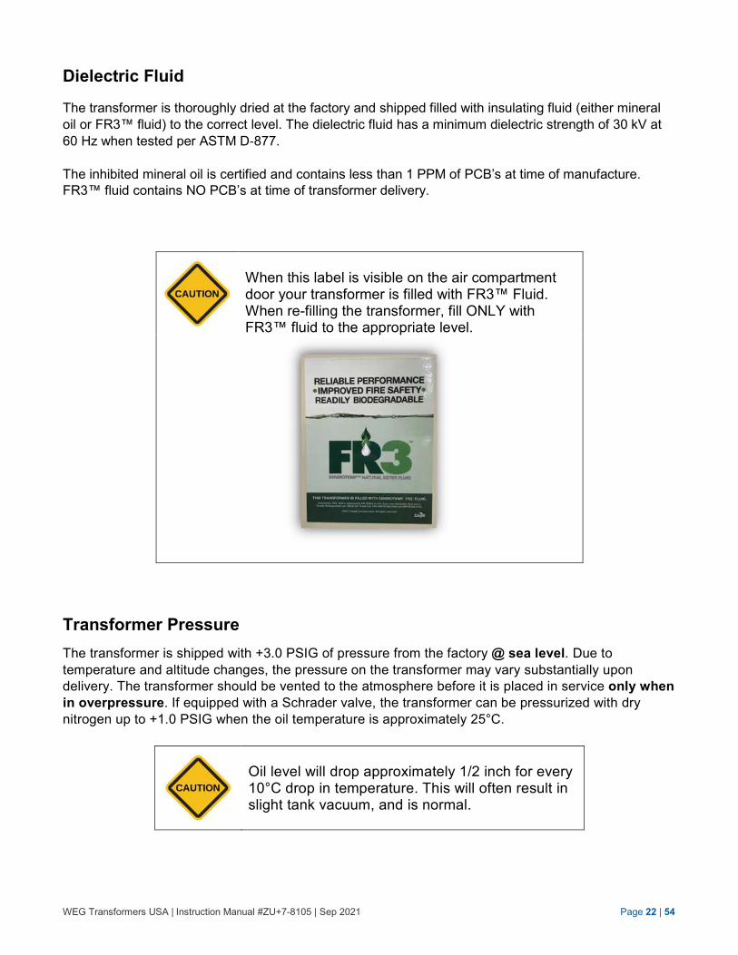
When the below mentioned label is visible on the air compartment door your transformer is filled with FR3™ dielectric fluid. When re-filling the transformer, fill ONLY with FR3™ dielectric fluid to the appropriate level.
WEG Transformers USA | Instruction Manual #ZU+7-8105 | Sep 2021 Page 15 | 54
Acceptance of the Transformer
Upon receipt and unloading of the transformer from the truck, carefully examine the transformer, parts,
and loose parts (spares) delivered (if applicable) for damage. The acceptance assessment should be
completed at this time.
Any damages noted prior to unloading as well as bill of lading errors must be noted. Notification shall be given to WEG prior to attempting any form of repair or correction. Issue any claim for missing parts to WEG within 30 days. Not doing so may lead to misunderstandings and additional cost for the purchaser.
In case of shipping damage, immediately file a claim with the carrier and contact WEG Transformers at +1 (636)-239-9300.
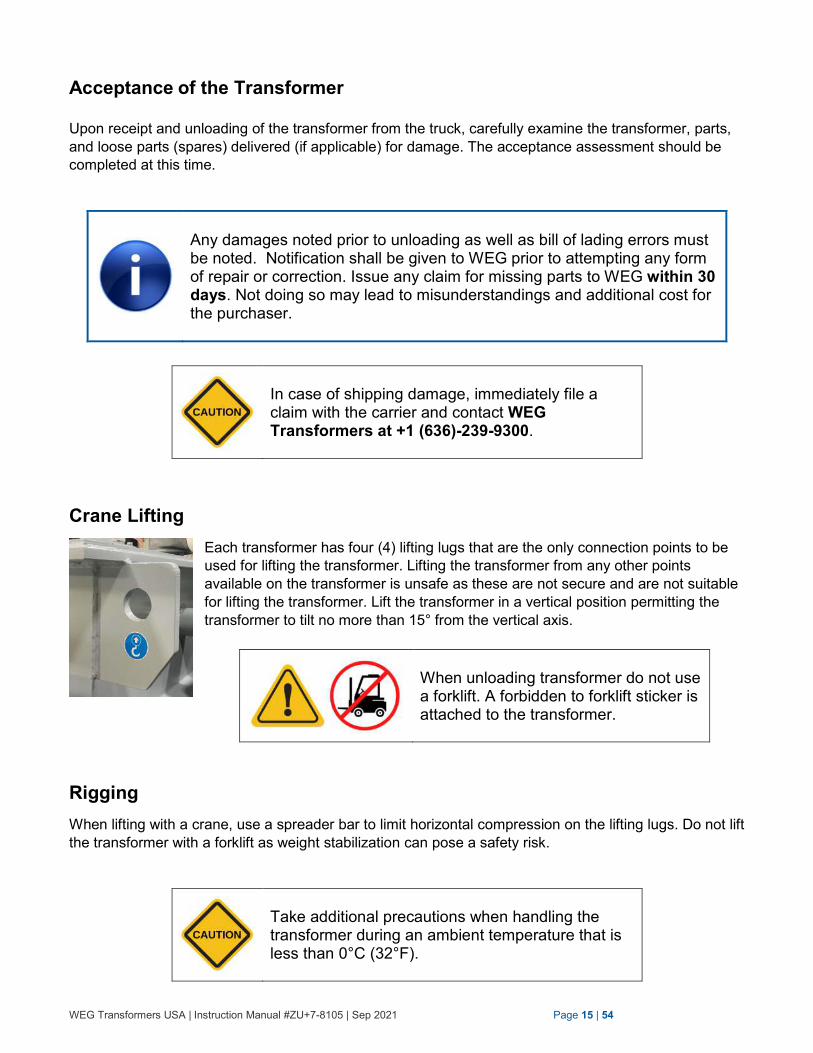
Crane Lifting
Each transformer has four (4) lifting lugs that are the only connection points to be
used for lifting the transformer. Lifting the transformer from any other points
available on the transformer is unsafe as these are not secure and are not suitable
for lifting the transformer. Lift the transformer in a vertical position permitting the
transformer to tilt no more than 15° from the vertical axis.
When unloading transformer do not use a forklift. A forbidden to forklift sticker is attached to the transformer.
Rigging
When lifting with a crane, use a spreader bar to limit horizontal compression on the lifting lugs. Do not lift
the transformer with a forklift as weight stabilization can pose a safety risk.
Take additional precautions when handling the transformer during an ambient temperature that is less than 0°C (32°F).
WEG Transformers USA | Instruction Manual #ZU+7-8105 | Sep 2021 Page 16 | 54
When lifting the transformer by crane, only use the lifting lugs in combination with a spreader bar to allow vertical lift. DO NOT use radiators or any other apparent lifting point such as jacking pads.
Unloading Process
Perform the following critical checks prior to unloading the transformer from the truck:
A. Ensure that the serial number on the transformer nameplate and on the bill of lading match.
Likewise, check the nameplate for kVA rating, high-voltage rating, low-voltage rating, and
impedance. Ensure that they agree with the order specifications.
B. Check bill of lading and make sure the shipment is complete.
C. If the shipment is not complete, contact WEG immediately. Inability to make a timely claim
of incomplete shipment may result in voiding of any future claims.
D. The tank vacuum/pressure must show a positive or negative pressure when the transformer
is unloaded contingent upon the relative temperature of the oil and altitude. A rising or
falling pressure over time assures the purchaser that the transformer tank is hermetically
sealed. If the vacuum/pressure gauge shows a consistent zero pressure reading, then this
demonstrates that the tank is not hermetically sealed and that there is a “leak”. In the event
that this happens, the tank and its accessories must be checked immediately for oil leaks.
Please contact WEG immediately if a leak is found during this examination.
E. Check the transformer for transportation damages. In particular, carefully examine and look
for damage to corrugated fin-walls, radiators, tank, compartment, bushings and all other
accessories.
F. Check for any damages to paint due to handling. Repair any damaged paint with touch up
paint. Make sure not to over-spray labels, nameplate or any specific labels pertaining to the
transformer.
G. Do NOT remove any labels on the transformer.
H. Check for missing parts.
I. Store the transformer
Dielectric Fluid Level Check
The transformer is delivered from our manufacturing facility filled with dielectric fluid, either mineral oil or
FR3™ fluid, and is filled to the appropriate level.
Prior to energization of the transformer, complete the dielectric fluid level check. The liquid level
indicator must be between the "High" and "Low" marks on the gauge.
WEG Transformers USA | Instruction Manual #ZU+7-8105 | Sep 2021 Page 17 | 54
For transformers provided with a liquid sight gauge, the liquid level can be observed easily. On the off
chance that the transformer does not have a liquid level gauge or sight gauge, check the liquid level by
removing the plug at the 25°C level.
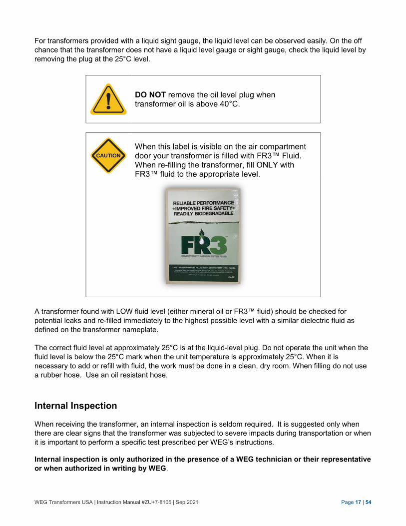
DO NOT remove the oil level plug when transformer oil is above 40°C.
When this label is visible on the air compartment door your transformer is filled with FR3™ Fluid. When re-filling the transformer, fill ONLY with FR3™ fluid to the appropriate level.
A transformer found with LOW fluid level (either mineral oil or FR3™ fluid) should be checked for
potential leaks and re-filled immediately to the highest possible level with a similar dielectric fluid as
defined on the transformer nameplate.
The correct fluid level at approximately 25°C is at the liquid-level plug. Do not operate the unit when the
fluid level is below the 25°C mark when the unit temperature is approximately 25°C. When it is
necessary to add or refill with fluid, the work must be done in a clean, dry room. When filling do not use
a rubber hose. Use an oil resistant hose.
Internal Inspection
When receiving the transformer, an internal inspection is seldom required. It is suggested only when
there are clear signs that the transformer was subjected to severe impacts during transportation or when
it is important to perform a specific test prescribed per WEG’s instructions.
Internal inspection is only authorized in the presence of a WEG technician or their representative
or when authorized in writing by WEG.
WEG Transformers USA | Instruction Manual #ZU+7-8105 | Sep 2021 Page 18 | 54
UNAUTHORIZED OPENING OF THE TRANSFORMER TANK BY THE PURCHASER MAY VOID THE WARRANTY.
When a certified technician opens the transformer, specific actions must be taken to avoid weakening of the insulation of the transformer, please refer to Section J – Maintenance. Therefore:
1. Prevent ingress of foreign objects or dirt. 2. Prevent ingress of moisture.
Prior to internal inspection, follow all safety precautions. These include:
1. De-energize the transformer. 2. Make sure the dielectric fluid is at
or below 25°C. 3. Vent the transformer. 4. Ground the transformer. 5. Adhere to all applicable OSHA
and National Safety standards.
Storage
When storing the transformer, respect the conditions below.
NOT RESPECTING LONG TERM TRANSFORMER STORAGE REQUIREMENTS MAY VOID THE WARRANTY. TRANSFORMER GENERAL CONDITIONS ARE:
1. CANNOT BE STORED IN A SALTY OR CORROSIVE ENVIRONMENT. 2. MUST BE STORED IN A DRY ENVIRONMENT. 3. MUST BE STORED HORIZONTALLY, NO MORE THAN 4 DEGREE TILT. 4. CONTROL CABINETS, IF ANY, MUST HAVE DESICCANT. CONSULT
DESICCANT CALCULATOR ON THE INTERNET OR CONTACT WEG.
WEG Transformers USA | Instruction Manual #ZU+7-8105 | Sep 2021 Page 19 | 54
SECTION D TRANSFORMER INSTALLATION
Prior to installing the transformer on the foundation, the purchaser shall make themselves familiar with
the transformer and its basic characteristics.
Crane Lifting
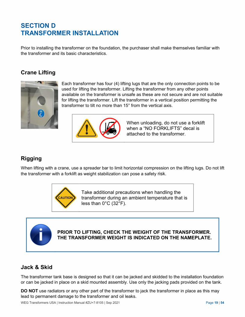
Each transformer has four (4) lifting lugs that are the only connection points to be
used for lifting the transformer. Lifting the transformer from any other points
available on the transformer is unsafe as these are not secure and are not suitable
for lifting the transformer. Lift the transformer in a vertical position permitting the
transformer to tilt no more than 15° from the vertical axis.
When unloading, do not use a forklift when a “NO FORKLIFTS” decal is attached to the transformer.
Rigging
When lifting with a crane, use a spreader bar to limit horizontal compression on the lifting lugs. Do not lift
the transformer with a forklift as weight stabilization can pose a safety risk.
Take additional precautions when handling the transformer during an ambient temperature that is less than 0°C (32°F).
PRIOR TO LIFTING, CHECK THE WEIGHT OF THE TRANSFORMER. THE TRANSFORMER WEIGHT IS INDICATED ON THE NAMEPLATE.
Jack & Skid
The transformer tank base is designed so that it can be jacked and skidded to the installation foundation
or can be jacked in place on a skid mounted assembly. Use only the jacking pads provided on the tank.
DO NOT use radiators or any other part of the transformer to jack the transformer in place as this may
lead to permanent damage to the transformer and oil leaks.
WEG Transformers USA | Instruction Manual #ZU+7-8105 | Sep 2021 Page 20 | 54
When skidding the transformer, utilize a sufficient number of rollers to divide the transformers weight
equally over the rollers. Rollers size must be able to support the weight of the transformer, as this is key
for safe rolling.
Foundation
Prior to installation always, consult with National Codes and IEEE Standard C57.12.00 for installation
compliance.
Mount the transformer on a level solid horizontal foundation adequate to support the weight of the
transformer as indicated on the nameplate. The transformer (including the air compartment) must sit
flush with the horizontal surface of the pad, such that there are NO openings or gaps between the
transformer base and pad.
The transformer must be installed such that it is not tilted more than 4 degrees. When tilted more than
4 degrees, it may compromise the life of the transformer. The transformer’s internal wiring and
components such as fuses, switches, core and coils must be under immersed in dielectric fluid for
proper functioning. The tilting could potentially cause dielectric failure or cooling problems leading to
overheating and therefore diminish transformer life.
With the transformer installed on its foundation, there must be a minimum clearance of 2 feet clearance
around the perimeter of the transformer.
Installation of the transformer in a salty or corrosive environment should be avoided as this will introduce
degradation of the protective paint and ultimately lead to corrosion of mild steel, unless designed for
such an environment.
Grounding
Permanently ground the transformer in accordance to local and national standards. Ground the
transformer tank using the provided ground pads or any special and adequate connection provided on
the transformer tank. Make sure that a proper low-impedance ground connection is established.
The transformer must be grounded properly at all times in accordance with local and national standards. Make sure that a proper low-impedance ground connection is established.
WEG Transformers USA | Instruction Manual #ZU+7-8105 | Sep 2021 Page 21 | 54
High Voltage and Low Voltage Connections
The transformer may have full-length air terminal chambers, which are designed to protect personnel.
Air terminal chambers must be installed according to instructions on the drawings provided and/or
approved.
Securely attach the flexible connectors supplied by the switchgear manufacturer to the switchgear bus
bars. The number of flexible connectors supplied is determined by the transformer current and not by
the current rating of the bus bar.
Prior to making the high voltage and low voltage connections, make sure that, all mating surfaces of the
connectors are free of burr and debris. All connections must be torqued appropriately to avoid
overheating and/or cause failure of the connections leading to failure of the transformer; please refer to
Section M – Tables and Procedures.
All cable connections shall be made in such a way that the high voltage and low voltage bushings and
busbar are not undergoing excessive cantilever stress. Excessive cantilever stress can lead to busbar
and bushing failure leading to leaking of dielectric fluid followed by failure of the transformer.
Avoid excessive cantilever stress on the high voltage and low voltage bushings and bus bars from excessive cable weight.
Improper installation of air terminal chambers and switch gear connectors ducts may lead to water ingress or other contamination of live parts resulting in severe personal injury or even death
High Voltage Connections
Your transformer is equipped with porcelain, polymer or epoxy high-voltage bushings. The
bushing are bottom connected or draw lead connected bushings. These have an external clamp
that seat the bushing on a seal. These type of bushings are provided with tin-plated eyebolts,
spade terminals or studs that are designed and are suitable for connecting the cables (copper or
aluminum).
Low Voltage Connections
Transformers are in most case designed with low-voltage bushings, with or without spade
terminals. The bushing are in most cases bottom connected bushings
WEG Transformers USA | Instruction Manual #ZU+7-8105 | Sep 2021 Page 22 | 54
Dielectric Fluid
The transformer is thoroughly dried at the factory and shipped filled with insulating fluid (either mineral
oil or FR3™ fluid) to the correct level. The dielectric fluid has a minimum dielectric strength of 30 kV at
60 Hz when tested per ASTM D‐877.
The inhibited mineral oil is certified and contains less than 1 PPM of PCB’s at time of manufacture.
FR3™ fluid contains NO PCB’s at time of transformer delivery.
When this label is visible on the air compartment door your transformer is filled with FR3™ Fluid. When re-filling the transformer, fill ONLY with FR3™ fluid to the appropriate level.
Transformer Pressure
The transformer is shipped with +3.0 PSIG of pressure from the factory @ sea level. Due to
temperature and altitude changes, the pressure on the transformer may vary substantially upon
delivery. The transformer should be vented to the atmosphere before it is placed in service only when
in overpressure. If equipped with a Schrader valve, the transformer can be pressurized with dry
nitrogen up to +1.0 PSIG when the oil temperature is approximately 25°C.
Oil level will drop approximately 1/2 inch for every 10°C drop in temperature. This will often result in slight tank vacuum, and is normal.
WEG Transformers USA | Instruction Manual #ZU+7-8105 | Sep 2021 Page 23 | 54
DO NOT allow tank to exceed more than 3 PSIG vacuum (-3 PSIG) as tank will deform. Do not allow tank to exceed more than 5 PSIG pressure. Tank will distort over 7 PSIG pressure.
DO NOT add nitrogen to a cold transformer to bring it back up to positive pressure. Doing so, can cause over- pressure and damage to the transformer when the oil temperature rises to normal levels. Pressure at 25°C oil temperature should be between 0.5 to +1.0 PSIG.
When venting the transformer pressure, carefully open the pipe plug or pressure relief valve above
the liquid level at approximately 25°C. Screw-in the plug immediately after pressure equalization or
let go of the pressure valve such that it will seat again on the seal.
Always verify the dielectric fluid of the transformer by checking the nameplate.
Fill and drain provisions are provided on each transformer.
From time-to-time, it may be necessary to check the oil quality of the transformer. For guidance on
taking samples and interpretation of baseline results, please refer to Section J – Maintenance. WEG
suggests taking more than one sample to establish a solid baseline for oil quality.
Always vent the transformer prior taking oil samples. NEVER take oil samples while the transformer tank pressure is below 0 PSI relative.
WEG Transformers USA | Instruction Manual #ZU+7-8105 | Sep 2021 Page 24 | 54
SECTION E
PRE-ENERGIZATION
Pre-Energization Inspection and Tests
Inspect the installed transformer on the pad and test prior to energization.
Pre-energization inspections and tests are required as well as standard checks prescribed in the instruction manual. Only certified technicians with the appropriate safety and testing equipment can perform the pre-energization inspections and tests.
DO NOT energize without cleaning the bushings. Always consult the instruction manual for the high voltage connectors.
NEVER operated the transformer beyond the nameplate rating.
DO NOT ENERGIZE without the pre-energization inspection and tests completed.
WEG Transformers USA | Instruction Manual #ZU+7-8105 | Sep 2021 Page 25 | 54
DO NOT ENERGIZE without the following pre-energization inspections and tests, please refer
Section K – Field Acceptance Test Guidelines:
A. Ratio test – using a transformer turns ratio tester (TTR), perform a ratio test to verify the primary to secondary winding ratio.
B. Insulation resistance test - perform a 1,000 Volt insulation test (megger test) to measure the resistance of the insulation between windings and from each windings to ground.
C. Tap Changer Setting – make sure the tap changer is set to the correct voltage setting and make sure the setscrew is well seated in the bottom of the hole.
D. Series/Multiple or Delta/Wye Switch Settings – should the transformer be equipped with delta/wye switch, ensure it is set to the correct position and make sure the setscrew is well seated in the bottom of the hole.
E. Grounding - verify the transformer has a solid low impedance grounding.
F. Bolted Connections – verify that bolted connections are torqued in accordance to the torque table guide, please refer to Section L – Tables and Procedures.
G. Dielectric Liquid Level - verify the transformer is filled correctly by verifying the liquid level gauge or sight gauge, please refer to Section C – Shipment, Handling, Rigging and Storage.
H. Current Transformers – should the transformer be equipped with current transformers (CTs), the associated CT leads should be connected to the metering load or relays and with the proper burden. If the CT leads are not connected to a metering load, they must be shorted together and grounded before transformer energization!
I. Control Wiring For Accessories – verify all control wires, if any, and verify that all are connected and functional. Functionality can be verified by checking continuity of each wire. Ensure that no wire insulation is damaged.
J. IFD – if the transformer is equipped with an internal fault detector (IFD), the shipping lock must be removed prior to energization. Turn the shipping lock (red exterior piece) 90 degrees counter clock wise to remove.
K. Accessories – verify the functionality of all accessories with or without contacts.
L. Tank and Compartment Finish – make sure that all painted surfaces are intact and are not scratched due to installation. If there is damage, use touch-up paint on the damaged surfaces.
M. External Tank Inspection – make sure the transformer handhole is closed and a tamper resistant protection cover is installed.
N. Field Tools – verify that all tools are removed from the transformer’s cabinet/ compartments and are accounted for.
O. Prior to connecting the low voltage cables or busbar, make sure the surfaces of all spade terminals and matching connectors or busbars are perfectly clean and smooth.
P. External Control Cabinet - if the transformer is equipped with an external control cabinet, make sure all wires are connected and accessories are functional. Make sure cabinet is clean and free of debris. Padlock the cabinet after inspection.
Q. Padlock – securely lock all switches, compartments and control cabinet.
WEG Transformers USA | Instruction Manual #ZU+7-8105 | Sep 2021 Page 26 | 54
R. Fans - if your transformer is equipped with fans, make sure they are spinning freely and are operational.
S. Clearance Inspection – ensure all line connections maintain clearances per IEEE C57.12.34 2015 table 15, please refer to Section L – Tables and Procedures.
T. Radiator valves – should your transformers be supplied with detachable radiators, ensure all radiators valves are OPEN at time of pre-energization!
IF performing VLF (Very Low Frequency) Testing, please consult the bushing manufacturer’s specification for maximum withstand voltage.
1. In no case shall the voltage exceed 115% of the nominal
transformer voltage for a duration of 30 minutes. 2. In no case shall the test be conducted with the transformer
switch in the closed position. If the transformer does not have a switch, then the transformer must not be in the circuit when performing this test.
3. Ensure arrestors, if any, are disconnected before starting test.
Pre-energization/verification must be performed on all radiator valves (if any). Ensure all radiator valves are open (bottom and top)! Failure to open the valves will damages the transformer by overheating which will void the WEG warranty.
WEG Transformers USA | Instruction Manual #ZU+7-8105 | Sep 2021 Page 27 | 54
SECTION F POST-ENERGIZATION
Post-Energization inspection and tests
After the transformer pre-energization inspection and tests are successfully completed, the following
examination/verification must be performed.
Post-energization/verification must be performed as well as standard checks as described in the instruction manual. Only certified technicians with the appropriate safety and testing equipment are allowed to energize the transformer. Ensure all radiator valves are open.
A. Voltage verification – prior to loading the transformer, verify that the secondary voltage output is correct. Confirm that the low voltage is correct by utilizing an AC voltmeter. Measure the voltage and verify this agrees with the secondary voltages as indicated on the nameplate.
B. Leaks – verify by walking around the tank and compartment and carefully examining that there
are no leaks.
C. Operation – verify after the transformer is loaded that there are no abnormalities observed
such as excess noise, vibration or even heating. When the transformer is energized, the transformer will make a humming noise. For allowable
noise levels, please refer to NEMA Standards Publication TR-1.
If the transformer makes extreme or irregular sounds, this must be investigated, as this may
show a potential issue. Always contact WEG in these situations!
D. Gauges – verify liquid level gauge and temperature gauge indicate the correct level and
temperature.
E. High Voltage/Low Voltage Air Terminals or Bus Ducts, ensure that all compartments,
boxes, and security covers are closed.
F. Radiator valves – should your transformers be supplied with detachable radiators, ensure
again that all radiators valves are OPEN at time of energization!
WEG Transformers USA | Instruction Manual #ZU+7-8105 | Sep 2021 Page 28 | 54
SECTION G SWITCHING OPERATION
The directions given in this section are for the switching operation of devices installed on the
transformer. This section serves as a general guide only. Please note that these guidelines do not
address every conceivable application or circumstance that might be encountered with the product or its
installation.
The certified technician should acquaint himself with all warning and instruction labels attached to the
installed/optional device and the transformer.
The devices considered in this instruction manual are optional features and may not be included in all
WEG transformers.
Tap Changer
The device specifically used to change the general ratio of the transformer. The tap changer setting is
controlled through the tap changer rotating knob or handle situated inside the terminal compartment of
the transformer. This switch is for de-energized operation only!
DO NOT use tap changer to operate at secondary voltage outside nameplate rating.
NEVER operate the tap changer with an energized transformer
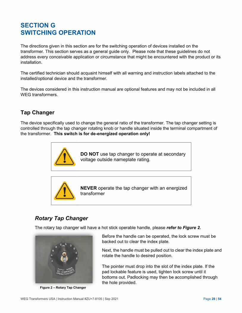
Rotary Tap Changer
The rotary tap changer will have a hot stick operable handle, please refer to Figure 2.
Before the handle can be operated, the lock screw must be
backed out to clear the index plate.
Next, the handle must be pulled out to clear the index plate and
rotate the handle to desired position.
The pointer must drop into the slot of the index plate. If the
pad lockable feature is used, tighten lock screw until it
bottoms out. Padlocking may then be accomplished through
the hole provided.
Figure 2 – Rotary Tap Changer
WEG Transformers USA | Instruction Manual #ZU+7-8105 | Sep 2021 Page 29 | 54
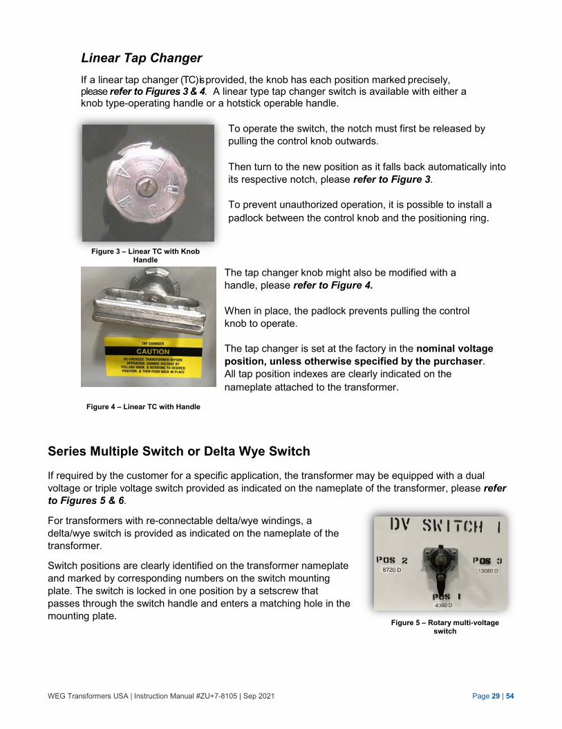
Linear Tap Changer
If a linear tap changer (TC) is provided, the knob has each position marked precisely, please refer to Figures 3 & 4. A linear type tap changer switch is available with either a knob type-operating handle or a hotstick operable handle.
To operate the switch, the notch must first be released by
pulling the control knob outwards.
Then turn to the new position as it falls back automatically into
its respective notch, please refer to Figure 3.
To prevent unauthorized operation, it is possible to install a
padlock between the control knob and the positioning ring.
The tap changer knob might also be modified with a
handle, please refer to Figure 4.
When in place, the padlock prevents pulling the control
knob to operate.
The tap changer is set at the factory in the nominal voltage
position, unless otherwise specified by the purchaser.
All tap position indexes are clearly indicated on the
nameplate attached to the transformer.
Series Multiple Switch or Delta Wye Switch
If required by the customer for a specific application, the transformer may be equipped with a dual
voltage or triple voltage switch provided as indicated on the nameplate of the transformer, please refer
to Figures 5 & 6.
For transformers with re-connectable delta/wye windings, a
delta/wye switch is provided as indicated on the nameplate of the
transformer.
Switch positions are clearly identified on the transformer nameplate
and marked by corresponding numbers on the switch mounting
plate. The switch is locked in one position by a setscrew that
passes through the switch handle and enters a matching hole in the
mounting plate.
Figure 3 – Linear TC with Knob Handle
Figure 4 – Linear TC with Handle
Figure 5 – Rotary multi-voltage switch
WEG Transformers USA | Instruction Manual #ZU+7-8105 | Sep 2021 Page 30 | 54
To operate a rotary type multi-voltage switch (see Figure 5):
1. Release the locking bolt and back it out until it clears the position hole.
2. Rotate the switch handle 90-degrees. Line up the locking screw with the desired position hole.
3. Tighten the setscrew until it seats firmly in the position hole.
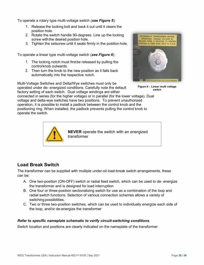
To operate a linear type multi-voltage switch (see Figure 6):
1. The locking notch must first be released by pulling the control knob outwards.
2. Then turn the knob to the new position as it falls back automatically into the respective notch.
Multi-Voltage Switches and Delta/Wye switches must only be operated under de- energized conditions. Carefully note the default factory setting of each switch. Dual voltage windings are either connected in series (for the higher voltage) or in parallel (for the lower voltage). Dual voltage and delta-wye switches have two positions. To prevent unauthorized operation, it is possible to install a padlock between the control knob and the positioning ring. When installed, the padlock prevents pulling the control knob to operate the switch.
NEVER operate the switch with an energized transformer
Load Break Switch
The transformer can be supplied with multiple under-oil load-break switch arrangements, these
can be:
A. One two-position (ON-OFF) switch or radial feed switch, which can be used to de- energize
the transformer and is designed for load interruption
B. One four or three-position sectionalizing switch for use as a combination of the loop and
radial switch functions. Selection of various connection schemes allows a variety of
switching possibilities.
C. Two or three two-position switches, which can be used to individually energize each side of
the loop, and/or de-energize the transformer
Refer to specific nameplate schematic to verify circuit-switching conditions.
Switch location and positions are clearly indicated on the nameplate of the transformer.
Figure 6 – Linear multi voltage switch
WEG Transformers USA | Instruction Manual #ZU+7-8105 | Sep 2021 Page 31 | 54
The switches CAN ONLY be operated by attaching a hot-line tool to the external hook eye handle and rotating either to the “ON” or “OFF” position.
Transformers use conventional transformer oil or FR3™ fluid for an insulating liquid. When the insulating liquid temperature is less than -20 °C (-4 °F) for conventional transformer oil or less than -10 °C (14 °F) for FR3™ fluid, the increase in fluid viscosity may reduce make and break capabilities of loadbreak devices. Below these temperatures, under-oil loadbreak accessories should not be used to make or break a load. Instead, de-energize transformer from a remote upstream source before operating under-oil loadbreak devices.
WEG Transformers USA | Instruction Manual #ZU+7-8105 | Sep 2021 Page 32 | 54
SECTION H
PROTECTION
Surge Arresters
At the option of the purchaser, the transformer may be equipped with surge arresters to protect the
transformer from overvoltage surges. Surge arresters can be mounted in the high-voltage or low-voltage
compartment or even internally under oil.
The surge arresters must be sized and installed based upon the design of the electrical distribution
system connected to the transformer. The proper selection of the surge arrester ratings will be based
upon the electrical systems maximum operating voltage and grounding conditions.
During steady state conditions, line-to-ground voltage is applied continuously across the arrester
terminals. If surges occur, the arrester immediately limits the overvoltage to the required protective level
by conducting the surge current to ground. Upon passage of the surge, the arrester returns to its initial
state and conducts minimal leakage current.
NOTE: Maximum continuous operating voltage to ground (MCOV) of the system MUST be less than
the MCOV rating of the arrester installed on the transformer.
When the transformer is equipped with, surge arresters strictly follow the application and instruction of the OEM supplier for the surge arresters zero voltage.
Live Front Arresters - If your transformer has porcelain or epoxy bushings with live front spade, eyebolt
or stud type terminals, the transformer may be equipped with live front type arresters. These arresters
will be installed on the transformer at the factory and will be grounded to the tank with the appropriate
wire size. When specifying these arresters, be sure the fault current withstand rating of the arrester
matches the fault current expected on the system. Fault ratings increase in order of distribution class
normal duty, distribution class heavy duty, intermediate class, and Station class. There are also custom
fault ratings you can specify within each class.
If induced-voltage tests, applied voltage tests, low frequency tests, power factor tests and insulation
resistance tests are to be performed on a transformer equipped with arresters, then the arresters must
be disconnected during the test and reconnected after the test is completed. Surge arresters should also
be disconnected before cables are hi-pot tested. When arresters are mounted internally, a switch for
disconnecting them is provided for this purpose.
Follow the manufacturer's instructions and
warnings on the use of these terminations.
WEG Transformers USA | Instruction Manual #ZU+7-8105 | Sep 2021 Page 33 | 54
SECTION I
ACCESSORIES
Your transformers may be equipped with the accessories as described in this section; some
accessories might be optional and may not be listed in the instruction manual.
Certain optional accessories are provided due to compliance with National Standards as well as to the
IEEE Standard C57.12.34.
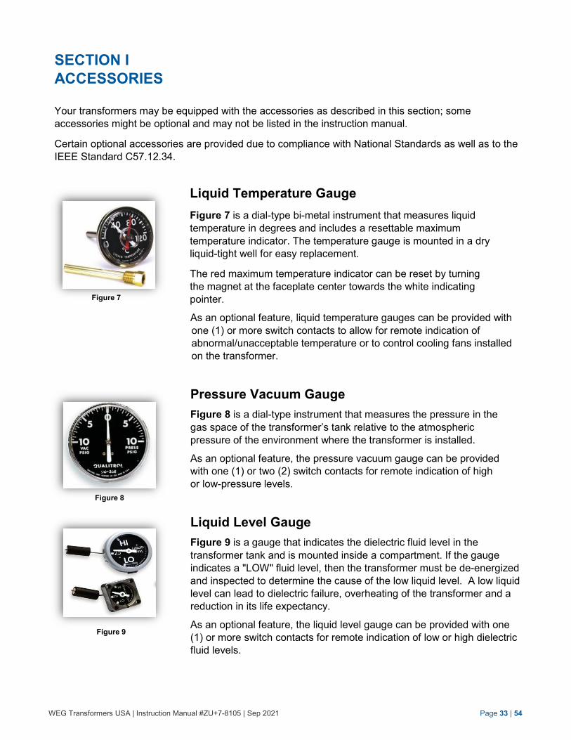
Liquid Temperature Gauge
Figure 7 is a dial-type bi-metal instrument that measures liquid
temperature in degrees and includes a resettable maximum
temperature indicator. The temperature gauge is mounted in a dry
liquid-tight well for easy replacement.
The red maximum temperature indicator can be reset by turning
the magnet at the faceplate center towards the white indicating
pointer.
As an optional feature, liquid temperature gauges can be provided with
one (1) or more switch contacts to allow for remote indication of
abnormal/unacceptable temperature or to control cooling fans installed
on the transformer.
Pressure Vacuum Gauge
Figure 8 is a dial-type instrument that measures the pressure in the
gas space of the transformer’s tank relative to the atmospheric
pressure of the environment where the transformer is installed.
As an optional feature, the pressure vacuum gauge can be provided
with one (1) or two (2) switch contacts for remote indication of high
or low-pressure levels.
Liquid Level Gauge
Figure 9 is a gauge that indicates the dielectric fluid level in the
transformer tank and is mounted inside a compartment. If the gauge
indicates a "LOW" fluid level, then the transformer must be de-energized
and inspected to determine the cause of the low liquid level. A low liquid
level can lead to dielectric failure, overheating of the transformer and a
reduction in its life expectancy.
As an optional feature, the liquid level gauge can be provided with one
(1) or more switch contacts for remote indication of low or high dielectric
fluid levels.
Figure 7
Figure 17
Figure 9
Figure 8
WEG Transformers USA | Instruction Manual #ZU+7-8105 | Sep 2021 Page 34 | 54
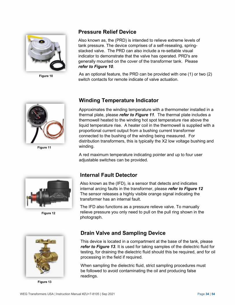
Pressure Relief Device
Also known as, the (PRD) is intended to relieve extreme levels of
tank pressure. The device comprises of a self-resealing, spring-
stacked valve. The PRD can also include a re-settable visual
indicator to demonstrate that the valve has operated. PRD's are
generally mounted on the cover of the transformer tank. Please
refer to Figure 10.
As an optional feature, the PRD can be provided with one (1) or two (2)
switch contacts for remote indicate of valve actuation.
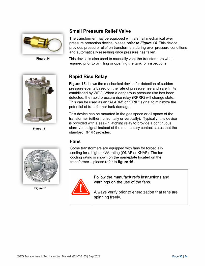
Winding Temperature Indicator
Approximates the winding temperature with a thermometer installed in a
thermal plate, please refer to Figure 11. The thermal plate includes a
thermowell heated to the winding hot spot temperature rise above the
liquid temperature rise. A heater coil in the thermowell is supplied with a
proportional current output from a bushing current transformer
connected to the bushing of the winding being measured. For
distribution transformers, this is typically the X2 low voltage bushing and
winding.
A red maximum temperature indicating pointer and up to four user
adjustable switches can be provided.
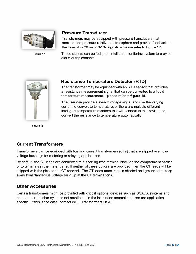
Internal Fault Detector
Also known as the (IFD), is a sensor that detects and indicates
internal arcing faults in the transformer, please refer to Figure 12
The sensor releases a highly visible orange signal indicating the
transformer has an internal fault.
The IFD also functions as a pressure relieve valve. To manually
relieve pressure you only need to pull on the pull ring shown in the
photograph.
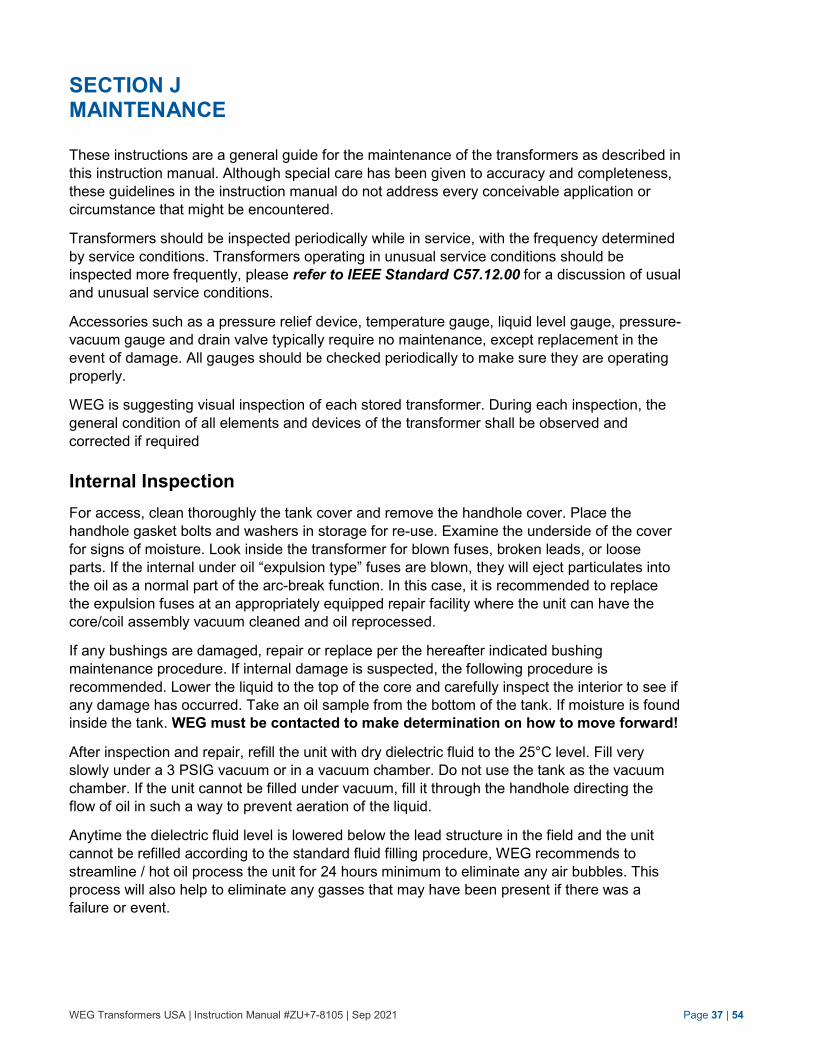
Drain Valve and Sampling Device
This device is located in a compartment at the base of the tank, please
refer to Figure 13. It is used for taking samples of the dielectric fluid for
testing, for draining the dielectric fluid should this be required, and for oil
processing in the field if required.
When sampling the dielectric fluid, strict sampling procedures must
be followed to avoid contaminating the oil and producing false
readings.
Figure 10
Figure 11
Figure 12
Figure 13
WEG Transformers USA | Instruction Manual #ZU+7-8105 | Sep 2021 Page 35 | 54
Small Pressure Relief Valve
The transformer may be equipped with a small mechanical over
pressure protection device, please refer to Figure 14. This device
provides pressure relief on transformers during over pressure conditions
and automatically resealing once pressure has fallen.
This device is also used to manually vent the transformers when
required prior to oil filling or opening the tank for inspections.
Rapid Rise Relay
Figure 15 shows the mechanical device for detection of sudden
pressure events based on the rate of pressure rise and safe limits
established by WEG. When a dangerous pressure rise has been
detected, the rapid pressure rise relay (RPRR) will change state.
This can be used as an “ALARM” or “TRIP” signal to minimize the
potential of transformer tank damage.
This device can be mounted in the gas space or oil space of the
transformer (either horizontally or vertically). Typically, this device
is provided with a seal-in latching relay to provide a continuous
alarm / trip signal instead of the momentary contact states that the
standard RPRR provides.
Fans
Some transformers are equipped with fans for forced air-
cooling for a higher kVA rating (ONAF or KNAF). The fan
cooling rating is shown on the nameplate located on the
transformer – please refer to figure 16.
Follow the manufacturer's instructions and
warnings on the use of the fans.
Always verify prior to energization that fans are
spinning freely.
Figure 14
Figure 15
Figure 16
WEG Transformers USA | Instruction Manual #ZU+7-8105 | Sep 2021 Page 36 | 54
Pressure Transducer
Transformers may be equipped with pressure transducers that
monitor tank pressure relative to atmosphere and provide feedback in
the form of 4- 20ma or 0-10v signals – please refer to figure 17.
These signals can be fed to an intelligent monitoring system to provide
alarm or trip contacts.
Resistance Temperature Detector (RTD) The transformer may be equipped with an RTD sensor that provides
a resistance measurement signal that can be converted to a liquid
temperature measurement – please refer to figure 18.
The user can provide a steady voltage signal and use the varying
current to convert to temperature, or there are multiple different
intelligent temperature monitors that will connect to this device and
convert the resistance to temperature automatically.
Current Transformers
Transformers can be equipped with bushing current transformers (CTs) that are slipped over low-
voltage bushings for metering or relaying applications.
By default, the CT leads are connected to a shorting type terminal block on the compartment barrier
or to terminals in the meter panel. If neither of these options are provided, then the CT leads will be
shipped with the pins on the CT shorted. The CT leads must remain shorted and grounded to keep
away from dangerous voltage build up at the CT terminations.
Other Accessories
Certain transformers might be provided with critical optional devices such as SCADA systems and
non-standard busbar systems not mentioned in the instruction manual as these are application
specific. If this is the case, contact WEG Transformers USA.
Figure 17
Figure 18
WEG Transformers USA | Instruction Manual #ZU+7-8105 | Sep 2021 Page 37 | 54
SECTION J MAINTENANCE
These instructions are a general guide for the maintenance of the transformers as described in
this instruction manual. Although special care has been given to accuracy and completeness,
these guidelines in the instruction manual do not address every conceivable application or
circumstance that might be encountered.
Transformers should be inspected periodically while in service, with the frequency determined
by service conditions. Transformers operating in unusual service conditions should be
inspected more frequently, please refer to IEEE Standard C57.12.00 for a discussion of usual
and unusual service conditions.
Accessories such as a pressure relief device, temperature gauge, liquid level gauge, pressure-
vacuum gauge and drain valve typically require no maintenance, except replacement in the
event of damage. All gauges should be checked periodically to make sure they are operating
properly.
WEG is suggesting visual inspection of each stored transformer. During each inspection, the
general condition of all elements and devices of the transformer shall be observed and
corrected if required
Internal Inspection
For access, clean thoroughly the tank cover and remove the handhole cover. Place the
handhole gasket bolts and washers in storage for re-use. Examine the underside of the cover
for signs of moisture. Look inside the transformer for blown fuses, broken leads, or loose
parts. If the internal under oil “expulsion type” fuses are blown, they will eject particulates into
the oil as a normal part of the arc-break function. In this case, it is recommended to replace
the expulsion fuses at an appropriately equipped repair facility where the unit can have the
core/coil assembly vacuum cleaned and oil reprocessed.
If any bushings are damaged, repair or replace per the hereafter indicated bushing
maintenance procedure. If internal damage is suspected, the following procedure is
recommended. Lower the liquid to the top of the core and carefully inspect the interior to see if
any damage has occurred. Take an oil sample from the bottom of the tank. If moisture is found
inside the tank. WEG must be contacted to make determination on how to move forward!
After inspection and repair, refill the unit with dry dielectric fluid to the 25°C level. Fill very
slowly under a 3 PSIG vacuum or in a vacuum chamber. Do not use the tank as the vacuum
chamber. If the unit cannot be filled under vacuum, fill it through the handhole directing the
flow of oil in such a way to prevent aeration of the liquid.
Anytime the dielectric fluid level is lowered below the lead structure in the field and the unit
cannot be refilled according to the standard fluid filling procedure, WEG recommends to
streamline / hot oil process the unit for 24 hours minimum to eliminate any air bubbles. This
process will also help to eliminate any gasses that may have been present if there was a
failure or event.
WEG Transformers USA | Instruction Manual #ZU+7-8105 | Sep 2021 Page 38 | 55
Prior any internal maintenance inspection always
follow all safety precautions, these are:
1. De-energize the transformer. 2. Make sure the dielectric fluid is at or below
the 25°C level. 3. Vent the transformer. 4. Ground the transformer. 5. Prevent ingress of dirt and or moisture. 6. Adhere to all applicable OSHA and National
Safety standards.
Exceeding 3 PSIG vacuum will make the tank
collapse!
Bushing Maintenance
If required and warranted, lower the liquid level prior to bushing removal or inspection through the
handhole. In all cases, the high-voltage bushings may be changed by removing the external
clamp hardware and carefully pulling the bushing out. Access to the internal lead will allow it to
be disconnected. Replace the bushing and carefully insert it back in its hole in the tank.
Low-voltage bushings may be replaced externally or through the main tank cover handhole. The
bushing may be replaced externally by removing the clamps and pulling the bushing out of its hole.
The lead hardware may be removed and the bushing can be changed. Be sure to install the
hardware in the original sequence. The gasket must be located so that it will seal properly and not
be damaged when repairing the unit.
We differentiate Draw Lead Connected Bushings and Bottom Lead Connected Bushing. For
mounting and removal of the bushings, please follow the procedure guidelines below, while always
consulting with the OEM Instruction Manual for the bushing provided.
Always vent the tank prior starting to initiate bushing removal procedure.
WEG Transformers USA | Instruction Manual #ZU+7-8105 | Sep 2021 Page 39 | 55
For transformers supplied with “Bottom Lead Connected Bushings separate from the trasnformer,
the following installation procedures must be followed:
Mounting
1. Remove any blanking flanges covering the bushing holes on the cover.
2. Unpack the bushing keeping it tilted with the top side higher than the bottom side to avoid
air bubbles penetrating the insulation at the bottom.
3. Check the bushing carefully (for oil leaks as well). Check the center tube and remove the
plastic sealing plugs if present.
4. Remove the outer terminal cap on the top of the bushing.
5. Clean the porcelain using clean rags, moisturized with Methyl Hydrate if needed.
6. If the terminals are dirty, clean them with clean, dry rags (moisturized with Methyl Hydrate
if necessary) or use a soft brush.
7. Remove the blind flange on the transformer tank (cover), pull out the draw lead and
check for damage, remove the shipping gasket and clean the gasket surface.
8. Place a new gasket on the cover and cover the opening for foreign parts, dust and
moisture.
9. Sling the bushing at the correct angle according per the manufacturers’ instruction
10. Attach a strong rope or wire to the terminal stud and pull it through the central tube of the
bushing.
11. Slowly draw the draw lead cable in the bushing while the bushing is placed into position.
Fix the bushing flange into position and mount the upper terminal stud and cap; please
refer to the specific manufacturers’ instruction.
12. Tighten the top terminal arrangement and the flange bolts with the correct torque
according to the specific documentation.
13. Ground the bushing for personnel safety as well as to ensure that the transformer will not
be damaged due to lightning.
Removal
For removing the Bottom Lead Bushing, following the mounting procedure STEP 13 through
STEP 1 - reverse procedure.
Always vent the tank prior starting to initiate bushing removing procedure.
When opening the transformer make sure no debris or foreign object is entering in the transformers as it will contaminated live parts resulting in severe personal injury or even death!
WEG Transformers USA | Instruction Manual #ZU+7-8105 | Sep 2021 Page 40 | 55
For transformers supplied with “Draw Lead Bushings” separate from the trasnformer, the
following installation procedures must be followed:
1. Remove any blanking flanges covering the bushing holes on the cover.
2. Unpack the bushing keeping it tilted with the top side higher than the bottom side to avoid
air bubbles penetrating the insulation at the bottom.
3. Check the bushing carefully (for oil leaks as well). Check the center tube and remove the
plastic sealing plugs if present.
4. Remove the outer terminal cap on the top of the bushing.
5. Clean the porcelain using clean rags, moisturized with Methyl Hydrate if needed.
6. If the terminals are dirty, clean them with clean, dry rags (moisturized with Methyl Hydrate
if necessary) or use a soft brush.
7. Mount the bushing into position. Tighten the bushing flange bolts according to the specific
manufacturers’ instruction.
8. Open the handhole and make the internal connection through the handhole or manhole.
9. Tighten the bolts according to the manufacturers’ instruction.
10. Close the handhole carefully and make sure to foreign object have fallen into the
transformer.
11. Ground the bushing for personnel safety as well as to ensure that the transformer will not
be damaged due to lightning.
Removal
Prior removing the Draw Lead Bushing, following the procedures below:
1. Close the upper and lower throttle radiator valve. 2. Open the handhole and lower the oil level below the bushing connection. 3. Follow the mounting procedure STEP 10 through STEP 1 – reverse procedure.
When opening the transformer make sure no debris or foreign object is entering in the transformers as it will contaminated live parts resulting in severe personal injury or even death!
Tightness of the top terminals of the bushing is essential for trouble free operation and must be ensured at the time of installation and checked periodically during service.
When installing the bushing, always consult the OEM’s instruction manual.
WEG Transformers USA | Instruction Manual #ZU+7-8105 | Sep 2021 Page 41 | 55
Detachable Radiators
The transformer uses custom designed radiator assemblies to provide proper cooling for the specific
design. Is your transformer shipped with detachable radiators, the following installation procedure must
be followed:
Mounting
1. Unpack and check each radiator carefully; remove blind flanges (the inside should be dry,
clean and free from foreign objects): clean gasket surfaces.
2. Prior removing the blind flanges make sure the throttle valves are closed (top and bottom
valve
3. Clean the gasket surface of each throttle valve.
4. Mount the radiators (one by one) to the tank with the right side up (topside = lifting lug).
5. Always use new gaskets, tighten all throttle valve bolts and retighten after 24 hours.
Using a small amount of a correct sealing compound will help to keep the gaskets in
place during installation and will limit the risk for leaks.
6. Mount stiffener bars (if any) between the radiators.
7. Install the fans (if any) and connect the power control cables
8. If necessary, touch up the damaged/scratched radiator surfaces
Only left the radiator with the provided lifting lugs; never lift with the spot-welded side rods of the radiators as it may cause a radiator leak.
Filling
Radiator must be filled one by one once the radiator is attached to the tank.
Fill as follows:
1. Open the air-vent screw on the top of the radiator.
2. Partially open the lower throttle valve located on the tank.
3. Wait until oil escapes from the air-vent screw and close the air-vent screw
immediately.
4. Completely open the upper and the lower throttle valve.
During this process, the oil level in the transformer tank must be checked regularly; the oil level may never be below the radiator inlet / highest point of the windings to avoid moisture, air, or gas ingress. For this reason, it could be necessary to fill-up oil immediately to safeguard the integrity of the transformer.
WEG Transformers USA | Instruction Manual #ZU+7-8105 | Sep 2021 Page 42 | 55
Removal
Prior removing the radiator it must be drained by following the below procedure:
1. Close TOP and BOTTOM throttle valves first prior proceeding with any other described
radiator draining procedures.
2. Unscrew the protection cover of the drain plug
3. Make sure that the air vent is fully closed.
4. Unscrew the drain plug entirely and make sure that out coming oil does not drip on the
ground.
5. After a while, the oil flow stops due to a vacuum created in the radiator.
6. Connect a flexible hose or another device to the drain plug so that oil spillage is avoided.
7. Remove the protection cover.
8. Open the air vent further by turning the screw in a counterclockwise direction.
9. Incoming air in radiator results in a rapid oil draining via the drain plug.
10. After draining :
a. Close vent plug
b. Remount protection cover of vent plug
c. Close drain plug
d. Remount protection cover of drain plug
Prior draining the radiator ALWAYS close TOP and BOTTOM throttle valves first prior proceeding with any other described radiator draining procedures as otherwise it main drain the dielectric fluid.
When the radiator need to be detached from the tank, follow the below procedure:
1. Remove the fans and fan supports and disconnect the power control cable if any
2. Verify if radiator is drained and verify bottom and top throttle valve is closed.
3. Unscrew the four (4) nuts on each throttle valves.
4. Remove the radiators by lifting then at the lifting lug provided on each radiator.
5. Place a blank flange on the throttle valves of the transformer when the radiator is
removed for longer than 1 hour. If the radiators are to be used again, provide them also
with a blank flange
ALWAYS make sure that TOP and BOTTOM throttle valves are closed as otherwise it main drain the dielectric fluid into the environment.
WEG Transformers USA | Instruction Manual #ZU+7-8105 | Sep 2021 Page 43 | 55
When mounting or removing the radiator make
sure no debris or foreign object is entering in the
transformers as it will contaminated live parts
resulting in severe personal injury or even death!
Refilling after Repairs
After repairs have been completed, refill the unit under a small vacuum of 3 PSIG with dry
dielectric fluid to the 25°C liquid level.
Always follow the torque guidelines when replacing
bushings; please refer to Section L - Tables and
Procedures for recommended torque values.
When necessary to add or refill the transformer with dielectric fluid, the work must be done in a clean,
dry room. When filling do not use a rubber hose, use an oil resistant hose.
Dissolved Gas Analysis (DGA)
IEEE does not have a standard for DGA levels in distribution transformers. However, DGA’s can be a
very important tool to diagnose the health of a transformer and samples taken over time can certainly
show trends of a transformer’s health. Interpretation of DGA results is not an exact science, but is
subject to variability.
DGA samples can be affected by welding on the tanks or the operation of a load break switch or fuse.
In the manufacturing process, units that are welded on after filling with dielectric fluid do see a slight
generation of gases due to heating of the fluid inside the tank. It is important to know if units have had
any weld repairs or modifications as they can cause DGA increases.
Taking dielectric fluid samples for DGA does reduce the liquid level in a transformer, especially in
smaller distribution transformers. Generally speaking, a 2000 kVA transformer can have 4 or 5
samples taken without causing an issue with low dielectric fluid. Caution needs to be used to insure
proper fluid levels are maintained when taking many samples from a unit.
Operating a transformer with excessive harmonics or beyond nameplate ratings will cause gas levels
to increase.
WEG Transformers USA | Instruction Manual #ZU+7-8105 | Sep 2021 Page 44 | 55
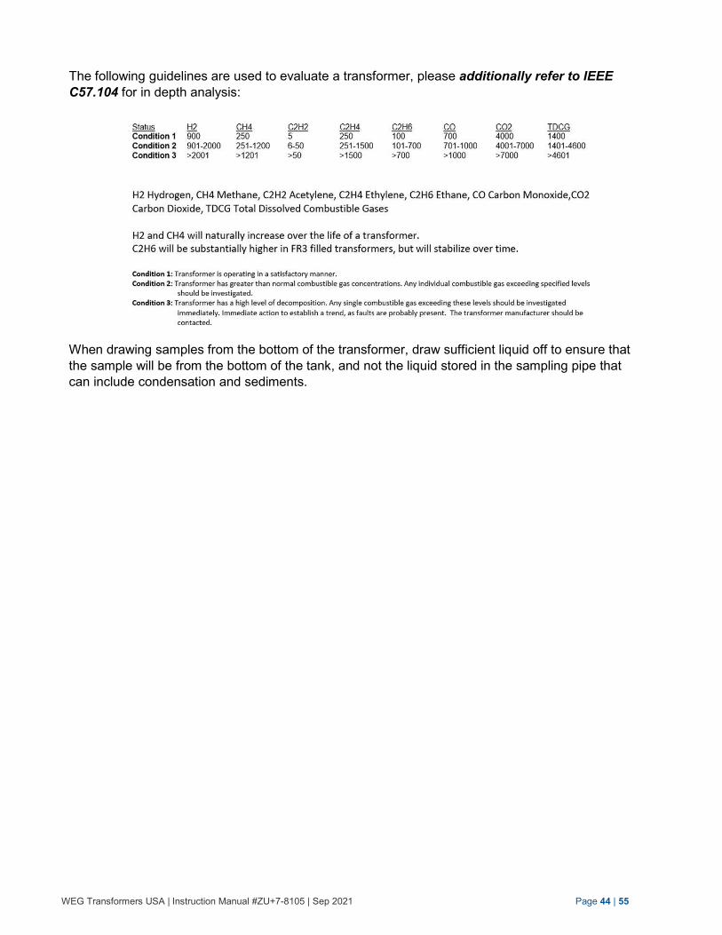
The following guidelines are used to evaluate a transformer, please additionally refer to IEEE
C57.104 for in depth analysis:
When drawing samples from the bottom of the transformer, draw sufficient liquid off to ensure that
the sample will be from the bottom of the tank, and not the liquid stored in the sampling pipe that
can include condensation and sediments.
WEG Transformers USA | Instruction Manual #ZU+7-8105 | Sep 2021 Page 45 | 55
Always vent the transformer prior to taking samples of dielectric fluid. Never take oil samples while the transformer tank pressure is below 0 PSI relative.
Only take dielectric fluid samples when the transformer is warmer than the surrounding air to avoid
condensation of moisture inside the tank. ONLY draw samples from the sampling valve located at
the bottom of the transformer tank. Always vent the transformer tank by use of the pressure relief
valve, located in the compartment, prior to taking a sample of dielectric fluid.
For sampling, a clean dry bottle is required. Rinse the bottle three (3) times with the liquid being
sampled. Make sure the liquid being sampled is representative of liquid in the transformer.
Samples of dielectric fluid should ONLY be taken after the liquid has settled for some time, up to
several days for a large transformer (2000 kVA and above) that has not been energized. Cold
insulating liquid is much slower in settling. If the transformer is or has been operating, dielectric
fluid samples can be taken at any time. Liquid samples from the transformer should be taken from
the sampling valve at the bottom of the tank.
DO NOT energize the transformer unless it is filled with dielectric fluid. If it should be necessary to
add or replace the dielectric fluid in the transformer, only use clean, dry fluid having a minimum
dielectric strength of 30 kV and less than 1 ppm PCB's. Make sure before filling that the
transformer is sufficiently cooled down to ambient temperature to eliminate the possibility of
moisture condensation from the air.
After taking fluid samples, ALWAYS verify dielectric
fluid level prior to energization.
External Finish Maintenance
Examine the external condition of the transformer at regular intervals. If it is found that
weathering is taking place, then the surface should be cleaned thoroughly and repainted
with a high-grade durable paint as recommended by WEG.
Spare Parts
Orders for spare parts may be placed by describing the part and giving the rating and serial
number appearing on the nameplate of the transformer.
For quick handling and/or resolution of your needs or non-conformances, always when
emailing WTU-Service [email protected] , provide the following information:
1. Transformer serial number as indicated on the nameplate.
2. Transformer model number as indicated on the nameplate.
3. Figures of the finding(s).
WEG Transformers USA | Instruction Manual #ZU+7-8105 | Sep 2021 Page 46 | 55
4. Description of the finding(s).
All Inspection check lists, long term and short term storage check lists, as well as non-conformance forms can be downloaded from our web site: www.weg.us
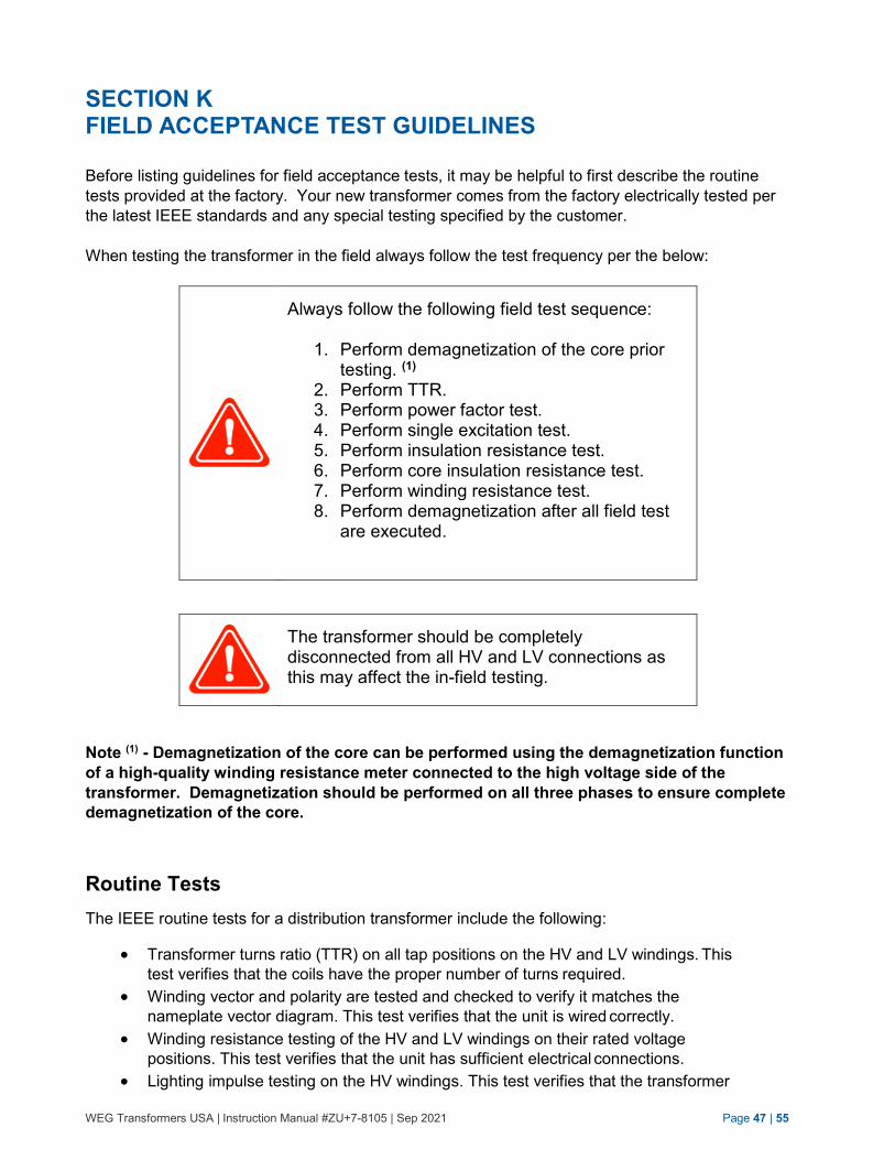
WEG Transformers USA | Instruction Manual #ZU+7-8105 | Sep 2021 Page 47 | 55
SECTION K FIELD ACCEPTANCE TEST GUIDELINES
Before listing guidelines for field acceptance tests, it may be helpful to first describe the routine
tests provided at the factory. Your new transformer comes from the factory electrically tested per
the latest IEEE standards and any special testing specified by the customer.
When testing the transformer in the field always follow the test frequency per the below:
Always follow the following field test sequence:
1. Perform demagnetization of the core prior testing. (1)
2. Perform TTR. 3. Perform power factor test. 4. Perform single excitation test. 5. Perform insulation resistance test. 6. Perform core insulation resistance test. 7. Perform winding resistance test. 8. Perform demagnetization after all field test
are executed.
The transformer should be completely disconnected from all HV and LV connections as this may affect the in-field testing.
Note (1) - Demagnetization of the core can be performed using the demagnetization function
of a high-quality winding resistance meter connected to the high voltage side of the
transformer. Demagnetization should be performed on all three phases to ensure complete
demagnetization of the core.
Routine Tests
The IEEE routine tests for a distribution transformer include the following:
Transformer turns ratio (TTR) on all tap positions on the HV and LV windings. This
test verifies that the coils have the proper number of turns required.
Winding vector and polarity are tested and checked to verify it matches the
nameplate vector diagram. This test verifies that the unit is wired correctly.
Winding resistance testing of the HV and LV windings on their rated voltage
positions. This test verifies that the unit has sufficient electrical connections.
Lighting impulse testing on the HV windings. This test verifies that the transformer
WEG Transformers USA | Instruction Manual #ZU+7-8105 | Sep 2021 Page 48 | 55
can withstand the prescribed electrical stresses (lead to lead, winding to winding,
turn to turn, layer to layer, and phase to ground).
Applied voltage testing on any floating winding. This test verifies that the
transformer can withstand prescribed electrical stresses winding to ground.
Induced voltage testing at either two times rated voltage or 3.46 times rated voltage
plus 1000 volts on the HV if the HV winding is internally grounded. This test verifies
that the transformer can withstand the prescribed electrical stresses (lead to lead,
winding to winding, turn to turn, and layer to layer).
Core loss and excitation current testing to verify the unit meets efficiency standards
per IEEE, DOE, and customer specific requirements.
Winding loss and impedance testing to verify that the unit meets the efficiency
standards of IEEE, DOE, and customer specific requirements.
Pressure leak check at 5 PSI for 24 hours to verify the tank is hermetically sealed.
Function check of installed devices.
Field Acceptance Tests
The most commonly performed field acceptance tests include the following:
If you choose to do any acceptance testing, be
sure to have personnel that are qualified and
trained in high voltage testing practices as
hazardous voltages and currents will be present
during testing.
Transformer Turns Ratio (TTR)
TTR testing can give an indication of the health of a transformer with the following:
The ratio of turns from the high voltage winding compared to the low voltage
winding.
Single-phase excitation of the transformer winding to give an indication of a shorted
coil. TTR test exciting current should be approximately within 10% between phases.
Indicates the wiring inside the transformer matches the nameplate wiring diagram
and vector.
Can show an open circuit or a high resistance connection on one of the three
phases or neutral.
WEG Transformers USA | Instruction Manual #ZU+7-8105 | Sep 2021 Page 49 | 55
When performing this test, please be aware of the following items that can cause invalid
test readings:
Switches not in the proper position: Load break, delta/wye, dual voltage, H0X0.
Verify load break switches are closed. Verify Delta / Wye or dual voltage switches
are in the proper position. Verify tap changer is in proper position. Verify reading to
calculated nameplate ratio. Match data to transformer test report.
Bay-o-net fuses not installed into the transformer.
Operated (blown) fuses
Winding Resistance
A winding resistance test will verify that there is a complete circuit between bushings through
the transformer windings. When performing the test the values should match the tested
winding resistance from the factory.
If the transformer test report is unavailable, a general rule of thumb is that when winding
resistance values are compared from one phase of a transformer to another they should be
within 5% of each other. Please note that the design of padmount distribution transformers
inherently lends itself to have unequal lead lengths due to the required bushing arrangement.
These unequal lead lengths can increase variation in winding resistance. It is possible that
variations greater than 5% between phases could still match factory test results and be
acceptable. Winding resistance values must be corrected to a uniform temperature for
accurate comparisons to be made.
The transformer under test must always be demagnetized before putting into service. A magnetized core can cause severe switching currents upon energization due to the core’s natural opposition to receive magnetic energy in the magnetized state.
When performing this test, please be aware of the following items that can cause invalid
test readings:
Switches not in the proper position: Load break, delta/wye, dual voltage, H0X0.
Verify load break switches are closed. Verify Delta / Wye or dual voltage switches
are in the proper position. Verify tap changer is in proper position. Verify reading to
calculated nameplate ratio. Match data to transformer test report.
Bay-o-net fuses not installed into the transformer.
Operated (blown) fuses.
Not allowing the test equipment to operate long enough to settle on a stable
resistance reading.
Improper temperature correction factor used or none used at all.
WEG Transformers USA | Instruction Manual #ZU+7-8105 | Sep 2021 Page 50 | 55
Insulation Resistance (Megger)
Insulation resistance tests (also commonly referred to as “Megger” tests) should be done
before putting the transformer into service, and at periodic intervals throughout the
transformer’s life cycle. Please note that measured values do not have absolute pass/fail
criteria, as tested values for duplicate transformers will vary considerably. Test results for an
individual transformer should be trended over time.
Before performing the test, verify bushing insulators are clean and dry as debris and moisture
can affect the insulation resistance readings. Testing in humid conditions can also affect the
insulation resistance readings.
When performing this test, please be aware of the following items that can cause significant
variation in test readings:
Insulation resistance results need to be done at the same voltage test level for
subsequent tests to have comparable results.
Insulation resistance results need to be temperature corrected to be a comparable
result.
Units filled with FR3 dielectric fluid will naturally have lower insulation resistance
values compared to units that are filled with mineral oil.
Insulation Power Factor (Doble, Dissipation Factor, Tan Delta)
Power factor tests should be done before putting the transformer into service, and at periodic
intervals throughout the transformer’s life cycle. Measured values do not have absolute pass/fail
criteria, as tested values for duplicate transformers will vary considerably. Test results for an
individual transformer should be trended over time.
Before performing the test, verify bushing insulators are clean and dry as debris or moisture
can affect the insulation power factor readings. Testing in humid conditions or freezing
conditions can also significantly affect the insulation power factor readings.
Please keep the shorting wire a minimum of 5 inches away from protrusions on the tank.
When performing this test, please be aware of the following items that can cause significant
variation in test readings:
The capacitance measurement from the insulation power factor test can show shifts in
transformer leads if a substantial capacitance change is noticed from subsequent tests.
Units filled with FR3 dielectric fluid will naturally have lower insulation power factor
values compared to units that are filled with mineral oil.
If the unit is equipped with a core ground bushing, ensure the core ground is
connected while performing the test.
WEG Transformers USA | Instruction Manual #ZU+7-8105 | Sep 2021 Page 51 | 55
Single Phase Excitation
Single-phase excitation is a test to verify the exciting current of each phase of a coil. Test
results should be within 10% phase to phase.
Single Phase Excitation results need to be done at the same voltage test level for subsequent
tests to have comparable results. Only results in the same tap position are comparable. The
transformer core must be demagnetized before doing any single-phase excitation tests.
Single-phase excitation is typically done if there is a suspicion of a transformer fault, but the transformer turns ratio test does not show an issue. This is because single-phase excitation is typically done at a voltage level substantially higher than transformer turns ratio testing.
Oil Quality
Oil quality tests can be done during commissioning testing. If oil samples are taken, they
should be done at yearly intervals. Please try to follow the requirements of ASTM Standard D
923, Standard Practices for Sampling Electrical Insulating Liquids. Depending on the size of
the transformer, the amount of oil taken from the unit may need to be replaced after an oil
sample is taken since taking an oil sample on a small unit can cause an insufficient oil level in
the transformer. Oil samples should be taken from the drain valve of the transformer. The
transformer should not be under vacuum when attempting to take an oil sample. A minimum of
three gallons of oil needs to be drained from the transformer to get a good representative oil
sample. It is best to remove the plug at the end of the drain valve and use a reducer plug to
connector to the hose used for oil sampling. The oil sampling hose should be made of an oil
compatible material such as Tygon® tubing. Do not use a standard rubber hose as the pores
of the rubber could introduce moisture into the sample.
If there is a question regarding an oil sample test result, then a second sample should be
taken to confirm the result. Oil quality test results should be trended over time.
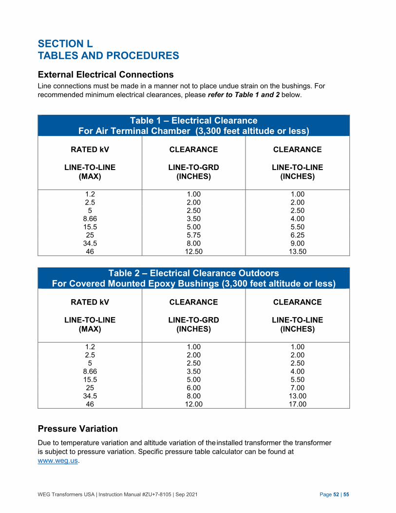
WEG Transformers USA | Instruction Manual #ZU+7-8105 | Sep 2021 Page 52 | 55
SECTION L TABLES AND PROCEDURES
External Electrical Connections
Line connections must be made in a manner not to place undue strain on the bushings. For
recommended minimum electrical clearances, please refer to Table 1 and 2 below.
Table 1 – Electrical Clearance For Air Terminal Chamber (3,300 feet altitude or less)
RATED kV
LINE-TO-LINE
(MAX)
CLEARANCE
LINE-TO-GRD
(INCHES)
CLEARANCE
LINE-TO-LINE
(INCHES)
1.2 1.00 1.00 2.5 2.00 2.00 5 2.50 2.50
8.66 3.50 4.00 15.5 5.00 5.50 25 5.75 6.25
34.5 46
8.00 12.50
9.00 13.50
Table 2 – Electrical Clearance Outdoors For Covered Mounted Epoxy Bushings (3,300 feet altitude or less)
RATED kV
LINE-TO-LINE
(MAX)
CLEARANCE
LINE-TO-GRD
(INCHES)
CLEARANCE
LINE-TO-LINE
(INCHES)
1.2 1.00 1.00 2.5 2.00 2.00 5 2.50 2.50
8.66 3.50 4.00 15.5 5.00 5.50 25 6.00 7.00
34.5 46
8.00 12.00
13.00 17.00
Pressure Variation
Due to temperature variation and altitude variation of the installed transformer the transformer
is subject to pressure variation. Specific pressure table calculator can be found at
www.weg.us.
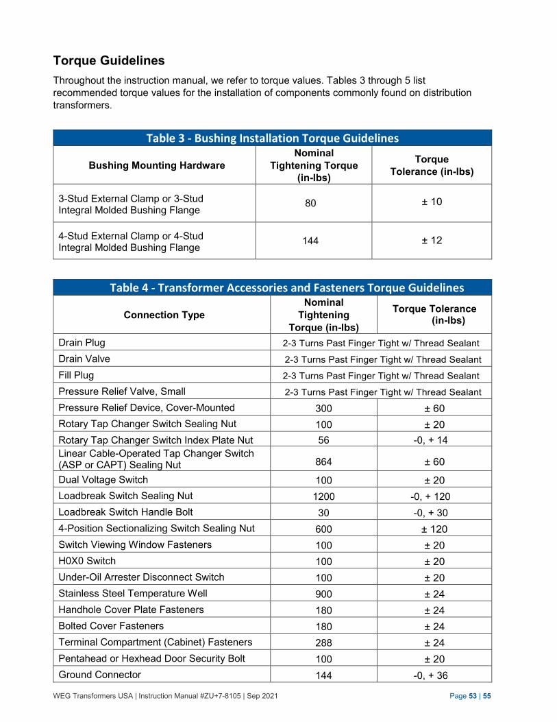
WEG Transformers USA | Instruction Manual #ZU+7-8105 | Sep 2021 Page 53 | 55
Torque Guidelines
Throughout the instruction manual, we refer to torque values. Tables 3 through 5 list
recommended torque values for the installation of components commonly found on distribution
transformers.
Table 3 - Bushing Installation Torque Guidelines
Bushing Mounting Hardware
Nominal
Tightening Torque
(in-lbs)
Torque
Tolerance (in-lbs)
3-Stud External Clamp or 3-Stud Integral Molded Bushing Flange
80
± 10
4-Stud External Clamp or 4-Stud Integral Molded Bushing Flange
144
± 12
Table 4 - Transformer Accessories and Fasteners Torque Guidelines
Connection Type
Nominal
Tightening
Torque (in-lbs)
Torque Tolerance (in-lbs)
Drain Plug 2-3 Turns Past Finger Tight w/ Thread Sealant
Drain Valve 2-3 Turns Past Finger Tight w/ Thread Sealant
Fill Plug 2-3 Turns Past Finger Tight w/ Thread Sealant
Pressure Relief Valve, Small 2-3 Turns Past Finger Tight w/ Thread Sealant
Pressure Relief Device, Cover-Mounted 300 ± 60
Rotary Tap Changer Switch Sealing Nut 100 ± 20
Rotary Tap Changer Switch Index Plate Nut 56 -0, + 14
Linear Cable-Operated Tap Changer Switch (ASP or CAPT) Sealing Nut 864 ± 60
Dual Voltage Switch 100 ± 20
Loadbreak Switch Sealing Nut 1200 -0, + 120
Loadbreak Switch Handle Bolt 30 -0, + 30
4-Position Sectionalizing Switch Sealing Nut 600 ± 120
Switch Viewing Window Fasteners 100 ± 20
H0X0 Switch 100 ± 20
Under-Oil Arrester Disconnect Switch 100 ± 20
Stainless Steel Temperature Well 900 ± 24
Handhole Cover Plate Fasteners 180 ± 24
Bolted Cover Fasteners 180 ± 24
Terminal Compartment (Cabinet) Fasteners 288 ± 24
Pentahead or Hexhead Door Security Bolt 100 ± 20
Ground Connector 144 -0, + 36
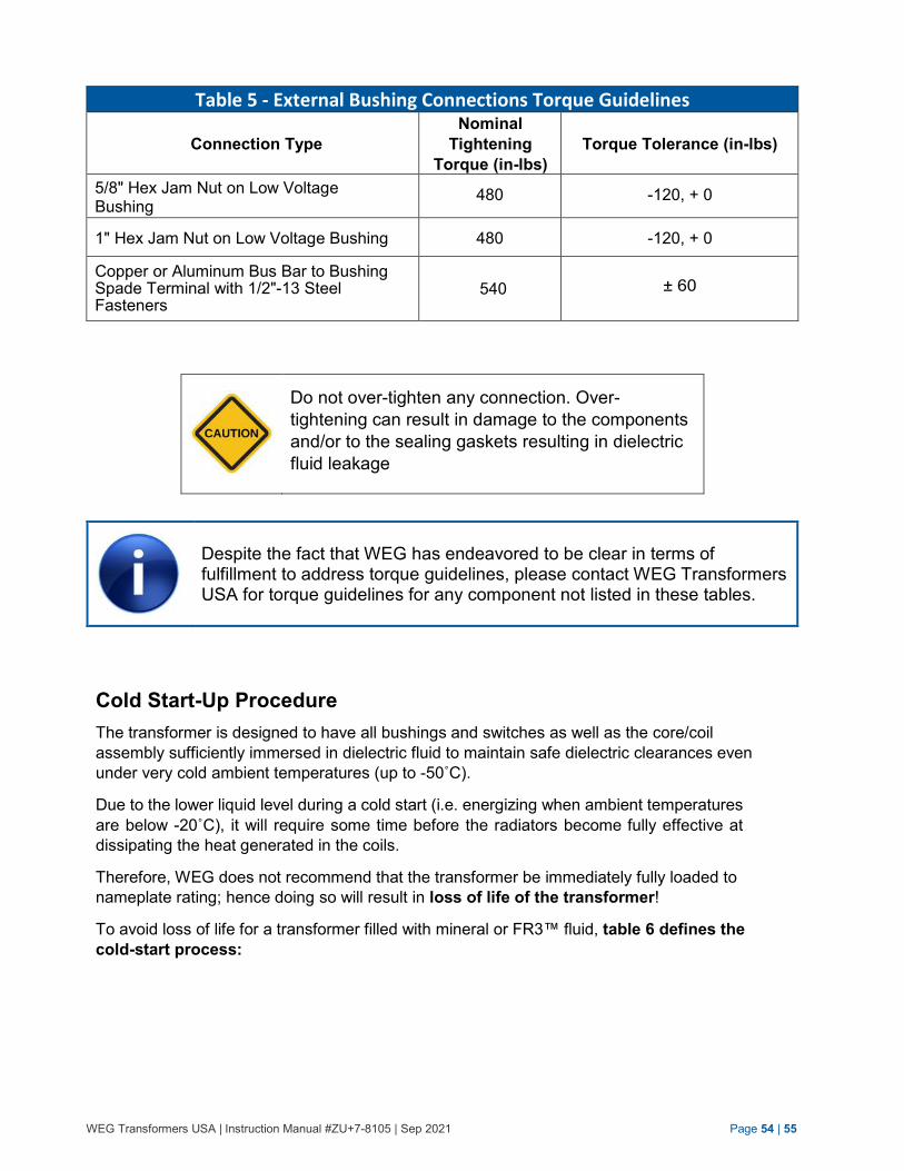
WEG Transformers USA | Instruction Manual #ZU+7-8105 | Sep 2021 Page 54 | 55
Table 5 - External Bushing Connections Torque Guidelines
Connection Type
Nominal
Tightening
Torque (in-lbs)
Torque Tolerance (in-lbs)
5/8" Hex Jam Nut on Low Voltage Bushing
480 -120, + 0
1" Hex Jam Nut on Low Voltage Bushing 480 -120, + 0
Copper or Aluminum Bus Bar to Bushing Spade Terminal with 1/2"-13 Steel Fasteners
540
± 60
Do not over-tighten any connection. Over-
tightening can result in damage to the components
and/or to the sealing gaskets resulting in dielectric
fluid leakage
Despite the fact that WEG has endeavored to be clear in terms of fulfillment to address torque guidelines, please contact WEG Transformers USA for torque guidelines for any component not listed in these tables.
Cold Start-Up Procedure
The transformer is designed to have all bushings and switches as well as the core/coil
assembly sufficiently immersed in dielectric fluid to maintain safe dielectric clearances even
under very cold ambient temperatures (up to -50˚C).
Due to the lower liquid level during a cold start (i.e. energizing when ambient temperatures
are below -20˚C), it will require some time before the radiators become fully effective at
dissipating the heat generated in the coils.
Therefore, WEG does not recommend that the transformer be immediately fully loaded to
nameplate rating; hence doing so will result in loss of life of the transformer!
To avoid loss of life for a transformer filled with mineral or FR3™ fluid, table 6 defines the
cold-start process:
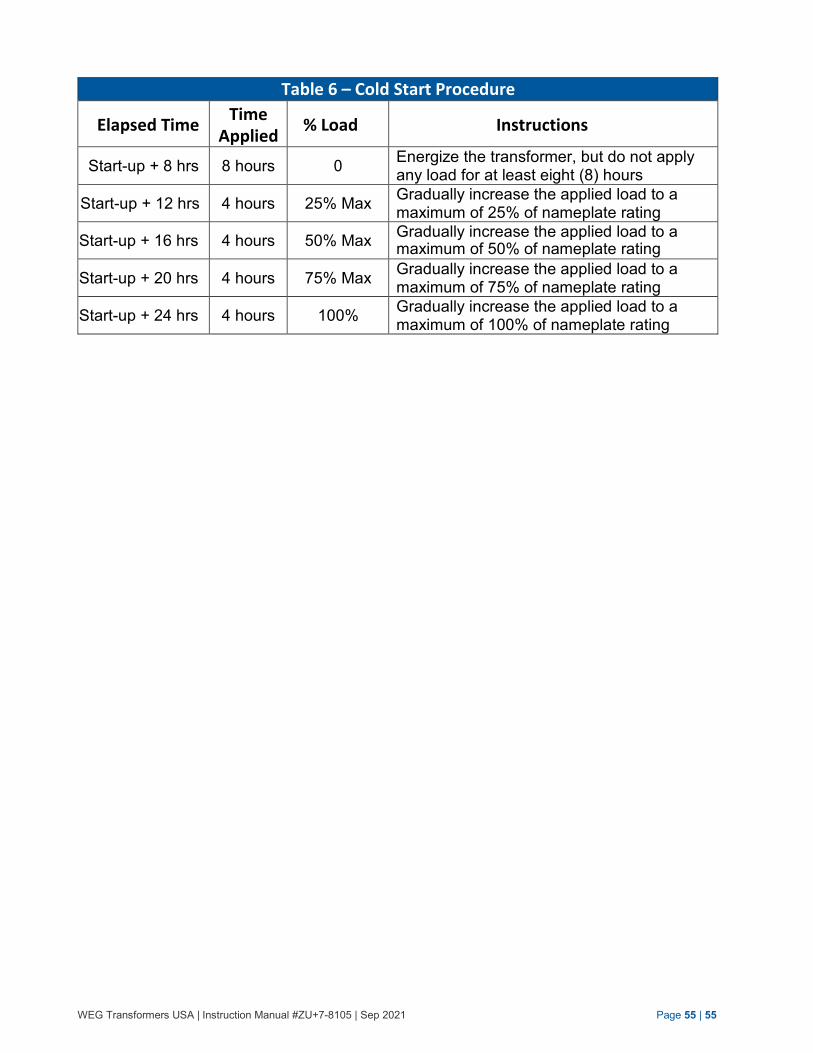
WEG Transformers USA | Instruction Manual #ZU+7-8105 | Sep 2021 Page 55 | 55
Table 6 – Cold Start Procedure
Elapsed Time Time
Applied % Load Instructions
Start-up + 8 hrs 8 hours 0 Energize the transformer, but do not apply any load for at least eight (8) hours
Start-up + 12 hrs 4 hours 25% Max Gradually increase the applied load to a maximum of 25% of nameplate rating
Start-up + 16 hrs 4 hours 50% Max Gradually increase the applied load to a maximum of 50% of nameplate rating
Start-up + 20 hrs 4 hours 75% Max Gradually increase the applied load to a maximum of 75% of nameplate rating
Start-up + 24 hrs 4 hours 100% Gradually increase the applied load to a maximum of 100% of nameplate rating

WEG Transformers USA, LLC
6350 WEG Drive Washington, MO 63090 USA
Telephone: 636-239-9300
Website: www.weg.us
Instr
uction M
anual #Z
U+
7-8
105 | S
ep 2
021
Thre
e P
hase S
ubsta
tion T
ype T
ransfo
rmers
| 4
5 k
VA
thro
ugh 1
0,0
00 k
VA