Embed Size (px)
Citation preview
I N D E X SPECIFIC PROVISIONS SECTION PAGE 1 TESTING OF MATERIALS 1.01 Description ..................................................................................................... 1 2 EARTHWORK 2.01 Description ..................................................................................................... 3 2.02 Grade Tolerance ............................................................................................... 3 2.03 Relative Compaction ......................................................................................... 3 2.04 Subgrade Stability/Deflection Test .................................................................... 3 2.05 Lime Treatment................................................................................................. 3 3 ENGINEERING FABRICS 3.01 Description ..................................................................................................... 5 3.02 Pavement Reinforcing Fabric ............................................................................ 5 3.03 Subgrade Stabilization Fabric ........................................................................... 5 3.04 Measurement and Payment .............................................................................. 6 4 AGGREGATE SUBBASE 4.01 Description ..................................................................................................... 7 4.02 Measurement and Payment .............................................................................. 7 5 AGGREGATE BASE 5.01 Description ..................................................................................................... 9 5.02 Measurement and Payment .............................................................................. 9 6 ASPHALT CONCRETE 6.01 Description ................................................................................................... 11 6.02 Penetration Treatment, Seal, Prime and Tack Coats............................................................................................... 11 6.03 Adjustment of Iron........................................................................................... 11 6.04 Stage Construction ......................................................................................... 12 6.05 Mix Design ................................................................................................... 12 6.06 Spreading and Compacting Equipment ........................................................... 12 6.07 Measurement and Payment ............................................................................ 12
SECTION PAGE 7 ADJUSTMENT OF MANHOLES, WATER VALVE BOXES, AND SURVEY MONUMENT
BOXES 7.01 Description ................................................................................................... 13 7.02 Adjustment ................................................................................................... 13 7.03 Measurement and Payment ............................................................................ 13 8 CONCRETE CURB, GUTTER, SIDEWALK, AND DRIVEWAYS 8.01 Description ................................................................................................... 15 8.02 Installation ................................................................................................... 15 8.03 Damaged or Unacceptable Concrete .............................................................. 16 8.04 Testing ................................................................................................... 17 8.05 Measurement and Payment ............................................................................ 17 9 UTILITY TRENCHING AND BACKFILL 9.01 Description ................................................................................................... 19 9.02 Maximum Length of Open Trench ................................................................... 19 9.03 Maximum and Minimum Width of Trench ........................................................ 19 9.04 Bracing Excavations ....................................................................................... 20 9.05 Bedding ................................................................................................... 20 9.06 Backfill ................................................................................................... 21 9.07 Densification Methods ..................................................................................... 22 9.08 Backfill Placement Requirements ................................................................... 22 9.09 Backfill Materials ............................................................................................. 24 9.10 Measurement and Payment ............................................................................ 25 10 STORM DRAINAGE 10.01 Description ................................................................................................... 27 10.02 Materials ................................................................................................... 27 10.03 Installation, Grouting, and Banding ................................................................. 29 10.04 Measurement and Payment ............................................................................ 29 11 SANITARY SEWERS 11.01 Description ................................................................................................... 31 11.02 Materials ................................................................................................... 31 11.03 Installation ................................................................................................... 33 11.04 Measurement and Payment ............................................................................ 44 12 WATER DISTRIBUTION 12.01 Description ................................................................................................... 47 12.02 Materials ................................................................................................... 47 12.03 Installation ................................................................................................... 52 12.04 Measurement and Payment ............................................................................ 57
SECTION PAGE 13 PLANTING 13.01 Description ................................................................................................... 59 13.02 Preservation of Property ................................................................................. 59 13.03 Soils Testing ................................................................................................... 59 13.04 Personnel ................................................................................................... 59 13.05 Weather ................................................................................................... 59 13.06 Inspections ................................................................................................... 59 13.07 Submittals ................................................................................................... 60 13.08 Materials ................................................................................................... 60 13.09 Planting ................................................................................................... 65 13.10 Cleaning Up ................................................................................................... 69 13.11 Watering ................................................................................................... 69 13.12 Maintenance Period ........................................................................................ 69 13.13 Final Inspection and Acceptance .................................................................... 72 13.14 Guarantee ................................................................................................... 72 13.15 Measurement and Payment ............................................................................ 73 14 IRRIGATION SYSTEM 14.01 Description ................................................................................................... 75 14.02 General ................................................................................................... 75 14.03 Materials ................................................................................................... 78 14.04 Installation ................................................................................................... 86 14.05 Testing ................................................................................................... 90 14.06 Completion Cleaning ....................................................................................... 92 14.07 Maintenance ................................................................................................... 92 14.08 Guarantee ................................................................................................... 92 14.09 Turnover Items................................................................................................ 94 14.10 Measurement .................................................................................................. 95 14.11 Payment ................................................................................................... 95 15 NON-POTABLE WATER DISTRIBUTION 15.01 Description ................................................................................................... 97 15.02 General ................................................................................................... 97 15.03 Materials ................................................................................................... 97 15.04 Installation ................................................................................................... 98 15.05 Measurement and Payment ............................................................................ 98 16 IRRIGATION SYSTEM - NON-POTABLE WATER 16.01 Description ................................................................................................... 99 16.02 General ................................................................................................... 99 16.03 Materials ................................................................................................... 99 16.04 Installation ................................................................................................. 100 16.05 Testing ................................................................................................. 101 16.06 Measurement and Payment .......................................................................... 101
SECTION PAGE 17 STREET LIGHTING 17.01 Description ................................................................................................. 103 17.02 Materials ................................................................................................. 103 17.03 Installation ................................................................................................. 108 17.04 Acceptance Test ........................................................................................... 110 17.05 Measurement and Payment .......................................................................... 110 18 TRAFFIC SIGNALS 18.01 Description ................................................................................................. 111 18.02 Warranties, Guarantees, and Instruction Sheets .......................................... 112 18.03 Pre-Construction Meeting ............................................................................. 112 18.04 Scheduling of Work ...................................................................................... 112 18.05 Maintaining Existing and Temporary Electrical Systems ............................... 112 18.06 Utility/Agency Coordination and Order of Work ............................................. 113 18.07 Materials, Equipment List and Drawings ....................................................... 114 18.08 Excavating and Backfilling ........................................................................... 114 18.09 Foundations ................................................................................................. 115 18.10 Standards, Steel Pedestals, and Posts ......................................................... 115 18.11 Conduit ................................................................................................. 115 18.12 Pull Boxes ................................................................................................. 117 18.12A Pull Box Anti-Theft Wire Enclosure ............................................................... 117 18.13 Conductors and Wiring ................................................................................. 118 18.14 Fused Splice Connectors .............................................................................. 119 18.15 Bonding and Grounding ................................................................................ 119 18.16 Functional Testing ........................................................................................ 119 18.17 Controller Assembly Testing ......................................................................... 119 18.18 System Testing ............................................................................................. 120 18.19 Service Enclosure- Service ........................................................................... 120 18.20 Controller Assembly- Controller and Cabinet ................................................ 121 18.21 Adaptive Signal Control- Description ............................................................. 123 18.22 Adaptive Signal Control- Materials ................................................................ 124 18.23 Adaptive Signal Control- Installation ............................................................. 131 18.24 Adaptive Signal Control- Warranty ................................................................ 131 18.25 Closed Circuit Television Cameras ............................................................... 131 18.26 Signal and Video Interconnection- Wireless .................................................. 132 18.27 Managed Switches (Fiber/Copper) ................................................................ 132 18.27A Ethernet Over Copper Wired Interface (Switch) ............................................ 133 18.28 Fiber (Switch) ................................................................................................ 135 18.28A Fiber Switch (Modular and Field Replaceable Ports) ..................................... 138 18.29 Copper Twisted Pair Interconnect ................................................................. 140 18.30 Fiber Interconnect ......................................................................................... 140 18.31 Battery Back-Up System Assembly ............................................................... 145 18.32 Traffic Signal faces and Heads ..................................................................... 148 18.33 Vehicle Signals ............................................................................................. 148 18.34 Emergency Vehicle Preemption (Optical Detectors) ..................................... 149 18.35 Back-Plates ................................................................................................. 149 18.36 Pedestrian Signals and Push Buttons ........................................................... 149
SECTION PAGE 18.37 Audible Pedestrian System (APS)- Pedestrian Push Buttons (POPB) .......... 151 18.38 Detection- Detectors ..................................................................................... 152 18.39 Detector Hand Hole (DH) .............................................................................. 153 18.40 Lighting (Intersection) ................................................................................... 153 18.41 Measurement and Payment .......................................................................... 154 19 TRAFFIC STRIPING AND PAVEMENT MARKINGS 19.01 Description ................................................................................................. 155 19.02 Materials and Installation .............................................................................. 155 19.03 Removal of Striping, Legends and Markings ................................................. 155 19.04 Measurement and Payment .......................................................................... 156 20 SIGNS 20.01 Description ................................................................................................. 157 20.02 Materials ................................................................................................. 157 20.03 Installation ................................................................................................. 159 20.04 Measurement and Payment .......................................................................... 159 21 MISCELLANEOUS CONCRETE 20.01 Description ................................................................................................. 161 20.02 Materials ................................................................................................. 161 20.03 Testing ................................................................................................. 161 20.04 Measurement and Payment .......................................................................... 161

“THIS PAGE INTENTIONALLY LEFT BLANK”

1
SECTION 1 TESTING OF MATERIALS 1.01 DESCRIPTION Testing of materials will be performed by the City following State of California Test
Methods. The statistical testing procedure will not be used. Each material used shall meet the requirements of the moving average.
The City will provide all initial material and compaction tests. Sampling and testing will
comply with Chapter 3 of the State Construction Manual and the City Quality Assurance Program. Where conditions vary, the City may require additional testing. The cost of all retests shall be charged to the developer/contractor at $150.00 each. The cost for testing of materials offered in lieu of the specified materials shall be the responsibility of the contractor/developer. The cost for R-value tests when required by the standard specifications shall be the responsibility of the contractor/developer.
Compaction tests shall be requested by the contractor a minimum of 24 hours in
advance of the time desired. A minimum of 24 hours shall be allowed for testing to be performed. The interval for testing shall be determined by the City Engineer. No subsequent layer of material shall be placed until a passing test is obtained.
Current mix designs for asphalt concrete and mix design for all concrete shall be
provided to and approved by the City, prior to placement. The City shall have on file a list of pre-approved suppliers and mix designs for the
contractor's review. The contractor shall submit his list of suppliers and mix designs prior to the start of work.
Contractor shall request additional Soil Testing Policy information from the City.

2
"THIS PAGE LEFT INTENTIONALLY BLANK"
3
SECTION 2 EARTHWORK 2.01 DESCRIPTION Work shall conform with Section 19 of the State Standard Specifications except as
noted herein. 2.02 GRADE TOLERANCE Immediately prior to placing subsequent layers of material, the grading plane of the
basement material shall not vary more than 0.05 foot above or below the design grade. 2.03 RELATIVE COMPACTION Relative compaction of 92 percent shall be used in lieu of 95 percent required in the
State Specifications. In excavated areas the top 0.5 foot of undisturbed material shall be compacted to 92 percent. Any fill material shall be considered as embankment construction.
2.04 SUBGRADE STABILITY/DEFLECTION TEST The contractor shall be required to furnish loaded trucks for the purpose of testing the
load bearing capacity of the finished basement material or ditch backfill. Total gross load per rear axle shall be 16,000 pounds. Tire pressure must be over 65 pounds. If the tested surface shows a visible defection extending more than 6 inches from the wheel track at the time of loading, or a visible crack remains after loading, the contractor shall take corrective measures.
2.05 LIME TREATMENT Lime Treatment is allowable for the purpose of drying upon obtaining approval from
the City Engineer. Under no circumstances will Lime Treatment be allowed to reduce the structural section of a roadway.

4
"THIS PAGE LEFT INTENTIONALLY BLANK"
5
SECTION 3 ENGINEERING FABRICS 3.01 DESCRIPTION This work shall include furnishing all the labor, materials, tools and equipment
necessary to place the engineering fabrics in accordance with the approved plans and these specifications.
Engineering fabrics shall include pavement reinforcing fabric and light duty subgrade
stabilization fabrics. A Certificate of Compliance from the product manufacturer for each type of engineering fabric used shall be furnished to the City Engineer. Engineering fabrics shall be furnished in protective covers to shield against ultraviolet rays, abrasion, and water.
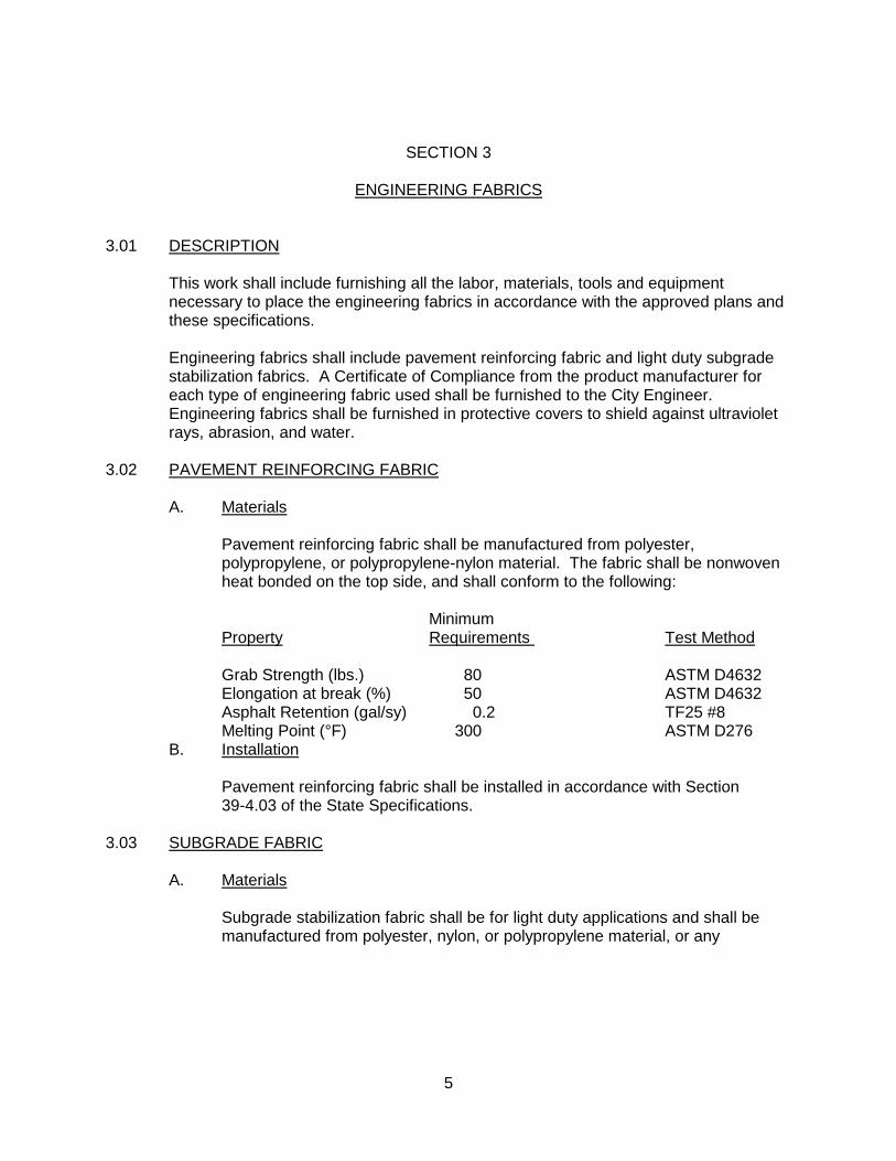
3.02 PAVEMENT REINFORCING FABRIC A. Materials Pavement reinforcing fabric shall be manufactured from polyester,
polypropylene, or polypropylene-nylon material. The fabric shall be nonwoven heat bonded on the top side, and shall conform to the following:
Minimum Property Requirements Test Method Grab Strength (lbs.) 80 ASTM D4632 Elongation at break (%) 50 ASTM D4632 Asphalt Retention (gal/sy) 0.2 TF25 #8 Melting Point (°F) 300 ASTM D276 B. Installation Pavement reinforcing fabric shall be installed in accordance with Section
39-4.03 of the State Specifications. 3.03 SUBGRADE FABRIC A. Materials Subgrade stabilization fabric shall be for light duty applications and shall be
manufactured from polyester, nylon, or polypropylene material, or any
6
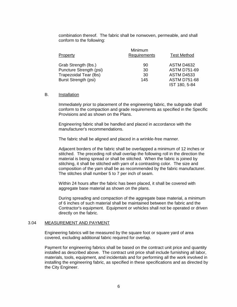
combination thereof. The fabric shall be nonwoven, permeable, and shall conform to the following:
Minimum Property Requirements Test Method Grab Strength (lbs.) 90 ASTM D4632 Puncture Strength (psi) 30 ASTM D751-69 Trapezoidal Tear (lbs) 30 ASTM D4533 Burst Strength (psi) 145 ASTM D751-68 IST 180, 5-84 B. Installation Immediately prior to placement of the engineering fabric, the subgrade shall
conform to the compaction and grade requirements as specified in the Specific Provisions and as shown on the Plans.
Engineering fabric shall be handled and placed in accordance with the
manufacturer's recommendations. The fabric shall be aligned and placed in a wrinkle-free manner. Adjacent borders of the fabric shall be overlapped a minimum of 12 inches or
stitched. The preceding roll shall overlap the following roll in the direction the material is being spread or shall be stitched. When the fabric is joined by stitching, it shall be stitched with yarn of a contrasting color. The size and composition of the yarn shall be as recommended by the fabric manufacturer. The stitches shall number 5 to 7 per inch of seam.
Within 24 hours after the fabric has been placed, it shall be covered with
aggregate base material as shown on the plans. During spreading and compaction of the aggregate base material, a minimum
of 6 inches of such material shall be maintained between the fabric and the Contractor's equipment. Equipment or vehicles shall not be operated or driven directly on the fabric.
3.04 MEASUREMENT AND PAYMENT Engineering fabrics will be measured by the square foot or square yard of area
covered, excluding additional fabric required for overlap. Payment for engineering fabrics shall be based on the contract unit price and quantity
installed as described above. The contract unit price shall include furnishing all labor, materials, tools, equipment, and incidentals and for performing all the work involved in installing the engineering fabric, as specified in these specifications and as directed by the City Engineer.

7
SECTION 4 AGGREGATE SUBBASE 4.01 DESCRIPTION Shall conform with Section 25 of the State Specifications and shall be Class 2 ASB.
Thickness shown on the plans shall be the minimum section allowed. Under no circumstances will the use of Recycled Aggregate Subbase be allowed.
4.02 MEASUREMENT AND PAYMENT Aggregate subbase shall be measured by the ton as placed on the street and other
areas designated by the City Engineer. Payment shall be made at the contract price per ton and shall include full
compensation for furnishing all labor, materials, tools, equipment, incidentals and for doing all the work in placing aggregate subbase, complete in place as shown on the plans, as specified in these specifications and as directed by the City Engineer.

8
"THIS PAGE LEFT INTENTIONALLY BLANK"
9
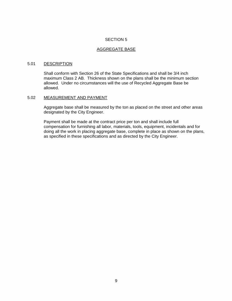
SECTION 5 AGGREGATE BASE 5.01 DESCRIPTION Shall conform with Section 26 of the State Specifications and shall be 3/4 inch
maximum Class 2 AB. Thickness shown on the plans shall be the minimum section allowed. Under no circumstances will the use of Recycled Aggregate Base be allowed.
5.02 MEASUREMENT AND PAYMENT Aggregate base shall be measured by the ton as placed on the street and other areas
designated by the City Engineer. Payment shall be made at the contract price per ton and shall include full
compensation for furnishing all labor, materials, tools, equipment, incidentals and for doing all the work in placing aggregate base, complete in place as shown on the plans, as specified in these specifications and as directed by the City Engineer.

10
"THIS PAGE LEFT INTENTIONALLY BLANK"
11
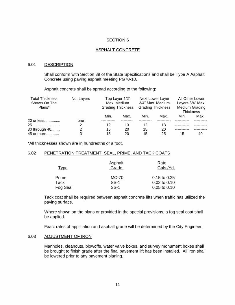
SECTION 6 ASPHALT CONCRETE 6.01 DESCRIPTION Shall conform with Section 39 of the State Specifications and shall be Type A Asphalt
Concrete using paving asphalt meeting PG70-10. Asphalt concrete shall be spread according to the following:
Total Thickness Shown On The
Plans*
No. Layers Top Layer 1/2” Max. Medium
Grading Thickness
Next Lower Layer 3/4” Max. Medium Grading Thickness
All Other Lower Layers 3/4” Max. Medium Grading
Thickness Min. Max. Min. Max. Min. Max. 20 or less............... one ----------- --------- ---------- ----------- ----------- ---------- 25.......................... 2 12 13 12 13 ----------- ---------- 30 through 40........ 2 15 20 15 20 ----------- ---------- 45 or more............ 3 15 20 15 25 15 40
*All thicknesses shown are in hundredths of a foot. 6.02 PENETRATION TREATMENT, SEAL, PRIME, AND TACK COATS Asphalt Rate Type Grade Gals./Yd. Prime MC-70 0.15 to 0.25 Tack SS-1 0.02 to 0.10 Fog Seal SS-1 0.05 to 0.10 Tack coat shall be required between asphalt concrete lifts when traffic has utilized the
paving surface. Where shown on the plans or provided in the special provisions, a fog seal coat shall
be applied. Exact rates of application and asphalt grade will be determined by the City Engineer. 6.03 ADJUSTMENT OF IRON Manholes, cleanouts, blowoffs, water valve boxes, and survey monument boxes shall
be brought to finish grade after the final pavement lift has been installed. All iron shall be lowered prior to any pavement planing.
12
6.04 STAGE CONSTRUCTION Asphalt concrete and asphalt concrete base shall be spread and compacted in layers.
The top layer of asphalt concrete shall not exceed 0.20-foot in compacted thickness. The next lower layer shall not exceed 0.25-foot in compacted thickness, and any lower layers shall not exceed 0.40-foot in compacted thickness. Each subsequent layer of asphalt concrete base shall not exceed 0.40-foot in compacted thickness. No layer shall be placed over a layer which exceeds 0.25-foot in compacted thickness until the temperature at mid depth, of the layer which exceeds 0.25-foot in compacted thickness, is not more than 160°F.
Refer to Section 3 of these specifications for pavement reinforcing fabrics required for
asphalt concrete overlays. 6.05 MIX DESIGN Contractor shall insure the asphalt concrete suppliers have a current (calendar year)
mix design on file with the City of Fairfield prior to any paving. 6.06 SPREADING AND COMPACTING EQUIPMENT Spreading and compacting equipment shall be as specified in Section 39-5 of the
State Specifications. The State Specifications are amended to allow use of a motorized self-propelled layton-type box for projects involving less than 50 tons of asphalt concrete.
6.07 MEASUREMENT AND PAYMENT Asphalt concrete shall be measured by the ton as placed on the street, driveways, and
other areas designated by the City Engineer. Payment shall be made at the contract price per ton and shall include full
compensation for furnishing all labor, materials, tools, equipment, incidentals and for doing all the work in placing asphalt concrete, prime coat, tack coat and fog seal, complete in place as shown on the plans, as specified in these specifications and as directed by the City Engineer.
13
SECTION 7 ADJUSTMENT OF MANHOLES, WATER VALVE BOXES, AND SURVEY MONUMENT BOXES 7.01 DESCRIPTION This work shall consist of adjusting manholes, water valve boxes, and survey
monument boxes to conform with the new elevation of the street and in conformance with the Standard Specifications and Details.
7.02 ADJUSTMENT Manholes, cleanouts, blowoffs, water valve boxes, and survey monument boxes shall
be brought to finish grade after the final pavement lift has been installed. All iron shall be lowered prior to any pavement planing. The openings shall be temporarily covered by steel plates (minimum ½ -inch thick for manholes, and ¼ -inch thick for all others).
For street reconstructions or asphalt repairs on existing streets, manholes, water valve
boxes, and survey monument boxes shall be raised and asphalt concrete placed within three working days after permanent pavement wearing course has been placed. The necessary portions of the subgrade, base and pavement shall be neatly cut away, the manhole built up, and the frames set to a grade flush with the surface of the adjacent pavement. The surrounding area from which the pavement, base or subgrade has been removed shall be back-filled to within 1-1/2 inches of the surface with Portland Cement Concrete. The remaining 1-1/2 inches shall be backfilled with 1/2-inch maximum asphalt concrete and compacted. The work shall be performed so as to present a neat and thoroughly workmanlike appearance upon completion.
7.03 MEASUREMENT AND PAYMENT Unless specifically shown as an item of work on the proposal form, the adjustment of
manholes, cleanouts, blowoffs, water valve boxes, and survey monument boxes shall be considered included in other items of work and no additional compensation will be made for labor, materials or equipment required in the adjustment of utility appurtenances.

14
"THIS PAGE LEFT INTENTIONALLY BLANK"
15
SECTION 8 CONCRETE CURB, GUTTER, SIDEWALK, AND DRIVEWAYS 8.01 DESCRIPTION Work shall conform with Section 73 and Section 90 of the State Specifications with the
following additions. All curb, gutter and sidewalk shall be placed monolithically unless otherwise specified and shall be constructed of 3000 psi portland cement concrete.
8.02 INSTALLATION A. Subgrade Preparation The finished subgrade immediately prior to placement of aggregate base shall
be compacted to 92% for a depth of 0.5 feet. B. Cushion Shall be Class 2 Aggregate Base mechanically compacted to 95%. C. Forms Lumber used for forms must be surfaced on the side placed next to the
concrete and shall not be less than 1-1/2 inches thick after being surfaced. Warped forms and forms not having a smooth, straight upper edge shall not be used. Benders or thin planks, rigidly placed, may be used on curves, grade changes, or the curb returns.
All forms shall be clean and coated with a light anti-bonding oil to prevent the
concrete from adhering to them. All forms must be carefully set to proper alignment and grade and shall be rigidly held in place by the use of steel or wooden stakes. Clamps, spreaders and braces shall be used where required to insure rigidity in the forms.
Forms shall not vary from vertical grade by more than 0.02 feet and from
horizontal alignment by more than 0.05 feet within the distance not to exceed 25 feet at each occurrence. Unnecessary meandering of the alignment shall be sufficient cause for rejection and removal. All forms shall have smooth even lines in both the horizontal and vertical plane. A windrow of earth placed against the forms prior to placing concrete may be required to prevent them from bulging.
16
Except for vertical curb face forms, all forms shall remain in place for at least
12 hours after the concrete is placed. D. Extruded Sidewalk, Curb and Gutter Use of an extrusion machine is allowed. A test pour may be required by the
City Engineer. All edges shall have smooth even lines in both the horizontal and vertical plane. The grade tolerance is the same as formed concrete.
E. Placing and Finishing No concrete shall be placed or finished in the rain. It shall be the contractor's
responsibility to schedule his operations such that concrete will not be placed or finished in the rain.
Finished concrete shall have a high quality appearance. Defects such as
crooked joints, exposed aggregate, surface pitting, or excessively rough finish will be cause for rejection. Removal and replacement will be done at the Contractor's expense.
Placement of driveways and handicap ramps require careful journeyman
quality finishing. Through the driveway flowline a tangent line should be projected from full curb to full curb to assure that the 1" driveway lip does not 'encroach' into the flowline. The longitudinal curbline extension score line through the driveway shall be 6" from flowline. To assure positive flow, driveways and handicap ramps will be flow tested during installation.
At the end of each day's pour, when work is terminated, or when a delay of
more than 30 minutes occurs, a construction joint, consistent with the jointing pattern, shall be made vertical or square ended and shall end the work. In no case shall the end of a day's pour terminate in a driveway or handicap ramp.
Weakened plane joints and score lines shall be constructed according to the
standard details, and at right angles to the curb line. 8.03 DAMAGED OR UNACCEPTABLE CONCRETE Care shall be taken so as to not damage adjoining concrete areas which are in place.
Any damage so caused shall be repaired by the contractor at his expense. Any substandard work shall be replaced by the contractor at his expense and no additional compensation will be allowed thereto. Limits of replacement shall be determined by the City; saw cuts may only be made at score lines or joints. Saw cuts shall be straight, at a right angle to the curb line, and consistent with the jointing pattern.
17
When concrete is being removed and replaced, dowels will be required. Placement of
dowels will be on 2' centers with one #4 rebar running longitudinally. Refer to the Standard Details for further information. Monolithic curb, gutter and sidewalk which is damaged shall be completely removed and replaced as monolithic curb, gutter and sidewalk and removed at expansion joints.
Any work done beyond the limits established by the City or any additional work done
without written consent from the City shall be considered completed at the Contractor's expense.
8.04 TESTING The finished concrete shall be in conformance with the tolerances for forms as stated
above and attain a minimum 28-day compressive strength of 3000 psi. Core testing of substandard concrete will not be permitted.
After construction, gutters shall be checked by flowing water. The Engineer or his
representative must be present during the flow test. Any high spots or depressions revealed by the flow test (which exceed 0.02 foot) shall be repaired by removing that section of concrete and replacing it to the correct grade.
Finished face of curb shall not vary by more than an aggregate total of 0.05 foot from
the design alignment within a distance not to exceed 25 feet at each occurrence. Unnecessary meandering of the alignment shall be sufficient cause for rejection and removal.
8.05 MEASUREMENT AND PAYMENT Quantities of concrete in curb, gutter, sidewalk, driveways and handicap ramps shall
be measured and payment made at the bid price per unit as shown on the bid sheet. Payment shall include full compensation for the furnishing, placing and curing of the concrete together with the excavation, cushion material and all incidentals.

18
"THIS PAGE LEFT INTENTIONALLY BLANK"
19
SECTION 9 UTILITY TRENCHING AND BACKFILL 9.01 DESCRIPTION A trench is defined as an excavation in which the depth is greater than the width of the
bottom of the excavation. Excavations for appurtenant structures such as but not limited to, manholes, transition
except for overlays and existing street structures, junction structures, vaults, valve boxes, catch basins, thrust blocks, and boring pits shall be deemed to be in the category of trench excavation.
Excavation shall include the removal of all water and materials of any nature which
interfere with the construction work. Placement of spoil materials on adjacent asphalt pavement shall not be allowed.
Excavation for the installation of conduit shall be by open trench unless otherwise
specified or shown on the drawings. However, should the contractor desire to bore and jack any portion not so specified, he shall first obtain written approval from the City Engineer. Arterial streets, streets less than three years old, streets overlayed within the last three years and streets with surface treatments within the last year shall require crossings to be made by bore and jack methods.
9.02 MAXIMUM LENGTH OF OPEN TRENCH The maximum length of open trench where prefabricated pipe is to be laid shall be the
distance necessary to accommodate that amount of pipe which can be installed in a single day. Installed shall be interpreted as pipelaying, appurtenance construction, and backfilling, complete in place. The distance is the collective length at any location, including open excavation, pipe laying and appurtenant construction and backfill which has not been temporarily resurfaced. Use of steel plates as open trench covers shall be allowed only with prior approval of the City Engineer. In no instance shall the length of open trench exceed 200 lineal feet.
9.03 MAXIMUM AND MINIMUM WIDTH OF TRENCH The maximum clear width of the trench at the top of the pipe shall not be more than
the outside diameter of the pipe at any point plus 2 feet. Greater width of trench at the top of the pipe shall be permitted only on written approval by the City Engineer. In no case shall the free working space on each side of the pipe be less than 6 inches.
20
If the maximum trench width is exceeded, the contractor shall provide additional
bedding, another type of bedding, or a higher strength of pipe, as shown on the plans or as approved by the City Engineer, at no additional cost to the City.
9.04 BRACING EXCAVATIONS The manner of bracing excavations shall be as set forth in the rules, orders, and
regulations of the Division of Industrial Safety of the State of California. 9.05 BEDDING Bedding shall be defined as that material supporting, surrounding and extending to a
minimum of six inches and a maximum of one foot above the top of pipe for pipes 24-inches in diameter and less, but not exceeding an overall depth of 36 inches as measured from the bottom of the pipe.
If soft, spongy, unstable, or similar other material is encountered upon which the
bedding material or pipe is to be placed, this unsuitable material shall be removed to a depth ordered by the Engineer and replaced with bedding material suitably densified. Additional bedding so ordered, over the amount required by the plans or specifications, shall be paid for as provided in the contract or the Special Provisions. If the necessity for such additional bedding material has been caused by an act or failure to act on the part of the contractor, or is required for the control of ground water, the contractor shall bear the expense of the additional excavation and bedding.
Bedding material shall first be placed so that the pipe is supported for the full length of
the barrel with full bearing on the bottom segment of the pipe equal to a minimum of 0.4 of the outside diameter of the barrel except for PVC pipe which requires bedding to the top of the pipe. The remainder of the bedding shall be carefully placed to the proper depth.
Bedding material shall be compacted to a relative density of 90%. Bedding material
shall meet the specifications listed under Section 9.09 "Backfill Materials." Where pipe is to be installed in new embankment, the embankment shall first be
constructed to a height of 12 inches above the top of pipe and for a distance on each side of the pipe location of not less than 5 times the diameter of the pipe, after which the trench shall be excavated with sides nearly vertical and the pipe installed.
When water is encountered, the trench shall be kept dry until laying and jointing of the
pipe and placing of the bedding material has been completed, inspected, and approved. The contractor shall place a minimum of 6 inches of pervious material or de-water the trench in a manner which has received prior approval of the City Engineer.
21
9.06 BACKFILL Backfill shall be defined as that material which lies above the pipe bedding or conduit
bedding. Backfill, for cast-in-place structures such as, but not limited to, manholes, transition
structures, junction structures, vaults, valve boxes and reinforced concrete box conduits shall start at the surface upon which the base of the structure rests.
In areas of previously undeveloped land (new construction), backfill shall be "native
material" provided all organic material, rubbish, debris, large rocks, clay chunks, and other objectionable materials are first removed. When satisfactory compaction of the native material cannot be obtained, "select backfill" shall be required.
Except where the pipe must remain exposed for force main leakage tests and subject
to the provisions herein, the contractor shall proceed as soon as possible with backfilling operations. Care shall be exercised so that the conduit will not be damaged or displaced.
Backfill for cast-in-place concrete pipe shall conform with Section 63 of the State
Standard Specifications. The last paragraph of Section 63-1.06 Curing and Protecting Concrete, shall be amended to read as follows:
Except as otherwise provided, the Contractor shall not place or compact backfill
against or over to top of any cast-in-place pipe for a period of ten days and until the concrete has developed a compressive strength equal to or greater than 85% of the specified design strength.
If the minimum compressive strength requirement is attained prior to 10 days, the
minimum cure time, prior to placing or compacting backfill, shall be 7 days or as directed by the City Engineer.
Where it becomes necessary to excavate beyond the limits of normal excavation lines
in order to remove boulders or other interfering objects, the voids remaining after the removal of the boulders shall be backfilled as specified herein, or as otherwise approved by the City Engineer.
Where the void is below the subgrade for bedding conduits or structures, backfill shall
be thoroughly densified bedding material. Where the void is in the side of the trench, it shall be backfilled with suitable material
and densified as approved by the City Engineer. It shall be understood that the removal of all boulders or other interfering objects and
the backfilling of voids left by such removals shall be at the expense of the contractor and no direct payment for the cost of such work will be made. The cost of such work shall be included in the prices bid for the various items of work.
22
After the placing of backfill has been started, the contractor shall proceed as soon as practicable with densification.
9.07 DENSIFICATION METHODS Backfill shall be mechanically compacted by means of tamping rollers, sheepsfoot
rollers, pneumatic tire rollers, vibrating rollers, or other mechanical tampers. All such equipment shall be of a size and type approved by the City Engineer.
Permission to use specific compaction equipment shall not be construed as
guaranteeing or implying that the use of such equipment will not result in damage to adjacent ground, existing improvements, or improvements installed under the contract. The contractor shall make his own determination in this regard.
Material for mechanical compacted backfill shall be placed in lifts which, prior to
compaction, shall not exceed the depths specified below for the various types of equipment:
1. Impact, free-fall, or "stomping" equipment - maximum lift depth of 3 feet. 2. Vibratory equipment, vibratory smooth-wheel rollers, and vibratory
pneumatic-tired rollers - maximum lift depth of 2 feet. 3. Rolling equipment, including sheepsfoot (both vibratory and
non-vibratory), grid, smooth-wheel (not vibratory), pneumatic tired (non-vibratory), and segmented wheels - maximum lift depth of 1 foot.
4. Hand directed mechanical tampers, including vibratory plates -
maximum lift depth of 8 inches. Mechanically compacted backfill shall be placed in horizontal layers of such
depths (not exceeding those specified above) compatible to the material being placed and the type of equipment being used. Each layer shall be evenly spread, moistened (or dried, if necessary), and then tamped or rolled until the specified relative compaction has been attained.
9.08 BACKFILL PLACEMENT REQUIREMENTS A. Method "A": Method "A" is to be used in existing streets. Backfill shall be "select backfill" as
specified in these specifications. The area above the pipe zone shall contain Class II Aggregate Base mechanically compacted to a minimum relative compaction of 95% and a temporary layer (2 inch minimum) of asphalt cutback placed to grade. This temporary cutback shall be maintained by the contractor until permanent paving is installed. Permanent asphalt paving shall be l inch greater in thickness than the existing pavement, with a minimum thickness of 3 inches.
23
B. Method "B": Method "B" is to be used within the public right-of-way in previously
undeveloped land (new construction). Backfill shall be as specified in "BACKFILL", Section 9.06.
When native material is used as backfill, the area of the trench between the
bedding zone and 18 inches below the bottom of the street section shall be mechanically compacted to a minimum relative compaction of 90%. The minimum relative compaction shall be 92% in the top 18 inches.
C. Method "C": Method "C" is to be used in unimproved or non-street right-of-way areas. The
area of the trench between the bedding zone and the top of trench shall be backfilled with native material. Compaction shall be done mechanically in uniform lifts so as to attain a minimum relative compaction of 90%.
24
9.09 BACKFILL MATERIALS Bedding PVC and HDPE Pipe All Other Pipe Sieve Size % Passing* % Passing 3/4" 100 100 3/8" - 100 #4 35-55 70-100 #30 - 20-100 #200 3-9 0-15 Sand Equivalent 30 min 30 min Minimum Dry Density - 80 lb/cu ft R-value 78 min - * Standard bedding material shall be equivalent to 3/4-inch minus angular crushed
rock aggregate base. Select Backfill Sieve Size % Passing 3" 100 #4 35 - 100 #30 20 - 100 Sand Equivalent to be 20 Min. Minimum Dry
Density 110 lb./cu.ft. Pervious Material Sieve Size % Passing 2" 100 #50 0 - 100 #100 0 - 8 #200 0 - 4 Drain Rock Washed coarse aggregate conforming to one of the following gradings: 1 1/2" x 3/4" 3/4" x #4 Sieve Size % Passing Sieve Size % Passing 2" 100% 1" 100% 1 1/2" 90 - 100% 3/4" 90 - 100% 1" 20 - 55% 1/2" 60 - 85% 3/4" 0 - 15% 3/8" 20 - 55% 3/8" 0 - 5% #4 0 - 15% #8 0 - 5% Backfill Native material as specified in "BACKFILL" Section 9.06.
25
The percentage composition by weight in place shall conform to the gradings previously mentioned as determined by Test Method No. California 202. Materials as delivered shall be of uniform mixture and shall be free of vegetable matter and refuse.
9.10 MEASUREMENT AND PAYMENT Payment for utility trenching and backfill shall be included in the contract price for the
utility being installed and no additional payment shall be made for excavation, bracing and shoring, dewatering, backfilling or compaction.

26
"THIS PAGE LEFT INTENTIONALLY BLANK"
27
SECTION 10 STORM DRAINAGE 10.01 DESCRIPTION This work shall include the furnishing of all labor, materials, tools and equipment to
construct and complete in an efficient and workmanlike manner the installation of the storm drainage system in accordance with the approved plans, these specifications and the City Standard Details.
10.02 MATERIALS A. Pipe 1. Reinforced Concrete Pipe shall conform to the specifications of
A.S.T.M. Designation C76 and shall be Class IV unless otherwise specified on the plans. Reinforcing shall be as specified in A.S.T.M. Designation C76. Portland Cement used in the manufacture of reinforced concrete pipe shall conform to the requirements of the specifications for Type II Portland Cement, A.S.T.M. Designation C150.
Tests on reinforced concrete pipe shall be required to determine
conformance with "D" load and reinforcing requirements of these specifications.
Pipe samples for testing shall be furnished, without charge, by the
Contractor one week in advance of construction. The cost of testing the pipe shall be borne by the Contractor. One section of pipe from each lot to be used shall be tested in accordance with the procedures outlined in A.S.T.M. C76. Lots tested shall be marked with the date made as well as by lot number for shipment to the specific project for which that lot has been tested. Any pipe arriving on the job without the appropriate markings shall be rejected and sent back to the supplier until such lot or lots can be tested and accepted for use.
In lieu of the above testing of reinforced concrete pipe, the Contractor
may submit to the City Engineer the manufacturer's "Certificate of Compliance" guaranteeing the requirements of A.S.T.M. C76.
2. Cast-In-Place Concrete Pipe shall require prior approval of the City
Engineer and shall conform to the requirements of Section 63 of the State Specifications except that the concrete shall be placed around the full circumference in one operation. Concrete shall be a minimum of 4000 psi.

28
3. Non-Reinforced Concrete Pipe shall not be allowed. 4. Polyvinyl Chloride (PVC) Pipe and Fittings shall at a minimum conform
to the requirements of A.S.T.M. Designation D3034 as they apply to SDR 26 PVC pipe using an elastomeric gasket joint in a bell and spigot assembly system. The use of PVC pipe for storm drain mains shall be restricted to 12-inch through 24-inch diameters in areas of landscaping, parks, and non-traffic areas under the face of curb. PVC pipe shall not be used for street crossings. Trench depths shall not exceed 15 feet and pipe shall have a minimum cover of 2 feet.
5. High Density Polyethylene (HDPE) Pipe and Fittings shall be type S and
conform to the requirements of AASHTO M294 and Section 64 of the State Specifications except as noted herein. Joints shall be integral bell and spigot or bell/bell coupler with water tight gaskets conforming to ASTM F-477. The use of HDPE pipe for storm drain mains shall be restricted to diameters 12-inch through 24-inch in areas of landscaping, and parks. HDPE pipe shall not be used for street crossings. Trench depths shall not exceed 15 feet and pipe shall have a minimum cover of 2 feet.
6. Roadway Edge Drain and associated fittings and connections shall be
pre-fabricated Multi-Flow drainage pipe manufactured by Varicore Technologies® or an approved equal.
B. Manhole and Junction Boxes For storm drains of less than 48 inches in diameter, precast reinforced concrete
manholes shall be used. Manholes shall conform to the specifications of sanitary sewer manholes.
For storm drains of 48 inches and greater diameter, junction boxes shall be
cast-in-place conforming to the Standard Details. Concrete shall be furnished, mixed, placed, and cured in accordance with the provisions of Section 90 of the State Specifications and shall be 4000 psi with 1-1/2 inch maximum aggregate size. The inside dimension of manholes and junction boxes shall be such as to provide a minimum of 3 inches clearance on the outside diameter of the outfall pipe and the minimum wall thickness shall be 6 inches.
All solid concrete manhole lids shall have openings for lifting hooks. C. Catch Basins 1. Storm drain catch basins shall be pre-cast or cast-in-place conforming
to the Standard Details. Concrete shall be 3000 psi with 1-1/2 inch maximum aggregate size.
29
2. Curb inlet shall be precast equal to Santa Rosa Model 4A or 4AC with fiberglass throat form attached or cast-in-place using the Pelican series form liner with fiberglass throat form attached.
D. Headwalls, Wingwalls, Endwalls, and Railings All headwalls, wingwalls, and endwalls shall be of 3000 psi reinforced Portland
Cement Concrete constructed in accordance with the plans and Section 51 of the State Specifications. Temporary bank protection may be provided by sack concrete rip-rap in accordance with Section 72 of the State Specifications.
E. Drainage Pump Stations Drainage pump stations shall be allowed on an individual basis with the specific
approval of the City Engineer. 10.03 INSTALLATION, GROUTING, AND BANDING All pipe installation and pipeline construction shall be in accordance with the
manufacturer's specification for the particular pipe and fitting material, unless modified by these Standard Specifications and Details.
Roadway edge drains shall be installed along all new arterial and collector
roadways, and in other locations as directed by the City Engineer. 10.04 MEASUREMENT AND PAYMENT A. Pipe Payment for storm drain pipe complete in place shall be per lineal foot
measured from center of manhole to center of manhole or catch basin, or from center of manhole to wall of outlet structure as the case may be. Measurement shall be along a line parallel to the grade of the storm drain.
Payment shall include the furnishing of all labor, materials, water, tools, and
equipment required to construct and complete in an efficient and workmanlike manner the installation of storm drain pipe in accordance with the plans and these specifications.
Full compensation for all incidentals arising from this work shall be considered
as included in the price paid per lineal foot measure and no further compensation shall be allowed.
B. Structures, Manholes and Catch Basins The unit of measure for payment shall be per each unit. Payment shall be
made at the bid price per item for each structure complete in place and shall include the cost of excavation, backfill, frames, covers, plates or reinforcing steel where required.

30
Full compensation for all incidentals, arising from this work shall be considered
as included in the price paid per each unit and no further compensation shall be allowed.

31
SECTION 11 SANITARY SEWERS 11.01 DESCRIPTION This work shall include the furnishing of all the labor, materials, tools and equipment to
construct and complete in an efficient and workmanlike manner the installation of the sanitary sewer mains and laterals in accordance with the approved plans, standard details and these specifications.
11.02 MATERIALS A. General The source and supply of materials shall be approved by the City Engineer. B. Gravity Sewer Pipe 1. Vitrified Clay Pipe shall be extra strength, bell and spigot, conforming to
A.S.T.M. Designation C700 as it applies to unglazed vitrified clay pipe. 2. Polyvinyl Chloride (PVC) Pipe and fittings shall, at a minimum, conform
to the requirements of A.S.T.M. Designation D3034 as they apply to SDR 35 PVC sewer pipe using an elastomeric gasket joint in a bell and spigot assembly system. The use of this pipe for sanitary sewer mains shall be restricted to 8- and 10-inch diameters and shall be used within residential areas only where there is no possibility of commercial or industrial waste flowing through the pipe. Trench depths shall not exceed 15 feet and shall be a minimum of 6 feet.
3. Ductile Iron Pipe and fittings shall conform with the requirements of
ANSI/AWWA C151/A21.51 and shall have a minimum 35 mil polyethylene lining in conformance with A.S.T.M. Designation D1248. Class of pipe shall be as required for design loads.
4. Other Pipe shall be as specified by the City Engineer. C. Pressure Sewer Pipe Whenever the design of a sanitary sewer system includes the necessity of a
sewage lift station and pressure mains, types of pipe shall be approved by the City Engineer and Sewer District for each specific case.

32
D. Joints and Couplings 1. Vitrified Clay Joints shall be resilient material conforming to the
requirements of A.S.T.M. Designation C425. 2. Polyvinyl Chloride joints shall be bell and spigot using an elastomeric
gasket which meets the requirements of A.S.T.M. Designation D3212. No solvent weld joints will be allowed.
3. Banded Rubber Couplings shall conform to the requirements of
A.S.T.M. Designation C425. E. Fittings All fittings shall be manufactured of the same materials as the pipe and
installed in accordance with City Standard Details. F. Laterals 1. Pipe shall be of the same type and class as that used for the main or
SDR 35 PVC which will require the approval of the City Engineer. 2. Joints and Couplings for laterals shall be the same type and
specifications as those used for the main. G. Manholes Sanitary sewer manholes shall be of precast reinforced concrete conforming to
A.S.T.M. Designation C478 except that the Portland Cement shall be Type II modified cement. The manhole base, riser and cone shall have a minimum compressive strength of 4,000 psi at 28 days. Manholes shall be constructed in accordance with the Standard Details.
Iron castings for manhole covers and frames shall conform to A.S.T.M.
Designation A48, Class 25 and be of the dimensions shown on the Standard Details.
All castings shall be sound and free from shrinkage cracks, blow holes, and
other defects. All fins and burnt sand must be removed. Excessive porosity and spongy surfaces will constitute causes for rejection. The City Engineer shall be the judge as to whether the defects are sufficient to cause rejection.
The manhole cover shall seat evenly and firmly in the frame. Cast iron frames
and covers shall be dipped or painted with asphalt which will form a tough,
33
tenacious, non-scaling coating which does not have a tendency to become brittle when cold or sticky when hot.
H. Cleanouts Back of sidewalk cleanouts shall be constructed in accordance with the
Standard Details. I. Conductor Pipe Pipe used as a conductor pipe under a highway or railroad shall be welded
steel pipe. Any protective lining and coating, shall be as shown on the plans or specified in the Special Provisions.
Welded steel pipe shall be manufactured of steel meeting the requirements of
A.S.T.M. Designation A570, Commercial Grade. The method by which the pipe is manufactured shall comply with one or more of A.S.T.M. Specifications: A-134, A-135, or A-139. The pipe shall be welded by either the electric-resistance or electric-fusion process, with either spiral seam welded joint or straight seam welded joint. All joints shall be butt welded.
When the conductor pipe is to be installed by boring and jacking, the wall
thickness shall be 1/4 inch for sizes up to and including 24 inches in diameter, and 5/16 inch for sizes 27 inches to 36 inches in diameter, unless otherwise specified.
11.03 INSTALLATION A. Sanitary Sewer Installations All sanitary sewer pipe installations shall be accomplished as specified herein
except where modified by the requirements specific to the various types of pipeline materials specified under Section 11.02. PVC pipe shall be installed per manufacturer's recommendation or as otherwise directed by the City Engineer.
All sewer pipe shall be laid with a minimum of 12 inches vertical clearance from
water and 6 inches clearance from all other improvements and utilities, unless otherwise approved by the City Engineer. Refer to the pipe cover requirements in Section 5 of the Design Standards for minimum cover requirements. Water and sewer lines shall meet minimum vertical and horizontal separation requirements as stipulated by the California Department of Public Health under Section 64572, Title 22, of the California Administrative Code. Where the horizontal separation between sewer and water lines is less than 10 feet or where a sewer line crosses over the top of a water line, special
34
requirements shall apply for the type of pipe used and the location of joints. All pipe shall be laid to conform to the prescribed line and grade as shown on the plans and each pipe length checked to the grade line which the Contractor establishes from the grade stakes.
The grade line shall be established before any pipe is laid in the trench. For
pipes with slopes greater than 1%, the string line set for trenching purposes may be used as the grade line. For pipes with slopes less than 1%, either: (1) a grade line shall be established in the bottom of the trench such that the top of each bell will touch the line when the pipe has been properly positioned or, (2) a grade line shall be established above the trench on firmly secured batter boards from which the grade of each pipe can be checked by using a grade pole.
Alternate use of commercial LASER grade setting systems in lieu of string lines
specified herein are acceptable when the following requirements and conditions are met:
1. The Contractor shall have the responsibility of providing an instrument
operator who is qualified and trained in the operation of the LASER and said operator must adhere to the provisions of the State of California Construction Safety Orders issued by the Division of Industrial Safety. Attention is particularly directed to Sections 1516, 1800, and 1801 of said Orders for applicable requirements.
2. All LASER control points shall be established bench marks or
construction off-set stakes identified on cut sheets and set in the field for the work. LASER set up points shall be these control points or points set directly from them by instrument.
Each length of pipe shall be laid on compacted, approved bedding material as
specified and shall have full bearing for its entire length between bell holes excavated in said bedding material to allow for unobstructed assembly of all bell and spigot joints. "Stabbing", "Swinging In", or "Popping On" spigot ends of pipe into bell ends will not be permitted. After jointing is accomplished, all annular spaces between pipe and bell holes shall be packed with bedding material, taking care not to damage, move or lift the pipe from its bedding support.
Adjustments of pipe to line and grade shall be made by scraping away or filling
in and tamping approved material under the body of the pipe. No wedging or blocking to support the pipe will be permitted.
A sewer line, unless otherwise approved by the City Engineer, shall be laid,
without break, upgrade from point of connection to existing sewer and with the
35
bell end forward or upgrade. Pipe shall not be laid when the City Engineer
determines that the condition of the trench or the weather is unsuitable. When pipe laying is not in progress, the forward end of the pipe shall be kept effectively closed with an approved temporary plug or cap.
Sewer pipes, branches, stubs, or other open ends which are not to be
immediately connected, shall be plugged or capped with a standard watertight plug or cap, as approved by the City Engineer for use in the particular installation. The plug or cap shall be placed on a standard end.
Pipe, entering or leaving manholes or other structures shall have joints within
2-1/2 feet of the manhole base. In all cases, flexibility of joints in or at the manhole base shall be preserved to
prevent damage to the pipe by differential settlement. All sewer line connections to manholes, trunk sewers, main sewers, or side
sewers shall be left uncovered until after the inspection has been made. After approval of the connection, the trench shall be backfilled as specified. The City Engineer may, at his discretion, require special pipe to be laid in areas that are potentially unstable or subject to settlement.
If the sewer is to be laid in an area that is to be filled, and the cover prior to
filling is less than 5 feet, the pipe shall not be laid until the area has been filled to a level 5 feet above the proposed pipe and compacted to 90% relative compaction, unless otherwise authorized by the Engineer.
When a new sewer is extended from other than an existing manhole and the
first new manhole upstream of the connection establishes conditions prescribed in Section 5.01 of the Design Standards, the Contractor installing such new facilities shall also be responsible for installing backwater prevention devices in conformance with said section on existing side sewers so affected.
B. Laterals Attention is directed to the Standard Details for additional details and
requirements pertinent to lateral installations. Whenever lateral lines are to be installed as part of the contract for the
construction of the sewer main, the use of saddles will not be permitted. That portion of any lateral line to be placed under an existing curb and gutter
and/or sidewalk shall be done by boring or cutting and replacing the existing curb and gutter and/or sidewalk.
The lateral line shall have a clean-out at back edge of sidewalk as shown on
the Standard Details. A cover box shall be installed. Laterals and cleanouts
shall not be located in the driveway.
36
When a backwater prevention device is required under Section 5 of the Engineering Design Standards, such installations shall be made after final grading around the building has been completed and at a location where sewage can overflow without serious property damage on adjacent areas. It shall be the responsibility of the Contractor installing backwater prevention devices to see that informational notices, for present and future owners, regarding the importance of such devices are conspicuously posted upon the device and on the structure by said device.
C. Locating Wire
All sewer mains, laterals, and appurtenances shall have a direct burial wire laid above the top of pipe before backfilling. The wire shall be installed and spliced in accordance with the Standard Drawings to form a set of continuous electrical conductors throughout the pipe system.
D. Manholes Precast Manhole Construction All precast manholes shall be excavated and backfilled in conformance with the
requirements of Section 19-3 of the State Specifications and installed as specified herein. All embedment materials under, around and at least 3 inches over all pipelines located within five feet of structure bases shall be compacted without jetting prior to barrel section placements. All precast manholes shall be constructed to subgrade prior to jetting adjoining sewer pipeline trench and/or structure backfill where such method of compaction is permitted and used.
All joint surfaces of precast sections and face of manhole base shall be
thoroughly cleaned prior to setting precast sections. The various sections shall be set in preformed plastic sealing gaskets of material conforming to the requirements of FEDERAL SPECIFICATION SS-S-00210.
1. Installation of gaskets - Apply one coat of primer to clean, dry joint
surface (both tongue and groove) and allow to dry. Remove the paper wrapper from one side only of the two-piece wrapper on the gasket. The outside paper will protect the gasket and assure against stretching. Before setting the manhole section in the trench, attach the plastic gasket strips end-to-end to the tongue or groove of each joint, forming a continuous gasket around the entire circumference of the manhole joint.
2. Handling of barrel sections after the plastic gasket has been affixed
shall be carefully controlled to avoid bumping the gasket and thus displacing it or contaminating it with dirt or other foreign material. Any gaskets so disturbed shall be removed and replaced if damaged and repositioned if displaced.
3. Care shall be taken to properly align the manhole section with the
previously set section before it is lowered into position.
37
4. During cold or wet weather, pass direct heat over the concrete joint
surface lightly until ice, frost and moisture are removed and surface to be primed is dry and warm immediately before application of primer. Direct heat shall also be passed over plastic gasket strips immediately prior to attaching them to joint surfaces and immediately prior to insertion of tongue into groove.
The cast-in-place concrete base shall be 4,000 psi, 28 day concrete with 1-1/2
inch maximum size aggregate. It shall rest on firm, undisturbed soil, and shall be of the dimensions shown on the Standard Details.
Where sewer lines pass through manholes, the pipe shall be laid continuously
as a whole pipe. After the manhole base and precast sections have been placed and sufficient time has elapsed to allow all concrete and grout to set, the top half of the pipe within the manhole shall be carefully cut off and the sides mortared. All channels so formed shall be checked with a template and shall form a smooth flowing channel at all flow depths.
Temporary covers of 3/8 inch steel plate of sufficient size to adequately cover
the opening shall be placed on the cone until the base is complete and the manhole casting shall then be installed. Suitably located ribs shall be welded to the underside of the cover to hold it in place during any grading operations.
The throat of the manhole shall be made of precast concrete rings of the
proper inside diameter. The minimum depth of throat permitted shall be one 3 inch ring between the cone and the frame. The maximum depth permitted shall be 18 inches of rings between the cone and frame.
When adjusting the manhole frame and cover to grade, the frame shall be
wired to a 2" x 4" of sufficient length to span the excavation, and the throat completed to the right level. Whenever the space between the bottom of the frame and the top of a ring is less than three inches, the void may be filled with concrete, poured against a suitable form on the inside of the structure.
When adjusting an existing manhole to grade and the total depth of the throat
from the top of the frame to the bottom of the throat exceeds 24 inches, the upper portion of the manhole shall be removed to the first full-size manhole section. The upper portion shall then be reconstructed as outlined above.
Connections to existing manholes shall be made by carefully breaking out an
opening in the wall of the manhole, inserting the end of the pipe through the opening, and packing the opening around the pipe with a stiff mix of cement

38
mortar thoroughly compacted. The mortar shall be composed of one part Type II Portland Cement and three parts clean sand. All connections shall be watertight.
Before any work is started on adjusting or repairing a manhole, the channels in
the base shall be covered with strips of wood and the entire base covered with a heavy piece of canvas. This cover shall be kept in place during all work. Upon completion of the work the wood strips and the canvas shall be removed from the manhole allowing no debris to fall or remain in the manhole.
E. Inspection The City Engineer shall at all times have access to the work during its
construction, and the Contractor shall provide proper and safe facilities for such access and inspection. The City Engineer shall be furnished with every reasonable facility for ascertaining that the materials and the workmanship are in accordance with the requirements and intentions of these specifications. All work done and all materials furnished shall be subject to his inspection and approval.
The work shall be done under the supervision and to the complete satisfaction
of the City and in accordance with the laws of the State of California. The inspection of the work shall not relieve the Contractor of any of his
obligations to fulfill his contract as prescribed, and defective work shall be made good and unsuitable materials may be rejected, notwithstanding that such defective work and materials have been previously overlooked by the City Engineer and accepted or estimated for payment. See Section 3.07 of the General Provisions.
The Contractor, shall, at any time when requested, submit to the City Engineer
properly authenticated documents or other satisfactory proof as to his compliance with the requirements of these Specifications.
39
F. Testing of Sewer Lines and Manholes All leakage tests for sewer lines shall be completed and approved after
backfilling and prior to placing of permanent surfacing. All manhole testing shall conform to ASTM C1244-05a Standard Test Methods prior to backfill.
1. Cleaning and Flushing Prior to performing a leakage test, the pipe installation shall be
thoroughly cleaned. Cleaning shall be performed by the Contractor by means of an inflatable rubber ball. The ball shall be of a size that will fit snugly into the pipe to be flushed. The ball shall be placed in the last cleanout or manhole on the pipe to be cleaned, and water introduced behind it. The ball shall pass through the pipe with only the pressure of the water impelling it. All debris flushed out ahead of the ball shall be removed at the first manhole where its presence is noted. If any wedged debris or damaged pipe shall stop the ball, the Contractor shall remove the obstruction. When a new sewer is connected to an existing line, cleaning and flushing shall be carried out to the first existing manhole downstream from the point of connection.
40
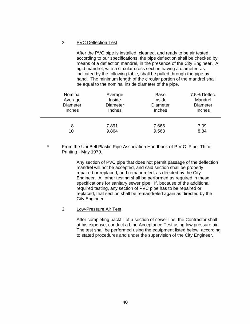
2. PVC Deflection Test After the PVC pipe is installed, cleaned, and ready to be air tested,
according to our specifications, the pipe deflection shall be checked by means of a deflection mandrel, in the presence of the City Engineer. A rigid mandrel, with a circular cross section having a diameter, as indicated by the following table, shall be pulled through the pipe by hand. The minimum length of the circular portion of the mandrel shall be equal to the nominal inside diameter of the pipe.
Nominal Average Base 7.5% Deflec. Average Inside Inside Mandrel Diameter Diameter Diameter Diameter Inches Inches Inches Inches 8 7.891 7.665 7.09 10 9.864 9.563 8.84 * From the Uni-Bell Plastic Pipe Association Handbook of P.V.C. Pipe, Third
Printing - May 1979. Any section of PVC pipe that does not permit passage of the deflection
mandrel will not be accepted, and said section shall be properly repaired or replaced, and remandreled, as directed by the City Engineer. All other testing shall be performed as required in these specifications for sanitary sewer pipe. If, because of the additional required testing, any section of PVC pipe has to be repaired or replaced, that section shall be remandreled again as directed by the City Engineer.
3. Low-Pressure Air Test After completing backfill of a section of sewer line, the Contractor shall
at his expense, conduct a Line Acceptance Test using low pressure air. The test shall be performed using the equipment listed below, according to stated procedures and under the supervision of the City Engineer.
41
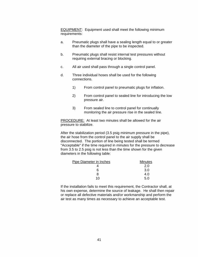
EQUIPMENT: Equipment used shall meet the following minimum requirements:
a. Pneumatic plugs shall have a sealing length equal to or greater
than the diameter of the pipe to be inspected. b. Pneumatic plugs shall resist internal test pressures without
requiring external bracing or blocking. c. All air used shall pass through a single control panel. d. Three individual hoses shall be used for the following
connections. 1) From control panel to pneumatic plugs for inflation. 2) From control panel to sealed line for introducing the low
pressure air. 3) From sealed line to control panel for continually
monitoring the air pressure rise in the sealed line. PROCEDURE: At least two minutes shall be allowed for the air
pressure to stabilize. After the stabilization period (3.5 psig minimum pressure in the pipe),
the air hose from the control panel to the air supply shall be disconnected. The portion of line being tested shall be termed "Acceptable" if the time required in minutes for the pressure to decrease from 3.5 to 2.5 psig is not less than the time shown for the given diameters in the following table:
Pipe Diameter in Inches Minutes 4 2.0 6 3.0 8 4.0 10 5.0 If the installation fails to meet this requirement, the Contractor shall, at
his own expense, determine the source of leakage. He shall then repair or replace all defective materials and/or workmanship and perform the air test as many times as necessary to achieve an acceptable test.
42
SAFETY: The air test may be dangerous if, because of ignorance or
carelessness, a line is improperly prepared. It is extremely important that the various plugs be installed and braced in such a way as to prevent blowouts. Since a force of 250 lbs. is exerted on an 8 inch plug by an internal pipe pressure of 5 psi, it should be realized that sudden expulsion of a poorly installed plug or of a plug that is partially deflated before the pipe pressure is released can be dangerous.
As a safety precaution, pressurizing equipment should include a
regulator set at 10 psi to avoid over-pressurizing and damaging an otherwise acceptable line. No one shall be allowed in the manholes during testing. If the test is not passed in two trials, the leak shall be located and repaired to the satisfaction of the City Engineer and the line shall be retested at the Contractor's expense.
The pressure gage used shall be supplied by the Contractor and shall
have minimum divisions of 0.10 psi, and shall have an accuracy of 0.04 psi. Accuracy and calibration of the gage shall be certified by a reliable testing firm.
4. T.V. Inspection Prior to acceptance of any sanitary sewer line by the City, said line shall
be inspected internally by television as outlined below at the contractor's expense.
Defects such as high and low spots, joint separations, offset joints,
chipped ends, cracked or damaged pipe, infiltration points and debris in lines shall be corrected by the contractor at his expense. For joint separations, low spots and chipped ends, the following maximum acceptable limits will apply for eight and ten inch pipes:
Joint separations - 1/2 inch Low spots - 1 inch maximum depth Chipped ends - 1/4 inch For pipe larger than 10 inches specific maximum limits will be specified
by the City and Sewer District for each project. a. The complete job is ready for television inspection when the
following work has been completed: 1) All sewer pipelines are installed and backfilled.

43
2) All structures are in place, all channeling is complete and
pipelines are accessible from structures. 3) All other underground facilities, utility piping and conduits
are installed. 4) Final street subgrading is complete and ready for
asphaltic concrete surfacing. 5) Pipelines to be inspected have been preliminarily balled
and flushed or cleaned with a high pressure cleaner. 6) Final air test has been completed and approved. b. When the above work is complete, the Contractor shall arrange
for the television inspection. c. The Contractor of the project will notify the City in writing as to
the scheduled date of the television inspection. d. After conditions 1 through 6 as outlined above are met, the
entire job will be initially televised and recorded in digital format. The digital copies and reports shall be delivered to the City.
e. Video inspection shall be in digital format that is compatible with
Wincann America, and the audio and video portions shall be free of electrical interference and excessive background noise.
f. The audio report shall be recorded by the operating technician in
digital format as they are being produced and shall include the location of the sewer, the names or numbers of the manholes involved, the direction of travel and a description of all lateral locations and conditions in the sewerline as they are encountered and their locations.
g. In addition to the audio report, a written report shall be required
listing all the information required in the audio report. h. The Contractor will be notified in writing of any deficiencies
revealed by the television inspection that will require repair. If corrective work is indicated and the Contractor wishes to view the digital copy, he shall contact the City to set a time for viewing with the City Engineer.
i. Corrective work shall be done. The cost shall be borne by the
Contractor.
44
j. Those portions of the pipeline system that have been corrected must be retelevised and recorded and the digital copy and reports delivered to the City.
k. The procedure outlined in conditions "A" through "G" above will
be repeated until all deficiencies observed by television inspection have been corrected to the complete satisfaction of the City.
l. All digital copies and reports become the property of the City to
be used as "As Builts" for future reference.
5. Sewer Manhole Testing a. Testing procedures shall be specified in ASTM C1244 (latest
revision)-Standard Test Method for Concrete Sewer Manholes by Negative Air Pressure (Vacuum) Test.
b. The test head shall be placed at the top of the manufactures’ recommendations.
c. A vacuum of 10 inches of mercury shall be drawn on the manhole, the valve on the vacuum line of the test head closed, and the vacuum pump shut off.
d. The manhole shall pass if the time for the vacuum reading to drop from 10 inches of 9 inches does not exceed the allotted time per ASTM C1244.
11.04 MEASUREMENT AND PAYMENT A. Pipe Payment for sanitary sewer pipe complete in place shall be per lineal foot
measured from center of manhole to center of manhole following a line parallel to the grade of the sewer. Payment shall include the furnishing of all labor, materials, water, tools, and equipment required to construct and complete in an efficient and workmanlike manner the installation of the sewer pipe in accordance with the plans and these specifications.
Full compensation for all incidentals arising from this work shall be considered
as included in the price paid per unit of measure and no further compensation shall be allowed.
45
B. Structures & Manholes The unit of measure for payment shall be per each unit. Payment shall be
made at the bid price per item for each structure complete in place and shall include the cost of excavation, backfill, frames, covers, plates, or reinforcing steel where required.
Full compensation for all incidentals arising from this work shall be considered
as included in the price paid per unit of measure and no further compensation shall be allowed.

46
"THIS PAGE LEFT INTENTIONALLY BLANK"

47
SECTION 12 WATER DISTRIBUTION 12.01 DESCRIPTION This work shall include the furnishing of all the labor, materials, tools and equipment to
construct and complete, in an efficient and workmanlike manner, the installation of the water lines in accordance with the approved plans, these specifications, and the Standard Details.
12.02 MATERIALS A. Mains 1. Pipe
a. Polyvinyl Chloride (PVC) Pipe shall be manufactured in accordance with AWWA C900 (4 in. through 12 in.) or AWWA C905 (14 in.). All PVC pressure pipe shall have a cast-iron pipe equivalent outside diameter unless noted otherwise. C900 PVC pressure pipe shall have a pressure class rating of 200 PSI and a dimension ratio of 14. C905 PVC pressure pipe shall have a pressure class rating of 235 PSI and a dimension ratio of 18. PVC pressure pipe shall have gasketed joints with an integral bell end. Gaskets shall be part of a complete pipe section and purchased as such. Maximum pipe length not to exceed 20 feet.
b. Ductile Iron Pipe (DIP) shall be manufactured in accordance with
AWWA C151 unless otherwise specified. The weight, class or nominal thickness, and casting period shall be shown on each pipe. Laying length shall be the manufacturer’s standard length. The exterior surface shall be polyethylene wrapped in accordance with AWWA C105.
c. Other pipe shall not be allowed except as specified by the City
Engineer and shall conform to applicable specifications for the specific pipe.
2. Fittings Fittings shall be flanged, mechanical joint, or push-on, as designated by
the City Engineer. Mega-lug type fittings may be allowed by the City Engineer. Fittings are acceptable as manufactured by American Cast Iron Pipe Company, Griffin Pipe Products Company, Tyler Pipe Utilities Division, Union Foundry, or U.S. Pipe and Foundry. Flange bolts and nuts to be ASTM A-276 Type 304 stainless steel. All nuts and bolts to be ASTM A-276 Type 316 stainless steel.
48
a. PVC Fittings for PVC pipe shall be ductile iron rated for 250 PSI
working pressure minimum, and conforming to ANSI/AWWA Specification C-153 and its latest revisions. Fittings shall have a bituminous outside coating as specified above and shall be cement lined and sealed in accordance with ANSI/AWWA C-104 utilizing NSF-61 approved materials. PVC push-on fitting will not be allowed except for the rubber-gasket PVC coupler meeting the pressure class ratings.
b. DIP
Fittings for DIP pipe shall conform to AWWA C110 or AWWA C153, and have the same outside polyethylene wrapping specified for ductile iron pipe.
3. Valves and Valve Boxes a. All distribution valves in sizes 4 inch through 12 inch shall be of
the iron body, non-rising stem, resilient-wedge type as per AWWA Standard C509 and the specific requirements outlined in these specifications:
1) Valves shall open left and be provided with 2-inch square
wrench nuts. 2) Valves shall have full opening flow-way of equal diameter
as the nominal size of connecting pipe. 3) All internal and external ferrous metal surfaces shall be
fully coated with epoxy as per AWWA C550, to protect all seating and adjacent surfaces from corrosion and prevent build-up of scale or tuberculation.
4) All valves adjacent to tees and crosses shall have a
flanged connection to the tee or cross. Flange bolts and nuts to be ASTM A-276 Type 304 stainless steel.
5) Valves shall have two O-ring stem seals.
49
6) Valves shall be so designed that complete ZERO
leakage may be effected with flow in either direction at pressures up to 200 psi, which shall be the working water pressure rating of the valves, and they shall be suitable for throttling if required.
b. All valves in sizes larger than 12 inches shall be butterfly valves
(unless otherwise stated in the plans and specifications) and shall meet the following requirements:
1) AWWA C504. 2) 150 psi (Class 150 B) flow 16 fps. 3) Shaft seal "0" rings. 4) Body and disc to be ductile-iron suitable for buried
installation. 5) All internal and external ferrous metal surfaces
shall be fully coated with epoxy as per AWWA C550.
6) Key operated clockwise to close, having two inch
square operating nut. Locate valve stem on side of main nearest curb.
c. Valves currently approved by the City Engineer are: 1) American Flow Control 2) Clow 3) Mueller d. Valves boxes shall be Christy Concrete Products No. G-5, or
equal. e. If distance from top of valve to finish grade is more than 8 feet,
extension of valve riser shall be required to meet a minimum distance of 4 feet.
4. Fire Hydrants Fire hydrant outlets shall include one 4-l/2 inch pumper nozzle and one
or two 2-1/2 inch hose nozzles (depending on location), all with "National Standard" threads.
50
Fire hydrants shall be as follows: a. Residential Clow 850 or 950, Long Beach 610 or 425 or Mueller A-481-F. b. Commercial/Industrial Clow 860 or 960, Long Beach 615 or 430 or Mueller A-481-H. Hydrant risers shall be Clow/Rich No. 100 with localized break-off
scoring on the exterior near each flanged end. Even though not indicated on the plans, every fire hydrant installation shall have a six inch resilient-wedge gate valve, as described in paragraph 3A, installed on the lateral from the main. Refer to Standard Details for installation. Top hydrant riser shall be installed with breakaway-style bolts at connection to hydrant.
B. Services Services shall be installed in conformance with the Standard Details. All fittings
shall comply with Section 116875 of the California Health and Safety Code. 1. Pipe - Service lines between the water main and the property line shall
be soft-rolled tube-type K copper meeting the requirements of A.S.T.M. Designation B88.
2. Corporation Stops a. PVC water mains - Corporation stops for 1 inch copper services
shall be I.P. Threaded by compression connection threaded into a service saddle. Direct service tap will not be allowed into a PVC water main. Corporation stops shall be Jones J-1935, Mueller B-25028, Ford FB-1100 or approved equal.
b. Existing ACP water mains - Corporation stops for 1 inch copper
services shall be I.P. Threaded by compression connection threaded into a service saddle or approved equivalent for compression connection.
c. Corporation stops for 1 1/2 and 2 inch services on PVC and
existing ACP shall be Ford FB-500, Jones J-1943, Mueller H-10012, or approved equivalent for compression connection threaded into a service saddle.
51
3. Service Saddles a. PVC water mains - Service saddles for 3/4, 1, 1-1/2, or 2 inch
services shall be I.P. Threaded Ford 202 BS, Jones J-969, Mueller BR2S Series or approved equivalent. Saddles shall be I.P. Threaded, and shall be two strap stainless steel bands.
b. Existing ACP water mains - Service saddles for 1-1/2 or 2 inch
services shall be Ford 202 B, Jones J-979, Mueller BR2S series or approved equivalent. Straps shall be I.P. Threaded, and shall be two strap bronze bands.
4. Angle Meter Stops a. 3/4 and 1 inch: Ford BA43-332W (3/4"), Ford BA43-444W (1"),
Jones J-1963W, Mueller B-24258 with lock wings, or approved equivalent.
b. 1-1/2 and 2 inch: Ford BFA13-666W (1-1/2"), Ford
BFA13-777W (2"), Jones J-1974W, Mueller B-24286 with lock wings, or approved equivalent.
5. Unions No union or splice shall be allowed for each 1 inch service installation
60 feet or less. Unions shall be Ford C44-33 (3/4"), Ford C44-44 (1"), Jones J-2609, Mueller H-15403, three piece union or approved equivalent. Services of 1-1/2 and 2 inch shall be Ford C44-66 (1-1/2"), Ford C44-77 (2"), Jones J-2609, Mueller H-15403, three piece union or approved equivalent.
C. Backflow Prevention Devices All backflow prevention devices shall be approved by the California Department
of Public Health and the USC Foundation for Cross Connection Control. Backflow prevention devices shall be delivered to the project site as a unit
assembled by the manufacturer. Backflow prevention devices for lines larger than 2” shall be painted black.
Devices for lines smaller than 4” shall be enclosed. All devices shall be covered with a thermal blanket.
All backflow prevention devices shall be tested and certified by an AWWA
certified technician. The certification shall be submitted to the Public Works Inspector prior to the Building Department final inspection for project acceptances or issuance of Certificate of Occupancy. No service shall be provided until this certification is submitted.
52
12.03 INSTALLATION A. Handling of Materials Water pipe, fittings, hydrants and valves must be carefully handled at all times.
Only safe, suitable and proper equipment and appliances shall be used for the loading, hauling, unloading, handling and placing of materials. Special care shall be exercised so that the coating on pipe, valves and fittings will not be damaged. If such damage should occur, the coating shall be repaired to the satisfaction of the Engineer. Chain slings will not be permitted. Pipe loaded on trucks or stacked one upon another shall be supported on wooden blocking. Pipe handled on skidways shall not be skidded or rolled against pipe already on the ground.
B. Laying Pipe Water and sewer lines shall be installed so as to meet minimum horizontal and
vertical separation standards stipulated by the California Department of Public Health under Section 64572, Title 22, of the California Administrative Code. Where the horizontal separation between sewer and water lines is less than 10 feet or where a sewer line crosses over a water line special requirements shall apply for the type of pipe used and the location of joints.
Each section of pipe and each fitting shall be thoroughly cleaned out before it is
installed. All pipe, fittings, valves, etc., shall be carefully lowered into the trench by suitable tools or equipment, in such a manner as to prevent damage to the pipe, lining, coating, fitting or other appurtenances. Under no circumstances shall pipe accessories be dropped into the trench.
C. Installation When joining PVC pressure pipe to fittings and accessories, pipe ends shall be
cut square, deburred, beveled and cleaned in accordance with pipe manufacturer's recommendation. Bevel requirements for PVC pipe bells are the same as a factory bevel. If mechanical joint fittings are used, PVC pipe ends shall be square cut. A short section of PVC pipe (3' to 6' long) shall be installed leading into and out of all fittings or valves. Joint restraint devices for PVC pipe will not be allowed in lieu of cast-in-place thrust blocks as per the standard detail. Weight of metallic fittings and valves shall not be carried by the PVC pipe. For pipe sizes 4" through 12", the weight of the metallic fittings and valves shall be supported by either redwood blocks, precast concrete slab or blocks, or by a cast-in-place concrete cradle. For pipe sizes larger than 12", the weight of the metallic fittings and valves shall be supported by a cast-in-place concrete cradle with 3/4" stainless steel anchor rods as per the standard detail.
The pipe shall be laid true to line, with no visible change in alignment at any
joint, unless curved alignment is shown on the plans.
53
When curved alignment is shown on the plans the maximum deflection at any joint shall not exceed the manufacturer's recommendation for the type of pipe and joint being used.
Thrust blocks of 3000 psi concrete shall be cast-in-place at all bends of 22-1/2°
or more, behind each tee, or each cross which is valved in such a manner that it can act as a tee, and at the back of fire hydrants. The thrust block shall extend from the fitting to undisturbed soil, shall be kept clear of the joints, and shall be of such bearing area as to assure adequate resistance to the force to be encountered. In lieu of the above, movement may be prevented by the use of pipe collars and stainless steel rods. Thrust blocks will be installed in conformance with the Standard Details. When straps are used to secure thrust blocks, they shall be stainless steel.
Whenever pipe laying is discontinued for short periods, or when work is
stopped at the end of the day, the open ends of all mains shall be closed with water-tight plugs. The plug shall not be removed unless or until the trench is dry.
Valves shall be set plumb and properly fitted to the adjacent sections of the
main. A valve box shall be installed over each valve as per standard detail. D. Locating Wire
All water mains, services, and appurtenances shall have a direct burial wire laid above the top of pipe before backfilling. The wire shall be installed and spliced in accordance with the Standard Drawings to form a set of continuous electrical conductors throughout the pipe system.
E. Bedding Material for PVC Pressure Pipe Bedding material for PVC shall be sand or 3/4 - inch minus angular crushed
rock aggregate base around the pipe with a minimum of 12" above the pipe. F. Installation of Service Lines The location of water service lines shall be on the center line of the lot and not
within the driveway area. Refer to Standard Details for installation. The water service line shall be considered as a part of the main for the purpose
of hydrostatic test.

54
G. Connection to Existing Mains The Contractor shall make connections to existing mains where indicated on
the plans. The City shall make all wet taps. The newly installed facilities are to be kept isolated from the City system until bacteriologically acceptable. If isolation is provided by a closed valve, pressure testing for leakage in the new facilities shall be conducted only after bacteriological acceptance.
The City Engineer shall designate method and sequence of connecting to
existing mains to minimize contamination danger. Connections to existing valves prior to obtaining satisfactory leakage and pressure tests of the new facilities shall be at the Contractor's risk. The City will assume no responsibility for the water tightness of existing valves.
Service in existing mains can be interrupted only upon authorization of the City
Engineer who will specify time and duration of the outage. The Contractor shall notify all affected users in writing at least 48 hours in advance of service interruption, using printed forms provided by the City Engineer. The Contractor shall also request the City Engineer to notify the City Water Division personnel at least 48 hours in advance to schedule valve closing for service interruption.
Manipulation of existing valves shall only be done by or under the direction of
City Water Division personnel. H. Air Reliefs and Blowoffs Air relief and blowoff assemblies shall be located as shown on the plans and
installed in accordance with the Standard Details. I. Testing of Water Mains After the pipe has been backfilled to 12 inches over the top, each section of the
pipe to be tested shall be slowly filled with water and all air shall be expelled from the pipe. The release of the air can be accomplished by opening hydrants and service line cocks at the high points of the system and the blowoffs at the dead ends. The valves controlling the admission of water into the section of pipe to be tested should be opened wide before shutting the hydrants or blowoffs. After the system has been filled with water and all air expelled, all valves controlling the section to be tested shall be closed and the line be allowed to set for a period of not less than 24 hours.
A pressure test is required by the contractor so all exposed pipe, fittings,
valves, hydrants, and joints can be carefully examined. Any defective pipe, fittings, valves, or hydrants discovered during the test shall be removed and replaced with sound material and the test repeated until the system is proved satisfactory. Test duration shall be 2 hours. The test water shall be left in the main until backfilling operations are completed.
55
After backfilling is completed and just prior to the acceptance of the street
aggregate base grade, a hydrostatic and leakage test shall be performed on the water main for acceptance.
For ACP water main a 4 hour hydrostatic test is performed and the allowable
leakage in gallons is equal to: Diameter (inches) x Length (feet) X 0.00158. (Example: 400 feet of 8" line = 5.06 gallons allowable leakage.) For PVC water main a 2 hour hydrostatic test is performed and the allowable leakage in gallons is equal to: Diameter (inches) X length (feet) X 0.00158 / 8. (Example: 1000 feet of 8" line - 1.58 gallons allowable leakage.) The testing pressure for the pressure and leakage test shall be 150 pounds per square inch or the service pressure plus 50 pounds per square inch, whichever is greater. The testing pressure for the section being tested at the highest elevation shall not be less than 25 pounds per square inch below the testing pressure.
City will assume no responsibility for the water tightness of any water valves
during the pressure and leakage test. J. Sanitizing All lines, mains, and branches shall be disinfected by chlorination in
accordance with AWWA Standard C651- 05 "Disinfecting Water Mains" and as herein specified. Chlorine may be a one percent solution (containing 10,000 parts per million available chlorine) or may be obtained by use of dry chlorine in tablet form firmly attached to interior walls of the pipe.
The weight of chlorine or chlorine compound required to make a 1 percent
chlorine solution is as follows: Product Compound Water (in gals.) High-Test Calcium hypochlorite 1 lb. 7.50 (65-70% Cl) Chlorinated Lime (32-35% Cl) 2 lb. 7.50 Liquid Laundry Bleach (5.25% Cl) 1 gal. 4.25 Liquid Chlorine (100% available 0.62 lb. 7.50 Chlorine)
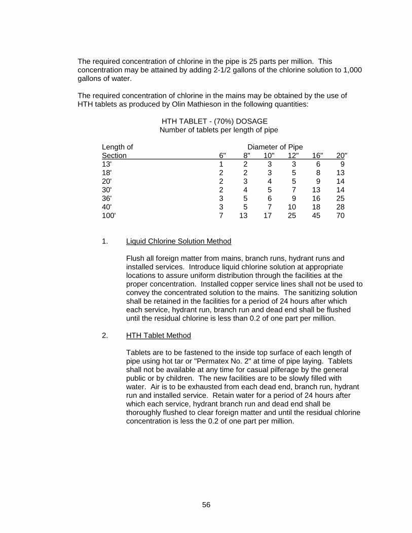
56
The required concentration of chlorine in the pipe is 25 parts per million. This
concentration may be attained by adding 2-1/2 gallons of the chlorine solution to 1,000 gallons of water.
The required concentration of chlorine in the mains may be obtained by the use of
HTH tablets as produced by Olin Mathieson in the following quantities: HTH TABLET - (70%) DOSAGE Number of tablets per length of pipe Length of Diameter of Pipe Section 6" 8" 10" 12" 16" 20" 13' 1 2 3 3 6 9 18' 2 2 3 5 8 13 20' 2 3 4 5 9 14 30' 2 4 5 7 13 14 36' 3 5 6 9 16 25 40' 3 5 7 10 18 28 100' 7 13 17 25 45 70 1. Liquid Chlorine Solution Method Flush all foreign matter from mains, branch runs, hydrant runs and
installed services. Introduce liquid chlorine solution at appropriate locations to assure uniform distribution through the facilities at the proper concentration. Installed copper service lines shall not be used to convey the concentrated solution to the mains. The sanitizing solution shall be retained in the facilities for a period of 24 hours after which each service, hydrant run, branch run and dead end shall be flushed until the residual chlorine is less than 0.2 of one part per million.
2. HTH Tablet Method Tablets are to be fastened to the inside top surface of each length of
pipe using hot tar or "Permatex No. 2" at time of pipe laying. Tablets shall not be available at any time for casual pilferage by the general public or by children. The new facilities are to be slowly filled with water. Air is to be exhausted from each dead end, branch run, hydrant run and installed service. Retain water for a period of 24 hours after which each service, hydrant branch run and dead end shall be thoroughly flushed to clear foreign matter and until the residual chlorine concentration is less the 0.2 of one part per million.
57
12.04 MEASUREMENT AND PAYMENT Water main shall be measured horizontally by the linear foot through valves and
fittings. Valves shall each be measured as one completed installed unit in operable condition including valve, anchor block, valve box and riser. Fire hydrants shall each be measured as one complete installed unit in operable condition including hydrant, break-off riser, bury, thrust block, 6 inch valve, and piping from main to bury. Air relief and blowoff assemblies shall each be measured as one complete unit in operable condition including valve, valve box, curb stop, corporation stop, service clamp and any other necessary fittings. Fittings, anchors, and thrust blocks shall not be measured for payment.
The contract price for water main and appurtenances shall constitute full compensation
for all labor, materials, and tests necessary to furnish and install the main and appurtenances in accordance with the drawings and specification.

58
"THIS PAGE LEFT INTENTIONALLY BLANK"
59
SECTION 13 PLANTING 13.01 DESCRIPTION This work shall consist of furnishing all labor, materials, and equipment required to
grade, prepare soil, fertilize, plant, and complete the landscape as shown on the approved plans, specifications and the Standard Details.
13.02 PRESERVATION OF PROPERTY The planting operations shall result in no damage to existing site improvements and
plantings. The Contractor shall be responsible for any damage resulting from his operations, and shall repair or replace such damage at his own expense. Vehicles of any kind shall not be allowed to pass over curbs, sidewalk, planting areas, etc, unless proper protection is provided.
13.03 SOILS TESTING The Contractor shall obtain soils tests for all planting areas after completion of finish
grading and prior to the start of soil preparation work. Tests shall be performed by an approved soils testing laboratory and include a fertility and suitability analysis with written recommendations for pre and post landscape installation. The soils report recommendations supersede minimum requirements of plans and specifications.
13.04 PERSONNEL Planting and seeding operations shall be performed by personnel familiar with planting
procedures and under supervision of a qualified contractor's representative. 13.05 WEATHER No planting shall occur during weather conditions which will adversely affect materials
or when soil is in a muddy condition. 13.06 INSPECTIONS Inspections of planting operations will be required. The Contractor shall contact the
City of Fairfield at least 48 hours (two working days) in advance of an anticipated inspection. An inspection will be required at each of the stages below:
60
A. Upon completion of finish grade and prior to commencement of soil
preparation, for acceptance of finish grades and taking of soils samples. B. Reinspection of finish grade following soil amendment work. C. When plants are spotted for planting before holes are dug. D. When planting and all other specified work has been completed. E. During application of pre-emergent herbicides. F. At start of 90-day maintenance period. G. At the end of 90-day maintenance, prior to acceptance of the project for
maintenance by the City. This acceptance for maintenance will be confirmed in writing by the City of Fairfield Public Works Department.
Note: 90-day maintenance is separate from the overall Project Final. 13.07 SUBMITTALS The following written certifications are required to be submitted to the Inspector upon
delivery of the respective materials to the job site: Total quantity of commercial fertilizer by type Total quantity of soil amendments and conditioners by type Total quantity of seed Total quantity of mulch 13.08 MATERIALS A. Imported Topsoil Topsoil shall be of loamy character containing a normal amount of organic
matter. It shall be free of refuse, roots, heavy and stiff clay and stones larger than one inch in size. Soil shall consist of the following: Sand - between 45 and 52 percent, Silt - between 26 an 50 percent, Clay - between 6 and 26 percent. Sand shall be defined as ranging in size from 2 to 0.05 mm in diameter: silt from 0.05 to 0.002 mm; and clay less than 0.002 millimeters.

61
B. Soil Amendment 1. Soil amendment shall be delivered to the job site bearing the warranty
of the producer for the grade furnished and shall be uniform in composition and free flowing. Grade of particles shall be 0 to 1/4 inch with 15% maximum proportion of 1/4 inch particles.
2. Soil amendment shall be nitrogen stabilized (1-0-0) and shall be
Nursery Mix, as distributed by Sun-up Forest Products Inc., Sacramento, CA or City approved equal. Supply sample of proposed substitutes to the City Engineer within two weeks of award of contract with laboratory organic amendment analysis.
3. Soil conditioners shall be agricultural grade gypsum, soil sulfur, and iron
sulfate. C. Fertilizer Fertilizer shall be a commercial inorganic fertilizer in the granular or pellet form.
Fertilizer shall be delivered to the site in containers labeled in accordance with the applicable State of California regulations, bearing the warranty of the producer for the grade furnished, and shall be uniform in composition, dry and free-flowing. Material which is caked or otherwise damaged shall not be used.
1. Turf areas and Planting Areas Prill type with analysis of 6-20-20 ( 6% Nitrogen, 20% Phosphorus, and
20% Potassium) for soil preparation and/or 16-6-8 for plant maintenance.
2. Planting Tablets 21 gram size, tightly compressed, long lasting, slow release fertilizer
tablets with a potential acidity of not more than 5% and with an analysis of 20-10-5.
Any substitutions shall be submitted to the City Engineer for approval
within two weeks of award of contract. Include a complete analysis. D. Herbicide Submit written chemical weed control advisory recommendation by a licensed
Pest Control advisor within two weeks of the award of the contract for approval by the City Engineer.
62
E. Seed Seed mixture shall be 98 percent pure and noxious weed free, with a minimum
of 88 percent germination. All turf seed shall be re-cleaned Grade A "new crop" seed, delivered in the original unopened containers, and shall bear a guaranteed analysis and dealer's label. The dealer may mix the seed provided a guaranteed statement of composition of mixture and percentages of purity and germination of each variety is attached to the sealed container. The seed shall be pre-treated with a pre-emergent fungus preventative such as "Thiram", or other City approved equal, in accordance with manufacturer's specifications. The seed containers shall be stored immediately in a dry, weather and damp proof structure. Any seed which has become wet, moldy or is otherwise damaged in transit or storage will not be acceptable. Supplier shall be approved by the City Engineer prior to delivery.
F. Hydroseeding Materials 1. Seed - as specified on the plans or in the Special Conditions. 2. Fertilizer - use 16-6-8, 400 lbs per acre. 3. Cellulose - Cellulose shall be certified to indicate that laboratory and
field testing of the product has been accomplished and that it meets all of the requirements below. The mulch shall be fibrous wood cellulose containing no growth or germination inhibiting factors. It shall be manufactured so that after agitation in the slurry tanks with fertilizer, seed, water and other additives, the fibers in the material will become uniformly suspended to form a homogeneous slurry. When hydraulically sprayed on the ground the material will form a blotter-like ground cover. After application the mulch will allow the absorption of moisture and allow rainfall to percolate to the underlying soil without causing erosion. Weight specifications of this material from suppliers and for all applications shall refer only to air dry weight on the fiber material. Each package of the cellulose fiber shall be marked by the manufacturer to show the air dry weight content. Mulch shall be applied at 1800 lbs per acre.
4. Binding Agent - Dry powder organic concentrate, such as Ecology
Controls M-binder or City approved equal. 5. Water - Water for hydromulching shall be clean potable water added to
the slurry mixture in sufficient amount to spread uniformly the required quantity of hydromulch solids (approximately 3,000 gallons per acre).
6. Equipment - Hydromulching equipment used for the application of the
seed, fertilizer and slurry of prepared wood pulp shall be of the type
63
normally used in such operations and shall be approved by the City Engineer.
G. Plant Stock Plants shall be the variety, quantity, and size indicated on the drawings.
Quality and size shall conform to the State of California Grading Code of nursery stock, No. 1 grade. Nursery grown stock only shall be used unless otherwise specified, and it shall be free from insect pests and diseases.
All plants shall be true to species and size indicated, and shall be tagged in
accordance with the standard practice recommended by the American Association of Nurserymen; however, determination of plant species or variety will be made by the City Engineer and his decision shall be final.
Plants shall be healthy, shapely, and well rooted, and roots shall show no
evidence of having been rootbound, restricted or deformed. Root condition of plants in containers will be inspected by the City Engineer and condition determined by removal of earth from the roots of not less than two plants of each species or variety from each source. If the sample plants are found to be defective, the City Engineer reserves the right to reject the entire lot or lots of plants represented by the defective samples. All plants rendered unsuitable for planting because of this inspection shall be immediately removed from the site.
Each plant shall be handled and packed in the approved manner for that
species or variety, and all necessary precautions shall be taken to ensure that the plants will arrive at the work site in proper condition for successful growth without scarred or broken branches. Trucks used for transporting plants shall be equipped with covers to protect plants from windburn.
Substitutions will not be permitted, unless proof is submitted to the City
Engineer that any plant specified is not available. The City will then consider the use of the nearest equivalent variety. Such proof shall be substantiated and submitted in writing by the Contractor within 35 days after the effective date of the Notice to Proceed.
Plants shall have straight trunks with the leader intact, undamaged and uncut.
At no time shall the Contractor prune the leader without the prior written approval of the Public Works landscape inspector. Trees shall be well tapered in the trunk so that they will stand alone without the support of the nursery stake. Branching on the main leader shall be in alternate locations and well spaced apart with no severe crossing of the branches. All old abrasions and cuts shall be completely calloused over. All plants shall be measured when their branches are in their normal position. Height and spread dimensions indicated refer to the main body of the plant and not from branch to branch or
64
root tip to top. Sizes shown are before pruning. Plants shall not be pruned prior to delivery except upon approval of the City Engineer.
Groundcover shall be rooted plants from flats unless otherwise approved by the
City Engineer. H. Mulch Mulch shall be Walk-On Bark as distributed by Cement Hill Ready-Mix or Idaho
walk-on bark as distributed by Sun-up. Submit a sample to the City for approval.
I. Backfill Soil used for backfill of plant pits shall be enriched using the following blend: 1 CY on-site soil 2 lbs 16-6-8 commercial fertilizer 3 lbs Gypsum 2 lbs Iron Sulfate J. Tree Stakes and Ties Tree stakes shall be 2" by 10' straight, close grained lodgepole pine, pointed at
one end. Stakes shall be free from knots, checks, splits or disfigurements. Paint the stakes prior to treatment with Copper Napthanate which shall penetrate stake surfaces to a minimum depth of 1/4 inch.
Tree ties shall be "Gro-strait" or City approved equal. Earth anchors for specimen trees shall be equal to the "Duckbill" as supplied by
Landscape Supply, Inc., Santa Clara, CA. The size of the trees to be supported shall determine the necessary holding capacity of the anchors used. The anchor holding capacity shall be approved by the City Engineer.
K. Deep Rooting Containers All trees planted within 8' of pavement or of a shallow rooting variety within 10'
of pavement shall be provided with a root barrier. The barrier shall be placed along the curb, sidewalk and/or other pavement and shall extend 6' along each face of pavement. When the area where the tree is to be planted is less than 6' square, a box type barrier may be used. This barrier shall have a minimum bottom opening of 30". If panels are used there shall be a minimum of four 24" panels for a 15 gallon tree and they shall extend a minimum of 23" into the
65
ground. Panels shall not surround the tree if there is sufficient room to extend the panels along the edge of the pavement.
L. Deep Root Water Tubes All trees shall be provided with two 24" long by 4" diameter perforated pipe
deep root under tubes. They shall be wrapped with a fabric to prevent soil intrusion while allowing passage of water and filled with 1/2" to 1" drain rock.
13.09 PLANTING A. Soil Preparation and Fine Grading Prior to any planting bed preparation or planting, finish grade all planting areas,
fill as needed or remove excess dirt. Install all irrigation. Float all areas to a smooth uniform grade as indicated on the Grading plans. Slope all planting areas to drain. Roll, scarify, rake and level as necessary to obtain true, even planting surfaces. Finish grades shall be approved by the City Engineer and all soils testing completed prior to any planting work. All planting areas shall be thoroughly wet down and sprinkler/emitter coverage and operation inspected and approved. Allow soil to dry so as to be workable. Finish grades shown on the plans are given in feet and decimals of feet. Slope uniformly between given spot elevations. Grades not otherwise indicated shall be uniform levels or slopes between points established by pavings, curbs or catch basins. Minor adjustments of finish grade shall be made at the direction of the City Engineer if required. All grades shall provide for natural runoff of water without low spots or pockets. Flow line grades shall be accurately set and shall not be less than 2 percent gradient unless otherwise indicated. Tops and toes of all slopes shall be rounded to produce a natural appearing transition between various levels.
After approval of finish grade but before the installation of irrigation, thoroughly
cultivate the soil to a depth of 12 inches. This shall be done in two lifts adding half of the amendments and fertilizer outlined below to each lift. Soil amendment and fertilizers shall be spread at the rates designated by the soils lab but at no less than the following rates:
1. Soil Amendment - 10 cubic yards per 1,000 square feet. 2. Fertilizer - 30 lbs per 1,000 s.f. of 6-20-20. After approval of amendment and fertilizer applications by the City Engineer,
thoroughly incorporate into the top 12 inches of soil by repeated rototilling.
66
Finish grade of all shrub, annual and groundcover areas shall be 1/2 inch below
the top of adjacent pavement, headers, curbs or walls before the installation of the mulch, unless otherwise indicated on the drawings. Finish grade of turf areas shall be 1/2 inch below top of adjacent pavement, sidewalks, curbs, and headers.
B. Tree, Shrub, and Groundcover Planting Mark tree and shrub locations on site using stakes or similar means. Locations
shall be approved in the field by the City Engineer before plant holes are dug. Adjustments shall be made as required.
Dig pits circular in outline with vertical sides as shown on the Standard Detail.
After pits are dug, roughen sides of the pit and loosen soil in the bottom of the pit to a depth of 3". Construct foot-tamped mound in the bottom of the pit to support the plant at the proper level.
Do not handle container plants by the tops, stems or trunks at any time, lift all
plants so that the rootball is supported from the underside. Plants that do not have a satisfactory root system will be rejected. If plants do not have young feeder roots showing at the edge of the container, loosen their roots and score the rootball with 1/2 inch deep vertical lines to encourage new feeder root development.
Bare root stock backfill shall consist of 90% onsite soil and 10% organic
amendment with fertilizer and soil conditioners as listed above. All soil backfill shall be bulk mixed, not individually mixed at each plant pit.
Place plant in hole in an upright position. Crown of tree should be 1 1/2 inch
above finish grade. Crown of shrubs shall be 1 inch above finish grade. Backfill using the specified soil mix to within 18" of finish grade. At this depth, place the plant fertilizer tablets, Agriform 20-10-5 21 gram, or City approved equal, at the following rates: 1 tablet per one gallon plant, 3 tablets per 5 gallon plant, 5 tablets per 15 gallon plant, 8 tablets per 24 inch box, 12 tablets per 36 inch box. Thoroughly water and complete the backfill. Place a 3 inch high berm outside the excavated area to create a watering basin and fill the watering basin with water. The crown of the plant after settlement shall be 1/2 to 1 inch above finish grade and all roots shall be covered by soil. Remove the berm before installing the bark.
After any pruning that has been approved by the Public Works landscape
inspector, place the tree stakes along side but not piercing the rootball. Stakes shall extend a minimum of 1 foot into undisturbed soil. Attach trees to the stakes with tree ties as shown on the standard detail. Mulch the inside of each
67
watering basin with 3 inches of bark mulch. Mulch shall not touch the crown of the plant
Specimen trees shall be staked or guyed as shown on the Standard Details.
When trees are planted in public areas, install a 24" by 1/2" piece of white PVC pipe on each guy wire for visibility as directed by the City Engineer. Staking exceptions may be allowed on a case-by-case basis for evergreen Conifers.
All plants shall be planted immediately after the containers are cut or broken.
Containers shall be immediately removed from the site to prevent a hazard to persons using the area. No containers shall be left on site overnight.
In groundcover areas, apply fertilizer (16-6-8) at a rate of 6 lbs./1000 square
feet with a uniform spread. Groundcover shall be installed at spacings indicated on the drawings, evenly spaced and in staggered rows. Place each plant in its pit so that the root system lies freely without doubling and so that the plant is vertical to the ground. Firm the soil around each plant making sure that the crown is 1/2 to 1 inch above finish grade. All roots shall be below the soil. Provide a small watering basin as shown on the Standard Details and water the plant in thoroughly.
After all plants are installed, pre-emergent herbicide shall be applied to all
groundcover and shrub areas after removing plant basins. Also apply pre-emergent in the tree basins. Chemicals used are to be as shown on the written recommendations prepared by a licensed Pest Control Advisor and approved by the City Engineer.
After the application of the pre-emergent, all groundcover, shrub, and tree
areas shall be mulched. All groundcover and shrub areas shall receive a two inch layer of the approved mulch, taking care not to cover the crown of any plant. Mulch shall not be installed under low growing groundcover but shall be placed up to the edges, and not covering the newly installed plants. All tree basins shall receive a 3 inch layer of mulch.
C. Hydromulch Seeding All areas to receive hydromulch shall be sprayed with a uniform visible coat
using the green color of the mulch as a guide. The slurry shall be applied in a sweeping motion, in an arching stream, so as to fall like rain allowing the fibers to build on each other until a good coat is achieved and the specified amount of materials are applied. The nozzle shall not be pointed at the ground nor shall the pressure be allowed to roll the mulch, forming ridges along the ground. Such areas shall be immediately re-sprayed.
68
Any slurry mixture which has not been applied to the designated areas within
four hours of mixing shall be rejected by the City Engineer and shall be removed from the project at the Contractor's expense.
The slurry shall not be sprayed on undesignated areas. It shall not be allowed
to fall onto groundcover or shrub areas nor onto trees that are within the designated areas. Any slurry spilled or sprayed into areas other than those designated to receive spray or onto objects such as trees, posts, fences, poles, vaults, walks, etc. shall be cleaned up to the satisfaction of the City at the Contractor's expense.
All bare spots shall be reseeded by the Contractor at 10 day intervals at the
Contractor's expense. The Contractor shall be responsible for all seeded or reseeded areas until acceptable germination and establishment is realized and approved by the City.
D. Seeding Installation of plants shall have been completed before seeding operations are
begun. Just prior to sowing, the areas to be seeded shall be made sufficiently loose and friable to receive the seed.
The seed shall be sown evenly using a mechanical spreader at the rates
specified on the plans or in the Special Provisions. One-half of the seed shall be sown in one direction and the second half sown at 90 degrees to the first during a time when weather will not disturb the seeding process. Apply fertilizer (16-6-8) at a rate of 6 lbs/1000 sq ft uniformly over the seeded areas. Lightly rake the surface to cover the seed and to mix with the fertilizer, then compact the surface with a 200 lb. roller. Soil shall be kept moist but not saturated until the seed is germinated.
Protect the grass areas with temporary fencing as necessary. Barriers shall be
maintained by the Contractor and kept in orderly condition at all times until the work has been accepted by the City. Any damage to the turf shall be repaired by the Contractor at his own expense. If for some reason the maintenance period does not start immediately, refer to Section 13.12B following for the care and maintenance of seeded areas.
E. Installation of Sod Sod area should be prepared by stripping all plant material from the area. If
there is existing turf to match, the edge shall be lowered approximately one inch so that the new turf will meet existing grade. All rocks and uneven areas shall be removed and the area rolled smooth. Sod area shall then be dampened to a depth of a minimum of one inch to ensure a tight contact with
69
the new sod. Care should be given to prevent heel or footprints in the grade as the sod is installed. Unroll the sod, fitting each strip tightly on all sides to the preceding strips or the existing turf. Do not stretch or deform the sod. Force each strip together as tightly as possible. Stagger the strips of sod like a bricklayer places bricks to prevent the seams from matching.
As soon as the sod is placed, water lightly and roll it in, making certain that no
airspace is left under the sod. Care should be taken to leave no footprints in the sod. Upon completion of the rolling, apply sufficient water to wet the sod and soil to a depth of six inches. At the end of 10 days, mow to a height of 2½ inches.
13.10 CLEANING UP The Contractor shall at all times keep the premises free from the accumulation of
waste material or rubbish. At the completion of the work, he shall remove all rubbish from the site and all of his and his sub-contractors tools, scaffolding, and surplus materials.
13.11 WATERING It shall be the Contractor's responsibility to maintain a balanced watering program to
ensure proper growth until final acceptance of the work. Apply water in sufficient quantities and as often as seasonal conditions require to keep the planted area moist at all time, well below the root system of the plants. The Contractor shall not, however, water so much that the area floods or that insufficient oxygen is allowed to the plant roots. Remove basins from around trees as necessary to prevent flooding the crown of the trees.
13.12 MAINTENANCE PERIOD A. Preliminary Inspection Upon completion of all construction and planting work, the Contractor shall
notify the City by phone or fax that the landscape work is ready for preliminary inspection for start of maintenance. The approval of the completed work will establish the beginning of the maintenance period.
B. Maintenance The Maintenance Period shall be 90 calendar days after the acceptance of the
landscape for Start of Maintenance. A longer period may be required if the plant maintenance is not acceptable during the 90 day maintenance period. The maintenance period may be suspended at any time upon written notice to the Contractor/Developer that the Landscape is not being acceptably
70
maintained, and the day count suspended until the landscape is brought up to City standards.
Permanent electrical power connections to remote controller shall be provided
prior to the Start of Maintenance. All valves must be operated from the controller and the controller shall be connected to permanent power. Valves shall operate in sequence down the street and shall not jump from side to side or around the site.
Maintenance shall include, but is not limited to all watering, weeding, fertilizing,
cultivation, spraying, and pruning necessary to keep the plant material in a healthy growing condition and to keep the area neat throughout the maintenance period. However, the Contractor shall not prune any trees without the express written consent of the City. Watering shall be of sufficient quantity as to provide optimum growth conditions. The Contractor shall provide the equipment and means for its proper application. During the maintenance period, should the appearance of any plant indicate weakness and the probability of dying in the opinion of the City Engineer, that plant shall be replaced immediately by the Contractor at his own expense. Replacements shall be made in the same manner as specified for the original planting. At the end of the maintenance period, all plant material shall be in a healthy growing condition and free of physical injury of any kind.
Lawn shall be mowed as specified herein. Clippings and debris shall be
removed from the site. Lawn shall be trimmed at the edges of curbs, paving, drains, and headers. Lawn areas which fail to germinate shall be re-seeded at maximum 10 day intervals until a vigorous, even stand of turf is established. Lawn areas shall be kept free from weeds by hand pulling or by spraying with the approved selective chemical herbicide before they exceed 2 inches in height. Lawn shall be mowed for the first time after the turf has reached a uniform height of 3 inches. Turf shall be mowed for the second time when it again reaches a height of 3 inches. This second mowing shall be no sooner than 10 days after the first mowing. Mowing thereafter shall take place at 7 day intervals until final acceptance.
After the second mowing of the turf, apply a second application of (16-6-8)
fertilizer at a rate of 6 lbs. per 1000 square feet. Fertilizer shall be spread uniformly over the turf area. Apply fertilizer at the same rates at 30 day intervals thereafter until final acceptance of the project.
The final application of pre-emergent in shrub and groundcover areas and
fertilizer in all areas shall take place immediately preceding the final inspection. The pre-emergent shall be a mix of Surflan and Ronstar or equal. A minimum of 3 applications of fertilizer shall have been applied prior to acceptance by the
71
City. All applications of pre-emergent or fertilizer shall take place in the presence of the City.
The Contractor shall apply (16-6-8) commercial fertilizer to all groundcover
areas at a rate of 5 lbs per 1000 square feet at 30 day intervals for 3 applications as a minimum during the 90 day maintenance period above and beyond the original soils preparation application. After planting and during the maintenance period, in the event that any plants or turf areas exhibit iron chlorosis symptoms, apply FE 138 Geigy or City approved equal at the manufacturer's recommended rates.
Any plantings that do not show a prompt establishment of plant material shall
have defective plant material replaced at 10 day intervals until accepted by the Department Representative. If a good rate of growth has not been demonstrated within 30 days of the first planting/hydroseeding, the Contractor shall be responsible for determining the appropriate horticultural practices necessary to obtain good growth. The Contractor shall obtain agronomic soils testing and/or plant pathology reports for all areas not showing good growth and shall provide copies of the test results to the City to verify the appropriateness of all plant establishment work performed. If additional soils amendments are needed, such amendments shall be provided by the Contractor at no additional cost to the City. The Contractor is also responsible for providing the appropriate fungicides or other chemical control to provide healthy plants at the end of the Maintenance period.
During the maintenance period, all flow lines shall be maintained to allow for
free flow of surface water without causing erosion. Displaced materials which interfere with drainage shall be removed and relocated as directed. Low spots and pockets shall be regraded to drain properly and plant material replaced. Jute netting shall be installed at flow lines and other locations where erosion is evident as directed by the inspector. Work under this Section shall include complete responsibility for maintaining adequate protection for all areas. Any damaged areas shall be repaired at no additional cost to the City.
During the Maintenance Period, any turf areas or plants which are vandalized,
diseased, dead, or in an unhealthy condition, shall be replaced by the Contractor at his expense within two weeks after notification from the City Engineer or his inspectors. Any plant damaged by herbicide shall be replaced by the Contractor at his expense. Maintenance shall also include treatments for fungus, diseases, rodents and insects with requirements for approvals of chemicals being the same as for herbicides. Weed all areas at no less than 7 day intervals. Maintenance is to include all items installed under the contract. All mechanical items shall be maintained in optimum working condition. The site shall be kept free of trash and debris by means of a general clean-up once a week.
72
13.13 FINAL INSPECTION AND ACCEPTANCE Final inspection will be conducted at the end of the Maintenance Period. Notice
requesting final inspection shall be submitted by the Contractor to the City Engineer at least 7 days prior to the anticipated date. Acceptance by the City will be contingent upon proper maintenance and the establishment of a vigorous, uniform stand of turf over all areas seeded. Any portion thereof which does not show a vigorous, uniform stand shall make all areas subject to continued maintenance at the Contractor's expense.
Just prior to the final inspection, the Contractor shall have performed weeding, repair
or touch-up of pavement, repair of equipment and structures, and a thorough cleaning of the site. Apply Ronstar pre-emergent to all tree basins, shrub and groundcover areas and apply a 16-6-8 granular form commercial fertilizer as follows:
Specimen Tree 1 pint 15 gal. plants 1 cup 5 gal. plants 1/2 cup 1 gal. plants 1/4 cup Groundcover 10 lbs per 1,000 s.f. Turf Areas 6 lbs. per 1,000 s.f. Fertilizer shall be spread around the base of the plants and thoroughly watered. At the final inspection, the City Engineer will determine the condition of improvements,
planting and turf. Plants which are missing, vandalized, dead or unhealthy shall be replaced by the Contractor at his expense with the same species and sizes originally specified. The Contractor shall make such replacements within two weeks after the final inspection and maintain the areas for an additional 30 days before calling for another Final Inspection. If project improvements, corrective work, and maintenance have not been performed as specified to the satisfaction of the City Engineer, the maintenance period shall continue at the Contractor's expense until such time as the work has been successfully been completed. When the work has been performed as specified to the satisfaction of the City Engineer, the City will assume maintenance responsibilities following the final inspection. End of the maintenance period shall occur only upon acceptance of the project by City Council.
13.14 GUARANTEE A. All plant materials installed under the contract shall be guaranteed against any
and all poor, inadequate or inferior materials and/or workmanship for a period of one year following final acceptance.
73
B. Any trees or other plant material that die back and lose the form and size originally specified shall be replaced, even if they have taken root and are growing after the dieback.
C. During the guarantee period, any material found to be dead, missing or in poor
condition by the City shall be replaced by the Contractor within 10 (ten) working days of written notification. The City of Fairfield Public Works Department shall be the sole judge as to the condition of the material.
D. Replacement shall be made in accordance with City of Fairfield Standards.
Material and Labor involved in replacing the plant material shall be provided by the Contractor at no additional cost to the City.
E. Replacement material shall be installed to the same specifications as required
for the original installation and shall carry the same guarantee from the time they are replaced.
13.15 MEASUREMENT AND PAYMENT The landscaping shall be measured and payment made at the contract lump sum or
unit price and shall include full compensation for furnishing all labor, materials, tools, equipment, and incidentals for doing all landscape installation and maintenance work as shown on the plans and as specified in these specifications under the direction of the City Engineer or his representative. Payment shall only be made for installed materials as approved by the City Engineer.

74
"THIS PAGE LEFT INTENTIONALLY BLANK"

75
SECTION 14 IRRIGATION SYSTEM 14.01 DESCRIPTION This work shall consist of furnishing all the labor, materials, tools, and equipment
necessary to construct and complete in an efficient and workmanlike manner the installation of an irrigation system in accordance with the approved plans and these specifications.
14.02 GENERAL A. Purpose It is the intention of these Specifications to accomplish the work of installing a
sprinkler system which will operate in an efficient manner and provide adequate coverage. The Plans indicate the general arrangement of piping and equipment, and do not necessarily indicate all offsets, fittings and accessories that may be required. The Contractor shall furnish incidental materials and labor not specifically called for but required to complete work as intended.
B. Type of Irrigation Because of the high wind conditions typical to the Fairfield area and the
problems with run off onto paved areas, irrigation for median islands and parkway strips shall be either 1) drip, 2) low angle, low pop-up spray, or 3) low volume stream rotor pop-ups. The system shall be designed in such a way as to prevent runoff onto sidewalks, streets, curbs and gutters. Overhead spray systems shall be used for large turf or groundcover areas.
C. Details The Irrigation plan and the piping details are diagrammatic. Pipe lines shown
parallel on the drawing may be placed in a common trench, providing that a minimum horizontal and/or vertical distance of 6 inches is maintained between buried lines. Sprinkler heads and quick-coupler valves are schematic. Discrepancies in dimensions or sizes of areas to be irrigated shall be brought to the attention of the City, prior to submission of bid. After such time, intent of City will govern all discrepancies.

76
D. Damage by Leaks The Contractor shall be responsible for damages to any property or work
caused by leaks in the piping systems being installed. The contractor shall repair, at no cost to the City , all damages so caused. All repair work shall be done as directed, and in a manner satisfactory to the City.
E. Protection The Contractor shall be responsible for any damage to this work which occurs
before final acceptance. He shall securely cover all openings into the systems and protect all apparatus, equipment and appliances, both before and after being set in place, to prevent obstructions in the pipes and breakage, misuse or disfigurement of the apparatus, equipment of appliance. Contractor shall be responsible for damage to all existing utilities and existing facilities (buildings, turf, and landscape areas, paving, etc.), whether or not they are indicated on drawings.
F. Equipment List and Drawings Within 15 days following notification of award of the contract, the Contractor
shall submit to the City Engineer for approval a list of equipment and material which he proposes to furnish and install. The list shall be complete as to name of manufacturer, size and catalog number of unit, and shall be supplemented by such other data as may be required, including detailed scale drawings, plumbing, and writing diagrams. All of the above data shall be submitted in duplicate for checking. Following checking, correcting and approval, three complete sets shall be submitted to the City Engineer.
Materials list shall be submitted using the following format: Item Description Manufacturer Model No. 1 Pressure Supply Line Lasco Sch.40 2 Lawn Head Rainbird 2400 etc. etc. etc. etc. G. "Record" Prints 1. Record accurately on one set of blue-line prints all changes in the work
constituting departures from the original contract drawings, including changes in pressure and non-pressure line locations, and a complete schematic circuit diagram.
2. The changes and dimensions shall be recorded in a legible and
workmanlike manner to the satisfaction of the City. Prior to final
77
inspection of work, and prior to transferring the information to mylars, submit record prints to the City Inspector for approval.
3. Dimension from two permanent points of reference (buildings,
monuments, sidewalks, curbs, pavement, etc.). Data to be shown on record prints shall be recorded day-to-day as the project is being installed.
4. Show locations and depths of the following items: a. Point of connection. b. Routing of sprinkler pressure lines (dimension maximum
100 feet along routing). c. Gate valves. d. Sprinkler control valves. e. Quick coupling valves. f. Routing of control wires. g. Sleeves h. Related equipments (as may be directed). 5. Maintain record prints onsite at all times. 6. Upon completion of work, transfer all as-built information and
dimensions to reproducible sepia mylars. The changes and dimensions shall be recorded in a legible and workmanlike manner, to the satisfaction of the City of Fairfield Public Works Department.
H. Standard of Installation Material and workmanship shall be in accordance with local codes and
ordinances of legally constituted authorities, except where provisions of these Specifications exceed such requirements, these Specifications shall govern.
I. Personnel All layout, installation, and work relating to the irrigation system shall be
performed by personnel experienced in the trade and under the supervision of a qualified contractor's representative.
78
14.03 MATERIALS A. Pipe and Fittings 1. Mains a. PVC - Polyvinyl Chloride for 2 inch up to 6 inch shall be
1120-200 PSI (SDR 21) rubber gasket type PVC. Pipe shall be marked continuously and permanently with manufacturer's quality control identification.
b. Copper shall be soft rolled tube Type K conforming to A.S.T.M.
Designation B88. 2. Main or Sub-Main a. PVC - Polyvinyl Chloride for all pipe 1 1/2 inch or under shall be
Schedule 40 - A.S.T.M. 1785 - Type I PVC 1120. Fittings shall be Type I/II, Schedule 40 NSF PVC, Solvent Weld.
b. Copper shall be soft rolled tube Type K conforming to A.S.T.M.
Designation B88. 3. Sleeves Separate sleeving shall be installed to carry mains, laterals, and control
wires under all paved surfaces. Sleeves shall be Schedule 0 (PVC) pipe - size as required. Sleeves shall be bored under existing paving and shall extend 12 inches beyond paving edge. A separate sleeve shall be provided for each water line and one for the electrical control wires. Two empty 4” sleeves shall be installed from island nose to island nose and stubbed into a pull box with an end bell. Duct seal shall be used at each conduit stub. A 5/8” flat woven traceable pull tape with footage markings shall be installed into the sleeve.
4. Laterals Lateral lines on the discharge side of valves shall be Schedule 40 PVC.
Fittings shall be Schedule 40, Solvent Weld. 5. Drip Lines Above ground spaghetti type tubing shall not be used. Subterranean
drip lines shall be ½” or ¾”, .96 GPH Netafim or city-approved equivalent. Subterranean drip lines shall be installed in 12” spacing grids with a PVC Schedule 40 manifold at both ends. There shall be a filter at the beginning of each run and a popup pressure indicator and flush valve at the end of each run. Compression fittings shall be used at all joints.

79
Where flex hose is used it shall be Agrifim ½” or ¾” flex PVC IP tubing
or city-approved equivalent. The distance from lateral line to plant shall not exceed five (5) feet.
B. PVC Pipe Cements 1. Primer shall be IPS P-70 PVC, or equal, for all sizes of PVC pipe and
fittings. 2. Cement shall be IPS 721 medium bond blue cement or equal for all
sizes of PVC pipe and fittings up to 1½”. 3. Cement shall be IPS 2711 heavy bond grey cement or equal for all
sizes of PVC pipe and fittings larger than 1½”. 4. Cement for flexible PVC connections shall be IPS 2795 Clear or equal. C. Sprinkler Heads Sprinkler heads shall be of the types and sizes with the radius of throw,
pressure, discharge and any other designations necessary to determine the types and sizes, as indicated on the Plans.
All heads of a particular type of function in the system shall be of the same
manufacture and shall be marked with the manufacturer's name and identification in such a position that they can be identified without being removed from the system. Any substitutions for items specified on the Plans must be submitted for approval in writing. Subsequent approval or rejection will be given in writing.
The following sprinklers are approved for installation in city landscapes. Rainbird: 8005 Rotors; 1800 series popups; 1800 sams will be used on slopes;
All sprinklers will use appropriate nozzles for head-to-head coverage. Rainbird R-Van series variable arc nozzles are acceptable for rotary streamers.
Hunter: I-20; PGJ; PGP-12 series rotors. All sprinklers use appropriate nozzle
for head-to-head coverage. D. Sprinkler Risers All riser nipples shall be threaded Schedule 80 PVC and swing joints shall be
Schedule 40 threaded street ells wrapped with Teflon tape or prefabricated swing joints, such as Rainbird TSJ/TSJ-PRS series or city approved equivalent.
All 1 inch riser assemblies shall consist of swing joints rated at 200 psi and two
Class 200 PVC nipples and one Schedule 80 nipple. See Standard Details.
80
E. Check Valves In line check valves shall be installed in the risers of all heads that are 12 inch
or more below the grade of the valve. F. Emitters and Bubblers Emitters shall be of the types and sizes as indicated on the Plans. They shall
be constructed of plastic. Spaghetti tube emitters shall not be used. Bubblers shall be fixed amount .25 GPM or .50 GPM Rainbird 1401/1402 or city
approved equivalent. All emitters of a particular type of function in the system shall be of the same
manufacture and shall be marked with the manufacturer's name and identification in such a position that they can be identified without being removed from the system. Any substitutions for items specified on the Plans must be submitted for approval in writing. Subsequent approval or rejection will be given in writing.
G. Underground Drip Line Underground drip lines shall be of a type that will provide an even coverage of
water over the entire area where they are used. All lines within a system shall be the product of one manufacturer and shall be installed as specified on the plans and as approved by the manufacturer. System shall be as manufactured by Netafim, Agrifim or a City approved equal.
H. Flush End All emitter and drip systems shall be provided with a ball type, faucet handle
flush valve at the end of each emitter line. It shall be installed in a round valve box at the end of 5 feet of flexible PVC.
I. Fertilizer Injector Kit All underground and drip emitter systems shall be provided with a fertilizer
injector kit to allow for the use of water soluble fertilizers on the site. Install in a plastic or concrete valve box.
J. Pressure Gauge Underground and drip emitter systems shall be provided with pressure gauges
as necessary to ensure the proper operation of the system. Pressure gauge as manufactured by Irrometer or City approved equal. Install in a plastic valve box.
81
K. Screen Filter A screen filter such as that manufactured by Amaid or City approved equal
shall be provided after the fertilize injector kit for each underground or drip emitter system. Install in a plastic valve box.
L. Valves 1. Remote Control Valves (R.C.V.), Electric Solenoid Type For Uses Other
Than Drip Systems The remote control valve shall be 24 volts, 0.3 amp in rush, .02 amp
holding, normally closed, spring loaded and diaphragm actuated. It shall be self-cleaning, self-purging. It will have adjustable closing speed with no chatter or hammer. It shall have self-cleaning main seat and will operate under extreme low flow conditions. It will be capable of self-bleeding trapped air in the cover chamber. It will be capable of angle or globe installation. It should be easily flushed if a foreign object becomes lodged in the internal control mechanism. It should have no screens, filters, or small orifices in the control mechanism which are subject to clogging. It will have a manual bleed system. It shall be completely serviceable in the field without removing the valve body from the system. Valve rating shall be 220 PSI. The valve shall be ICV series as manufactured by Hunter Industries. Valve boxes shall be plastic with snap cover, green, with the word "Irrigation" embossed on the cover, Ametec 10-170-001, or equal. Stencil valve station number on the cover using a contrasting epoxy resin paint in 2 inch numbers.
2. Remote Control Valves (R.C.V.), Electric Solenoid Type For Use With
Drip Irrigation Systems The remote control valve shall be 24 volts, 0.3 amp in rush, 0.2 amp
holding, normally closed, spring loaded and diaphragm actuated. It will have a regulating range of 5 to 100 PSI. Upstream pressure can vary from 5 to 200 psi, while controlling a steady downstream pressure. Downstream pressure can be regulated when manually opened. It shall be capable of operating under any dirty water conditions - sand, silt, algae, chemicals, fertilizers, slime, or other particulate. It shall have no screens or filters to clog. It must work well under low flow - low pressure conditions. It shall be capable of downstream pressure measurement and shall be 220 psi rated. The valve shall be an ICV series, as manufactured by Hunter Industries or city approved equivalent. The valve boxes shall be plastic with snap covers, green, with the word "Irrigation" embossed on the cover, Ametec 10-170-001 or equal. Valve station number shall be stenciled in 2 inch numerals on the cover using epoxy resin based paint of a contrasting color.
82
3. Gate Valves Gate valves shall be iron body, bronze mounted, double disc, parallel
seat with non-rising stem and with a 2 inch square operating nut, opening counterclockwise. Valves shall have "O" ring seals and have hubs suitable for use with the main distribution pipe furnished for the sprinkler system. All internal ferrous metal surfaces shall be fully coated with epoxy as per AWWAC 550 to protect all seating and adjacent surfaces from corrosion and prevent build-up of scale of tuberculation. Size shall be a indicated on the drawings. Valve boxes shall be plastic with lock bolt cover, green, with the word "Irrigation" embossed on the cover, Carson Model 910-12B or equal.
4. Ball Valves Ball valves shall be bronze body, two-piece, full port, threaded with
brass, chrome-plated ball. The valve boxes shall be plastic with snap covers, green, with the word “IRRIGATION” embossed on the cover.
5. Quick Coupling Valves Quick coupling valves shall be two piece, single slot, 1 inch diameter
Buckner No. 14 or approved equal. Quick coupling valves to be installed in plastic box with green lock bolt cover marked "Irrigation", Carson Model 910-12B or equal. Location as shown on the plans.
M. Backflow Prevention Device A Reduce Pressure Principle Backflow Prevention assembly device shall be
used. The device shall be U.S.C. approved and shall be installed at the locations indicated on the plans. It shall be installed above grade and covered in an insulated backflow blanket and housed in a Guard Shack backflow enclosure or City approved equal. After the device is installed, it shall be tested by a certified Backflow Assembly Tester and the test report given to the City.
All backflow prevention devices serving drinking fountains shall be lead-free. Reduced pressure device shall be in accordance with the Standard Details. N. Irrigation Controller The irrigation system controller shall be a U.L. approved, micro-processor
based, solid state unit capable of fully automatic or manual operation of the system. It shall be housed in an exterior (16 gauge) weatherproof pedestal mounted locking case. It shall operate on 117 volts AC, 50/60 Hz power input and be capable of operating 24 volt AC electric control valves. In addition, the controller shall be equipped with or shall be capable of the following:

83
1. Each station shall have the capability of being individually programmed
to operate from one minute to nine hours and 59 minutes in one minute increments.
2. It shall have a quick stations function which allows for rapid
programming of a block of stations with the same watering period. 3. It shall have three independent programs with four automatic starts per
day per program. 4. Each program shall have its own percentage function which allows the
watering length of all stations in the program to be changed from 0% to 300% in 1% increments and at all times be able to display the original watering length of each station.
5. Each program shall be capable of being set on either a seven day
weekly repeat cycle where the active days are displayed all at once or on a skip day basis where the user may select the number of days skipped, from one to thirty, between waterings with the starting day selectable.
6. The controller shall have a review program function which, with one
button, will sequentially bring all its programmed information to the displays at a readable rate. The recall display shall be interruptible at any time for changing the program. Each program shall provide a total duration watering time in hours and minutes.
7. The controller shall allow for setting in a "rain mode" for up to seven
days after which, it will revert to the "automatic mode." 8. Program may be protected by use of an access code. 9. Controller shall be capable of being operated manually at any time
without affecting the original program. 10. The controller shall have a rechargeable battery back-up to maintain
time and the user's program. 11. The controller shall have the capability of responding to external remote
control signals when coupled to a master remote control system. 12. The controller shall have a built-in self test which allows the user to
check each of the following: a. LEDs for lighting and shorts,

84
b. the digital display for lighting and shorts, c. each key of the keyboard for integrity and proper function, and d. all station outputs. 13. Output power capacity shall be 24 VAC, 1 amp maximum, equivalent to
24 VA. 14. Acceptable controllers are as follows; substitutions shall require prior
approval of city staff. Controllers of ten stations or more shall be Rainmaster Smart Controller
Evolution DX2 with radio communications and antenna. If controller is located in an area where the signal cannot reach a repeater antenna then a high gain antenna will be used. A site assessment by John Deere Greentech will be required and a phone/modem setup will be installed, if needed.
Controllers with fewer than ten stations shall be Rainmaster Sentar II
with non-volatile memory to hold programming indefinitely in case of power outages.
The controller shall be housed in a DX2-SPED stainless steel box with 120
volt/20 amp GFCI plug., or City approved equal, installed on a Class B Portland Cement Concrete foundation as recommended by the manufacturer of the controller. A 6 foot copper grounding rod shall be provided inside of the controller enclosure. Enclosure shall be a weatherproof, 3/16-inch plate, metal locking case to which two keys shall be provided. The enclosure and accessories shall be installed in conformance with the manufacturer's instructions and recommendations. Foundation to be a minimum of 4 inches deep and sufficient width to prevent tipping.
Controllers with 1-2 stations shall be Hunter Pro-C outdoor model. The
controller will be housed in a wall-mounted or pedestal box of 14 gauge metal to be approved by city staff. The controller shall have a 120 volt/20 amp power supply.
Each park or maintenance district shall provide with the controller a master
remote control unit compatible with the controller. If the project is completed in phases, the remote control unit shall be provided with the acceptance of the first phase.
85
O. Electrical 1. Control Wire All wiring to be used for connecting the automatic controller to the
electric solenoid actuated remote control valve shall be type UF-600V, 14 gauge solid copper, PVC insulation, single conductor, UL approved underground feeder cable. All pilot or "hot" wires are to be of one color and all "common" wires are to be white. Connecting and splicing of wire at the valves or in the field shall be made as follows: The wire shall be connected by twist connectors applied per City Detail #34. The splice shall then be insulated with a Spears pre-filled dri-spliced connector with crimp sleeves Splice Kit or equal. Field splices between the controller and valves will not be allowed without special written permission from the landscape inspector/City Engineer.
2. Pull Boxes Pull boxes shall be installed at the locations shown on the plans or at
locations designated by the City Engineer at site of work. Contractor may, at his own expense, install such additional pull boxes as may be
desired to facilitate the work. Reinforced concrete covers shall be inscribed "Irrigation 24 Volt."
Covers shall be provided with two 3/8 inch brass hold down bolts with brass washers and nuts. Nuts shall be recessed below the surface of the cover. If pull boxes are set in an area subject to vehicle traffic load, they shall have a steel cover of suitable design to withstand such loads.
Pull boxes shall be installed on a base of bricks to prevent settling and
will be flush with the ground at the top surface. 3. Service Service shall be provided to the controller from a street light pull box. A
fused connection line shall be provided. The connection shall be made by the General Contractor.
4. PVC Conduit All conductors shall be placed into a 1” minimum schedule 80 heavy
walled poly-vinyl-chloride (coded "PVC" on the Drawings) conduit with factory made bends, couplings, and fittings; where permitted by NEC. The conduit shall not exceed 180 degree in bends per run. Each conduit shall include an end bell and duct seal. All conduits shall include a 5/8” nylon traceable flat woven pull tape with footage markings rated at 2,400 lb.
86
14.04 INSTALLATION A. General Prior to all work of this section, carefully inspect the installed work of all other
trades and verify that all such work is complete to the point where this installation may properly commence. Verify that irrigation system may be installed in strict accordance with all pertinent codes and regulations, the original design, the referenced standards, and the manufacturer's recommendations.
In the event any equipment or methods indicated on the drawings or in
specifications is in conflict with local codes, immediately notify the inspector prior to installing. If this notification is not provided, the Contractor shall assume full responsibility for the cost of all revisions necessary to comply with code.
Grades: Before starting work, carefully check grades to determine that work
may safely proceed, keeping within the specified material depths with respect to finish grade.
Coordination with work of other trades: Make all necessary measurements in
the field to ensure precise fit of items in accordance with the approved design. Contractor shall coordinate the installation of all irrigation materials with all other work. Special attention shall be given to coordination of piping locations and tree locations to avoid conflicts.
B. Water Supply Connections to or the installation of the water supply shall be at the locations
shown on the drawings. Minor changes caused by actual site conditions shall be made at no additional cost to the City.
C. Electrical Service Contractor shall provide an electrical meter and make 120V connection to the
irrigation controllers, all as necessary for a complete and operational system. D. Trenching No trenching shall commence until rough grading work has been completed
and accepted by the inspector. Excavation shall be open vertical construction sufficiently wide to provide free working space around the work installed and to provide ample space for backfilling and compacting. Trenches for pipe shall be cut to required grade lines, and trench bottom shall be compacted to provide an accurate grade and uniform bearing for the full length of the line. When two pipes are to be placed in the same trench, it is required that a minimum of 6 inches be maintained between the pipes.
87
The excavation required for the installation of conduit, foundations, and other appurtenances shall be performed in such a manner as to cause the least possible injury to the streets, sidewalks and other improvements. All lawns or improvements disturbed in excavating shall be replaced or reconstructed with the same kind of material as that damaged or with materials of equal quality. The material from the excavation shall be placed in a position that will not cause damage or obstruction to vehicular and pedestrian traffic nor interfere with surface drainage.
The depth of trench shall provide a minimum cover above the conduit or wiring
as follows: 1. 18 inches over non-pressure lateral lines. 2. 24 inches over mainline under pressure. 3. 36 inches over pipe crossing under paving, or 12 inches below
aggregate base section of the street paving, whichever is greater. E. Control Wiring 1. Connections between the automatic controllers and the electric control
valves shall be made with direct burial copper wire AWG-U.F. 600 volt. Pilot wires shall be a different color wire for each automatic controller. Common wires shall be white with a different color stripe for each automatic controller. Install in accordance with valve manufacturer's specifications and wire chart. In no case shall wire size be less that #14.
2. Conductors shall occupy the same trench and shall be installed along
the same route as pressure supply or lateral lines wherever possible and be installed in 1” PVC schedule 80 conduit.
3. Where more than one wire is placed in a trench, the wiring shall be
taped together at intervals of 10 feet. 4. Wires installed in conduits shall not be taped together to facilitate
replacement of individual wires. 5. An expansion curl should be provided within 3 feet of each wire
connection and at least every 100 feet of wire length on runs more than 100 feet in length. Expansion curls shall be formed by wrapping at least 5 turns of wire around a 1 inch in diameter pipe, then withdrawing the pipe.
6. Field splices between the automatic controller and electric control
valves will not be allowed without prior approval of the City Engineer.
88
F. Backfilling Backfill material shall be of native material free from lumps or stones and
placed in 4 inch layers thoroughly compacted by mechanical tamping until the relative compaction is not less than 92 percent except under pavement. Provide sand backfill a minimum of 6 inches over and under all piping under paved areas. Flooding in lieu of tamping is not allowed.
G. Water Service and Meter The water service and meter shall be installed by the City of Fairfield Water
Division at the location shown on the plans. H. PVC Pipe Pipe shall be cut with a fine tooth hacksaw or approved PVC cutting tool and
any burrs shall be removed. The outside surface of the pipe and the inside surface of the fittings shall be wiped with a clean cloth saturated with methyl isobutyl ketone (MIBK) to remove all dirt and moisture before the cement solution is applied. The cement solution shall be applied to the pipe and fitting socket with a brush having a width approximately one-half the diameter of pipe.
The cement solution shall be applied freely with a light wiping action to spread the cement uniformly over the surfaces. The pipe surface or fitting socket shall not be rubbed with a brush any more than is necessary to spread the cement. If the cement thickens, it shall be discarded.
Immediately after the cement has been applied to the surface to be joined, the
pipe shall be inserted into the fitting with a twisting motion to the full depth of the fitting socket. Immediately after joining is completed, any excess cement shall be thoroughly wiped from the pipe and fitting. The joined members shall be allowed to cure for at least 5 minutes before they are handled. In cold or damp weather, the curing period shall be increased due to slower evaporation of the solvent. An additional fitting or pipe section may be added to the completed joint within 3 minutes if care is exercised in handling so that a strain is not placed on the previous joint. The male and female pipe threads of all threaded connections on PVC pipe shall be coated with Permatex #51, or equal, pipe joint compound. Tighten fittings finger tight plus no more than one or two turns.
For plastic to metal connections, work the metal connections first. Use a
non-hardening pipe dope on all threaded plastic to metal connections, except where noted otherwise.
89
Except as shown on the plans, PVC pipe placed in a trench shall be laid on level, undisturbed, or well-compacted earth and solvent-weld pipe shall be snaked from side to side in the trench at intervals of approximately 50 feet. Pipe shall be held down between joints with small mounds of earth to prevent movement. After completing the pressure tests on the pipelines and before any backfill is placed, water shall be run through the entire line until the pipe has been cooled to the supply water temperature. The trench shall be immediately backfilled, covering the pipe with soft earth to prevent damage to the pipe from rocks or clods.
I. Emitters Spaghetti tubing shall be installed after emitters are in place. Spaghetti tubing
shall extend no more than 5' from any emitter. Run minimum of four (4) tubes to each tree, spacing them equally around the tree. Run four tubes to each shrub. Tubing shall be attached to the ground with plastic coated stakes and each tube shall have a bug cap. All emitter openings not used shall be capped.
Emitters shall be set perpendicular to finished grade and shall be installed as
indicated on the Plans and shown in the details. Tubing or emitter lines shall be stapled/staked as necessary to hold the lines in place under the bark. Single outlet emitters such as the Salco emitter shall be installed on the uphill side of the plant and shall be sized to allow a minimum of 50% of the rootball to receive water.
J. Sprinkler Heads Nozzles on stationary sprinklers shall be tightened after installation and
sprinklers having an adjustment stem shall be adjusted on a lateral line for the proper radius, diameter, and/or gallonage. They shall be set perpendicular to finished grade and shall be installed as indicated on the Plans and shown in the details.
K. Valves Provide each assembly with its own outlet; no multiple assemblies will be
allowed. Each valve is to be housed in its own valve box. Quick couplers and valves shall not be installed in the same boxes. There shall be a minimum three foot clear distance between valves.
Remote control valves shall be adjusted so the most remote sprinkler heads
operate at the pressure recommended by the head manufacturer and so a uniform distribution of water is applied by the sprinkler heads to the planting areas for each individual valve system.
All valves shall be installed as shown in the details and in accordance with
manufacturer's recommendations.
90
L. Valve Boxes All remote control valves, gage valves, and manual angle, or globe valves shall
be installed in a plastic valve box as shown in details, or stated in Section 14.03 G complete with cover, unless otherwise specified on the plans. All plastic valve boxes shall be Ametec or Carson with locking lid installed as shown in the Standard Details.
All valve boxes shall be set to finish grade in lawn areas and 1 inch above finish
grade in ground cover areas. Under no circumstances shall more than one remote control valve be installed in one valve box. Valve boxes shall not rest on lines. A minimum of 2 inches clear distance shall be left between the box wall.
Valve boxes located near walks, curbs, headerboards, and paving shall be
installed in such a way as to allow for valve boxes to abut those items with top surface matching plane of items listed above.
M. Irrigation Controller All controller locations are essentially diagrammatic, and shall be specifically
located by the Designated Authority. All local and applicable codes shall take precedence in connecting of 120 volt
electrical service to the controller. This service will be provided by others. The Contractor shall provide and install the service unit and meter socket or splice box and make the connection between the service unit or splice box and the controller.
Adequate coverage and protection of the 24 volt service wire leading from the
controller shall be maintained from the bottom of the controller. 14.05 TESTING A. Record Prints No inspection will commence without "record" prints. In the event the
Contractor calls for an inspection without up to date "record" prints, without completing previously noted corrections, or without preparing the system for inspection, the inspection will be canceled and the Contractor back charged for the direct costs of all City personnel's time and consultant's time lost. Inspection will be required for:
1. Pressure test of irrigation main line. 2. Coverage test. 3. Final inspection/start of maintenance. 4. Final acceptance.
91
B. Testing of Service Lines and Irrigation Main Service lines and irrigation main shall be tested in accordance with applicable
provisions of the Water Distribution Specifications. C. Hydrostatic Test 1. Prior to the installation of any valves, all pressure lines shall be tested
under a hydrostatic pressure of 150 psi for a period of not less than 2 hours, with all ends of lines capped and the line fully charged with water after all air has been expelled from the line.
2. All hydrostatic tests shall be made in the presence of the City. No
pressure line shall be backfilled until it has been inspected, tested, and approved in writing.
3. Contractor shall furnish necessary forces and all other test equipment. D. Flushing Plastic Pipe After all new sprinkler piping and risers are in place and connected, and all
necessary division work has been completed and prior to the installation of sprinkler heads, control valves shall be opened and a full head of water used to flush out the system.
E. Closing in Un-inspected Work Do not allow any of the work of this section to be covered up or enclosed until it
has been inspected, tested, and approved by the City. F. Coverage Test When the irrigation system is completed, Contractor shall perform a coverage
test in the presence of the Landscape Projects Inspector to determine if the water coverage for planting areas is complete and adequate. Overhead systems shall provide complete head-to-head coverage with no dry spots under normal Fairfield wind conditions. This test shall be accomplished before any planting. Any exceptions shall be approved by the Landscape Inspector.
G. Testing of Electrical System Prior to acceptance of the work the Contractor shall cause the following tests to
be made: 1. For continuity of each circuit. 2. For grounds in each circuit. 3. A functional test in which it is demonstrated that each and every part of
the system functions as specified or intended herein.
92
14.06 COMPLETION CLEANING Upon completion of the work, Contractor shall smooth all ground surfaces; remove
excess materials, rubbish, debris, etc.; sweep adjacent streets, curbs, gutters and trails and remove construction equipment from the premises.
14.07 MAINTENANCE Contractor shall properly and complete maintain the irrigation system. A balanced
water program shall be maintained to ensure proper germination and growth until final acceptance of the work. Plants which cannot be watered sufficiently with the irrigation system shall be watered by means of a hose.
All valves must operate from the controller and the controller shall be connected to and
run by permanent power prior to the Start of Maintenance. Valves shall operate in sequence down the street or walk and shall not jump from side to side or around the site. After the Start of Maintenance, all valve and quick coupler boxes shall be bolted or locked closed. Any boxes that have been damaged during the maintenance period shall be replaced before the final walk through.
All controllers are to have each station individually adjusted on a weekly basis. System
shall be set considering the application rate each area is capable of receiving. The system shall operate on short intervals, with the cycle repeating at a later time to reduce runoff.
14.08 GUARANTEE A. The entire sprinkler system shall be unconditionally guaranteed by the
Contractor as to material and workmanship, including settling of backfilled areas below grade for a minimum period of one year following the date of final acceptance of the work.
B. Guarantee shall be submitted on Contractor's own letterhead as follows: We hereby guarantee that the sprinkler irrigation system we have
furnished and installed is free from defects in materials and workmanship, and the work as been completed in accordance with the drawings and specifications, ordinary wear and tear and unusual abuse, or neglect excepted, and that the work, materials, and equipment as installed will fulfill the requirements of the guarantee included in the specifications. We agree to repair or replace any or all of our work, together with any other adjacent work which may be displaced by so doing, that may prove to be defective in its workmanship or materials within a period of one (1) year from date of acceptance of the below
93
named project by the City of Fairfield, California, at no additional cost to the City. We shall make such repairs or replacement of the work within seven (7) calendar days of written notification by the City. When the immediate repair or replacement of the work is necessary to ensure the public safety and welfare, which would be endangered by continued usage of the facility, such circumstance will be deemed an operational emergency. In the event of such an emergency after the City contacts our firm and after authorizing 24 hours to initiate repairs, if we fail to initiate and diligently complete such repairs in a timely manner, the City Engineer may direct City forces to perform such functions as he may deem necessary to correct the work and immediately place the facility back in operations condition. If such procedure is implemented, we shall bear all expenses incurred by the City. In all cases, the judgment of the City Engineer shall be final in determining whether an operational emergency exists. In the event of our failure to make such repairs or replacements within the time specified after receipt of written notice from the City (other than an operational emergency), we authorize the City to proceed to have said repairs or replacements made at our expense and we will pay the costs and charges therefore upon demand.
PROJECT: LOCATION SIGNED: ADDRESS: PHONE: C. If, within one year following acceptance of the work, settlement occurs and
adjustments in pipes, valves and sprinkler heads, sod or paving is necessary to bring the system, sod or paving to the proper level of the permanent grades, the Contractor, as part of the work under this Contract, shall make all adjustments without extra cost to the City, including the complete restoration of all damaged planting, paving or other improvements of any kind.
D. Should any operational difficulties in connection with the sprinkler system
develop within the specified guarantee period which in the opinion of the City may be due to inferior material and/or workmanship, said difficulties shall be immediately corrected by the Contractor to the satisfaction of the City at no additional cost to the City, including any and all other damage caused by such defects.
E. After work has been completed, the Contractor shall instruct the City in the
operation and maintenance of the system and shall furnish a complete set of operating instructions.
94
14.09 TURNOVER ITEMS A. Controller Charts 1. Record prints must be approved by City before charts are prepared. 2. Provide one controller chart (of the maximum size controller door will
allow) for each automatic controller. Chart shall show the area covered by controller.
3. The chart is to be a reduced copy of the actual "record" print. In the
event the controller sequence is not legible when the print is reduced, it shall be enlarged to a readable size.
4. Chart shall be marked with a different color to show the area of
coverage for each station. 5. When completed and approved, the chart shall be hermetically sealed
between two pieces of plastic, each piece being minimum 20 mils in thickness. Chart shall be installed in the controller enclosure using velcro fasteners.
6. Controller charts shall be completed prior to final inspection. B. Operation and Maintenance Manuals Within 10 calendar days prior to acceptance of construction, prepare and
deliver to the City all required descriptive materials, properly prepared in two individually bound copies of the operation and maintenance manual. The manual shall describe the material installed and shall be in sufficient detail to permit operating personnel to understand, operate, and maintain all equipment. Spare parts list and related manufacturer's information shall be included for each equipment item installed. Each complete, bound manual shall include the following information:
1. Index sheet stating Contractor's address and telephone, including
names and addresses of local manufacturer's representatives. 2. Complete operating and maintenance instructions on all major
equipment. C. Materials to be furnished: 1. Supply as part of the contract the following spare parts:
95
a. 4% additional sprinkler heads of each type and spray pattern
shown and/or 4% additional emitters and/or tubing of each type shown.
b. Two (2) wrenches for disassembly and adjustment of each type
sprinkler head installed. c. Two (2) keys for each automatic controller. d. Two (2) couplers with a 3/4 inch bronze hose bib, bent nose type
with hand wheel and two coupler keys. e. One valve box cover key. f. "As-built" sepia mylars from "record" prints. g. Backflow device valve handles and Water Department
inspection documentation. h. Test reports on Reduced Pressure Backflow Prevention Device. i. Gate valve key 2. The above spare parts shall be turned over to the City at the final
inspection. 14.10 MEASUREMENT The work performed under these specifications will be measured by the unit or lump
sum as designated in the contract item for constructing an irrigation system. If measured by unit, quantities of sprinkler heads, quick coupling valves, backflow
preventers, etc. will be determined from actual count of the items in place in the completed work. Quantities of conduit and the various sizes of pipe will be measured by the linear foot in place in the completed work.
14.11 PAYMENT Payment will be made at the lump sum or unit price for sprinklers, sprinkler heads,
bubblers, emitters, quick coupling valves, backflow preventers, control valves, control assemblies, turning unions, or garden valves; and the contract prices per linear foot for the various sizes and types of pipe. Full compensation for furnishing and installing swing joints and pipe used for risers shall be considered as included in the price paid

96
for the contract item requiring the riser or swing joint and riser and no separate payment will be made therefore.
When there are no separate contract items for spray nozzles, valve protectors, valve
boxes or any other materials necessary to complete the irrigation system, such materials shall be furnished and installed. Full compensation for this work and materials shall be considered as included in the prices paid for the various contract items of the irrigation system and no separate payment will be made therefore.
The above prices and payments shall include full compensation for furnishing all labor,
materials, tools, equipment, and incidentals; and for doing all the work involved in installing the irrigation systems, complete in place, as shown on the plans, and specified in these specifications and the special provisions, and as directed by the City Engineer, including any structure excavation, structure backfill and water involved.
97
SECTION 15 NONPOTABLE WATER DISTRIBUTION 15.01 DESCRIPTION This work shall include the furnishing of all labor, materials, tools and equipment
necessary to complete the construction of the Nonpotable Water Distribution facilities in an efficient and workmanlike manner in accordance with the approved plans, these specifications, and the Standard Details.
15.02 GENERAL All nonpotable water distribution facilities shall conform to the requirements of Section
12, Water Distribution, of the Specific Provisions and the AWWA Guidelines for Distribution of Nonpotable Water except as modified or expanded upon in this section.
15.03 MATERIALS A. Pipe Identification 1. General All buried nonpotable water piping, including service lines and risers,
shall be installed with identification tape and stenciled pipe identifying it as nonpotable water.
2. Identification Tape Identification tape shall be of an inert material such as polyethylene
plastic with a red field having the works, 'CAUTION: NONPOTABLE WATERLINE," "CAUTION: RECLAIMED WATERLINE," or similar wording as approved by the City in black printing, repeating continuously the full length of the tape. Tape width shall be 3-inches.
3. Pipe Identification Pipe shall have the words "NONPOTABLE WATER" stenciled in 2-inch
high green letters on both sides of the pipe in at least three places in a 13-foot length of pipe for a total of 6 places per section of pipe.
98
B. Valve Identification Valve Boxes Valve boxes shall be provided with the designation "NPW" cast thereon. Valve
boxes and covers shall be Christy G-5 or approved equal. 15.04 INSTALLATION A. Identification Tape Identification tape shall be installed 12-inches above the top of the pipe
longitudinally and centered. The identification tape shall be installed continuously for the entire length of the pipe.
B. Sanitizing Sanitizing is not required for nonpotable water lines. 15.05 MEASUREMENT AND PAYMENT Nonpotable water distribution facilities shall be measured for payment in the same
manner as potable water distribution facilities, see Section 12.04 of these specifications.
The contract price for nonpotable water lines and appurtenances shall constitute full compensation for all labor, materials and tests necessary to furnish and install the lines and appurtenances in accordance with the drawings and specifications.

99
SECTION 16
IRRIGATION SYSTEM - NONPOTABLE WATER 16.01 DESCRIPTION This work shall include the furnishing of all labor, materials, tools and equipment
necessary to complete the construction of an irrigation system to be supplied with nonpotable water in an efficient and workmanlike manner in accordance with the approved plans, these specifications, and the Standard Details.
16.02 GENERAL All nonpotable water irrigation system facilities shall conform to the requirements of
Section 14, Irrigation System, of the Specific Provisions except as modified or expanded upon in this section.
In general, nonpotable water facilities and potable water facilities at the same site
should be constructed of different materials or difference colors of the same materials. In addition, all nonpotable water facilities shall be provided with warning tapes, marking or signs as specified in this section.
16.03 MATERIALS A. Pipe Identification 1. General All buried nonpotable water piping, with the exception of intermittent
pressure lines, shall be installed with identification tape and stenciled pipe identifying them as nonpotable water lines.
2. Identification Tape Identification tape shall be of an inert material such as polyethylene
plastic with a red field having the words, "CAUTION: NONPOTABLE WATERLINE," "CAUTION: RECLAIMED WATERLINE," or similar wording as approved by the City in black printing, repeating continuously the full length of the tape. Tape width shall be 3-inches.
3. Stenciled Pipe Asbestos-cement pipe shall have the words "NONPOTABLE WATER"
stenciled in 2-inch high green letters on both sides of the pipe in at least three places in a 13-foot length of pipe for a total of 6 places per section of pipe.
PVC pipe stenciling shall appear on both sides of the pipe with the
marking "NONPOTABLE WATER" in 5/8-inch letters repeated ever 12 inches.
100
B. Controller Identification Controllers shall be labeled inside and outside identifying the system as using
nonpotable water. Labeling may be by painted on, use of decals, or permanently affixed engraved plastic signs with the wording "CAUTION: NONPOTABLE WATER - DO NOT DRINK".
C. Riser and Valve Identification Risers, valves, and other above-grade facilities shall be painted green. Valves
shall be identified with a stamped brass or engraved plastic disk not less than 1/2-inch in diameter with the marking "NPW" in letters at least 1/4-inch high permanently affixed to the valve.
D. Strainers and Filters Strainers shall be of a wye or basket type with stainless-steel or Monel screen.
Strainer discharge or filter backwash water may not cause runoff or standing water.
E. Quick Coupling Valves Quick coupling valves shall be installed in a plastic box with green lock bolt
cover marked "NONPOTABLE," Carson Model 910-12B or equal. Quick coupling valves shall be of two piece, single slot, 1-inch diameter
Buckner No. 14 or approved equal. Two each, Couple Keys (single lug Buckner No. 14CS or approved equal) shall be supplied to the City prior to final inspection. In order to prevent unauthorized use, the valve shall be operated only with a special coupler key with an acme tread for opening and closing the valve. The cover shall be permanently attached to the valve and shall be green rubber or vinyl.
16.04 INSTALLATION A. Identification Tape Identification tape shall be installed 12-inches above the top of the pipe
longitudinally and centered. The identification tape shall be installed continuously for the entire length of the pipe.
B. Warning Signs and Labels The water requires warning labels to be installed on designated facilities, such
as but not limited to, controller panels, blowoffs, and temporary construction water services. The labels will notify that the system contains nonpotable water that is unsafe to drink.
101
Where nonpotable water is used for recreational or decorative impoundments, warning signs shall be installed to notify that the impoundment is unsafe for body contact. A detailed plan must be submitted showing placement and spacing of the proposed signs.
In all cases the warning labels or signs must be approved by the City Engineer
prior to installation. A detailed signing plan shall be prepared and submitted with the construction plans showing placement, wording, and size of all signs.
16.05 TESTING In addition to the testing called for in SECTION 14.05 of these specifications, a
Coverage Test will be required. This test shall consist of operation of the system and observation for overspray or runoff and shall be continued for a period suitable to ensure that runoff or overspray will not occur during normal operation.
When the irrigation system is complete and at least 72 hours in advance of testing, the
Contractor shall notify the City and request the presence of a representative of the City Engineer for the Coverage Test. During the test the Contractor shall have personnel available who are capable of making adjustments to the system if required.
If system modifications other than minor adjustments are required, the Contractor will
be notified in writing of the changes required. All modifications are the responsibility of the Contractor and said Contractor shall pay all costs associated with such modifications. Retesting shall be required following any system modifications.
16.06 MEASUREMENT AND PAYMENT Nonpotable irrigation system work shall be measured for payment in the same manner
as potable water irrigation systems, see Section 14.11 of these specifications.

102
"THIS PAGE LEFT INTENTIONALLY BLANK"
103
SECTION 17 LIGHTING 17.01 DESCRIPTION This work shall include the furnishing of all labor, materials, tools and equipment to
construct and complete in an efficient and workmanlike manner the installation of the lighting system in accordance with the approved plans, these specifications, the City Standard Details, the State Standard Specifications and Standard Plans, and the National Electric Code (NEC).
17.02 MATERIALS A. Poles and Arms Cobrahead style (signalized and un-signalized) light poles and arms for
major/minor arterials and major collectors shall be spun aluminum (no painting of poles is authorized unless approved by the City Engineer).
If approved, powder coating is an approved method to apply color to the pole. If a color is used, powder coating material shall be a thermosetting polyester powder coating and follow these conditions.
1. A minimum coating thickness of 2.0 mils shall be maintained. 2. The application powder shall be electrostatically applied by a closed loop
automated powder coating system featuring twelve automatic spray guns with computerized controls and positioners to assure mil thickness
conformance. 3. The powder coating system shall employ a powder recovery system
utilizing closed loop quick-change technology to achieve efficient and contamination free color changes.
4. The powder shall be applied only when both the ambient and part temperatures are 50 degrees F. or above.
5. The product shall proceed through a curing oven operating at 400 degrees F. that has been surveyed and certified for temperature uniformity.
6. The product shall move continuously through the oven from beginning to end and shall attain the time at temperature in accordance with the paint manufacturer’s recommendations.
7. Once oven cured, the product shall move immediately to and continuously through a forced air cooling tunnel designed to restore the product to acceptable packaging temperature prior to inspection and packaging.
8. Upon exiting the cooling tunnel the product shall be immediately inspected and packaged.
All light poles shall match to existing field conditions:
104
The pole shall be as listed below: 1. Aluminum 28’ Mounting Height, Davet Style with 5’0”’ internal Radius,
8’0” arm. 2. Aluminum 28’ Mounting Height, Davet Style with 3’0”
internal Radius, 8’0” arm. 3. Aluminum 28’ Mounting Height, Standard 8’0” Arm.
Each tapered aluminum pole shall be constructed with these specifications:
1. Wall thickness of 0.188” alloy 6063-T6. 2. The internal frame of the hand hole shall be tapped 3/8” – 16NC for
grounding. 3. Reinforced aluminum oval 4” x 6” hand hole with cover and Stain-less
steel hex head screws at 1’6” from base flange. 4. The base shall be cast aluminum 44207 with bolt covers and Stain-less
steel hex head screws. 5. The bolt circle shall be 11” to 12” slotted to fit either option. 6. Each pole shall include an internal damper. 7. The end of each pole where the fixture is to be installed shall be 2-3/8”
outside diameter. As approved by the City Engineer, themed, architectural style light poles and
arms shall be constructed of steel. Each light pole shall have a welded plate flat surface for the sole purpose of placing 2” numbers (black on white high intensity) with enough room for the Letter “C”, at least six (6) 2” height numerals, and the light wattage. The bolt circle at the base of the pole shall be 11”-12” with the center of the slot at 11-1/2”. The height of the themed light pole shall be 19’ +/- 6” from grade. Steel poles shall be neatly stamped or bead welded at the base if the identification tag indicating the year and type of pole standard is missing.
Concrete themed (for parks, pathways only) light poles shall be polished to a smooth finish and treated with an anti-graffiti coating with a minimum 5 year warranty on seal protection. The concrete shall be octagonal or round shaped with an 11” bolt circle for 1” diameter bolts. Slotted holes are acceptable as long as the center cut diameter remains at least 11” bolt circle. The concrete pole shall be high strength centrifugally cast concrete with high-tensile, solid steel pre-stressing wires, uniformly wrapped with spiral welded wire cage at a controlled pitch for torsion reinforcement conforming to American Standards Testing Materials (ASTM). Each pole shall come with a rectilinear 1/4” – 3/8” inset specifically for the purpose of pole numbering. The rectangular cut out shall be large enough to install 6 numerals 2” tall. The pole should have an embedded insert 1 3/4” wide and 12” tall minimum and should be painted dark bronze to match hand-hole frame and cover. This insert should be centered at 7 1/2’ above finished grade
The height of the themed concrete light shall be 19 feet +/- 6” from grade. There shall be a 1 inch hole with rounded edges cast into the pole located at 10 feet from above grade. Each of these holes will be fitted with a rubberized or knockout insert resembling the same color of the pole.
105
One spare pole and arm shall be supplied for the first five (5) installed. One (1)
spare pole and arm shall be supplied for each subsequent ten (10). B. Fixtures and Lenses All lighting fixtures shall be light emitting diode (LED) and shall meet all the
conditions as set forth in Section 7, Lighting Specifications. The LED, fixture, and its associated and solid state electronics shall have a minimum warranty period of 10 years. Illumination Engineering Society of North America (IESNA) LM 79 and LM 80 testing shall be provided. The TM-21 showing projected LED life shall have been performed and submitted. Individual LEDs shall be at a minimum of 120-200 lumens per watt. The light distribution shall be Type II or III, depending on the application and design as per plan. Type IV may be considered in unique cases based on photometric study and the uniformity. All lenses shall be polycarbonate.
With each light fixture installed up to 5, 1 additional fixture shall be supplied for
maintenance. Each subsequent 10 fixtures will require one additional fixture to be supplied to operations for future maintenance.
C. Foundations Lighting foundations shall be bolted pre-cast or cast-in-place concrete. The
reinforced concrete foundation shall have a minimum 28 day compressive strength of 4,000 psi meeting conditions in the Department of Transportation State Standard Specifications. Themed concrete lights in park pathways shall be direct burial.
. D. Conductors All lighting service runs shall be wired with minimum No. 8 AWG stranded UL
listed rated up to 600 Volts. Poles shall be wired internally with No. 10 AWG stranded, as a minimum. All wire shall be stranded copper with THWN-2 insulation, resistant to water and heat.
E. Conduit All lighting conduit shall be 2” schedule 80 polyvinyl chloride conduit, as a
minimum. Larger sizes shall be dictated by the State of California Standard Specifications or National Electric Code, whichever is more conservative. The conduit shall be constructed of Type 1, Grade 1 polyvinyl chloride (PVC) compound with Cell Classification of 12454 per ASTM D1784. Conduit and fittings shall be solvent welded in accordance with the manufacturer’s recommendations. Conduits terminated in pull boxes shall include an end bell fitting. Duct seal shall be used on all conduit ends.
106
F. Circuit Multiple circuits shall be used in accordance with the National Electric Code
(N.E.C.). G. I.D. Number
All lights shall have a Type III high intensity prismatic reflective black on white 2 inch minimum height light identification number vertically affixed onto the pole. A companion label shall be placed horizontally identifying the LED wattage. For concrete poles, each pole shall come with a rectilinear inset specifically for the purpose of pole numbering as identified in section 17.02 (A). The rectangular cut out should be large enough to install 6 numerals 2” tall. The pole should have an embedded insert 1 ¾” wide and 12” tall minimum and should be painted dark bronze to match hand-hole frame and cover. This insert should be centered at 7 ½’ above finished grade. Just beneath the light identification number shall be a ¾” wide 2 to 3 digit number specifying the wattage of the fixture placed horizontally.
Identification numbers are assigned by PG&E and furnished and installed by the contractor. The City will be responsible for coordinating efforts with PG&E to energize the street lights so that proper billing takes place.
H. Pull Boxes All lighting pull boxes shall be a, minimum No. 3 ½ California State Pull Boxes.
The cover shall be marked “Lighting". Each light shall have an adjacent pull box on the downstream side of the light. All pull boxes whether with the light or intermediate stand alone shall include a concrete housekeeping pad 4” thick x 12” wide x 4.5” thick around the perimeter of the pull box.
Pull boxes shall be constructed of light weight precast polymer concrete.
Covers for pull-boxes shall be composolite materials. Covers shall be rated for no less than 15,000 Lbs. over a 10” x 10” area and tested to 22,568 lbs at temperatures of – 50 deg F. Material compressive strength should be no less than 11,000 PSI.
Covers shall have a minimum coefficient of friction of 0.5’. The specific logo for cover shall be (Lighting or Service). Covers shall be concrete gray in color.
I. Pull Box Anti-Theft Wire Enclosure System
The contractor shall supply a City approved theft proof deterrent system in each pull box. Pull boxes shall include a pad lockable galvanized steel incasing theft resistant system. The theft deterrent system shall include a galvanized sheet metal pull box insert that can be accepted by all sizes of pull boxes, but allow the
107
conductors to be neatly protected. The padlock shall be protected from bolt cutters. The contractor shall supply either McCain (Anaheim Hills, Ca) or Madruga (Tracy, Ca) brand inserts or approved equal. The contractor will provide the interim pad locks in accordance to the City requirements until such time the project is accepted by City council.
J. Trenching Trenching for street lights may be in the joint utility trench or in a separate
trench. Depth of trenching shall be per Standard Details. K. Photoelectric Control Fixtures with externally installed photoelectric control shall be multi volt
photoelectric relay on twist lock receptacles. Themed lighting without externally installed twist lock receptacle shall include a button type photo electric control. The externally mounted twist lock photoelectric control shall be multi voltage 120, 208, 240, 277 on a photoelectric relay with a 1.5 footcandle turn on with twist lock receptacles with a stated minimum 8 year warranty. The receptacles shall meet the 3 prong NEMA ANSI C136.10 standard. The photocell shall also be instant on with non-delay. Photo control shall be installed on all the fixtures not centrally controlled.
K. Fused Splice Connectors Fused splice connectors shall be installed in the light hand hole, fusing only the
hot leg with an in-line fuse connector. L. Fuses All lights shall have a five (5) amp fuse installed. Fuse shall be the slow
blowing type and located in the hand hole. M. Splices
1. All lighting splices shall be performed in the pull box made using Scotchloks or Burndy "C" taps after striping. The methodology shall follow the steps below:
a. The splice shall be completely covered with Performix brand or
equal “Liquid Tape”, dielectric brush on liquid electrical tape rated at 1200volts/mil per coat, rubberized that will not harden or unravel.
b. Apply minimum 2 layers, ½ lapped, electrical liner-less rubberized splicing tape 3M 130C or equal
c. Apply minimum 3 layers, ½ lapped polyvinyl tape, 3M 88 or equal.
108
d. Cover entire splice with electrical insulating coating and allow to dry.
17.03 INSTALLATION A. Foundations Foundations shall be constructed of Portland Cement concrete (PCC) per
California State Standard Specifications. Foundations shall rest on firm ground. The area around each foundation shall be backfilled and compacted per Standard Details.
Plumbing of light standards shall be accomplished by adjusting the leveling
nuts. Shims or other devices shall not be used. There shall be no more than a maximum of 2 +/- ¼” between the bottom of the base plate and grade. After each standard is in position, non-shrink mortar shall be packed under the base plate. Foundations shall be installed a minimum of 6 feet from any fire hydrant and 40 feet from any anticipated street tree.
B. Conduit Conduit shall be installed as shown on the plans. There shall be no more than
360 degrees in bends between each run. An intermediate pull box maybe installed to provide bend relief with 4.5” thick x 12” wide concrete cap. Non-metallic conduit connections shall be of the solvent weld type. Depth of conduit and backfill requirements shall be as shown in the State Standard Details. Where conduit enters a pull box, the exposed end shall be installed with an end bell and treated with duct seal. Each conduit shall include a 5/8” flat woven 2,400 lb traceable pull tape with footage markings.
No conduit splices are permitted. Any existing conduits being re-used in an
existing conduit system or as a part of a new system shall be mandreled prior to use to confirm all debris is removed and the conduits are clear to accept new conductors.
C. Pull Boxes Pull boxes shall be installed adjacent, approximately 2’-4’ from each light. The
maximum spacing between intermediate pull boxes shall not exceed 200’ spacing. The Contractor may install additional intermediate pull boxes depending on terrain or other conditions at no cost to the City.
Pull boxes shall be installed flush with the surrounding grade, sidewalk, or top
of curb with a 12” wide tolerance for concrete cap. The bottom of all pull boxes shall be bedded with crushed rock, unless indicated otherwise. The cover shall be marked "Lighting” or “Service", depending on the appropriate contents of the pull box. All pull boxes (whether separate or in conjunction with a light) shall include a concrete collar constructed around either just the pull box or both the pull box and lighting system to provide additional support. The collar shall be constructed so that at least 12” of clearance is achieved from any near edge of
109
pole or pull box. The concrete cap shall be at least 4.5” thick. If the collar is constructed in the planting strip, the concrete collar shall extend from the sidewalk to the back of curb.
D. Pull Box Anti-Theft Wire Enclosure The contractor shall provide an interim padlock during construction. Upon
completion of the project and council approval, the contractor shall replace all interim padlocks with City padlocks.
D. Conductors Conductors shall be of the American Wire Gauge (AWG) shown on the plans.
A waterbase U.L. listed lubricant shall be used when pulling conductors through conduit.
Conductors shall be identified with street light pole number in PG&E service
box. Identification shall be by direct labeling, tags, or bands and shall be weatherproof. A minimum three feet of slack shall be left in each hand-hole and pull box. Absolutely no mechanical devices shall be used to pull conductors.
The contractor shall label all lighting conductors and wiring with ¾” black on
white nylon cloth resistant to conditions that naturally occur in underground pull boxes.
E. Splicing
All lighting splices shall be performed in the pull box made using Scotchloks or Burndy "C" taps after striping. The methodology shall follow the steps below: 1. The splice shall be completely covered with Performix brand or equal
“Liquid Tape”, dielectric brush on liquid electrical tape rated at 1200volts/mil per coat, rubberized that will not harden or unravel.
2. Apply minimum 2 layers, ½ lapped, electrical liner-less rubberized splicing tape 3M 130C or equal.
3. Apply minimum 3 layers, ½ lapped polyvinyl tape, 3M 88 or equal. 4. Cover entire splice with electrical insulating coating and allow to dry,
see above. F. Labeling The 2” PG&E light numbers shall be centered at 7 ½’ from the sidewalk or
street level grade and aimed perpendicular towards the street with one numeral on top of the other in a vertical manner. The numbers shall be black on white background, high intensity or diamond grade sheeting. Smaller numerals representing the wattages shall be installed on the poles in a horizontal manner directly beneath the PG&E number. Fixtures shall be clearly labeled beneath the fixture with the same size labels. All high intensity or diamond grade sheeting shall be used.
110
17.04 ACCEPTANCE TEST After completion of the installation of the street lights, the Contractor shall test all street
lights in the presence of the Inspector. The street light system from the service point to the luminaire shall be tested for the following items:
A. Identification of light distribution patterns. B. Acceptability of electrical and noise standards. C. Verification that all connections are electrically and mechanically sufficient. D. Conductors shall move, with minimal effort, within the conduit. 17.05 MEASUREMENT AND PAYMENT A. Lights Each light shall each be measured and paid for as one complete installed unit
in operable condition including concrete foundation, pole with arm(s), luminaire fixture complete LEDs and driver, photoelectric control, grounding, and conductors.
B. Conduit Conduit shall be paid for by the linear foot as measured horizontally through all
phases of the electrical underground street lighting system. C. Pull Boxes Pull boxes shall be measured and paid for as one complete installed unit,
housekeeping pad including the base and lid.
111
SECTION 18 TRAFFIC SIGNALS 18.01 DESCRIPTION
This work shall consist of furnishing all the labor, materials, tools, and equipment necessary to construct and complete in an efficient, operative, and workmanlike manner the installation of a traffic signal system. Installation of a traffic signal system shall conform with Section 86, "Signals and Lighting," of the State Specifications, Standard Plans, these Special Provisions, and the most current version of the City of Fairfield Standard Specifications and Standard Details. Special care shall be exercised so that the Contractor's operations do not disturb any landscaping or irrigation. The Contractor shall replace in kind any landscaping disturbed by his operations. The Contractor shall reroute or install new irrigation systems along with other frontage improvements disturbed by operations in kind and conduct proper flow testing with the method approved by the city to confirm no blockage exists. No additional cost will be associated with the repair or landscaping and irrigation disturbed/damaged by the contractor. Improvements such as sidewalks, curbs, gutters, Portland cement concrete, and asphalt concrete pavement, underlying material, lawns and plants, and any other improvements removed, broken or damaged by the Contractor’s operations, shall be replaced or reconstructed with the same kind of material as found on the work or with materials of equal quality at no extra cost to the City. The new work shall be left in a serviceable condition upon inspection of the City. Whenever a part of a square or slab of existing concrete sidewalk, curb, gutter, or driveway is broken or damaged, the entire section or slab to the expansion joint shall or score line shall be removed and the concrete reconstructed to meet the City’s specifications as specified in these documents. The Contractor shall submit two copies of photos of the jobsite prior to the start of construction, for the purpose of providing a record of existing conditions. These photos shall provide a view encompassing the entire project with sufficient clarity and scope that will satisfy the Engineer. The photos should include and confirm utility markings prior to excavation. The Contractor shall submit these photos with a written log stating any defects or irregularities in the existing improvements along the proposed improvements. The log shall also state the location, date, and time the photos were made. Upon acceptance by the Engineer, the photos and logs shall become the property of the City. The photos shall include existing landscaping to be removed and reinstalled during construction. Payment for work under this section shall
be included in “Mobilization.”
112
18.02 WARRANTIES, GUARANTEES, AND INSTRUCTIN SHEETS Warranties, guarantees, and instruction sheets shall conform to Section 86-1.05,
“Warranties, Guarantees, and Instruction Sheets” of the Standard Specifications and these special provisions.
The traffic signal and lighting system installed under these special provisions, including all equipment, workmanship, and appurtenances furnished or performed in connection therewith shall be guaranteed to the City by the Contractor for a period of not less than one (1) year following the date of City Council acceptance thereof except for street light fixtures which require 10 year or any other identified traffic signal equipment identified in these documents. Any parts found to be defective in materials or workmanship within the one (1) year period which cannot be repaired satisfactorily on the site shall be immediately replaced by Contractor in kind and/or type during the repair period. Once the part is repaired or replaced an additional year shall be added to the part. Contractor shall be responsible for the removal, handling, repair, or replacement, and reinstallation of the part or parts until such time as the traffic signal or lighting system is functioning as specified or intended herein; the repair period shall in no event exceed 72 hours including acquisition of parts. The one (1) year guarantee on the repaired or replaced parts shall commence with the date of reassembly of the system unless otherwise noted in these special provisions. The one (1) year guarantee period is not applicable to equipment supplied by the City for use on the project.
18.03 PRE-CONSTRUCTION MEETING
Prior to the actual beginning of work on the traffic signal or lighting system, a pre-construction meeting will be held to familiarize all parties with the work to be done and the City’s inspection procedures. The inspector will determine if a field meeting is necessary. Contractor shall contact the engineer 48 hours in advance of the proposed meeting date, time (between 8:30 a.m. and 3:00 p.m.) and location.
18.04 SCHEDULING OF WORK
Scheduling of work shall conform to Section 86-1.07, “Scheduling of Work” of the Standard Specifications and these special provisions. Unless otherwise arranged in advance, working hours shall be from 7:30 a.m. to 5:00 p.m., Monday through Friday, except that lane closures on major arterials and in downtown areas shall be limited to 9:00 a.m. to 11:30 and 1:00 to 3:30 p.m. Contractors are required to notify the local transit system at (707)434-3800 24 to 48 hours prior to any lane closures. Work outside of these hours, or on weekends or observed City holidays shall not be allowed except by special written permission of the Engineer. Special considerations like work around schools or special events should be considered and noted.
18.05 MAINTAINING EXISTING AND TEMPORARY ELECTRICAL SYSTEMS
Traffic signal system shutdowns shall be limited to periods between the hours of 9:00a.m. and 3:30p.m. Turn on of traffic signals are only allowed after all the detectors are functionally tested and operational, signal flashed out, communications
113
functional, striping and signing modified or installed matching the signal intended
phasing operations. The intersections shall not be placed on detector recall to simulate fixed timing. The intersection must be fully actuated at the time of the turn on. The signal shall only be turned on or switched over Monday through Thursday on a non-holiday work week between the hours of 9:00a.m. to Noon allowing ample time to for any issues to arise.
Traffic signal system shutdowns shall be limited to periods allowed for lane closures listed or specified in “Maintaining Traffic” of these special provisions.
18.06 UTILITY/AGENCY COORDINATION AND ORDER OF WORK
The Contractor shall coordinate efforts with and abide by the requirements of all agencies with facilities in the vicinity of the project. Existing facilities shall be identified by potholing prior to installation of conduits and foundation. These agencies include, but are not limited, to the following:
Solano Irrigation District (SID): The Contractor shall arrange for and coordinate
with SID regarding inspection personnel. An SID inspector is required where work is shown in the location of SID facilities and within SID right-of-way.
Pacific Gas & Electric (PG&E): The Contractor shall coordinate with PG&E regarding connection to existing service points. The Contractor shall not work in a PG&E pull box or splice box without the presence of a PG&E employee.
AT&T: The Contractor shall coordinate with AT&T regarding connection to existing service points. The Contractor shall not work in a AT&T pull box or splice box without the presence of a AT&T employee.
City of Fairfield (Water): The Contractor shall arrange for and coordinate with the City regarding inspection requirements and inspection personnel. A City inspector is required where work is shown in the location of City facilities and within City right-of-way.
City of Fairfield / Suisun Sewer District (Sanitary Sewer and Storm Sewer): The Contractor shall arrange for and coordinate with the City regarding inspection requirements and inspection personnel. A City inspector is required where work is shown in the location of City facilities and within City right-of-way.
Traffic signal equipment shall not be ordered until underground service alert (USA) has been completed and location of poles staked and approved by the engineer. If conflicts arise with the existing utilities, the contractor shall pot hole to determine the exact location of the utilities at the location of the conflicting signal pole standard. The consultant overseeing the design shall be involved in the pole location and identified on the as-built plans. Special consideration shall be made that includes access to pedestrian push button distance to the proposed extended crosswalk line. Cost of this work shall be included in the “lump sum price paid for “Signals and Lighting”.
MATERIALS AND INSTALLATION
114
18.07 MATERIALS, EQUIPMENT LIST AND DRAWINGS The controller cabinet schematic wiring diagram and intersection sketch showing the
phasing and detector loops shall be combined into one (1) drawing, so that when the cabinet door is fully open, the drawing is oriented with the intersection.
The Contractor shall furnish a maintenance manual for the controller unit, auxiliary equipment, and vehicle detectors sensor units, control units and amplifiers and communication equipment. The maintenance manual and operation manual may be combined into one (1) manual. Copies of the traffic signal plans, traffic signal specifications, and the maintenance manual or combined maintenance and operation manual for the controller shall be submitted at the time the controller assembly is delivered for testing. The maintenance manual shall include, but need not be limited to, the following items:
1. Specifications 2. Design characteristics 3. General operation theory 4. Function of all controls 5. Troubleshooting procedure (diagnostic routine) 6. Block circuit diagram 7. Geographical layout of components 8. Schematic diagrams (3 minimum) 9. List of replaceable component parts with stock numbers
The Contractor shall submit to the Engineer within 10 days after receiving the fully executed contract a list of equipment and materials proposed for installation in accordance with Section 86-1.04, "Equipment List and Drawings," of the Standard Specifications. All equipment and traffic signal appurtenances related to the installation of the traffic signal shall be included and approved by the engineer prior to placement of the order and commencement of the work. Equipment such as, pull boxes, wire, poles, battery back-up, service enclosure, controller and controller assembly, detector amplifiers, push button, push button housing, framework plumbing, signal and pedestrian heads, signal and pedestrian modules, etc shall be included in the submittal. A checklist can be obtained from the Public Works Department website to assist in gathering equipment. This list is not all encompassing but includes the major components of the materials to be submitted. The Contractor upon completion of the project shall furnish one (1) "As-Built" drawing showing in detail all modifications or changes to the project plans. The “As-Built” plan shall be scanned and submitted in electronic format in addition to the hardcopy.
18.08 EXCAVATING AND BACKFILLING
Excavating and backfilling shall conform to the provisions in Section 86-2.01 “Excavating and Backfilling” of the Standard Specifications. Excavation of any sidewalk or roadway structural section material shall be replaced in kind unless otherwise indicated on the plans.
115
No separate payment will be made for structure excavation and backfill or disposal of materials.
18.09 FOUNDATIONS
Portland Cement Concrete shall conform to Section 90-10, "Minor Concrete," of the Standard Specifications and shall contain not less than 517 pounds of cement per cubic yard for 3,000 psi, and 611 pounds of cement per cubic yard for 4,000 psi.
18.10 STANDARDS, STEEL PEDESTALS, AND POSTS
Standards, steel pedestals, and posts shall conform to the provisions in Section 86-2.04, "Standards, Steel Pedestals, and Posts," of the California State Specifications and these Special Provisions. Traffic signal pole standards shall not be installed until the Contractor furnished controller assembly location is identified at each intersection. The Engineer shall notify the Contractor when traffic signal pole standards may be installed. Any construction within ten (10) radial feet or in accordance to PG&E standards of an overhead line must not commence until PG&E is notified and the lines are de-energized and their requirements met. All Standards and posts shall be galvanized. The Engineer shall approve the locations of standards and posts. Mast arm mounted street name signs shall be installed on signal mast arm and pole at the locations shown on the plans. Refer to signing section in these provisions for further details.
The base of the pole shall be installed a minimum of 2” and maximum of 3” from sidewalk grade. To maintain the elevation of the base plate of the pole at sidewalk grade, it maybe necessary to construct a concrete block wall. The concrete block walk shall have a minimum clearance of 48” around the pole flange. The base plate of the mast arm pole shall be neatly stamped or bead welded with the pole standard and the specification year upon completion of the project. Portland Cement Concrete shall conform to Section 90-10, "Minor Concrete," of the Standard Specifications.
18.11 CONDUIT
Conduit shall conform to the provisions in Section 86 2.05 A (1), “Conduit,” of the State of California Standard Specifications and the following. All conduit and fittings to be installed shall be continuous rigid nonmetallic type, polyvinyl chloride (PVC) Schedule 80 and manufactured in strict accordance to American Standards Testing and Materials (ASTM) D1735. All conduits shall enter a pull box with a minimum 60 degree sweep unless otherwise permitted by the Engineer. Bends of 90 degrees are not permitted. Each terminated conduit shall include an end bell bushing to protect the conductors and duct sealed to
116
prevent debris. The ends of the conduit shall be exposed a minimum of 2 inches above the ¾ inch clean rock. There shall be a minimum of 6-12 inch space between the bottom of the lid to the top of the conduits for adequate conductor clearance. Conduit runs from pull box to pull box in excess of 360 degree in bends shall not be permitted. A pull box may be installed to provide intermediate relief of the bends. All conduits shall have a ¾”, 2,400 lb flat polyester woven traceable tape with footage markings installed. In addition, each empty conduit shall include a #8 solid bond wire. All conduits placed under the street section, sidewalks, or driveways, shall be installed by boring and jacking unless otherwise specified in the plans or by the Engineer. No trenching in pavement is permitted unless directed by the Engineer in writing. Conduit shall be placed a minimum of 48 inches under the finished grade of the street, 12” under sidewalks, and 24 inches under landscaping or at back of sidewalk. The schedule 80 conduits to be installed shall not be used as a drilling or jacking rod.
In addition to the requirements of Section 86-2.05 of the Standard Specifications, conduit shall be installed in accordance with State of California Electrical Safety Orders (ESO). The size of conduit used shall be as shown on the plan, but in no case shall it be less than 2 inches in diameter. The size of conduit for street crossings shall be a minimum of 3 inches in diameter unless otherwise specified in the plan. Interconnect shall have a separate conduit, pull box, and shall not mix with the existing signal conductors. Each interconnect conduit run shall have a minimum of 1- two (2)-inch conduit between each pull box. The signal interconnect conduit shall be entirely separate from all other conduit, including the conduit entering the controller cabinet. Absolutely, no high density polyethylene (HDPE) can be used. At the cost of the Contractor, conduit of larger size may be used than that shown or specified in the plan, provided the larger size is used for the entire length of the run from terminus to terminus. Reducing couplings will not be permitted. In cases where conduit is allowed to be placed in a trench (not under Portland cement concrete sidewalk), the trench shall be backfilled with sand followed by commercial quality concrete, containing not less than 376 pounds of cement per cubic yard, to not less than 4 inches above the conduit before additional backfill material is placed after the bedding material is placed and conduit installed. Under certain circumstances, conductors may be pulled into existing occupied conduits provided an approved water based lubricant is used and the conductors in the conduit do not exceed the available capacity as identified by California Department of Transportation. Mechanical pulling devices shall not be used to pull any conductors.
117
All existing conduits to be used or reused shall be cleaned out by pulling a minimum 6” length mandrel of appropriate size through the conduit run and any remaining debris shall be blown out using compressed air.
18.12 PULL BOXES
Pull boxes shall conform to the provisions in Section 86-2.06, "Pull Boxes," of the Standard Specifications and these Special Provisions. Pull boxes shall be constructed of fiberglass reinforced precast polymer concrete. The pull box loadings must comply with American National Standards Institute (ANSI)/Society of Telecommunications Engineers (SCTE) 77 with a design load of 22,500 lbs and a test load of 33,750 lbs meeting Tier 15 test provisions. The pull boxes shall be installed in the locations shown on plans. Pull box size shall be No. 6 unless otherwise noted on the plan. All pull boxes shall be constructed with a minimum 12 inch wide x 4 - 6 inch thick concrete collar. In cases where pull boxes are installed in a landscaping median or strip along the property frontage and there is less than 12 inch exposed earth after the 12 inch wide x 4 inch collar is constructed, the concrete collar shall be extended to the sidewalk or back of curb. Pull boxes shall have proper identification lids, i.e. "Traffic Signal", “Interconnect”, "Service" or “Lighting.” All pull boxes installed in sidewalk area must have back edge parallel and common with back edge of sidewalk. The pull boxes shall be protected during construction. Any damage, chips, or dried cement debris located on the top surface of the pull box lid shall be replaced with the proper labels. PG&E power and traffic signal conductors shall not share a pull box. Pull boxes shall be installed with clean ¾ inch graded crushed rock. Existing and new conductors in the pull box shall be neatly wrapped and coiled on the interior wall of the pull box. Where pull boxes are to be placed in areas subject to traffic loads, a non slip steel or cast iron cover shall be used in lieu of the concrete cover with the appropriate contents of the pull box neatly bead welded on the lid. Pull boxes of this nature shall be discouraged from installation. Such pull boxes shall be installed on a minimum 18” concrete footing to withstand traffic loads. Tops of pull boxes shall be flush with the surrounding finished grade (i.e., top of curb or sidewalk).
18.12A PULL BOX ANTI-THEFT WIRE ENCLOSURE
The contractor shall install and supply a City approved theft proof deterrent system in
each pull box. The theft deterrent system shall include a galvanized sheet metal pull box insert that can be accepted by all sizes of pull boxes, but allow the conductors to be neatly protected. The padlock shall be protected from bolt cutters. The contractor
118
shall supply either McCain (Anaheim Hills, Ca) or Madruga (Tracy, Ca) brand inserts or approved equal. The contractor shall provide an interim padlock during construction. Upon completion of the project, the contractor shall replace all interim padlocks with City padlocks.
18.13 CONDUCTORS AND WIRING
Conductors and wiring shall conform to the provisions in Sections 86-2.08, "Conductors," and 86-2.09, "Wiring," of the State Standard Specifications and these Special Provisions. The conductors shall be THWN-2. Conductors shall be pulled into conduits by hand. The use of winches or other power actuated pulling equipment will not be permitted. At least five (5) feet of slack shall be left for each conductor at each signal standard and at least five (5) feet of slack at each pull box. Aluminum conductors shall not be allowed. Conductors shall be spliced by the use of "C" shaped compression connectors. Special attention is directed to the requirement that all traffic signal conductors be run continuously without splices except branch neutrals which may be spliced in pull boxes. Junction boxes on the standards maybe used to combine like phases prior to entering the pull box. Neutral and luminare conductors shall not be spliced in the pull box nearest the controller but shall be continued to terminals in the service enclosure or cabinet. All field connections to controller cabinets shall be made using approved CNMP Type Y connectors. All conductors shall be clearly labeled, identification shall be by direct labeling, tags, or bands fastened to the conductors in such a manner that they will be permanent and not move along the conductors. Identification bands shall be constructed from nylon cable tie with 3/8 inch by ¾ inch label flag. The indelible marking pen shall be one recommended by the manufacturer of the cable tie or it shall be indelible marking pen compatible with the writing on the nylon material approved by the engineer. No other method of labeling will be acceptable. All phase conductors and detector cables shall be labeled by phase designations in the pull box nearest their termination, and in the controller cabinet. Detector cables shall be labeled with phase and loop number. Lighting conductors shall be labeled. Spare conductors do not require any labeling. All conductors in the cabinet shall be neatly coiled, secured, and tie wrapped to the edges or corners of the cabinet. Conductors shall not be draped from one end of the cabinet to the other. The preemption cable shall be Opticom Model 138 cable or equal.
119
18.14 FUSED SPLICE CONNECTORS
All splices shall be performed in the pull box made using Scotchloks or Burndy "C" taps after striping as outlined below:
1. The splice shall be completely covered with Performix brand or equal
“Liquid Tape”, dielectric brush on liquid electrical tape rated at 1200volts/mil per coat, rubberized that will not harden or unravel,
2. Apply minimum 2 layers, ½ lapped, electrical liner-less rubberized splicing tape 3M 130C or equal
3. Apply minimum 3 layers, ½ lapped polyvinyl tape, 3M 88 or equal. 4. Cover entire splice with electrical insulating coating and allow to dry, (see
above)
18.15 BONDING AND GROUNDING
Bonding and grounding shall conform to provisions in Section 86-2.10, "Bonding and Grounding," of the Standard Specifications and these Special Provisions. Grounding jumper shall be attached by a 3/16 inch or larger brass bolt in the signal mast arm standard and proceed to the controller pedestal where a 5/8 inch x 10 foot ground electrode is installed and shall run to each conduit and pull box. The grounding jumper shall be visible after cap has been poured on foundation. Grounding rods shall be copper bonded steel core with a minimum of 10 mils, a minimum compressive strength of 90,000 psi and UL listed, Equipment grounding conductors will not be required in conduit containing loop lead-in cables only.
TESTING 18.16 FUNCTIONAL TESTING
Testing shall conform to the provisions in Section 86-2.14, “Testing,” of the Standard Specifications and these special provisions.
18.17 CONTROLLER ASSEMBLY TESTING
The Contractor shall arrange with the City to deliver a fully-wired controller assembly to the corporation yard a 2070L traffic signal controller, including detector cards, flash transfer relays, load switches, racks and all other traffic signal appurtenances relative to the proper operation prior to field installation. Contractor shall coordinate with the City regarding availability of testing equipment and City Corporation Yard staff prior to delivery of equipment to schedule an appropriate time for testing. A minimum of 10 working days notice of delivery is recommended but not less than 48 hours.
120
Testing shall be for 14 calendar days of continuous, uninterrupted operation (burn-in period). The testing period shall begin when the equipment has been hooked-up to the testing bay and may not necessarily be the same day that the equipment is delivered to the City. In the event that the traffic signal equipment submitted for testing does not comply with the City specifications or fails during the testing period, the Contractor shall remove said equipment for repair or replacement within five working days after notification that the equipment is rejected. In the event the equipment is not removed within five days, it may be shipped to Contractor at his/her expense. After replacement of equipment, Contractor shall deliver equipment back to the Corporation Yard for re-start of testing period. Upon notification that the equipment has passed the testing phase and has been accepted by the City of Fairfield, the Contractor shall pick-up equipment from Corporation Yard and shall deliver it to the work site.
18.18 SYSTEM TESTING
The functional test for the traffic signal system shall consist of not less than five (5) days of continuous satisfactory service. The functional test shall not begin until the entire installation is complete and in place, to include leveling the signal indications and full operation of the detector loops in accordance with all requirements of the plans, these special provisions, Standard Plans, and Standard Specifications, to the satisfaction of the Engineer. The Contractor shall arrange to have a signal technician, qualified to work on the controller unit and employed by the controller unit manufacturer (or representative) present at the time signal controller is turned on and traffic signal energized.
SERVICE ENCLOSURE 18.19 SERVICE
Service shall conform to the provisions in Section 86-2.11, "Service," of the Standard Specifications and these Special Provisions.
The Contractor shall furnish Two (2) Type III-AF service equipment enclosures per project location as indicated on the Project Plans. The Contractor shall install one service equipment enclosures at the project site and the second service enclosure shall be delivered to the City of Fairfield Corporation Yard as a spare.
The service enclosure shall be 12 inch wide X 63 inch high X 7 ¼ inch deep, Tesco. Tesco Class 26-100-M-A or City approved equivalent.
The service enclosure shall meet EUSERC requirements.
The service enclosure shall be fabricated from ” anodized aluminum” and conform to Caltrans Standard Plan ES-2D (2002).
The interior of service enclosure shall be fabricated from 14 gauge cold rolled steel and painted white.
121
The service enclosure shall have continuous welded seams and have full length dead front with stainless steel hinge.
The service enclosure shall be a UL 508 industrial control panel label for service entrance equipment.
The service enclosure shall have pull section with removable step and have fully framed side hinged outer door with swaged close tolerance sides for flush fit with top drip lip & closed cell neoprene flange compressed gaskets.
The service enclosure shall have hinged dead front with ¼ turn latch & knurled knobs.
The dead front door shall be hinged on the same side as exterior door & open a minimum of 100. The removable back pan shall be mounted on 4 welded ¼ inch studs.
All circuit breakers shall be mounted in a vertical position, handle up for “On” handle down for “Off”. The lowest circuit breaker shall be 24 inches minimum above the bottom of the service equipment enclosure. The circuit breakers shall be of cable-in cable-out type.
Service enclosure shall consist of absolutely no “Bolt-On” or “Plug-In” circuit breakers.
Service enclosure shall be completely prewired in the factory and shall have a generator receptacle.
Wiring will be to NEMA IIB standards showing external connections & external equipment. The neutral conductor shall run from the service equipment enclosure to the controller cabinet without splicing to any other neutral conductor. All bussing shall be UL approved copper THHN cable bussing, fully rated. The function of all circuit breakers, switches & other components as required shall be identified by laminated engraved plastic nameplates with minimum ¼” letters fastened with minimum of two #4-40 stainless steel machine screws.
Wiring schematics will be Computer Aided Drafting & include all external equipment & connections per NEMA IIB.
As built factory drawings shall be enclosed in clear plastic & held inside the outer door by welded hooks.
The Contractor shall coordinate with PG&E any necessary service connection. The Contractor shall pay any fees and costs required by the utility company. The Contractor shall contact all serving utilities prior to performing any service work and shall do all work and furnish all materials necessary to conform to the requirements of the utility companies. The Contractor shall comply with PG&E requirement for connection to service point, including attached PG&E requirement, to the satisfaction of the Engineer.
CONTROLLER ASSEMBLY 18.20 CONTROLLER AND CABINET
Controller assemblies shall conform to Section 86-3 “Controller Assemblies” of the Standard Specification and these special provisions. The police panel shall include a ¼ inch RCA phone plug clearly labeled “Stop Time” and wired to the stop timer for all
122
pre-programmed standard ring structures. The cabinet shall also include a stop timer switch fully insulated ergonomic push button with 6-foot coiled extension. The pushbutton shall be supplied to traffic engineering or signal operation staff.
The Contractor shall furnish one (1) complete traffic signal controller assembly fully loaded with detector amplifiers, relays, load switches, flasher unit, conflict monitor unit, and preemption cards per project location as indicated on the plans. The contractor shall install the traffic signal controller assembly at the project site once properly tested. Attention is directed to Section 18.17 of these special provisions. The contractor shall furnish spare modules for each unit as described below unless otherwise noted, compatible with the City’s traffic management and controller assembly.
Quantity Description
1 2070 1B CPU with Ethernet Port
1 2070 2A 332 Cabinet I/O
1 2070 4C Power Supply
2 764 Phase selector cards
5 Dual Channel Detector Amplifier Cards
Controller Assembly (Spares) for each New Intersection
The controller cabinet shall be a Model 332 cabinet wired for 8 vehicle phases, 4 pedestrian phases, 24 overlaps, and 24 channels of detection constructed with anodized aluminum. There shall be a minimum of 8” clearance from the bottom of the auxiliary load bay to the top of the conduits. The cabinet base shall have a separate 3-inch conduit and pull box for signal interconnect cable. The controller cabinet shall have florescent lighting inside which automatically turn on when the cabinet doors are opened. Two (2) fans will be installed. The cabinet shall also have a 1 sliding pull out tray that can be used as a shelf for laptops including a plexiglass lid. The Contractor shall construct the controller cabinet foundation, including furnishing and installing anchor bolts, install the controller cabinet on said foundation, and shall make all field wiring connections to the terminal blocks in the controller cabinet. The foundation shall be as specified in State Standards Section 86-2.03 Foundations. The controller assembly shall be properly sealed with weather proof sealant at the base of the cabinet. The pad shall large enough to allow a person to stand comfortably to open any doors and include the controller assembly, battery back-up cabinet assembly, and the service enclosure with adequate door swing clearance. A 4 foot wide x 4 inch thick pathway shall be constructed providing access to the sidewalk from any curb. When installed on the foundation, the door of the cabinet shall face away from traffic so that a technician servicing the cabinet is able to simultaneously observe the operation of the intersection.
The controller shall be the “lite” version, Model 2070L ATC NAZTEC traffic controller per California Department of Transportation (Caltrans) specifications, dated November 2002 Transportation Electrical Equipment Specifications (TEES) and loaded with the
123
operating system and traffic controller software compatible with the City’s current system. The controller shall be equipped with the following modules and software preinstalled and configured:
2070-1B CPU with Ethernet port 2070-2A 332 Cabinet I/O 2070-3B 8x40 line display 2070-4C power supply 2070-7A dual serial port card
Ethernet Port: The 2070-1B shall be equipped with a working and operational Ethernet port. The Apogee controller software operating on the 2070-1B shall capable of utilizing the Ethernet port for data transfers. The operating system shall allow the user FTP and Telnet access via the Ethernet port.
2070-7A: The 2070-7A shall conform to the latest TEES specification, and shall be optically isolated. Operating System: The 2070 controller software shall operate on the 2070-1B using Microware OS9 v3.2 or current version.
Software: The controller software shall be the most current version of the Patriot Version 76.0 with Transit Signal Priority (TSP) functionality NTCIP-based Naztec
TM
brand NTCIP-based Intersection Control Software.
Detector Cards: The detector amplifier cards shall be solid state 2-channel Model C-1103 SS (Reno A&E, Oracle, or approved equivalent) with backlit LCD and built-in tester for each channel.
Phase Selector Cards: The controller shall be prewired, preinstalled and shall include the proper number of cards according operational requirements identified on the plan plus one additional for spare. The card shall be GTT Opticom 764 series phase selector.
ADAPTIVE SIGNAL CONTROL
18.21 DESCRIPTION
This work shall consist of furnishing, configuring and placing into operation an adaptive traffic signal control system, which detects and collects vehicle data by processing video images and automatically optimizes the changing of traffic signals in response to real-time traffic demands. The system should have remote monitoring and configuring capability using IEEE 802.3 standards. The equipment shall meet the NEMA environmental, power and surge ratings according to the latest NEMA Specifications. The system shall include all equipment listed as shown on the plans and described in this special provision and shall include any incidental items necessary for the satisfactory operation of the system. This special provision shall be in addition to the standard specifications.
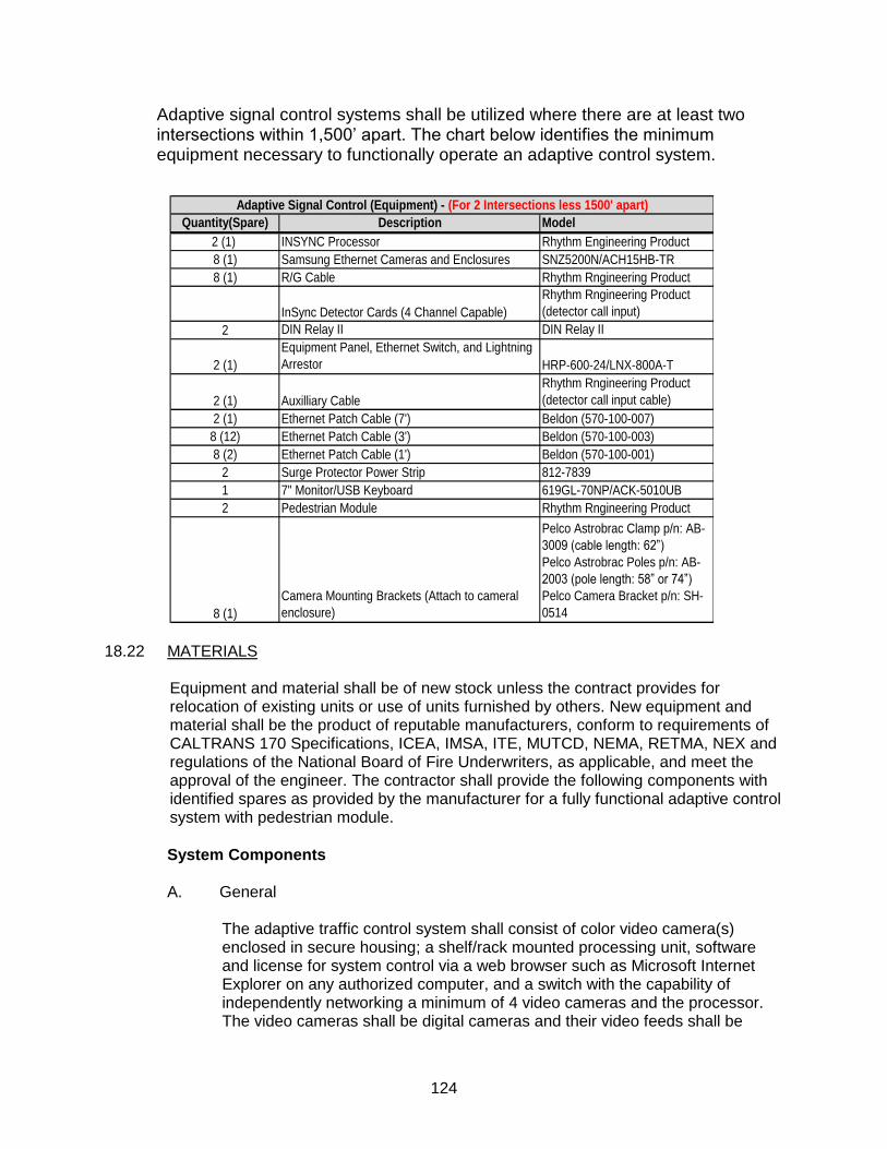
124
Adaptive signal control systems shall be utilized where there are at least two intersections within 1,500’ apart. The chart below identifies the minimum equipment necessary to functionally operate an adaptive control system.
Quantity(Spare) Description Model
2 (1) INSYNC Processor Rhythm Engineering Product
8 (1) Samsung Ethernet Cameras and Enclosures SNZ5200N/ACH15HB-TR
8 (1) R/G Cable Rhythm Rngineering Product
InSync Detector Cards (4 Channel Capable)
Rhythm Rngineering Product
(detector call input)
2 DIN Relay II DIN Relay II
2 (1)
Equipment Panel, Ethernet Switch, and Lightning
Arrestor HRP-600-24/LNX-800A-T
2 (1) Auxilliary Cable
Rhythm Rngineering Product
(detector call input cable)
2 (1) Ethernet Patch Cable (7') Beldon (570-100-007)
8 (12) Ethernet Patch Cable (3') Beldon (570-100-003)
8 (2) Ethernet Patch Cable (1') Beldon (570-100-001)
2 Surge Protector Power Strip 812-7839
1 7" Monitor/USB Keyboard 619GL-70NP/ACK-5010UB
2 Pedestrian Module Rhythm Rngineering Product
8 (1)
Camera Mounting Brackets (Attach to cameral
enclosure)
Pelco Astrobrac Clamp p/n: AB-
3009 (cable length: 62”)
Pelco Astrobrac Poles p/n: AB-
2003 (pole length: 58” or 74”)
Pelco Camera Bracket p/n: SH-
0514
Adaptive Signal Control (Equipment) - (For 2 Intersections less 1500' apart)
18.22 MATERIALS
Equipment and material shall be of new stock unless the contract provides for relocation of existing units or use of units furnished by others. New equipment and material shall be the product of reputable manufacturers, conform to requirements of CALTRANS 170 Specifications, ICEA, IMSA, ITE, MUTCD, NEMA, RETMA, NEX and regulations of the National Board of Fire Underwriters, as applicable, and meet the approval of the engineer. The contractor shall provide the following components with identified spares as provided by the manufacturer for a fully functional adaptive control system with pedestrian module.
System Components A. General
The adaptive traffic control system shall consist of color video camera(s) enclosed in secure housing; a shelf/rack mounted processing unit, software and license for system control via a web browser such as Microsoft Internet Explorer on any authorized computer, and a switch with the capability of independently networking a minimum of 4 video cameras and the processor. The video cameras shall be digital cameras and their video feeds shall be
125
available over standard Internet Protocol (IP) connection in Motion JPEG and MPEG 4 formats using the latest IP technology. All camera views shall be obtainable simultaneously without cable swaps. The system shall be capable of
displaying post‐processed video on a web browser such as Microsoft Internet
Explorer. The engineer shall have the option to view one camera at a time, all cameras at an intersection, or some or all of the cameras along an arterial on a single browser window.
B. Detection System Data Access
The video detection system shall be programmable via a web browser using the same IP network connection that delivers the video camera output and thus allowing the engineer to have complete control of the system without being physically present at the intersection. It shall provide still image and real time detection displays in color video to a remote computer using a web browser
such as Microsoft Internet Explorer. The system shall collect real‐time traffic
data such as vehicle counts, stop delay and level of service. Real‐time and
historical statistical information should be available to the engineer in graphical and/or tabular form as and when required.
C. System Software The system shall include software that detects vehicles in multiple lanes using only the video image. The software should automatically account for changes in scene including but not limited to lighting conditions or adverse weather. The engineer would have the dual benefit of defining detection zones via a web interface accessible from any regular computer with an IP network connection or using a computer physically connected to the network (which may include a laptop computer). A minimum of 12 detection zones per camera shall be available. The detections zones should be capable of counting multiple vehicles within a single detection zone. The system software should communicate to an existing signal controller passively, allowing the signal controller to still handle emergency pre-empts. The software shall determine
and display real‐time queue lengths along each approach.
Processing Unit
A. General
The PU may be rack or shelf mounted and shall be modular in design. It shall support on-site configuration using a USB keyboard and VGA monitor, or remote configuration over an IP Network. It shall support on-site backup to/restore from a USB Memory Stick for rapid replacement. The PU shall contain at least 4 USB ports to allow simultaneous connection of keyboard/mouse and storage devices.
B. Communications
Communications from the PU to any computer shall be through RJ45 (8P8C) connector over a regular IP network connection at the installation location or over a network. The computer shall have the capability to download detection
126
data as well as the real‐time detection information needed to show detector
actuations. The user shall also have the capability of connecting directly to the
detection cameras over the IP network and display post‐processed and
pre‐processed color video in the MPEG 4 and MJPEG format.
C. Compatability with NEMA Standards
The PU shall be available with NEMA TS1/TS2 detector interface. Output levels shall be compatible with the NEMA TS1 and NEMA TS2 Type 2 standards.
D. Historical Split Information
The PU shall store historical split information and shall compute and deploy optimized signal splits based on historical split information when the system goes into fog mode or emergency mode.
E. Free Mode Controller Operations
The PU shall input optimized detector calls into a controller that is running in free mode.
F. Suspension of Inputs When Needed
The PU shall suspend, for the necessary time, its inputs to a controller when calls of a higher priority are put in to the controller by pedestrians, preemption
vehicles or the pre‐determined parameters set by traffic officials.
G. Transmission of Information to other Intersections
The PU shall automatically send all necessary information to processors at adjacent upstream and downstream intersections in order to facilitate the optimization of traffic flow along an arterial.
H. Optimization of Traffic Flow
The PU shall optimize the flow of traffic at both intersections and arterials based on the possible states of traffic rather than required splits, cycles and offsets.
I. Pedestrian Calls
The PU shall incorporate the optional capability to include pedestrian calls in the optimization algorithms.
J. Time Clock Synchronization
The PU shall keep accurate time using a mechanism that synchronizes the clocks at least weekly.
127
K. Time of Day Operation
The PU shall be capable of functioning in a detector mode or adaptive mode selectable by time of day and day of week.
Video Detection (for Adaptive Control)
A. Video Detection General
The video detection system shall provide flexible detection zone and/or count sensor placement anywhere and at any orientation within the combined field of view of the image processors. Preferred presence detector zone configurations shall be a box or polygons across lanes of traffic placed parallel with lanes of traffic. A single detector zone shall be able to replace multiple conventional detector loops. Detection zones shall be capable of overlapping. Detection zones shall detect multiple vehicles within a single detection zone.
B. Detection Zones
The detection zones shall be created by using a pointing device and a graphical user interface (GUI) displayed on any computer connected directly to the PU or a GUI available to any authorized remote terminal over IP network connection. It shall be possible to add, edit or remove previously defined
detector configurations to fine‐tune detection zone placement.
C. Detection System Outputs
When a vehicle is detected by crossing a detection zone, there shall be a visual change on the video display, such as a change in color or intensity , thereby verifying proper operation of the detection system. The system shall
compute and display real‐time queue information per lane. The system shall
compute and store traffic volumes, stopped time delay, and Level of Service per phase and display such information on demand over an Internet Browser.
D. Detection System Performance Standards
Overall performance of the video detection system shall be comparable to inductive loops. Using camera, optics and in the absence of occlusion, the system shall be able to detect vehicle presence with 95% accuracy under normal (day and night) conditions and with only a slight deterioration in performance under adverse (fog, snow, rain) conditions. During extremely adverse conditions or camera failures the system shall default to emergency mode or fog mode. The processor shall store historical split information and shall compute and deploy optimized signal splits based on historical split information when the system goes into fog mode or emergency mode.
E. Cameral Operation
The camera shall automatically function in a special mode at night and the processor shall utilize such images and conduct image processing after
128
filtering out a high degree of reflected and ambient lighting. The PU shall change image parameters such as sharpness and contrast based on the lighting conditions.
F. Cameral Notification
The system shall be able to automatically generate notifications to one or more email addresses when a camera has failed or the view is obstructed (e.g. fog or ice).
Video Camera and Housing (For Adaptive Control) A. Video Camera
The PU supplier shall furnish the video camera for traffic detection. The camera shall produce a usable color video image of vehicles under normal roadway lighting conditions regardless of time of day. Usable video in color shall be produced for scenes with a minimum luminance of 0.65 lux at aperture
f‐value 1.0.
B. Camera System Sensing and Video Stream
The camera system shall use a CCD sensing element and shall deliver MJPEG and MPEG 4 video streams simultaneously.
C. Camera Lens and Control
The camera shall include an electronic shutter or auto iris control based upon average scene luminance and shall be equipped with an auto iris lens.
D. Camera Focal Length
The camera shall have a variable focal length. The maximum aperture of the lens shall not be smaller than f1.8 and the minimum aperture shall not be larger than f360.
E. Camera Environmental Parameters
The camera shall be able to operate under harsh environmental conditions, including temperatures -30F (-34C) to 165F (74C), heavy rain, and ice. The enclosure shall allow the camera to be adjusted in the field during installation.
F. Camera Enclosure
The enclosure shall be equipped with a sun shield that prevents sunlight from directly entering the lens. The sun shield shall include a provision for water diversion to prevent water from flowing in the camera field of view.
G. Camera System Access
129
The camera system shall be Ethernet‐centric. The system shall be capable of
delivering MPEG‐4 and MJPEG video to the switch in the cabinet. The user
shall be able to access the camera directly over the network and configure the camera parameters using a standard Internet Browser.
Cable
A. Ethernet Cable
Any Ethernet cable run outside of the traffic cabinet shall be environmentally hardened, shielded, outdoor rated 350 MHz Category 6 cable. The cable shall be riser rated, 24 AWG solid copper, have Polyolefin insulation, UV and oil resistant PVC jacket. Pair 1 shall be Blue, White/Blue, Pair 2 shall be Orange, White/Orange, Pair 3 shall be Green, White/Green and Pair 4 shall be Brown,
White/Brown. The operating temperature shall be from ‐40° C to +70° C. The
cable shall conform to the following standards: ISO/IEC 11801 Category 5e,
NEMA WC 63, and ANSI/TIA/EIA 568‐B.2 Category 5e. The cable shall be
without splicing or joints for any single run. The contractor shall obtain instructions from the manufacturer about alternate architecture when length of a single run of CAT 5e cable exceeds 320 feet.
B. RJ-45
The RJ‐45 plug connectors shall be used at both the camera and cabinet ends.
The supplier of the video detection systems shall approve the Category 5
cable, RJ‐45 connector and crimping tool and the manufacturer’s instructions
must be followed to insure proper connection.
C. Power Cable
Power cable shall be 14 AWG three‐conductor cable. This cable shall comply
with the requirements of IMSA Specification 19‐1.
Adaptive Traffic Signal Control A. Adaptive Control General
The adaptive traffic control module shall be contained within the PU. The PU shall communicate with neighboring PUs over an IP network. The PUs shall communicate information such as the green and red status of signal, queue lengths, and traffic volumes in real time. Based on such information received from adjacent signals and local traffic data, the PU shall optimize the phasing sequence, duration, and initiation of movements in order to optimize traffic flow on arterials as well as arterial networks.
B. Optimization of Green Time Allocation
The adaptive traffic control shall not use common cycle lengths but use principles of robotics and artificial intelligence to optimize traffic flow. The optimization shall be real time using principles of finite state changing machine

130
and shall not involve switching between cycle lengths. The system shall not be
in transition at any time but shall respond to real‐time inputs with changing of
states. Guaranteed arterial progression shall be created using dynamic green bands. Non-arterial traffic at each intersection shall be served adequately without interfering with the green bands.
C. Configuration of Signal Control
The supplier’s engineers shall configure the adaptive traffic signal control system for optimal operation of the arterial or arterial network. Traffic flow and anomalous traffic conditions shall be programmed into the adaptive traffic signal control system.
D. Configuration via IP Network
The parameters for the adaptive traffic signal control shall be capable of being configured remotely over the IP network. Parameters are adjustable via a web browser capable of running Java, such as Internet Explorer. The software shall also display traffic signal green status and up to 48 camera views. All configuration information shall be stored in easily backed-up and humanly readable XML files.
E. Monitoring of Arterial
The system shall allow monitoring via a web browser such as Microsoft Internet Explorer on any authorized computer. Custom authorization levels must be supported, allowing users to view pre- or post-processed video, traffic counts and statistics, and to remotely control the intersection. Each authorization level will allow access to one or more of these capabilities.
It shall be possible to view a single camera, multiple cameras from a single intersection, or multiple cameras from multiple intersections. This system must be capable of displaying these views even under limited network bandwidth. It must be possible to format these views to support different size viewing screens.
It shall also be possible to use the web browser to view the status of the system over a geographic map of the area. The user must be able to pan and zoom around the map display, and it must allow access to the intersection configuration, camera views, the real-time green/amber/red status of the signals, and information about the historical performance of each phase at each intersection.
F. Self Monitoring of Arterial
The system shall be able to automatically generate notifications to one or more email addresses when it detects disruption of the communications network, failure of PUs, intersections going into flash, or other such events that would impact the operation of the arterial.
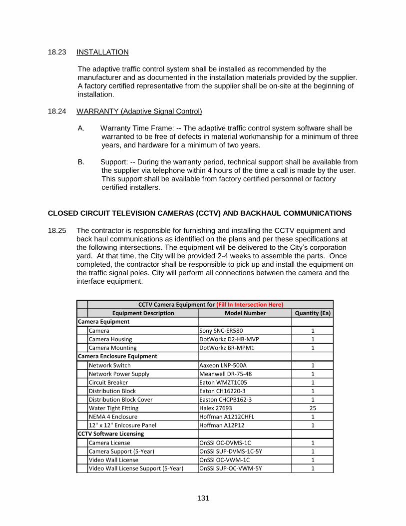
131
18.23 INSTALLATION
The adaptive traffic control system shall be installed as recommended by the manufacturer and as documented in the installation materials provided by the supplier. A factory certified representative from the supplier shall be on-site at the beginning of installation.
18.24 WARRANTY (Adaptive Signal Control)
A. Warranty Time Frame: -- The adaptive traffic control system software shall be warranted to be free of defects in material workmanship for a minimum of three years, and hardware for a minimum of two years.
B. Support: -- During the warranty period, technical support shall be available from
the supplier via telephone within 4 hours of the time a call is made by the user. This support shall be available from factory certified personnel or factory certified installers.
CLOSED CIRCUIT TELEVISION CAMERAS (CCTV) AND BACKHAUL COMMUNICATIONS
18.25 The contractor is responsible for furnishing and installing the CCTV equipment and
back haul communications as identified on the plans and per these specifications at the following intersections. The equipment will be delivered to the City’s corporation yard. At that time, the City will be provided 2-4 weeks to assemble the parts. Once completed, the contractor shall be responsible to pick up and install the equipment on the traffic signal poles. City will perform all connections between the camera and the interface equipment.
Equipment Description Model Number Quantity (Ea)
Camera Equipment
Camera Sony SNC-ER580 1
Camera Housing DotWorkz D2-HB-MVP 1
Camera Mounting DotWorkz BR-MPM1 1
Camera Enclosure Equipment
Network Switch Aaxeon LNP-500A 1
Network Power Supply Meanwell DR-75-48 1
Circuit Breaker Eaton WMZT1C05 1
Distribution Block Eaton CH16220-3 1
Distribution Block Cover Easton CHCPB162-3 1
Water Tight Fitting Halex 27693 25
NEMA 4 Enclosure Hoffman A1212CHFL 1
12" x 12" Enlcosure Panel Hoffman A12P12 1
CCTV Software Licensing
Camera License OnSSI OC-DVMS-1C 1
Camera Support (5-Year) OnSSI SUP-DVMS-1C-5Y 1
Video Wall License OnSSI OC-VWM-1C 1
Video Wall License Support (5-Year) OnSSI SUP-OC-VWM-5Y 1
CCTV Camera Equipment for (Fill In Intersection Here)
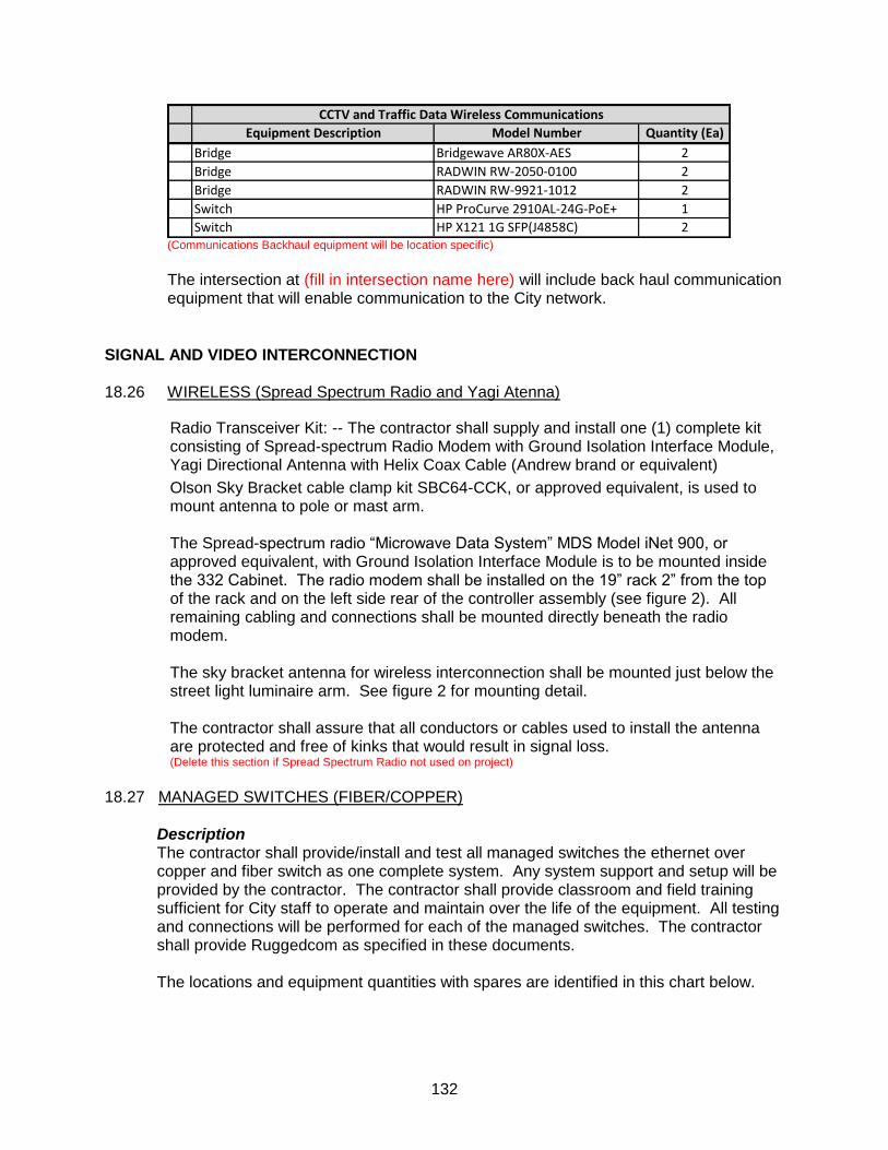
132
Equipment Description Model Number Quantity (Ea)
Bridge Bridgewave AR80X-AES 2
Bridge RADWIN RW-2050-0100 2
Bridge RADWIN RW-9921-1012 2
Switch HP ProCurve 2910AL-24G-PoE+ 1
Switch HP X121 1G SFP(J4858C) 2
CCTV and Traffic Data Wireless Communications
(Communications Backhaul equipment will be location specific)
The intersection at (fill in intersection name here) will include back haul communication equipment that will enable communication to the City network.
SIGNAL AND VIDEO INTERCONNECTION 18.26 WIRELESS (Spread Spectrum Radio and Yagi Atenna)
Radio Transceiver Kit: -- The contractor shall supply and install one (1) complete kit consisting of Spread-spectrum Radio Modem with Ground Isolation Interface Module, Yagi Directional Antenna with Helix Coax Cable (Andrew brand or equivalent)
Olson Sky Bracket cable clamp kit SBC64-CCK, or approved equivalent, is used to mount antenna to pole or mast arm. The Spread-spectrum radio “Microwave Data System” MDS Model iNet 900, or approved equivalent, with Ground Isolation Interface Module is to be mounted inside the 332 Cabinet. The radio modem shall be installed on the 19” rack 2” from the top of the rack and on the left side rear of the controller assembly (see figure 2). All remaining cabling and connections shall be mounted directly beneath the radio modem. The sky bracket antenna for wireless interconnection shall be mounted just below the street light luminaire arm. See figure 2 for mounting detail. The contractor shall assure that all conductors or cables used to install the antenna are protected and free of kinks that would result in signal loss. (Delete this section if Spread Spectrum Radio not used on project)
18.27 MANAGED SWITCHES (FIBER/COPPER)
Description The contractor shall provide/install and test all managed switches the ethernet over copper and fiber switch as one complete system. Any system support and setup will be provided by the contractor. The contractor shall provide classroom and field training sufficient for City staff to operate and maintain over the life of the equipment. All testing and connections will be performed for each of the managed switches. The contractor shall provide Ruggedcom as specified in these documents. The locations and equipment quantities with spares are identified in this chart below.
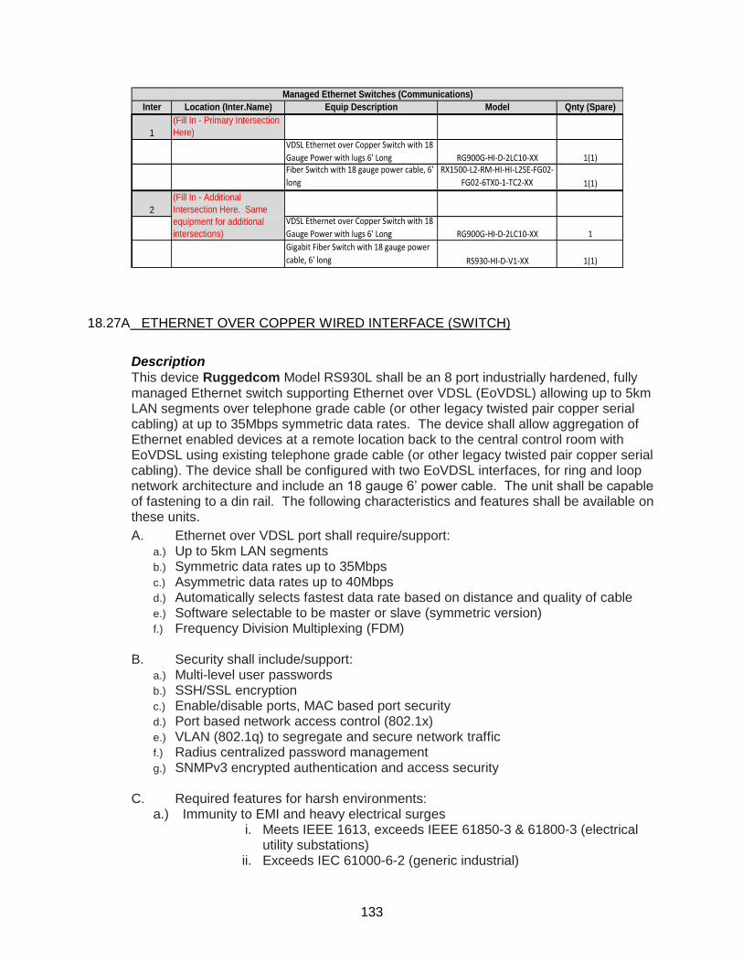
133
Inter Location (Inter.Name) Equip Description Model Qnty (Spare)
1
(Fill In - Primary Intersection
Here)
VDSL Ethernet over Copper Switch with 18
Gauge Power with lugs 6' Long RG900G-HI-D-2LC10-XX 1(1)Fiber Switch with 18 gauge power cable, 6'
long
RX1500-L2-RM-HI-HI-L2SE-FG02-
FG02-6TX0-1-TC2-XX 1(1)
2VDSL Ethernet over Copper Switch with 18
Gauge Power with lugs 6' Long RG900G-HI-D-2LC10-XX 1
Gigabit Fiber Switch with 18 gauge power
cable, 6' long RS930-HI-D-V1-XX 1(1)
Managed Ethernet Switches (Communications)
(Fill In - Additional
Intersection Here. Same
equipment for additional
intersections)
18.27A ETHERNET OVER COPPER WIRED INTERFACE (SWITCH)
Description
This device Ruggedcom Model RS930L shall be an 8 port industrially hardened, fully managed Ethernet switch supporting Ethernet over VDSL (EoVDSL) allowing up to 5km LAN segments over telephone grade cable (or other legacy twisted pair copper serial cabling) at up to 35Mbps symmetric data rates. The device shall allow aggregation of Ethernet enabled devices at a remote location back to the central control room with EoVDSL using existing telephone grade cable (or other legacy twisted pair copper serial cabling). The device shall be configured with two EoVDSL interfaces, for ring and loop network architecture and include an 18 gauge 6’ power cable. The unit shall be capable of fastening to a din rail. The following characteristics and features shall be available on these units.
A. Ethernet over VDSL port shall require/support: a.) Up to 5km LAN segments b.) Symmetric data rates up to 35Mbps c.) Asymmetric data rates up to 40Mbps d.) Automatically selects fastest data rate based on distance and quality of cable e.) Software selectable to be master or slave (symmetric version) f.) Frequency Division Multiplexing (FDM)
B. Security shall include/support:
a.) Multi-level user passwords b.) SSH/SSL encryption c.) Enable/disable ports, MAC based port security d.) Port based network access control (802.1x) e.) VLAN (802.1q) to segregate and secure network traffic f.) Radius centralized password management g.) SNMPv3 encrypted authentication and access security
C. Required features for harsh environments:.
a.) Immunity to EMI and heavy electrical surges i. Meets IEEE 1613, exceeds IEEE 61850-3 & 61800-3 (electrical
utility substations) ii. Exceeds IEC 61000-6-2 (generic industrial)
134
iii. Exceeds NEMA TS-2 (traffic control equipment) b.) .-40 to +85°C operating temperature (no fans) c.) The unit shall contain no fans or moving parts d.) The enclosure shall be constructed of 20 AWG galvanized steel e.) DIN rail mountable
D. Operating system required items:
a.) The plug and play operation shall include automatic learning, negotiation, and crossover detection
b.) RSTP (802.1D-2004) and Enhanced Rapid Spanning Tree (eRSTP) network fault recovery (<5ms)
c.) Quality of Service (802.1p) for real-time traffic d.) VLAN (802.1q) with double tagging and GVRP support e.) Link aggregation (802.3ad) f.) IGMP Snooping for multicast filtering g.) Port Rate Limiting and Broadcast Storm Limiting h.) Port configuration, status, statistics, mirroring, security i.) Loss of link management on fiber ports j.) SNTP time synchronization (client and server)
E. Power supply requirements: The unit shall contain a fully integrated power supply, with no external adaptor and these parameters a.) Power Consumption: 10W MAX a. Voltage shall be HI Voltage AC/DC: 88-300VDC, 85-264VAC, 0.1A b.) Include terminal blocks c.) CSA/UL 60950 safety approved to +85°C
F. Physical required features:
The width x height x depth shall be 7.3” x 2.6" x 5.0” with a weight of 2.7 pounds, IP 40 ingress protection, an enclosure made up of a minimum of 20AWG steel enclosure and installation through the use of din rail.
G. Switch required properties:
a.) Switching method: Store & Forward
b.) Switching latency: 8 us (100Mbps) c.) Switching bandwidth: 1.8Gbps d.) MAC address table size: 16kbytes e.) Priority Queues: 4 f.) Frame buffer memory: 1 Mbit g.) VLANs: 64 h.) IGMP and static multicast groups: 256 i.) Port rate limiting: 128kbps, 256, 512, 4, 8Mbps j.) No head of line blocking
H. Industry required approvals:
a.) .ISO: Designed and manufactured using a ISO9001: 2000 certified quality program b.) CE Marking c.) .Emissions: FCC Part 15 (Class A), EN55022 (CISPR22 Class A) d.). Safety: cCSAus (Compliant with CSA C22.2 No. 60950, UL 60950, EN60950) e.) .Laser Eye Safety (FDA/CDRH): Complies with 21 CFR Chapter1, Subchapter J.
I. Required technical specifications:
a.) Network Management must include.ROSVue HTTP graphical web-based, SNMP v1, v2c (v3), Telnet (VT100) and Command Line Interface (CLI)
135
b.) IEEE Compliance shall include 802.3-10BaseT, 802.3u-100BaseTX, 100BaseFX,.802.3x-Flow Control, 802.3z-1000BaseLX,.802.3ab-1000BaseTX, 802.3ad-Link Aggregation, 802.1D-MAC Bridges, 802.1D-Spanning Tree Protocol, 802.1p-Class of Service, 802.1q-VLAN Tagging, 802.1D-2004 -Rapid Spanning Tree Protocol, and 802.1x-Port Based Network Access Control
c.) IETF RFC Compliance shall include RFC768-UDP, RFC783-TFTP, RFC791-IP, RFC792-ICMP,.RFC793-TCP, RFC826-ARP, RFC854-Telnet, RFC894-IP over Ethernet, RFC1112-IGMP (v1), RFC1519-CIDR, RFC1541-DHCP (client), .RFC2030-SNTP, RFC2068-HTTP, RFC2236-IGMP (v2), RFC2284-EAP, RFC2475-Differentiated Services, RFC2865-Radius, RFC3414-SNMPv3-USM, and RFC3415-SNMPv3-VACM
IETF SNMP MIBS shall include RFC1493-BRIDGE-MIB, RFC1907-SNMPv2-MIB, RFC2012-TCP-MIB, RFC2013-UDP-MIB, RFC2578-SNMPv2-SMI, RFC2579-SNMPv2-TC, RFC2819-RMON-MIB, RFC2863-IF-MIB, draft-ietf-bridge-rstpmib-03-BRIDGE-MIB, draft-ietf-bridge-bridgemib-smiv2-03-RSTP-MIB, and IANAifType-MIB
J. Required warranty:
.5 Years - Applicable to design or manufacturing related product defects
Installation The contractor shall be responsible for installing the equipment on the din rail to the back of the cabinet with connections facing the back door. City staff will provide location guidance within the cabinet. The contractor shall also terminate all the copper pairs neatly to the switch to the back of the 332 cabinet. The contractor will then adjust settings and perform any setup routine necessary for the operation of the switch.
18.28 FIBER (SWITCH)
Description
The fiber Ethernet switch, Ruggedcom Model RS900G shall include two fiber optic gigabit Ethernet ports (1000BaseLX) and 8 fast Ethernet ports (10/100BaseTX). The fiber ports shall be supplied with square/subscriber connector (SC) types. The managed Ethernet Switch with fiber optic uplinks and environmentally hardened Ethernet switch, herein referred to as a ‘switch’ shall be compliant with IEEE 802.3 (10Mbps) and IEEE 802.3u (100Mbps).
A. Required operating environment shall consist of an ambient temperature range
of -40C to +85C without the use of internal or external cooling fans in accordance with IEC 60068-2-1 and 60068-2-2. The switch shall be capable of operating
properly in relative humidity conditions of 95% non-condensing at 55C in accordance with IEC 60068-2-30. The switch shall meet the environmental requirements of traffic control equipment in accordance with NEMA TS 2 (1998), Section 2: Environmental Requirements. The manufacturer shall provide evidence of independent testing verifying that performance. In general, the switch shall comply with the environmental requirements outlined in Environmental Requirements – Table in this section. The switch shall be capable of operating properly when exposed to radiated electric fields of up to 10V/m continuously and magnetic fields of up to 40A/m continuously. In general, the switch shall comply
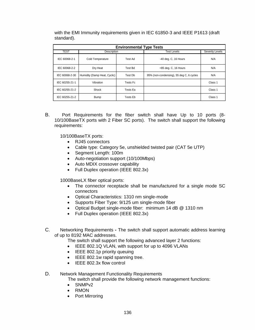
136
with the EMI Immunity requirements given in IEC 61850-3 and IEEE P1613 (draft standard).
B. Port Requirements for the fiber switch shall have Up to 10 ports (8- 10/100BaseTX ports with 2 Fiber SC ports). The switch shall support the following requirements:
10/100BaseTX ports:
RJ45 connectors
Cable type: Category 5e, unshielded twisted pair (CAT 5e UTP)
Segment Length: 100m
Auto-negotiation support (10/100Mbps)
Auto MDIX crossover capability
Full Duplex operation (IEEE 802.3x) 1000BaseLX fiber optical ports:
The connector receptacle shall be manufactured for a single mode SC connectors
Optical Characteristics: 1310 nm single-mode
Supports Fiber Type: 9/125 um single-mode fiber
Optical Budget single-mode fiber: minimum 14 dB @ 1310 nm
Full Duplex operation (IEEE 802.3x)
C. Networking Requirements - The switch shall support automatic address learning of up to 8192 MAC addresses.
The switch shall support the following advanced layer 2 functions:
IEEE 802.1Q VLAN, with support for up to 4096 VLANs
IEEE 802.1p priority queuing
IEEE 802.1w rapid spanning tree.
IEEE 802.3x flow control
D. Network Management Functionality Requirements The switch shall provide the following network management functions:
SNMPv2
RMON
Port Mirroring
TEST Test Levels Severity Levels
Class 1
Class 1
Class 1
Test Bd +85 deg. C, 16 Hours N/A
IEC 60068-2-30 Humidity (Damp Heat, Cyclic) Test Db 95% (non-condensing), 55 deg C, 6 cycles N/A
IEC 60068-2-2 Dry Heat
IEC 60255-21-2 Bump Tests Eb
IEC 60255-21-1 Vibration Tests Fc
IEC 60255-21-2 Shock Tests Ea
Description
IEC 60068-2-1 Cold Temperature Test Ad -40 deg. C, 16 Hours N/A
Environmental Type Tests

137
Spanning Tree
Rapid Spanning Tree (IEEE 802.1w)
Enhanced Rapid Spanning Tree (eRSTP™) network fault recovery (<5ms)
F. Required security functions
The switch shall provide the following security features:
Multi-level user passwords
SSH/SSL (128-bit encryption)
Enable/disable ports, MAC based port security
Port based network access control (802.1x)
VLAN (802.1Q) to segregate and secure network traffic
RADIUS centralized password management
SNMPv3 authentication and 56-bit encryption G. Requirements for harsh environments
The switch shall provide the features for the outdoor/harsh environment:
Immunity to EMI and heavy electrical surges
Meets IEEE 1613 class 1 (electric utility substations)
Exceeds IEC 61850-3 (electric utility substations)
Exceeds IEC 61800-3 (variable speed drive systems)
Exceeds IEC 61000-6-2 (generic industrial)
Exceeds NEMA TS-2 (traffic control equipment)
Hazardous Location Certification: Class 1 Division 2
-40°C to +85°C operating temperature (no fans or moving parts)
Conformal coated printed circuit boards (optional) H. Required programmable critical failure relay - The switch shall provide a
programmable critical failure out relay that may be configured to activate upon critical error detection such as loss of link or detection of critical system errors. This function shall be user enabled and programmable. The output contacts shall be available in a Form-C configuration and be capable of switching at least 30Vdc @ 2A.
I. Required power supply requirements
The switch shall provide the following power supply requirements and options
Fully integrated power supply
Universal high-voltage range: 88-300VDC or 85-264VAC
Dual low-voltage DC inputs: 24VDC (10-36VDC) or 48VDC (36-72VDC)
Terminal blocks for reliable maintenance free connections
CSA/UL 60950 safety approved to +85°C The switch shall require no more than 10W of power.
J. Mounting Requirements
The switch shall provide options for DIN Rail mounting or panel mounting via brackets
138
K. Safety Requirements - The switch shall comply with the following electrical safety requirements or equivalents: UL60950 or CSA C22.2 No. 60950 (safety requirements for IT equipment). The switch shall also have CE (Europe) qualification. The switch shall also comply with FCC Part15 Class A for EMI emissions.
L. Warranty: The Switch shall be warranted for defects in material and workmanship for five
(5) years
Installation The contractor shall be responsible for installing the equipment on din rail to the back of the cabinet with fiber modules on the switch facing the back door. City staff will provide location guidance within the cabinet. The contractor shall also terminate all the fibers neatly to the switch to the back of the 332 cabinet only after end to end fiber testing has been accomplished. The contractor will then adjust settings and perform any setup routine necessary for the operation of the switch.
18.28A FIBER SWITCH (MODULAR AND FIELD REPLACEABLE PORTS)
General
The contractor shall supply Ruggedcom model RX1500 (1U) 19” rack mounted industrially hardened, fully managed, modular layer 2 gigabit ethernet switch. It shall operate in electrically harsh and climatically demanding utility substation and industrial environments as demonstrated below. The unit shall be available in WAN, serial, and ethernet. The unit shall be immune to electromagnetic interference (EMI) and heavy electrical surges often demonstrated in harsh environments. The unit shall operate at a temperature range of -40 to +85 degree centrigrade. The unit shall be for single mode fiber optic. The unit shall adhere to the requirements below:
A. Required Security functions:
a.) Multi-level passwords b.) SSH/SSL encryption capability c.) Prt based network access control (802.1x) d.) VLAN (802.1Q) allowing segregation and securing network traffic. e.) RADIUS centralize password management f.) SNMPv3 encrypted authentication and access security
B. Requirement for harsh environments
a.) Immune to EMI and high voltage electrical transient voltages a. Meets IEEE 1613 (electrical utility substations) b. Exceeds IEC 61850-3 (electrical utility substations) c. Exceeds IEC 61800-3 (variable speed drive systems) d. Exceeds IEC 61000-6-2 (generic industrial environment) e. Exceeds NEMA TS-2 (traffic control equipment)
b.) Operating temperature between -40 degrees Celsius to +80 degree Celsius c.) Failsafe Output Relay for critical failure or error alarming
C. Physical Port Requirements
139
a.) Four hot swappable field replaceable modules b.) Two redundant hot swappable power supplies c.) Four 1000LX Singlemode, 1310nm, SC Connector, 10km ports d.) Six 10/100TX RJ45 Ethernet ports e.) Two T1/E1 WAN Ports, Channelized via RJ-48
D. WAN Port optional module requirements (when specified on plans) a.) T1/E1 (channelized/unchannelized) b.) E1 75 ohm via BNC connector c.) Cellular (HSPA/EVDO) d.) DDS
E. Required serial ports (when used)
a.) Fully compliant EIA/TIA RS485, RS422, RS232 serial ports that is software selectable)-RJ45 connectors – DNP, MODBUS
b.) Raw socket mode support conversion of serial port
F. Required supported protocols a.) WAN
a. Frame Relay RFC, 1490 or RFC 1294 b. PPP RFC 1661, 1332, 1321, 1334, PAP, CHAP authentication
b.) IP a. Routing OSPF, BGP, RIPv1 and 2 b. VRRP c. Traffic control, NTP server, IP multicast routing d. DHCP agent (Option 82 capable)
G. Frame Relay Supported requirements a.) ISO and ITU complian, network certified b.) ANSI T1.617 annex D, Q.933 or LMI local signaling
H. Required management tools a.) Web based, SSH, CLI management interfaces b.) SNMP v1/v2/v3 c.) Remote syslog d.) Rich set of diagnostic including alarms and logging e.) Loopback diagnostic tests f.) Raw and interpreted real time line traces
I. Power supply requirements a.) Modular b.) Hot swappable c.) The unit shall include a fully integrated power supply. d.) Input voltage shall be of 15-72VDC, 88-300VDC, and 85-264VAC. e.) CSA/UL 60950 safety approved to +85 degrees centigrade
J. Warranty – 5 years
Installation The contractor shall be responsible for installing the equipment on the back of the cabinet with fiber modules on the switch facing the back door. City staff will provide location guidance within the cabinet. The contractor shall also terminate all the fibers
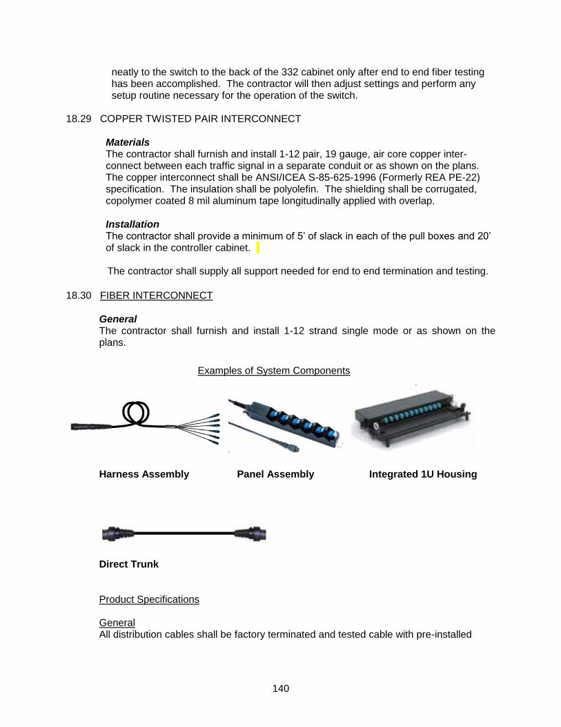
140
neatly to the switch to the back of the 332 cabinet only after end to end fiber testing has been accomplished. The contractor will then adjust settings and perform any setup routine necessary for the operation of the switch.
18.29 COPPER TWISTED PAIR INTERCONNECT
Materials The contractor shall furnish and install 1-12 pair, 19 gauge, air core copper inter-connect between each traffic signal in a separate conduit or as shown on the plans. The copper interconnect shall be ANSI/ICEA S-85-625-1996 (Formerly REA PE-22) specification. The insulation shall be polyolefin. The shielding shall be corrugated, copolymer coated 8 mil aluminum tape longitudinally applied with overlap.
Installation The contractor shall provide a minimum of 5’ of slack in each of the pull boxes and 20’ of slack in the controller cabinet. The contractor shall supply all support needed for end to end termination and testing.
18.30 FIBER INTERCONNECT
General The contractor shall furnish and install 1-12 strand single mode or as shown on the plans.
Harness Assembly Panel Assembly Integrated 1U Housing
Direct Trunk Product Specifications General All distribution cables shall be factory terminated and tested cable with pre-installed
Examples of System Components

141
tether attachment points (TAPs) at customer specified location along the length of the distribution trunk cable for quick and reliable installation. Standard optical fiber cable will pre-installed with tether attachment points at locations specified by the system design. The system trunk cable shall have the flexibility to be configured in various network topologies for both outside plant (OSP) and inside plant (ISP) environment. The system shall consist of: - Distribution Thru cable. - Tether attachment Point (TAP) which includes a factory installed molded preformed system closure (access splice) at specified length of the distribution trunk cable. - Tether assembly with pinned HMFOC connector. - Point-to-point trunk with pinned or non-pinned HMFOC Connector for network extension based on application - Harness, terminated on one end with a non-pinned HMFOC Connector and terminated on the other end, with one of the following: SC, LC, ST® Compatible, MTP® Connectors or factory terminated and sealed panel assembly HMFOC (Hardened Mult Fiber Optic Connector) The HMFOC shall be available in fiber count of 12. The HMFOC will have an 8
o angled
end face for single-mode and no angle for multi-mode and shall always mate “key up” to “key down.” The connector housings shall be keyed to ensure proper connector mating relative to the end face angle. Direct Trunk & Harness The direct trunk and harness cable assembly shall be robust in design with factory terminated connectors for superior optical performance and durability and ease of installation in all indoor or outdoor applications. These advantages directly translate into cost savings via a reduced installation time and a longer life-span (20 years) resulting in less repairs. The direct trunk shall be made with a non-pinned, MT-style, environmentally-hardened connector on both ends of the assembly. The direct harness shall be made with a non-pinned/pinned MT-style, environmentally-hardened connector on one end of the assembly, and either another non-pinned/pinned MT hardened connector, MTP, or the assembly is furcated up to 12 single-fiber connectors SC. Prior to the cable assembly being made, individual tests shall be done on both the cable and the connectors. The cable itself shall be designed to and undergo Telcordia GR-20 testing, and the environmentally hardened connector shall be designed to and undergo Telcordia GR-3152 testing. The completed cable assembly shall be designed to and undergo Telcordia GR-326 testing. Distribution Cable The Distribution cable shall be made of standard loose tube cable design with 12 fibers to 144 fibers. The distribution cable shall consist of either Single mode fiber, Multimode — Standard 50/125 µm Fiber or Multimode — Laser-optimized 50/125 µm Fiber. The Tether Attachment Point (TAP) “Access Splice “shall be a factory assembly that has a 5-ft tether spliced at pre-determined location. The TAP includes the Plug & Play AnyLAN System closure, where the cable is accessed and spliced to an

142
environmentally-hardened OptiTip MT Connector tether assembly. The tether shall be a short cable section emerging from the TAP, terminated with a pinned OptiTip MT connector. Each Tether Attachment Point Shall allow up to two tethers per location and a maximum of 24 fibers. Panel Housing (no pre-attached drop cable) The housing shall be configured to accept one or two pin-less HMFOCs. The housing shall be configurable with SC connectivity. The housing shall have available configurations, a 12-fiber configuration. The 12-fiber configuration is for SC connectivity. The housing shall be configurable with 50um, and single-mode fiber and connector types. The housing shall be wall-mountable using a set of mounting ears and screws that comes with the hardware. The housing shall be compact so that it easily installed inside NEMA rated and IP-rated enclosures and other environments where space is a premium. The housing shall have nominal dimensions of 16.5cm x 15.2cm x 3.8cm (6.5in x 6.0in x 1.5in). The housing shall have a nominal weight of 0.7kg (1.5lb). The module shall satisfy various wiring standards including but not limited ISO/IEC 11801and TIA 568. The insertion loss for ISPH connectors is 0.5dB max with a reflectance of < -55 dB and <-20dB max for single-mode and multimode respectively. The insertion loss for OptiTip MT connectors is 0.62dB and 0.75dB max with a reflectance of < -65 Panel Assembly (pre-attached drop cable)
The panel assembly shall be a rugged, modular patch panel assembly with drop cable
length, an ideal solution for industrial control networks. It shall be deployed at drop
locations from the distribution trunk access point or used as a pre-installed patch panel
at each end of direct link cable. The drop cable and panel shall be available in single
tube drop outdoor cable and an indoor/outdoor drop cable.
The panel shall be mountable onto a variety of hardware devices, including swing-out
mounting brackets and wall-mount boxes and shall not require any rack space. The
maximum length of the drop cable shall be 500ft and shall be a factory-terminated
hardened multi-fiber optic connector (pinned or non-pinned) or a pigtail. The panel shall
be 12-fiber configurations and SC® Compatible Connectors Single-Mode fiber.
Manufacturer Requirements The manufacturer shall have an in-depth knowledge, and more than 10-year history, of manufacturing and supporting pre-determined direct trunk cable and measured optical fiber cabling technology. Manufacturer shall be ISO 9001 and TL 9000 registered. Due to the custom nature of the pre-engineered, pre-measured distribution cable, a single part number is incapable of capturing all of the information required to produce the cable to the specific design requirements.
Fiber Installation The contractor shall pull the 1-12 fiber (or as identified on plans), direct trunk harness into each pull box with a minimum of 12 feet of slack with connections (most commonly at the pull box adjacent to the controller cabinet) as identified on the plans. The fiber

143
will then be routed to each controller cabinet with a minimum of 20 feet of slack. The pre-determined cable shall be tested panel to panel after installation.
Contractor shall leave 20 feet of fiber optic cable slack each fiber optic pull box for each cable entering the splice enclosure (60 feet for three cables). Pull boxes shall not be installed in paved roadway surfaces. Conduits terminating in fiber optic vaults shall be brought into the box on a gradual upward sweep of up to 45 degrees. Fiber optic cable shall not be subject to any sharp bends – the cable shall never be bent to a radius smaller that 20 times the diameter of the cable or 9.5 inches. Contractor shall tag and label each fiber optic cable with City of Fairfield and location (street name) for trunkline cables and (intersection name) for drop cables. The Contractor shall make a physical survey of the project site for the purpose of establishing the exact cable routing and direct trunk/distribution cable lengths prior to the commencement of any fiber optic work or committing any fiber optic materials. The Contractor shall submit a cable routing plan that shows the locations of all HFOC joints. The fiber will not be spliced unless shown on the plans or otherwise approved by the Engineer.
The Contractor shall obtain manufacturer's handling and installation recommendation instructions. Instructions shall be provided with each reel in a weatherproof envelope attached to the reel.
The Contractor shall use a ¾” pull 2,400 lb traceable pull tape with footage markings to pull the fiber optic cable into the conduit, or approved equal. coordinated to pull simultaneously in continuous pulling operation.
The fiber optic cable pull rope shall be adequately attached to the fiber optic cable using Cable Manufacture approved pulling end, Kellems Grip connector and a one hundred pound (100lb) breakaway swivel. The pulling force from the pull rope to fiber optic cable shall be transferred directly to the integrated pulling eye on the HMFOC. This assembly shall be wrapped with black electrician’s tape or equivalent to reduce the pulling friction of the pulling rope and fiber optic cable connection.
Splicing and Connectorizing: Will not be necessary with the predetermined fiber connections.
To log the fiber routes, terminations, the Contractor shall use a series of numbers and letters to describe the cable, tube, fiber and location of the termination or splice. The following naming convention shall be used as a guide to developing your documentation:
Intersection Name - Sequential # Segment Name-# Strands Buffer Tube Color-Strand Color
Fiber Testing
144
The fiber optic cable shall be meet the maximum acceptable loss in accordance to the TIA-standards. For this cable a maximum 1.5 dB of connection loss (0.75 dB for each connection) plus 0.3 dB of splice loss and 0.1 dB of fiber loss (1 dB / km).
Test results shall be furnished to the City in a neatly bound, printed format. Electronic submittal to the Engineer on floppy disk or compact disc (CD) shall also be required. The results shall include the software for the City to review and work with the traces. The Contractor shall be responsible for formulating and developing test procedures and forms for approval by the City in conformance with ANSI/TIA/EIA 526-7 "Measurement of Optical Power Loss of Installed Single-mode Fiber Cable Plant." All tests shall be performed with light wavelengths at 1310 nm and 1550 nm. Test forms shall contain at least the following basic information: type of test performed, type of equipment used (including name and model number), results of calibration check, location of test equipment used, technician(s) performing the test, date of tests, wavelength(s) tested, cable ID reference, buffer tube color, reference reading, fiber number, direction of reading/attenuation, and any general notes or remarks the technician(s) determine to be pertinent to this process. The test forms shall include the required power level reading required in each strand of cable, based on the following equations:
For 1310 nm: Max loss = 0.35L + 0.08N + 0.5C + K For 1550 nm: Max loss = 0.25L + 0.08N + 0.5C + K; where:
L = actual optical path length in km N = number of splices in optical path C = number of connectors K = 3 dB (a constant for optical point discontinuities)
Contractor shall be responsible for installing a working cable, and providing written certification that each strand (even those that are unused or “dark”) meet specifications, prior to the project being considered complete. It is at the contractor’s discretion if pre-testing is needed. It is recommended that the Contractor consider testing the cable at three stages of the cable installation:
Once the cable has been delivered but before it has been installed
Once the trunk cable has been installed in the conduit, but before it has been spliced
A final test once all splices and connectorizations are complete.
All results shall be submitted in printed form on 8 1/2 x11 paper in a suitable binder organized by cable and strand number. Each binder shall have a cover sheet indicating which cable(s) were tested, the operator's name, the reviewer's name, the type of test performed, and the date(s) of the test. Cover sheets for the final test results shall bear the reviewer's signature, the date, and a statement indicating that the installation complies with the requirements of this section. All OTDR traces shall bear the signature or initials of the Contractor’s representative who has reviewed the traces. The Contractor shall place a check mark on all traces that satisfy the requirements identified herein. For intermediate test results, the Contractor shall highlight any discrepancies that may exist and place a post-it flag on the subject page. The page shall bear a short description of the proposed corrective action (e.g., re-splice).
145
The final ‘As-Built’ testing results shall be prepared by the Contractor and submitted to the City for its maintenance and troubleshooting activities. Three copies of the as-built data sheets shall be provided to the Engineer and shall also include the following information:
Insertion loss measurements OTDR measurements Wavelength Spectral width Equipment used (manufacturer, model number, and serial number) Direction of test
Final test: The Contractor shall connect the light source to the connectorized fiber and shall connect a power meter to the other end of the fiber. The Contractor shall turn the light source on and off at a rate of approximately once per second for three cycles. The individual observing the power meter shall record the response of the meter. The response shall be "OK" if the Contractor’s individual notes the meter responding to each of the three cycles. Any other responses, such as no cycles, less than three cycles, or more than three cycles shall require a "BAD" response. For each "BAD" response, the Contractor shall submit to the City a statement summarizing the response noted on the power meter and shall correct all "BAD" responses. After making corrections to the cable, the strobe test shall be re-conducted. A tone modulated light source may also be used, in place of the three-cycle method, to conduct this test. Continuity tests shall be performed in both directions for all fibers terminated on both ends.
BATTERY BACK-UP 18.31 BATTERY BACK-UP SYSTEM ASSEMBLY
A. The Contractor shall furnish two (2) S6 56 inch x26 inch x12 inch BBS Assemblies (by Alpha Technologies or City approved equivalent) complete with Novus FXM 1100 inverter, 106 Ah batteries, and all cabling for a fully operational unit as indicated in Section 10-3.18. The unit shall be provided on a separate pedestal. The Contractor shall install one complete BBS Assembly on the same concrete pad as the controller assembly, including furnishing and installing anchor bolts and terminated. The second complete BBS Assembly shall be delivered to the City of Fairfield Corporation Yard as a spare. The BBS cabinet shall be positioned on the concrete pad so that when all three cabinet doors (controller assembly, Type III AF Service enclosure and BBS assembly door) are opened simultaneously, there is ample space for the signal technician to perform maintenance.
Each BBS assembly shall include one (1) battery charging management system. The battery management system shall be capable of identifying failures resulting in ability to replace one battery at a time. The unit shall be capable of spreading charge voltage equally across batteries to maximize battery life and to compensate for battery differences as they age.
146
The BBS Cabinet shall be constructed of 0.125 inch aluminum, (painted to match the 332 cabinet) with stainless steel exterior hardware. The doors shall have neoprene gaskets and aluminum continuous hinge with stainless steel pin and bolts. The door shall have three-point locking system, which secures the top, center and bottom with aluminum bar door rods. It shall have a steel brush zinc plated door handle with a Corbin #2 key lock. The BBS cabinet shall have 100 CFM thermostat controlled fan inside and air vent with filter. It shall also have four adjustable shelves. Battery Power Backup System: -- The Battery Backup System shall be Novus FXM model #1100(by Alpha Technologies or approved equivalent). The contractor shall supply a Novus FXM model #1100 battery backup unit with the following minimum components:
-Inverter #1100 -Cable Assembly -(4) 105 AH batteries
A. GENERAL
This specification establishes the minimum requirements for a complete emergency battery backup system for use with Light Emitting Diode (LED) Traffic Signal Modules. The Battery Backup System (BBS) shall include, but not be contain the following nominal requirements:
1. Input/Output Voltage: 120/230VAC 2. Input/Output Frequency: 60Hz/50Hz 3. Input Current: 12.6A/6.5A 4. Output Current: 9.2A/4.8A 5. Output Power to 55 degrees F: 1100W/VA 6. Output Power to 55 to 74 degrees F: 850W/VA 7. Battery String Voltage: 48VDC
B. The BBS shall be capable of providing power for full run-time operation for an
“LED-only” intersection (all colors: red, yellow, green and pedestrian heads) for up to 6 hours.
The BBS shall be designed for outdoor applications, in accordance with the Caltrans Transportation Electrical Equipment Specifications (TEES), dated August 16, 2002, Chapter 1, Section 8 requirements. The BBS system shall be UL listed for use with traffic signal equipment.
C. BBS Requirements
The BBS shall provide a minimum six (6) hours of full run time operation for an “LED-only” intersection in addition to what is shown below:
1. Automatic Voltage Regulation

147
2. Automatic Frequency Sensing 3. Remote Monitor and control communication with standard RS232 4. Emergency power off 5. Temperature compensating battery charging 6. Variable speed fan 7. Circuit breaker protection on the input and external battery input 8. Generator ready for extended run time applications 9. Selectable battery charging temperature compensation
The general specifications shall include:
1. Input Voltage Range (120VAC) – 85-175 VAC 2. Input Voltage Range (230VAVC) – 150 to 328 VAC 3. Output Voltage Regulation – +/- 10% 4. Waveform – Pure sine wave 5. Typical Efficiency – >98% 6. Inverter Output Voltage Regulation – +/-2% 7. Typical Output Voltage – <3% 8. Transfer Time – <5ms 9. Operating Temperature – -40 to 55 degrees Celsius
10. AC Input and Output – Terminal Block with maximum 10 AWG 11. Dry Contacts – Terminal Block with maximum 16 AWG 12. RS-232 Interface – DE9/DB-9 Female 13. Ethernet Interface – Factory installed RJ-45
D. Battery Testing Equipment
Each project shall include one (1) battery testing device suitable for accurately testing the load of the batteries. It shall be capable of testing the status of standby batteries. The unit shall test for proper conductance coupled with a utility load test. The unit shall be insulated crimps with a digital readout.
E. Warranty
Manufacturers shall provide a two (2) year factory-repair warranty for parts and labor on the BBS from date of acceptance. Batteries shall be warranted for full replacement for two (2) years from date of purchase.
The warranty shall be included in the total bid price of the BBS.
148
TRAFFIC SIGNAL EQUIPMENT 18.32 TRAFFIC SIGNAL FACES AND HEADS
General: Traffic signal faces and signal heads as shown on the plans, and the installation thereof shall be 12 inch round and conform to the provisions in Section 86-4, "Traffic Signal Faces and Fittings," of the Standard Specifications and these Special Provisions. Eight (8) inch circular or arrow signal indications shall not be used.
18.33 VEHICLE SIGNALS
A. General: Signal heads shall be die-cast or permanent mold-cast aluminum conforming to the most current ANSI Standards. Structural plastic or any other type of signal head material shall not be used.
1. Signal indications shall be furnished and installed by the Contractor.
2. Signal indications shall be die cast aluminum conforming to ANSI
standards. Structural plastic signal indications are prohibited from use.
3. Signal head nipples shall be of adequate length to accommodate back plates. Signal head covers shall lock and secure, closed by means of a wing nut and thread stock fastener.
4. All red circular “BALL”, red “ARROW”, yellow circular “BALL”, yellow
“ARROW”, green circular “BALL”, and green “ARROW” indications shall consist of Light Emitting Diodes (LED). The arrow and circular indications shall meet Institute of Transportation Engineers (ITE) Vehicle Traffic Control Signal Heads (VTCSH) LED Circular Signal Supplement and provide an incandescent look.
5. The LED signal modules shall have prominent and permanent
directional marking(s)that have an “up arrow”, for correct indexing and orientation within the signal housing. The manufacturer’s name, trademark, serial number and other necessary identification shall be permanently marked on the backside of the LED signal module. A label shall be placed on the LED signal module certifying compliance to this specification. The LED signal module shall be a single, self-contained device, not requiring on-site assembly for installation into an existing traffic signal housing.
6. The minimum luminous intensity values and light output distribution shall
be as shown in Section 11.04 and Table 1 of the ITE VTCSH) Standard in Equipment and Materials Standards of the ITE
7. The maximum wattage for twelve-inch “BALL” indications shall not be
more than 22 watts and 10 watts for twelve-inch “ARROW” indications.
8. The LED signal modules shall be operationally compatible with currently used controllers and conflict monitors.
149
9. The LED signal modules shall be rated for use in the ambient operating temperature range of -40C to 74C.
10. The LED signal modules shall be dust and moisture tight to protect all
internal LED and electrical components.
11. The LED signal module will be replaced or repaired by the manufacturer if it exhibits a failure due to workmanship or material defects within the first 60 months of operation.
12. All signal heads, hardware, and back plates shall be factory powder
coated method using industry standards and shall be black. Signal hardware shall be black or hunter green.
13. Signal head mounting bracket arms shall be long enough to permit
proper alignment of signals and back-plate installation.
Prior to turn on and once the signal heads are installed, all signal indications must be covered with material designed for that purpose that specifically indicates “Out of Service”. The material shall be fabricated using cloth and be of contrasting color to the signal head.
Cardboard, plastic sheets, wood, or other field fabricated temporary cover shall not be used. Adhesive tape such as duct tape shall not be used to attach any of the covers. No holes shall be drilled or louvers used to secure the cover. The material used shall provide a central mesh of contrasting color, so that each indication can be tested from the ground. Upon acceptance of the project, the approved covers shall become property of the City.
18.34 EMERGENCY VEHICLE PREEMPTION (OPTICAL DETECTORS)
The optical detector typically mounted on poles or mast arms shall be installed per plan and compatible with existing City system. The optical detectors shall be GTT dual channel Opticom 722. The optical detectors shall be drilled out as recommended by the manufacturer to allow for moisture release.
18.35 BACK-PLATES
A. General: Back-plates shall be provided on all vehicle indications. All back-plates shall be factory powder coated black louvered one-piece.
18.36 PEDESTRIAN SIGNALS AND PUSH BUTTONS
General: Pedestrian signals shall conform to the provisions of Section 86-4.06, “Pedestrian Signal Faces,” of the State Standard Specifications, all applicable ITE specifications Pedestrian Traffic Control Signal Indications (PTCSI) and these Special Provisions. All pedestrian indications shall be countdown type.

150
A. Pedestrian signal face modules shall be designed to mount behind or replace the existing faceplate of Type “A” housing as specified by the requirements of the ITE Standards, “Pedestrian Traffic Control Signal Indications”, and the CA MUTCD.
B. The design of the modules shall require a specific mounting orientation. C. Each module shall provide an average luminous intensity of at least
3,750candela/m2 for Upraised hand and 5,300 candela/m
2 for the walking
person symbol throughout the useful life over the operating temperature range. D. The uniformity ratio of an illuminated symbol shall not exceed 4:1 between the
highest luminance area and the lowest luminance area in the module. E. The color output of the module shall conform to the requirements of the ITE:
”Pedestrian Traffic Control Signal Indications” and the CA MUTCD. The measured chromaticity coordinates of the modules shall conform to the chromaticity requirements of section 5.3.2.1 and Figure C of the VTCSH standard.
Raised Hand shall be Portland orange and shall be filled.
Walking figure shall be lunar white and shall be filled.
F. The module shall not require special tools for installation. G. The module shall fit securely into existing pedestrian signal section housings
built to the PTCSH specifications without modification to the housing. H. The pedestrian signal face shall be no less than 16” high. I. The modules shall be self-contained device not requiring on-site assembly for
installation into a Type "A" pedestrian push button housing. J. The pedestrian signal shall be capable of displaying the LED “Raised Hand”
legend and two (2) seven segment digits, constructed of dual row of LED’s, simultaneously. Four (4) additional units shall be supplied per each intersection.
K. The signal shall be configured, such that the countdown timer can start at the
end of the “Walk” portion of the pedestrian phase. L. A 1 ½ inch deep z-create type visor of 0.030 inch minimum thickness shall be
installed on all the pedestrian signal face. The visor shall be installed parallel to the face of the pedestrian message and shall be held in place with the use of stainless steel screws
Pedestrian signals shall be Type A. The assembly shall be mounted in a frame constructed of 0.04-inch minimum thickness aluminum alloy.
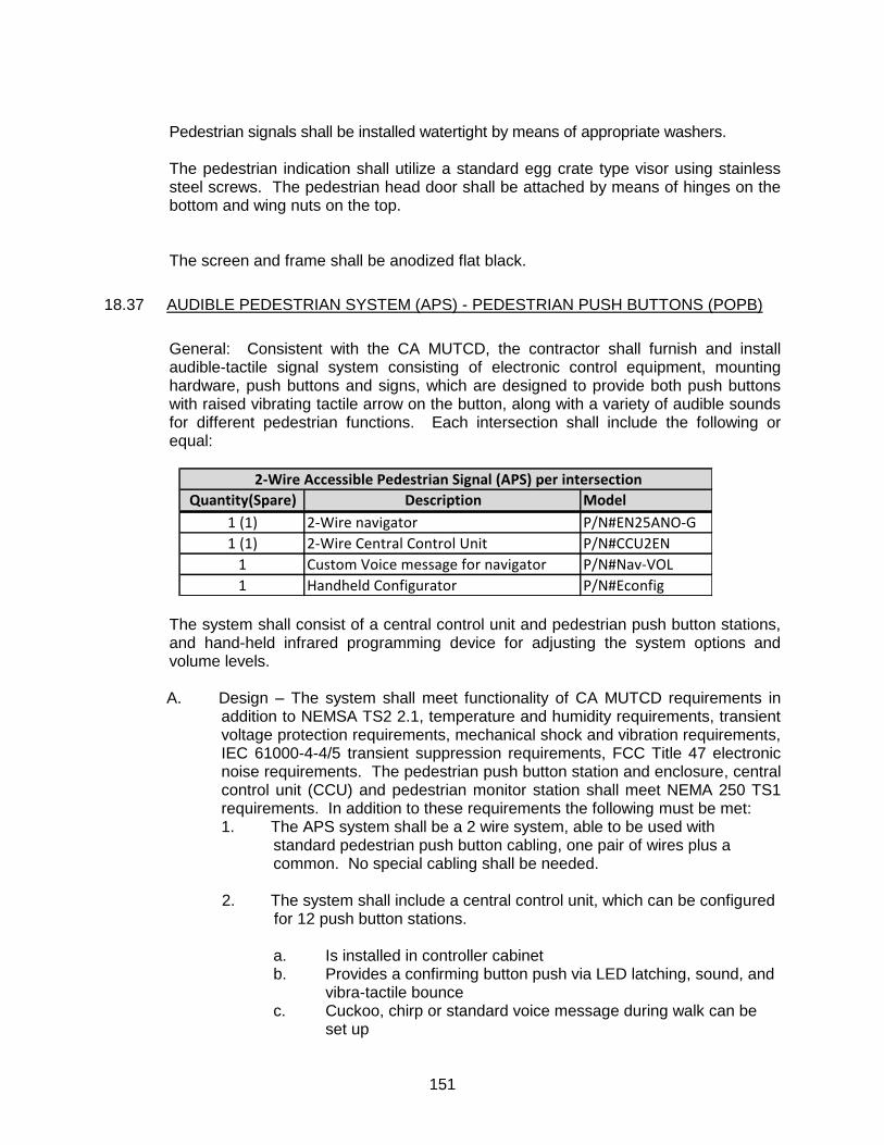
151
Pedestrian signals shall be installed watertight by means of appropriate washers. The pedestrian indication shall utilize a standard egg crate type visor using stainless steel screws. The pedestrian head door shall be attached by means of hinges on the bottom and wing nuts on the top. The screen and frame shall be anodized flat black.
18.37 AUDIBLE PEDESTRIAN SYSTEM (APS) - PEDESTRIAN PUSH BUTTONS (POPB)
General: Consistent with the CA MUTCD, the contractor shall furnish and install audible-tactile signal system consisting of electronic control equipment, mounting hardware, push buttons and signs, which are designed to provide both push buttons with raised vibrating tactile arrow on the button, along with a variety of audible sounds for different pedestrian functions. Each intersection shall include the following or equal:
Quantity(Spare) Description Model
1 (1) 2-Wire navigator P/N#EN25ANO-G
1 (1) 2-Wire Central Control Unit P/N#CCU2EN
1 Custom Voice message for navigator P/N#Nav-VOL
1 Handheld Configurator P/N#Econfig
2-Wire Accessible Pedestrian Signal (APS) per intersection
The system shall consist of a central control unit and pedestrian push button stations, and hand-held infrared programming device for adjusting the system options and volume levels.
A. Design – The system shall meet functionality of CA MUTCD requirements in addition to NEMSA TS2 2.1, temperature and humidity requirements, transient voltage protection requirements, mechanical shock and vibration requirements, IEC 61000-4-4/5 transient suppression requirements, FCC Title 47 electronic noise requirements. The pedestrian push button station and enclosure, central control unit (CCU) and pedestrian monitor station shall meet NEMA 250 TS1 requirements. In addition to these requirements the following must be met: 1. The APS system shall be a 2 wire system, able to be used with
standard pedestrian push button cabling, one pair of wires plus a common. No special cabling shall be needed.
2. The system shall include a central control unit, which can be configured for 12 push button stations.
a. Is installed in controller cabinet b. Provides a confirming button push via LED latching, sound, and
vibra-tactile bounce c. Cuckoo, chirp or standard voice message during walk can be
set up
152
d. A vibrating walk is provided e. Shall have options for a standard locating tone, custom sound,
or verbal countdown during pedestrian clearance f. Sounds shall have the ability to adjust at 60dB range g. The system shall have the ability to set minimum and maxium
sound ranges h. All sounds shall be synchronized i. An extended button push can turn on, boost volumes, and/or
mute all sounds except those on the activated crosswalk j. Special messages can be made available to the agency
i. Custom locating tone ii. Informational message iii. Custom walk sounds/message iv. Custom clearance sound v. Multiple languages vi. Street name in Braille on the sign.
k. The system shall be able to provide both vibrating arrow button and audible sounds.
l. The speaker shall be weather proof. m. A sunlight visible red LED shall latch “ON” to confirm the button
has been pushed n. The push button station shall include the entire housing, frame,
sign, ADA compliant push button, and mounting hardware. o. The housing shall be black
DETECTION
18.38 DETECTORS
Loop detectors for inductive detector loop installation shall conform to the provisions in Section 86-5, "Detectors," of the Standard Specifications and these Special Provisions.
A. Slots in asphalt concrete pavement surface shall be filled with “Hot-Melt Rubberized Asphalt Sealant” sealant per Section 86-5.01A(5), "Installation Details."
B. If an asphalt overlay is anticipated, an emulsified asphalt sealant shall be used. In
no case shall the emulsified asphalt sealant be used on the surface of the final lift of asphalt.
C. Detector loop configuration and location shall be as shown on the plans. The
front loop shall be a Type D, capable of detecting bikes. D. Loop wire shall be IMSA Type 2 and loop detector lead-in cable shall be Type B
1. The traffic loop homeruns shall be twisted then spliced to the lead in cable in the pull boxes. All Splices shall be performed in the pull box made using Scotchloks or Burndy "C" taps after striping. The methodology shall follow the steps below:
153
a. Solder using rosin core 60/40(tin to lead ratio) solder. The heat source shall be without flame
b. The splice shall be completely covered with Performix brand or equal “Liquid Tape”, dielectric brush on liquid electrical tape rated at 1200volts/mil per coat, rubberized that will not harden or unravel,
c. Apply minimum 2 layers, ½ lapped, electrical liner-less rubberized splicing tape 3M 130C or equal
d. Apply minimum 4 layers, ½ lapped polyvinyl tape, 3M 33+ or equal.
e. Cover entire splice with electrical insulating coating and allow to dry, see above.
E. Where loops are installed partially in rigid pavement, the installation of the
detector shall be installed in such a manner as to provide a coupled schedule 80 PVC expansion fitting to allow flexing and differential settlement of two pavement types.
F. The third paragraph of Section 86-5.01A(5), “Installation Detail,” of the
Standard Specifications is amended to read:
1. Slots cut in the pavement shall be washed clean, blown out and thoroughly dried before installing conductors. Residue resulting from slot cutting operations shall not be permitted to flow across shoulders or lanes occupied by public traffic and shall be removed from the pavement surface before any such material flows off of the pavement surface. Residue from slot cutting operations shall be disposed of outside the roadway right of way in accordance with Section 7-1.13.
2. No splices are permitted in detector lead-in cables.
G. Loop lead-in cable from the first pull box to the controller cabinet shall be
tagged with the identity of all conductor loops connected to the circuit. H. Each loop shall megger 2000 mega-ohms or greater. 18.39 DETECTOR HAND HOLE (DH)
Detector Hand holes for inductive detector loop installation shall conform to the provisions in Section 86-2.06, "Pull Boxes," of the Standard Specifications and these Special Provisions. DH shall be generally positioned along the lane lines. DH shall be Type A unless otherwise shown on the plans (see Caltrans standard plans detail ES-5E). Cast iron lid shall be marked “detector”. DH conduit shall be placed using the detail for conduit in street as shown in the signal plans.
18.40 LIGHTING (INTERSECTION) All new intersection and non-intersection cobra head style and theme lighting shall be
Light Emitting Diode (LED). Refer to City Lighting standards 7.02 (A) 1.

154
18.41 MEASUREMENT AND PAYMENT
Traffic signal systems shall be measured and paid for as one complete installed system in operable condition including foundations, poles, mast arms, signals (traffic and pedestrian), lighting, wiring, detector loops, cabinets, controller and associated equipment, complete in place.
155
SECTION 19
TRAFFIC STRIPING AND PAVEMENT MARKINGS
19.01 DESCRIPTION Work shall conform to Section 84 and 85 of the State Standard Specifications, State
Standard Details, and CA MUTCD except as noted herein. 19.02 MATERIALS AND INSTALLATION
A. Thermoplastic Materials shall conform to Section 84 and 85 of the State Standard
Specifications except that thermoplastic material shall be required on all arterials, collectors, residential streets, and off site city facilities unless otherwise directed by the City Engineer.
All thermoplastic shall be alkyd thermoplastic. Thermoplastic material for traffic stripes shall be applied at a minimum
thickness of 0.080 inches. For legend and markings the minimum thickness shall be 0.125 inches.
B. Pavement Markers
Pavement markers shall not be placed in pavement recesses. Hot melt bitumen adhesive shall be used to cement the pavement markers to
the surface. Rapid set type epoxy adhesive shall not be used without prior written approval from the City Engineer.
Only ceramic markers shall be used. 19.03 REMOVAL OF STRIPING, LEGENDS AND MARKINGS A. All traffic striping, legend and markings shall be removed completely by
grinding or sandblasting. The maximum pavement scoring depth shall be 1/8”. Final area of removal shall be in the shape of a square or rectangle. The removal marks shall not be the same shape as the legend or the marking being removed.
B. All areas of the street that have been damaged by grinding or sandblasting as
a result of striping, legend or marking removal, shall receive a minimum of one (1) coat of asphalt of seal coat. The asphalt coat shall be in a rectangular or square shape.
156
19.04 MEASUREMENT AND PAYMENT Thermoplastic traffic stripes will be measured by the linear foot along the line of the
traffic stripes without deduction for gaps and broken traffic stripes. Double traffic stripes consisting of two four-inch wide yellow stripes will be measured as two traffic stripes. Thermoplastic pavement markings will be measured by the square foot for the actual area covered.
Payment shall be made at the contract price per linear foot for traffic strips of the
widths and patterns designated on the plans and per square foot for pavement markings as designated on the plans. The contract price shall include full compensation for furnishing all labor, materials, tools, equipment, and incidentals and for doing all the work involved in applying traffic stripes and pavement markings complete in place, including establishing alignment for stripes and layout work as shown on the plans, as specified in these specifications, and as directed by the City Engineer.
157
SECTION 20
SIGNS
20.01 DESCRIPTION Work shall conform to Section 56 of the State Standard Specifications, details in the
State Standard Plans, and CA MUTCD except as noted herein. 20.02 MATERIALS A. Sign Blanks – All signs shall have thickness of 0.080 gauge, except for ground
mounted street name signs which shall be 0.125 gauge, non-recycled aluminum.
B. Mounting Hardware – All brackets, banding, buckles, nuts, washers and bolts
must be stainless steel unless otherwise noted herein. (When fastening signs to brackets, use plastic or fiber washers in between the flat washer and sign face to prevent damage to sign sheeting). Damaged sheeting due to improper installation is not acceptable and will be rejected.
C. Sign Poles and bases – A break-away system using Western Highway Ulti-
Mate with soil stabilizer as appropriate or equal. Sign poles shall be perforated 12 gauge, 1-3/4” x 1-3/4”.
D. Street Name Signs (Corner) – Shall have a 9” vertical dimension, length will
vary based upon the street name; minimum 24” length to maximum 48” length in 6” increments. The legend shall be white Series “C” with minimum ½” spacing. If the street name sign exceeds the 48” maximum length, Series B lettering maybe used. Street name lettering shall be 6” upper case and 4-1/2” lower case and street suffix lettering shall be 3” uppercase. In cases where the length of the street name is too long for a 48” sign plate, lettering may be narrowed to fit with prior City approval. There shall be a ¼” white border.
E. Cross Bracing – All 36” or larger ground mounted signs and larger shall be cross braced.
1. The cross bracing shall be a flat 3/16” x 1” galvanized formed steel.
F. Sign Reflectivity – All signs must comply with the following standards
1. The sign face shall have white 3M high intensity prismatic legend (or equal) reflective sheeting (ASTM Type III, IV, X) applied as a background.
2. Lettering/graphics shall be one of the following:
158
a. 3M Scotchlite Electrocut (letter cutting) or equal transparent cuttable film (1170 series) inverse cut to allow white reflective background to show through lettering.
b. Screen printed using 3M 8801 series color translucent ink.
c. Both processes (a or b) will accomplish a color field with white copy.
d. The sign shall include a 3M series 1160 graffiti guard. G. Sign Color – All new warning signs in school areas shall be fluorescent yellow
green.
H. Street Name Signs on Signal Mast Arms or any aerially mounted signs.
1. All sign hardware shall be aluminum and any moving parts shall be stainless steel.
3. Various streets in the City change names at major intersections. Mast
Arm Signs that designate different names shall be made with a 30 inch vertical blank by variable with suffix. The name of the roads to the right mounted shown as the street name on top. All legend shall be 8” upper and lower case.
4. Various streets in the City change names at major intersections. Mast
Arm
5. Signs that designate different names shall be made with a 30 inch vertical blank by variable with suffix.
6. The name of the roads to the right mounted shown as the street name on top.
7. All legends shall be 8” upper and lower case.
I. Corner Street Name signs shall be mounted on top of stop signs when
appropriate, otherwise they can be mounted separately. 1. The U Channel sign bracket with minimum 12” blade shall used and
mounted on the new or existing square post. At least two holes shall be used to affix the bracket to the post and sign to bracket. A 5/16” x ¾” bolt shall be used to affix the bracket to the pole. There shall be at least two threaded holes for the set screws to affix the sign to the blade. These set screws shall be a 12 point 5/16-18 x ½” as distributed by Simi Fasteners (or Equal). For clarification and guidance, contact traffic operations.
2. The corresponding U channel bracket at the intersection shall be mounted with a one piece double bladed positioned perpendicular to each other. Each blade shall include two 5/16-18 threaded, spaced at 6” centers, to accept a 5/16-18x1/2” 12 point faster as distributed by Simi
159
Fasteners (or Equal). The top street name sign shall not show the any holes.
20.03 INSTALLATION A. Sign Height – Traffic signs shall be mounted a minimum of 7’-0” and 7’-2”
above existing grade from the bottom of the sign. Street name signs shall be mounted between 9’-0” and 10’-5” above existing grade. Height of the bottom of the sign maybe adjusted higher to compensate for roadway approach grade. Please refer to CA MUTCD for any variation.
B. Street Name Signs – Shall be mounted on a square perforated tube above
stop sign, if provided with a one piece bracket assembly mounted on the post and another once piece bracket assemble mounted above the first represented street name.
C. New sign on any new or existing pole (street light or standard sign post) shall
be installed using stainless steel bolts. 20.04 MEASUREMENT AND PAYMENT Roadside signs on metal posts will be measure by lump sum combining dual signed
posts, single signed posts, or strap and saddle on an existing or new post. Mast arms signs shall be measured based on lump sum and incorporated into the cost
of the traffic signal.

160
"THIS PAGE LEFT INTENTIONALLY BLANK"
161
SECTION 21 MISCELLANEOUS CONCRETE 21.01 DESCRIPTION Work shall conform with Section 90 of the State Specifications and attain a minimum
28-day compressive strength of 3000 PSI. 21.02 MATERIALS Contractor shall ensure that the concrete suppliers have a current (calendar year) mix
design on file with the City of Fairfield prior to any placement of concrete. 21.03 TESTING The compressive strength shall be tested in accordance with California Test Method
No. 521. The consistency of concrete shall be tested in accordance with California Test Method No. 533. The sampling shall be in conformance with California Test Method No. 539. Casting, handling and storage shall be in conformance with California Test Method No. 540.
21.04 MEASUREMENT AND PAYMENT Miscellaneous concrete shall be measured and payment made at the bid price per unit
as shown on the bid sheet. Payment shall include full compensation for the furnishing, forming, placing and curing of the concrete together with the excavation, cushion material, and all incidentals.

162
"THIS PAGE LEFT INTENTIONALLY BLANK"