Embed Size (px)
Citation preview
SVF Flow Controls, Inc. • 13560 Larwin Circle • Santa Fe Springs, CA 90670 • Tel: 1.800.783.7836 • FAX: [email protected] • Visit our website: www.SVF.net • © SVF Flow Controls, Inc. • Specifications subject to change without noticewww.SVF.net
Specifications subject to change. Please visit www.SVF.net for the latest updates on this Data Sheet. All Data Sheets posted on our website supersede all prior publications • [Document #SVF_aero2_Data_Sheet • 11/20/2015]
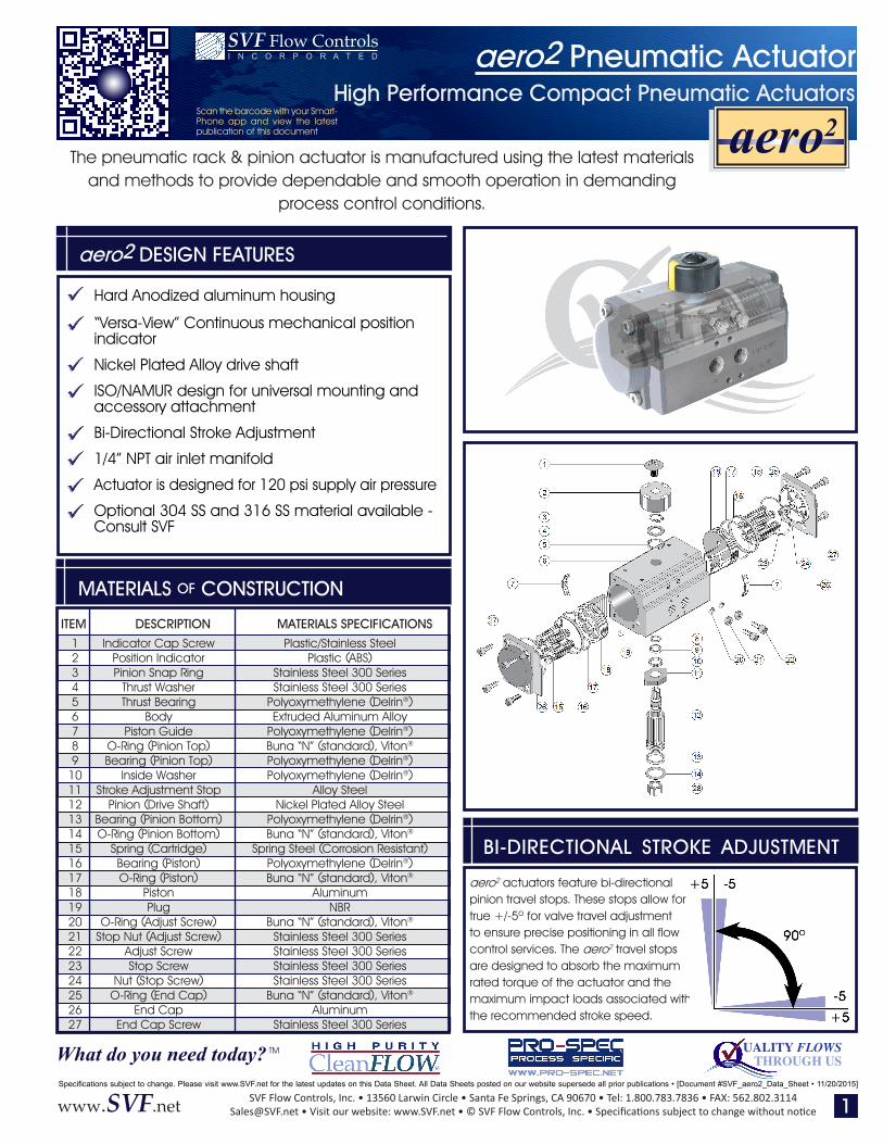
The pneumatic rack & pinion actuator is manufactured using the latest materials and methods to provide dependable and smooth operation in demanding
process control conditions.
UALITY FLOWSTHROUGH USWhat do you need today? TM
aero2 DESIGN FEATURES
High Performance Compact Pneumatic Actuators
Hard Anodized aluminum housing
“Versa-View” Continuous mechanical position indicator
Nickel Plated Alloy drive shaft
ISO/NAMUR design for universal mounting and accessory attachment
Bi-Directional Stroke Adjustment
1/4” NPT air inlet manifold
Actuator is designed for 120 psi supply air pressure
Optional 304 SS and 316 SS material available - Consult SVF
Indicator Cap ScrewPosition IndicatorPinion Snap Ring
Thrust WasherThrust Bearing
BodyPiston Guide
O-Ring (Pinion Top)Bearing (Pinion Top)
Inside WasherStroke Adjustment Stop
Pinion (Drive Shaft)Bearing (Pinion Bottom)O-Ring (Pinion Bottom)
Spring (Cartridge)Bearing (Piston)O-Ring (Piston)
PistonPlug
O-Ring (Adjust Screw)Stop Nut (Adjust Screw)
Adjust ScrewStop Screw
Nut (Stop Screw)O-Ring (End Cap)
End CapEnd Cap Screw
Plastic/Stainless SteelPlastic (ABS)
Stainless Steel 300 SeriesStainless Steel 300 Series
Polyoxymethylene (Delrin®)Extruded Aluminum Alloy
Polyoxymethylene (Delrin®)Buna “N” (standard), Viton®
Polyoxymethylene (Delrin®)Polyoxymethylene (Delrin®)
Alloy SteelNickel Plated Alloy Steel
Polyoxymethylene (Delrin®)Buna “N” (standard), Viton®
Spring Steel (Corrosion Resistant)Polyoxymethylene (Delrin®)Buna “N” (standard), Viton®
AluminumNBR
Buna “N” (standard), Viton®
Stainless Steel 300 SeriesStainless Steel 300 SeriesStainless Steel 300 SeriesStainless Steel 300 Series
Buna “N” (standard), Viton®
AluminumStainless Steel 300 Series
ITEM DESCRIPTION MATERIALS SPECIFICATIONS123456789
101112131415161718192021222324252627
MATERIALS OF CONSTRUCTION
aero2 Pneumatic Actuator
BI-DIRECTIONAL STROKE ADJUSTMENT
aero2 actuators feature bi-directional pinion travel stops. These stops allow for true +/-5o for valve travel adjustment to ensure precise positioning in all flow control services. The aero2 travel stops are designed to absorb the maximum rated torque of the actuator and the maximum impact loads associated with the recommended stroke speed.
aero2
I N C O R P O R A T E DSV F Flow Controls
Scan the barcode with your Smart-Phone app and view the latest publication of this document
1
SVF Flow Controls, Inc. • 13560 Larwin Circle • Santa Fe Springs, CA 90670 • Tel: 1.800.783.7836 • FAX: [email protected] • Visit our website: www.SVF.net • © SVF Flow Controls, Inc. • Specifications subject to change without noticewww.SVF.net
Specifications subject to change. Please visit www.SVF.net for the latest updates on this Data Sheet. All Data Sheets posted on our website supersede all prior publications • [Document #SVF_aero2_Data_Sheet • 11/20/2015]
High Performance Compact Pneumatic Actuators
aero2 Pneumatic Actuator
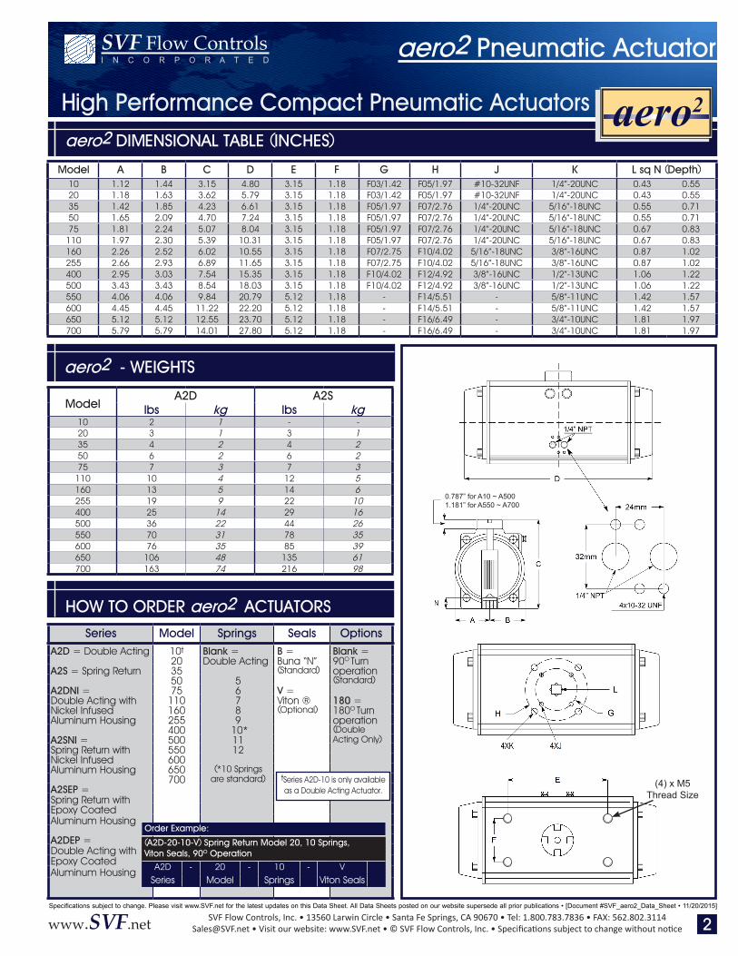
aero2 DIMENSIONAL TABLE (INCHES)
HOW TO ORDER aero2 ACTUATORS
aero2 - WEIGHTS
0.787” for A10 ~ A5001.181” for A550 ~ A700
I N C O R P O R A T E DSV F Flow Controls
2
aero2
Model A B C D E F G H J K L sq N (Depth)10 1.12 1.44 3.15 4.80 3.15 1.18 F03/1.42 F05/1.97 #10-32UNF 1/4”-20UNC 0.43 0.5520 1.18 1.63 3.62 5.79 3.15 1.18 F03/1.42 F05/1.97 #10-32UNF 1/4”-20UNC 0.43 0.5535 1.42 1.85 4.23 6.61 3.15 1.18 F05/1.97 F07/2.76 1/4”-20UNC 5/16”-18UNC 0.55 0.7150 1.65 2.09 4.70 7.24 3.15 1.18 F05/1.97 F07/2.76 1/4”-20UNC 5/16”-18UNC 0.55 0.7175 1.81 2.24 5.07 8.04 3.15 1.18 F05/1.97 F07/2.76 1/4”-20UNC 5/16”-18UNC 0.67 0.83
110 1.97 2.30 5.39 10.31 3.15 1.18 F05/1.97 F07/2.76 1/4”-20UNC 5/16”-18UNC 0.67 0.83160 2.26 2.52 6.02 10.55 3.15 1.18 F07/2.75 F10/4.02 5/16”-18UNC 3/8”-16UNC 0.87 1.02255 2.66 2.93 6.89 11.65 3.15 1.18 F07/2.75 F10/4.02 5/16”-18UNC 3/8”-16UNC 0.87 1.02400 2.95 3.03 7.54 15.35 3.15 1.18 F10/4.02 F12/4.92 3/8”-16UNC 1/2”-13UNC 1.06 1.22500 3.43 3.43 8.54 18.03 3.15 1.18 F10/4.02 F12/4.92 3/8”-16UNC 1/2”-13UNC 1.06 1.22550 4.06 4.06 9.84 20.79 5.12 1.18 - F14/5.51 - 5/8”-11UNC 1.42 1.57600 4.45 4.45 11.22 22.20 5.12 1.18 - F14/5.51 - 5/8”-11UNC 1.42 1.57650 5.12 5.12 12.55 23.70 5.12 1.18 - F16/6.49 - 3/4”-10UNC 1.81 1.97700 5.79 5.79 14.01 27.80 5.12 1.18 - F16/6.49 - 3/4”-10UNC 1.81 1.97
ModelA2D A2S
lbs kg lbs kg10 2 1 - -20 3 1 3 135 4 2 4 250 6 2 6 275 7 3 7 3
110 10 4 12 5160 13 5 14 6255 19 9 22 10400 25 14 29 16500 36 22 44 26550 70 31 78 35600 76 35 85 39650 106 48 135 61700 163 74 216 98
(4) x M5Thread Size
Series Model Springs Seals OptionsA2D = Double Acting 10t Blank = B = Blank =
20 Double Acting Buna “N” 90O TurnA2S = Spring Return 35 (Standard) operation
50 5 (Standard) A2DNI = 75 6 V =Double Acting with 110 7 Viton ® 180 =Nickel Infused 160 8 (Optional) 180O TurnAluminum Housing 255 9 operation
400 10* (Double A2SNI = 500 11 Acting Only)Spring Return with 550 12Nickel Infused 600Aluminum Housing 650 (*10 Springs
700 are standard)A2SEP = Spring Return withEpoxy CoatedAluminum Housing
A2DEP =Double Acting withEpoxy CoatedAluminum Housing
tSeries A2D-10 is only available as a Double Acting Actuator.
Order Example:
(A2D-20-10-V) Spring Return Model 20, 10 Springs, Viton Seals, 90O Operation
A2D - 20 - 10 - VSeries Model Springs Viton Seals
SVF Flow Controls, Inc. • 13560 Larwin Circle • Santa Fe Springs, CA 90670 • Tel: 1.800.783.7836 • FAX: [email protected] • Visit our website: www.SVF.net • © SVF Flow Controls, Inc. • Specifications subject to change without noticewww.SVF.net
Specifications subject to change. Please visit www.SVF.net for the latest updates on this Data Sheet. All Data Sheets posted on our website supersede all prior publications • [Document #SVF_aero2_Data_Sheet • 11/20/2015]
High Performance Compact Pneumatic Actuators
aero2 Pneumatic Actuator
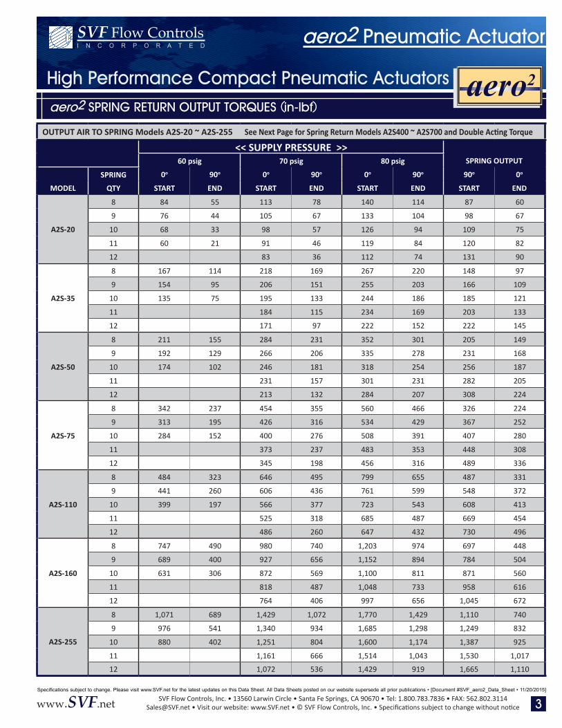
aero2 SPRING RETURN OUTPUT TORQUES (in-lbf)
I N C O R P O R A T E DSV F Flow Controls
aero2
3
OUTPUT AIR TO SPRING Models A2S-20 ~ A2S-255 See Next Page for Spring Return Models A2S400 ~ A2S700 and Double Acting Torque
<< SUPPLY PRESSURE >>60 psig 70 psig 80 psig SPRING OUTPUT
SPRING 0o 90o 0o 90o 0o 90o 90o 0o
MODEL QTY START END START END START END START END
A2S-20
8 84 55 113 78 140 114 87 60
9 76 44 105 67 133 104 98 67
10 68 33 98 57 126 94 109 75
11 60 21 91 46 119 84 120 82
12 83 36 112 74 131 90
A2S-35
8 167 114 218 169 267 220 148 97
9 154 95 206 151 255 203 166 109
10 135 75 195 133 244 186 185 121
11 184 115 234 169 203 133
12 171 97 222 152 222 145
A2S-50
8 211 155 284 231 352 301 205 149
9 192 129 266 206 335 278 231 168
10 174 102 246 181 318 254 256 187
11 231 157 301 231 282 205
12 213 132 284 207 308 224
A2S-75
8 342 237 454 355 560 466 326 224
9 313 195 426 316 534 429 367 252
10 284 152 400 276 508 391 407 280
11 373 237 483 353 448 308
12 345 198 456 316 489 336
A2S-110
8 484 323 646 495 799 655 487 331
9 441 260 606 436 761 599 548 372
10 399 197 566 377 723 543 608 413
11 525 318 685 487 669 454
12 486 260 647 432 730 496
A2S-160
8 747 490 980 740 1,203 974 697 448
9 689 400 927 656 1,152 894 784 504
10 631 306 872 569 1,100 811 871 560
11 818 487 1,048 733 958 616
12 764 406 997 656 1,045 672
A2S-255
8 1,071 689 1,429 1,072 1,770 1,429 1,110 740
9 976 541 1,340 934 1,685 1,298 1,249 832
10 880 402 1,251 804 1,600 1,174 1,387 925
11 1,161 666 1,514 1,043 1,530 1,017
12 1,072 536 1,429 919 1,665 1,110
SVF Flow Controls, Inc. • 13560 Larwin Circle • Santa Fe Springs, CA 90670 • Tel: 1.800.783.7836 • FAX: [email protected] • Visit our website: www.SVF.net • © SVF Flow Controls, Inc. • Specifications subject to change without noticewww.SVF.net
Specifications subject to change. Please visit www.SVF.net for the latest updates on this Data Sheet. All Data Sheets posted on our website supersede all prior publications • [Document #SVF_aero2_Data_Sheet • 11/20/2015]
High Performance Compact Pneumatic Actuators
aero2 Pneumatic Actuator
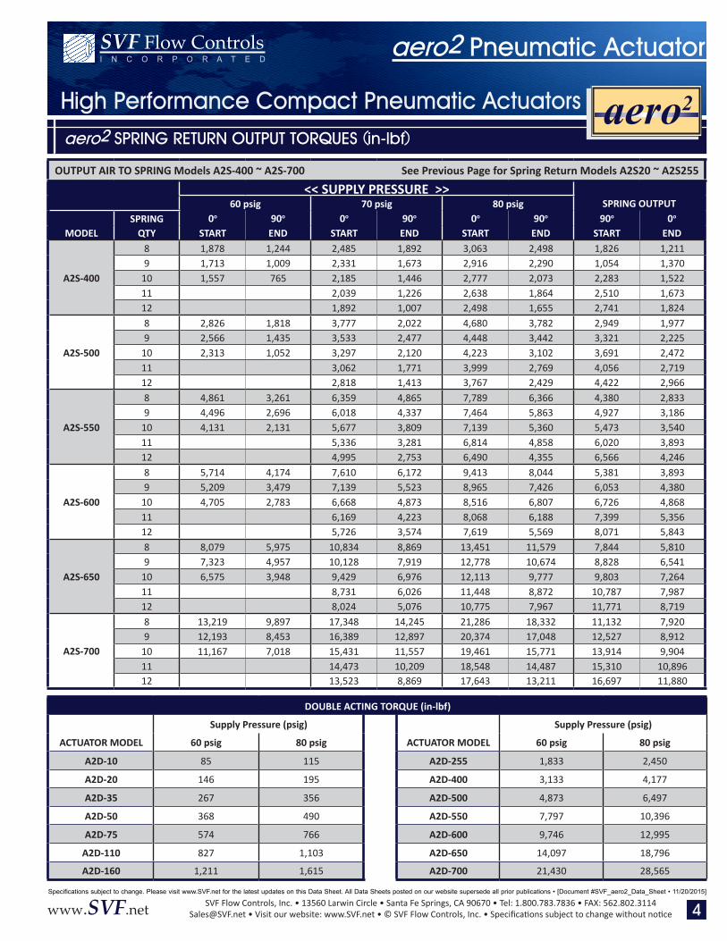
aero2 SPRING RETURN OUTPUT TORQUES (in-lbf)
I N C O R P O R A T E DSV F Flow Controls
4
OUTPUT AIR TO SPRING Models A2S-400 ~ A2S-700 See Previous Page for Spring Return Models A2S20 ~ A2S255
<< SUPPLY PRESSURE >>60 psig 70 psig 80 psig SPRING OUTPUT
SPRING 0o 90o 0o 90o 0o 90o 90o 0o
MODEL QTY START END START END START END START END
A2S-400
8 1,878 1,244 2,485 1,892 3,063 2,498 1,826 1,2119 1,713 1,009 2,331 1,673 2,916 2,290 1,054 1,370
10 1,557 765 2,185 1,446 2,777 2,073 2,283 1,52211 2,039 1,226 2,638 1,864 2,510 1,67312 1,892 1,007 2,498 1,655 2,741 1,824
A2S-500
8 2,826 1,818 3,777 2,022 4,680 3,782 2,949 1,9779 2,566 1,435 3,533 2,477 4,448 3,442 3,321 2,225
10 2,313 1,052 3,297 2,120 4,223 3,102 3,691 2,47211 3,062 1,771 3,999 2,769 4,056 2,71912 2,818 1,413 3,767 2,429 4,422 2,966
A2S-550
8 4,861 3,261 6,359 4,865 7,789 6,366 4,380 2,8339 4,496 2,696 6,018 4,337 7,464 5,863 4,927 3,186
10 4,131 2,131 5,677 3,809 7,139 5,360 5,473 3,54011 5,336 3,281 6,814 4,858 6,020 3,89312 4,995 2,753 6,490 4,355 6,566 4,246
A2S-600
8 5,714 4,174 7,610 6,172 9,413 8,044 5,381 3,8939 5,209 3,479 7,139 5,523 8,965 7,426 6,053 4,380
10 4,705 2,783 6,668 4,873 8,516 6,807 6,726 4,86811 6,169 4,223 8,068 6,188 7,399 5,35612 5,726 3,574 7,619 5,569 8,071 5,843
A2S-650
8 8,079 5,975 10,834 8,869 13,451 11,579 7,844 5,8109 7,323 4,957 10,128 7,919 12,778 10,674 8,828 6,541
10 6,575 3,948 9,429 6,976 12,113 9,777 9,803 7,26411 8,731 6,026 11,448 8,872 10,787 7,98712 8,024 5,076 10,775 7,967 11,771 8,719
A2S-700
8 13,219 9,897 17,348 14,245 21,286 18,332 11,132 7,9209 12,193 8,453 16,389 12,897 20,374 17,048 12,527 8,912
10 11,167 7,018 15,431 11,557 19,461 15,771 13,914 9,90411 14,473 10,209 18,548 14,487 15,310 10,89612 13,523 8,869 17,643 13,211 16,697 11,880
DOUBLE ACTING TORQUE (in-lbf)
Supply Pressure (psig) Supply Pressure (psig)
ACTUATOR MODEL 60 psig 80 psig ACTUATOR MODEL 60 psig 80 psig
A2D-10 85 115 A2D-255 1,833 2,450
A2D-20 146 195 A2D-400 3,133 4,177
A2D-35 267 356 A2D-500 4,873 6,497
A2D-50 368 490 A2D-550 7,797 10,396
A2D-75 574 766 A2D-600 9,746 12,995
A2D-110 827 1,103 A2D-650 14,097 18,796
A2D-160 1,211 1,615 A2D-700 21,430 28,565
aero2
SVF Flow Controls, Inc. • 13560 Larwin Circle • Santa Fe Springs, CA 90670 • Tel: 1.800.783.7836 • FAX: [email protected] • Visit our website: www.SVF.net • © SVF Flow Controls, Inc. • Specifications subject to change without noticewww.SVF.net
Specifications subject to change. Please visit www.SVF.net for the latest updates on this Data Sheet. All Data Sheets posted on our website supersede all prior publications • [Document #SVF_aero2_Data_Sheet • 11/20/2015]
aero2 ACTUATOR SIZING GUIDE
High Performance Compact Pneumatic Actuators
aero2 Pneumatic ActuatorI N C O R P O R A T E DSV F Flow Controls
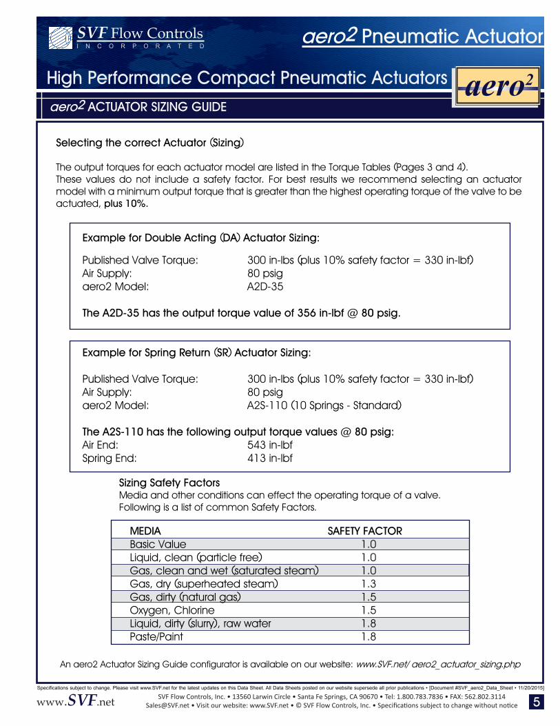
Selecting the correct Actuator (Sizing)
The output torques for each actuator model are listed in the Torque Tables (Pages 3 and 4).These values do not include a safety factor. For best results we recommend selecting an actuator model with a minimum output torque that is greater than the highest operating torque of the valve to be actuated, plus 10%.
Example for Double Acting (DA) Actuator Sizing:
Published Valve Torque: 300 in-lbs (plus 10% safety factor = 330 in-lbf)Air Supply: 80 psigaero2 Model: A2D-35
The A2D-35 has the output torque value of 356 in-lbf @ 80 psig.
Example for Spring Return (SR) Actuator Sizing:
Published Valve Torque: 300 in-lbs (plus 10% safety factor = 330 in-lbf)Air Supply: 80 psigaero2 Model: A2S-110 (10 Springs - Standard)
The A2S-110 has the following output torque values @ 80 psig:Air End: 543 in-lbfSpring End: 413 in-lbf
Sizing Safety FactorsMedia and other conditions can effect the operating torque of a valve.Following is a list of common Safety Factors.
MEDIA SAFETY FACTOR Basic Value 1.0 Liquid, clean (particle free) 1.0 Gas, clean and wet (saturated steam) 1.0 Gas, dry (superheated steam) 1.3 Gas, dirty (natural gas) 1.5 Oxygen, Chlorine 1.5 Liquid, dirty (slurry), raw water 1.8 Paste/Paint 1.8
5
An aero2 Actuator Sizing Guide configurator is available on our website: www.SVF.net/ aero2_actuator_sizing.php
aero2