Embed Size (px)
Citation preview

By
TODD WALLICK
ASHOK JALANDANKI
NATRAJ BHAT
ARVIND BENAL
Goodrich Aerospace Services Private Limited
IMPLEMENTATION OF ACTUATOR POSITION CONTROL IN FPGA

Electronic Systems Center 2
Topics
Introduction
What is EHSA (Electro Hydraulic Servo Actuator)?
What is ECU (Electronic Control Unit)?
EHSV (Electro Hydraulic Servo Valve) Interface
LVDT (Linear Variable Displacement Transformer) Interface
PID (Proportional Integral Derivative) based Position Control Loop
Matlab/Simulink model for PID Control
– Resource utilization
– Optimized resource.
Verification strategy in compliance with DO-254 A assurance guidelines .
Comparison of Resource for Simulink HDL code and Optimized HDL code

Electronic Systems Center 3
Introduction:
An Electro Hydraulic Servo Control (EHSC) system consists of major elements indicated in the diagram below:
Actuator Control electronics for a command input signal
A Control Loop which provides a low power electrical actuating signal which is the difference between the
position demand input signal (Command logic) and the position feedback signal generated by the position
sensor (Position calculator and monitor)
A servo valve which responds to this electrical signal and controls the hydraulic fluid flow to an actuation
element (piston and cylinder) which positions the control surface.
The feedback transducer measures the output position of the actuator and converts this measurement into a
proportional signal which is sent back to the Control Loop.
System Interface of the ECU(Electronic Control Unit) with the Control surface through the EHSA actuator

Electronic Systems Center 4
What is EHSA?
The EHSA (Electrical Hydraulic Servo-Actuator) is a conventional hydraulic control actuator driven by the
electronics.
The control electronics sends a current signal to the servo-valve in order to move the actuator rod. In case of a
fault detected in the hydraulic supply, the ECU is able to change the mode(from active to damp)through a
solenoid which damps the actuator. See the EHSA architecture below:
Electrical Hydraulic Servo-Actuator
SUPPLY HYDRAULIC
SERVOVALVE
Control Electronics

Electronic Systems Center 5
What is ECU?
ECU is Electronic Control Unit to drive and control Electro Hydraulic Valve,
Applications : primary and secondary flight systems.

Electronic Systems Center 6
The required actuator position is commanded by the ECU typically through an ARINC 429/ MIL-STD 1553
communication interface to the FPGA. The communication interface is used to communicate the required
position demand and loop gains from ECU.
This actuator position demand is fed to a III order controller (PID control) to determine a stable position
demand irrespective of the load on the actuator control surface. This is achieved by taking the feedback of the
actuator position displacement by the LVT/ LVDT sensors and feedback this data to the ERROR block of the
III order controller.
There are two control loops in this application:
The position control loop implemented with a Matlab/SIMULINK HDL model to control the actuator
displacement and measure the displacement with the sensors viz. LVT / LVDT.
The current control loop implemented in the hardware to control the current to the Torque coil motor of
EHSV.
The position in the position control loop is corrected at a rate of 1 ms; whereas the current in the current
control loop is corrected in the HW for less than 100 us.

Electronic Systems Center 7
EHSV Interface:
The Electro-Hydraulic Servo Valve (EHSV) consists of Torque coil motor which is controlled by DC current
ranging from +/- 10mA. The desired current is commanded from the FPGA to a 16-bit DAC which generates
+/- 10mA of current.
EHSV Torque Coil requirements
This circuit implements a closed current control loop.
The error amplifier circuit controls the current to the EHSV
by computing the error between the commanded current
and the feedback current from the current sense circuit.
In addition to the close loop current control, this value is
digitized proportional to the EHSV current and send to the
FPGA for status monitoring.
EHSV
(Torque motor command)
Type Torque motor coil (2 wires)
Commanded current +/- 10mA
Commanded Current oscillation < 0.01 mA
Commanded Current accuracy < 0.05 mA

Electronic Systems Center 8
LVDT Interface: The excitation to the position sensor is provided from the sine samples generated by the FPGA.
The feedback position is computed by sampling of sensor signals of the position sensor. Data is transferred from
the ADC serially to the FPGA. For the LVDT the peak-to-peak value is scaled and the LVDT sensor ratio is
computed, range checked and the ratio stored in a register.
There are several popular methods for demodulating LVDT signals and computing the feedback position, for
example:
Rectifying and Filtering the sensor signal in analog or digital domain and then perform the position
calculations.
Sample the sensor signals, mix the input with a sinusoid lookup table, and filter the product to perform the
position calculations; which involves tracking the input frequency.

Electronic Systems Center 9
• The position sensor demodulation technique for the ECU is unique [PATENT pending] for its simultaneous
asynchronous sampling of the sensor signals. The peak to peak value is used to compute the sensor
position. This method was chosen for the following reasons:
• Its noise and phase immunity.
• Minimum number of external discrete components,
• Immunity to offset, temperature, differences in part tolerances and aging.
LVDT
Used for Piston rod
position measurement
(X = X0 x (V1-V2)/(V1+V2))
Type 6-wire LVDT
Primary power supply +10VRMS +/- 0.5 VRMS @ 5000Hz
Full Scale -80 mm to +80 mm
Sensor Accuracy < 0.5 + 0.02.X mm (X = position)
Resolution < 0.05 mm
Measurement Accuracy < 0.1 + 0.02.X mm (X = position)
LVDT Electrical Characteristics

Electronic Systems Center 10
• PID(Proportion Integral and Derivative) Controller

Electronic Systems Center 11
Electronic Systems Center 12
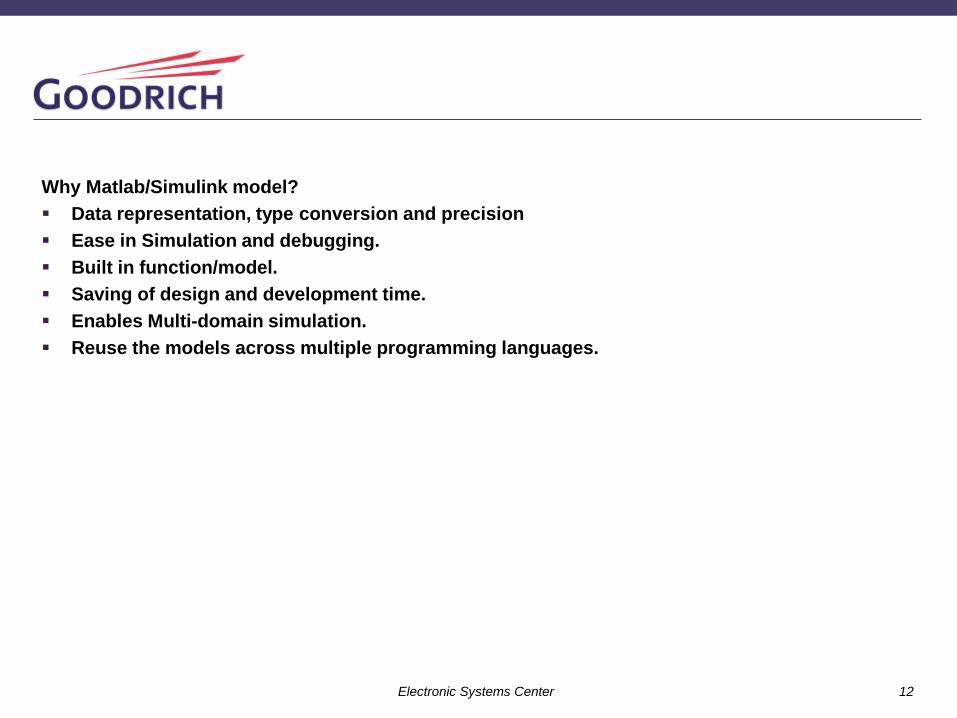
Why Matlab/Simulink model?
Data representation, type conversion and precision
Ease in Simulation and debugging.
Built in function/model.
Saving of design and development time.
Enables Multi-domain simulation.
Reuse the models across multiple programming languages.

Electronic Systems Center 13
PID based Position Control Loop (Simulink Model)
Simulink Model

Electronic Systems Center 14

Electronic Systems Center 15
Programmable Control and Monitor registers through ARINC 429 Interface:
Scaling and Low Pass Filter(LPF) :
Scaling: : This element scales down or scales up the data by factor x.
Low Pass Filter: To remove the noise or High frequency component which may
cause to de-stabilize the loop.
R/W Registers R/O Registers
a) Desired Position
b) Feedback gain register
c) Proportional Gain register
d) Integral Gain Register
e) Derivative Gain register
f) Loop update rate register
g) Saturation limit register
a) ADC Value register
b) Feedback Filter register
c) Error register
d) Proportional Error register
e) Integral Error register
f) Derivative Error register
g) Summed Error register

Electronic Systems Center 16
FPGA Implementation.
An EHSC system is implemented in FPGA using VHDL language for aerospace application with DO-254 level-A
design guidance assurance level. The main module of EHSC Actuator Position control loop is implemented in
MATLAB/SIMULINK model. From MATLAB/Simulink model, generated VHDL RTL code by HDL code generator
and optimized for the resource utilization. Optimized RTL code is verified against the MATLAB/Simulink model.
This paper also compares the resource utilization of HDL generated by code generator with Optimized RTL code.
Electronic Systems Center 17
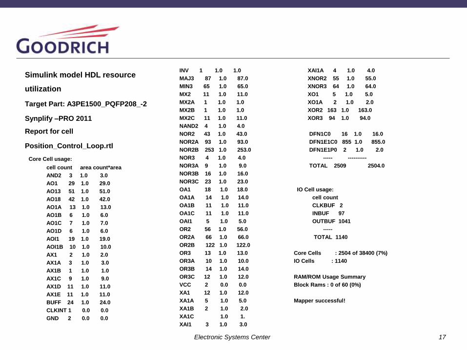
Simulink model HDL resource
utilization
Target Part: A3PE1500_PQFP208_-2
Synplify –PRO 2011
Report for cell
Position_Control_Loop.rtl
Core Cell usage:
cell count area count*area
AND2 3 1.0 3.0
AO1 29 1.0 29.0
AO13 51 1.0 51.0
AO18 42 1.0 42.0
AO1A 13 1.0 13.0
AO1B 6 1.0 6.0
AO1C 7 1.0 7.0
AO1D 6 1.0 6.0
AOI1 19 1.0 19.0
AOI1B 10 1.0 10.0
AX1 2 1.0 2.0
AX1A 3 1.0 3.0
AX1B 1 1.0 1.0
AX1C 9 1.0 9.0
AX1D 11 1.0 11.0
AX1E 11 1.0 11.0
BUFF 24 1.0 24.0
CLKINT 1 0.0 0.0
GND 2 0.0 0.0
INV 1 1.0 1.0
MAJ3 87 1.0 87.0
MIN3 65 1.0 65.0
MX2 11 1.0 11.0
MX2A 1 1.0 1.0
MX2B 1 1.0 1.0
MX2C 11 1.0 11.0
NAND2 4 1.0 4.0
NOR2 43 1.0 43.0
NOR2A 93 1.0 93.0
NOR2B 253 1.0 253.0
NOR3 4 1.0 4.0
NOR3A 9 1.0 9.0
NOR3B 16 1.0 16.0
NOR3C 23 1.0 23.0
OA1 18 1.0 18.0
OA1A 14 1.0 14.0
OA1B 11 1.0 11.0
OA1C 11 1.0 11.0
OAI1 5 1.0 5.0
OR2 56 1.0 56.0
OR2A 66 1.0 66.0
OR2B 122 1.0 122.0
OR3 13 1.0 13.0
OR3A 10 1.0 10.0
OR3B 14 1.0 14.0
OR3C 12 1.0 12.0
VCC 2 0.0 0.0
XA1 12 1.0 12.0
XA1A 5 1.0 5.0
XA1B 2 1.0 2.0
XA1C 1.0 1.
XAI1 3 1.0 3.0
XAI1A 4 1.0 4.0
XNOR2 55 1.0 55.0
XNOR3 64 1.0 64.0
XO1 5 1.0 5.0
XO1A 2 1.0 2.0
XOR2 163 1.0 163.0
XOR3 94 1.0 94.0
DFN1C0 16 1.0 16.0
DFN1E1C0 855 1.0 855.0
DFN1E1P0 2 1.0 2.0
----- ----------
TOTAL 2509 2504.0
IO Cell usage:
cell count
CLKBUF 2
INBUF 97
OUTBUF 1041
-----
TOTAL 1140
Core Cells : 2504 of 38400 (7%)
IO Cells : 1140
RAM/ROM Usage Summary
Block Rams : 0 of 60 (0%)
Mapper successful!

Electronic Systems Center 18
Optimized HDL resource.
Target Part: A3PE1500_PQFP208_-2
Synplify –PRO 2011
Report for cell
Position_Control_Loop.rtl
Core Cell usage:
cell count area count*area
AND2 3 1.0 3.0
AO1 39 1.0 39.0
AO13 29 1.0 29.0
AO18 25 1.0 25.0
AO1A 11 1.0 11.0
AO1B 5 1.0 5.0
AO1C 3 1.0 3.0
AO1D 6 1.0 6.0
AOI1 12 1.0 12.0
AOI1B 10 1.0 10.0
AX1A 4 1.0 4.0
AX1B 4 1.0 4.0
AX1C 15 1.0 15.0
AX1D 5 1.0 5.0
AX1E 10 1.0 10.0
BUFF 24 1.0 24.0
CLKINT 1 0.0 0.0
GND 2 0.0 0.0
MAJ3 98 1.0 98.0
MIN3 67 1.0 67.0
MX2A 1 1.0 1.0
MX2C 4 1.0 4.0
NAND2 1 1.0 1.0
NOR2 40 1.0 40.0
NOR2A 77 1.0 77.0
NOR2B 211 1.0 211.0
NOR3 7 1.0 7.0
NOR3A 5 1.0 5.0
NOR3B 8 1.0 8.0
NOR3C 21 1.0 21.0
OA1 15 1.0 15.0
OA1A 7 1.0 7.0
OA1B 5 1.0 5.0
OA1C 5 1.0 5.0
OAI1 10 1.0 10.0
OR2 47 1.0 47.0
OR2A 52 1.0 52.0
OR2B 127 1.0 127.0
OR3 4 1.0 4.0
OR3A 6 1.0 6.0
OR3B 13 1.0 13.0
OR3C 15 1.0 15.0
VCC 2 0.0 0.0
XA1 10 1.0 10.0
XA1A 5 1.0 5.0
XA1B 3 1.0 3.0
XAI1 1 1.0 1.0
XAI1A 1 1.0 1.0
XNOR2 43 1.0 43.0
XNOR3 52 1.0 52.0
XO1 5 1.0 5.0
XO1A 2 1.0 2.0
XOR2 173 1.0 173.0
XOR3 93 1.0 93.0

Electronic Systems Center 19
DFN1C0 17 1.0 17.0
DFN1E1C0 839 1.0 839.0
DFN1E1P0 2 1.0 2.0
----- ----------
TOTAL 2302 2297.0
IO Cell usage:
cell count
CLKBUF 2
INBUF 97
OUTBUF 1041
-----
TOTAL 1140
Core Cells : 2297 of 38400 (6%)
IO Cells : 1140
RAM/ROM Usage Summary
Block Rams : 0 of 60 (0%)

Electronic Systems Center 20
Verification Strategy.
The verification for the optimized HDL code is as shown in the below diagram.
Simulink HDL
Code/Model
Optimized HDL
code
Test case Checker

Electronic Systems Center 21
Comparison of Simulink HDL code and Optimized code :
Simulink model HDL resource utilization
Resource utilization
Core cells : 2504 of 38400 (7%)
IO cells : 1140
ROM usage : 0 of 60 (0%)
Compile/Synthesis time : At Mapper Exit (Time elapsed 0h:00m:44s; Memory used current: 36MB peak: 129MB)
Process took 0h:00m:45s realtime, 0h:00m:44s cputime
Optimized HDL resource.
Resource utilization
Core cells : 2295 of 38400 (6%)
IO cells : 1140
ROM usage : 0 of 60 (0%)
Compile/Synthesis time : At Mapper Exit (Time elapsed 0h:00m:15s; Memory used current: 33MB peak: 119MB)
Process took 0h:00m:15s realtime, 0h:00m:15s cputime
Optimized in Percentage = (2295 – 2504) / 2504 * 100
= 8.3%

Electronic Systems Center 22
Q & A

Electronic Systems Center 23
THANK YOU!