Embed Size (px)
Citation preview

innovative, intelligent, inventive electronicsiLumTech Connected Lighting
DALI 4 x RELAYiL
umTe
ch C
onne
cted
Lig
hting
1 YearWarranty The Company reserves the right to change any product specifications without prior notification.
iLumTech906 02 Dojč 419, SlovakiaT: +421-34-6940847 [email protected] • www.ilumtech.eu
Connections
Mains cable Wires AWG 24–12 (0.2–2.5 mm²)
DALI cable Wires AWG 28–16 (0.08–1.5 mm²)
Relays cable Wires AWG 24–12 (0.2–2.5 mm²)
Power
Mains supply 220–240 V AC / 50–60 Hz
Max. system power 6 W
DALI consumption < 2 mA
Relay loads 12 A (per contact)
Insulation 4 kV
Mechanical Data
Housing 4U DIN rail box 71 mm wide
Weight 300 g
IP rating IP 20
Operating Conditions
Operating temp. range from 0 ºC up to 40 ºC
Relative Humidity 85 % max., non-condensing
Storage temp. range from -40 °C up to 70 °C
Conformance with regulations
EN 55015 Limits and methods of measurement of radio disturbance characteristics of electrical lighting and similar equipment
EN 61547 Equipment for general lighting purposes EMC immunity requirements
EN 60950-1 Information technology equipment – Safety – Part 1: General requirements
EN 62386-208 Digital addressable lighting interface
Key features
• four independent relay contacts
• 12 A maximum switching current per contact
• push button for manual control (test function)
• one DALI address for each contact (DALI device type 7, EN 62386-
208)
Function
After powering-up the device, an internal test sequence is initiated that lasts for no more than 2 seconds. The device then acts in Normal Mode and awaits DALI commands.
The ‘STATUS‘ LED indicator is lit when the DALI bus is correctly supplied. LED indicators 1 to 4 show the current status of each relay: a lit LED means the corresponding relay is switched on, an unlit LED means the corresponding relay is switched off.
Test mode
Test Mode can be activated at any time by pressing the push button ‘TEST’. A short push of the button, for a period less than 3 seconds, changes which relay is selected, indicated by the corresponding LED indicator blinking. By pressing the push button for a period of more than 3 seconds the selected relay is switched on/off, indicated by the way in which the LED indicator blinks (predominantly on means the relay is switched on, predominantly off means the relay is switched off). The device will return to Normal Mode after 5 seconds of push button inactivity.
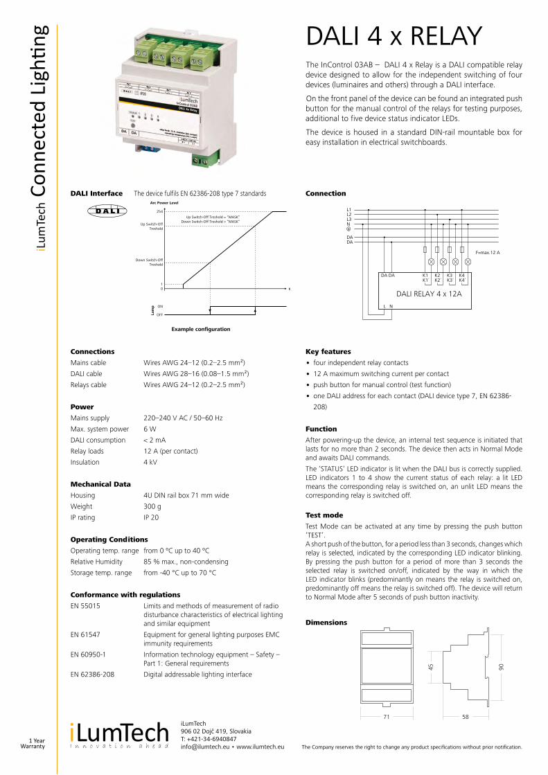
DALI Interface The device fulfils EN 62386-208 type 7 standards Connection
Dimensions
The InControl 03AB – DALI 4 x Relay is a DALI compatible relay device designed to allow for the independent switching of four devices (luminaires and others) through a DALI interface.
On the front panel of the device can be found an integrated push button for the manual control of the relays for testing purposes, additional to five device status indicator LEDs.
The device is housed in a standard DIN-rail mountable box for easy installation in electrical switchboards.
71
9045
58
L1L2L3N
DADA
DALI RELAY 4 x 12A
F=max.12 A
254
Up Switch-OffTreshold
Up Switch-Off Treshold = “MASK”Down Switch-Off Treshold = “MASK”
Down Switch-OffTreshold
10
ON
OFFLam
p
Arc Power Level
Example configuration
t
DA DA
L N
K1K1´
K2K2´
K3K3´
K4K4´
254
Vrchná hranicavypnutia
Vrchná hranica vypnutia = “MASK”Spodná hranica vypnutia = “MASK”
Spodná hranicavypnutia
10
ZAP.
VYP.Svet
elný
zdro
j
Arc Power úroveň
Príklad nastavenia
t
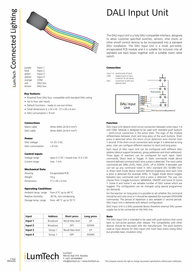
DALI Input Unit
The Company reserves the right to change any product specifications without prior notification.
iLumTech906 02 Dojč 419, SlovakiaT: +421-34-6940847 [email protected] • www.ilumtech.eu
Connections
Mains cable Wires AWG 24 (0.5 mm²)
DALI cable Wires AWG 24 (0.5 mm²)
Power
DALI voltage 12–25 V DC
DALI consumption < 9 mA
Control Inputs
Voltage range open 5 V DC / closed max. 0.3 V DC
Current range max. 1 mA
Mechanical Data
Housing Encapsulated PCB
Weight 10 g
Dimensions 27 x 20 x 4 mm
Operating Conditions
Ambient temp. range from 0 ºC up to 40 ºC
Relative Humidity 85 %, non-condensing
Storage temp. range from -40 °C up to 70 °C
Function
DALI Input Unit detects short-circuit connection between wires Input 1-4 and COM. Module is designed to be used with standard push buttons – short-circuit connection is the active state. The logic of the module differentiates between short and long press of the push buttons. Short press is detected when the short-circuit detection lasts shorter than 1 second. If the short-circuit connection lasts longer it is detected as long press. User can configure different reaction to short and long press.
Each input of DALI Input Unit can be configured with different DALI address (device support broadcast, group addresses and short addresses). Three types of reactions can be configured for each input: Static commands, Direct level or Toggle. In Static commands mode device transmit defined command each time a press is detected. The most useful commands are: MIN_LEVEL, MAX_LEVEL, UP or DOWN. If desirable user can set up any command listed in DALI standard (IEC 62386-102). In Direct level mode device transmit defined brightness level each time a press is detected (for example 50%). In Toggle mode device toggles between two commands each time a press is detected. The user can choose from 3 toggle functions: MIN/MAX, ON/OFF and Scene X/ Scene Y. Scene X and Scene Y are settable number of DALI scenes which are toggled. The configuration can be changed using special programmer (on demand).
For the reaction on long press it is possible to set whether the command should be sent only once or it should be repeated (for example UP/DOWN commands). The period of repetition is also settable (1 second period). DALI Input Unit is delivered with default configuration.
DALI Input Unit is a DALI powered device therefore external DALI power supply has to be connected on the DALI line.
Note The DALI Input Unit is intended to be used with push buttons that come back to non-active position after release. The compatibility with other devices should be discussed with the manufacturer. The push buttons used as input devices for DALI Input Unit must have mains rating (DALI bus provides basic insulation only).
purple Input 1 blue Input 2 green Input 3 yellow Input 4orange COM red DALI bus brown DALI bus
Key features
• Powered from DALI bus, compatible with standard DALI rating
• Up to four user inputs
• Default functions – ready to use out-of-box
• Small dimensions (L x W x H): 27 x 20 x 4 mm
• DALI consumption < 9 mA
Connection
The DALI Input Unit is a fully DALI-compatible interface, designed to allow customer specified switches, sensors, time clocks or other on/off control devices to be incorporated into a standard DALI installation. The DALI Input Unit is a small, pre-wired, encapsulated PCB module and it is suitable for inclusion into all standard size back boxes together with a suitable mains rated switch.
Input 1-4 positive pole of inputCOM negative pole of input (common for all inputs)DALI connection to DALI bus (polarity free)
Input Address Short press Long press
Input 1 Broadcast Recall Max level UP
Input 2 Broadcast OFF DOWN
Input 3 Group 1 Recall Max level UP
Input 4 Group 1 OFF DOWN
1 YearWarranty
iLum
Tech
Con
nect
ed L
ighti
ng

DALI TW MODULE type 6
The Company reserves the right to change any product specifications without prior notification.
iLumTech906 02 Dojč 419, SlovakiaT: +421-34-6940847 [email protected] • www.ilumtech.eu
Connections
Mains cable Wires AWG 28-16 (0.08–1.5 mm²)
DALI cable Wires AWG 28-16 (0.08–1.5 mm²)
LED cable Wires AWG 28-16 (0.08–1.5 mm²)
Power
Mains supply 90–260 V AC / 47-400 Hz 120–370 V DC
System power < 200 mW
DALI consumption < 2 mA
Insulation Class II
Output
Output voltage range 30 V DC - 180 V DC
Output current range 0 - 2 A
Output power range 0 – 150 W
Mechanical Data
Housing Open Frame
Weight 60 g
Dimensions 94 x 45 x 25 mm
Operating Conditions
Ambient temp. range from 0 ºC up to 55 ºC
Relative Humidity < 85 %, non-condensing
Storage temp. range from -40 °C up to 70 °C
Key features
• independent control of CCT
• up to 180 V voltage range
• DALI control (device type 6)
Function
DALI TW MODULE is a DALI device designed for TunableWhite control. It is not a power source for LEDs! For correct function an external LED driver must be used (constant current). Selection of the LED driver depends on the LED load used (forward voltage and current). DALI TW MODULE controls the CCT of light according to the DALI commands received. On DALI line, the device appears as standard DALI device type 6 (LED driver) allowing for direct CCT level control, group addressing, fading and scene settings.
DALI TW MODULE represents simple way of CCT control via DALI using standard components – LED driver and DALI controller.
Conformance with regulations
EN 55015 limits and methods of measurement of radio disturbance characteristics of electrical lighting and similar equipment
EN 61547 Equipment for general lighting purposes EMC immunity requirements
EN 62386-102 Digital addressable lighting interface, general requirements for control gears
EN 62386-207 Digital addressable lighting interface, LED drivers
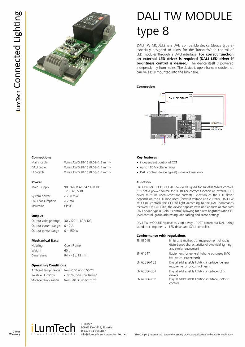
Connection
DALI TW MODULE is a DALI compatible device (device type 6) especially designed to allow for the TunableWhite control of LED modules through a DALI interface. For correct function an external LED driver is required (DALI LED driver if brightness control is desired). The device itself is powered independently from mains. The device is open-frame module that can be easily mounted into the luminaire.
1 YearWarranty
iLum
Tech
Con
nect
ed L
ighti
ng
The Company reserves the right to change any product specifications without prior notification.
iLumTech906 02 Dojč 419, SlovakiaT: +421-34-6940847 [email protected] • www.ilumtech.eu
Connections
Mains cable Wires AWG 28-16 (0.08–1.5 mm²)
DALI cable Wires AWG 28-16 (0.08–1.5 mm²)
LED cable Wires AWG 28-16 (0.08–1.5 mm²)
Power
Mains supply 90–260 V AC / 47-400 Hz 120–370 V DC
System power < 200 mW
DALI consumption < 2 mA
Insulation Class II
Output
Output voltage range 30 V DC - 180 V DC
Output current range 0 - 2 A
Output power range 0 – 150 W
Mechanical Data
Housing Open Frame
Weight 60 g
Dimensions 94 x 45 x 25 mm
Operating Conditions
Ambient temp. range from 0 ºC up to 55 ºC
Relative Humidity < 85 %, non-condensing
Storage temp. range from -40 °C up to 70 °C
Key features
• independent control of CCT
• up to 180 V voltage range
• DALI control (device type 8) – one address only
Function
DALI TW MODULE is a DALI device designed for Tunable White control. It is not a power source for LEDs! For correct function an external LED driver must be used (constant current). Selection of the LED driver depends on the LED load used (forward voltage and current). DALI TW MODULE controls the CCT of light according to the DALI commands received. On DALI line, the device appears with one address as standard DALI device type 8 (Colour control) allowing for direct brightness and CCT level control, group addressing, and fading and scene settings.
DALI TW MODULE represents simple way of CCT control via DALI using standard components – LED driver and DALI controller.
Conformance with regulations
EN 55015 limits and methods of measurement of radio disturbance characteristics of electrical lighting and similar equipment
EN 61547 Equipment for general lighting purposes EMC immunity requirements
EN 62386-102 Digital addressable lighting interface, general requirements for control gears
EN 62386-207 Digital addressable lighting interface, LED drivers
EN 62386-209 Digital addressable lighting interface, Colour control
Connection
DALI TW MODULE is a DALI compatible device (device type 8) especially designed to allow for the TunableWhite control of LED modules through a DALI interface. For correct function an external LED driver is required (DALI LED driver if brightness control is desired). The device itself is powered independently from mains. The device is open-frame module that can be easily mounted into the luminaire.
DALI TW MODULE type 8
1 YearWarranty
iLum
Tech
Con
nect
ed L
ighti
ng
MANUAL TW MODULE 01
The Company reserves the right to change any product specifications without prior notification.
iLumTech906 02 Dojč 419, SlovakiaT: +421-34-6940847 [email protected] • www.ilumtech.eu
Connections
Cable Wires AWG 24-12 (0.5–2.5 mm²)
Power
Input voltage 25 V DC - 56 V DC
Output
Output voltage 25 V DC - 56 V DC
Output current 0 - 1.5 A
Module consumption 50 mW
Mechanical Data
Housing Open case
Weight 18 g
Dimensions 60 x 45 x 15 mm
Operating Conditions
Ambient temp. range from 0 ºC up to 55 ºC
Key features
• Two push buttons for manual control
• Output current range: up to 2 A
• Output power: up to 110 W
• Module internal biasing: 5 V / 8 mA (40 mW)
Function
After powering up Manual TW electronic reloads last used setting of output current ratio. The new level is saved to memory after 10 seconds of push button inactivity. Push button 1 (PB 1) serves for increasing and Push button 2 (PB 2) for decreasing of output current ratio. There are two modes of current ratio transients – smooth mode and discrete mode.
Discrete mode / discrete mode is activated by default. When short pressing one of the push buttons (holding pressed shorter than 1 second) the current ratio level is changed in discrete steps according to the table below. One press activates change of one step.
Smooth mode – smooth mode is activated when one of the push buttons is hold pressed longer than 1 second. After this period current ratio starts to change (increase or decrease) smoothly with approximately 2 % per second.
Connection
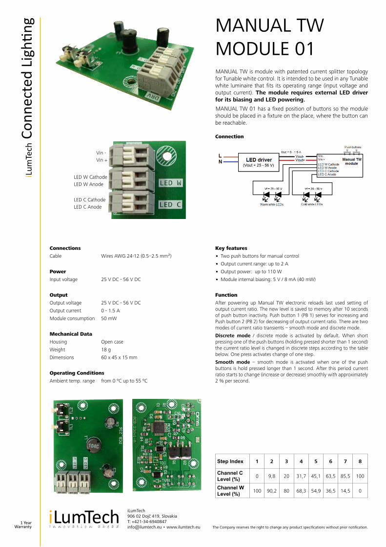
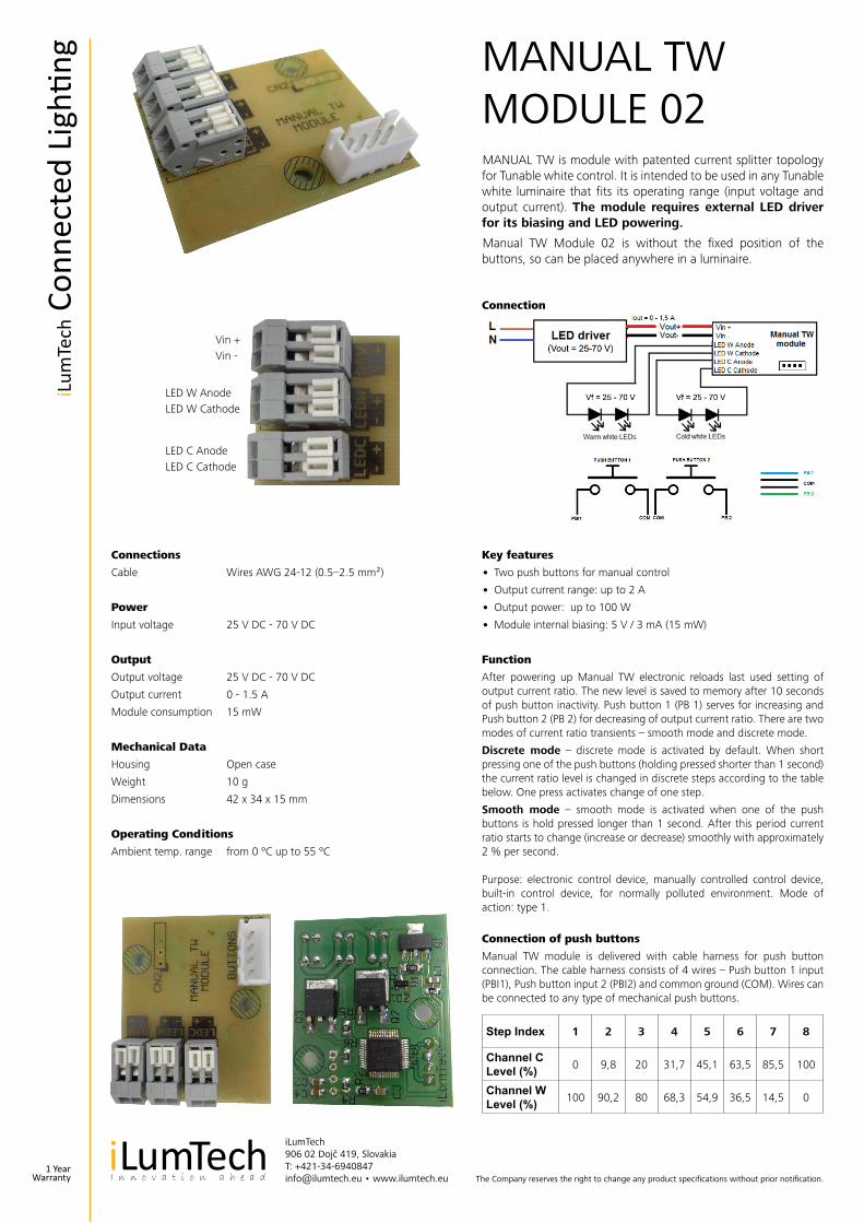
MANUAL TW is module with patented current splitter topology for Tunable white control. It is intended to be used in any Tunable white luminaire that fits its operating range (input voltage and output current). The module requires external LED driver for its biasing and LED powering.
MANUAL TW 01 has a fixed position of buttons so the module should be placed in a fixture on the place, where the button can be reachable.
Vin -Vin +
LED W CathodeLED W Anode
LED C CathodeLED C Anode
Step Index 1 2 3 4 5 6 7 8
Channel C Level (%) 0 9,8 20 31,7 45,1 63,5 85,5 100
Channel W Level (%) 100 90,2 80 68,3 54,9 36,5 14,5 0
1 YearWarranty
iLum
Tech
Con
nect
ed L
ighti
ng
MANUAL TW MODULE 02
The Company reserves the right to change any product specifications without prior notification.
iLumTech906 02 Dojč 419, SlovakiaT: +421-34-6940847 [email protected] • www.ilumtech.eu
Connections
Cable Wires AWG 24-12 (0.5–2.5 mm²)
Power
Input voltage 25 V DC - 70 V DC
Output
Output voltage 25 V DC - 70 V DC
Output current 0 - 1.5 A
Module consumption 15 mW
Mechanical Data
Housing Open case
Weight 10 g
Dimensions 42 x 34 x 15 mm
Operating Conditions
Ambient temp. range from 0 ºC up to 55 ºC
Key features
• Two push buttons for manual control
• Output current range: up to 2 A
• Output power: up to 100 W
• Module internal biasing: 5 V / 3 mA (15 mW)
Function
After powering up Manual TW electronic reloads last used setting of output current ratio. The new level is saved to memory after 10 seconds of push button inactivity. Push button 1 (PB 1) serves for increasing and Push button 2 (PB 2) for decreasing of output current ratio. There are two modes of current ratio transients – smooth mode and discrete mode.
Discrete mode – discrete mode is activated by default. When short pressing one of the push buttons (holding pressed shorter than 1 second) the current ratio level is changed in discrete steps according to the table below. One press activates change of one step.
Smooth mode – smooth mode is activated when one of the push buttons is hold pressed longer than 1 second. After this period current ratio starts to change (increase or decrease) smoothly with approximately 2 % per second.
Purpose: electronic control device, manually controlled control device, built-in control device, for normally polluted environment. Mode of action: type 1.
Connection of push buttons
Manual TW module is delivered with cable harness for push button connection. The cable harness consists of 4 wires – Push button 1 input (PBI1), Push button input 2 (PBI2) and common ground (COM). Wires can be connected to any type of mechanical push buttons.
Connection
MANUAL TW is module with patented current splitter topology for Tunable white control. It is intended to be used in any Tunable white luminaire that fits its operating range (input voltage and output current). The module requires external LED driver for its biasing and LED powering.
Manual TW Module 02 is without the fixed position of the buttons, so can be placed anywhere in a luminaire.
Vin +Vin -
LED W AnodeLED W Cathode
LED C AnodeLED C Cathode
Step Index 1 2 3 4 5 6 7 8
Channel C Level (%) 0 9,8 20 31,7 45,1 63,5 85,5 100
Channel W Level (%) 100 90,2 80 68,3 54,9 36,5 14,5 0
1 YearWarranty
iLum
Tech
Con
nect
ed L
ighti
ng
DEE BRIDGE
The Company reserves the right to change any product specifications without prior notification.
iLumTech906 02 Dojč 419, SlovakiaT: +421-34-6940847 [email protected] • www.ilumtech.eu
Connections
Power cable Wires AWG 28-16 (0.08–1.5 mm²)
DALI cable Wires AWG 28-16 (0.08–1.5 mm²)
Ethernet cable UTP CAT5E
Power
Input voltage 12 VDC
System power < 0,5 W
DALI consumption < 2 mA
Insulation Class II
Mechanical Data
Housing 2U sized DIN box
Weight 70 g
Dimensions 94 x 36 x 60 mm
Operating Conditions
Ambient temp. range from 0 °C up to 40 °C
Relative Humidity < 85 %, non-condensing
Storage temp.range from -40 °C up to 70 °C
Connection
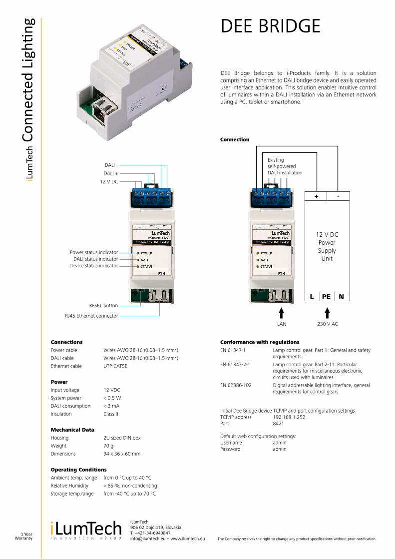
DEE Bridge belongs to i-Products family. It is a solution comprising an Ethernet to DALI bridge device and easily operated user interface application. This solution enables intuitive control of luminaires within a DALI installation via an Ethernet network using a PC, tablet or smartphone.
DALI -
DALI +
12 V DC
Power status indicatorDALI status indicator
Device status indicator
RESET button
RJ45 Ethernet connector
12 V DCPowerSupplyUnit
+ -
L PE N
LAN 230 V AC
Existing self-powered DALI installation
Conformance with regulations
EN 61347-1 Lamp control gear. Part 1: General and safety requirements
EN 61347-2-1 Lamp control gear. Part 2-11: Particular requirements for miscellaneous electronic circuits used with luminaires
EN 62386-102 Digital addressable lighting interface, general requirements for control gears
Initial Dee Bridge device TCP/IP and port configuration settings:TCP/IP address 192.168.1.252Port 8421
Default web configuration settings:Username adminPassword admin
1 YearWarranty
iLum
Tech
Con
nect
ed L
ighti
ng
DLS Touch Panel II
The Company reserves the right to change any product specifications without prior notification.
iLumTech906 02 Dojč 419, SlovakiaT: +421-34-6940847 [email protected] • www.ilumtech.eu
General
Power consumption max. 9W
Power input 12 VDC
Cooling system fanless
Temp.-Range 0°C to 40°C
System Hardware
CPU Texas Instruments AM3354, 720MHz
Memory 256 MB SDRAM
Flash 128 MB NAND FLASH
Networking LAN 100BaseTX, Bluetooth, Wi-Fi
I/O 3xDALI (1xDALI internally powered - 250mA)
Display
Size 7“
LCD Type TFT, Transmissive, Anti-Glare
Resolution 800x480, 262K colors
Viewing angle (H/V) 140 / 120 deg
Luminance 350 Cd/m2
Contrast ratio 350:1
Touchscreen Capacitive
Temp. Range 0°C to 40°C
Key features
• 2 modes: RGB and Dynamic white
• Manual or fully automatic control of light
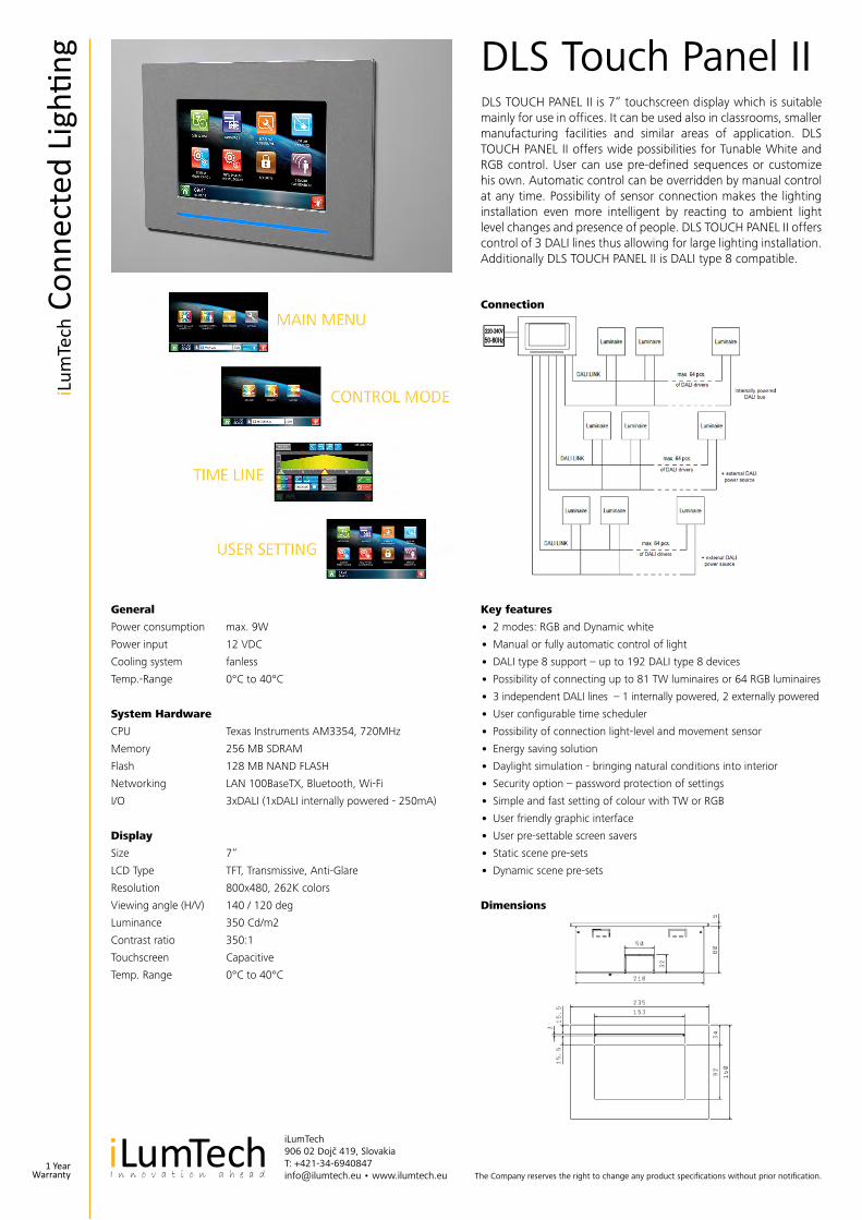
• DALI type 8 support – up to 192 DALI type 8 devices
• Possibility of connecting up to 81 TW luminaires or 64 RGB luminaires
• 3 independent DALI lines – 1 internally powered, 2 externally powered
• User configurable time scheduler
• Possibility of connection light-level and movement sensor
• Energy saving solution
• Daylight simulation - bringing natural conditions into interior
• Security option – password protection of settings
• Simple and fast setting of colour with TW or RGB
• User friendly graphic interface
• User pre-settable screen savers
• Static scene pre-sets
• Dynamic scene pre-sets
DLS TOUCH PANEL II is 7“ touchscreen display which is suitable mainly for use in offices. It can be used also in classrooms, smaller manufacturing facilities and similar areas of application. DLS TOUCH PANEL II offers wide possibilities for Tunable White and RGB control. User can use pre-defined sequences or customize his own. Automatic control can be overridden by manual control at any time. Possibility of sensor connection makes the lighting installation even more intelligent by reacting to ambient light level changes and presence of people. DLS TOUCH PANEL II offers control of 3 DALI lines thus allowing for large lighting installation. Additionally DLS TOUCH PANEL II is DALI type 8 compatible.
Connection
Dimensions
1 YearWarranty
iLum
Tech
Con
nect
ed L
ighti
ng
iLumTech906 02 Dojč 419, SlovakiaT: +421-34-6940847 [email protected] • www.ilumtech.eu