Embed Size (px)
Citation preview
I LEWIr %
HEADQUARTERS STRATEGIC AIR COUMAND
Directorate of Aircraft Maintenance
Aircraft Engineering Division
Inuineering Report No. 8-114 /
A STATEMENT OF WOR
FOR AN AERONAUTICAL SYSE S EL CTNUCLEAR NARDNESS PROGRAM
JUL30 1981 i]
Appro ;ed: Prep By:
MS K. STREETT, Colonel, USAF PAT ICK,ife, Aircraft Engineering Division Project Officer
[.rectorate of Aircraft Maintenance Aircraft Systems Branch4
This report reflects the views and opinions of the author. It is not official
HQ SAC policy, or a formal SAC position. Specific action by organizations orunits will not be taken as a result of this report unless requested by HQ SAC
C. under separate cover.
-LJ
-DISTRlIBUT ION STATEMENT A
Approved tot public release;Dit•ibutiofl Unlimited
S3 30 O70O
Engineering Report S-114 ,-.....
§TATMEN OF WORK FOR A ia -CO
HARDNESSJRGRAM, SE/
R11j y o P PatrickJ
F HQ SAC/LGMEOffutt AFB, Neb 68113 Program Element 11898
K ~~29 Juns98lj
Unclassified
K42 prv''' rpb lae distribution unlimited..
Aprvdfo kbcre'ae
Nuclar urvvabiityVulerailit, Ncler Hadnes Pogrm Pln, tatmenofWr, ularRdaioArca(/ifcce uvvbiiy Hrns
Nhicleaort Surv isailty/Vulnea biiy Nuclear HardnessPrga Pl, Statement o ok(O)Apni
intended for incorporation into a ma~jor system full scale development Statementof Work. This SOW Appendix is unique because its objective is the achievement
of hardness at minimum life cycle cost.
St rong emphasis is placed on the initial design phase to eliminate/minimize
I hardness critical items whose monitoring and control efforts during productionand over the operational life of the system result in high life cycle costs.Strong emphasis is also placed on assuring that production systems are hard a
(Abstract Continued) i
on maintaining hardness during operational deployment.
Visibility into the program is high and timely guidance is included viafrequent status reports and informal technical interchanges. Minutes of theinterchanges provide superior traceability and reduce uncertainty about AirI'orce/Contractor positions. It is believed that this SOW, amended/modifiedas necessary to fit a specific weapon system, would result in a highly reli-able, maintainable, and survivable system at miaiiium life cycle cost.
• , A e erT l e •tl o F o r - - - -i
"F , N: [ ".,,,'.
SI)1 -
] A s•'' 'i .i tt v (Tdes
"ID i : , t o: , . ta ,1,
=, ( IL
it
"
A Statement of Work
for an Aeronautical System
Nuclear Hardness Program
RAYFORD P. PATRICK, LTC, USAFProject Officer
Systems Branch
S. . ....
ABSTRACT
This report consists of a Nuclear Hardness Stateuent of Work (SOW)Appendix intended for incorporation into a major system full scale develop-ment Statement of Work. This SOW Appendix is unique because its objectiveis the achievement of hardness at minimum life cycle cost.
Strong emphasis is placed on the initial design phane to eliminate/mini-mize hardness critical items whose monitoring and control efforts duringproduction and over the operational life of the system result in high lifecycle costs. Strong emphasis is also placed on assuring that productionsystems are hard and on maintaining hardness during operational deployment.
Visib'lity into the program is high and timely guidance is included viafrequent status reports and informal technical interchanges. Minutes of theinterchanges provide superior traceability and re4;.ce uncertainty about AirForce/Contractor positions. It is believed that this SOW, amended/modifiedas necessary to fit a spocific weapon system, would result in a highly reli-able, maintainable, and survivable system at minimum life cycle cost.
2
Statement of Work
Appendix -
Nuclear Hardness
1.0 SCOPE AND OBJECTIVE
1.1 SCOPE. This Appendir establishes the tasks required during full scaledevelopment to insure that thc system is capable of successfully with-standing exposure to the nuclear environmental levels specified in thesystem specification and to develop a foundation for efforts to insure thatthis design hardness is not degraded during production and operationaldeployment.
1.2 OBJECTIVE: The major objective of this Appendix is the achievement ofmaintainable hardness at minimum life cycle cost.
2.0 GENERAL CONSIDERATIONS
2.1 To insure that design hardness is achieved, and that hardness is notdegraded during production and operational deployment, a complete, inte-grated lifecycle survivability program must be developed and implementedthroughout the entire acquisition process.
2.2 Once a comprehensive set of nuclear criteria have been developed andvalidated, they are incorporated into the full scale development as designrequiremenws. After this point, changes to those criteria evoke ripple likeeffects throughout the numerous Ai Force/DOD, contractor/subcontractororganizations, and numerous other ar:nices directly or indirectly involvedin the program. Therefore such changes are strongly discouraged and only
!•i drastic alterations in the original basis of the criteria would substantiate
such change.
2.3 It is the intent of the Air Force that the Nuclear SurvivabilityProgram be optimized over the system life. A major feature of such optimi-zation is the delineation of system elements and manufacturing/inspectiontechniques into hardness critical categories. The most critical categorieswill be subjected to special emphasis while less critical categories wouldbe afforded only standard program attention. Therefore extra effort toincorporate safety margins isometimes called hardness design margins) intothe design to eliminate/minimize hardness critical items should be superior
N• investment strategy. The relatively small nonrecurring cost increases toachieve adequate safety margins should result in significant decreases infuture recurring costs from reduced piecepart qualification, hardness assur-ance, and hardness maintenance programs.
3
2.4 Critical to the above approach is the early development of detailedguidance to design engineers. Electronic pieceparts susceptibility tonuclear environments must be characterized and the associated data madeavailable to the designer. Since susceptibility is circuit as well as partdependent, hardness design techniques must also be developed actd publicized.In many cases, tOe standard library of circuit designs used by deaicners,often company approved, must be modified. "Off-the-shelf", canned circuitdesigns may not provide the required hardness and/or reliability at thecircuit level. Extensive renovation of the reference library of circuitdesigns may be necessary, and if necessary, priority attention must be paidthis task. If the basic circuits in a sophisticated subsystem cannot meettheir hardness/reliability allocation, the overall subsystem wilt haveproblems. For this reason, few existing off-the-shelf subsystems (whichwere not optimally designed) generally are compatible with the program spec-ification and/or statement of work requirements. Such "off-the-shelf"systems, if used, -'at be treated as Contractor Furnished Equipment (CFE)subject to the same hardening and reliability requirements as new-designequipment. Subcontractors providing this equipment must be directed, guidedand supported in their redesign to ensure compatibility of design approachs,approved parts listings, safety margins, reliability allocations, Hardnessassurance design documentation (HADD) inputs, and hardness assurance/hard-ness maintenance (HA/HM) planning throughout the program. The prime con-tractor is responsible for compliance with the specification, for the gener-ation of required documentation, and for compliance with the requirements ofthis statement of work not only for new design equipment, but for all mis-sion critical equipment."-
2.5 Included in the initial guidance to design engineers will be specificguidance for the safety margin analyses and formats for the documentation ofthe analyses for later collation and inclusion in the hardness assurancedesign documentation. The contractor shall also consider future Assurance/maintenance tasks and utilize hardness designs which are easy and simple toverify Ly ordinary production workers and organizational maintenance person-nel. For example, in a good design, LRU EMP shielding integrity may beassured by visual inspection. If all the scews/rivets are present and tight- LRU shielding is adequate. Where feasible, the contractor shall developengineering-like requirements of an unclassified nature for their designersand for subcontractors. For exawple, an LRU not in a shielded area musthave a case capable of carrying the specified currents without resulting inmalfunctions of enclosed components. The design requirements may call formetal construction of the case, specified overlap and screw/rivet patternsfor case components, waveguide treatment of drainage/ventilation holes, etc.
2.6 A key aspect of the hardening approach is the definition of hardnesscritical items (HCIs). These items will be the subject of tight (costly)controls throughout the operational life of the system. In this program allelements of mission critical subsystems will be designated Pither ashardness critical or non hardness critical. For electroni.c pieceparts,hardness criticality is measured via hardness critical categories, i.ehardness critical category 1 (HCCl), hardness critical category 2, (ICC2),or non hardness critical (NHC). HCCI parts are those piezeparts which mustbe treated on an exceptional basis because 1) their safety margins are
4
iaadequate to insure long-term hardness unless special procurement controlsare developed and utilized (UCCIM); 2) the parts are hardness dedicated,i.e. they are contained in the design exclusively for hardness (NCClH).Examples of HCCIH parts may be games dose rate detectors which trigger cir-cumvention, or zener diodes used to propect susceptible interface piecepartsfrom transient voltages induced by incident electromagnetic pulses; 3) theyare nonstandard (HCClS). These pieceparts are unique parts not procuredsubject to requirements of pertinent military standards (thus potentially
subject to extreme variations in their response to nuclear environments).Except for special cases requiring detailed justification and prior AirForce approval HCCIS parts will not be used. If used, they will be treated
as HCCIM parts, regardless of their safety margins. HCC2 parts are thosewith safety margins sufficient to insure long-term hardness with routine iprecaution. Non hardness critical parts are those which can not degradeihardness below criteria levels. For example, a wire-wound resistor isgenerically non hardness critical to blast, thermal, and total gamma doseenvironments. Each of the above categories is treated differently with theHCCIM category having the most stingent requirements. Note that a part can-
not be both HCCIM and HCCIH. HCCIM categorization has priority. For exam-ple, if a sener diode is hardness dedicated, but if its own safety margin issmall, it will be designated as HCCIM, if its safety margin is large, it isHCCIH.
2.7 The contractor should develop his own safety margins where practicailand time permits. Design support nuclear environmental testing will be con-ducted to generate response data. These data and/or existing reliable datawill be used to characterize the response of each part type to the nuclearenvironment of interest. These distributions may be used to define hardiness
•: ~critical categories: Otherwise the following table will be used to deflife
the hardness critical caLegories.
5
qI
,11
K= .....--.----... *
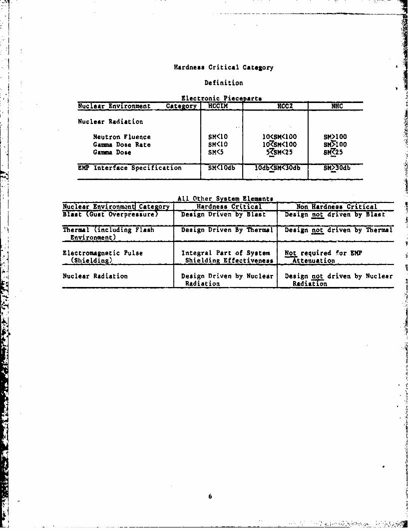
Hardness Critical Category
Definition
Electronic Piece arts
Nuclear Environment Category HCCIM HCC2 NHC
Nuclear Radiation
Neutron Fluence SM<10 10<SM<100 SM>100Gamma Dose Rate SM<10 107SM<100 SM7.100Gamma Dose SM<5 57SM<25 SM<25
EMP Interface Specification SM(10db lOdb<SM<30db SM>3Odb
All Other System ElementsNuclear Environmaný Category Hardness Critical Non Hardness CriticalBlast (Gust Overpressure) Design Driven by Blast Design not driven by Blast
Thermal (including Flash Design Driven By Thermal Design aot driven by ThermlEnvironment) .......
Electromagnetic Pulse Integral Part of System Not required for EMP(Shielding) Shielding Effectiveness Attenuation
Nuclear Radiation Design Driven by Nuclear Design not driven by Nuclear,_ _ _ _ _ _ Radiation RadiaE-Mn
6
Contractor derived categories must be reviewed and approved by the Air Forceprior Zo their use.
2.8 Each category is treated differently in the HADD documentation and insubsequent Hardness Assurance/Maintenance Programs. References 1 and 2 areLo be used to define the different treatments. Of course along with suchcategorization must be the establishment of a strong and effective Configu-
ration, Parts and Quality Control Programs applicable to all system ele-ments/procedures. Change of any part of the system could result in massivechanges in hardness criticality of numerous system elements/ptocesses.Therefore all changes must be closely monitored for such adverse impacts.
2.9 The contractor shall design all mission critical system elements touminioize life cycle costs. As a design goal, the contractor shall strive todesign each system element to be non hardness critical. If this is notpossible because of adverse weight, performance, cost, and/or scheduleimpacts, or because of technology limitations, a firmer secondary goal forelectronic pieceparts is the achievement of HCC2 status, if necessary, viause of protective HCC1H elements. Such HCClH elements will be fail-safe,i.e. their failure causes detectable subsystem malfunction; or self-test orperiodic field-level bench test will be incorporated. The HCCiM category isreserved for those few cases where it can be demonstrated that the abovegoals are technically impossible or cost prohibitive (nonrecurring costs aregreater than recurring costs). For these situations, the contractor shall
•ully document his attempts to achieve the goal, and/or the cost tradestudy. This documentation will be reviewed and approved by the Air ForceK along with the normal safety margin analysis.
2.10 The incorporation of adequate safety margins into system electronic
*i equipment results in another bonus feature, simplified verification. In themajority of cases, verification of design hardness will be based on theanalyses used to determine safety margins. Actual nuclear radiation tests
of LRU level equipment would only be needed for a very few cases. (Anexception may be testing of a computer protected via a circumventionscheme.) Neutron fluence tests, in particular, are to be minimized becauseof the destructive nature of the tests. Current injection tests of LRUswill also be minimized. Only if there are HCC1M parts in one or more inter-face circuits should such tests be conducted. The majority of the testingwill be at the component/piecepart level.
2,11 Prubably the one most important part of the Life Cycle Nuclear Surviv-ability Program is documentatluio. Even a superior hardness design can bedegraded rapidly during production or deployment unless preventative meass-ures are taken. Such measures are highly dependent upon precise knowledgeof the design, design elements, design technique, rationale for the tech-nique, specific safety margins, etc. The amount of documentation requiredis massive and early planning is mandatory for its development, and acquisi-tion: its content, formal storage, updating, security and accessibility; andits readibility and useability to future hardness assurance/maintenancepersonnel.
7
2.12 The name HADD (hardness assurance design documentation) has beenbestowed upon this library of data and references 1 and 2 will be used bythe contractor to guide his HADD efforts. A complete HADD is essential forhardness assurance and hardness maintenance, and it must be developed duringfull scale development. In fact, an extensive HADD development program,commencing immediately after contract award is necessary to insure a timely,cost-effective effort. After the Critical Design Review, the HADD shouldreflect the current system design configuration, as well as numerous otheritems required by the above references.
2.13 The specified reliability for the strategic mission length must beachieveable after system exposure to the specified nuclear environments.
The EX•P, blast, thermal, and gamma total dose exposures will be assumed tobe at take off and the neutron fluence and gamma dose rate exposure will be
taken to be at start of penetration. Close initial coordination betweennuclear hardness and reliability engineers is essential to the satisfactionof chis objective. Results from such coordination will be incorporated intothe published design guidance. Close coordination between maintainabilityand nuclear hardness engineers is also necessary to insure satisfaction ofpotentially conflicting requirements. For example, EMP shielding effective-ness requirements tend to force designers to securely fastened, metallic
construction. Accessibility requirements favor "quick disconnects" andlightweight construction. Close coordination is essential for the satisfac-
tion of both requirements.
2.14 The contractor is encouraged to use the information storage, retrival,and updating capabilities inherent to the HADD for other significant programdocuments, e.g., ILS Reliability and Maintainability and Safety Program.One central library facility would serve the entire program, which shouldreduce costly duplication of effort.
3.0 Specific Contractor Tasks
The contractor shall be guided by the philosophy and general consideration
expressed in the previous section during the accomplishment of the followingspecific tasks.
3.1 The Contractor shall design the system to withstand exposure to thespecified nuclear environments without loss of mission completion capabil-
and all hardness critical elements from the system. If this goal is not
achieveable because of state-of-the art limitations or because cost (i.e.the nonrecurrine design cost is greater than subsequent recurring costs) up-on Air Force approval substantiating documentation will be prepared andincorporated into the HADD.
3.2 Design Support. Design support consists of all those actions requiredto guide, direct and support contractor and subcontractor design engineersin the accomplishment of maintainable hardness design at minimum life cyclecosts.
"8
.... .. ....:: '
3.2.1 Mission Critical Equipment Analysis. Because only mission criticalequipment/components are required for strategic mission completion, onlythese equipment/components must be hardened. The contractor shall develop alist of such equipment/components for Air Force approval. This rlist will bemaintained current at all times. The Contractor shall treat all missioncritical equipment/components as Contractor Furnished Equipment (CFE)subject to the same control, design approach, safety margin, and philosophy.
3.2.2 Design Support Testing. The Cot,,.:-ctor shall conduct design supporttesting as necessary to support the design and effort. Available data, ifcurrent and reliable, may be used to minimize the test program. Resultingnuclear environmental response data will be us."d to define hardness criticalcategories, to develop approved parts lists, and to support the developmentof parts 4pecifications.
3.2.3 Design Guidelines. The Contractor shall prepare, document, and
distribute design guidelines for electromagnetic effects (EMP, EMI, andlightning), and nuclear radiation (neutron fluence, gqmmm dose rate, andgamma total dose). The guidelines shall incorporate the Latest state-of--the-art in design hardening techniques and shall be widely distributed toensure contractor and subcontractor designers are using a uniform approachbased on the latest and best information available. The guidelines willspecifically address the concept of safety margin, and contain the designgoals. They must also contain specific guidance/examples demonstrating com-bined circuit design/piecepart selection techniques which result in accept-able safety margins. The guidelines will also contain specific examples ofsafety margin analyses in the format for HADD incorporation along with firmrequirements to the designers to document design techniques, rationale andother information necessary to support the construction of the HADD.Briefings and/or tutorials will also be conducted as required to acqualnidesigners and management personnel with the fundamentals of nuclear hard-ening and the! impacts of the hardening effort on standard program functions.The guidelines will also address those design aspects of reliability, main-tainability, safety, and other disciplines whose cooperation is mandatoryfor simultaneous satisfaction of all program design objectives. Blast andthermal environments will also be addressed, but since applicability of suchguidelines will probably be more limited, separate documentation may be morecost effective.
3.2.4 Design Handbooks. The Contractor shall evaluate design handbooksused by both resident and subcontractor design personnel. If the handbookdesigns are not compatible with system requirements allocacea down to thedesign level of interest, then such designs will be reaccomplished and therevised handbook provided to design personnel. keliability, maintainabillityas well as hardness and operational requirements must all be simultaneouslysatisfied.
9
FA
I
3.3 nlast and Thermal Design and Verification. The Contractor shalldevelop and implement a program to insure that the blast and thermal crite-ria are satisfied by the system design. Necessary develupment testing andanalysis will be conducted and used both to support the design effort andsystem design verification. System level testing is not required. Computeraided analysis will be the primary method of verifying the design and pro-viding data to support the generation of vulnerability envelopes.
3.4 Electromagnetic Pulse Design and Verification. The Contractor shalldevelop and implemenc a program to insure that the system and subsystem EMPrequirements are satisfied. The Contractor shall conduct an analysis todetermine the local EMP induced environments for each deliberate antenna,and for significant ports of entry. The results will establish/verify thetq•quirements for each specific antenna and connecting electronics. For sub-system designs, a design goal will be the lack of HCC1M pieceparts. Excep-tions will be documented. Emphasis will be placed on LRU case design,internal wiring and circuit board layouts to minimize coupling to buriedcircuits. Random analysis of typical buried circuits will be conducted on asmall sample basis to provide confidence in the design. Subsystem designverification shall be by analysis and where there are HCClM parts at theinterface, by testing. Where necessary, methods will be developed to verifyEMP shielding integrity of component elements, i.e. joints, door seals, etc.However, it will be a design goal to obtain acceptable shielding integrityvia visual inspection, or other simple technique. Such designs greatlysimply subseqzent hardness assurance/hardness maintenance efforts. A systemlevel EHP test of a fully equipped aircraft will be conducted using the USAFTrestle facility at Kirland AFB, New Mexico. Test plans will be prepared tocover all phases of the test. Pre-analysis will be accomplished and in-cluded in the test plan. Data reduction and post-test analysis will beaccomplished and included in the test report. The system will be tested invarious modes o' degraded shielding, and critical interior points monitored.Such data will be used to sup' .t the hardness maintenance/hardness surveil-lance (HM/HS) Program, and t( ierify the pin specification adequacy for anaged system. The test report will also include a complete description ofthe test, the conduct of the test, test results and recommendations.
3.5 Nuclear Radiation Hardening Design Verification. The Contractor shallestablish and implement a program resulting in minimum-cost nuclear radi-ation hardness ove: the system life. Safety margins sufficient to minimizelife cycle control and monitoring are crucial to this objective. As ndesign goal, the contractor shall eliminate HCCIM parts from the design.Exceptions will be documented. The breakpoint between HCClM and HCC2 are as ishown in para 2.7 unless contractor derived breakpoints are devetoped.Design verification shall be by analysis, supported by piecepart tests andin some cases bv testing of circumvention/clamp circuit. No LkU tests arerequired. An analysis will be conducted on semiconductor pieceparts andcircuits to determine the safety margins. Piecepart and circuit margins andparts categorization will be determined from the analysis. If the analysisindicates that the part fails to meet the requirements, part substitution,
10
A1
circuit redesign and circumvention will be considered. Deviations from thedefined Hardness Critical Category (HCC) breakpoints for selected piecepartsshall be substantiated. For example, test data on a specific piecepart mayshow latch up and photo current caused burnout from gamma rate will alwaysoccur above the specification level but below the standard HCC2 breakpoint.For this case, designating the piecepart as HCC2 would not reduce hardnessconfidence, but would reduce production and maintenance cost.
3.6 Hardness Assurance. Although the hardness assurance program does notformally begin until after production decision, considerable prerequisiteefforts are required during fuil scale development. The first effort is thedevelopment of an overall plan of attack which defines the tasks requiredduring full scale development to support minimum cost hardness assurance/maintenance. In addition to the previously noted design guidelines, thecontractor shall develop formats and guidelines for initiation, development,and maintenance of the Hardness Assurance Design Documentation (HADD). TheHADD in its entirety is a deliverable item. Contractor developed fcomatswill be used to guide the development. Normally the HADD would be transi-tioned to the responsible Air Force agency after the full scale developmentprogram. In the event of program cancellation, the Contractor shall corm-plete the HADD as much as possible and deliver it to the Air Force. Inaddition, production procedures will be developed to provide strict control 'iover system configuration. All changes must be monitored and controlled toprevent deterioration of the hardened design. Existing military standards"(amended as required) shall be the basis for such change control, parts con-trol, and manufacturing/inspection procedure control. Parts specificationswill be developed for hardness critical design elements.
3.7 Hardness Mainenance and Hardness Surveillance (HM/HS). A hardnesstmaintenance and hardness surveillance plan will be developed to ensure that
the production system remains hard during its life cycle. The HM/HS planwill be written incorporating HM/HS procedures developed during full scaledevelopment and production. HM/HS test equipment, if required, will bedesigned and fabricated under separately funded; procurement. The Contractor
shall incorporate into the HM/HS program all "hardness" related requirements(i.e., nuclear, RCS, lightning, etc.) which will mandate special ma-inte-
-1 nance/surveilLance procedures/attention upon deployment.
3.8 Inherent Laser Hardness. The inherent laser hardness of the systemwill be assessed using results of laser tests of selected surface materialsand coatings, and structural sections.
3.9 Crew Protection Anaiysis. Crew protection requirements will beanalyzed for the nuclear environnv.nts to be encountered, including passagethrough a radioactive cloud. These environments will include radioactivedust ingested through the ECS inl-ts, thermal (flash blindness and skinburns), and nuclear radiation. Protection requirements will be identifiedalong with potential benefits to be gained from implementation.
"i1.
'la
3.10 On-Board EMP Hardness Monitor. An on-boerd means of verifying systemhardness to EMP is highly desirable. In particular, prior to entry ontostrategic alert the system's capability to protect its electronic subsystemsfrom incident EMP environments should be gaged, i.e., the system Phieldingeffectiveness (S.E.) or equivalent, should be acceptable. The contractorshall investigate the feasibility and practicality of providing this builtin test (BIT) capability. The best technique(s) will be presented to theA.F. for evaluation and approval.
3.11 Software. Software use, requirements and application to hardeningwill be examined and implemented as required. Applications will includereset for upset and commands for possible data storage and retrieval forcircumvention. Hardness critical software will be identified andcontrolled.
3.12. Parts Criticality Integration. The Contractor shall review otheraspects of the program and evaluate the feasibility and practicality ofintegrating "critical" parts control into the normal hardness criticalcontrol effort. The concepts, techniques, and methodology of hardnesscritical item (HCI) control are well established and could be extended to"reliability" critical items, "survivability" critical items, etc. Anyspecial controls, assurance/maintenance requirements, parts specifications,etc. could be integrated into the Hardness Acaurance/Maintenance Program.
3.13. Survivability/Vulnerability (S/V) Analysis. An S/V analysis will bemade for the SIOP mission profile and required nuclear weapon yields for thevarious mission phases. These phases include base escape, enroute (withpossible aerial refueling) penetration. The S/V analysis will considerthe blast (overpressure ann .,st), thermal, and nuclear radiation environ-ments. The analysis will include, but not be limited to, vulnerabilityenvelopes for free-field environments and responses to the environments as afunction of aspect angle. Only the EMP high altitude criteria will beaddressed.
3.14. Coordination and Monitoring of Equipment Suppliers. The Contractorwill direct, coordinate, and monitor suppliers of contractor furnishedequipment (CFE) for nuclear hardness assurance, nuclear hardness design,analysis, and/or testing throughout the program. The Contractor will pro-vide design guidelines and other guidance to suppliers to insure the imple-mentation of t '!iclear Hardening Program compatible with the intent andrequirements of this SOW.
3.15 Drawing Annotations. Individual nuclear Hardness Critical Items(HC1s) shall be identified on the drawing, on the parts list, and/or on thelist materials. Nuclear Hardness Critical Items are defined as any items atany assembly level which are mission critical and which require special pro-curement controls/unique specification requirements to prevent degrading ofsystem hardness. (Hardness criticality is defined in Table I. For elec-tronic pieceparts, only HCCl parts are to be considered HCI's). HardnessCritical Processes (HCPs) must be identified in drawings and drawing notes.
.4
.12
- . . .. m -
Nuclear Haedness Critical Processes are processes, specifications, and/orprocedures which are hardness critical, (i.e. required to assure hardness isa'chieved during production and/or to maintain hardness during operationaldeployment) and which could degrade nuclear hardness if they change.
Hardness Critical Items are to be marked: HCI
VHardness Critical Processes are to be marked: HCP
*Drawings that contain HCIs or HCPs ehall have the following statement on theface of the drawing:
"This drawing contains Hardness Critical Items or Hardness
Critical Processes. Refer to the appropriate section of the(Weakon System Name) Hardness Assurance Design Documentationfor more information."
In addition all drawings of all mission critical design elements and higherlevel assemblies shall have the following statement on the face of each drawdrawing:
"This drawing contains Mission Critical Items of the(waoSystem Name). All changes must be evaluated for impa~cts tosystem hardness."
3.16 Visibility. Air Force visibility into the Nuclear Hardness Programshall be via informal technical interchanges, formal design reviews andperiodic Nuclear Hardness Program Status reports. Informil interchanges maybe scheduled at the request of either the Contractor or the Air Force at anytime, otherwise the Contractor shall plan on hosting such interchanges on aK quarterly basis. Such meetings shall he the major vehicle for timely AirForce review and approval of on-going efforts and to resolve any Air Force
¾ or contractor concerns. The Contractor shall record minutes of each meetingfor permanent record. The Nuclear Program Status Report will be quarterlyreports delivered to the Air Force not less than 15 days prior to the tech-
* -~ nical interchange. The Status Reports will consist of loose-leaf pages toallow for updating via page replacement interchanges. Material ini originalreports need not be duplicated in subsequent reports. The initial reportwill also contain the outline of the Nuclear Program Management Structure,its relative position in the overall Program and the relationship with othertechnical and managerial program agencies. An overall Nuclear Hardnessprogram Task/Milestone chart will be included and updated in subsequentreports. In addition, each report shall contain "~executive sum~mary" detail
A of the status of each of the specific tasks required by this Appendix withreference to the complete documentation available in the HADD. Updates ofpreviously reported areas will also be included.
13
4.0 REFERNCES
1. Patrick, L and J. Ferry, "'Nuclear Hardness Assuranoe rabidelifles forSystem •ith Mderate Requiresents". A,--TR-14 7 , :4ir Forc. WO-P."c
laboratory, Kirtland AFn NK, Septenber 1976.
2. Patrick, R. aid J. Ferry, 'N&uclear Hardness As..rnme_ fors nauntlcae
System", Paper 801227, Aerospace Congress & ZKxP0-tto, los Aetes
CQxwention Center, October 1981. (Order frcm Society of Aerospame
Engineers, Inc. 400 COMusxMaIth Drive, Warrendal, Penn. 15096.)
14
EI
DISTRIBUTION
2 - AFWL/NT, Kirtland AFB, NM 871172 - AFWL/NTN, Kirtland AFB, NM 871172 - ASD/ENFTV, Wright-Patterson AFB, OH 454332 - ASD/YYEH, Wright-Patterson AFB, OH 454332 - SAC/XPFS, Offutt AFB, NE 681132 - SAC/XPH, Offutt AFB NE 68113I - SAC/XPHJ, Offutt AFB, NE 681131 - USAFSAM/RZW, Brooks AFB, TX 782352 - HQ USAF/LEY, Washington, DC"2 - HQ USAF/RDQ, Washington, DCI - HQ TAC/DR, Langley AFB, VA1 - HQ TAC/LG, Langley, AFB, VA1 - HQ IISAFE/GE, Ramstein AB, GEI - HQ USAFE/Lq, Ramstein AB, CEI - HQ AFLC/LO, Wright-Patterson AFB, OHI - DNA, Washington, DC 20305I - Harry Dia-'ond Lab.,
2800 Powder Mill RdAdelphi, MD 20783
1 - ESD/CC, Hanscom APB, MA 01731]5 - HQ SAC/LGME, Offutt APB NE 68]J3
.15
'U!