Embed Size (px)
Citation preview
N A S A T E C H N I C A L Sf̂ SiM& NASA TM X-2860
MEMORANDUM
NP00CM
I L £CO
% f »*i f > - . . - . . , s
. . - . * . , . . » * . . . « , . , j« ^ * * * ' • * =^ * s • : > * :' -%- i jf - *• ;. J *•
f - * : ' # f • -. *
|f " f ^ ^ - % -, &
fr *COMPUTER OPTIMIZATIONOF REACTOR-THERMOELECTRICSPACE POWER SYSTEMS
by William L. Maag, Patrick M, Fitmegan,and Laurence H. Frshbach
Lewis Research Center
Cleveland} Ohio 44-135
NATIONAL AERONAUTICS AND SPACE ADMINISTRATION • WASHINGTON, D. C. • AUGUST 1973
https://ntrs.nasa.gov/search.jsp?R=19730018859 2018-05-30T12:12:26+00:00Z

1. Report No.
NASA TM X-28602. Government Accession No. 3. Recipient's Catalog No.
4. Title and Subtitle
COMPUTER OPTIMIZATION OF REACTOR-THERMOELECTRICSPACE POWER SYSTEMS
5. Report DateAugust 1973
6. Performing Organization Code
7. Author(s)
William L. Maag, Patrick M. Finnegan,and Laurence H. Fishbach
8. Performing Organization Report No.
E-7446
9. Performing Organization Name and Address
Lewis Research CenterNational Aeronautics and Space AdministrationCleveland, Ohio 44135
10. Work Unit No.
503-25
11. Contract or Grant No.
12. Sponsoring Agency Name and Address
National Aeronautics and Space AdministrationWashington, D.C. 20546
13. Type of Report and Period Covered
Technical Memorandum
14. Sponsoring Agency Code
15. .Supplementary Notes
16. Abstract
This report describes a computer simulation and optimization code that has been developedfor nuclear space power systems. The results of using this code to analyze two reactor-thermoelectric systems are presented.
17. Key Words (Suggested by Author(s))
Space powerNuclearThermoelectricSystems analysis
18. Distribution Statement
Unclassified - unlimited
19. Security dassif. (of this report)
Unclassified20. Security Classif. (of this page)
Unclassified21. No. of Pages
1622. Price*
$3.00
'For sale by the National Technical Information Service, Springfield, Virginia 22151
COMPUTER OPTIMIZATION OF REACTOR-THERMOELECTRIC
SPACE POWER SYSTEMS
by William L Maag, Patrick M. Finnegan,and Laurence H. Fishbach
Lewis Research Center
SUMMARY
The selection of a particular nuclear space power system is a result of a trade-offstudy of the system performance with some predetermined figure-of-merit such asweight, size; cost, or reliability. This report describes a computer simulation and op-timization code that has been developed for nuclear space power-systems. The codecomputes the steady-state operating conditions and the component design characteristicsthat correspond to the optimum system as defined by the figure-of-merit.
The code was used to analyze two reactor-thermoelectric space power systems fornet electrical power requirements between 5 and 40 kilowatts. One system used the -SNAP zirconium hydride reactor coupled to lead telluride thermoelectric converters,while the other was a higher temperature system using a uranium nitride fueled reactorcoupled to silicon-germanium thermoelectric converters. The program generated theminimum-weight-against-power curve for each system. ;
INTRODUCTION
Electric power requirements for future space missions have been estimated to rangefrom a few kilowatts to more than 100 kilowatts. The lower power requirements(<5 kWe) will be supplied by solar cells which have proved to be a dependable, light-weight power source. For the higher powers and-for conditions of inadequate sunlight,the use of nuclear energy as a heat source for various energy conversion devices ap-pears to be most promising.
The power converters include thermoelectric, thermionic, Rankine, and Brayton.To obtain acceptable conversion efficiency, these devices must be coupled to a high-temperature, liquid-metal-cooled nuclear reactor. The waste heat .is rejected to spaceby radiation.

The selection of a particular power system is a result of a tradeoff study of the sys-tem performance with some predetermined figure-of-merit such as weight, size, cost,or reliability. The figure-of-merit for a system is totally dependent on the figures-of-merit for each of the components in the system. An optimum system, therefore, canonly be determined by considering the relation of each component to the total system.
This report describes a computer simulation of a reactor-thermoelectric spacepower system and a technique for determining the optimum system when the figure-of -merit is minimum weight. .
METHOD OF ANALYSIS
Powerplant
The reactor-thermoelectric powerplant is represented schematically in figure 1. Itis designed to produce electrical power for unmanned space applications (ref. 1) whichrequire high reliability for as long as 5 years of continuous operation. The system con-sists of a nuclear reactor heat source coupled to the hot side of thermoelectric convertermodules. The cold side of each module is coupled to a radiator that rejects the wasteheat to space. The heat is transferred by means of two circulating liquid-metal loopswhich are pumped by dual-throat electromagnetic pumps powered by separate thermo-electric modules. An expansion compensator in each loop accommodates the thermal ex-pansion of the liquid metal and maintains a void-free loop for zero-gravity operation.The reactor is separated from the power conversion equipment and the payload by ashadow shield that attenuates the gamma and neutron radiation to acceptable levels. For
1 . - fi
this analysis the radiation dose at the payload mating plane was assumed to be 10 roent-1 2 • . ' ' • • . -
gens and 10 nvt in 5 years.A typical arrangement of system components is shown in figure 2. This figure rep-
resents the flight configuration of the 5-kilowatt-electric space power system consistingof a zirconium hydride (ZrH) reactor and lead telluride (PbTe) thermoelectricconverters.
Optimization Procedure
A simplified flow chart for the computer program is shown in figure 3. Starting withthe input data, which consist of the required electrical load and an initial estimate of theoperating conditions, the program performs a cycle analysis that establishes the loopflow rates and a consistent set of state-point conditions. The cycle analysis is a heat andmaterial balance for the system which includes the pumping power required to circulate

the coolants, the efficiency of the pumps, the conversion efficiency of the thermoelectricmodules and power conditioner, and all heat losses from the system.
Each component is then designed for the operating conditions established by the cycleanalysis. The figure-of-merit for the total system is then determined by summing thefigures-of-merit for each component. The optimization routine compares this value witha previously calculated value and decides whether it represents the optimum (e.g., theminimum system weight or the minimum cost). If not, the program returns to the inputstep and perturbs one of any number of predetermined variables (e.g., radiator outlet,temperature). Then with this new set of operating conditions the calculations are re-peated and a new system figure-of-merit is determined. The program continues to per-turb each variable in a consistent manner until the figure-of-merit for the systemreaches the optimum.
This procedure is depicted graphically by the following illustration:
Cycle Variable perturbed
Figu re- of- me rit
Four variables were chosen to be perturbed to illustrate the principle of operation ofthe optimization program. Starting with variable 1 the initial value is perturbed in thedirection (higher or lower) that improves the figure-of-merit, and this continues until thefigure-of-merit does not show improvement. Then starting with the optimum operatingconditions from variable 1, the second variable is perturbed, and so on through var-iable 4. The program then returns to variable 1, and the calculation cycle is repeateduntil no further improvement in the figure-of-merit is realized. It then prints the finalset of state-point operating conditions and component design characteristics.
Components
Each powerplant component is represented by a subroutine in the program, the pur-pose of which is to design the component for the state-point conditions determined by thecycle analysis. The result of each design calculation is some figure-of-merit that de-scribes the component along with any other design details (e.g., heat-exchanger surfacearea) that might be pertinent to the investigator.
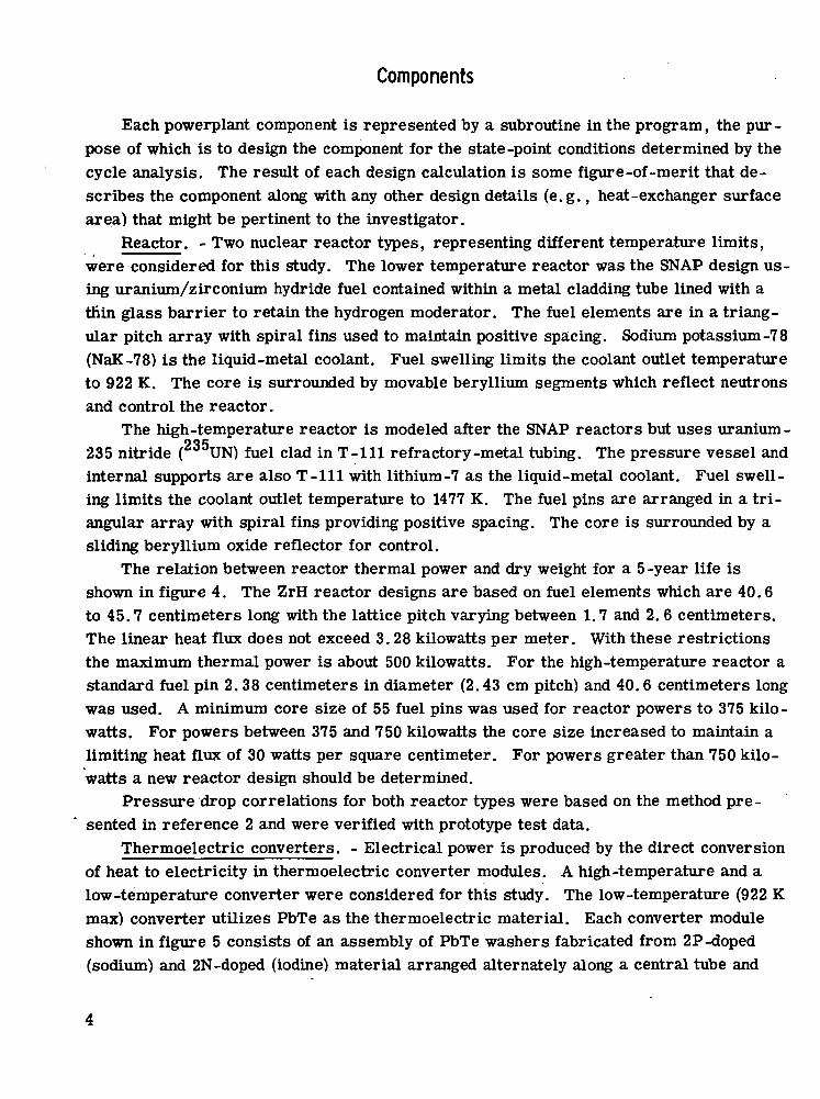
Reactor. - Two nuclear reactor types, representing different temperature limits,were considered for this study. The lower temperature reactor was the SNAP design us-ing uranium/zirconium hydride fuel contained within a metal cladding tube lined with athin glass barrier to retain the hydrogen moderator. The fuel elements are in a triang-ular pitch array with spiral fins used to maintain positive spacing. Sodium potassium-7 8(NaK-78) is the liquid-metal coolant. Fuel swelling limits the coolant outlet temperatureto 922 K. The core is surrounded by movable beryllium segments which reflect neutronsand control the reactor.
The high-temperature reactor is modeled after the SNAP reactors but uses uranium-ooc
235 nitride ( U N ) fuel clad in T-lll refractory-metal tubing. The pressure vessel andinternal supports are also T-lll with lithium-7 as the liquid-metal coolant. Fuel swell-ing limits the coolant outlet temperature to 1477 K. The fuel pins are arranged in a tri-angular array with spiral fins providing positive spacing. The core is surrounded by asliding beryllium oxide reflector for control.
The relation between reactor thermal power and dry weight for a 5 -year life isshown in figure 4. The ZrH reactor designs are based on fuel elements which are 40.6to 45.7 centimeters long with the lattice pitch varying between 1.7 and 2. 6 centimeters.The linear heat flux does not exceed 3.28 kilowatts per meter. With these restrictionsthe maximum thermal power is about 500 kilowatts. For the high-temperature reactor astandard fuel pin 2. 38 centimeters in diameter (2.43 cm pitch) and 40.6 centimeters longwas used. A minimum core size of 55 fuel pins was used for reactor powers to 375 kilo-watts. For powers between 375 and 750 kilowatts the core size increased to maintain alimiting heat flux of 30 watts per square centimeter. For powers greater than 750 kilo-watts a new reactor design should be determined.
Pressure drop correlations for both reactor types were based on the method pre-sented in reference 2 and were verified with prototype test data.
Thermoelectric converters. - Electrical power is produced by the direct conversionof heat to electricity in thermoelectric converter modules. A high-temperature and alow-temperature converter were considered for this study. The low-temperature (922 Kmax) converter utilizes PbTe as the thermoelectric material. Each converter moduleshown in figure 5 consists of an assembly of PbTe washers fabricated from 2P-doped(sodium) and 2N-doped (iodine) material arranged alternately along a central tube and

separated by mica washers which act as insulators. Conductor rings span adjacentwashers on both the inside diameter and outside diameter to provide a serpentine elec -trical path through the module. The conductor rings are electrically isolated from thecenter refractory tube and the outer stainless-steel cladding by thin sleeves of boron ni-tride, which also provide good thermal contact between clad and rings. This completeassembly with appropriate end closures containing electrical feedthroughs is compactedby an autoclave process into a rugged, void-free, sealed module. The module is en-closed within a larger tube that provides an annular passage for the cold-side NaK flow.The hot-side NaK flows through the center refractory tube; the resulting temperaturedifference across the PbTe washers creates the driving force for current flow.
The high-temperature (1273 K max) thermoelectric converter utilizes N- and P-typesilicon-germanium (SiGe) alloys. This module is based on the "compression module"design described in reference 3. It is similar to the low-temperature module, where aninner and outer cylinder form the hot and cold surfaces between which the heat flows ra-dially. However, the SiGe thermoelectric material is arranged in radial, pieshapedsegments with insulators and conductors positioned to form an electrical series connec-tion but in a serpentine, circular path.
A standard-load power module producing about 325 watts at 4 volts dc was used tocharacterize each thermoelectric converter. The description includes dry weight, liq-uid weight, and size for the modules and associated piping. The total heat load per mod-ule was determined from experimental and analytical data as a function of the temper -ature difference between hot and cold clad junctions. However, the conversion efficiencywas determined as a function of the average hot and average cold clad temperatures.The efficiency curves are shown in figure 6. With this information the total number ofstandard-load power modules can be determined for a given system defined by power andvoltage.
A standard-pump power module was also specified for each converter. This differedfrom the load module because of the high-current, low-voltage requirements for theliquid-metal electromagnetic pumps.
Pressure drop correlations for the complex flow passages within the modules weredetermined from experimental data and analysis (ref. 4).
Electromagnetic pumps. - The pumps used for both hot and cold liquid-metal loopsare dual-throat dc-conduction electromagnetic (EM) pumps powered by separate thermo-electric converters that are designed to supply high-current, low-voltage power. Theprincipal advantage of EM pumps is high reliability, which is inherent because they haveno moving parts. The pump design is based on steady-state operation at end-of-life con-ditions. During startup and shutdown, auxiliary power is supplied to maintain loopcirculation.

Radiator. - The waste heat from the converters is rejected to space by radiation.The radiator considered here has a conical-cylindrical shape with only one side radiating.The liquid metal (NaK) is contained in stainless-steel tubes and headers, while the armorand fins of the radiating surface are fabricated from either aluminum or copper, depend-ing on whether the maximum fluid temperature is less than or greater than 672 K, re-spectively. Radiator size and weight are determined by a method similar to that used byJ. P. Couch of Lewis for the assumptions that the radiator is in a 720-kilometer equa-torial orbit with its axis perpendicular to the orbital plane and that the no -puncture prob -ability is 0.99 for 50 000 hours.
Piping. - Connecting the major components in each loop are two sections of pipe,each operating at different liquid-metal temperatures. A pipe section consists ofstraight-run tubing, welded fittings (elbows, bends, and tees), and insulation. Pipe ma-terial is either 316 stainless steel (used for NaK at temperatures less than 922 K) orCb-lZr (used for lithium at temperatures less than 1273 K) as limited by the SiGe ther-moelectrics. The piping subroutine will size the pipe according to the friction pressuredrop specified by the cycle analysis and the length of pipe section assumed for the par-ticular powerplant. Knowing the pipe size permits calculation of pipe weight, insulationweight, and fluid weight.
When lithium is used in the high-temperature loop, a weight penalty must be appliedto melt the lithium and then heat it and the piping to a reasonable pumping temperaturefor startup. The heat required for this is calculated, and the weight of a battery to sup-ply electrical heating is added to the insulation weight for this pipe section.
Expansion compensator. - An expandable reservoir is required in each loop to ac-commodate the thermal expansion of the liquid metal in going from room temperature tooperating temperature and also to maintain the system at a positive pressure sufficientto prevent pump cavitation or local boiling in the reactor. Each compensator consists ofa tandem bellows enclosed in a housing with a positive stop to prevent bellows compres-sion beyond a stacked height. The first bellows provides volume for the expanding fluid.The volume between the bellows is filled with static fluid for redundancy. An inert gassurrounds the second bellows to serve as the pressure source.
The SNAP programs have provided sufficient information about expansion compen-sator design to determine an empirical relation between the required expansion volumeand component weight and size.
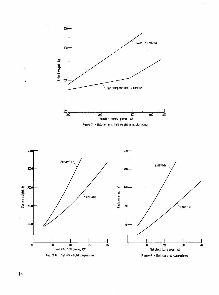
Shield. - For unmanned applications a shadow shield is sufficient to attenuate thegamma and neutron radiation to acceptable levels. The attenuation covers a shadow areacorresponding to the space vehicle diameter at some specified distance from the reactorwhere the payload is located. The shield is multilayered: tungsten and uranium are usedfor gamma attenuation, and lithium hydride cast in a stainless-steel container is usedfor neutron attenuation. Shield weight was determined for each reactor type as a functionof the reactor power and for a constant cone half-angle of 8°. These correlations are
6

shown in figure 7. The increase in weight with power for the ZrH reactor is continuousbecause the reactor size is constantly increasing, which requires that both the shieldthickness and diameter increase accordingly. For the high-temperature UN reactor, thereactor size is constant below 375 kilowatts and then increases with power. The firstsection of the shield curve therefore reflects only a change in shield thickness, while thesecond section includes both diameter and thickness changes. The slopes of these twosections indicate the strong influence of reactor size on shield weight.
Power conditioner. - The power conditioner converts the low-voltage power from thethermoelectric modules to a voltage acceptable for the payload. For this study the 4000-volt power conditioner of reference 5 was assumed to be applicable. Reference 5 reportsconditioner specific weight and conversion efficiency as a function of input power andvoltage. The component weight was modified to include the additional radiator weight re-quired to dissipate the heat generated in the power conditioner.
Physical properties. - A separate subroutine is provided to store the physical prop-erties of the various materials used throughout the program. This makes it possible tointerchange materials quite easily and thereby investigate their effect on the system.
RESULTS AND DISCUSS ION
A computer simulation program similar to this one has been initiated for variousnuclear reactors coupled to thermoelectric, thermionic, and Brayton electrical powergeneration systems. The goal of this work was the development of a management toolthat would select the optimum space power system for specific power requirements andfigures-of-merit. The results presented herein represent an initial effort to identify theoptimum reactor-thermoelectric space power system for requirements ranging between5 and 40 kilowatts of electrical power conditioned to 4000 volts. The figure-of-meritused to define optimum is total system weight.
Figure 8 shows the optimum system weights for the low-temperature ZrH/PbTe andthe high-temperature UN/SiGe systems as a function of net electrical power. The opti-mization parameters (i. e., the operating variables that were perturbed) for this studywere the cold-side temperatures into and out of the radiator and the pressure drop ineach of the four piping sections. The reactor inlet and outlet temperatures were fixed toadhere to component design criteria. For the ZrH reactor the 866 K inlet and 922 K out-let temperatures were determined by the maximum allowable fuel temperature of theZrH-uranium alloy. For the UN reactor a maximum allowable temperature of the SiGethermoelectric material set the reactor outlet temperature at 1273 K. The UN reactorinlet temperature was set at 1216 K to correspond to a reasonable temperature drop
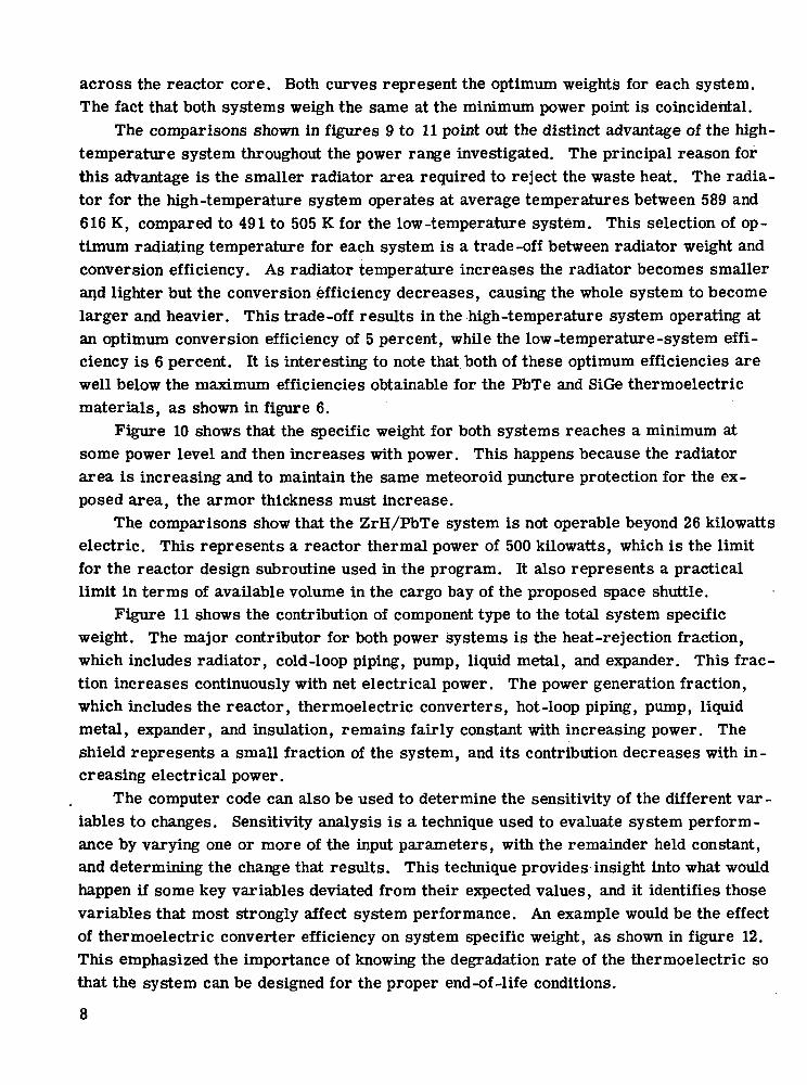
across the reactor core. Both curves represent the optimum weights for each system.The fact that both systems weigh the same at the minimum power point is coincidental.
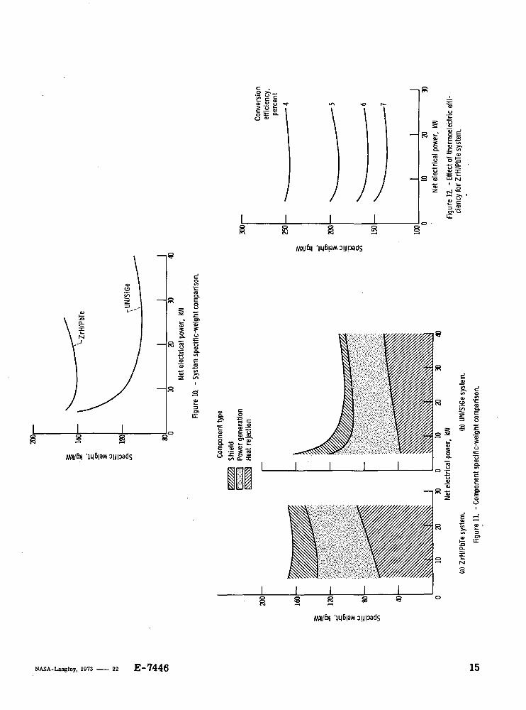
The comparisons shown in figures 9 to 11 point out the distinct advantage of the high-temperature system throughout the power range investigated. The principal reason forthis advantage is the smaller radiator area required to reject the waste heat. The radia-tor for the high-temperature system operates at average temperatures between 589 and616 K, compared to 491 to 505 K for the low-temperature system. This selection of op-timum radiating temperature for each system is a trade-off between radiator weight andconversion efficiency. As radiator temperature increases the radiator becomes smallerand lighter but the conversion efficiency decreases, causing the whole system to becomelarger and heavier. This trade-off results in the high-temperature system operating atan optimum conversion efficiency of 5 percent, while the low-temperature-system effi-ciency is 6 percent. It is interesting to note that both of these optimum efficiencies arewell below the maximum efficiencies obtainable for the PbTe and SiGe thermoelectricmaterials, as shown in figure 6.
Figure 10 shows that the specific weight for both systems reaches a minimum atsome power level and then increases with power. This happens because the radiatorarea is increasing and to maintain the same meteoroid puncture protection for the ex-posed area, the armor thickness must increase.
The comparisons show that the ZrH/PbTe system is not operable beyond 26 kilowattselectric. This represents a reactor thermal power of 500 kilowatts, which is the limitfor the reactor design subroutine used in the program. It also represents a practicallimit in terms of available volume in the cargo bay of the proposed space shuttle.
Figure 11 shows the contribution of component type to the total system specificweight. The major contributor for both power systems is the heat-rejection fraction,which includes radiator, cold-loop piping, pump, liquid metal, and expander. This frac-tion increases continuously with net electrical power. The power generation fraction,which includes the reactor, thermoelectric converters, hot-loop piping, pump, liquidmetal, expander, and insulation, remains fairly constant with increasing power. Theshield represents a small fraction of the system, and its contribution decreases with in-creasing electrical power.
The computer code can also be used to determine the sensitivity of the different var-iables to changes. Sensitivity analysis is a technique used to evaluate system perform-ance by varying one or more of the input parameters, with the remainder held constant,and determining the change that results. This technique provides insight into what wouldhappen if some key variables deviated from their expected values, and it identifies thosevariables that most strongly affect system performance. An example would be the effectof thermoelectric converter efficiency on system specific weight, as shown in figure 12.This emphasized the importance of knowing the degradation rate of the thermoelectric sothat the system can be designed for the proper end-of-life conditions.
8

SUMMARY OF RESULTS
A computer simulation and optimization code has been developed for nuclear spacepower systems. The code consists of a cycle analysis for the closed-loop system, aseries of subroutines that describe each component, and an optimization technique thatmanipulates the operating variables to arrive at an optimum system as defined by somefigure-of-merit.
The code was used to analyze two reactor-thermoelectric space power systems for .net electrical power requirements between 5 and 40 kilowatts. The figure-of-merit usedto define optimum was minimum system weight. A low-temperature system using a zirr
conium hydride reactor coupled to lead telluride thermoelectric converters and a high-temperature system using a uranium nitride reactor coupled to silicon-germanium ther-moelectric converters were investigated. The results show that the high-temperaturesystem was smaller and lighter for the power range investigated, even though the con-verter efficiency was about 1 percentage point lower. The radiating temperature atwhich the waste heat was rejected to space was the dominant factor.
The code also enables the user to perform system analyses to determine the effectsof various real or proposed changes, and it serves as an accessible storage bank for allpertinent information about a system.
Lewis Research Center,National Aeronautics and Space Administration,
Cleveland, Ohio, May 18, 1973,503-25.
REFERENCES
1. VanOsdol, J. H.; and Howard, J. M.: Unmanned Reactor-Thermoelectric Systemfor Applications in the 1970's. Presented at Fourth Intersociety Energy ConversionEngineering Conference, Washington, D.C., Sept. 22-26, 1969.
2. Sangster, W. A.: Calculation of Rod Bundle Pressure Loss. Paper 68-WA/HT-35,ASME, 1968.
3. Raag, V.: New Design Concepts in Thermoelectric Generators. Microwave Tech-nology. RCA, 1969, pp. 109-113.

4. Mason, D. G.: SNAP Reactor Programs Progress Report, February 1969-April1969. Rep. AI-AEC-12819, Atomics International, June 29, 1969.
5. Jacobsen, A. S.; and Tasca, D. M.: Thermionic Reactor Power Conditioner Designfor Nuclear Electric Propulsion. Proceedings of the Tenth Annual Thermionic Con-version Specialist Conference. IEEE, 1971, pp. 52-58.
10

•€
11

Inputi
Variable ! Fixed
Cycle solution
System state points
Component design
Weights
No OptimizationYes
6001—
Figure 3. - Program flowchart
200 400Reactor thermal power, Kfl
600 800 1000
Figure 4 - Relation of reactor weight to power.
12

">-Clad -compatiblewith NaK
^Electrical conductor
-Electrical insulation - high• thermal conductivity
-Electrical insulation - lowthermal conductivity
-N-type thermoelectricmaterial
-P-type thermoelectricmaterial
CD-11517-22
Figure 5. - Compact, tubular lead telluride thermoelectric module.
MI- Cold-cladtemperature,
K
Converter
Low temperature (PbTe)High temperature (SiGe)
Ol—600
I700 • 800 900 1000 1100
Hot clad temperature, K
Figure 6. - Thermoelectric efficiency.
1200 1300
13
600
400
200
100 L_100
v High-temperature UN reactor
I200 400 600Reactor thermal power, kW
Figure 7. - Relation of shield weight to reactor power.
800
I
5000
4000
3000
2000
1000
ZrH/PbTe
UN/SiGe
I J4010 20 30
Net electrical power, kW
Figure 8. - System weight comparison.
8ro
a
20ft
160 —
120
80
40
ZrH/PbTe
I I I10 20 30
Net electrical power, kW
Figure 9. - Radiator area comparison.
40
14
o >^^^s is> 'o fc-
o a= ca.
otsfc
S "3•S
MH/fo|
_
S «'C Q-
I 6"
= 1
R
1
OI
I I'£ .H1
M
S
NASA-Langley, 1973 — 22 E-7446 15

f »• «"
. D.C.
•«*r
#"
OFFICIALRATE
POSTAGE ANO rets PAK>_•*t*1»0»|*t MtaGMAfeHC* AKOa SPACE ADMINISTRATION
f -,-«s4^
*USjSut
I »(Section 158
aj) IteNotBeturn
*- *
n of, H%e '
d$SfS»,tfatr
i ACT
* ft*- «S» ̂
T
.. $0, awfk IfASA
o existing ksowfcd|;e,
TECHNICAL MEMO1AJSPUMS:infeiTioation j«ceiviag limited dijtribarause of pi^Iimimry data, secarity classlica-tiott, or other reasons. Also mdudes conferenceproceedings with either limited or tmlimiteddistribution.
CONTRACTOR REPORTS: Scientific andtechnical infoiination generated uncler a NASAcontract or grant and considered an importantcontribution to txisring knowledge.
SPECIAL POBiICATK>NS: Inferrnatioaderived fons or of fahje te NASA activities.yublkatiffitts indfcde firfal reports of majorprojects, sttoiKjgraplis, ^tt •
TECHNOLOGY UTILIZATIONPUBLICATIONS: Information on technologyused by NASA that may be of particularinterest in commercial and other non-aerospaceapplications. Publications include Tech Briefs,Technology Utilization Reports andTechnology Surveys.
Details on fhe availability of fhese pufa / icaf ions may be obtained from:
SCIENTIFIC AND TECHNICAL INFORMATION OFFICE
N A T I O N A L A E R O N A U T I C S A N D S P A C E A D M I N I S T R A T I O N
Washington, D.C. 20546