Embed Size (px)
Citation preview

AD-R124 923 CONCRETE CONSTRUCTION USING SLIPFORN TECHNIQUES(U) i/FLORIDA UNIV GAINESVILLE B R CRRTER NOV 92
UNCLASSIFIED F/G 13/3 N
smhhhhhhhhhiEhhhohhhmhhhhIsmhhhhhhhhhhhEhhhhmomhhhhhIsmhhhhhhhhhhhEhhhhhEEmhhhhIEE 1hh1 hhhi0 1monoE

12.
W 132 02.
=, 111.6
1.25 1=lull
MICROCOPY~ RE§OLUTION TEST CHART
NATIONAL. BUREAU OF STANDARDS1963-A

CONCRETE CONSTRUCTION USING SLIPFORM TECHNIQUES
BY
BRUCE R. CARTER
;-C.pa10
A REPORT PRESENTED TO THE GRADUATECOMMITTEE OF THE DEPARTMENT OF CIVILENGINEERING IN PARTIAL FULFILLMENT OFTHE REQUIREMENTS FOR THE DEGREE OF
MASTER OF ENGINEERING
UNIVERSITY OF FLORIDA
NOVEMBER 1982
- 83 02 025 027
b'" .. . . .. ..

To my wifeMargaret
for her patience and support

I
ACKNOWLEDGEMENTS
IN The preparation of this report required the support and guidance
of several individuals and organizations.
It is with sincere appreciation that I thank all the members of
my graduate committee: Professor Zohar Herbsman, Professor Willard
G. Shafer, and Professor Byron D. Spangler. I am especially indebted
to my committee chairman, Dr. Herbsman.
I wish to thank the U.S. Navy Civil Engineer Corps without whose
support this Report would have been impossible. I also wish to note
my gratitude to Linden-Alimak Inc. of Bridgeport, Conn.; R. A. Hanson
Company of Spokane, WA.; and GOMACO Corp. of Ida Grove, Iowa for their
technical assistance.
I/I U I. AvailaliMy Codes
':" ----- Nvali wWlsr. "" , 'Dist Sipetl,

TABLE OF CONTENTS
.
PAGECHAPTER ONE - INTRODUCTION 1
1.1 Background 1!:1.2 Definitions 2
1.3 Scope of Report 2
CHAPTER TWO -HISTORY 3
2.1 Brief History of Vertical Slipforming Technique 32.2 Brief History of Horizontal Slipforming Technique 6
CHAPTER THREE - BASICS OF THE VERTICAL SLIPFORMING TECHNIQUE 8
3.1 Vertical Slipform Technique Overview 83.2 The Design and Construction of Vertical Slipforms 9
3.2.1 Yokes 93.2.2 Wales 123.2.3 Sheathing 13
3.3 Case Study of Pressure Acting on Vertical Slipforms 213.3.1 Influence Factors 213.3.2 Test Setup 223.3.3 Test Procedures 223.3.4 Test Results 25
3.4 Working Deck 383.5 Finishers Scaffold 423.6 Jacks and Jack Rods 423.7 Vertical Slipform Concrete 463.8 Reinforcement and Embedment Steel 493.9 Blockouts and Pockets 533.10 Tolerance Control 553.11 Rate of Slide 603.12 Distribution of Concrete 633.13 Vertical Slipforning in Winter 643.14 Form Stripping 673.15 Special Applications 68
CHAPTER FOUR - BASICS OF THE HORIZONTAL SLIPFORMING TECHNIQUE 734.1 Slipform Paving 73
4.1.1 Slipform Paving Equipment 734.1.2 Slipform Paving Operations 754.1.3 Ramp, Curb, Gutter, Sidewalk and Median Paving "/4.1.4 Canal Lining 80
4.2 Cast-in-Place Pipe 824.3 Tunnel Inverts 834.4 Miscellaneous Uses 84

PAGE
CHAPTER FIVE - ECONOMIC ASPECTS OF SLIPFORMING 85
5.1 Economic Aspects of Vertical Slipforming 855.2 Economic Aspects of Horizontal Slipforming 87
CHAPTER SIX - CONCLUSIONS/RECOMMENDATIONS 90
6.1 Vertical Slipforming 906.2 Horizontal Slipforming 92
IF APPENDIX A - Data Reference 101
APPENDIX B - Bibliography 102
b.

-E CHAPTER 1
INTRODUCTION
1.1 BACKGROUND
The formwork for concrete structures represents a critical part of
concrete construction, in terms of cost and importance toward getting
the job done properly and on time. In fact, concrete formwork frequently
costs more than the concrete and reinforcing steel combined. Therefore,.
any system or method of concrete placement which can significantly
reduce the time and/or cost of the construction project should be of
great interest to all concerned.
In general, one can minimize investment in concrete formwork by:
a. using the least number of forms required to maintain
a smooth workflow of the required productivity.
b. maximizing the reuse of forms.
c. minimizing form size to 4educe handling costs.
d. minimizing form setup/dismantling costs.
The family of concrete slipforming techniques meets the above
criteria for economy and efficiency.
This paper shall illustrate some of the basic vertical and
horizontal slipforming techniques, and discuss their relative economies
as compared to other concrete forming practices.
- i " - i"..
". ' • "- " " " ."... .". ' " " " " m, m,. ,i,,,,.,.'.--. ,, z. w , ~a ,m :-.,',,,,,b" " , ,,, ,I" , ,,,,,. .,1

I ........
1.2 DEFINITIONS
Concrete slipform construction, which is sometimes referred to
as sliding form construction, is a type of extrusion process. Plastic
concrete is placed or pumped into moving forms which shape and hold the
concrete until it is self-supporting. Vertical .slipform techniques
as the term implies, is associated with the vertical construction of
such structures as water tanks, silos, and multi-storied buildings.
Horizontal Slipform construction as described herein will include the
techniques used in the construction of such structures as canal linings,
concrete pipe, highway pavement, and tunnel inverts.
1.3 SCOPE OF REPORT
----- This report will examine the use of concrete slipforming techniques
to reduce construction costs for particular structures, and discuss the
basic equipment and techniques used in the slipforming process. Chapter
Two will outline the history of the slipforming technique in America.
Chapter Three will discuss the basic equipment and techniques employed
in vertical slipforming. Chapter Four will discuss the equipment used
in conjunction with horizontal slipforming techniques. Chapter Five
will examine the economic and productive aspects involved with slip-
forming. Chapter Six is a summary of conclusions and recommendations.
It is the purpose of this report to acquaint the reader with the
advantages and disadvantages of employing slipforming techniques, and
to broaden the readers scope of knowledge with respect to the versa-
tility of concrete as a construction material.
2

CHAPTER TWO
BRIEF HISTORY OF THE USE OF SLIPFORMING IN AMERICA
2.1 HISTORY OF VERTICAL SLIPFORMING
The origin of conrete slipforming is quite obscure, although it
is generally accepted that the first use of this technique took place
in 18851 when a Texan named Carrico used it to build a small concrete
raft. No further development apparently took place until 18992 when
the Peavey Elevator Company at St. Louis Park, Minnesota performed
vertical concrete slipforming on an experimental basis. In general,
slipforming was the outgrowth of continued experimentation by con-
tractors to construct multiple reinforced concrete walls of uniform
thickness, quickly and economically. Various methods of moving and
lifting sectional forms were tried, but all had the same defect of
leaving numerous horizontal and vertical joints in the walls.3
The method used by Peavey in 1899, employed a system of steel
angle walers and yokes to maintain the spread and shape of the forms,
while a lifting force was applied to the forms by hand-operated
locomotive screw jacks located on the top of previously harden
concrete. Figure 1 provides a sketch of the Peavey system. The
first true slipform system was developed in 1903, when contractors
began supplying lifting power to the forms by screw jacks positioned
outside the form through the use of wooden jacking legs. Such a
system is shown in Figure 2.
3

~ WALERMOVING
~ - -P. CONCRETE'~YOKE
.. AOL.~t~L
;.FORMr~ JACINGFigure 1 -Slipform Technique
~,*~Circa 1899
(Source: Linden-Alimak Inc.
~ WAL~ ~ $ '~W7Publication)
e j.
2..',SCCRW
DEC.. . . .. . YKE 0 0,10 HOLLO
DECK oo co c o rIJACK ROD~' ) ... COMPLETED
Figure 2 Slipform Technique .WALL
Circa 1903 - L(Source: Linden Alimak Inc.Publication)
* MOVINGCONCRETE- FR
WALL
Figure 3 - SlipfoftTechniqueCirca 1910
4 (Source: Linden-Alimak' Publication)

-.. I-This first true slipform system highlighted the problems associated
with concrete vibration, fallouts, honeycombing, and wall damage by
buckling climbing-tubes which had to be overcome in order to success-
fully employ the vertical slipform concept. Several additional
lifting systems were devised, and by 1910, the most commonly used
system consisted of a hand-operated hollow screw jack which climbed a
steel rod or hollow pipe that was subsequently left in place in the
completed concrete wall. Figure 3 illustrates such a system. By
1920, Fegles-Power Service (then known as Fegles Construction Company)
was using a system of worm gears and rope drives attached to a central
line shaft to power the hollow screw jacks. In the early 1920's
Fegles-Power Service developed and used a pneumatic lifting jack,
4utilizing compressed air distributed from a central air compressor.
Further progress was noted in the early 1940's when a Swedish
manufacturer developed the now-standard hydraulic equipment which has
since enabled contractors to produce record lifts. By 1958 average
vertical slide rates of 6-12 inches per hour were common and use of
the vertical slipforming technique was no longer being restricted
to bins and silos, but was being used to construct apartment houses,
water tanks, bridge piers, dam structures and even church steeples.6
Slipformed walls at this time were stepped rather than tapered,
and the fresh high slump (5-6 inch) concrete at the top of the forms
was spaded. It was thought that mechanical vibration incr-ased the
pressure on the forms, and posed some danger to the concrete within
the forms that had already set.7
However, rapid improvements in the vertical slipform technique
in the late 1950" 3nd earl 1960's soon led to average slide rates
5i=...................
-, ...---- -.- _--.----.-

of approximately 12 inches per hour and the use of 3-4 inch slump
concrete combined with mechanical vibration. The use of lower slump
concrete was made possible through the use of immersion type vibrators,
concrete admixtures and air entrainment. At this time, peak slide
rates in excess of 18 inches per hour were being achieved.8
In the last 10 years, refinements in material, equipment, and
K "management techniques have led to slide rates of over 40 inches per
hour, and application of the slip forming process to an increasing
* number of structural types, including tapered chimneys, communications
towers, cooling towers, offshore drilling platforms, ski jump towers,
nuclear shield walls, high-rise building cores, and the worlds largest
dry dock.
2.2 HISTORY OF HORIZONTAL SLIPFOR.IING
The first widespread use of horizontal slipforming techniques
involved the concrete paving of highways. The first concrete paving
project in America was an experimental project completed in Iowa in
November 1947, when the Iowa Highway Commission extruded a finished
slab of concrete 18 inches wide and 3 inches thick without the use of
side forms. In February 1948, using an improved model, the same
engineers placed a 36 inch wide slab, 6 inches thick. In 1949 a
slightly modified and further enlarged slipform paver placed a 0.5
mile section of county road consisting of pavement 10 feet wide and
0e 6 inches thick. 9
The first slipform paver was the Johnson Machine which consisted
of a simple skid-mounted box equipped with a vibrator and extrusion
e plate. This machine was pulled by the ready-mix trucks or transit
6

trucks which supplied the concrete. The first production slipform
paver and Quad "ity machine, was placed on the market in 1955. The
Quad City machine was self-propelled on crawler tracks, pulled several
lengths of trailing form, and was able to pave a full width, two-lane
pavement. As the use of the slipform paver spread, still newer machines
with more automation appeared. In 1959, the Guntert-Zimmerman Company
produced a machine with electronic controls for surface elevation.
This machine was available in sizes to pave as many as 3 lanes (36
feet) in one pass. At about the same time Hurst Lewis of California
developed a paver, with four short crawler tracks rather than the two
long tracks of other machines. The four crawlers were interchangeable
with bogy wheels which permitted the paver to operate on forms as a
combination spreader-finisher. In 1963 the Lewis Slipform paver in
concert with a twin turbine central mix plant was able to exceed one
mile of paving per day in New Mexico. A model manufactured by Koehring
as early as 1963 used aitomatic controls for both elevation and slope.10
In the late 1950's and early 1960's slipform paving was adapted
to the lining of canals. The R.A. Hanson Company which had developed
a self-leveling mechanism for wheat combines in the state of Washington,
was asked by construction firms in that state who were engaged in
canal work to adapt their leveling device to canal machinery. The R.A.
Hanson Co. canal trimmer and concrete placer proved to be very popular.
In 1964, the R.A. Hanson Co. successfully designed, manufactured and
11used a continuous concrete cast-in-place pipe system. Several companies
during this time period also produced automatic machines for placing
curbs, and sidewalks. By the late 1970's several companies were
producing slipform equipment that could produce concrete barriers,
parapets, and overlays.
7

I
CHAPTER 3
BASICS OF THE VERTICAL SLIPFORMING TECHNIQUE
3.1 VERTICAL SLIPFORM TECHNIQUE OVERVIEW
In general, vertical slipform construction is the uninterrupted
vertical molding of concrete walls through the use of a 4-6 feet form
which is lifted in small (1-3 inch) but continual increments while
fresh concrete and reinforcing steel are placed in the top of the open
form. Thus vertical slipforming is an extrusion process where the
material is stationary and the form moves upward. Normally the setting
time of concrete is 2-3 hours. Using this typical setting time and
with slipforms 4 feet deep, a possible form speed of 16-24 inches per
hour can be achieved. The actual median form speed however, depends
on such factors as the concreting temperatures, the concrete admixtures
used, the grind of the cement, the water-cement ratio, the percent of
fines in the concrete aggregate, the symmetry of the structure being
constructed, required variations in wall thickness,the amount and
complexity of rebar placement, the jack spacing, the number of blockouts
required, and the depth of the forms.
Because slipforming is an extrusion process, nothing can be cast
that is not within the confines of the inner and outer sheathing of
the moving forms. This means that beams, slabs, corbels, or other
horizontal elements cannot be cast simultaneously with the walls, but
must be placed later.
8

Inserts that do not project outside the formed wall are used to
provide attachments for floor members and beam-and-girder frames.
Inserts can include keys, pockets, weld boxes, and electrical conduit
runs. Blockouts provide for such items as door frames and window12
frames.12 (blockouts are discussed in more detail in Section 3.2.10.)
It is also possible to stop the slide at any time and produce:" 13
conventional fixed form construction joints.
3.2 THE DESIGN AND CONSTRUCTION OF VERTICAL SLIPFORMS
Vertical slip-forms are composed of three basic sections: yokes,
wales, and sheathing. (See Figures 4 and 5).
3.2.1 Yokes
Yokes provide two primary functions: to keep the forms from
spreading, and to transfer the load of the forms and working decks to
the jack.14
The yokes are inverted U's consisting of two legs and a cross
beam. The legs are attached to the wales and carry the vertical
loads in tension, and the lateral loads as cantilever beams. The
cross arm of the yoke must be designed as a simple beam supported at
the center by the jack and subject to the moments from both the vertical
and lateral leg loads. Although yokes are normally of steel, they can
be constructed of wood or other material . They should al.o be
.4 designed with enough clearance above the forms to allow horizontal
reinforcement steel and embedded items (blockouts, insert material)
to be installed in a correct fashion prior to being submerged in the
concrete.
I9• , ., ., ' *- , - : ...... ... ..... - ..... .... :,9

ThinPipeYoke AssemblyAround Jock
-Working Deck
Bracing for
Shealhng" -Sight Bolterof Sheathing
Figure 4 -Cross Section of Typical Slipforni
(Source: Hurd, Formlwork for ConcreteAmerican Concrete Institute, ~3p. 284)
10

I. " . . . . . .-
Figure5 - ReinfTp clng i eel w It Jack Rod
scf lauppotes Le.t
ind eWorkin /Deck
DOec k
nstitute 1, p. 2
scaffld. s ,,.
indicated
(Source: Hurd, Formwork for Concrete., American Concrete~Institute, 1913, p. 283)

Bracing frames called false yokes are sometimes placed between
yokes to support the forms at wall intersections or whenever the
wales need additional support. Hence false yokes transmit their
load to the wales, and do not transmit their vertical load to the
jacks. 16
Yoke spacing depends on several factors including the design
loads of the yoke and wales, and the lifting capacity of the jacks
attached to the yokes. In conventional slip-forming systems employ-
i ng 3 or 6 ton capaci ty jacks, the spaci ng i s about 7 feet. 1
3.2.2 Wales
Wales serve the following purposes:
a. They support and hold the sheathing in position
0. They support the working platform
c. They support the suspended scaffolding
d. They transmit the lifting forces from the yokes to the
form system.1
Wood wales are usually built up of 2 or 3 plies of two inch
thick material. Two ply wales are always built of 2 inch thick
material. (for example a double layer of 2x6's) Three ply wales
may be a combination of 2 inch and 1 inch material. 9 For structures
with plane surfaces, such as buildings and piers, the wales may be 4x 6
inch or 4 x 8 inch lumber in solid pieces. However, for structures
having curved surfaces, such as silos, the wales usually are assemblies
of two or three 2 x 6 inch or 2 x 8 inch planks sawed to required20curvatures. Steel wales are also used. The miniiwum depth of seci-
mented wales for curved walls should be 41i inches at the center after
cutting to the required shape. 21
12

323Sheathing
The sheathing makes up the sides or walls of the forms and is the
portion of the formwork which actually contains and shapes the concrete.
Since slip-forms are subjected to the hydrostatic pressure of the
plastic concrete, the sheathing must support this lateral pressure with
beam action between the wales, and as a cantilever at the bottom of the
form. At one time the wood most commnonly used for sheathing was 1
inch thick staves in 4 inch widths, tongue and groove or squared ended
depending upon the job. 22 The 1 inch thick staves were placed vertically
to reduce drag, and often presoaked to reduce swelling during the sliding
23operation. However, the use of staves as slip-form sheathing is
diminishing and according to some experts, should be avoided.2 To
accommodate expansion due to moistisre pickup, the staves must be spaced
approximately 3/32 inch face to face (depending on the stave width
and initial moisture content). Consequently, stave sheathing cannot
provide a stiff partition, and a complex water system must be used to
prevent the sheathing from undergoing excessive distortion. An
additional, and more serious problem with staves is their tendency to
deflect between the walers under the hydrostatic pressure of the
concrete. This causes a negative batter, or pinching action to take
place just above the bottom waler, and produces a tendency for the
sheathing to pick up the concrete.2 Often this results in large
through-wall horizontal cracks and voids. Cracks 2 feet high and 10 feet
long have been observed. For straight walls, J.M. Henry of Linden-
Alimak Inc. recommnends that the minimum slip-form be constructed with
3/4 inch high strength plywood braced with 2x4 inch or 2x6 inch vertical
stiffeners, spaced approximately 12 inches on center. Depending on the
13

radius, 3/8 inch, 1/2 inch, 5/8 inhor multiple laeso /8 nho1/4inc plwoo (al wthvertical stiffeners) is recommended for
curved walls. If the vertical stiffeners are omitted from the plywood
forms, then they too will tend to pick up the concrete and cause
damage. 26
It should be noted that some firms still use 1 inch stave sheaths
for curved surfaces, and under proper circumstances of form control,
staves do have the advantage of requiring smaller wales than plywood. 27
All-steel forms with steel sheathing, though more expensive than
wood, are economical if sufficient reuse is anticipated. Steel forms
are more rugged, smoother, and easier to clean, but they do not lend
themselves to easy alteration or repair during the slip operation.
Steel sheathing is impermeable, but wood sheathing must be oiled or
given plastic treatment in order to prevent or minimize absorption
of the film of excess moisture on the inner sheath surfaces. The film
of excess moisture is desirable because of its ability to reduce form
drag.
The friction or drag force on the forms during the sliding action
is significant. This loading is highly variable, and depends not only
on the type and depth of sheathing used, but on the temperature, moisture
content, workability, and rate of set of the concrete. A drag load
of 100 lb. per lineal foot of sheathing is sometimes used in form
design. 28(The drag load is discussed in more detail in Section 3.2.4)
A slight batter of between 1/32 inch per foot and 1/16 inch per
foot of the sheathing, suich that the bottom of the forms are slightly
further apart than at the top helps to reduce the drag of the concrete
on the sheaths. In fact, the top of the forms may be slightly smaller
14

than the required wall thickness and the bottom of the forms slightly
*larger. (See Figure 4) In this way the concrete can take its final
shape about halfway down the form, and is completely free of the form
at the bottom. Sometimes the exterior or outside sheath is left""-" 29
vertical and the batter achieved by tilting the interior sheath.
There are several methods being used throughout the world to
calculate design pressures acting against slipforms. The designer must
take into account the effects of possible alterations in wall thickness,
slide speed, initial concrete set, the condition of the formwork
faces, the concrete consistency, live loads, difference in travel of
lifting gear, various additional dead loads, and wind pressume.
Of particular concern in slipform design are the lateral and friction
forces on the sheathing. In America, the following formula approved
by the American Concrete Institute, is used to calculate the lateral
pressure of fresh concrete against the slipforms:30
P =100 + 6000R
where:
P = maximum lateral pressure (psf)
R = rate of concrete placement (ft/hr), (R< 7 ft/hr)
T = temperature of the concrete in the firms (°F)
In Europe three additional methods are being used to calculate the
concrete pressures against the slipforms.
(a) Bohm's Method3 1
The basic assumption of this method is that pressures
on the formwork are greater at lower slide rates. Calculations
are therefore base on a conservative 10 cm/hr. (3.9 in/hr)
and an assumed separation point between the form and the concrete
15

II
Top of the new concrete
-/ 02 M
Tb e~3 Hydroststic+D pressure
• ,," d istrib u tio nTimber 5
formwork7 C,
:/
Concrete wall
r.'7
Figure 6 - Lateral Slipform Pressure DistributionAccording to Bohm.
(Source: Batterham, S ipform Concrete LongmenPublishers, New Yor , 1981, p. 42)
16
. ..

a distance of 600mm (23.6 in) below the top of the fresh
concrete. Figure 6 illustrates the slipform pressure
distribution according to Bohm. Bohm assumes a setting
time of one hour thus giving a resultant force of 280 kg
per lineal meter of form. (188 lb/ft.) Bohms Method gives
a friction force of 45 kg/m (30 lb/lin. ft.) on the frame-
work sides. For comparison the lateral pressure calculated
by the ACI method under the same assumptions is 492 lb/ft.
Thus Bohm's method is more liberal than the ACI method
by a factor of approximately 2.6
(b) Dreschel's Method32
Dreschel uses a combination of the earth pressure theory
combined with reduced hydrostatic pressure distribution and
coefficients of internal friction for fresh concrete.
Figure 7 illustrates the assumed pressure distribution on
the slipform using this method. For thin walls, a so-called
silo pressure is assumed, while for thick walls a reduced
hydrostatic distribution is used. (the reference did not
define "thin" and "thick" walls) A maximum effective
concrete head of 100mm (27.6 in) is assumed which produces a
resultant lateral force of 485 kg/m (326 lb/ft) and a
maximum reduced hydrostatic distribution pressure 1310 kg/m2
4 (268 lb/ft2). The value of the resultant is 1.7 times the
calculated resultant from Bohm's Method but only 0.7 of the
value obtained using the ACI method.
17

Top of the new concrete
N Reducedhydrostatic
-~ . N pressure
INNN
Silo pre-sure NNN
Timber 7formwork 7__
- P. max
Concrete wall P a
- h =effective head of new concrete
Figure 7 -Lateral Slipform Pressure DistributionAccording to Drechsel
(source: Batterham, Slipform Concrete,Longman Publishers, 1981, p.43
18

(c) Nennig's Method33
The third European method used is Nennig's Method. Nennig assumes
a parabolic pressure distribution acting over the depth at which the
concrete is against the form. Figure 8 illustrates the
framework pressure distribution according to this method.
For slow speeds ("slow" is not defined in the reference,
but slide speeds less than 6 in/hr can be considered slow)
and an effective concrete head of 1 meter, a resultant
force of 375 kg/m (252 lb/ft) is calculated. Thus,Nennig's
method is more liberal than Drechsels method, or the ACI
method; but more conservative than Bohm's method. Nennig
uses the following equation to determine the effective
depth of concrete pressure against the forms:
h = 2a = 2 vbtv
where:
tv = setting time of concrete
vb = sliding speed of framework
a = 1/2h
The resultant force per lineal meter of form width is!
Pn: 2/3 (vbtv )2
4: 3 (Vbtv)
The lateral pressure for slip-form work is often lower than for
conventional form work because vibration is less intense, the concrete
is placed in shallow layers, and there is little revibration. If
full internal vibration is used, the,, use of conventional lateral form
work formulas is recommended by some experts, though this will produce
34a conservative design.
19

Top of the new concrete
7 - NHydrostaticN pressure
p,max Ndistribution
T rN N N NI
foo rmwo rk NN
Concrete wallI
Figure 8 -Lateral Slipform Pressure DistributionAccording to Nennig
(Source: Batterham, Slipform Concrete, LongmnanPublishers, 1981, p. 44)-
20

i~i.The depth of the sheathing is commonly 3 to 6 feet with 4 ft.
being the usual depth.35 The depth of the form depends on the desired
36VL. rate of slide, and the time required for initial set of the concrete.
The lesser form depths are used when a relatively rapid set of the
concrete is expected. The deeper forms have proven successful in
winter weather or when greater sliding speed was desired.37
3.3 CASE STUDY OF PRESSURE ACTING ON VERTICAL SLIPFORMS
3.3.1 Influence Factors
38R.G. Batterham reported on a series of tests which investigated
the lateral and friction forces acting on vertical slipforms. The
various influence factors involved were divided into two general groups.
Group One Factors were defined as the controllable variables such as
general formwork design, wall thickness, slide speed, initial concrete
set, type of formwork facing, concrete compaction (vibration), and
concrete consistency (slump). The Group Two Factors were the uncontroll-
able influence factors which included wind loads, live loads, and
differences in travel of the lifting gear.
The test series involved strict control and analysis of Group One
factors, while Group Iwo Factor influence was eliminated as much as
possible. Thus,climatic conditions, live loads, and the operation of
the lifting gear were carefully controlled. In setting up the tests
it was noted that the more rapi:d the rate of formwork slide, the greater
* the contact area between the fresh concrete and the formwork face.
Therefore, it was assumed that the pressure head on the form was
directly related to the rate of slide. To a very limited extent, the
thickness of the completed wall was also related to the rate of slide
21

and the degree of batter. Figure 9 illustrates these points. Batterham
Snoted that the nature of the formwork face, especially its permeability,
had a great effect on the friction and pressure factors. With timber
forms, if small gaps were left between the wood slats (usually to allow
S for expansion), a certain amount of grout would leak through, thus re-
ducing lateral pressure and increasing friction.
3.3.2 Test Setup
A series of three tests were conducted using a dual formwork system
consisting of one timber slipform with expansion gaps between the wood
slats, and a second slipform made of plywood with a watertight form-
work face. Figure 10 shows the general formwork arrangement.
The reinforcement in each case was made up of 10mm diameter mild
steel bars (approximately #3 rebar) spaced at 200mm (7.9 in) horizon-
tally and vertically. The hydraulic equipment consisted of 4 sets or
jacks (size not given), controlled by a central hydraulic pump.
The measurement of forces acting on the formwork was accomplished
by 'ecording strains produced on duralymin strips coupled with strain
gages and 3 and 8 loop oscillographs. Figure 10 depicts the
locations of the strain gages. Forces transmitted to the wales were
pre-calculated, to allow for correct separation of the vertical and
horizontal forces.
3.3.3 Test Procedures
Three individual tests were conducted on the dual formwork. In
each of the tests, a different combination of form slide rate, wall
thickness, and setting time was used. The concrete used in each case
was of a plastic consistency (no slump test results given) with a
22

25 mm climbing tubes
Top ofthe new concrete
I *
Timber formwork . .
ilkC.
** Hardened concrete
..
4.
Figure 9 -Depth of Concrete Separation from the FormVaries with slide rate. At a given slide rate,the Concrete will undergo initial set by depthhl. At a greater slide rate, initial set won'toccur until depth h2. Note the slight differencein wall thickness wfiich results.
(Source: Batterham, Slipform Concrete, Longman Publishers,S1981, p. 41)
23
- . .-.....
*,

JacksYoke plates
Vertical members ofthe lifting frame
1200 r
LABoard formwork Watetgtfrn
2100 2100
30
Climbing gear
Strain gauge- Cimbing tube
-Timber forms filled with concrete
Section A-A
Jointing timber
Strain gauge
Section B-B
Figure 10 -Test Formiwork and Strain Gage Setup
(Source: Batterham, Slipform Concrete, LongmanPublishers, 1981, p. 45)
24

2nominal 28 day strength of 375 kg/cm (5334 psi). The aggregate was
proportioned as follows:
% Retained Material Particle Size (mmn)
18 crushed stone 15-30
22 gravel 7-15
17 sand 3-7
35 fine sand 0.2-3
8 fines 0-0.2
To begin the test, the forms were filled with concrete, and allowed
to set for 3 hours before sliding operations began. Strain measurements
were taken beginning with the first movement of the form, and there-
after at 200 mm (7.9 in) intervals of upward vertical form movement.
After the slipform operations had begun the concrete was placed in
200 mm (7.9 in) lifts, and vibrated by internal vibration. The actual
horizontal and vertical forces acting on the forms were measured con-
currently with three major activities: after concrete placement, after
vibration, and during formwork lifting. (The lift increment was not
* given, but is assumed to be on the order of 70mm (2.8 in) based on
typical British practice.)
3.3.4 Test Results
* The data resulting from the series of tests conducted, is given
iii Table 1. Figure 11 gives a generalized graph of the behavior of
the forces on the slipforms once lifting took place. As graphically
shown, the vertical forces on the forms are greatest just before the
forms overcome surface friction and begin to move. Once the slipform is
25

I.
Test 1 2 3
Sliding speed (cm/h) 10 40 40Wall thickness (mm) 150 150 400Setting time (min) 45 15 20Final set (h/min) 3:50 2:55 5:5Laboratory temperature (0 C) 19 20 14
Formwork material WT BT W" BT WT BT
Friction (kg/m) max 360 377 204 404 194 600mean 214 238 78 290 138 460
Aa afterplacing max - - 240 140 280 214concrete mean - - 134 66 197 146
Safter max 200 144 312 240 326 278vibration mean 165 99 230 176 240 233
0after0
p placing max - - 270 143 374 364o concrete mean - - 210 120 330 298
0 after max - - 320 133 440 480- vibration mean - - 268 119 400 352
o 0E during max 128 92 320 140 - -
lifting mean 64 39 273 125 - -
resulting formwork max 200 183 602 364 748 736pressure on the mean 195 118 497 295 605 575
lifting frame
WT = watertight timberBT = board formwork
Table 1 - Slipform Pressure Test Data
(Source: Batterham, Slipform Concrete, Longman Publishers,1981, p. 46)
26

a b c
Where a = initial formwork frictionb = duration of slidec = dead weight of formwork
IHorizontal:upper waling
0U.
Horizontal: /lower waling F ____________
DDatumI
1 2 5 7 10-
t (S)
Figure 11 - Generalized Behavior of Horizontal andVertical Forces on the Slipform During theMeasurin~g Sequence
(Source: Batterham, Slipforn Concrete, Longman Publishers,1981, p. 48)
27

K- in motion, the vertical force continues to decrease until the hydraulic
pressure in the jacks reaches zero. A further decrease in vertical
force in then caused by slippage in the jack lifting head. The remain-
ing vertical force is caused by the weight of forrmwork. The horizontal
force in the upper waling decreases during the slide. The initial dip
in horizontal force on the upper waling is caused by the inward batter
of the form which resulted from the concrete pulling on the formwork.
The force on the lower waling is relatively constant, reflecting the
fact that the concrete has already begun initial set by the time it
reaches this lower portion of the slipform. Batterham noted that the
horizontal forces increased on both wales whenever vibration of the
concrete was taking place.
The extent of increase was greater with greater depth of vibration.
Table 2 compares the experimental results of lateral formwork pressures
with those calculated by the four methods (Bohm, Drechsel, Nennig,
and ACI) previously discussed. It is apparent that the Bohm,
Dreshsel, and Nennig methods are inadequate. Only the ACI method.
gives an adequate calculated lateral pressure. In fact the ACI method
gives a figure approximately 1.5 times the actual value. It must be
noted however, that the ACI method does not automatically give a factor
of safety. Higher slide speeds than those used in the Batterhan
experiment are common, and the resulting lateral pressures under
extreme slide speeds (24 in/hr - 40 in/hr) will be much greater than
those notdd in these tests. As noted earlier, the effective head of
concrete which in turn determines the lateral pressure on the formwork
is influenced by the sliding speed, concrete setting time, watertightness
28

American ExperimentalBohm Drechscl Nennig Regulation results
(kg/ni) (kg/rn) (kg/m) (kg/m) (kg/m)
Formwork 280 458 375 1100 748
pressure WT
Forruwork 45 - 75 - 600friction BT
WT = watertight formworkBT = board forinwork
Table 2 - Comparison of Test Results with CalculationMethods for Determining Lateral Pressure onSlipforms
(Source: Batterham, Slipform Concrete, Longman Publishers,1981, p. 50)
2
29

of the form sheathing, and the depth of concrete vibrations. All of
these factors except concrete vibration can be controlled. If the
concrete is lightly vibrated, the concrete will achieve initial set
and detach itself from the form at a higher elevation. However, well
vibrated concrete is desired in many cases for the increased density
and strength which is produced. Excessive vibration will have a
detrimental effect on the deeper concrete which has already begun
initial set. It should be noted that a watertight form tends to
• . increase effective depth via the trapped water pressure, while
simultaneously keeping the water-cement ratio higher than would occur
with a less than watertight form. Batterham incorporated these facts
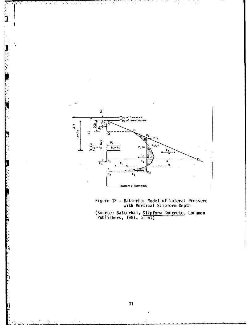
and the test data to produce an analytical formwork model. Figure 12
. shows the general Batterham model of lateral pressure distribution on
vertical slipforms as a function of formwork depth. Using this figure,
Batterham states that:
P =H +H0 0 u
where Po = Total Resultant Lateral Force
Ho = Measured Lateral Force Against the Upper Wale
Hu = Measured Lateral Force Against the Lower Wale
Z which is the distance of P0 from the top of the new concrete is
evaluated as:
0.11H + 0.735 H0 uZ o H0 + Hu
this is actually the sum of moments about point A (in meter - kg)
divided by the sum of the horizontal forces on the wales (in kg.), for
*I a 1 meter longitudinal length of slipform.
* 30
Top of formwork10A
CC.
Bottm o forwo '
Pulser,18, p.h 51) T
B, E2 C31

Again using Figure 12, Batterham defines three limiting values
as follows:
(a) At point A which corresponds to the top of the freshly
placed concrete, which also corresponds to j(z) = 0, and
z = 0
(b) Hydrostatic pressure for the density of the concrete just
placed is represented by j(z) = pz
(c) Point B is the point where the concrete and form separate.
.- Using these assumptions, Batterham determines what he calls the first
approximation of lateral pressure distribution with formwork depth.
Here the lateral pressure is equivalent to a hydrostatic pressure
distribution corresponding to triangle AC1 B1 and with the resultant
horizontal or lateral pressure equaling P1. P1 is assumed to equal
P0. Using the given assumptions and limitations, Batterham states
that:
2P0Z 1 = 2.25p
The derivation is not given, but the following method may have been
used. Triangle AC1 B1 represents the hydrostatic pressure distribution
for concrete which weighs approximately 140 lb/ft3 or 2.25 times that
of water. P equals the hydrostatic pressure due to water.
:4
al 32
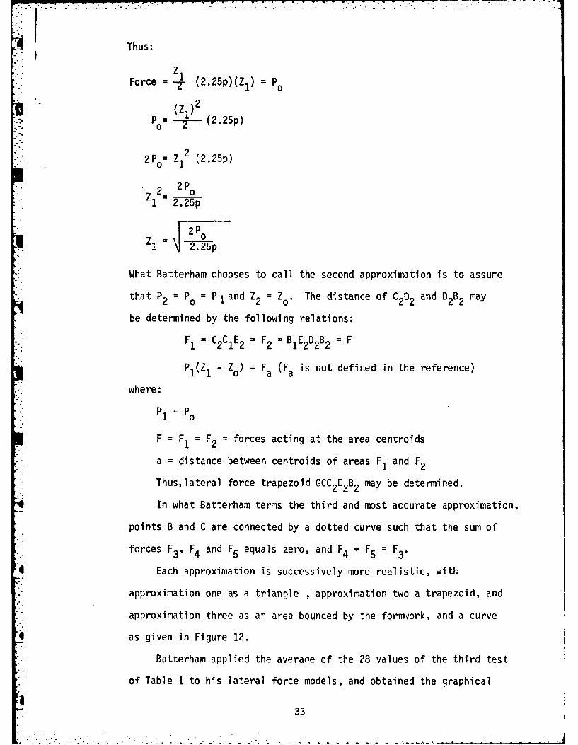
r -- Thus:
zForce = -2- (2.25p)(Z1) = P0
(Z )2
S2P z12 (2.2 5p)
2= 2P0Z 1 2.25p
2 2pi l= 2.25p
What Batterham chooses to call the second approximation is to assume
that P2 = Po = Pl and Z2 = Z0 . The distance of C2D2 and D2B2 may
be determined by the following relations:
F1 = C2CIE 2 = F2 = B1E2D2B2 = F
PI(Z1 - Zo) F a (F a is not defined in the reference)
where:
".,. P1 = P0
F = F1 = F2 = forces acting at the area centroids
a = distance between centroids of areas FI and F2
Thus,lateral force trapezoid GCC2D2B2 may be determined.
In what Batterham terms the third and most accurate approximation,
points B and C are connected by a dotted curve such that the sum of
forces F3, F4 and F5 equals zero, and F4 + F5 = F3.
Each approximation is successively more realistic, with
approximation one as a triangle , approximation two a trapezoid, and
approximation three as an area bounded by the forniork, and a curve
* as given in Figure 12.
Batterham applied the average of the 28 values of the third test
of Table 1 to his lateral force models, and obtained the graphical
33

representation given in Figure 13 and the figures given in Table 3.
The final approximation curve shows that the concrete and slipform
separate at a point B2, 850 mm below the top of the formwork, thus
indicating that the slide speed could have been increased. At the
theoretical maximum slide speed, the separation point would coincide
with point B.
Batterham recommends that the resulting lateral formwork pressure
at point B (at the bottom of the slipform for optimal slide rate) be
used as the design load. This can be easily done because the trape-
zoidal pressure distribution gives an excellent approximation of both
the general distribution of lateral pressure, and the position of the
resultant force, as verified by the test series.
Therefore, for the standard British slipform 1200 mm (47.2 in)
deep, and with concrete lifts of 200 mm (7.9 in) the bottom of the force
trapezoid is determined to coincide with the bottom of the formwork,
and the horizontal width is determined as one half the maximum
hydrostatic pressure of a point 800 mm (31.5 in) below the top of the
new concrete. This lateral force distribution can be proportionately
applied to all slipform depths. Thus the maximum force trapezoid
can be determined by the formwork base, the top of the fresh concrete,
and a lateral force equal to one half the maximum hydrostatic pressure
taken at a depth equal to 2/3 the form depth. This maximum force
trapezoid represents a maximum slide rate. For less than maximum slide
rates, the lateral pressure would correspond to one half the hydrostatic
pressure at 2/3 the concrete depth. It should be noted that if a
slower setting concrete is used, the corresponding maximum slide speed
has to be lower.
34

Top of formworkTop of new concrete
P(54 kDr Proposed pressure distribution
LOCN ydrostatic pressure
C4P= 900 kg/rn=m d80r rmtpBto ffrwr
134 13rssr2o eria
Sl pfrm Batterham Model
(Source: Batterhai, Slipform Concrete, LongmanPublihers 198, p.52)
Z'P, P, (Z)(min) (kg) (kg/rn)
.4Plywood 450 544 47forniwork
Board 420 489 51formwork
Table 3 -Mean Value of Readings Related to Figure 13
(Source: Batterham, Slipform Concrete, Longmian Publishers,1981, p. 50)
4 35

In concluding his analysis of these tests, Batterham states that
formwork friction depends on three main factors, which in turn are all
dependent on the formwork facing material. These factors are:
a) Magnitude of effective head on the formwork
b) Type of working face
c) Length of time between lifts
The watertight formwork apparently creates a thin layer of grout
between the concrete and the form facing, which provides a lubricating
effect for the moving formwork. Tongue-and-grove formwork causes a
similar lubricating layer to be formed, but to a much lesser degree.
Roughness of the formwork increases with use, and this is more pro-
nounced with tongue-and-groove formwork than the watertight plywood.
According to Batterham, the minimum wall thickness of 100-200mm
(3.9-7.9 in) recommended by Dreschels Theory, was not supported by
the tests. The test results gave unexpectedly high values for friction,
indicating that the minimum wall size should be much la-ger. (how much
larger, Batterham didn't state). Thus, the frictional forces can very
likely be greater than the weight of the barely set concrete resulting
in a tearing apart of concrete layers. Two-way reinforcing steel
tends to prevent such action, and in fact transmits such forces to
the hardened concrete.
Batterham also noted that horizontal cracks sometimes appear in
the concrete during periods of high slide rates. He concluded that
they were caused by a decrease in strength immediately adjacent to the
horizontal and vertical reinforcement connections. However, such
cracks closed up eventually under the weight of concrete above.
36

These cracks also tended to be sealed by the layer of grout between
the concrete and the form face when watertight forms were used.
During the tests, a prolonged stoppage on the order of 45 minutes
* produced wide horizontal cracks once the formw'ork was restarted,
especially near the horizontal reinforcing steel. Batterham notedp that the degree of batter produced was dependent on 4 major factors:a) friction
b) formwork pressure
c) flexibility of the lifting frame
d) number of connections within the lifting frame
He was basing his observations on the fact that, even if the forms
were originally set at vertical, the flexing of the forms and the
pressure distribution of the concrete would soon cause a form batter
to be produced.
In general, as stated earlier, the slipform should be as rigid
as feasible and the top of the form slightly smaller than the wall
thickness required and the bottom of the form slightly larger than
than required such that the desired wall thickness is at about the
midpoint of the forms and the actual batter is between 1/32 and 1/16
inch per foot of form height.
Batterham concluded that the slipform tests illustrated the
substantial advantages of watertight formwork over the typical tongue
and groove wood plank forms. The single greatest advantage was the
reduction in downward friction force by 47% when the watertight forms
were used.
37

3.4 WORKING DECK
The working deck (See Figures 14 and 15) provides space for
storage of limited amounts of materials such as rebar, and prefabri-
cated blockouts, a platform for workers, and also lends rigidity to
the formwork. A well-built rigid deck and slipform will tend to
remain level. 39 The deck should be swept clean on a routine basis,
and the storage of materials should be systematic and orderly. (See
Figure 16)
The floor and joists of the work deck are usually designed for a
dead load plus construction live load of 75 PSF or maximum concentrated
buggy wheel load of other construction equipment loading, whichever
gives the greater loading.40 It should be noted that power buggies
can give dangerously high lateral loadings to the slipform, and should
be used only when truly required. Working deck beams and trusses,
however, may be designed for a uniform live load of 40-50 PSF.41
Often the working deck is used as the roof slab form at the end of
the slide. In such cases the working deck has to be designed to hold
the additional weight of the slab.42
In any case, the deflection of the working deck should not be43
greater than 1/8 inch or 1/360 of its span, whichever governs.
Some high capacity jack slip-form systems employ a 3 deck system.
(See Figure 15) The top deck is the work platform, the middle deck
becomes the forming deck, and the third level is the finishing deck.44
In order to keep bits of hardened concrete and miscellaneous
items from falling from the working deck into the forms, the decks
* must be scraped and swept daily. In order to insure safety for the
a 38
M.

a ~a.II - aa0.4--
-~ __Z4~ )
'. VA Al;~
m a
a 4-)---- LL.
39/

7-1 ~-q-- vat
Figure 15 -Modern Slipform Assembly with 3 Deck System
(Source: Linden-Alimake Inc. P'ublication)
40

Figure 16 -View Inside Typical Slipform Working Deck(Source: Camellerie, Vertical Slipforming as a ConstructionTool, Concrete Construction Magazine, May 1978, p. 268)
41 41

workers below the forms, it is recommended that special cleanout chutes
and openings be provided.45
3.5 FINISHERS SCAFFOLD
If the slip-forms are designed correctly and properly maintained,
the concrete will emerge from the bottom of the form ready for a float
7and broom finish.46 The concrete finishers are positioned on a scaf-
fold hung about 7 feet below the forms. (See Figures 15 and 17)
Equipment for application of curing compound is also carried by this
scaffold. Water lines may be attached to the finishers scaffold to
apply a continuous fog spray to the concrete. A shield can also be
attached to the forms to protect the scaffold and fresh concrete from
drying winds. (See winter concreting section of this report) In
addition to the dead loads mentioned earlier, live loads of 50 lb.
per lineal foot of scaffold must be supported by the slipform and
jacks.47
3.6 JACKS AND JACK RODS
Vertical movement of the slip-forms iS brought about by jacks
climbing on smooth steel rods about 1 inch in diameter, which are cast
in the hardened concrete below. These jacks may be manual, electric,
pneumatic, or hydraulic, and operate at speeds up to 40 inches/hour.
Jacks typically have capacities of between 3 and 25 tons each, but much
higher capacities are available.48 The jacks carry the entire weight
of the decks, scaffolds, and formwork via the yokes. (See Figure 15)
In the past most slip-form systems used 3 or 6 ton jacks placed
approximately 7 ft. on center.49 However, several recent prominent
slipforming projects have been performed with 22 ton capacity jacks,
42

I
Figure 17 -Finishers Scaffold with Safety Rails
(Source: Camellerie, Vertical Slipforming as aConstruction Tool, Concrete Construction, May1918, p. 266)
43

therefore requiring fewer jacks, creating more work space, and adding
to project efficiency.
In any slipform system, the jacks should be placed so that they
each carry nearly equal vertical loads that do not exceed the jack
capacity. The steel rods on which the jacks climb should be especially
designed for this purpose. If they are to be used as reinforcement,
consideration must be given to splices, and the low bond value of
these smooth rods. If the jacking rods are to be saved,they cannot
be allowed to bond to the concrete. Bonding can be prevented by
placing a thin pipe sleeve about 3 or 4 feet long around the jacking
and attaching it to the yoke or jack so that it is carried upward
with the forms. Since the pipe is carried upward, the jackrods are
left standing in a small hole in the concrete and can easily be! 50
pulled out after the slipfo.rming is completed. The rods must be
braced when not encased within the concrete, such as when there are
openings or blockouts. (See Figure 18) Beyond the typical spacings,
Jacks should be concentrated at corners, deck beams, concrete hoppers,
bridge landing and other heavily loaded locations.51 A "heavy jack"
system employing 22 ton jacks, has typically required a jack for approx-
imately every 175 sq. ft. of core plan area on succEssful highrise
construction projects involving slipformed cores.52
Jacks are almost always connected to operate simultaneously
from a central pressure or power source and climb a predetermined
stroke distance (such as 1/2 inch or 1 inch) simultaneously every
time the electrical or hydraulic, or pneumatic system is activated.
Most jacks have exellent stroke accuracy, nonetheless, field cond-
itions, formwork twist and load variations require a continual adjust-
ment of form level.
44

-- - -
FormedOpe ning-
. Bottom of
Slop Form
I~~Jc Rodse BarracedSid
SOpenings, Beam Pockets, Concrete
Figure 18 -Typical Forming Details to Allow for
Brackets, etc. Where Jack RodsExtend Through Formed Openings,Bracing must be provided for theirSupport
(Source: Hurd, Formwork for Concrete, AmericanConcrete Institute, 1973, p. 287)
S45
Reserve jacking and placing equipment and standby service equipmeit,
should be immediately available to the project in order to maintain a
continuous operation. This is particularly important where a stop in
slipforming operations would have a detrimental effect on the overall
structural integrity of the project.
3.7 VERTICAL SLIPFORM CONCRETE
The basic concrete mix used in slipforming does not vary greatly
from those mixes used in other construction methods. However, because
of the nature of placement (6-10 in. lifts) the concrete is in various
degrees of set from the top to the bottom of the form. Thus with a
form moving 6-40 in/hr, the design and placement of the concrete
becomes a critical item. In general, any proper mix designed for a
28 day strength of 3000 psi or higher is acceptable. Generally the
slump of the concrete used in slipforming is higher than that for
fixed formwork. A slump of 4 inches plus or minus 1 inch is usually
specified. In hot dry climates or when using certain kinds of aggregates
and cement a higher slump than 5 inches may be required. The use of
accelerators, pozzolons, "super" strength mixes, and retarders should
be considered, but not for reducing the slump below 3 inches or for
reducing the free water which is necessary for good form movement
lubrication.53
The higher concrete slump desired for slipforming results from
the fact that the vibration is confined to each thin layer plus a
couple of inches into the preceding layer, and a higher slump assures
good bonding to the steel without heavy vibration. The higher slump
also aids lubrication of the moving forms.54
6G 46

The aggregate sizes are determined by the reinforcement steel
design and the wall width Ellison indicates a limiting size of 1
inches while Pruitt56 sets 3/4 inch as the maximum size. The propor-
tion of sand should be as high as possible to produce a high degree
of workability in the mix.
In addition to workability, the concrete set time, moisture
content, and temperature are also key elements of proper slipform
concrete control. Retarding mixtures may be required to accommodate
blockouts, heavy reinforcing steel placement, inserts or other
factors which might cause a reduction in the slide rate.
Minor amounts of retarding workability agents can be used to
both delay the set, and increase the plasticity without adding water.
However, the use of ice as part of the mixing water as a retarder is
more effective and less likely to cause the complications connected
with the use of special retarding agents.57 If the slide rate is
greatly reduced it may be necessary to place the concrete in layers
as thin as 2-3 inches to prevent cold joints.
Because of the danger of creating uneven setting rates within
various portions of the slipform, the use of high early strength
concrete or accelerators can be troublesome and should be used only in
special circumstances.
Rather, it is better, especially in cold weather situations,
to increase the rate of set and the heat of hydration by increasing
the proportion of cement in the mix. 58 Because of the importance of
controlling the setting rate, Type I and Type II concrete normally
should be used in slipforming. 5 9 In general, the concrete temperature60
should be in the 65-85*F range.
47

As stated earlier, the concrete is normally placed in
layers of 6 to 10 inches keeping the forms as nearly full as possible
and spading or vibrating each layer as it is placed. It is best
that the concrete be placed alternately in clockwise and counter-
clockwise directions or that other placing sequences or methods be
used which prevent uneven loading and rotation of the formwork system.
Shrinkage cracks in slipform concrete tend not to be a problem
because the concrete is in the form for only 3 or 4 hours, the batter
of the forms allows excess water to escape, and both sides of the wall
are exposed to the air simultaneously.61
The hanging scaffold or finishers' scaffold attached to the
slipform allows finishers to apply a float and brush finish to the62
emerging concrete. Nonetheless, shingling and striation of the
surface of the concrete are considered a normal part of slipforming.
The shingle effect is produced by the intermittent moving of the
slipform every few minutes, and striations in the surface coloring are
caused by minor variations in the concrete (especially water content)
and also by variations in the slide rate. Careful control of the
concrete mix, concrete temperature, and slide rate will significantly
reduce but not eliminate shingles, and color striations to the emerging
sl ipformed concrete.63
On some projects, the results of good management have been
4i impressive. According to dames Henry, Vice President of Linden-Alimak,
the two towers of the Royal Kolani Project in Hawaii each had 38
horizontal construction joints without noticeable shingling. In fact,
Mr. Henry stated64 that detection ;.f the construction joinsts required
close inspection with a straightedge.
48

In general, when finishing the concrete surface it is desirable
jto chamfer all corners 1 1 inches or more. 65This includes inside as
well as outside corners. In slipforming, the use of outside acute
angles is not recommnended. If such angles cannot be avoided, the use
of welded wire fabric should be used to give vertical reinforcement
to the angle to prevent spalling.6
It should be noted that the relative absence of joints and tie
holes produces-a very durable finish for withstanding the effects of
climate.
Curing of the concrete is usually done by using membrane curing
compounds applied by workers on the finishing scaffold. Water curing
using water lines hung from the forms can be used but is subject
to several problems including discoloration and erosion of the concrete.
If water curing is used, it is best to use fog type nozzles. 67
3.8 REINFORCEMENT AND EMBEDMENT STEEL
The placement of reinforcing steel in vertical slipforming
involves several difficulties not encountered in conventional concrete
construction. The vertical reinforcement steel must be placed so as
to miss the form yokes, and horizontal steel must be threaded through
or tied to the vertical steel and jack rods, and be placed under the
yoke beams quickly and efficiently as the forms continually move
upward.
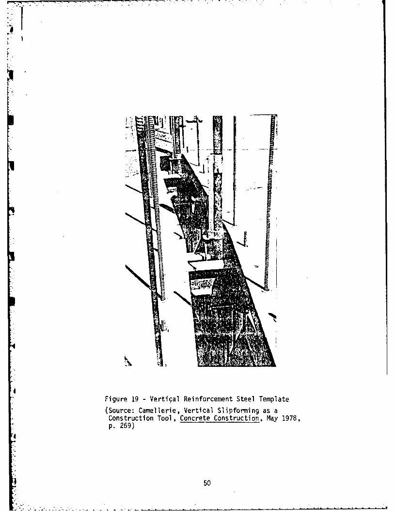
The vertical steel is held in place by templates normally placed
68between 4 and 10 fee. q2,ove the top of the sheathing. In a three
deck system, the vertical steel templates are at the third deck or
upper deck level. (See Figures 14 and 19) The length of indivi-dual
49
-". -- - -. .
r
n
Figure 19 -Vertical Reinforcement Steel Template
(Source: Carnellerie, Vertical Slipforrning as aConstruction Tool, Concrete Construction, May 1978,p. 269)
50

vertical steel bars are usually limited to 10-15 feet, depending on
diameter, to avoid the whipping action which could occur on windy days
if the rebar extended too far above the templdtes. 69 However, some
contractors use as a rule of thumb, limiting the length of vertical
rebar; to 1 floor plus lap length.
The vertical rebar splices should be staggered, not only for
structural considerations, but to spread the workload for the iron
workers.
With respect to the placement of horizontal reinforcement steel,
some contractors prefer to weave the horizontal rebar among the vertical
steel and jack rods, while other contractors using recently developed
high capacity, high clearance yokes are able to efficiently tie the
horizontal steel to the verticals thus maintaining better quality
control.
The vertical spacing of the horizontal steel should be designed
for maximum placement efficiency in the field. Camallerie7 recommends
sizing the steel for 10-12 inch spacings, except where such a design
leads to bar diameters in excess of 1 inch. The lengths of the rebar
are usually limited to 20 feet, since steel bars any longer than that
amount would be difficult for the workers to handle. 71Pruitt 7
recommends that the horizontal steel be placed on the outside of the
vertical steel when the rebar is tied together. This would increase
the efficiency and ease of placement of the horizontals.
It is necessary to detail all ties and stirrups so that they
can be placed from the side. This means, of course, that stirrups
be made of two or three pieces, since a single loop or closed stirrup
could not be placed from the side. Ninety degree hooks are often used
51

in place of sandard hooks, since these hooks can be placed from the
side and rotated into position. Open ties must be used. Of course,
special care must be taken that the design and placement of reinforce-
ment steel does not interfere with weld plates, embedment and anchor
steel, and blockouts. Pruitt73 recommends the following general
guidelines with respect to reinforcement and embedment steel placement
during the slipforming of highrise building cores:
(a) Dowels out of the footing to be of staggered lengths
(b) Minimum dowel length of 4 feet plus lap length
(c) Rebar spacing should be consistent if possible. Rebar size
could be graduated.
(d) Minimum coverage of 1 inch for walls, 2 inches for columns
and pilasters
(e) Vertical splices should not be made on more than 1/3 of the
vertical steel at any one elevation
(f) Detail reinforcing required at weld plate locations
(g) Consider use of weld plates in place of pockets or blockouts
for beam connections. Oversize plates 3 inches and set to a
plumb tolerance of 1 inch per foot
(h) Break out dowels and slab dowels should be 40 KSI steel, and
inserts should be used in place of break out dowels when
feasible
(i) Weld plate thickness should be checked against rebar clearance.
52

Since the rebars are being continually engulfed by the rising
concrete at the typical rate of 12-24 inches/hour, it is necessary
to dictate a placement procedure which will allow orderly inspection
and placement without mandating a slowdown in slide rate. The best
method to insure timely inspection and placement of the rebar is to
detail the horizontal reinforcement in equal horizontal layers, or at
74least multiples of the prominent layer spacing. Such a system allows
the workers to place one complete set of steel as shown on the detail
drawings. The inspector can then more easily check to insure that no
steel is missing.
There are several ways to check the vertical spacing of the
reinforcement steel, such as providing markings on the vertical bars
or embedding light angle iron templates vertically in the concrete
and bolting the templates together in sections as the slide proceeds.75
3.9 BLOCKOUTS AND POCKETS
Obviously, no projections beyond the inner face of the forms can
be permitted until the forms have passed by. Packets with anchors and
dowels must therefore be formed during the slipforming process through
the use of inserts and blockouts. Blockouts are also necessary in order
to construct openings for doors windows or utilities. Figures 18 and 20
illustrate typical forming details for pockets, blockouts and inserts.
Blockouts may also be used to reduce the thickness of the wall.
The blockouts may be stationary; as in providing for a window opening,
or moving; as in discontinuing a segment of wall. Pruitt76 recommends
the following guidelines for construction of blockouts:
(a) Taper and Draft blockouts for easy removal
53
, ~~~~~~~. ..... .' " " . - -" " " - " "- . . - "-' - " . ... . . . . .

Concrete -wail Concrete wallAfter slidingformwork haspassedl, block
Prefabricated unit fixed to is removed andsteel reinforcement of walls steel reinforcement
Prefabricated uslit bent out to suitis fixed into wall4before sliding; m s Steel startersreinforcing bars arefixed to main bars ~ I_____within the actual -concrete wall l
block Proposed concretefloor
-Bars stapled to the~~ woodMain vertical and~horizontal m s
IU reinforcement barsSection at Section atstage one stage two
Figure 20 -Slipform Insert(Source: Batterhan, Slipform Concrete, LongmanInc., New York, 1980, p. 81)
54

WI(b) It is more economical to have repetition of the same blockout
size, rather than varying sizes.
(c) Reasonable elevation tolerance for blockouts is approximately
+ 1 inches.
(d) Reasonable horizontal tolerance for blockouts is approximately
+ I inch.
(e) Designers must note the minimum yoke spacing when considering
structural alterations which will require blockouts.
(f) Easier to work with oversized openings in which jambs will
be attached to furring if possible. It is recommended that
openings for mechanical/electrical fixtures and door jambs
can be oversized 1 inch; and thi openings for door heads
be oversized 2-3 inches.
(g) Elevator openings (as in a slipformed highrise building core),
should have at least a 6-8 inch tolerance all around.
(h) Keep openings (and thus blockouts) at least 12 inches
away from wall corners. This will also keep the blockout
away from the jack and yoke situated at the corner point.
(i) Bear in mind that it is difficult to achieve a level concrete
surface at the bottom of a long blockout.
(j) Do not notch decking into door openings. Uneconomical as a
blockout shape.
M (k) It is best to use sheet metal for all wall sleeves.
3.10 CONTROL OF TOLERANCES
There has been relatively little published concerning tolerances
of slipforming that can be used asa technical specification. This is
55

probably because most slipforming is performed by contractors on a
design and construct basis. Some very general guidelines may be
obtained from the ACI Committee Report on, Bins Wall Design and
77* Construction. The ACI does dictate a tolerance of 1 inch per 50
feet of height.
The ACI also recommends that the maximum variation in wall: 78thickness not exceed + inch for walls thicker than 8 inches.
During the slipforming process, several factors such as differences
in form face friction, blockouts, climatic conditions, and material
variances cause an imbalance of the forces on the formwork. These
imbalances cause the formwork to move out of line by translation,
rotation, or a combination of both. This same imbalance of forces
can cause the formwork to loose its proper shape. In order to counter
this ever-present imbalancing of forces, it is necessary to provide for
continual adjustment of the forms. In order to maintain shape, many
slipforms have a "spider" system of adjustable cables or rods holding the
interior portion of the slipform together. Other slipforms are held in
shape by the horizontal members and bracing of the interior working decks.
The forms must be rigid, and strong, and should be checked for
level before lifting of the form begins. The level of each jack should
be monitored and whenever any jack gets to be more than 3/4 inch out of
the proper elevation, the jack should be adjusted.79 This can be done
by bringing up lagging jacks singularly, or by causing leading jacks
to skip one lift increment. Marks may be cut into vertical rebar at
1 foot spacings to serve as a general elevation check. Another method
for checking elevation, involves attaching a tape measure directly
between the forms and ground level, with the tape measure being unwound
by the movement of the forms.
56

Several systems have been devised to check overall formwork level.
These include water leveling systems, vertical plumbs, and optical
plumb systems. With water leveling systems, there is usually a control
reservoir with plastic tubing leading to various jacking points.
Operators of water leveling systmes must, however, be careful not to
let air bubbles develop in the system, for these bubbles will cause
false readings to be obtained. Camallerie80 recommends that water
level reddings be taken as often as every 3 hours for structures
requiring closer tolerances than normal; and that readings every 12-24
hours are sufficient to achieve the ACI tolerance of 1 inch per 50
feet of structure height. The ACI recommends that slipform alignment
and plumbness be checked at least once every 24 hours, with a check
every 12-18 hours being preferred.
Vertical plumbing techniques usually involve reading targets set
up on the formwork at several critical points. Care is taken to place
targets such that key targets are at right angles to each other. A
regular transit or level is used to obtain foresights and backsights
and thus determine the degree of level. Targets on the hardened
concrete can be compared against targets on the forms, thus checking
for rotational movement.
Optical plumbs, which are essentially a weighted free hanging
telescope combined with a targiet at ground level, tend to be sensitive
to wind and vibration, but are used at lower elevations.81
Laser beam instruments are also available. One such system
involves lasers that are set up on the foundation slab and beamed to
targets on the moving forms. This system simultaneously monitors slip
rate, elevation, and plumbness of the jack rods.82
57

Using good techniques and proper formwt~ork control, tolerances
U within 12 inch in 400 ft. have been consistently achieved on building
cores.~8
However, to set such achievements as a standard is unrealistic.
Pruitt 84 reccomends the following tolerance goals:
(a) Wall thickness tolerance, -1 to + 2 inch.
(b) Plan alignment along entire length, + 1 inch.
(c) Variation from plumb, + 2 inch in any story and + 1 inch
over the entire height.
()Variation in location and placement of embedded plates, +
2 inches (both in horizontal and vertical directions).
(e) Variation in alignment of embedded plates + . inch in 1
foot.
Mf Variation in size and location of sleeve, + 2 inches.
With regard to nuclear shield wall construction, the engineer is
faced with a different set of tolerance limits, and additional complicating
factors influencing the structural design and construction.
Because these walls are typically 2.5 -3 feet thick, they are
included in the category of mass concrete under some codes. However,
as leading engineers such as J.C. Ellison of Fegles-Power Corp. have
pointed out, even slipforming a wall 3 feet in diameter, really involves
placing 6-10 inch layers of concrete that will be exposed to the air
within 4 hours. Thus the concrete temperature standards for mass
concrete are really too low to apply to typical slipformed shield
walls.
* Shield walls involve high reinforcing steel concentrations involving
550 lb. or more of steel per cubic yard of concrete, and greater forces
o 58

acting on the formwork than in typical slipform wall construction.84
The need for wall placement precision is less stringent. Ellison85
recommends the following tolerance guidelines:
(a) Variation from plumb, + 4 inches for total height, taken
at the vertical axis of the structure; or no more than +
1 inch in any 20 feet of wall height.
(b) Variation from true circular section, + 3 inches, measured
along the radius from vertical axis of the structure.
( (c) Variation of wall thickness, -4 inch to +1 inch.
As in all vertical slipform construction, the formwork will always
have some tendency to drift and rotate during the slipforming operation.
As stated earlier, the greatest forces tending to drive a form system
out of shape are those caused by the imbalance of forces associated
with large blockouts. In the slipforming of large shield walls, the
traditional central "spider" network of braces and cables are not
enough to control drift and rotation of the forms. In some cases, an
additional inner and outer supporting ring trusswork is added to
maintain form shape. However, this trusswork will not prevent rotation.
On one shield wall project, two 3 ton hoists were used to counteract
rotational forces. Lateral loads can also be added to the formwork
system to counter imbalances of load caused by large blockouts.87
Wall thickness in shield wall slipforming, as in all slipforming
is controlled by the yokes. In shield wall construction however, the
yokes are an integral part of the inner and outer ring trusses. In
order to allow for the failure of any one jack, these ring trusses
* must be designed to handle the forces spanning over a single jack
59
* * - ,* ,

support. It should also be noted that with the increasing use of 22
ton jacks vice the traditional 3 ton setups, the typical jack spacing
is increasing from the former 7 feet to approximately 21 feet. This
requires yokes approximately 3 times stronger in order to maintain
the proper form stiffness.88
3.11 RATE OF SLIDE
The rate of slide is essentially dependent on the condition of the
concrete as it emerges from the bottom of the forms.
The importance of having a consistent concrete mix is therefore
critical, and good quality control must be maintained.
The amount of time the concrete spends in the forms, and the
amount of time required for the concrete to sufficiently set to the
point of being self-supporting should be determined beforehand. Typically,
the concrete in slipforming operations, spends about 3-4 hours in the
forms, and the bearing strength of the concrete as it leaves the forms;': 89
is about 300 psi.
The maximum slide rate is, therefore, limited by the depth of the
forms and the set time of the concrete. As noted earlier the depth
of the forms is typically about 4 feet, with 3 feet being the practical
minimum, and depending on the source, with 6 - 10 feet being the
maximum. Generally,forms much less than 4 feet in depth don't give
the concrete sufficient set time, or provide an. adequate margin for
error. Forms greater than 4 feet in depth experience a dramatic
increase in drag forces, although deeper forms may be required for
winter concreting, or when more rapid slide rates are desired.
460

Although the maximum slide rate can be designed and planned for before
aconstruction operations begin, a change in concrete temperature, or thenecessity to install blockouts or complicated rebar arrangements can
require a change in the slide rate. For these reasons, a supervisor
experienced in slipform operations must be present at all times to
ensure that the most rapid.slide rate feasible is being maintained.
- If the slide is too fast, the concrete will be too soft at the
bottom of the forms causing a "blowout". Conversely, if the slide
*: is too slow, the forms will tend to lift the partially set concrete
causing crevices and gaps within the concrete.90
The rate of slide is usually checked by pushing steel rods into
the fresh concrete to determine the depth of hardened concrete. A
minimum of 12 inches and a maximum of 30 inches is recommended.91
The rate of slide can also be checked by scratching the concrete as
it emerges from the forms. This technique though, requires much
experience.92
Figure 21 illustrates the relationship between hardened concrete
depth, concrete set time, and slide rate.
Some contractors have removable sections built into the forms, so
that at periods of 1, 2, and 3 hours after the initial filling, certain
sections can be removed to check concrete hardness. This technique
allows the contractor to start the form movement as soon as possible
(thereby reducing form drag), and gives the initial maximum slide rate
feasible.
:I6
ia 61

1219 Assumptions made:-1 Placing of concrete 15 mins after mixing
1118 2 Test cube A shows consistency at 3 hoursTest cube B shows consistency at 4 hours
1000 203 mm of freshly Test cube C shows consistency at 5 hours
E 914 Placed concrete 3 Formwork height 1066 mm
8130 Formwork face3:711EC 71 A__ _ Concrete must not stiffen above this level
0 610
5086
4007 Level of
305 Istiffening at203 average speeds203 _
""
100..
0.0025 51 76 102 127 152 178, 203 229- 254 280 305 356
330- p.ed (mm/h)
Figure 21 - Graph of the Level of Hardened ComLreteRelative to Form Depth, and Set Time
(Source: Batterham, Slipform Concrete, Longman Publishers, NewYork, 1981, p. 29)
62

With forms 4 ft. deep, the rate of slide will normally be 16 to 24
inches/hour.93 The average slip-forming rate for silo work is 10 to 15
inches per hour, and the average slip-forming rate for buildings is 15
to 20 inches per hour. Of course, on projects with numerous delays
* due to placing blockouts, inserts and rebar placement, the overall
slide rate will be below average.
Despite the design slide speed, hot weather may make it necessary
for jacking speeds of up to 40 inches per hour to be attained.95
Because of such variances in "maximum" slide rate, extra jacking capability
above the design slide rate should be available. The alternative is
the addition of retarder agents to the concrete, and additional risk of
non-homogeneous concrete mix.
3.12 Distribution of Concrete
This section includes only a cursory look at concrete distribution
during slipforming operations, as the methods used are many and varied,
and limited only by the imagination.
In slipforming, it is required that the concrete be lifted
vertically to the forms. The usual methods of doing this, include
96tower cranes, hoisting towers, and concrete pumps. When the volume
of concrete is large, the most economical method of moving the concrete
to the form level appears to be through the use of a tower crane which
itself is carried upward by the moving formwork system.97 Hoisting
towers or winches sitting on one of the slipform decks, and lifting
concrete up through the center of the structure can also be an economical
method in most cases. Pumping the concrete can be very economical,
although limited by the maximum lifts and capacities of the pumps.
63

V At the working deck level, distribution of the concrete can be
accomplished with wheelbarrows, monorail systems, crane, conveyors,
pump, buggies, or combinations of these methods.
Some contractors have placed concrete at two or more points on the
working deck simultaneously.
On one highly successful project the contractor pumped a total of
22,000 cubic yards of concrete through a 5 inch pipe into the structure
and thence up a standpipe to a mini-mixer placed at the center of the
formwork spider. The mini-mixer split the concrete flow into 2 lines
which were attached to 2 booms whose ends rested on rubber tired buggies.
The concrete, in effectwas pumped directly to the forms through a
maximum elevation of over 212 feet, thus eliminating the need for tower
cranes.98 It must be noted that when using concrete pumps, the pumping
rate must be high enough to prevent plugging, thus the use of a single
pump with a line split, can succeed where two separate pump lines may
not.
In the case cited above, the contractor credited the improved
concrete delivery system, as one of the reasons he was able to underbid
the competition by a huge margin, leaving 1 million dollars on the bidding
table on a 10.5 million dollar job.
In any event, the relative costs of delivery systems of the concrete
to the slipforms is a significant aspect of the overall economy of the
4construction operation.
3.13 VERTICAL SLIPFORMING IN WINTER
Vertical slipforming in cold weather is not recommended, but slip-
form operations can be successfully conducted at temperatures below
64

40°F. Camallerie99 recommends that the following special provisions
be considered when undertaking vertical slipform operations in cold
weather:
(a) Use of Type III cement with air entrainment.
(b) Keep the concrete temperature at 70°F in the forms.
(c) Use a protective enclosure to keep the air around the concrete
at 70°F for at least 24 hours.
(d) Ensure reinforcing steel is free of ice.
It is possible to use Type I or Type II cement or to maintain the
air temperature at only 50'F, but these provisions necessitate a
minimum curing period of 3-5 days. To illustrate the effect, assume a
slide rate of 6 inches/hour and a 3 day curing period. During the
curing period the forms will have moved 36 feet, thus necessitating
a protective enclosure 36 feet high to shield the green concrete and
maintain the required temperatures.
An enclosure 36 feet high attached to the forms, would complicate
efforts to keep the forms plumb, and could even jeopardize the sliding
operation. However, an enclosure 12 feet high would be manageable,
reasonably safe and far more economical. A 12 feet high enclosure
equates to a protection period of 24 hours, at the assumed slide rate
of 6 inches/hour. And, as alluded to earlier, a 24 hour protection
period is most feasible with high early strength concrete.
Canvas tarpaulins and polyethylene sheets, are probably the most
common materials associated with protective enclosures, although
Camallerie 100 prefers enclosures constructed of rigid panels of plywood,
masonite, or insulation board. Rigid panels hold the air in better
65

II .
since they don't flap in the wind. Hanging the enclosure in a series
of sections provides safety against one detached section from pulling
the other sections down with it.10 1
Steam heat is preferred since a dry heat would tend to dry out the
concrete and hinder hydration.
The inside and outside of the green concrete walls should be
maintained at as nearly equal a temperature as possible to minimize
temperature cracks. 102
Because of the lower temperatures, the setting time of the concrete
is slower, and the concrete must spend a greater period of time of
within the forms. For these reasons, a slower slide rate and deeper
forms are used in cold weather slipforming.
The durability of the concrete is especially important for structures
which will be exposed to freeze-thaw cycles. A low water/cement ratio
will result in a more durable concrete. Strength in concrete is a
physical phenomenon, where the hydrated cement fills capillary voids
within the concrete. 103 A high water/cement ratio means that a lot of
void space will be left over after the cement has hydrated. When the
water to cement ratio gets to 0.70 the voids start connecting. The
freezing point of a super-saturated water-cement mixture is very low,
whereas the freezing point of the mixture in large pore spaces approaches
the freezing point of water.104 The durability of the concrete is
therefore related to the water-cement ratio. Thus, the lowest slump
concrete feasible for use in the slip forms will be required in cold
weather areas. The protection of the concrete is critical since strength
gain practically stops when moisture required for curing is no longer
available.105 The use of antifreeze compounds or other materials to the
66

I
concrete should not be permitted, as these materials seriously affect
other concrete properties.106
* Assume that the desired strength of the concrete is 300 psi as it
emerges from the forms, and Type IlIA cement is used. The strength of
Type IlIA cement at 12 hours is 500 psi at 70*F.107 Assuming a linear
rate of hydration, the concrete would reach 300 psi at 7.2 hours. For
slipforms 6 feet deep this translates to a maximum slide rate of 10
inches/hour. Reducing the curing temperatures from 70*F to 50'F will
reduce the curing temperatures by approximately 50%108, thereby reducing
the maximum slide rate in the previous example to 5 inches/hour. A 300
psi strength for the emerging concrete may be very conservative, since
the compressive stress at the base of the 555 ft. high Washington
Monument is only 300 psi. 109 The fact remains that slower slip rates
and additional heating costs are necessities of cold weather vertical
sl i pforming.
3.14 FORM STRIPPING
Once the forms have reached the top of the structure and the
jacking is complete, the weight of the forms is usually transferred
from the jacking rods to the finished wall. This is generally done by
sliding bolts through carefully placed holes in the walls just below
the wales. Once the weight is off the jacks, and jackrods, the formwork,
jacks and jackrods may be removed and used elsewhere.
If the working deck is to serve as the roof slab form, as is
irequently done, small boxes need to be constructed around the vertical
members of the yokes so they will not be keyed into the roof slab.
Upon removal of the yokes, the boxes are stripped and the resulting
cavities filled with concrete.110
"! 67

The removal of the inside forms can be facilitated by leaving holes
jin planned positions in the roof slab to enable the hanging of a stripping
scaffold. 1i 1 The removal of the outside forms does not need to involve
-_ any special procedures.
The form stripping operations must be properly organized and
controlled in order to save labor costs, and ensure reuse of formwork
materials.
Although safety is of paramount importance throughout the
construction sequence, there is a greater opportunity for accidents
during formstripping operations, with relatively large amounts of
waste materials or pieces of formwork stored high up on a structure,
and the dismantling of formwork and scaffolding taking place.
So unless the stripping sequences are organized in detail,removing
formwork can be both a wasteful and a dangerous exercise.
3.15 SPECIAL APPLICATIONS
Vertical slipforming has been used in a variety of innovative ways
to cut the construction time or cost of several projects. A few of
these special applications are described herein to give the reader a
sense of the breadth of application possible with vertical slipforming.
3.15.1 Vertical Shaft Linings112
Both single wall and double wall vertical shaft linings can be
slipformed. In 1979, an Indiana contractor constructed the first under-
ground double wall slipformed concrete shaft linings in North America.
The design called for an unreinforced outside wall 1 foot thick an
annular space 9 inches across, and a reinforced inner wall 2.3 feet
68

thick. The annular space was filled with a bituminous mixture. The
outer 1 foot thick wall was built with 10' jump forms descending the
shaft, while the bituminous mixture and the 2.3 feet thick inner wall
were slipformed from the bottom up. Figure 22 illustrates the formwork
Sand working platform setup. The concrete slump was 4-4.5 inches and
slide rates in excess of 24 inches/hour were attained.I-.,
3.15.2 Dry Dock 113
The worlds largest dry 'dock (able to accommodate 1 million ton
ships) was constructed primarily of a series of slipformed caissons.
Each caisson is 69 feet high, 102 feet long, and 56 feet wide. Since
several caissons were required, they were produced in a casting yard,
using slipforms hung from z- irge steel truss gantry. The gantry would
straddle the caisson during slipforming operations. The caissons
were slipformed at an average rate of 16 inches/hour, in 100OF heat and
90% relative humidity. At times the jacking speeds were increased to
keep the concrete from setting in the forms, but the relative thinness
of the walls (10-16 inches) kept the heat of hydration from being a
problem. The project was completed 22 weeks ahead of schedule.
3.15.3 Providing a Facing for Mass Concrete114
A Japanese contractor used a single face slipforming system in
conjunction with concrete and steel bonding facilities to triple
construction speed ona hydroelectric project. The unconventional one-
sided slipform required a special bearing frame to prevent it from
being pushed outward by the weight of the concrete. The bearing frame
*.d was constructed of vertical 8x8 H-beams set at the back of the slipform
at 6.5 feet intervals. Figure 23 gives a simplified view of the slipform
* •69

r
bearing system. The concrete was pumped alternately to 2 main distribution
hoppers on the slipform frame. Each hopper in turn distributed the
concrete to a pair of sub-hoppers, which in turn fed (again alternatively)
ten 8 inch diameter discharge hoses, in order to balance the distribution
of the concrete. The slipform rose in 1.6 inch increments at an
overall average rate of approximately 2 inches/hour.
3.15.4 Changing Sections
The wall thickness of a slipform is usually reduced by jacking
the form free of the previously placed concrete and relocating one of
the form faces, or by placing an insert on one or both of the inner
form facings. It is important to note that when the reduction in
thickness is on one face only that the jack rods will no longer be
in the center of the slipformed section, and a resulting imbalance of
pull on the yokes will result, which must be balanced.115 There are
also prefabricated circular metal slipforms being manufactured in
Japan which can be made to change shape by changing the length of the
inner spider arms, and through the use of overlapping sheathing which
can simultaneously reduce form circumference by an alternately sliding
over and under neighboring sheathing.
3.15.5 Standard Slipform Machines
Numerous standard slipform machines are available to construct
such common structures as silos and chimneys. Such machines are
commonly available in sizes from 6 feet to 30 feet in diameter, with
provisions for reducing wall thickness during the slipform operations.
These standard slipform packages which can be leased or rented, normally
4 70

KNYOAUUC JA§JE
CELLAR 2
FR'EEZE IELEMENTS
DoblWl ShaftE Lining
BEARING COL MN L#04 SIFOMFRM
BERN COUM i-CONCET FORME
ROLLER
*,g~ a .~ ~ .CONCRETE FR
Figure ~ ~ ~ ~ "--FRS 23CSpcalyCosrutdETEfrn o
(Source:2 pal ConstructineMtod d Eguipent Juef 177o.r6
71

include lifting equipment, various accessories, and are usually con-
structed of steel. 116
In addition, various construction equipment supplier's, such as
Linden-Alimak, specialize in providing slipforming equipment, slipform
project analysis, and supervision of slipform operations.
72

CHAPTER FOUR
BASICS OF THE HORIZONTAL SLIPFORMING TECHNIQUE
Most horizontal slipforming involves a fixed form support such as
rock or earth and a moving slipform machine. The slipform machine may
or may not be self-propelled, and is usually supported by rails or
earth berms. Typical applications of horizontal slipforming include
the paving of highways and runways,and the construction of medium
barriers, sidewalks, curbs, tunnel inverts, cast-in-place pipe, and
canal linings.
4.1 SLIPFORM PAVING
4.1.1 Slipform Paving Equipment
Slipform pavers are the single most common form of horizontal
slipform machine, with over 38 different models available in America
alone. 117 Slipform pavers are not to be confused with the side-form
pavers that were predcminant in the paving industry about 20 years
ago. In side-form paving, the steel rails were incorporated into
side forms which contained the concrete and set the finished grade
for the pavement. In slipform paving, the forms move with the paving
machine, and the final grade is determined by built-in sensors.
A slipform paver is essentially a single self-propelled machine
which takes concrete in via a chute, distributes the concrete along
an auger shaft, and passes over the concrete thereby molding it to
approximately the correct shape while vibrating and compacting it.
Trailing forms attached to the paver give the concrete its final
shape with smooth vertical sides, and a smooth top surface. Figures
24 and 25 show a slipforrt paver in operation. Concrete used with a
ii
73

~ a
Figure 24 -Front View of Slipform Paver inOperation(Source: Oglesby andHewes, Highway Engineering, SecondEd., John Wiley & Sons, New York,1966, p. 701)
Figure 25 -Rear View of Slipforn Paver in OperationSource: Nunnelly, Maagn Construction Equipment, Prentice-
*HallI, New Jersey, 1977, p. 182T)
74

slipform paver must be carefully controlled with a uniform consistency.
The slump employed is between 1 inch and 4 inches, with a 1-2 inch
slump being preferred.118 The concrete is placed on a prepared base.
Typical slipform pavers can produce concrete pavements from 6 to 54
feet wide, and 6 to 20 inches thick. 119 Maximum operating speed for
these nachines varies between 10 and 60 feet/min.120
Slipform pavers are available today with such capabilities as
adjustable single lane and dual lane capability, automatic grade
setting, automatic steering, automatic profile monitoring, the ability
to pave curb and gutter on a single pass, the ability to transition
from a crowned cross section to a straight cross section without
stopping, the ability to adjust pavement width on one machine from
6 feet to 50 feet, and accessories to allow the paver to be used on
reservoir slopes up to 1.25 to 1.121 Some slipform pavers operate as
combination fine graders and slipformers.122
4.1.2 Slipform Paving Operations
Although operation of the equipment used in conducting slipform
paving operations may appear to be straight-forward, there are
several management pitfalls which can cripple a project.
For slipforming to be used to the maximum advantage, the width
of the pavement should remain relatively constant since the pavers
can't readily be adjusted to varying widths.123 Variations in grade
should be gradual and infrequent, and the minimum radius must be
checked to ensure capability of paver to negotiate the turns.12 4
The ideal length for a slipform paving project is between 7 and| 125
10 miles, depending on local conditions.
75
a,--.-

With lesser project lengths, the full economic potential of
the paver is not realized, while longer projects start to incur
problems with concrete transportation cost and control.
However, the key ingredient to success in rmst slipform paving
projects is speed. Contractors have been able to lay over 15,900 feet
of 24 feet wide pavement in 20 hours. To maintain that pace
the availability and coordination of aggregate, batching capacity,
materials stockpiling, and materials delivery is critical. In
another record-setting project, over 16,390 cubic yards were placed
in 16 hours. (6,013 ft. of 17 to 21 inch thick pavement, 50 feet
wide) That is a rate of over 1024 cubic yards per hour. On such
large volume projects, a sufficiently large fleet of trucks is re-
quired to reduce the risk of halting the paver for lack of concrete.
Queuing theory equations can be used to help decide the appropriate
number of material haulers.
Aggregate stock piles and cement supplies need to be replenished
constantly, and aggregate moisture content and gradation need to be
monitored continually.
Even with proper planning and operational control, the contractor must
take all feasible steps to ensure the paver will not break down during
operations. Some contractors have on the job site a mechanical
engineer or other machinery repair expert in order to minimize downtime.
Operator carelessness can lead to costly errors, since there is
practically no room for profile error, and the expense of grinding
down bad sections can be prohibitive. 127
76

The slipform paver is usually followed by two gantry type pieces
of equipment, one carrying the finishers and a second gantry to apply
curing compound. The finishers work the surface with large bullfloats.
With respect to reinforcing steel for concrete slipformed pavements,
the steel dowels used at the construction joints are usually pre-
assembled into dowel baskets and nailed to the earth base at pre-
determined joint locations. The slipform paver places and shapes the
concrete over the dowels. Between 6 and 30 hrs. after the paver has
passed, a concrete saw crew cuts construction joints in the green
concrete. 128
For those pavements requiring continuous reinforcement, the
paving train will include a spreader in front of the slipform paver.
The spreader will receive the concrete from the trucks and spread the
concrete to approximately one half the final pavement depth. (The
spreader will pass over the dowels.) After the spreader has passed
a crane will place a section of steel reinforcing mat on the fresh
concrete. The slipform paver, which follows about 50 feet behind the
spreader will then bring the concrete to final shape and grade. 129
When dowel ties are needed to tie the pavement slab to a subsequent,
adjacent lane, they can be inserted by the paving machine, or be
inserted by hand into gang-drilled holes, a few hours after the paver
has passed.
4.1.3 Ramp, Curb, Gutter, Sidewalk, and Median Paving
Slipform paving machines are also used to pave ramps, curb, gutter,
sidewalks, and median barriers.
In many cases, the chief difficulty with ramp paving has been
ramp design modifications in order to successfully employ slipforming
77

techniques. If ramps are designed originally, so that the slipform
payers can be used, the owners can realize a significant economic
savings. The recommended ramp design features include:'3
(a) Uniform pavement width
(b) Minimize length of tapered section
(c) Construction of a sufficiently wide subbase to support
a 24 feet wide slipform paver, regardless of pavement width
(d) The elimination of reinforcing steel from ramp pavement
(e) Construction of a stabilized subbase that concrete delivery
trucks can use
(f) Greater range of tolerances than those required of mainline
pavements
(g) For ramps with curbs, a provision for attaching the curb
to the pavement at a later date, as an alternative method
to integral pavement and curb construction.
In addition to the numerous slipform payers that can produce curb
and gutter sections simultaneously with the main pavement surface,
there are at least six different slipform machine models available
in America that specialized in curb, gutter, and barrier wall
placement. 131 These machines have operating speeds which vary from
25 to 60 feet/minute, and some can extrude barrier walls up to 65
inches high. 132 The general minimum radius that these curb and barrier
slipflormer payers will negotiate is approximately 7-15 feet.'133
Figures 26 and 27 illustrate typical slipform machines used for
constructing curbs and barriers. Since these machine involve
relatively small daily volumes of concrete, they are used in conjunction
78

~.611__ __ __IA.
Figure 26 -Curb Being Produced by Specialized Slipform Machine(Source: Gamaco Inc. , Ida Grove, IA, Pamphlet, 1 79)
~RED
42 L
Figure 27 -Barrier Being Produced by Specialized Slipform Machine(Source: Gomaco Inc., Ida Grove, IA. Pamp~hlet, 1980)
.6 79
fiL
K' with transit mixers.
Curb and gutter machines typically slipform 2500 feet/day, although
as much as 11,440 feet have been placed in 11 hours.134,135
4.1.4 Canal Lining
There are several different methods of slipforming canal and
channel linings. One very simple method involves conventional paving
of the horizontal canal floor, and the use of a weighted steel pan to
form the slope linings. The steel pan or slipform screed is pulled
or winched, up the slope, over low-slump concrete while a hand-held
immersion vibrator is used to compact the concrete just in front of the
screed. The form itself is not vibrated since this would cause a
swell wave in the concrete just emerging from the trailing edge.136
* Figure 28 illustrates the operation of a slipform screed.
Numerous sophisticated slipform pavers are available to line
canals and channels at a single pass. These full section canal lining
machines are used on canals with up to about 50 feet of total lining
width. Larger canals are lined in half sections, or the slopes and
bottom deck are constructed separately.
Canal lining machines operate much like the conventional pavers,
but have a transverse, compartmented trough for uniformly distributing
the concrete on the slope. 137 Sometimes a distributor plate is
attached to the leading edge of the slipform, while other machines
use a continuous row of hoppers, each supplying one compartment of
the trough below. Concrete is usually delivered to the hoppers or
trough compartments by a shuttle car on the working platform.138
.-.
a80
- - -• - - -

Unvibroted Concrete
Steel Plate
For Weight-.
Vibrated
(Source: Hurd, Formwork for Concrete, American ConcreteInstitute, Detroit, MI, 1973, p. 290)
7
81
After the concrete passes through the trough, it is consolidated by a
vibrating tube parallel to and just a few inches in front of the
slipform. The trailing edge of the slipform is set at a position
lower than the leading edge which tends to further improve concrete
consolidation. 139 The concrete consistency must be even more carefully
monitored than that for conventional road pavement, with low slump
concrete being used. Another key consideration, is whether or not the
slipforms have enough weight to resist hydrostatic uplift.
4.2 Cast-in-Place Pipe
Various slipform machines are available to cast pipe in place
for such uses as drains, highway culverts, aqueducts, sewers, and even
140underground missle passages. The NO-Joint Pipe Company for instance,
has machines available to case pipe in sizes from 24 inch in diameter
to 120 inches in diameter in 6 inch increments. The machines manu-
factured by this company consist of a mandrel assembly which has as
its components; an inside bottom form, an outside top form, and a
hopper. The mandrel rides on a steel sled along the bottom of the
trench. As the self-propelled machine advances, semi-circular,
collapsible, aluminum forms 4-6 feet long are fed into the front of
the mandrel and manually attached to the preceding form. These
collapsible forms together with the outside top form of the machine
produce the upper 230 degrees of the pipe. The rest of the pipe is
formed by the machine's inner slipform and the base of the trench.
The concrete is discharged from the hopper down around the forms by an
electronically powered spading device. The concrete is also vibrated.
82

The collapsible forms are left in place for 4-6 hours after the concrete
placement.
This machine has produced 120 inch diameter pipe with walls 12
inches thick at the rate of 30 feet/hour.
The R.A. Hansen Company has another type of cast-in-place machine
to slipform large diameter concrete pipe in place. This machine works
essentially the same as that described in the previous section, with
the concrete being produced between the upper slipform, the circular
inner form, and the trench walls. However this machine includes a
forward trench scraper, and a mobile truck ramp system for unloading
large bottom-dump trucks. A 16 meter long rubber-tired form transporter
recovers the inner forms for reuse several hours after the slipform
machine has passed. This system has been used to case nearly 700 feet
of 14.3 feet diameter pipe with an 8 inch wall thickness in only 8 hours.
That placement required the use of 700 feet of collapsible inner forms.
4.3 Tunnel Inverts
Slipform machines are often used141 to place a continuous tunnel
invert. The invert is shaped to a predetermined diameter, and a curved
paving machine rides over the invert slipforming a layer of concrete.
The slipform can be moved forward by winches or in some cases, is
self-propelled. The concrete is usually delivered by pump or conveyor
belt and is placed just ahead of the slipform. Hurd 142 recommends that
the best way to hold the concrete to a true arch shape, is to vibrate well
the concrete along the sides of the form, and to use a heavily weighted
83
K. slipform which has a length equal to or greater than the width of the
invert.
4.4 Miscellaneous Uses
Horizontal slipforms can also be used for surfacing bridge decks,
sidewalks, breakwaters, and warehouse slabs. As stated earlier, the
variety of uses is limited only by the imagination. Perhaps one of
the more unique uses of a horizontal slipform machine is-in the
construction of risers for fieldhouses and stadiums. H.A. Lott slip-
formed 30 rises for a 15,000 seat fieldhouse 8 weeks ahead of the14
scheduled time allowed for conventional methods.14 3
There are also slipform pavers available which will can pass over
obstacles through the use of hydraulic arms and an articulated joint~144
frame.
Future development of horizontal slipform machine may include the
use of slipform pavers in concert with surface planers, to give a one
pass surface rehabilitation or overlay treatment.
84

H .
CHAPTER FIVE
ECONOMIC ASPECTS OF SLIPFORMING
5.1 Economic Aspects of Vertical Slipforming
Vertical Slipforming can result in a significant cost savings for
the owner and contractor. However, slipforming is not always the most
economical concrete placing method. Although many people assume that
structures over 60 feet high are ideal candidates for slipforming,
J. F. Camellerie of Ebasco Services, Inc. states that some structures
over 500 feet high cannot be economically slipformed. Although,in
general, the higher the building, the lower the unit form cost;
consideration for the volume of concrete needed is also important.144
The ideal slipform project would involve a structure requiring 20-30
cubic yards of concrete per foot of elevation, light reinforcing
steel, and no openings or inserts. 145 Mr. Camellerie cautions further
that it is necessary to consider slipforming as only part of an over-
all project system. A lower formwork cost does not necessarily
translate into a lower total project cost.
However, vertical slipforming usually does result in a major146
savings in the cost per square foot of form contact area.
Normally a set of 4 foot high forms will last for 400 feet of slipforming,
which results in a reuse factor of 100.I 7
The other major advantage of slipforming is speed. Vertical
slipforming is generally quicker than other vertical forming methods,
and has been responsible for significantly reducing construction times
by over 25% on several large projects. Perhaps the most recent
85

example of the success afforded by slipforming is the $125 million
Executive Center Project in Honolulu, Hawaii. Project manager, Albert
Fink states that vertical slipforming saved $100,000 in the first 6
floors alone of the 41 story tower. Slipforming is also credited
with shaving 1 month off the construction time. 148
Of course, to realize the full economic potential of vertical
slipforming the contractor must be able to place the required amount
of steel without interfering with the form slide-rate. Tight material
delivery schedules are also required.
In fact slipforming forces the contractor to plan the entire
project more thoroughly.149 It is critical that the formwork not make
any unscheduled stops.
In areas which undergo severe weather extremes, close scrutiny
of the mix is essential. During one slipform project, which was being
performed in a widely varying climate, the contractor had 5 difference-" 150
mix designs available, the choice depending on the temperature.
Despite all the precautions, vertical slipforming is not considered
to be a difficult technique for contractors to learn.151 In fact the
success rate is very high among contractors using this method.
There is some disagreement among slipforming experts, as to the
neccessity to employ workers overtime in order to reach the full
economic benefits of slipforming. Slipforming can be successfully
accomplished without resorting to continous placements, or overtime,
but there are other times when a tight schedule must be met despite
the premium of overtime costs.
d Additional economic benefits which are side-effects of slipforming
operations include, decreased crane capacity requirements, decreased
finishing costs, and increased crane hoisting time available.
86

Tables 4 and 5 show the relative costs associated with different
u concrete casting systems. The tables show that with respect to the
construction of high-rise buildings, (approximately 60 feet or more
in height) slipforming has a lower average labor cost than either:
p cast-in-place concrete, precast panels, combination precast and
conventional forms, and combination slip and gang forms. With respect
to medium-rise buildings (approximately 20-60 feet in height) slip-
forming is no longer the clear choice. In fact, for medium rise
buildings, several of the other methods of concrete casting have a
lower labor cost.
As Table 5 outlines, overall system comparison show slipforming
as having a lesser cost factor, than any of the other 4 systems shown
with the single exception of precasting. Note, however, the significant
savings in construction time that slipforming gives when compared to
the other systems being analyzed. With todays interest rates, the
cost of financing a project is substantial and finishing on or ahead of
schedule can make the difference between a loss and a profit.
There is an unfortunate misconception by many contractors that
vertical slipforming involves unreasonably high start-up costs, highly
specialized training, round-the-clock operations, and overtime premiums.
Until more contractors are educated as to the potential profitability
of vertical slipforming, many contractors are going to be convinced
that slipforming won't save them money.
5.2 Economic Aspects of Horizontal Slipforming
A contractor cannot compete today in mainline paving without using
a slipforming machine. 152 In fact, some contractors estimate a 50%
87

A erage Ihgh.Risc: lhlulding AIedium-Rife BuldingComparative
C'ost A Ic'rug" Ihgh Low A Itra'ge Ihg/h Low
borming Svysiem Factors Labor Ciost Labur Cost Labor Cost labor Cost Labor Cost Labor Cost
(1.1; hin-Ijr11 1.00 .96 1.14 .75 1.04 1.26 .82
[',Preca~t hIned 1.02 .98 1.16 .79 1.06 1.26 .86L%0 /
-'(o i nmIon ulSlip and Gang Form .98 .94 1.12 .75 1.02 1.21 .82
Sliplurm .96 .86 1.02 .69 1.06 1.20 .83
.96 .95 1.04 .78 .97 1.09 .80
Figure 4 - Cost Comparison by Casting System
(Source: Fintel, Handbook of Concrete Engineering,Jan Nostrand Reinhold, New York, 19/4, p. /Ub)
Cunstruction:='- Tolerance
Conlparative ConstructionTCost Concrete liime Plwnb. Wall
Placing Svsten Pactors Finish Joints Factor j SaJc tV. t x i, 'k Spccial Features
horitontal and No Special Skills(.,,ni |Iwnu11lng 1.00 A- vertical 1.00 B I -14", +12" R, equired
('onvcntio.l Forin + hotizontal and
I'recast Panels 1.02 A+ vertical 1.00 1+ 1" -14". +12" Irecasting at Yard
Fosi ng (p i ation
I uinhinal ll horizontal and ConvenltionalSlip iand G.Iang ForIn .98 A- veLrticil .75 B+ 3" -12", +12" Slip I'oring
Specijl Skill andSh1'lnhg In .97 A+ none .40 A- 2" -14". +12" Fqluipelnt l Required
1. \V lroteiot:,at Grade.
2 In,pection at[retjja ' .94 A+ h1oriiUntal .50 A 12" -14", +12" Gliade.
SIgmn h ratedi as J nto$' fv IJrinish wilulj tie uule.; -+Utiprir,, Jtvi wah tie hlw''s
*,',vy rati'd as jollw$, WoI A Pnostil i a ,rneandl por .t'o/id pltatforn
.l'Ol A lo.$ fy 11 scaljuldting, - II
Table 5 - Cost Comparison of Casting Systemfor a Specific Building
(Source: Fintel, Handbook of Concrete Engineering,Van Nostrand Reinhold, New York, 1974, p. 706)
88
savings over the once conventional paving methods.153 As stated earlier,
the optimal horizontal slipforming job would be a straight stretch of
multi-lane highway 1-10 miles in length. Some contractors, however,
set a minimum total cubic yardage before they will consider undertaking
a slipform paving project. Some contractors set a minimum volume as
high as 300,000 cubic yards while others will take jobs as small as
1500 cubic yards total volume or mile in length.154
Horizontal slipforming is usually performed by a specialty
contractor or sub-contractor, since the equipment required represents
a minimum investment of $1 million. The minimum investment jumps to
over $3 million if the contractor wants to own his own batch plant. 155
Horizontal slipforming is very unforgiving when it comes to
contractor error. A small profile error can cost hundreds of thousands
of dollars to correct. 156 On the other hand, slipforming requires 30
to 40 fewer laborers than a typical paving machine and can pave at a
rate which is 60% greater.157
Horizontal slipforming is universally recognized in America as
being far more economical for roadway paving than fixed form or side
form methods. The fact that the construction industry is expanding the
use of horizontal slipforming into areas previously done by fixed
form methods, is a positive endorsement of the profitability of this
technique.
8
I
1 89

bq I
CHAPTER SIX
CONCLUS IONS/RECOMMENDATIONS
6.1 Vertical Slipforming
The advantages of vertical slipforming over convential casting
systems includes:1 58
(a) Accuracy
(b) Fewer construction joints
(c) Ability to cast a monolithic structure
(d) Can be used with almost any shape in plan
(e) Superior strength
(f) High quality finish with fewer finishers
(g) Speed
(h) With proper planning and design, slipforming can result
in a lower crew size
(i) Uses less formwork materials, while maximizing form reuse
(j) Most economical method of construction for certain types
of high-rise buildings, towers, and chimneys
(k) Lends itself well to producing aesthetically pleasing
structures
(1) Reduces crane sizes required.
The disadvantages of vertical slipforming include: 159
(a) Good job site planning and supervision required
V (b) Large quantities of equipment, such as jacks, lights, arerequired, level monitoring equipment, and hoisting equipment
'90r
i~b '90
(c) May require round-the-clock operations to maximize profit
(d) Employees must become trained in use of the equipment and
methods
(e) Operations must be continued despite bad weather
(f) High initial cost
(g) Round-the-clock operations necessitate 24 hour canteen
services, and material supply
(h) Communication between ground level crane operators, and
slipform operators is critical
(i) The need for continuous operations, either during the
regular workday, or round-the-clock creates labor union
problems
Ci) Placement of reinforcing steel must be carefully detailed
and supervised
(k) A minimum amount of time to form openings
(1) Workers needed on the job before and after the daily
slide operations
(m) Less site contrul if specialty subcontractor required for
sl i pformi ng
(n) Slipforming leaves less room for error, and mistakes
tend to be costly.
Vertical slipforming is primarily a time saving method, which,
in saving time, can save the owner and contractor significant sums
of money. It is best employed in the construction of tall chimneys,
towers, and building cores requiring approximately 20-30 cubic yards
of concrete for each foot of elevation.
4 91

D-R124 923 CONCRETE CONSTRUCTION USING SLIPFORN TECNNIOUES(U) 2/2FLORIDA UNIV GAINESVILLE B R CARTER NOV 92
UNCLASSIFIED F/G 13/3 N
IND

1111
MIRCP R§LTO TS HRPtTOA UEUOFSADRS16-

-.7- .7
Since the forms are usually only 4 feet deep most slipforms can be
economically constructed and still achieve a relatively high factor
of safety. Therefore, calculation of lateral forces tends not to be
critical.
A paucity of comprehensive, educational literature exists on the
subject of vertical slipforming, even though several large companies
have been successfully employing the technique for several decades.
The use of this technique has really mushroomed in the last 15 years,
and demand for comprehensive data concerning the technique is surely
to increase. It is recommended that engineering students be exposed
to this and other innovative yet important construction techniques,
during the course of their studies at engineering schools, and that
more research dollars be spent to study the execution of innovative
and state-of-the-art construction techniques.
6.2 Horizontal Slipforming
That portion of the horizontal slipforming technique that involves
road paving is generally accepted throughout the construction industry,
as the fastest, most profitable method of paving concrete structures
that is now available. However, the slipforming or extrusion of barriers,
median walls, curbs, gutters and concrete pipe is just beginning to
exhibit its potential. Much has been achieved in the slipforming of
horizontal structures during the last 10 years. Yet the ever-increasing
* cost of labor indicates that even greater use of concrete slipforming
and extrusion techniques will be achieved.
Perhaps the greatest problem facing the practitioners of horizontil
*41 slipforming is the availability of a sufficient supply of materials.
*Q 92

o _ . . . . - : - - . . . . . . . . . . -. . - . • - , , - - - '- . . "
The larger slipforming machines can place more concrete than the
contractor can supply. It appears that the weak link in horizontal
slipforming is the delivery system design and control.
Slipforming requires the best of our resource management skills
m and equipment management techniques.
* 93
. I .o

REFERENCES
1. Batterham, R.G., Slipform Concrete, Construction Press Ltd.,Lancaster England, and Longman Inc., New York, New York, 1980.
K:' 2. Perkins, A.C., "Slip-Form Concrete Construction," Fegles-PowerService Corp. Booklet, 1977.
3. Ibid., p. 2.
4. Ibid., p. 3.
5. Batterham, op.cit., p. 9.
6. Camellerie, J.F., "Slip-Form Details and Techniques"Journal of the American Concrete Institute, Vol. 30, No. 10,April 1959, p. 1131.
7. Ibid., pp. 1133-1137.
8. Camellerie, J.F., "Slip-Form Details and Techniques - Addenda,"Journal of the American Concrete Institute, Vol. 59, August, 1962.
9. Ray, G.K., and Halm, H.J., "Fifteen Years of Slip-Form Paving,"Journal of the American Concrete Institute, Vol. 62, February, 1965,| p. 145.
10. Ibid., pp. 145-149.
11. Hawkins, G.P., "RAHCO Concrete Placing Machines," R.A. Hansen Co.Brochure.
12. Camellerie, J.F., "Verticle Slipforming as a Construction Tool,"Concrete Construction, May, 1978, (Reprinted by Linden-Alimak Inc.,Bridgeport, Conn.), p. 263-264.
13. Hurd, M.K., "Formwork for Concrete," Special Publication Number 4,American Concrete Institute, Detroit, Michigan, 1973, AmericanConcrete Institute, p. 281.
14. Ibid., p. 283.
15. Camellerie, "Vertical Slipforming as a Construction Tool," p. 267.
16. Hurd, op.cit., p. 284.
17. In Slipforming, Less can be More," Engineering News Record,June 12, 1980, p. 31.
4 18. Peurify, R.L., Formwork for Concrete Structures, Second Ed.,McGraw-Hill, New York, 1976, p. 282.
94
'. .

19. Camellerie, "Vertical Slipforming as a Construction Tool,"
p. 267.
20. Peurify, Op.cit., p. 282.
21. Hurd, Op.cit., p. 285.
22. Carnellerie, "Vertical Slipforming as a Construction Tool,"p. 267.
23. Hurd, Op.cit., p. 285.
24. Henry, J.M., "Coments on Vertical Slipforming as a ConstructionTool," Concrete Construction, August, 1978 (Reprinted by Linden-Alimak Inc., Bridgeport, Conn.), p. 1.
25. Ibid., p. 1.
7 26. Ibid., p. 1.
27. Camellarie, "Vertical Slipforming as a Construction Tool,"p. 267.
28. Ibid., P. 267.
29. Hurd, Op.cit., p. 285.
30. Ibid., p. 283.
31. Batterham, Op.cit., p. 40.
32. Ibid., pp. 41-42.
33. Ibid., p. 42.
34. Hurd, Op.cit., p. 283.
35. Camellerie, "Vertical Slipfonning as a Construction Tool," p. 263.
36. Hurd, Op.cit., p. 286.
37. Ibid., p. 286.
38. Batterham Op.cit., pp. 44-53.
39. Camellerie, "Vertical Sllpforming as a Construction Tool," p. 267-268.
40. Ibid., p. 267.
41. Hurd, Op.cit., p. 282.
95K ,-.

I
42. Camellerie, "Vertical Slipforming as a Construction Tool," p. 268.
* 43. Hurd, Op.cit., p. 283.
44. "In Slipforming, Less can be More," Op.cit., p. 31.
45. Camellerie, "Vertical Slipforming as a Construction Tool," p. 267.
46. Hurd, Op.cit., p. 288.
47. Camallerie, "Vertical Slipforming as a Construction Tool, p. 266.
48. Ibid., p. 266.
49. "In Slipforming, Less can be More," Op.cit., p., 31.
50. Hurd, Op.cit•, p. 284.
51. Camellerie, "Vertical Slipforming as a Construction Tool," p. 267.
52. In Slipforming, Less can be More," Op.cit., p. 31.
53. Camellerie, "Vertical Slipforming as a Construction Tool," p. 269.
54. Ellison, J.C., "Slipform Construction of Concrete Nuclear ShieldWalls," American Concrete Institute Journal, March, 1973, p. 179.
55. Ibid., p. 179.
56. Pruitt, J.D., "Slipforming Building Cores," M.M. Sundt ConstructionCompany Paper. M.M. Sundt Co., Phoenix, Arizona, February, 1980,
-" p. 9.
57. Camellerie, "Vertical Slipforming as a Construction Tool," p. 269.
58. Ibid., p. 269.
59. Pruitt, Op.cit., p. 9.
60. Ellison, Op.cit., p. 179.
61. ibid., p. 179.
62. Camellerie, "Vertical Slipforming as a Construction Tool," p. 269.
63. Pruitt, Op.cit., p. 9.
64. Henry, Op.cit.
65. Pruitt, Op.cit., p. 9.
66. Pruitt, Op.cit., p. 9.
96

67. Camellerie, "Slip-Form, Details and Techniques," p. 1138.
68. Camellerie, "Vertical Slipforning as a Construction Tool," p. 269.
69. Ibid., p. 269.
70. Ibid., p. 269.
71. Pruitt, Op.cit., p. 9.
72. Ibid., p. 9.
73. Ibid., p. 9.
74. Camallerie, "Vertical Slipforming as a Construction Tool," p. 270.
75. Ibid., p. 270.
76. Pruitt, Op.cit., p. 10.
77. Ellison, Op.cit., p. 181.
78. "Slipform Details and Techniques Addenda," Journal of the AmericanConcrete Institute, August, 1962, p. 1035.
79. Camallerie, "Vertical Slipforming as a Construction Tool," p. 270.
80. Ibid., p. 270.
81. Ibid., p. 270.
82. First Slipformed Ski-Jump Towers Built," Highway and Heavy Construction,September, 1978, p. 88.
83. Camellerie, "Vertical Slipforming as a Construction Tool," p. 270.
84. Hsieh, M.C., and King, J.R., Slipforming of Reinforced ConcreteShield Building," Journal of the Construction Division, AmericanSociety of Civil Engineers, COIl, March, 1982, p. 66.
85. Ellison, Op.cit., p. 181.
86. Hsieh, Op.cit., p. 70.
87. Ibid., p. 70.
88. Ibid., p. 69.
89. Hsieh, Op.cit., p. 72.
90. Hurd, Op.cit., p. 287.
97
.. " _,_____ * i ,, "." *" , , ," "- , .. . •- . J ' j......L.....J a: . -L- - - a'
91. Camellerie, "Vertical Slipforming as a Construction Tool," p. 269.
92. Ibid., p. 269.
93. Ibid., p. 263.
94. Henry, Op.cit., p. 1.
p 95. Ibid., p. 17.
96. Stein, J., and Donaldson, P.K., "Techniques and Formwork forContinuous Vertical Construction," Concrete, January, 1967, p. 32.
97. Ibid., p. 32.
98. "Improved Techniques Aid Record Slipforming Pace on NuclearContainment," Engineering News Record, September 13, 1979, p. 29.
99. Camellerie, "Slipform Details and Techniques," p. 1138.
100. Ibid., p. 1139.
101. Ibid., p. 1139.
102. Ibid., p. 1139.
103. Philleo, Robert "Crom Lecture Series, University of Florida - 1982."
104. Ibid.
105. "Design and Control of Concrete Mixtures," Eleventh Ed., PortlandCement Association, 1968, p. 78.
106. Ibid., p. 78.
107. Ibid., p. 65.
108. Ibid., p. 78.
109. Urguhart, L.C., "Civil Engineering Handbook," McGraw-Hill, NewYork, 1962, p. 7-2.
110. Hurd, Op.ctt., p. 289.
111. Ibid., p. 289.
112. "Double Wall Shaft Linings Slipformed in Salt Dome," EngineeringNews Record, 11 October, 1979, p. 29-30.
113. "Largest Dry Dock Rises in Persian Gulf," Engineering News Record,*9 June, 1979, p. 18-19.
98

114. "Slipforming with a Straight Face Proves no Laughing Matter,"Construction Methods and Equipment, June 1917, p. 46-47.
115. Hurd, Op.cit., p. 287.
116. Ibid., p. 286.
1(7; "Specs, Concrete Slipform Pavers," Construction Contracting,January/February, 1982, p. 118.
118. Oglesby, C.H., and Hewes, L I "Highway Engineering," John Wiley
& Sons, New York, 1966, p. 681.
119. "Specs, Concrete Slipform Pavers," p. 118.
120. Ibid., p. 118.
121. "Continuous Concreting, Slipform Paving on the Move, Part Three,"Construction Methods and Equipment, October, 19.73, p. 108-110.
122. Ibid., p. 109.
123. "Continuous Concreting, Slipform Paving on the Move, Part Two,"Construction Methods, and Equipment, August, 1973, p. 64.
124. Ibid., p. 64.
125. Ibid., P. 64.
126. Ibid., p. 64.
127. Ibid., p. 66.
128. Nunnally, S.W., "Managing Construction Equipment," Prentice-Hall,Englewood Cliffs, New Jersey, 1977, p. 183.
129. "Continuous Concreting, Part II," p. 55-56.
130. Ibid., p. 67.
131. "Specs, Concrete Slipform Pavers," p. 118.
132. Ibid., p. 118.
133. "Continuous Concreting, Part III," p. 108-109.
134. Nunally, Op.clt., P. 183.
135. "Continuous Concreting, Part II," p. 69.
136. Hurd, Op.cit., p. 290.
99,...

1 4
I
137. Ibid., p. 291.
138, Ibid., p. 291.
139. Ibid., p. 292.
140. "Continuous Concreting, Part III," p. 111.
141. Hurd, Op.cit., p. 290.
142. Ibid., p. 290.
143. "Continuous Concreting, Part II," p. 70.
144. Ibid., p. 70.
145. "Continuous Concreting, Slipforming on the Move, Part I,"Construction Methods & Equipment, May 1973, p. 97.
146. Camellerie, "Vertical Slipforming as a Construction Too," p. 265.
147. Ibid., p. 265.
148. Ibid., p. 265.
149. "Forming Strategy Slips Job a Month Ahead of Schedule," EngineeringNews Record, 28 October 1982, p. 28.
150. "Continuous Concreting, Part I," p. 99.
151. Ibid., p. 99.
152. Ibid., p. 99.
153. "Continuous Concreting, Part II," p. 64.
154. Ibid., p. 64.
155. Ibid., p. 65.
156. Ibid., p. 65.
157. Ibid., p. 65.
158. Ibid., p. 64.
159. Batterham, Op.cit., p. 24.
160. Ibid., p. 25.
10
100

I
APPENDIX A
DATA REFERENCE
p..
r.
'.4
4
.4
.4
1,.
....................................

1 Specs Concrete slipform pavers
Standard Engine Dimensions
700
%. .% 'k° o ., * 4
MI SF-2 C8 0 10-6
SF-5w C 24-0 20 Yes No 60 180 115,000 M Cal D-3406 375 29-3 40-1 10-2
Suburban C z110 18 yes No 60 180 12,000 H Cat 0331106 200 40 206 so
S.... 2020 C O 1 00 0 to Y. Y. 2t, 00 29.1,00 H C., 0-3208 142 2W-I 202 6
516 C l 00 I to Y., V., 60 IOU 19641 H C.1 0320 142 0 214 04
I.J0 C 16 0N bb6 Y., V., 46 d 02 ?4I00] GM00 311 113 d0 210 It6
GP 2 b2 c 260 Il to V.. V. 4. 4012 LI GM 47t 100 320 120 26
1461, C 201 . 16 t V. 4 24M00 E C00) 411 160 b b -4 V0P...CS14W C 20 4 I 0 4a 0 E iM00 403 02 65 64 90
Glu40JI11 C 40 04 0 . 46 60 1110 ow16 1. G2D63 1.4 2.4 Its 62
I...
G )bUD go C 50 00a ADl V- 46 00 11.300 E GM 00 33 641 64 tiI 62f ..
671410 c Y. 40 40 3f-IOU 2 1 O 100 240 120
MSP 30 C 10-0 5 9 yes Yes 16 65 21.000 6 Doutz F41912 80 1" 12-0 0
MSP 50 C 16-5 18 12 yes Yes 10 30 28,600 E Customer 70 20-0 17-0 9-0
MS*P 65 C 2- 1 8 N No 10 65 55DO E Customer 1|1 " 2- 10-0Choice
MSP 65 C 2. 1 I N NO 10 62 500 Customer 1 1I80 2- 10-0 IMGI' 1S0 C 2.0-0 12 20 No No 1Q 62 121.000 E Cualuor I 260 56- 13-6 13-0
CholieW ..,l - L 4u k;.V 21 N. 30 100 W4UU EI. Deer 4319 52 1.11 13 V
M,9°0 C 210 00 120 Y. V,. 12 70 30W EA4 Deere 6414 11 o 26-0 9-4
At1/60 C 10 6 69 v., V.. C3O 70 24.UUU L Deere 6414 113 s0 111 00:- ,-.f. w t30
W1308100 C b-0 6 59 Yes Yes P112 70 35,600 F/* Duere 6414 113 8 17-10 6-9
21) , 120 12 26 24. 224 ?0 so
1220 20 120 120 4.00 222 140 70
16 A ?, 0 It,0 10 110M W,,2 140 70
1.11.. 02 C IOU 0-6 10 Yn vS. 45 80 Mow film Lh, 4239 lb 166 1-I
NS 24V r 061) II 1 4 1- , y- 15,14 C.. U1 110
1140 L. 41 U 2,0 6 4.. Y 7 1 6 1. NI C.1) )3A0 Ito
1l ,4(0 C 14 1, W Y., 1 1 . C. 1220 III
0117C C 2:00 31.0 I N" N., 15 C.. 0330 I to
PfwSJc C 310 1/0 b. N.. 7 16 I Ll C., L
HS 26C C 20 10 It N. 7.. IS fm/I c, 12330 110
Ii1 C 22 It 0 Io N. , I LI 1 . 0330 Ito
tob 1C fwN V 2 b. .. d .. ,I (rl 1,..
1ISK2 w NP0 6 1 , N. I., lb, ill 9/to 6.11Oe 25K.
IIIIIc w 2002 0 11 1.1 16 1? 2,1 nl., ., bs..
S20 C 200 so P rI. V.. to A, L'I 41 JAN, l~b
6)0 , .. U IOU I N.. V.. to 20 I , 3204 16b.
640 c 460 121 1 W. IS* I0 "aII l 20 2W6 L. boo 144 1 j , t n IC "t0 3I .202. 25UP
H-. 1220,C 20-0 12 14 yes Yes 60 48,000 E70. Cal 03304 24-2 11-4 11.9Iv -"n a Country
5,0 I a 02 1-2. -15, onr C 2"- 20 14 yes yes 65 4.0 7 Cl 03304 292191l-9ruwn Coty
lie Conostruction Cntrating JAsnoaryFebnaey 1962
6 . - - , ~~~~101 :: ~ IIliF ~ 1~~vu.
,%Ijr A41I

APPENDIX B
BIBLIOGRAPHY

-I
BIBLIOGRAPHY
Batterham, R.G., Slipform Concrete, Construction Press Ltd., LancasterEngland, and Longman Inc., New York, New York, 1980.
Camellerie, J.F., "Slipforms Accelerate Erection of Concrete Towers,"Engineering News Record, Vol. 172, June 25, 1972, pp. 24-25.
Camellerie, J.F., "Slip-Form Details and Techniques," Journal of theAmerican Concrete Institute, Vol. 30, No. 10, April 1959.
Camellerie, J.F., "Slip-Form Details and Techniques - Addenda," Journalof the American Concrete Institute, Vol. 59, August 1962.
Camellerie, J.F., "Vertical Slipforming as a Construction Tool," ConcreteConstruction, May 1978, (Reprinted by Linden-Alimak Inc., Bridgeport,Conn.).
"Concrete and Formwork Logistics and Optimizing," American Society ofCivil Engineers, ASCE 104, C02, June 1978, pp. 219-240.
"Continuous Concreting, Slipform Paving on the Move, Part II,"Construction Methods & Equipment, August 1973.
"Continuous Concreting, Slipform Paving on the Move, Part III,"Construction Methods & Equipment, October 1973.
"Design and Control of Concrete Mixtures," Eleventh Ed., Portland CementAssociation Publication, 1968.
"Dome Forms Carried Up by Slip-Form for 2.95 Million Gallon PrestressedConcrete Standpipe," American Concrete Institute Journal, August 1960.
"Double Wall Shaft Linings Slipformed in Salt Dome," Engineering NewsRecord, October 11, 1979.
Drossel, M.R., "Slipformed Steel Bridge Construction," Construction4 ~Methods & Equipment, October 1978, pp. 63-65.
Ellison, J.C., "Slipform Construction of Concrete Nuclear Shield Walls,"American Concrete Institute Journal, March 1973.
Fintel, M., Handbook of Concrete Engineering, Van Nostrand ReinholdCompany, New York, 1974.
102
-----------

"First Slipformed Ski-jump Towers Built," Highway & Heavy Construction,.-, September 1978.
"Formwork for Concrete," American Concrete Institute Journal Proceedings,. - Vol. 57, March 1961.
"Formwork for Concrete," American Concrete Institute Journal, Vol. 60,May 1963.
Hawkins, G.P., "RAHCO Concrete Placing Machines," R.A. Hansen Co.Brochure, January 1982.
Henry, J.M., "Comments on Vertical Slipforming as a Construction Tool,"Concrete Construction, August 1978 (Reprinted by Linden-Alimak Inc.,Bridgeport, Conn.).
Hsieh, M.C., and King, J.R., "Slipforming of Reinforced Concrete ShieldBuilding," Journal of the Construction Division, American Society ofCivil Engineers, COl, March 1982.
Hurd, M.K., "Formwork for Concrete," Special Publication Number 4,American Concrete Institute, American Concrete Institute, Detroit,Michigan, 1973.
"Improved Techniques Aid Record Slipforming Pace on Nuclear Containment,"Engineering News Record, September 13, 1979.
"In Slipforming, Less can be More," Engineering News Record, June 12,1980.
Johnson, M.R., "Slipform Lining of the San Luis Canal," American ConcreteInstitute Journal, October 1965, pp. 1313-1326.
"Largest Dry Dock Rises in Persian Gulf," Engineering News Record, June9, 1979.
Liberati, A.M., "Slipform Construction of Cement Storage Silos," AmericanConcrete Institute Journal, Vol. 63, September 1966.
"Multi-Stage Form, Slips Massive Core for Dallas Tower," Engineering NewsRecord, February 11, 1982, pp. 26-27.
Nunnally, S.W., Managing Construction Equipment, Prentice-Hall, EnglewoodCliffs, New Jersey, 1977.
Oglesby, C.H., and Hewes, L.I., Highway Engineering, John Wiley & Sons,New York, 1966.
Perkins, A.C., "Slipform Concrete Construction," Fegles-Power ServiceCorp. Booklet, 1977.
Peurify, R.L., Formwork for Concrete Structures, Second Ed., McGraw-Hill,New York, 1976.
103
. * -.

Philleo, R., "Crom Lecture Series,-University of Florida, 1982."
Pruitt, J.D., "Slipforming Building Cores," M.M. Sundt ConstructionCompany Paper, M.M. Sundt Co., Phoenix, Arizona, February 1980.
Pruitt, J.D., "Slipform Building Cores," Concrete International, July1981, pp. 23-27.
Ray, G.K., and Halm, H.J., "Fifteen Years of Slipform Paving," Journalof the American Concrete Institute, Vol. 62, February 1965.
"Rebar, Core Shape Make Slipforming a Tough Job," Engineering NewsRecord, May 31, 1979, pp. 26-27.
"Shear Walls and Slipforming Speed Dallas Rehabilitation Project,"Engineering News Record, July 28, 1978, pp. 20-21.
"Slipform Adjusts for Alignment as it Forms Fluted Tower," ConstructionMethods & Equipment, January 1967.
"Slipformed Building Core and Steel Frame Rise Together," ConstructionMethods & Equipment, July 1974, pp. 66-67.
"Slipform Concrete Pavers Place 28 Miles in 28 Days," Roads & Street,May 1972, p. 96.
"Slipforms Cut Building Time by 25%," Engineering News Record, No. 171,
September 12, 1963.
"Slipforming, Part I," Construction Methods & Equipment, May 1973.
"Slipforming Rescues Job," Engineering News Record, July 9, 1981,pp. 106-108.
"Slipforming with a Straight Face Proves No Laughing Matter," ConstructionMethods & Equipment, June 1977.
Smith, L., "Pump-Fed Slipform Handles Units with Circular and SquareCasting," Construction Methods & Equipment, March 1977, pp. 56-57.
Smith, L., "Wide-Reach Slipformer Sets Fast Pace," Construction Methods& Equipment, August 1973, pp. 54-56.
"Specs, Concrete Slipform Pavers," Construction Contracting, January/February 1982.
"Split Slipform in Half for Big Concrete Pours," Construction Methods &Equipment, March 1968, pp. 68-71.
Stein, J., and Donaldson, P.K., "Techniques and Formwork for ContinuousVertical Construction, Concrete, January 1967.
"Tower Crane Rides Slipform to Top of 29 Story Building," ConstructionMethods & Equipment, August 1967.
104

Urguhart, L.C., Civil Engineering Handbook, McGraw-Hill, New York,1962.
Waddell, J.J., Concrete Construction Handbook, Second Edition, McGraw-Hill,New York, 1974.
105
. .o . . . . . . . .

/I p


![Gainesville Daily Sun. (Gainesville, Florida) 1909-02-13 [p ].ufdcimages.uflib.ufl.edu/UF/00/02/82/98/01576/00302.pdf · frtflttfl1k Transpiring n ASSAILANT LAKELAND Gainesville Fighting](https://img.pdfslide.us/doc/110x75/602047a957169a19391012e6/gainesville-daily-sun-gainesville-florida-1909-02-13-p-frtflttfl1k-transpiring.jpg)