Embed Size (px)
Citation preview

SystemSystemThe The
ww
w.g
lob
alf
ire
.pt
ww
w.g
lob
alf
ire
.pt

TeamTeamThe
The

Pedro CoutinhoManaging Director
João Paulo AjamiGeneral Director
Luis MagalhãesProduction Director
What was to become Global Fire Equipment was started by João Paulo Ajami inDenmark in the spring of 1994 and went through a series of mutations in the questto become a world player in the development and manufacture of leading edge firealarm equipment.
Since re-locating to the outskirts of Faro, Portugal, in the summer of 2000 andestablishing itself as a privately owned limited company with three partners withmore than 50 years cumulative experience in the Security and Fire Protection field,Global Fire grew swiftly to its present staffing level of 40 people and a projectedturnover for 2008 of 5,0 Million EUR.
In October 2006 the company outgrew its original premises and found a much moreadequate haven in a brand new Industrial and Commercial Park with easy road connections to the entire region and a mere 10 min. ride from the International Faro airport.
Presently, Global Fire is a leading player in the fire detection equipment market, withboth addressable analogue and conventional ranges of fire alarm control panels andancillary devices.
Through our deep partnership with Wizmart, our detector manufacturing friends inTaiwan and NingBo, we are able to offer a complete solution to all the needs ofdistributors worldwide.
. .
. .
.
.
.

INDEX
DETECTORS
- GFE-AD
- GFE-AD-ISO
- REM-IND
- GFE-C
MODULES
- LSC-ISO
- INPUT
- I/O
- 3 I/O
- CCPI
- ZMU
- QUAD-ZMU
- MAM
- SAM
SOUNDERS
- VULCAN 2 A SOUNDER
- VULCAN 2 A SPECS
- VULCAN 2 D SOUNDER
- VULCAN 2 D SPECS
- VULCAN WSA
- VULCAN 2C
- VULCAN WSC
CALL-POINTS
- GFE-MCPA
- MCPA-LP-FLAP
- MCPA-KAC
- GFE-MCPC
- MCPC-LP-FLAP
BATTERY CHARGER
- GFE-BCM
ADDRESSABLE
ACCESSORIES
CONVENTIONAL
ADDRESSABLE
CONVENTIONAL
ADDRESSABLE
CONVENTIONAL
5
8
9
12
13
15
17
18
19
20
21
22
23
25
27
30
31
57
56
55
54
53
52
51
50
49
48
47
46
45
44
43
42
41
40
39
38
37
36
35
34
33
32
ADDRESSABLE FIRE ALARM PANELS
- J-NET-EN-54 (Main Panel)
- J-NET-CON-SP1
- J-NET-SP ( Sub-Panels)
- JUNIOR V4
- J-NET-REP
- JUNIOR MINI REP
- JUNIOR REP
- J-NET-IP
- J-NET-MPX-REL
- J-NET-ADV-COMS-485
- J-NET-ADV-COMS-FO
- J-NET-ADV-COMS-TCP/IP
- J-NET-INT-485
- J-NET-INT-FO
- J-NET-INT-TCP/IP
- ODYSSEY (SOFTWARE)
- ODYSSEY ACCESSORIES
CONVENTIONAL
FIRE ALARM PANELS
- ORION
- ORION MINI REP
- ORION REP
- ORION-RS-232
- GFE-MPX-REL
- GFE-ADLI
JUNO-NET
REPEATERS
ACCESSORIES
COMMUNICATION INTERFACES
ACCESSORIES
COMMUNICATION INTERFACES
10
16
14
24
28
29
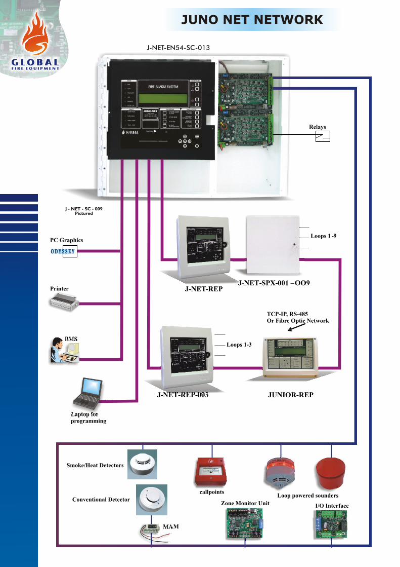
JUNO NET NETWORK
Laptop forprogramming
BMS
Printer
PC Graphics
ODY S S E YODY S S E Y
Relays
J - NET - SC - 009Pictured
J-NET-SPX-001 –OO9
JUNIOR-REP
TCP-IP, Or Fibre Optic Network
RS-485
Loops 1 -9
J-NET-REP-003
Loops 1-3
Smoke/Heat Detectors
callpoints Loop powered sounders
I/O InterfaceZone Monitor Unit
MAM
Conventional Detector
J-NET-REP
J-NET-EN54-SC-013

Juno-Net is a powerful Analogue Addressable
Fire Alarm Control System with networking
capabilities that facilitate the configuration of
complex Wide Area Fire Detection Systems.
Modular construction and distributed intelligence allow systems of up to 96 Loops to be
constructed. With a high level of built-in redundancy and emergency back-up features, the Juno-
Net is fully equipped to control the most complex installations.
Using its wide array of interfacing capabilities the Juno-Net is ideally placed to provide an efficient
and effective solution to the logistics of protecting large institutions. Universities, Airports,
industrial complexes etc which may have many individual Fire Alarm systems but require central
reporting and control can easily be accommodated by the advanced capabilities of the Juno-Net.
Juno-Net is available as a standalone system of up to 13 Loops in a single cabinet and can be
expanded to up to 96 Loops via a networked array of sub-panels which can be supplied in a blank
box version or combined with a repeater to allow remote display and control of the system.
Networking is done by a monitored, redundant, double RS422/485 or Fibre optic loop or TCP/IP
network.
The Juno-Net networking capabilities are further enhanced by a wide range of programming
options which provide the capability to customise the system according to the needs of the
customer. Flexible cause and effect programming of I/O devices and warning devices ensure that
Fire or Fault warnings trigger the appropriate response.
An interactive Graphic representation of the system can be displayed on the users' computer via
the Odyssey Graphics software(optional). All the devices on the system can be displayed on a
building plan showing their status in real time. In the event of Fire or fault the customer can control
the system and access all the necessary information with a few mouse-clicks.
Automatic Device detection at start up reduces time spent at the commissioning stage. In
Installation mode the Juno-Net detects and
recognises addressed and connected devices with
the system being fully operational in less than two
minutes. The default programming ensures that
the system is ready to detect Fire/Fault alerts
from the moment that power is applied.
Additional programming, to customise the system
can be implemented via the onboard keypad, IR
programmer, PS 2 Keyboard or with a laptop PC
running the GFE Connector software which is
available free of charge on the Global Fire website.
JUNO NET
NetworkableFire Detection System
Available in 2 colours
Juno Net 1 to 13 Loops
Juno Net 1 to 4 Loops

Global Fire Equipment Lda.MARF - Armazéns F3 e F4, Sítio do Guelhim, Estoi, 8009-021 FARO, PORTUGAL
Tel: + 351 289 896 560 Fax: + 351 289 865 587Sales [email protected] Technical Support [email protected]
Technical Specifications
Order Code
J-NET-EN54-SC-002
J-NET-EN54-SC-003
J-NET-EN54-SC-004
J-NET-EN54-SC-004-L
J-NET-EN54-SC-001
Large Box - 4 Loops - PSU 5A
1 Loop - PSU 2.4A
2 Loops - PSU 2.4A
3 Loops - PSU 2.4A
4 Loops - PSU 5A
Large Box - 5 Loops - PSU 5A
Large Box - 6 Loops - PSU 5A
LOOPS
SOUNDER OUTPUTS
AUX. RELAYS FIRE
AUX. RELAY FAULT
AUX POWER OUTPUT
ADDITIONAL OUTPUTS
PRIMARY SUPPLY
SECONDARY SUPPLY
POWER SUPPLY RATING
QUIESCENT CURRENT (NO DEVICES)
BATTERIES (INTERNAL)
DIMENSIONS
WEIGHT (NO BATTERIES)
OPERATING TEMPERATURE
STORAGE TEMPERATURE
HUMIDITY/ PROTECTION
1 to 4 loops - max 275mA per loop
2 at 28V DC/500mA each
2 rated 50 VAC/DC 1A resistive
1 rated 50 VAC/DC 1A resistive
28V DC 600mA
Multiplexed up to 384 Zones
85 - 265 V AC, 50/60Hz
28 V DC Nominal
65 W (1-3 Loop) - 150 W (4 Loop)
130mA(1-3 Loop) - 180mA(4 Loop)
2 x 12V 12 AH
H: 375 W: 345 D: 139 mm
5,1 Kg (no batteries)
0ºC to +40ºC
max 85% no condensation - IP21
4 to 13 loops - max 275mA per loop
4/6/8 24V DC/ 500mA each
2 rated 50 VAC/DC 1A resistive
1 rated 50 VAC/DC 1A resistive
28V DC 600mA
Multiplexed up to 384 Zones
85 - 265 V AC, 50/60Hz
28 V DC Nominal
150W(4-6 Loop)-200W(7-13 Loop)
130mA + 90 mA/sub-panel
2 x 12V 12 AH
H: 420 W: 550 D: 127 mm
8,1 Kg (no batteries)
0ºC to +40ºC
-10 to +50ºC
max 85% no condensation - IP21
1 to 4 LOOPS 4 to 13 LOOPS
-10 to +50ºC
Order CodeJuno Net EN54-Self Contained Juno Net EN54-Self Contained
J-NET-EN54-SC-005
J-NET-EN54-SC-006
Large Box - 7 Loops - PSU 7.5A
Large Box - 8 Loops - PSU 7.5A
Large Box - 9 Loops - PSU 7.5A
Large Box - 10 Loops - PSU 7.5A
Large Box - 11 Loops - PSU 7.5A
Large Box - 12 Loops - PSU 7.5A
Large Box - 13 Loops - PSU 7.5A
J-NET-EN54-SC-008
J-NET-EN54-SC-009
J-NET-EN54-SC-010
J-NET-EN54-SC-011
J-NET-EN54-SC-007
J-NET-EN54-SC-012
J-NET-EN54-SC-013
Key Features
[
[
[
[ major analogue addressable communications protocols
[
[
[
[
[
[
[
[
[
[
[
[
[
[
[
[
Fully expandable system from 1-96 Loops with distributed intelligence for added security
125 device addresses per loop
Up to 96 Loop sounders with 32 individually programmable addresses per Loop
Compatible with
2 Fire output changeover relays and 1 Fault output relay (NC)
Open collector outputs for Fire, Fault and pre-alarm remote indication
2 fully monitored sounder outputs on main panel and each sub panel
Repeaters with optional integrated Sub-Panels (J-NET-REP + Loop Card)
Blank box option for Sub Panels
Detector loops fully monitored for integrity
384 programmable zones
512 fully programmable sounder and I/O groups
Event Log 2000 entries FIFO
Backlit LCD display 4 row * 40 characters
Multiple programming options, onboard keypad, Remote IR(optional), PS2 Keyboard
Windows ™ based GFE CONNECTOR Software for Programming with Laptop PC
Windows™ based PC Graphics package ODYSSEY for alarm management and reporting(Optional)
Multiple Language support (menu selectable)
MODBUS (ASCII & RTU) and BMS support
Evacuate / Class Change input (optional)

The introduction of the J-NET-CON-SP1, brings in a new level of flexibility and competitiveness to
our customers.
By including a single loop sub-panel in the JUNO-NET CON board, we were able to pack 4 loops into
our standard box. The new range of self contained Juno Net panels covers all variants in steps of 1
from 1 to 13 loops. Using this new board the Juno Net panel can be provided in the standard box
from 1 to 4 loops and on the larger enclosure from 4 to 13 loops.
The J-NET-CON-SP1 is compatible with all models of interface cards used either when interfacing
the Juno Net Main Panel to other Sub-Panels and/or Repeaters or when connecting Juno Net
Systems to GFE’s graphical software Odyssey, BMS or MODBUS.
J-NET-CON-SP1
Juno Net Main Connector Board including
Single Loop Expansion Sub-Panel
Global Fire Equipment Lda.MARF - Armazens F3 e F4, Sítio do Guelhim, Estoi, 8009-021 FARO, PORTUGAL
Tel: + 351 289 896 560 Fax: + 351 289 865 587Sales [email protected] Technical Support [email protected]
Technical Specifications
Order CodeJ-NET-CON-SP1
LOOPS
SOUNDER OUTPUTS
AUX. RELAYS FIRE
AUX. RELAY FAULT
AUX POWER OUTPUT
ADDITIONAL OUTPUTS
QUIESCENT CURRENT (NO DEVICES)
DIMENSIONS
WEIGHT
OPERATING TEMPERATURE
STORAGE TEMPERATURE
1 loop - max 275mA per loop
2 rated at 28V DC 500mA each
2 - Changeover C-NO-NC rated @ 50 VAC/DC 1A resistive
1 - Normally Closed rated @ 50 VAC/DC 1A resistive
2 rated @ 28V DC 300mA/output
Multiplexed up to 384 Zones
80mA
L: 163 W: 120 H: 27 mm
240 g
0ºC to +40ºC
-10 to +50ºC
Juno Net Main Connector Board inc. 1 Loop Exp. Sub-Panel
Juno Net 1 to 13 LoopsJuno Net 1 to 4 Loops

J-NET-SP Stand AloneJ-NET-SP
Global Fire Equipment Lda.MARF - Armazéns F3 e F4, Sítio do Guelhim, Estoi, 8009-021 FARO, PORTUGAL
Tel: + 351 289 896 560 Fax: + 351 289 865 587Sales [email protected] Technical Support [email protected]
Technical Specifications
Order Code
J-NET-SP-001-SA
J-NET-SP-003-SA
J-NET-SP Sub-Panel Board w/o Loop Card
Sub-Panel Board w/ 1 Loop
Sub-Panel Board w/ 3 Loops
LOOPS
SOUNDER OUTPUTS/ sub-panel
AUX. RELAYS FIRE/ sub-panel
AUX. RELAY FAULT/ sub-panel
AUX POWER OUTPUT
ADDITIONAL OUTPUTS
PRIMARY SUPPLY
SECONDARY SUPPLY
POWER SUPPLY RATING
QUIESCENT CURRENT (NO DEVICES)
BATTERIES (INTERNAL)
DIMENSIONS
WEIGHT (NO BATTERIES)
OPERATING TEMPERATURE
STORAGE TEMPERATURE
HUMIDITY/ PROTECTION
1 or 3 loops - max 275mA per loop
2 at 28V DC/500mA each
2 rated 50 VAC/DC 1A resistive
1 rated 50 VAC/DC 1A resistive
28V DC 300mA
N/A
N/A
28 V DC Nominal
N/A
90 mA
2 x 12V 12 AH
L: 113 W: 180 H: 26 mm
0,3 Kg
0ºC to +40ºC
N/A
1 to 9 loops - max 275mA per loop
4/6/8 24V DC/ 500mA each
2 rated 50 VAC/DC 1A resistive
1 rated 50 VAC/DC 1A resistive
28V DC 300mA
N/A
85 - 265 V AC, 50/60Hz
28 V DC Nominal
150W
90 mA/sub-panel
2 x 12V 12 AH
H: 375 W: 345 D: 139 mm
5,1 Kg (no batteries)
0ºC to +40ºC
-10 to +50ºC
max 85% no condensation - IP21
J-NET-SP Stand Alone J-NET-SPX (Boxed)
-10 to +50ºC
Order CodeJ-Net Sub-Panel Board Juno NET Sub-Panel Boxed1 Loop - 5.4A PSU
3 Loops - 5.4A PSU
4 Loops - 5.4A PSU
6 Loops - 5.4A PSU
7 Loops - 5.4A PSU
9 Loops - 5.4A PSU
J-NET-SPX-001
J-NET-SPX-003
J-NET-SPX-004
J-NET-SPX-006
J-NET-SPX-007
J-NET-SPX-009
J-NET-SP Boxed 1 to 9 Loops
Juno Net Sub Panel
*J-NET-SP-003-SA pictured
*J-NET-SPX-009 pictured
Juno-Net Sub-Panels allow expansion of the
system in groups of either 1 or 3 loops. When
supplied in an enclosed cabinet with independent
primary and secondary power supplies up to 9
Loops may be installed in each cabinet which also
contains a 5A PSU/Charger unit and space for
standby rechargeable batter ies. One
RS422/RS485, Fibre Optic or TCP/IP interface is
required per cabinet to enable networking with
the rest of the system.
Each sub-panel board controls up to 3 Analogue
Addressable Detection Loops via its own
independent processor. In the event of
communications failure with the main control
unit, the sub panel is capable of operating
independently, detecting Fire/Fault events and
activating its own sounders, relays and I/O
devices.

The Global Fire Junior V4 is a single loop Analogue
addressable control panel which can be expanded to two
loops. It provides a cost effective solution for small to
medium sized installations. The Junior V4 can support up
to 125 addressable devices on each loop which are
compatible with
.
Using Global Fire’s advanced communications
mechanism, up to 32 individually addressed Loop
sounders can be connected to each of the Junior V4
detection Loops. The Junior V4 also supports Shadow
and Auxiliary Sounder/Beacons together with GFE’s new Vulcan 2 addressable Sounder-Beacon-
Isolator along with all other GFE Interface devices.
The panel is equipped with a backlit LCD display of 4 rows each with 40 characters to give clear
textual indications of Fire / Fault occurrences to the end user.
There are also 16 Zone Fire LED indicators.
Junior Repeaters and Mini-Repeaters can be connected via an RS422/RS485, Fibre Optic or
TCP/IP interface to facilitate remote display and control of the system.
Automatic Device detection at start up reduces time spent at the commissioning stage. In
Installation mode the Junior V4 detects and recognises addressed and connected devices with
the system being fully operational in less than two minutes.
The default programming ensures that the system is ready to detect Fire / Fault alerts from the
moment that power is applied. Additional programming, to customise the system can be
implemented using a laptop PC running the GFE Connector software which is available free of
charge on GFE’s website.
major analogue addressable
communications protocols
JUNIOR V4
S L AC P
ingle oop Analogue ddressableontrol anel Expandable to 2 Loops
Junior Repeater Junior Loop CardJunior Mini-Rep
Available in 3 colours
Available in 3 colours

Global Fire Equipment Lda.MARF - Armazéns F3 e F4, Sítio do Guelhim, Estoi, 8009-021 FARO, PORTUGAL
Tel: + 351 289 896 560 Fax: + 351 289 865 587Sales [email protected] Technical Support [email protected]
Auxiliary Relay Outputs
Weight
Loop Current Drive
Conventional Sounder Circuits
Dimensions
Max. Humidity
Operating Temperature
2.4 A @ 28.5 V DC nominal (max.)
21.0 min. - 27.2 max.V DC -BAT charger o/p 28V DC01.6 Amp Maximum @ 20 C
2 x 12V x 7Ah Sealed VRLA Lead Acid Batteries
2 Fire (COM-NC-NO) - 1 Fault (COM-NC) non-supervised
2.0 Kg - 7 Kg (inc. 2 x 7AH 12V bat.)
275 mA (quiescent) - 800 mA (alarm) using GFE’s Loop Sounders
2 - 400mA max. current drive per circuit - fully monitored.
272 (W) x 404 (H) x 107 (D) mm
0 ºC to 40 ºC
95% RH Non-Condensing
Technical SpecificationsPrimary Supply Voltage - INPUT
Secondary Supply Voltage
Secondary Supply Current Output
Internal Battery Capacity - Maximum
Primary Supply Voltage - OUTPUT
Primary Supply Current - OUTPUT
85-264 VAC
28.5 V DC nominal
Order CodeJNR-V4-1
JNR-V4-2
JNR-V4-CARD
Junior V4, 1 Loop Expandable to 2 Loops, PSU 2.4 A
Junior V4, 2 Loops, PSU 2.4 A
Junior V4 Loop Card Expansion from 1 to 2 Loop
[Single loop panel - Expandable to two Loops using JNR-V4-Card
[Supports connection to Mini-repeaters via RS422/485, Fibre-Optic or TCP/IP interfaces
[125 device addresses per loop
[32 individually programmable sounder addresses per Loop
[96 VULCAN 2 (addressable) ultra low current sounders or beacons per Loop. Only 64 of these units should be installed per loop when combined sounder beacons are being used. This number includes addressable, shadow, auxiliary and detector-sounder/beacon versions of these units
[Full SAM (Self Addressable Module) & MAM (Manually Addressable Module) support
[2 Fire output relays (change-over) and 1 Fault relay (Normally closed)
[2 conventional alarm outputs (Individually programmable)
[Detector loops monitored for integrity
[384 fully programmable zones
[512 fully programmable sounder groups
[512 fully programmable Input and Output groups
[Event log (rolling, 2000 entries)
[Compatible with major analogue addressable communications protocols
[Compatible with all our own low cost ancillary modules
[Backlit LCD display with 4 rows of 40 characters
[PC Programming using Upload/Download GFE Connector Software
[Multiple language support (menu selectable)
[Integrated 16 zone LED fire zone indication
Key Features
Technical Specifications
Order CodeJ-NET-EN54-REP Juno Net EN54 Repeater
LOOPS
SOUNDER OUTPUTS
AUX. RELAYS FIRE
AUX. RELAY FAULT
AUX POWER OUTPUT
ADDITIONAL OUTPUTS
PRIMARY SUPPLY
SECONDARY SUPPLY
POWER SUPPLY RATING
QUIESCENT CURRENT (NO DEVICES)
BATTERIES (INTERNAL)
DIMENSIONS
WEIGHT (NO BATTERIES)
OPERATING TEMPERATURE
STORAGE TEMPERATURE
HUMIDITY/ PROTECTION
N/A
2 at 28V DC/500mA each
2 rated 50 VAC/DC 1A resistive
1 rated 50 VAC/DC 1A resistive
28V DC 600mA
Multiplexed up to 384 Zones
N/A
28 V DC Nominal
N/A
110 mA
2 x 12V 12 AH
H: 375 W: 345 D: 139 mm
4,5 Kg (no batteries)
0ºC to +40ºC
max 85% no condensation - IP21
1 or 3 loops - max 275mA per loop
2 - 28V DC/ 500mA each
2 rated 50 VAC/DC 1A resistive
1 rated 50 VAC/DC 1A resistive
28V DC 600mA
Multiplexed up to 384 Zones
85 - 265 V AC, 50/60Hz
28 V DC Nominal
65 W
130mA no loop devices fitted
2 x 12V 12 AH
H: 420 W: 550 D: 127 mm
5,1 Kg (no batteries)
0ºC to +40ºC
-10 to +50ºC
max 85% no condensation - IP21
no loop card with loop card
-10 to +50ºC
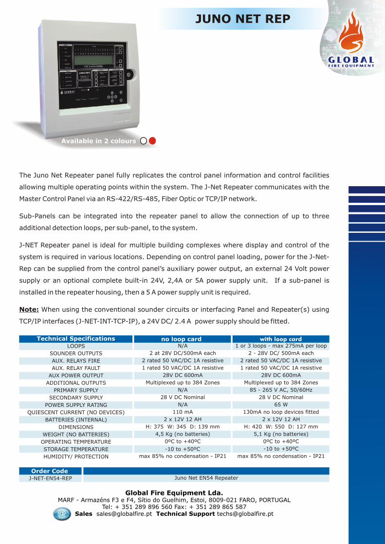
JUNO NET REP
Available in 2 colours
Global Fire Equipment Lda.MARF - Armazéns F3 e F4, Sítio do Guelhim, Estoi, 8009-021 FARO, PORTUGAL
Tel: + 351 289 896 560 Fax: + 351 289 865 587Sales [email protected] Technical Support [email protected]
The Juno Net Repeater panel fully replicates the control panel information and control facilities
allowing multiple operating points within the system. The J-Net Repeater communicates with the
Master Control Panel via an RS-422/RS-485, Fiber Optic or TCP/IP network.
Sub-Panels can be integrated into the repeater panel to allow the connection of up to three
additional detection loops, per sub-panel, to the system.
J-NET Repeater panel is ideal for multiple building complexes where display and control of the
system is required in various locations. Depending on control panel loading, power for the J-Net-
Rep can be supplied from the control panel’s auxiliary power output, an external 24 Volt power
supply or an optional complete built-in 24V, 2,4A or 5A power supply unit. If a sub-panel is
installed in the repeater housing, then a 5 A power supply unit is required.
Note: When using the conventional sounder circuits or interfacing Panel and Repeater(s) using
TCP/IP interfaces (J-NET-INT-TCP-IP), a 24V DC/ 2.4 A power supply should be fitted.

JUNIOR MINI REP
The JUNIOR MINI REP will provide remote control, system status display and monitoring functions for any of GFE’s Analogue Addressable Fire Detection Panels. All Fire, Fault, Test and Disabled conditions are displayed. User is able to control all functions at access Level’s 1, 2 (authorized user level) and 3 (installer/ programming level). Compliant with EN-54 part 2. Display and Control Functions are replicated and shown in the same manner as on any of GFE’s Analogue Addressable Fire Detection Panels. Access to Levels 2 and 3 is via a code using the same as programmed for the associated panel.
It includes as standard an RS-485 interface. This unit is also compatible with all of GFE’s standard data loop interfaces allowing the Junior Mini Rep panel to be interfaced to both Junior and Juno Net addressable panels using 3 different interfacing technologies:
lRS-485lFibre OpticslTCP/IP
A maximum of 4 Junior Mini Rep panels can be connected to a single Addressable Panel if powered directly from the Control Panel’s Auxiliary Supply Output. This number is always dependent on maximum current load derived from a single auxiliary supply output.
It's reduced dimensions make it ideal for installation in reception areas or security booths.
Mechanical Details
FIRE
FAULT
DISABLED
TEST
SUPPLY
SYSTEM FAULT
SUPPLY FAULT
BATTERY FAULT
AUX. SUPPLY FAULT
EARTH FAULT
1
2
3
4
5
6
7
1 2 3 4 5 6 7 8
FIRE
FAULT
BUZZERSILENCE
RESET
LAMP TEST
SOUNDERSACTIVATE/
SILENCE
OUTPUTSAUXILIARY
DISABLESOUNDERS
SELECTEDZONES
DELAYSACTIVE
2
3
4
STATUS
FAULTS DISABLEMENTS
CONTROLSZONES
TEST
DISABLED
1
Global Fire Equipment Lda.MARF - Armazéns F3 e F4, Sítio do Guelhim, Estoi, 8009-021 FARO, PORTUGAL
Tel: + 351 289 896 560 Fax: + 351 289 865 587Sales [email protected] Technical Support [email protected]
256.0 74.0
194.0
All dimensions in mm
Junior MINI REPOrder CodeSupply Voltage
Supply Current
Repeater NetworkConnections
WeightDimensions
Max. Humidity
Operating Temperature
28V DC nominal derived from panel’s Aux. Supply O/P
+Supply, -Supply plus interface connections.
4 units max. when powered from aux. supply o/p from panel
1.5 Kg256.0 (L) x 194.0 (W) x 76.0 (H) mm
0 ºC to 50 ºC
95% RH Non-Condensing
80 mA
RS-485, Fibre Optics, TCP/IP
STATUS QUEUE REVIEW
FAULTS KEYPAD CONTROLS DISABLEMENTS
FIRE
FAULT
PRE-ALARM
TEST
DISABLED
SYSTEM ON
ALARM FAULT
SUPPLY FAULT
SYSTEM FAULT
ENTERESC
DELAYSACTIVE
SELECTEDDETECTORS
SOUNDERSDISABLE
AUXILIARYRELAYS
SOUNDERSACTIVATE/ SILENCE
SYSTEM RESET
LAMP TEST
BUZZERSILENCE
DISABLED
TEST
FAULT
FIRE
ZONES
1 2 3 4 5 6 7 8
9 10 11 12 13 14 15 16 STATUS QUEUE REVIEW
FAULTS KEYPAD CONTROLS DISABLEMENTS
FIRE
FAULT
PRE-ALARM
TEST
DISABLED
SYSTEM ON
ALARM FAULT
SUPPLY FAULT
SYSTEM FAULT
ENTERESC
DELAYSACTIVE
SELECTEDDETECTORS
SOUNDERSDISABLE
AUXILIARYRELAYS
SOUNDERSACTIVATE/ SILENCE
SYSTEM RESET
LAMP TEST
BUZZERSILENCE
DISABLED
TEST
FAULT
FIRE
ZONES
1 2 3 4 5 6 7 8
9 10 11 12 13 14 15 16
Available in 2 colours

JUNIOR REP
The JUNIOR REP will provide remote control, system status display and monitoring functions for any of GFE’s Analogue Addressable Fire Detection Panels. All Fire, Fault, Test and Disabled conditions are displayed. User is able to control all functions at access Level’s 1, 2 (authorized user level) and 3 (installer/programming level). Compliant with EN-54 part 2. Display and Control Functions are replicated and shown in the same manner as on any of GFE’s Analogue Addressable Fire Detection Panel. Access to Levels 2 and 3 is via a code using the same as programmed for the associated panel.
This unit uses the same plastic enclosure as the Junior V4 panel and is available in 3 colours: white, red and black.
It includes as standard an RS-485 interface. This unit is also compatible with all of GFE’s standard data loop interfaces allowing the Junior Rep panel to be interfaced to both Junior and Juno Net addressable panels using 3 different interfacing technologies:
lRS-485lFibre OpticslTCP/IP
A maximum of 4 JUNIOR REPs panels can be connected to a single Addressable Panel if powered directly from the Control Panel’s Auxiliary Supply Output. This number is always dependent on maximum current load derived from a single auxiliary supply output.
Available in 3 colours
Global Fire Equipment Lda.MARF - Armazéns F3 e F4, Sítio do Guelhim, Estoi, 8009-021 FARO, PORTUGAL
Tel: + 351 289 896 560 Fax: + 351 289 865 587Sales [email protected] Technical Support [email protected]
Mechanical DetailsSTATUS QUEUE REVIEW
FAULTS KEYPAD CONTROLS DISABLEMENTS
FIRE
FAULT
PRE-ALARM
TEST
DISABLED
SYSTEM ON
ALARM FAULT
SUPPLY FAULT
SYSTEM FAULT
ENTERESC
DELAYSACTIVE
SELECTEDDETECTORS
SOUNDERSDISABLE
AUXILIARYRELAYS
SOUNDERSACTIVATE/ SILENCE
SYSTEM RESET
LAMP TEST
BUZZERSILENCE
DISABLED
TEST
FAULT
FIRE
ZONES
1 2 3 4 5 6 7 8
9 10 11 12 13 14 15 16
STATUS QUEUE REVIEW
FAULTS KEYPAD CONTROLS DISABLEMENTS
FIRE
FAULT
PRE-ALARM
TEST
DISABLED
SYSTEM ON
ALARM FAULT
SUPPLY FAULT
SYSTEM FAULT
ENTERESC
DELAYSACTIVE
SELECTEDDETECTORS
SOUNDERSDISABLE
AUXILIARYRELAYS
SOUNDERSACTIVATE/ SILENCE
SYSTEM RESET
LAMP TEST
BUZZERSILENCE
DISABLED
TEST
FAULT
FIRE
ZONES
1 2 3 4 5 6 7 8
9 10 11 12 13 14 15 16
404.0
mm
272.0 mm107 mm
JUNIOR REPOrder CodeSupply Voltage
Supply Current
Repeater NetworkConnections
WeightDimensions
Max. Humidity
Operating Temperature
28V DC nominal derived from panel’s Aux. Supply O/P
+Supply, -Supply plus interface connections.
4 units max. when powered from aux. supply o/p from panel
1.6 Kg
0 ºC to 50 ºC
95% RH Non-Condensing
80 mA
RS-485, Fibre Optics, TCP/IP
272 (W) x 404 (H) x 107 (D) mm

Global Fire Equipment Lda.MARF - Armazéns F3 e F4, Sítio do Guelhim, Estoi, 8009-021 FARO, PORTUGAL
Tel: + 351 289 896 560 Fax: + 351 289 865 587Sales [email protected] Technical Support [email protected]
Order CodeJ-NET-IP Juno Net - Internal Thermal Printer - 40 column
WeightDimensions
Max. HumidityOperating Temperature
5-way straight polarised Molex type connector
Flat cable assembly provided with mechanism
Connector Type
Interface
121 g Printer Assembly - 208 g inc. paper roll145 (W) x 45 (D) x 65 (H) mm
0 ºC to 40 ºC
85% RH Non-Condensing
Technical Specifications
Supply Voltage 5 V DC nominal - Does not require external supply.
Hardware handshake - Printer Busy Signal
TTL logic levels @ 1200 baud, 8 data bits, 1 stop bit, no parity
Current Consumptiono
50 mA - standby/ 250 mA - printing @ 25 C
J-NET-IP
Juno NetInternal Printer
This 40 column internally mounted thermal printer provides a hardcopy of the Juno Net panel log containing all relevant events occurring in the system.
All events are date and time stamped and are backed by a 2000 events deep rolling log kept in the panel's non-volatile memory.
Note: in order for the printer to work properly it is necessary that the J-NET-QUART chip be installed on the Juno Net Panel - Main Board. Please refer to the panel's installation manual for full details.
The Juno Net QUART chip should be installed on the Juno Net Panel Main Board when panel is fitted with an internal and/or external printer and when panel is connected to GFE’s graphical software package Odyssey, 3rd party BMS systems or MODBUS via one of GFE’s J-NET-ADV-COMS interface boards.J-NET-QUART
Order CodeJ-NET-QUART Juno Net QUART IC (QUAD-UART)
J-NET-QUART
Juno Net QUART

J-NET-MPX-REL
Junior and Juno NetMultiplexed Zone Relay Outputs
Interface card that provides zone in Fire/ Fault indication via a voltage free change-over relay contact for each zone in any of GFE’s Analogue Addressable Fire Detection Panels. There is also a LED indication of FIRE/ FAULT condition for each individual zone. The LED RED indicator will be ON when the relay is active. These relay outputs are not monitored.
This module operates in three different modes:
l8 Zone Blocks - Indication of Fire for each zone in the range 1 to 384l4 Zone Blocks - Indication of Fire and Fault for each zone in the range 1 to 256lSystem Status - Each relay output is assigned to a specific System Status indication:Fire, Fault, Pre-Alarm, Test, Disabled, Sounders ON, Auxiliary Outputs and Sounders Disabled
The module requires an external 24 V DC supply and connection to either Juno Net or Junior Panels is via a 5 way flat cable fitted with polarised connectors. Two of these connectors are provided to enable connection of more than 1 module.
Global Fire Equipment Lda.MARF - Armazéns F3 e F4, Sítio do Guelhim, Estoi, 8009-021 FARO, PORTUGAL
Tel: + 351 289 896 560 Fax: + 351 289 865 587Sales [email protected] Technical Support [email protected]
WeightDimensions
Max. HumidityOperating Temperature
7mA + 15 mA per active relay
D.I.L. SwitchCurrent - Zones in Alarm
Zone Selection
Current - Quiescent
8 zone - 95 g88.0 (L) x 72.5 (W) x 18.0 (H) mm
0 ºC to 50 ºC
95% RH Non-Condensing
Technical Specifications
Supply Voltage 28V DC nominal7 mA - No relays active
Order Code
J-NET-MPX-REL Junior and Juno Net Multiplexed 8 Zone Relay Board
Switches 1-6Selects Zone Block Address
Switch 7 OFF: 8 Zone Fire Indication
ON: 4 Zone Fire and Fault Indication
1 2 3 4 5 6 7 8
ON
OFF
Switch 8 - Not used Zone 5 Zone 6 Zone 7 Zone 8
Zone 1 Zone 2 Zone 3 Zone 4
Relay Status Indicators Zone Settings
ExternalSupply 24 VDC
1 2 3 4 5 6 7 8
MPX
MPX

J-NET-ADV-COMS-485
Global Fire Equipment produces a range of interfaces that allow the Juno Net Analogue Addressable Fire Detection Panel to be interfaced to GFE’s graphical monitoring software Odyssey.
Four different interfacing technologies are available, namely:
lRS-232lRS-485lFibre OpticslTCP/IP
The J-NET-ADV-COMS-485 is used when connecting a Juno Net Main Panel to GFE’s Odyssey software, BMS or MODBUS using either RS-232 or RS-485. This interface is also used when an external serial printer is linked to the panel. In either case the QUART chip has to be fitted on the Juno Net Main Board.
Global Fire Equipment Lda.MARF - Armazéns F3 e F4, Sítio do Guelhim, Estoi, 8009-021 FARO, PORTUGAL
Tel: + 351 289 896 560 Fax: + 351 289 865 587Sales [email protected] Technical Support [email protected]
J-NET-ADV-COMS-485
Order CodeJuno Net - Odyssey RS-485 Interface
Technical Specifications
Supply Voltage
Supply Current
Software & Hardware Compatability
WeightDimensions
Max. Humidity
Operating Temperature
28V DC nominal - range 17 to 30 V DC
36 g
0 ºC to 40 ºC
85% RH Non-Condensing
14 mA
Juno Net Main Panel all versions
74.3 (L) x 51.1 (W) x 24.0 (H) mm
Odyssey
Connections
Printe
r
RS-232
RS-485
RS-232
NOTE: When using RS-485 and should be in place and should be removed. When using RS-232 should be in place and and should be removed.
IC7 IC8IC7 IC8
IC6IC6
IC7
IC8
IC6
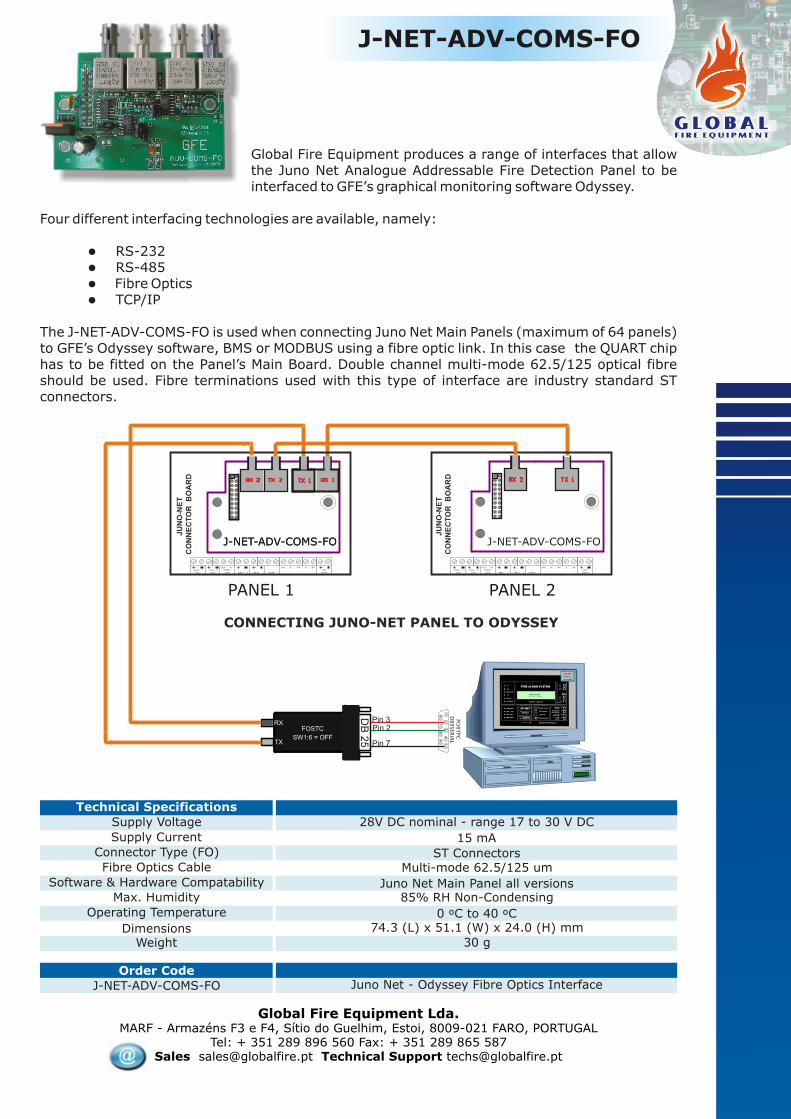
J-NET-ADV-COMS-FO
Global Fire Equipment produces a range of interfaces that allow the Juno Net Analogue Addressable Fire Detection Panel to be interfaced to GFE’s graphical monitoring software Odyssey.
Four different interfacing technologies are available, namely:
lRS-232lRS-485lFibre OpticslTCP/IP
The J-NET-ADV-COMS-FO is used when connecting Juno Net Main Panels (maximum of 64 panels) to GFE’s Odyssey software, BMS or MODBUS using a fibre optic link. In this case the QUART chip has to be fitted on the Panel’s Main Board. Double channel multi-mode 62.5/125 optical fibre should be used. Fibre terminations used with this type of interface are industry standard ST connectors.
TX
RX
SW1:6 = OFF
FOSTC
DB
25
DB9SERIAL
PORTPC
98
76
45
32
1
Pin 2Pin 3
Pin 7
CONNECTING JUNO-NET PANEL TO ODYSSEY
AUX 1
PSU
AUX 2
PSU BELL 1 BELL 2
24v
BATTEVAC
ZONE
MPX
OUT PF E SF24v0v 0v
JU
NO
-NE
TC
ON
NE
CT
OR
B
OA
RD
JU
NO
-NE
TC
ON
NE
CT
OR
B
OA
RD
AUX 1
PSU
AUX 2
PSU BELL 1 BELL 2
24v
BATTEVAC
ZONE
MPX
OUT PF E SF24v0v 0v
PANEL 1 PANEL 2
J-NET-ADV-COMS-FOJ-NET-ADV-COMS-FO J-NET-ADV-COMS-FO
Global Fire Equipment Lda.MARF - Armazéns F3 e F4, Sítio do Guelhim, Estoi, 8009-021 FARO, PORTUGAL
Tel: + 351 289 896 560 Fax: + 351 289 865 587Sales [email protected] Technical Support [email protected]
J-NET-ADV-COMS-FO
Order CodeJuno Net - Odyssey Fibre Optics Interface
Technical Specifications
Supply Voltage
Connector Type (FO)
Supply Current
Fibre Optics Cable
Software & Hardware Compatability
WeightDimensions
Max. Humidity
Operating Temperature
28V DC nominal - range 17 to 30 V DC
ST Connectors
30 g
0 ºC to 40 ºC
85% RH Non-Condensing
15 mA
Multi-mode 62.5/125 um
Juno Net Main Panel all versions
74.3 (L) x 51.1 (W) x 24.0 (H) mm

J-NET-ADV-COMS-TCP/IP
Global Fire Equipment Lda.MARF - Armazéns F3 e F4, Sítio do Guelhim, Estoi, 8009-021 FARO, PORTUGAL
Tel: + 351 289 896 560 Fax: + 351 289 865 587Sales [email protected] Technical Support [email protected]
Order CodeJ-NET-ADV-COMS-TCP/IP
Technical Specification
Supply Voltage
Supply Current
NetworkConfiguration
WeightDimensions
Max. Humidity
Operating Temperature
28V DC nominal
10/100Mbit Ethernet - auto-sensing
Network (Internet Browser, Telnet, Device Installer)
Serial Port / Terminal Emulator
40 g74.3 (L) x 51.1 (W) x 24.0 (H) mm
Juno Net - Odyssey TCP/IP Interface
0 ºC to 40 ºC
85% RH Non-Condensing
45 mA
NetworkConnection
Serial Port
PCPanel
51.1
mm
74.3 mm
Global Fire Equipment produces a range of interfaces that allow the Juno Net Analogue Addressable Fire Detection Panel to be interfaced to GFE’s graphical monitoring software Odyssey.
Four different interfacing technologies are available, namely:
lRS-232lRS-485lFibre OpticslTCP/IP
The J-NET-ADV-COMS-TCP/IP interface is used when connecting Juno Net Main Panel’s (maximum of 64) to GFE’s Odyssey software, BMS or MODBUS using TCP/IP protocol within a Local Area Network (LAN).
Both 10/100 Mbps speeds are supported by this device and the communication rate is automatically set depending on the type of network to which the device is connected. Juno Net panels linked to Odyssey, BMS or MODBUS, will also need to be equipped with a QUAD-UART chip (GFE ref. J-NET-QUART).
This interface is easily configured using LAN communications with provided software, Internet browser or Telnet. Alternatively the interface can also be configured using terminal emulation software via the serial port provided in the form of a D-Type 9 pin miniature connector. Two RED LED’s on the interface board will assist the user when monitoring the system communication status.

The J-NET-INT-485 interface module allows GFE's range of panels to be interfaced to repeaters and/or sub-panels using a 4-core data communication cable suitable for RS-422/RS-485 data transmission using a common data communication loop in a ring topology. These units can also use a double-redundant data communication loop for extra security and reliability when used in conjunction with a Juno Net or Junior main panel by creating a bi-directional communication flow. In this case if the Juno Net or Junior panel is unable to communicate with a repeater or sub-panel due to a cut cable or short circuit, it will try to establish communication via the 2nd loop. A communication fault will be signalled by the Juno Net main panel when communication is lost with any sub-panels or repeater panel equipped with a loop card. Please note that the Junior panel, in all its versions, can only be interfaced with Junior Mini-Rep and Junior Rep.
This interface is used in the fire alarm control panel to provide a communications interface for the following:
1) An Orion conventional panel and its repeater(s) - version 1.5 and above2) A Junior panel (all versions), and its Junior Mini-Rep(s) and Junior Rep(s)3) A Juno Net panel and Repeater(s), Junior Mini-Rep, Junior Rep and Sub-Panels
This interface is compatible with the following panels, repeaters and sub-panels:
1) Orion Conventional Panel 2, 4 and 8 zones - version 1.5 and above2) Orion Rep and Orion Mini-Rep3) Junior analogue addressable panel (all versions)4) Junior Mini-Rep and Junior Rep5) Juno Net, expandable analogue addressable panel6) Juno Net Repeater7) Sub-Panel
This interface can be used in parallel with other similar modules using other interface technologies such as Fibre Optics, providing the installer with the tools to interface and create a network of panels, repeaters and sub-panels using mixed data communication technologies, catering for the most demanding applications and networking requirements.
Each panel, repeater and sub-panel will require one of these interface modules. The maximum distance between two nodes is 1.2Kms including the return path to the main panel.
Custom made versions of these modules can be produced for connection to GFE's proprietary MPX protocol to connect LEDs, mimic displays, relays and conventional sounder circuits to GFE's extensive range of conventional and analogue addressable panels. Please consult GFE for further information.
Global Fire Equipment Lda.MARF - Armazéns F3 e F4, Sítio do Guelhim, Estoi, 8009-021 FARO, PORTUGAL
Tel: + 351 289 896 560 Fax: + 351 289 865 587Sales [email protected] Technical Support [email protected]
J-NET-INT-485
Order CodeRS422/485 Data Loop Interface
Technical Specifications
Supply Voltage
Supply Current
Software & Hardware Compatability
WeightDimensions
Max. Humidity
Operating Temperature
28V DC nominal - range 17 to 30 V DC
47 g135.0 (L) x 35.5 (W) x 18 (H) mm
0 ºC to 40 ºC
85% RH Non-Condensing
14 mAJuno Net Panel & Repeater - Sub-Panel
Junior Panel V2,3 and 4, Mini-Rep, Junior Repeaters
Orion Conventional Panel (version 1.5) and Orion Repeaters
J-NET-INT-485RS-485 Data Loop Interface

The J-NET-INT-FO interface modules allow GFE's range of panels to be interfaced to repeaters and/or sub-panels using fibre optic cable using a common data communication loop in a ring topology. These units also use a double-redundant data communication loop for extra security and reliability.
These modules are used in the fire alarm control panel to provide a communications interface for the following:
1) An Orion conventional panel and its repeater(s) - version 1.5 and above2) A Junior, analogue addressable panel, and its repeater(s)3) A Juno Net panel and Repeater(s), Junior Rep(s), Junior Mini-Rep(s) and Sub-Panels
The interface module is compatible with the following panels, repeaters and sub-panels:
1) Orion Conventional Panel 2, 4 and 8 zones - version 1.5 and above2) Orion Rep and Orion Mini Rep3) Junior panel all versions4) Junior Rep and Junior Mini-Rep5) Juno Net, expandable analogue addressable panel6) Juno Net Repeater7) Sub-Panel
These interfaces can be used in parallel with other similar modules using other interface technologies such as RS-485, providing the installer with the tools to interface and create a network of panels, repeaters and sub-panels using mixed data communication technologies, catering for the most demanding applications and networking requirements.
Each panel, repeater and sub-panel will require one of these interface modules. The maximum ring distance is 4 Kms.
Fibre optic cables to be used in conjunction with these modules should be multi-mode 62.5/125um and terminated using the industry standard ST connectors.
Custom made versions of these modules can be produced for connection to GFE's proprietary MPX protocol to connect LEDs, mimic displays, relays and conventional sounder circuits to GFE's extensive range of conventional and analogue addressable panels. Please consult GFE for further information.
Global Fire Equipment Lda.MARF - Armazéns F3 e F4, Sítio do Guelhim, Estoi, 8009-021 FARO, PORTUGAL
Tel: + 351 289 896 560 Fax: + 351 289 865 587Sales [email protected] Technical Support [email protected]
J-NET-INT-FO
Order CodeFibre Optic - Data Loop Interface
Technical Specifications
Supply Voltage
Connector Type (FO)
Supply Current
Fibre Optics Cable
Software & Hardware Compatability
WeightDimensions
Max. Humidity
Operating Temperature
28V DC nominal - range 17 to 30 V DC
ST Connectors
32 g135.0 (L) x 35.6 (W) x 20 (H) mm
0 ºC to 40 ºC
85% RH Non-Condensing
15 mA
Multi-mode 62.5/125 umJuno Net Panel & Repeater - Sub-Panel
Junior Panel V2,3 and 4, Mini-Rep, Junior Repeaters
Orion Conventional Panel (version 1.5) and Orion Repeaters
J-NET-INT-FOFibre Optics Data Loop Interface

J-NET-INT-TCP/IP
Global Fire Equipment produces a range of interfaces that allow its range of panels, both conventional and analogue addressable panels to communicate with repeaters and sub-panels.
Four different interfacing technologies are available, namely:
lRS-232 ( Orion Conventional Panel only)lRS-485lFibre OpticslTCP/IP
The J-NET-INT-TCP-IP interface is used when connecting any of GFE’s range of Fire Detection panels to Repeaters or Sub-Panel, using TCP/IP protocol within a Local Area Network (LAN). Please note that sub-panels can only be interfaced to Juno Net panels.
Both 10/100 Mbps speeds are supported by this device and communication rate is automatically set depending on the type of network to which the device is connected.
Interface is easily configured using LAN communications using Telnet. Alternatively the interface can also be configured using terminal emulation software via the serial port provided in the form of a D-Type 9 pin miniature connector.
Two RED LEDs on the interface board will assist the user when monitoring the system communication status.
Global Fire Equipment Lda.MARF - Armazéns F3 e F4, Sítio do Guelhim, Estoi, 8009-021 FARO, PORTUGAL
Tel: + 351 289 896 560 Fax: + 351 289 865 587Sales [email protected] Technical Support [email protected]
J-NET-INT-TCP-IP
Order CodeData Loop TCP/IP Interface
Technical Specifications
Supply Voltage
Supply Current
NetworkConfiguration
WeightDimensions
Max. Humidity
Operating Temperature
28V DC nominal
10/100Mbit Ethernet - auto-sensing
Network - Telnet
Serial Port / Terminal Emulator
40 g120.0 (L) x 35.2 (W) x 18.4 (H) mm
0 ºC to 50 ºC
95% RH Non-Condensing
45 mA
Dat
aLo
op
Dat
aLo
op
NETWORK
INTERFACESerial Port Connector
Pan
el C
on
nec
tors
COM Status LED Indicators
120,0 mm
35
,2 m
m

Second zoom screen showing zone in alarm
Initial alarm screen showing general area
O D Y S S E YO D Y S S E Y
stA Graphics Interface for the 21 Century
The Odyssey Graphics Display and Alarm
Management System allows the connection of up to
64 Juno-NET fire alarm panels to a PC. Each panel
can be displayed on the screen as if the operator
were standing in front of it, and can be fully
controlled from the computer.
Odyssey is simple to set up and to operate.
Programming is password protected. Once in
programming mode, each panel in the system can be
enabled, and drawings can easily be imported from a
graphics program such as Autocad®.
Detectors and Call Points etc. are then added
graphically via the built-in interface. There are no
complicated tables to set up. Device descriptions are
received directly from the Juno-Net control panel.
In the event of an alarm or fault, the location of the
incident will be displayed on the computer screen,
with three levels of zoom available to the operator.The individual device can be viewed and
interrogated, and if necessary disabled.
A printer can be connected to the computer to record
all alarm, fault and programming activities on the
system. Whether or not a printer is connected, a log
is kept of all events. This log can be periodically
downloaded and printed if required.
Other utilities are provided, such as a list of
emergency phone numbers, and an operator
notepad.
If a second computer is required at another location,
this can be connected as a slave via an Ethernet
network to the main computer. For longer distances,
Fibre Optic cabling can be used. TCP/IP
communications can also be used to allow remote
access.
Odyssey is available in several language versions
including English, Spanish, Italian and Portuguese.
Highest zoom showing detector in alarm

Global Fire Equipment Lda.MARF - Armazéns F3 e F4, Sítio do Guelhim, Estoi, 8009-021 FARO, PORTUGAL
Tel: + 351 289 896 560 Fax: + 351 289 865 587Sales [email protected] Technical Support [email protected]
Order CodeRS422/485 CONVERTER RS232 to RS422/485 CONVERTER - Model 4WSD9R
WeightDimensions
Max. HumidityOperating Temperature
IP44
RS232 side DB9 Female - RS485 side DB9 Female
Protection Category
Connector Type
Communications Settings
40 g78 (L) x 43 (W) x 20 (H) mm
0 ºC to 40 ºC
85% RH Non-Condensing
Technical Specifications
Supply Voltage 12 V DC nominal - Does not require external supply.
9600 baud - 8 data bits - 1 stop bit - no parity
Half Duplex - 4 wire
Current Consumption 3.0 mA + transmission load current
ODYSSEY
Hardware Accessories
Used at the PC to convert RS-485 signal levels to RS-232 when connecting Juno Net panels to Odyssey using this interconnection technology. The unit is port powered and hence no external power is required.
Used at the PC to convert Fiber Optic signal levels to RS-232 when connecting Juno Net panels to Odyssey using this interconnection technology. The unit requires an external supply of 12 V DC.
FOSTC
WeightDimensions
Max. HumidityOperating Temperature
IP44Protection Category
70 g
110 (L) x 59 (W) x 25 (H) mm0 ºC to 40 ºC
85% RH Non-Condensing
Technical Specifications
Supply Voltage External Supply - 12 V DC
Order Code
FOSTC RS-232 TO FIBRE OPTICS CONVERTER
Current Consumption 140 mA max.Connector Type (FO)
Fibre Optics CableST Connectors
Multi-mode 62.5/125 umCommunications Settings 9600 baud - 8 data bits - 1 stop bit - no parity
RS232/485 Converter

ORION
Conventional Fire Detection Control Panel
The Orion range of conventional control panels features three models with 2, 4 and 8 Zones of
detection. Housed in a stylish modern ABS housing, the Orion is the ideal control panel for
smaller installations.
Designed and manufactured to comply with the requirements of EN54 parts 2 and 4(1998) the
Orion uses active End of Line monitoring to permit head removal protection as required by
BS5839. (detector bases must be fitted with Diode)
Programmable Zone coincidence and alarm delay timer (0-10 min) are standard features to
help reduce false alarms.
The one man test facility enables simple and rapid testing of the system at commissioning and
during maintenance operations.
Two, four and eight zone non-expandable control panelsUp to 32 conventional smoke and/or heat detectors per zoneActive End of Line monitoringProgrammable non-latching zonesDelay timer programmable on/off per zoneZone coincidence programmable for adjacent zonesThree Access LevelsOne man testSupervised auxiliary 24 volt output2 supervised/ monitored sounder circuits3 remote inputs used for activation of Class Change, Day/Night mode, and Reset2 Relay outputs fire and faultPower supply 1,7A at 28V DCFully EN54 part 2 and 4 compliantRepeater outputMultiplexed output for LEDs and additional relay outputs per zone (GFE-MPX-REL)Addressable Loop Interface card (GFE-ADLI)
Features:
Orion Rep ORION-INT-RS232
GFE-ADLI
Orion Mini-Rep
Repeater Interface
Analogue Loop Interface
Available in 3 colours

Conventional Fire Detection Control Panel
ORION
Technical Specifications
Global Fire Equipment Lda.MARF - Armazéns F3 e F4, Sítio do Guelhim, Estoi, 8009-021 FARO, PORTUGAL
Tel: + 351 289 896 560 Fax: + 351 289 865 587Sales [email protected] Technical Support [email protected]
Auxiliary Relay Outputs
Evacuation (CC) - Day/ Night Mode
Relay Contact Rating
Reset
Weight
Conventional Sounder Circuits
End of Line Resistor
Dimensions
Max. HumidityOperating Temperature
1 Fire (COM-NC-NO) - 1 Fault (COM-NC) non-supervised
Non-Latching - Voltage free contact
50 V DC - 1 Amp resistive loads
Non-Latching - Voltage free contact
1.7 Kg - 7 Kg (inc. 2 x 7AH bat.)
272 (W) x 404 (H) x 107 (D) mm
0 ºC to 40 ºC
95% RH Non-Condensing
Mains FuseBattery Fuse
1.7 A @ 28.5 V DC nominal (max.)
21.0 min. - 27.2 max.V DC -BAT charger o/p 28V DC0
1.1 Amp Maximum @ 20 C2 x 12V x 7Ah Sealed VRLA Lead Acid Batteries
4 A -250V Slow Blow - 20mm1.6 Amp - Resettable
Supply Specification
Detection Circuit Specification
Sounder Circuit Specification
Auxiliary Outputs Specification
Remote Input Specification
Mechanical & Operating Spec.
Number of circuits
Max. Cable Resistance
Max. Cable Capacitance
Zone Current - Quiescent
Zone Current - Alarm
End of Line Monitoring
BS5839 Detector removal Compliant
Devices per Zone
Alarm Resistance Value
Primary Supply Voltage - INPUT
Secondary Supply Voltage
Secondary Supply Current Output
Internal Battery Capacity - Maximum
Primary Supply Voltage - OUTPUT
Primary Supply Current - OUTPUT
85-264 VAC
28.5 V DC nominal
Order Code
ORION 2
ORION 4
ORION 8
2 Zones Conventional Fire Detection Control Panel
4 Zones Conventional Fire Detection Control Panel
8 Zones Conventional Fire Detection Control Panel
2,4 or 8
40 Ohms
0.470 uF
5 mA maximum
60 mA - Maximum
Active EOL - Capacitor
YES provided diodes are fitted to detector base32 Maximum - EN54 pt.2
270 - 1000 Ohms
2 - 500mA max. current drive per circuit - fully monitored.
10 K Ohms - 1/4 Watt
Open and Short Circuit
27.5 V DC Nominal
1.1 Amp resettable
Monitoring
Alarm Voltage
Fuse Rating

ORION MINI REP
The ORION MINI REP will provide remote control, system status display and monitoring functions. All Fire, Fault, Test and Disabled conditions are displayed. User is able to control all functions at access Level’s 1 and 2. Compliant with EN-54 part 2. Display and Control Functions are replicated and shown in the same manner as on the Orion Fire Detection Panel. Access to Level 2 is via a four digit code (same code as used on the Orion Conventional Panel).
It includes as standard an RS-232 interface. This unit is also compatible with all of GFE’s standard data loop interfaces allowing the Orion Mini Rep panel to be interfaced to an ORION conventional panel using 4 different interfacing technologies:
lRS-232lRS-485lFibre OpticslTCP/IP ( Specific for Orion Conventional Systems)
A maximum of 4 Orion Mini Rep panels can be connected to a single Orion Conventional Fire Detection Panel. When using RS-232 interfaces only one repeater panel will offer both control and display of the system. The remainder of the repeater panels will only offer system status display. In order to have control from more than one Orion Mini Rep panels any of the other interfacing technologies can be used.
Global Fire Equipment Lda.MARF - Armazéns F3 e F4, Sítio do Guelhim, Estoi, 8009-021 FARO, PORTUGAL
Tel: + 351 289 896 560 Fax: + 351 289 865 587Sales [email protected] Technical Support [email protected]
ORION MINI REPOrder CodeSupply Voltage
Supply Current
Repeater NetworkConnections
WeightDimensions
Max. Humidity
Operating Temperature
28V DC nominal derived from Orion Aux. Supply O/P
RS-232 - 1 Display & Control 3 Display Only
+Supply, -Supply, TX and RX
RS-485, Fibre Optics, TCP/IP - 4 units max. Display and Control
1.4 Kg256.0 (L) x 194.0 (W) x 75.0 (H) mm
0 ºC to 50 ºC
95% RH Non-Condensing
40 mA
MANUFACTURED IN THE E.U. TO THEREQUIREMENTS OF EN54 Pt 2 & Pt 4 1999
FIRE
FAULT
DISABLED
TEST
SUPPLY
SYSTEM FAULT
SUPPLY FAULT
BATTERY FAULT
AUX. SUPPLY FAULT
EARTH FAULT
1
2
3
4
5
6
7
8
1 2 3 4 5 6 7 8
FIRE
FAULT
BUZZERSILENCE
RESET
LAMP TEST
SOUNDERSACTIVATE/
SILENCE
OUTPUTSAUXILIARY
DISABLESOUNDERS
SELECTEDZONES
DELAYSACTIVE
2
3
4
STATUS
FAULTS INSTRUCTIONS FOR CONVENTIONAL FIRE ALARM PANEL DISABLEMENTS
CONTROLSZONES
TEST
DISABLED
General User ( Access Level 1)To silence internal buzzer press BUZZER SILENCE.To override active delays, during an alarm condition, press DELAYS ACTIVE.
Authorized User ( Access Level 2 )To enter this level enter 4 digit code.Consult Manual for more details.
EVACUATIONEnter Authorised User Code (Access Level 2).Press SOUNDER (Activate/Silence).Repeat last step to SILENCE sounders.
Fire EventsInternal Buzzer sounds.System Status Fire LED is lit.Zones on Fire will have their respective Fire LED lit.To silence fire alarms: First enter authorised user code (Access Level 2). Press SOUNDER (Activate/ Silence) button.
Fault EventsInternal Buzzer Sounds.System Status Fault LED is lit.Each fault will be shown by its own LED being lit.Call service engineer.
1
Mechanical Details
FIRE
FAULT
DISABLED
TEST
SUPPLY
SYSTEM FAULT
SUPPLY FAULT
BATTERY FAULT
AUX. SUPPLY FAULT
EARTH FAULT
1
2
3
4
5
6
7
8
1 2 3 4 5 6 7 8
FIRE
FAULT
BUZZERSILENCE
RESET
LAMP TEST
SOUNDERSACTIVATE/
SILENCE
OUTPUTSAUXILIARY
DISABLESOUNDERS
SELECTEDZONES
DELAYSACTIVE
2
3
4
STATUS
FAULTS DISABLEMENTS
CONTROLSZONES
TEST
DISABLED
1
256.0 75.0
194.0
All dimensions in mm
Available in 2 colours

ORION REP
Available in 3 colours
The ORION REP will provide remote control, system status display and monitoring functions. All Fire, Fault, Test and Disabled conditions are displayed. User is able to control all functions at access Level’s 1 and 2. Compliant with EN-54 part 2. Display and Control Functions are replicated and shown in the same manner as on the Orion Fire Detection Panel. Access to Level 2 is via a four digit code (same code as used on the Orion Conventional Panel).
It includes as standard an RS-232 interface. This unit is also compatible with all of GFE’s standard data loop interfaces allowing the Orion Mini Rep panel to be interfaced to an ORION conventional panel using 4 different interfacing technologies:
lRS-232lRS-485lFibre OpticslTCP/IP ( Specific for Orion Conventional Systems)
A maximum of 4 Orion Rep panels can be connected to a single Orion Conventional Fire Detection Panel. When using RS-232 interfaces only one repeater panel will offer both control and display of the system. The remainder of the repeater panels will only offer system status display. In order to have control from more than one Orion Mini Rep panels any of the other interfacing technologies can be used.
Global Fire Equipment Lda.MARF - Armazéns F3 e F4, Sítio do Guelhim, Estoi, 8009-021 FARO, PORTUGAL
Tel: + 351 289 896 560 Fax: + 351 289 865 587Sales [email protected] Technical Support [email protected]
ORION REPOrder CodeSupply Voltage
Supply Current
Repeater NetworkConnections
WeightDimensions
Max. Humidity
Operating Temperature
28V DC nominal derived from Orion Aux. Supply O/P
RS-232 - 1 Display & Control 3 Display Only
+Supply, -Supply, TX and RX
RS-485, Fibre Optics, TCP/IP - 4 units max. Display and Control
1.4 Kg
0 ºC to 50 ºC
95% RH Non-Condensing
40 mA
MANUFACTURED IN THE E.U. TO THEREQUIREMENTS OF EN54 Pt 2 & Pt 4 1999
FIRE
FAULT
DISABLED
TEST
SUPPLY
SYSTEM FAULT
SUPPLY FAULT
BATTERY FAULT
AUX. SUPPLY FAULT
EARTH FAULT
1
2
3
4
5
6
7
8
1 2 3 4 5 6 7 8
FIRE
FAULT
BUZZERSILENCE
RESET
LAMP TEST
SOUNDERSACTIVATE/
SILENCE
OUTPUTSAUXILIARY
DISABLESOUNDERS
SELECTEDZONES
DELAYSACTIVE
2
3
4
STATUS
FAULTS INSTRUCTIONS FOR CONVENTIONAL FIRE ALARM PANEL DISABLEMENTS
CONTROLSZONES
TEST
DISABLED
General User ( Access Level 1)To silence internal buzzer press BUZZER SILENCE.To override active delays, during an alarm condition, press DELAYS ACTIVE.
Authorized User ( Access Level 2 )To enter this level enter 4 digit code.Consult Manual for more details.
EVACUATIONEnter Authorised User Code (Access Level 2).Press SOUNDER (Activate/Silence).Repeat last step to SILENCE sounders.
Fire EventsInternal Buzzer sounds.System Status Fire LED is lit.Zones on Fire will have their respective Fire LED lit.To silence fire alarms: First enter authorised user code (Access Level 2). Press SOUNDER (Activate/ Silence) button.
Fault EventsInternal Buzzer Sounds.System Status Fault LED is lit.Each fault will be shown by its own LED being lit.Call service engineer.
1
Mechanical Details
404.0
mm
272.0 mm107 mm
FIRE
FAULT
DISABLED
TEST
SUPPLY
SYSTEM FAULT
SUPPLY FAULT
BATTERY FAULT
AUX. SUPPLY FAULT
EARTH FAULT
1
2
3
4
5
6
7
8
1 2 3 4 5 6 7 8
FIRE
FAULT
BUZZERSILENCE
RESET
LAMP TEST
SOUNDERSACTIVATE/
SILENCE
OUTPUTSAUXILIARY
DISABLESOUNDERS
SELECTEDZONES
DELAYSACTIVE
2
3
4
STATUS
FAULTS INSTRUCTIONS FOR CONVENTIONAL FIRE ALARM PANEL DISABLEMENTS
CONTROLSZONES
TEST
DISABLED
General User ( Access Level 1)To silence internal buzzer press BUZZER SILENCE.To override active delays, during an alarm condition, press DELAYS ACTIVE.
Authorized User ( Access Level 2 )To enter this level enter 4 digit code.Consult Manual for more details.
EVACUATIONEnter Authorised User Code (Access Level 2).Press SOUNDER (Activate/Silence).Repeat last step to SILENCE sounders.
Fire EventsInternal Buzzer sounds.System Status Fire LED is lit.Zones on Fire will have their respective Fire LED lit.To silence fire alarms: First enter authorised user code (Access Level 2). Press SOUNDER (Activate/ Silence) button.
Fault EventsInternal Buzzer Sounds.System Status Fault LED is lit.Each fault will be shown by its own LED being lit.Call service engineer.
1
272 (W) x 404 (H) x 107 (D) mm
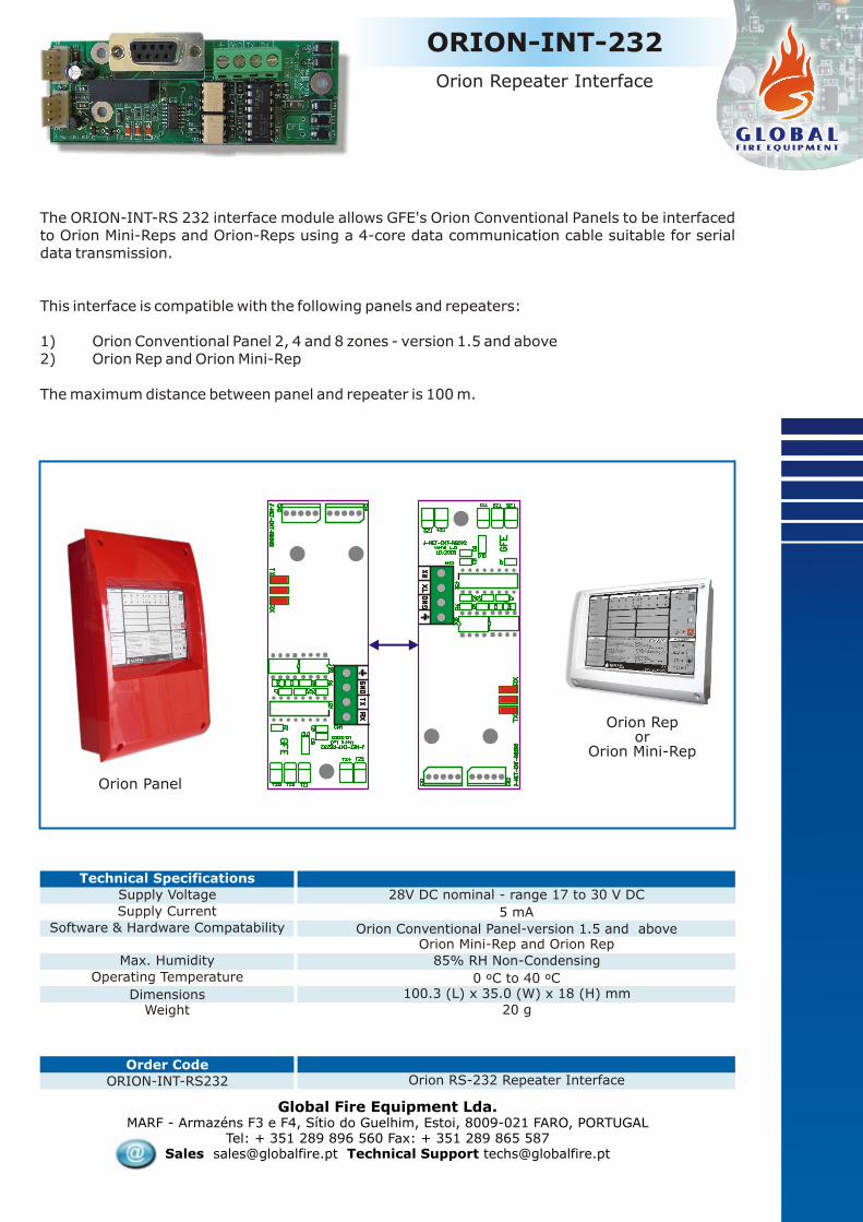
The ORION-INT-RS 232 interface module allows GFE's Orion Conventional Panels to be interfaced to Orion Mini-Reps and Orion-Reps using a 4-core data communication cable suitable for serial data transmission.
This interface is compatible with the following panels and repeaters:
1) Orion Conventional Panel 2, 4 and 8 zones - version 1.5 and above2) Orion Rep and Orion Mini-Rep
The maximum distance between panel and repeater is 100 m.
Global Fire Equipment Lda.MARF - Armazéns F3 e F4, Sítio do Guelhim, Estoi, 8009-021 FARO, PORTUGAL
Tel: + 351 289 896 560 Fax: + 351 289 865 587Sales [email protected] Technical Support [email protected]
ORION-INT-RS232
Order CodeOrion RS-232 Repeater Interface
20 g
Technical Specifications
Supply Voltage
Supply Current
Software & Hardware Compatability
WeightDimensions
Max. Humidity
Operating Temperature
28V DC nominal - range 17 to 30 V DC
100.3 (L) x 35.0 (W) x 18 (H) mm0 ºC to 40 ºC
85% RH Non-Condensing
5 mA
Orion Conventional Panel-version 1.5 and above Orion Mini-Rep and Orion Rep
ORION-INT-232
Orion Repeater Interface
Orion Panel
Orion Repor
Orion Mini-Rep

Interface card that provides an individual zone in alarm indication via a voltage free change-over relay contact for each zone in an Orion conventional panel.There are 2 versions: 4 and 8 zone and they are always used for indication of ALARM/ FIRE conditions. There is also a LED indication of ALARM condition for each individual zone. The LED RED indicator will be ON when the relay is active. These relay outputs are not monitored.
.
The DIL switch allows one relay output for a particular zone in the range 1 to 8 to be programmed as delayed and this is achieved using the first three switches (1 to 3) and the delay time will be provided in the range between 0-10 minutes using the next four positions (4-7) on the DIL switch. The module requires an external 24 V DC supply. Connection to the Orion PCB board is via a 5 way flat cable fitted with Molex type polarised connectors.
Global Fire Equipment Lda.MARF - Armazéns F3 e F4, Sítio do Guelhim, Estoi, 8009-021 FARO, PORTUGAL
Tel: + 351 289 896 560 Fax: + 351 289 865 587Sales [email protected] Technical Support [email protected]
GFE-MPX-REL
Orion Multiplexed Zone Relay Outputs
WeightDimensions
Max. HumidityOperating Temperature
7mA + 15 mA per active relay
15 settings from 0 to 10 minutesCurrent - Zones in Alarm
Timer
Current - Quiescent
4 zone - 60 g 8 zone - 95 g88.0 (L) x 72.5 (W) x 18.0 (H) mm
0 ºC to 50 ºC
95% RH Non-Condensing
Technical Specifications
Supply Voltage 28V DC nominal7 mA - No relays active
Order Code
GFE-MPX-REL-4
GFE-MPX-REL-8
Orion Multiplexed 4 Zone Relay Board
Orion Multiplexed 8 Zone Relay Board
Switches 1-3Selects delayed zone
Switches 4-7 Set the delay time.
1 2 3 4 5 6 7 8
ONOFF
Switch 8 - Not used
1 2 3 4 5 6 7 8
ON (1)
OFF (0)
Zone Time1 = 0002 = 1003 = 0104 = 1105 = 0016 = 1017 = 0118 = 111
030s1m
1m30s2m
2m30s3m
3m30s
= 0000= 1000= 0100= 1100= 0010= 1010= 0110= 1110
4m4m30s
5m6m7m8m9m
10m
= 0001= 1001= 0101= 1101= 0011= 1011= 0111= 1111

The analogue addressable systems. It allows the addressable panel to monitor and control the status of the conventional unit.
An 8 way DIL switch and a pluggable jumper are provided which will be used for setting the module address and the reporting mode. The module will transmit to the analogue addressable panel the status of each individual zone on the Orion Conventional Panel both in terms of Fire and Fault conditions. Alternatively the GFE-ADLI can provide a general indication per panel of both Fire or Fault conditions. When programmed to provide an individual indication per zone, the module will occupy a number of consecutive addresses corresponding to the total number of zones available on the Orion panel. If set for general indication, only one address will be occupied per module.The module is reported by the analogue addressable panel as a ZONE MONITORING UNIT. The unit is also equipped with 3 LEDs that will provide an optical indication of the status of the module, namely: Polling Rate (GREEN), Faults (YELLOW) and Fire (RED).
Finally the module allows the Orion panel to be controlled remotely from any of GFE’s analogue addressable panels allowing the user to Silence/Resound Alarms (EVACUATION) and RESET.
GFE-ADLI is used as an interface between an Orion conventional panel and any of GFE’s
Global Fire Equipment Lda.MARF - Armazéns F3 e F4, Sítio do Guelhim, Estoi, 8009-021 FARO, PORTUGAL
Tel: + 351 289 896 560 Fax: + 351 289 865 587Sales [email protected] Technical Support [email protected]
GFE-ADLI
Order CodeOrion - Analogue Loop Interface
20 g
Technical Specifications
Supply Voltage
Supply Current
Software & Hardware Compatability
WeightDimensions
Max. Humidity
Operating Temperature
Loop Powered - 17 to 30 V DC
100.3 (L) x 35.0 (W) x 18 (H) mm0 ºC to 40 ºC
85% RH Non-Condensing
1.2 mA (quiescent) - 3 mA (Alarm or Fault)
Orion Conventional Panel-version 1.5 and above Junior and Juno Net panels (all versions)
GFE-ADLI
Orion Analogue Loop Interface
Orion Panel
Juno Net
Junior
StatusIndicators
Lo
op
AD
DR
ES
S

GFE-AD
Analogue Addressable Fire Detectors
The GFE-AD series of Analogue Addressable Detectors have been designed to be fully compatible with the Global Fire Equipment range of intelligent control panels, Junior and Juno-Net.
Compliant to EN54 pt. 5 and 7 and certified by DIFT for CPD compliance, the GFE-AD series detectors are available in Optical, Heat and combined Smoke/Heat detector versions.
Global Fire Equipment Lda.MARF - Armazéns F3 e F4, Sítio do Guelhim, Estoi, 8009-021 FARO, PORTUGAL
Tel: + 351 289 896 560 Fax: + 351 289 865 587Sales [email protected] Technical Support [email protected]
Dimensions/ Weight
Oper. Temperature/ Max. Humidity
4 mA - Alarm LED Illuminated
2 2100 m (Smoke) - 50 m (Heat) - Height Dependent
White / PolyCarbonate (PC) - FR 94V0
Current - Device in Alarm
Coverage
Colour/ Case Material
Current - Quiescent/ Surge
Smoke Sensitivity
100.0 mm (Diameter) - 46.0 mm (Heigth) / 82 g (without base)
0 ºC to 50 ºC/ 95% RH Non-Condensing
Technical Specifications
Supply Voltage Loop Powered 17-30 V DC370/ 500 uA max.
2.666 +/- %FT Obscuration (UL) - 0.10-0.157 dB/m (EN54)
Order Code CE Marking CPD No.
GFE-AD-SL Y 0845-CPD-232-1483
GFE-AD-HL Y 0845-CPD-232-1482
GFE-AD-SHL
Type
SMOKE
HEAT
SMOKE & HEAT
LED O/P
Y
Y
Y Y
ApprovalEN54 pt. 5
EN54 pt. 7
EN54 pt. 5 & 7 0845-CPD-232-1484
Cable SizeReset/Star-Up Times
20.5-2.5 mm
10/ 30 seconds max.
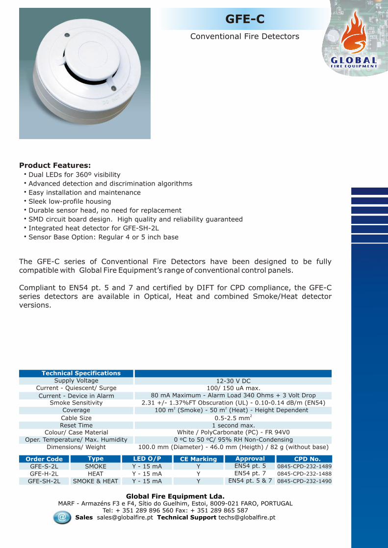
Product Features:
! Dual LEDs for 360º visibility! Advanced detection and communication protocols! Easy installation and maintenance! Sleek low-profile housing! Durable sensor head, no need for replacement! SMD circuit board design. High quality and reliability guaranteed! Five years limited warranty! Sensor Base Option: Regular GFE Detector Base or Deep Base
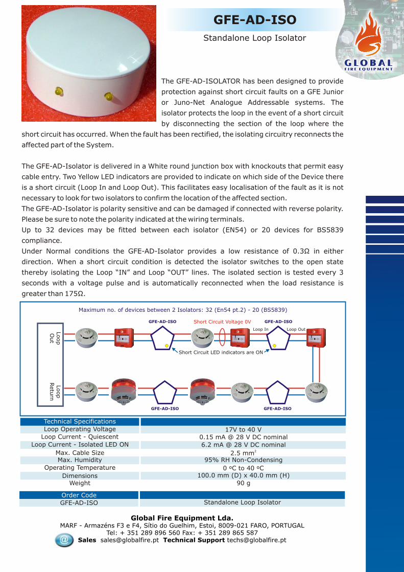
The GFE-AD-ISOLATOR has been designed to provide
protection against short circuit faults on a GFE Junior
or Juno-Net Analogue Addressable systems. The
isolator protects the loop in the event of a short circuit
by disconnecting the section of the loop where the
short circuit has occurred. When the fault has been rectified, the isolating circuitry reconnects the
affected part of the System.
The GFE-AD-Isolator is delivered in a White round junction box with knockouts that permit easy
cable entry. Two Yellow LED indicators are provided to indicate on which side of the Device there
is a short circuit (Loop In and Loop Out). This facilitates easy localisation of the fault as it is not
necessary to look for two isolators to confirm the location of the affected section.
The GFE-AD-Isolator is polarity sensitive and can be damaged if connected with reverse polarity.
Please be sure to note the polarity indicated at the wiring terminals.
Up to 32 devices may be fitted between each isolator (EN54) or 20 devices for BS5839
compliance.
Under Normal conditions the GFE-AD-Isolator provides a low resistance of 0.3Ω in either
direction. When a short circuit condition is detected the isolator switches to the open state
thereby isolating the Loop “IN” and Loop “OUT” lines. The isolated section is tested every 3
seconds with a voltage pulse and is automatically reconnected when the load resistance is
greater than 175Ω.
GFE-AD-ISO
Standalone Loop Isolator
Global Fire Equipment Lda.MARF - Armazéns F3 e F4, Sítio do Guelhim, Estoi, 8009-021 FARO, PORTUGAL
Tel: + 351 289 896 560 Fax: + 351 289 865 587Sales [email protected] Technical Support [email protected]
WeightDimensions
Max. HumidityOperating Temperature
6.2 mA @ 28 V DC nominal22.5 mm
Loop Current - Isolated LED ON
Max. Cable Size
Loop Current - Quiescent
90 g
100.0 mm (D) x 40.0 mm (H)0 ºC to 40 ºC
95% RH Non-Condensing
Technical Specifications
Loop Operating Voltage 17V to 40 V0.15 mA @ 28 V DC nominal
Order Code
GFE-AD-ISO Standalone Loop Isolator
GFE-AD-ISO
Loop
Out
Loop In Loop Out
Loop
Retu
rn
Short Circuit Voltage 0V
Maximum no. of devices between 2 Isolators: 32 (En54 pt.2) - 20 (BS5839)
Short Circuit LED indicators are ON
GFE-AD-ISO
GFE-AD-ISO GFE-AD-ISO

Global Fire Equipment Lda.MARF - Armazéns F3 e F4, Sítio do Guelhim, Estoi, 8009-021 FARO, PORTUGAL
Tel: + 351 289 896 560 Fax: + 351 289 865 587Sales [email protected] Technical Support [email protected]
This remote indicator can be used with any fire alarm detector, be it of the conventional or addressable types, to indicate remotely the activation of the relevant detection device.
Its main characteristics are the high visibility due to the alternate blinking of two high efficiency LEDs and the wide operating voltage range (3 to 15V DC) with a minimum 300 uA current consumption. The connections of this device are non-polarised.
This unit comes complete with a face plate compatible with standard flush mounting boxes.
REM-IND
Order Code
Remote Indicator
Technical Specifications
Supply Voltage
Supply Current
WeightDimensions
Max. Humidity
Operating Temperature
5-15 V DC
20 g
0 ºC to 40 ºC
85% RH Non-Condensing
300 uA Quiescent - 15 mA max. LED ON
68 (L) x 33 (W) x 25 (H) mm
REM-INDFlashing Remote Indicator
Interface card that provides in any of GFE’s Analogue Addressable Fire Detection Panels a LED indication of FIRE/ FAULT condition for each individual zone. The LED RED indicator will be ON when the zone is in FIRE condition.
This module operates in three different modes:
l16 Zone Blocks - Indication of Fire for each zone in the range 1 to 384l8 Zone Blocks - Indication of Fire and Fault for each zone in the range 1 to 384lSystem Status - Each LED output is assigned to a specific System Status indication: Fire, Fault, Pre-Alarm, Test, Disabled, Sounders ON, Auxiliary Outputs and Sounders Disabled
The module requires a connection to either Juno Net or Junior Panels via a 5 way flat cable fitted with polarised connectors. And it should be connected to the MPX output of either panel.
WeightDimensions
Max. HumidityOperating Temperature
60 mA - Max Current during LAMP TEST @ 5 V DC
Solder Links
Current - Zones in AlarmZone Selection
Current - Quiescent
10 g78.5 (L) x 20.5 (W) x 16.0 (H) mm
0 ºC to 40 ºC
85% RH Non-Condensing
Technical Specifications
Supply Voltage 5V DC nominal2 mA - No LEDS active
Order Code
16 ZONE LED BOARD Junior and Juno Net Multiplexed 16 Zone LED Board
MPX-LED
Multiplexed Zone LED Board
Global Fire Equipment Lda.MARF - Armazéns F3 e F4, Sítio do Guelhim, Estoi, 8009-021 FARO, PORTUGAL
Tel: + 351 289 896 560 Fax: + 351 289 865 587Sales [email protected] Technical Support [email protected]
GFE-C
Conventional Fire Detectors
The GFE-C series of Conventional Fire Detectors have been designed to be fully compatible with Global Fire Equipment’s range of conventional control panels.
Compliant to EN54 pt. 5 and 7 and certified by DIFT for CPD compliance, the GFE-C series detectors are available in Optical, Heat and combined Smoke/Heat detector versions.
Order Code CE Marking CPD No.
GFE-S-2L Y 0845-CPD-232-1489
GFE-H-2L Y 0845-CPD-232-1488
GFE-SH-2L
Type
SMOKE
HEAT
SMOKE & HEAT
LED O/P
Y - 15 mA
Y - 15 mA
Y - 15 mA Y
ApprovalEN54 pt. 5
EN54 pt. 7
EN54 pt. 5 & 7 0845-CPD-232-1490
Dimensions/ Weight
Oper. Temperature/ Max. Humidity
80 mA Maximum - Alarm Load 340 Ohms + 3 Volt Drop
2 2100 m (Smoke) - 50 m (Heat) - Height Dependent
White / PolyCarbonate (PC) - FR 94V0
Current - Device in Alarm
Coverage
Colour/ Case Material
Current - Quiescent/ Surge
Smoke Sensitivity
100.0 mm (Diameter) - 46.0 mm (Heigth) / 82 g (without base)
0 ºC to 50 ºC/ 95% RH Non-Condensing
Technical Specifications
Supply Voltage 12-30 V DC100/ 150 uA max.
2.31 +/- 1.37%FT Obscuration (UL) - 0.10-0.14 dB/m (EN54)
Cable SizeReset Time
20.5-2.5 mm
1 second max.
Product Features:! Dual LEDs for 360º visibility! Advanced detection and discrimination algorithms! Easy installation and maintenance! Sleek low-profile housing ! Durable sensor head, no need for replacement! SMD circuit board design. High quality and reliability guaranteed! Integrated heat detector for GFE-SH-2L! Sensor Base Option: Regular 4 or 5 inch base

The LSC-ISO Module is a fully monitored interface which is used to connect a line of conventional sounders to the Global Fire Addressable control panel via the detection loop.
The module requires an external 24V DC power supply and can supply up to 1A at the sounder output which is monitored for both open and short circuit faults. A 10K ohm end of line resistor is connected to the last sounder to provide line monitoring.
The LSC-ISO uses the Global Fire proprietary sounder control protocol and therefore is only compatible with the GFE range of control panels. The output can be programmed as pulsed or continuous. A maximum of 32 LSC-ISO can be connected to each Loop using address numbers 94 -125 inclusive.
Also available complete with housing. Address setting is via switches 1 to 5 of the 6 way DIL switch where all off represents address 94.
WeightDimensions
Max. HumidityOperating Temperature
1.2 mA Quiescent - 1 Amp maximum for sounders.22.5 mm
Ext. Supply Current @ 24V DC
Max. Cable Size
Loop Current
25 g - unboxed
87.8 (L) x 72.7 (W) x 15.0 (H) mm0 ºC to 40 ºC
95% RH Non-Condensing
Technical Specifications
Supply Voltage Loop Powered - 17V to 30 V DC
1.0 mA (Quiescent or OC/ SC FAULT) - 1.65 mA O/P active
Global Fire Equipment Lda.MARF - Armazéns F3 e F4, Sítio do Guelhim, Estoi, 8009-021 FARO, PORTUGAL
Tel: + 351 289 896 560 Fax: + 351 289 865 587Sales [email protected] Technical Support [email protected]
Order Code
LSC-ISO Loop Sounder Control Unit
LSC-ISOLoop Sounder Control Module(with 1Amp monitored output)
Switches 1-5Address SettingRange 94 - 125
Switch 6Not used
1 2 3 4 5 6
ONOFF
LOOP IN
LO
OP O
UT
Ext.
Supply
24 V
DC
for
SO
UN
DERS
10K Ohm - End of Line Resistor
Note: Maximum 1 Amp current drivefor conventional sounders per module.
Only use polarized 24V DC sounders
Ext.
Supply
24 V
DC
for
SO
UN
DERS
Address SettingD.I.L. Switch
+ +
SN
DR
SN
DR

The Addressable Input Module is a fully monitored device which permits the interfacing of third party equipment with the Fire Alarm Control panel using normally open dry contact connections.
The connection to the input is monitored for fault (open or short circuit) and Alarm conditions.
The interface is used to monitor the contacts of an external system which must be interfaced to the Fire Alarm System, for example a Flow Switch in a sprinkler system to indicate if the sprinklers have been activated or extinguishant level monitoring in Gas Extinguishing systems etc.
The module is powered by the detection loop and is available as an electronic module with four fixing holes or as a boxed unit for field installation.
Global Fire Equipment Lda.MARF - Armazéns F3 e F4, Sítio do Guelhim, Estoi, 8009-021 FARO, PORTUGAL
Tel: + 351 289 896 560 Fax: + 351 289 865 587Sales [email protected] Technical Support [email protected]
INPUT
Addressable Input Unit
WeightDimensions
Max. HumidityOperating Temperature
2.5 mA22.5 mm
Loop Current - Alarm LED illuminated
Max. Cable Size
Loop Current - Quiescent
20 g - unboxed
58.1 (L) x 52.1 (W) x 20.0 (H) mm0 ºC to 40 ºC
95% RH Non-Condensing
Technical Specifications
Supply Voltage Loop Powered - 17V to 30 V DC
0.75 mA
Order CodeINPUT Addressable Input Module
Switches 1-7Address SettingRange 1 - 125
Switch 8Not used 1 2 3 4 5 6 7 8
ONOFF
FaultShort circuit - 2K2Open Circuit - 47KNormal - 8K2 to 47KFire - 2K2 to 8K2
Resistance values
22K
4K7
END OF LINE MONITORING RESISTOR 22K
ALARM RESISTOR (4K7) IN SERIES WITH NORMALLY OPEN CONTACT
LOOP IN
LOOP OUT

The Addressable Input/Output Module is a fully monitored device which permits the interfacing of third party equipment with the Fire Alarm Control panel using normally open dry contact connections while also providing a changeover output relay to control ancillary equipment.
The connection to the input is monitored for fault (open or short circuit) and Alarm conditions.The output relay can be powered from the detection loop (default) or optionally by an external 24Vdc supply. Relay operation is confirmed by an onboard yellow LED.
The interface is used to monitor the contacts of an external system which must be interfaced to the Fire Alarm System, for example a Flow Switch in a sprinkler system to indicate if the sprinklers have been activated or extinguishant level monitoring in Gas Extinguishing systems etc.
The output relay can be programmed to close fire doors, activate smoke removal systems etc. The factory default setting is for the relay to receive its operating power from the Loop. Opening a link on the PCB allows the use of external power which is optically isolated from the detection loop. This option is recommended in the event that many I/O units are connected to the same Loop. The Addressable I/O module is available as an electronic module with four fixing holes or as a boxed unit for field installation.
Global Fire Equipment Lda.MARF - Armazéns F3 e F4, Sítio do Guelhim, Estoi, 8009-021 FARO, PORTUGAL
Tel: + 351 289 896 560 Fax: + 351 289 865 587Sales [email protected] Technical Support [email protected]
I/O ISO
Addressable Input/ Output Module
WeightDimensions
Max. HumidityOperating Temperature
2.45 mA - 12.0 mA with Relay Active (loop powered)22.5 mm
Loop Current - Alarm LED illuminated
Max. Cable Size
Loop Current - Quiescent
30 g - unboxed
58.1 (L) x 52.1 (W) x 20.0 (H) mm0 ºC to 40 ºC
95% RH Non-Condensing
Technical Specifications
Supply Voltage Loop Powered - 17V to 30 V DC
0.75 mA
Order Code
IO-ISO Addressable Input/Output Module
Switches 1-7Address SettingRange 1 - 125
Switch 8Not used
FaultShort circuit - 2K2Open Circuit - 47KNormal - 8K2 to 47KFire - 2K2 to 8K2
Resistance values
END OF LINE MONITORING RESISTOR 22K
ALARM RESISTOR (4K7) IN SERIES WITH NORMALLY OPEN CONTACT
1 2 3 4 5 6 7 8
ONOFF
22K
4K7
LOOP IN
LO
OP O
UT
Remove solder linkswhen relay poweredext. 24V DC supply
Ext.
Supply
24 V
DC
OUTPUTChange Over Relay
COM- NO - NCContact Rating
1A @ 50V DC Res.
Note: When relay powered directly from loopmaximum of 6 IO-ISO modules per loop.

3 I/O
Addressable Triple Input/Output Module
The Triple Input/Output Module is a fully monitored device which permits the interfacing of third party equipment with the Fire Alarm Control panel using three normally open dry contact connections while also providing three changeover output relays to control ancillary equipment.
The connections to the input are monitored for fault (open or short circuit) and Alarm conditions.
The output relays require an external 24Vdc supply. Relay operation is confirmed by onboard red LEDs, a yellow general Fault LED is also provided. The 3 I/O occupies three consecutive addresses on the detection Loop.
The interface is used to monitor the contacts of an external system which must be interfaced to the Fire Alarm System, for example a Flow Switch in a sprinkler system to indicate if the sprinklers have been activated or extinguishant level monitoring in Gas Extinguishing systems etc.
The output relays can be programmed to close fire doors, activate smoke removal systems etc. An external 24 volt DC power supply is required to power the relays, this supply is optically isolated from the Address Loop. The Addressable 3 I/O module is available as an electronic module with four fixing holes.
Global Fire Equipment Lda.MARF - Armazéns F3 e F4, Sítio do Guelhim, Estoi, 8009-021 FARO, PORTUGAL
Tel: + 351 289 896 560 Fax: + 351 289 865 587Sales [email protected] Technical Support [email protected]
WeightDimensions
Max. HumidityOperating Temperature
5.3 mA Quiescent - 15 mA per Relay Active22.5 mm
Ext. Supply Current @ 24V DC
Max. Cable Size
Loop Current
72 g - unboxed
87.8 (L) x 72.7 (W) x 20.0 (H) mm0 ºC to 40 ºC
95% RH Non-Condensing
Technical Specifications
Supply Voltage Loop Powered - 17V to 30 V DC
1.2 mA (Quiescent) - 6.2 mA all I/P’s in ALARM
Order Code3 I/O Triple Input/ Output Module
Switches 1-7Address SettingRange 1 - 123
Switch 8Not used
Each module uses 3 consecutive addresses
FaultShort circuit - 2K2Open Circuit - 47KNormal - 8K2 to 47KFire - 2K2 to 8K2
Resistance values
E.O.L monitoring Resistor 22KAlarm Resistor (4K7) in series with N/O Contact
1 2 3 4 5 6 7 8
ONOFF
22K
4K7
LOOP IN
LO
OP O
UT
Ext.
Supply
24 V
DC
3 O
UTPU
TS
Change O
ver
Rela
y
CO
M-N
O-N
CConta
ct
Rating
1A @
50V D
C R
esis
tive
Ext.
Supply
24 V
DC
Note: When output operation is required, external supply 24V DC must be applied.

The Control panel interface provides eight individually addressed normally open inputs and two pre-defined outputs. The interface permits the connection of a conventional fire alarm control panel with up to eight Zones to the Global Fire Analogue Addressable Fire Control panel via the detection loop.
The outputs are pre-defined as Silence and Reset and allow these functions on the conventional panel to be executed from the Addressable system. An external 24 V DC supply is required to power the onboard relays. This supply is optically isolated from the detection Loop. The silence and reset relay operations are indicated by two green LEDs.
Each CCPI occupies 8 addresses on the Loop even when not all inputs are used. See address setting chart below.
Global Fire Equipment Lda.MARF - Armazéns F3 e F4, Sítio do Guelhim, Estoi, 8009-021 FARO, PORTUGAL
Tel: + 351 289 896 560 Fax: + 351 289 865 587Sales [email protected] Technical Support [email protected]
CCPI
Conventional Control Panel Interface
WeightDimensions
Max. HumidityOperating Temperature
3 mA Quiescent - 15 mA Max.22.5 mm
Ext. Supply Current @ 24V DC
Max. Cable Size
Loop Current
60 g - unboxed
88 (L) x 74 (W) x 20.0 (H) mm0 ºC to 40 ºC
95% RH Non-Condensing
Technical Specifications
Supply Voltage Loop Powered - 17V to 30 V DC
0.7 mA
Order Code
CCPI Conventional Control Panel Interface
Switches 1-4Address Setting
Each address uses 8 consecutive addresses
1 2 3 4
ONOFF
LOOP IN
LO
OP O
UT
2 OUTPUTS (NO) Contact Rating 1A @ 50V DC Resistive
O/P A : ResetO/P B : Silence
Ext.
Supply
24 V
DC
INPUTS A-HZones 1-8driven by
Zone Repeater Outputsof
Conventional Panel

Global Fire Equipment Lda.MARF - Armazéns F3 e F4, Sítio do Guelhim, Estoi, 8009-021 FARO, PORTUGAL
Tel: + 351 289 896 560 Fax: + 351 289 865 587Sales [email protected] Technical Support [email protected]
ZMU
Addressable Zone Monitoring Unit
Order CodeZMU Zone Monitoring Unit
Switches 1-7Address SettingRange 1 - 125
Switch 8Not used
1 2 3 4 5 6 7 8
ONOFF
LOOP IN
LO
OP O
UT
Ext.
Supply
24 V
DC
for
Zones
End of Line Resistor4K7 Ohms 1/4 Watt Resistor
Det MCP
RES
INOUT
RES= Alarm Resistor in series with dry NO contactrange 270 Ohms to 820 Ohm ( 1 Watt )
Note: Maximum 20 conventional devices per zone.
Maximum 6 ZMU’s per Loopif conventional zone ispowered directly from Loop
Note:Remove jumpers whenext. 24V DC supply is applied.
WeightDimensions
Max. HumidityOperating Temperature
7 mA Quiescent - per zone OC/ SC/ FIRE - 2.5/ 60/ 29 mA22.5 mm
Ext. Supply Current @ 24V DC
Max. Cable Size
Loop Current - Zone Supply External
External Zone Supply
28 g - unboxed
60.0 (L) x 58.0 (W) x 20.0 (H) mm0 ºC to 40 ºC
95% RH Non-Condensing
Technical Specifications
Supply Voltage Loop Powered - 17V to 30 V DC
24V DC
Loop Current - Loop Powered 12 mA (Quiescent) - 34.5 mA (FIRE) - 4.5mA (OC) - 42.5 mA (SC)
4.9 mA (Quiescent) - 5.1 mA (FIRE) - 1.9mA (FAULT)
The ZMU is a fully monitored interface module which is used to connect a number of current limited conventional detectors to the Global Fire Addressable control panel via the detection loop. These detectors are then seen as one address at the addressable control panel.
The module can be powered from the Loop or optionally by an external 24V DC power supply in which case, the jumpers J1 and J2 should be removed. The detector line is monitored by a 4K7 resistor end of line (e.o.l.) resistor. A bi-colour LED is used to signal the status of the module.
Green NormalRed AlarmOFF Fault
The external power, if used, is also monitored with the module reporting a Fault if external power is not present. Since the current drawn from the loop can be significant, particularly in Fire and Short Circuit Fault conditions, the number of ZMUs that can be connected to a loop is limited to six depending on Loop load.

QUAD-ZMU
Addressable QUAD Zone Monitoring Unit
WeightDimensions
Max. HumidityOperating Temperature
5.3 mA Quiescent - per zone OC/ SC/ FIRE - 7/ 33/ 23 mA22.5 mm
Ext. Supply Current @ 24V DC
Max. Cable Size
Loop Current
46 g - unboxed
87.8 (L) x 72.7 (W) x 15.0 (H) mm0 ºC to 40 ºC
95% RH Non-Condensing
Technical Specifications
Supply Voltage Loop Powered - 17V to 30 V DC
1.6 mA
Global Fire Equipment Lda.MARF - Armazéns F3 e F4, Sítio do Guelhim, Estoi, 8009-021 FARO, PORTUGAL
Tel: + 351 289 896 560 Fax: + 351 289 865 587Sales [email protected] Technical Support [email protected]
Order CodeQUAD-ZMU Addressable Quad Zone Monitoring Unit
Switches 1-7Address SettingRange 1 - 122
Switch 8Not used
Each module uses 4 consecutive addresses
1 2 3 4 5 6 7 8
ONOFF
LOOP INLO
OP O
UT
Ext.Supply24V DC
forZones
Active End of Line Capacitor10 uF/ 50V Bipolar
Electrolytic Capacitor
Det MCP
RES
INOUT
Det MCP
RES
INOUT
Det MCP
RES
Det MCP
RES
INOUT
Det MCP
RES
INOUT
RES= Alarm Resistor in series with dry NO contactrange 270 Ohms to 1 K Ohm
Note: Maximum 32 conventional devices per zone. Maximum 31 QUAD-ZMUs per Loop
The QUAD-ZMU is a fully monitored interface module which is used to connect up to four
individually addressed zones of current limited conventional detection devices to the Global Fire
Addressable control panel via the detection loop.
The module requires an external 24V DC power supply. Active End of Line Monitoring with BS5839
Detector Removal compliance when Diode bases are used (New Feature).
The detection Zones and their supply voltage are optically isolated from the addressable detection
loop which allows the use of a local power supply. If that supply fails, a fault condition is reported at
the control panel. The status of each zone is indicated by two LEDs. A red LED signals Fire, Yellow
indicates Fault on that zone. The normal state is indicated by neither LEDs being illuminated. A
Green LED indicates the presence of 24 Volts. Irrespective of how many Zones are actually used,
each QUAD-ZMU occupies four consecutive addresses on the loop.
Ext. Sup.FAULT

Global Fire Equipment Lda.MARF - Armazéns F3 e F4, Sítio do Guelhim, Estoi, 8009-021 FARO, PORTUGAL
Tel: + 351 289 896 560 Fax: + 351 289 865 587Sales [email protected] Technical Support [email protected]
Order Code
MAM Manually Addressable Module
WeightDimensions
Max. HumidityOperating Temperature
IP4422.5 mm
Protection Category
Max. Cable Size
Loop Current - Alarm
Address Range
18 g
48 (L) x 24 (W) x 12 (H) mm0 ºC to 40 ºC
95% RH Non-Condensing
Technical Specifications
Supply Voltage Loop Powered - 17V to 30 V DC
1-125 ( Detectors, MCP, I/O) 94-125 (Sounder/ Beacons)
Loop Current - Quiescent 1.1 mA
12 mA
MAM
Manually Addressable Module
LO
OP IN
LOOP OUT
Conventional
Devic
eCALL-POINT
MICRO-INPUT(UNMONITORED)
X X X X
ON
1 2 3 4 5 6 7 8
X X X X
ON
1 2 3 4 5 6 7 8
8ON
8OFF
SMOKE
X X X X
ON
1 2 3 4 5 6 7 8
HEAT
X X X X
ON
1 2 3 4 5 6 7 8
8ON
8OFF
OUTPUT(NON-ISOLATED)
LSC(NON-ISOLATED)
X X X X
ON
1 2 3 4 5 6 7 8
X X X X
ON
1 2 3 4 5 6 7 8
8ON
8OFF
7OFF
7ON
=SOUNDER
=BEACON(NO ALARM SILENCE)
The MAM allows the connection and addressing of conventional
detectors, call points, Micro Input, Micro Output and conventional
Sounder/ Beacon.
With its small physical size and convenient 8 way DIL switch for address
setting and configuration, the MAM provides the facility to upgrade all the
components of a conventional system to a full addressable system, ideal
for retrofit installations. The MAM is fully compatible with all our
standard addressable modules, addressable sounders, addressable manual call points and GFE
detectors facilitating extensions to existing systems. To assist easy identification, the MAM is
supplied in 3 coloured plastic housings:
Red: Manual call point interface / Micro Input Module
Mustard: Micro Output Module / LOOP SOUNDER/ BEACON Controller
White: Smoke / Heat Detector interface.
Device type selection is by means of switch 8 on the DIL. Additionally the MAM-LSC can be set as a
sounder or beacon driver using switch 7. In Sounder mode the output is removed when a Silence
Alarm signal is received from the control panel. In Beacon mode the output remains active until
the system is reset.

Global Fire Equipment Lda.MARF - Armazéns F3 e F4, Sítio do Guelhim, Estoi, 8009-021 FARO, PORTUGAL
Tel: + 351 289 896 560 Fax: + 351 289 865 587Sales [email protected] Technical Support [email protected]
Order Code
SAM Self Addressable Module
WeightDimensions
Max. HumidityOperating Temperature
IP4422.5 mm
Protection Category
Max. Cable Size
Loop Current - Alarm
Address Range
18 g
48 (L) x 24 (W) x 10 (H) mm0 ºC to 40 ºC
95% RH Non-Condensing
Technical Specifications
Supply Voltage Loop Powered - 17V to 30 V DC
1-125
Loop Current - Quiescent 1.1 mA
12 mA
SAM
Self Addressable Module
LOOP IN
LO
OP O
UT
ConventionalManual Call Point
OR
Smoke/ HeatDetector
This tiny, very low cost, module provides any
conventional detector or Manual Call Point with an
address without the inconvenience of using a manual
addressing unit or DIP switch. The SAM is simply
attached to the conventional device and the detector address is automatically assigned to each
SAM by the JUNO-NET or JUNiOr control panel during commissioning and testing. A SAM based
system tolerates loop branches and can monitor loop interruptions and head removal.
SAM is ideal for low budget retrofits where fire point identification is needed but the cost of fitting
a fully analogue system is too high. SAM is also an option in low budget installations that would
normally be implemented with 4 to 8 zone conventional systems. It gives you the cable savings
possible with an addressable system, together with the loop sounder capability but without the
extra costs of analogue addressable heads.
Compatible with most conventional detectors, the SAM is fully encapsulated in a plastic case,
unobtrusive and easy to connect to the detector base or manual call point.

With 15 different variations, the Vulcan 2 brings an exciting flexibility to the Global Fire Equipment range of warning devices and interfaces. Up to 96 Vulcan 2 devices can be connected to a single Loop depending on Loop Loading. In the case of combined Sounder and Beacon devices the maximum number of devices should not exceed 64.
The addressable Vulcan 2 is available as an Addressable Sounder, Beacon or combined Sounder / Beacon which may be field configured as a Shadow Sounder / Beacon or Auxiliary Sounder / Beacon. There are also versions available incorporating a loop isolator.
All Vulcan 2 devices have dip-switch Address setting while Tone selection is via a jumper. Shadow Sounder and Auxiliary Sounder settings are also achieved using the 8 way dip switch and a jumper respectively. There is also a potentiometer which may be used to adjust the sound level if required.
Normally the Vulcan 2 will be used in conjunction with a detector however a White or Transparent lid is available as an option for the Addressable Vulcan 2.
Shadow Sounder / Beacon
The Vulcan 2 Addressable Sounder / Beacon can be configured as a Shadow Sounder/ Beacon using the 8 way dip switch provided. A Shadow Sounder / Beacon does not have an individual address thus freeing up addresses for more detection devices. Shadow sounders / Beacons do not report back to the control panel so their presence on the Loop is not monitored, however they do draw current from the Loop and must be included in Loop load calculations. The number of combined Sounder / Beacons connected to a Loop should not exceed 64 or 96 in the case of a Beacon or Sounder only.
Auxiliary Sounder / Beacon
When the Vulcan 2 is configured as an Auxiliary device the Sounder / Beacon shares the same address as the detector with which it is co-located. Configuration of this mode is done via the jumper provided. When operating in this mode the Vulcan 2 monitors the Address loop for the command from the control Panel to the detector to illuminate it's LED. When this command is received the Vulcan 2 is also activated. If a Fire is confirmed the remaining sounders may be activated using the Evacuate command. This reduces the inconvenience to other guests in the event of a false alarm while at the same time giving early warning to the occupant of the room in the case of an actual Fire event. Pressing Sounder silence at the panel silences all active sounders.
The maximum number of Auxiliary Sounder/Beacons is 63 and they can be allocated between address 1 and 63.
VULCAN-2A
Addressable Sounder - Beacon
VULCAN 2 - STAND ALONE INTERNAL VIEW

Global Fire Equipment Lda.MARF - Armazéns F3 e F4, Sítio do Guelhim, Estoi, 8009-021 FARO, PORTUGAL
Tel: + 351 289 896 560 Fax: + 351 289 865 587Sales [email protected] Technical Support [email protected]
Enclosure - Material
WeightDimensions
Max. HumidityOperating Temperature
4 mA sounder only - 5.5 mA inc. Beacon
7 mA sounder only -8 mA inc. Beacon
2.5 mA150 uA - added to device quiescent/alarm current load
84 dB @ 1 m
88 dB @ 1 m22.5 mmMax. Cable Size
Loop Current - Quiescent
Loop Current -Alarm- 800 to 1000 Hz
Sounder Output - Low Freq.
Sounder Output - High Freq.
Loop Current -Alarm- 2.0 to 3.0 KHz
Loop Current -Alarm- Beacon
Loop Current -Isolator
White ABS - Transparent PC - FR rating 94V0
100 g or 120 g with lid
100 mm (D) x 29 mm (H) - w/ LID 37.5 mm (H)
0 ºC to 40 ºC
95% RH Non-Condensing
Technical Specifications
Supply Voltage Loop Powered - 17V to 30 V DC
1.1 mA
Order CodeVULCAN 2 AS
VULCAN 2 ASI
VULCAN 2 ASB
VULCAN 2 ASBI
VULCAN 2 AB
VULCAN 2 ABI
VULCAN 2 L
VULCAN 2 LT
Vulcan 2 - Addressable Sounder
Vulcan 2 - Addressable Sounder - Isolator
Vulcan 2 - Addressable Sounder/Beacon
Vulcan 2 - Addressable Sounder/Beacon - Isolator
Vulcan 2 - Addressable Beacon
Vulcan 2 - Addressable Beacon - Isolator
Vulcan 2 - LID - WHITE
Vulcan 2 - LID - TRANSPARENT
CONNECTIONS AND TONE CONFIGURATIONS
Place spare jumperto select Auxilliary Sounder Mode
SWEEPINGTONE
ALTERNATINGLOW-FREQUENCY
TONE
CONTINUOUSTONE
ALTERNATINGHIGH-FREQUENCY
TONE
= JUMPER
LOO
PO
UT
LOO
PRETU
RN
PAN
EL
Ad
dre
ss|A
|B|S
+
+
-
-
LoopIn/Out
LoopIn/Out
Ton
e
Mo
de
- Vo
l +
GFEVulcan 2Addressable
Sounder
DetectorBeacon
Isolator
DetectorBase
VolumeAdjustment
VULCAN-2A
Addressable Sounder - Beacon

With 15 different variations, the Vulcan 2 brings an exciting flexibility to the Global Fire Equipment
range of warning devices and interfaces. Up to 96 Vulcan 2 devices can be connected to a single
Loop depending on Loop Loading. In the case of combined Sounder and Beacon devices the
maximum numberof devices should not exceed 64.
The addressable Vulcan 2 is available as a Detector Sounder, Beacon or combined
Sounder/Beacon. This particular device permits a conventional detector to be connected to the
addressable loop via the Sounder and/or Beacon. There are also versions available incorporating a
loop isolator.
All Vulcan 2 devices have dip-switch Address setting while Tone selection is via a jumper. Shadow
Sounder and Detector Sounder settings are also achieved using the 8 way dip switch and a jumper
respectively. There is also a potentiometer which may be used to adjust the sound level if required.
Normally the Vulcan 2 will be used in conjunction with a detector however a White or Transparent
lid is available as an option for the Addressable Vulcan 2.
The number of Detector Sounders/ Beacons connected to each Loop is dependent on Loop loading
and in any case the total number/ loop should not exceed 64. If only detector sounders are used
then this number may be increased to 96 sounders per loop. This includes normal addressable
sounder beacons placed between address 94 and 125. These are fully programmable in sounder
groups. Detector Sounders are always placed between address 1 and 63 and cannot be included in
sounder groups. Device will report to the panel as either a SMOKE or HEAT detector depending on
MODE jumper position.
VULCAN-2D
Detector Sounder - Beacon
VULCAN 2 - DETECTOR SOUNDER INTERNAL VIEW
AddressableSounder
ConventionalDetector
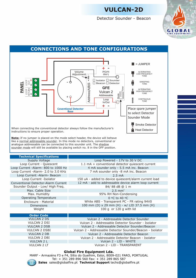
Global Fire Equipment Lda.MARF - Armazéns F3 e F4, Sítio do Guelhim, Estoi, 8009-021 FARO, PORTUGAL
Tel: + 351 289 896 560 Fax: + 351 289 865 587Sales [email protected] Technical Support [email protected]
Enclosure - Material
WeightDimensions
Max. HumidityOperating Temperature
4 mA sounder only - 5.5 mA inc. Beacon
7 mA sounder only -8 mA inc. Beacon
2.5 mA150 uA - added to device quiescent/alarm current load
12 mA - add to addressable device alarm loop current
84/ 88 dB @ 1 m22.5 mmMax. Cable Size
Loop Current - Quiescent
Loop Current -Alarm- 800 to 1000 Hz
Sounder Output - Low/ High Freq.
Loop Current -Alarm- 2.0 to 3.0 KHz
Loop Current -Alarm- Beacon
Loop Current -Isolator
Conventional Detector-Alarm Current
White ABS - Transparent PC - FR rating 94V0
100 g or 120 g with lid
100 mm (D) x 29 mm (H) - w/ LID 37.5 mm (H)
0 ºC to 40 ºC
95% RH Non-Condensing
Technical Specifications
Supply Voltage Loop Powered - 17V to 30 V DC
1.1 mA + conventional detector quiescent current
Order CodeVULCAN 2 DS
VULCAN 2 DSI
VULCAN 2 DSB
VULCAN 2 DSBI
VULCAN 2 DB
VULCAN 2 DBI
VULCAN 2 L
VULCAN 2 LT
Vulcan 2 - Addressable Detector Sounder
Vulcan 2 - Addressable Detector Sounder - IsolatorVulcan 2 - Addressable Detector Sounder/Beacon
Vulcan 2 - Addressable Detector Sounder/Beacon - Isolator
Vulcan 2 - Addressable Detector Beacon
Vulcan 2 - Addressable Detector Beacon - IsolatorVulcan 2 - LID - WHITE
Vulcan 2 - LID - TRANSPARENT
CONNECTIONS AND TONE CONFIGURATIONS
VULCAN-2D
Detector Sounder - Beacon
When connecting the conventional detector always follow the manufacturer’s instructions to ensure proper operation.
Note: If no jumper is placed on the mode select header, the device will behave like a normal addressable sounder. In this mode no detectors, conventional or analogue addressable can be connected to this sounder unit. The shadow sounder mode will still be available by placing switch no. 8 in the OFF position.
.
Place spare jumperto select DetectorSounder Mode
SWEEPINGTONE
ALTERNATINGLOW-FREQUENCY
TONE
CONTINUOUSTONE
ALTERNATINGHIGH-FREQUENCY
TONE
= JUMPER
LOO
PO
UT
LOO
PRETU
RN
PAN
EL
Ad
dre
ss|A
|B|S
+
+
-
-
LoopIn/Out
LoopIn/Out
Ton
e
Mo
de
- Vo
l +
GFEVulcan 2Addressable
Sounder
DetectorBeacon
Isolator
Coventional DetectorBase
VolumeAdjustment
Heat Detector
Smoke Detector
+
-
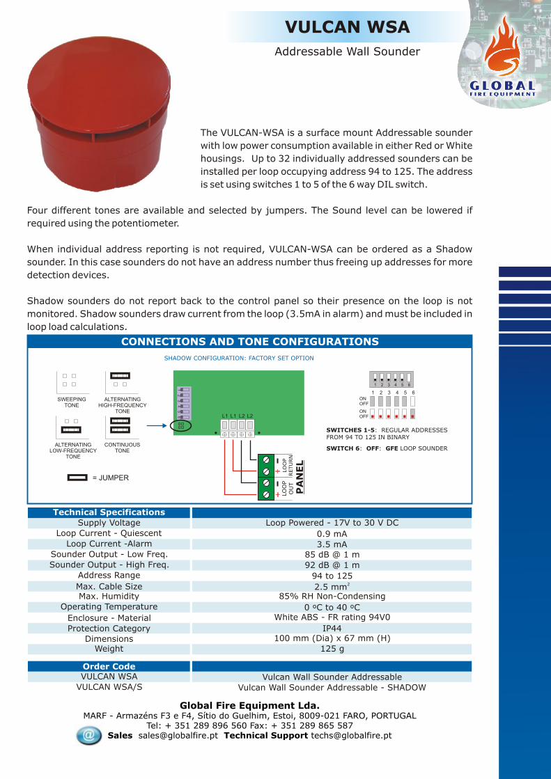
The VULCAN-WSA is a surface mount Addressable sounder
with low power consumption available in either Red or White
housings. Up to 32 individually addressed sounders can be
installed per loop occupying address 94 to 125. The address
is set using switches 1 to 5 of the 6 way DIL switch.
Four different tones are available and selected by jumpers. The Sound level can be lowered if
required using the potentiometer.
When individual address reporting is not required, VULCAN-WSA can be ordered as a Shadow
sounder. In this case sounders do not have an address number thus freeing up addresses for more
detection devices.
Shadow sounders do not report back to the control panel so their presence on the loop is not
monitored. Shadow sounders draw current from the loop (3.5mA in alarm) and must be included in
loop load calculations.
VULCAN WSA
Addressable Wall Sounder
Global Fire Equipment Lda.MARF - Armazéns F3 e F4, Sítio do Guelhim, Estoi, 8009-021 FARO, PORTUGAL
Tel: + 351 289 896 560 Fax: + 351 289 865 587Sales [email protected] Technical Support [email protected]
Enclosure - Material
Protection Category
WeightDimensions
Max. HumidityOperating Temperature
3.5 mA85 dB @ 1 m
92 dB @ 1 m
94 to 12522.5 mmMax. Cable Size
Loop Current - Quiescent
Loop Current -Alarm
Sounder Output - Low Freq.
Sounder Output - High Freq.
Address Range
White ABS - FR rating 94V0
IP44
125 g
100 mm (Dia) x 67 mm (H)
0 ºC to 40 ºC
85% RH Non-Condensing
Technical Specifications
Supply Voltage Loop Powered - 17V to 30 V DC
0.9 mA
Order CodeVULCAN WSA
VULCAN WSA/SVulcan Wall Sounder Addressable
Vulcan Wall Sounder Addressable - SHADOW
CONNECTIONS AND TONE CONFIGURATIONS
12
34
56 L1 L1 L2 L2
SWEEPINGTONE
ALTERNATINGHIGH-FREQUENCY
TONE
ALTERNATINGLOW-FREQUENCY
TONE
CONTINUOUSTONE
= JUMPER
SHADOW CONFIGURATION: FACTORY SET OPTION
SWITCHES 1-5: REGULAR ADDRESSES FROM 94 TO 125 IN BINARY
SWITCH 6: OFF: GFE LOOP SOUNDER
1 2 3 4 5 6ONOFF
ONOFF
1 2 3 4 5 6
LO
OP
OU
TLO
OP
RETU
RN
PA
NEL

The Vulcan 2 C is a low consumption sounder designed to be used as an unobtrusive low profile
sounder or as a base sounder to be installed in conjunction with a conventional detector. This leads
to reduced installation costs and improves the aesthetics of the fire alarm system.
Four different tones are available and selected by jumpers. The Sound level can be adjusted if
required, using the potentiometer.
The complete range is composed of 3 varieties in both base and wall mounted versions: Beacon,
Sounder and combined Sounder/ Beacon.
VULCAN-2 C
Conventional Sounder-Beacon
Global Fire Equipment Lda.MARF - Armazéns F3 e F4, Sítio do Guelhim, Estoi, 8009-021 FARO, PORTUGAL
Tel: + 351 289 896 560 Fax: + 351 289 865 587Sales [email protected] Technical Support [email protected]
Enclosure - Material
WeightDimensions
Max. HumidityOperating Temperature
4 mA sounder only - 5.5 mA inc. Beacon
7 mA sounder only -8 mA inc. Beacon
2.5 mA84 dB @ 1 m
88 dB @ 1 m22.5 mmMax. Cable Size
Current - Quiescent
Alarm Current - 800 to 1000 Hz
Sounder Output - Low Freq.
Sounder Output - High Freq.
Alarm Current - 2.0 to 3.0 KHz
Alarm Current - Beacon
White ABS - Transparent PC - FR rating 94V0
100 g or 120 g with lid
100 mm (D) x 29 mm (H) - w/ LID 37.5 mm (H)
0 ºC to 40 ºC
95% RH Non-Condensing
Technical Specifications
Supply Voltage 17V to 30 V DC
1.1 mA
Order Code
VULCAN 2 CSVULCAN 2 CSB
VULCAN 2 CB
VULCAN 2 L
VULCAN 2 LT
Vulcan 2 - Conventional SounderVulcan 2 - Conventional Sounder/Beacon
Vulcan 2 - Conventional Beacon
Vulcan 2 - LID - WHITE
Vulcan 2 - LID - TRANSPARENT
VULCAN 2-Sounder/Beacon BASE CONNECTIONS AND TONE CONFIGURATIONS
Note: Only last sounder should have e.o. l .device fitted across + and - terminals.
Please note that this device is polarised.
To next devicein Sounder Circuit
SWEEPINGTONE
ALTERNATINGLOW-FREQUENCY
TONE
CONTINUOUSTONE
ALTERNATINGHIGH-FREQUENCY
TONE
= JUMPER
VolumeAdjustment
Sounder
Circuit
PA
NEL
+
+
-
-
To
ne
- Vo
l +
GFEVulcan 2
Conventional
SounderBeacon
E.O
.L

The Vulcan WSC is a low consumption sounder designed to be used as an unobtrusive low profile
wall sounder. This improves the aesthetics of the fire alarm system.
Four different tones are available and selected by jumpers. The Sound level can be adjusted if
required using the potentiometer.
Conventional Wall Sounder
Global Fire Equipment Lda.MARF - Armazéns F3 e F4, Sítio do Guelhim, Estoi, 8009-021 FARO, PORTUGAL
Tel: + 351 289 896 560 Fax: + 351 289 865 587Sales [email protected] Technical Support [email protected]
Enclosure - Material
Protection Category
WeightDimensions
Max. HumidityOperating Temperature
3.5 mA85 dB @ 1 m
92 dB @ 1 m22.5 mmMax. Cable Size
Loop Current - Quiescent
Loop Current -Alarm
Sounder Output - Low Freq.
Sounder Output - High Freq.
White ABS - FR rating 94V0
IP44
125 g
100 mm (Dia) x 67 mm (H)
0 ºC to 40 ºC
85% RH Non-Condensing
Technical Specifications
Supply Voltage 17V to 30 V DC
0.9 mA
Order CodeVULCAN WSC Vulcan Conventional Wall Sounder
CONNECTIONS AND TONE CONFIGURATIONS
NOTE: TO OBTAIN CONTINUOUS TONECONNECT 0V TO C- TERMINALS (SHORT BETWEEN - AND C-)
= JUMPER
SWEEPINGTONE
ALTERNATINGHIGH-FREQUENCY
TONE
ALTERNATINGLOW-FREQUENCY
TONE
+ + C- C-
Note: Only last sounder should have e.o. l .device fitted across + and - terminals.
Please note that this device is polarised.
To next devicein Sounder Circuit
SounderCircuit
PANEL
E.O.L
VULCAN WSC

The GFE-MCPA is an Analogue Addressable Manual
Call Point, designed and manufactured to comply with
EN-54 part 11, compatible with all GFE Addressable
Control panels. There is also a version incorporating a
loop isolator. With its enhanced communications mechanism the
typical response time, when in alarm, is approximately one second, depending on the number of
call points connected to the device loop. A bi-colour LED flashes Green when the unit is interrogated by the control panel and is illuminated
Red when in Alarm. The command to illuminate the Red LED is emitted by the control panel in
response to activation of the individual call point thus confirming that the Alarm signal has been
received at the control panel. The individual address, up to 125, of each call point is set via an eight
way DIL switch.
The unit is supplied complete with a hinged flap which protects the trigger element from accidental
activation and reduces malicious activations as two actions are required in order to activate the
device. This unit can be both surface and flush mounted and it can be easily reset using the
supplied key after activation.
GFE-MCPA
Addressable Manual Call Point
With
Loop Isolatoroptional
Global Fire Equipment Lda.MARF - Armazéns F3 e F4, Sítio do Guelhim, Estoi, 8009-021 FARO, PORTUGAL
Tel: + 351 289 896 560 Fax: + 351 289 865 587Sales [email protected] Technical Support [email protected]
Dimensions/ Weight
Oper. Temperature/ Max. Humidity
3.5 mA - Alarm LED Illuminated
3.1mA - YELLOW LED ON only applies to GFE-MCPA-ISO
Red / ABS Flame Retardant 94V0/ IP24
Current - Device in AlarmCurrent - Loop Short Circuit
Colour/ Case Material/ Protection
Current - Quiescent
92.0 (W) x 92.0 (H) x 54.0 (D) mm/ 152 grams
-10 ºC to 50 ºC/ 95% RH Non-Condensing
Technical Specifications
Supply Voltage Loop Powered 17-30 V DC
500 uA - 650 uA for GFE-MCPA-ISO
Order Code
GFE-MCPA
GFE-MCPA-ISO
Addressable Manual Call Point
Addressable Manual Call Point w/ Loop Isolator
Switches 1-7Used to configure the Manual Call Point
Address
Switch 8Not used
1 2 3 4 5 6 7 8
ON (1)
OFF (0)
Address Switches binary weights1 on =12 on =23 on =4
4 on =85 on =166 on =32
7 on = 64
Cable SizeMax. Recommended per Loop
20.5-2.5 mm
30 GFE-MCPA or 6 GFE-MCPA-ISO
Mechanical Specification
92 mm
92
mm
54 mm

MCPA-LP-FLAP
Addressable Manual Call PointLow Profile
The MCPA-LP-FLAP is an Analogue Addressable
Manual Call Point, designed and manufactured to
comply with EN-54 part 11, compatible with all GFE
Addressable Control panels. With its enhanced communications mechanism the
typical response time, when in alarm, is approximately
one second, depending on the number of call points
connected to the device loop.
A bi-colour LED flashes Green when the unit is interrogated by the control panel and is illuminated
Red when in Alarm. The command to illuminate the Red LED is emitted by the control panel in
response to activation of the individual call point thus confirming that the Alarm signal has been
received at the control panel. The individual address, up to 125, of each call point is set via an eight
way DIL switch.
The unit is supplied complete with a hinged flap which protects the trigger element from accidental
activation and reduces malicious activations as two actions are required in order to activate the
device. This unit can be both surface and flush mounted and it can be easily reset using the
supplied key after activation.
Global Fire Equipment Lda.MARF - Armazéns F3 e F4, Sítio do Guelhim, Estoi, 8009-021 FARO, PORTUGAL
Tel: + 351 289 896 560 Fax: + 351 289 865 587Sales [email protected] Technical Support [email protected]
Order Code
MCPA-LP-FLAP Addressable Manual Call Point
Dimensions/ Weight
Oper. Temperature/ Max. Humidity
3.5 mA - Alarm LED Illuminated
Red / ABS Flame Retardant 94V0/ IP24
Current - Device in Alarm
Colour/ Case Material/ Protection
Current - Quiescent
90.0 (W) x 90.0 (H) x 28.0 (D) mm/ 80 grams
-10 ºC to 50 ºC/ 95% RH Non-Condensing
Technical Specifications
Supply Voltage Loop Powered 17-30 V DC500 uA
Cable SizeMax. Recommended per Loop
20.5-2.5 mm
30
Switches 1-7Used to configure the Manual Call Point
Address
Switch 8Not used
1 2 3 4 5 6 7 8
ON (1)
OFF (0)
Address Switches binary weights1 on =12 on =23 on =4
4 on =85 on =166 on =32
7 on = 64
ON
1 2 3 4 5 6 7 8L2 L2L1 L1ADDRESS
LOOP IN LOOP OUT

Global Fire Equipment Lda.MARF - Armazéns F3 e F4, Sítio do Guelhim, Estoi, 8009-021 FARO, PORTUGAL
Tel: + 351 289 896 560 Fax: + 351 289 865 587Sales [email protected] Technical Support [email protected]
MCPA-KAC
Addressable Manual Call Point
Order Code
MCPA-KAC KAC Addressable Manual Call Point
The MCPA-KAC is an Analogue Addressable Manual
Call Point, designed and manufactured to comply with
EN-54 part 11, compatible with all GFE Addressable
Control panels. With its enhanced communications mechanism the
typical response time, when in alarm, is approximately one second, depending on the number of
call points connected to the device loop. A bi-colour LED flashes Green when the unit is interrogated by the control panel and is illuminated
Red when in Alarm. The command to illuminate the Red LED is emitted by the control panel in
response to activation of the individual call point thus confirming that the Alarm signal has been
received at the control panel. The individual address, up to 125, of each call point is set via an eight
way DIL switch.
This unit can be both surface and flush mounted and it can be easily reset using the supplied key
after activation. Optionally it can be supplied complete with a hinged flap which protects the
trigger element from accidental activation and reduces malicious activations as two actions are
required in order to activate the device.
Dimensions/ Weight
Oper. Temperature/ Max. Humidity
3.5 mA - Alarm LED Illuminated
Red / ABS Flame Retardant 94V0/ IP24
Current - Device in Alarm
Colour/ Case Material/ Protection
Current - Quiescent
93.0 (H) x 89.0 (W) x 59.5 (D) mm/ 160 grams
0 ºC to 50 ºC/ 95% RH Non-Condensing
Technical Specifications
Supply Voltage Loop Powered 17-30 V DC500 uA
Cable SizeMax. Recommended per Loop
20.5-2.5 mm
30
Switches 1-7Used to configure the Manual Call Point
Address
Switch 8Not used
1 2 3 4 5 6 7 8
ON (1)
OFF (0)
Address Switches binary weights1 on =12 on =23 on =4
4 on =85 on =166 on =32
7 on = 64
Mechanical Specification
60.0
72.0
72.059.589.0
93.0

GFE-MCPC
Conventional Manual Call Point
Mechanical Specification
92 mm
92
mm
54 mm
ZO
NE
PAN
EL
To next devicein zone
To next devicein zone
e.o.l.
Note: Only last device in zone should have e.o.l.(end of line) fitted across zone terminals.
Global Fire Equipment Lda.MARF - Armazéns F3 e F4, Sítio do Guelhim, Estoi, 8009-021 FARO, PORTUGAL
Tel: + 351 289 896 560 Fax: + 351 289 865 587Sales [email protected] Technical Support [email protected]
Order Code
GFE-MCPC Conventional Manual Call Point
Dimensions/ Weight
Oper. Temperature/ Max. Humidity
50 mA @ 24V DC - Alarm Resistance 490 Ohms max.
IP24
Current - Device in Alarm
Protection - IP Rating
Current - Quiescent
92.0 (W) x 92.0 (H) x 54.0 (D) mm/ 152 grams
-10 ºC to 50 ºC/ 95% RH Non-Condensing
Technical Specifications
Supply Voltage 16-30 V DC200 uA
Cable Size2
0.5-2.5 mmColour/ Case Material Red / ABS Flame Retardant rating 94V0
The GFE-MCPC is a Conventional Manual Call Point that can be both surface or flush mounted. It is designed and manufactured to comply with EN54 pt.11.
A bi-colour LED flashes Green when the unit is connected to a control panel and is illuminated Red when in Alarm.
The unit is supplied complete with a hinged flap which protects the trigger element from accidental activation and reduces malicious activations as two actions are required to activate it.
Another convenient feature of the GFE-MCPC is that after an activation the plastic insert is easily reset using the supplied key, replacement is not required.

MCPC-LP-FLAP
Conventional Manual Call PointLow Profile
Global Fire Equipment Lda.MARF - Armazéns F3 e F4, Sítio do Guelhim, Estoi, 8009-021 FARO, PORTUGAL
Tel: + 351 289 896 560 Fax: + 351 289 865 587Sales [email protected] Technical Support [email protected]
Order Code
MCPC-LP-FLAP Conventional Manual Call Point - Low Profile
The MCPC-LP-FLAP is a low profile surface mounting Conventional Manual Call Point. A bi-colour LED flashes Green when the unit is connected to a control panel and is illuminated Red when in Alarm.
The unit is supplied complete with a hinged flap which protects the trigger element from accidental activation and reduces malicious activations as two actions are required to activate it.
Another convenient feature of the MCPC-LP-FLAP is that after an activation the plastic insert is easily reset using the supplied key, replacement is not required.
Dimensions/ Weight
Oper. Temperature/ Max. Humidity
50 mA @ 24V DC - Alarm Resistance 490 Ohms max.
IP24
Current - Device in Alarm
Protection - IP Rating
Current - Quiescent
90.0 (W) x 90.0 (H) x 28.0 (D) mm/ 80 grams
-10 ºC to 50 ºC/ 95% RH Non-Condensing
Technical Specifications
Supply Voltage 16-30 V DC200 uA
Cable Size2
0.5-2.5 mmColour/ Case Material Red / ABS Flame Retardant rating 94V0
Note: Only last device in zone should have e.o.l.(end of line) fitted across zone terminals.
MCPC-LP-FLAP MCPC-LP-FLAP CONTROL PANEL
+-
+-
+-
+- Z
ON
Ee.
o.l.
Note: This device is polarised. Please ensure that the positive(+) and negative(-) sides of the zone are connected to the corresponding terminals on the MCPC-LP-FLAP.

GFE-BCM-10GFE-BCM
Global Fire Equipment Lda.MARF - Armazéns F3 e F4, Sítio do Guelhim, Estoi, 8009-021 FARO, PORTUGAL
Tel: + 351 289 896 560 Fax: + 351 289 865 587Sales [email protected] Technical Support [email protected]
Technical SpecificationsSupply Input
Supply Output
Current Output
Battery Charger - Current O/P
Battert Type
Battery Charger Monitored
Battery Fuse
I/O Unit - Loop Current
Address Range
Fault Relay
Supply Relay
Dimensions
Weight
Operating Temperature
Storage Temperature
Humidity/ Protection
28.5 V DC - Monitored
28V DC
10A max. @ 28V DC nominal
4A max.
Lead Acid VRLA
YES
10A
1.7mA Quiescent - 2.4mA Fault
1-125
Changeover-30V DC 1A Resistive
2 x 12V 12 AH
131(W) x 81(W) x 41(H) mm
225 g
0ºC to +40ºC
N/A
85-265 V AC - Monitored
28 V DC
1.7A OR 2.4A @ 28 V DC nominal
1A max.
Lead Acid VRLA
YES
3A
1.7mA Quiescent - 2.4mA Fault
1-125
Changeover-30V DC 1A Resistive
2 x 12V 12 AH
0ºC to +40ºC
-10 to +50ºC
max 85% no condensation - IP21
242(W) x 404(H) x 107(D) mm
1.7 Kg - 7 Kg inc. 2 x 7AH Bat.
GFE-BCM-3 GFE-BCM-10
-10 to +50ºC
Order CodeBATTERY CHARGER MODULE - INCLUDING CHASSIS
BATTERY CHARGER MODULE - I/O INC. - 28V DC 1.7A PSU - BOXED
BATTERY CHARGER MODULE - I/O INC. - 28V DC 2.4A PSU - BOXED
BATTERY CHARGER MODULE - 28V DC 1.7A PSU - BOXED
BATTERY CHARGER MODULE - 28V DC 2.4A PSU - BOXED
GFE-BCM-10
GFE-BCM-3-I/O (1.7A)
GFE-BCM-3-I/O (2.4A)
GFE-BCM-3 (1.7A)
GFE-BCM-3 (2.4A)
GFE-BCM-3
This unit is a fully EN-54 pt. 4 compliant battery
charger which also incorporates, in some models,
a loop interface that can be used with all of GFE’s
addressable panels. It will monitor all fault
conditions including: charger fault, charger
voltage level, input voltage supply fault and
supply removal. It can be supplied as a
standalone module or boxed in an ABS plastic
enclosure, including a 28V DC @ 1.7 or 2.4 Amp
PSU. The standalone unit has 10A current rating
and is supplied complete with heat dissipation.
FEATURES
lBattery Charger Monitored by Addressable Panel
lFault Relay Output
lRelay O/P Controlled Externally
lRelay O/P Remotely Controlled by Panel
lLow Battery Voltage Shutdown
lReverse Polarity Protection
lBattery Charger Current Regulated
lLED indicators: AC ON, Battery & Charger Fault
lBoxed Unit inc. PSU and Battery Compartment
lFully Compliant with EN54 part 4
Battery Charger Module
Available in 3 colours

Wizmart Inc. is a Taiwanese based detector manufacturer with aproduction facility in the city of Ning Bo in continental China.
The range of conventional as well as analogue addressable smoke, heat and combined detectors, holds various approvals by EN54notified bodies such as Dift (Denmark), VDS (Germany) and also has many products UL listed.
Wizmart’s capability to respond to customer’s needs and their OEMcapabilities, allied with their total quality commitment, is the reason why so many customers worldwide have chosen Wizmart as theircommercial partner.
.
ww
w.w
izm
art.
co
mw
ww
.wiz
ma
rt.
co
m


M. A. R. F. (Mercado Abastecedor da Região de Faro)
Sitio Guelhim, Armazém F3 e F4, Caixa Postal 1-M8009-021 Faro, PORTUGAL
Taipei Office2F, No.41-2, Sec. 1, Chang-an East Rd.,
Taipei City 104, Taiwan
Tel.: +351 289 896 560 Fax: +351 289 865 587
e-mail: [email protected]
Tel.: +886 2 2571 6098 Fax: +886 2 2571 6186
e-mail: [email protected]