Embed Size (px)
Citation preview
7 RD- 156 566 N ATION L PROGRAM FOR INSPECTION OF
NON-FEDER L DAMS i/ I
UPPER RESERVOIR DAN (..(U) CORPS OF ENGINEERS WALTHAMU CLRS MA NEW ENGLAND DIV NOV 79
UNCLSSIFIED F/G 0/0 NL
E!UhhhhhhhhhliIhhmhhhhhmhhliMlimhillluu-i
MENEM

V. J&.2
I2.0
2".ii'- 1I".25 . 111.6
MICROCOPY RESOLUTION TEST CHART
NATIONAL BUREAU OF STANDARDS-1963-A
'-a------ - . a66id_'
7

I CONNECTICUT RIVER BASIN
I HANQVER, NEW HAMPSHIRE
CD
UPPER RESERVOIR DAM
I NH 00049
I NHWRB NO. 10806
PHASE I INSPECTION REPORT
NATIONAL DAM INSPECTION PROGRAM
Copy ovc1ilabln to DTIC does MCnwmg bully legibl e p,"OdutiOfl
JU 0 ~
0....DEPARTMENT OF THE ARMY1 3 NEW ENGLAND DIVISION,'CORPS OF ENGINEERSI __ WALTHAM, MASS. 02154
-- 'fUmtNT A
ApproveA i public zelease%'I- NO EMBERDistzbuticn Unlimited
a A
*10 2
*~ ~~ . . . . . . . ..S S U U U

SECURITY CL ASSI FICATION OF TIlS PAGE (When Des Anord)
REPORT DOCUMENTATION PAGE READ INSTRUCTIONSBEFORE COMPLETING FORM
. RfEPORT NUMBER 2. GOVT ACCESSION NO. 3.RECIPIENT'S CATALOG HUMMER
4. TITLE (ad SublitiJ S. TYPE OP REPORT A PERIOD COVERED
Upper Reservoir Dam INSPECTION REPORT
NATIONAL PROGRAM FOR INSPECTION OF NON-FEDERAL S EFRIGOG EOTNME
flAMS7. AUTHOR(@) I. CONTRACT OR GRANT NUMBER(e)
U.S. ARMY CORPS OF ENGINEERSNEW ENGLAND DIVISION
9. PERFORMING ORGANIZATION NAMIE AND ADDRESS 10. PROGRAM ELEMENT. PROjECIt, TASK
ARE A BWORK UN IT NU1MBERS
ICONTROLLING OFFICE NAME AND ADDRESS 12. REPORT DATE
DEPT. OF THE ARMY, CORPS OF ENGINEERS November 1979NEW ENGLAND DIVISION, NEDED 13. NUMBER OFPAGES
424 TRAPELO ROAD, WALTHAM, MA. 02254 6014. MONITORING AGENCY NAME IAODRESS(I diffet i gra COMeI16V Office) Is. 61ECURITY CLASS. (of this report)
UNCLASSI FIEDIlia. DIE LASSIPICATIONIDOWNGRADING
SC14 DULE
IS. DISTRIBUTION STATEMENT (of tis Aope)
APPROVAL FOR PUBLIC RELEASE: DISTRIBUTION UNLIMITED -
17. DISTRIBUTION STATEMENT (of thme abstract mntored in BlckA sOf different ieo R81040)
III. SUPPLEMENTARY NOTESCover program reads: Phase I Inspection Report, National Dam Inspection Program;however, the official title of the program is: National Program for Inspection ofNon-Federal Dams; use cover date for date of report.
19. KEY WORDS (Ca onner an rvverg side it 00060@V md 8~000F$ 61F 06 W1.0 1 inm)
DAMS, ANSPECTION, DAM SAFETY. --
Connecticut River BasinHanover New HampshireCamp Brook 1 /
20. ABSTRACT (C001800160 mN Povfoe 04,It. 016 6M 4111141p 14110010Y Fr 66, ale ner)
TIk dam is an earthen structure with an overall length of 1340 ft. The dam hasa height of 30 ft. .AThe dam is considered to be in good condition. It is smallin size with a significant hazard potential.
D 1473 toITION oP I Ov #$is OSsoLeSI'

REPRODUCED AT GOVERNMENT EXPFNSE
DISCLAIMER NOTICE
THIS DOCUMENT IS BEST QUALITYPRACTICABLE. THE COPY FURNISHEDTO DTIC CONTAINED A SIGNIFICANTNUMBER OF PAGES WHICH DO NOTREPRODUCE LEGIBLY.

b7.
UPPER RESERVOIR DAM
NH 00049 1
M~RS 108.06
-STI ......
CONTICT RVRBAI
Dicsrbion/
- Unann il nd/or1
D st Special
PHASE I INSPECTION REPORT. .
[ NATIONAL DAM INSPECTION PROGRAM
S w w w w w w w w w w ----

DEPARTMENT OF THE ARMYNEW ENGLAND DIVISION, CORPS OF ENGINEERS . _
424 TRAPELO ROAD
TION OF WALTHAM. MASSACHUSETTS 02154'" '' ~REPLY TO "''''''''%.
' ~~ATTENTION OF _.-..
NEDEDPIP ~MAK 0618
Honorable Hugh J. GallenGovernor of the State of New HampshireState HouseConcord, New Hampshire 03301 .. - .
Dear Governor Gallen:
Inclosed is a copy of the Upper Reservoir Dam Phase I Inspection Report, |- S* - which was prepared under the National Program for Inspection of.-. Non-Federal Dams. This report is presented for your use and is based" upon a visual inspection, a review of the past performance and a brief
hydrological study of the dam. A brief assessment is included at thebeginning of the report. I have approved the report and support the
* . findings and recommendations described in Section 7 and ask that you
keep me informed of the actions taken to implement them. This follow-up. action is a vitally important part of this program.
A copy of this report has been forwarded to the Water Resources Board,the cooperating agency for the State of New Hampshire. In addition, acopy of the report has also been furnished the owner, Hanover WaterWorks Company.
Copies of this report will be made available to the public, uponrequest, by this office under the Freedom of Information Act. In thecase of this report the release date will be thirty days from the dateof this letter.
I wish to take this opportunity to thank you and the Water ResourcesBoard for your cooperation in carrying out this program.
Sincerely,
:', ncl Sv'-E'.".."As stated Colonel, Corps of Engineers
Division Engineer L .
• °, r r - -. .. °-
---------------------------------- -

LETTER OF TRANSMITTAL
rFROM THE CORPS OF ENGINEERS TO THE STATETO BE SUPPLIED BY THE CORPS OF ENGINEERS
*0
lv -z-
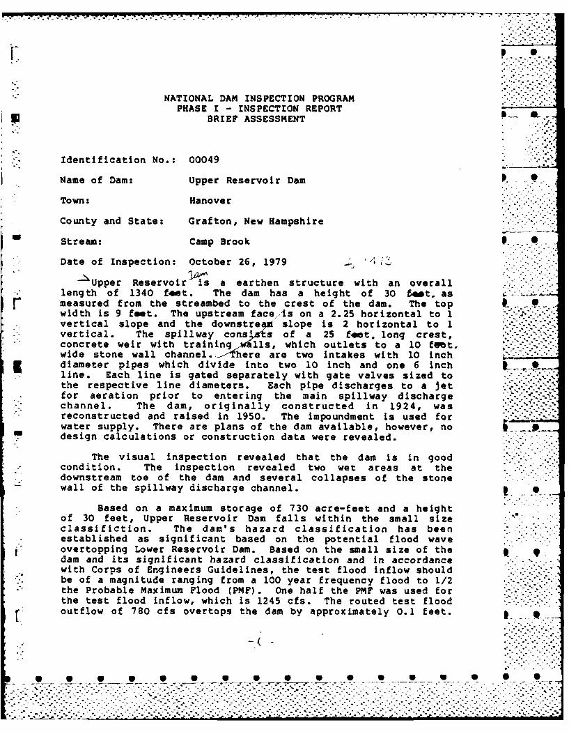
NATIONAL DAM INSPECTION PROGRAMPHASE I - INSPECTION REPORT .'.,'-"
BRIEF ASSESSMENT
Identification No.: 00049
Name of Dam: Upper Reservoir Dam
Town: Hanover
County and State: Grafton, New Hampshire
Stream: Camp Brook S
Date of Inspection: October 26, 1979 -. ; i-. .
Upper Reservoir is a earthen structure with an overalllength of 1340 feet. The dam has a height of 30 t4hto asmeasured from the streambed to the crest of the dam. The topwidth is 9 feet. The upstream face,is on a 2.25 horizontal to 1vertical slope and the downstre " slope is 2 horizontal to 1vertical. The spillway cons ts of a 25 fet. long crest,concrete weir with training alls, which outlets to a 10 fet,wide stone wall channel., _ here are two intakes with 10 inch
5 diameter pipes which divide into two 10 inch and one 6 inch IL..,,line. Each line is gated separately with gate valves sized tothe respective line diameters. Each pipe discharges to a jet.for aeration prior to entering the main spillway dischargechannel. The dam, originally constructed in 1924, wasreconstructed and raised in 1950. The impoundment is used forwater supply. There are plans of the dam available, however, no9design calculations or construction data were revealed.
The visual inspection revealed that the dam is in goodcondition. The inspection revealed two wet areas at thedownstream toe of the dam and several collapses of the stonewall of the spillway discharge channel. ,
Based on a maximum storage of 730 acre-feet and a heightof 30 feet, Upper Reservoir Dam falls within the small sizeclassifiction. The dam's hazard classification has been
.. established as significant based on the potential flood waveovertopping Lower Reservoir Dam. Based on the small size of thedam and its significant hazard classification and in accordancewith Corps of Engineers Guidelines, the test flood inflow shouldbe of a magnitude ranging from a 100 year frequency flood to 1/2the Probable Maximum Flood (PMF). One half the PMF was used forthe test flood inflow, which is 1245 cfs. The routed test floodoutflow of 780 cfs overtops the dam by approximately 0.1 feet.
4,. -~~~~~. . . . . . . . . . .. . . . . . . . .. . ."
~~...,- ....-...-.-.--..... . . . . . '.. - - -.--.... . . .''.,".-....-.. '. -,... ..-.......-.. , .- .- .

With the water surface at the top of dam the spillway capacitywithout flashboards is approximately 550 cfs (about 71 percentof the routed test flood outflow).
It was recommended that the owner engage a qualified,registered professional engineer to perform a visual inspectionof the dam during dry weather so it can be determined if thewet areas observed during the Phase I investigation were aresult of surface runoff or seepage beneath the dam, in addition 0 0a way of removing flashboards during high water should bedevised so that they can be removed without exposing personel tohazardous conditions. Remedial measures include the developmentof a downstream warning system and repair of portions of thestone wall along the spillway discharge channel.
The recommendations are described in Section 7.2 and shouldbe addressed within 1 year, after receipt of this Phase I -Inspection Report by the owner. The remedial measures aredescribed in Section 7.3 and should be addressed within 2 years. .
Co 7q .- -
Gordon H. Slaney, Jr., P.E.-- GOROU Project EngineerI SLAEY, JR. 2
tio. 3774 " " "
4 ,txiSe~ ~ HOWARD NEEDLES TAMMEN &BERGENDOFFI Boston, Massachusetts- -.
.... ._- ... .......
S,,. 0.' -."-
0 °. . .
[:j:::::::::::
0 0 0 0.0 S -,..0-,,0 0 0 0 0

This Phase I Inspection Report on Upper Reservoi r Damnhas been reviewed by the undersigned Review Board members. In our
- opinion, the reported findings, conclusions, and recoumeandations areconsistent with the Recommended Guidelines for Safety Inspection of21ms, and with good engineering judgement and practice, and is hereby -
submitted for approval.
ngineering Division
CARNEY M.ER "= W, ?IDmERDesign BranchEngineering Division
JOSEPH A. MCELROY, CHAIRMAN* * Chief, NED Materials Testing Lab.
Foundations & Materials BranchEngineering Division S
APPROVAL RECOMMNDED:
Chief. Engtineering Division
w~W _p W a W
71 .

PREFACE - -'-
This report is prepared under guidance contained in theRecommended Guidelines for Safety Inspection of Dams, for Phase ..-. -I Investigations. Copies of these guidelines may be obtainedfrom the Office of Chief of Engineers, Washington, D.C. 20314... .The purpose of a Phase I Investigation is to identifyexpeditiously those dams which may pose hazards to human life orproperty. The assessment of the general condition of the dam is
* based upon available data and visual inspections. Detailedinvestigations and analyses involving topographic mapping,subsurface investigations, testing and detailed computationalevaluations are beyond the scope of a Phase I iavestigation;however, the investigation is intended to identify any need for S .such studies.
In reviewing this report, it should be realized that thereported condition of the dam is based on observations of field
,* conditions at the time of inspection along with data available -.
to the inspection team. In cases where the reservoir was .lowered or drained prior to inspection, such action, whileimproving the stability and safety of the dam, removes the
. normal load on the structure and may obscure certain conditionswhich might be otherwise detectable if inspected under thenormal operating environment of the structure.
It is important to note that the condition of a dam dependson numerous and constantly changing internal and externalconditions, and is evolutionary in nature. It would beincorrect to assume that the present condition of the dam willcontinue to represent the condition of the dam at some point inthe future. Only through continued care and inspection can
* there be any chance that unsafe conditions be detected.
Phase I inspections are not intended to provide detailedhydrologic and hydraulic analyses. In accordance with theestablished Guidelines, the Spillway Test Flood is based on theestimated "Probable Maximum Flood" for the region (greatestreasonably possible storm runoff) , or fractions thereof.Because of the magnitude and rarity of such a storm event, a " -finding that a spillway will not pass the test flood should notbe interpreted as necessarily posing a highly inadequate
r condition. The test flood provides a measure of relativespillway capacity and serves as an aide in determining the need
.*. for more detailed hydrologic and hydraulic studies, considering :-,...the size of the dam, its general condition and the downstream -damage potential. -
........................................ ,
.. .. . . .....-.. . .. . .- ,- .. •- ..... *...........

TABLE OF CONTENTS
Section Page
.- Letter of Transmittal
Brief Assessment 6 •
* Review Board Page
Preface i
Table of Contents ii-iv S.
Overview Photo v
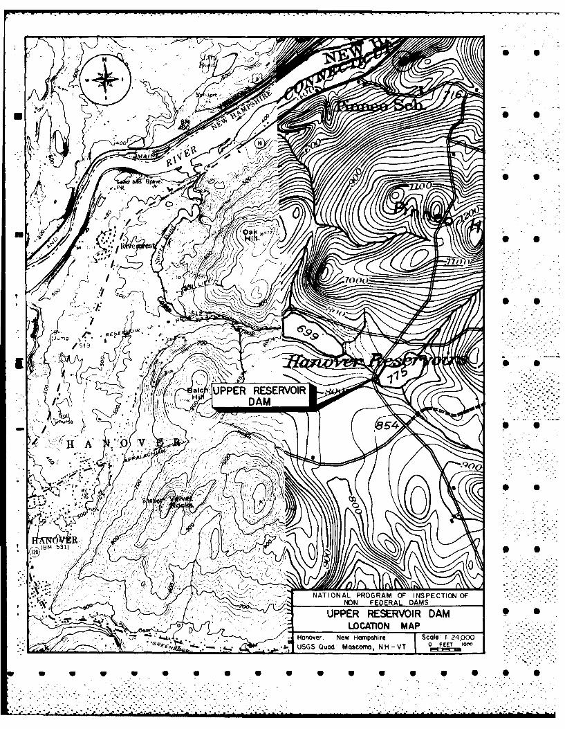
Location Map vi
REPORT
-*-i 1. PROJECT INFORMATION 1-1 .-
1.1 General 1-1
a. Authority 1-1b. Purpose of Inspection 1-i
1.2 Description of Project i-"
a. Location 1-i •..- b. Description of Dam and Appurtenances 1-2
c. Size Classification 1-2d. Hazard Classification 1-2e. Ownership 1-3f. Operator 1-3g. Purpose of Dam 1-3h. Design and Construction History 1-3i. Normal Operational Procedure 1-3
1.3 Pertinent Data 1-3
2. ENGINEERING DATA 2-1
2.1 Design Data 2-1
2.2 Construction Data 2-1
2.3 Operation Data 2-1
2.4 Evaluation of Section 2-1
* . U ,"6 6 __S-S S S o-S.S.6-5 0.
......................................................................

Section Page
3. VISUAL INSPECTION 3-1
3.1 Findings 3-1
a. General 3-1b. Dam 3-1c. Appurtenant Structures 3-2d. Reservoir Area 3-2e. Downstream Channel 3-3
3.2 Evaluation 3-3
4. OPERATIONAL PROCEDURES 4-1
4.1 Procedures 4-1
4.2 Maintenance of Dam 4-1
El 4.3 Maintenance of Operating Facilities 4-1
4.4 Description of any Warning System 4-1in Effect
4.5 Evaluation 4-1
1 5. HYDRAULIC/HYDROLOGY 5-1 .
5.1 Evaluation of Features 5-1
a. General 5-1
b. Design Data 5-1- c. Experience Data 5-1
d. Visual Observation 5-1e. Test Flood Analysis 5-1f. Dam Failure Analysis 5-2
6. STRUCTURAL STABILITY 6-1
6.1 Evaluation of Structural Stability 6-1
a. Visual Observation 6-1b. Design and Construction Data 6-1c. Operating Records 6-1d. Post-Construction Changes 6-1 * Se. Seismic Stability 6-1
* 0 0 0 0 0 0 0 0 0 0 0 S 0 0 S
.................................................... " -::::::::::::::..............

S 0
Section Page
7. ASSESSMENT, RECOMMENDATIONS AND REMEDIAL MEASURES 7-1 "
7.1 Dam Assessment 7-1
a. Condition 7-1b. Adequacy of Information 7-1c. Urgency 7-1d. Need for Additional Investigation 7-1
7. 2 Recommendations 7-1
- 7.3 Remedial Measures 7-2
7.4 Alternatives 7-2
APPENDIXES
APPENDIX A - INSPECTION CHECKLIST O.
APPENDIX B - ENGINEERING DATA
APPENDIX C PHOTOGRAPHS
[ APPENDIX D - HYDROLOGIC AND HYDRAULIC COMPUTATIONS S S
APPENDIX E - INFORMATION-AS CONTAINED IN THE NATIONAL , .INVENTORY OF DAMS
. . . . -. .
. .
p. p
...... ..- .'. . . .

y4,
II
7rS
1~ .Arn,IteI. 4
16 ,
* S
ftS
Al
* 0 0
m/
4000 01
o* 0z
T'-44.k* 0. 0
UPPER RESERVIRODA
.. . .. . .A .0 'V"
% a .

NATIONAL DAN INSPECTION PROGRAMPHASE I INSPECriotN REPORT
SECTI)R' I
PROJECT 1".ORMATION,
N . ~.%".0 .
1.1 General
a. A.rit. Public Law 92-367, Aug.st 8, 1972,m authorized the Secetary of the Army, through the Corps of
Engineers, to init..ate a National Program of Dam InspectionSthroughout the United States. The New England Division of theCorps of Engineers has been assigned the responsibility ofsupervising the inspection of dams within the New EnglandRegion. Howard, Needles, Tanmen & Bergendoft has been retainedby the New England Division to inspect and report on selected
Fdams in the State of New Hampshire. Authorization and notice '4 0to proceed were issued to Howard, Needles, Talamen & Bergendoffunder a letter of October 11, 1979 from William E. Hodgson, Jr.,Colonel, Corps of Engineers. Contract No. DACW33-79-C-0060 hasbeen assigned by the Corps of Engineers for this work.
•b. Purpose. "
(1) To perform technical inspection and evaluation of* non-Federal dams to identify conditions which threaten the
public safc-Ly and thus permit correction in a timely manner bynon-Federal interests.
".- PSJC " R IN" "- S -
(2) To encourage and prepare the states to Initiatequickly effective 'lam safety programs for non-Federal dams.
(3) To update, verify and complete the National Inventory.-..
* of Dams.
1.2 Description of Project
a. Location. Upper Reservoir Dam is located on Camp Brookapproximatelr .miles upstream of the Connecticut River in the
*Town of Hanover, New Hampshire. The dam is shown on U.S.G.S.hQuadrangle, Masc a, New Hamshire-Vermont, with approximatecoordinates N43 4252w, E72 14 18w, Grafton County, NewHampshire. The location of Upper Reservoir Dam is shown on the
* preceding page.
......................Region•Howard Nedls Ta* . .. .. .. & Br nd *ha bee reaie . '- " .

b. Description of Dam and Appurtenances. Upper ReservoirDam is an earthen embankment structure with an overall length of1,340 feet. The dam has a maximum height of 30 feet as measured -from the dam crest to the streambed. The crest of the dam is 9feet wide. The upstream face is on a 2.25 horizontal to 1vertical slope and the downstream embankment is on a 2
. horizontal to 1 vertical slope. The present dam is constructedon the old dam. The new embankment was placed on the crest anddownstream slope of the old dam. The present crest is 5 feetabove the old crest. In cross-section the embankment consistsof a wedge section of impervious material against the downstreamface of the old dam backed by a section of semi-pervious
*material. The outside portion of the downstream face consists- of a layer of pervious material spread with loam and an
established vegetative cover. The upstream face has riprap S 0protection from mid-height to the crest.
Appurtenant structures consist of a spillway and dischargechannel and two 10 inch diameter outlet pipes. The spillway has
- a 25 foot long concrete weir crest. The spillway crest is 3.6feet below the dam crest. There are flashboards 1.4 feet high ! Son the spillway crest. The concrete training walls extend 15feet upstream of the spillway crest and 25 feet downstream. Thespi]lway discharges directly onto exposed ledge. The outletcharnel bends to the left immediately downstream of the dam andis it 10 feet wide with dry masonry stone walls. The two 10
3 in, iameter cast iron outlet pipes have intakes near theups__am toe of slope. Each pipe enters a manhole at the - . -downstream toe of slope. The manhole covers are flush with theground surface. One line is gated with a 10 inch gate valve and ... -
discharges to a 10 inch diameter aerated jet in the spillwaydischarge channel. The other 10 inch line divides to a 10 inchand 6 inch diameter lines at a wye in the manhole. Each line isgated with a gate valve downstream of the wye. Each linedischarges to an aerated jet 4 and 3 inches in diameter,respectively.
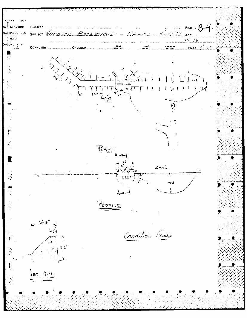
Figures 1 and 2 located in Appendix B, show a plan of thedam and its appurtenant structures. Photographs of each S Sstructure are shown in Appendix C.
c. Size Classification. Small (hydralic height - 30 feet,storage 730 acre-feet) classification based on the hydraulicheight being less than 40 feet and the storage being less than
L7 1,000 acre-feet as given in Recommended Guidelines for SafetyInspection of Dams.
d. Hazard Classification. The potential for damage posedby this dam is classified as significant. Failure of the damwith the water level at the top of dam would result in a floodwave about 17 feet high in the reach extending from the dam to
1-2
___ r ..- r- rr- .r
. ?. . ... .. ... .. .. ..................... . .-

- =~ U . -. -. .. - ... , -. - . -° - .
the upstream end of Lower Reservoir located 1,300 feetdownstream. There are no structures in that reach. However,
K the storage in Upper Reservoir is great enough to raise thelevel of Lower Reservoir and cause overtopping of the Lower . --
Reservoir Dam, thus endangering that dam.
e. Ownership. This dam is owned by the Hanover WaterWorks Company, P.O. Box 1006, Hanover, New Hampshire 03755.
f• Operator. This dam is operated by the Hanover WaterWorks Company, Rr. Carl Brink, Superintendent, P.O. Box 1006,Hanover, New Hampshire, Telephone No. 603-643-3506.
g. Purpose of Dam. The impoundment is used exclusivelyfor water supply. The reservoir is one of three in a system.Reservoir No. 3 is located above and in another watershed thanUpper Reservoir and discharges to Upper Reservoir via a 10 inchdiameter gravity pipeline. Upper Reservoir discharges to LowerReservoir through the two 10 inch diameter outlet pipes whichempty to a stream tributary to Lower Reservoir.
h• Design and Construction History. Upper Reservoir Dam -.'.-.was constructed in 1924. In 1950, the original structure was .,...raised 5.0 feet and the spillway was reconstructed. Nomodifications to the dam have been made since 1950.
i. Normal Operating Procedures. Upper Reservoir provides Sadditional storage for the Hanover water system. Water isreleased as required to the Lower Reservoir. The outlet pipesdischarge to jets which operate by the head supplied from thereservoir. Flashboards on the spillway crest are removed fromDecember to April. The lake level fluctuates according to thewater supply demand.
1.3 Pertinent Data
a. rai.nage Area. The area tributary to Upper Reservoirconsists of 0.83 square miles of mountainous wooded terrain.There is no development in the watershed which is owned by theHanover Water Works Company. Maximum elevation in the basin is1,280 feet NGVD. There are three other peaks over elevation1,000. The average water surface in the reservoir is aboutelevation 784.0.
A large portion of the reservoir bank is riprapped at thewaterline. Above the riprap the banks are clear of trees for adistance of 10 to 15 feet. Beyond that point the area isheavily wooded. There are no islands in the reservoir or nearby " .* "structures.
1-3S S.°__ S S S S S°SS•S ,- S"
• -. , - ,-.....-.--.....-.-..... . ..... '-,,-, °.-.. -,.... .......... ,,..-,.' .. ,

.- .. .. .-- .: .
b. Discharge at Dam Site.
U (1) Outlet works for Upper Reservoir consist of two Ointakes located at the upstream toe of slope. The inverts ofthe intakes are unknown, but are estimated to be at aboutelevation 765.0. Ten inch cast iron pipe connects each intaketo a separate manhole where one line is gated with a 10 inchgate valve and the other line divides into a 10 inch line and a6 inch line, each of which is gated downstream of the wye with a10 inch gate valve and a 6 inch gate valve, respectively.
(2) There are no records of maximum discharge at the site.
f (3) The spillway capacity with the water surface the top
of dam, elevation 790.5, would be about 550 cfs without.. flashboards in place and 290 cfs with the flashboards in place.
(4) The spillway capacity with the water surface at thetest flood elevation of 790.6 would be about 580 cfs.
(5) The total project discharge at the test flood Oelevation of 790.6 is approximately 780 cfs.
c. Elevation (feet above NGVD)
(1) Streambed at centerline of dam- 760.5 * 0I(2) Maximum tailwater - unknown
(3) Upstream invert of outlet works - 765.0 estimated
(4) Normal pool - 786.9
(5) Full flood control pool -N/A
(6) Spillway crest (permanent spillway) - 786.9
(7) Design surcharge - N/A
(8) Top Dam - 790.6 7
(9) Test Flood Surcharge -790.6
d. Reservoir (miles)
(1) A.ength of Maximum Pool - 0.31
(2) Length of Normal Pool - 0.30
(3) Length of Flood Control Pool - N/A -' .
1-4
.."."' .- . -- .- -
. . . .. .. . - :: : : : : "":" '" " ' :
,'. '.- -' " " * -'."-' " '-' " . . '_,-_ _.'j__ " ,' . -, • • - " ." "_ _ ' . '.' '- ," " " '-- '. -' . L'. _' 2-._''_--'

e.- Storage (gross acre-feet)
(1) Normal Pool - 580 -ji.(2) Flood Control Pool - 580
(3) Spillway Crest Pool - 580 without flashboards
(4) Top of Dam - 730
f. Reservoir Surface (acres)
(1) Normal Pool -46
(2) Flood Control Pool -N/A 0
(3) Spillway Crest -46
(4) Test Flood Pool -46
F(5) Top Dam - 46
g. Dam
(1) Type -earth
* (2) Length - 1,340 feet
(3) Height -30 feet
(4) Top Width - 9 feet
M (5) Side Slopes -upstream 2.25 horizontal to 1 verticaldownstream 2 horizontal to 1 vertical
(6) Zoning -3 zones
(7) impervious core - yes material unknown 3
(8) Cutof f - unknown
(9) Grout Curtain - unknown
(10) Other - unknown
h. Diversion and Regulating Tunnel
See Section jbelow. -.
-7.- 70

* .. r...r -.- I... .-.-
i. Spillway
(1) Type concrete weir
(2) Length of Weir - 25 feet
(3) Crest Elevation - 786.9
(4) Controls - Flashboards 1.4 feet high, removable 0...
(5) Upstream Channel - none
(6) Downstream Channel - The spillway outlets to a 10 footwide channel with dry masonry stone walls. The channel turns tothe left immediately downstream of the spillway and almost .parallels the downstream toe of slope for 150 feet where itjoins the jets which are part of the outlet works. The channelthen makes a right angle turn downstream and passes under abridge for the access road which has a 10 foot wide by 5 foothigh opening.
j. Regulating Outlets. The outlet works consist of two 10inch diameter cast iron pipes which divide into three pipes. . _.Each of the three pipes are gated with gate valves of the samesizes as the lines. Each pipe discharges to a jet for aeration 'prior to open channel transportation to Lower Reservoir.Capacity of the three jet outlets with the water surface. at the P _
spillway crest would be about 10 cfs. --
1-6
*•** ~ . • • . ,- •
: -- -. . ..-
... .. . . . . . . . . . . . . . . . . .. ..-. . . .%" - ,'.. . .-.
-, :'S S S S . . . . . . . .. * .. .. ::"
S. . . . . .. S°- -

SECTION 2
ENGINEERING DATA
2.1 Design
Plans of the 1950 reconstruction of Upper Reservoir Dam areon file with the New Hampshire Water Resources Board. These 'p lans also show the original 1924 dam. Design was done byWeston & Sampson, Boston, Massachuietts. No specifictions ordesign calculations were made available. There is no record ofany modifications to the dam since the 1950 reconstruction. -..-
S S2.2 Construction
No construction records are available for use in evaluatingthe dam.
2.3 Operation .No engineering operational data were disclosed.....
2.4 Evaluation
a. Availability. Information available consists of a setof 3 plan sheets and an inspection report by the New Hampshire P .Water Resources Board. The above data is available at theDepartment's offices in Concord, New Hampshire. -
b. Adequacy. The lack of in-depth engineering data didnot allow or a definitive review. Therefore, the adequacy ofthis dam could not be assessed from the standpoint of reviewing
* design and construction data, but is based primarily on visualinspection, past performance history and sound engineeringjudgment.
c. Validity. The field inspection indicated that theexternal feature; of Upper Reservoir Dam substantially agree S -with those shown on the available plans.
2-1
.- . -.
.. . ..-..
- . . . .. . . .. . . . . . . .
. . . . . . . . . . . . . . . . . . .
S..._. . . . ... .... .
...-. . :, .. . . - a . , ., .> . *. . .: .- -.. .. '. . - . . i '.< -: - " " Y -. i . .

SECTION 3VI SUM-MT TION
j: q 3.1 Findings
a. General. The field inspection of Upper Reservoir Dam - .was made on October 26, 1979. The inspection team consisted of 0
S.. personnel from Howard, Needles, Tammen & Bergendoff andGeotechnical Engineers, Inc. A representative of the owner wasalso present during the inspection. Inspection checklists,completed during the inspection, are included in Appendix A. Atthe time of inspection, the water level was approximately 5.8feet below the permanent spillway crest. The upstream face of "the dam could only be inspected above this level.
b. Dam. Visual inspection of the dam indicated that it isin good condition.
p [. The dam consists of an earth embankment about 1340 feetlong and 30 feet high. The axis of the embankment is serpentinealong its length with the right half of the embankmentpractically perpendicular to the main embankment section.
A concrete spillway section passes through the main-* i embankment section. S
Upstream Slope
The inclination of the upstream slope is 2.25 horizontal to1 vertical. The upstream slope is shown in Photo No. 4. Theriprap is in good condition and there are no indications ofsloughing or erosion on the slope.
Crest
* The crest of the dam is 9 feet wide and, as shown in Photo . -
No. 4, is uniformly grass covered.
Downstream Slope
The downstream slope of the embankment is inclined at 2horizontal to 1 vertical and is shown in Photo No. 5. The slopeis uniform and covered with an excellent grass cover.
There is a wet area which contains standing water locatedat the downstream toe about 50 feet left of the aeration jets.The wet area extends 50 feet along the toe of the embankment andextends 60 feet downstream of the toe. This area is shown inPhoto Nos. 7 & 8.
3-1
- S -S U• U-S U -V-.
~" -* -* %- .
• • • • •....................======== == === ======= ======== === == =========::::::: -:-i : :! :::: : : -: :::: ::: :: :: :: :: : :: :: :: :: : : : : ::i: -:i-!: :i i :! :: : : : :::. :.:

It is not possible to state explicitly if the wet area isdue to seepage from beneath the dam or is a result of localponding of surface runoff. An inspection report from the NewHampshire Water Resources Board dated May 23, 1977 states thatno seepage was observed.
A swampy area exists at the toe of the dam at the pointwhere the embankment makes a sharp turn. This area is shown inPhoto No. 6. This swampy area is about 3 feet below the normalreservoir high water level, and it is likely that the swamp isdue to local surface runoff. At the time of inspection, thewater surface in the reservoir was below the level of the swamp.
c. Appurtenant Structures. Visual inspection of theconcrete spillway, spillway channel and outlet works did notreveal any evidence of stability problems. The concrete surfaceat the spillway structure generally appeared to be in goodcondition except for three, rather insignificant cracks intraining walls. The spillway channel with unmortared fieldstone is in fair condition.
The spillway structure, shown in Photo Nos. 9, 10 & 11,consists of a gravity concrete weir structure and two trainingwalls. The spillway crest is in good condition. The concrete
- training walls are also in good condition except for two cracksin the right wall and one insignificant crack in left wall as
* seen in Photo No. 12. The wingwalls and flashboards are in Sexcellent condition. (Photo No. 10). However, there is nomeans of removing the flashboards during high water withoutexposing personel to hazardous conditions.
The outlet works include two intake structures, piping, twovalve manholes and discharge jets. The intake structures were , ,
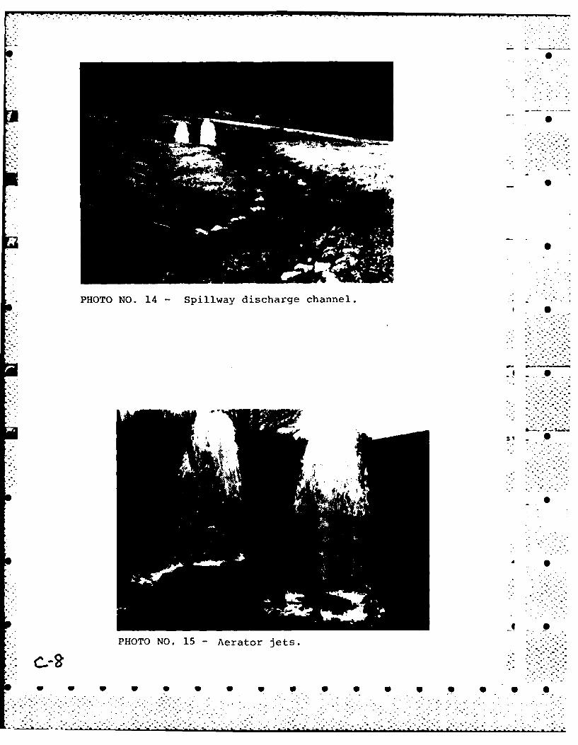
- under water and could not be inspected. The valve manholes hadcovers flush with the ground that are normally locked. Thedischarge jets outlet to the spillway channel. The two smallerdiameter jets were in operation as seen in Photo No. 15. Thelarger 10 inch diameter jet is located to the right side ofPhoto No. 10 and was covered with a flat stone. The outlet S .works appeared to be in good condition.
Visual inspection of the spillway discharge channel seen inPhoto No. 14 showed it to be in fair condition. The sides ofthe channel are reinforced with dry stone masonry. The bottomof the channel was covered with loose stone and some vegetation *has established itself along the bed. The dry stone masonry hascollapsed in several areas.
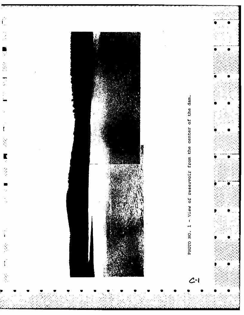
d. Reservoir Area. The immediate banks of the reservoir " '-are paved with rip-rap at the water line. An overview of thereservoir area from the dam is shown in Photo No. 1. There are
3-2
.° .- . - .. ....
- * .-...•-..•. .•.

no overhanging trees and no debris along the banks although thearea surrounding the reservoir is heavily wooded. P S
e. Downstream Channel. The stone wall discharge channelends about 90 feet downstream of the toe of slope of dam wherethere is a bridge for the access road as seen in Photo No. 16.The water way opening is clear of debris. Downstream of the -bridge the channel is natural with a 10 foot bottom width. The 0 0bridge is in fair condition, with some spalling of concrete.There is a high steep bank on the left side. Both overbanks areheavily wooded.
3.2 Evaluation
Visual examination indicates that the dam is in goodcondition. Visual examination revealed the following:
(a) There is a wet area at the downstream toe of the damembankment 50 feet to the left of the aeration jets.
r (b) A second wet area, a swamp, was noted near the right Send of the dam.
(c) Several collapses of the dry stone wall of thedischarge channel.
* (d) There is no means of removing the flashboards during * S
high water without exposing personel to hazardous conditions. - . .
-- 3
.- . ' - '
.- S U U3 .3 - ...'::":::::[-
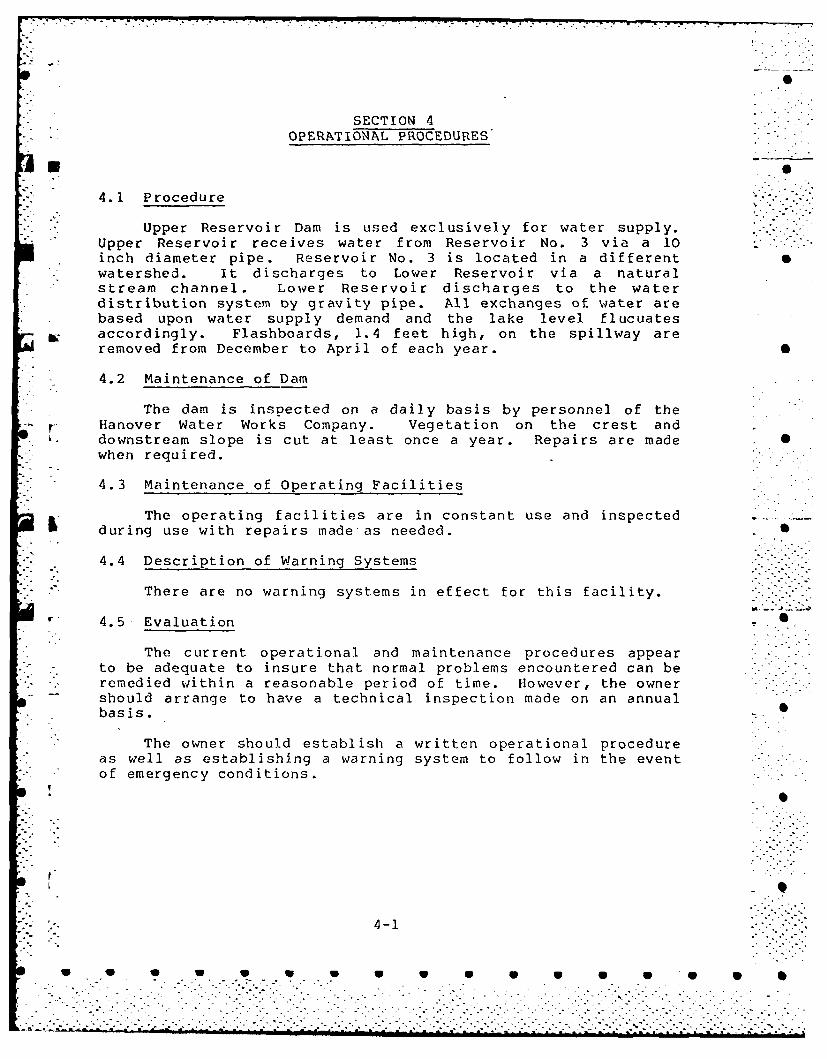
SECTION 4OPERATIONAL PROCEDURES
4.1 Procedure
Upper Reservoir Dam is used exclusively for water supply.Upper Reservoir receives water from Reservoir No. 3 via a 10inch diameter pipe. Reservoir No. 3 is located in a differentwatershed. It discharges to Lower Reservoir via a naturalstream channel. Lower Reservoir discharges to the waterdistribution system oy gravity pipe. All exchanges of water arebased upon water supply demand and the lake level flucuatesaccordingly. Flashboards, 1.4 feet high, on the spillway areremoved from December to April of each year. S
L 4.2 Maintenance of Dam
The dam is inspected on a daily basis by personnel of theHanover Water Works Company. Vegetation on the crest and
- • downstream slope is cut at least once a year. Repairs are made ,when required.
- 4.3 Maintenance of Operating Facilities
The operating facilities are in constant use and inspectedduring use with repairs made as needed. 5
4.4 Description of Warning Systems
There are no warning systems in effect for this facility.
I' 4.5 Evaluation .
The current operational and maintenance procedures appear .
*to be adequate to insure that normal problems encountered can be •"- remedied within a reasonable period of time. However, the owner
should arrange to have a technical inspection made on an annualbasis.
The owner should establish a written operational procedure .
as well as establishing a warning system to follow in the eventof emergency conditions.
4-1
. . . . . . . . . . . . . .

7% N
SECTION 5HYDROLOGY AND HYDRAULIC ANALYSIS
, A.
5.1 Evaluation of Features
a. General. Upper Reservoir Dam is an earthen embankmentstructure with an overall length of 1,340 feet and a maximumheight of 30 feet. The crest is 9 feet wide and a vegetativecover is established on the crest and downstream slope.Appurtenant structures consist of a spillway and outlet works.The spillway weir is concrete and has a crest length of 25 feet.The concrete training walls are normal to the spillway crest andare 3.6 feet higher than spillway crest. Immediately downstreamof the spillway the channel is on ledge and enters a 10 footwide dry masonry, stone wall channel. Outlet works consist of ..
two 10 inch diameter intake pipes. Each pipe is gated in amanhole. One pipe divides to a 6 inch and 10 inch diameter pipewith gate valves downstream of the dividing point.
The impoundment is used for water supply by the H., ver -Water Works Company. The dam is classified as intermed.ate insize with a height of 30 feet and a maximum storage of 730
* acre-feet.
b. Design Data. Plans of the reconstruction of the* original dam were available, however, no hydraulic or hydrologic
design data were availble.
c. Experience Data. There are no records of maximumdischarge at the site.
- d. Visual Observations. No evidtnce of damage to any I ."- portion of the project from overtopping was visible at the time
of inspection.
e. Test Flood Analysis. No detailed design and* operational information are available for this dam. The
hydrologic evaluation was performed using information gathered S Sby field investigation, watershed characteristics, and ProbableMaximum Flood (PMF) curves prepared by the Corps of Engineers.In accordance with Corps of Engineer Guidelines the significanthazard classification and small size classification of this damwarrants a test flood magnitude ranging from a 100-yearfrequency flood to one-half the PMF. A test flood equal to 1/2 _ •the PMF was used. A test flood inflow of 1,245 cfs is based on -
**." a watershed of .83 square mile in mountainous terrain.
5-1
-' _ • - ., .....
, . . . . -, ' .' . .-.'

The routed test flood outflow was determined in accordancewith Corps of Engineers Guidance for Estimating Effect ofSurcharge Storage on Maximum Probable Discharge, and the
*hydraulic characteristics of the dam. Spillway discharge wascomputed as flow over a weir. Discharge over the crest of the
* dam was computed as flow over an embankment using the weir*discharge equation. It was assumed that the flashboards were not
in place. The routing was started with the water surface at thecrest of the spillway. The routed test flood outflow wasdetermined to be approximately 780 cfs. As the maximum capacityof the spillway is approximately 550 cfs (about 71 percent of. -
the routed test flood outflow) the dam will be overtopped by 0.1feet.
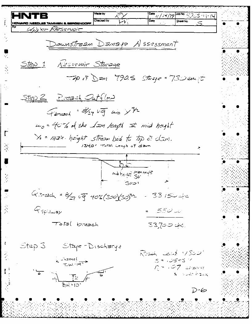
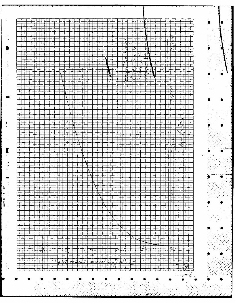
f. Dam Failure Analysis. The impact of failure of the damS 0was assessed using the "Rule of Thumb" Guidance for EstimatingDownstream Dam Failure Hydrographs prepared by the Corps ofEngineers. The breach discharge was estimated with the watersurface at the crest of the dam and a breach width equal to 40percent of the length of the dam at mid-height. The downstreamhydrograph is a sum of the breach discharge and the maximum - ,-spillway discharge. Prior to the breach of dam the downstreamriver stage would be about 3.5 feet, with the spillway at afull capacity discharge of 550 cfs. Breach of dam would resultin an additional 33,150 cfs for a total of 33,700 cfs. Thedownstream stage was estimated using an average channel crosssection in the reach between the dam and Lower Reservoir located 1,300 feet downstream. The stage through this reach.would beabout 17 feet. The only structure in this reach is the accessroad bridge downstream of the dam which would be inundated by "about 15 feet. If at the time of breach the level of LowerReservoir is at the spillway crest, there will be approximately
- 119 acre-feet of surcharge storage available in Lower Reservoir.Discounting spillway discharge at Lower Reservoir andattenuation of the breach discharge with time it would takeabout 3 minutes for the Lower Reservoir Dam to be overtopped byd tthe flood wave.
0 S
0
5-2 .
1,O-fe downstream ...Th stg thog.hsrah ol e,' .....
... ........ ontra fth a hihwud eiudae y":-..'.'---" abou......e... a.het.eo.bechte.eelo.Lwe...-.....-..<
. ** . . . * * * * U* 1 5 * * - - - '- 1 --.. - •
SECTION 6
STRUCTURAL STABILITY __"_.",-.
6.1 Evaluation of Structural Stability
a. Visual Observation. The visual inspection of UpperReservoir Dam did not reveal any immediate stability problems O
b. Design and Construction Data. Design drawings datedMay 1950 which delineate the design for raising an existing damat the site were available for review. The drawings indicatethat the earlier dam was an embankment dam and that the addition
n raised the old dam 5 feet by placing a zoned embankment directlyon the downstream slope of the original dam.
Specifications indicate that the added embankment ascompacted in 6- or 10-inch-thick lifts.
The addition was constructed with a wide imperviousupstream section, a semi-pervious downstream section which wascovered with a sloping pervious section forming the downstreamface.
c. Operating Records. No operating records were made3 available. _ _
d. Post-Construction Changes. There is no record ofchanges since the raising of the original dam as described inSection 6.2.
e. Seismic Stabilitx. The dam is located in Seismic Zone
2, and in accordance with the recommended Phase I guidelines,does not warrant seismic analysis.
4P~~~~ W0 W W S V 4
S S
6-1
1 .U U U U U U •

I. -o S
SECTION 7ASSESSMENT, RECOMMENDATIONS AND REMEDIAL MEASURES
7.1 Dam Assessment
a. Condition. The visual inspection of Upper ReservoirDam indicates that the dam is in good condition. The inspection 0revealed the following:
(1) There is a wet area at the downstream toe of the dam• embankment 50 feet to the left of the aeration jets..-"
(2) A second wet area, a swamp, was noted near the rightend of the dam. The area may be due to surface runoff.
(3) Several collapses of the dry stone wall of thespillway discharge channel.
(4) There is no means of removing the flashboards duringhigh water without exposing personel to hazardous conditions.
The hydraulic analysis reveals that the spillway cannotpass the routed test flood without overtopping the dam.
*b. Adequacy of Information. The lack of in-depth 0 .-- engineering data did not allow for a definitive review.
Therefore, the adequacy of this dam could not be assessed fromthe standpoint of reviewing design and construction data but isbased primarily on visual inspection, past performance historyand sound engineering judgment. ' --
c. Urgency. This dam is in generally good condition. The* recommendations described in Section 7.2 should be accomplished
within 1 year, after receipt of this Phase I Inspection Reportby the owner. The remedial measures described in Section 7.3should be accomplished within 2 years.
d. Necessity of Additional Investigation. No additionalinvestigation is needed to complete the Phase I inspection.
7.2 Recommendations
The owner should engage a qualified, registeredprofessional engineer to perform a visual inspection of the damduring a period of dry weather so it can be determined if thewet areas observed during this Phase I investigation were theresult of surface runoff or seepage beneath the dam. Inaddition, a way of removing the flashboards should be devised sothat they can removed during high water conditions withoutexposing personel to hazardous conditions.
.[ ~~~~7-1 .. -..v.?
. S S SoS S S.S So So5 5 0,
7.3 Remedial Measures
(a) Repair the collapses in the stone walls along thespillway discharge channel.
(b) Prepare a downstream warning system in the event of anemergency.
(c) A technical inspection program should be initiated and 0continued on a biennial basis.
(d) Establish a system such that the reservoir level can*be monitored during periods of intense rainfall.
7.4 Alternatives
There are no practical alternatives to the recommendations .-- .
*of Sections 7.2 and 7.3.
P- A
7-2
%,.S S S -"S -- S _ ";-
APPENDIX A
INSPECTION CHECKLIST
* 0
. . . . . . ..

IA-i .0 0VISUAL INSPECTION CHECK LIST
PARTY ORGANIZATION
PROJECT Upper Damn DATE 10/26/79
U C(Hanover)TIME 12:00 PM
WEATHER Cod
W.S. ELEV.781.1_U.S. -_DN.S
PARTY:
1. D. Laatta GEI 6.
- 2. S. Mazur HNTB 7.
3. R. Yarsites ENTE 8._________________
4. Carl Brink, Hanover Water Works Company 9.
5. 10.
PROJECT FEATURE INSPECTED BY REMARKS
~*Damn Dan Laatta
* 2. Spillway, outlet and Stan Mazur
Downstreamn Channel. Robert Yarsites
4.
5.
6.
*7.
8.
9.
10.
's0 0

• ': A-2PERIODIC INSPECTION CHECK LIST
PROJECTZ UPPER HANOVER RESERVOIR DATE 10/26179
PROJECT FEATURE Embankment Dam NAME D. LaGatta-
DISCIPLINE Geotechnical Engineer NAME .
AREA EVALUATED CONDITIONr. -" DAM EMBANKMENT ---'-.----
Crest Elevation 790.5 0
Current Pool Elevation 781.1
Maximum Impoundment to Date Unknown.
Surface Cracks None observed. •
Pavement Condition No pavement.
Movement or Settlement of Crest None observed.
Lateral Movement .No misalignment observed.
Vertical Alignment
Horizontal Alignment
I Condition at Abutment and at Concrete Good
* Structures
Indications of Movement of Structural No structures on slopes." "Items on Slopes
~~~~None. "-' -Trespassing on Slopes None.
None.Sloughing or Erosion of Slopes orAbutments
Rock Slope Protection - Riprap Failures "p"igocntn_ Riprap in good condition.
Unusual Movement or Cracking at or NNon observed.""".-near Toes
Unusual Embankment or Downstream Standing water extending 50 ft alongUnusua Embankmen orDownstreatoe and 60 ft d.s. of toe. LocatedSeepage 50 ft left of outlet jets.
Piping or Boils No piping or boils observed.
Foundation Drainage Features None.
Toe Drains None.
Instrumentation System None.
VeeainGrass slopes in good condition.

PERIODIC INSPECTION CHECK LIST A-3
PROJECT upper pa DATE 10/26/79
PROJECT FEATURE Int-akea strue-rura NAME D. LaGatta
*DISCIPLINE Gotachnical/Structural NAME S. Mazur
AREA EVALUATED CONDITION
* OUTLET WORKS - INTAKE CHANNEL AND -
INTAKE STRUCTURE 0
a. Approach Channel Outlet is below reservoir surface.
Slope Conditions
Bottom Conditions
Rock Slides or Falls
Log Boom
F Debris
Condition of Concrete Lining -
Drains or Weep Holes
b. nta e S ruc ureIntake structure - under water.Condition of Concrete
Stop Logs and Slots
. . .
A-4
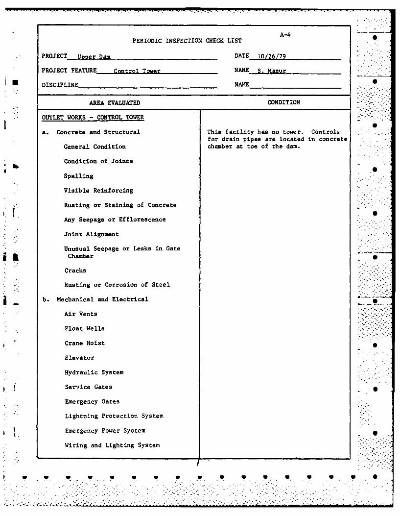
PERIODIC INSPECTION CHECK LIST
PROJECT Upner Dam DATE 10/26/79
PROJECT FEATURE Control Tower NAME S. Mazur
DISCIPLINE NAME 0
AREA EVALUATED CONDITION . -
OUTLET WORKS - CONTROL TOWER
a. Concrete and Structural This facility has no tower. Controlsfor drain pipes are located in concrete
General Condition chamber at toe of the dam.
Condition of JointsW
Spalling
Visible Reinforcing
Rusting or Staining of Concrete
Any Seepage or Efflorescence
, - "Joint Alignment
Unusual Seepage or Leaks in Gateis !Chamber
Cracks
" . Rusting or Corrosion of Steel
i b. Mechanical and Electrical
," Air Vents
Float Wells
Crane Hoist
Elevator
Hydraulic System
Service Gates
Emergency Gates
Lightning Protection System
Emergency Power System
Wiring and Lighting System
w S S.°U U.-U U .- U °-
PERIODIC INSPECTION CHECK LISTA-
PROJECT TUpgpr Damt, DATE Ip,/7j,7g
PROJECT FEATURE 0Outlt W,,rk Cidt NAME gM~n
I *DISCIPLINE Structural/Hydraulic NAME R. Yarsites
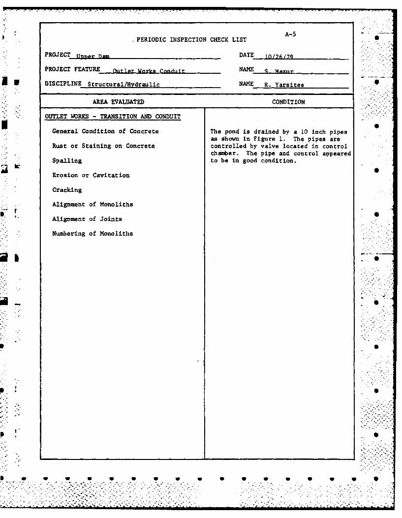
AREA EVALUATED CONDITION .-
- - OUTLET WORKS -TRANSITION AND CONDUIT
General Condition of Concrete The pond is drained by a 10 inch pipesas shown in Figure 1. The pipes are
Rust or Staining on Concrete controlled by valve located in controlchamber. The pipe and control appeared
Spalling to be in good condition.
Erosion or Cavitation
Cracking
Alignment of Monoliths
Alignment of Joints
* Numbering of Monoliths
Di W -W l 1 p W W
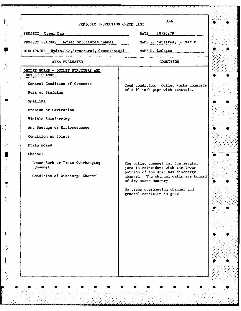
PERIODIC INSPECTION CHECK LIST A-6
*PROJECT Upper Dan DATE 10/26/79
PROJECT FEATURE Outlet Structure/Channel NAME R. Yarsites, S. Mazur
* DISCIPLINE HydraulicStructural, Geotechnical NAME D. LaGatta -
AREA EVALUATED CONDITION
. OUTLET WORKS - OUTLET STRUCTURE ANDOUTLET CHANNEL 0 0
General Condition of Concrete Good condition. Outlet works consists
Rustor Staining of a 10 inch pipe with controls. .Rust or Sann
is Spalling
Erosion or Cavitation
Visible Reinforcing
Any Seepage or Efflorescence
* Condition at Joints
Drain Holes
3I Channel
Loose Rock or Trees Overhanging The outlet channel for the aerator -
* ..-. Channel jets is coincident with the lower "". " "
portion of the spillway discharge "'" "'Condition of Discharge Channel channel. The channel walls are formed .'..
of dry stone masonry.
No trees overhanging channel andgeneral condition is good. "
*
.r a . i j . . . a . . .-. ..

A-7
PERIODIC INSPECTION CHECK LIST
PROJECT Upper Dam DATE 10/26/79
PROJECT FEATURE Outlet Works - Spillway NAME D. LaGatta, R. Yarsites
DISCIPLINE Geotechnical, Hydraulic, Structural NAME S. Mazur 0
AREA EVALUATED CONDITION
OUTLET WORKS - SPILLWAY WEIR, APPROACHAND DISCHARGE CHANNELS
a. Approach Channel
General Condition
Loose Rock Overhanding Channel S
Trees Overhanging Channel
Floor of Approach Channel
b. Weir and Training Walls Good condition. Two cracks at righttraining wall and one at left training
General Condition of Concrete wall were noted.
Rust or Staining
None! Spelling
NoneAny Visible Reinforcing
None noted.Any Seepage or Efflorescence
Drain Holes S
c. Discharge Channel
General Channel
Loose Rock Overhanging Channel S
Trees Overhanging Channel
Floor of Channel
Other Obstructions •
..................... ~ .. . . . . . . . . . . . . . . . . . . . . . .

ii • -s -- -
A-8PERIODIC INSPECTION CHECK LIST
PROJECT Upper Dam DATE 10/26/79
PROJECT FEATURE NAME_ _ _ _
B DISCIPLINE NAME_ _ _ _
AREA EVALUATED CONDITION
".[ OUTLET WORKS - SERVICE BRIDGE-"-. "This facility has no service bridge. -
a. Super Structure
Bearings
Anchor Bolts
Bridge Seat
Longitudinal Members
Under Side of Deck
Secondary Bracing
Deck
Drainage System
Railings
Expansion Joints
Paint
-= b. Abutment & Piers
General Condition of Concrete
Alignment of Abutment
Approach to Bridge
Condition of Seat & Backwall
w r
- .- ..- .- - .... . . .

APPENDIX B S S
ENGINEERING DATA
w 1. LIST OF DESIGN, CONSTRUCTION AND MAINTENANCERECORDS 0
2. PAST INSPECTION REPORTS
3. PLAN AND DETAILS
w w RSw w

AVAILABLE ENGINEERING DATA
1. A set of drawings (3 sheets) ,dated May 1950, showing the .
original dam and proposed changes. The plans are on file with w jthe New Hampshire Water Resources Board, 37 Pleasant Street,Concord, New Hampshire.
W W W W W w W- W W W 10

S S
*-~.* .~. 2
S 0
- p 0
r PAST INSPECTION REPORTS P 0
I. ~-n~r
pe
- p 0
* 0
p 0
PP
* U U U U U U U U U U w w w w S S............... ~. --.............. ' ~......
...................................
.................... . .~
...........................
. . . . . .

* 0
NEW HA.%PSPIR\E WATER RESOURCES BOARD
INSI"CTO';
Town:_______________________ Dam Number: J.6S 0
Name of Dam, Stream and/or Water Body:_______________________
Owner:- dk_&fo. ~n 4 cC Telephone Number:______
Mailing Address:
Max. Height of Dam:______ PQnd Area: ______Length of Dam:________
FOUNDATION: C6
OUTLET WORKS: ell..K' /~
I7 --71
EMBANKMENT: 6c7J-L :, ~/ . s
ot'Give 3izing, Condition and detailed description for each item, if applicable. .
W W W W U U U U U U

SPILLWAY: Length: __________ Freeboard: BiSEEPAGE: Location, estimated quantity, etc.
Changes Since Construction or Last Inspection:
Tail Water Conditions:
Overall Condition of Dam: ____________________________
Contact With Ownmer: A'
Date of Inspection: 3A~ 1Suggested Reinspection Date 2'O-Class of Dam: ~ z:
Signature __________ ____
Date _ _ _ _ _ _ _ _ _ _ _ _ _ _ _ _
-- 4
*~ 2W t. .
. . . . . . . .. . .

NEW1 HAMlPS-IRE_ VIATER RESOURCES BCARD
INVENTl"ORY OF D'A'MS A1,1 r!A'ER PO,'. DEV-L%,P N~TS
BASIN ___. C.Ac:_RI. 6T , IILES FROM MO1UTH DA.SQ.lU
7N Nci OWNER ,. '-*
L OCA L IUA2- OF DAM ,, :, .....
BUJIL 2_____ DESCRIPTION /.- 1.P/4' " ,"C# * /
?C D AREA-ACRES'~4 R O!Ii FT. 0 VMPO CAPAiC'Y-ACRE FT.tT2I-)-M2OP roRA BD OFs'_R.;A4M-F. HA~._ ____ ____
CV-*LALL LENGTTM OF DAII..FT. 11UMAX. OD 11EIGHT ABOVE CEST-l T.__- PERM'ANE Y7 CREST ELEV .t.S.1T_ T -CAL GAGE _________
:A IVA 2_E R ELEV..U.3.S S.___ LOCAL GAGE ________
S P 1:L,*AkY =T N G HSF* 4 , * .17.iFREEBOARD-FT.________
:;SEGAl2:S-KO,, V!IIr M .AX.,,'F:ThGj : TH -SILL BELT,~ CRES
(!,ERDEVrEL0P.ET, - -
R A "E'l HEAD C.F.S'.UNITS 11O. HP FEET FULL GATEKWItE
SE o /,7,,
*REMA."RKS Z /s/',z ~C~*.. - .
~M i IE PtlOJ'C ............ . ..... .. FILE. e .~
ERE J 5 SUBJECT ......
............... . . . ................................ ..................... ~ ....'L-....... ... .
,o~r S./N. 2
/**
* Li
-ZP
. . .. . . .

~~ ! o
~ N
fl'~ o
.47 -
7
b
g
~ .*v -
~
I i-- -. t.
- ~ z I- 4~- -J V
- -~ . a.
I I
II
7 ~
~ .- 7 )-
1' '7 -J1, 5:
- 4~ -J
JJ
S
* - ~- - ---- -~ -
-.... . C - * CC....... . . . . . . . . . . . * * C C. *. * -
-,.C........- iii bi ~m . I~'m bi b;~~l bilbibibil i~b~b~b'mb.m. ihaiba *immrnIm.m mu I mmiii

- . - - ~- , - - .. - i~ U *-~~W. -s-
- - ------. ----- - -__--
'I~'
AI~g ~
I a
I j g~
IgI1 I4~LVm
V
/ tI:
'F
3 Ii
i~. .v~. (~..
~
I
iI~UU) Y
.N - -
I- -
IU! .. -
I->1 -
* 3**' *oIYs
*w 0
APPENDIX C
PHOTOGRAPHS3 0
FOR LOCATION OF PHOTOS, SEE FIGURE 1LOCATED IN APPENDIX 8
a 0
0 0
41
.44
04
rp w 1w0 i

W 00
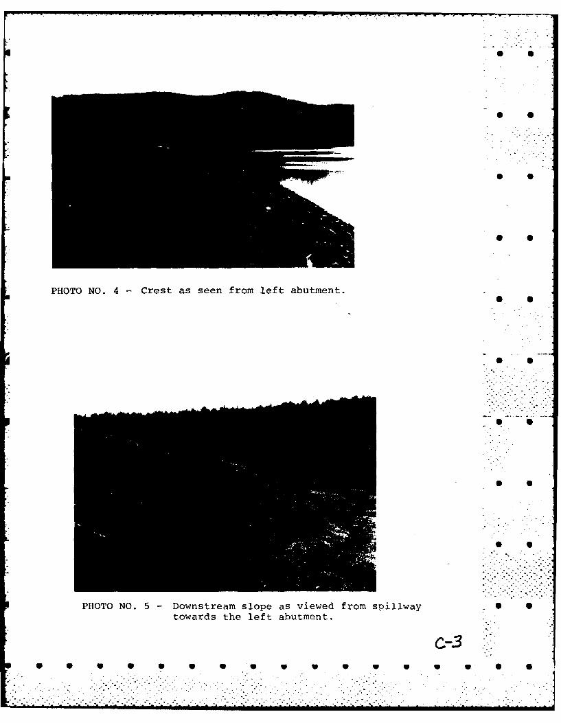
PHOTO NO. 4 Crest as seen from left abutment.
• S
PHOTO NO. 5 - Downstream slope as viewed from sillwaytowards the left abutment.
c-3- - - - - - -U S-0

PHOTO NO. 6 -Swampy area a downstream toe near right end of dam.
th acaorcs
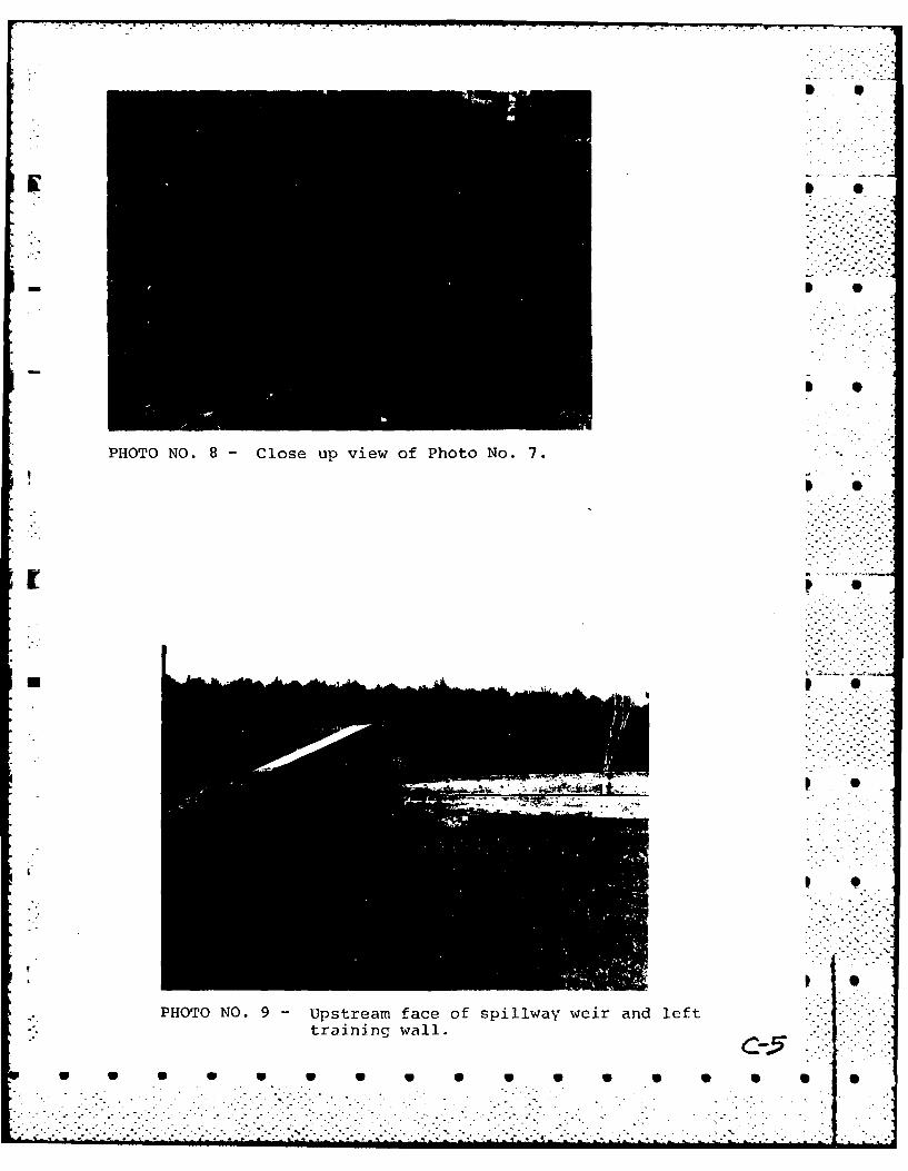
PHOTO NO. 8- Close up view of Photo No. 7.[ p.
p 0r p •
PHOTO NO. 9 - Upstream face of spiliway weir and lefttraining wall.
- - °.._ ..°.•-

I - -
* 0
* S
-- I ~e
* S
PHOTO NO. 10 - View of spiliway weir crest.
* S
S
S
S
S
0NO. 11 - Downstream side of spiliway structure.
Note bedrock outcrop at base of weir.
- V V V V V V V V V V 0
. . . .

0@
* 0
0 0
* S
PHOTO NO. 12 - Crack in right training wall of spiliway.L *
i S S
* S S
* S
h.
* 9
PHOTO NO. 13 - Downstream edge of spiliway weir. Noteclose-up of bedrock outcrop. .
S S S S S S S S S S S S S S S S S
- -.
------
0
PHOTO NO. 14 -Spillway discharge channel.
PHOTONO. 5 Aeatorjets
W0

- . . . . . .
PHOTO NO. 16 - Access road bridge over spiliway discharge S ..channel.,•
PHOT NO.17 Canne dowstrem.ofaccesorod brdge?> lc '2'.".tt -/-t .
..- . . . . . . . . . ..

SO
SO
* 0
* S
APPENDIX D
HYDROLOGIC AND HYDRAULIC COMPUTATIONS - -
* S.
~* 0
* 0
p
* S
* .**
* 0 6 S S S S S S _ S S *S _ U 0 S
- . . . I . . .

IMOtomI3NuU by MUN&____ O'sc No.
MOW-#____ NMX=TM~m4
(',"Ie~ v. '7 F
I-ev 7-p.
- ~ " 7.. . . . . .. .4

Mde toy Date N05ob
Cced dby Dateo -CPA NISvLM 1AMMEN a 1UN .... ,J "
5 '~~~ .~CfOv- .t .cS ./ . . --
~ Z.rd . -/
Z-Z 0-1 ZZ J S/,17 /I
'I40
C-7

Made by -1 oNo,mhiITB Date' 2
MOA MV-L ̂ MA kM M CW Chocked by jDate_. No
1/ of
____ rl.r ____Z4 177 5-A7-& j
'-
0 0 0 0 0 0 0

II-INTBmof by~ -Date /i, Job No~~
INatoNmam~mma ___________ IChoed by ~Date .. I ShOW No
ForF
- /z
-93 9,
I J!A.T.
717 kS7ftjt4t

A I
aTl
IN I0
r~ I I
* S
Sx I
I J6 '11.
N ~ NOLS hNMN ________ Cekby Date wtN
H r'-2sje) .B.
HCN't ASCM OI E AMKrI~'dc2m SY2 NO
Z-0
? rS

HIJTB O~ceb ae'{ .-mmRoum Chockedb V,4M' 4Dtq -. SheetNo.
Fbr~ ~~ AA '..T MW
p >N. 0a
,k 7=-
U. -7

Maeb Date Job No --
M~~Choke bySThMN Date Sheet No-
0 0
RA 1
- Jill
i t SXr I 1 1 1
I F0
i~~~ IS 4
I it 1,S1 1 1 1 1 1
. . .. . .. 2 2

100
0
e es ( U BOUNDARY
5E
I S
V ~~Vi 1 U U V !(U V U
UPE RESEVOI
DAM-.

r ** ** ~.*-* .~N
w
t/1 7'
al* So t
010
H
L\ UPPER RESERVOIR
v a'
UPPER RESERVOIR DAM
V V V V V U SPOUSSIL FLO DAMAGE AREA

- - - - r-~---r--r--r- V -
I.
* 0
*
* 0
S S
APPENDIX E -* S-i
INFORMATION AS CONTAINED INTHE NATIONAL INVENTORY OF DAMS
I * S
- p 5
* S
* S
99
S ~ S S S S S S S _ S S S S S S
. . - . . . 4. . . ..........-
......................................................
...................................... 44. 4 . . . 4 4 .........-
...........................................................................

P P
ta
NJ a9
IL
wlw
a. at
C2
z -j 9
0. - l W0D
LL. I -S
L Z j
4 w ~ , 'g .4
C. -gI dc -i
Acicc yr ''
L'.J
>
EI m -

'0
*0
FILMED
. . . . .~o . . . .. . . . . . .o
".l
.0
. o. , . -