Embed Size (px)
Citation preview
i
DEVELOPMENT OF A MECHANICAL FRUIT PICKER
MOHD IZULRADHI B MOHD NAPIS
A report submitted in partial fulfilment of the requirements for the award of the degree of
Diploma of Mechanical Engineering
Faculty of Mechanical Engineering UNIVERSITI MALAYSIA PAHANG
NOVEMBER 2008

ii
SUPERVISOR DECLARATION
“I declare that I have read this thesis and in my opinion, this thesis is enough to fulfill the
purpose for the award for the Diploma of Mechanical Engineering from the aspects of
scope and quality.”
Signature : ……………………………
Supervisor : MUHAMMAD AMMAR BIN NIK MU’TASIM
Date : 11 NOVEMBER 2008
iii
DECLARATION
I declare that this report entitled “Development of A Mechanical Fruit Picker” is the
results of my own work and research. The report has not been degree and is not
concurrently submitted in candidature of any other degree.
SIGNATURE: ……………………………..
NAME : MOHD IZULRADHI B MOHD NAPIS
ID NUMBER : MB06072
DATE : 11 NOVEMBER 2008

iv
ACKNOWLEDGEMENT
I would like to express my gratitude and appreciation to all those who gave me
support and help to complete this report. Special thanks to my supervisor Mr.
Muhammad Ammar Bin Nik Mu’tasim for his patience and constructive comments that
encourage me to finish this project. His time and effort have been a great contribution can
not be forgotten.
I would to thanks to all the staff in mechanical laboratory for their precious
comments, sharing idea and knowledge during this project being carried out. I also want
acknowledge the assistance of everybody especially students from Diploma of
Mechanical Engineering for spending their time in helping me sharing and solve the
problem during my hard time in fabricated the project and finishing the report for this
final year project. Finally, my profound thanks and gratitude for my family for their
continuous support and confidence in my efforts.
v
ABSTRACT
The idea to create and build a mechanical fruit picker is come from supervisor
that gives me this title and task for this project. To design and fabricated this fruit picker,
it must be compare with other product that maybe available in the market. First, get an
idea from internet, magazine, newspaper or other from available data. Form there the
information and idea to design and fabricated can be created. Whole project involves
various methods such as collecting data, concept design and fabrication process. The
whole project involved various method and process that usually use in engineering such
as concept design, analysis process and lastly fabrication process. This final year project
takes one semester to complete. This project is individual project and must be done
within this semester. In this project, students must able apply all knowledge during their
studies in this Diploma of Mechanical Engineering course. Overall from this project, time
management and discipline is important to make sure this project goes smooth as plan
and done at correct time.
vi
ABSTRAK
Idea untuk menghasilkan dan membina pemetik buah mekanikal ini datang
daripada penyelia yang memberi saya tajuk dan tugasan untuk projek ini. Untuk
merekabentuk dan pembinaan pemetk buah, ia hendaklah dibandingkan dengan produk
lain yang mungkin berada dalam pasaran. Langkah pertama, dapatkan maklumat daripada
internet, majalah, suratkhabar atau daripada sumber yang lain. Keseluruhan projek
melibatkan pelbagai cara atau kaedah seperti mengumpulan data, rekabentuk konsep dan
proses membina. Kaedah yang selalu yang digunakan dalam kejuruteraan seperti proses
analisis juga digunakan. Projek akhir tahun ini mengambil satu semester untuk disiapkan.
Projek ini adalah projek individu dan mesti disiapkan dalam semester ini. Didalam projek
ini, pelajar mesti berupaya menggunakan segala pengetahuan yang mereka perolehi
semasa pembelajaran mereka di dalam kursus Diploma Kejuruteraan Mekanikal ini.
Secara keseluruhan daripada projek ini, pengurusan masa dan disiplin adalah penting
dalam memastikan projek berjalan lancar dan siap tepat pada waktunya.
vii
TABLE OF CONTENT
CHAPTER TITLE PAGE
SUPERVISOR DECLARATION ii
STUDENT DECLARATION iii
ACKNOWLEDGEMENT iv
ABSTRACT v
ABSTRAK vi
TABLE OF CONTENT vii
LIST OF TABLES xi
LIST OF FIGURES xii
LIST OF APPENDICES xiv
CHAPTER 1 INTRODUCTION
1.1 Project Synopsis 1
1.2 Problem Statement 2
1.3 Project Objective 2
1.4 Project Scopes 2
1.5 Planning Project 4
CHAPTER 2 LITERATURE REVIEW
2.1 Introduction 5
2.2 Comparison of Current Product 5
2.2.1 Twister Fruit Picker 6
2.2.2 Pole Fruit Picker 7
2.2.3 Wolf Garten Fruit Picker 8
2.3 Fabrication process 9
2.3.1 Welding 9
2.3.1.1 Introduction 9
2.3.1.2 Arc Welding 10
2.3.1.3 Metal Inert Gas 11
viii
2.3.2 Drilling 12
2.3.2.1 Introduction 12
2.3.3 Angle Grinder 13
2.3.3.1 Introduction 13
2.3.4 EDM wire cut 14
2.3.4.1 Introduction 14
2.3.5 Rivet 15
2.3.5.1 Introduction 15
CHAPTER 3 METHODOLOGY
3.1 Introduction 16
3.2 Project Flow Diagram 17
3.3 Design 19
3.3.1 Introduction 19
3.3.2 Drawing 19
3.3.3 Sketching Drawing Selection 19
3.3.3.1 Concept A 20
3.3.3.2 Concept B 21
3.3.3.3 Concept C 22
3.3.3.4 Concept D 23
3.3.4 Result 24
3.3.5 Concept Generation & Evalution 25
3.3.6 Product Design Specification 26
1. Main Blade 26
2. Blade Handle 26
3. Cutter 27
4. Pulley 27
5. Bucket 28
6. Handle 28
7. Puller 29
ix
3.3.7 Engineering Drawing of Fruit Picker 30
1. Main Blade 31
2. Cutter 31
3. Blade Handle 32
4. Pulley 32
5. Bucket 33
6. Handle 33
7. Puller 34
8. Full Assembly 34
3.3.8 Processes Involves 35
1. Getting Material 35
2. Measuring & Marking 36
3. Cutting process 37
4. Joining Process 37
3.3.9 Summary 38
CHAPTER 4 RESULT AND DISCUSSION
4.1 Introduction 39
4.2 Results 39
4.2.1 Introduction 40
4.2.2 Analysis 43
4.3 Discussion 44
4.3.1 Type of Defect 44
4.3.2 Problem In Progress 46
CHAPTER 5 CONCLUSION AND RECOMMENDATIONS
5.1 Introduction 47
5.2 Conclusion 47
5.3 Recommendation 48

x
REFERENCES 49
APPENDIX A-C 50

xi
LIST OF TABLES
TABLE NO. TITLE PAGE
3.6 Pugh Concept 26
xii
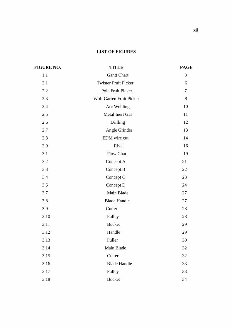
LIST OF FIGURES
FIGURE NO. TITLE PAGE
1.1 Gantt Chart 3
2.1 Twister Fruit Picker 6
2.2 Pole Fruit Picker 7
2.3 Wolf Garten Fruit Picker 8
2.4 Arc Welding 10
2.5 Metal Inert Gas 11
2.6 Drilling 12
2.7 Angle Grinder 13
2.8 EDM wire cut 14
2.9 Rivet 16
3.1 Flow Chart 19
3.2 Concept A 21
3.3 Concept B 22
3.4 Concept C 23
3.5 Concept D 24
3.7 Main Blade 27
3.8 Blade Handle 27
3.9 Cutter 28
3.10 Pulley 28
3.11 Bucket 29
3.12 Handle 29
3.13 Puller 30
3.14 Main Blade 32
3.15 Cutter 32
3.16 Blade Handle 33
3.17 Pulley 33
3.18 Bucket 34
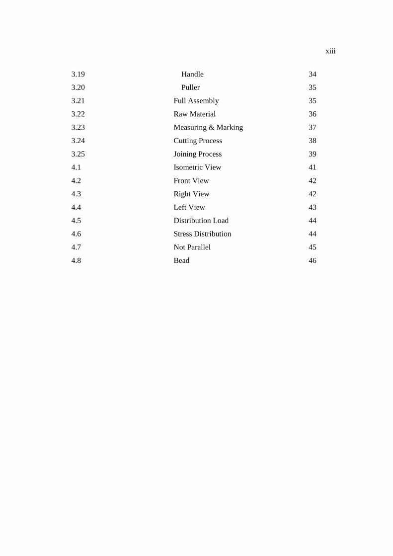
xiii
3.19 Handle 34
3.20 Puller 35
3.21 Full Assembly 35
3.22 Raw Material 36
3.23 Measuring & Marking 37
3.24 Cutting Process 38
3.25 Joining Process 39
4.1 Isometric View 41
4.2 Front View 42
4.3 Right View 42
4.4 Left View 43
4.5 Distribution Load 44
4.6 Stress Distribution 44
4.7 Not Parallel 45
4.8 Bead 46

xiv
LIST OF APPENDICES
APPENDIX TITLE
A Detail Drawing
B Completed Product
C Machining Tool
CHAPTER 1
INTRODUCTION
1.1 PROJECT SYNOPSIS
Many trees with good grade fruits are hard to get because trees with this portions
are high and rarely be able to climb, unless if you’re willing to hurt yourself by falling
from a tree branch. The purpose of the project is to design and fabricate mechanical part
of fruit picker to get a grade A fruit and for general purpose to fulfill the requirement for
home and market. This fruit picker would be different from another fruit picker that have
in market. In this study, the new concept of fruit picker will be designed and fabricate
and ensure these fruit picker comply with customer needs. As the Diploma final year
project allocates the duration of 1 semester, this project is need skills to handle several
machines such as EDM wire cut machine, bending machine, MIG, SMAW, drilling,
grinder and others.
Title of this project is “Development of a mechanical Fruit Picker”. This project
involves the fabrication of fruit picker with a specification regarding strength, material
and cost. With the newly designed and fabricated this fruit picker, tests are required to
be conducted and to verify the design. Overall, this project will acquire the skill of
design and fabrication.
2
1.2 PROBLEM STATEMENT
1.2.1 Difficult to pick fruit at the limited area
1.2.2 The fruit picker in market just have capability to pick certain fruits.
1.2.3 Cannot maintain the quality of the fruits.
1.3 PROJECT OBJECTIVES
The main objective of this project is to design the new mechanical fruit picker and
fabricate the new mechanical fruit picker based on mechanical design method. Another
objective is to develop a fruit picker able to achieve the product on customer need.
1.4 PROJECT SCOPES
Scopes of this project are:
1.4.1 To development of concept selection.
1.4.2 To determine about product specification.
1.4.3 To design using CAD software.
1.4.4 To produce a prototype home base method.
1.4.5 To produce or develop using process such as grinding, milling, lathe, bending and
welding.
3
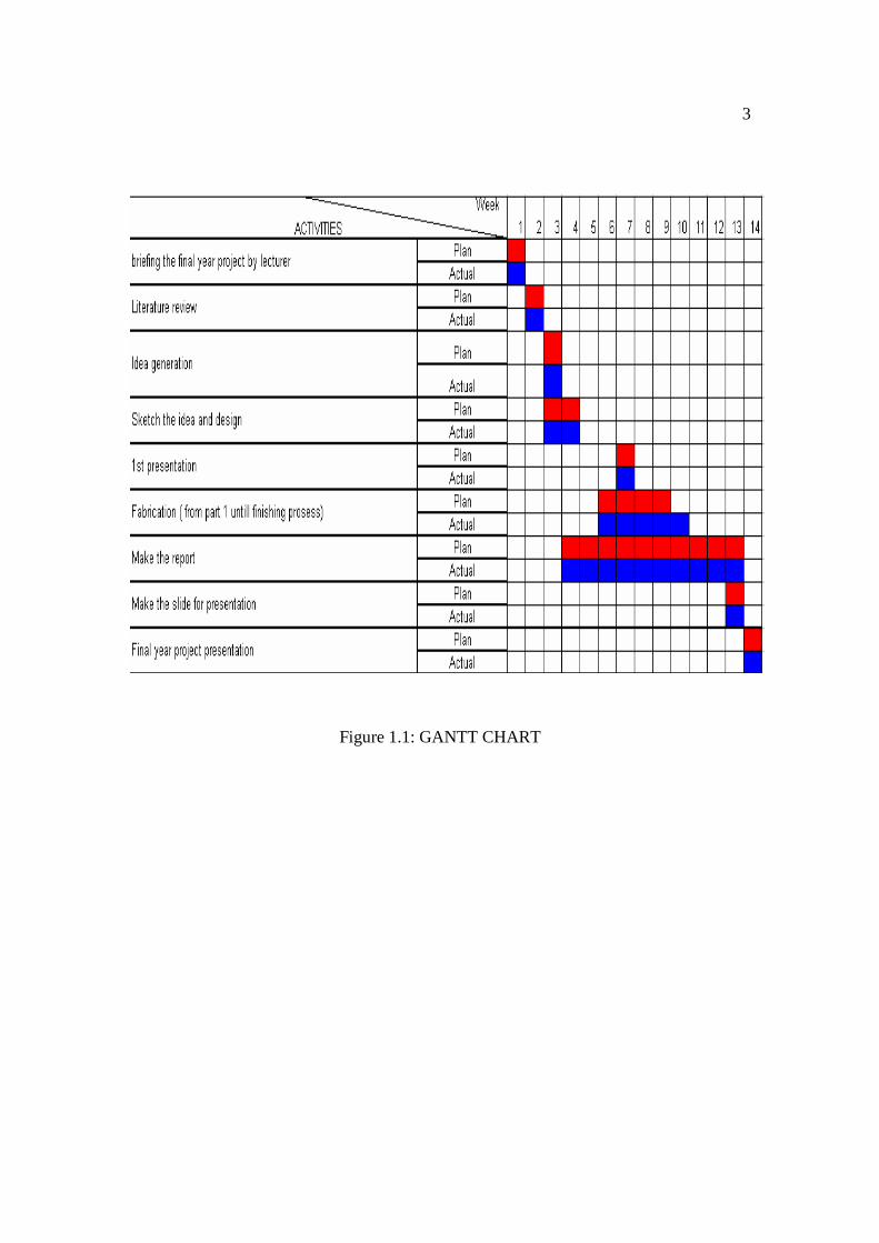
Figure 1.1: GANTT CHART
4
1.5 PLANNING PROJECT
According to the Gantt chart, project started by briefing by lecturer about final
year project and include chooses the title of the project. After got the title, project
briefing started followed by collecting literature review. These include gathering raw data
via internet, book and other source. The literature review process taken 2 weeks.
After that, this project was continued with idea generation on week 3 then sketch
and design process on week 3 and 4.This is started with sketching four types of fruit
picker and all design identify the strength and weakness. The best concept that was be
chosen and re-draw again using solidwork software with actual dimension.
After identifies finalized concept, finding a raw material to fabricate was started.
Materials to be used must be suitable and easy to get. The criteria when selected the
material is includes strength, durability and other. This is important for fabrication
process. To easy in selecting raw material I use “Bill of material” concept, where we
identify every part with raw material.
The fabrication was started after finish finding a raw material and cutting the
material. According the Gantt chart, the fabrication process is from week 6 until week 12.
After finish the fabrication, we get the result and also do the discussion or conclusion.
Next task is the final presentation preparation and report writing. The report
writing occurs during the finalized concept and fabrication. (from week 5 until week 13).
Then, for week 14 I must present my project and submit report writing.
CHAPTER 2
LITERATURE REVIEW
2.1 INTRODUCTION
This chapter is present about literature review of fabrication process such as
punching, bending, welding, drilling and other else. Before fabrication process, the
material selection is crucial. The selection of joining process is also important to get
a product with better strength and durability. Literature review about machine is also
important. It is include guide to setup the machine, type of machine suitable for
fabrication process and advantages using this machine.
2.2 COMPARISSON OF CURRENT PRODUCT
In this project, 3 current design of cabinet from market are selected to make the
comparison.
6
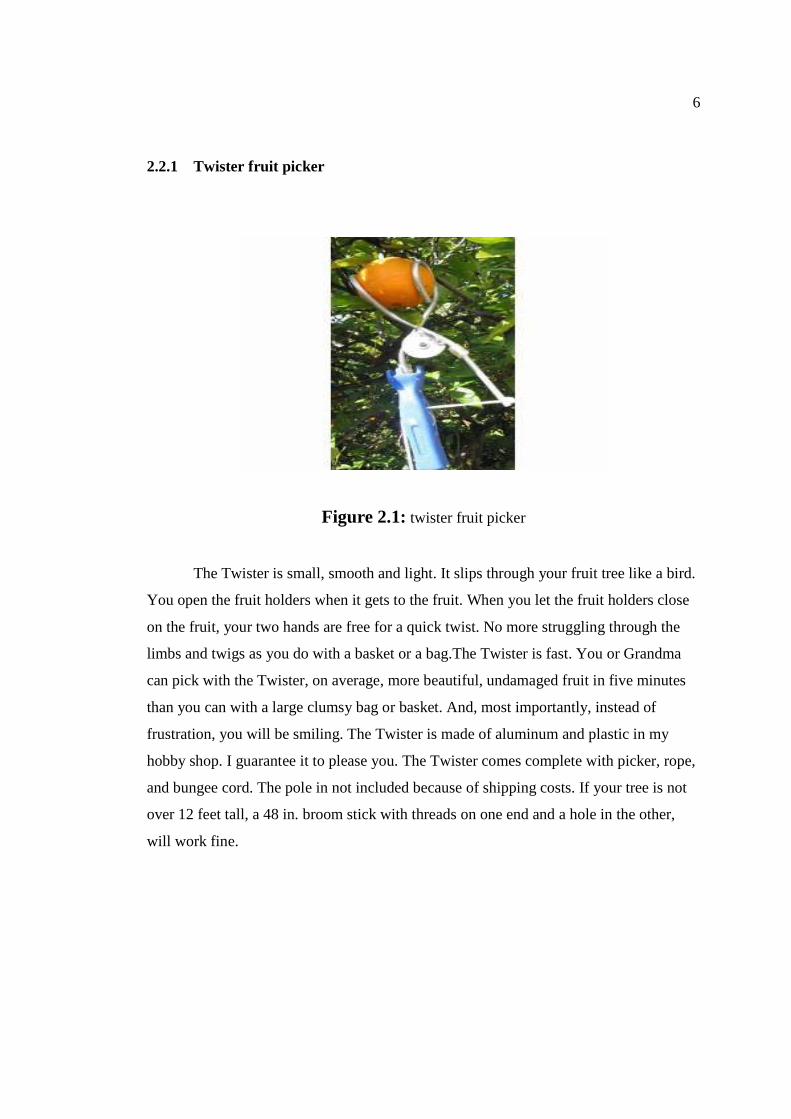
2.2.1 Twister fruit picker
Figure 2.1: twister fruit picker
The Twister is small, smooth and light. It slips through your fruit tree like a bird.
You open the fruit holders when it gets to the fruit. When you let the fruit holders close
on the fruit, your two hands are free for a quick twist. No more struggling through the
limbs and twigs as you do with a basket or a bag.The Twister is fast. You or Grandma
can pick with the Twister, on average, more beautiful, undamaged fruit in five minutes
than you can with a large clumsy bag or basket. And, most importantly, instead of
frustration, you will be smiling. The Twister is made of aluminum and plastic in my
hobby shop. I guarantee it to please you. The Twister comes complete with picker, rope,
and bungee cord. The pole in not included because of shipping costs. If your tree is not
over 12 feet tall, a 48 in. broom stick with threads on one end and a hole in the other,
will work fine.
7
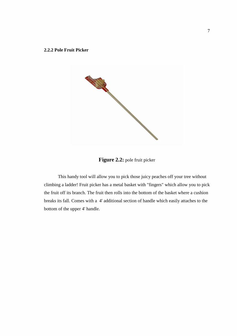
2.2.2 Pole Fruit Picker
Figure 2.2: pole fruit picker
This handy tool will allow you to pick those juicy peaches off your tree without
climbing a ladder! Fruit picker has a metal basket with "fingers" which allow you to pick
the fruit off its branch. The fruit then rolls into the bottom of the basket where a cushion
breaks its fall. Comes with a 4' additional section of handle which easily attaches to the
bottom of the upper 4' handle.
8
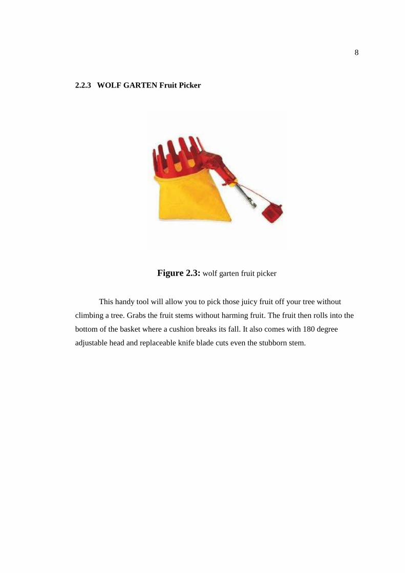
2.2.3 WOLF GARTEN Fruit Picker
Figure 2.3: wolf garten fruit picker
This handy tool will allow you to pick those juicy fruit off your tree without
climbing a tree. Grabs the fruit stems without harming fruit. The fruit then rolls into the
bottom of the basket where a cushion breaks its fall. It also comes with 180 degree
adjustable head and replaceable knife blade cuts even the stubborn stem.
9
2.3 FABRICATION PROCESS
2.3.1 Welding
2.3.1.1 Introduction
Welding is a fabrication process that joins materials, usually metals or
thermoplastics, by causing coalescence. This is often done by melting the workpieces
and adding a filler material to form a pool of molten material (the weld puddle) that
cools to become a strong joint, with pressure sometimes used in conjunction with heat,
or by itself, to produce the weld. This is in contrast with soldering and brazing, which
involve melting a lower-melting-point material between the workpieces to form a bond
between them, without melting the workpieces
Many different energy sources can be used for welding, including a gas flame,
an electric arc, a laser, an electron beam, friction, and ultrasound. While often an
industrial process, welding can be done in many different environments, including open
air, underwater and in outer space. Regardless of location, however, welding remains
dangerous, and precautions must be taken to avoid burns, electric shock, eye damage,
poisonous fumes, and overexposure to ultraviolet light.
10
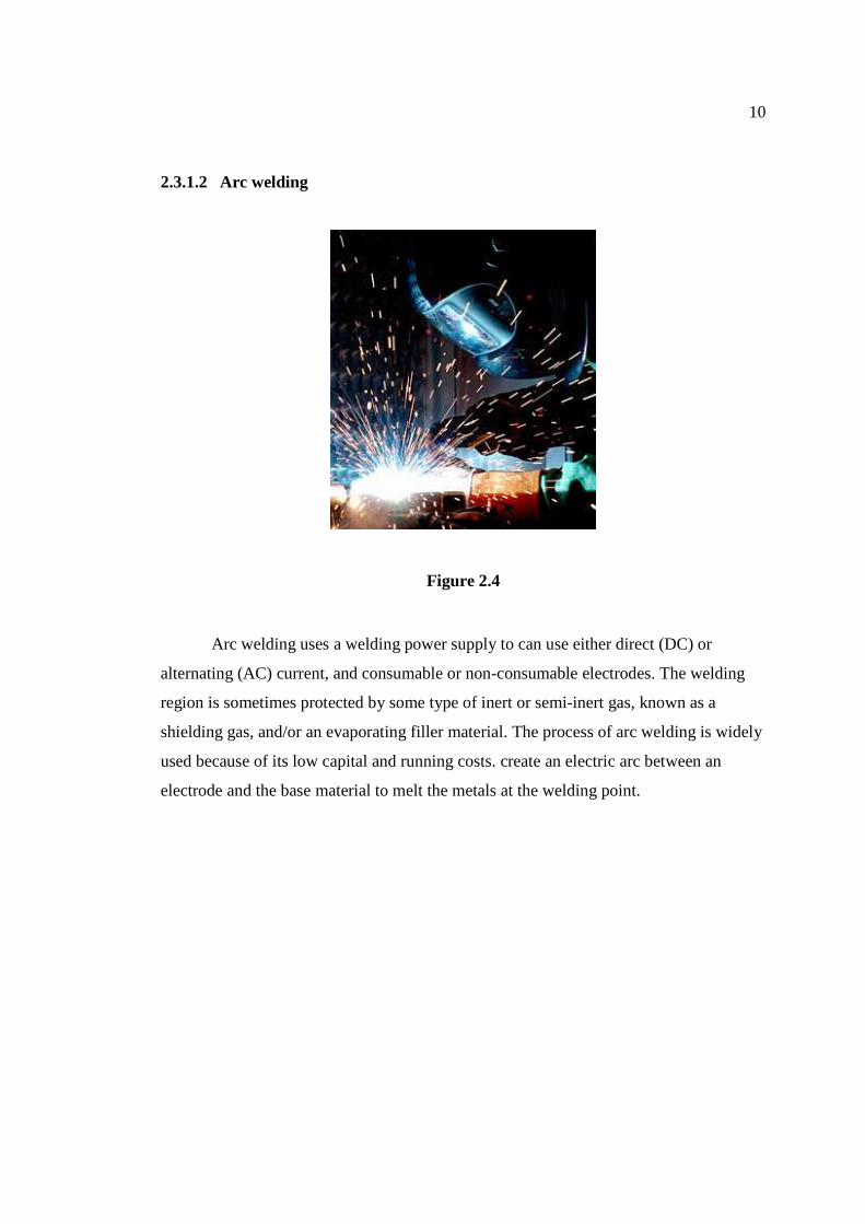
2.3.1.2 Arc welding
Figure 2.4
Arc welding uses a welding power supply to can use either direct (DC) or
alternating (AC) current, and consumable or non-consumable electrodes. The welding
region is sometimes protected by some type of inert or semi-inert gas, known as a
shielding gas, and/or an evaporating filler material. The process of arc welding is widely
used because of its low capital and running costs. create an electric arc between an
electrode and the base material to melt the metals at the welding point.
11
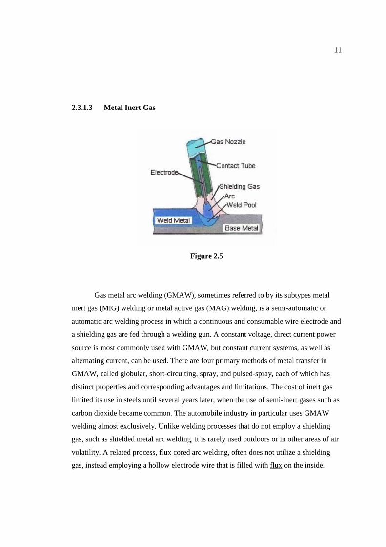
2.3.1.3 Metal Inert Gas
Figure 2.5
Gas metal arc welding (GMAW), sometimes referred to by its subtypes metal
inert gas (MIG) welding or metal active gas (MAG) welding, is a semi-automatic or
automatic arc welding process in which a continuous and consumable wire electrode and
a shielding gas are fed through a welding gun. A constant voltage, direct current power
source is most commonly used with GMAW, but constant current systems, as well as
alternating current, can be used. There are four primary methods of metal transfer in
GMAW, called globular, short-circuiting, spray, and pulsed-spray, each of which has
distinct properties and corresponding advantages and limitations. The cost of inert gas
limited its use in steels until several years later, when the use of semi-inert gases such as
carbon dioxide became common. The automobile industry in particular uses GMAW
welding almost exclusively. Unlike welding processes that do not employ a shielding
gas, such as shielded metal arc welding, it is rarely used outdoors or in other areas of air
volatility. A related process, flux cored arc welding, often does not utilize a shielding
gas, instead employing a hollow electrode wire that is filled with flux on the inside.
12
2.3.2 Drilling
2.3.2.1 Introduction
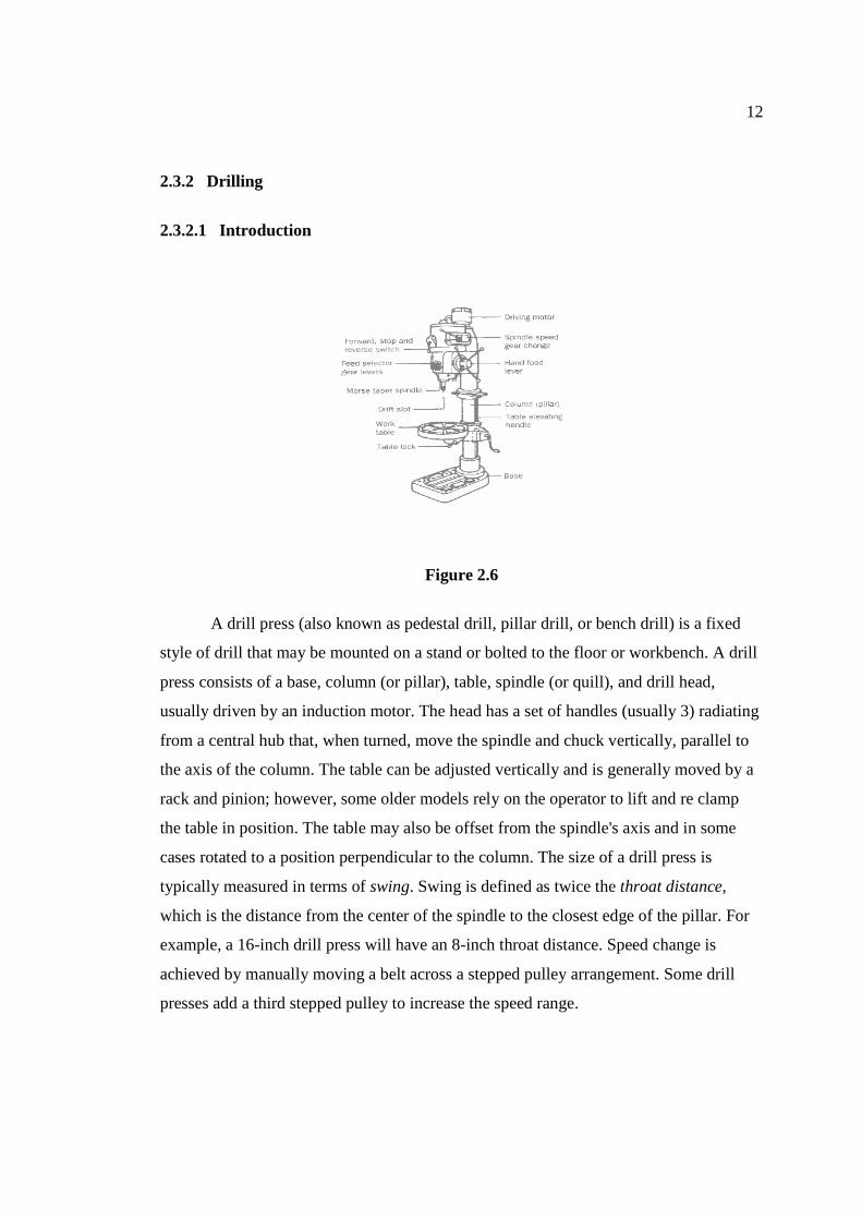
Figure 2.6
A drill press (also known as pedestal drill, pillar drill, or bench drill) is a fixed
style of drill that may be mounted on a stand or bolted to the floor or workbench. A drill
press consists of a base, column (or pillar), table, spindle (or quill), and drill head,
usually driven by an induction motor. The head has a set of handles (usually 3) radiating
from a central hub that, when turned, move the spindle and chuck vertically, parallel to
the axis of the column. The table can be adjusted vertically and is generally moved by a
rack and pinion; however, some older models rely on the operator to lift and re clamp
the table in position. The table may also be offset from the spindle's axis and in some
cases rotated to a position perpendicular to the column. The size of a drill press is
typically measured in terms of swing. Swing is defined as twice the throat distance,
which is the distance from the center of the spindle to the closest edge of the pillar. For
example, a 16-inch drill press will have an 8-inch throat distance. Speed change is
achieved by manually moving a belt across a stepped pulley arrangement. Some drill
presses add a third stepped pulley to increase the speed range.
13
2.3.3 Angle grinders
2.3.3.1 Introduction
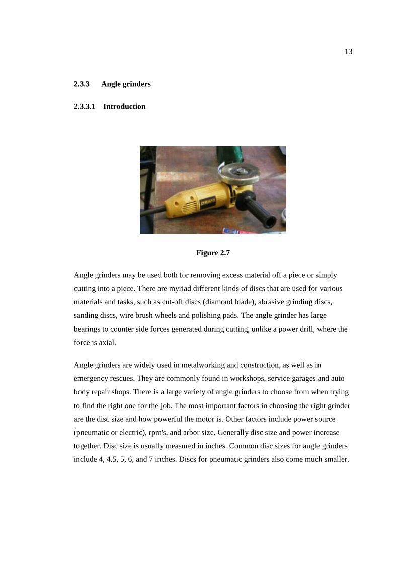
Figure 2.7
Angle grinders may be used both for removing excess material off a piece or simply
cutting into a piece. There are myriad different kinds of discs that are used for various
materials and tasks, such as cut-off discs (diamond blade), abrasive grinding discs,
sanding discs, wire brush wheels and polishing pads. The angle grinder has large
bearings to counter side forces generated during cutting, unlike a power drill, where the
force is axial.
Angle grinders are widely used in metalworking and construction, as well as in
emergency rescues. They are commonly found in workshops, service garages and auto
body repair shops. There is a large variety of angle grinders to choose from when trying
to find the right one for the job. The most important factors in choosing the right grinder
are the disc size and how powerful the motor is. Other factors include power source
(pneumatic or electric), rpm's, and arbor size. Generally disc size and power increase
together. Disc size is usually measured in inches. Common disc sizes for angle grinders
include 4, 4.5, 5, 6, and 7 inches. Discs for pneumatic grinders also come much smaller.
14
2.3.4 EDM wire cut
2.3.4.1 Introduction
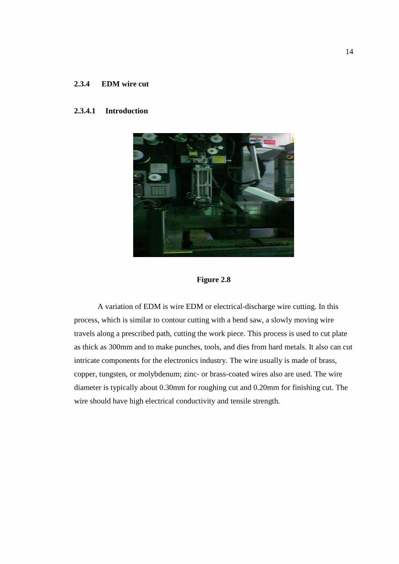
Figure 2.8
A variation of EDM is wire EDM or electrical-discharge wire cutting. In this
process, which is similar to contour cutting with a bend saw, a slowly moving wire
travels along a prescribed path, cutting the work piece. This process is used to cut plate
as thick as 300mm and to make punches, tools, and dies from hard metals. It also can cut
intricate components for the electronics industry. The wire usually is made of brass,
copper, tungsten, or molybdenum; zinc- or brass-coated wires also are used. The wire
diameter is typically about 0.30mm for roughing cut and 0.20mm for finishing cut. The
wire should have high electrical conductivity and tensile strength.
15
2.3.5 Rivet
2.3.5.1 Introduction
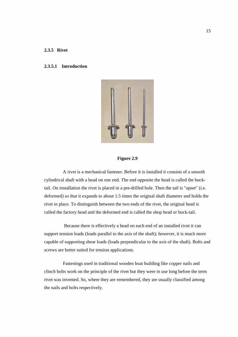
Figure 2.9
A rivet is a mechanical fastener. Before it is installed it consists of a smooth
cylindrical shaft with a head on one end. The end opposite the head is called the buck-
tail. On installation the rivet is placed in a pre-drilled hole. Then the tail is "upset" (i.e.
deformed) so that it expands to about 1.5 times the original shaft diameter and holds the
rivet in place. To distinguish between the two ends of the rivet, the original head is
called the factory head and the deformed end is called the shop head or buck-tail.
Because there is effectively a head on each end of an installed rivet it can
support tension loads (loads parallel to the axis of the shaft); however, it is much more
capable of supporting shear loads (loads perpendicular to the axis of the shaft). Bolts and
screws are better suited for tension applications.
Fastenings used in traditional wooden boat building like copper nails and
clinch bolts work on the principle of the rivet but they were in use long before the term
rivet was invented. So, where they are remembered, they are usually classified among
the nails and bolts respectively.
CHAPTER 3
3.1 INTRODUCTION In this chapter will discuss about steps that we need to follow in completing final
year project. .Beside that, this chapter also represent about methods and machining
process that will be used to make the cabinet.
17
3.2 Project flow diagram
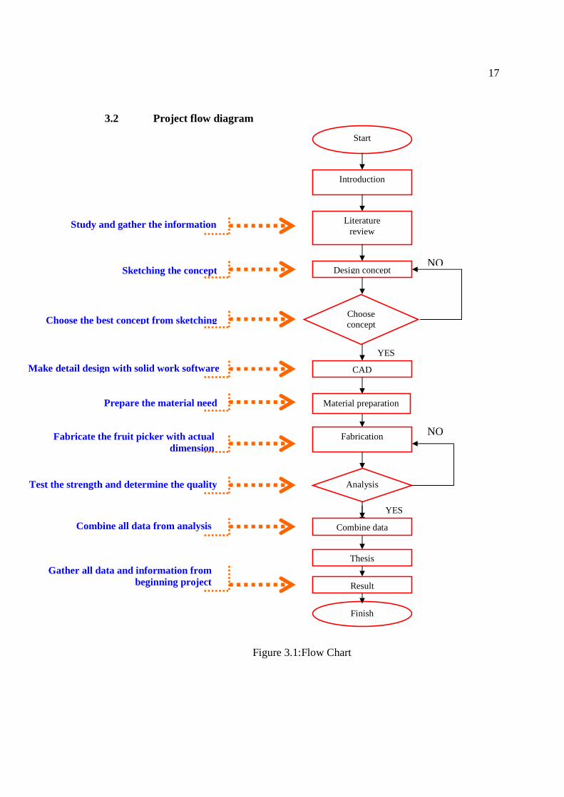
Figure 3.1:Flow Chart
Fabrication NO
Start
Introduction
Literature review
Study and gather the information
Design concept NO
YES
CAD
Material preparation
Sketching the concept
Finish
Thesis
Result
Analysis
Gather all data and information from beginning project
Combine all data from analysis
Test the strength and determine the quality
YES
Combine data
Choose concept Choose the best concept from sketching
Make detail design with solid work software
Prepare the material need
Fabricate the fruit picker with actual dimension
18
From the flow chart above, this project was start with define the product title that
the product is mechanical fruit picker. Then, collect the raw data from via internet, book
and other source. After get the data, make a study and make a lot of research about fruit
picker. This includes a study about concept to pick the fruit, process to fabricate, and
material to use
Then the information gathered and the project is continued with the design
process. It is important to make a best design for the project. After several design
sketched, the best concept have been chosen for finalized concept design. The selected
design is then transferred to detail drawing using Solid work software.
After all the part drawing finished, prepare the material need for the fabrication.
Then, the fabrication process will start with actual dimension. The manufacturing
processes include in this process are welding, cutting, drilling, bending and others.
Next step is the analysis stage. The evaluation considering the strength,
durability, safety, quality and combine all data from the analysis.
Then after all processes that mentioned above done, gather all data and
information from beginning project.
19
3.3 DESIGN 3.3.1 Introduction
The design and fabrication of mechanical fruit picker must be compliance to
several aspects. The design consideration must be done carefully in order that design can
be fabricated and all parts are functioning. The aspects must be considered in designing
the fruit picker such as the bucket strength. The bucket needs to have certain strength to
ensure that it can load the fruit. The second thing is material. Usually use the available
material is one of aspects that have been considered. The materials used depend on their
purpose and their function. Then another factor must be consider is cost. The cost of
whole system must be not exceeding from budget and reasonable. It should reduce the
cost to the minimum. Besides that the ergonomic factors also need to be considered. The
fruit picker must be user friendly and give a pride to people to have it.
3.3.2 Drawing
The drawings are divided into two categories, which are:
i. Sketching – all the ideas for the recycle bin fabrication are sketched on the
paper first to ensure that idea selection can be produce.
ii. Solid Works software – the selected design or concept sketched is
transfer to solid modeling and engineering drawing using Solid Works
software.
3.3.3 Sketching drawing selection
From the existing ideas, several sketching had been chosen to be considered to find
the best design as the final ideas, which are:
20
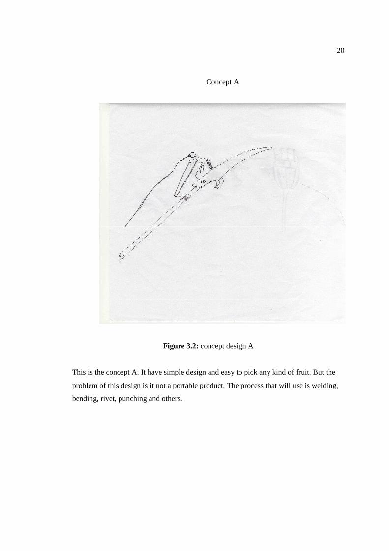
Concept A
Figure 3.2: concept design A
This is the concept A. It have simple design and easy to pick any kind of fruit. But the
problem of this design is it not a portable product. The process that will use is welding,
bending, rivet, punching and others.
21
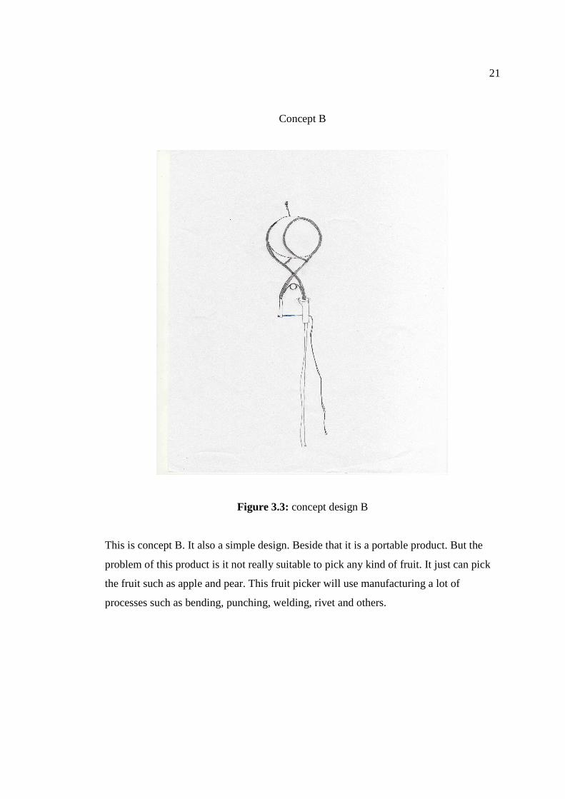
Concept B
Figure 3.3: concept design B
This is concept B. It also a simple design. Beside that it is a portable product. But the
problem of this product is it not really suitable to pick any kind of fruit. It just can pick
the fruit such as apple and pear. This fruit picker will use manufacturing a lot of
processes such as bending, punching, welding, rivet and others.
22
Concept C
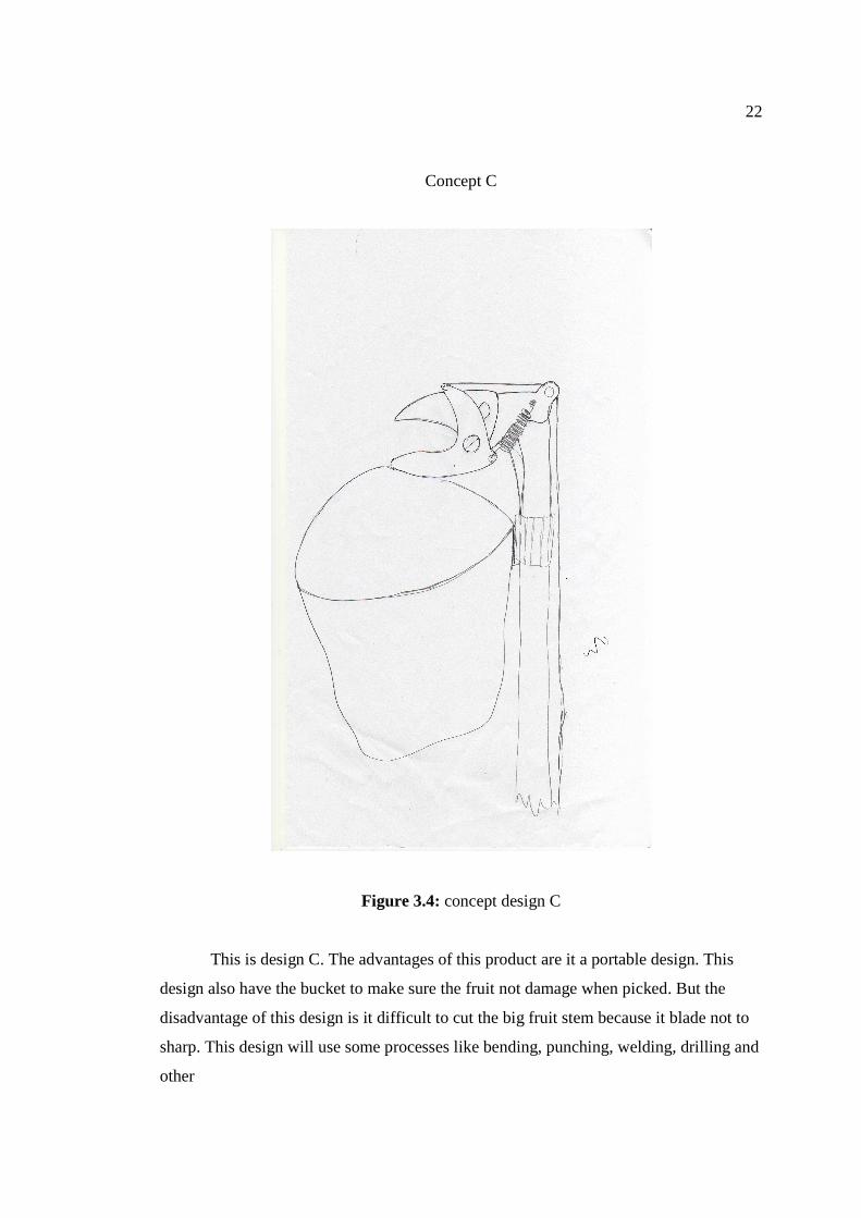
Figure 3.4: concept design C
This is design C. The advantages of this product are it a portable design. This
design also have the bucket to make sure the fruit not damage when picked. But the
disadvantage of this design is it difficult to cut the big fruit stem because it blade not to
sharp. This design will use some processes like bending, punching, welding, drilling and
other
23
Concept D
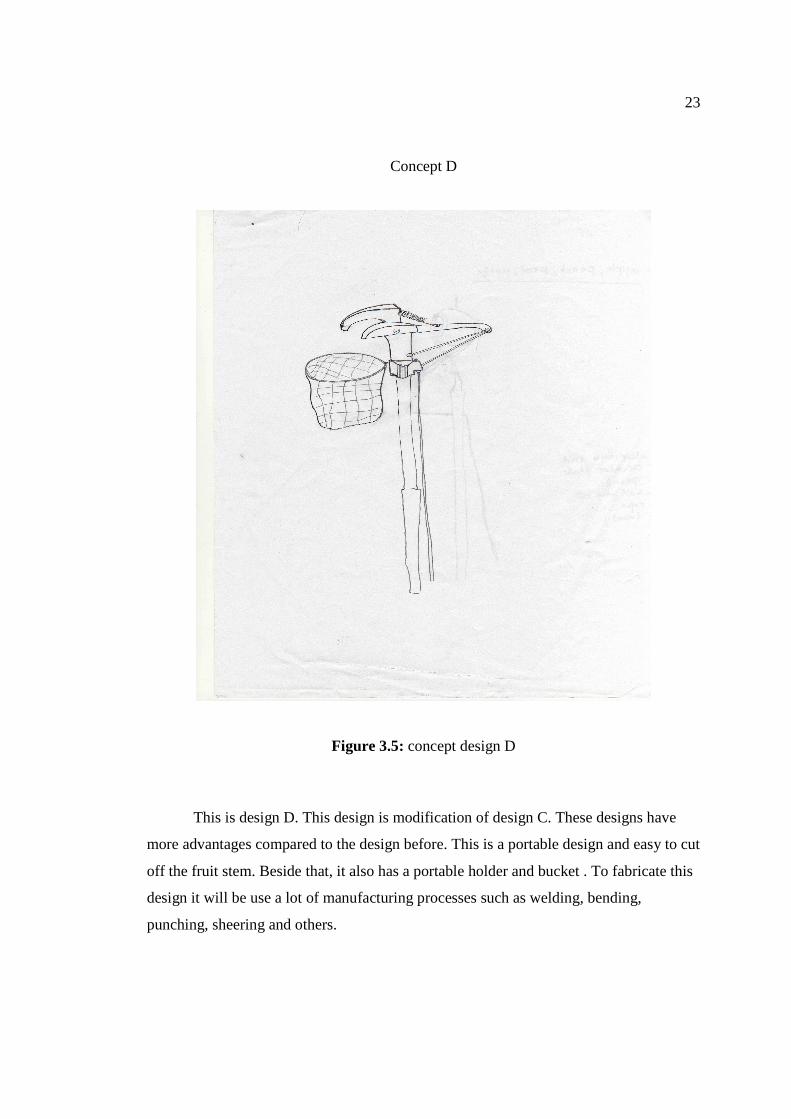
Figure 3.5: concept design D
This is design D. This design is modification of design C. These designs have
more advantages compared to the design before. This is a portable design and easy to cut
off the fruit stem. Beside that, it also has a portable holder and bucket . To fabricate this
design it will be use a lot of manufacturing processes such as welding, bending,
punching, sheering and others.
24
3.3.4 Result
From the design sketch, one of the best designs will be selected. It can be evaluated
through several section criteria for it function.
The first criteria are customer needs. It is important to know what customers want
about this product. It is easier when product enter the market. Next criteria is easy to use.
Beside that, easy to manufacture also be an important criteria to select the design. It
is include the process to fabricate the concept, the material that will use, the capability of
the machine at FKM lab to fabricate the design and others
After that, cost of manufacture also has been considered as selection material. When
the concept enter a market, cost is very important to attract customer to but it. Lastly the
selection criteria the strength or the product. The strength of the product can be know
through the analysis.
According to the criteria above, the concept D have been selected as the best
design. It is because the concept D can fulfill the criteria and have some advantages
compared to design A, design B, and design C.