Embed Size (px)
Citation preview

Model: iCOMM3Publication: AMEN00125 2017-12-04
i-COMM™ 3Touch Screen Control
Installation/Service ManualThis manual covers units shipped: To date
Language: English
NOTICE TO USER � � � � � � � � � � � � � � � � � � � � � � � 2
SAFETY � � � � � � � � � � � � � � � � � � � � � � � � � � � � � � � 3
FEATURES � � � � � � � � � � � � � � � � � � � � � � � � � � � � 6
INSTALLATIONi-COMM™ 3 Layout � � � � � � � � � � � � � � � � � � � � � � 7Touch Screen Controls � � � � � � � � � � � � � � � � � � � � 8Set-Up – Input / Output Values� � � � � � � � � � � � � � 9Set-Up – Folders � � � � � � � � � � � � � � � � � � � � � � � 11Set-Up – Logic Chart � � � � � � � � � � � � � � � � � � � � 13
INSTALLATION (OPTIONAL)Set-Up – Wireless Interlock � � � � � � � � � � � � � � � 14Building Management System Interface� � � � � � 15
OPERATIONOpening, Closing, and Stopping� � � � � � � � � � � � 16Security� � � � � � � � � � � � � � � � � � � � � � � � � � � � � � � 16Common Locations� � � � � � � � � � � � � � � � � � � � � � 17Common Tasks� � � � � � � � � � � � � � � � � � � � � � � � � 17
TROUBLESHOOTINGCommon Startup Issues� � � � � � � � � � � � � � � � � � 18LEDs Functions or Input / Output Values � � � � � 19Inverter (VFD) Programming � � � � � � � � � � � � � � 20
PARTS � � � � � � � � � � � � � � � � � � � � � � � � � � � � � � � 23
WARRANTY� � � � � � � � � � � � � � � � � � � � � � � � � � � 24

i-COMM™ 3 Touch Screen Control Installation/Service Manual Rite-Hite®
2 Publication: AMEN00125 2017-12-04
NOTICE TO USER
The i-COMM™ 3 Touch Screen Controls are used to manage and adjust settings for Rite-Hite doors�The English version of this manual shall prevail over any error in, or conflicting interpretation of, any translations.Rite-Hite reserves the right to substitute and/or modify parts and drawings� If separate prints are included with the unit they supersede those contained in the manual�A Planned Maintenance Program (P�M�P�), customized to your specific operation is available and recommended. For a P�M�P�, contact your local Rite-Hite representative or Rite-Hite technical support at (U�S�) 1-563-589-2722, (S�A�) +55 21 99616 4421, (E�U�) +49-5693 98700�
Portions of this software may utilize copyrighted and/or Open Source materials which are acknowledged on the following website along with source code where required�
https://bitbucket.org/rhdengineering/acknowledgements
The Rite-Hite products in this manual are covered by one or more of the following U�S� patents: 5887385, 6145571, 6148897, 6192960, 6212826, 6321822, 6325195, 6330763, 6360487, 6481487, 6560927, 6598648, 6615898, 6688374, 6698490, 6837296, 6901703, 6942000, 6964289, 7034682, 7045764, 7111661, 7114753, 7151450, 7578097, 7699089, 7748431, 7757437, 8037921, 8167020, 8113265, 8863815, 8857498, 9222304 and may be covered by additional pending U�S� and foreign patent applications�
Rite-Hite®, FasTrax®, FasTrax® FR, FasTrax® FR LD, FasTrax® CL, FasTrax® XL, FasTrax® LD, LiteSpeed™, SplitSecond™, TrakLine™, Bug-Shield™, Iso-Tek®, Barrier® Glider, Dok-Dor™ are trademarks of Rite-Hite®�
FCC ComplianceNOTE: This device complies with Part 18 of the FCC Rules� These limits are designed to provide reasonable protection against harmful interference when the equipment is operated in a commercial environment� This equipment generates, uses, and can radiate radio frequency energy and, if not installed and used in accordance with the instruction manual, may cause harmful interference to radio communications� Operation of this equipment in a residential area is likely to cause harmful interference in which case the user will be required to correct the interference at his own expense�
NOTE: Changes or modifications not expressly approved by the party responsible for compliance could void the user's authority to operate the equipment�
Specifications• Input Voltage 24 VDC +/- 10% • Terminals accept wire sizes 12 – 22 AWG�• 8 Digital Inputs (24VDC; 10 mA)�• 4 Relay Outputs (24VAC/DC; 1 AMP)�• 6 DC Outputs� (24VDC; 0�3 AMP MAX)�

Rite‑Hite® Installation/Service Manual i‑COMM™ 3 Touch Screen Control
Publication: AMEN00125 2017-12-04 3
SAFETY
Safety Identifications
DANGERIndicates a hazardous situation which, if not avoided, will result in death or serious injury.
Indique une situation dangereuse qui, si elle n’est pas évitée, peut entraîner la mort ou de graves blessures.
WARNING / AVERTISSEMENTIndicates a hazardous situation which, if not avoided, could result in death or serious injury.
Indique une situation dangereuse qui, si elle n’est pas évitée, peut entraîner la mort ou des blessures graves.
CAUTION / ATTENTIONIndicates a hazardous situation which, if not avoided, could result in minor or moderate injury.
Indique une situation dangereuse qui, si elle n’est pas évitée, peut entraîner des blessures légères à modérées.
NOTICEIndicates a situation which can cause damage to the equipment, personal property and/or the environment, or cause the equipment to operate improperly�
NOTE:� A note is used to inform you of important installation, operation, or maintenance information�
Lockout ProcedureBarricade work area and post safety warnings�Power supply/control must:• Be disconnected or locked in OFF
position using a lockout device approved by local codes�
• Have signage that: − Clearly states repairs are being made� − Identifies person responsible for lockout condition. NOTE:� Only this person should be able to remove warnings and lockout device�
− Withstands environmental conditions (weather, wet, and damp, etc�) and remains readable�
1706
19

i-COMM™ 3 Touch Screen Control Installation/Service Manual Rite-Hite®
4 Publication: AMEN00125 2017-12-04
SAFETY
General
DANGERA qualified electrician should install the wiring in accordance with local electrical codes.Use lockout procedures to prevent death or severe personal injury.
L'installation du câblage doit être effectuée par un électricien qualifié, conformément aux normes électriques nationales et locales.Afin de réduire le risque de blessures graves ou mortelles, utilisez des procédures de verrouillage.
DANGERTo reduce risk of injury or death, an earth ground connection must be made to the green/yellow control box ground terminal. If metal conduit is used as the ground connector, a ground bushing and green/yellow wire must be properly attached to the conduit for connection to the ground terminal, per local electrical codes.
Pour réduire le risque de blessures ou de décès,un raccordement de terre doit être fait à la boite de contrôle verte/jaune de la borne de terre. Si le connecteur de terre utilisé est un conduit métallique, un manchon de mise à la terre et un câble vert/jaune doivent être correctement fixés au conduit un raccordement à la borne de terre, par codes électriques locales.
WARNING / AVERTISSEMENT
STAND CLEAR!TENEZ-VOUS À L’ÉCART
Rapid moving door could cause serious injury or death.La porte mobile rapide peut causer des blessures graves ou la mort.
Door could close automatically.La porte peut se fermer automatiquement.
DO NOT stand in the doorway, and DO NOT walk under moving door. Keep door in full view and free of obstructions while operating.NE PAS rester debout dans la porte et Ne PAS marcher sous la porte mobile. Garder la porte en pleine vue et sans obstruction pendant l’opération.
Repairs or adjustments should be made only by a trained door systems technician.Les réparations ou les ajustements ne doivent être effectués que par un technicien agréé.
WARNING / AVERTISSEMENTThe Variable Frequency Drive (in control box) has a stored charge, it is unsafe to work on for 10 minutes after disconnecting power.
Le variateur de fréquence (dans la boîte de contrôle) a une mémoire de charge, il est dangereux de travailler pendant 10 minutes après la coupure de l’alimentation.

Rite‑Hite® Installation/Service Manual i‑COMM™ 3 Touch Screen Control
Publication: AMEN00125 2017-12-04 5
SAFETY
General Continued
CAUTION / ATTENTIONDuring installation and repair, barricade both sides of the door to prevent unauthorized use.
Pendant l’installation et la réparation, délimitez et protégez les deux côtés de la porte pour éviter toute utilisation non autorisée.
CAUTION / ATTENTIONForklift drivers should sound horn when approaching the door to alert others.
Les conducteurs de chariot élévateur doivent faire sonner le klaxon lorsqu’ils s’approchent de la porte pour alerter les autres.
NOTICEThe safest location for conduit is at the bottom of the control box. Failure to install conduit at the bottom of the control box may void the warranty.Be extremely careful when drilling conduit holes into the control box. Drilling too deeply or allowing debris to fall into electrical components may cause severe equipment damage or component failure.DO NOT turn control box upside down when drilling holes. Holes on top of control box may allow dust and moisture to enter the control box.
NOTICEIn freezer and cooler applications where a conduit passes from a warm to cold temperature zone, the conduit must be sealed with an approved material per local electrical codes.
NOTICEDO NOT attempt to drive through a door that is not open when in a fault mode.

i-COMM™ 3 Touch Screen Control Installation/Service Manual Rite-Hite®
6 Publication: AMEN00125 2017-12-04
FEATURES
Door G H
J
K
L
I
M N O P Q
A
B
D
C
D
E F
A� Touch Screen Controls /GUI (Graphical User Interface)
B� Control Box C� i-COMM™ 3D� Communication CableE� Wall Attachment (x4)F� Enclosure screw (x4)
Buttons:
G� Close (Yellow)*H� Stop (Red)*I� Open/Reset (Green)*J� Language indicatorK� Door Status:
Red Fault
Yellow Warning
White Operating Normally
L� HomeM� Settings**N� Support**O� Insights**P� Info**Q� Login**
*Buttons are mirrored on the i-COMM 3 for use during installation�**Conditional buttons� Shown: Home Screen�
Figure 1

Rite‑Hite® Installation/Service Manual i‑COMM™ 3 Touch Screen Control
Publication: AMEN00125 2017-12-04 7
INSTALLATION
i-COMM™ 3 Layout
D C G E
A
H
I
J
B
N L K M
F
O
P
Q
R
A� J4 Connector (GUI – 9 pin)B� J7 Connector (LED countdown – 5 pin)C� J1 Header (wireless interlock)D� J3 Header (wireless interlock)E� SD Card (minimum 2GB required)F� J6 Connector (controls connector – 20 pin)G� Reset ButtonH� Open Button (SW0 – Up)I� Stop Button (SW1)J� Close Button (SW2 – Down)K� Encoder TerminalsL� Input Terminals
M� DC TerminalsN� 0V TerminalsO� Solid State OutputsP� Relay Outputs (Dry contacts)Q� Input LED's indicate statusR� Blue blinking LED indicates proper status of
communication with:D31: VFDD32: GUID34: Wireless Interlock�
Figure 2

i-COMM™ 3 Touch Screen Control Installation/Service Manual Rite-Hite®
8 Publication: AMEN00125 2017-12-04
INSTALLATION
Touch Screen Controls
TERMINAL COLOR
A BN/WH
GND no connection
B BN
OV BU/WH
DC BU
GND no connection
CLS GN/WH
OPN OG
STP OG/WH
clip GN
clip Drain
A
Use Figure 1 unless otherwise noted�1� Follow Lockout procedure�2� Open the main control box (B)�3� Plug 9 pin connector on communication cable to
i-COMM™ 3 (Figure 2 (A))4� Feed opposite end of cable thru bottom of control
box�5� Securely anchor touch screen control to wall with
anchors and fasteners (E) (supplied by others) �6� Remove 4 screws on front of touch screen controls
enclosure (F)�7� Remove the terminal block in J12 ((A) Figure 3)�8� Route cable through connector on bottom of
touchscreen control (D)� Cable must:• Exit the bottom of enclosure• Be cut to appropriate lengthNOTE:� DO NOT coil excess cable in control box or touch screen enclosure�
9� Connect communication cable according to table (Figure 3)� Isolate unused wires (Green, Drain) so they do not come in contact with other electrical components�
10� Re-insert terminal block into J12�11� Replace screws in enclosure12� Turn power onto door�13� When the door is first powered up for the first time the
screen will start at the "Door Setup Wizard"�14� Follow the directions on the screen�
Figure 3

Rite‑Hite® Installation/Service Manual i‑COMM™ 3 Touch Screen Control
Publication: AMEN00125 2017-12-04 9
INSTALLATION
Set-Up – Input / Output Values
TYPE # FUNCTION DESCRIPTION
Inpu
t
0 Interlock In Interlock Input - When Input is set to this function door will not open until input is ON� Valid only for inputs X3, X4, and X5�
1 Stop N�C� Stops the door when input is OFF�2 Activation Opens the door when input is ON, w/ Auto close�3 Toggle Open and Closes the door when ON� Door will not automatically close when opened by a toggle input�4 Close Closes the door when input is ON�5 Sequential Activation Activates door and blocks sequential activation output from triggering opposite door� Use only for sequential
interlocks�6 Reverse Reverses the door when input is ON�7 Stop N�O� Stops the door when input is ON�8 Manual Open Opens the door when input is ON� This input will open from a stop condition, unlike activation� DO NOT
connect motion sensors or other automatic devices to a manual open input�9 Auto / Manual When input is ON reclose timer is disabled�
10 Partial Open Activation Opens the door to the partial open position when ON
11 Partial Open Toggle Toggle open/close door to and from partial open position� See #3 "Toggle".12 Toggle w/ Auto Close Open and Closes the door when ON� Door will automatically close when opened by this type of toggle input�13 Hand / Auto Mode When input is ON reclose timer is disabled and hold-to-run close is enabled�14 Disabled Input disabled�15 Reverse N�C� Reverses the door when input is OFF�16 Clean Opens door to "Cleaning" position when on�17 E-Stop Places door in fault when OFF�18 Seq� Activation 2 Consult Engineering19 LZR in N�C� Reverses the door when off and monitors the input for fault20 Pre-announce to Open Opens the door after the set amount of time in the Preann� to Open timer� Immediate reversal/activation if
the door is not closed�21 Interlock Override Opens the door and overrides any standard interlock configuration22 Manual Partial Open Opens the door to (partial open) when input is ON� This input will open from a stop condition, unlike
activation� DO NOT connect motion sensors or other automatic devices to a manual open input�23 Manual Open N�C� Opens the door when input is OFF� This input will open from a stop condition, unlike activation� DO NOT
connect motion sensors or other automatic devices to a manual open input�24 Activation N�C� Opens the door when input is ON, w/ Auto close�

i-COMM™ 3 Touch Screen Control Installation/Service Manual Rite-Hite®
10 Publication: AMEN00125 2017-12-04
INSTALLATION
Set-Up – Input / Output Values Continued
TYPE # FUNCTION DESCRIPTION
Out
put
0 Interlock ON when door is closed�1 Interlock N�C� OFF when door is closed�2 Pre-announce ON during pre-announce to close, and stays on until the door is closed�3 Open ON when door is open�4 Open N�C� OFF when door is open�5 Fault ON during fault�6 Ready ON when not in fault�7 Activation ON during activation�8 Run Open ON during run open�9 Run Close ON during run close�
10 Run ON during run open or close�11 At Limits ON when door is open or closed�12 I-Zone Alarm ON during I-Zone alarm�13 Door Open 30 sec� ON when door is open for more than 30 seconds�14 Door Open 60 sec� ON when door is open for more than 60 seconds�15 Door Open 120 sec� ON when door is open for more than 120 seconds�16 Sequential Activation ON to activate opposite door� Use for sequential interlock�17 Run Open N�C� OFF during run open�18 Run Close N�C� OFF during run close�19 Run Close N�C� OFF during run open or close�20 Disabled Always OFF�21 Flash 3�1 Hz Flashes at 3�125 Hz�22 Flash 1�6 Hz Flashes at 1�5625 Hz�23 Partial Timer Consult Engineering24 Reverse / Activation ON when any reverse command or activation signal is on�25 Door Open Alarm ON when door has been opened for time set in "Open Alrm Time"26 Interlock Pass-Thru ON when door is able to be opened (Interlock Input is not preventing door from opening)27 Interlock Pass-Thru
N�C�OFF when door is able to be opened (Interlock Input is not preventing door from opening)
28 Pre-announce & Close ON during pre-announce to close, and while closing� Note: this output will turn on while door is closed from Toggle or Close command or re-close timer�
29 Photoeye Test ON when emitters are on, OFF to test photoeyes30 Encoder Bit 9 Consult Engineering31 Encoder Bit 10 Consult Engineering32 Encoder Bit 11 Consult Engineering33 Encoder Bit 12 Consult Engineering34 Pre-announce & Open ON during the set pre-announce to open time�35 Pre-announce to Close ON only during pre-announce to close� OFF during run close36 Pre-announce & Flash Flashes at 3�1 Hz during pre-announce to close� OFF during run close�37 Flash 1Hz Flashes at ≈ 1 Hz38 38 Flash 6 Hz Flashes at ≈ 6 Hz

Rite‑Hite® Installation/Service Manual i‑COMM™ 3 Touch Screen Control
Publication: AMEN00125 2017-12-04 11
INSTALLATION
Set-Up – FoldersGeneral
– Region
Set Time Zone
Measurement
Set Date
Set Time
Date Format
Time Format
– Info
Door Model
Serial Number
RHC Number
Cycles
Rep� Name
Rep� Phone
Square Feet
Legal
– Options
Reversing Edge
Spec� Package
Reverse Delay
Non-Powered Open
Voltage
Speed Threshold
– Security
User PIN
Service PIN
Lock / Unlock
– Reset Maintenance
– Maintenance Info�
Maintenance (Months)
Maintenance (Cycles)
Next Maintenance Date
Next Maintenance Cycle Count
– Reset to Default
– Backlight
Limits – Limit Setup
– Close Position Adj�
– Open Position Adj�
– Advanced
Lower PE Cut-Out Height
Upper PE Cut-Out Height
i-Zone Cut-Out Height
Partial Open
Encoder Baud
Drive Side
– Approach Close
– Approah Open
IO Settings – Open/Reset Function
– Loop Function
– i-Zone System
– Relay Outputs
Output YK0
Output YK1
Output YK2
Output YK3
– DC Outputs
Output Type YDC0
Output YDC1
Output Type YDC1
Output YDC1
Output Type YDC2
Output YDC2
Output Type YDC3
Output YDC3
Output YDC4
Output YDC5
Output YDC6
Output YDC6
– Inputs
Input X0 Input X6
Input X1 Input X7
Input X2 Input X8
Input X3 Input X9
Input X4
Input X5 = Locked
= Service Only

i-COMM™ 3 Touch Screen Control Installation/Service Manual Rite-Hite®
12 Publication: AMEN00125 2017-12-04
INSTALLATION
Set-Up – Folders Continued
Timers – Set Close Timer
– Preann� to Close
– Advanced
Preann� to Open
Autocycle Timer
Open Alarm Time
Logout Timer
Return Home Timer
Backlight Timer
Inverter – Inverter Type
– Speeds
Open Speed
Close Speed
Approach Speed
Jog Speed
– Ramps
Acceleration Time
Acceleration Time 2
Deceleration time
– Torque Reversing Level
– Injection Braking Time
– Injection Braking Level
– Program Inverter
Load/Save – Update Software (TFTP)
– USB Software Update
Network – DHCP/Static (IP)
– Static IP
IP Address
DNS
Subnet Mask
Gateway
– Wi-Fi
Wi-Fi Enable
SSID Name
Wi-Fi Password
– Advanced
Enable NTP server
NTP Server
Update Server
– Modbus TCP
Modbus TCP Port
Modbus TCP Slave
– BACnet
BACnet ID
BACnet Permissions
BACnet Name
– Modbus RTU
Modbus RTU Baud Rate
Modbus RTU Parity
Modbus RTU Data Bits
Modbus RTU Stop Bits
Modbus RTU Slave ID
– Interlocks
Interlock Control Reg� Door Interlock 8
Door Interlock 1 Door Interlock 9
Door Interlock 2 Door Interlock 10
Door Interlock 3 Door Interlock 11
Door Interlock 4 Door Interlock 12
Door Interlock 5 Door Interlock 13
Door Interlock 6 Door Interlock 14
Setup-Wizards – Door
– Network
– Wi-Fi
– Modbus TCP = Locked
= Service Only
Rite‑Hite® Installation/Service Manual i‑COMM™ 3 Touch Screen Control
Publication: AMEN00125 2017-12-04 13
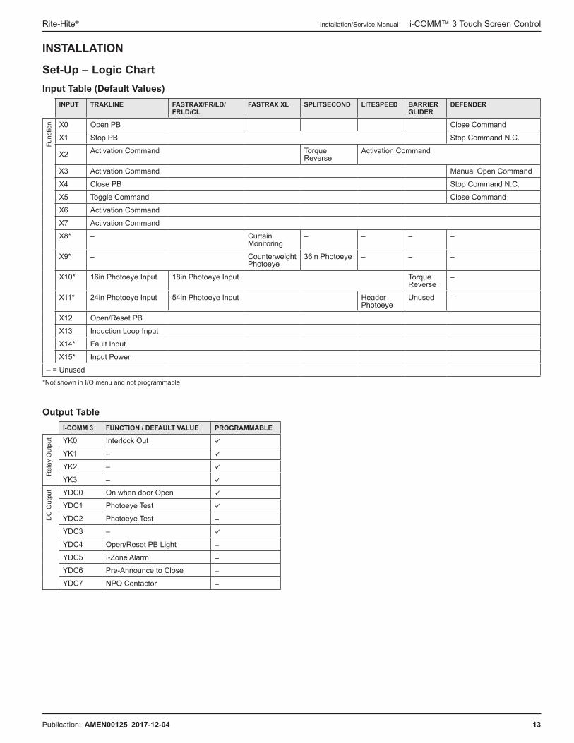
INSTALLATION
Set-Up – Logic ChartInput Table (Default Values)
INPUT TRAKLINE FASTRAX/FR/LD/FRLD/CL
FASTRAX XL SPLITSECOND LITESPEED BARRIER GLIDER
DEFENDER
Func
tion X0 Open PB Close Command
X1 Stop PB Stop Command N�C�
X2 Activation Command Torque Reverse
Activation Command
X3 Activation Command Manual Open Command
X4 Close PB Stop Command N�C�
X5 Toggle Command Close Command
X6 Activation Command
X7 Activation Command
X8* – Curtain Monitoring
– – – –
X9* – Counterweight Photoeye
36in Photoeye – – –
X10* 16in Photoeye Input 18in Photoeye Input Torque Reverse
–
X11* 24in Photoeye Input 54in Photoeye Input Header Photoeye
Unused –
X12 Open/Reset PB
X13 Induction Loop Input
X14* Fault Input
X15* Input Power
– = Unused*Not shown in I/O menu and not programmable
Output TableI-COMM 3 FUNCTION / DEFAULT VALUE PROGRAMMABLE
Rel
ay O
utpu
t YK0 Interlock Out
YK1 –
YK2 –
YK3 –
DC
Out
put YDC0 On when door Open
YDC1 Photoeye Test
YDC2 Photoeye Test –
YDC3 –
YDC4 Open/Reset PB Light –
YDC5 I-Zone Alarm –
YDC6 Pre-Announce to Close –
YDC7 NPO Contactor –

i-COMM™ 3 Touch Screen Control Installation/Service Manual Rite-Hite®
14 Publication: AMEN00125 2017-12-04
INSTALLATION (OPTIONAL)
Set-Up – Wireless InterlockOnly 1 door is allowed to be open at a time�NOTE:� The door serial number is located on the side of the control box or the front of the door sideframe�
NON-SEQUENTIAL INTERLOCK
2-16 doors (total)
1� Close door� Press Stop button�
2� Home ►Login ►Settings ►Network ►Interlock
3� In parameters “Door Interlock 0” – “Door Interlock 14”, enter serial numbers (1 per line) of doors to interlock with� Leave unused parameters at ‘0’�
4� Set Interlock Control Reg� to ‘Non-Sequential Interlock’� Log out� Cycle Power to door�
5� Repeat steps 1 - 4 at remaining door(s)�
6� Verify operation�
SEQUENTIAL INTERLOCK
2 doors (total)After a door has been activated and then re-closes, it will automatically activate the other door�
1� Close door� Press Stop button�
2� Home ►Login ►Settings ►Network ►Interlock
3� In parameter “Door Interlock 0”, enter serial number of door to interlock with� Leave unused parameters at ‘0’�
4� Set Interlock Control Reg� to ‘Sequential Interlock’� Log out� Cycle Power to door�
5� Repeat steps 1 - 4 at remaining door�
6� Verify operation�
To disable Wireless Interlock: Home ►Login ►Settings ►Network ►Interlock Set “Interlock Control Reg�” to “Interlock Disabled”�

Rite‑Hite® Installation/Service Manual i‑COMM™ 3 Touch Screen Control
Publication: AMEN00125 2017-12-04 15
INSTALLATION (OPTIONAL)
Building Management System InterfaceBACnet and Modbus Parameter
MODBUS TCP BACNET
PARAMETER TYPE REGISTER ADDRESS NAME TYPE
Door State Enumeration 0 40001 gui_state
48 : Object Positive Integer Value
Active FaultInteger
1 40002 active_fault
Door Cycles Low Word 2 40003cycle_count_stored
Door Cycles High Word – 3 40004
Serial Number Low Word
Integer
4 40005sn_prop
Serial Number High Word 5 40006
RHC Number Low Word 6 40007rhc_prop
RHC Number High Word 7 40008
Door Model Enumeration 8 40009 – –
Percent door Closed
Integer
9 40010 percent_closed
48 : Object Positive Integer Value
Total Time Closed Low Word 10 40011time_closed
Total Time Closed High Word 11 40012
Total Time Open Low Word 12 40013time_open
Total Time Open High Word 13 40014
Cycle Count Ave� (24 Hrs) Low Word 14 40015cycle_count_average
Cycle Count Ave� (24 Hrs) High Word 15 40016
Time Open Ave� (24 Hrs) Low Word 16 40017time_open_average
Time Open Ave� (24 Hrs) High Word 17 40018
Input Status Low Word 18 40019io_input_status
Input Status High Word 19 40020
Output Status Low Word 20 40021io_output_status
Output Status High Word 21 40022
Active VFD Fault 22 40023 active_vfd_fault
Door StateDOOR STATE VALUE DESCRIPTION
Pre-Fault 0 Prepare for fault state
Fault 1 Door is faulted
Pre-Run Open 2 Prepare to run open
Run Open State 3 Door is running open
Pre-Open Position 4 Door is at Open (activated)
Open Position 5 Door is Open (counting down)
Pre-Run Close 6 Prepare to run close
Run Close 7 Door is running close
Pre-Door Closed 8 Prepare for closed
Door Closed 9 Door is closed
Not Used 10-13 Reserved for future use
Pre-Stopped State 14 Prepare to stop
Stopped State 15 Door is stopped
Door Model ValueDOOR MODEL VALUE
FasTrax 8
FasTrax FR 9
SpitSecond 10
FasTrax CL 11
LiteSpeed 12
FasTrax FRLD 13
FasTraXL 14
Defender 15
Barrier Glider BP 16
Barrier Glider SS 17
Reserved 18
TrakLine Roll 19
TrakLine Fold 20
TrakLine PL 21

i-COMM™ 3 Touch Screen Control Installation/Service Manual Rite-Hite®
16 Publication: AMEN00125 2017-12-04
OPERATION
Opening, Closing, and StoppingSee "Figure 1".
# OPERATE DOOR: PRESS BUTTON:
G Close YellowH Stop RedI Open/Reset Green
Optional activation devices (e�g�, motion/presence sensors, photoeyes, radio controls, pull cords, push buttons, and floor loops) can be used to open and close the door� Contact your local Rite-Hite representative for specific instructions based on your application.Common activation device connections: Home ►Support ►Activation Help
SecurityAll parameters are protected by a PIN (Personal Identification Number). Login is required before changing any settings� There are 2 security levels:1� End User
NOTE:� Default PIN for the user is 3667� PIN can be changed (Home ►Login ►Settings ► General ►Security ►User PIN)�
2� Service TechnicianPIN is provided by your Service Manager or Leader�
To Login (see Figure 1):1� Press Home (L)2� Press Login (Q)3� Enter PIN 4� Press Login5� The display will return to the main screen after
successful loginNOTE:� The system will log you out automatically based on Logout Time specified in Settings ►Timers ►Advanced ►Logout Timer.

Rite‑Hite® Installation/Service Manual i‑COMM™ 3 Touch Screen Control
Publication: AMEN00125 2017-12-04 17
OPERATION
Common LocationsLOCATION: NAVIGATE TO:
Change PIN Home ►Login ►Settings ►General ►Security ►User PINActivation Wiring Help Home ►Support ►Activation ►Help (choose screen)Fault and Change History Home ►Support ►Logs ►(choose screen)Local Representative Home ►Support ►Local Rep.
Troubleshooting Guides – Faults Home ►Support ►Fault Help (choose screen)
Common TasksTASK NAVIGATE TO:
Door Setup (Installation) Home ►Login ►Settings ►Setup Wizards ►Door Quickly setup:Region Settings (Time, Date, Etc�)Door Limits (Encoder)�
Lim
it (E
ncod
er) S
etup Reset all limits: Home ►Login ►Settings ►Limits ►Limit Setup Follow all on-screen prompts
Adjust Open Limit: Home ►Login ►Settings ►Limits ►Open Position Adj. To adjust the limit so the door opens: • Further, enter a positive value�• Less, enter a negative value�
Adjust Close Limit: Home ►Login ►Settings ►Limits ►Close Position Adj. To adjust the limit so the door closes:• Further, enter a negative value�• Less, enter a positive value�
Door Closing Timers Home ►Login ►Settings ►Timers Total open time is the sum of Close Timer and Pre-announce to Close Timers�orTotal open time = Close Timer + Pre-announce to Close Timers
Reset Maintenance Home ►Login ►Settings ►General ►Reset Maintenance
Net
wor
k S
etup Wired Home ►Settings ►Setup Wizards ►Network
Wireless Home ►Settings ►Setup Wizards ►NetworkHome ►Settings ►Setup Wizards ►Wi-Fi
Install USB wireless module�
i-COMM™ 3 Touch Screen Control Installation/Service Manual Rite-Hite®
18 Publication: AMEN00125 2017-12-04
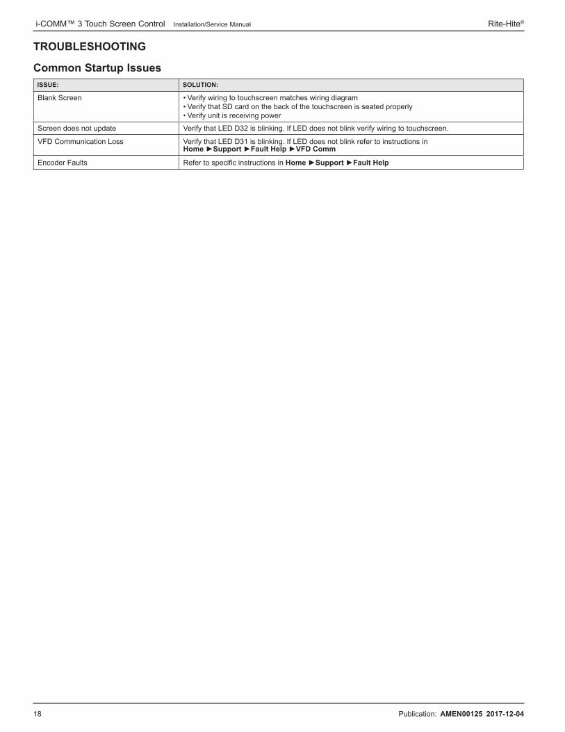
TROUBLESHOOTING
Common Startup IssuesISSUE: SOLUTION:
Blank Screen • Verify wiring to touchscreen matches wiring diagram• Verify that SD card on the back of the touchscreen is seated properly• Verify unit is receiving power
Screen does not update Verify that LED D32 is blinking� If LED does not blink verify wiring to touchscreen�
VFD Communication Loss Verify that LED D31 is blinking� If LED does not blink refer to instructions in Home ►Support ►Fault Help ►VFD Comm
Encoder Faults Refer to specific instructions in Home ►Support ►Fault Help

Rite‑Hite® Installation/Service Manual i‑COMM™ 3 Touch Screen Control
Publication: AMEN00125 2017-12-04 19
TROUBLESHOOTING
LEDs Functions or Input / Output ValuesFUNCTION DESCRIPTION LED COLOR Reference
Sta
tus
LED
s Open On Solid when open, flashes during opening Green D28
Stop On Solid when stopped Red D29
Close On Solid when closed, flashes during closing Yellow D30
Door Command On Solid when activation on, flashes when reversing device active Red D33
Not Used – Red D35
VFD Flashes when communicating with inverter (VFD) Blue D31
Touch Screen Flashes when communicating with touch screen Blue D32
Wireless Radio Flashes when communicating with wireless interlock radio Blue D34
Out
put L
ED
s Fault Flashes during fault Red D5
I-Zone On for I-Zone fault Red D6
YDC6 (Warning Device)
On when YDC6 output is active Red D7
Fault Output On when no in fault Red D8
YDC0 On when output is active Red D44
YDC1 On when output is active Red D45
YDC2 On when output is active Red D46
YDC3 On when output is active Red D47
YK0 On when output is active Red D14
YK1 On when output is active Red D16
YK2 On when output is active Red D18
YK3 On when output is active Red D20
OPTO1 On when inverter output 1 is active Red D41
OPTO2 On when inverter output 2 is active Red D42
Intp
ut L
ED
s X0 On when input is on Green X0
X1 On when input is on Green X1
X2 On when input is on Green X2
X3 On when input is on Green X3
X4 On when input is on Green X4
X5 On when input is on Green X5
X6 On when input is on Green X6
X7 On when input is on Green X7
X8 On when input is on Green X8
X9 On when input is on Green X9
X10 On when input is on Green X10
X11 On when input is on Green X11
X12 On when open/reset (via J6) is on Green X12
X13 On when loop input is on Green X13
X14 On when not in fault Green X14
X15 On when power is on Green X15

i-COMM™ 3 Touch Screen Control Installation/Service Manual Rite-Hite®
20 Publication: AMEN00125 2017-12-04
TROUBLESHOOTING
Inverter (VFD) Programming230/460V – Emerson M200 DriveThese instructions are only to change parameters when not using the i-Comm 3�
Basic Navigation
Safety information
Productinformation
Mechanical installation
Electricalinstallation
Gettingstarted
Basicparameters
Running the motor Optimization NV Media
CardOnboard
PLCAdvanced
parameters Diagnostics UL Listing
Unidrive M200 / M201 Control User Guide 23Issue Number: 2
5 Getting startedThis chapter introduces the user interfaces, menu structure and security levels of the drive�
5.1 Understanding the display5.1.1 KeypadThe keypad display consists of a 6 digit LED display� The display shows the drive status or the menu and parameter number currently being edited�The option module Unidrive menu (S�mm�ppp) is only displayed if the option module is installed� Where S signifies the option module slot number and the mm�ppp signifies the menu and parameter number of the option module’s internal menus and parameter�The display also includes LED indicators showing units and status as shown in Figure 5-1� When the drive is powered up, the display will show the power up parameter defined by Parameter Displayed At Power-Up(11�022)�
The values in the Status Mode Parameters (Pr 22 and Pr 23) shown on the display when the drive is running, can be toggled by using the escape button�Figure 5-1 Unidrive M200 keypad detail
1� Escape button2� Down button3� Start button (green)4� Stop / Reset button (red)5� Up button6� Enter button7� Run forward indicator8� Run reverse indicator9� Keypad reference indicator10� Unit indicators
Figure 5-2 Unidrive M201 keypad detail
1� Run forward indicator2� Unit indicators3� Speed reference potentiometer4� Keypad reference indicator5� Run reverse indicator
The red stop button is also used to reset the drive�
The parameter value is correctly displayed on the keypad display as shown in Table 5-1�On the Unidrive M201, the speed reference potentiometer is used to adjust the keypad reference�Table 5-1 Keypad display formats
*Alternate display
5.2 Keypad operation5.2.1 Control buttonsThe keypad consists of:• Up and down button - Used to navigate the parameter structure and
change parameter values�• Enter button - Used to change between parameter edit and view
mode as well as entering data� This button can also be used to select between slot menu and parameter display�
• Escape button - Used to exit from parameter edit or view mode� In parameter edit mode, if parameter values are edited and the escape button pressed, the parameter value will be restored to the value it had on entry to edit mode�
• Start button - Used to provide a 'Run' command if keypad mode is selected�
• Stop / Reset button - Used to reset the drive� In keypad mode can be used for 'Stop'�
NOTE
10
78
6
5
4
9
1
2
3
Display formats ValueStandard 100�99
Date 31�12�11 or 12�31�11Time 12�34�56
Character ABCDEFBinary 5
IP Address 192�168 88�1*MAC Address 01�02�03 04�05�06*
Version number 01�23�45
1
3
2
5
V A Hz rpm %1
4
NOTE
<unidrive-m200-m201-control-user-guide�pdf>
Figure 4

Rite‑Hite® Installation/Service Manual i‑COMM™ 3 Touch Screen Control
Publication: AMEN00125 2017-12-04 21
TROUBLESHOOTING
230/460V – Emerson M200 Drive Continued
Parameter Access
WARNING / AVERTISSEMENT
Consult factory before changing any parameters not listed in this table.
Contactez l'usine avant de modifier les paramètres non répertoriés dans ce tableau.
NAME EXAMPLE VALUE UNITS
PAR
AM
ETER
# 00�003 Acceleration Rate 1 0�5 s/100 Hz
00�004 Deceleration Rate 1 0�5 s/100 Hz
00�006 Motor Rated Current 2�93 A
00�010 Security Status L2 –
01�022 Close Speed 25�00 Hz
01�023 Open Speed 60�00 Hz
01�024 Approach Open Speed 25�00 Hz
12�004 Torque Detection Level 60 %
06�006 Injection Braking Level 70 %
06�007 Injection Braking Time �7 seconds
Safetyinformation
Product information
Mechanical installation
Electricalinstallation
Gettingstarted
Basicparameters
Running the motor Optimization NV Media
CardOnboard
PLCAdvanced
parameters Diagnostics UL Listing
24 Unidrive M200 / M201 Control User Guide Issue Number: 2
Figure 5-3 Display modes
The up and down buttons can only be used to move between menus if Pr 10 has been set to show 'ALL'� Refer to section 5�9 Parameter access level and security on page 27�
To return to Status Mode,
press button
To return to Parameter View Mode,press button
Press or to select parameter
StatusMode
To enter Parameter View Mode,press button
ParameterView Mode
Pr 10
Pr 01
0.00
0.00
To view parameter valuepress button
To enter Edit Mode,press button
0.00
Edit Mode (edited digit flashes)
Holding or increases or decreases value
ParameterValue View
To return to Parameter Value Viewpress button to keep the new value
press button to ignore new value and
return the parameter to the pre-edited value
NOTE
<unidrive-m200-m201-control-user-guide�pdf:2>
NOTE:� To acccess parameters other than those in menu zero, navigate to parameter 10 (PR 10) and change the value to 'ALL'�
Figure 5

i-COMM™ 3 Touch Screen Control Installation/Service Manual Rite-Hite®
22 Publication: AMEN00125 2017-12-04
TROUBLESHOOTING
230/460V – Emerson M200 Drive Continued
Status Indicators
Safetyinformation
Product information
Mechanical installation
Electricalinstallation
Gettingstarted
Basicparameters
Running the motor Optimization NV Media
CardOnboard
PLCAdvanced
parameters Diagnostics UL Listing
26 Unidrive M200 / M201 Control User Guide Issue Number: 2
5.5 Advanced menus The advanced menus consist of groups or parameters appropriate to a specific function or feature of the drive� Menus 0 to 24 can be viewed on the Keypad� The option module menu (1�mm�ppp) is only displayed if the option module is installed� Where 1 signifies the option module slot number and the mm�ppp signifies the menu and parameter number of the option module’s internal menus and parameters�Table 5-2 Advanced menu descriptions
* Only displayed when the option module is installed�
5.5.1 Display messagesThe following tables indicate the various possible mnemonics which can be displayed by the drive and their meaning�
Table 5-3 Status indications
5.5.2 Alarm indicationsAn alarm is an indication given on the display by alternating the alarm string with the drive status string on the display� Alarms strings are not displayed when a parameter is being edited�
Table 5-4 Alarm indications
5.6 Changing the operating modeProcedureUse the following procedure only if a different operating mode is required:1� Ensure the drive is not enabled, i�e� drive is in inhibit or under
voltage state�2� Change the setting of Pr 79 as follows:
The figures in the second column apply when serial communications are used�
When the operating mode is changed, a parameter save is carried out�3� Either:
Press the red reset button
Carry out a drive reset through serial communications by setting Pr 10.038 to 100�
5.7 Saving parametersWhen changing a parameter in Menu 0, the new value is saved when
pressing the Enter button to return to parameter view mode from parameter edit mode�If parameters have been changed in the advanced menus, then the change will not be saved automatically� A save function must be carried out�
Procedure1� Select ‘Save' in Pr 00 or Pr mm.000 (alternatively enter a value of
1001 in Pr 00 or Pr mm.000)2� Either:
• Press the red reset button• Carry out a drive reset through serial communications by setting
Pr 10.038 to 100
Menu Description
0 Commonly used basic set up parameters for quick / easy programming
1 Frequency reference2 Ramps3 Frequency control4 Torque and current control5 Motor control6 Sequencer and clock7 Analog I/O8 Digital I/O9 Programmable logic, motorized pot, binary sum, timers10 Status and trips11 Drive set-up and identification, serial communications12 Threshold detectors and variable selectors14 User PID controller15 Option module slot 1 set-up menu18 General option module application menu 120 General option module application menu 221 Second motor parameters22 Menu 0 set-up24 Option module slot 1 application menu
Slot 1 Slot 1 option menus*
String DescriptionDrive
output stage
inh
The drive is inhibited and cannot be run� The Drive Enable signal is not applied to the drive enable terminal or Pr 06.015 is set to 0� The other conditions that can prevent the drive from enabling are shown as bits in Enable Conditions (06�010)
Disabled
rdyThe drive is ready to run� The drive enable is active, but the drive inverter is not active because the final drive run is not active
Disabled
Stop The drive is stopped / holding zero speed� EnabledS.Loss Supply loss condition has been detected Enableddc inj The drive is applying dc injection braking Enabled
ErThe drive has tripped and no longer controlling the motor� The trip code appears on the display�
Disabled
UV The drive is in the under voltage state either in low voltage or high voltage mode� Disabled
HEAt The motor pre-heat function is active� Enabled
Alarm string Description
br.resBrake resistor overload� Braking Resistor Thermal Accumulator (10�039) in the drive has reached 75�0 % of the value at which the drive will trip�
OV.LdMotor Protection Accumulator (04�019) in the drive has reached 75�0 % of the value at which the drive will trip and the load on the drive is >100 %�
d.OV.LdDrive over temperature� Percentage Of Drive Thermal Trip Level (07�036) in the drive is greater than 90 %�
tuning The autotune procedure has been initialized and an autotune in progress�
LS Limit switch active� Indicates that a limit switch is active and that is causing the motor to be stopped�
Opt.AI Option slot alarm�Lo.AC Low voltage mode� See Low AC Alarm (10�107)�
I.AC.Lt Current limit active� See Current Limit Active(10�009)�
24.LoSt 24 V backup not present� See 24V Alarm Loss Enable (11�098)�
Pr 79 setting Operating mode
1 Open-loop
2 RFC-A
NOTE
Safety information
Productinformation
Mechanical installation
Electricalinstallation
Gettingstarted
Basicparameters
Running the motor Optimization NV Media
CardOnboard
PLCAdvanced
parameters Diagnostics UL Listing
Unidrive M200 / M201 Control User Guide 129Issue Number: 2
12 DiagnosticsThe keypad display on the drive gives various information about the status of the drive� The keypad display provides information on the following categories: • Trip indications • Alarm indications • Status indications
12.1 Status modes (Keypad and LED status)Figure 12-1 Keypad status modes
1 Drive OK status2 Trip status3 Alarm status
12.2 Trip indicationsThe output of the drive is disabled under any trip condition so that the drive stops controlling the motor� If the motor is running when the trip occurs it will coast to a stop�During a trip condition, the display indicates that a trip has occurred and the keypad will display the trip string� Some trips have a sub-trip number to provide additional information about the trip� If a trip has a sub-trip number, the sub-trip number is flashed alternately with the trip string�
Trips are listed alphabetically in Table 12-2 based on the trip indication shown on the drive display� Alternatively, the drive status can be read in Pr 10.001 'Drive OK' using communication protocols� The most recent trip can be read in Pr 10.020 providing a trip number� It must be noted that the hardware trips (HF01 to HF23) do not have trip numbers� The trip number must be checked in Table 12-2 to identify the specific trip�
Example1� Trip code 2 is read from Pr 10.020 via serial communications�2� Checking Table 12-3 shows Trip 2 is an OV trip�
3� Look up OV in Table 12-2�4� Perform checks detailed under Diagnosis�
12.3 Identifying a trip / trip sourceSome trips only contain a trip string whereas some other trips have a trip string along with a sub-trip number which provides the user with additional information about the trip� A trip can be generated from a control system or from a power system� The sub-trip number associated with the trips listed in Table 12-1 is in the form xxyzz and used to identify the source of the trip�
Table 12-1 Trips associated with xxyzz sub-trip number
The digits xx are 00 for a trip generated by the control system� For a drive, if the trip is related to the power system then xx will have a value of 01, when displayed the leading zeros are suppressed�For a control system trip (xx is zero), the y digit where relevant is defined for each trip� If not relevant, the y digit will have a value of zero�The zz digits give the reason for the trip and are defined in each trip description�Figure 12-2 Key to sub-trip number
Users must not attempt to repair a drive if it is faulty, nor carry out fault diagnosis other than through the use of the diagnostic features described in this chapter�If a drive is faulty, it must be returned to an authorized Control Techniques distributor for repair�WARNING
1
3
2
OV PH�Lo
PSU OI�Sn
Oht�I tH�Fb
Oht�P P�dAt
Oh�dc
Keypaddisplay
Commscode
No. Trip
2 OV
x x y z z
00 - Generated by the control module
01 - Generated by the power module
0 Upwards - Identifies the location of the trip
00
01
.
.
07
- Reason for the trip<unidrive-m200-m201-control-user-guide�pdf:4>
Error Screens
Safetyinformation
Product information
Mechanical installation
Electricalinstallation
Gettingstarted
Basicparameters
Running the motor Optimization NV Media
CardOnboard
PLCAdvanced
parameters Diagnostics UL Listing
26 Unidrive M200 / M201 Control User Guide Issue Number: 2
5.5 Advanced menus The advanced menus consist of groups or parameters appropriate to a specific function or feature of the drive� Menus 0 to 24 can be viewed on the Keypad� The option module menu (1�mm�ppp) is only displayed if the option module is installed� Where 1 signifies the option module slot number and the mm�ppp signifies the menu and parameter number of the option module’s internal menus and parameters�Table 5-2 Advanced menu descriptions
* Only displayed when the option module is installed�
5.5.1 Display messagesThe following tables indicate the various possible mnemonics which can be displayed by the drive and their meaning�
Table 5-3 Status indications
5.5.2 Alarm indicationsAn alarm is an indication given on the display by alternating the alarm string with the drive status string on the display� Alarms strings are not displayed when a parameter is being edited�
Table 5-4 Alarm indications
5.6 Changing the operating modeProcedureUse the following procedure only if a different operating mode is required:1� Ensure the drive is not enabled, i�e� drive is in inhibit or under
voltage state�2� Change the setting of Pr 79 as follows:
The figures in the second column apply when serial communications are used�
When the operating mode is changed, a parameter save is carried out�3� Either:
Press the red reset button
Carry out a drive reset through serial communications by setting Pr 10.038 to 100�
5.7 Saving parametersWhen changing a parameter in Menu 0, the new value is saved when
pressing the Enter button to return to parameter view mode from parameter edit mode�If parameters have been changed in the advanced menus, then the change will not be saved automatically� A save function must be carried out�
Procedure1� Select ‘Save' in Pr 00 or Pr mm.000 (alternatively enter a value of
1001 in Pr 00 or Pr mm.000)2� Either:
• Press the red reset button• Carry out a drive reset through serial communications by setting
Pr 10.038 to 100
Menu Description
0 Commonly used basic set up parameters for quick / easy programming
1 Frequency reference2 Ramps3 Frequency control4 Torque and current control5 Motor control6 Sequencer and clock7 Analog I/O8 Digital I/O9 Programmable logic, motorized pot, binary sum, timers10 Status and trips11 Drive set-up and identification, serial communications12 Threshold detectors and variable selectors14 User PID controller15 Option module slot 1 set-up menu18 General option module application menu 120 General option module application menu 221 Second motor parameters22 Menu 0 set-up24 Option module slot 1 application menu
Slot 1 Slot 1 option menus*
String DescriptionDrive
output stage
inh
The drive is inhibited and cannot be run� The Drive Enable signal is not applied to the drive enable terminal or Pr 06.015 is set to 0� The other conditions that can prevent the drive from enabling are shown as bits in Enable Conditions (06�010)
Disabled
rdyThe drive is ready to run� The drive enable is active, but the drive inverter is not active because the final drive run is not active
Disabled
Stop The drive is stopped / holding zero speed� EnabledS.Loss Supply loss condition has been detected Enableddc inj The drive is applying dc injection braking Enabled
ErThe drive has tripped and no longer controlling the motor� The trip code appears on the display�
Disabled
UV The drive is in the under voltage state either in low voltage or high voltage mode� Disabled
HEAt The motor pre-heat function is active� Enabled
Alarm string Description
br.resBrake resistor overload� Braking Resistor Thermal Accumulator (10�039) in the drive has reached 75�0 % of the value at which the drive will trip�
OV.LdMotor Protection Accumulator (04�019) in the drive has reached 75�0 % of the value at which the drive will trip and the load on the drive is >100 %�
d.OV.LdDrive over temperature� Percentage Of Drive Thermal Trip Level (07�036) in the drive is greater than 90 %�
tuning The autotune procedure has been initialized and an autotune in progress�
LS Limit switch active� Indicates that a limit switch is active and that is causing the motor to be stopped�
Opt.AI Option slot alarm�Lo.AC Low voltage mode� See Low AC Alarm (10�107)�
I.AC.Lt Current limit active� See Current Limit Active(10�009)�
24.LoSt 24 V backup not present� See 24V Alarm Loss Enable (11�098)�
Pr 79 setting Operating mode
1 Open-loop
2 RFC-A
NOTE
Safety information
Productinformation
Mechanical installation
Electricalinstallation
Gettingstarted
Basicparameters
Running the motor Optimization NV Media
CardOnboard
PLCAdvanced
parameters Diagnostics UL Listing
Unidrive M200 / M201 Control User Guide 23Issue Number: 2
5 Getting startedThis chapter introduces the user interfaces, menu structure and security levels of the drive�
5.1 Understanding the display5.1.1 KeypadThe keypad display consists of a 6 digit LED display� The display shows the drive status or the menu and parameter number currently being edited�The option module Unidrive menu (S�mm�ppp) is only displayed if the option module is installed� Where S signifies the option module slot number and the mm�ppp signifies the menu and parameter number of the option module’s internal menus and parameter�The display also includes LED indicators showing units and status as shown in Figure 5-1� When the drive is powered up, the display will show the power up parameter defined by Parameter Displayed At Power-Up(11�022)�
The values in the Status Mode Parameters (Pr 22 and Pr 23) shown on the display when the drive is running, can be toggled by using the escape button�Figure 5-1 Unidrive M200 keypad detail
1� Escape button2� Down button3� Start button (green)4� Stop / Reset button (red)5� Up button6� Enter button7� Run forward indicator8� Run reverse indicator9� Keypad reference indicator10� Unit indicators
Figure 5-2 Unidrive M201 keypad detail
1� Run forward indicator2� Unit indicators3� Speed reference potentiometer4� Keypad reference indicator5� Run reverse indicator
The red stop button is also used to reset the drive�
The parameter value is correctly displayed on the keypad display as shown in Table 5-1�On the Unidrive M201, the speed reference potentiometer is used to adjust the keypad reference�Table 5-1 Keypad display formats
*Alternate display
5.2 Keypad operation5.2.1 Control buttonsThe keypad consists of:• Up and down button - Used to navigate the parameter structure and
change parameter values�• Enter button - Used to change between parameter edit and view
mode as well as entering data� This button can also be used to select between slot menu and parameter display�
• Escape button - Used to exit from parameter edit or view mode� In parameter edit mode, if parameter values are edited and the escape button pressed, the parameter value will be restored to the value it had on entry to edit mode�
• Start button - Used to provide a 'Run' command if keypad mode is selected�
• Stop / Reset button - Used to reset the drive� In keypad mode can be used for 'Stop'�
NOTE
10
78
6
5
4
9
1
2
3
Display formats ValueStandard 100�99
Date 31�12�11 or 12�31�11Time 12�34�56
Character ABCDEFBinary 5
IP Address 192�168 88�1*MAC Address 01�02�03 04�05�06*
Version number 01�23�45
1
3
2
5
V A Hz rpm %1
4
NOTE
<unidrive-m200-m201-control-user-guide�pdf>
Figure 6
Figure 7

Rite‑Hite® Installation/Service Manual i‑COMM™ 3 Touch Screen Control
Publication: AMEN00125 2017-12-04 23
PARTS
# QTY DESCRIPTION PART #
1 1 Cable,touch,50’ (non FSTXXL models) 15650343
2 1 Cable,touch,75’ (FSTXXL only) 15650344
3 1 Interface,GUI,ip67 55150353
4 2 FTG,STRT,L/T,PG11,3�5-10mm 45550004

RITEHITE.COM24 www�ritehite�com Publication: AMEN00125 2017-12-04
GLOBAL SALES & SERVICE Representatives in All Major Cities
RITE-HITE WORLD HEADQUARTERS8900 N� Arbon DriveP�O� Box 245020Milwaukee, Wisconsin 53224
RITE-HITE CHINAFirst Floor, Building #3,558 Tongxie Road, Changning DistrictShanghai 200335, China
RITE-HITE LATIN AMERICAAlameda Lorena, 800 - Conj� 401/402- Jardim Paulista São Paulo/SP, CEP 01424- Brazil
RITE-HITE GMBHCarl-Zeiss-Strasse 334471 Volkmarsen, Germany
414-355-2600 U�S� Only: 1-800-456-0600
+86-21-6237-6333 011-55-11-3527-9590 +49-5693 98700
LIMITED PRODUCT WARRANTY i-COMM™ 3 Touch Screen Control
Rite-Hite Company, LLC and its affiliates (collectively "Rite-Hite") warrant that the Product sold to the Owner will be free of defects in design, materials and workmanship (ordinary wear and tear excepted) for the periods set forth below ("Limited Warranty")�
Two (2) Year(s) on all mechanical and electrical parts (non-prorated)�One (1) Year(s) labor, based on approved travel and labor repair times�
REMEDIESParts: Rite-Hite's obligations under this Limited Warranty are limited to repairing or replacing, at Rite-Hite's option, any part which is determined by Rite-Hite to be defective during the applicable warranty period� Such repair or replacement shall be Rite-Hite's sole obligation and the Owner's exclusive remedy under this Limited Warranty�Labor: Rite-Hite will provide warranty service without charge for labor per the specified warranty period� Thereafter, a charge will apply to any repair or replacement under this Limited Warranty�
CLAIMS Claims under this Limited Warranty must be made (i) within 30 (thirty) days after discovery and (ii) prior to expiration of the applicable warranty period� Warranty period commences on the date of shipment� Claims shall be made in writing or by contacting the representative from whom the Product was purchased directly� Owner must allow Rite-Hite or its agent, a reasonable opportunity to inspect any Product claimed to be defective and shall, at Rite-Hite's option, either (x) grant Rite-Hite or its agent access to Owner's premises for the purpose of repairing or replacing the Product or (y) return of the Product to the Rite-Hite, F�O�B� Rite-Hite's factory�
NOT WARRANTED Rite-Hite does not warrant against and is not responsible for wear items such as fuses, batteries, bulbs, vision and seals� No implied warranty shall be deemed to cover damages that result directly or indirectly from: (i) the unauthorized modification or repair of the Product, (ii) damage due to misuse, neglect, accident, failure to provide necessary maintenance, or normal wear and tear of the Product, (iii) failure to follow Rite-Hite's instructions for installation, failure to operate the Product within the Product's rated capacities and/or specified design parameters, or failure to properly maintain the Product, (iv) use of the Product in a manner that is inconsistent with Rite-Hite's guidelines or local building codes, (v) movement, settling, distortion, or collapse of the ground, or of improvements to which the Products are affixed, (vi) fire, flood, earthquake, elements of nature or acts of God, riots, civil disorder, war, or any other cause beyond the reasonable control of Rite-Hite, (vii) improper handling, storage, abuse, or neglect of the Product by Owner or by any third party�
DISCLAIMERS THIS LIMITED WARRANTY IS EXCLUSIVE AND IN LIEU OF ALL OTHER REPRESENTATIONS AND WARRANTIES, EXPRESS OR IMPLIED, AND RITE-HITE EXPRESSLY DISCLAIMS AND EXCLUDES ANY IMPLIED WARRANTIES OF MERCHANTABILITY OR FITNESS FOR PURPOSE� RITE-HITE SHALL NOT BE SUBJECT TO ANY OTHER OBLIGATIONS OR LIABILITIES, WHETHER ARISING OUT OF BREACH OF CONTRACT, WARRANTY, TORT (INCLUDING NEGLIGENCE AND STRICT LIABILITY) OR OTHER THEORIES OF LAW, WITH RESPECT TO THE PRODUCTS SOLD OR SERVICES RENDERED BY RITE-HITE, OR ANY UNDERTAKINGS, ACTS, OR OMISSIONS RELATING THERETO�
LIMITATION OF LIABILITY IN NO EVENT SHALL RITE-HITE BE RESPONSIBLE FOR, OR LIABLE TO ANYONE FOR, SPECIAL, INDIRECT, COLLATERAL, PUNITIVE, INCIDENTAL, OR CONSEQUENTIAL DAMAGES, EVEN IF RITE-HITE HAS BEEN ADVISED OF THE POSSIBILITY OF SUCH DAMAGES� Such excluded damages include, but are not limited to, personal injury, damage to property, loss of goodwill, loss of profits, loss of use, cost of cover with any substitute product, interruption of business, or other similar indirect financial loss� 17
0714