Embed Size (px)
Citation preview
AD-A269 741
SDT I C Technical R eport
US Army Corps ELECTP CPAR-GL-93-1of Engineers l May 1993
Waterways Experiment S % DStation A
CONSTRUCTION PRODUCTIVITY ADVANCEMENTRESEARCH (CPAR) PROGRAM
IMPROVED MATERIALS AND PROCESSES FOR SEALINGAND RESEALING JOINTS IN PORTLAND CEMENTCONCRETE PAVEMENTS: LABORATORY STUDY
by
Larry N. Lynch, Dewey W. White, James Chehovits
Approved For Public Release; Distribution Is Unlimited
IIIlk
93--22276
A CorpAndwutry Pnershlip to Advanc
24 0A9'1
The contents of this report are not to be used for advertising,publication, or promotional purposes. Citation of trade namesdoes not constitute an official endorsement or approval of the useof such commercial products.
0 PintuoImcYa.tDIC PAm
Construction Productivity Advancement CPAR-GL-93-1
Research (CPAR) Program May 1993
Improved Materials and Processesfor Sealing and Resealing Jointsin Portland Ceme,-* ConcretePavements: Laboratory Study
by Larry N. Lynch, Dewey W. White,
Geotechnical Laboratory
U.S. Army Corps of EngineersWaterways Experiment Station3909 Hails Ferry RoadVicksburg, MS 39180-6199 ACCC'1Ql For
James Chehovits NTIS
Crafco Incorporated L)
6975 West Crafco WayChandler, AZ 85226 ..
By
A.-Ij
Final reportApproved for public release; distribution is unlimited
V=T QOuA'rn nuw I
Prepared for U.S. Army Corps of Engineers
Washington, DC 20314-1000
Under CPAR Work Unit 32614
US Army Corpsof EngineersWaterways Experiment N
Station r pta- a DataTECHNOLOGY
Lynch, Larry N.
LABOMTOW i
SIt
WATOTE09" I T~
HYDAMIS CWA DOE IR.M PTI R
Lynh, ewe W.Whie, ame Chho4ts
18 p: ll;08c. - [Tchicl eprt; PA-G-9-1
EMRAM LASOPATOW
St1atAIes.Army Corp o. Eniees VUSAmyEgneWaENwaysgineer Waterways Experiment Station); CAling-nPuli W34O
nl.CP LL--AR -G-3
Inclteras bibpiorapimetSatio reeeces.gn-I-ulc nDt
Impsrutove --materials. and prcsseoealing aoponds r.esealing joicntsl-
Lynch, Dewe Whie. Whie Jamese .I Chehovits, ae.Ii.Uie
States. Army. Corps of Engineers. IV. U.S. Army Engineer WaterwaysExperiment Station. V. Construction Productivity Advancement Re-search Program. VI. Title. VII. Series: Technical report (U.S. Army En-gineer Waterways Experiment Station); CPAR-GL-93-1 W34no.CPAR-GL-93-1
PREFACE
Section 7 of the Water Resources Development Act of 1988, P.L. 100-676,
33 U.S.C. 2313, and the Stevenson-Wydler Technology Innovation Act of 1980, as
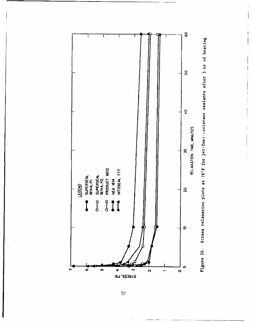
amended, 15 U.S.C. 37102a, provide the legislative authority for the Construc-
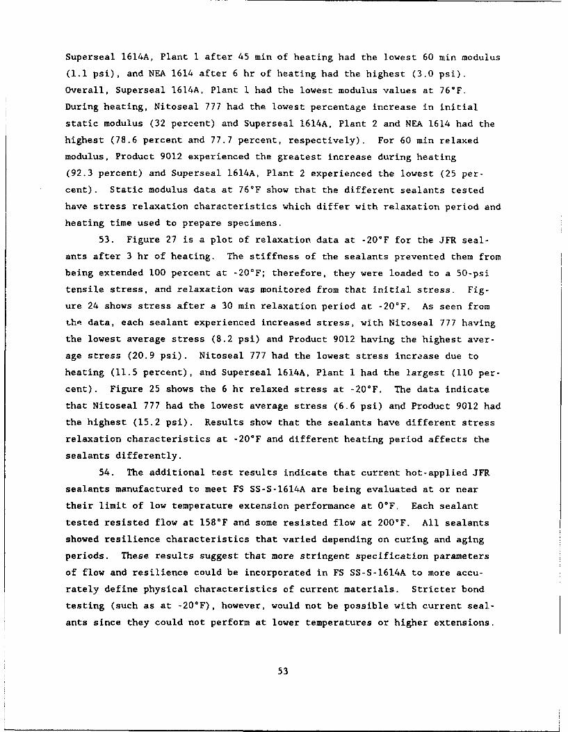
tion Productivity Advancement Research (CPAR) Program. The CPAR program
allows the US Army Corps of Engineers to enter into cooperative re.search and
development agreements with construction industry partners to conduct cost-
shared, collaborative efforts with the goal of improving construction
productivity.
The CPAR project "Improved Materials and Processes for Sealing and
Resealing Joints in Portland Cement Concrete Pavements," was a collaborative
effort of the Geotechnical Laboratory (GL) of the US Army Engineer Waterways
Experiment Station (WES) and Crafco Incorporated. The work was conducted from
October 1989 to December 1991. The US Army Corps of Engineers Technical Moni-
tor was Mr. Gregory Hughes.
The project was conducted under the general supervision of Dr. W. F.
Marcuson III, Director, GL, WES, and under the direct supervision of Mr. H. H.
Ulery Jr., former Chief, Pavement Systems Division (PSD); Dr. G. M.
Hammitt II, Chief, PSD, GL; Dr. R. S. Rollings, former Chief, Materials
Research and Construction Technology (MR&CT), and Mr. T. W. Vollor, Chief,
MR&CT. The WES Principal Investigator was Mr. Larry N. Lynch, and the Crafco
Principal Investigator was Mr. James Chehovits. The report was prepared by
Messrs. Dewey W. White, Lynch, and Chehovits.
At the time of publication of this report Director of WES was
Dr. Robert W. Whalin. Commander was COL Leonard G. Hassell, EN.
ACKNOWLEDGEMENTS
The authors extend thanks to the many individuals whose efforts and
assistance with this research are greatly appreciated.
Laboratory Research
Sirous Baradaran, Research Engineer, Crafco Inc.Robert Polynin, Laboratory Technician, Crafco Inc.Herbert McKnight, Materials Engineering Technician, WES
Project Accounting and Management
Don Brooks, General Manager, Crafco Iic.Vicki Cooper, Accounting SupervisorLeanne Green, Audit Office, WES
Field Installations
Larry Erickson, Specialty Products Manager, Crafco Inc.Warren O'Brien, Plant Manager, Crafco Inc.Gary Allen, Plant Manager, Crafco Inc.
Mark Manning, Marketing, Crafco Inc.Mr. Ron Sanders, 92 SPTG/DEEE, Fairchild AFB, WATSGT Ted Strom, 92 SPTE/DEMHH, Fairchild AFB, WA
Report Preparation
Laura Cochrane, Administrative Assistant, Crafco Inc.Mark Lively, Laboratory Technician, Crafco Inc.Odell Allen, Editorial Section, WES
Project Consultant
Edward Klabunde
2
CONTENTS
Pag e
PREFACE .. ............................................................... I
ACKNOWLEDGEMENTS ....................................................... 2
CONVERSION FACTORS, NON-SI TO SI (METRIC)UNITS OF MEASUREMENT ..................................................... 5
PART I: INTRODUCTION ................................................... 6
Background.................................... ..................... 6Project Objectives ................................................... 8Purpose of Report .................................................... 8
PART II: LABORATORY RESEARCH PLAN ...................................... 10
PART III: PHYSICAL CHARACTERISTICS OF AVAILABLE HOT-APPLIED JET-FUEL-RESISTANT SEALANTS ..................................... 12
Products Tested ...................................................... 12Specification Testing ................................................ 13
Specification Test Analysis .......................................... 13Additional Laboratory Testing ....................................... 23Additional Laboratory Test Analysis ................................. 26
PART IV: PHYSICAL CHARACTERISTICS OF AVAILABLE HOT-APPLIED NON-JET-FUEL-RESISTANT SEALANTS ..................................... 55
Products Tested ...................................................... 55Specification Testing ................................................ 56Specification Test Analysis .......................................... 56Additional Laboratory Testing ....................................... 68Additional Laboratory Test Analysis ................................. 69
PART V: DEVELOPMENT OF IMPROVED HOT-APPLIED JET-FUEL-RESISTANTSEALANT ...................................................... 96
Development Goals .................................................... 96Laboratory Research .................................................. 101Suggested Specification ............................................. 110
Production Results ................................................... 113
PART VI: DEVELOPMENT OF IMPROVED HOT-APPLIED NON-JET-FUEL-RESISTANTSEALANT ...................................................... 115
Development Goals .................................................... 115
Suggested Specification ............................................. 116
Production Results ................................................... 117
PART VII: DEVELOPMENT OF ENCAPSULATING PRIMER .......................... 122
Literature Search .................................................... 122Analysis of the CRD-C 525-89 Bubble Testing Procedure ............ 122Bubbling Analysis Procedure ......................................... 125
Jet-Fuel-Resistant Primer Formulation Studies ...................... 129Non-Jet-Fuel-Resistant Primer Formulation Studies ................ 132Suggested Specification for Non-Jet-Fuel Resistant Primer ........ 135
Production Results ................................................... 136
3
Page
PART VIII: CONCLUSIONS AND RECOMMENDATIONS ............................ 137
REFERENCES . ............................................................ 139
APPENDIX A: SUMMARY OF SELECTED TEST PROCEDURES ....................... Al
APPENDIX B: PROPOSED SPECIFICATION FOR LOW-MODULUS, HOT-APPLIED,JET-FUEL-RESISTANT PAVEMENT JOINT SEALANTS FOR RICIDPAVEMENTS .................................................. B
APPENDIX C: PROPOSED SPECIFICATION FOR LOW-MODULUS, HOT-APPLIED,NON-JET-FUFL-RESISTANT PAVEMENT JOINT SEALANTS FORRIGID AND FLEXIBLE PAVEMENTS ................................ Cl
APPENDIX D: SUGGESTED SPECIFICATION FOR PRIMER, JOINT, NON-JET-FUEL-RESISTANT, COLD-APPLIED, SINGLE COMPONENT FOR PORTLANDCEMENT CONCRETE PAVEMENTS .................................... Dl
4
CONVERSION FACTORS, NON-SI TO SI (METRIC)UNITS OF MEASUREMENT
Non-SI units of measurement used in this report can be converted to SI
(metric) units as follows:
Multiply By To Obtain
degrees (angle) 0.01745329 radians
Fahrenheit degrees 5/9 Celsius degrees or Kelvins*
inches 2.54 centimetres
ounces (US fluid) 0.02957353 cubic decimetres
pounds (force) per square inch 6.894757 kilopascals
square inches 6.4516 square centimetres
* To obtain Celsius (C) temperature readings from Fahrenheit (F) readings,
use the following formula: C - (5/9)(F - 32). To obtain Kelvin (K) read-
ings, use: K - (5/9)(F - 32) + 273.15.
5
IMPROVED MATERIALS AND PROCESSES FOR SEALING AND RESEALINGJOINTS IN PORTLAND CEMENT CONCRETE PAVEMENTS
LABORATORY STUDY
PART I: INTRODUCTION
Background
1. Many types and compositions of sealants are currently used for seal-
ing joints in portland cement concrete (FCC) pavement. These materials vary
widely in chemical complexity, field performance, suitability for a specific
application, and price. Currently, there are four types of sealants which can
be specified on military projects. The specifications for these sealants are:
a. Federal Specification (FS) SS-S-1401C, "Sealant, Joint, Non-Jet-Fuel Resistant, Hot-Applied, for Portland Cement and AsphaltConcrete Pavements" (FS 1984a).
b. FS SS-S-1614A, "Sealant, Joint, Jet-Fuel-Resistant, Hot-Applied,for Portland Cement and Tar Concrete Pavements" (FS 1984b).
C. FS SS-S-200E, "Sealants, Joint, Two Component, Jet-Blast-Resistant, Cold-Applied, for Portland Cement Concrete Pavement"(FS 1988).
d. US Army Corps of Engineers Handbook for Concrete and CementCRD-C 527, "Joint Sealants, Cold-Applied, Non-Jet-Fuel-Resistant, for Rigid and Flexible Pavements" US Army Corps ofEngineers Handbook of Concrete and Cement 1988).
2. Sealants manufactured to meet the requirements of FS SS-S-140.C are
typically polymer modified asphalt-base, hot-applied materials. These seal-
ants are used to seal cracks in asphalt cement pavements, or joints in PCC
pavements in areas that are not exposed to fuel spillage. Typical application
areas for FS SS-S-1401C sealants are parking lots, roadways, and some portions
of taxiways. For personnel not familiar with federal specifications, FS SS-S-
1401C is similar, but not identical to American Society for Testing and Mate-
rials (ASTM) D3405 (ASTM 1991).
3. Sealants manufactured to meet the requirements of FS SS-S-1614A are
polymer modified coal tar-base, hot-applied materials and are used to seal
joints in PCC pavements where fuel spillage would be expected. FS SS-S-1614A
type sealants should not be used to seal cracks in asphalt pavements. Typical
application areas are maintenance areas and aircraft parking aprons. FS SS-S-
1614A is somewhat similar to ASTM D3581 (ASTM 1991).
6
4. Sealants manufactured to meet the requirements of FS SS-S-200E are
two-component, cold-applied materials which are typically polysulfide ur poly-
urethane modified tar compositions. These sealants are used to snal joints in
PCC pavements where both fuel spillage and aircraft blast are expected. Typi-
cal application areas are aircraft warm-up areas, pavemenLs that are exposed
to vertical short takeoff landing (VSTOL) aircraft, and the ends of runways.
There is not an ASTM specification that is similar to FS SS-S-200E.
5. Sealants manufactured to meet the requirements of CRD-C 527 (US Army
Corps of Engineers Handbook of Concrete and Cement 1988) are cold-applied and
can be either single or multicomponent materials. CRD-C 527 6eala-Lts are used
to seal joints and cracks in either PCC or asphalt cement concrete pavements
that are not exposed to fuel spillage. Typical areas where these sealants can
be used are the same as for FS SS-S-1401C sealants. An ASTM specification
that is similar to CRD-C 527 does not exist.
6. Each of the above mentioned pavement joint sealants is manufactured
for a specific use; however, an ideal sealant, regardless of the specification
to which it was manufactured, would have certain characteristics. These ideal
characteristics would include:
a. Simple and repeatable application techniques.
b. Adhesion to joint faces when subjected to extreme temperaturesand joint movements.
C. Insensitive to moisture.
d. Reject intrusion of incompressible materials.
e. Resistant to long term weathering.
f. Resistant to various de-icing chemicals.
g. Resist bubbling and/or blistering during application andservice.
h. Economical.
Special characteristics for particular applications are also desirable. For
example, fuel resistance and/or blast resistance are required for some
applications.
7. Each sealant type; FS SS-S-1401C, SS-S-1614A, SS-S-200E, and
CRD-C527 may possess one more of these ideal characteristics. But no one type
of sealant contains all of them.
8. Field observations and evaluations conducted in recent years by
various agencies have indicated problem areas associated with the sealing and
7

resealing of joints in PCC pavements. Some of the specific problems that- have
been observed include the following:
a. Some sealants tend to become brittle or hard as atmospheric andpavement temperatures decrease and as sealants age.
b. Hot-applied sealants have experienced bubbling tendencies duringapplication or within the first few months (usually within6 months) of application.
C. Some sealants experience cohesion and/or adhesion failures.
project Obiectives
9. Crafco Incorporated and the US Army Engineer Waterways Experiment
Station (WES) conducted a cost-shared collaborative effort to investigate
methods of improving pavement joint sealant performance. This program was
funded under the auspices of the FY 89 Construction Productivity Advancement
Research (CPAR) Program. The stated objectives of the research effort were as
follows:
a. Objective 1: Development of specification limitz for a hot-applied, jet-fuel-resistant (JFR) sealant with improved perfor-mance characteristics as compared to current FS SS-S-1614A typematerials.
b. Objective 2: Development of specification limits for a hot-applied, non-jet-fuel-resistant (non-JFR) sealant with improvedlow temperature performance characteristics as compared to cur-rent FS SS-S-1401C type materials.
c. Objective 3: Development of specification limits for a prime-system that will minimize bubbling tendencies associated withhot-applied sealants and improve sealant adhesion to PCC.
d. Objective 4: Develop field data to determine performance offlush fill sealant application geometry versus 1/8 to 1/4 in.*recess application technique.
Purpose of Report
10. Since the project involved both laboratory investigations and field
installation information, the project was divided into a laboratory phase, and
a field installation phase.
* A table of factors for converting non-SI units of measurement to SI(metric) units is presented on page 5.
8

I1. The purpose of this report is to document the laboratory investiga-
tion effort or laboratory phase of the project.
PART II: LABORATORY RESEARCH PLAN
12. The research plans to accomplish the three objectives included in
the laboratory phase were very similar. Initial meetings were conducted to
identify specific properties and characteristics that would be desirable in an
improved hot-applied, JFR sealant, an improved hot-applied, non-JFR sealant,
and in a primer system that would minimize the bubbling tendencies of hot-
applied sealants. Once the desirable characteristics of the two types of
sealants were identified, several JFR and non-JFR sealants were procured.
13. The procured sealants were representative of commercially available
non-JFR and JFR sealants. The sealants obtained were not limited to those
manufactured to FS SS-S-1401C or FS SS-S-1614A. For example, some of the
sealants were manufactured to meet ASTM specifications. More specifically,
the non-JFR sealants procured were manufactured to meet the requirements of
FS SS-S-1401C, ASTM D3405, or a modified low modulus ASTM D3405 which has been
adopted by several state agencies. The procured JFR sealants were
manufactured to meet the requirements of FS SS-S-1614A, ASTM D3569, or
ASTM D3581. The non-JFR sealants were tested in accordance with
FS SS-S-1401C, and the JFR sealants were tested in accordance with
FS SS-S-1614A to establish a material properties baseline. Additional testing
of each of the sealants was conducted to determine if the hot-applied sealants
exhibited the desired characteristics outlined in the initial meetings.
14. Laboratory formulation studies of both non-JFR and JFR sealants
were conducted to produce hot-applied sealants which exhibit more of the
desired characteristics than those exhibited by commercially available seal-
ants. Based on the laboratory testing of the procured sealants and on the
laboratory formulations, draft material specifications were developed to high-
light the desired material characteristics. Finally, production quantities of
the most promising laboratory formulations were produced for laboratory test-
ing and allow field evaluations.
15. Once the desirable properties and characteristics were defined in
the initial meeting, a literature search and laboratory study were initiated.
The literature search was conducted to gather information on primer materials
used in construction applications. The laboratory study was conducted using
the US Army Corps of Engineers Handbook of Concrete and Cement CRD-C 525
(1989) test procedure which evaluates the bubbling tendencies of hot-applied
10
sealants. The labora * study was conducted to gain an increased understai
ing of the sealant bubbling phenomena. Laboratory formulation studies were
conducted to develop a non-JFR and a JFR primer material with the identifiec
desirable properties. A draft material specification was developed for the
primer system based on the laboratory study and laboratory formulations.
Production quantities of primer were produced for testing in accordance with
the draft material specification and for future field evaluations.
16. The specific materials, testing procedures, testing results, and
development procedures and results are discussed in the remainder of this
report.
11
PART III: PHYSICAL CHARACTERISTICS OF AVAILABLEHOT-APPLIED, JET-FUEL-RESISTANT SEALANTS
Products Tested
17. During initial project planning meetings, it was determined that
prior to initiating development activities for an improved JFR sealant, it
would be helpful to test a variety of commercially available hot-applied JFR
sealants to determine their physical properties. It was also decided that not
only should testing in accordance to FS SS-S-1614A be conducted, but that more
extensive testing to determine performance limits and to provide a basis for a
comparison and improvement should also be conducted. The sealants submitted
were manufactured to meet either FS SS-S-1614A, ASTM D3569, or ASTM D3581.
18. Joint sealants evaluated for the JFR portion of this project were
as follows:
a. Superseal 1614A, Plant 1, Crafco Inc., manufactured to meet therequirements of FS SS-S-1614A and ASTM D3581. This is a liquidmaterial as supplied by the manufacturer.
b. Superseal 1614A, Plant 2, Crafco Inc., manufactured to meet therequirements of FS SS-S-1614A and ASTM D3581. This is a liquidmaterial as supplied by the manufacturer. The purpose forusing two materials from Crafco Inc. was to determine if anydifferences were evident in products made to meet the samespecification, by the same manufacturer, but at different plantlocations with different sources of raw materials.
C. Product 9012, Koch Materials Company, manufactured to meet therequirements of FS SS-S-1614A, ASTM D3581, and ASTM D3569.This is a solid material as supplied by the manufacturer.
d. NEA-1614, Koch Materials Company, manufactured to meet therequirements of FS SS-S-1614A and ASTM D3581. This is a liquidmaterial as supplied by the manufacturer.
e. Nitoseal 777, Fosroc International, LTD., manufactured to meetthe requirements of ASTM D3569. This is a liquid material assupplied by the manufacturer.
Production lot numbers with the manufacturers' recommended pour and safe heat-
ing temperatures are as follows:
12

Lot Pour Safe HeatingProduct Identification Temperature Temperature
Superseal 1614A, Plant I SACIBO 250°F 270°F
Superseal 1614A, Plant 2 SHM9A9 250°F 270°F
Product 9012 1260 260°F 280°F
NEA-1614 1246 250°F 270"F
Nitoseal 777 3371-T 275 0 F 300°F
Specification Testing
19. Each of the five sealant materials was tested in accordance with
FS SS-S-1614A using the manufacturers' recommended safe heating temperature.
FS SS-S-1614A requires the material to be heated for a total of 3 hr before
being poured into the sample molds for testing. The sealants were also tested
to FS SS-S-1614A required parameters at several other heating periods. The
additional heating periods included 45 min to provide an indication of short
term heating and application, and 4.5 and 6 hr to provide indications of the
effects of heating for longer periods than required by the specification.
Selected testing was performed by both WES and Crafco laboratories to provide
an indication of testing variability between laboratories. Summaries of the
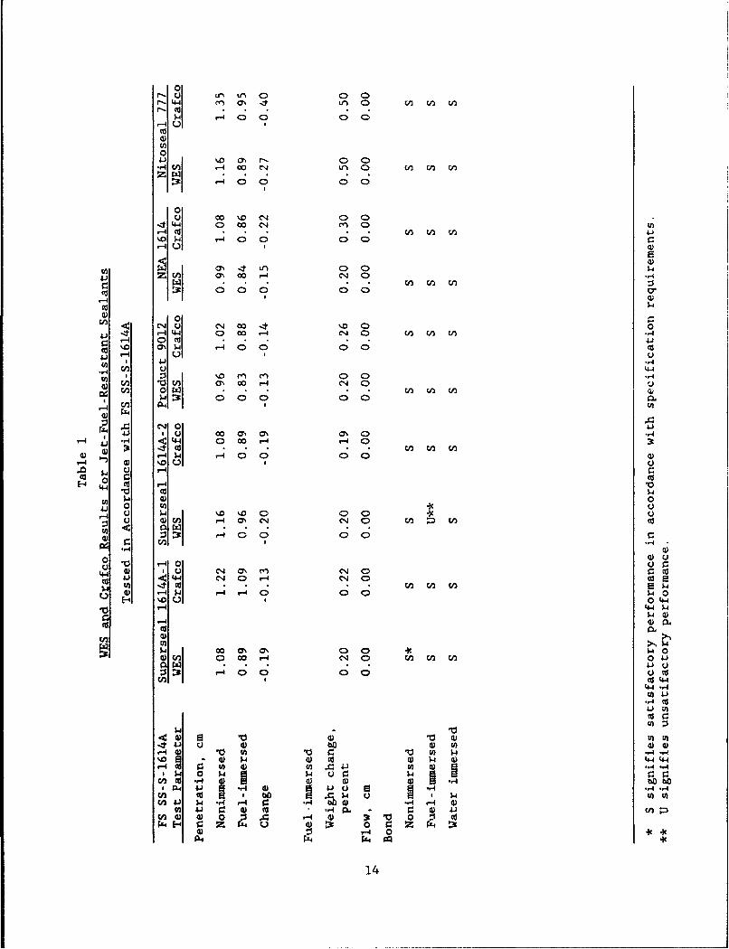
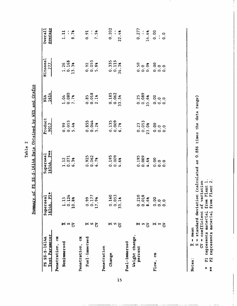
FS SS-S-1614A testing conducted by Crafco and WES are presented in Table 1. A
data summary which shows mean values, estimated standard deviation (based on a
value of 0.886 times the range of the two values) (Burr 1974), and the coeffi-
cient of variation is shown in Table 2.
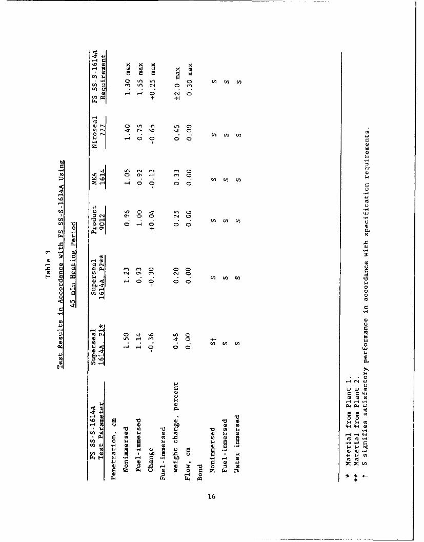
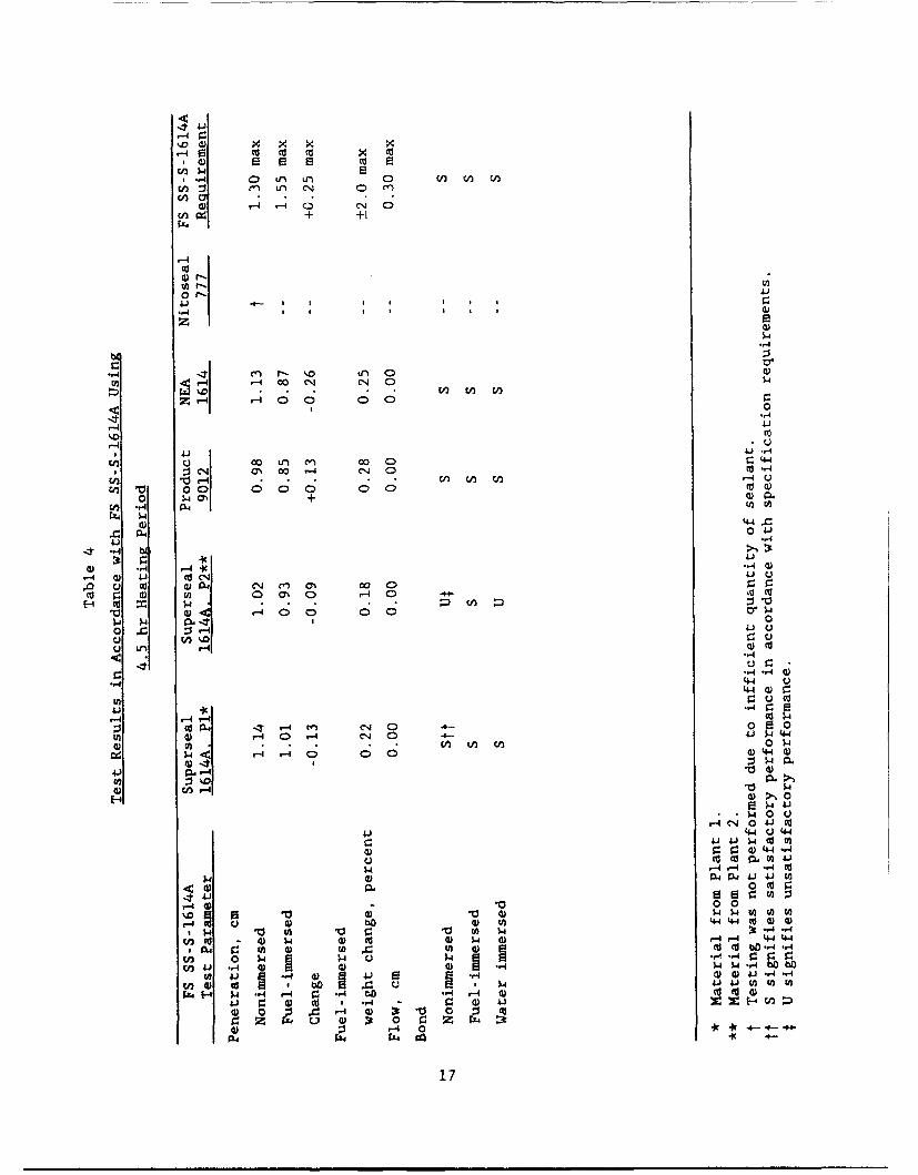
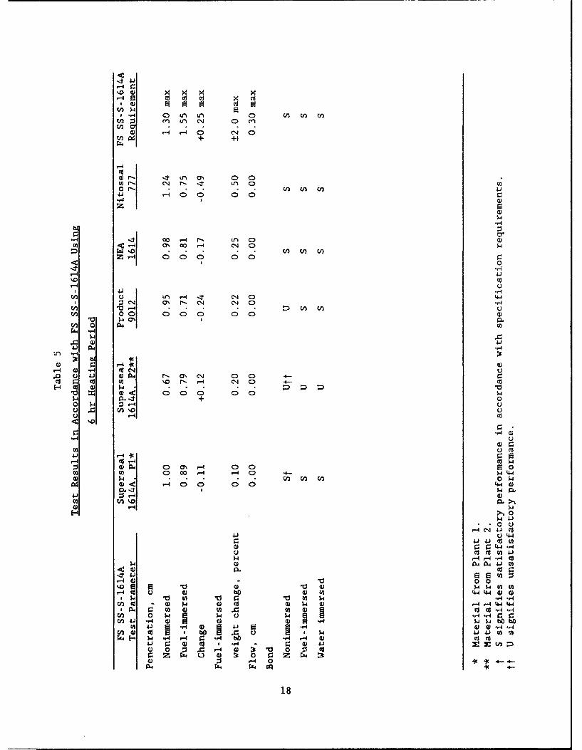
20. Crafco test results for the JFR sealants tested in accordance with
FS SS-S-1614A with heating times of 45 min, 4.5 hr, and 6.0 hr are summarized
in Tables 3 through 5.
21. A brief summary of the test procedures is provided in Appendix A.
Specification Test Analysis.
22. The test results provided in Table I indicate that the Super-
seal 1614A from Plant 1, the Product 9012, and the NEA 1614 conformed to the
test requirements of FS SS-S-1614A in both the WES and the Crafco laborato-
ries. The other two sealants, Superseal 1614A from Plant 2 and Nitoseal 777,
13
01
14 CD, 0 ; C> 0 0-4 u I
Cu0
C; C
01. 0.0 O10 CN-0
,1 4-4 000 004
'A '.0 (n. 0n 0A4ý0 p -4 0 CD CN ' 0 C) S
41 O 00 0- C40
0 w (n
Cd 1 0 00a 0 0CD
,4-
< C'NJ CQ .04 00 'D 04 4 -4 44 0C 00 4 C'.4 0D C(i V)i W
,4 0 ca%u .0 MO'1-J 00C 0 0
co
4o 0 00 0U 44
V0;N00 04CN0u
V) 044-
41) U 00 m. 0'h m' 0-4 -'4 4~4 0 00 14 -4 0
0 w-4 -400 0 0 0,4 %10 riC.
-4 *0Cu ý
Co 0 0 C
, U 0 w.0' (1 C'o 0 Ci ~ CiC
0 0'0
0u 'u 04 0'. C1 C'.4 0 r:Cd4 - i :.-) C. - 'Co 4 4 -4 Ui C C> i c5a I
E -40. u -4 00 140
-44
Cd Co
00 4 CSC 0' '0 4'. n E 04
0 0 00 ca
44 "4.
-,4 C0
44) UA 0 ') 00r-4 4 - 5. 0 C 0 w -4 "4
4) CdCo wo~4 C 05 44 44
inCu Ic 41 m' .w .,
ClAJ 5a b,. w- C) p4bo ~ - -U I) 41 $4 01 Cu4 V. 4O "4 0 4.) C0 " 000 0 jný ' 0 0 " E ::V) 4) 4) 0 9 10 r- 4):30 -
0 i 0ýt -40 z 4 4
14
- -4 dP dP 0 r, W- * 0
f-4 co' (N' 0ý 0
Cu00 f" LnCr- %D 0D dP C%4~ V)dO cn-4 d 0 dP CD
41 JA 0C" : 0L 0 It00 CD4c Lf0, 0 00..I r-r-0z0 ~ 00 0 0
0
Cuco0 00 I~n a'S4~ l 4 w d U~-dP 00 * %DdtWI00dP C0
,- 0 ar-. 00 0r- r 0 Ln 0 ',D 0 00C
Cu CY)C
> 4-'c.) Cn Ln (N C:I0% ,Ln flndP Cn 0 dP M tn d 0 C)
'00 cO0( C14r- 0 O 000
w OCDLf 0 0 -$ 00 0 0 0 tn 00 0
00
tu 0
r4
oU
r-4 C)'4 ,-0\ 00D1 00 004 000
4) 1'. C) 0 0 - % - -4c- 0 0 4 > 5 E00 w 40 0 0 o a4
%D 4) " -4 (N
,40Cu .s4 IL) 4) A
4-4 44C Cu Cuo~ .4 ,.4 8 8.
'-4to4 (1 r-1 Oc 01
CuP4 0~- p.0~P -~ 0 0 r.IDC) -ý4 v-40 r4 4a ,4 r- C'J'. 000 W
W-4J r-4 r4f w. 04 4 4 bO4-4 C14
En~~~C .1- 0 .,.4 r4 4)4
44~~~ E-4~ z ) 1Q)J 4) 1-4
-4 C)4 C14 g004C)
~ C) (C.15
4*41
-4o
cjco
1-4
0 ý 0 LI' L, UA 0
O r-- En m 2 41" "3 00 0) 0C
-,44
4 Li, C%4 M~ c" 0 a0n 0' -4 4
000 00
'.08 4 r- 4443 C1 1 ) Cj 0-H
'.0 0- w LA 0 /
En 00 0 -40 0 0 4
4) 44
4) 43".
cv . 4 ) biCJ 0'C
4) .,4-4 0 04) 0 4 M 0n
E o *10,410 0 C)'. p0 14 : _-4
-4 L
"-4.14)
-4-4 -4
'ul. 04 '0 W 00
P -4 r-4 0 0 04.4
14 ~0.1-4C1 4
41 u4
9W-04 4N
4) 4) 0 L0
N- C) PAP.4 44 3
0 ) Vd 004 d 4 4S V 4) (n c) a) 8 v ca4j .4 4) 4) 0) W- b4-44MN 4J 1 1 E ) N) -r4-(A 4) cc 4) N 1) .41 " w.
4j C: 4) d 14 .,4 i 4) " 4 C~-
4) 0 0 .c r4 44)t'o (d
11.4- N1 CO4.4 Z ,4 b . 4 4
16
kD 4) 9
+ +1
-4
.4)
-4 ,14 cn W'
mZ-4 r-4 00 01 C40
Z-. 0 -0C
r-4
41 41.-
C14 a% 0A ý4 o 0 M-1 .- 4 CA. (n En) 0-
C ' 00 0 0 0> to 00 wO + (D 0.
C40 --4 PL ( U )t
ý4
~P., 04-41)
0) .-r4 1-4 * '."4
,-4 0) 41J tC r' CJU0 'lq rn N COO
0 4) 0to 0 0 r-4 0 -
'0~~ C)< o- 0 0ý4 0
0 X~ r4-4 -
*-,4
-,4 *-4 W)
'44 d)
41) -iI4 r. r
-4 04 'T-4 m~ c- 0 -o- ~0~4 4 04) '4-j 44
V.) 0.- '0
4) c/-41
1 1p 1
4)4 o 45 '44.-
(Dr 4.4 r4
,-4 41'00
4) oo ca1.444'0~~~~ t) ' 0 on1
c -cd 4) 1w 4) m) -4 ) -4 -4 4-4 444 to 4) wo A ~ (n 4) C 'I bO -4-,4
(2 0 ý.4 ý 4 U k- -, : r1f 4j -A4 4) 4) 4) W $4-4ýbb
?Ao 4 4) a 4.) 0) S..44) j .,4 .,4
W 4) cd jD cI I ý441) (n to to
934E4 P .W -- 4 -- 4 C: *.4 bko -4 r-4 4) ( C( 4)C:) 4) CU 1 -4 4 1 CA :
04 4) Ms 'C: ~ Z a):t00 X
4) z r4 0 .9c- - - 0-4A4 4 4 44 go.
17
14 0, C) L ' 0 nV W
wur -n u-n a' 0 0n-4 - 4 0 0q <D
+ +0
CCu
1*) r--- I?
0 l. C1r 000 00
44 C'C444
-.0 (n nZ ý4 ) 0 C)
41 .,jC) L) ,-4 1 C-4 0) '44
T C, O r- C4. CN 0 -.4
A0 0 0; 0 0, 0 0 4)En 0 V)Crz4 ..4
41.
Ln Ic
,4 Q) ".4 Cu' C)'m C) j.1 Cu. r- a' ON'0 0 0Cu 9 u in %,D r. r-4 C14 0 -C
E-4 CU Cu w ;4)00 0 0 1-4
+ 0
<0p
",4 C)r-
:1) -4) 4C Y -
CuP-i 00' r-4 040 P 0
C4 4).4 4 C"00 0 0 4-4 a)
41) :r..4 4)(ntn10 -
(-4l
e4 41)C
4) C )4 4J C
41 U 4-4'4
C) Cu C ul 41Aý -'4 ,4 -. 4 (u
1-4 Cu CL4 A44J ) Ca)P.. od 9
'-40~ a~0%D~ $4 '~C -).4 tOCt
) Cu hO Cu W 4-44-4 Cu Cu# ~ CO V'A 0 r. '0 CO 1.4 4-,
U Cu 4) a4 ) Cu Cu k- 0) -4'-44-44-404 CO 4) CO 4)CO C Cu Cu -4 "4
En 0 $4~ 1 -C -44 r.4 9:rEn J -r4 0 4) 4) Cu) . 1-i 1 bObtO
WCOJ l U. )41u4J. 10. C) C) -,4'.,4cn 4)cuU'bC .C) u I - 4 "4)4- CO Mia-4W '. 14 .- 4 r .4 _i bo- m m u
W) r. Cu Cu I r4 z =u w )4) 0 :j X '-4 Cu ;3 '00 11 Cur. Zz. P4 u D13 0 r: c'. ýkD4) 0 -4 0'I C 4 -
'c 4-
18
had conflicting reports. The Superseal 1614A from Plant 2 material was
reported as conforming to FS SS-S-1614A requirements in the Crafco laboratory
tests, but the material exhibited cohesive failure on the second cycle during
the testing at WES. The Nitoseal 777 conformed to the test requirements of
FS SS-S-1614A at WES, but the material did not meet the nonimmersed penetra-
tion requirement as reported by Crafco.
23. The summarized data provided in Table 2 indicate some variability
between the testing conducted by WES and Crafco. The nonimmersed penetration
average values ranged from 0.99 to 1.26 cm. The range of values indicates the
diversity of materials that can meet the FS SS-S-1614A nonimmersed penetration
requirement of 1.30 cm maximum. More important than the change in average
penetration values is the coefficient of variance (CV) of the nonimmersed
penetration results of each of the sealants. The CV ranges from a low of
5.4 percent for the Product 9012 results to a high of 13.3 percent for the
Nitoseal 777. The fuel-immersed penetration average values had a narrower
range, Lut the CV ranged from a low of 2.1 percent for the NEA 1614 to a high
of 17.9 percent for the Superseal 1614A from Plant 1. The CV for the fuel-
immersed change in weight exhibited a larger range than either the non-
immersed or fuel-immersed penetration results. The CV ranged from 0.0 percent
to 35.6 percent. The flow tests indicated no apparent variability because
none of the samples exhibited flow. The simple statistical analysis of the
data indicates that variability in the test results does exist between labora-
tories and that the variability could be of a sufficient magnitude for one
laboratory to report that the sealant conforms to the specifications and a
second laboratory to report that the sealant does not conform to the specifi-
cation requirements. The bond testing is reported by satisfactory or unsatis-
factory; therefore, statistical analysis is more difficult. The bond test
results were very consistent between the laboratories with only one test that
did not correspond. The one exception was the fuel-immersed bond testing for
the Superseal 1614A from Plant 2. The reason for the discrepancy in the bond
testing or the variability of the other test results is not known. However,
items such as sampling techniques, melting and heating effects of the labora-
tory equipment, human variability, and conditions to which the sealants were
exposed during shipment could be contributing factors to the noted variances.
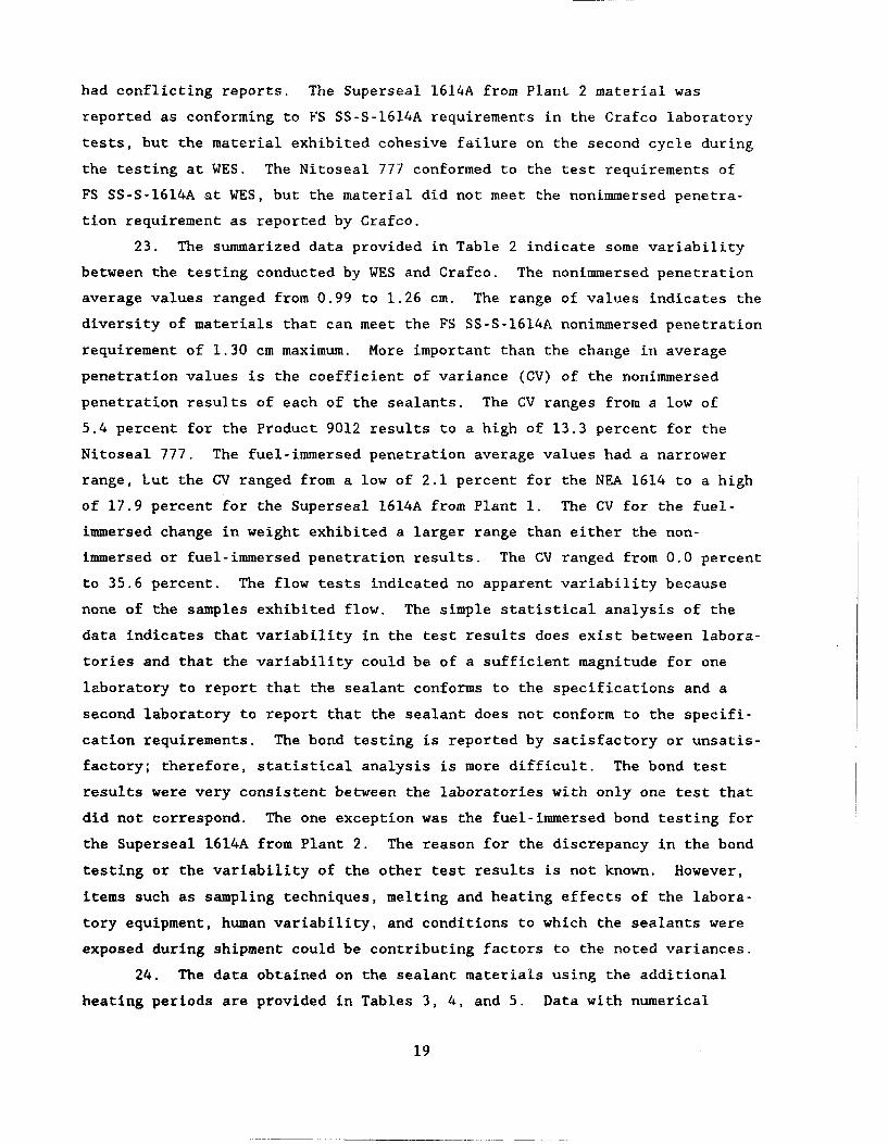
24. The data obtained on the sealant materials using the additional
heating periods are provided in Tables 3, 4, and 5. Data with numerical
19
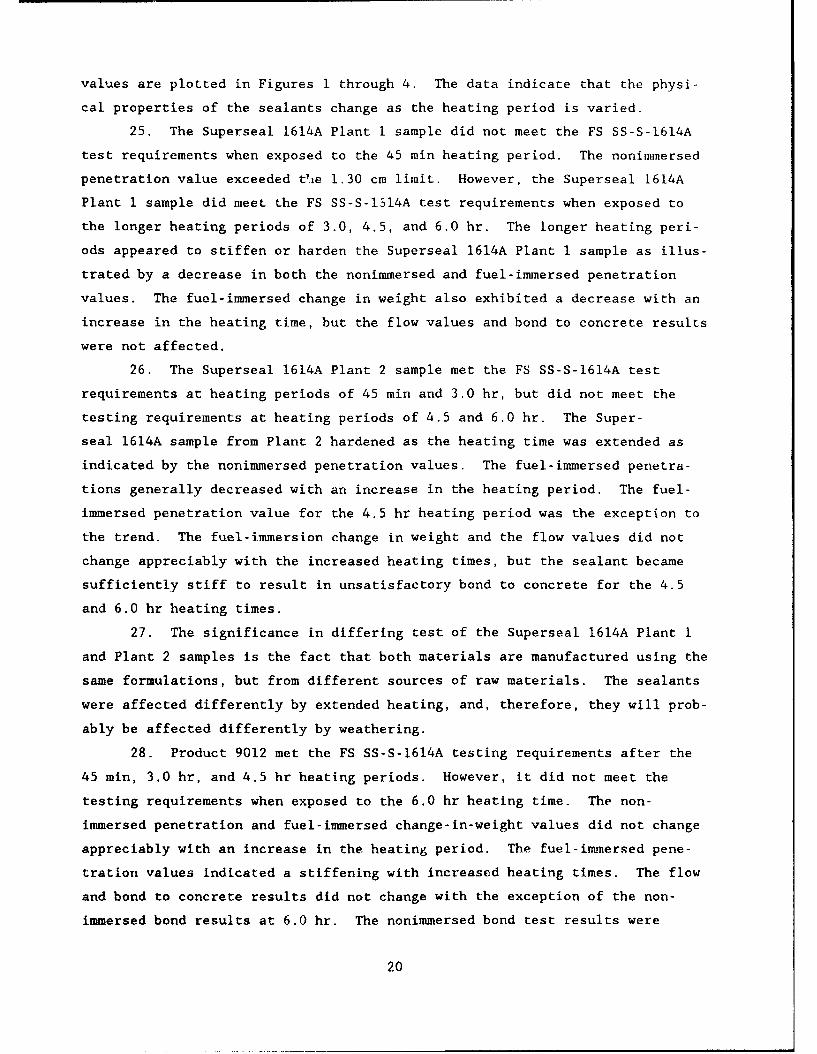
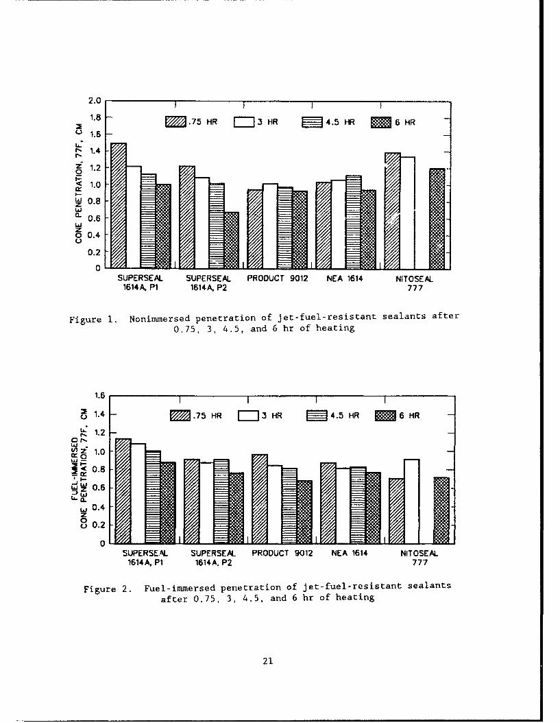
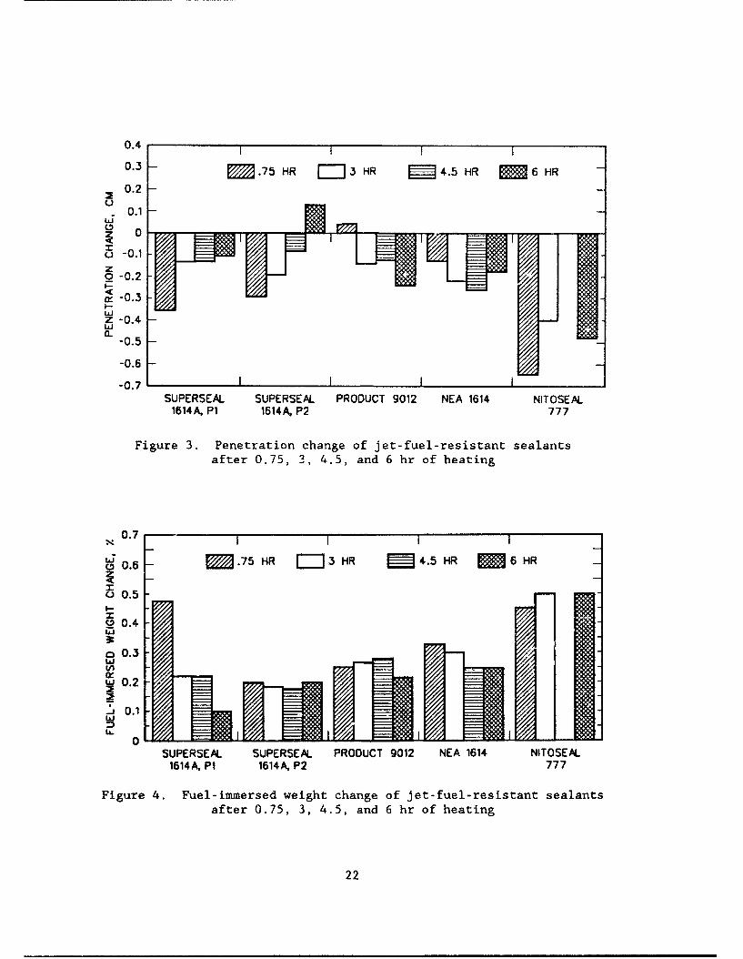
values are plotted in Figures 1 through 4. The data indicate that the physi-
cal properties of the sealants change as the heating period is varied.
25. The Superseal 1614A Plant 1 sample did not meet the FS SS-S-1614A
test requirements when exposed to the 45 min heating period. The nonimmersed
penetration value exceeded tVe 1.30 cm limit. However, the Superseal 1614A
Plant 1 sample did meet the FS SS-S-1514A test requirements when exposed to
the longer heating periods of 3.0, 4.5, and 6.0 hr. The longer heating peri-
ods appeared to stiffen or harden the Superseal 1614A Plant 1 sample as illus-
trated by a decrease in both the nonimmersed and fuel-immersed penetration
values. The fuel-immersed change in weight also exhibited a decrease with an
increase in the heating time, but the flow values and bond to concrete results
were not affected.
26. The Superseal 1614A Plant 2 sample met the FS SS-S-1614A test
requirements at heating periods of 45 min and 3.0 hr, but did not meet the
testing requirements at heating periods of 4.5 and 6.0 hr. The Super-
seal 1614A sample from Plant 2 hardened as the heating time was extended as
indicated by the nonimmersed penetration values. The fuel-immersed penetra-
tions generally decreased with an increase in the heating period. The fuel-
immersed penetration value for the 4.5 hr heating period was the exception to
the trend. The fuel-immersion change in weight and the flow values did not
change appreciably with the increased heating times, but the sealant became
sufficiently stiff to result in unsatisfactory bond to concrete for the 4.5
and 6.0 hr heating times.
27. The significance in differing test of the Superseal 1614A Plant 1
and Plant 2 samples is the fact that both materials are manufactured using the
same formulations, but from different sources of raw materials. The sealants
were affected differently by extended heating, and, therefore, they will prob-
ably be affected differently by weathering.
28. Product 9012 met the FS SS-S-1614A testing requirements after the
45 min, 3.0 hr, and 4.5 hr heating periods. However, it did not meet the
testing requirements when exposed to the 6.0 hr heating time. The non-
immersed penetration and fuel-immersed change-in-weight values did not change
appreciably with an increase in the heating period. The fuel-immersed pene-
tration values indicated a stiffening with increased heating times. The flow
and bond to concrete results did not change with the exception of the non-
immersed bond results at 6.0 hr. The nonimmersed bond test results were
20
2.0 I 1 1 1
1.8 -- E .75 HR =3 HR 4.5 HR 6 HR
S1.6 -
- 1.41.2
0
1.0
w 0.8zw.. 0.6
zo 0.4.Lii
0.2
01SUPERSEAL SUPERSEAL PRODUCT 9012 NEA 1614 NITOSEAL
1614A, P1 1614A, P2 777
Figure 1. Nonimmersed penetration of jet-fuel-resistant sealants after
0.75, 3, 4.5, and 6 hr of heating
1.6 1 1
UM 1.4 -. 75 HR r-j3 HR • 4.5 HR 6 HR
S1.2 -LaUz 1.0L P< 0.8o.4 I i
wz 0.6
,., 0.4z0u0.2
0SUPERSEAL SUPERSEAL PRODUCT 9012 NEA 1614 NITOSEAL
1614A, PI 1614A, P2 777
Figure 2. Fuel-immersed penetration of jet-fuel-resistant sealants
after 0.75, 3, 4.5, and 6 hr of heating
21
0.4 t 1 1 1
0.3 - M .75 HR H3 HR 4.5 HR 6 HR0.2 -
0.1
U 0.1zo -0.2I--
i- 0.3I-.
Z -0.4Lii ii
-0.5
-0.6
-0.7 1ISUPERSEAL SUPERSEAL PRODUCT 9012 NEA 1614 NITOSEAL
1614A, P1 1614 A, P2 777
Figure 3. Penetration change of jet-fuel-resistant sealantsafter 0.75, 3, 4.5, and 6 hr of heating
0.7 -
~M0.6 -. 75 HR 3 HR 4.5 HR M 6 HR
00.5I--
' .4
o 0.3
0.2
0
SUPERSEAL. SUPERSEAL PRODUCT 9012 NEA 1614 NITOSEAL1614A, PI 1614A, P2 777
Figure 4. Fuel-immersed weight change of jet-fuel-resistant sealantsafter 0.75, 3, 4.5, and 6 hr of heating
22
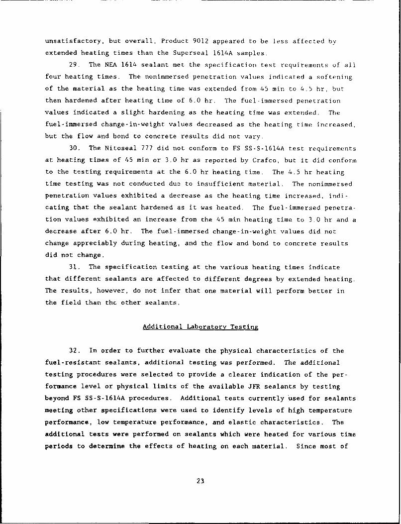
unsatisfactory, but overall, Product 9012 appeared to be less affected by
extended heating times than the Superseal 1614A samples.
29. The NEA 1614 sealant met the specification test requirements of all
four heating times. The nonimmersed penetration values indicated a softening
of the material as the heating time was extended from 45 min to 4.5 hr, but
then hardened after heating time of 6.0 hr. The fuel-immersed penetration
values indicated a slight hardening as the heating time was extended. The
fuel-immersed change-in-weight values decreased as the heating time increased,
but the flow and bond to concrete results did not vary.
30. The Nitoseal 777 did not conform to FS SS-S-1614A test requirements
at heating times of 45 min or 3.0 hr as reported by Crafco, but it did conform
to the testing requirements at the 6.0 hr heating time. The 4.5 hr heating
time testing was not conducted du3 to insufficient material. The nonimmersed
penetration values exhibited a decrease as the heating time increased, indi-
cating that the sealant hardened as it was heated. The fuel-immersed penetra-
tion values exhibited an increase from the 45 min heating time to 3.0 hr and a
decrease after 6.0 hr. The fuel-immersed change-in-weight values did not
change appreciably during heating, and the flow and bond to concrete results
did not change.
31. The specification testing at the various heating times indicate
that different sealants are affected to different degrees by extended heating.
The results, however, do not infer that one material will perform better in
the field than thc other sealants.
Additional Laboratory Testing
32. In order to further evaluate the physical characteristics of the
fuel-resistant sealants, additional testing was performed. The additional
testing procedures were selected to provide a clearer indication of the per-
formance level or physical limits of the available JFR sealants by testing
beyond FS SS-S-1614A procedures. Additional tests currently Used for sealants
meeting other specifications were used to identify levels of high temperature
performance, low temperature performance, and elastic characteristics. The
additional tests were performed on sealants which were heated for various time
periods to determine the effects of heating on each material. Since most of
23
the JFR sealants were supplied as liquids which polymerize during heating,
testing of the liquid materials in their as supplied state was also performed.
33. Test procedures used to determine "as-supplied" properties were as
follows:
a. Brookfield viscosity at 77°F and 100°F. These evaluations wereperformed to determine the thickness of each material at typi-cal ambient temperatures which the sealant may experience priorto application. The viscosity indicates the ease with whichthe material may be handled when adding to melter-applicatoidevices. Testing was performed using a Brookfield Model HATviscometer, with a No. 4 probe at 20 rpm for 77±I°F testing,and a No. 2 probe at 20 rpm for 100±1IF testing.
b. Oven-aged weight change at 158°F. The weight change was evalu-ated in two different sample configurations to determine thevolatile content of the sealant materials. The first sampleconfiguration was a standard 6 oz (70 mm diam, and 45 mm deep)ointment tin that is used for penetration testing in FS SS-S-1614A. For this evaluation, 100 ± I g of the sealant wasplaced in the tin. The second configuration was a 140-mm diamby 9.5-mm deep pan as specified in ASTM D1754 with 100 ± 1 g ofsealant. For each configuration, the pans with sealant wereplaced in a 158°F ± 2°F forced-draft oven and their weight wasmonitored after 0, 2, 6, 24, 72, and 168 hr of exposure. Fromthese measurements, percent weight loss was calculated.
34. Test procedures used to determine additional physical properties
were as follows:
a. Resilience. Resilience was determined after four differentcuring periods used in several different sealant testing proce-dures. The resilience parameter provides an indication of theelastic characteristics of the sealant. Evaluation at severaldifferent curing periods provides an indication of variationswhich may occur in elastic characteristics during aging. Test-ing was performed in accordance with FS SS-S-1401C except fourdifferent curing and conditioning periods prior to conditioningin the 77°F water bath were used. The four curing and condi-tioning periods were (a) 24 ± 2 hr at standard conditions (thestandard FS SS-S-1401C procedure), (b) 72 ± 4 hr at standardconditions (the standard ASTM D3583 procedure), (c) 72 ± 4 hrat standard conditions followed by 24 ± 2 hr in a 1588 ± 20 Fforced-draft oven (the standard ASTM D3583 aged procedure), and(d) 72 ± 4 hr at standard conditions followed by 168 ±4 hr in a1580 ± 2°F forced-draft oven (the FS SS-S-1401C agedprocedure).
b. Cone penetration at 0°F. This test provides an indication ofthe material stiffness at O°F. The test procedure consisted offurther conditioning the 77°F penetration samples from standardFS SS-S-1614A testing in an air atmosphere at 0 ± 2*F for16 ± 4 hr immediately after determining the 77°F penetration.The specimen was removed from the O°F atmosphere and rested
24
immediately at standard lab conditions for penetration usingthe 150 g cone with a 5 sec duration. Three determinationswere made within 60 sec from the time of removal from the O*Fatmosphere and the results were averaged.
C. Flow testing. Flow of the sealants was evaluated at highertemperatures and longer times using ASTM D3583 and FS SS-S-200Eprocedures. This testing was conducted to provide an indica-tion of high service temperature flow resistance properties.Testing was performed using samples prepared in accordance withFS SS-S-1614A procedures. Samples were then exposed to thefollowing four sets of conditions to determine flow:(a) 158° ± 2°F for 5 hr, (b) 158° ± 2°F for 24 hr,(c) 200* ± 2°F for 5 hr, and (d) 200' ± 2°F for 24 hr.
d. Oven-aged weight loss, 158°F. This evaluation was performedafter 24, 72, and 168 hr of exposure to determine sealant vola-tile loss after application due to exposure to summer tempera-tures. The test consisted of pouring specimens into tared 6 oz(70 mm diam x 45 mm deep) tins, curing at standard laboratoryconditions for 72 ± 4 hr, weighing each to the nearest onehundredth of a gram, and then placing them in a 158° ± 2°Fforced-draft oven. Specimens were then removed after 24, 72,and 168 hr, allowed to cool for I hr, and weighed. Percentweight loss for each condition was calculated.
e. Bond testing. Bond testing was performed using three addi-tional procedures which consisted of higher extensions andlower temperatures than standard FS SS-S-1614A procedures.This testing was conducted to provide a better indication ofthe low temperature stiffness and adhesion properties of eachsealant. Only nonimmersed bond specimens were tested using theadditional procedures. Specimen preparation was the same asspecified in FS SS-S-1614A. Testing conditions for threecycles each were as follows: (a) 0 ± 2°F, 100 percent exten-sion, (b) -20 ± 2°F, 50 percent extension, and (c) -20 ± 2°F,100 percent extension. The same evaluation criteria for 1614Anonimmersed bond testing was used for evaluating the bond
tests.
f. Flame resistance. Testing was performed using the FS SS-S-200Eprocedures to provide an indication of the resistance of eachsealant to aircraft exhaust.
g.Tack free time. Testing was performed to determine cure timeand to provide an estimate of the tack free time using thebasic FS SS-S-200E procedure.
h. Brookfield viscosity. The viscosity was performed with thehaed material at the safe heating temperature (± 2*F) just
prior to pouring specimens. The viscosity testing was con-ducted to provide an indication of sealant application charac-teristics. Testing was performed using a Brookfield Model HATviscometer with the appropriate probes and speeds (typicallyNo. 4 at 20 rpm).
25
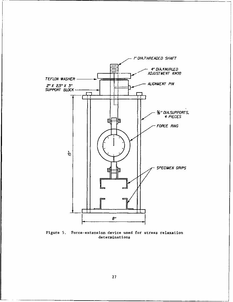
i. Stress relaxation. Stress relaxation testing was performed onthe sealants conditioned at each heating period. The testingwas conducted at both 76 ± 1IF and -20 ± 2°F. The testingconsisted of extending bond specimens prepared in accordancewith FS SS-S-1614A to a predetermined distance or force using
an extension frame. The force decay curve as a function oftime was then monitored. Before testing, the bond specimenswere conditioned for a minimum of 4 hr at the test temperature.
For testing at 76°F, specimens were placed in the extensiondevice grips, and then extended at a uniform rate in 10 sec to100 percent, (1.00 in. separation between the blocks). Theinitial force was then recorded and time measurements werestarted as soon as the 100 percent extension was reached.Extension was then maintained at 100 percent, and the forcerecorded as the specimen relaxes at 10, 30, and 60 sec, as wellas 5, 10, and 60 min. For testing at -20'F, the procedure wassimilar, except the specimens were loaded to a force of 200 lb,(50 psi) in the 10 sec period instead of 100 percent. Theforce relaxation was then monitored at 0, 30, and 60 sec, 2, 5,30, and 60 min, and 3 and 6 hr. During the test, the force wasmonitored using a calibzated 100 lb force ring for 76°F tests,and a 500-lb forco ring for -20'F tests. A diagram of theextension device used i3 shown in Figure 5. Force data wereconverted into pounds per square inch based on the originalspzcimen surface area of 4.00 sq in.
35. Additional test result data are summarized in Tables 6 through 11
and plotted in Figures 6 through 21.
Additional Laboratory Test Analysis
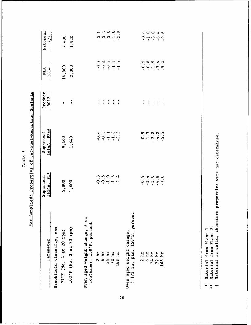
36. The "as-supplied" properties of the liquid JFR sealants are pro-
vided in Table 6. The Product 9012 as-supplied properties were not determined
since it was supplied in solid form.
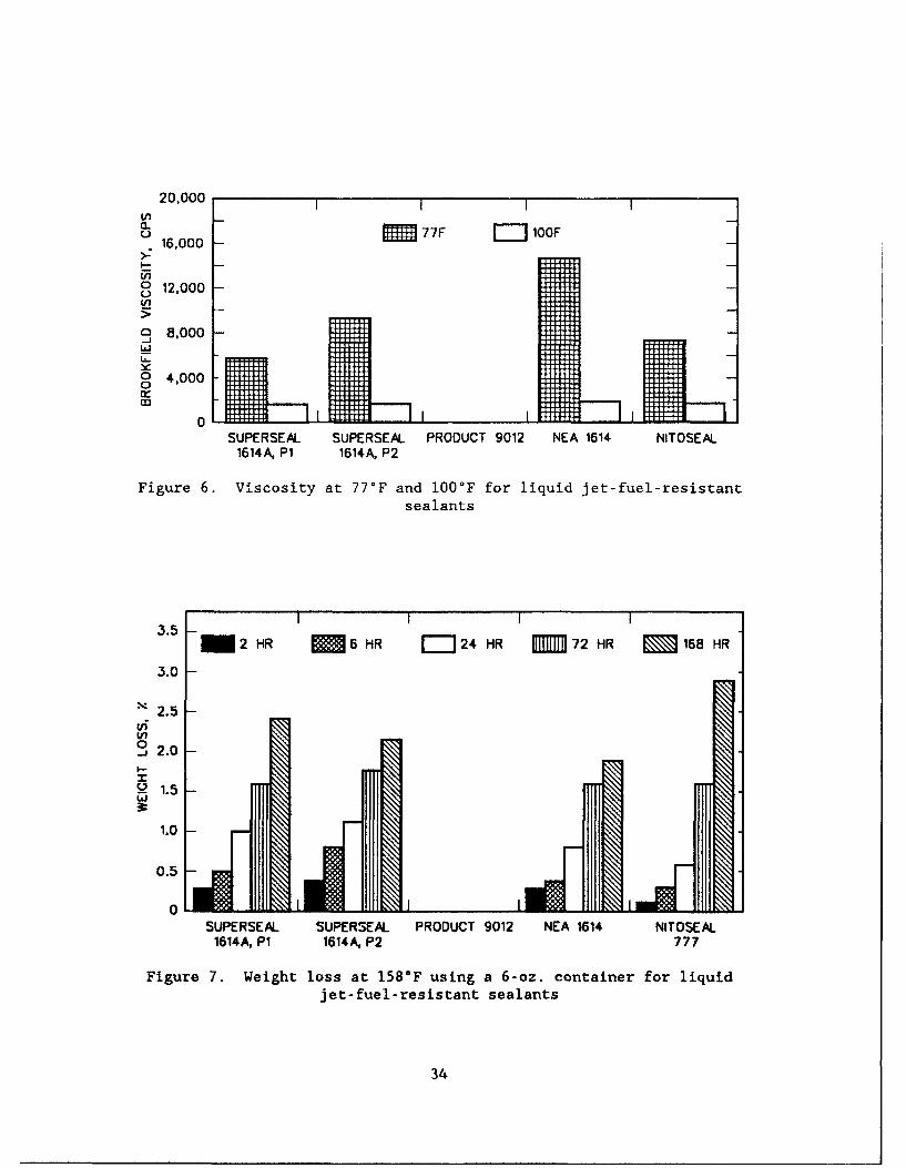
Brookfield viscosity
37. The Brookfield viscosities of the liquid sealants decreased as the
materials were heated to 100°F as illustrated in Figure 6. As temperature
increases above 100°F to approximately 180-200°F, the viscosity decreases.
Then the liquid materials get to an extremely high viscosity at 200 to 230 0 F,
and then they thin down to the viscosity at the safe heating temperature. The
viscosity of each sealant significantly increased as the temperature was
increased from IOOOF to the safe heating temperature. The viscosity continued
to increase as the sealant was exposed to extended heating times. The
increase in viscosity at the extended heating times indicates that the seal-
ants become more difficult to pump out of the application equipment as
26
I" DIA THREADED SHAFT
- 4" DIAXKNURLED- ADJU,,STMENT KNOB
TEFLON WASHER -
2"X 2.5" X 3" ALIGNMENT PIN
SUPPORT BLOCK .
S0,DIA SUPPORTS.4 PIECES
FORCE RING
SPECIMEN GRIPS
.44
Figure 5. Force-extension device used for stress relaxationdeterminations
27
-1Cd ~. 0 CD 0 0 C> 4 0
N. C-4
0 0 00.4,
00m I co D m co a, ,I o
0 04 00 0'
--4
4.) 0
Co -9 4 1r4i 00 C->I I
0) P64
41)
CU
1 4) 0 0 0 0 0 -- C-4 0 -4 04 -tr 4)-4 cl) 0> .4 * $
4) - -44) 9- *
--- 4
4-4 41)ECd 0 0
U)
,4)441) 1- ýqMU) oI ONIt0 00 C)p (d 4 . ..34) 4) I 0 0 C;-~4' 0-4 C.n .
0 V 0 0 1 1 s I I I Ul
6L %r. - -
En1 f-4 O -
)4
44)
004)40
41
0 .4 r. 0 oc)4 0 Cd0 o4r4ý
a) "4D)1 n .4)
4) 0bO -- 4) b-u I 4W4c -4 4,4,4) 0.4.
A4 >4 040 COk I 140 -4 4-* 0P C14 r,%, (14 0 CUz.
4) 10 0r. .I~
o (d- bo 0-444)o 4.).4 d dcdC
0) r- 9:i 0 44444 ~ 4 40
$4 () C% bO~4 ~ OC28
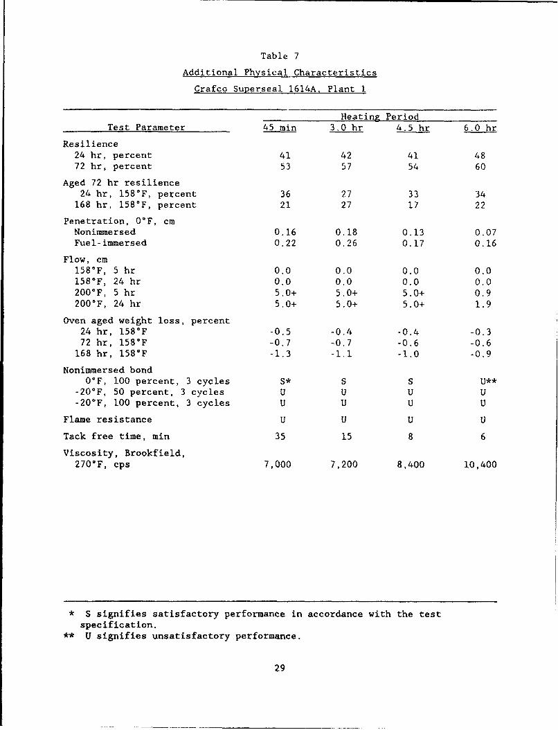
Table 7
Additional Physical Characteristics
Crafco Superseal 1614A, Plant 1.
Heatinz PeriodTest Parameter 45 min 3.0 hr 4.5 hr 6.0 hr
Resilience24 hr, percent 41 42 41 4872 hr, percent 53 57 54 60
Aged 72 hr resilience24 hr, 158°F, percent 36 27 33 34
168 hr, 158°F, percent 21 27 17 22
Penetration, O°F, cmNonimmersed 0.16 0.18 0.13 0.07Fuel-immersed 0.22 0.26 0.17 0.16
Flow, cm158°F, 5 hr 0.0 0.0 0.0 0.0158°F, 24 hr 0.0 0.0 0.0 0.0200°F, 5 hr 5.0+ 5.0+ 5.0+ 0.9200°F, 24 hr 5.0+ 5.0+ 5.0+ 1.9
Oven aged weight loss, percent24 hr, 158°F -0.5 -0.4 -0.4 -0.372 hr, 158°F -0.7 -0.7 -0.6 -0.6
168 hr, 158°F -1.3 -1.1 -1.0 -0.9
Nonimmersed bond0°F, 100 percent, 3 cycles S* S S U**
-20*F, 50 percent, 3 cycles U U U U-20°F, 100 percent, 3 cycles U U U U
Flame resistance U U U U
Tack free time, min 35 15 8 6
Viscosity, Brookfield,270°F, cps 7,000 7,200 8,400 10,400
* S signifies satisfactory performance in accordance with the testspecification.
** U signifies unsatisfactory performance.
29
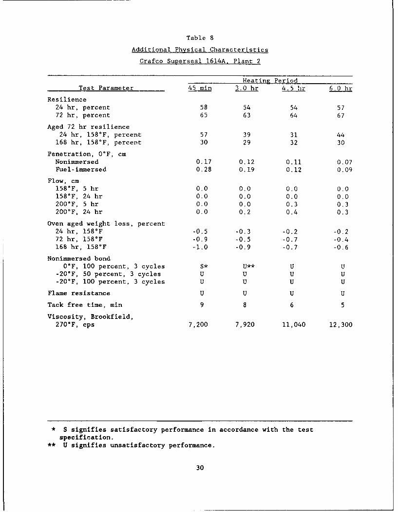
Table 8
Additional Physical Characteristics
Crafco Superseal 1614A. Plant 2
Heating PeriodTest Parameter 45 min 3.0 hr 4.5 hr 6.0 hr
Resilience24 hr, percent 58 54 54 5772 hr, percent 65 63 64 67
Aged 72 hr resilience24 hr, 158°F, percent 57 39 31 44
168 hr, 158°F, percent 30 29 32 30
Penetration, 0°F, cmNonimmersed 0.17 0.12 0.11 0.07Fuel-immersed 0.28 0.19 0.12 0.09
Flow, cm158°F, 5 hr 0.0 0.0 0.0 0.0158°F, 24 hr 0.0 0.0 0.0 0.0200°F, 5 hr 0.0 0.0 0.3 0.3200°F, 24 hr 0.0 0.2 0.4 0.3
Oven aged weight loss, percent24 hr, 158°F -0.5 -0.3 -0.2 -0.272 hr, 158°F -0.9 -0.5 -0.7 -0.4168 hr, 158°F -1.0 -0.9 -0.7 -0.6
Nonimmersed bond00 F, 100 percent, 3 cycles S* U** U U
-20°F, 50 percent, 3 cycles U U U U-20*F, 100 percent, 3 cycles U U U U
Flame resistance U U U U
Tack free time, min 9 8 6 5
Viscosity, Brookfield,270*F, cps 7,200 7,920 11,040 12,300
* S signifies satisfactory performance in accordance with the testspecification.
** U signifies unsatisfactory performance.
30

Table 9
Additional Physical Characteristics
Product 9012
Heating Period"est Parameter 45 min 3.0 hr 4.5 hr 6.0 hr
24 hr, percent 38 49 52 5472 hr, percent 53 58 59 57
Aged 72 hr resilie:-e24 hr, 158°F, percent 45 49 58 51
168 hr, 158°F, percent 27 29 30 28
Penetration, 0°F, cmNonimmersed 0.10 0.09 0.08 0.08Fuel-immersed 0.19 0.15 0.16 0.16
Flow, cm158°F, 5 hr 0.0 0.0 0.0 0.0158°F, 24 hr 0.0 0.0 0.0 0.0200°F, 5 hr 0.5 0.5 0.6 0.6200°F, 24 hr 0.6 0.5 0.6 0.6
Oven aged weight loss, percent24 hr, 158°F -0.3 -0.. -0.2 -0.272 hr, 158 0 F -0.5 -0.4 -0.43 -0.5
168 hr, 158°F -0.8 -0.8 -0.6 -0.6
Nonimmersed bond0°F, 100 percent, 3 cycles U* U U U
-20'F, 50 percent, 3 cycles U U U U-20'F, 100 percent, 3 cycles U U U U
Flame resistance U U U U
Tack free time, min 20 15 9 7
Viscosity, Brookfield,280°F, cps 8,400 11,000 12,400 14,400
* U signifies unsatisfactory performance in accordance with the test
specification.
31
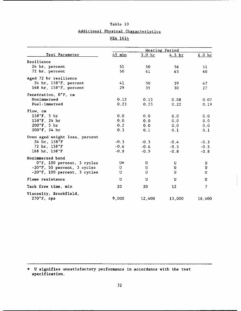
Table 10
Additional Physical Characteristics
NEA 1614
Heating PeriodTest Parameter 45 min 3.0 hr 4.5 hr 6.0 hr
Resilience24 hr, percent 51 50 56 5172 hr, percent 50 61 63 60
Aged 72 hr resilience24 hr, 158°F, percent 41 50 39 47
168 hr, 158°F, percent 29 35 30 27
Penetration, O°F, cmNonimmersed 0.12 0.13 0.08 0.07Fuel-immersed 0.23 0.23 0.22 0.19
Flow, cm158°F, 5 hr 0.0 0.0 0.0 0.0158 0 F, 24 hr 0.0 0.0 0.0 0.0200 0 F, 5 hr 0.2 0.0 0.0 0.0200 0 F, 24 hr 0.3 0.1 0.1 0.1
Oven aged weight loss, percent24 hr, 158°F -0.3 -0.3 -0.4 -0.372 hr, 158°F -0.6 -0.6 -0.5 -0.5
168 hr, 158°F -0.9 -0.9 -0.8 -0.8
Nonimmersed bondOOF, 100 percent, 3 cycles U* U U U
-20°F, 50 percent, 3 cycles U U U U-20°F, 100 percent, 3 cycles U U U U
Flame resistance U U U U
Tack free time, min 20 20 12 7
Viscosity, Brookfield,270 0 F, cps 9,000 12,400 13,000 16,400
* U signifies unsatisfactory performance in accordance with the test
specification.
32
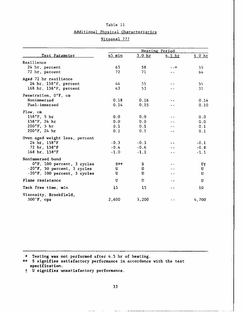
Table 11
Additional Physical Characteristics
Nitoseal 777
Heating PeriodTest Parameter 45 min 3.0 hr 4.5 hr 6.0 hr
Resilience24 hr, percent 63 58 -- * 5572 hr, percent 72 71 -- 64
Aged 72 hr resilience24 hr, 158°F, percent 44 55 -- 54
168 hr, 158°F, percent 43 53 -- 31
Penetration, 0°F, cmNonimmersed 0.18 0.16 -- 0.14Fuel-immersed 0.14 0.15 -- 0.10
Flow, cm158°F, 5 hr 0.0 0.0 -- 0.0158°F, 24 hr 0.0 0.0 -- 0.0200°F, 5 hr 0.1 0.1 -- 0.1200°F, 24 hr 0.1 0.1 -- 0.1
Oven aged weight loss, percent24 hr, 158°F -0.3 -0.3 -- -0.172 hr, 158°F -0.4 -0.6 -- -0.8
168 hr, 158°F -1.0 -1.1 -- -1.1
Nonimmersed bondOF, 100 percent, 3 cycles S** S -- Ut
-20°F, 50 percent, 3 cycles U U -- U-20°F, 100 percent, 3 cycles U U -- U
Flame resistance U U -- U
Tack free time, min 15 15 -- 10
Viscosity, Brookfield,300'F, cps 2,600 3,200 4,700
* Testing was not performed after 4.5 hr of heating.** S signifies satisfactory performance in accordance with the test
specification.t U signifies unsatisfactory performance.
33
20,000 I I 1
a_So 77 -' f~100F16,000
-
V-
0 12,000
O8.000-JJU-
o 4,000omX
0SUPERSEAL SUPERSEAL PRODUCT 9012 NEA 1614 NITOSEAL
1614A, PI 1614A, P2
Figure 6. Viscosity at 77°F and 100°F for liquid jet-fuel-resistantsealants
I I IM 2 HR 6 HR E"-24 HR I 72 HR 168 HR
3.0-
' 2.5In
0 2.0 -I-r21.5-LbJ
1.0
0.5
0SUPERSEAL SUPERSEAL PRODUCT 9012 NEA 1614 NITOSEAL
1614A. PI 1614A, P2 777
Figure 7. Weight loss at 158°F using a 6-oz. container for liquidjet-fuel-resistant sealants
34
I' I I I I
"1 - 1 2 HR r6 HR E 24 HR • 72 HR • 168 H.R10
9
U'"" 7
I--
0
SUPERSEAL SUPERSEAL PRODUCT 9012 NEA 1614 NITOSEAL1614A, P1 1614A. P2 777
Figure 8. Weight loss at 158°F using a 140mm diameter pan for liquidj et-fuel-resistant sealants
801III
70 - .75 HR •3 HR •4.5 HR 1 6 HR -
60
S2 50
3t. 40
bJu30Z-20
(10
10
o. 1 .1 ,,,Ll
SUPERSEAL SUPERSEAL PRODUCT 9012 NEA 1614 NITOSEAL1614A. P1 1614A, P2 777
Figure 9. Twenty-four hr cured resilience of jet-fuel-resistant sealantsafter 0.75, 3, 4.5, and 6 hr of heating
35
90
80 - M.75 HR m 3 HR 4.5 HR M 6 HR
.J 70-
S60-
" 50
-40
LAZ 30
L" 20io
10
0SUPERSEAL SUPERSEAL PRODUCT 9012 NEA 1614 NITOSEAL
1614A, P1 1614A, P2 777
Figure 10. Seventy-two hr cured resilience of jet-fuel-resistantsealants after 0.75, 3, 4.5, and 6 hr of heating
80 I I I I
70".75 HR =3 HR 4.5 HR M 6 HRZ 70
S60
. 50 -
o 40
" 30C-r
z 20,,J
S10
0SUPERSEAL SUPERSEAL PRODUCT 9012 NEA 1614 NITOSEAL
1614A. P1 1614 A, P2 777
Figure 11. Seventy-two hr cured, 24 hr aged resilience of jet-flel-resistant sealants after 0.75, 3, 4.5, and 6 hr of heating
36
80
70 .75 HR 3 HR 4.5 HR MM6 HR70
z!. 60
Erx 50(0ID
t3 40
2:2O
m "
(jlU
W: 0 .. .....
SUPERSEAL SUPERSEAL PRODUCT 9012 NEA 1614 NITOSEAL1614A, PI 1614A, P2 777
Figure 12. Seventy-two hr cured, 168 hr aged resilience of jet-fuel-resistant sealants after 0.75, 3, 4.5, and 6 hr of heating
0.22
0.20 - M .75 HR r- 3 HR 4.5 HR M 6 HR
"2 0.18
. 0.16
b- 0.14
0 0.12
S0.10 IML
S0.08
J 0.06 ;.z I :0 •) 0.04
0.02
0SUPERSEAL. SUPERSEML PRODUCT 9012 NEA 1614 NITOSEAL
1614A. P1 1614A, P2 777
Figure 13. Cone penetration at OOF for jet-fuel-resistant sealantsafter 0.75, 3, 4.5, and 6 hr of heating
37
0.40 1 I 1 1
"0.35 M.75 HR E 3 HR E4.5 HR 6 HR
' 0.300.25
*0"0.25
z
< 0.20r-
w. 0.15
0 0.10
0.05
0SUPERSEAL SUPERSEAL PRODUCT 9012 NEA 1614 NITOSEAL
1614A. P1 1614 A. P2 777
Figure 14. Fuel-immersed cone penetration at 0°F for jet-fuel-resistant sealants after 0.75, 3, 4.5, and 6 hr of heating
2.0
1.8 j"J24 HR Il]I72 HR 168 HR
1.6
' 1.4
(f 1.2
-j 1.0-i--
S0.8 -
S0.6
0.4
0.2
0.75 HR 3 HR 4.5 HR 6 HR
HEATING PERIOD
Figure 15. Weight loss for superseal 1614A, Plant I after
24, 72, and 168 hr of aging at 158°F
38
1.2- 1.F-1 24 HR 1M172 HR E 168 HR
. 1.0
w) 0.8
--0.6
3 0.4
0.2 .. K0
.75 HR 3 HR 4.5 HR 6 HRHEATING PERIOD
Figure 16. Weight loss for superseal 1614A, Plant 2 after24, 72, and 168 hr of aging at 158=F
1.0 n"24 HR W1172 HR 168 HR
' 0.8
vi1
00.6
-00.4
0.2
o ~IL0
.75 HR 3 HR 4.5 HR 6 HRHEATING PERIOD
Figure 17. Weight loss for product 9012 after 24, 72, and168 hr of aging at 158°F
39
1.2 1 1
1.0 E324 HR U 72 HR 168 HR
i 0.8
0 " 0.6I--
• 0.4
0.2
0.75 HR 3 HR 4.5 4R 6 HR
HEATING PERIOD
Figure 18. Weight loss for NEA 1614 after 24, 72, and 168 hrof aging at 158°F
1.6
1.4 - -24 HR EM 72 HR 168 HR
1.2 -
i 1.0 -(n0
S0.8 -0. -S0.4
0.2
0.75 HR 3 HR 4.5 HR 6 HR
HEATING PERIOD
Figure 19. Weight loss for Nitoseal 777 after 24, 72, and168 hr of aging at 158°F
40
4 5 1 1 1 1
40 M .75 HR -3 HR 4.5 HR M 6 HR
CA 35UJI--
z 30
_•25
IA-~15
I-10
5
0 -SUPERSEAL SUPERSEAL PRODUCT 9012 NEA 1614 NITOSEAL
1614A, P1 1614A, P2 777
Figure 20. Tack free time of jet-fuel-resistant sealants after
0.75, 3, 4.5, and 6 hr of heating
22,000 1 1 1 1
20,000 - M .75 HR m 3 HR M 4.5 HIR M 6 HR
S18,000-U
.16,000 -I-j- 14,0000L 12,000-5
10,000--Jw 8,000 -
0 6,000
4,000
2,000
0SUPERSEAL SUPERSEAL PRODUCT 9012 NEA 1614 NITOSEAL
1614A, P1 1614A, P2 777
Figure 21. Viscosity at safe heating temperature for jet-fuel-resistant
sealants after 0.75, 3, 4, 4.5, and 6 hr of heating
41
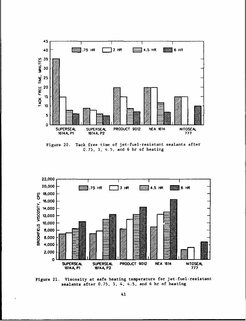
heating times are increased. Tables 7-11 provide the additional test results
for the sealants.
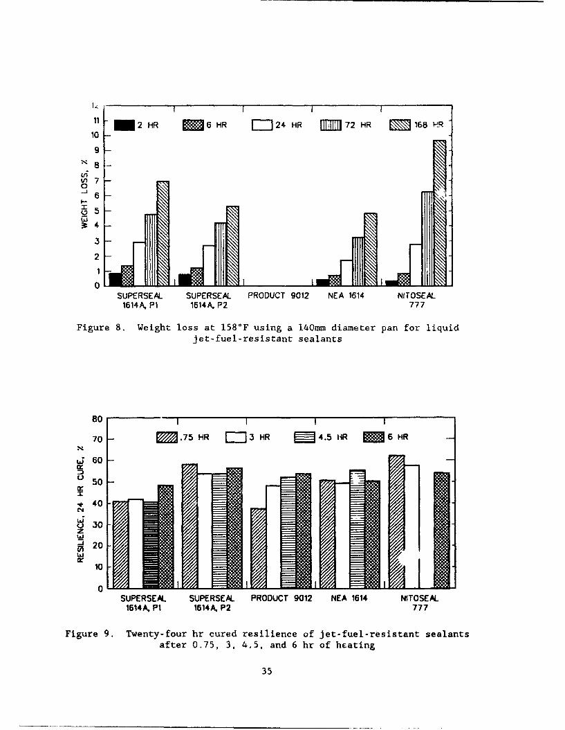
Oven-aged change in weight
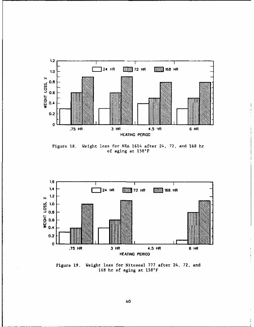
38. The oven-aged change-in-weight data for the as-received sealants
indicate they all experienced weight loss with aging. The tests conducted in
the 140-mm-diam pan (Figure 8) exhibited greater weight loss than the tests
conducted in the 6-oz tin (Figure 7). The greater weight loss occurs in the
140-mm-diam samples due to the greater surface area exposed to the heated air.
The oven-aged change-in-weight tests indicate that the Nitoseal 777 had the
largest volatile loss and the NEA 1614 experienced the smallest loss. The
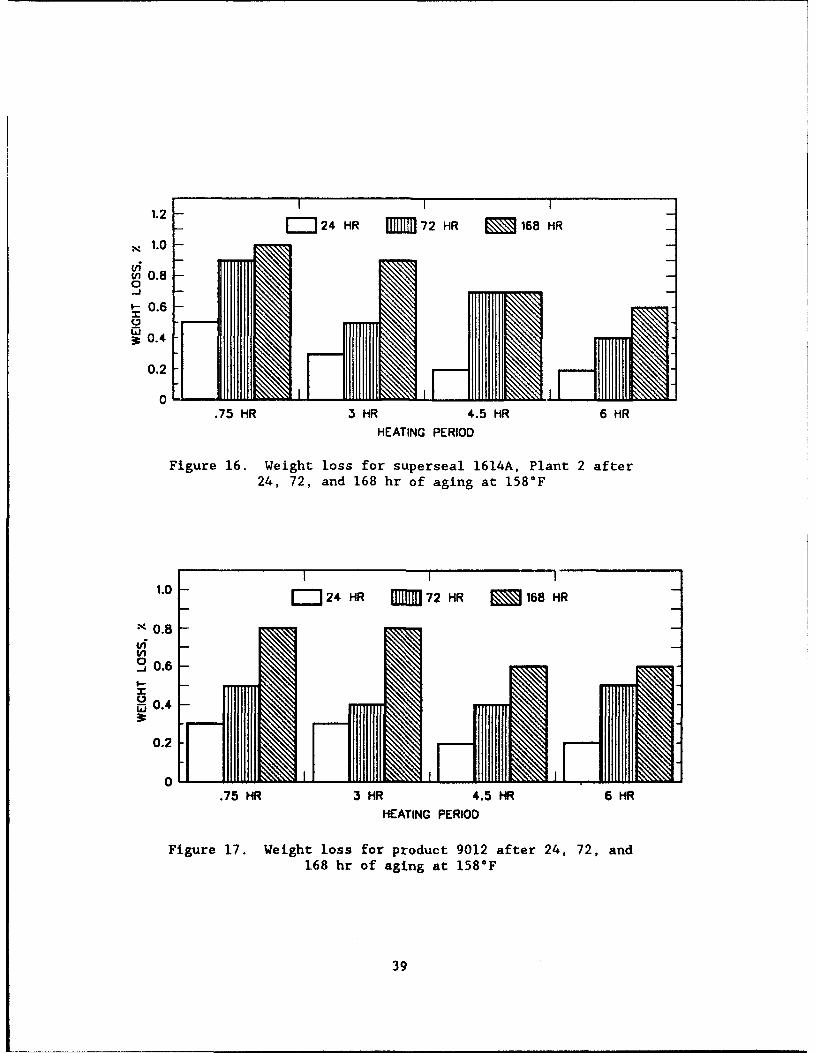
oven-aged change-in-weight results for the sealants exposed to the various
heating times are plotted in Figures 15 through 19. The test results indi-
cated that as the sealants were exposed to longer heating times before condi-
tioning, the percent weight loss decreased except for the Nitoseal 777. This
trend was expected, since the sealants were exposed to longer heating times
and the volatiles would be lost during the heating.
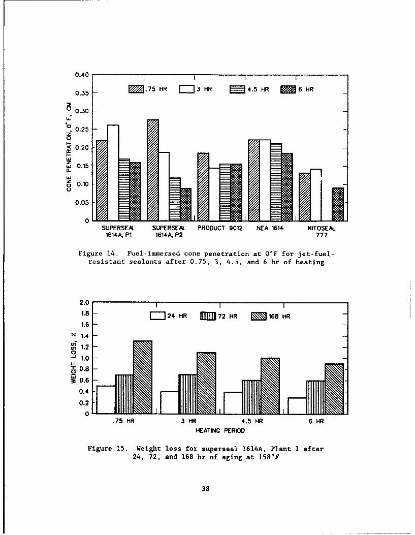
39. The maximum weight loss after 168 hr of aging was 1.3 percent for
Superseal 1614A, Plant I after 45 min of heating, and the minimum weight loss
was 0.6 percent for Superseal 1614A, Plant 2 after 6.0 hr of heating. The two
sealants manufactured using raw materials from different sources again exhib-
ited different physical properties.
40. During the oven-age testing, the surface of the sealant samples
became brittle. An increase in brittleness or hardness also occurred as the
samples were exposed to longer aging periods. This phenomena was studied in
greater detail, and the testing procedures and results are discussed in
Part V.
Resilience testing
41. Resilience after 24 hr of curing at ambient conditions (Figure 9)
varied from a low of 38 percent for the Product 9012 after 45 min of heating
to a high of 63 percent for Nitoseal 777 after 45 min of heating. Resilience
data varied depending on heating period, and differences exist between seal-
ants. Superseal 1614A, Plant 1 had the lowest overall average resilience
(43 percent), and Superseal 1614A, Plant 2 had the highest average (57 per-
cent). Superseal 1614A, Plant 2 experienced the least change during heating
(4 percent range of data), and Product 9012 experienced the greatest change
(16 percent range of data).
42
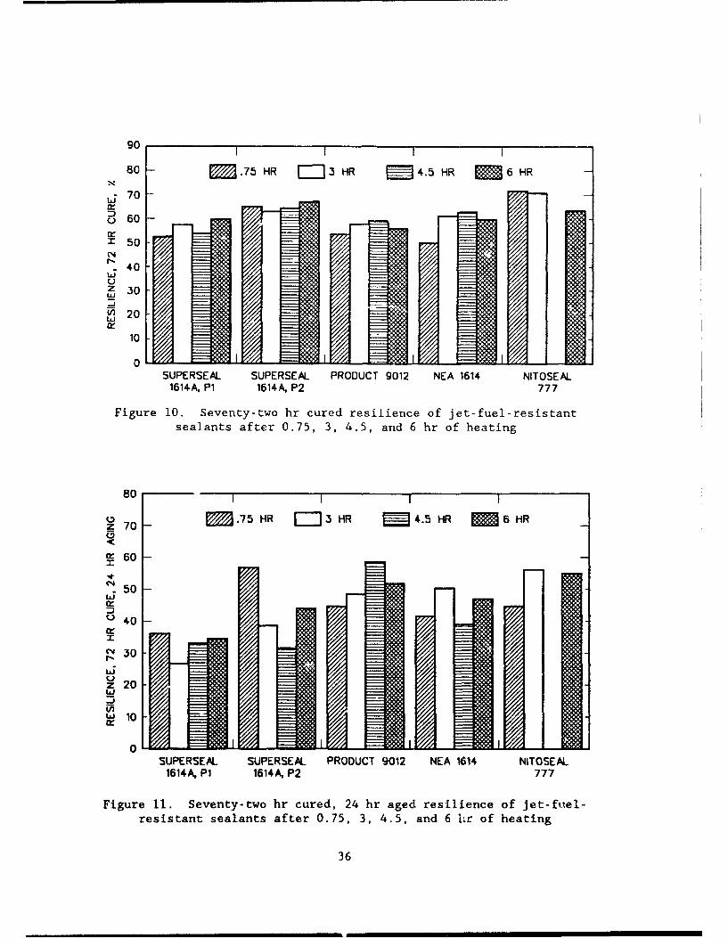
42. Resilience after 72 hr of curing at ambient conditions (Figure 10)
varied from a low of 50 percent for NEA 1614 after 45 min of heating to a high
of 72 percent for Nitoseal 777 after 45 min of heating. Superseal 1614A,
Plant 1 had the lowest average resilience (56 percent) and Nitoseal 777 had
the highest average (69 percent). All resilience results for the sealant
materials were higher after 72 hr of curing than after 24 hr of curing. The
one exception to this trend was the NEA 1614 that had been exposed to 45 min
of heating. The average increase in resilience varied from 6 to 13 percent.
43. The resilience of the sealants after they were subjected to aging
at 158°F for 24 hr (Figure 11) varied from a low of 27 percent for Super-
seal 1614A, Plant 1 after a 3 hr heating time to a high of 58 percent for
Product 9012 after a 4.5 hr heating time. Superseal 1614A, Plant 1 had the
lowest overall average (33 percent), and Product 9012 and Nitoseal 777 had the
highest averages (51 percent). All resilience results for the sealant materi-
als were lower after aging for 24 hr at 158°F than the sealants cured for
72 hr. The greatest overall average decrease in resilience was for Super-
seal 1614A, Plant 1 (24 percent decrease), and the least decrease was for
Product 9012 (6 percent).
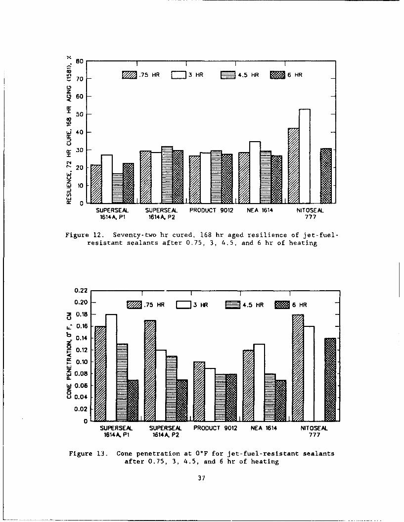
44. The resilience of the sealants after they were subjected to aging
at 158°F for 168 hr (Figure 12) varied from a low of 17 percent for Super-
seal 1614A, Plant 1 after 4.5 hr of heating to a high of 53 percent for Nito-
seal 777 after 3 hr of heating. Superseal 1614A, Plant I had the lowest
average resilience (22 percent) and Nitoseal 777 had the highest (42 percent).
In all but two tests, resilience results after 168 hr of aging were lower than
at 24 hr of aging. Product 9012 experienced the greatest average decrease
(22 percent) and Nitoseal 777 experienced the least (9 percent).
45. The above results and discussions indicate that resilience varies
significantly between the sealants tested due to the length of heating period
used and the curing and aging period. Lowest overall resilience resul.ts were
obtained for Superseal 1614A, Plant 1 (39 percent), and the highest results
were for Nitoseal 777 (59 percent). The effect of heating period varies
depending on the sealant tested. For some materials heating had little effect
on results, while with others, the results tended to either increase or
decrease with heating. Increasing curing time from 24 to 72 hr prior to test-
ing caused the resilience to increase by an average of 9 percent for all
materials tested. The resilience values within a specific heating for the
43
sealants exhibited a general decrease as the samples were exposed to aging,
but clear trends were not exhibited for specific resilient testing of varying
heating times.
Penetration testing
46. Penetration testing at 0°F (Figure 13) showed a decrease as heating
time increased for all sealants. Results after 45 min of heating varied from
0.10 to 0.18 cm. Results after 6 hr of heating varied from 0.07 to 0.14 cm.
All materials tested had lower penetrations after 6 hr than after 45 min.
Percent retained penetration after 6 hr compared to 45 min of heating varied
from a low of 41 percent for Superseal 1614A, Plant 2 to 80 percent for
Product 9012.
47. Fuel-immersed penetration data at 0°F are plotted in Figure 14. As
with nonimmersed penetration at 0°F, results show a decrease as the heating
time was increased. Additionally for all materials except Nitoseal 777, fuel-
immersed penetration results at 0°F are higher than nonimmersed results. This
may be due to a softening effect of fuel with some materials. After 45 min of
heating, Superseal 1614A, Plant 2 had the highest penetration (0.28 cm), and
Nitoseal 777 had the lowest (0.14 cm). After 6 hr of heating, NEA 1614 had
the highest penetration (0.19 cm) and Superseal 1614A, Plant 2 had the lowest
(0.09 cm). Retesting for 0°F fuel-immersed penetration of specimens which
were stored several days at standard conditions showed decreases in penetra-
tion. It is believed this was caused by the evaporation of fuel from the
samples. The penetration values indicate that the sealants became more brit-
tle with aging.
Flow testing
48. The flow for all of the sealants at 158°F for 5 and 24 hr was
0.0 cm at all heating periods. Testing at 200°F resulted in a wide variation
in flow results. Superseal 1614A, Plant 1 flowed more than 5.0 cm for each
heat period except 6 hr, where the flow was 0.9 and 1.0 cm. The flow of all
other materials was less than 1.0 cm for all heat periods. Based on this
data, it appears that the current FS SS-S-1614A specification flow testing
procedure could be changed to use higher temperatures for a more stringent
evaluation of sealants.
Nonimmersed bond testing
49. All of the sealants from each of the heating periods failed the
-20*F nonimmersed bond testing at both 50 and 100 percent extension. All
44
materials failed during the first extension cycle. Results obtained at O°F
using 100 percent extension varied for the different sealants and heating
periods. Superseal 1614A, Plant 1 showed satisfactory results for each heat-
ing period except 6.0 hr. Superseal 1614A, Plant 2 results were satisfactory
after 45 min of heating, but unsatisfactory for the other heating periods.
Product 9012 and NEA 1614 results were unsatisfactory at all heating periods.
Nitoseal 777 showed satisfactory results after 45 min and 3.0 hr of heating,
but unsatisfactory results after 6.0 hr. Previously discussed bond results in
accordance with FS SS-S-1614A (which used 50 percent extension at 0°F) showed
satisfactory results for all materials. These results indicate that the
FS SS-S-1614A bond testing procedure evaluates available sealant materials at
or near their limit of low temperature performance.
Flame resistance testing
50. Flame resistance testing yielded unsatisfactory results for all
materials tested. During the test, all materials dripped before the end of
the 2 min 500'F flame exposure period which illustrates that these materials
are not resistant to concentrated aircraft exhaust.
Tack free testing
51. Tack free time (Figure 20) varied from a high of 35 min for Super-
seal 1614A, Plant 1 to a low of 5 min of Superseal 1614A, Plant 2. Results
for all materials decreased with longer heating periods. Thus, areas sealed
with these materials can be opened to traffic within a short period of time
without damaging the sealant.
Stress relaxation testing
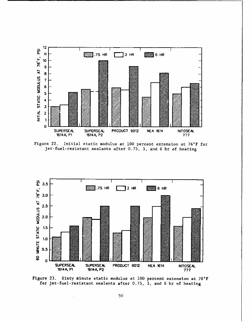
52. Stress relaxation results at 76 and -20°F are summarized in
Tables 12 through 15. Results are plotted in Figures 22 through 25. A plot
of relaxation data at 76"F for each sealant after 3 hr of heating is shown in
Figure 26. The initial stress is the highest and as time increases, stress
decreases as the specimen relaxes. Since testing at 76*F was performed using
a 100 percent extension, the data can also be referred to as a static modulus.
Figure 22 shows the initial 76°F static modulus, and that the modulus
increased with heating period. Superseal 1614A, Plant I after 45 min of heat-
ing had the lowest initial static modulus (3.0 psi), and Superseal 1614A,
Plant 2 after 6 hr of heating had the highest (10.0 psi). Initial static
modulus behaved in an inverse manner compared to 77°F penetration trends.
Figure 23 shows static modulus at 76°F after a 60 min relaxation period.
45
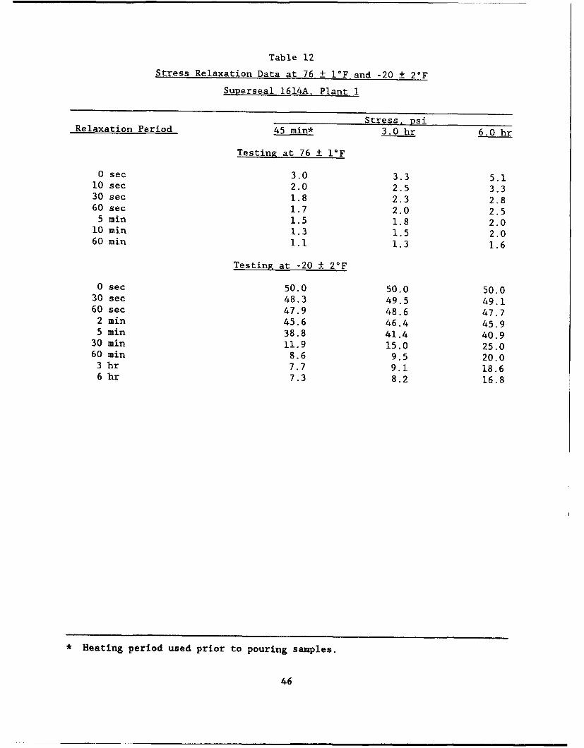
Table 12Stress Relaxation Data at 76 ± 1F and -20 ± 20F
Superseal 1614A. Plant I
Stress, psi
Relaxation Period 45 min* 3.0 hr 6.0 hr
Testing at 76 ± 1°F
0 sec 3.0 3.3 5.110 sec 2.0 2.5 3.330 sec 1.8 2.3 2.860 sec 1.7 2.0 2.5
5 min 1.5 1.8 2.010 min 1.3 1.5 2.060 min 1.1 1.3 1.6
Testing at -20 ± 2*F
0 sec 50.0 50.0 50.030 sec 48.3 49.5 49.160 sec 47.9 48.6 47.7
2 min 45.6 46.4 45.95 min 38.8 41.4 40.9
30 min 11.9 15.0 25.060 min 8.6 9.5 20.03 hr 7.7 9.1 18.66 hr 7.3 8.2 16.8
* Heating period used prior to pouring samples.
46
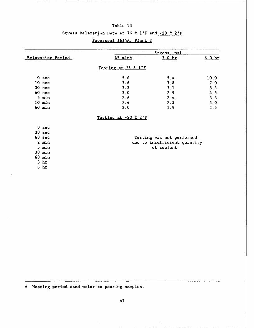
Table 13
Stress Relaxation Data at 76 ± 1F and -20 + 2°F
Superseal 1614A. Plant 2
Stress, psiRelaxation Period 45 min* 3.0 hr 6.0 hr
Testing at 76 ± 1F
0 see 5.6 5.4 10.010 sec 3.6 3.8 7.030 sec 3.3 3.1 5.360 see 3.0 2.9 4.5
5 min 2.6 2.4 3.310 min 2.4 2.3 3.060 min 2.0 1.9 2.5
Testing at -20 + 2°F
0 sec30 sec60 sec Testing was not performed
2 min due to insufficient quantity5 min of sealant
30 min60 min
3 hr6 hr
* Heating period used prior to pouring samples.
47
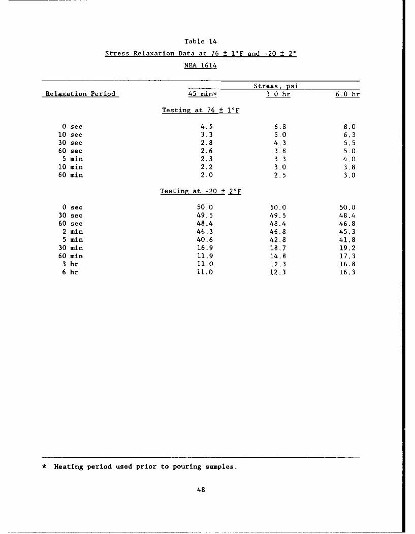
Table 14
Stress Relaxation Data at 76 + I°F and -20 + 20
NEA 1614
Stress, psiRelaxation Period 45 min* 3.0 hr 6.0 hr
Testing at 76 1 I°F
0 sec 4.5 6.8 8.010 sec 3.3 5.0 6.330 sec 2.8 4.3 5.560 sec 2.6 3.8 5.0
5 min 2.3 3.3 4.010 min 2.2 3.0 3.860 min 2.0 2.5 3.0
Testing at -20 ± 2°F
0 sec 50.0 50.0 50.030 sec 49.5 49.5 48.460 sec 48.4 48.4 46.8
2 min 46.3 46.8 45.35 miin 40.6 42.8 41.8
30 min 16.9 18.7 19.260 min 11.9 14.8 17.3
3 hr 11.0 12.3 16.86 hr 11.0 12.3 16.3
* Heating period used prior to pouring samples.
48
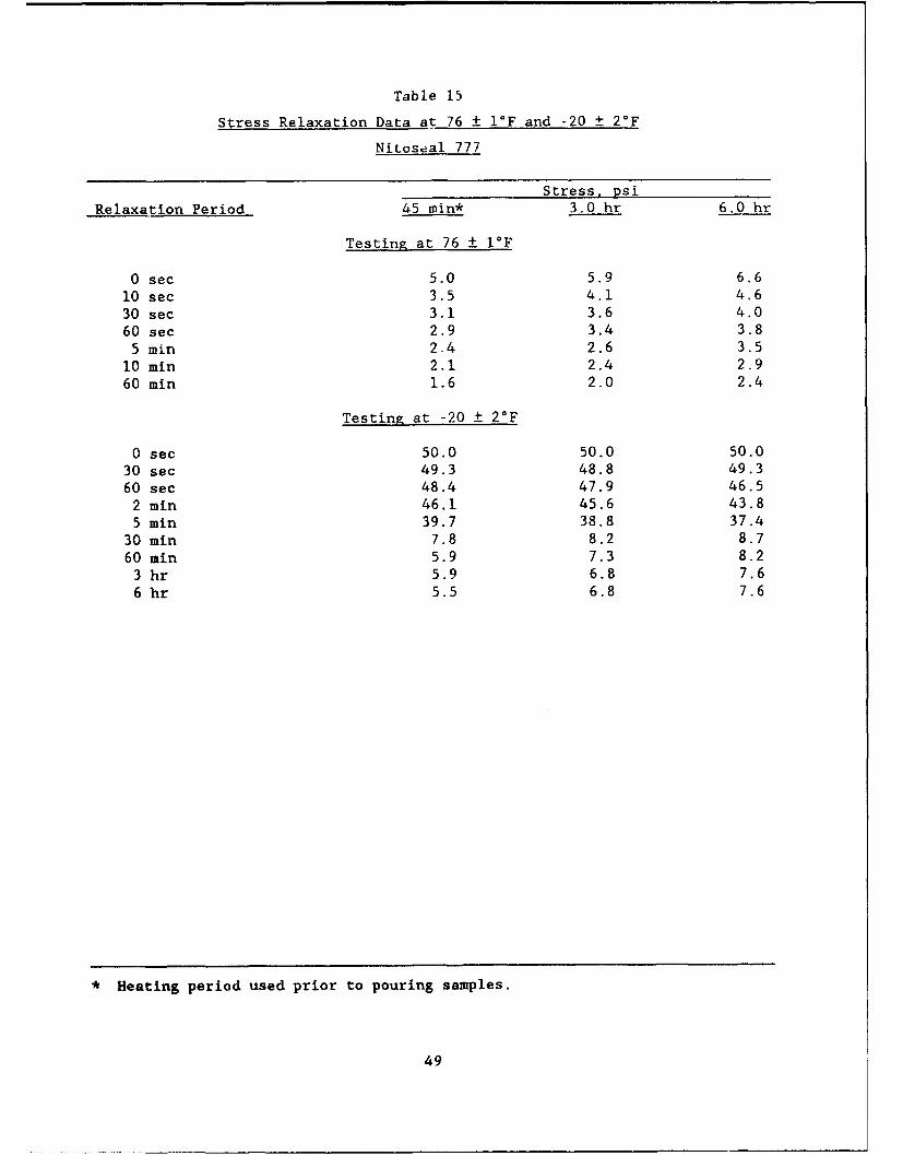
Table 15
Stress Relaxation Data at 76 ± I°F and -20 + 2°F
Nitoseal 777
Stress, psi
Relaxation Period 45 min* 3.0 hr 6.0 hr
Testing at 76 ± I°F
0 sec 5.0 5.9 6.6
10 sec 3.5 4.1 4.6
30 sec 3.1 3.6 4.060 sec 2.9 3.4 3.8
5 min 2.4 2.6 3.510 min 2.1 2.4 2.9
60 min 1.6 2.0 2.4
Testing at -20 ± 2°F
0 sec 50.0 50.0 50.030 sec 49.3 48.8 49.360 sec 48.4 47.9 46.5
2 min 46.1 45.6 43.85 min 39.7 38.8 37.4
30 min 7.8 8.2 8.760 min 5.9 7.3 8.2
3 hr 5.9 6.8 7.66 hr 5.5 6.8 7.6
* Heating period used prior to pouring samples.
49
12 1 1 1
(L 11 M .75 HR 3 HR M 6HR H
LZ10
<8-JO
S7 -
C 6-
'4
(/3
1614A. P1 1614A. P2 7177
Figure 22. Initial static modulus at 100 percent extension at 76*F forjet-fuel-resistant sealants after 0.75, 3, and 6 hr of heating
a 3. M.75 HR 3 HR M 6 HR
'C2.5
-j
c2.0
y1.5
in// 1.10
Z 0.5
SUPERSEAL SUPERSEAL PRODUCT 9012 NEA 1614 NITOSEAL1614A. PI 1614A. P2 777
Figure 23. Sixty minute static modulus at 100 percent extension at 76*Ffor jet-fuel-resistant sealants after 0.75, 3, and 6 hr of heating
50
22 II I
20fM I .75 HR = 3 HR M 6 HR
F 18(.
n- . 16 --
X 14c'4
12
10
SUPESEA4 SP-REL PRDi 91 E 11 ITSA
in-
25I
z
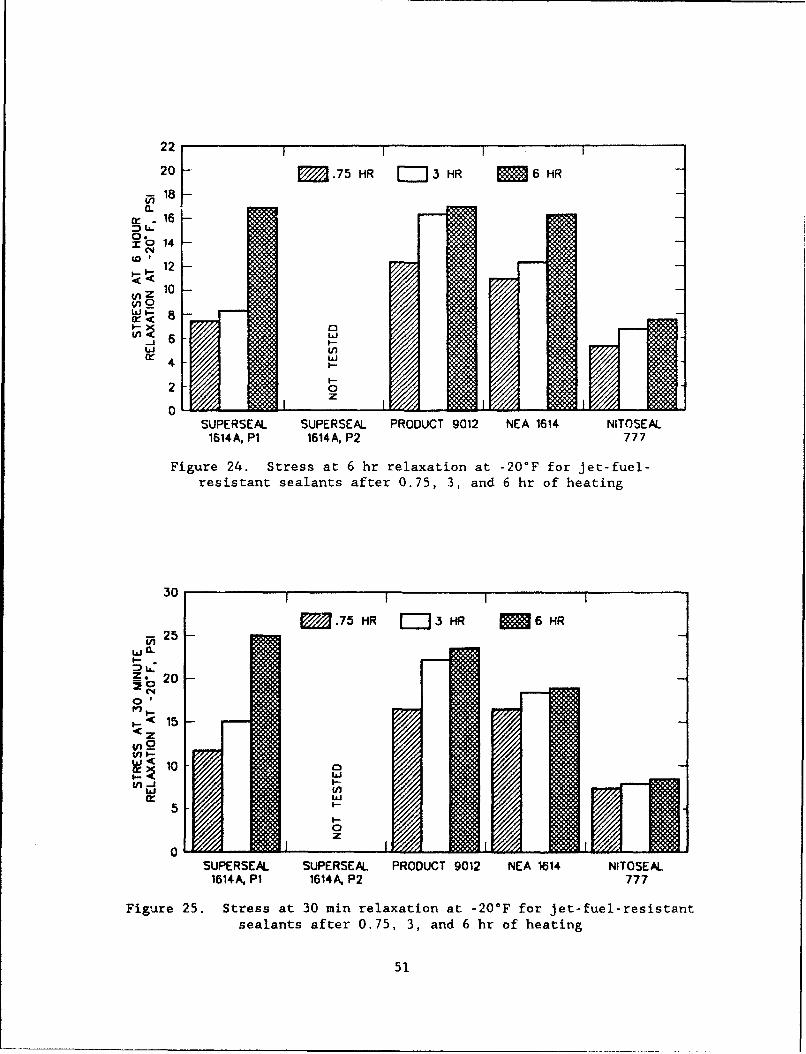
Figure 24. Stress at 6 hr relaxation at -202F for jet-fuel-resistant sealants after 0.75, 3, and 6 hr of heating
30 1 1 I
M •.75 HR I---3 HR M 6 HR
F 25 -
z. 20 -
0'
!z' 15
~10MU,-'
5
000 z
SUPERSEAL SUPERSEAL PRODUCT 9012 NEA 1614 NITOSEAL1614A, Pi 1614A. P2 777
Figure 25. Stress at 30 min relaxation at -20°F for jet-fuel-resistantsealants after 0.75, 3, and 6 hr of heating
51
4-40
$4-
'44to
ul41)
0C'
0
x 4.4
44)U)
0/ tna LZI~~ LUwi
0
0 ~ 4J
x 4-iN CA
C14
P.C
-iiIs~il
520
Superseal 1614A, Plant I after 45 min of heating had the lowest 60 min modulus
(1.1 psi), and NEA 1614 after 6 hr of heating had the highest (3.0 psi).
Overall, Superseal 1614A, Plant 1 had the lowest modulus values at 76°F.
During heating, Nitoseal 777 had the lowest percentage increase in initial
static modulus (32 percent) and Superseal 1614A, Plant 2 and NEA 1614 had the
highest (78.6 percent and 77.7 percent, respectively). For 60 min relaxed
modulus, Product 9012 experienced the greatest increase during heating
(92.3 percent) and Superseal 1614A, Plant 2 experienced the lowest (25 per-
cent). Static modulus data at 76°F show that the different sealants tested
have stress relaxation characteristics which differ with relaxation period and
heating time used to prepare specimens.
53. Figure 27 is a plot of relaxation data at -20°F for the JFR seal-
ants after 3 hr of heating. The stiffness of the sealants prevented them from
being extended 100 percent at -20*F; therefore, they were loaded to a 50-psi
tensile stress, and relaxation was monitored from that initial stress. Fig-
ure 24 shows stress after a 30 min relaxation period at -20°F. As seen from
thA data, each sealant experienced increased stress, with Nitoseal 777 having
the lowest average stress (8.2 psi) and Product 9012 having the highest aver-
age stress (20.9 psi). Nitoseal 777 had the lowest stress increase due to
heating (11.5 percent), and Superseal 1614A, Plant 1 had the largest (110 per-
cent). Figure 25 shows the 6 hr relaxed stress at -20°F. The data indicate
that Nitoseal 777 had the lowest average stress (6.6 psi) and Product 9012 had
the highest (15.2 psi). Results show that the sealants have different stress
relaxation characteristics at -20°F and different heating period affects the
sealants differently.
54. The additional test results indicate that current hot-applied JFR
sealants manufactured to meet FS SS-S-1614A are being evaluated at or near
their limit of low temperature extension performance at O°F. Each sealant
tested resisted flow at 158°F and some resisted flow at 200°F. All sealants
showed resilience characteristics that varied depending on curing and aging
periods. These results suggest that more stringent specification parameters
of flow and resilience could be incorporated in FS SS-S-1614A to more accu-
rately define physical characteristics of current materials. Stricter bond
testing (such as at -20"F), however, would not be possible with current seal-
ants since they could not perform at lower temperatures or higher extensions.
53
04
0 A
0n
Q.)
2 w
41
44. 44I., 41
w $4
00t:2
ccIcc
o **4 .
"14
0 Wf 0 An2 0 in 0 tn 0 t
lSd SS361S
514
PART IV: PHYSICAL CHARACTERISTICS OF AVAILABLE HOT-APPLIEDNON-JET-FUEL-RESISTANT SEALANTS
Products Tested
55. During initial project planning meetings, it was decided that in
order to determine specification limits for an improved non-JFR sealant, a
variety of available hot-applied, non-JFR sealants should be tested to deter-
mine their physical properties. It was also decided that tests in addition to
those in FS SS-S-1401C should be conducted. The additional tests would be
more extensive and would be conducted to determine performance limits and
provide a basis for comparison and improvement. Sealant materials manufac-
tured to meet a variety of specifications including FS SS-S-1401C, ASTM D3405,
American Association of State Highway and Transportation Officials (AASHTO)
M173, (AASHTO 1986), and modifications of ASTM D3405 and AASHTO M173 were
procured for testing. All of those sealants were supplied as solid materials.
56. Joint sealant materials which were evaluated for the non-JFR por-
tion o" this study were as follows:
a. RoadSaver 222, Crafco Inc., manufactured to meet FS SS-S-1401C,ASTM D3405, and ASTM D1190.
b. RoadSaver 231, Crafco Inc., manufactured to meet several statemodified low-modulus ASTM D3405 specifications including IowaDepartment of Transportation (IDOT) 4136.02a (IDOT 1984),Kansas Department of Transportation (KDOT) TS109.6 (KDOT 1986),and South Dakota Department of Transportation (SDDOT) low modu-lus D3405 (SDDOT, undated).
c. RoadSaver 299, Crafco Inc., manufactured to meet a low moduluscompany developed specification (Crafco 1991).
d. RoadSaver 515, Crafco Inc., manufactured to meet a variety ofstate modified AASHTO M173 specifications such as Mis-souri 1051.1.4 (Missouri Highway and Transportation Commission1988), Minnesota Department of Transportation (MNDOT) 3723(MNDOT 1988), and South Dakota 870.1 (SDDOT 1985).
e. Product 9030, Koch Materials Company, manufactured to meetseveral state low-modulus modified ASTM D3405 specifications.
f. Product 9005, Koch Materials Company, manufactured to meetrequirements of FS SS-S-1401C, ASTM D3405, and ASTM D1190.
g. Sof Seal, W. R. Meadows, manufactured to meet several statelow-modulus modified ASTM D3405 specifications.
h. Hi-Spec, W. R. Meadows, manufactured to meet requirements ofFS SS-S-1401C and ASTM D3405.
55
57. Production lot numbers and the manufacturer's recommended pour
temperature and safe heating temperature are as follows:
Lot Pour Safe HeatingProduct Identification Temperature Temperature
RoadSaver 222 011290T 380°F 410°FRoadSaver 231 021240E 380°F 410°FRoadSaver 299 121489F 380 0 F 410°FRoadSaver 515 0630890 380°F 410°FProduct 9030 213 370°F 390°FProduct 9005 717 370OF 390°FSof Seal 9082 370*F 390°FHi-Spec 8210 370°F 390*F
Specification Testing
58. Each of the eight sealant materials was tested in accordance with
FS SS-S-1401C using the manufacturer's recommended safe heating temperature.
The sealants were also tested for FS SS-S-1401C properties at several other
heating periods to determine if the heating period affected measured physical
properties. The additional heating periods included 45 min to provide an
indication of short term heating and application, and 6 hr to determine the
effects of long term heating. Testing for conformance with FS SS-S-1401C at
the standard heat period was performed by both WES and Crafco to determine
testing variability between laboratories.
59. WES and Crafco results are presented in Table 17, and a data sum-
mary which provides mean values, estimated standard deviation (based on a
value of 0.886 times the range of the two values) (Burr 1974), and coefficient
of variation is shown in Table 18. Crafco results for the non-JFR sealants
using heating times of 45 min and 6 hr are summarized in Tables 19 and 20.
Data with numerical values are plotted in Figures 28 through 33.
Specification Test Analysis
60. The test results provided by both WES and Crafco in Table 17 indi-
cate that the RoadSaver 222 and the Hi-Spec sealants conformed to the specifi-
cation requirements of FS SS-S-1401C. Product 9005 did not meet the unaged
resilience initial indentation in the WES testing, but it passed the Crafco
56
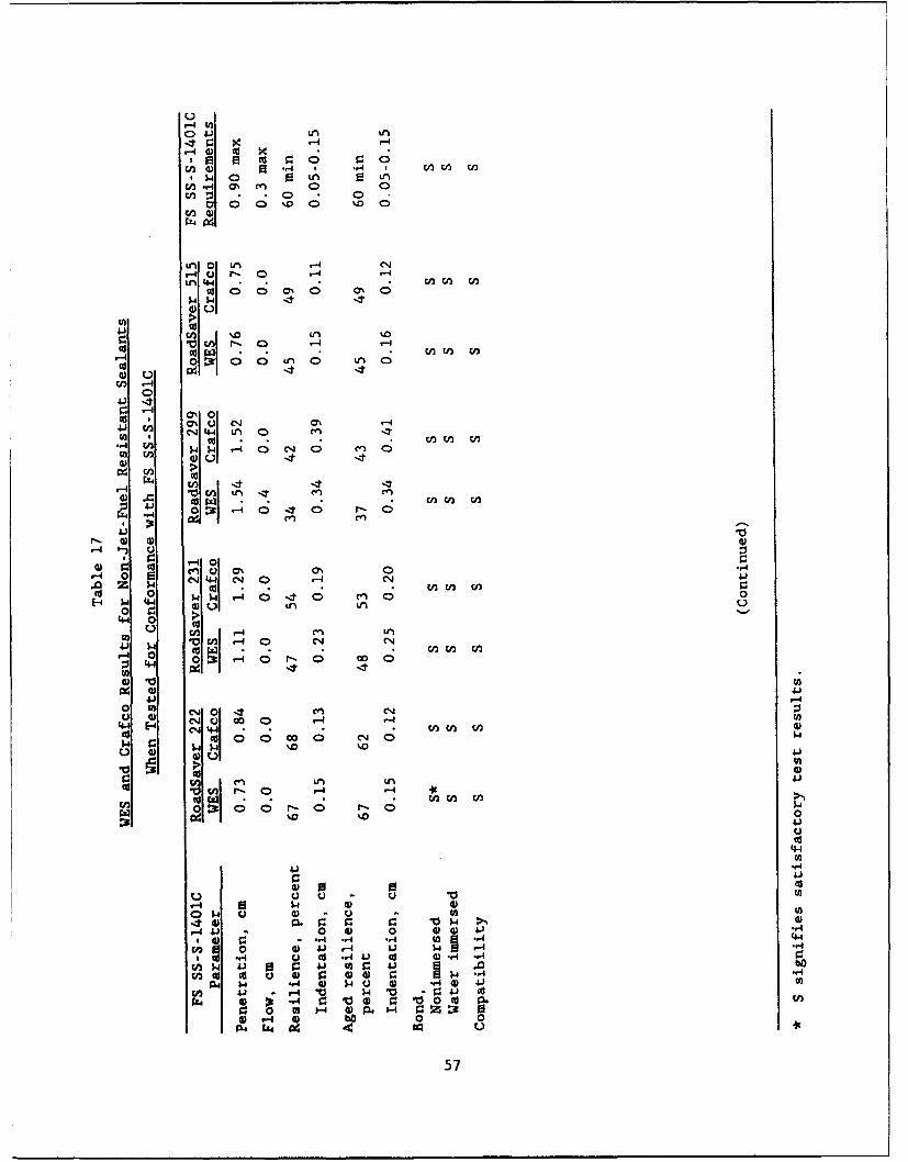
-4 V.
04- Ln
Cn ) .,4 01 M
En O LA .
r-4 U r- 0 -4 1-4
to 0 0 OC 0 ,
LLM
cd wn r- 0 L-n-
ý 4
rj40
O'1 c'. (7%0c,4 44 LAOn
V)W4~ r-40 e.J 0- a ~W) 4
C4 >
*- w I -d
F-. ) a) w)-4r,
C; En(
"* 0 LU1 ý4 o ý 0
v4
04 0
LU 0 LU Q~c m)44 C-4 04 4 ' 0~ V
E-4 )A 44 W) LA LAu 10
Li0 n 14 0 l CV41 p t U)Ur) w)
0 0 0 rF- 0 Do 0
C4) Q-4ar4
C.44 '.4 -o aLUL 0 0 W 0n ( CJ 04
'.0 0 P0
4))
4) w~AL
LU .14 O, _4-.4 w - .44U) 4) 41oo r- o -
'0 w01 i : 4 or 1b
0 -w-)4
r4 0 P-4 to 0 00~~~4t U ) U *u)
4a) 0 V~4 '-~57
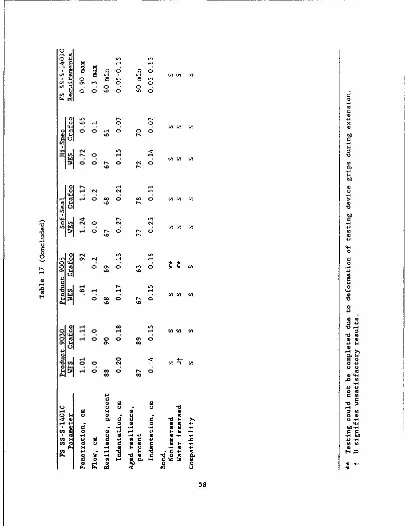
00
01 Xr . -.4 r- -- 4
'u %. 0 0 U,4~,4 0) "2 0) 0
u l 0 0 .0 CD 00Z
"-4
04 L0CU 0- 0 r-4 0 4U
r- C; q Cr I-,4
4ýf4o
'4)
oH 4- r- r
I ) V -I (N)
4.440 -C C14 0 n CO OO C2.,
CU$. CN .04 r-
C)44 4 .U
0 C; 0\U U, m4.3y v-4 0 D 410N~0
'-4 C
r- 0 (N4 L, 0
%00
0 C0
01 r-4
0 -U 00 n4 -
Q r- 4 cc 0 En- 0s
04)
r4 0
cn0 a- cO 0 v41OC w -1 v-I u- ,,wC v-I 00co0 0' 0) 00
0'I- 00 4) 4J~
0 0v
00 4)--00- 410 ) 4 4 4
3Iv--AC"o r-A U) -- b0 1 0 ) J r41 c-4 0r.4.r4 u cd v 4j d 4)-4 -
04 4 r. 0 'C v
4)4. 0- 0 0 0 4-)a0 P 4v4 .. b'-
cU 0'v4 ' 58
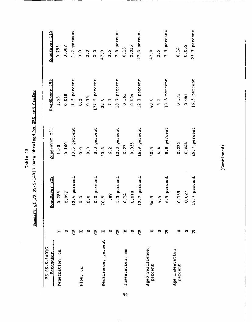
Ln 4.) 41) 41 41)4.
4 $4 $4 $4 $ 44) 4) 4) 4) 4) 4)
SLn 43% Ln a. 13A LA P..4) LA 0 LA LA LU~r- 0 (N 0 0 0 ) LA) T-40 LA 0 Ln Ln ,-4 0D LA
4)00 r-4 000 4.- L .0 C) C>' f-- 4' 00 t LA
a%4o 4J (1 4 '
04 4) a) 4) 4) 4)4)
0 ý-l $4$
Go- rO V).~ .L 4 p. P. Ln (N p444 M) L -. 4 LA %0i It. rý 0 Lca 0 0A (N (4 MA r-O MA 0 -4 LAO) m Ln
'4 04)l .4 00 4. c; 0' r 00* (N 00 LA LA -, )t 0 0 0
04-. CV) r-4 .4 -4 I-
4)4
cn
> -4 41) 41)4 41) 41)4.0e .r.r
41 ) 4) 4) a) 4) 4)u U U
1 4 $4 $4$4$4$
4) 0 0 m- Ln (N 4
V-4 CD %D4-co i W .-4 ý 0 L n 0 0 0 M. 4N 00 '.0 04 It co 000'-
0 '-4 LA r4 -4 VA)-
-4 41) ..1
-4 Cuto 0
044-4 04 r. 9 pp
04 a)4 )4 ) 4)Q UUU UU
I $4 $4 4 $4$444) 4)a) 4)4))
>' LA trs PA. 0. CL O P. LA P- P.W oo co 0% T' 4 -4 M C(N
r. rn f-- 0 4 0 0 0 n CO LA -40 r-. LA 4Cs -4 0 N.l
0 0
$4C)
4.1
44-
0 U -44" "4 .' $H V ) 41
E 41 1 m) V. U 0En ) p.o Cpt ) )
I, - w. -4)
0 10 4) Ia.
4) 0o P u4) 0 4) ~ F4) ))'4
~ $4-'-84.) 4059
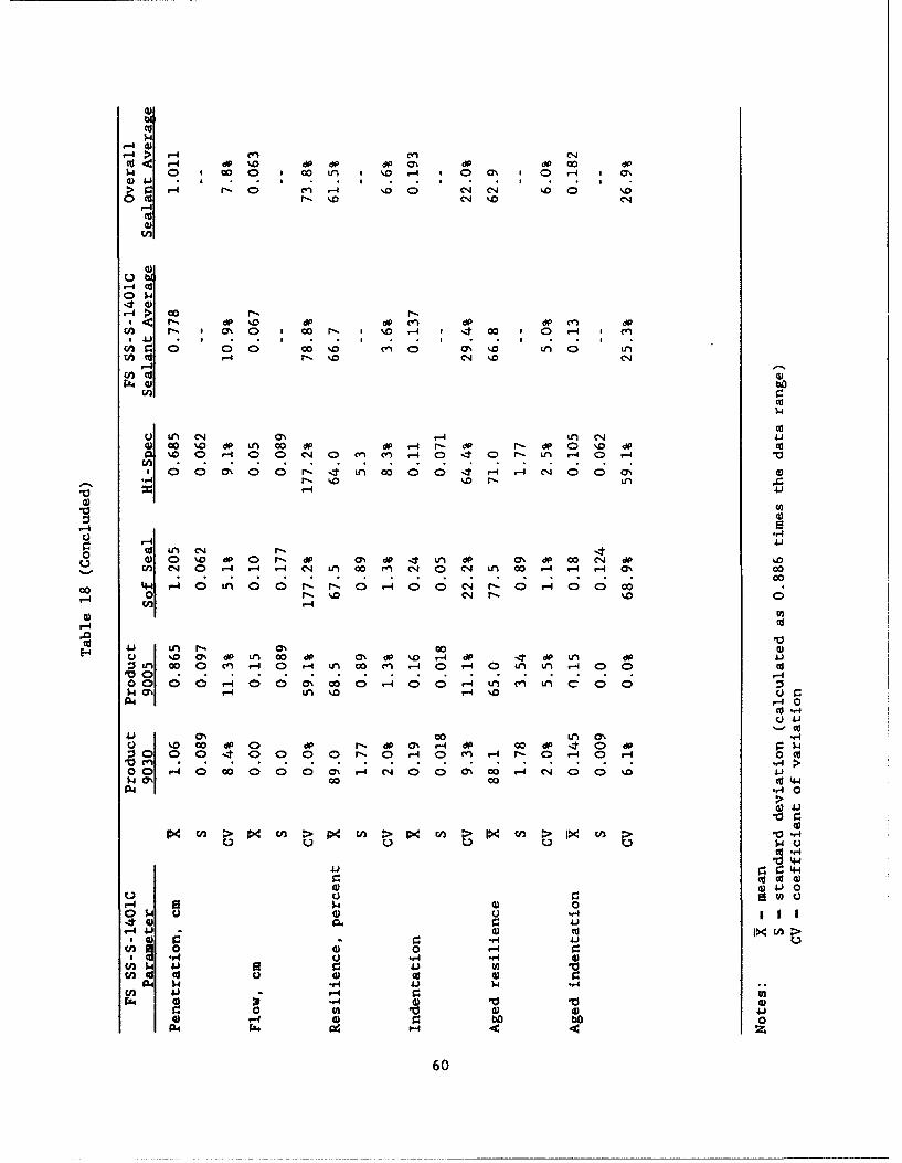
'3)
CU
r4I r-4
cn c', C'.JCU< v-I %0 ' dO dP dP ON 0% 8 00 891.4 0 o0 0 00 Ln .0vI %. - 0 0 0 r-4I CN0
4)4 3 .I 3 . , .
'3)
r-I CU
00 .3 ý dP %9'0 *p 89 mA 89 8 Ce) dP
U ~ ~ ~ ~ ~ ~ ~ ~ ~ : -4 M %0 30 ' . - *0 '0C
P-I
CU$.4
I CU4)0 co %0 89 LA 00 89 dP -4 r- 89 r-- 890 %D0 dP '
%0 0r-4 0 0 C4O CY) On r-4 0> (D 0r- Ln ,-4 v-I
100; 0 0 1'- r I LA 00 I;00 ' -4 vI C-4 (400 a% W3"_ r- %0o '.o r-r4 4.3
'3) W
CU cd 890 c, LArA L0 4) 0 %O vP -I 0P 1-1p4 nd 0 p00 .
V0 C-14v- 0 LA 0 r-4 -4 0j 0nc C40 04~ t= 00 000-0-4CN0
r4 0 r'- '.D C%4 r- .C
'U ~ LA P- 0% 00 '3)0- %D0OA O9 LA co 89 M' O9 .D ,-4 89 .4t 89 LA 89:1Ln 00 0 M v-4 0 v-4 tn 00 CA -4 0 v-I 0 LA LA1 ,-4 00CU
V 0 -4
444
4130 00 LA 0% v-0. '.000890 89 r- 890 89r4d 0089 4 0 dP;s 0 0 40 0 00 r- Ov 0 CA 4 r- 0 -4 0r-4 0 cd
0 0 -4 0 w0 0 0 0 0; CN 0; 0' Y%' 41-(10 . .$4 ON 00 co CV 44
r. (d 4)
C) $4 U u -,
r-4~C 4J d4
4) -r4 41
41 4)1.30
a 10OS-IL '3) bU 'v1'*4) 0. 4.
y-14J 4)6C
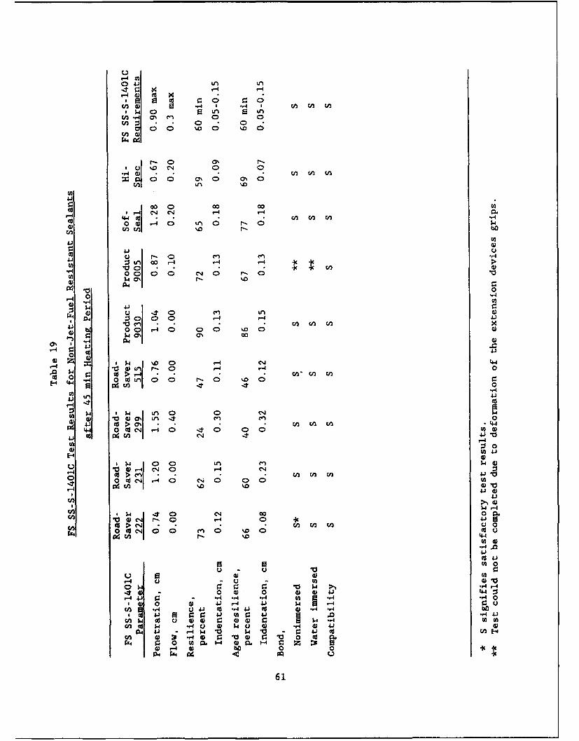
ur-4 fn)
ý4-
wn C) -4 ' 4 ' n inr~ 0A ON m 0 u0cn :1- 0CDn0
i 0 0 o
a -0 ONC' .2
00I 0 00 001- idC n in .,n
a)
'-4 -4l.
"q 04 Cý r- C
Q) c)
4.)
blA 0 0 0 - 44 1-D 03 0000 0r c"J r 00
P614
Il 'D _ 0 -0 A 00 0
$4 r0 0 Ed4 1-4 4.)r
Vn in 4n
004 4 0% 4 0 0 .o 0 0)41' i W(A0
w :3 o%
'0u cd 04 14-4 0- 0 u0)
~ý r-4.
2.4 (D e 0 0CA 14 ,
0 cq in in in1
W~ ~~ 0( -4. 0 0
cn 004)4 1-4
-4 4 4-0 w 4 4 4:4,., - ? 1A "4 r.40
o) 0 d i- 4 4'J w ý .
0 0 ,~4 0 0 1 0 0 04 41U))r4 -4b
in 02. Wl.n4 4 m H 0 z D4) r-4bo0 0 I
61W
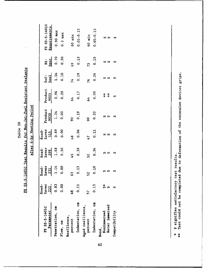
ur-4 (A10 4-i Ln LA
t- 0 0
00 '.0 'o0
rX4 4
100 CD~
r. 0
-- 4 r-4 -4-40 0)-40 40C. 0 $4W2U M- pN-b
'a (U24-1 4)
0 41 UCCU
00 00 It0 40
0400 r000
1 ~ 0 C- 0 '4 CI '1'a 04 10 -n (n V) W
0 00 -4 0 0 0 0W0'?$ 4 C'
M 4 a 0 %.0 -4 (4.4
0 q - 0 r 04-4 $ 4 o4dL 0 0
A 0'..0
'a 0 a' '0 LA ON.~W cU1a 4) *7 Ln
al 0 0 'dC1-4 0 LAO C-4 0 0)
UP-4M0
cn 00WOi O4 v40 r-4
-4 CU, C1 r 0 M0 LA
41J
r4-4'$ A LA C11 0I P6V) w 0eq, CcO ,i W4 41 IsU, IL)c 0rk0(c4 00COD-0I '. LA 4-4
(d'V) 0
f- U-4 4 0 '12 0 4)4 4 :0$4 00 r4 Tj $ to -,44-40
0 '.4 .4 -4J-4r V."00 01 to 'a 41 C bo01 : 4J W-1- (U 4 0) '4 4r~' pO 'ar )4) l ) 0 .0 'cn( cc W$ 4 .- U 0) $4 U 0) .. 4G '
04 'a - P-4$ p V 4 'Ti - g: 4 CU(12 4) 21 *."4 0) Z 0 4) r 0 T0( orz.. 00ou W0.- wO- m r 0
4)-4 0 bo 0 0 cI04 FF4 n o U4
62
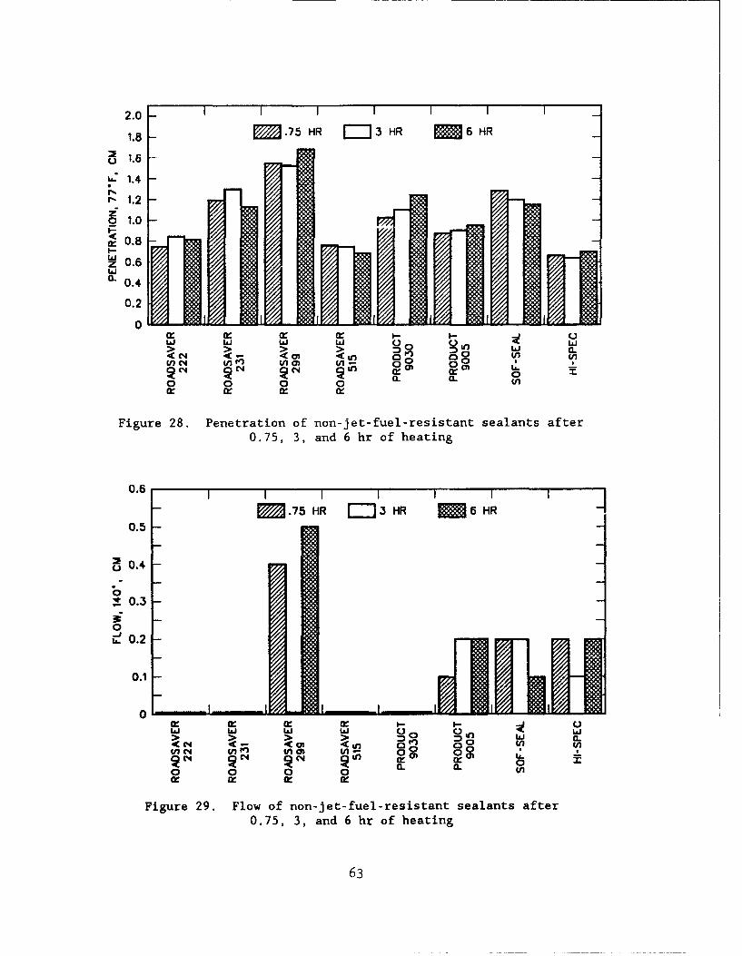
2.0 - I I I I I I
1.8 - M .75 HR =-I3 HR 6 6 HR
"• 1.6 -
.. 1.4 -
-. 1.2 -
%.8z"o_ to- •
wz 0.6
C. 0.4
0.2
0 I~ I IJ. I () 0 Ln..nn- -II- a..t•o •• W CL
Q' (fl 0r 0 T-
o 0 0 n a. VU
Figure 28. Penetration of non-jet-fuel-resistant sealants after0.75, 3, and 6 hr of heating
0.6
M .75 HR -- 3 HR M 6 HR0.5
o0.4
0,.. 0.3 -
0
--0L.2
0.1
0I- W
I (n O 0 0n EL04 l N fO Ckn 0 k 0~ V
0 0 0 0 a. L
Figure 29. Flow of non-jet-fuel-resistant sealants after0.75, 3, and 6 hr of heating
63
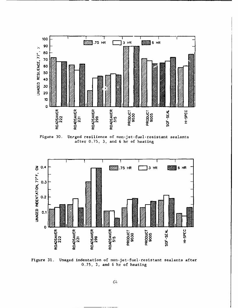
100 I I I I90 M .75 HR i 3 HR M 6 HR*90-
• 80
70Li
z 60
- 50FnUie 400"' 30'Cz 20
10
0n,,- • •. •I-- I--, r
afte 0.75 3,ad6hUoetn
Li Ui Li Li> Di a..(C4 a. < LOD 0 II j. C
• ~ ~ ~ ~ ( o.1 -n 007.7 0R r--13 R N 6H
o 0 0 (n
Figure 30. Unpged resilience of non-jet-fuel-resistant sealantsafter 0.75, 3, and 6 hr of heating
•; _I
I-- 0.4
2 0. .75 HR 3J HR 5 HRU-
w0.3
0- o 0.2• 1.U
z0
.60.2z 0
U OQ In- a - C .C4 Li tn aI00L
<In c4 WA (n0 w
0 0 0 0 a. . vs
Figure 31. Unaged indentation of non-jet-fuel-resistant sealants after0.75, 3, and 6 hr of heating
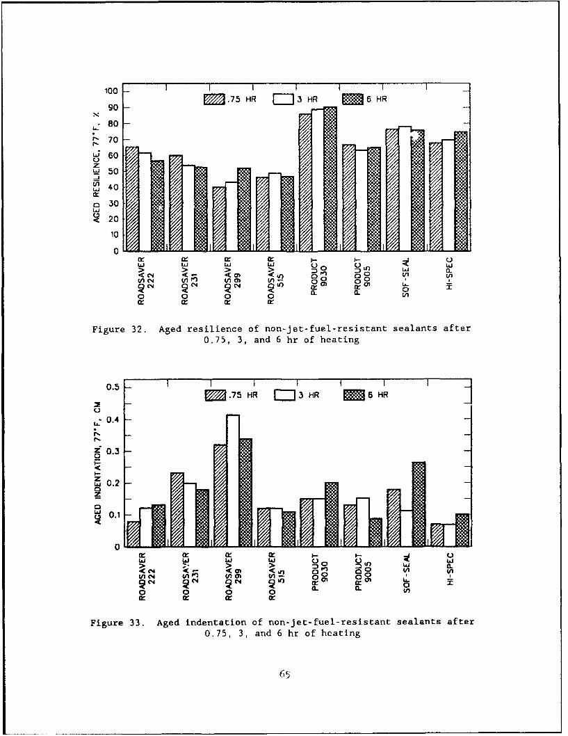
100 - I I I I i I
90 E3.75 HR =3 HR M6 HR
80 -
760 7Li. 60zW1 50-4" 340
o30
, /20
10 " ....
0
>V > ....0qo 04 P V) (na) V 0 0°o
0 0 0 0 an
Figure 32. Aged resilience of non-jet-fuel-resistant sealants after
0.75, 3, and 6 hr of heating
0.5 -IIIIII•0.5M.75 HR E• 3 HR M 6 HR
C.,
r-.
Lz 03
0.3 -
zS0.2 - -m
0.1 'A ll
0
meQ in~ wn ~o0 0 0 0 0. CL In
Figure 33. Aged indentation of non-jet-fuel-resistant sealants after0.75, 3, and 6 hr of heating
65
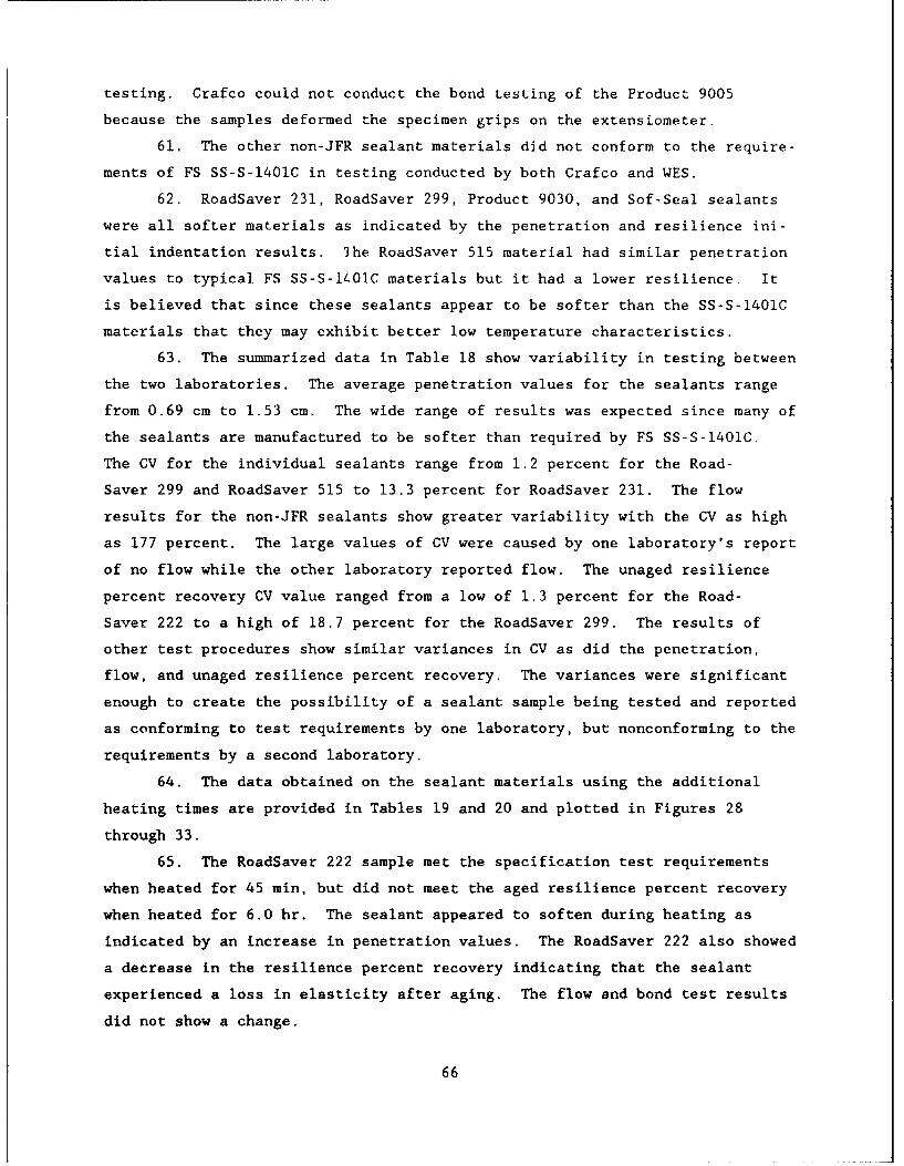
testing. Crafco could not conduct the bond testing of the Product 9005
because the samples deformed the specimen grips on the extensiometer.
61. The other non-JFR sealant materials did not conform to the require-
ments of FS SS-S-1401C in testing conducted by both Crafco and WES.
62. RoadSaver 231, RoadSaver 299, Product 9030, and Sof-Seal sealants
were all softer materials as indicated by the penetration and resilience ini-
tial indentation results. The RoadSaver 515 material had similar penetration
values to typical FS SS-S-lQ01C materials but it had a lower resilience. It
is believed that since these sealants appear to be softer than the SS-S-1401C
materials that they may exhibit better low temperature characteristics.
63. The summarized data in Table 18 show variability in testing between
the two laboratories. The average penetration values for the sealants range
from 0.69 cm to 1.53 cm. The wide range of results was expected since many of
the sealants are manufactured to be softer than required by FS SS-S-1401C.
The CV for the individual sealants range from 1.2 percent for the Road-
Saver 299 and RoadSaver 515 to 13.3 percent for RoadSaver 231. The flow
results for the non-JFR sealants show greater variability with the CV as high
as 177 percent. The large values of CV were caused by one laboratory's report
of no flow while the other laboratory reported flow. The unaged resilience
percent recovery CV value ranged from a low of 1.3 percent for the Road-
Saver 222 to a high of 18.7 percent for the RoadSaver 299. The results of
other test procedures show similar variances in CV as did the penetration,
flow, and unaged resilience percent recovery. The variances were significant
enough to create the possibility of a sealant sample being tested and reported
as conforming to test requirements by one laboratory, but nonconforming to the
requirements by a second laboratory.
64. The data obtained on the sealant materials using the additional
heating times are provided in Tables 19 and 20 and plotted in Figures 28
through 33.
65. The RoadSaver 222 sample met the specification test requirements
when heated for 45 min, but did not meet the aged resilience percent recovery
when heated for 6.0 hr. The sealant appeared to soften during heating as
indicated by an increase in penetration values. The RoadSaver 222 also showed
a decrease in the resilience percent recovery indicating that the sealant
experienced a loss in elasticity after aging. The flow and bond test results
did not show a change.
66
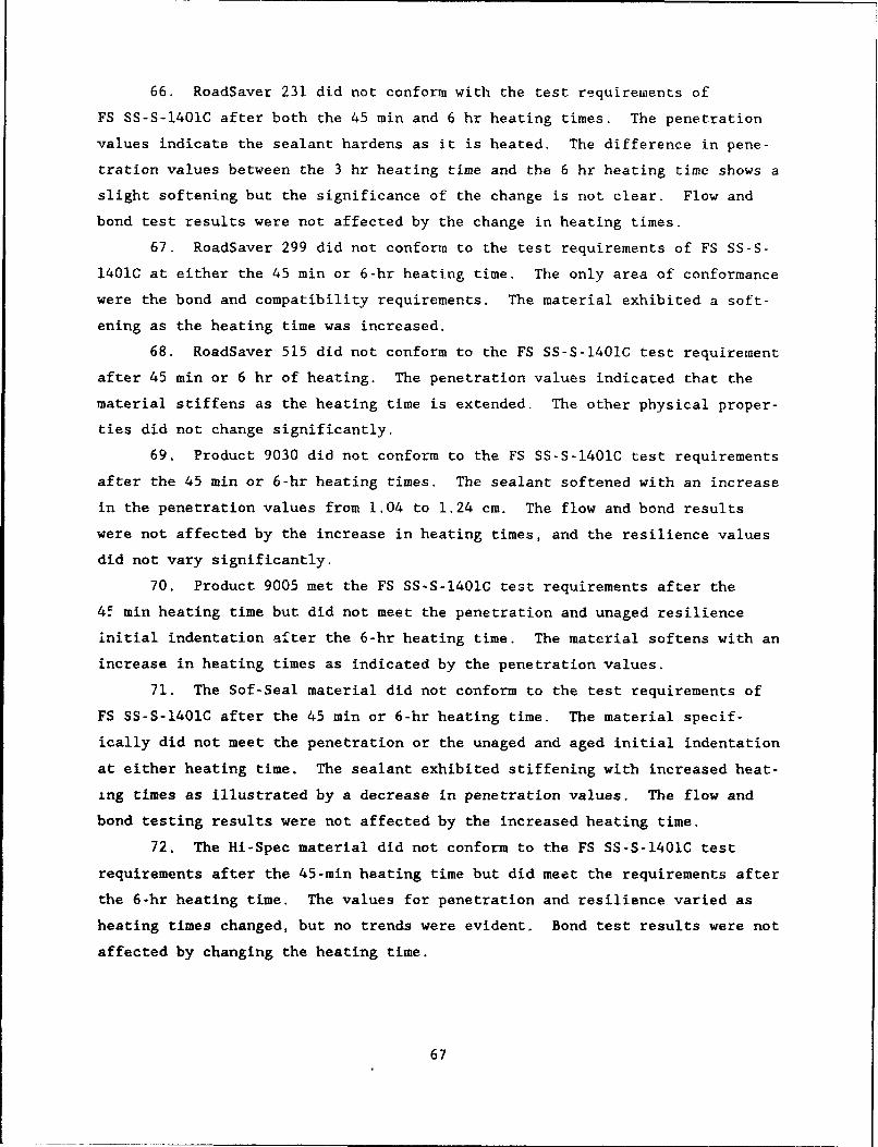
66. RoadSaver 231 did not conform with the test requirewents of
FS SS-S-1401C after both the 45 min and 6 hr heating times. The penetration
values indicate the sealant hardens as it is heated. The difference in pene-
tration values between the 3 hr heating time and the 6 hr heating time shows a
slight softening but the significance of the change is not clear. Flow and
bond test results were not affected by the change in heating times.
67. RoadSaver 299 did not conform to the test requirements of FS SS-S-
1401C at either the 45 min or 6-hr heating time. The only area of conformance
were the bond and compatibility requirements. The material exhibited a soft-
ening as the heating time was increased.
68. RoadSaver 515 did not conform to the FS SS-S-1401C test requirement
after 45 min or 6 hr of heating. The penetration values indicated that the
material stiffens as the heating time is extended. The other physical proper-
ties did not change significantly.
69. Product 9030 did not conform to the FS SS-S-1401C test requirements
after the 45 min or 6-hr heating times. The sealant softened with an increase
in the penetration values from 1.04 to 1.24 cm. The flow and bond results
were not affected by the increase in heating times, and the resilience values
did not vary significantly.
70. Product 9005 met the FS SS-S-1401C test requirements after the
45 min heating time but did not meet the penetration and unaged resilience
initial indentation after the 6-hr heating time. The material softens with an
increase in heating times as indicated by the penetration values.
71. The Sof-Seal material did not conform to the test requirements of
FS SS-S-1401C after the 45 min or 6-hr heating time. The material specif-
ically did not meet the penetration or the unaged and aged initial indentation
at either heating time. The sealant exhibited stiffening with increased heat-
ing times as illustrated by a decrease in penetration values. The flow and
bond testing results were not affected by the increased heating time.
72. The Hi-Spec material did not conform to the FS SS-S-1401C test
requirements after the 45-min heating time but did meet the requirements after
the 6-hr heating time. The values for penetration and resilience varied as
heating times changed, but no trends were evident. Bond test results were not
affected by changing the heating time.
67
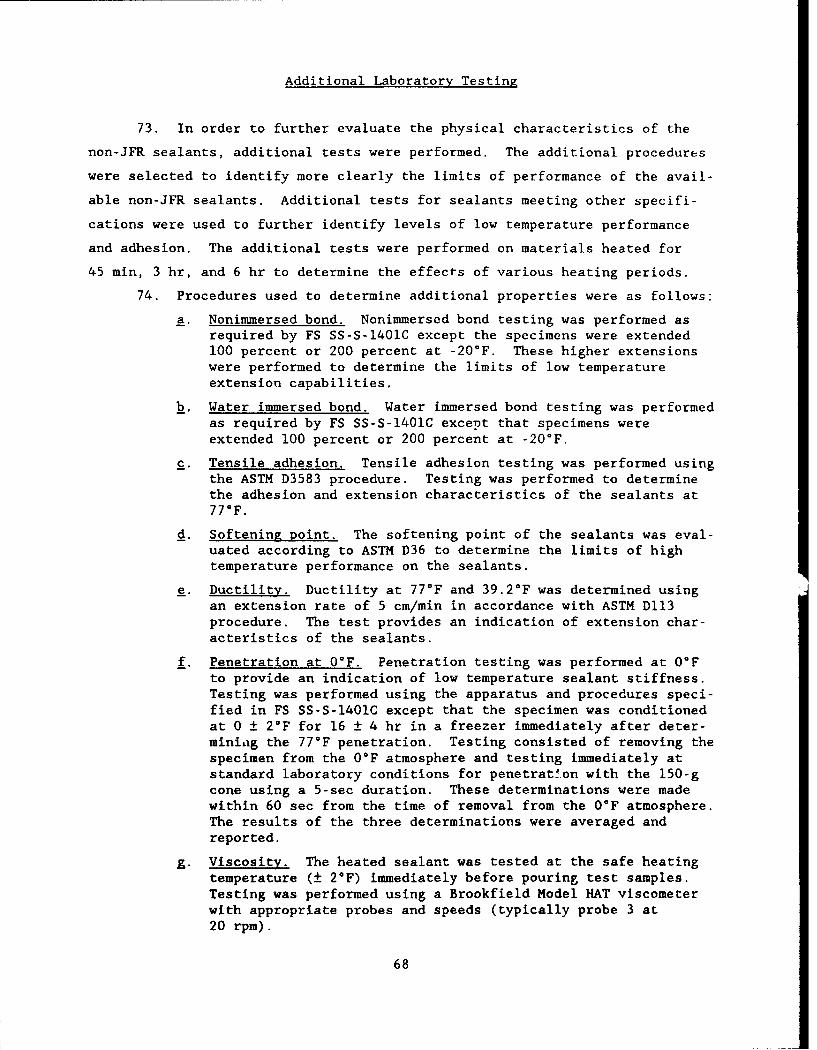
Additional Laboratory Testing
73. In order to further evaluate the physical characteristics of the
non-JFR sealants, additional tests were performed. The additional procedures
were selected to identify more clearly the limits of performance of the avail-
able non-JFR sealants. Additional tests for sealants meeting other specifi-
cations were used to further identify levels of low temperature performance
and adhesion. The additional tests were performed on materials heated for
45 min, 3 hr, and 6 hr to determine the effects of various heating periods.
74. Procedures used to determine additional properties were as follows:
a. Nonimmersed bond. Nonimmersed bond testing was performed asrequired by FS SS-S-1401C except the specimens were extended100 percent or 200 percent at -20'F. These higher extensionswere performed to determine the limits of low temperatureextension capabilities.
b. Water immersed bond. Water immersed bond testing was performedas required by FS SS-S-1401C except that specimens wereextended 100 percent or 200 percent at -20 0 F.
c. Tensile adhesion. Tensile adhesion testing was performed usingthe ASTM D3583 procedure. Testing was performed to determinethe adhesion and extension characteristics of the sealants at77*F.
d. Softening point. The softening point of the sealants was eval-uated according to ASTM D36 to determine the limits of hightemperature performance on the sealants.
e. Ductility. Ductility at 77°F and 39.2°F was determined usingan extension rate of 5 cm/min in accordance with ASTM D113procedure. The test provides an indication of extension char-acteristics of the sealants.
f. Penetration at 00 F. Penetration testing was performed at O°Fto provide an indication of low temperature sealant stiffness.Testing was performed using the apparatus and procedures speci-fied in FS SS-S-1401C except that the specimen was conditionedat 0 ± 2°F for 16 ± 4 hr in a freezer immediately after deter-minialg the 77°F penetration. Testing consisted of removing thespecimen from the O°F atmosphere and testing immediately atstandard laboratory conditions for penetration with the 150-gcone using a 5-sec duration. These determinations were madewithin 60 sec from the time of removal from the O°F atmosphere.The results of the three determinations were averaged andreported.
g. Viscosity. The heated sealant was tested at the safe heatingtemperature (± 2*F) immediately before pouring test samples.Testing was performed using a Brookfield Model HAT viscometerwith appropriate probes and speeds (typically probe 3 at20 rpm).
68
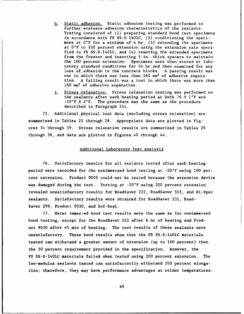
h. Static adhesion. Static adhesion testing was performed tofurther evaluate adhesion characteristics of the sealants.Testing consisted of (1) preparing standard bond test specimensin accordance with FS SS-S-1401C, (2) conditioning the speci-mens at 0°F for a minimum of 4 hr, (3) extending the specimensat OF to 100 percent extension using the extension rate speci-fied in FS SS-S-1401C, and (4) removing the extended specimensfrom the freezer and inserting 1-in.-thick spacers to maintainthe 100 percent extension. Specimens were then stored at labo-ratory standard conditions for 24 hr and then examined for anyloss of adhesion to the concrete blocks. A passing result wasone in which there was less than 160 mm2 of adhesive separa-tion. A failing result was a test in which there was more than160 mm2 of adhesive separation.
i. Stress relaxation. Stress relaxation testing was performed onthe sealants after each heating period at both 76 ± 1IF and-20°F ± 2°F. The procedure was the same as the proceduredescribed in Paragraph 33i.
75. Additional physical test data (excluding stress relaxation) are
summarized in Tables 21 through 28. Appropriate data are plotted in Fig-
ures 34 through 39. Stress relaxation results are summarized in Tables 29
through 36, and data are plotted in Figures 40 through 44.
Additional Laboratory Test Analysis
76. Satisfactory results for all sealants tested after each heating
period were recorded for the nonimmersed bond testing at -20°F using 100 per-
cent extension. Product 9005 could not be tested because the extension device
was damaged during the test. Testing at -20°F using 200 percent extension
revealed unsatisfactory results for RoadSaver 222, RoadSaver 515, and Hi-Spec
sealants. Satisfactory results were obtained for RoadSaver 231, Road-
Saver 299, Product 9030, and Sof-Seal.
77. Water immerced bond test results were the same as for nonimmersed
bond testing, except for the RoadSaver 222 after 6 hr of heating and Prod-
uct 9030 after 45 min of heating. The test results of these sealants were
unsatisfactory. These bond results show that the FS SS-S-1401C materials
tested can withstand a greater amount of extension (up to 100 percent) than
the 50 percent requirement provided in the specification. However, the
FS SS-S-1401C materials failed when tested using 200 percent extension. The
low-modulus sealants tested can satisfactorily withstand 200 percent elonga-
tion; therefore, they may have performance advantages at colder temperatures.
69
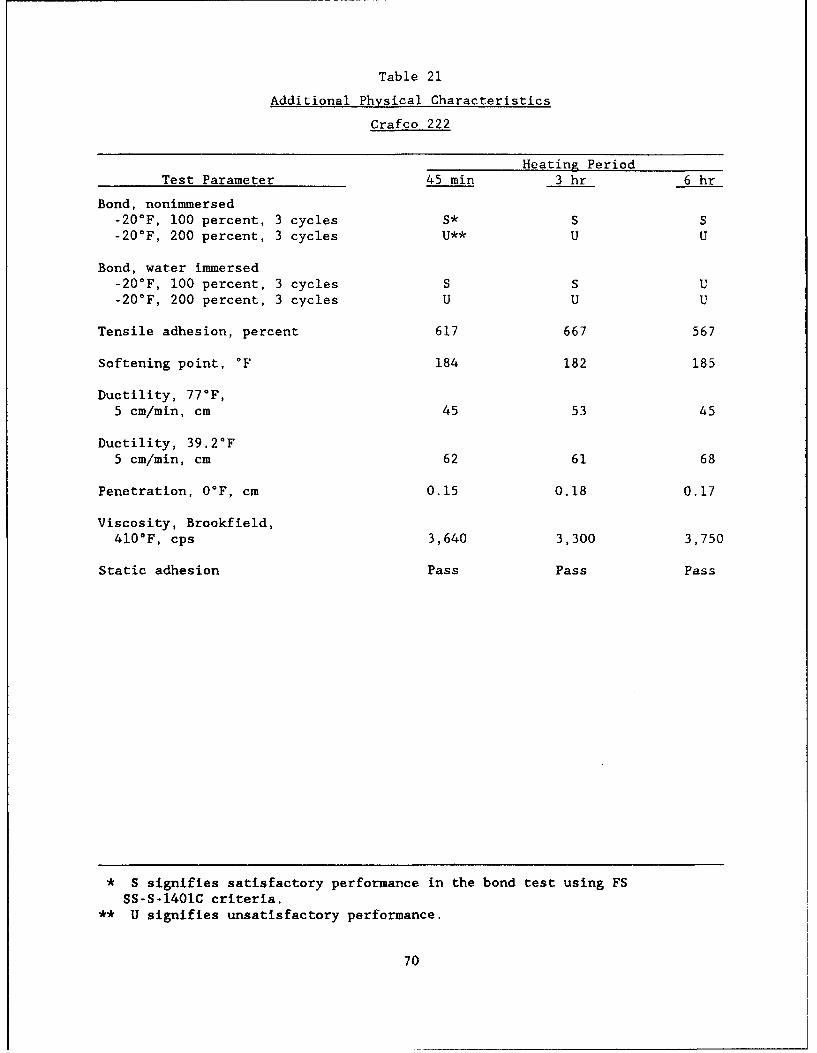
Table 21
Additional Physical Characteristics
Crafco 222
Heating PeriodTest Parameter 45 min 3 hr 6 hr
Bond, nonimmersed-20'F, 100 percent, 3 cycles S* S S-20°F, 200 percent, 3 cycles U** U U
Bond, water immersed-20°F, 100 percent, 3 cycles S S U-20°F, 200 percent, 3 cycles U U U
Tensile adhesion, percent 617 667 567
Softening point, °F 184 182 185
Ductility, 77°F,5 cm/min, cm 45 53 45
Ductility, 39.2°F5 cm/min, cm 62 61 68
Penetration, 0°F, cm 0.15 0.18 0.17
Viscosity, Brookfield,410'F, cps 3,640 3,300 3,750
Static adhesion Pass Pass Pass
* S signifies satisfactory performance in the bond test using FSSS-S-1401C criteria.
** U signifies unsatisfactory performance.
70
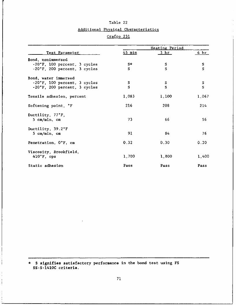
Table 22
Additional Physical Characteristics
Crafco 231
Heating PeriodTest Parameter 45 min 3 hr 6 hr
Bond, nonimmersed-20'F, 100 percent, 3 cycles S* S S-20°F, 200 percent, 3 cycles S S S
Bond, water immersed-20°F, 100 percent, 3 cycles S S S-20°F, 200 percent, 3 cycles S S S
Tensile adhesion, percent 1,083 1,100 1,067
Softening point, *F 216 208 214
Ductility, 77°F,5 cm/min, cm 73 66 56
Ductility, 39.2°F
5 cm/min, cm 91 84 76
Penetration, OF, cm 0.32 0.30 0.30
Viscosity, Brookfield,410*F, cps 1,700 1,800 1,400
Static adhesion Pass Pass Pass
* S signifies satisfactory performance in the bond test using FSSS-S-1410C criteria.
71
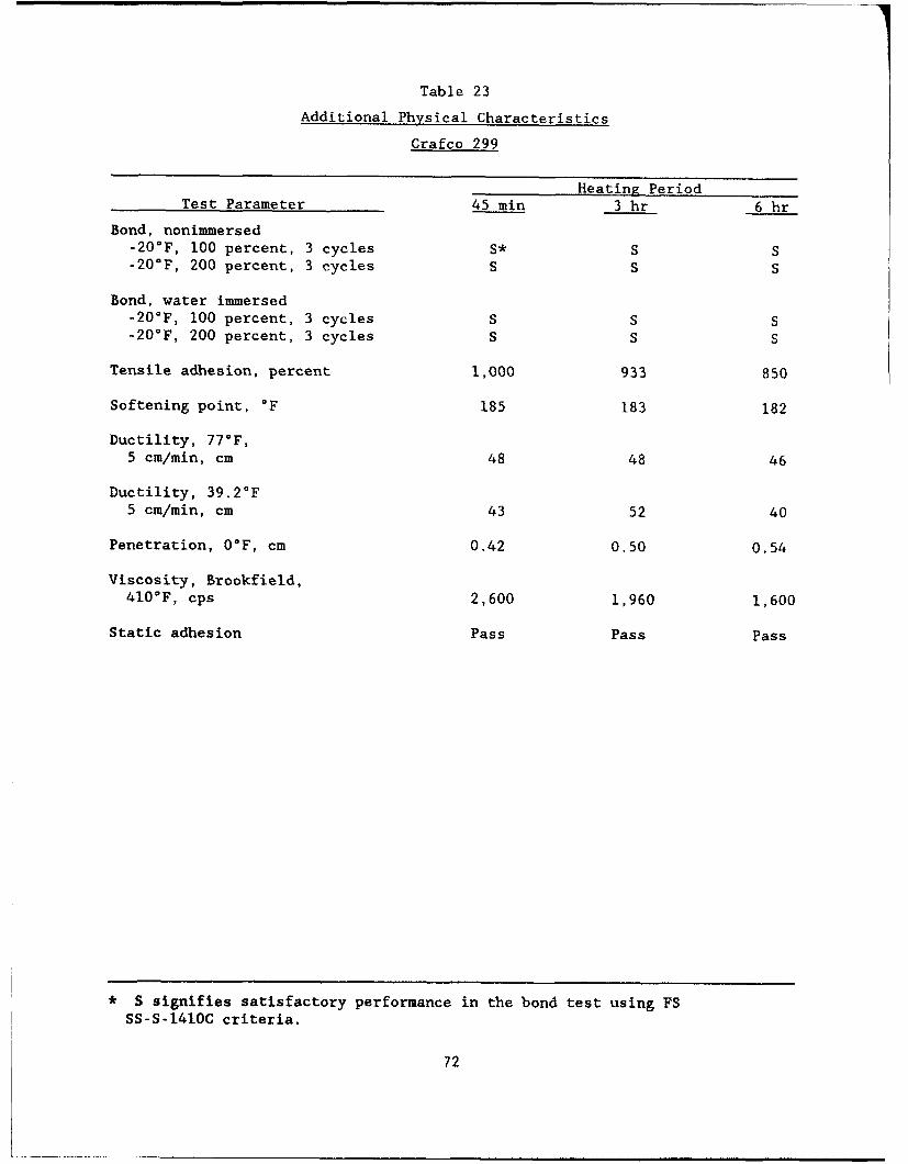
Table 23
Additional Physical Characteristics
Crafco 299
Heating PeriodTest Parameter 45 min 3 hr 6 hr
Bond, nonimmersed-20°F, 100 percent, 3 cycles S* S S-20°F, 200 percent, 3 cycles S S S
Bond, water immersed-20°F, 100 percent, 3 cycles S S S-20°F, 200 percent, 3 cycles S S S
Tensile adhesion, percent 1,000 933 850
Softening point, *F 185 183 182
Ductility, 77°F,5 cm/min, cm 48 48 46
Ductility, 39.2°F5 cm/min, cm 43 52 40
Penetration, 0°F, cm 0.42 0.50 0.54
Viscosity, Brookfield,410°F, cps 2,600 1,960 1,600
Static adhesion Pass Pass Pass
* S signifies satisfactory performance in the bond test using FSSS-S-1410C criteria.
72
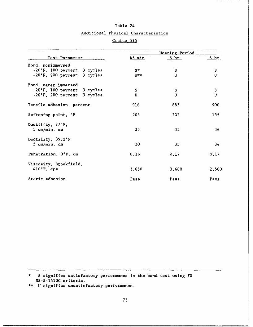
Table 24
Additional Physical Characteristics
Crafco 515
Heating PeriodTest Parameter 45 min 3 hr 6 hr
Bond, nonimmersed-20°F, 100 percent, 3 cycles S* S S-20°F, 200 percent, 3 cycles U** U U
Bond, water immersed-20°F, 100 percent, 3 cycles S S S-20'F, 200 percent, 3 cycles U U U
Tensile adhesion, percent 916 883 900
Softening point, °F 205 202 195
Ductility, 77°F,5 cm/min, cm 35 35 36
Ductility, 39.2°F5 cm/min, cm 30 35 34
Penetration, O°F, cm 0.16 0.17 0.17
Viscosity, Brookfield,410°F, cps 3,680 3,680 2,500
Static adhesion Pass Pass Pass
* S signifies satisfactory performance in the bond test using FSSS-S-1410C criteria.
** U signifies unsatisfactory performance.
73
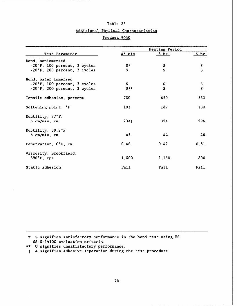
Table 25
Additional Physical Characteristics
Product 9030
Heating PeriodTest Parameter 45 min 3 hr 6 hr
Bond, nonimmersed-20°F, 100 percent, 3 cycles S* S S-20 0 F, 200 percent, 3 cycles S S S
Bond, water immersed-20°F, 100 percent, 3 cycles S S S-20°F, 200 percent, 3 cycles U** S S
Tensile adhesion, percent 700 650 550
Softening point, *F 191 187 180
Ductility, 77°F,5 cm/min, cm 23At 32A 29A
Ductility, 39.2 0 F5 cm/min, cm 43 44 48
Penetration, O°F, cm 0.46 0.47 0.51
Viscosity, Brookfield,390°F, cps 1,000 1,150 800
Static adhesion Fail Fail Fail
* S signifies satisfactory performance in the bond test using FS
SS-S-1410C evaluation criteria.** U signifies unsatisfactory performance.
t A signifies adhesive separation during the test procedure.
74
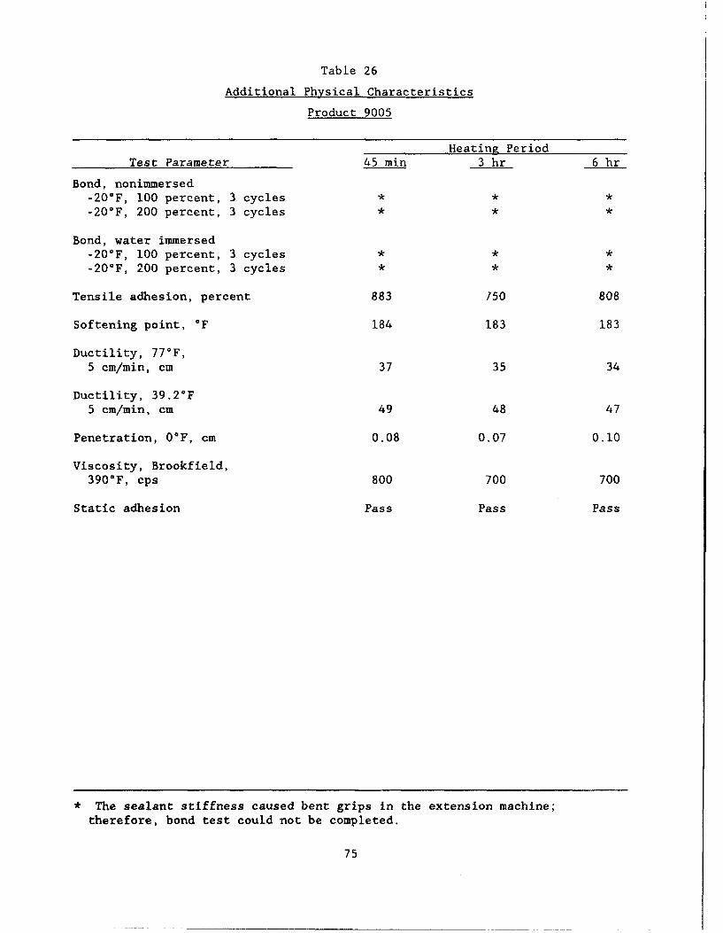
Table 26
Additional Physical Characteristics
Product 9005
Heating PeriodTest Parameter 45 min 3 hr 6 hr
Bond, nonimmersed-20°F, 100 percent, 3 cycles * * *
-20°F, 200 percent, 3 cycles * * *
Bond, water immersed-20°F, 100 percent, 3 cycles * * *-20°F, 200 percent, 3 cycles * * *
Tensile adhesion, percent 883 750 808
Softening point, °F 184 183 183
Ductility, 77*F,5 cm/min, cm 37 35 34
Ductility, 39.2°F5 cm/min, cm 49 48 47
Penetration, 0°F, cm 0.08 0.07 0.10
Viscosity, Brookfield,390°F, cps 800 700 700
Static adhesion Pass Pass Pass
* The sealant stiffness caused bent grips in the extension machine;therefore, bond test could not be completed.
75
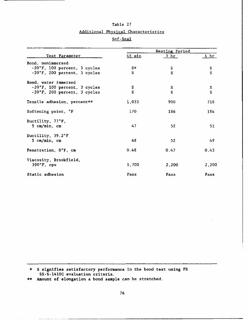
Table 27
Additional Physical Characteristics
Sof-Seal
Heating PeriodTest Parameter 45 min 3 hr 6 hr
Bond, nonimmersed-20°F, 100 percent, 3 cycles S* S S-20°F, 200 percent, 3 cycles S S S
Bond, water immersed-20°F, 100 percent, 3 cycles S S S-20°F, 200 percent, 3 cycles S S S
Tensile adhesion, percent** 1,033 900 716
Softening point, °F 170 186 184
Ductility, 77 0 F,5 cm/min, cm 47 52 51
Ductility, 39.2°F
5 cm/min, cm 48 52 49
Penetration, 0°F, cm 0.48 0.47 0.43
Viscosity, Brookfield,390°F, cps 1,700 2,200 2,200
Static adhesion Pass Pass Pass
* S signifies satisfactory performance in the bond test using FSSS-S-1410C evaluation criteria.
** Amount of elongation a bond sample can be stretched.
76
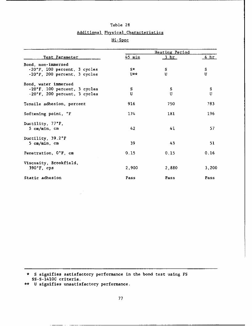
Table 28
Additional Physical Characteristics
Hi-Spec
Heating PeriodTest Parameter 45 min 3 hr 6 hr
Bond, non-immersed-20 0 F, 100 percent, 3 cycles S* S S-20°F, 200 percent, 3 cycles U** U U
Bond, water immersed-20°F, 100 percent, 3 cycles S S S-20*F, 200 percent, 3 cycles U U U
Tensile adhesion, percent 916 750 783
Softening point, °F 174 181 196
Ductility, 77"F,5 cm/min, cm 42 41 57
Ductility, 39.2°F5 cm/min, cm 39 43 51
Penetration, 0°F, cm 0.15 0.15 0.16
Viscosity, Brookfield,390°F, cps 2,900 2,880 3,200
Static adhesion Pass Pass Pass
* S signifies satisfactory performance in the bond test using FS
SS-S-1410C criteria.** U signifies unsatisfactory performance.
77
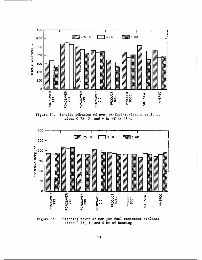
1400 1 1 1 1 I
1200 EM.75 HR = 3 HR M 6 HR
. 1000z0
Uj 800
,., 600
z,., 400
200
00 ~ ~ z C- ) < U-) 7"/ In,, n,, t,,," •I-- .
1,0 I.d Li I~l( •
V)'~ mno r
a . a.
Figure 34. Tensile adhesion of non-jet-fuel-resistant sealantsafter 0.75, 3, and 6 hr of heating
300 1 1 1 1 1
250 .75 HR E::,3 HR M 6 HR
2000
a.150
zz.dS100U-0
50
0 Li w ilSI..d
> > n w CN < a) <o 0L C
Figure 35. Softening point of non-jet-fuel-resistant sealantsafter C 75, 3, and 6 hr of heating
73
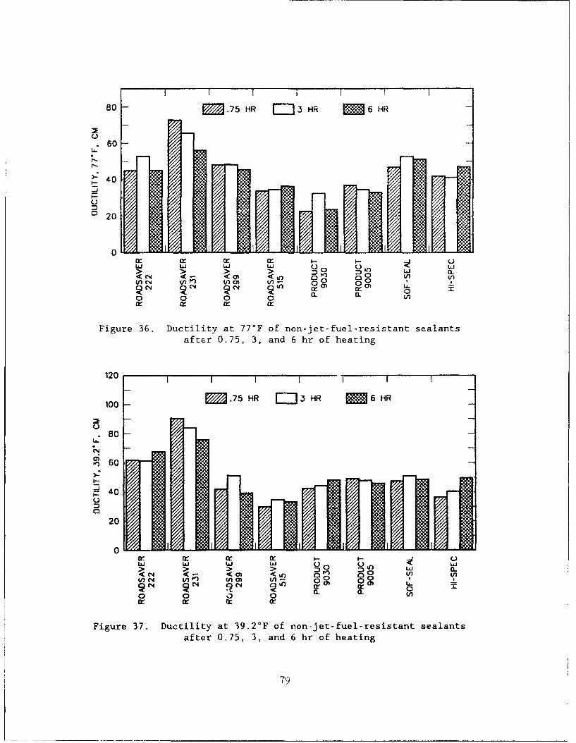
80 M .75 HR =-J3 HR M 6 HR
C-)60
S40
o20
0 U Ui w I U') i>: >: >: a _~ .--
< < < • 0 ( ,V) N V V)Li L C-) in0 0
0 o 0 0 C LVOf a: a: w:
Figure 36. Ductility at 77°F of non-jet-fuel-resistant sealantsafter 0.75, 3, and 6 hr of heating
120 I I I I
100 M .75 HR 3 HR M 6 HR
C-)80
(N-
- 60
S40
20
r 0 , and M x o - ULi Ui Li Li W
0 0 13 0 CL C..
Figure 37. Ductility at 39.2*F of non~-jet-fuel-resistant sealantsafter 0.75, 3, and 6 hr of heating
79
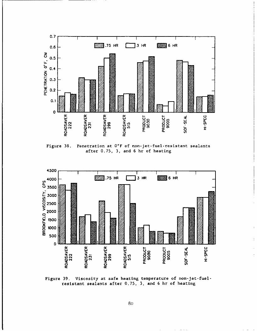
0.7 II I I
0.6 - M .75 HR F--13 HR M 6 HR
S0.5 -
0.4 -
za -!< 0.3 -I-bJz 0.2LI
0.1
0S> > > LO w"-
01 0 M en 0 0 Wa. a
Cc C- X0 n-
Figure 38. Penetration at O°F of non-jet-fuel-resistant sealantsafter 0.75, 3, and 6 hr of heating
4500 1 1 1
ino4000 M.75 HR j-'3 HR M 6 HRin0 3500
> 3000
02500
2 0000
-J/.100 I mo1000
M 500
0X- CI-r C
< , a 0 0 00w i -; v) Ch W 0 a.U
Figure 39. Viscosity at safe heating temperature of non-jet-fuel-resistant sealants after 0.75, 3, and 6 hr of heating
80
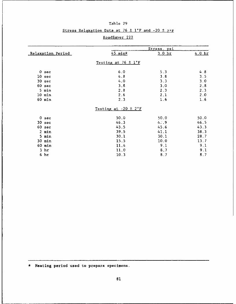
Table 29
Stress Relaxation Data at 76 ± I°F and -20 +
RoadSaver 222
Stress, psiRelaxation Period 45 min* 3.0 hr b.0 hr
Testing at 76 ± I°F
0 sec 6.0 5.3 4.810 sec 4.8 3.8 3.530 sec 4.0 3.3 3.060 sec 3.8 3.0 2.8
5 min 2.8 2.3 2.310 min 2.6 2.1 2.060 min 2.3 1.6 1.6
Testing at -20 ± 2°F
0 sec 50.0 50.0 50.030 sec 46.3 4,'.9 46.560 sec 43.5 45.6 43.3
2 min 39.5 41.1 38.35 min 30.1 30.1 28.7
30 min 15.5 10.0 13.760 min 11.4 9.1 9.1
3 hr 11.0 8.7 9.16 hr 10.3 8.7 8.7
* Heating period used to prepare specimens.
81

Table 30
Stress Relaxation Data at 76 ± I°F and -20 ± 2°F
RoadSaver 231
Stress, psiRelaxation Period 45 min* 3.0 hr 6.0 hr
Testing at 76 1 I°F
0 sec 2.5 2.8 3.010 sec 1.8 2.0 2.030 sec 1.3 1.8 1.560 sec 1.2 1.5 1.5
5 win 1.1 1.1 1.010 win 0.8 1.0 1.060 min 0.6 0.6 0.8
Testing at -20 ± 2°F
0 sec 50.0 50.0 50.030 sec 42.4 40.1 42.060 sec 35.5 33.3 34.5
2 min 31.0 28.3 27.25 min 20.5 18.7 17.1
30 min 4.6 5.2 4.460 min 4.5 5.0 4.4
3 hr 4.1 5.0 3.96 hr 4.1 4.5 3.9
* Signifies heating period used to prepare specimenz.
82
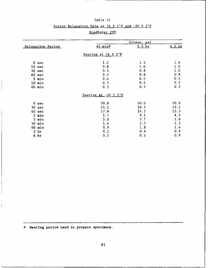
Table 31
Stress Relaxation Data at 76 ± 1F and -20 + 2°F
RoadSaver 299
Stress, psiRelaxation Period 45 min* 3.0 hr 6.0 hr
Testing at 76 + 1IF
0 sec 1.2 1.3 1.610 sec 0.8 1.0 1.030 sec 0.5 0.8 1.060 sec 0.5 0.8 0.8
5 min 0.4 0.5 0.510 min 0.3 0.5 0.560 min 0.3 0.3 0.3
Testing at -20 ± 2°F
0 sec 50.0 50.0 50.030 sec 25.1 20.5 19.160 sec 17.8 14.2 13.3
2 min 5.7 9.1 8.35 min 5.0 3.7 2.8
30 min 1.4 2.3 2.360 min 0.9 1.8 1.4
3 hr 0.5 0.9 0.96 hr 0.5 0.5 0.9
• Heating period used to prepare specimens.
83
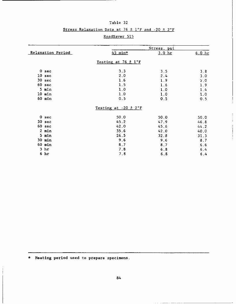
Table 32
Stress Relaxation Data at 76 ± I°F and -20 ± 2°F
RoadSaver 515
Stress, psiRelaxation Period 45 min* 3.0 hr 6.0 hr
Testing at 76 ± 1IF
0 sec 3.3 3.5 3.810 sec 2.0 2.4 3.030 sec 1.6 1.9 2.060 sec 1.5 1.6 1.9
5 min 1.0 1.0 1.410 min 1.0 1.0 1.060 min 0.5 0.5 0.5
Testing at -20 ± 2OF
0 sec 50.0 50.0 50.030 sec 45.2 47.9 46.860 sec 42.0 45.6 44.2
2 min 35.6 42.0 40.05 min 26.5 32.8 31.3
30 min 9.6 9.6 8.760 min 8.7 8.7 6.6
3 hr 7.8 6.8 6.46 hr 7.8 6.8 6.4
* Heating period used to prepare specimens.
84
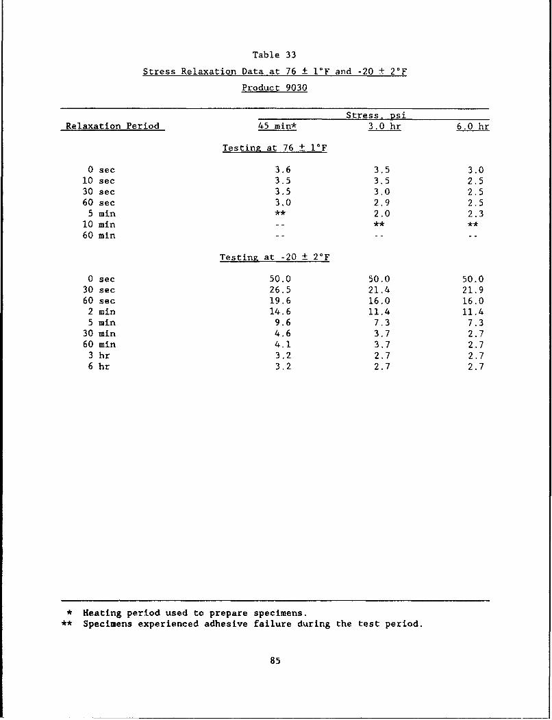
Table 33
Stress Relaxation Data at 76 ± 1F and -20 ± 2°F
Product 9030
Stress, psi
Relaxation Period 45 min* 3.0 hr 6.0 hr
Testing at 76 i I°F
0 sec 3.6 3.5 3.010 sec 3.5 3.5 2.530 sec 3.5 3.0 2.560 sec 3.0 2.9 2.5
5 min ** 2.0 2.310 min -- ** **
60 min
Testing at -20 + 2°F
0 sec 50.0 50.0 50.030 sec 26.5 21.4 21.960 sec 19.6 16.0 16.0
2 min 14.6 11.4 11.45 min 9.6 7.3 7.3
30 min 4.6 3.7 2.760 min 4.1 3.7 2.7
3 hr 3.2 2.7 2.76 hr 3.2 2.7 2.7
* Heating period used to prepare specimens.** Specimens experienced adhesive failure during the test period.
85
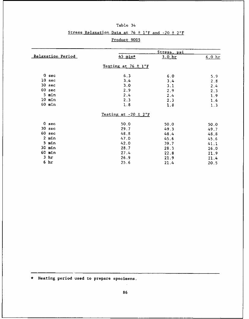
Table 34
Stress Relaxation Data at 76 ± I°F and -20 ± 2-F
Product 9005
Stress, psiRelaxation Period 45 min* 3.0 hr 6.0 hr
Testing at 76 ± 1°F
0 sec 6.3 6.0 5.910 sec 3.4 3.4 2.830 sec 3.0 3.1 2.460 sec 2.9 2.9 2.3
5 min 2.4 2.4 1.910 min 2.3 2.3 1.660 min 1.8 1.8 1.3
Testing at -20 ± 20F
0 sec 50.0 50.0 50.030 sec 29.7 49.3 49.760 sec 48.8 48.4 48.8
2 min 47.0 45.6 45.65 min 42.0 39.7 41.1
30 min 28.7 28.3 26.060 min 27.4 22.8 21.9
3 hr 26.9 21.9 21.46 hr 25.6 21.4 20.5
* Heating period used to prepare specimens.
86
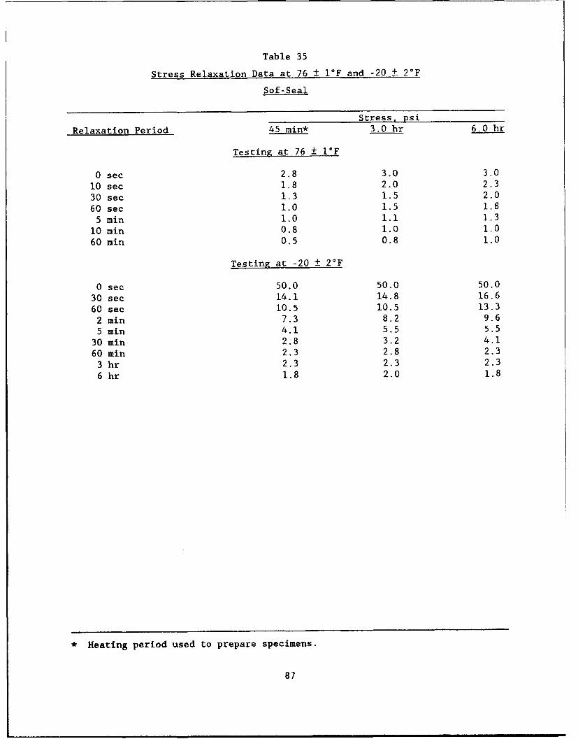
Table 35
Stress Relaxation Data at 76 ± 1IF and -20 + 2°F
Sof-Seal
Stress, psi
Relaxation Period 45 min* 3.0 hr 6.0 hr
Testing at 76 ± I°F
0 sec 2.8 3.0 3.010 sec 1.8 2.0 2.3
30 sec 1.3 1.5 2.0
60 sec 1.0 1.5 1.85 min 1.0 1.1 1.3
10 mrin 0.8 1.0 1.0
60 min 0.5 0.8 1.0
Testing at -20 ± 2°F
0 sec 50.0 50.0 50.0
30 sec 14.1 14.8 16.6
60 sec 10.5 10.5 13.3
2 min 7.3 8.2 9.6
5 min 4.1 5.5 5.5
30 min 2.8 3.2 4.1
60 min 2.3 2.8 2.3
3 hr 2.3 2.3 2.3
6 hr 1.8 2.0 1.8
* Heating period used to prepare specimens.
87
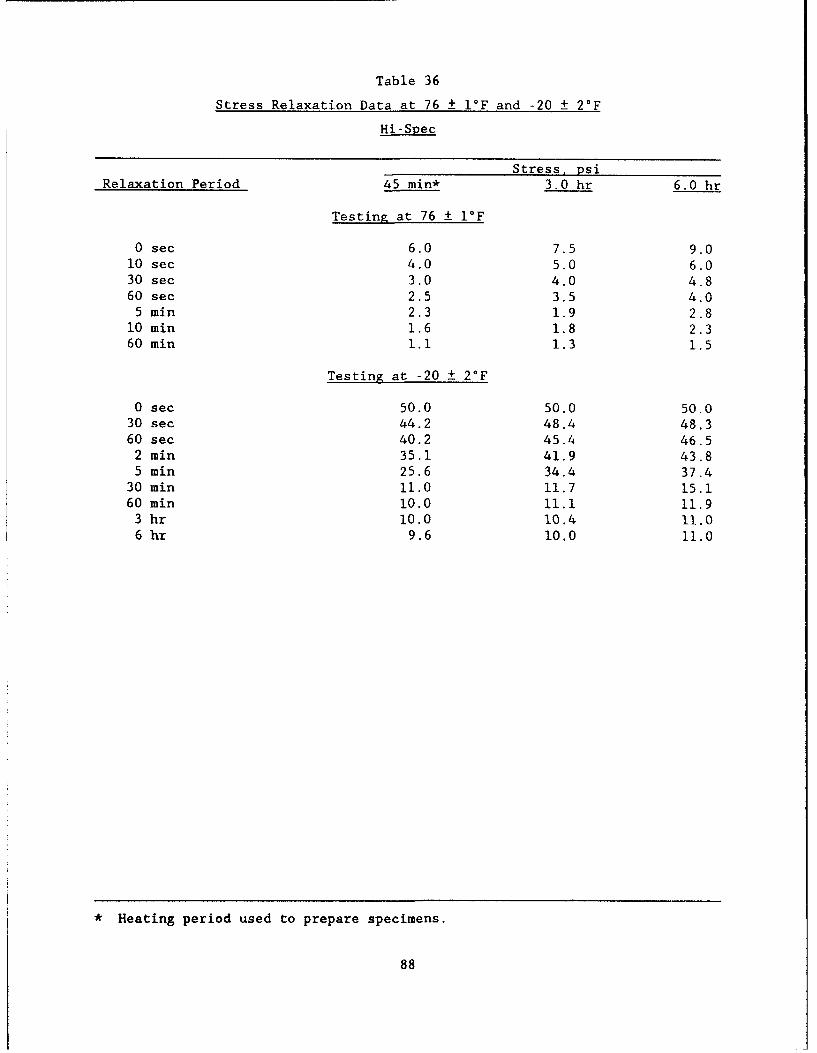
Table 36
Stress Relaxation Data at 76 1 I°F and -20 ± 2°F
Hi-Spec
Stress, psiRelaxation Period 45 min* 3.0 hr 6.0 hr
Testing at 76 ± 1IF
0 sec 6.0 7.5 9.010 sec 4.0 5.0 6.030 sec 3.0 4.0 4.860 sec 2.5 3.5 4.0
5 min 2.3 1.9 2.810 min 1.6 1.8 2.360 min 1.1 1.3 1.5
Testing at -20 ± 2'F
0 sec 50.0 50.0 50.030 sec 44.2 48.4 48.360 sec 40.2 45.4 46.5
2 min 35.1 41.9 43.85 min 25.6 34.4 37.4
30 min 11.0 11.7 15.160 min I0.0 11.1 11.9
3 hr 10.0 10.4 11.06 hr 9.6 10.0 11.0
* Heating period used to prepare specimens.
88
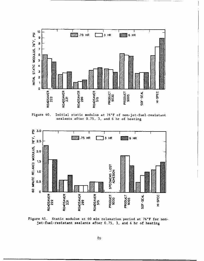
10 6 RM '.75 HR .j3 HR M 6 HRL 9 -
S7-
020 5 " " :
Y 4
-3S2•-
01"° h 111,011"1 I
Cr j i W Cr
'C<- ( <fLn 0' W) D0 W/S 0 0 00
Figure 40. Initial static modulus at 76°F of non-jet-fuel-resistantsealants after 0.75, 3, and 6 hr of heating
M 2.0
0
to 2.5
2 .000
1.5
w
00
LAJI I - II
ciw 1.00
0.5
0C4 ~ C, 0 h, I IIt o ffo = => > > 0 CL C
Figure 41. Static modulus at 60 min relaxation period at 76°F for non-jet-fuel-resistant sealants after 0.75, 3, and 6 hr of heating
89
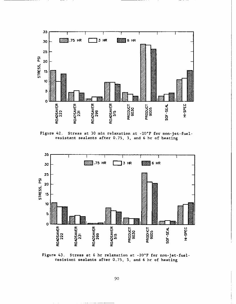
35 1 1 1 1 |
30 - .75 HR =-3 HR I 6 HR
25-
a. 20
(ifV)
S15L-
10
5
0
L5 LI I I I
g:n rn :3a04U U))Oano (
V)O UN ( P ) 0
20 --
0 0 0 0 12.W
Figure 42. Stress at 30 mi relaxation at -20°F for non-jet-fuel-resistant sealants after 0.75, 3, and 6 hr of heating
30 M.75 HR J3 HR M96 HR
25
i 20~20i
U)U)
~15in
10
5
0RI
<C4 <o <t 5n0r M0 V) U
0 0 0 0 a. a. c
Figure 43. Stress at 6 hr relaxation at -20*F for non-jet-fuel-resistant sealants after 0.75, 3, and 6 hr of heating
90
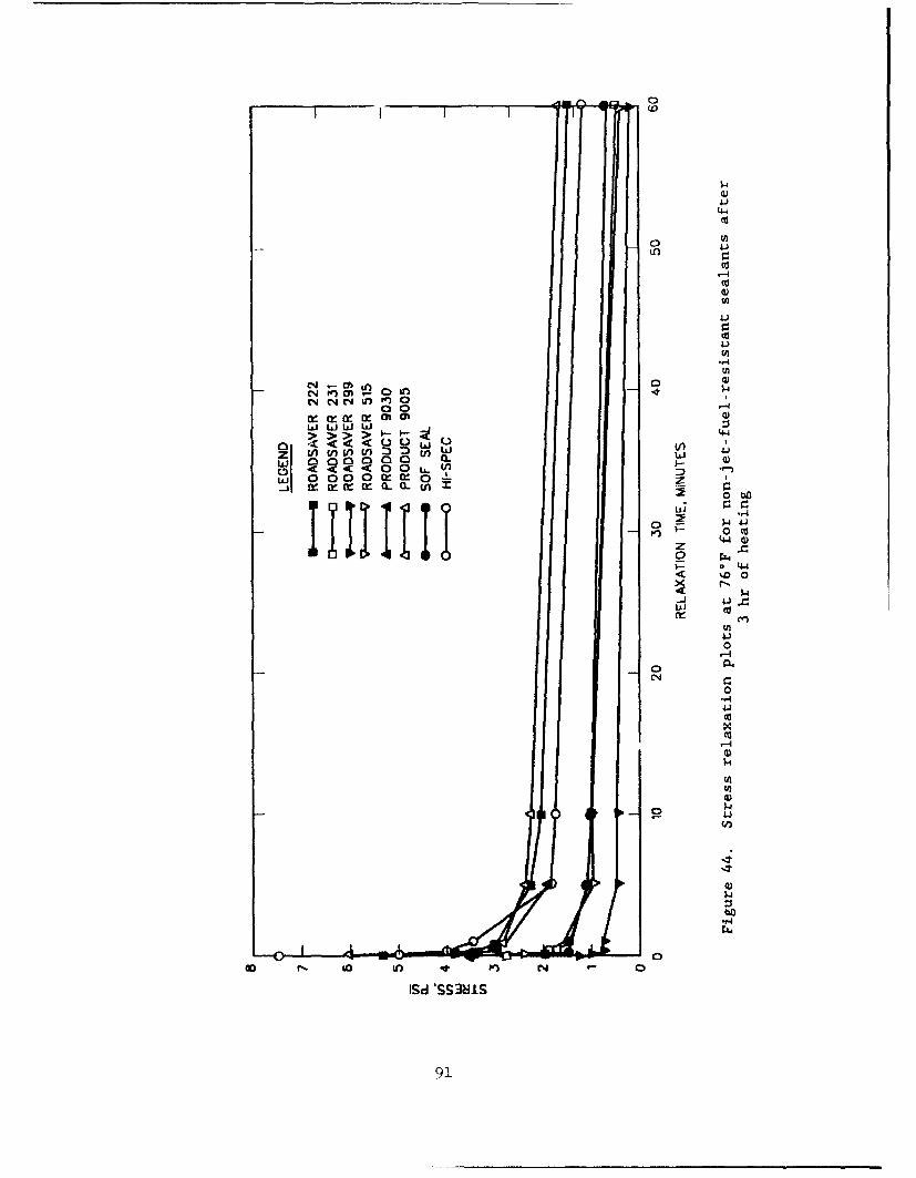
,4.
,.4
M1
C-4 C-4 C4 un
Isi LiLh Li 41
0 (A) tn V t j
w w0 0 0 (1z W-(-Co~ :3 "
0oto'4- 4)
00
41
00
I.4
911
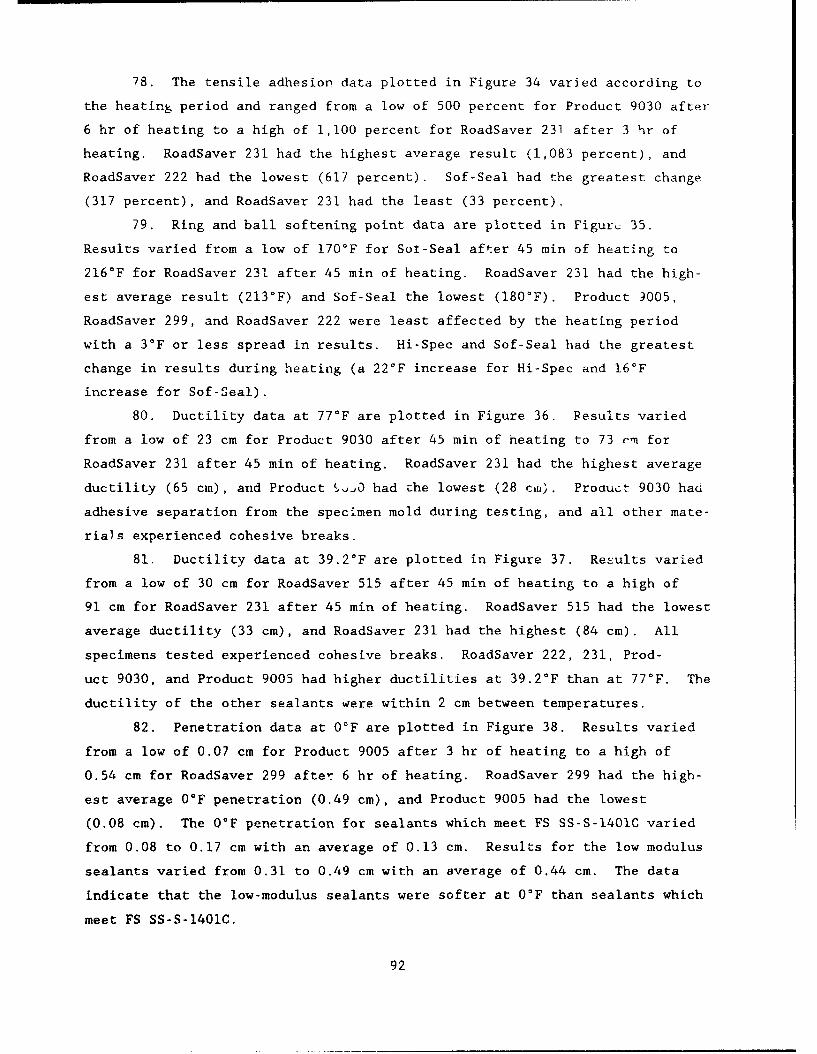
78. The tensile adhesion data plotted in Figure 34 varied according to
the heating period and ranged from a low of 500 percent for Product 9030 after
6 hr of heating to a high of 1,100 percent for RoadSaver 231 after 3 hr of
heating. RoadSaver 231 had the highest average result (1,083 percent), and
RoadSaver 222 had the lowest (617 percent). Sof-Seal had the greatest change
(317 percent), and RoadSaver 231 had the least (33 percent).
79. Ring and ball softening point data are plotted in Figur. 35.
Results varied from a low of 170°F for Sol-Seal after 45 min of heating to
216°F for RoadSaver 231 after 45 min of heating. RoadSaver 231 had the high-
est average result (213°F) and Sof-Seal the lowest (180'F). Product 9005,
RoadSaver 299, and RoadSaver 222 were least affected by the heating period
with a 3°F or less spread in results. Hi-Spec and Sof-Seal had the greatest
change in results during heating (a 22*F increase for Hi-Spec and 16'F
increase for Sof-Seal).
80. Ductility data at 77°F are plotted in Figure 36. Results varied
from a low of 23 cm for Product 9030 after 45 min of heating to 73 om for
RoadSaver 231 after 45 min of heating. RoadSaver 231 had the highest average
ductility (65 cm), and Product %.ojO had the lowest (28 cai). Procuct 9030 had
adhesive separation from the specimen mold during testing, and all other mate-
rials experienced cohesive breaks.
81. Ductility data at 39.2°F are plotted in Figure 37. Results varied
from a low of 30 cm for RoadSaver 515 after 45 min of heating to a high of
91 cm for RoadSaver 231 after 45 min of heating. RoadSaver 515 had the lowest
average ductility (33 cm), and RoadSaver 231 had the highest (84 cm). All
specimens tested experienced cohesive breaks. RoadSaver 222, 231, Prod-
uct 9030, and Product 9005 had higher ductilities at 39.2°F than at 77'F. The
ductility of the other sealants were within 2 cm between temperatures.
82. Penetration data at 0°F are plotted in Figure 38. Results varied
from a low of 0.07 cm for Product 9005 after 3 hr of heating to a high of
0.54 cm for RoadSaver 299 after 6 hr of heating. RoadSaver 299 had the high-
est average 0°F penetration (0.49 cm), and Product 9005 had the lowest
(0.08 cm). The O°F penetration for sealants which meet FS SS-S-1401C varied
from 0.08 to 0.17 cm with an average of 0.13 cm. Results for the low modulus
sealants varied from 0.31 to 0.49 cm with an average of 0.44 cm. The data
indicate that the low-modulus sealants were softer at 0°F than sealants which
meet FS SS-S-1401C.
92
83. Brookfield viscosity data at the sealant safe heatirQ temperature
are plotted in Figure 39. Product 9005 had the lowest average viscosit,,
(733 cp), and RoadSaver 222 had the highest (3,563 cp). Several sealants
experienced viscosity changes during heating while others were relatively
constant.
84. Results of static adhesion tests revealed that all sealants except
Product 9030 had satisfactory results at all heating periods. Product 9030
experienced separations in excess of 160 mm2 when tested after each heating
period.
85. Stress relaxation results at 76°F and -20°F are shown in Tables 29
through 36. Results are plotted in Figures 39 through 42. A plot of relax-
ation data at 76°F for each sealant after heating for 3 hr is shown in Fig-
ure 44. Figure 44 also illustrates the typical shape of the relaxation
curves. The initial stress is the highest, and the stress decreases with time
as the specimen experiences relaxation. Figure 44 also indicates that differ-
ent materials not only have different initial and relaxed stresses, but that
the slopes of the relaxation curves vary. The variation indicates differences
in elastic characteristics. Since testing at 76°F was performed using
100 percent extension (1.00 strain), the-data can also be referred to as a
static modulus. Figure 40 is a plot of initial static modulus at 76°F. The
data show that some sealants experience decreases in initial modulus as a
result of heating while others remain approximately the same, and others
experience increases. RoadSaver 299 has the lowest initial modulus (1.4 psi
average), and Hi-Spec has the highest (7.5 psi average). Figure 41 shows
static modulus after a 60 min relaxation period. Roadsaver 222 had the high-
est relaxed modulus (1.8 psi average), and Roadsaver 299 had the lowest
(0.3 psi average). Product 9030 had adhesive failure during the test. Exami-
nation of the data shows that the adhesive stress at failure did not exceed
3.0 psi after 45 min of heating, 2.0 psi after 3 hr, and 2.3 psi after 6 hr of
heating. Additionally, Product 9030 had the highest resilience or elasticity,
experienced adhesive separations during ductility testing at 77°F, and did not
pass static adhesion testing. The data indicate that sealants which meet
FS SS-S-1401C have higher initial and relaxed modulus values than the other
sealants tested. The 60 min relaxed modulus of RoadSaver 515 was the second
lowest (0.50 psi) and was even lower than values obtained for the low modulus
type materials (RoadSaver 231 and Sof-Seal). This may be due to the lower
93
resilience characteristics of RoadSaver 515. Sof-Seal had the largest
increase in relaxed modulus with increased heating period.
86. Figure 45 is a plot of relaxation data at -20°F for the non-JFR
sealants after 3 hr of heating. Due to the widely varying stiffness of the
sealants, it was not possible to extend each to a uniform extension at the
beginning of the test; therefore, specimens were loaded with a 50 psi tensile
stress, and relaxation was monitored from that initial stress. The extension
required for the different sealants to achieve 50 psi varied due to the vary-
ing stiffness of each sealant. Figure 45 shows wide variations in the relax-
ation plots at -20°F. Relaxed stresses after 6 hr vary from an average low of
0.6 psi for RoadSaver 299 to an average high of 22.5 psi for Product 9005.
The data indicate that the majority of the relaxation occurs within approxi-
mately I hr after loading. Figure 42 shows stress at 30 min relaxation. The
data also show that sealants which meet FS SS-S-1401C exert higher stresses
than the low-modulus sealants. The effect of the heating period varies with
the sealant material. Stresses after 6 hr of relaxation are plotted in Fig-
ure 43. Results follow the same trends as the 30 min data.
87. The additional test results show some major differences in the low
temperature stiffness and extension characteristics of the sealants. The low-
modulus sealants (RoadSaver 231, RoadSaver 299, Product 9030, and Sof-Seal)
are softer and are capable of extending further at low temperatures than the
sealants which meet FS SS-S-1401C. Even though the low-modulus sealants are
softer, flow characteristics at 140°F and resilience results are similar to
those required by FS SS-S-1401C.
9/,
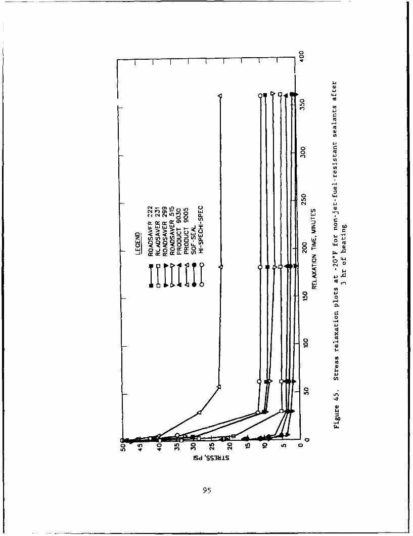
04
0 0d
0 4
Loo4 0 n c
010, $ D 01
z 4 4
J4J
0I0
-44J
'54:s
0(in rn 04-4
954
PART V: DEVELOPMENT OF IMPROVED HOT-APPLIED FUEL-RESISTANT SEALANT
Development Goals
88. One of the project objectives was to develop specification limits
for an improved hot-applied, JFR sealant. The specific performance characte!
istics where impr-vement was desired include the following:
a. Incompressible rejection.
b. Weathering and durability.
C. Low temperature properties.
d. Blast and flow resicrnc'p
e. Fuel resistance.
89. The testing reported in Part III of this report identified the
physical properties of commercially available hot-applied, JFR sealants, The
data collected during that testing provided an improved understanding of the
performance limits of those sealants and is basis for the following recom-
mended specification limits.
Incompressible rejection
90. FS SS-S-1614A does not include procedures to measure the resilient
or elastic characteristics of a sealant. Inclusion of a resilience test simi-
lar to those contained in FS SS-S-1401C and FS SS-S-200E would provide that
measurement. However, to include the test into a specification, the test
limits must be established. The resilience data reported in Part III show
that resilience values are dependent upon several factors. These factors
include the sealant material, the length of the heating period, the cure
period, and the aging conditions. Resilience results of the available JFR
sealants varied from 50 to 72 percent after 72 hr of curing at standard
laboratory conditions. Aging the samples for 7 days at 158*F caused the
resilience values to decrease. Based upon these results, an initial develop-
mental goal of 40 to 50 percent after curing at standard laboratory conditions
for 72 hr would be feasible.
Weathering and durability
91. FS SS-S-1614A does not specifically address weathering and dura-
bility. The test used to evaluate these characteristics was oven-aged weight
loss. Samples were taken from the sealants before and after heating. These
samples were then placed in a 158*F oven and the weight loss measured
96
periodically. The samples taken prior to heating had weight losses of 1.9 to
2.9 percent. The samples taken after heating had weight losses ranging from
0.6 to 1.3 percent. A correlation between weight loss and durability could
not be established; therefore, the testing was discontinued.
Low temperature properties
92. FS SS-S-1614A requires a sealant to withstand 50 percent extension
at a test temperature of 0°F. Obvious improvements to this requirement could
be to lower the test temperature, increase the amount of extension, or both.
The bond testing conducted on the JFR sealants showed that none of them could
be extended 50 percent extension at -20°F. Therefore, a developmental goal of
50 percent extension at -20°F was established.
Blast and flow resistance
93. FS SS-S-1614A allows a maximum flow of 3.0 cm after 5 hr exposure
to 140°F. It does not include a blast resistance test. There were initially
two developmental goals in this area. The first goal was to develop a mate-
rial that would pass with an increase in the flow test temperature and a
reduction in the allowable flow. The second goal was to determine if blast
resistance could be obtained in a hot-applied JFR sealant. The laboratory
testing conducted on the available JFR sealants indicated that they had
significantly less flow than the 3.0 cm requirement even at higher tempera-
tures of up to 158°F. The limit set for this developmental goal was 0.5 cm
flow maximum after 24 hr exposure to 158°F.
94. Initial laboratory studies at Crafco Inc. indicated that it might
be possible to formulate a hot-applied sealant that was resistant to the
effects of aircraft exhaust (blast resistant). However, the sealants formu-
lated in the laboratory to be more blast resistant were believed to be too
stiff to perform satisfactorily in the field. Therefore, formulation efforts
were directed toward low temperature performance improvements and away from
blast resistance.
Fuel resistance
95. An improved fuel resistance would be desirable. Methods that could
be used to determine improvement in fuel resistance are penetration and bond
testing. The penetration tests conducted on the JFR sealants showed the
amount of change between the nonimmersed penetration and the fuel-immersed
penetration varied with the sealant material and the length of the heating
period. Comparisons between the fuel-immersed penetration and fuel-immersed
97
bond showed that sealants which experienced large changes in penetration
values could still pass the fuel-immersed bond testing, These results indi-
cate that changes between nonimmersed and fuel-immersed penetrations do not
necessarily indicate that adhesion is adversely affected. Therefore, a lower
limit for the amount of change in penetration would not be investigated fur-
ther. Instead, the fuel-immersed bond results would be used for specification
consideration.
96. The surface of the oven-aged samples of JFR sealants became hard-
ened, and the amount of hardening increased with time. This phenomena was
further investigated by removing the sealant from the container and examining
the properties underneath the hardened surface. This examination showed that
the sealant material under the surface had not hardened, thus suggesting that
the hardening was probably caused by an oxidation mechanism on the exposed
Furface. Subsequent to this examination, samples of several hot-applied JFR
sealants which varied in age were obtained from several field installations.
The samples were cut from the joints using a knife. Examination showed hard-
ened top surfaces varying frotan approximately 1/8 to 1/4 in. in thickness.
Hardening was also noted on the bottom surface of the sealant that was in
contact with the backer rod. However, the bottom hardening was not as severe
as the top. Hardening on the top of the sealant surface was large enough to
cause adhesive and/or cohesive separations to the depth of the hardened mate-
rial. Below the hardened surface, strong adhesion to the joint surfaces was
observed. In areas where the sealant thickness was approximately 1/4 in., the
total thickness of the sealant had hardened, and both adhesive and cohesive
failure modes were observed. The hardened surfaces observed in field speci-
mens and the laboratory oven-aged specimens had a similar hardened, brittle
appearance. These observations indicate that surface hardening may be a pri-
mary cause of failure in hot-applied, JFR sealants. It was decided that a
method to measure surface hardening characteristics should be developed.
97. Penetration samples of Superseal 1614A, Plant 1, Product 9012, and
NEA 1614 were prepared and subjected to forced-draft oven exposure at 158°F
for 4 weeks. Penetration at 77°F was monitored during the 4 week period to
determine surface hardening characteristics. The results are shown in
Table 37 and plotted in Figure 46. These data show that forced-draft oven
exposure of the specimens cause significant drops in penetration. The
98
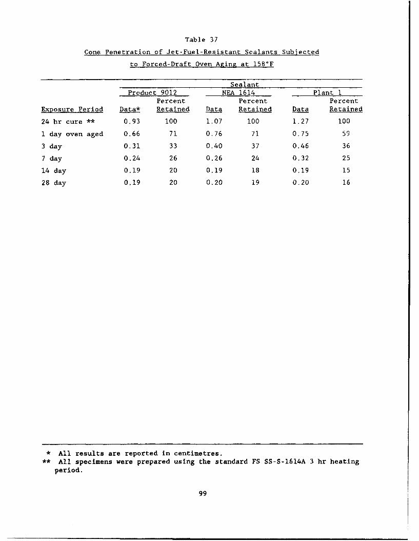
Table 37
Cone Penetration of Jet-Fuel-Resistant Sealants Subjected
to Forced-Draft Oven Aging at 158°F
SealantProduct 9012 NEA 1614 Plant I
Percent Percent PercentExposure Period Data* Retained Data Retained Data Retained
24 hr cure ** 0.93 100 1.07 100 1.27 100
1 day oven aged 0.66 71 0.76 71 0.75 59
3 day 0.31 33 0.40 37 0.46 36
7 day 0.24 26 0.26 24 0.32 25
14 day 0.19 20 0.19 18 0.19 15
28 day 0.19 20 0.20 19 0.20 16
* All results are reported in centimetres.
** All specimens were prepared using the standard FS SS-S-1614A 3 hr heatingperiod.
99
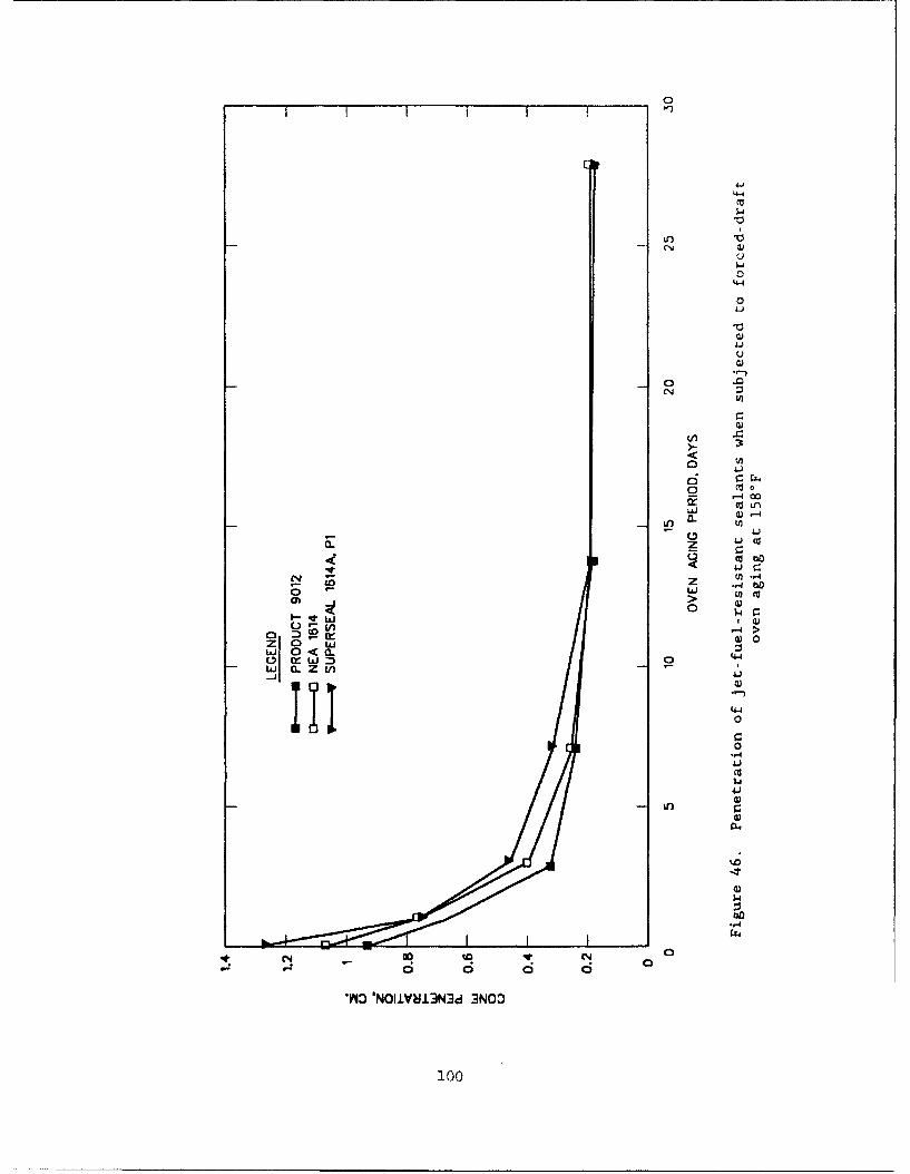
4.4
0
41
040cc n
as> Q30 w"
-4 >w 0
w~~ o OC
44
.. 4
4.,
100
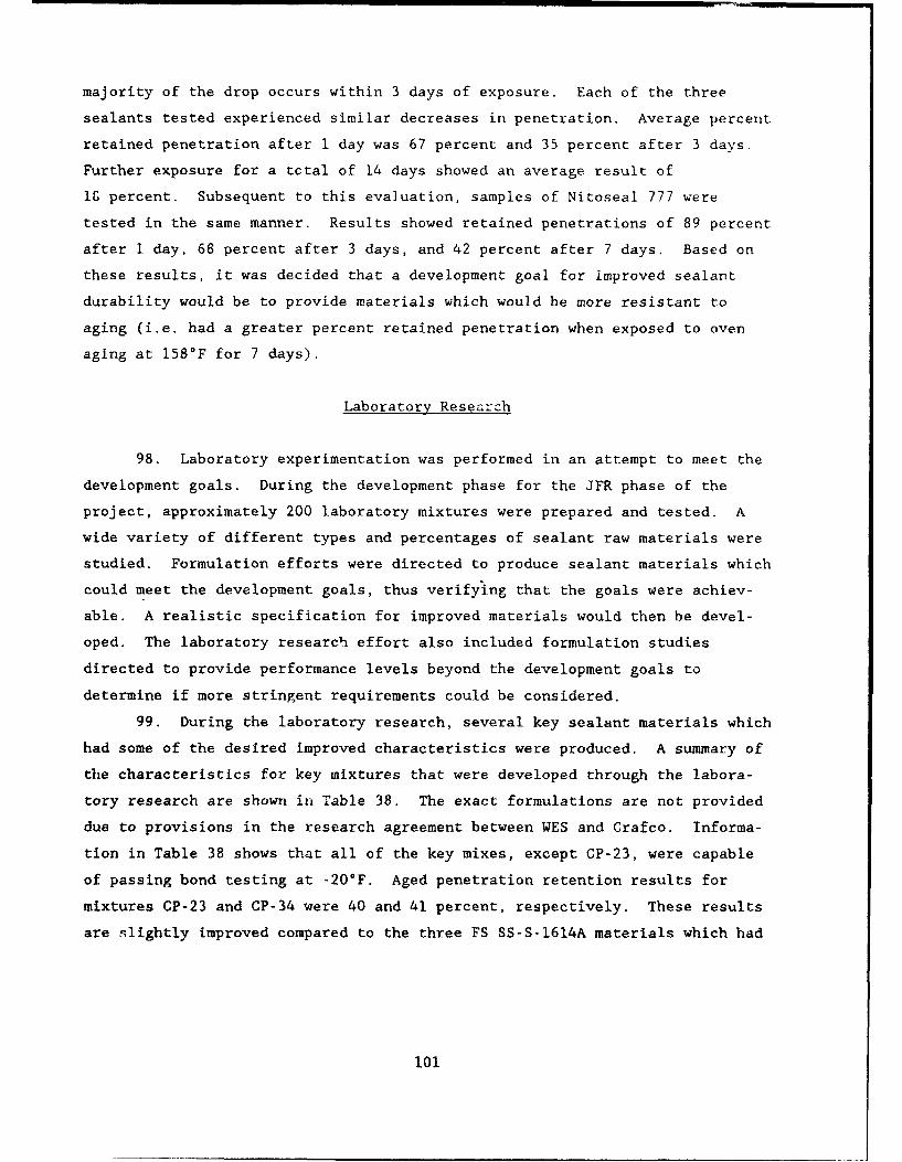
majority of the drop occurs within 3 days of exposure. Each of the three
sealants tested experienced similar decreases in penetration. Average percent
retained penetration after i day was 67 percent and 35 percent after 3 days.
Further exposure for a tctal of 14 days showed an average result of
lg percent. Subsequent to this evaluation, samples of Nitoseal 777 were
tested in the same manner. Results showed retained penetrations of 89 percent
after I day, 68 percent after 3 days, and 42 percent after 7 days. Based on
these results, it was decided that a development goal for improved sealant
durability would be to provide materials which would be more resistant to
aging (i.e. had a greater percent retained penetration when exposed to oven
aging at 1580F for 7 days).
Laboratory Research
98. Laboratory experimentation was performed in an attempt to meet the
development goals. During the development phase for the JFR phase of the
project, approximately 200 laboratory mixtures were prepared and tested. A
wide variety of different types and percentages of sealant raw materials were
studied. Formulation efforts were directed to produce sealant materials which
could meet the development goals, thus verifying that the goals were achiev-
able. A realistic specification for improved materials would then be devel-
oped. The laboratory research effort also included formulation studies
directed to provide performance levels beyond the development goals to
determine if more stringent requirements could be considered.
99. During the laboratory research, several key sealant materials which
had some of the desired improved characteristics were produced. A summary of
the characteristics for key mixtures that were developed through the labora-
tory research are shown in Table 38. The exact formulations are not provided
due to provisions in the research agreement between WES and Crafco. Informa-
tion in Table 38 shows that all of the key mixes, except CP-23, were capable
of passing bond testing at -20°F. Aged penetration retention results for
mixtures CP-23 and CP-34 were 40 and 41 percent, respectively. These results
are slightly improved compared to the three FS SS-S-1614A materials which had
101
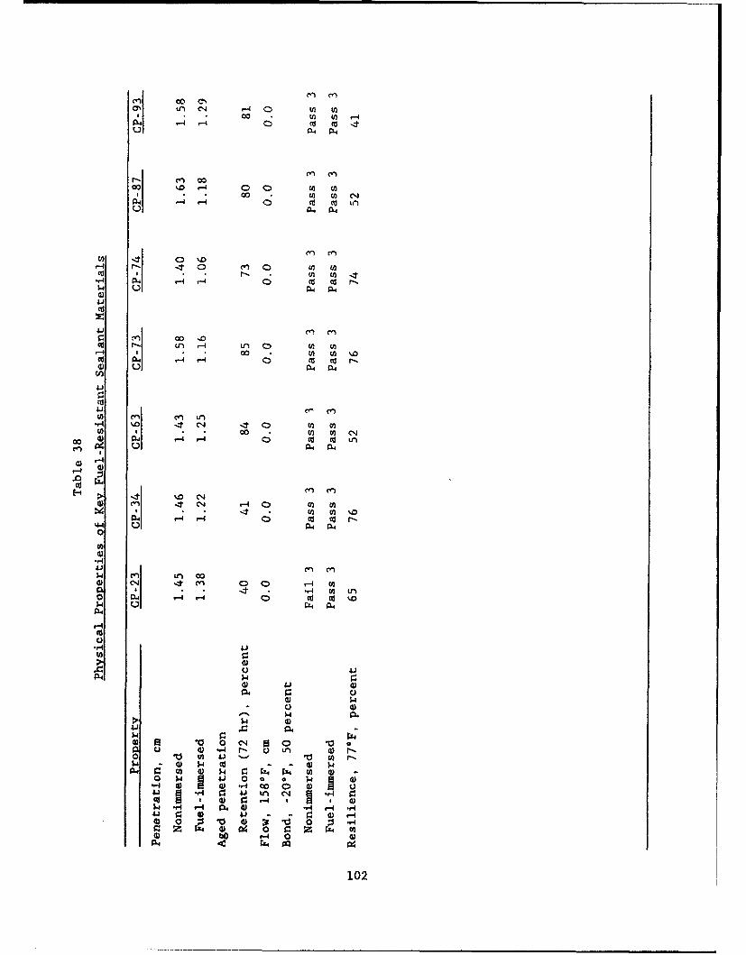
ON Ln (N .. 4 0 w V)* c0c U) -4
04 -4 -4 w wU CUU04 04
cc E
41 en ccrj y)
Cd C -4 ,4 0Cd Co r-) Ul 04 04
C'ý CY)
Eni 00 m En C4 C)
" -0 4) 14 -4 -4 0 Cd cu r-S-4 Ul 04 04
E 4 .> t o Ccy, C',
c" c4 -4U C i) (a .E
OW 0414-4 0 co tv r-44 040a4
4.) 04 ItC) ,q U
0- 1.4 41 (-4 4d 0d C) o
04 u - 0 X Cu u4 L
U)
4-4 U 00.
-'-0. C') a'
w 4 *,- Cd LA 0 1
o, 0) 15 a) -4 X 0 C) C u'
54 "4IA 0 4 4 -A
r.04)0 r-4r- 04
P4- 4.)11
0.102
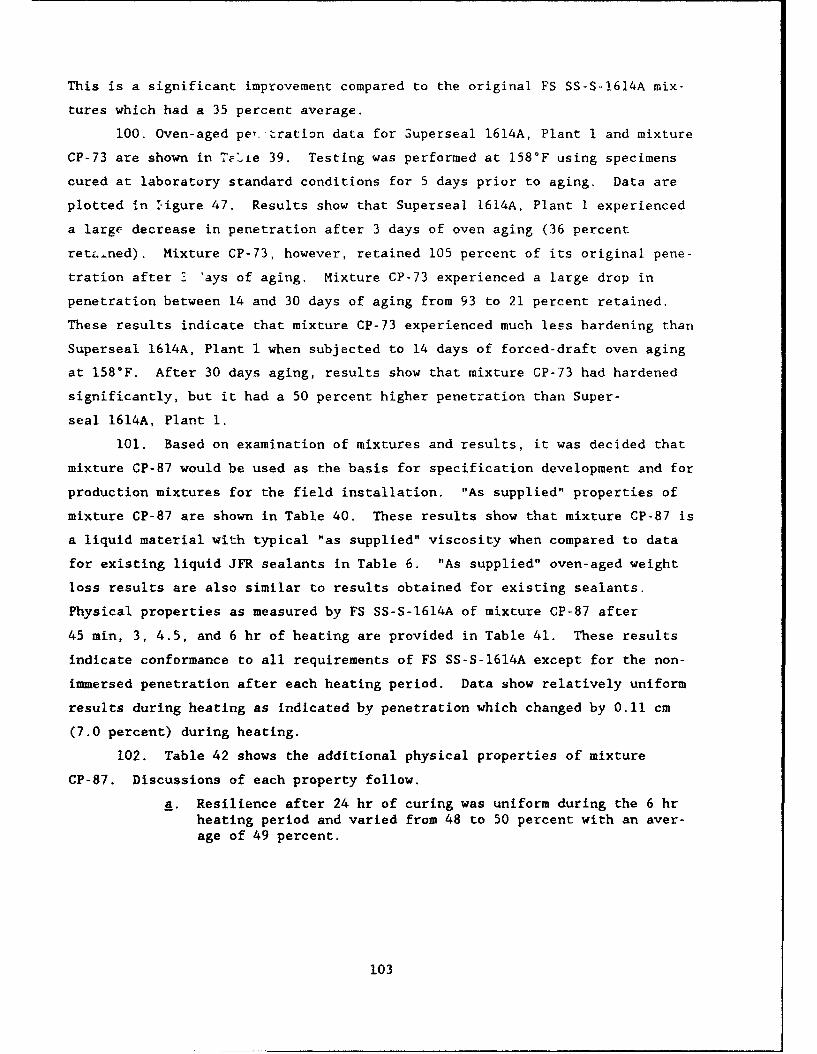
This is a significant improvement compared to the original FS SS-S-1614A mix-
tures which had a 35 percent average.
100. Oven-aged pe,_ tration data for Superseal 1614A, Plant I and mixture
CP-73 are shown in 7TLie 39. Testing was performed at 158°F using specimens
cured at laboratory standard conditions for 5 days prior to aging. Data are
plotted in :igure 47. Results show that Superseal 1614A, Plant I experienced
a large decrease in penetration after 3 days of oven aging (36 percent
retL-ned). Mixture CP-73, however, retained 105 percent of its original pene-
tration after 3 'ays of aging. Mixture CP-73 experienced a large drop in
penetration between 14 and 30 days of aging from 93 to 21 percent retained.
These results indicate that mixture CP-73 experienced much less hardening than
Superseal 1614A, Plant I when subjected to 14 days of forced-draft oven aging
at 158°F. After 30 days aging, results show that mixture CP-73 had hardened
significantly, but it had a 50 percent higher penetration than Super-
seal 1614A, Plant 1.
101. Based on examination of mixtures and results, it was decided that
mixture CP-87 would be used as the basis for specification development and for
production mixtures for the field installation. "As supplied" properties of
mixture CP-87 are shown in Table 40. These results show that mixture CP-87 is
a liquid material with typical "as supplied" viscosity when compared to data
for existing liquid JFR sealants in Table 6. "As supplied" oven-aged weight
loss results are also similar to results obtained for existing sealants.
Physical properties as measured by FS SS-S-1614A of mixture CP-87 after
45 min, 3, 4.5, and 6 hr of heating are provided in Table 41. These results
indicate conformance to all requirements of FS SS-S-1614A except for the non-
immersed penetration after each heating period. Data show relatively uniform
results during heating as indicated by penetration which changed by 0.11 cm
(7.0 percent) during heating.
102. Table 42 shows the additional physical properties of mixture
CP-87. Discussions of each property follow.
a. Resilience after 24 hr of curing was uniform during the 6 hrheating period and varied from 48 to 50 percent with an aver-age of 49 percent.
103
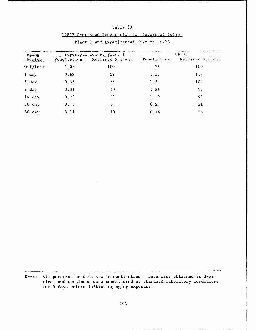
Table 39
158°F Over-Aged Penetration for Superseal 1614A,
Plant I and Experimental Mixture CP-73
Aging Superseal 1614A Plant I CP-73
Period Penetration Retained Percent Penetration Retained Percent
Original 1.05 100 1.28 100
i day 0.62 59 1.51 11I
3 day 0.38 36 1.34 105
7 day 0.31 30 1.26 98
14 day 0.23 22 1.19 93
30 day 0.15 14 0.27 21
60 day 0.11 10 0.16 13
Note: All penetration data are in centimetres. Data were obtained in 3-oztins, and specimens were conditioned at standard laboratory conditionsfor 5 days before initiating aging exposure.
104
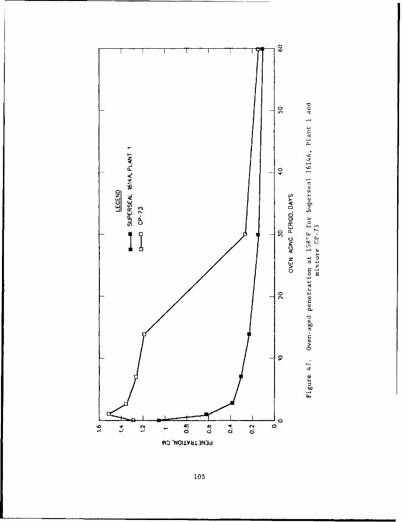
0nc
ae
z viL'i >-
0 3
.~ Lr)
0 osd.,41/41
L.L
CC.
V40~~ 'NlV83U
105
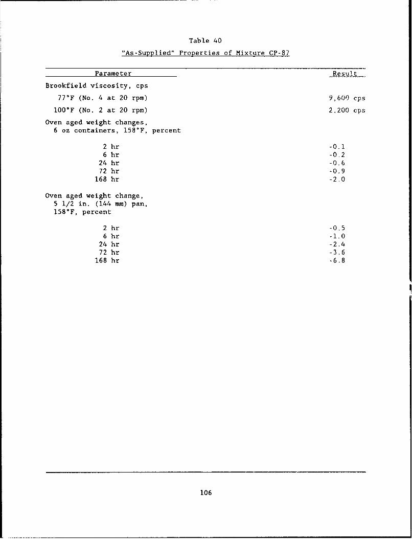
Table 40
"As-Supplied" Properties of Mixture CP-87
Parameter Result
Brookfield viscosity, cps
77*F (No. 4 at 20 rpm) 9,600 cps
100*F (No. 2 at 20 rpm) 2,200 cps
Oven aged weight changes,6 oz containers, 158°F, percent
2 hr -0.16 hr -0.2
24 hr -0.672 hr -0.9
168 hr -2.0
Oven aged weight change,5 1/2 in. (144 nun) pan,158°F, percent
2 hr -0.56 hr -1.0
24 hr -2.472 hr -3.6
168 hr -6.8
106
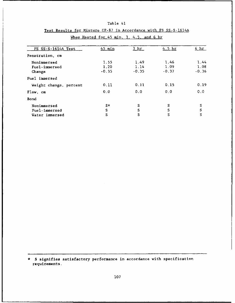
Table 41
Test Results for Mixture CP-87 in Accordance with FS SS-S-1614A
When Heated for 45 min, 3, 4.5. and 6 hr
FS SS-S-1614A Test 45 min 3 hr 4.5 hr 6 hr
Penetration, cm
Nonimmersed 1.55 1.49 1.46 1.44
Fuel-immersed 1.20 1.14 1.09 1.08
Change -0.35 -0.35 -0.37 -0.36
Fuel immersed
Weight change, percent 0.11 0.11 0.15 0.19
Flow, cm 0.0 0.0 0.0 0.0
Bond
Nonimmersed S* S S SFuel-immersed S S S S
Water immersed S S S S
S signifies satisfactory performance in accordance with specification
requirements.
107
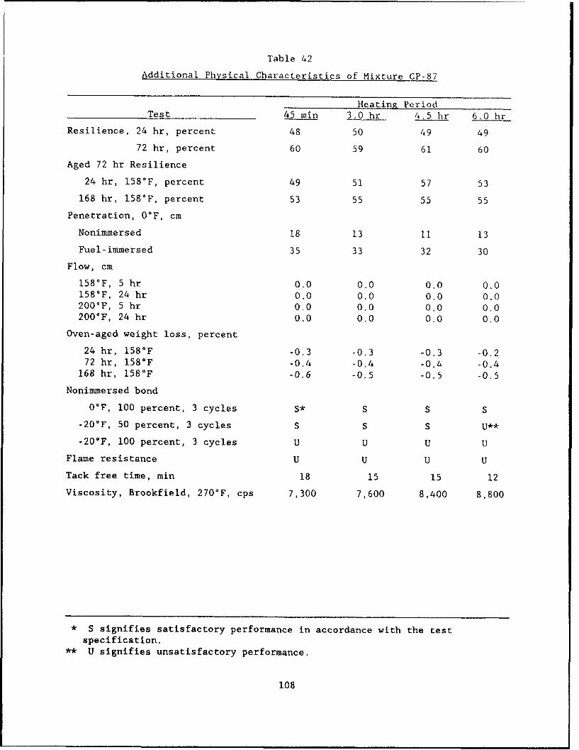
Table 42
Additional Physical Characteristics of Mixture CP-87
Heating PeriodTest 45 min 3.0 hr 4.5 hr 6.0 hr
Resilience, 24 hr, percent 48 50 49 49
72 hr, percent 60 59 61 60
Aged 72 hr Resilience
24 hr, 158°F, percent 49 51 57 53
168 hr, 158'F, percent 53 55 55 55
Penetration, OF, cm
Nonimmersed 18 13 11 13
Fuel-immersed 35 33 32 30
Flow, cm
158°F, 5 hr 0.0 0.0 0.0 0.0158°F, 24 hr 0.0 0.0 0.0 0.0200'F, 5 hr 0.0 0.0 0.0 0.0200°F, 24 hr 0.0 0.0 0.0 0.0
Oven-aged weight loss, percent
24 hr, 158°F -0.3 -0.3 -0.3 -0.272 hr, 158°F -0.4 -0.4 -O.La -0.4
168 hr, 158°F -0.6 -0.5 -0.5 -0.5
Nonimmersed bond
OF, 100 percent, 3 cycles S* S S S
-20-F, 50 percent, 3 cycles S S S U**
-20*F, 100 percent, 3 cycles U U U U
Flame resistance U U U U
Tack free time, min 18 15 15 12
Viscosity, Brookfield, 270'F, cps 7,300 7,600 8,400 8,800
* S signifies satisfactory performance in accordance with the testspecification.
** U signifies unsatisfactory performance.
108
b. Resilience after 72 hr of curing was also relatively uniformduring heating varying from 59 to 61 percent. The averageresult was 60 percent.
c. The 24 hr aging at 158°F produced decreases in resilience,The resilience varied from 49 to 57 percent with an average of53 percent for all heating periods. Drops in resilienceranged from 4 to 11 percent compared to the unaged samples.
d. The 168 hr aging produced smaller changes in resilience thanfor the previously tested sealants. The change varied from adecrease of 2 percent to an increase of 4 percent. Averagedata for all heating periods were 54 percent which is an aver-age increase of 1 percent compared to the 24 hr aged results.
e. Penetration at O°F ranged from 0.18 to 0.11 cm and decreasedduring heating. Results are in the same general range as forthe existing tested JFR sealants.
f. Fuel-immersed penetration at 0°F ranged from 0.35 to 0.30 cmand decreased during heating. These results are higher thanthose obtained for the existing tested JFR sealants.
g. Flow testing at 158 and 200'F for both 5 and 24 hr produced0.0. cm of flow which is similar to most of the tested exist-ing sealants.
h. Oven-aged weight loss data after exposure to 158'F for 168 hrshow losses which range from 0.6 percent to 0.5 percent. Thisloss was less than for the existing sealants tested.
i. Nonimmersed bond testing showed satisfactory results for allheating periods at O°F with 100 percent extension. Testing at-20°F with 50 percent extension showed satisfactory resultsfor each heating period except 6 hr. Unsatisfactory resultswere obtained at -20'F with 100 percent extension for allheating periods. These results indicate improved low tempera-ture performance compared to the existing sealants.
j. Flame resistance testing showed unsatisfactory results at eachheating period. Results are similar to the tested existingsealants.
k. Tack free time varied from 12 to 18 min. Results are in thesame range as the tested existing sealants.
1. Viscosity at the safe heating temperature varied from 7,300 to8,800 cp during heating. Average viscosity was 8,025 cp.These results are in the same range as the existing testedsealants. Mixture CP-87, however, only had a 20.5 percentviscosity increase during heating. In comparison, the exist-ing tested sealants showed increases from 48.5 to 83.3 Der-
cent. This indicates that mixture CP-37 is more stible duringheating than the existing tested sealants.
103. Stress relaxation data at 76°F and -20'F are tabulated in Table 7.
Data at 76*F show an initial static modulus which varies from 3.2 to 4.1 psi
with an average of 3.8 psi. The modulus increased 29 percent during heating
109
from 45 min to 6 hr. Results show that mixture CP-87 had a lower average
initial static modulus at 76°F, and increased less during heating than the
existing JFR sealants. The 60 min relaxed modulus varied from 1.5 psi to
1.7 psi with an average of 1.6 psi. The increase during heating was
13.3 percent.
104. Thirty minute relaxation results at -20°F (Table 43) range from
2.3 to 7.3 psi and average 4.9 psi. This indicates that mixture CP-87 exerts
significantly lower stresses than the existing tested sealants. The stresses
of the existing sealants ranged from 8.2 to 20.9 psi. Relaxation data after
6 hr show an average result of 3.2 psi which is also significantly lower than
the existing tested sealants which had average results ranging from 6.6 to
15.2 psi.
Suggested Specification
105. Considering the laboratory results for the experimental mixtures,
a specification for an improved hot-applied, single component, JFR sealant was
developed. The specification is patterned after the current FS SS-S-1614A
specification with several changes in property limits and test procedures.
The specification is listed in Appendix B.
106. A comparison of methods and requirements of FS SS-S-1614A and the
suggested JFR specification is shown in Table 44. The suggested specification
requires increased high temperature flow resistance, increased hardening
resistance, increased low temperature extension characteristics, and increased
elasticity or resilience. The differences between the suggested specification
and FS SS-S-1614A are as follows:
a. Specimen curing. All specimens are cured at standard labora-tory conditions for 72 hr prior to initiating testingprocedures.
b. Nonimmersed penetration. Upper limit is 1.60 cm instead of1.30 cm maximum. This permits use of a softer material.
c. Fuel-immersed penetration. Upper limit is 1.60 cm maximum andno increase is permitted over the nonimmersed result. Nosoftening is permitted after fuel immersion.
d. Azed penetration retention. This is a new requirement with a70 percent of the inital value minimum. This requirementmeasures increased resistance to hardening during aging.
110
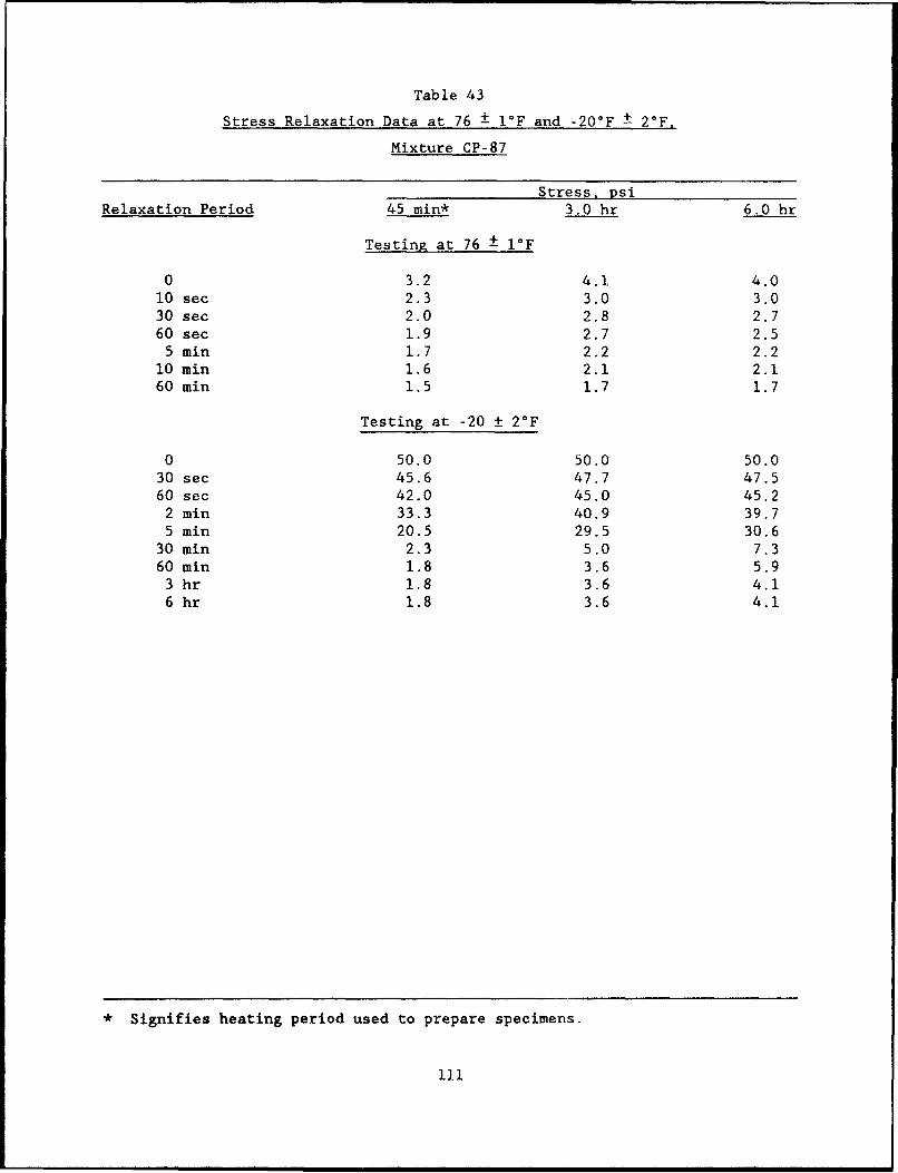
Table 43
Stress Relaxation Data at 76 ± 1F and -20°F ± 20 F,
Mixture CP-87
Stress, psiRelaxation Period 45 min* 3.0 hr 6.0 hr
Testing at 76 ± 1-F
0 3.2 4.1 4.010 sec 2.3 3.0 3.030 sec 2.0 2.8 2.760 sec 1.9 2.7 2.5
5 min 1.7 2.2 2.210 min 1.6 2.1 2.160 min 1.5 1.7 1.7
Testing at -20 + 2°F
0 50.0 50.0 50.030 sec 45.6 47.7 47.560 sec 42.0 45.0 45.2
2 win 33.3 40.9 39.75 win 20.5 29.5 30.6
30 min 2.3 5.0 7.360 win 1.8 3.6 5.9
3 hr 1.8 3.6 4.16 hr 1.8 3.6 4.1
* Signifies heating period used to prepare specimens.
11i
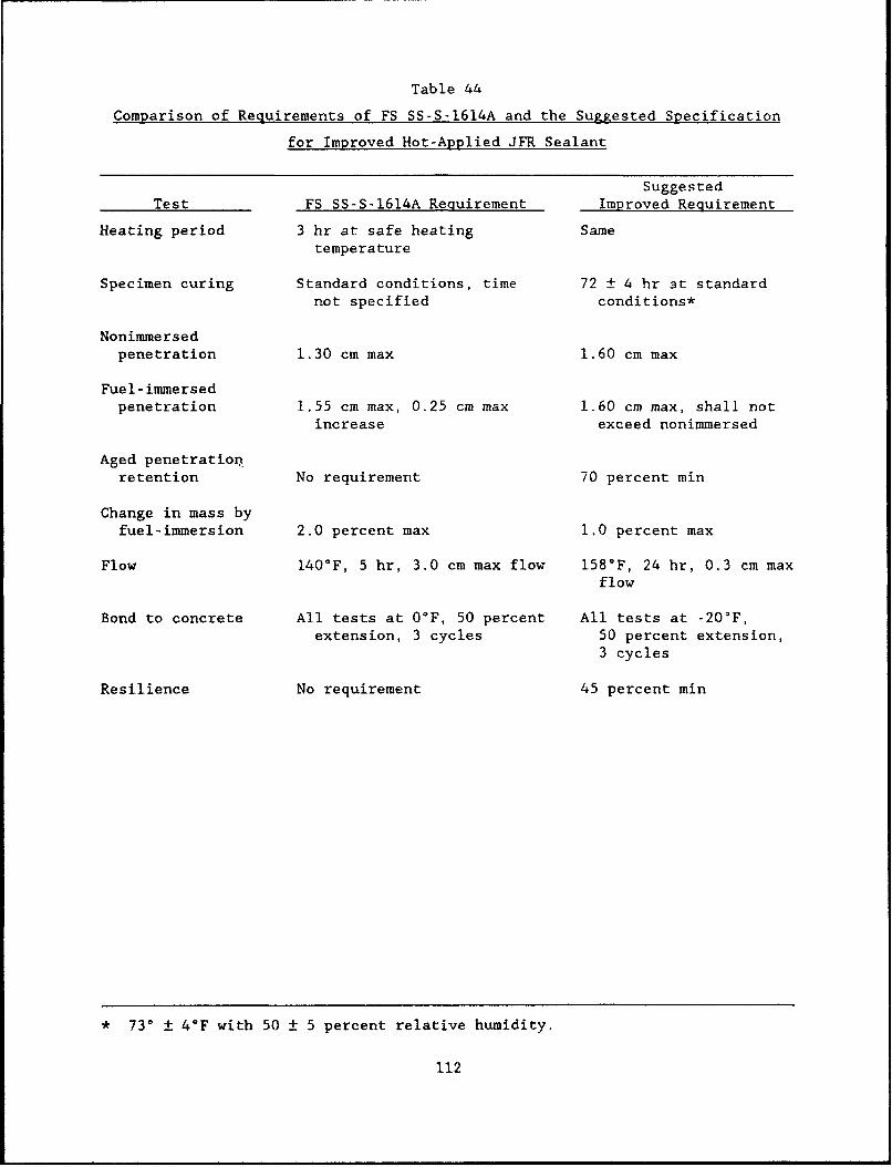
Table 44
Comparison of Requirements of FS SS-S-1614A and the Suggested Specification
for Improved Hot-Applied JFR Sealant
SuggestedTest FS SS-S-1614A Requirement Improved Requirement
Heating period 3 hr at safe heating Sametemperature
Specimen curing Standard conditions, time 72 ± 4 hr at standardnot specified conditions*
Nonimmersedpenetration 1.30 cm max 1.60 cm max
Fuel-immersedpenetration 1.55 cm max, 0.25 cm max 1.60 cm max, shall not
increase exceed nonimmersed
Aged penetrationretention No requirement 70 percent min
Change in mass byfuel-immersion 2.0 percent max 1.0 percent max
Flow 140*F, 5 hr, 3.0 cm max flow 158°F, 24 hr, 0.3 cm maxflow
Bond to concrete All tests at 0°F, 50 percent All tests at -20'F,extension, 3 cycles 50 percent extension,
3 cycles
Resilience No requirement 45 percent min
* 730 ± 4*F with 50 ± 5 percent relative humidity.
112
e. Change in mass by fuel immersion. The limit is 1.0 percentmaximum instead of 2.0 percent maximum.
f. Flow. Testing is performed at 158°F for 24 hr and the limitis 0.3 cm maximum.
g. Bond to concrete. Testing is at -20'F instead of 0°F to mea-sure low temperature extension and flexibilitycharacteristics.
h. Resilience. This is a new requirement which would be con-ducted using the same procedures described in ASTM D3406. Thepercent recovery shall be a minimum of 45 percent. This mea-sures the sealants ability to reject incompressibles.FS SS-S-1614A has no requirement.
107. Since test procedures in the suggested specification are similar
to current FS SS-S-1614A procedures, laboratory testing according to the sug-
gested specification would require only slight modifications. Laboratories
equipped to perform FS SS-S-1614A and FS SS-S-1401C analyses could perform the
required tests in accordance with the proposed specification with no addi-
tional equipment.
Production Results
108. A pilot production batch of sealant based on mixture CP-87 was
manufactured for installation in the field test project. The sealant was
tested in accordance with requirements of the suggested specification as an
improved hot-applied JFR sealant. Results and specification limits are shown
in Table 45. Results indicate that the sealant from the pilot production
batch met the suggested specification requirements.
113
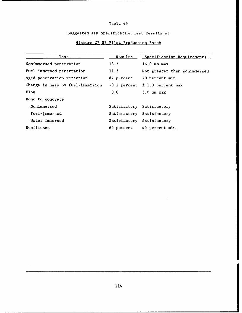
Table 45
Suggested JFR Specification Test Results of
Mixture CP-87 Pilot Production Batch
Test Results Specification Requirements
Nonimmersed penetration 13.5 16.0 mm max
Fuel-immersed penetration 11.3 Not greater than nonimmersed
Aged penetration retention 87 percent 70 percent min
Change in mass by fuel-immersion -0.1 percent ± 1.0 percent max
Flow 0.0 3.0 mm max
Bond to concrete
Nonimmersed Satisfactory Satisfactory
Fuel-immersed Satisfactory Satisfactory
Water immersed Satisfactory Satisfactory
Resilience 65 percent 45 percent min
114
PART VI: DEVELOPMENT OF IMPROVED HOT-APPLIED
NON-JET-FUEL-RESISTANT SEALANT
Development Goals
109. The purpose of this phase of the project was to develop specifica-
tion limits for a hot-applied, non-JFR sealant with improved low temperature
performance characteristics compared to current materials which meet FS SS-S-
1401C. There are several sealant materials available which are similar in
characteristics to materials meeting FS SS-S-1401C, except that they have
higher penetrations and improved low temperature extension characteristics.
Specifications for these materials are generally referred to as "low-modulus
ASTM D3405." Several states have issued these types of specifications
including Iowa (Iowa Department of Transportation 1984), South Dakota (South
Dakota Department of Transportation, undated), Kansas (Kansas Department of
Transportation 1986), Michigan (Michigan Department of Transportation 1987),
and Minnesota (Minnesota Department of Transportation 1988). The major devel-
opment goal of this phase was to provide a material specification which would
require improved low temperature sealant performance. The requirements would
be similar to the performance level of low-modulus D3405 materials while main-
taining adequate high temperature performance.
110. Tests performed and reported in Part IV of this report were used
to identify and compare physical properties of current FS SS-S-1401C materials
and several of the low-modulus materials. Review and comparison results con-
tained in Part IV indicate the following:
a. Bond testing. Results showed the low-modulus materials werecapable of passing bond testing at -20°F using 200 percent
extension while the FS SS-S-1401C materials did not. Resultswere similar for both nonimmersed and water immersed testing.
b. Tensile adhesion. Results show that the low-modulus materialshave higher tensile adhesion than FS SS-S-I01C materials.Product 9030, however, which meets several of the low-modulusspecifications, had lower tensile adhesion results compared tothe other low-modulus materials.
R. Flow. Flow testing results at 140°F using the FS SS-S-1401Cprocedures show the low-modulus materials met currentrequirements.
d. Resilience. Results show that the low-modulus materials canconform to current FS SS-S-1401C requirements of 60 percentminimum. Other types of data obtained indicate that increased
115
resilience can adversely affect other properties. Examinationof stress relaxation data shows that the lower resiliencematerials relax to lower stresses than the higher resiliencematerials. Additionally, high resilience may also adverselyaffect adhesion characteristics.
e. Penetracion. Results show that the low-modulus materials havehigher penetrations than the FS SS-S-1401C materials.
Suggested Specification
111. Based on the results contained in Part IV of this report and the
desired development goals, a suggested specification for low-modulus, hot-
applied, non-JFR sealant was developed. The specification is contained in
Appendix C. A summary of requirements and differences between FS SS-S-1401C
and the suggested specification is contained in Table 46. Differences are as
follows:
a. Penetration. The suggested limit is 9.0 to 15.0 mm comparedto 9.0 mm maximum for FS SS-S-1401C. This requirement permitsthe use of a softer material.
b. Flow. The requirement is the same at 3.0 mm maximum.
c. Resilience. The requirement is 50 to 80 percent compared to60 percent minimum for FS SS-S-1401C. The lower limit of50 percent permits materials with increased ability to undergorelaxation, and the upper limit of 80 percent limits materialelasticity.
d. Indentation. The requirement is 1.0 to 3.5 mm compared to0.5 to 1.5 mm. The higher range allows the use of a softermaterial.
e. Bond to concrete. The suggested procedure is to extend thesamples to 200 percent elongation instead of the 50 percentrequirement of FS SS-S-1401C. This procedure measuresincreased low temperature extension and flexibilitycharacteristics.
f. Static adhesion. The suggested specification includes astatic adhesion requirement to further evaluate sealant adhe-sion characteristics.
Z. Compatibility. Compatibility results are the same as forFS SS-S-1401C.
116
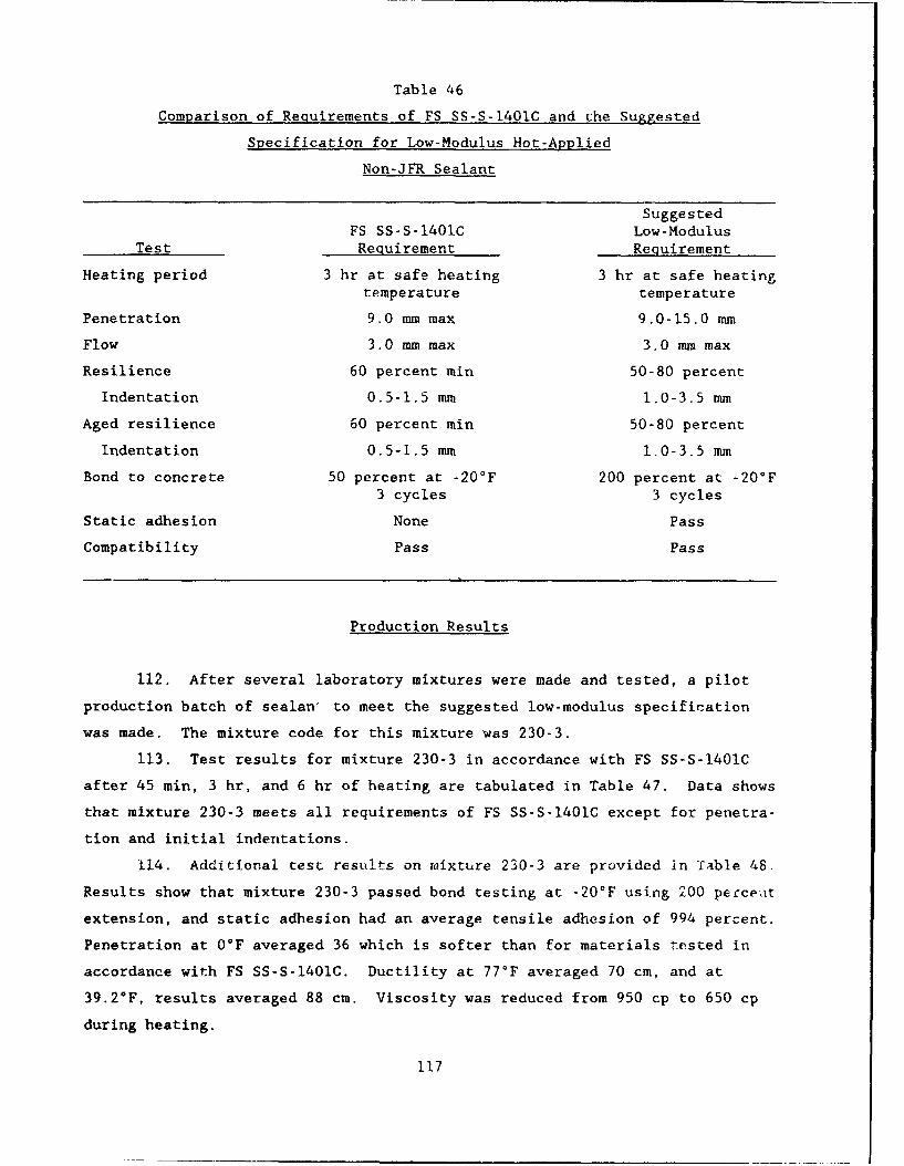
Table 46
Comparison of Requirements of FS SS-S-1401C and che Suggested
Specification for Low-Modulus Hot-Applied
Non-JFR Sealant
SuggestedFS SS-S-1401C Low-Modulus
Test Requirement Requirement
Heating period 3 hr at safe heating 3 hr at safe heatingtemperature temperature
Penetration 9.0 mm max 9.0-15.0 mm
Flow 3.0 mm max 3.0 mma max
Resilience 60 percent min 50-80 percent
Indentation 0.5-1.5 mm 1.0-3.5 mm
Aged resilience 60 percent min 50-80 percent
Indentation 0.5-1.5 mm. 1.0-3.5 nmm
Bond to concrete 50 percent at -20°F 200 percent at -20°F3 cycles 3 cycles
Static adhesion None Pass
Compatibility Pass Pass
Production Results
112. After several laboratory mixtures were made and tested, a pilot
production batch of sealan' to meet the suggested low-modulus specification
was made. The mixture code for this mixture was 230-3.
113. Test results for mixture 230-3 in accordance with FS SS-S-1401C
after 45 min, 3 hr, and 6 hr of heating are tabulated in Table 47. Data shows
that mixture 230-3 meets all requirements of FS SS-S-1401C except for penetra-
tion and initial indentations.
114. Additional test results on mixture 230-3 are provided in Toable 48.
Results show that mixture 230-3 passed bond testing at -20*F using 200 perce-at
extension, and static adhesion had an average tensile adhesion of 994 percent.
Penetration at 0*F averaged 36 which is softer than for materials tested in
accordance with FS SS-S-1401C. Ductility at 77°F averaged 70 cm, and at
39.2°F, results averaged 88 cm. Viscosity was reduced from 950 cp to 650 cp
during heating.
117
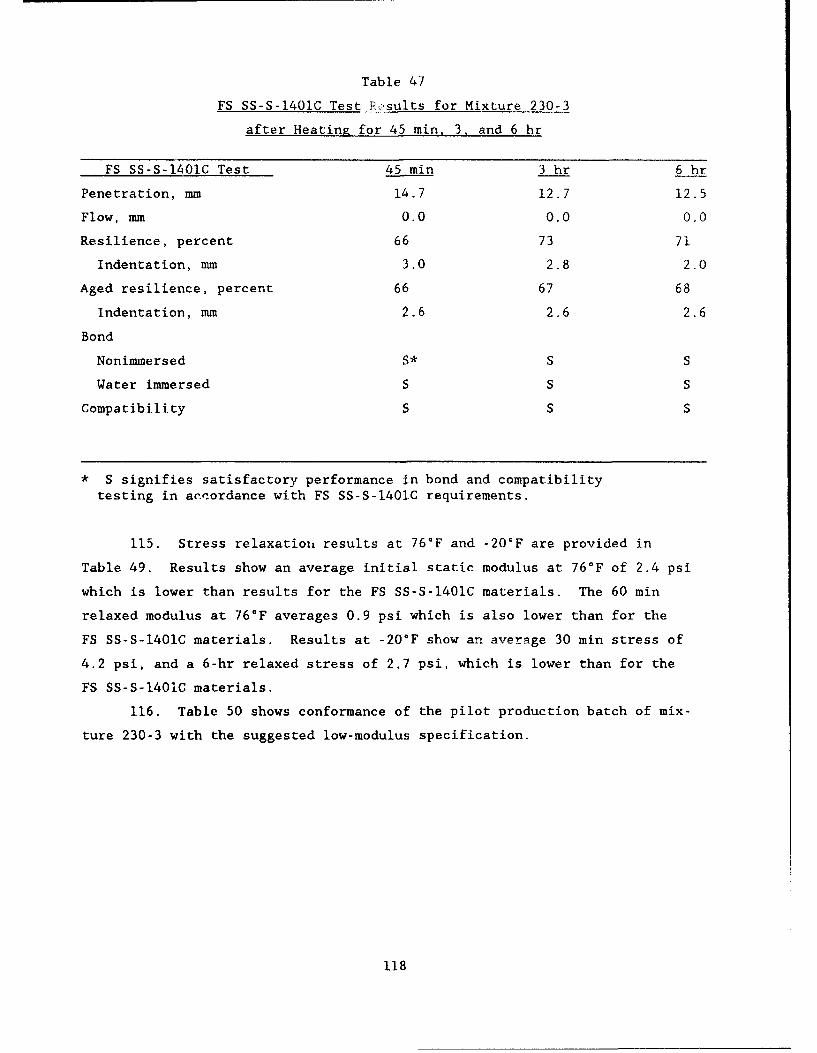
Table 47
FS SS-S-1401C Test Results for Mixture 230-3
after Heatiny for 45 min, 3. and 6 hr
FS SS-S-1401C Test 45 min 3 hr 6 hr
Penetration, mm 14.7 12.7 12.5
Flow, mm 0.0 0.0 0.0
Resilience, percent 66 73 71
Indentation, mm 3.0 2.8 2.0
Aged resilience, percent 66 67 68
Indentation, mm 2.6 2.6 2.6
Bond
Nonimmersed S* S S
Water immersed S S S
Compatibility S S S
* S signifies satisfactory performance in bond and compatibilitytesting in ancordance with FS SS-S-1401C requirements.
115. Stress relaxation results at 76°F and -20'F are provided in
Table 49. Results show an average initial static modulus at 76°F of 2.4 psi
which is lower than results for the FS SS-S-1401C materials. The 60 min
relaxed modulus at 76°F averages 0.9 psi which is also lower than for the
FS SS-S-1401C materials. Results at -20°F show an average 30 min stress of
4.2 psi, and a 6-hr relaxed stress of 2.7 psi, which is lower than for the
FS SS-S-1401C materials.
116. Table 50 shows conformance of the pilot production batch of mix-
ture 230-3 with the suggested low-modulus specification.
118
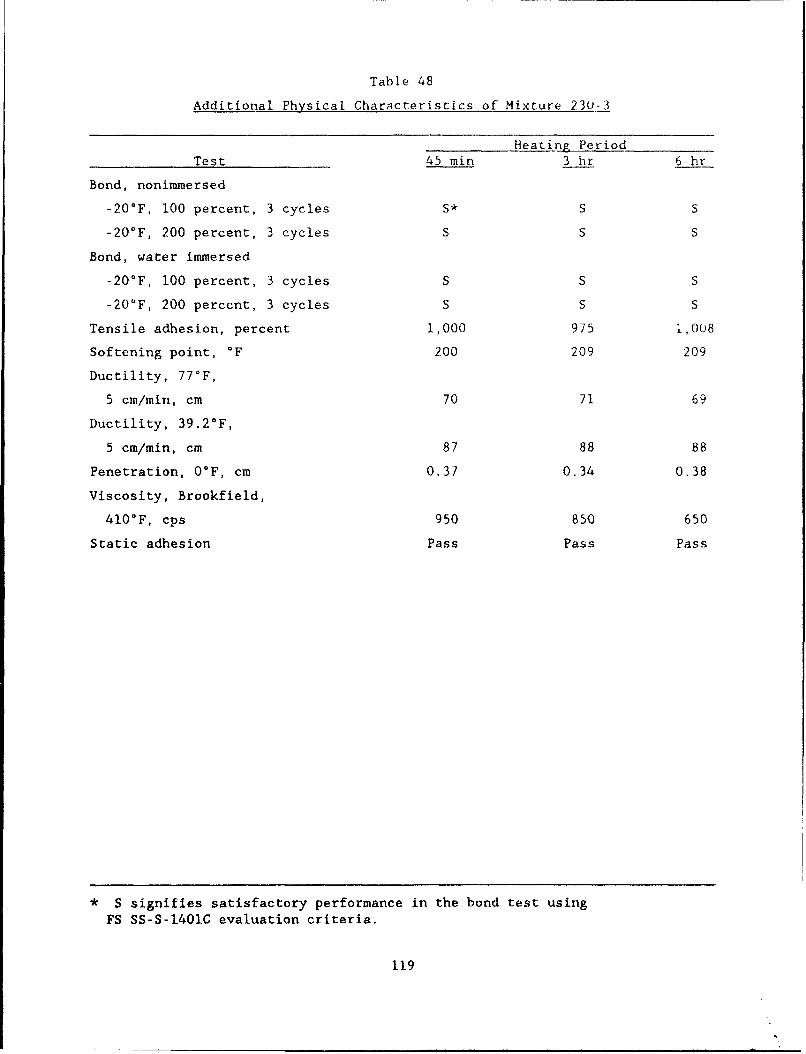
Table 48
Additional Physical Characteristics of Mixture 230-3
Heating PeriodTest 45 min 3 hr 6 hr
Bond, nonimmersed
-20°F, 100 percent, 3 cycles S* S S
-20°F, 200 percent, 3 cycles S S S
Bond, water immersed
-20'F, 100 percent, 3 cycles S S S
-20'F, 200 percent, 3 cycles S S S
Tensile adhesion, percent 1,000 975 1,008
Softening point, °F 200 209 209
Ductility, 77°F,
5 cm/min, cm 70 71 69
Ductility, 39.2°F,
5 cm/min, cm 87 88 88
Penetration, 0°F, cm 0.37 0.34 0.38
Viscosity, Brookfield,
410°F, cps 950 850 650
Static adhesion Pass Pass Pass
* S signifies satisfactory performance in the bond test using
FS SS-S-1401C evaluation criteria.
119
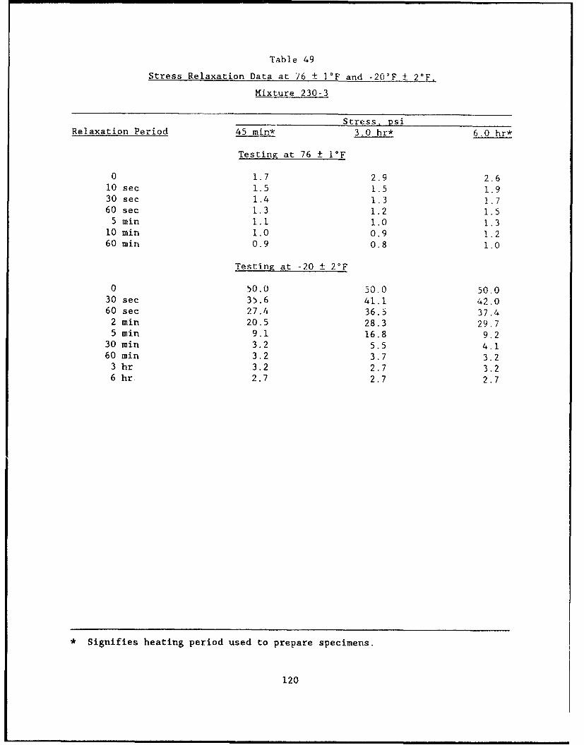
Table 49
Stress Relaxation Data at 76 ± I°F and -20°F ± 20 F,
Mixture 230-3
Stress, psiRelaxation Period 45 min* 3.0 hr* 6.0 hr*
Testing at 76 ± I°F
0 1.7 2.9 2.610 sec 1.5 1.5 1.930 sec 1.4 1.3 1.760 sec 1.3 1.2 1i5
5 min 1.1 1.0 1.310 min 1.0 0.9 1.260 min 0.9 0.8 1.0
Testing at -20 ± 2°F
0 50.0 50.0 50.030 see 35.6 41.1 42.060 sec 27.4 36.5 37.4
2 min 20.5 28.3 29.75 min 9.1 16.8 9.2
30 min 3.2 5.5 4.160 min 3.2 3.7 3.2
3 hr 3.2 2.7 3.26 hr 2.7 2.7 2.7
* Signifies heating period used to prepare specimens.
120
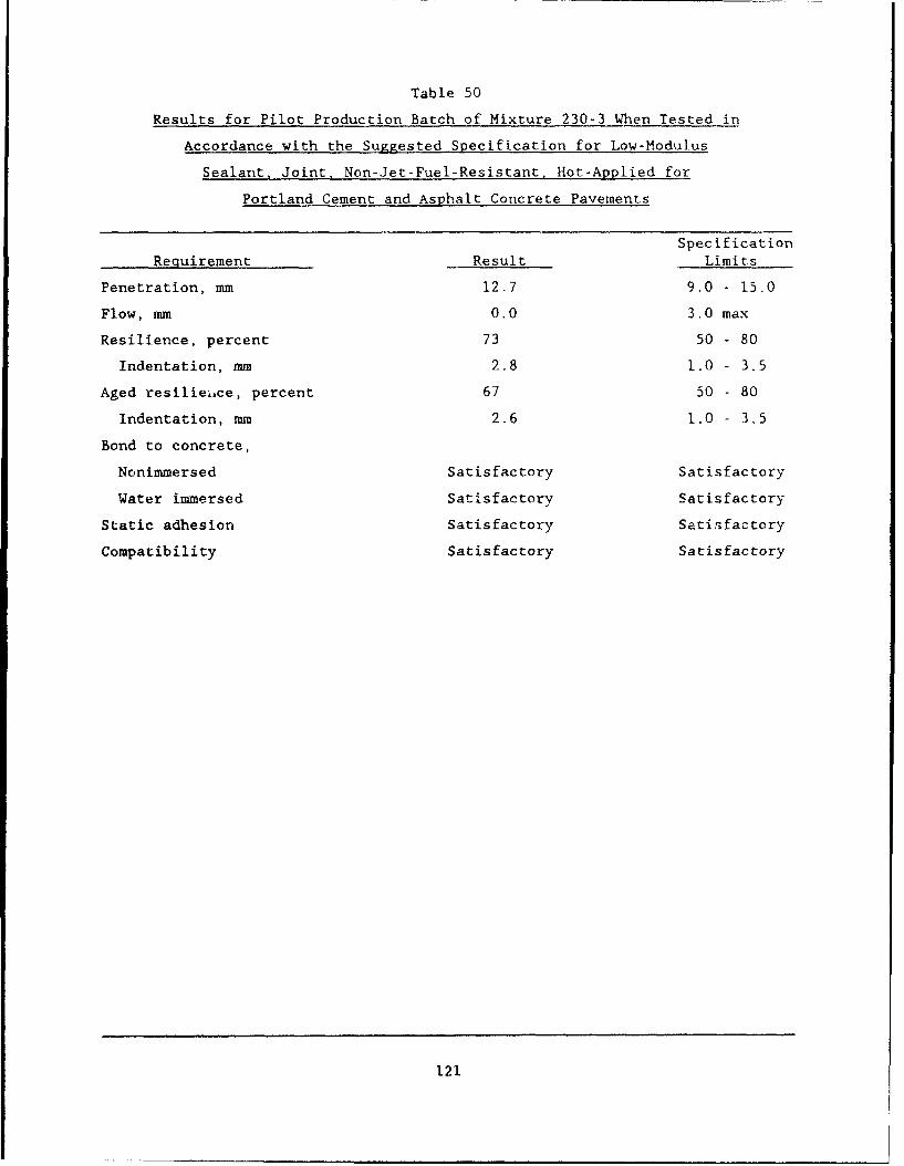
Table 50
Results for Pilot Production Batch of Mixture 230-3 When Tested in
Accordance with the Suggested Specification for Low-Modulus
Sealant, Joint, Non-Jet-Fuel-Resistant. Hot-Applied for
Portland Cement and Asphalt Concrete Pavements
Specification
Requirement Result Limits
Penetration, mm 12.7 9.0 - 15.0
Flow, mm 0.0 3.0 max
Resilience, percent 73 50 - 80
Indentation, mm 2.8 1.0 - 3.5
Aged resilienice, percent 67 50 - 80
Indentation, mm 2.6 1.0 - 3.5
Bond to concrete,
Nonimmersed Satisfactory Satisfactory
Water immersed Satisfactory Satisfactory
Static adhesion Satisfactory Satisfactory
Compatibility Satisfactory Satisfactory
121
PART VII: DEVELOPMENT OF ENCAPSULATING PRIMER
Literature Search
117. Two literature searches were conducted to gather information on
potential primer systems which could be used as encapsulants. The first
search was restricted to patents at the US Patent Office. The search was
directed to identify any patents in which primer or surface coatings were
applied to concrete to reduce moisture passage and to improve adhesion of
sealing materials. This search was unsuccessful as no patents meeting the
search criteria were found.
118. The second search effort was conducted by the Arizona State Uni-
versity (ASU) First Division of Hayden Library at ASU and the Information
Center, Information Technology Laboratory at WES. The computer search used
several sources including (a) Dialog Information Service, (b) Patent files
from 1950 to 1991, (c) Trade Industry Index, (d) New Product Announcements,
and (e) World Coating and Surface Abstracts. The search identified a variety
of US and foreign patents related to surface sealing of concrete, and other
construction materials and references related to adhesion and coatings were
identified. However, no references that referred to encapsulating primer
treatments prior to joint sealing were located.
Analysis of the CRD-C 525-89 Bubble Testing Procedure
119. The US Army Corps of Engineers developed a test method and speci-
fication for evaluating bubbling tendencies of hot-applied sealants. This
procedure was issued in December, 1989 as CRD-C 525-89, "Standard Specifica-
tion for Bubbling Tendencies of Hot-Applied Joint Sealers for Rigid Pavements"
(US Army Corps of Engineers Handbook of Concrete and Cement 1989). The proce-
dure consists of exposing samples which have passed nonimmersed bond testing
to 24 hr at 158°F in a forced-draft oven and then evaluating for evidence of
bubbling. Previous testing has shown that some hot-applied sealants experi-
ence bubbling when tested using this procedure.
120. In order to gain a better understanding of the bubble testing
procedure, initial testing with a variety of sealants, substrates, and a coat-
ing was performed. Sealants used include Crafco RoadSaver 211 (an ASTM D1190
122
xmarttc>.O , iJ':~. :22 '-1.401C material), Crafco 34515 (Modified
AASHTO M173), and Superseal £oi4A, Plant 1. Substrates used were 1/4 by
2 by 3 in. steel plates, 1/4 by 2 by 3 in. glass plates, and standard concrete
bond test blocks which were either oven dried to a constant weight or dried to
a saturated surface dried (SSD) condition.
121. Testing with steel and glass plates was performed using the
CRD-C 525-89 procedure except that steel or glass plates were used instead of
concrete blocks. These specimens were not subjected to bond testing prior to
initiating the 158°F oven exposure period. Test results showed that none of
the sealants bubbled or swelled when steel or glass plates were used.
122. Sets of oven dried concrete blocks were prepared by drying to
constant weight in a 250 ± 10'F forced-draft oven. Average weight loss data
for the blocks were 5.1 percent after 3 hr, 5.6 percent after 5 br, 6.0 per-
cent after 21 hr, and 6.0 percent after 24 hr. Data show that the standard
FS SS-S-1401C concrete blocks contain approximately 6 percent moisture when
they are in a saturated surface dry condition. After the 24 hr drying period,
the blocks were stored and cooled in a desiccator until use. Specimens for
each of the four sealants were poured, and were then subjected to 24 hr of
exposure at 158°F. Again, as with the metal and glass plates, no evidence of
bubbling or swelling was observed.
123. Testing as specified in CRD-C 525-89 was then performed with con-
crete blocks prepared in accordance with FS SS-S-1401C and FS SS-S-1614A.
These blocks were prepared as saturated surface dried and then subjected to
required blotting prior to pouring specimens. The blocks experienced a weight
loss which averaged 0.5 percent due to the required blotting and drying which
left an average of 5.5 percent moisture in the blocks when sealant was poured
to make the test specimens. A deviation from the CRD-C 525-89 procedure was
that bond testing was not performed prior to aging the specimens at 158°F for
24 hr. Results showed significant amounts of expansion, flow, and swelling of
each sealant. More sealant flow and deformation were noted for the non-JFR
sealants than for the JFR Superseal 1614A, Plant 1 which only experienced
swelling.
124. Examination of data for the steel, glass, oven-dried, and satu-
rated surface dry block substrates shows that bubbling occurred only with
blocks which contained moisture. It appears that bubbling is caused by the
release of moisture vapor from the concrete which then migrates through the
123
sealant at high temperatures. At high temperatures such as 158°F, hot-applied
sealants are softened and may not be capable of resisting moisture vapor
migration.
125. Additional tests were performed in which the moisture content of
concrete blocks was adjusted to 3.0 percent, 1.0 percent, and 0.5 percent by
oven drying, resoaking and then redrying to achieve the proper moisture con-
tcnt. Testing was performed with RoadSaver 515. Results showed significant
amounts of expansion, flow, and swelling of the sealant at each of the three
moisture contents. These results show that concrete blocks with a moisture
content as low as 0.5 percent can cause swelling and flow when testing is
performed using CRD-C 525-89 procedures.
126. Several of the additional sealants received from other manufactur-
ers were also tested for bubbling tendencies using the basic CRD-C 525-89
procedure as descr;bed above. The additional sealants tested were Prod-
ucts 9030 and 9005, Sof-Seal, and Hi-Spec. Each of these sealants experienced
swelling, flow, and deformation during the 24 hr oven exposure period.
127. During testing it was noted that the amount of sealant deforma-
tion, swelling, and flow that occurred using CRD-C 525-89 did not appear to be
typical of bubbling which occurs in field installations. Therefore, the test
temperature was reduced from 158°F to 140°F. Additional tests were conducted
using a test temperature of 120°F. The bubbling experienced in the laboratory
using the test temperature of 120°F was representative of bubbling exhibited
in the field. Sealant bubbling which occurs in field installations typically
does not produce flow of the sealant, but shows up as numerous individual
bubbles on top of the sealant surface. These bubbles may range from approxi-
mately 1/16 to 1/4 in. in diameter. Test temperatures of 120 and 140°F were
used with Superseal 1614A, Plant I and 140°F with RoadSaver 515. Results
showed that Superseal 1614A, Plant I did not experience any bubbling, swell-
ing, or flow at 120 or 140°F. RoadSaver 515 experienced formation of several
small bubbles on the top of the sealant surface and experienced swelling.
128. While testing was proceeding with various sealants, temperatures,
etc., several block coatings were tried to provide some basic information on
encapsulating coatings. Prepared concrete blocks were coated on the bonding
surface side with a two-component epoxy glue thickened by adding approximately
I percent amorphus fumed silica. Following curing, bond specimens were pre-
pared and tested for bubbling. Sealants used were the same as those used in
124
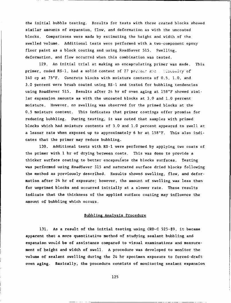
the initial bubble testing. Results for tests with these coated blocks showed
similar amounts of expansion, flow, and deformation as with the uncoated
blocks. Comparisons were made by estimating the height and width of the
swelled volume. Additional tests were performed with a two-component epoxy
floor paint as a block coating and using RoadSaver 515. Swelling,
deformation, and flow occurred when this combination was tested.
129. An initial trial at making an encapsulating primer was made. This
primer, coded RS-I, had a solid content of 27 p&e:!ae- a ,La a.iit±y of
140 cp at 75°F. Concrete blocks with moisture contents of 0.5, 1.0, and
3.0 percent were brush coated using RS-l and tested for bubbling tendencies
using RoadSaver 515. Results after 24 hr of oven aging at 158°F showed simi-
lar expansion amounts as with the uncoated blocks at 3.0 and 1.0 percent
moisture. However, no swelling was observed for the primed blocks at the
0.5 moisture content. This indicates that primer coatings offer promise for
reducing bubbling. During testing, it was noted that samples with primed
blocks which had moisture contents of 3.0 and 1.0 percent appeared to swell at
a lesser rate when exposed up to approximately 6 hr at 158°F. This also indi-
cates that the primer may reduce bubbling.
130. Additional tests with RS-I were performed by applying two coats of
the primer with 1 hr of drying between coats. This was done to provide a
thicker surface coating to better encapsulate the blocks surfaces. Testing
was performed using RoadSaver 515 and saturated surface dried blocks following
the method as previously described. Results showed swelling, flow, and defor-
mation after 24 hr of exposure; however, the amount of swelling was less than
for unprimed blocks and occurred initially at a slower rate. These results
indicate that the thickness of the applied surface coating may influence the
amount of bubbling which occurs.
Bubbling Analysis Procedure
131. As a result of the initial testing using CRD-C 525-89, it became
apparent that a more quantitative method of studying sealant bubbling and
expansion would be of assistance compared to visual examinations and measure-
ment of height and width of swell. A procedure was developed to monitor the
volume of sealant swelling during the 24 hr specimen exposure to forced-draft
oven aging. Basically, the procedure consists of monitoring sealant expansion
125
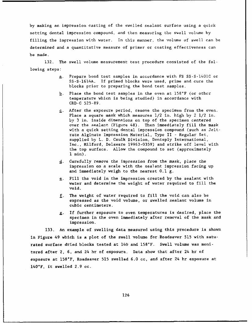
by making an impression casting of the swelled sealant surface using a quick
setting dental impression compound, and then measuring the swell volume by
filling the impression with water. In this manner, the volume of swell can be
determined and a quantitative measure of primer or coating effectiveness can
be made.
132. The swell volume measurement test procedure consisted of the fol-
lowing steps:
a. Prepare bond test samples in accordance with FS SS-S-1401C orSS-S-1614A. If primed blocks were used, prime and cure theblocks prior to preparing the bond test samples.
b. Place the bond test samples in the oven at 158°F (or othertemperature which is being studied) in accordance withCRD-C 525-89.
c. After the exposure period, remove the specimen from the oven.Place a square mask which measures 1/2 in. high by 2 1/2 in.by 3 in. inside dimensions on top of the specimen centeredover the sealant (Figure 48). Then immediately fill the maskwith a quick setting dental impression compound (such as Jelt-rate Alginate Impression Material, Type II - Regular Set,supplied by L. D. Caulk Division, Dentsply International,Inc., Milford, Delaware 19963-0359) and strike off level withthe top surface. Allow the compound to set (approximately1 min).
d. Carefully remove the impression from the mask, place theimpression on a scale with the sealant impression facing upand immediately weigh to the nearest 0.1 g.
e. Fill the void in the impression created by the sealant withwater and determine the weight of water required to fill thevoid.
f. The weight of water required to fill the void can also beexpressed as the void volume, or swelled sealant volume incubic centimeters.
g. If further exposure to oven temperatures is desired, place thespecimen in the oven immediately after removal of the mask andimpression.
133. An example of swelling data measured using this procedure is shown
in Figure 49 which is a plot of the swell volume for Roadsaver 515 with satu-
rated surface dried blocks tested at 140 and 158°F. Swell volume was moni-
tored after 2, 6, and 24 hr of exposure. Data show that after 24 hr of
exposure at 158*F, Roadsaver 515 swelled 6.0 cc, and after 24 hr exposure at
140*F, it swelled 2.9 cc.
126
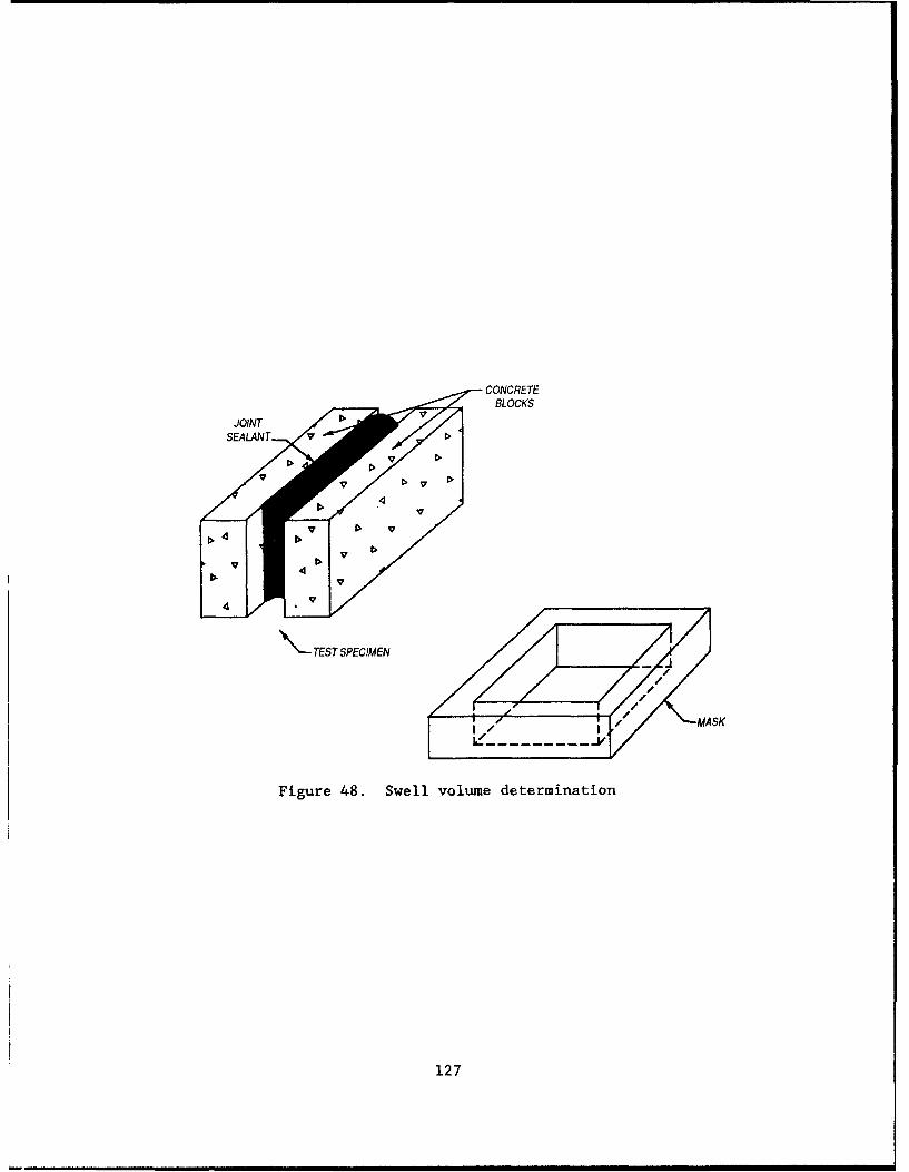
CONCRETEBLOCKS
JOINT >
\-TEST SPECIMEN
Figure 48. Swell volume determination
127
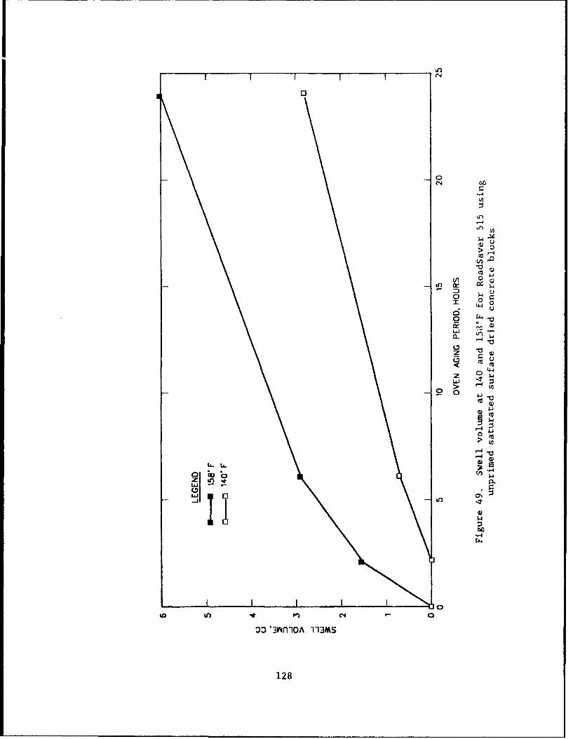
(N
-4 1
> 00co
0 0
ck:8Ja- 4
z
ui -1
0
40~~~ to v (
3D JnllOA113>
1284
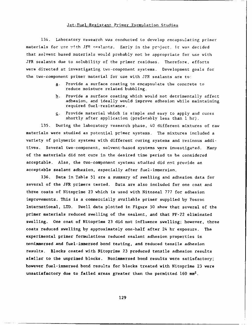
Jet-Fuel-Resistant Primer Formulation Studies
134. Laboratory research was conducted to develop encapsulating primer
materials for use 7-ith JFR T-ilants. Early in the pr'ject, it was decided
that solvent based materials would probably not be appropriate for use with
JFR sealants due to solubility of the primer residues. Therefore, efforts
were directed at investigating two-component systems. Development goals for
the two-component primer material for use with JFR sealants are to:
a. Provide a surface coating to encapsulate the concrete toreduce moisture related bubbling.
b. Provide a surface coating which would not detrimentally affectadhesion, and ideally would improve adhesion while maintainingrequired fuel-resistance.
C. Provide material which is simple and easy to apply and cures
shortly after application (preferably less than i hr).
135. During the laboratory research phase, 40 different mixtures of raw
materials were studied as potential primer systems. The mixtures included a
variety of polymeric systems with different curing systems and resinous addi-
tives. Several two-component, solvent-based systems were investigated. Many
of the materials did not cure in the desired time period to be considered
acceptable. Also, the two-component systems studied did not provide an
acceptable sealant adhesion, especially after fuel-immersion.
136. Data in Table 51 are a summary of swelling and adhesion data for
several of the JFR primers tested. Data are also included for one coat and
three coats of Nitoprime 23 which is used with Nitoseal 777 for adhesion
improvements. This is a commercially available primer supplied by Fosroc
International, LTD. Swell data plotted in Figure 50 show that several of the
primer materials reduced swelling of the sealant, and that PF-22 eliminated
swelling. One coat of Nitoprime 23 did not influence swelling; however, three
coats reduced swelling by approximately one-half after 24 hr exposure. The
experimental primer formulations reduced sealant adhesion properties in
nonimmersed and fuel-immersed bond testing, and reduced tensile adhesion
results. Blocks coated with Nitoprime 23 produced tensile adhesion results
similar to the unprimed blocks. Nonimmersed bond results were satisfactory;
however fuel-immersed bond results for blocks treated with Nitoprime 23 were
unsatisfactory due to failed areas greater than the permitted 160 mm2 .
129
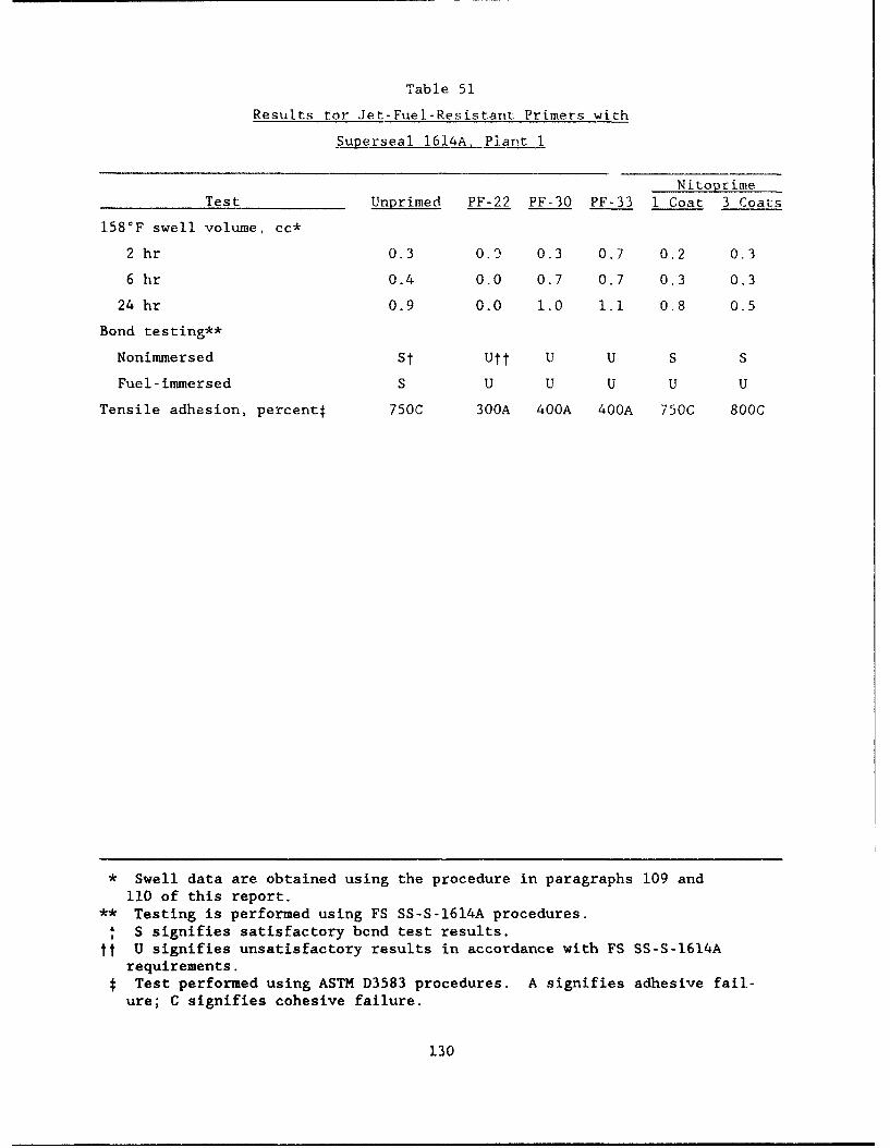
Table 51
Results tor Jet-Fuel-Resistant Primers with
Superseal 1614A, Plant 1
Nitoprime
Test Unprimed PF-22 PF-30 PF-33 I Coat 3 Coats
158'F swell volume, cc*
2 hr 0.3 0.9 0.3 0.7 0.2 0.3
6 hr 0.4 0.0 0.7 0.7 0.3 0.3
24 hr 0.9 0.0 1.0 1.1 0.8 0.5
Bond testing**
Nonimmersed Sf Utf U U S S
Fuel-immersed S U U U U U
Tensile adhesion, percentf 750C 300A 400A 400A 750C 800C
* Swell data are obtained using the procedure in paragraphs 109 and
110 of this report.** Testing is performed using FS SS-S-1614A procedures.
SS signifies satisfactory bond test results.tt U signifies unsatisfactory results in accordance with FS SS-S-1614A
requirements.STest performed using ASTM D3583 procedures. A signifies adhesive fail-
ure; C signifies cohesive failure.
130
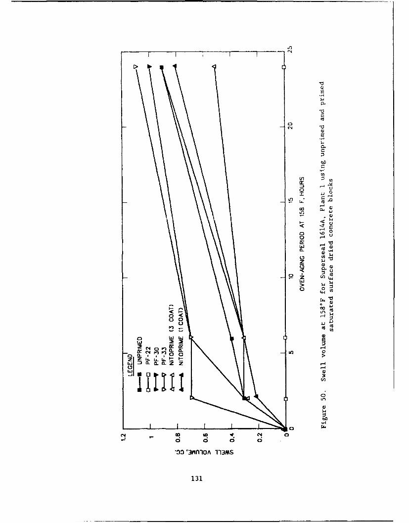
In)
(N
"-4
0
z -4
"-4
00 a;0
0~0
0
r4
40 44
o d o>3D~ 0VflO 113
1314
137. The research work performed was not succcssful in developing
acceptable encapsulating primer materials for use with JFR scalants.
Non-Jet-Fuel-Resistant Primer Formulation Studies
138. Laboratory testing was conducted to develop encapsulating primer
materials for use with the non-JFR sealants. During initial project planning
meetings, it was decided that development efforts would be directed at inves-
tigating single-component systems. Development goals for the single-component
non-JFR primer were to:
a. Pro-Tide a surface coating to encapsulate the concrete toreduce moisture related bubbling.
b. Provide a surface coating which would not detrimentally affectadhesion
c. Provide a mateiial which is simple and easy to apply ard .uresshortly after application (preferably less thani 1hr).
139. During the laboratory research phase, approximately 20 different
mixtures of raw materials were studied as potential primer systems. The mix-
tures included combinations of polymeric materials, resinous additives, and a
variety of additives in a solvent carrier. The materials were formulated of
25 to 35 percent solids and typically cured well within 1 hr after application
to concrete blocks.
140. Table 52 contains a summary of swelling and adhesion data for
several of the non-JFR primers. Swelling data obtained at 158*F are plotted
in Figure 51. Figure 51 shows that the primer coatings reduced swell volume
of RoadSaver 515 throughout the 24 hr aging period. Reductions in swelling
after 24 hr average 34 percent and ranged from 22 to 50 percent for the
primers reported in Table 52. After 6 hr of aging at 158°F, reductions in
swell volume averaged 60 percent and ranged from 38 to 69 percent. Data show
that primer RS-12 improved adhesion of RoadSaver 515 as indicated by an
approximate 30 percent increase in tensile adhesion test results and changed
the failure mode from adhesive to cohesive.
141. The research work performed produced primer coating materials
which partially met the development goals for non-JFR primer. Swelling in
laboratory testing was reduced, adhesion to concrete was increased, and the
produced primer materials were low viscosity materials that could be easily
applied and cured quickly.
132
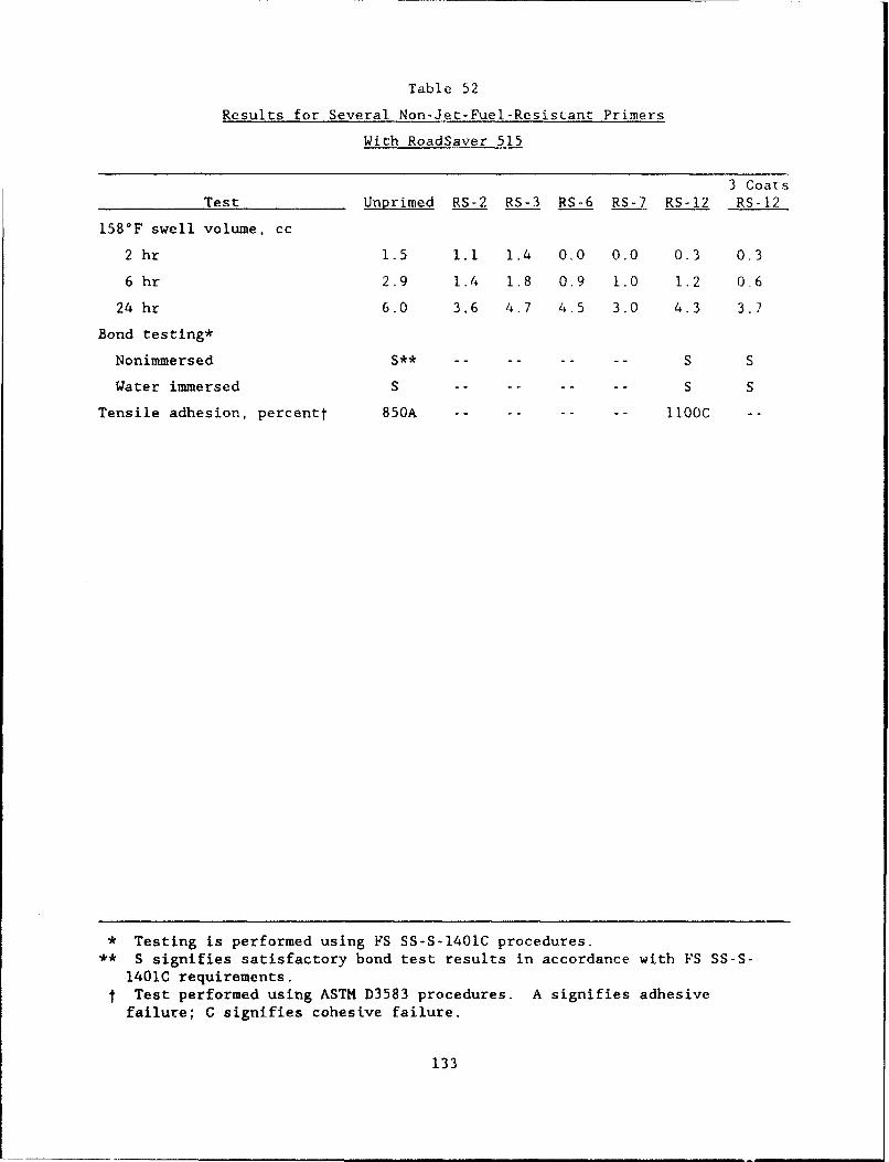
Table 52
Results for Several Non-Jet-Fuel-Resistant Primers
With RoadSaver 515
3 CoatsTest Unprimed RS-2 RS-3 RS-6 RS-7 RS-12 RS-12
158°F swell volume, cc
2 hr 1.5 1.1 1.4 0.0 0o0 0.3 0.3
6 hr 2.9 1.4 1.8 0.9 1.0 1.2 0.6
24 hr 6.0 3.6 4.7 4.5 3.0 4.3 3.7
Bond testing*
Nonimmersed S** -- -- -- -- S S
Water immersed S .. .. .. .. S S
Tensile adhesion, percentt 850A .. .. .. .. - IOOC --
* Testing is performed using FS SS-S-1401C procedures.** S signifies satisfactory bond test results in accordance with FS SS-S-
1401C requirements.t Test performed using ASTM D3583 procedures. A signifies adhesive
failure; C signifies cohesive failure.
133
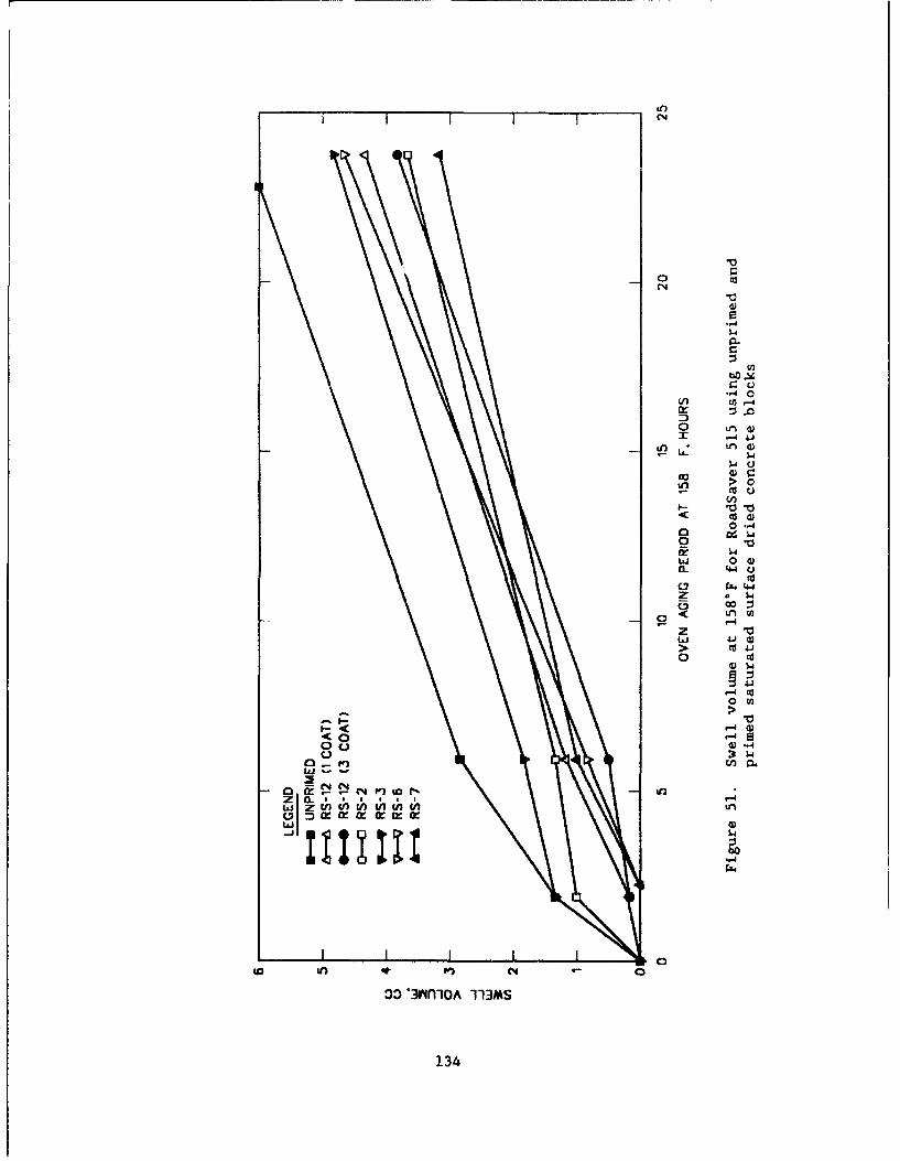
I I CN
-4 0
Z)
GoG
&nI.-
ILi O" "o 4-40
Z a 1-4
z
ý4)-
-4 1
<00
00
Mi -
oIa f ý~)it' gf
"4)
oo 'Jrifl10A 113MS
134
Suggested Specification for Non-Jet-Fuel-Resistant Primer
142. Based on the laboratory results for non-JFR primers, a suggested
specification for primer, joint, non-JFR, cold-applied, single-component for
portland cement concrete pavements was developed. The specification is con-
tained in Appendix D. Requirements of the specification are based on proper-
ties and characteristics of primer mixtures reported herein. A summary of
requirements of the suggested specification is as follows:
a. Viscosity. Viscosity of the primer is measured at 77°F andindicates the consistency of the material for applicationpurposes. The suggested requirement is 25 to 250 cp.
b. Tack-free time. Tack-free time is measured using a modifica-tion of the basic FS SS-S-200E procedure with primer that hasbeen applied to a prepared standard concrete block. The sug-gested requirement is 10 min maximum. The requirement indi-cates a material which cures quickly after application toconcrete.
c. Cured tack-free evaluation. The tack-free characteristics aremeasured on primer coated concrete block specimens which havebeen allowed to cure for 60 min. The procedure then subjectsthe cured primer to a tack-free evaluation using a 60 minperiod at 158*F. The suggested requirement is that at the endof the 60 min period, the weight is removed, and the polyeth-ylene strip shall pull free without any primer adhering to thestrip. This evaluation indicates the high temperature stabil-ity of the primer coating.
d. Nonvolatile content. The nonvolatile content indicates theresidue content of the primer. The suggested requirement is20 to 40 percent.
e. Permeability. The permeability requirement indicates theability of the primer coating to limit passing of moisture.The procedure subjects oven-dried, primer coated concreteblocks to water immersion and measures the amount of waterabsorption into the block expressed as a percentage of thesaturated surface dried moisture content of the block. Thesuggested limit is 10 percent maximum. Testing performedduring development of the procedure showed that unprimed con-crete blocks experience water absorption which exceeds 95 per-cent when tested using the specified procedure.
f. Low temperature flexibility. The procedure uses theASTM C711-72 "Low Temperature Flexibility and Tenacity of One-Part, Elastomeric, Solvent-Release Type Sealants" procedurewith several modifications. The requirement indicates flexi-bility of the cured primer residue at 30°F.
K. Adhesion. Adhesion of the primer is evaluated using primercoated concrete blocks for sealant bond testing with manufac-turer recommended sealants. The suggested requirement is that
135
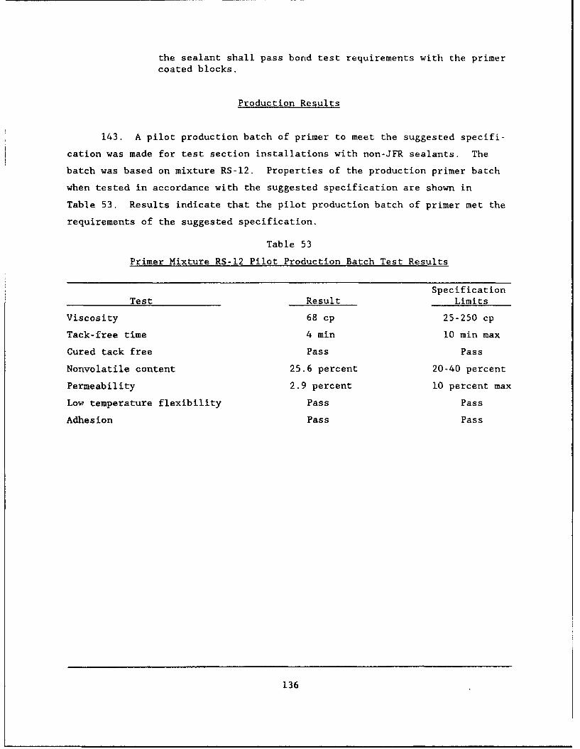
the sealant shall pass bond test requirements with the primercoated blocks.
Production Results
143. A pilot production batch of primer to meet the suggested specifi-
cation was made for test section installations with non-JFR sealants. The
batch was based on mixture RS-12. Properties of the production primer batch
when tested in accordance with the suggested specification are shown in
Table 53. Results indicate that the pilot production batch of primer met the
requirements of the suggested specification.
Table 53
Primer Mixture RS-12 Pilot Production Batch Test Results
Specification
Test Result Limits
Viscosity 68 cp 25-250 cp
Tack-free time 4 min 10 min max
Cured tack free Pass Pass
Nonvolatile content 25.6 percent 20-40 percent
Permeability 2.9 percent 10 percent max
Low temperature flexibility Pass Pass
Adhesion Pass Pass
136
PART VIII: CONCLUSIONS AND RECOMMENDATIONS
144. Evaluations of the procurred hot-applied JFR sealants indicated
that these sealants iret FS SS-S-1614A requirements and were capable of passing
low temperature bond testing at O°F, but were not capable of passing at -20'F.
Results also showed that these materials had significant surface hardening
when subjected to oven aging at 158°F. Flow testing revealed that all materi-
als had lower degrees of flow than the maximum requirement in FS SS-S-1614A.
Testing performed at various heating periods showed that physical properties
of hot-applied JFR sealants changed with changes in the heating period. This
indicates that if the materials are over heated or exposed to prolonged heat-
ing in the field, premature failure due to hardening can occur.
145. Evaluations of the procurred hot-applied non-JFR sealants showed
that low-modulus ASTM D3405 materials were capable of passing 200 percent
extension bond testing at -20°F while materials manufactured to meet
FS SS-S-1401C were not. The flow and resilience properties of the low-modulus
materials were similar to FS SS-S-1401C materials. Additional testing proce-
dures showed the sealants had differences in adhesion and modulus characteris-
tics. Test results show that different heating periods cause the properties
of some materials to change more than others. This indicates that the low-
modulus type materials could perform more satisfactorily in cold climates than
the FS SS-S-1401C materials. This possibility will be evaluated during the
field evaluations.
146. Laboratory development work revealed that it was possible to pro-
duce hot-applied JFR sealant materials which could satisfactorily pass non-
immersed, water immersed, and fuel-immczsed bond testing at -20"F, with less
surface hardening when subjected to oven-aging at 158°F than current materi-
als. A suggested specification for this type of sealant with improved perfor-
mance characteristics was developed in accordance with the first objective of
the project. The developed material should have better low temperature pro-
perties than current hot-applied materials and should be more resistant to
aging. These properties could translate to a longer lasting seal. The field
evaluations will be used to determine exact life-cycle benefits.
147. A suggested specification for low-modulus non-JFR sealant was
developed for sealants with improved low temperature properties in accordance
with the second objective of the project. The specification includes bond
137
testing at -20*F using 200 percent extension, a static adhesion evaluation,
and resilience limits in addition to requirements of FS SS-S-1401C.
148. Testing using the CRD-C 525-89 bubbling tendencies procedures
revealed that hot-applied sealants do not experience bubbling when in contact
with metal, glass, or oven-dried concrete surfaces. Bubbling, however, occurs
when these sealants are in contact with concrete surfaces which contain as low
as 0.5 percent moisture by weight of the concrete. This indicates that mois-
ture is one of the major causes of bubbling and that bubbling caused by mois-
ture may be difficult to eliminate. The difficulty arises from the fact that
in most areas of the United States, the natural moisture content of the con-
crete may be greater than 0.5 percent.
149. Appropriate adhesion with hot-applied JFR sealants could not be
established with the developmental fuel-resistant primer materials studied.
However, primer materials for use with non-JFR sealants were developed which
reduced sealant bubbling in the laboratory and provided increased sealant
adhesion to portland cement concrete. A suggested specification for the
primer materials was developed in accordance with the third objective of the
project.
150. If, after review of primer and sealant field evaluations, improve-
ments are shown, it is recommended that additional field projects be under-
taken. These projects would provide the data required to adopt the proposed
specifications.
138
REFERENCES
American Association of State Highway and Transportation Officials. 1986."Standard Specifications for Transportation Materials on Methods of Samplingand Testing," Part 1, Specifications, 14th ed., Washington, DC.
Annual Book of ASTM Standards. 1991. "Road and Paving Materials, PavementManagement Tcchnologics," Vol 4.03, American Society, for Testing and Materi-als, 1916 Race Street, Philadelphia, PA.
Burr, I. W. 1974. "Applied Statistical Methods," Academic Press, Inc., NewYork.
Crafco, Inc. 1991 (Jan). "RoadSaver 299 Product Data Sheet," 6975W CrafcoWay, Chandler, AZ.
Federal Specification SS-S-1401C. 1984a (Aug). "Sealant, Joint, Non-Jet-Fuel-Resistant, Hot-Applied for Portland Cement and Asphalt Concrete Pave-ments," Washington, DC.
Federal Specification SS-S-1614A. 1984b (Aug). "Sealants, Joint, Jet-Fuel-Resistant, Hot-Applied, for Portland Cement and Tar Concrete Pavements," Wash-ington, DC.
Federal Specification SS-S-200E. 1988 (Aug). "Sealants, Joint, Two-Component, Jet-Blast-Resistant, Cold-Applied for Portland Cement ConcretePavement," Washington, DC.
Iowa Department of Transportation. 1984. "Standard Specifications for High-way and Bridge Construction," Section 4136.02, Ames, IA.
Kansas Department of Transportation. 1986 (Jul). "Specification for Hot-
Applied Crack Sealant," Specification TS 109.6, Topeka, KS.
Lynch, Larry N., and White, Dewey W., (draft), "Improved Materials and Pro-cesses for Sealing and Resealing joints in PCC Pavements-Field Evaluation,"Construction Productivity Advancement Research Program, US Army EngineerWaterways Experiment Station, Vicksburg, MS.
Michigan Department of Transportation. 1987 (Mar). "Special Provision forLow-Modulus Hot-Poured Joint Sealant," Bureau of Highways, Lansing, MI.
Minnesota Department of Transportation. 1988. "Standard Specifications forConstruction," Section 3723, Concrete Joint and Crack Sealer (Hot-Poured Elas-tic Type), St. Paul, MN.
Missouri Highway and Transportation Commission. 1988. "Missouri StandardSpecification for Highway Construction," Section 1057.1.3, Concrete JointSealer, Hot-Poured Elastic Type, Jefferson City, MO.
South Dakota Department of Transportation. (undated). "Minimum Specificationfor Rubber Asphalt and Hot-Poured Elastic Joint Sealer," Pierre, SD.
South Dakota Department of Transportation. 1985. "Standard Specificationsfor Roads and Bridges," Section 870. Concrete Joint Sealer, Pierre, SD.
US Army Corps of Engineers Handbook of Concrete and Cement. 1989. "StandardSpecification for Bubbling Tendencies of Hot-Applied Joint Sealers for RigidPavements," CRD-C 525-89, Washington, DC.
139

US Army Corps of Engineers Handbook of Concrete and Cement. 1988. "StandardSpecification for Joint Sealants, Cold-Applied, Non-Jet-Fuel-Resistant forRigid and Flexible Pavements," CRD-C 527-88, Washington, DC.
140
APPENDIX A: SUMMARY OF SELECTED TEST PROCEDURES
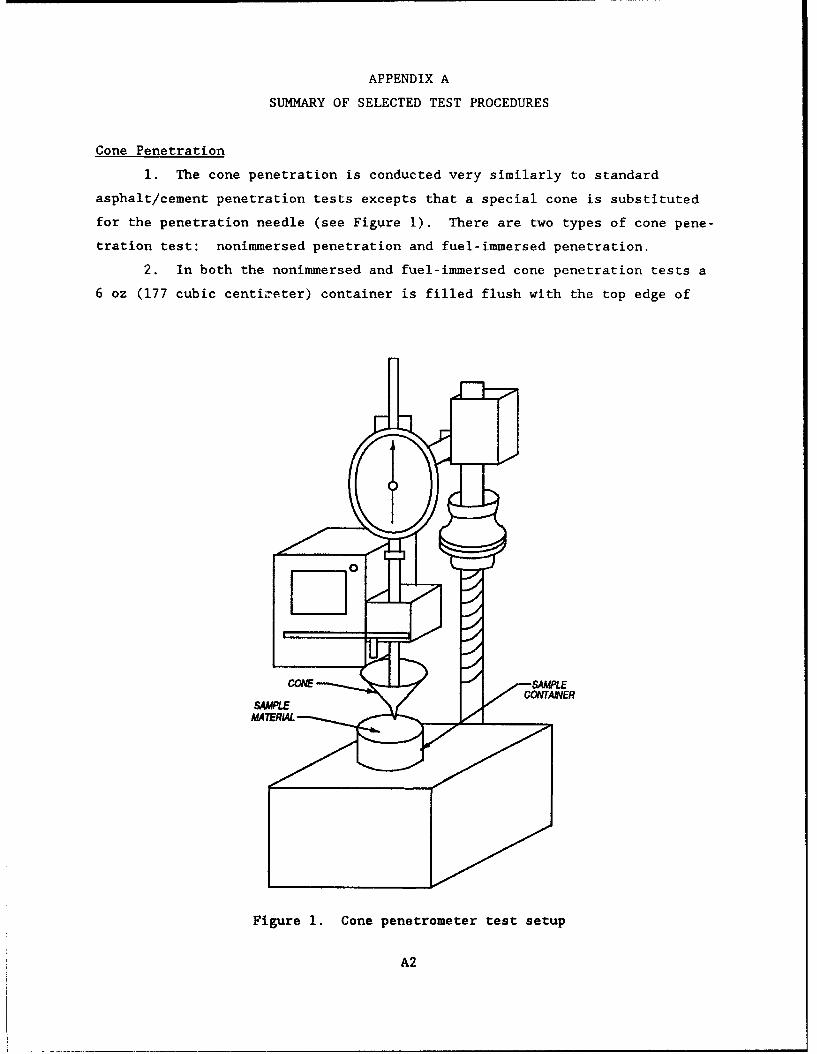
APPENDIX A
SUMMARY OF SELECTED TEST PROCEDURES
Cone Penetration
1. The cone penetration is conducted very similarly to standard
asphalt/cement penetration tests excepts that a special cone is substituted
for the penetration needle (see Figure I). There are two types of cone pene-
tration test: nonimmersed penetration and fuel-immersed penetration.
2. In both the nonimmersed and fuel-immersed cone penetration tests a
6 oz (177 cubic centizeter) container is filled flush with the top edge of
CONE SAMUE
SAMPLE
Figure 1. Cone penetrometer test setup
A2
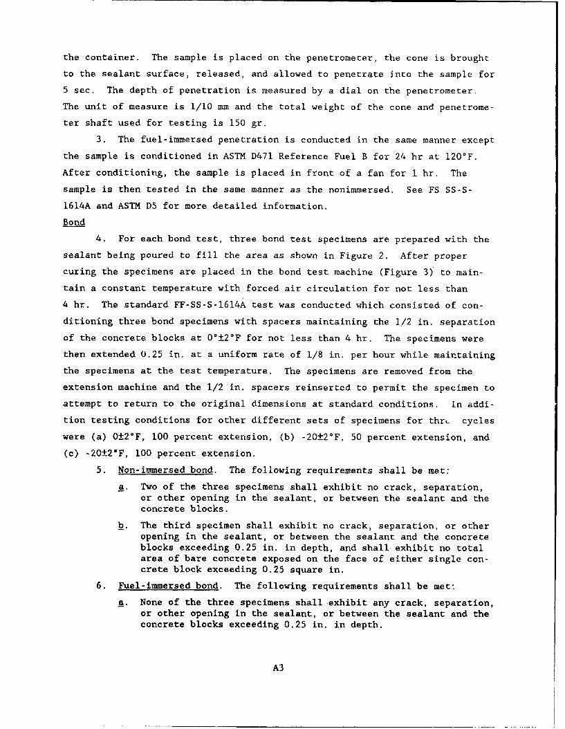
the container. The sample is placed on the penetrometer, the cone is brought
to the sealant surface, released, and allowed to penetrate into the sample for
5 sec. The depth of penetration is measured by a dial on the penetrometer.
The unit of measure is 1/10 mm and the total weight of the cone and penetrome-
ter shaft used for testing is 150 gr.
3. The fuel-immersed penetration is conducted in the same manner except
the sample is conditioned in ASTM D471 Reference Fuel B for 24 hr at 120'F.
After conditioning, the sample is placed in front of a fan for I hr. The
sample is then tested in the same manner as the nonimmersed. See FS SS-S-
1614A and ASTM D5 for more detailed information.
Bond
4. For each bond test, three bond test specimens are prepared with the
sealant being poured to fill the area as shown in Figure 2. After proper
curing the specimens are placed in the bond test machine (Figure 3) to main-
tain a constant temperature with forced air circulation for not less than
4 hr. The standard FF-SS-S-1614A test was conducted which consisted of con-
ditioning three bond specimens with spacers maintaining the 1/2 in. separation
of the concrete blocks at 0°±2°F for not less than 4 hr. The specimens were
then extended 0.25 in. at a uniform rate of 1/8 in. per hour while maintaining
the specimens at the test temperature. The specimens are removed from the
extension machine and the 1/2 in. spacers reinserted to permit the specimen to
attempt to return to the original dimensions at standard conditions. In addi-
tion testing conditions for other different sets of specimens for thrt_ cycles
were (a) 0±2°F, 100 percent extension, (b) -20±2°F, 50 percent extension, and
(c) -20±2°F, 100 percent extension.
5. Non-immersed bond. The following requirements shall be met:
a. Two of the three specimens shall exhibit no crack, separation,or other opening in the sealant, or between the sealant and theconcrete blocks.
b. The third specimen shall exhibit no crack, separation, or otheropening in the sealant, or between the sealant and the concreteblocks exceeding 0.25 in. in depth, and shall exhibit no totalarea of bare concrete exposed on the face of either single con-crete block exceeding 0.25 square in.
6. Fuel-immersed bond. The following requirements shall be met:
a. None of the three specimens shall exhibit any crack, separation,or other opening in the sealant, or between the sealant and theconcrete blocks exceeding 0.25 in. in depth.
A3
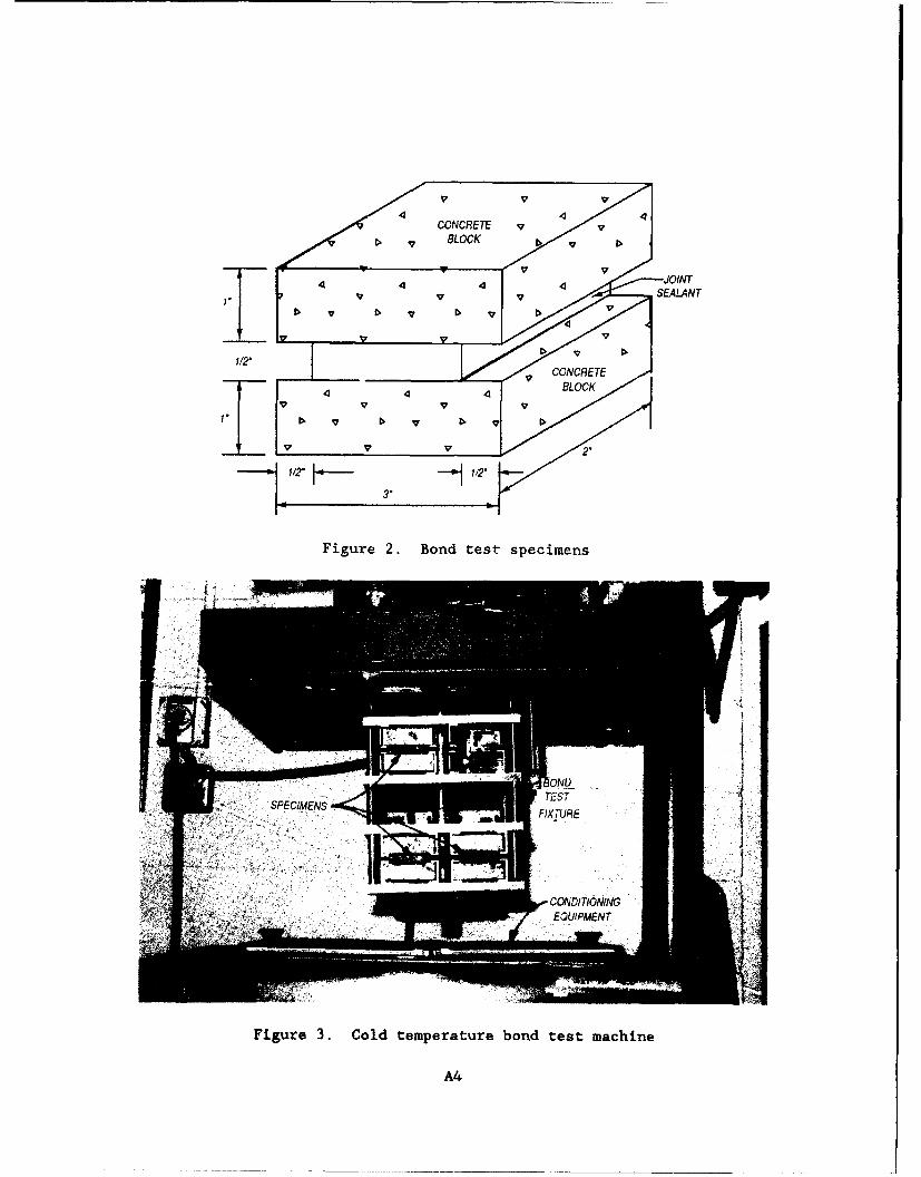
FiurD. BLOndtstsecmn
4 ON
v v SALAN
Figue 3 Col teperturebon tes mahin
V2"A4
b. None of ý:he three specimens shall exhibit a total area of bareconcrete- exposed on the face of any single concrete blockexceeding 0.25 square in.
7. Water-immersed bond. Requirements a., and b. of nonimmersed bond
shall be met.
Ductility
8. The ductility of joint sealants is determined similar to the
ductility determination of bituminous materials, A sample of joint sealant is
poured and cured in the mold shown in Figure 4 when assembled on a flat brass
plate. The specimen then is placed in the water at 77*F for 85 to 95 min.
The clips of the mold are attached to the pins of the test machine (Figure 5)
and the sides of the mold and brass plate are removed. The clips are then
pulled at a uniform speed of 5 cm/min until the sample of joint sealant rup-
tures. The distance in centimeters through which the clips moved to produce
rupture of the sample is measured and recorded. The specific gravity of the
water bath is adjusted so that the sample of joint sealant does not come into
contact with the bottom of the tank during the test. Three specimens are
subjected to this test and the length to rupture is measured, averaged and
recorded.
Flow
9. Two duplicate specimens are prepared for flow testing. Each speci-
men is prepared by placing a mold on a bright tin panel, pouring the sealant
into the mold and striking the sealant flush with the top of the Xold. The
interior dimensions of the mold are 40 mm by 60 mm by 3.2 mm. The tin panel
is used for the bottom of the mold.
10. The sealant is allowed to cool at standard laboratory temperature
(73±4*F) for a minimum of 1/2 hr and then the mold is removed, A reference
line is marked across the panel coincident with the transverse edges (40 mm)
of the sealant. The specimen is then mounted into a specimen holder (Fig-
ure 6) that maintains it at a 75* angle with the horizontal. The specimen is
mounted so that the 60 mm edges are vertical. The specimen holder is then
placed irA a forced-draft oven maintained at 140*F for 5 hr. After 5 hr the
specimen holder is removed from the oven and the specimen is allowed to cool.
A reference line is made coincident with the transverse edge of the sealant.
The distance between the two reference lines is measured in mm and is reported
as flow.
Al
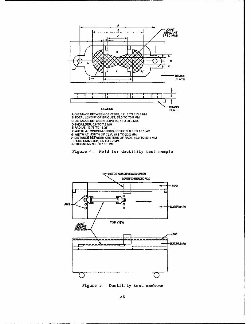
A____________________JOINT
SEALANT
_ýl t:- CSPECIMAN
BRASS~PLATE
J_
BRA$$LEGEND PLATE
A-DISTANCE BETWEEN CENTERS, 111-5 TO 113.5 MM.8-TOTAL LENGHT OF BRIQUET, 74 -5 TO 75.5 MMC-DISTANCE BETWEEN CLIPS, 29.7 TO 30.3 MM.D-SHOULDER, 6.8 TO 7.2 MME-RADIUS. 15.75 TO 16.25F-WIDTH AT MINIMUM CROSS SECTION. 9.9 TO 10.1 MM
6-WIDTH AT MOUTH OF CLIP, 19.8 TO 20.2 MM.H-DISTANCE BETWEEN CENTERS OF RADII, 42.9 TO 43.1 MMI.
I-HOLE DIAMETER, 6.5 TO 6.7 MM.J-THICKNESS, 9.9 TO 10. 1 MM.
Figure 4. Mold for ductility test sample
MOTORAND DRIVEECME4AISM
SCRE TW ADEDRODTANK
"0 -WA TER BA TH
ATA
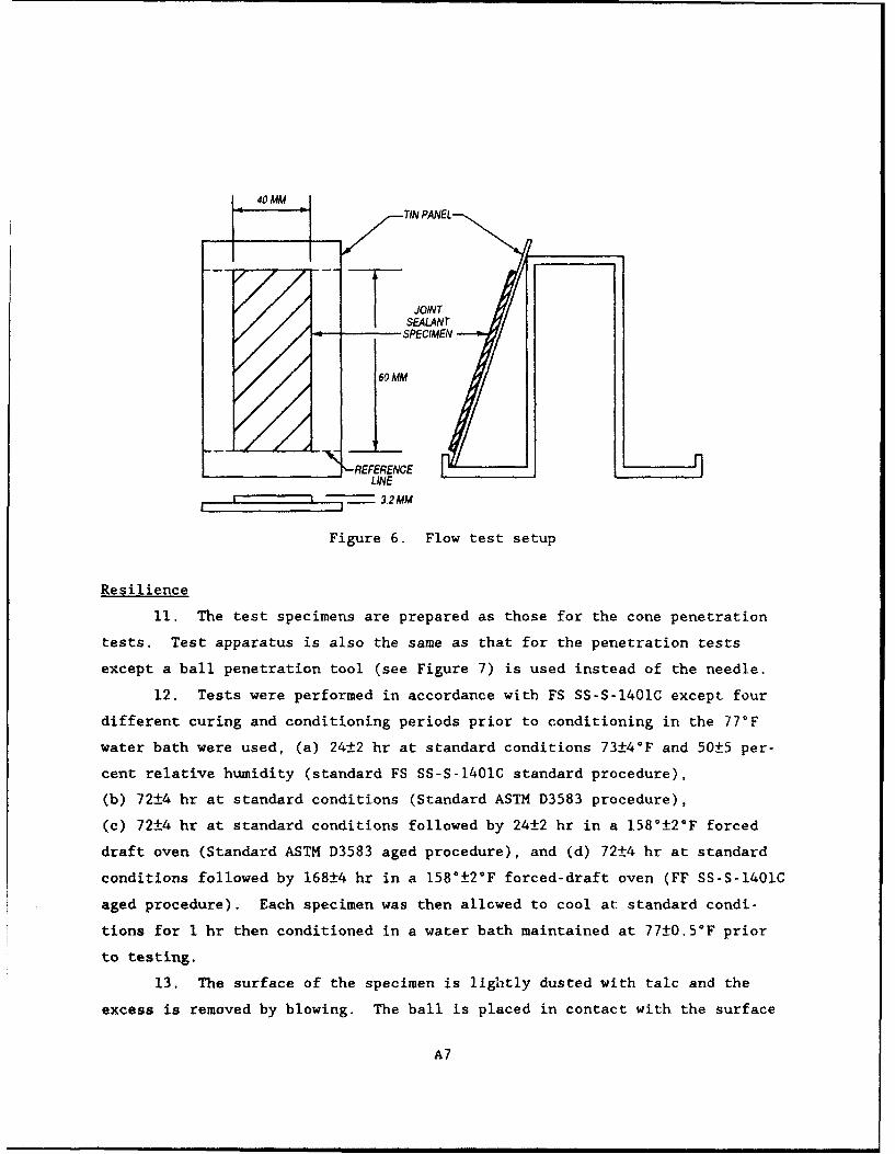
40 MM--- TIN PA NEL
JOINTSEALNT
•.e-. •~SPECIMEN.---
M/
T
NtREFERENCE I
........... 3,2 MM
Figure 6. Flow test setup
Resilience
11. The test specimens are prepared as those for the cone penetration
tests. Test apparatus is also the same as that for the penetration tests
except a ball penetration tool (see Figure 7) is used instead of the needle.
12. Tests were performed in accordance with FS SS-S-1401C except four
different curing and conditioning periods prior to conditioning in the 77°F
water bath were used, (a) 24±2 hr at standard conditions 73±4°F and 50±5 per-
cent relative humidity (standard FS SS-S-1401C standard procedure),
(b) 72±4 hr at standard conditions (Standard ASTM D3583 procedure),
(c) 72±4 hr at standard conditions followed by 24±2 hr in a 158°±2°F forced
draft oven (Standard ASTM D3583 aged procedure), and (d) 72±4 hr at standard
conditions followed by 168±4 hr in a 158°±2°F forced-draft oven (FF SS-S-1401C
aged procedure). Each specimen was then allowed to cool at standard condi-
tions for I hr then conditioned in a water bath maintained at 77±0.5°F prior
to testing.
13. The surface of the specimen is lightly dusted with talc and the
excess is removed by blowing. The ball is placed in contact with the surface
A7
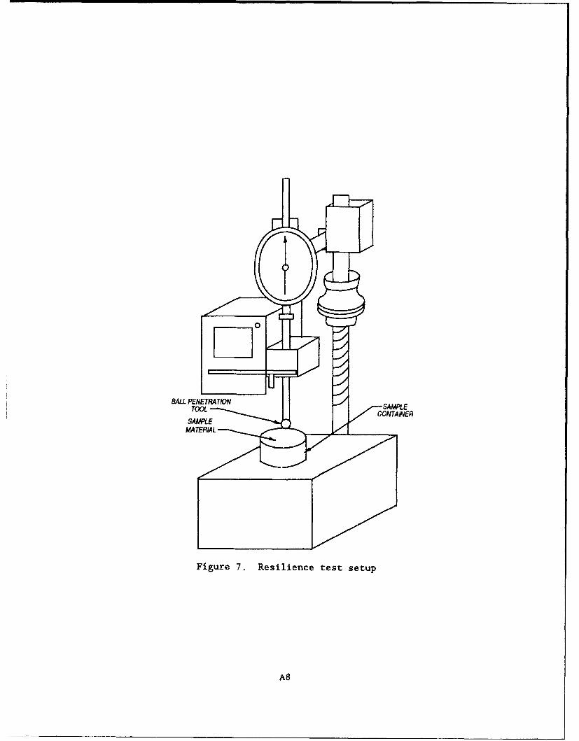
0
BALL PENETRATIONTOOL SAMPLESAMPLE'• .. CONTAINER
Figure 7. Resilience test setup
AS
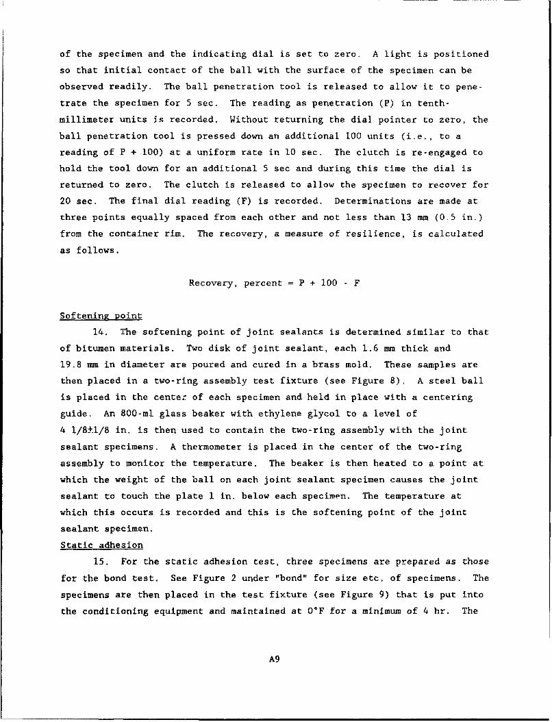
of the specimen and the indicating dial is set to zero. A light is positioned
so that initial contact of the ball with the surface of the specimen can be
observed readily. The ball penetration tool is released to allow it to pene-
trate the specimen for 5 sec. The reading as penetration (P) in tenth-
millimeter units is recorded. Without returning the dial pointer to zero, the
ball penetration tool is pressed down an additional 100 units (i.e., to a
reading of P + 100) at a uniform rate in 10 sec. The clutch is re-engaged to
hold the tool down for an additional 5 sec and during this time the dial is
returned to zero. The clutch is released to allow the specimen to recover for
20 sec. The final dial reading (F) is recorded. Determinations are made at
three points equally spaced from each other and not less than 13 mm (0.5 in.)
from the container rim. The recovery, a measure of resilience, is calculated
as follows.
Recovery, percent = P + 100 - F
Softening point
14. The softening point of joint sealants is determined similar to that
of bitumen materials. Two disk of joint sealant, each 1.6 mm thick and
19.8 mm in diameter are poured and cured in a brass mold. These samples are
then placed in a two-ring assembly test fixture (see Figure 8), A steel ball
is placed in the center of each specimen and held in place with a centering
guide. An 800-ml glass beaker with ethylene glycol to a level of
4 1/8±1/8 in. is then used to contain the two-ring assembly with the joint
sealant specimens. A thermometer is placed in the center of the two-ring
assembly to monitor the temperature. The beaker is then heated to a point at
which the weight of the ball on each joint sealant specimen causes the joint
sealant to touch the plate 1 in. below each specimen. The temperature at
which this occurs is recorded and this is the softening point of the joint
sealant specimen.
Static adhesion
15. For the static adhesion test, three specimens are prepared as those
for the bond test. See Figure 2 under "bond" for size etc. of specimens. The
specimens are then placed in the test fixture (see Figure 9) that is put into
the conditioning equipment and maintained at 00F for a minimum of 4 hr. The
A9
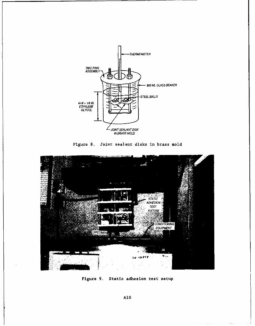
.0THERMOMETER
TWORING
ASSEMBLY
-~ 800 ML GLASS BEAKER
I -STEEL BALLS418+1/8+liIN.ETHYLENE -
GLYCOL
JOINT SEALANT DISKIN BRASS MOLD
Figure 8. Joint sealant disks in brass mold
- SATI
Figure9. Staic adhsionHEStIstu
ATES
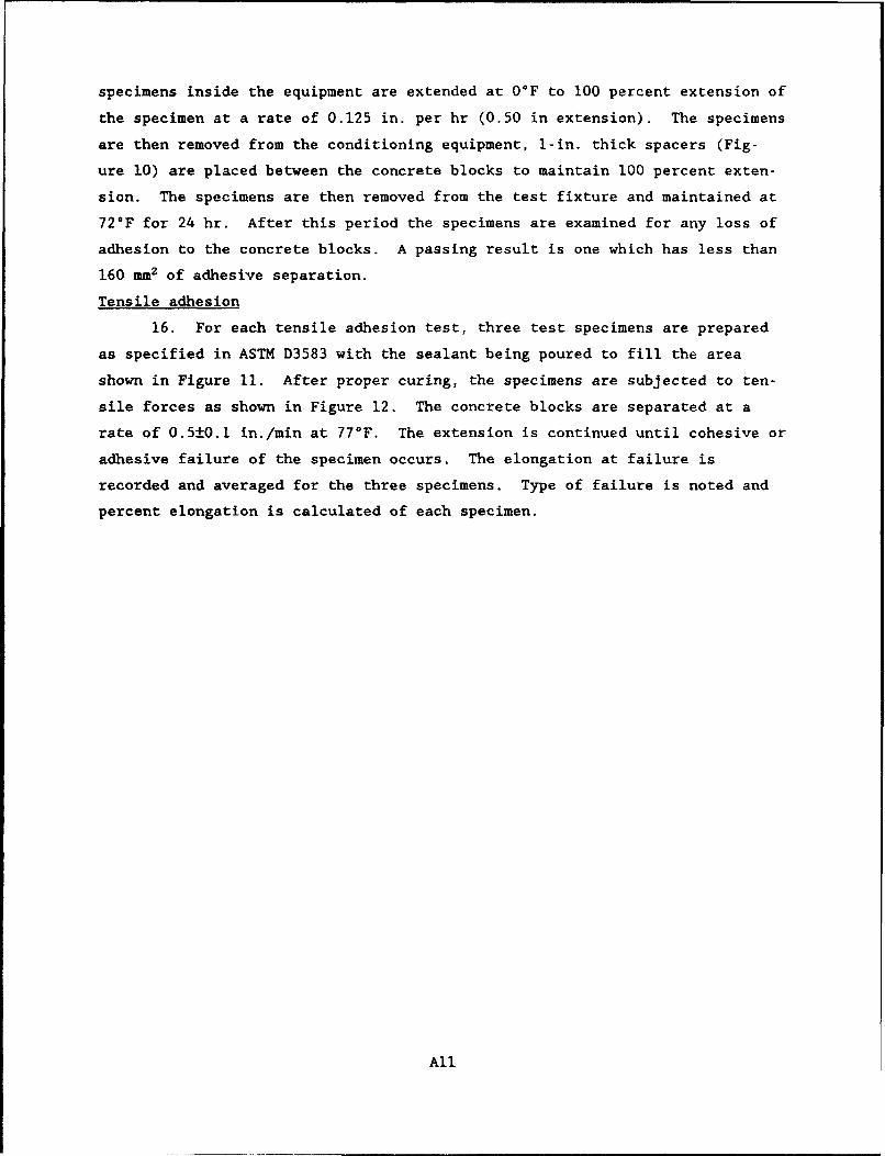
specimens inside the equipment are extended at 0°F to 100 percent extension of
the specimen at a rate of 0.125 in. per hr (0.50 in extension). The specimens
are then removed from the conditioning equipment, 1-in. thick spacers (Fig-
ure 10) are placed between the concrete blocks to maintain 100 percent exten-
sion. The specimens are then removed from the test fixture and maintained at
72*F for 24 hr. After this period the specimens are examined for any loss of
adhesion to the concrete blocks. A passing result is one which has less than
160 mm2 of adhesive separation.
Tensile adhesion
16. For each tensile adhesion test, three test specimens are prepared
as specified in ASTM D3583 with the sealant being poured to fill the area
shown in Figure il. After proper curing, the specimens are subjected to ten-
sile forces as shown in Figure 12. The concrete blocks are separated at a
rate of 0.5±0.1 in./min at 77°F. The extension is continued until cohesive or
adhesive failure of the specimen occurs. The elongation at failure is
recorded and averaged for the three specimens. Type of failure is noted and
percent elongation is calculated of each specimen.
All
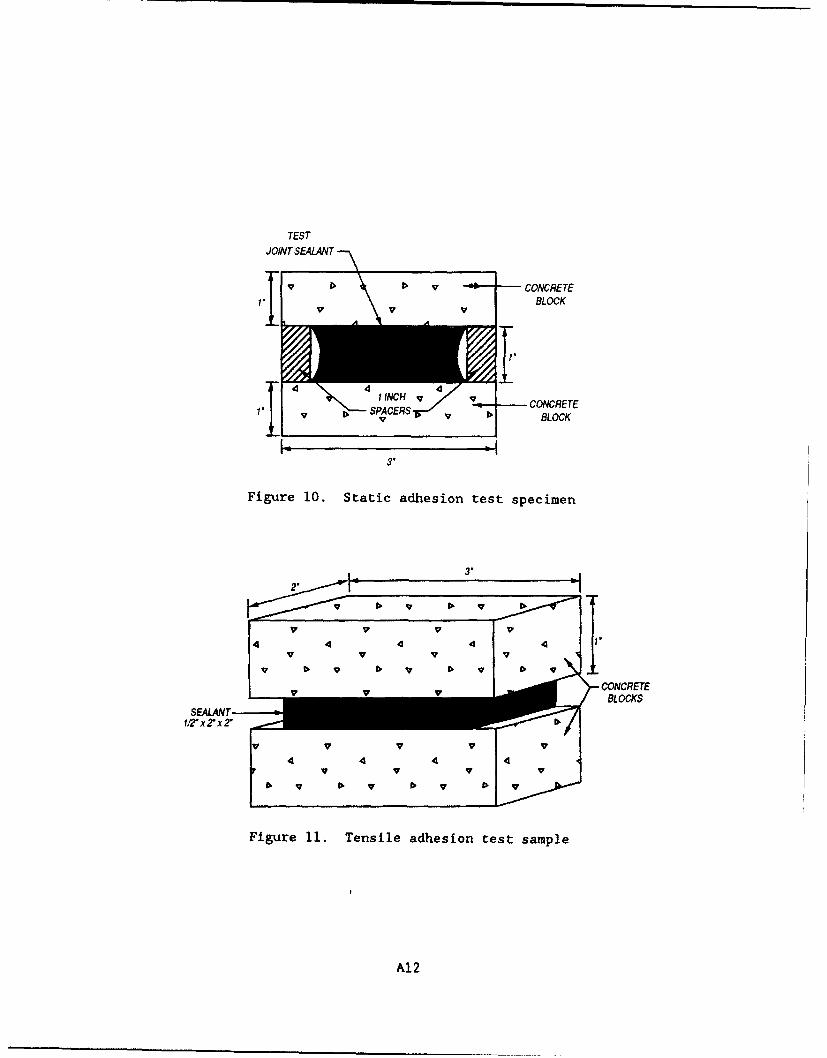
TEST
JOINT SEALANT
I V I> •" -• CONCRETE
BLOCKv v
P. SPACERS CONCRETE
3.
Figure 10. Static adhesion test specimen
3.
4 4 4 4 BLOCKS
vv v w
Figure 11. Tensile adhesion test sample
A12
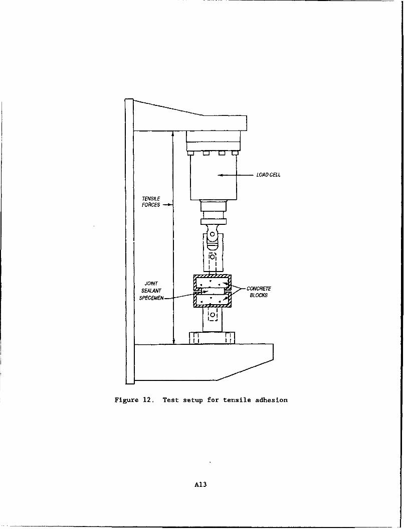
LOAD CELL
TENSILE •
FORCES
JOINTSEALANT
SPECEMEN ,BLOCKS
Figure 12. Test setup for tensile adhesion
Al3
APPENDIX B: PROPOSED SPECIFICATION FOR LOW-MODULUS, HOT-APPLIED,JET-FUEL-RESISTANT PAVEMENT JOINT SEALANTS
FOR RIGID PAVEMENTS
NOTE: This proposal is not finalized and changes may occur before it is pub-
lished as a material specification. Therefore, it may not be applicable for
project specifications.
1. SCOPE: This specification covers low-modulus, hot-applied, jet-fuel-
resistant pavement joint sealant materials for use in sealing joints and
cracks in rigid pavements that are exposed to cold ambient temperatures.
2. APPLICABLE DOCUMENTS
2.1 The following documents, of the issues in effect on date of invitation
for bids or request for proposal, form a part of this specification to the
extent specified herein.
Federal Specification
PPP-P-704 - Pails, Metal: (Shipping, Steel, I Through 12 Gallons)
Federal Standards
FED-STD-123 - Marking for Shipment (Civil Agencies)
FED-STD-313 - Material Safety Data Sheets, Preparation and the
Submission of,
Military Standards
MIL-STD-105 - Sampling Procedures and Tables for Inspection by
Attributes
MIL-STD-129 - Marking for Shipment and Storage
MIL-STD-147 - Palletized Unit Loads
B3
Federal Regulations
29 CFR 1900-1999 - Occupational Safety and Health Administration
(OSHA), Department of Labor
2.2 Other Publications. The following documents form a part of this specifi-
cation to the extent specified herein. Unless a specific issue is identified,
the issue in effect on date of invitation for bid or request for proposal
shall apply.
American Society for Testing and Materials (ASTM)
D5 - Penetration of Bituminous Materials, Test Method for
D140 - Sampling Bituminous Materials, Methods of
D217 - Cone Penetration of Lubricating Grease, Test Method for
D471 - Rubber Property - Effect of Liquids, Test Method for
D1985 - Preparing Concrete Blocks for Testing Sealants for
Joints and Cracks, Standard Practice for
D5167 - Melting of Hot-Applied Joint and Crack Sealant and Filler
Material for Evaluation, Standard Practice for
Technical Association of the Pulp and Paper Industry
T431 om - Ink Absorbency of Blotting Paper
2.3 Order of Precedence. In the event of a conflict between the text of this
specification and the references cited herein, the text of this specification
shall have precedence.
3. REQUIREMENTS
3.1 Description.
3.1.1 Material. The sealant shall be a thermoplastic material. It shall be
composed of a mixture of coal tar and rubber or resin with additives. The
manufacturer's specified application or pouring temperature shall not exceed
B4
232 deg Celsius (°C) (450 deg Fahrenheit (°F)), and shall be at least II°C
(20*F) lower than the safe heating temperature. The sealant shall meet the
requirements of this specification when poured after held at the application
temperature for no more than 10 min, and shall retain all of its properties
with up to 3 hr of continuous heat.
3.1.2 Performance. The sealant shall form a resilient and adhesive compound,
resistant to the solvent action of jet fuels and lubricating oils. The seal-
ant shall effectively seal joints and cracks in pavements against the infil-
tration of moisture throughout repeated cycles of expansion and contraction.
The sealant shall not flow from the joint or be picked up by pneumatic tires
at ambient temperatures of 52°C (125*F) or below. The sealant shall have a
uniform application or pouring consistency suitable for filling the joint or
crack without the inclusion of blisters, bubbles, or discontinuities.
3.2 Safe Heating Temperature. The safe heating temperature is the highest
used temperature permitted by the manufacturer (see 5.3.3) and is a tempera-
ture to which the sealant can be heated for a duration of at least 3 hr, and
still conform to all of the requirements specified herein.
3.3 Penetration.
3.3.1 Nonimmersed Penetration. The nonimmersed penetration shall not exceed
16.0 millimeters (mm) (160 test units) (0.630 in.) when the sealant is tested
as specified in 4.4.3.1.
3.3.2 Fuel-Immersed Penetration. The fuel-immersed penetration shall not
exceed the nonimmersed penetration when the sealant is tested as specified in
4.4.3.2.
3.3.3 Aged Penetration Retention. The aged penetration retention shall be a
minimum of 70 percent when tested as specified in 4.4.3.3.
3.4 Change in Mass by Fuel Immersion. The change in dry mass after fuel
immersion for 24 hr at 49*C (120*F) shall not exceed 1.0 percent, and there
B5
shall be no apparent defects that will affect the material as a sealant when
sealant is tested as specified in 4.4.4.
3.5 Flow. Flow shall not exceed 3.0 mm (0.118 in.) for either specimen when
tested as specified in 4.4.5.
3.6 Bond to Concrete.
3.6.1 Nonimmersed Bond. When the sealant is tested as specified in 4.4.6.4,
the following requirements shall be met:
a. Two of the three specimens shall exhibit no crack, separation, or
other opening in the sealant, or between the sealant and the concrete blocks.
b. The third specimen shall exhibit no crack, separation, or other
opening in the sealant, or between the sealant and the concrete blocks exceed-
ing 6.35 mm (0.25 in.) in depth, and shall exhibit no total area of bare con-
crete exposed on the face of either single concrete block exceeding 160 mm2
(0.25 in. 2 ).
3.6.2 Fuel-Immersed Bond. When the sealant is tested as specified in
4.4.6.5, the following requirements shall be met:
a. None of the three specimens shall exhibit any crack, separation, or
other opening in the sealant, or between the sealant and the concrete blocks
exceeding 6.35 mm (0.25 in.) in depth.
b. None of the three specimens shall exhibit a total area of bare con-
crete exposed on the face of any single concrete block exceeding 160 mm2
(0.25 in. 2 ).
3.6.3 Water-Immersed Bond. When the sealant is tested as specified in
4.4.6.6, requirements a. and b. of 3.6.1 shall be met.
3.7 Resilience. Recovery shall be a minimum 45 percent when the sealant is
tested as specified in 4.4.7.
B6
3.8 Storage Stability. When specified (see 6.2), the user agency will retain
samples for verification of these requirements: The sealant, when stored for
2 years from date of delivery, at temperatures from -18 0 C to 46°C (0°F to
115°F), and tested in accordance with this specification, shall meet all of
the requirements herein.
3.9 Toxicity. The material shall have no adverse effect on the health of
personnel when used for its intended purpose in the manner recommended by the
manufacturer. Questions pertinent to this effect shall be referred by the
acquiring activity to the appropriate medical service who will act as advisor
to the acquiring activity. The manufacturer's instructions shall provide
personnel protection to meet OSHA requirements, including 29 CFR 1910.1000,
1910.1002, and 1910.1017, as applicable (see 4.5).
3.10 Material Safety Data Sheets (MSDS). MSDSs shall be prepared in accor-
dance with FED-STD-313 and submitted as directed (see 6.2, 6.3, and 6.5).
4. QUALITY ASSURANCE PROVISIONS
4.1 Responsibility for Inspection. Unless otherwise specified, the contrac-
tor is responsible for the performance of all inspection requirements and may
use his own or any other facilities suitable for the performance of the
inspection requirements that are approved by the user agency. The user agency
reserves the right to perform any inspections set forth in the specification
where such inspections are deemed necessary to assure supplies and services
conform to prescribed requirements.
4.4.1 Materials Inspection. The contractor is responsible for insuring that
supplies and materials are inspected for compliance with all the requirements
specified herein and in applicable referenced documents.
4.2 Classification of Inspections. The inspection requirements specified
herein are classified as follows:
a. Quality conformance inspection (see 4.2.1)
B7
b. Inspection of preparation for delivery (see 4.6)
4.2.1 Quality Conformance Inspection. The quality conformance inspection
shall be as specified in 4.4. Sampling shall be in accordance with 4.3.
4.3 Sampling. Unless otherwise specified (see 6.2), samples for testing
shall be taken at the point of manufacture in accordance with ASTM D 140. It
shall be the responsibility of the contractor to determine that the samples
taken are representative of the batches for shipment. The representative
composite sample of the sealant shall consist of not less than 7 kg (15 ib)
from each batch. A lot consisting of a single batch, if taken from filled
containers, shall be sampled from 3 containers, selected at random, to make up
the composite sample. Sample identification shall include the name of the
testing agency, the contract or purchase order number, and special marking as
specified in 5.3.3. Each container from which sample material has been taken
shall be resealed and marked for identification.
4.4 Testing. Testing shall be conducted at a user-agency approved facility
(see 6.2). Samples taken as specified in 4.3 shall be tested as specified in
4.4.1 through 4.4.7. Individual test values and results of failure analyses
of individual shall be recorded. Failure of the sealant to pass any test
shall be cause for rejection of the lot, except as noted for bond specimen
casting defects in 4.4.6.3, and as noted for a marginal test result. The
exceptions for marginal test results are as follows: where results of only
one of the specified tests are judged by the testing agency to be marginal as
to meeting requirements, the testing agency has the option to perform a
retest. If the testing agency does not exercise its option to retest, either
the contractor or the user agency may request that a retest for that property
be made at the requester's expense. Such a test will be made only when an
adequate quantity of the original sample is available or where additional
material can be obtained from the previously marked sampled containers.
4.4.1 Standard Conditions. Laboratory atmospheric conditions, hereinafter
referred to as standard conditions, shall be a temperature of 23±2*C (73±4°F)
and 50 ± 5 percent relative humidity. Specimens shall be stored and tested at
standard laboritory conditions unless otherwise specified.
B8
4.4.2 Specimen Preparation.
4.4.2.1 Equipment. The unit for melting the aboratory samples shall be as
specified in ASTM D5167.
4.4.2.2 Melting. The portion of the sample selected for testing shall pro-
",ide approximately 1.6 cubic decimeter (1.7 quarts) of melted material. The
portion of material selected shall be obtained from the original sample and
melted as specified in ASTM D5167. The sample shall be heated at the safe
heating temperature until 3 hr have elapsed since the first segment was added
to the melters.
4.4.2.3 Pouring. Pour all test specimens as specified in 4.4.5 through 4.4.7
within a period of 10 min. Discard the first 50 to 60 grams of material dis-
charged from each melting pot. After pouring, store all specimens at standard
laboratory conditions for 72±4 hr prior to beginning testing or initiating
fuel or water immersion procedures.
4.4.3 Penetration.
4.4.3.1 Nonimmersed Penetration. Testing shall be as specified in ASTM D5
except as specifijd herein. Use a penetrometer as specified in ASTM D217 with
a cone conforming to the optional cone therein in place of the needle. Pre-
pare specimen in 177 cubic centimeter (cc) (6 oz) container, and cast flush
with the top edge. Make determinations at locations on 120° radii, and half-
way between the center and outside of the specimen. Determine conformance to
the requirements of 3.3.1.
4.4.3.2 Fuel-Immersed Penetration. Immerse specimens prepared as specified
in 4.4.3.1, for 24 hr in 500 cc (16.9 oz) each of clean test fuel maintained
at 49±1*C (120±2*F). The container for the test fuel and specimens shall have
a 3.2 mm (0.125 in.) round hole cut in the lid to eliminate pressure build-up.
More than one specimen of the same manufacturer's material may be immersed in
the same container, provided the volume of test fuel per specimen is main-
tained at 500 cc. The container shall be deep enough to provide a minimum
cover of 12.7 mm (0.5 in.) over the specimens. Use a covered constant
B9
temperature water bath to maintain the container, specimens and test fuel at
the required temperature. The test fuel shall be a 70 percent isooctane/
30 percent toluene composition, by volume, conforming to the requirements of
ASTM Reference Fuel B of ASTM D471 (see 6.6.2). Immediately after the 24-hr
immersion period, dry the specimens for 1 hr under a 300 mm (12 in.) diameter
electric fan, placed to provide an air speed of 0.76 to 2.54 meters per sec
(m/s) (150 to 500 ft per min (f/m)) over the surface of the specimens. Test
as specified in 4.4.3.1. Determine conformance to the requirements of 3.3.2.
4.4.3.3 Aged Penetration Retention. Prepare one specimen as specified in
4.4.3.1. Cure the specimen at standard laboratory conditions for 72±4 hr and
then place the specimen in a forced-draft oven maintained at 70±1C (158±2°F)
for 72±1 hr. Remove the specimen from the oven and cool at standard labora-
tory conditions for I hr. Further condition the specimen for 1 hr in a con-
stant temperature water bath maintained at 25±0.1IC (77±0.2°F). Determine the
aged penetration as specified in 4.4.3.1. Calculate the aged penetration
retention using the following formula:
Oven Aged Penetration x 100%Nonimmersed Penetration
Determine" conformance to the requirement of 3.3.3.
4.4.4 Change in Mass by Fuel Immersion. Prepare a specimen as specified in
4.4.3.1, in a tared container, and determine the mass to the nearest
0.01 gram. Immerse and dry the specimen as specified in 4.4.3.2, and redeter-
mine the mass. Report the change in mass of the specimen in percent gain or
loss. Determine conformance to the requirements of 3.4.
4.4.5 Flow.
4.4.5.1 Specimen Preparation. Prepare duplicate specimens in molds with
inside dimensions of 40 mm by 60 mm by 3.2 mm (1.56 in. by 2.34 in. by
0.125 in.) placed on a bright tin panel. Metal molds coated with a release
agent, such as a thin, cured film of heat-stable silicone (see 6.6.3), or
BI0
equivalent, shall be used. Fill the molds with excess sealant and allow the
specimens to cool at standard laboratory conditions for a minimum of 30 min,
After the specimens have cooled, trim off the excess sealant flush with the
face of the mold with a heated knife or spatula.
4.4.5.2 Test. Remove the molds and mark reference lines across the panels
coincident with the transverse edges of the specimens. Mount the specimens
with the long axis at an angle of 75±1° with the horizontal and the transverse
axis horizontal, in a forced-draft oven maintained at 60±10 C (140±2°F). After
5 hr, remove the specimens and mark a reference line on each specimen coin-
cident with the lowest point of sag or flow, and parallel to the reference
line. Measure the indicated change in length of the specimen and report as
flow. Determine conformance to the requirements of 3.4.
4.4.6 Bond to Concrete.
4.4,6.1 Extension Machine. The extension machine used in the bond test shall
be so designed that the specimen can be maintained at the test temperature
while being extended at a uniform rate as specified. It shall consist essen-
tially of one or more screws rotated by an electric motor through suitable
gear reductions. Self-aligning plates or grips, one of each pair fixed and
the other carried by the rotating screw or screws, shall be provided for hold-
ing the test specimen in position during the test.
4.4.6.2 Concrete Block Preparation. The concrete blocks used for bond test-
ing shall be prepared as specified in ASTM D1985. The blocks may be prepared
by the testing agencý or procured (see 6.6.3).
4.4.6.3 Specimen Preparation. Prepare 6 bond test specimens (12 blocks) as
follows: Remove blocks from the storage water individually, scrub the 50 mm
by 75 mm (2 in. by 3 in.) faces lightly with a stiff bristle brush, under run-
ning water, and resubmerge in fresh tap water until all blocks have been
scrubbed, Remove all blocks from the water and lightly blot with an oil-free,
soft, absorbent cloth or paper to remove all free surface water. Place the
blocks, 3 each, with 50 mm by 75 mm faces down, centered and uniformly spaced
25 mm (I in.) apart on sheets of blotting paper placed on a plane, solid,
BIl
nonabsorbent surface. The sheets shall be approximately 100 mm by 240 mm
(4 in. by 9.5 in.) cut from material having a maximum absorption time of
28 sec as measured by TAPPI T431 (see 6.6.6). At the end of I hr, assemble
pairs of concrete blocks to provide test specimens. Complete setup and pour
specimens within I hr. Spacers and the base plate used for the test specimens
shall have nonadherent, nonreactive surfaces (see 4.4.5.1). Place spacer
strips not less than 6.35 mm (0.25-in.) thick on a base plate to form an open
space 12.7 mm (0.5 in.) wide and 50 mm (2 in.) long. Place pairs of the con-
crete blocks on the spacers so that the 25 mm by 75 mm faces are on the spac-
ers and the 50 mm by 75 mm faces which were against the blotting paper form
the space to be filled by the sealant. Space the blocks 12.7±0.1 mm
(0.500±0.005 in.) apart with 12.7±0.1 mm square by 75 mm long spacers. Cor-
ners may be slightly rounded, but discard spacers that have a diagonal dimen-
sion less than 16.51 mm (0.650 in.). Place these spacers at a distance from
the ends of the blocks so that an opening 12.7±0.1 by 50 mm by 50 mm
(0.5±0.005 in. by 2 in. by 2 in.) is formed. Place spacer strips that are a
minimum of 12.7 mm thick on top of the blocks to provide for an overfill.
Clamps or other suitable means may be used to hold the blocks and overfill
spacers in position. Pour sealant prepared in accordance with 4.4.2 into the
space between the blocks in sufficient quantity to bring it at least even 4ith
the top of the overfill spacers, and in a manner to exclude air pockets from
being trapped in the sealant. After the specimens have cooled to standard
conditions remove the excess sealant protruding beyond the top and bottom of
the concrete blocks by trimming with a hot knife or spatula. If the material
shrinks on cooling below the top of the blocks, or if other casting defects
are apparent, discard the specimens and prepare additional ones. Cool the
specimens at least 2 hr, but no more than 24 hr, at standard laboratory condi-
tions before subjecting them to test conditions.
4.4.6.4 Nonimmersed Bond. Condition 3 bond test specimens with spacers main-
taining the 12.7 mm dimensions at the test temperature of -29±1IC (-20±2°F)
with forced air circulation for 4 to 16 hr. Then extend the specimen 6.35 mm
(0.25 in.) at a uniform rate of 3.18 mm (0.125 in.) per hr, while maintaining
the specimens at the test temperature. Remove the specimens from the exten-
sion machine and reinsert the 12.7 mm spacers, and examine the spacers as
described in 4.4.6.7. Then allow the specimens to return to the original
B12
dimensions at standard conditions, resting each specimen on one concrete 'lock
so that the weight of the top block recompresses the joint sealant. Three
cycles of conditioning, extension, and recovery shall be completed within
5 days after the start of the first cycle, and shall constitute one complete
test for nonimmersed bond (see 4.4.6.7). When initiation ot the second or
third cycle is delayed, store the specimens at the test temperature.
4.4.6.5 Fuel-Immersed Bond. Insert thinner spacers between the concrete
blocks of another three bond specimens, so that an opening of not less than
6.35 mm by 12.7 mm by 50 mm (0.25 in. by 0.5 in. by 2 in.) will be produced
and maintained between the spacers and the sealant. Using the type containers
and procedures described in 4.4.3.2, and the test fuel specified therein,
immerse the specimens for 24±0.25 hr in 500 cc (16.9 oz) of the test fuel
maintained at 49±1IC (120±2°C) by means of a constant temperature water bath.
Place the specimens with the concrete blocks in a horizontal position. Three
specimens may be placed in the same container, provided that the fuel-to-
specimen ratio is maintained. At the end of the 24 hr immersion period,
condition the entire assembly of test specimens, fuel, and container in an
atmosphere at -29±1°C (-20±2*F) for 4 hr. Remove the test specimens from the
fuel, remove the spacers, and conduct the, extension test as specified in
4.4.6.4. One cycle of immersion and three cycles of conditioning, extension,
and recovery shall constitute one complete test for water-immersed bond (see
4.4.6.6).
4.4.6.6 Water-Immersed Bond. Insert thinner spacers between the concrete
blocks of the remaining three bond specimens, so that an opening of not less
than 6.35 mm by 12.7 mm by 50 mm (0.25 in. by 0.5 in. by 2 in.) will be pro-
duced and maintained between the spacers and the sealant. Using covered con-
tainers deep enough to provide a minimum of 12.7 mm water cover, immerse the
specimens for 96 hr in 500 cc (16.9 oz) of distilled or deionized water per
specimen, and maintain at standard laboratory temperature. Place the speci-
mens with the concrete blocks in a horizontal position. Three specimens may
be placed in the same container, provided that the water-to-specimen ratio is
maintained. At the end of the 96 hr immersion period, remove the test speci-
mens from the water, remove the spacers, and remove the excess surface water
from the specimens with a soft, dry absorbent material. Subject the specimens
BI3
to conditioning and extension test as specified in 4.4.6.4. One cycle of
immersion and three cycles of conditioning, extension, and recovery shall
constitute one complete test for water-immersed bond (see 4.4.6.7).
4.4.6.7 Bond Test Results. Remove the bond-test specimens from the extension
machine within 30 min after the completion of the extension of each of the
first two test cycles and examine the specimens for obvious separations within
the sealant and between the sealant and the concrete blocks without distorting
or manually causing extension of the specimens. Immediately upon completion
of the final cycle, insert both sets of spacers or otherwise maintain 50 per-
cent extension during examination and dimensional measurements, examining the
specimens thoroughly, while still frozen, for separations between the sealant
and concrete blocks and within the sealant, including surface cracks. This
shall be accomplished without distorting the specimens, but after recovery as
specified in 4.4.6.4, the specimens may be extended uniformly up to 25.4 mm
(1 in.) to permit further detailed examination. Determine conformance to the
requirements of 3.6.1, 3.6.2, and 3.6.3.
4.4.7 Resilience.
4.4.7.1 Specimen Preparation. Prepare one specimen as specified in 4.4.3.1
except cure the specimens for 72±4 hr at standard laboratory conditions prior
to testing. Condition the specimen for I hr in a water bath maintained at
25±0.03°C (77±0.5°F) prior to testing.
4.4.7.2 Procedure. Use a penetrometer as specified in ASTM D217, substitut-
ing the ball penetration tool illustrated in Figure 1 of ASTM D217 for the
needle. Lightly dust the surface of the specimen with talc and immediately
remove the excess by blowing. Place the ball in contact with the surface of
the specimen and set the indicating dial to zero. Position a light so that
initial contact of the ball with the specimen surface can be readily observed.
Release the ball penetration tool, allow it to penetrate the specimen for
5 sec. Record this reading as penetration (P) in tenth-millimeter units.
Without returning the dial pointer to zero, press the ball penetration tool
down an additional 100 units (i.e., to a dial reading of P+100) at a uniform
rate within 10 sec. Re-engage the clutch to hold the ball in this position
B14
for 5 sec and during this time return the indicator dial to zero. Release the
clutch, allow the specimen to recover for 20 sec, and record the final dial
reading (F). Make determinations at 3 points equally spaced from each other
and not less than 13 mm (0.5 in.) from the container rim. Calculate the
recovery, a measure of resilience, as follows:
Recovery, percent = P + 100 - F
Report the average of 3 determinations of recovery for the specimen. Deter-
mine conformance to the requirements of 3.7.
4.5 Toxicological Data and Formulations. The manufacturer shall provide a
listing of the components in the sealant that when heated could produce haz-
ardous vapors (see 5.3.3). Where precautions need to be taken relative to the
inhaling of, or skin and eye contact with the material or vapors, these pre-
cautions shall be included in the manufacturer's instructions (see 3.9 and
5.3.3.1).
4.6 Inspection of Preparation for Delivery.
4.6.1 Sampling. Sampling for inspection of filled containers shall be in
accordance with MIL-STD-105, inspection Level II. The unit of product shall
be one unit prepared for shipment.
4.6.2 Examination. Each filled container selected shall be inspected for
conformance to the requirements of Section 5. Inspection shall be based on an
Acceptable Quality level of 2.5 percent defective.
5. PREPARATION FOR DELIVERY
5.1 Packing. Packing shall be Level A, B, or commercial as specified (see
6.2).
5.1.1 Level A. The material shall be packed in a close-fitting, tapered
24-gage metal pail with gasket and lug cover. Pails shall have a wire handle
securely attached to ears or clips which shall be attached to the body of the
Bl5
pails. The exterior surfaces of the pails shall be coated as specified in
PPP-P-704. The unit pack quantity shall be one unit of issue quantity
specified in the contract or purchase order.
5.1.2 Level B. The material shall be packed the same as for Level A except
that the exterior surfaces of the pail shall be coated with a commercial
coating.
5.1.3 Commercial. The material shall be packed to insure carrier acceptance
and safe delivery to the destination in containers complying with the rules
and regulations applicable to the mode of transportation.
5.2 Palletization.
5.2.1 Level A. Unless otherwise specified (see 6.2), material shall be pal-
letized in accordance with MIL-STD-147.
5.2.2 Level B and Commercial. When specified (see 6.2), material shall be
palletized in accordance with MIL-STD-147.
5.3 Marking.
5.3.1 Civil Agencies. Shipments to civil agencies shall be marked in accor-
dance with MIL-STD-123.
5.3.2 Military Agencies. Shipments to military agencies shall be marked in
accordance with MIL-STD-129.
5.3.3 Special Marking. In addition to the marking of 5.3.1 or 5.3.2, and any
special marking of the contract or order, the following information shall be
shown on each pail:
a. Name of sealant
b. Specification number
c. Manufacturer's name and material designation
d. Manufacturer's lot and batch number
B16
e. Date of manufacturer (month and year)
f. List of hazardous components (see 4.5)
g. Quantity of sealant in pail (net weight)
h. Application or pouring temperature
i. Safe heating temperature
j. Instructions for use
5.3.3.1 Instructions for Use. The instructions for use (see 6.7) shall
include, but not limited to the following: ambient temperature and humidity
ranges, and moisture conditions of joints, for successful installation; essen-
tial requirements for preparation of joints, heating of the sealant, handling,
placing, and disposal of hot materials; and any restrictions to be adhered to
in order to reduce hazards to personnel or to the environment. If it is not
feasible to include all the instructions on the container without sacrificing
legibility, the most important information shall be shown on the container and
the full instructions referenced and furnished separately.
6. NOTES
6.1 Intended Use. This sealant is intended for sealing joints and cracks in
pavements that are subjected to the spillage of jet fuels and lubricating
oils. It is not intended to be resistant to the heat and blast of jet air-
craft engines, except when aircraft are moving at moderate speeds.
6.2 Ordering Data. Purchasers shall select the preferred options permitted
herein, and include the following in procurement documents:
a. Title, number and date of this specification
b. When stability samples are required, quantity to be retained
and by what activity (see 3.7 and 6.4)
c. Addresses for submission of MSDS (see 3.9 and 6.5)
d. Sampling, if other than as specified (see 4.3)
e. Designation of Government-approved test facility (see 4.4)
f. Level of packing required (see 5.1)
g. If palletization is not required for Level A (see 5.2.1)
B17
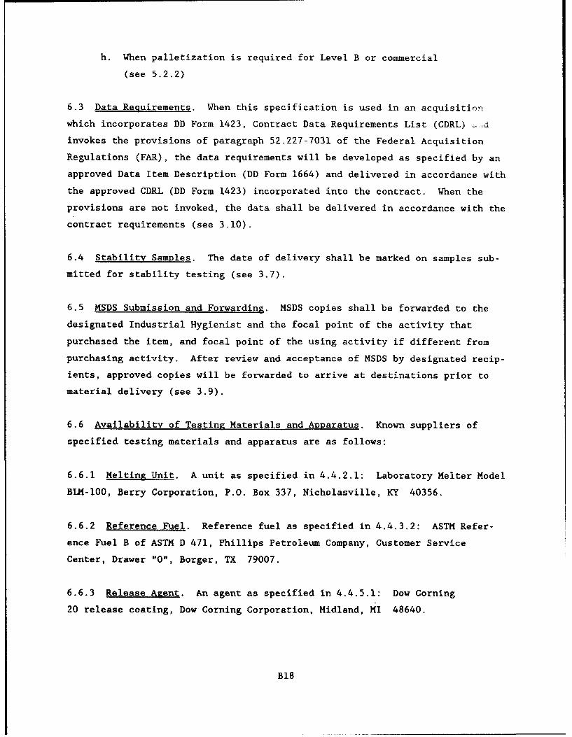
h. When palletization is required for Level B or commercial
(see 5.2.2)
6.3 Data Requirements. When this specification is used in an acquisition
which incorporates DD Form 1423, Contract Data Requirements List (CDRL) -d
invokes the provisions of paragraph 52.227-7031 of the Federal Acquisition
Regulations (FAR), the data requirements will be developed as specified by an
approved Data Item Description (DD Form 1664) and delivered in accordance with
the approved CDRL (DD Form 1423) incorporated into the contract. When the
provisions are not invoked, the data shall be delivered in accordance with the
contract requirements (see 3.10).
6.4 Stability Samples. The date of delivery shall be marked on samples sub-
mitted for stability testing (see 3.7).
6.5 MSDS Submission and Forwarding. MSDS copies shall be forwarded to the
designated Industrial Hygienist and the focal point of the activity that
purchased the item, and focal point of the using activity if different from
purchasing activity. After review and acceptance of MSDS by designated recip-
ients, approved copies will be forwarded to arrive at destinations prior to
material delivery (see 3.9).
6.6 Availability of Testing Materials and Apparatus. Known suppliers of
specified testing materials and apparatus are as follows:
6.6.1 Melting Unit. A unit as specified in 4.4.2.1: Laboratory Melter Model
BLK-lO0, Berry Corporation, P.O. Box 337, Nicholasville, KY 40356.
6.6.2 Reference Fuel. Reference fuel as specified in 4.4.3.2: ASTM Refer-
ence Fuel B of ASTM D 471, Phillips Petroleum Company, Customer Service
Center, Drawer "0", Borger, TX 79007.
6.6.3 Release Agent. An agent as specified in 4.4.5.1: Dow Corning
20 release coating, Dow Corning Corporation, Midland, MI 48640.
B18
6.6.4 Concrete Blocks. Blocks as specified in 4.4.6.2: US Army Corps of
Engineers, Missouri River Division Laboratory, 420 South 18th Street, Omaha,
NE 68102.
6.6.6 Blotting Paper. Paper as specified in 4.4.6.3: White Reliance Blot-
ting Paper, Product Code 13-01-12, James River Paper Company, Inc , 145 James
Way, Southampton, PA 18966.
6.7 Precautions. The sealant material can be damaged by heating at too high
a temperature, reheating, or by heating for too long a period of time. The
temperature of the sealant in the melting equipment should never exceed the
safe heating temperature set by the manufacturer. Any given quantity of mate-
rial should never be heated at the application or pouring temperature for more
than 3 hr and should never be reheated. Sealant material left in the
equipment at the end of the working day should be removed and discarded. The
sealant should be heated in a kettle or tank constructed as a double boiler,
with the space between the inner and outer shells filled with heat transfer
oil. Positive thermostatic control, mechanical agitation, and recirculating
pumps should be provided to maintain a uniform temperature of the sealant and
he.iting oil. Direct heating is not permitted. Thermometers should be pro-
vided for continuous temperature readings of both oil and the sealant.
B19
APPENDIX C: PROPOSED SPECIFICATION FOR LOW-MODULUS, HOT-APPLIED,NON-FUEL-RESISTANT, PAVEMENT JOINT SEALANTS
FOR RIGID AND FLEXIBLE PAVEMENTS
NOTE: This proposal is not finalized and changes may occur before it is pub-
lished as a material specification. Therefore, it may not be applicable for
project specifications.
1. SCOPE: This specification covers low-modulus, hot-applied, non-fuel-
resistant pavement joint sealant materials for use in sealing joints and
cracks in rigid and flexible pavements that are exposed to cold ambient
temperatures.
2. APPLICABLE DOCUMENTS
2.1 The following documents, of the issues in effect on date of invitation
for bids or request for proposal, form a part of this specification to the
extent specified herein.
Federal Specification
PPP-P-704 - Pails, Metal: (Shipping, Steel, I Through 12 Gallons)
Federal Standards
FED-STD-123 Marking for Shipment (Civil Agencies)
FED-STD-313 Material Safety Data Sheets Preparation and the
Submission of
Military Standards
MIL-STD-105 Sampling Procedures and Tables for Inspection by
Attributes
MIL-STD-129 - Marking for Shipment and Storage
MIL-STD-147 - Palletized Unit Loads
C3
Federal ReKulations
29 CFR 1900-1999 - Occupational Safety and Health Administration
(OSHA), Department of Labor
2.2 Other publications. The following documents form a part of this specifi-
cation to the extent specified herein. Unless a specific issue is identified,
the issue in effect on date of invitation for bid or request for proposal
shall apply.
American Society for Testing and Materials (ASTM)
D5 - Penetration of Bituminous Materials, Test Method for
D140 - Sampling Bituminous Materials, Methods of
D217 - Cone Penetration of Lubricating Grease, Test Methods for
D1985 - Preparing Concrete Blocks for Testing Sealants for Joints
and Cracks, Standard Practice for
D5167 - Melting of Hot-Applied Joint and Crack Sealant and Filler
Material for Evaluation, Standard Practice for
Technical Association of the Pulp and Paper Industry
T431 om - Ink Absorbency of Blotting Paper
2.3 Order of Precedence. In the event of a conflict between the text of this
specification and the references cited herein, the text of this specification
shall have precedence.
3. REQUIREMENTS
3.1 Description.
3.1.1 Material. The sealant shall be a fully polymerized and cured thermo-
plastic material furnished as a solid. It shall be composed of a mixture of
asphalt and rubber with additives. The manufacturer's specified application
or pouring temperature shall not exceed 232 deg Celsius (°C) (450 deg
C4
Fahrenheit (°F)), and shall be at least lIIC (20°F) lower than the safe heat-
ing temperature. The sealant shall meet the requirements of this
specification when poured after held at the application temperature for no
more than 10 min, and shall retain all of its properties with up to 3 hr of
continuous heat.
3.1.2 Performance. The sealant shall form a resilient and adhesive compound,
which effectively seals joints and cracks in pavements against the infiltra-
tion of moisture throughout repeated cycles of expansion and c~ntraction. The
sealant shall not flow from the joint or be picked up by pneumatic tires at
ambient temperatures of 52'C (125°F) or below. The sealant shall have a uni-
form application or pouring consistency suitable for filling the joint or
crack without the inclusion of blisters, bubbles, or discontinuities.
3.2 Safe Heating Temperature. The safe heating temperature is the highest
use temperature permitted by the manufacturer (see 5.3.3) and is a temperature
to which the sealant can be heated for a duration of at least 3 hr, and still
conform to all of the requirements specified herein.
3.3 Penetration. Penetration shall not exceed 15.0 millimeters (mm)
(150 test units) (0.591 in.) or be less than 9.0 mm (90 test units)
(0.354 in.) when the sealant is tested as specified in 4.4.3.
3.4 Flow. Flow shall not exceed 3.0 mm (0.118 in,) for either specimen when
tested as specified in 4.4.4.
3.5 Resilience. Recovery shall be a minimum of 50 percent and shall not
exceed 80 percent when the sealant is tested as specified in 4.4.5. The ini-
tial indentation shall not exceed 3.5 mm (0.138 in.) or be less than 1.0 mm
(0.039 in.) wnen tested as specified in 4.5.5.
3.6 Bond to Concrete. No specimen shall develop any surface crack, separa-
tion, or other opening in the Lealant, or between the sealant and the concrete
blocks when the sealant is tested as specified in 4.4.6.
C5
3.7 Static Adhesion. When the sealant is tested as specified in 4.4.7, none
of the 3 specimens shall exhibit any crack, separation, or other opening in
the sealant, or between the sealant and the concrete blocks exceeding 6.35 mm
(0.25 in.) in depth. Additionally. none of the 3 specimens shall e:hibit a
total area of bare concrete exposed on the face of any single concrete block
exceeding 160 mm2 (0.25 in. 2 ).
3.8 Compatibility with Asphalt. There shall be no failure in adhesion, for-
mation of an oily exudate at the interface between the sealant and the
asphaltic concrete, or softening or other deleterious effect on the asphaltic
concrete, when tested as specified in 4.4.7.
3.9 Storage Stability. When specified (see 6.2), the user agency will retain
samples for verification of these requirements: The sealant, when stored for
2 years from date of delivery, at temperatures from -18°C to 46 0 C (0°F to
115°F), and tested in accordance with this specification, shall meet all of
the requirements herein.
3.10 Toxicity. The material shall have no adverse effect on the health of
personnel when used for its intended purpose in the manner recommended by the
manufacturer. Questions pertinent to this effect shall be referred by the
acquiring activity to the appropriate medical service who will act as advisor
to the acquiring activity. The manufacturer's instructions shall provide
personnel protection to meet OSHA requirements, including 29 CFR 1910.1000,
1910.1002, and 1910.1017, as applicable (see 4.5).
3.11 Material Safety Data Sheets (MSDS). MSDSs shall be prepared in accor-
dance with FED-STD-313 and submitted as directed (see 6.2, 6.3, and 6.5).
4. QUALITY ASSURANCE PROVISIONS
4.1 Responsibility for Inspection. Unless otherwise specified, the contrac-
tor is responsible for the performance of all inspection requirements and may
use his own or any other facilities suitable for the performance of the
inspection requirements that are approved by the user agency. The user agency
reserves the right to perform any inspections set forth in the specification
C6
where such inspections are deemed necessary to assure supplies and services
conform to prescribed requirements.
4.1.1 Materials Inspection. The contractor is responsible Z• insurinig that
supplies and materials are inspected for compliance with all the requirements
specified herein and in applicable referenced documents.
4.2 Classification of Inspections. The inspection requirements specified
herein are classified as follows:
a. Quality conformance inspection (see 4.2.1).
b. Inspection of preparation for delivery (see 4.6).
4.2.1 Quality Conformance Inspection. The quality conformance inspection
shall be as specified in 4.4. Sampling shall be in accordance with 4.3.
4.3 Samplini. Unless otherwise specified (see 6.2), samples for testing
shall be taken at the point of manufacture in accordance with ASTM D140. It
shall be the responsibility of the contractor to determine that the samples
taken are representative of the batches for shipment. The representative
composite sample of the sealant shall consist of not less than 7 kilograms
(15 lbs) from each batch. A lot consisting of a single batch, if taken from
filled containers, shall be sampled from 3 containers, selected at random, to
make up the composite sample. Sample identification shall include the name of
the testing agency, contract or purchase order number, and special marking as
specified in 5.3.3. Each container from which sample material has been taken
shall be resealed and marked for identification.
4.4 Testing. Testing shall be conducted at a user-agency approved facility
\see 6.2). Samples taken as specified in 4.3 shall be tested as specified in
4.4.1 through 4.4.7. Individual test values and results of failure analyses
of individual shall be recorded. Failure of the sealant to pass any test
shall be cause for rejection of the lot, except as noted for bond specimen
casting defects in 4.4.6.3, and as noted for a marginal test result. The
exceptions for marginal test results are as follows: where results of only
C7
one of the specified tests are judged by the testing agency to be marginal as
to meeting the requirements, the testing agency has the option to perform a
retest. If the testing agency does not exercise its option to retest, either
the contractor or the user agency may request that a retest for that property
be made at the requester's expense. Such a test will be made only when an
adequate quantity of the original sample is available or where additional
material can be obtained from the previously marked sample containers.
4.4.1 Standard Conditions. Laboratory atmospheric conditions, hereinafter
referred to as standard conditions, shall be a temperature of 23±2'C (73±4°F)
and 50±5 percent relative humidity. Specimens shall be stored and tested at
standard laboratory conditions unless otherwise specified.
4.4.2 Specimen Preparation.
4.4.2.1 Equipment. The unit for melting the laboratory samples shall be as
specified in ASTM D5167.
4.4.2.2 Melting. The portion of the sample selected for testing shall pro-
vide approximately 1.6 cubic decimeter (1.7 quarts) of melted material. The
portion of material selected shall be obtained from the original sample and
melted as specified in ASTM D5167. The sample shall be heated at the safe
heating temperature until 3 hr have elapsed since the first segment was added
to the melters.
4.4.2.3 Pouring. Pour all test specimens as specified in 4.4.3 through 4.4.7
within a period of 10 min. Discard the first 50 to 60 grams of material dis-
charged from each melting pot.
4.4.3 Penetration. Penetration testing shall be as specified in ASTM D5
except as specified herein. Use a penetrometer as specified in ASTM D217 with
a cone conforming to the optional cone therein in place of the needle. Pre-
pare specimen in 177 cubic centime,:er (cc) (6 oz) container, and cast flush
with the top edge. Make determinations at locations on 120° radii, and half-
way between the center and outside of the specimen. Determine conformance to
the requirements of 3.3.
C8
4.4.4 Flow.
4.4.4.1 Specimen Preparation. Prepare duplicate specimens in molds with
inside dimensions of 40 mm by 60 mm by 3.2 mm (1.56 in. by 2.34 in. by
0.125 in.), placed on a bright tin panel. Metal molds, coated with a release
agent, such as a thin, cured film of heat-stable silicone (see 6.6.3), or
equivalent, shall be used. Fill the molds with excess sealant and allow the
specimens to cool at standard laboratory conditions for a minimum of 30 min.
After the specimens have cooled, trim of the excess sealant flush with the
face of the mold with a heated knife or spatula.
4.4.4.2 Test. Remove the molds and mark reference lines across the panels
coincident with the transverse edges of the specimens. Mount the specimens
with the long axis at an angle of 75±1' with the horizontal and the transverse
axis horizontal in a forced-draft oven maintained at 60±1C (140±2°F). After
5 hr, remove the specimens and marl' ,ference line on each specimen coin-
cident with the lowest point of sa •r iow, and parallel to the reference
line. Measure the indicated change in length of the specimen and report as
flow. Determine conformance to the requirements of 3.4.
4.4.5 Resilience.
4.4.5.1 Specimen Preparation. Prepare duplicate specimens as specified in
4.4.3, except cure the specimens for 24 hr at standard laboratory conditions
prior to testing. Oven-age one specimen in a forced-draft oven at 70±1C
(158±2*F) for 168±2 hr, cool at standard laboratory conditions for 1 hr, and
then condition for 1 hr in a water bath maintained at 25±0.3 0 C (77±0.5°F)
prior to testing. Condition the unaged specimen for 1 hr in a water bath
maintained at 25±0.3°C (77±0.5°F) prior to testing.
4.4.5.2 Procedure. Use a penetrometer as specified in ASTM D217, substitut-
ing the ball penetration tool illustrated in Figure 1 for the needle. Lightly
dust the surface of the specimen with talc and immediately remove the excess
by blowing. Place the ball in contact with the surface of the specimen and
set the indicating dial to zero. Position a light so that initial contact of
the ball with the specimen surface can be readily observed. Release the ball
C9
penetration tool and allow the ball to penetrate the specimen for 5 sec.
Record this reading as penetration (P) in tenth-millimeter units. Without
returning the dial pointer to zero, press the ball penetration tool down for
an additional 100 units (i.e., to a dial reading of P+l00) at a uniform rate
within 10 sec. Re-engage the clutch to hold the ball in this position for
5 sec and during this time return the indicator dial to zero. Release the
clutch, allow the specimen to recover for 20 sec, and record the final dial
reading (F). Make determinations at 3 points equally spaced from each other
and not less than 13 mm (0.5 in.) from the container rim. Calculate the
recovery, a measure of resilience, as follows:
Recovery, percent = P + 100 - F
Report the averages of 3 determinations of recovery and initial penetration
for each specimen. Determine conformance to the requirements of 3.5.
4.4.6 Bond to Concrete.
4.4.6.1 Extension Machine. The extension machine used in the bond testing
shall be so designed that the specimen can be maintained at the test tempera-
ture while being extended at a uniform rate as specified. It shall consist
essentially of one or more screws rotated by an electric motor through suit-
able gear reductions. Self-aligning plates or grips, one of each pair fixed
and the other carried by the rotating screw or screws, shall be provided for
holding the test specimen in position during the test.
4.4.6.2 Concrete Block Preparation. The concrete blocks used for bond test-
ing shall be prepared as specified in ASTM D1985. The blocks may be prepared
by the testing agency or procured (see 6.6.3).
4.4.6.3 Specimen Preparation. Prepare 6 bond test specimens (12 blocks) as
follows: Remove blocks from the storage water individually, scrub the 50 mm
by 75 mm (2 in. by 3 in.) faces lightly with a stiff bristle brush under run-
ning water, and resubmerge in fresh tap water until all blocks have been
scrubbed. Remove all blocks from the water and lightly blot with an oil-free,
soft, absorbent cloth or paper to remove all free surface water. Place the
Clo
blocks, 3 each, with the 50 mm by 75 mm faces down, centered and uniformly
spaced 25 mm (I in.) apart on sheets of blotting paper placed on a plane,
solid, nonabsorbent surface. The sheets shall be approximately 100 mm by
240 mm (4 in. by 9.5 in.), cut from material having a maximum absorption time
of 28 sec as measured by TAPPI T431 (see 6.6.4). At the end of 1 hr, assemble
pairs of concrete blocks to provide test specimens. Complete setup and pour
specimens within 1 hr. Spacers and the base plate used for the test specimens
shall have nonadherent, nonreactive surfaces (see 4.4.4.1). Place the spacer
strips not less than 6.35 mm (0.25 in.) thick on a base plate to form an open
space 12.7 mm (0.5 in.) wide and 50 mm (2 in.) long. Place pairs of the con-
crete blocks on the spacers so that the 25 mm by 75 mm faces are on the
spacers and the 50 mm by 75 nmu faces which were against the blotting paper
form the space to be filled by the sealant. Space the blocks 12.7±0.1 mm
(0.500±0.005 in.) apart with 12.7±0.1 mm square by 75 mm long spacers. Cor-
ners may be slightly rounded, but discard spacers that have a diagonal dimen-
sion less than 16.51 mm (0.650 in.). Place these spacer strips at a distance
from the ends of the blocks so that an opening 12.7±0.1 by 50 mm by 50 mm
(0.5±0.005 in. by 2 in. by 2 in.) is formed. Place spacer strips that are a
minimum of 12.7 mm thick on top of the blocks to provide for an overfill.
Clamps or other suitable means may be used te hold the blocks and overfill
spacers in position. Pour sealant prepared in accordance with 4.4.2 into the
space between the blocks in sufficient quantity to bring it at least even with
the top of the overfill spacers, and in a manner essentially to exclude air
pockets from being trapped in the sealant. After the specimens have cooled to
standard conditions, remove the excess sealant protruding beyond the top and
bottom of the concrete blocks by trimming with a hot knife or spatula. If the
material shrinks on cooling below the top of the blocks, or if other casting
defects are apparent, discard the specimens and prepare additional ones. Cool
the specimens at least 2 hr, but no more than 24 hr at standard laboratory
conditions before subjecting them to test conditions.
4.4.6.4 Nonimmersed Bond. Condition 3 bond test specimens, with spacers
maintaining the 12.7 mm dimensions, at the test temperature of -29±1IC
(-20±2°F), with forced air circulation for 4 to 16 hr. Then extend the
specimen 25.4 mm (I in.) at a uniform rate of 3.18 mm (0.125 in.) per hr while
maintaining the specimens at the test temperature. Remove the specimens from
Cl1
the extension machine and reinsert the 12.7 mm spacers, and examine the
spacers as described in 4.4.6.6. Then allow the specimens to return to the
original dimensions at standard conditions, resting each specimen on one con-
crete block so that the weight of the top block recompresses the joint seal-
ant. Three cycles of conditioning, extension, and recovery shall be completed
within 5 days after the start of the first cycle, and shall constitute one
complete test for nonimmersed bond. When initiation of the second or third
cycle is delayed, store the specimens at the test temperature.
4.4.6.5 Water-Immersed Bond. Insert thinner spacers between the concrete
blocks of the remaining three bond specimens so that an opening of not less
than 6.35 mm by 12.7 mm by 50 mm (0.25 in. by 0.5 in. by 2 in.) will be pro-
duced and maintained between the spacers and the sealant. Using covered con-
tainers deep enough to provide a minimum of 12.7 mm water cover, immerse the
specimens for 96 hr in 500 cc (16.9 oz) of distilled or deionized water per
specimen, and maintain at standard laboratory temperature. Place the speci-
mens with the concrete blocks in a horizontal position. Three specimens may
be placed in the same container, provided that the water-to-specimen ratio is
maintained. At the end of the 96 hr immersion period, remove the test
specimens from the water, remove the spacers, and remove the excess surface
water from the specimens with soft, dry, absorbent material. Subject the
specimens to conditioning and extension test as specified in 4.4.6.4. One
cycle of immersion and three cycles of conditioning, extension, and recovery
shall constitute one complete test for water-immersed bond (see 4.4.6.6).
4.4.6.6 Bond Test Results. Remove the bond test specimens from the extension
machine within 30 min after the completion of the extension of each of the
first two test cycles and examine the specimens for obvious separations within
the sealant and between the sealant and the concrete blocks without distorting
or manually causing extension of the specimens. Immediately upon completion
of the final cycle, insert both sets of spacers or otherwise maintain 50 per-
cent extension during examination and dimensional measurements, examining the
specimens thoroughly, while still frozen, for separations between the sealant
and concrete blocks and within the sealant, including surface cracks. This
shall be accomplished without distorting the specimens, but after recovery as
specified in 4.4.6.4, the specimens may be extended uniformly up to 25.4 mm
C12
(1 in.) to permit further detailed examination. Determine conformance to the
requirements of 3.6.
4.4.7 Static Adhesion.
4.4.7.1 Specimen Preparation. Prepare 3 bond test specimens as specified in
4.4.6.2 and 4.4.6.3 of this specification.
4.4.7.2 Procedure. Condition 3 bond test specimens with spacers maintaining
the 12.7 mm (0.5 in.) dimensions at the test temperature of -29±1IC (-20±2*F)
with forced air circulation for not less than 4 hr. Then extend the specimens
12.7 mm (0.5 in.) at a uniform rate of 3.18 mm (0.125 in.) per hr while main-
taining the specimens at the test temperature. Remove the test specimens from
the extension machine and insert 2.54 mm (1 in.) spacers to maintain the
12.7 mm extension. Store the specimens at standard laboratory conditions for
24 hr and then examine them for the separations between the sealant and the
concrete blocks or within the sealant. Determine conformance to the require-
ments of 3.7.
4.4.8 Compatibility with Asphalt.
4.4.8.1 Specimen Preparation. Prepare duplicate specimens of hot-mix asphal-
tic concrete, not less than 100 mm (4 in.) in diameter and 64 mm (2.5 in.)
high using 85 - 100 penetration asphalt cement. Density and asphalt content
shall be for asphaltic concrete pavement mix design and design method as spec-
ified (see 6.2 and 6.7). Specimens other than circular, but of similar dimen-
sions and properties may be used. Allow the specimens to cool to standard
laboratory temperature, then cut a groove 100 mm (4 in.) long by 13±3.2 mm
(0.5±0.125 in.) wide by 19±3.2 mm (0.75±0.125 in.) deep in the surface of the
specimen by wet sawing with a power driven masonry saw. Remove all residue
from the grooves by scrubbing with a stiff-bristle brush under running water.
Allow the specimens to return to standard laboratory conditions and securely
wrap with cloth-backed adhesive tape, or otherwise reinforce to prevent slump-
ing during the test period. Caulk the ends of the grooves to prevent leaking
of the sealant during testing. Pour sealant, prepared in accordance with
4.4.2, into the groove, overfilling slightly, but not allowing overflow onto
C13
the adjacent asphaltic concrete surface. Allow the specimen to cool to stan-
dard laboratory temperature, then trim any overfill flush, using a hot knife
or spatula.
4.4.8.2 Procedure. Place the specimens in a forced-draft oven maintained at
60±3-C (140±5'F) for 168±2 hr. Inspect at least once each day for specimen
damage. Immediately after removing from the oven and again after cooling to
standard laboratory temperature, examine the specimens for incompatibility of
sealant with the asphaltic concrete. Determine conformance to the require-
ments of 3.8.
4.5 Toxicological Data and Formulations. The manufacturer shall provide a
listing of the components in the sealant that when heated could produce haz-
ardous vapors (see 5.3.3). Where precautions need to be taken relative to the
inhaling of, or skin and eye contact with the material or vapors, these pre-
cautions shall be included in the manufacturer's instructions (see 3.9 and
5.3.3.1).
4.6 Inspection of Preparation for Delivery.
4.6.1 Sampling. Sampling for inspection of filled containers shall be in
accordance with MIL-STD-105, inspection Ievel II. The unit of product shall
be one unit prepared for shipment.
4.6.2 Examination. Each filled container selected shall be inspected for
conformance to the requirements of Section 5. Inspection shall be based on an
Acceptable Quality level of 2.5 percent defective.
5. PREPARATION FOR DELIVERY
5.1 Packing. Packing shall be Level A, B, or Commercial as specified (see
6.2).
5.1.1 Level A. The material shall be packed in a close-fitting, tapered
24-gage metal pail with gasket and lug cover. Pails shall have a wire handle
securely attached to ears or clips which shall be attached to the body of the
C14
pails. The exterior surfaces of the pails shall be coated as specified in
PPP-P-704. The unit pack quantity shall be one unit of issue quantity speci-
fied in the contract or purchase order.
5.1.2 Level B. The material shall be packed the same as for Level A except
that the exterior surfaces of the pail shall be coated with a commercial
coating.
5.1.3 Commercial. The material shall be packed to insure carrier acceptance
and safe delivery at the destination in containers complying with the rules
and regulations applicable to the mode of transportation.
5.2 Palletization.
5.2.1 Level A. Unless otherwise specified (see 6.2), material shall be pal-
letized in accordance with MIL-STD-147.
5.2.2 Level B and Commercial. When specified (see 6.2), material shall be
palletized in accordance with MIL-STD-147.
5.3 Marking.
5.3.1 Civil agencies. Shipment to civil agencies shall be marked in accor-
dance with FED-STD-123.
5.3.2 Military agencies. Shipments to military agencies shall be marked in
accordance with MIL-STD-129.
5.3.3 Special marking. In addition to the marking of 5.3.1 or 5.3.2, and any
special marking of the contract or order, the following information will be
shown on each pail:
a. Name of sealant
b. Specification number
c. Manufacturer's name and material designation
d. Manufacturer's lot and batch number
C15
e. Date of manufacturer (month and year)
f. List of hazardous components (see 4.5)
g. Quantity of sealant in pail (net weight)
h. Application or pouring temperature
i. Safe heating temperature
j. Instructions for use
5.3.3.1 Instructions for Use. The instructions for use (see 6.8) shall
include but not limited to the following: ambient temperature and humidity
ranges, and moisture conditions of joints, for successful installation; essen-
tial requirements for preparation of joints, heating of the sealant, handling,
placing, and disposal of the hot materials; and any restrictions to be adhered
to in order to reduce hazards to personnel or to the environment. If it is
not feasible to include all the instructions on the container without sacri-
ficing legibility, the most important information shall be shown on the con-
tainer and the full instructions referenced and furnished separately.
6. NOTES
6.1 Intended Use. This sealant is intended for sealing joints and cracks in
pavements in rigid or flexible pavements that are not exposed to spillage of
jet fuels and lubricating oils. It is not intended to be resistant to the
heat and blast of jet aircraft engines, except when aircraft are moving at
moderate speeds.
6.2 Ordering Data. Purchasers shall select the preferred options permitted
herein, and include the following in procurement documents:
a. Title, number and date of this specification
b. When stability samples are required, quantity to be retained
and by what activity (see 3.8 and 6.4)
c. Addresses for submission of MSDS (see 3.10 and 6.5)
d. Sampling, if other than as specified (see 4.3)
C16
e. Designation of Government approved test facility (see 4.4)
f. Density and asphalt content values for asphaltic concrete
pavement mix design and design method required (see 4.4.7.1)
g. Level of packing required (see 5.1)
h. If palletization is not required for Level A (see 5.2.1)
i. When palletization is required for Level B or Commercial
(see 5.2.2).
6.3 Data Requirements. When this specification is used in an acquisition
which incorporates a DD Form 1423, Contract Data Requirements List (CDRL) and
invokes the provisions of paragraph 52.227-7031 of the Federal Acquisition
Regulations (FAR), the data requirements will be developed as specified by an
approved Data Item Description (DD Form 1664) and delivered in accordance with
the approved CDRL (DD Form 1423) incorporated into the contract. When the
provisions are not invoked, the data shall be delivered in accordance with the
contract requirements (3.10).
6.4 Stability Samples. The date of delivery shall be marked on samples sub-
mitted for stability testing (see 3.8).
6.5 MSDS Submission and Forwarding. MSDS copies will be forwarded to the
designated Industrial Hygienist and the focal point of the activity that pur-
chased the item, and the focal point of the using activity if different from
purchasing activity. After review and acceptance of MSDS by designated recip-
ients, approved copies will be forwarded to arrive at the destinations prior
to material delivery (see 3.10).
6.6 Availability of Testing Materials and Apparatus. Known suppliers of
specified testing materials and apparatus are as follows:
6.6.1 Melting Unit. A unit as specified in 4.4.2.1: Laboratory Melter Model
BLM-100, Berry Corporation, P.O Box 337, Nicholasville, KY 40356.
C17
6.6.2 Release Agent. An agent as specified in 4.4,4.1: Dow Corning
20 release coating, Dow Corning Corporation, Midland, MI 48640.
6.6.3 Concrete Blocks. Blocks as specified in 4.4.6.2: US Army Corps of
Engineers, Missouri River Division Laboratory, 420 South 18th Street, Omaha,
NE 68102.
6.6.4 Blotting Paper. Paper as specified in 4.4.6.3: White Reliance Blot-
ting Paper, Product Code 13-01-12, James River Paper Company, Incorporated,
145 James Way, Southampton, PA 18966.
6.7 Asphalt Compatibility Specimens. The specimens of hot-mix asphaltic
concrete as specified in 4.4.7.1 may be prepared using the methods described
in ASTM D1074, D1559, or D1561.
6.8 Precautio- . The sealant material can be damaged by heating at too high
a temperature, reheating, or by heating for too long a period of time. The
temperature of the sealant in the melting equipment should never exceed the
safe heating temperature set by the manufacturer. Any given quantity of mate-
rial should never be heated at the application or pouring temperature for more
than 3 hr and should never be reheated. Sealant left in the equipment at the
end of the working day should be removed and discarded. The sealant should be
heated in a kettle or tank constructed as a double boiler, with the space
between the inner and outer shells filled with heat transfer oil. Positive
thermostatic control, mechanical agitation, and recirculating pumps should be
provided to maintain uniform temperature of the sealant and heating oil.
Direct heating is not permitted. Thermometers should be provided for continu-
ous temperature readings of both oil aid the sealant.
C18
APPENDIX D: SUGGESTED SPECIFICATION FOR PRIMER, JOINT, NON-JET-FUEL-RESISTANT, COLD-APPLIED, SINGLE COMPONENT
FOR PORTLAND CEMENT CONCRETE PAVEMENTS
I. SCOPE
1.1 Scope. This specification covers one type of one-component, cold-applied material for use in priming joints and cracks in portland cement con-crete pavements prior to sealing the joint.
2. APPLICABLE DOCUMENTS
2.1 The following documents form a part of this specification.
Federal Specification
SS-S-1401C - Sealant, Joint, Non-Jet-Fuel-Resistant, Hot-Applied,for Portland Cement and Asphalt Concrete Pavements
2.2 Other publications. The following documents form a part of thisspecification to the extent specified herein.
American Society for TemZing and ""terias CIASTI
C711-72 - Low Temperature Flexibility and Tenacity of One-Part,Elastomeric, Solvent-Release Type Sealants
D5-83 - Penetration of Bituminous MaterialsD2823-75 - Standard Specification for Asphalt Roof Coatings
2.3 Order of precedence. In the event of a conflict between the textof this specification and the references cited herein, the text of this spici-fication shall take precedence.
3. REQUIREMENTS
3.1 Description.
3.1.1 Material. The primer shall be a single-component, liquid com-position that cures after application and which can be spray or brush appliedto pavement crack or joint surfaces at temperatures between 50 and 120°F. Themanufacturer shall specify the specific sealant products with which the primeris compatible and approved for use.
3.1.2 Performance. The primer shall cure to form a well-bonded toughsurface coating which is non-tacky. The cured primer coating shall be fullycompatible with m .facturer approved sealant materials and shall in no wayadversely affect sealant performance characteristics. The cured primer coat-ing shall be capable of filling and sealing voids in portland cement concretejoint faces to assist in restricting passage of moisture.
3.2 Viscosity. Viscosity shall not be less than 25 cp, or shall notexceed 250 cp when the primer is tested as specified in 4.4.3.
3.3 Tack Free Time. Tack free time shall not exceed 10 min when theprimer is tested as specified in 4.4.4.
3.4 Cured Tack Free Evaluation. The primer shall pass the cured tackfree evaluation at 60 min when tested as specified in 4.4.5.
D3
3.5 Non-Volatile Content. The non-volatile content shall not be lessthan 20 percent and shall not exceed 40 percent when the primer is tested asspecified in 4.4.6.
3.6 Permeability. Permeability shall not exceed 10 percent when theprimer is tested as specified in 4.4.7.
3.7 Low-Temperature Flexibility. None of the specimens shall developany cracks greater than 1/4 in. in length or exhibit any adhesion loss whentested as specified in 4.4.8.
3.8 Adhesion. No specimen shall develop any crack, separation, oropening between the sealant and the concrete blocks when the primer is testedas specified in 4.4.9.
3.9 Storage Stability. When specified, the Government will retainsamples for verification of these requirements: The primer, when stored for2 years from the date of delivery, at temperatures from -18' to 46°C (0' to115F), and tested in accordance with this specification, shall meet all ofthe requirements herein.
3.10 Toxicity. The material shall have no adverse effect on the healthof personnel when used for its intended purpose. Questions pertinent to thiseffect shall be referred by the acquiring activity to the appropriate medicalservice who will act as advisor to the acquiring activity. The manufacturer'sinstructions shall provide personnel protection to meet OSHA requirements,including 29 CFR 1910.1000, 1910.1002, and 1910.1017, as applicable (see 4.5).
3.11 Material Safety Data Sheets (MSDS). MSDS shall be prepared inaccordance with FES-STD-313 and submitted as directed in the contract or orderat the time of acquisition award.
4. QUALITY ASSURANCE PROVISIONS
4.1 Responsibility for Inspection. Unless otherwise specified in thecontract or purchase order, the contractor is responsible for the performanceof all inspection requirements as specified herein. Except as otherwisespecified in the contract or purpose order, the contractor may use his own orany other facilities suitable for the performance of the inspection require-ments specified herein, unless disapproved by the Government. The Governmentreserves the right to perform any of the inspections set forth in the specifi-cation where such inspections are deemed necessary to assure supplies andservices conform to prescribed requirements.
4.1.1 Materials inspection. The contractor is responsible for insuringthat supplies and materials are inspected for compliance with all the require-ments specified herein and in applicable referenced documents.
4.2 Quality conformance inspection. The quality conformance inspectionshall be as specified in 4.4. Sampling shall be in accordance with 4.3.
4.3 Sampling. Unless otherwise specified, samples for testing shall betaken at the point of manufacture in accordance with ASTM D140. It shall bethe responsibility of the contractor to detprmine that the samples taken are
D4
representative of the batches proposed for shipment. The representative com-posite sample of the primer shall consist of not less than 2 liters (0.52 gal)from each batch. A lot consisting of a single batch, if taken from filledcontainers, shall be sampled by withdrawing approximately equal portions fromthree containers, selected at random, to make up the composite sample. Thesample shall immediately be placed in an appropriate airtight sealed containerwhich is either metal or plastic, in order to prevent loss of volatiles priorto testing. Sample identification shall include the name of the testingagency and contract or purchase order number. Each container from which sam-ple material has been taken shall be resealed and marked for identification.
4.4 Testing. Testing shall be conducted at a Government-approvedfacility. Samples taken as specified in 4.3 shall be tested as specified in4.4.1 through 4.4.9. Individual test values, and results of failure analysosof individual specimens, shall be recorded. Failure of the primer to pass anytest shall be cause for rejection of the lot, except as noted for a marginaltest result, following: where results of only one of the specified tests arejudged by the testing agency to be marginal as to meeting requirements, thetesting agency has the option to perform a retest. If the testing agency doesnot exercise its option to retest, either the contractor or Government mayrequest that a retest for that property be made at the requester's expense.Such a test will be made only when an adequate quantity of the original sampleis available or where additional material can be obtained from the previouslymarked sampled containers.
4.4.1 Standard conditions. Laboratory atmospheric conditions, herein-after referred to as standard conditions, shall be 23 ± 2°C (73 ± 4'F) tem-perature and 50 ± 5 percent relative humidity. Specimens shall be stored andtested at standard conditions unless otherwise specified.
4.4.2 Specimen preparation. Prior to beginning testing, the sampleshall be stored at laboratory standard conditions for a minimum of 24 hr inorder to temperature condition the sample prior to opening the container.Since the primer contains volatile constituents, care must be taken duringhandling to minimize volatile loss. Therefore, the sample container shouldremain tightly closed at all times except when required for testing purposes.Just prior to initiating all testing, the sample container shall be opened andthe sample shall be stirred to assure uniformity.
4.4.3 Viscosity.
4.4.3.1 Specimen preparation. The test sample be prepared by pouring700 ± 100 ml. of the primer into at standard 1 quart (0.946 1) metal open topcan with double friction lid. The lid shall then be placed on the can and thecan sealed. The container shall then be placed in a constant temperaturewater bath as specified in ASTM D5, which is maintained at 77 ± 0.2*F for1.5 to 2 hi.
4.4.3.2 Test. Remove the can from the water bath and remove the lid.Stir the sample to assure uniformity. Test for viscosity using a BrookfieldModel HAT viscometer using Probe No. 1 at a speed of 50 rpm. Determine con-formance to the requirements of 3.2.
D5
4.4.4 Tack Free Time.
4.4.4.1 Specimen Preparation. Obtain one 2" x 3" x I" concrete testblock prepared in accordance with sections 4.4.6.2.1 and 4.4.6.2.2 of FS SS-S-1401C. Remove the blocks from the storage water and scrub the 2 by 3 in.faces with a stiff bristle brush under running water. Then lightly blot thesurfaces of the block with an oil-free, soft absorbent cloth or paper toremove all free surface water. Place the block on a 2" x I" face and permitto dry at standard conditions for 60 min.
4.4.4.2 Block Coating. Pour approximately 700 ml of primer into astandard 1 quart (0.946 1) open top metal can. Immerse the prepared and driedconcrete block totally into the primer for 30 sec. Remove the block from theprimer using forceps which grip the I" x 3" sides, and hold the block with the3 in. sides in a vertical position over the primer container and allow todrain for 60 sec.
4.4.4.3 Testing. Immediately after the draining period, place thecoated block with the 2" x 3" side down on any appropriate level surface atlaboratory standard conditions of 23 ± 2°C (73 ± 4°) and 50 ± 5 percent rela-tive humidity for 10 min. Place a 150 by 25 by 0.1 ± 0.025 mm (6 by I by0.004 ± 0.001 in.) polyethylene film on top of the primer coated block surfacewith the 6 in. axis of the film aligned with the 3 in. axis of the block.Load the polyethylene film for 30 sec with a metal plate approximately 41 by29 mm (1.6 by 1.1 in.), with not less than 30 or more than 31 grams (g) mass.Remove the plate, and withdraw the film, uniformly and progressively, at rightangles to the surface of the primer. Primer adhering to the polyethylene filmshall constitute failure to conform to the requirements specified in 3.3.
4.4.5 Cured Tack Free Evaluation.
4.4.5.1 Specimen preparation. Prepare one block in accordance withsection 4.4.4.1 of this specification.
4.4.5.2 Block Coating. Coat the block in accordance with section4.4.4.2 of this specification.
4.4.5. 3 Testing. Immediately after the draining period, place thecoated block with a 2" x 3" side down on an appropriate level surface atlaboratory standard conditions for 60 min. Place a 150 by 25 by 0.1 ±0.025 mm (6 by 1 by 0.004 ± 0.001 in.) polyethylene film on top of the primercoated block surface with the 6 in. axis of the film aligned with the 3 in.axis of the block. Load the polyethylene film at the center of the block witha metal place approximately 41 by 29 mm (1.6 by 1.1 in.) with not less than30 or more than 31 grams (g) mass. Place the block, film, and weight in aforced draft oven maintained at 158°F for 60 min. Remove the specimen fromthe oven and immediately. Remove the plate, and withdraw the film, uniformlyand progressively, at right angles to the surface of the primer. Primeradhering to the polyethylene film shall constitute failure to conform to therequirements specified in 3.4.
D6
4.4.6 Non-Volatile Content.
4.4.6.1 Procedure. Test according to the Non-Volatile Matter determi-nation of ASTM D2823-75 section 8.2. Determine non-volatile matter contentand determine conformance to the requirement of 3.5.
4.4.7 Permeability.
4.4.7.1 Specimen Preparation. Prepare three test blocks in accordancewith section 4.4.4.1 of this specification except instead of allowing to air
dry for 60 min, determine and record the saturated surface-dried weight ofeach block (A) to the nearest 0.01 gram, immediately after blotting to removefree surface water. Then, dry the blocks to constant weight at 135 t 5°C(275 ± 9°F). Constant weight shall be verified by successive weighing using ascale accurate to 0.01 gm. Dry until the blocks show a weight change of notmore than 0.05 gm on successive hourly weighing. Each weighing should beafter cooling in a desiccaLor. Label each block and record the oven-driedweight (B) to the nearest 0.01 gm. Store dried blocks in a desiccator untilthey are used.
4.4.7.2 Block Coating. Coat each block with primer following the pro-cedure in section 4.4.4.2 of this specification. After the 60 sec drainingperiod, support the block with one of the 2 in. by 3 in. sides down on a fix-ture with four vertical supporting pins, as shown in Figure 1. Cure the sup-
ported block for 4 hr at standard conditions.
4.4.7.3 Test Procedures. Weigh the block and primer to the nearest0.01 gm at the end of the 4 hr curing period and record the weight as C,Place each block in a I liter glass beaker which contains 500 ± 50 ml of dis-tilled water which is at 25 ± 1IC (77 ± 2°F). Loosely cover each beaker andplace in an oven or water bath to maintain the 25 ± 2°C temperature for60 min. At the end of the 60 min period, remove the blocks from the water,blot the surfaces with an oil free soft absorbent cloth, to remove all freesurface moisture. Immediately weigh to the nearest 0.01 gm, and record theweight as D.
4.4.7.4 Calculations. Calculate permeability as the percentage ofweight gained during the 60 min soaking period at 25°C as a percentage of thesaturated surface dried moisture content of the block as follows:
A - Saturated surface dried weight ef uncoated block
B - Oven-dried block weight
C - Block weight when coated with primer
D - Saturated surface dried weight of soaked coated block
Permeability - D - CA - B X 100 percent
Calculate the permeability for each of the three blocks average the results,and then determine conformance to the requirements specified in 3.6.
4.4.8 Low Temperature Flexibility.
D7
4.4.8.1 Specimen Preparation. Test specimens are prepared in accor-dance with the ASTM C711-72 procedure. Due to the low viscosity of theprimer, it will be necessary to seal the interface between the template andthe plate with a solvent resistant sealer (such as Pearmatex No. 2, Pliable,Non-Hardening Gasket Sealant supplied by Loctite Corporation, Automotive andConsumer Group, Kansas City, Kansas 66115) to prevent leakage of the primer.The sealed template and plate shall then be filled with primer and conditionedat lab standard conditions for 24 ± 2 hr. Remove the template after condi-tioning with the aid of a thin knife by cutting around the outside edge of theprimer.
4.4.8.2 Testing Procedure. Expose the conditioned specimen to 158 ±3.6-F (70 ± 2-C) for 16 hr, and then further condition thp specimen at 32 4
1°F (0 ± 0.5°C) for 1 hr. After the 1 hr conditioning at 320F, bend the panelthrough 180° over the 1/4 in. diameter mandrel with the primer side uppermost.The bend shall be performed in not less than 1 s and not more than 1.5 s.Immediately after bending examine the primer for cracking, separation, delami-nation, and adhesion loss. Minor surface crazing or hairline cracks and minoredge cracking may be ignored. Determine conformance to requirements ofsection 3.7.
4.4.9 Adhesion.
4.4.9.1 Specimen Preparation. Prepare 6 concrete blocks as specifiedin sections 4.4.4.1 and 4.4.4.2. Then, place a 2 in. by 3 in. surface of thecoated block on an appropriate level surface and allow to cure at laboratorystandard conditions for 60 min. Assemble three sets of blocks in preparationfor pouring sealant in accordance with section 4.4.6.3 of FS SS-S-1401C. Heatsealant recommended by the manufacturer which meets FS SS-S-1401C in accor-dance with section 4.4.2 and prepare specimens using the primer coated blocksin accordance with section 4.4.6.3 of FS SS-S-1401C.
4.4.9.2 Testing. Test the prepared samples for nonimmersed and water-immersed bond using procedures specified in sections 4.4.6.4 and 4.4.6.5 of FSSS-S-1401C. Examine the results as specified in section 4.4.6.6 of FS SS-S-1401C. Determine conformance to the requirements of section 3.8 of thisspecification.
4.5 Toxicoloyical data and formulations. The manufacturer shall pro-vide a listing of the components in the primer that could give off hazardousvapors during use. Where precautions need to be taken relative to the inhal-ing of, or skin and eye contact with the vapors, these precautions shall beincluded in the manufacturer's instructions (see 3.10).
D8
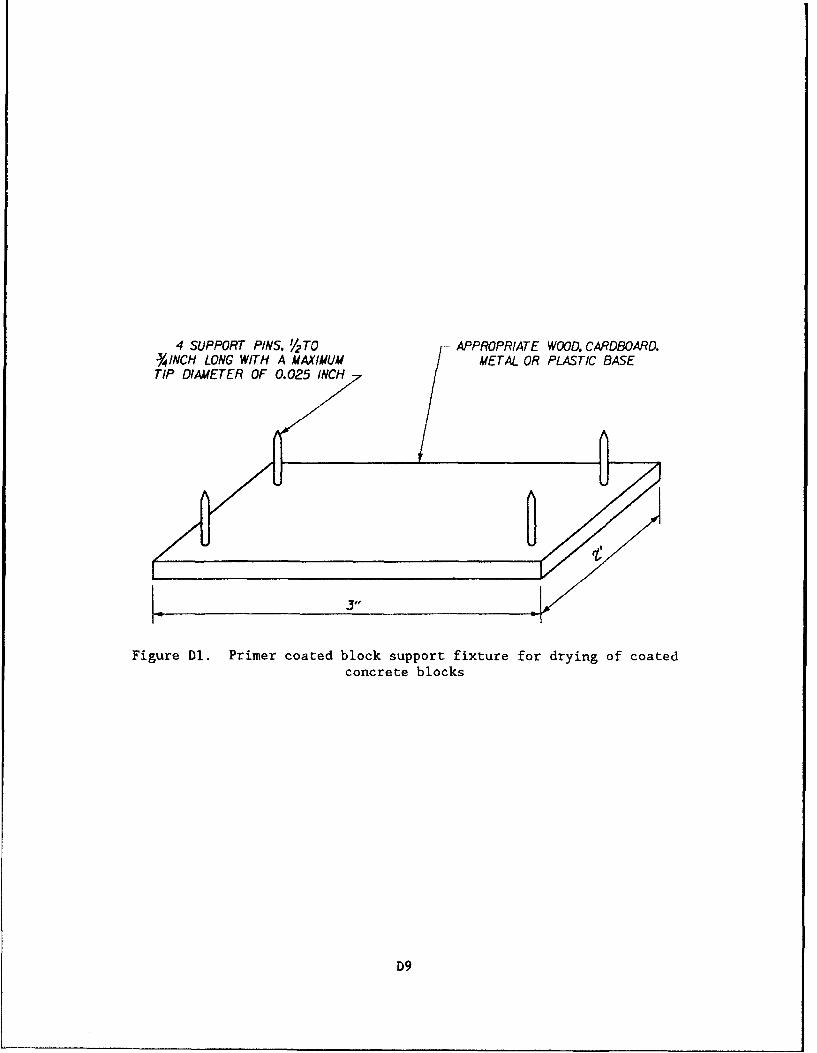
4 SUPPORT PINS. Y2 TO- APPROPRIATE WOOD. CARDBOARD.-1INCH LONG WITH A MAXIMUM / METAL OR PLASTIC BASETIP DIAMETER OF 0.025 INCH
Figure Dl. Primer coated block support fixture for drying of coatedconcrete blocks
D9
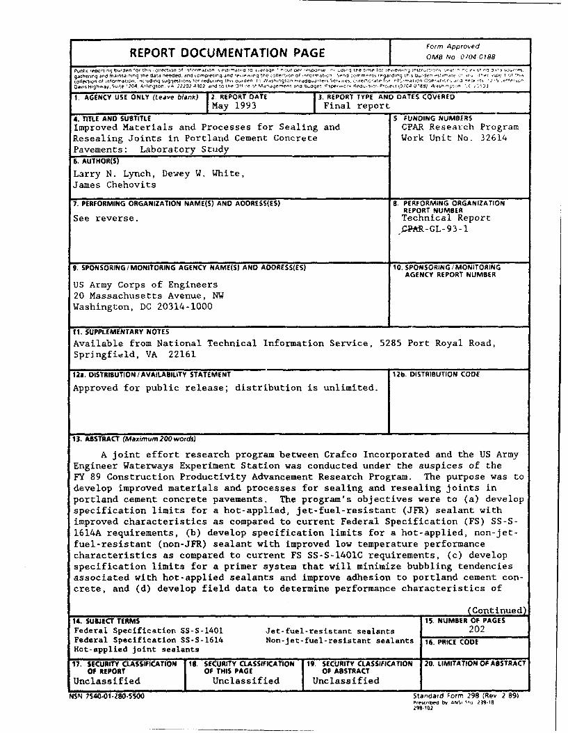
Form Approved
REPORT DOCUMENTATION PAGE I OMB No 0904 0188
Puotii reoCrtflq buroef for " iecii on of rt" rat, on ýs est- 1. ma .e4 ,3 , ")V ae, yr -5tpacr e Ldaq met" n !ý r e~ enfpft~t i. 9 -n y dgathering and mairrtaio.Sg thre data needed, And re~plet eq ted t n e e e i of .01it ..- r rrýr-t eadrýr dr stlr' te "I T" I~e .0 T1Collectiton of information. n( didng suggestions tof feduon th 0 ov. def Aitr vah'qton -rnadaw es d i nr.ns itr r ,itC ;'eaton . e at Cr.it ý ii-.e't '
Da~ti~qi Hig-aiSu~te 1204, A I rtgton A 22202 43102 and to. the Jll I - Maralerrrer iria Budg i'e r.c dQ.Io _C1t O C4 0 1881 a'rt.it ( 1)
1. AGENCY USE ONLY (Leave blank) 2. REPORT DATE I3REPORT TYPE AND DATES COVEREDMay 1993 _ Final report__________
4. TITLE AND SUBTITLE S. FUNDING NUMBERSImproved Materials and Processes for Sealing and CPAR Research ProgramResealing Joints in Portland Cement Concrete Work Unit No. 32614Pavements: Laboratory Study
6. AUTHOR(S)
Larry N. Lynch, Dewey W. White,James Chehovits
7. PERFORMING ORGANIZATION NAME(S) AND AOORESS(ES) S. PERFORMING ORGANIZATIONREPORT NUMBER
See reverse. Technical Report_PAR-CL-93-1
9. SPONSORING/ MONITORING AGENCY NAME(S) AND AOORESS(ES) 10. SPONSORING /MONITORINGAGENCY REPORT NUMBER
US Army Corps of Engineers20 Massachusetts Avenue, NWWashington, DC 20314-1000
111. SUPPLEMENTARY NOTES
Available from National Technical Information Service, 5285 Port Royal Road,Springfield, VA 22161
12a. DISTRIBUTION / AVAILABILITY STATEME NT 12b. DISTRIBUTION CODE
Approved for public release; distribution is unlimited.
13. ABSTRACT (Maximuim 200 words)
A joint effort research program between Crafco Incorporated and the US ArmyEngineer Waterways Experiment Station was conducted under the auspices of theFY 89 Construction Productivity Advancement Research Program. The purpose was todevelop improved materials and processes for sealing and resealing joints inportland cement concrete pavements. The program's objectives were to (a) developspecification limits for a hot-applied, jet-fuel-resistant (JFR) sealant withimproved characteristics as compared to current Federal Specification (FS) SS-S-1614A requirements, (b) develop specification limits for a hot-applied, non-jet-fuel-resistant (non-JFR) sealant with improved low temperature performancecharacteristics as compared to current FS SS-S-1401C requirements, (c) developspecification limits for a primer system that will minimize bubbling tendenciesassociated with hot-applied sealants and improve adhesion to portland cement con-crete, and (d) develop field data to determine performance characteristics of
________________________________________________(Continued)14. SUBJECT TERMS IS, NUMBER OF PAGESFederal Specification SS-S-1401 Jet-fuel-resistant seal~ants 202Federal Specification SS-S-1614 Non-jet-fuel-resistant sealants 16. PRICE CODEHot-applied joint sealants
17. SECURITY CLASSIFICATION 18. SECURITY CLASSIFICATION 19. SECURITY CLASSIFICATION 20. LIMITATION OF ABSTRACTOF REPORT I Of THIS PAGE OF ABSTRACT
Unclassified Unclassified Unclassified
NSN 7540-01 -280-5500 Standard Form 298 (Rev 2-89)Pres(rtbed bv ANSI ?3' 19-18298-102
7. (Concluded)
USAE Waterways Experiment StationGeotechnical Laboratory3909 Halls Ferry RoadVicksburg, MS 39180-6199
Crafco Incorporated6975 West Crafco WayChandler, AZ 85226
13. (Concluded).
flush fill sealant application geometry versus 1/8 to 1/4 in. recess applicationtechniques. This report summarizes the laboratory investigation phases of theresearch program. Field evaluations of the materials developed to meet thesespecifications are being conducted to determine actual maintenance cost reduc-tions and improved construction quality.
Prior to initiating sealant development activities, testing of availablesealant materials was performed to identify the level of laboratory performanceof currently available hot-applied, JFR and non-JFR sealants. Thirteen differ-ent sealants from four manufacturers were tested for specification conformanceto FS SS-S-1614A and FS SS-S-1401C. Additional testing procedures were alsoused to aid in determining performance limits. Testing verified that the JFRsealants tested were not capable of passing bond tests at -20=F, and that theyexperience significant amounts of surface hardening when subjected to 158°Foven-aging. Non-JFR sealants tested varied in low temperature extension capa-bilities. Products which met low-modulus ASTM D 3405 specificaticns were capa-ble of passing bond testing at -20°F using 200 percent extension, while theFS SS-S-1401C materials could not.
Laboratory development work determined that it was possible to produce hot-applied, JFR sealant materials which could pass bond testing at -20'F, and withless surface hardening after aging. A suggested specification was developed forthis improved material, and a pilot production batch of sealant meeting thisspecification was made. Additionally, a suggested specification for a low-modulus non-JFR sealant with improved low temperature properties was developed,and a pilot production batch of sealant meeting this specification was made.Both sealants were installed at Fairchild AFB, WA, for field evaluation. Theresults of the field evaluation of the improved sealants versus commerciallyavailable sealants are presented in a separate report.
Bubbling characteristics cf sealants were studied using the US Army Corpsof Engineers' Handbook for Concrete and Cement CRD-C 525-89 procedure along withseveral modifications to better understand the bubbling problem. Data indicatethat as little as 0.5 percent moisture in portland cement concrete (PCC) cancause sealant bubbling. A quantitative method to monitor bubbling rate wasdeveloped. A variety of potential encapsulating primer formulations were stud-ied. Results indicated that when the appropriate primer system is used on PCC,swelling and bubbling of sealants can be reduced. Appropriate adhesion couldnot be obtained between the sealant and PCC pavement when the developmental JFRprimers were used. The developmental non-JFR primers increased sealant adhesionand reduced sealant bubbling in the laboratory. A suggested specification forprimer for use with non-JFR sealant for PCC pavements was developed, and a pilotproduction batch of primer to meet this specification was made for field evalu-ation at Fairchild AFB, WA.