Embed Size (px)
Citation preview

I2C Overview
2H 2003

Semiconductors 2
Agenda
• What is I2C and why would you be interested in using the I2C bus?
• What new I2C devices are there and what are the typical applications?
• How are we going to help you design-in these devices?

Semiconductors 3
Transmission Standards
General Purpose
Logic
GTLPBTLETL
1394.a
CML
RS-422
RS-485
RS-232 RS-423
LVDS =RS-644ECL/PECL/LVPECL
I2C0.1
1
1035
400655
2500
Dat
a Tr
ansf
er R
ate
(Mbp
s)
0 10 100 10000.5Cable Length (meters)Backplane Length (meters)
I2C data can be transmitted at speeds of 100 kHz, 400 kHz
or 3.4 MHz.
3.4 MHz
100 KHz400 KHz
I2C data can be transmitted longer
distances using bus buffers like the
P82B96

Semiconductors 4
I2C Bus Basics - Address and Dataµcon-troller
GPIO A/D D/A
LCD RTC µcon-troller
IIThe master always sends the SCL (clock) signal. SCL
SDA
1010A2A1A0R/WEEPROM
A2A1A0
1010100R/W
Each device is addressed individually by software with a unique address that
can be modified by hardware pins.New devices or
functions can be easily ‘clipped on to an
existing bus!The open drain/collector outputs
provide for a “wired-AND” connection that allows devices to be added or
removed without impact and always require a pull-up resistor.
Write data Master Slave
S slave address W A data A data A PS slave address W A data A data A P transmitter
< n data bytes >Read data
receiver
receiver transmitterS slave address R A data A data A P
< n data bytes > last data byte S = Start condition R/W = read / write not A = Acknowledge A = Not Acknowledge P = Stop condition

Semiconductors 5
Typical Signaling Characteristics
I2C
GTL+1394
CML
PECLLVPECL LVDS
LVTTL
I2C SMBusI2C
RS422/485
GTLGTLP
2.5 V3.3 V5 VLVTLVC

Semiconductors 6
I2C by the numbers Standard-Mode Fast-Mode High-Speed-
ModeBit Rate(kbits/s) 0 to 100 0 to 400 0 to
17000 to3400
Max Cap Load(pF) 400 400 400 100
Rise time(ns) 1000 300 160 80
Spike Filtered(ns) N/A 50 10
Address Bits 7 and 10 7 and 10 7 and 10
0.4 V @ 3 mA Sink Current
Rise TimeVDD
VIH 0.7xVDD
VIL 0.3xVDD
VOL
GND

Semiconductors 7
I2C Bus Basics - Bus Operation
Typical bus communication waveforms
The I2C specification and other useful application information can be found on Philips Semiconductors I2C web site at www.semiconductors.philips.com/i2c
Semiconductors 8
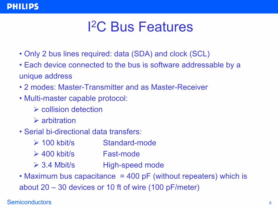
I2C Bus Features
• Only 2 bus lines required: data (SDA) and clock (SCL)• Each device connected to the bus is software addressable by a unique address • 2 modes: Master-Transmitter and as Master-Receiver• Multi-master capable protocol:
collision detectionarbitration
• Serial bi-directional data transfers:100 kbit/s Standard-mode400 kbit/s Fast-mode3.4 Mbit/s High-speed mode
• Maximum bus capacitance = 400 pF (without repeaters) which is about 20 – 30 devices or 10 ft of wire (100 pF/meter)
Semiconductors 9
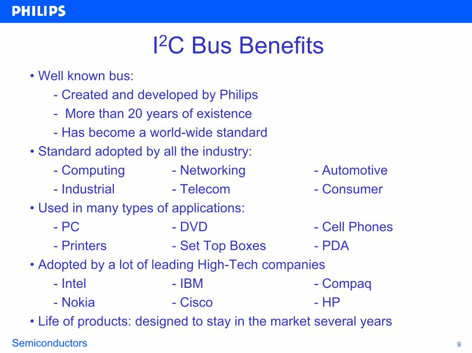
I2C Bus Benefits• Well known bus:
- Created and developed by Philips- More than 20 years of existence - Has become a world-wide standard
• Standard adopted by all the industry:- Computing - Networking - Automotive- Industrial - Telecom - Consumer
• Used in many types of applications:- PC - DVD - Cell Phones- Printers - Set Top Boxes - PDA
• Adopted by a lot of leading High-Tech companies- Intel - IBM - Compaq- Nokia - Cisco - HP
• Life of products: designed to stay in the market several years
Semiconductors 10
I2C Designer Benefits• No need to design bus interfaces because the I2C-bus interface is already integrated on-chip.• Integrated addressing and data-transfer protocol allow systems to be completely software-defined.• The same IC types can often be used in many different applications.• ICs can be added to or removed from a system without affecting any other circuits on the bus.• Fault diagnosis and debugging are simple; malfunctions can be immediately traced.• Software development time can be reduced by assembling a library of reusable software modules.
Semiconductors 11
I2C Manufacturer Benefits• Simplicity: 2 wire protocol
- Minimum inter connections- Minimum footprint- Simpler, smaller and less expensive PCB
• Robustness of the protocol- Completely integrated protocol- No need for address decoding and “glue logic”- Interrupt oriented architecture- Multi-master capable
• Upgrade path: - Speed: 100 kHz 400 kHz- Modular architecture allowing easy design and architecture updates and upgrades

Semiconductors 12
I2C Product Characteristics• Package Offerings
Typically SO, TSSOP and HVQFN packages
• Frequency RangeOlder devices 100 kHz operationNewer devices operating up to 400 kHzGraphic devices up to 3.4 MHz
• Operating Supply Voltage Range2.5 to 5.5 V or 2.8 to 5.5 VNewer devices at 2.3 to 5.5 V or 3.0 to 3.6 V with 5 V tolerance
• Operating temperature rangeTypically -40 to +85 ºCSome 0 to +70 ºC
• Hardware address pins Typically three (AO, A1, A2) are provided to allow up to eight of the identical device on the same I2C bus but sometimes due to pin limitations there are fewer address pins
24 pin 1624 pin 16--bit PCA9555 shownbit PCA9555 shown4 mm x 4 mm4 mm x 4 mm
Semiconductors 13
I2C Patent and Legal Information• The I2C bus is protected by patents held by Philips. Licensed IC manufacturers that sell devices incorporating the technology already have secured the rights to use these devices, relieving the burden from the purchaser.
• A license is required for implementing an I2C interface on a chip (IC, ASIC, FPGA, etc). It is Philips's position that all chips that can talk to the I2C bus must be licensed. It doesn’t matter how this interface is implemented. The licensed manufacturer may use its own know how, purchased IP cores, or whatever.
• This also applies to FPGAs. However, since the FPGAs are programmed by the user, the user is considered a company that builds an I2C-IC and would need to obtain the license from Philips.
• Apply for a license or text of the Philips I2C Standard License Agreement• US and Canadian companies: contact Mr. Piotrowski (I2C.Support at philips.com)• All other companies: contact Mr. Hesselmann (I2C.Support at philips.com)

Semiconductors 14
Agenda
• What is I2C and why would you be interested in using the I2C bus?
• What new I2C devices are there and what are the typical applications?
• How are we going to help you design-in these devices?
Semiconductors 15
Philips Semiconductors I2C Devices Overview
• TV Reception
• Radio Reception
• Audio Processing
• SMART Card Interface
• DTMF
• LCD display control
• Clocks/timers
• General Purpose I/O
• LED display control
• Bus Extension/Control
• A/D and D/A Converters
• EEPROM/RAM
• Hardware Monitors
• Microcontroller
I2C devices are broken down into 14 different categories
Philips offers over 400 different I2C devices

Semiconductors 16
TV ReceptionThe SAA56xx family of microcontrollers are a derivative of the Philips industry-standard 80C51 microcontroller and are intended for use as the central control mechanism in a television receiver. They provide control functions for the television system, OSD and incorporate an integrated Data Capture and display function for either Teletext or Closed Caption.
Additional features over the SAA55xx family have been included, e.g. 100/120 Hz (2H/2V only) display timing modes, two page operation (50/60 Hz mode for 16:9, 4:3), higher frequency microcontroller, increased character storage, more 80C51 peripherals and a larger Display memory. For CC operation, only a 50/60 Hz display option is available. Byte level I²C-bus up to 400 kHz dual port I/O

Semiconductors 17
Radio Reception
The TEA6845H is a single IC with car radio tuner for AM and FM intended for microcontroller tuning with the I²C-bus. It provides the following functions:
• AM double conversion receiver for LW, MW and SW (31 m, 41 m and 49 m bands) with IF1 = 10.7 MHz and IF2 = 450 kHz • FM single conversion receiver with integrated image rejection for IF = 10.7 MHz capable of selecting US FM, US weather, Europe FM, East Europe FM and Japan FM bands.
Semiconductors 18
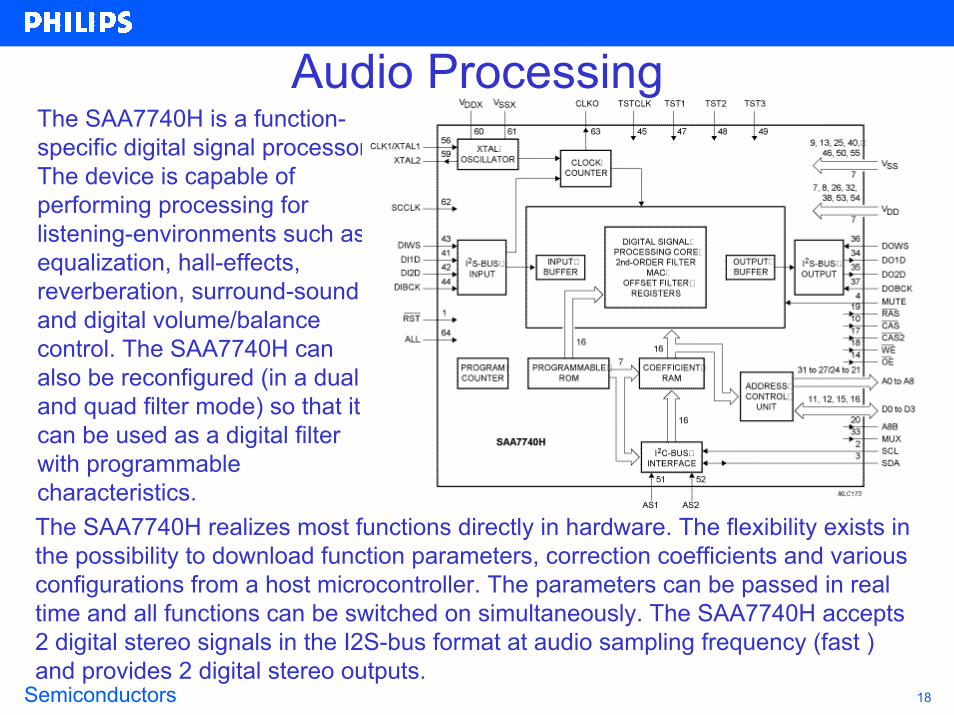
The SAA7740H is a function-specific digital signal processor. The device is capable of performing processing for listening-environments such as equalization, hall-effects, reverberation, surround-sound and digital volume/balance control. The SAA7740H can also be reconfigured (in a dual and quad filter mode) so that it can be used as a digital filter with programmable characteristics.The SAA7740H realizes most functions directly in hardware. The flexibility exists in the possibility to download function parameters, correction coefficients and various configurations from a host microcontroller. The parameters can be passed in real time and all functions can be switched on simultaneously. The SAA7740H accepts 2 digital stereo signals in the I2S-bus format at audio sampling frequency (fast ) and provides 2 digital stereo outputs.
Audio Processing

Semiconductors 19
SMART Card Interface - TDA8003Reference voltage from the Host
40000 clock cycles counter for ATR sequence
I2C bus (control /status)
Vddp(2.5 to 6V)
Vddi (1.5 to 6V)(reference for µC
signals)
Asynchronous cards (3&5V) onlyPower off switch
Supply /Supervisor
Power on reset
Security / protections
Sequ
ence
r
VCC
RST
I/O
CLK
Card presence
Buffer
Buffer
BufferClock generator
Step-upconverter
I/O (µC)IRQ
Vgen.
counter
Clock in
Offmode
Possibility to cascade 4 ICs I2C sub-addresses
Semiconductors 20
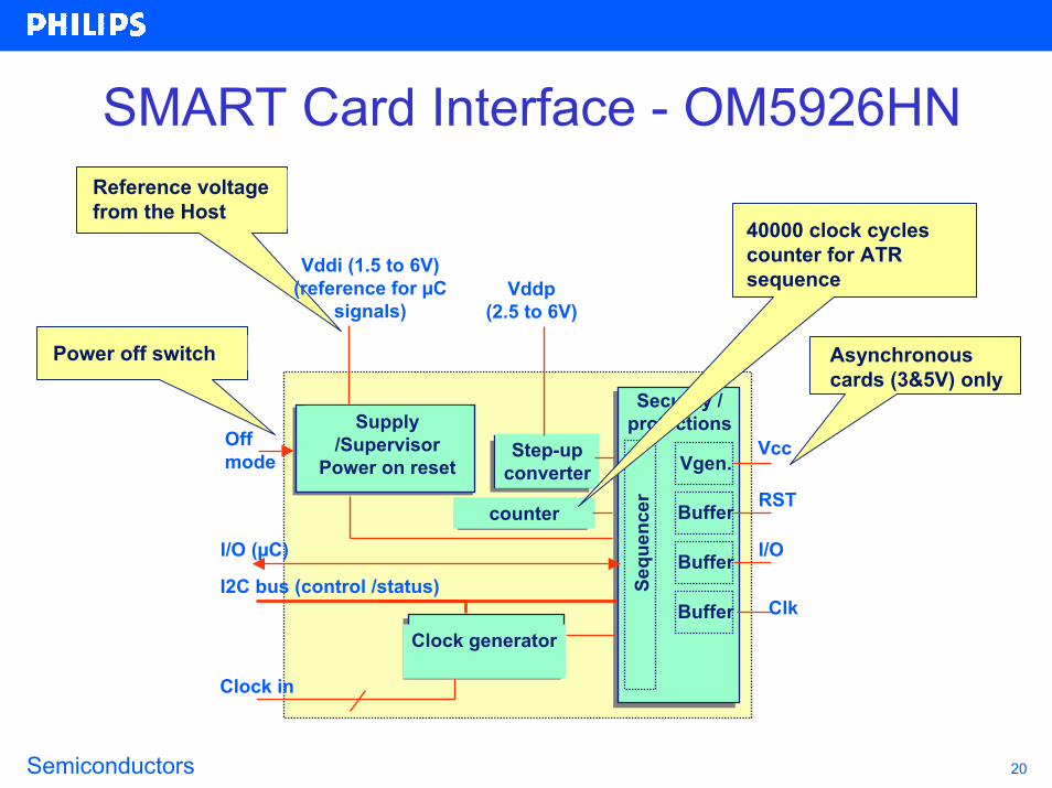
SMART Card Interface - OM5926HNReference voltage from the Host
Asynchronous cards (3&5V) only
Power off switch
Supply /Supervisor
Power on reset
Security / protections
Sequ
ence
r
Vcc
RST
I/O
Clk
Buffer
Buffer
BufferClock generator
Step-upconverter
I/O (µC)
Vgen.
counter
Clock in
I2C bus (control /status)
Offmode
40000 clock cycles counter for ATR sequence Vddi (1.5 to 6V)
(reference for µC signals)
Vddp(2.5 to 6V)

Semiconductors 21
Single chip baseband
ISO UART TDA8003 or OM5926iso iso
SIM/WIM card
TDA8029RS232or SIM/WIM
or banking card
SMART Card - Telecom Terminal Application
Single Slot application or
isoSingle chip baseband I²C
Single chip baseband
ISO UARTiso
TDA8029
TDA8003 or OM5926
RS232orI²C
SIM cardisoDual slot
application
Banking cardiso

Semiconductors 22
SMART Card Interface - TDA8023VDDP
(2.7 to 6.5V)
Supply /Supervisor
Power on reset
DC/DCConverter
Inductive orcapacitive
Security / protections
Sequ
ence
r
V gen. Vcc
RST
I/O
Clk
Card presence
Buffer
Buffer
BufferClocks
counters
C4
C 8
SDA
osc.
I/O(µC)
INT
Adjust supervisorThreshold (opt)
I2CInterface
I2CInterface
POFF
VDD(2.7to 6.5V)
CLKIN
SCL
VDDI(1.5 to 6.5V)

Semiconductors 23
SMART Card Interface - TDA8020
VDDI(1.8 to 6.5V)
Card presence1
Card presence2Security / protections
Level shifters
Supply /Supervisor
Power on reset
Step-upconverter
Sequ
ence
r V gen.VCC1RST1
I/O1
CLK1
BufferBuffer
Buffer
Sequ
ence
r V gen.VCC2RST2I/O2
CLK2
BufferBuffer
Buffer
SCLSDAIRQ
AVDD = 2.7V to 6V
CGND1
CGND2
clock circuit
clock circuit
internaloscillator
A0A1
I²C busControl
&Status
Leve
l shi
fters
resetdelay
CLKIN1CLKIN2
I/O µC1I/O µC2

Semiconductors 24
DTMF/Modem/Musical Tone Generators
• Modem and musical tone generation• Telephone tone dialing
• DTMF > Dual Tone Multiple Frequency• Low baud rate modem

Semiconductors 25
I2C LCD Display and Segment DriversThe LCD Display driver is a complex device and is an example of how "complete" a system an I2C chip can be – it generates the LCD voltages, adjusts the contrast, temperature compensates, stores the messages, has CGROM and RAM etc etc.
DDRAM
Bias voltage generator
Voltage multi-plier
Column driver
Sequ
ence
r
Row
driv
erControl logicCGRAM
CGROM
SDA
SCL
Display size:2 line by 12 characters + 120 icons
LCD Display Control
Supply
Display sizes 1 x 24 … 2 x 40…single chip: 4 x 40 ... 16 x 24LCD Segment Control
RAM
Bias voltage generator
Segment driversSe
quen
cer
Bac
kpla
ne d
river
s
Control logic
The LCD Segment driver is a less complex LCD driver (e.g., just a segment driver).
SDA
SCL
Supply
Semiconductors 26
I2C LCD Display and Segment Drivers
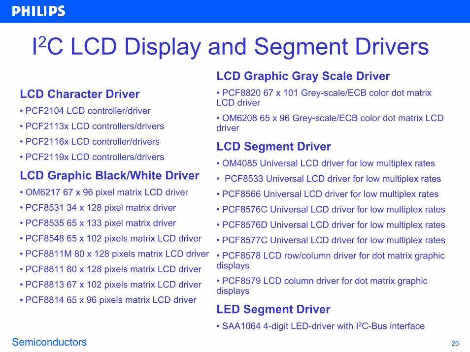
LCD Character Driver • PCF2104 LCD controller/driver• PCF2113x LCD controllers/drivers • PCF2116x LCD controller/drivers • PCF2119x LCD controllers/drivers
LCD Graphic Black/White Driver• OM6217 67 x 96 pixel matrix LCD driver• PCF8531 34 x 128 pixel matrix driver • PCF8535 65 x 133 pixel matrix driver • PCF8548 65 x 102 pixels matrix LCD driver • PCF8811M 80 x 128 pixels matrix LCD driver • PCF8811 80 x 128 pixels matrix LCD driver• PCF8813 67 x 102 pixels matrix LCD driver• PCF8814 65 x 96 pixels matrix LCD driver
LCD Graphic Gray Scale Driver• PCF8820 67 x 101 Grey-scale/ECB color dot matrix LCD driver • OM6208 65 x 96 Grey-scale/ECB color dot matrix LCD driver
LCD Segment Driver• OM4085 Universal LCD driver for low multiplex rates • PCF8533 Universal LCD driver for low multiplex rates• PCF8566 Universal LCD driver for low multiplex rates• PCF8576C Universal LCD driver for low multiplex rates• PCF8576D Universal LCD driver for low multiplex rates• PCF8577C Universal LCD driver for low multiplex rates• PCF8578 LCD row/column driver for dot matrix graphic displays • PCF8579 LCD column driver for dot matrix graphic displays
LED Segment Driver• SAA1064 4-digit LED-driver with I2C-Bus interface

Semiconductors 27
I2C Real Time Clock/CalendarThe RTC is used to provide absolute timing to devices on the I2C Bus. The latest RTC is the PCF8565 which is the automotive temp range version of the PCF8563 low current consumption RTC. The PCF8583 has 240 bytes 'scratchpad' RAM integrated with the RTC.
Real-Time Clock / Calendar
Alarm-, Timer- Registers
Sub address decoder
Oscillator / prescaler
I2C-bus interface
Counters: s, min, h, day, month, year
(240 Byte RAM 8583)
Interrupt
POR
32kHz
SDA
SCL
• PCA8565 Real time clock/calendar• PCF8563 Real time clock/calendar • PCF8573 Clock/calendar with serial I/O • PCF8583 Clock/calendar with 240 x 8-bit RAM • PCF8593 Low power clock/calendar
Semiconductors 28
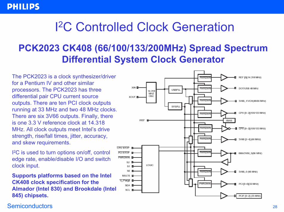
I2C Controlled Clock GenerationPCK2023 CK408 (66/100/133/200MHz) Spread Spectrum
Differential System Clock GeneratorThe PCK2023 is a clock synthesizer/driver for a Pentium IV and other similar processors. The PCK2023 has three differential pair CPU current source outputs. There are ten PCI clock outputs running at 33 MHz and two 48 MHz clocks. There are six 3V66 outputs. Finally, there is one 3.3 V reference clock at 14.318 MHz. All clock outputs meet Intel’s drive strength, rise/fall times, jitter, accuracy, and skew requirements.
I2C is used to turn options on/off, control edge rate, enable/disable I/O and switch clock input.
Supports platforms based on the Intel CK408 clock specification for the Almador (Intel 830) and Brookdale (Intel 845) chipsets.

Semiconductors 29
I2C Controlled Clock DistributionThe PCK2001/2 are a LVTTL fanout buffers used for 133/100 MHz CPU, 66/33 MHz PCI, 14.318 MHz REF, or 133/100/66 MHz SDRAM clock distribution.
18 outputs are used to support up to 4 SDRAM DIMMS commonly found in desktop, workstation or server applications.
10 outputs of the mobile (M) version support 2 SDRAM DIMMS in notebook applications.
6 outputs of the registered (R) version support up to 4 registered SDRAM DIMMs commonly found in server applications.
I2C is used to turn each individual I/O on/off
• PCK2001 14.318-167MHz I²C 1:18 SDRAM Clock Buffer• PCK2001M 14.318-167MHz I²C 1:10 SDRAM Clock Buffer• PCK2001R 14.318-133MHz I²C 1:6 SDRAM Clock Buffer• PCK2002 0-300MHz I²C 1:18 SDRAM Clock Buffer• PCK2002M 0-300MHz I²C 1:10 SDRAM Clock Buffer

Semiconductors 30
I2C Controlled Zero-Delay Clock Distribution
PCK2057 DDR Memory Clock Driver• Optimized for clock distribution in DDR (Double Data Rate) SDRAM applications supporting DDR 200/266/300/333• 1:10 differential clock distribution• Jitter < 100 ps• HCSL to SSTL_2 input conversion• 2.5 V and 3.3 V I²C support @ 100 kHz• Test mode enables output buffers while enabling PLL• Spread spectrum tolerant clock input• 48-pin plastic TSSOP packaging• Form, fit, and function compatible with CDCV850
Clocking Solution for ServerWorks Grand Champion™ System I/O Switch

Semiconductors 31
Quasi Output I2C I/O ExpandersKEY POINTS-Transfers keyboard, ACPI Power switch, keypad, switch or other inputs to microcontroller via I2C bus-Expand microcontroller via I2C bus where I/O can be located near the source or on various cards-Use outputs to drive LEDs, sensors, fans, enable and other input pins, relays and timers- Quasi outputs can be used as Input or Output without the use of a configuration register-The PCA9501 has 6 address pins, allowing up to 64 devices to share the same I2C Bus. -Application Note, AN469 GPIO Selection, discusses pros and cons of GPIOs
alternative analog input configurations
General Purpose I/OSupply
Latc
hes
Sub address decoder
I2C-bus interface
InterruptPOR
≠In
put/
outp
ut s
tage
sSDA
SCL
# of Outputs Interrupt 2Kbit EEPROM
Interrupt and 2Kbit EEPROM
8 PCF8574/74A PCA9500/58 PCA950116 PCF8575/75C - -
Quasi Output (20-25 ma sink and 100 uA source)
Application Note AN469
Semiconductors 32
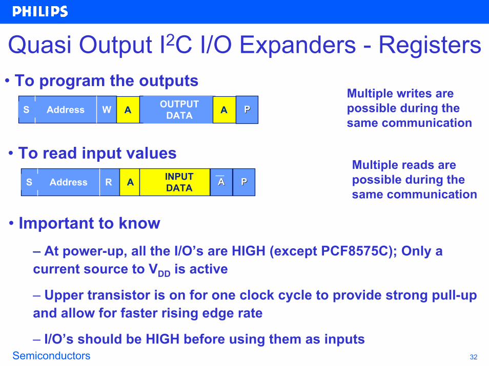
Quasi Output I2C I/O Expanders - Registers• To program the outputs
Multiple writes are possible during the same communication
Address WS AA OUTPUT DATA AA PP
• To read input valuesMultiple reads are possible during the same communication
Address RS AA INPUTDATA AA PP
• Important to know–– At power-up, all the I/O’s are HIGH (except PCF8575C); Only a current source to VDD is active
– Upper transistor is on for one clock cycle to provide strong pull-up and allow for faster rising edge rate
– I/O’s should be HIGH before using them as inputs
Semiconductors 33
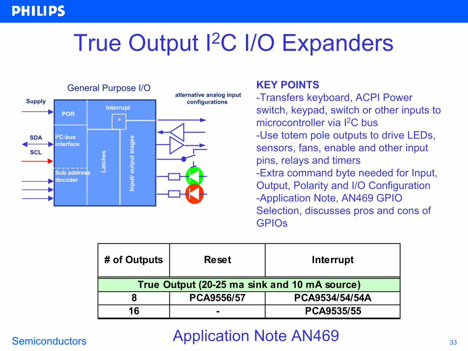
True Output I2C I/O ExpandersKEY POINTS-Transfers keyboard, ACPI Power switch, keypad, switch or other inputs to microcontroller via I2C bus-Use totem pole outputs to drive LEDs, sensors, fans, enable and other input pins, relays and timers-Extra command byte needed for Input, Output, Polarity and I/O Configuration -Application Note, AN469 GPIO Selection, discusses pros and cons of GPIOs
alternative analog input configurations
General Purpose I/OSupply
Latc
hes
Sub address decoder
I2C-bus interface
InterruptPOR
≠
Inpu
t/ ou
tput
sta
gesSDA
SCL
# of Outputs Reset Interrupt
8 PCA9556/57 PCA9534/54/54A16 - PCA9535/55
True Output (20-25 ma sink and 10 mA source)
Application Note AN469

Semiconductors 34
True Output I2C I/O Expanders - Registers• To configure the device
No need to access Configuration and Polarity registers once programmed
Address WS AA 03H AA CONFIG DATA AA
Address WS AA 02H AA POLARITY DATA AA PP
• To program the outputsMultiple writes are possible during the same communication
Address WS AA 01H AA OUTPUT DATA AA PP
• To read input values
Address WS AA 00H AA Multiple reads are possible during the same communicationAddress RSR AA INPUT
DATA AA PP

Semiconductors 35
True Output I2C I/O Expanders - ExampleInput Reg#
Polarity Reg#
Config Reg#
Output Reg#
00
00
1100
00
111100
00
00
0000
11
111111
11
11
1100
XX
XXXXXX
11
11
0000
11
001100
1111001111
000011
Read/ Write
Read Read/ Write
Read/ Write
I/O’s

Semiconductors 36
I2C LED Dimmers/Blinkers
FEATURES-25 mA open drain outputs-Internal oscillator (+/- 15%)-Two user definable blink rates and duty cycles adjustable between 160 Hz and 1.6 seconds (3x Dimmers) or 40 Hz and 6.4 seconds (5x Blinkers) in 256 steps-Unused pins can be used for normal GPIO-Hardware Reset pin and Power On Reset (POR)
KEY POINTS-I2C/SMBus is not tied up by sending repeated transmissions to turn LEDs on and then off to “blink” LEDs.-Frees up the micro’s timer-Continues to blink LEDs even when no longer connected to bus master-Can be used to cycle relays and timers-Higher frequency rate allows LEDs to be dimmed by varying the duty cycle for Red/Green/Blue color mixing applications.
# of Outputs Reset and POR2 PCA9530/504 PCA9533/538 PCA9531/51
16 PCA9532/52
SCL
Osc
illat
or
Sub address decoder
I2C-bus interface
ResetPOR
≠
Inpu
t/ ou
tput
sta
ges
alternative analog input configurations
Application Note AN264
Supply
SDA
Semiconductors 37
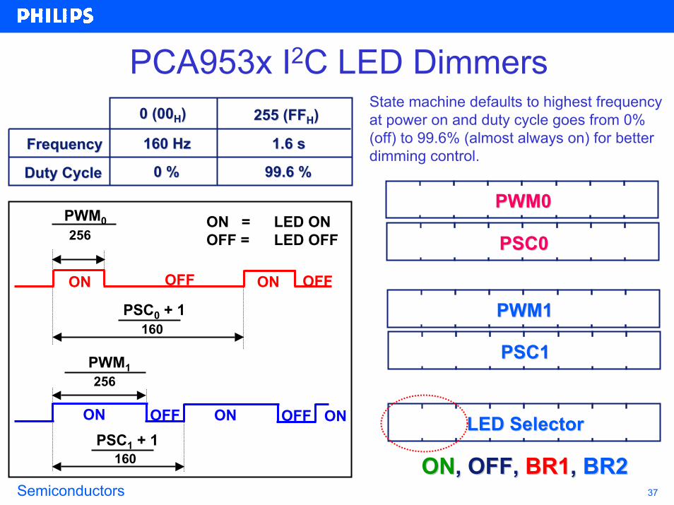
PCA953x I2C LED DimmersState machine defaults to highest frequency at power on and duty cycle goes from 0% (off) to 99.6% (almost always on) for better dimming control.
FrequencyFrequency
Duty CycleDuty Cycle
0 (000 (00HH)) 255 (FF255 (FFHH))
160 Hz160 Hz 1.6 s1.6 s
0 %0 % 99.6 %99.6 %00 00 0000 00 00PWM0PWM0
ON OFF ON OFF ON
ON OFF ON
PWM0256
PSC0 + 1160
PWM1256
PSC1 + 1160
ON = LED ONOFF = LED OFF
OFF
00 00 0000 00 00PSC0PSC0
00 00 0000 00 00PWM1PWM1
00 00 0000 00 00PSC1PSC1
00 00 0000 00 00LED SelectorLED Selector
ONON, OFF, , OFF, BR1BR1, , BR2BR2

Semiconductors 38
PCA955x I2C LED Blinkers
FrequencyFrequency
Duty CycleDuty Cycle
0 (000 (00HH)) 255 (FF255 (FFHH))
40 Hz40 Hz 6.4 s6.4 s
100 %100 % 0.4 %0.4 %
00 00 0000 00 00Input Register(s)Input Register(s)
00 00 0000 00 00PWM0 (ON Time)PWM0 (ON Time)
ON OFF ON OFF ON
ON OFF ON
256 - PWM0256
PSC0 + 140
256 - PWM1256
PSC1 + 140
ON = LED ONOFF = LED OFF
OFF
00 00 0000 00 00PSC0 (Frequency)PSC0 (Frequency)
00 00 0000 00 00PWM1 (ON Time)PWM1 (ON Time)
00 00 0000 00 00PSC1 (Frequency)PSC1 (Frequency)
00 00 0000 00 00LED SelectorLED Selector
ONON, OFF, , OFF, BR1BR1, , BR2BR2

Semiconductors 39
LED Dimmers/Blinkers vs Micros
Difference between using a LED Blinker/Dimmer or a micro: • Easier software generation to control LEDs
Don’t have to use micro timerDon’t have to continually send on and off command
to blink or dim LEDs• Frequency fixed by device, not dependant on internal processor clock frequency• I2C devices have higher sink current capability per bit and larger sink current capability per device
Semiconductors 40
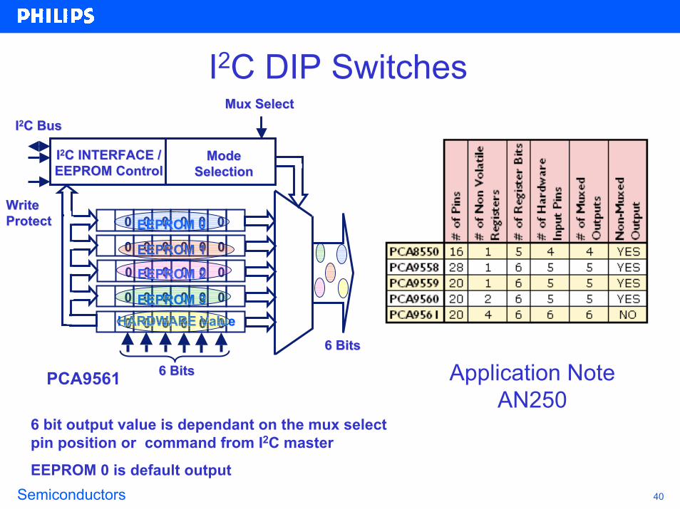
I2C DIP Switches
Write Write ProtectProtect 00 00 0000 00 00EEPROM 0EEPROM 0
00 00 0000 00 00EEPROM 1EEPROM 100 00 0000 00 00EEPROM 2EEPROM 2
00 00 0000 00 00EEPROM 3EEPROM 3
00 00 0000 00 00HARDWARE ValueHARDWARE Value
Mode Mode SelectionSelection
II22C INTERFACE /C INTERFACE /EEPROM ControlEEPROM Control
Mux SelectMux SelectII22C BusC Bus
6 Bits6 Bits
Application Note AN250
6 Bits6 BitsPCA9561
6 bit output value is dependant on the mux select pin position or command from I2C master
EEPROM 0 is default output

Semiconductors 41
I2C Multiplexers and Switches
I2C Bus
Interrupt 0Interrupt 1
Interrupt Out I2C Controller
OFFI2C Bus 0I2C Bus 1
I2C Bus
Reset I2C Controller
Interrupt 0Interrupt 1Interrupt Out
OFF
OFF
2, 4 and 8 channel
I2C Bus 0I2C Bus 1
Application Note AN262

Semiconductors 42
I2C Multiplexers: Address DeconflictI2C device
1
Same I2C devices with same address
MASTER
I2C device2
I2C device1
MASTER
I2C device2
PCA9540 I2C MULTIPLEXER
The multiplexer allows to address 1 devicethen the other one
Semiconductors 43
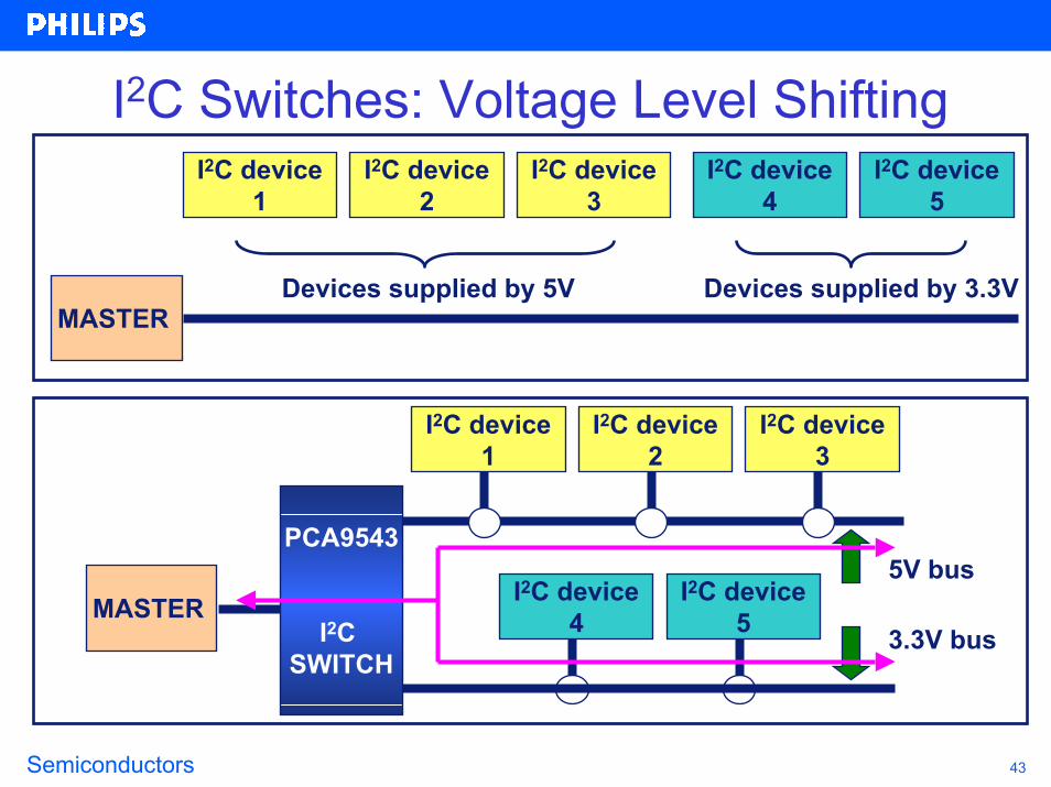
I2C Switches: Voltage Level ShiftingI2C device
1
Devices supplied by 5VMASTER
I2C device2
I2C device3
I2C device4
I2C device5
Devices supplied by 3.3V
I2C device1
MASTER
I2C device2
I2C device3
I2C device4
I2C device5
PCA9543
I2C SWITCH
5V bus
3.3V bus

Semiconductors 44
I2C Switches: Branch isolationI2C device
1
Separate devices 1, 2 and 3 from devices 4 and 5
MASTER
I2C device2
I2C device3
I2C device4
I2C device5
I2C device1
MASTER
I2C device2
I2C device3
I2C device4
I2C device5
PCA9543
I2C SWITCH

Semiconductors 45
I2C Multiplexers: Multi-card ApplicationCard 0
Card 1Card 2
PCA9544
INT0
INT3
INT1INT2
INT
I2C bus 3I2C bus 2I2C bus 1
I2C bus 0
-- Cards are identicalCards are identical-- One card is selected / controlledOne card is selected / controlledat a timeat a time
-- PCA9544 collects InterruptPCA9544 collects Interrupt
PCA9554
Card 3
INT
SubSystemInt
Reset
I2C bus 3
Reset
Alarm 1
Int
Reset
Alarm 1
Int
Alarm 11
1
0
0
0
1
MASTER
Interrupt signals are Interrupt signals are collected into one signalcollected into one signal
Semiconductors 46
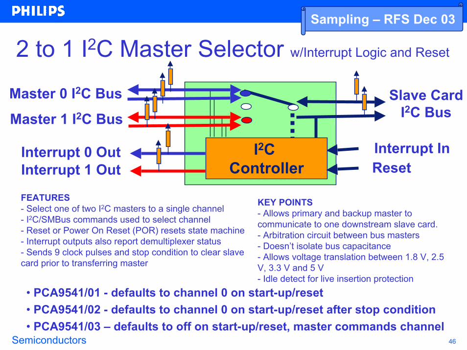
2 to 1 I2C Master Selector w/Interrupt Logic and Reset
Slave Card I2C Bus
Interrupt InI2C Controller
Master 0 I2C Bus
Master 1 I2C Bus
Interrupt 0 Out Interrupt InReset
Sampling – RFS Dec 03
Interrupt 1 Out
FEATURES- Select one of two I2C masters to a single channel- I2C/SMBus commands used to select channel- Reset or Power On Reset (POR) resets state machine- Interrupt outputs also report demultiplexer status- Sends 9 clock pulses and stop condition to clear slave card prior to transferring master
KEY POINTS- Allows primary and backup master to communicate to one downstream slave card.- Arbitration circuit between bus masters- Doesn’t isolate bus capacitance- Allows voltage translation between 1.8 V, 2.5 V, 3.3 V and 5 V- Idle detect for live insertion protection
• PCA9541/01 - defaults to channel 0 on start-up/reset• PCA9541/02 - defaults to channel 0 on start-up/reset after stop condition• PCA9541/03 – defaults to off on start-up/reset, master commands channel
Semiconductors 47
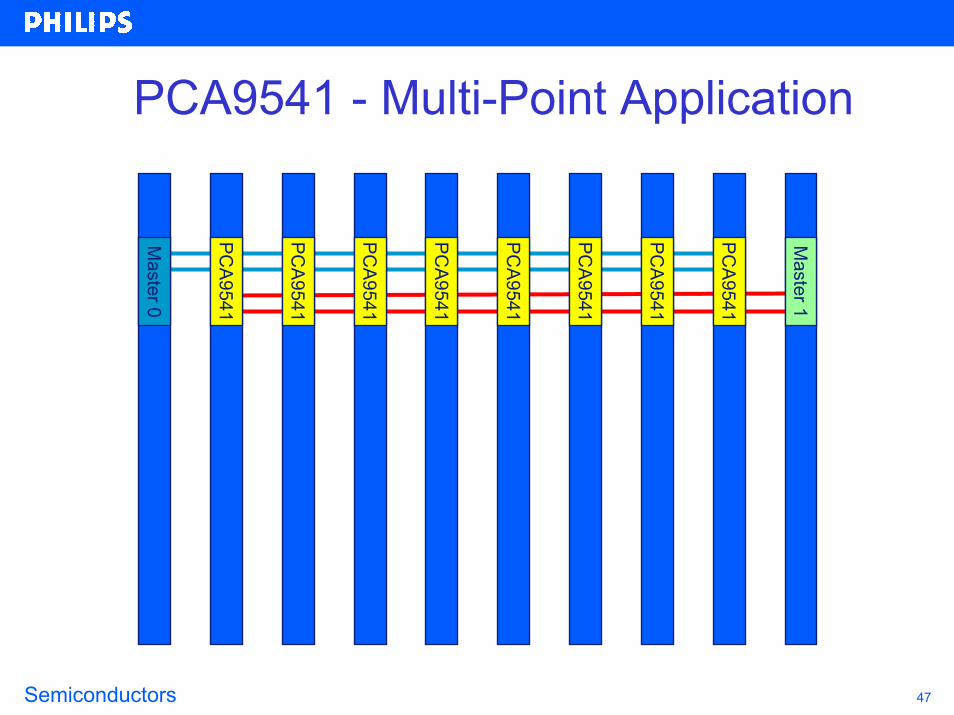
PCA9541 - Multi-Point Application
Master 0
PCA9541
PCA9541
PCA9541
PCA9541
PCA9541
PCA9541
PCA9541
PCA9541
Master 1
Semiconductors 48
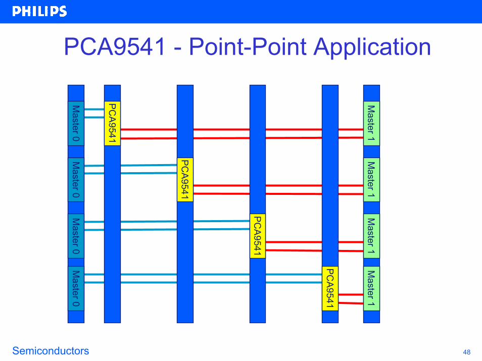
PCA9541 - Point-Point Application
Master 0
Master 1
Master 0
Master 1
Master 0
Master 1
Master 0
Master 1
PCA9541
PCA9541
PCA9541
PCA9541

Semiconductors 49
PCA9541 – Shared Resources
• Some masters may not be multi-master capable or some masters may not play well together and continually lock up the bus.
• The PCA9541 can be used to separate the masters but still allowshared access to slave devices, such as Field Replaceable Unit (FRU) EEPROMs or temperature sensors.
Main Master
PCA9541
Slave A0
Master AAssembly A
Slave A1 Slave A2
SDA/SCL
PCA9541
Slave B0
Master BAssembly B
Slave B1 Slave B2
SDA/SCL
Semiconductors 50
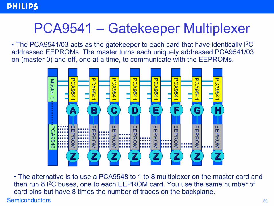
PCA9541 – Gatekeeper Multiplexer• The PCA9541/03 acts as the gatekeeper to each card that have identically I2C addressed EEPROMs. The master turns each uniquely addressed PCA9541/03 on (master 0) and off, one at a time, to communicate with the EEPROMs.
Master 0
PCA9541
PCA9541
EEPRO
M
EEPRO
M
EEPRO
M
EEPRO
M
EEPRO
M
EEPRO
M
EEPRO
M
EEPRO
M
ZZ ZZ ZZ ZZ ZZ ZZ ZZ ZZ
PCA9548
AA BB CC DD EE FF GG HH
PCA9541
PCA9541
PCA9541
PCA9541
PCA9541
PCA9541
• The alternative is to use a PCA9548 to 1 to 8 multiplexer on the master card and then run 8 I2C buses, one to each EEPROM card. You use the same number of card pins but have 8 times the number of traces on the backplane.
Semiconductors 51
PCA9541 – Bus Recovery
PCA
9541/03
Slave
SlavePCA
9541/03
SDA
SCL
Slave
ResetReset
MASTER Slave I2C Bus
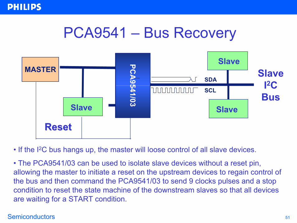
• If the I2C bus hangs up, the master will loose control of all slave devices.
• The PCA9541/03 can be used to isolate slave devices without a reset pin, allowing the master to initiate a reset on the upstream devices to regain control of the bus and then command the PCA9541/03 to send 9 clocks pulses and a stop condition to reset the state machine of the downstream slaves so that all devices are waiting for a START condition.

Semiconductors 52
I2C Multiplexers and Switches
Semiconductors 53
I2C Bus Bi-Directional Voltage Level Translation5 V
GND
SREF
GREF
DREF
S1
S2 D2
D1
GTL2002
Chipset I/OCPU I/O
1.8 V1.5 V1.2 V1.0 V
VCORE VCC
200 KΩ
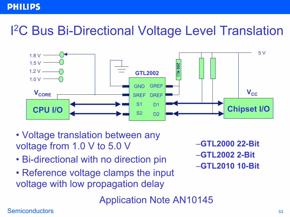
• Voltage translation between any voltage from 1.0 V to 5.0 V • Bi-directional with no direction pin • Reference voltage clamps the input voltage with low propagation delay
–GTL2000 22-Bit–GTL2002 2-Bit–GTL2010 10-Bit
Application Note AN10145
Semiconductors 54
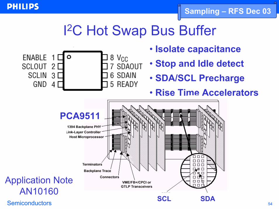
• Isolate capacitance• Stop and Idle detect• SDA/SCL Precharge• Rise Time Accelerators
SCL SDA
PCA9511
Application Note AN10160
I2C Hot Swap Bus BufferSampling – RFS Dec 03

Semiconductors 55
I2C Hot Swap Bus BufferSampling – RFS Dec 03
Feature PCA9511 PCA9513 PCA9514 PCA9512
Alternate source to Linear Tech LTC4300-1ISM8 Yes Similar Similar -
Alternate source to Linear Tech LTC4300-2ISM8 - - - Yes
Idle Detect Yes Yes Yes Yes
High Impedance SDA, SCL pins for Vcc = 0V Yes Yes Yes Yes
Rise Time Accelerator Circuitry on all SDA and SCL lines Yes Yes Yes Yes
Rise Time Accelerator Circuitry Hardware Enable Pin - - - Yes
Rise Time Accelerator threshold 0.8 V vs 0.6 V improves noise margin - Yes Yes -
Separate Vccs to support 5 V to 3.3 V level translation - - - Yes
1V Precharge on all SDA and SCL Lines Yes No No Yes
92 uA Current Source on SCLIN and SDAIN for PICMG applications - Yes - -
Improve acknowledge and clock stretching behavior Yes Yes Yes Yes
Low Icc chip disable < 1 uA Yes Yes Yes No
Ready Open Drain Output Yes Yes Yes No
Semiconductors 56
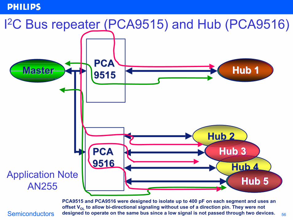
I2C Bus repeater (PCA9515) and Hub (PCA9516)
MasterMaster Hub 1Hub 1PCAPCA95159515
Hub 2Hub 2Hub 3Hub 3
Hub 4Hub 4Hub 5Hub 5
PCAPCA95169516
Hub 1Hub 1MasterMaster
Hub 5Hub 5Hub 5Hub 5
Hub 3Hub 3
Hub 1Hub 1
Application Note AN255
PCA9515 and PCA9516 were designed to isolate up to 400 pF on each segment and uses an offset VOL to allow bi-directional signaling without use of a direction pin. They were not designed to operate on the same bus since a low signal is not passed through two devices.

Semiconductors 57
PCA9518 ApplicationsHub 4Hub 4
Hub 3Hub 3
Hub 2Hub 2
Hub 1Hub 1
PCAPCA95189518
MasterMaster II22CC
Hub 8Hub 8
Hub 7Hub 7
Hub 6Hub 6
Hub 5Hub 5
PCAPCA95189518
Inter Device IInter Device I22C busC busMasterMaster
Hub 12Hub 12
Hub 11Hub 11
Hub 10Hub 10
Hub 9Hub 9
PCAPCA95189518 Hub 15Hub 15
Hub 14Hub 14
Hub 13Hub 13
PCAPCA95189518
Non used Hub
The PCA9518 was design to allow expansion to an unlimited number of segments of 400 pF each.
Hub 13Hub 13Hub 9Hub 9
Hub 5Hub 5

Semiconductors 58
I2C Bus Extenders
Dual Bi-Directional Bus Buffer
P82B96
I2C Bus Extender
P82B715
KEY POINTS• High drive outputs are used to extend the reach of the I2C bus and exceed the 400 pF/system limit.• Possible distances range from 50 meters at 85kHz to 1km at 31kHz over twisted-pair phone cable.• P82B96 has split high drive outputs allowing differential transmission or Opto-isolation of the I2C Bus.• See Application Note AN255 for more details.

Semiconductors 59
Driving I2C bus signals long distancesBase Enclosure Remote Control Enclosure
P82B96
12V
SDA
SCL12V
Long cables3.3 -5V
3.3-5V
12V
P82B96
• Normal I2C logic levels (3.3 or 5 V)
• I2C currents (3mA)
• Conventional CMOS logic levels (2-15V)
• Higher current option, up to 30mA static sink
• Normal I2C logic levels (3.3 or 5 V)
• I2C currents (3mA)

Semiconductors 60
12V
SDA
SCL12V
P82B96
12V3.3/5V
3.3/5
P82B96 P82B96 P82B96 P82B96
SDA/SCL SDA/SCL SDA/SCL
3.3V
SCLSDA
Changing I2C bus signals for multi-point applications!Twisted-pair telephone wires,
USB or flat ribbon cablesUp to 15V logic levels, Include VCC & GND
NO LIMIT to the number of connected bus devices !
Link parking metersand pay stations
•--•--•--•--•--
•--•--•--•--•--
•--•--•--•--•--
Link vending machinesto save cell phone links
Warehouse pick/packsystems
• Factory automation
• Access/alarm systems
• Video, LCD & LED display signs
• Hotel/motel management systems
• Monitor emergency lighting/exit signs
Semiconductors 61
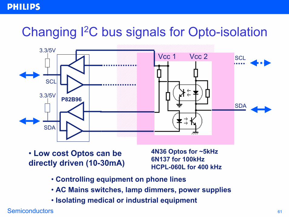
Changing I2C bus signals for Opto-isolation
SDA
Vcc 1 Vcc 2 SCL
SDA
P82B96
SCL
3.3/5V
3.3/5V
4N36 Optos for ~5kHz6N137 for 100kHz HCPL-060L for 400 kHz
• Low cost Optos can be directly driven (10-30mA)
• Controlling equipment on phone lines • AC Mains switches, lamp dimmers, power supplies• Isolating medical or industrial equipment

Semiconductors 62
Parallel Bus to I2C Bus Controller
Mic
roco
ntro
ller
Operation Control
ControlBus Buffer
I 2C Interface
Chip EnableWrite StrobeRead StrobeResetAddress Inputs Interrupt RequestData (8-bits)
I2C Bus
FEATURES-Provides both master and slave functions.-Controls all the I2C bus specific sequences, protocol, arbitration and timing -Internal oscillator (PCA9564 only)-Hardware Reset pin and Power On Reset (POR)
KEY POINTS-Serves as an interface between most standard parallel-bus microcontrollers/ microprocessors and the serial I2C bus.-Allows the parallel bus system to communicate with the I2C bus
Voltage range Max I2C freq Clock source Parallel interfacePCF8584 4.5 - 5.5V 90 kHz External 3 MHz - SlowPCA9564 2.3 - 3.6V w/5V tolerance 320 kHz Internal 50 MHz - Fast
Application Note AN10148

Semiconductors 63
Application – Add I2C Bus Port
µcontroller,µprocessor
or ASICPCA9564
Control signals
SDASCL8-bits
• The PCA9564 converts 8-bit parellel data into a multiple master capable I2C port for microcontrollers, microprocessors, custom ASICs, DSPs, etc.., that need to interface with I2C or SMBus components.

Semiconductors 64
Bus Controller vs Bit-bangingHardware I2CDisadvantages: additional costAdvantages: frees up the micro to perform other tasks, multi-master capability, glitch filters, bus error detection and recovery, can easily be added to most microcontrollers, simple code (code for a hardware I2C is relatively simple to write (to write a byte, just load the I2CDAT register with a byte and the hardware does the rest) but you may need to take into consideration all the different error conditions (such as lost arbitration, etc))
Bit-bangingDisadvantages: ties up the micro during the transmission and very difficult to use in a multi-master environmentAdvantages: inexpensive, can be incorporated into any micro and very little code required (code required for bit-banging an 80C51 micro is only about 50 bytes)

Semiconductors 65
Application – Add additional I2C Bus PortsSDASCLµcontroller,
µprocessor or ASIC PCA9564
SDASCL
• The PCA9564 can be used to convert 8-bit parallel data into additional multiple master capable I2C port for microcontrollers, microprocessors, custom ASICs, DSPs, etc.., that already have an I2C port but need one or more additional I2C ports to interface with more I2C or SMBus components or components that can’t be located on the same bus (e.g., 100 kHz and 400 kHz slaves).
Control signals
8-bits

Semiconductors 66
Application – Lower Voltage & Higher Frequency Migration Path for PCF8584
PCF8584SDASCL
PCA9564SDASCL
Voltage Frequency
2.3 – 3.6 V < 400 kHz
4.5 – 5.5 V < 100 kHz
Oscillator
Clock input
• The PCA9564 does the same type of parallel to serial conversion as the PCF8584. Although not footprint compatible, the PCA9564 provides improvements such as:
• Operating at 3.3 V and 2.5 V voltage nodes
• Allows interface with I2C or SMBus components at speeds up to 400 kHz.
• The built-in oscillator provides a cost effective solution since the external clock input is no longer required.
• Parallel data can be exchanged at speeds up to 50 MHz allowing the use of faster processors. The PCA9564 is optimized for the Intel 8051 architecture.

Semiconductors 67
Application – Convert 8 bits of parallel data into I2C serial data stream
µprocessor PCA9564SDAControl signals
Master8-bits SCL
• Functioning as a slave transmitter, the PCA9564 can convert 8-bit parallel data into a two wire I2C data stream. This prevents having to run 8 traces across the entire width of the PC board.

Semiconductors 68
Analog to Digital Converter
+-
+-
+-
FEATURES-4 channel A to D-1 channel D to A-Internal oscillator-Power On Reset (POR)
KEY POINTS-Converts signals from digital to analog and analog to digital
+-
+-
Data registers
Sub address decoder
I2C-bus interface
Oscillator, intern / extern
Analog reference
POR
+-
Supply
SDA
Voltage range Max I2C freq ResolutionPCF8591 2.5 - 5.5V w/5V tolerance 100 kHz 8-bit
SCL
Semiconductors 69
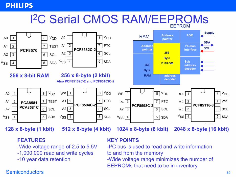
I2C Serial CMOS RAM/EEPROMs
256 x 8-byte (2 kbit)Also PCF85102C-2 and PCF85103C-2
256 x 8-bit RAM
Sub address decoder256
Byte
RAMSub address decoder
POR
I2C-bus interface
Address pointer
Supply
SDA
SCL
EEPROM
RAM
256
Byte
E2PROM Sub address decoder
POR
I2C-bus interface
Address pointer
1024 x 8-byte (8 kbit)512 x 8-byte (4 kbit)128 x 8-byte (1 kbit) 2048 x 8-byte (16 kbit)
FEATURES-Wide voltage range of 2.5 to 5.5V-1,000,000 read and write cycles-10 year data retention
KEY POINTS-I²C bus is used to read and write information to and from the memory-Wide voltage range minimizes the number of EEPROMs that need to be in inventory
Semiconductors 70
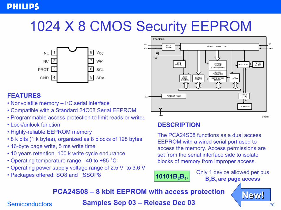
1024 X 8 CMOS Security EEPROM
FEATURES• Nonvolatile memory – I2C serial interface• Compatible with a Standard 24C08 Serial EEPROM• Programmable access protection to limit reads or writes• Lock/unlock function• Highly-reliable EEPROM memory• 8 k bits (1 k bytes), organized as 8 blocks of 128 bytes• 16-byte page write, 5 ms write time• 10 years retention, 100 k write cycle endurance• Operating temperature range - 40 to +85 °C• Operating power supply voltage range of 2.5 V to 3.6 V• Packages offered: SO8 and TSSOP8
DESCRIPTIONThe PCA24S08 functions as a dual access EEPROM with a wired serial port used to access the memory. Access permissions are set from the serial interface side to isolate blocks of memory from improper access.
Only 1 device allowed per busB2B1 are page access10101B2B1.
PCA24S08 – 8 kbit EEPROM with access protection Samples Sep 03 – Release Dec 03
New!New!
Semiconductors 71
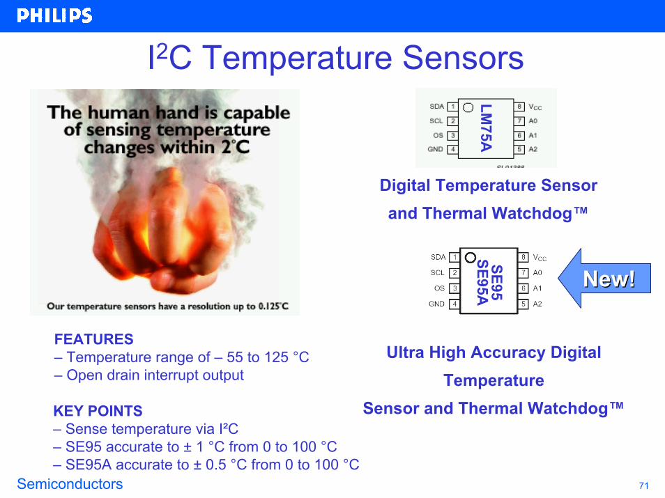
I2C Temperature Sensors
Digital Temperature Sensor and Thermal Watchdog™
LM75A
SE95SE95A New!New!
FEATURES– Temperature range of – 55 to 125 °C– Open drain interrupt output
Ultra High Accuracy Digital Temperature
Sensor and Thermal Watchdog™KEY POINTS– Sense temperature via I²C– SE95 accurate to ± 1 °C from 0 to 100 °C– SE95A accurate to ± 0.5 °C from 0 to 100 °C
Semiconductors 72
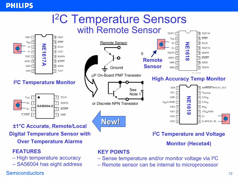
±1°C Accurate, Remote/Local Digital Temperature Sensor with
Over Temperature Alarms
FEATURES– High temperature accuracy– SA56004 has eight address
KEY POINTS– Sense temperature and/or monitor voltage via I²C– Remote sensor can be internal to microprocessor
I2C Temperature and Voltage
Monitor (Heceta4)
NE1617A
NE1618
NE1619
I2C Temperature Monitor High Accuracy Temp Monitor
Remote Sensor
I2C Temperature Sensorswith Remote Sensor
New!New!
Semiconductors 73
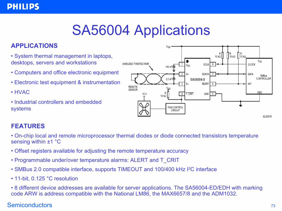
SA56004 ApplicationsAPPLICATIONS• System thermal management in laptops, desktops, servers and workstations
• Computers and office electronic equipment
• Electronic test equipment & instrumentation
• HVAC
• Industrial controllers and embedded systems
FEATURES• On-chip local and remote microprocessor thermal diodes or diode connected transistors temperature sensing within ±1 °C• Offset registers available for adjusting the remote temperature accuracy• Programmable under/over temperature alarms: ALERT and T_CRIT• SMBus 2.0 compatible interface, supports TIMEOUT and 100/400 kHz I2C interface• 11-bit, 0.125 °C resolution• 8 different device addresses are available for server applications. The SA56004-ED/EDH with marking code ARW is address compatible with the National LM86, the MAX6657/8 and the ADM1032.

Semiconductors 74
I2C Microcontroller
P87C55x 100 kHz I2CP87C6xxX2 400 kHz I2CP87LPC76x 100 kHz I2CP89C66x 100 kHz I2CP89LPC932 400 kHz I2C
The µcontroller provides the brains behind the I2C bus
operation and most feature at least one I2C port.
AnalogComparators
Power Management, RTC, WDT,power-on-reset, brownout detect
Enh.UART
Ports0, 1, 2, 3
+ −+ −
Keypad/Pattern Match
Interrupt
Internal ±2.5%7.3728 MHz
RC Oscillator
600% Accelerated C51 Core
16-bit PWM CCU
32xP
LL
I2C SPI
Timer0/1
16-bit
8K ISPIAP
Flash
512BData
EEPROM
768BSRAM

Semiconductors 75
I2C Microcontroller
In December we've released a new P87C654X2 and with this family we also released our first microcontroller (P87C661) with two separate byte oriented I2C interfaces.
The two I2C blocks are useful for applications:• Which need to support different transmission rates (e.g. 400 kHz and 100 kHz)• With high amount of I2C devices that physically can't be addressed all on one bus due to address conflicts• Require gateway/re-route capability
Semiconductors 76
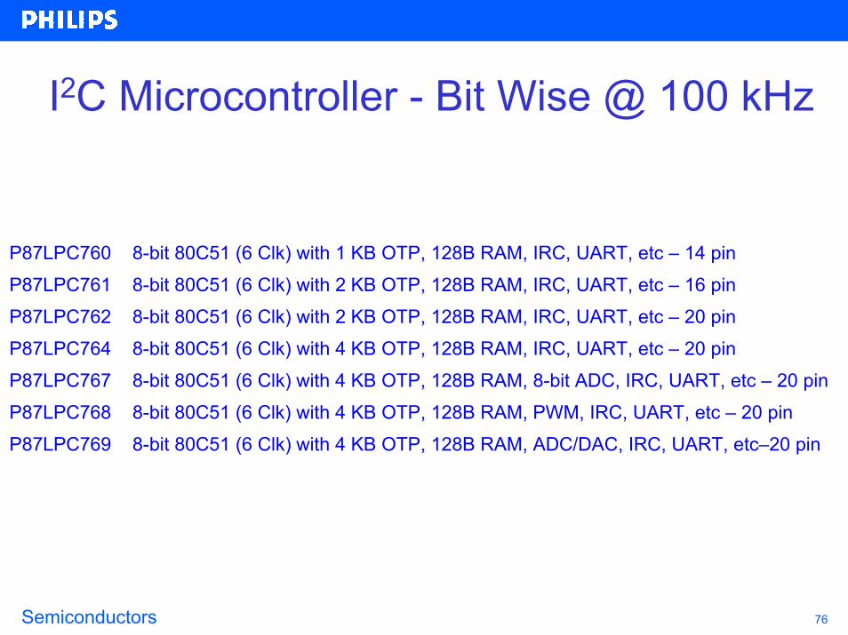
I2C Microcontroller - Bit Wise @ 100 kHz
P87LPC760 8-bit 80C51 (6 Clk) with 1 KB OTP, 128B RAM, IRC, UART, etc – 14 pinP87LPC761 8-bit 80C51 (6 Clk) with 2 KB OTP, 128B RAM, IRC, UART, etc – 16 pinP87LPC762 8-bit 80C51 (6 Clk) with 2 KB OTP, 128B RAM, IRC, UART, etc – 20 pinP87LPC764 8-bit 80C51 (6 Clk) with 4 KB OTP, 128B RAM, IRC, UART, etc – 20 pinP87LPC767 8-bit 80C51 (6 Clk) with 4 KB OTP, 128B RAM, 8-bit ADC, IRC, UART, etc – 20 pinP87LPC768 8-bit 80C51 (6 Clk) with 4 KB OTP, 128B RAM, PWM, IRC, UART, etc – 20 pinP87LPC769 8-bit 80C51 (6 Clk) with 4 KB OTP, 128B RAM, ADC/DAC, IRC, UART, etc–20 pin

Semiconductors 77
I2C Microcontroller - Byte Wise @ 100 kHz
P80C552 8-bit 80C51 ROMless with 256B RAM, 10-bit ADC, PWM, UART, etc – 68 pinP80C554 8-bit 80C51 ROMless with 512B RAM, 10-bit ADC, PWM, UART, etc – 64 pinP87C552 8-bit 80C51 with 8 KB OTP, 256B RAM, 10-bit ADC, PWM, UART, etc – 68 pinP87C554 8-bit 80C51 with 16 KB OTP, 512B RAM, 10-bit ADC, PWM, UART, etc – 64/68 pinP87C654X2 8-bit 80C51 (6 Clk) with 16 KB OTP, 256B RAM, UART, etc – 44 pinP80C557E4 8-bit 80C51 ROMless with 1KB RAM, 10-bit ADC, UART, low EMI, etc – 80 pinP87C557E8 8-bit 80C51 with 64 KB OTP, 2 KB RAM, 10-bit ADC, UART, low EMI etc – 80 pinP87C591 8-bit 80C51 with 16 KB OTP, 512B RAM, 10-bit ADC, CAN2.0B, UART, etc – 44 pinP89C660 8-bit 80C51 (6 Clk) with 16 KB Flash, 512B RAM, PCA, PWM, UART, etc – 44 pinP89C662 8-bit 80C51 (6 Clk) with 32 KB Flash, 1 KB RAM, PCA, PWM, UART, etc – 44 pinP89C664 8-bit 80C51 (6 Clk) with 64 KB Flash, 2 KB RAM, PCA, PWM, UART, etc – 44 pinP89C668 8-bit 80C51 (6 Clk) with 64 KB Flash, 8 KB RAM, PCA, PWM, UART, etc – 44 pinP89C669 8-bit 80C51 (6 Clk) with 96 KB Flash, 3 KB RAM, PCA, PWM, 2 UARTs, etc – 44 pin
Semiconductors 78
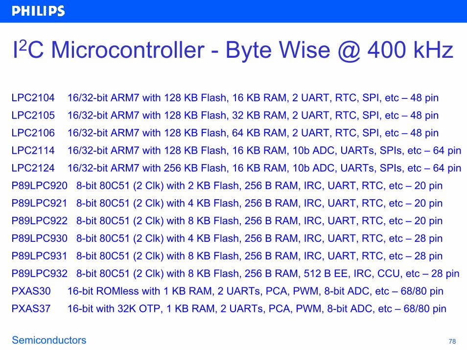
I2C Microcontroller - Byte Wise @ 400 kHz
LPC2104 16/32-bit ARM7 with 128 KB Flash, 16 KB RAM, 2 UART, RTC, SPI, etc – 48 pinLPC2105 16/32-bit ARM7 with 128 KB Flash, 32 KB RAM, 2 UART, RTC, SPI, etc – 48 pinLPC2106 16/32-bit ARM7 with 128 KB Flash, 64 KB RAM, 2 UART, RTC, SPI, etc – 48 pinLPC2114 16/32-bit ARM7 with 128 KB Flash, 16 KB RAM, 10b ADC, UARTs, SPIs, etc – 64 pinLPC2124 16/32-bit ARM7 with 256 KB Flash, 16 KB RAM, 10b ADC, UARTs, SPIs, etc – 64 pinP89LPC920 8-bit 80C51 (2 Clk) with 2 KB Flash, 256 B RAM, IRC, UART, RTC, etc – 20 pinP89LPC921 8-bit 80C51 (2 Clk) with 4 KB Flash, 256 B RAM, IRC, UART, RTC, etc – 20 pinP89LPC922 8-bit 80C51 (2 Clk) with 8 KB Flash, 256 B RAM, IRC, UART, RTC, etc – 20 pinP89LPC930 8-bit 80C51 (2 Clk) with 4 KB Flash, 256 B RAM, IRC, UART, RTC, etc – 28 pinP89LPC931 8-bit 80C51 (2 Clk) with 8 KB Flash, 256 B RAM, IRC, UART, RTC, etc – 28 pinP89LPC932 8-bit 80C51 (2 Clk) with 8 KB Flash, 256 B RAM, 512 B EE, IRC, CCU, etc – 28 pinPXAS30 16-bit ROMless with 1 KB RAM, 2 UARTs, PCA, PWM, 8-bit ADC, etc – 68/80 pinPXAS37 16-bit with 32K OTP, 1 KB RAM, 2 UARTs, PCA, PWM, 8-bit ADC, etc – 68/80 pin

Semiconductors 79
I2C Signal ConversionThese microcontrollers have I2C and UART (RS-232) ports to allow conversion• P87C6xxx2 family (661 has two byte oriented I2C interfaces)• P87C55x • P87LPC76x family• P89C66x• P89LPC932 and future LPC9xx products
These microcontrollers have I2C and SPI ports to allow conversion • XA• 87C51MX (future product)• 89LPC9xx (future product)
These microcontrollers and USB devices allow a two device conversion between I2C and USB• PDIUSBD12 + P89C66x -> 100 kHz I2C and USB1.1• ISP1181 + P89C66x -> 100 kHz I2C and USB1.1• ISP1581 + P89LPC932 -> 400 kHz I2C and USB2.0
These ucontrollers have I2C and CAN ports to allow conversion • P87C591 - 8 bit solution• PXA-C37 - 16 bit solution
Products from > www.semiconductors.philips.com/microcontrollersSupport > www.PhilipsMCU.com/products/standard/microcontrollers/support/feedback/

Semiconductors 80
I2C Bus Basics - Typical Bus Arrangement
EEPROM
GPI
O
GPI
O
Keyboard
Microprocessor
100 kHz and 400 kHz
C++
InterruptReset3.3 V
LED
Blin
ker

Semiconductors 81
I2C Bus Basics - Complex Bus ArrangementC
Microprocessor
100 kHzEEPROMMultiplexer
Outputs
Hardw
are Inputs
Voltage Regulator ModuleMicroprocessor
100 kHz and 400 kHz
C++
InterruptReset3.3 V 5 V
Reset
Bus Controller
Repeater
Disable
EEPROM
GPI
O
GPI
O
Keyboard
Switch
LED Blinker
Temp Sensor
1
Temp Sensor
Temp Sensor
2
Temp Sensor
3
5 V
3.3 V
2.5 V
1.8 V
4
Semiconductors 82
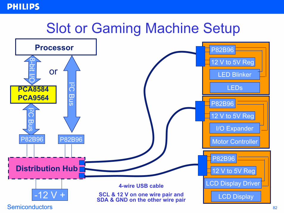
Slot or Gaming Machine SetupProcessor
I 2
8-b/O
I 2
-12 V +LCD Display Driver
P82B96
12 V to 5V Reg
LCD Display
I/O Expander
P82B96
12 V to 5V Reg
Motor Controller
LED Blinker
P82B96
12 V to 5V Reg
LEDs
or
it I
PCA8584PCA9564
C Bus
C Bus
P82B96 P82B96
Distribution Hub
4-wire USB cableSCL & 12 V on one wire pair and
SDA & GND on the other wire pair
Semiconductors 83
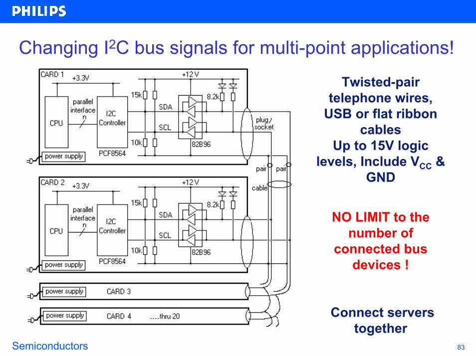
Changing I2C bus signals for multi-point applications!
Twisted-pair telephone wires,
USB or flat ribbon cables
Up to 15V logic levels, Include VCC &
GND
NO LIMIT to the number of
connected bus devices !
Connect servers together

Semiconductors 84
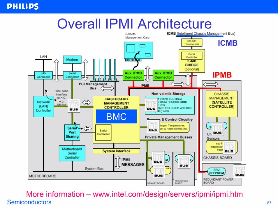
Intelligent Platform Management Interface• IPMI is new Intel initiative in conjunction with hp, NEC and Dell • Consists of three specifications:
– Intelligent Platform Management Interface (IPMI) for software extensions– Intelligent Platform Management Bus (IPMB) for intra-chassis (in side the box) extensions– Inter Chassis Management Bus (ICMB) for inter-chassis (outside of the box) extensions
• Needed since as the complexity of systems increase, MTBF decreases • Defines a standardized, abstracted, message-based interface to intelligent platform management hardware.• Defines standardized records for describing platform managementdevices and their characteristics.• Provides a self monitoring capability increasing reliability of the systems
Semiconductors 85
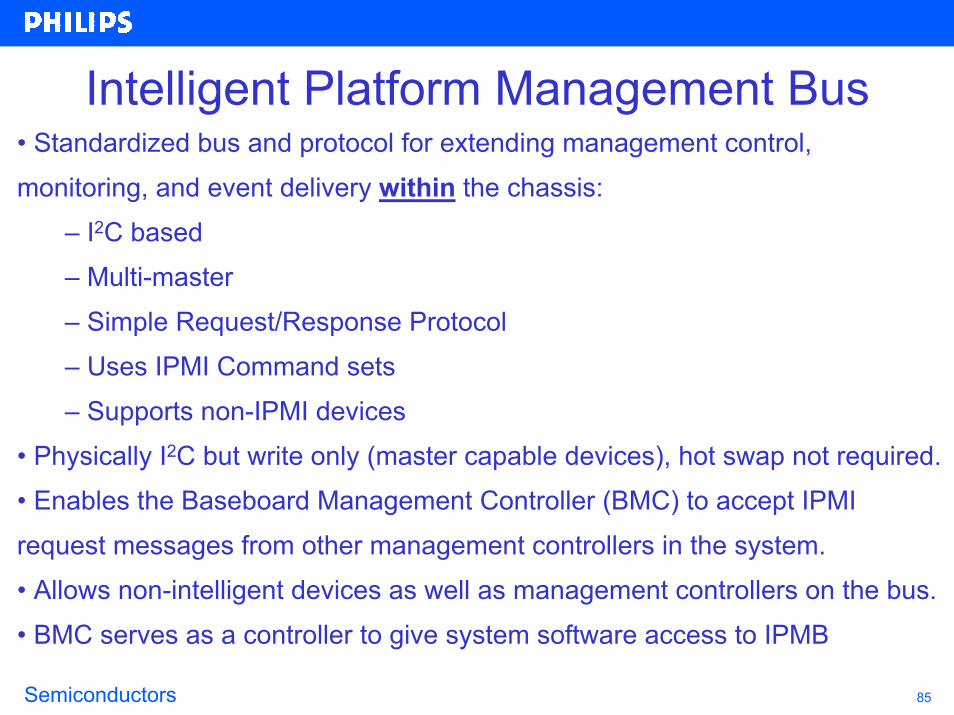
Intelligent Platform Management Bus• Standardized bus and protocol for extending management control,monitoring, and event delivery within the chassis:
– I2C based– Multi-master– Simple Request/Response Protocol– Uses IPMI Command sets– Supports non-IPMI devices
• Physically I2C but write only (master capable devices), hot swap not required.• Enables the Baseboard Management Controller (BMC) to accept IPMI request messages from other management controllers in the system.• Allows non-intelligent devices as well as management controllers on the bus.• BMC serves as a controller to give system software access to IPMB

Semiconductors 86
IPMI Details• Defines a standardized interface to intelligent platform managementhardware
– Prediction and early monitoring of hardware failures– Diagnosis of hardware problems– Automatic recovery and restoration measures after failure– Permanent availability management– Facilitate management and recovery – Autonomous Management Functions: Monitoring, Event
Logging, Platform Inventory, Remote Recovery– Implemented using Autonomous Management Hardware:
designed for Microcontrollers based implementations • Hardware implementation is isolated from software implementation• New sensors and events can then be added without any software changes
Semiconductors 87
BMC
Overall IPMI ArchitectureICMB
IPMB
More information – www.intel.com/design/servers/ipmi/ipmi.htm
Semiconductors 88
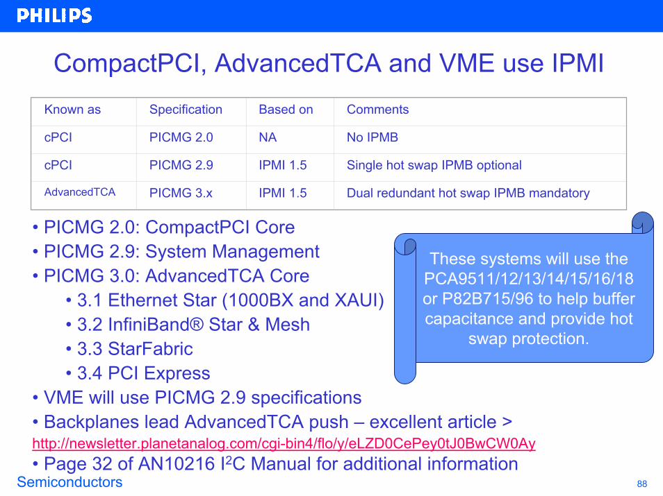
CompactPCI, AdvancedTCA and VME use IPMIKnown as Specification Based on Comments
cPCI PICMG 2.0 NA No IPMB
cPCI PICMG 2.9 IPMI 1.5 Single hot swap IPMB optional
AdvancedTCA PICMG 3.x IPMI 1.5 Dual redundant hot swap IPMB mandatory
• PICMG 2.0: CompactPCI Core • PICMG 2.9: System Management • PICMG 3.0: AdvancedTCA Core
• 3.1 Ethernet Star (1000BX and XAUI)• 3.2 InfiniBand® Star & Mesh• 3.3 StarFabric• 3.4 PCI Express
• VME will use PICMG 2.9 specifications• Backplanes lead AdvancedTCA push – excellent article > http://newsletter.planetanalog.com/cgi-bin4/flo/y/eLZD0CePey0tJ0BwCW0Ay• Page 32 of AN10216 I2C Manual for additional information
These systems will use the PCA9511/12/13/14/15/16/18 or P82B715/96 to help buffer capacitance and provide hot
swap protection.
Semiconductors 89
Agenda
• What is I2C and why would you be interested in using the I2C bus?
• What new I2C devices are there and what are the typical applications?
• How are we going to help you design-in these devices?

Semiconductors 90
I2C 2002-1A Evaluation Board Kit
FEATURES- Converts Personal Computer parallel port to I2C bus master- Simple to use graphical interface for I2C commands- Win-I2CNT software compatible with Windows 95, 98, ME, NT, XP and 2000- Order kits at www.demoboard.com
Provide easy to use, PC based system to play
with the I2C devices and learn how they operate.
Semiconductors 91
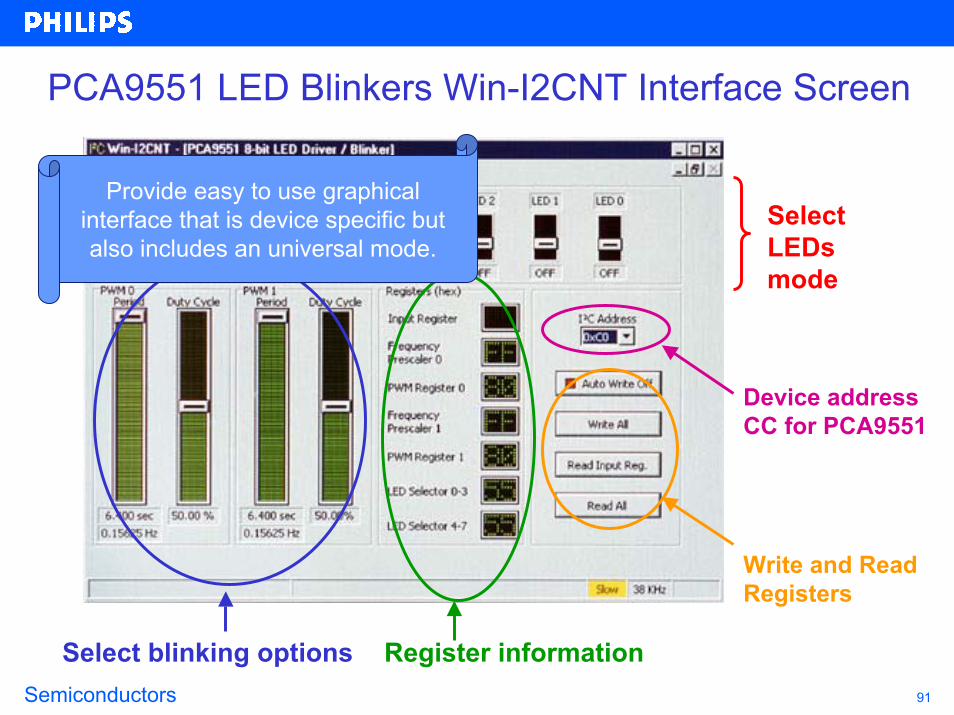
PCA9551 LED Blinkers Win-I2CNT Interface Screen
Select LEDs mode
Device addressCC for PCA9551
Select blinking options Register information
Write and Read Registers
Provide easy to use graphical interface that is device specific but also includes an universal mode.

Semiconductors 92
I2C Product Flyers and Selection Guides2003 I2C Selection Guide Order Number: 9397 750 10591
2003 CBT Selection Guide Order Number: 9397 750 10336
LM75A Order Number: None
NE1617A/18/19 Order Number: 9397 750 07609
PCA8550 Order Number: 9397 750 04323
PCA9500/01 Order Number: 9397 750 09897
PCA9504A Order Number: 9397 750 08562
PCA9515/16 Order Number: 9397 750 08205
PCA9540/42/44 Order Number: 9397 750 06542
PCA954X Order Number: 9397 750 09222
PCA9550/51/52 Order Number: 9397 750 09208
PCA9554/54A/55 Order Number: 9397 750 08924
PCA9556 Order Number: 9397 750 06812
PCA9558 Order Number: 9397 750 08211
PCA9559 Order Number: 9397 750 06813
PCA9560/61 Order Number: 9397 750 09206
PCF EEPROM Order Number: 9397 750 09209
P82B96 Order Number: 9397 750 09084
Provide overview of all the devices to make selection
easier.
Download from > www.philipslogic.com/products/collateral

Semiconductors 93
Technical Support InformationApplication Notes
AN250 PCA8550 4-Bit Multiplexed/1-Bit Latched 5-Bit I2C E2PROMAN255 I2C and SMBus Hubs, Buffers, and RepeatersAN444 P82B715 I2C Bus BufferAN460 Introducing the P82B96 I2C Bus BufferAN262 PCA954X Multiplexers and SwitchesAN264 I2C Devices for LED Display ControlAN469 I2C I/O Port SelectionAN10145 Bi-Directional Voltage TranslatorsAN10146 I2C 2002-1A Evaluation BoardAN10148 I2C Bus Controller ** (July)AN10149 PCA9564 Evaluation Board ** (Sep)AN10160 I2C Hot Swap Bus Buffers (preliminary)AN10216 I2C Manual
Download from > www.philipslogic.com/support/appnotes/
Provide in-depth technical support to make it easier to design in the
device.

Semiconductors 94
I2C Sample Kit
Devices include three each of the GTL2010PW, P82B96TD, PCA9551D, PCA9545D, PCA9555D, PCA9557D,
PCA9515D and PCA9501D
Provide small quantity of free samples to make it easy to assemble and test
your system.
The I2C Sample Kit consists of eight different I2C devices in tape inserted into the I2C Sample Kit box
with an informative insert.
Request I2C Sample Kit or individual samples from your Philips Sales Representative or directly from I2C.Support at philips.com

Semiconductors 95
I2C Device Data Sheets, IBIS models Application Notes and Other Information
Product familydescriptionsline cardscross referencedata sheets
www.philipslogic.com/i2c or www.philipslogic.com/i2c or www.semiconductors.philips.com/i2cwww.semiconductors.philips.com/i2c
Provide easy to access to all the up to
date data sheets, application notes and
modeling tools.Link toapp notesmodelsuser guidesPLL designsoftwaredatasheets

EndPhilips Semiconductors


![Price – Rs.10/- M©L rªjh - %.130/ nghwpahshaoeaeatnpwd.org/PDF/Magazine/2018/Bulletin-August2018.pdf · 2018-08-29 · 1 Mf]l; 2018 nghwpahsh; Annual Subscription – Rs.130/-M©L](https://img.pdfslide.us/doc/110x75/5f9e98386e8bbb3daf426380/price-a-rs10-ml-rjh-130-2018-08-29-1-mfl-2018-nghwpahsh-annual.jpg)


![L & m overview rs mehta [compatibility mode]](https://img.pdfslide.us/doc/110x75/5458605db1af9fcf338b5427/l-m-overview-rs-mehta-compatibility-mode.jpg)