Embed Size (px)
Citation preview
I . - v DESIGN DEVELOPMENT OF THE APOLLO LUNAR MODULE*
By Kenneth J. Cox Manned Spacecraft Center
ABSTRACT P
The lunar module autopilot is a first-generation digital control system design. The two torque sources available fo,r the control function of the descent-staqe configuration consist of 16 reaction jets and a slow, gimbaled, throttlable engine. This case study includes a review of the design history, the design requirements, criteria, constraints, and general design philosophy of the control system development. Comparative flight-test results derived from design testing are presented,
INTRODUCTION
In the fall of 1964, a significant Apollo program decision was made; that is, to develop a digital autopilot (DAP) for all spacecraft primary control systems. It is noteworthy that pre- vious manned spacecraft designs (Mercury, Gemini) involved analog control system techniques; thus, the Apollo DAP represents a first-generation design development, This paper contains a case study of the design history of the lunar module (LM) primary control system. The LM DAP, with respect to design requirements and constraints, is considered to be the most complex Apollo con- trol system in use. Hence, significant original design concepts were necessarily required in the development process.
The general purpose and motivation of this paper are to provide some insight into the problems encountered by the control system designer. In many ways, the so-called "gap" between con- trol system theory and practice is the result of a lack of appreciation of the severe/time and cost constraints under which the control system designer is required to produce his product-
Reading this paper, one may wonder why *he total development has continued during a period of approximately 4 years; he may ask why the DAP should not be designed once and be finished. Most projects of this magnitude are iterative, because the requirements sometimes change radically, because the initial design constraints are generally poorly defined, because the
*Paper first given and printed in Workshop Preprints I969 Case Studies in System Control, University of Colorado, August 4 , 1969, sponsored by the IEEE Group on Automatic Control (copyright 1969 IEEE, Report No. 69C41-AC).
-1-
https://ntrs.nasa.gov/search.jsp?R=19780015068 2018-07-26T21:35:25+00:00Z

inherent characteristics of the spacecraft plant are not well known, and because the basic input data for control system design are frequently not available in a timely manner. It is important to realize that major design decisions must be made, rightly or wrongly, despite the lack of fundamental input infor- mation. Because of the basic factors that characteristically make the design task difficult, the designer must adopt an implicit or explicit philosophy of providing some degree of flexibility in the control design, so as to accommodate future contingencies or unexpected developmental problems.
The concept of performance margin will be examined in a later section, but a point to be recognized now is that most papers on control theory emphasize obtaining optimum (or accept- able) performance for nominal situations, whereas in practice, the acceptability of the total design is most often determined by performance under extreme, off-nominal conditions. Generally, establishing explicit mathematical criteria for off-nominal per- formance is extremely difficult; therefore, the subjective judg- ment of the system designer (who uses significant simulation testing programs for design validation) is essential.
A significant problem encountered in designing the DAP was the lack of effective analysis techniques for developing and evaluating the digital control system. The major design tools used were phase-plane simulation techniques in which tradeoffs and design constants were established by "cut-and-try" methods. A more colorful manner of expressing this approach is (I) "the [design] has been chosen on the basis of theoretical investigations and empirical observations."
LIST OF ACRONYMS AND SYMBOLS
ACRONYMS
AP S CDU CM C SM DAP DB DPS GTS ICs IMU LGC LM PIPA
ascent propulsion system coupling data unit command module command and service module digital autopilot deadband descent propulsion system gimbal trim system interpretive computer simulators inertial measurement unit LM guidance computer lunar module pulsed integrating pendulous accelerometer
-2-
P R M pulse-ratio modulation RCS reaction control system SM service module
, TJET time (duration) of jet firing
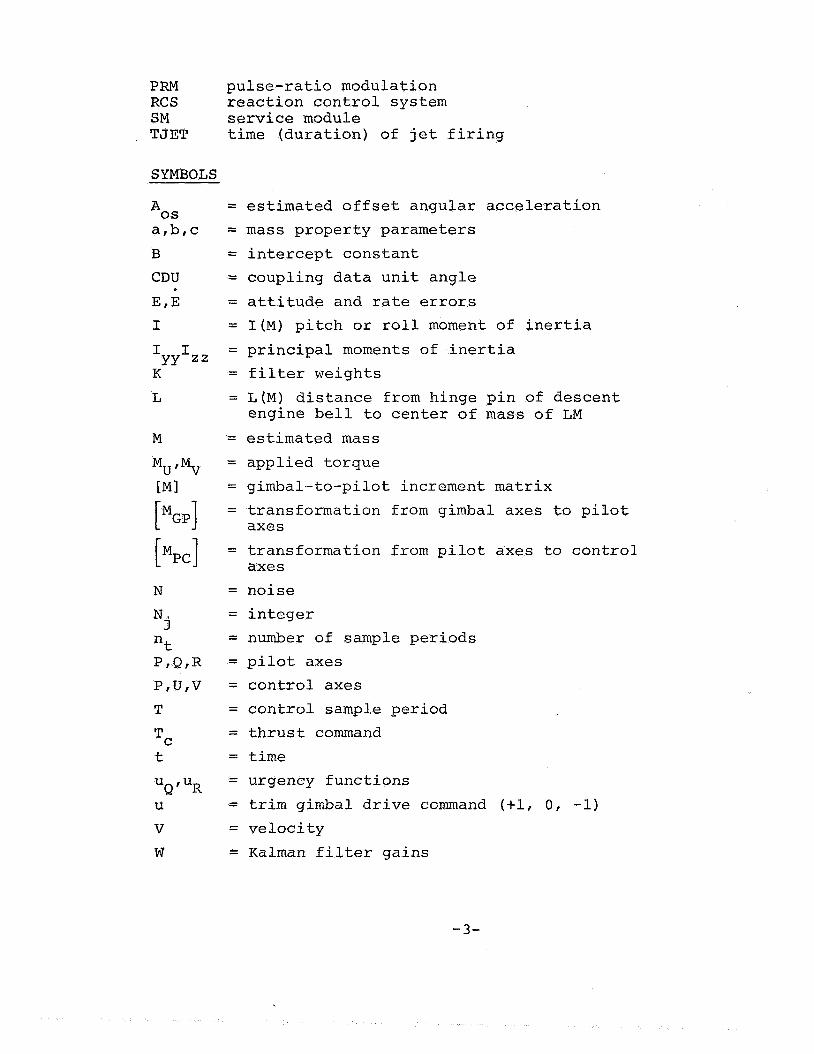
SYMBOLS
= estimated offset angular acceleration = mass property parameters = intercept constant = coupling data unit angle = attitude and rate errors = I ( M ) pitch or roll moment of inertia = principal moments of inertia = filter weights = L ( M ) distance from hinge pin of descent
= estimated mass = applied torque = gimbal-to-pilot increment matrix = transformation from gimbal axes to pilot axes
= transformation from pilot axes to control axes
= noise = integer = number of sample periods = pilot axes = control axes = control sample period = thrust command = time = urgency functions = trim gimbal drive command (+l, 0, -1) = velocity = Kalman filter gains
engine bell to center of mass of LM
-3-

Greek Letters Subscripts
a B Y 0
= angular acceleration C = lag angles cg = transformation angle d
e G I i
descent engine = J
= PRM attitude err M
= gimbal angle, attitude = angular velocity n
0
between U/V and u'/V' axes
= steering'sample period = control sample period = gimbal drive rate of
0.2 deg/sec
Opera tors
= estimate = first time derivative = second time derivative = measured value
h
..
.-"
c = summation
= cycle = center of mass = desired angular velocity = attitude error = gimbaling = inner gimbal angle = index = about an axis from the firing of a single jet
= middle gimbal angle = index = index = outer gimbal angle
D E S I G N CONSIDERATIONS
Vehicle Characteristics
The DAP provides stabilization and control of the both coasting and powered light in three configuratio (Figure l), ascent (Figur 2), and docked with the command and service module (CSM) as shown in Figure 3 . During'the preliminary spacecraft-design phase, many fundamental decisions were made that define (and constrain) the control system design. For the LM, three basic propulsion force and torque systems were estab- lished - reaction control system ( R C S ) , descent propulsion system ( D P S ) , and ascent propulsion system (APS). Characteristics that influenced the control task included the type of actuation system, the geometrical location and number of thrusters or jets (for redundancy), and the type of thrust-variation system.
The control options available to the systems designer are divided into various flight-mode categories (Table I). The RCS
-4-

Inertial measirretnent Ascent
I Desceiit Des ce ii t staye eiiyii ie
Figure 1. The LM descent configuration
RCS thrusters
L-. Ascent engine
Figure 2. The LM ascent configuration
-5-

, Lunar module (LM 1 7
engine
Figure 3 . The CSM-docked configuration of the LM
provides automatic/manual rotation and small translation control for all LM configurations during coasting flight. During coasting flight, the design problem is characterized by the presence of extremely low disturbance torques (except for an RCS jet-on failure).
During APS-powered flight, the primary purpose of the RCS is to provide attitude stabilization and control. However, when- ever feasible, it is a design reqbirement to fire only the upward-thrusting RCS jets to obtain AV in the desired direction. Because the APS is a non-gimbaled, fixed-throttle system, the RCS control laws associated with this mode must accommodate large time-variant disturbance torques.
P
During DPS-powered flight, the design provides yaw control with the RCS jets, and pitch/roll attitude control with a com- bination of the RCS and the gimbal trim system (GTS) . The design
-6-

TABLE I
CHARACTERISTICS OF SPACECRAFT PROPULSION FORCES AND MOMENTS
Propulsion force/moment
Reaction con- trol system
Vehicle configuration
LM descent, LM ascent, LM/CSM
Descent propulsion system
LM descent, LM/CSM
problems associated with dual
Ascent propulsion sys tem
Characteris tics
LM ascent
16 jets mounted in 4 quads 45 deg off Y/Z body axes center- line. Nominal force of 100 lb., arm length of 5.5 ft.
Throttable engine (1,050 to 10,500 lb.) with slow-speed gimbal actua- tors in Q-, R- axes
Constant-thrust engine (3,500 lb.) fixed with respect to space- craft
~
Control function
P-, U-, V-axis control for all configura- tions
Q-, R-axis control for both con- figurations
None
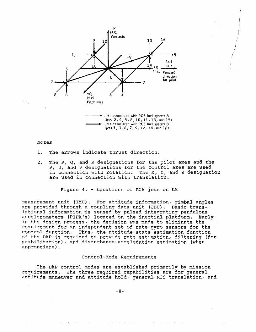
control, including interactions between RCS and GTS modes, were significant for-the DAP. As pre- viously mentioned, the geometrical location of the RCS jets is significant in establishing the fundamental design approach. The locations of the RCS jets are shown in Figure 4 . The eight X-axis RCS jets inherently provide control about the U/V axes, where the natural axes to consider phase-plane logic design are the Q/R pilot (or body) axes. The descent engine (not shown) is gimbaled about the pitch (Q) and roll (R) axes.
An important parameter not shown in Figure 4 is the distance from the spacecraft center of mass to the geometric center of the 16 RCS jets. This equivalent arm length is dependent upon both configuration and propellant loading, and strongly influences the ability to translate in the Y or Z direction.
Sensor Characteristics
The sensor information available for the control-design pro- blem is provided by an inertial platform called the inertial
-7-
+P
direction
7
Pitch axis
- Jets associated with RCS fuel system A (jets 2 , 4, 5, 8, 10, 11, 13, and 15) - Jets associated with RCS fuel system B (jets 1,3,6, 7, 9/12, 14, and 16)
Notes
1. The arrows indicate thrust direction.
2. The P, Q, and R designations for the pilot axes and the P , U , and V designations for the control axes are used in connection with rotation. The X, Y, and Z designation are used in connection with translation.
Figure 4 . - Locations of RCS jets on LM
measurement unit (IMU) . For attitude information, gimbal angles are provided through a coupling data unit ( C D U ) . Basic trans- lational information is sensed by pulsed integrating pendulous accelerometers (PIPA'S) located on the inertial platform. Early in the design process, the decision was made to eliminate the requirement for an independent set of rate-gyro sensors for the control function. Thus, the attitude-state-estimation function of the DAP is required to provide rate estimation, filtering (for stabilization), and disturbance-acceleration estimation (when appropriate) .
Control-Mode Requirements
The DAP control modes are established primarily by mission requirements. The three required capabilities'are for general attitude maneuver and attitude hold, general RCS translation, and
-a-

DPS/APS-powered-flight maneuvers, A listing of the control mades associated with the present design is presented in Table If, The design of the control modes requiring phase-plane logic will be emphasized in this case study.
Design Constraints
Numerous constraints influenced the DAP design, the most pre- dominant class of which related to weight restrictions associated with the lunar-landing program, Weight considerations constrained
TABLE I1
CONTROL-MODE STRUCTURE OF THE DAP
Coasting Flight
Attitude hold
Automatic maneuvering
Manual attitude rate
Manual X-axis rota- tional override
Rotational mini- mum impulse
Manual trans- lation
Powered Flight
Attitude hold
Automatic steering
Manual attitude rate
Manual X-axis rota- tional override
Manual translation
the system design in structural character- istics of the LM/ CSM - structural bending modes are significant; in pro- pellant-sloshing dynamics - slosh baffles were removed early in khe program; and in unbalanced c oup le --con t r o 1 re ~"
quirements f o r APS- powered flight..
Another class of constraints I generally identified late in the design- development phase, involved restrictions on RCS jet firing, These res trictxons
included duty-cycle constraints (because of propulsion instahili- ties), exhaust-contamination constraints (particles on windows, optics), thermal constraints (rendezvous radar, antennas) spacecraft-impingement heating), and operational constraints (during extravehicular activity docking),
A third class of constraints that influenced t h e design pro- blem was associated with propulsion-system characteristics, The slow-speed trim-gimbal-actuator characteristics of the DPS were established for crew safety to avoid hardover actuator failures during powered descent of the LM. A special gear drive was developed to restrict the trim-gimbal-drive rate to 2 O s 2 dey/sec, Unlike the classical actuator used for the CSM thrust-vector- control system, the DPS actuator cannot fail at a higher drive rate. A second propulsion-system constraint was associated with the decision to have a non-gimbaled APS engine, This decision imposed significant limits on allowable center-of-mass character- istics during powered ascent flight, Unfortunately, effective
-9-

control of mass-property characteristics is extremely difficult in a program such as Apollo. Another propulsion-system constraint was associated with the decision to locate the RCS jets 45 degrees
interaction between the RCS mode (U/V axes) and the GTS mode (Q/R axes) during DPS-powered flight. With respect to design and development, effective analytical techniques were virtually non- existent for this problem.
from the body axes. This geometry significantly influenced the i
The fourth class of constraints that impacted the design pro- blem included computer-oriented restrictions, The LM guidance computer (LGC) is limited in both fixed and erasable memories; in addition, definite timing restrictions are placed upon the pro- grams required to provide the control functions,
Performance and Stability Criteria
The criteria for establishing the adequacy of the DAP design are outlined in Table 111, which lists functional criteria for both coasting-flight and powered-flight control modes.
TABLE I11
PERFORMANCE AND STABILITY CRITERIA OF THE DAP
Control modes
Coasting flight
Transient behavior - acquisition and recovery
Limit-cycle characteris- tics
Attitude-maneuver-rate overshoot
RCS propellant comsump- tion
Total number of jet - firings
Powered flight
Stability characteristics
Integrated AV pointing accuracy
Attitude-transient be- havior
Limit-cycle characteris- tics
Steady-state attitude off set
RCS propellant consump- tion
Total number of jet firings
-10-
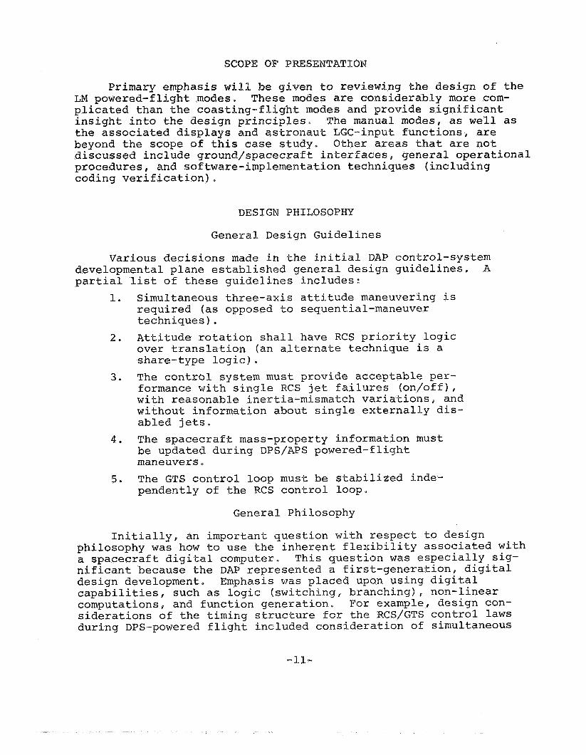
TAT
Primary emphasis en to revie ing the design of the LM powered-flight rno des are considerably more com- plicated than the co and provide significant insight into the des e manual modes, as well as the associated displays and astronaut LGG-input functions, are beyond the scope of this case study, Other areas that are not discussed include ground/spaceeraft interfaces, general operational procedures, and soft e-implementation techniques (including coding verification),
DESIGN PHILOSOPHY
General Design Guidelines
partial 1.
2.
3 .
4 .
5.
Various decisions made in the initial DAP control-system A developmental plane established general design guidelines.
list of these guidelines includes: Simultaneous three-axis attitude maneuvering is required (as opposed to sequential-maneuver techniques). Attitude rotation shall have RCS priority logic over translation (an alternate technique is a share-type logic) The control system must provide acceptable per- formance with single RCS jet failures (on/off), with reasonable inertia-mismatch variations, and without information about single externally dis- abled jets. The spacecraft mass-property information must be updated during DPS/APS powered-flight maneuvers The GTS control loop must be stabilized inde- pendently of the RCS control loop.
General Philosophy
Initially, an important question with respect to design philosophy was how to use the inherent flexibility associated with a spacecraft digital computer, nificant because the DAP represented a first-generation, digital design development, capabilities,. such as logic (switching, branching), non-linear computations, and function generation, For example, design con- siderations of the timing structure for the RCS/GTS control laws during DPS-powered flight included consideration of simultaneous
This question was especially sig-
Emphasis was placed upon using digital
-11-
controlp sequential control, and time-interlaced logic control. These options are generally limited to analog control-system design, Another example was the reduction of switching-line chatter by logical branching to achieve improved performance under inertia mismatch, undetected jet failures, and ullage (X- axis translation) maneuvers.
The concept of performance margin was an area of design philosophy that influenced DAP development. This concept empha- sized the principle that the acceptability of the design should be based upon performance of the system during extreme (but re- quired) degraded conditions. Acceptable performance during off - nominal conditions, such as single undetected jet failures, and large control-effectiveness uncertainties (thrust magnitude, inertia properties, thrust misalignment, actuator drive rates, etc,) was difficult to achieve, The performance-margin concept identified a general trade-off between lowering the nominal to achieve acceptable performance during degraded conditions and maintaining high nominal performance despite severe degradation during off-nominal conditions. The control-system designer must use insight and judgment in establishing the degree of degradation (or margin) to which the design must accommodate in terms of per- formance, Even after this philosophy has been adopted, the abil- ity to develop explicit mathematical criteria for off-nominal per- formance is still generally difficult to establish.
Another general philosophy was maximum utilization of modern cantrol-theory techniques and frequency-domain techniques assoc- iated with sampled data-control systems. For example, the original attitude-state estimator developed for the DPS-powered flight was a Kalman filter. In addition, the GTS control loop was developed. as a time-optimal control law. The many analytical methods available at that time were reviewed in reference 2, the authors of which implied that state phase-plane techniques (involving simulations) would probably be the primary design tools in DAP development. Techniques considered, but discarded, included convergence and stability (Liapunov, Aizeman, Lagrange), modified rate diagram, describing function, and dynamic pro- graming. The concepts of defining regions of attraction and ultimately bounded regions were found to be inapplicable for this design development.
The philosophy of providing system-design flexibility to accommodate developmental problems or future contingencies was related to the concept of performance margin. An example was the guideline to stabilize the GTS control loop independently of RCS control loop. Three years after this design was initiated, additional thermal constraints (which essentially restricted all X-axis RCS jet firings) were identified for the LM/CSM config- uration during DPS-powered flight. The design was flexible
-12-

enough to accommodate this restriction without significantly affecting the program.
The final design philosophy listed for DAP development was associated with the RCS propellant-performance requirements, Design emphasis to achieve efficient propellant usage should be placed upon those control functions that require the largest amount of propellant over a complete mission profile. For the DAP, these control functions included manual translations, manual and automatic-attitude maneuvers, and maneuvers associated with powered-flight guidance. In this general sense, the importance of efficient RCS propellant performance for coasting-flight and powered-flight minimum-impulse operation should be downgraded. Thus, one may reasonably ask why design complexity (and assoc- iated verification) should be increased to save 20 percent per- formance on an item that uses 5 percent of the total mission pro- pellant. A dbfinite trade-off exists between design complexity and performance-improvement payoff.
DESCRIPTION OF DAP DESIGN
The DAP design that was flight-tested on the Apollo 9 manned mission will be described in this section. This design (assoc- iated with the SUNDANCE flight ropes) is described in reference 3, and will be treated as the base line design for the case study. Virtually all of the following design descriptions are condensed from reference 3.
Coasting-Flight Modes
The two coasting-flight modes described are the attitude- hold mode, and the automatic-maneuver mode. A block diagram of the coasting-flight attitude-hold mode is presented in Figure 5.
The major design elements include the attitude-state estimator, the RCS control laws, and the jet-selection logic, functional descriptions of which are provided in this section.
The basic measurements available to the recursive state estimator are the three gimbal angles from the IMU. The estimator for coasting flight predicts both attitude and angular velocity, and uses non-linear threshold logic to reject low-level measurement noise. Angular-acceleration information caused by RCS jet firings is an additional input to the state estimator.
The ‘RCS control laws compute the requirements for rotational impulses, using information based upon attitude phase-plane errors, control effectiveness, and phase-plane targeting logic.
-13-
[MGp] = Transformation from gimbal axes to pilot axes
[Mpc]’ Transformation from pilot axes to control axes r Manual t r y l a t i o n
Reference gimbal angles ___IC
‘d
Thruster disable
i I (Control)
Estimated applied control effectiveness
Spacecraft rotations and translations
e Gimbal
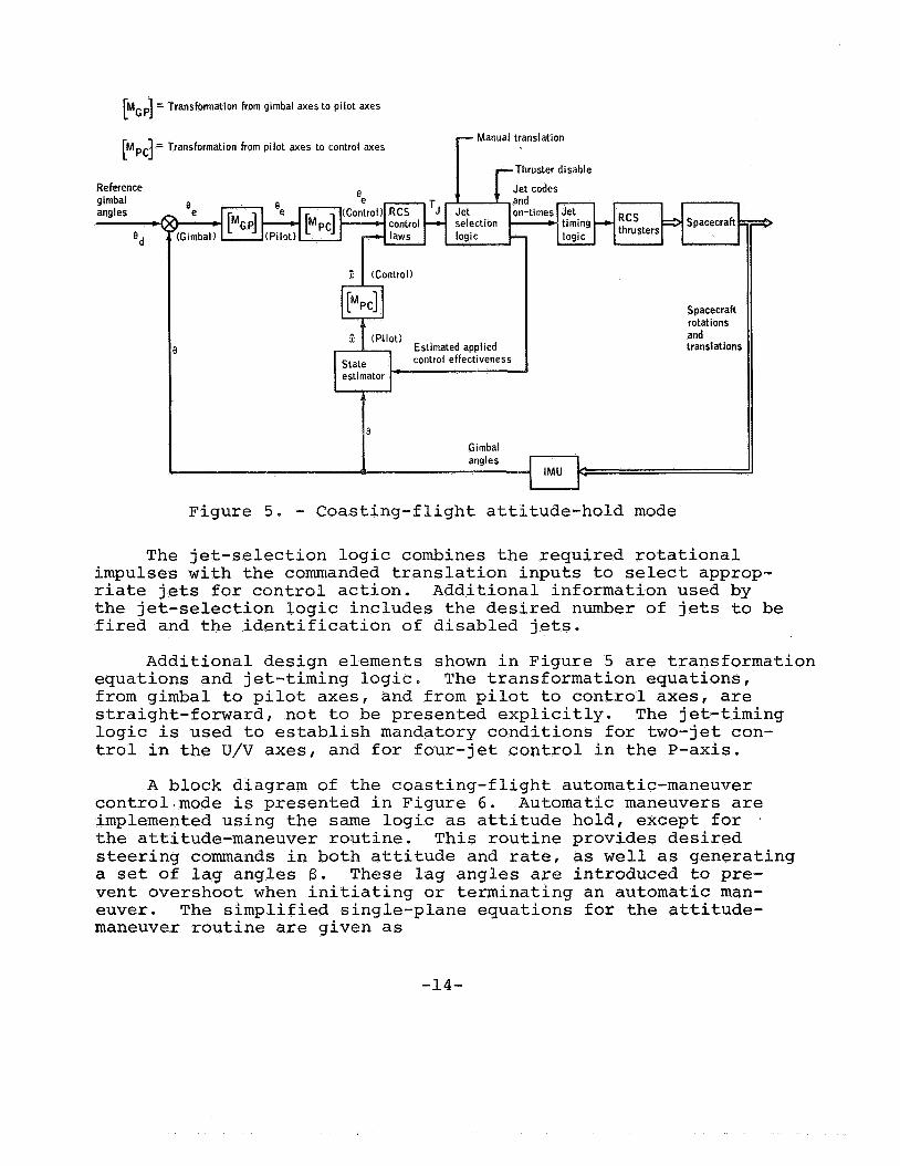
Figure 5 . - Coasting-flight attitude-hold mode
The jet-selection logic combines the required rotational impulses with the commanded translation inputs to select approp- riate jets for control action. Additional information used by the jet-selection logic includes the desired number of jets to be fired and the identification of disabled jets.
Additional design elements shown in Figure 5 are transformation equations and jet-timing logic. The transformation equations, from gimbal to pilot axes, and from pilot to control axes, are straight-forward, not to be presented explicitly. The jet-timing logic is used to establish mandatory conditions for two-jet con- trol in the U/V axes, and for four-jet control in the P-axis.
A block diagram of the coasting-flight automatic-maneuver control.mode is presented in Figure 6. Automatic maneuvers are implemented using the same logic as attitude hold, except for ~
the attitude-maneuver routine. This routine provides desired steering commands in both attitude and rate, as well as generating a set of lag angles 6 . These lag angles are introduced to pre- vent overshoot when initiating or terminating an automatic man- euver. The simplified single-plane equations for the attitude- maneuver routine are given as
-14-

'd("j) = 'd (Nj-l) -b Aed(tn)
where Equation (1) is computed every steering cycle (ATc = Nj - Nj-1 = 2 sec), and Equation ( 2 ) is computed every control cycle- (~Ts = 0.1 sec). The value of Wd is set by the maneuver-rate input, and aj is defined as the magnitude of the assumed two-jet acceleration. When the maneuver is completed, Wd, Aed, and f3 are reset to zero, and the control system reverts to attitude hold about the desired gimbal angles.
Powered-Flight Automatic Mode
The control operations associated with powered flight are considerably more complicated than coasting-flight operations. Major additions for both DPS- and APS-powered flight include an integrated guidance and navigation outer loop that interfaces with the DAP through a steering routine, and a mass monitor-and- control parameter routine. In addition, the state estimator is required to derive offset angular acceleration a . The RCS control laws are modified by making the control effectiveness and the phase-plane targeting logic dependent upon the estimated offset angular acceleration. During DPS-powered flight, a control law for the GTS is required. A timing-and-control-logic interaction between the RCS control and the GTS control is also required. A block diagram of the APS powered-flight automatic control is pre- sented in Figure 7. The major design elements (state estimator, control laws, jet-selection logic) will be discussed in detail in the following sections.
Control Effectiveness
The DAP control laws and the recursive state estimator re- quire information on the assumed RCS and GTS control effectiveness. The GTS control effectiveness is represented by the rate of change of angular acceleration, BG, caused by constant angular-drive- rate command to the actuators. A flow diagram indicating those factors that relate to the GTS control effectiveness is presented in Figure 8 . The factors indicated in Figure 8 are as follows:
M = estimated mass L = L(M) distance from hinge pin of descent
engine bell to center of mass of LM
-15-

Attitude
L
"
8
I
RCS thrusters a 'pacecraft
RCS Jet e control - selection -
laws logic -
Estimated applied State estimator
- 3
Spacecraft rotations and translations
le IMU
Figure 6 - - Coasting-flight automatic-maneuver mode
Soacecraft mass-. I
Figure 7. - Powered-flight automatic control of the DPS
I I - 1 - 1 1
Spacecraft - rotations an translations
Estimated applied. control effectiveness
I I - IMU
AV
-16-
I = I ( M ) pitch or roll moment of inertia AV/At = measured linear acceleration
for Q and R channels 4
0 . 2 deg /sec
= trim-gimbal drive commands {+lP 0, -1)
= gimbal-drive rate of descent engine =
U~ 1 U~
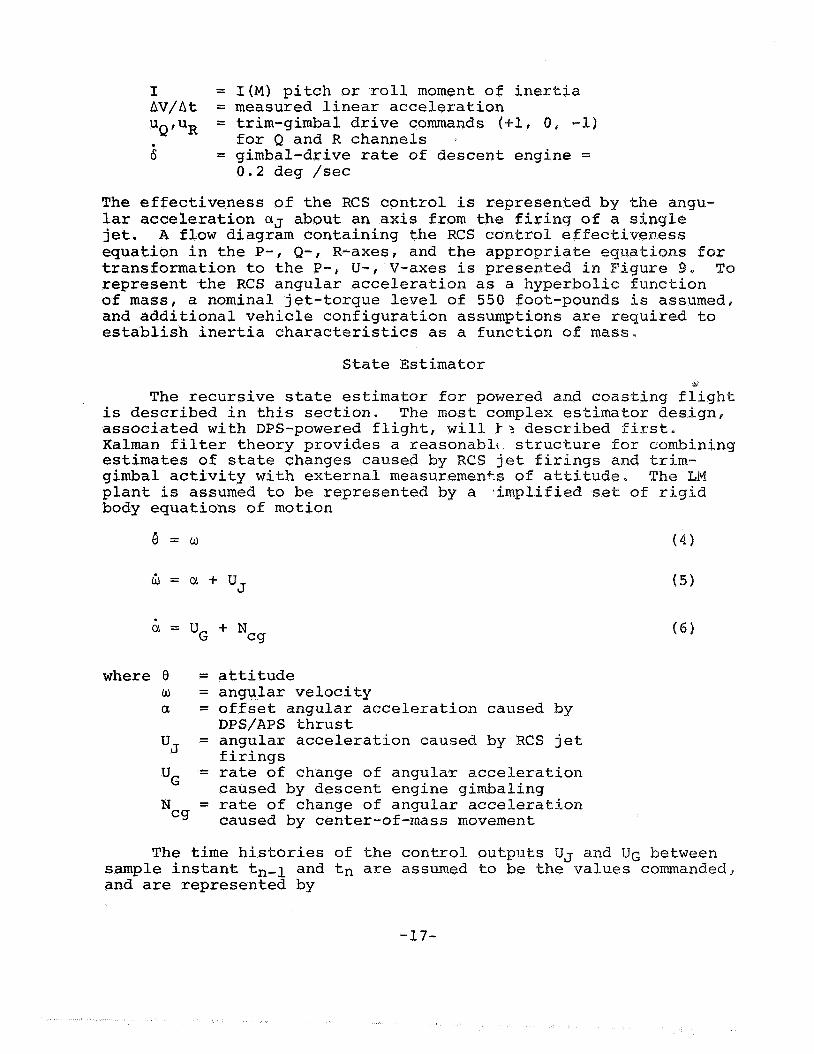
The effectiveness of the RCS control is represented by the angu- lar acceleration UJ about an axis from the firing of a single jet. A flow diagram containing the RCS control effective equation in the P-, Q-, R-axes, and the appro transformation to the P-, U-, V-axes is prese represent the RCS angular acceleration as a hyperbolic function of mass, a nominal jet-torque level of 550 foot-pounds is assumed, and additional vehicle configuration assumptions are required to establish inertia characteristics as a function of mass.
State Estimator ,
The recursive state estimator for powered and coasting flight is described in this section. The most complex estimator design, associated with DPS-powered flight, will I - ? described first. Kalman filter theory provides a reasonablt structure for combining estimates of state changes caused by RCS jet firings and trim- gimbal activity with external measuremen+s of attitude. The LM plant is assumed to be represented by a simplified set of rigid body
- - equations of motion
6 = u
B = c l + u J
c1 = UG
where 9 = w = a =
N = cg
+ N cg
attitude angular velocity offset angular acceleration caused by DPS/APS thrust angular acceleration caused by RCS jet firings rate of change of angulay acceleration caused by descent engine gimbaling rate of change of angular acceleration caused by center-of-mass movement
The time histories of the control outputs UJ and UG between sample instant tn-1 and tn are assumed to be khe values commandedp and are represented by
-1 7-

Figure 8. - Control effectiveness of the GTS
Configuration bit State est i mator
Figure 9. - Control effectiveness of the RC S
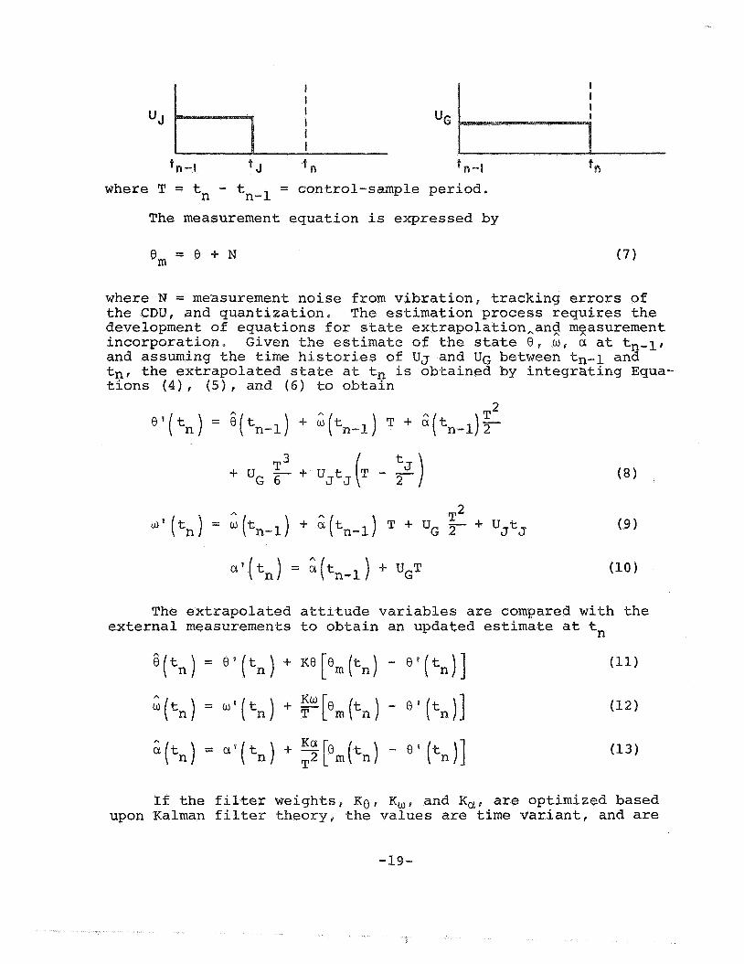
'.. = control-sample period. where T = tn tn-l The measurement equation is expressed by
B m = B + N (7)
where N = measurement noise from vibration, tracking errors of the CDU, and quantization, The estimation process requires the development of equations for state extrapolation,ang mgasurement incorporation. Given the estimate of the state 6, w r a at tn-lr and assuming the time histories of UJ and UG between tn-l and tnr the extrapolated state at t, is obtained by integrating Equa- tions (4), (51, and (6) to obtain
3
+ uG T3 6 +- UJt,(T - 2)
The extrapolated attitude variables are compared with the external measurements to obtain an updated estimate at t,
If the filter weights, K O r K,, and X,, are optimized based upon Kalman filter theory, the values are time variant! and are
-19-
dependent upon the values of Ne the initial state estimate. Du ing the design development of the DAP, the optimum filter-gain concept was discarded after many problems were identified through simulation testing. At that time, a nonlinear threshold filter was developed as part of the base line design. This filter and the threshold values assoc- iated with the concept were established from direct engineering considerations,
and M, and the uncertainty in
Development of the nonlinear threshold filter was motivated by the specific properties of the measurement noise from the IMU, For the design considered, the predominant measurement noise is derived from the nonlinear-tracking servo characteristics of the electronic CDUvse Gimbal-angle information encoded in the LGC (for moderate angular vehicle velocities) contains high-frequency - noise having a peak-to-peak amplitude of approximately 0.09 degree. It is important to note that the distribution of this noise is rectangular rather than gaussian, A trap filter using threshold logic bras developed to reject this type of low-level measurement noise‘ The logic and associated filter-gain equations are as follob7s. If lem .- 8 ’ 12 emax, then
If 18 - e n 1 > BmaxI then m
where 8 = threshold value (0.1 = rate gain constant = acceleration gain constant = number of sample periods that have
N Y ” J c Ncl
elapsed since the threshold was exceeded last t n
Extensive testing has demonstrated that the nonlinear thres- hold logic successfully rejects low-level measurement noise. This filter also erforms well with respect to disturbances that are cyclic in nature, such as slosh and structural vibrations, The filter gains for the rate and acceleration estimates derived by
-20-

Equation (15) are functions of nt. If the trap overflows almost every time, it is generally desirable for the filter characteris- tics to provide a fast rate estimate and a slow acceleration estimate. The desired response time on the acceleration estimate is set by requirements to track a moving center of mass and to respond to time-variant thrust-actuation compliance effects. The upper limit on response time is restricted because of the desire to avoid rapid fluctuations in the autopilot switching curves and because of the requirement to attenuate slosh accelerations.
If the threshold logic be exceeded only rarely, a maximum incorporation of the measurement is generally desired. The logic given in Equations (14) and (15) is actually a simplification of the developed design. The threshold value is actually compared with the total unexplained attitude that has accumulated since the last trap overflow, where the incremental amount for one con- trol-sample period is the difference between the measured and the predicted changes in attitude.
th state estimator for DPS-powered flight is presented in F' ure 10.
i 1" entical except that the variables associated with the GTS are deleted. Similarly, the state estimator for coasting flight is based upon the same structure, except that the estimated state does not include offset angular acceleration. The total estimator design represents an integrated concept with respect to both powered and unpowered modes of control. To conclude this section, the dynamical effects not explicitly considered in th' initial development of the filter equations will be iden fied, as fol-
A summary of the input and output variables associated with
The structure of the estimator for APS-powered flight is
lows : 1. 2. 3 .
4 .
5. 6. 7 .
8 . 9. 10. 11.
Propellant-slosh dynamics Structural-bending dynamics Jet-impingement-forces model Jet-thrust lags Jet-misalignment geometry Jet acceleration caused by Y/Z translation Undetected jet failures Trim-gimbal lags Inertial mipmatch DPS-actuator-compli&x!e,model Pqopellant-fuei-shift ; M,7 ,
i I
u
-21-

cr J ,PI "J ,Q' *J ,R Assumed RCS control effectiveness
Assumed GTS control effectiveness
Configuration b i t
ngular velocity estimate State estimator
I Trim-gimbal ac t i v i t y
t p l t"' tV
Signed fir ing durations
tip, nu, n,,
Number of je ts selected
Figure 10. - Input and output variables of the state estimator
Other assumptions that modified the estimator equations implemented in the filter design were that the cross products of inertia terms were ignored; that the terms in Equations ( 8 ) and (9) caused by the trim-gimbal drive UG were deleted; and that second-order rate terms were ignored in the equations of motion.
Detailed verification testing was 'required to demonstrate the stability and performance, including the known dynamical effects, of the total system. Simulation testing supported the establishment of the critical filter values of Omax, Nu, and N,.
-22-

An important consideration was testing the filter performance when an undetected jet-off failure existed, When this condition occurs, the acceleration estimate will seek an average value double the actual acceleration offset present. Because the DPS acceleration-nulling control law is a function of the sign of the acceleration-offset estimate, and is invariant with the magnitude, this control law will seek the center of mass properly when un- detected jet-off conditions exist,
RCS Control Laws
The control laws associated with the RCS establish jet-firing durations (TJET values) based upon phase-plane logic and assumed control effectiveness- These control laws are predictive in nature and are related to the classical two-point-boundary-value problem. To some extent, this predictive design is inherently sensitive to the uncertainties in control effectiveness and unmodeled disturbances. A description of the TJET LAWS associated with the LM descent and ascent configurations is provided in this section.
Angular error/error-rate phase planes are established for each P, U, and V RCS control axis, Because the sets of jets that produce rotation about each of these three axes are distinct, the P-, U-, and V-axis jets are turned on and off independently. A block diagram of the control-law inputs for the LM descent and ascent configurations is presented in Figure 11.
I
--/2-!jet performance I U/V axes
Figure 11. -- TJET LAWS, LEVI only
The attitude and rate errors ( E , 6 ) are used to establish the estimated state location in the phase plane. The acceleration inputs required by the RCS control laws include net angular acceleration (jet acceleration plus offset acceleration), and
-23-
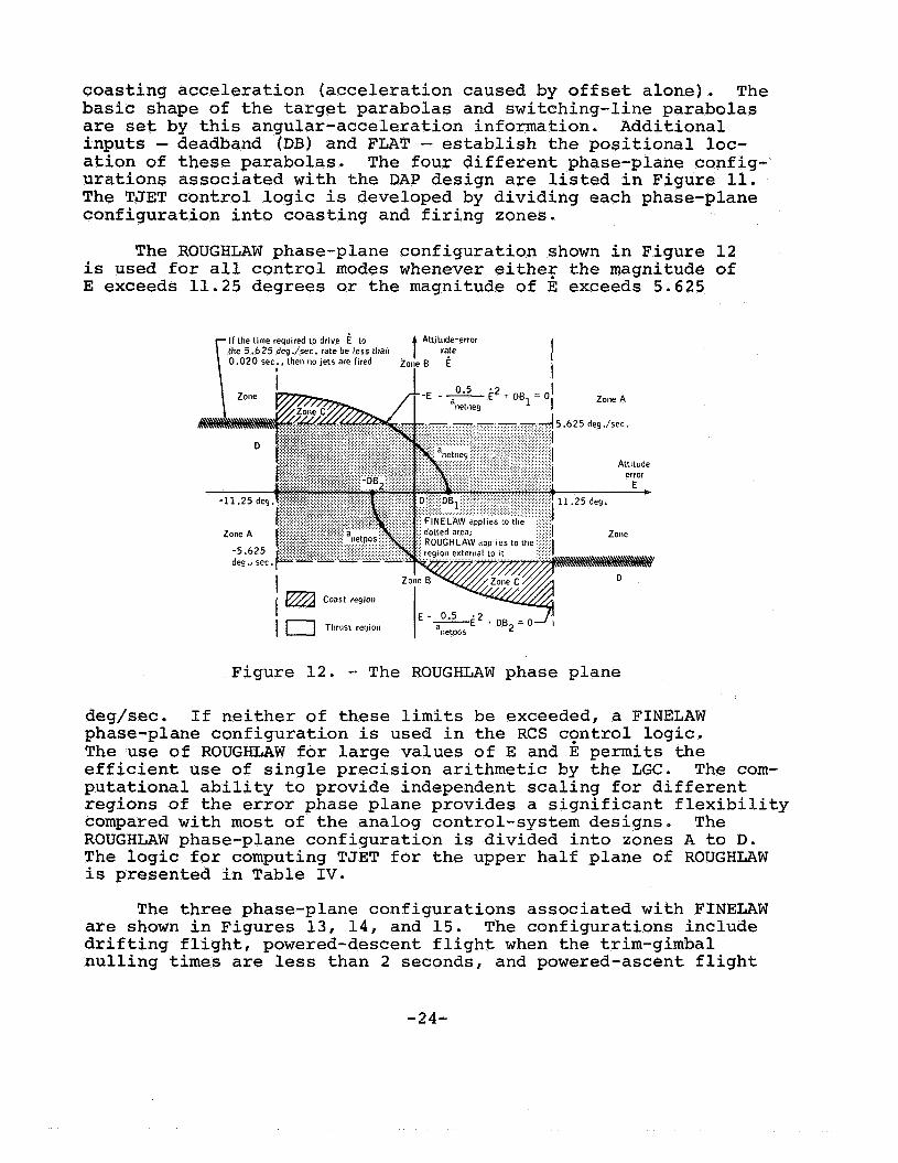
coasting acceleration (acceleration caused by offset alone). The basic shape of the target parabolas and switching-line parabolas are set by this angular-acceleration information. Additional inputs - deadband (DB) and FLAT - establish the positional loc- ation of these parabolas. The four different phase-plane config- urations associated with the DAP design are listed in Figure 11. The TJET control logic is developed by dividing each phase-plane configuration into coasting and firing zones.
The ROUGHLAW phase-plane configuration shown in Figure 12 lis used for all control modes whenever eithe? the magnitude of E exceeds 11.25 degrees or the magnitude of E exceeds 5.625
5.625 dey./sec.
Attitude error
Figure 12. - The ROUGHLAW phase plane deg/sec. If neither of these limits be exceeded, a FINELAW phase-plane configuration is used in the RCS cqntrol logic, The use of ROUGHLAW for large values of E and E permits the efficient use of sinqle precision arithmetic by the LGC. The com- putational ability to provide independent scaling for different regions of the error phase plane provides a significant flexibility compared with most of the analog control-system designs. The ROUGHLAW phase-plane configuration is divided into zones A to D. The logic for computing TJET for the upper half plane of ROUGHLAW is presented in Table IV.
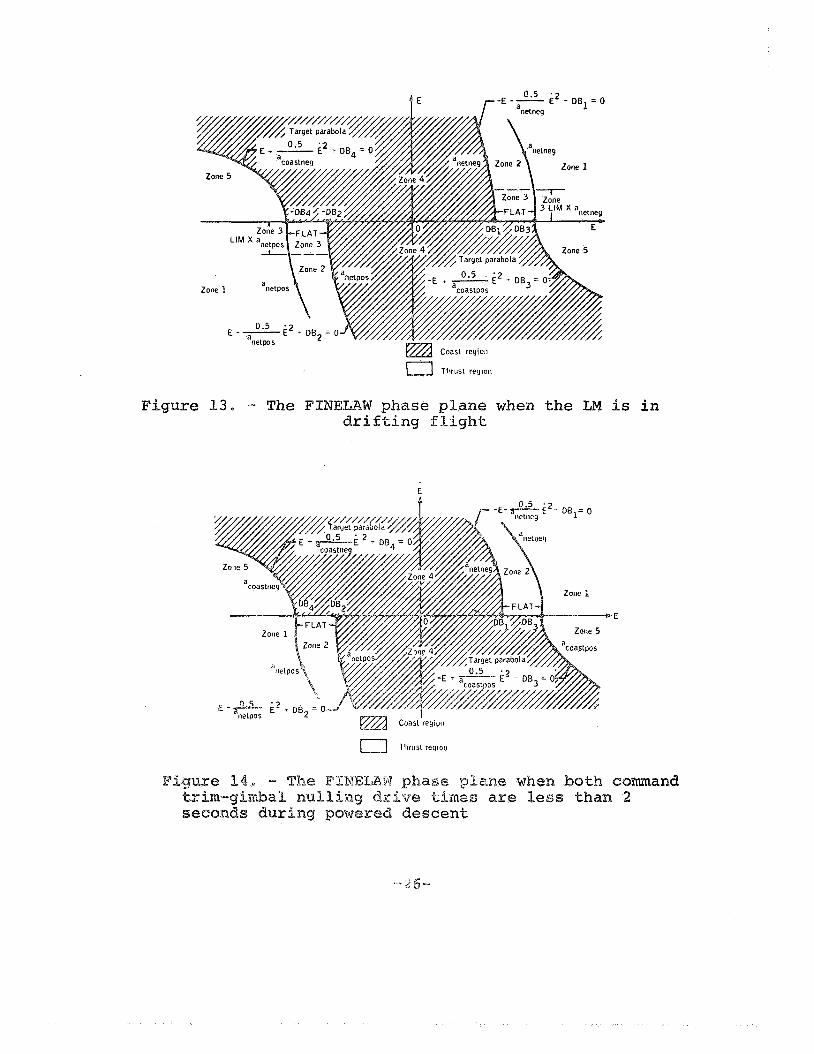
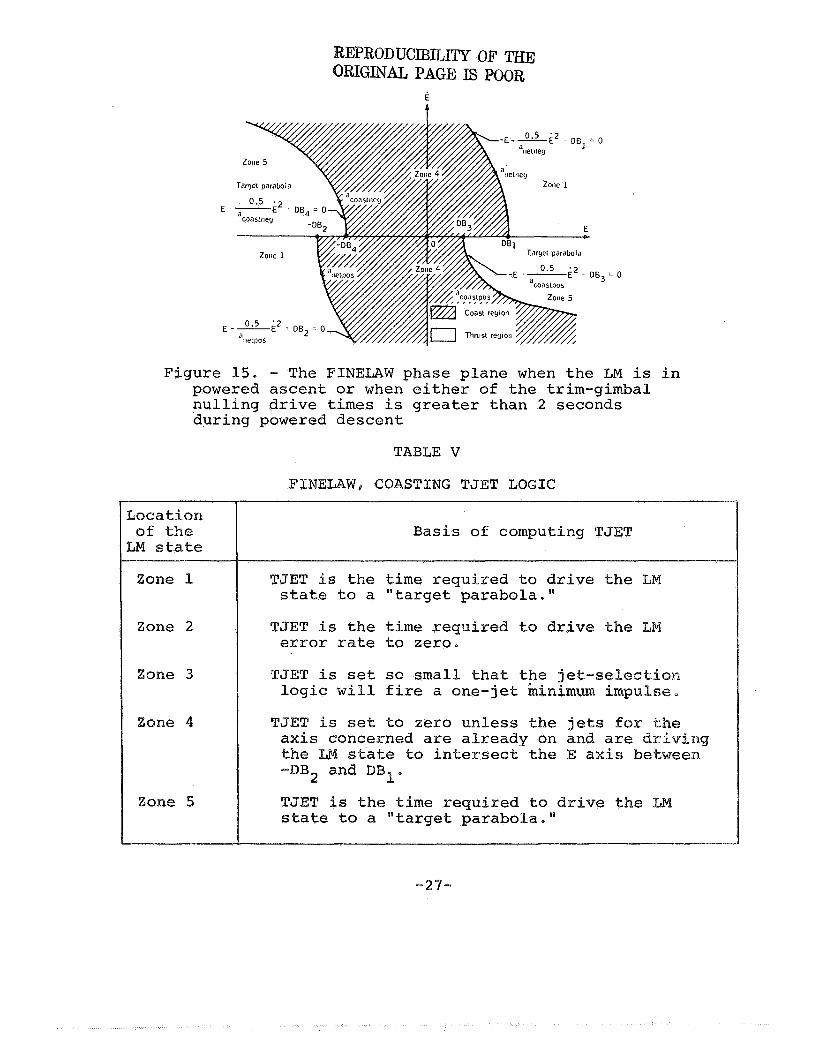
The three phase-plane configurations associated with FINELAW are shown in Figures 13, 14, and 15. The configurations include drifting flight, powered-descent flight when the trim-gimbal nulling times are less than 2 seconds, and powered-ascent flight
-24-
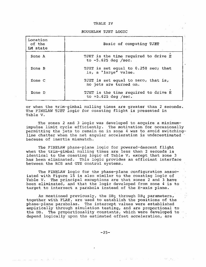
TABLE IV
Location of the LM state
Zone A
Basic of computing TJET
TJET is the time required to drive E to -5.625 deg /sec.
Zone B
Zone C
Zone D
TJET is set equal to 0.250 sec; that is, a "large" value.
TJET is set equal to zero, that is, no jets are turned on.
TJET is the time required to drive E to +5.625 deg /sec.
or when the trim-gimbal nulling times are greater than 2 seconds. The FINELAW TJET logic for coasting flight is presented in Table V.
The zones 2 and 3 logic was developed to acquire a minimum- impulse limit cycle efficiently. The motivation for occasionally permitting the jets to remain on in zone 4 was to avoid switching- line chatter when the net angular acceleration is underestimated - because of inertia mismatch.
The FINELAW phase-plane logic for powered-descent flight when the trim-gimbal nulling times are less than 2 seconds is identical to the coasting logic of Table V, except that zone 3 has been eliminated. This logic provides an efficient interface between the RCS and GTS control systems.
The FINELAW logic for the phase-plane configuration assoc- iated with Figure 15 is also similar to the coasting logic of Table V. The principal exceptions are that zones 2 and 3 have been eliminated, and that the logic developed from zone 4 is to target to intersect a parabola instead of the E-axis plane.
As mentioned previously, the DB1 through DB4 parameters, together with FLAT, are used to establish the positions of the phase-plane parabolas. The intercept values were established empirically through simulation testing, and are proportional to the DB. The proportionality constants, which were developed to depend logically upon the estimated offset acceleration, are
-25-
Thrust reyion
Figure 13. - The AT EL^^ phase plane when t h e LM is i n drifting flight
E
EPRODUCIBILITY OF THE RIGmAL PAGE IS POOR
E
t
E - a 2 0.5
coasttley
= o
Figure 15. - The FINELAW phase plane when the LM is in powered ascent or when either of the trim-gimbal nulling drive times is greater than 2 seconds during powered descent
TABLE V
FINEILAW, COASTING TJET LOGIC
Location of the LM state
one 1
Zone 2
one 3
one 4
one 5
Basis of computing T J
TJET i s the time required to drive the LM state to a "target parabola."
J E T is the time re error rate to zero.
TJET is set so small that the j e t logic will fire a one-jet ininimu
TJET is set to zero unless the axis concerned are already on
to intersect %he
TJET is the time required to drive t state to a "target parabola. I'
-27-
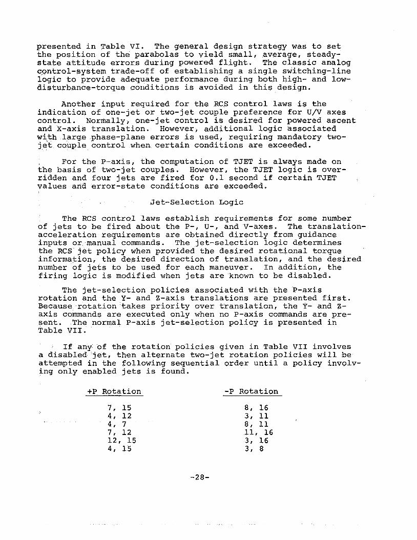
presented in Table VI. The general design strategy was to set the position of the parabolas to yield small, average, steady- state attitude errors during powered flight. The classic analog cpntrol-system trade-off of establishing a single switching-line logic to provide adequate performance during both high- and low- disturbance-torque conditions is avoided in this design.
Another input required for the RCS control laws is the indication of one-jet or two-jet couple preference for U/V axes control. Normally, one-jet control is desired for powered ascent and X-axis translation. However, additional logic associated with large phase-plane errors is used, requiring mandatory two- je't couple control when certain conditions are exceeded.
the basis of two-jet couples. However, the TJET logic is over- ridden and four jets are fired for 0.1 second if certain TJET values arid error-state conditions are exceeded.
For the P-axis, the computation of TJET is always made on
Jet-Selection Logic
The RCS control laws establish requirements for some number of jets to be fired about the P-, U-, and V-axes. The translation- acceleration requirements are obtained directly from guidance inputs or manual commands. The jet-selection logic determines the RCS jet policy when provided the desired rotational torque information, the desired direction of translation, and the desired number of jets to be used for each maneuver. In addition, the firing logic is modified when jets are known to be disabled.
The jet-selection policies associated with the P-axis rotation and the Y- and Z-axis translations are presented first. Because rotation takes priority over translation, the Y- and Z- axis commands are executed only when no P-axis commands are pre- sent. The normal P-axis jet-selection policy is presented in Table VII.
If any of the rotation policies given in Table VI1 involves a disabled jet, then alternate two-jet rotation policies will be attempted in the following sequential order until a policy involv- ing only enabled jets is found.
+P Rotation -P Rotation
7, 15 4 , 12 4 , 7 7, 12 12, 15 4 , 15
-28-
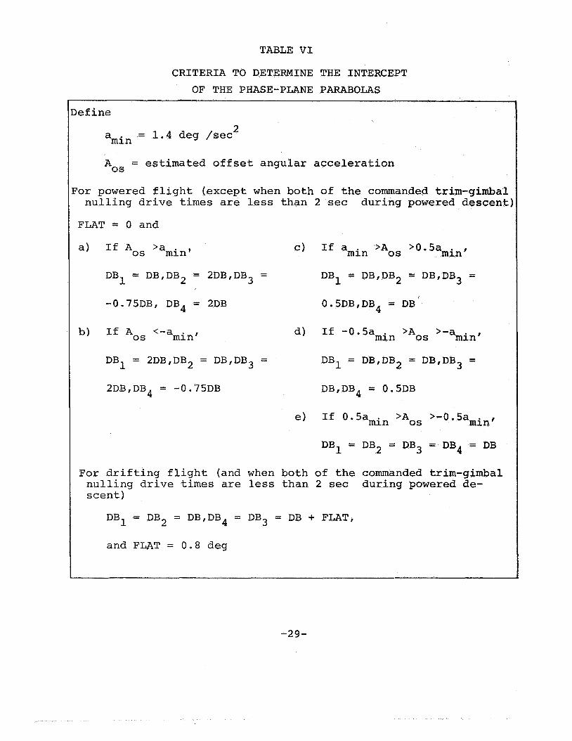
TABLE VI
CRITERIA TO DETERMINE THE INTERCEPT OF THE PHASE-PLANE PARABOLAS
befine 2 = 1.4 deg /sec amin
= estimated offset angular acceleration Aos
?or powered flight (except when both of the commanded trim-gimbal nulling drive times are less than
FLAT = 0 and
-O175DB, DB4 = 2DB
mint If Aos <-a
DB1 = 2DB,DB2 = DB,DB3 =
d)
2DB,DB4 = -0.75DB
e>
2 sec during powered descent:
If amin >Aos >0.5amin,
DB1 = DB,DB2 = DB,DB3 =
0.5DB,DB4 = DB'
If -0.5amin >Aos >-amin,
DB1 = DB,DB2 = DB,DB3 =
DB,DB4 = 0.5DB
If 0.5amin >Aos >-0.5amin,
DB1 = DB2 = DB3 = DB4 = DB
F o r drifting flight (and when both of the commanded trim-gimbal nulling drive times are less than 2 sec during powered de- scent)
DB1 = DB2 = DB,DB4 = DB3 = DB 4- FLAT,
and FLAT = 0.8 deg
-29-
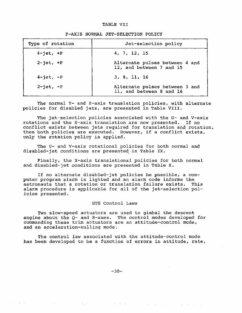
TABLE VI1
P-AXIS NORMAL JET-SELECTION POLICY
Type of rotation
4-jet, +P
2-jet, +P
4-jet, -P
2-jet, -P
Jet-selection policy
4, 7, 12, 15
Alternate pulses between 4 and 12, and between 7 and 15
3 , 8, 11, 16
Alternate pulses between 3 and 11, and between 8 and 16
The normal Y- and Z-axis translation policies, with alternate policies for disabled jets, are presented in Table VIII.
The jet-selection policies associated with the U- and V-axis rotations and the X-axis translation are now presented. If no conflict exists between jets required for translation and rotation, then both policies are executed. However, if a conflict exists, only the rotation policy is applied.
The U- and V-axis rotational policies for both normal and disabled-jet conditions are presented in Table IX.
and disabled-jet conditions are presented in Table X. Finally, the X-axis translational policies for both normal
If no alternate disabled-jet policies be possible, a com- puter program alarm is lighted and an alarm code informs the astronauts that a rotation or translation failure exists. This alarm procedure is applicable for all of the jet-selection pol- icies presented.
GTS Control Laws
Two slow-speed actuators are used to gimbal the descent engine about the Q- and R-axes. The control modes developed for commanding these trim actuators are an attitude-control mode, and an acceleration-nulling mode.
The control law associated with the attitude-control mode has been developed to be a function of errors in attitude, rate,
-30-

Type of translation
+Y
-Y
+Z
-Z
TABLE VI11
Y- AND Z-AXIS JET-SELECTION POLICIES
Normal policy
12, 16
4, 8
7, 11
3 , 15
Alternate disabled-jet policy
If 16 has been disabled, set up the tacking policy of alternating between 12 and 3 , and between 12 and 11. If 12 has been disabled, set up the tacking policy of alternating between 16 and 15, and between 16 and 7.
If 8 has been disabled, set up the tacking policy of alternating between 4 and 3 , and between 4 and 11. If 4 has been disabled, set up the tacking policy of alternating between 8 and 7, and between 8 and 15.
If 11 has been disabled, set up the tacking policy of alternating between 7 and 8, and between 7 and 16. If 7 has been disabled, set up the tacking policy of slternating between 11 and 12, and between 11 and 4.
If 15 has been disabled, set up the tacking,policy of alternating between 3 and 4, and between 3 and 12. If 3 has been disabled, set up the tacking policy of alternating between 15 and 8, and between 15 and 16.
-31-
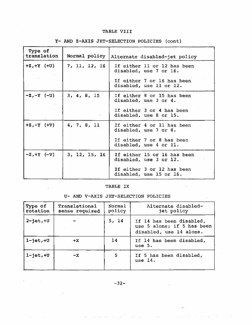
TABLE VI11
Y- AND Z-AXIS JET-SELECTION POLICIES (cont)
Normal policy
Type o f translation
+Z,+Y (+U)
-2,-Y (4)
Alternate disabled- jet policy
+2,-Y (+V)
-Z,+Y (-VI
Normal policy
7, 11, 12, 16
3 , 4 , 8 , 15
4 , 7 , 8 , 11
3 , 12, 15, 16
Alternate disabled-jet policy
If either 11 or 12 has been disabled, use 7 or 16.
If either 7 or 16 has been disabled, use 11 or 12.
If either 8 or 15 has been disabled, use 3 or 4 .
If either 3 or 4 has been disabled, use 8 or 15.
If either 4 or 11 has been disabled, use 7 or 8.
If either 7 or 8 has been disabled, use 4 or 11.
If either 15 or 16 has been disabled, use 3 or 12.
If either 3 or 12 has been disabled, use 15 or 16.
TABLE IX
U- AND V-AXIS JET-SELECTION POLICIES ~~ ~
Translational rotation I sense requiaed Type of
2-jet,+U
I +X
I 1-jet,+U
1- jet , +U -X
If 14 has been disabled, use 5 alone; if 5 has been disabled, use 14 alone.
If 14 has been disabled, use 5.
If 5 has been disabled, use 14.
I
-32-
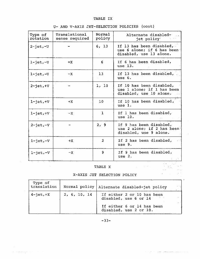
TABLE IX
U- AND V-AXIS JET-SELECTION POLICIES (cont)
Type of rotation
Translational Normal sense required policy
2- jet , -U
1- jet, -U
-
+X
2, 6, 10, 14
l 6
If either 2 or 10 has been disabled, use 6 or 14
If either 6 or 14 has been disabled, use 2 or 10.
l-jet,-U I I l3 -X
2- j et , +V 1, 10
1-jet,+V I lo +X
1- j et , +V -X I 1 2- j et , -V
1-jet,-V +X l 2 1- j et , -V -- X l 9
I I
TABLE X
Alternate disabled- j et policy
If 13 has been disabled, use 6 alone; if 6 has been disabled, use 13 alone.
If 6 has been disabled, use 13.
If 13 has been disabled, use 6.
If 10 has been disabled, use 1 alone; if 1 has been disabled, use 10 alone,
If 10 has been disabled, use 1.
If 1 has been disabled, use 10.
If 9 has been disabled, use 2 alone; if 2 has been disabled, use 9 alone.
If 2 has been disabled, use 9.
If 9 has been disabled, use 2.
X-AXIS JET SELECTION POLICY
4-jet,+X
-33-

TABLE X
4 -'j et , -X
2- jet I -X (fuel system A)
2- jet, -X (fuel system B)
X-AXIS JET SELECTION POLICY (cont)
disabled, use 2 or 10.
If either 1 or 9 has been disabled, use 5 or 13.
If either 1 or 9 has been disabled, use 5 or 13.
and acceleration. The control-law equations are basically a modification of a time-optimal solution, and are given as
AV
I K = 0.3M E L -
A = -sgn (XB + ep )
The control output commands the sign of the change in angular acceleration. The sampling period f o r this mode is set at 200 milliseconds. Referring to Equation (16), the time-optimal law
-34-

is modified by a 0 - 3 gain factor in the assumed control- effectiveness term K. This reduction is designed to avoid tran- sient-response overshoot, and to prevent large steady-state limit cycles. However, this gain should be kept reasonably high to provide good transient-response characteristics*
The GTS control law associated with the acceleration-nulling mode is designed to regulate the offset (disturbance) acceleration from the descent thrust. The primary dynamical environments that cause offset acceleration include shifting center-of-mass prop- erties, DPS actuator compliance, and DPS engine-ablation effects. This control law is structured in the form of a trim-gimbal drive- time equation, and is given as
AV * M - L6 T = 0.41 1
The principal sampling period associated with the acceleration- nulling law is 2 seconds. However, under certain conditions, this acceleration-nulling law is used as part of the basic RCS control- law timing structure., The interaction and timing logic between the RCS and GTS control laws are presented in the following section.
RCS/GTS Interface
During DPS-powered flight, the GTS is generally adequate to provide satisfactory control in the Q/R axes when the maneuver requirements are slowly varying. It is believed that the GTS should provide complete control (rather than regulation of the off- set acceleration) whenever possible, to limit jet firings and to minimize RCS propellant usage, During design of the DAP, a time- shared control logic was developed in which the use of RCS and GTS controls are interfaced to minimize mutual interaction,
The RCS/GTS interface has been designed so that the RCS phase-plane state is examined for a lo ical decision (and the RCS control law applied) at least every 200 milliseconds. The time- line operation is as follows.
1 t I t + 100 msec It + 200 msec 1 t -+ 300 msec
RC S Test for RC s Test for
law control law law control law (2) Acceleration- (2 1 Acceleration-
nulling law nulling law ( 3 ) RCS control ( 3 ) RCS control
control (1) Attitude- control (1) Attitude-
law i* law
-35-

law (in and
The test logic associated with use of the attitude-control every 200 milliseconds is that the trim-gimbal drive times the Q- and R-axes) must be less than 2 seconds IEquation (1911, that all U and V RCS jets must be off.
The requirements associated with the use of the acceleration- nulling law are that the attitude-control law must have been used on the previous pass, and that the test logic for present use of attitude-control law must have failed.
Therefore, in the RCS/GTS timing loop, the acceleration- nulling law is used only as a transaction between the attitude- control law and the RCS control law.
In addition to the RCS/GTS timing loop, another routine executes a test for the GTS acceleration-nulling law every 2 sec- onds. The nulling law is applied if, and only if, the trim gimbal is not under GTS attitude control (at least one of the two test conditions is not satisfied). This "captive" logic is designed to prevent a sustained thrust offset when the RCS control laws are commanding jet firings to counteract the disturbance acceleration.
HISTORY OF DESIGN DEVELOPMENT
The history of DAP development will be discussed by pre- senting base line designs for the design-formulation phase (September 1964 to December 1966) and for the SUNBURST flight- program phase (December 1966 to August 1967). Where applicable, comparisons will be made to the SUNDANCE base line design pre- viously discussed. The significant problems encountered will also be discussed.
Apollo 5, the first (unmanned) LM mission, was launched into earth orbit January 22, 1968, and used the SUNBURST flight pro- gram. Following this mission, a decision was made to simplify the DAP logic, and a significant redesign of the control system was begun, resulting in the SUNDANCE digital program. This de- sign version was flight tested on the first manned LM mission (Apollo 9 > , launched March 3, 1969. Subsequent lunar-landing missions will be flown using a slightly-modified SUNDANCE flight program e
Preliminary Design Development
Many modifications in design philosophy and in control- system implementation occurred during the preliminary design phase of DAP development. Excellent insight into the various control- system problems encountered is provided by reference 4 . To estab- lish background for a discussion of design problems, a base line
a;
- 3 6 -

block diagram using assumed conditions was formulated (Figure 16). The major design areas to be discussed include RCS control-law formulation, estimation concepts, RCS/GTS control-mode interaction logic, and RCS switching logic.
(Powered
Figure 16. - Preliminary design control system
Three types of estimation programs were developed (an inte- grated design concept had not established at that time). For coasting flight, a simple rate estimator was established; for powered ascent, a combined rate and acceleration estimator was designed; and for powered descent, a Kalman filter was developed for the GTS control-law function, and a rate estimator for the RCS control-law function.
Two control modes were provided for the powered-descent operation. GTS, and the P-axis with the RCS. The secondary control mode uses the RCS to control all rotational axes, The primary and secondary control modes were designed to be exclusive as shown by the interface logic (Figure 17). When any primary-logic con- dition is exceeded, control is switched to the secondary mode, and an open-loop GTS drive is performed, using data based upon
The primary mode controls the Q- and R-axes with the
-37-

/
the drive time derived from Equation (19), A Ralman filter I
estimate of offset acceleration A,, is required, and is calculated '
i a design factor. During the nominal secondary-mode operation, the RCS jets are commanded off every 10 seconds, and a Ralman filter estimate of the current offset acceleration is obtained. After this sequence, the RCS control is reinstated, accompanied by a new trim-gimbal open-loop drive, The logic conditions nec- essary to effect transfer from the secondary to the primary con- trol are also presented in Figure 17. It should be noted that . all conditions must be satisfied to return from secondary to primary control. The problems associated with this logic-design concept will be discussed in a following section.
in the primary mode in which undetected RCS jet failures are not
1. Switch to secondary i f Switch to primary if 1, E > 2 deg., or 1. E < 1 .4 deg., and
2 . 3 . Change in throttle 3 , All jets are-off
0.65 deg ./set, , or 2 , i ~ 0 . 5 deg./sec., and
Figure 17. - Interface logic of the RCS/GTS
A significant design decision required in the initial devel- opmentahperiod was associated with the philosophy of RCS control law. The two fundamental concepts considered were a predictive control law based upon a two-point-boundary-value approach in the error phase plane, and a logic-determination technique requiring only present- and past-state information to calculate modulated jet commands. When the two concepts were being considered, the logic-modulation technique had the advantage of considerable de- sign experience because of analog control-system development. Hence, the basic decision was whether to establish the control- law design by digitizing a known analog-autopilot concept, or by developing a predictive control law solely based upon digital principles.
The logic-determination techniques available included pulse- frequency modulation, pulse-width modulation, pulse-ratio mod- ulation (PRM) delta modulation, and integral pulse-frequency mod- ulation. The development of two proposed designs that use PRM techniques is discussed in references 5 and 6, The input to the
-38-

modulator is typically obtained from attitude-error and rate information, as shown in Fiqure 18.
Figure 18. - Generation of control-error signal
The various trade-off factors between the digital PRM and the predictive control law are worthy of discussion. For nominal conditions, the predictive control law is generally more efficient in RCS propellant usage, (an I, penalty occurs for pulses shorter than 80 milliseconds), and usuayly commands a smaller number of jet firings. The principal disadvantages of the predictive approach include the sensitivity to plant uncertainties, such as inertia, thrust, and undetected jet failures, and the storage requirements for a large computer memory (parameter tracking, pre- diction logic, and recursive-filter techniques).
The most significant advantage of the digital PRM approach is that all logic is based upon present- and past-state infor- mation. Thus, for large off-nominal conditions, this approach has distinct advantages over the predictive design. The dis- advantages include the sensitivity to noise because of low-value threshold logic, and the large steady-state attitude offsets for sustained disturbance-torque conditions. The digital PRM system cited in reference 5 estimated a sampling-rate requirement of 30 to 40 samples per second. A modification to this PRM concept, in which both on-time and off-time were calculated and the sampling requirement was reduced to 10 samples per second, is discussed in reference 6. A general trade-off exists in the area of sampling, because a good predictive system will generally require lower sampling rates than a comparative logic-determination system. However, off-nominal environmental conditions (and basic plant un- certainties) tend to increase the sampling-rate requirements of a predictive system. Thus, an estimate of expected plant uncer- tainties and environmental conditions is important in establishing sampling-requirement trade-offs between predictive and logic- determination control laws. After extended consideration, the decision was made to develop a predictive control law for the DAP design.
-39-
I
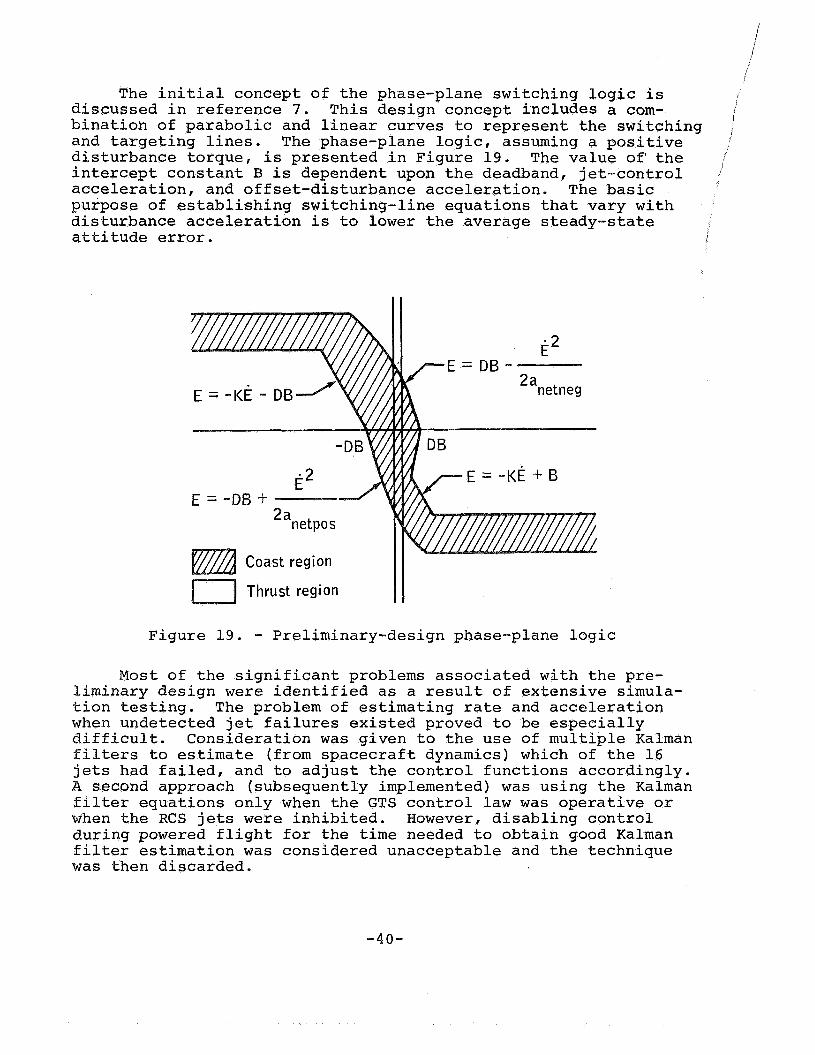
The initial concept of the phase-plane switching logic is discussed in reference 7. This design concept includes a com- bination of parabolic and linear curves to represent the switching , and targeting lines. The phase-plane logic, assuming a positive i
disturbance torque, is presented in Figure 19. The value of the I I
intercept constant B is dependent upon the deadband, jet-control acceleration, and offset-disturbance acceleration. The basic purpose of establishing switching-line equations that vary with disturbance acceleration is to lower the average steady-state
i
attitude error. i
3
E*
I Thrust region II Figure 19. - Preliminary-design phase-plane logic
Most of the significant problems associated with the pre- liminary design were identified as a result of extensive simula- tion testing. The problem of estimating rate and acceleration when undetected jet failures existed proved to be especially difficult. Consideration was given to the use of multiple Kalman filters to estimate (from spacecraft dynamics) which of the 16 jets had failed, and to adjust the control functions accordingly. A second approach (subsequently implemented) was using the Kalman filter equations only when the GTS control law was operative or when the RCS jets were inhibited. However, disabling control during powered flight for the time needed to obtain good Kalman filter estimation was considered unacceptable and the technique was then discarded.
-40-

A second problem was that minimum-impulse operation was not achieved using the initial design. Design-verification studies indicated that this problem was caused by rate-estimation in- accuracies and quantization effects. Four phase-plane logic mod- ifications were considered: establishing a zone 3 concept (Figure 13), discounting the computed TJET time when in zone 2 , setting the derived rate (under certain conditions) equal to a relatively large magnitude with the sign changed from the value used previously, and establishing the value FLAT as a function of inertia. The first modification was implemented in the prelim- inary design.
Significant design problems were identified with respect to Kalman filter performance. In simulation testing, this estimator was shown to be sensitive to slosh disturbances and large initial conditions. Furthermore, during the DPS start transient, the filter performance exhibited poor convergence because of engine compliance, propellant-fuel shift, and initial engine-mistrim conditions. The manner in which the Kalman filter estimate of acceleration was initialized was also of concern. The GTS open- loop drive technique influences how the initial acceleration estimate should be set for the next pass. The filter-extrapolation equations were also modified during the preliminary design phase. Originally,, the equations did not use information on the assumed GTS control effectiveness. The addition of the UG term [Equation (lo)] substantially improved the performance of the Kalman filter.
Another preliminary design problem concerned the vehicle performance during the DPS start transient. The convergence characteristics between the primary and secondary control modes were demonstrated to be marginal. The interaction of the GTS and RCS control modes under off-nominal conditions was of concern at that time, and proved to be a major motivation in the subsequent decision to redesign the control system.
The final problem concerned rate-overshoot performance during coasting maneuvers. The command-maneuver logic did not explicitly account for the finite time required to accelerate or decelerate to the desired maneuver rate, and additional jet firings resulted. To solve this problem, lag angles were provided to prevent over- shoot when initiating or terminating an automatic maneuver.
To conclude this section on preliminary design, a few general remarks on the control-system performance under off-nominal con- ditions are worthy of mention. Performance-verification studies indicated that the control system was insensitive to noise and small disturbance-torque conditions, but sensitive to inertia variations and thrust degradations (including undetected jet fail- ures).
-41-

SUNBURST Design Development , i i The base line design developed for the initial flight pro- )
gram (1) and design problems that occurred in that time period f
are presented in this section. The flight-test results of the SUNBURST DAP, flown on the Apollo 5 mission, will be presented in' a later section. This description of the SUNBURST design empha- sizes the modifications and additions to the preliminary base line design.
The state-estimator equations are structured in a manner similar to that outlined in the description of preliminary design. The rate equation for coasting flight is given by
5' h
w n = (1 - K) [ in-l + aJtJ] + TI n - 'n-1 ocJt/ ] 2 +
L
The rate-estimation equation for poweredKflight is identical to Equation (20) exce t that the term (1 - 2 TAos is added to the right-hand side. gOs is defined as the estimated disturbance acceleration caused by a main-engine thrust. During descent, 2 is determined every control period (T = 0.1 second) by os
AV + - T
A ME .Lt - -
A
I n-1 n AOS
For powered a.scent, the A,, estimate is evaluated every 2 seconds by
4 (ti ;.I It is interesting to note that the rate- and acceleration-
estimate equations are coupled for ascent. 'The filter gains, K and C, were established through detailed simulation testing. The nominal value of K for coast and descent is 0.5. The gains values
-42-

for ascent are time variant to accommodate a nominal offset- acceleration profile and are given as
0.56 t 400 K = 0.44 +
0.5 t 400 C = 0.25 +
Kalman filter equations are used during the primary (GTS) mode and are updated every 50 milliseconds. These equations are programed in gimbal-angle coordinates and are given as
1 A I -w
CDU = CDU + Wo CDU - CDU A
C6U = CbU' + W1 (C6U - CDU' ) -., .. 1 .. 1 A
CDU = CDU + W2 (CDU - CDU )
The assumed extrapolated state equations are expressed by
where the assumed GTS control-effectiveness term is transformed to gimbal-angle coordinates.
A description of the RCS control laws associated with the SUNBURST design is necessary to the discussion of development. The basic structure of the switching lines was modified from the structure shown in Figure 19 to a format using only parabolic equations. Most of the design description has emphasized the single-plane aspects of the control-system development. A design area unique to the LM-thruster geometry (RCS jets 45 degrees from the body axes) was the logic of establishing the desired axes of rotation when simultaneous errors in pitch and roll occur. For the SUNBURST design, the Q/R axes were chosen for the control laws, and the concepts of urgency functions and urgency plane were established. Urgency functions in both the Q- and R-axes
-43-
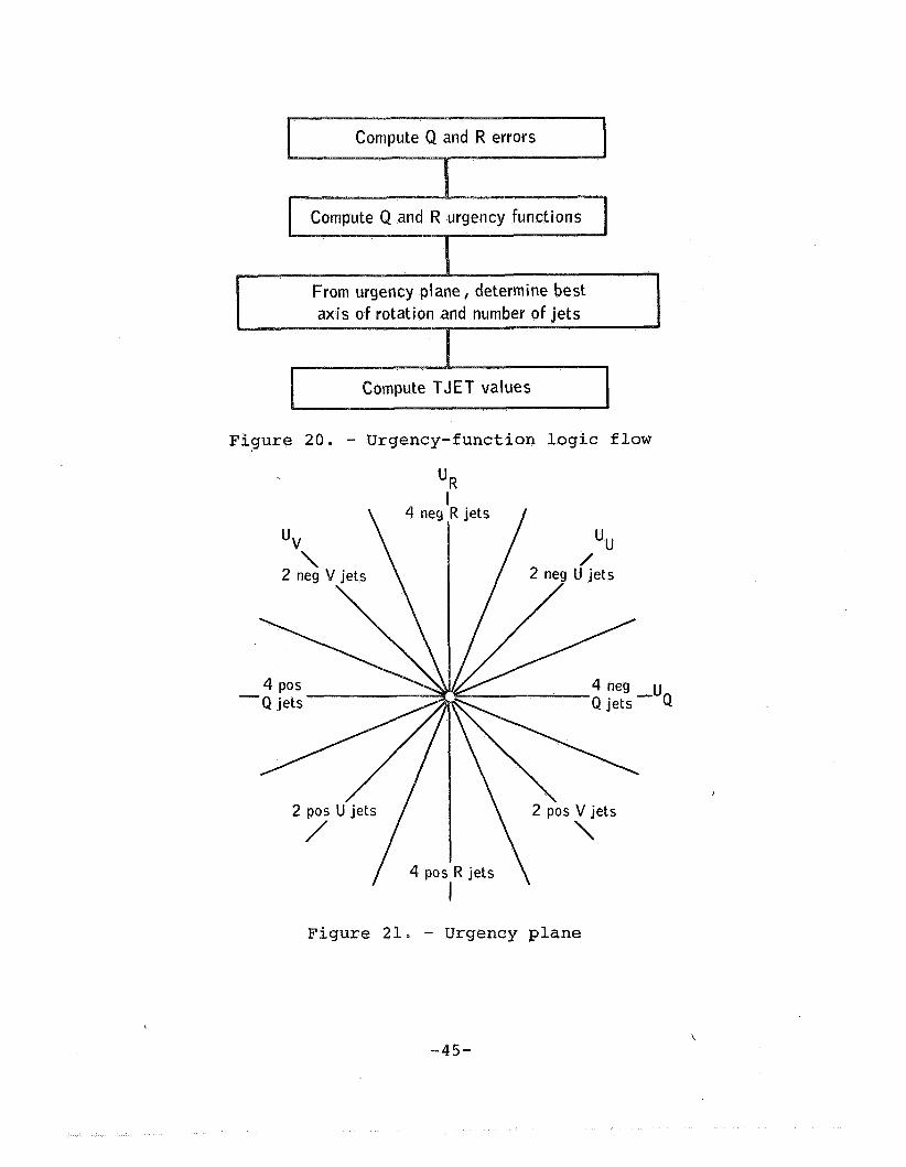
were developed to measure the state location from the coast region, as well as to measure the RCS propellant penalty if the design to apply torque be deferred. These functions are approx- imately equivalent to the torquing time needed to reach the boundary of the coast region. The logic flow associated with the urgency-function concept is presented in Figure 20.
The urgency plane used to select the desired axis of rotation is illustrated in Figure 21.
The two urgency functions UQ and UR define a position in the urgency plane and thus establish the desired axis of rotation from the eight rotation sets available (+R, +Q, +U, +V) . Additional logic is applied to determine the number of jets to be used in the chosen axis.
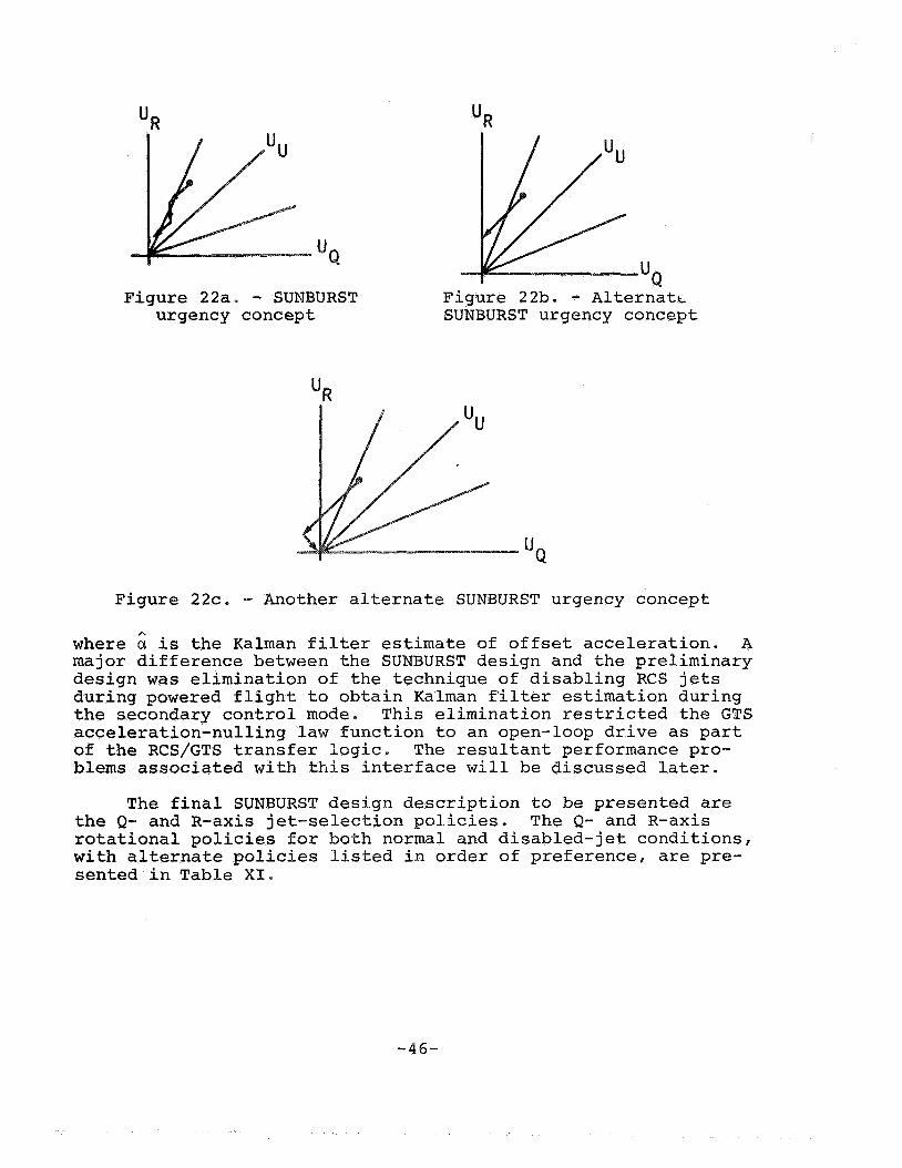
Two alternate approaches will give some insight into the de- sign trade-offs. To illustrate the techniques, one must assume that the urgency functions in UR and UQ are initially established as shown in Figure 22a. The SUNBURST design logic will command a U rotation, then an R rotation, then a U rotation - until the urgency-function errors are nulled. An alternate design approach would be to null all U errors first, and then command the re- maining R errorsF as shown in Figure 22b.
The alternate approach is attractive in that advantage may be taken of the diagonal-jet moment arm; but, during certain dis- turbance-torque conditions, the delaying of the R correction could give undesirable performance. A second alternate approach (im- plemented in the subsequent redesign) would be to transform the original errors into the U- and V-axes, and to command U and V as shown in Figure 22c. Because the control-axis torques in U and V are decoupled, these corrections can be applied simultaneously. The logic simplifications that result from this design approach are significant; however, inefficiencies do occur for a detected jet failure, as discussed in reference 8.
A brief description of the GTS control laws associated with the SUNBURST design is needed. The time-optimal attitude-control law provided by equations (16), (17) and (18) was 'developed for the primary control mode in which the attitude-state errors are obtained from the Kalman filter equations. This design satisfies the requirement for an independently stabilized DPS control. The GTS acceleration-nulling law is used as part of the transfer logic from the primary mode to the secondary mode. The open-loop drive- time equation is
h
a M Li
I
T =
-44 -
Compute TJET values
Figure 20. - Urgency-function logic flow
/ 4P0
& jets
Q jets -"Q
t jets
Figure 21. - Urgency plane
-45-
"R "R
Figure 22a. - SUNBURST urgency concept
Figure 22b. - Alternatt SUNBURST urgency concept
Figure 22c. - Another alternate SUNBURST urgency concept
where is the Kalman filter estimate of offset acceleration. A major difference between the SUNBURST design and the preliminary design was elimination of the technique of disabling RCS jets during powered flight to obtain Kalman filter estimation during the secondary control mode. This elimination restricted the GTS acceleration-nulling law function to an open-loop drive as part of the RCS/GTS transfer logic. The resultant performance pro- blems associated with this interface will be discussed later.
The final SUNBURST design description to be presented are the 9- and R-axis jet-selection policies. The Q- and R-axis rotational policies for both normal and disabled-jet conditions, with alternate policies listed in order of preference, are pre- sented in Table XI,
-46-

TABLE XI
-V
+Q (+x sensea)
-Q (+X sense)
+R (+X sense)
-R (+X sense)
2, 9 2; 9
2, 5, 9, 14 2, 14; 2, 5; 9, 14; 5, 9
1, 6, 10, 13 6 , 10; 1, 6 ; 10, 13; 1, 13
1, 5, 10, 14 10, 14; 1, 14; 5, 10; 1, 5
2, 6, 9, 13 2, 6; 6, 9; 2, 13; 9 , 13
Several problems occurred during the SUNBURST design phase. The general area associated with the descent primary/secondary mode interface was tested under extreme conditions, with parti- cular emphasis upon the DPS start-transient performance. The nominal start-transient thrust profile for DPS powered-flight firings is presented in Figure 23. A "mass lockout" problem can occur for certain off-nominal conditions, when the thrust is operating at a maximum value of 10,500 pounds. One of the logic conditions needed for mandatory secondary control mode operation
-47-

is that a change in throttle setting has occurred. This logic is applied when a change in thrust command Tc is sufficiently large to satisfy the inequality.
- ME AV >525 pounds TC
When Tc is operating at a maximum value of 10,500 pounds, a mass of 5 percent or more will cause the primary control mode to be locked out. The intent of this logic was to inhibit Kalman filter estimates of offset acceleration when actuator-compliance effects were introduced by changing throttling conditions. This potential problem with the interface logic was corrected in the SUNDANCE redesign.
, The performance of the primary/secondary modes during the DPS start-transient period was of sufficient concern to require design modifications before the mission. The major problem was caused by errors introduced in the open-loop drive-time equation and by the subsequent poor convergence characteristics of the primary/secondary control modes. The effect of a drive-time error is to maintain a residual offset disturbance torque while the system is in the secondary mode. If this offset be large, the RCS jets converge the attitude and rate errors very slowly to the region in which return to the GTS control is made. During this period, the jets must fire to combat the sustained offset dis- turbance. An example of this type trajectory behavior is shown in Figure 24.
Factors that significantly contribute to the error in open- loop drive time are
I .
1. Propellant-fuel shift during ullage and the low throttling-time period
2. Actuator mount compliance 3 . Uncertainties in the assumed values of M, L, I,
4. Kalman estimate of offset acceleration and 6
a. Insufficient measurements ~ - b. Propellant-slosh dynamics c. Attitude-rate initial conditions d. Measurement noise
Simulation testing indicated that these factors could seriously degrade the performance of the control system during the DPS start-transient period. Design modifications were made to improve the RCS/GTS logic interface and the quality o’f the Kalman estimate of offset acceleration. The modified interface logic is given in
-48-

0.5
-0.5
0 26 Time, sec.
Figure 23. - Throttle profile
I RCS control law Ini t ia l condition upon entering
i 4 I
Figure 24. - Example of RCS/GTS convergence
Reqion for transfer from RCS to GTS
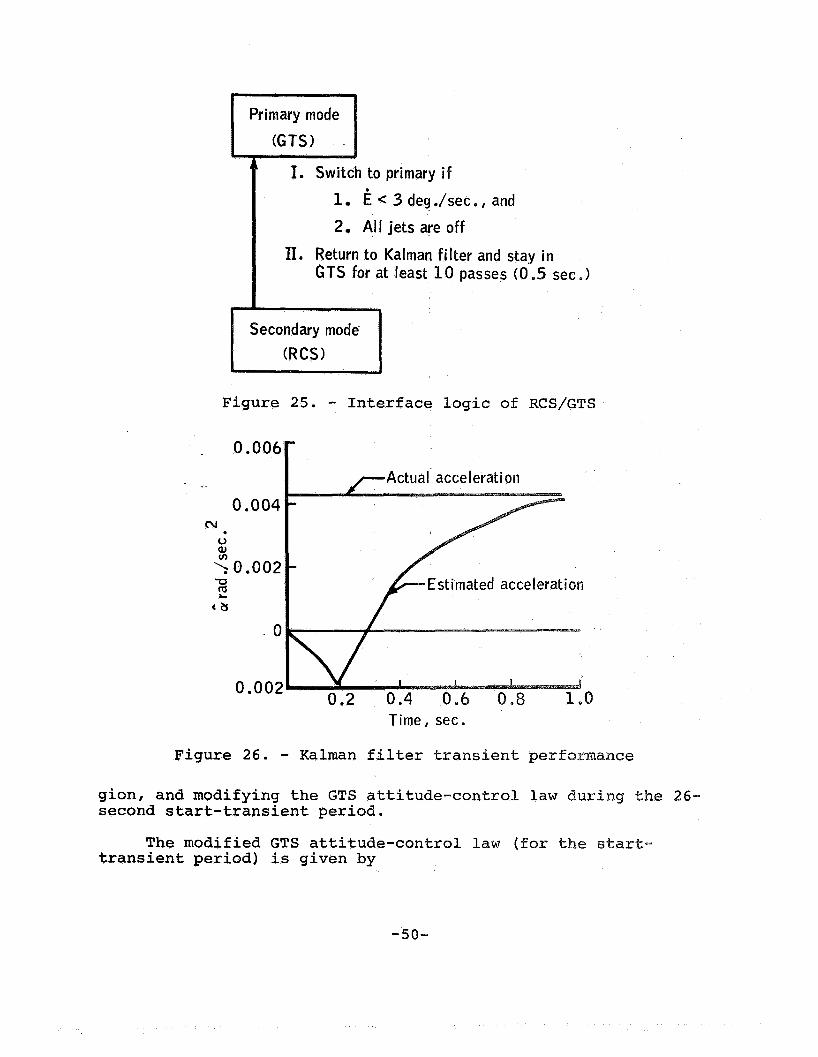
Figure 25. The interface logic shown provides significantly im- proved convergence characteristics at the expense of permitting large attitude errors during the transfer of control modes. The additional logic of insuring a minimum number of measurements for the Kalman filter was inserted because of the transient charac- teristic of the estimator. An actual acceleration-estimate re- sponse (9) is shown in Figure 26. For the simulation response shown, the acceleration estimate contained an error in sign for the first few measurements.
' Four additional design modifications were made to improve the DPS start-transient performance: modifying the Kalman filter weighting values, limiting the maximum open-loop drive time to 15 seconds, forcing the primary control (and Kalman filter esti- mates) at specific times when operating in the low-throttle re-
-49-
to primary i f
P i c 3 deg ./set., and
2 Al l jets are off
11. Return to Kalman fi l ter and stay i n GTS for at least 10 passes (0.5 sec.)
Figure 25. - Interface logic of RCS/GTS
cv . u 0)
0.006 Actual acceleration
0.004
0.002 Estimated acceleration
. o
0.002
Time, sec.
Figure 26. - Kalman filter transient perf gion, and modifying the GTS attitude-control law second start-transient period.
transient period) is given by The modified GTS attitude-control law (for %he
-50-

A
u = -sgn(a) (32)
The modified design was considered acceptable for the first un- manned flight, although the inherent properties of the open-loop gimbal drive was of concern.
In August 1967, a decision was made to redesign the DAP; the SUNDANCE design, previously described, was the result of this re- design effort. The objectives of the redesign were to reduce memory-storage requirements, improve off-nominal performance, and reduce computer-execution time. The five major changes that re- sulted included elimination of the urgency-function concept, simplification of the jet-selection logic, simplification of the RCS control-law logic, improvement in the GTS/RCS interface de- sign, and development of an integrated state-estimator design.
TESTING AND VERIFICATION
The mission-verification and design testing conducted on the SUNDANCE DAP is discussed next. The primary objectives of pre- flight testing were to validate the control-system performance during nominal conditions, off-nominal conditions, and mission- related conditions. The types of simulation facilities used in- cluded engineering digital simulators, interpretive computer simulators (ICs), and hybrid simulators.
Engineering simulators were used during initial development (or modification) phases to provide dynamic validation and per- formance evaluation of the functional design under a broad spec- trum of mission conditions. The ICs bit-by-bit simulator modeled the detailed computer characteristics, and was used to verify the software-programing design. Parameter-type studies associated with off-nominal performance are generally inefficient to run on the ICs. However, nominal-performance verification is conducted on a mission-by-mission basis. The hybrid simulators were used to verify hardware/software interfaces, and to provide overall system-performance validation. With respect to the DAP, both de- sign-validation and mission-verification testing programs were conducted on hybrid simulators.
The formal testing conducted on the SUNDANCE DAP design is reported in references 8 , 10, and 11. Reference 10 is an excellent test-results document. All control modes of flight were tested during nominal-performance conditions, RCS jet-failure conditions, and incorrect-mass-property conditions. Powered-flight testing included recovery from large rate and attitude errors, DPS/APS start-transient performance, and performance with large offset accelerations. A general summary of the test results follows.
-51-

” 1. Nominal performance was satisfactory (all modes).
(coasting modes).
achieved.
degraded by jet failures.
sitive to inertia mismatch (errors of 225 percent were tolerable).
2. Minimum-impulse limit cycles were achieved
3 . Efficient, automatic attitude maneuvers were
4 . Translation-acceleration capibility was
5. Powered flight modes were relatively insen-
Several test results from reference LO are presented to indicate performance trends.
The RCS propellant consumed during a 2-degree-per-second maneuver is shown in Figure 27 as a function of mass mismatch. The theoretical fuel (1.21 pounds) is substantially below the
/ 2.4 Tlieoretical fuel cotlsuinptiotl = 1 . 2 1 Ib.
2.3} Descetit coiifiytiratioii 0 I
2.2
2 . 1
=‘ 2 .o - 0
g 1 . 9 -
-
- 3 -
Noinitial data load @
In c - 8 1.8 2 v 1 . 7 -
- -
1 . 5 -
1.6 - I I 1 I I I I
1 6 , 2 0 0 18,600 21,000 23,400 25 ,800 28 ,200 30,600 LM mass, Ib.
Figure 27. - RCS fuel for 2 deg /see maneuver
minimum fuel usage (1.55 pounds), because the theoretical model does not account for jet-plume-impingement forces. A summary of descent-configuration maneuver performance for various jet-failed conditions is presented in Table XII.
For the third condition listed, the fuel consumed was less than nominal. The reason for this paradox is that the jet 10 im-
-52-
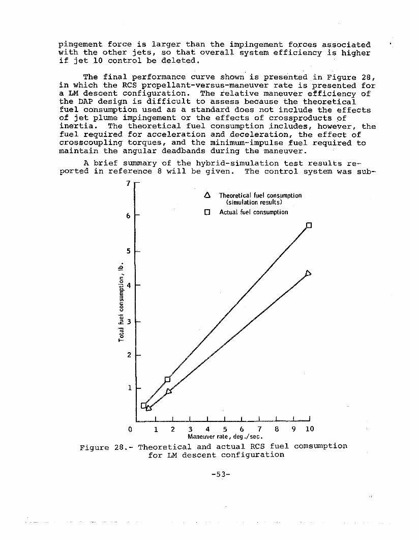
pingement force is larger than the impingement forces associated e
with the other jets, so that overall system efficiency is higher if jet 10 control be deleted.
The final performance curve shown is presented in Figure 28, in which the RCS propellant-versus-maneuver rate is presented for a LM descent configuration. The relative maneuver efficiency of the DAP design is difficult to assess because the theoretical fuel consumption used as a standard does not include the effects of jet plume impingement or the effects of crossproducts of inertia. The theoretical fuel consumption includes, however, the fuel required for acceleration and deceleration, the effect of crosscoupling torques, and the minimum-impulse fuel required to maintain the angular deadbands during the maneuver.
ported in reference 8 will be given. The control system was sub- A brief summary of the hybrid-simulation test results re-
0 1 2 3 4 5 6 7 8 9 1 0 Maneuver rate, deg ./sec.
Figure 28.- Theoretical and actual RCS fuel cornsumption for LM descent configuration
-53-
3r P 3 m I3 m w E-r pc; w 3
i5 B H z B 3 t3 H
# I I3 z w # m w cl
a &
rl ni
rl e
In In
rl .
r l m I n 00-
m r l m r l m m
. . .
000 Na3d
w 0
N
N
l- d m W M a3
rl rl rl . e
m o w do03 cowl- OMCO m o m T r ' c o e
o o m m o m m o m No30 rla3M rlcOm
. . . . . . 0 . .
N cu N
N ni OI
rl rl
-54-
rl cu rl .
In In
rl
000 meow
m 0
N
N
jected to a realistic flight environment including the effects of RCS thruster impingement, propellant slosh, and actuator com- pliance. Off-nominal spacecraft environments included inertia, thrust, and center-of-mass uncertainties; DPS actuator-drive un- certainty; and RCS jet failures, The verification-run matrix associated with the hybrid testing was quite extensive. Inte- grated guidance and control hardware and a flight attitude table were used in the test facilities. Twenty-seven discrepancy items reported by the testing activity required formal disposition. Virtually all items requiring minor design modifications were in- corporated into the lunar-landing-mission program.
An interesting design problem occurred in the area of in- ertia cross-coupling effects. With the TJET calculations estab- lished in the U/V-axes system, an RCS torque applied around the U-axis produces not only an acceleration around the desired U- axis, but also, in general, a coupled acceleration about the V- axis. The same situation applies to an RCS torque applied around the V-axis. The simplified equations of motion that demonstrate the effect of inertia crosscoupling are written as
Mv Iyy + IZZ
YY IZZ
Iyy - I Z Z YY 5-2 MU + 21 u = u 21 ( 3 3 )
( 3 4 )
where w = angular velocity
MU,% = applied torque I
= principal moments of inertia yy' I Z Z I
This inertia crosscoupling effect between applied U/V tor- ques and resulting U/V angular accelerations is significant only when the pitch and roll moments of inertia are substantially different. For powered-ascent operation, these inertia values were sufficient to cause crosscoupling that resulted in undesired limit-cycle performance. A subsequent design modification was made to eliminate the inertia crosscoupling effects. A non- orthogonal set of control axes U'/V' was defined which has the property that a pure U torque produces no observable acceleration in the V' direction, and a pure V torque produces no observable acceleration in the U' direction. This. U'/V' nonorthogonal system can be constructed as shown in Figure 2 9 .
-55-
The desired relationship between the U- and V-axes! and the U- and V-axes can be obtained if the transformation angle satisfies
The implementation of this control law where the crosscoupling accelerations are eliminated is described as follows, The vehi- cle state is estimated in the P-, Q-, R-axis system. When RCS control is to be applied, the Q and R components of error angle and rate are transformed to the U'/V' system. Errors about the U'-axis are controlled by firing a U-axis RCS torquel and errors about the VI-axis are controlled by firing a V-axis RCS torque.
FLIGHT TEST RESULTS
The flight results discussed include test data from the un- manned Apollo 5 mission and the manned Apollo 9 mission. Typical flight-data results are presented to indicate performance trends. The ability to match the preflight-simulation test results closely with the actual flight data is dependent upon the quality of the telemetered data and the knowledge of the spacecraft environment. In general, powered-flight maneuvers and coasting-flight attitude maneuvers can be closely duplicated, but attitude-hold limit- cycle behavior is more difficult to match in the postflight analysis process. For the test data shownl. a data-sampling fre- quency of one sample per second was available.
Only the DAP coasting-flight modes were exercised on the Apollo 5 flight. Flight data for an automatic 5-degree-per- second attitude maneuver showed close agreement with simulation data, As reported in reference 12, the Apollo 5 mission provided some unplanned limit-cycle data during coasting ascent because of a mass-mismatch condition. This situation arose because, although the spacecraft was actually in an ascent configuration, the DAP computed the vehicle inertia to be that of the unstaged LM, As a consequence of the 300-percent inertia-mismatch condition, a vir- tually continuous-firing limit cycle resulted. The narrow- deadband attitude-hold logic did maintain the desired conditions, however. After this operation, one RCS propellant system was allowed to fire to depletion, and data were taken at various lower thrust levels as the propellant was being depleted, Almost immed- iately, the limit-cycle characteristics began to improve, and eventually the attitude-hold function settled into a minimum- impulse condition.
Limit-cycle data were also analyzed during the descent-coast phase of the Apollo 5 mission (13). Une p1aine.d limit-cycle tra-
-56-

jectories in both pitch and roll phase planes, which were asymmetrical in computed error rate and symmetrical in attitude error, were observed. A representative trajectory is shown in Figure 3 0 . During a ?-Four period, 125 jet firings occurred, approximately 3 0 of wh:<th had durations of from 50 to 110 milli- seconds.
Preflight verification testing indicated that 16-millisecond (minimum-impulse) firings should occur at the deadband extremities. An extended effort was made to match the flight-test data through simulation testing. Inertia coupling, aerodynamic torques, and diagonal. firing logic were all examined, but the observed limit- cycle phenomenon was only partially explained.
During another descent-coast phase, a different limit-cycle characteristic (Figure 3 1 ) was obtained. These trajectories con- tained 20-millisecond firing times, with the limit cycle restrained to one side of the attitude deadband.
This trajectory condition generally occurs during sustained torque disturbances. Limited post-flight data prevented iden- tifying the exact nature of this disturbance, but a combination of aerodynamic torque and rate-estimation error was believed to have been the cause.
The Apollo 9 mission, during which the LM was manned for the first time, was flown in earth orbit. All powered- and coasting- flight DAP modes were exercised during the mission, and the con- trol system performance was generally excellent. No anomalous or unexpected control-system conditions occurred. Data examined in the postflight analysis included peak-to-peak rates, attitude- deadband excursions, general limit-cycle characteristics (in- cluding existence of disturbance torques), and trim-gimbal per- formance.
Several flight-data results are given to indicate general performance. A 2-degree-per-second maneuver response for the as- cent configuration is illustrated in Figure 3 2 . A slight over- shoot occurred in the Q- and R-axes, but overall rate performance was satisfactory. This overshoot was caused by rate-estimator errors.
A phase-plane plot of the limit-cycle performance during a powered ascent firing is presented in Figure 3 3 . The intent of the plot is to trace the shape of the limit-cycle trajectory. Because of the data-sampling limitations, only discrete data points in the phase pl?.ne are available. The plot does indicate on a quantitative basis that the results are within a range con- sistent with preflight simulation results.
-57-

Figure
0.5
0.4 1
29. - Nonorthogonal U'/V' system
i Two-jet flruig for 0.090 sec .-7 0.3
0.2
; 0.1
> o . -0.1 -0.2
VI
J,
-cI
o-jet firtiiy for 0.02 sec.
4 W
-0.3
-0.4
-0.5
E , deg. 9
30. - Pi t ch - ra e erxor versu itch error during eseent-coast
r 0,03
0.02
0.01
8)
'0 . -0.01 CT
(bl
-0.02
-0.03
-0.04
eh error during se
--7- ----
-.8 I I I I I I I I I I I 1 0 2 4 6 8 10 12 14 16 18 20 22
Time, sec.
ure 3 % . - Attitude maneuver during ascent-coast phase
he final Apol o 9 flight- est results presented (Figure 3 4 ) is a plot of pkase- l ane ~ttitu e p e r ~ ~ r ~ ~ n ~ e during a DpS in- sertion firing. formance - The results indicate nominal attitude-hold per-
CQNCLUSIONS
The history of th,e desi eneration digi 01 system has been ed in this case
ternsp it is that increased emphasis will be placed tudy. Because esign flexibility i in digital
sl-system techniques.
as been writte stem designer works implicit perspectiv oint of the relative
ewing the design his-
impo~ta~ce of optimal control and modern control techniques.
ring development of the DAP
n development, ues may un-
al decision
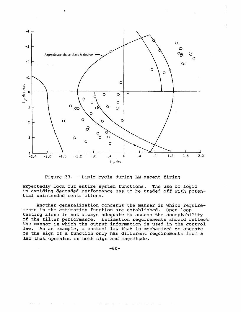
Figure 3 3 . - Limit cycle during LM ascent firing expectedly lock out entire system functions. The use of logic in avoiding degraded performance has to be traded off with poten- tial unintended restrictions.
Another generalization concerns the manner in which require- ments in the estimation function are established. Open-loop testing alone is not always adequate to assess the acceptability of the filter performance. Estimation requirements should reflect the manner in which the output information is used in the control law. As an example, a control law that is mechanized to operate on the sign of a function only has different requirements from a law that operates on both sign and magnitude.
-60-

0.05
V
\ 2 g 0 -0 . Q
w
-0 -05 -1 .O -0 ,5 0
Ep, deg, 0.5 1 .o
4 - ._ : L a m i t cycle during LM descent firing
Further research e f f o r t snou”Ld be expended to develop addi- tional analytical tec n i q u e s for digital control-system design. Adaptive design teefan q u e s making- use of the inherent flexibility available in ds. i t a 1 systems shouPd a l s o be established.

REFERENCES
1.
2.
3 .
4.
5.
6.
7.
8.
9.
10.
11.
12.
13.
"Guidance System Operations Plan AS-206," MIT Instr. Lab., Rep. R-527, Vol. I,. Rev. 1 (Jan. 1967)
Covey, R. R., R. B. Sherwood, and S . H. Wu, "Apollo Digital Reaction Control System Design Studies," TRW Space Technology Lab., Rep. 4181-6010-KU000 (Apr. 5, 1965)
"Guidance System Operations Plan for Manned LM Earth Orbital Missions Using Program SUNDANCE," MIT Instr. Lab., Rep. R-557, Sec. 3 (Sept. 1968)
"Design Verification and Performance Evaluation of the Lunar Module Digital Autopilot," TRW Systems Group, Rep. 05952- 6078-R0-00 (Nov. 1966)
"Preliminary Analysis of Sampling Rate Requirements and Digital Computer Functional Considerations for Design of LEM Digital Autopilot," GAEC, Rep. LMO-500-211 (Sept. 9, 1964)
Heiber, A., J. M. Nervik, and E. A . Nussbaumer, "Apollo Block I1 CM and LM Guidance and Control Study," Bellcomm, Inc., TM-64-1021-3 (Dec. 17, 1964)
Cherry, George, and Joseph O'Connor, "Design Principles of the Lnnar Excursion Module Digital Autopilot," MIT Instr. Lab., Rep. R-499 (July 1965)
"Performance and Analysis of GFE SUNDANCE Digital Autopilot," GAEC, Rep. LED-500-23 (Feb. 1969)
"Evaluation and Analyses of GFE Digital Autopilot (DAP) Per- formance," GAEC, Rep. LED-500-17 (July 1967)
"LM Digital Autopilot Simulation Results Using Program SUNDANCE," MIT Instr. Lab., Rep. E-2377 (Jan. 1969)
"Digital Autopilot Software Verification Test Results Summary for Mission D - SUNDANCE and COLOSSUS IA," TRW Space Tech- nology Lab., Rep. 11176-H149-RO-00 (Feb. 1969)
"LM-1 Guidance and Control Systems Postflight Analysis," GAEC, Rep. LMO-500-657 (Apr. 5, 1968)
"Supplement 4 to Apollo 5 Mission Report - Analysis of Digital Autopilot Performance," TRW Space Technology Lab., Rep. 11176-H061-RO-00 (Oct. 1968). A l s o available as MSC-PA-R- 68-7, Supplement 4 (Jan. 1969)
-62-