Embed Size (px)
Citation preview

(The photo of the unit is indicative and may vary depending on the model)
ErP READYSYSTEM EFFICIENCYHIGH EFFICIENCY AT PARTIAL LOADHIGH EFFICIENCY COMPONENTSEXTENSIVE OPERATING LIMITSINTEGRATED HYDRONIC MODULE
Climaveneta Technical Bulletini-BX 004 - 035_202102_EN HFC R410A
i-BX 004 - 0354,30-35,1 kW
Chiller, air source for outdoor installation

Quality System complying with the requirements of UNI EN ISO 9001:2008 regulationEnvironmental Management System complying with the requirements of UNI EN ISO 14001:2004 regulation
Occupational Health and Safety Management System complying with the requirements of BS OHSAS 18001:2007
CERTIFICATIONS
cations
V cations
System certi cations
Check ongoing validity of certi cate:www.eurovent-certi cation.com
orwww.certi ash.com

i-BX_004_035_202102_EN HFC 410A3
i-BX 004-035
INDEX
Liability disclaimerThe present publication is drawn up by of information only and does not constitute an offer binding upon Mitsubishi Electric Hydronics &
IT Cooling Systems S.p.A.
Mitsubishi Electric Hydronics & IT Cooling Systems S.p.A. has compiled the content of this publication to the best of its knowledge.
The data contained herein are subject to change without notice. Mitsubishi Electric Hydronics & IT Cooling Systems S.p.A. explicitly
rejects any liability for any direct or indirect damage, in the broadest sense, arising from or related to the use and/or interpretation of
this publication.
All content is copyrighted by Mitsubishi Electric Hydronics & IT Cooling Systems S.p.A.
The units highlighted in this publication contain HFC R410A [GWP100 2088] fluorinated greenhouse gases.
1. PRODUCT PRESENTATION 5
2. UNIT STANDARD CONFIGURATION 7
3. ELECTRONIC CONTROLLER 8
4. OPERATING CHARACTERISTICS 9
5. ACCESSORIES 11
6. GENERAL TECHNICAL DATA 16
7. ENERGY EFFICIENCY 18
8. OPERATING LIMITS 18
9. ETHYLENE GLYCOL MIXTURE 19
10. FOULING FACTORS 19
11. HYDRAULIC DATA 19
12. MINIMUM AND MAXIMUM SYSTEM WATER CONTENT 21
13. SYSTEM PUMP CURVES 22
14. HYDRONIC GROUP 24
15. UTILITY WATER CIRCUIT CONNECTION DIAGRAM 25
16. ELECTRICAL DATA 26
17. FULL LOAD SOUND LEVEL 27
18. POSITION OF THE WATER CONNECTIONS 28
19. DIMENSIONAL DRAWINGS 29

Functions
Cooling
Refrigerant
R-410A
Compressors
Scroll compressor
Fan
Axial fan
Exchangers
Plates
Other features
Eurovent
Inverter Driven Compressor
Electronic Expansion Valve
Rotary compressor
LEGEND
4i-BX_004_035_202102_EN HFC 410A
i-BX 004-035

i-BX_004_035_202102_EN HFC 410A5
i-BX 004-035
1. PRODUCT PRESENTATION
1.1 GREEN CERTIFICATION RELEVANT
Mitsubishi Electric Hydronics & IT Cooling Systems S.p.A., as a
major player in the world HVAC market and a leading manufac-
turer of energy efficient, sustainable HVAC solutions, recog-
nizes and supports the diffusion of green certification systems,
as an effective way to deliver high performance buildings and
improve the quality and the sustainability of the built environ-
ment.
Since the first certification system was introduced at the begin-
ning of the 1990s, the demand for certified buildings has grown
considerably, as well as the number of standards, rating and
certification programs.
Operating worldwide Mitsubishi Electric Hydronics & IT Cooling
Systems S.p.A., has extensive experience with many of them
and is active member of Green Building Council Italy.
Mitsubishi Electric Hydronics & IT Cooling Systems S.p.A.,
commitment to develop responsible and sustainable HVAC
solutions, is reflected by a full range of premium efficiency prod-
ucts and systems, designed with special care to improve build-
ing energy performance ratings, according to major certification
protocols, including LEED, BREAM, GREENSTAR, BCA,
NABERS, DNGB, HQE and BEAM.
To find out more about how our products contribute to
enhanced green certification rating and energy performance of
a building, please refer to:
https://www.melcohit.com/GLOBAL/Company/Green-Certifications/
QR%20code/

6i-BX_004_035_202102_EN HFC 410A
i-BX 004-035
1. PRODUCT PRESENTATION
1.2 NOMENCLATURE
1 2 3 4 5 6 7 8 9
i - B X - N - 0 0 4 M H A N R V Code Descriptions Extensions
1 Modeli-BX Chiller
i-BX-N Heat pump
2 Segment- Comfort
Y Process
3 Nominal capacity [kW] 004-006-008-010-013-015-020-025-030-035
4 Power supplyM 230/1/50
T 400/3/50
5 Hydronic ModuleN Without hydronic module
H Withhydronic module
6 Tube & Fin coil
A Cu/Al regular coil
B Cu/Cu tube & fin coill
E Epoxy pre-painted fins
7* Basement electric heaterN Without basement electric heater
S With basement electric heater
8 Coil protection grillN Without protection grill
R With protection grill
9 Structure & Panelling V All parts polyester-powder painted
Outdoor unit for cold water production, with hermetic rotary
compressors with variable speed (Inverter Driven) in a single-
circuit configuration using R410A refrigerant, air side heat
exchanger with copper tubes and aluminum fins, water side
steel brazed plate heat exchanger. The unit is equipped with
electronic expansion valve and integrated hydraulic module as
standard.
Flexible and reliable unit that adapts to the actual load condi-
tions thanks to the accurate temperature control combined with
the use of inverter technology. The high performance at both full
and partial load, is achieved due to the accurate design of the
unit and the use of variable speed motor (inverter).
The chillers i-BX are used in many applications, even complete-
ly different from each other, suitable for comfort and industrial
processes, without making any compromises.
1.3 ErP READY
The high level of efficiency of i-BX at partial load meets and
exceeds the minimum seasonal efficiency for cooling, SEER,
according with the eco-sustainable design requirements for all
products using energy.
For this reason, the unit represents the best choice for all the
hydronic application on the residential and commercial markets.
The unit is suitable also for industrial market, satisfying the sea-
sonal energy performance ratio SEPR.
1.4 SYSTEM EFFICIENCY
The unit is designed with a system approach: all components
are set in sinergy according to a proprietary logic to obtain the
highest efficiency.
1.5 HIGH EFFICIENCY AT PARTIAL LOAD
High seasonal efficiency in both heating and cooling mode,
using DC inverter technology to modulate compressor operation
and deliver the exact amount of energy based on the actual
needs of the building. High efficiency for low energy consump-
tion during the operating hours.
1.6 HIGH EFFICIENCY COMPONENTS
In terms of improving performance and reducing power con-
sumption, the electronic thermostatic valve is a key component
that maximises system efficiency, as well as the hydronic kit
with inverter water pump and the modulating the fans speed as
standard equipments.
1.7 EXTENSIVE OPERATING LIMITS
Full load operation is ensured with outdoor air temperature up
to 45°C during summer and down to -10°C of outdoor air tem-
perature during winter. Production of evaporator leaving water
temperature from -8°C to 18°C.
1.8 INTEGRATED HYDRONIC MODULE
The integrated hydronic include all the water circuit components
(anti-freeze electrical heater on plate heat exchanger, air
release valve, flow switch, water filter, safety valve, EC water
pump
*Not available for i-BX

i-BX_004_035_202102_EN HFC 410A7
i-BX 004-035
2.1 Air cooled chiller, air source for outdoor installation
Outdoor unit for cold water production, with hermetic rotary
compressors with variable speed (Inverter Driven) in a single-
circuit configuration using R410A refrigerant, air side heat
exchanger with copper tubes and aluminum fins, water side
steel brazed plate heat exchanger. The unit is equipped with
electronic expansion valve and integrated hydraulic module as
standard.
A flexible and reliable unit that adapts to the actual load condi-
tions thanks to the accurate temperature control combined with
the use of inverter technology. The precise design and the use
of innovative variable speed motors (inverters) ensures a high
level of energy efficiency both at full and partial loads.
The chillers i-BX are used in many applications, even complete-
ly different from each other, suitable for comfort and industrial
processes, without making any compromises.
2.2 Structure
Structure in hot-galvanised shaped sheet steel with a suitable
thickness. All parts polyester-powder painted RAL 7035. The
self-supporting frame is built to guarantee maximum accessibili-
ty for servicing and maintenance operations.
2.3 Panelling
The external paneling made from hot galvanised metal plate
and painted with epoxy powder coat RAL 7035. The panels are
easy to remove for quick and easy access to the inside compo-
nents from either side of the unit.
2.4 Variable-speed compressor
The inverter scroll compressor uses a brushless Interior Perma-
nent Magnet (IPM) design to give you higher efficiency across a
wider range of applications and with an oil sump heater.
Inverter logic ensures a soft start that reduces inrush current.
The frequency converter is designed with built-in harmonic fil-
ters, making it easy to install in the electrical panel while com-
plying with industry standards.
2.5 Utility-side heat exchanger
Braze welded AISI 316 steel plate heat exchanger. The heat
exchangers are lined on the outside with a layer of closed-cell
neoprene to prevent condensation.
When the unit is operating, the heat exchangers are protected
against no flow conditions by a flow switch. The unit is also
ready to operate using non-freezing fluid mixes, down to heat
exchanger outlet temperatures of -8° and with a frost protection
heater on the heat exchanger.
2.6 Source-side heat exchanger
Finned coil heat exchanger made of copper tubes and alumini-
um fins, spaced apart so as to guarantee maximum heat
exchange efficiency. The unit is fitted as standard with protec-
tion grills on the coil.
2.7 Fans
Axial-flow fans with IP 54 ingress protection, external impeller,
pressed metal blades, housed in aerodynamic tubes, complete
with accident prevention grill. Six-pole electric motor with inte-
grated thermal protector. Continuous fan speed control by pres-
sure transducer.
2.8 Refrigerant circuit
Main components in the refrigerant circuit:
- refrigerant R410A
- electronic thermostatic valve,
- filter-drier,
- high safety pressure switches,
- low and high pressure transducers.
2.9 Power and control electrical panel:
Power and control electrical panel built in compliance with EN
60204-1/IEC 204-1, complete with:
- Compressor circuit breaker,
- Electronic controller,
- Numbered control circuit cables,
- Continuous fan speed control,
- Pump enabling relay,
- Fan start capacitor,
- System water pump protection fuse,
- Auxiliary circuit protection fuse,
- Fan protection fuse,
- Board power supply protection fuse,
- Spring terminal blocks for the control circuits,
- Remote ON/OFF terminals,
- Demand limit /night mode terminals
- Reduced electricity rate terminals
- Alarm/secondary pump/dehumidifier terminals,
- Buffer tank probe terminals
2.10 Water circuit:
Standard configuration includes the hydronic module with the
following components: EC water pump, expansion tank, safety
valve, air vent, anti-freeze electric heater, flow switch, water fil-
ter (delivered with the unit).
The configuration without hydronic module includes the follow-
ing components: safety valve, air release valve, anti-freeze
electric heater, flow switch, water filter (delivered with unit).
2.11 Versions
- Basic version
Standard unit
2.12 Configurations
- Standard unit
Standard unit for production of chilled water.
2.13 Accessories
- N-CM kit for managing chillers in cascade.
- N-RS RS485 serial card for ModBus protocol.
- Low-loss header: 35, 100 or 200 litres.
- Rubber vibration dampers
- Copper-Aluminum heat exchanger coils with epoxy treatment
- Copper-Copper heat exchanger coils
2. UNIT STANDARD CONFIGURATION

8i-BX_004_035_202102_EN HFC 410A
i-BX 004-035
NADISYSTEM ensures dynamic control of water outlet temper-
ature according to real needs in the building and the outside air
temperature, optimising comfort and reducing wasted energy.
Moreover, the controller modulates fan operation for optimum
condensation, reducing noise at night.
NADISYSTEM also allows easy service, being interfaceable to
supervision systems for remote maintenance by specialist tech-
nicians, as well as remote control of certain functions, such as:
- on/off
- shutdown due to electricity rate
Main functions
- Operating parameters with dedicated user and installer
menus to configure the type of system
- Outside air temperature probe to control the system water
temperature set point based on compensation curves. Fixed
point operation also available.
- Cascaded management of up to 4 chillers (option).
- Alarm signals
- Frost protection management based on inside or outside air
temperature or water temperature, to protect the system pipes
and heat exchangers inside the unit.
- Night mode: is a system setting to limit maximum noise level
of the unit. Noise level is reduced limiting maximum compres-
sor frequency and fan speed.
The controller can manage up to four 4 chillers connected in
cascade, by means of the remote keypad kit N-CM (optional).
This configuration increases the capacity in applications with
multiple occupied areas, such as hotels, schools, apartment
blocks, offices and shopping centres. The units are managed in
master-slave mode: the master unit processes the information
and sends it to the slave units.
This ensures fine control over the capacity delivered, without
decreasing performance, and more precise system sizing.
The controller also balances compressor operating hours based
on time logic, activating the units in rotation, and where neces-
sary excluding any units that are momentarily out of service,
without interrupting operation of the cascade as a whole.
3. ELECTRONIC CONTROLLER

i-BX_004_035_202102_EN HFC 410A9
i-BX 004-035
4. OPERATING CHARACTERISTICS
TEMPERATURE CONTROLThe water temperature delivered to the cooling circuit is calcu-
lated by the controller and depends on the selected cooling and
heating compensation curve.
A building’s thermal requirements do not remain constant
throughout the day or the year, but rather increase or decrease
based on the outside air temperature.
It’s therefore a waste of energy to keep the water at a constant
temperature. The delivering of water at different temperatures to
the terminals according to the outside air temperature allows to
achieve high seasonal efficiency ratios and considerable sav-
ings in running costs. The compensation curve in cooling mode
can be adjusted to allow correct heat pump operation according
to the system (radiant panels, radiators, fan coils).
SYSTEM PUMP OPERATIONWhen reaching the system water temperature set point, the
compressor stops and the system pump is activated periodical-
ly, so as to minimise energy consumption and ensure correct
measurement of the water temperature. The pump on and off
times can be set using a parameter, according to the type of
system.
In systems with fan coils, the time between one ON/OFF cycle
and the next should be reduced in order to avoid excessive
cooling of the water, in heating operation, and if and if the sys-
tem water content is equal to the minimum value shown in the
paragraph on “Minimum and maximum system water content”.
HIGH EFFICIENCY AND REDUCED CONSUMPTIONThe i-BX air cooled chiler is fitted with DC inverter-driven com-
pressor.
Inverter technology continuously controls compressor speed to
ensure perfect adaptation to system load, modulating the cool-
ing capacity delivered and consequently reducing power con-
sumption and achieving the highest seasonal coefficients cur-
rently available on the market.
The seasonal coefficient of performance faithfully reflects the
advantages in energy and economic terms of using the unit all
year around, being the ratio between energy delivered and
power consumed.
In terms of improving performance and reducing power con-
sumption, the electronic thermostatic valve is an important com-
ponent that maximises system efficiency.
Quick and effective adaptation by the electronic thermostatic
valve to variations in load allows the compressor to always work
at optimum efficiency, as well as extending compressor life.
Te2 Outside temp.Te1
Tm2
Tm1
Waterset point
Cooling compensation curve

10i-BX_004_035_202102_EN HFC 410A
i-BX 004-035
FROST PROTECTIONThe frost protection function is active even when the chiller is
OFF.
PRIMARY CIRCUIT FROST PROTECTION SYSTEMThe frost protection function is guaranteed by activation of the
electric heater on the heat exchanger and the system pump.
The pump and electric heater are activated when the water
temperature (measured by the probe on the heat exchanger
outlet) is less than 4.5°C, and are deactivated when the water
temperature reaches +7°C.
FROST PROTECTION BASED ON OUTSIDEAIR TEMPERATUREThe system pump is activated according to the outside air tem-
perature to prevent ice forming in the pipes.
The pump is activated if the outside air temperature is less than
4°C and deactivated when it rises back over 5°C.
ALARM SIGNALSCorrect unit operation and any alarms are displayed on the
room thermostat, the latter by the symbol.
The diagnostics functions include complete alarm management,
with an alarm log (via service keypad) for more detailed analy-
sis of unit behaviour.

i-BX_004_035_202102_EN HFC 410A11
i-BX 004-035
5. ACCESSORIES
The accessories listed below are supplied separately.
METAL MESH WATER FILTER (standard with the unit) This filter MUST be installed on the chiller return pipe to trap
any impurities in the water circuit that may damage the unit’s
heat exchanger.
VIBRATION DAMPERSUsed between the chiller and the support plane.
Vibration dampers made from rubber, elastomer and aluminium
alloy casing for fastening to the floor.
Characteristics
Body Brass
Finish Sanded
Body gasket Betaflex 71
Thread ISO 228/1
FilterAISI 304 stainless steel micro-perforated
sheet metal
Hole pitch DN25=1,5mm - DN32=2mm
Inscribed hole diameter DN25=400micron - DN32=500micron
Number of holes per cm2 DN25=150 - DN32=80
Dimensions
DN 25 32
R inch 1” 1” 1/4
L mm 87 96
H mm 60 68
Pressure drop
R inch 1” 1” 1/4
Kv 11,08 17,00
BTB STORAGE TANKStorage tanks to be used in heating and cooling systems, to
ensure minimum heat pump operating time in all operating con-
ditions and avoid excessive starts and stops.
To be install under the unit on the heat pump return pipe.
In this case, make sure the available pressure head of the
pump on the unit is sufficient to guarantee correct system oper-
ation.
Installing the storage tank may result in an increase in the over-
all dimensions of the unit. In particular, the overall height could
increase by about 280 mm for BTB30 and 190mm for BTB60.
12i-BX_004_035_202102_EN HFC 410A
i-BX 004-035
The diagram shown is purely indicative.
The diagram shown is purely indicative.
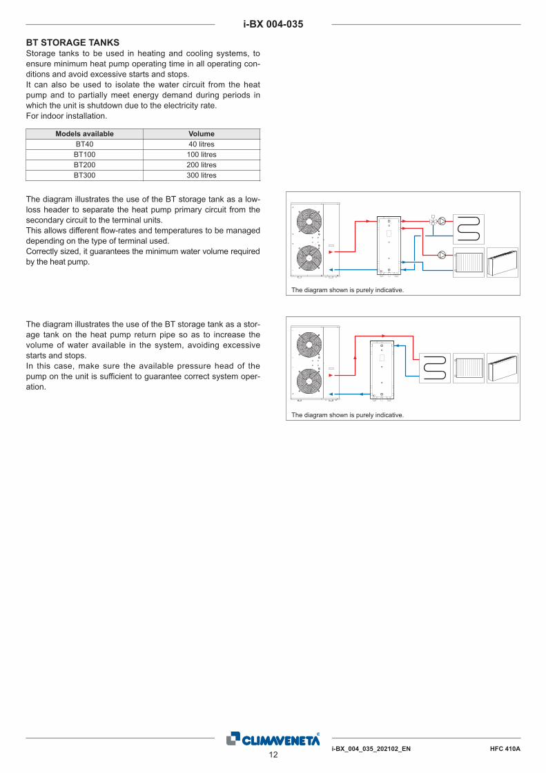
BT STORAGE TANKSStorage tanks to be used in heating and cooling systems, to
ensure minimum heat pump operating time in all operating con-
ditions and avoid excessive starts and stops.
It can also be used to isolate the water circuit from the heat
pump and to partially meet energy demand during periods in
which the unit is shutdown due to the electricity rate.
For indoor installation.
The diagram illustrates the use of the BT storage tank as a low-
loss header to separate the heat pump primary circuit from the
secondary circuit to the terminal units.
This allows different flow-rates and temperatures to be managed
depending on the type of terminal used.
Correctly sized, it guarantees the minimum water volume required
by the heat pump.
The diagram illustrates the use of the BT storage tank as a stor-
age tank on the heat pump return pipe so as to increase the
volume of water available in the system, avoiding excessive
starts and stops.
In this case, make sure the available pressure head of the
pump on the unit is sufficient to guarantee correct system oper-
ation.
Models available Volume
BT40 40 litres
BT100 100 litres
BT200 200 litres
BT300 300 litres

i-BX_004_035_202102_EN HFC 410A13
i-BX 004-035
Technical specifications
BT buffer tanks units have a set of two additional connections
dedicated to a possible supplemental source.
The BT 40-80 buffer tanks (provided complete with mounting
brackets) are made of S 235 JR carbon steel with PU-R insula-
tion (energy class B) and outer envelope in painted galvanised
sheet metal.
The BT 100-300 buffer tanks are made of S 235 JR carbon
steel with PU-R insulation (energy class B-C) and exterior coat-
ing in PVC (blue color).
80 l40 l
Dimensions - Model BT40 - BT80
300 l100-200 l
Dimensions - Model BT100 - BT200 - BT300Legend
D Drain
E1 .... E4 Probe / Thermometer
G1 From plant
G2 To plant
I Electrical resistor
K1 .... K4 Ausiliary
P1 To energy source
P2 From energy source
T Vent
Couplings chart
CAP. Cod. D E1-E3 E2-E4 G1 G2 I K1-K2 K3-K4 P1 P2 T
[l] [inch]
100 5590021300 1"1/4 1/2" - 1"1/2 1"1/2 2" 1"1/2 - 1"1/2 1"1/2 1"1/4
200 5590021400 1"1/4 1/2" - 1"1/2 1"1/2 2" 1"1/2 - 1"1/2 1"1/2 1"1/4
300 5590021500 1"1/4 1/2" 1/2" 2" 2" 2" 1"1/2 1"1/2 2" 2" 1"1/4
Size chart
CAP.[l]
Cod.Øi
[mm]Øe
[mm]Ht
[mm]R *
[mm]D
[mm]E1
[mm]E2
[mm]E3
[mm]E4
[mm]G1
[mm]G2
[mm]I
[mm]K1
[mm]K2
[mm]K3
[mm]K4
[mm]P1
[mm]P2
[mm]
100 5590021300 400 460 950 1060 125 395 - 655 - 285 765 285 445 605 - - 285 765
200 5590021400 450 510 1335 1430 125 520 - 920 - 320 1120 320 580 850 - - 320 1120
300 5590021500 500 610 1680 1790 130 555 895 1055 1155 355 1405 355 645 1255 780 980 355 1405
Features
CAP.[l]
Internal
protectionInsulation
Thick.
Insul.
[mm]
Ext.
Cover
p
max
[bar]
T
min/max
[°C]
Shipp.
Weight
[kg]
100Black Raw
Steel
PU-R 30 PVC 6 -10°/70° 25
200 PU-R 30 PVC 6 -10°/70° 36
300 PU-R 50 PVC 6 -10°/70° 48
* R: reversal quote
Legend
D Drain
E1 Probe / Thermometer
G1 From plant
G2 To plant
I Electrical resistor
K1 - K2 Ausiliary
P1 To energy source
P2 From energy source
T VentCouplings chart
CAP.Cod.
D E G1 - G2 I K1 - K2 P1 - P2 T
[l] [inch]
40 5590021100 3/4" 1/2" 1" 1"1/2 1" 1" 1/2"
80 5590021200 3/4" 1/2" 1" 1"1/2 1" 1" 1/2"
Size chart
CAP.[l]
Cod.Øi
[mm]Øe
[mm]Ht
[mm]R *
[mm]E
[mm]G1
[mm]G2
[mm]I
[mm]K1
[mm]K2
[mm]P1
[mm]P2
[mm]
40 5590021100 400 460 477 663 307 177 307 177 177 307 177 307
80 5590021200 400 460 862 978 682 187 682 187 287 582 187 682
Insulation
PU-R Highly rigid polyurethane foam
* R: reversal quote
14i-BX_004_035_202102_EN HFC 410A
i-BX 004-035
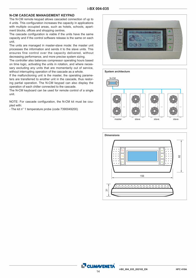
N-CM
master slave slave slave
N-CM CASCADE MANAGEMENT KEYPADThe N-CM remote keypad allows cascaded connection of up to
4 units. This configuration increases the capacity in applications
with multiple occupied areas, such as hotels, schools, apart-
ment blocks, offices and shopping centres.
The cascade configuration is viable if the units have the same
capacity and if the control software release is the same on each
unit.
The units are managed in master-slave mode: the master unit
processes the information and sends it to the slave units. This
ensures fine control over the capacity delivered, without
decreasing performance, and more precise system sizing.
The controller also balances compressor operating hours based
on time logic, activating the units in rotation, and where neces-
sary excluding any units that are momentarily out of service,
without interrupting operation of the cascade as a whole.
If the malfunctioning unit is the master, the operating parame-
ters are transferred to another unit in the cascade, thus restor-
ing partial operation. The N-CM keypad can also display the
operation of each chiller connected to the cascade.
The N-CM keyboard can be used for remote control of a single
unit.
NOTE: For cascade configuration, the N-CM kit must be cou-
pled with:
- The kit n° 1 temperature probe (code 7390049200)
System architecture
82
31
156
Dimensions

i-BX_004_035_202102_EN HFC 410A15
i-BX 004-035
N-RS RS485 SERIAL CARDThe N-RS is an optional card for directly interfacing the heat
pumps to an RS485 network.
The card guarantees opto-isolation of the controller from the
RS485 serial network.
The maximum baud rate available is 19200 baud.
The optional card is fitted in the comb connector on the unit’s
board.

16i-BX_004_035_202102_EN HFC 410A
i-BX 004-035
6. GENERAL TECHNICAL DATA
Available unit's head (1) kPa 50,7 38,1 61,8 55,6 55,3 52,7 51,7 76,7 66,3 60,3
i-BX 004 006 008 010 013 010 013 015 020 025Power supply V/ph/Hz 230/1/50 230/1/50 230/1/50 230/1/50 230/1/50 400/3+N/50 400/3+N/50 400/3+N/50 400/3+N/50 400/3+N/50
PERFORMANCECOOLING ONLY (GROSS VALUE)Cooling capacity (1) kW 4,30 6,11 8,10 10,6 12,9 10,7 13,3 15,5 20,6 25,0Total power input (1) kW 1,55 2,12 2,82 3,64 4,74 3,64 4,74 5,44 7,20 8,69EER (1) kW/kW 2,77 2,88 2,87 2,91 2,72 2,94 2,81 2,85 2,86 2,88ESEER (1) kW/kW 4,20 4,36 4,70 4,29 4,55 4,36 4,57 4,14 4,12 4,26COOLING ONLY (EN14511 VALUE)Cooling capacity (1)(2) kW 4,30 6,11 8,11 10,6 12,9 10,7 13,3 15,5 20,6 25,0EER (1)(2) kW/kW 2,82 2,92 2,92 2,92 2,74 2,95 2,82 2,87 2,88 2,90ESEER (1)(2) kW/kW 4,53 4,60 5,08 4,34 4,69 4,42 4,69 4,20 4,20 4,36Cooling energy class C B B B C B C C C BEXCHANGERSHEAT EXCHANGER USER SIDE IN REFRIGERATIONWater flow (1) l/s 0,21 0,29 0,39 0,51 0,62 0,51 0,64 0,74 0,99 1,20
REFRIGERANT CIRCUITCompressors nr. N° 1 1 1 1 1 1 1 1 1 1Number of capacity steps N° 0 0 0 0 0 0 0 0 0 0No. Circuits N° 1 1 1 1 1 1 1 1 1 1Regulation STEPLESS STEPLESS STEPLESS STEPLESS STEPLESS STEPLESS STEPLESS STEPLESS STEPLESS STEPLESS
Min. capacity step % 25 25 25 25 25 25 25 25 25 25Refrigerant R410A R410A R410A R410A R410A R410A R410A R410A R410A R410ARefrigerant charge kg 1,45 2,10 3,55 3,60 3,65 3,60 3,65Oil charge kg 0,35 0,35 0,40 0,87 1,40 0,87 1,40 1,40 1,40 1,40Rc (ASHRAE) (3) kg/kW 0,34 0,35 0,44 0,34 0,29 0,34 0,28 0,31 0,33 0,28FANSFans number N° 1 1 1 2 2 2 2 2 1 2Air flow m³/s 1,02 0,98 0,99 1,74 1,58 1,74 1,70 1,64 2,26 3,76Fans power input kW 0,12 0,12 0,12 0,12 0,12 0,12 0,12 0,12 0,60 0,40NOISE LEVELSound Pressure (4) dB(A) 33 34 35 38 39 38 39 43 43 43Sound power level in cooling (5)(6) dB(A) 64 65 66 69 70 69 70 74 74 75SIZE AND WEIGHTA (7) mm 900 900 900 900 900 900 900 900 1450 1450B (7) mm 370 370 420 420 420 420 420 420 550 550H (7) mm 940 940 1240 1240 1240 1240 1240 1390 1200 1700Operating weight (7) kg 75 80 95 110 125 110 125 135 190 250
Notes:1 Plant (side) cooling exchanger water (in/out) 12,0°C/7,0°C; Source (side) heat exchanger air (in) 35,0°C.2 Values in compliance with EN14511-3:2013.3 Rated in accordance with AHRI Standard 550/590 (2011 with addendum 1).4 Average sound pressure level at 10m distance, unit in a free field on a reflective surface; non-binding value calculated from the sound power level.5 Sound power on the basis of measurements made in compliance with ISO 9614.6 Sound power level in cooling, outdoors.7 Unit in standard configuration/execution, without optional accessories.- Not availableCertified data in EUROVENT

i-BX_004_035_202102_EN HFC 410A17
i-BX 004-035
Available unit's head (1) kPa 90,0 73,5
i-BX 030 035Power supply V/ph/Hz 400/3+N/50 400/3+N/50
PERFORMANCECOOLING ONLY (GROSS VALUE)Cooling capacity (1) kW 29,8 35,1Total power input (1) kW 10,0 11,8EER (1) kW/kW 2,98 2,97ESEER (1) kW/kW 4,15 4,29COOLING ONLY (EN14511 VALUE)Cooling capacity (1)(2) kW 29,9 35,2EER (1)(2) kW/kW 3,01 3,00ESEER (1)(2) kW/kW 4,27 4,39Cooling energy class B BEXCHANGERSHEAT EXCHANGER USER SIDE IN REFRIGERATIONWater flow (1) l/s 1,43 1,68
REFRIGERANT CIRCUITCompressors nr. N° 1 1Number of capacity steps N° 0 0No. Circuits N° 1 1Regulation STEPLESS STEPLESS
Min. capacity step % 25 25Refrigerant R410A R410ARefrigerant charge kgOil charge kg 2,30 2,30Rc (ASHRAE) (3) kg/kW 0,27 0,24FANSFans number N° 2 2Air flow m³/s 4,20 4,86Fans power input kW 0,55 0,52NOISE LEVELSound Pressure (4) dB(A) 44 45Sound power level in cooling (5)(6) dB(A) 76 77SIZE AND WEIGHTA (7) mm 1450 1700B (7) mm 550 650H (7) mm 1700 1700Operating weight (7) kg 270 305
Notes:1 Plant (side) cooling exchanger water (in/out) 12,0°C/7,0°C; Source (side) heat exchanger air (in) 35,0°C.2 Values in compliance with EN14511-3:2013.3 Rated in accordance with AHRI Standard 550/590 (2011 with addendum 1).4 Average sound pressure level at 10m distance, unit in a free field on a reflective surface; non-binding value calculated from the sound power level.5 Sound power on the basis of measurements made in compliance with ISO 9614.6 Sound power level in cooling, outdoors.7 Unit in standard configuration/execution, without optional accessories.- Not availableCertified data in EUROVENT

18i-BX_004_035_202102_EN HFC 410A
i-BX 004-035
8. OPERATING LIMITS
COOLING
-10
-5
-8
0
5
10
15
20
18
-15 -10 -5 0 5 10 15 20 25 30 35 40 45 50
Wat
er o
utle
t tem
pera
ture
[°C
]
Air intake temperature [°C]
OPERATING RANGE WITH WATER-GLYCOL MIXES
Operation in cooling mode:
System circuit temperature difference, minimum 3°K, maximum 8°K
Maximum glycol content 40%
7. ENERGY EFFICIENCY
SEASONAL EFFICIENCY IN COOLING (Reg. EU 2016/2281)
Ambient refrigeration
Notes:
(1) Seasonal energy efficiency of the cooling environment [REGULATION (EU) N. 2016/2281]
(2) Seasonal space heating energy index
(3) Seasonal energy efficiency of the space cooling
The units highlighted in this publication contain HFC R410A [GWP100 2088] fluorinated greenhouse gases.
Certified data in EUROVENT
i-BX 004 006 008 010 013 010 013 015 020 025 030 035
Prated,c (1) kW 4,3 6,11 8,11 10,6 12,9 10,7 13,3 15,5 20,6 25 29,9 35,2
SEER (1)(2) 4,38 4,43 4,93 4,39 4,78 4,46 4,8 4,31 4,31 4,52 4,52 4,57
Performance (1)(3) % 172 174 194 172 188 176 189 169 169 178 178 180

i-BX_004_035_202102_EN HFC 410A19
i-BX 004-035
9. ETHYLENE GLYCOL MIXTURE
Ethylene glycol and water mixture, used as a heat-conveying fluid, cause a variation in unit performance. For correct data, use the fac-
tors indicated in the following tabel.
cPf: cooling power correction factor
cQ: flow correction factor
cdp: pressure drop correction factor
For data concerning other kind of anti-freeze solutions (e,g, propylene glycol)
please contact our Sale Department.
Freezing point (°C)
0 -5 -10 -15 -20 -25 -30 -35
Ethylene glycol percentage by weight
0 12% 20% 30% 35% 40% 45% 50%
cPf 1 0,985 0,98 0,974 0,97 0,965 0,964 0,96
cQ 1 1,02 1,04 1,075 1,11 1,14 1,17 1,2
cdp 1 1,07 1,11 1,18 1,22 1,24 1,27 1,3
ff: fouling factors
f1 - f2: potential correction factors
fk1 - fk2: compressor power input correction factors
r3: capacity correction factors
KE: minimum condenser outlet temperature increase
KC: maximum condenser outlet temperature decrease
10. FOULING FACTORS
Performances are based on clean condition of tubes (fouling factor = 1). For different fouling values, performance should be adjusted
using the correction factors shown in the following table.
FOULING FACTORS EVAPORATOR CONDENSER/RECOVERY DESUPERHEATER
ff (m2 °CW) F1 FK1 KE [°C] F2 FK2 KC [°C] R3
0 1,000 1,000 0,0 1,000 1,000 0,0 1,000
1,80 x 10 -5 1,000 1,000 0,0 1,000 1,000 0,0 1,000
4,40 x 10 -5 1,000 1,000 0,0 0,990 1,030 1,0 0,990
8,80 x 10 -5 0,960 0,990 0,7 0,980 1,040 1,5 0,980
13,20 x 10 -5 0,944 0,985 1,0 0,964 1,050 2,3 0,964
17,20 x 10 -5 0,930 0,980 1,5 0,950 1,060 3,0 0,950
11. HYDRAULIC DATA
Water flow and pressure drop
Water flow in the plant (side) exchanger is given by:
Q=P/(4,186 x Dt)
Q: water flow (l/s)
Dt: difference between inlet and outlet water temp. (°C)
P: heat exchanger capacity (kW)
Pressure drop is given by:
Dp= K x (3,6 x Q)^2/1000
Q: water flow (l/s)
Dp: pressure drop (kPa)
K: unit size ratio
Q min: minimum water flow admitted to the heat exchanger
Q max: maximum water flow admitted to the heat exchanger
C.A.S.: Exchanger water content
HEAT EXCHANGER USER SIDE
K Q minl/s
Q maxl/s
C.A.S.l
SIZEPowersupplyV/ph/Hz
i-BX /004 230/1/50 15500 0,14 0,36 1,00
i-BX /006 230/1/50 13500 0,19 0,50 1,00
i-BX /008 230/1/50 7500 0,25 0,64 1,50
i-BX /010 230/1/50 4800 0,31 0,81 1,80
i-BX /013 230/1/50 3300 0,39 1,06 2,00
i-BX /010 400/3+N/50 4800 0,33 0,86 1,80
i-BX /013 400/3+N/50 3300 0,39 1,06 2,00
i-BX /015 400/3+N/50 2850 0,47 1,22 2,10
i-BX /020 400/3+N/50 1900 0,61 1,64 2,50
i-BX /025 400/3+N/50 1100 0,75 2,00 3,10
i-BX /030 400/3+N/50 700 0,89 2,39 4,20
i-BX /035 400/3+N/50 650 1,06 2,81 4,90

20i-BX_004_035_202102_EN HFC 410A
i-BX 004-035
PRESSURE DROP, VERSION WITHOUT PUMP
Pre
ssur
e dr
op [k
Pa]
Flow rate [m3/h]
0,0 0,5 1,0 1,5 2,0 2,5 3,0 3,5 4,0
013 010 008 006
004
60
50
40
30
20
10
0
Pre
ssur
e dr
op [k
Pa]
Flow rate [m3/h]
0,0 1,0 2,0 3,0 4,0 5,0 6,0 7,0 8,0 9,0 10,0 11,00
10
20
30
40
50
60
70
80
020
025 030
035 015

i-BX_004_035_202102_EN HFC 410A21
i-BX 004-035
Tab. 2Size 004 006 008 010 013 015 020 025 030 035
Expansion vessel Lt 2 5 8
Tab. 3Size 004 006 008 010 013 015 020 025 030 035
Safety valve kPa 600
12. MINIMUM AND MAXIMUM SYSTEM WATER CONTENT
Expansion vessel calibration
The expansion vessels are pre-charged to a standard pressure
of 1 bar.
The pre-charge pressure is chosen depending on the maximum
difference in height between the system terminal and the heat
pump, as shown in the figure.
The maximum height must not exceed 55 metres due to the
maximum vessel pre-charge pressure of 6 bars.
Make sure that the system terminal at the lowest point H1 can
withstand the pressure of the water column at that point.
Maximum system water content
The heat pumps are fitted as standard with an expansion vessel and safety valve. The maximum system water content depends on the
capacity of the expansion vessel (see table 2) and the calibration of the safety valve (see table 3).
The expansion vessel is suitable for the radiant panel system, hydronic terminal system and radiator system with following installation
maximum water content.
If the volume of water in the system is higher, an additional, correctly sized expansion vessel is required.
H
H1
0
100
200
300
400
500
600
0 100 200 300 400 500 600 700 800 900 1000 1100 1200 1300 1400
Pre
char
ge e
xpan
sion
tank
[kP
a]
Maximum water volume [l]
i-BX-(Y)
2Lt 5Lt 8Lt
Minimum system water content
Minimum water content: in the case of i-BX-N units (heat pump, reversible), the highest value between refrigeration and heating operation must be con-
sidered. Use water / glycol mixture for water temperature below + 5°C.
2
3
4
5
6
7
8
9
30 35 40 45 50 55 60
Syst
em w
ater
con
tent
[l/k
W]
Water outlet temperature to system [°C]
W
heating mode
outside air temperature = -5 ÷ -15°C
outside air temperature = 20 ÷ -5°C
-
2
1
0
3
4
5
6
7
8
Syst
em w
ater
con
tent
[l/k
W]
Water outlet temperature to system [°C]
cooling mode
h
-10 -5 0 +5 +10 +15 +20

22i-BX_004_035_202102_EN HFC 410A
i-BX 004-035
13. SYSTEM PUMP CURVES
0,0 0,2 0,4 0,6 0,8 1,0 1,2 1,4 1,6 0
10
20
30
40
50
60
70
80
Res
idua
l Hea
d H
u [k
Pa]
i-BX / i-BX-N 004M
Water flow Q [m3/h]
R
esid
ual H
ead
Hu
[kPa
]
0,0 0,2 0,4 0,6 0,8 1,0 1,2 1,4 1,6 1,8 2,0 0
10
20
30
40
50
60
70 i-BX / i-BX-N 006M
Water flow Q [m3/h]
Res
idua
l Hea
d H
u [k
Pa]
0,0 0,3 0,6 0,9 1,2 1,5 1,8 2,1 2,4 2,7 0
10 20 30 40 50 60 70 80 90
i-BX / i-BX-N 008M
Water flow Q [m3/h]
R
esid
ual H
ead
Hu
[kPa
]
0,0 0,3 0,6 0,9 1,2 1,5 1,8 2,1 2,4 2,7 3,0 0
10
20
30
40
50
60
70
80 i-BX / i-BX-N 010M
Water flow Q [m3/h]
Res
idua
l Hea
d H
u [k
Pa]
0,0 0,4 0,8 1,2 1,6 2,0 2,4 2,8 3,2 3,6 4,0 4,4 0
10
20
30
40
50
60
70
80 i-BX / i-BX-N 013M
Water flow Q [m3/h]
The pressure head values refer to the pressure available at the connections to the unit.

i-BX_004_035_202102_EN HFC 410A23
i-BX 004-035
The pressure head values refer to the pressure available at the connections to the unit.
0,0 0,5 1,0 1,5 2,0 2,5 3,0 3,5 4,0 4,5 0
10
20
30
40
50
60
70
80
Water flow Q [m3/h]
Res
idua
l Hea
d H
u [k
Pa]
i-BX / i-BX-N 010T
0,0 0,5 1,0 1,5 2,0 2,5 3,0 3,5 4,0 4,5 0
10
20
30
40
50
60
70
80
Water flow Q [m3/h]
Res
idua
l Hea
d H
u [k
Pa]
i-BX / i-BX-N 013T
0,0 0,5 1,0 1,5 2,0 2,5 3,0 3,5 4,0 4,5 5,0 5,5 6,0 0
20
40
60
80
100
120
Water flow Q [m3/h]
Res
idua
l Hea
d H
u [k
Pa]
i-BX / i-BX-N 015T
0,0 0,5 1,0 1,5 2,0 2,5 3,0 3,5 4,0 4,5 5,0 5,5 6,0 0
20
40
60
80
100
120
Water flow Q [m3/h]
Res
idua
l Hea
d H
u [k
Pa]
i-BX / i-BX-N 020T
0,0 0,5 1,0 1,5 2,0 2,5 3,0 3,5 4,0 4,5 5,0 5,5 6,0 0
20
40
60
80
100
120
Water flow Q [m3/h]
Res
idua
l Hea
d H
u [k
Pa]
i-BX / i-BX-N 025T
0,0 1,0 2,0 3,0 4,0 5,0 6,0 7,0 8,0 9,0 10,0 0
20
40
60
80
100
120
Water flow Q [m3/h]
Res
idua
l Hea
d H
u [k
Pa]
i-BX / i-BX-N 030T
0,0 1,0 2,0 3,0 4,0 5,0 6,0 7,0 8,0 9,0 10,0 0
20
40
60
80
100
120
Water flow Q [m3/h]
Res
idua
l Hea
d H
u [k
Pa]
i-BX / i-BX-N 035T

24i-BX_004_035_202102_EN HFC 410A
i-BX 004-035
14. HYDRONIC GROUP
(HEAT EXCHANGER USER SIDE - HYDRONIC KIT 1 PUMP 2 POLES LH)

i-BX_004_035_202102_EN HFC 410A25
i-BX 004-035
FACTORYCONNECTIONS
INSTALLER CONNECTIONS
UTILITYRETURN
UTILITYOUTLET
129
8
14
14
2
102 4
3
11
6
113
13
8 7 135
12
9
System water circuit connection diagram, i-BX with pump
1 Pressure gauge
2 Vibration damper joint
3 Shut-off valve
4 Calibrating valve
5 Flow switch
6 Thermometer
7 Circulating pump
8 Safety valve
9 Expansion vessel
10 Wire mesh filter
11 Fill – Refill
12 Temperature sensor
13 System vent
14 Drain / chemical washing valve
15. UTILITY WATER CIRCUIT CONNECTION DIAGRAM
FACTORYCONNECTIONS
INSTALLER CONNECTIONS
UTILITYRETURN
UTILITYOUTLET
12
12
14
14
2
102 4
3
11
6
113
137
8
12
13 59
System water circuit connection diagram, i-BX version without pump
1 Pressure gauge
2 Vibration damper joint
3 Shut-off valve
4 Calibrating valve
5 Flow switch
6 Thermometer
7 Circulating pump
8 Safety valve
9 Expansion vessel
10 Wire mesh filter
11 Fill – Refill
12 Temperature sensor
13 System vent
14 Drain / chemical washing valve

26i-BX_004_035_202102_EN HFC 410A
i-BX 004-035
16. ELECTRICAL DATA
Electrical data at maximum conditions allowed (full load)
F.L.I. Maximum power input
F.L.A. Maximum current input
Maximum values for sizing the protection switches and power supply cables.
Unit without hydronic unit
Size
Power supply Total power consumption Fuses (5x20T 250V)
V/Ph/HzFLI FLA FU1 FU2 FU3 FU4 FU5 FU6 FU7
[kW] [A] [A] [A] [A] [A] [mA] [A] [A]
004 230/1/50 1,9 7,9 2 2 1,6 1,25 160 5 -
006 230/1/50 2,7 11,5 2 2 1,6 1,25 160 5 -
008 230/1/50 3,6 15,5 2 2 1,6 1,25 160 5 -
010 230/1/50 4,8 21,6 2 2 1,6 1,25 160 5 -
013 230/1/50 6,4 24,3 2 2 1,6 1,25 160 5 -
010 400/3N/50 4,6 11,5 2 2 1,6 1,25 160 5 -
013 400/3N/50 5,8 15,6 2 2 1,6 1,25 160 5 -
015 400/3N/50 7,2 16,2 2 2 1,6 1,25 160 5 -
020 400/3N/50 9,2 19,1 2 1,6 1,6 1,25 160 8 (6.3x32) 1
025 400/3N/50 11,1 27,2 2 1,6 1,6 1,25 160 8 (6.3x32) 1
030 400/3N/50 13,4 27,4 2 1,6 1,6 1,25 160 8 (6.3x32) 1
035 400/3N/50 15,7 37,6 2 1,6 1,6 1,25 160 8 (6.3x32) 1
Unit with hydronic unit
Size
Power supply Total power consumption Fuses (5x20T 250V)
V/Ph/HzFLI FLA FU1 FU2 FU3 FU4 FU5 FU6 FU7
[kW] [A] [A] [A] [A] [A] [mA] [A] [A]
004 230/1/50 2,0 8,7 1,25 2 1,6 1,25 160 5 -
006 230/1/50 2,8 12,3 1,25 2 1,6 1,25 160 5 -
008 230/1/50 3,6 16,1 1,25 2 1,6 1,25 160 5 -
010 230/1/50 5,0 22,6 1,6 2 1,6 1,25 160 5 -
013 230/1/50 6,5 25,3 1,6 2 1,6 1,25 160 5 -
010 400/3N/50 4,7 12,5 1,6 2 1,6 1,25 160 5 -
013 400/3N/50 6,0 16,6 1,6 2 1,6 1,25 160 5 -
015 400/3N/50 7,4 17,5 2 2 1,6 1,25 160 5 -
020 400/3N/50 9,4 20,4 2 1,6 1,6 1,25 160 8 (6.3x32) 1
025 400/3N/50 11,3 28,5 2 1,6 1,6 1,25 160 8 (6.3x32) 1
030 400/3N/50 13,7 28,8 2 1,6 1,6 1,25 160 8 (6.3x32) 1
035 400/3N/50 16,0 39,0 2 1,6 1,6 1,25 160 8 (6.3x32) 1

i-BX_004_035_202102_EN HFC 410A27
i-BX 004-035
17. FULL LOAD SOUND LEVEL

28i-BX_004_035_202102_EN HFC 410A
i-BX 004-035
18. POSITION OF THE WATER CONNECTIONS
H
G
L
M
HC
SV
HC
IP
i-BX
HL
M
G
HC
SV
HC
IP
i-BX
Size G [mm] H [mm] L [mm] M [mm] HC Ø
i-BX 004 66 142 720 676 1"
i-BX 006 66 142 720 676 1"
i-BX 008 66 332 830 868 1"
i-BX 010 66 332 830 868 1"
i-BX 013 66 332 830 868 1" 1/4
i-BX 015 66 332 830 868 1" 1/4
Size G [mm] H [mm] L [mm] M [mm] HC Ø
i-BX 020 112 295 830 830 1" 1/4
i-BX 025 112 295 830 830 1" 1/4
i-BX 030 112 565 1055 1100 1" 1/2
i-BX 035 112 565 1055 1100 1" 1/2
HC HYDRAULIC CONNECTIONS
SV SAFETY VALVE DISCARGE
IP POWER SUPPLY INLET
OC CONDENSATE DRAIN OUTLET
HC HYDRAULIC CONNECTIONS
SV SAFETY VALVE DISCARGE
IP POWER SUPPLY INLET
OC CONDENSATE DRAIN OUTLET

i-BX_004_035_202102_EN HFC 410A29
i-BX 004-035
19. DIMENSIONAL DRAWINGS
D C
A
F
E
B
400400400
400
900
W3 W4
W2 W1
B
C E
FD
A
W3 W4
W2 W1
�
�
400 400
400
400
900
SizeA B C D E F W1 W2 W3 W4 Weight
[mm] [mm] [mm] [mm] [mm] [mm] [kg] [kg] [kg] [kg] [kg]
i-BX 020 1450 1200 550 1510 500 1480 89 10 82 9 190
i-BX 025 1450 1200 550 1510 500 1480 124 16 97 13 250
i-BX 030 1450 1700 550 1510 500 1480 134 17 105 14 270
i-BX 035 1700 1700 650 1760 600 1730 174 19 101 11 305
SizeA B C D E F W1 W2 W3 W4 Weight
[mm] [mm] [mm] [mm] [mm] [mm] [kg] [kg] [kg] [kg] [kg]
i-BX 004 900 940 370 430 580 405 25 12 12 26 75
i-BX 006 900 940 370 430 580 405 26 13 14 28 80
i-BX 008 900 1240 420 480 580 455 34 19 15 27 95
i-BX 010 900 1240 420 480 580 455 40 19 17 34 110
i-BX 013 900 1240 420 480 580 455 45 19 18 42 125
i-BX 015 900 1240 420 480 580 455 48 16 53 18 135

30i-BX_004_035_202102_EN HFC 410A
i-BX 004-035
HANDLING PACKAGED UNITSThe unit should always be handled by qualified personnel using
equipment adequate for the weight of the unit, in compliance
with the safety standards in force (and subsequent amend-
ments).
• Lifting by forklift (1)
Insert the forks under the long side of base, opening the forks
as fare as possible.
• Lifting by crane (2)
To lift the unit, insert tubes long enough to allow positioning of
the lifting slings and safety pins in the special feet on the unit.
For the sizes of these tubes, see the figures shown in the cor-
responding section. To avoid the slings damaging the unit,
place protection between the slings and the unit.
H
PL
Codice a barre(lato compressore)
1
2
i-BX Dimensions and weight with standard packaging
Size 04 06 08 10 13 15 20 25 30 35
Dimension L mm 990 990 990 990 990 990 1530 1530 1530 1780
Dimension P mm 490 490 540 540 540 540 700 700 700 800
Dimension H mm 1090 1090 1390 1390 1390 1540 1400 1900 1900 1900
Weight Kg 90 95 110 125 140 155 210 270 290 325
Max stackable units n° 1 1 1 1 1 1 1 1 1 1
i-BX Dimensions and weight with wooden crate
Size 04 06 08 10 13 15 20 25 30 35
Dimension L mm 1040 1040 1040 1040 1040 1040 1630 1630 1630 1880
Dimension P mm 545 545 595 595 595 595 750 750 750 850
Dimension H mm 1170 1170 1470 1470 1470 1620 1450 1950 1950 1950
Weight Kg 115 120 140 155 170 190 250 320 340 380
Max stackable units n° 1 1 1 1 1 1 1 1 1 1


![û6^BX]BX M±K - pku.edu.cn](https://img.pdfslide.us/doc/110x75/61736064a433c678797cd078/6bxbx-mk-pkueducn.jpg)