Embed Size (px)
Citation preview
I 750-310
Revision: July 2007 Supersedes: June 2007
VBM Fault Interrupter Instructions
THREE PHASE THREE PHASE THREE PHASE 15kV/25kV Grounded 400A 25kV 200A 38kV 300A 15kV/25kV Grounded 600A 25kV 300A 25kV 400A
ONE POLE* ONE POLE* ONE POLE* 38kV 400A 48.5kV 300A 72.5kV 300A 38kV 600A 48.5kV 400A 48.5kV 200A
(with longer insulators)
*Three poles required for a three phase installation.
Joslyn Hi-Voltage 4000 E. 116th St.
Cleveland, OH 44105 Ph (216) 271-6600 Fax (216) 341-3615
Email: [email protected]
VBM Instruction Manual I 750-310
2
TABLE OF CONTENTS: I. Safety ........................................................................................................... 4
Hazard Statement Definitions..................................................................................................................... 4
II. General ....................................................................................................... 5 Description ................................................................................................................................................. 5
III. Installation ................................................................................................ 7 Inspection and Uncrating............................................................................................................................ 7 Mounting .................................................................................................................................................... 8 Clearance Requirements............................................................................................................................. 9 Clearance Requirements - Continued ....................................................................................................... 10 Control Voltage ........................................................................................................................................ 11 Control Wiring ......................................................................................................................................... 12 High Voltage Connections ....................................................................................................................... 12 VACSTATTM Operational Information.................................................................................................... 13 Vacuum Interrupter Integrity Test............................................................................................................ 14 High Potential Withstand ......................................................................................................................... 14 Vacuum Contact Resistance Test ............................................................................................................. 15
IV. Servicing ................................................................................................. 16 Tools Required ......................................................................................................................................... 16 Replacement Parts .................................................................................................................................... 17 Removal and Replacement of the Housing Cover and Breather Bag....................................................... 17 Removal and Replacement of a Vacuum Module Assembly ................................................................... 20 Synchronization of Replacement Module Assembly ............................................................................... 25 Switch Operators ...................................................................................................................................... 28
The Solenoid Operator ......................................................................................................................... 28 The Motor Operator ............................................................................................................................. 30
Servicing – Electrical ............................................................................................................................... 32 Removal and Installation of Control Assembly - Brief ........................................................................ 32 Installation of Control Assembly - Detailed......................................................................................... 33
Servicing – Mechanical ............................................................................................................................ 35 Install Motor Mechanism ..................................................................................................................... 35 Install and Pre-adjust two Power springs into the assembly. ............................................................... 37 Setup tripping. ...................................................................................................................................... 39
Replacement of Motor.............................................................................................................................. 42 Auxiliary Switch Adjustment ................................................................................................................... 43
V. Switches Rated 1,000 Amperes and Higher ............................................ 45
VBM Instruction Manual I 750-310
3
TABLE OF FIGURES: Figure 1: Diagram VBM Switch .................................................................................................................... 5 Figure 2: Cutaway Drawing of a Single Vacuum Module on 15kV Line-to-Ground Insulator.................... 5 Figure 3: VBM Switch with VACSTATTM vacuum monitor ........................................................................ 6 Figure 4a: Motor Operator Figure 4b: Solenoid Operator ...................................................................... 7 Figure 5: Typical Erecting Sling .................................................................................................................... 8 Figure 6a: 32” Clearance Around Interrupters – Front View (38 kV Single Phase shown) ......................... 9 Figure 6b: 32” Clearance Around Interrupters - Side View.......................................................................... 9 Figure 7: Terminal Pad Diagram.................................................................................................................. 12 Figure 8: VACSTATTM Operational Information ........................................................................................ 13 Figure 9: AC High Potential Test Set Connections...................................................................................... 14 Figure 10: Contact Resistance Test Connections ......................................................................................... 15 Figure 11: Replacement Module with Temporary Bolts .............................................................................. 22 Figure 12: Synchronization of Replacement Module Assembly.................................................................. 26 Figure 13: Description of Operation ............................................................................................................ 28 Figure 14: VBM Motor Operator Picture..................................................................................................... 30 Figure 15: VBM Motor Operator Diagram .................................................................................................. 31 Figure 16: Sequence of Motor Operation..................................................................................................... 31 Figure 17: Sequence of Motor Operation..................................................................................................... 31 Figure 18: Sequence of Motor Operation..................................................................................................... 31 Figure 19: Sequence of Motor Operation..................................................................................................... 32 Figure 23: Shim Placement .......................................................................................................................... 43 Figure 24: Auxiliary Switch Adjustment ..................................................................................................... 43 Figure 25: Auxiliary Switch Adjustment (Prior to 1997)............................................................................. 44 Figure 26: Wiring Harness and Auxiliary Contact Adjustment ................................................................... 45
VBM Instruction Manual I 750-310
4
I. Safety Hazard Statement Definitions
! WARNING: Refers to hazards or unsafe practices which could result in death, severe personal injury, or significant equipment damage.
! CAUTION: Refers to hazards or unsafe practices which could result in damage to equipment or in personal injury.
! WARNING: Before installing, operating, maintaining, or testing this equipment, carefully read and understand the contents of this manual. Improper operation, handling, or maintenance can result in death, severe personal injury, or equipment damage.
! WARNING: This equipment is not intended to protect human life. Follow all locally approved procedures and safety practices when installing or operating this equipment. Failure to comply may result in death, severe personal injury and/or equipment damage.
! WARNING: Hazardous voltage. Do not rely on the contact position indicator to determine that the line has been de-energized. Always establish a visible disconnect and establish person grounds when performing de-energized line work. Failure to follow proper safety practices can result in contact with high voltage, which can cause death or severe personal injury.
!
WARNING: Hazardous voltage. Contact with high voltage will cause serious personal injury or death. Follow all locally approved safety procedures when working around high voltage lines and equipment.
VBM Instruction Manual I 750-310
II. General Description
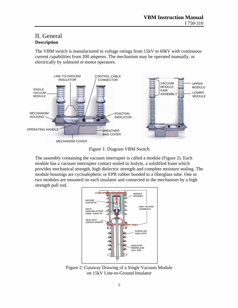
The VBM switch is manufactured in voltage ratings from 15kV to 69kV with continuous current capabilities from 200 amperes. The mechanism may be operated manually, or electrically by solenoid or motor operators.
Figure 1: Diagram VBM Switch
The assembly containing the vacuum interrupter is called a module (Figure 2). Each module has a vacuum interrupter contact sealed in Joslyte, a solidified foam which provides mechanical strength, high dielectric strength and complete moisture sealing. The module housings are cycloalephetic or EPR rubber bonded to a fiberglass tube. One or two modules are mounted on each insulator and connected to the mechanism by a high strength pull rod.
SINGLE VACUUMMODULE
VACUUM MODULE PAIR ASSEMBLY
OPERATING HANDLE
POSITION INDICATOR
CONTROL CABLE CONNECTOR
BREATHER BAG COVER
MECHANISM HOUSING
MECHANISM COVER
LINE-TO-GROUND INSULATOR
UPPER MODULE
LOWER MODULE
Figure 2:
5
Cutaway Drawing of a Single Vacuum Module on 15kV Line-to-Ground Insulator
VBM Instruction Manual I 750-310
6
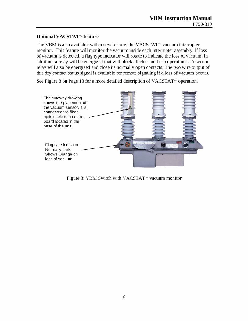
Optional VACSTATTM feature
The VBM is also available with a new feature, the VACSTATTM vacuum interrupter monitor. This feature will monitor the vacuum inside each interrupter assembly. If loss of vacuum is detected, a flag type indicator will rotate to indicate the loss of vacuum. In addition, a relay will be energized that will block all close and trip operations. A second relay will also be energized and close its normally open contacts. The two wire output of this dry contact status signal is available for remote signaling if a loss of vacuum occurs.
See Figure 8 on Page 13 for a more detailed description of VACSTATTM operation.
The cutaway drawing shows the placement of the vacuum sensor. It is connected via fiber-optic cable to a control board located in the base of the unit.
Flag type indicator. Normally dark. Shows Orange on loss of vacuum.
Figure 3: VBM Switch with VACSTATTM vacuum monitor
VBM Instruction Manual I 750-310
7
The VBM is offered with two types of mechanisms: motor and solenoid. The VBM is offered with two types of mechanisms: motor and solenoid.
Figure 4a: Motor Operator Figure 4a: Motor Operator (For single mechanism switches only) (For single mechanism switches only)
The completely sealed operating mechanism houand the modules. An expansion bag in the housinor moisture and contains a desiccant package to m
The completely sealed operating mechanism houand the modules. An expansion bag in the housinor moisture and contains a desiccant package to m
All electrical control connections to the mechanienvironmental control cable connector. All electrical control connections to the mechanienvironmental control cable connector. An “Open-Closed” position indicator is directly coperating crank enables manual operation of the withstand several G’s without damage. Dependinmechanisms for a three-phase switch.
An “Open-Closed” position indicator is directly coperating crank enables manual operation of the withstand several G’s without damage. Dependinmechanisms for a three-phase switch.
III. Installation III. Installation Inspection and Uncrating Inspection and Uncrating Carefully inspect the equipment on arrival. Contaduring shipment. Remove crating or carton surroswitch from the wooden base to prevent accidentConsult the factory if VBMs with multiple interrinstalled in a metal enclosure. An indoor RC netthe 32” requirement to standard clearances.
Carefully inspect the equipment on arrival. Contaduring shipment. Remove crating or carton surroswitch from the wooden base to prevent accidentConsult the factory if VBMs with multiple interrinstalled in a metal enclosure. An indoor RC netthe 32” requirement to standard clearances.
! CAUTION: PERFORM A VACUUM DESCRIBED IN THIS SECTION, PRIOSERVICE.
CAUTION: PERFORM A VACUUM DESCRIBED IN THIS SECTION, PRIOSERVICE.
Figure 4b: Solenoid Operator Figure 4b: Solenoid Operator
sing supports line-to-ground insulators g prevents “breathing-in” contaminants aintain dry air.
sing supports line-to-ground insulators g prevents “breathing-in” contaminants aintain dry air.
sms are made through a single sms are made through a single
oupled to the mechanism. A separate switch. The entire assembly can g upon rating there may be one or more
oupled to the mechanism. A separate switch. The entire assembly can g upon rating there may be one or more
ct carrier and file a claim if damaged unding the VBM switch. Do not unbolt al contact from knocking over switch. upters (Figures 6d thru 6h) are being work option can be supplied to reduce
ct carrier and file a claim if damaged unding the VBM switch. Do not unbolt al contact from knocking over switch. upters (Figures 6d thru 6h) are being work option can be supplied to reduce
INTERRUPTER INTEGRITY TEST R TO PUTTING EQUIPMENT INTO
INTERRUPTER INTEGRITY TEST R TO PUTTING EQUIPMENT INTO
VBM Instruction Manual I 750-310
8
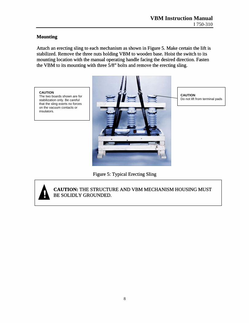
Mounting Mounting Attach an erecting sling to each mechanism as shown in Figure 5. Make certain the lift is stabilized. Remove the three nuts holding VBM to wooden base. Hoist the switch to its mounting location with the manual operating handle facing the desired direction. Fasten the VBM to its mounting with three 5/8” bolts and remove the erecting sling.
Attach an erecting sling to each mechanism as shown in Figure 5. Make certain the lift is stabilized. Remove the three nuts holding VBM to wooden base. Hoist the switch to its mounting location with the manual operating handle facing the desired direction. Fasten the VBM to its mounting with three 5/8” bolts and remove the erecting sling.
Figure 5: Typical Erecting Sling Figure 5: Typical Erecting Sling
! CAUTION: THE STRUCTURE AND VBM MECHANISM HOUSING MUST BE SOLIDLY GROUNDED. CAUTION: THE STRUCTURE AND VBM MECHANISM HOUSING MUST BE SOLIDLY GROUNDED.
CAUTION The two boards shown are for stabilization only. Be careful that the sling exerts no forces on the vacuum contacts or insulators.
CAUTION Do not lift from terminal pads
VBM Instruction Manual I 750-310
9
Clearance Requirements
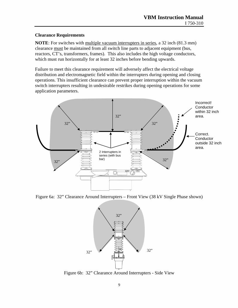
NOTE: For switches with multiple vacuum interrupters in series, a 32 inch (81.3 mm) clearance must be maintained from all switch line parts to adjacent equipment (bus, reactors, CT’s, transformers, frames). This also includes the high voltage conductors, which must run horizontally for at least 32 inches before bending upwards. Failure to meet this clearance requirement will adversely affect the electrical voltage distribution and electromagnetic field within the interrupters during opening and closing operations. This insufficient clearance can prevent proper interruption within the vacuum switch interrupters resulting in undesirable restrikes during opening operations for some application parameters.
32”
32”
32”
32” 32”
Figure 6a: 32” Clearance Around Interrupters – Front View (38 kV Single Phase sh
32”
32” 32”
Figure 6b: 32” Clearance Around Interrupters - Side View
Incorrect! Conductor within 32 inch area. Correct. Conductor outside 32 inch area.
2 Interrupters inseries (with bus bar)
own)
VBM Instruction Manual I 750-310
10
Clearance Requirements - Continued
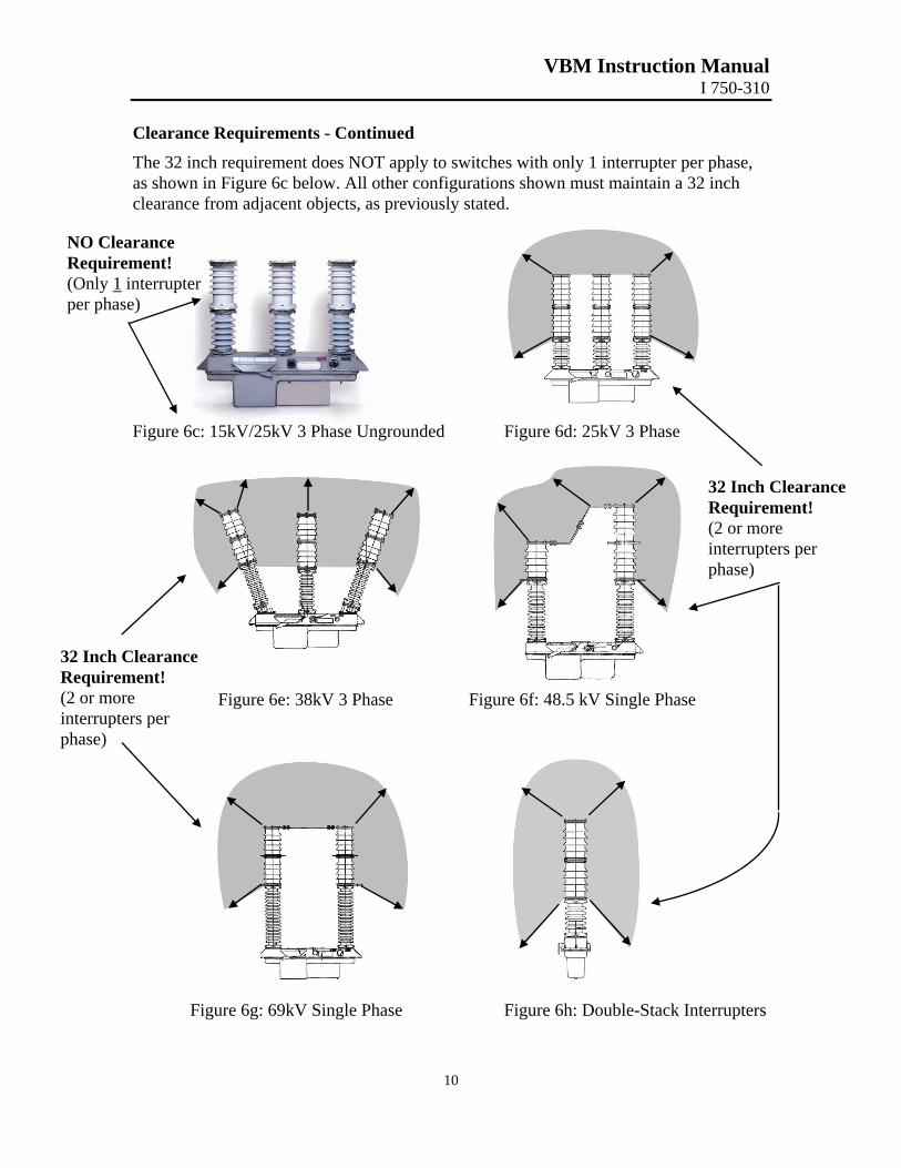
The 32 inch requirement does NOT apply to switches with only 1 interrupter per phase, as shown in Figure 6c below. All other configurations shown must maintain a 32 inch clearance from adjacent objects, as previously stated.
NO Clearance Requirement! (Only 1 interrupter per phase)
Figure 6c: 15kV/25kV 3 Phase Ungrounded Figure 6d: 25kV 3 Phase Figure 6e: 38kV 3 Phase Figure 6f: 48.5 kV Single Phase
32 Inch Clearance Requirement! (2 or more interrupters per phase)
32 Inch Clearance Requirement! (2 or more interrupters per phase)
Figure 6g: 69kV Single Phase Figure 6h: Double-Stack Interrupters
VBM Instruction Manual I 750-310
11
Control Voltage Control Voltage
A variety of control voltage options are available. Refer to the table below. A variety of control voltage options are available. Refer to the table below.
Control Voltage Control Voltage
Operating Mechanism Operating
Mechanism Control Current
Per Switch Mechanism
Control Current Per Switch Mechanism
Close Time Close Time Trip Time Trip Time
48 VDC
Motor1
Solenoid4
Reclosing
3 amps 60 amps3,4
7 amps
5 sec 6 cycles 6 cycles
2 cycles 6 cycles 3 cycles
125 VDC
Motor1
Solenoid Reclosing
4 amps 60 amps2
7 amps
3 sec 6 cycles 6 cycles
2 cycles 6 cycles 3 cycles
120 VAC
Motor1
Solenoid Reclosing
5 amps 60 amps3,4
7 amps
3 sec 6 cycles 5 cycles
2 cycles 6 cycles 3 cycles
250 VDC Solenoid 60 amps 6 cycles 6 cycles Note 1: Motor operating mechanisms are designed for single mechanism switches. Note 2: Current is 60 amperes peak for one, two, or three mechanism switch systems. Note 3: Current is 120 amperes for 34.5kV 300A VBM. Note 4: Current for three mechanism switch systems is approximately 180 amperes. Control power must meet the requirements of the drawing supplied with the switch. Refer to the appropriate power input tables for proper requirements.
Solenoid Operated Switches Direct Energy DC Operated VBM Switch 3045A0176 Direct Energy AC Operated VBM Switch 3045A0169
Motor Operated Switches
5A max during operation
! CWO
AUTION: FAILURE TO COMPLY WITH THE CONTROL POWER AND IRING REQUIREMENTS MAY RESULT IN SWITCH MALFUNCTION R DAMAGE.
VBM Instruction Manual I 750-310
12
Control Wiring All control connections to the VBM switch are made through either of the following methods:
a. Environmental cable and connector. The cable may be shortened to desired length if supplied with a connector on the switch end only. NOTE: For multiple mechanism switches, all cable lengths should be cut to the same length. Connection to the control enclosure must be in accordance with the specific wiring diagram for the system supplied.
b. A junction box mounted on the housing wired to the mechanism through conduit.
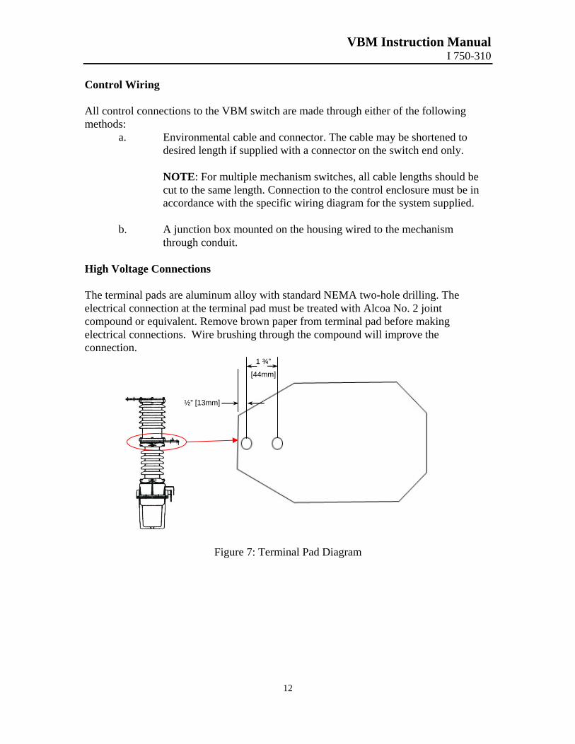
High Voltage Connections The terminal pads are aluminum alloy with standard NEMA two-hole drilling. The electrical connection at the terminal pad must be treated with Alcoa No. 2 joint compound or equivalent. Remove brown paper from terminal pad before making electrical connections. Wire brushing through the compound will improve the connection.
½” [13mm]
1 ¾”
[44mm]
Figure 7: Terminal Pad Diagram
VBM Instruction Manual I 750-310
13
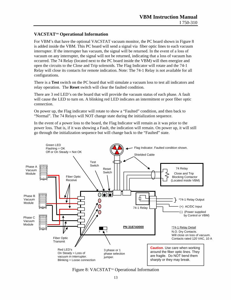
VACSTATTM Operational Information For VBM’s that have the optional VACSTAT vacuum monitor, the PC board shown in Figure 8 is added inside the VBM. This PC board will send a signal via fiber optic lines to each vacuum interrupter. If the interrupter has vacuum, the signal will be returned. In the event of a loss of vacuum on any interrupter, the signal will not be returned, indicating that a loss of vacuum has occurred. The 74 Relay (located next to the PC board inside the VBM) will then energize and open the circuits to the Close and Trip solenoids. The Flag Indicator will rotate and the 74-1 Relay will close its contacts for remote indication. Note: The 74-1 Relay is not available for all configurations.
There is a Test switch on the PC board that will simulate a vacuum loss to test all indicators and relay operation. The Reset switch will clear the faulted condition.
There are 3 red LED’s on the board that will provide the vacuum status of each phase. A fault will cause the LED to turn on. A blinking red LED indicates an intermittent or poor fiber optic connection.
On power up, the Flag indicator will rotate to show a “Faulted” condition, and then back to “Normal”. The 74 Relays will NOT change state during the initialization sequence.
In the event of a power loss to the board, the Flag Indicator will remain as it was prior to the power loss. That is, if it was showing a Fault, the indication will remain. On power up, it will still go through the initialization sequence but will change back to the “Faulted” state.
Fiber Optic Transmit
Fiber Optic Receive
74 Relay Close and Trip
Blocking Contactor (Located inside VBM)
Flag Indicator. Faulted condition shown. Shielded Cable
Red LED’s On Steady = Loss of vacuum in interrupter. Blinking = Loose connection
3 phase or 1 phase selection jumper.
Test Switch
Reset Switch
*74-1 Relay Output (+) AC/DC Input
(-) (Power supplied by Control or VBM)
*74-1 Relay Detail N.O. Dry Contacts. Will close on loss of vacuum. Contacts rated 120 VAC, 10 A
74-1 Relay
PN 3187A0000
Caution. Use care when working around the fiber optic lines. They are fragile. Do NOT bend them sharply or they may break.
13
Green LED Flashing = OK Off or On Steady = Not OK
Phase A Vacuum Module
Phase B Vacuum Module
Phase C Vacuum Module
Figure 8: VACSTATTM Operational Information
VBM Instruction Manual I 750-310
14
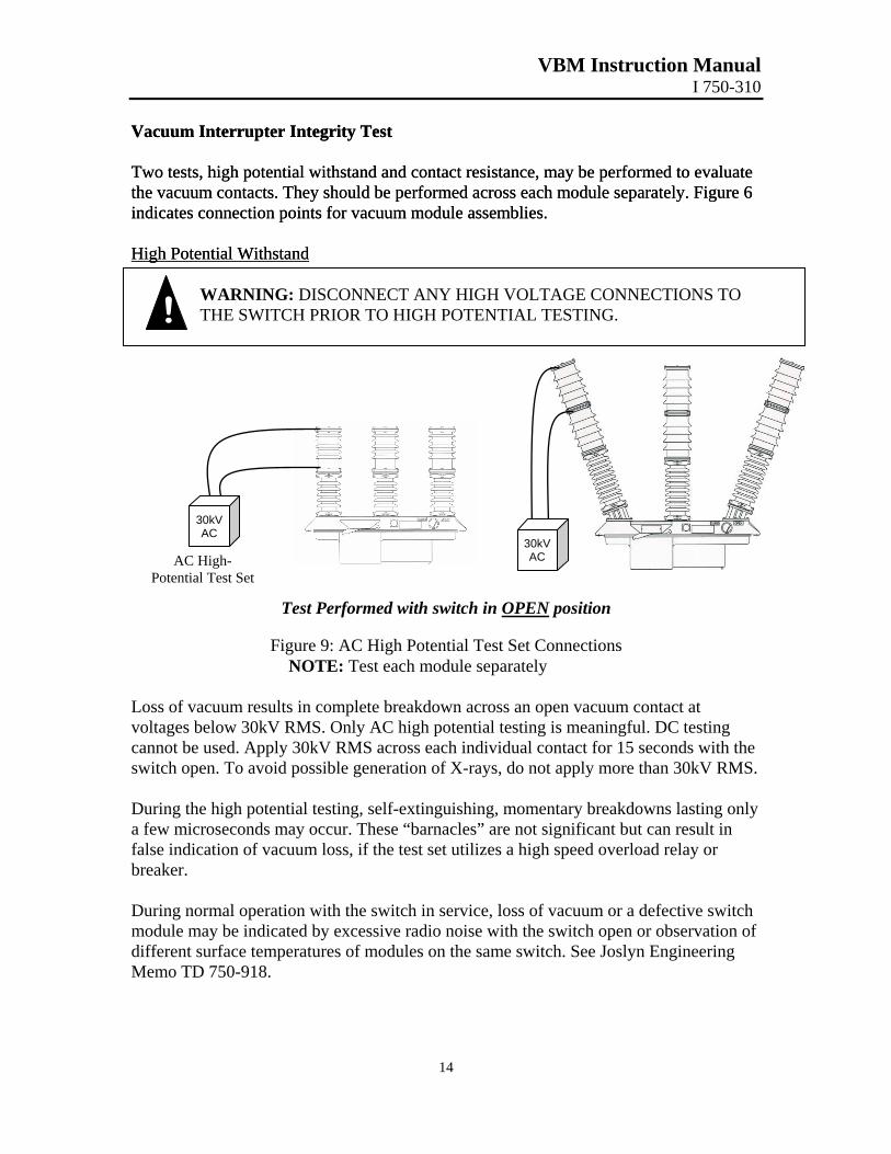
Vacuum Interrupter Integrity Test Vacuum Interrupter Integrity Test Two tests, high potential withstand and contact resistance, may be performed to evaluate the vacuum contacts. They should be performed across each module separately. Figure 6 indicates connection points for vacuum module assemblies.
Two tests, high potential withstand and contact resistance, may be performed to evaluate the vacuum contacts. They should be performed across each module separately. Figure 6 indicates connection points for vacuum module assemblies. High Potential Withstand High Potential Withstand
! WARNING: DISCONNECT ANY HIGH VOLTAGE CONNECTIONS TO THE SWITCH PRIOR TO HIGH POTENTIAL TESTING.
AC High- Potential Test Set
30kV AC
Test Performed with switch in OP
Figure 9: AC High Potential Test SeNOTE: Test each module separat
Loss of vacuum results in complete breakdown across avoltages below 30kV RMS. Only AC high potential testcannot be used. Apply 30kV RMS across each individuaswitch open. To avoid possible generation of X-rays, do During the high potential testing, self-extinguishing, moa few microseconds may occur. These “barnacles” are nfalse indication of vacuum loss, if the test set utilizes a hbreaker. During normal operation with the switch in service, lossmodule may be indicated by excessive radio noise with different surface temperatures of modules on the same sMemo TD 750-918.
30kV AC
EN position
t Connections ely
n open vacuum contact at ing is meaningful. DC testing l contact for 15 seconds with the not apply more than 30kV RMS.
mentary breakdowns lasting only ot significant but can result in igh speed overload relay or
of vacuum or a defective switch the switch open or observation of witch. See Joslyn Engineering
VBM Instruction Manual I 750-310
15
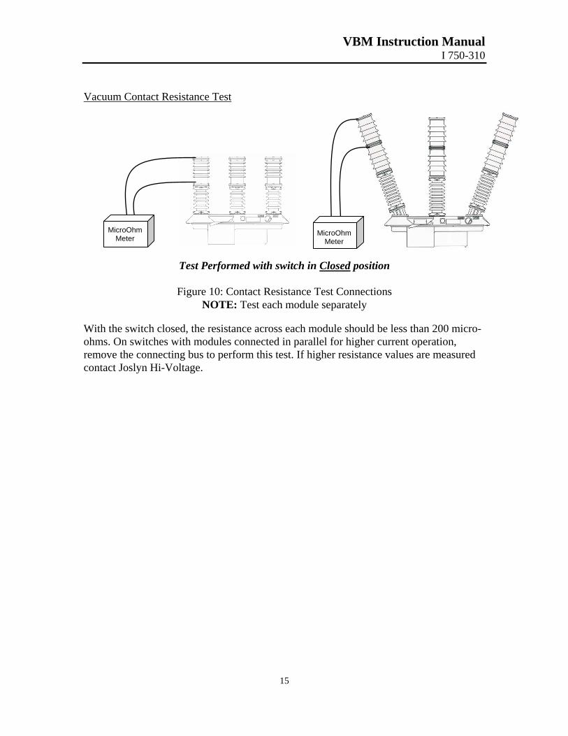
Vacuum Contact Resistance Test
MicroOMete
MicroOhm Meter
Test Performed with switch in Clos
Figure 10: Contact Resistance Test CNOTE: Test each module sepa
With the switch closed, the resistance across each moduleohms. On switches with modules connected in parallel foremove the connecting bus to perform this test. If higher rcontact Joslyn Hi-Voltage.
hm r
ed position
onnections rately
should be less than 200 micro-r higher current operation, esistance values are measured
VBM Instruction Manual I 750-310
16
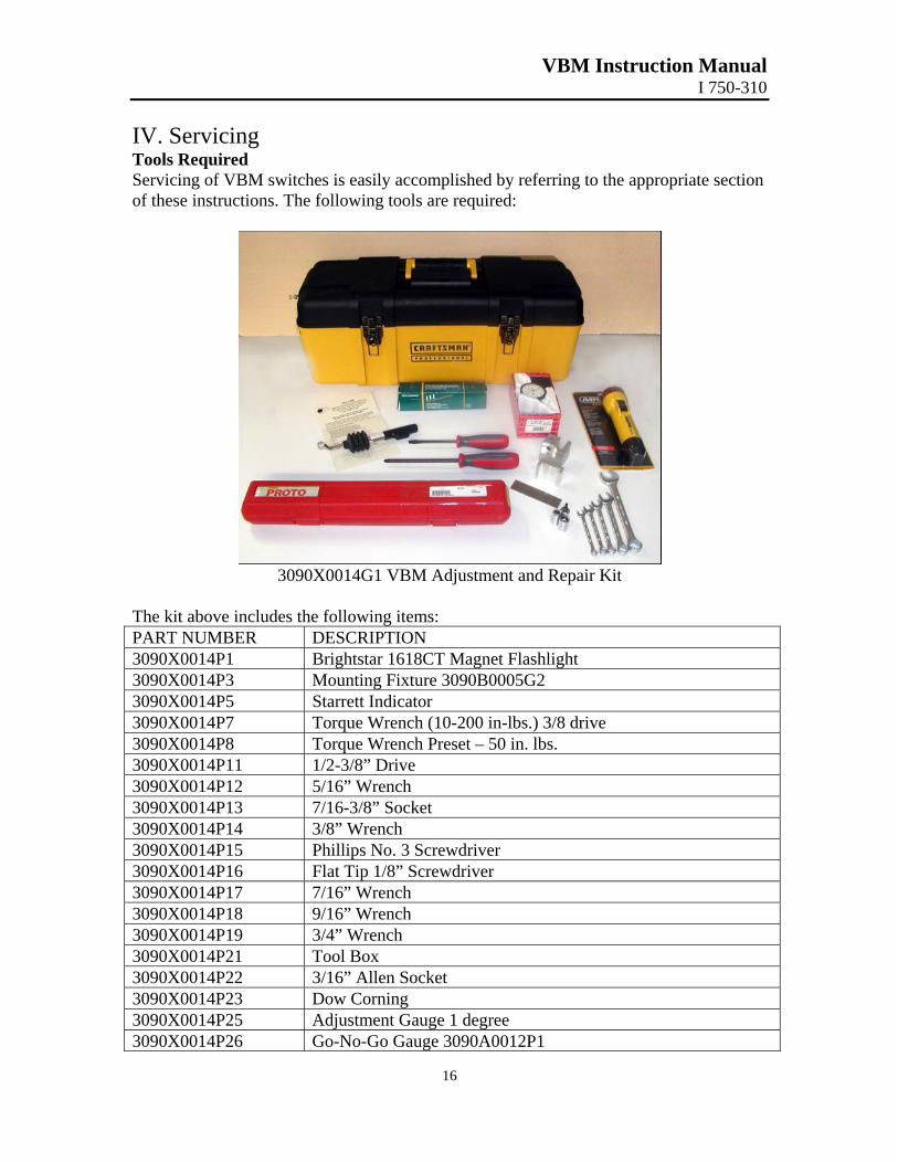
IV. Servicing Tools Required Servicing of VBM switches is easily accomplished by referring to the appropriate section of these instructions. The following tools are required:
3090X0014G1 VBM Adjustment and Repair Kit
The kit above includes the following items: PART NUMBER DESCRIPTION 3090X0014P1 Brightstar 1618CT Magnet Flashlight 3090X0014P3 Mounting Fixture 3090B0005G2 3090X0014P5 Starrett Indicator 3090X0014P7 Torque Wrench (10-200 in-lbs.) 3/8 drive 3090X0014P8 Torque Wrench Preset – 50 in. lbs. 3090X0014P11 1/2-3/8” Drive 3090X0014P12 5/16” Wrench 3090X0014P13 7/16-3/8” Socket 3090X0014P14 3/8” Wrench 3090X0014P15 Phillips No. 3 Screwdriver 3090X0014P16 Flat Tip 1/8” Screwdriver 3090X0014P17 7/16” Wrench 3090X0014P18 9/16” Wrench 3090X0014P19 3/4” Wrench 3090X0014P21 Tool Box 3090X0014P22 3/16” Allen Socket 3090X0014P23 Dow Corning 3090X0014P25 Adjustment Gauge 1 degree 3090X0014P26 Go-No-Go Gauge 3090A0012P1
VBM Instruction Manual I 750-310
17
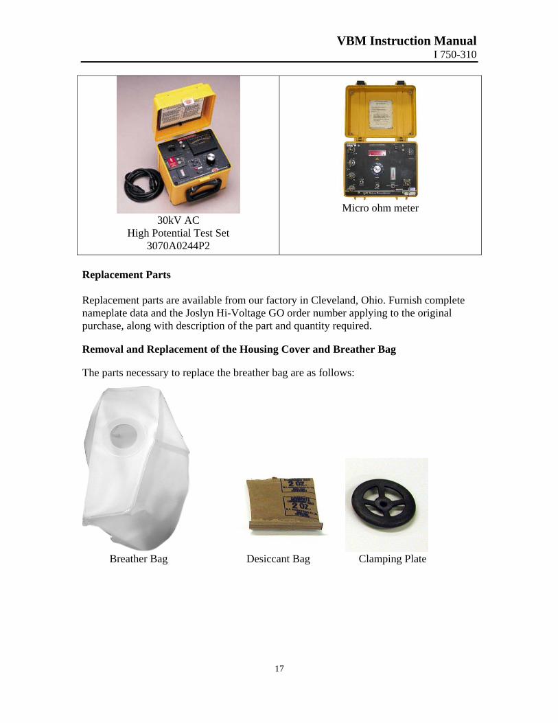
30kV AC
High Potential Test Set 3070A0244P2
Micro ohm meter
Replacement Parts Replacement parts are available from our factory in Cleveland, Ohio. Furnish complete nameplate data and the Joslyn Hi-Voltage GO order number applying to the original purchase, along with description of the part and quantity required. Removal and Replacement of the Housing Cover and Breather Bag The parts necessary to replace the breather bag are as follows:
Breather Bag Desiccant Bag Clamping Plate
VBM Instruction Manual I 750-310
18
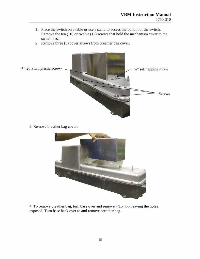
1. Place the switch on a table or use a stand to access the bottom of the switch. Remove the ten (10) or twelve (12) screws that hold the mechanism cover to the switch base.
2. Remove three (3) cover screws from breather bag cover.
¼”-20 x 5/8 plastic screw ¼” self tapping screw
s
3. Remove breather bag cover.
4. To remove breather bag, turn base over and remove 7/16” nut leaving the holeexposed. Turn base back over to and remove breather bag.
Screw
s
VBM Instruction Manual I 750-310
19
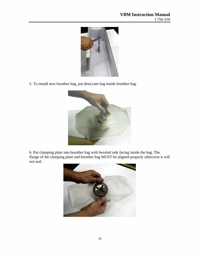
5. To install new breather bag, put desiccant bag inside breather bag.
6. Put clamping plate into breather bag with beveled side facing inside the bag. The flange of the clamping plate and breather bag MUST be aligned properly otherwise it will not seal.
VBM Instruction Manual I 750-310
20
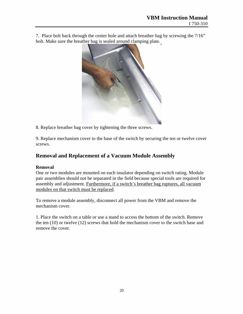
7. Place bolt back through the center hole and attach breather bag by screwing the 7/16” bolt. Make sure the breather bag is sealed around clamping plate.
8. Replace breather bag cover by tightening the three screws. 9. Replace mechanism cover to the base of the switch by securing the ten or twelve cover screws. Removal and Replacement of a Vacuum Module Assembly Removal One or two modules are mounted on each insulator depending on switch rating. Module pair assemblies should not be separated in the field because special tools are required for assembly and adjustment. Furthermore, if a switch’s breather bag ruptures, all vacuum modules on that switch must be replaced. To remove a module assembly, disconnect all power from the VBM and remove the mechanism cover. 1. Place the switch on a table or use a stand to access the bottom of the switch. Remove the ten (10) or twelve (12) screws that hold the mechanism cover to the switch base and remove the cover.
VBM Instruction Manual I 750-310
21
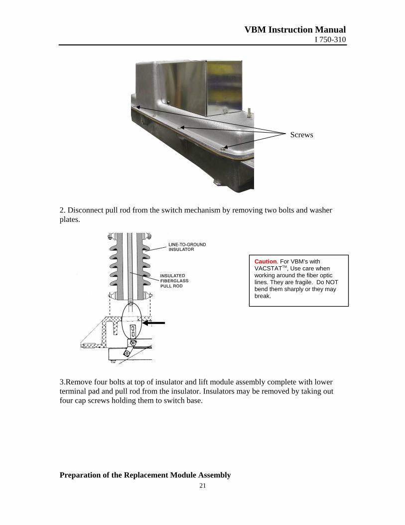
Screws
2. Disconnect pull rod from the switch mechanism by removing two bolts and washer plates.
Caution. For VBM’s with VACSTATTM, Use care when working around the fiber optic lines. They are fragile. Do NOT bend them sharply or they may break.
3.Remove four bolts at top of insulator and lift module assembly complete with lower terminal pad and pull rod from the insulator. Insulators may be removed by taking out four cap screws holding them to switch base. Preparation of the Replacement Module Assembly
VBM Instruction Manual I 750-310
22
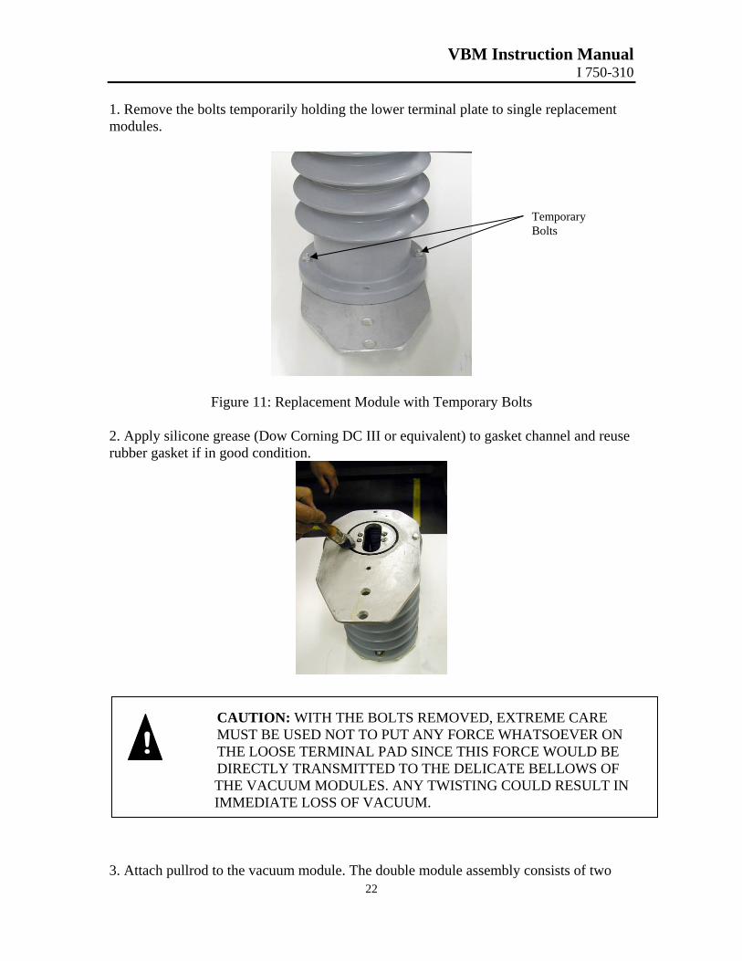
1. Remove the bolts temporarily holding the lower terminal plate to single replacement modules.
Temporary Bolts
Figure 11: Replacement Module with Temporary Bolts
2. Apply silicone grease (Dow Corning DC III or equivalent) to gasket channel and reuse rubber gasket if in good condition.
CAUTION: WITH THE BOLTS REMOVED, EXTREME CARE MUST BE USED NOT TO PUT ANY FORCE WHATSOEVER ON THE LOOSE TERMINAL PAD SINCE THIS FORCE WOULD BE DIRECTLY TRANSMITTED TO THE DELICATE BELLOWS OF THE VACUUM MODULES. ANY TWISTING COULD RESULT IN IMMEDIATE LOSS OF VACUUM.
!
3. Attach pullrod to the vacuum module. The double module assembly consists of two
VBM Instruction Manual I 750-310
23
modules in series, an upper terminal plate and a lower terminal. It should not be disassembled. The single module and module pair assemblies are mounted in the same manner. An aluminum clevis link may be bolted in the mechanism end of replacement pull rods. If so, remove the aluminum clevis link and discard it. DO NOT attempt to replace the link already in the mechanism. All single replacement modules are supplied with a separate “screw-on” pull rod. It is installed by slowly screwing onto the bolt in base of the module. Stop as thread bottoms to avoid putting any stress or strain on the vacuum contact. Back the rod off a maximum of one turn as required to mate with the clevis link on mechanism. NOTE: Do not overtighten pull rod to module. Earlier modules utilized either a permanently attached pull rod or a “screw-in” design. To replace a “screw-in” pull rod, slip the 1” nylon bushing supplied over the bolt end of the rod and slowly screw into the threaded module base. Stop as thread bottoms and back rod out approximately three full turns as required for proper orientation with the mechanism. Double module assemblies of the present design utilize a pull rod which is bolted to a draw bar in the lower module. All necessary hardware is supplied with replacement double module assemblies. The former design utilized a “screw-on” pull rod system. All module assemblies are interchangeable and may be used on the same mechanism, regardless of type of pull rod, however using a present and former design double module pair assembly on the same mechanism requires special considerations. If this situation is required, contact Joslyn Hi-Voltage.
! CAUTION: BUMPING OR TWISTING ANY PULL ROD WHEN ATTACHED TO A MODULE CAN DAMAGE THE VACUUM INTERRUPTER AND REDUCE ITS LIFE.
VBM Instruction Manual I 750-310
24
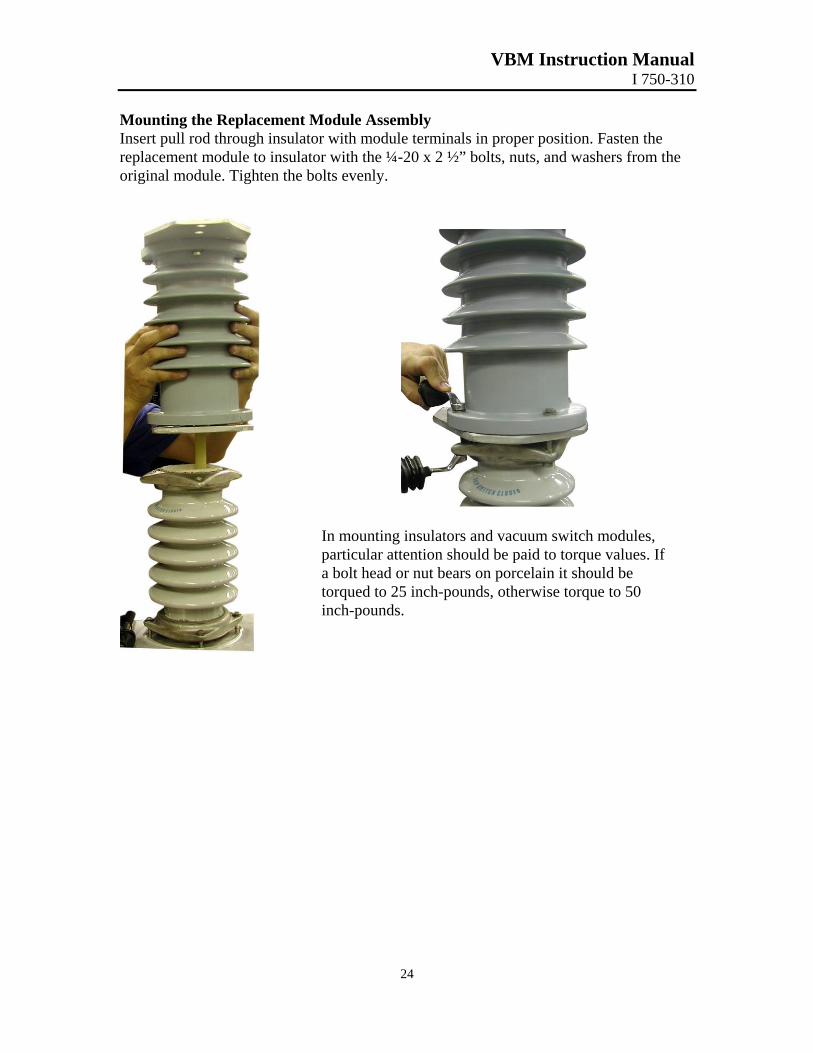
Mounting the Replacement Module Assembly Insert pull rod through insulator with module terminals in proper position. Fasten the replacement module to insulator with the ¼-20 x 2 ½” bolts, nuts, and washers from the original module. Tighten the bolts evenly.
In mounting insulators and vacuum switch modules, particular attention should be paid to torque values. If a bolt head or nut bears on porcelain it should be torqued to 25 inch-pounds, otherwise torque to 50 inch-pounds.
VBM Instruction Manual I 750-310
25
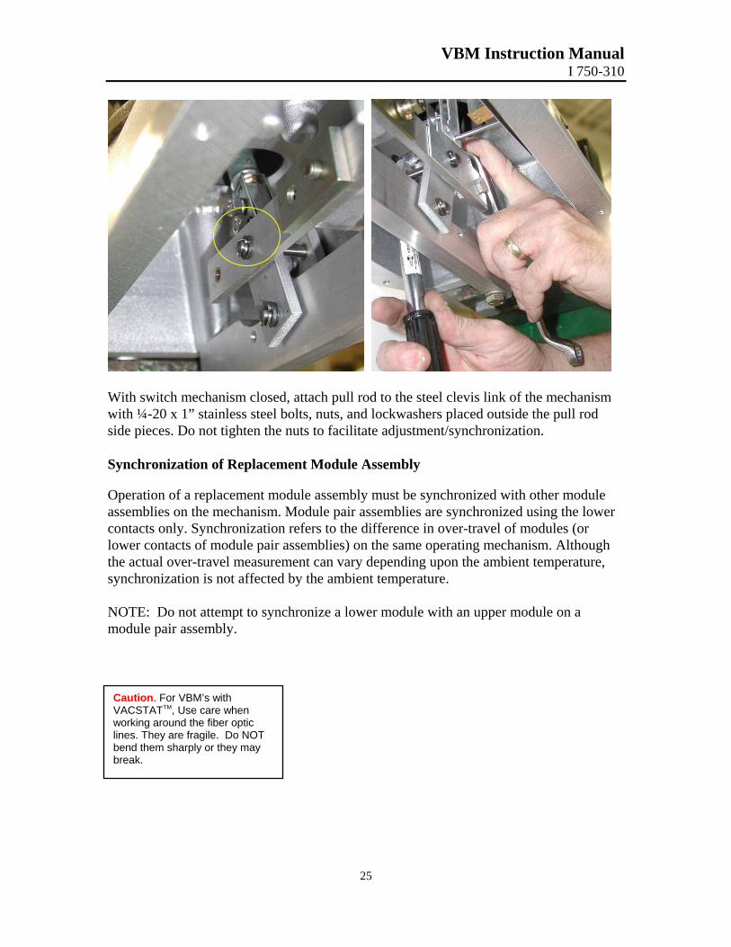
With switch mechanism closed, attach pull rod to the steel clevis link of the mechanism with ¼-20 x 1” stainless steel bolts, nuts, and lockwashers placed outside the pull rod side pieces. Do not tighten the nuts to facilitate adjustment/synchronization. Synchronization of Replacement Module Assembly Operation of a replacement module assembly must be synchronized with other module assemblies on the mechanism. Module pair assemblies are synchronized using the lower contacts only. Synchronization refers to the difference in over-travel of modules (or lower contacts of module pair assemblies) on the same operating mechanism. Although the actual over-travel measurement can vary depending upon the ambient temperature, synchronization is not affected by the ambient temperature. NOTE: Do not attempt to synchronize a lower module with an upper module on a module pair assembly.
Caution. For VBM’s with VACSTATTM, Use care when working around the fiber optic lines. They are fragile. Do NOT bend them sharply or they may break.
VBM Instruction Manual I 750-310
26
Toggle Link
Auxiliary Contact Assembly
Toggle Link
Dial Indicator (Secure against bolt)
Toggle Link
Open Stop Screws
Support Bar
Cable Connector
Bolts Close Stop
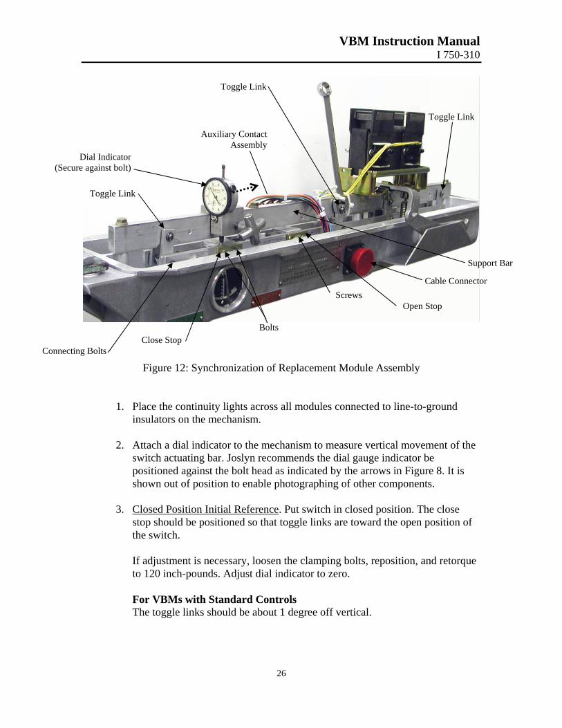
Connecting Bolts Figure 12: Synchronization of Replacement Module Assembly
1. Place the continuity lights across all modules connected to line-to-ground insulators on the mechanism.
2. Attach a dial indicator to the mechanism to measure vertical movement of the
switch actuating bar. Joslyn recommends the dial gauge indicator be positioned against the bolt head as indicated by the arrows in Figure 8. It is shown out of position to enable photographing of other components.
3. Closed Position Initial Reference. Put switch in closed position. The close
stop should be positioned so that toggle links are toward the open position of the switch. If adjustment is necessary, loosen the clamping bolts, reposition, and retorque to 120 inch-pounds. Adjust dial indicator to zero. For VBMs with Standard Controls The toggle links should be about 1 degree off vertical.
VBM Instruction Manual I 750-310
27
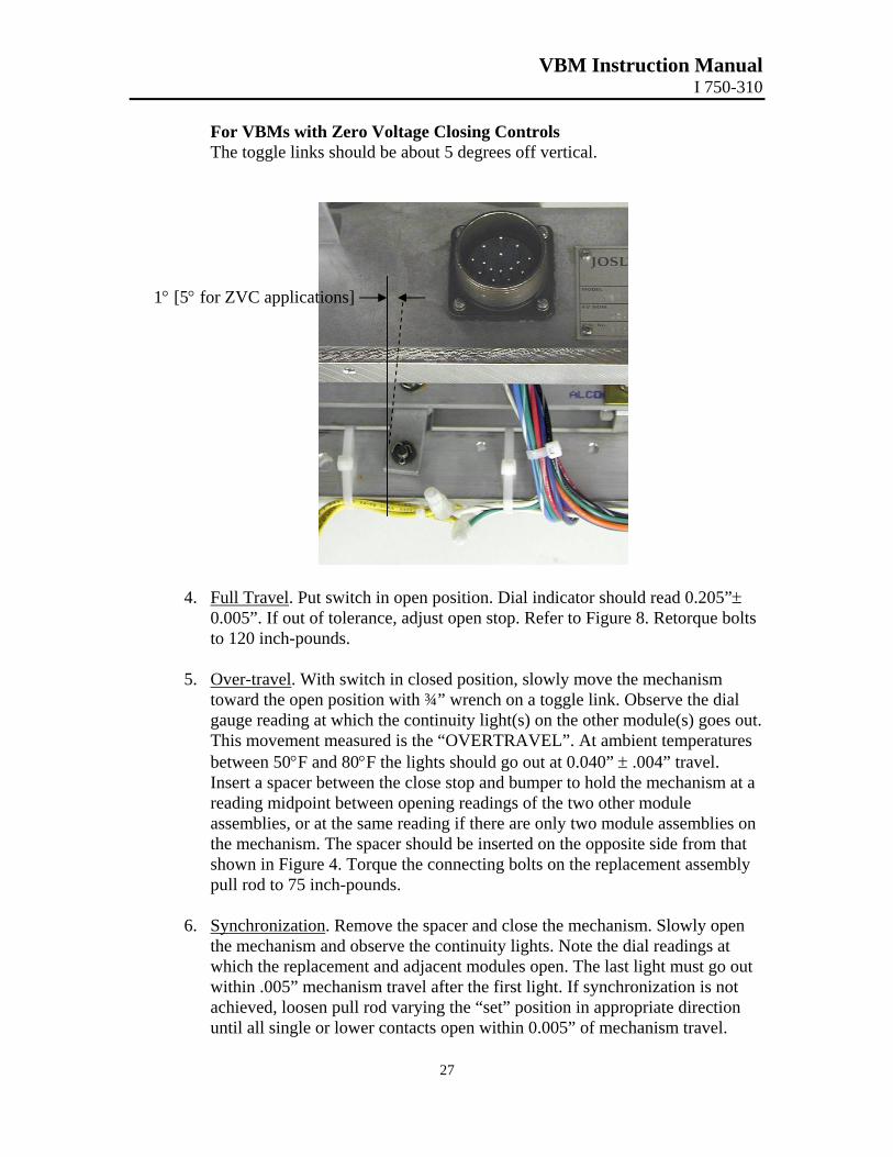
For VBMs with Zero Voltage Closing Controls The toggle links should be about 5 degrees off vertical.
1° [5° for ZVC applications]
4. Full Travel. Put switch in open position. Dial indicator should read 0.205”±
0.005”. If out of tolerance, adjust open stop. Refer to Figure 8. Retorque bolts to 120 inch-pounds.
5. Over-travel. With switch in closed position, slowly move the mechanism
toward the open position with ¾” wrench on a toggle link. Observe the dial gauge reading at which the continuity light(s) on the other module(s) goes out. This movement measured is the “OVERTRAVEL”. At ambient temperatures between 50°F and 80°F the lights should go out at 0.040” ± .004” travel. Insert a spacer between the close stop and bumper to hold the mechanism at a reading midpoint between opening readings of the two other module assemblies, or at the same reading if there are only two module assemblies on the mechanism. The spacer should be inserted on the opposite side from that shown in Figure 4. Torque the connecting bolts on the replacement assembly pull rod to 75 inch-pounds.
6. Synchronization. Remove the spacer and close the mechanism. Slowly open
the mechanism and observe the continuity lights. Note the dial readings at which the replacement and adjacent modules open. The last light must go out within .005” mechanism travel after the first light. If synchronization is not achieved, loosen pull rod varying the “set” position in appropriate direction until all single or lower contacts open within 0.005” of mechanism travel.
VBM Instruction Manual I 750-310
28
7. After module pair assemblies have been synchronized using the lower contacts only, the synchronization between upper and lower contacts should be verified. The synchronization of upper and lower contacts is related to ambient temperature. At temperatures between 50°F and 80°F the dial gauge should measure a maximum of 0.010” travel of the actuating bar between the opening of each lower contact and its corresponding upper contact.
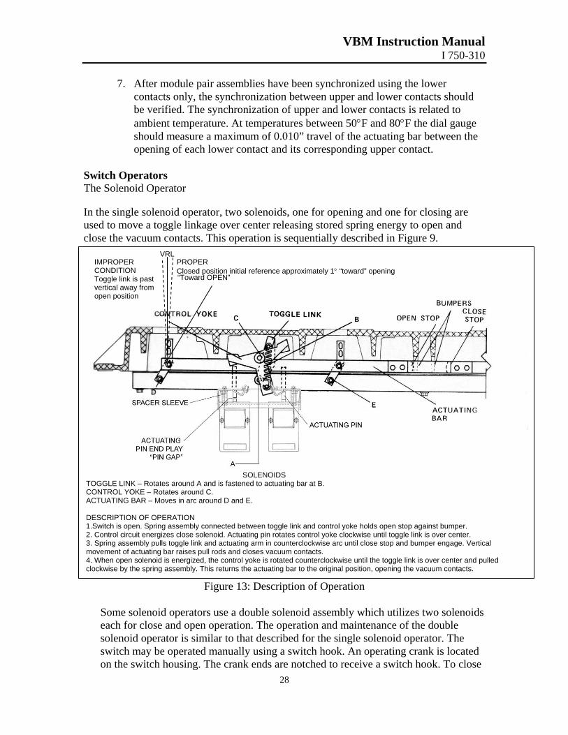
Switch Operators The Solenoid Operator In the single solenoid operator, two solenoids, one for opening and one for closing are used to move a toggle linkage over center releasing stored spring energy to open and close the vacuum contacts. This operation is sequentially described in Figure 9.
SOLENOIDS TOGGLE LINK – Rotates around A and is fastened to actuating bar at B. CONTROL YOKE – Rotates around C. ACTUATING BAR – Moves in arc around D and E. DESCRIPTION OF OPERATION 1.Switch is open. Spring assembly connected between toggle link and control yoke holds open stop against bumper. 2. Control circuit energizes close solenoid. Actuating pin rotates control yoke clockwise until toggle link is over center. 3. Spring assembly pulls toggle link and actuating arm in counterclockwise arc until close stop and bumper engage. Vertical movement of actuating bar raises pull rods and closes vacuum contacts. 4. When open solenoid is energized, the control yoke is rotated counterclockwise until the toggle link is over center and pulled clockwise by the spring assembly. This returns the actuating bar to the original position, opening the vacuum contacts.
IMPROPER CONDITION Toggle link is past vertical away from open position
VRL PROPER Closed position initial reference approximately 1° “toward” opening “Toward OPEN”
Figure 13: Description of Operation Some solenoid operators use a double solenoid assembly which utilizes two solenoids each for close and open operation. The operation and maintenance of the double solenoid operator is similar to that described for the single solenoid operator. The switch may be operated manually using a switch hook. An operating crank is located on the switch housing. The crank ends are notched to receive a switch hook. To close
VBM Instruction Manual I 750-310
29
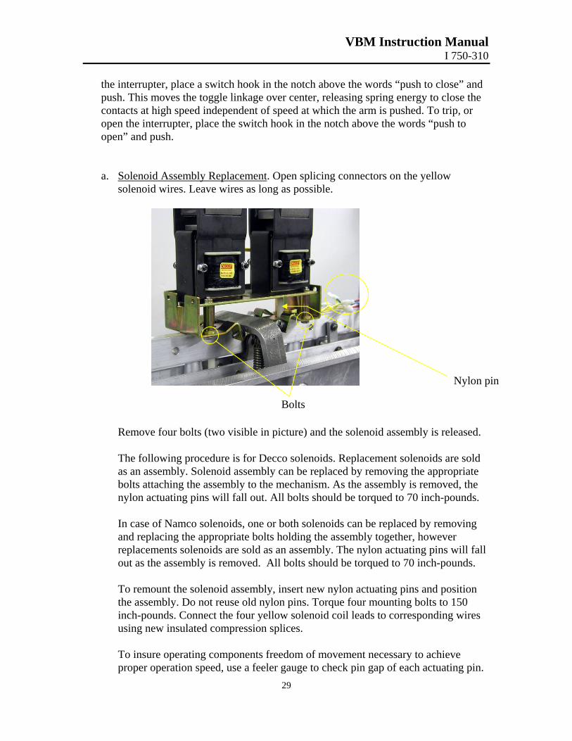
the interrupter, place a switch hook in the notch above the words “push to close” and push. This moves the toggle linkage over center, releasing spring energy to close the contacts at high speed independent of speed at which the arm is pushed. To trip, or open the interrupter, place the switch hook in the notch above the words “push to open” and push. a. Solenoid Assembly Replacement. Open splicing connectors on the yellow
solenoid wires. Leave wires as long as possible.
Remove four bolts (two visible in picture) and the solenoid assembly is released. The following procedure is for Decco solenoids. Replacement solenoids are sold as an assembly. Solenoid assembly can be replaced by removing the appropriate bolts attaching the assembly to the mechanism. As the assembly is removed, the nylon actuating pins will fall out. All bolts should be torqued to 70 inch-pounds. In case of Namco solenoids, one or both solenoids can be replaced by removing and replacing the appropriate bolts holding the assembly together, however replacements solenoids are sold as an assembly. The nylon actuating pins will fall out as the assembly is removed. All bolts should be torqued to 70 inch-pounds. To remount the solenoid assembly, insert new nylon actuating pins and position the assembly. Do not reuse old nylon pins. Torque four mounting bolts to 150 inch-pounds. Connect the four yellow solenoid coil leads to corresponding wires using new insulated compression splices. To insure operating components freedom of movement necessary to achieve proper operation speed, use a feeler gauge to check pin gap of each actuating pin.
Nylon pin
Bolts
VBM Instruction Manual I 750-310
30
The gap should be .070 and .090”. Manually change the switch position to check opposite pins. Pin gap is adjusted by adding or removing flat washer shims under nylon spacer sleeves.
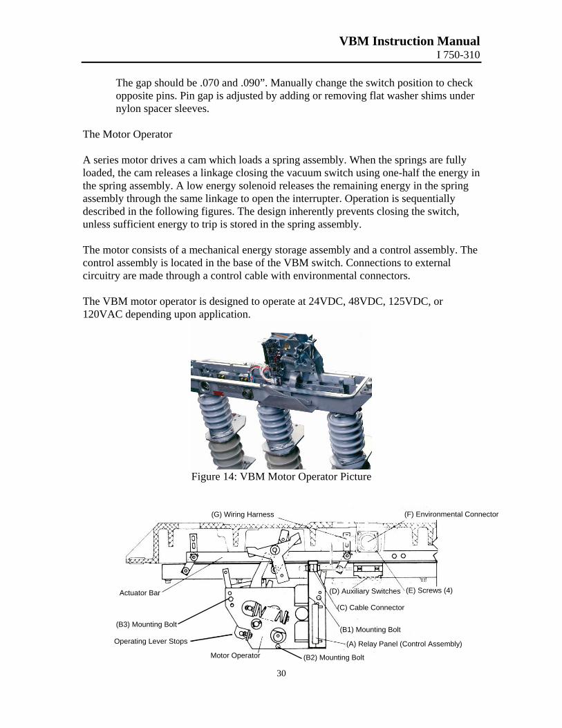
The Motor Operator A series motor drives a cam which loads a spring assembly. When the springs are fully loaded, the cam releases a linkage closing the vacuum switch using one-half the energy in the spring assembly. A low energy solenoid releases the remaining energy in the spring assembly through the same linkage to open the interrupter. Operation is sequentially described in the following figures. The design inherently prevents closing the switch, unless sufficient energy to trip is stored in the spring assembly. The motor consists of a mechanical energy storage assembly and a control assembly. The control assembly is located in the base of the VBM switch. Connections to external circuitry are made through a control cable with environmental connectors. The VBM motor operator is designed to operate at 24VDC, 48VDC, 125VDC, or 120VAC depending upon application.
Figure 14: VBM Motor Operator Picture
(F) Environmental Connector (G) Wiring Harness
(E) Screws (4) (D) Auxiliary Switches Actuator Bar
(B3) Mounting Bolt
(C) Cable Connector
(B1) Mounting Bolt Operating Lever Stops (A) Relay Panel (Control Assembly)
(B2) Mounting Bolt Motor Operator
VBM Instruction Manual I 750-310
Figure 15: VBM Motor Operator Diagram
Description of Operation The following figures illustrate the sequential operation of the assembly. The motor operator lever is connected to the switch actuating bar at point M. The actuating bar linkage is connected to the pull rods (not shown) of each module assembly.
1. 2.
3. 4.
Figure 16: Sequence of Motor Operation
Figure 17: Sequence of Motor Operation
Figure 18: Sequence of Motor Operation
5. Lever is displaced in direction R1. 6. Spring assembly S1 is compressed storing energy in springs. 7. Lever pulls toggle links P1 and P2 over center. 8. Toggle spring S2 brings toggle linkage in
extended position against stop. 9. The switch is open and the mechanism is ready to
close.
31
10
11
12
. As spring assembly S1 is fully loaded the cam releases lever and stops.
. Lever pivots around fulcrum T. Pin R moves in arc R2 and comes against motor assembly chassis stop using ½ total energy in spring assembly S1.
. M is moved in arc M1. M’s displacement moves the switch actuating bar and closes the interrupter contacts.
Switch is open. Toggle links P1 and P2 are in relaxed position. Spring assembly S1 is unloaded. Cam is rotated counter-clockwise by motor ormanual pumping.
VBM Instruction Manual I 750-310
32
1314
15
16
17
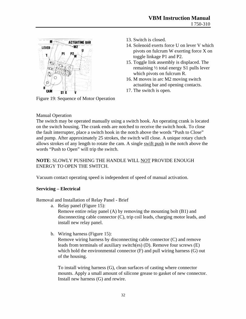
Figure 19: Sequence of Motor Operation Manual Operation The switch may be operated manually using a swon the switch housing. The crank ends are notchethe fault interrupter, place a switch hook in the noand pump. After approximately 25 strokes, the swallows strokes of any length to rotate the cam. A words “Push to Open” will trip the switch. NOTE: SLOWLY PUSHING THE HANDLE WENERGY TO OPEN THE SWITCH. Vacuum contact operating speed is independent o Servicing – Electrical Removal and Installation of Relay Panel - Brief
a. Relay panel (Figure 15): Remove entire relay panel (A) by remdisconnecting cable connector (C), triinstall new relay panel.
b. Wiring harness (Figure 15): Remove wiring harness by disconnectleads from terminals of auxiliary switcwhich hold the environmental connectof the housing.
To install wiring harness (G), clean sumounts. Apply a small amount of silicInstall new harness (G) and rewire.
. Switch is closed.
. Solenoid exerts force U on lever V whichpivots on fulcrum W exerting force X on toggle linkage P1 and P2.
. Toggle link assembly is displaced. The remaining ½ total energy S1 pulls lever which pivots on fulcrum R.
. M moves in arc M2 moving switch actuating bar and opening contacts.
. The switch is open.
itch hook. An operating crank is located d to receive the switch hook. To close tch above the words “Push to Close” itch will close. A unique rotary clutch
single swift push in the notch above the
ILL NOT PROVIDE ENOUGH
f speed of manual activation.
oving the mounting bolt (B1) and p coil leads, charging motor leads, and
ing cable connector (C) and remove h(es) (D). Remove four screws (E) or (F) and pull wiring harness (G) out
rfaces of casting where connector one grease to gasket of new connector.
VBM Instruction Manual I 750-310
33
c. Auxiliary switch(es) (D) (Figure 15): Refer to Auxiliary Switch Adjustment section.
Installation of Relay Panel - Detailed Relay Panel Installation.
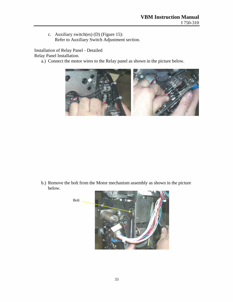
a.) Connect the motor wires to the Relay panel as shown in the picture below.
b.) Remove the bolt from the Motor mechanism assembly as shown in the picture below.
Bolt
VBM Instruction Manual I 750-310
34
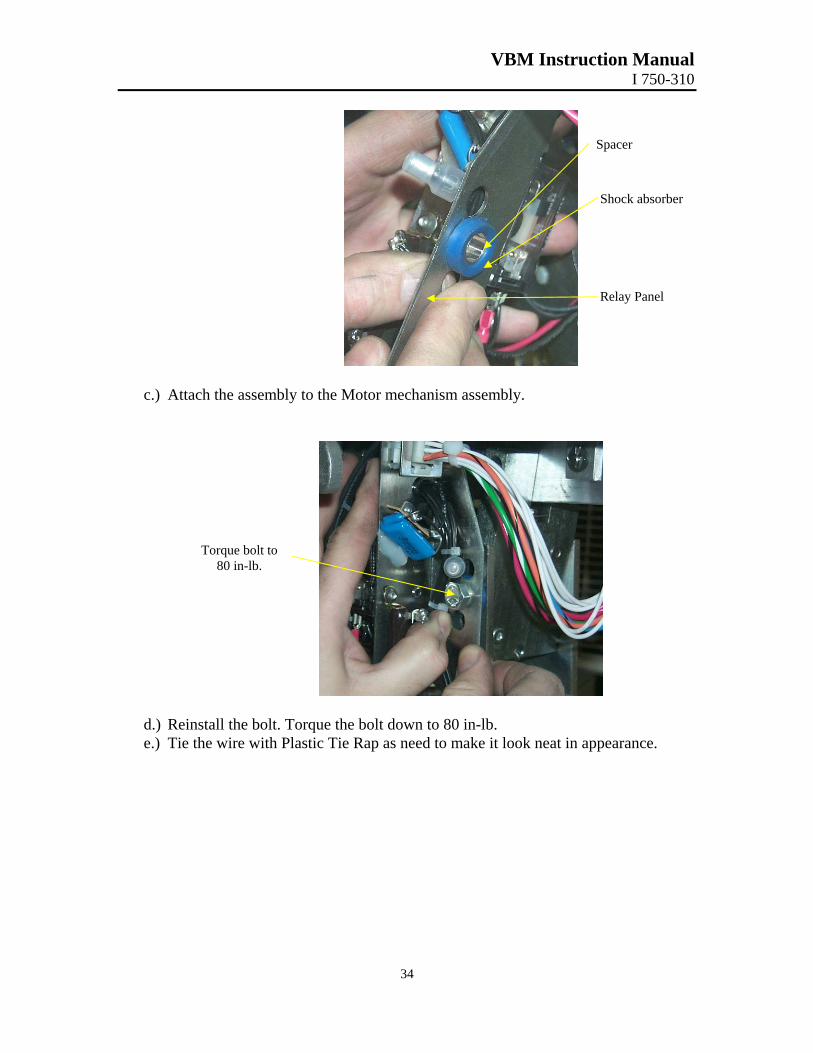
Spacer
Shock absorber
Relay Panel
c.) Attach the assembly to the Motor mechanism assembly.
Torque bolt to 80 in-lb.
d.) Reinstall the bolt. Torque the bolt down to 80 in-lb. e.) Tie the wire with Plastic Tie Rap as need to make it look neat in appearance.
VBM Instruction Manual I 750-310
35
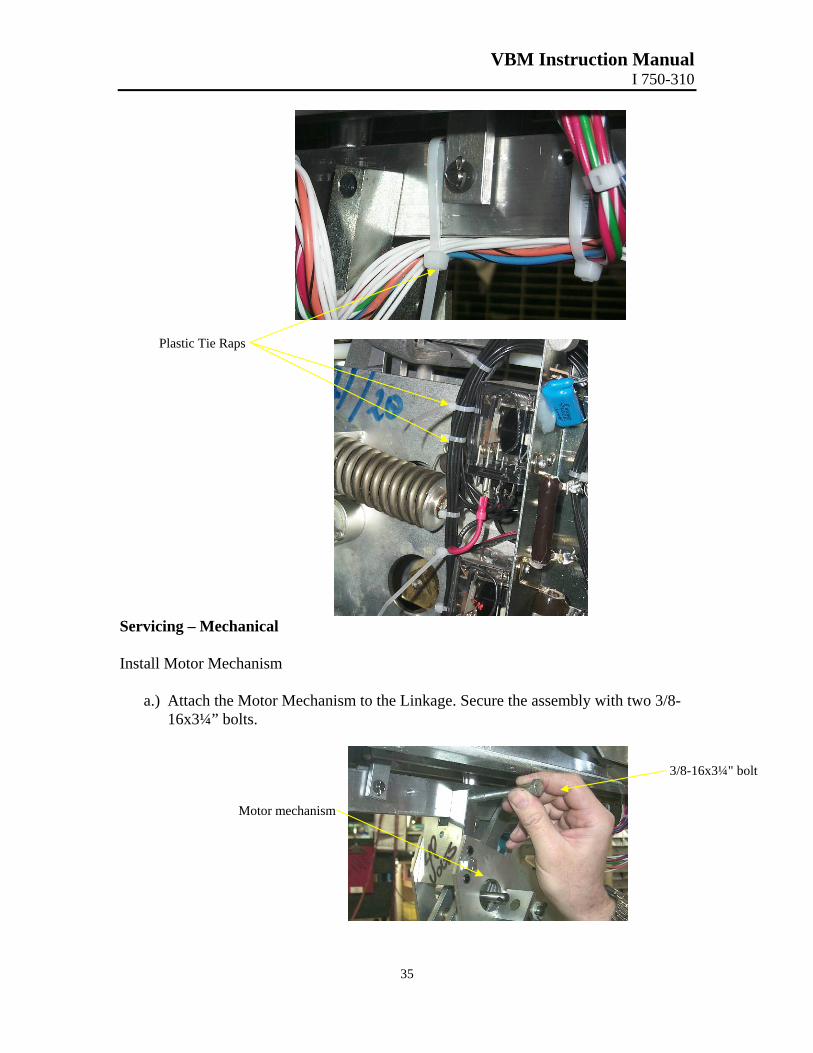
Plastic Tie Raps
Servicing – Mechanical Install Motor Mechanism
a.) Attach the Motor Mechanism to the Linkage. Secure the assembly with two 3/8-16x3¼” bolts.
3/8-16x3¼" bolt
Motor mechanism
VBM Instruction Manual I 750-310
36
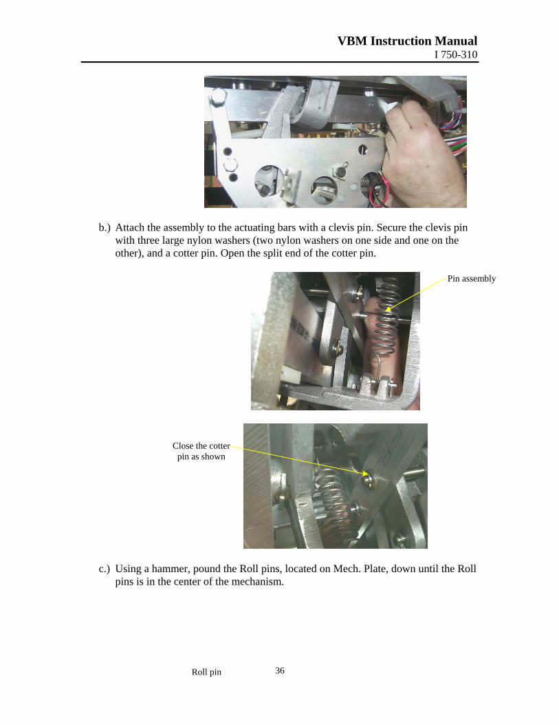
b.) Attach the assembly to the actuating bars with a clevis pin. Secure the clevis pin with three large nylon washers (two nylon washers on one side and one on the other), and a cotter pin. Open the split end of the cotter pin.
Pin assembly
Close the cotter pin as shown
c.) Using a hammer, pound the Roll pins, located on Mech. Plate, down until the Roll pins is in the center of the mechanism.
Roll pin
VBM Instruction Manual I 750-310
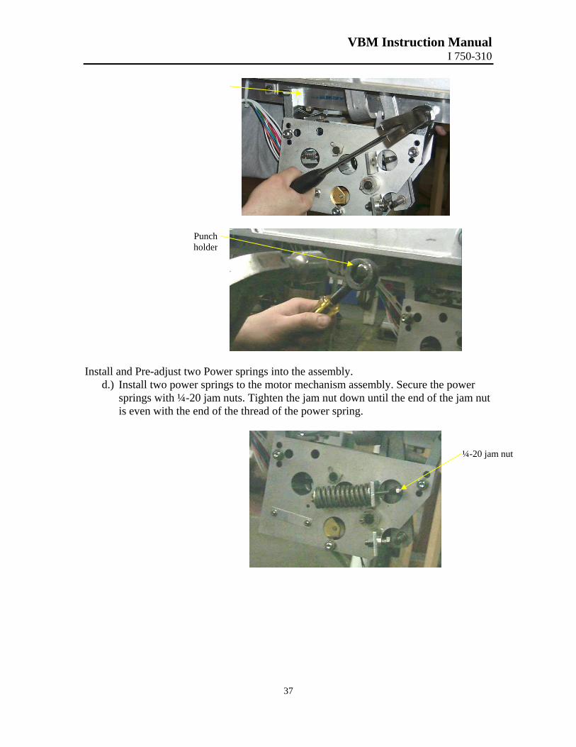
Install and Pre-adjust twd.) Install two pow
springs with ¼-is even with the
Punch holder
37
o Power springs into the assembly. er springs to the motor mechanism assembly. Secure the power 20 jam nuts. Tighten the jam nut down until the end of the jam nut end of the thread of the power spring.
¼-20 jam nut
VBM Instruction Manual I 750-310
38
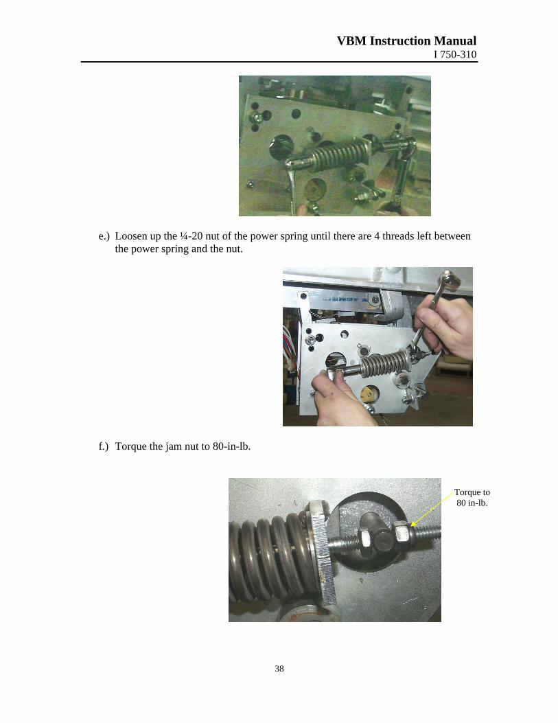
e.) Loosen up the ¼-20 nut of the power spring until there are 4 threads left between the power spring and the nut.
f.) Torque the jam nut to 80-in-lb.
Torque to80 in-lb.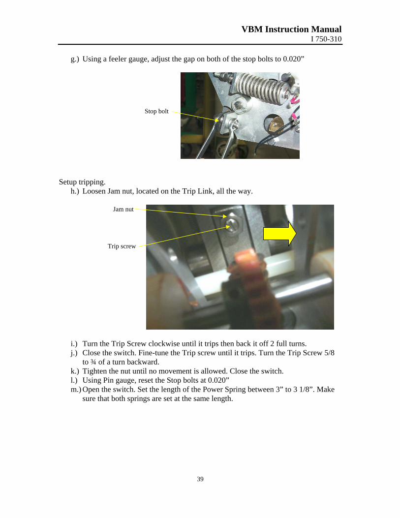
VBM Instruction Manual I 750-310
39
g.) Using a feeler gauge, adjust the gap on both of the stop bolts to 0.020”
Stop bolt
Setup tripping. h.) Loosen Jam nut, located on the Trip Link, all the way.
Jam nut
Trip screw
i.) Turn the Trip Screw clockwise until it trips then back it off 2 full turns. j.) Close the switch. Fine-tune the Trip screw until it trips. Turn the Trip Screw 5/8
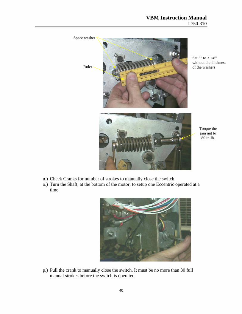
to ¾ of a turn backward. k.) Tighten the nut until no movement is allowed. Close the switch. l.) Using Pin gauge, reset the Stop bolts at 0.020” m.) Open the switch. Set the length of the Power Spring between 3” to 3 1/8”. Make
sure that both springs are set at the same length.
VBM Instruction Manual I 750-310
40
Space washer
Ruler
Set 3" to 3 1/8" without the thickness of the washers
Torque the jam nut to 80 in-lb.
n.) Check Cranks for number of strokes to manually close the switch. o.) Turn the Shaft, at the bottom of the motor; to setup one Eccentric operated at a
time.
p.) Pull the crank to manually close the switch. It must be no more than 30 full manual strokes before the switch is operated.
VBM Instruction Manual I 750-310
41
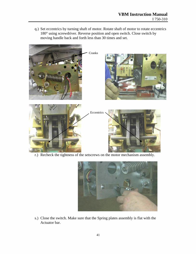
q.) Set eccentrics by turning shaft of motor. Rotate shaft of motor to rotate eccentrics 180° using screwdriver. Reverse position and open switch. Close switch by moving handle back and forth less than 30 times and set.
Cranks
Eccentrics
r.) Recheck the tightness of the setscrews on the motor mechanism assembly.
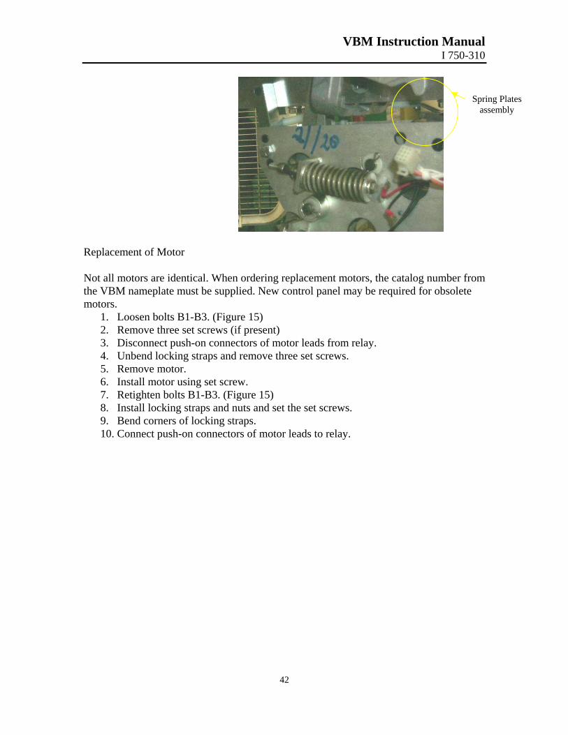
s.) Close the switch. Make sure that the Spring plates assembly is flat with the
Actuator bar.
VBM Instruction Manual I 750-310
42
Spring Plates assembly
Replacement of Motor Not all motors are identical. When ordering replacement motors, the catalog number from the VBM nameplate must be supplied. New control panel may be required for obsolete motors.
1. Loosen bolts B1-B3. (Figure 15) 2. Remove three set screws (if present) 3. Disconnect push-on connectors of motor leads from relay. 4. Unbend locking straps and remove three set screws. 5. Remove motor. 6. Install motor using set screw. 7. Retighten bolts B1-B3. (Figure 15) 8. Install locking straps and nuts and set the set screws. 9. Bend corners of locking straps. 10. Connect push-on connectors of motor leads to relay.
VBM Instruction Manual I 750-310
Auxiliary Switch Adjustment
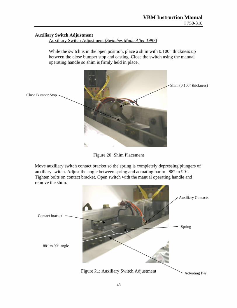
Auxiliary Switch Adjustment (Switches Made After 1997) While the switch is in the open position, place a shim with 0.100” thickness up between the close bumper stop and casting. Close the switch using the manual operating handle so shim is firmly held in place.
Shim (0.100” thickness)
Close Bumper Stop
Figure 20: Shim Placement
Move auxiliary switch contact bracket so the spring is completely depressing plungers of auxiliary switch. Adjust the angle between spring and actuating bar to 88° to 90°. Tighten bolts on contact bracket. Open switch with the manual operating handle and remove the shim.
Auxiliary Contacts
Contact bracket
Spring
Figure 21: Auxiliary Switch Adjustment
43
88° to 90° angle
Actuating Bar
VBM Instruction Manual I 750-310
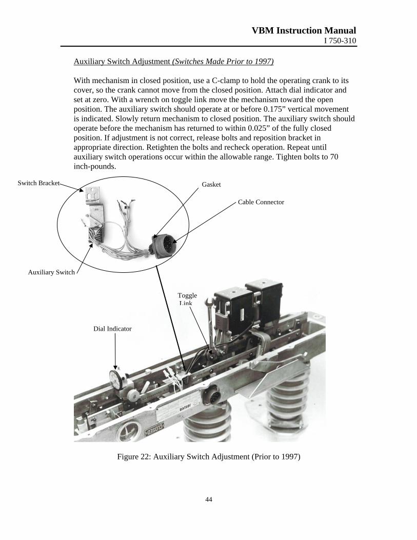
Auxiliary Switch Adjustment (Switches Made Prior to 1997) With mechanism in closed position, use a C-clamp to hold the operating crank to its cover, so the crank cannot move from the closed position. Attach dial indicator and set at zero. With a wrench on toggle link move the mechanism toward the open position. The auxiliary switch should operate at or before 0.175” vertical movement is indicated. Slowly return mechanism to closed position. The auxiliary switch should operate before the mechanism has returned to within 0.025” of the fully closed position. If adjustment is not correct, release bolts and reposition bracket in appropriate direction. Retighten the bolts and recheck operation. Repeat until auxiliary switch operations occur within the allowable range. Tighten bolts to 70 inch-pounds.
Dial Indicator
Auxiliary Switch
Switch Bracket Gasket
Cable Connector
Figure 22: Auxili
Toggle Link
44
ary Switch Adjustment (Prior to 1997)
VBM Instruction Manual I 750-310
45
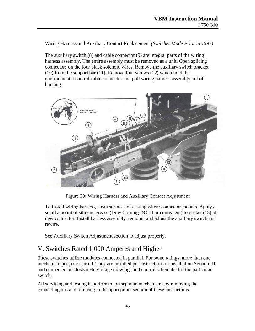
Wiring Harness and Auxiliary Contact Replacement (Switches Made Prior to 1997) The auxiliary switch (8) and cable connector (9) are integral parts of the wiring harness assembly. The entire assembly must be removed as a unit. Open splicing connectors on the four black solenoid wires. Remove the auxiliary switch bracket (10) from the support bar (11). Remove four screws (12) which hold the environmental control cable connector and pull wiring harness assembly out of housing.
Figure 23: Wiring Harness and Auxiliary Contact Adjustment
To install wiring harness, clean surfaces of casting where connector mounts. Apply a small amount of silicone grease (Dow Corning DC III or equivalent) to gasket (13) of new connector. Install harness assembly, remount and adjust the auxiliary switch and rewire.
See Auxiliary Switch Adjustment section to adjust properly.
V. Switches Rated 1,000 Amperes and Higher These switches utilize modules connected in parallel. For some ratings, more than one mechanism per pole is used. They are installed per instructions in Installation Section III and connected per Joslyn Hi-Voltage drawings and control schematic for the particular switch.
All servicing and testing is performed on separate mechanisms by removing the connecting bus and referring to the appropriate section of these instructions.


![Series and Parallel Arc-Fault Circuit Interrupter Tests · the DC electrical arc-fault noise signatures of series and parallel arc-faults were measured and quantified [1-2]. Many](https://img.pdfslide.us/doc/110x75/5e88bc1ba36b331bef64c424/series-and-parallel-arc-fault-circuit-interrupter-tests-the-dc-electrical-arc-fault.jpg)