Embed Size (px)
Citation preview
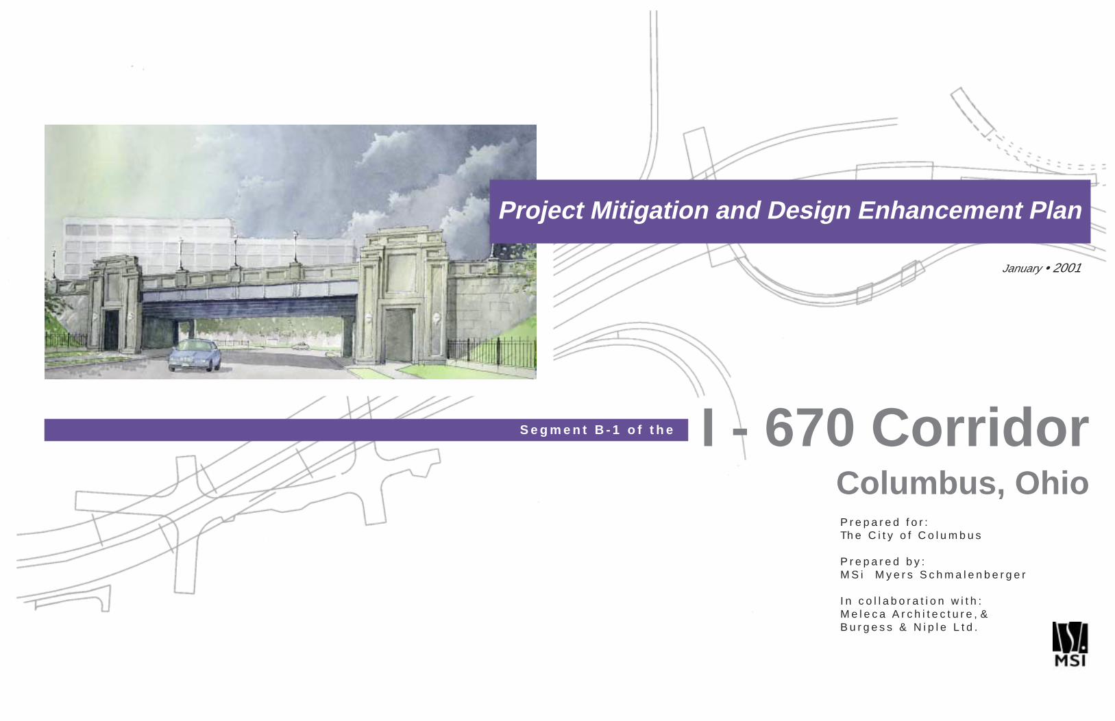
Project Mitigation and Design Enhancement Plan
January • 2001
I - 670 CorridorColumbus, OhioP r e p a r e d f o r :Th e C i t y o f C o l u m b u s
P r e p a r e d b y :M S i M y e r s S c h m a l e n b e r g e r
I n c o l l a b o r a t i o n w i t h :M e l e c a A r c h i t e c t u r e , &B u r g e s s & N i p l e L t d .
S e g m e n t B - 1 o f t h e
Acknowledgements
The Myers Schmalenberger design team thanks the following groups and individuals for their efforts and contributions tothe I-670 Corridor Design Enhancement Study process:
City of Columbus:Department of Public Service:Mike Martin, Deputy DirectorEngineering & Construction Division:Andy Zarins, State & Federal Project ManagerTed Beidler, PE, Planning & Programming ManagerBob Long, PE, Assistant City Engineer (former)Kelly Cramer, Administrative SecretaryTraffic Engineering & Planning/Parking Division:Chuck Mayeres, Acting AdministratorJim Davis, Operations Engineer (retired)City Historic Preservation OfficeDiane Cole, Historic Preservation OfficerDawn Grunwell, Assistant Historic Preservation OfficerOther Divisions:Linda Scothorn, Street Lighting Coordinator, Dept. of Public UtilitiesDaniel Thomas, Urban Design Manager, Planning DivisionNeal Semel, Education Coordinator, Community Relations DivisionLelia Cady, Legislative Aide to Councilwoman O’Shaughnessy
Gavin ArmstrongPresidentVictorian Village Society
Craig CopelandPresidentCitizens for a Better Spring Sandusky
Steven ShinnRepresentativeHarrison West Society
Tim WagnerPresidentDennison Place AssociationExecutive DirectorShort North Special Improvement District
Andy KleinPresidentItalian Village Society
Kent MillsBoard MemberFriends of Goodale Park
Spring Sandusky Interchange Design Task Force:Linda PageDirector, Department of Public ServiceCity of Columbus
Paul GrahamAssistant AdministratorOffice of Environmental ServicesOhio Department of Transportation
Andy GarnesRural Program EngineerFederal Highway Administration
Mary SmithArchitecture Reviews ManagerOhio Historic Preservation Office
Elizabeth MerrittAssociate General CounselDepartment of Law and Public PolicyNational Trust for Historic Preservation
Laura DeanProgram AnalystAdvisory Council on Historic Preservation
Concurring Parties:Italian Village Society
Victorian Village Society
Friends of Goodale Park
Harrison West Society
Citizens for a Better Spring Sandusky
Dennison Place Association
National Trust for Historic Preservation
City of Columbus
Ohio Department of Transportation
Federal Highway Administration
Ohio Historic Preservation Office
Advisory Council on Historic Preservation
Ohio Department of Transportation:Jack Marchbanks, District Deputy Director, ODOT District 6Herb Ligocki, Production Administrator, ODOT District 6Megan Blackford, Project Manager, ODOT District 6Larry Sutherland, Roadway Engineer, ODOT Central OfficeJohn Binns, Highway Lighting Engineer, ODOT Central Office
Project Engineer:Carl Eriksson, PE, President, Eriksson Engineering
Consultant Team:Keith A. Myers, ASLA, Senior Principal, Myers Schmalenberger Inc.David B. Meleca, AIA, Architect, Meleca ArchitectureMartin P. Burke, Jr., PE, Senior Civil Engineer, Burgess & Niple Ltd.Chris S. Hermann, AICP, Urban Planner, Myers Schmalenberger Inc.
Others:Scott McGuire, Federal Highway AdministrationHarvey Schwager, AIA ColumbusRex Hagerling, AIA ColumbusPaul Cianelli, Friends of Goodale Park, Victorian Village Com.Robert Harmon, Citizens for a Better Spring SanduskyPat Henahan, Ohio Arts CouncilMark Haker, Italian Village SocietyBrian Higgins, Victorian Village Society, North Market DistrictRob Vogt, Victorian Village SocietyTodd Law, Victorian Village SocietyKeith Dimoff, Harrison West SocietyMaddy Weisz, Harrison West SocietyJoel Teaford, Columbus Neighborhood Design Assistance CenterKim Moss, Columbus Neighborhood Design Assistance CenterFrank Elmer, Italian Village Society
Myers Schmalenberger Team:Keith Myers, PrincipalChris Hermann, Urban PlannerTim McSheffery, Landscape ArchitectDarren Meyer, Landscape ArchitectSteven Hussey, Computer VisualizationKathryn Wimberger, Urban PlannerPaul Kelley, Graphic DesignerPaul Buchanan, Graphic DesignerRick Espe, Senior Project ManagerJason Sudy, Urban PlannerAron Fraizer, GIS CoordinatorKaren McCoy, PrincipalJulie Steigerwald, ArchitectStephen Kolwicz, Landscape ArchitectJennifer Gelb, Landscape ArchitectBrad Kissling, Intern
Mayor of the City of Columbus: Michael B. Coleman
Columbus City Council:Matthew D. Habash, PresidentRichard W. Sensenbrenner, President Pro-TemMaryellen O’Shaughnessy
Jennette B. BradleyKevin BoyceMichael C. MentelCharleta B. Tavares
Parties to the Memorandum of Agreement (MOA):
Signatory Agencies:

Prologue
P r o l o g u e
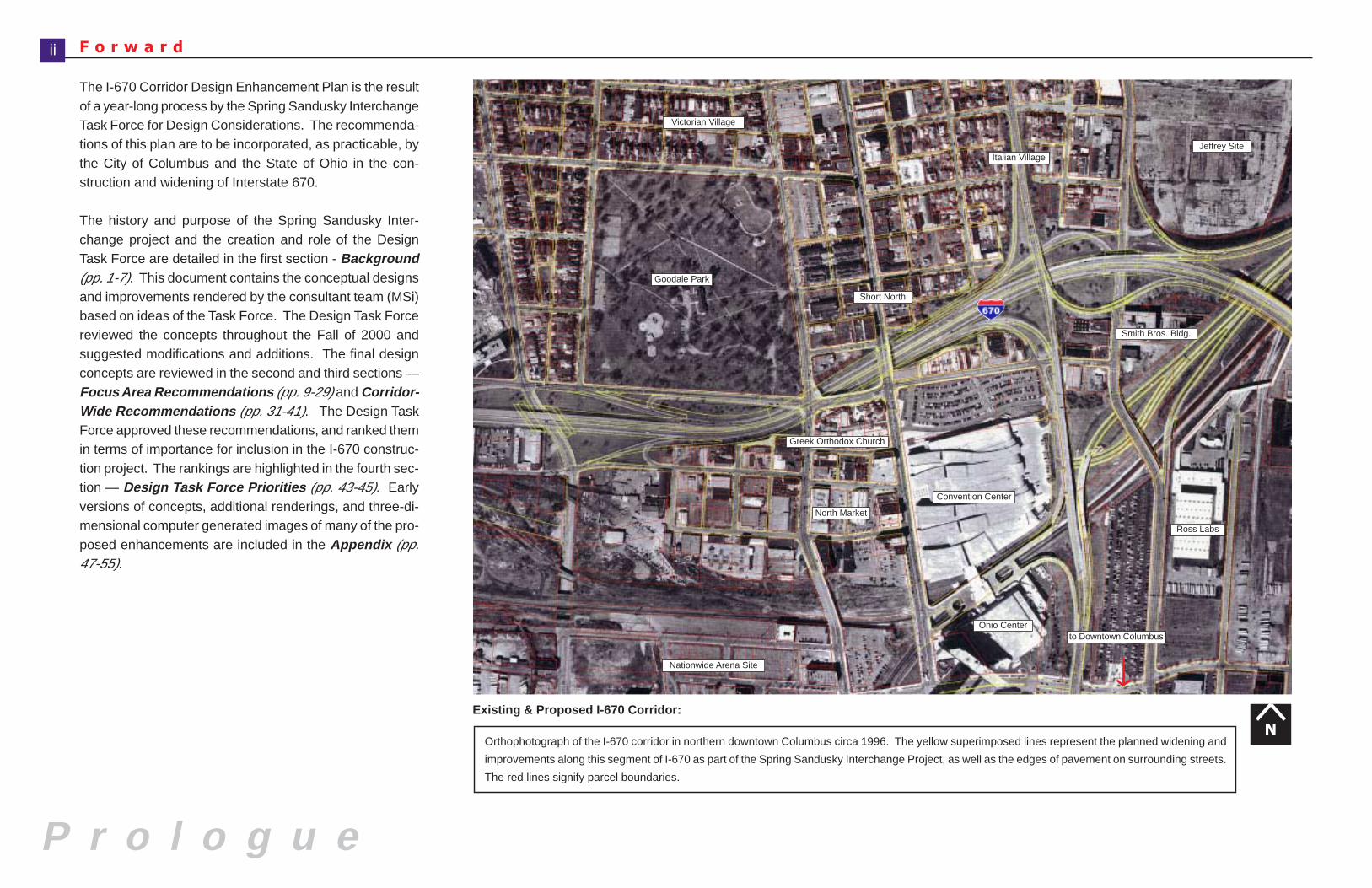
The I-670 Corridor Design Enhancement Plan is the resultof a year-long process by the Spring Sandusky InterchangeTask Force for Design Considerations. The recommenda-tions of this plan are to be incorporated, as practicable, bythe City of Columbus and the State of Ohio in the con-struction and widening of Interstate 670.
The history and purpose of the Spring Sandusky Inter-change project and the creation and role of the DesignTask Force are detailed in the first section - Background(pp. 1-7). This document contains the conceptual designsand improvements rendered by the consultant team (MSi)based on ideas of the Task Force. The Design Task Forcereviewed the concepts throughout the Fall of 2000 andsuggested modifications and additions. The final designconcepts are reviewed in the second and third sections —Focus Area Recommendations (pp. 9-29) and Corridor-Wide Recommendations (pp. 31-41). The Design TaskForce approved these recommendations, and ranked themin terms of importance for inclusion in the I-670 construc-tion project. The rankings are highlighted in the fourth sec-tion — Design Task Force Priorities (pp. 43-45). Earlyversions of concepts, additional renderings, and three-di-mensional computer generated images of many of the pro-posed enhancements are included in the Appendix (pp.47-55).
F o r w a r dii
Convention Center
Smith Bros. Bldg.
Ross Labs
to Downtown Columbus
Short North
Jeffrey Site
N
Greek Orthodox Church
Italian Village
Orthophotograph of the I-670 corridor in northern downtown Columbus circa 1996. The yellow superimposed lines represent the planned widening and
improvements along this segment of I-670 as part of the Spring Sandusky Interchange Project, as well as the edges of pavement on surrounding streets.
The red lines signify parcel boundaries.
North Market
Goodale Park
Ohio Center
Existing & Proposed I-670 Corridor:
Victorian Village
Nationwide Arena Site
Background
I n t r o d u c t i o n
B a c k g r o u n d
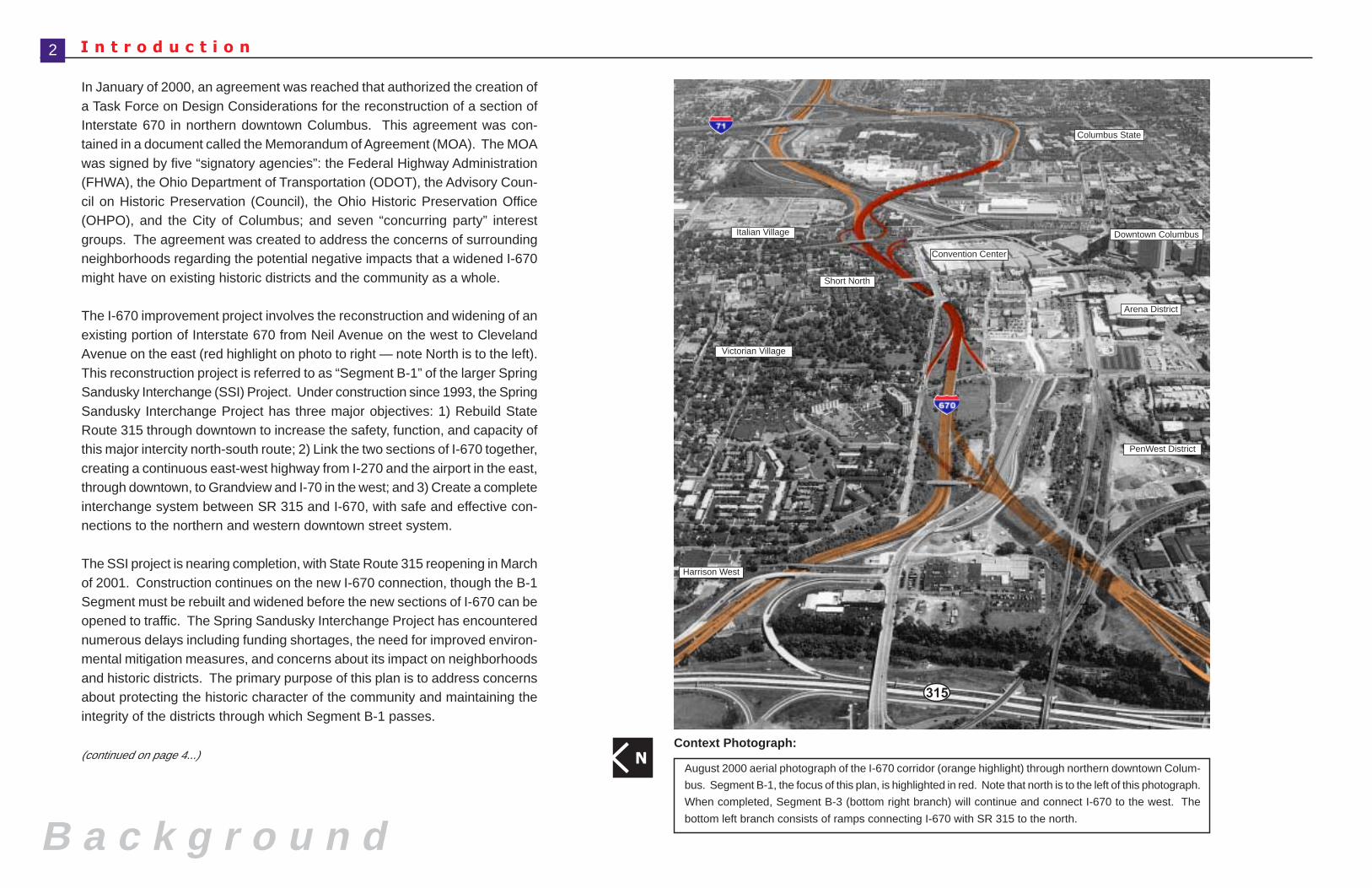
NAugust 2000 aerial photograph of the I-670 corridor (orange highlight) through northern downtown Colum-
bus. Segment B-1, the focus of this plan, is highlighted in red. Note that north is to the left of this photograph.
When completed, Segment B-3 (bottom right branch) will continue and connect I-670 to the west. The
bottom left branch consists of ramps connecting I-670 with SR 315 to the north.
In January of 2000, an agreement was reached that authorized the creation ofa Task Force on Design Considerations for the reconstruction of a section ofInterstate 670 in northern downtown Columbus. This agreement was con-tained in a document called the Memorandum of Agreement (MOA). The MOAwas signed by five “signatory agencies”: the Federal Highway Administration(FHWA), the Ohio Department of Transportation (ODOT), the Advisory Coun-cil on Historic Preservation (Council), the Ohio Historic Preservation Office(OHPO), and the City of Columbus; and seven “concurring party” interestgroups. The agreement was created to address the concerns of surroundingneighborhoods regarding the potential negative impacts that a widened I-670might have on existing historic districts and the community as a whole.
The I-670 improvement project involves the reconstruction and widening of anexisting portion of Interstate 670 from Neil Avenue on the west to ClevelandAvenue on the east (red highlight on photo to right — note North is to the left).This reconstruction project is referred to as “Segment B-1” of the larger SpringSandusky Interchange (SSI) Project. Under construction since 1993, the SpringSandusky Interchange Project has three major objectives: 1) Rebuild StateRoute 315 through downtown to increase the safety, function, and capacity ofthis major intercity north-south route; 2) Link the two sections of I-670 together,creating a continuous east-west highway from I-270 and the airport in the east,through downtown, to Grandview and I-70 in the west; and 3) Create a completeinterchange system between SR 315 and I-670, with safe and effective con-nections to the northern and western downtown street system.
The SSI project is nearing completion, with State Route 315 reopening in Marchof 2001. Construction continues on the new I-670 connection, though the B-1Segment must be rebuilt and widened before the new sections of I-670 can beopened to traffic. The Spring Sandusky Interchange Project has encounterednumerous delays including funding shortages, the need for improved environ-mental mitigation measures, and concerns about its impact on neighborhoodsand historic districts. The primary purpose of this plan is to address concernsabout protecting the historic character of the community and maintaining theintegrity of the districts through which Segment B-1 passes.
(continued on page 4...)
Convention Center
Arena District
PenWest District
Downtown Columbus
Short North
Italian Village
Victorian Village
Harrison West
315
Columbus State
Context Photograph:
2
I - 670 Corridor Design Enhancement January • 2001
A e r i a l P h o t o g r a p h
N
315
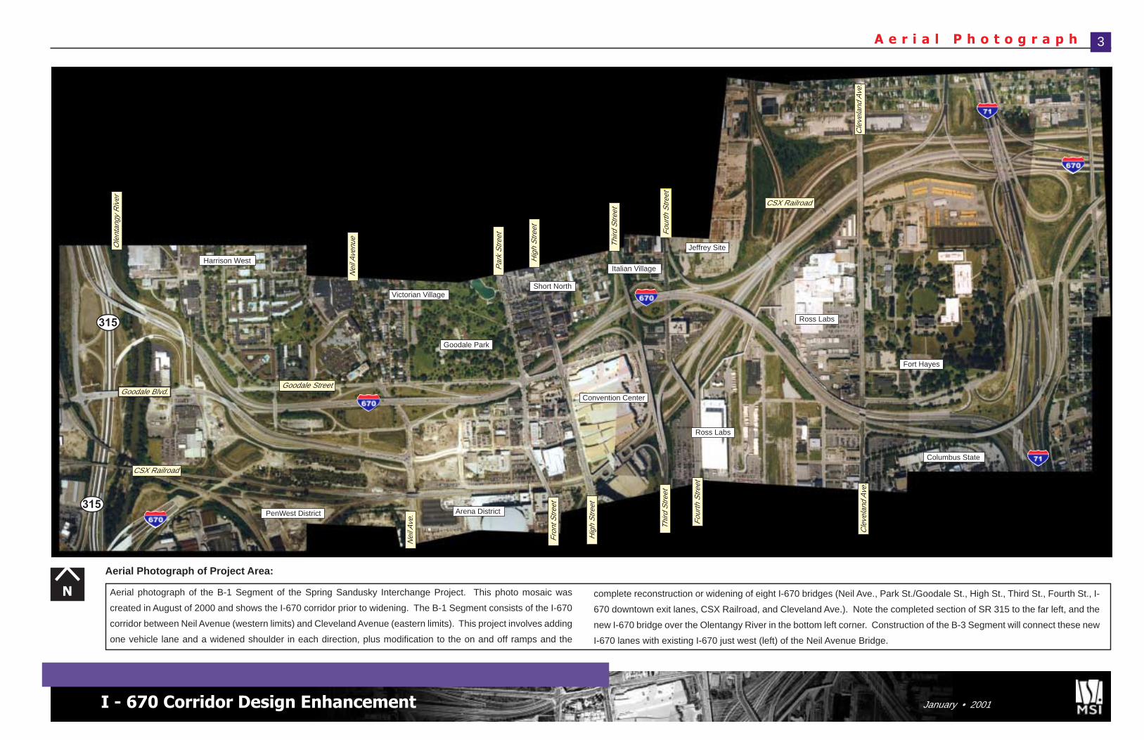
Aerial photograph of the B-1 Segment of the Spring Sandusky Interchange Project. This photo mosaic was
created in August of 2000 and shows the I-670 corridor prior to widening. The B-1 Segment consists of the I-670
corridor between Neil Avenue (western limits) and Cleveland Avenue (eastern limits). This project involves adding
one vehicle lane and a widened shoulder in each direction, plus modification to the on and off ramps and the
315
Ross Labs
complete reconstruction or widening of eight I-670 bridges (Neil Ave., Park St./Goodale St., High St., Third St., Fourth St., I-
670 downtown exit lanes, CSX Railroad, and Cleveland Ave.). Note the completed section of SR 315 to the far left, and the
new I-670 bridge over the Olentangy River in the bottom left corner. Construction of the B-3 Segment will connect these new
I-670 lanes with existing I-670 just west (left) of the Neil Avenue Bridge.
Cle
vela
nd A
ve.
3
Goodale Blvd.
CSX Railroad
PenWest District
Ole
ntan
gy R
iver
Harrison West
Goodale Street
Nei
l Ave
nue
Par
k S
treet
Hig
h S
treet
Victorian Village
Goodale Park
Short North
Arena District
Nei
l Ave
.
Fron
t Stre
et
Hig
h S
treet
Thir d
Stre
et
F ou r
th S
treet
Cle
v el a
nd A
ve.
Columbus State
Convention Center
Italian Village
Jeffrey SiteThird
Stre
et
Four
t h S
treet
CSX Railroad
Fort Hayes
Ross Labs
Aerial Photograph of Project Area:
S p r i n g - S a n d u s k y I n t e r c h a n g e ( S S I ) P r o j e c t
B a c k g r o u n d
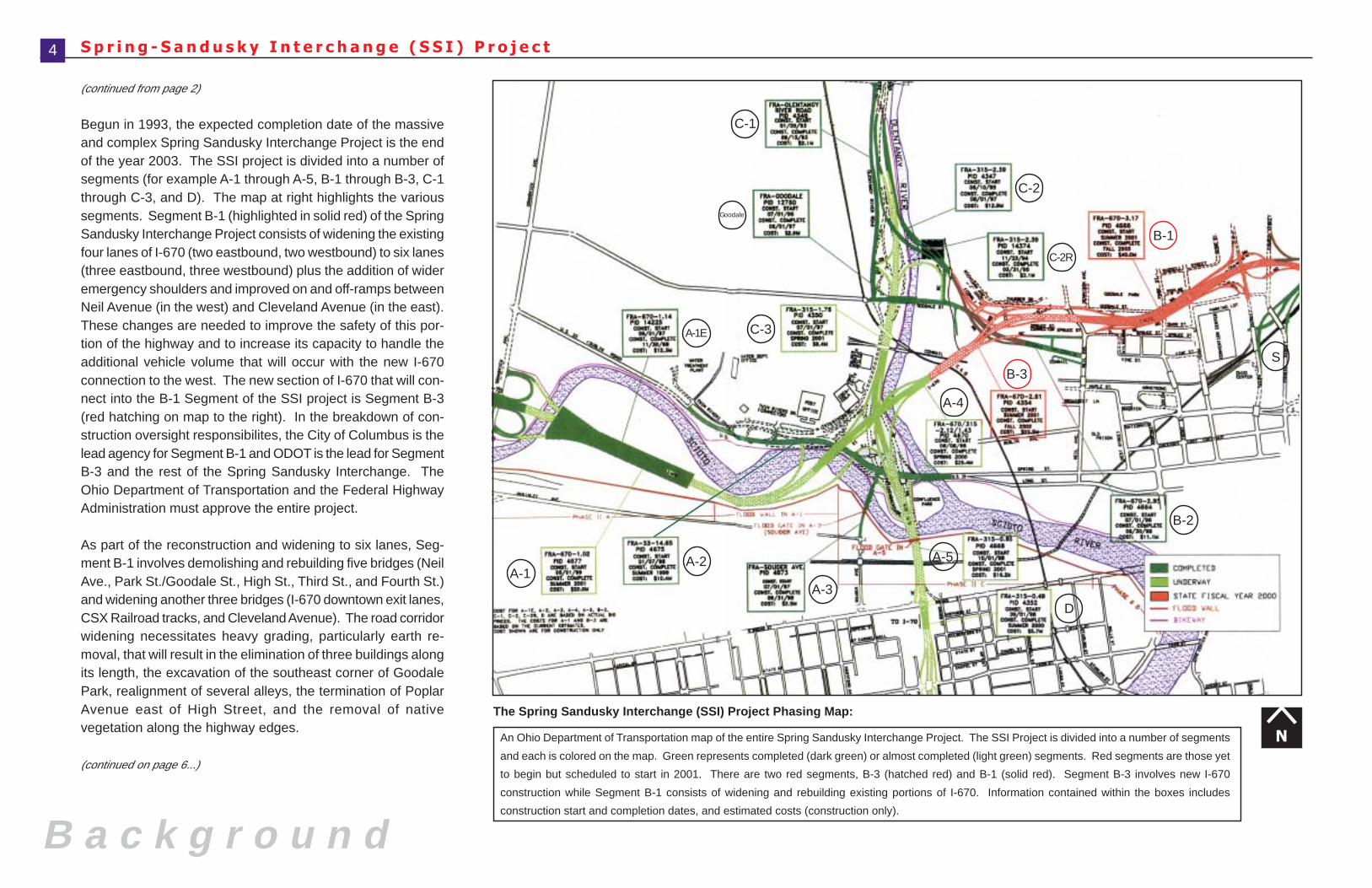
An Ohio Department of Transportation map of the entire Spring Sandusky Interchange Project. The SSI Project is divided into a number of segments
and each is colored on the map. Green represents completed (dark green) or almost completed (light green) segments. Red segments are those yet
to begin but scheduled to start in 2001. There are two red segments, B-3 (hatched red) and B-1 (solid red). Segment B-3 involves new I-670
construction while Segment B-1 consists of widening and rebuilding existing portions of I-670. Information contained within the boxes includes
construction start and completion dates, and estimated costs (construction only).
(continued from page 2)
Begun in 1993, the expected completion date of the massiveand complex Spring Sandusky Interchange Project is the endof the year 2003. The SSI project is divided into a number ofsegments (for example A-1 through A-5, B-1 through B-3, C-1through C-3, and D). The map at right highlights the varioussegments. Segment B-1 (highlighted in solid red) of the SpringSandusky Interchange Project consists of widening the existingfour lanes of I-670 (two eastbound, two westbound) to six lanes(three eastbound, three westbound) plus the addition of wideremergency shoulders and improved on and off-ramps betweenNeil Avenue (in the west) and Cleveland Avenue (in the east).These changes are needed to improve the safety of this por-tion of the highway and to increase its capacity to handle theadditional vehicle volume that will occur with the new I-670connection to the west. The new section of I-670 that will con-nect into the B-1 Segment of the SSI project is Segment B-3(red hatching on map to the right). In the breakdown of con-struction oversight responsibilites, the City of Columbus is thelead agency for Segment B-1 and ODOT is the lead for SegmentB-3 and the rest of the Spring Sandusky Interchange. TheOhio Department of Transportation and the Federal HighwayAdministration must approve the entire project.
As part of the reconstruction and widening to six lanes, Seg-ment B-1 involves demolishing and rebuilding five bridges (NeilAve., Park St./Goodale St., High St., Third St., and Fourth St.)and widening another three bridges (I-670 downtown exit lanes,CSX Railroad tracks, and Cleveland Avenue). The road corridorwidening necessitates heavy grading, particularly earth re-moval, that will result in the elimination of three buildings alongits length, the excavation of the southeast corner of GoodalePark, realignment of several alleys, the termination of PoplarAvenue east of High Street, and the removal of nativevegetation along the highway edges.
(continued on page 6...)
N
C-1
Goodale
C-2
C-2R
A-1E
S
B-2
B-3
A-4
A-1A-2
A-3
C-3
A-5
D
The Spring Sandusky Interchange (SSI) Project Phasing Map:
4
B-1
I - 670 Corridor Design Enhancement January • 2001
S S I • S e g m e n t B - 1
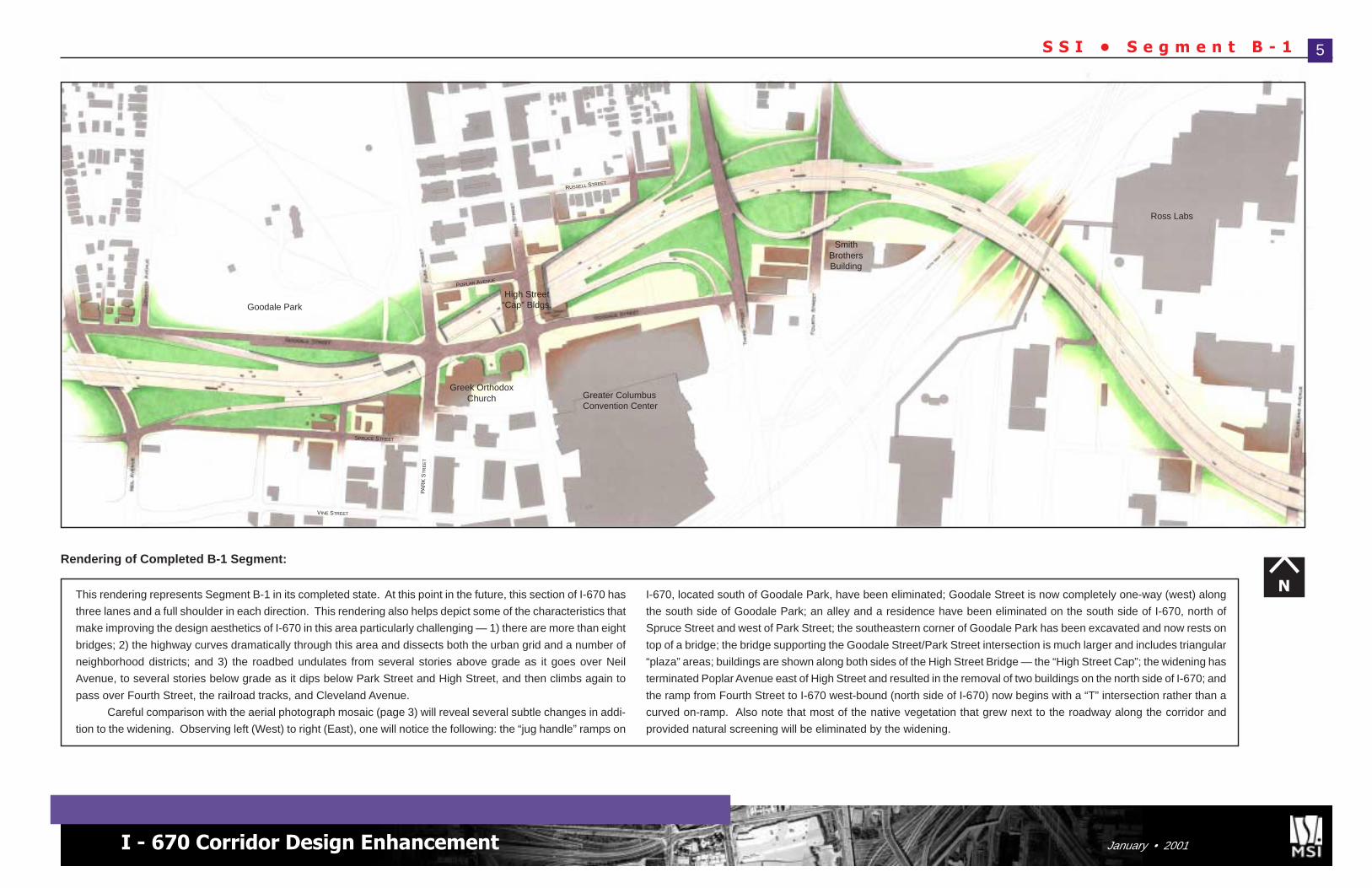
This rendering represents Segment B-1 in its completed state. At this point in the future, this section of I-670 has
three lanes and a full shoulder in each direction. This rendering also helps depict some of the characteristics that
make improving the design aesthetics of I-670 in this area particularly challenging — 1) there are more than eight
bridges; 2) the highway curves dramatically through this area and dissects both the urban grid and a number of
neighborhood districts; and 3) the roadbed undulates from several stories above grade as it goes over Neil
Avenue, to several stories below grade as it dips below Park Street and High Street, and then climbs again to
pass over Fourth Street, the railroad tracks, and Cleveland Avenue.
Careful comparison with the aerial photograph mosaic (page 3) will reveal several subtle changes in addi-
tion to the widening. Observing left (West) to right (East), one will notice the following: the “jug handle” ramps on
I-670, located south of Goodale Park, have been eliminated; Goodale Street is now completely one-way (west) along
the south side of Goodale Park; an alley and a residence have been eliminated on the south side of I-670, north of
Spruce Street and west of Park Street; the southeastern corner of Goodale Park has been excavated and now rests on
top of a bridge; the bridge supporting the Goodale Street/Park Street intersection is much larger and includes triangular
“plaza” areas; buildings are shown along both sides of the High Street Bridge — the “High Street Cap”; the widening has
terminated Poplar Avenue east of High Street and resulted in the removal of two buildings on the north side of I-670; and
the ramp from Fourth Street to I-670 west-bound (north side of I-670) now begins with a “T” intersection rather than a
curved on-ramp. Also note that most of the native vegetation that grew next to the roadway along the corridor and
provided natural screening will be eliminated by the widening.
N
5
Rendering of Completed B-1 Segment:
Goodale Park
Greater ColumbusConvention Center
SmithBrothersBuilding
Ross Labs
Greek OrthodoxChurch
High Street“Cap” Bldgs.
POPLAR AVENUE
SPRUCE STREET
VINE STREET
PAR
K S
TR
EE
T
RUSSELL STREET
N a t i o n a l H i s t o r i c D i s t r i c t s
N
Near North Side
North Market
Short North
5th Ave. & North High
Old North End
3rd Ave. & North High
315
B a c k g r o u n d
(continued from page 4)
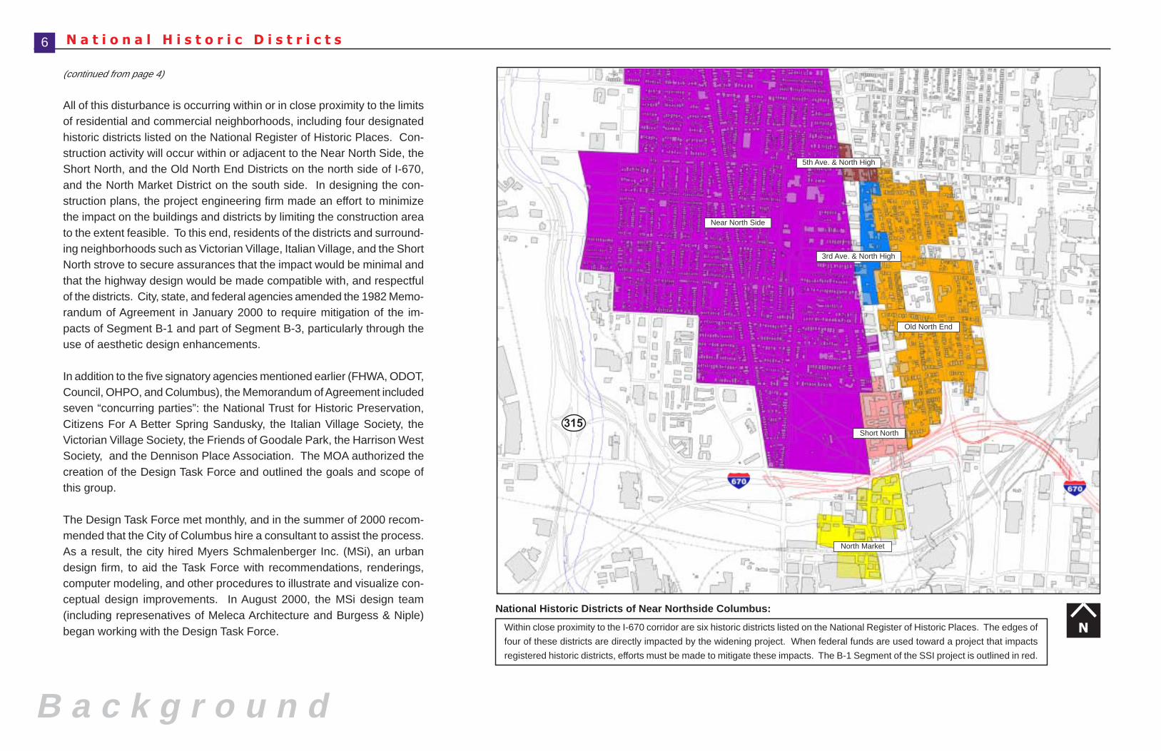
All of this disturbance is occurring within or in close proximity to the limitsof residential and commercial neighborhoods, including four designatedhistoric districts listed on the National Register of Historic Places. Con-struction activity will occur within or adjacent to the Near North Side, theShort North, and the Old North End Districts on the north side of I-670,and the North Market District on the south side. In designing the con-struction plans, the project engineering firm made an effort to minimizethe impact on the buildings and districts by limiting the construction areato the extent feasible. To this end, residents of the districts and surround-ing neighborhoods such as Victorian Village, Italian Village, and the ShortNorth strove to secure assurances that the impact would be minimal andthat the highway design would be made compatible with, and respectfulof the districts. City, state, and federal agencies amended the 1982 Memo-randum of Agreement in January 2000 to require mitigation of the im-pacts of Segment B-1 and part of Segment B-3, particularly through theuse of aesthetic design enhancements.
In addition to the five signatory agencies mentioned earlier (FHWA, ODOT,Council, OHPO, and Columbus), the Memorandum of Agreement includedseven “concurring parties”: the National Trust for Historic Preservation,Citizens For A Better Spring Sandusky, the Italian Village Society, theVictorian Village Society, the Friends of Goodale Park, the Harrison WestSociety, and the Dennison Place Association. The MOA authorized thecreation of the Design Task Force and outlined the goals and scope ofthis group.
The Design Task Force met monthly, and in the summer of 2000 recom-mended that the City of Columbus hire a consultant to assist the process.As a result, the city hired Myers Schmalenberger Inc. (MSi), an urbandesign firm, to aid the Task Force with recommendations, renderings,computer modeling, and other procedures to illustrate and visualize con-ceptual design improvements. In August 2000, the MSi design team(including represenatives of Meleca Architecture and Burgess & Niple)began working with the Design Task Force. Within close proximity to the I-670 corridor are six historic districts listed on the National Register of Historic Places. The edges of
four of these districts are directly impacted by the widening project. When federal funds are used toward a project that impacts
registered historic districts, efforts must be made to mitigate these impacts. The B-1 Segment of the SSI project is outlined in red.
6
National Historic Districts of Near Northside Columbus:
I - 670 Corridor Design Enhancement January • 2001
N e i g h b o r h o o d D i s t r i c t s
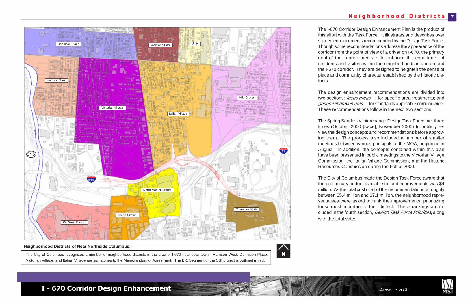
The I-670 Corridor Design Enhancement Plan is the product ofthis effort with the Task Force. It illustrates and describes oversixteen enhancements recommended by the Design Task Force.Though some recommendations address the appearance of thecorridor from the point of view of a driver on I-670, the primarygoal of the improvements is to enhance the experience ofresidents and visitors within the neighborhoods in and aroundthe I-670 corridor. They are designed to heighten the sense ofplace and community character established by the historic dis-tricts.
The design enhancement recommendations are divided intotwo sections: focus areas — for specific area treatments; andgeneral improvements — for standards applicable corridor-wide.These recommendations follow in the next two sections.
The Spring Sandusky Interchange Design Task Force met threetimes (October 2000 [twice], November 2000) to publicly re-view the design concepts and recommendations before approv-ing them. The process also included a number of smallermeetings between various principals of the MOA, beginning inAugust. In addition, the concepts contained within this planhave been presented in public meetings to the Victorian VillageCommission, the Italian Village Commission, and the HistoricResources Commission during the Fall of 2000.
The City of Columbus made the Design Task Force aware thatthe preliminary budget available to fund improvements was $4million. As the total cost of all of the recommendations is roughlybetween $5.4 million and $7.1 million, the neighborhood repre-sentatives were asked to rank the improvements, prioritizingthose most important to their district. These rankings are in-cluded in the fourth section, Design Task Force Priorities, alongwith the total votes.
NThe City of Columbus recognizes a number of neighborhood districts in the area of I-670 near downtown. Harrison West, Dennison Place,
Victorian Village, and Italian Village are signatories to the Memorandum of Agreement. The B-1 Segment of the SSI project is outlined in red.
7
Arena District
315
PenWest District
North Market District
Victorian Village
Italian Village
Milo Grogan
Harrison West
Columbus State
UnityWeinland ParkDennison Place
Neighborhood Districts of Near Northside Columbus:
Focus Area Recomendations
D e s i g n T a s k F o r c e F o c u s A r e a s
Focus Area Recommendat ions
Neil Avenue Gateway
Goodale Park Edge
Park Street Cap
High Street Cap
Italian Villa
ge Edge
Third Street
Bridge
Fourth StreetGateway Railroad Overpass
Cleveland AvenueBridge
Elevated RoadwayDepressedRoadway
DepressedRoadway
Elevated Roadway
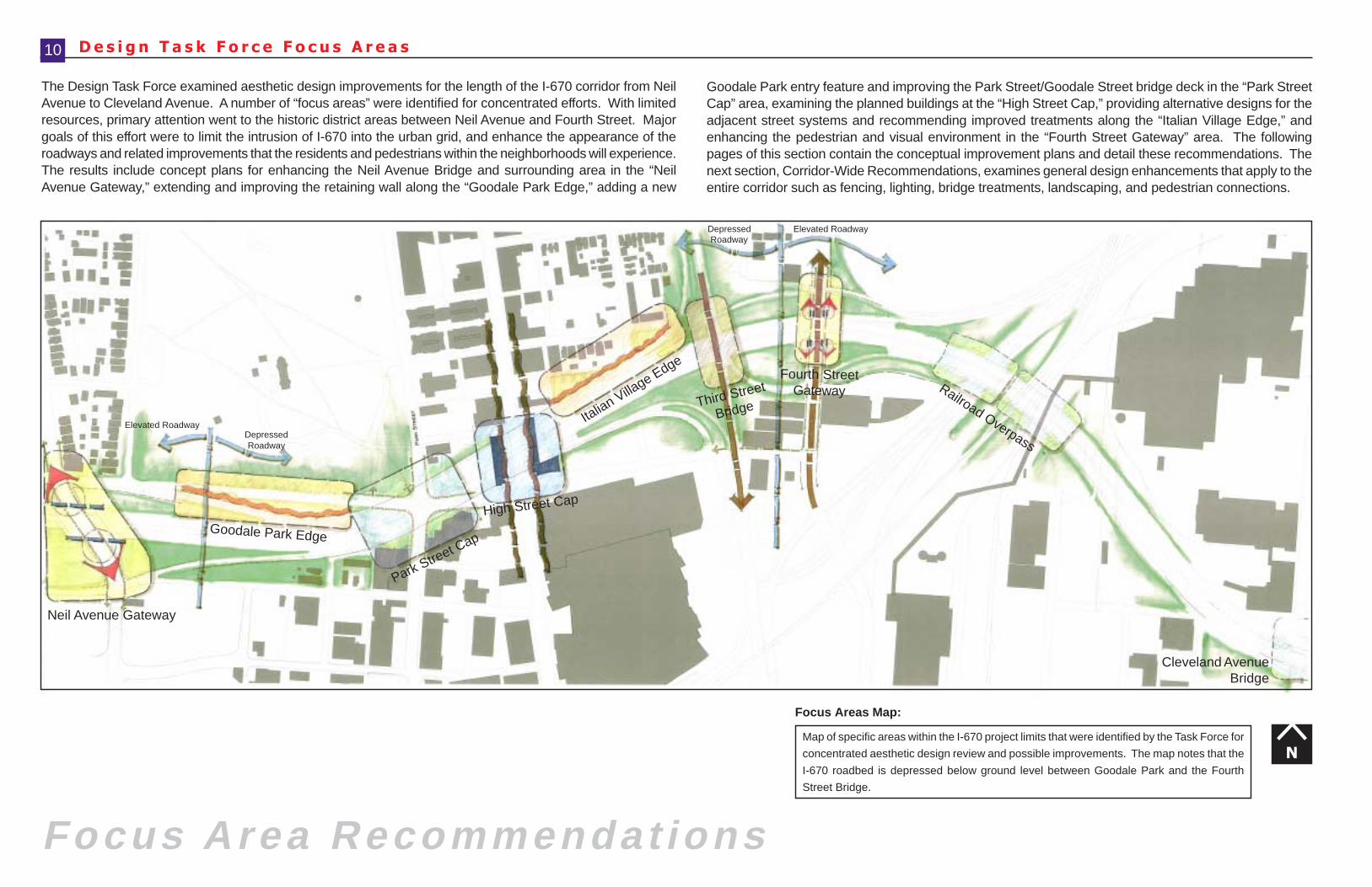
The Design Task Force examined aesthetic design improvements for the length of the I-670 corridor from NeilAvenue to Cleveland Avenue. A number of “focus areas” were identified for concentrated efforts. With limitedresources, primary attention went to the historic district areas between Neil Avenue and Fourth Street. Majorgoals of this effort were to limit the intrusion of I-670 into the urban grid, and enhance the appearance of theroadways and related improvements that the residents and pedestrians within the neighborhoods will experience.The results include concept plans for enhancing the Neil Avenue Bridge and surrounding area in the “NeilAvenue Gateway,” extending and improving the retaining wall along the “Goodale Park Edge,” adding a new
NMap of specific areas within the I-670 project limits that were identified by the Task Force for
concentrated aesthetic design review and possible improvements. The map notes that the
I-670 roadbed is depressed below ground level between Goodale Park and the Fourth
Street Bridge.
Focus Areas Map:
Goodale Park entry feature and improving the Park Street/Goodale Street bridge deck in the “Park StreetCap” area, examining the planned buildings at the “High Street Cap,” providing alternative designs for theadjacent street systems and recommending improved treatments along the “Italian Village Edge,” andenhancing the pedestrian and visual environment in the “Fourth Street Gateway” area. The followingpages of this section contain the conceptual improvement plans and detail these recommendations. Thenext section, Corridor-Wide Recommendations, examines general design enhancements that apply to theentire corridor such as fencing, lighting, bridge treatments, landscaping, and pedestrian connections.
10
I - 670 Corridor Design Enhancement January • 2001
N e i l A v e n u e B r i d g e 11
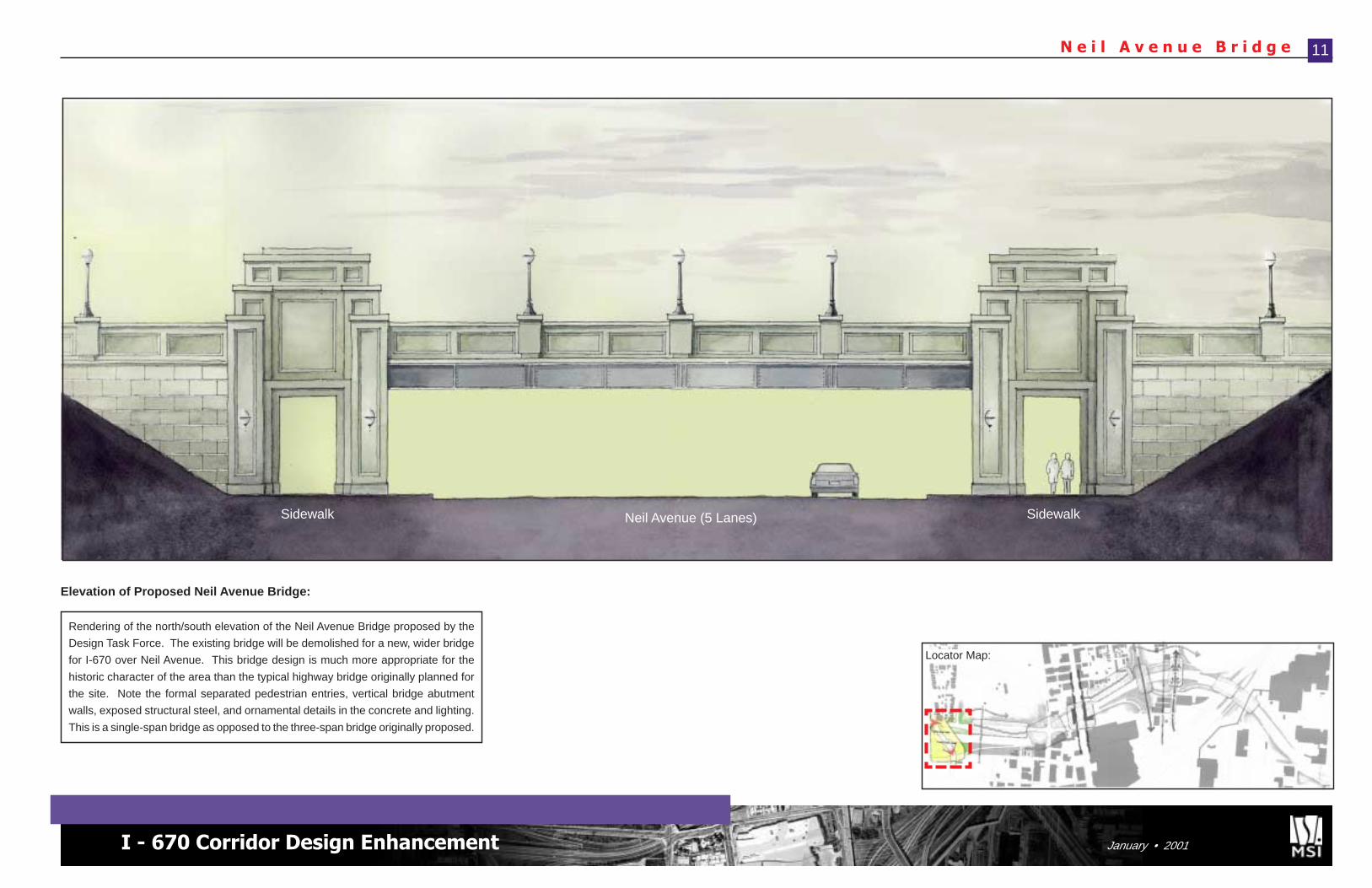
Rendering of the north/south elevation of the Neil Avenue Bridge proposed by the
Design Task Force. The existing bridge will be demolished for a new, wider bridge
for I-670 over Neil Avenue. This bridge design is much more appropriate for the
historic character of the area than the typical highway bridge originally planned for
the site. Note the formal separated pedestrian entries, vertical bridge abutment
walls, exposed structural steel, and ornamental details in the concrete and lighting.
This is a single-span bridge as opposed to the three-span bridge originally proposed.
Elevation of Proposed Neil Avenue Bridge:
Neil Avenue (5 Lanes) SidewalkSidewalk
Locator Map:
N e i l A v e n u e B r i d g e
Focus Area Recommendat ions
12
Early in this process, the Design Task Force realized the importance ofthe Neil Avenue Bridge area as a gateway into Victorian Village andneighborhoods further to the north, and to the Arena District and riverfrontpark to the south. Neil Avenue is experiencing a rebirth as a connectorof neighborhoods and should not be considered just a thoroughfare forvehicles. It should invite travel by pedestrians and bicyclists equally tocars and trucks. In the area of Interstate 670, however, vehicles areemphasized in form and design. Most prominent in this concentration ofhighway infrastructure is the Neil Avenue Bridge. Engineered for functionrather than character, this conventional highway bridge carries four lanesof I-670 traffic over five lanes on Neil Avenue. As part of the SSI Project,the existing Neil Avenue Bridge will be demolished and replaced with amuch wider bridge supporting six lanes of traffic with shoulders. Theoriginal plans for the new bridge show a design almost identical to thecurrent bridge, only wider. The Task Force believes that redesigning thebridge represents a significant opportunity to create a structure that invitespeople to travel through the bridge, exploring the districts on either side.
The proposed redesign of the Neil Avenue Bridge dramatically improvesits appearance, creating an architectural structure that makes a statementwhile fulfilling its function to safely convey traffic (compare photographand rendering). Borrowing from older railroad bridges in the area, thedesign anchors the bridge with classic pilaster elements that also provideseparate entrances for pedestrians. The result is a structure thatemphasizes people as well as automobiles. This design illustratessignificant changes to the character of the structure, making it much moreaesthetically appealing and appropriate for the adjacent neighborhoods.The sloping concrete abutment walls found at each end of a standardhighway bridge are replaced with vertical abutment walls. This reducesthe span of the bridge and makes it appear narrower and more traditional.In addition, this eliminates the dark cavities formed by the sloping walls.In this case it also allows conversion to a single-span bridge rather thana typical triple-span structure (one steel beam across rather than threesupported by two columns at connection points). The result is a narrowerbridge structure more in keeping with the pedestrian nature of an urbangateway. To increase the safety and security for pedestrians, the sidewalkcorridors under the bridge will be well-lit and open, possibly separatedfrom traffic by a low concrete knee-wall. At night, the classic form of thebridge will be lit by decorative lights.
With its grand facade, subtle ornamentation, and traditional designelements, the redesigned Neil Avenue Bridge is inviting and attractive --and a perfect fit as a symbolic gateway connecting the historicneighborhoods with the revitalizing downtown districts.
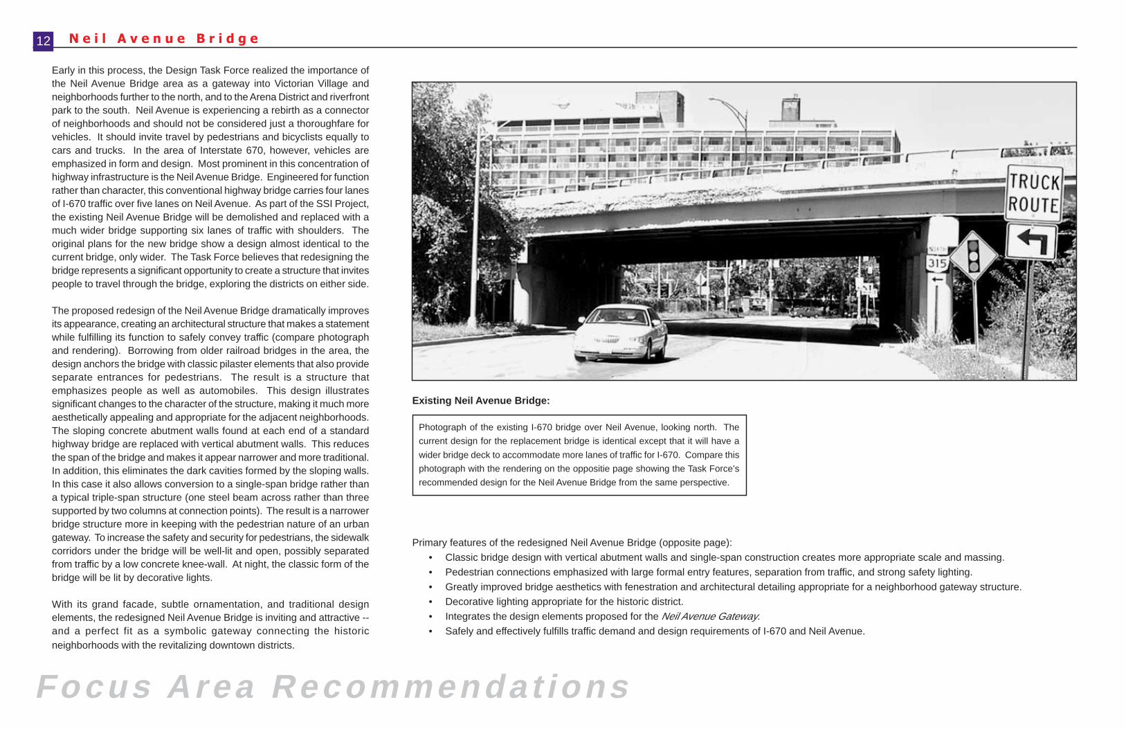
Photograph of the existing I-670 bridge over Neil Avenue, looking north. The
current design for the replacement bridge is identical except that it will have a
wider bridge deck to accommodate more lanes of traffic for I-670. Compare this
photograph with the rendering on the oppositie page showing the Task Force’s
recommended design for the Neil Avenue Bridge from the same perspective.
Existing Neil Avenue Bridge:
Primary features of the redesigned Neil Avenue Bridge (opposite page):
• Classic bridge design with vertical abutment walls and single-span construction creates more appropriate scale and massing.
• Pedestrian connections emphasized with large formal entry features, separation from traffic, and strong safety lighting.
• Greatly improved bridge aesthetics with fenestration and architectural detailing appropriate for a neighborhood gateway structure.
• Decorative lighting appropriate for the historic district.
• Integrates the design elements proposed for the Neil Avenue Gateway.
• Safely and effectively fulfills traffic demand and design requirements of I-670 and Neil Avenue.
I - 670 Corridor Design Enhancement January • 2001
N e i l A v e n u e B r i d g e 13
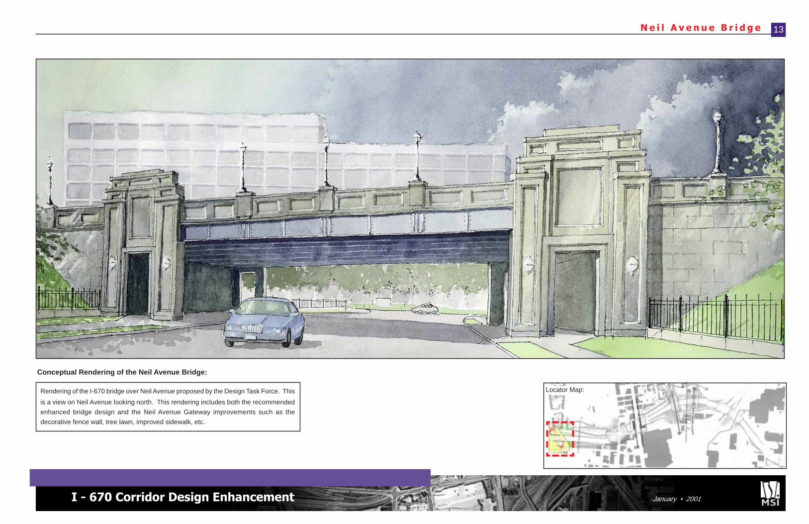
Conceptual Rendering of the Neil Avenue Bridge:
Rendering of the I-670 bridge over Neil Avenue proposed by the Design Task Force. This
is a view on Neil Avenue looking north. This rendering includes both the recommended
enhanced bridge design and the Neil Avenue Gateway improvements such as the
decorative fence wall, tree lawn, improved sidewalk, etc.
Locator Map:
N e i l A v e n u e G a t e w a y
Focus Area Recommendat ions
Neil Avenue has been a significant street for most of Columbus’ history. It has long servedas a link between the downtown riverfront and the residential neighborhoods to the northand on to The Ohio State University. Neil Avenue’s importance to the area’s communitieshas only intensified as the neighborhoods of Victorian Village, Harrison West, and DennisonPlace have revitalized and the Arena, PenWest, and North Market Districts redevelop.Cutting a swath between these beautiful historic neighborhoods to the north and theincreasingly vibrant downtown districts is the I-670 corridor and its related ramps. In thisarea of Columbus, Interstate 670 acts as a major physical and psychological barrier. NeilAvenue is one of a few critical connections across this divide. For this reason, great effortshould be made to enhance this avenue, making it pleasant for residents and visitors towalk this corridor. It is also important that the design of the I-670 improvements aroundNeil Avenue compliment the historic character of the districts.
The Neil Avenue Gateway design concept addresses the interaction of I-670 with thisarea. Currently, the intersections of Neil Avenue with Goodale Street (north of bridge)and Spruce Street (south of bridge) are challenging for pedestrians to negotiate with theamount and speed of traffic. Combined with the overgrown appearance of the highwaycorridor, the dilapidated sidewalks, and the threatening appearance of the bridge, thisarea is completely uninviting to the pedestrian. Signal timing for pedestrians and trafficcalming measures should be examined for this gateway and are the purview of the separateSSI Traffic Task Force. The suggested bridge improvements, including greatly improvedwalking areas, are illustrated in the Neil Avenue Bridge recommendation (pp. 11-13). Asfor the gateway improvements, this concept shows rebuilt/repaired sidewalks with rampsbetween the two intersections. The tree lawn remains, but trees should not be plantedhere in order to preserve views of the bridge. To create a unified feel with the new bridgeand tie into the character of the historic districts, the two most important features are theinstallation of ornamental fencing and decorative street lights along the Neil Avenue corridor(for decorative lights, see Lighting - pp. 38-39). The ornamental fencing replaces requiredchain link fencing and consists of wrought iron fencing mounted on a low wall. Thistreatment runs parallel with, and a little outside of the sidewalk, from the intersections tothe bridge. Lastly, the green infield areas should be seeded and replanted as necessaryto create naturally forested buffer areas along the sides of the I-670 overpass (seeLandscaping - p. 40). The final result is an improved streetscape that frames the NeilAvenue Bridge, invites pedestrian travel, and connects the districts.
Primary design features of the Neil Avenue Gateway:• Improved sidewalks encourage safe pedestrian connections between residential
districts and downtown.• Decorative fencing and lighting along the streetscape highlights the gateway,
encourages pedestrian flow, and complements the historic neighborhoods.• Naturalized forest buffer re-established along I-670 overpass by replanting infields
with trees.• Improved appearance of Neil Avenue Bridge as illustrated in the Neil Avenue
Bridge recommendation.
14
Neil Avenue
P
Neil Avenue Bridge
I-670 Overpass
I-670 Overpass
Spruce St.I-670 on-ramp
Spruce St.
Goodale St.
Church
Office
A
A’
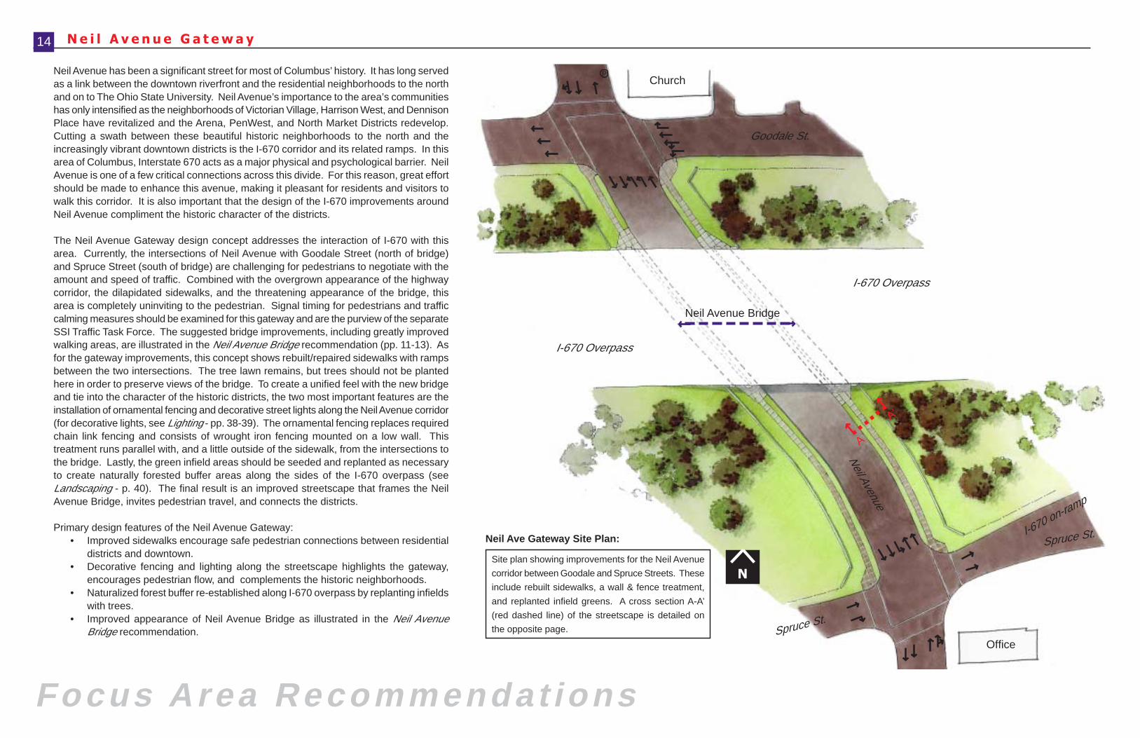
Site plan showing improvements for the Neil Avenue
corridor between Goodale and Spruce Streets. These
include rebuilt sidewalks, a wall & fence treatment,
and replanted infield greens. A cross section A-A’
(red dashed line) of the streetscape is detailed on
the opposite page.
Neil Ave Gateway Site Plan:
N
I - 670 Corridor Design Enhancement January • 2001
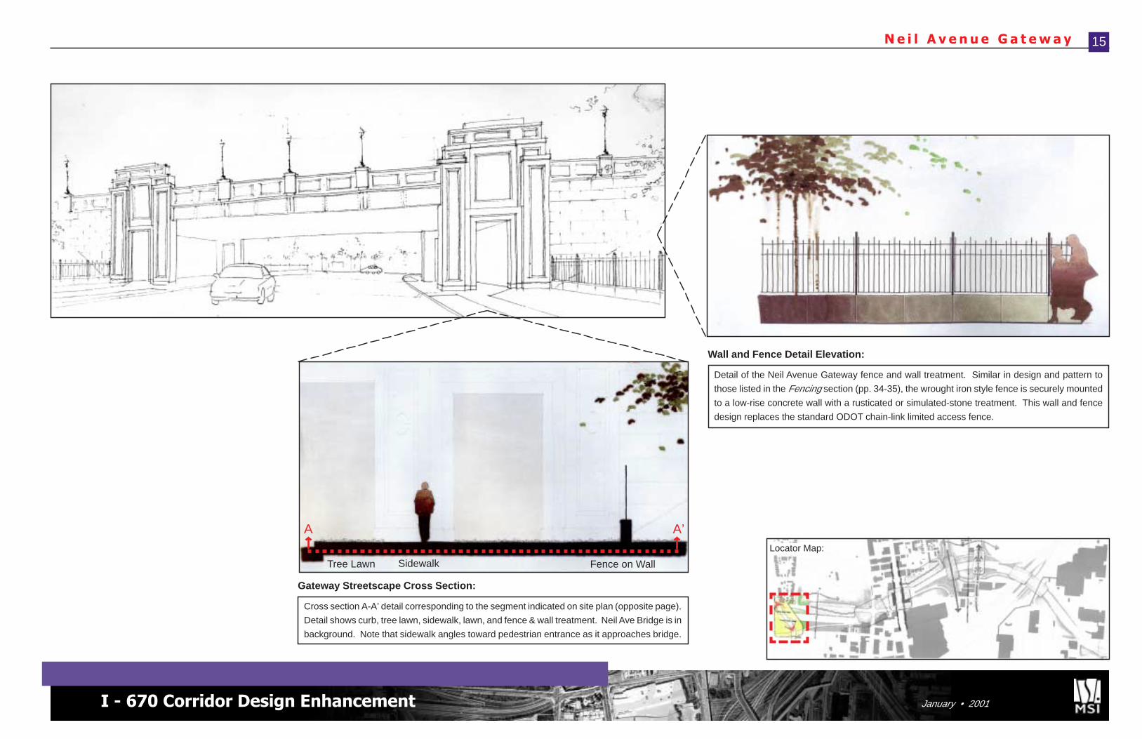
N e i l A v e n u e G a t e w a y 15
Fence on WallSidewalkTree Lawn
Cross section A-A’ detail corresponding to the segment indicated on site plan (opposite page).
Detail shows curb, tree lawn, sidewalk, lawn, and fence & wall treatment. Neil Ave Bridge is in
background. Note that sidewalk angles toward pedestrian entrance as it approaches bridge.
Gateway Streetscape Cross Section:
Detail of the Neil Avenue Gateway fence and wall treatment. Similar in design and pattern to
those listed in the Fencing section (pp. 34-35), the wrought iron style fence is securely mounted
to a low-rise concrete wall with a rusticated or simulated-stone treatment. This wall and fence
design replaces the standard ODOT chain-link limited access fence.
Wall and Fence Detail Elevation:
A A’Locator Map:
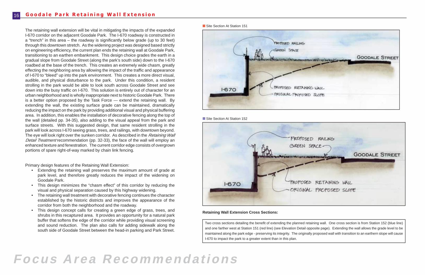
■ Site Section At Station 152
G o o d a l e P a r k R e t a i n i n g W a l l E x t e n s i o n
■ Site Section At Station 151
Focus Area Recommendat ions
The retaining wall extension will be vital in mitigating the impacts of the expandedI-670 corridor on the adjacent Goodale Park. The I-670 roadway is constructed ina “trench” in this area – the roadway is significantly below grade (up to 30 feet)through this downtown stretch. As the widening project was designed based strictlyon engineering efficiency, the current plan ends the retaining wall at Goodale Park,transitioning to an earthen embankment. This design choice grades the earth in agradual slope from Goodale Street (along the park’s south side) down to the I-670roadbed at the base of the trench. This creates an extremely wide chasm, greatlyeffecting the neighboring area by allowing the impact of the traffic and appearanceof I-670 to “bleed” up into the park environment. This creates a more direct visual,audible, and physical disturbance to the park. Under this condition, a residentstrolling in the park would be able to look south across Goodale Street and seedown into the busy traffic on I-670. This solution is entirely out of character for anurban neighborhood and is wholly inappropriate next to historic Goodale Park. Thereis a better option proposed by the Task Force — extend the retaining wall. Byextending the wall, the existing surface grade can be maintained, dramaticallyreducing the impact on the park by providing additional visual and physical bufferingarea. In addition, this enables the installation of decorative fencing along the top ofthe wall (detailed pp. 34-35), also adding to the visual appeal from the park andsurface streets. With this suggested design, that same resident strolling in thepark will look across I-670 seeing grass, trees, and railings, with downtown beyond.The eye will look right over the sunken corridor. As described in the Retaining WallDetail Treatment recommendation (pp. 32-33), the face of the wall will employ anenhanced texture and fenestration. The current corridor edge consists of overgrownportions of spare right-of-way marked by chain link fencing.
Primary design features of the Retaining Wall Extension:• Extending the retaining wall preserves the maximum amount of grade at
park level, and therefore greatly reduces the impact of the widening onGoodale Park.
• This design minimizes the “chasm effect” of this corridor by reducing thevisual and physical separation caused by this highway widening.
• The retaining wall treatment with decorative fencing continues the characterestablished by the historic districts and improves the appearance of thecorridor from both the neighborhood and the roadway.
• This design concept calls for creating a green edge of grass, trees, andshrubs in this recaptured area. It provides an opportunity for a natural parkbuffer that softens the edge of the corridor while providing visual screeningand sound reduction. The plan also calls for adding sidewalk along thesouth side of Goodale Street between the head-in parking and Park Street.
16
Two cross sections detailing the benefit of extending the planned retaining wall. One cross section is from Station 152 (blue line)
and one farther west at Station 151 (red line) (see Elevation Detail opposite page). Extending the wall allows the grade level to be
maintained along the park edge - preserving its integrity. The originally proposed wall with transition to an earthern slope will cause
I-670 to impact the park to a greater extent than in this plan.
Retaining Wall Extension Cross Sections:
I - 670 Corridor Design Enhancement January • 2001
■ Retaining Wall Elevation Detail
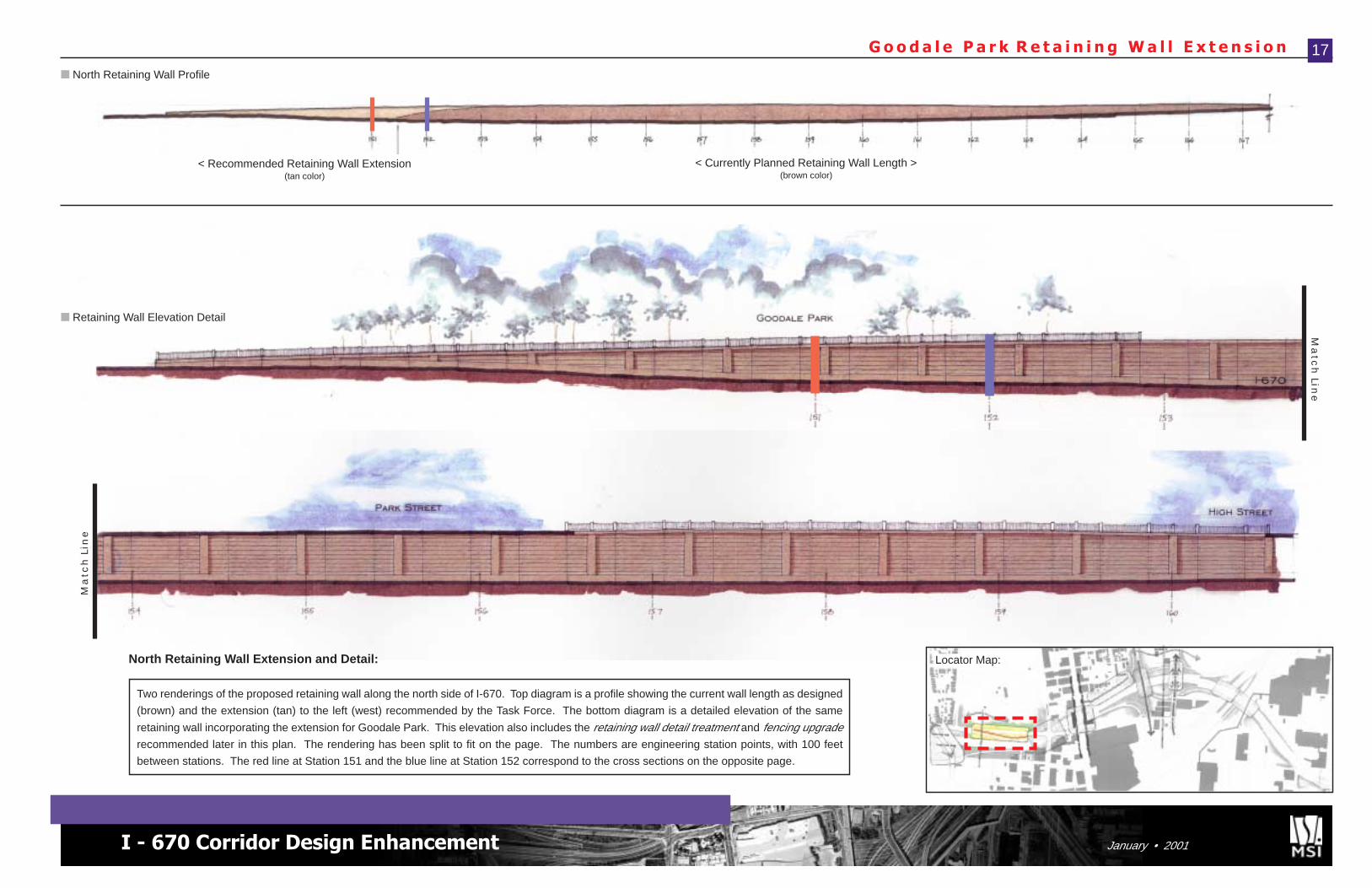
G o o d a l e P a r k R e t a i n i n g W a l l E x t e n s i o n 17
< Recommended Retaining Wall Extension(tan color)
< Currently Planned Retaining Wall Length >(brown color)
■ North Retaining Wall ProfileM
atc
h L
ine
Ma
tch
Line
Two renderings of the proposed retaining wall along the north side of I-670. Top diagram is a profile showing the current wall length as designed
(brown) and the extension (tan) to the left (west) recommended by the Task Force. The bottom diagram is a detailed elevation of the same
retaining wall incorporating the extension for Goodale Park. This elevation also includes the retaining wall detail treatment and fencing upgraderecommended later in this plan. The rendering has been split to fit on the page. The numbers are engineering station points, with 100 feet
between stations. The red line at Station 151 and the blue line at Station 152 correspond to the cross sections on the opposite page.
North Retaining Wall Extension and Detail: Locator Map:
G o o d a l e P a r k S o u t h e a s t C o r n e r
Focus Area Recommendat ions
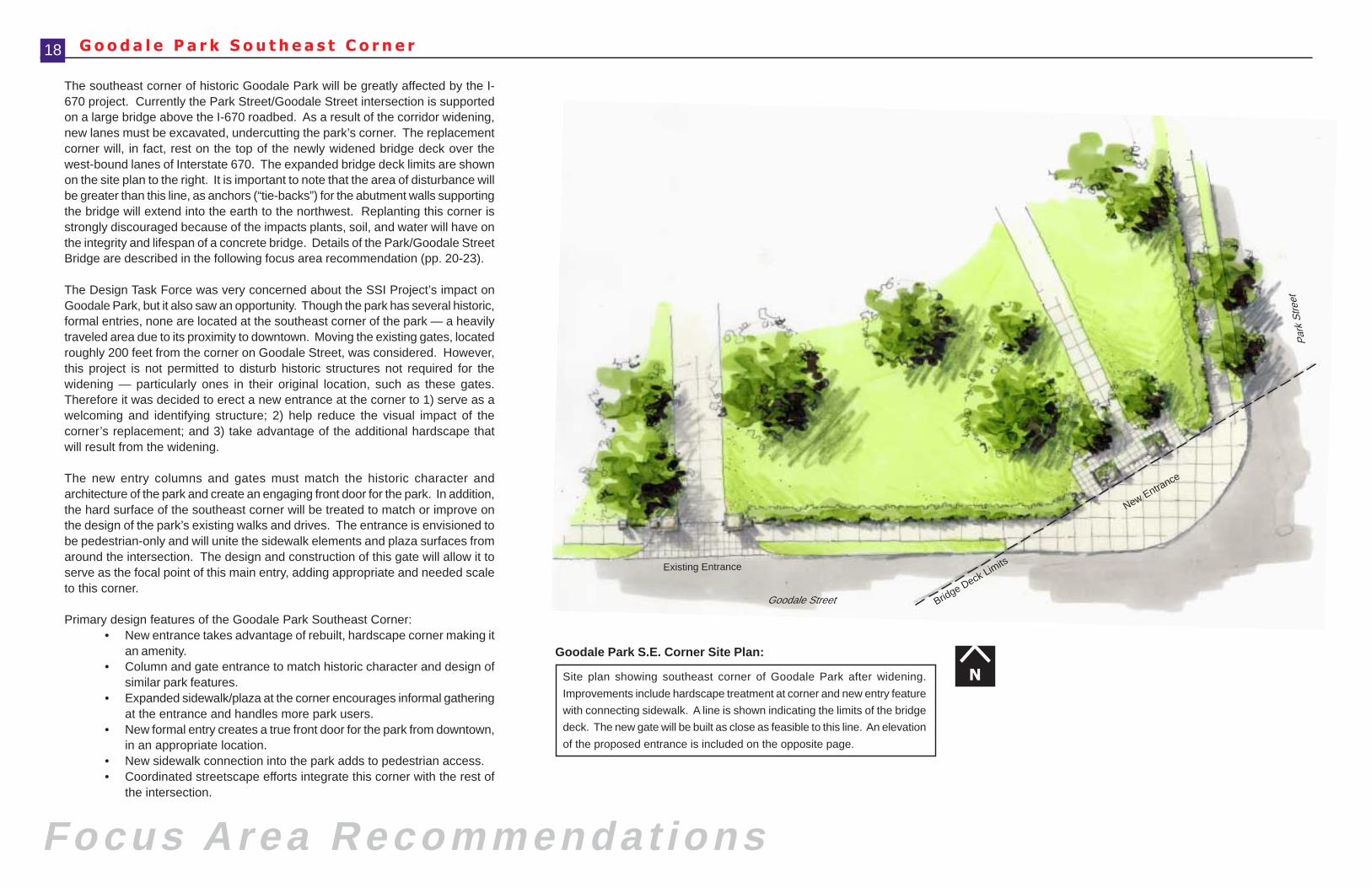
The southeast corner of historic Goodale Park will be greatly affected by the I-670 project. Currently the Park Street/Goodale Street intersection is supportedon a large bridge above the I-670 roadbed. As a result of the corridor widening,new lanes must be excavated, undercutting the park’s corner. The replacementcorner will, in fact, rest on the top of the newly widened bridge deck over thewest-bound lanes of Interstate 670. The expanded bridge deck limits are shownon the site plan to the right. It is important to note that the area of disturbance willbe greater than this line, as anchors (“tie-backs”) for the abutment walls supportingthe bridge will extend into the earth to the northwest. Replanting this corner isstrongly discouraged because of the impacts plants, soil, and water will have onthe integrity and lifespan of a concrete bridge. Details of the Park/Goodale StreetBridge are described in the following focus area recommendation (pp. 20-23).
The Design Task Force was very concerned about the SSI Project’s impact onGoodale Park, but it also saw an opportunity. Though the park has several historic,formal entries, none are located at the southeast corner of the park — a heavilytraveled area due to its proximity to downtown. Moving the existing gates, locatedroughly 200 feet from the corner on Goodale Street, was considered. However,this project is not permitted to disturb historic structures not required for thewidening — particularly ones in their original location, such as these gates.Therefore it was decided to erect a new entrance at the corner to 1) serve as awelcoming and identifying structure; 2) help reduce the visual impact of thecorner’s replacement; and 3) take advantage of the additional hardscape thatwill result from the widening.
The new entry columns and gates must match the historic character andarchitecture of the park and create an engaging front door for the park. In addition,the hard surface of the southeast corner will be treated to match or improve onthe design of the park’s existing walks and drives. The entrance is envisioned tobe pedestrian-only and will unite the sidewalk elements and plaza surfaces fromaround the intersection. The design and construction of this gate will allow it toserve as the focal point of this main entry, adding appropriate and needed scaleto this corner.
Primary design features of the Goodale Park Southeast Corner:• New entrance takes advantage of rebuilt, hardscape corner making it
an amenity.• Column and gate entrance to match historic character and design of
similar park features.• Expanded sidewalk/plaza at the corner encourages informal gathering
at the entrance and handles more park users.• New formal entry creates a true front door for the park from downtown,
in an appropriate location.• New sidewalk connection into the park adds to pedestrian access.• Coordinated streetscape efforts integrate this corner with the rest of
the intersection.
Existing Entrance
Goodale Street
Par
k S
treet
Bridge Deck Limits
New Entrance
N
18
Site plan showing southeast corner of Goodale Park after widening.
Improvements include hardscape treatment at corner and new entry feature
with connecting sidewalk. A line is shown indicating the limits of the bridge
deck. The new gate will be built as close as feasible to this line. An elevation
of the proposed entrance is included on the opposite page.
Goodale Park S.E. Corner Site Plan:
I - 670 Corridor Design Enhancement January • 2001
G o o d a l e P a r k E n t r y T r e a t m e n t 19
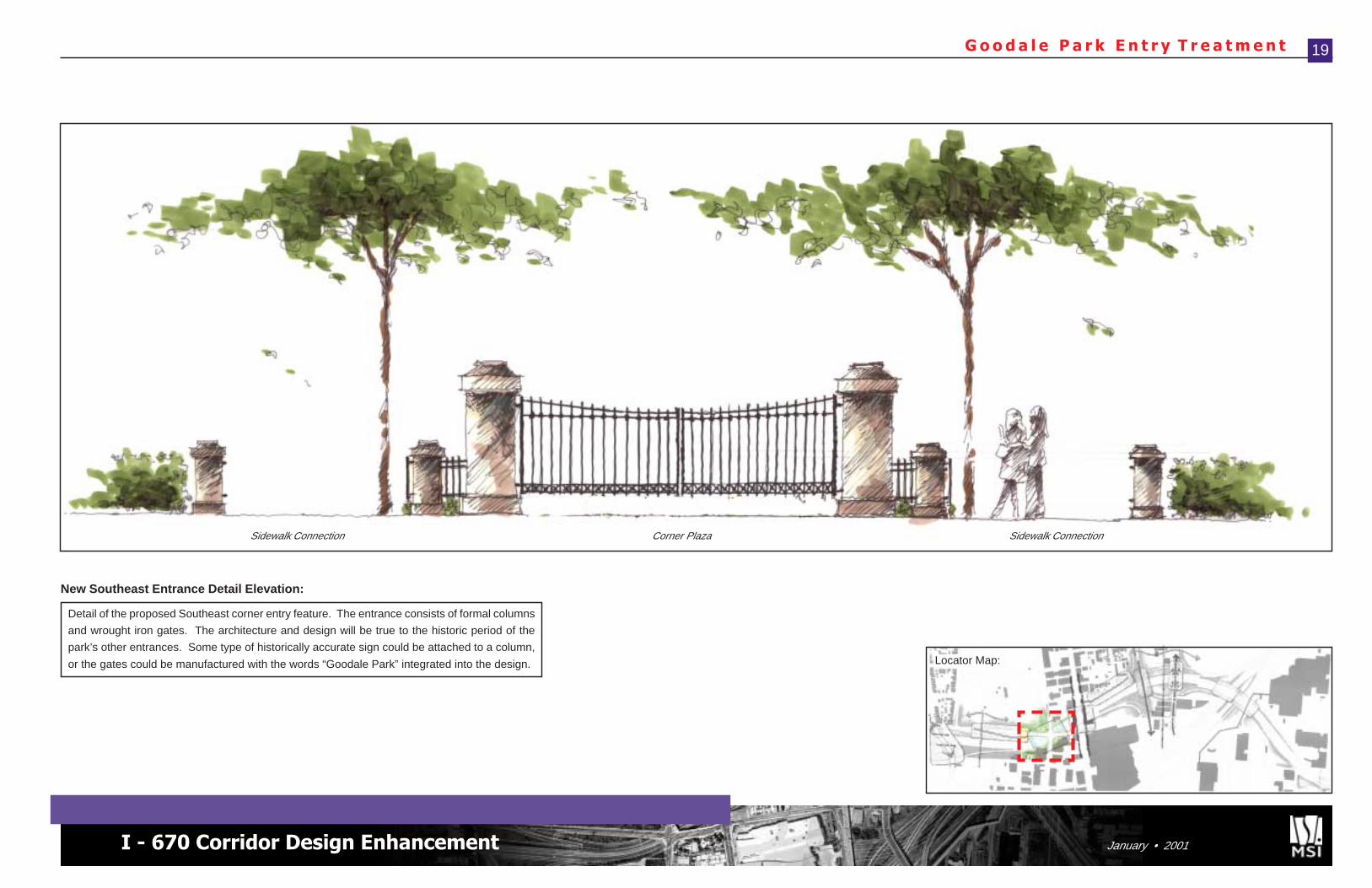
Detail of the proposed Southeast corner entry feature. The entrance consists of formal columns
and wrought iron gates. The architecture and design will be true to the historic period of the
park’s other entrances. Some type of historically accurate sign could be attached to a column,
or the gates could be manufactured with the words “Goodale Park” integrated into the design.
New Southeast Entrance Detail Elevation:
Corner PlazaSidewalk Connection Sidewalk Connection
Locator Map:
Abutment Wall
Abutment Wall
Concrete Piers
Spans
I-670
Par
k S
t.
Goodale St.
TriangularPlaza
TriangularPlaza
P a r k / G o o d a l e S t r e e t B r i d g e
Focus Area Recommendat ions
Park Street is the vital link between the Victorian Village/Short North/Goodale Park areas and the North Market and Arena Districts. Inaddition, Park Street (which becomes Front Street south of VineStreet) is a major connector with the downtown core. As with NeilAvenue, the I-670 corridor creates a physical and visual separationin this area. This not only impacts Park Street, but also GoodaleStreet, which crosses it east to west. More than other roads acrossthis divide, however, the Park/Goodale Street connection is not asforboding to pedestrians. This is in large part because 1) the I-670roadbed is below grade in this area; 2) the entire intersection issupported on a wide bridge; and 3) broad sidewalks are maintainedalong the roads over the bridge. These factors act in conjunction tofocus attention on the urban grid that exists at street level. Thiseffect must be continued and improved with the widening project.The I-670 widening requires the complete redesign andreconstruction of the Park/Goodale Street Bridge, as it must spanan even wider trench. The most important issue for the historicdistricts surrounding the new bridge is ensuring that the urban designmakes it less apparent that I-670 exists. The next most importantissue is improving the aesthetics of the bridge and intersection —integrating them into the character of the neighborhoods.
It is an important advantage having the I-670 roadbed depressed inthis location, as it is easier to hide its presence. The trick is to preventthe I-670 corridor from “reading” up into the historic urban grid. Inthis case, it is more challenging because I-670 runs at a diagonal tothe street and block grid. Thus, components like the tall safety fencing,which usually follows bridge edges, will run diagonally away fromthe street rather than parallel to it. This draws attention to the highwaybelow. Broad and empty expanses of concrete in front of this fencingonly accentuates the effect. The best solution is to place buildingsalong the bridge edge so that the traveler does not experience thehighway, but only sees a continuous streetfront. This is the conceptbehind the High Street Cap (see next focus area, pp. 24-25).Unfortunately in the case of the Park/Goodale Street Bridge, acomplete cap is not feasible at this time.
The original plans for the new Park/Goodale Street Bridge show avery different design than currently exists. This is due in part to thewider spans over I-670 that must be achieved. In the proposeddesign, the intersection is supported by two spans that when viewedfrom above look like a “Z” and almost appear as two separate bridges.Support piers are placed along the center of the I-670 roadbed, with
20
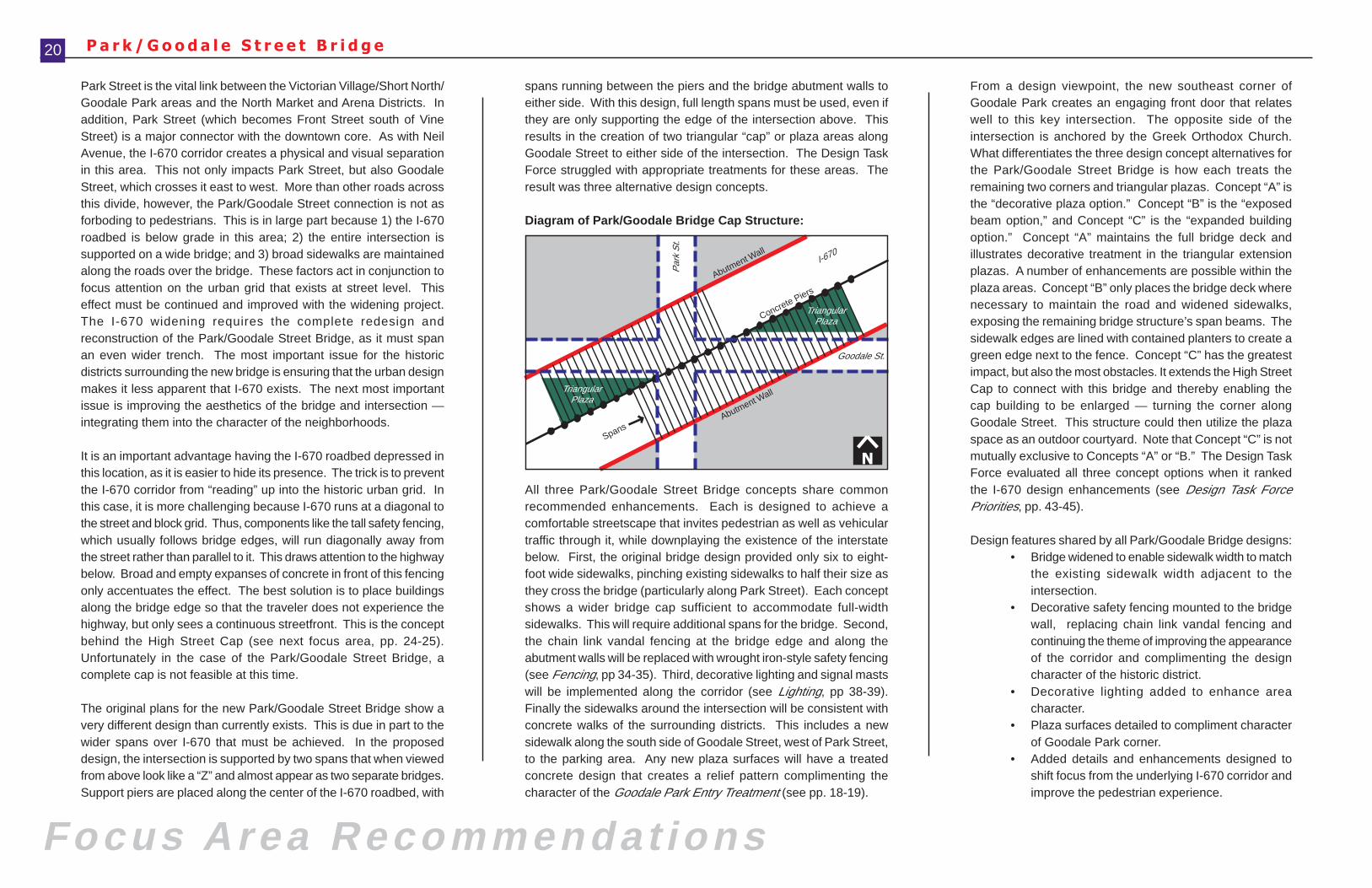
spans running between the piers and the bridge abutment walls toeither side. With this design, full length spans must be used, even ifthey are only supporting the edge of the intersection above. Thisresults in the creation of two triangular “cap” or plaza areas alongGoodale Street to either side of the intersection. The Design TaskForce struggled with appropriate treatments for these areas. Theresult was three alternative design concepts.
Diagram of Park/Goodale Bridge Cap Structure:
All three Park/Goodale Street Bridge concepts share commonrecommended enhancements. Each is designed to achieve acomfortable streetscape that invites pedestrian as well as vehiculartraffic through it, while downplaying the existence of the interstatebelow. First, the original bridge design provided only six to eight-foot wide sidewalks, pinching existing sidewalks to half their size asthey cross the bridge (particularly along Park Street). Each conceptshows a wider bridge cap sufficient to accommodate full-widthsidewalks. This will require additional spans for the bridge. Second,the chain link vandal fencing at the bridge edge and along theabutment walls will be replaced with wrought iron-style safety fencing(see Fencing, pp 34-35). Third, decorative lighting and signal mastswill be implemented along the corridor (see Lighting, pp 38-39).Finally the sidewalks around the intersection will be consistent withconcrete walks of the surrounding districts. This includes a newsidewalk along the south side of Goodale Street, west of Park Street,to the parking area. Any new plaza surfaces will have a treatedconcrete design that creates a relief pattern complimenting thecharacter of the Goodale Park Entry Treatment (see pp. 18-19).
From a design viewpoint, the new southeast corner ofGoodale Park creates an engaging front door that relateswell to this key intersection. The opposite side of theintersection is anchored by the Greek Orthodox Church.What differentiates the three design concept alternatives forthe Park/Goodale Street Bridge is how each treats theremaining two corners and triangular plazas. Concept “A” isthe “decorative plaza option.” Concept “B” is the “exposedbeam option,” and Concept “C” is the “expanded buildingoption.” Concept “A” maintains the full bridge deck andillustrates decorative treatment in the triangular extensionplazas. A number of enhancements are possible within theplaza areas. Concept “B” only places the bridge deck wherenecessary to maintain the road and widened sidewalks,exposing the remaining bridge structure’s span beams. Thesidewalk edges are lined with contained planters to create agreen edge next to the fence. Concept “C” has the greatestimpact, but also the most obstacles. It extends the High StreetCap to connect with this bridge and thereby enabling thecap building to be enlarged — turning the corner alongGoodale Street. This structure could then utilize the plazaspace as an outdoor courtyard. Note that Concept “C” is notmutually exclusive to Concepts “A” or “B.” The Design TaskForce evaluated all three concept options when it rankedthe I-670 design enhancements (see Design Task ForcePriorities, pp. 43-45).
Design features shared by all Park/Goodale Bridge designs:• Bridge widened to enable sidewalk width to match
the existing sidewalk width adjacent to theintersection.
• Decorative safety fencing mounted to the bridgewall, replacing chain link vandal fencing andcontinuing the theme of improving the appearanceof the corridor and complimenting the designcharacter of the historic district.
• Decorative lighting added to enhance areacharacter.
• Plaza surfaces detailed to compliment characterof Goodale Park corner.
• Added details and enhancements designed toshift focus from the underlying I-670 corridor andimprove the pedestrian experience.
N
I - 670 Corridor Design Enhancement January • 2001
P a r k / G o o d a l e S t r e e t B r i d g e • C o n c e p t ‘ A ’ 21
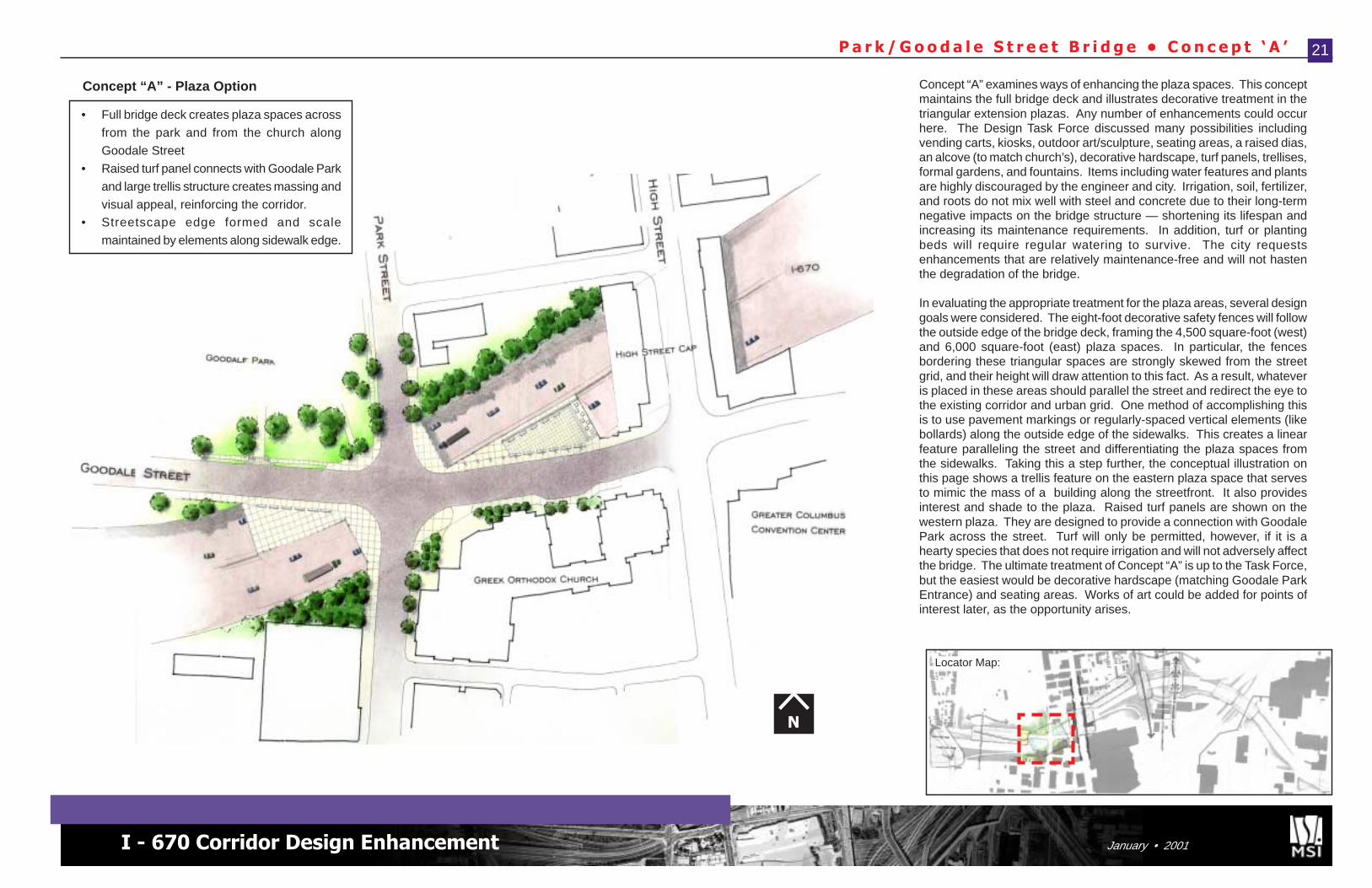
Concept “A” examines ways of enhancing the plaza spaces. This conceptmaintains the full bridge deck and illustrates decorative treatment in thetriangular extension plazas. Any number of enhancements could occurhere. The Design Task Force discussed many possibilities includingvending carts, kiosks, outdoor art/sculpture, seating areas, a raised dias,an alcove (to match church’s), decorative hardscape, turf panels, trellises,formal gardens, and fountains. Items including water features and plantsare highly discouraged by the engineer and city. Irrigation, soil, fertilizer,and roots do not mix well with steel and concrete due to their long-termnegative impacts on the bridge structure — shortening its lifespan andincreasing its maintenance requirements. In addition, turf or plantingbeds will require regular watering to survive. The city requestsenhancements that are relatively maintenance-free and will not hastenthe degradation of the bridge.
In evaluating the appropriate treatment for the plaza areas, several designgoals were considered. The eight-foot decorative safety fences will followthe outside edge of the bridge deck, framing the 4,500 square-foot (west)and 6,000 square-foot (east) plaza spaces. In particular, the fencesbordering these triangular spaces are strongly skewed from the streetgrid, and their height will draw attention to this fact. As a result, whateveris placed in these areas should parallel the street and redirect the eye tothe existing corridor and urban grid. One method of accomplishing thisis to use pavement markings or regularly-spaced vertical elements (likebollards) along the outside edge of the sidewalks. This creates a linearfeature paralleling the street and differentiating the plaza spaces fromthe sidewalks. Taking this a step further, the conceptual illustration onthis page shows a trellis feature on the eastern plaza space that servesto mimic the mass of a building along the streetfront. It also providesinterest and shade to the plaza. Raised turf panels are shown on thewestern plaza. They are designed to provide a connection with GoodalePark across the street. Turf will only be permitted, however, if it is ahearty species that does not require irrigation and will not adversely affectthe bridge. The ultimate treatment of Concept “A” is up to the Task Force,but the easiest would be decorative hardscape (matching Goodale ParkEntrance) and seating areas. Works of art could be added for points ofinterest later, as the opportunity arises.
• Full bridge deck creates plaza spaces across
from the park and from the church along
Goodale Street
• Raised turf panel connects with Goodale Park
and large trellis structure creates massing and
visual appeal, reinforcing the corridor.• Streetscape edge formed and scale
maintained by elements along sidewalk edge.
N
Locator Map:
Concept “A” - Plaza Option
Focus Area Recommendat ions
P a r k / G o o d a l e S t r e e t B r i d g e • C o n c e p t ‘ B ’22
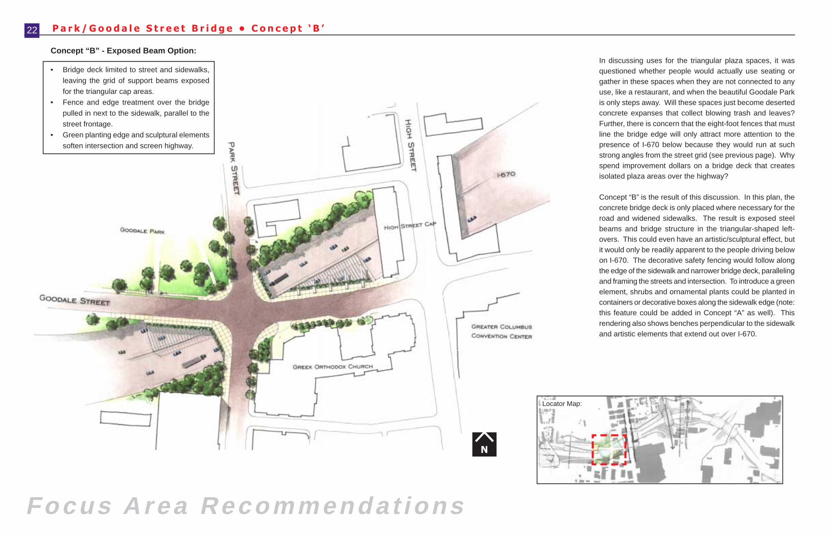
In discussing uses for the triangular plaza spaces, it wasquestioned whether people would actually use seating orgather in these spaces when they are not connected to anyuse, like a restaurant, and when the beautiful Goodale Parkis only steps away. Will these spaces just become desertedconcrete expanses that collect blowing trash and leaves?Further, there is concern that the eight-foot fences that mustline the bridge edge will only attract more attention to thepresence of I-670 below because they would run at suchstrong angles from the street grid (see previous page). Whyspend improvement dollars on a bridge deck that createsisolated plaza areas over the highway?
Concept “B” is the result of this discussion. In this plan, theconcrete bridge deck is only placed where necessary for theroad and widened sidewalks. The result is exposed steelbeams and bridge structure in the triangular-shaped left-overs. This could even have an artistic/sculptural effect, butit would only be readily apparent to the people driving belowon I-670. The decorative safety fencing would follow alongthe edge of the sidewalk and narrower bridge deck, parallelingand framing the streets and intersection. To introduce a greenelement, shrubs and ornamental plants could be planted incontainers or decorative boxes along the sidewalk edge (note:this feature could be added in Concept “A” as well). Thisrendering also shows benches perpendicular to the sidewalkand artistic elements that extend out over I-670.
• Bridge deck limited to street and sidewalks,
leaving the grid of support beams exposed
for the triangular cap areas.
• Fence and edge treatment over the bridge
pulled in next to the sidewalk, parallel to the
street frontage.
• Green planting edge and sculptural elements
soften intersection and screen highway.
N
Locator Map:
Concept “B” - Exposed Beam Option:
I - 670 Corridor Design Enhancement January • 2001
BuildingExtension
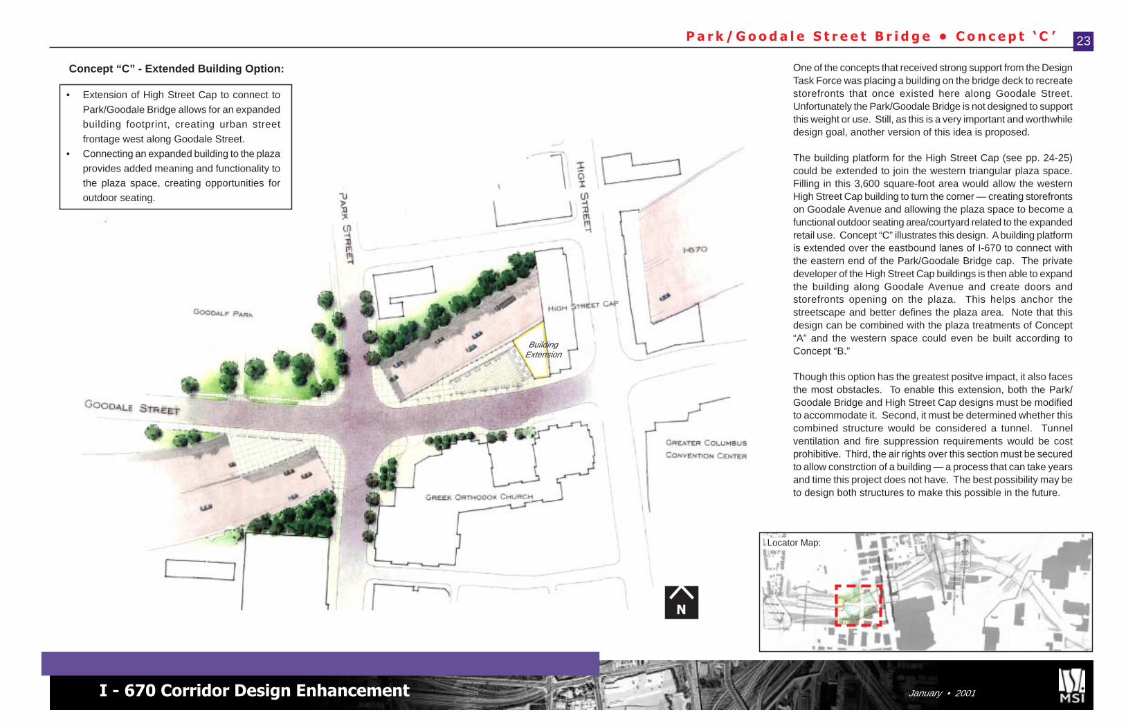
P a r k / G o o d a l e S t r e e t B r i d g e • C o n c e p t ‘ C ’
• Extension of High Street Cap to connect to
Park/Goodale Bridge allows for an expanded
building footprint, creating urban street
frontage west along Goodale Street.
• Connecting an expanded building to the plaza
provides added meaning and functionality tothe plaza space, creating opportunities for
outdoor seating.
23
One of the concepts that received strong support from the DesignTask Force was placing a building on the bridge deck to recreatestorefronts that once existed here along Goodale Street.Unfortunately the Park/Goodale Bridge is not designed to supportthis weight or use. Still, as this is a very important and worthwhiledesign goal, another version of this idea is proposed.
The building platform for the High Street Cap (see pp. 24-25)could be extended to join the western triangular plaza space.Filling in this 3,600 square-foot area would allow the westernHigh Street Cap building to turn the corner — creating storefrontson Goodale Avenue and allowing the plaza space to become afunctional outdoor seating area/courtyard related to the expandedretail use. Concept “C” illustrates this design. A building platformis extended over the eastbound lanes of I-670 to connect withthe eastern end of the Park/Goodale Bridge cap. The privatedeveloper of the High Street Cap buildings is then able to expandthe building along Goodale Avenue and create doors andstorefronts opening on the plaza. This helps anchor thestreetscape and better defines the plaza area. Note that thisdesign can be combined with the plaza treatments of Concept“A” and the western space could even be built according toConcept “B.”
Though this option has the greatest positve impact, it also facesthe most obstacles. To enable this extension, both the Park/Goodale Bridge and High Street Cap designs must be modifiedto accommodate it. Second, it must be determined whether thiscombined structure would be considered a tunnel. Tunnelventilation and fire suppression requirements would be costprohibitive. Third, the air rights over this section must be securedto allow constrction of a building — a process that can take yearsand time this project does not have. The best possibility may beto design both structures to make this possible in the future.
N
Locator Map:
Concept “C” - Extended Building Option:
Focus Area Recommendat ions
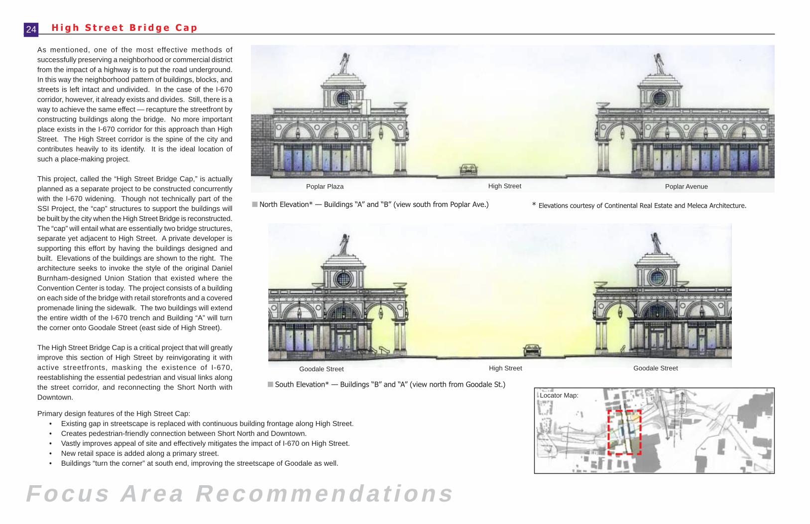
■ South Elevation* — Buildings “B” and “A” (view north from Goodale St.)
■ North Elevation* — Buildings “A” and “B” (view south from Poplar Ave.)
H i g h S t r e e t B r i d g e C a p
As mentioned, one of the most effective methods ofsuccessfully preserving a neighborhood or commercial districtfrom the impact of a highway is to put the road underground.In this way the neighborhood pattern of buildings, blocks, andstreets is left intact and undivided. In the case of the I-670corridor, however, it already exists and divides. Still, there is away to achieve the same effect — recapture the streetfront byconstructing buildings along the bridge. No more importantplace exists in the I-670 corridor for this approach than HighStreet. The High Street corridor is the spine of the city andcontributes heavily to its identify. It is the ideal location ofsuch a place-making project.
This project, called the “High Street Bridge Cap,” is actuallyplanned as a separate project to be constructed concurrentlywith the I-670 widening. Though not technically part of theSSI Project, the “cap” structures to support the buildings willbe built by the city when the High Street Bridge is reconstructed.The “cap” will entail what are essentially two bridge structures,separate yet adjacent to High Street. A private developer issupporting this effort by having the buildings designed andbuilt. Elevations of the buildings are shown to the right. Thearchitecture seeks to invoke the style of the original DanielBurnham-designed Union Station that existed where theConvention Center is today. The project consists of a buildingon each side of the bridge with retail storefronts and a coveredpromenade lining the sidewalk. The two buildings will extendthe entire width of the I-670 trench and Building “A” will turnthe corner onto Goodale Street (east side of High Street).
The High Street Bridge Cap is a critical project that will greatlyimprove this section of High Street by reinvigorating it withactive streetfronts, masking the existence of I-670,reestablishing the essential pedestrian and visual links alongthe street corridor, and reconnecting the Short North withDowntown.
Poplar Plaza High Street Poplar Avenue
Goodale Street High Street Goodale Street
24
Primary design features of the High Street Cap:• Existing gap in streetscape is replaced with continuous building frontage along High Street.• Creates pedestrian-friendly connection between Short North and Downtown.• Vastly improves appeal of site and effectively mitigates the impact of I-670 on High Street.• New retail space is added along a primary street.• Buildings “turn the corner” at south end, improving the streetscape of Goodale as well.
Locator Map:
* Elevations courtesy of Continental Real Estate and Meleca Architecture.
I - 670 Corridor Design Enhancement January • 2001
H i g h S t r e e t B r i d g e C a p 25
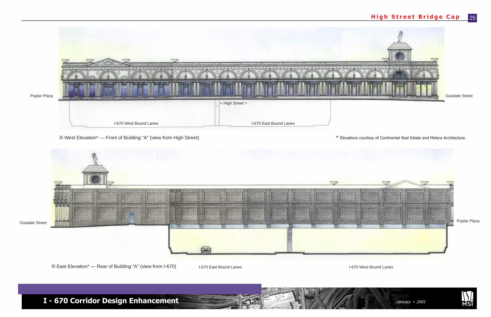
■ East Elevation* — Rear of Building “A” (view from I-670)
Goodale Street Poplar Plaza
I-670 East Bound Lanes I-670 West Bound Lanes
Goodale Street
■ West Elevation* — Front of Building “A” (view from High Street)
Poplar Plaza
I-670 East Bound LanesI-670 West Bound Lanes
< High Street >
* Elevations courtesy of Continental Real Estate and Meleca Architecture.
Focus Area Recommendat ions
Hig
h S
treet
I t a l i a n V i l l a g e E d g e T r e a t m e n t
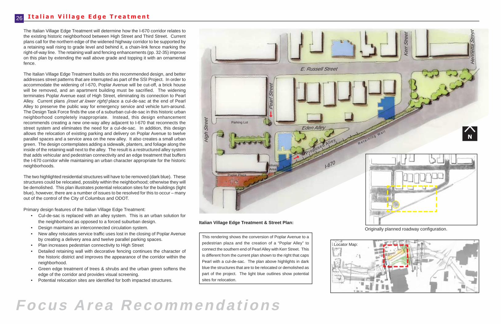
The Italian Village Edge Treatment will determine how the I-670 corridor relates tothe existing historic neighborhood between High Street and Third Street. Currentplans call for the northern edge of the widened highway corridor to be supported bya retaining wall rising to grade level and behind it, a chain-link fence marking theright-of-way line. The retaining wall and fencing enhancements (pp. 32-35) improveon this plan by extending the wall above grade and topping it with an ornamentalfence.
The Italian Village Edge Treatment builds on this recommended design, and betteraddresses street patterns that are interrupted as part of the SSI Project. In order toaccommodate the widening of I-670, Poplar Avenue will be cut-off, a brick housewill be removed, and an apartment building must be sacrified. The wideningterminates Poplar Avenue east of High Street, eliminating its connection to PearlAlley. Current plans (inset at lower right) place a cul-de-sac at the end of PearlAlley to preserve the public way for emergency service and vehicle turn-around.The Design Task Force finds the use of a suburban cul-de-sac in this historic urbanneighborhood completely inappropriate. Instead, this design enhancementrecommends creating a new one-way alley adjacent to I-670 that reconnects thestreet system and eliminates the need for a cul-de-sac. In addition, this designallows the relocation of existing parking and delivery on Poplar Avenue to twelveparallel spaces and a service area on the new alley. It also creates a small urbangreen. The design contemplates adding a sidewalk, planters, and foliage along theinside of the retaining wall next to the alley. The result is a restructured alley systemthat adds vehicular and pedestrian connectivity and an edge treatment that buffersthe I-670 corridor while maintaining an urban character appropriate for the historicneighborhoods.
The two highlighted residential structures will have to be removed (dark blue). Thesestructures could be relocated, possibly within the neighborhood; otherwise they willbe demolished. This plan illustrates potential relocation sites for the buildings (lightblue), however, there are a number of issues to be resolved for this to occur – manyout of the control of the City of Columbus and ODOT.
Primary design features of the Italian Village Edge Treatment:• Cul-de-sac is replaced with an alley system. This is an urban solution for
the neighborhood as opposed to a forced suburban design.• Design maintains an interconnected circulation system.• New alley relocates service traffic uses lost in the closing of Poplar Avenue
by creating a delivery area and twelve parallel parking spaces.• Plan increases pedestrian connectivity to High Street• Detailed retaining wall with decorative fencing continues the character of
the historic district and improves the appearance of the corridor within theneighborhood.
• Green edge treatment of trees & shrubs and the urban green softens theedge of the corridor and provides visual screening.
• Potential relocation sites are identified for both impacted structures.
Parking Lot
E. Russell Street
Eden Alley
Ker
r Stre
et
Hen
rietta
Stre
et
I-670
Proposed Al ley
I I
I
I I
I
I I
I
I
I I
26
This rendering shows the conversion of Poplar Avenue to a
pedestrian plaza and the creation of a “Poplar Alley” to
connect the southern end of Pearl Alley with Kerr Street. This
is different from the current plan shown to the right that caps
Pearl with a cul-de-sac. The plan above highlights in dark
blue the structures that are to be relocated or demolished as
part of the project. The light blue outlines show potential
sites for relocation.
Italian Village Edge Treatment & Street Plan:
Pea
rl S
treet
DeliveryArea
Poplar Plaza
R e t a i n i n g W a l l
N
Originally planned roadway configuration.
Locator Map:
I - 670 Corridor Design Enhancement January • 2001
P o p l a r A v e n u e T r e a t m e n t
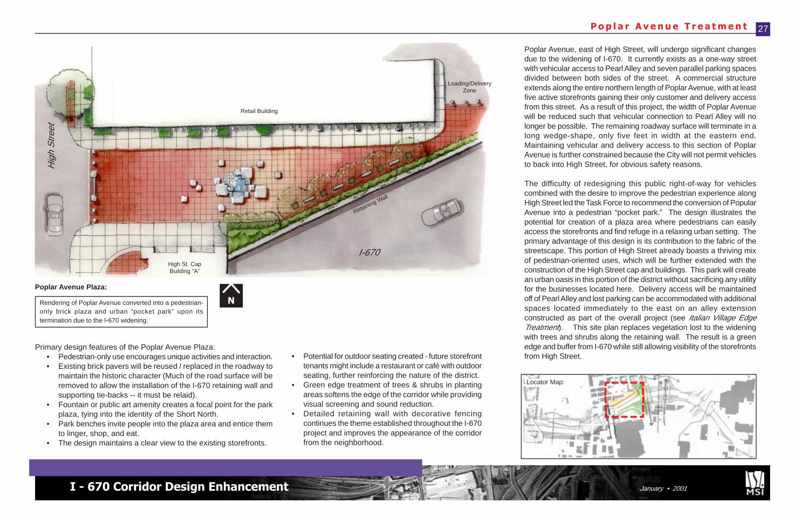
Poplar Avenue, east of High Street, will undergo significant changesdue to the widening of I-670. It currently exists as a one-way streetwith vehicular access to Pearl Alley and seven parallel parking spacesdivided between both sides of the street. A commercial structureextends along the entire northern length of Poplar Avenue, with at leastfive active storefronts gaining their only customer and delivery accessfrom this street. As a result of this project, the width of Poplar Avenuewill be reduced such that vehicular connection to Pearl Alley will nolonger be possible. The remaining roadway surface will terminate in along wedge-shape, only five feet in width at the eastern end.Maintaining vehicular and delivery access to this section of PoplarAvenue is further constrained because the City will not permit vehiclesto back into High Street, for obvious safety reasons.
The difficulty of redesigning this public right-of-way for vehiclescombined with the desire to improve the pedestrian experience alongHigh Street led the Task Force to recommend the conversion of PopularAvenue into a pedestrian “pocket park.” The design illustrates thepotential for creation of a plaza area where pedestrians can easilyaccess the storefronts and find refuge in a relaxing urban setting. Theprimary advantage of this design is its contribution to the fabric of thestreetscape. This portion of High Street already boasts a thriving mixof pedestrian-oriented uses, which will be further extended with theconstruction of the High Street cap and buildings. This park will createan urban oasis in this portion of the district without sacrificing any utilityfor the businesses located here. Delivery access will be maintainedoff of Pearl Alley and lost parking can be accommodated with additionalspaces located immediately to the east on an alley extensionconstructed as part of the overall project (see Italian Village EdgeTreatment). This site plan replaces vegetation lost to the wideningwith trees and shrubs along the retaining wall. The result is a greenedge and buffer from I-670 while still allowing visibility of the storefrontsfrom High Street.
I-670
Hig
h S
treet
High St. CapBuilding “A”
Retail Building
27
Primary design features of the Poplar Avenue Plaza:• Pedestrian-only use encourages unique activities and interaction.• Existing brick pavers will be reused / replaced in the roadway to
maintain the historic character (Much of the road surface will beremoved to allow the installation of the I-670 retaining wall andsupporting tie-backs -- it must be relaid).
• Fountain or public art amenity creates a focal point for the parkplaza, tying into the identity of the Short North.
• Park benches invite people into the plaza area and entice themto linger, shop, and eat.
• The design maintains a clear view to the existing storefronts.
• Potential for outdoor seating created - future storefronttenants might include a restaurant or café with outdoorseating, further reinforcing the nature of the district.
• Green edge treatment of trees & shrubs in plantingareas softens the edge of the corridor while providingvisual screening and sound reduction.
• Detailed retaining wall with decorative fencingcontinues the theme established throughout the I-670project and improves the appearance of the corridorfrom the neighborhood.
Rendering of Poplar Avenue converted into a pedestrian-only brick plaza and urban “pocket park” upon itstermination due to the I-670 widening.
Poplar Avenue Plaza:
N
Loading/DeliveryZone
Retaining Wall
Locator Map:
Focus Area Recommendat ions
Fourth Street Gateway Treatment
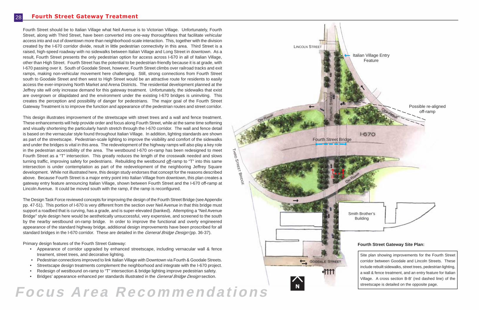
Fourth Street should be to Italian Village what Neil Avenue is to Victorian Village. Unfortunately, FourthStreet, along with Third Street, have been converted into one-way thoroughfares that facilitate vehicularaccess into and out of downtown more than neighborhood-scale interaction. This, together with the divisioncreated by the I-670 corridor divide, result in little pedestrian connectivity in this area. Third Street is araised, high-speed roadway with no sidewalks between Italian Village and Long Street in downtown. As aresult, Fourth Street presents the only pedestrian option for access across I-670 in all of Italian Village,other than High Street. Fourth Street has the potential to be pedestrian-friendly because it is at grade, withI-670 passing over it. South of Goodale Street, however, Fourth Street climbs over railroad tracks and exitramps, making non-vehicular movement here challenging. Still, strong connections from Fourth Streetsouth to Goodale Street and then west to High Street would be an attractive route for residents to easilyaccess the ever-improving North Market and Arena Districts. The residential development planned at theJeffrey site will only increase demand for this gateway treatment. Unfortunately, the sidewalks that existare overgrown or dilapidated and the environment under the existing I-670 bridges is uninviting. Thiscreates the perception and possibility of danger for pedestrians. The major goal of the Fourth StreetGateway Treatment is to improve the function and appearance of the pedestrian routes and street corridor.
This design illustrates improvement of the streetscape with street trees and a wall and fence treatment.These enhancements will help provide order and focus along Fourth Street, while at the same time softeningand visually shortening the particularly harsh stretch through the I-670 corridor. The wall and fence detailis based on the vernacular style found throughout Italian Village. In addition, lighting standards are shownas part of the streetscape. Pedestrian-scale lighting to improve the visibility and comfort of the sidewalksand under the bridges is vital in this area. The redevelopment of the highway ramps will also play a key rolein the pedestrian accessibility of the area. The westbound I-670 on-ramp has been redesigned to meetFourth Street as a “T” intersection. This greatly reduces the length of the crosswalk needed and slowsturning traffic, improving safety for pedestrians. Rebuilding the westbound off-ramp to “T” into this sameintersection is under contemplation as part of the redevelopment of the neighboring Jeffrey Squaredevelopment. While not illustrated here, this design study endorses that concept for the reasons describedabove. Because Fourth Street is a major entry point into Italian Village from downtown, this plan creates agateway entry feature announcing Italian Village, shown between Fourth Street and the I-670 off-ramp atLincoln Avenue. It could be moved south with the ramp, if the ramp is reconfigured.
The Design Task Force reviewed concepts for improving the design of the Fourth Street Bridge (see Appendixpp. 47-51). This portion of I-670 is very different from the section over Neil Avenue in that this bridge mustsupport a roadbed that is curving, has a grade, and is super-elevated (banked). Attempting a “Neil AvenueBridge” style design here would be aesthetically unsuccessful, very expensive, and screened to the southby the nearby westbound on-ramp bridge. In order to improve the functional and overly engineeredappearance of the standard highway bridge, additional design improvements have been proscribed for allstandard bridges in the I-670 corridor. These are detailed in the General Bridge Design (pp. 36-37).
Primary design features of the Fourth Street Gateway:• Appearance of corridor upgraded by enhanced streetscape, including vernacular wall & fence
treament, street trees, and decorative lighting. • Pedestrian connections improved to link Italian Village with Downtown via Fourth & Goodale Streets.• Streetscape design treatments complement the neighborhood and integrate with the I-670 project.• Redesign of westbound on-ramp to “T” intersection & bridge lighting improve pedestrian safety.• Bridges’ appearance enhanced per standards illustrated in the General Bridge Design section.
28
N
Site plan showing improvements for the Fourth Street
corridor between Goodale and Lincoln Streets. These
include rebuilt sidewalks, street trees, pedestrian lighting,
a wall & fence treatment, and an entry feature for Italian
Village. A cross section B-B’ (red dashed line) of the
streetscape is detailed on the opposite page.
Fourth Street Gateway Site Plan:T
HIR
D ST
RE
ET B
RID
GE
Smith Brother’sBuilding
Fourth Street Bridge
Italian Village EntryFeature
LINCOLN STREET
B B’
Possible re-alignedoff-ramp
I - 670 Corridor Design Enhancement January • 2001
F o u r t h S t r e e t G a t e w a y T r e a t m e n t 29
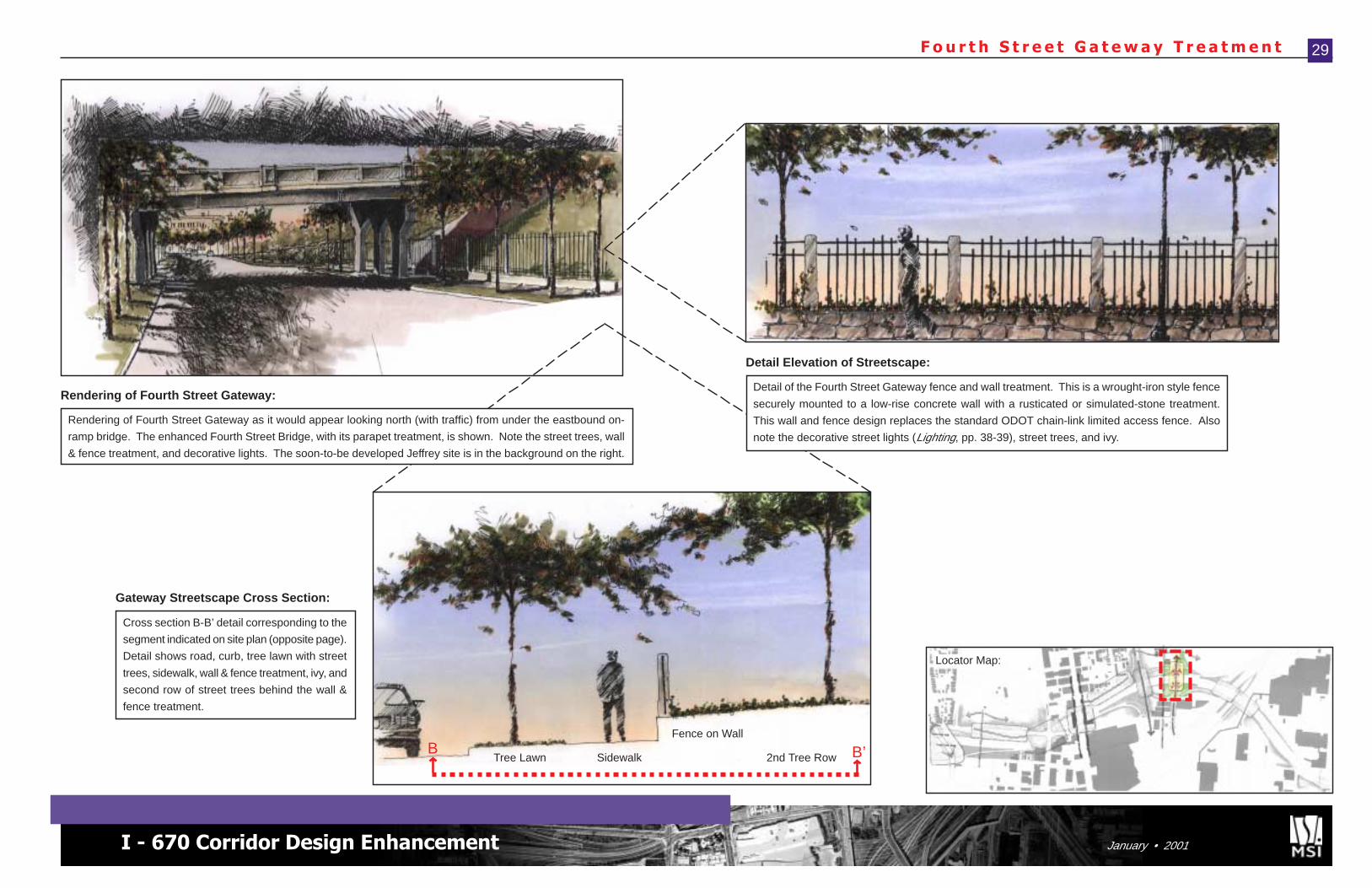
Detail Elevation of Streetscape:
Rendering of Fourth Street Gateway:
Locator Map:
Cross section B-B’ detail corresponding to the
segment indicated on site plan (opposite page).
Detail shows road, curb, tree lawn with street
trees, sidewalk, wall & fence treatment, ivy, and
second row of street trees behind the wall &
fence treatment.
Gateway Streetscape Cross Section:
B B’Tree Lawn Sidewalk
Fence on Wall
2nd Tree Row
Rendering of Fourth Street Gateway as it would appear looking north (with traffic) from under the eastbound on-
ramp bridge. The enhanced Fourth Street Bridge, with its parapet treatment, is shown. Note the street trees, wall
& fence treatment, and decorative lights. The soon-to-be developed Jeffrey site is in the background on the right.
Detail of the Fourth Street Gateway fence and wall treatment. This is a wrought-iron style fence
securely mounted to a low-rise concrete wall with a rusticated or simulated-stone treatment.
This wall and fence design replaces the standard ODOT chain-link limited access fence. Also
note the decorative street lights (Lighting, pp. 38-39), street trees, and ivy.
Corridor-Wide Recomendations
Corridor-Wide Recommendations
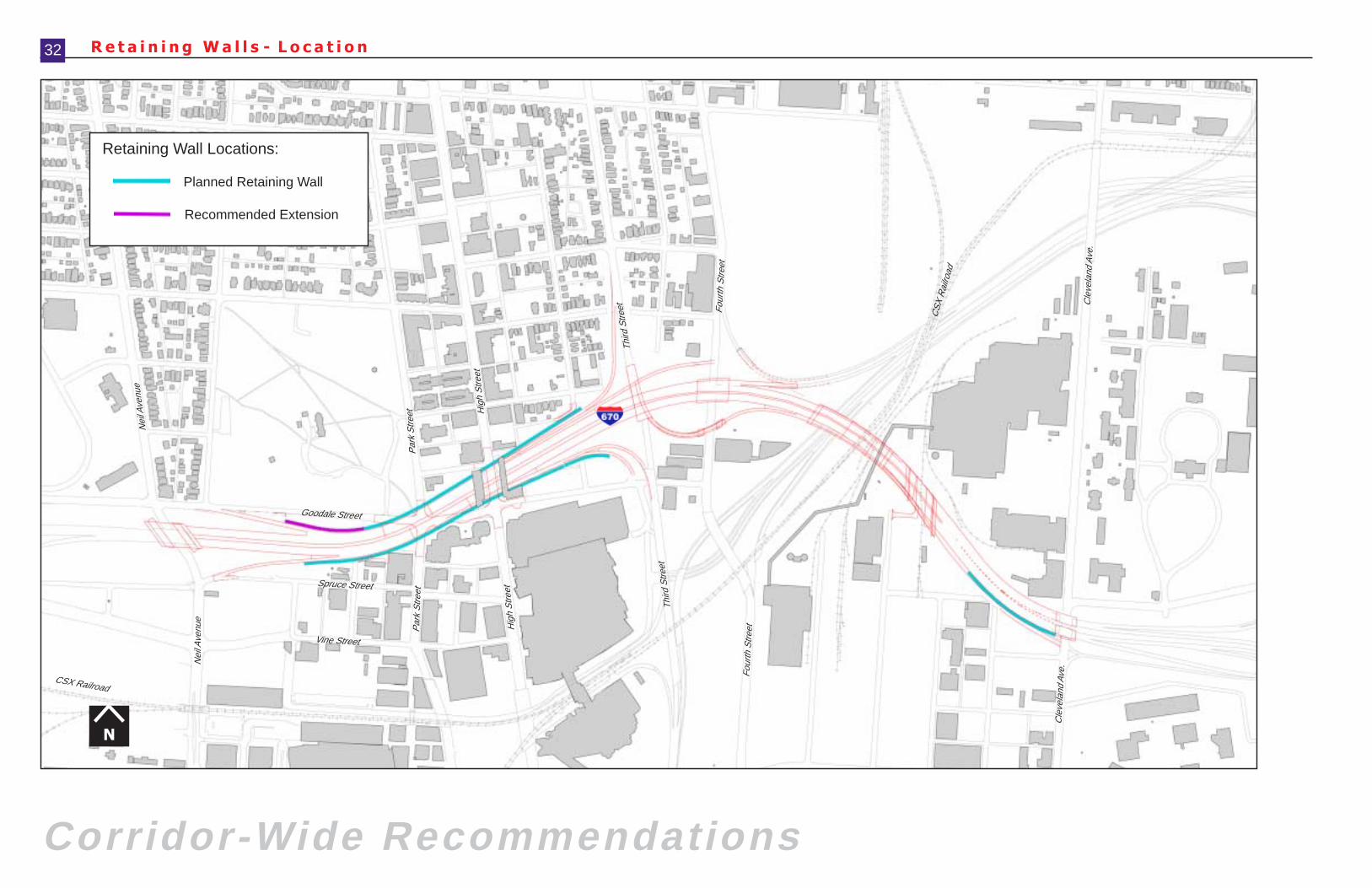
R e t a i n i n g W a l l s - L o c a t i o n
N
32
Cle
vela
nd A
ve.
Goodale Street
Nei
l Ave
nue
Par
k S
treet H
igh
Stre
et
Nei
l Ave
nue
Par
k S
treet
Cle
vela
nd A
ve.
Third
Stre
et Four
th S
treet
CS
X R
ailro
ad
Hig
h S
treet
Third
Stre
et
Four
th S
treet
CSX Railroad
Vine Street
Recommended Extension
Planned Retaining Wall
Retaining Wall Locations:
Spruce Street
I - 670 Corridor Design Enhancement January • 2001
R e t a i n i n g W a l l D e t a i l T r e a t m e n t 33
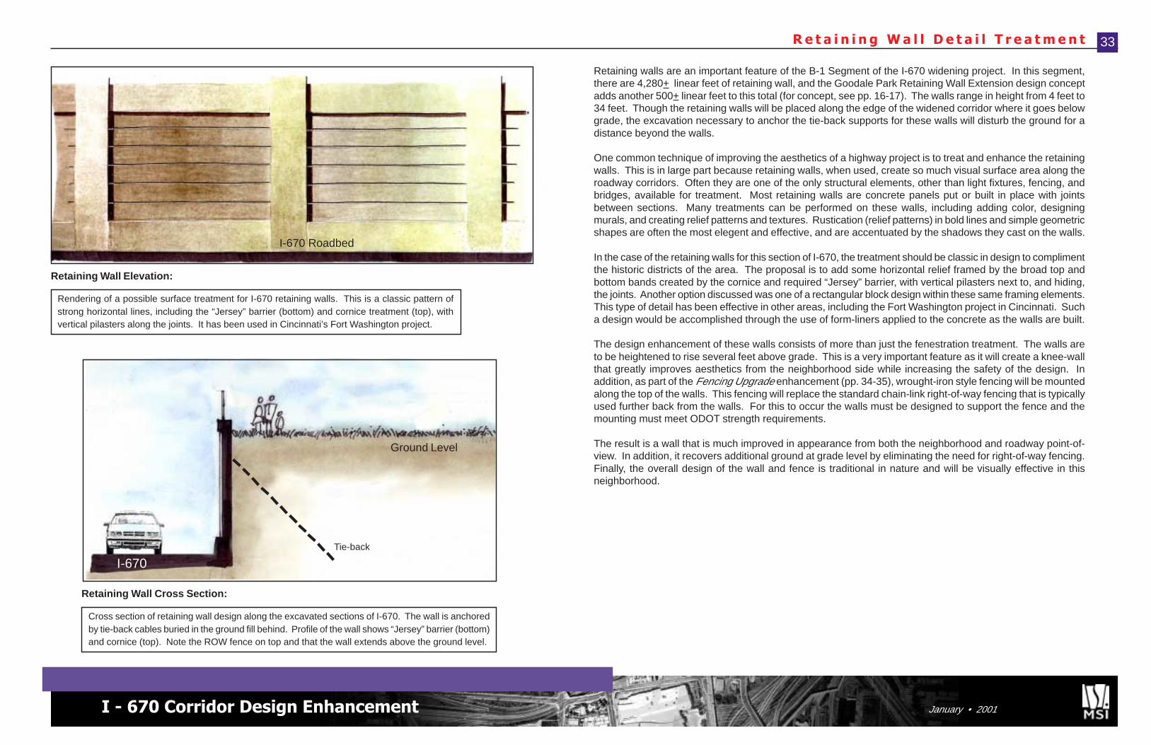
Rendering of a possible surface treatment for I-670 retaining walls. This is a classic pattern ofstrong horizontal lines, including the “Jersey” barrier (bottom) and cornice treatment (top), withvertical pilasters along the joints. It has been used in Cincinnati’s Fort Washington project.
Retaining Wall Elevation:
Cross section of retaining wall design along the excavated sections of I-670. The wall is anchoredby tie-back cables buried in the ground fill behind. Profile of the wall shows “Jersey” barrier (bottom)and cornice (top). Note the ROW fence on top and that the wall extends above the ground level.
Retaining Wall Cross Section:
I-670 Roadbed
I-670Tie-back
Ground Level
Retaining walls are an important feature of the B-1 Segment of the I-670 widening project. In this segment,there are 4,280+ linear feet of retaining wall, and the Goodale Park Retaining Wall Extension design conceptadds another 500+ linear feet to this total (for concept, see pp. 16-17). The walls range in height from 4 feet to34 feet. Though the retaining walls will be placed along the edge of the widened corridor where it goes belowgrade, the excavation necessary to anchor the tie-back supports for these walls will disturb the ground for adistance beyond the walls.
One common technique of improving the aesthetics of a highway project is to treat and enhance the retainingwalls. This is in large part because retaining walls, when used, create so much visual surface area along theroadway corridors. Often they are one of the only structural elements, other than light fixtures, fencing, andbridges, available for treatment. Most retaining walls are concrete panels put or built in place with jointsbetween sections. Many treatments can be performed on these walls, including adding color, designingmurals, and creating relief patterns and textures. Rustication (relief patterns) in bold lines and simple geometricshapes are often the most elegent and effective, and are accentuated by the shadows they cast on the walls.
In the case of the retaining walls for this section of I-670, the treatment should be classic in design to complimentthe historic districts of the area. The proposal is to add some horizontal relief framed by the broad top andbottom bands created by the cornice and required “Jersey” barrier, with vertical pilasters next to, and hiding,the joints. Another option discussed was one of a rectangular block design within these same framing elements.This type of detail has been effective in other areas, including the Fort Washington project in Cincinnati. Sucha design would be accomplished through the use of form-liners applied to the concrete as the walls are built.
The design enhancement of these walls consists of more than just the fenestration treatment. The walls areto be heightened to rise several feet above grade. This is a very important feature as it will create a knee-wallthat greatly improves aesthetics from the neighborhood side while increasing the safety of the design. Inaddition, as part of the Fencing Upgrade enhancement (pp. 34-35), wrought-iron style fencing will be mountedalong the top of the walls. This fencing will replace the standard chain-link right-of-way fencing that is typicallyused further back from the walls. For this to occur the walls must be designed to support the fence and themounting must meet ODOT strength requirements.
The result is a wall that is much improved in appearance from both the neighborhood and roadway point-of-view. In addition, it recovers additional ground at grade level by eliminating the need for right-of-way fencing.Finally, the overall design of the wall and fence is traditional in nature and will be visually effective in thisneighborhood.
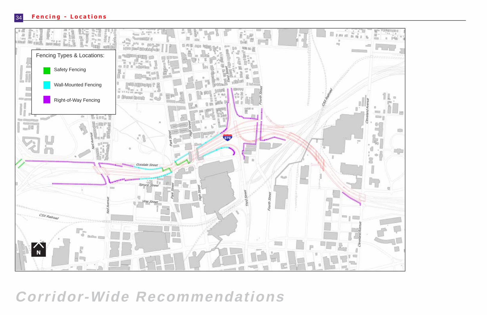
F e n c i n g - L o c a t i o n s
Corridor-Wide Recommendations
34
Fencing Types & Locations:
Safety Fencing
Wall-Mounted Fencing
Right-of-Way Fencing
N
Cle
vela
nd A
venu
e
Goodale Street
Nei
l Ave
nue
Par
k S
treet
Hig
h S
treet
Nei
l Ave
nue P
ark
Stre
et
Cle
vela
nd A
venu
e
Third
Stre
et
Four
th S
treet
CSX
Rai
lroad
Hig
h S
treet
Third
Stre
et
Four
th S
treet
CSX Railroad
Spruce Street
Vine Street
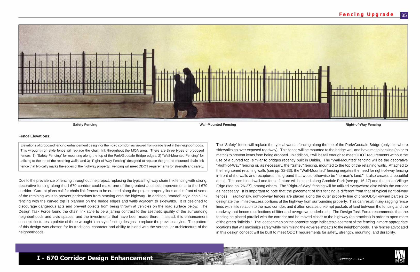
I - 670 Corridor Design Enhancement January • 2001
F e n c i n g U p g r a d e
Elevations of proposed fencing enhancement design for the I-670 corridor, as viewed from grade level in the neighborhoods.
This wrought-iron style fence will replace the chain link throughout the MOA area. There are three types of proposed
fences: 1) “Safety Fencing” for mounting along the top of the Park/Goodale Bridge edges; 2) “Wall-Mounted Fencing” for
affixing to the top of the retaining walls; and 3) “Right-of-Way Fencing” designed to replace the ground-mounted chain link
fence that typically marks the edges of the highway property. Fencing will meet ODOT requirements for strength and safety.
35
Fence Elevations:
Safety Fencing Wall-Mounted Fencing Right-of-Way Fencing
Due to the prevalence of fencing throughout the project, replacing the typical highway chain link fencing with strong,decorative fencing along the I-670 corridor could make one of the greatest aesthetic improvements to the I-670corridor. Current plans call for chain link fences to be erected along the project property lines and in front of someof the retaining walls to prevent pedestrians from straying onto the highway. In addition, “vandal”-style chain linkfencing with the curved top is planned on the bridge edges and walls adjacent to sidewalks. It is designed todiscourage dangerous acts and prevent objects from being thrown at vehicles on the road surface below. TheDesign Task Force found the chain link style to be a jarring contrast to the aesthetic quality of the surroundingneighborhoods and civic spaces, and the investments that have been made there. Instead, this enhancementconcept illustrates a palette of three wrought-iron style fencing designs to replace the previous styles. The patternof this design was chosen for its traditional character and ability to blend with the vernacular archictecture of theneighborhoods.
The “Safety” fence will replace the typical vandal fencing along the top of the Park/Goodale Bridge (only site wheresidewalks go over exposed roadway). This fence will be mounted to the bridge wall and have mesh backing (color tomatch) to prevent items from being dropped. In addition, it will be tall enough to meet ODOT requirements without theuse of a curved top, similar to bridges recently built in Dublin. The “Wall-Mounted” fencing will be the decorative“Right-of-Way” fencing or, as necessary, the “Saftey” fencing, mounted to the top of the retaining walls. Attached tothe heightened retaining walls (see pp. 32-33), the “Wall-Mounted” fencing negates the need for right-of-way fencingin front of the walls and recaptures this ground that would otherwise be “no-man’s land.” It also creates a beautifuldetail. This combined wall and fence feature will be used along Goodale Park (see pp. 16-17) and the Italian VillageEdge (see pp. 26-27), among others. The “Right-of-Way” fencing will be utilized everywhere else within the corridoras necessary. It is important to note that the placement of this fencing is different from that of typical right-of-wayfences. Traditionally, right-of-way fences are placed along the outer property line of civic/ODOT-owned parcels todesignate the limited-access portions of the highway from surrounding property. This can result in zig-zagging fencelines with little relation to the road corridor, and it often creates unkempt pockets of land between the fencing and theroadway that become collections of litter and overgrown underbrush. The Design Task Force recommends that thefencing be placed parallel with the corridor and be moved closer to the highway (as practical) in order to open moreof the green “infields.” The location map on the opposite page indicates placement of the fencing in more appropriatelocations that will maximize safety while minimizing the adverse impacts to the neighborhoods. The fences advocatedin this design concept will be built to meet ODOT requirements for safety, strength, mounting, and durability.
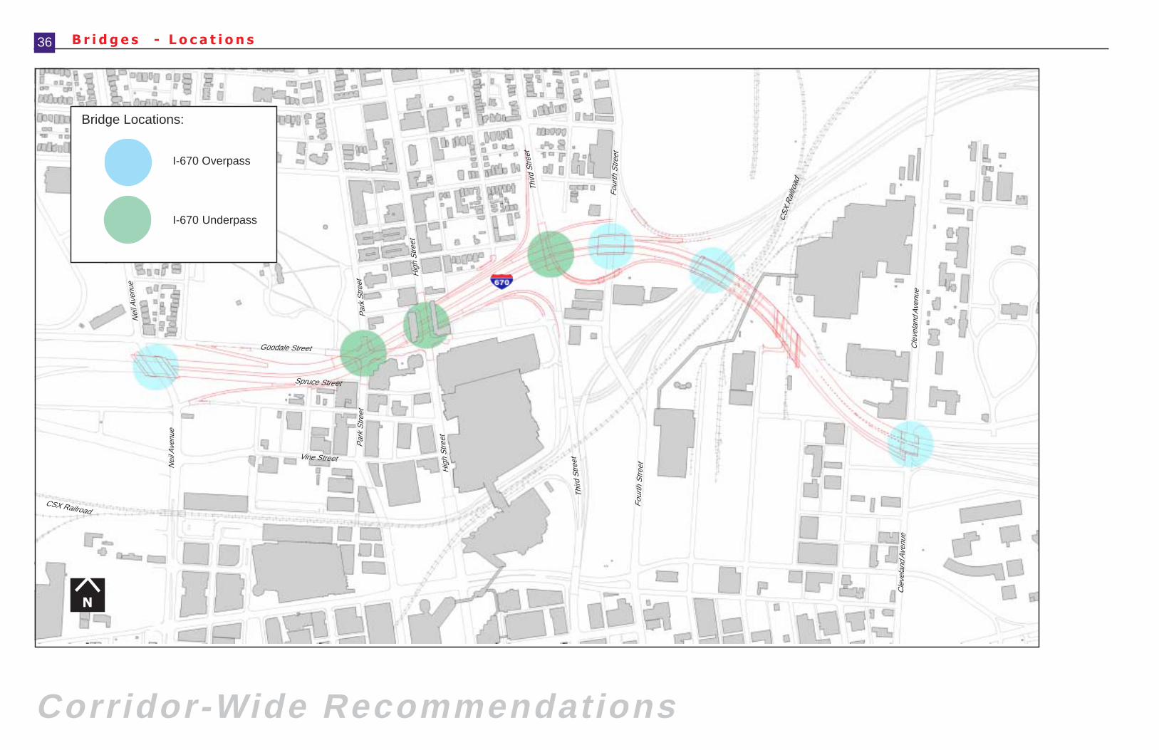
B r i d g e s - L o c a t i o n s
Corridor-Wide Recommendations
36
Bridge Locations:
N
I-670 Overpass
I-670 Underpass
Cle
vela
nd A
venu
e
Goodale Street
Nei
l Ave
nue
Par
k S
treet
Hig
h S
treet
Nei
l Ave
nue
Par
k S
treet
Cle
vela
nd A
venu
e
Third
Stre
et
Four
th S
treet
CS
X R
ailro
ad
Hig
h S
treet
Third
Stre
et
Four
th S
treet
CSX Railroad
Vine Street
Spruce Street
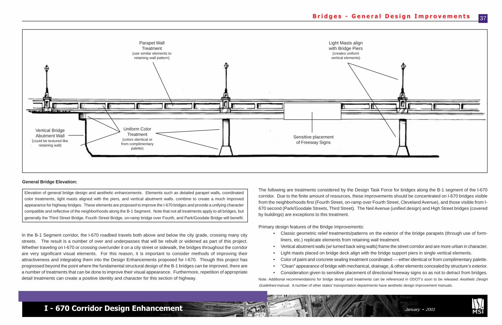
I - 670 Corridor Design Enhancement January • 2001
B r i d g e s - G e n e r a l D e s i g n I m p r o v e m e n t s 37
Elevation of general bridge design and aesthetic enhancements. Elements such as detailed parapet walls, coordinated
color treatments, light masts aligned with the piers, and vertical abutment walls. combine to create a much improved
appearance for highway bridges. These elements are proposed to improve the I-670 bridges and provide a unifying character
compatible and reflective of the neighborhoods along the B-1 Segment. Note that not all treatments apply to all bridges, but
generally the Third Street Bridge, Fourth Street Bridge, on-ramp bridge over Fourth, and Park/Goodale Bridge will benefit.
General Bridge Elevation:
In the B-1 Segment corridor, the I-670 roadbed travels both above and below the city grade, crossing many citystreets. The result is a number of over and underpasses that will be rebuilt or widened as part of this project.Whether traveling on I-670 or crossing over/under it on a city street or sidewalk, the bridges throughout the corridorare very significant visual elements. For this reason, it is important to consider methods of improving theirattractiveness and integrating them into the Design Enhancements proposed for I-670. Though this project hasprogressed beyond the point where the fundamental structural design of the B-1 bridges can be improved, there area number of treatments that can be done to improve their visual appearance. Furthermore, repetition of appropriatedetail treatments can create a positive identity and character for this section of highway.
The following are treatments considered by the Design Task Force for bridges along the B-1 segment of the I-670corridor. Due to the finite amount of resources, these improvements should be concentrated on I-670 bridges visiblefrom the neighborhoods first (Fourth Street, on-ramp over Fourth Street, Cleveland Avenue), and those visible from I-670 second (Park/Goodale Streets, Third Street). The Neil Avenue (unified design) and High Street bridges (coveredby buildings) are exceptions to this treatment.
Primary design features of the Bridge Improvements:• Classic geometric relief treatments/patterns on the exterior of the bridge parapets (through use of form-
liners, etc.) replicate elements from retaining wall treatment.
• Vertical abutment walls (w/ turned back wing walls) frame the street corridor and are more urban in character.
• Light masts placed on bridge deck align with the bridge support piers in single vertical elements.• Color of paint and concrete sealing treatment coordinated — either identical or from complimentary palette.
• “Clean” appearance of bridge with mechanical, drainage, & other elements concealed by structure’s exterior.
• Consideration given to sensitive placement of directional freeway signs so as not to detract from bridges.Note: Additional recommendations for bridge design and treatments can be referenced in ODOT’s soon to be released Aesthetic Design
Guidelines manual. A number of other states’ transportation departments have aesthetic design improvement manuals.
Vertical BridgeAbutment Wall
(could be textured likeretaining wall)
Light Masts alignwith Bridge Piers
(creates uniformvertical elements)
Parapet WallTreatment
(use similar elements toretaining wall pattern)
Uniform ColorTreatment
(colors identical orfrom complimentary
palette)
Sensitive placementof Freeway Signs
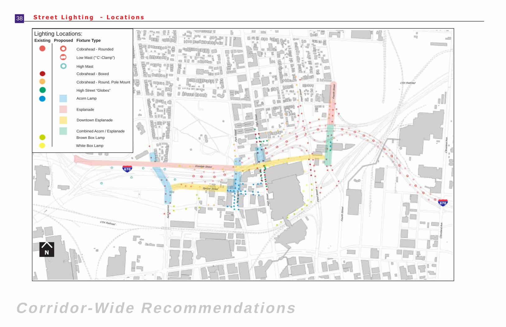
S t r e e t L i g h t i n g - L o c a t i o n s
Corridor-Wide Recommendations
38
Cle
vela
nd A
ve.
Goodale Street
Par
k S
treet
Hig
h S
treet
Nei
l Ave
nue
Fron
t Stre
et
Cle
vela
nd A
ve.
Third
Stre
et
Four
th S
treet
CSX Railroad
Hig
h S
treet
Third
Stre
et
Four
th S
treet
CSX Railroad
Spruce Street
N
Cobrahead - Rounded
Cobrahead - Round, Pole Mount
High Street “Globes”
Acorn Lamp
Esplanade
Cobrahead - Boxed
Low Mast (“‘C’-Clamp”)
High Mast
Existing Proposed Fixture Type
Lighting Locations:
Downtown Esplanade
White Box Lamp
Brown Box Lamp
Combined Acorn / Esplanade
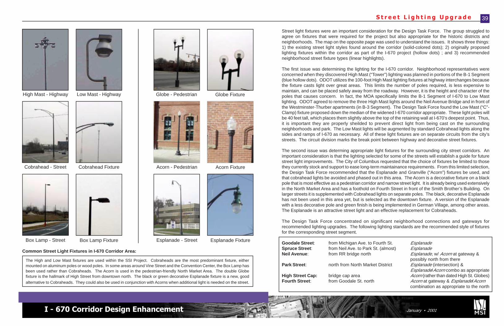
I - 670 Corridor Design Enhancement January • 2001
S t r e e t L i g h t i n g U p g r a d e
Street light fixtures were an important consideration for the Design Task Force. The group struggled toagree on fixtures that were required for the project but also appropriate for the historic districts andneighborhoods. The map on the opposite page was used to understand the issues. It shows three things:1) the existing street light styles found around the corridor (solid-colored dots); 2) originally proposedlighting fixtures within the corridor as part of the I-670 project (hollow dots) ; and 3) recommendedneighborhood street fixture types (linear highlights).
The first issue was determining the lighting for the I-670 corridor. Neighborhood representatives wereconcerned when they discovered High Mast (“Tower”) lighting was planned in portions of the B-1 Segment(blue hollow dots). ODOT utilizes the 100-foot High Mast lighting fixtures at highway interchanges becausethe fixture casts light over great areas. This limits the number of poles required, is less expensive tomaintain, and can be placed safely away from the roadway. However, it is the height and character of thepoles that causes concern. In fact, the MOA specifically limits the B-1 Segment of I-670 to Low Mastlighting. ODOT agreed to remove the three High Mast lights around the Neil Avenue Bridge and in front ofthe Westminster-Thurber apartments (in B-3 Segment). The Design Task Force found the Low Mast (“C”-Clamp) fixture proposed down the median of the widened I-670 corridor appropriate. These light poles willbe 40 feet tall, which places them slightly above the top of the retaining wall at I-670’s deepest point. Thus,it is important they are properly sheilded to prevent direct light from being cast on the surroundingneighborhoods and park. The Low Mast lights will be augmented by standard Cobrahead lights along thesides and ramps of I-670 as necessary. All of these light fixtures are on separate circuits from the city’sstreets. The circuit division marks the break point between highway and decorative street fixtures.
The second issue was determing appropriate light fixtures for the surrounding city street corridors. Animportant consideration is that the lighting selected for some of the streets will establish a guide for futurestreet light improvements. The City of Columbus requested that the choice of fixtures be limited to thosethey currently stock and support to ease long-term maintainance requirements. From this limited selection,the Design Task Force recommended that the Esplanade and Granville (“Acorn”) fixtures be used, andthat cobrahead lights be avoided and phased out in this area. The Acorn is a decorative fixture on a blackpole that is most effective as a pedestrian corridor and narrow street light. It is already being used extensivelyin the North Market Area and has a foothold on Fourth Street in front of the Smith Brother’s Building. Onlarger streets it is supplemented with Cobrahead lights on separate poles. The black, decorative Esplanadehas not been used in this area yet, but is selected as the downtown fixture. A version of the Esplanadewith a less decorative pole and green finish is being implemented in German Village, among other areas.The Esplanade is an attractive street light and an effective replacement for Cobraheads.
The Design Task Force concentrated on significant neighborhood connections and gateways forrecommended lighting upgrades. The following lighting standards are the recommended style of fixturesfor the corresponding street segment.
Goodale Street: from Michigan Ave. to Fourth St. EsplanadeSpruce Street: from Neil Ave. to Park St. (almost) EsplanadeNeil Avenue: from RR bridge north Esplanade, w/ Acorn at gateway &
possibly north from therePark Street: north from North Market District Esplanade (intersection) &
Esplanade/Acorn combo as appropriateHigh Street Cap: bridge cap area Acorn (rather than dated High St. Globes)Fourth Street: from Goodale St. north Acorn at gateway & Esplanade/Acorn
combination as appropriate to the north
39
High Mast - Highway Low Mast - Highway
Cobrahead - Street Cobrahead Fixture
Box Lamp - Street Box Lamp Fixture
Acorn - Pedestrian Acorn Fixture
Esplanade - Street Esplanade Fixture
Globe - Pedestrian Globe Fixture
The High and Low Mast fixtures are used within the SSI Project. Cobraheads are the most predominant fixture, eithermounted on aluminum poles or wood poles. In some areas around Vine Street and the Convention Center, the Box Lamp hasbeen used rather than Cobraheads. The Acorn is used in the pedestrian-friendly North Market Area. The double Globefixture is the hallmark of High Street from downtown north. The black or green decorative Esplanade fixture is a new, goodalternative to Cobraheads. They could also be used in conjunction with Acorns when additional light is needed on the street.
Common Street Light Fixtures in I-670 Corridor Area:
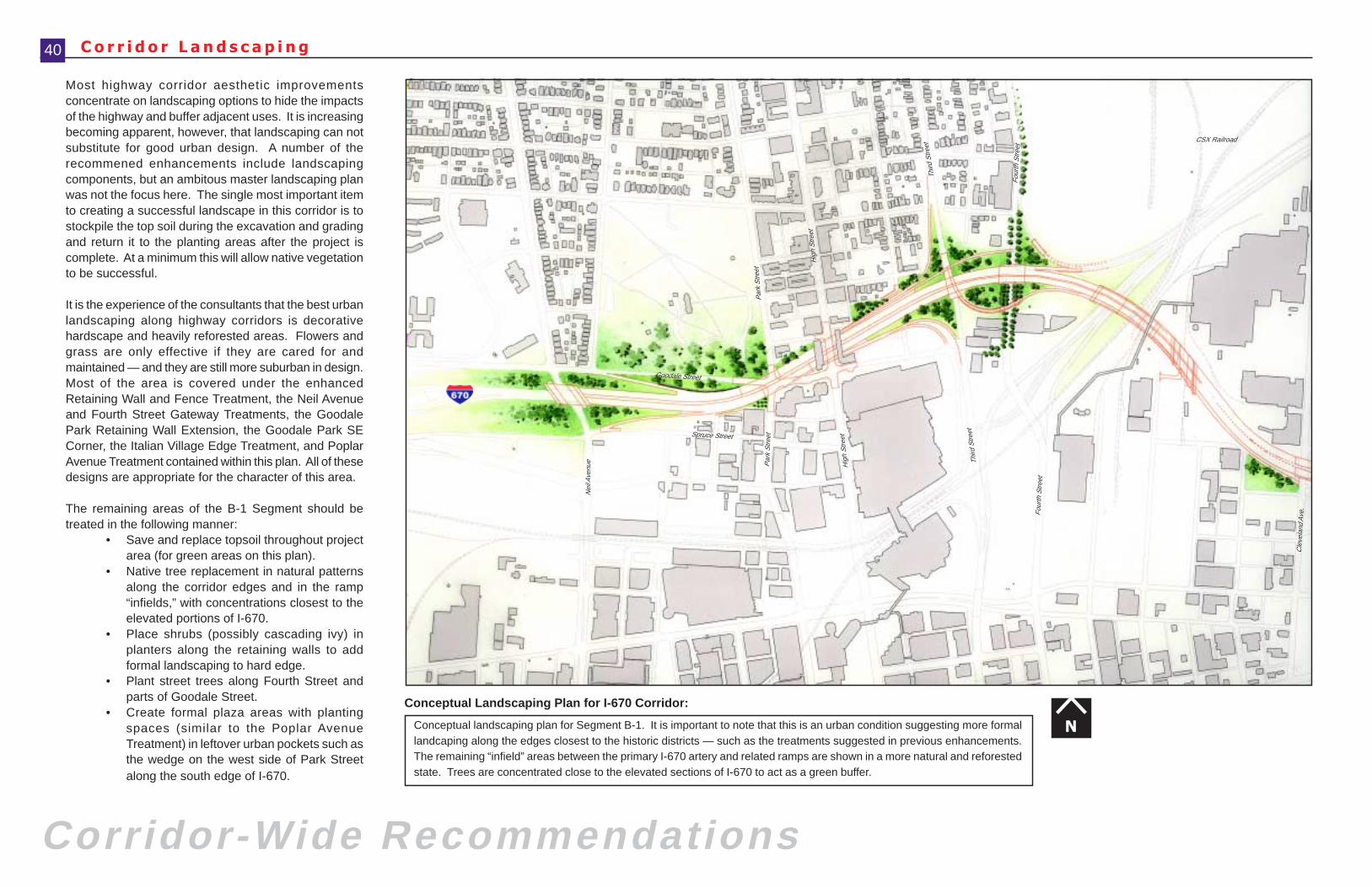
Corridor-Wide Recommendations
C o r r i d o r L a n d s c a p i n g40
Most highway corridor aesthetic improvementsconcentrate on landscaping options to hide the impactsof the highway and buffer adjacent uses. It is increasingbecoming apparent, however, that landscaping can notsubstitute for good urban design. A number of therecommened enhancements include landscapingcomponents, but an ambitous master landscaping planwas not the focus here. The single most important itemto creating a successful landscape in this corridor is tostockpile the top soil during the excavation and gradingand return it to the planting areas after the project iscomplete. At a minimum this will allow native vegetationto be successful.
It is the experience of the consultants that the best urbanlandscaping along highway corridors is decorativehardscape and heavily reforested areas. Flowers andgrass are only effective if they are cared for andmaintained — and they are still more suburban in design.Most of the area is covered under the enhancedRetaining Wall and Fence Treatment, the Neil Avenueand Fourth Street Gateway Treatments, the GoodalePark Retaining Wall Extension, the Goodale Park SECorner, the Italian Village Edge Treatment, and PoplarAvenue Treatment contained within this plan. All of thesedesigns are appropriate for the character of this area.
The remaining areas of the B-1 Segment should betreated in the following manner:
• Save and replace topsoil throughout projectarea (for green areas on this plan).
• Native tree replacement in natural patternsalong the corridor edges and in the ramp“infields,” with concentrations closest to theelevated portions of I-670.
• Place shrubs (possibly cascading ivy) inplanters along the retaining walls to addformal landscaping to hard edge.
• Plant street trees along Fourth Street andparts of Goodale Street.
• Create formal plaza areas with plantingspaces (similar to the Poplar AvenueTreatment) in leftover urban pockets such asthe wedge on the west side of Park Streetalong the south edge of I-670.
Conceptual landscaping plan for Segment B-1. It is important to note that this is an urban condition suggesting more formallandcaping along the edges closest to the historic districts — such as the treatments suggested in previous enhancements.The remaining “infield” areas between the primary I-670 artery and related ramps are shown in a more natural and reforestedstate. Trees are concentrated close to the elevated sections of I-670 to act as a green buffer.
Conceptual Landscaping Plan for I-670 Corridor:
N
Goodale Street
Par
k S
treet
Hig
h S
treet
Nei
l Ave
nue Par
k S
treet
Cle
vela
nd A
ve.
Third
Stre
et
Four
th S
treet
CSX Railroad
Hig
h S
treet
Third
Stre
et
Four
th S
treet
Spruce Street
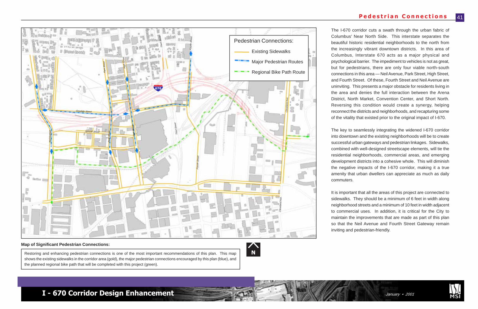
I - 670 Corridor Design Enhancement January • 2001
P e d e s t r i a n C o n n e c t i o n s 41
The I-670 corridor cuts a swath through the urban fabric of
Columbus’ Near North Side. This interstate separates the
beautiful historic residential neighborhoods to the north from
the increasingly vibrant downtown districts. In this area of
Columbus, Interstate 670 acts as a major physical and
psychological barrier. The impediment to vehicles is not as great,
but for pedestrians, there are only four viable north-southconnections in this area — Neil Avenue, Park Street, High Street,
and Fourth Street. Of these, Fourth Street and Neil Avenue are
uninviting. This presents a major obstacle for residents living in
the area and denies the full interaction between the Arena
District, North Market, Convention Center, and Short North.
Reversing this condition would create a synergy, helping
reconnect the districts and neighborhoods, and recapturing some
of the vitality that existed prior to the original impact of I-670.
The key to seamlessly integrating the widened I-670 corridor
into downtown and the existing neighborhoods will be to create
successful urban gateways and pedestrian linkages. Sidewalks,
combined with well-designed streetscape elements, will tie the
residential neighborhoods, commercial areas, and emerging
development districts into a cohesive whole. This will diminish
the negative impacts of the I-670 corridor, making it a true
amenity that urban dwellers can appreciate as much as dailycommuters.
It is important that all the areas of this project are connected to
sidewalks. They should be a minimum of 6 feet in width along
neighborhood streets and a minimum of 10 feet in width adjacent
to commercial uses. In addition, it is critical for the City to
maintain the improvements that are made as part of this plan
so that the Neil Avenue and Fourth Street Gateway remain
inviting and pedestrian-friendly.
Restoring and enhancing pedestrian connections is one of the most important recommendations of this plan. This mapshows the existing sidewalks in the corridor area (gold), the major pedestrian connections encouraged by this plan (blue), andthe planned regional bike path that will be completed with this project (green).
Map of Significant Pedestrian Connections:
N
Pedestrian Connections:
Existing Sidewalks
Major Pedestrian Routes
Regional Bike Path Route
Cle
vela
nd A
ve.
Goodale Street
Par
k S
treet
Hig
h S
treet
Nei
l Ave
nue
Par
k S
treet
Cle
vela
nd A
ve.
Third
Stre
et
Four
th S
treet
Hig
h S
treet
Third
Stre
et
Four
th S
treet
Spruce Street
Design Task Force Priorities
P r o j e c t P r i o r i t i z a t i o n L i s t44
On November 7th, 2000, the Design Task Force met to prioritze the design enhancementrecommendations. The City of Columbus’ preliminary budget for the project was $4 million. Thisbudget for the design enhancements/project mitigation was the extra dollars above the estimatedcost of the B-1 Segment construction cost that the City of Columbus set aside for the project. Thismoney would go toward the incremental cost difference between what was originally planned andwhat is recommended by the Task Force. In otherwords, if the original plan called for a chain-linkfence and this plan calls for a wrought-iron fence upgrade, it is the difference in cost between thechain-link and the upgrade that is deducted from the enhancement budget. The Task Force wasgiven incremental cost estimates for each of the design enhancements detailed in the plan. Theestimates were placed in ranges with a high and low cost. This was done to emphasize theconceptual nature of the estimates, as no actual design development or detailed engineering hasbeen performed. These estimates are based on experience and projects with similar elements.The estimated incremental cost total of all the design enhancement recommendations was be-tween $5.4 million and $7.1 million. It was pointed out to the group that almost half the enhance-ments were not dependent on the I-670 construction project or schedule to be completed. In otherwords, items like the Goodale Park Corner Treatment, the Italian Village Edge Treatment, theFourth Street Gateway Treatment, the Neil Avenue Gateway Treatment, the Poplar Avenue Treat-ment, and the Improved I-670 Corridor Landscaping can all be accomplished even after the SSIProject is complete. Improvements such as the Neil Avenue Bridge, Goodale Park Retaining WallExtension, Fencing/Lighting/Wall/Bridge Upgrades, Park/Goodale Bridge Treatment, and High StreetCap extension must all be done as part of the construction project or the opportunity will be lost.
With these costs presented, the Design Task Force was asked to prioritize the recommendations.Using a nominal group technique method, each member of the Design Task Force that was not agovernment agency was given twelve votes to distribute among the sixteen enhancements as theywished. The groups that voted were: the Victorian Village Society, the Italian Village Society,Dennison Place Association, Harrison West Society, Citizens for a Better Spring-Sandusky, andFriends of Goodale Park. This made a total of six groups and 72 total votes. The results aresummarized on the facing page (pg. 45), in order of most votes to least. The general concept wasthat the highest priority projects would be funded within the constraint of the total available funding.
The results are telling. The Design Task Force clearly prioritized elements that must be accomplishedas part of the SSI Project, except for the Goodale Park Southeast Corner Treatment. The threeenhancements tied with the most votes (nine each) were the Neil Avenue Bridge, the Goodale ParkRetaining Wall Extension, and the Retaining Wall Treatment. Finishing a close second were theFencing Upgrade and the Lighting Upgrade, with eight votes each. Following in decending orderwere the Goodale Park Corner Treatment (7), High Street Cap Extension (6), General BridgeEnhancement (5), the Italian Village Edge Treatment (4), the Fourth Street Gateway Treatment (4),Neil Avenue Gateway Treatment (2), and Park Street Cap General Improvements (1). The otherPark/Goodale Cap Concepts, Poplar Avenue Treatment, and I-670 Corridor Landscaping receivedzero votes. This does not necessarily indicate a complete lack of interest in these improvements,
however. The Task Force realized that a base level of landscaping is already part of the projectand that the brick on Poplar Avenue that is disturbed must be replaced. The wall and fence im-provement components are covered under separate enhancements. Thus only the alley connec-tion, plaza focal point, and tree and green edge plantings remain to be “funded.” For the most part,these could be completed in the future. The general Park/Goodale Cap Treatment consisting ofwider sidewalks was made part of the base plan and approval of the fence upgrade improved thefences on the bridge as well. It was apparent, however, that there was some confusion on thealternate Park/Goodale Bridge Cap concepts. Concept “C,” the cap extension, only makes theexpansion of the building possible, but does not treat the plaza spaces beyond basic seating andhardscape. There might have been a few votes for Concept “A” if that had been better understood.
What the SSI Design Task Force has accomplished is impressive. An extremely diverse group ofinterests have come together, at a very late stage in the process, and agreed upon ways to improvethe design of a highway project for the betterment of the community. All parties have been willingto negotiate and work in good faith. This positive experience should be an inspiration for all involvedto continue to strive for improvement in one’s surroundings. The members of the Design TaskForce will experience the fruits of this labor when they see how much residents of and visitors tothese neighborhoods enjoy the positive impact these improvements make on the historiccommunities.
D e s i g n T a s k F o r c e P r i o r i t i e s
C o n c l u s i o n
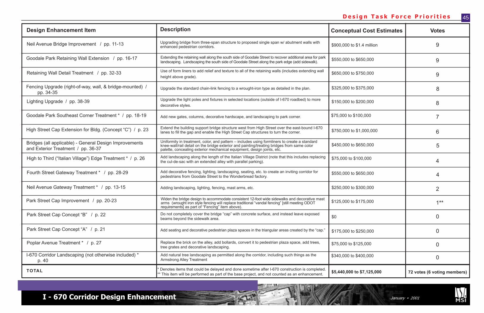
I - 670 Corridor Design Enhancement January • 2001
D e s i g n T a s k F o r c e P r i o r i t i e s 45
Neil Avenue Bridge Improvement / pp. 11-13
Goodale Park Retaining Wall Extension / pp. 16-17
Retaining Wall Detail Treatment / pp. 32-33
Fencing Upgrade (right-of-way, wall, & bridge-mounted) /pp. 34-35
Lighting Upgrade / pp. 38-39
Goodale Park Southeast Corner Treatment * / pp. 18-19
High Street Cap Extension for Bldg. (Concept “C”) / p. 23
Bridges (all applicable) - General Design Improvementsand Exterior Treatment / pp. 36-37
High to Third (“Italian Village”) Edge Treatment * / p. 26
Fourth Street Gateway Treatment * / pp. 28-29
Neil Avenue Gateway Treatment * / pp. 13-15
Park Street Cap Improvement / pp. 20-23
Park Street Cap Concept “B” / p. 22
Park Street Cap Concept “A” / p. 21
Poplar Avenue Treatment * / p. 27
I-670 Corridor Landscaping (not otherwise included) *p. 40
Design Enhancement Item Description
Upgrading bridge from three-span structure to proposed single span w/ abutment walls withenhanced pedestrian corridors.
Extending the retaining wall along the south side of Goodale Street to recover additional area for parklandscaping. Landscaping the south side of Goodale Street along the park edge (add sidewalk).
Use of form liners to add relief and texture to all of the retaining walls (includes extending wall
height above grade).
Upgrade the standard chain-link fencing to a wrought-iron type as detailed in the plan.
Upgrade the light poles and fixtures in selected locations (outside of I-670 roadbed) to more
decorative styles.
Add new gates, columns, decorative hardscape, and landscaping to park corner.
Extend the building support bridge structure west from High Street over the east-bound I-670lanes to fill the gap and enable the High Street Cap structures to turn the corner.
Uniformity in treatment, color, and pattern – includes using formliners to create a standardknee-wall/rail detail on the bridge exterior and painting/treating bridges from same colorpalette, concealing exterior mechanical equipment, design joints, etc.
Add landscaping along the length of the Italian Village District (note that this includes replacingthe cul-de-sac with an extended alley with parallel parking).
Add decorative fencing, lighting, landscaping, seating, etc. to create an inviting corridor forpedestrians from Goodale Street to the Wonderbread factory.
Adding landscaping, lighting, fencing, mast arms, etc.
Widen the bridge design to accommodate consistent 12-foot wide sidewalks and decorative mastarms (wrought iron style fencing will replace traditional “vandal fencing” [still meeting ODOTrequirements] as part of “Fencing” item above).
Do not completely cover the bridge “cap” with concrete surface, and instead leave exposedbeams beyond the sidewalk area.
Add seating and decorative pedestrian plaza spaces in the triangular areas created by the “cap.”
Replace the brick on the alley, add bollards, convert it to pedestrian plaza space, add trees,tree grates and decorative landscaping.
Add natural tree landscaping as permitted along the corridor, including such things as theArmstrong Alley Treatment
Conceptual Cost Estimates Votes
$900,000 to $1.4 million
$550,000 to $650,000
$650,000 to $750,000
$325,000 to $375,000
$150,000 to $200,000
$75,000 to $100,000
$750,000 to $1,000,000
$450,000 to $650,000
$75,000 to $100,000
$550,000 to $650,000
$250,000 to $300,000
$125,000 to $175,000
$0
$175,000 to $250,000
$75,000 to $125,000
$340,000 to $400,000
9
9
9
8
8
7
6
5
4
4
2
1
0
0
0
0
TOTAL $5,440,000 to $7,125,000 72 votes (6 voting members)* Denotes items that could be delayed and done sometime after I-670 construction is completed.
**
** This item will be performed as part of the base project, and not counted as an enhancement.

Appendix
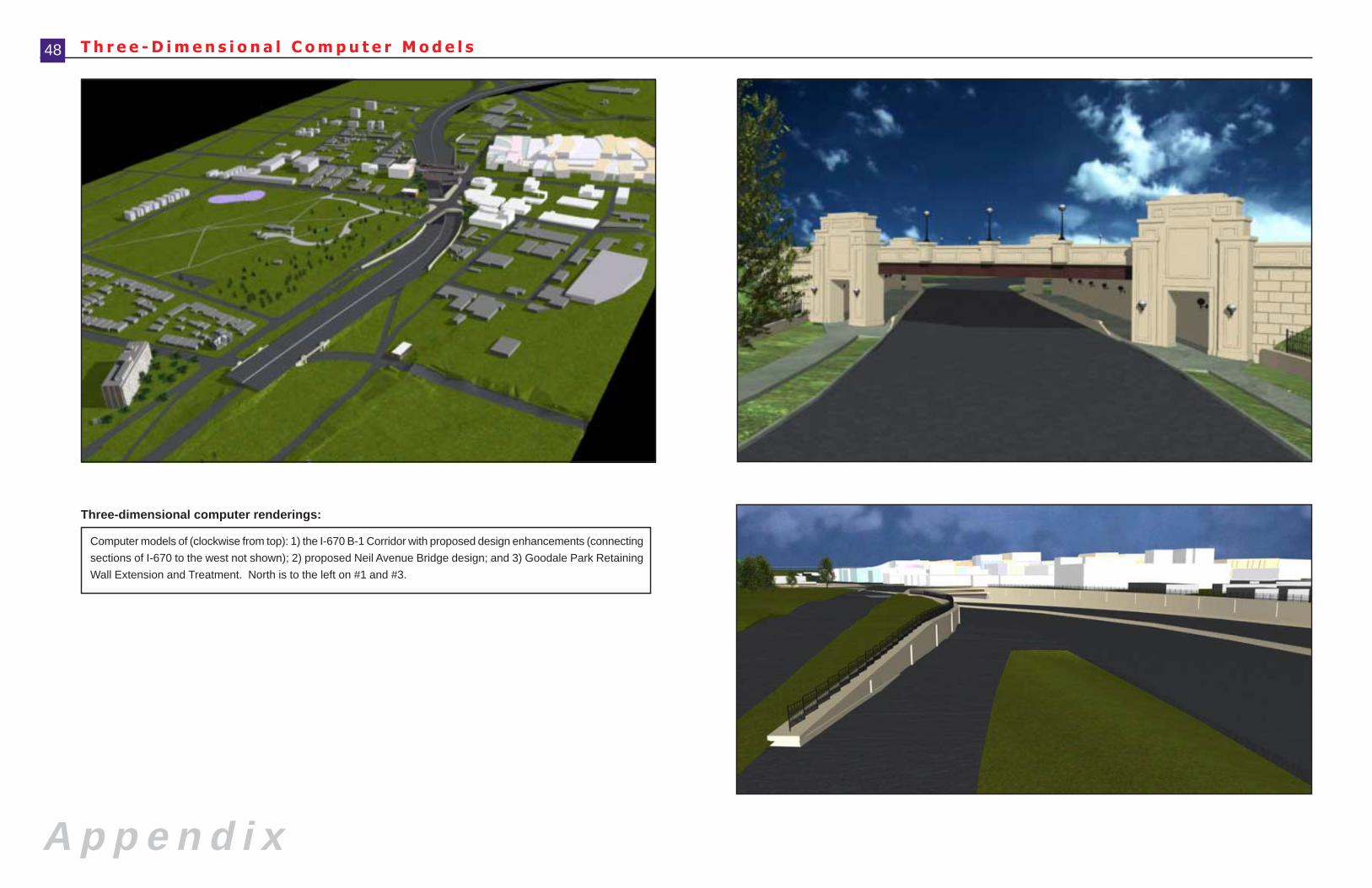
A p p e n d i x
48 T h r e e - D i m e n s i o n a l C o m p u t e r M o d e l s
Computer models of (clockwise from top): 1) the I-670 B-1 Corridor with proposed design enhancements (connecting
sections of I-670 to the west not shown); 2) proposed Neil Avenue Bridge design; and 3) Goodale Park Retaining
Wall Extension and Treatment. North is to the left on #1 and #3.
Three-dimensional computer renderings:
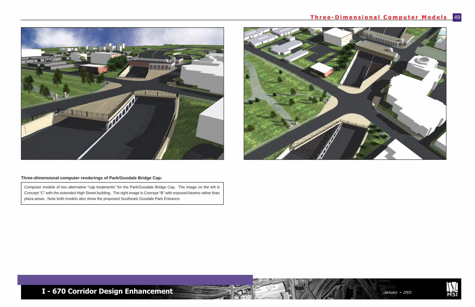
I - 670 Corridor Design Enhancement January • 2001
49T h r e e - D i m e n s i o n a l C o m p u t e r M o d e l s
Computer models of two alternative “cap treatments” for the Park/Goodale Bridge Cap. The image on the left is
Concept “C” with the extended High Street building. The right image is Concept “B” with exposed beams rather than
plaza areas. Note both models also show the proposed Southeast Goodale Park Entrance.
Three-dimensional computer renderings of Park/Goodale Bridge Cap:
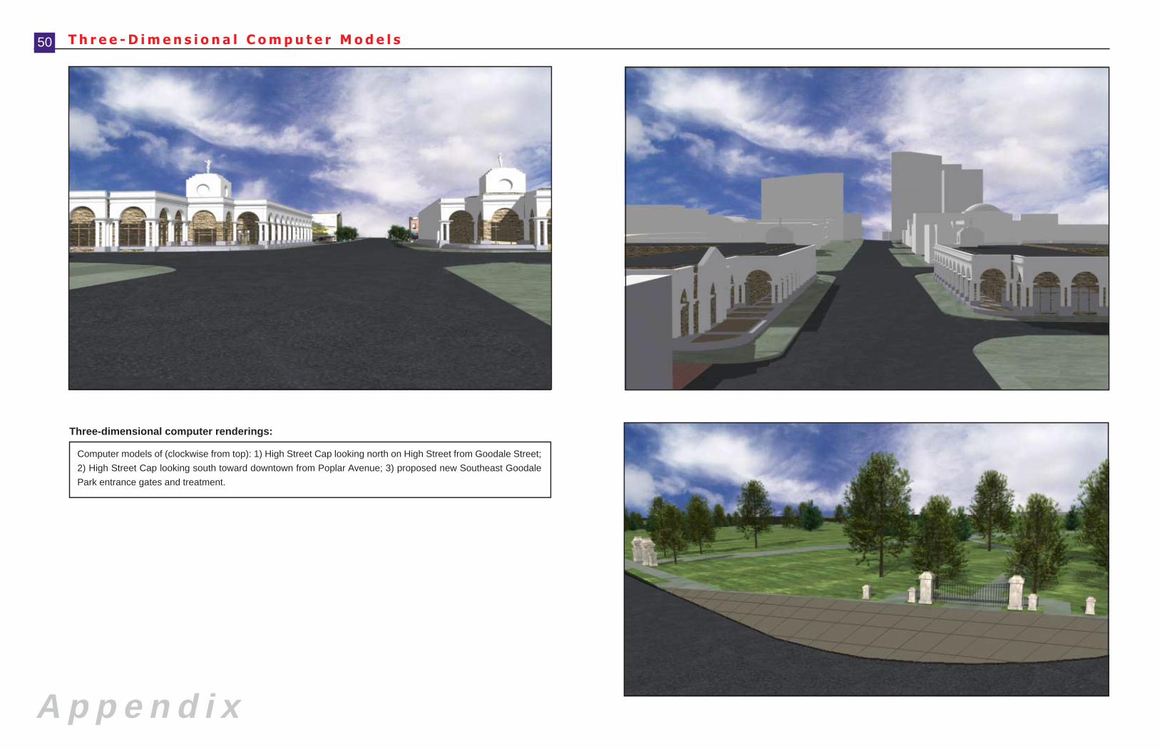
A p p e n d i x
50 T h r e e - D i m e n s i o n a l C o m p u t e r M o d e l s
Computer models of (clockwise from top): 1) High Street Cap looking north on High Street from Goodale Street;
2) High Street Cap looking south toward downtown from Poplar Avenue; 3) proposed new Southeast Goodale
Park entrance gates and treatment.
Three-dimensional computer renderings:
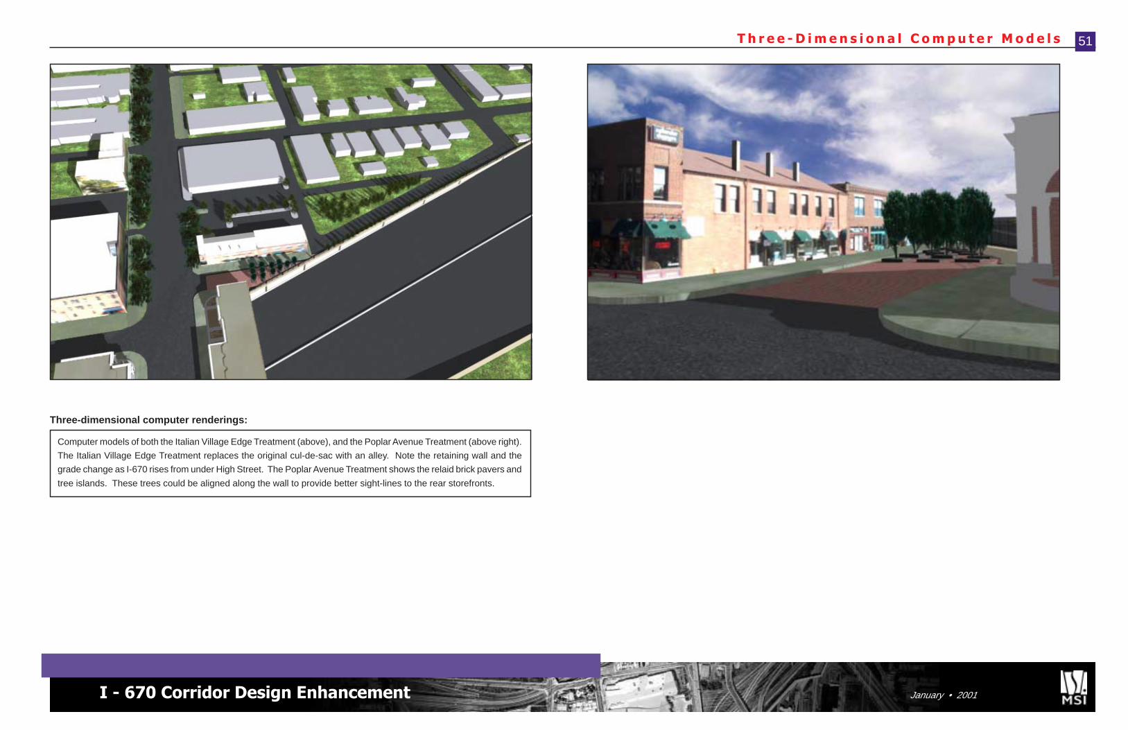
I - 670 Corridor Design Enhancement January • 2001
51T h r e e - D i m e n s i o n a l C o m p u t e r M o d e l s
Computer models of both the Italian Village Edge Treatment (above), and the Poplar Avenue Treatment (above right).
The Italian Village Edge Treatment replaces the original cul-de-sac with an alley. Note the retaining wall and the
grade change as I-670 rises from under High Street. The Poplar Avenue Treatment shows the relaid brick pavers and
tree islands. These trees could be aligned along the wall to provide better sight-lines to the rear storefronts.
Three-dimensional computer renderings:

A p p e n d i x
N e i l A v e n u e B r i d g e C o n c e p t s52
Conceptual renderings of various architectural treatments for the Neil Avenue Bridge.
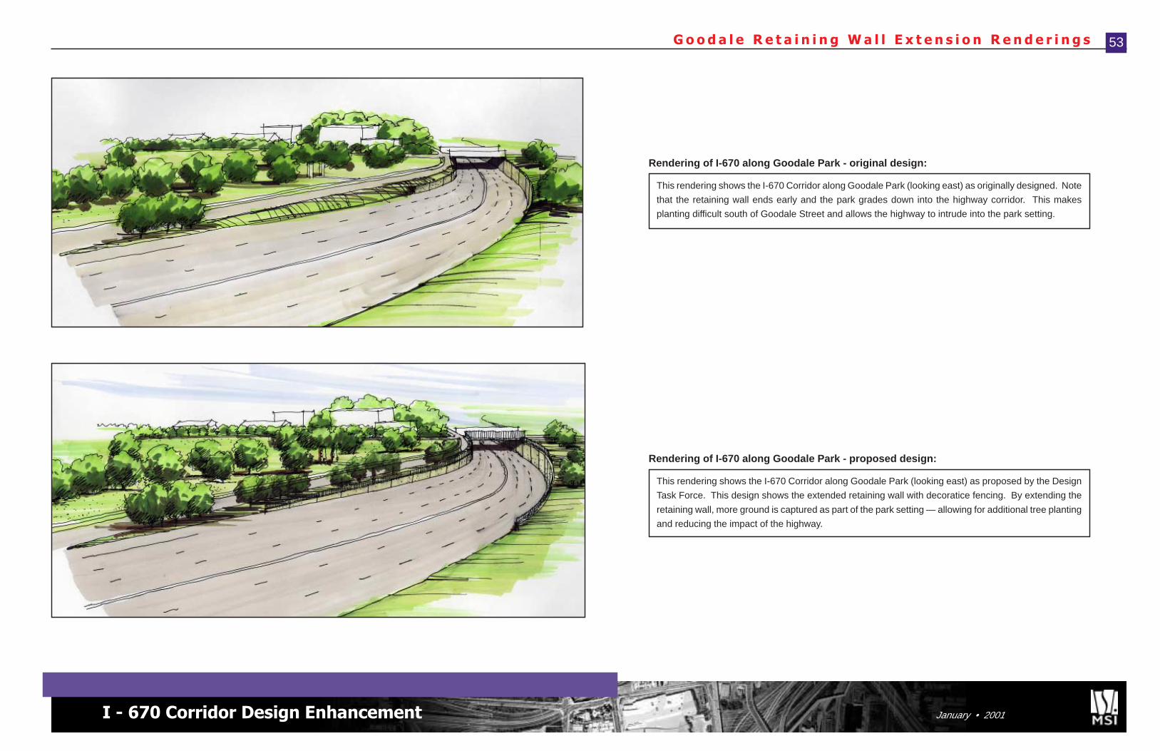
I - 670 Corridor Design Enhancement January • 2001
53G o o d a l e R e t a i n i n g W a l l E x t e n s i o n R e n d e r i n g s
This rendering shows the I-670 Corridor along Goodale Park (looking east) as originally designed. Note
that the retaining wall ends early and the park grades down into the highway corridor. This makes
planting difficult south of Goodale Street and allows the highway to intrude into the park setting.
Rendering of I-670 along Goodale Park - original design:
This rendering shows the I-670 Corridor along Goodale Park (looking east) as proposed by the Design
Task Force. This design shows the extended retaining wall with decoratice fencing. By extending the
retaining wall, more ground is captured as part of the park setting — allowing for additional tree planting
and reducing the impact of the highway.
Rendering of I-670 along Goodale Park - proposed design:
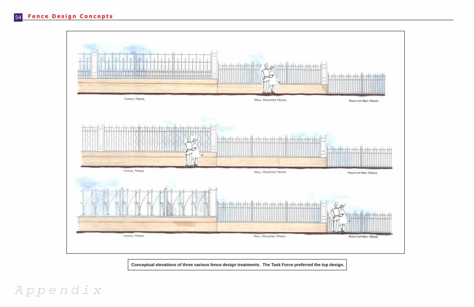
A p p e n d i x
54 F e n c e D e s i g n C o n c e p t s
Conceptual elevations of three various fence design treatments. The Task Force preferred the top design.
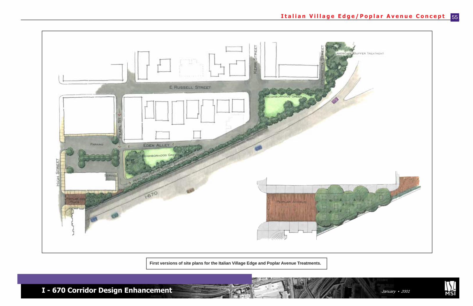
I - 670 Corridor Design Enhancement January • 2001
55I t a l i a n V i l l a g e E d g e / P o p l a r A v e n u e C o n c e p t
First versions of site plans for the Italian Village Edge and Poplar Avenue Treatments.
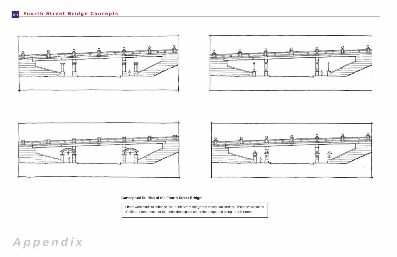
A p p e n d i x
F o u r t h S t r e e t B r i d g e C o n c e p t s56
Conceptual Studies of the Fourth Street Bridge:
Efforts were made to enhance the Fourth Street Bridge and pedestrian corridor. These are sketches
of different treatments for the pedestrian space under the bridge and along Fourth Street.
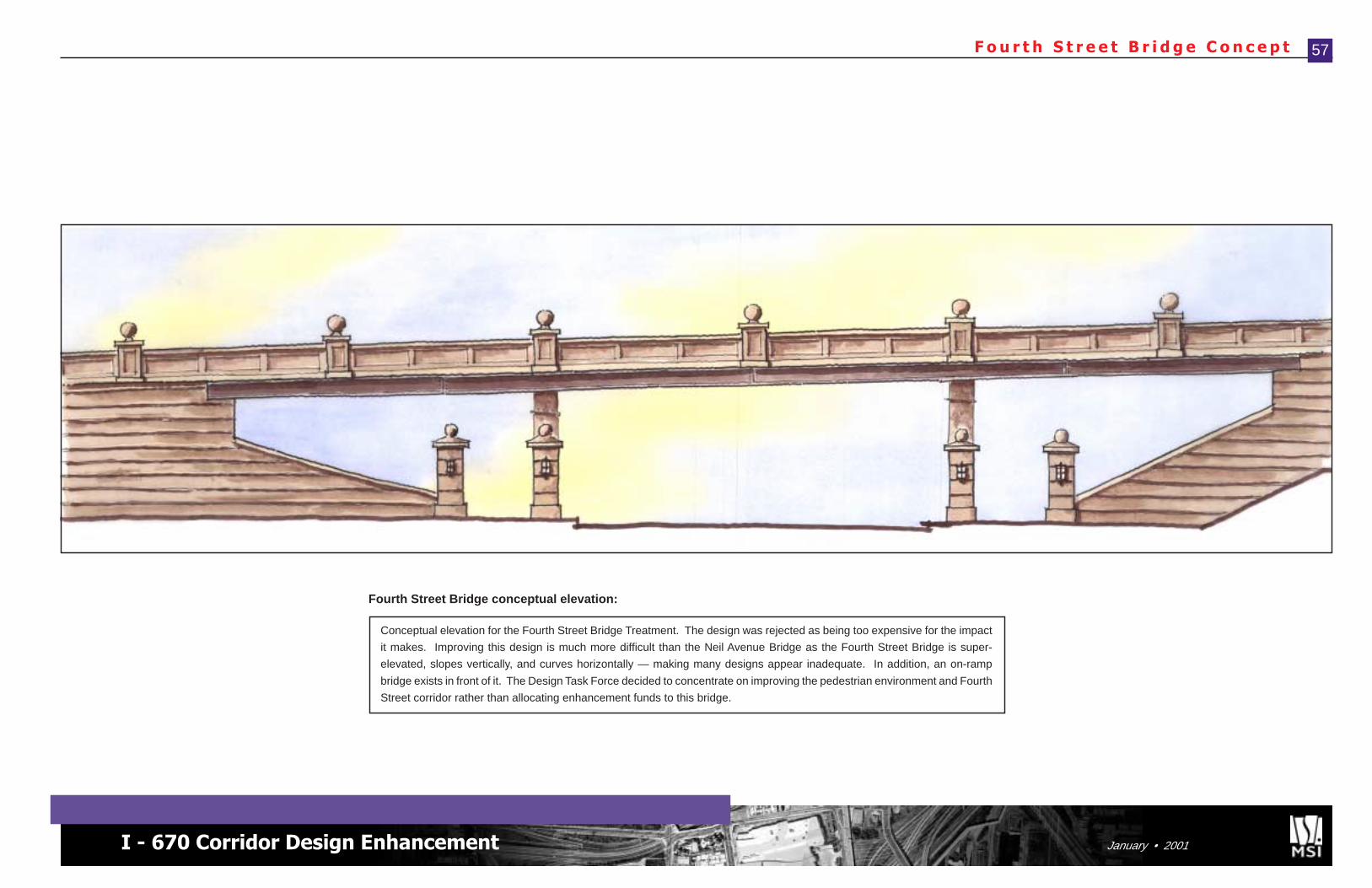
I - 670 Corridor Design Enhancement January • 2001
F o u r t h S t r e e t B r i d g e C o n c e p t 57
Fourth Street Bridge conceptual elevation:
Conceptual elevation for the Fourth Street Bridge Treatment. The design was rejected as being too expensive for the impact
it makes. Improving this design is much more difficult than the Neil Avenue Bridge as the Fourth Street Bridge is super-
elevated, slopes vertically, and curves horizontally — making many designs appear inadequate. In addition, an on-ramp
bridge exists in front of it. The Design Task Force decided to concentrate on improving the pedestrian environment and Fourth
Street corridor rather than allocating enhancement funds to this bridge.
This project is not about building a roadconnecting cities -- this is about building a roadthrough a city. Building a road between citiesis a simple engineering problem. Building aroad within a city becomes an urban designissue as well, which makes the project muchmore difficult, but also much more important.