Embed Size (px)
Citation preview
18 November 2015 1081160 - Cool Down Timer 2 (I-00005) Page 1
BD Engine Brake Inc. Plant Address: 33541 MacLure Rd. Abbotsford, BC, Canada V2S 7W2
U.S. Shipping Address: 88-446 Harrison St, Sumas, WA 98295 U.S. Mailing Address: P.O. Box 231, Sumas, WA 98295 Phone: 604-853-6096 | Fax: 604-853-8749 | Internet: www.bd-power.com
BD Cool Down Timer 2
Application Chart --
1081160
Dodge Cummins (5.9/ 6.7) 1994-2005
Ford F Series (6.0/ 6.4/ 6.7/ 7.3) 1994-2016
GMC/Chevy Duramax (6.6) 2001-2014
1081160-D1 Dodge Cummins (5.9/ 6.7) 2006-2009
1081160-D2 Dodge Cummins (6.7) 2010-2012
1081160-D3 Dodge Cummins (6.7) 2013-2016
* * * P l e a s e r e a d t h i s m a n u a l b e f o r e s t a r t i n g i n s t a l l a t i o n . * * *
OWNER’S MANUAL - LEAVE IN GLOVE BOX Install Manual Part # I1081160
Printed in Canada

18 November 2015 1081160 - Cool Down Timer 2 (I-00005) Page 2
BD Engine Brake Inc. Plant Address: 33541 MacLure Rd. Abbotsford, BC, Canada V2S 7W2
U.S. Shipping Address: 88-446 Harrison St, Sumas, WA 98295 U.S. Mailing Address: P.O. Box 231, Sumas, WA 98295 Phone: 604-853-6096 | Fax: 604-853-8749 | Internet: www.bd-power.com
T A B L E O F C O N T E N T S
Kit Contents ......................................................................................................... 3
Required Tools .............................................................................................................. 5
Options.......................................................................................................................... 5
Compatibility ................................................................................................................. 5
Notes On Connectors .......................................................................................... 5
What Is The Cool Down Timer 2 (CDT2)? ........................................................... 6
How Does The Cool Down Timer 2 Work? ......................................................... 6
Precautions .......................................................................................................... 6
Safety Features .................................................................................................... 7
Vehicle Wiring ...................................................................................................... 8
NOTES .................................................................................................................. 9
GENERAL WIRING ............................................................................................... 9
FORD POWERSTROKE WIRING DIAGRAM ..................................................... 10
DODGE CUMMINS WIRING DIAGRAM ............................................................. 13
2004½ - 2005 Dodge Trucks Wastegate Solenoid Power Wiring .................... 14
Dodge 2006-2009 ............................................................................................... 15
Dodge 2010-2012 ............................................................................................... 16
Dodge 2013-2016 ............................................................................................... 17
DURAMAX WIRING DIAGRAMS ........................................................................ 20
Thermocouple Wiring (Not needed if monitoring with Time vs. Temp) ......... 24
Direct Thermocouple Connection ................................................................................ 24
Amplified Pyrometer Gauge Kit ................................................................................... 24
Conventional Non-Amplified Pyrometer Kit ................................................................. 25
Temperature Adjustment .................................................................................. 25
Time Adjustment ................................................................................................ 26
Communication / Operation Lights .................................................................. 27
Mounting ............................................................................................................ 27
Technical Assistance ........................................................................................ 27
Wire Color Glossary .......................................................................................... 27
Troubleshooting ................................................................................................ 28

18 November 2015 1081160 - Cool Down Timer 2 (I-00005) Page 3
BD Engine Brake Inc. Plant Address: 33541 MacLure Rd. Abbotsford, BC, Canada V2S 7W2
U.S. Shipping Address: 88-446 Harrison St, Sumas, WA 98295 U.S. Mailing Address: P.O. Box 231, Sumas, WA 98295 Phone: 604-853-6096 | Fax: 604-853-8749 | Internet: www.bd-power.com
Kit Contents
Please check to make sure that you have all the parts listed in this kit before you begin to install this kit.
BD Cool Down Timer 2 (P/N# 1081160)
1801160 1801161 1300131
CDT2 Control Module CDT2 Wiring Harness Cable Tie (Medium)
Qty: 1 Qty: 1 Qty: 10
1300348 1300349 1300350 1801151
Posi-Tap Connector (18-22ga – Red in color)
Posi-Tap Connector (12-18ga – Black in color)
Posi-Tap Connector (10-12ga – Yellow in color)
Ring Connector
Qty: 5 Qty: 2 Qty: 2 Qty: 2
DODGE 2006-2009 (P/N# 1081160-D1)
1801160 1801162-1 1300348 1300131
CDT2 Control Module 2006-09 Harness Posi-Tap
Connector (Red) Cable Tie (Medium)
Qty: 1 Qty: 1 Qty: 1 Qty: 5

18 November 2015 1081160 - Cool Down Timer 2 (I-00005) Page 4
BD Engine Brake Inc. Plant Address: 33541 MacLure Rd. Abbotsford, BC, Canada V2S 7W2
U.S. Shipping Address: 88-446 Harrison St, Sumas, WA 98295 U.S. Mailing Address: P.O. Box 231, Sumas, WA 98295 Phone: 604-853-6096 | Fax: 604-853-8749 | Internet: www.bd-power.com
DODGE 2010-2012 (P/N# 1081160-D2)
1801160 1801162-2 1300131
CDT2 Control Module 2010-2012 Harness Cable Tie (Medium)
Qty: 1 Qty: 1 Qty: 5
DODGE 2013-2016 (P/N# 1081160-D3)
1801160 1801162-3 1300131 1330051
CDT2 Control Module 2013-2016 Harness Cable Tie (Medium)
Velcro (3” L)
Qty: 1 Qty: 1 Qty: 5 Qty: 2
1607313 1300348 1607317 1307310
Wire; 18GA – Lt Blue Posi-Tap
(Red) Wire; 18GA - Yellow Wire: 18GA - Red
Qty: 60” Qty: 1 Qty: 120” Qty: 120”

18 November 2015 1081160 - Cool Down Timer 2 (I-00005) Page 5
BD Engine Brake Inc. Plant Address: 33541 MacLure Rd. Abbotsford, BC, Canada V2S 7W2
U.S. Shipping Address: 88-446 Harrison St, Sumas, WA 98295 U.S. Mailing Address: P.O. Box 231, Sumas, WA 98295 Phone: 604-853-6096 | Fax: 604-853-8749 | Internet: www.bd-power.com
Required Tools Wire strippers
Wire crimpers
Small Flat Nose Screwdriver
Philips Screwdriver
Pliers (Needle / Flat Nose)
Soldering Gun (Optional)
Heat Shrink / Liquid Tape (Optional)
Options 1081151 Probe (Thermocouple) Kit
Compatibility This Cool Down Timer will work with virtually all “K” type of thermocouples offered by companies such as ISSPRO or EGT.
Notes On Connectors
The kit includes a number of Posi-Tap™ connectors (Gray or Red/Black/Green or Yellow) to tap onto OEM wiring. It is important to select the correct color of connector so that it matches the gauge of the OEM wire that it is being installed on. Using the incorrect connector could cause an inadequate connection and/or the OEM wire could be severed.
OEM Wire Posi-Tap™ Color
18-22ga Gray
12-18ga Black
10-12ga Yellow
Though these connectors offer a quicker installation, the best option would be to solder the wires and isolate the joints with heat shrink or liquid electrical tape. Proper soldering techniques should be used to ensure adequate connections.
Posi-Tap™ Connector Usage Diagram
Insert Hot Wire Tighten Strip Leads Insert & Tighten
Make sure to center the wire when tightening the pierced portion of the hot wire to make a solid connection.
The ground terminals of the vehicle’s batteries should be disconnected before performing any piercing/posi-tapping onto any ECM/PCM wire.

18 November 2015 1081160 - Cool Down Timer 2 (I-00005) Page 6
BD Engine Brake Inc. Plant Address: 33541 MacLure Rd. Abbotsford, BC, Canada V2S 7W2
U.S. Shipping Address: 88-446 Harrison St, Sumas, WA 98295 U.S. Mailing Address: P.O. Box 231, Sumas, WA 98295 Phone: 604-853-6096 | Fax: 604-853-8749 | Internet: www.bd-power.com
What Is The Cool Down Timer 2 (CDT2)?
The CDT2 is designed to keep the engine running when the ignition is turned to prevent turbocharger bearing failure that could occur when the engine is shut down and the turbocharger is still hot. The turbocharger is lubricated and cooled by the engine oil and when the engine is turned off, that oil supply is cut off. If the turbocharger is still hot at shutdown, the remaining oil in the bearing housing will overheat, causing coking of the turbocharger bearings. Over time this coking causes both premature bearing wear and reduced oiling of the bearings. Allowing the engine to idle gives the turbocharger time to cool down before stopping the supply of lubrication oil which can prolong turbocharger life. Turbochargers rotate at high speeds, often in excess of 100,000rpm under load. If the engine is shut down too quickly after use, the residual oil in the bearing housing will not be sufficient for lubrication and may cause premature bearing wear. A short period of engine idling after use will help to ensure the turbocharger has reached a minimum operating speed before shutting down.
How Does The Cool Down Timer 2 Work?
When the key is turned off, the CDT2 module will keep the power supplied to the ECM/PCM, which will in turn keep the engine running. On late model vehicles the CDT2 keeps most or all of the vehicle ignition system and accessories powered until engine shutdown, on early model vehicles only the engine will remain running. The CDT2 can shut the engine down once the exhaust temperature reaches a set temperature as this is the most effective method of determining a safe shut off point. The CDT2 can also be set to keep the engine on for a fixed time after the key is removed. The suggested shutdown exhaust temperature is below 400°F. When using the CDT2 set for exhaust temperature, the module must be connected to a thermocouple which may be purchased separately or may be connected to an existing temperature sensor already installed in the vehicle.
Precautions
The CDT2 by default will not lock the doors or set the alarm. With most vehicles, once you shut the door you can use the keyless remote or key to lock the doors. Most OEM and aftermarket alarms will have to be activated after the CDT2 has shutdown the engine. Due to the wide variety of the alarms and immobilizers, it is best to test the

18 November 2015 1081160 - Cool Down Timer 2 (I-00005) Page 7
BD Engine Brake Inc. Plant Address: 33541 MacLure Rd. Abbotsford, BC, Canada V2S 7W2
U.S. Shipping Address: 88-446 Harrison St, Sumas, WA 98295 U.S. Mailing Address: P.O. Box 231, Sumas, WA 98295 Phone: 604-853-6096 | Fax: 604-853-8749 | Internet: www.bd-power.com
system(s) thoroughly to ensure proper procedures of activation or use in conjunctions with the CDT2. The “Relay Output (NO)” and the “Relay Common” terminals can be configured to lock the doors automatically. Depending on the vehicle and the method of locking the doors you can wire either a Ground or 12V source to the “Relay Common” terminal. When the CDT2 shuts down the “Relay Common” terminal will be pulsed out to the “Relay Output (NO) terminal. See the below wiring diagram. Note BD cannot provide support on this option.
Proper parking procedures should be adhered to before leaving the vehicle including the engagement of the parking brake. Children or animals should not be left unattended in the vehicle while the CDT2 is keeping the vehicle running.
Safety Features
The CDT2 module has a few safety features built-in that the driver should be aware of. If for some reason the exhaust gas temperature does not fall below the shutdown setting within five (5) minutes from the key being turned off, the CDT2 will automatically shutdown the engine. As well if the engine starts to initiate a REGEN cycle causing the EGT’s to rise the CDT2 will shut the truck off. The CDT2 module is also designed to monitor the vehicle’s hydraulic brakes when it is connected to the brake pedal switch via the Brake Pedal terminal on the module. While the CDT2 module is keeping the engine alive (ignition key turned off and exhaust gas temperature above the shutdown setting), if the brake pedal is depressed the CDT2 will shutdown the engine. This was implemented to protect the vehicle from being stolen when the engine is in cool down mode; eventually the brake pedal would have to be pressed which will shutdown the engine preventing the thief from easily driving away with the vehicle. This is also useful in situations where the engine needs to be shutdown immediately or is desired to be shutdown sooner.

18 November 2015 1081160 - Cool Down Timer 2 (I-00005) Page 8
BD Engine Brake Inc. Plant Address: 33541 MacLure Rd. Abbotsford, BC, Canada V2S 7W2
U.S. Shipping Address: 88-446 Harrison St, Sumas, WA 98295 U.S. Mailing Address: P.O. Box 231, Sumas, WA 98295 Phone: 604-853-6096 | Fax: 604-853-8749 | Internet: www.bd-power.com
Vehicle Wiring
Using the following diagrams applicable to your vehicle, tap onto the vehicles wires using the appropriate sized Posi-Tap™ connector (not necessary if soldering the connections). All the vehicle wires are located under the dash where the module will be located. Excess wire can be trimmed but please keep in mind that the module may have to be accessed to adjust the shutdown temperature so we suggest leaving enough slack to perform this function. Connect to the appropriate terminals as per the charts and diagrams. Tighten each terminal by turning the terminal screws clockwise until the wire is secure. When connecting the wires to the module, leave enough slack so that the module can be accessed to make temperature or time adjustments.

18 November 2015 1081160 - Cool Down Timer 2 (I-00005) Page 9
BD Engine Brake Inc. Plant Address: 33541 MacLure Rd. Abbotsford, BC, Canada V2S 7W2
U.S. Shipping Address: 88-446 Harrison St, Sumas, WA 98295 U.S. Mailing Address: P.O. Box 231, Sumas, WA 98295 Phone: 604-853-6096 | Fax: 604-853-8749 | Internet: www.bd-power.com
NOTES
Please be advised that when the engine is in cool down mode (CDT2 is active) a number of trouble lights or message center errors maybe displayed. This is completely normal and should not be a concern. The vehicle will function normally once the key is inserted again.
GENERAL WIRING

18 November 2015 1081160 - Cool Down Timer 2 (I-00005) Page 10
BD Engine Brake Inc. Plant Address: 33541 MacLure Rd. Abbotsford, BC, Canada V2S 7W2
U.S. Shipping Address: 88-446 Harrison St, Sumas, WA 98295 U.S. Mailing Address: P.O. Box 231, Sumas, WA 98295 Phone: 604-853-6096 | Fax: 604-853-8749 | Internet: www.bd-power.com
FORD POWERSTROKE WIRING DIAGRAM
1994-2004 Fords 2005-2007 Fords

18 November 2015 1081160 - Cool Down Timer 2 (I-00005) Page 11
BD Engine Brake Inc. Plant Address: 33541 MacLure Rd. Abbotsford, BC, Canada V2S 7W2
U.S. Shipping Address: 88-446 Harrison St, Sumas, WA 98295 U.S. Mailing Address: P.O. Box 231, Sumas, WA 98295 Phone: 604-853-6096 | Fax: 604-853-8749 | Internet: www.bd-power.com
2008-2010 Fords

18 November 2015 1081160 - Cool Down Timer 2 (I-00005) Page 12
BD Engine Brake Inc. Plant Address: 33541 MacLure Rd. Abbotsford, BC, Canada V2S 7W2
U.S. Shipping Address: 88-446 Harrison St, Sumas, WA 98295 U.S. Mailing Address: P.O. Box 231, Sumas, WA 98295 Phone: 604-853-6096 | Fax: 604-853-8749 | Internet: www.bd-power.com
2011-2016 Connector location
Connect the black wire to a good grounding point.
Model Location OEM Wire Pin
Brake Pedal (Blue Wire)
1994-2003 7.3L
Brake Pedal Switch
LG 4
2003-2007 6.0L LG 03-05 (4)
06 (2) 07 (4)
2008-2010 6.4L VT/WH 2
2011-2016 6.7L VT/WH 4
Key (Green Wire)
1994-1997 7.3L Ignition Connector C269
BK/LG 297 A1
1999-2003 7.3L RD/BK 1040 A3
2003-2004 6.0L
Ignition Connector C250
RD/BK 1040 A3
2005-2007 6.0L RD/BK 1040 13
2008-2010 6.4L BR/YE or YE/OG 7
2011-2016 6.7L VT/GN 6
Keep Alive (Tan Wire)
1994-1997 7.3L
Ignition Switch Harness
RD/LG 16 I1
1999-2001 7.3L RD/BK 1000 I1
2002-2003 7.3L RD/LG 16 I1
2003-2004 6.0L
Ignition Connector C250
WH/YL 1044 I1
2005-2007 6.0L RD/LG 16 1
2008-2010 6.4L WH/OG 1
2011-2016 6.7L WH/OG 1
Constant (Pink Wire)
1994-2003 7.3L Ignition Switch Harness YL 37 B1 or B3
2003-2004 6.0L
Ignition Connector C250
YL 37 B1 or B3
2005-2007 6.0L YL 37 7
2007-2010 6.4L DB/RD 8
2011-2016 6.7L (Early 2011) BL/RD
4 (2011.5 - 2016) GN/RD

18 November 2015 1081160 - Cool Down Timer 2 (I-00005) Page 13
BD Engine Brake Inc. Plant Address: 33541 MacLure Rd. Abbotsford, BC, Canada V2S 7W2
U.S. Shipping Address: 88-446 Harrison St, Sumas, WA 98295 U.S. Mailing Address: P.O. Box 231, Sumas, WA 98295 Phone: 604-853-6096 | Fax: 604-853-8749 | Internet: www.bd-power.com
DODGE CUMMINS WIRING DIAGRAM
1994-2001 Dodge Ignition Switch (Steering Column)
2002-05 Dodge Ignition Switch (Steering Column)
1994-2001 Dodge Brake Pedal Switch 2002-09 Dodge Brake Pedal Switch
Model Location OEM Wire Pin # Brake Pedal (Blue Wire)
1994-2001 Brake Pedal Switch
WT/TN L50 5
2002-2009 WT/TN L50 2
Key (Green Wire)
1994-2002
Ignition Switch Harness
BK/OR A22 5
2003 BK/WT A31 9
2004-2005 PK/YL F982 9
Keep Alive (Tan Wire)
1994-2002
Ignition Switch Harness
DB A21 2
2003 DB A21 3
2004-2005 PK/LG F951 3
Constant (Pink Wire)
1994-2002
Ignition Switch Harness
RD A1 7
2003 RD A1 4
2004-2005 RD A951 4
18 November 2015 1081160 - Cool Down Timer 2 (I-00005) Page 14
BD Engine Brake Inc. Plant Address: 33541 MacLure Rd. Abbotsford, BC, Canada V2S 7W2
U.S. Shipping Address: 88-446 Harrison St, Sumas, WA 98295 U.S. Mailing Address: P.O. Box 231, Sumas, WA 98295 Phone: 604-853-6096 | Fax: 604-853-8749 | Internet: www.bd-power.com
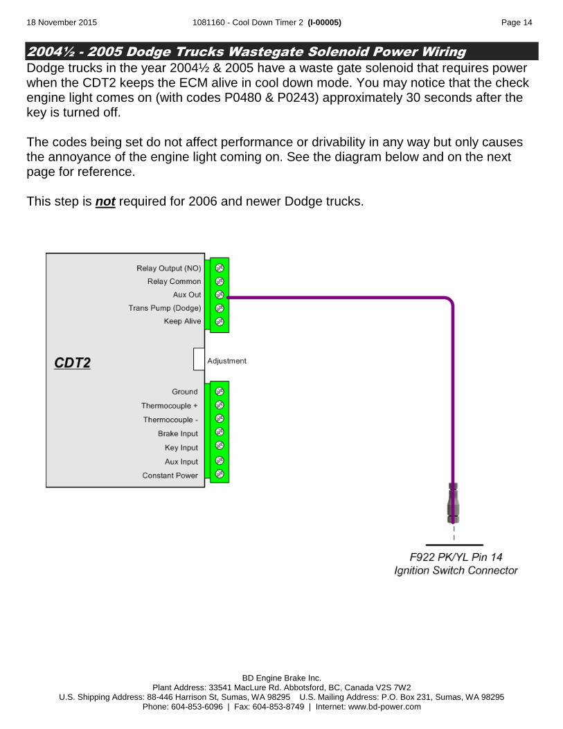
2004½ - 2005 Dodge Trucks Wastegate Solenoid Power Wiring
Dodge trucks in the year 2004½ & 2005 have a waste gate solenoid that requires power when the CDT2 keeps the ECM alive in cool down mode. You may notice that the check engine light comes on (with codes P0480 & P0243) approximately 30 seconds after the key is turned off. The codes being set do not affect performance or drivability in any way but only causes the annoyance of the engine light coming on. See the diagram below and on the next page for reference. This step is not required for 2006 and newer Dodge trucks.

18 November 2015 1081160 - Cool Down Timer 2 (I-00005) Page 15
BD Engine Brake Inc. Plant Address: 33541 MacLure Rd. Abbotsford, BC, Canada V2S 7W2
U.S. Shipping Address: 88-446 Harrison St, Sumas, WA 98295 U.S. Mailing Address: P.O. Box 231, Sumas, WA 98295 Phone: 604-853-6096 | Fax: 604-853-8749 | Internet: www.bd-power.com
Dodge 2006-2009
1. Record radio settings and disconnect the negative terminal from both batteries.
2. Remove the knee bolster and upper and lower steering column covers.
Knee Bolster Steering Column Covers
3. Disconnect ignition switch connector. Then connect the CDT harness to the ignition switch connectors.
4. Connect blue brake switch wire to the WT/TN wire on the brake pedal switch. (see table on page 13 above for details)
5. Secure module away from pedals. Route wires to module and connect using the general wiring diagram on page 9 in this manual.
6. Reinstall knee bolster and steering column covers.
7. Reconnect batteries and test for functionality.
SHIFTER
STEERING WHEEL
TURN SIGNAL LEVER
IGNITION SWITCH
CONNECTOR

18 November 2015 1081160 - Cool Down Timer 2 (I-00005) Page 16
BD Engine Brake Inc. Plant Address: 33541 MacLure Rd. Abbotsford, BC, Canada V2S 7W2
U.S. Shipping Address: 88-446 Harrison St, Sumas, WA 98295 U.S. Mailing Address: P.O. Box 231, Sumas, WA 98295 Phone: 604-853-6096 | Fax: 604-853-8749 | Internet: www.bd-power.com
Dodge 2010-2012
1. Record radio settings and disconnect the negative terminal from both batteries.
2. Remove knee bolster.
3. Disconnect ignition switch connector and plug CDT harness inline.
4. Mount module securely away from pedals. Route wires to module and connect wires using the general wiring diagram on page 9 in this manual.
5. Reinstall knee bolster.
6. Reconnect batteries and test for functionality.
CONNECTOR ON BACKSIDE OF IGNITION SWITCH
KEY INSERTS HERE

18 November 2015 1081160 - Cool Down Timer 2 (I-00005) Page 17
BD Engine Brake Inc. Plant Address: 33541 MacLure Rd. Abbotsford, BC, Canada V2S 7W2
U.S. Shipping Address: 88-446 Harrison St, Sumas, WA 98295 U.S. Mailing Address: P.O. Box 231, Sumas, WA 98295 Phone: 604-853-6096 | Fax: 604-853-8749 | Internet: www.bd-power.com
Dodge 2013-2016
1. Record radio settings. Disconnect batteries to avoid setting TPMS fault codes; also to avoid risk of short circuiting the 12V feed to the RF module.
2. Removal procedure for the 60/40 split rear seats is described in the following steps. Only the rear left (driver side) seat needs to be removed. Bench seat removal is similar but requires additional fastener removal.
3. Flip up the bottom of the left (driver side) rear seat. Disconnect the gray electrical connector for the seat and remove the two rear 18mm securing bolts
4. Flip up the under seat compartment lid by releasing the snap button. Remove the two forward 18mm securing bolts.
Lift rear left seat up to release it from the hooks on the rear cab wall and remove from vehicle.
18 November 2015 1081160 - Cool Down Timer 2 (I-00005) Page 18
BD Engine Brake Inc. Plant Address: 33541 MacLure Rd. Abbotsford, BC, Canada V2S 7W2
U.S. Shipping Address: 88-446 Harrison St, Sumas, WA 98295 U.S. Mailing Address: P.O. Box 231, Sumas, WA 98295 Phone: 604-853-6096 | Fax: 604-853-8749 | Internet: www.bd-power.com
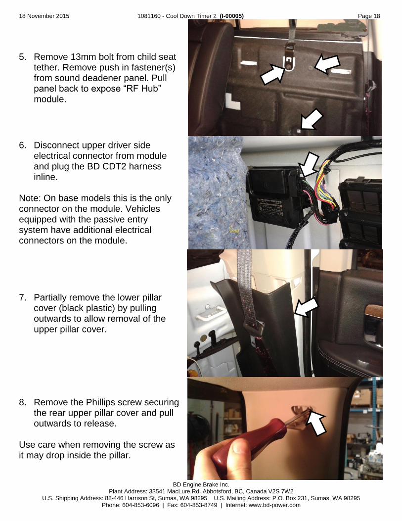
5. Remove 13mm bolt from child seat tether. Remove push in fastener(s) from sound deadener panel. Pull panel back to expose “RF Hub” module.
6. Disconnect upper driver side electrical connector from module and plug the BD CDT2 harness inline.
Note: On base models this is the only connector on the module. Vehicles equipped with the passive entry system have additional electrical connectors on the module.
7. Partially remove the lower pillar cover (black plastic) by pulling outwards to allow removal of the upper pillar cover.
8. Remove the Phillips screw securing the rear upper pillar cover and pull outwards to release.
Use care when removing the screw as it may drop inside the pillar.
18 November 2015 1081160 - Cool Down Timer 2 (I-00005) Page 19
BD Engine Brake Inc. Plant Address: 33541 MacLure Rd. Abbotsford, BC, Canada V2S 7W2
U.S. Shipping Address: 88-446 Harrison St, Sumas, WA 98295 U.S. Mailing Address: P.O. Box 231, Sumas, WA 98295 Phone: 604-853-6096 | Fax: 604-853-8749 | Internet: www.bd-power.com
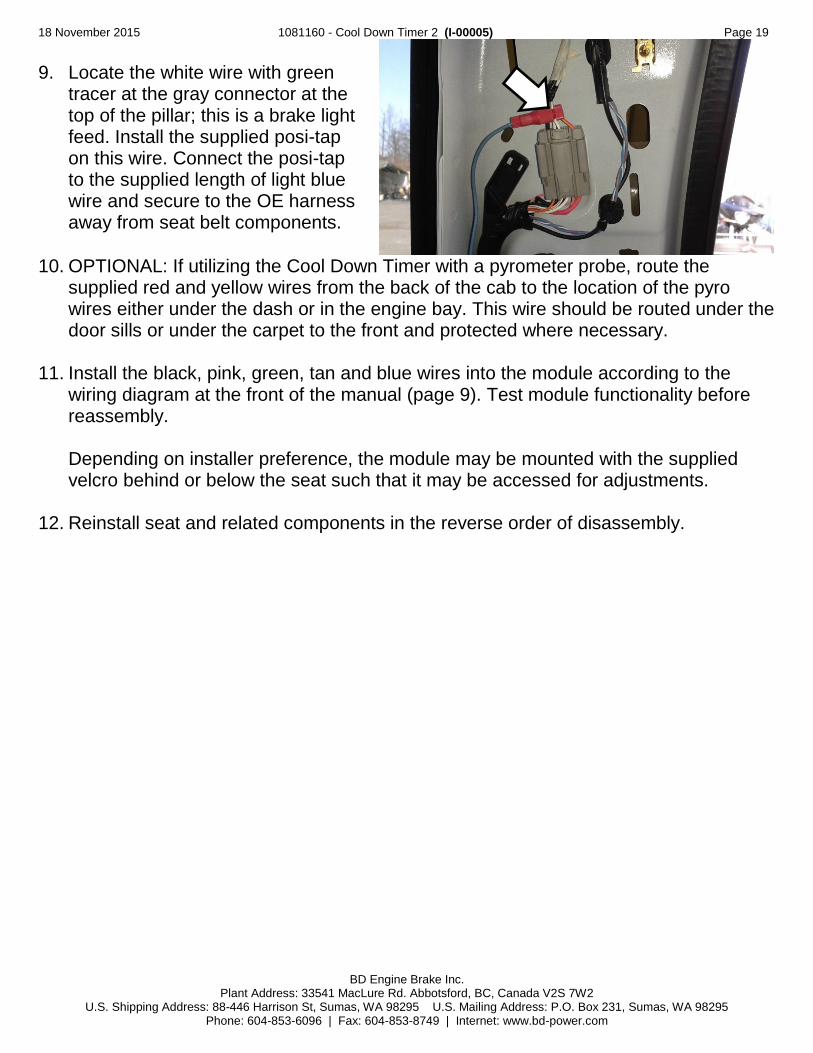
9. Locate the white wire with green tracer at the gray connector at the top of the pillar; this is a brake light feed. Install the supplied posi-tap on this wire. Connect the posi-tap to the supplied length of light blue wire and secure to the OE harness away from seat belt components.
10. OPTIONAL: If utilizing the Cool Down Timer with a pyrometer probe, route the
supplied red and yellow wires from the back of the cab to the location of the pyro wires either under the dash or in the engine bay. This wire should be routed under the door sills or under the carpet to the front and protected where necessary.
11. Install the black, pink, green, tan and blue wires into the module according to the
wiring diagram at the front of the manual (page 9). Test module functionality before reassembly. Depending on installer preference, the module may be mounted with the supplied velcro behind or below the seat such that it may be accessed for adjustments.
12. Reinstall seat and related components in the reverse order of disassembly.

18 November 2015 1081160 - Cool Down Timer 2 (I-00005) Page 20
BD Engine Brake Inc. Plant Address: 33541 MacLure Rd. Abbotsford, BC, Canada V2S 7W2
U.S. Shipping Address: 88-446 Harrison St, Sumas, WA 98295 U.S. Mailing Address: P.O. Box 231, Sumas, WA 98295 Phone: 604-853-6096 | Fax: 604-853-8749 | Internet: www.bd-power.com
DURAMAX WIRING DIAGRAMS
Duramax Ignition Connector Location
Legend
1. Hazard Button 2. Multi-Function Lever 3. Cruise Control Switches 4. Tilt Steering Actuator 5. Inflatable Restraint Harness 6. 201 Inline Connector
Connect the black wire to a good grounding point.
2001-2002 Duramax Ignition Connector (C201)

18 November 2015 1081160 - Cool Down Timer 2 (I-00005) Page 21
BD Engine Brake Inc. Plant Address: 33541 MacLure Rd. Abbotsford, BC, Canada V2S 7W2
U.S. Shipping Address: 88-446 Harrison St, Sumas, WA 98295 U.S. Mailing Address: P.O. Box 231, Sumas, WA 98295 Phone: 604-853-6096 | Fax: 604-853-8749 | Internet: www.bd-power.com
2003-2007 Duramax Ignition Connector
2007.5-2014 Duramax Body Control Module
Locate the BCM (#5).
Connector X1, Light Green in color. Face shown is internal mating face. You will need to access the reverse of this.
Connector X2, White in color. Face shown is internal mating face. You will need to access the reverse of this.

18 November 2015 1081160 - Cool Down Timer 2 (I-00005) Page 22
BD Engine Brake Inc. Plant Address: 33541 MacLure Rd. Abbotsford, BC, Canada V2S 7W2
U.S. Shipping Address: 88-446 Harrison St, Sumas, WA 98295 U.S. Mailing Address: P.O. Box 231, Sumas, WA 98295 Phone: 604-853-6096 | Fax: 604-853-8749 | Internet: www.bd-power.com
Connector X5 is Brown in color. Face shown is internal mating face. You will need to access the reverse of this.
2003-2007 Duramax Brake Pedal Connector
2007.5-2011 Duramax Brake Pedal Connector

18 November 2015 1081160 - Cool Down Timer 2 (I-00005) Page 23
BD Engine Brake Inc. Plant Address: 33541 MacLure Rd. Abbotsford, BC, Canada V2S 7W2
U.S. Shipping Address: 88-446 Harrison St, Sumas, WA 98295 U.S. Mailing Address: P.O. Box 231, Sumas, WA 98295 Phone: 604-853-6096 | Fax: 604-853-8749 | Internet: www.bd-power.com
Model Location OEM Wire Pin Brake Pedal (Blue Wire)
2001-2002 Ignition Connector C201 WT 17 A1
2003-2007 Brake Pedal Connector WT 5689 2
2007.5-2011 Brake Pedal Connector Light Blue/White A
2012-2014 Body Control Module (BCM) X5 Light Blue/White 6
Key (Green Wire) 2001-2002
Ignition Connector C201 BR 41 A13
2003-2007 BR 41 B18
2007.5-2010 Body Control Module (BCM) X1 PK 1020 2
2011-2014 Body Control Module (BCM) X1 Pink/Black 2
Keep Alive (Tan Wire) 2001-2007 Ignition Connector C201 PK 139 A2
2007.5-2014 Body Control Module (BCM) X1 PK 3 14
Constant (Pink Wire) 2001-2002
Ignition Connector C201 RD 242 B1
2003-2007 RD 342 C1
2007.5-2014 Body Control Module (BCM) X2 Red/White 2

18 November 2015 1081160 - Cool Down Timer 2 (I-00005) Page 24
BD Engine Brake Inc. Plant Address: 33541 MacLure Rd. Abbotsford, BC, Canada V2S 7W2
U.S. Shipping Address: 88-446 Harrison St, Sumas, WA 98295 U.S. Mailing Address: P.O. Box 231, Sumas, WA 98295 Phone: 604-853-6096 | Fax: 604-853-8749 | Internet: www.bd-power.com
Thermocouple Wiring (Not needed if monitoring with Time vs. Temp)
On most common “K” type thermocouples and wiring, a yellow wire is connected to the positive (+) side and a red wire is connected to the negative (-) side. The following are three common ways to connect the thermocouple to the CDT2 module. In all cases, the positive side of the thermocouple will be connected to the “Thermocouple +” terminal as indicated on the CDT2 module drawings and the negative side will be connected to the “Thermocouple -” terminal.
Direct Thermocouple Connection If there is no pyrometer gauge in the vehicle and a thermocouple is being installed to connect to the CDT2 module, follow this diagram:
Amplified Pyrometer Gauge Kit Some pyrometer gauge kits utilize a powered amplifier in between the pyrometer gauge head and the thermocouple. If the vehicle has one of these systems installed, use the following diagram:

18 November 2015 1081160 - Cool Down Timer 2 (I-00005) Page 25
BD Engine Brake Inc. Plant Address: 33541 MacLure Rd. Abbotsford, BC, Canada V2S 7W2
U.S. Shipping Address: 88-446 Harrison St, Sumas, WA 98295 U.S. Mailing Address: P.O. Box 231, Sumas, WA 98295 Phone: 604-853-6096 | Fax: 604-853-8749 | Internet: www.bd-power.com
Conventional Non-Amplified Pyrometer Kit A conventional pyrometer gauge kit will have the thermocouple connected to the pyrometer gauge head via a lead wire. If the vehicle has one of these systems installed, use the following diagram:
Temperature Adjustment
The shutdown temperature can be set by using a small flat-headed screwdriver to adjust the potentiometer that can be accessed through the hole on the left side of the CDT2 module. By turning the screw all the way to the right (clockwise), the CDT2 will shutdown at approximately 550°F. By turning the potentiometer all the way counter-clockwise, the CDT2 will shutdown at approximately 250°F. The CDT2 may have to be adjusted a few times until the desired shutdown temperature is achieved. NOTE: Be careful not to apply too much pressure as the potentiometer is plastic and can break.
Adjustment Range: 250° to 550°
18 November 2015 1081160 - Cool Down Timer 2 (I-00005) Page 26
BD Engine Brake Inc. Plant Address: 33541 MacLure Rd. Abbotsford, BC, Canada V2S 7W2
U.S. Shipping Address: 88-446 Harrison St, Sumas, WA 98295 U.S. Mailing Address: P.O. Box 231, Sumas, WA 98295 Phone: 604-853-6096 | Fax: 604-853-8749 | Internet: www.bd-power.com
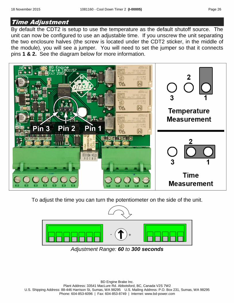
Time Adjustment
By default the CDT2 is setup to use the temperature as the default shutoff source. The unit can now be configured to use an adjustable time. If you unscrew the unit separating the two enclosure halves (the screw is located under the CDT2 sticker, in the middle of the module), you will see a jumper. You will need to set the jumper so that it connects pins 1 & 2. See the diagram below for more information.
To adjust the time you can turn the potentiometer on the side of the unit.
Adjustment Range: 60 to 300 seconds

18 November 2015 1081160 - Cool Down Timer 2 (I-00005) Page 27
BD Engine Brake Inc. Plant Address: 33541 MacLure Rd. Abbotsford, BC, Canada V2S 7W2
U.S. Shipping Address: 88-446 Harrison St, Sumas, WA 98295 U.S. Mailing Address: P.O. Box 231, Sumas, WA 98295 Phone: 604-853-6096 | Fax: 604-853-8749 | Internet: www.bd-power.com
Communication / Operation Lights
There are several built in LEDs within the CDT2 to help troubleshoot operation of the module, these are aligned with their corresponding input or output pin on the module.
Inputs LED Operation
Key Lit when supplied power
Aux. In Lit when supplied power
Brake Input Lit when Brake is depressed
Temperature Lit when temperature is above set point
Outputs LED Operation
Aux Out Lit when output powered
Transfer Pump Lit when output powered
Keep Alive Lit when output powered
Mounting
Once all the wiring and adjustments have been performance, secure or mount the CDT2 module so that it does not interfere with pedal operation, the driver’s feet, moving parts and is away from direct heat. The module may be mounted to an existing vehicle wiring harness using a zip-tie or may be adhered to the firewall using a double sided Velcro type tape.
Technical Assistance
If you required technical assistance with the installation or operation of this kit, please contact us at 604-853-6096, Monday to Friday, 8:00am to 5:00 Pacific Time. We can also be contacted via email at [email protected]
Wire Color Glossary
BK Black
In the wiring diagrams, there are usually two wire colors for each OEM wire, for example: RD/LB. This means it’s a red colored wire with a light blue tracer.
BR Brown
DB Dark Blue
GN Green
GY Gray
LB Light Blue
LG Light Green
OR Orange
PK Pink
RD Red
TN Tan/Light Brown
WT White
YL Yellow

18 November 2015 1081160 - Cool Down Timer 2 (I-00005) Page 28
BD Engine Brake Inc. Plant Address: 33541 MacLure Rd. Abbotsford, BC, Canada V2S 7W2
U.S. Shipping Address: 88-446 Harrison St, Sumas, WA 98295 U.S. Mailing Address: P.O. Box 231, Sumas, WA 98295 Phone: 604-853-6096 | Fax: 604-853-8749 | Internet: www.bd-power.com
Troubleshooting
Check that EGT is above set
temperature (or within set
time frame)
Check for power at Keep Alive
output. Keep Alive LED should
be lit.
Okay – normal.
Check that brake input has
voltage only when brake pedal is
depressed.
Check for power at brake input to
module & that brake input LED is
lit.
Check that module has good key
input power & LED is lit with key
in run position. Must have no
power and no LED with key off.
Check that module has good
ground & constant power.
Key Input wire has poor
connection or is on wrong
factory wire.
Brake wire has poor
connection or is on wrong
factory wire.
Should only have power when
brake pedal is depressed. If it
has power at any other time it
is on the wrong factory wire or
something else if back-feeding
power into the brake circuit
(such as alarm system or trailer
wiring).
Power or ground wires have
poor connection or are on
wrong factory wire.
Keep Alive wire is on wrong
factory wire or has poor
connection.
Adjust time/temp or run engine
to increase EGT’s
COMPLAINT: VEHICLE WON’T STAY RUNNING
NO
YE
SY
ES
YE
SY
ES
NO
NO
YES
YES
NO
NO
NO