Embed Size (px)
Citation preview
Emergency Response Guide
Prepared for Fire Service, Law Enforcement, Emergency Medical, and Professional Towing Personnel.
2
Introduction ················································································································
High Voltage Safety System in FCEV
Fuel cell stack ···········································································································
High voltage battery system ························································································
Safety of High voltage system ·····················································································
Safety Issue of Compressed Hydrogen
General Features········································································································
Properties of Hydrogen Gas·······················································································…
Hydrogen Gas Leak Detection System············································································
Hydrogen Safety System
Hydrogen Gas Ventilation····························································································
Hydrogen Safety Devices····························································································
Front and Rear Impact Sensors·····················································································
Safety precaution for FCEV
Safety Precautions with the Hydrogen Storage System····················································
Safety Precautions with the High Voltage System···························································
Tucson FCEV Identification
Exterior visual identification ························································································
Interior visual identification ·························································································
FCEV Main Components ································································································
FCEV Systems Overview
Features of Fuel Cell Electric Vehicle·············································································
Fuel cell stack, High voltage Battery ·············································································
High pressure hydrogen storage tank, High voltage cable, 12V battery ·······························
Supplement Restraint System (SRS) ··············································································
Vehicle Specifications ··································································································
Warning Lamps on cluster
Power Down Warning Lamp·························································································
Hydrogen Gas Leak Warning Lamp················································································
Motor Overheat Warning Lamp·····················································································
Service Lamp·············……………………………··········································································
Fuse Box Position and Engine Room Layout ······································································
Emergency procedures - Initial response
Identify, Immobilize ···································································································
Disable ····················································································································
4
5
5
6
7
7
8
9
9
9
10
10
11
13
14
15
16
17
18
20
21
21
21
21
22
23
24
ContentsContents

3
ContentsContents
Emergency procedures – Specific types response
Extrication, Vehicle stabilization, Extrication equipment and techniques ·····························
Firefighting, Firefighting operations, Emergency venting of hydrogen gas ·························
Extinguishers, Placing water on High-voltage electricity ·················································
Overhaul operations, Vehicle’s cutting area for Emergency escape ···································
Submersion in Water ··································································································
High-voltage battery damage / Spills ············································································
First aid for electrolyte exposure ·················································································
Emergency towing ·······································································································
Jump starting ··············································································································
28
29
30
31
32
33
34
35
37
IntroductionIntroduction
Forward Hyundai has high standards and is dedicated to the safety of our customers and emergency
responders alike. Hyundai is providing this fuel cell electric vehicle information as a result of our
commitment to safety.
Document purposeThe purpose of this document is to familiarize emergency responders and the towing/roadside
assistance industry with the proper methods to treat the Hyundai Tucson fuel cell electric vehicle in
an emergency situation. This guide offers a basic overview of key vehicle systems and provides
instructions for dealing with the different types of situations encountered by emergency
responders. The emergency response procedures for this vehicle are somewhat similar to a
conventional Tucson with additional information provided on dealing with the hydrogen system and
high-voltage electrical system.
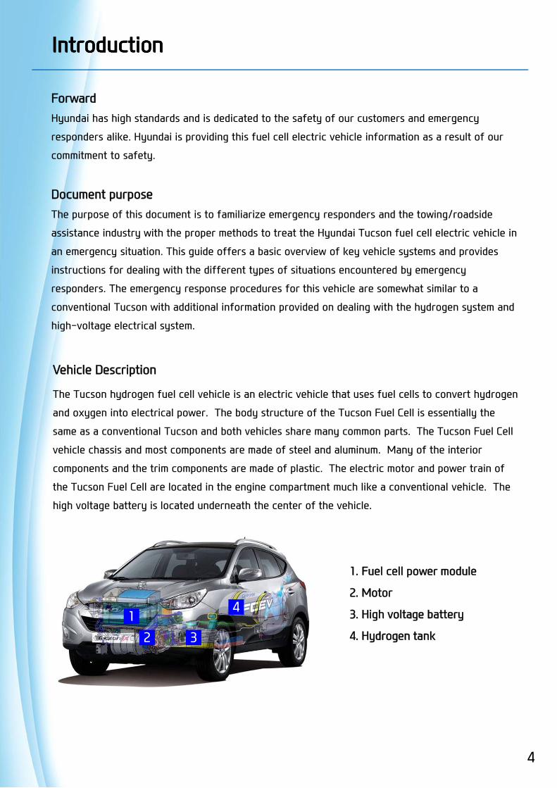
Vehicle Description
The Tucson hydrogen fuel cell vehicle is an electric vehicle that uses fuel cells to convert hydrogen
and oxygen into electrical power. The body structure of the Tucson Fuel Cell is essentially the
same as a conventional Tucson and both vehicles share many common parts. The Tucson Fuel Cell
vehicle chassis and most components are made of steel and aluminum. Many of the interior
components and the trim components are made of plastic. The electric motor and power train of
the Tucson Fuel Cell are located in the engine compartment much like a conventional vehicle. The
high voltage battery is located underneath the center of the vehicle.
1. Fuel cell power module
2. Motor
3. High voltage battery
4. Hydrogen tank
12 3
4
4

5
High voltage battery system
The high voltage battery system is comprised of a lithium-ion polymer battery that operates at a
nominal voltage of 180V. This battery stores power generated by the fuel cell stack and also by
the traction motor during regenerative braking. The battery provides extra current to the
traction motor during acceleration. The high voltage battery is located underneath the vehicle
near the center of the vehicle and is stored in a protective steel enclosure.
High Voltage Safety System in FCEVHigh Voltage Safety System in FCEV
Battery system→ underneath the vehicle(center)
High voltage battery system
Battery pack voltage 180 Volts (Max 206V)
Battery type LI-POLYMER
Number of cells 48 Cells
Battery system total weight 106 lb (47 Kg )
Fuel Cell Stack
The main power source of the Tucson Hydrogen Fuel Cell electric vehicle comes from the fuel cell
stack. The fuel cell stack contains layers of individual fuel cells that combine hydrogen and oxygen
to produce a voltage. The cells are stacked together in series to multiply the voltage and generate
electricity, which is used to drive the electric traction motor. The only by-products of this
electrochemical process are heat and water. Some of the water is recirculated to the humidifier.
Excess water is extracted out of the tailpipe. Because the fuel cell stack generates over 400V when
operating, some precautions are required.
1) The fuel cell stack is located in the engine compartment, underneath the high voltage junction box
and the fuel processing unit. The fuel cell stack is housed in a metal enclosure which is insulated
from the rest of the vehicle.
2) Live parts and high voltage buses which are generating over DC 400V in the fuel cell stack are
designed to maintain a reliable insulation resistance with an electro-conductive enclosure. When
the insulation resistance is lower than the regulated value, it is alarmed to the user and limited the
output current of fuel cell stack.
6
High Voltage Safety System in FCEVHigh Voltage Safety System in FCEV
To ensure safety, the high voltage battery system cuts off the main relay when the ignition is off.
The main relay is enclosed within the high voltage battery module assembly. An over-current
protection circuit is used, and all high voltage cables are identified by distinctive orange coloring.
A safety plug which houses the high voltage main fuse is also applied to isolate the high voltage from
the rest of the vehicle.
Safety of high voltage system
Direct contact with any electrically-charged high voltage component can cause serious injury or
death. However, as long as certain precautions are taken, the risk of getting electrocuted is highly
unlikely. The high voltage components of the Tucson hydrogen fuel cell vehicle are designed to
provide reliable insulation resistance and protect against the occurrence of electrical shock. Most of
the high voltage components are located within a protective enclosure. The enclosure is mounted to
the chassis and is electrically grounded should there be a change in the insulation resistance between
the high voltage component and the enclosure. All high voltage power cables are sufficiently
insulated and can easily be identified (orange color). High voltage fuses protect devices from
overheating and a Ground Fault Detector (GFD) circuit will shut off the high voltage relay if a current
leak is detected. To disconnect the high voltage battery from the rest of the vehicle, a safety plug
accessible from the rear of the vehicle inside the trunk can be easily removed. (Refer to page 22 for
detailed instructions on how to remove the safety plug.)
7
General Features of Hydrogen
Hydrogen is a gas at room temperature and is the lightest of all the elements and has the lowest
density. It is non-toxic, odorless, tasteless, and colorless. It makes up about 75% of the mass of the
universe since it is present in most organic compounds and in water. As a result, it is the most
abundant element on earth. However, like other fuels, hydrogen is flammable and explosive.
Compared to gasoline, for example, when mixed with air, hydrogen has a much larger range of
flammability, and its explosive range is also much larger.
Because it is lighter than air and diffuses rapidly, hydrogen burns very quickly and radiates less
heat than gasoline or other fuels. Pure hydrogen-oxygen flames emit ultraviolet light and are
invisible to the naked eye. As such, the detection of burning hydrogen requires a flame detector.
Safety Issues of Compressed Hydrogen Safety Issues of Compressed Hydrogen
Facts About Hydrogen Gas
- Like gasoline or natural gas, hydrogen is a fuel that must be handled properly. It can be
used safely as with other common fuels when simple guidelines are followed. Some key
properties of hydrogen and some important facts are listed below:
- Hydrogen is the lightest and smallest element in the periodic table; it is two times lighter
than helium
- Hydrogen is a colorless, odorless, tasteless, non-toxic, and non-poisonous gas at room
temperature. It is also non-corrosive, but it can cause embrittlement in some metals
- Natural gas and propane are also odorless, but industry adds a sulfur-containing odorant
so people can detect them. Currently, odorants are not used with hydrogen because
there are no known odorants light enough to "travel with" hydrogen at the same
dispersion rate. Current odorants also can contaminate the hydrogen fuel cell
- Hydrogen is about 57 times lighter than gasoline vapor, and 14 times lighter than air. This
means that if it is released in an open environment, it will typically rise and disperse
rapidly. This is a safety advantage in an outside environment.
- Hydrogen is a very small molecule with low viscosity; as a result it is prone to leakage
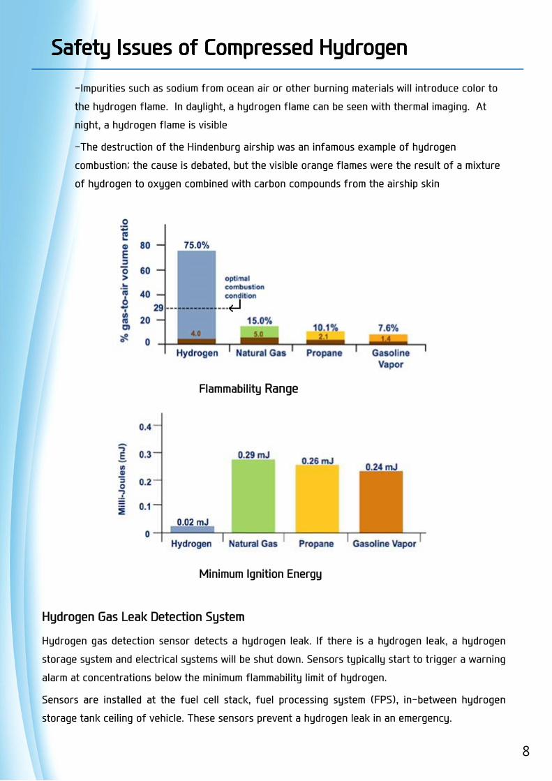
- Hydrogen gas is highly flammable and will burn in air at a very wide range of
concentrations between 4% and 75% by volume; the mixture may be ignited by spark or
heat
- Pure hydrogen-oxygen flames emit ultraviolet light. The flames are nearly invisible to
the naked eye. A good example of this is the faint plume of the space shuttle main
engine at full thrust (cryogenic liquid hydrogen) versus the highly visible plume of a
space shuttle solid rocket booster (solid rocket propellant)
8
Hydrogen Gas Leak Detection System
Hydrogen gas detection sensor detects a hydrogen leak. If there is a hydrogen leak, a hydrogen
storage system and electrical systems will be shut down. Sensors typically start to trigger a warning
alarm at concentrations below the minimum flammability limit of hydrogen.
Sensors are installed at the fuel cell stack, fuel processing system (FPS), in-between hydrogen
storage tank ceiling of vehicle. These sensors prevent a hydrogen leak in an emergency.
Safety Issues of Compressed Hydrogen Safety Issues of Compressed Hydrogen
-Impurities such as sodium from ocean air or other burning materials will introduce color to
the hydrogen flame. In daylight, a hydrogen flame can be seen with thermal imaging. At
night, a hydrogen flame is visible
-The destruction of the Hindenburg airship was an infamous example of hydrogen
combustion; the cause is debated, but the visible orange flames were the result of a mixture
of hydrogen to oxygen combined with carbon compounds from the airship skin
Flammability Range
Minimum Ignition Energy

9
Hydrogen Safety Devices
In-Tank Solenoid Valve (ITS)Solenoid valves are directly connected to each tank to control the flow of hydrogen. The solenoids are energized ON when the vehicle is operating (READY state), and OFF when the vehicle is turned off.
Thermally-activated Pressure Relief Device (PRD)The in-tank solenoid valve is also equipped with a Pressure Relief Device (PRD) that discharges the hydrogen in the tank if the gas temperature exceeds 110°C [230°F].
Excess Flow Valve (EFV)The in-tank solenoid valve includes an Excess Flow Valve (EFV) that functions as an overflow prevention mechanism and prevents excessive discharge of hydrogen from the fuel tank that might occur (for example, in the case of damage to the high pressure line).
Pressure Relief Valve (PRV)A Pressure Relief Valve is mounted to the Hydrogen Pressure Regulator and will vent hydrogen to atmosphere if the pressure in the line exceeds the regulated pressure.
Front and Rear Impact Sensors
As part of the vehicle crash safety system, the front and rear impact sensors are installed on the front bumper and the rear floor member, respectively. In the event of a front end or rear end collision, the system controller will automatically shut off the flow of hydrogen to the vehicle and the vehicle will shut down.
수소 안전 시스템수소 안전 시스템Hydrogen sensor
Hydrogen sensor
Impact sensor
Pressure Relief Valve (PRV)
Hydrogen Safety SystemHydrogen Safety System

Safety precaution for FCEVSafety precaution for FCEV
This Fuel Cell Electric Vehicle (FCEV) uses approximately DC 180 ~ 400 voltage and high pressure hyd
rogen gas. Be sure to follow safety instructions below. Failure to follow safety instructions may resul
t in serious injury or electrocution.
[Safety Precautions with the Hydrogen Storage System]
• There must be no ignition sources around the vehicle. For example, exposed flame, sparks,
electrostatic discharge or hot surfaces that could cause hydrogen gas to ignite.
• Caution labels for hydrogen are attached to the hydrogen storage system components.
The hydrogen storage system is comprised of two separate tanks that are interconnected and filled
with hydrogen gas. Each tank is made of aluminum cylinder wrapped in carbon fiber. The cylinders
contain hydrogen gas under high pressure. Serious injury or death can result from improper
installation, lack of maintenance, or over pressurization. Do not attempt to remove the fuel tanks or
any of its fittings from the vehicle. The tanks may contain residual flammable gas under pressure
which could cause fire or explosion.
[Safety Precautions with the High Voltage System]
• Warning labels for high voltage are attached to the high voltage components. The color of the high
voltage cables and connectors are orange. Do not touch any of these high voltage components, cable
s, and connectors without proper Personal Protection Equipment (PPE: Insulating Gloves, Safety Glas
ses, etc.)
10
Tucson FCEV IdentificationTucson FCEV Identification
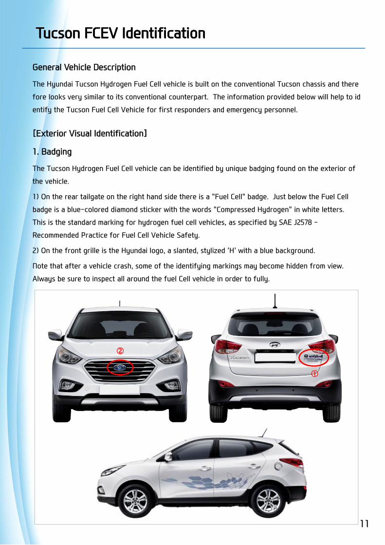
General Vehicle Description
The Hyundai Tucson Hydrogen Fuel Cell vehicle is built on the conventional Tucson chassis and there
fore looks very similar to its conventional counterpart. The information provided below will help to id
entify the Tucson Fuel Cell Vehicle for first responders and emergency personnel.
[Exterior Visual Identification]
1. Badging
The Tucson Hydrogen Fuel Cell vehicle can be identified by unique badging found on the exterior of
the vehicle.
1) On the rear tailgate on the right hand side there is a "Fuel Cell" badge. Just below the Fuel Cell
badge is a blue-colored diamond sticker with the words "Compressed Hydrogen" in white letters.
This is the standard marking for hydrogen fuel cell vehicles, as specified by SAE J2578 -
Recommended Practice for Fuel Cell Vehicle Safety.
2) On the front grille is the Hyundai logo, a slanted, stylized 'H' with a blue background.
Note that after a vehicle crash, some of the identifying markings may become hidden from view.
Always be sure to inspect all around the fuel Cell vehicle in order to fully.
11
①
②

Tucson FCEV IdentificationTucson FCEV Identification
2. Vehicle Identification Number (VIN)
The Vehicle Identification Number (VIN) is a
unique number that can be used to help identify
the type of vehicle.
The VIN is located on the driver’s side windshield
cowl and under the passenger’s seat.
A sample VIN for the Tucson Hydrogen Fuel Cell
vehicle is shown below. The number "6" in the
8th digit identifies the vehicle as a Tucson
Hydrogen Fuel Cell vehicle.
KM8JU3A67EUxxxxxx (8th position)
3. Fuel cell module compartment
The FCEV version has a High junction box cover
with “Tucson Fuel Cell” clearly shown on it.
Additionally, there are orange colored high-
voltage electrical cables in the fuel cell module
compartment.
12
Tucson
( xxxxxx represents the vehicle serial no.)
Tucson FCEV IdentificationTucson FCEV Identification
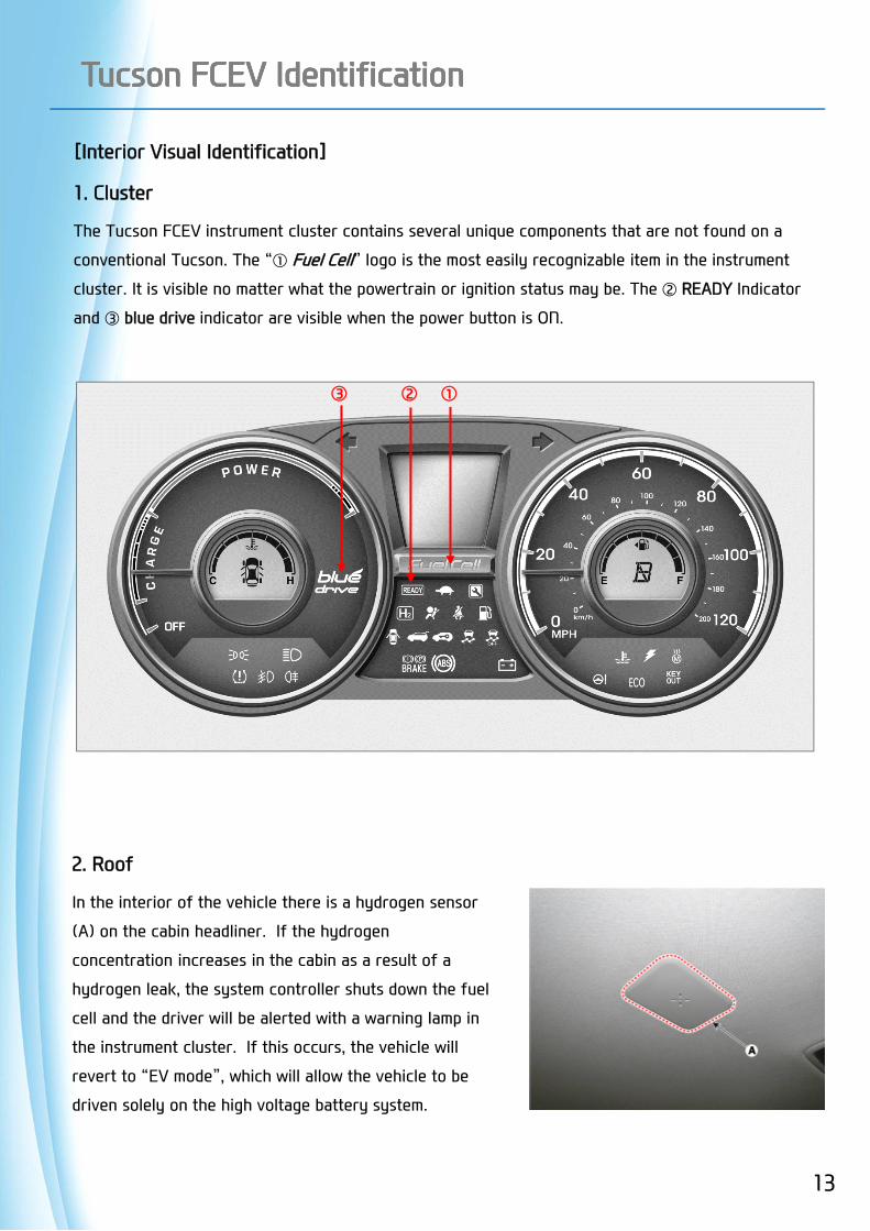
[Interior Visual Identification]
1. Cluster
The Tucson FCEV instrument cluster contains several unique components that are not found on a
conventional Tucson. The “① Fuel Cell” logo is the most easily recognizable item in the instrument
cluster. It is visible no matter what the powertrain or ignition status may be. The ② READY Indicator
and ③ blue drive indicator are visible when the power button is ON.
①②③
2. Roof
In the interior of the vehicle there is a hydrogen sensor
(A) on the cabin headliner. If the hydrogen
concentration increases in the cabin as a result of a
hydrogen leak, the system controller shuts down the fuel
cell and the driver will be alerted with a warning lamp in
the instrument cluster. If this occurs, the vehicle will
revert to “EV mode”, which will allow the vehicle to be
driven solely on the high voltage battery system.
13
14
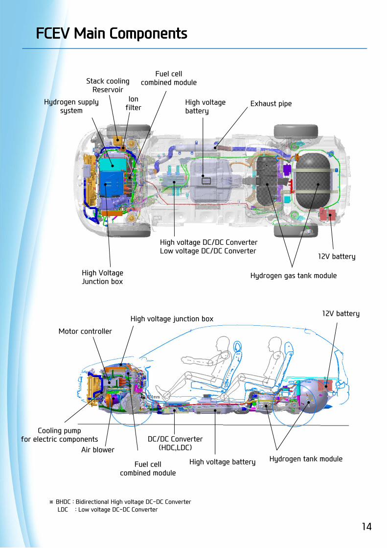
FCEV Main ComponentsFCEV Main Components
Hydrogen gas tank moduleHigh VoltageJunction box
High voltage DC/DC ConverterLow voltage DC/DC Converter
High voltagebattery
Fuel cellcombined module
Hydrogen supplysystem
High voltage junction box
Hydrogen tank module
Motor controller
High voltage battery
DC/DC Converter(HDC,LDC)
※ BHDC : Bidirectional High voltage DC-DC ConverterLDC : Low voltage DC-DC Converter
Exhaust pipe
Air blower
12V battery
12V battery
Cooling pumpfor electric components
Stack coolingReservoir
Ionfilter
Fuel cellcombined module
15
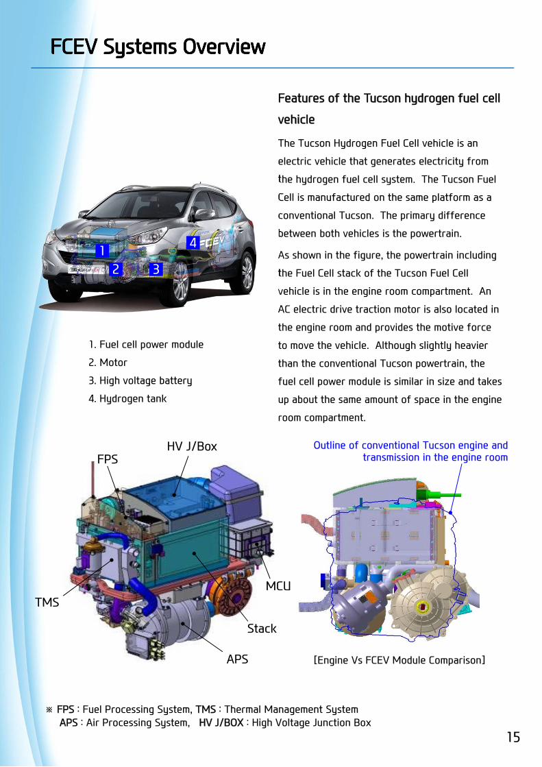
Features of the Tucson hydrogen fuel cell
vehicle
The Tucson Hydrogen Fuel Cell vehicle is an
electric vehicle that generates electricity from
the hydrogen fuel cell system. The Tucson Fuel
Cell is manufactured on the same platform as a
conventional Tucson. The primary difference
between both vehicles is the powertrain.
As shown in the figure, the powertrain including
the Fuel Cell stack of the Tucson Fuel Cell
vehicle is in the engine room compartment. An
AC electric drive traction motor is also located in
the engine room and provides the motive force
to move the vehicle. Although slightly heavier
than the conventional Tucson powertrain, the
fuel cell power module is similar in size and takes
up about the same amount of space in the engine
room compartment.
FCEV Systems OverviewFCEV Systems Overview
1. Fuel cell power module
2. Motor
3. High voltage battery
4. Hydrogen tank
12 3
4
[Engine Vs FCEV Module Comparison]
※ FPS : Fuel Processing System, TMS : Thermal Management SystemAPS : Air Processing System, HV J/BOX : High Voltage Junction Box
APS
Stack
Outline of conventional Tucson engine and transmission in the engine room
TMS
FPSHV J/Box
MCU
16
The Tucson Hydrogen Fuel Cell vehicle is comprised of four major systems:
1) The Fuel Cell system which combines hydrogen and oxygen to generate electical power
2) The Electrical Power System which provides the motive force using an electric motor
3) The Hydrogen Storage System which provides the fuel source for the vehicle
4) Components of the Auxiliary Power Supply System, which provides energy storage and battery
management, are located in the engine compartment and underneath the center of the vehicle.
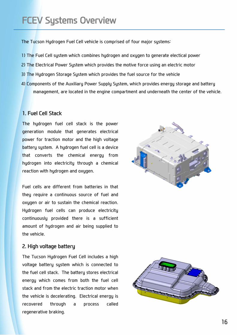
1. Fuel Cell Stack
The hydrogen fuel cell stack is the power
generation module that generates electrical
power for traction motor and the high voltage
battery system. A hydrogen fuel cell is a device
that converts the chemical energy from
hydrogen into electricity through a chemical
reaction with hydrogen and oxygen.
Fuel cells are different from batteries in that
they require a continuous source of fuel and
oxygen or air to sustain the chemical reaction.
Hydrogen fuel cells can produce electricity
continuously provided there is a sufficient
amount of hydrogen and air being supplied to
the vehicle.
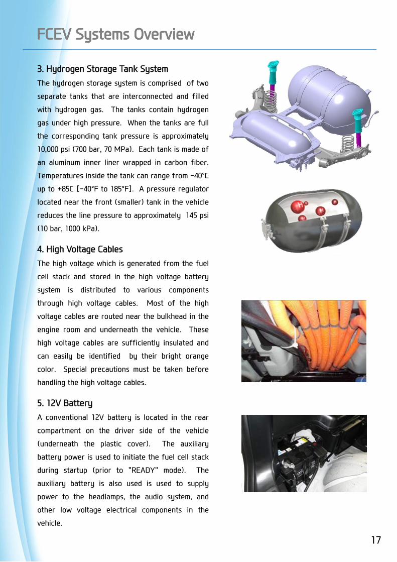
2. High voltage battery
The Tucson Hydrogen Fuel Cell includes a high
voltage battery system which is connected to
the fuel cell stack. The battery stores electrical
energy which comes from both the fuel cell
stack and from the electric traction motor when
the vehicle is decelerating. Electrical energy is
recovered through a process called
regenerative braking.
FCEV Systems OverviewFCEV Systems Overview
17
3. Hydrogen Storage Tank SystemThe hydrogen storage system is comprised of two
separate tanks that are interconnected and filled
with hydrogen gas. The tanks contain hydrogen
gas under high pressure. When the tanks are full
the corresponding tank pressure is approximately
10,000 psi (700 bar, 70 MPa). Each tank is made of
an aluminum inner liner wrapped in carbon fiber.
Temperatures inside the tank can range from -40°C
up to +85C [-40°F to 185°F]. A pressure regulator
located near the front (smaller) tank in the vehicle
reduces the line pressure to approximately 145 psi
(10 bar, 1000 kPa).
4. High Voltage CablesThe high voltage which is generated from the fuel
cell stack and stored in the high voltage battery
system is distributed to various components
through high voltage cables. Most of the high
voltage cables are routed near the bulkhead in the
engine room and underneath the vehicle. These
high voltage cables are sufficiently insulated and
can easily be identified by their bright orange
color. Special precautions must be taken before
handling the high voltage cables.
5. 12V BatteryA conventional 12V battery is located in the rear
compartment on the driver side of the vehicle
(underneath the plastic cover). The auxiliary
battery power is used to initiate the fuel cell stack
during startup (prior to "READY" mode). The
auxiliary battery is also used is used to supply
power to the headlamps, the audio system, and
other low voltage electrical components in the
vehicle.
FCEV Systems OverviewFCEV Systems Overview
FCEV Systems OverviewFCEV Systems Overview
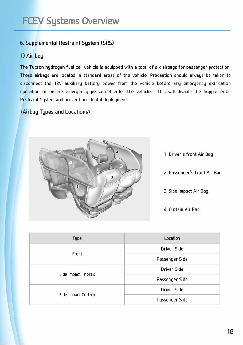
6. Supplemental Restraint System (SRS)
1) Air bag
The Tucson hydrogen fuel cell vehicle is equipped with a total of six airbags for passenger protection.
These airbags are located in standard areas of the vehicle. Precaution should always be taken to
disconnect the 12V auxiliary battery power from the vehicle before any emergency extrication
operation or before emergency personnel enter the vehicle. This will disable the Supplemental
Restraint System and prevent accidental deployment.
<Airbag Types and Locations>
1. Driver’s front Air Bag
2. Passenger’s front Air Bag
3. Side impact Air Bag
4. Curtain Air Bag
Type Location
FrontDriver Side
Passenger Side
Side Impact ThoraxDriver Side
Passenger Side
Side Impact CurtainDriver Side
Passenger Side
18
2) Seatbelt Pretensioners
The Tucson hydrogen fuel cell vehicle has a total of four seatbelt Pretensioners. Two are located in
the Driver’s Side B-pillar, one is a Belt Pretensioner (BPT) and the other is an Anchor Pretensioner
(APT). The other two are located in the Passenger’s Side B-pillar. They also consist of a BPT and an
APT.
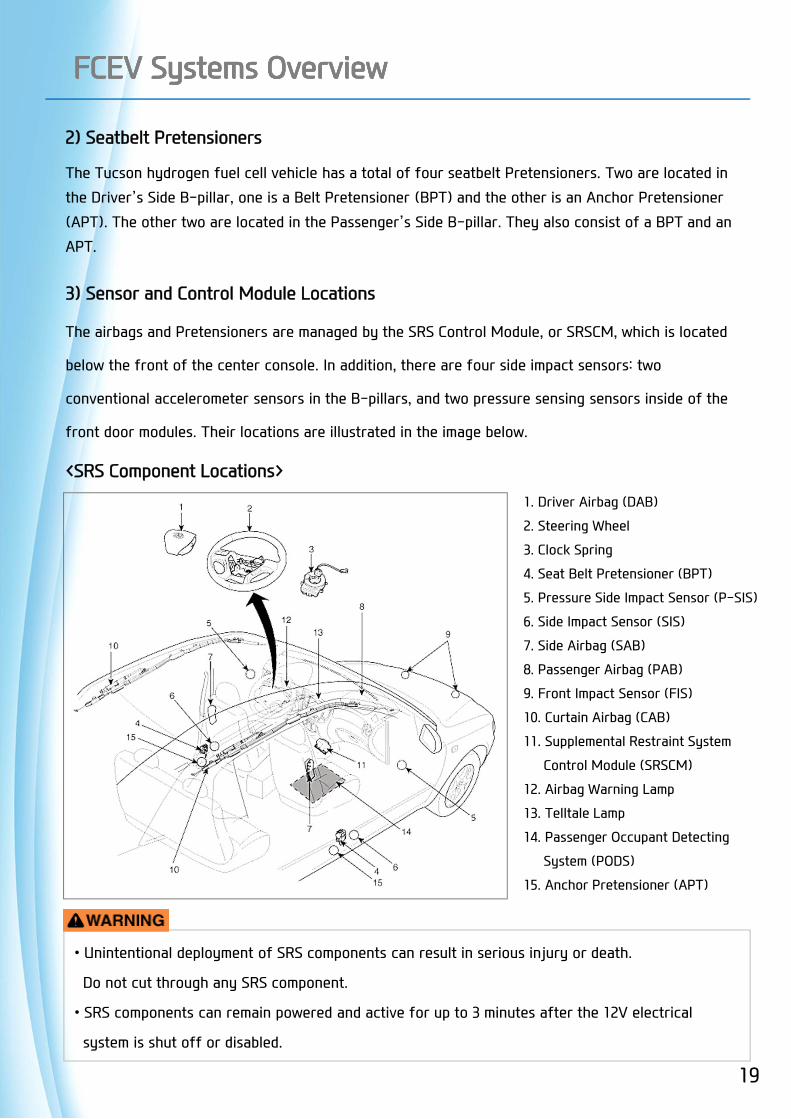
3) Sensor and Control Module Locations
The airbags and Pretensioners are managed by the SRS Control Module, or SRSCM, which is located
below the front of the center console. In addition, there are four side impact sensors: two
conventional accelerometer sensors in the B-pillars, and two pressure sensing sensors inside of the
front door modules. Their locations are illustrated in the image below.
<SRS Component Locations>
FCEV Systems OverviewFCEV Systems Overview
1. Driver Airbag (DAB)
2. Steering Wheel
3. Clock Spring
4. Seat Belt Pretensioner (BPT)
5. Pressure Side Impact Sensor (P-SIS)
6. Side Impact Sensor (SIS)
7. Side Airbag (SAB)
8. Passenger Airbag (PAB)
9. Front Impact Sensor (FIS)
10. Curtain Airbag (CAB)
11. Supplemental Restraint System
Control Module (SRSCM)
12. Airbag Warning Lamp
13. Telltale Lamp
14. Passenger Occupant Detecting
System (PODS)
15. Anchor Pretensioner (APT)
• Unintentional deployment of SRS components can result in serious injury or death.
Do not cut through any SRS component.
• SRS components can remain powered and active for up to 3 minutes after the 12V electrical
system is shut off or disabled.
19
20
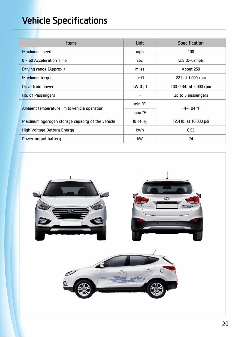
Vehicle SpecificationsVehicle Specifications
Items Unit Specification
Maximum speed mph 100
0 - 60 Acceleration Time sec 12.5 (0-62mph)
Driving range (Approx.) miles About 250
Maximum torque lb-ft 221 at 1,000 rpm
Drive train power kW (hp) 100 (134) at 5,000 rpm
No. of Passengers - Up to 5 passengers
Ambient temperature limits vehicle operationmin °F
-4~104 °Fmax °F
Maximum hydrogen storage capacity of the vehicle lb of H2 12.4 lb. at 10,000 psi
High Voltage Battery Energy kWh 0.95
Power output battery kW 24

21
Warning Lamps on ClusterWarning Lamps on Cluster
Power Down Warning Lamp
This warning light illuminates:
• When the vehicle power should be limited due to a malfunction with fuel cell stack. If the warning light continuously remains on when the vehicle is in "READY" state, or comes on while driving, this indicates that there may be a malfunction with the fuel cell stack. If this occurs, have the vehicle inspected by an authorized Tucson fuel cell dealer.
Hydrogen Gas Leak Warning Lamp
This warning light illuminates:
• When the hydrogen leakage is detected in the vehicle. If the warning light continuously remains on when the vehicle is in "READY" state, or comes on while driving, this indicates that there may be hydrogen leakage. If this occurs, turn off the vehicle and have the vehicle inspected by an authorized Tucson fuel cell dealer.
There are four hydrogen gas detectors located in the vehicle. When the sensor is triggered, the hydrogen fuel cell system will be shut down. At that time, the vehicle will revert to “EV mode”, which will allow the vehicle to be driven solely on the high voltage battery system. EV mode is limited to only about 1 mile of driving range, therefore it is important to pull over to the side of the road as soon as it is reasonably safe to do so. When the vehicle has stopped, turn OFF the ignition and contact an authorized Hyundai Tucson Fuel Cell dealer immediately.
Motor Overheat Warning Lamp
This warning light illuminates:
• When the motor or inverter is overheated. Do not continue driving with an overheated motor or inverter. Have the vehicle inspected by an authorized Tucson fuel cell dealer.
Service Lamp
This warning light illuminates:
• When the fuel cell electric vehicle control system is not working properly. If the warning light continuously remains on, have the vehicle inspected by an authorized Tucson fuel cell dealer.

22
Fuse Box Position and Engine Room LayoutFuse Box Position and Engine Room Layout
Fuel cell coolant reservoir [Left] Fuel cell system fuse and relay[Right]Conventional system fuse and relay
Conventional vehicle system related fuses and relays
Electric coolant reservoir
Tucson

23
Emergency Procedures - Initial ResponseEmergency Procedures - Initial Response
The following procedures should be utilized when working with a Tucson Hydrogen Fuel Cell
vehicle at an emergency scene. All other operations should be consistent with your department’s
Standard Operating Procedure.
1. Identify
When working with a Tucson at an accident scene, emergency responders should always assume
that it is a Tucson Hydrogen Fuel Cell vehicle until it can be proven otherwise using the
identification features outlined at the beginning of this Emergency Response Guide (ERG).
External stickers and badging will usually be the first indicator, but it often can be hidden by
damage caused in a crash. Responders must always be sure to inspect all sides of the vehicle, as
well as using the identifiers found under the hood and in the interior of the vehicle.
2. Immobilize
The next step is to immobilize the vehicle to prevent any accidental movement that can endanger
the emergency response personnel and any crash victims. Since the Tucson hydrogen fuel cell
vehicle is essentially an electric vehicle, there is little or no sound from the electric motor that is
generated when the vehicle moves. When the vehicle is in the "READY" state, as indicated in the
cluster, the vehicle can move if the accelerator is depressed. Responders should approach the
vehicle from the sides and stay away from the front or rear as they are both potential paths of
travel. Instructions for immobilizing the vehicle are shown below.
Chock the Wheels Engage Parking Brake Place Vehicle in Park
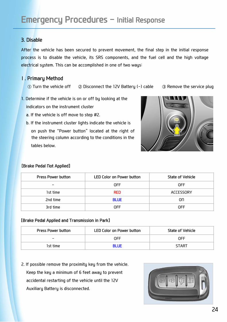
3. Disable
After the vehicle has been secured to prevent movement, the final step in the initial response
process is to disable the vehicle, its SRS components, and the fuel cell and the high voltage
electrical system. This can be accomplished in one of two ways:
Ⅰ. Primary Method ① Turn the vehicle off ② Disconnect the 12V Battery (-) cable ③ Remove the service plug
1. Determine if the vehicle is on or off by looking at the
indicators on the instrument cluster
a. If the vehicle is off move to step #2.
b. If the instrument cluster lights indicate the vehicle is
on push the “Power button” located at the right ofthe steering column according to the conditions in the
tables below.
Press Power button LED Color on Power button State of Vehicle
- OFF OFF
1st time BLUE START
[Brake Pedal Applied and Transmission in Park]
Press Power button LED Color on Power button State of Vehicle
- OFF OFF
1st time RED ACCESSORY
2nd time BLUE ON
3rd time OFF OFF
[Brake Pedal Not Applied]
2. If possible remove the proximity key from the vehicle.
Keep the key a minimum of 6 feet away to prevent
accidental restarting of the vehicle until the 12V
Auxiliary Battery is disconnected.
Emergency Procedures - Initial ResponseEmergency Procedures - Initial Response
24

3. Disconnect the 12V battery (-) cable (A) which islocated in the trunk.
Before disconnecting the 12V battery (-) cable ,
if necessary, lower the windows and unlock the doors.Once the 12V battery (-) cable is disconnected, thewindow and door lock controls will not operate.
4. If possible, remove the service plug in the trunk.
1) Lift the locking hook (A) in the direction of the arrow.
2) Remove the safety plug after pulling the lever
(B) 90 degrees in the direction of the arrow.
Emergency Procedures - Initial ResponseEmergency Procedures - Initial Response
25
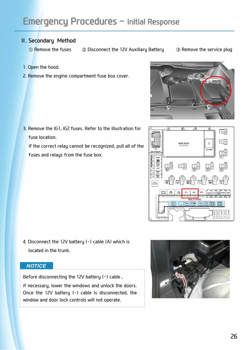
Ⅱ. Secondary Method ① Remove the fuses ② Disconnect the 12V Auxiliary Battery ③ Remove the service plug
1. Open the hood.
2. Remove the engine compartment fuse box cover.
3. Remove the IG1, IG2 fuses. Refer to the illustration for
fuse location.
If the correct relay cannot be recognized, pull all of the
fuses and relays from the fuse box.
4. Disconnect the 12V battery (-) cable (A) which is
located in the trunk.
Before disconnecting the 12V battery (-) cable ,
if necessary, lower the windows and unlock the doors.Once the 12V battery (-) cable is disconnected, thewindow and door lock controls will not operate.
Emergency Procedures - Initial ResponseEmergency Procedures - Initial Response
26
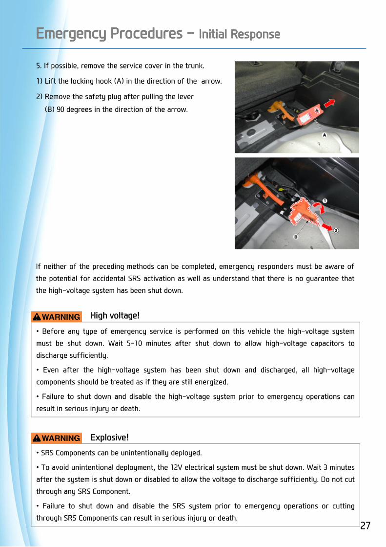
5. If possible, remove the service cover in the trunk.
1) Lift the locking hook (A) in the direction of the arrow.
2) Remove the safety plug after pulling the lever
(B) 90 degrees in the direction of the arrow.
If neither of the preceding methods can be completed, emergency responders must be aware of
the potential for accidental SRS activation as well as understand that there is no guarantee that
the high-voltage system has been shut down.
• Before any type of emergency service is performed on this vehicle the high-voltage system
must be shut down. Wait 5-10 minutes after shut down to allow high-voltage capacitors to
discharge sufficiently.
• Even after the high-voltage system has been shut down and discharged, all high-voltage
components should be treated as if they are still energized.
• Failure to shut down and disable the high-voltage system prior to emergency operations can
result in serious injury or death.
• SRS Components can be unintentionally deployed.
• To avoid unintentional deployment, the 12V electrical system must be shut down. Wait 3 minutes
after the system is shut down or disabled to allow the voltage to discharge sufficiently. Do not cut
through any SRS Component.
• Failure to shut down and disable the SRS system prior to emergency operations or cutting
through SRS Components can result in serious injury or death.
High voltage!
Explosive!
Emergency Procedures - Initial ResponseEmergency Procedures - Initial Response
27
Having addressed the general initial response procedures for handling the Tucson hydrogen fuel
cell vehicle in an emergency, the following sections will address specific types of emergencies.
Extrication
Extrication operations for the Tucson hydrogen fuel cell vehicle is almost the same as for a
conventional vehicle, but
with some exceptions. Utilize the “Identify, Immobilize, and Disable” model described in the
previous pages prior to engaging in emergency extrication operations.
Emergency Procedures - Specific types ResponseEmergency Procedures - Specific types Response
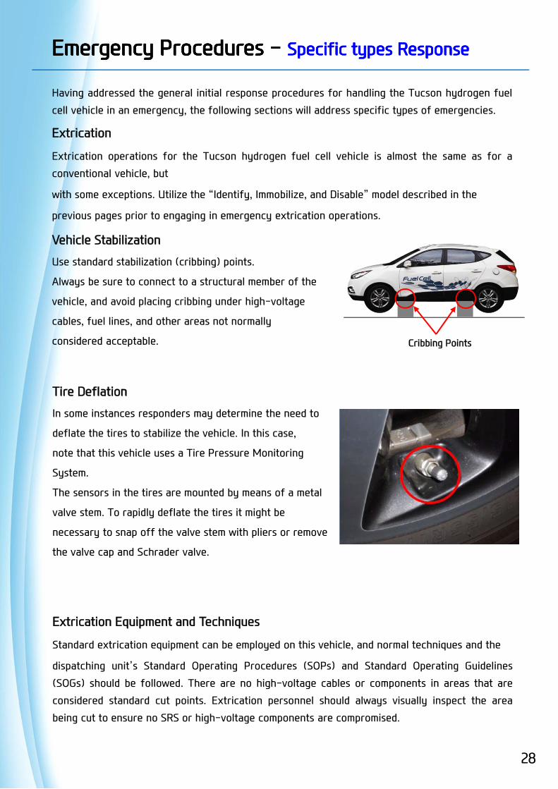
Cribbing Points
Vehicle Stabilization
Use standard stabilization (cribbing) points.
Always be sure to connect to a structural member of the
vehicle, and avoid placing cribbing under high-voltage
cables, fuel lines, and other areas not normally
considered acceptable.
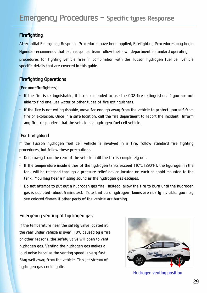
Tire Deflation
In some instances responders may determine the need to
deflate the tires to stabilize the vehicle. In this case,
note that this vehicle uses a Tire Pressure Monitoring
System.
The sensors in the tires are mounted by means of a metal
valve stem. To rapidly deflate the tires it might be
necessary to snap off the valve stem with pliers or remove
the valve cap and Schrader valve.
Extrication Equipment and Techniques
Standard extrication equipment can be employed on this vehicle, and normal techniques and the
dispatching unit’s Standard Operating Procedures (SOPs) and Standard Operating Guidelines
(SOGs) should be followed. There are no high-voltage cables or components in areas that are
considered standard cut points. Extrication personnel should always visually inspect the area
being cut to ensure no SRS or high-voltage components are compromised.
28
Emergency Procedures - Specific types ResponseEmergency Procedures - Specific types Response
Firefighting
After Initial Emergency Response Procedures have been applied, Firefighting Procedures may begin.
Hyundai recommends that each response team follow their own department’s standard operating
procedures for fighting vehicle fires in combination with the Tucson hydrogen fuel cell vehicle
specific details that are covered in this guide.
Firefighting Operations
[For non-firefighters]
• If the fire is extinguishable, it is recommended to use the CO2 fire extinguisher. If you are not
able to find one, use water or other types of fire extinguishers.
• If the fire is not extinguishable, move far enough away from the vehicle to protect yourself from
fire or explosion. Once in a safe location, call the fire department to report the incident. Inform
any first responders that the vehicle is a hydrogen fuel cell vehicle.
[For firefighters]
If the Tucson hydrogen fuel cell vehicle is involved in a fire, follow standard fire fighting
procedures, but follow these precautions:
• Keep away from the rear of the vehicle until the fire is completely out.
• If the temperature inside either of the hydrogen tanks exceed 110°C [290°F], the hydrogen in the
tank will be released through a pressure relief device located on each solenoid mounted to the
tank. You may hear a hissing sound as the hydrogen gas escapes.
• Do not attempt to put out a hydrogen gas fire. Instead, allow the fire to burn until the hydrogen
gas is depleted (about 5 minutes). Note that pure hydrogen flames are nearly invisible; you may
see colored flames if other parts of the vehicle are burning.
29
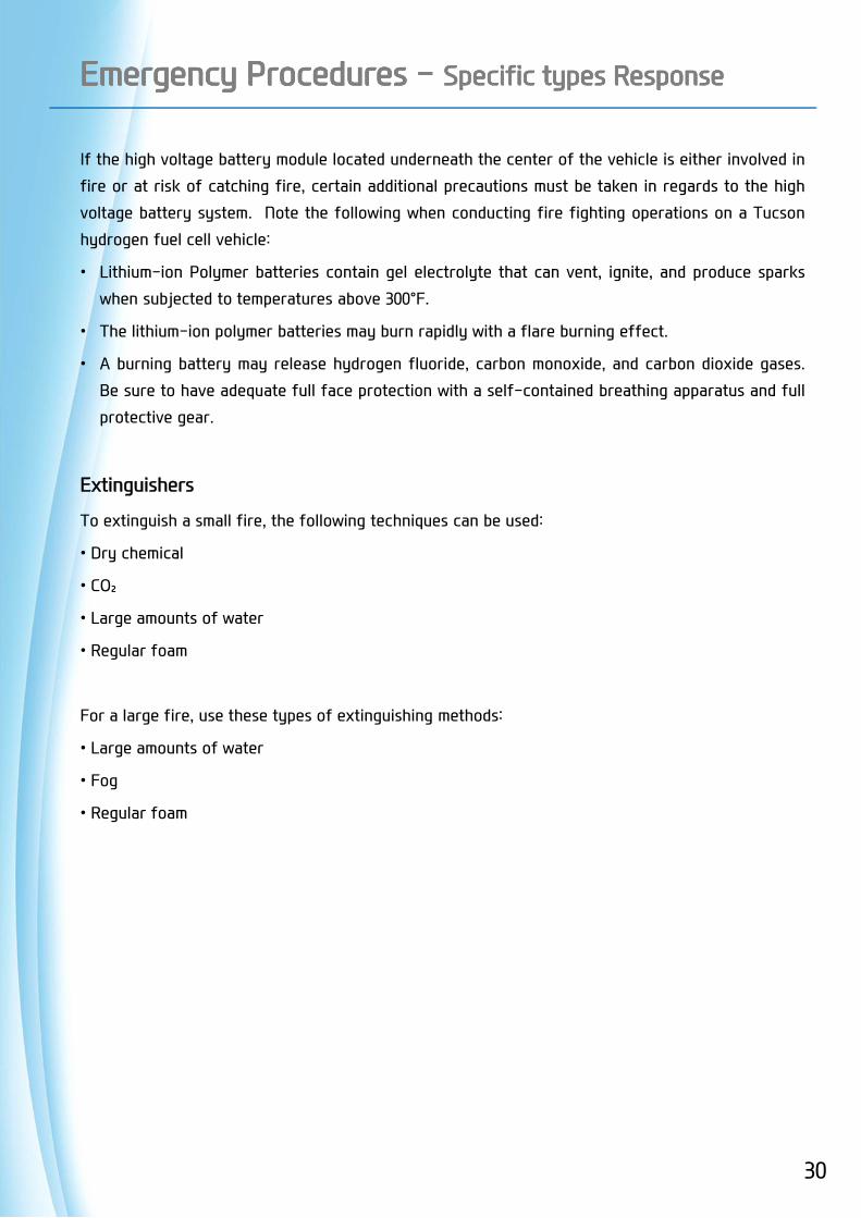
Hydrogen venting position
Emergency venting of hydrogen gas
If the temperature near the safety valve located at
the rear under vehicle is over 110°C caused by a fire
or other reasons, the safety valve will open to vent
hydrogen gas. Venting the hydrogen gas makes a
loud noise because the venting speed is very fast.
Stay well away from the vehicle. This jet stream of
hydrogen gas could ignite.
Emergency Procedures - Specific types ResponseEmergency Procedures - Specific types Response
If the high voltage battery module located underneath the center of the vehicle is either involved in
fire or at risk of catching fire, certain additional precautions must be taken in regards to the high
voltage battery system. Note the following when conducting fire fighting operations on a Tucson
hydrogen fuel cell vehicle:
• Lithium-ion Polymer batteries contain gel electrolyte that can vent, ignite, and produce sparks
when subjected to temperatures above 300°F.
• The lithium-ion polymer batteries may burn rapidly with a flare burning effect.
• A burning battery may release hydrogen fluoride, carbon monoxide, and carbon dioxide gases.
Be sure to have adequate full face protection with a self-contained breathing apparatus and full
protective gear.
Extinguishers
To extinguish a small fire, the following techniques can be used:
• Dry chemical
• CO₂
• Large amounts of water
• Regular foam
For a large fire, use these types of extinguishing methods:
• Large amounts of water
• Fog
• Regular foam
30
Emergency Procedures - Specific types ResponseEmergency Procedures - Specific types Response
Overhaul Operations
During overhaul operations it is important for responders to remember the dangers that are still
present, even after a fire has been extinguished.
Just as during a fire, the same dangers exist. They include, but are not limited to:
• Harmful gasses
• Reignition of fire
• Electrical Burns, Shock, or Electrocution
To protect oneself and others, and to minimize potential risk, responders should use appropriate
Personal Protective Equipment (PPE) defined by the department’s SOP’s and ensure the vehicle’s
high-voltage electrical system has been disabled. The methods described at the beginning of the
Emergency Response Procedures should be followed.
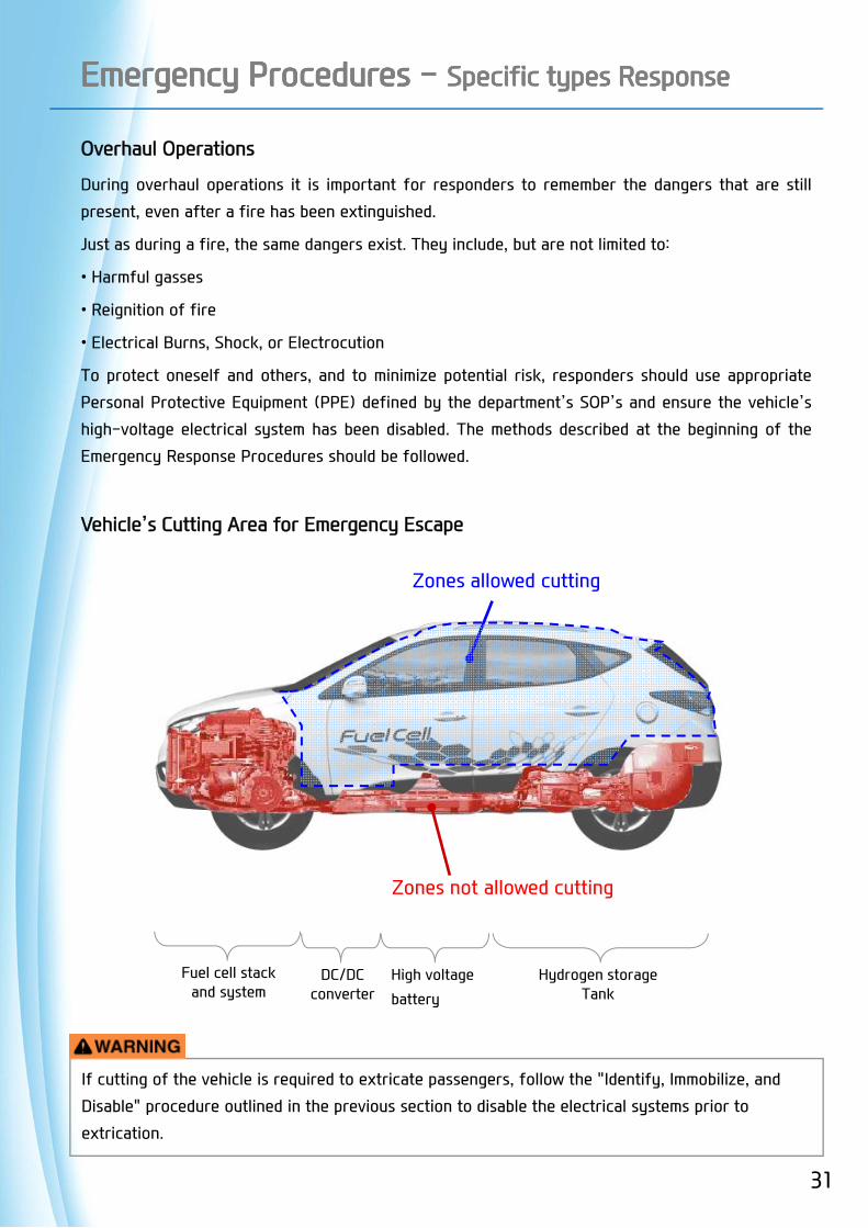
Vehicle’s Cutting Area for Emergency Escape
If cutting of the vehicle is required to extricate passengers, follow the "Identify, Immobilize, and
Disable" procedure outlined in the previous section to disable the electrical systems prior to
extrication.
Zones allowed cutting
Fuel cell stack and system
DC/DCconverter
High voltage
battery
Hydrogen storage Tank
Zones not allowed cutting
31

Submersion in Water
In the case of an incident involving a submerged or partially submerged Tucson hydrogen fuel cell
vehicle, follow the procedures outlined below.
Once the vehicle has been removed from the water and drained completely, the drained water that
is surrounding the area will not be electrically charged. The high voltage electrical system remains
isolated from the water that had been in contact with the vehicle.
[Procedure]
1. Remove the vehicle from water.
2. Drain the water from the vehicle.
3. Disable the vehicle by using the method described in the
"Identify, Immobilize, and Disable" procedure outlined in
the previous section.
Emergency Procedures - Specific types ResponseEmergency Procedures - Specific types Response
32
33
Emergency Procedures - Specific types ResponseEmergency Procedures - Specific types Response
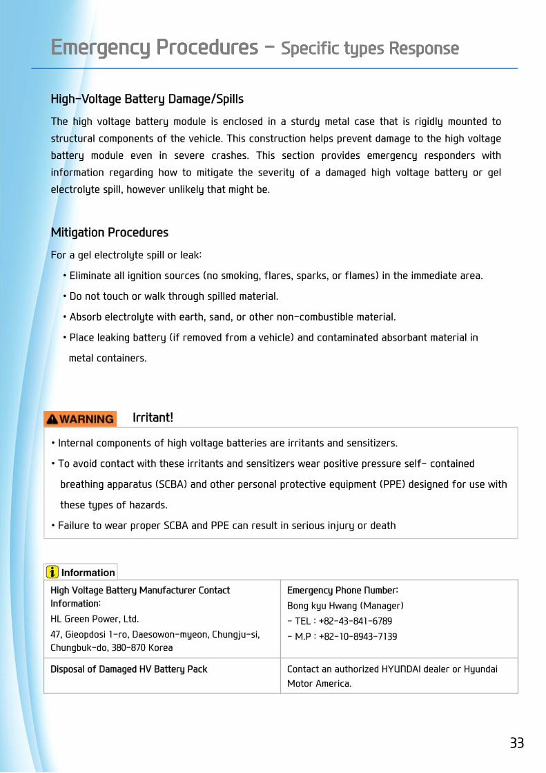
High-Voltage Battery Damage/Spills
The high voltage battery module is enclosed in a sturdy metal case that is rigidly mounted to
structural components of the vehicle. This construction helps prevent damage to the high voltage
battery module even in severe crashes. This section provides emergency responders with
information regarding how to mitigate the severity of a damaged high voltage battery or gel
electrolyte spill, however unlikely that might be.
Mitigation Procedures
For a gel electrolyte spill or leak:
• Eliminate all ignition sources (no smoking, flares, sparks, or flames) in the immediate area.
• Do not touch or walk through spilled material.
• Absorb electrolyte with earth, sand, or other non-combustible material.
• Place leaking battery (if removed from a vehicle) and contaminated absorbant material in
metal containers.
• Internal components of high voltage batteries are irritants and sensitizers.
• To avoid contact with these irritants and sensitizers wear positive pressure self- contained
breathing apparatus (SCBA) and other personal protective equipment (PPE) designed for use with
these types of hazards.
• Failure to wear proper SCBA and PPE can result in serious injury or death
Irritant!
High Voltage Battery Manufacturer Contact Information:
HL Green Power, Ltd.
47, Gieopdosi 1-ro, Daesowon-myeon, Chungju-si, Chungbuk-do, 380-870 Korea
Emergency Phone Number:
Bong kyu Hwang (Manager)
- TEL : +82-43-841-6789
- M.P : +82-10-8943-7139
Disposal of Damaged HV Battery Pack Contact an authorized HYUNDAI dealer or Hyundai Motor America.
Emergency Procedures - Specific types ResponseEmergency Procedures - Specific types Response
First Aid for Electrolyte Exposure
The Tucson Hydrogen Fuel Cell battery module is a self-contained, sealed unit and poses no
electrolyte contamination hazards under normal conditions. It is only under the rare instance of
battery damage that the gel electrolyte would be exposed and a person could come in contact
with it.
Follow these guidelines for electrolyte exposure.
If a victim has been exposed to electrolyte, complete these steps first:
• Move victim to fresh air.
• Apply artificial respiration if victim is not breathing.
• Administer oxygen if breathing is difficult.
• Remove and isolate contaminated clothing and shoes.
• Ensure that other emergency responders are aware of the materials involved and take
precautions to protect themselves.
Then treat the victim according to his/her path of exposure:
[Absorption]
- Eye Contact: Rinse eyes with water for 15 minutes.
- Skin Contact: Wash area thoroughly with soap and water.
[Inhalation]
- Remove the victim and leave the area immediately to avoid further exposure.
[Ingestion]
- Compel the victim to drink milk or water and induce vomiting.
34
35
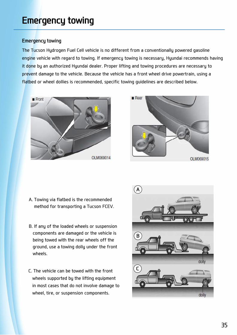
Emergency towing
The Tucson Hydrogen Fuel Cell vehicle is no different from a conventionally powered gasoline
engine vehicle with regard to towing. If emergency towing is necessary, Hyundai recommends having
it done by an authorized Hyundai dealer. Proper lifting and towing procedures are necessary to
prevent damage to the vehicle. Because the vehicle has a front wheel drive powertrain, using a
flatbed or wheel dollies is recommended, specific towing guidelines are described below.
Emergency towingEmergency towing
A. Towing via flatbed is the recommendedmethod for transporting a Tucson FCEV.
B. If any of the loaded wheels or suspensioncomponents are damaged or the vehicle isbeing towed with the rear wheels off theground, use a towing dolly under the frontwheels.
C. The vehicle can be towed with the front
wheels supported by the lifting equipment
in most cases that do not involve damage to
wheel, tire, or suspension components.
A
B
C
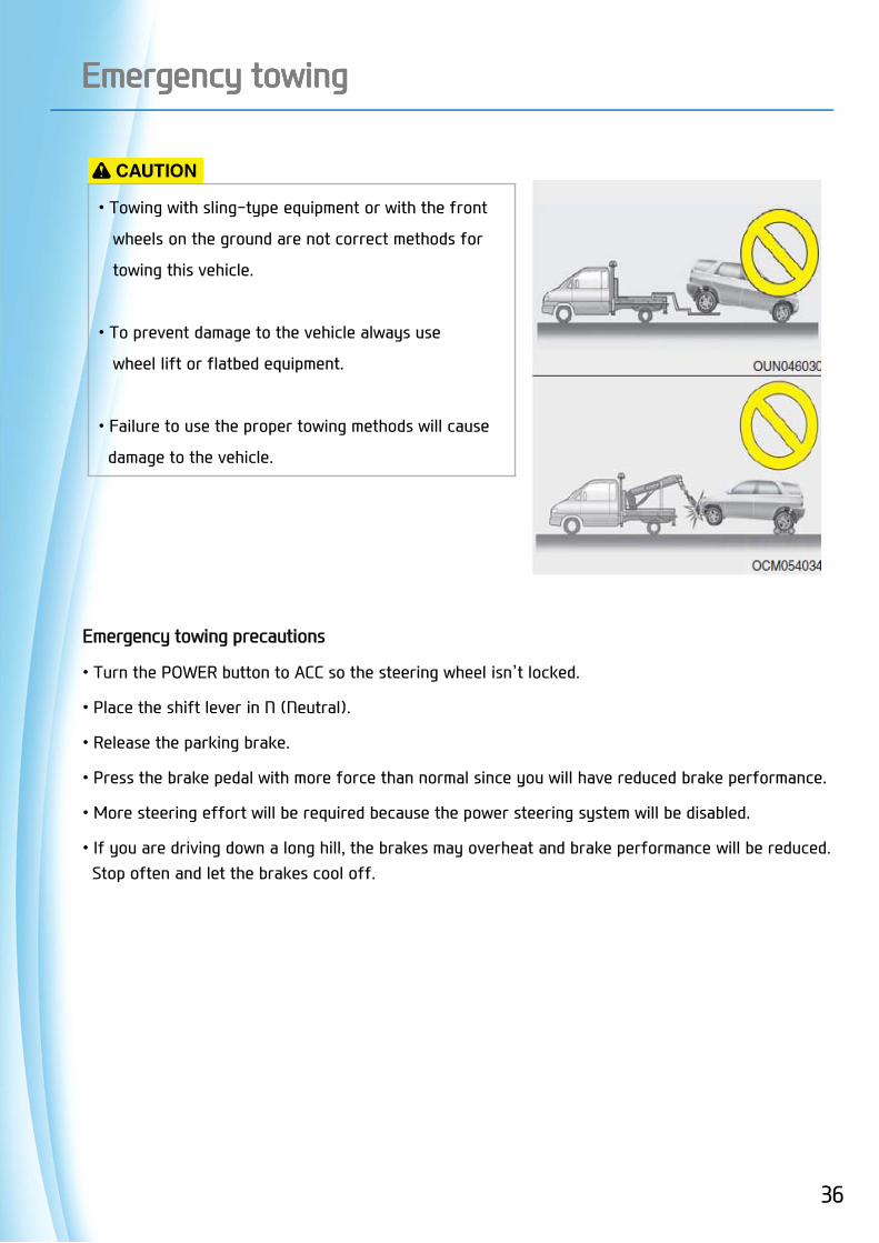
Emergency towingEmergency towing
• Towing with sling-type equipment or with the front
wheels on the ground are not correct methods for
towing this vehicle.
• To prevent damage to the vehicle always use
wheel lift or flatbed equipment.
• Failure to use the proper towing methods will cause
damage to the vehicle.
Emergency towing precautions
• Turn the POWER button to ACC so the steering wheel isn’t locked.
• Place the shift lever in N (Neutral).
• Release the parking brake.
• Press the brake pedal with more force than normal since you will have reduced brake performance.
• More steering effort will be required because the power steering system will be disabled.
• If you are driving down a long hill, the brakes may overheat and brake performance will be reduced. Stop often and let the brakes cool off.
36
37
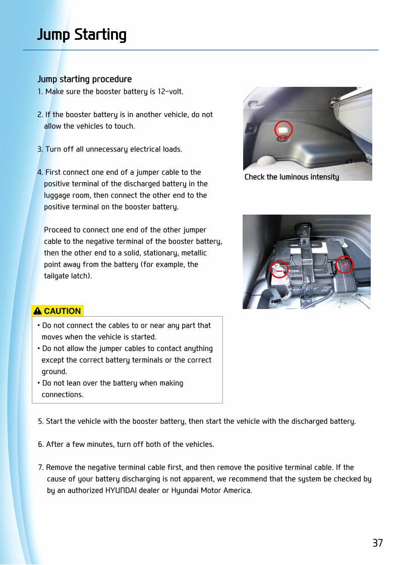
Check the luminous intensity
Jump starting procedure1. Make sure the booster battery is 12-volt.
2. If the booster battery is in another vehicle, do not allow the vehicles to touch.
3. Turn off all unnecessary electrical loads.
4. First connect one end of a jumper cable to the positive terminal of the discharged battery in the luggage room, then connect the other end to the positive terminal on the booster battery.
Proceed to connect one end of the other jumper cable to the negative terminal of the booster battery, then the other end to a solid, stationary, metallic point away from the battery (for example, the tailgate latch).
Jump StartingJump Starting
• Do not connect the cables to or near any part that moves when the vehicle is started. • Do not allow the jumper cables to contact anything except the correct battery terminals or the correct ground. • Do not lean over the battery when making connections.
5. Start the vehicle with the booster battery, then start the vehicle with the discharged battery.
6. After a few minutes, turn off both of the vehicles.
7. Remove the negative terminal cable first, and then remove the positive terminal cable. If the cause of your battery discharging is not apparent, we recommend that the system be checked by by an authorized HYUNDAI dealer or Hyundai Motor America.
-

ⓒ2014 Hyundai Motor CompanyAll rights reserved.This document may not be altered without the writtenpermission of Hyundai Motor Company.