Embed Size (px)
Citation preview
With Tier 4 Interim Engine installed
HYUNDAI HEAVY INDUSTRIES
MOVING YOU FURTHER
HYUNDAICONSTRUCTION EQUIPMENT AMERICAS, INC.*Photo may include optional equipment
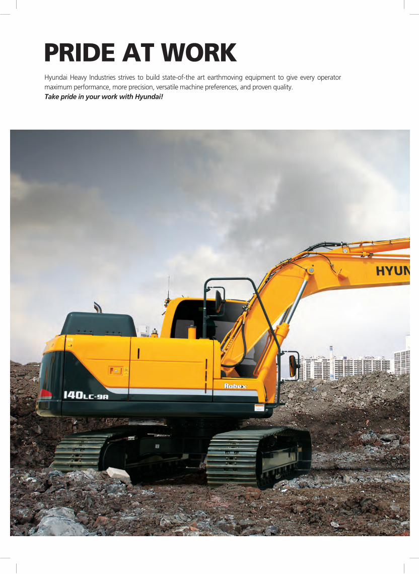
Hyundai Heavy Industries strives to build state-of-the art earthmoving equipment to give every operator maximum performance, more precision, versatile machine preferences, and proven quality. Take pride in your work with Hyundai!
PRIDE AT WORK
2/3
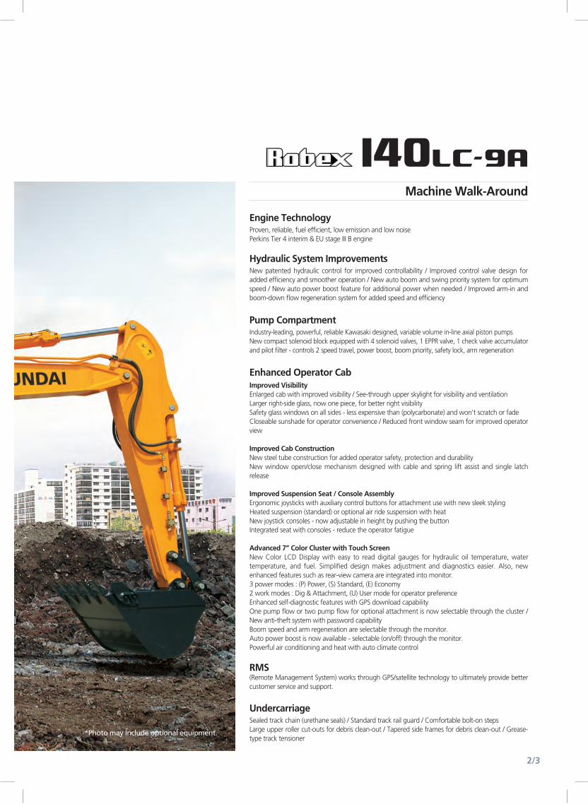
*Photo may include optional equipment.
Sealed track chain (urethane seals) / Standard track rail guard / Comfortable bolt-on stepsLarge upper roller cut-outs for debris clean-out / Tapered side frames for debris clean-out / Grease-type track tensioner
Undercarriage
New patented hydraulic control for improved controllability / Improved control valve design for added efficiency and smoother operation / New auto boom and swing priority system for optimum speed / New auto power boost feature for additional power when needed / Improved arm-in and boom-down flow regeneration system for added speed and efficiency
Hydraulic System Improvements
Proven, reliable, fuel efficient, low emission and low noise Perkins Tier 4 interim & EU stage III B engine
Engine Technology
Industry-leading, powerful, reliable Kawasaki designed, variable volume in-line axial piston pumpsNew compact solenoid block equipped with 4 solenoid valves, 1 EPPR valve, 1 check valve accumulator and pilot filter - controls 2 speed travel, power boost, boom priority, safety lock, arm regeneration
Pump Compartment
Improved VisibilityEnlarged cab with improved visibility / See-through upper skylight for visibility and ventilationLarger right-side glass, now one piece, for better right visibilitySafety glass windows on all sides - less expensive than (polycarbonate) and won’t scratch or fadeCloseable sunshade for operator convenience / Reduced front window seam for improved operator view
Improved Cab ConstructionNew steel tube construction for added operator safety, protection and durabilityNew window open/close mechanism designed with cable and spring lift assist and single latch release
Improved Suspension Seat / Console AssemblyErgonomic joysticks with auxiliary control buttons for attachment use with new sleek stylingHeated suspension (standard) or optional air ride suspension with heatNew joystick consoles - now adjustable in height by pushing the buttonIntegrated seat with consoles - reduce the operator fatigue
Advanced 7” Color Cluster with Touch ScreenNew Color LCD Display with easy to read digital gauges for hydraulic oil temperature, water temperature, and fuel. Simplified design makes adjustment and diagnostics easier. Also, new enhanced features such as rear-view camera are integrated into monitor.3 power modes : (P) Power, (S) Standard, (E) Economy 2 work modes : Dig & Attachment, (U) User mode for operator preferenceEnhanced self-diagnostic features with GPS download capabilityOne pump flow or two pump flow for optional attachment is now selectable through the cluster / New anti-theft system with password capabilityBoom speed and arm regeneration are selectable through the monitor.Auto power boost is now available - selectable (on/off) through the monitor.Powerful air conditioning and heat with auto climate control
RMS (Remote Management System) works through GPS/satellite technology to ultimately provide better customer service and support.
Enhanced Operator Cab
Machine Walk-Around
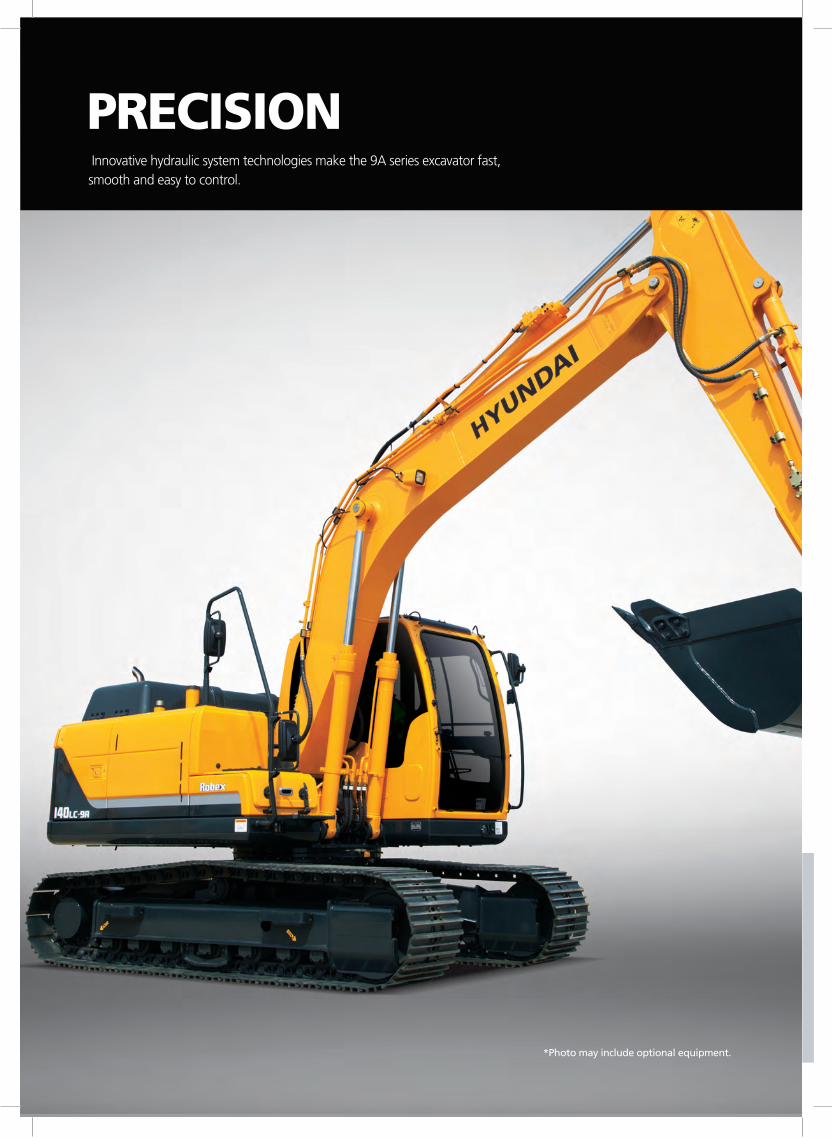
*Photo may include optional equipment.
Innovative hydraulic system technologies make the 9A series excavator fast, smooth and easy to control.
PRECISION
4/5
The engine horsepower and hydraulic horsepower together in unison through the advanced CAPO (Computer Aided Power Optimization) system, flow for the job at hand. Operator can set their own preferences for boom or swing priority, power mode selection and optional work tools at the touch of a button.The CAPO system also provides complete self diagnostic features and digital gauges for important information like hydraulic oil temperature, water temperatures and fuel level. This system interfaces with multiple sensors placed throughout the hydraulic system as well as the electronically controlled engine to provide the optimum level of engine power and hydraulic flow.
Computer Aided Power
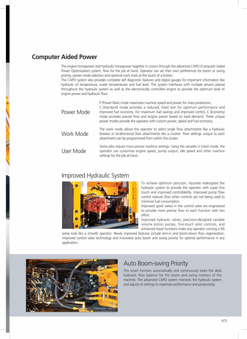
Improved Hydraulic SystemTo achieve optimum precision, Hyundai redesigned the hydraulic system to provide the operator with super fine touch and improved controllability. Improved pump flow control reduces flow when controls are not being used to minimize fuel consumption.Improved spool valves in the control valve are engineered to provide more precise flow to each function with less effort.Improved hydraulic valves, precision-designed variable volume piston pumps, fine-touch pilot controls, and enhanced travel functions make any operator running a 9A
series look like a smooth operator. Newly improved features include arm-in and boom-down flow regeneration, improved control valve technology and innovative auto boom and swing priority for optimal performance in any application.
P (Power Max) mode maximizes machine speed and power for mass production. S (Standard) mode provides a reduced, fixed rpm for optimum performance and improved fuel economy. For maximum fuel savings and improved control, E (Economy) mode provides precise flow and engine power based on load demand. Three unique power modes provide the operator with custom power, speed and fuel economy.
Power Mode
Some jobs require more precise machine settings. Using the versatile U (User) mode, the operator can customize engine speed, pump output, idle speed and other machine settings for the job at hand.
User Mode
The work mode allows the operator to select single flow attachments like a hydraulic breaker or bi-directional flow attachments like a crusher. Flow settings unique to each attachment can be programmed from within the cluster.
Work Mode
Auto Boom-swing PriorityThis smart function automatically and continuously looks the ideal hydraulic flow balance for the boom and swing motions of the machine. The advanced CAPO system monitors the hydraulic system and adjusts its settings to maximize performance and productivity.
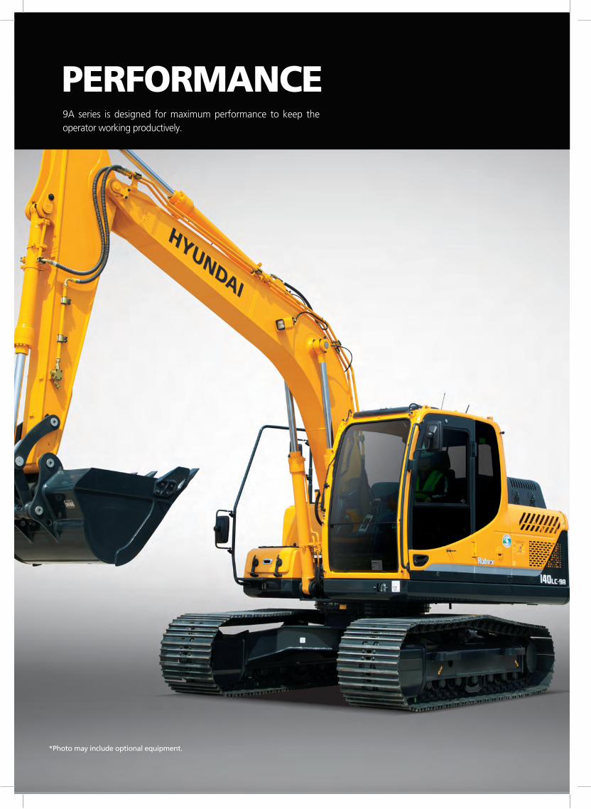
*Photo may include optional equipment.*Photo may include optional equipment.
9A series is designed for maximum performance to keep the operator working productively.
PERFORMANCE
Durable track rail guards keep track links in place. Track adjustment is made easy with standard grease cylinder track adjusters and shock absorbing springs.
Track Rail Guard & Adjusters
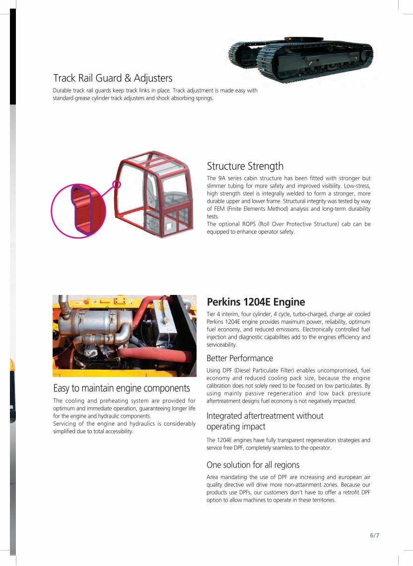
Easy to maintain engine componentsThe cooling and preheating system are provided for optimum and immediate operation, guaranteeing longer life for the engine and hydraulic components.Servicing of the engine and hydraulics is considerably simplified due to total accessibility.
8/9
Structure StrengthThe 9A series cabin structure has been fitted with stronger but slimmer tubing for more safety and improved visibility. Low-stress, high strength steel is integrally welded to form a stronger, more durable upper and lower frame. Structural integrity was tested by way of FEM (Finite Elements Method) analysis and long-term durability tests.The optional ROPS (Roll Over Protective Structure) cab can be equipped to enhance operator safety.
Better PerformanceUsing DPF (Diesel Particulate Filter) enables uncompromised, fuel economy and reduced cooling pack size, because the engine calibration does not solely need to be focused on low particulates. By using mainly passive regeneration and low back pressure aftertreatment designs fuel economy is not negatively impacted.
Integrated aftertreatment without operating impactThe 1204E engines have fully transparent regeneration strategies and service free DPF, completely seamless to the operator.
One solution for all regionsArea mandating the use of DPF are increasing and european air quality directive will drive more non-attainment zones. Because our products use DPFs, our customers don't have to offer a retrofit DPF option to allow machines to operate in these territories.
Perkins 1204E EngineTier 4 interim, four cylinder, 4 cycle, turbo-charged, charge air cooled Perkins 1204E engine provides maximum power, reliability, optimum fuel economy, and reduced emissions. Electronically controlled fuel injection and diagnostic capabilities add to the engines efficiency and serviceability.
8/96/7
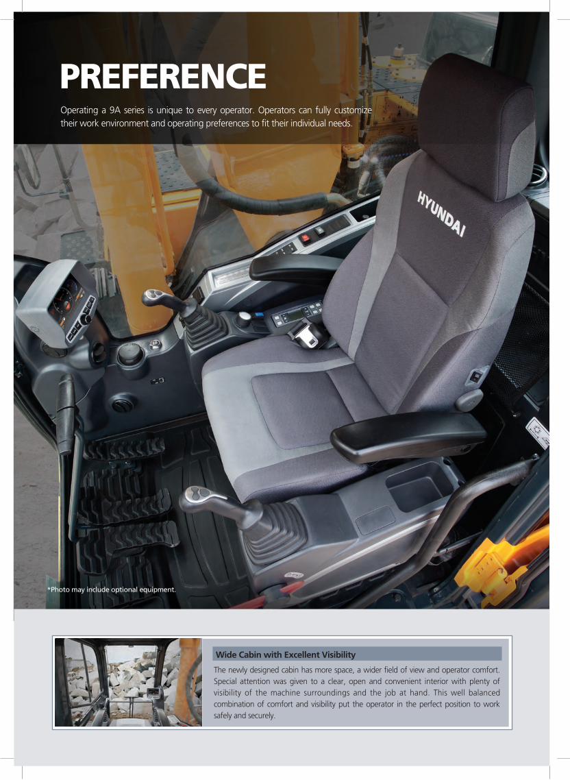
*Photo may include optional equipment.
Operating a 9A series is unique to every operator. Operators can fully customize their work environment and operating preferences to fit their individual needs.
PREFERENCE
Wide Cabin with Excellent Visibility
The newly designed cabin has more space, a wider field of view and operator comfort. Special attention was given to a clear, open and convenient interior with plenty of visibility of the machine surroundings and the job at hand. This well balanced combination of comfort and visibility put the operator in the perfect position to work safely and securely.
8/9
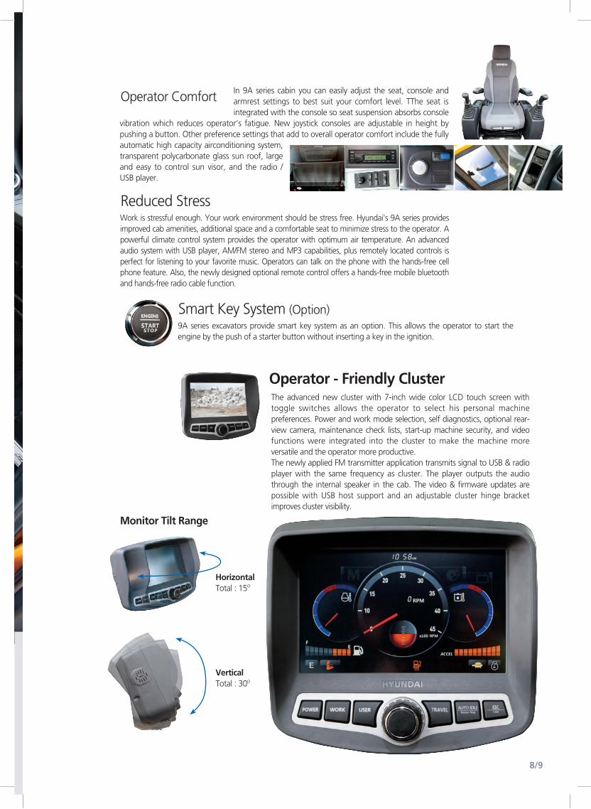
The advanced new cluster with 7-inch wide color LCD touch screen with toggle switches allows the operator to select his personal machine preferences. Power and work mode selection, self diagnostics, optional rear-view camera, maintenance check lists, start-up machine security, and video functions were integrated into the cluster to make the machine more versatile and the operator more productive.The newly applied FM transmitter application transmits signal to USB & radio player with the same frequency as cluster. The player outputs the audio through the internal speaker in the cab. The video & firmware updates are possible with USB host support and an adjustable cluster hinge bracket improves cluster visibility.
Operator - Friendly Cluster
Work is stressful enough. Your work environment should be stress free. Hyundai's 9A series provides improved cab amenities, additional space and a comfortable seat to minimize stress to the operator. A powerful climate control system provides the operator with optimum air temperature. An advanced audio system with USB player, AM/FM stereo and MP3 capabilities, plus remotely located controls is perfect for listening to your favorite music. Operators can talk on the phone with the hands-free cell phone feature. Also, the newly designed optional remote control offers a hands-free mobile bluetooth and hands-free radio cable function.
9A series excavators provide smart key system as an option. This allows the operator to start the engine by the push of a starter button without inserting a key in the ignition.
Reduced Stress
Smart Key System (Option)
In 9A series cabin you can easily adjust the seat, console and armrest settings to best suit your comfort level. TThe seat is integrated with the console so seat suspension absorbs console
vibration which reduces operator‘s fatigue. New joystick consoles are adjustable in height by pushing a button. Other preference settings that add to overall operator comfort include the fully automatic high capacity airconditioning system, transparent polycarbonate glass sun roof, large and easy to control sun visor, and the radio / USB player.
Operator Comfort
HorizontalTotal : 15o
VerticalTotal : 30o
Monitor Tilt Range
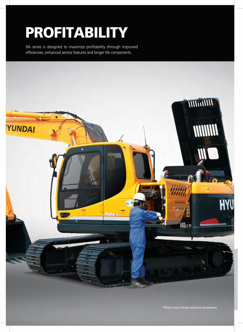
9A series is designed to maximize profitability through improved efficiencies, enhanced service features and longer life components.
PROFITABILITY
*Photo may include optional equipment.
10/11
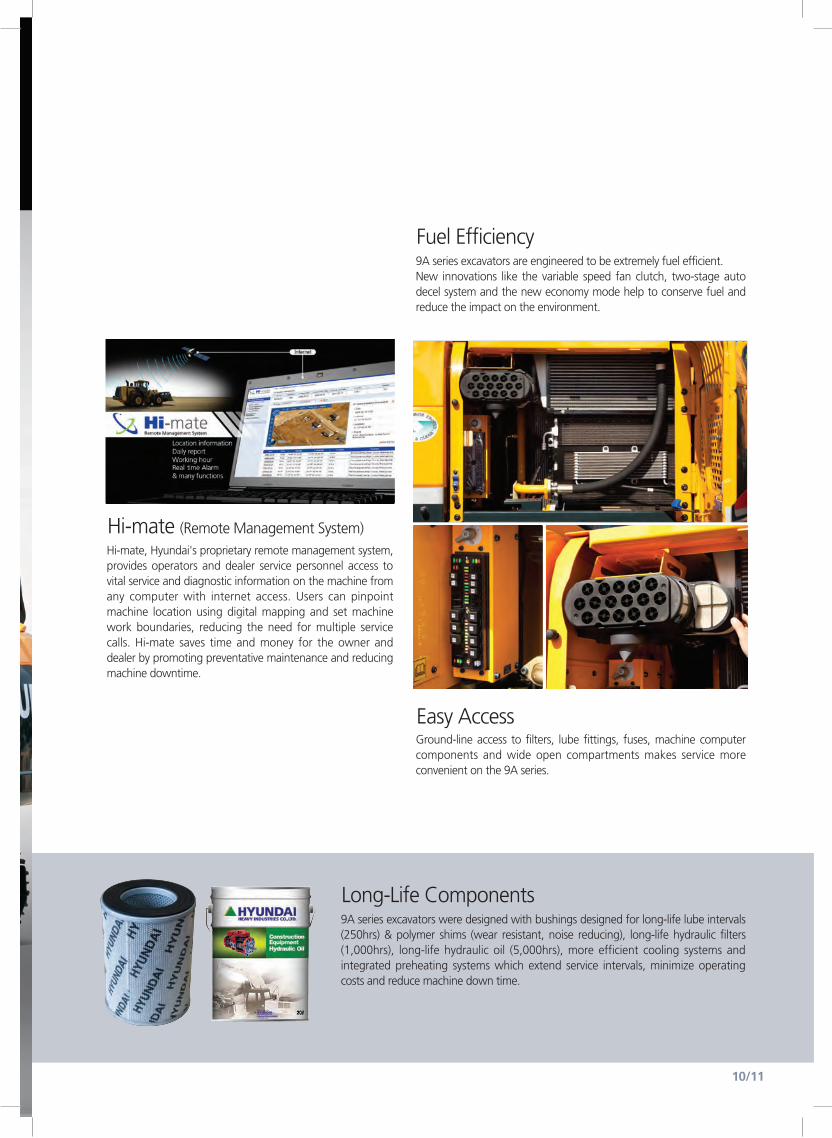
Easy AccessGround-line access to filters, lube fittings, fuses, machine computer components and wide open compartments makes service more convenient on the 9A series.
Hi-mate (Remote Management System)Hi-mate, Hyundai's proprietary remote management system, provides operators and dealer service personnel access to vital service and diagnostic information on the machine from any computer with internet access. Users can pinpoint machine location using digital mapping and set machine work boundaries, reducing the need for multiple service calls. Hi-mate saves time and money for the owner and dealer by promoting preventative maintenance and reducing machine downtime.
Fuel Efficiency9A series excavators are engineered to be extremely fuel efficient.New innovations like the variable speed fan clutch, two-stage auto decel system and the new economy mode help to conserve fuel and reduce the impact on the environment.
Long-Life Components9A series excavators were designed with bushings designed for long-life lube intervals (250hrs) & polymer shims (wear resistant, noise reducing), long-life hydraulic filters (1,000hrs), long-life hydraulic oil (5,000hrs), more efficient cooling systems and integrated preheating systems which extend service intervals, minimize operating costs and reduce machine down time.
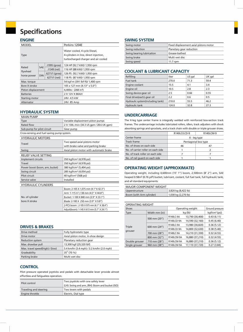
Specifications
MODEL
Type
Rated
flywheel
horse power
Max. torque
Bore X stroke
Piston displacement
Batteries
Starting motor
Alternator
54 kgf.m (391 lbf.ft)/ 1,400 rpm
105 x 127 mm (4.13” x 5.0”)
4,400cc (268 in3)
2 X 12V X 80AH
24V- 4.5 kW
24V- 85 Amp
DIN
SAEJ1995 (gross)
J1349 (net)
6271/1 (gross)
6271/1 (net)
Water cooled, 4 cycle Diesel,
4-cylinders in line, direct injection,
turbocharged charger and air cooled
124 HP (92.7 kW)/ 1,950 rpm
116 HP (88 kW)/ 1,950 rpm
126 PS (92.7 kW)/ 1,950 rpm
118 PS (87 kW)/ 1,950 rpm
Perkins 1204E
ENGINE
MAIN PUMPType
Rated flow
Sub-pump for pilot circuit
Cross-sensing and fuel saving pump system.
Variable displacement piston pumps
2 X 130L /min (34.3 US gpm / 28.6 UK gpm)
Gear pump
HYDRAULIC SYSTEM
DRIVES & BRAKES
HYDRAULIC MOTORS
Travel
Swing
Two speed axial pistons motor
with brake valve and parking brake
Axial piston motor with automatic brake
HYDRAULIC CYLINDERS
No. of cylinder
bore X stroke
Boom: 2-105 X 1,075 mm (4.1”X 42.3”)
Arm: 1-115 X 1,138 mm (4.5” X 44.8”)
Bucket: 1-100 X 840 mm (3.9” X 33.1”)
Blade: 2-100 X 250 mm (3.9” X 9.8”)
2-PCS boom : 2-105 X 975 mm (4.1” X 38.4”)
Adjust(boom): 1-145 X 613 mm (5.7” X 24.1”)
RELIEF VALVE SETTINGImplement circuits
Travel
Power boost (boom, arm, bucket)
Swing circuit
Pilot circuit
Service valve
350 kgf/cm2 (4,978 psi)
350 kgf/cm2 (4,978 psi)
380 kgf/cm2 (5,404 psi)
285 kgf/cm2 (4,054 psi)
40 kgf/cm2 (568 psi)
Installed
MAJOR COMPONENT WEIGHTUpperstructure
Boom (with Arm cylinder)
3,820 kg (8,422 lb)
1,030 kg (2,270 lb)
OPERATING WEIGHTShoes
Type
Triple
grouser
Width mm (in)
500 mm (20”)
600 mm (24”)
700 mm (28”)
800 mm (32”)
710 mm (28”)
R140LC-9A
R140LCD-9A
R140LC-9A
R140LCD-9A
R140LC-9A
R140LCM-9A
R140LCM-9AR140LCM-9A 17,110 (37,720) 0.27 (3.84)
Operating weight
kg (lb)
13,790 (30,400)
14,590 (32,160)
13,980 (30,820)
14,800 (32,630)
14,210 (31,330)
16,880 (37,210)
16,880 (37,210)
Ground pressure
kgf/cm2 (psi)
0.43 (6.11)
0.45 (6.40)
0.36 (5.12)
0.38 (5.40)
0.32 (4.55)
0.32 (4.55)
0.36 (5.12)
Drive method
Drive motor
Reduction system
Max. drawbar pull
Max. travel speed(high) / (low)
Gradeability
Parking brake
Fully hydrostatic type
Axial piston motor, in-shoe design
Planetary reduction gear
13,300 kgf (29,320 lbf)
5.4 km/hr (3.4 mph) / 3.2 km/hr (2.0 mph)
35O (70 %)
Multi wet disc
SWING SYSTEMSwing motor
Swing reduction
Swing bearing lubrication
Swing brake
Swing speed
Fixed displacement axial pistons motor
Planetary gear reduction
Grease-bathed
Multi wet disc
11.7 rpm
COOLANT & LUBRICANT CAPACITYRefilling
Fuel tank
Engine coolant
Engine oil
Swing device-gear oil
Final drive(each)-gear oil
Hydraulic system(including tank)
Hydraulic tank
liter
270.0
15.5
10.5
2.5
2.2
210.0
124.0
US gal
71.3
4.1
2.8
0.66
0.6
55.5
32.8
UK gal
59.4
3.4
2.3
0.55
0.5
46.2
27.3
CONTROLPilot pressure operated joysticks and pedals with detachable lever provide almost
effortless and fatigueless operation.
Pilot control
Traveling and steering
Engine throttle
Two joysticks with one safety lever
(LH): Swing and arm, (RH): Boom and bucket (ISO)
Two levers with pedals
Electric, Dial type
UNDERCARRIAGEThe X-leg type center frame is integrally welded with reinforced box-section track
frames. The undercarriage includes lubricated rollers, idlers, track adjusters with shock
absorbing springs and sprockets, and a track chain with double or triple grouser shoes.
Center frame
Track frame
No. of shoes on each side
No. of carrier roller on each side
No. of track roller on each side
No. of rail guard on each side
X - leg type
Pentagonal box type
R140LC/LCD-9 R140LCM-9
47
2
7
1
46
1
7
1
OPERATING WEIGHT (APPROXIMATE)Operating weight, including 4,600mm (15’ 1”) boom, 2,500mm (8’ 2”) arm, SAE
heaped 0.58m3 (0.76 yd3) bucket, lubricant, coolant, full fuel tank, full hydraulic tank,
and all standard equipments.
Double grouserSingle grouser 960 mm (38”)
Capacity
m3 (yd3)
BoomLength
Weight
Length
Weight
mm (ft.in)
kg (lb)
mm (ft.in)
kg (lb)
1,900 (6’ 3”)
560 (1,230)
87.3 [94.8]
8,900 [9,660]
19,620 [21,300]
102 [110.8]
10,400 [11,290]
22,930 [24,890]
76.5 [83.1]
7,800 [8,470]
17,200 [18,670]
80.4 [87.3]
8,200 [8,900]
18,080 [19,630]
87.3 [94.8]
8,900 [9,660]
19,620 [21,300]
102 [110.8]
10,400 [11,290]
22,930 [24,890]
73.6 [79.9]
7,500 [8,140]
16,530 [17,950]
77.5 [84.1]
7,900 [8,580]
17,420 [18,910]
87.3 [94.8]
8,900 [9,660]
19,620 [21,300]
102 [110.8]
10,400 [11,290]
22,930 [24,890]
62.8 [68.2]
6,400 [6,950]
14,110 [15,320]
65.7 [71.4]
6,700 [7,270]
14,770 [16,040]
87.3 [94.8]
8,900 [9,660]
19,620 [21,300]
102 [110.8]
10,400 [11,290]
22,930 [24,890]
55.9 [60.7]
5,700 [6,190]
12,570 [13,640]
57.9 [62.8]
5,900 [6,410]
13,010 [14,120]
[ ]:
Power
Boost
2,100 (6’ 11”)
580 (1,280)
2,500 (8’ 2”)
610 (1,340)
4,600 (15’ 1”)1,030 (2,270)
3,000 (9’ 10”)
670 (1,480)
Remarks
Arm
Bucket
digging
force
SAE
kN
kgf
lbf
ISO
kN
kgf
lbf
SAE
kN
kgf
lbf
ISO
kN
kgf
lbf
Arm
crowd
force
Note: Boom weight includes arm cylinder, piping, and pin
Arm weight includes bucket cylinder, linkage, and pin
SAE
heaped
CECE
heaped
Without
sidecutters
With
sidecutters
Width
mm (in) Weight
kg (lb)
Recommendation mm (ft.in)
4,600 (15’ 1”) Boom 4,900 (16’ 1”) Adjustable Boom 4,100 (13’ 5”) Boom
1,900 (6’ 3”) Arm 2,100 (6’ 11”) Arm 2,500 (8’ 2”) Arm 3,000 (9’ 10”) Arm 1,900 (6’ 3”) Arm 2,100 (6’ 11”) Arm 1,900 (6’ 3”) Arm 2,100 (6’ 11”) Arm 2,500 (8’ 2”) Arm
0.23 (0.30)
0.40 (0.52)
0.46 (0.60)
0.52 (0.68)
0.58 (0.76)
0.65 (0.85)
0.71 (0.93)
0.45 (0.59)
0.55 (0.72)⊙★
0.20 (0.26)
0.35 (0.46)
0.40 (0.52)
0.45 (0.59)
0.50 (0.65)
0.55 (0.72)
0.60 (0.78)
0.40 (0.52)
0.45 (0.59)
520 (20.5)
760 (29.9)
850 (33.5)
935 (36.8)
1,030 (40.6)
1,110 (43.7)
1,205 (47.4)
1,520 (59.8)
1,800 (70.9)
620 (24.4)
860 (33.9)
950 (37.4)
1,035 (40.8)
1,130 (44.5)
1,210 (47.6)
-
-
-
335 (740)
410 (900)
435 (960)
460 (1,010)
480 (1,060)
500 (1,100)
540 (1,190)
410 (900)
585 (1,290)
SAEheapedm3 (yd3)
0.23 (0.30) 0.40 (0.52)0.46 (0.60)
0.71 (0.93) ⊙ ★0.45 (0.59) 0.55 (0.72)
●
●
●
●
●
■
▲
●
■
●
●
●
●
●
■
▲
●
■
●
●
●
●
●
●
■
●
●
●
●
●
●
●
■
▲
●
●
●
●
●
●
■
▲
▲
■
■
●
●
●
■
▲
▲
-
■
▲
●
●
■
■
▲
-
-
▲
▲
●
●
●
●
■
▲
-
■
▲
■
■
▲
-
-
-
-
-
-
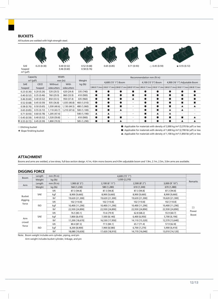
Booms and arms are welded, a low-stress, full-box section design. 4.1m, 4.6m mono booms and 4.9m adjustable boom and 1.9m, 2.1m, 2.5m, 3.0m arms are available.
⊙ Ditching bucket
★ Slope finishing bucket
●: Applicable for materials with density of 2,000 kg /m3 (3,370 lb/ yd3) or less
■: Applicable for materials with density of 1,600 kg /m3 (2,700 lb/ yd3) or less
▲: Applicable for materials with density of 1,100 kg /m3 (1,850 lb/ yd3) or less
ATTACHMENT
All buckets are welded with high-strength steel.
BUCKETS
DIGGING FORCE
12/13
0.52 (0.68)0.58 (0.76)
0.65 (0.85)
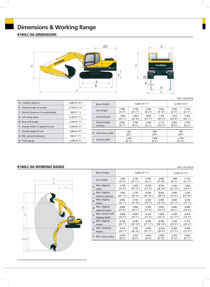
Dimensions & Working Range
Boom length
Arm length
Max. digging
reach
Max. digging
reach on ground
Max. digging
depth
Max. digging
depth (8' level)
Max. vertical wall
digging depth
Max. digging
height
Max. dumping
height
Min. swing radius
A
A’
B
B’
C
D
E
F
1,900(6’ 3”)
7,750(25’ 5”)
7,600(24’ 11”)
4,950(16’ 2”)
4,680(15’ 4”)
4,650(15’ 3”)
8,100(26’ 7”)
5,670(18’ 7”)
2,630(8’ 8”)
2,100(6’ 11”)
7,920(25’ 11”)
7,770(25’ 6”)
5,150(16’ 10”)
4,900(16’ 1”)
4,900(16’ 1”)
8,180(26’ 10”)
5,750(18’ 10”)
2,670(8’ 9”)
4,600 (15’ 1”)
2,500(8’ 2”)
8,330(27’ 4”)
8,180(26’ 10”)
5,550(18’ 3”)
5,340(17’ 6”)
5,330(17’ 6”)
8,500(27’ 11”)
6,060(19’ 11”)
2,650(8’ 8”)
3,000(9’ 10”)
8,790(28’ 10”)
8,650(28’ 4”)
6,050(19’ 10”)
5,870(19’ 3”)
5,850(19’ 2”)
8,780(28’ 10”)
6,330(20’ 9”)
2,680(8’ 10”)
1,900(6’ 3”)
7,260(23’ 10”)
7,090(23’ 3”)
4,540(14’ 11”)
4,280(14’ 1”)
4,240(13’ 11”)
7,700(25’ 3”)
5,260(17’ 3”)
2,350(7’ 9”)
2,100(6’ 11”)
4,100 (13’ 5”)
7,420(24’ 4”)
7,260(23’ 10”)
4,740(15’ 7”)
4,490(14’ 9”)
4,350(14’ 3”)
7,770(25’ 6”)
5,340(17’ 6”)
2,460(8’ 1”)
Tumbler distance
Overall length of crawler
Ground clearance of counterweight
Tail swing radius
Rear-end length
Overall width of upperstructure
Overall height of cab
Min. ground clearance
Track gauge
A
B
C
D
D’
E
F
G
H
3,000 (9’ 10”)
3,750 (12’ 4”)
940 (3’ 1”)
2,330 (7’ 7”)
2,330 (7’ 7”)
2,500 (8’ 2”)
2,860 (9’ 4”)
440 (1’ 5”)
2,000 (6’ 7”)
Unit : mm (ft.in)
Unit : mm (ft.in)
Boom length
Arm length
Overall length
Overall height of boom
I
J
1,900(6’ 3”)
7,820(25’ 7”)
2,650(8’ 7”)
2,100(6’ 11”)
7,850(25’ 8”)
2,760(9’ 0”)
2,500(8’ 2”)
7,820(25’ 7”)
2,780(9’ 1”)
3,000(9’ 10”)
7,790(25’ 6”)
3,110(10’ 2”)
1,900(6’ 3”)
7,320(24’ 0”)
2,600(8’ 5”)
2,100(6’ 11”)
4,100 (13’ 5”)
7,350(24’ 1”)
2,790(9’ 2”)
600(24”)
700(28”)
2,600(8’ 6”)
2,700(8’ 10”)
4,600 (15’ 1”)
Track shoe width
Overall width
R140LC-9A DIMENSIONS
R140LC-9A WORKING RANGE
AB
D,D'
I
C
J F
G
E
HL
K
D
E
B B' C
A
A'
F
AB
D,D'
I
C
J F
G
E
HL
K
D
E
B B' C
A
A'
F
K
L
500(20”)
2,500(8’ 2”)
Boom length
Arm length
Max. digging
reach
Max. digging
reach on ground
Max. digging
depth
Max. digging
depth (8' level)
Max. vertical wall
digging depth
Max. digging
height
Max. dumping
height
Min. swing radius
A
A’
B
B’
C
D
E
F
1,900(6’ 3”)
7,750(25’ 5”)
7,600(24’ 11”)
4,950(16’ 2”)
4,680(15’ 4”)
4,650(15’ 3”)
8,100(26’ 7”)
5,670(18’ 7”)
2,630(8’ 8”)
2,100(6’ 11”)
7,920(25’ 11”)
7,770(25’ 6”)
5,150(16’ 10”)
4,900(16’ 1”)
4,900(16’ 1”)
8,180(26’ 10”)
5,750(18’ 10”)
2,670(8’ 9”)
4,600 (15’ 1”)
2,500(8’ 2”)
8,330(27’ 4”)
8,180(26’ 10”)
5,550(18’ 3”)
5,340(17’ 6”)
5,330(17’ 6”)
8,500(27’ 11”)
6,060(19’ 11”)
2,650(8’ 8”)
3,000(9’ 10”)
8,790(28’ 10”)
8,650(28’ 4”)
6,050(19’ 10”)
5,870(19’ 3”)
5,850(19’ 2”)
8,780(28’ 10”)
6,330(20’ 9”)
2,680(8’ 10”)
1,900(6’ 3”)
7,260(23’ 10”)
7,090(23’ 3”)
4,540(14’ 11”)
4,280(14’ 1”)
4,240(13’ 11”)
7,700(25’ 3”)
5,260(17’ 3”)
2,350(7’ 9”)
2,100(6’ 11”)
4,100 (13’ 5”)
7,420(24’ 4”)
7,260(23’ 10”)
4,740(15’ 7”)
4,490(14’ 9”)
4,350(14’ 3”)
7,770(25’ 6”)
5,340(17’ 6”)
2,460(8’ 1”)
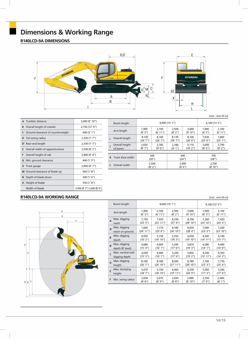
Unit : mm (ft.in)R140LCD-9A WORKING RANGE
AB
D,D'
I
J
O M C
N
F
G
E
HL
K
D
E
B B' C
A
A'
F
Dimensions & Working Range
Tumbler distance
Overall length of crawler
Ground clearance of counterweight
Tail swing radius
Rear-end length
Overall width of upperstructure
Overall height of cab
Min. ground clearance
Track gauge
Ground clearance of blade up
Depth of blade down
Height of blade
Width of blade
A
B
C
D
D’
E
F
G
H
M
N
O
3,000 (9’ 10”)
3,750 (12’ 4”)
940 (3’ 1”)
2,330 (7’ 7”)
2,330 (7’ 7”)
2,500 (8’ 2”)
2,860 (9’ 4”)
440 (1’ 5”)
2,000 (6’ 7”)
560 (1’ 8”)
500 (1’ 6”)
550 (1’ 8”)
2,500 (8’ 2”) 2,600 (8’ 6”)
Unit : mm (ft.in)
R140LCD-9A DIMENSIONS
AB
D,D'
I
J
O M C
N
F
G
E
HL
K
D
E
B B' C
A
A'
F
Boom length
Arm length
Overall length
Overall height of boom
I
J
1,900(6’ 3”)
8,130(26’ 7”)
2,650(8’ 7”)
500(20”)
2,500(8’ 2”)
2,100(6’ 11”)
8,160(26’ 7”)
2,760(9’ 0”)
2,500(8’ 2”)
8,130(26’ 7”)
2,780(9’ 1”)
3,000(9’ 10”)
8,100(26’ 6”)
3,110(10’ 2”)
1,900(6’ 3”)
7,630(25’ 0”)
2,600(8’ 5”)
2,100(6’ 11”)
4,100 (13’ 5”)
7,660(25’ 1”)
2,790(9’ 2”)
600(24”)
700(28”)
2,600(8’ 6”)
2,700(8’ 10”)
4,600 (15’ 1”)
Track shoe width
Overall width
K
L
14/15
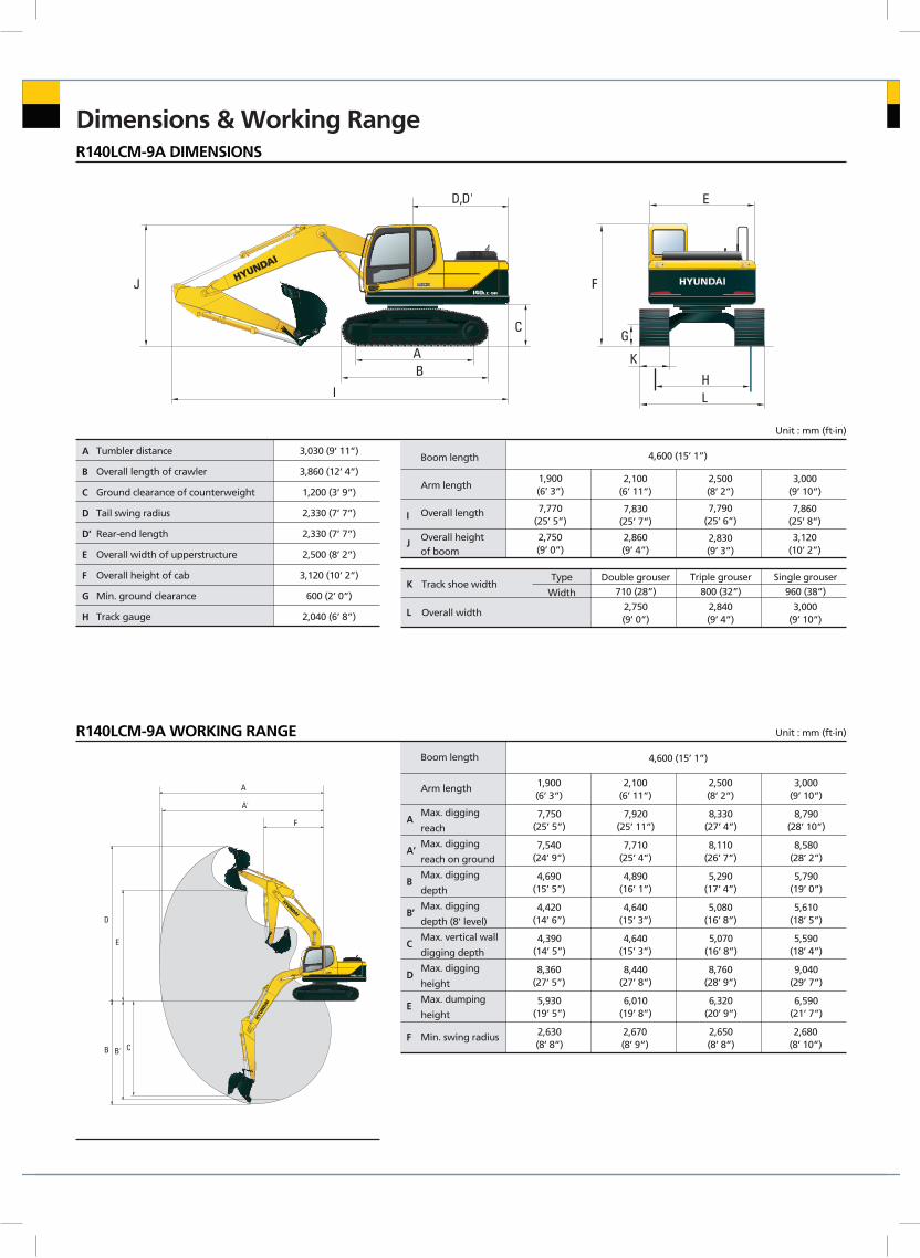
Dimensions & Working Range
Tumbler distance
Overall length of crawler
Ground clearance of counterweight
Tail swing radius
Rear-end length
Overall width of upperstructure
Overall height of cab
Min. ground clearance
Track gauge
A
B
C
D
D’
E
F
G
H
3,030 (9’ 11”)
3,860 (12’ 4”)
1,200 (3’ 9”)
2,330 (7’ 7”)
2,330 (7’ 7”)
2,500 (8’ 2”)
3,120 (10’ 2”)
600 (2’ 0”)
2,040 (6’ 8”)
Unit : mm (ft.in)
Unit : mm (ft.in)
R140LCM-9A DIMENSIONS
R140LCM-9A WORKING RANGE
AB
D,D'
I
C
J F
G
E
HL
K
D
E
B B' C
A
A'
F
Boom length
Arm length
Overall length
Overall height of boom
I
J
1,900(6’ 3”)
7,770(25’ 5”)
2,750(9’ 0”)
2,100(6’ 11”)
7,830(25’ 7”)
2,860(9’ 4”)
2,500(8’ 2”)
7,790(25’ 6”)
2,830(9’ 3”)
3,000(9’ 10”)
7,860(25’ 8”)
3,120(10’ 2”)
800 (32”) 960 (38”)710 (28”)Double grouser Triple grouser Single grouser
2,840(9’ 4”)
3,000(9’ 10”)
2,750(9’ 0”)
4,600 (15’ 1”)
Track shoe width
Overall width
Type
WidthK
L
Boom length
Arm length
Max. digging
reach
Max. digging
reach on ground
Max. digging
depth
Max. digging
depth (8' level)
Max. vertical wall
digging depth
Max. digging
height
Max. dumping
height
Min. swing radius
A
A’
B
B’
C
D
E
F
1,900(6’ 3”)
7,750(25’ 5”)
7,540(24’ 9”)
4,690(15’ 5”)
4,420(14’ 6”)
4,390(14’ 5”)
8,360(27’ 5”)
5,930(19’ 5”)
2,630(8’ 8”)
2,100(6’ 11”)
7,920(25’ 11”)
7,710(25’ 4”)
4,890(16’ 1”)
4,640(15’ 3”)
4,640(15’ 3”)
8,440(27’ 8”)
6,010(19’ 8”)
2,670(8’ 9”)
4,600 (15’ 1”)
2,500(8’ 2”)
8,330(27’ 4”)
8,110(26’ 7”)
5,290(17’ 4”)
5,080(16’ 8”)
5,070(16’ 8”)
8,760(28’ 9”)
6,320(20’ 9”)
2,650(8’ 8”)
3,000(9’ 10”)
8,790(28’ 10”)
8,580(28’ 2”)
5,790(19’ 0”)
5,610(18’ 5”)
5,590(18’ 4”)
9,040(29’ 7”)
6,590(21’ 7”)
2,680(8’ 10”)
AB
D,D'
I
C
J F
G
E
HL
K
D
E
B B' C
A
A'
F
Boom length
Arm length
Overall length
Overall height of boom
I
J
Dimensions & Working Range
Boom length
Arm length
Max. digging
reach
Max. digging
reach on ground
Max. digging
depth
Max. digging
depth (8' level)
Max. vertical wall
digging depth
Max. digging
height
Max. dumping
height
Min. swing radius
A
A’
B
B’
C
D
E
F
1,900(6’ 3”)
8,140(26’ 8”)
8,000(26’ 3”)
5,110(16’ 9”)
5,000(16’ 5”)
4,490(14’ 9”)
8,810(28’ 11”)
6,330(20’ 9”)
2,670(8’ 9”)
2,100(6’ 11”)
8,320(27’ 4”)
8,180(26’ 10”)
5,310(17’ 5”)
5,190(17’ 0”)
4,660(15’ 3”)
8,890(29’ 2”)
6,410(21’ 0”)
2,830(9’ 3”)
2,500(8’ 2”)
8,720(28’ 7”)
8,590(28’ 2”)
5,710(18’ 9”)
5,610(18’ 5”)
5,120(16’ 10”)
9,270(30’ 5”)
6,780(22’ 3”)
2,690(8’ 10”)
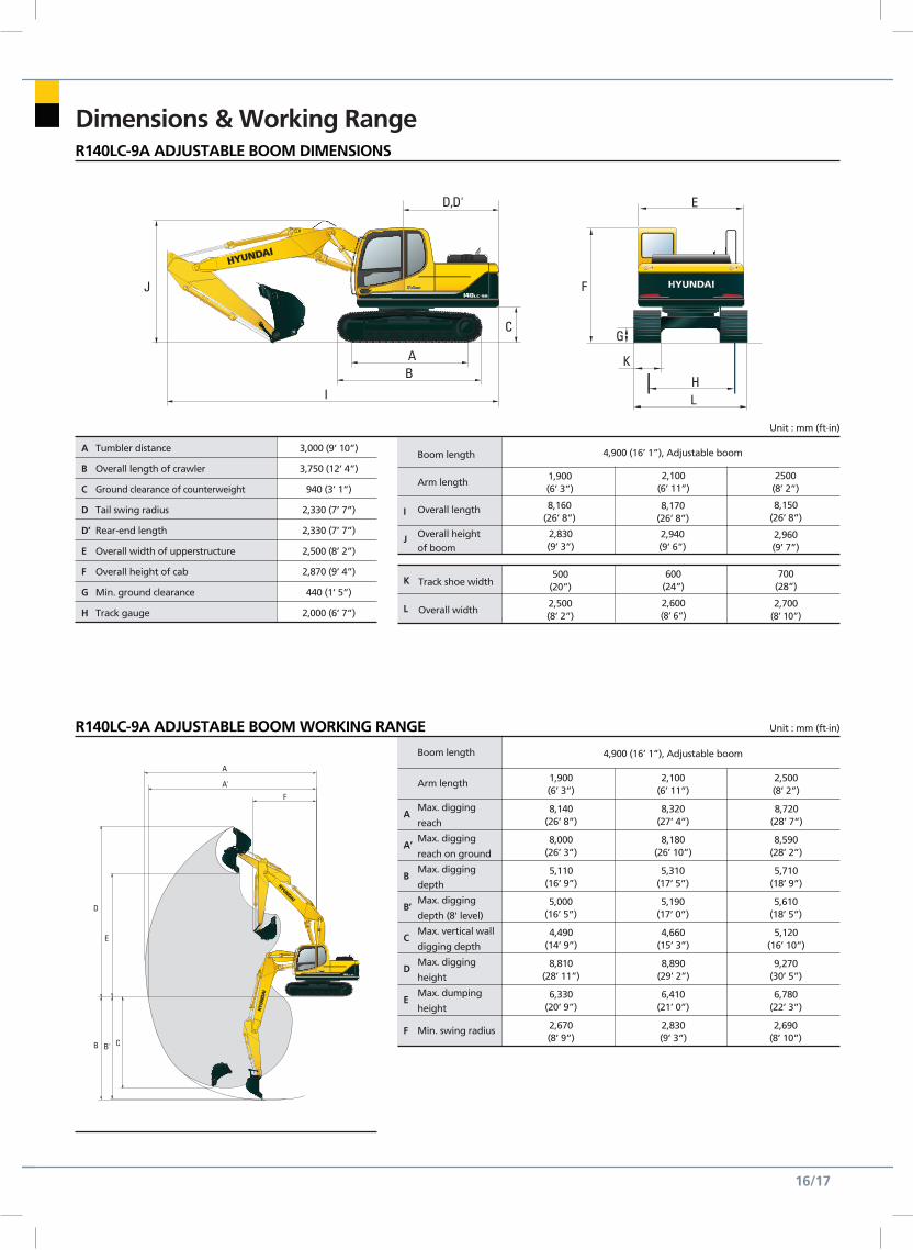
4,900 (16’ 1”), Adjustable boom
Tumbler distance
Overall length of crawler
Ground clearance of counterweight
Tail swing radius
Rear-end length
Overall width of upperstructure
Overall height of cab
Min. ground clearance
Track gauge
A
B
C
D
D’
E
F
G
H
3,000 (9’ 10”)
3,750 (12’ 4”)
940 (3’ 1”)
2,330 (7’ 7”)
2,330 (7’ 7”)
2,500 (8’ 2”)
2,870 (9’ 4”)
440 (1’ 5”)
2,000 (6’ 7”)
Unit : mm (ft.in)
Unit : mm (ft.in)
R140LC-9A ADJUSTABLE BOOM DIMENSIONS
R140LC-9A ADJUSTABLE BOOM WORKING RANGE
AB
D,D'
I
C
J F
G
E
HL
K
D
E
B B' C
A
A'
F
AB
D,D'
I
C
J F
G
E
HL
K
D
E
B B' C
A
A'
F
1,900(6’ 3”)
8,160(26’ 8”)
2,830(9’ 3”)
500(20”)
2,500(8’ 2”)
2,100(6’ 11”)
8,170(26’ 8”)
2,940(9’ 6”)
2500(8’ 2”)
8,150(26’ 8”)
2,960(9’ 7”)
600(24”)
700(28”)
2,600(8’ 6”)
2,700(8’ 10”)
4,900 (16’ 1”), Adjustable boom
Track shoe width
Overall width
K
L
16/17
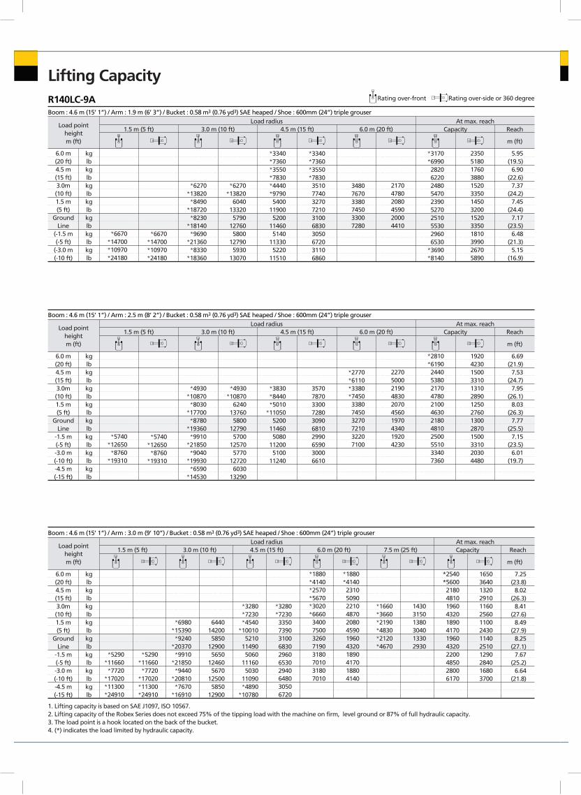
Lifting CapacityR140LC-9A Rating over-front Rating over-side or 360 degree
Boom : 4.6 m (15’ 1”) / Arm : 1.9 m (6’ 3”) / Bucket : 0.58 m3 (0.76 yd3) SAE heaped / Shoe : 600mm (24”) triple grouser
Load pointheightm (ft)
Load radius1.5 m (5 ft) 3.0 m (10 ft) 4.5 m (15 ft) 6.0 m (20 ft) Capacity Reach
m (ft)
At max. reach
6.0 m(20 ft)4.5 m(15 ft)3.0m(10 ft)1.5 m(5 ft)
GroundLine
(-1.5 m(-5 ft)
(-3.0 m(-10 ft)
kglbkglbkglbkglbkglbkglbkglb
*6670*14700*10970*24180
*6670*14700*10970*24180
*6270*13820*8490
*18720*8230
*18140*9690
*21360*8330
*18360
*6270*13820
6040133205790
127605800
127905930
13070
*3340*7360*3550*7830*4440*97905400
119005200
114605140
113305220
11510
*3340*7360*3550*78303510774032707210310068303050672031106860
348076703380745033007280
217047802080459020004410
*3170*69902820622024805470239052702510553029606530
*3690*8140
23505180176038801520335014503200152033501810399026705890
5.95(19.5)
6.90(22.6)
7.37(24.2)
7.45(24.4)
7.17(23.5)
6.48(21.3)
5.15(16.9)
Boom : 4.6 m (15’ 1”) / Arm : 2.5 m (8’ 2”) / Bucket : 0.58 m3 (0.76 yd3) SAE heaped / Shoe : 600mm (24”) triple grouser
Load pointheightm (ft)
Load radius1.5 m (5 ft) 3.0 m (10 ft) 4.5 m (15 ft) 6.0 m (20 ft) Capacity Reach
m (ft)
At max. reach
6.0 m(20 ft)4.5 m(15 ft)3.0m(10 ft)1.5 m(5 ft)
GroundLine
-1.5 m(-5 ft)-3.0 m(-10 ft)-4.5 m(-15 ft)
kglbkglbkglbkglbkglbkglbkglbkglb
*5740*12650*8760
*19310
*5740*12650*8760
*19310
*4930*10870*8030
*17700*8780
*19360*9910
*21850*9040
*19930*6590
*14530
*4930*10870
6240137605800
127905700
125705770
127206030
13290
*3830*8440*5010
*110505200
114605080
112005100
11240
3570787033007280309068102990659030006610
*2770*6110*3380*7450338074503270721032207100
2270500021904830207045601970434019204230
*2810*6190244053802170478021004630218048102500551033407360
19204230150033101310289012502760130028701500331020304480
6.69(21.9)
7.53(24.7)
7.95(26.1)
8.03(26.3)
7.77(25.5)
7.15(23.5)
6.01(19.7)
Boom : 4.6 m (15’ 1”) / Arm : 3.0 m (9’ 10”) / Bucket : 0.58 m3 (0.76 yd3) SAE heaped / Shoe : 600mm (24”) triple grouser
Load pointheightm (ft)
Load radius1.5 m (5 ft) 3.0 m (10 ft) 4.5 m (15 ft) 6.0 m (20 ft) 7.5 m (25 ft) Capacity Reach
m (ft)
At max. reach
6.0 m(20 ft)4.5 m(15 ft)3.0m(10 ft)1.5 m(5 ft)
GroundLine
-1.5 m(-5 ft)-3.0 m(-10 ft)-4.5 m(-15 ft)
kglbkglbkglbkglbkglbkglbkglbkglb
*5290*11660*7720
*17020*11300*24910
*5290 *11660*7720
*17020*11300*24910
*6980*15390*9240
*20370*9910
*21850*9440
*20810*7670
*16910
6440142005850
129005650
124605670
125005850
12900
*3280*7230*4540
*100105210
114905060
111605030
11090*4890
*10780
*3280*72303350739031006830296065302940648030506720
*1880*4140*2570*5670*3020*666034007500326071903180701031807010
*1880*4140231050902210487020804590196043201890417018804140
*1660*3660*2190*4830*2120*4670
143031501380304013302930
*2540*5600218048101960432018904170196043202200485028006170
16503640132029101160256011002430114025101290284016803700
7.25(23.8)
8.02(26.3)
8.41(27.6)
8.49(27.9)
8.25(27.1)
7.67(25.2)
6.64(21.8)
1. Lifting capacity is based on SAE J1097, ISO 10567.2. Lifting capacity of the Robex Series does not exceed 75% of the tipping load with the machine on firm, level ground or 87% of full hydraulic capacity.3. The load point is a hook located on the back of the bucket.4. (*) indicates the load limited by hydraulic capacity.
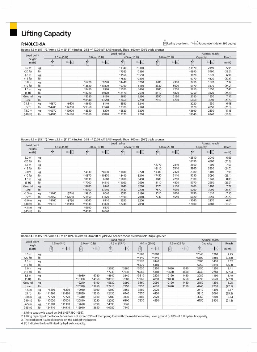
Lifting CapacityR140LCD-9A Rating over-front Rating over-side or 360 degree
Boom : 4.6 m (15’ 1”) / Arm : 1.9 m (6’ 3”) / Bucket : 0.58 m3 (0.76 yd3) SAE heaped / Shoe : 600mm (24”) triple grouser
Load pointheightm (ft)
Load radius1.5 m (5 ft) 3.0 m (10 ft) 4.5 m (15 ft) 6.0 m (20 ft) Capacity Reach
m (ft)
At max. reach
6.0 m(20 ft)4.5 m(15 ft)3.0m(10 ft)1.5 m(5 ft)
GroundLine
(-1.5 m(-5 ft)
(-3.0 m(-10 ft)
kglbkglbkglbkglbkglbkglbkglb
*6670*14700*10970*24180
*6670*14700*10970*24180
*6270*13820*8490
*18720*8230
*18140*9690
*21360*8330
*18360
*6270*13820
6380140706130
135106140
135406270
13820
*3340*7360*3550*7830*4440*9790*5520
*121705650
124605590
12320*5520
*12170
*3340*7360*3550*78303700816034607630329072503240714033007280
378083303680811035907910
230050702210487021304700
*3170*69903070677027105970261057502750606032307120
*3690*8140
24905490187041201620357015503420163035901930425028306240
5.95(19.5)
6.90(22.6)
7.37(24.2)
7.45(24.4)
7.17(23.5)
6.48(21.3)
5.15(16.9)
Boom : 4.6 m (15’ 1”) / Arm : 2.5 m (8’ 2”) / Bucket : 0.58 m3 (0.76 yd3) SAE heaped / Shoe : 600mm (24”) triple grouser
Load pointheightm (ft)
Load radius1.5 m (5 ft) 3.0 m (10 ft) 4.5 m (15 ft) 6.0 m (20 ft) Capacity Reach
m (ft)
At max. reach
6.0 m(20 ft)4.5 m(15 ft)3.0m(10 ft)1.5 m(5 ft)
GroundLine
-1.5 m(-5 ft)-3.0 m(-10 ft)-4.5 m(-15 ft)
kglbkglbkglbkglbkglbkglbkglbkglb
*5740*12650*8760
*19310
*5740*12650*8760
*19310
*4930*10870*8030
*17700*8780
*19360*9910
*21850*9040
*19930*6590
*14530
*4930*10870
6580145106140
135406040
133206110
134706370
14040
*3830*8440*5010
*110505640
124305530
121905550
12240
3770831034907690328072303180701032007050
*2770*6110*3380*7450368081103570787035107740
2410531023205110221048702110465020604540
*2810*61902660586023805250230050702400529027306020
*3540*7800
20404500160035301400309013402950140030901610355021704780
6.69(21.9)
7.53(24.7)
7.95(26.1)
8.03(26.3)
7.77(25.5)
7.15(23.5)
6.01(19.7)
Boom : 4.6 m (15’ 1”) / Arm : 3.0 m (9’ 10”) / Bucket : 0.58 m3 (0.76 yd3) SAE heaped / Shoe : 600mm (24”) triple grouser
Load pointheightm (ft)
Load radius1.5 m (5 ft) 3.0 m (10 ft) 4.5 m (15 ft) 6.0 m (20 ft) 7.5 m (25 ft) Capacity Reach
m (ft)
At max. reach
6.0 m(20 ft)4.5 m(15 ft)3.0m(10 ft)1.5 m(5 ft)
GroundLine
-1.5 m(-5 ft)-3.0 m(-10 ft)-4.5 m(-15 ft)
kglbkglbkglbkglbkglbkglbkglbkglb
*5290*11660*7720
*17020*11300*24910
*5290 *11660*7720
*17020*11300*24910
*6980*15390*9240
*20370*9910
*21850*9440
*20810*7670
*16910
6780149506190
136505990
132106010
132506190
13650
*3280*7230*4540
*10010*5630
*124105500
121305480
12080*4890
*10780
*3280*72303540780032907250315069403130690032407140
*1880*4140*2570*5670*3020*6660*3610*7960356078503480767034807670
*1880*4140244053802350518022204890209046102020445020204450
*1660*3660*2190*4830*2120*4670
154034001480326014803150
*2540*5600238052502150474020804590215047402410531030606750
17603880141031101250276011902620123027101390306018003970
7.25(23.8)
8.02(26.3)
8.41(27.6)
8.49(27.9)
8.25(27.1)
7.67(25.2)
6.64(21.8)
1. Lifting capacity is based on SAE J1097, ISO 10567.2. Lifting capacity of the Robex Series does not exceed 75% of the tipping load with the machine on firm, level ground or 87% of full hydraulic capacity.3. The load point is a hook located on the back of the bucket.4. (*) indicates the load limited by hydraulic capacity.
18/19/20
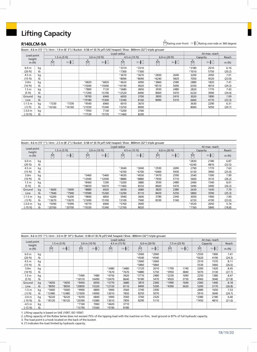
Lifting CapacityR140LCM-9A Rating over-front Rating over-side or 360 degree
Boom : 4.6 m (15’ 1”) / Arm : 1.9 m (6’ 3”) / Bucket : 0.58 m3 (0.76 yd3) SAE heaped / Shoe : 800mm (32”) triple grouser
Load pointheightm (ft)
Load radius1.5 m (5 ft) 3.0 m (10 ft) 4.5 m (15 ft) 6.0 m (20 ft) Capacity Reach
m (ft)
At max. reach
6.0 m(20 ft)4.5 m(15 ft)3.0m(10 ft)1.5 m(5 ft)
GroundLine
(-1.5 m(-5 ft)
(-3.0 m(-10 ft)
kglbkglbkglbkglbkglbkglbkglb
*7330*16160
*7330*16160
*6820*15040*7800
*17200*8700
*19180*9540
*21030*7950
*17530
*6820*15040
7120157006940
153006960
153407130
15720
*3310*7300*3670*8090*4620
*10190*5680
*125206050
133406010
13250*5200
*11460
*3310*7300*3670*80904090902038508490370081603670809037608290
*2830*6240*3860*85103930866038508490
26405820258056902480547024105310
*3180*70103200705028806350282062203020666036308000
261057502050452018204010177039001890417022905050
6.16(20.2)
7.01(23.0)
7.41(24.3)
7.43(24.4)
7.09(23.3)
6.31(20.7)
Boom : 4.6 m (15’ 1”) / Arm : 2.5 m (8’ 2”) / Bucket : 0.58 m3 (0.76 yd3) SAE heaped / Shoe : 800mm (32”) triple grouser
Load pointheightm (ft)
Load radius1.5 m (5 ft) 3.0 m (10 ft) 4.5 m (15 ft) 6.0 m (20 ft) Capacity Reach
m (ft)
At max. reach
6.0 m(20 ft)4.5 m(15 ft)3.0m(10 ft)1.5 m(5 ft)
GroundLine
(-1.5 m(-5 ft)
(-3.0 m(-10 ft)
kglbkglbkglbkglbkglbkglbkglb
*3600*7940*6200
*13670*9390
*20700
*3600*7940*6200
*13670*9390
*20700
*5460*12040*8460
*18650*8880
*19580*9840
*21690*8770
*19330
*5460*12040
7290160706920
152606850
151006960
15340
*3040*6700*4030*8880*5200
*114606030
132905940
13100*5760
*12700
*3040*6700*4030*888038808550368081103600794036408020
*2930*6460*3470*7650393086603820842037808330
2690593025905710248054702380525023405160
*2830*62402790615025405600249054902630580030506720
*3520*7760
21804810177039001590351015403400163035901900419026505840
6.87(22.5)
7.63(25.0)
7.99(26.2)
8.01(26.3)
7.70(25.3)
7.00(23.0)
5.74(18.8)
Boom : 4.6 m (15’ 1”) / Arm : 3.0 m (9’ 10”) / Bucket : 0.58 m3 (0.76 yd3) SAE heaped / Shoe : 800mm (32”) triple grouser
Load pointheightm (ft)
Load radius1.5 m (5 ft) 3.0 m (10 ft) 4.5 m (15 ft) 6.0 m (20 ft) 7.5 m (25 ft) Capacity Reach
m (ft)
At max. reach
6.0 m(20 ft)4.5 m(15 ft)3.0m(10 ft)1.5 m(5 ft)
GroundLine
-1.5 m(-5 ft)-3.0 m(-10 ft)-4.5 m(-15 ft)
kglbkglbkglbkglbkglbkglbkglbkglb
*3650*8050*5660
*12480*8220
*18120
*3650*8050*5660
*12480*8220
*18120
*7490*16510*9450
*20830*9900
*21830*9250
*20390*7160
*15790
7480164906950
153206800
149906840
150807060
15560
*3480*7670*4750
*10470*5770
*127205900
130105900
13010*4420*9740
*3480*76703920864036808110356078503560785037108180
*2060*4540*2660*5860*3120*6880*3710*8180381084003740825037608290
*2060*4540*2660*58602610575024805470236052002300507023205110
*1790*3950*2230*4920*1990*4390
174038401690373016403620
*2550*56202510553023005070225049602360520026805910
*3380*7450
19004190157034601420313013803040144031701650364021804810
7.41(24.3)
8.11(26.6)
8.45(27.7)
8.47(27.8)
8.18(26.8)
7.53(24.7)
6.40(21.0)
1. Lifting capacity is based on SAE J1097, ISO 10567.2. Lifting capacity of the Robex Series does not exceed 75% of the tipping load with the machine on firm, level ground or 87% of full hydraulic capacity.3. The load point is a hook located on the back of the bucket.4. (*) indicates the load limited by hydraulic capacity.
*6420*14150
*5430*11970*9210
*20300*8450
*18630
*6420*14150
*5430*11970
5620123905780
12740
*2900*6390*3280*7230*4230*93305310
117105110
112705050
111305130
11310
*2900*6390*3280*72303440758031606970298065702940648030006610
*3150*694034707650334073603240714032207100
2220489021304700202044501930425019004190
*2880*63502530558022404940217047802270500026305800
201044301540340013402950128028201340295015703460
6.45(21.2)
7.33(24.0)
7.76(25.5)
7.84(25.7)
7.58(24.9)
6.93(22.7)
21
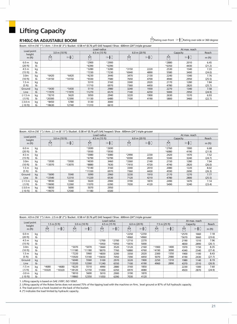
Lifting CapacityR140LC-9A ADJUSTABLE BOOM Rating over-front Rating over-side or 360 degree
Boom : 4.9 m (16’ 1”) / Arm : 1.9 m (6’ 3”) / Bucket : 0.58 m3 (0.76 yd3) SAE heaped / Shoe : 600mm (24”) triple grouser
Load pointheightm (ft)
Load radius3.0 m (10 ft) 4.5 m (15 ft) 6.0 m (20 ft) Capacity Reach
m (ft)
At max. reach
6.0 m(20 ft)4.5 m(15 ft)3.0m(10 ft)1.5 m(5 ft)
GroundLine
(-1.5 m(-5 ft)
(-3.0 m(-10 ft)
kglbkglbkglbkglbkglbkglbkglb
*5930*13070
*5690*12540*8930
*19690*8650
*19070
*5930*13070
5540122105560
122605690
12540
*2690*5930*3080*6790*4030*8880*5140
*113305090
112205020
110705070
11180
*2690*5930*3080*67903460763031606970296065302900639029506500
*2990*6590*3360*7410334073603230712031907030
2230492021404720201044301910421018704120
*2760*60802420534021504740208045902170478024905490
190041901470324012802820122026901270280014703240
6.68(21.9)
7.52(24.7)
7.94(26.0)
8.02(26.3)
7.77(25.5)
7.14(23.4)
Boom : 4.9 m (16’ 1”) / Arm : 2.1 m (6’ 11”) / Bucket : 0.58 m3 (0.76 yd3) SAE heaped / Shoe : 600mm (24”) triple grouser
Load pointheightm (ft)
Load radius3.0 m (10 ft) 4.5 m (15 ft) 6.0 m (20 ft) Capacity Reach
m (ft)
At max. reach
6.0 m(20 ft)4.5 m(15 ft)3.0m(10 ft)1.5 m(5 ft)
GroundLine
(-1.5 m(-5 ft)
(-3.0 m(-10 ft)
kglbkglbkglbkglbkglbkglbkglb
Boom : 4.9 m (16’ 1”) / Arm : 2.5 m (8’ 2”) / Bucket : 0.58 m3 (0.76 yd3) SAE heaped / Shoe : 600mm (24”) triple grouser
Load pointheightm (ft)
Load radius1.5 m (5 ft) 3.0 m (10 ft) 4.5 m (15 ft) 6.0 m (20 ft) 7.5 m (25 ft) Capacity Reach
m (ft)
At max. reach
6.0 m(20 ft)4.5 m(15 ft)3.0m(10 ft)1.5 m(5 ft)
GroundLine
-1.5 m(-5 ft)-3.0 m(-10 ft)
kglbkglbkglbkglbkglbkglbkglb
*4680*10320
*4680*10320
*5070*11180*7220
*15920*6040
*13320*8220
*18120*9010
*19860
*5070*11180
5960131405560
122605510
121505600
12350
*2700*5950*3660*8070*4830
*106505100
112404990
110005010
11050
*2700*59503520776032007050297065502880635029006390
*2250*4960*2710*5970*3120*688033507390322071003160697031907030
*2250*4960227050002160476020204450190041901850408018704120
*1900*41902300507022504960
140030901350298013102890
*2570*56702190483019704340190041901980437022304920
166036601310289011502540110024301140251013002870
7.18(23.6)
7.96(26.1)
8.35(27.4)
8.43(27.7)
8.19(26.9)
7.60(24.9)
1. Lifting capacity is based on SAE J1097, ISO 10567.2. Lifting capacity of the Robex Series does not exceed 75% of the tipping load with the machine on firm, level ground or 87% of full hydraulic capacity.3. The load point is a hook located on the back of the bucket.4. (*) indicates the load limited by hydraulic capacity.

Notes

Notes
PLEASE CONTACT
www.hceamericas.com 2013. 10 Rev.0
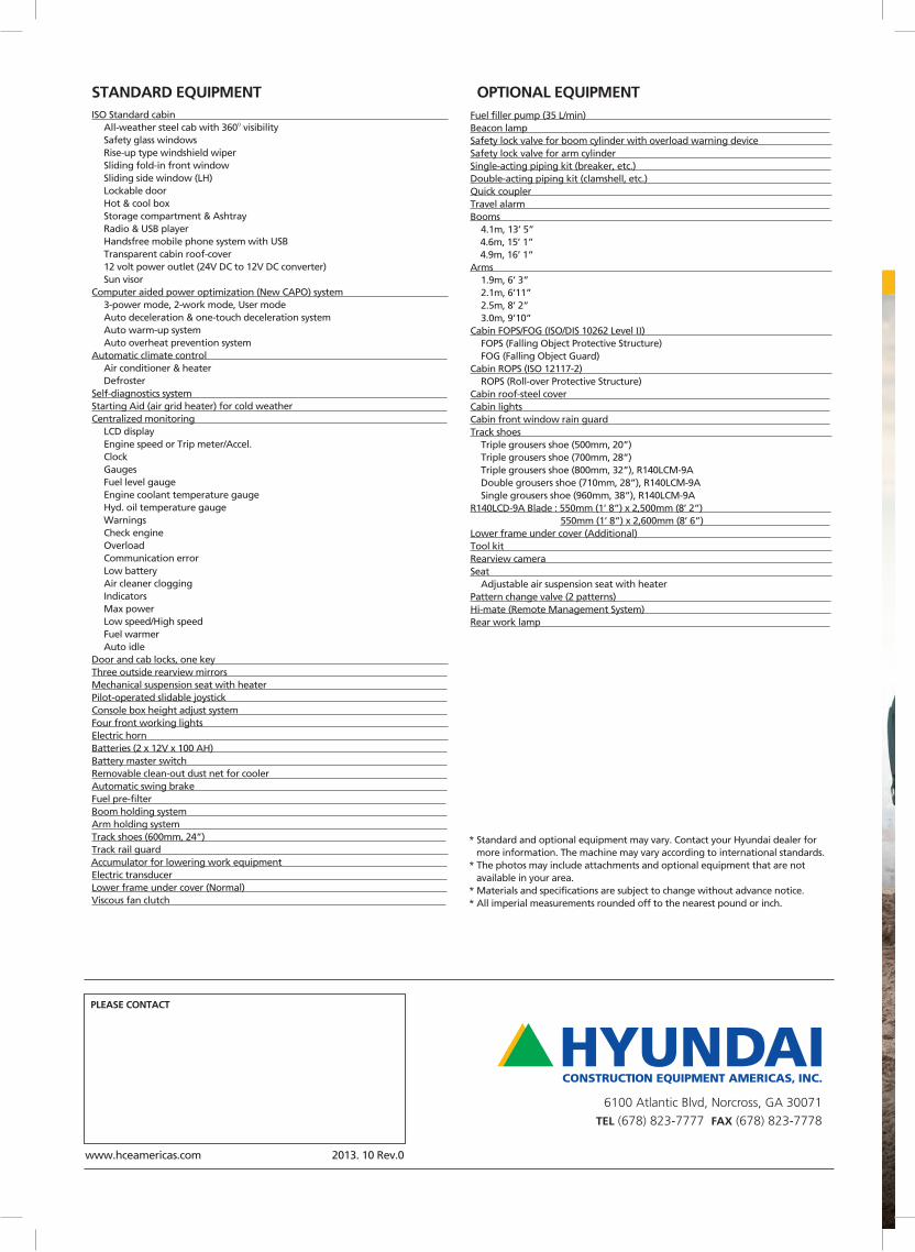
ISO Standard cabin All-weather steel cab with 360O visibility Safety glass windows Rise-up type windshield wiper Sliding fold-in front window Sliding side window (LH) Lockable door Hot & cool box Storage compartment & Ashtray Radio & USB player Handsfree mobile phone system with USB Transparent cabin roof-cover 12 volt power outlet (24V DC to 12V DC converter) Sun visor Computer aided power optimization (New CAPO) system 3-power mode, 2-work mode, User mode Auto deceleration & one-touch deceleration system Auto warm-up system Auto overheat prevention system Automatic climate control Air conditioner & heater Defroster Self-diagnostics system Starting Aid (air grid heater) for cold weather Centralized monitoring LCD display Engine speed or Trip meter/Accel. Clock Gauges Fuel level gauge Engine coolant temperature gauge Hyd. oil temperature gauge Warnings Check engine Overload Communication error Low battery Air cleaner clogging Indicators Max power Low speed/High speed Fuel warmer Auto idle Door and cab locks, one key Three outside rearview mirrors Mechanical suspension seat with heater Pilot-operated slidable joystick Console box height adjust system Four front working lights Electric horn Batteries (2 x 12V x 100 AH) Battery master switch Removable clean-out dust net for cooler Automatic swing brake Fuel pre-filter Boom holding system Arm holding system Track shoes (600mm, 24”) Track rail guard Accumulator for lowering work equipment Electric transducer Lower frame under cover (Normal) Viscous fan clutch
Fuel filler pump (35 L/min) Beacon lamp Safety lock valve for boom cylinder with overload warning device Safety lock valve for arm cylinder Single-acting piping kit (breaker, etc.) Double-acting piping kit (clamshell, etc.) Quick coupler Travel alarm Booms 4.1m, 13’ 5” 4.6m, 15’ 1” 4.9m, 16’ 1”Arms 1.9m, 6’ 3” 2.1m, 6’11” 2.5m, 8’ 2” 3.0m, 9’10”Cabin FOPS/FOG (ISO/DIS 10262 Level II) FOPS (Falling Object Protective Structure) FOG (Falling Object Guard)Cabin ROPS (ISO 12117-2) ROPS (Roll-over Protective Structure)Cabin roof-steel cover Cabin lights Cabin front window rain guard Track shoes Triple grousers shoe (500mm, 20”) Triple grousers shoe (700mm, 28”) Triple grousers shoe (800mm, 32”), R140LCM-9A Double grousers shoe (710mm, 28”), R140LCM-9A Single grousers shoe (960mm, 38”), R140LCM-9AR140LCD-9A Blade : 550mm (1’ 8”) x 2,500mm (8’ 2”) 550mm (1’ 8”) x 2,600mm (8’ 6”) Lower frame under cover (Additional) Tool kit Rearview camera Seat Adjustable air suspension seat with heaterPattern change valve (2 patterns) Hi-mate (Remote Management System) Rear work lamp
STANDARD EQUIPMENT OPTIONAL EQUIPMENT
* Standard and optional equipment may vary. Contact your Hyundai dealer for more information. The machine may vary according to international standards.* The photos may include attachments and optional equipment that are not available in your area.* Materials and specifications are subject to change without advance notice.* All imperial measurements rounded off to the nearest pound or inch.
HYUNDAICONSTRUCTION EQUIPMENT AMERICAS, INC.
6100 Atlantic Blvd, Norcross, GA 30071 TEL (678) 823-7777 FAX (678) 823-7778