Embed Size (px)
Citation preview
HYTORC Tool BasicsDescription, Operation and Safety
BOSS Training SeriesBasic Operation and Safety Series
November 10, 2017
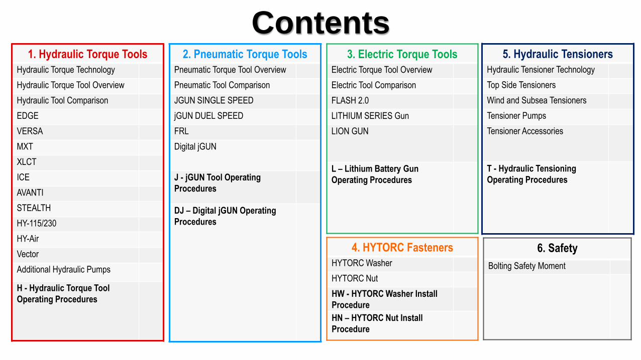
Contents1. Hydraulic Torque Tools
Hydraulic Torque Technology
Hydraulic Torque Tool Overview
Hydraulic Tool Comparison
EDGE
VERSA
MXT
XLCT
ICE
AVANTI
STEALTH
HY-115/230
HY-Air
Vector
Additional Hydraulic Pumps
H - Hydraulic Torque Tool
Operating Procedures
2. Pneumatic Torque Tools
Pneumatic Torque Tool Overview
Pneumatic Tool Comparison
JGUN SINGLE SPEED
jGUN DUEL SPEED
FRL
Digital jGUN
J - jGUN Tool Operating
Procedures
DJ – Digital jGUN Operating
Procedures
3. Electric Torque Tools
Electric Torque Tool Overview
Electric Tool Comparison
FLASH 2.0
LITHIUM SERIES Gun
LION GUN
L – Lithium Battery Gun
Operating Procedures
4. HYTORC Fasteners
HYTORC Washer
HYTORC Nut
HW - HYTORC Washer Install
Procedure
HN – HYTORC Nut Install
Procedure
6. Safety
Bolting Safety Moment
5. Hydraulic Tensioners
Hydraulic Tensioner Technology
Top Side Tensioners
Wind and Subsea Tensioners
Tensioner Pumps
Tensioner Accessories
T - Hydraulic Tensioning
Operating Procedures

1. Hydraulic Torque Tools
BOSS Training SeriesBasic Operation and Safety Series
Hydraulic Torque Tool Technology
PUSH
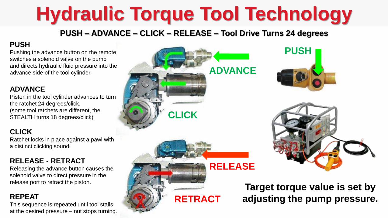
PUSH – ADVANCE – CLICK – RELEASE – Tool Drive Turns 24 degrees
ADVANCE
CLICK
RELEASE
PUSHPushing the advance button on the remote
switches a solenoid valve on the pump
and directs hydraulic fluid pressure into the
advance side of the tool cylinder.
ADVANCEPiston in the tool cylinder advances to turn
the ratchet 24 degrees/click.
(some tool ratchets are different, the
STEALTH turns 18 degrees/click)
CLICKRatchet locks in place against a pawl with
a distinct clicking sound.
RELEASE - RETRACTReleasing the advance button causes the
solenoid valve to direct pressure in the
release port to retract the piston.
REPEATThis sequence is repeated until tool stalls
at the desired pressure – nut stops turning.
RETRACT
Target torque value is set by
adjusting the pump pressure.
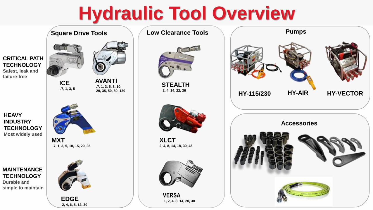
Hydraulic Tool Overview
ICE.7, 1, 3, 5
AVANTI.7, 1, 3, 5, 8, 10,
20, 35, 50, 80, 130
STEALTH2, 4, 14, 22, 36
CRITICAL PATH
TECHNOLOGYSafest, leak and
failure-free
HEAVY
INDUSTRY
TECHNOLOGYMost widely used
MAINTENANCE
TECHNOLOGYDurable and
simple to maintain
MXT.7, 1, 3, 5, 10, 15, 20, 35
XLCT2, 4, 8, 14, 18, 30, 45
EDGE2, 4, 6, 8, 12, 30
VERSA1, 2, 4, 8, 14, 20, 30
Pumps
Accessories
Square Drive Tools Low Clearance Tools
HY-115/230 HY-AIR HY-VECTOR
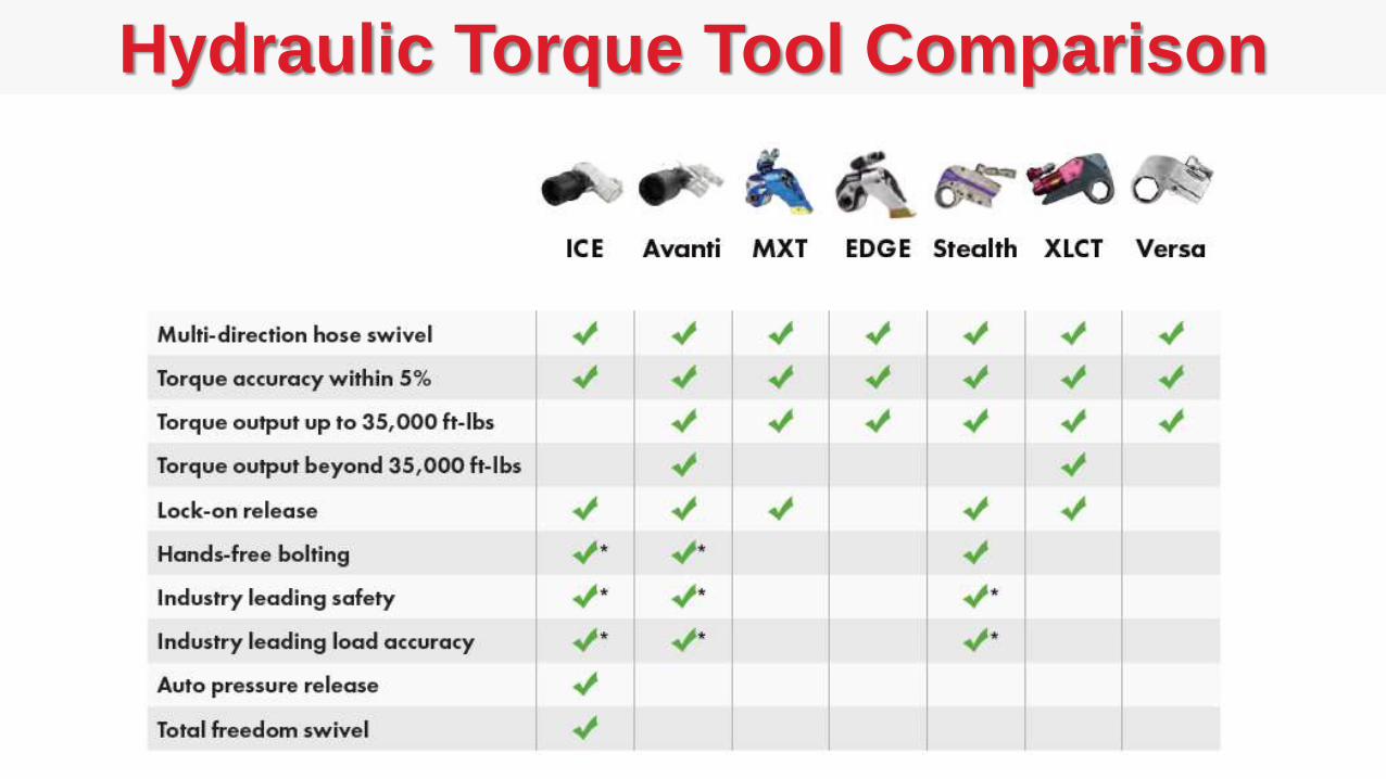
Hydraulic Torque Tool Comparison
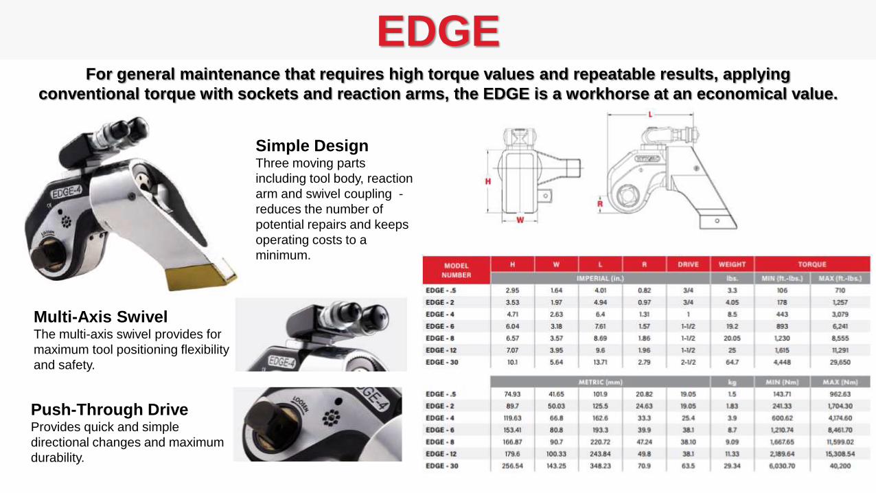
EDGE
Simple DesignThree moving parts
including tool body, reaction
arm and swivel coupling -
reduces the number of
potential repairs and keeps
operating costs to a
minimum.
For general maintenance that requires high torque values and repeatable results, applying
conventional torque with sockets and reaction arms, the EDGE is a workhorse at an economical value.
Multi-Axis SwivelThe multi-axis swivel provides for
maximum tool positioning flexibility
and safety.
Push-Through DriveProvides quick and simple
directional changes and maximum
durability.
VERSA
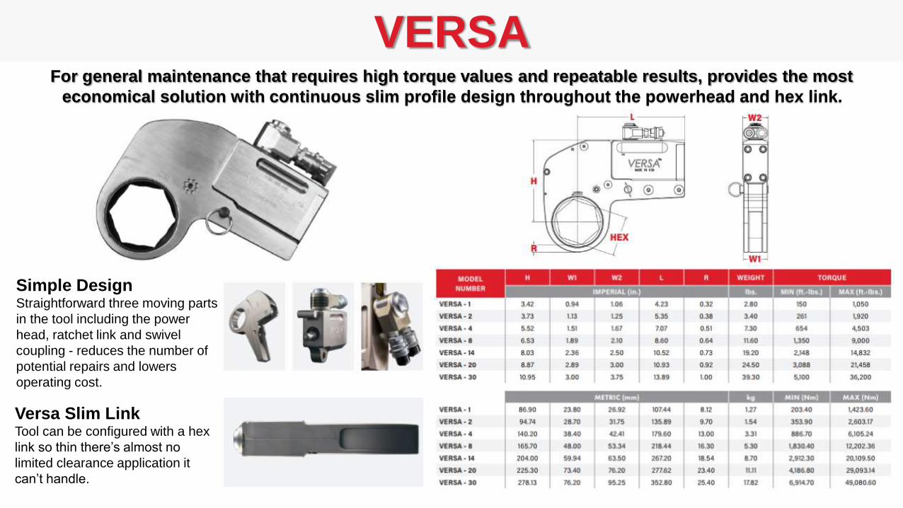
Simple DesignStraightforward three moving parts
in the tool including the power
head, ratchet link and swivel
coupling - reduces the number of
potential repairs and lowers
operating cost.
For general maintenance that requires high torque values and repeatable results, provides the most
economical solution with continuous slim profile design throughout the powerhead and hex link.
Versa Slim LinkTool can be configured with a hex
link so thin there’s almost no
limited clearance application it
can’t handle.

MXT Features
Zero-Slip Square DriveThe MXT series has a powerful drive with
faster tightening and a secondary pawl inside
the tool that prevents the ratchet from turning
backwards during tightening resulting in
controlled application of torque at high
precision
Lock-Up Release LeverThe MXT was the first tool in the industry to
feature the lock-up release lever that allows you to
release pressure after torqueing – simply toggle
the lever for easy removal.
Super Alloy OptionThe MXT-SA series provides the
proven reliability of the MXT
design with advanced materials
used to increase lifespan further
for extreme usage. The MXT-SA
tools come with a 5 year no-
questions warranty
MXT series is the all time most requested square drive hydraulic torque equipment
by maintenance, service and construction personnel worldwide!
Multi-Directional CouplingCoupling has 360-180 rotational capability allowing
hoses to be arranged to ensure safe operation.
Indexing Reaction ArmReaction arm can be rotated 360
degrees – simply push the lever
and pull out the arm, rotate to
desired position and then snap
back on the tool body.
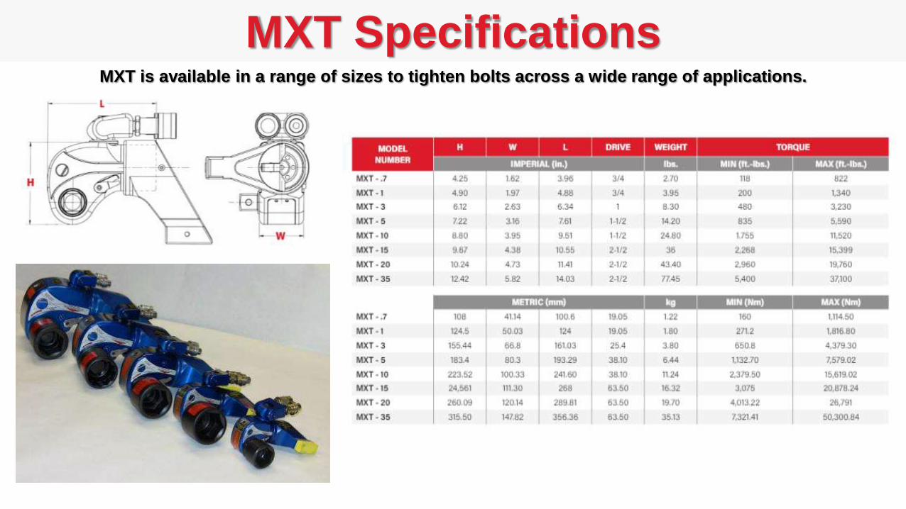
MXT SpecificationsMXT is available in a range of sizes to tighten bolts across a wide range of applications.
XLCT Features
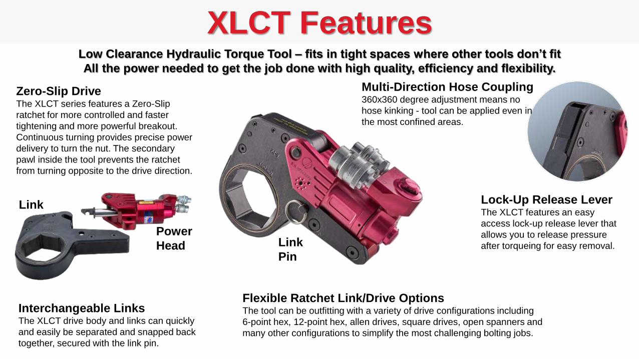
Zero-Slip DriveThe XLCT series features a Zero-Slip
ratchet for more controlled and faster
tightening and more powerful breakout.
Continuous turning provides precise power
delivery to turn the nut. The secondary
pawl inside the tool prevents the ratchet
from turning opposite to the drive direction.
Lock-Up Release LeverThe XLCT features an easy
access lock-up release lever that
allows you to release pressure
after torqueing for easy removal.
Flexible Ratchet Link/Drive OptionsThe tool can be outfitting with a variety of drive configurations including
6-point hex, 12-point hex, allen drives, square drives, open spanners and
many other configurations to simplify the most challenging bolting jobs.
Link
Pin
Multi-Direction Hose Coupling360x360 degree adjustment means no
hose kinking - tool can be applied even in
the most confined areas.
Low Clearance Hydraulic Torque Tool – fits in tight spaces where other tools don’t fit
All the power needed to get the job done with high quality, efficiency and flexibility.
Interchangeable LinksThe XLCT drive body and links can quickly
and easily be separated and snapped back
together, secured with the link pin.
Power
Head
Link

XLCT SpecificationsXLCT is available in a range of sizes to tighten bolts in a wide range of applications.
ICE Features
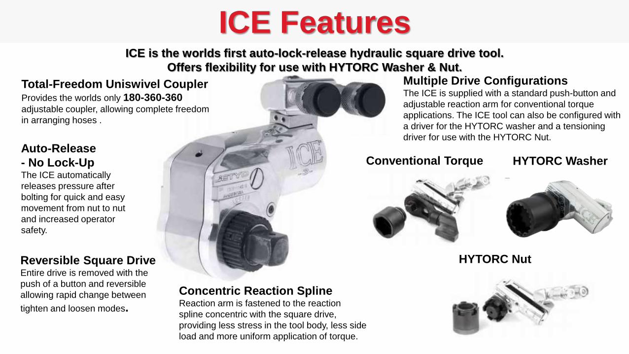
Auto-Release
- No Lock-UpThe ICE automatically
releases pressure after
bolting for quick and easy
movement from nut to nut
and increased operator
safety.
Reversible Square Drive Entire drive is removed with the
push of a button and reversible
allowing rapid change between
tighten and loosen modes.
Total-Freedom Uniswivel CouplerProvides the worlds only 180-360-360 adjustable coupler, allowing complete freedom
in arranging hoses .
Concentric Reaction SplineReaction arm is fastened to the reaction
spline concentric with the square drive,
providing less stress in the tool body, less side
load and more uniform application of torque.
ICE is the worlds first auto-lock-release hydraulic square drive tool.
Offers flexibility for use with HYTORC Washer & Nut.Multiple Drive ConfigurationsThe ICE is supplied with a standard push-button and
adjustable reaction arm for conventional torque
applications. The ICE tool can also be configured with
a driver for the HYTORC washer and a tensioning
driver for use with the HYTORC Nut.
Conventional Torque HYTORC Washer
HYTORC NutHYTORC Nut
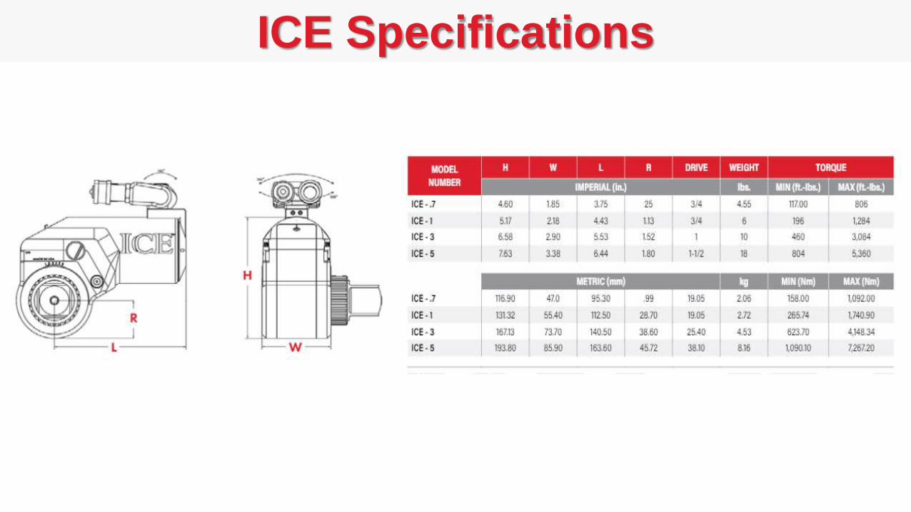
ICE Specifications
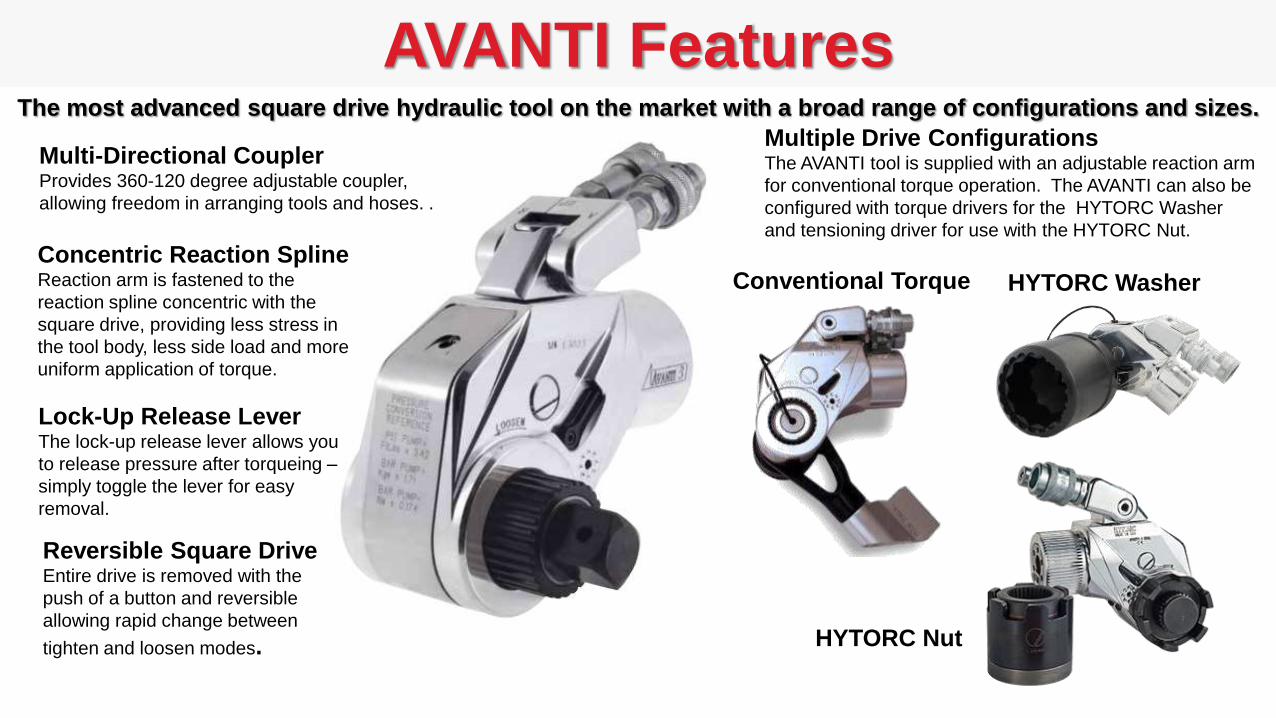
AVANTI Features
Reversible Square Drive Entire drive is removed with the
push of a button and reversible
allowing rapid change between
tighten and loosen modes.
Multi-Directional CouplerProvides 360-120 degree adjustable coupler,
allowing freedom in arranging tools and hoses. .
Concentric Reaction SplineReaction arm is fastened to the
reaction spline concentric with the
square drive, providing less stress in
the tool body, less side load and more
uniform application of torque.
The most advanced square drive hydraulic tool on the market with a broad range of configurations and sizes.
Multiple Drive Configurations The AVANTI tool is supplied with an adjustable reaction arm
for conventional torque operation. The AVANTI can also be
configured with torque drivers for the HYTORC Washer
and tensioning driver for use with the HYTORC Nut.
Conventional Torque HYTORC Washer
HYTORC Nut
Lock-Up Release LeverThe lock-up release lever allows you
to release pressure after torqueing –
simply toggle the lever for easy
removal.
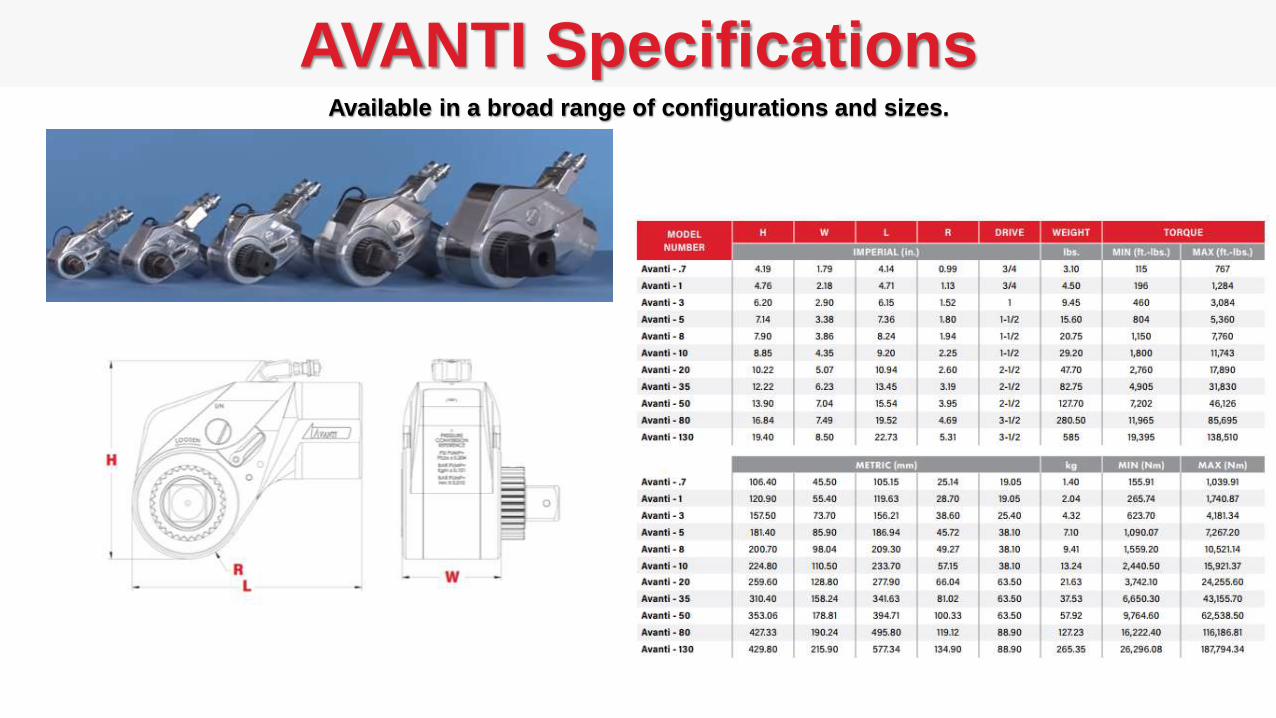
AVANTI SpecificationsAvailable in a broad range of configurations and sizes.
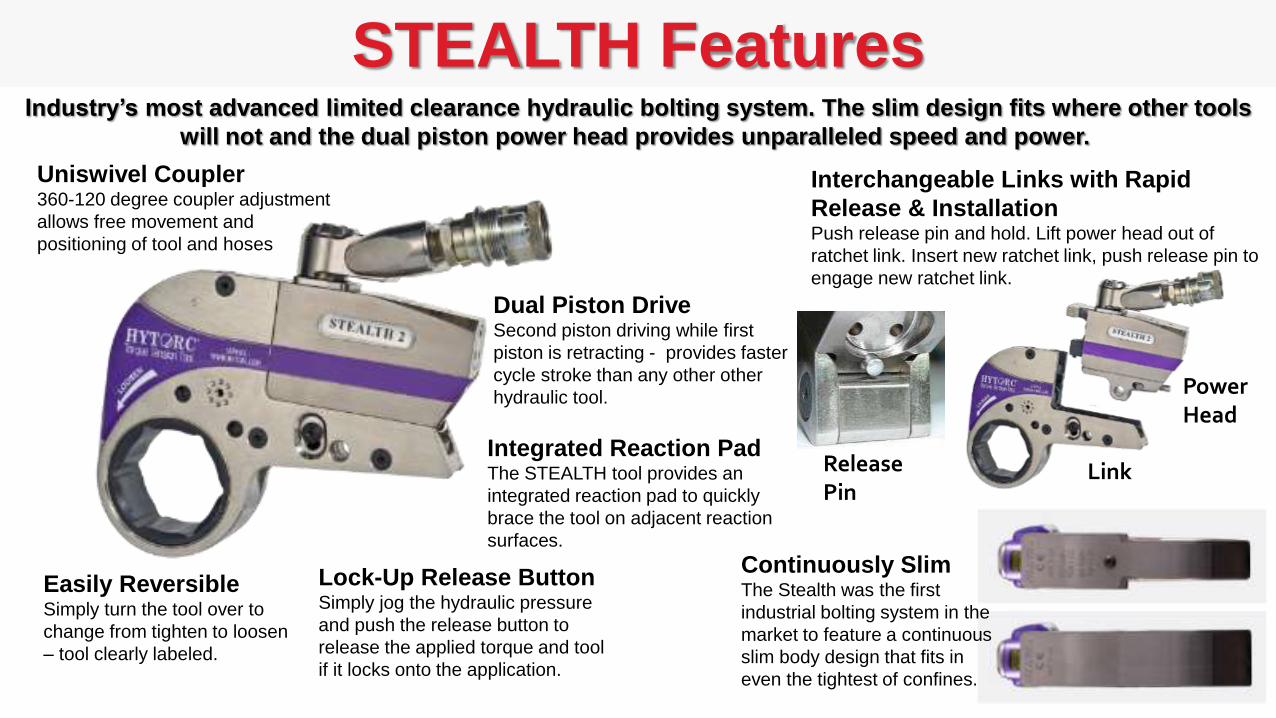
STEALTH Features
Uniswivel Coupler360-120 degree coupler adjustment
allows free movement and
positioning of tool and hoses
Integrated Reaction PadThe STEALTH tool provides an
integrated reaction pad to quickly
brace the tool on adjacent reaction
surfaces.
Lock-Up Release ButtonSimply jog the hydraulic pressure
and push the release button to
release the applied torque and tool
if it locks onto the application.
Dual Piston DriveSecond piston driving while first
piston is retracting - provides faster
cycle stroke than any other other
hydraulic tool.
Easily ReversibleSimply turn the tool over to
change from tighten to loosen
– tool clearly labeled.
Interchangeable Links with Rapid
Release & InstallationPush release pin and hold. Lift power head out of
ratchet link. Insert new ratchet link, push release pin to
engage new ratchet link.
Link
PowerHead
Industry’s most advanced limited clearance hydraulic bolting system. The slim design fits where other tools
will not and the dual piston power head provides unparalleled speed and power.
Continuously SlimThe Stealth was the first
industrial bolting system in the
market to feature a continuous
slim body design that fits in
even the tightest of confines.
ReleasePin
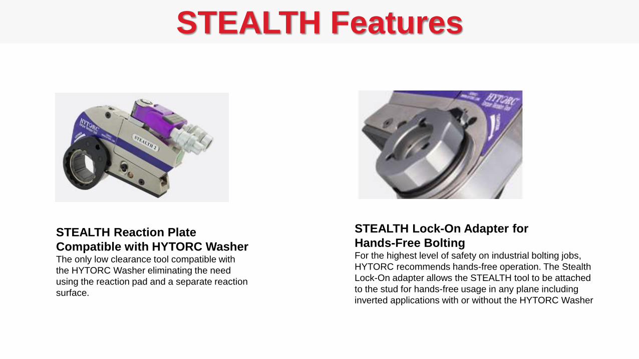
STEALTH Reaction Plate
Compatible with HYTORC WasherThe only low clearance tool compatible with
the HYTORC Washer eliminating the need
using the reaction pad and a separate reaction
surface.
STEALTH Features
STEALTH Lock-On Adapter for
Hands-Free BoltingFor the highest level of safety on industrial bolting jobs,
HYTORC recommends hands-free operation. The Stealth
Lock-On adapter allows the STEALTH tool to be attached
to the stud for hands-free usage in any plane including
inverted applications with or without the HYTORC Washer
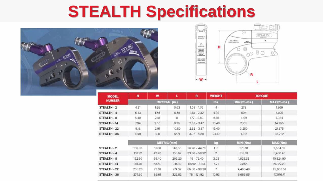
STEALTH Specifications

STEALTH Applications

HY-115/230 PumpThe HY-115/230 is a high capacity, low-weight, 10,000 psi portable pump
designed for continuous/heavy duty operation – will out preform any standard pump.
Analog Pressure GaugePump operates in a range of 500 to
10,000 psi. (+/- 1% accuracy)
Oil Reservoir 1.35 Gal (5 liter) with
Sight Glass and Drain
- 2.1 Gal (8 liter) option
Remote ControlStart-Stop Buttons, 24V, 15-ft (5m)
AC Power Cord
Simple ControlsMakes setup time easier
Pressure Control
Valve and Lock Easily adjust and set
pump pressure
4 Ports
Up to four bolting tools of
the same type can be
connected simultaneously
to 4 Port pump.
High Performance Pump3-stage pump design provides consistent
performance over the entire operating range
while maintaining low noise less than 69dB.
LED IndicatorsQuickly verify the
pump is operating
within voltage and
temperature limits.
Oil Cooled Easily handles extreme work loads.
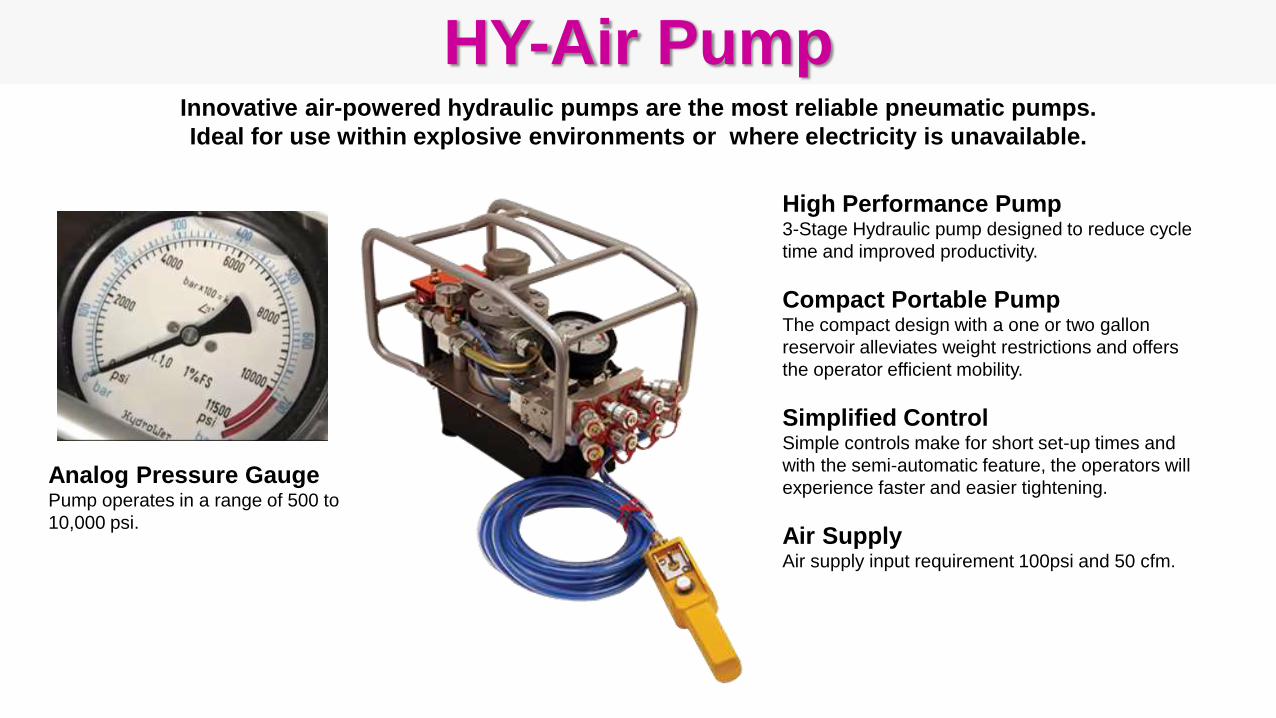
HY-Air Pump
Analog Pressure GaugePump operates in a range of 500 to
10,000 psi.
High Performance Pump3-Stage Hydraulic pump designed to reduce cycle
time and improved productivity.
Compact Portable PumpThe compact design with a one or two gallon
reservoir alleviates weight restrictions and offers
the operator efficient mobility.
Simplified Control Simple controls make for short set-up times and
with the semi-automatic feature, the operators will
experience faster and easier tightening.
Air SupplyAir supply input requirement 100psi and 50 cfm.
Innovative air-powered hydraulic pumps are the most reliable pneumatic pumps.
Ideal for use within explosive environments or where electricity is unavailable.
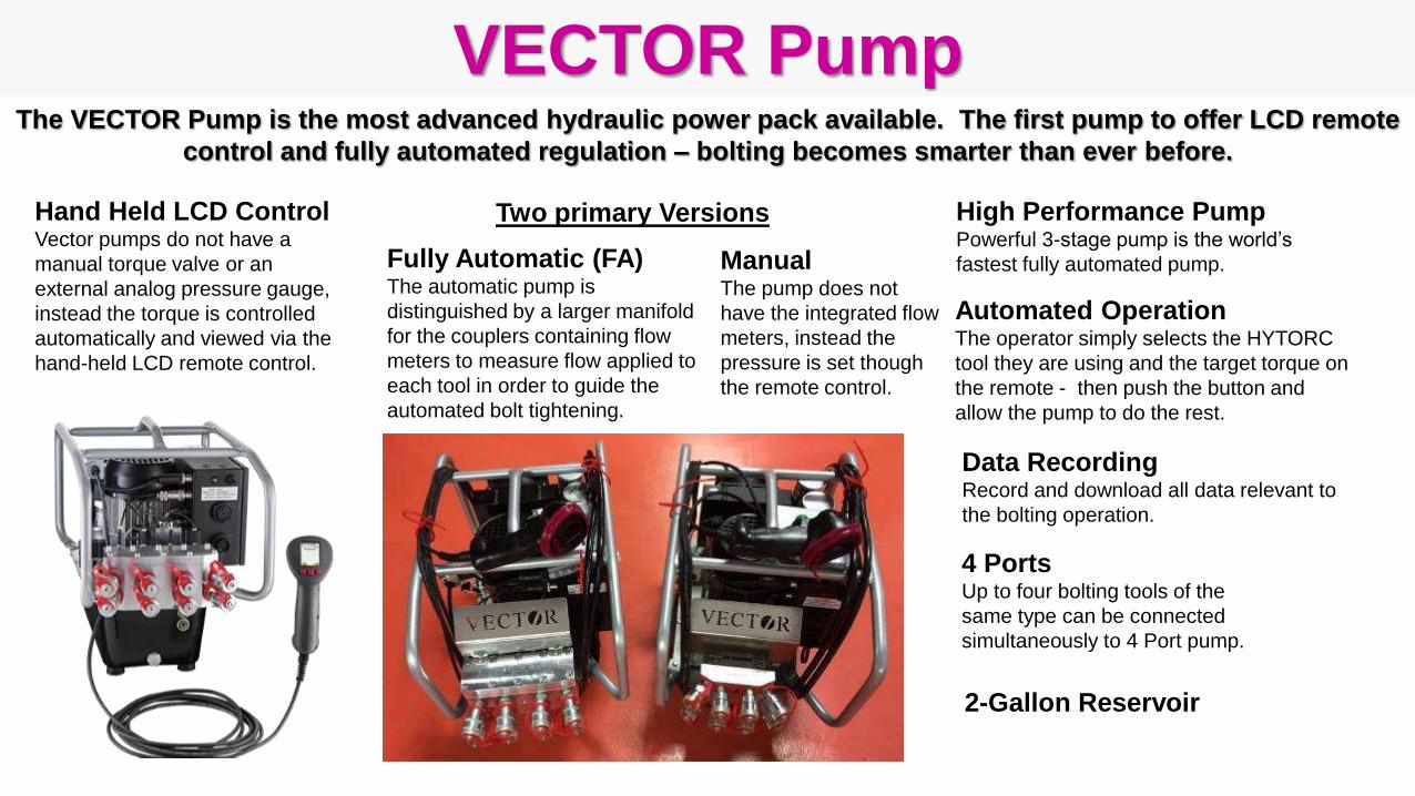
VECTOR PumpThe VECTOR Pump is the most advanced hydraulic power pack available. The first pump to offer LCD remote
control and fully automated regulation – bolting becomes smarter than ever before.
ManualThe pump does not
have the integrated flow
meters, instead the
pressure is set though
the remote control.
Hand Held LCD ControlVector pumps do not have a
manual torque valve or an
external analog pressure gauge,
instead the torque is controlled
automatically and viewed via the
hand-held LCD remote control.
Fully Automatic (FA)The automatic pump is
distinguished by a larger manifold
for the couplers containing flow
meters to measure flow applied to
each tool in order to guide the
automated bolt tightening.
4 PortsUp to four bolting tools of the
same type can be connected
simultaneously to 4 Port pump.
High Performance PumpPowerful 3-stage pump is the world’s
fastest fully automated pump.
Two primary Versions
2-Gallon Reservoir
Data RecordingRecord and download all data relevant to
the bolting operation.
Automated OperationThe operator simply selects the HYTORC
tool they are using and the target torque on
the remote - then push the button and
allow the pump to do the rest.

Additional Hydraulic Pumps
BIGJETHydraulic Power System for a
customer using larger tools and
looking for more speed. The Big Jet
3 stage motor will increase oil flow by
30% and thanks to the built in Oil
Cooler you won’t need to worry about
the pump overheating. A compact
design with two gallon reservoir
alleviates weight restrictions and
offers the operator efficient mobility.
Simple controls make for short set-up
times and with the semi-automatic
feature the operators will experience
faster and easier tightening.
JETPRO-SThe JETPRO 2 stage hydraulic
Power System is the most
affordable lightweight pump on
the market. The JETPRO’s
compact design and one gallon
reservoir alleviates weight
restrictions like no other
hydraulic pump which offers the
operator efficient mobility. Simple
two button manual controls and
portability ensures the operators
will experience fast and simple
bolting. The JETPRO operates at
a very quiet 69Db.
HY-TWINThis hydraulic pump gives the
operator the power they need to
utilize 10,000 ft. lb. and up Torque
Wrenches without compromising
speed. Fitted with a 5 gallon reservoir
this pump will have enough oil to
power up to four large tools at once.
Don’t worry about the portability
because the HY Twin pumps come
with wheel casters that ensure you
can roll this pump from application to
application giving you the mobility
you've come to expect when using
HYTORC Hydraulic Power Systems.
JETPRO-S-AIRThe JETPRO’s compact
design and one gallon
reservoir alleviates weight
restrictions like no other
hydraulic pump which offers
the operator efficient mobility.
Simple one button manual
control ensures the operators
will experience fast and simple
bolting. The HY AIR is an
element of HYTORC’s ATEX
approved Bolting System
Package.
H1 Inspect Tool
H2 Install Reaction Arm
H3 Install Socket or Link
H4 Install Handles
H5 Set-Up Pump
H6 Connect Hoses
H7 Select Pump Pressure
H8 Adjust Pump to Set Torque
H9 Position the Tool
H10 Tighten Bolt
H11 Release Locked-On Tool
H12 Loosen Bolt
H - Hydraulic Torque Tool ProceduresThe following operating procedures should be followed
to set-up and operate hydraulic torque tools.
Inspect Tool
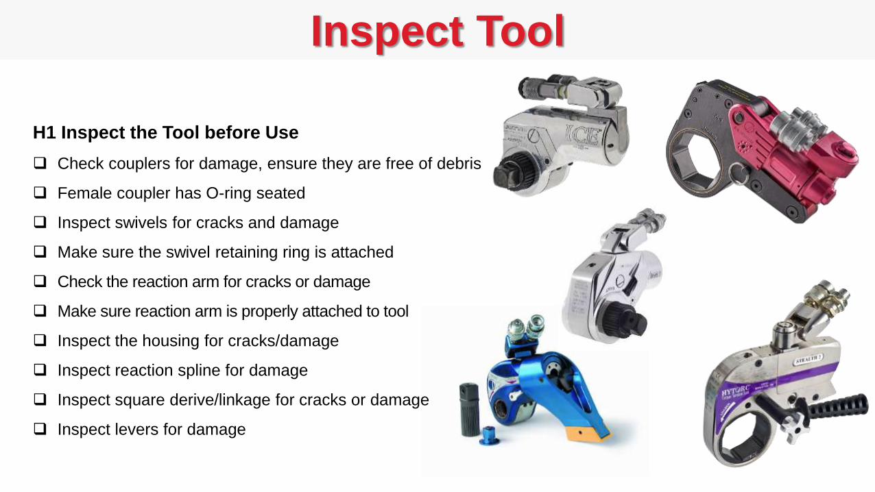
H1 Inspect the Tool before Use
Check couplers for damage, ensure they are free of debris
Female coupler has O-ring seated
Inspect swivels for cracks and damage
Make sure the swivel retaining ring is attached
Check the reaction arm for cracks or damage
Make sure reaction arm is properly attached to tool
Inspect the housing for cracks/damage
Inspect reaction spline for damage
Inspect square derive/linkage for cracks or damage
Inspect levers for damage
Install Reaction Arm
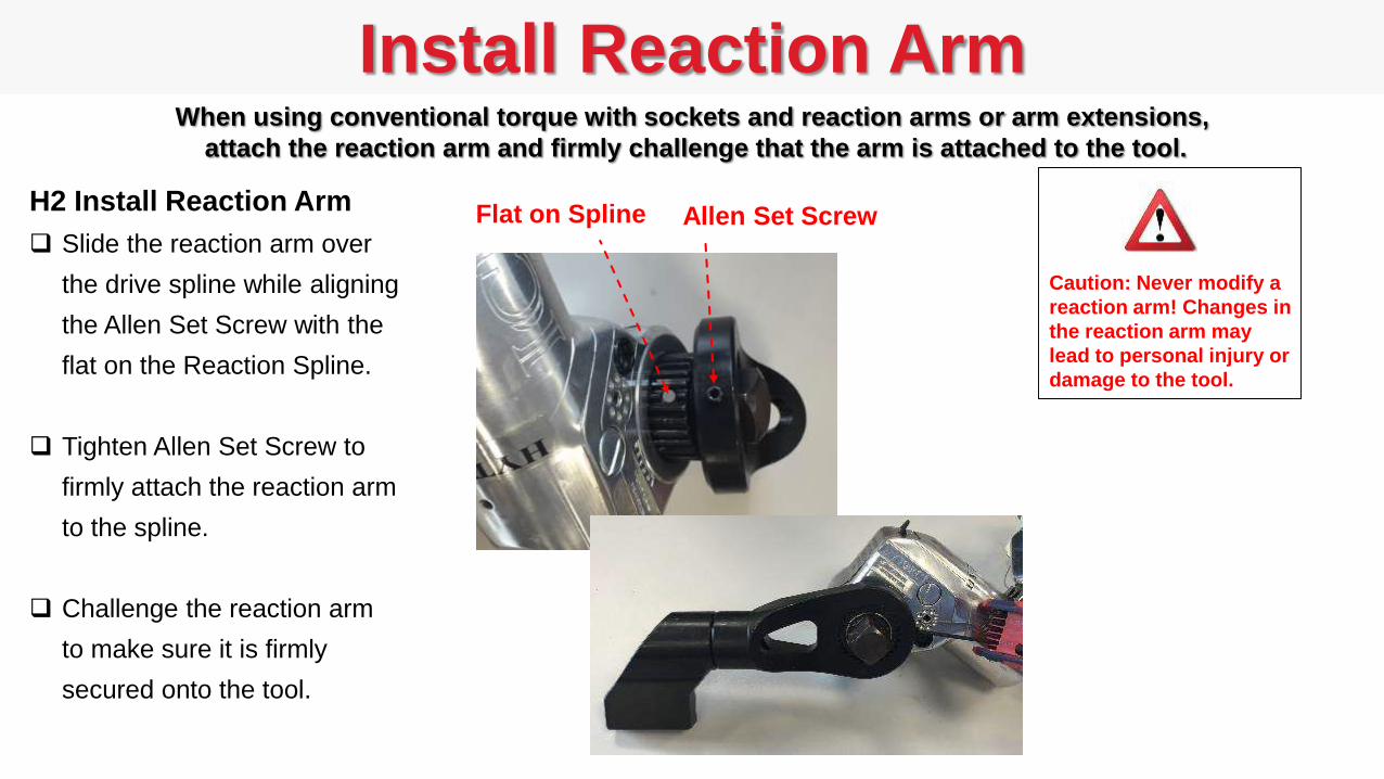
H2 Install Reaction Arm
Slide the reaction arm over
the drive spline while aligning
the Allen Set Screw with the
flat on the Reaction Spline.
Tighten Allen Set Screw to
firmly attach the reaction arm
to the spline.
Challenge the reaction arm
to make sure it is firmly
secured onto the tool.
Caution: Never modify a
reaction arm! Changes in
the reaction arm may
lead to personal injury or
damage to the tool.
When using conventional torque with sockets and reaction arms or arm extensions,
attach the reaction arm and firmly challenge that the arm is attached to the tool.
Flat on Spline Allen Set Screw
Install Socket or Link
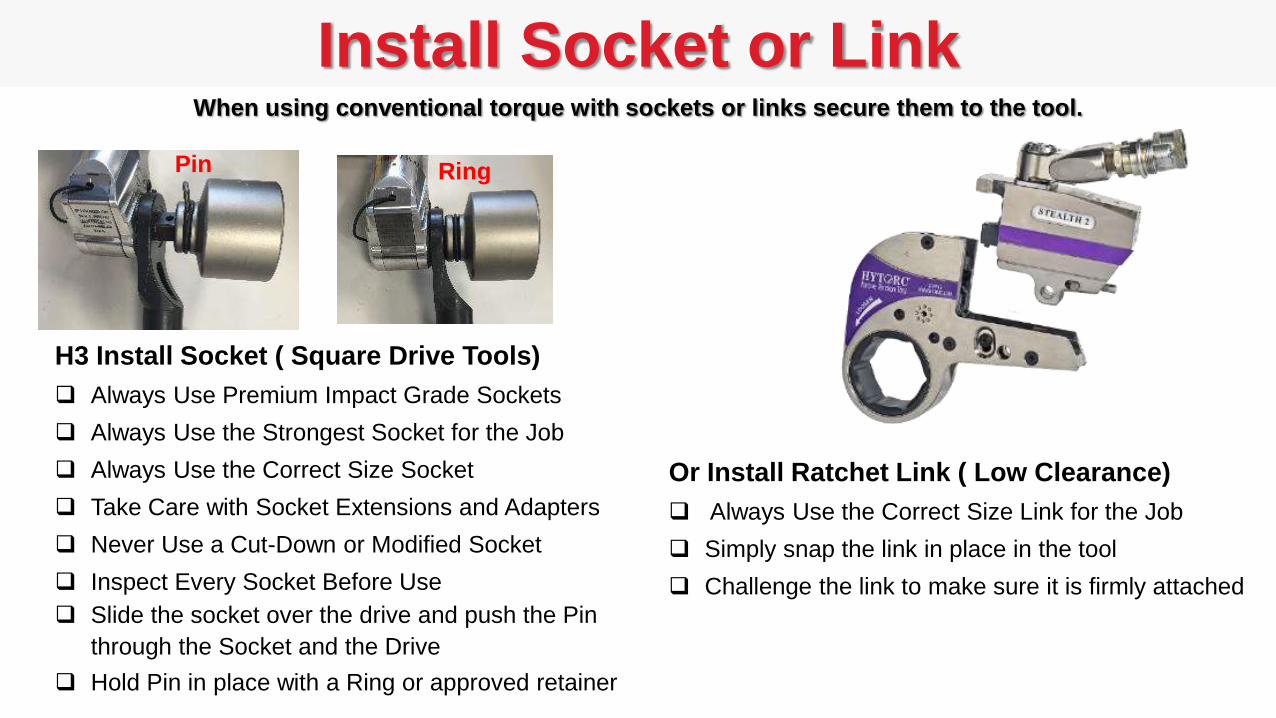
H3 Install Socket ( Square Drive Tools)
Always Use Premium Impact Grade Sockets
Always Use the Strongest Socket for the Job
Always Use the Correct Size Socket
Take Care with Socket Extensions and Adapters
Never Use a Cut-Down or Modified Socket
Inspect Every Socket Before Use
Slide the socket over the drive and push the Pin
through the Socket and the Drive
Hold Pin in place with a Ring or approved retainer
Or Install Ratchet Link ( Low Clearance)
Always Use the Correct Size Link for the Job
Simply snap the link in place in the tool
Challenge the link to make sure it is firmly attached
Pin
When using conventional torque with sockets or links secure them to the tool.
Ring
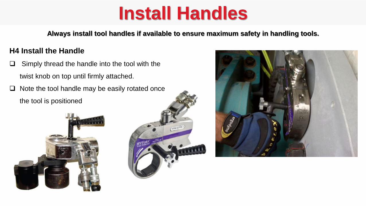
Install HandlesAlways install tool handles if available to ensure maximum safety in handling tools.
H4 Install the Handle
Simply thread the handle into the tool with the
twist knob on top until firmly attached.
Note the tool handle may be easily rotated once
the tool is positioned
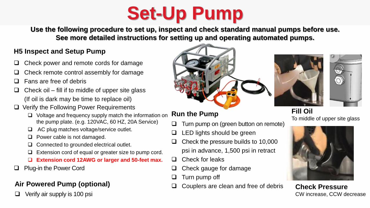
Set-Up Pump
H5 Inspect and Setup Pump
Check power and remote cords for damage
Check remote control assembly for damage
Fans are free of debris
Check oil – fill if to middle of upper site glass
(If oil is dark may be time to replace oil)
Verify the Following Power Requirements
Voltage and frequency supply match the information on
the pump plate. (e.g. 120VAC, 60 HZ, 20A Service)
AC plug matches voltage/service outlet.
Power cable is not damaged.
Connected to grounded electrical outlet.
Extension cord of equal or greater size to pump cord.
Extension cord 12AWG or larger and 50-feet max.
Plug-in the Power Cord
Use the following procedure to set up, inspect and check standard manual pumps before use.
See more detailed instructions for setting up and operating automated pumps.
Run the Pump
Turn pump on (green button on remote)
LED lights should be green
Check the pressure builds to 10,000
psi in advance, 1,500 psi in retract
Check for leaks
Check gauge for damage
Turn pump off
Couplers are clean and free of debrisAir Powered Pump (optional)
Verify air supply is 100 psi
Fill OilTo middle of upper site glass
Check PressureCW increase, CCW decrease
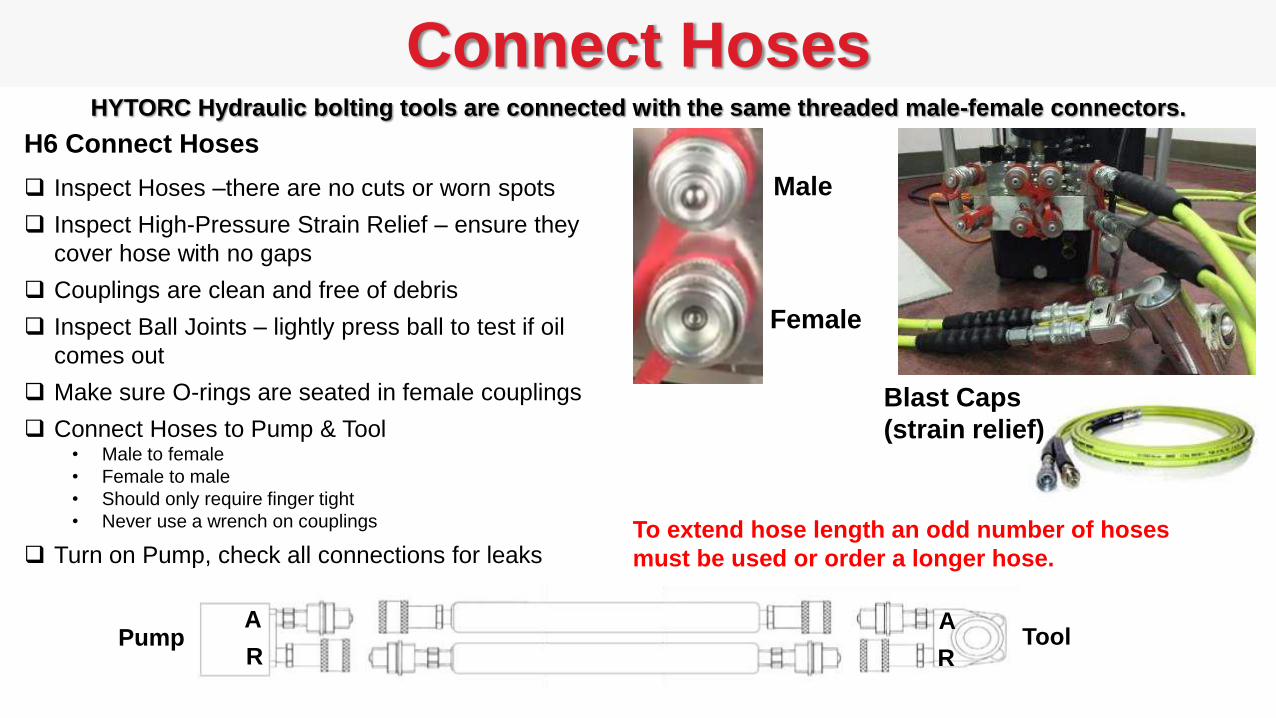
Connect Hoses
H6 Connect Hoses
Inspect Hoses –there are no cuts or worn spots
Inspect High-Pressure Strain Relief – ensure they
cover hose with no gaps
Couplings are clean and free of debris
Inspect Ball Joints – lightly press ball to test if oil
comes out
Make sure O-rings are seated in female couplings
Connect Hoses to Pump & Tool• Male to female
• Female to male
• Should only require finger tight
• Never use a wrench on couplings
Turn on Pump, check all connections for leaks
HYTORC Hydraulic bolting tools are connected with the same threaded male-female connectors.
To extend hose length an odd number of hoses
must be used or order a longer hose.
Male
Female
Blast Caps
(strain relief)
Pump ToolA
R
A
R

Select Pump PressureEach Hydraulic Tool Torque output is calibrated over a range of hydraulic pressures and has it’s own torque
conversion chart. To achieve a target torque select pressure from the table provided with each tool.
Torque Conversion Chart for STEALTH-2
Tool calibrated from 1,500 psi (278 ft-lbs)
to 10,000 psi (1,869 ft-lbs)
H7 Select Pump Pressure Given a target torque (e.g. 750 ft-lbs)
Read from the chart, required pump pressure( e.g. 4,000 psi).
Torque Conversion Charts for
all HYTORC tools are easily
accessed at HYTORC.com
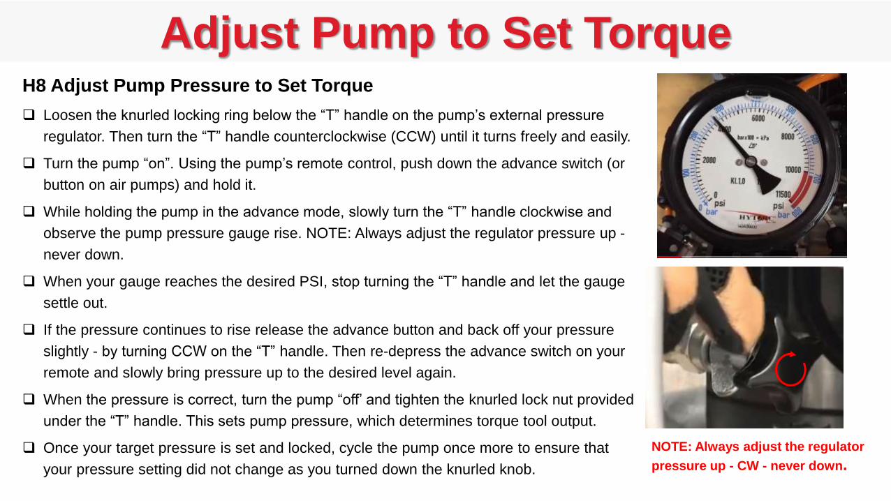
Adjust Pump to Set TorqueH8 Adjust Pump Pressure to Set Torque
Loosen the knurled locking ring below the “T” handle on the pump’s external pressure
regulator. Then turn the “T” handle counterclockwise (CCW) until it turns freely and easily.
Turn the pump “on”. Using the pump’s remote control, push down the advance switch (or
button on air pumps) and hold it.
While holding the pump in the advance mode, slowly turn the “T” handle clockwise and
observe the pump pressure gauge rise. NOTE: Always adjust the regulator pressure up -
never down.
When your gauge reaches the desired PSI, stop turning the “T” handle and let the gauge
settle out.
If the pressure continues to rise release the advance button and back off your pressure
slightly - by turning CCW on the “T” handle. Then re-depress the advance switch on your
remote and slowly bring pressure up to the desired level again.
When the pressure is correct, turn the pump “off’ and tighten the knurled lock nut provided
under the “T” handle. This sets pump pressure, which determines torque tool output.
Once your target pressure is set and locked, cycle the pump once more to ensure that
your pressure setting did not change as you turned down the knurled knob.
NOTE: Always adjust the regulator
pressure up - CW - never down.
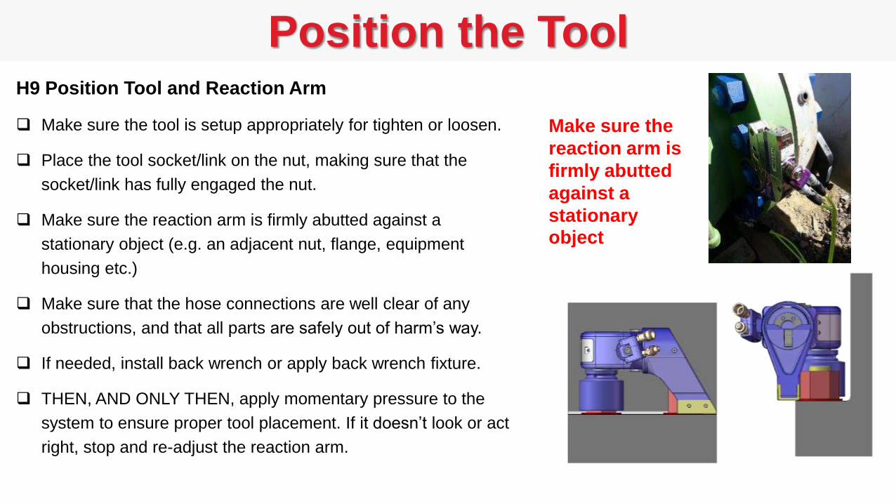
Position the ToolH9 Position Tool and Reaction Arm
Make sure the tool is setup appropriately for tighten or loosen.
Place the tool socket/link on the nut, making sure that the
socket/link has fully engaged the nut.
Make sure the reaction arm is firmly abutted against a
stationary object (e.g. an adjacent nut, flange, equipment
housing etc.)
Make sure that the hose connections are well clear of any
obstructions, and that all parts are safely out of harm’s way.
If needed, install back wrench or apply back wrench fixture.
THEN, AND ONLY THEN, apply momentary pressure to the
system to ensure proper tool placement. If it doesn’t look or act
right, stop and re-adjust the reaction arm.
Make sure the
reaction arm is
firmly abutted
against a
stationary object
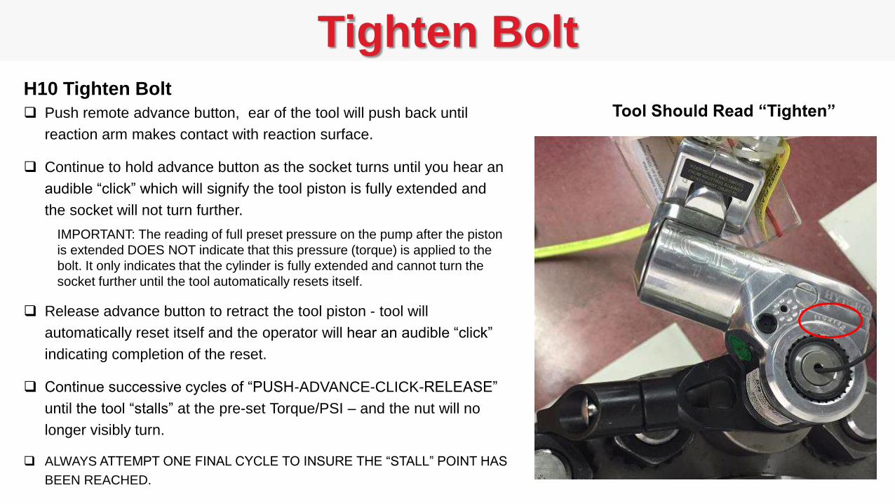
Tighten BoltH10 Tighten Bolt
Push remote advance button, ear of the tool will push back until
reaction arm makes contact with reaction surface.
Continue to hold advance button as the socket turns until you hear an
audible “click” which will signify the tool piston is fully extended and
the socket will not turn further.
IMPORTANT: The reading of full preset pressure on the pump after the piston
is extended DOES NOT indicate that this pressure (torque) is applied to the
bolt. It only indicates that the cylinder is fully extended and cannot turn the
socket further until the tool automatically resets itself.
Release advance button to retract the tool piston - tool will
automatically reset itself and the operator will hear an audible “click”
indicating completion of the reset.
Continue successive cycles of “PUSH-ADVANCE-CLICK-RELEASE”
until the tool “stalls” at the pre-set Torque/PSI – and the nut will no
longer visibly turn.
ALWAYS ATTEMPT ONE FINAL CYCLE TO INSURE THE “STALL” POINT HAS
BEEN REACHED.
Tool Should Read “Tighten”
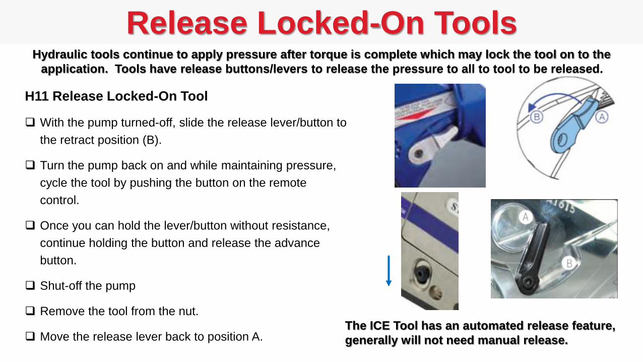
Release Locked-On Tools
H11 Release Locked-On Tool
With the pump turned-off, slide the release lever/button to
the retract position (B).
Turn the pump back on and while maintaining pressure,
cycle the tool by pushing the button on the remote
control.
Once you can hold the lever/button without resistance,
continue holding the button and release the advance
button.
Shut-off the pump
Remove the tool from the nut.
Move the release lever back to position A.
Hydraulic tools continue to apply pressure after torque is complete which may lock the tool on to the
application. Tools have release buttons/levers to release the pressure to all to tool to be released.
The ICE Tool has an automated release feature,
generally will not need manual release.
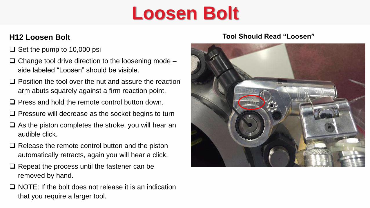
Loosen BoltH12 Loosen Bolt
Set the pump to 10,000 psi
Change tool drive direction to the loosening mode –
side labeled “Loosen” should be visible.
Position the tool over the nut and assure the reaction
arm abuts squarely against a firm reaction point.
Press and hold the remote control button down.
Pressure will decrease as the socket begins to turn
As the piston completes the stroke, you will hear an
audible click.
Release the remote control button and the piston
automatically retracts, again you will hear a click.
Repeat the process until the fastener can be
removed by hand.
NOTE: If the bolt does not release it is an indication
that you require a larger tool.
Tool Should Read “Loosen”

2. Pneumatic Torque Tools
BOSS Training SeriesBasic Operation and Safety Series

j GUN SINGLE SPEED.25, .5, 1, 2, 3, 5, 8
j GUN DUAL SPEED.5, 1, 2, 3, 5, 8
Digital j GUN
FRL
Pneumatic Powered Torque Tools
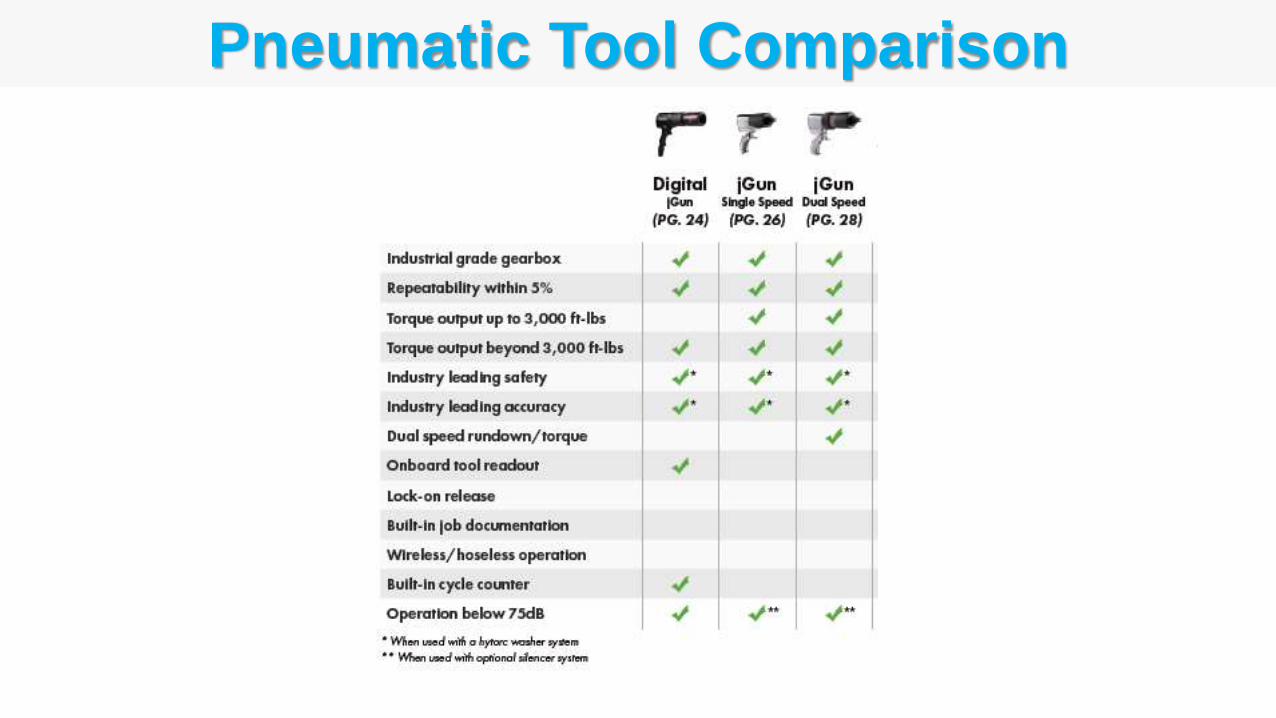
Pneumatic Tool Comparison
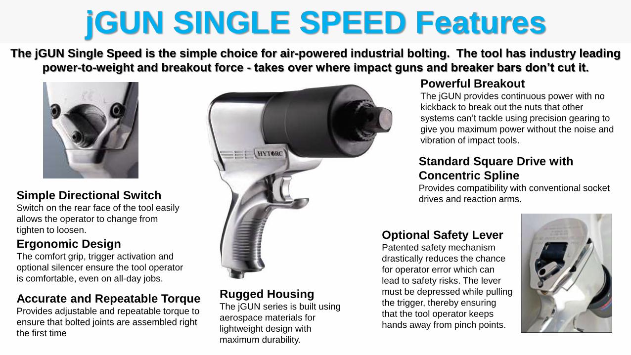
jGUN SINGLE SPEED FeaturesThe jGUN Single Speed is the simple choice for air-powered industrial bolting. The tool has industry leading
power-to-weight and breakout force - takes over where impact guns and breaker bars don’t cut it.
Powerful BreakoutThe jGUN provides continuous power with no
kickback to break out the nuts that other
systems can’t tackle using precision gearing to
give you maximum power without the noise and
vibration of impact tools.
Ergonomic DesignThe comfort grip, trigger activation and
optional silencer ensure the tool operator
is comfortable, even on all-day jobs.
Rugged HousingThe jGUN series is built using
aerospace materials for
lightweight design with
maximum durability.
Simple Directional SwitchSwitch on the rear face of the tool easily
allows the operator to change from
tighten to loosen.
Accurate and Repeatable TorqueProvides adjustable and repeatable torque to
ensure that bolted joints are assembled right
the first time
Standard Square Drive with
Concentric SplineProvides compatibility with conventional socket
drives and reaction arms.
Optional Safety LeverPatented safety mechanism
drastically reduces the chance
for operator error which can
lead to safety risks. The lever
must be depressed while pulling
the trigger, thereby ensuring
that the tool operator keeps
hands away from pinch points.
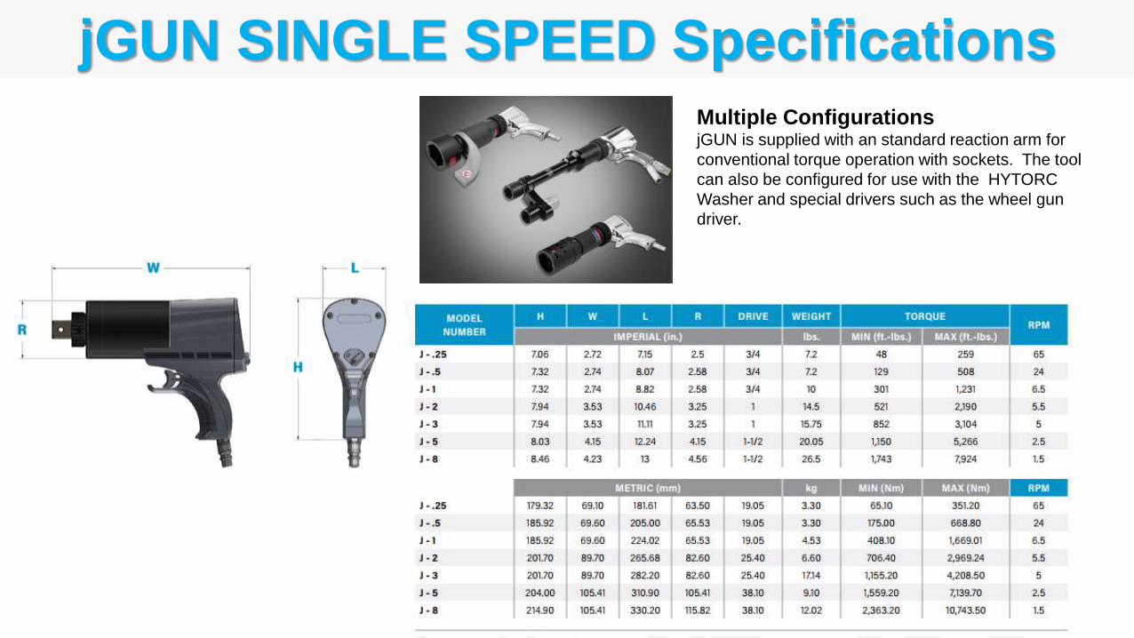
jGUN SINGLE SPEED SpecificationsMultiple Configurations jGUN is supplied with an standard reaction arm for
conventional torque operation with sockets. The tool
can also be configured for use with the HYTORC
Washer and special drivers such as the wheel gun
driver.
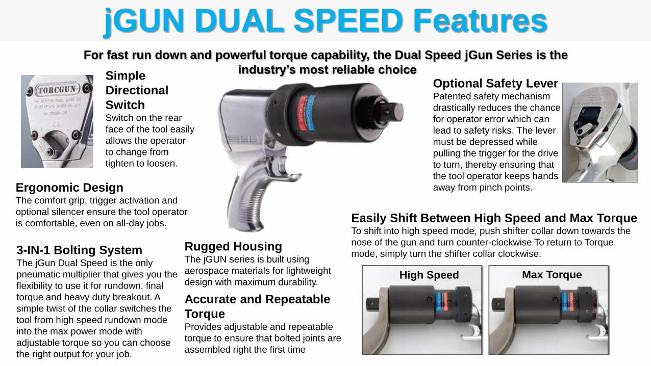
jGUN DUAL SPEED Features
3-IN-1 Bolting SystemThe jGun Dual Speed is the only
pneumatic multiplier that gives you the
flexibility to use it for rundown, final
torque and heavy duty breakout. A
simple twist of the collar switches the
tool from high speed rundown mode
into the max power mode with
adjustable torque so you can choose
the right output for your job.
Simple
Directional
SwitchSwitch on the rear
face of the tool easily
allows the operator
to change from
tighten to loosen.
For fast run down and powerful torque capability, the Dual Speed jGun Series is the
industry’s most reliable choice
Easily Shift Between High Speed and Max TorqueTo shift into high speed mode, push shifter collar down towards the
nose of the gun and turn counter-clockwise To return to Torque
mode, simply turn the shifter collar clockwise.
High Speed Max Torque
Optional Safety LeverPatented safety mechanism
drastically reduces the chance
for operator error which can
lead to safety risks. The lever
must be depressed while
pulling the trigger for the drive
to turn, thereby ensuring that
the tool operator keeps hands
away from pinch points.
Rugged HousingThe jGUN series is built using
aerospace materials for lightweight
design with maximum durability.
Ergonomic DesignThe comfort grip, trigger activation and
optional silencer ensure the tool operator
is comfortable, even on all-day jobs.
Accurate and Repeatable
TorqueProvides adjustable and repeatable
torque to ensure that bolted joints are
assembled right the first time
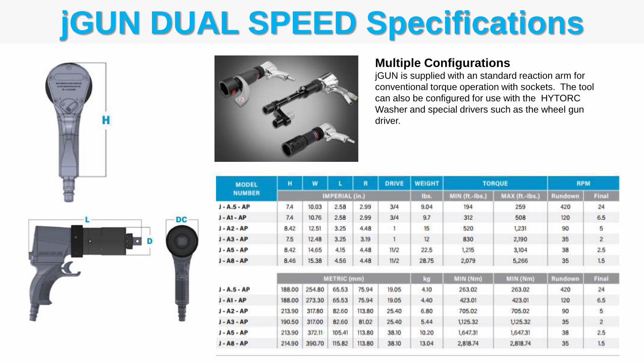
jGUN DUAL SPEED SpecificationsMultiple Configurations jGUN is supplied with an standard reaction arm for
conventional torque operation with sockets. The tool
can also be configured for use with the HYTORC
Washer and special drivers such as the wheel gun
driver.
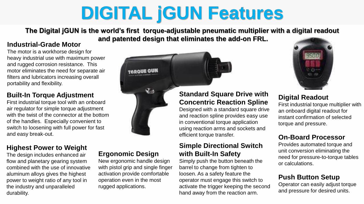
DIGITAL jGUN FeaturesThe Digital jGUN is the world’s first torque-adjustable pneumatic multiplier with a digital readout
and patented design that eliminates the add-on FRL.
Built-In Torque AdjustmentFirst industrial torque tool with an onboard
air regulator for simple torque adjustment
with the twist of the connector at the bottom
of the handles. Especially convenient to
switch to loosening with full power for fast
and easy break-out.
Industrial-Grade MotorThe motor is a workhorse design for
heavy industrial use with maximum power
and rugged corrosion resistance. This
motor eliminates the need for separate air
filters and lubricators increasing overall
portability and flexibility.
Standard Square Drive with
Concentric Reaction SplineDesigned with a standard square drive
and reaction spline provides easy use
in conventional torque application
using reaction arms and sockets and
efficient torque transfer.
Digital ReadoutFirst industrial torque multiplier with
an onboard digital readout for
instant confirmation of selected
torque and pressure.
On-Board ProcessorProvides automated torque and
unit conversion eliminating the
need for pressure-to-torque tables
or calculations.
Push Button SetupOperator can easily adjust torque
and pressure for desired units.
Simple Directional Switch
with Built-In SafetySimply push the button beneath the
barrel to change from tighten to
loosen. As a safety feature the
operator must engage this switch to
activate the trigger keeping the second
hand away from the reaction arm.
Highest Power to WeightThe design includes enhanced air
flow and planetary gearing system
combined with the use of innovative
aluminum alloys gives the highest
power to weight ratio of any tool in
the industry and unparalleled
durability.
Ergonomic DesignNew ergonomic handle design
with pistol grip and single finger
activation provide comfortable
operation even in the most
rugged applications.
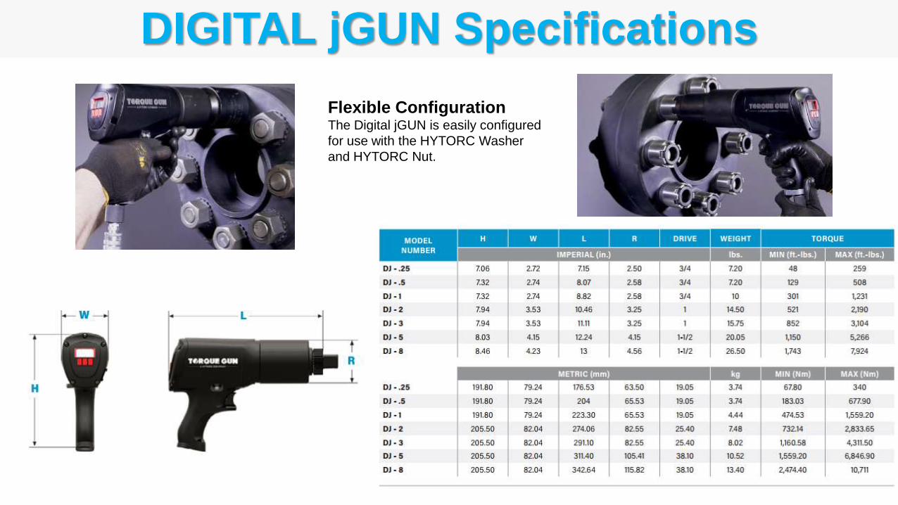
DIGITAL jGUN Specifications
Flexible ConfigurationThe Digital jGUN is easily configured
for use with the HYTORC Washer
and HYTORC Nut.
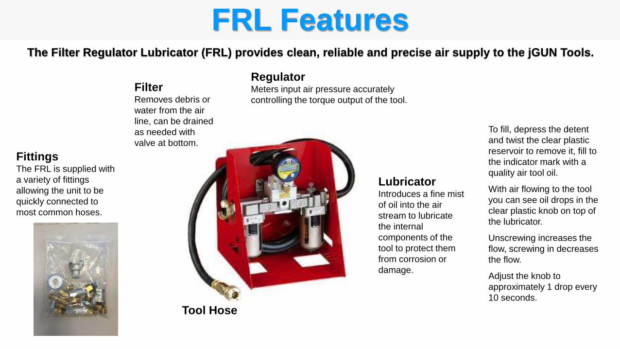
Tool Hose
FilterRemoves debris or
water from the air
line, can be drained
as needed with
valve at bottom.
RegulatorMeters input air pressure accurately
controlling the torque output of the tool.
To fill, depress the detent
and twist the clear plastic
reservoir to remove it, fill to
the indicator mark with a
quality air tool oil.
With air flowing to the tool
you can see oil drops in the
clear plastic knob on top of
the lubricator.
Unscrewing increases the
flow, screwing in decreases
the flow.
Adjust the knob to
approximately 1 drop every
10 seconds.
LubricatorIntroduces a fine mist
of oil into the air
stream to lubricate
the internal
components of the
tool to protect them
from corrosion or
damage.
FRL FeaturesThe Filter Regulator Lubricator (FRL) provides clean, reliable and precise air supply to the jGUN Tools.
FittingsThe FRL is supplied with
a variety of fittings
allowing the unit to be
quickly connected to
most common hoses.
J1 Inspect Tool
J2 Install Reaction Arm
J3 Install Socket
J4 Verify Air Supply
J5 Setup FRL and Connect Hoses
J6 Test Flow and Adjust Lubrication
J7 Shift Tool Speed (jGUN DUAL SPEED)
J8 Select the Air Pressure for Target Torque
J9 Adjust the Air Pressure
J10 Tighten Bolt
J11 Release Locked-On Tool
J12 Loosen Bolt
J - jGUN Torque Tool ProceduresThe following procedures should be followed to operate the jGUN tools.
Inspect Tool
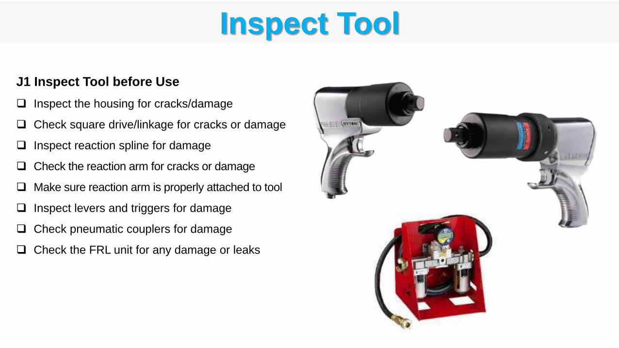
J1 Inspect Tool before Use
Inspect the housing for cracks/damage
Check square drive/linkage for cracks or damage
Inspect reaction spline for damage
Check the reaction arm for cracks or damage
Make sure reaction arm is properly attached to tool
Inspect levers and triggers for damage
Check pneumatic couplers for damage
Check the FRL unit for any damage or leaks
Install Reaction Arm
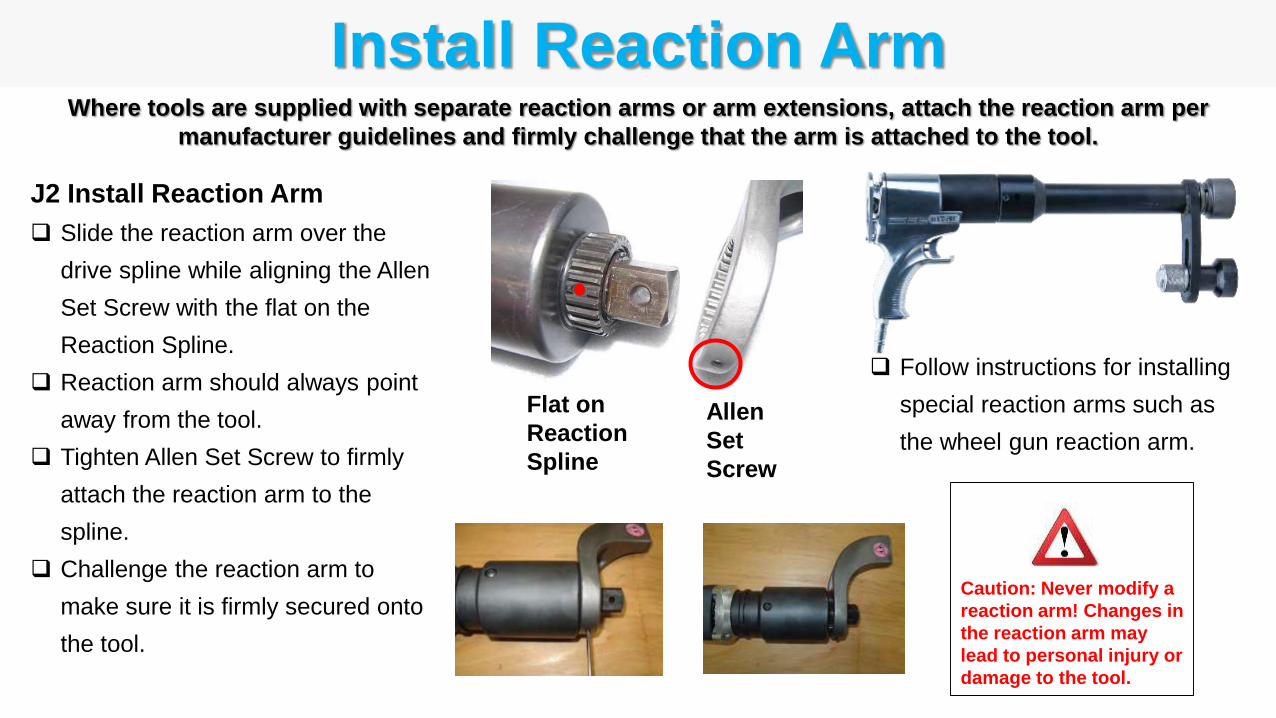
J2 Install Reaction Arm
Slide the reaction arm over the
drive spline while aligning the Allen
Set Screw with the flat on the
Reaction Spline.
Reaction arm should always point
away from the tool.
Tighten Allen Set Screw to firmly
attach the reaction arm to the
spline.
Challenge the reaction arm to
make sure it is firmly secured onto
the tool.
Caution: Never modify a
reaction arm! Changes in
the reaction arm may
lead to personal injury or
damage to the tool.
Where tools are supplied with separate reaction arms or arm extensions, attach the reaction arm per
manufacturer guidelines and firmly challenge that the arm is attached to the tool.
Follow instructions for installing
special reaction arms such as
the wheel gun reaction arm.
Allen
Set
Screw
Flat on
Reaction
Spline
Install Socket
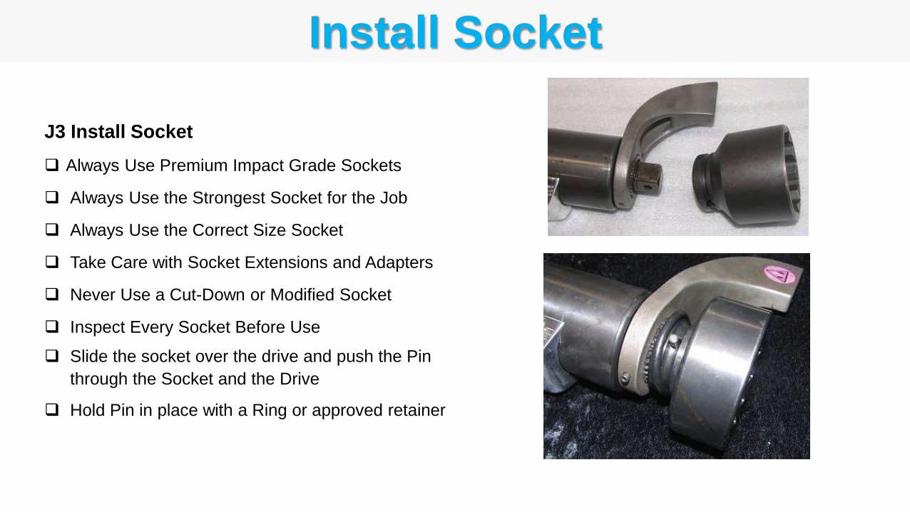
J3 Install Socket
Always Use Premium Impact Grade Sockets
Always Use the Strongest Socket for the Job
Always Use the Correct Size Socket
Take Care with Socket Extensions and Adapters
Never Use a Cut-Down or Modified Socket
Inspect Every Socket Before Use
Slide the socket over the drive and push the Pin
through the Socket and the Drive
Hold Pin in place with a Ring or approved retainer
Verify Air Supply
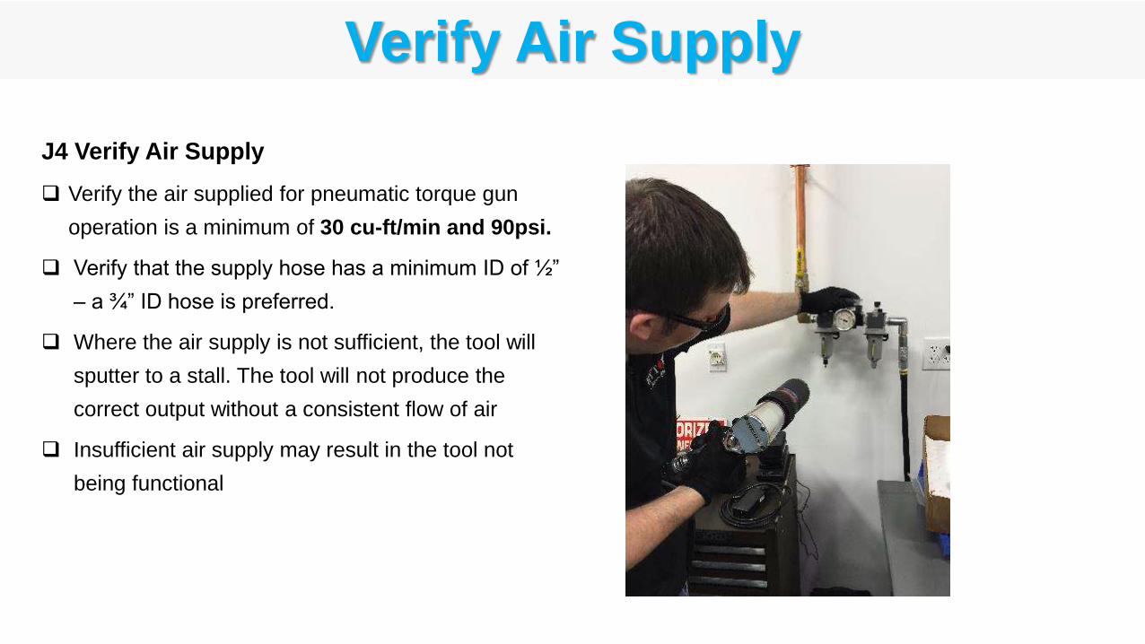
J4 Verify Air Supply
Verify the air supplied for pneumatic torque gun
operation is a minimum of 30 cu-ft/min and 90psi.
Verify that the supply hose has a minimum ID of ½”
– a ¾” ID hose is preferred.
Where the air supply is not sufficient, the tool will
sputter to a stall. The tool will not produce the
correct output without a consistent flow of air
Insufficient air supply may result in the tool not
being functional
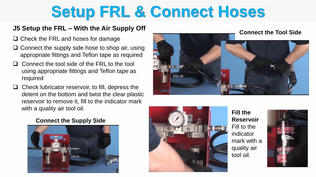
Setup FRL & Connect Hoses
Connect the Supply Side
Connect the Tool SideJ5 Setup the FRL – With the Air Supply Off
Check the FRL and hoses for damage
Connect the supply side hose to shop air, using
appropriate fittings and Teflon tape as required
Connect the tool side of the FRL to the tool
using appropriate fittings and Teflon tape as
required
Check lubricator reservoir, to fill, depress the
detent on the bottom and twist the clear plastic
reservoir to remove it, fill to the indicator mark
with a quality air tool oil.Fill the
Reservoir
Fill to the
indicator
mark with a
quality air
tool oil.
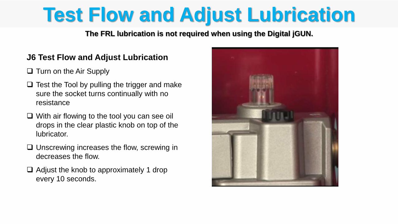
J6 Test Flow and Adjust Lubrication
Turn on the Air Supply
Test the Tool by pulling the trigger and make
sure the socket turns continually with no
resistance
With air flowing to the tool you can see oil
drops in the clear plastic knob on top of the
lubricator.
Unscrewing increases the flow, screwing in
decreases the flow.
Adjust the knob to approximately 1 drop
every 10 seconds.
Test Flow and Adjust LubricationThe FRL lubrication is not required when using the Digital jGUN.
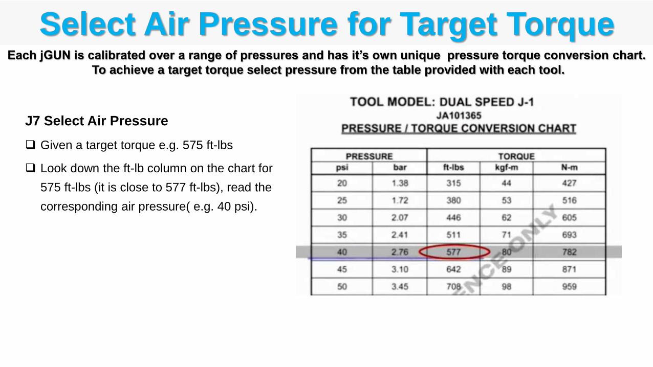
Select Air Pressure for Target TorqueEach jGUN is calibrated over a range of pressures and has it’s own unique pressure torque conversion chart.
To achieve a target torque select pressure from the table provided with each tool.
J7 Select Air Pressure
Given a target torque e.g. 575 ft-lbs
Look down the ft-lb column on the chart for
575 ft-lbs (it is close to 577 ft-lbs), read the
corresponding air pressure( e.g. 40 psi).
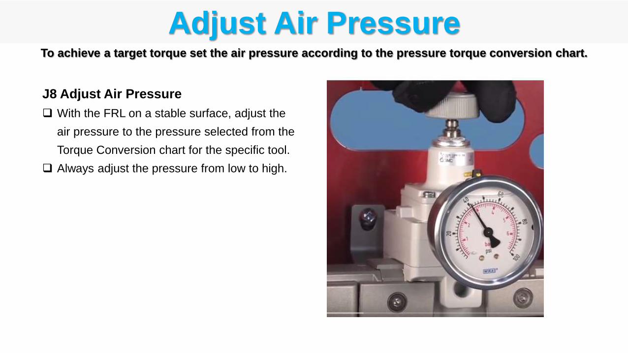
Adjust Air PressureTo achieve a target torque set the air pressure according to the pressure torque conversion chart.
J8 Adjust Air Pressure
With the FRL on a stable surface, adjust the
air pressure to the pressure selected from the
Torque Conversion chart for the specific tool.
Always adjust the pressure from low to high.
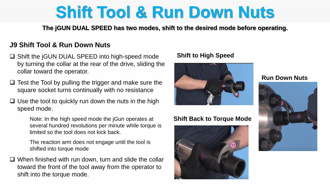
Shift Tool & Run Down NutsThe jGUN DUAL SPEED has two modes, shift to the desired mode before operating.
J9 Shift Tool & Run Down Nuts
Shift the jGUN DUAL SPEED into high-speed mode
by turning the collar at the rear of the drive, sliding the
collar toward the operator.
Test the Tool by pulling the trigger and make sure the
square socket turns continually with no resistance
Use the tool to quickly run down the nuts in the high
speed mode.
Note: In the high speed mode the jGun operates at
several hundred revolutions per minute while torque is
limited so the tool does not kick back.
The reaction arm does not engage until the tool is
shifted into torque mode
When finished with run down, turn and slide the collar
toward the front of the tool away from the operator to
shift into the torque mode.
Shift to High Speed
Run Down Nuts
Shift Back to Torque Mode
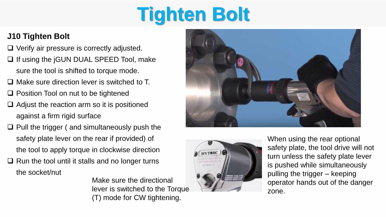
Tighten BoltJ10 Tighten Bolt
Verify air pressure is correctly adjusted.
If using the jGUN DUAL SPEED Tool, make
sure the tool is shifted to torque mode.
Make sure direction lever is switched to T.
Position Tool on nut to be tightened
Adjust the reaction arm so it is positioned
against a firm rigid surface
Pull the trigger ( and simultaneously push the
safety plate lever on the rear if provided) of
the tool to apply torque in clockwise direction
Run the tool until it stalls and no longer turns
the socket/nut
When using the rear optional
safety plate, the tool drive will not
turn unless the safety plate lever
is pushed while simultaneously
pulling the trigger – keeping
operator hands out of the danger
zone.
Make sure the directional
lever is switched to the Torque
(T) mode for CW tightening.
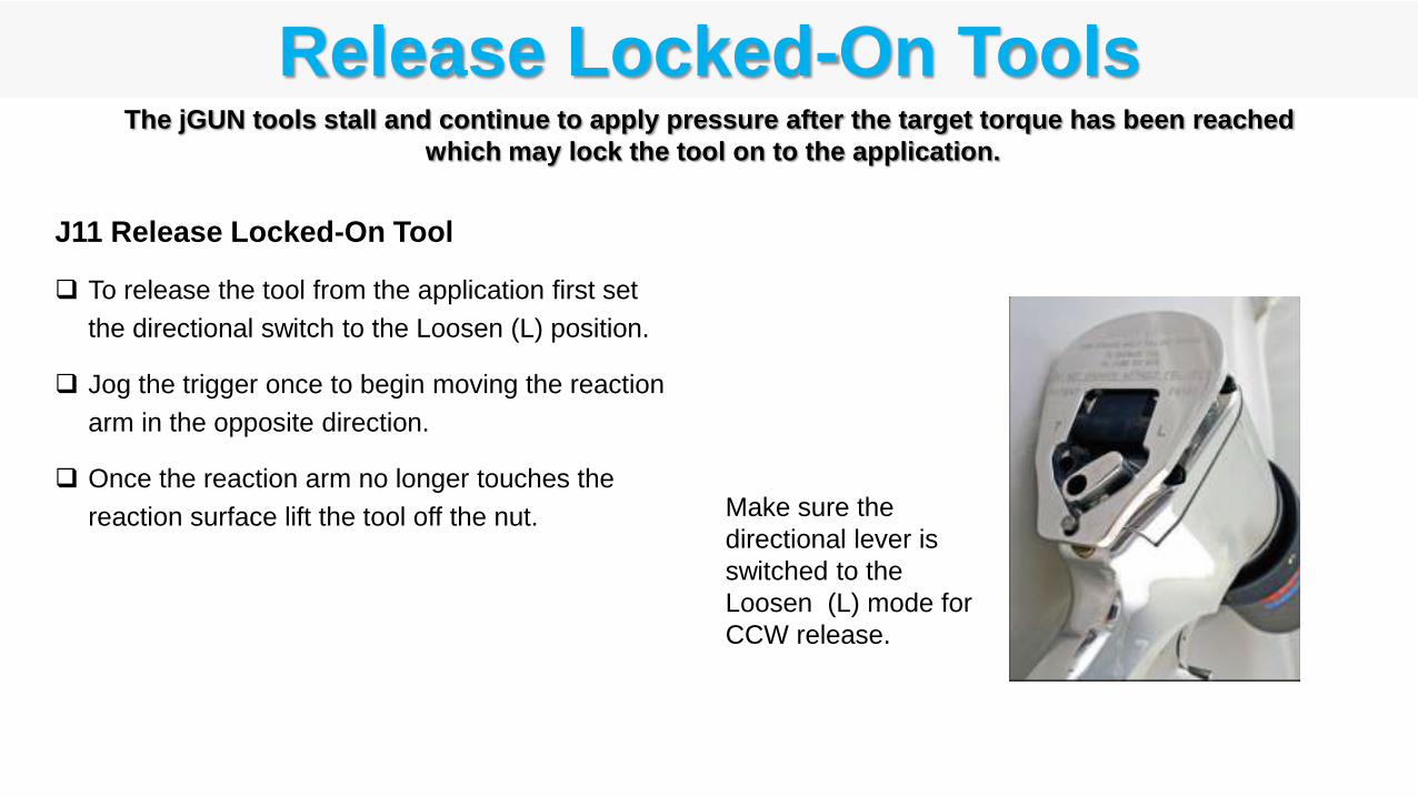
Release Locked-On Tools
J11 Release Locked-On Tool
To release the tool from the application first set
the directional switch to the Loosen (L) position.
Jog the trigger once to begin moving the reaction
arm in the opposite direction.
Once the reaction arm no longer touches the
reaction surface lift the tool off the nut.
The jGUN tools stall and continue to apply pressure after the target torque has been reached
which may lock the tool on to the application.
Make sure the
directional lever is
switched to the
Loosen (L) mode for
CCW release.
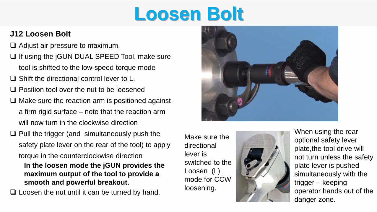
Loosen BoltJ12 Loosen Bolt
Adjust air pressure to maximum.
If using the jGUN DUAL SPEED Tool, make sure
tool is shifted to the low-speed torque mode
Shift the directional control lever to L.
Position tool over the nut to be loosened
Make sure the reaction arm is positioned against
a firm rigid surface – note that the reaction arm
will now turn in the clockwise direction
Pull the trigger (and simultaneously push the
safety plate lever on the rear of the tool) to apply
torque in the counterclockwise direction
In the loosen mode the jGUN provides the
maximum output of the tool to provide a
smooth and powerful breakout.
Loosen the nut until it can be turned by hand.
When using the rear
optional safety lever
plate,the tool drive will
not turn unless the safety
plate lever is pushed
simultaneously with the
trigger – keeping
operator hands out of the
danger zone.
Make sure the
directional
lever is
switched to the
Loosen (L)
mode for CCW
loosening.
DJ1 Inspect Tool
DJ2 Install Reaction Arm
DJ3 Install Socket
DJ4 Verify Air Supply
DJ5 Connect Hoses
DJ6 Set Display
DJ7 Tighten Bolt
DJ8 Loosen Bolt
DJ9 Charge Tool
DJ – Digital jGUN Operating ProceduresThe following procedures should be followed to operate the Digital jGUN tools.

Inspect Tool
DJ1 Inspect Tool before Use
Inspect the housing for cracks/damage
Check square drive/linkage for cracks or damage
Inspect reaction spline for damage
Check the reaction arm for cracks or damage
Make sure reaction arm is properly attached to tool
Inspect levers and triggers for damage
Check pneumatic couplers for damage
Check LCD screen and buttons for damage

Install Reaction Arm
DJ2 Install Reaction Arm
Slide the reaction arm over the drive
spline while aligning the Allen Set
Screw with the flat on the Reaction
Spline.
Reaction arm should always point
away from the tool.
Tighten Allen Set Screw to firmly
attach the reaction arm to the spline.
Challenge the reaction arm to make
sure it is firmly secured onto the tool.
Caution: Never modify a reaction
arm! Changes in the reaction arm
may lead to personal injury or
damage to the tool.
Where tools are supplied with separate reaction arms or arm extensions, attach the reaction arm per
manufacturer guidelines and firmly challenge that the arm is attached to the tool.
Install Socket
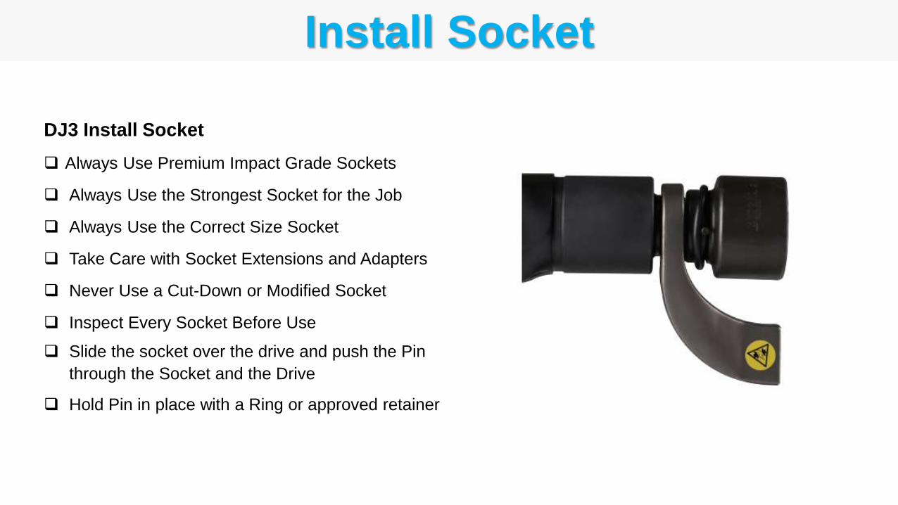
DJ3 Install Socket
Always Use Premium Impact Grade Sockets
Always Use the Strongest Socket for the Job
Always Use the Correct Size Socket
Take Care with Socket Extensions and Adapters
Never Use a Cut-Down or Modified Socket
Inspect Every Socket Before Use
Slide the socket over the drive and push the Pin
through the Socket and the Drive
Hold Pin in place with a Ring or approved retainer

Verify Air Supply
DJ4 Verify Air Supply
Verify the air supplied for pneumatic torque gun
operation is a minimum of 50 cu-ft/min and 90psi.
Verify that the supply hose has a minimum ID of ½” –
a ¾” ID hose is preferred.
Where the air supply is not sufficient, the tool will
sputter to a stall. The tool will not produce the correct
output without a consistent flow of air
Insufficient air supply may result in the tool not being
functional
Connect Hoses
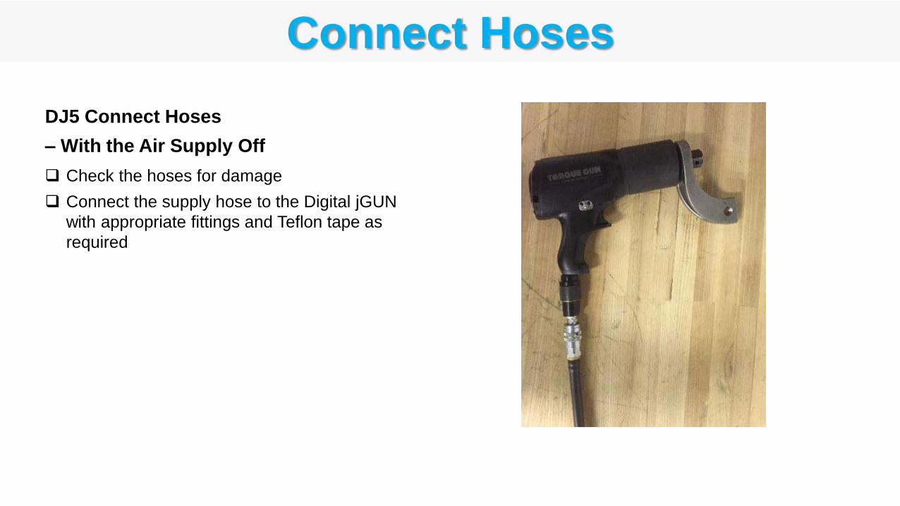
DJ5 Connect Hoses
– With the Air Supply Off
Check the hoses for damage
Connect the supply hose to the Digital jGUN
with appropriate fittings and Teflon tape as
required
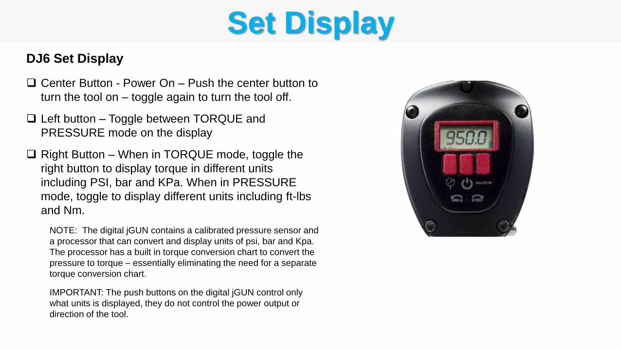
Set DisplayDJ6 Set Display
Center Button - Power On – Push the center button to
turn the tool on – toggle again to turn the tool off.
Left button – Toggle between TORQUE and
PRESSURE mode on the display
Right Button – When in TORQUE mode, toggle the
right button to display torque in different units
including PSI, bar and KPa. When in PRESSURE
mode, toggle to display different units including ft-lbs
and Nm.
NOTE: The digital jGUN contains a calibrated pressure sensor and
a processor that can convert and display units of psi, bar and Kpa.
The processor has a built in torque conversion chart to convert the
pressure to torque – essentially eliminating the need for a separate
torque conversion chart.
IMPORTANT: The push buttons on the digital jGUN control only
what units is displayed, they do not control the power output or
direction of the tool.
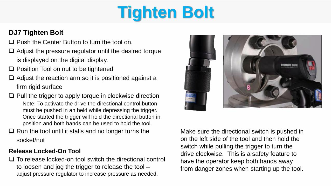
Tighten BoltDJ7 Tighten Bolt
Push the Center Button to turn the tool on.
Adjust the pressure regulator until the desired torque
is displayed on the digital display.
Position Tool on nut to be tightened
Adjust the reaction arm so it is positioned against a
firm rigid surface
Pull the trigger to apply torque in clockwise direction
Note: To activate the drive the directional control button
must be pushed in an held while depressing the trigger.
Once started the trigger will hold the directional button in
position and both hands can be used to hold the tool.
Run the tool until it stalls and no longer turns the
socket/nut
Release Locked-On Tool
To release locked-on tool switch the directional control
to loosen and jog the trigger to release the tool –adjust pressure regulator to increase pressure as needed.
Make sure the directional switch is pushed in
on the left side of the tool and then hold the
switch while pulling the trigger to turn the
drive clockwise. This is a safety feature to
have the operator keep both hands away
from danger zones when starting up the tool.
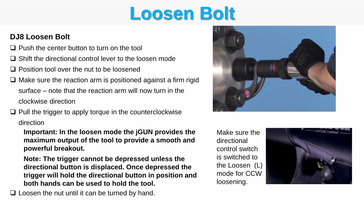
Loosen BoltDJ8 Loosen Bolt
Push the center button to turn on the tool
Shift the directional control lever to the loosen mode
Position tool over the nut to be loosened
Make sure the reaction arm is positioned against a firm rigid
surface – note that the reaction arm will now turn in the
clockwise direction
Pull the trigger to apply torque in the counterclockwise
direction
Important: In the loosen mode the jGUN provides the
maximum output of the tool to provide a smooth and
powerful breakout.
Note: The trigger cannot be depressed unless the
directional button is displaced. Once depressed the
trigger will hold the directional button in position and
both hands can be used to hold the tool.
Loosen the nut until it can be turned by hand.
Make sure the
directional
control switch
is switched to
the Loosen (L)
mode for CCW
loosening.

Charge Battery
DJ9 Charge Battery
Monitor the three-segment battery charge
indicator on the lower right side of the screen -
when the level drops the tool can easily be
recharged.
Use the USB cable provided in the case with the
tool to recharge the tool.
Connect the charger to the USB connector on the
right side of the display housing on the rear of the
gun.
The battery will be recharged in less than an hour
- it is fully charged as indicated by three bars.
The Digital jGun contains a non-removable rechargeable Li-Ion Battery that powers the Display Electronics.
Follow the instructions below for charging the battery.

3. Electric Torque Tools
BOSS Training SeriesBasic Operation and Safety Series

FLASH 2.0
1, 2, 3
Lithium SeriesBTM
250, 700, 1000, 2000, 3000
Electric Powered Torque Tools
Corded Cordless
LION GUN250, 700
Industrial
Commercial
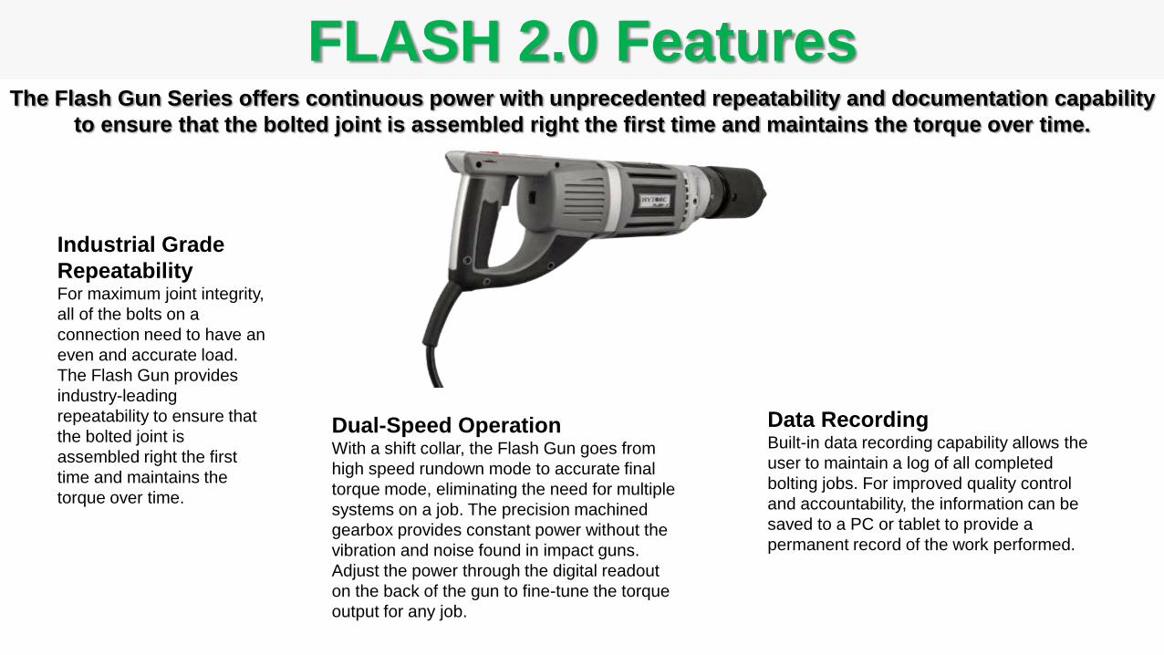
FLASH 2.0 FeaturesThe Flash Gun Series offers continuous power with unprecedented repeatability and documentation capability
to ensure that the bolted joint is assembled right the first time and maintains the torque over time.
Industrial Grade
RepeatabilityFor maximum joint integrity,
all of the bolts on a
connection need to have an
even and accurate load.
The Flash Gun provides
industry-leading
repeatability to ensure that
the bolted joint is
assembled right the first
time and maintains the
torque over time.
Dual-Speed OperationWith a shift collar, the Flash Gun goes from
high speed rundown mode to accurate final
torque mode, eliminating the need for multiple
systems on a job. The precision machined
gearbox provides constant power without the
vibration and noise found in impact guns.
Adjust the power through the digital readout
on the back of the gun to fine-tune the torque
output for any job.
Data RecordingBuilt-in data recording capability allows the
user to maintain a log of all completed
bolting jobs. For improved quality control
and accountability, the information can be
saved to a PC or tablet to provide a
permanent record of the work performed.
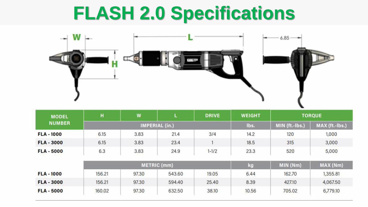
FLASH 2.0 Specifications

LITHIUM SERIES Features
Rugged Planetary Gear BoxReliable Heavy Duty Operation
Dual Speed SwitchFast Run-Down and Torque in Same Tool
Standard Square DriveCompatible with standard sockets
36V Rechargeable Lithium Ion BatteryLong life battery for continuous reliable use
TriggerSingle Finger Operation
Concentric Reaction splineMore efficient transfer of torque
Battery Lock ButtonEasily swap with fresh battery
Battery Test Button and Charge IndicatorAllows easier monitoring of charge level
USB Micro
PortPistol Grip HandleHandle design conforms to hand, providing a more secure grip
Cooling vents
The LITHIUM SERIES Battery Gun is a rugged industrial tool designed for precise application of
torque using electronic control features packaged in an ergonomic hand-held tool.
Brushed
DC Motor
and cooling
fans
Eyelet
Heads-Up LCD DisplayUser can safely view the screen
during operation
BeeperProvides audible feedback on
completion of operation
Quiet OperationNoise level typically less than 80dB
Push-Button SetupFor easy and fast setup and operation
Data CollectionCollect data on each bolting event

LITHIUM SERIES Control Panel FeaturesTool has (3) push-buttons and a simple graphical LCD Display Screen
on the rear to control all functions, menus and features.
Status LED
Angle Release (Angle)
Fastener Setting
Battery Charge Indicator(green charged battery, turns red with low voltage)
Left Button Right Button
Center Button
Increase Value Decrease Value
Rotating Nut Icon
Rotational Direction ArrowTorque, Angle, Release
Setting
Menu Shortcut Key
Job NumberShown when recording job data
Job On IndicatorShown when recording job data
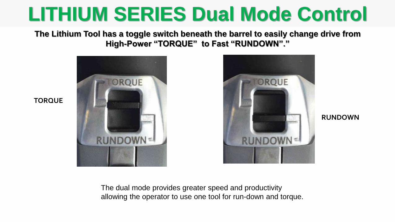
LITHIUM SERIES Dual Mode ControlThe Lithium Tool has a toggle switch beneath the barrel to easily change drive from
High-Power “TORQUE” to Fast “RUNDOWN”.”
RUNDOWN
TORQUE
The dual mode provides greater speed and productivity
allowing the operator to use one tool for run-down and torque.

LITHIUM SERIES Data Recording
USB Connection to tool
The LITHIUM SERIES Tools can record and store torque data in the tool memory and when
complete a CSV file can be downloaded with a complete record for the job.
USB Connection to computer
Automatically record torque parameters for all events.Reduces the time and cost of automatically collecting data at the source,
allowing data to be used for quality assurance and as a permeant job
record.
Stores up to 9999 jobs Allows better administrative tracking of each bolt and each job, file transfer
can occur after the fact so that does not impact work schedules.
Standard USB - PC connection to tool.Use readily available USB cables, saves time and cost for downloading
data
Plug-and-play file transfer to a PC.Data may be easily transferred to a PC by simply connecting the cable.
File automatically generated in a standard CSV formatCSV format is imported in the PC as an Excel file (when Excel is installed
on the PC) making it faster to analyze and share data.
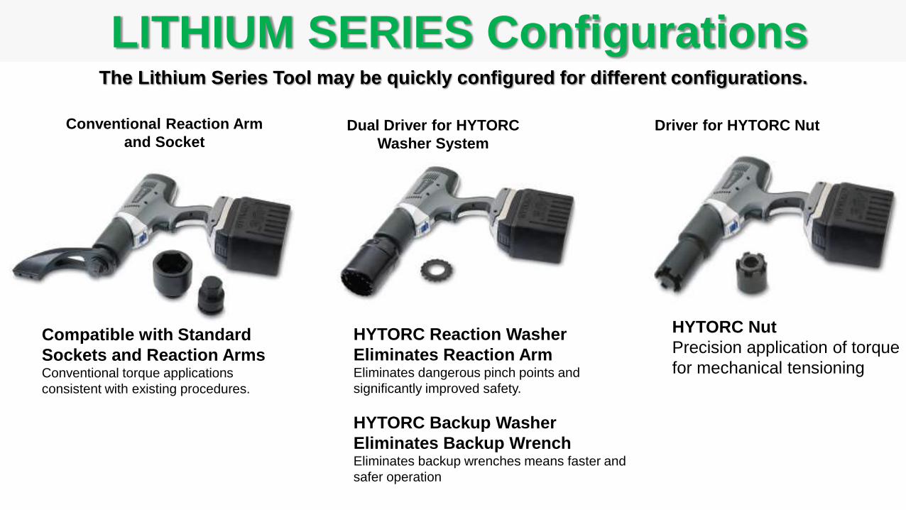
LITHIUM SERIES ConfigurationsThe Lithium Series Tool may be quickly configured for different configurations.
Conventional Reaction Arm
and SocketDual Driver for HYTORC
Washer System
Driver for HYTORC Nut
HYTORC Reaction Washer
Eliminates Reaction Arm Eliminates dangerous pinch points and
significantly improved safety.
HYTORC Backup Washer
Eliminates Backup WrenchEliminates backup wrenches means faster and
safer operation
Compatible with Standard
Sockets and Reaction ArmsConventional torque applications
consistent with existing procedures.
HYTORC Nut
Precision application of torque
for mechanical tensioning
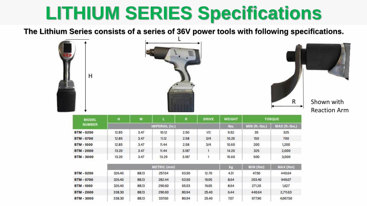
LITHIUM SERIES Specifications
L
H
R Shown withReaction Arm
The Lithium Series consists of a series of 36V power tools with following specifications.

LION GUN Features
Rugged Planetary Gear BoxReliable Heavy Duty Operation
Directional
SwitchEasily switch
between tighten
and loosen
Standard Square DriveCompatible with standard sockets
18V Rechargeable Lithium Ion BatteryLong life battery for continuous reliable use
TriggerSingle Finger Operation
Concentric Reaction splineMore efficient transfer of torque
Battery Lock ButtonEasily swap with fresh battery
Battery Test Button and Charge IndicatorAllows easier monitoring of charge level
USB
Micro
PortPistol Grip HandleHandle design conforms to hand, providing a more secure grip
Cooling vents
The LION GUN is a rugged industrial tool designed for precise application of torque using
electronic control features packaged in an ergonomic hand-held tool.
Brushless
DC Motor
and cooling
fans
Heads-Up LCD DisplayUser can safely view the screen
during operation
BeeperProvides audible feedback on
completion of operation
Quiet OperationNoise level typically less than 80dB
Push-Button SetupFor easy and fast setup and operation
Data CollectionCollect data on each bolting event

LION GUN Control Panel FeaturesThe LION GUN tool has (3) push-buttons and a simple graphical LCD Display Screen
on the rear to control all functions, menus and features.
Status LED
Angle Release (Angle)
Fastener Setting
Battery Charge IndicatorGreen charged battery, turns red with low voltage
Left Button Right Button
Center Button
Increase ValueCorresponds to left button
Decrease ValueCorresponds to right button
Rotating Nut Icon
Rotational Direction ArrowTorque, Angle, Release
Setting
Menu Shortcut Key
Job NumberShown when recording job data
Job On IndicatorShown when recording job data

LION GUN Directional ControlThe LION GUN Tool has a toggle switch beneath the barrel to easily change drive direction from
tighten to loosen by pressing the switch - Screen also Changes from TORQUE to LOOSEN.
TIGHTEN LOOSEN
Tighten Loosen
T L T L
Toggle-switch directional control allows the operator to easily change to
tighten or loosen nuts without the need to remove drives or sockets
Reduces setup time by allowing the operator to select tighten or loosen
without reconfiguring the tool; significantly improving productivity.

LION GUN Data Recording & Offload
USB Connection to tool
USB Connection to computer
The LION GUN Tool can record and store torque data in the tool memory and when complete
download a CSV file with a complete record for the job; compatible with Excel, text & other formats.
Automatically records torque parameters for all events for a job.Reduces the time and cost of automatically collecting data at the source, allowing data to
be used for job quality assurance and as a permeant job record.
Stores up to 9999 jobs Allows better administrative tracking of each bolt and each job, file transfer can occur
after the fact so that does not impact work schedules.
Standard USB - PC connection to tool.Use readily available USB cables, saves time and cost for downloading data
Plug-and-play file transfer to a PC.Data may be easily transferred to a PC by simply connecting the cable.
File automatically generated in a standard CSV file format.CSV format is imported in the PC as an Excel file (when Excel is installed on the PC)
making it faster to analyze and share data.
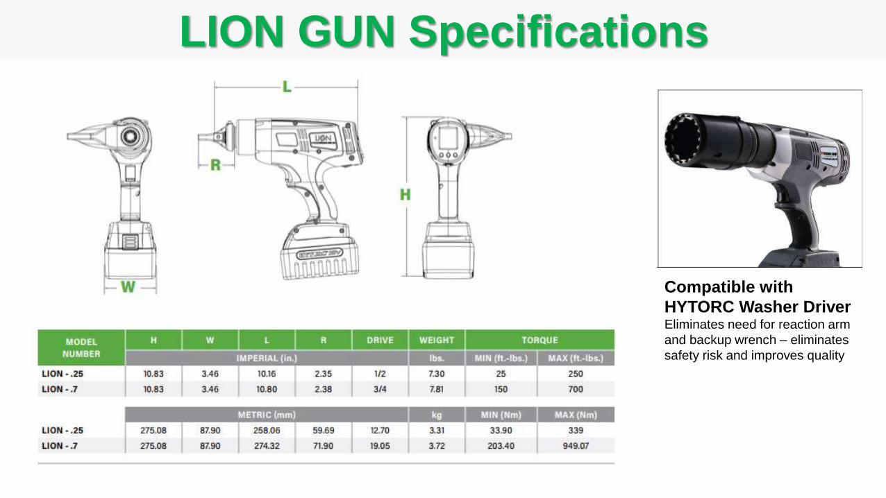
LION GUN Specifications
Compatible with
HYTORC Washer DriverEliminates need for reaction arm
and backup wrench – eliminates
safety risk and improves quality
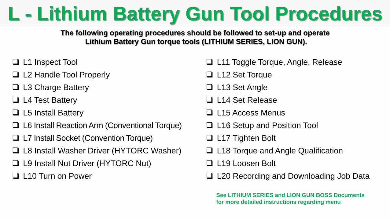
L1 Inspect Tool
L2 Handle Tool Properly
L3 Charge Battery
L4 Test Battery
L5 Install Battery
L6 Install Reaction Arm (Conventional Torque)
L7 Install Socket (Convention Torque)
L8 Install Washer Driver (HYTORC Washer)
L9 Install Nut Driver (HYTORC Nut)
L10 Turn on Power
L - Lithium Battery Gun Tool ProceduresThe following operating procedures should be followed to set-up and operate
Lithium Battery Gun torque tools (LITHIUM SERIES, LION GUN).
L11 Toggle Torque, Angle, Release
L12 Set Torque
L13 Set Angle
L14 Set Release
L15 Access Menus
L16 Setup and Position Tool
L17 Tighten Bolt
L18 Torque and Angle Qualification
L19 Loosen Bolt
L20 Recording and Downloading Job Data
See LITHIUM SERIES and LION GUN BOSS Documents
for more detailed instructions regarding menu
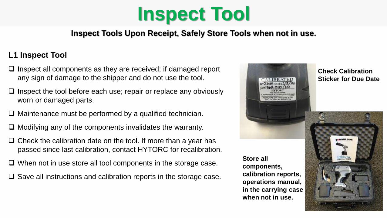
L1 Inspect Tool
Inspect all components as they are received; if damaged report
any sign of damage to the shipper and do not use the tool.
Inspect the tool before each use; repair or replace any obviously
worn or damaged parts.
Maintenance must be performed by a qualified technician.
Modifying any of the components invalidates the warranty.
Check the calibration date on the tool. If more than a year has
passed since last calibration, contact HYTORC for recalibration.
When not in use store all tool components in the storage case.
Save all instructions and calibration reports in the storage case.
Inspect Tool
Store all
components,
calibration reports,
operations manual,
in the carrying case
when not in use.
Inspect Tools Upon Receipt, Safely Store Tools when not in use.
Check Calibration
Sticker for Due Date

Handle Tool
L2 Handle Tool
Avoid Liquids/Humidity – The tool will withstand light
splashing but should not be submerged or subjected to
continuous rain or extreme humidity.
Check Operating Temperature – The operating temperature of
the tool should be less than150 deg. F.
Keep Vents Clean – All Cooling Vents should be kept clear of
dust, dirt and debris to allow internal fans to maintain airflow
to keep the motor and electronics within temperature limits,
do not subject the tool to extreme dust environments that
would clog the vents or do not cover the vents with your hand.
Do Not Use in Explosive environments – The tool and
electronic components are not certified or approved for
explosive environments or areas containing combustible
chemical materials.
Do Not Drop – Secure tool to protect from damage if dropped.
Secure Tool
according to
local practice
to prevent
damage from
dropping.
The Lithium Battery Gun Tools have electronic motors and components that will stand up under
rugged use when handled properly to ensure reliable long term operation.
Keep cooling vents clear

Charge Battery
L3 Charge Battery
Verify power supply voltage - power supply can operate at 110V
or 220V AC. Note: Compatible 100V to 240V AC, 50/60 Hz.
Verify power plug - supply cord is configured for North American
outlets/plugs, other regions may require adapters.
Connect the power charging cable into the charger cradle.
Plug the power supply cord into the appropriate AC outlet before
inserting a battery pack.
Insert the battery pack by sliding it into the charger cradle and
locking it in place.
Battery 80% charged in 2-hours, fully charged in 4-hours.
Charging IndicatorsPOWER INDICATOR green when charger is plugged into AC outlet.
CHARGING INDICATOR is flashing green while battery is charging.
CHARGING INDICATOR solid green when battery is fully charged.
FAULT INDICATOR is flashing red for battery fault not charging.
Power SupplyCharging
Cradle
Battery
Pack
Power
Supply
Cord
Charging
Cable
Power
Indicator
Charging
IndicatorLegend
Fault
Indicator
The battery is quickly charged in less than 4 hours.

Test Battery
36 V Battery
Weight 3.3lbs
L4 Test Battery
Push the TEST button on the side of the battery
and the LED’s will provide an approximate
indicator of remaining battery life:
1 LED On 25% Battery Charge Left
2 LEDs On 50% Battery Charge Left
3 LEDs On 75% Battery Charge Left
4 LEDs On 100% Battery Charge Left
The operator can easily test the battery to verify the battery has a charge,
and estimate how much charge remains.
18 V Battery
Weight 1.9lbs
Operation
The Lithium-Ion battery is designed for long running times with
quick recharges and operates at full speed until depleted, so
there is no gradual drop in power during use.
Batteries can be charged hundreds of times without any
noticeable loss in capacity.
A typical charged battery can tighten hundreds of bolts
(estimated 100-to-200 bolts), depending on the torque
requirements.
For continuous use, workers will typically have one or more
spare battery packs charging while the tool is in use and
quickly swap batteries as they are drained.
HYTORC has partnered with the RBRC (Rechargeable Battery
Recycling Corporation) in the US, and batteries can be
returned at no charge for recycling at HYTORC service
centers or local recycling centers.
Note: Check local and country guidelines for shipping
Lithium Ion batteries.

Install Battery
L5 Install Battery
Press the release button on the battery and
slide battery pack off the charger.
Align the base of the tool with the rails in the
battery and slide the battery pack firmly into
the handle until you hear (or see) the lock
snap in place.
Note: To remove the battery pack from the
tool, press the release button on the battery
and firmly pull the battery pack out of the
tool
ONOFF
The battery easily slides onto the tool body and snaps into place.
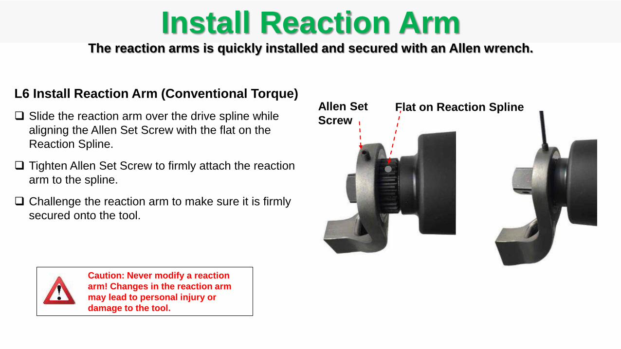
Install Reaction Arm
L6 Install Reaction Arm (Conventional Torque)
Slide the reaction arm over the drive spline while
aligning the Allen Set Screw with the flat on the
Reaction Spline.
Tighten Allen Set Screw to firmly attach the reaction
arm to the spline.
Challenge the reaction arm to make sure it is firmly
secured onto the tool.
Caution: Never modify a reaction
arm! Changes in the reaction arm
may lead to personal injury or
damage to the tool.
The reaction arms is quickly installed and secured with an Allen wrench.
Flat on Reaction SplineAllen Set
Screw
Install Socket
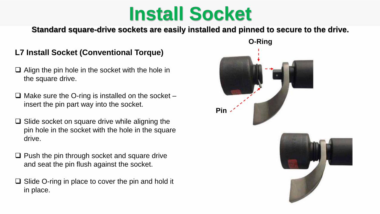
L7 Install Socket (Conventional Torque)
Align the pin hole in the socket with the hole in
the square drive.
Make sure the O-ring is installed on the socket –
insert the pin part way into the socket.
Slide socket on square drive while aligning the
pin hole in the socket with the hole in the square
drive.
Push the pin through socket and square drive
and seat the pin flush against the socket.
Slide O-ring in place to cover the pin and hold it
in place.
Standard square-drive sockets are easily installed and pinned to secure to the drive.
Pin
O-Ring
Install Washer Driver
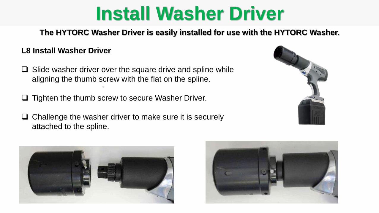
L8 Install Washer Driver
Slide washer driver over the square drive and spline while
aligning the thumb screw with the flat on the spline.
Tighten the thumb screw to secure Washer Driver.
Challenge the washer driver to make sure it is securely
attached to the spline.
The HYTORC Washer Driver is easily installed for use with the HYTORC Washer.
Install Nut Driver
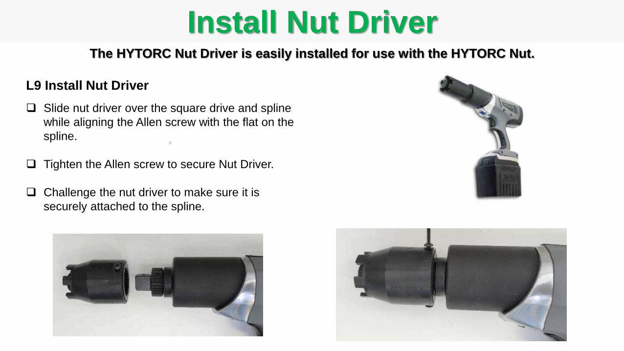
L9 Install Nut Driver
Slide nut driver over the square drive and spline
while aligning the Allen screw with the flat on the
spline.
Tighten the Allen screw to secure Nut Driver.
Challenge the nut driver to make sure it is
securely attached to the spline.
The HYTORC Nut Driver is easily installed for use with the HYTORC Nut.

Turn On Power
L10 Power On:
Push and release any of the 3 red buttons to
power-up the tool.
The tool displays initial settings which are
easily adjusted for specific job conditions. (see
operations instructions to adjust settings)
Tool powers off automatically after 5 minutes of
“Trigger” inactivity in order to save battery
charge.
When the tool is powered off, or the battery is
removed, all settings are saved as a Current
Working Profile (CWP) and loaded
automatically when the tool is powered back
on.
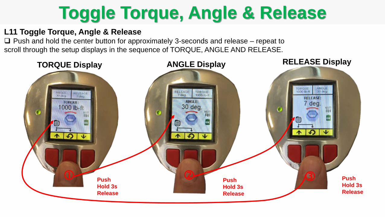
Toggle Torque, Angle & ReleaseL11 Toggle Torque, Angle & Release Push and hold the center button for approximately 3-seconds and release – repeat to
scroll through the setup displays in the sequence of TORQUE, ANGLE AND RELEASE.
TORQUE Display ANGLE Display RELEASE Display
Push
Hold 3s
Release
Push
Hold 3s
Release
Push
Hold 3s
Release

Set Torque
L12 Set Torque
While in the Torque Display, push the left button to increase
the torque or pus the right button to decrease the torque.
Torque may be set to any value from the minimum to the
maximum capability of the tool (or MAX MIN Torque Limits set
in the ADMIN menu).
Output units may be displayed in lb-ft, N-m, Kgf-m or %. (See
ADMIN menu to change output unit setting)
The Torque rotational direction arrow and the rotating nut icon
reflect the fastener clockwise or counter clockwise rotation
associate with the specific fastener type. (the fastener type
may be set under the Operation– Fastener Type menu ; Right-
Hand, Left-Hand, HYTORC NUT and HYTORC Washer). Torque is set to 1000 ft-lbs.
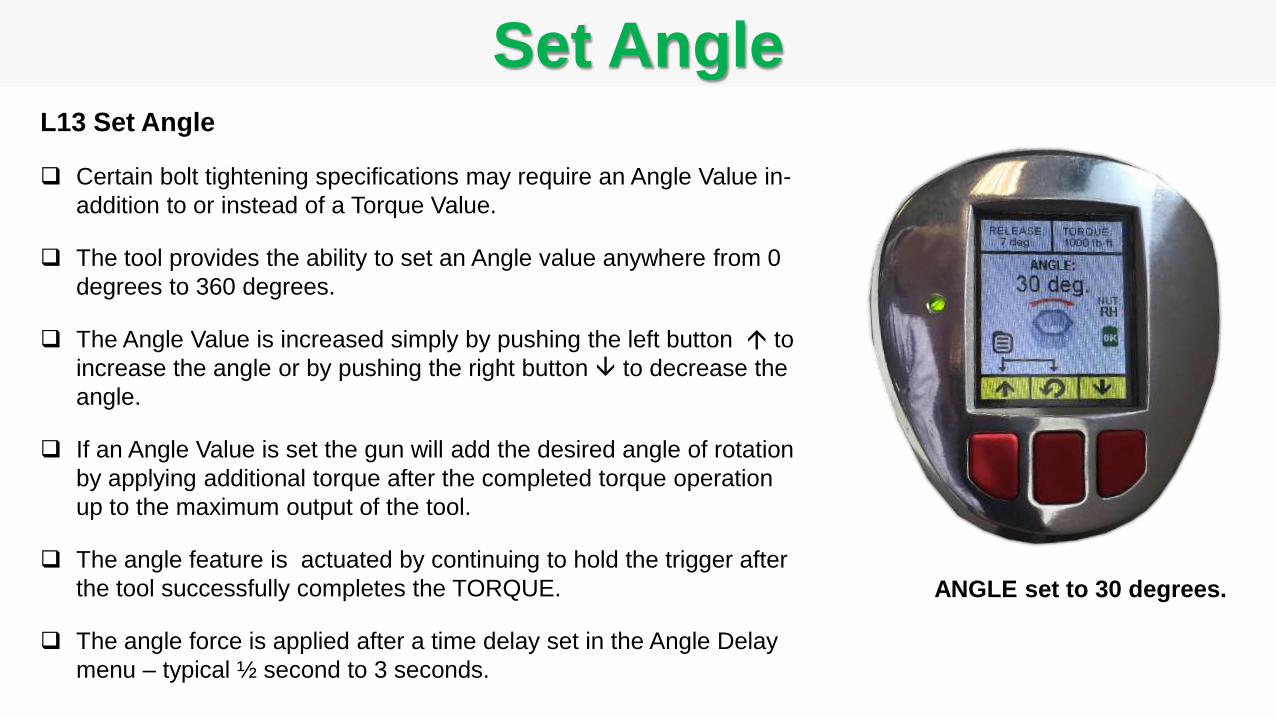
Set AngleL13 Set Angle
Certain bolt tightening specifications may require an Angle Value in-
addition to or instead of a Torque Value.
The tool provides the ability to set an Angle value anywhere from 0
degrees to 360 degrees.
The Angle Value is increased simply by pushing the left button to
increase the angle or by pushing the right button to decrease the
angle.
If an Angle Value is set the gun will add the desired angle of rotation
by applying additional torque after the completed torque operation
up to the maximum output of the tool.
The angle feature is actuated by continuing to hold the trigger after
the tool successfully completes the TORQUE.
The angle force is applied after a time delay set in the Angle Delay
menu – typical ½ second to 3 seconds.
ANGLE set to 30 degrees.
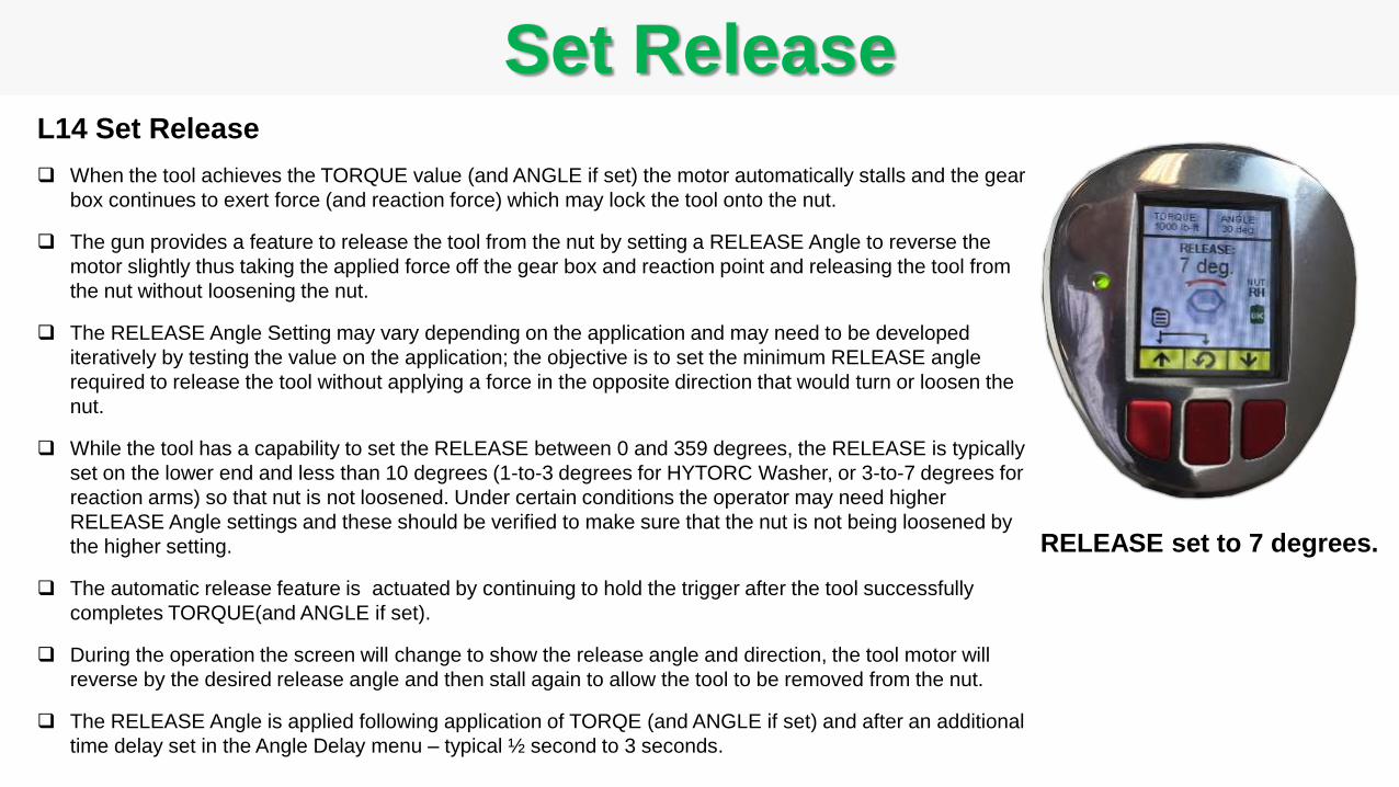
Set ReleaseL14 Set Release
When the tool achieves the TORQUE value (and ANGLE if set) the motor automatically stalls and the gear
box continues to exert force (and reaction force) which may lock the tool onto the nut.
The gun provides a feature to release the tool from the nut by setting a RELEASE Angle to reverse the
motor slightly thus taking the applied force off the gear box and reaction point and releasing the tool from
the nut without loosening the nut.
The RELEASE Angle Setting may vary depending on the application and may need to be developed
iteratively by testing the value on the application; the objective is to set the minimum RELEASE angle
required to release the tool without applying a force in the opposite direction that would turn or loosen the
nut.
While the tool has a capability to set the RELEASE between 0 and 359 degrees, the RELEASE is typically
set on the lower end and less than 10 degrees (1-to-3 degrees for HYTORC Washer, or 3-to-7 degrees for
reaction arms) so that nut is not loosened. Under certain conditions the operator may need higher
RELEASE Angle settings and these should be verified to make sure that the nut is not being loosened by
the higher setting.
The automatic release feature is actuated by continuing to hold the trigger after the tool successfully
completes TORQUE(and ANGLE if set).
During the operation the screen will change to show the release angle and direction, the tool motor will
reverse by the desired release angle and then stall again to allow the tool to be removed from the nut.
The RELEASE Angle is applied following application of TORQE (and ANGLE if set) and after an additional
time delay set in the Angle Delay menu – typical ½ second to 3 seconds.
RELEASE set to 7 degrees.

Access Menus & Sub-Menus
The green bar highlights the current position
Push left button to scroll down , right button to scroll up
Press the center button to select and display a sub-menu
or to select EXIT MENU to return to Home Display
or to select POWER OFF DEVICE to shut off the power immediately
Main MenuMAIN MENU
OPERATION
JOB DATA
SYSTEM
ADMIN
EXIT MENU
POWER OFF
OPERATION
JOB PROFILES
FASTENER TYPE
OUTPUT UNITS
ANGLE DELAY
MAIN MENU
JOB DATA
JOB SELECT
DATA HISTORY
GENERATE CSV FILE
MAIN MENU
L15 Access Menus and Sub-Menus Press and hold left and center buttons simultaneously for
approximately 3-seconds, release buttons when the “MAIN
MENU” screen appears
Press and hold Left and Center
Buttons Simultaneously to
Display Main Menu
SYSTEM
SYSTEM INFO
DISPLAY ROTATION
BEEPER
SETUP DEVICE
RESERVED
MAIN MENU
ADMIN
SET ADMIN CODE
SET LOCKOUT MODE
SET CLOCK
SET TORQUE LIMIT
CALIBRATE GUN
FORMAT NVRAM
MAIN MENU
Setup and Position ToolL16 Setup and Position Tool
Setup the Battery Gun to the desired configuration for the job:
- Assemble appropriate socket and reaction arm for the traditional torque application or
assemble appropriate HYTORC Washer Driver or HYTORC Nut Driver as specified for the application.
- Press any button to turn on the tool power.
- Select options in the Operations Menu; e.g. Fastener Type, Units, etc.
- Select options in the System Menu; e.g. Beeper On/Off.
- Select options in the Job Data menu; e.g. specify Job number to start collecting data.
- Set desired values for TORQUE, ANGLE and RELEASE
Run Down Nut either by hand or by using the tool until positioned tight against the flange. When using the tool
to run down the nut set the speed control to “RUN DOWN” and position the tool on the nut – pull the trigger to
quickly run down the nut until it touches against the flange. After applying the tool to Run Down the nut set the
speed control to TORQUE.
Position Back Wrench - If needed, apply a back wrench to the back nut on the bolt to prevent the back nut from
turning during tightening. If using the HYTORC Back Washer a back wrench is unnecessary.
Position Drive/Socket - Place the tool socket on the nut, making sure that the socket has fully engaged the nut.
If using an alternate driver such as the HYTORC Washer Driver or HYTORC Nut driver make sure the driver
properly engages the fastener including HYTORC washer or nut if installed.
Position Reaction Arm - If a reaction arm is used, make sure the reaction arm is firmly abutted against a
stationary object (e.g. an adjacent nut, flange, equipment housing etc.)
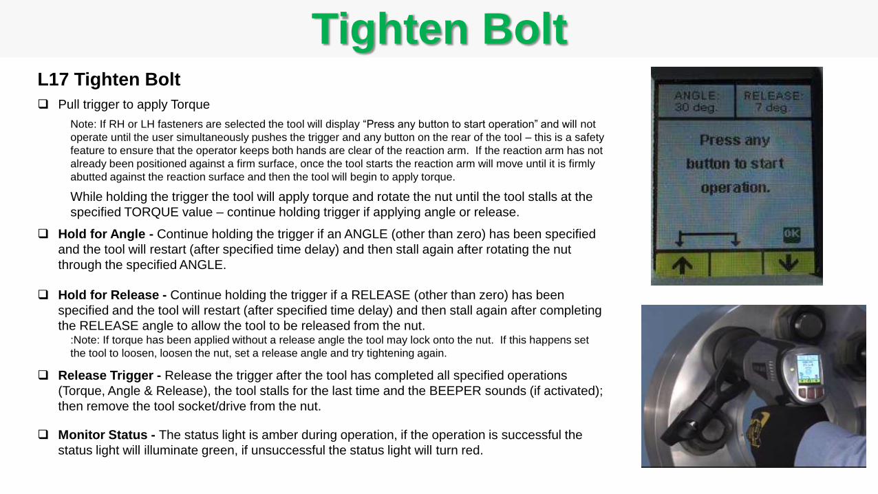
Tighten BoltL17 Tighten Bolt
Pull trigger to apply Torque
Note: If RH or LH fasteners are selected the tool will display “Press any button to start operation” and will not
operate until the user simultaneously pushes the trigger and any button on the rear of the tool – this is a safety
feature to ensure that the operator keeps both hands are clear of the reaction arm. If the reaction arm has not
already been positioned against a firm surface, once the tool starts the reaction arm will move until it is firmly
abutted against the reaction surface and then the tool will begin to apply torque.
While holding the trigger the tool will apply torque and rotate the nut until the tool stalls at the
specified TORQUE value – continue holding trigger if applying angle or release.
Hold for Angle - Continue holding the trigger if an ANGLE (other than zero) has been specified
and the tool will restart (after specified time delay) and then stall again after rotating the nut
through the specified ANGLE.
Hold for Release - Continue holding the trigger if a RELEASE (other than zero) has been
specified and the tool will restart (after specified time delay) and then stall again after completing
the RELEASE angle to allow the tool to be released from the nut.:Note: If torque has been applied without a release angle the tool may lock onto the nut. If this happens set
the tool to loosen, loosen the nut, set a release angle and try tightening again.
Release Trigger - Release the trigger after the tool has completed all specified operations
(Torque, Angle & Release), the tool stalls for the last time and the BEEPER sounds (if activated);
then remove the tool socket/drive from the nut.
Monitor Status - The status light is amber during operation, if the operation is successful the
status light will illuminate green, if unsuccessful the status light will turn red.
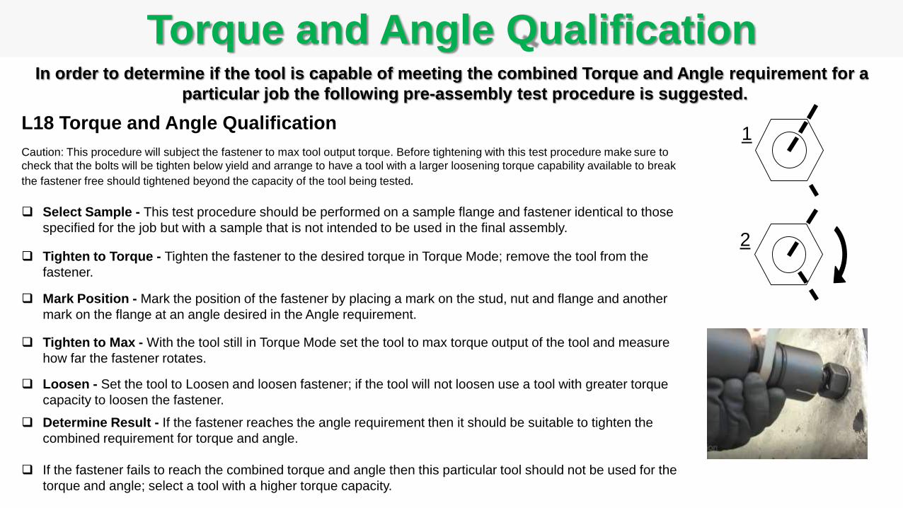
Torque and Angle QualificationIn order to determine if the tool is capable of meeting the combined Torque and Angle requirement for a
particular job the following pre-assembly test procedure is suggested.
L18 Torque and Angle Qualification
Caution: This procedure will subject the fastener to max tool output torque. Before tightening with this test procedure make sure to
check that the bolts will be tighten below yield and arrange to have a tool with a larger loosening torque capability available to break
the fastener free should tightened beyond the capacity of the tool being tested.
Select Sample - This test procedure should be performed on a sample flange and fastener identical to those
specified for the job but with a sample that is not intended to be used in the final assembly.
Tighten to Torque - Tighten the fastener to the desired torque in Torque Mode; remove the tool from the
fastener.
Mark Position - Mark the position of the fastener by placing a mark on the stud, nut and flange and another
mark on the flange at an angle desired in the Angle requirement.
Tighten to Max - With the tool still in Torque Mode set the tool to max torque output of the tool and measure
how far the fastener rotates.
Loosen - Set the tool to Loosen and loosen fastener; if the tool will not loosen use a tool with greater torque
capacity to loosen the fastener.
Determine Result - If the fastener reaches the angle requirement then it should be suitable to tighten the
combined requirement for torque and angle.
If the fastener fails to reach the combined torque and angle then this particular tool should not be used for the
torque and angle; select a tool with a higher torque capacity.
1
2
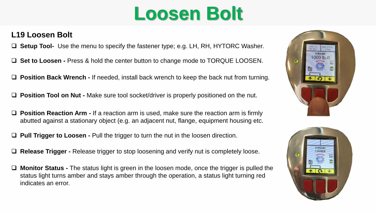
L19 Loosen Bolt
Setup Tool- Use the menu to specify the fastener type; e.g. LH, RH, HYTORC Washer.
Set to Loosen - Press & hold the center button to change mode to TORQUE LOOSEN.
Position Back Wrench - If needed, install back wrench to keep the back nut from turning.
Position Tool on Nut - Make sure tool socket/driver is properly positioned on the nut.
Position Reaction Arm - If a reaction arm is used, make sure the reaction arm is firmly
abutted against a stationary object (e.g. an adjacent nut, flange, equipment housing etc.
Pull Trigger to Loosen - Pull the trigger to turn the nut in the loosen direction.
Release Trigger - Release trigger to stop loosening and verify nut is completely loose.
Monitor Status - The status light is green in the loosen mode, once the trigger is pulled the
status light turns amber and stays amber through the operation, a status light turning red
indicates an error.
Loosen Bolt
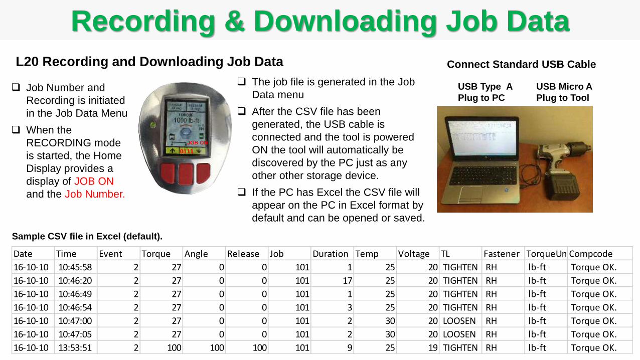
0111
JOB ON
Recording & Downloading Job Data
Date Time Event Torque Angle Release Job Duration Temp Voltage TL Fastener TorqueUnitsCompcode
16-10-10 10:45:58 2 27 0 0 101 1 25 20 TIGHTEN RH lb-ft Torque OK.
16-10-10 10:46:20 2 27 0 0 101 17 25 20 TIGHTEN RH lb-ft Torque OK.
16-10-10 10:46:49 2 27 0 0 101 1 25 20 TIGHTEN RH lb-ft Torque OK.
16-10-10 10:46:54 2 27 0 0 101 3 25 20 TIGHTEN RH lb-ft Torque OK.
16-10-10 10:47:00 2 27 0 0 101 2 30 20 LOOSEN RH lb-ft Torque OK.
16-10-10 10:47:05 2 27 0 0 101 2 30 20 LOOSEN RH lb-ft Torque OK.
16-10-10 13:53:51 2 100 100 100 101 9 25 19 TIGHTEN RH lb-ft Torque OK.
Sample CSV file in Excel (default).
The job file is generated in the Job
Data menu
After the CSV file has been
generated, the USB cable is
connected and the tool is powered
ON the tool will automatically be
discovered by the PC just as any
other other storage device.
If the PC has Excel the CSV file will
appear on the PC in Excel format by
default and can be opened or saved.
USB Micro A
Plug to Tool
USB Type A
Plug to PC
Connect Standard USB CableL20 Recording and Downloading Job Data
Job Number and
Recording is initiated
in the Job Data Menu
When the
RECORDING mode
is started, the Home
Display provides a
display of JOB ON
and the Job Number.

4. HYTORC Fasteners
BOSS Training SeriesBasic Operation and Safety Series
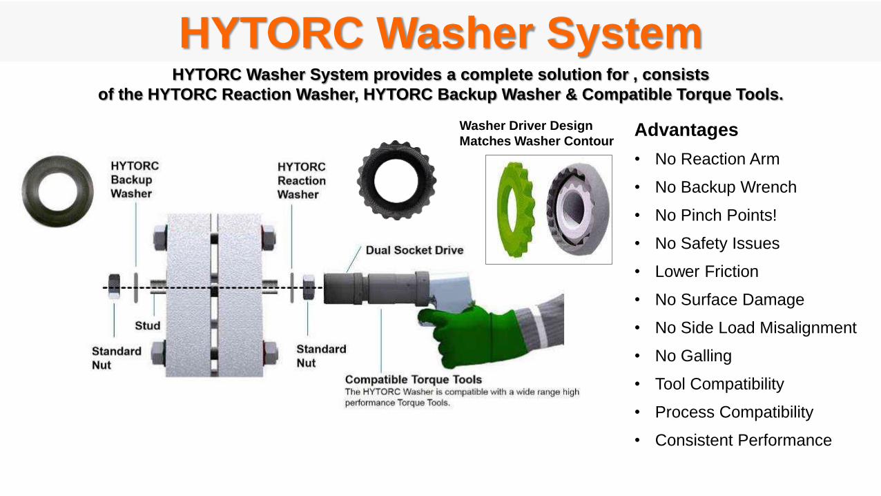
HYTORC Washer SystemHYTORC Washer System provides a complete solution for , consists
of the HYTORC Reaction Washer, HYTORC Backup Washer & Compatible Torque Tools.
Advantages
• No Reaction Arm
• No Backup Wrench
• No Pinch Points!
• No Safety Issues
• Lower Friction
• No Surface Damage
• No Side Load Misalignment
• No Galling
• Tool Compatibility
• Process Compatibility
• Consistent Performance
Washer Driver Design
Matches Washer Contour
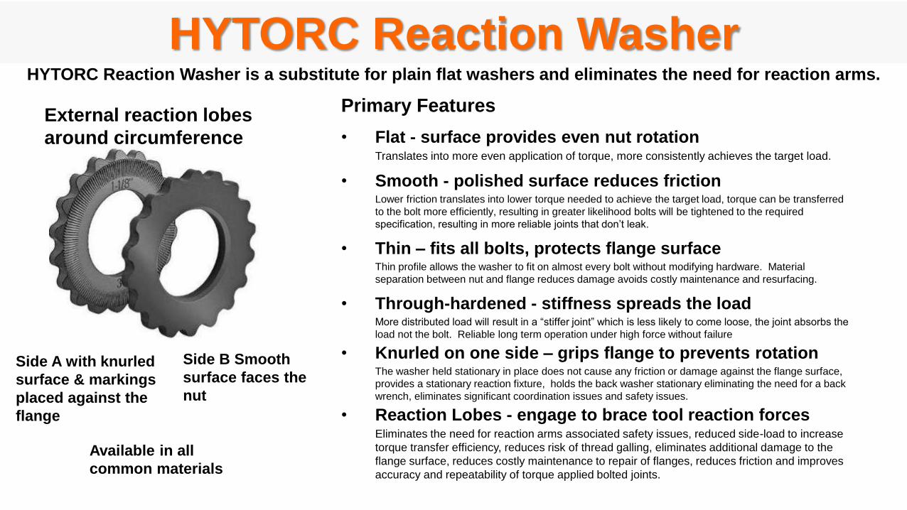
HYTORC Reaction WasherHYTORC Reaction Washer is a substitute for plain flat washers and eliminates the need for reaction arms.
Side B Smooth
surface faces the
nut
External reaction lobes
around circumference
Primary Features
• Flat - surface provides even nut rotationTranslates into more even application of torque, more consistently achieves the target load.
• Smooth - polished surface reduces frictionLower friction translates into lower torque needed to achieve the target load, torque can be transferred
to the bolt more efficiently, resulting in greater likelihood bolts will be tightened to the required
specification, resulting in more reliable joints that don’t leak.
• Thin – fits all bolts, protects flange surfaceThin profile allows the washer to fit on almost every bolt without modifying hardware. Material
separation between nut and flange reduces damage avoids costly maintenance and resurfacing.
• Through-hardened - stiffness spreads the loadMore distributed load will result in a “stiffer joint” which is less likely to come loose, the joint absorbs the
load not the bolt. Reliable long term operation under high force without failure
• Knurled on one side – grips flange to prevents rotationThe washer held stationary in place does not cause any friction or damage against the flange surface,
provides a stationary reaction fixture, holds the back washer stationary eliminating the need for a back
wrench, eliminates significant coordination issues and safety issues.
• Reaction Lobes - engage to brace tool reaction forcesEliminates the need for reaction arms associated safety issues, reduced side-load to increase
torque transfer efficiency, reduces risk of thread galling, eliminates additional damage to the
flange surface, reduces costly maintenance to repair of flanges, reduces friction and improves
accuracy and repeatability of torque applied bolted joints.
Side A with knurled
surface & markings
placed against the
flange
Available in all
common materials
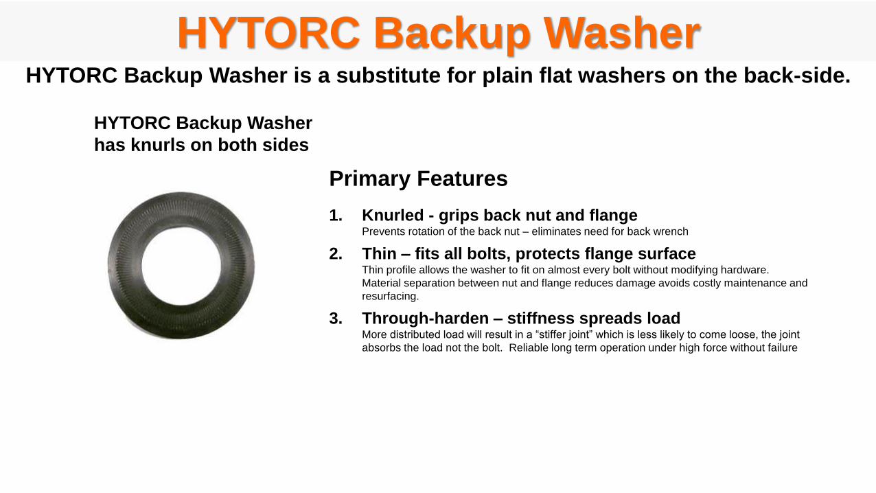
HYTORC Backup Washer
HYTORC Backup Washer
has knurls on both sides
HYTORC Backup Washer is a substitute for plain flat washers on the back-side.
Primary Features
1. Knurled - grips back nut and flangePrevents rotation of the back nut – eliminates need for back wrench
2. Thin – fits all bolts, protects flange surfaceThin profile allows the washer to fit on almost every bolt without modifying hardware.
Material separation between nut and flange reduces damage avoids costly maintenance and
resurfacing.
3. Through-harden – stiffness spreads loadMore distributed load will result in a “stiffer joint” which is less likely to come loose, the joint
absorbs the load not the bolt. Reliable long term operation under high force without failure
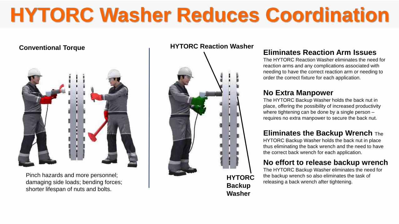
HYTORC Washer Reduces Coordination
Eliminates Reaction Arm IssuesThe HYTORC Reaction Washer eliminates the need for
reaction arms and any complications associated with
needing to have the correct reaction arm or needing to
order the correct fixture for each application.
No Extra ManpowerThe HYTORC Backup Washer holds the back nut in
place, offering the possibility of increased productivity
where tightening can be done by a single person –
requires no extra manpower to secure the back nut.
Eliminates the Backup Wrench The
HYTORC Backup Washer holds the back nut in place
thus eliminating the back wrench and the need to have
the correct back wrench for each application.
No effort to release backup wrenchThe HYTORC Backup Washer eliminates the need for
the backup wrench so also eliminates the task of
releasing a back wrench after tightening.
HYTORC Reaction Washer
HYTORC
Backup
Washer
Conventional Torque
Pinch hazards and more personnel;
damaging side loads; bending forces;
shorter lifespan of nuts and bolts.
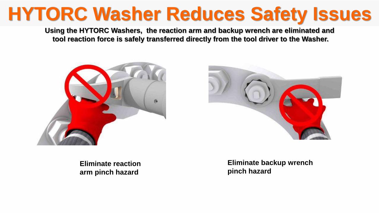
HYTORC Washer Reduces Safety IssuesUsing the HYTORC Washers, the reaction arm and backup wrench are eliminated and
tool reaction force is safely transferred directly from the tool driver to the Washer.
Eliminate reaction
arm pinch hazard
Eliminate backup wrench
pinch hazard
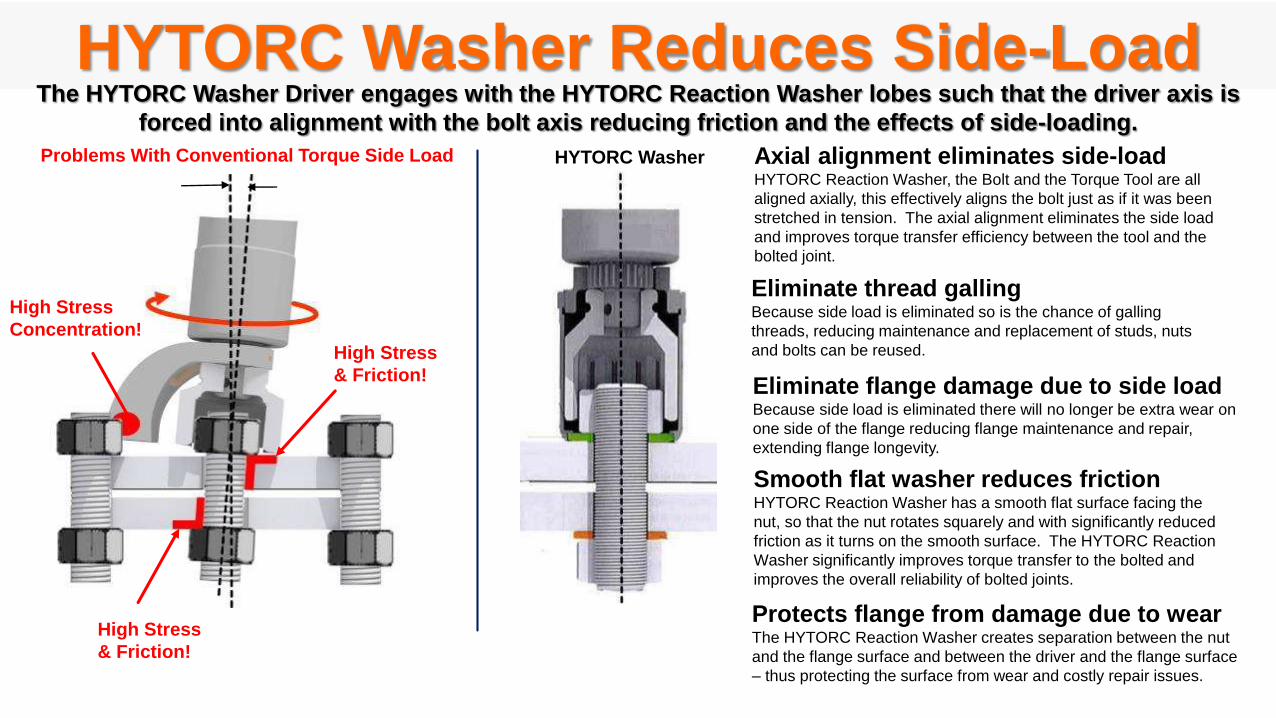
HYTORC Washer Reduces Side-Load
HYTORC Reaction Washer
Smooth flat washer reduces frictionHYTORC Reaction Washer has a smooth flat surface facing the
nut, so that the nut rotates squarely and with significantly reduced
friction as it turns on the smooth surface. The HYTORC Reaction
Washer significantly improves torque transfer to the bolted and
improves the overall reliability of bolted joints.
The HYTORC Washer Driver engages with the HYTORC Reaction Washer lobes such that the driver axis is
forced into alignment with the bolt axis reducing friction and the effects of side-loading.
Protects flange from damage due to wearThe HYTORC Reaction Washer creates separation between the nut
and the flange surface and between the driver and the flange surface
– thus protecting the surface from wear and costly repair issues.
Axial alignment eliminates side-load HYTORC Reaction Washer, the Bolt and the Torque Tool are all
aligned axially, this effectively aligns the bolt just as if it was been
stretched in tension. The axial alignment eliminates the side load
and improves torque transfer efficiency between the tool and the
bolted joint.
Eliminate thread gallingBecause side load is eliminated so is the chance of galling
threads, reducing maintenance and replacement of studs, nuts
and bolts can be reused.
Eliminate flange damage due to side loadBecause side load is eliminated there will no longer be extra wear on
one side of the flange reducing flange maintenance and repair,
extending flange longevity.
High Stress
& Friction!
High Stress
& Friction!
High Stress
Concentration!
Problems With Conventional Torque Side Load HYTORC Washer

Scatter With Conventional TorqueScatter With HYTORC Washer
HYTORC Washer Improves ConsistencyAs a result of reduced side load,
the HYTORC Washer results in more uniform application of torque to the bolt.
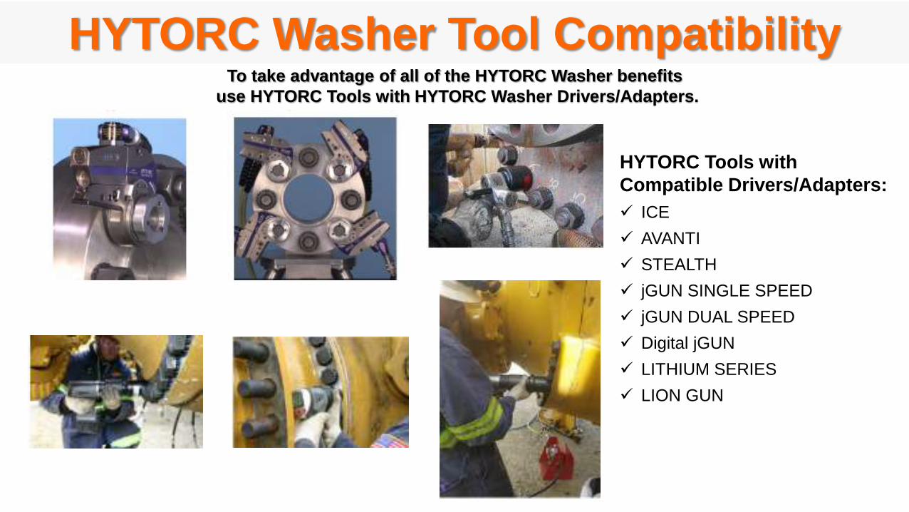
HYTORC Washer Tool Compatibility
HYTORC Tools with
Compatible Drivers/Adapters:
ICE
AVANTI
STEALTH
jGUN SINGLE SPEED
jGUN DUAL SPEED
Digital jGUN
LITHIUM SERIES
LION GUN
To take advantage of all of the HYTORC Washer benefits
use HYTORC Tools with HYTORC Washer Drivers/Adapters.
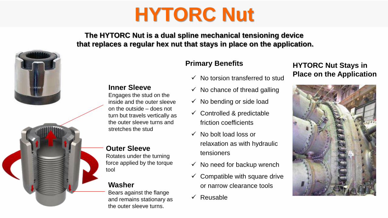
HYTORC NutThe HYTORC Nut is a dual spline mechanical tensioning device
that replaces a regular hex nut that stays in place on the application.
Inner SleeveEngages the stud on the
inside and the outer sleeve
on the outside – does not
turn but travels vertically as
the outer sleeve turns and
stretches the stud
Outer SleeveRotates under the turning
force applied by the torque
tool
WasherBears against the flange
and remains stationary as
the outer sleeve turns.
Primary Benefits
No torsion transferred to stud
No chance of thread galling
No bending or side load
Controlled & predictable
friction coefficients
No bolt load loss or
relaxation as with hydraulic
tensioners
No need for backup wrench
Compatible with square drive
or narrow clearance tools
Reusable
HYTORC Nut Stays in
Place on the Application
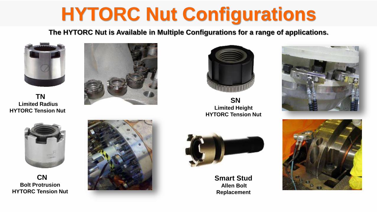
TNLimited Radius
HYTORC Tension Nut
SNLimited Height
HYTORC Tension Nut
CNBolt Protrusion
HYTORC Tension Nut
Smart StudAllen Bolt
Replacement
HYTORC Nut ConfigurationsThe HYTORC Nut is Available in Multiple Configurations for a range of applications.
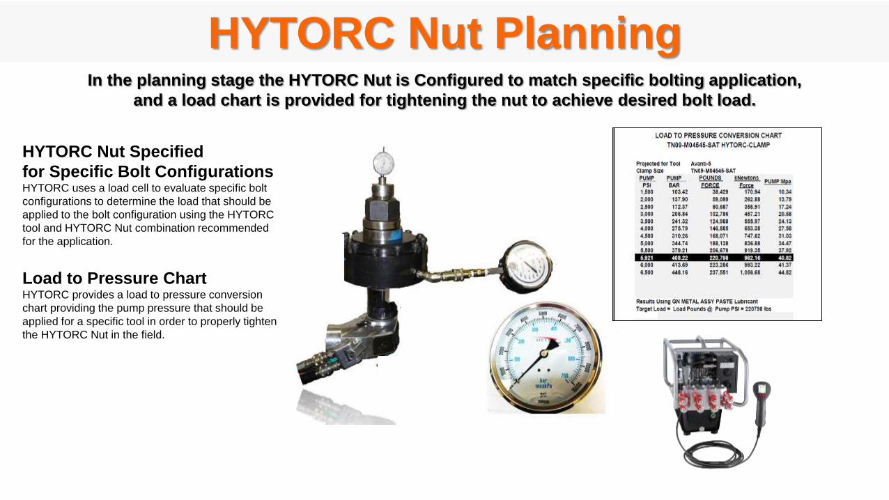
HYTORC Nut Planning
HYTORC Nut Specified
for Specific Bolt ConfigurationsHYTORC uses a load cell to evaluate specific bolt
configurations to determine the load that should be
applied to the bolt configuration using the HYTORC
tool and HYTORC Nut combination recommended
for the application.
Load to Pressure ChartHYTORC provides a load to pressure conversion
chart providing the pump pressure that should be
applied for a specific tool in order to properly tighten
the HYTORC Nut in the field.
In the planning stage the HYTORC Nut is Configured to match specific bolting application,
and a load chart is provided for tightening the nut to achieve desired bolt load.
HW- HYTORC Washer Install Procedure
HW1 Setup Flange
HW2 Install Back Washer & Nut
HW3 Install Reaction Washer
HW4 Apply Lubrication
HW5 Install Active Nut & Tighten
The following procedures should be followed to install HYTORC Washers.
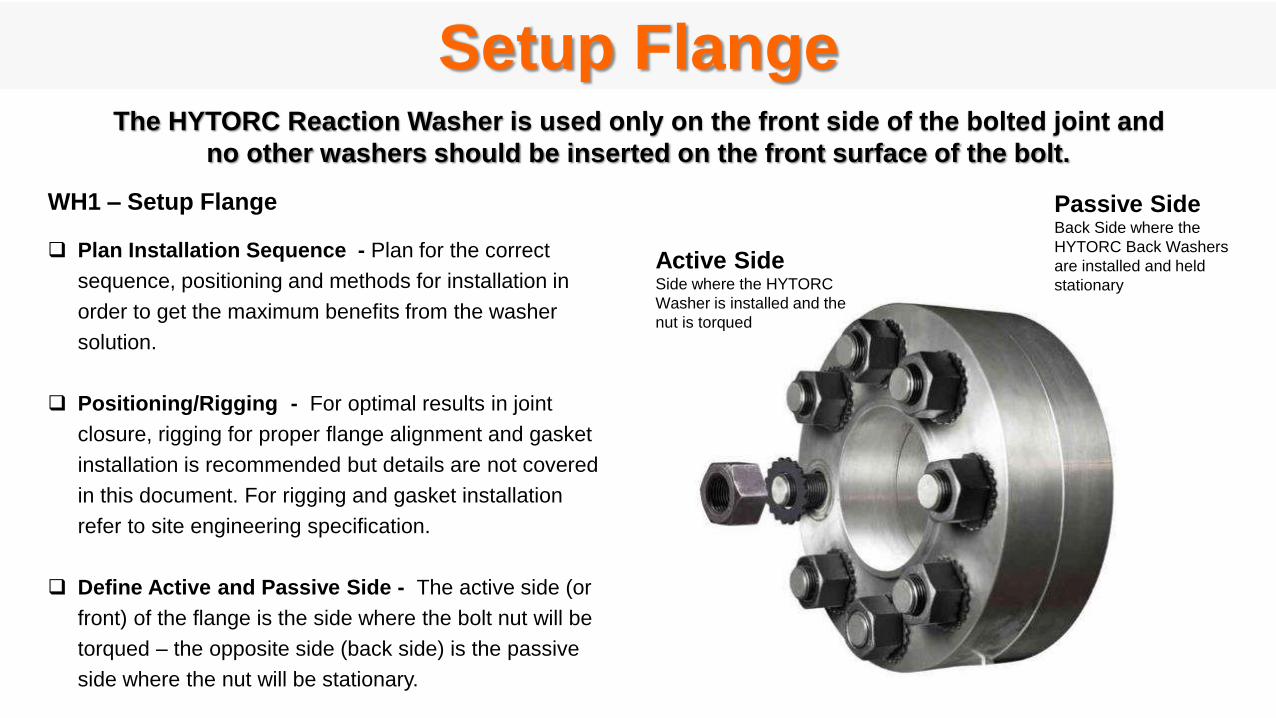
WH1 – Setup Flange
Plan Installation Sequence - Plan for the correct
sequence, positioning and methods for installation in
order to get the maximum benefits from the washer
solution.
Positioning/Rigging - For optimal results in joint
closure, rigging for proper flange alignment and gasket
installation is recommended but details are not covered
in this document. For rigging and gasket installation
refer to site engineering specification.
Define Active and Passive Side - The active side (or
front) of the flange is the side where the bolt nut will be
torqued – the opposite side (back side) is the passive
side where the nut will be stationary.
The HYTORC Reaction Washer is used only on the front side of the bolted joint and
no other washers should be inserted on the front surface of the bolt.
Setup Flange
Active SideSide where the HYTORC
Washer is installed and the
nut is torqued
Passive SideBack Side where the
HYTORC Back Washers
are installed and held
stationary
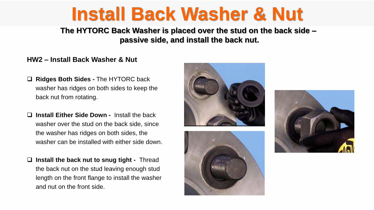
HW2 – Install Back Washer & Nut
Ridges Both Sides - The HYTORC back
washer has ridges on both sides to keep the
back nut from rotating.
Install Either Side Down - Install the back
washer over the stud on the back side, since
the washer has ridges on both sides, the
washer can be installed with either side down.
Install the back nut to snug tight - Thread
the back nut on the stud leaving enough stud
length on the front flange to install the washer
and nut on the front side.
The HYTORC Back Washer is placed over the stud on the back side –
passive side, and install the back nut.
Install Back Washer & Nut
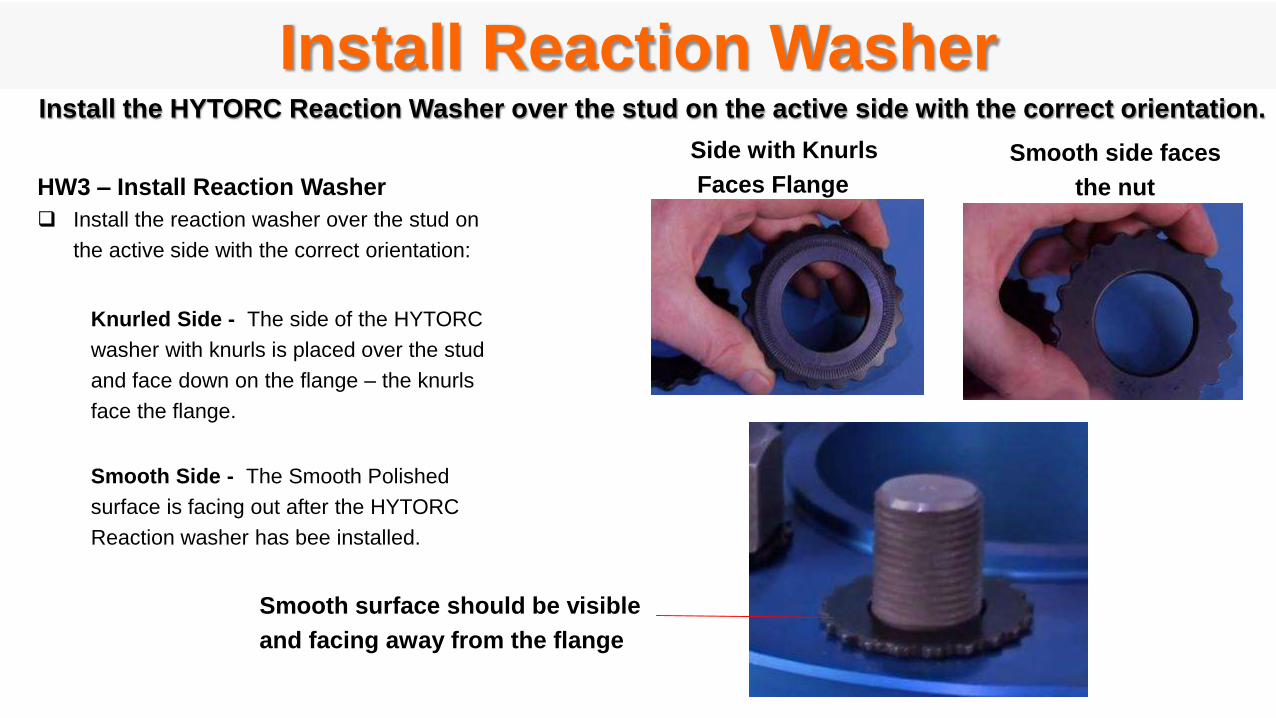
HW3 – Install Reaction Washer
Install the reaction washer over the stud on
the active side with the correct orientation:
Knurled Side - The side of the HYTORC
washer with knurls is placed over the stud
and face down on the flange – the knurls
face the flange.
Smooth Side - The Smooth Polished
surface is facing out after the HYTORC
Reaction washer has bee installed.
Smooth surface should be visible
and facing away from the flange
Side with Knurls
Faces Flange
Smooth side faces
the nut
Install the HYTORC Reaction Washer over the stud on the active side with the correct orientation.
Install Reaction Washer
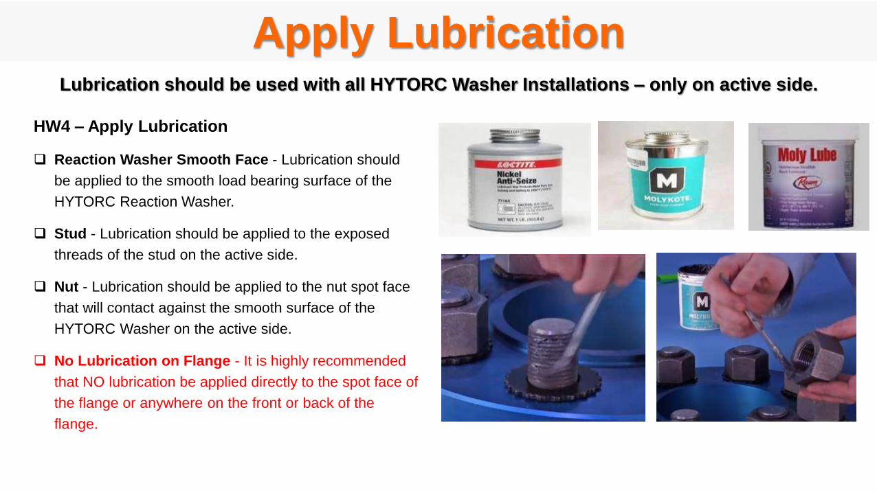
HW4 – Apply Lubrication
Reaction Washer Smooth Face - Lubrication should
be applied to the smooth load bearing surface of the
HYTORC Reaction Washer.
Stud - Lubrication should be applied to the exposed
threads of the stud on the active side.
Nut - Lubrication should be applied to the nut spot face
that will contact against the smooth surface of the
HYTORC Washer on the active side.
No Lubrication on Flange - It is highly recommended
that NO lubrication be applied directly to the spot face of
the flange or anywhere on the front or back of the
flange.
Lubrication should be used with all HYTORC Washer Installations – only on active side.
Apply Lubrication
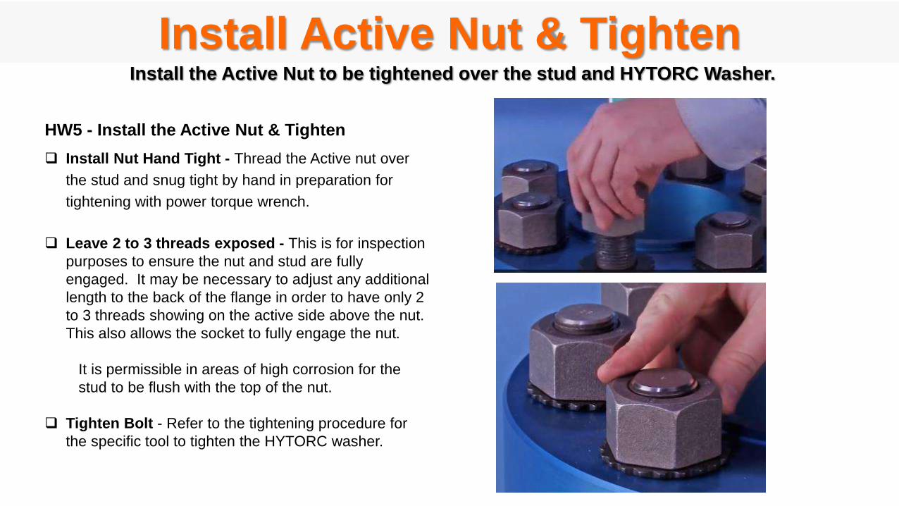
Install the Active Nut to be tightened over the stud and HYTORC Washer.
HW5 - Install the Active Nut & Tighten
Install Nut Hand Tight - Thread the Active nut over
the stud and snug tight by hand in preparation for
tightening with power torque wrench.
Leave 2 to 3 threads exposed - This is for inspection
purposes to ensure the nut and stud are fully
engaged. It may be necessary to adjust any additional
length to the back of the flange in order to have only 2
to 3 threads showing on the active side above the nut.
This also allows the socket to fully engage the nut.
It is permissible in areas of high corrosion for the
stud to be flush with the top of the nut.
Tighten Bolt - Refer to the tightening procedure for
the specific tool to tighten the HYTORC washer.
Install Active Nut & Tighten
HW- HYTORC Nut Install Procedure
HN1 Lubricate HYTORC Nut & Stud
HN2 Assemble HYTORC Nut
HN3 Assemble Driver
HN4 Tighten HYTORC Nut
HN5 Loosen HYTORC Nut
The following procedures should be followed to install HYTORC Nut.

Lubricate HYTORC Nut & StudIn order to produce uniform tensioning loads the HYTORC Nut comes pre-lubricated.
Before reusing HYTORC Nuts they should be disassembled, cleaned an re-lubricated before the next use.
HN1 - HYTORC NUT LUBRICATION
Lubricate all Surfaces Shown
Although the bolt stud is not subject to any torsion during
installation it is recommended to lubricate the bolt stud
threads to facilitate future disassembly and removal.

Assemble HYTORC NutHN2- HYTORC NUT ASSEMBLY
Thread the HYTORC Nut onto the stud by hand.
For long studs in may be desirable to use an impact
wrench with mating insert to run down the HYTORC
Nut.
Adjust the height of the stud so that the stud fully
engages all the threads of the inner sleeve and the top
of the stud is about 2 threads below the lip of the inner
sleeve.
When the HYTORC Nut is in place check to make sure
the inner sleeve fully engages the splined washer and
the outer sleeve rests on the washer.
The two sleeves should be aligned at the top.
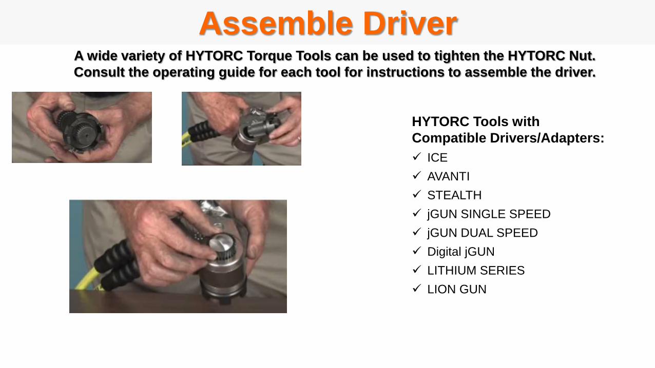
Assemble DriverA wide variety of HYTORC Torque Tools can be used to tighten the HYTORC Nut.
Consult the operating guide for each tool for instructions to assemble the driver.
HYTORC Tools with
Compatible Drivers/Adapters:
ICE
AVANTI
STEALTH
jGUN SINGLE SPEED
jGUN DUAL SPEED
Digital jGUN
LITHIUM SERIES
LION GUN
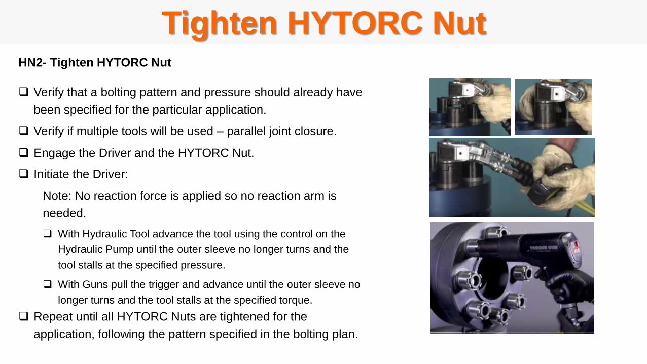
Tighten HYTORC NutHN2- Tighten HYTORC Nut
Verify that a bolting pattern and pressure should already have
been specified for the particular application.
Verify if multiple tools will be used – parallel joint closure.
Engage the Driver and the HYTORC Nut.
Initiate the Driver:
Note: No reaction force is applied so no reaction arm is
needed.
With Hydraulic Tool advance the tool using the control on the
Hydraulic Pump until the outer sleeve no longer turns and the
tool stalls at the specified pressure.
With Guns pull the trigger and advance until the outer sleeve no
longer turns and the tool stalls at the specified torque.
Repeat until all HYTORC Nuts are tightened for the
application, following the pattern specified in the bolting plan.
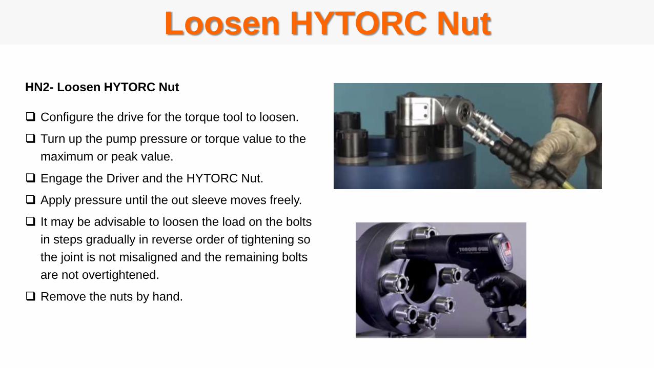
Loosen HYTORC Nut
HN2- Loosen HYTORC Nut
Configure the drive for the torque tool to loosen.
Turn up the pump pressure or torque value to the
maximum or peak value.
Engage the Driver and the HYTORC Nut.
Apply pressure until the out sleeve moves freely.
It may be advisable to loosen the load on the bolts
in steps gradually in reverse order of tightening so
the joint is not misaligned and the remaining bolts
are not overtightened.
Remove the nuts by hand.

5. Hydraulic Tensioners
BOSS Training SeriesBasic Operation and Safety Series
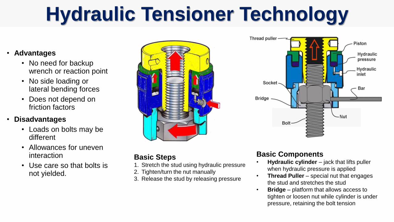
• Advantages
• No need for backup wrench or reaction point
• No side loading or lateral bending forces
• Does not depend on friction factors
• Disadvantages
• Loads on bolts may be different
• Allowances for uneven interaction
• Use care so that bolts is not yielded.
Hydraulic Tensioner Technology
Basic Steps1. Stretch the stud using hydraulic pressure
2. Tighten/turn the nut manually
3. Release the stud by releasing pressure
Basic Components• Hydraulic cylinder – jack that lifts puller
when hydraulic pressure is applied
• Thread Puller – special nut that engages
the stud and stretches the stud
• Bridge – platform that allows access to
tighten or loosen nut while cylinder is under pressure, retaining the bolt tension
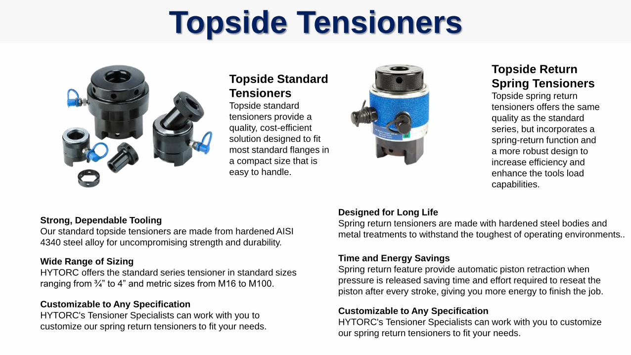
Topside Standard
TensionersTopside standard
tensioners provide a
quality, cost-efficient
solution designed to fit
most standard flanges in
a compact size that is
easy to handle.
Strong, Dependable Tooling
Our standard topside tensioners are made from hardened AISI
4340 steel alloy for uncompromising strength and durability.
Wide Range of Sizing
HYTORC offers the standard series tensioner in standard sizes
ranging from ¾” to 4” and metric sizes from M16 to M100.
Customizable to Any Specification
HYTORC's Tensioner Specialists can work with you to
customize our spring return tensioners to fit your needs.
Topside Return
Spring TensionersTopside spring return
tensioners offers the same
quality as the standard
series, but incorporates a
spring-return function and
a more robust design to
increase efficiency and
enhance the tools load
capabilities.
Designed for Long Life
Spring return tensioners are made with hardened steel bodies and
metal treatments to withstand the toughest of operating environments..
Time and Energy Savings
Spring return feature provide automatic piston retraction when
pressure is released saving time and effort required to reseat the
piston after every stroke, giving you more energy to finish the job.
Customizable to Any Specification
HYTORC's Tensioner Specialists can work with you to customize
our spring return tensioners to fit your needs.
Topside Tensioners
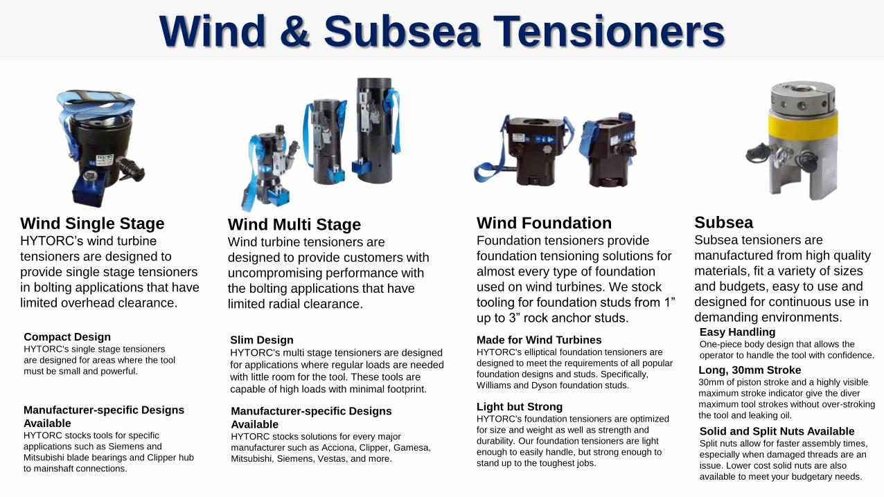
Wind Single StageHYTORC’s wind turbine
tensioners are designed to
provide single stage tensioners
in bolting applications that have
limited overhead clearance.
Wind & Subsea Tensioners
Wind Multi StageWind turbine tensioners are
designed to provide customers with
uncompromising performance with
the bolting applications that have
limited radial clearance.
Slim DesignHYTORC's multi stage tensioners are designed
for applications where regular loads are needed
with little room for the tool. These tools are
capable of high loads with minimal footprint.
Manufacturer-specific Designs
AvailableHYTORC stocks solutions for every major
manufacturer such as Acciona, Clipper, Gamesa,
Mitsubishi, Siemens, Vestas, and more.
Wind FoundationFoundation tensioners provide
foundation tensioning solutions for
almost every type of foundation
used on wind turbines. We stock
tooling for foundation studs from 1”
up to 3” rock anchor studs.
Made for Wind TurbinesHYTORC's elliptical foundation tensioners are
designed to meet the requirements of all popular
foundation designs and studs. Specifically,
Williams and Dyson foundation studs.
Light but StrongHYTORC's foundation tensioners are optimized
for size and weight as well as strength and
durability. Our foundation tensioners are light
enough to easily handle, but strong enough to
stand up to the toughest jobs.
SubseaSubsea tensioners are
manufactured from high quality
materials, fit a variety of sizes
and budgets, easy to use and
designed for continuous use in
demanding environments. Easy HandlingOne-piece body design that allows the
operator to handle the tool with confidence.
Long, 30mm Stroke30mm of piston stroke and a highly visible
maximum stroke indicator give the diver
maximum tool strokes without over-stroking
the tool and leaking oil.
Solid and Split Nuts AvailableSplit nuts allow for faster assembly times,
especially when damaged threads are an
issue. Lower cost solid nuts are also
available to meet your budgetary needs.
Compact DesignHYTORC's single stage tensioners
are designed for areas where the tool
must be small and powerful.
Manufacturer-specific Designs
AvailableHYTORC stocks tools for specific
applications such as Siemens and
Mitsubishi blade bearings and Clipper hub
to mainshaft connections.
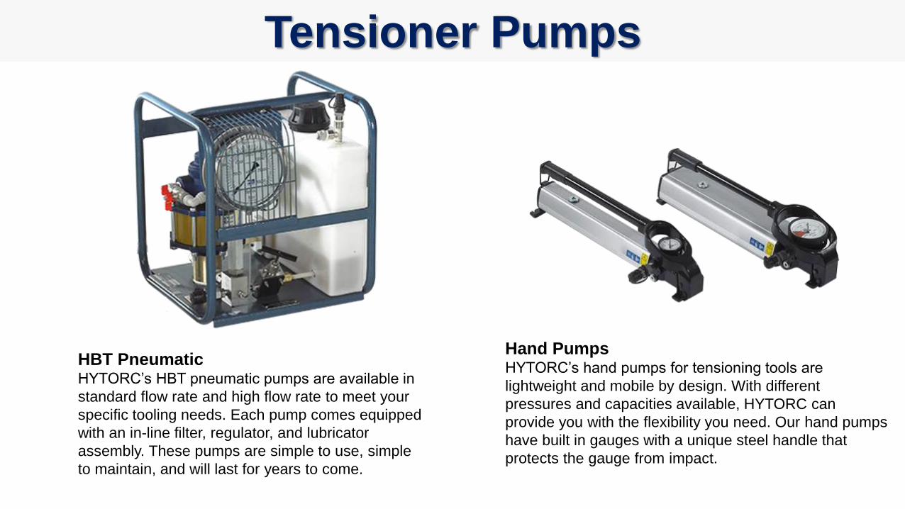
Tensioner Pumps
HBT PneumaticHYTORC’s HBT pneumatic pumps are available in
standard flow rate and high flow rate to meet your
specific tooling needs. Each pump comes equipped
with an in-line filter, regulator, and lubricator
assembly. These pumps are simple to use, simple
to maintain, and will last for years to come.
Hand PumpsHYTORC’s hand pumps for tensioning tools are
lightweight and mobile by design. With different
pressures and capacities available, HYTORC can
provide you with the flexibility you need. Our hand pumps
have built in gauges with a unique steel handle that
protects the gauge from impact.
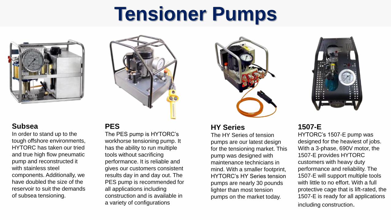
Tensioner Pumps
SubseaIn order to stand up to the
tough offshore environments,
HYTORC has taken our tried
and true high flow pneumatic
pump and reconstructed it
with stainless steel
components. Additionally, we
have doubled the size of the
reservoir to suit the demands
of subsea tensioning.
PESThe PES pump is HYTORC’s
workhorse tensioning pump. It
has the ability to run multiple
tools without sacrificing
performance. It is reliable and
gives our customers consistent
results day in and day out. The
PES pump is recommended for
all applications including
construction and is available in
a variety of configurations
HY SeriesThe HY Series of tension
pumps are our latest design
for the tensioning market. This
pump was designed with
maintenance technicians in
mind. With a smaller footprint,
HYTORC’s HY Series tension
pumps are nearly 30 pounds
lighter than most tension
pumps on the market today.
1507-EHYTORC’s 1507-E pump was
designed for the heaviest of jobs.
With a 3-phase, 690V motor, the
1507-E provides HYTORC
customers with heavy duty
performance and reliability. The
1507-E will support multiple tools
with little to no effort. With a full
protective cage that is lift-rated, the
1507-E is ready for all applications
including construction.
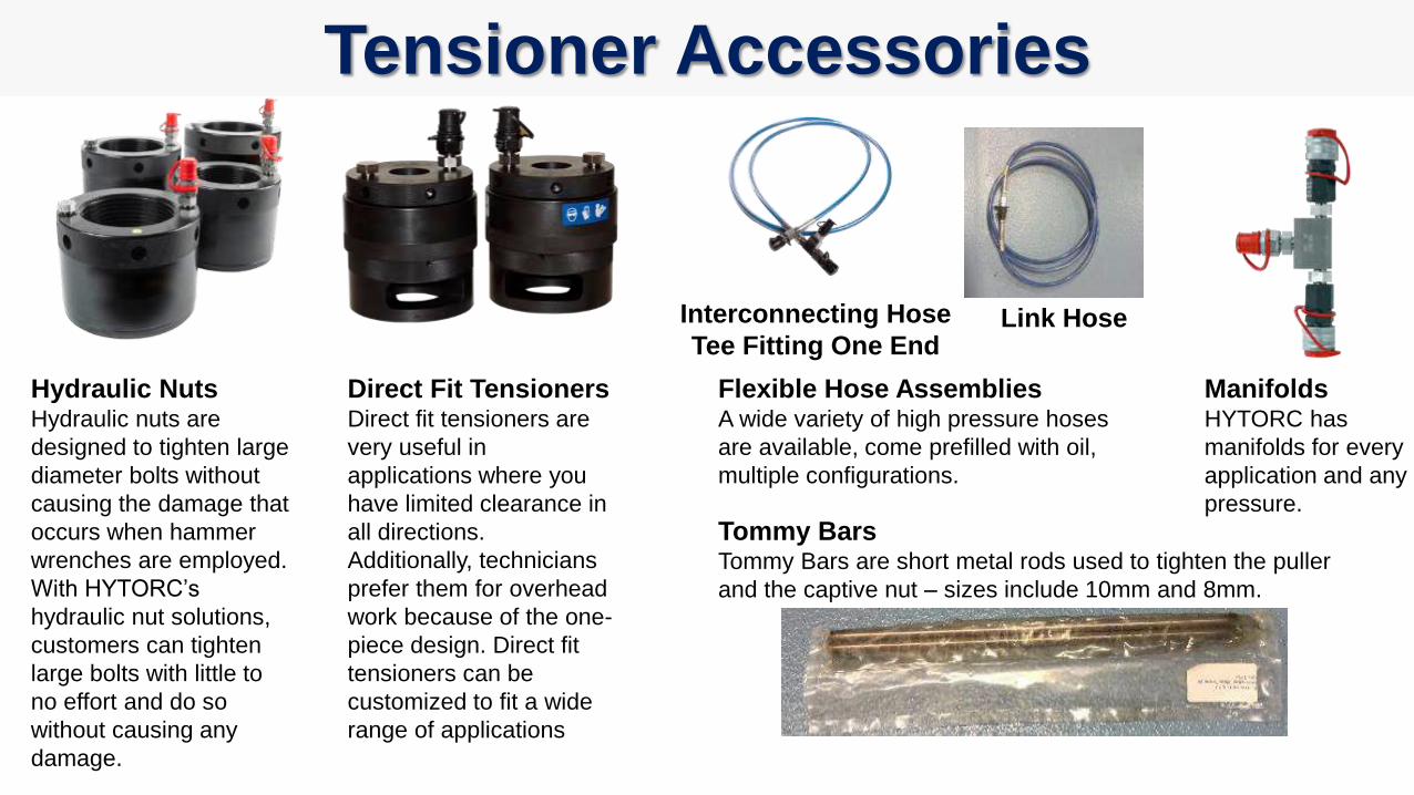
Tensioner Accessories
Hydraulic NutsHydraulic nuts are
designed to tighten large
diameter bolts without
causing the damage that
occurs when hammer
wrenches are employed.
With HYTORC’s
hydraulic nut solutions,
customers can tighten
large bolts with little to
no effort and do so
without causing any
damage.
Direct Fit TensionersDirect fit tensioners are
very useful in
applications where you
have limited clearance in
all directions.
Additionally, technicians
prefer them for overhead
work because of the one-
piece design. Direct fit
tensioners can be
customized to fit a wide
range of applications
Flexible Hose AssembliesA wide variety of high pressure hoses
are available, come prefilled with oil,
multiple configurations.
ManifoldsHYTORC has
manifolds for every
application and any
pressure.
Tommy BarsTommy Bars are short metal rods used to tighten the puller
and the captive nut – sizes include 10mm and 8mm.
Interconnecting Hose
Tee Fitting One EndLink Hose
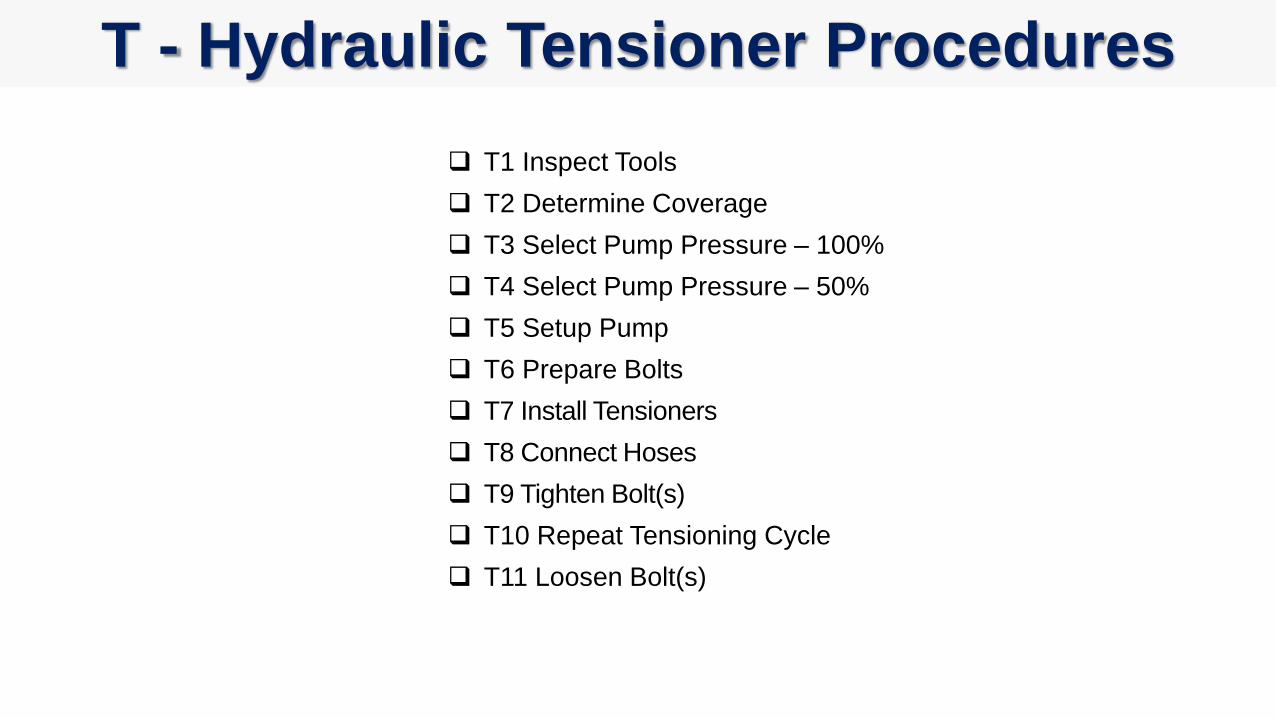
T - Hydraulic Tensioner Procedures
T1 Inspect Tools
T2 Determine Coverage
T3 Select Pump Pressure – 100%
T4 Select Pump Pressure – 50%
T5 Setup Pump
T6 Prepare Bolts
T7 Install Tensioners
T8 Connect Hoses
T9 Tighten Bolt(s)
T10 Repeat Tensioning Cycle
T11 Loosen Bolt(s)
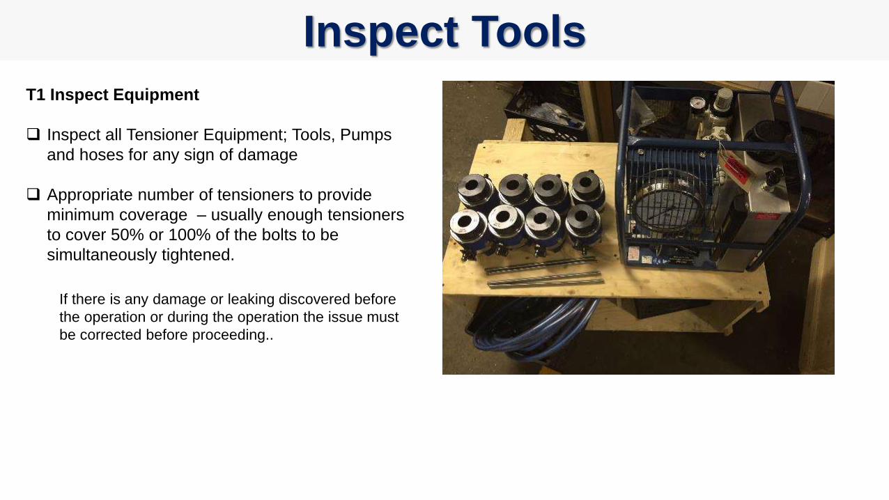
Inspect Tools
T1 Inspect Equipment
Inspect all Tensioner Equipment; Tools, Pumps
and hoses for any sign of damage
Appropriate number of tensioners to provide
minimum coverage – usually enough tensioners
to cover 50% or 100% of the bolts to be
simultaneously tightened.
If there is any damage or leaking discovered before
the operation or during the operation the issue must
be corrected before proceeding..
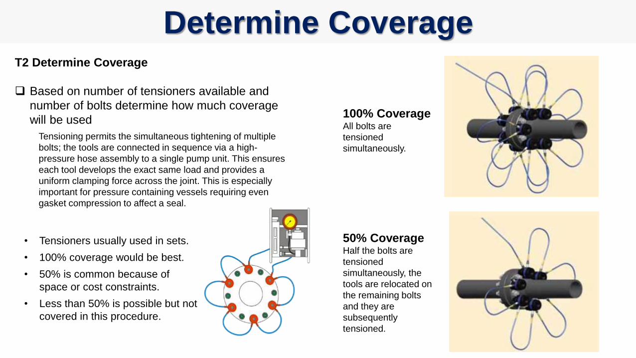
Determine CoverageT2 Determine Coverage
Based on number of tensioners available and
number of bolts determine how much coverage
will be used
Tensioning permits the simultaneous tightening of multiple
bolts; the tools are connected in sequence via a high-
pressure hose assembly to a single pump unit. This ensures
each tool develops the exact same load and provides a
uniform clamping force across the joint. This is especially
important for pressure containing vessels requiring even
gasket compression to affect a seal.
50% CoverageHalf the bolts are
tensioned
simultaneously, the
tools are relocated on
the remaining bolts
and they are
subsequently
tensioned.
100% CoverageAll bolts are
tensioned
simultaneously.
• Tensioners usually used in sets.
• 100% coverage would be best.
• 50% is common because of
space or cost constraints.
• Less than 50% is possible but not
covered in this procedure.

T3 Select Pump Stall Pressure
– 100% CoverageAn Applied Bolt Stress/Tool Pressure Graph is
provided for each tensioner type. The chart
provides lines for different size tensioners at
different bolt stress. Setting the stall pressure is
achieved by adjusting the regulated air pressure
to achieve the desired bolt stress.
100% Coverage – Select the
stall pressure on the chart
corresponding to the size of
the bolt and bolt load required.
Example:
Bolt size 1-1/4” (green line)
Required bolt load 50,000 psi
Read Stall Pressure: 700 bar
or 10,000 psi
Select Pump Pressure – 100% Coverage
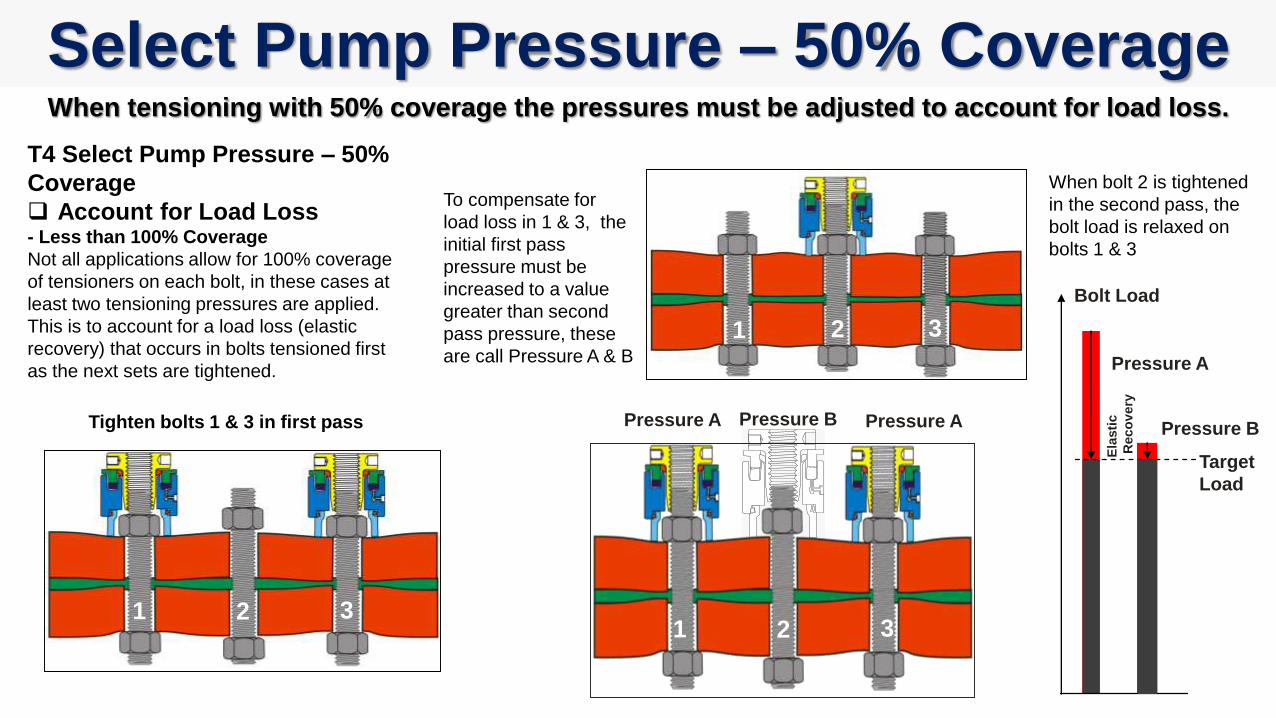
Select Pump Pressure – 50% Coverage
T4 Select Pump Pressure – 50%
Coverage
Account for Load Loss- Less than 100% Coverage
Not all applications allow for 100% coverage
of tensioners on each bolt, in these cases at
least two tensioning pressures are applied.
This is to account for a load loss (elastic
recovery) that occurs in bolts tensioned first
as the next sets are tightened.
1 2 3
21 3
Tighten bolts 1 & 3 in first pass
When bolt 2 is tightened
in the second pass, the
bolt load is relaxed on
bolts 1 & 3
To compensate for
load loss in 1 & 3, the
initial first pass
pressure must be
increased to a value
greater than second
pass pressure, these
are call Pressure A & B
Target
Load
Pressure A
Pressure BPressure A Pressure B
Bolt Load
1 2 3
Pressure A
Ela
sti
c
Reco
very
When tensioning with 50% coverage the pressures must be adjusted to account for load loss.
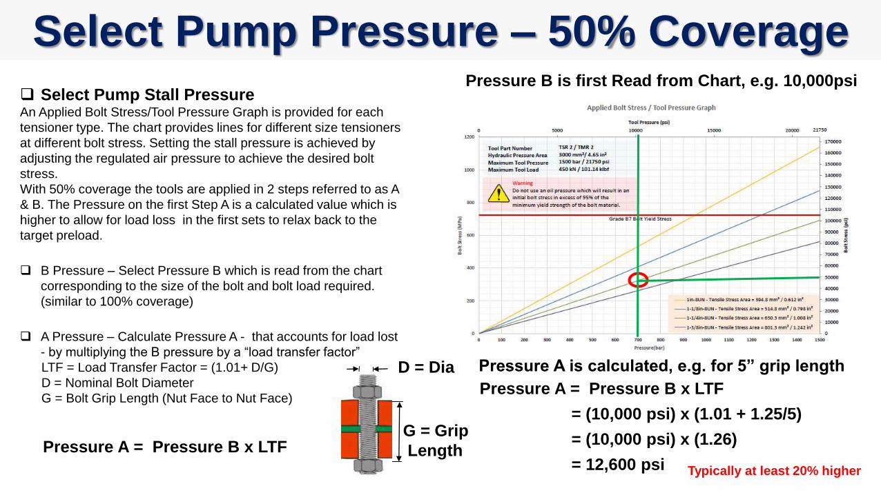
Select Pump Stall PressureAn Applied Bolt Stress/Tool Pressure Graph is provided for each
tensioner type. The chart provides lines for different size tensioners
at different bolt stress. Setting the stall pressure is achieved by
adjusting the regulated air pressure to achieve the desired bolt
stress.
With 50% coverage the tools are applied in 2 steps referred to as A
& B. The Pressure on the first Step A is a calculated value which is
higher to allow for load loss in the first sets to relax back to the
target preload.
B Pressure – Select Pressure B which is read from the chart
corresponding to the size of the bolt and bolt load required.
(similar to 100% coverage)
A Pressure – Calculate Pressure A - that accounts for load lost
- by multiplying the B pressure by a “load transfer factor”
LTF = Load Transfer Factor = (1.01+ D/G)
D = Nominal Bolt Diameter
G = Bolt Grip Length (Nut Face to Nut Face)
Pressure A = Pressure B x LTF
Select Pump Pressure – 50% CoveragePressure B is first Read from Chart, e.g. 10,000psi
Pressure A is calculated, e.g. for 5” grip length
G = Grip
Length
D = Dia
Pressure A = Pressure B x LTF
= (10,000 psi) x (1.01 + 1.25/5)
= (10,000 psi) x (1.26)
= 12,600 psi Typically at least 20% higher
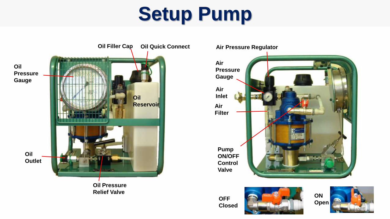
Oil
Pressure
Gauge
Oil
Reservoir
Oil Pressure
Relief Valve
Oil
Outlet
Oil Filler Cap Oil Quick Connect
Air
Inlet
Air Pressure Regulator
Air
Pressure
Gauge
Air
Filter
Pump
ON/OFF
Control
Valve
OFF
Closed
ON
Open
Setup Pump
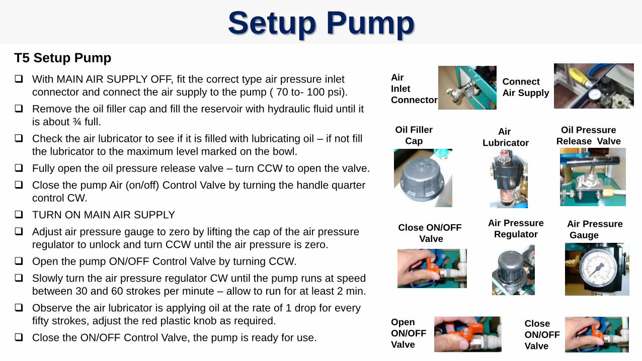
Setup PumpT5 Setup Pump
With MAIN AIR SUPPLY OFF, fit the correct type air pressure inlet
connector and connect the air supply to the pump ( 70 to- 100 psi).
Remove the oil filler cap and fill the reservoir with hydraulic fluid until it
is about ¾ full.
Check the air lubricator to see if it is filled with lubricating oil – if not fill
the lubricator to the maximum level marked on the bowl.
Fully open the oil pressure release valve – turn CCW to open the valve.
Close the pump Air (on/off) Control Valve by turning the handle quarter
control CW.
TURN ON MAIN AIR SUPPLY
Adjust air pressure gauge to zero by lifting the cap of the air pressure
regulator to unlock and turn CCW until the air pressure is zero.
Open the pump ON/OFF Control Valve by turning CCW.
Slowly turn the air pressure regulator CW until the pump runs at speed
between 30 and 60 strokes per minute – allow to run for at least 2 min.
Observe the air lubricator is applying oil at the rate of 1 drop for every
fifty strokes, adjust the red plastic knob as required.
Close the ON/OFF Control Valve, the pump is ready for use.
Air Pressure
RegulatorAir Pressure
Gauge
Air
Inlet
Connector
Air
Lubricator
Oil Filler
CapOil Pressure
Release Valve
Close ON/OFF
Valve
Connect
Air Supply
Open
ON/OFF
Valve
Close
ON/OFF
Valve
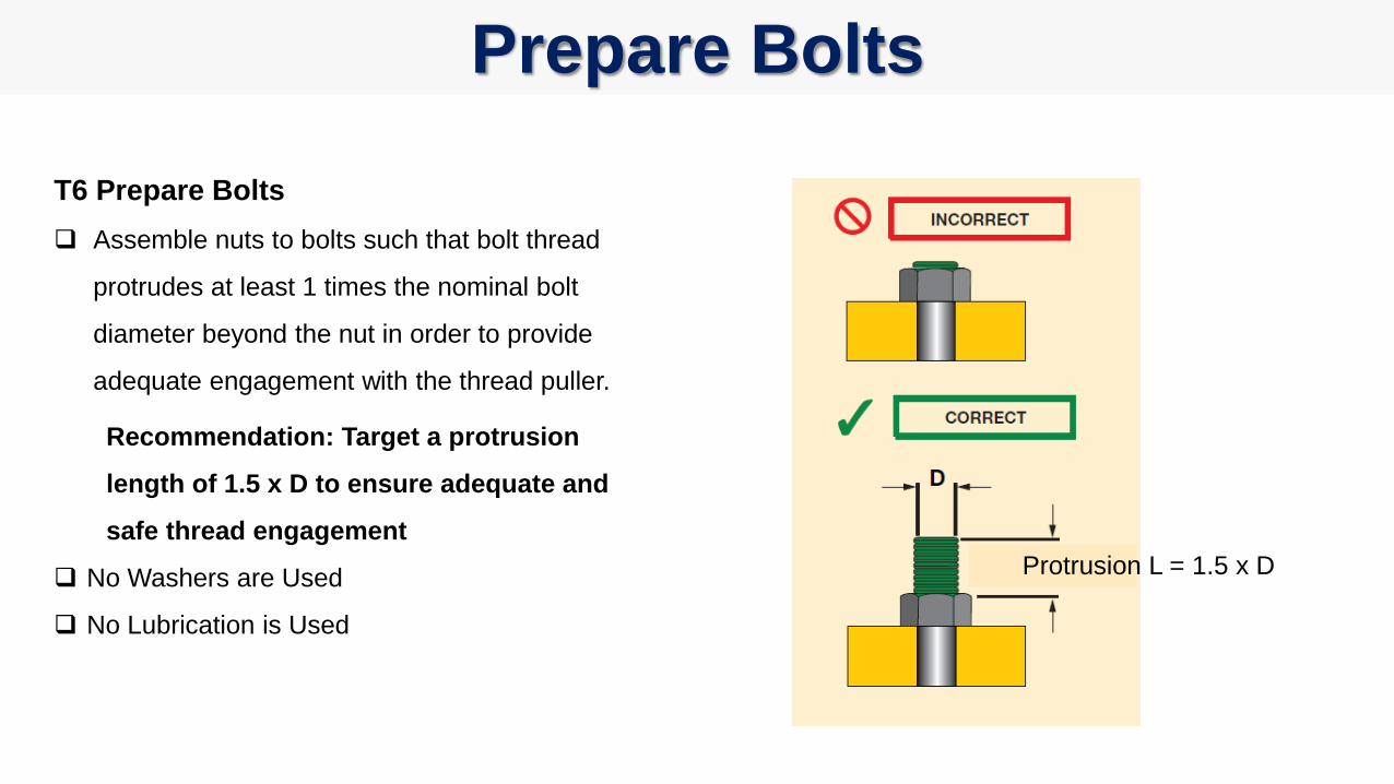
Prepare Bolts
T6 Prepare Bolts
Assemble nuts to bolts such that bolt thread
protrudes at least 1 times the nominal bolt
diameter beyond the nut in order to provide
adequate engagement with the thread puller.
Recommendation: Target a protrusion
length of 1.5 x D to ensure adequate and
safe thread engagement
No Washers are Used
No Lubrication is Used
Protrusion L = 1.5 x D
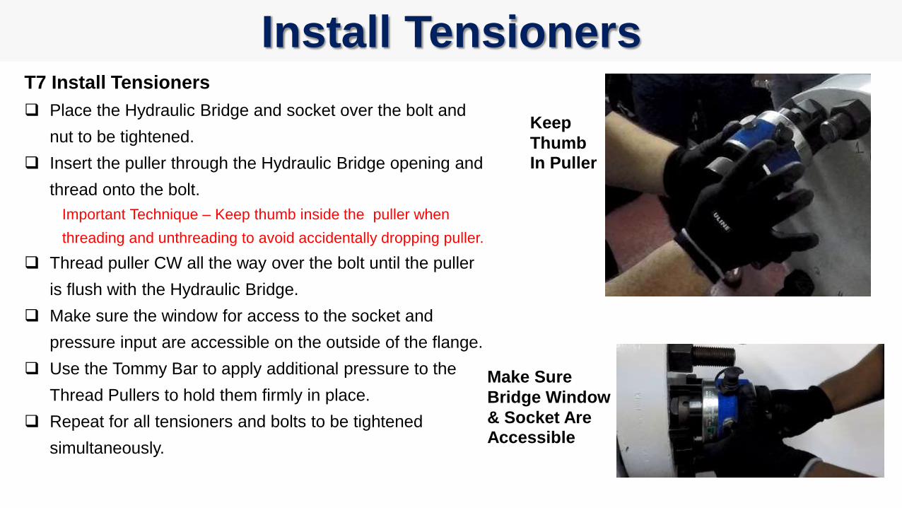
Install TensionersT7 Install Tensioners
Place the Hydraulic Bridge and socket over the bolt and
nut to be tightened.
Insert the puller through the Hydraulic Bridge opening and
thread onto the bolt.
Important Technique – Keep thumb inside the puller when
threading and unthreading to avoid accidentally dropping puller.
Thread puller CW all the way over the bolt until the puller
is flush with the Hydraulic Bridge.
Make sure the window for access to the socket and
pressure input are accessible on the outside of the flange.
Use the Tommy Bar to apply additional pressure to the
Thread Pullers to hold them firmly in place.
Repeat for all tensioners and bolts to be tightened
simultaneously.
Keep
Thumb
In Puller
Make Sure
Bridge Window
& Socket Are
Accessible
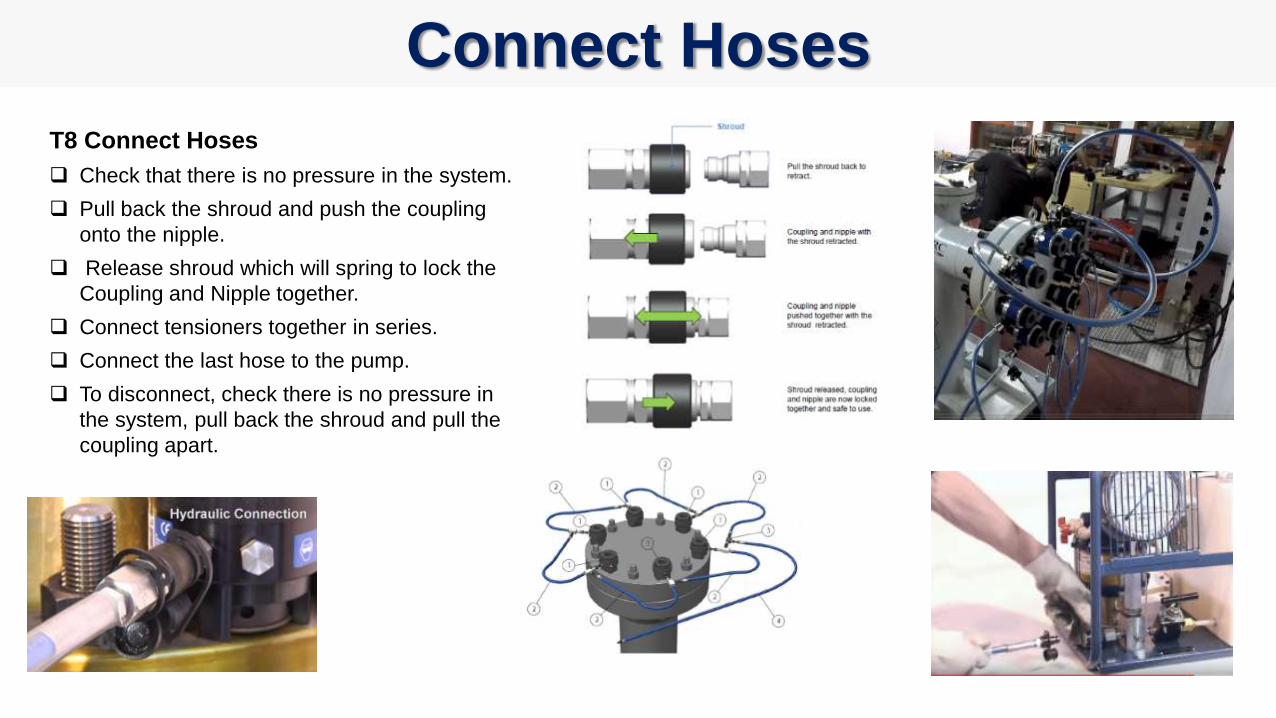
Connect Hoses
T8 Connect Hoses
Check that there is no pressure in the system.
Pull back the shroud and push the coupling
onto the nipple.
Release shroud which will spring to lock the
Coupling and Nipple together.
Connect tensioners together in series.
Connect the last hose to the pump.
To disconnect, check there is no pressure in
the system, pull back the shroud and pull the
coupling apart.
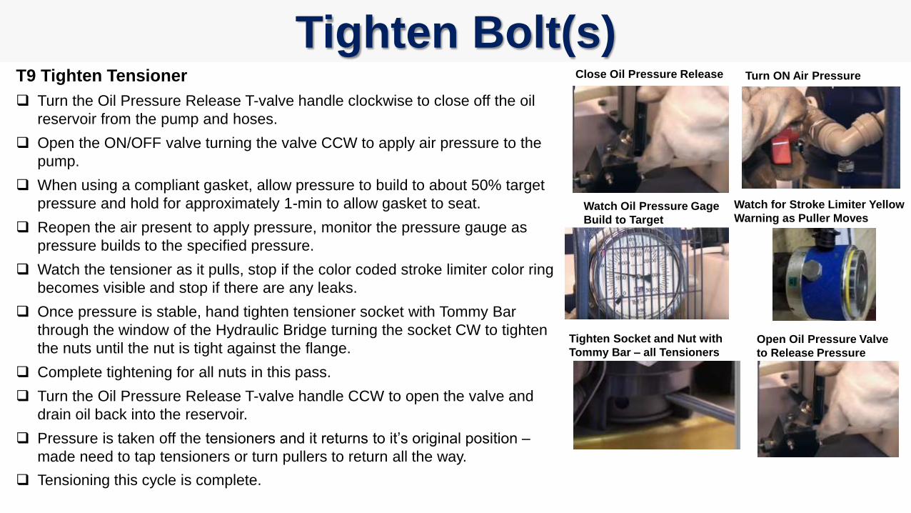
Tighten Bolt(s)T9 Tighten Tensioner
Turn the Oil Pressure Release T-valve handle clockwise to close off the oil
reservoir from the pump and hoses.
Open the ON/OFF valve turning the valve CCW to apply air pressure to the
pump.
When using a compliant gasket, allow pressure to build to about 50% target
pressure and hold for approximately 1-min to allow gasket to seat.
Reopen the air present to apply pressure, monitor the pressure gauge as
pressure builds to the specified pressure.
Watch the tensioner as it pulls, stop if the color coded stroke limiter color ring
becomes visible and stop if there are any leaks.
Once pressure is stable, hand tighten tensioner socket with Tommy Bar
through the window of the Hydraulic Bridge turning the socket CW to tighten
the nuts until the nut is tight against the flange.
Complete tightening for all nuts in this pass.
Turn the Oil Pressure Release T-valve handle CCW to open the valve and
drain oil back into the reservoir.
Pressure is taken off the tensioners and it returns to it’s original position –
made need to tap tensioners or turn pullers to return all the way.
Tensioning this cycle is complete.
Watch for Stroke Limiter Yellow
Warning as Puller MovesWatch Oil Pressure Gage
Build to Target
Close Oil Pressure Release Turn ON Air Pressure
Tighten Socket and Nut with
Tommy Bar – all TensionersOpen Oil Pressure Valve
to Release Pressure
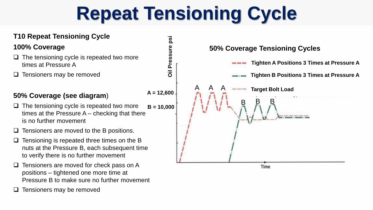
Repeat Tensioning CycleT10 Repeat Tensioning Cycle
100% Coverage
The tensioning cycle is repeated two more
times at Pressure A
Tensioners may be removed
50% Coverage (see diagram)
The tensioning cycle is repeated two more
times at the Pressure A – checking that there
is no further movement
Tensioners are moved to the B positions.
Tensioning is repeated three times on the B
nuts at the Pressure B, each subsequent time
to verify there is no further movement
Tensioners are moved for check pass on A
positions – tightened one more time at
Pressure B to make sure no further movement
Tensioners may be removed
A A A
B B B
50% Coverage Tensioning Cycles
Tighten A Positions 3 Times at Pressure A
Tighten B Positions 3 Times at Pressure A
Target Bolt Load
Oil
Pre
ss
ure
ps
i
A = 12,600
B = 10,000
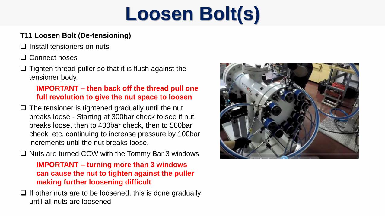
Loosen Bolt(s)T11 Loosen Bolt (De-tensioning)
Install tensioners on nuts
Connect hoses
Tighten thread puller so that it is flush against the
tensioner body.
IMPORTANT – then back off the thread pull one
full revolution to give the nut space to loosen
The tensioner is tightened gradually until the nut
breaks loose - Starting at 300bar check to see if nut
breaks loose, then to 400bar check, then to 500bar
check, etc. continuing to increase pressure by 100bar
increments until the nut breaks loose.
Nuts are turned CCW with the Tommy Bar 3 windows
IMPORTANT – turning more than 3 windows
can cause the nut to tighten against the puller
making further loosening difficult
If other nuts are to be loosened, this is done gradually
until all nuts are loosened

6. Safety
BOSS Training SeriesBasic Operation and Safety Series

HAND PROTECTIONWear safety gloves to protect against heat and sharp objects.
FOOT PROTECTIONWear approved safety shoes with steel/reinforced toes
Protects feet from injury of falling object
Provides support to prevent slips, trips or falls
EYE PROTECTIONWear eye or face protection to protect against flying objects. Safety glasses
should have side shields to provide full coverage
HEAD PROTECTIONWear protective hard hat helmets wherever there is possible
danger of head injury from impact or from of falling or flying
objects and from electrical hazards.
HEARING PROTECTIONWear ear plugs or muffs or both when exposed to excessive or
prolonged noise in excess of 80dB.
! SOCKET SAFETYUse only impact grade sockets
Inspect all sockets before use
! REACTION ARM SAFETYAlways react against fixed surfaces
Keep hands well clear of any reaction points
Eliminate reaction arms by using HYTORC washers
! HOSES & CORDSArrange associated cords, hoses and equipment to avoid
slips, trips and falls.
! TOOL OPERATION & SAFETYFollow manufacturer recommendations for handling tools
Always use the correct tool for the job
Tools should only be used by fully trained personnel
Inspect all tools before use
PROTECTIVE CLOTHINGWear protective clothing if required
Wear high visible vest if required
Avoid wearing loose fitting clothing or jewelry
Bolting
Safety
Moment
Let’s Bolt!
BOSS Training SeriesBasic Operation and Safety Series