Embed Size (px)
Citation preview
2 2
HYSTERETIC DAMPERS FOR THE PROTECTION OF STRUCTURES
FROM EARTHQUAKES
R.I. Skinner, R.G. Tyler, A.J. Heine and
W.H. Robinson* SYNOPSIS
The development of hysteretic dampers for the protection of structures against earthquake attack, carried out at the Physics and Engineering Laboratory over the past six years, is described. Details of both steel and lead devices and their application to bridges and base isolated buildings are given. Steel devices are designed to absorb energy by plastic deformation in torsion or bending, while lead devices rely on plastic extrusion or shear. The characteristics of PTFE sliding bearings are also described and the possibility of using this type of bearing to permit sliding on base isolated systems, and to allow dissipation of energy in joints in conventional structures, referred to. The most promising development is in the lead rubber bearing in which the properties of load-bearing and damping are combined in one unit.
INTRODUCTION
The development and testing of hysteretic dampers at the Pjysics and Engineering Laboratory was initiated in 1970 and has proceeded rapidly since 1973 in order to provide dampers for particular base isolated structures, which were at the same time investigated by the Laboratory!, and were the subject of theoretical studies^. There have been a number of publications 2-13 giving details of various types of devices and it is the intention in this paper to give the latest details of research and to write a commentary on the characteristics of the devices, rather than repeat the details, in order that a choice may be made between the various types for a particular application. Up to the present the use of simple types involving the loading of either steel or lead into the plastic range has been favoured, because of the need for minimum maintenance. In addition bridge bearings of rubber or PTFE have also been the subject of tests, as a knowledge of their characteristics is required for their use in conventional ductile design of bridge decks and also in base isolation systems.
TYPES OF DEVICE
Work on steel energy dissipating devices has been carried out in the Engineering Seismology Section and on lead devices in the Materials Science Section; a range of devices is now available, the principle of design being that energy is dissipated by the plastic yielding of either steel or lead.
1. Steel Hysteretic Dampers
Attention has been directed towards the production of mild steel devices of solid cross section, which do not become unstable at high levels of plastic strain. Black mild steel to BS 4360/43A or bright steels to a similar composition have been
*Physics and Engineering Laboratory, DSIR, Gracefield, Lower Hutt.
found to be the most suitable, preferably heat treated for 5 hours at 620 C following fabrication. In design, welding is kept well away from highly strained zones otherwise rapid failure results.
1.1 Torsion Beam Device
The first hysteretic damper developed by the laboratory was of the torsional beam type (Plate 1) for the Rangitikei Bridge p r o j e c t 1 3 ' 1 4 (Plate 2 and Fig. 1 ) . In the device the short sections of the beam between the loading arms are overstrained in torsion and bending. The initial testing of models was followed by the testing of the full scale device of 450 kN capacity with a range of movement of up to 80 mm (Plate 2 ) .
The device offered a means of providing a comparatively large dissipating force from a welded fabrication using 600 mm plate. However, it is likely now that, for large forces, the flexural beam device (Section 2.1.5) would be preferred in any future application requiring a steel device, as this can be fabricated with a minimum of welding using cast steel arms.
1.2 Round Steel Cantilever
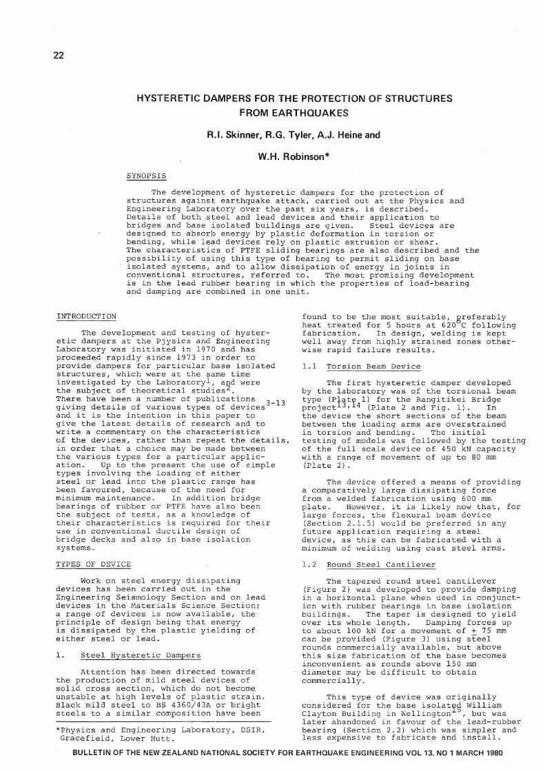
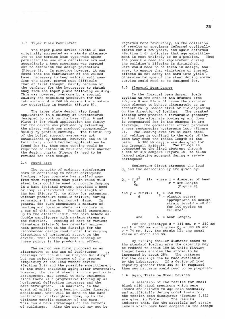
The tapered round steel cantilever (Figure 2) was developed to provide damping in a horizontal plane when used in conjunction with rubber bearings in base isolation buildings. The taper is designed to yield over its whole length. Damping forces up to about 100 kN for a movement of + 75 mm can be provided (Figure 3) using steel rounds commercially available, but above this size fabrication of the base becomes inconvenient as rounds above 150 mm diameter may be difficult to obtain commercially.
This type of device was originally considered for the base isolated William Clayton Building in Wellington , but was later abandoned in favour of the lead-rubber bearing (Section 2.2) which was simpler and less expensive to fabricate and install.
B U L L E T I N O F T H E N E W Z E A L A N D N A T I O N A L S O C I E T Y F O R E A R T H Q U A K E E N G I N E E R I N G V O L 1 3 . N O 1 M A R C H 1 9 8 0
23
Fig. 1: Details of Rangitikei Bridge
Plate 1 : Torsion beam hysteretic damper in test machine Plate 2: South Rangitikei Rail Bridge under
construction
25
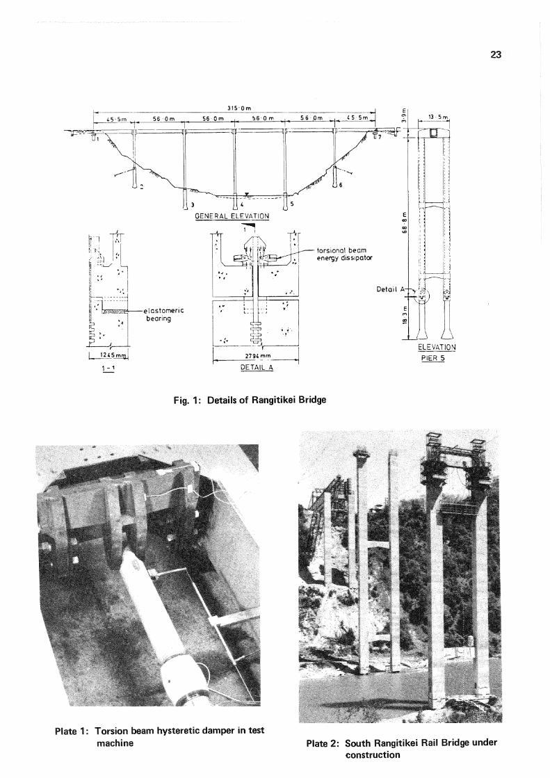
1.3 Taper Plate Cantilever The taper plate device (Plate 3) was
originally suggested as a simple alternative to the torsion beam type when space permitted the use of a cantilever arm and, accordingly a test programme was carried out to establish the design parameters (Figure 4 ) . In practice however, it was found that the fabrication of the welded base, necessary to keep welding well away from the taper, proved more difficult than at first thought, mainly because of the tendency for the buttresses to shrink away from the taper plate following welding. This was however, overcome by a special welding and machining procedure for the fabrication of a 240 kN device for a motorway overbridge in Dunedin (Figure 5 ) .
The taper plate design also found application in a chimney at Christchurch designed to rock on its base (Fig. 6 and Plate 4) for which application the fixity for the device was provided by extending the plate, which was produced economically mainly by profile cutting. The flexibility of the bolted support system was not established by testing, however, and it is felt that, should further applications be found for it, then more testing would be required to establish this and check whether the design charts (Figure 4) need to be revised for this design.
1.4 Round Bars
The tenacity of ordinary reinforcing bars in continuing to resist earthquake loading, after concrete has spalled away from them suggested that plain round mild steel bars could be used to provide damping in a base isolated system, provided a bend or loop is introduced into the length of the bar (Figure 7 ) , to allow for extension, without premature tensile failure, during excursions in the horizontal plane. In general for such excursions a mixture of bending and torsion overstrain occurs in a bar of this shape. For small excursions, up to the elastic limit, the bars behave as double cantilevers with maximum stress at the fixities. Testing of bars of various diameters (Plate 5) has revealed maximum heat generation at the fixities for the recommended design conditions 7 for varying directions of horizontal attack on the device, thus indicating that bending at these points is the predominant effect.
15 The method was first proposed as an
alternative to the use of lead-rubber bearings for the William Clayton Building"1
but was rejected because of the greater simplicity of the lead-rubber device (Section 2.2) and the possible embrittlement of the steel following aging after overstrain. However, the use of steel, in this particular arrangement, may appeal to many engineers since there is a progressive locking up as horizontal deflection increases and the bars straighten. In addition, in the event of uplift on a bearing under disaster conditions, work will be done on the bars vertically to straighten them, up to the ultimate tensile capacity of the bars. This could have advantages at the corners of buildings. Also the method may now be
regarded more favourably, as the collation of results on specimens deformed cyclically, stored for a few years, and again deformed (Section 1.6) indicates that age embrittlement is most unlikely to be a problem. Thus the possible need for replacement during the building 1s lifetime is diminished. Care would need to be taken in design, however, to ensure that windstorms or thermal effects do not carry the bars into yield"?. Otherwise fatigue of the steel during normal service would need to be designed for.
1.5 Flexural Beam Damper
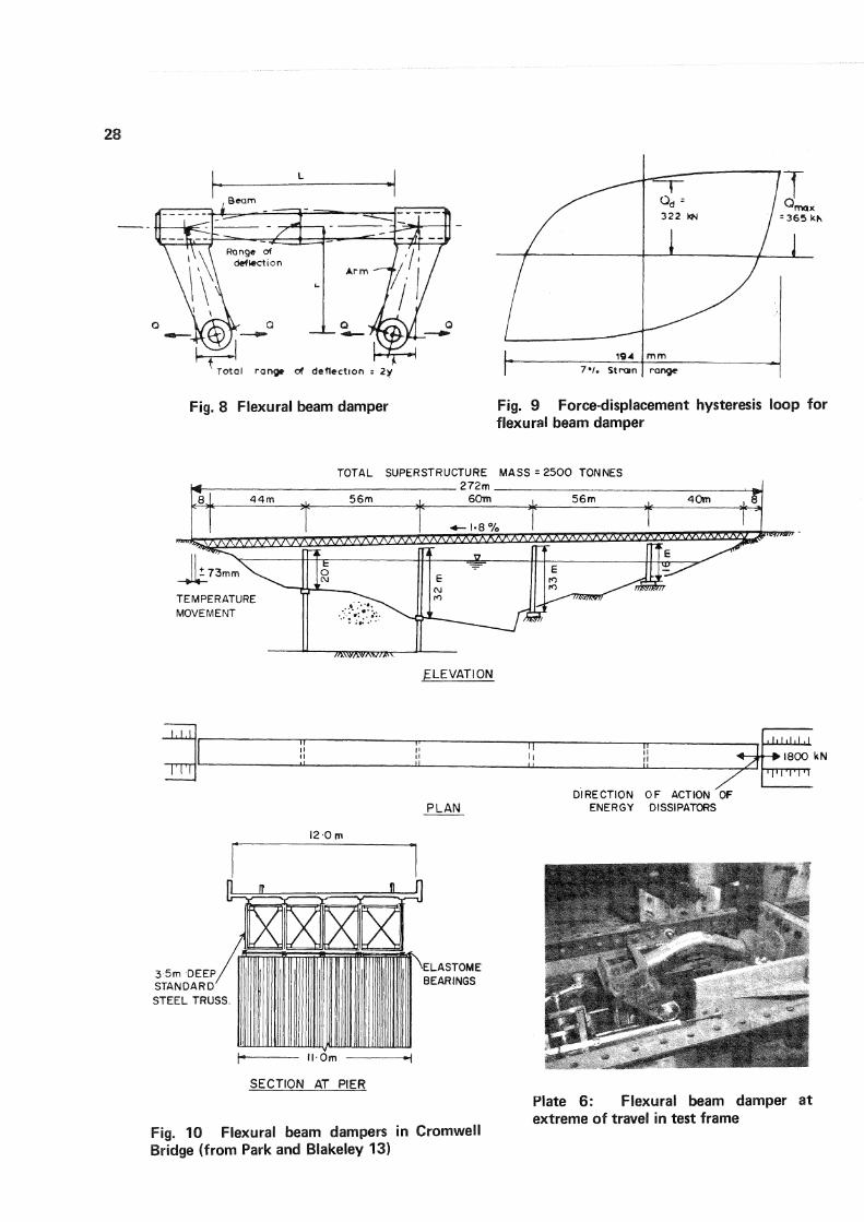
In the flexural beam damper, loads applied to the ends of the cranked arms (Figure 8 and Plate 6) cause the circular beam element to behave alternately as an eccentrically loaded strut or tie depending on the direction of loading. The cranked loading arms produce a favourable geometry in that the alternate bowing up and down is compensated for in the changes in arm leverage; the geometrical effect produces a near rectangular hysteresis loop (Figure 9 ) . The loading arms are of cast steel and welding is confined to the ends of the beam away from the loaded length of the beam. A 300 kN device was designed for the Cromwell Bridge 1 3. The bridge is connected to the fixed abutment through a set of six dampers (Figure 10) to allow damped relative movement during a severe earthquake.
Neglecting direct stresses the load Q, and the deflection +y are given by:
f d~ 6r
(1) where d = diameter of beam r = arm length
(Figure 8)
and y = 2Lr e(2) f = 350 MPa
and
= plastic stress appropriate to design strain levels = +0.03 for 100 cycles to failure 7.
= beam length.
For the prototype d = 114 mm, r = 280 mm and L = 500 mm which gives Q d = 309 kN and y = 74 mm, i.e. the stroke has the usual value of about 150 mm.
By fitting smaller diameter beams to the standard loading arms the capacity may be reduced to about 150 kN while fitting longer beams enables the stroke to be increased by about 25%. The patterns for the castings can be made available by the Laboratory. If a device of load capacity greater than 300 kN is required then new patterns would need to be prepared.
1.6 Aging Tests on Steel Devices
A selection of the results for small black mild steel specimens which were loaded and allowed to age both naturally and artificially during model tests for the torsion beam dissipator (Section 2.11) are given in Table 1. The results indicate that, for the materials and strain levels which have been adopted in the design
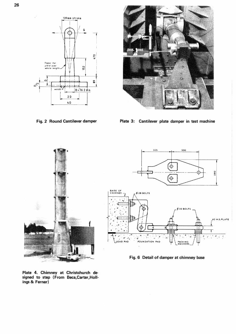
Fig. 2 Round Cantilever damper Plate 3: Cantilever plate damper in test machine
Plate 4. Chimney at Christchurch designed to step (From Beca,Carter, Hoi I-ings & Ferner)
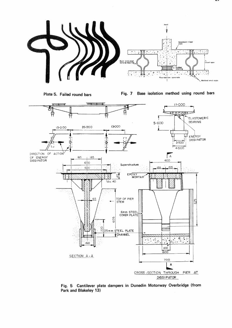
Plate 5. Failed round bars Fig. 7 Base isolation method using round bars
11-000
ELASTOMERIC
BEARING
ENERGY DISS I PAT OR
S E C T I O N A - A
C R O S S - S E C T I O N T H R O U G H P I E R AT
D I S S I P A T O R
Fig. 5 Cantilever plate dampers in Dunedin Motorway Overbridge (from Park and Blakeley 13)
28
Fig. 8 Flexural beam damper Fig. 9 Force-displacement hysteresis loop for flexural beam damper
T O T A L S U P E R S T R U C T U R E MASS = 2 5 0 0 TONNES
4 i 8yt 44m , c 5 6 m ,
? 7 2 m 6 0 m , 5 6 m _ 4 0 m ,
* - | . 8 % V
TEh MOV
7V\ AAAAAAZ V X/VNA fT " IT
TEh MOV
t 73mm \ .
1PERATURE T E M E N T
t o CM
. V
£ CM 11 rO 1
E
f
E L E V A T I O N
TT
P L A N
h I i l l
- # 1 8 0 0 k N
' I ' l T I T
D I R E C T I O N O F ACTION OF ENERGY DISSIPATORS
12 O m
3 5m DEEP S T A N D A R D S T E E L TRUSS
S E C T I O N A T P I E R
ELASTOME BEARINGS
Fig. 10 Flexural beam dampers in Cromwell Bridge (from Park and Blakeley 13)
• H H H T
' -
Plate 6: Flexural beam damper at extreme of travel in test frame
29
of steel dissipators, embrittlement is not likely to be a problem following excursions into the plastic range,
2. Lead Hysteretic Dampers
2.1 Extrusion damper
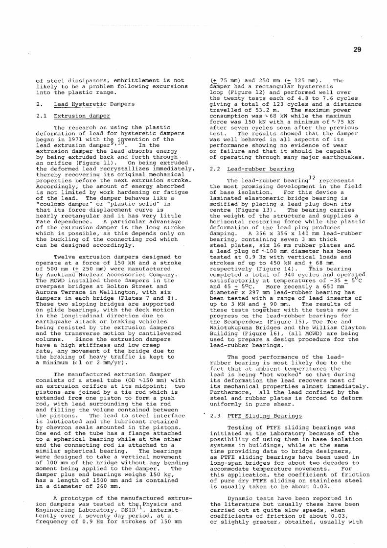
The research on using, the plastic deformation of lead for hysteretic dampers began in 1971 with the invention of the lead extrusion damper 9' 1 . In the extrusion damper the lead absorbs energy by being extruded back and forth through an orifice (Figure 11). On being extruded the deformed lead recrystallizes immediately, thereby recovering its original mechanical properties before the next extrusion stroke. Accordingly, the amount of energy absorbed is not limited by work hardening or fatigue of the lead. The damper behaves like a "coulomb damper" or "plastic solid" in that its force displacement curve is nearly rectangular and it has very little rate dependence. A particular advantage of the extrusion damper is the long stroke which is possible, as this depends only on the buckling of the connecting rod which can be designed accordingly.
Twelve extrusion dampers designed to operate at a force of 150 kN and a stroke of 500 mm ( + 250 mm) were manufactured by Auckland Nuclear Accessories Company. The MOWD installed these dampers in the overpass bridges at Bolton Street and Aurora Terrace in Wellington, with six dampers in each bridge (Plates 7 and 8 ) . These two sloping bridges are supported on glide bearings, with the deck motion in the longitudinal direction due to earthquake attack or braking vehicles being resisted by the extrusion dampers and the transverse motion by cantilevered columns. Since the extrusion dampers have a high stiffness and low creep rate, any movement of the bridge due to the braking of heavy traffic is kept to a minimum (< 1 or 2 mm/yr) .
The manufactured extrusion damper consists of a steel tube (OD ^150 mm) with an extrusion orifice at its midpoint; two pistons are joined by a tie rod which is extended from one piston to form a push rod, with lead surrounding the tie rod and filling the volume contained between the pistons. The lead to steel interface is lubticated and the lubricant retained by chevron seals amounted in the pistons. One end of the tube has a flange attached to a spherical bearing while at the other end the connecting rod is attached to a similar spherical bearing. The bearings were designed to take a vertical movement of 100 mm of the bridge without any bending moment being applied to the damper. The damper plus end bearings weighs 150 kg, has a length of 1500 mm and is contained in a diameter of 260 mm.
A prototype of the manufactured extrusion dampers was tested at the Physics and Engineering Laboratory, DSIR 1 , intermittently over a seventy day period, at a frequency of 0.9 Hz for strokes of 150 mm
(+ 75 mm) and 250 mm ( + 125 m m ) . The damper had a rectangular hysteresis loop (Figure 12) and performed well over the twenty tests each of 4.8 to 7.6 cycles giving a total of 123 cycles and a distance travelled of 53.2 m. The maximum power consumption was ^68 kW while the maximum force was 150 kN with a minimum of ^75 kN after seven cycles soon after the previous test. The results showed that the damper was well behaved in all aspects of its performance showing no evidence of wear or failure and that it should be capable of operating through many major earthquakes.
2.2 Lead-rubber bearing 12
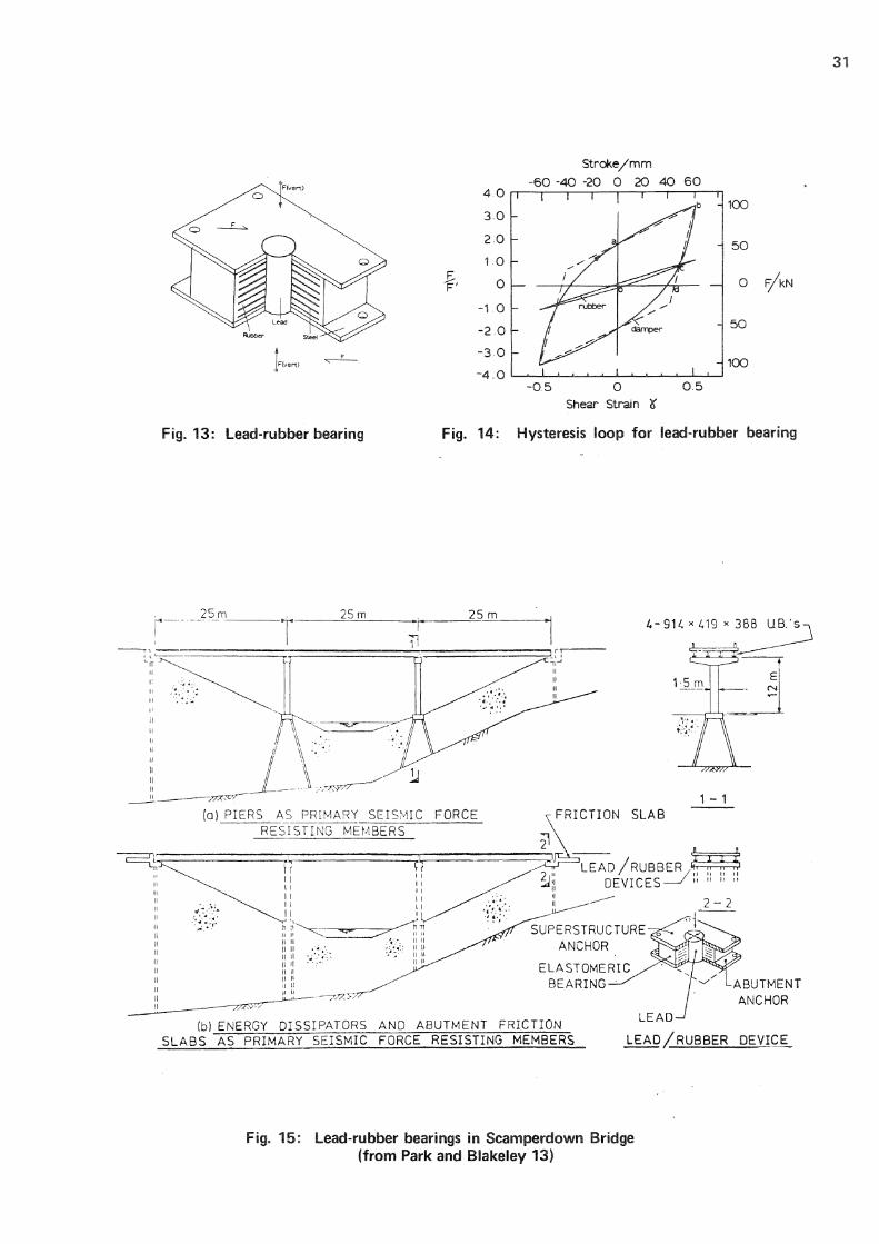
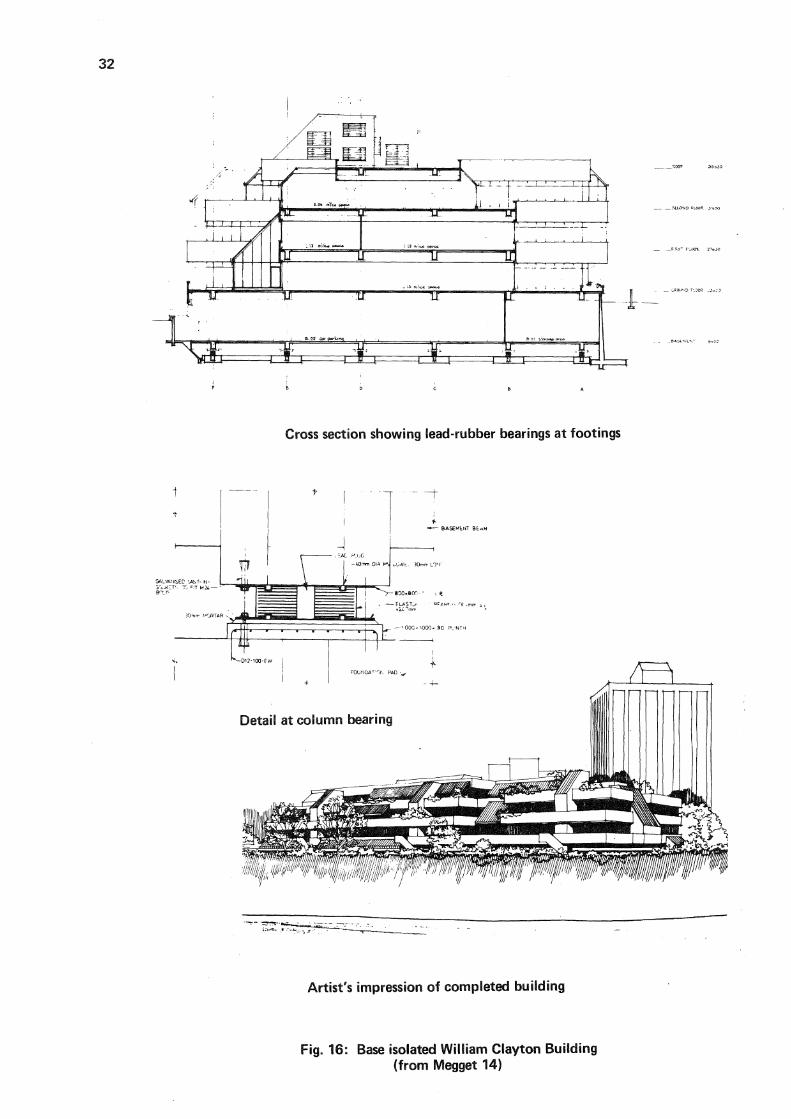
The lead-rubber bearing represents the most promising development in the field of base isolation. For this device a laminated elastomeric bridge bearing is modified by placing a lead plug down its centre (Figure 13). The bearing carries the weight of the structure and supplies a horizontal restoring force while the plastic deformation of the lead plug produces damping. A 356 x 356 x 140 mm lead-rubber bearing, containing seven 3 mm thick steel plates, six 16 mm rubber plates and a lead plug of ^100 mm diameter has been tested at 0.9 Hz with vertical loads and strokes of up to 450 kN and + 68 mm respectively (Figure 14). This bearing completed a total of 34 0 cycles and operated satisfactorily at temperatures of -35 + 5°C and 45 + 5°C. More recently a 650 mm diameter x 297 mm lead-rubber bearing has been tested with a range of lead inserts of up to 3 MN and + 9 0 mm. The results of these tests together with the tests now in progress on the lead-rubber bearings for the Scamperdown (Figure 15), Toe Toe and Waiotukupuna Bridges and the William Clayton Building (Figure 16), (all MOWD) are being used to prepare a design procedure for the lead-rubber bearings.
The good performance of the lead-rubber bearing is most likely due to the fact that at ambient temperatures the lead is being "hot worked" so that during its deformation the lead recovers most of its mechanical properties almost immediately. Furthermore, all the lead confined by the steel and rubber plates is forced to deform uniformly in pure shear.
2.3 PTFE Sliding Bearings
Testing of PTFE sliding bearings was initiated at the Laboratory because of the possibility of using them in base isolation systems in buildings, while at the same time providing data to bridge designers, as PTFE sliding bearings have been used in long-span bridges for about two decades to accommodate temperature movements. For this application, the coefficient of friction of pure dry PTFE sliding on stainless steel is usually taken to be about 0.03.
Dynamic tests have been reported in the literature but usually these have been carried out at quite slow speeds, when coefficients of friction of about 0.03, or slightly greater, obtained, usually with
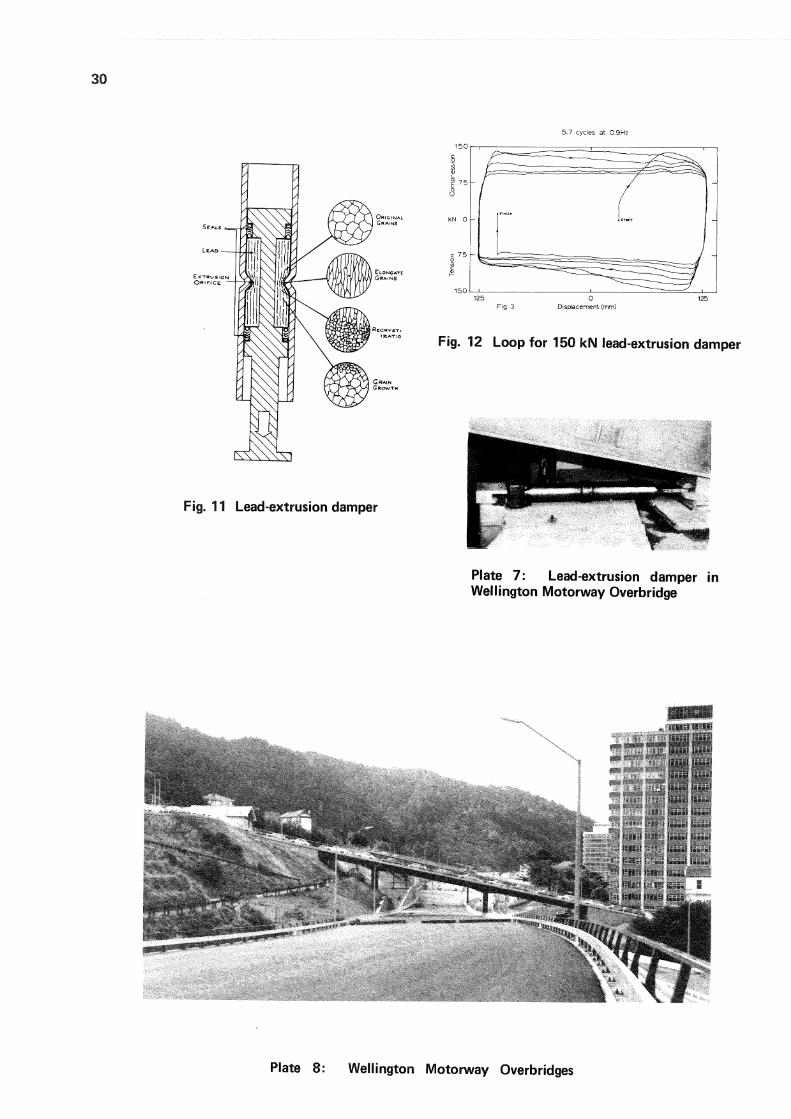
Plate 8: Wellington Motorway Overbridges
(b) ENERGY DISSIPATORS AND ABUTMENT FRICTION SLABS AS PRIMARY SEISMIC FORCE RESISTING MEMBERS L E A D / R U B B E R D E V I C E
Fig. 15: Lead-rubber bearings in Scamperdown Bridge (from Park and Blakeley 13)
t 0 C fc A
Cross section showing lead-rubber bearings at footings
Artist's impression of completed building
Fig. 16: Base isolated William Clayton Building (from Megget 14)
33
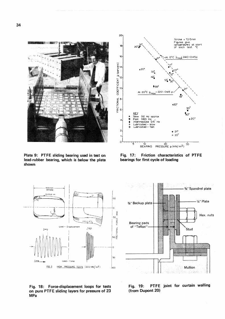
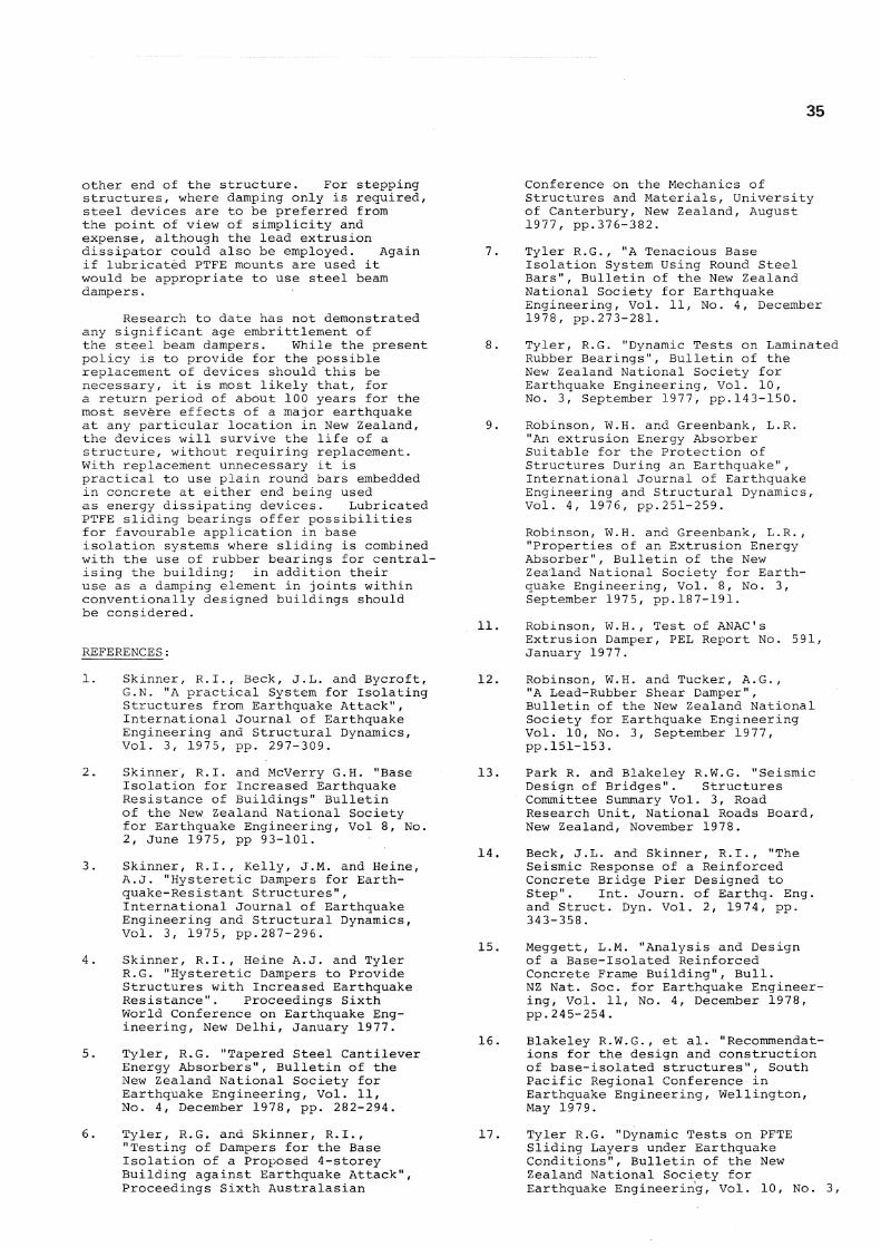
a suggestion that if the speed is increased then perhaps the coefficient of friction will also go up. In fact, it does so markedly, as tests at the Laboratory have shown 1^. For conditions equivalent to a moderate to severe earthquake, viz. a travel of 150 mm and simple harmonic motion at frequencies up to 0.83 Hz, giving a maximum velocity of 3 8 cm/sec, frictional coefficients up to 17% were obtained for the pressures normally employed in bridge bearings (Figure 17). Thus the damping obtained from PTFE bearing in the dry state is rate dependent; a near rectangular hysteresis loop is obtained with friction peaking up at the beginning of the stroke (Figure 18).
A promising development for.base isolated structures is in the field of lubricated PTFE bearings. For the conditions given above a frictional coefficient of less than 2% was obtained (Figure 17) for a type of greased lubricated bearing which has been employed by one manufacturer of bridge bearings for more than a decade. This opens up the possibility of using a combination of lubricated PTFE and rubber or lead-rubber bearings in a base isolation system to reduce the transmitted horizontal shear to a minimum. There may be a cost restriction however as PTFE bridge bearings tend to be more expensive than rubber bearings of the same capacity.
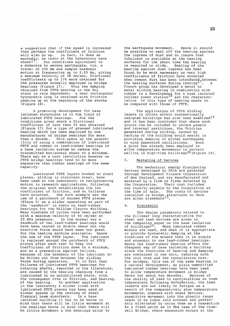
Lubricated PTFE layers bonded to steel plates, sliding in stainless steel, have been used at the Laboratory in reciprocating motion in research applications, following the original work establishing the low coefficient of friction, and no failures have occurred. One such example was the use of a patchwork of bonded PTFE pieces (Plate 9) as a slider operating as part of the 'sandwich 1 in tests on lead-rubber bearings for the William Clayton Building. Many hundreds of cycles have been performed with a maximum velocity of 4 0 cm/sec at 25 MPa pressure. In the normal way a sandwich of two lead-rubber bearings would have been tested in double shear but the tractive force would have been too great for the testing machine available; hence the use of the PTFE layer. The lubricant is replaced around the patchwork of PTFE pieces after each test to keep the coefficient of friction down to a minimum, and as a precaution against failure, because of the tendency of the lubricant to be driven out from between the sliding faces during operation. It is felt that failures of lubricated PTFE bearings for rotating shafts, reported in the literature, are caused by the bearing changing from a lubricated to an unlubricated state, with the consequent rise in friction, and heating, of the bearing. In another application in the laboratory a slider lined with lubricated PTFE pieces has been used at slower speeds in the testing of steel flexural beam absorbers. In a base isolated building it has to be borne in mind that there will be little movement at the bearings borne in mind that there will be little movement a the bearings prior to
the earthquake movement, Hence it should be possible to seal off the bearing against the ingress of dust and to insure that lubricant is available at the bearing surfaces for the short time the bearing is required to slide. Sealing of the bearing against dust ingress has been found to be most necessary as very high coefficients of friction have occurred when cement dust has been introduced between the bearing surfaces during testing . A French group has developed a metal to metal sliding bearing in combination with rubber in a development for a base isolated nuclear power station 1 8 and the characteristics of this type of bearing needs to be compared with those of PTFE.
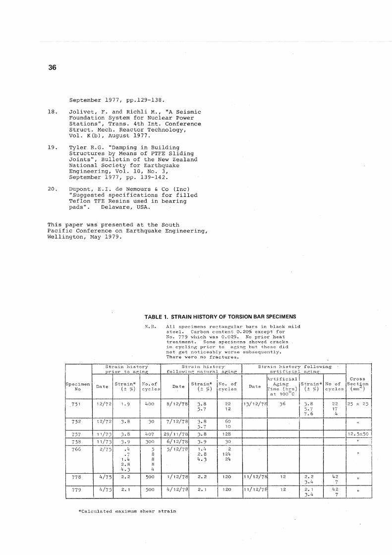
The application of PTFE sliding layers in joints within conventionally designed buildings has also been examined 1 9
and it has been concluded that where such joints can be included to secure panels and internal partitions, the friction generated during sliding, caused by racking of the building would assist in providing damping of either earthquake or wind generated oscillations. Such a joint has already been employed to allow temperature movements in curtain walling in high-rise buildings^O(Figure 19).
3. Marketing of Devices
The mechanical energy dissipating devices developed by DSIR are patented through Development Finance Corporation of New Zealand, and are manufactured and marketed by a firm or firms selected by the Corporation. Their cost includes any royalty payable to the Corporation at the time of sale. The costs of devices installed in bridge structures to date are given elsewhere 1 3.
4. Discussion
The design parameters related to the bilinear loop characteristics for steel and lead devices are given in the companion paper on the base isolation of buildings 1^. When laminated rubber mounts are used, and when it is appropriate to provide hysteretic damping at the locations of the mounts then it is simple and economic to use lead-rubber bearings. Hence the lead-rubber bearing offers the cheapest way of base isolating a building since the functions of bearing and damping are contained in one unit, reducing both the unit cost and the installation cost. For bridges, this use of the same bearing is a natural development, as plain unmodified laminated rubber bearings have been used to allow temperature movement in bridge decks for about two decades. Because of the ability of lead to recrystallise at room temperature following deformation, the lead inserts are not likely to fatigue as a result of the comparatively slow temperature movements, whereas with steel devices, repetitive movement into the plastic range needs to be taken into account and preferably eliminated by using them as a connection to a fixed point as in the case of the Cromwell Bridge, where expansion occurs at the
20n
18-
16-
Ld U
Ld O U
8
y Q: 6
Stroke t 72-5mm Figures give temperatures at s t a r t of each tes t ° C
^ - A t 0 ° C [ J , ^ 24 -0 -0 -45p
A20°
3 0 -
KEY A Stow 0-2 Hz approx • Fast 0-83 Hz . $ Intermediate 0-5 Hz + Lubricated - slow ^ Lubricated - fast
T40°
A 2 0 °
+ 21° + 20°
5 10 20 30 BEARING PRESSURE p ( M N / m 2 )
Plate 9: PTFE sliding bearing used in test on lead-rubber bearing, which is below the plate shown
Fig. 17: Friction characteristics of PTFE bearings for first cycle of loading
Fig. 18: Force-displacement loops for tests on pure PTFE sliding layers for pressure of 23 MPa
Fig. 19: PTFE joint for curtain walling (from Dupont 20)
35
other end of the structure. For stepping structures, where damping only is required, steel devices are to be preferred from the point of view of simplicity and expense, although the lead extrusion dissipator could also be employed. Again if lubricated PTFE mounts are used it would be appropriate to use steel beam dampers.
Research to date has not demonstrated any significant age embrittlement of the steel beam dampers. While the present policy is to provide for the possible replacement of devices should this be necessary, it is most likely that, for a return period of about 100 years for the most severe effects of a major earthquake at any particular location in New Zealand, the devices will survive the life of a structure, without requiring replacement. With replacement unnecessary it is practical to use plain round bars embedded in concrete at either end being used as energy dissipating devices. Lubricated PTFE sliding bearings offer possibilities for favourable application in base isolation systems where sliding is combined with the use of rubber bearings for centralising the building; in addition their use as a damping element in joints within conventionally designed buildings should be considered.
REFERENCES:
1. Skinner, R.I., Beck, J.L. and Bycroft, G.N. "A practical System for Isolating Structures from Earthquake Attack", International Journal of Earthquake Engineering and Structural Dynamics, Vol. 3, 1975, pp. 297-309.
2. Skinner, R.I. and McVerry G.H. "Base Isolation for Increased Earthquake Resistance of Buildings" Bulletin of the New Zealand National Society for Earthquake Engineering, Vol 8, No. 2, June 1975, pp 93-101.
3. Skinner, R.I., Kelly, J.M. and Heine, A.J. "Hysteretic Dampers for Earthquake-Resistant Structures", International Journal of Earthquake Engineering and Structural Dynamics, Vol. 3, 1975, pp.287-296.
4* Skinner, R.I., Heine A.J. and Tyler R.G. "Hysteretic Dampers to Provide Structures with Increased Earthquake Resistance". Proceedings Sixth World Conference on Earthquake Engineering, New Delhi, January 19 77.
5. Tyler, R.G. "Tapered Steel Cantilever Energy Absorbers", Bulletin of the New Zealand National Society for Earthquake Engineering, Vol. 11, No. 4, December 1978, pp. 282-294.
6. Tyler, R.G, and Skinner, R.I., "Testing of Dampers for the Base Isolation of a Proposed 4-storey Building against Earthquake Attack", Proceedings Sixth Australasian
Conference on the Mechanics of Structures and Materials, University of Canterbury, New Zealand, August 1977, pp.376-382.
7. Tyler R.G., "A Tenacious Base Isolation System Using Round Steel Bars", Bulletin of the New Zealand National Society for Earthquake Engineering, Vol. 11, No. 4, December 1978, pp.273-281.
8. Tyler, R.G. "Dynamic Tests on Laminated Rubber Bearings", Bulletin of the New Zealand National Society for Earthquake Engineering, Vol. 10, No. 3, September 1977, pp.143-150.
9. Robinson, W.H. and Greenbank, L.R. "An extrusion Energy Absorber Suitable for the Protection of Structures During an Earthquake", International Journal of Earthquake Engineering and Structural Dynamics, Vol. 4, 1976, pp.251-259.
Robinson, W.H. and Greenbank, L.R., "Properties of an Extrusion Energy Absorber", Bulletin of the New Zealand National Society for Earthquake Engineering, Vol. 8, No. 3, September 1975, pp.187-191.
11. Robinson, W.H., Test of ANAC's Extrusion Damper, PEL Report No. 5 91, January 1977.
12. Robinson, W.H. and Tucker, A.G., "A Lead-Rubber Shear Damper", Bulletin of the New Zealand National Society for Earthquake Engineering Vol. 10, No. 3, September 1977, pp.151-153.
13. Park R. and Blakeley R.W.G. "Seismic Design of Bridges". Structures Committee Summary Vol. 3, Road Research Unit, National Roads Board, New Zealand, November 1978.
14. Beck, J.L. and Skinner, R.I., "The Seismic Response of a Reinforced Concrete Bridge Pier Designed to Step". Int. Journ. of Earthq. Eng. and Struct. Dyn. Vol. 2, 1974, pp. 343-358.
15. Meggett, L.M. "Analysis and Design of a Base-Isolated Reinforced Concrete Frame Building", Bull. NZ Nat. Soc. for Earthquake Engineering, Vol. 11, No. 4, December 1978, pp.245-254.
16. Blakeley R.W.G., et al. "Recommendations for the design and construction of base-isolated structures", South Pacific Regional Conference in Earthquake Engineering, Wellington, May 1979.
17. Tyler R.G. "Dynamic Tests on PFTE Sliding Layers under Earthquake Conditions", Bulletin of the New Zealand National Society for Earthquake Engineering, Vol. 10, No. 3,
36
September 1977, pp.129-138.
18. Jolivet, F. and Richli M. , "A Seismic Foundation System for Nuclear Power Stations", Trans. 4th Int. Conference Struct. Mech. Reactor Technology, Vol. K(b), August 1977.
19. Tyler. R.G. "Damping in Building Structures by Means of PTFE Sliding Joints", Bulletin of the New Zealand National Society for Earthquake Engineering, Vol. 10, No. 3, September 1977, pp. 139-142.
20. Dupont, E.I. de Nemours & Co (Inc) "Suggested specifications for filled Teflon TFE Resins used in bearing pads". Delaware, USA.
This paper was presented at the South Pacific Conference on Earthquake Engineering, Wellington, May 1979.
T A B L E 1 . S T R A I N H I S T O R Y O F T O R S I O N B A R S P E C I M E N S
N.B. All specimens rectangular bars in black mild steel. Carbon content 0.20°/o except for No. 7 7 9 which was 0 . 0 2 9 6 . No prior heat treatment. Some specimens showed cracks in cycling prior to aging but these did not get noticeably worse subsequently. There were no fractures.
Strain history prior to aging
Stra.i n history folloxvurig natural aging
Strain history following artificial aging
Specimen No Date Strain*
(± %) No. of cycles Date Strain*
(± *) No, of cycles Date
lrti ficial Aging
Time (brs) at 1 0 0°C
Strain* (± *)
No of cycles
Cross Section (mm )
. 7 5 1 1 2 / 7 2 1 . 9 4 0 0 8 / 1 2 / 7 8 3-8 5 . 7
2 2 1 2
1 3 / 1 2 / 7 8 3 6 3 - 8 5 . 7 7 . 6
2 2 1 7
4
2 5 x 2 5
7 5 2 1 2 / 7 2 3 . 8 3 0 7 / 1 2 / 7 8 3 - 8 5 - 7
6 0 1 0
7 5 7 1 1 / 7 3 3 . 8 4 0 7 2 9 / 1 1 / 7 8 3 . 8 128 1 2 . 5 - 5 0
7 5 8 1 1 / 7 3 3 . 9 3 0 0 6 / 1 2 / 7 8 3 . 9 3 0
7 6 6 2 / 7 5 . 4 • 7
1 . 4 2 . 8 4 . 3
5 8 8 8 4
5 / 1 2 / 7 8 1 . 4 2 . 8 4 . 3
2 1 2 4
24
*i
7 7 8 4 / 7 5 2 . 2 5 0 0 1 / 1 2 / 7 8 2 . 2 1 20 1 1 / 1 2 / 7 8 12 2 . 2 3 . 4
4 2 7
it
7 7 9 4 / 7 5 2 . 1 5 0 0 4 / 1 2 / 7 8 2 , 1 120 1 1 / 1 2 / 7 8 1 2 2 . 1 3 . 4
4 2 7
^Calculated maximum shear strain