Embed Size (px)
Citation preview

# 30061
DEAD EYE®
MANAGED RECOIL SHOOTING & VARMINT RESTDESIGNED FOR THE AR-15
Hyskore®
Always use appropriate eye and ear protection when using this device!
The Dead Eye® Managed Recoil Shooting & Varmint Rest
A. Provides a rock solid platform that smoothly elevates and traverses.B. Uses spring and compression damper technology to progressively reduce recoil.C. By reducing recoil and muzzle rise the shooter is able to keep the crosshairs on target. Even during rapid fire gun returns to battery after each shot.D. Accommodates high capacity magazines.E. Recoil strap adjusts for length of pull.F. Designed to handle all popular calibers from .17 thru .308/.30-06
In the course of shipping and packing, parts may end up missing or damaged-call us at 631.673.5975. 8:30 a.m. - 5:00 p.m. Eastern Time. We will promptly send replacements.
For parts or technical support contact:
© 2009
Hyskore®/Power Aisle, Inc.193 West Hills Road • Huntington Station, NY • 11746
Phone: 631.673.5975 • Fax: 631.673.5976 visit us @ www.hyskore.com
P.O. Box 983 • Middleburgh, NY 12122

IntroductionREAD THIS ENTIRE MANUAL BEFORE USING THE REST!
Page 2
WARNING ! !A. The Dead EyeTM Managed Recoil Shooting & Varmint Rest is designed to be the perfect varmint rest for AR-15 type weapons. The dimensions and geometry of the Dead EyeTM
Compliment the straight (no drop) stock, float tube forend, and magazine location. The Dead EyeTM will work with most semi-automatic and bolt action rifles, too. It will accommodate most factory rifle ammunition combinations that are in the hands of American shooters up to, and including, .308/.30-06 factory loads. B. Vibration and motion caused by shooting may cause knobs, straps and adjustments to loosen. Check them after every 20-30 shots. Pay special attention to the fittings that hold the gas springs in place.
READ THIS CAREFULLYThe Dead EyeTM Managed Recoil Shooting & Varmint Rest is designed and constructedto operate consistently and safely within certain limits, i.e., do not use gun/ammunition combinations that will exceed the recoil range of the compression damper/spring combination. The chart on page 4 is a general guideline for recoil expectations. If you exceed the maximum recoil, you can expect several very bad things to happen as the travel of the damper may be exhausted and the gun carrier may "bottom-out".
First: Expect damage to the gun stock as the inertia of the barrel/action will now be absorbed by those components. Second: For the same reason you can expect the action/and barrel to separate from the bedding.
Third: You may damage the structural components of the rest. Always calculate the maximum recoil for your gun and Ammunition combination and use the correct damper/spring combination. NEVER exceed the Damper's upper limit. Conversely a damper/spring combination with too much compression for the gun/ammunition combination can result in similar consequences.
If you're not impressed with damage to your weapon and your rest, over loading the device by using a light gun and/or too potent a loading for the damper/spring combination has the potential to result in serious injury. Use common sense and observe, all firearms safety procedures. Never use this rest to fire any weapon that is not in "as new" condition or certified safe by a competent gunsmith. Always wear appropriate ear & eye protection.Never exceed the Gun Manufacturer's maximum recommended loading for any ammunition.Repeat: if you do something dumb, bad things can happen. The chart on page 4 is only a general guideline. For more detailed recoil data (as of this writing) there are several good websites that you can reference:1. www.real-guns.com 4. www.handleads.com2. www.zvis.com 5. www.rfgc.org/reload 3. www.chuckhawks.com/recoil 6. www.siskguns.com
or go to our website (www.hyskore.com) click on the image of the Dead EyeTM then click on the link to the recoil calculator.
The recoil that you feel is a function of the action-reaction created as the bullet moves forward in the barrel and, shortly thereafter, gas exiting the muzzle (Rocket Effect). Therefore, the quantity of propellant in addition to gun weight, bullet weight and muzzle velocity is an important factor in determining recoil. Make certain that this is part of your calculation. Calculate your recoil spring combination carefully and do not use gun/ammunition combinations that will exceed the recoil range of the compression damper/spring combination.See pages 14-15 for information on calculating recoil.

Page 3
HOW THE RECOIL MANAGEMENT FEATURE WORKSDead EyeTM Managed Recoil Shooting & Varmint Rest works by applying progressive resistance againstthe recoil produced by a gun. Shooting a gun, especially one with a wood stock and serious recoil, from arest that provides too much resistance, or no give at all, will result in damage to both the gun and stock.Guns have either a two piece stock e.g. AR, AK, Lever, and Pump Actions or a one piece stock, Model 70,700, etc. With a two piece stock the rear of the receiver transfers the recoil to the butt stock. With a onepiece stock the recoil is transferred to the stock by either the recoil lug and/or the cross bolt. If the gun doesnot move with the recoil in a manner similar to that of your shoulder, too much of the recoil energy will betransferred to the stock and eventually the stock will become damaged and/or break. Either way, accuracywill degrade as the action/stock fit becomes compromised resulting in expanded group sizes. Shooting rests which require various types of weight to offset recoil can easily cause this type of damage. In add-ition, this type of rest must be completely reset after each shot to get back on target. If the Dead EyeTM
Managed Recoil Shooting & Varmint Rest is firmly anchored to a solid bench the compression damperand/or coil springs, automatically return it to battery after every shot. We have provided a recoil calculationformula for those who are mathematically inclined. For those of us not so inclined, we have provided variousrecoil calculation websites which also can also be linked directly form the www.hyskore.com website.These are both to be considered guidelines to assist you in developing the correct amount of resistance for the gunand ammunition combination you are shooting.
There are numerous levels of resistance that can be achieved with this rest. Finding one that is agreeableto your gun and recoil tolerance should not be difficult:
A. Remove the compression damper and all four springs. The part of the rest that moves (the carrier) is 3.0 lbs., and not surprisingly, will provide a maximum of 3.0 lbs. of resistance. Generally speaking this would be the correct amount of resistance to use when shooting a rim fire or similar light recoiling weapons; as a rim fire produces very little recoil and the 3.0 lbs. presents less resistance than your shoulder. Without the damper in place the carrier must be manually pushed forward after each shot.
B. The two long yellow springs in the front each provide 2.0 lbs. of resistance per inch of travel. Using these two springs only will add 4 lbs. of resistance per inch, of travel e.g. One inch is 4 lbs., two inches is 8 lbs, etc.
C. The two short red springs each provide 4 lbs. of resistance per inch for a total of 8 lbs. of resistance per inch of travel.
D. Without the compression damper in place, the following outlines the progress of the resistance with all four coil springs in place. The length and positioning of the springs have been set so that after 1/2 inch of travel against the long yellow springs, the carrier makes contact with the short red springs thus increasing the resistance from 4 lbs. total to 16 lbs. total per inch of travel. In other words, once all four springs are engaged 1 inch the total resistance would be 4 lbs. for the two front springs (because they each traveled 1 inch) plus 4 lbs. for the two rear springs, plus 3 lbs. for the carrier. For a total of 11 +/- lbs. of resistance. With one additional inch of travel, the resistance would increase by 4 lbs. for the front springs, plus 8 lbs for the rear springs for 23 lbs total. Without the damper in place the carrier must be manually pushed forward after each shot.
A pair of blue springs (same length as the yellow springs), each providing 4.0 lbs of resistance per inch is included. Using these springs in place of the yellow springs, will increase the maximum resistance (without using the damper) to 23 lbs +/-.
E. Without the assistance of any springs the compression damper alone provides 17 lbs. of progressive resistance. Adding or subtracting the compression damper to any combination of springs will increase or decrease the resistance accordingly.
F . After each shot, (when not using the compression damper) it is a good idea to push the carrier forward until it makes contact with the retaining nuts as this will give you consistent return travel and more consistent groups. The damper, if used, automatically pushes the carrier forward to full battery.

Page 4
* Dampers with 11lbs (#30061-1) and 22 lbs (330061-3) resistance are available as extra cost options (see replacement parts).
Warning Choose the Appropriate Resistance: Using too little for a heavy recoil gun may exhaust all of the travel in the damper and cause
The Dead EyeTM Managed Recoil Shooting & Varmint Rest to "bottom out." This could
result in damage to the Rest and/or damage to the weapon, specifically the stock and the
bedding. In extreme cases this type of over loading could result in personal injury. Vibration
and motion caused by shooting may cause knobs, adjustments and straps to loosen. Check
them after every 20-30 shots. Also make certain that your bench is secure. If the bench shifts,
it will be impossible to hold a tight group. Pay special attention to the fittings that hold the gas
springs in place. Not to be repetitive but, if you exceed the recommended limits for any gun/
ammunition combination, bad things can happen, not only can you damage the rest and/or
your weapon but the end result could be personal injury.
A simple method to test the travel of the damper is to put some grease on the polished damper
shaft. After a shot, the grease will form a ring at the point of maximum travel. If any springs are
in place you must take the fully compressed length of the springs into consideration as that
will limit damper travel.
Approximate Recoil in FT. LBS.
Cartridge BulletWeight
MuzzleVelocity
7.0 LBGun
8.0 LBGun
9.0 LBGun
22 LR22 LR223 Rem22-250 Rem243 Winchester7.62mm x 39mm 25 -06 Rem270 Winchester270 WSM308 Win8mm Mauser308 Win7mm Rem Mag30 - 06 SPFLD
4037525210012585130160150
150200
160150
11501700341738002700216034002790254027502695235026752850
0.160.27
56771416181818202123
N/AN/A45861314161616181920
N/AN/A351051112141414161718
Page 5
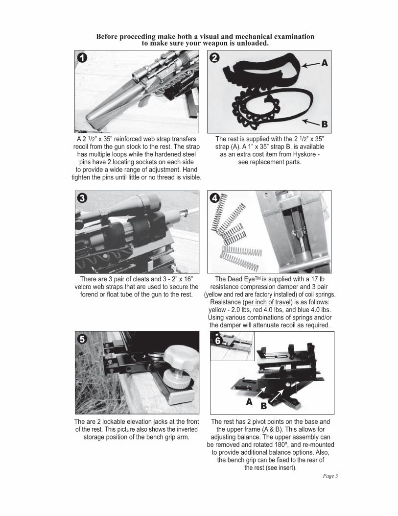
Before proceeding make both a visual and mechanical examination to make sure your weapon is unloaded.
A 2 1/2” x 35” reinforced web strap transfersrecoil from the gun stock to the rest. The strap
has multiple loops while the hardened steelpins have 2 locating sockets on each side
to provide a wide range of adjustment. Handtighten the pins until little or no thread is visible.
The rest is supplied with the 2 1/2” x 35”strap (A). A 1” x 35” strap B. is available
as an extra cost item from Hyskore -see replacement parts.
There are 3 pair of cleats and 3 - 2” x 16”velcro web straps that are used to secure the
forend or float tube of the gun to the rest.
The Dead EyeTM is supplied with a 17 lbresistance compression damper and 3 pair
(yellow and red are factory installed) of coil springs.Resistance (per inch of travel) is as follows:yellow - 2.0 lbs, red 4.0 lbs, and blue 4.0 lbs.Using various combinations of springs and/orthe damper will attenuate recoil as required.
The are 2 lockable elevation jacks at the frontof the rest. This picture also shows the inverted
storage position of the bench grip arm.
The rest has 2 pivot points on the base andthe upper frame (A & B). This allows for
adjusting balance. The upper assembly canbe removed and rotated 180º, and re-mounted
to provide additional balance options. Also,the bench grip can be fixed to the rear of
the rest (see insert).
A
B
A B
1 2
3
65
4

Page 6
Before proceeding make both a visual and mechanical examination to make sure your weapon is unloaded.
Instructions:
Depending on how you set the balance(Point #6), The appearance trim caps mayor may not limit the range of elevation. It isyour option to install them. Just press into
place or tap with a mallet.
To maximize repeatability and recoil reduction,it is important to solidly anchor the rest to a
solid bench. There are 2 anchor points behindthe levelers and one at the rear. 1/4” x 2” lags
or # 14 x 2” sheet metal screws work well.
For removal and/or replacement of thesprings or damper the 12mm insert lock
nuts must be removed. When replaced theyshould be tightened so that the threadengages the insert by about 1/2 turn.
The compression damper is secured by 2 x 8mminsert lock nuts. These are accessible with a
combination wrench. When retightening, make 1 to 1 1/2 revolutions after the thread engages
the insert. Once the nuts are removed, liftthe rear eye of the damper over the threaded
stud, slide the assembly forward and lift.
To reassemble, first fit the shaft end of the damper overthe stud on the gun cradle assembly. Tighten the nut
one revolution to allow for extra play. (Note: if you attach thewrong end of the damper you will note be able to reassemble).
Carefully read step 13 at this time!If the ends of the damper are not exactly parallel it will
not align easily with the mounting studs. Use one(or two) screwdrivers and gently twist to re-align.
To fit the gun cradle assembly to the upperbase, first engage the forward tubes over
the forward guide pins about 1/4”. Therear set will now be able to fit ahead of
their respective guide pins.
87
9 10
1211
Page 7
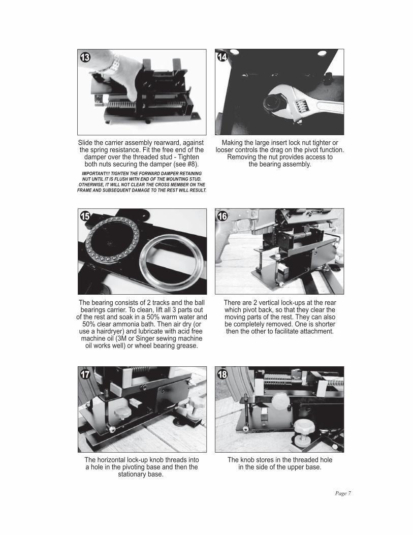
The horizontal lock-up knob threads intoa hole in the pivoting base and then the
stationary base.
The knob stores in the threaded holein the side of the upper base.
There are 2 vertical lock-ups at the rearwhich pivot back, so that they clear themoving parts of the rest. They can alsobe completely removed. One is shorterthen the other to facilitate attachment.
Slide the carrier assembly rearward, against the spring resistance. Fit the free end of the
damper over the threaded stud - Tightenboth nuts securing the damper (see #8).
IMPORTANT!!! TIGHTEN THE FORWARD DAMPER RETAININGNUT UNTIL IT IS FLUSH WITH END OF THE MOUNTING STUD.
OTHERWISE, IT WILL NOT CLEAR THE CROSS MEMBER ON THEFRAME AND SUBSEQUENT DAMAGE TO THE REST WILL RESULT.
Making the large insert lock nut tighter orlooser controls the drag on the pivot function.
Removing the nut provides access tothe bearing assembly.
The bearing consists of 2 tracks and the ballbearings carrier. To clean, lift all 3 parts out
of the rest and soak in a 50% warm water and50% clear ammonia bath. Then air dry (or
use a hairdryer) and lubricate with acid free machine oil (3M or Singer sewing machine
oil works well) or wheel bearing grease.
13 14
1615
17 18

Page 8
Suggestions For Building A Shooting Bench PlatformFor the 30013 Dangerous Game® Rest, 30003 Precision Rifle Rest,
30061 Dead EyeTM Rest, 30088 Precision DLX Rifle Rest,or 30080 Ten Ring® Recoil Assist Shooting Rest
The above captioned rifle rests must be secured to a bench. When there is a concretebench or a range that doesn’t allow shooters to screw anything to their benches it is necessary
to mount your rest to a platform that can be fixed to the bench using “C” Clamps.
Hyskore®
Suggested Bill of Materials:
1 - 24” x 48” x 3/4” Plywood2 - 2” x 4” x 8” wood block
2 - 6” or 8” stair angles (These are heavy duty 90˚ angle braces. At Lowes or Home Depot they can be found in the lumber area with the joist hangers.) 1 - Wood Glue (The exterior type is the best)
2 - 5/16” x 3/4” Sheet Metal Screws1 - 5/16” x 1 1/2” (or 2”) Sheet Metal Screw16-20 - 2” Drywall Screws2 or 4 - “C” Clamps (Size will depend on the thickness of the bench)
Description
For Constructing a Bench PlatformThese components can be purchased at any big box home improvement retailer.
Page 9
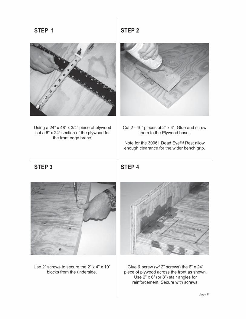
Using a 24” x 48” x 3/4” piece of plywoodcut a 6” x 24” section of the plywood for
the front edge brace.
Cut 2 - 10” pieces of 2” x 4”. Glue and screwthem to the Plywood base.
Note for the 30061 Dead EyeTM Rest allowenough clearance for the wider bench grip.
Use 2” screws to secure the 2” x 4” x 10”blocks from the underside.
Glue & screw (w/ 2” screws) the 6” x 24”piece of plywood across the front as shown.
Use 2” x 6” (or 8”) stair angles forreinforcement. Secure with screws.
STEP 1 STEP 2
STEP 3 STEP 4

Page 10
Notch the front brace so that the edge of thenotch is flush with the surface of the plywoodbase. This can be done either before or after
it is fixed in place.
Use 2 - 5/16” x 3/4” sheet metal screws toanchor the left & right sides of the rest. Youmay find it necessary to stack several flatwashers between the flange on the rest
and the plywood.
Use 1 - 5/16” x 1 1/2” (or 2”) sheet metal screwto anchor the bench grip arm.
Use 2 or 4 - “C” clamps to anchor thecompleted set-up to the bench.
STEP 5
STEP 8
STEP 6
STEP 7

Page 11
CENTER FIRE ACCURACY
A WORD ABOUT ACCURACYWhen it comes to shooting, the word “accuracy” really refers to group size. Once the group is established, adjustingthe sights to move the point of impact to the point of aim is a simple task. A gun/ammunition combination that shoots to 1, 3, or 5 MOA is just that. No matter what device you use to support the gun that group size will not change, not to mention extraneous factors such as sighting device, wind, stability of the shooting platform, trigger pull, parallax and/or the shooter. There is a long list of factors that can affect group size. Below we have attempted to briefly address a few of the more common ones. All comments are made with the “all things being equal” and “under perfect conditions” provisos. Please consider this a general guide that might point out a few things that might not have come to mind. Our #30013 Dangerous Game®, #30003 Precision Rifle Rest and #30088 DLX Precision Rifle Rest are designed to produce repeatable results. If the rests are properly assembled, securely anchored to a bench that is rock solid and does not shift under the stress of recoil, you will be able to maximize repeatability. Each rest will consistently repeat well under 3 MOA. What this means is that if the gun/ammunition combination is capable of shooting groups of less than 3 inches at 100 yards (nominal 3 MOA), you will be able to realize this degree of repeatability with either rest. The big word in the previous sentence is “IF”. Neither rest will make a 3 MOA gun place all of the bullets in one hole. The group will still be 3 MOA. If your bullets are not all forming a tight group, there is a high probability that the problem is a result of the gun, ammunition and/or the sight. * MOA – Minute of arc – A circle has 360°, each degree has 60 minutes, i.e. 1/60th degree. 1.0 MOA is exactly 1.047 inches at 100 yards.
A large percentage of the rifles, old and new, in the hands of American sportsmen will not shoot much better than 2.5 MOA with exceptional guns shooting 1.0 – 1.5 MOA, (assuming the ammunition is correctly matched to the gun). The average deer rifle, using popular brand, off the shelf ammunition is probably capable of 2.5-3.0 MOA because the gun and ammunition manufacturers know that a typical white tail is statistically harvested at a range of less than 100 yards, and a gun that places the bullets within 3 MOA will easily place all of them within a heart sized circle. Manufacturing guns and ammunition that will shoot under 1 MOA is, of course, done every day, but there are only a few manufacturers that guarantee that result, and then only with ammunition that they specify. The costs associated with the manufacturing, quality control, and attention to detail, price these guns out of reach of a large part of the market. With that being said, a gun/ammunition combination with 3 MOA accuracy, properly sighted in, will usually get the job done and nobody will know the difference. The target is dead –end of story. The point here is that if your gun is shooting at or beyond 3 MOA, the issue is, in all probability, a combination, of factors that can affect accuracy. We have prepared a short list of issues you may want to consider in examining the group size of your rifle.
A. Bolt action sporting rifles are by nature and design typically more accurate than pump, lever, or semi-automatic rifles. The reason for this is the bolt action tends to be much more rigid, and therefore flexes less. In addition, a bolt action usually has a larger and stronger extraction mechanism, which means the chamber can be made to closer tolerances than other types of actions. Believe it or not, not all ammunition in the same caliber is made to the exact same dimensions by all manufacturers. For example, SAAMI (Sporting Arms and Ammunition Manufacturers Institute, www.saami.org publication ANSI/SAAMI Z299-1992) allows a variance of up to -.008 under the standard for diameter, and up to -.007 under for the standard distance from the base to the shoulder (this determines headspacing) for center fire 30-06 ammunition. (Variances across most calibers are similar.) The extraction mechanism in pump, lever, and especially in semi-automatic weapons must be able to consistently and effectively extract cartridge cases at a rate equal to the cyclic rate of the weapon using the entire range of commercially available ammunition. This can be problematic if the cartridge fits too tight in the chamber. As a result manufacturers tend to make these chambers more tolerant of ammunition that may tend towards the larger end of the size range. Conversely, if ammunition manufacturers want their product to function in guns typically in the hands of sportsmen, they must also consider how easily the cartridge seats and extracts. Needless to say, there are exceptions to this, but as a rule as you move away from a precise cartridge chamber fit accuracy suffers. This is especially apparent in military weapons because they must chamber ammunition from various sources (therefore with various tolerances) and must function even if the ammunition is corroded or dirty. Reliability, not pinpoint accuracy is the primary criteria.
B. Match the correct bullet weight to the twist of the rifling. This is one of the most commonly overlooked factors that determines group size. If the bullet length and twist rate of the barrel are not synchronized, accuracy will suffer. A 110 grain .308 bullet is, of necessity, shorter than a 220 grain .308 bullet. For proper stabilization the heavier, and hence longer bullet, requires a faster rate of rifling twist than a short, light bullet. Further to this point, different guns respond differently to ammunition from different manufacturers. The point here is that you should test fire ammunition from several manufacturers and select bullet weights that are compatible with the rate of twist of the gun’s rifling. Generally speaking, twist rate is stamped on the barrel or the information is available from the manu- facturer. You need to test different bullet weights to optimize results.) The following websites will give you more information regarding this issue: www.snipercountry.com/hotlips/twistrate.html www.uslink.net kwk.us/twist.html en.wilkipedia.org/wiki/rifling www.gsgroup.co.za/cip.html

Page 12
Calculating Twist RateLegend: BL = Bullet LengthBD = Bullet DiameterC = 150 constant for muzzle velocity 1500-2800 FPSC = 180 constant for muzzle velocity over 2800 FPS(choose the correct constant for the ammunition you are using)
Formula: C x BD BL BD
First divide the bullet diameter (for example .224) into the bullet length (for example .712). Divide the result into the correct constant (150 or 180) and multiply the result by the BD (for example .224). The results is the approximate minimum twist rate necessary to stabilize the bullet - Remember a 1:9 rate is faster than a 1:14 rate.
Example A: .223 (5.56 x 45) @ 3200 FPS, 52 Grain, BL= .712 BD=.224 180 = 180 = 180 = 56.64 x BD = 56.64 x .224 = 12.7 BL .712 3.178 BD .224 12.7 is the optimum rate of twist
Example B: .223 (5.56 x 45) @ 2500 FPS, 75 Grain, BL= 1.095 BD=.224 150 = 150 = 150 = 30.6 x BD = 30.6 x .224 = 6.86 BL 1.095 4.9 BD .224 6.9 is the optimum rate of twist
If you use the 52 grain bullets in a 7.0 twist barrel the result will be fairly accurate. If you use the 75 grain bullet in a 12.0 or 13.0 twist barrel your group will probably be all over the target.
Diameters of Popular Bullets.204 - .204 7mm - .284..223 - .224 .308 - .308.243 - .243 .338 - .338.270 - .277 .375 - .375 Bullet length varies by manufacturer and style. For this information check with the manufacturer or take an actual measurement. C. A perfectly formed muzzle crown allows the gas to escape in a uniform pattern around the base of the bullet as it exits. Through improper cleaning and handling the crown of the muzzle can be easily damaged. Even a small ding, which may not necessarily be visible to the naked eye, can cause an uneven release of gas, which can heel the bullet over slightly, producing a yaw attitude. This will affect the bullet’s stability and accuracy, as the long axis of the bullet will no longer be coincidental with the path of travel.
D.The quality of the ammunition you use can have a direct result on repeatable group size; the more consistent the ammunition, and the components from which it is manufactured, the more consistent the results. Several manufactures make match grade ammunition where the components are carefully selected and screened for consistency and conformance to specification. (One of the manufacturers that are best known for achieving the most consistent results is Black Hills www.black-hills.com ). There are several other manufacturers that make acceptable match grade ammunition, and there are other options. If you are a re-loader, you are already aware of the range of quality components available and in all probability you are able to produce consistent, high quality ammunition.
E. Vertical Grouping – See Rim Fire section point D.
F. Check Your Scope and Mounting – With older and especially inexpensive scopes it is not uncommon for the reticle to stick or shift, especially under heavy recoil and/or temperature extremes. If this happens your muzzle could end up pointing in a slightly different direction after each shot. To check for this condition, lock the gun in a vise that doesn’t move and sight the reticle on a set point/target then use a piece of wood or other object (that will not do damage), to tap the scope tube to imitate recoil. If the reticle moves from the original point of aim, you have a problem with the scope. Also check the scope mounting using the same procedure. Mounts and rings frequently become loose due to recoil and heat. In addition to properly mounting a scope the rings must be lapped and centered otherwise there may not be sufficient contact to secure the scope. Even Locktite doesn’t insure that mounts and rings will not shift.
Page 13
RIM FIRE ACCURACY
G. Parallax is the apparent shift of the target relative to the reticle due to the horizontal movement of the observer. Scopes with parallax adjustments must be correctly adjusted. Scopes without a parallax adjustment are generally range specific for parallax free sighting. If you have made the adjustments to eliminate parallax you are good to go. If not, it is important to make sure that the longitudinal optical axis of the scope that runs through the center of the crosshairs is directly aligned with the pupil of your eye. If you have an inconsistent cheek weld to your stock or fail in any other way to address parallax your groups will suffer from horizontal dispersion, i.e.:open up left to right. This will happen because your view of the target in the horizontal plane will vary with each shot.
H. Barrel temperature plays a major role in maintaining group size. As a barrel heats up torsional stress will cause the barrel to twist. Bench rest shooters wait several minutes between each shot to keep the barrel from over- heating. If you fire 10 or 12 shots in rapid succession from a sporter weight barrel your groups will expand.
I. Other factors, which we will not explore here include: Free floating barrels, bedding, barrel harmonics, etc. - Not to mention the shooter!
(Some of this applies to center fire rifles also.)Accuracy in a rim fire rifle is to a large degree more dependent upon the ammunition as opposed to the equipment. Center fire ammunition can be loaded and/or reloaded to precise and consistent specifications. Rim fire ammunition can only be loaded at the factory level. Since rim fire ammunition is not re-loadable, it is necessary to use whatever is commercially available. Factors affecting rim fire accuracy are:
A. As with a center fire cartridge there is a SAAMI specification (ANSI/SAAMI Z 299.1-1992) and variance for the dimensional aspects of rim fire ammunition that allows up to -.004 under the standard diameter for .22 long rifle match or sporting ammunition. Consequently, manufacturers make ammunition within the entire range of this variance. As a direct result a gun that is expected to perform reliably must be able to accept the full range of available ammunition. What this has led to are guns that are match chambered which are invariably bolt action. (The chambers in these guns have a tight precise cartridge fit and the guns perform best with match grade ammunition that is made to close tolerance), and then we have most other guns that have sporting chambers, many of which are auto loaders. The chambers in these guns must be made large enough so that the gun will cycle correctly with any off the shelf brand of ammunition which could be manufactured to any size within the allowable range of tolerance. i.e., This means the cartridge may fit loosely in the chamber. Due to gravity the cartridge settles into the lowest portion of the chamber. The result is that the center axis of the chamber, and hence the center axis of the barrel is not aligned with the center axis of the bullet. This means that the bullet will engage the rifling off center and will travel down the barrel and exit the muzzle at an angle resulting in a loss of stability and accuracy.
B. Concentricity – If the long axis of the bullet is not concentric with the long axis of the case it will also not be concentric with the long axis of the bore, as above the bullet will travel down the barrel and exit the muzzle at an angle with similar results. As little as .002”–.003” off center will cause a noticeable enlargement of the grouping.
C. Head Spacing is the distance the bullet must move from the casing until it engages the rifling. In a rim fire this is controlled by the thickness of the rim. According to SAAMI standards rim thicknesses may vary from as little as .036” to as much as .043”. A gun may perform much better with one rim thickness as opposed to others. It is therefore important to test your gun with a wide range of ammunition. Typically in a box of inexpensive ammunition you will find a considerable variance in rim thicknesses. This will usually result in expanding the group size; consistency of rim thickness will result in smaller, consistent group sizes. Both concentricity and rim thickness can be measured by using the HYSKORE® #30075 Ammo Analyzer.
D. If the group spread is more vertical than horizontal it is usually the fault of the ammunition. At a known distance, a faster bullet reaches the target quicker and drops less, i.e. gravity has less time to act. As you may appreciate, the small quantities of primer and propellant used in a rim fire cartridge must be precisely and accurately measured in order to produce consistent velocity. Only a small variance in absolute terms translates to a significant percentage variation and by extension, variation in velocity. Maintaining this type of consistency across large production runs is incompatible with maintaining low cost. Primer compound has an explosive force in the magnitude of 25 to 50 times that of the propellant. As little as 1/10 grain (1/70,000 lb.) deviation will cause a velocity differential. With these thoughts in mind, the culprit in groups that open top to bottom is almost always inconsistent velocity. The faster bullets strike higher and the slower ones lower.
E. Scope Problems – See “F” and “G” under Center Fire.
The aforementioned issues represent a brief synopsis of various conditions that may affect accuracy. There are numerous in depth studies that can provide detailed analysis of each situation. We are not experts and do not intend to be. Our comments and suggestions are the result of studying and compiling data from a wide range of sources. Furthermore, we have only touched on the more significant factors that affect accuracy. If you elect to make adjustments to your gun/ammunition combination to increase accuracy, we suggest that you address each issue one at a time. Do not try to make multiple corrections at the same time as you may contaminate the results, and possibly obscure important issues that need further attention.

Page 14
CALCULATING RECOILThere are two ways to do this. A. The easy way - go to one of the websites listed in this pamphlet or go to one of the links listed on our website: www.hyskore.com B. If you like playing with numbers, use the following formula. While Isaac Newton or Albert Einstein might take us to task for being off by 2 or 3 %, this will get you into the ballpark. We have divided the process into 2 steps. First, calculate the recoil velocity then use this information to calculate the recoil energy in ft/lbs.
Legend:PW - Weight of powder chargeBW - Weight of bullet (grains)MV - Muzzle VelocityGW - Weight of loaded gun/w scopeRV - Recoil VelocityRE - Recoil Energy
1. RV= [(1.75 x PW) + BW] x MV
7,000 x GW
Run the calculation like this: A. Multiply the weight of the powder charge PW x 1.75 B. Add the bullet weight (BW) to this number (result from A) C. Multiply this number (result from B) by the bullet velocity (MV) - Hold this number aside D. Multiply the weight of the gun (GW) x 7000 E. Take the calculation from D (GW x 7000) and divide it into the number you held aside in C (above) - This is the velocity of the recoil.
2. RE= RV2 x GW
64.4
Run the calculation like this: F. Square the recoil velocity and multiply it by the weight of the gun G. Divide this number (result from F) by 64.4. This is the recoil energy in ft./lbs.
Example: Actual data for .308 Winchester model 70 with 24” barrel & scope.PW = 40 GrainsBW = 180 Grain (sierra match king)BV = 2,500 FpsGW = 8.2 lbs.
RV = [(1.75 x 40) + 180] x 2,500 = 625,000 7,000 x 8.2 57,400
= 10.89 fps
RE = 10.89 x 10.89 x 8.2 = 972 = 15.10 ft./lbs. 64.4 64.4
The Recoil Velocity (RV) is 10.89 fpsThe Recoil Energy (RE) is 15.10 ft/lbs
A few pointers A. The weight of the gun (GW) should always be in pounds. eg. 7.3, 8.2, etc. B. The weight of the powder charge has a very small influence on the recoil velocity (RV) or recoil energy (RE). If you do not know the exact number, use the flowing guidelines:
.219 - .223 - 25 grains
.22 - 25 - .257 - 38 grains
.264 - .28 - 55 grains
.308 - 30’06 - 45 grains
.300 & 7mm mag - 62 grains
.338 - 70 grains
.375 - 85 grains
.416 - .458 - 110 grains
.

Page 15
Do your calculations with 2 or 3 different powder weights and you will see that the recoil energy (RE) only varies slightly. The 64.4 Number is a constant and the 7000 number is the number of grains in one pound.Repeat: if you do something dumb, bad things can happen. The chart is only a general guideline.
For more detailed recoil data (as of this writing) there are several good websites that you can reference:1. www.real-guns.com 2. www.zvis.com 3. www.chuckhawks.com/recoil 4. www.handleads.com5. www.rfgc.org/reload6. www.siskguns.com
or go to our website (www.hyskore.com) click on the image of the Dead EyeTM then click on the link to the recoil calculator.The recoil that you feel is a function of the action-reaction created as the bullet moves forward in the barrel and, shortly thereafter, gas exiting the muzzle (Rocket Effect). Therefore, the quantity of propellant in addition to gun weight, bullet weight and muzzle velocity is an important factor in determining recoil. Make certain that this is part of your calculation. Calculate your recoil carefully and DO NOT EXCEED THE LIMITS OF THE COMPRESSION DAMPER/SPRING COMBINATION!
PARALLAX\When attempting to achieve the highest degree of repeatability i.e. smallest group size, with any HYSKORE® shooting rest, it is important to have a clear understanding of parallax. Even experienced, good shots can improve their group size by up to 30% by paying close attention to parallax. Parallax is the difference in apparent position of an object viewed along two different lines of sight. To experience parallax extend one of your arms, hold an index finger up, close your left eye, and align the index finger with an object on the distant wall. Now close your right eye and open your left. The object has appeared to have moved. What has actually happened is that you are now viewing the object along a different line of sight. This is exactly what happens inside a rifle scope. Wehave prepared three diagrams to show you the various conditions that may develop in sighting with a scope.
A. This is a parallax free focusing arrangement. The image of the target is focused on the reticle. (The reticle is the optical element inside the scope on which the cross hairs are inscribed.)
B. The image focuses in front of the reticle and in this case you would experience parallax.
C. The image focuses behind the reticle and also in this instance you could experience parallax.
The correction in diagrams B and C is to adjust the objective lens of the scope so the image focuses on the reticle. On better scopes there is usually an adjustment on the objective bell (this is the end of the scope facing the target) with yardage markings. By turning this you can approximate the correct adjustment. However, since parallax is magnification and range variable, it is a good idea to clamp the rifle in a solid vise on the bench top (The HYSKORE® #30022 Parallax Cleaning and Sighting Vise is perfect for this.) Look at the target through the scope and shift your eye left to right, if the cross hairs remain dead center on the target you are parallax free, if not, you need to do additional adjustment. Inexpensive and low magnification scopes are usually parallax free at a specific range, and do not have parallax adjustments.
Keeping the pupil of your eye concentric with the optical axis of the scope is critical to eliminating parallax. If you can keep your eye positioned on the axis every time you will experience parallax free shooting. Of course, this is almost impossible to do and repeat shot after shot. Moving your eye even a few thousandths of an inch off dead center, when parallax is present, will influence your visual alignment and cause you to change your point of aim, resulting in expanding your group. Therefore, you must make the appropriate adjustments at the designated range to remove parallax. Unfortunately, most scope manufacturers assume that all shooters have a working knowledge of parallax. As a result, the instructions they provide give little or incomplete details regarding this optic condition.
Target Objective Lens Reticle Observer’s Eye
Optical Axis
Optical Axis
Optical Axis
A
C
B

• REPLACEMENT PARTS •
Visit our website: www.hyskore.com
These are replacement parts for purchase. Pictures do not represent contents of set.
Parts List & Pricing:30061 - 1 Compression Damper 22 lbs. .............................................................. $ 32.5030061 - 2 Compression Damper 17 lbs. .............................................................. $ 32.5030061 - 3 Compression Damper 11 lbs. ............................................................... $ 32.50 30061 - 4 Recoil Transfer Strap 70mm ................................................................ $ 19.5030061 - 5 Recoil Transfer Strap 25mm ................................................................ $ 15.0030061 - 6 Recoil Transfer Pins (2 pcs.) ................................................................ $ 17.5030061 - 7 Elevation Lockdown Set....................................................................... $ 17.5030061 - 8 Leveling Jack & Knob Set .................................................................... $ 10.0030061 - 9 Foam Pad Set (4 Pads + 6 Pads) ........................................................ $ 17.5030061 - 10 Forend Restraining straps (3 Pcs.) ...................................................... $ 12.5030061 - 11 Bench Grip Set..................................................................................... $ 32.50 30061 - 12 Coil spring Set (6 Springs) ................................................................... $ 15.0030061 - 13 Magnetic Spirit Level............................................................................ $ 7.5030061 - 14 16mm Insert Lock Nut .......................................................................... $ 5.00 30061 - 15 12mm Insert Lock Nut (2 Pcs.) ............................................................ $ 5.0030061 - 16 Bearing Set .......................................................................................... $ 37.50
Send Check or Money Order with Phone Number to:Power Aisle, Inc.P.O. Box 983Middleburgh, NY 12122NYS Resident add 8.75% Sales Tax
** $10.00 Shipping & Handling to Lower 48 States**
** $25.00 Shipping & Handling to Alaska, Hawaii, Puerto Rico**
30061-1
30061-6
30061-2
30061-7
30061-1230061-11
30061-3
30061-8
30061-13
30061-4
30061-9
30061-14/15
30061-5
30061-10
30061-16


![‘Once dead, always dead!’ [The challenge of the resurrection]](https://img.pdfslide.us/doc/110x75/568134b8550346895d9bd735/once-dead-always-dead-the-challenge-of-the-resurrection.jpg)