Embed Size (px)
Citation preview
HYRIA INVERTER
Series Inverter Manual
HYRIA INVERTER
HYRIA ELECTRICAL CO., LTD
Address: Chen Yu Chen Bei Industrial District, YuHuan
Town, Taizhou City, Zhejiang 317600 China
Subsidiary Company: HONG KONG Y&F GROUP LIMITED
Address: Tai Yau Street San Po Kong, Kowloon Wong King
Industrial Building 2
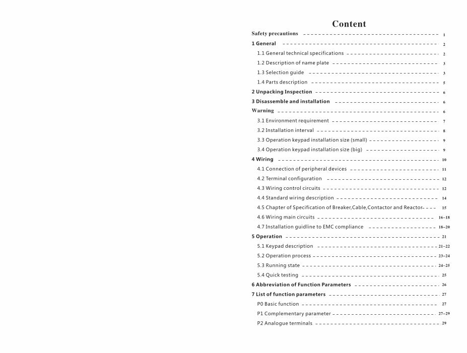
ContentSafety precautions
1 General
1.1 General technical specifications
1.2 Description of name plate
1.3 Selection guide
1.4 Parts description
2 Unpacking Inspection
3 Disassemble and installation
Warning
3.1 Environment requirement
3.2 Installation interval
3.3 Operation keypad installation size (small)
3.4 Operation keypad installation size (big)
4 Wiring
4.1 Connection of peripheral devices
4.2 Terminal configuration
4.3 Wiring control circuits
4.4 Standard wiring description
4.5 Chapter of Specification of Breaker,Cable,Contactor and Reactor
4.6 Wiring main circuits
4.7 Installation guidline to EMC compliance
5 Operation
5.1 Keypad description
5.2 Operation process
5.3 Running state
5.4 Quick testing
6 Abbreviation of Function Parameters
7 List of function parameters
P0 Basic function
P1 Complementary parameter
P2 Analogue terminals
1
2
2
3
3
5
6
6
6
7
8
9
9
10
11
12
12
14
15
16-18
18-20
21
21-22
23-24
24-25
25
26
27
27
27-29
29
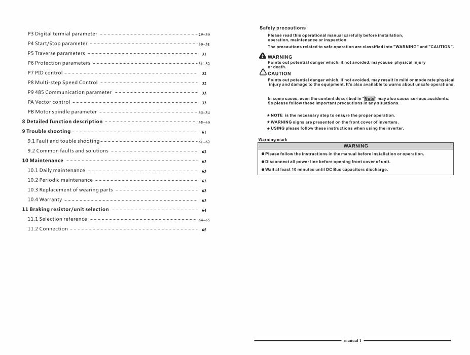
Safety precautions
Please read this operational manual carefully before installation, operation, maintenance or inspection.
The precautions related to safe operation are classified into "WARNING" and "CAUTION".
WARNINGPoints out potential danger which, if not avoided, maycause physical injury or death.
CAUTION
Points out potential danger which, if not avoided, may result in mild or mode rate physical injury and damage to the equipment. lt's also available to warns about unsafe operations.
In some cases, even the content described in "Note" may also cause serious accidents. So please follow these important precautions in any situations.
NOTE is the necessary step to ensure the proper operation.
WARNING signs are presented on the front cover of inverters.
USING please follow these instructions when using the inverter.
Warning mark
WARNING
Please follow the instructions in the manual before installation or operation.
Disconnect all power line before opening front cover of unit.
Wait at least 10 minutes until DC Bus capacitors discharge.
P3 Digital termial parameter
P4 Start/Stop parameter
P5 Traverse parameters
P6 Protection parameters
P7 PID control
P8 Multi-step Speed Control
P9 485 Communication parameter
PA Vector control
PB Motor spindle parameter
8 Detailed function description
9 Trouble shooting
9.1 Fault and touble shooting
9.2 Common faults and solutions
10 Maintenance
10.1 Daily maintenance
10.2 Periodic maintenance
10.3 Replacement of wearing parts
10.4 Warranty
11 Braking resistor/unit selection
11.1 Selection reference
11.2 Connection
manual 1
29-30
30-31
31
31-32
32
32
33
33
33-34
35-60
61
61-62
62
63
63
63
63
63
64
64-65
65
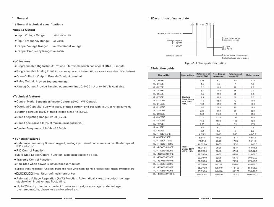
General
General technical specifications
Input & Output
Input Voltage Range:
Input Frequency Range:
Output Voltage Range:
Output Frequency Range:
I/O features
Programmable Digital Input: Provide 6 terminals which can accept ON-OFFinputs.
Programmable Analog Input:AI1 can accept input of 0 ~10V; AI2 can accept input of 0~10V or 0~20mA.
Open Collector Output: Provide 2 output terminal.
Relay Output: Provide 1output terminal.
Analog Output:Provide 1analog output terminal, 0/4~20 mA or 0~10 V is Available.
rated input voltage
Technical features
Control Mode:Sensorless Vector Control (SVC), V/F Control.
Overload Capacity: 60s with 150% of rated current and 10s with 180% of rated current.
Starting Torque: 150% of rated torque at 0.5Hz (SVC).
Speed Adjusting Range: 1:100 (SVC).
Speed Accuracy: + 0.5% of maximum speed (SVC).
Carrier Frequency: 1.0KHz ~15.0KHz.
Function features
Reference Frequency Source: keypad, analog input, serial communication,multi-step speed, PID and so on.
PID Control Function.
Multi-Step Speed Control Function: 8 steps speed can be set.
Traverse Control Function.
Non-Stop when power is instantaneously cut off.
Spe ed tracki ng rest ar t funct ion: make the revol ving motor spi ndl e real ize non-i mpact smoot h star t
QUICK/JOG Key: User-defined shortcut key.
Automatic Voltage Regulation (AVR) Function: Automatically keep the output voltage stable when input voltage fluctuating.
Up to 25 fault protections: protect from overcurrent, overvoltage, undervoltage,overtemperature, phase loss and overload etc.
1.2Description of name plate
HYRIA SL Vector Inverter
Voltage degree
E:three phase power supply
S:single phase power supply
P: fan, water pumpE:constant torque
software version
1.3Selection guide
Model No. Input voltage Rated output power(KW)
Rated input current(A)
Rated output current(A)
Motor power
Figure1-1 Nameplate description
manual 2 manual 3
75 7.5W750 75KW
Three phase 380V -15%+15%
Single & Three Phase 220V -15%+15%
Three phase 380V -15%+15%
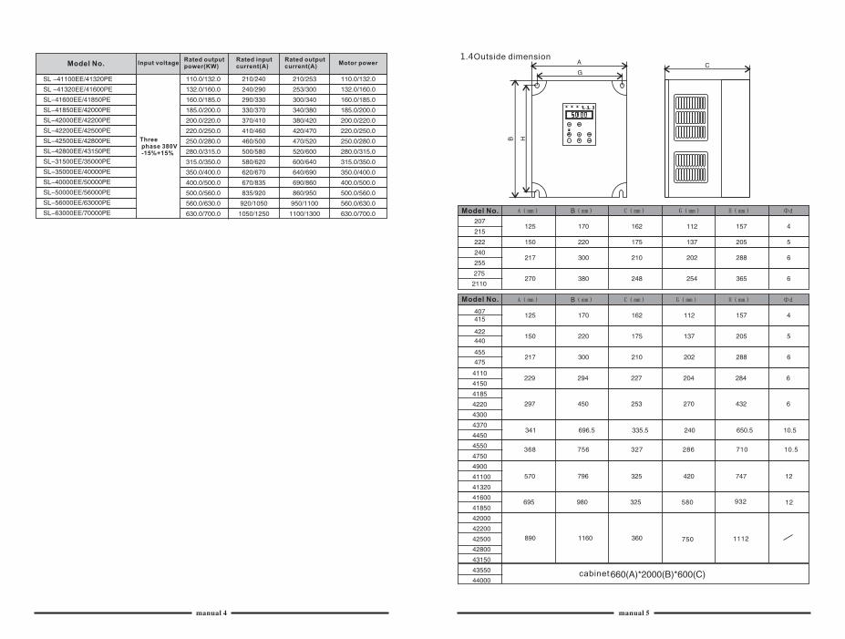
Model No. Input voltage Rated output power(KW)
Rated input current(A)
Rated output current(A)
Motor power 1.4Outside dimension
cabinet
manual 4 manual 5
Model No.
Model No.
Unpacking inspection
CAUTION
Don't install or use any inverter that is damaged or has defective parts, otherwise physical injury may occur
Check following items after unpacking the inverter:
lnspect to ensure there are no scratches or other damage caused by the transportation.
Ensure there is operation manual in the packing box.
Inspect the nameplate and ensure it is the right ordered product.
Ensure the optional parts are the right ordered products.
Please contact the local agent if there is any damage to the inverter or optional parts.
Disassembly and installation
WARNING
Only qualified electricians are allowed to operate on the drive device/system. Ignoring the
instructions in "warning" may cause serious physical injury or death or property loss.
Connect the input power lines tightly and permanently. And ground the device with proper
techniques.
Even when the inverter is stopped, dangerous voltage is present at the terminals:
Power Terminals: R, S, T
Motor Connection Terminals: U, V, W.
Stop the drive and disconnect it from the power line. Wait for 5 minutes to let the drive
discharge and then begin the installation.
Minimum cross-sectional areas of the grounding conductor should be equal or larger than the cross-sectional area of the power cord conductors
CAUTION
Lift the inverter by its base other than by the keypad or the cover. The dropping of the main part may cause physical injury.
The inverter is fixed on a non-flammable wall such as metal and away from heat and flammable materials to avoid the fire.
If more than two drives are installed in a cabinet, the temperature should be lower than 45℃ by means of a cooling fan. Overheat may cause fire or damage to the drive.
3.1Environmental requirement
TemperatureThe ambient temperature is among -10℃ to +40℃ and the inverter has to derate by 4% for every additional l℃ if the ambient temperature exceeds 40℃ .
Humidity
Relative humidity of the air: ≤ 95%.No condensation is allowed.
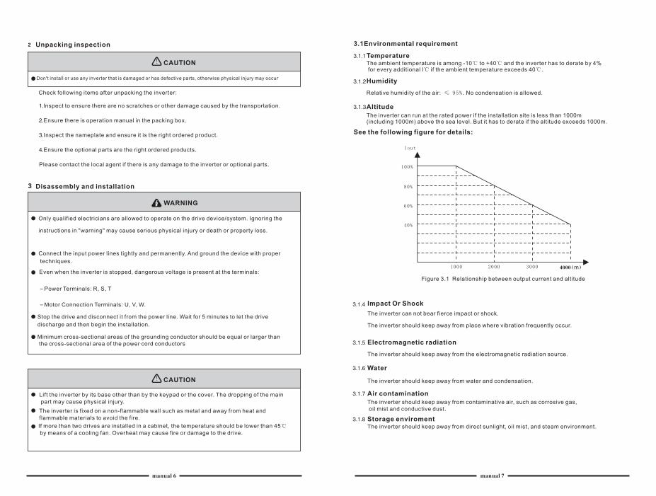
AltitudeThe inverter can run at the rated power if the installation site is less than 1000m(including 1000m) above the sea level. But it has to derate if the altitude exceeds 1000m.
See the following figure for details:
m
Figure 3.1 Relationship between output current and altitude
Impact Or Shock
The inverter can not bear fierce impact or shock.
The inverter should keep away from place where vibration frequently occur.
Electromagnetic radiation
The inverter should keep away from the electromagnetic radiation source.
Water
The inverter should keep away from water and condensation.
Air contamination
Storage enviroment
The inverter should keep away from contaminative air, such as corrosive gas, oil mist and conductive dust.
The inverter should keep away from direct sunlight, oil mist, and steam environment.
manual 6 manual 7
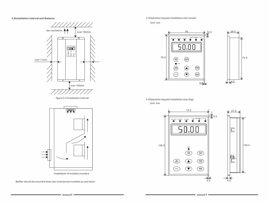
3.2Installation interval and distance
fan ventilationover 100mm
over 50mm
over 100mm
figure 3-2 Installation interval
Installation of multiple inverters
3.3Operation keypad installation size (small)
Unit: mm
Unit: mm
3.4Operation keypad installation size (big)
Baffler should be mounted when two inverters be installed up and down
manual 8 manual 9
Wiring
WARNING
Only qualified electricians are allowed to operate on the drive for the insurance of a safe running of the inverter.
Never carry out any insulation or voltage withstand tests on the cablesconnecting with the inverter.
Even if the servo drive is stopped, dangerous voltage is present at the input power lines, DC circuit terminals and motor terminals. Wait for 5 minutes even when the inverter is switched off until is discharge before operation.
Ground the grounding terminals of the inverter with proper techniques.
The grounding resistor will be less than 100Ω for 220V series inverter.
The grounding resistor will be less than 10Ω for 380V series inverter.
Please ensure right connection between the power wires and the motor wires. The power wire is connected with the terminals of R, S and T. And the motor wire isconnected with the terminals of U, V and W.
Never do wiring or other operations on the inverter with wet hands. Otherwise there is danger of electric shock
CAUTION
Verify that the rated voltage of the servo drive equals to the voltage of the AC power supply.
The power wires and motor wires must be permanently fastened and connected.
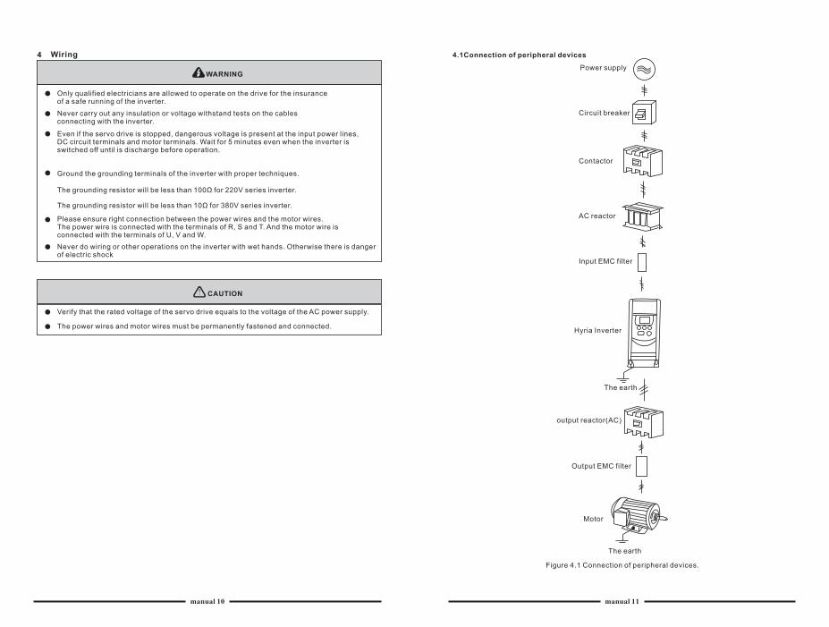
4.1Connection of peripheral devices
Power supply
Circuit breaker
Contactor
AC reactor
Input EMC filter
Hyria Inverter
The earth
output reactor(AC)
Output EMC filter
Motor
The earth
Figure 4.1 Connection of peripheral devices.
manual 10 manual 11
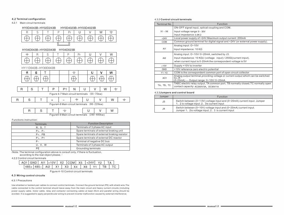
Terminal configuration
Main circuit terminals
Figure 4-7 Main circuit terminals (55-75kw)
Figure4-8 Main circuit terminals (90-220kw)
Figure4-9 Main circuit terminals (280-400kw)
Functions instruction:
Terminals Function Description
Terminals of 3 phase AC input
Spare terminals of external braking unit
Spare terminals of external braking resistor
Spare terminals of external DC reactor
Terminal of negative DC bus
Terminals of 3 phase AC output
Grounding terminals Note: The terminal configuration above is consult only, if there is fluctuation, according to the real object please.
Control circuit terminals
Figure 4-10 Control circuit terminals
Wiring control circuits
Precautions
Control circuit terminals
Terminal No. Function
ON-OFF signal input, optical coupling and COM.
Input voltage range:
Input impedance:
Local power supply of +24V.Maximum output current: 200mA
Common ground terminal for digital signal and +24V (or external power supply).
Analog input: O~10V
Input impedance: 10 KΩ
Analog input: O~10V/ 0~20mA, switched by J3.
Input impedance: 10 KΩ(/ (voltage input) / 250Ω(current input).
when current input is 0-20mA the correspondent voltage is 5V
Supply +10V to inverter
COM is the correspondent common port of open circuit collector
Analog output terminal,providing voltage or current output which can be switched by J4.(0-20mA) --- Output range: 0~10V/ 0~20mA.
TABC electric relay output, TA common port, TB normally closed,TC normally open
+10V reference zero electric potential
contact capacity:
Jumpers and control board
Jumper Function
Switch between (0~1 0V) voltage input and (0~20mA) current input. Jumper 1、 is voltage input; 2、3is current input2
Switch between (0~10V) voltage input and (0~20mA) current input. Jumper 1、2is voltage input; 2、3 is current input
4.2
4.3
Use shielded or twisted-pair cables to connect control terminals. Connect the ground terminal (PE) with shield wire.The
cable connected to the control terminal should leave away from the main circuit and heavy current circuits (including
power supply cable, motor cable, relay and contactor connecting cable) at least 20cm and parallel wiring should be
avoided. It is suggested to apply perpendicular wiring to prevent inverter malfunction caused by external interference.
manual 12 manual 13
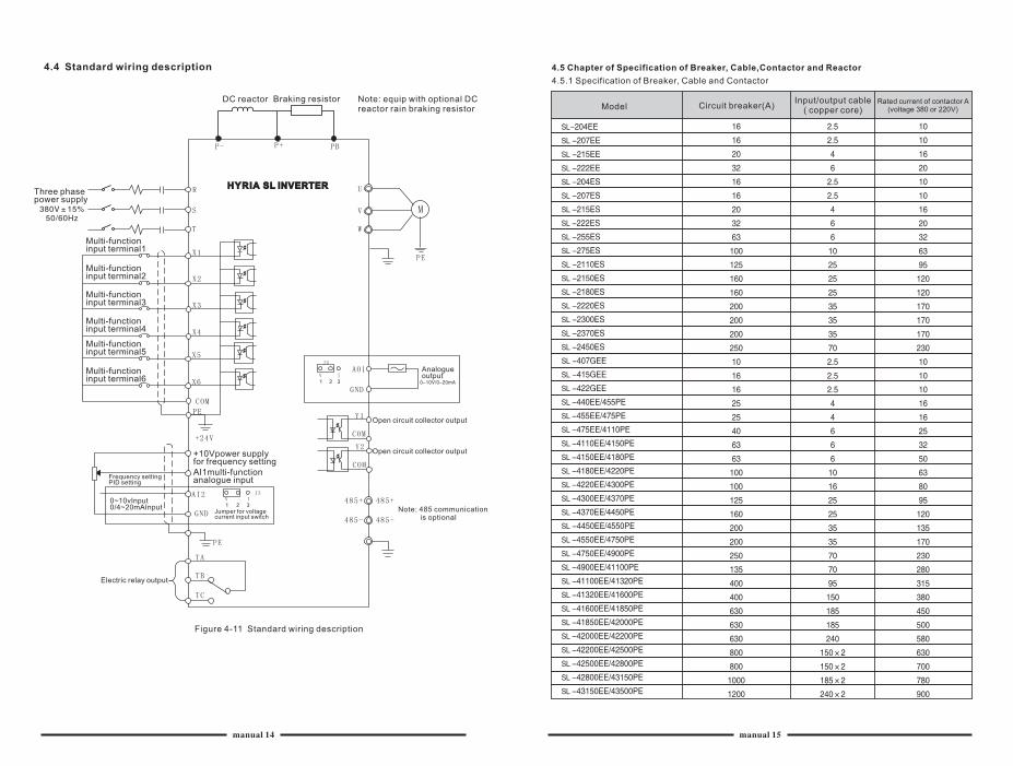
4.4 Standard wiring description
DC reactor Braking resistor Note: equip with optional DC reactor rain braking resistor
Three phase power supply
Multi-function input terminal1
Multi-function input terminal2
Multi-function input terminal3
Multi-function input terminal4
Multi-function input terminal5
Multi-function input terminal6
+10Vpower supply for frequency settingAI1multi-function analogue inputFrequency setting
PID setting
0~10vInput0/4~20mAInput
Jumper for voltagecurrent input switch
Electric relay output
Analogue output
Open circuit collector output
Open circuit collector output
Note: 485 communication is optional
Figure 4-11 Standard wiring description
4.5 Chapter of Specification of Breaker, Cable,Contactor and Reactor
Model Circuit breaker(A)Input/output cable
( copper core)
4.5.1 Specification of Breaker, Cable and Contactor
Rated current of contactor A (voltage 380 or 220V)
manual 14 manual 15
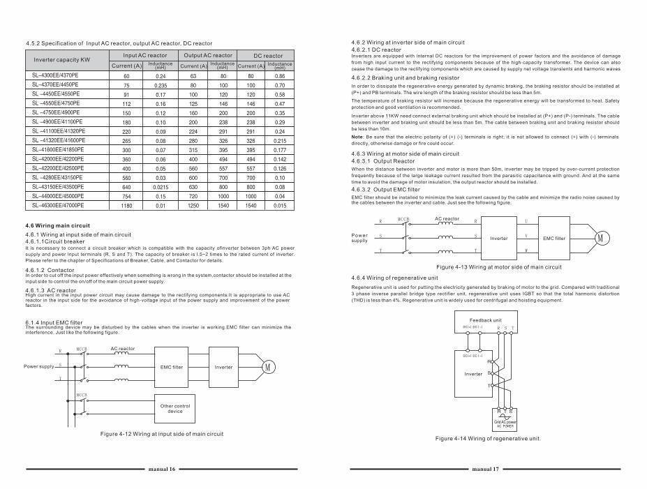
4.5.2 Specification of Input AC reactor, output AC reactor, DC reactor
Inverter capacity KWInput AC reactor
Current (A) Inductance(mH)
Output AC reactor DC reactor
Current (A)Inductance
(mH) Current (A) Inductance(mH)
4.6 Wiring main circuit
4.6.1 Wiring at input side of main circuit4.6.1.1Circuit breakerIt is necessary to connect a circuit breaker which is compatible with the capacity ofinverter between 3ph AC power
supply and power input terminals (R, S and T). The capacity of breaker is l.5~2 times to the rated current of inverter.
Please refer to the chapter of Specifications of Breaker, Cable, and Contactor for details.
4.6.1.2 ContactorIn order to cut off the input power effectively when something is wrong in the system,contactor should be installed at the
input side to control the on/off of the main circuit power supply.
4.6.1.3 AC reactorHigh current in the input power circuit may cause damage to the rectifying components.It is appropriate to use AC reactor in the input side for the avoidance of high-voltage input of the power supply and improvement of the power factors.
6.1.4 Input EMC filterThe surrounding device may be disturbed by the cables when the inverter is working.EMC filter can minimize the interference. Just like the following figure.
Power supply
AC reactor
EMC filter
Other control device
Figure 4-12 Wiring at input side of main circuit
Inverter
4.6.2 Wiring at inverter side of main circuit
4.6.2.1 DC reactorInverters are equipped with internal DC reactors for the improvement of power factors and the avoidance of damage
from high input current to the rectifying components because of the high-capacity transformer. The device can also
cease the damage to the rectifying components which are caused by supply net voltage transients and harmonic waves
4.6.2.2 Braking unit and braking resistor
In order to dissipate the regenerative energy generated by dynamic braking, the braking resistor should be installed at
(P+) and PB terminals. The wire length of the braking resistor should be less than 5m.
The temperature of braking resistor will increase because the regenerative energy will be transformed to heat. Safety
protection and good ventilation is recommended.
Inverter above 11KW need connect external braking unit which should be installed at (P+) and (P-) terminals. The cable
between inverter and braking unit should be less than 5m. The cable between braking unit and braking resistor should
be less than 10m.
Note: Be sure that the electric polarity of (+) (-) terminals is right; it is not allowed to connect (+) with (-) terminals
directly, otherwise damage or fire could occur.
4.6.3 Wiring at motor side of main circuit
4.6.3.1 Output Reactor
When the distance between inverter and motor is more than 50m, inverter may be tripped by over-current protection
frequently because of the large leakage current resulted from the parasitic capacitance with ground. And at the same
time to avoid the damage of motor insulation, the output reactor should be installed.
4.6.3.2 Output EMC filter
EMC filter should be installed to minimize the leak current caused by the cable and minimize the radio noise caused by the cables between the inverter and cable. Just see the following figure.
P o w e r supplly
AC reactor
Inverter EMC filter
Figure 4-13 Wiring at motor side of main circuit
4.6.4 Wiring of regenerative unit
Regenerative unit is used for putting the electricity generated by braking of motor to the grid. Compared with traditional
3 phase inverse parallel bridge type rectifier unit, regenerative unit uses IGBT so that the total harmonic distortion
(THD) is less than 4%. Regenerative unit is widely used for centrifugal and hoisting equipment.
Feedback unit
Inverter
Grid AC power
Figure 4-14 Wiring of regenerative unit.
manual 16 manual 17
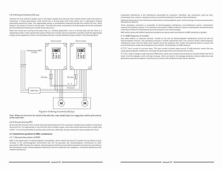
4.6.5 Wiring of Common DC bus
Common DC bus method is widely used in the paper industry and chemical fiber industry which need multi-motor to
coordinate. In these applications, some motors are in driving state while some others are in regenerative braking
(generating electricity) state. The regenerated energy is automatically balanced through the common DC bus, which
means it can supply to motors in driving state. Therefore the power consumption of whole system will be less compared
with the traditional method (one inverter drives one motor).
When two motors are running at the same time (i.e. winding application), one is in driving state and the other is in
regenerative state. In this case the DC buses of these two inverters can be connected in parallel so that the regenerated
energy can be supplied to motors in driving state whenever it needs. Detailed wiring is shown in the following figure:
3-phase input 380V(±15%)
Hyria inverter
DC fuse
EMC filter
DC fuse
DC bus(+)
Figure 4-15 Wiring of common DC bus.
4.6.6 Ground wiring (PE)
Ground the PE terminal of the inverter with grounding resistors for the insurance of safety and avoidance of electrical
shock and fire. It is appropriate to use thick and short multiple copper core wires whose sectional area is larger than 23.5mm . It is not recommended to use the public earth wire; otherwise, the grounding wires may complete the circuit.
4.7 Installation guidline to EMC compliance
4.7.1 General description of EMC
EMC is the abbreviation of electromagnetic compatibility, which means the device or system has the ability to work
normally in the electromagnetic environment and will not generate any electromagnetic interference to other
equipments. EMC includes two subjects: electromagnetic interference and electromagnetic anti-jamming. According to
the transmission mode, Electromagnetic interference can be divided into two categories: conducted interference and
radiated interference.
Conducted interference is the interference transmitted by conductor. Therefore, any conductors (such as wire,
transmission line, inductor, capacitor and so on) are the transmission channels of the interference.
Radiated interference is the interference transmitted in electromagnetic wave, and the energy is inverse proportional to the square of distance.
Three necessary conditions or essentials of electromagnetic interference are:interference source, transmission
channel and sensitive receiver. For customers, the solution of EMC problem is mainly in transmission channel because
of the device attribute of disturbance source and receiver can not be changed
EMC ability varies with different electrical and electronic device which are different in EMC standards or grades.
4.7.2 EMC features of inverter
Like other electric or electronic devices, inverter is not only an electromagnetic interference source but also an
electromagnetic receiver. The operating principle of inverter determines that it can produce certain electromagnetic
interference noise. And the same time inverter should be designed with certain anti-jamming ability to ensure the
smooth working in certain electromagnetic environment. The following is its EMC features:
4.7.2.1 Input current is non-sine wave. The input current includes large amount of high-harmonic waves that can
cause electromagnetic interference, decrease the grid power factor and increase the line loss.
4.7.2.2 Output voltage is high frequency PMW wave, which can increase the temperature rise and shorten the life of
motor. And the leakage current will also increase, which can lead to the leakage protection device malfunction and
generate strong electromagnetic interference to influence the reliability of other electric devices.
Note: When two inverters be wired to bus directly, same model types are suggested, and be powered on at the same time.
manual 18 manual 19
Hyria inverter
4.7.2.3 As the electromagnetic receiver, too strong interference will damage the inverter and influence the normal
using of customers.
4.7.2.4 In the system, EMS and EMI of inverter coexist. Decrease the EMI of inverter can increase its EMS ability.
4.7.3 EMC Installation Guideline
In order to ensure all electric devices in the same system to work smoothly, this section,based on EMC features of
inverter, introduces EMC installation process in several aspects of application (noise control, site wiring, grounding,
leakage current and power supply filter). The good effective of EMC will depend on the good effective of all of these five
aspects.
4.7.3.1 Noise control
All the connections to the control terminals must use shielded wire. And the shield layer of the wire must ground near the
wire entrance of inverter. The ground mode is 360 degree annular connection formed by cable clips. It is strictly
prohibitive to connect the twisted shielding layer to the ground of inverter, which greatly decreases or loses the shielding
Connect inverter and motor with the shielded wire or the separated cable tray. One side of shield layer of shielded wire or
metal cover of separated cable tray should connect to ground, and the other side should connect to the motor cover.
Installing an EMC filter can reduce the electromagnetic noise greatly.
4.7.3.2 Site configuration
Power supply configuration: the power should be separated supplied from electrical transformer. Normally it is 5 core
wires, three of which are fire wires, one of which is the neutral wire, and one of which is the ground wire. It is strictly
prohibitive to use the same line to be both the neutral wire and the ground wire.
Device categorization: there are different electric devices contained in one control cabinet, such as inverter, filter, PLC
and instrument etc, which have different ability of emitting and withstanding electromagnetic noise. Therefore, it needs
to categorize these devices into strong noise device and noise sensitive device. The same kinds of device should be
placed in the same area, and the distance between devices of different category should be more than 20cm.
Wire Arrangement inside the control cabinet: there are signal wire (light current) and power cable (strong current) in one
cabinet. For the inverter, the power cables are categorized into input cable and output cable. Signal wires can be easily
disturbed by power cables to make the equipment malfunction. Therefore when wiring, signal cables and power cables
should be arranged in different area. It is strictly prohibitive to arrange them in parallel or interlacement at a close
distance (less than 20cm) or tie them together. If the signal wires have to cross the power cables, they should be
arranged in 90 angles. Power input and output cables should not either be arranged in interlacement or tied together,
especially when installed the EMC filter. Otherwise the distributed capacitances of its input and output power cable can
be coupling each other to make the EMC filter out of function.
4.7.3.3 Grounding
Inverter must be ground safely when in operation. Grounding enjoys priority in all EMC methods because it does not only
ensure the safety of equipment and persons, but also is the simplest, most effective and lowest cost solution for EMC
problems. Grounding has three categories: special pole grounding, common pole grounding and series-wound
grounding. Different control system should use special pole grounding,and different devices in the same control system
should use common pole grounding,and different devices connected by same power cable should use series-wound
grounding.
4.7.3.4 Leakage Current
Leakage current includes line-to-line leakage current and over-ground leakage current.lts value depends on distributed
capacitances and carrier frequency of inverter. The over-ground leakage current, which is the current passing through
the common ground wire, can not only flow into inverter system but also other devices. It also can make leakage current
circuit breaker, relay or other devices malfunction. The value of line-to-line leakage current, which means the leakage
current passing through distributed capacitors of input output wire, depends on the carrier frequency of inverter, the
length and section areas of motor cables. The higher carrier frequency of inverter, the longer of the motor cable and/or
the bigger cable section area, the larger leakage current will occur.
Countermeasure:
Decreasing the carrier frequency can effectively decrease the leakage current. In the case of motor cable is relatively
long (longer than 50m), it is necessary to install AC reactor or sinusoidal wave filter at the output side, and when it is
even longer, it is necessary to install one reactor at every certain distance.
4.7.3.5 EMC Filter
EMC filter has a great effect of electromagnetic decoupling, so it is preferred for customer to install it.
1. For inverter, noise filter has following categories.
2. Install noise isolation for other equipment by means of isolation transformer or power filter.
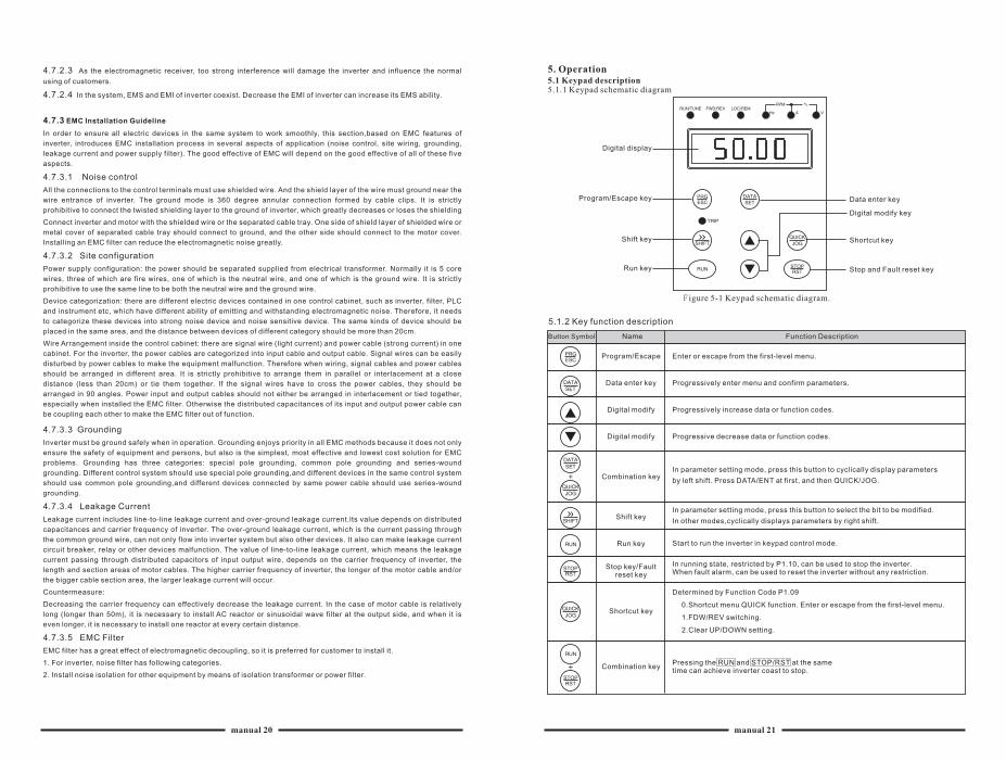
5. Operation5.1 Keypad description5.1.1 Keypad schematic diagram
Digital display
Program/Escape key
Shift key
Run key
Data enter key
Digital modify key
Shortcut key
Stop and Fault reset key
F igure 5-1 Keypad schematic diagram.
5.1.2 Key function description
Button Symbol Name Function Description
Program/Escape
Data enter key
Digital modify
Digital modify
Combination key
Shift key
Run key
Stop key/Fault reset key
Shortcut key
Combination key
Enter or escape from the first-level menu.
Progressively enter menu and confirm parameters.
Progressively increase data or function codes.
Progressive decrease data or function codes.
Start to run the inverter in keypad control mode.
In running state, restricted by P1.10, can be used to stop the inverter. When fault alarm, can be used to reset the inverter without any restriction.
Determined by Function Code P1.09
0.Shortcut menu QUICK function. Enter or escape from the first-level menu.
1.FDW/REV switching.
2.Clear UP/DOWN setting.
Pressing the RUN and STOP/RST at the sametime can achieve inverter coast to stop.
In parameter setting mode, press this button to select the bit to be modified.
In other modes,cyclically displays parameters by right shift.
In parameter setting mode, press this button to cyclically display parameters
by left shift. Press DATA/ENT at first, and then QUICK/JOG.
manual 20 manual 21
5.1.3 Indicator light description
(1)Function Indicator Liqht Description
Indicator Light Name State Indicator
Extinguished: stop state Flickering;parameter auto running state
Light on; running state
Extinguished: forward operation Light on: reverse operation.
Extinguished: keypad control Flickering: terminal control
Light on: communication control
Extinguished: normal operation state
Flickering: overload pre-warning state
(2)Unit Indicator Light Description
Symbol Description
Frequency unit
Current unit
Voltage unit
Rotation speed unit
Percentage
(3)Digital display
5-digit LED, which can display all kinds of monitoring data and alarm codes such as reference frequency, output
frequency and so on.
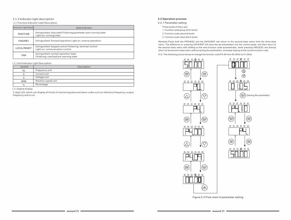
5.2 Operation process
5.2.1 Parameter setting
Three levels of menu are:
1. Function code group (first-level);
2. Function code (second-level);
3. Function code value (third-level).
Remarks:Press both the PRG/ESC and the DATA/ENT can return to the second-class menu from the third-class
menu. The difference is: pressing DATA/ENT will save the set parameters into the control panel, and then return to
the second-class menu with shifting to the next function code automatically; while pressing PRG/ESC will directly
return to the second-class menu without saving the parameters, and keep staying at the current function code.
E.G. The following picture shows to change the function code P4.09 from 00.00Hz to 01.05Hz
(Saving the parameter)
Figure 5-2 Flow chart of parameter setting.
manual 22 manual 23
Under the third-class menu, if the parameter has no flickering bit, it means the function code cannot be modified. The
possible reasons could be:
(1)This function code is not modifiable parameter, such as actual detected parameter, operation records and so on;
(2) This function code is not modifiable in running state, but modifiable in stop state
5.2.2 Fault reset
If the inverter has fault, it will prompt the related fault information. The user can use STOP/RST or according terminals
determined by P3 Group to reset the fault. After fault reset, the inverter is at stand-by state. If the user does not reset the
inverter when it is at fault state, the inverter will be at operation protection state, and can not run.
5.2.3 Parameter copy (save)
See the function description of LCD kepad
5.2.4 Motor parameter autotuning
If "Sensorless Vector Control" mode is chosen, motor nameplate parameters must be input correctly as the autotuning is
based on it. The performance of vector control depends on the parameters of motor strongly. To achieve excellent
performance, firstly must obtain the parameter of motor exactly.
The procedure of motor parameter autotuning is specified as follows:
Firstly, choose the keypad command channel as the operation command channel
And then input following parameters according to the actual motor parameters:
PB.02: motor rated power.
PB.03: motor rated frequency;
PB.04: motor rated speed;
PB.05: motor rated voltage;
PB.06: motor rated current
Note: the motor should be uncoupled with its load, otherwise, the motor parameters obtained
by autotuning may be not correct. Set PB.00 to be 1, and for the detail process of motor
parameter autotuning, please refer to the description of Function Code PB.00. And then press RUN on the keypad panel the inverter will automatically calculate following parameter of the motor:
PB.07: motor stator resistance;
PB.08: motor rotor resistance;
PB.09: motor stator and rotor inductance;
PB.10: motor stator and rotor mutual inductance;
PB.11: motor current without load;Then motor autotuning is finished.
5.2.5 Password setting
HYRIA SL series inverter offers the user's password protection function. When P1.20 is set to be nonzero, it will be the
user's password, and after exiting function code edit mode, it will become effective after 1 minute.
5.3 Running state
5.3.1 Power-on initialization
Firstly the system initializes during the inverter power-on, and LED displays "-----". After the initialization is completed,
the inverter is on stand-by state.
5.3.2 Stand-by
At stop or running state, parameters of multi-state can be displayed. Whether or not to display this parameter can be
chosen through Function Code P1.14 (Running state display selection ) and P1.15 (Stop state display selection)
according to binary bits, the detailed description of each bit please refer the function code description of P1.14 and
P1.15.
In stop state, there are nine parameters which can be chosen to display or not. They are: reference frequency, DC bus
voltage, ON-OFF input state, open collector output state, PID setting, PID feedback, analog input AI1voltage, analog
input AI2 voltage, step number of multi-step speed. Whether or not to display can be decided by setting the
corresponding binary bit of P1.15. Press the /SHIFT to scroll through the parameters in right order . Press DATA/ENT+
QUICK/JOG to scroll through the parameters in left order.
If pressing the FRG/ESC again to try to access the function code edit mode, "0.0.0.0.0"will be displayed, and the
operator must input correct user's password, otherwise will be unable to access it. If it is necessary to cancel the
password protection function, just set P1.20 to be zero.User's password don' t provide protection function to the
parameters of shortcut menu.
5.3.3 Motor parameter autotuning
For details, please refer to the description of PB.00.
5.3.4 Operation
In running state, there are fourteen running parameters: output frequency, reference frequency, DC bus voltage, output
voltage, output current, output torque, PID setting, PID feedback, ON-OFF input state, open collector output state,
voltage of AIl , voltage of AI2 and step number of multi-step speed. Whether or not to display can be decided by the bit
option of Function Code P1.14 (converted into binary system). Press the >>/SHIFT to scroll through the parameters in
right order . PressDATA/ENT+QUICK JOG to scroll through the parameters in left order.
5.3.5 Fault
HYRIA SL se r i es i nve r te r o f f e r s a va r i e t y o f f au l t i n fo rma t i on . P lease re fe r t o t he i nve r te r f au l t s and the i r
t r oub leshoo t i ng f o r de ta i l ed i n fo rma t i on .
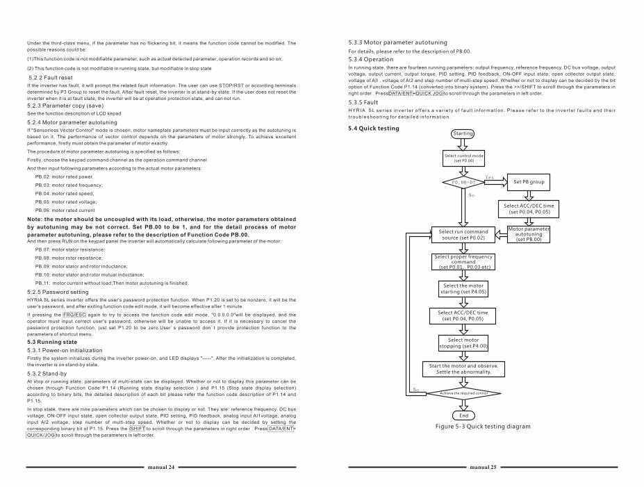
5.4 Quick testingStarting
Select control mode
(set P0.00)
Set PB group
Select ACC/DEC time
(set P0.04, P0.05)
Select run command
source (set P0.02)
Motor parameter autotuning (set PB.00)
Select proper frequency command
(set P0.01,P0.03 etc)
Select the motor
starting (set P4.05)
Select ACC/DEC time
(set P0.04, P0.05)
Select motor
stopping (set P4.00)
Start the motor and observe.
Settle the abnormality.
Achieve the required control
End
Figure 5-3 Quick testing diagram
manual 24 manual 25
6.Abbreviation of Function Parameters
The function parameters of SL series inverters have been divided into 12 groups (P0~PB) according to the
function. Each function group contains certain function codes applying 3-class menus. For example, "P8.08" means the
eighth function code in the P8 group function, and all reservation variable are factory reserved, and users are forbidden
to access these parameters.
For the convenience of function codes setting, the function group number corresponds to the first class menu, the
function code corresponds to the second class menu and the function code corresponds to the third class menu.
1. Below is the instruction of the function lists:
The first line "Function code": codes of function parameter group and parameters;
The second line "Name": full name of function parameters;
The third line "Detailed illustration of parameters": Detailed illustration of the function parameters;
The fourth line "Range Setting": Effective Range Setting of function parameter that shows in keypad LCD display;
The fifth line "Factory Setting": the original factory set value of the function parameter;
The sixth line "Modify": the modifying character of function codes (the parameters can be modified or not and the
modifying conditions), below is the instruction:
"O": means the set value of the parameter can be modified on stop and running state ;
"◎": means the set value of the parameter can not be modified on the running state;
"●": means the value of the parameter is the real detection value which can not be modified.
(The inverter has limited the automatic inspection of the modifying character of the parameters to help users avoid
mismodifying)
The seventh line "No.": The serial number of function code, at the same time, it also means the register address
during communication.
2."Parameter radix" is decimal (DEC), if the parameter is expressed by hex, then the parameter is separated from each
other when editing. The setting range of certain bits are 0~F (hex).
3.Factory setting" means the function parameter will restore to the default value during default parameters restoring.
But the detected parameter or recorded value won't be restored.
4.For a better parameter protection, the inverter provides password protection to the parameters. After setting the
password (set P1.20 to any non-zero number), the system will come into the state of password verification firstly after
the user press PRG/ESC to come into the function code editing state. And then "0.0.0.0.0." will be displayed. Unless the
user input right password, they cannot enter into the system. For the factory setting parameter zone, it needs correct
factory password (remind that the users can not modify the factory parameters by themselves, otherwise, if the
parameter setting is incorrect, damage to the inverter may occur).
If the password protection is unlocked, the user can modify the password freely and the inverter will work as the last
setting one. When P1.20 is set to 0, the password can be canceled. If P1.20 is not 0 during powering on, then the
parameter is protected by the password.
5.When modify the parameters by serial communication, the function of the password follows the above rules, too.
HYRIA
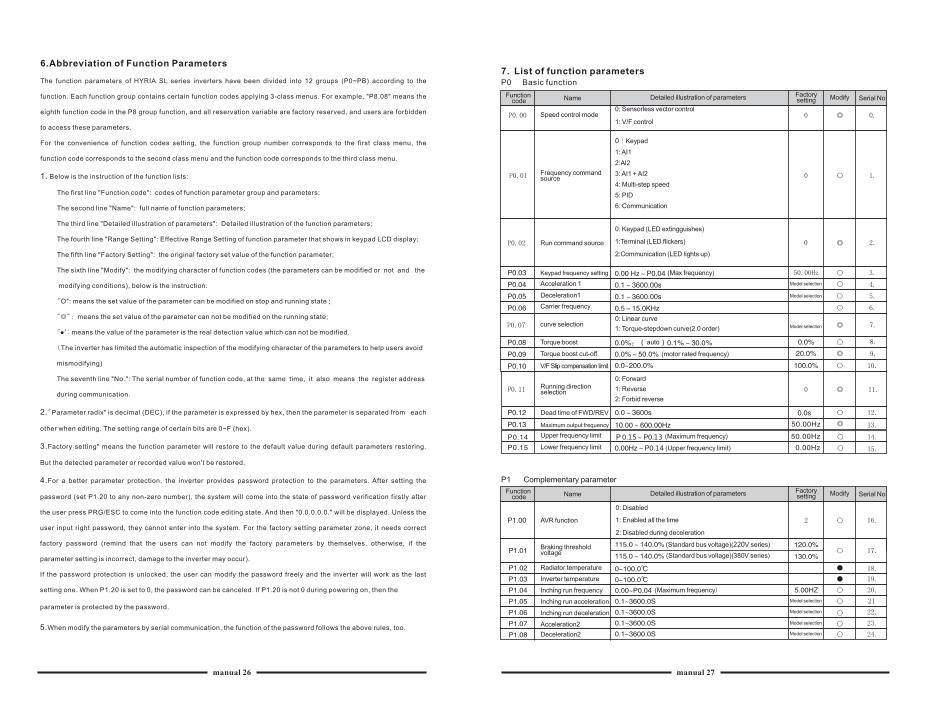
7. List of function parametersP0 Basic function
Function code Name Detailed illustration of parameters Factory
setting Modify Serial No
Speed control mode0: Sensorless vector control
1: V/F control
Frequency command source
Run command source
0: Keypad (LED extingguishes)
1:Terminal (LED flickers)
2:Communication (LED lights up)
Keypad frequency setting (Max frequency)
Acceleration 1
Deceleration1
Carrier frequency
curve selection0: Linear curve
1: Torque-stepdown curve(2.0 order)
Torque boost
Torque boost cut-off (motor rated frequency)
V/F Slip compensation limit
Running direction selection
0: Forward
1: Reverse
2: Forbid reverse
Dead time of FWD/REV
Maximum output frequency
Upper frequency limit (Maximum frequency)
Lower frequency limit (Upper frequency limit)
P1 Complementary parameter
AVR function
Braking threshold voltage
Radiator temperature
Inverter temperature
Inching run frequency
Inching run acceleration
Inching run deceleration
Acceleration2
Deceleration2
0: Disabled
1: Enabled all the time
2: Disabled during deceleration
(Standard bus voltage)(220V series)
(Standard bus voltage)(380V series)
(Maximum frequency)
Model selection
Model selection
Model selection
Model selection
Model selection
Model selection
Model selection
Function code Name Detailed illustration of parameters Factory
setting Modify Serial No
manual 26 manual 27
0:Keypad
1: AI1
2:AI2
3: AI1 + AI2
4: Multi-step speed
5: PID
6: Communication
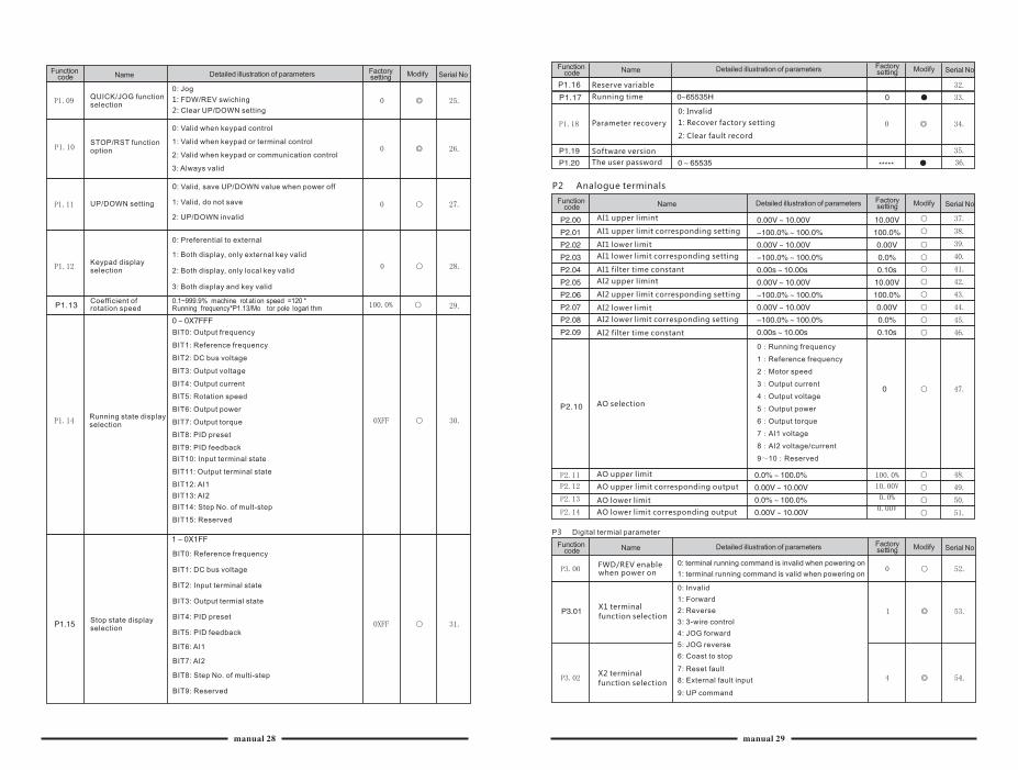
QUICK/JOG function selection
STOP/RST function option
UP/DOWN setting
Keypad display selection
Coefficient of rotation speed
Running state display selection
Stop state display selection
0: Jog
1: FDW/REV swiching
2: Clear UP/DOWN setting
0: Valid when keypad control
1: Valid when keypad or terminal control
2: Valid when keypad or communication control
3: Always valid
0: Valid, save UP/DOWN value when power off
1: Valid, do not save
2: UP/DOWN invalid
0: Preferential to external
1: Both display, only external key valid
2: Both display, only local key valid
3: Both display and key valid
BIT0: Output frequency
BIT1: Reference frequency
BIT2: DC bus voltage
BIT3: Output voltage
BIT4: Output current
BIT5: Rotation speed
BIT6: Output power
BIT7: Output torque
BIT8: PID preset
BIT9: PID feedback
BIT10: Input terminal state
BIT11: Output terminal state
BIT12: AI1
BIT13: AI2
BIT14: Step No. of mult-step
BIT15: Reserved
BIT0: Reference frequency
BIT1: DC bus voltage
BIT2: Input terminal state
BIT3: Output termial state
BIT4: PID preset
BIT5: PID feedback
BIT6: AI1
BIT7: AI2
BIT8: Step No. of multi-step
BIT9: Reserved
Function code Name Detailed illustration of parameters Factory
setting Modify Serial No
0.1~999.9%Running frequency*P1.13/Mo tor pole logari thm
machine rot ati on speed =120 *
Function code Name Detailed illustration of parameters Factory
setting Modify Serial No
Reserve variable
Running time
Parameter recovery
Software version
The user password
0: Invalid
1: Recover factory setting
2: Clear fault record
P2 Analogue terminals
AI1 upper limint
AI1 upper limit corresponding setting
AI1 lower limit
AI1 lower limit corresponding setting
AI1 filter time constant
AI2 upper limint
AI2 upper limit corresponding setting
AI2 lower limit
AI2 lower limit corresponding setting
AI2 filter time constant
AO selection
AO upper limit
AO upper limit corresponding output
AO lower limit
AO lower limit corresponding output
0:Running frequency
1:Reference frequency
2:Motor speed
3:Output current
4:Output voltage
5:Output power
6:Output torque
7:AI1 voltage
8:AI2 voltage/current
9~10:Reserved
P3 Digital termial parameter
FWD/REV enable when power on
0: Invalid
1: Forward
2: Reverse
3: 3-wire control
4: JOG forward
5: JOG reverse
6: Coast to stop
7: Reset fault
8: External fault input
9: UP command
Function code Name Detailed illustration of parameters Factory
setting Modify Serial No
Function code Name Detailed illustration of parameters Factory
setting Modify Serial No
0: terminal running command is invalid when powering on
1: terminal running command is valid when powering on
X1 terminal
function selection
X2 terminal
function selection
manual 28 manual 29
X3 terminal function
X4 terminal function
X5 terminal function
X6 terminal function
10:Down command
11:Clear UP/DOWN
12:Multi-step speed reference1
13:Multi-step speed reference2
14:Multi-step speed reference3
15:ACC/DEC time selection
16:Pause PID
17:Pause traverse operation
18:Reset traverse operation
19:ACC/DEC ramp hold
20:Disable torque control
21:UP/DOWN invalid temporarily
22~25:reserved
ON/OFF filter times
FWD/REV control mode
UP/DOWN setting change rate
Y1 output selection
Y2 output selection
Relay output selection
FDT level
FDT lag
Frequency arrival detecting range
0:2-wire control mode 1
1:2wire control mode 2
2:3-wire control mode 1
3:3wire control mode 2
0:No output
1:Run forward
2:Run reverse
3:Fault output
4:FDT reached
5:Frequency reached
6:Zero speed running
7:Upper frequency limit reached
8:Lower frequency limit reached
9~10:Reserved
(maximum frequency)
(FDTD level)
(Maximum frequency)
P4 Start/Stop parameter
Stop mode
Waiting time before DC braking
DC braking time
Stop braking time
Starting frequency of DC braking
Start mode
Hold time of starting frequencyDC Braking time before startDC Braking current before start
Starting frequency
0:Deceleration to stop
1 Coast to stop:
0:Start directly
1 DC braking and start:
2 Rotation speed tracking restart above 5KW:
(Maximum frequency)
Function code Name Detailed illustration of parameters Factory
setting Modify Serial No
Function code Name Detailed illustration of parameters Factory
setting Modify Serial No
Skip frequency
Skip frequency bandwidth
(Maximum frequency)
(Maximum frequency)
Function code Name Detailed illustration of parameters Factory
setting Modify Serial No
P5 Traverse parameters
Function code Name Detailed illustration of parameters Factory
setting Modify Serial No
Jitter frequency
Traverse amplitude
Rise time of traverse
Fall time of traverse
(Relative frequency amplitude)
(Relative reference frequency)
Over-voltage stall protection
0:Disabled
1 Enabled:
Over-voltage stall protection point
(380V series)
(220V series)
Motor overload protection
0:Disabled
1 Normal motor:
2 Variable frequency motor:
Motor overload protection current
(motor rated current)
Auto current limiting threshold
P model:120%G model160%
Frequency decrease rate when current limiting
Threshold of trip-free (standard bus voltage)
(Maximum frequency)Decrease rate of trip-free
0:No fualt
1 IGBT PH-U fault (OUT 1):
2 IGBT PH-V fault (OUT 2):
3 IGBT PH-W fault (OUT 3):
4 Over-current when acceleration (OC1):
5 Over-current when deceleration (OC2):
6 Over-current when constant speed running (OV3):
7 Over-voltage when acceleration( OV1):
8 Over-voltage when deceleration( OV2):
9 Over-voltage when constant speed running ( OV3):
10 DC bus Under-voltage (UV):
11 Motor overload (OL1):
12 Inverter overload (OL2):
13 Input phase failure (SPI):
14 Output phase failure( SPO):
15 Retify overheat (OH1):
16 IGBT overheat (OH2):
17 External fault (EF):
18 Communication fault ( CE):
19 Current detection fault (ITE):
20 Autotuning fault (TE):
Previous two
fault types
Function code Name Detailed illustration of parameters Factory
setting Modify Serial No
P6 Protection function parameter
Previous fault types
manual 30 manual 31
P3.03
P3.04
P3.05
P3.06
P3.07
P3.08
P3.09
P3.10
P3.11
P3.12
P3.13
P3.14
P3.15
P4.00
P4.01
P4.02
P4.03
P4.04
P4.05
P4.06
P4.07
P4.08
P4.09
Current fault type
21:EEPROM fault (EEP)
22 PID feedback fault (PIDE):
23 Braking unit fault (bCE) :
24 Reserved :
Output frequency at current faultOutput current at current faultDC bus voltage at current faultInput terminal state at current faultOutput terminal state at current faultFault auto reset inverval time setting
Fault auto reset times
Function code Name Detailed illustration of parameters Factory
setting Modify Serial No
P7 PID control
Function code Name Detailed illustration of parameters Factory
setting Modify Serial No
PID feedback source selection
0:AI1
1:AI2
2:AI1+AI2
3:Communication
PID preset source selection
0:Keypad
1:AI1
2:AI2
3:Communication
4:Multi-step
Keypad PID preset
PID output characteristic
Proportional gain (Kp)
Integral time (Ti)
Differential time( Td)
Sampling cycle
Bias limit
Feedback lost detecting value
Feedback lost detecting time
P8 Multi-step Speed Control
Multi-step speed 0
Multi-step speed 1
Multi-step speed 2
Multi-step speed 3
Multi-step speed 4
Multi-step speed 5
Multi-step speed 6
Multi-step speed 7
Function code Name Detailed illustration of parameters Factory
setting Modify Serial No
0:Positive
1 Negative:
(P7.02)
P9 485Communication parameterFunction
code Name Detailed illustration of parameters Factory setting Modify Serial No
Local address 1~247,0Broadcast address
Baud rate selection
Data format
0: RTU, 1 start bit, 8 data bits, no parity check, 1 stop bit
1: RTU, 1 start bit, 8 data bits, even parity check, 1 stop bit
2: RTU, 1 start bit, 8 data bits, odd parity check, 1 stop bit
3: RTU, 1 start bit, 8 data bits, no parity check, 2 stop bits
4: RTU, 1 start bit, 8 data bits, even parity check, 2 stop bits
5: RTU, 1 start bit, 8 data bits, odd parity check, 2 stop bits
6: ASCII, 1 start bit, 7 data bits, no parity check, 1 stop bit
7: ASCII, 1 start bit, 7 data bits, even parity check, 1 stop bit
8: ASCII, 1 start bit, 7 data bits, odd parity check, 1 stop bit
9: ASCII, 1 start bit, 7 data bits, no parity check, 2 stop bits
10: ASCII, 1 start bit, 7 data bits, even parity check, 2 stop bits
11: ASCII, 1 start bit, 7 data bits, odd parity check, 2 stop bits
12: ASCII, 1 start bit, 8 data bits, no parity check, 1 stop bit
13: ASCII, 1 start bit, 8 data bits, even parity check, 1 stop bit
14: ASCII, 1 start bit, 8 data bits, odd parity check, 1 stop bit
15: ASCII, 1 start bit, 8 data bits, no parity check, 2 stop bits
16: ASCII, 1 start bit, 8 data bits, even arity check, 2 stop bits
17: ASCII, 1 start bit, 8 data bits, odd parity check, 2 stop bits
Communication delay time
Communication timeout delay Disabled
Communication error action
Response action0:Response to writing
1:No response to writing
PA vector control
ASR proportional gain Kp1
ASR integral time Ki1
ASR switching point1
ASR proportional gain Kp2
ASR integral time Kp2
ASR integral time Ki2
Slip compensation rate of VC
Torque limit
Function code Name Detailed illustration of parameters Factory
setting Modify Serial No
Maximum frequency)(
Inverter rated current)(
0:Alarm and coast to stop
1:No alarm and continue to run
2:No alarm but stop according to P4.00
3:No alarm but stop according to P4.00
Motor parameters autotuning
0:No action
1:Rotation autotuning
2:Static autotuning
PB Motor parameter
Function code Name Detailed illustration of parameters Factory
setting Modify Serial No
manual 32 manual 33
E/P option
Motor rated power
Motor rated frequency
Motor rated speed
Motor rated voltage
Motor rated current
Motor stator resistance
Motor rator resistance
Motor leakage inductance
Motor mutual inductance
Current without load
0:E model
0:P model
(Maximum frequency)
Model selection
Model selection
Model selection
Model selection
Model selection
Model selection
Model selection
Model selection
Model selection
Model selection
Function code Name Detailed illustration of parameters Factory setting Modify Serial No
8 Detailed function description P0 group
Function code Name Description Setting range Factory setting
Speed control mode0:Sensorless vector control
1 V/F control:
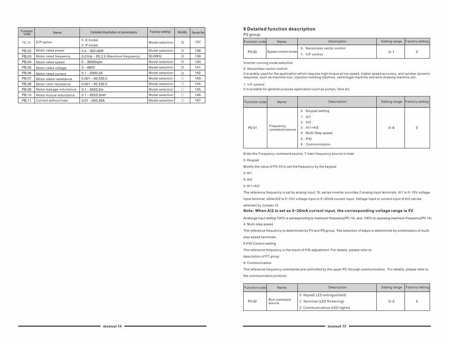
Inverter running mode selection
0: Sensorless vector control:
It is widely used for the application which requires high torque at low speed, higher speed accuracy, and quicker dynamic response, such as machine tool, injection molding machine, centrifugal machine and wire-drawing machine,etc.
1: V/F control:
It is suitable for general purpose application such as pumps, fans etc.
Function code Name Description Setting range Factory setting
Frequency command source
0:Keypad setting
1:AI1
2:AI2
3:AI1+AI2
4:Multi-Step speed
5:PID
6:Communication
Enter the Frequency command source, 7 main frequency source in total
0: Keypad
Modify the value of P0.03 to set the frequency by the keypad
0: AI1
0: AI2
0: AI1+AI2
The reference frequency is set by analog input. SL series inverter provides 2 analog input terminals. AI1 is 0~10V voltage
input terminal, while AI2 is 0~10V voltage input or 0~20mA current input. Voltage input or current input of AI2 can be
selected by Jumper J3.
Note: When AI2 is set as 0~20mA current input, the corresponding voltage range is 5V.
Analouge input setting 100% is corresponding to maximum frequency(P0.14), and -100% to opposing maximum frequency(P0.14)
4: Multi-step speed
The reference frequency is determined by P3 and P8 group. The selection of steps is determined by combination of multi-
step speed terminals.
5:PID Control setting
The reference frequency is the result of PID adjustment. For details, please refer to
description of P7 group
6: Communication
The reference frequency commands are controlled by the upper PC through communication. For details, please refer to
the communication protocol
Function code Name Description Setting range Factory setting
Run command source
0:Kepad( LED extinguished)
1:Terminal (LED flickering)
2:Communication (LED lights)
manual 34 manual 35
Function code Name Description Setting range Factory setting
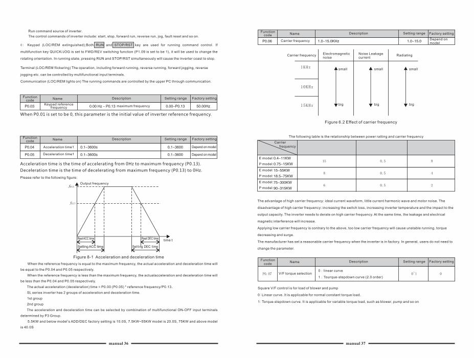
Carrier frequency Depend on model
Carrier frequency Electromagnetic noise
Noise Leakage current
Radiating
big
small small
big
small
big
Figure 6.2 Effect of carrier frequency
The following table is the relationship between power ratting and carrier frequency
P model:
E model:
E model:
P model:
E model:
P model:
The advantage of high carrier frequency: ideal current waveform, little current harmonic wave and motor noise. The
disadvantage of high carrier frequency: increasing the switch loss, increasing inverter temperature and the impact to the
output capacity. The inverter needs to derate on high carrier frequency. At the same time, the leakage and electrical
magnetic interference will increase.
Applying low carrier frequency is contrary to the above, too low carrier frequency will cause unstable running, torque
decreasing and surge.
The manufacturer has set a reasonable carrier frequency when the inverter is in factory. In general, users do not need to
change the parameter.
V/F torque selection0:linear curve
1:Tourque-stepdown curve (2.0 order)
Function code
Name Description Setting range Factory setting
Square V/F control is for load of blower and pump
0:Linear curve. It is applicable for normal constant torque load.
1:Torque-stepdown curve. It is applicable for variable torque load, such as blower, pump and so on
Carrier frequency
Run command source of inverter.
The control commands of inverter include: start, stop, forward run, reverse run, jog, fault reset and so on.
0: Keypad (LOC/REM extinguished);Both RUN and STOP/RST key are used for running command control. If
multifunction key QUICK/JOG is set to FWD/REV switching function (P1.09 is set to be 1), it will be used to change the
rotating orientation. In running state, pressing RUN and STOP/RST simultaneously will cause the inverter coast to stop.
Terminal (LOC/REM flickering) The operation, including forward running, reverse running, forward jogging, reverse
jogging etc. can be controlled by multifunctional input terminals.
Communication (LOC/REM lights on) The running commands are controlled by the upper PC through communication.
Name Description Setting range Factory settingFunction code
Name Description Setting range Factory settingFunction code
Keypad reference frequency maximum frequency
When P0.01 is set to be 0, this parameter is the initial value of inverter reference frequency.
Acceleration time1
Deceleration time1
Depend on model
Depend on model
Acceleration time is the time of accelerating from 0Hz to maximum frequency (P0.13).
Deceleration time is the time of decelerating from maximum frequency (P0.13) to 0Hz.
Please refer to the following figure:
Output frequency
Real ACC time
Setting ACC time
Real DEC time time t
Set ting DEC time
Figure 8-1 Acceleration and deceleration time
When the reference frequency is equal to the maximum frequency, the actual acceleration and deceleration time will
be equal to the P0.04 and P0.05 respectively.
When the reference frequency is less than the maximum frequency, the actualacceleration and deceleration time will
be less than the P0.04 and P0.05 respectively.
The actual acceleration (deceleration) time = P0.00 (P0.05) * reference frequency/P0.13.
SL series inverter has 2 groups of acceleration and deceleration time.
1st group
2nd group
The acceleration and deceleration time can be selected by combination of multifunctional ON-OFF input terminals
determined by P3 Group.
5.5KW and below model’s ADD/DEC factory setting is 10.0S, 7.5KW~55KW model is 20.0S, 75KW and above model
is 40.0S
manual 36 manual 37
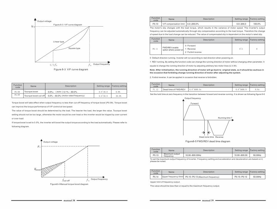
Output voltage
Linear type
Square type
Output frequency
Figure 8-3 V/F curve diagram
Figure 8-3 V/F curve diagram
Factory settingDescription Setting rangeFunction code
Name
Tourque boost
Tourque boost cut-off (motor rated frequency)
Torque boost will take effect when output frequency is less than cut-off frequency of torque boost (P0.09). Torque boost
can improve the torque performance of V/F control at low speed.
The value of torque boost should be determined by the load. The heavier the load, the larger the value. Tourque boost
setting should not be too large, otherwise the motor would be over-heat or the inverter would be tripped by over-current
or over-load.
If torque boost is set to 0.0%, the inverter will boost the output torque according to the load automatically. Please refer to
following diagram.
Output voltage
boost
cut-offOutput frequency
Figure8-4 Manual torque boost diagram
Factory settingDescription Setting rangeFunction code
Name
V/F compensation limit
The motor's slip changes with the load torque, which results in the variance of motor speed. The inverter's output
frequency can be adjusted automatically through slip compensation according to the load torque. Therefore the change
of speed due to the load change can be reduced. The value of compensated slip is dependent on the motor's rated slip.
Factory settingDescription Setting rangeFunction code
Name
FWD/REV enable option whenc power on
0:Forward
1:Reverse
2:Forbid reverse
0:Default direction running. Inverter will run according to real direction when powering on.
1:REV running. By setting the function code can change the running direction of motor without changing other parameter. It
equals to change the running direction of motor by adjusting arbitrary two motor lines (U,V,W).
Note: After initialization, the running direction of motor will go back to original state, so it should be cautious in
the occasion that forbiding change running direction of motor after adjusting the system.
2. Forbid reverse. It can be applied in occasion that reverse is forbidden.
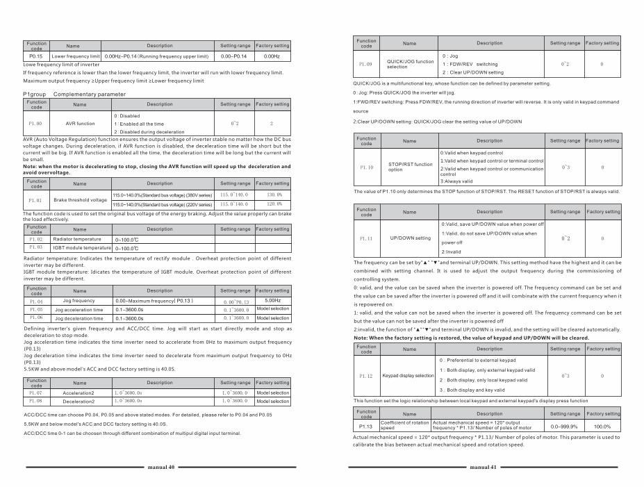
Factory settingDescription Setting rangeFunction code
Name
Dead time of FWD/REV
Set the hold time at zero frequency in the transition between forward and reverse running. It is shown as following figure 6-6
Output frequency
Forward
Running time T
Dead zone time Reverse
Figure8-5 FWD/REV dead time diagram
Factory settingDescription Setting rangeFunction code
Name
Maximum output frequency
To set the maximum output frequency of inverter. Frequency setting and acceleration and deceleration are based on it, please be noted.
Factory settingDescription Setting rangeFunction code
Name
Upper frequency lilmit (Maximum frequency)
Upper limit of frequency output.
The value should be less than or equal to the maximum frequency output.
manual 38 manual 39
Factory settingDescription Setting rangeFunction code
Name
Lower frequency limit (Running frequency upper limit)
Lowe frequency limit of inverter
If frequency reference is lower than the lower frequency limit, the inverter will run with lower frequency limit.
Maximum output frequency ≥Upper frequency limit ≥Lower frequency limit
P1group Complementary parameter
Factory settingDescription Setting rangeFunction code
Name
AVR function
0:Disabled
1:Enabled all the time
2:Disabled during deceleration
AVR (Auto Voltage Regulation) function ensures the output voltage of inverter stable no matter how the DC bus
voltage changes. During deceleration, if AVR function is disabled, the deceleration time will be short but the
current will be big. If AVR function is enabled all the time, the deceleration time will be long but the current will
be small.
Note: when the motor is decelerating to stop, closing the AVR function will speed up the deceleration and
avoid overvoltage.
Factory settingDescription Setting rangeFunction code
Name
Brake threshold voltage115.0~140.0%(Standard bus voltage) (380V series)
115.0~140.0%(Standard bus voltage) (220V series)
The function code is used to set the original bus voltage of the energy braking. Adjust the value properly can brakethe load effectively.
Factory settingDescription Setting rangeFunction code
Name
Radiator temperature
IGBT module temperature
Radiator temperature: Indicates the temperature of rectify module . Overheat protection point of different
inverter may be different.
IGBT module temperature: Idicates the temperature of IGBT module. Overheat protection point of different
inverter may be different.
Factory settingDescription Setting rangeFunction code
Name
Jog frequency Maximum frequency
Jog acceleration time
Jog deceleration time
Model selection
Model selection
Defining inverter's given frequency and ACC/DCC time. Jog will start as start directly mode and stop as
deceleration to stop mode.
Jog acceleration time indicates the time inverter need to accelerate from 0Hz to maximum output frequency
(P0.13)
Jog deceleration time indicates the time inverter need to decelerate from maximum output frequency to 0Hz
(P0.13)
5.5KW and above model's ACC and DCC factory setting is 40.0S.
Factory settingDescription Setting rangeFunction code
Name
Acceleration2
Deceleration2
Model selection
Model selection
ACC/DCC time can choose P0.04, P0.05 and above stated modes. For detailed, please refer to P0.04 and P0.05
5.5KW and below model's ACC and DCC factory setting is 40.0S.
ACC/DCC time 0-1 can be choosen through different combination of multipul digital input terminal.
Factory settingDescription Setting rangeFunction code
Name
QUICK/JOG function selection
0:Jog
1:FDW/REV switching
2:Clear UP/DOWN setting
QUICK/JOG is a multifunctional key, whose function can be defined by parameter setting.
0:Jog: Press QUICK/JOG the inverter will jog.
1:FWD/REV switching: Press FDW/REV, the running direction of inverter will reverse. It is only valid in keypad command
source
2:Clear UP/DOWN setting: QUICK/JOG clear the setting value of UP/DOWN
Factory settingDescription Setting rangeFunction code
Name
STOP/RST function option
0:Valid when keypad control
1:Valid when keypad control or terminal control
2:Valid when keypad control or communication control
3:Always valid
The value of P1.10 only determines the STOP function of STOP/RST. The RESET function of STOP/RST is always valid.
Factory settingDescription Setting rangeFunction code
Name
UP/DOWN setting
0:Valid, save UP/DOWN value when power off
1:Valid, do not save UP/DOWN value when
power off
2:Invalid
The frequency can be set by"▲" "▼"and terminal UP/DOWN. This setting method have the highest and it can be
combined with setting channel. It is used to adjust the output frequency during the commissioning of
controlling system.
0: valid, and the value can be saved when the inverter is powered off. The frequency command can be set and
the value can be saved after the inverter is powered off and it will combinate with the current frequency when it
is repowered on.
1: valid, and the value can not be saved when the inverter is powered off. The frequency command can be set
but the value can not be saved after the inverter is powered off
2:invalid, the function of "▲""▼"and terminal UP/DOWN is invalid, and the setting will be cleared automatically.
Note: When the factory setting is restored, the value of keypad and UP/DOWN will be cleared.
Factory settingDescription Setting rangeFunction code
Name
Keypad display selection
0:Preferential to external keypad
1:Both display, only external keypad valid
2:Both display, only local keypad valid
3:Both display and key valid
This function set the logic relationship between local keypad and external keypad's display press function
Factory settingDescription Setting rangeFunction code
Name
Coefficient of rotation speed
Actual mechanical speed = 120* output frequency * P1.13/ Number of poles of motor
Actual mechanical speed = 120* output frequency * P1.13/ Number of poles of motor. This parameter is used to
calibrate the bias between actual mechanical speed and rotation speed.
manual 40 manual 41
Factory settingDescription Setting rangeFunction code
Name
Running state display selection
P1.14 defines the parameters that can be displayed by LED in running state. If Bit is l , the parameter will be displayed.
Press >>/SHIFT to scroll through these parameters . If Bit is 0, the parameter will not be displayed;
The display content corresponding to each bit of P1.14 is described in the following table:
Output Output Output Output
Torque Power
Running
Rotation speed Current Voltage Voltage
DC bus Reference
Frequency Frequency
The display content corresponding to each bit of P1.14 is described in the following table:
Reserved Step No. of multi-step Output terminal state
Input terminal state PID feedback PID preset
The input/output terminal state is displayed by decimal. X1(Y) corresponds to the lowest bit. For example: if the input
terminal is displayed to 3, terminals Xl and X2 are switched on and other terminals are switched off. Please refer to
PD1.14 and P1.15 for detailed information.
Factory settingDescription Setting rangeFunction code
Name
The setting of this function code is the same as that of P1.14. When SL series inverters are in the stopping state, the
displaying of the parameter is determined by the function code.
The display content corresponding to each bit of P1.15 is described in the following table:
PID feedback PID preseOutput terminal state
Input terminal state DC busFrequency reference
The display content corresponding to each bit of P1.15 is described in the following table:
Reserved Reserved Reserved Reserved Reserved Reserved ReservedStep No. of multi-step
Factory settingDescription Setting rangeFunction code
Name
Reserved variable Factory parameter
Factory settingDescription Setting rangeFunction code
Name
Running time
Factory settingDescription Setting rangeFunction code
Name
Restore function parameter restore
0:No action
1:Restore Factory setting
2:Clear fault record
1: Restore all parameters fo factory setting
2: Clear recent fault records
The function code restore to 0 after finish the operation of selected fuction
Software version
Software version: software version No
Factory settingDescription Setting rangeFunction code
Name
The user password
Factory settingDescription Setting rangeFunction code
Name
Running time: display the accumulative running time of inverter by present.
Stop state display selection
The password protection function will be valid when set to be any nonzero data.
00000: WhenP1.20 is set to be 00000, the user's password set before will be cleared and the password
protection function will be disabled.
After the password has been set and becomes valid, the user can not access menu if the user's password is not
correct. Only when a correct the user's password is input, the user can see and modify the parameters. Please
keep the user's password in mind.
The password will be valid in l minute after retreat the function code edition state. Press PRG/ESC to enter into
the function code edition state after the password takes effect, "0.0.0.0.0." will be displayed. The operator
should input correct password.
P2 group Analouge terminal parameter
Factory settingDescription Setting rangeFunction code
Name
AI1 upper limit
AI1 upper limit corresponding setting
AI1 lower limit
AI1 lower limit corresponding setting
AI1 filter time constant
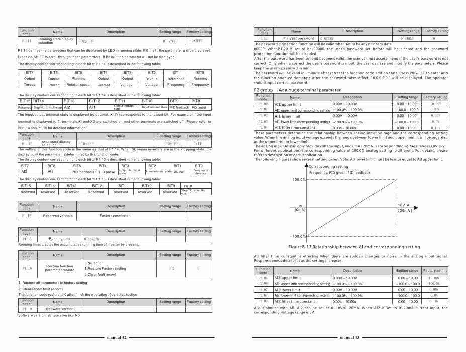
These parameters determine the relationship between analog input voltage and the corresponding setting
value. When the analog input voltage exceeds the range between lower limit and upper limit, it will be regarded
as the upper limit or lower limit.
The analog input AIl can only provide voltage input, and 0mA~20mA 's corresponding voltage range is 0V~5V.
For different applications, the corresponding value of 100.0% analog setting is different. For details, please
refer to description of each application.
The following figures show several setting cases. Note: AIl lower limit must be less or equal to AIl upper limit.
Corresponding setting
Frequency, PID given, PID feedback
Figure8-13 Relationship between AI and corresponding setting
AIl filter time constant is effective when there are sudden changes or noise in the analog input signal.
Responsiveness decreases as the setting increases.
Factory settingDescription Setting rangeFunction code
Name
AI2 upper limit
AI2 upper limit corresponding setting
AI2 lower limit
AI2 lower limit corresponding setting
AI2 filter time constant
AI2 is similar with AIl. AI2 can be set as 0~10V/0~20mA. When AI2 is set to 0~20mA current input, the
corresponding voltage range is 5V.
Running
manual 42 manual 43
Factory settingDescription Setting rangeFunction code
Name
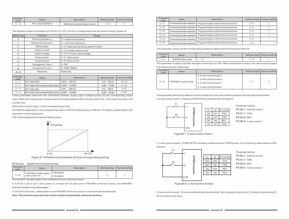
A01 output selection Multifunctional analogue output
The standard output of analogue is 0~20 mA or 0~10V. Current or voltage output can be chosen through Jumper J4:
Setting value Function Range
Running frequency 0~ maximum frequency
Reference frequency
Motor speed 0~2* rated synchoronous speed of motor
0~ maximum frequency
Output current 0~2* inverter rated current
Output voltage 0~1.5* inverter rated voltage
Output power 0~2* rated power
Output torque 0~2* rated current
Analogue AI1 input
Analogue AI2 input
Reserved Reserved
Factory settingDescription Setting rangeFunction code
Name
AO1 upper limit
AO1 upper limit corresponding output
AO1 lower limit
AO1 lower limit corresponding output
These parameters determine the relationship between analog output voltage/current and the corresponding output
value. When the analog output value exceeds the range between lower limit and upper limit, it will output the upper limit
or lower limit.
When AO is current output, 1 mA is corresponding to 0.5V.
For different applications, the corresponding value of 100.0% analog output is different. For details, please refer to the
description of each application.
The following figures show several setting cases:
Figure 8-14 Relationship between AO and corresponding setting.
P3 Group Digital terminal parameter
FWD/REV enable option when power on
0:Disabled
1:Enabled
Factory settingDescription Setting rangeFunction code
Name
This function only takes effect if run command source is terminal control.
0: If P3.00 is set to be 0, when power on, inverter will not start even if FWD/REV terminal is active, until FWD/REV
terminal disabled and enabled again.
1: If P3.00 is set to be 1, when power on and FWD/REV terminal is active, inverter will start automatically.
Note: This function may cause the inverter restart automatically, please be cautious.
X1 terminal function selection
X2 terminal function selection
X3 terminal function selection
X4 terminal function selection
X5 terminal function selection
X6 terminal function selection
Programmable multifunctional terminal
Programmable multifunctional terminal
Programmable multifunctional terminal
Programmable multifunctional terminal
Programmable multifunctional terminal
Programmable multifunctional terminal
Factory settingDescription Setting rangeFunction code
Name
The parameter used to set the corresponding problem of digital multifunctional input terminal
Factory settingDescription Setting rangeFunction code
Name
ON/OFF filter times
This parameter is used to set filter strength of terminals (X1~X6). When interference is heavy, the user should increase
this value to prevent malfunction.
Factory settingDescription Setting rangeFunction code
Name
FWD/REV control mode
0: 2-wire control mode 1
1: 2-wire control mode 2
2: 3-wire control mode 1
3: 3-wire control mode 2
This parameter defines four different control modes that control the inverter operation through external terminals.
0: 2-wire control mode 1: Integrate START/STOP command with run direction.
Run command
Stop
FWD
REV
Stop
Parameter setting:
external control
FWD
REV
2-wire control 1
Figure8-7 2-wire control mode1
1: 2-wire control mode 2: START/STOP command is determined by FWD terminal. Run direction is determined by REV
terminal.
Run command
Stop
FWD
REV
Stop
Parameter setting:
external control
FWD
REV
2-wire control 21
Figure8-8 2-wire control mode2
HY
RIA
Inv
erte
r
2:3-wire control mode1: X4 is the multifunctional input terminal. Run command is given by X1, direction command by X2.
X4 is normally close input.
manual 44 manual 45
HY
RIA
Inv
erte
r
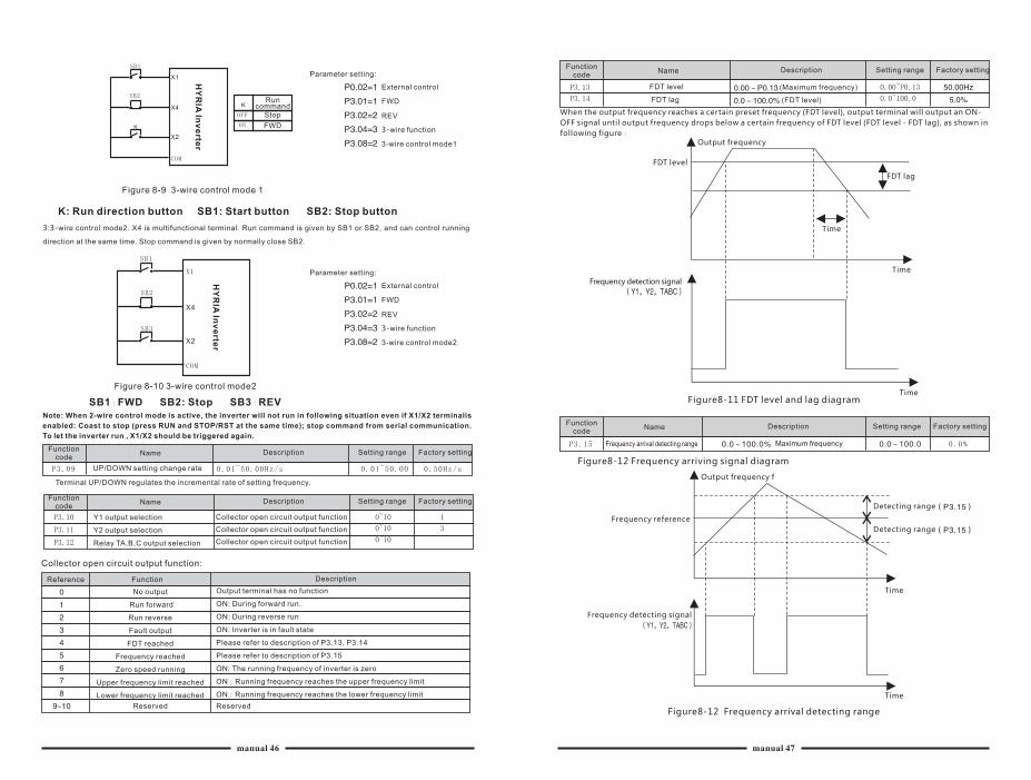
Run command
Stop
FWD
Parameter setting:
External control
FWD
REV
3-wire function
3-wire control mode1
Figure 8-9 3-wire control mode 1
K: Run direction button SB1: Start button SB2: Stop button
3:3-wire control mode2. X4 is multifunctional terminal. Run command is given by SB1 or SB2, and can control running
direction at the same time. Stop command is given by normally close SB2.
Parameter setting:
External control
FWD
REV
3-wire function
3-wire control mode2
SB1:FWD SB2: Stop SB3:REVNote: When 2-wire control mode is active, the inverter will not run in following situation even if X1/X2 terminalis
enabled: Coast to stop (press RUN and STOP/RST at the same time); stop command from serial communication.
To let the inverter run , X1/X2 should be triggered again.
Factory settingDescription Setting rangeFunction code
Name
UP/DOWN setting change rate
Terminal UP/DOWN regulates the incremental rate of setting frequency.
Factory settingDescription Setting rangeFunction code
Name
Y1 output selection
Y2 output selection
Relay TA,B,C output selection
Collector open circuit output function
Collector open circuit output function
Collector open circuit output function
Collector open circuit output function:
Reference Function Description
No output
Run forward
Run reverse
Fault output
FDT reached
Frequency reached
Zero speed running
Upper frequency limit reached
Lower frequency limit reached
Reserved
Output terminal has no function
ON: During forward run.
ON: During reverse run
ON: Inverter is in fault state
Please refer to description of P3.13, P3.14
Please refer to description of P3.15
ON: The running frequency of inverter is zero
ON:Running frequency reaches the upper frequency limit
ON:Running frequency reaches the lower frequency limit
Reserved
Factory settingDescription Setting rangeFunction code
Name
FDT level
FDT lag
(Maximum frequency)
(FDT level)
When the output frequency reaches a certain preset frequency (FDT level), output terminal will output an ON-
OFF signal until output frequency drops below a certain frequency of FDT level (FDT level - FDT lag), as shown in
following figure:
Figure 8-10 3-wire control mode2
Output frequency
FDT level
FDT lag
Time
Frequency detection signal
Figure8-11 FDT level and lag diagram
Time
Time
Factory settingDescription Setting rangeFunction code
Name
Frequency arrival detecting range Maximum frequency
Figure8-12 Frequency arriving signal diagram
Output frequency f
Frequency reference
Detecting range
Detecting range
Frequency detecting signal
Time
Figure8-12 Frequency arrival detecting range
Time
manual 46 manual 47
HY
RIA
Inv
erte
r
HY
RIA
Inv
erte
r
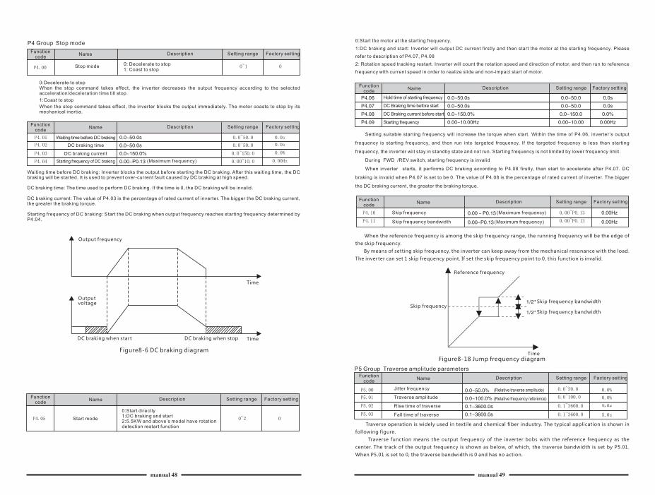
P4 Group Stop mode
Stop mode
0:Decelerate to stop
1:Coast to stop
Factory settingDescription Setting rangeFunction code
Name
Factory settingDescription Setting rangeFunction code
Name
When the stop command takes effect, the inverter decreases the output frequency according to the selected acceleration/deceleration time till stop.
When the stop command takes effect, the inverter blocks the output immediately. The motor coasts to stop by its mechanical inertia.
Waiting time before DC braking
DC braking time
DC braking current
Starting frequency of DC braking (Maximum frequency)
Waiting time before DC braking: Inverter blocks the output before starting the DC braking. After this waiting time, the DC braking will be started. It is used to prevent over-current fault caused by DC braking at high speed.
DC braking time: The time used to perform DC braking. If the time is 0, the DC braking will be invalid.
DC braking current: The value of P4.03 is the percentage of rated current of inverter. The bigger the DC braking current, the greater the braking torque.
Starting frequency of DC braking: Start the DC braking when output frequency reaches starting frequency determined by P4.04.
Output frequency
Output voltage
DC braking when start DC braking when stop
Figure8-6 DC braking diagram
Factory settingDescription Setting rangeFunction code
Name
Start mode
0:Start directly1:DC braking and start2:5.5KW and above’s model have rotation detection restart function
0:Start the motor at the starting frequency.
1:DC braking and start: Inverter will output DC current firstly and then start the motor at the starting frequency. Please
refer to description of P4.07, P4.08
2: Rotation speed tracking restart. Inverter will count the rotation speed and direction of motor, and then run to reference
frequency with current speed in order to realize slide and non-impact start of motor.
Factory settingDescription Setting rangeFunction code
Name
Hold time of starting frequency
DC Braking time before start
DC Braking current before start
Starting frequency
Setting suitable starting frequency will increase the torque when start. Within the time of P4.06, inverter ’s output
frequency is starting frequency, and then run into targeted frequency. If the targeted frequency is less than starting
frequency, the inverter will stay in standby state and not run. Starting frequency is not limited by lower frequency limit.
During F WD /REV switch, starting frequency is invalid
W hen inverter starts, it performs DC braking according to P4.08 firstly, then start to accelerate after P4.07. DC
braking is invalid when P4.07 is set to be 0. The value of P4.08 is the percentage of rated current of inverter. The bigger
the DC braking current, the greater the braking torque.
(Maximum frequency)
(Maximum frequency)
Skip frequency
Skip frequency bandwidth
When the reference frequency is among the skip frequency range, the running frequency will be the edge of
the skip frequency.
By means of setting skip frequency, the inverter can keep away from the mechanical resonance with the load.
The inverter can set 1 skip frequency point. If set the skip frequency point to 0, this function is invalid.
Time
Time
Reference frequency
Skip frequencySkip frequency bandwidth
Time
Skip frequency bandwidth
Figure8-18 Jump frequency diagram
P5 Group Traverse amplitude parameters
Factory settingDescription Setting rangeFunction code
Name
Factory settingDescription Setting rangeFunction code
Name
Jitter frequency
Traverse amplitude
Rise time of traverse
Fall time of traverse
(Relative traverse amplitude)
(Relative frequency reference)
Traverse operation is widely used in textile and chemical fiber industry. The typical application is shown in
following figure.
Traverse function means the output frequency of the inverter bobs with the reference frequency as the
center. The track of the output frequency is shown as below, of which, the traverse bandwidth is set by P5.01.
When P5.01 is set to 0, the traverse bandwidth is 0 and has no action.
manual 48 manual 49
0: Decelerate to stop1: Coast to stop
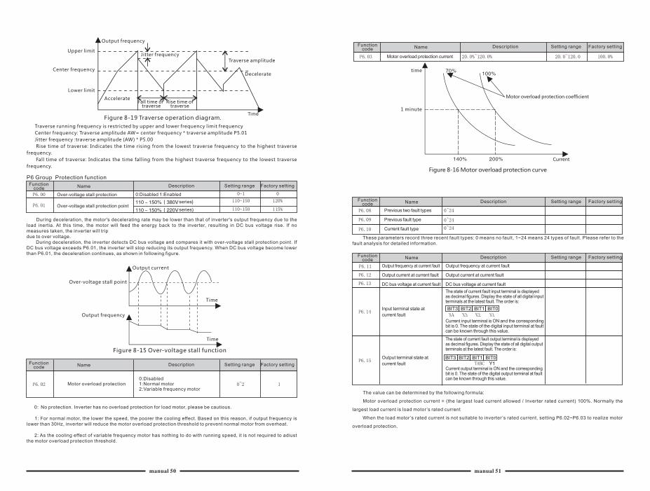
Upper limit
Output frequency
Center frequency
Lower limit
Accelerate
Jitter frequency
Fall time of traverse
Rise time of traverse
Traverse amplitude
Decelerate
TimeFigure 8-19 Traverse operation diagram.
Traverse running frequency is restricted by upper and lower frequency limit frequency
Center frequency: Traverse amplitude AW= center frequency * traverse amplitude P5.01
Jitter frequency :traverse amplitude (AW) * P5.00
Rise time of traverse: Indicates the time rising from the lowest traverse frequency to the highest traverse
frequency.
Fall time of traverse: Indicates the time falling from the highest traverse frequency to the lowest traverse
frequency.
P6 Group Protection function
Factory settingDescription Setting rangeFunction code Name
Over-voltage stall protection
Over-voltage stall protection point
0:Disabled 1:Enabled
series
series
During deceleration, the motor's decelerating rate may be lower than that of inverter's output frequency due to the load inertia. At this time, the motor will feed the energy back to the inverter, resulting in DC bus voltage rise. If no measures taken, the inverter will tripdue to over voltage. During deceleration, the inverter detects DC bus voltage and compares it with over-voltage stall protection point. If DC bus voltage exceeds P6.01, the inverter will stop reducing its output frequency. When DC bus voltage become lower than P6.01, the deceleration continues, as shown in following figure.
Over-voltage stall point
Output frequency
Output current
Time
Time
Figure 8-15 Over-voltage stall function
Factory settingDescription Setting rangeFunction code Name
Motor overload protection0:Disabled1:Normal motor2:Variable frequency motor
0: No protection. Inverter has no overload protection for load motor, please be cautious.
1: For normal motor, the lower the speed, the poorer the cooling effect. Based on this reason, if output frequency is lower than 30Hz, inverter will reduce the motor overload protection threshold to prevent normal motor from overheat.
2: As the cooling effect of variable frequency motor has nothing to do with running speed, it is not required to adiust the motor overload protection threshold.
Factory settingDescription Setting rangeFunction code Name
Motor overload protection current
time
1 minute
Motor overload protection coefficient
Current
Figure 8-16 Motor overload protection curve
Factory settingDescription Setting rangeFunction code Name
Previous two fault types
Previous fault type
Current fault type
These parameters record three recent fault types: 0 means no fault, 1~24 means 24 types of fault. Please refer to the fault analysis for detailed information.
Factory settingDescription Setting rangeFunction code Name
Output frequency at current fault
Output current at current fault
DC bus voltage at current fault
Input terminal state at
current fault
Output terminal state at
current fault
Output frequency at current fault
Output current at current fault
DC bus voltage at current fault
Current input terminal is ON and the corresponding bit is 0. The state of the digital input terminal at fault can be known through this value.
The state of current fault input terminal is displayed as decimal figures. Display the state of all digital input terminals at the latest fault. The order is:
The state of current fault output terminal is displayed as decimal figures. Display the state of all digital output terminals at the latest fault. The order is:
Current output terminal is ON and the corresponding bit is 0. The state of the digital output terminal at fault can be known through this value.
The value can be determined by the following formula:
Motor overload protection current = (the largest load current allowed / Inverter rated current) 100%. Normally the
largest load current is load motor’s rated current
When the load motor’s rated current is not suitable to inverter ’s rated current, setting P6.02~P6.03 to realize motor
overload protection.
manual 50 manual 51
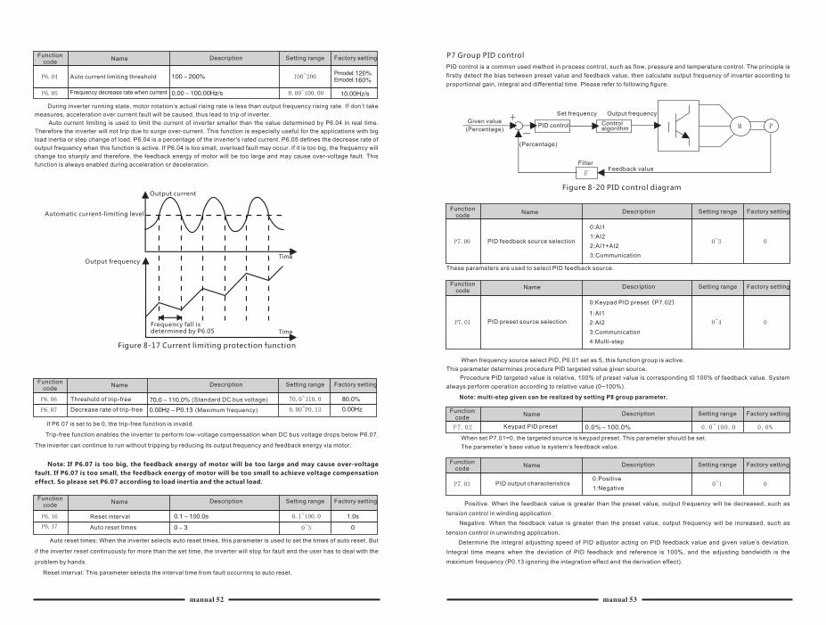
Factory settingDescription Setting rangeFunction code
Name
Auto current limiting threshold
Frequency decrease rate when current
Pmodel:Emodel:
During inverter running state, motor rotation’s actual rising rate is less than output frequency rising rate. If don’t take
measures, acceleration over current fault will be caused, thus lead to trip of inverter.
Auto current limiting is used to limit the current of inverter smaller than the value determined by P6.04 in real time.
Therefore the inverter will not trip due to surge over-current. This function is especially useful for the applications with big
load inertia or step change of load. P6.04 is a percentage of the inverter's rated current. P6.05 defines the decrease rate of
output frequency when this function is active. If P6.04 is too small, overload fault may occur. If it is too big, the frequency will
change too sharply and therefore, the feedback energy of motor will be too large and may cause over-voltage fault. This
function is always enabled during acceleration or deceleration.
Automatic current-limiting level
Output frequency
Output current
Frequency fall is determined by P6.05
Figure 8-17 Current limiting protection function
Time
Time
Factory settingDescription Setting rangeFunction code
Name
Threshold of trip-free
Decrease rate of trip-free
(Standard DC bus voltage)
(Maximum frequency)
If P6.07 is set to be 0, the trip-free function is invalid.
Trip-free function enables the inverter to perform low-voltage compensation when DC bus voltage drops below P6.07.
The inverter can continue to run without tripping by reducing its output frequency and feedback energy via motor.
Note: If P6.07 is too big, the feedback energy of motor will be too large and may cause over-voltage
fault. If P6.07 is too small, the feedback energy of motor will be too small to achieve voltage compensation
effect. So please set P6.07 according to load inertia and the actual load.
Factory settingDescription Setting rangeFunction code
Name
Reset interval
Auto reset times
Auto reset times: When the inverter selects auto reset times, this parameter is used to set the times of auto reset. But
if the inverter reset continuously for more than the set time, the inverter will stop for fault and the user has to deal with the
problem by hands.
Reset interval: This parameter selects the interval time from fault occurrinq to auto reset.
P7 Group PID control
Factory settingDescription Setting rangeFunction code
Name
Factory settingDescription Setting rangeFunction code
Name
Given value
(Percentage)
(Percentage)
Set frequency
PID control Control algorithm
Output frequency
FilterFeedback value
Figure 8-20 PID control diagram
PID feedback source selection
These parameters are used to select PID feedback source.
0:AI1
1:AI2
2:AI1+AI2
3:Communication
PID preset source selection
0:Keypad PID preset(P7.02)
1:AI1
2:AI2
3:Communication
4:Multi-step
When frequency source select PID, P0.01 set as 5, this function group is active.
This parameter determines procedure PID targeted value given source.
Procedure PID targeted value is relative, 100% of preset value is corresponding t0 100% of feedback value. System
always perform operation according to relative value (0~100%).
Note: multi-step given can be realized by setting P8 group parameter.
Factory settingDescription Setting rangeFunction code
Name
Keypad PID preset
When set P7.01=0, the targeted source is keypad preset. This parameter should be set.
The parameter’s base value is system’s feedback value.
Factory settingDescription Setting rangeFunction code
Name
PID output characteristics 0:Positive
1:Negative
Positive. When the feedback value is greater than the preset value, output frequency will be decreased, such as
tension control in winding application.
Negative. When the feedback value is greater than the preset value, output frequency will be increased, such as
tension control in unwinding application.
Determine the integral adjustting speed of PID adjustor acting on PID feedback value and given value’s deviation.
Integral time means when the deviation of PID feedback and reference is 100%, and the adjusting bandwidth is the
maximum frequency (P0.13 ignoring the integration effect and the derivation effect).
manual 52 manual 53
PID control is a common used method in process control, such as flow, pressure and temperature control. The principle is
firstly detect the bias between preset value and feedback value, then calculate output frequency of inverter according to
proportional gain, integral and differential time. Please refer to following figure.
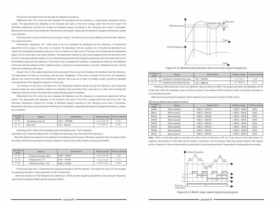
The shorter the integral time, the stronger the adjusting strength is.
Differential time (Td): when the error between the feedback and the reference, a proportional adjustment will be
output. The adjustment only depends on the direction and value of the error change other than the error itself. The
derivation adjustment controls the change of feedback signals according to the changing trend when it fluctuates.
Because the derivation may enlarge the interference to the system, especially the frequent-changing interference, please
use it carefully.
PID is the most common method in the procedure control. The effect of every part is different from the other. Below is
the simple instruction:
Proportional adjustment (P): when there is an error between the feedback and the reference, a Proportional
adjustment will be output. If the error is constant, the adjustment will be constant, too. Proportional adjustment can
respond to the feedback change quickly, but it can not realize non-fault control. The gain will increase with the adjustment
speed, but too much gain may cause vibration. The adjustment method is: set a long integration time and derivation time
to 0 first. Secondly make the system run by proportional adjustment and change the reference. And then watch the error of
the feedback signal and the reference. If the static error is available (for example, increasing the reference, the feedback
will be less than the reference after a stable system), continue to increase the gain, vice versa. Repeat the action until the
static error achieves a little value.
Integral time (I): the output adjustment will accumulate if there is an error between the feedback and the reference.
The adjustment will keep on increasing until the error disappears. If the error is existent all the time, the integration
adjustor can cancel the static error effectively. Vibration may occur as a result of unstable system caused by repeated
over-adjustment if the integration adjustor is too strong.
The features of this kind of vibration are: the fluctuating feedback signal (around the reference) and increasing
traverse range will cause vibration. Adjust the integration time parameter from a big value to a little one to change the
integration time and monitor the result until a stable system speed is available.
Differential time (Td): when the error between the feedback and the reference, a proportional adjustment will be
output. The adjustment only depends on the direction and value of the error change other than the error itsef. The
derivation adjustment controls the change of feedback signals according to the changing trend when it fluctuates.
Because the derivation may enlarge the interference to the system, especially the frequent-changing interference, please
use it carefully.
Factory settingDescription Setting rangeFunction code
Name
Sampling cycle (T)
Bias limit
Sampling cycle T refers to the sampling cycle of feedback value. The Pl regulator
calculates once in each sampling cycle. The bigger the sampling cycle, the slower the response is.
Bias limit defines the maximum bias between the feedback and the preset. PID stops operation when the bias is within
this range. Setting this parameter correctly is helpful to improve the system output accuracy and stability.
Factory settingDescription Setting rangeFunction code
Name
Proportional gain (Kp)
Integral time(Ti)
Differential time(Td)
Proportional gain (Kp): it determines the adjusting strength of the PID adjustor. The larger the value of P, the stronger
the adjusting strength is. If the parameter is 100, it means that.
when the deviation of PID feedback and reference is 100% and the adjusting bandwidth is the maximum frequency
(ignoring the integration effect and the derivation effect).
Reference value
Output frequency
Feedback valueBias limit
Figure 8-21 Relationship between bias limit and output frequency.
Time
Time
Factory settingDescription Setting rangeFunction code
Name
Feedback lost detecting value
Feedback lost detecting time
Feedback offline detection value: the detection value is relative to l00%. The system will detect the feedback of PID
all the time. When the feedback value is below or equal to the feedback offline detection value, the system will begin to
count the detecting time.
When the time exceeds the feedback offline detection time, the system will report PIDE.(E201)
P8 Group Multi-step speed control
Factory settingDescription Setting rangeFunction code
Name
Multi-speed0
Multi-speed1
Multi-speed2
Multi-speed3
Multi-speed4
Multi-speed5
Multi-speed6
Multi-speed7
Output frequency
Running command
Figure 8-22 Multi-steps speed operating diagram
manual 54 manual 55
Note: 100% of multi-step speed x corresponds to the maximum frequency (P0.13). If the value of multi-step speed x is
negative, the direction of this step will be reverse, otherwise it will be forward. Multi-step speed function has highest
priority. Selection of step is determined by combination of multi-step terminals. Please refer to following figure and table.
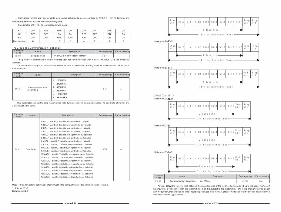
Multi-steps running start and coast to stop source selection is also determined by P0.02. X1, X2, X3 terminal and
multi-steps’ relationship is showed in following table.
Relationship of X1, X2, X3 terminal and multi-steps.
Running step
P9 Group 485 Communication ( optional)
Factory settingDescription Setting rangeFunction code
Name
Factory settingDescription Setting rangeFunction code
Name
Local address 1~247,0 is the broadcast address
This parameter determines the slave address used for communication with master. The value "0" is the broadcast
address.
Local address is unique in communication network. This is the base of realizing upper PC and inverter’s point to point
communication.
Communication baud rate setting
This parameter can set the data transmission rate during serial communication. Note: The baud rate of master and
slave must be the same.
Factory settingDescription Setting rangeFunction code
Name
Data format
Upper PC and inverter’s setting dada form must be the same, otherwise the communication is invalid.
11-bits(for RTU)
Data form:8-N-2
Factory settingDescription Setting rangeFunction code
Name
Data form:
Data form:
Data form:
Data form:
Data form:
0: RTU, 1 start bit, 8 data bits, no parity check, 1 stop bit
1: RTU, 1 start bit, 8 data bits, even parity check, 1 stop bit
2: RTU, 1 start bit, 8 data bits, odd parity check, 1 stop bit
3: RTU, 1 start bit, 8 data bits, no parity check, 2 stop bits
4: RTU, 1 start bit, 8 data bits, even parity check, 2 stop bits
5: RTU, 1 start bit, 8 data bits, odd parity check, 2 stop bits
6: ASCII, 1 start bit, 7 data bits, no parity check, 1 stop bit
7: ASCII, 1 start bit, 7 data bits, even parity check, 1 stop bit
8: ASCII, 1 start bit, 7 data bits, odd parity check, 1 stop bit
9: ASCII, 1 start bit, 7 data bits, no parity check, 2 stop bits
10: ASCII, 1 start bit, 7 data bits, even parity check, 2 stop bits
11: ASCII, 1 start bit, 7 data bits, odd parity check, 2 stop bits
12: ASCII, 1 start bit, 8 data bits, no parity check, 1 stop bit
13: ASCII, 1 start bit, 8 data bits, even parity check, 1 stop bit
14: ASCII, 1 start bit, 8 data bits, odd parity check, 1 stop bit
15: ASCII, 1 start bit, 8 data bits, no parity check, 2 stop bits
16: ASCII, 1 start bit, 8 data bits, even arity check, 2 stop bits
17: ASCII, 1 start bit, 8 data bits, odd parity check, 2 stop bits
Communication delay time
Answer delay: the interval time between the data receiving of the inverter and data sending to the upper monitor. If
the answer delay is shorter than the system time, then it is subject to the system time, and if the answer delay is longer
than the system, then the waiting time should be prolonged after the data processing to achieve the answer delay and then
to send data to the upper monitor.
manual 56 manual 57

Factory settingDescription Setting rangeFunction code
Name
Factory settingDescription Setting rangeFunction code
Name
Communication timeout delay Disabled
If the function code is set to 0.0s, this parameter is invalid.
If the function code is set to a valid value, when the interval time exceeds the communication overtime, the system will
report communication fault (E017).
Generally, the parameter is set to invalid. If the parameter is set in a continuous communication system, the
communication state can be monitored.
Communication error action
0:Alarm and coast to stop1:Do not alarm and keep running2:Do not alarm and stop at the stopping method (only for communication control mode) 3:Do not alarm and stop at stopping method (for all control modes)
In the abnormal situation, the inverter can act through setting communication fault processing. The selected running
state of the inverter is: shield the CE fault, stop or keep running.
Factory settingDescription Setting rangeFunction code
Name
Response action0:Response to writing1:No response to writing
When this function code is set to 0, inverter have response to reading and writing command of Upper PC
When this function code is set to 1, inverter only have response reading command and no response to writing
command. The communication efficiency can be improved by this way.
PAGroup vector control
Factory settingDescription Setting rangeFunction code
Name
ASR proportional gain Kp1
ASR integral time Ki1
ASR switching point1
ASR proportional gain Kp2
ASR integral time Ki2
ASR switching point2 (maximum frequency)
PA.04~PA.05 are only valid for vector control and torque control and invalid for V/F control. Through PA.00~PA.05, the
user can set the proportional gain Kp and integral time K of speed regulator (ASR), so as to change the speed response
characteristic. ASR's structure is shown in following figure.PA.00 and PA.01 only take effect when output frequency is less
than PA.02. PA.03 and PA.04 only take effect when output frequency is greater than PA.05. When output frequency is
between PA.02 and PA.05, Kp and Ki are proportional to the bias between PA.02 and PA.05. For details, please refer to
following figure.
PI parameter
Figure 8-23 PI parameter diagram.
The system's dynamic response can be faster if the proportion gain Kp is increased; However, if Kp is too large, the
system tends to oscillate. The system dynamic response can be faster if the integral time K is decreased; However, if K is
too small, the system becomes overshoot and tends to oscillate.
PA.00 and PA.01 are corresponding to Kp and K at low frequency, while PA.03 and PA.04 are corresponding to Kp
and K at high frequency. Please adjust these parameters according to actual situation.
Factory settingDescription Setting rangeFunction code
Name
Factory settingDescription Setting rangeFunction code
Name
Slip compensation rate of VC
Torque limit (Inverter rated current)
Slip compensation rate of VC: is to adjust vector control’s slip frequency and improve system’s speed control
accuracy. To adjust this parameter appropriately can restrain static error.
Torque limit: Set 100.0% corresponds to the rated output current of the inverter.
PB Group Motor parameters
Motor parameter autotuning
0:No action
1:Rotation autotuning
2:Static autotuning
0:No action: Forbidding autotuning.
1: Rotation autotuning:
Do not connect any load to the motor when performing autotuning and ensure the motor is in static state.
Input the nameplate parameters of motor (PB.02 ~PB.06) correctly before performing autotuning. Otherwise the
parameters detected by autotuning will be incorrect; it may influence the performance of inverter.
Set the proper acceleration and deceleration time (P0.04 and P0.05) according to the motor inertia before performing
autotuning. Otherwise it may cause over-current and over-voltage fault during autotuning. The operation process is as
follow:
Set PB.00 to be 1 then press DATA/ENT, LED will display "-FUN-" and flickers. During "-FUN-" is flickering, if you want
to exit autotuning, press the PRG/ESC to exit autotuning. Press the RUN to start the autotuning. LED will display "-FUN-".
After a few seconds the motor will start to run. LED will display "-FUN-" and "RUN/TUNE" light will flicker. After a few
minutes, LED will display "-END-". That means the autotuning is finished and return to the stop state.
During the autotuning, pressing STOP/RST can also stop autotuning. Note: Only the keypad can control the
autotuning. PB.00 will restore to 0 automatically when the autotuning is finished or cancelled.
2: Static autotuning:
If it is difficult to disconnect the load, static autotuning is recommended. The operation process is the same as
rotation autotuning except step c. Note: The Mutual inductance and current without load will not be detected by static
autotuning, if needed the user should input suitable value according to experience.
Factory settingDescription Setting rangeFunction code
Name
E/P option0:E model
1:P model
0: Applicable to constant torque load
1: Applicable to variable torque load (i.e. fans, pumps) SL series inverters provide the E/P integration function. The
adaptive motor power used for constant torque load (E model) should be one grade less than that used for variable torque
load (P model). It only has E model for 220V inverter.
The factory setting of inverter is E model. To change from E model to P model, procedures are as follow:
(1)Set this function code to 1
(2)Reset PB Group motor parameter
manual 58 manual 59
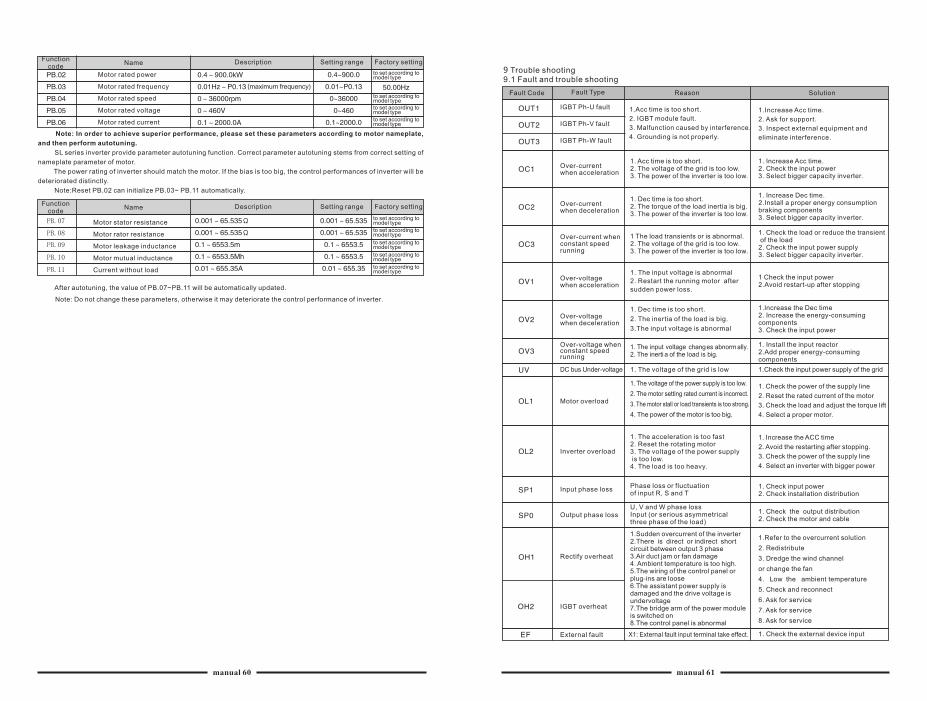
Motor rated power
Motor rated frequency
Motor rated speed
Motor rated voltage
Motor rated current
(maximum frequency)
Factory settingDescription Setting rangeFunction code
Name
Motor stator resistance
Motor rator resistance
Motor leakage inductance
Motor mutual inductance
Current without load
Factory settingDescription Setting rangeFunction code
Name
After autotuning, the value of PB.07~PB.11 will be automatically updated.
Note: Do not change these parameters, otherwise it may deteriorate the control performance of inverter.
to set according to model type
Note: In order to achieve superior performance, please set these parameters according to motor nameplate,
and then perform autotuning.
SL series inverter provide parameter autotuning function. Correct parameter autotuning stems from correct setting of
nameplate parameter of motor.
The power rating of inverter should match the motor. If the bias is too big, the control performances of inverter will be
deteriorated distinctly.
Note:Reset PB.02 can initialize PB.03~ PB.11 automatically.
9 Trouble shooting9.1 Fault and trouble shooting
Fault Code Fault Type
IGBT Ph-U fault
IGBT Ph-V fault
IGBT Ph-W fault
Over-current when acceleration
Over-current when deceleration
Over-current when constant speedrunning
Over-voltage when acceleration
Over-voltage when deceleration
Over-voltage when constant speed running
1.Acc time is too short.
2. IGBT module fault.
3. Malfunction caused by interference.
4. Grounding is not properly.
X1: External fault input terminal take effect.
1.Sudden overcurrent of the inverter2.There is direct or indirect short circuit between output 3 phase3.Air duct jam or fan damage4. Ambient temperature is too high.5.The wiring of the control panel or plug-ins are loose6.The assistant power supply is damaged and the drive voltage isundervoltage7.The bridge arm of the power moduleis switched on8.The control panel is abnormal
Phase loss or fluctuationof input R, S and T
U, V and W phase lossInput (or serious asymmetricalthree phase of the load)
1. The acceleration is too fast2. Reset the rotating motor3. The voltage of the power supply is too low.4. The load is too heavy.
1. The voltage of the power supply is too low.
2. The motor setting rated current is incorrect.
3. The motor stall or load transients is too strong.
4. The power of the motor is too big.
DC bus Under-voltage
Motor overload
Inverter overload
Input phase loss
Output phase loss
Rectify overheat
IGBT overheat
External fault
1. The voltage of the grid is low
1. The input voltage changes abnorm ally.2. The inerti a of the load is big.
1. Dec time is too short.
2. The inertia of the load is big.
3.The input voltage is abnormal
1. The input voltage is abnormal
2. Restart the running motor after
sudden power loss.
1 The load transients or is abnormal.2. The voltage of the grid is too low.3. The power of the inverter is too low.
1. Dec time is too short.2. The torque of the load inertia is big.3. The power of the inverter is too low.
1. Acc time is too short.2. The voltage of the grid is too low.3. The power of the inverter is too low.
Reason Solution
1. Check the output distribution2. Check the motor and cable
1.Increase Acc time.
2. Ask for support.
3. Inspect external equipment and
eliminate interference.
1. Increase Acc time.2. Check the input power3. Select bigger capacity inverter.
1. Increase Dec time.2.Install a proper energy consumption braking components3. Select bigger capacity inverter.
1. Check the load or reduce the transient of the load2. Check the input power supply3. Select bigger capacity inverter.
1 Check the input power2.Avoid restart-up after stopping
1.lncrease the Dec time2. Increase the energy-consuming components3. Check the input power
1. Install the input reactor2.Add proper energy-consuming components
1.Check the input power supply of the grid
1. Check the power of the supply line
2. Reset the rated current of the motor
3. Check the load and adjust the torque lift
4. Select a proper motor.
1. Increase the ACC time
2. Avoid the restarting after stopping.
3. Check the power of the supply line
4. Select an inverter with bigger power
1. Check input power2. Check installation distribution
1. Check the external device input
1.Refer to the overcurrent solution
2. Redistribute
3. Dredge the wind channel
or change the fan
4. Low the ambient temperature
5. Check and reconnect
6. Ask for service
7. Ask for service
8. Ask for service
to set according to model type to set according to model type
to set according to model type
to set according to model type
to set according to model type
to set according to model type
to set according to model type
to set according to model type
manual 60 manual 61
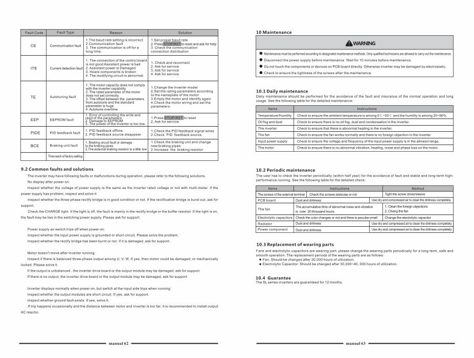
Fault Code Fault Type Reason Solution
Communication fault
Current detection fault
Autotuning fault
EEPROM fault
PID feedback fault
Braking unit fault
Time reach of factory setting
1.The baud rate setting is incorrect.2.Communication fault3. The communication is off for a long time.
1. Braking circuit fault or damage to the braking pipes2.The external braking resistor is a little low
1. PID feedback offline2. PID feedback source disappear
1. Error of controlling the write and read of the parameters2. Damage to EEPROM3. The power of the inverter is too low.
1. The motor capacity does not comply with the inverter capability2. The rated parameter of the motor does not set correctly.3. The offset between the parametersfrom autotune and the standard parameter is huge4. Autotune overtime
1. The connection of the control board is not good Assistant power is bad2. Assistant power is Damaged3. Hoare components is broken4. The modifying circuit is abnormal.
1.Set proper baud rate
3. Check the communicationconnection distribution
2. Press STOP/RST to reset and ask for help
1.Check the braking unit and change new braking pipes2.Increase the braking resistor
1.Check the PID feedback signal wires2.Check PID feedback source
1.Press STOP/RST to reset2. Ask for service
1.Change the inverter model2.Set the rating parameters according to the nameplate of the motor3.Empty the motor and identify again4.Check the motor wiring and set the parameters
1. Check and reconnect2. Ask for service3. Ask for service4. Ask for service
9.2 Common faults and solutions
The inverter may have following faults or malfunctions during operation, please refer to the following solutions.
No display after power on:
Inspect whether the voltage of power supply is the same as the inverter rated voltage or not with multi-meter. If the
power supply has problem, inspect and solve it.
Inspect whether the three-phase rectify bridge is in good condition or not. If the rectification bridge is burst out, ask for
support.
Check the CHARGE light. If the light is off, the fault is mainly in the rectify bridge or the buffer resistor. If the light is on,
the fault may be lies in the switching power supply. Please ask for support.
Power supply air switch trips off when power on:
Inspect whether the input power supply is grounded or short circuit. Please solve the problem.
Inspect whether the rectify bridge has been burnt or not. If it is damaged, ask for support.
Motor doesn't move after inverter running:
Inspect if there is balanced three-phase output among U, V, W. If yes, then motor could be damaged, or mechanically
locked. Please solve it.
If the output is unbalanced , the inverter drive board or the output module may be damaged, ask for support.
If there is no output, the inverter drive board or the output module may be damaged, ask for support.
Inverter displays normally when power on, but switch at the input side trips when running:
Inspect whether the output modules are short circuit. If yes, ask for support.
Inspect whether ground fault exists. If yes, solve it.
If trip happens occasionally and the distance between motor and inverter is too far, it is recommended to install output
AC reactor.
10 Maintenance
WARNING
Maintenance must be performed according to designated maintenance methods. Only qualified technicians are allowed to carry out the maintenance.
Disconnect the power supply before maintenance. Wait for 10 minutes before maintenance.
Do not touch the components or devices on PCB board directly. Otherwise inverter may be damaged by electrostatic.
Check to ensure the tightness of the screws after the maintenance.
10.1 Daily maintenanceDaily maintenance should be performed for the avoidance of the fault and insurance of the normal operation and long
usage. See the following table for the detailed maintenance:
Items Instructions
Temperature/Humility
Oil fog and dust
The inverter
The fan
Input power supply
The motor
Check to ensure the ambient temperature is among 0℃~50℃ and the humility is among 20~90%.
Check to ensure there is no oil fog, dust and condensation in the inverter.
Check to ensure that there is abnormal heating in the inverter.
Check to ensure the fan works normally and there is no foreign objection in the inverter.
Check to ensure the voltage and frequency of the input power supply is in the allowed range.
Check to ensure there is no abnormal vibration, heating, noise and phase loss on the motor.
10.2 Periodic maintenance
The user has to check the inverter periodically (within half year) for the avoidance of fault and stable and long-term high-
performance running. See the following table for the detailed check:
Items Instructions Method
10.3 Replacement of wearing parts
Fans and electrolytic capacitors are wearing part; please change the wearing parts periodically for a long-term, safe and
smooth operation. The replacement periods of the wearing parts are as follows:
Fan: Should be changed after 20,000 hours of utilization,
Electrolytic Capacitor: Should be changed after 30,000~40, 000 hours of utilization.
10.4 GuaranteeThe SL series inverters are guaranteed for 12 months.
PCB board
The fan
Electrolytic capacitors
Radiator
Power component
The screws of the external terminal Check the screws areloose or not
Dust and dirtiness
The accumulative time of abnormal noise and vibration
is over 20 thousand hours.
Check the color changes or not and there is peculiar smell
Dust and dirtiness
Dust and dirtiness
Tight the screw driver/sleeve
1. Clean the foreign objections
2. Chang the fan
Change the electrolytic capacitor
Use dry and compressed air to clean the dirtiness completely.
Use dry and compressed air to clean the dirtiness completely.
Use dry and compressed air to clean the dirtiness completely.
manual 62 manual 63
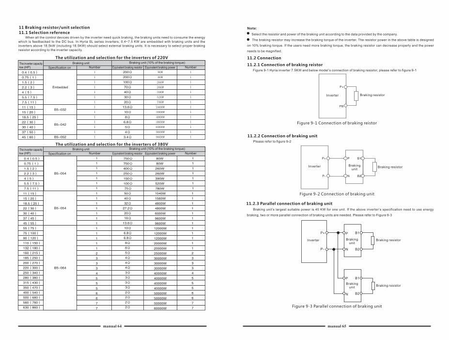
11 Braking resistor/unit selection
11.1 Selection reference When all the control devices driven by the inverter need quick braking, the braking units need to consume the energy
which is feedbacked to the DC bus. In Hyria SL series inverters, 0.4~7.5 KW are embedded with braking units and the
inverters above 18.5kW (including 18.5KW) should select external braking units. It is necessary to select proper braking
resistor according to the inverter capacity.
The utilization and selection for the inverters of 220V
The inverter capacity kw (HP)
Braking unit Braking unit (10% of the braking torque)
Specification on Number Equivalent braking resistor Equivalent braking power Number
Embedded
The utilization and selection for the inverters of 380V
The inverter capacity kw (HP)
Braking unit Braking unit (10% of the braking torque)
Specification on Number Equivalent braking resistor Equivalent braking power Number
Note:
Select the resistor and power of the braking unit according to the data provided by the company.
The braking resistor may increase the braking torque of the inverter. The resistor power in the above table is designed
on 10% braking torque. If the users need more braking torque, the braking resistor can decrease properly and the power
needs to be magnified.
11.2 Connection
11.2.1 Connection of braking reistor
Figure 9-1 inverter 7.5KW and below model’s connection of braking resistor, please refer to figure 9-1Hyria
Figure 9-1 Connection of braking reistor
Inverter Braking resistor
11.2.2 Connection of braking unit
Please refer to figure 9-2
Figure 9-2 Connection of braking unit
Inverter Braking resistorBraking unit
Figure 9-3 Parallel connection of braking unit
Inverter Braking unit
Braking unit
Braking resistor
Braking resistor
11.2.3 Parallel connection of braking unit
Braking unit’s largest suitable power is 45 KW for one unit. If the above inverter’s specification need to use energy
braking, two or more parallel connection of braking units are needed. Please refer to Figure 9-3
manual 64 manual 65