Embed Size (px)
Citation preview

“ The Efficient Way of Air Handling Unit ”
www.acsklima.com
Package Type
Hygienic Air Handling Unit
Operation & MaintenanceManual
Thank you for choosing
ACS and CLIMACS brandPackage Type Hygienic Air Handling
Units.
In addition to “Air Handling Units Installation, Operation and
Maintenance Manual” supplied with each unit, this manual
contains instructions for the first installation, operation and
maintenance of the software automated system.
All the best...
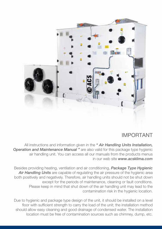
IMPORTANT
All instructions and information given in the “ Air Handling Units Installation, Operation and Maintenance Manual ” are also valid for this package type hygienic
air handling unit. You can access all our manuals from the products menusin our web site www.acsklima.com
Besides providing heating, ventilation and air conditioning, Package Type Hygienic Air Handling Units are capable of regulating the air pressure of the hygienic area
both positively and negatively. Therefore, air handling units should not be shut down except for the periods of maintenance, cleaning or fault conditions.
Please keep in mind that shut down of the air handling unit may lead to the contamination risk in the hygienic location.
Due to hygienic and package type design of the unit, it should be installed on a level floor with sufficient strength to carry the load of the unit; the installation method
should allow easy cleaning and good drainage of condensed water. The installation location must be free of contamination sources such as chimney, dump, etc.

| Maintenance & Cleaning
MAINTENANCE & CLEANING
The instructions of the manufacturer should be followed prior
the operation for the first time (or after annual maintenance).
After that, below points should be checked:
For annual maintenance, shut down the air handling unit and turn off all motor switches, turn off the power.
Make sure that the all compartments are cleaned and no foreign object or material is left in the unit. Please check no duct isolation residues, tapes, nuts, hand tools are left behind.
Please check all the handles on doors and access panels.
If the unit is installed outside make sure that it is placed under an overhead shelter and check the joints of gaskets.
Duct connectionsand dampers
Cooling unitsand refrigerant check
Drainageand siphon check
Fan and motorconnections
Connections for allelectrical parts
and sensors
Door locksand hinges
Air tightness and pollutioncheck of filters
Water and refrigerantleakage control in heating,
cooling and DX exchangers.
In addition to check of connections;all notifications shown on the control panel must be carefully inspected and intervened.
| Air Filters & Panel Filters
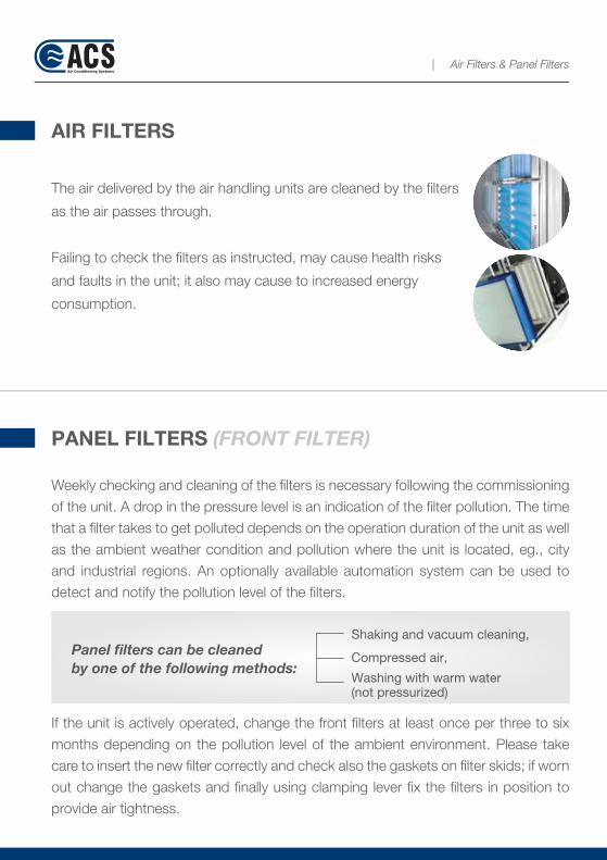
The air delivered by the air handling units are cleaned by the filters
as the air passes through.
Failing to check the filters as instructed, may cause health risks
and faults in the unit; it also may cause to increased energy
consumption.
AIR FILTERS
Weekly checking and cleaning of the filters is necessary following the commissioning
of the unit. A drop in the pressure level is an indication of the filter pollution. The time
that a filter takes to get polluted depends on the operation duration of the unit as well
as the ambient weather condition and pollution where the unit is located, eg., city
and industrial regions. An optionally available automation system can be used to
detect and notify the pollution level of the filters.
If the unit is actively operated, change the front filters at least once per three to six
months depending on the pollution level of the ambient environment. Please take
care to insert the new filter correctly and check also the gaskets on filter skids; if worn
out change the gaskets and finally using clamping lever fix the filters in position to
provide air tightness.
PANEL FILTERS (FRONT FILTER)
Panel filters can be cleanedby one of the following methods:
Shaking and vacuum cleaning,
Compressed air,
Washing with warm water(not pressurized)

| 2nd & 3rd Stage Filters
2nd and 3rd STAGE FILTERS
Check if there is any pressure drop and inspect the condition of the gaskets on the
skids. The most significant indication of a filter pollution is the pressure drop.
Max Pressure Difference = 1.6 x Initial Pressure Difference + 40 Pa
When the max pressure drop is reached remove and renew the filter. Make sure that
the filter frame firmly sits on the outer cassette and check that the contact between
doors and filters is good.
Correct positioning and good sealing affect the filter performance.
"Please contact to ACS engineers to get
information on special filters "
BAG, MPACK AND HEPA type filters cannot be cleaned and reused. These should be changed
upon completion of life cycle
Ensuring the filter sealing
ATTENTION
Table 1: Pressure differences for panel (front) filters
FILTERCLASS
EU - 2
EU - 3
EU - 4
35 Pa
35 Pa
45 Pa
INITIAL PRESSUREDIFFERENCE
150 Pa
150 Pa
150 Pa
RECOMMENDEDMAX PRESSURE DIFFERENCE
FILTERCLASS
EU - 4
EU - 5
EU - 6
EU - 7
EU - 8
EU - 9
45 Pa
80 Pa
80 Pa
80 Pa
95 Pa
95 Pa
FILTERCLASS
150 Pa
200 Pa
200 Pa
200 Pa
300 Pa
300 Pa
RECOMMENDEDMAX PRESSURE DIFFERENCE
Table 2: Pressure differences for 2nd and 3rd stage filters
Note: ACS package type hygienic air handling units are supplied with automation system by which you can easily monitor the filters on touch sensitive panel screen.

| Air Dampers
AIR DAMPERS
Check that the rotation of the flaps is not obstructed.
Do not touch the body or flexible connections.
Remove the accumulated dust by compressed air.
If you observe any problem in opening or closing of the flapscall an authorized service.
STEAM TYPE HUMIDIFIERS
At the beginning of each season, clean the strainer in the steam feed of control valve.
Annually check the control valve, condensed water discharge system and dispersion pipe.
Humidifier boiler and electrodes should be checked at least once per year. If the water used in the system is not distilled water then the frequency of checks should be increased depending on the chemical composition of the water used.
Following the periodic checks of humidifier section the operation of the humidifier can be checked from the air handling compartments after humidifier. Looking towards air flow direction a steam increase should be observed.
Silencers chambers should be inspected carefully. If there the surfaces of the silencer chambers are damaged, the glass wool inside may be caught by the air flow and carried away towards the filters. This may damage the filters and pollute the ambient air.
(ACS, wraps the glass wool by a special fabric in order to minimize the risk.)
IMPORTANT
| Heaters, Coolers & Heat Recovery Exchangers
HEATERS, COOLERS AND HEAT RECOVERYEXCHANGERS
Cleaning of air inlet side should be checked at least once per year. Surrounding weather and environmental conditions may require more frequent checks. Remove the parts and clean them applying pressurized water in the opposite direction of air flow.
If the pollution is severe please check the condition of the filters.
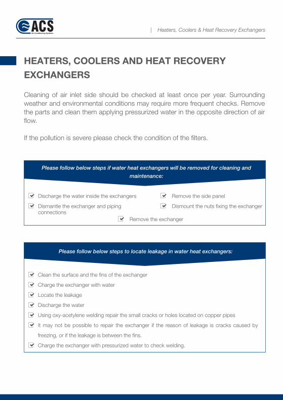
Discharge the water inside the exchangers
Dismantle the exchanger and piping connections
Remove the side panel
Dismount the nuts fixing the exchanger
Remove the exchanger
Please follow below steps if water heat exchangers will be removed for cleaning and
maintenance:
Clean the surface and the fins of the exchanger
Charge the exchanger with water
Locate the leakage
Discharge the water
Using oxy-acetylene welding repair the small cracks or holes located on copper pipes
It may not be possible to repair the exchanger if the reason of leakage is cracks caused by
freezing, or if the leakage is between the fins.
Charge the exchanger with pressurized water to check welding.
Please follow below steps to locate leakage in water heat exchangers:

" Prevent freezing of water inside heat exchangers "
LOCATING LEAKAGE IN DX (REFRIGERANT CHARGED) HEAT EXCHANGERS:
After shutting down the unit and switching off the power, clean the surface of the exchanger by compressed air or water.
Straighten the bent fins by using a fin comb.
If ice is observed during operation let the ice melt down naturally and inform the technical service
If you think that there is a refrigerant leakage in the system please inform the technical service
If the water inside the pipes of exchanger freezes, this will severely damage the pipes. For this reason, if there is a risk of freezing the antifreeze should be added to circulating water. If you are planning to take the exchanger out of operation for a short period, at least, make sure the water inside the exchanger is partially circulated.
| Heaters, Coolers & Heat Recovery Exchangers
Some condensed water might be observed
in the return compartments of heat
exchangers that serve for cooling or heat
recovery. Please check the condensing water
drainage
Please clean by using either compressed air or water in the opposite direction to air flow.
You can also use a very soft brush.
Straighten the bent fins by using a special fin comb.
Air Flow Direction

| Fans
FANS
Make sure that the impeller is fixed on the motor shaft tightly.
Check if fan and motor rotate freely.
Make sure that there is no foreign object at the inlet of the fan.
Check the rotation direction of the fan. To do that, momentarily switch on and off the power then observe the rotation direction of fan.
Check that the motor shaft and fan inlet flange are aligned.
Check the motor and its connections.
Check that flexible connections are secured tightly and not damaged; duct connections are designed according to the recommendations of the manufacturer with acceptable engineering applications.
Check the setting of the motor protection switch is correct.
Switch on the power and let the fan to reach to its full speed.
Do not forget to observe below points!
x y
z
Excessive vibration
Proper lubrication Motor current and voltage values
Strange noise Axial alignment of motorand fan flange
| Fans
If any problem is observed shut down the unit immediately.
Switch off the power.
Secure the fan to prevent unintended rotation of the impeller.
Inspect the source of the problem carefully and rectify it if necessary.
The operation of the fan should be observed periodically for the first 8 hours of the operation.
Pay attention to excessive vibration or noise during this observation.
Check that the input current of motor and temperatures of the bearings are within the limits specified by the manufacturer.
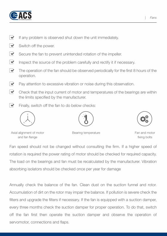
Finally, switch off the fan to do below checks:
x y
z
Axial alignment of motorand fan flange
Bearing temperature Fan and motorfixing bolts
Fan speed should not be changed without consulting the firm. If a higher speed of
rotation is required the power rating of motor should be checked for required capacity.
The load on the bearings and fan must be recalculated by the manufacturer. Vibration
absorbing isolators should be checked once per year for damage
Annually check the balance of the fan. Clean dust on the suction funnel and rotor.
Accumulation of dirt on the rotor may impair the balance. If pollution is severe check the
filters and upgrade the filters if necessary. If the fan is equipped with a suction damper,
every three months check the suction damper for proper operation. To do that, switch
off the fan first then operate the suction damper and observe the operation of
servomotor, connections and flaps.
| Fans
MAINTENANCE PROGRAM
A protective maintenance program is an important part of an active safety program.
Maintenance works should be carried out by trained and experienced personnel.
Do not attempt to conduct any maintenance unless the power is switched off and
the fan is secured.
Package type hygienic air handling units are the kind of devices that directly relate
to human health. Therefore, except for routine cleaning and maintenance, the
works requiring a special attention must be performed only by the trained
personnel. Maintenance period varies depending on the operation conditions.
Recommended maintenance program is given below.
Warnings on filter pollution etc. will be given automatically and can be followed in
the screen of the systems equipped with the automation. The warning should be
followed carefully and necessary precautions must be taken immediately.
Ignoring these warnings may lead to an automatic shut down of the unit due to
self-protection.
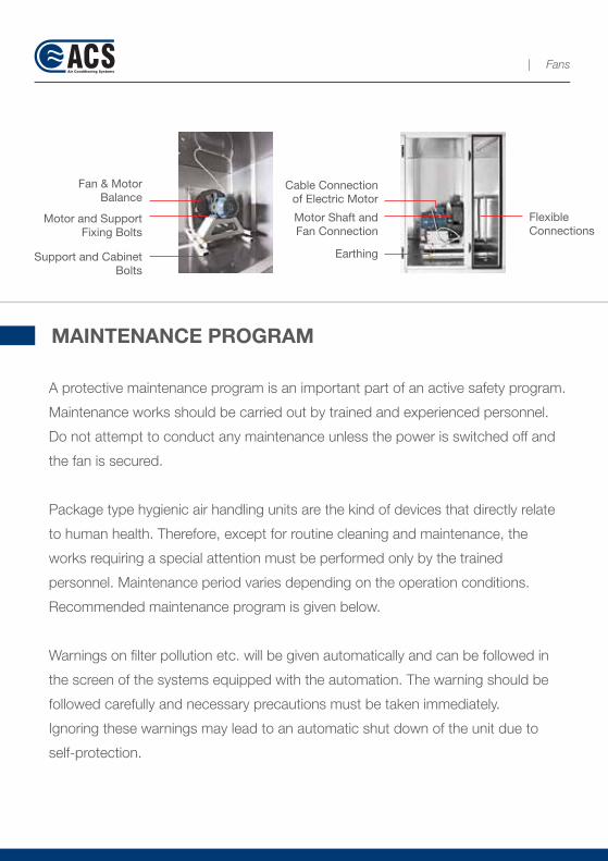
Fan & Motor Balance
Motor and Support Fixing Bolts
Support and Cabinet Bolts
Cable Connection of Electric Motor
Motor Shaft and Fan Connection
Flexible Connections
Earthing
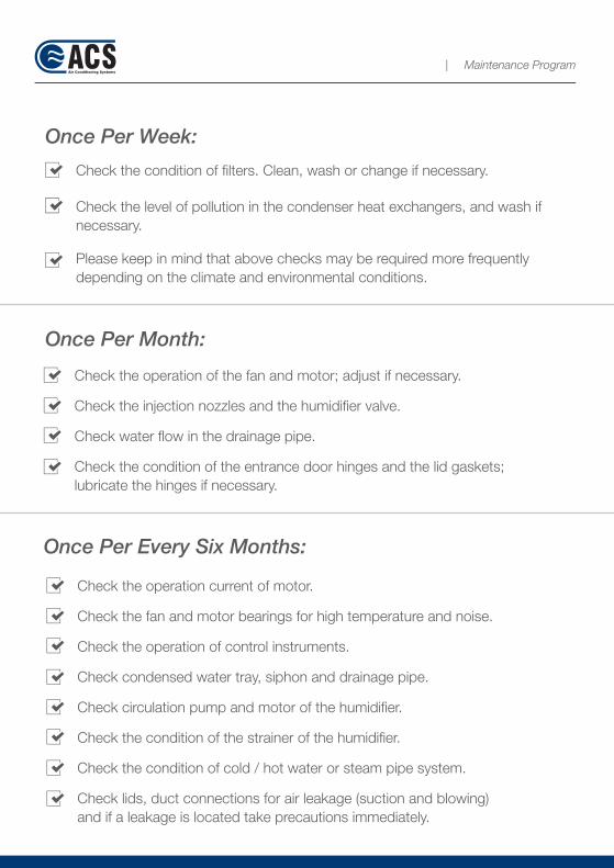
| Maintenance Program
Once Per Week:
Check the condition of filters. Clean, wash or change if necessary.
Check the level of pollution in the condenser heat exchangers, and wash if necessary.
Please keep in mind that above checks may be required more frequently depending on the climate and environmental conditions.
Once Per Month:
Check the operation of the fan and motor; adjust if necessary.
Check the injection nozzles and the humidifier valve.
Check water flow in the drainage pipe.
Check the condition of the entrance door hinges and the lid gaskets;lubricate the hinges if necessary.
Once Per Every Six Months:
Check the operation current of motor.
Check the fan and motor bearings for high temperature and noise.
Check the operation of control instruments.
Check condensed water tray, siphon and drainage pipe.
Check circulation pump and motor of the humidifier.
Check the condition of the strainer of the humidifier.
Check the condition of cold / hot water or steam pipe system.
Check lids, duct connections for air leakage (suction and blowing)and if a leakage is located take precautions immediately.

| Maintenance Program
Once Per Year:
Check the isolation of the filter frame.
Change the synthetic wool in panel filters.
Check the heat exchangers and fins. Wash by water jet if necessary.
If any, straighten the bent fins by using a fin comb.
Check the heat exchangers for leakage.
Bleed the heat exchangers with water.
Check the tightness of the bolts fixing the fan and motor.
Check lubrication of motor and fan bearings.
Check the operation of the dampers.
Check the doors of the air handling unit for easy opening and closing.
Check the conditions of the fittings and valves in piping system.
Check all cabling, control and isolating apparatus and terminal connections etc.
In case a part is changed during a maintenance consult the relating section of the manual and follow the instructions to restart the unit.
Following the checks summarized above, if you still observe some problems such as the air flow rate is excessive or insufficient; or set temperature cannot be reached in the location; or intended pressure values cannot be reached in the location etc., please check outer systems (conditions and air tightness of ducts, VAVs - CAV - duct type heaters, operation of duct dampers, condition of surrounding environment). If you have any difficulty in detecting such problems you may call ACS engineers and technicians for support.
IMPORTANT WARNINGAll maintenance instructions and warnings above are essential for smooth operation of
the unit. Failing to follow the instructions or ignoring warnings notified on unit's screen
(the unit automatically logs the warnings) and continuing the operation may lead to
severe faults and make the warranty invalid.

| Maintenance Program
Once Per Year: RECOMMENDED MAINTENANCE SPECIFICATION
Upon the end of warranty period, please check below points to cover in your maintenance contract when you sign a maintenance contract with a third party. Please do not make a maintenance contract with any person or company who are not qualified.
Hot and cold water heat exchangers to be washed with chemical agents. Air handling unit compartments to be cleaned with chemical agents.
All filters in the air handling unit to be checked, cleaned and if necessary replaced.
Air dampers to be checked and adjusted. Water inlet strainers and nozzles of the steam humidifier to be cleaned. Re-heater and pump (if any) flow directions to be checked. Droplet catcher to be checked DX heat exchangers to be checked and cleaned.
Refrigerant leakage test to be conducted in the cooling system. Condenser heat exchangers to be washed with chemical agents and the fans to be checked. Heat exchangers to be checked for leakage.
Motor and compressor current and voltage values to be measured.
Compressor oil to be checked. Overall operation and performance values to be retrieved. Hygiene of units to be provided by use of alcohol. Filters to be re-installed and checked for air tightness.
Freeze thermostat setting to be checked.
All site equipment (sensors) operation to be checked. Water tank of the steam humidifier to be checked and if necessary cleaned. Electrodes of the steam humidifier to be checked and if necessary renewed.
AD
JUS
TAB
LE D
ATE
and
TIM
E F
RO
M S
ETT
ING
S P
AG
E
DA
TETI
ME
dd
/mm
/yy
AÇ
HH
:MM
:SS
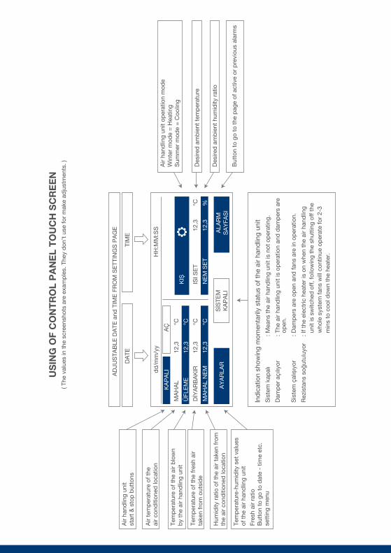
Air
hand
ling
unit
star
t &
sto
p b
utto
ns
Air
tem
per
atur
e of
the
air
cond
ition
ed lo
catio
n
Tem
per
atur
e of
the
air
blo
wn
by
the
air
hand
ling
unit
Tem
per
atur
e of
the
fres
h ai
rta
ken
from
out
sid
e
Hum
idity
rat
io o
f the
air
take
n fr
omth
e ai
r co
nditi
oned
loca
tion
Tem
per
atur
e-hu
mid
ity s
et v
alue
sof
the
air
hand
ling
unit
Fres
h ai
r ra
tioB
utto
n to
go
to d
ate
- tim
e et
c.se
ttin
g m
enu
But
ton
to g
o to
the
pag
e of
act
ive
or p
revi
ous
alar
ms
Air
hand
ling
unit
oper
atio
n m
ode
Win
ter
mod
e =
Hea
ting
Sum
mer
mod
e =
Coo
ling
Des
ired
am
bie
nt t
emp
erat
ure
Des
ired
am
bie
nt h
umid
ity r
atio
Ind
icat
ion
show
ing
mom
enta
rily
stat
us o
f the
air
hand
ling
unit
Sis
tem
kap
alı
: Mea
ns t
he a
ir ha
ndlin
g un
it is
not
op
erat
ing.
Dam
per
açı
lıyor
: T
he a
ir ha
ndlin
g un
it is
op
erat
ion
and
dam
per
s ar
e
op
en.
Sis
tem
çal
ıșıy
or
: Dam
per
s ar
e op
en a
nd fa
ns a
re in
op
erat
ion.
Rez
ista
ns s
oğut
uluy
or
: If t
he e
lect
ric h
eate
r is
on
whe
n th
e ai
r ha
ndlin
g
uni
t is
sw
itche
d o
ff, f
ollo
win
g th
e sh
uttin
g of
f the
who
le s
yste
m fa
ns w
ill c
ontin
ue o
per
ate
for
2-3
m
ins
to c
ool d
own
the
heat
er.
KA
PA
LI
MA
HA
L
ÜFL
EM
E
DİY
AR
BA
KIR
MA
HA
L N
EM
ISI S
ET
NE
M S
ET
12,3
12,3
°C %
12,3
12,3
12,3
12,3
°C °C °C °C
SİS
TEM
KA
PA
LIA
LAR
MS
AY
FAS
I
KIȘ
AY
AR
LAR
US
ING
OF
CO
NT
RO
L P
AN
EL
TO
UC
H S
CR
EE
N( T
he v
alue
s in
the
scr
eens
hots
are
exa
mp
les.
The
y d
on’t
use
for
mak
e ad
just
men
ts. )
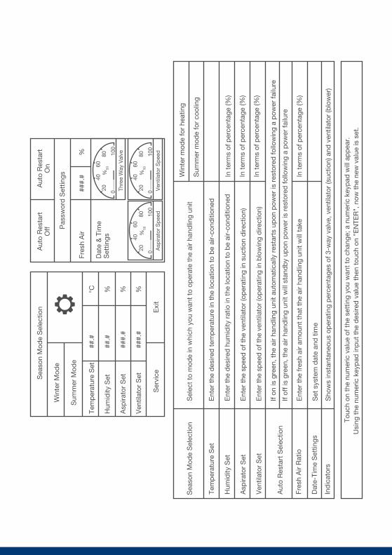
Sea
son
Mod
e S
elec
tion
Aut
o R
esta
rtO
ffA
uto
Res
tart
On
Pas
swor
d S
ettin
gs
Fres
h A
ir
Dat
e &
Tim
eS
ettin
gs
###.
#%
Win
ter
Mod
e
Sum
mer
Mod
e
Ser
vice
Exi
t
Tem
per
atur
e S
et
Hum
idity
Set
Asp
irato
r S
et
Ven
tilat
or S
et
##.#
##.#
###.
#
###.
#
°C % % %
Sea
son
Mod
e S
elec
tion
Tem
per
atur
e S
et
Hum
idity
Set
Asp
irato
r S
et
Ven
tilat
or S
et
Aut
o R
esta
rt S
elec
tion
Fres
h A
ir R
atio
Dat
e-Ti
me
Set
tings
Ind
icat
ors
Ent
er t
he d
esire
d t
emp
erat
ure
in t
he lo
catio
n to
be
air-
cond
ition
ed
Ent
er t
he d
esire
d h
umid
ity r
atio
in t
he lo
catio
n to
be
air-
cond
ition
ed
Ent
er t
he s
pee
d o
f the
ven
tilat
or (o
per
atin
g in
suc
tion
dire
ctio
n)
Ent
er t
he s
pee
d o
f the
ven
tilat
or (o
per
atin
g in
blo
win
g d
irect
ion)
If on
is g
reen
, the
air
hand
ling
unit
auto
mat
ical
ly r
esta
rts
upon
pow
er is
res
tore
d fo
llow
ing
a p
ower
failu
re
If of
f is
gree
n, t
he a
ir ha
ndlin
g un
it w
ill s
tand
by
upon
pow
er is
res
tore
d fo
llow
ing
a p
ower
failu
re
Ent
er t
he fr
esh
air
amou
nt t
hat
the
air
hand
ling
unit
will
tak
e
Set
sys
tem
dat
e an
d t
ime
Sho
ws
inst
anta
neou
s op
erat
ing
per
cent
ages
of 3
-way
val
ve, v
entil
ator
(suc
tion)
and
ven
tilat
or (b
low
er)
Sel
ect
to m
ode
in w
hich
you
wan
t to
op
erat
e th
e ai
r ha
ndlin
g un
itW
inte
r m
ode
for
heat
ing
Sum
mer
mod
e fo
r co
olin
g
In t
erm
s of
per
cent
age
(%)
In t
erm
s of
per
cent
age
(%)
In t
erm
s of
per
cent
age
(%)
In t
erm
s of
per
cent
age
(%)
Touc
h on
the
num
eric
val
ue o
f the
set
ting
you
wan
t to
cha
nge;
a n
umer
ic k
eyp
ad w
ill a
pp
ear.
Usi
ng t
he n
umer
ic k
eyp
ad in
put
the
des
ired
val
ue t
hen
touc
h on
"E
NTE
R",
now
the
new
val
ue is
set
.
010
0
20 Thre
e W
ay V
alve80
40%
50
60
010
0
20 Ven
tilat
or S
pee
d
8040
%50
60
010
0
20 Asp
irato
r S
pee
d8040
%50
60

Pha
se p
rote
ctio
n al
arm
Em
erge
ncy
stop
is p
ushe
dor
the
lid
is o
pen
No
air
flow
Air
hand
ling
unit
inve
rtor
faul
t
Free
zing
ala
rm
Com
pre
ssor
1 m
otor
pro
tect
ion
alar
m
Com
pre
ssor
2 m
otor
pro
tect
ion
alar
m
Low
hig
h p
ress
ure
alar
m
If on
e of
or
all o
f the
pha
ses;
The
air
hand
ling
unit
is e
qui
pp
ed w
ith e
mer
genc
yp
ush
but
tons
loca
ted
nex
t to
doo
rs o
f eac
h su
ctio
nan
d b
low
ing
vent
ilato
rs.
Bes
ides
, eac
h d
oor
is e
qui
pp
ed w
ith a
saf
ety
switc
h.
Doe
s in
vert
or r
ecei
ve p
ower
?
Blo
win
g or
suc
tion
vent
ilato
r in
vert
or p
rote
ctio
n tr
ip
Ab
sent
Low
Hig
h
A m
easu
rem
ent
shou
ld b
e ta
ken
by
a re
liab
le in
stru
men
t.
Mak
e su
re t
hat
syst
em is
fed
by
a re
liab
le v
olta
ge (3
-pha
se/3
80V
+N
).
Che
ck t
hat
doo
rs b
low
ing
and
suc
tion
vent
ilato
rs a
re fu
lly c
lose
d.
Che
ck t
hat
emer
genc
y st
ops
of b
low
ing
and
suc
tion
vent
ilato
rs a
re n
ot d
epre
ssed
.
Che
ck t
hat
blo
win
g an
d s
uctio
n ve
ntila
tors
run
whe
n th
e ai
r ha
ndlin
g un
it is
sta
rted
Not
e d
own
the
faul
t co
des
from
the
scr
eens
of
the
inve
rtor
s an
d in
form
the
cod
es t
o th
e se
rvic
e
Che
ck t
hat
the
wat
er t
emp
erat
ure
at t
he in
let
of t
he a
ir ha
ndlin
g un
it is
suf
ficie
nt (7
0-90
oC)
Pre
par
e yo
ur m
easu
ring
inst
rum
ent
and
cal
l the
ser
vice
.
Che
ck c
lean
in o
f filte
rs
Che
ck c
lean
ing
of c
ond
ense
r he
at e
xcha
nger
If fil
ter
and
con
den
ser
is c
lean
cal
l the
ser
vice
ALA
RM
S A
ND
TH
EIR
ME
AN
ING
S
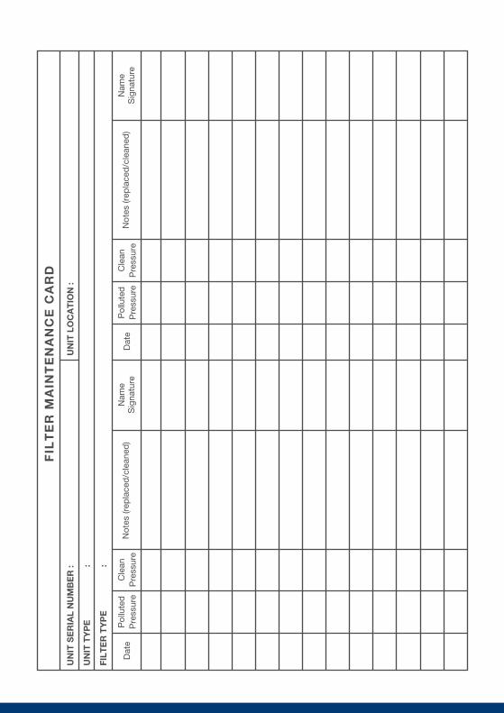
FIL
TE
R M
AIN
TE
NA
NC
E C
AR
D
UN
IT S
ER
IAL
NU
MB
ER
:
UN
IT T
YP
E
:
FILT
ER
TY
PE
:
Dat
eN
otes
(rep
lace
d/c
lean
ed)
Nam
eS
igna
ture
Pol
lute
dP
ress
ure
Cle
anP
ress
ure
Dat
eN
otes
(rep
lace
d/c
lean
ed)
Nam
eS
igna
ture
Pol
lute
dP
ress
ure
Cle
anP
ress
ure
UN
IT L
OC
AT
ION
:

Please note that the components in the picture are for illustration pupose only.Actual layout and numbers can be different.
37 8
2
HE
PA
FIL
TER
HY
GE
NIC
LO
CA
TIO
N
+ P
oziti
ve P
ress
ure
- N
egat
ive
Pre
ssur
eTR
AN
SM
ETE
R R
OO
MP
RE
SS
UR
E S
EN
SO
R
BLOWING TO THE LOCATION
DU
CK
TY
PE
HE
ATE
RB
LOW
ING
TO
TH
E L
OC
ATI
ON
( BO
AR
D R
EQ
UIR
ED
)
PA
CK
AG
E T
YP
EH
YG
IEN
IC A
IR H
AN
DLIN
G U
NIT
OP
ER
ATI
NG
RO
OM
EN
TRA
NC
EC
OR
RID
OR
IN F
RO
NT
OF
THE
DO
OR
4+ -
Lam
inar
flow
or
hep
a fil
ter
units
Panel frame and LCD screenair handling unit LCD control
Suc
tion
Inle
t
Suc
tion
Inle
t
Suc
tion
Inle
t
PT
- 10
0
PT
- 10
0
EX
HA
US
T
FRE
SH
AIR
INLE
T
HU
MID
ITY
SE
NS
OR
LOC
ATI
ON
RE
TUR
ND
UC
T
POWERAUTOMATION
HUMIDIFYNGSTEAM UNIT
BOARDMCC - DDC
Loca
tion
retu
rnV
av m
otor
Blo
win
gV
av m
otor
S c r e e n
1
1
1
11
1
13
3
32
2 4
34 M
BY
-PA
SS
RE
TUR
N P
IPE
UNIT
INFE
ED
PIP
E
SP
HE
RIC
AL
VA
LVE
DIR
T R
ETA
INE
R
RE
DU
CTI
ON
ELE
ME
NT
3-W
AY
VA
LVE
w/M
OTO
R
CO
NN
EC
TIO
N D
IAG
RA
M O
F TH
E 3
-WA
Y V
ALV
E w
/MO
TOR
If t
he
re is
a w
ate
r he
at
exchang
er
in t
he
sys
tem
, 3
-way
valv
e w
ill b
e u
se
56
910
14
1113
12
PRELIMINARY WORKS FOR THE COMMISSIONING OF THE UNIT(ACCORDING TO THE DIAGRAM ABOVE)
Cross Section andType of Cable
Implementation
1
2
3
4
5
6
7
8
9
10
11
12
13
14
Cabling for location blowing and VAV motor (ratio adjusted)
Cabling for location return and VAV motor (ratio adjusted)
Cabling for pressure difference switch for HEPA filter (if any) pollution notification
Cabling for room pressure transmitter sensor
Cabling for the duct type heater (if any) according to power, stage and voltage(220V or 380 V)
Cabling for temperature limit thermostat of the duct type heater (if any)
Cabling for control panel screen, 24 V DC to control location of the unit
Data cabling for the screen, to the control location of the unit
Air handling unit MMC DCC main branch feeder (according to kW rating)
Earthing cabling separate from air handling unit MMC DCC main branch feeder
Pipe connection for water (of suitable hardness) supply to steam humidifier
Water inlet, outlet and 3-way valve connections if there is a water heat exchanger
Drainage connections for humidifier and cooling heat exchanger
Ethernet cabling between the air handling unit and the internet connection point of thecompany for software updates and remote diagnose
Wall installation of the screen case (supplied by ACS), at the control location of the unit.Screen cases are available for either surface mount or flush mount.Please send your preference previously.Receiving the units at site, transportation of the units to the location specified in theproject and making duct connections.
Implementation of cable trays to protect all cabling done by eitherACS or your electrician
All sensor connections between the unit and the control panel
Piping, welding and refrigerant charging works for cooling heat exchanger
Commissioning of the units, delivery of training and handing over to operators
3 x 0,75Halogen Free
3 x 0,75Halogen Free
2 x 0,75Halogen Free
3 x 0,75Halogen Free
___________Halogen Free
4 x 0,75Halogen Free
3 x 0,75Halogen Free
Cat 6
_____x_____Halogen Free
By the electricianof your company
By the electricianof your company
By the electricianof your company
By the electricianof your company
By the electricianof your company
By the electricianof your company
By the electricianof your company
By the electricianof your company
By the electricianof your company
By the electricianof your company
By the plumberof your company
By the plumberof your company
By the plumberof your company
By the electrician orthe plumber of your
company
By your company
By your company
By your company
By ACS
By ACS
By ACS

Notes:

Notes:
facebook.com/acsklima twitter.com/acsklima linkedin.com/company/acs-klima
Mimar Sinan Cad. No: 81 Karakuyu, Torbali / IZMIR / TURKEYTel : +90 (232) 866 20 50 | Fax: +90 (232) 866 22 23
www.acsklima.com