Embed Size (px)
Citation preview

CnC 5Axis Manufacturing of Gears
with
™ V 4.0
An Overview
Involute Simulation Softwares Inc., Québec, Canada
www.HyGEARS.com [email protected]
December 2017

Contents
Introduction ………………….………………………………………………………………………………………………. 4 Vector Simulation ………………….………………………………………………………………………………………... 5 HyGEARS : The Vector Model ………………….…………………………………………………………………………. 6 Face Milling and Face Hobbing ………………….………………………………………………………………………. 8 Calibration ………………….……………………………………………………………………………………………….. 9 Supported Gear Types ………………….…………………………………………………………………………………... 13 5Axis CnC Post-Processor
Overview ………………….……………………………………………………………………………………………. 14 Architectures ………………….………………………………………………………………………………………. 17-20 Main Features ………………….……………………………………………………………………………………… 21 Conversion ………………….…………………………………………………………………….............................. 22 Machines / Tools ..……….……………………………………………………………………………………………. 23 Display ………………….……………………………………………………………………………………………… 27 Cycles ………………….……………………………………………………………………………………………….. 30 Metrics ………………….……………………………………………………………………………………………... 48 Cycle Timing ………………….……………………………………………………………………………………..... 49 Arbor ………………….……………………………………………………………………………………................. 50 Tool Definition ………………….……………………………………………………………………………………… 51 Tool Reference Point ..………………….…………………………………………………………………………….. 53 Part Reference Point ..………………….…………………………………………………………………………….. 56
2

Contents
Operations ………………….………………………………………………………………………………………….. 60 Processes ………………….………………………………………………………………………………………….. 63 Output ………………….……………………………………………………………………………………………….. 65 Sample result 1 .…………………..…………………………………………………………………………………… 69 Sample result 2 .…………………..…………………………………………………………………………………… 73 Sample result 3 …………………...…………………………………………………………………………………… 77
Summary …………………...………………………………………………………………………………………………….. 78
3
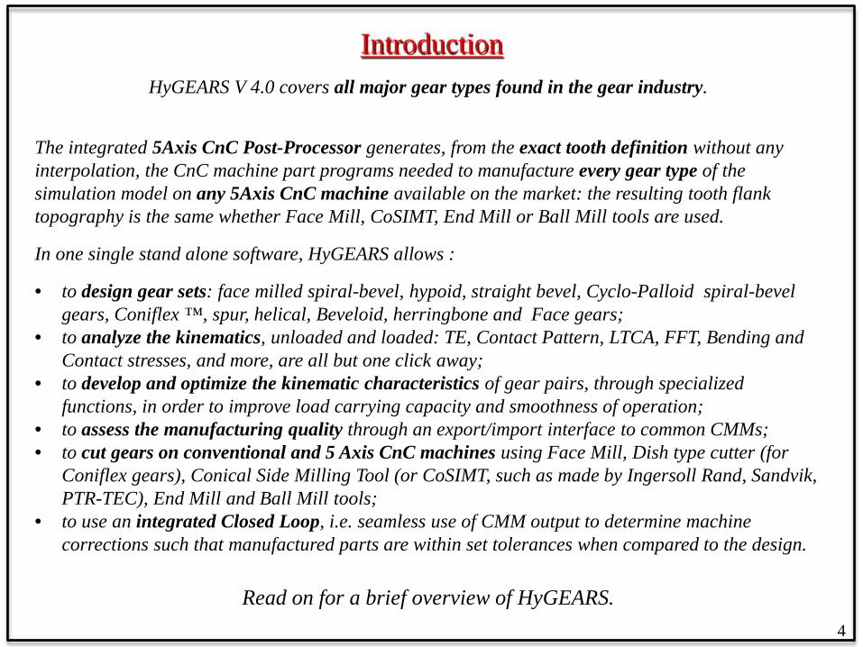
Introduction HyGEARS V 4.0 covers all major gear types found in the gear industry.
The integrated 5Axis CnC Post-Processor generates, from the exact tooth definition without any interpolation, the CnC machine part programs needed to manufacture every gear type of the simulation model on any 5Axis CnC machine available on the market: the resulting tooth flank topography is the same whether Face Mill, CoSIMT, End Mill or Ball Mill tools are used.
In one single stand alone software, HyGEARS allows :
• to design gear sets: face milled spiral-bevel, hypoid, straight bevel, Cyclo-Palloid spiral-bevel gears, Coniflex ™, spur, helical, Beveloid, herringbone and Face gears;
• to analyze the kinematics, unloaded and loaded: TE, Contact Pattern, LTCA, FFT, Bending and Contact stresses, and more, are all but one click away;
• to develop and optimize the kinematic characteristics of gear pairs, through specialized functions, in order to improve load carrying capacity and smoothness of operation;
• to assess the manufacturing quality through an export/import interface to common CMMs; • to cut gears on conventional and 5 Axis CnC machines using Face Mill, Dish type cutter (for
Coniflex gears), Conical Side Milling Tool (or CoSIMT, such as made by Ingersoll Rand, Sandvik, PTR-TEC), End Mill and Ball Mill tools;
• to use an integrated Closed Loop, i.e. seamless use of CMM output to determine machine corrections such that manufactured parts are within set tolerances when compared to the design.
Read on for a brief overview of HyGEARS. 4

HyGEARS™ is built on Vector Simulation
D’2
Z1
W2
Offset
X2
X1
X3
W3
Tooth Trace
T
L2
Work
D1 D3
D’3
Z2 Z3
Z1
L1 D1
D3
Cutter
D2
D2
X1X2
X3
α3Sliding base
WorkMachine center to back
ψ
κ
D’2
D’3
D1
Machine Plane
τ
αc
γm
Machine Plane
Cutter Blade
S
M
M
Z3
Z2
L1
yn
zn
xnϕsnOnen
Qn
xj
Γn
Bn
g
In Vector Simulation, a theoretical gear generator is simulated by translations and rotations applied to reference frames that determine the relations between cutting tool and machine.
1: The reference machine is discretized in a series of ref. frames
2: The Vector Model uses the ref. frames of the discretized machine
3: A Numerical machine is created from the Vector Model
4: A Numerical gear set is created with the Numerical machine.
5

HyGEARS™ The Vector Model
D’2
Z1
W2
Offset
X2
X1
X3
W3
Tooth Trace
T
L2
Work
D1 D3
D’3
Z2 Z3
Z1
L1 D1
D3
Cutter
D2
D2
X1X2
X3
α3Sliding base
Work
Machine center to back
ψ
κ
D’2
D’3
D1
Machine
τ
αc
γm
Machine Plane
Cutter Blade
S
M
M
Z3
Z2
L1 Point on tooth flank:
Normal on tooth flank:
X = 𝑫 𝜏 3 𝑘 1 𝑅𝑅𝑅𝑅𝑅𝑅 𝐿1 3 𝐷𝑅𝐷𝐷 𝛾𝑚 2 𝜃3 3
𝑵𝒙 = 𝑵 𝜏 3 𝑘 1 𝐿1 3 𝛾𝑚 2 𝜃3 3
The coordinates and normal vectors at any point on the tooth flanks are obtained by applying machine specific rotations and translations to cutter definition.
6

HyGEARS™ The Vector Model
Example 1) Modified Roll higher order changes:
where: L1m: modified cradle angle α3: work piece roll angle Rr: ratio of roll, cradle to work piece Cr: cradle ref. position 2C: 2nd Order parameter (Gleason notation) 6D: 3rd Order parameter 24E: 4th Order parameter 120F: 5th Order parameter 720G: 6th Order parameter
Higher order changes, up to 6th order, are superimposed to tool and work piece movements in order to achieve specific kinematic behavior.
Example 2) Helical Motion higher order changes:
where: Xbm: modified sliding base α3: work piece roll angle Rr: ratio of roll, cradle to work piece Cr: cradle ref. position 1st : 1st Order parameter 2nd : 2nd Order parameter 3rd : 3rd Order parameter 4th : 4th Order parameter 5th : 5th Order parameter 6th : 6th Order parameter
7

HyGEARS™ – Face Milling and Face Hobbing
Face Milling (single indexing)
Both the Face Milling and Face Hobbing processes are supported for all Spiral Bevel type gears.
8
Face Hobbing (continuous indexing)
HyGEARS™ – Calibration
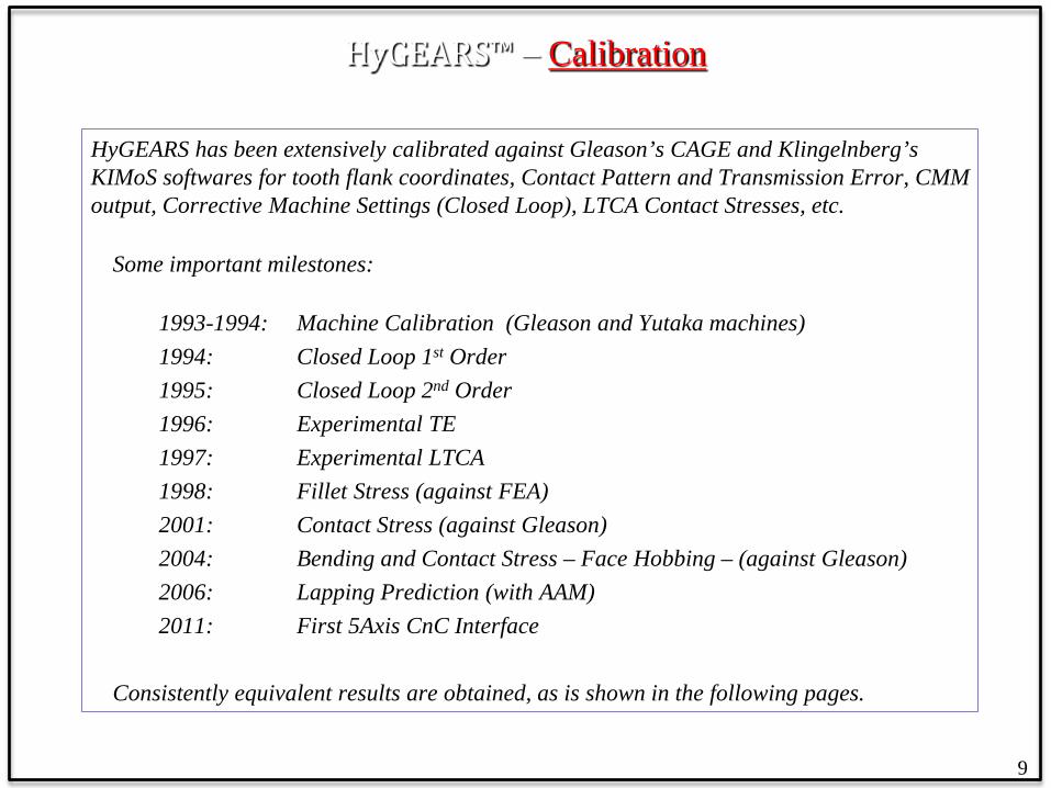
HyGEARS has been extensively calibrated against Gleason’s CAGE and Klingelnberg’s KIMoS softwares for tooth flank coordinates, Contact Pattern and Transmission Error, CMM output, Corrective Machine Settings (Closed Loop), LTCA Contact Stresses, etc.
Some important milestones:
1993-1994: Machine Calibration (Gleason and Yutaka machines) 1994: Closed Loop 1st Order 1995: Closed Loop 2nd Order 1996: Experimental TE 1997: Experimental LTCA 1998: Fillet Stress (against FEA) 2001: Contact Stress (against Gleason) 2004: Bending and Contact Stress – Face Hobbing – (against Gleason) 2006: Lapping Prediction (with AAM) 2011: First 5Axis CnC Interface
Consistently equivalent results are obtained, as is shown in the following pages.
9
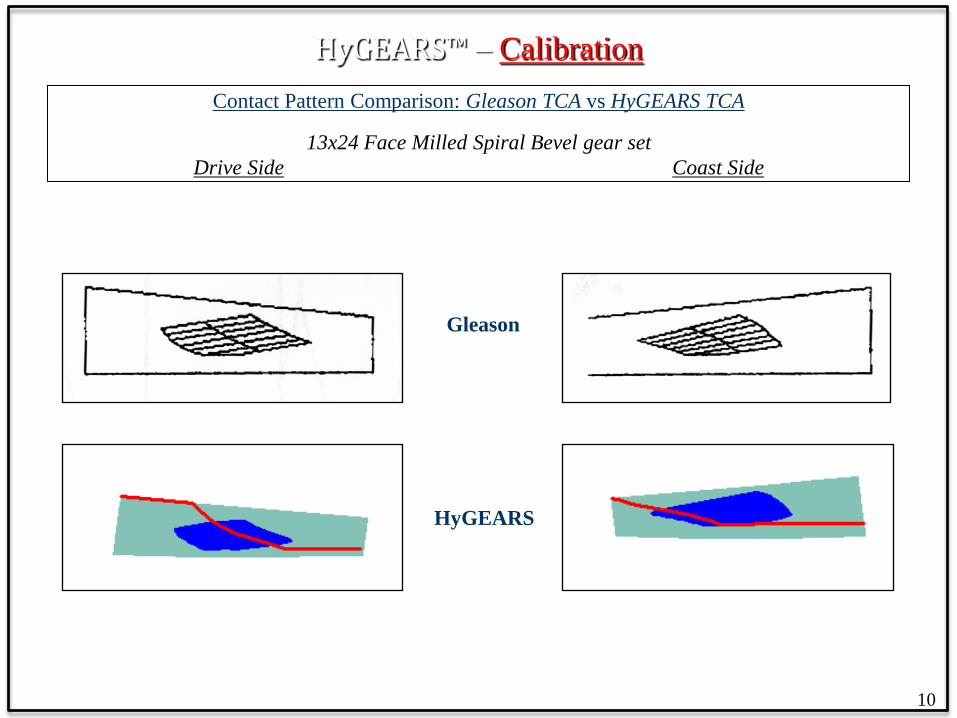
HyGEARS™ – Calibration Contact Pattern Comparison: Gleason TCA vs HyGEARS TCA
13x24 Face Milled Spiral Bevel gear set Drive Side Coast Side
Gleason
HyGEARS
10

HyGEARS™ – Calibration Tooth Flank Topography Comparison: Gleason and Klingelnberg vs HyGEARS
8x39 Face Milled Spiral Bevel gear set: comparing Nominals using the same machine settings
HyGEARS vs. Gleason Nominal
HyGEARS vs. KIMoS Nominal
The colored lines are the Gleason nominal; HyGEARS is in black Note the deviation at fillet, Heel-OB
The colored lines are the KIMoS nominal; HyGEARS is in black No deviation here !
11
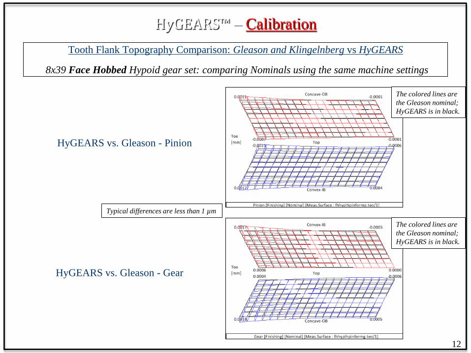
HyGEARS™ – Calibration Tooth Flank Topography Comparison: Gleason and Klingelnberg vs HyGEARS
8x39 Face Hobbed Hypoid gear set: comparing Nominals using the same machine settings
HyGEARS vs. Gleason - Pinion
HyGEARS vs. Gleason - Gear
Typical differences are less than 1 µm
The colored lines are the Gleason nominal; HyGEARS is in black.
The colored lines are the Gleason nominal; HyGEARS is in black.
12

HyGEARS™ – Supported Gear Types
The most popular gear types are supported by HyGEARS. All can be cut on any CnC machine.
• Spur/Helical • Herringbone • Spiral Bevel: Face Milled, Face Hobbed, Cyclo-Palloid • Hypoids, both conventional and High Ratio (HRH) • Straight Bevels • Coniflex (™ The Gleason Works) • Beveloid • Face Gears • Spiral Bevel Face Clutches
Hypoid
Helical
Face
Herringbone
13
Spiral-Bevel/Hypoid cutting processes: • Fixed Setting (i.e. the old 5 cut system); • Non Generated (i.e. Formate ®) • Spread Blade • Modified Roll • Duplex Helical • Semi-Completing • Face Hobbed • Cyclo-Palloid

The HyGEARS™ 5 Axis CnC Post-Processor
Overview:
HyGEARS integrates a Post-Processor that can generate CnC part programs to cut any HyGEARS supported gear type on any 3, 4 and 5 Axis CnC machine using any tool. The part programs, based on the exact tooth definition, need no user intervention and can be uploaded directly to any 3, 4 and 5Axis CnC machine. Tool and machine movements are displayed in 3D, can be rotated in any direction for better viewing, and can be animated or single stepped to allow visualization and collision detection throughout the tool path. The use of the Post-processor is easy, intuitive, and reflects the actual work done on the shop floor. The Post-processor directly supports machine architectures of “AB”, “AB”, “BA” and “BC” types, where : • the A axis rotates about the X axis • the B axis rotates about the Y axis • the C axis rotates about the Z axis Other architectures are supported through workpiece coordinates in Traori/TCP/TCPM/TCPC mode Specific machines can be created and saved for later use: the translation and rotation axes can be renamed, and their positive direction can be inverted. Typical tools include Face Milling, Coniflex™ dish, CoSIMT (i.e. Conical Side Milling Tool), End Mill and Ball Mill cutters. A tool box for each tool type can be created by the users to suit their needs.
14
The HyGEARS™ 5 Axis CnC Post-Processor
15
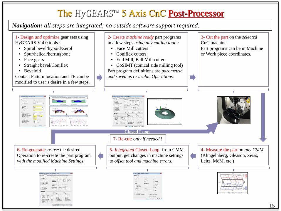
1- Design and optimize gear sets using HyGEARS V 4.0 tools :
• Spiral bevel/hypoid/Zerol • Spur/helical/herringbone • Face gears • Straight bevel/Coniflex • Beveloid
Contact Pattern location and TE can be modified to user’s desire in a few steps.
2- Create machine ready part programs in a few steps using any cutting tool :
• Face Mill cutters • Coniflex cutters • End Mill, Ball Mill cutters • CoSIMT (conical side milling tool)
Part program definitions are parametric and saved as re-usable Operations.
3- Cut the part on the selected CnC machine. Part programs can be in Machine or Work piece coordinates.
4- Measure the part on any CMM (Klingelnberg, Gleason, Zeiss, Leitz, MdM, etc.)
6- Re-generate: re-use the desired Operation to re-create the part program with the modified Machine Settings.
5- Integrated Closed Loop: from CMM output, get changes in machine settings to offset tool and machine errors.
7- Re-cut: only if needed ! Closed Loop
Navigation: all steps are integrated; no outside software support required.
The HyGEARS™ 5 Axis CnC Post-Processor
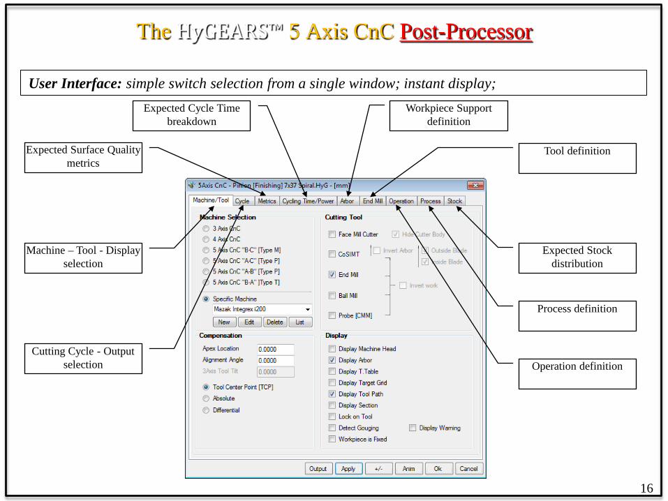
User Interface: simple switch selection from a single window; instant display;
16
Machine – Tool - Display selection
Cutting Cycle - Output selection
Expected Cycle Time breakdown
Expected Surface Quality metrics
Workpiece Support definition
Tool definition
Expected Stock distribution
Process definition
Operation definition
The HyGEARS™ 5 Axis CnC Post-Processor
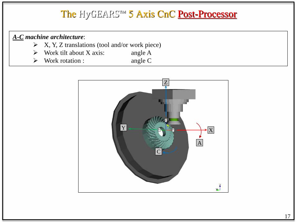
A-C machine architecture: X, Y, Z translations (tool and/or work piece) Work tilt about X axis: angle A Work rotation : angle C
17
X Y
C
Z
A
The HyGEARS™ 5 Axis CnC Post-Processor
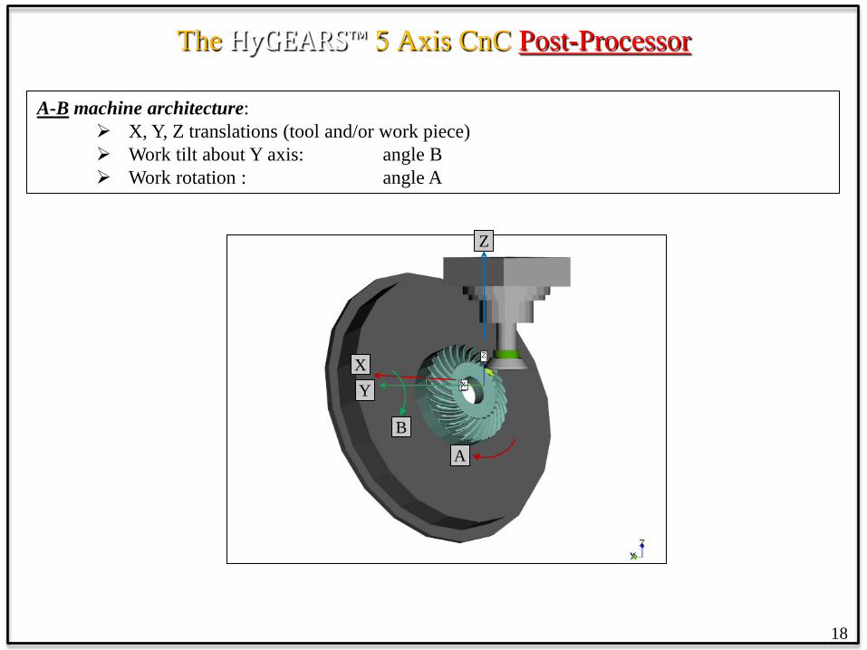
A-B machine architecture: X, Y, Z translations (tool and/or work piece) Work tilt about Y axis: angle B Work rotation : angle A
18
Y X
A
Z
B
The HyGEARS™ 5 Axis CnC Post-Processor
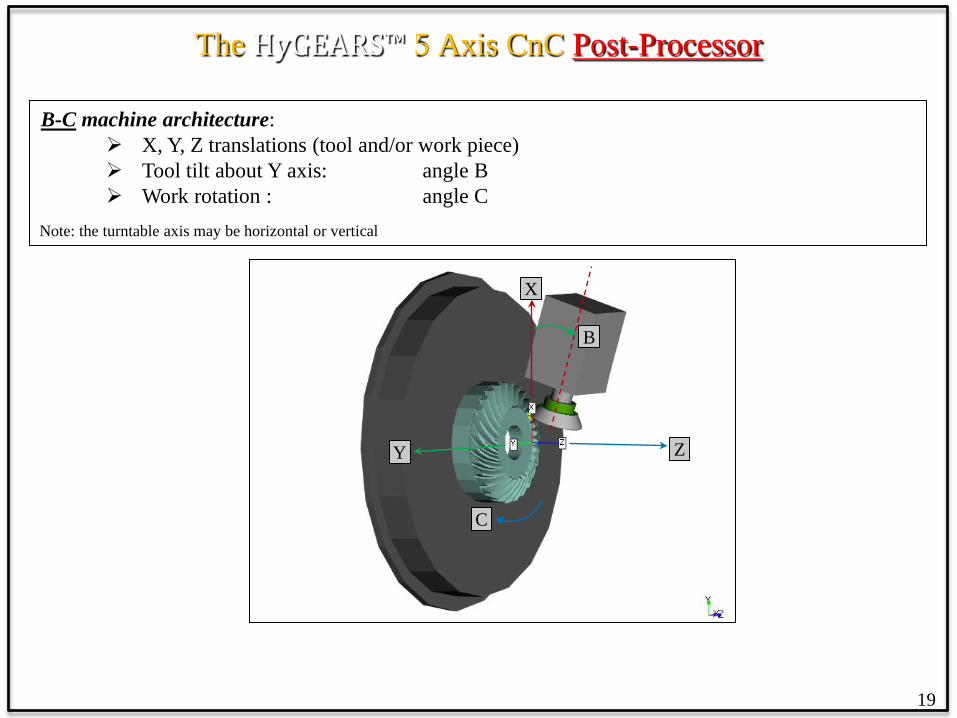
B-C machine architecture: X, Y, Z translations (tool and/or work piece) Tool tilt about Y axis: angle B Work rotation : angle C
Note: the turntable axis may be horizontal or vertical
19
Z Y
B
X
C

The HyGEARS™ 5 Axis CnC Post-Processor
B-A machine architecture: X, Y, Z translations (tool and/or work piece) Tool swivel about X axis: angle A Tool tilt about Y axis: angle B
20
X Y
A
Z
B

The HyGEARS™ 5 Axis CnC Post-Processor
Main features of the Post-Processor: • supports “AB”, “AC”, “BA” and “BC” architecture machines; • supports GCodes, Heidenhain, Siemens, Okuma, Fanuc and Mazak controllers; • supports Traori (Siemens), TCPM (Heidenhain), TCPC (Okuma) and TCP (Fanuc); • allows creation of specific 3, 4 and 5Axis machines from 4 basic architectures; specific machines can be fully
customized by the user to reproduce the exact implementation of any machine; • offers 14+ pre-defined cutting cycles for CoSIMT, End Mill and Ball Mill tools; and 4 pre-defined cutting cycles
for Face Mill tools (single roll/double roll); • CoSIMT and End Mill cutting edges can be linear or circular (to cut a Face Gear for example); • allows single pass and multi-pass roughing/semi-finishing/finishing for CoSIMT, End Mill and Ball Mill tools; • allows the generation of a negative protuberance in the fillet; • the tool path is easily customized by the user in order to optimize both cycle time and product quality; • allows automated / single stepping animation of the tool and work piece through the cutting cycle; • allows the display of the supporting arbor and the machine head to detect potential collisions; • allows the creation of “Operations” which define a given task; Operations can be re-used on different parts; • allows the creation of “Processes” which are a series of “Operations” in a specific order; Processes can thus
generate a complete program sequence including roughing and semi-finishing of the tooth flank and fillet using different tools.
Part Programs:
• can be in CSV (comma separated values) format for import in Excel; • can include or exclude comments describing the logic and operations performed; • can be for Face Milling cutters (spiral bevel gears), Dish type cutters (Coniflex - ™ The Gleason Works -
gears), CoSIMT (such as made by Ingersoll Rand, Sandvik, PTR-TEC), End Mill, Ball Mill cutters.
21

The HyGEARS™ 5 Axis CnC Post-Processor
Conversion: To generate a part program, HyGEARS converts the movements of the conventional cutter (in a conventional machine) into movements of a Face Mill, Coniflex™ dish, CoSIMT, End Mill or a Ball Mill tool in a 5Axis CnC machine where:
• the relative orientation between the ref. frames of tool and work in the conventional machine
are maintained in the CnC machine; • the relative position between the ref. frames of tool and work in the conventional machine are
maintained in the CnC machine.
The figure to the right shows a Face Mill cutter (pink) and a CoSIMT (green) with coincident cutting edges. The HyGEARS Post Processor tracks the movements of the Face Mill cutter in the conventional machine and converts them to CoSIMT movements in a 5Axis CnC machine. The same approach is applied to all tools and gear types.
22
Photo courtesy of PTR-TEC.de

The HyGEARS™ 5 Axis CnC Post-Processor
23
Machine/Tool: Machine and Tool selection; display options
Machines are optional; • Generic type • Specific type
Cutting Tools are optional; they are user
defined.
Display switches control what is shown on screen..
Apex Location: used in “Machine” coordinates
The HyGEARS™ 5 Axis CnC Post-Processor
24
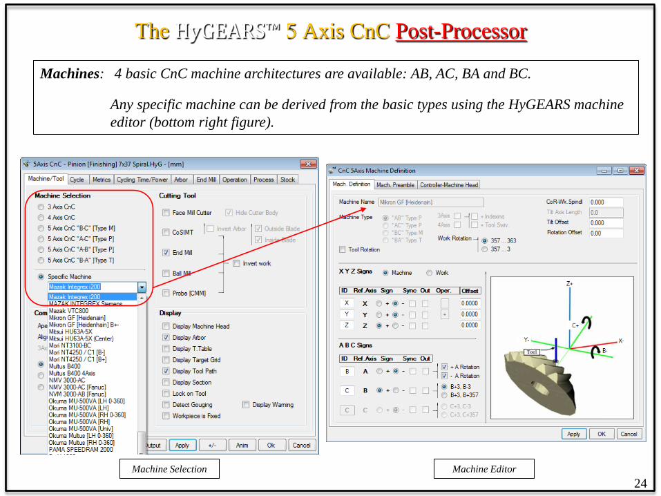
Machines: 4 basic CnC machine architectures are available: AB, AC, BA and BC. Any specific machine can be derived from the basic types using the HyGEARS machine
editor (bottom right figure).
Machine Selection Machine Editor

The HyGEARS™ 5 Axis CnC Post-Processor
Tools: HyGEARS offers 6 different tools: Face Mill cutter (spiral bevel, Zerol, hypoid gears) Dish cutter (Coniflex™ gears) CoSIMT (all gear types) End Mill (all gear types) Ball Mill (all gear types) Probe (CMM) (all gear types; for measurement)
25
Photos courtesy of PTR-TEC.de

The HyGEARS™ 5 Axis CnC Post-Processor
26
Tools: Each tool is described in a dedicated data page where the defining dimensions are entered by the user. The 30 character-long tool name is user defined.
The tools can be saved for re-use and are specific to users, i.e. they are not distributed with
HyGEARS. Hence, proprietary information remains proprietary.
Definition of an 8mm Bull Nose

The HyGEARS™ 5 Axis CnC Post-Processor
Display: Several options allow selective information display. These include: • the Machine Head, • the Machine Turn Table • the Work Arbor and support, • the Target Grid, where the target coordinates are displayed in wire frame mesh, • the Tool Path.
Display of the Target Grid (beige)
27
The HyGEARS™ 5 Axis CnC Post-Processor
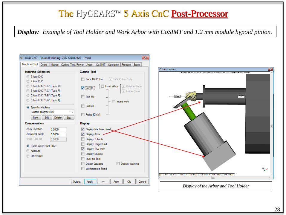
Display: Example of Tool Holder and Work Arbor with CoSIMT and 1.2 mm module hypoid pinion.
Display of the Arbor and Tool Holder
28

The HyGEARS™ 5 Axis CnC Post-Processor
Display: Detection of Gouging interference (tool back side contact with opposite tooth flank): HyGEARS can determine, and display where, if any Gouging occurs such as to alert the user of potential profile mutilation; valid for CoSIMT, End Mill, Ball Mill tools.
Display of Gouging points with Pink crosses
29
Current cutting point
The HyGEARS™ 5 Axis CnC Post-Processor
30
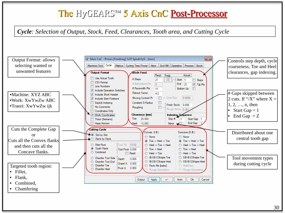
Cycle: Selection of Output, Stock, Feed, Clearances, Tooth area, and Cutting Cycle
Output Format: allows selecting wanted or unwanted features
Controls step depth, cycle coarseness, Toe and Heel clearances, gap indexing.
Tool movement types during cutting cycle Targeted tooth region:
• Fillet, • Flank, • Combined, • Chamfering
# Gaps skipped between 2 cuts. If “/X” where X = 1, 2, …, n, then • Start Gap = 1 • End Gap = Z
Distributed about one central tooth gap
Cuts the Complete Gap or
Cuts all the Convex flanks and then cuts all the
Concave flanks.
•Machine: XYZ ABC •Work: XwYwZw ABC •Traori: XwYwZw ijk

Cycle Options for CoSIMT, End Mill and Ball Mill tools
• Stock-Feed along the face width (#Facewidth Pts) and tooth depth (#Steps)
• When cutting starts and ends (Start / End) • Tool retraction at end of cycle (Retract
Factor, based on Heel tooth depth) • Whether the tooth description is with
constant roll angles or constant radius (Constant D-Radius)
• Whether the contact point moves, or does not move, along the tool’s cutting edge (Moving Contact Pt)
• Roughing and Finishing cycles • Toe and Heel clearances • Tip, Toe and Heel chamfering • Indexing sequence in order to spread tool
wear and thermal load over non sequential teeth (Skip#).
The HyGEARS™ 5 Axis CnC Post-Processor
Cycles: Cutting cycles can be extensively tailored to user preferences, depending on tool choice.
31

The HyGEARS™ 5 Axis CnC Post-Processor
Cycles: Constant D-Radius: checked: constant radial steps; insensitive for Z > ~25 un-checked: constant roll-angle steps – improved surface near fillet better for Z < ~20
32
Constant D-Radius Constant D-Roll

The HyGEARS™ 5 Axis CnC Post-Processor
Cycles: Moving Contact Pt: checked: contact point moves along tool edge; better Finish and reduced tool wear;
un-checked: contact point always at tool tip: more tool wear
33
Moving Contact Pt: Finishing Fixed Contact Pt: Roughing

The HyGEARS™ 5 Axis CnC Post-Processor
Cycles: Over Run: = 0: End Mill stops at Fillet Line > 0: End Mill extends below the Fillet Line: prevents lip forming in the fillet when negative stock is used on the flank
34
Over Run: 0 Over Run > 0
The HyGEARS™ 5 Axis CnC Post-Processor
35
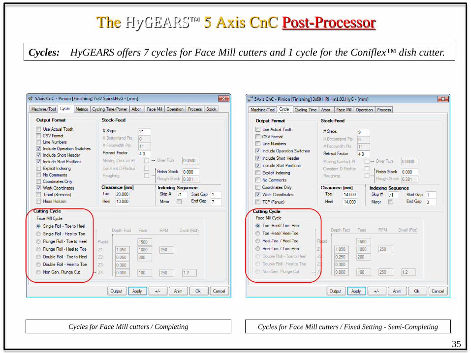
Cycles: HyGEARS offers 7 cycles for Face Mill cutters and 1 cycle for the Coniflex™ dish cutter.
Cycles for Face Mill cutters / Fixed Setting - Semi-Completing Cycles for Face Mill cutters / Completing
The HyGEARS™ 5 Axis CnC Post-Processor
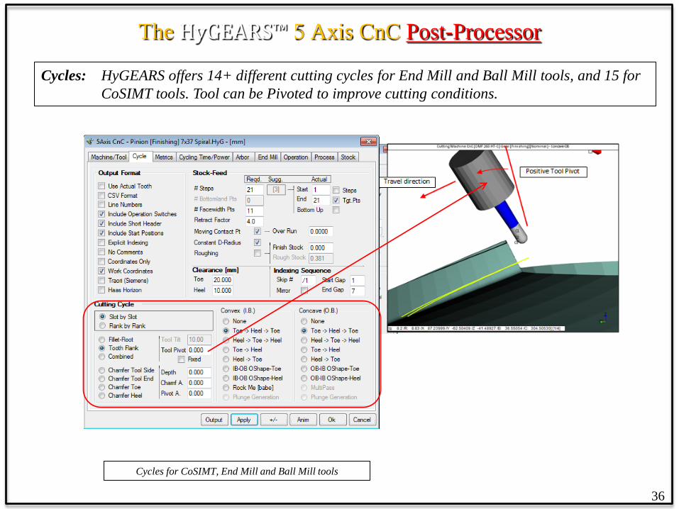
36
Cycles: HyGEARS offers 14+ different cutting cycles for End Mill and Ball Mill tools, and 15 for CoSIMT tools. Tool can be Pivoted to improve cutting conditions.
Cycles for CoSIMT, End Mill and Ball Mill tools

The HyGEARS™ 5 Axis CnC Post-Processor
Cycles: Finishing cycles for CoSIMT, End Mill and Ball Mill tools.
Finishing Cycles for CoSIMT, End Mill and Ball Mill tools
• Fillet/Root, Tooth Flank, Toe, Heel and Tip Chamfer (Deburring) are different operations;
• They can be cut Slot by Slot or Flank by Flank, depending on machine selection, work size, and how much travel is required by the machine or tool between tooth flanks;
• Finishing cycles can be different on each tooth flank.
37
The HyGEARS™ 5 Axis CnC Post-Processor
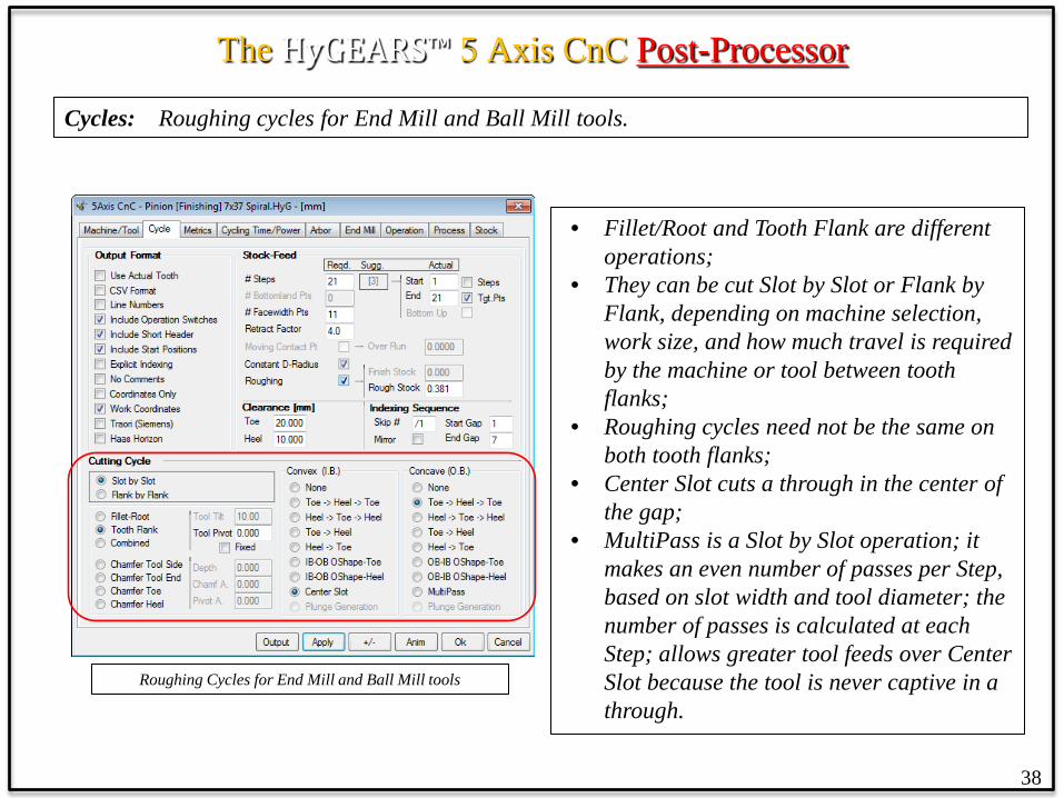
Cycles: Roughing cycles for End Mill and Ball Mill tools.
Roughing Cycles for End Mill and Ball Mill tools
• Fillet/Root and Tooth Flank are different operations;
• They can be cut Slot by Slot or Flank by Flank, depending on machine selection, work size, and how much travel is required by the machine or tool between tooth flanks;
• Roughing cycles need not be the same on both tooth flanks;
• Center Slot cuts a through in the center of the gap;
• MultiPass is a Slot by Slot operation; it makes an even number of passes per Step, based on slot width and tool diameter; the number of passes is calculated at each Step; allows greater tool feeds over Center Slot because the tool is never captive in a through.
38
The HyGEARS™ 5 Axis CnC Post-Processor
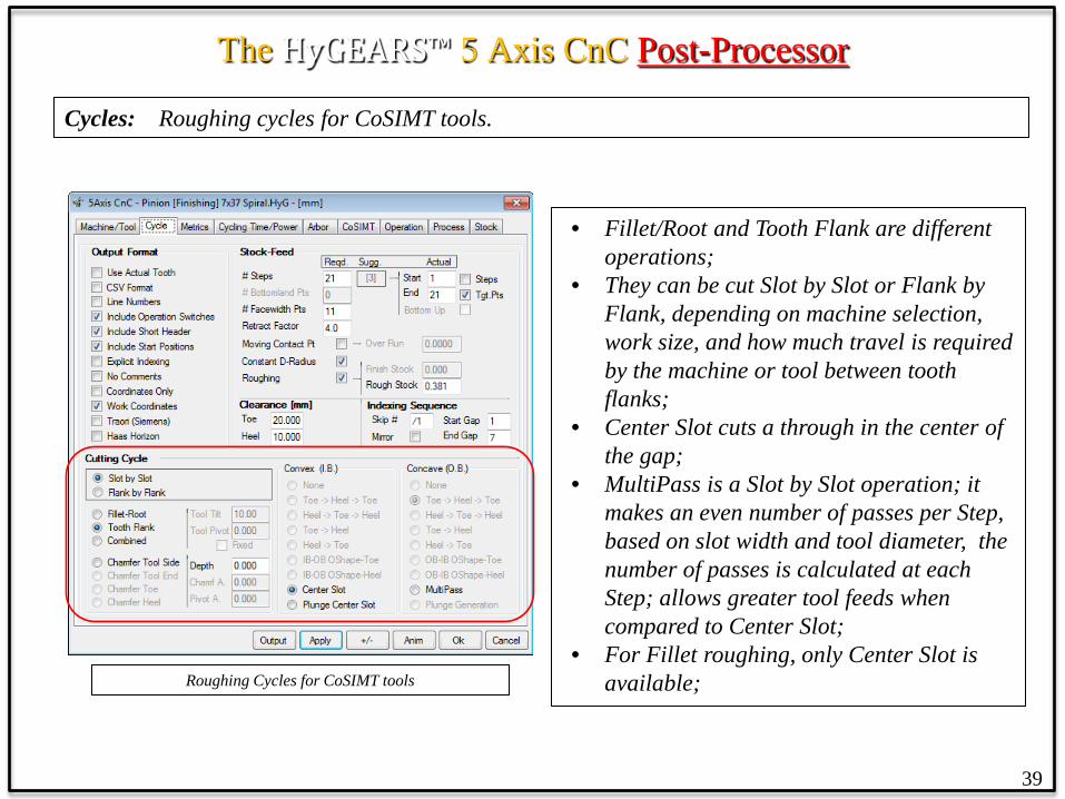
Cycles: Roughing cycles for CoSIMT tools.
Roughing Cycles for CoSIMT tools
• Fillet/Root and Tooth Flank are different operations;
• They can be cut Slot by Slot or Flank by Flank, depending on machine selection, work size, and how much travel is required by the machine or tool between tooth flanks;
• Center Slot cuts a through in the center of the gap;
• MultiPass is a Slot by Slot operation; it makes an even number of passes per Step, based on slot width and tool diameter, the number of passes is calculated at each Step; allows greater tool feeds when compared to Center Slot;
• For Fillet roughing, only Center Slot is available;
39
The HyGEARS™ 5 Axis CnC Post-Processor
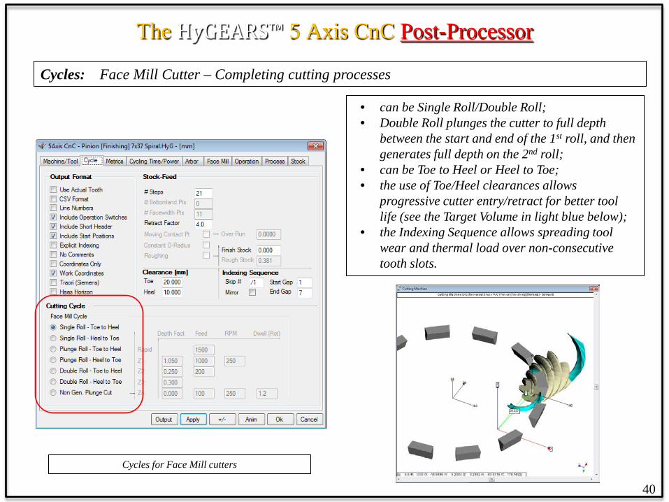
Cycles: Face Mill Cutter – Completing cutting processes
Cycles for Face Mill cutters
• can be Single Roll/Double Roll; • Double Roll plunges the cutter to full depth
between the start and end of the 1st roll, and then generates full depth on the 2nd roll;
• can be Toe to Heel or Heel to Toe; • the use of Toe/Heel clearances allows
progressive cutter entry/retract for better tool life (see the Target Volume in light blue below);
• the Indexing Sequence allows spreading tool wear and thermal load over non-consecutive tooth slots.
40
The HyGEARS™ 5 Axis CnC Post-Processor
41
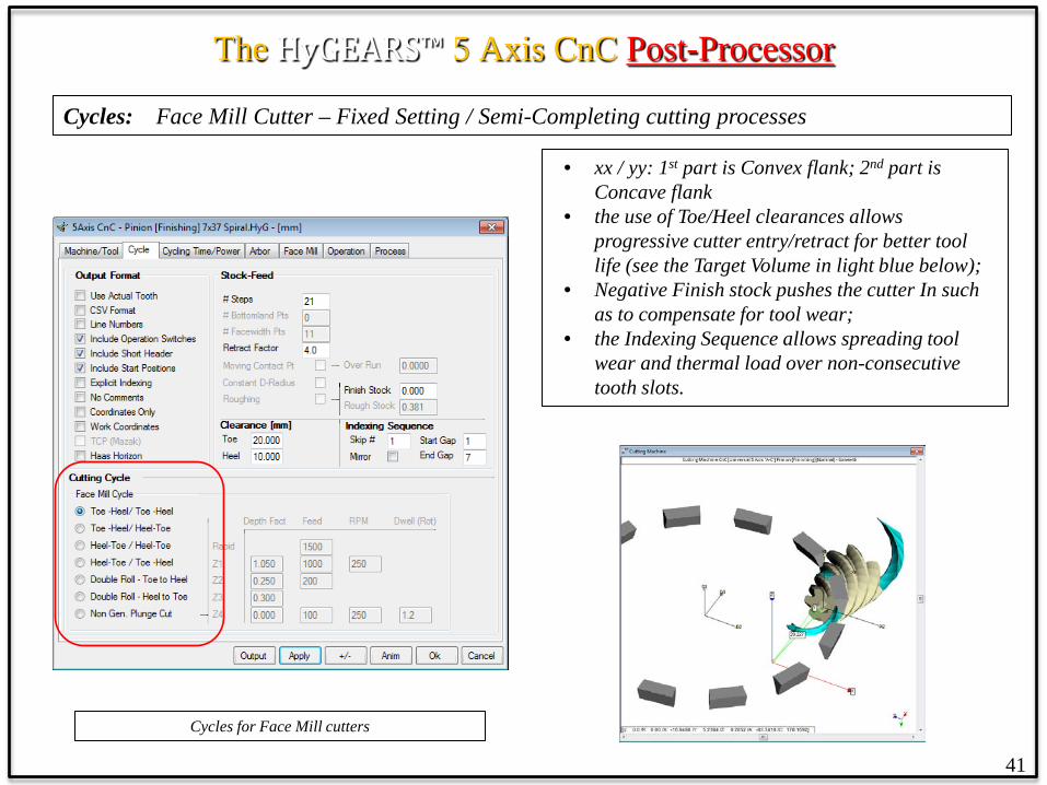
Cycles: Face Mill Cutter – Fixed Setting / Semi-Completing cutting processes
Cycles for Face Mill cutters
• xx / yy: 1st part is Convex flank; 2nd part is Concave flank
• the use of Toe/Heel clearances allows progressive cutter entry/retract for better tool life (see the Target Volume in light blue below);
• Negative Finish stock pushes the cutter In such as to compensate for tool wear;
• the Indexing Sequence allows spreading tool wear and thermal load over non-consecutive tooth slots.

The HyGEARS™ 5 Axis CnC Post-Processor
Cycles: Face Mill Cutter
Face Mill cutter definition
• the Face Mill cutter used on the 5Axis CnC machine can be defined and saved;
• cutter Diameter, Blade angles, Edge Radii, and Point Width are those described in the Summary Editor (see below).
42

The HyGEARS™ 5 Axis CnC Post-Processor
43
Cycles: CoSIMT, End Mill, Ball Mill
Cycles for CoSIMT, End Mill and Ball Mill tools
• CoSIMT, End Mill and Ball Mill tools can rough and finish tooth flanks and fillet;
• CoSIMT, Bull Nose End Mill and Ball Mill tools can finish the fillet, and a protuberance can be imposed in the form of negative Stock;
• End Mill and Ball Mill can Chamfer (i.e. deburring) tooth Tip;
• Positive and Negative stock can be used; • Toe and Heel clearances can be imposed; • The Indexing Sequence can be selected.

The HyGEARS™ 5 Axis CnC Post-Processor
Cycles: Example: End Mill tool, Toe-Heel-Toe (IB-Side) / Heel-Toe-Heel (OB-Side)
End Mill cycles
• Cutting cycles can be different for each tooth flank (IB-OB, Left-Right);
• a cutting cycle may start on the IB and finish on the OB (Left-Right for non spiral-bevels);
• for example, with the selections made in the left figure, given the IB cycle ends at Heel, unless otherwise dictated it could make sense to start the OB cycle at Heel to reduce cycle time (the tool path is the red line in the figure below).
44

The HyGEARS™ 5 Axis CnC Post-Processor
45
Cycles: Example: tapered End Mill tool, O-Shaped cycles
O-Shaped cycles
• one starting flank – IB / OB - and tooth end – Toe / Heel - is selected, the other being slave;
• for O-Shaped cycles, the cutting cycle takes a pass along the face width on the one flank and switches to the opposite flank for return; the cycle then switches back to the starting and takes one step depth wise before starting over again;
• can be a real time saver when used with a Tapered End Mill or a CoSIMT.
The HyGEARS™ 5 Axis CnC Post-Processor
46
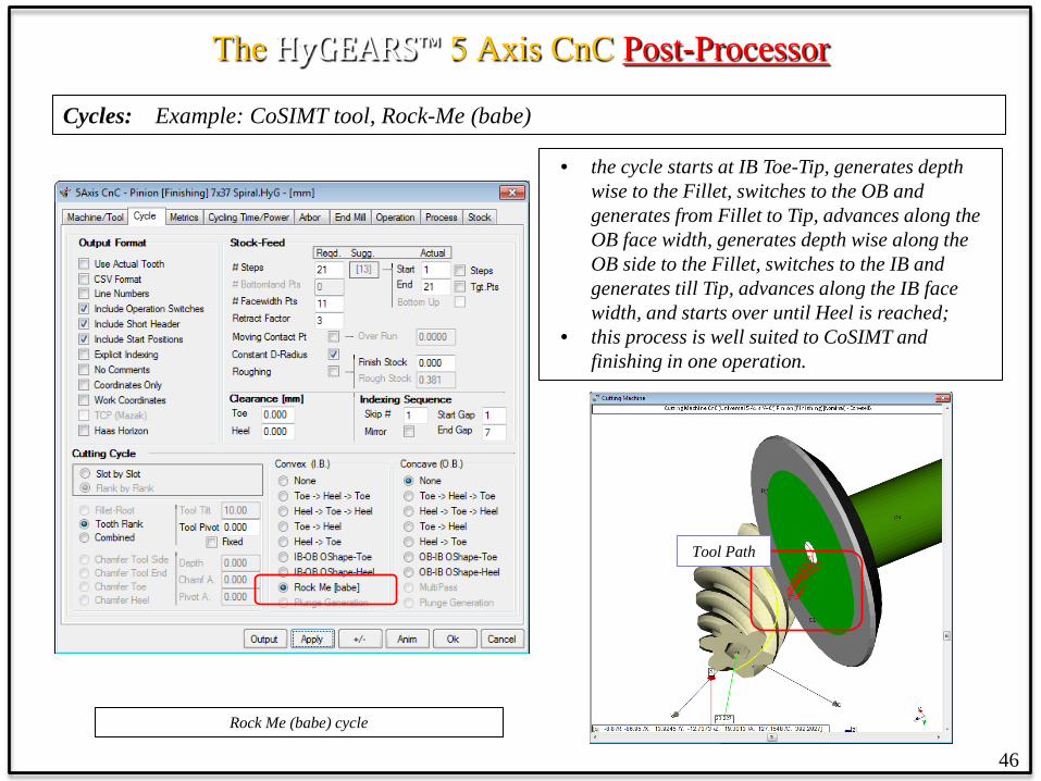
Cycles: Example: CoSIMT tool, Rock-Me (babe)
Rock Me (babe) cycle
• the cycle starts at IB Toe-Tip, generates depth wise to the Fillet, switches to the OB and generates from Fillet to Tip, advances along the OB face width, generates depth wise along the OB side to the Fillet, switches to the IB and generates till Tip, advances along the IB face width, and starts over until Heel is reached;
• this process is well suited to CoSIMT and finishing in one operation.
Tool Path

The HyGEARS™ 5 Axis CnC Post-Processor
47
Cycles: Example: End Mill tool, Fillet
Fillet cycles
• Fillet finishing is integral to tooth flank finishing when using a Face Mill cutter since the tool sweeping movement generates the fillet;
• Fillet finishing is done in a distinct operation when using CoSIMT, End Mill or Ball Mill tools;
• negative Stock can be imposed to produce a protuberance;
• End Mill and Ball Mill tools can be tilted away from the tooth to avoid interference;
• Fillet finishing uses the same cycles as for Flank finishing.

The HyGEARS™ 5 Axis CnC Post-Processor
48
Metrics: Profile-wise step depth, slot width, expected surface quality
Profile-wise Steps
Considered Tooth flank
Step by step breakdown Peak-Prof.
Ramp-Ang.

The HyGEARS™ 5 Axis CnC Post-Processor
49
Cycling Time: Flank by flank operation Cycling time breakdown
Concave Tooth Flank
Convex Tooth flank
Tool Feeds & Speeds
Complete Cycle
For Each Tooth Flank • Line: each line in the face
width direction • Face: the complete tooth
flank • Plunge/Retract: time needed
to go in and out of the slot; • Return: return trip time
(when applicable)
For the current cycle • Total/Slot: total time per slot • Indexing: indexing time • Operation: time needed to
complete the operation
The HyGEARS™ 5 Axis CnC Post-Processor
50
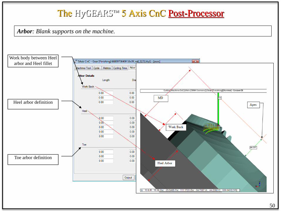
Arbor: Blank supports on the machine.
Work body between Heel arbor and Heel fillet
Heel arbor definition
Toe arbor definition

The HyGEARS™ 5 Axis CnC Post-Processor
51
Tool Definition: Tool dimensions, reference (tools are user defined).
Tool dimensions
Tip reference warning
Tool name & ID Tool list
Tooth reference dims.
Tool feeds & speeds

The HyGEARS™ 5 Axis CnC Post-Processor
Tools: CoSIMT tools (or Conical Side Milling Tool; same as Sandvik’s InvoMill and Gleason’s UpGear) can have circular cutting edges which allow the generation of tooth profiles with concave profile curvature, such as Face Gears. Blade angles are totally flexible.
Definition of a CoSIMT
52
Spherical Cutting Edge
The HyGEARS™ 5 Axis CnC Post-Processor
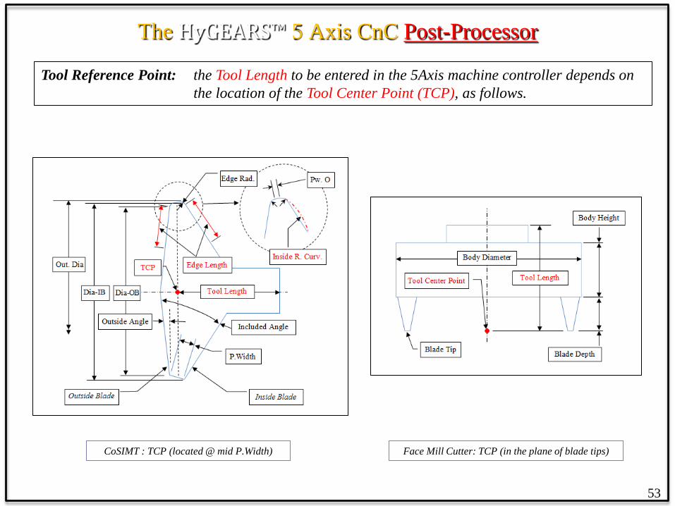
Tool Reference Point: the Tool Length to be entered in the 5Axis machine controller depends on the location of the Tool Center Point (TCP), as follows.
53
CoSIMT : TCP (located @ mid P.Width) Face Mill Cutter: TCP (in the plane of blade tips)
The HyGEARS™ 5 Axis CnC Post-Processor
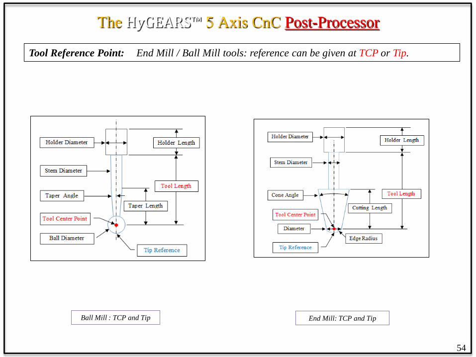
Tool Reference Point: End Mill / Ball Mill tools: reference can be given at TCP or Tip.
54
Ball Mill : TCP and Tip End Mill: TCP and Tip
The HyGEARS™ 5 Axis CnC Post-Processor
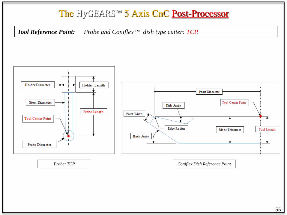
Tool Reference Point: Probe and Coniflex™ dish type cutter: TCP.
55
Coniflex Dish Reference Point Probe: TCP
The HyGEARS™ 5 Axis CnC Post-Processor
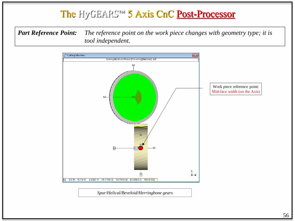
Part Reference Point: The reference point on the work piece changes with geometry type; it is tool independent.
56
Work piece reference point: Mid-face width (on the Axis)
Spur/Helical/Beveloid/Herringbone gears

The HyGEARS™ 5 Axis CnC Post-Processor
Part Reference Point: Straight Bevel / Spiral Bevel / Zerol / Coniflex gears.
57
Work piece reference point: Pitch cone Apex
Straight Bevel/Spiral Bevel/Zerol/Coniflex gears

The HyGEARS™ 5 Axis CnC Post-Processor
Part Reference Point: Hypoid gears.
58
Work piece reference point: Crossing Point (Xp)
Hypoid gears
The HyGEARS™ 5 Axis CnC Post-Processor
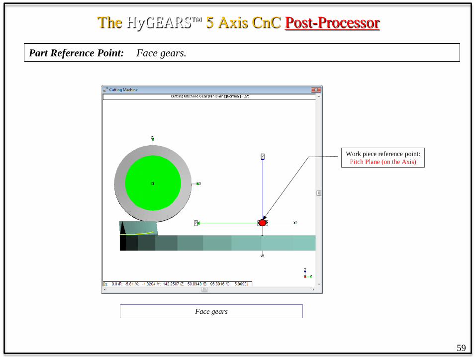
Part Reference Point: Face gears.
59
Work piece reference point: Pitch Plane (on the Axis)
Face gears
The HyGEARS™ 5 Axis CnC Post-Processor
60
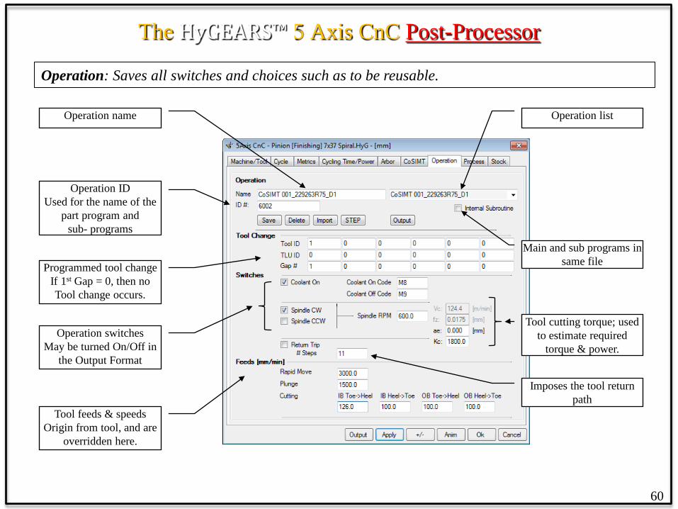
Operation: Saves all switches and choices such as to be reusable.
Operation ID Used for the name of the
part program and sub- programs
Programmed tool change If 1st Gap = 0, then no Tool change occurs.
Operation name Operation list
Operation switches May be turned On/Off in
the Output Format
Tool feeds & speeds Origin from tool, and are
overridden here.
Main and sub programs in same file
Imposes the tool return path
Tool cutting torque; used to estimate required
torque & power.

The HyGEARS™ 5 Axis CnC Post-Processor
Operations: The Operations page allows saving combinations of Machine, Tool and Cutting Cycle selections, for the current geometry, under one identifier such as to be able to use the same combinations with different geometries, or when defining Processes.
Operations Tab
• an Operation is specific to a geometry, i.e. it is saved in the “Operations.fil” file stored in a geometry’s folder;
• the Save / Delete buttons conserve and erase the selected operation;
• the Import button allows importing Operations from other geometries; thus, Operations can be re-used;
• the Output button generates the part program for the selected Operation;
• Tool Changes can be imposed at specified tooth gaps;
• Several Switches can be imposed to any given operation.
61
The HyGEARS™ 5 Axis CnC Post-Processor
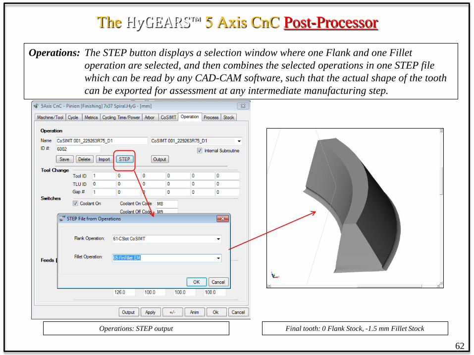
Operations: The STEP button displays a selection window where one Flank and one Fillet operation are selected, and then combines the selected operations in one STEP file which can be read by any CAD-CAM software, such that the actual shape of the tooth can be exported for assessment at any intermediate manufacturing step.
Operations: STEP output Final tooth: 0 Flank Stock, -1.5 mm Fillet Stock
62

The HyGEARS™ 5 Axis CnC Post-Processor
63
Process: Organizes Operations in a user defined sequence.
Process ID Used for the name of the
part program and sub programs
Available Operations
Process name Process list
Selected Operations
All Main and sub programs in same file
Overrides the No Comments switch for all Operations of a Process

The HyGEARS™ 5 Axis CnC Post-Processor
Process: A Process is an ordered sequence of Operations in which a Main, or Calling, program is generated which calls the selected Operations in the requested order.
For example, right column in the figure below, the Main program would call Operation “Rough MPass” first, and then Operation “Rough Fil-MPass”
64
Processes Tab
• A Process is specific to a geometry, i.e. it is saved in the “Processes.fil” file stored in a geometry’s folder;
• A Process can contain any number of operations – the controller’s memory being the practical limit;
• the Save / Delete buttons conserve and erase the selected Process;
• the Import button allows importing Processes from other geometries;
• the Output button generates the complete part program for the selected Process;
• All Switches imposed in any given operation appear in each step of the Process.

The HyGEARS™ 5 Axis CnC Post-Processor
Output: The Output button instructs HyGEARS to read the selected user choices, generate the part program and send the output to a Text Results window.
Part program Output
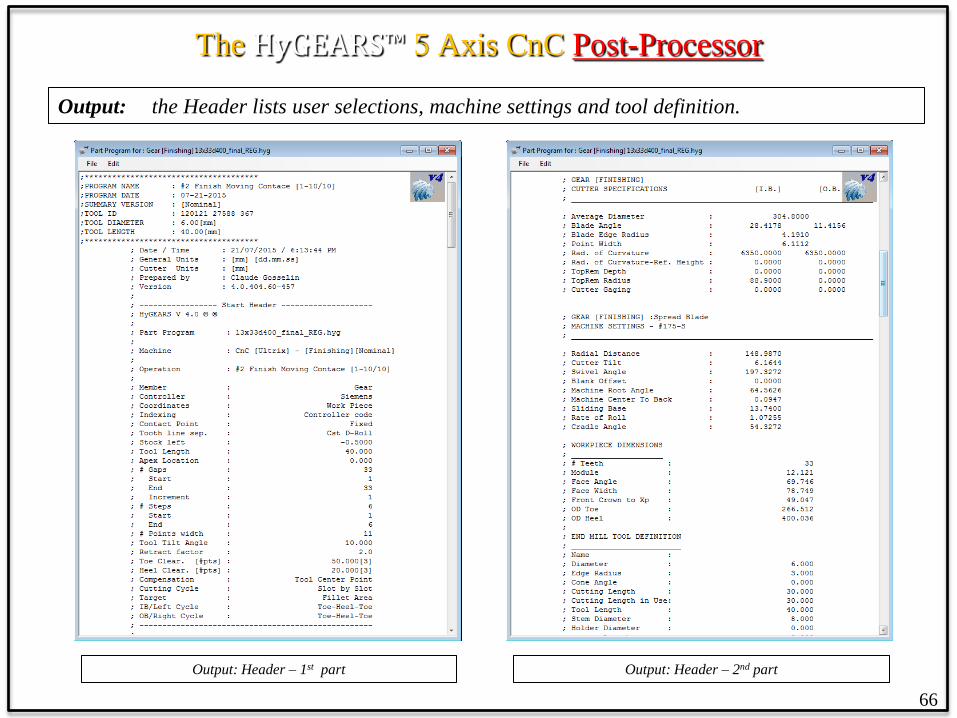
A part program comprises: • a Header, in which user selections,
machine settings and tool definition are listed; this is optional at output time using the “No comment lines” switch;
• a Preamble, specific to the selected machine, where machine code desired by the operator is added automatically;
• the Indexing Sequence, where each tooth slot calls the actual cutting program in the specified sequence order;
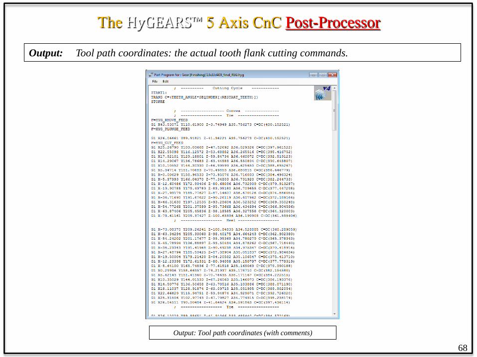
• the actual cutting program with tool path coordinates;
• Work Coordinates indicate that X, Y and Z are in work piece coordinates, and that angles A, B, C are machine angles;
• Traori, TCPM, TCP and TCPC indicate that the unit vector of the tool axis is provided along with X, Y and Z in work piece coordinates.
65
The HyGEARS™ 5 Axis CnC Post-Processor
Output: the Header lists user selections, machine settings and tool definition.
Output: Header – 1st part Output: Header – 2nd part
66

The HyGEARS™ 5 Axis CnC Post-Processor
Output: Indexing Sequence: indexes the work piece axis in the specified sequence.
Output: Header – Indexing Sequence
67
The HyGEARS™ 5 Axis CnC Post-Processor
Output: Tool path coordinates: the actual tooth flank cutting commands.
Output: Tool path coordinates (with comments)
68
The HyGEARS™ 5 Axis CnC Post-Processor
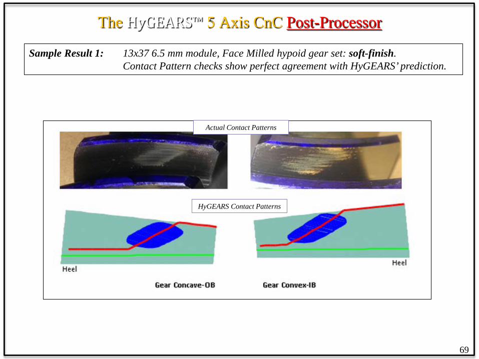
Sample Result 1: 13x37 6.5 mm module, Face Milled hypoid gear set: soft-finish. Contact Pattern checks show perfect agreement with HyGEARS’ prediction.
Actual Contact Patterns
HyGEARS Contact Patterns
69

The HyGEARS™ 5 Axis CnC Post-Processor
• Pinion Fixed Setting – Generated • Gear Spread Blade – Generated • Cut on DMU65 Monoblock (AC type
machine) • Roughing : CoSIMT • Pre-Finishing : Bull Nose End Mill • Hard finish : Tapered End Mill
13x37 hypoid gear pair on the VH tester
Actual Contact Pattern Pinion OB
HyGEARS’ Predicted Contact Pattern
Pinion OB
70
Sample Result 1: 13x37 6.5 mm module, Face Milled hypoid gear set: hard-finish. Contact Pattern check shows perfect agreement with HyGEARS’ prediction.

The HyGEARS™ 5 Axis CnC Post-Processor
Sample Result 1: 13x37 6.5 mm module, Face Milled hypoid gear set: Pinion CMM output after hard-finish shows negligible deviations between actual and HyGEARS’ theoretical.
71

The HyGEARS™ 5 Axis CnC Post-Processor
Sample Result 1: 13x37 6.5 mm module, Face Milled hypoid gear set: Gear CMM output after hard-finish shows negligible deviations between actual and HyGEARS’ theoretical.
72

The HyGEARS™ 5 Axis CnC Post-Processor
Sample Result 2: 26x26, 1.5 mm module, duplex helical spiral-bevel pinion cut using a Face Mill cutter.
Pinion CMM output after soft cut show a combination of pressure and spiral
angle errors, plus some surface bias and lengthwise crowning.
73
The HyGEARS™ 5 Axis CnC Post-Processor
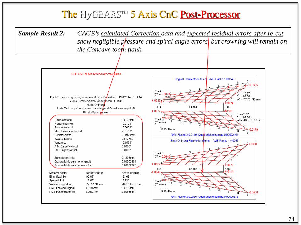
Sample Result 2: GAGE’s calculated Correction data and expected residual errors after re-cut show negligible pressure and spiral angle errors, but crowning will remain on the Concave tooth flank.
74

The HyGEARS™ 5 Axis CnC Post-Processor
Sample Result 2: HyGEARS’ calculated Correction data and expected residual errors after re-cut show negligible pressure and spiral angle errors, and crowning on the Concave tooth flank disappears.
75

The HyGEARS™ 5 Axis CnC Post-Processor
Sample Result 2: CMM results after the 1st corrective cycle appear below. As expected, crowning remains in the GAGE corrected tooth while it is not visible in the HyGEARS corrected tooth.
In both the GAGE and HyGEARS corrected teeth, spiral and pressure angle errors have been eliminated.
76
GAGE correction HyGEARS correction
The HyGEARS™ 5 Axis CnC Post-Processor
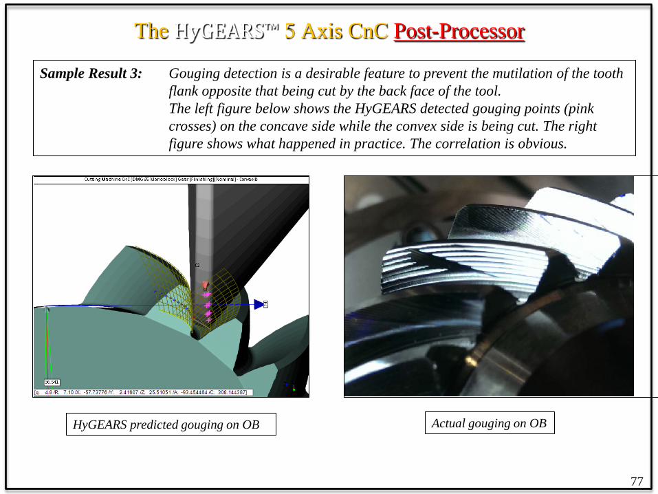
Sample Result 3: Gouging detection is a desirable feature to prevent the mutilation of the tooth flank opposite that being cut by the back face of the tool.
The left figure below shows the HyGEARS detected gouging points (pink crosses) on the concave side while the convex side is being cut. The right figure shows what happened in practice. The correlation is obvious.
77
HyGEARS predicted gouging on OB Actual gouging on OB
Summary 1. HyGEARS’ tooth flank generation and TCA calculations match Gleason’s CAGE and
Klingelnberg’s KIMoS; therefore, the reference topography in HyGEARS is the exact tooth definition;
2. HyGEARS designs gear set geometries, i.e. the Dimension sheet and Machine settings for all HyGEARS supported geometries are calculated and a Summary is created;
3. Geometries can be imported from Gleason SPA, KIMoS ND and BECAL ND files;
4. Spiral bevel cutting processes such as Face Milling and Face Hobbing are integral to HyGEARS;
5. Geometry kinematics can be analyzed unloaded and loaded for contact and tooth fillet stresses;
6. 5Axis CnC machine Post-Processing, i.e. the generation of a part program “machine ready”, is integral to HyGEARS;
7. Part programs are generated in reference to the exact tooth surface definition (rather than an interpolated surface as is the case with other CAM softwares);
8. Part program generation is based on a wide range of user selected cycle features;
9. Any 5Axis CnC machine architecture can be accommodated; current architectures include “AB”, “AC”, “BA” and “BC”; any controller can be accommodated; current controllers include GCodes, Siemens, Heidenhain, Okuma, Fanuc and Mazak;
10. Part programs can be in Machine coordinates, Work piece coordinates with axis angles, or Work piece coordinates with tool axis vector (Traori, TCPM, TCP and TCPC);
78

Summary 11. Users can define their own tool box for Face Mill, CoSIMT, End Mill, Ball Mill and Probe tools;
12. Cutting Cycles include Slot by Slot and Flank by Flank, both for tooth flank and fillet; Toe, Heel and Tip chamfering is available;
13. Animations and single stepping allow the visualization of tool movements and the verification of tool paths and possible interference;
14. A “Metrics” function gives an estimate of the deviations between the theoretical tooth flank and the “flats” and “peaks” created by the discrete movements of the tool; thus, the # of depth wise and face width steps can be adjusted to optimize quality and cycle time;
15. Toe and Heel clearances allow smooth tool entry and exit, and full speed tool plunge;
16. “Stock” allowance is available for roughing and finishing;
17. The “Roughing mode” allows to quickly remove material before the finishing operation;
18. “Operations”, including all user selections for a given task, may be saved for later re-use; “Processes” allow the organization of several Operations in 1 file;
19. Closed Loop (i.e. Corrective Machine Settings) is integral to HyGEARS and allows the seamless manufacture of gears to the required topography and tolerances.
20. The HyGEARS Closed Loop corrections match (and in some respect are better than) those of Gleason’s GAGE.
HyGEARS covers just about all your needs for the design and manufacture of gears.
79