Embed Size (px)
Citation preview
Hydrostatic Steering Unit TypeOSPB, OSPC and OSPF
Service Manual
2 520L0066 • Rev BC • Dec 2008
Hydrostatic Steering Unit OSPB, OSPC and OSPFService ManualTable of Contens
© 2008 Sauer-Danfoss. All rights reserved.
Sauer-Danfoss accepts no responsibility for possible errors in catalogs, brochures and other printed material. Sauer -Danfoss reserves the right to alter its products without prior notice. This also applies to products already ordered provided that such alterations can be made without affecting agreed specifications. All trademarks in this material are properties of their respective owners. Sauer-Danfoss, the Sauer-Danfoss logotype, the Sauer-Danfoss S-icon, PLUS+1™, what really matters is inside® and Know-How in Motion™ are trademarks of the Sauer-Danfoss Group.
Front cover illustrations: F300617, F300618, F300619 Drawing:150-577 fa
Table of contens .............................................................................................................................................. 2Exploded view OSPB ..................................................................................................................................... 3Exploded view OSPC / OSPF ....................................................................................................................... 4Tools .................................................................................................................................................................... 5Dismantling ...................................................................................................................................................... 7Dismantling the pressure relief valve for OSPC .................................................................................12Assembling .....................................................................................................................................................15Assembly pattern for standard bearing ...............................................................................................18Installation instruction for O-ring / roto Glyd ....................................................................................19Assambly of the pressure relief valve for OSPC .................................................................................26Assambly of the shock valves for OSPC/OSPC LS/OSPC LSR ........................................................27Maximum tightening torque and hydraulic connections .............................................................29
Table of RevisionsDate Page Changed RevDec 2008 26 Tightening torque changed BC
Revision History
3520L0066 • Rev BC • Dec 2008
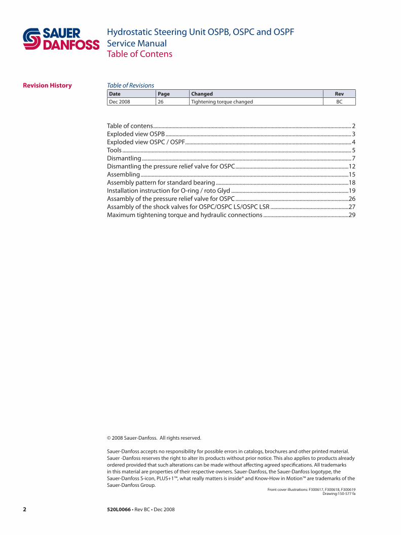
Hydrostatic Steering Unit OSPB, OSPC and OSPFService ManualExploded View OSPB
1 Dust seal ring2 Housing + spool + sleeve3 Ball 8.5 mm [0.33 in]4 Thread bushing5 O-ring with kin-ring or Roto Glyd7 Bearing assembly10 Ring for springs11 Cross pin 6 • 41 mm [0.24 • 1.61 in]12 Neutral position springs13 Cardan shaft14 Spacer15 O-ring 80,5 • 1,5 mm [3.17 • 0.06 in]
16 Distributor plate17 Gearwheel18 O-ring 75.92 • 1,78 mm [2.99 • 0.07 in]19 End cover
20 Washer 8.2 • 11,9 • 1.0 mm [0.32 • 0.47 • 0.04 in] 22 Special screw 23 Screw 24 Name label 26 Spacer
4 520L0066 • Rev BC • Dec 2008
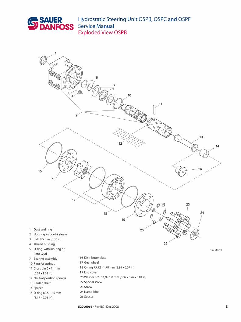
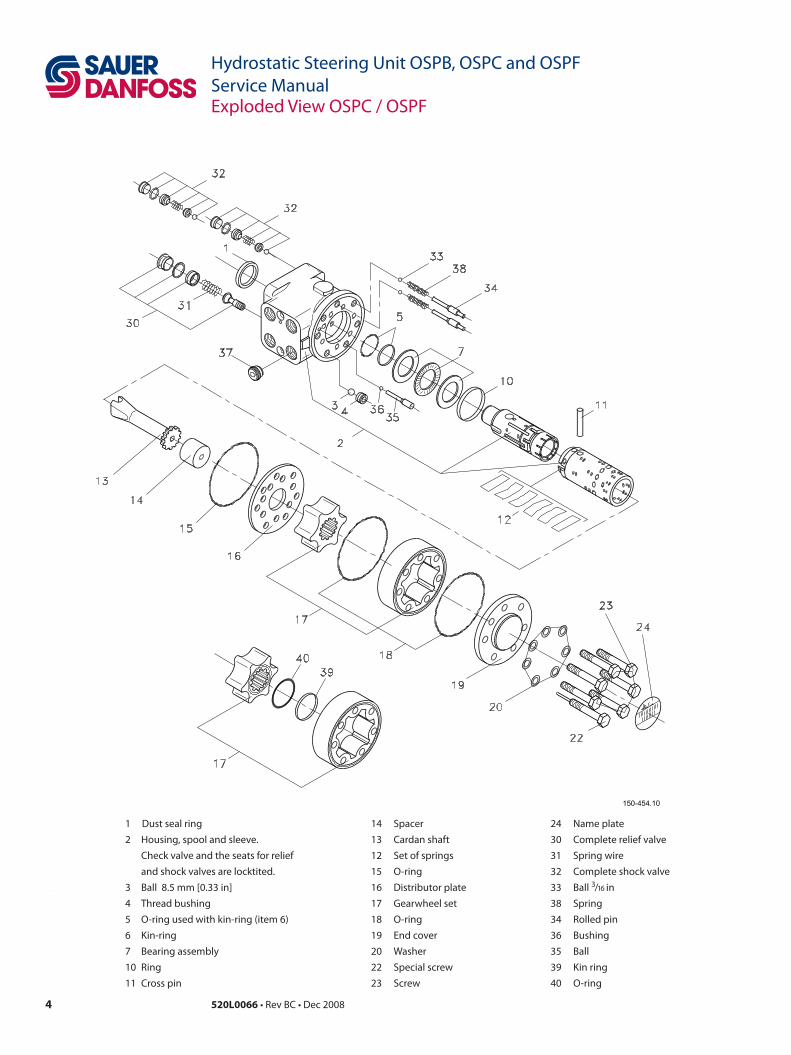
Hydrostatic Steering Unit OSPB, OSPC and OSPFService ManualExploded View OSPC / OSPF
1 Dust seal ring 2 Housing, spool and sleeve. Check valve and the seats for relief
and shock valves are locktited. 3 Ball 8.5 mm [0.33 in] 4 Thread bushing 5 O-ring used with kin-ring (item 6) 6 Kin-ring 7 Bearing assembly 10 Ring 11 Cross pin
14 Spacer 13 Cardan shaft 12 Set of springs 15 O-ring 16 Distributor plate 17 Gearwheel set 18 O-ring 19 End cover 20 Washer 22 Special screw 23 Screw
24 Name plate 30 Complete relief valve 31 Spring wire 32 Complete shock valve 33 Ball 3/16 in 38 Spring 34 Rolled pin 36 Bushing 35 Ball 39 Kin ring 40 O-ring
5520L0066 • Rev BC • Dec 2008
Hydrostatic Steering Unit OSPB, OSPC and OSPFService ManualTools
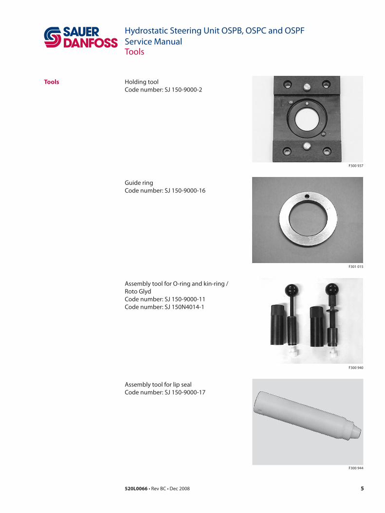
Holding toolCode number: SJ 150-9000-2
Guide ringCode number: SJ 150-9000-16
Assembly tool for O-ring and kin-ring /Roto GlydCode number: SJ 150-9000-11Code number: SJ 150N4014-1
Assembly tool for lip sealCode number: SJ 150-9000-17
Tools
F300 937
F301 015
F300 940
F300 944
6 520L0066 • Rev BC • Dec 2008
Hydrostatic Steering Unit OSPB, OSPC and OSPFService ManualTools
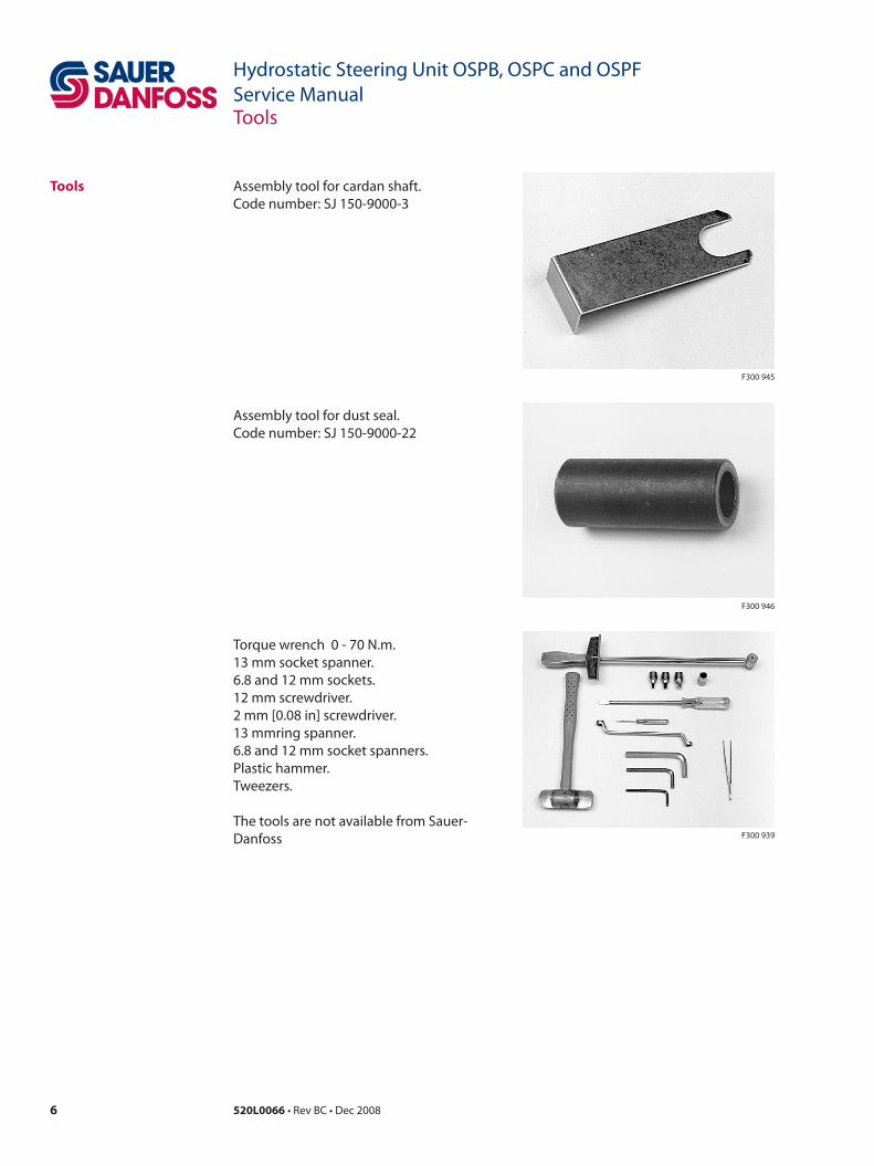
Assembly tool for cardan shaft.Code number: SJ 150-9000-3
Assembly tool for dust seal.Code number: SJ 150-9000-22
Torque wrench 0 - 70 N.m.13 mm socket spanner.6.8 and 12 mm sockets.12 mm screwdriver.2 mm [0.08 in] screwdriver.13 mmring spanner.6.8 and 12 mm socket spanners.Plastic hammer.Tweezers.
The tools are not available from Sauer-Danfoss
Tools
F300 945
F300 946
F300 939
7520L0066 • Rev BC • Dec 2008
Hydrostatic Steering Unit OSPB, OSPC and OSPFService ManualDismantling
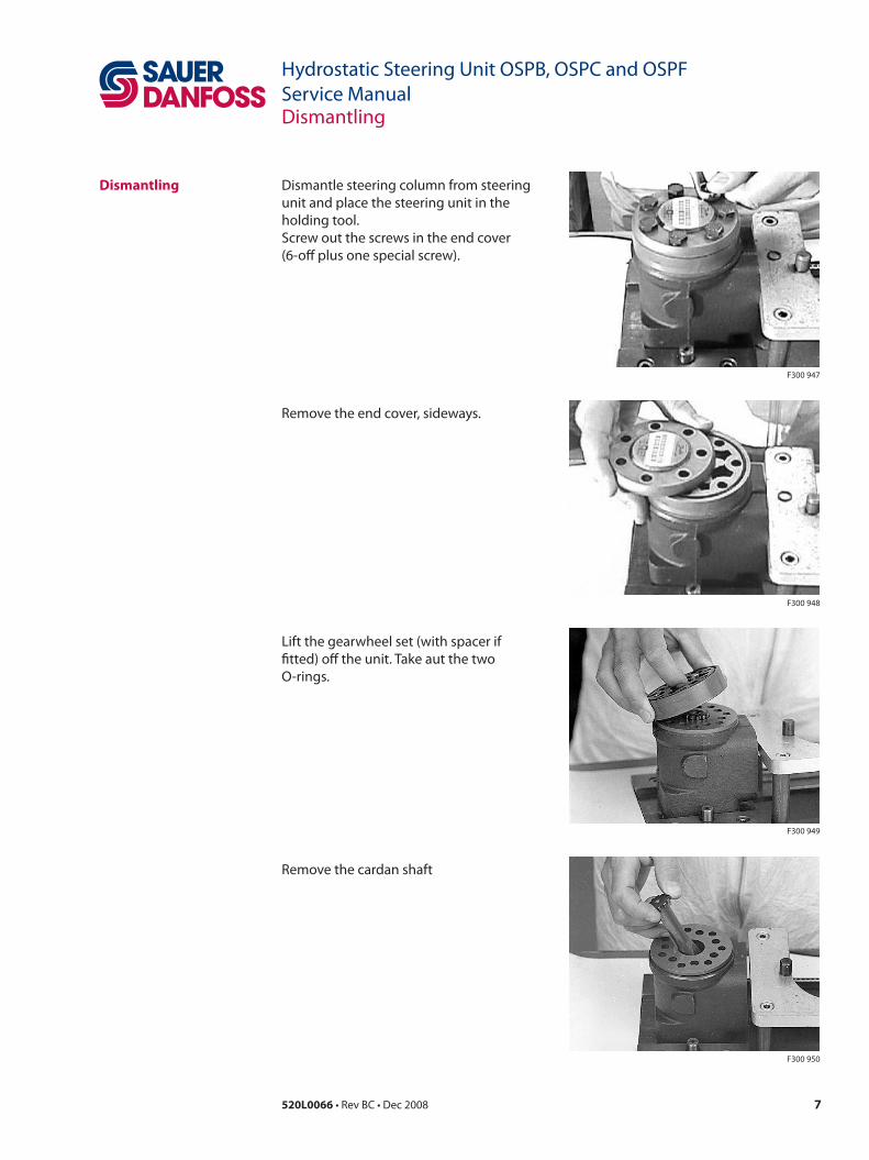
Dismantle steering column from steering unit and place the steering unit in the holding tool. Screw out the screws in the end cover (6-off plus one special screw).
Remove the end cover, sideways.
Lift the gearwheel set (with spacer if fitted) off the unit. Take aut the two O-rings.
Remove the cardan shaft
Dismantling
F300 947
F300 948
F300 949
F300 950
8 520L0066 • Rev BC • Dec 2008
Hydrostatic Steering Unit OSPB, OSPC and OSPFService ManualDismantling
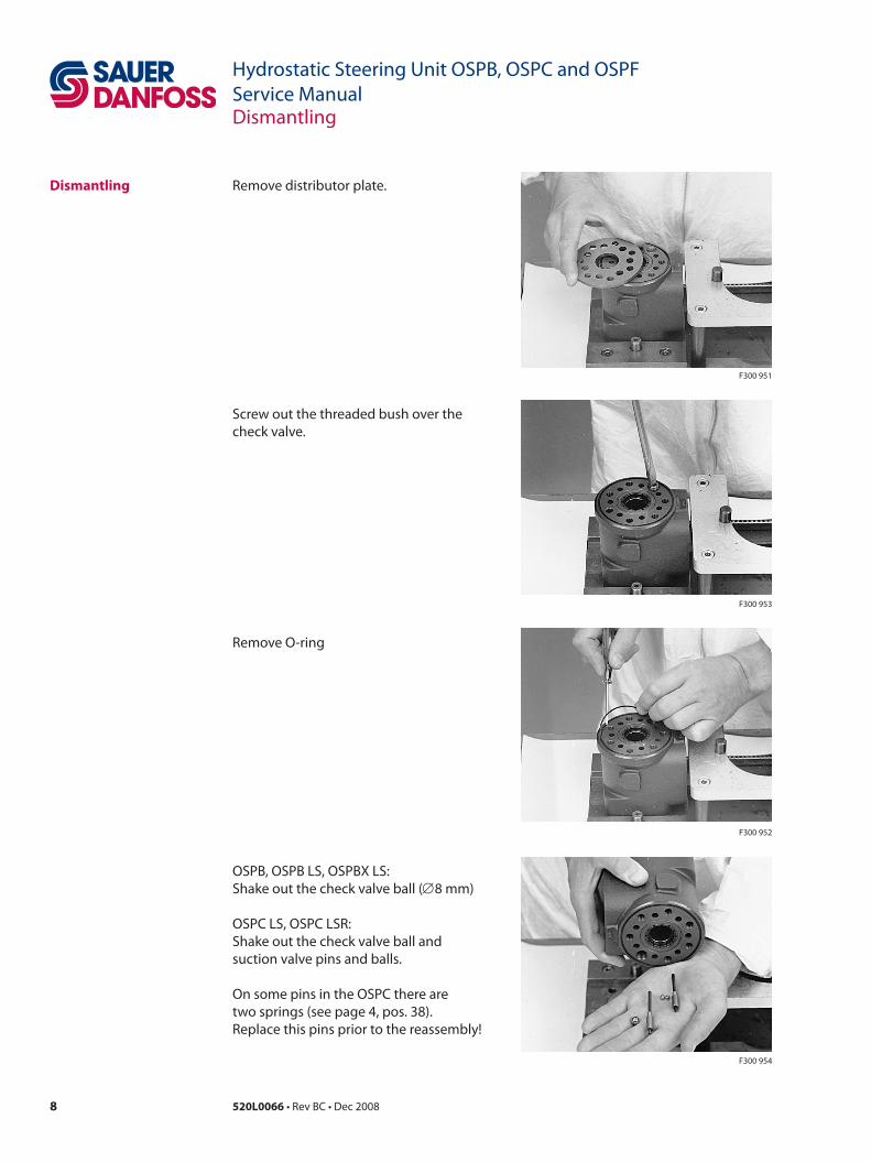
Remove distributor plate.
Screw out the threaded bush over the check valve.
Remove O-ring
OSPB, OSPB LS, OSPBX LS:Shake out the check valve ball (∅8 mm)
OSPC LS, OSPC LSR:Shake out the check valve ball and suction valve pins and balls.
On some pins in the OSPC there are two springs (see page 4, pos. 38). Replace this pins prior to the reassembly!
Dismantling
F300 951
F300 953
F300 952
F300 954
9520L0066 • Rev BC • Dec 2008
Hydrostatic Steering Unit OSPB, OSPC and OSPFService ManualDismantling
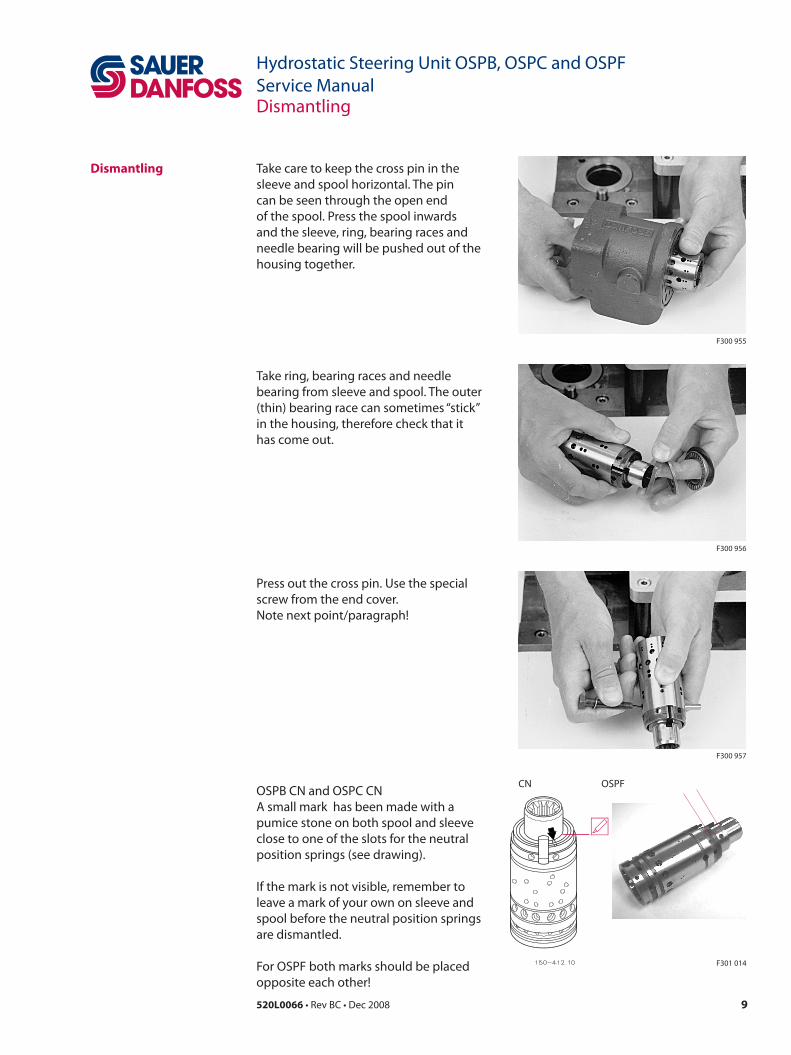
Take care to keep the cross pin in the sleeve and spool horizontal. The pin can be seen through the open end of the spool. Press the spool inwards and the sleeve, ring, bearing races and needle bearing will be pushed out of the housing together.
Take ring, bearing races and needle bearing from sleeve and spool. The outer (thin) bearing race can sometimes “stick” in the housing, therefore check that it has come out.
Press out the cross pin. Use the special screw from the end cover. Note next point/paragraph!
OSPB CN and OSPC CNA small mark has been made with a pumice stone on both spool and sleeve close to one of the slots for the neutral position springs (see drawing).
If the mark is not visible, remember to leave a mark of your own on sleeve and spool before the neutral position springs are dismantled.
For OSPF both marks should be placed opposite each other!
Dismantling
F300 955
F300 956
F300 957
F301 014
OSPFCN
m
10 520L0066 • Rev BC • Dec 2008
Hydrostatic Steering Unit OSPB, OSPC and OSPFService ManualDismantling
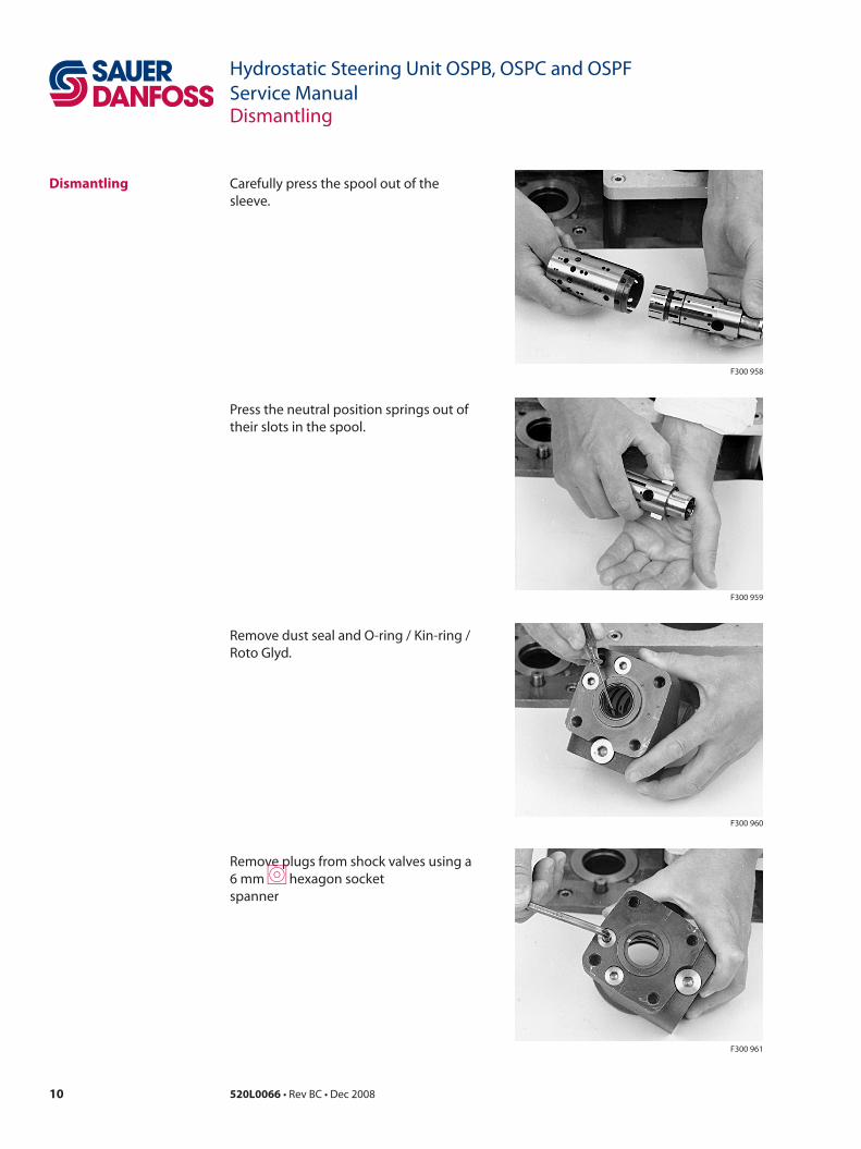
Carefully press the spool out of the sleeve.
Press the neutral position springs out of their slots in the spool.
Remove dust seal and O-ring / Kin-ring / Roto Glyd.
Remove plugs from shock valves using a 6 mm Ihexagon socket spanner
Dismantling
F300 958
F300 959
F300 960
F300 961
11520L0066 • Rev BC • Dec 2008
Hydrostatic Steering Unit OSPB, OSPC and OSPFService ManualDismantling
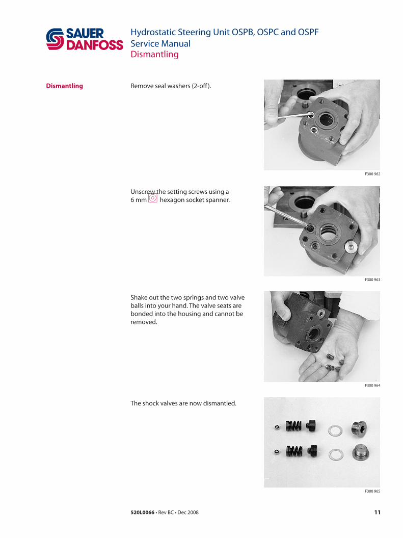
Remove seal washers (2-off).
Unscrew the setting screws using a 6 mm I hexagon socket spanner.
Shake out the two springs and two valve balls into your hand. The valve seats are bonded into the housing and cannot be removed.
The shock valves are now dismantled.
Dismantling
F300 962
F300 963
F300 964
F300 965
12 520L0066 • Rev BC • Dec 2008
Hydrostatic Steering Unit OSPB, OSPC and OSPFService Manual
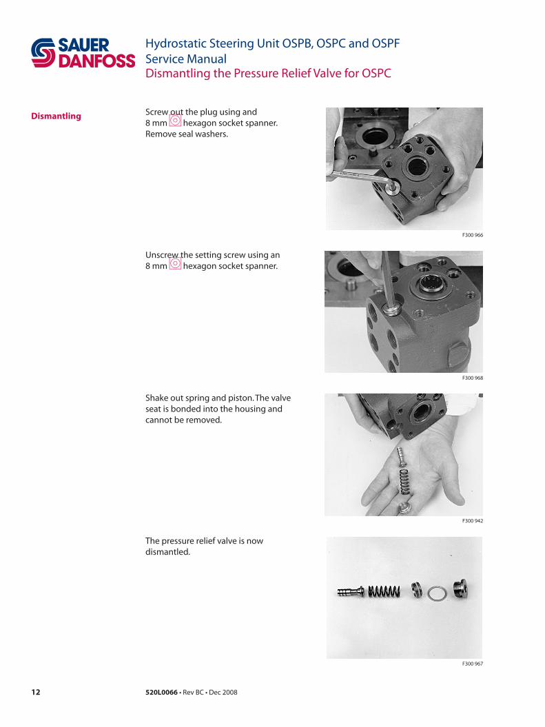
Screw out the plug using and 8 mm Ihexagon socket spanner. Remove seal washers.
Unscrew the setting screw using an 8 mm Ihexagon socket spanner.
Shake out spring and piston. The valve seat is bonded into the housing and cannot be removed.
The pressure relief valve is now dismantled.
Dismantling
F300 966
F300 968
F300 942
F300 967
Dismantling the Pressure Relief Valve for OSPC
13520L0066 • Rev BC • Dec 2008
Hydrostatic Steering Unit OSPB, OSPC and OSPFService Manual
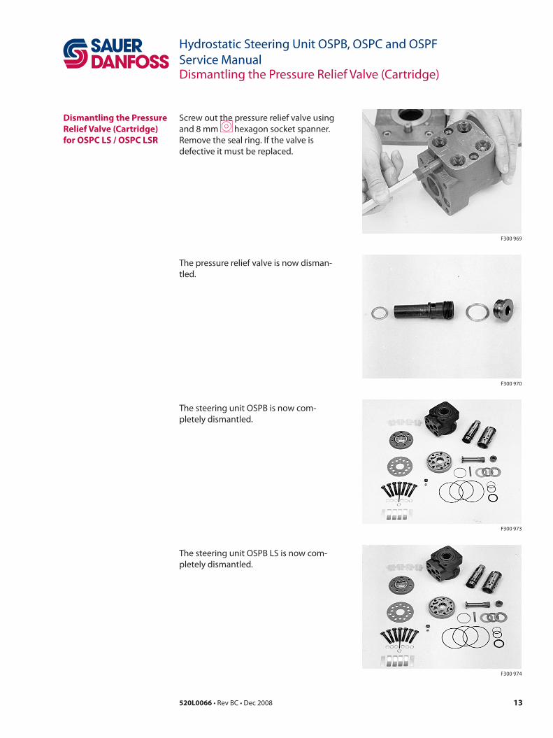
Screw out the pressure relief valve using and 8 mm Ihexagon socket spanner. Remove the seal ring. If the valve is defective it must be replaced.
The pressure relief valve is now disman-tled.
The steering unit OSPB is now com-pletely dismantled.
The steering unit OSPB LS is now com-pletely dismantled.
Dismantling the Pressure Relief Valve (Cartridge) for OSPC LS / OSPC LSR
F300 969
F300 970
F300 973
F300 974
Dismantling the Pressure Relief Valve (Cartridge)
14 520L0066 • Rev BC • Dec 2008
Hydrostatic Steering Unit OSPB, OSPC and OSPFService Manual
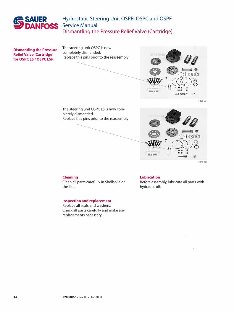
The steering unit OSPC is now completely dismantled.Replace this pins prior to the reassembly!
The steering unit OSPC LS is now com-pletely dismantled.Replace this pins prior to the reassembly!
CleaningClean all parts carefully in Shellsol K or the like.
Inspection and replacementReplace all seals and washers. Check all parts carefully and make any replacements necessary.
Dismantling the Pressure Relief Valve (Cartridge) for OSPC LS / OSPC LSR
F300 971
F300 972
Dismantling the Pressure Relief Valve (Cartridge)
LubricationBefore assembly, lubricate all parts with hydraulic oil.
15520L0066 • Rev BC • Dec 2008
Hydrostatic Steering Unit OSPB, OSPC and OSPFService Manual
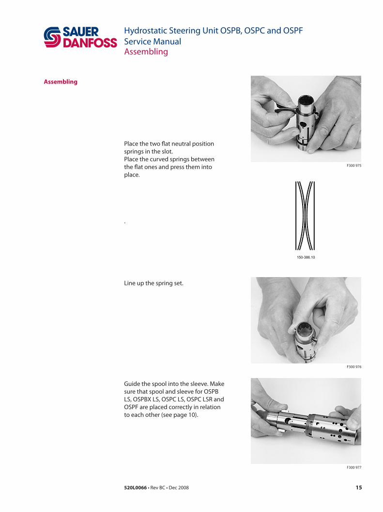
Place the two flat neutral position springs in the slot.Place the curved springs between the flat ones and press them into place.
.
Line up the spring set.
Guide the spool into the sleeve. Make sure that spool and sleeve for OSPB LS, OSPBX LS, OSPC LS, OSPC LSR and OSPF are placed correctly in relation to each other (see page 10).
Assembling
F300 975
Assembling
F300 976
F300 977
16 520L0066 • Rev BC • Dec 2008
Hydrostatic Steering Unit OSPB, OSPC and OSPFService Manual
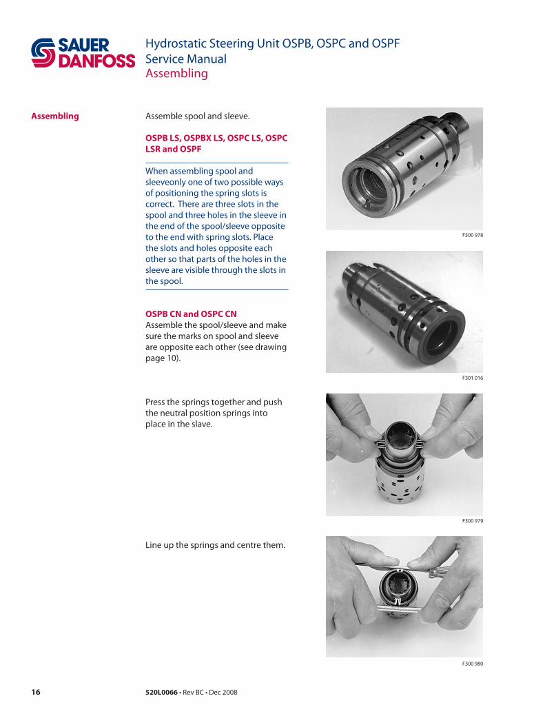
Assemble spool and sleeve.
OSPB LS, OSPBX LS, OSPC LS, OSPC LSR and OSPF
When assembling spool and sleeveonly one of two possible ways of positioning the spring slots is correct. There are three slots in the spool and three holes in the sleeve in the end of the spool/sleeve opposite to the end with spring slots. Place the slots and holes opposite each other so that parts of the holes in the sleeve are visible through the slots in the spool.
OSPB CN and OSPC CNAssemble the spool/sleeve and make sure the marks on spool and sleeve are opposite each other (see drawing page 10).
Press the springs together and push the neutral position springs into place in the slave.
Line up the springs and centre them.
Assembling
F300 978
F301 016
Assembling
F300 979
F300 980
17520L0066 • Rev BC • Dec 2008
Hydrostatic Steering Unit OSPB, OSPC and OSPFService Manual
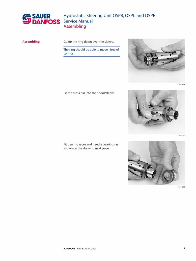
Guide the ring down over the sleeve.
The ring should be able to move - free of springs.
Fit the cross pin into the spool/sleeve.
Fit bearing races and needle bearings as shown on the drawing next page.
Assembling
F300 981
F300 982
Assembling
F300 983
18 520L0066 • Rev BC • Dec 2008
Hydrostatic Steering Unit OSPB, OSPC and OSPFService Manual
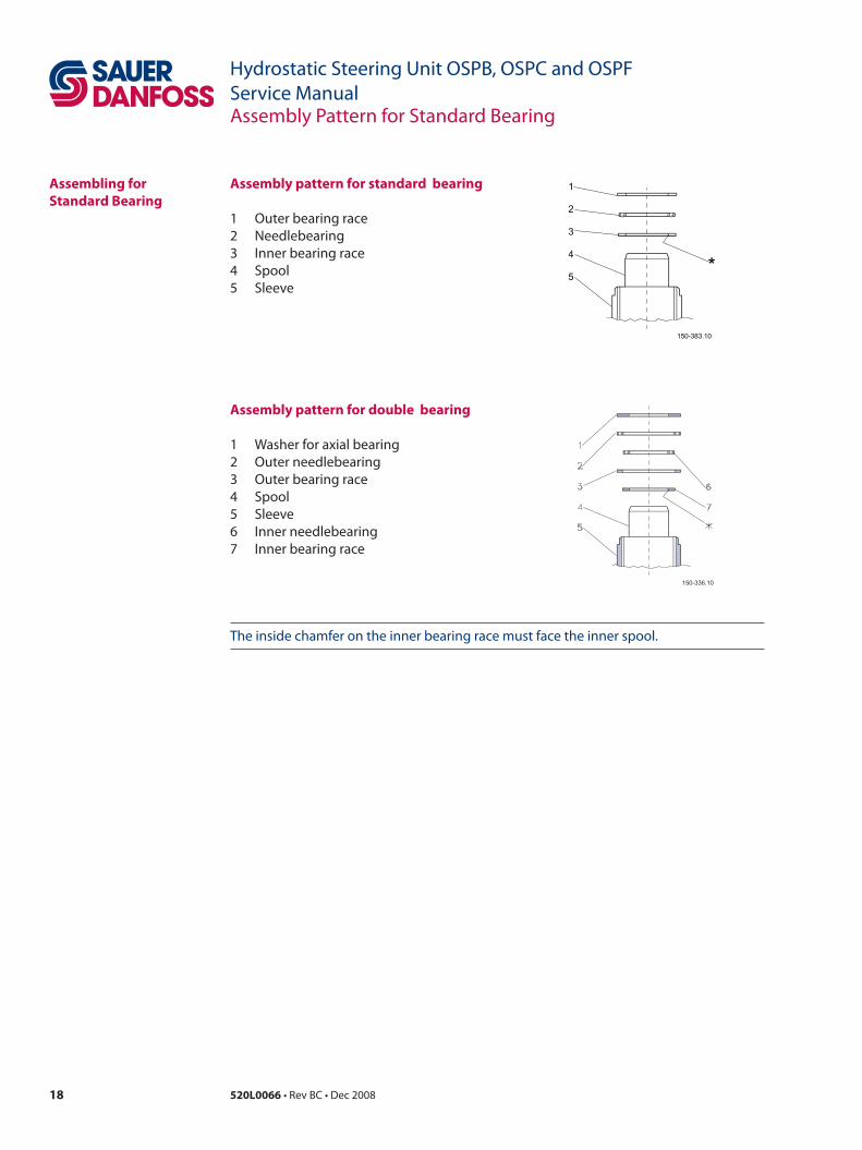
Assembly pattern for standard bearing
1 Outer bearing race2 Needlebearing3 Inner bearing race4 Spool5 Sleeve
Assembly pattern for double bearing
1 Washer for axial bearing2 Outer needlebearing3 Outer bearing race4 Spool5 Sleeve6 Inner needlebearing7 Inner bearing race
Assembling for Standard Bearing
Assembly Pattern for Standard Bearing
The inside chamfer on the inner bearing race must face the inner spool.
19520L0066 • Rev BC • Dec 2008
Hydrostatic Steering Unit OSPB, OSPC and OSPFService Manual
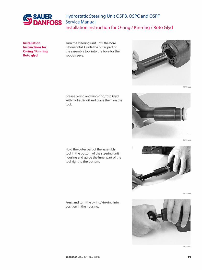
Turn the steering unit until the bore is horizontal. Guide the outer part of the assembly tool into the bore for the spool/sleeve.
Grease o-ring and king-ring/roto Glyd with hydraulic oil and place them on the tool.
Hold the outer part of the assembly tool in the bottom of the steering unit housing and guide the inner part of the tool right to the bottom.
Press and turn the o-ring/kin-ring into position in the housing.
Installation Instructions for O-ring / Kin-ring Roto glyd
F300 984
F300 985
Installation Instruction for O-ring / Kin-ring / Roto Glyd
F300 986
F300 987
20 520L0066 • Rev BC • Dec 2008
Hydrostatic Steering Unit OSPB, OSPC and OSPFService Manual
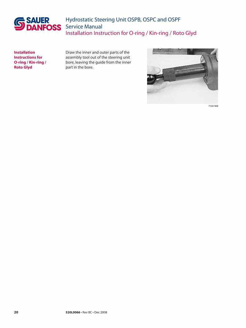
Draw the inner and outer parts of the assembly tool out of the steering unit bore, leaving the guide from the inner part in the bore.
Installation Instructions for O-ring / Kin-ring / Roto Glyd
F300 988
Installation Instruction for O-ring / Kin-ring / Roto Glyd
21520L0066 • Rev BC • Dec 2008
Hydrostatic Steering Unit OSPB, OSPC and OSPFService Manual
F300 989
F300 990
F300 991
Installation Instruction for Lip Seal
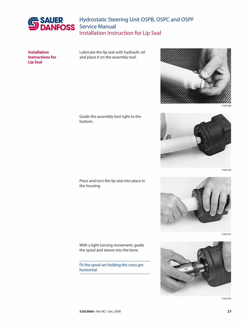
Lubricate the lip seal with hydraulic oil and place it on the assembly tool.
Guide the assembly tool right to the bottom.
Press and turn the lip seal into place in the housing.
With a light turning movement, guide the spool and sleeve into the bore.
Fit the spool set holding the cross pin horizontal.
Installation Instructions for Lip Seal
F300 992
22 520L0066 • Rev BC • Dec 2008
Hydrostatic Steering Unit OSPB, OSPC and OSPFService ManualInstallation Instruction for Lip Seal
Installation Instructions for Lip Seal
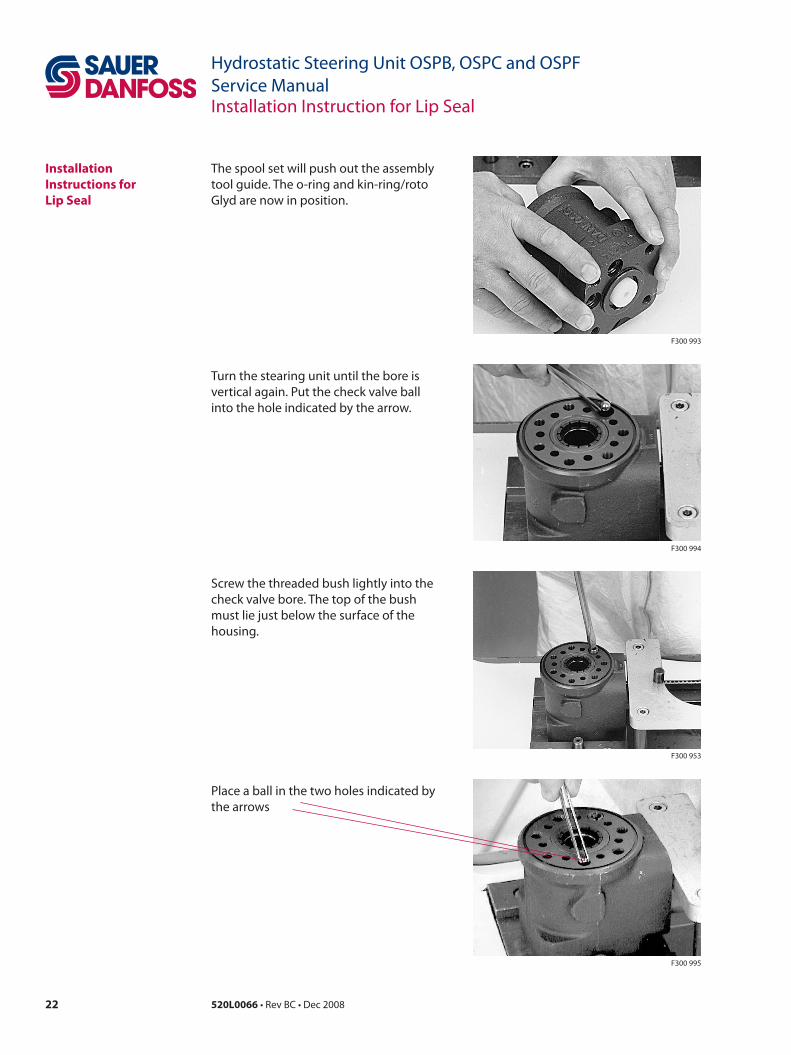
The spool set will push out the assembly tool guide. The o-ring and kin-ring/roto Glyd are now in position.
Turn the stearing unit until the bore is vertical again. Put the check valve ball into the hole indicated by the arrow.
Screw the threaded bush lightly into the check valve bore. The top of the bush must lie just below the surface of the housing.
Place a ball in the two holes indicated by the arrows
F300 993
F300 994
F300 953
F300 995
23520L0066 • Rev BC • Dec 2008
Hydrostatic Steering Unit OSPB, OSPC and OSPFService ManualInstallation Instruction for Lip Seal
Installation Instructions for Lip Seal
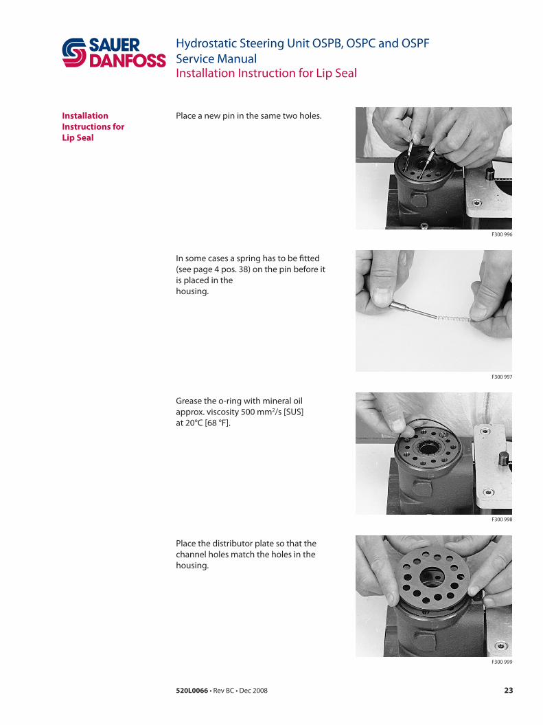
Place a new pin in the same two holes.
In some cases a spring has to be fitted (see page 4 pos. 38) on the pin before it is placed in the housing.
Grease the o-ring with mineral oil approx. viscosity 500 mm2/s [SUS]at 20°C [68 °F].
Place the distributor plate so that the channel holes match the holes in the housing.
F300 996
F300 997
F300 998
F300 999
24 520L0066 • Rev BC • Dec 2008
Hydrostatic Steering Unit OSPB, OSPC and OSPFService ManualInstallation Instruction for Lip Seal
Installation Instructions for Lip Seal
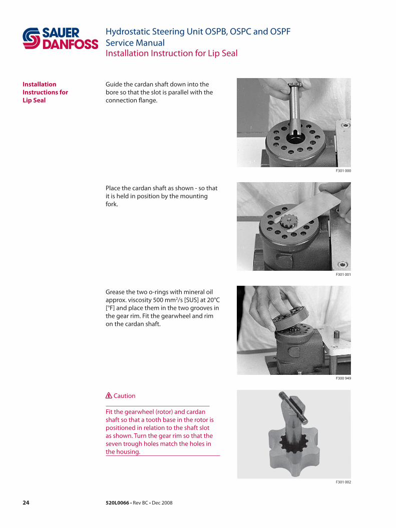
Guide the cardan shaft down into the bore so that the slot is parallel with the connection flange.
Place the cardan shaft as shown - so that it is held in position by the mounting fork.
Grease the two o-rings with mineral oil approx. viscosity 500 mm2/s [SUS] at 20°C [°F] and place them in the two grooves in the gear rim. Fit the gearwheel and rim on the cardan shaft.
Caution
Fit the gearwheel (rotor) and cardan shaft so that a tooth base in the rotor is positioned in relation to the shaft slot as shown. Turn the gear rim so that the seven trough holes match the holes in the housing.
F301 000
F301 001
F300 949
F301 002
25520L0066 • Rev BC • Dec 2008
Hydrostatic Steering Unit OSPB, OSPC and OSPFService ManualInstallation Instruction for Lip Seal
Installation Instructions for Lip Seal
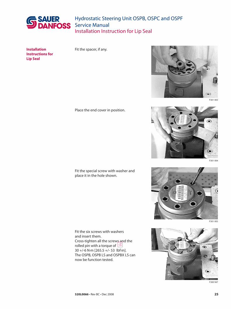
Fit the spacer, if any.
Place the end cover in position.
Fit the special screw with washer and place it in the hole shown.
Fit the six screws with washers and insert them. Cross-tighten all the screws and the rolled pin with a torque of 30 +/-6 N.m [265.5 +/- 53 lbf.in]. The OSPB, OSPB LS and OSPBX LS can now be function tested.
F301 003
F301 004
F301 005
F300 947
26 520L0066 • Rev BC • Dec 2008
Hydrostatic Steering Unit OSPB, OSPC and OSPFService ManualAssambly of the Pressure Relief Valve for OSPC
Assembly of the Pressure Relief Valve for OSPC
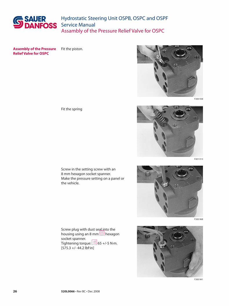
Fit the piston.
Fit the spring
Screw in the setting screw with an 8 mm hexagon socket spanner. Make the pressure setting on a panel or the vehicle.
Screw plug with dust seal into the housing using an 8 mm Ihexagon socket spanner.Tightening torque: 65 +/-5 N.m.[575.3 +/- 44.2 lbf.in]
F300 938
F301 013
F300 968
F300 941
27520L0066 • Rev BC • Dec 2008
Hydrostatic Steering Unit OSPB, OSPC and OSPFService ManualAssambly of the Shock Valves for OSPC/OSPC LS/OSPC LSR
Assambly of the Shock Valves for OSPC/OSPC LS/OSPC LSR
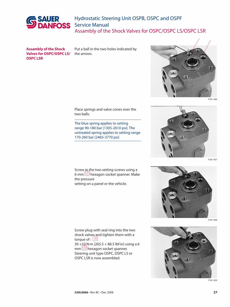
Put a ball in the two holes indicated by the arrows.
Place springs and valve cones over the two balls.
The blue spring applies to setting range 90-180 bar [1305-2610 psi]. The untreated spring applies to setting range 170-260 bar [2465-3770 psi]
Screw in the two setting screws using a 6 mm Ihexagon socket spanner. Make the pressure setting on a panel or the vehicle.
Screw plug with seal ring into the two shock valves and tighten them with a torque of : 30 +10 N.m [265.5 + 88.5 lbf.in] using a 6 mm Ihexagon socket spanner.Steering unit type OSPC, OSPC LS or OSPC LSR is now assembled.
F301 006
F301 007
F301 008
F301 009
28 520L0066 • Rev BC • Dec 2008
Hydrostatic Steering Unit OSPB, OSPC and OSPFService ManualAssambly of the Shock Valves for OSPC/OSPC LS/OSPC LSR
Assambly of the Shock Valves for OSPC/OSPC LS/OSPC LSR
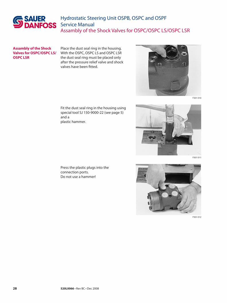
Place the dust seal ring in the housing. With the OSPC, OSPC LS and OSPC LSR the dust seal ring must be placed only after the pressure relief valve and shock valves have been fitted.
Fit the dust seal ring in the housing using special tool SJ 150-9000-22 (see page 5) and a plastic hammer.
Press the plastic plugs into the connection ports. Do not use a hammer!
F301 010
F301 011
F301 012
29520L0066 • Rev BC • Dec 2008
Hydrostatic Steering Unit OSPB, OSPC and OSPFService ManualMaximum Tightening Torque and Hydraulic Connections
Maximum Tightening Torque and Hydraulic Connections
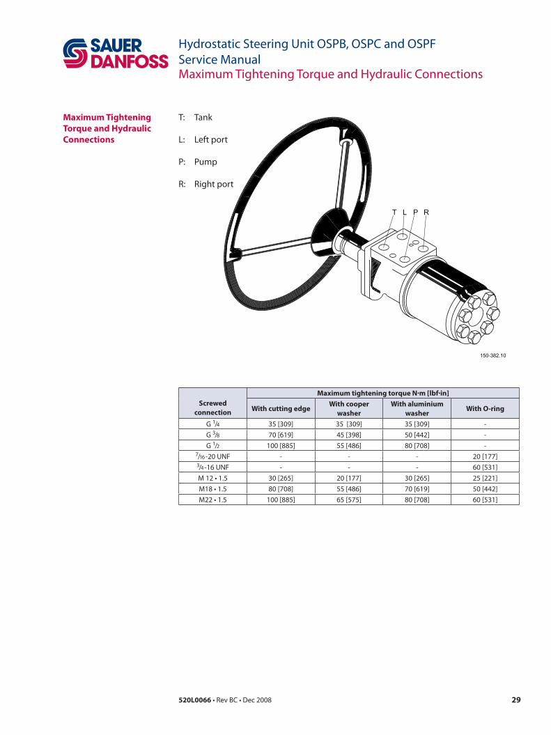
T: Tank
L: Left port
P: Pump
R: Right port
Screwed connection
Maximum tightening torque N.m [lbf.in]
With cutting edgeWith cooper
washerWith aluminium
washerWith O-ring
G 1/4 35 [309] 35 [309] 35 [309] -G 3/8 70 [619] 45 [398] 50 [442] -G 1/2 100 [885] 55 [486] 80 [708] -
7/16 -20 UNF - - - 20 [177]3/4 -16 UNF - - - 60 [531]M 12 • 1.5 30 [265] 20 [177] 30 [265] 25 [221]M18 • 1.5 80 [708] 55 [486] 70 [619] 50 [442]M22 • 1.5 100 [885] 65 [575] 80 [708] 60 [531]
30 520L0066 • Rev BC • Dec 2008
Hydrostatic Steering Unit OSPB, OSPC and OSPFService ManualNotes
Notes
31520L0066 • Rev BC • Dec 2008
Hydrostatic Steering Unit OSPB, OSPC and OSPFService ManualNotes
Notes
Sauer-Danfoss Mobile Power and Control Systems– Market Leaders Worldwide
Sauer-Danfoss is a comprehensive supplier providing complete systems to the global mobile market.
Sauer-Danfoss serves markets such as agriculture, construction, road building, material handling, municipal, forestry, turf care, and many others.
We offer our customers optimum solutions for their needs and develop new products and systems in close cooperation and partner ship with them.
Sauer-Danfoss specializes in integrating a full range of system components to provide vehicle designers with the most advanced total system design.
Sauer-Danfoss provides comprehensive worldwide service for its products through an extensive network of Global Service Partners strategically located in all parts of the world.
Our Products
Hydrostatic Transmissions
Hydraulic Power Steering
Electric Power Steering
Electrohydraulic Power Steering
Closed and Open Circuit Axial Piston Pumps and Motors
Gear Pumps and Motors
Bent Axis Motors
Orbital Motors
Transit Mixer Drives
Proportional Valves
Directional Spool Valves
Cartridge Valves
Hydraulic Integrated Circuits
Hydrostatic Transaxles
Integrated Systems
Fan Drive Systems
Electrohydraulics
Microcontrollers and Software
Electric Motors and Inverters
Joysticks and Control Handles
Displays
Sensors
Local address:
Sauer-Danfoss (US) Company2800 East 13th StreetAmes, IA 50010, USAPhone: +1 515 239-6000Fax: +1 515 239 6618
Sauer-Danfoss GmbH & Co. OHGPostfach 2460, D-24531 NeumünsterKrokamp 35, D-24539 Neumünster, GermanyPhone: +49 4321 871-0Fax: +49 4321 871 122
Sauer-Danfoss ApSDK-6430 Nordborg, DenmarkPhone: +45 7488 4444Fax: +45 7488 4400
Sauer-Danfoss-Daikin LTDSannomiya Grand Bldg. 8F2-2-21 Isogami-dori, Chuo-kuKobe, Hyogo 651-0086, JapanPhone: +81 78 231 5001Fax: +81 78 231 5004
www.sauer-danfoss.com520L0066 • Rev BC • Dec 2008