Embed Size (px)
Citation preview
HYDROSTATIC BEARINGS DESIGNED FOR POGAL (PRECISION OPTICAL GRINDER AND LATHE)
Layton Hale1, Robert Donaldson2, Stanley Edson3, and Richard Thigpen3
1Innovative Machine Solutions, Dublin, CA, USA 2Independent Consultant, Pittsboro, NC, USA
3Lawrence Livermore National Laboratory, Livermore, CA, USA
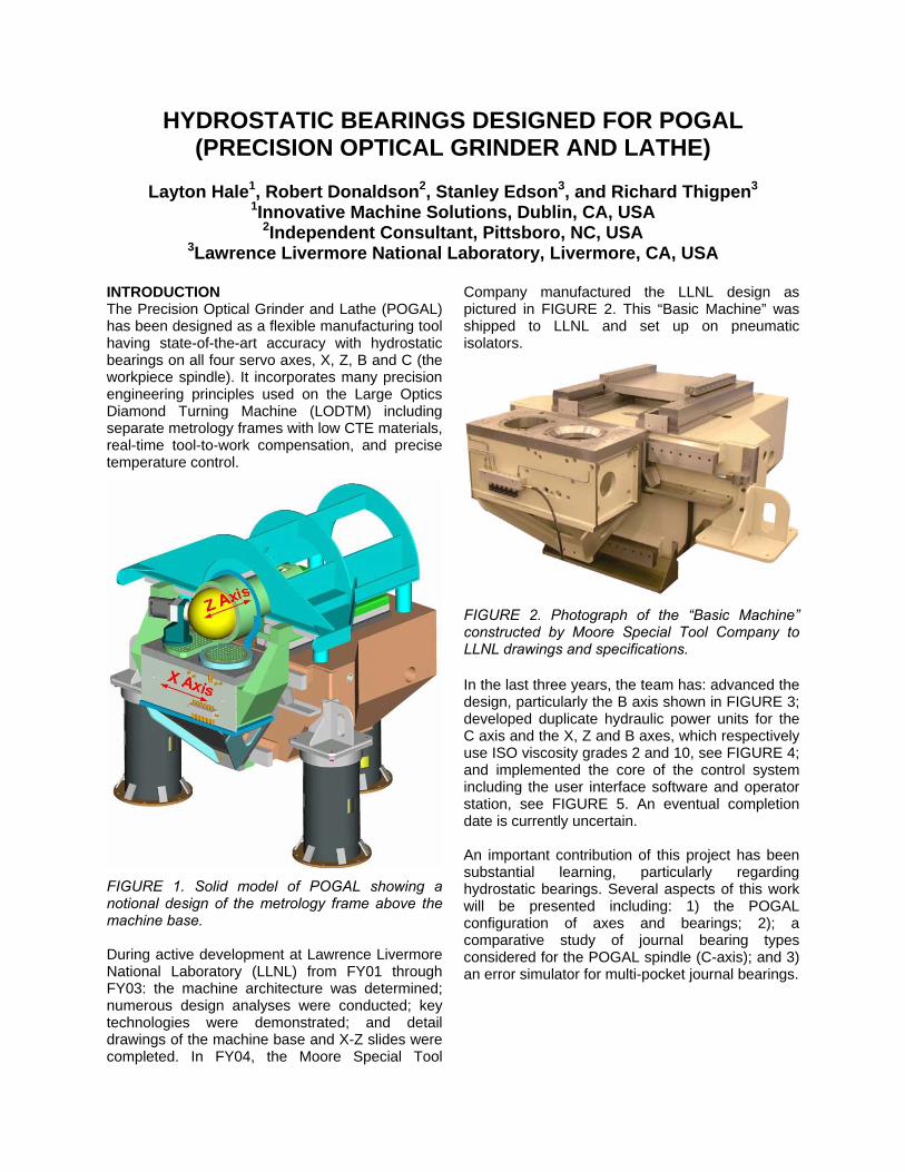
INTRODUCTION The Precision Optical Grinder and Lathe (POGAL) has been designed as a flexible manufacturing tool having state-of-the-art accuracy with hydrostatic bearings on all four servo axes, X, Z, B and C (the workpiece spindle). It incorporates many precision engineering principles used on the Large Optics Diamond Turning Machine (LODTM) including separate metrology frames with low CTE materials, real-time tool-to-work compensation, and precise temperature control.
FIGURE 1. Solid model of POGAL showing a notional design of the metrology frame above the machine base. During active development at Lawrence Livermore National Laboratory (LLNL) from FY01 through FY03: the machine architecture was determined; numerous design analyses were conducted; key technologies were demonstrated; and detail drawings of the machine base and X-Z slides were completed. In FY04, the Moore Special Tool
Company manufactured the LLNL design as pictured in FIGURE 2. This “Basic Machine” was shipped to LLNL and set up on pneumatic isolators.
FIGURE 2. Photograph of the “Basic Machine” constructed by Moore Special Tool Company to LLNL drawings and specifications. In the last three years, the team has: advanced the design, particularly the B axis shown in FIGURE 3; developed duplicate hydraulic power units for the C axis and the X, Z and B axes, which respectively use ISO viscosity grades 2 and 10, see FIGURE 4; and implemented the core of the control system including the user interface software and operator station, see FIGURE 5. An eventual completion date is currently uncertain. An important contribution of this project has been substantial learning, particularly regarding hydrostatic bearings. Several aspects of this work will be presented including: 1) the POGAL configuration of axes and bearings; 2); a comparative study of journal bearing types considered for the POGAL spindle (C-axis); and 3) an error simulator for multi-pocket journal bearings.
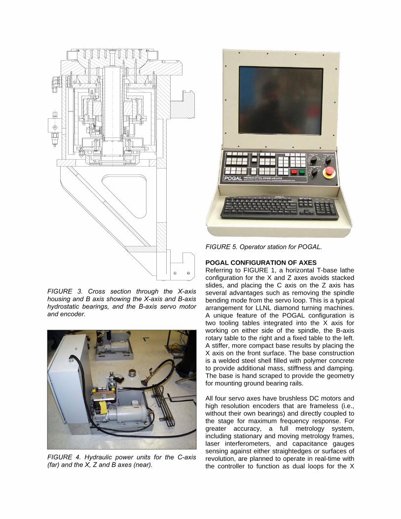
FIGURE 3. Cross section through the X-axis housing and B axis showing the X-axis and B-axis hydrostatic bearings, and the B-axis servo motor and encoder.
FIGURE 4. Hydraulic power units for the C-axis (far) and the X, Z and B axes (near).
FIGURE 5. Operator station for POGAL. POGAL CONFIGURATION OF AXES Referring to FIGURE 1, a horizontal T-base lathe configuration for the X and Z axes avoids stacked slides, and placing the C axis on the Z axis has several advantages such as removing the spindle bending mode from the servo loop. This is a typical arrangement for LLNL diamond turning machines. A unique feature of the POGAL configuration is two tooling tables integrated into the X axis for working on either side of the spindle, the B-axis rotary table to the right and a fixed table to the left. A stiffer, more compact base results by placing the X axis on the front surface. The base construction is a welded steel shell filled with polymer concrete to provide additional mass, stiffness and damping. The base is hand scraped to provide the geometry for mounting ground bearing rails. All four servo axes have brushless DC motors and high resolution encoders that are frameless (i.e., without their own bearings) and directly coupled to the stage for maximum frequency response. For greater accuracy, a full metrology system, including stationary and moving metrology frames, laser interferometers, and capacitance gauges sensing against either straightedges or surfaces of revolution, are planned to operate in real-time with the controller to function as dual loops for the X

and Z axes, which correct for a multitude of errors such as geometric, thermal and structural errors of modest frequency. This would correct any small errors caused by motors directly coupled to the low speed axes (X, Z and B). Errors caused by the C-axis motor have been studied and estimated to be of order 1 nm or less [1]. X-Axis Bearing Configuration Referring to FIGURE 2, FIGURE 3 and FIGURE 6, a kinematic arrangement with five bearings was chosen because the wide spacing available between bearings gives adequate moment stiffness. Three preloaded bearing pairs define a vertical plane with two pairs riding the upper rail of the base and one riding the lower rail. The bearing features, consisting of lands, pockets, drainage grooves and oil passages, are directly machined into the housing on one side and on the other side into one-piece upper and lower calipers that bolt to the housing. The total bearing clearance (sum for both sides), nominally 1.5 mils (38 µm), is determined by width tolerances on the rails and the calipers. The weight of the housing preloads the two remaining bearings that ride on top of the upper rail. These bearings are directly machined into the thick plate that bolts to and structurally closes the top of the housing. Additional dynamic stiffness comes from the oil film captured between the bottom of the upper rail and the caliper, which is set to approximately 3 mils (76 µm) clearance. Three gutters mount to the front of the base to captured leakage oil and return it by gravity to the hydraulic power unit located behind the machine. One of two upper gutters and the lower gutter appear in FIGURE 2. The upper caliper also serves to capture leakage oil and direct it outward to the upper gutters. This creates a dry zone to mount the linear motor and linear encoder. TABLE 1. Key dimensions for the X-axis bearings. X-axis dimensions inch mm Program travel 14.00 355.6Length of housing 32.00 812.8Length of upper bearings 6.00 152.4Length of lower bearing 8.00 203.2Width of upper bearings (top) 1.69 42.88Width of upper bearings (front) 1.20 30.48Width of upper bearings (rear) 1.40 35.56Width of lower bearings (front) 1.60 40.64Width of lower bearings (rear) 1.40 35.56Land width (all bearings) 0.20 5.08
FIGURE 6. Cross section showing the upper X-axis and B-axis bearings. The arrows indicate the hydrostatic forces applied by the bearings on the rail or rotor, respectively. Z-Axis Bearing Configuration Referring to FIGURE 2 and FIGURE 7, a configuration with two symmetrical assemblies totaling eight preloaded bearing pairs was chosen to give maximum moment stiffness for the overhanging workpiece. Four bearing pairs over define a horizontal plane and the remaining four over define X position and Y rotation. On each assembly, the front and rear bearing features are machined into four sides of a single bearing block, which is captured on four sides by stationary rails. The front bearings are longer than the rear bearings to optimize tool-to-work stiffness. This requires the bearing blocks to be mirror images of one another, while the rails are common to both units. The total bearing clearance, nominally 1.5 mils (38 µm), is determined vertically by height tolerances on the outer rail and bearing block and horizontally by setting the spacing between inner and outer rails. The left and right assemblies are then set on the base to be parallel to each other and perpendicular to the upper X-axis rail. At a future point in the machine’s development, the plate that ties the two bearing blocks together
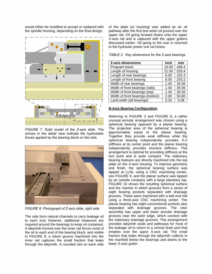
would either be modified to accept or replaced with the spindle housing, depending on the final design.
FIGURE 7. Solid model of the Z-axis slide. The arrows in the detail view indicate the hydrostatic forces applied by the bearing block on the rails.
FIGURE 8. Photograph of Z-axis slide, right side. The rails form natural channels to carry leakage oil to each end; however, additional measures are required around the bearings to keep oil contained. A labyrinth formed over the inner rail forces most of the oil to each end of the bearing block, and visible in FIGURE 8, a return groove machined into the inner rail captures the small fraction that leaks through the labyrinth. A rounded slot on each side
of the plate (or housing) was added as an oil pathway after the first test when oil poured over the upper rail. Oil going forward drains onto the upper X-axis rail and is captured with the upper gutters discussed earlier. Oil going to the rear is returned to the hydraulic power unit via hoses. TABLE 2. Key dimensions for the Z-axis bearings. Z-axis dimensions inch mm Program travel 16.00 406.4Length of housing 21.00 533.4Length of rear bearings 6.00 152.4Length of front bearing 8.00 203.2Width of rear bearings 1.40 35.56Width of front bearings (side) 1.40 35.56Width of front bearings (top) 1.40 35.56Width of front bearings (bottom) 2.00 50.80Land width (all bearings) 0.20 5.08
B-Axis Bearing Configuration Referring to FIGURE 3 and FIGURE 6, a rather unusual annular arrangement was chosen using a spherical bearing opposed by a planar bearing. The projected area of the spherical bearing is approximately equal to the planar bearing. Together they provide axial stiffness while the spherical bearing independently provides X-Z stiffness at its center point and the planar bearing independently provides moment stiffness. This arrangement is optimal for providing stiffness at the tool point and is quite compact. The stationary bearing features are directly machined into the top plate on the X-axis housing. To improve geometry and finish, the spherical bearing surface was lapped at LLNL using a CNC machining center, see FIGURE 9, and the planar surface was lapped by an outside company with a large planetary lap. FIGURE 10 shows the resulting spherical surface and the manner in which grooves form a series of eight bearing pockets separated with drainage grooves. These were machined with a ball end mill using a three-axis CNC machining center. The planar bearing has eight conventional pockets also separated with drainage grooves. The rotor assembly has upper and lower annular drainage grooves near the outer edge, which connect with the stationary drainage grooves. This arrangement provides labyrinth seals and pathways for most of the leakage oil to return to a central drain port that empties over the upper X-axis rail. The small fraction that leaks through the labyrinth collects in the manifold below the bearings and drains to the lower X-axis gutter.
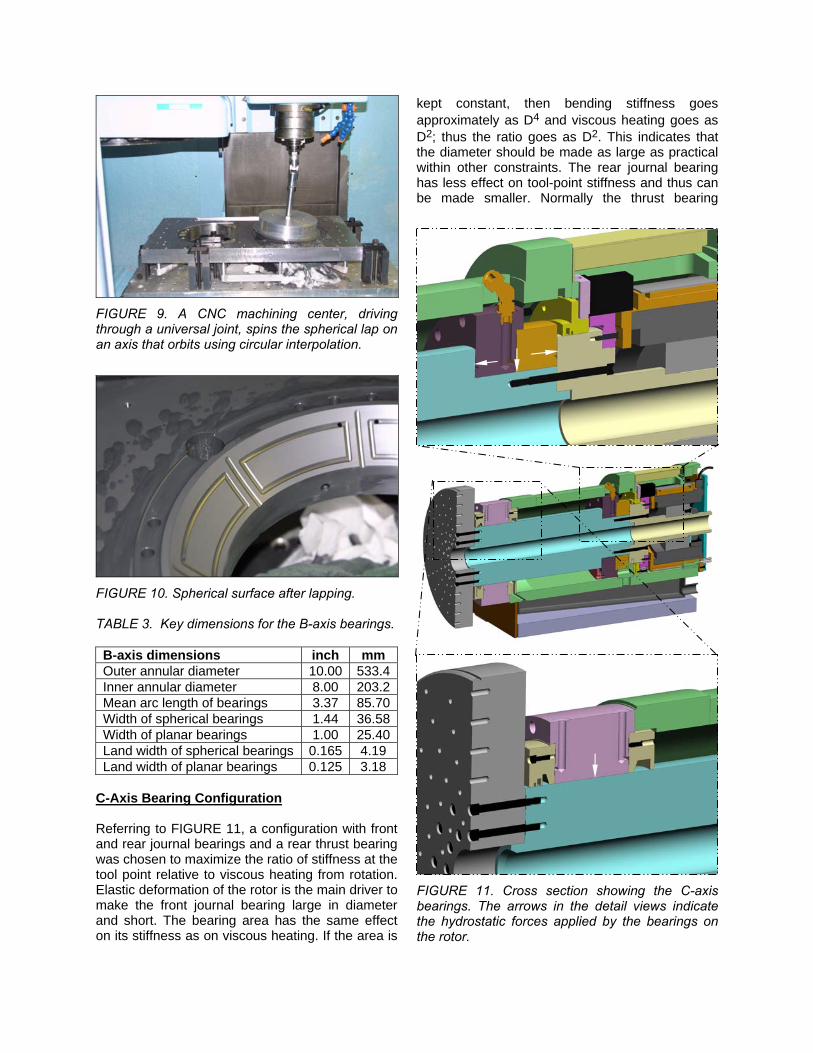
FIGURE 9. A CNC machining center, driving through a universal joint, spins the spherical lap on an axis that orbits using circular interpolation.
FIGURE 10. Spherical surface after lapping. TABLE 3. Key dimensions for the B-axis bearings. B-axis dimensions inch mm Outer annular diameter 10.00 533.4Inner annular diameter 8.00 203.2Mean arc length of bearings 3.37 85.70Width of spherical bearings 1.44 36.58Width of planar bearings 1.00 25.40Land width of spherical bearings 0.165 4.19 Land width of planar bearings 0.125 3.18
C-Axis Bearing Configuration Referring to FIGURE 11, a configuration with front and rear journal bearings and a rear thrust bearing was chosen to maximize the ratio of stiffness at the tool point relative to viscous heating from rotation. Elastic deformation of the rotor is the main driver to make the front journal bearing large in diameter and short. The bearing area has the same effect on its stiffness as on viscous heating. If the area is
kept constant, then bending stiffness goes approximately as D4 and viscous heating goes as D2; thus the ratio goes as D2. This indicates that the diameter should be made as large as practical within other constraints. The rear journal bearing has less effect on tool-point stiffness and thus can be made smaller. Normally the thrust bearing
FIGURE 11. Cross section showing the C-axis bearings. The arrows in the detail views indicate the hydrostatic forces applied by the bearings on the rotor.

would be located as far forward as possible to minimize axial thermal growth. However the metrology system planned for POGAL would track and correct axial thermal growth. A rear-mounted thrust bearing could be smaller and integrated with the journal bearing as shown. Further the rear bearings could be designed to approximately match the oil temperature rise of the front bearing, so that controlling the average oil temperature passing through the front bearing tends to control the whole spindle. In this scheme, the temperature controller on the hydraulic power unit would regulate a particular linear combination of inlet and outlet oil temperatures at the front bearing with the goal being to keep the temperature of the spindle nose constant. A later section goes into detail about several different types of journal bearings that were considered for the C axis. A final selection had not been made before attention was diverted to finishing other aspects of the machine. The baseline design had a 12-pocket front journal bearing and a slit-step rear journal bearing. The thrust bearing was independently pressurized but a Yates style bearing was also being considered. A separately funded LLNL TechBase project was developing a porous ceramic spindle that potentially could be used for POGAL, but it remains to be completed and tested. TABLE 4. Key dimensions for the C-axis bearings. C-axis dimensions inch mm Diameter of face plate 14.00 355.6Diameter of front journal bearing 6.00 152.4Diameter of rear journal bearing 4.00 101.6Length of journal bearings 3.00 76.20Length between bearing centers 13.0 330
Configuration of other system components All the POGAL bearings were designed to operate using a constant system pressure of 300 psi (2.07 MPa). Normally a bearing restrictor is set so that the pocket pressure is one-half the system pressure, which gives the highest stiffness relative to the system pressure. The typical pocket pressure used for X, Z and B axes is somewhat lower at 115 psi (0.793 MPa). Often the limitation on pocket pressure comes from a tolerable deflection of the bearing components. In this case, static stiffness may be increased by using a higher system pressure and correspondingly higher pressure drop across the restrictor. The consequence is somewhat higher pumping power.
A conscious effort to make effective use of squeeze-film damping for structural resonances led to relatively high flow rates for the X, Z and B axes, which total approximately 1.5 gpm (5.7 l/min). The typical capillary restrictor could not be conveniently packaged to give laminar flow. Instead, an annular restrictor was formed using a stepped pin fit to a precision hole. The pin was secured by a light press fit to the hole, but the press fit tends to wear away after several install/remove iterations to size the step diameter and/or length for the desired flow. Retaining the pin using a small SAE o-ring plug would provide a better solution. A useful feature of the design shown in FIGURE 12 is the ability to easily measure the restricted flow rate through the pin.
FIGURE 12. Cross section through the step-pin restrictor. Oil flows from the right at system pressure and drops to the pocket pressure at the cross-drilled hole. The hydraulic power unit supplies constant pressure to the bearings under closed-loop control. A variable frequency drive with built-in PID controller and AC induction motor provides this functionality at relatively low cost. An internal gear pump designed for low viscosity fluids, e.g., diesel fuel, was selected for lower advertised pressure ripple. In addition, a second-order, low-pass filter was constructed using two accumulators separated by approximately 20 ft (6 m) of 0.5 in (12.7 mm) steel tubing. The first accumulator is a small inline unit directly mounted to the pump. The feedback pressure sensor is located just before the length of tubing. The second accumulator is sized to provide enough reserve flow to stop the axes in a power failure. Modeling has shown that this arrangement can be controlled to make the natural mode (a slosh mode between accumulators) well damped, but careful experimentation to verify the modeling

has not been done to date. The oil also flows through a liquid-to-liquid heat exchanger for closed-loop temperature control and a particulate filter. A proportional valve is used to control the flow rate of chilled water through the heat exchanger based on the oil temperature measured immediately after the heat exchanger. This forms the fast inner loop of a cascaded system. As stated previously, the outer loop for the C-axis system will use a linear combination of the inlet and outlet oil temperatures. A thermistor embedded in the B-axis stator will provide the outer loop feedback for the other system. STUDY OF JOURNAL BEARING TYPES At least nine distinct types of journal bearing were investigated to various degrees for the POGAL spindle. Several design variations were considered for the most conventional type, the multi-pocket bearing. All the other types have smooth bores uninterrupted by multiple recesses around the circumference. The function and traits of six types are worthwhile describing here and three remain under consideration for use on the POGAL spindle. Presentation of bearing types A general understanding of how the different bearing types function may be obtained by studying FIGURE 13 through FIGURE 18. Each one shows a cross section through the upper half of the bearing with exaggerated clearances. The pressure profile along the length of the bearing is shown at nominal clearance (solid) and either side of nominal (dashed). The supply pressure is constant and the bearing film pressure decreases to zero (atmospheric pressure) at each end. The bearing exhibits positive stiffness when the film pressure integrated over the bearing area increases as the clearance decreases. The captions describe the particular traits for each type. Bearings using either a radial slit or stepped clearances for compensation were well studied over forty years ago by Donaldson [2]. Combining the two compensation methods into one bearing was a recent development considered and studied by the authors [3]. Bearings with multiple slits both with and without steps were considered and dismissed as being overly complicated for relatively little benefit. A plain journal lined with porous ceramic is conceptually simple but poses technical challenges including analysis, materials development and
LC
sγ P
sP
sP
FIGURE 13. The step bearing offers very simple construction but poor static stiffness. Khs = 0.28 for L/D = 1/2, cr/c = 2
sγ P
LC
sP
sP
FIGURE 14. The radial slit bearing offers better static stiffness and simple construction, but is not suited for high speed. Khs = 0.55 for L/D = 1/2
sγ PsP
LC
sP
FIGURE 15. The slit-step bearing offers good static stiffness, high speed and simple construction. Khs = 0.73 for L/D = 1/2, cr/c = 3
sP sP
LC
sγ P
sP
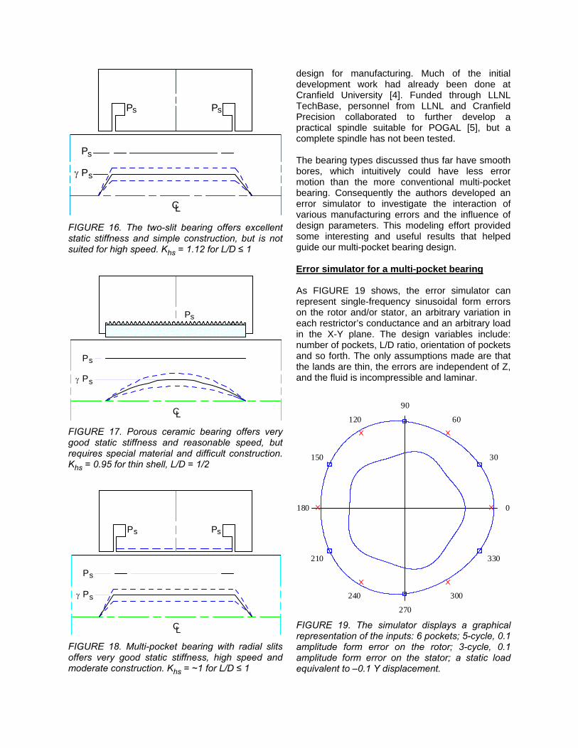
FIGURE 16. The two-slit bearing offers excellent static stiffness and simple construction, but is not suited for high speed. Khs = 1.12 for L/D ≤ 1
sγ P
sP
sP
LC FIGURE 17. Porous ceramic bearing offers very good static stiffness and reasonable speed, but requires special material and difficult construction. Khs = 0.95 for thin shell, L/D = 1/2
sPsP
LC
sγ P
sP
FIGURE 18. Multi-pocket bearing with radial slits offers very good static stiffness, high speed and moderate construction. Khs = ~1 for L/D ≤ 1
design for manufacturing. Much of the initial development work had already been done at Cranfield University [4]. Funded through LLNL TechBase, personnel from LLNL and Cranfield Precision collaborated to further develop a practical spindle suitable for POGAL [5], but a complete spindle has not been tested. The bearing types discussed thus far have smooth bores, which intuitively could have less error motion than the more conventional multi-pocket bearing. Consequently the authors developed an error simulator to investigate the interaction of various manufacturing errors and the influence of design parameters. This modeling effort provided some interesting and useful results that helped guide our multi-pocket bearing design. Error simulator for a multi-pocket bearing As FIGURE 19 shows, the error simulator can represent single-frequency sinusoidal form errors on the rotor and/or stator, an arbitrary variation in each restrictor’s conductance and an arbitrary load in the X-Y plane. The design variables include: number of pockets, L/D ratio, orientation of pockets and so forth. The only assumptions made are that the lands are thin, the errors are independent of Z, and the fluid is incompressible and laminar.
0
30
60
90
120
150
180
210
240
270
300
330
FIGURE 19. The simulator displays a graphical representation of the inputs: 6 pockets; 5-cycle, 0.1 amplitude form error on the rotor; 3-cycle, 0.1 amplitude form error on the stator; a static load equivalent to –0.1 Y displacement.
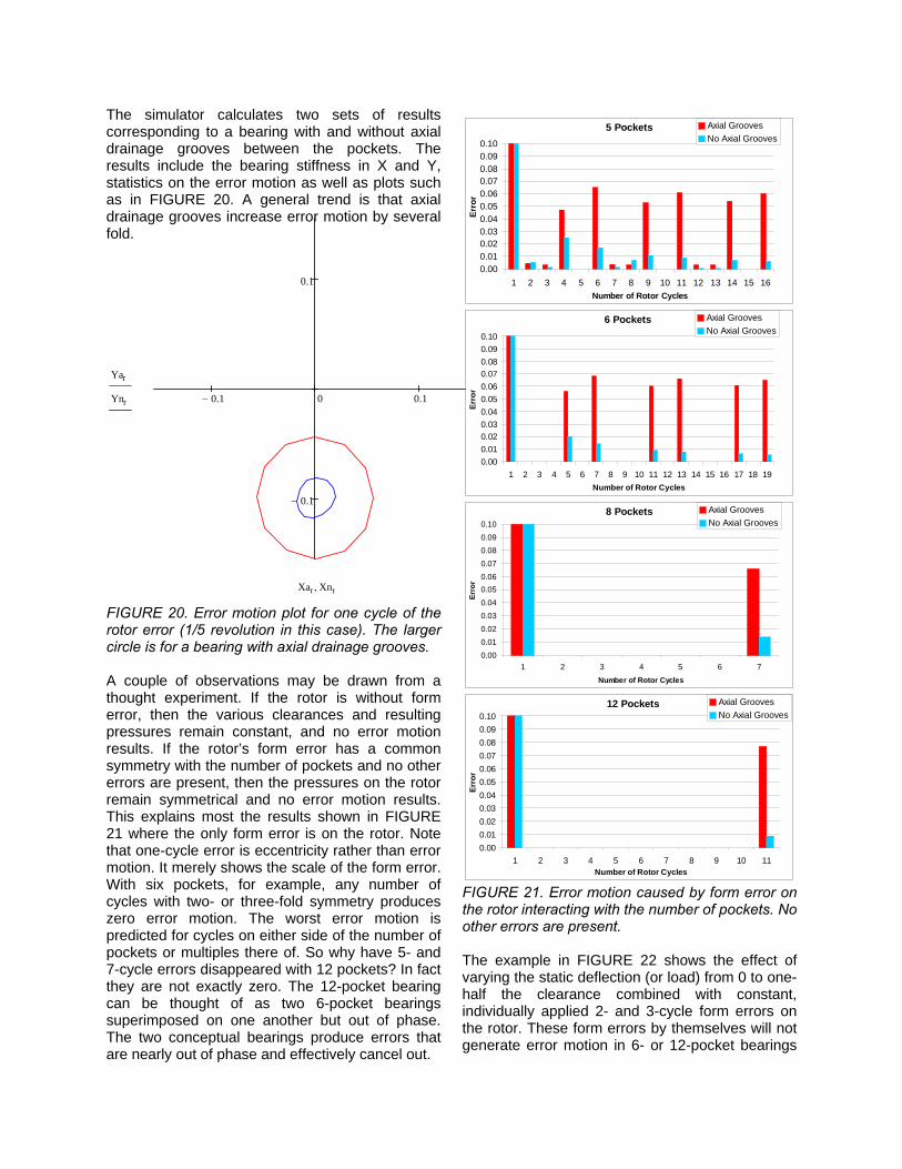
The simulator calculates two sets of results corresponding to a bearing with and without axial drainage grooves between the pockets. The results include the bearing stiffness in X and Y, statistics on the error motion as well as plots such as in FIGURE 20. A general trend is that axial drainage grooves increase error motion by several fold.
0.1− 0 0.1
0.1−
0.1
Yar
Ynr
Xar Xnr, FIGURE 20. Error motion plot for one cycle of the rotor error (1/5 revolution in this case). The larger circle is for a bearing with axial drainage grooves. A couple of observations may be drawn from a thought experiment. If the rotor is without form error, then the various clearances and resulting pressures remain constant, and no error motion results. If the rotor’s form error has a common symmetry with the number of pockets and no other errors are present, then the pressures on the rotor remain symmetrical and no error motion results. This explains most the results shown in FIGURE 21 where the only form error is on the rotor. Note that one-cycle error is eccentricity rather than error motion. It merely shows the scale of the form error. With six pockets, for example, any number of cycles with two- or three-fold symmetry produces zero error motion. The worst error motion is predicted for cycles on either side of the number of pockets or multiples there of. So why have 5- and 7-cycle errors disappeared with 12 pockets? In fact they are not exactly zero. The 12-pocket bearing can be thought of as two 6-pocket bearings superimposed on one another but out of phase. The two conceptual bearings produce errors that are nearly out of phase and effectively cancel out.
FIGURE 21. Error motion caused by form error on the rotor interacting with the number of pockets. No other errors are present. The example in FIGURE 22 shows the effect of varying the static deflection (or load) from 0 to one-half the clearance combined with constant, individually applied 2- and 3-cycle form errors on the rotor. These form errors by themselves will not generate error motion in 6- or 12-pocket bearings
6 Pockets
0.000.010.020.030.040.050.060.070.080.090.10
1 2 3 4 5 6 7 8 9 10 11 12 13 14 15 16 17 18 19Number of Rotor Cycles
Erro
r
Axial GroovesNo Axial Grooves
8 Pockets
0.000.010.020.030.040.050.060.070.080.090.10
1 2 3 4 5 6 7Number of Rotor Cycles
Erro
r
Axial GroovesNo Axial Grooves
12 Pockets
0.000.010.020.030.040.050.060.070.080.090.10
1 2 3 4 5 6 7 8 9 10 11Number of Rotor Cycles
Erro
r
Axial GroovesNo Axial Grooves
5 Pockets
0.000.010.020.030.040.050.060.070.080.090.10
1 2 3 4 5 6 7 8 9 10 11 12 13 14 15 16Number of Rotor Cycles
Erro
r
Axial GroovesNo Axial Grooves
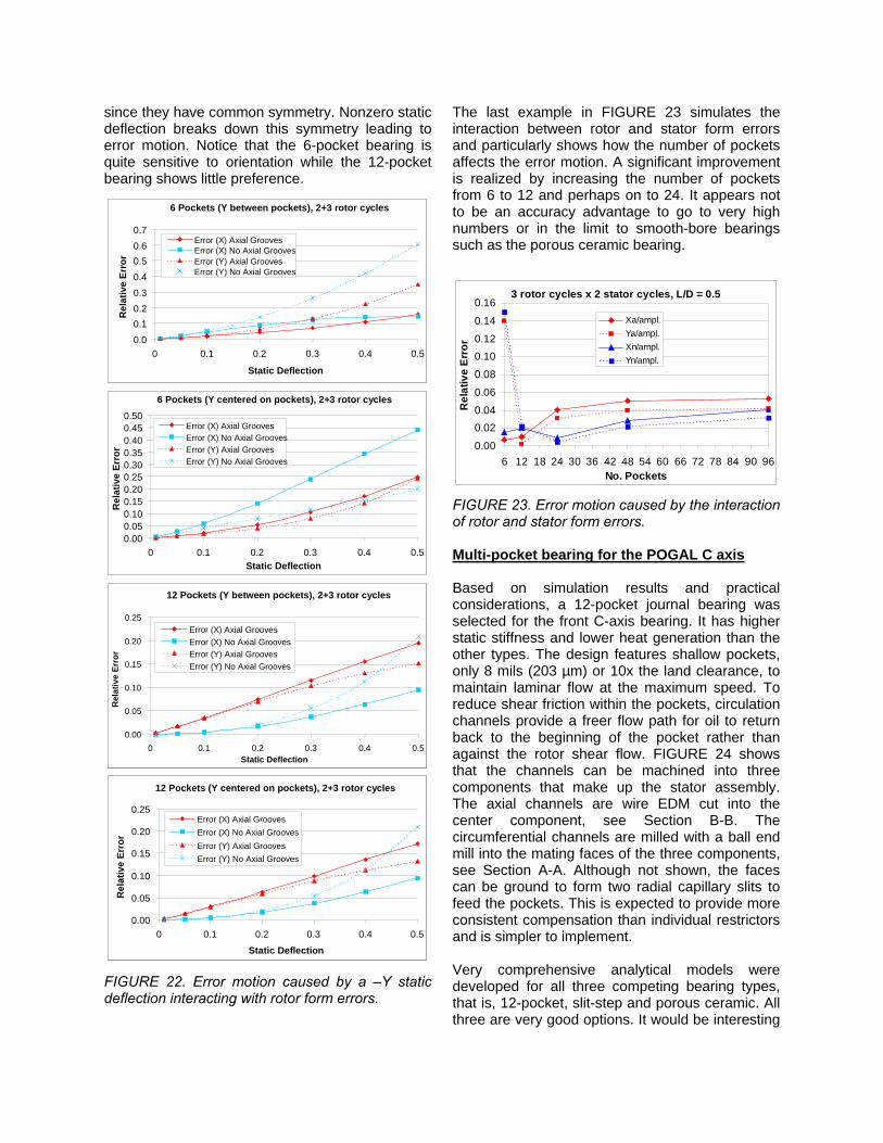
since they have common symmetry. Nonzero static deflection breaks down this symmetry leading to error motion. Notice that the 6-pocket bearing is quite sensitive to orientation while the 12-pocket bearing shows little preference.
6 Pockets (Y between pockets), 2+3 rotor cycles
0.00.10.20.30.4
0.50.60.7
0 0.1 0.2 0.3 0.4 0.5
Static Deflection
Rel
ativ
e Er
ror
Error (X) Axial GroovesError (X) No Axial GroovesError (Y) Axial GroovesError (Y) No Axial Grooves
6 Pockets (Y between pockets), 2+3 rotor cycles
0.00.10.20.30.4
0.50.60.7
0 0.1 0.2 0.3 0.4 0.5
Static Deflection
Rel
ativ
e Er
ror
Error (X) Axial GroovesError (X) No Axial GroovesError (Y) Axial GroovesError (Y) No Axial Grooves
6 Pockets (Y centered on pockets), 2+3 rotor cycles
0.000.050.100.150.200.250.300.350.400.450.50
0 0.1 0.2 0.3 0.4 0.5Static Deflection
Rel
ativ
e Er
ror
Error (X) Axial GroovesError (X) No Axial GroovesError (Y) Axial GroovesError (Y) No Axial Grooves
6 Pockets (Y centered on pockets), 2+3 rotor cycles
0.000.050.100.150.200.250.300.350.400.450.50
0 0.1 0.2 0.3 0.4 0.5Static Deflection
Rel
ativ
e Er
ror
Error (X) Axial GroovesError (X) No Axial GroovesError (Y) Axial GroovesError (Y) No Axial Grooves
12 Pockets (Y between pockets), 2+3 rotor cycles
0.00
0.05
0.10
0.15
0.20
0.25
0 0.1 0.2 0.3 0.4 0.5Static Deflection
Rel
ativ
e Er
ror
Error (X) Axial GroovesError (X) No Axial GroovesError (Y) Axial GroovesError (Y) No Axial Grooves
12 Pockets (Y between pockets), 2+3 rotor cycles
0.00
0.05
0.10
0.15
0.20
0.25
0 0.1 0.2 0.3 0.4 0.5Static Deflection
Rel
ativ
e Er
ror
Error (X) Axial GroovesError (X) No Axial GroovesError (Y) Axial GroovesError (Y) No Axial Grooves
12 Pockets (Y centered on pockets), 2+3 rotor cycles
0.00
0.05
0.10
0.15
0.20
0.25
0 0.1 0.2 0.3 0.4 0.5
Static Deflection
Rel
ativ
e Er
ror
Error (X) Axial GroovesError (X) No Axial GroovesError (Y) Axial GroovesError (Y) No Axial Grooves
12 Pockets (Y centered on pockets), 2+3 rotor cycles
0.00
0.05
0.10
0.15
0.20
0.25
0 0.1 0.2 0.3 0.4 0.5
Static Deflection
Rel
ativ
e Er
ror
Error (X) Axial GroovesError (X) No Axial GroovesError (Y) Axial GroovesError (Y) No Axial Grooves
FIGURE 22. Error motion caused by a –Y static deflection interacting with rotor form errors.
The last example in FIGURE 23 simulates the interaction between rotor and stator form errors and particularly shows how the number of pockets affects the error motion. A significant improvement is realized by increasing the number of pockets from 6 to 12 and perhaps on to 24. It appears not to be an accuracy advantage to go to very high numbers or in the limit to smooth-bore bearings such as the porous ceramic bearing.
3 rotor cycles x 2 stator cycles, L/D = 0.5
0.00
0.020.04
0.06
0.08
0.100.12
0.14
0.16
6 12 18 24 30 36 42 48 54 60 66 72 78 84 90 96No. Pockets
Rel
ativ
e Er
ror
Xa/ampl.Ya/ampl.Xn/ampl.Yn/ampl.
FIGURE 23. Error motion caused by the interaction of rotor and stator form errors. Multi-pocket bearing for the POGAL C axis Based on simulation results and practical considerations, a 12-pocket journal bearing was selected for the front C-axis bearing. It has higher static stiffness and lower heat generation than the other types. The design features shallow pockets, only 8 mils (203 µm) or 10x the land clearance, to maintain laminar flow at the maximum speed. To reduce shear friction within the pockets, circulation channels provide a freer flow path for oil to return back to the beginning of the pocket rather than against the rotor shear flow. FIGURE 24 shows that the channels can be machined into three components that make up the stator assembly. The axial channels are wire EDM cut into the center component, see Section B-B. The circumferential channels are milled with a ball end mill into the mating faces of the three components, see Section A-A. Although not shown, the faces can be ground to form two radial capillary slits to feed the pockets. This is expected to provide more consistent compensation than individual restrictors and is simpler to implement. Very comprehensive analytical models were developed for all three competing bearing types, that is, 12-pocket, slit-step and porous ceramic. All three are very good options. It would be interesting

to build all three spindle bearings and test them with the same rotor (perhaps a future possibility).
A
A
Ø 63°
.157
30°Section B-B
B
B
.007 .055
Ø .187
.15
.155
32.7
Section A-A
FIGURE 24. The initial layout drawing of the 12-pocket bearing showing the circulation channels around a pocket.
SUMMARY A general description of the hydrostatic bearings designed for POGAL has been presented with the rationale given for the choices made. Most of the details and analyses for this project have been omitted to present the main concepts and ideas that others may wish to apply (yielding a paper with 24 figures and no equations). Much of the analytical detail resides in Mathcad™ programs that are easy to modify for different applications. ACKNOWLEGEMENTS This work was performed under the auspices of the U.S. Department of Energy by the Lawrence Livermore National Laboratory under Contract No. W-7405-ENG-48. REFERENCES
[1] Hale L, Wulff T, Sedgewick J. Testing a low-influence spindle drive motor. Precision Engineering. 2005 Jan; 29(1): 1-10. (UCRL-JRNL-200853)
[2] Donaldson, Robert R. Incompressible Journal Bearings with Combined Hydrostatic-Hydrodynamic Action. Ph.D. Thesis, Massachusetts Institute of Technology. 1965 June
[3] Hale L, Donaldson R., Castro C, Chung C, Hopkins J. Development of a hydrostatic journal bearing with slit-step compensation. Proceedings of the American Society for Precision Engineering. 2006 Oct; 272-275
[4] Corbett J, Almond R, Stephenson D, Kwan Y. Porous Ceramic Water Hydrostatic Bearing for Improved for Accuracy Performance. Annals of the CIRP. 1998; 47(1)
[5] Geraghty P, Carlisle K, Hale L. Ultra-Precision Machine Spindle Using Porous Ceramic Bearings. FY02, FY03, FY04 Engineering Technology Reports, Technology Base (see http://www-eng.llnl.gov/pubs.html#tech)