Embed Size (px)
Citation preview
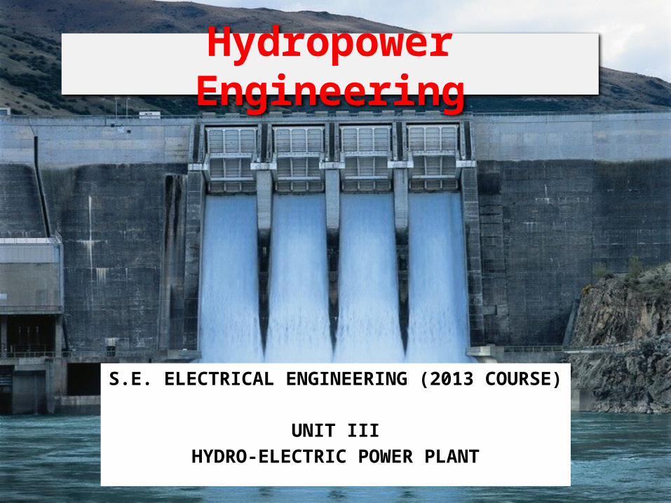
Hydropower Engineering
S.E. ELECTRICAL ENGINEERING (2013 COURSE)
UNIT IIIHYDRO-ELECTRIC POWER PLANT
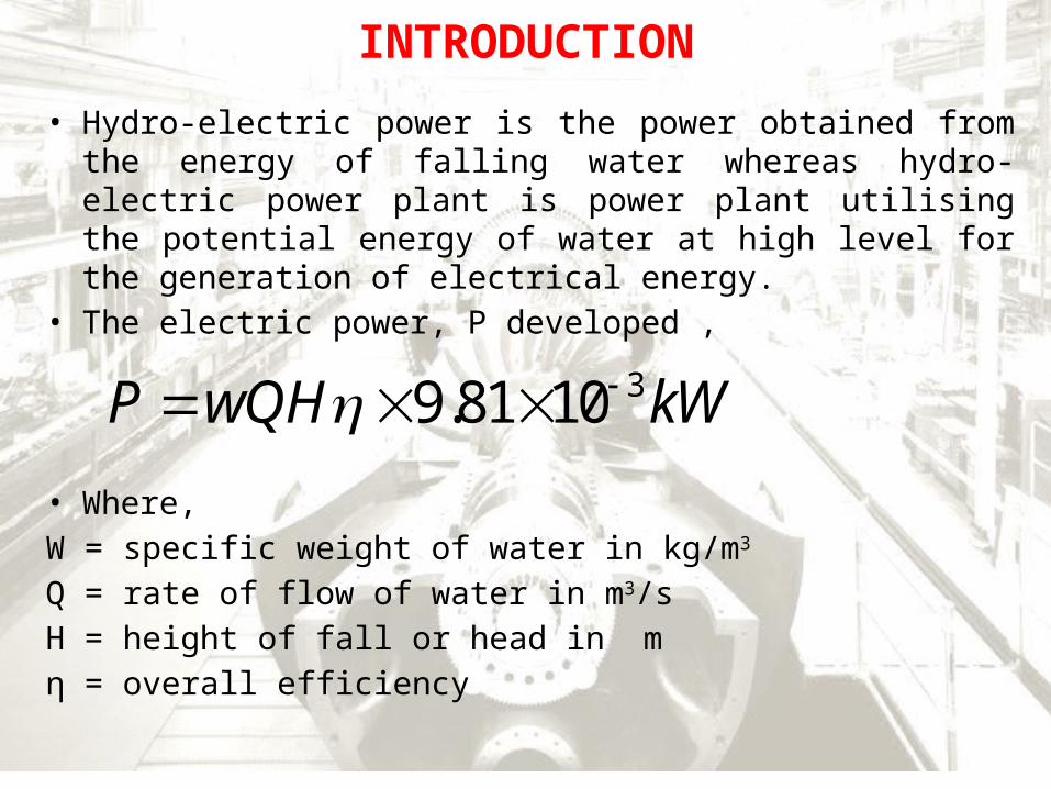
INTRODUCTION
• Hydro-electric power is the power obtained from the energy of falling water whereas hydro-electric power plant is power plant utilising the potential energy of water at high level for the generation of electrical energy.
• The electric power, P developed ,
• Where,W = specific weight of water in kg/m3
Q = rate of flow of water in m3/sH = height of fall or head in mη = overall efficiency
39.81 10P wQH kW
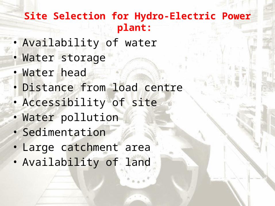
Site Selection for Hydro-Electric Power plant:
• Availability of water• Water storage• Water head• Distance from load centre• Accessibility of site• Water pollution• Sedimentation• Large catchment area• Availability of land
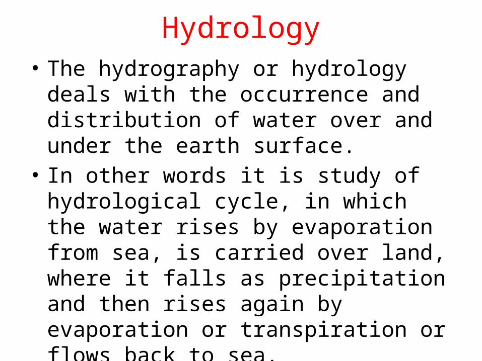
Hydrology• The hydrography or hydrology deals with the
occurrence and distribution of water over and under the earth surface.
• In other words it is study of hydrological cycle, in which the water rises by evaporation from sea, is carried over land, where it falls as precipitation and then rises again by evaporation or transpiration or flows back to sea.
Some important terms • Precipitation : Rainfall or Precipitation is defined as the
total condensation of moisture that reach the earth in any form.
• Evaporation : means all the rainfall that is returned to the atmosphere from land and water.
• Run – off : It is defined as that part of the precipitation which is available as stream flow.
i.e. Run –off = Total precipitation – Total evaporationTotal Run-off =Direct run-off over the land + run – off through
seepage.The unite of run-off is m3 /s or day-second
Some important terms
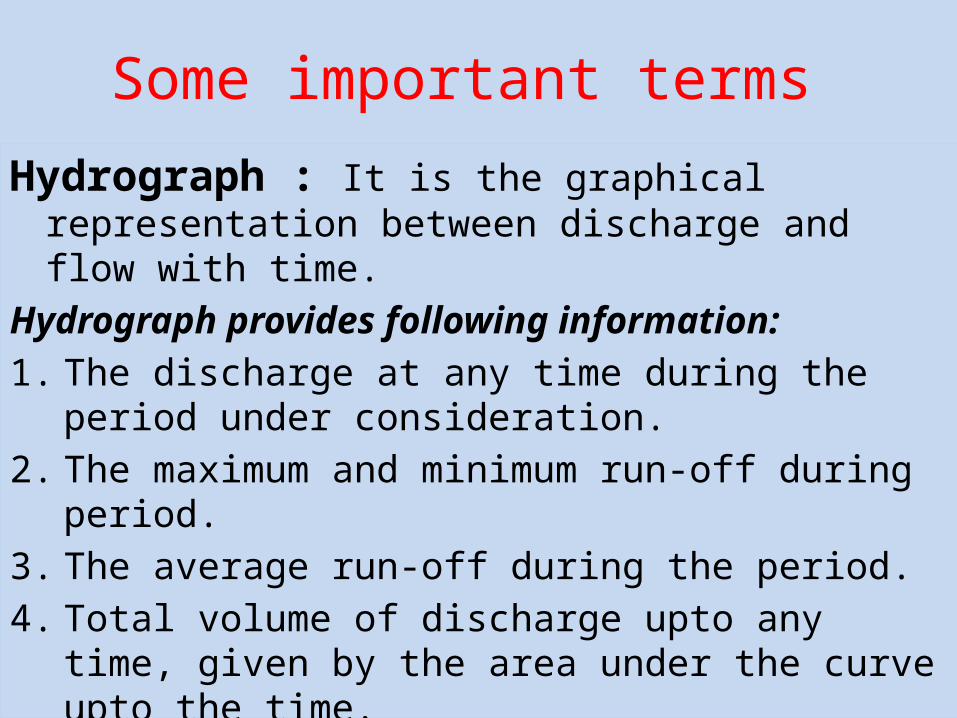
Hydrograph : It is the graphical representation between discharge and flow with time.
Hydrograph provides following information:1. The discharge at any time during the period under
consideration.2. The maximum and minimum run-off during period.3. The average run-off during the period.4. Total volume of discharge upto any time, given by the area
under the curve upto the time.
Hydrograph
Some important terms • Flow duration curve : It gives relation between
flows and lengths of time during which they are available.
• The area under flow-duration curve represents the total quantity of run-off during the period.
• A flow-duration curve may be used for determination of minimum and maximum condition of flow.
• A flow duration curve can be improved upon by storing water on the upstream side and using it during off peak period.
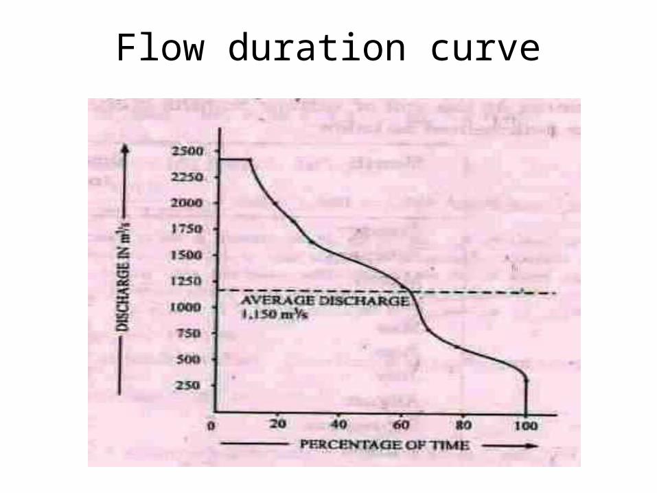
Flow duration curve
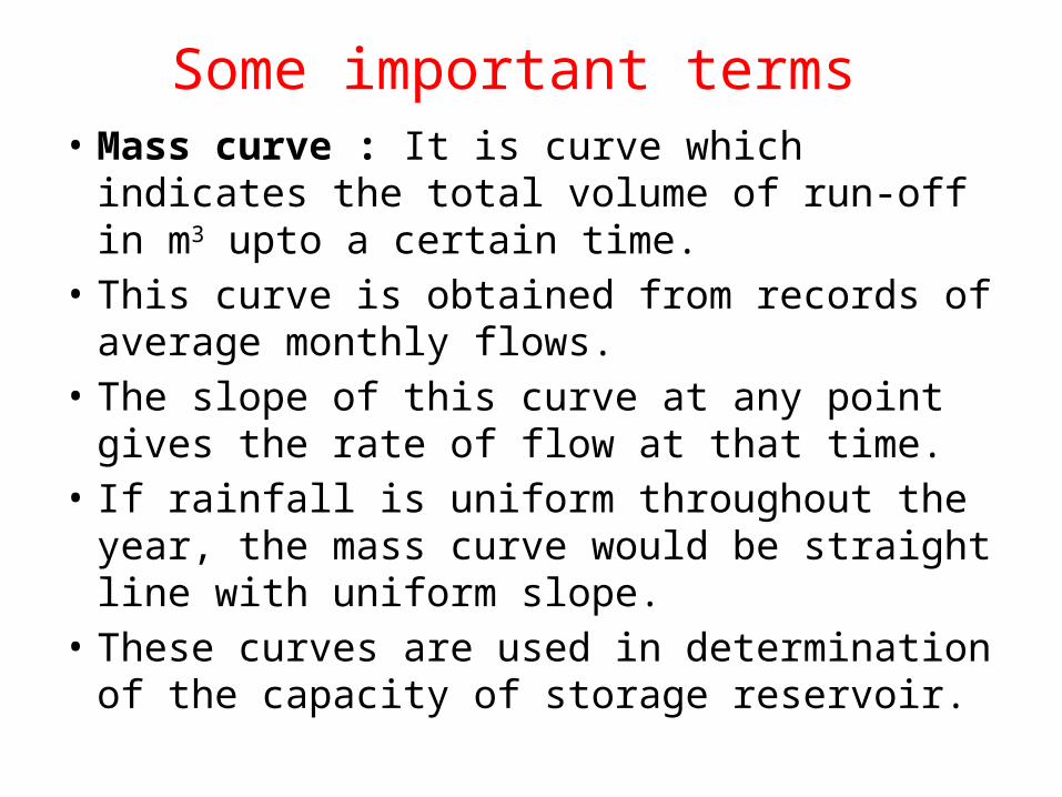
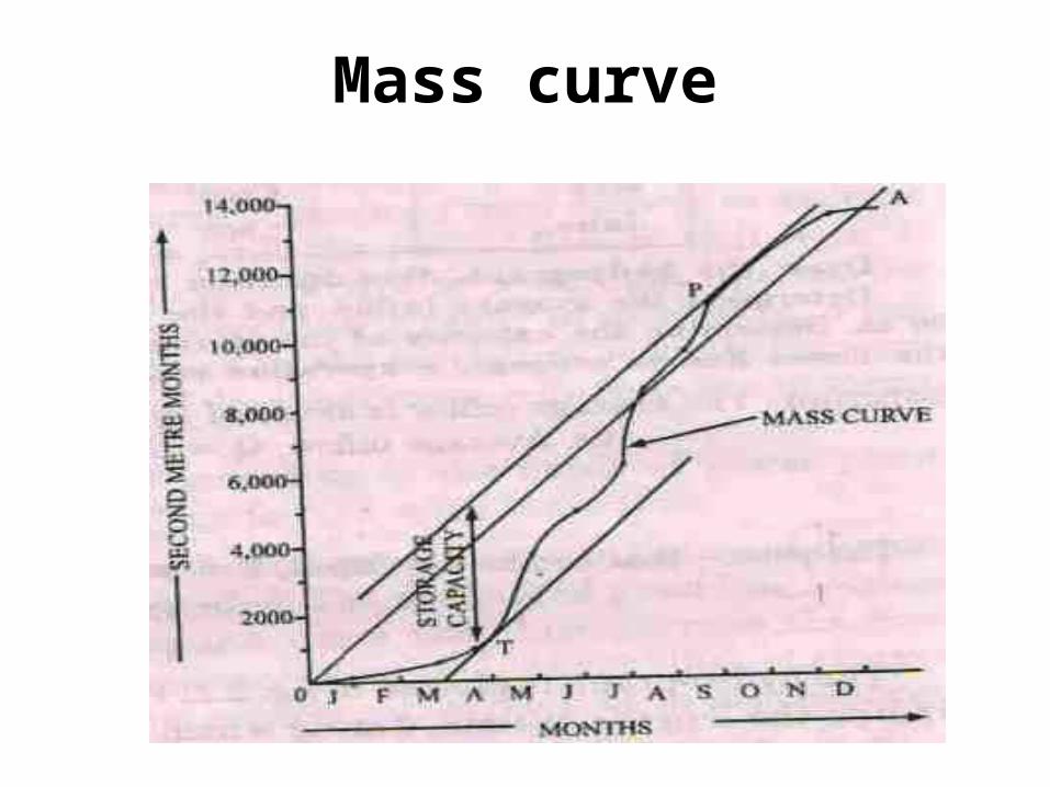
Some important terms • Mass curve : It is curve which indicates the total
volume of run-off in m3 upto a certain time.• This curve is obtained from records of average
monthly flows.• The slope of this curve at any point gives the
rate of flow at that time.• If rainfall is uniform throughout the year, the
mass curve would be straight line with uniform slope.
• These curves are used in determination of the capacity of storage reservoir.
Mass curve
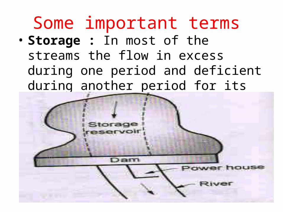
Some important terms • Storage : In most of the streams the flow in
excess during one period and deficient during another period for its regulation artificial storage is needed
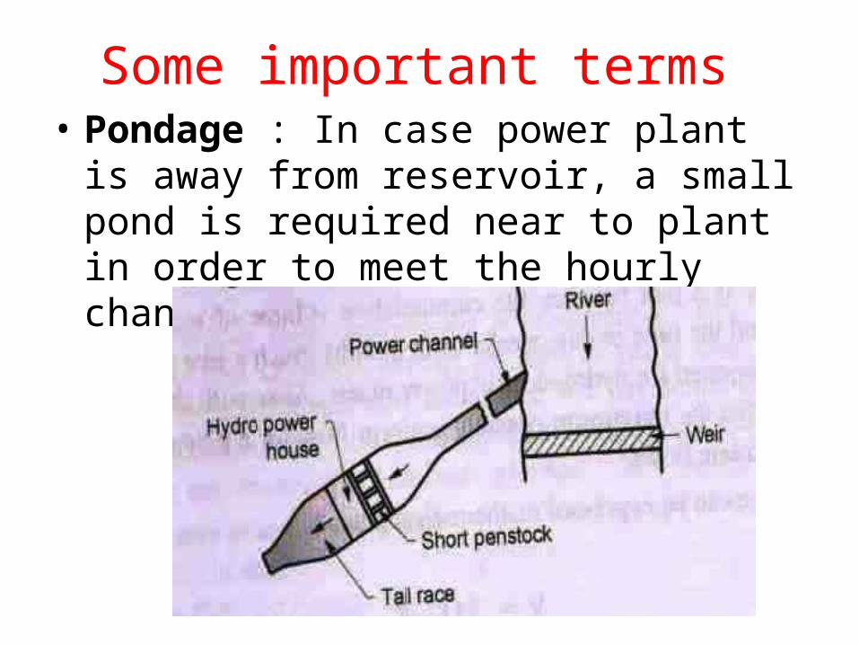
Some important terms • Pondage : In case power plant is away from
reservoir, a small pond is required near to plant in order to meet the hourly changes in power demand.
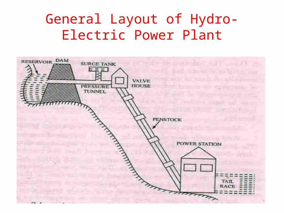
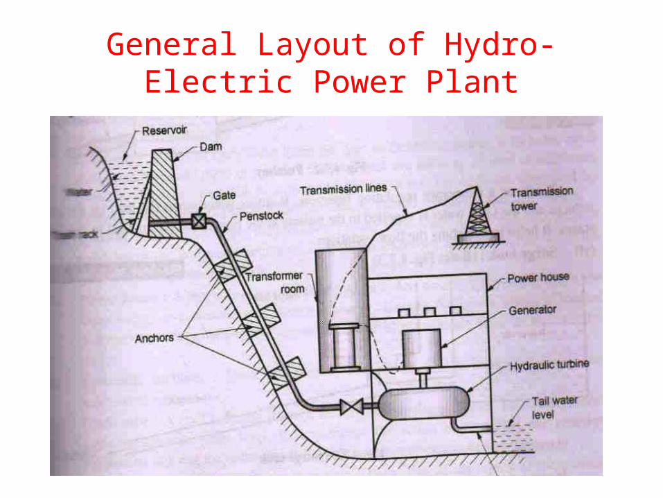
General Layout of Hydro-Electric Power Plant
General Layout of Hydro-Electric Power Plant
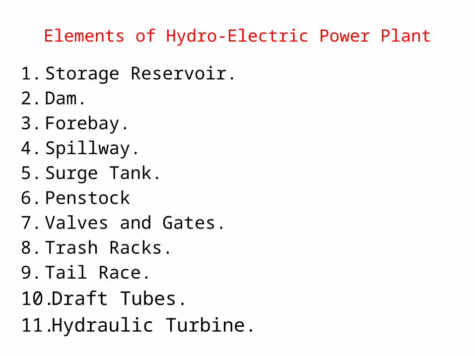
Elements of Hydro-Electric Power Plant1. Storage Reservoir.2. Dam.3. Forebay.4. Spillway.5. Surge Tank.6. Penstock7. Valves and Gates.8. Trash Racks.9. Tail Race.10. Draft Tubes.11. Hydraulic Turbine.
Elements of Hydro-Electric Power Plant• Storage Reservoir :- Its purpose is store water
during excess flow periods and supply the same during lean periods.
• Dam :- A dam is structure of considerable height built across the river to provide working head of water for power plant and increase the storage capacity of power plant.
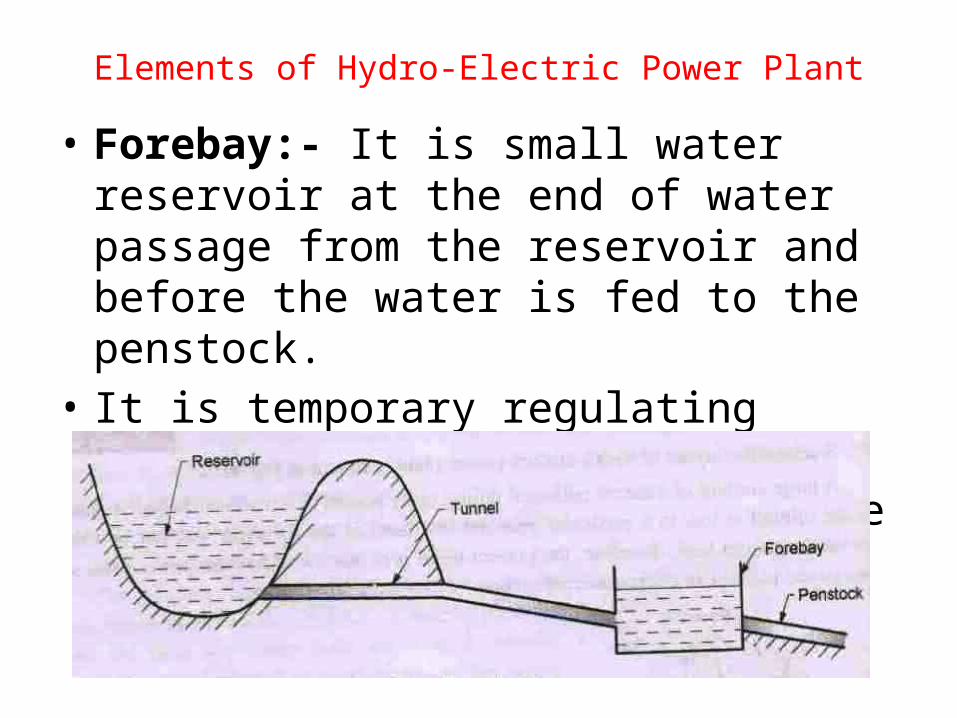
Elements of Hydro-Electric Power Plant• Forebay:- It is small water reservoir at the end
of water passage from the reservoir and before the water is fed to the penstock.
• It is temporary regulating reservoir. It store water when load is light and supplied same water during peak period.
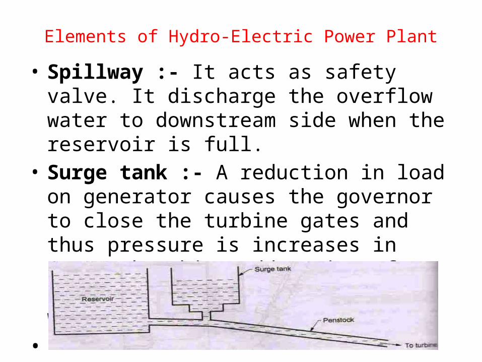
Elements of Hydro-Electric Power Plant• Spillway :- It acts as safety valve. It discharge the
overflow water to downstream side when the reservoir is full.
• Surge tank :- A reduction in load on generator causes the governor to close the turbine gates and thus pressure is increases in penstock. This sudden rise of pressure in penstock known as water hammering.
•
Elements of Hydro-Electric Power Plant
• Penstock :- It is closed conduit which connects the forebay or surge tank to the case of turbine.
• Valves and Gates :- Valves and Gates provided for controlling of flow of water from reservoir to hydraulic turbine.
• Trash Racks :- These are built up from long , flat bars set vertically or nearly so and spaced with the minimum width of water passage. It prevents debris from water.
Elements of Hydro-Electric Power Plant
• Tail Race :- after useful work in turbine the water is discharged to tail race which may lead to the river or reservoir.
• Draft Tubes :- An air tight pipe giving passage to the runner outlet water of turbine to tail race.
• Hydraulic turbines :- converting kinetic energy into mechanical energy.
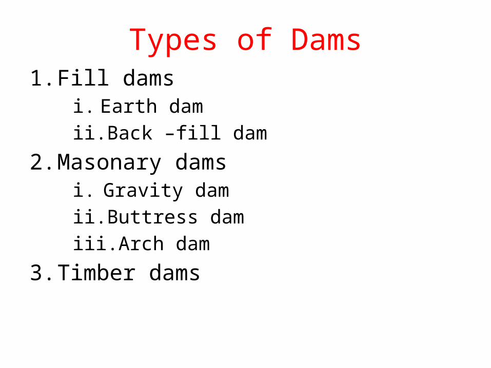
Types of Dams1. Fill dams
i. Earth damii. Back –fill dam
2. Masonary damsi. Gravity damii. Buttress damiii. Arch dam
3. Timber dams
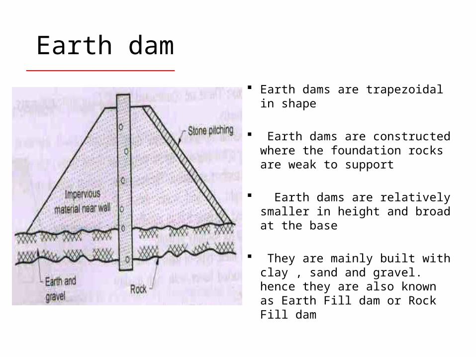
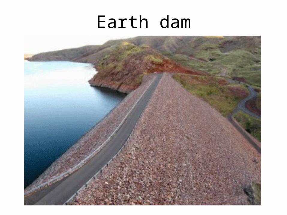
Earth dams are trapezoidal in shape
Earth dams are constructed where the foundation rocks are weak to support
Earth dams are relatively smaller in height and broad at the base
They are mainly built with clay , sand and gravel. hence they are also known as Earth Fill dam or Rock Fill dam
Earth dam
Earth dam
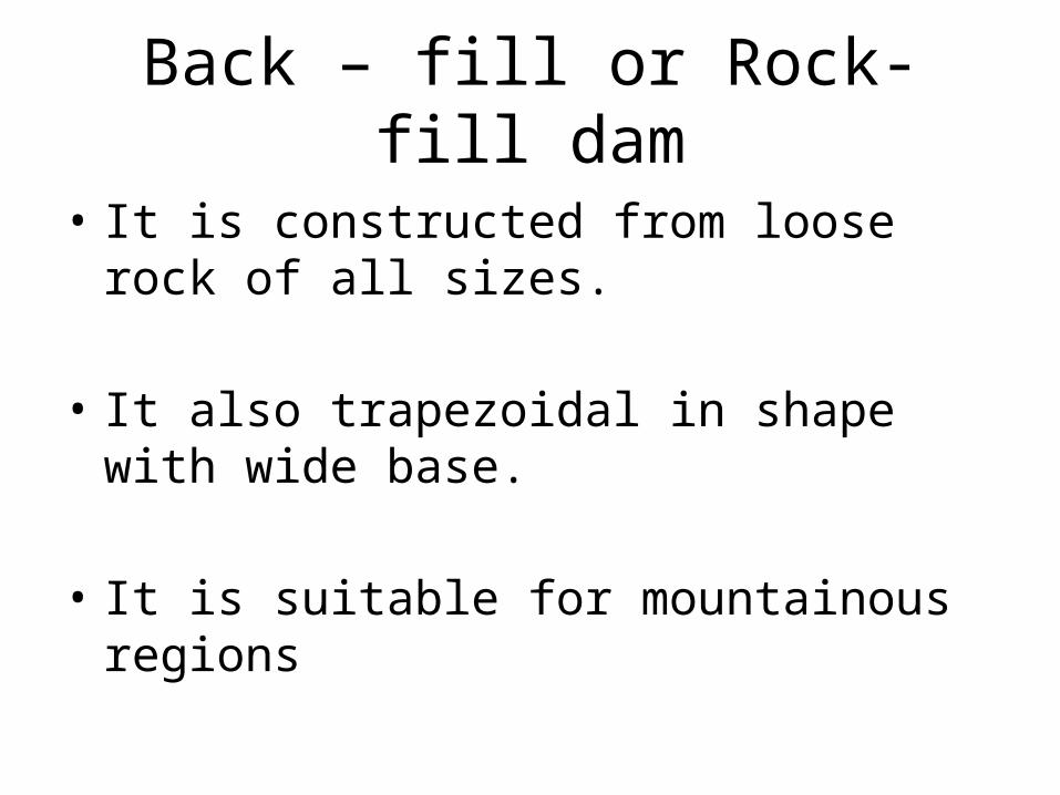
Back – fill or Rock- fill dam
• It is constructed from loose rock of all sizes.
• It also trapezoidal in shape with wide base.
• It is suitable for mountainous regions
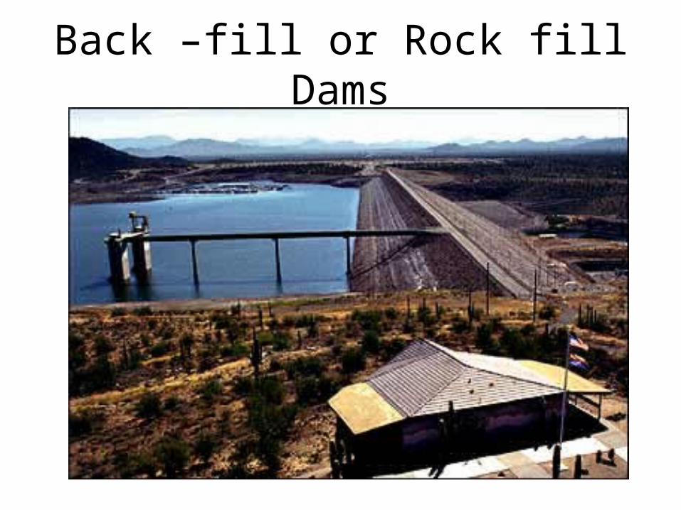
Back –fill or Rock fill Dams
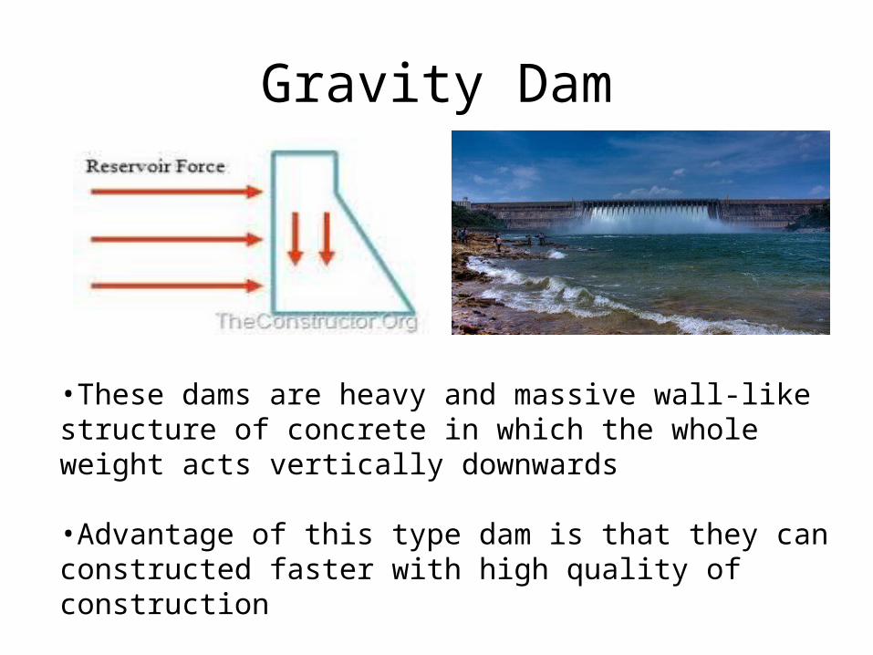
Gravity Dam
•These dams are heavy and massive wall-like structure of concrete in which the whole weight acts vertically downwards
•Advantage of this type dam is that they can constructed faster with high quality of construction
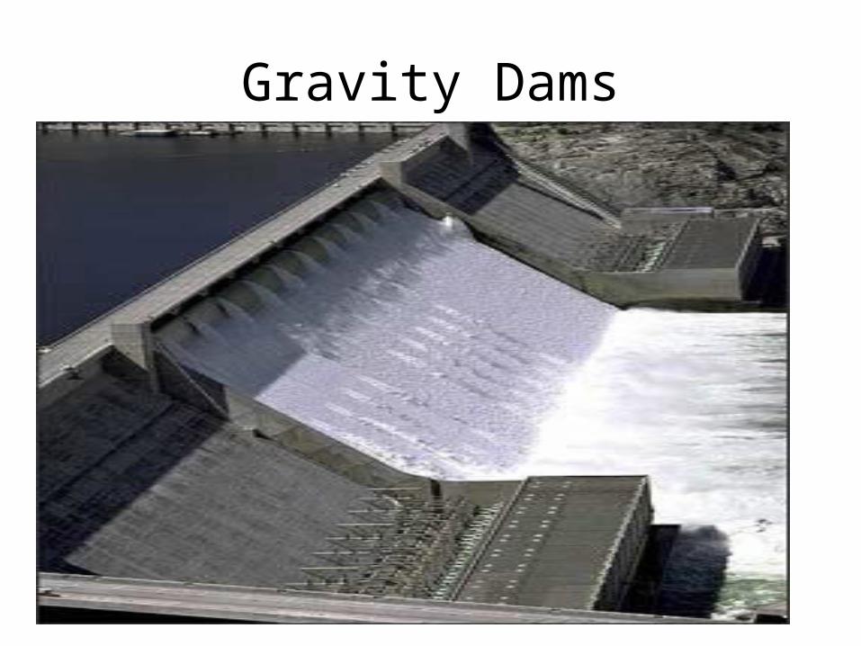
Gravity Dams
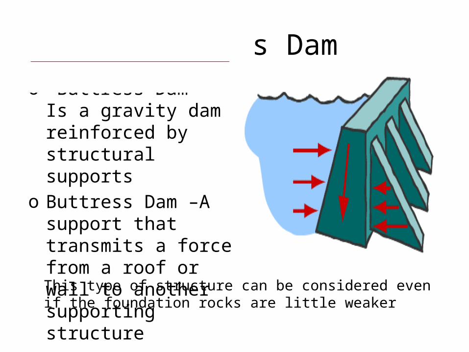
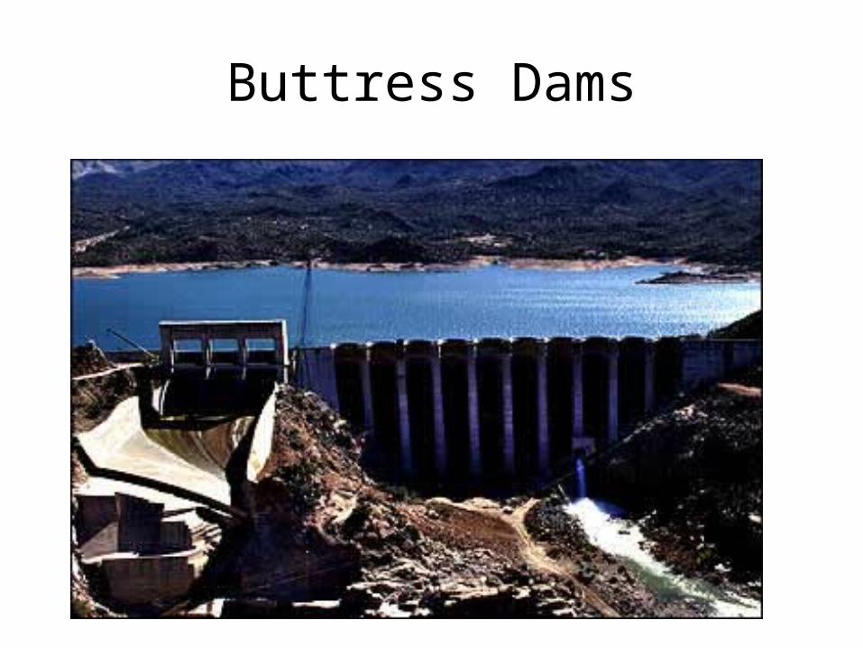
o Buttress Dam - Is a gravity dam reinforced by structural supports
o Buttress Dam –A support that transmits a force from a roof or wall to another supporting structure
Buttress Dam
This type of structure can be considered even if the foundation rocks are little weaker
Buttress Dams
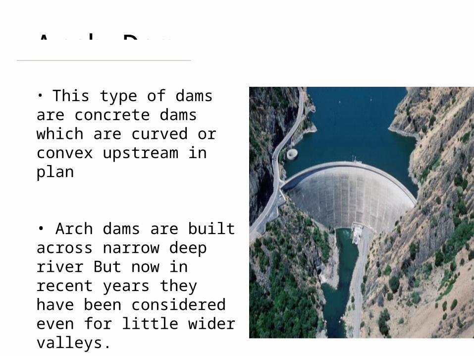
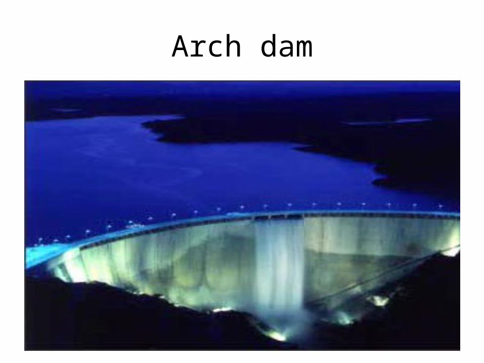
Arch Dam• This type of dams are concrete dams which are curved or convex upstream in plan
• Arch dams are built across narrow deep river But now in recent years they have been considered even for little wider valleys.
Arch dam
Types of Spillways
• Solid gravity or overall spillway• Chute or Trough spillway• Side channel spillway• Saddle spillway• Shaft spillway• Siphon spillway
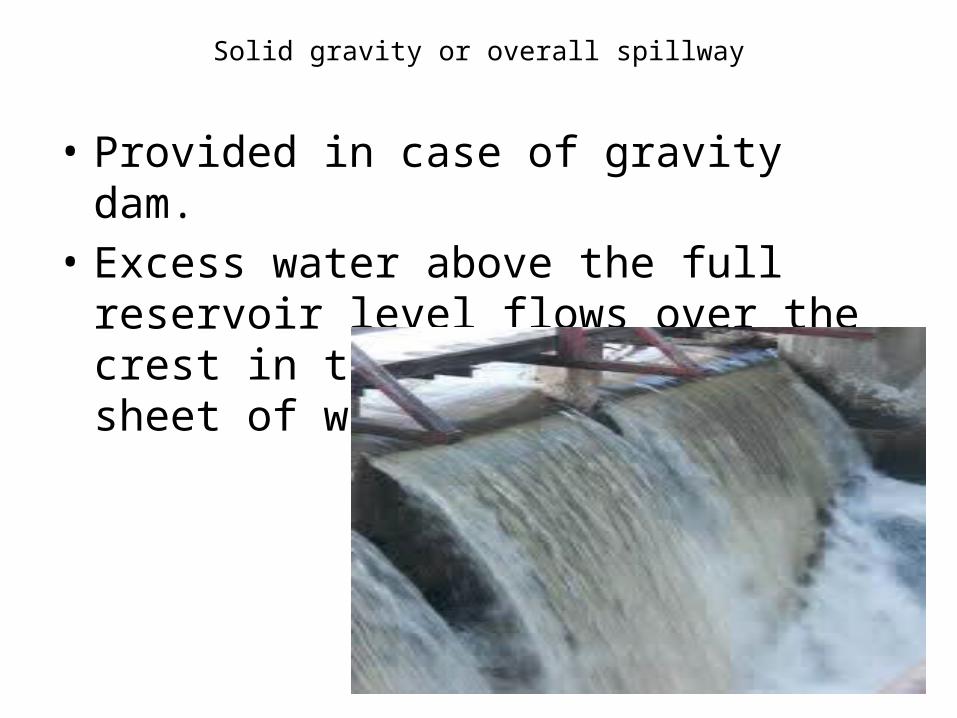
Solid gravity or overall spillway
• Provided in case of gravity dam.• Excess water above the full reservoir level
flows over the crest in the form of rolling sheet of water.
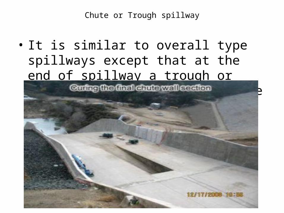
Chute or Trough spillway
• It is similar to overall type spillways except that at the end of spillway a trough or channel is provided to meet the river.
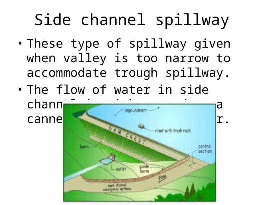
Side channel spillway • These type of spillway given when valley is too
narrow to accommodate trough spillway.• The flow of water in side channel is either
used as a cannel or it meets to river.
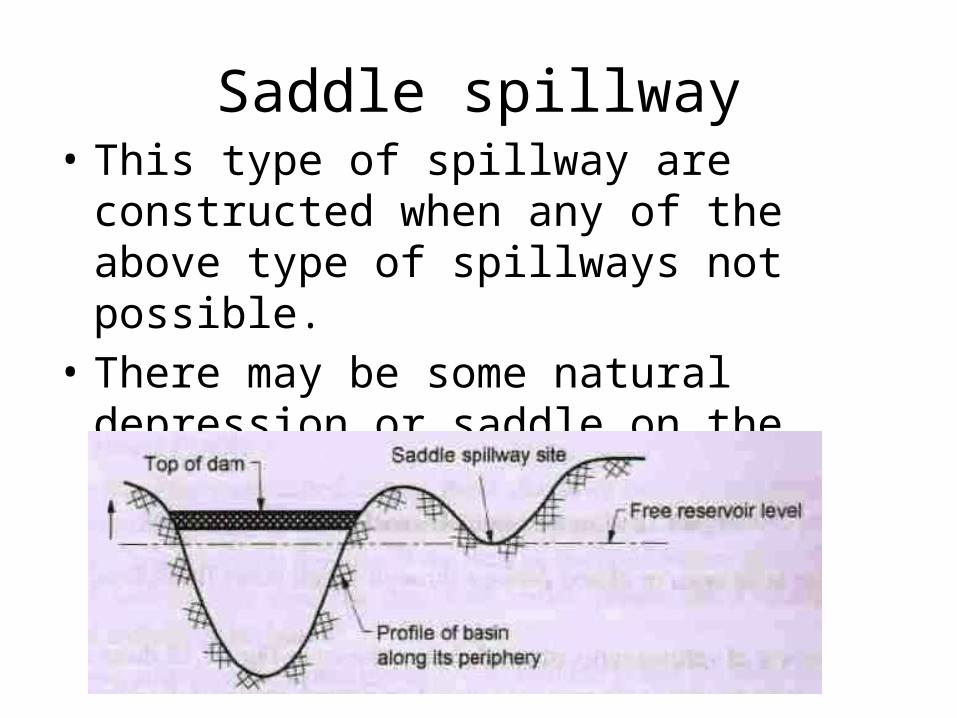
Saddle spillway• This type of spillway are constructed when any
of the above type of spillways not possible.• There may be some natural depression or
saddle on the periphery of the reservoir basin away from the dam.
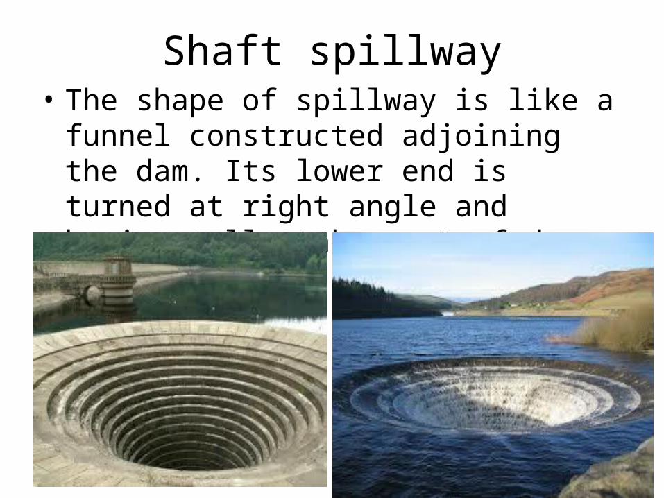
Shaft spillway• The shape of spillway is like a funnel
constructed adjoining the dam. Its lower end is turned at right angle and horizontally taken out of dam.
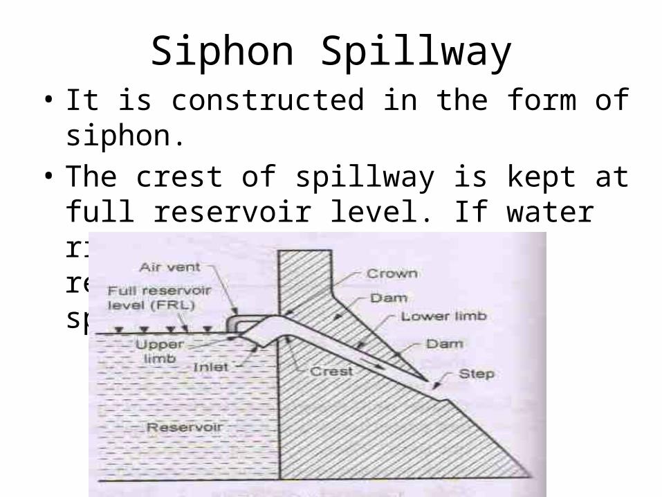
Siphon Spillway• It is constructed in the form of siphon.• The crest of spillway is kept at full reservoir
level. If water rises above full level of reservoir water enters into spillway and discharge.
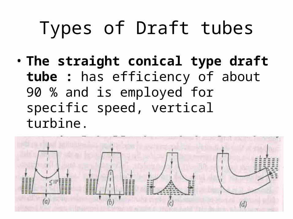
Types of Draft tubes
• The straight conical type draft tube : has efficiency of about 90 % and is employed for specific speed, vertical turbine.
• Vertical bell shaped draft tube :• Bent draft tube :
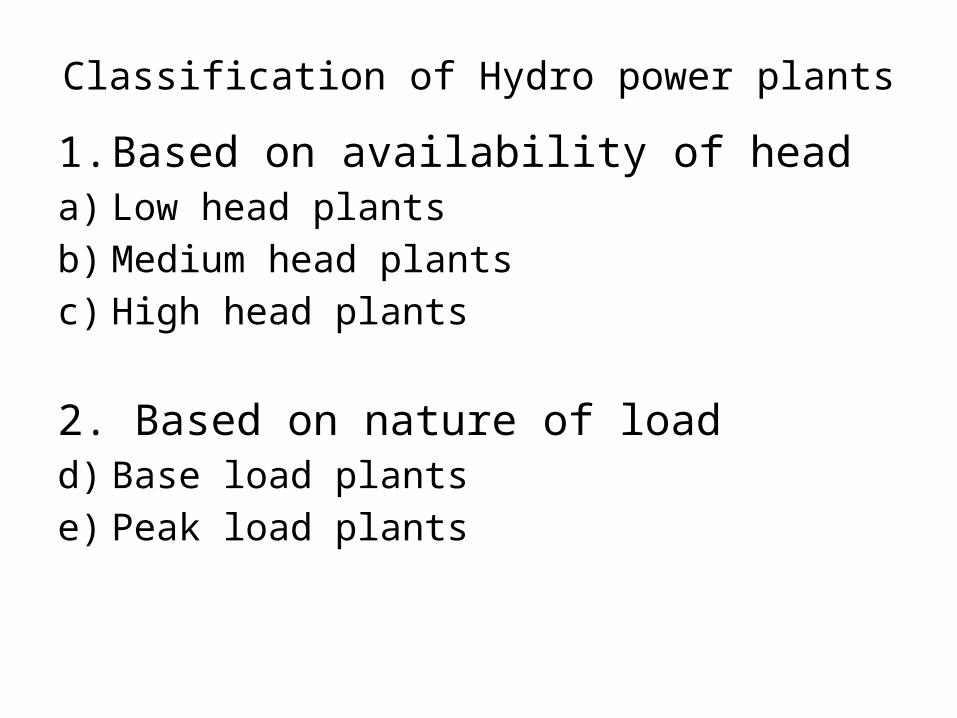
Classification of Hydro power plants1. Based on availability of heada) Low head plantsb) Medium head plantsc) High head plants
2. Based on nature of loadd) Base load plantse) Peak load plants
Classification of Hydro power plants
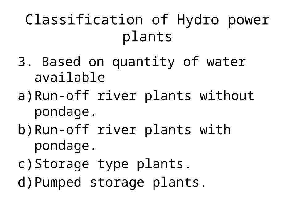
3. Based on quantity of water availablea) Run-off river plants without pondage.b) Run-off river plants with pondage.c) Storage type plants.d) Pumped storage plants.
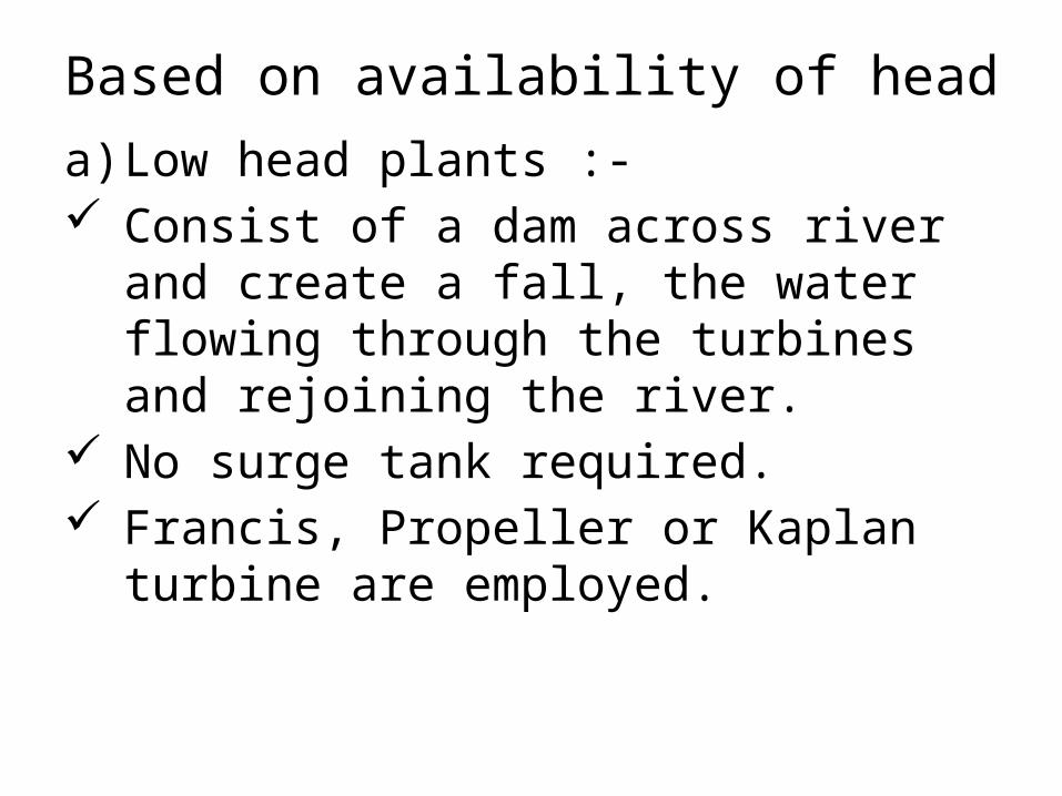
Based on availability of heada) Low head plants :- Consist of a dam across river and create a fall,
the water flowing through the turbines and rejoining the river.
No surge tank required. Francis, Propeller or Kaplan turbine are
employed.
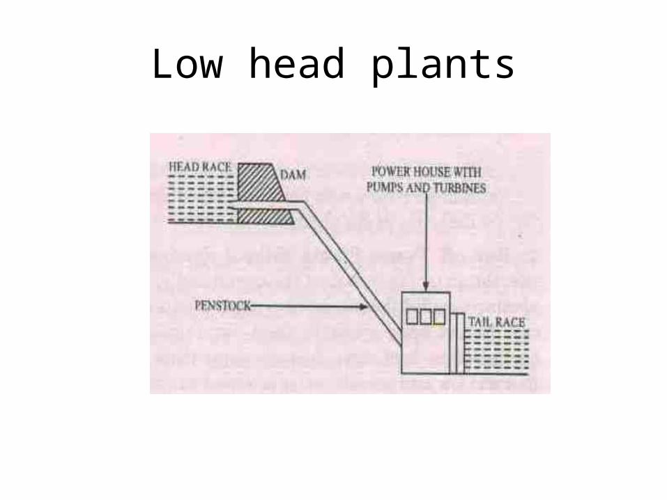
Low head plants
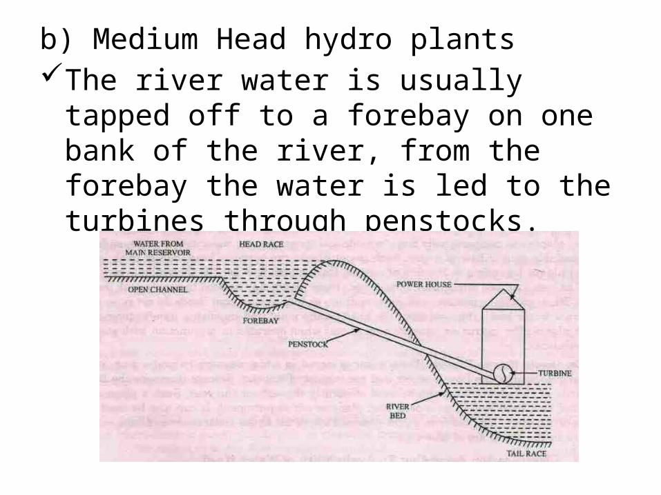
b) Medium Head hydro plantsThe river water is usually tapped off to a
forebay on one bank of the river, from the forebay the water is led to the turbines through penstocks.
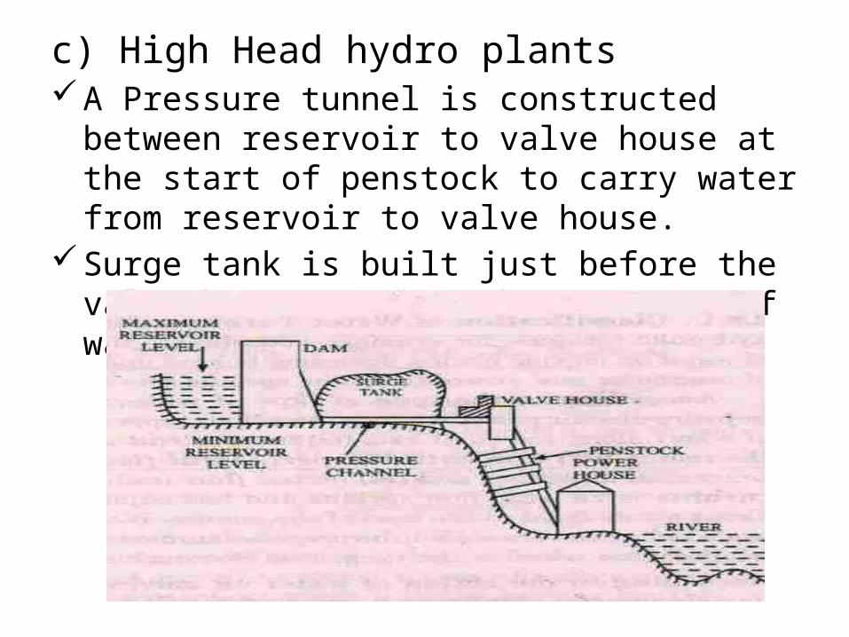
c) High Head hydro plantsA Pressure tunnel is constructed between reservoir
to valve house at the start of penstock to carry water from reservoir to valve house.
Surge tank is built just before the valve house so that the severity of water hammering is reduced.
Based on nature of load1. Base load plants• The plants, which can take up load on the
base portion of the load curve of the power system, are called the base load plants.
2. Peak load plants• The plants used to supply the peak load of
the system corresponding to the load curve are called peak load plants.
Based on quantity of water availablea) Run-off river plants without pondage. The plants are located that the water is taken
from the river directly, and no pondage or storage is possible. Such plants are called the Run-off river plants without pondage.
No control on flow of water. Capital cost required is low.
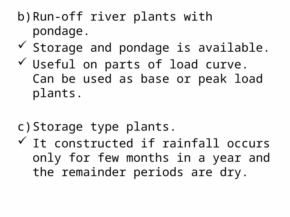
b) Run-off river plants with pondage. Storage and pondage is available. Useful on parts of load curve. Can be used as
base or peak load plants.
c) Storage type plants. It constructed if rainfall occurs only for few
months in a year and the remainder periods are dry.
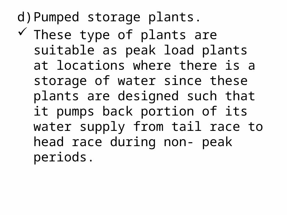
d) Pumped storage plants. These type of plants are suitable as peak load
plants at locations where there is a storage of water since these plants are designed such that it pumps back portion of its water supply from tail race to head race during non- peak periods.
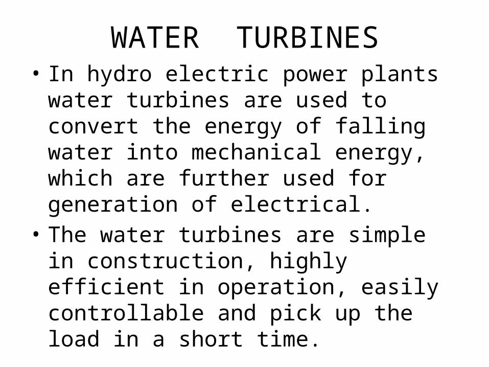
WATER TURBINES• In hydro electric power plants water turbines
are used to convert the energy of falling water into mechanical energy, which are further used for generation of electrical.
• The water turbines are simple in construction, highly efficient in operation, easily controllable and pick up the load in a short time.
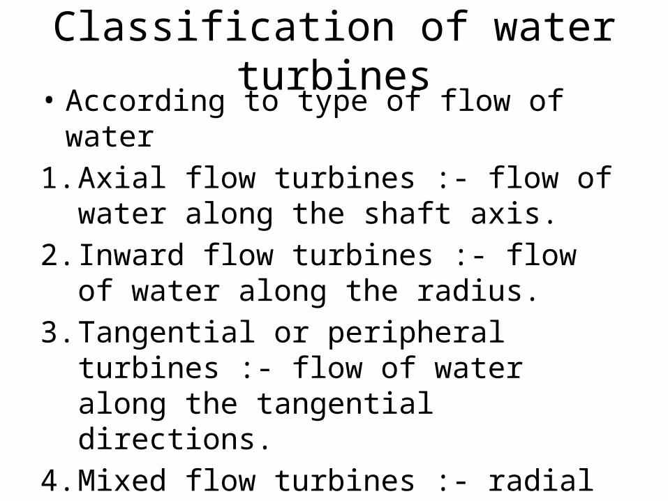
Classification of water turbines• According to type of flow of water1. Axial flow turbines :- flow of water along the
shaft axis.2. Inward flow turbines :- flow of water along
the radius.3. Tangential or peripheral turbines :- flow of
water along the tangential directions.4. Mixed flow turbines :- radial inlet axial outlet.
• According to action of water on moving blade 1. Impulse turbines :- • Uses the velocity of the water to move the
runner and discharges to atmospheric pressure.• The water stream hits each bucket on the runner. • No suction downside, water flows out through
turbine housing after hitting.• High head, low flow applications. • Types : Pelton wheel, Cross Flow
e.g. Pelton turbine.
2. Reaction turbines :- • Combined action of pressure and moving
water. • Runner placed directly in the water stream
flowing over the blades rather than striking each individually.
• lower head and higher flows than compared with the impulse turbines.
• According to name of originator1. Pelton turbines :- It is an impulse turbines
and suited for high head and low flow power plant.
2. Francis turbines :- it is an reaction turbines and suited for medium head and medium flow plant.
3. Kaplan turbines :- special type of propeller turbine having adjustable blades and is suited to low head and high plants.
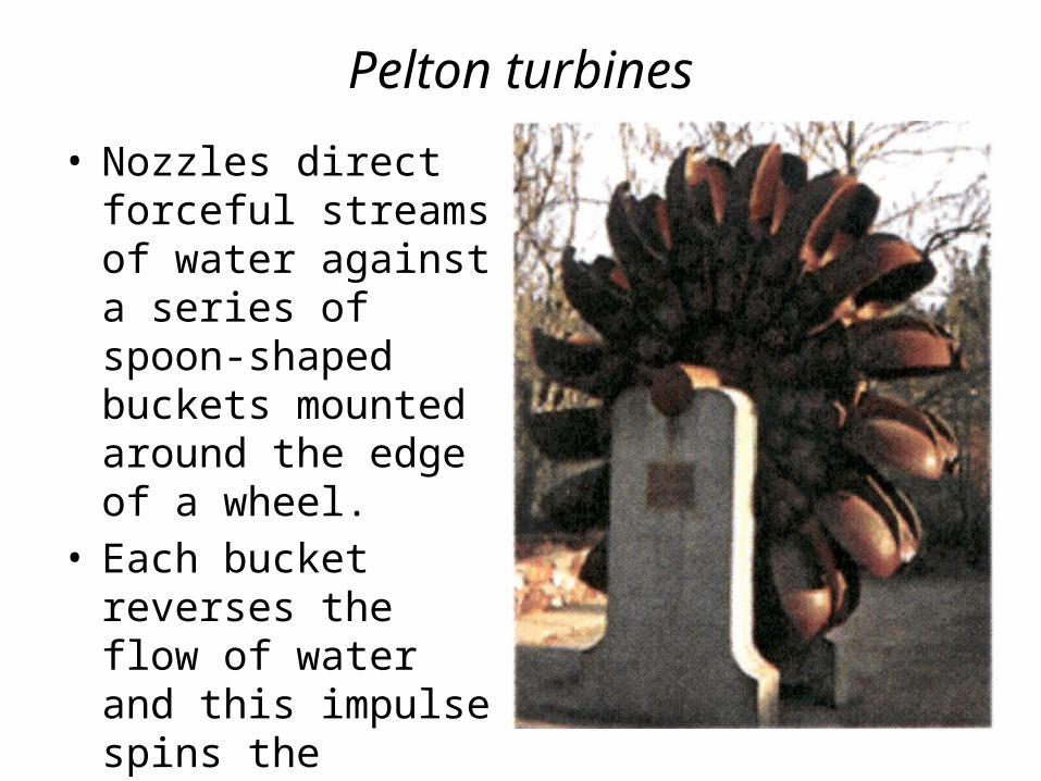
Pelton turbines
• Nozzles direct forceful streams of water against a series of spoon-shaped buckets mounted around the edge of a wheel.
• Each bucket reverses the flow of water and this impulse spins the turbine.
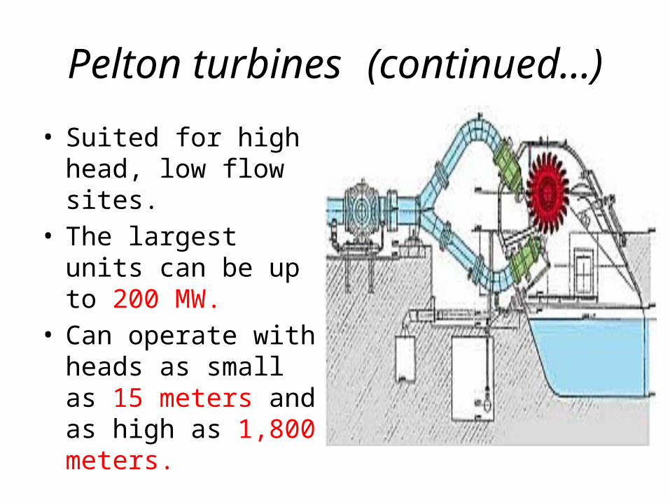
Pelton turbines (continued…)
• Suited for high head, low flow sites.
• The largest units can be up to 200 MW.
• Can operate with heads as small as 15 meters and as high as 1,800 meters.
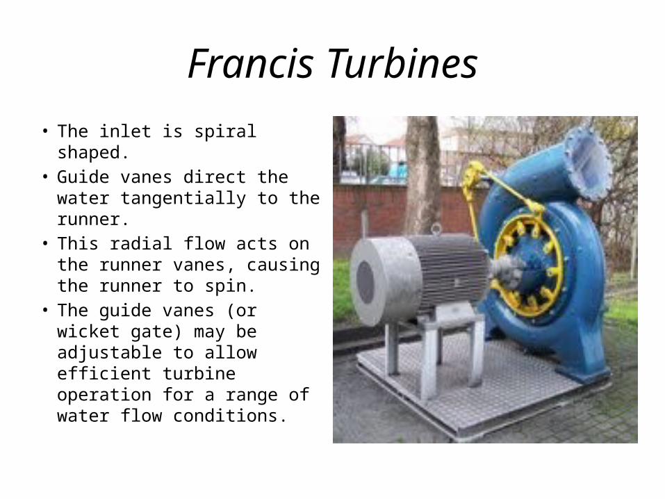
Francis Turbines
• The inlet is spiral shaped.• Guide vanes direct the water
tangentially to the runner.• This radial flow acts on the
runner vanes, causing the runner to spin.
• The guide vanes (or wicket gate) may be adjustable to allow efficient turbine operation for a range of water flow conditions.
Francis Turbines (continued…)
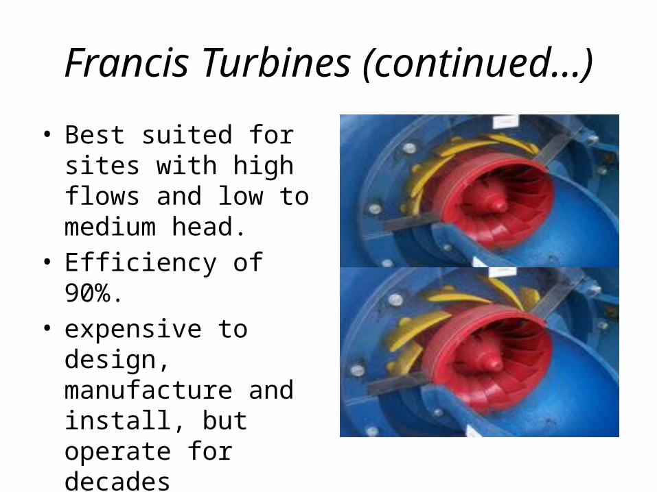
• Best suited for sites with high flows and low to medium head.
• Efficiency of 90%.• expensive to design,
manufacture and install, but operate for decades
Kaplan Turbine
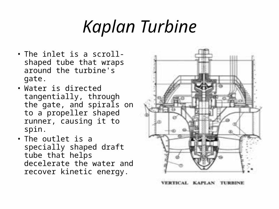
• The inlet is a scroll-shaped tube that wraps around the turbine's gate.
• Water is directed tangentially, through the gate, and spirals on to a propeller shaped runner, causing it to spin.
• The outlet is a specially shaped draft tube that helps decelerate the water and recover kinetic energy.
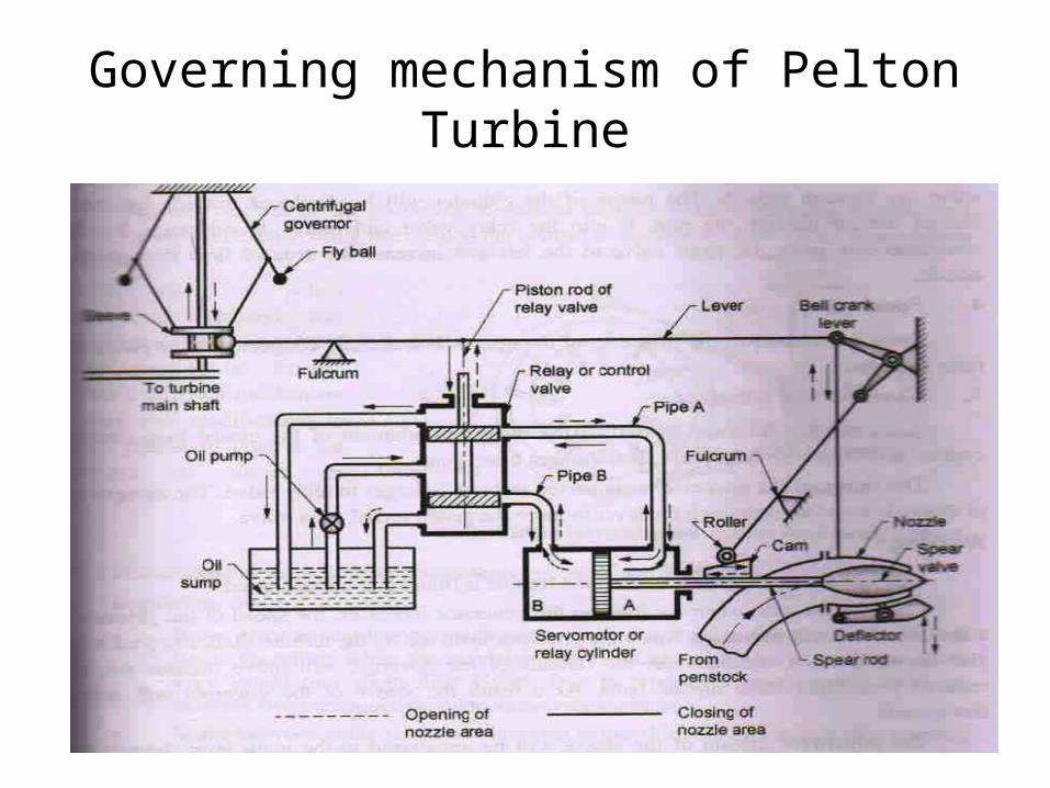
Governing mechanism of Pelton Turbine
Governing mechanism of Pelton Turbine
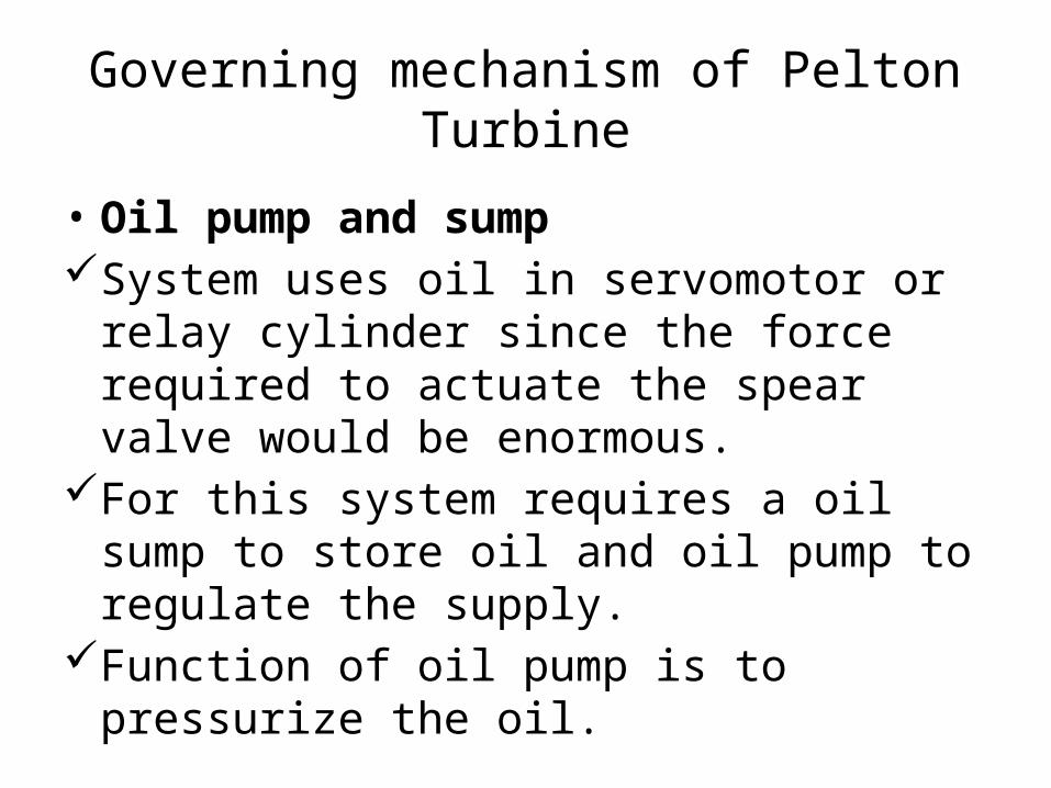
• Oil pump and sumpSystem uses oil in servomotor or relay cylinder
since the force required to actuate the spear valve would be enormous.
For this system requires a oil sump to store oil and oil pump to regulate the supply.
Function of oil pump is to pressurize the oil.
Governing mechanism of Pelton Turbine
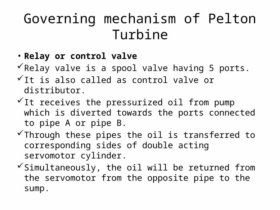
• Relay or control valveRelay valve is a spool valve having 5 ports. It is also called as control valve or distributor. It receives the pressurized oil from pump which is
diverted towards the ports connected to pipe A or pipe B.
Through these pipes the oil is transferred to corresponding sides of double acting servomotor cylinder.
Simultaneously, the oil will be returned from the servomotor from the opposite pipe to the sump.
Governing mechanism of Pelton Turbine
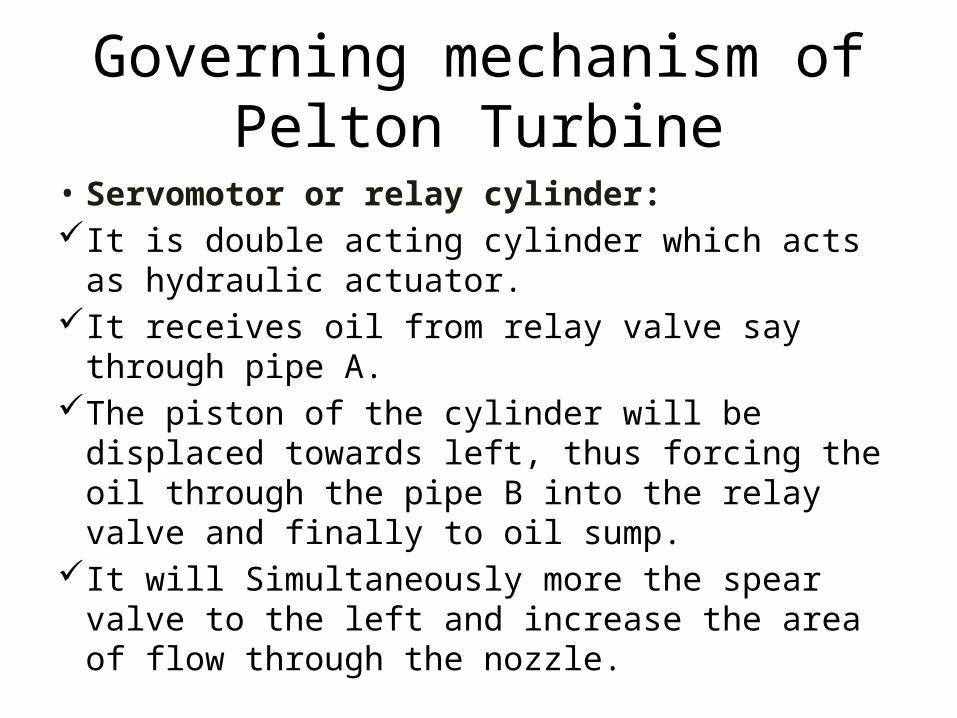
• Servomotor or relay cylinder: It is double acting cylinder which acts as hydraulic
actuator. It receives oil from relay valve say through pipe A.The piston of the cylinder will be displaced
towards left, thus forcing the oil through the pipe B into the relay valve and finally to oil sump.
It will Simultaneously more the spear valve to the left and increase the area of flow through the nozzle.
Governing mechanism of Pelton Turbine
• Spear valve: Spear valve controls the flow area of the nozzle. It is directly connected to the piston of relay cylinder• Governor and linkages: A centrifugal governor is used as the measuring
element of the closed loop control system. It is driven by the turbine shaft through bevel gears. The sleeve of the governor is connected through
linkages to relay valve. The movement of sleeve is transferred through the
lever to more the piston rod of relay valve.
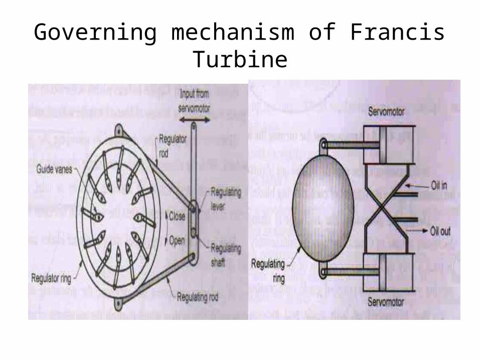
Governing mechanism of Francis Turbine
Governing mechanism of Francis Turbine
• Regulating Ring : It is a circular ring having guide vanes pivoted at a
point through the levers and links.Therefore when the regulator ring is rotated about
its axis, all the guide vane would turn about their pivots.
Due to turning of guide vanes the space between two consecutive guide vanes would change.
Space between guide vanes will increase in one direction of rotation of regulating ring and space will decrease in its opposite direction of rotation.
Governing mechanism of Francis Turbine
• Regulating rod: It connects the regulating ring to relay cylinder through
the various linkages as shown in fig. It can be seen by this mechanism, the linear motion of
servomotor piston is converted into rotary motion of regulating ring.
An alternate arrangement providing the rotary motion to regulating ring by using two servomotors.
This mechanism gives better performance since the force required for operation of Francis turbine guide vanes is much more compared to Pelton turbine.
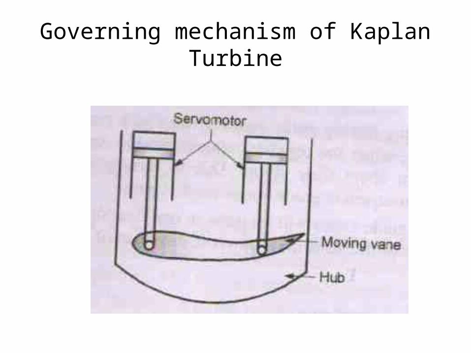
Governing mechanism of Kaplan Turbine
Governing mechanism of Kaplan Turbine
• Speed control in Kaplan turbine is also achieved by varying the discharge by changing the guide vane angle as in case of Francis turbine with an additional feature.
• The governing achieved by changing the guide vane angles.
• Therefore, a separate servomotor is provided to operate the runner blades which are few in number.
• Due to control of both guide and moving vanes, the Kaplan turbine gives better efficiency over wide range of load as compared to Francis turbine.
Thank you