Embed Size (px)
Citation preview
't, \
I
TECHNIC4~FEATURE I Fundamentals at Work ( -
'~
Hydronics 101 BY JEFF BOLDT, P.E., HBDP, MEMBER ASH RAE; JULIA KEEN, PH.D., P.E., HBDP, HEAP, MEMBER ASH RAE
Authors' note: This article focuses solery on the basics related to configuration, lqyout, and major system components ofhotwater and chilled water systems as an introduction to hydronics for those new to the design industry.
The first documented hydronic cooling systems were connected to the Roman aqueducts, in which water was routed through brick walls of homes of the affluent. Hydronic heating became prevalent in buildings as the source of hot water expanded. The first commercial hot water boilers became available in the 1700s. Gravity hot water or steam heating systems were the norm in buildings until the mid -1900s.
The operation and design of these systems were greatly to the atmosphere in at least one location. Systems that advanced with the introduction of water pumps early in employ cooling towers as their heat rejection method
the 20th century. Post -World War II, hydronic systems are one of the most common examples of open hydronic experienced significant competition with the develop- systems. Closed systems, on the other hand, are not ment of forced air systems. Today, hydronic heating open to the atmosphere, except possibly at an expan-
and cooling coils are frequently used in conjunction sion/compression tank. with forced air systems. More recently there has been a resurgence of hydronic applications at the zone
level as a result of the increased emphasis on energy conservation.
Definition of Hydronics This article uses the definitions ofhydronics, open
system, and closed system fromASHRAE Terminology
onASHRAE.org, which defines hydronics as "science of heating and cooling with water." Open systems are open
Advantages of Hydronic Systems Hydronic systems have several advantages: • They require little space when compared to air
systems. A 3 in. diameter pipe is needed to convey 1,000,000 Btu/h. of heating or cooling energy when a 70 in. x 46 in. duct would be necessary to accomplish the
same task with air.
(Assume a AT= 20°F and friction loss of 0.08 in./100 ft length for air and 4 MOO ft length for pipe.
Jeff Boldt, P.E., is a principal and director of engineering at KJWW Engineering in Monona, Wis. He is a member of standards committees 90.1, 189.1 and 215. Julia Keen, Ph.D., P.E., is an associate professor at Kansas State University in Manhattan, Kan. She is past chair of TC 6.1, Hydronic and Steam Equipment and Systems.
62 ASH RAE JOURNAL ashrae.org MAY 2015
100 gpm = 1,000,000 Btulh/[500(20°F)] and 46,000 cfm •1,000,000 Btulhl[l.086(20°F)] .)
• Energy loss due to pipe leakage is almost nonexistent. • Transport energy is very low. For example, trans
porting1,000,000 Btu/hof cooling ina ducted air system
may require 100 hp offans, whereas a typical hydronic
system would require about a 2 hp pump. 1,000,000 Btulh/(20°F x 1.086) = 46,000 cfm x 90.1
limit+ allowances!:::: 60 to 120 bhp. 1,000,000 Btulh/{20°F x 500)= 100 gpm x 50ft of head x
0.0002525nO% pump efficiency= 1.8 bhp.
• Noise complaints are less common than in air
systems, as long as established pipe sizing principles are followed.
How Many Pipes? Closed hydronic systems commonly are referenced
based on the number of pipes within the system:
one-, two-, three-, and four-pipe. One-pipe systems
have one supply pipe andreturnfromeach coil con
nected back into that same pipe. The advantage of
one-pipe systems is reduced piping cost. The disad
vantage is a loss of exergybecause of blending oftemperatures in the supply main. One-pipe systems are
rare, but sometimes seen in geothermal heat pump systems or individual floors of buildings with heating
water systems.
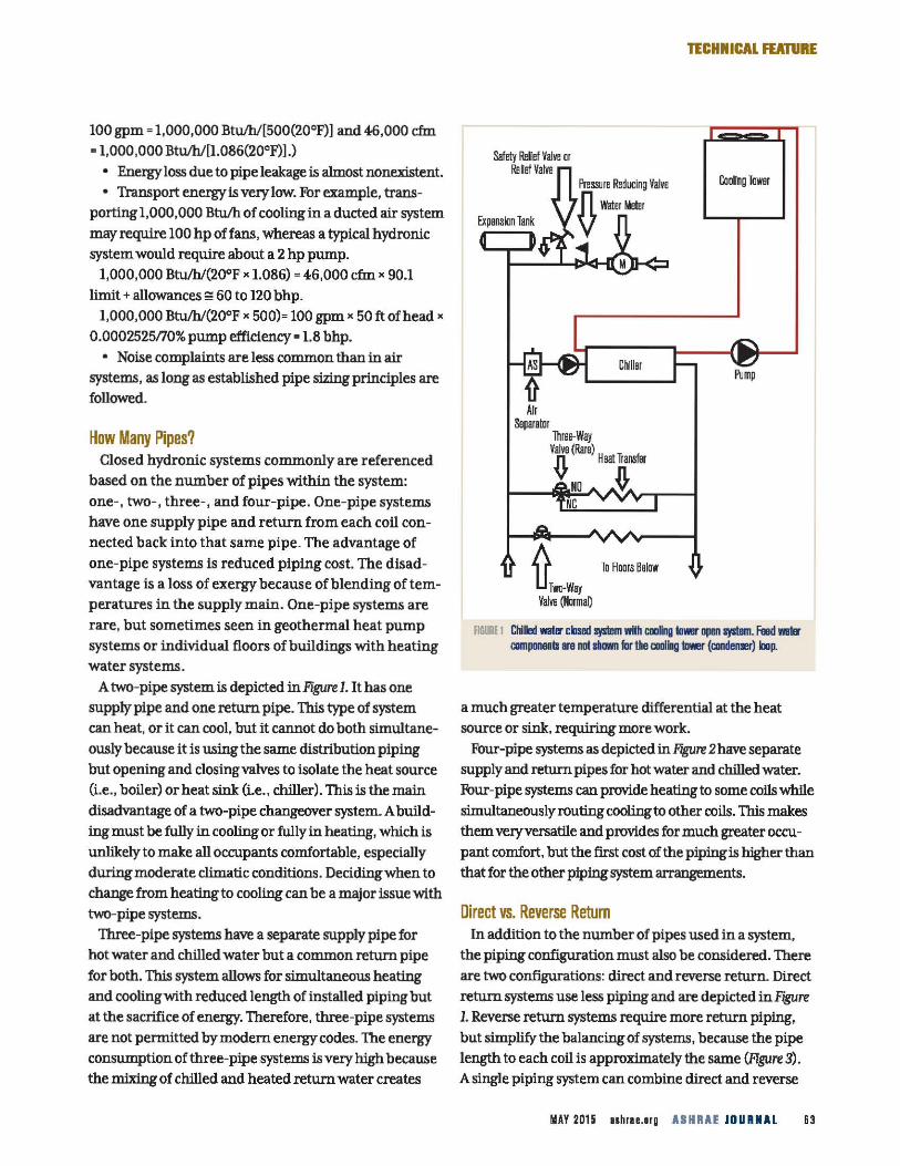
A two-pipe system is depicted in Figure 1. It has one
supply pipe and one return pipe. This type of system
can heat, or it can cool, but it cannot do both simultane
ously because it is using the same distribution piping
but opening and closing valves to isolate the heat source (i.e., boiler) or heat sink (i.e., chiller). This is the main
disadvantage of a two-pipe changeover system. A building must be fully in cooling or fully in heating, which is
unlikely to make all occupants comfortable, especially
during moderate climatic conditions. Deciding when to
change from heating to cooling can be a major issue with two-pipe systems.
Three-pipe systems have a separate supply pipe for
hot water and chilled water but a common return pipe
for both. This system allows for simultaneous heating
and cooling with reduced length of installed piping but at the sacrifice of energy. Therefore, three-pipe systems
are not permitted by modem energy codes. The energy consumption of three-pipe systems is very high because
the mixing of chilled and heated return water creates
Safety Rllief Valve or Rslef Valva
Cll!llar
To Floors Balow
TECHNICAL FUTURE
Cooing Tower
fiG~ 1 Cliled wat~r claml sy11em with cooling tower open system. Feed wm aii!IJDlllllls lie not ... for tile caolllg bier (candenler) IDap.
a much greater temperature differential at the heat
source or sink, requiring more work.
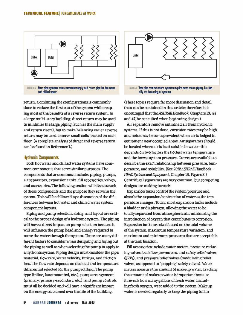
Four-pipe systems as depicted in Rgure 2have separate
supply and return pipes for hot water and chilled water. Fbur-pipe systems can provide heating to some coils while
simultaneously routing cooling to other coils. This makes them very versatile and provides for much greater occu
pant comfort, but the first cost of the piping is higher than that for the other piping system arrangements.
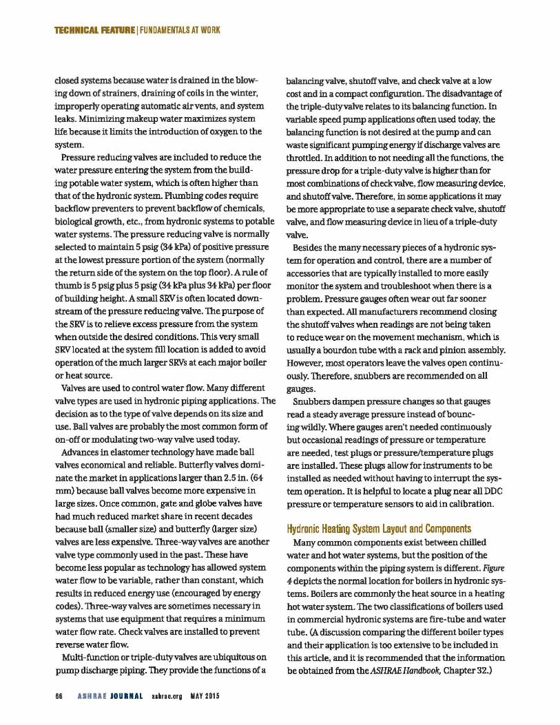
Direct vs. Reverse Return In addition to the number of pipes used in a system,
the piping configuration must also be considered. There
are two configurations: direct and reverse return. Direct
return systems use less piping and are depicted inFJgUre 1. Reverse return systems require more return piping,
but simplify the balancing of systems, because the pipe length to each coil is approximately the same (Figure 3).
A single piping system can combine direct and reverse
UAY 2015 nhraurg AIHRAE JOURNAL 63
TECHNICAL FEAtuRE I FUNDAMENTALS AT WORK
Chiller
FI&URE 2 Four-pipe systems haYe a sepal'llte supply and re1Urn pipe for hot water and chilled water.
rebwnrr-Conrrbll1Ungtheconf~rationsiscoD1DlonJy
done to reduce the first cost of the systenrr while reaping nrrost of the benefits of a reverse return systenrr. In
a large nrrulti -story building, direct return nrray be used to ntinimi.ze the large piping (such as the nrrain supply
and return risers), but to :make balancing easier reverse rebwnrr nrray be used to serve s01all coils located on each floor. (A conrrplete analysis of direct and reverse return
can be found in Reference L)
Hydronic Components Both hot water and chilled water systenrrs have conrr
nrron conrrponents that serve siD1ilar purposes. The
conrrponents that are coDlDlon include: piping, punrrps, air separators, expansion tanks, fill accessories, valves,
and accessories- The following section will discuss each
of these conrrponents and the purpose they serve in the
systenrr. This will be followed by a discussion of the differences between hot water and chilled water systenrr
conrrponent layouts. Piping and punrrp selection, sizing, and layout are criti
cal to the proper design of a hydronic systenrr. The piping
will have a direct inrrpact on punrrp selection because it
will influence the punrrp head and energy required to
nrrove the water through the systenrr. There are nrrany dif
ferent factors to consider when designing and laying out
the piping as well as when selecting the punrrp to apply to a hydronic systenrr. Piping design nrrust consider the pipe
nrraterial, flow rate, water velocity, fittings, and friction
loss_ The flow rate depends on the load and tenrrperature
differential selected for the punrrped fluid. The punrrp type (inline, base nrrounted, etc.), punrrp arrangenrrent (priD1ary, priD1ary-secondary, etc.), and punrrp controls
nrrust all be decided and will have a significant inrrpact
on the energy consunrred over the life of the building.
64 ASH RAE JOURNAL aahne.org MAY 2015
FI&URE 3 Two-pipe reverse return systems require mere return piping, but simplify the balanci~ of systems.
(These topics require far nrrore discussion and detail
than can be contained in this article; therefore it is encouraged that theASHRAE Handbook, Chapters 13, 44
and 47, be consulted when beginning design.) Air separators renrrove entrained air fronrr hydronic
systenrrs. If this is not done, corrosion rates nrraybe high
and noise nrray beconrre prevalent when air is lodged in
equipnrrent near occupied areas. Air separators should
be located where air is least soluble in water-this
depends on two factors the hottest water tenrrperature
and the lowest systenrr pressure. Curves are available to describe the exact relationship between pressure, tenrr
perature, and solubility. (See 2012ASHRAE HandbookHVAC Systems and Equipment, Chapter 13, Figure 3.) Centrifugal separators are very CODlDlOn, but conrrpeting
designs are nrraking inroads_
Expansion tanks control the systenrr pressure and
absorb the expansion/contraction of water as the tenrrperature changes. Today, nrrost expansion tanks include
a bladder or diaphragiil, allowing the water to be totally separated fronrr atnrrospheric air, D1iniD1izing the
introduction of oxygen that contributes to corrosion. Expansion tanks are sized based on the total volunrre of the systenrr, rnaximunrr tenrrperature variation, and
rnaximunrr and D1iniD1unrr pressures that are acceptable at the tank location.
Fill accessories include water nrreters, pressure reducing valves, backflow preventers, and safety relief valves
(SRVs), and pressure relief valves (nrrodulating relief
valves, as opposed to "popping" safetyvalves)_ Water
nrreters nrreasure the anrrount of :makeup water. Tracking the anrrount of nrrakeup water is inrrportant because
it reveals how nrrany gallons offresh water, includ-ing fresh oxygen, were added to the systenrr. Makeup water is needed regularly to keep the piping full in
TICHNICAL FEATURE I FUNDAMENTALS AT WORK
closed systems because water is drained in the blow
ing down of strainers, draining of coils in the winter,
improperly operating automatic air vents, and system
leaks. Minimizing makeup water maximizes system
life because it limits the introduction of oxygen to the
system.
Pressure reducing valves are included to reduce the
water pressure entering the system from the build-
ing potable water system, which is often higher than
that of the hydronic system. Plumbing codes require
backflow preventers to prevent backflow of chemicals,
biological growth, etc., from hydronic systems to potable
water systems. The pressure reducing valve is normally
selected to maintain 5 psig (34 kPa) of positive pressure
at the lowest pressure portion of the system (normally
the return side of the system on the top floor). A rule of
thumb is 5 psig plus 5 psig (34 kPa plus 34 kPa) per floor
of building height. A small SRV is often located down
stream of the pressure reducing valve. The purpose of
the SRV is to relieve excess pressure from the system
when outside the desired conditions. This very small
SRV located at the system fill location is added to avoid
operation of the much larger SRVs at each major boiler
or heat source.
Valves are used to control water flow. Many different
valve types are used in hydronic piping applications. The
decision as to the type of valve depends on its size and
use. Ball valves are probably the most common form of
on-off or modulating two-way valve used today.
Advances in elastomer technology have made ball
valves economical and reliable. Butterfly valves domi
nate the market in applications larger than 2.5 in. (64
mm) because ball valves become more expensive in
large sizes. Once common, gate and globe valves have
had much reduced market share in recent decades
because ball (smaller size) and butterfly Garger size)
valves are less expensive. Three-wayvalves are another
valve type commonly used in the past. These have
become less popular as technology has allowed system
water flow to be variable, rather than constant, which
results in reduced energy use (encouraged by energy
codes). Three-wayvalves are sometimes necessary in
systems that use equipment that requires a minimum
water flow rate. Check valves are installed to prevent
reverse water flow.
Multi-function or triple-dutyvalves are ubiquitous on
pump discharge piping. They provide the functions of a
66 AIHRAE JOURNAL uhne.org MAY 2015
balancing valve, shutoff valve, and check valve at a low
cost and in a compact configuration. The disadvantage of
the triple-duty valve relates to its balancing function. In
variable speed pump applications often used today, the
balancing function is not desired at the pump and can
waste significant pumping energy if discharge valves are
throttled. In addition to not needing all the functions, the
pressure drop for a triple-dutyvalve is higher than for
most combinations of checkvalve, flow measuring device,
and shutoff valve. Therefore, in some applications it may
be more appropriate to use a separate check valve, shutoff
valve, and flow measuring device in lieu of a triple-duty
valve.
Besides the many necessary pieces of a hydronic sys
tem for operation and control, there are a number of
accessories that are typically installed to more easily
monitor the system and troubleshoot when there is a
problem. Pressure gauges often wear out far sooner
than expected. All manufacturers recommend closing
the shutoff valves when readings are not being taken
to reduce wear on the movement mechanism, which is
usually a bourdon tube with a rack and pinion assembly.
However, most operators leave the valves open continu
ously. Therefore, snubbers are recommended on all
gauges.
Snubbers dampen pressure changes so that gauges
read a steady average pressure instead ofbounc
ingwildly. Where gauges aren't needed continuously
but occasional readings of pressure or temperature
are needed, test plugs or pressure/temperature plugs
are installed. These plugs allow for instruments to be
installed as needed without having to interrupt the sys
tem operation. It is helpful to locate a plug near all DDC
pressure or temperature sensors to aid in calibration.
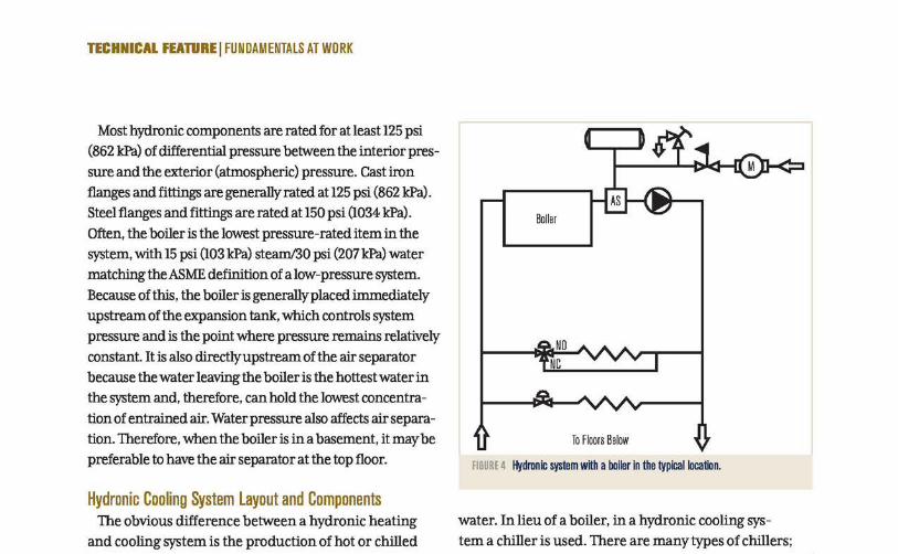
Hydronic Heating System layout and Components Many common components exist between chilled
water and hot water systems, but the position of the
components within the piping system is different. Figure 4 depicts the normal location for boilers in hydronic sys
tems. Boilers are commonly the heat source in a heating
hot water system. The two classifications of boilers used
in commercial hydronic systems are fire-tube and water
tube. (A discussion comparing the different boiler types
and their application is too extensive to be included in
this article, and it is recommended that the information
be obtained from theASHRAE Handbook, Chapter 32.)
TECHNICAL FEATURE I FUNDAMENTALS AT WORK
Most hydronic components are rated for at least 125 psi
(862 kPa) of differential pressure between the interior pres
sure and the exterior (atmospheric) pressure. Cast iron
flanges and fittings are generally rated at 125 psi (862 kPa).
Steel flanges and fittings are rated at 150 psi (1034 kPa).
Often, the boiler is the lowest pressure-rated item in the
system, with 15 psi (103 kPa) steam/30 psi (207 kPa) water
matching theASME definition of a low-pressure system.
Because of this, the boiler is generally placed immediately
upstream of the expansion tank, which controls system
pressure and is the point where pressure remains relatively
constant. It is also directly upstream of the air separator
because the water leaving the boiler is the hottest water in
the system and, therefore, can hold the lowest concentra
tion of entrained air. Water pressure also affects air separa
tion. Therefore, when the boiler is in a basement, it may be
preferable to have the air separator at the top floor.
Hydronic Cooling System layout and Components The obvious difference between a hydronic heating
and cooling system is the production of hot or chilled
To Floors Below
FIGURE 4 Hydronic system wKh a boiler in the typical location.
water. In lieu of a boiler, in a hydronic cooling sys
tem a chiller is used. There are many types of chillers;
The answer to increased airflow standards in operating rooms:
Our Criti-Ciean FFU with built-in surgical grade lighting.
With today's stringent operating room airflow standards and lighting requirements, there sometimes just isn't enough ceiling space to get the job done. That's why we've added lights to our popular Criti-Ciean Fan Powered Laminar Flow HEPA Filter Diffuser- so now you can deliver clean air and light in the same compact space. Criti-Ciean features include:
• Stainless steel construction with all-welded plenum.
• Higher CFM output than competitive models.
• Computer-controlled, variable-speed ECM motor.
• HEPA or ULPA filter with gel-seal frame.
~~
• Your choice of green or white surgical lights, in fluorescent or optional LED.
• Reverse flow units also available.
Criti-Ciean provides constant airflow, compensating for changes in filter load, static pressure and more. Available in 48"x24' and 24"x24" models, with a wide range of customizable controls capable of mapping and simultaneously controlling up to 800 linked units.
jljAIIFC. 800-247-5746 www.ajmfg.com
www.info.hotims.com/54428-5
68 ASH RAE JOURNAL ashrae.org MAY 2015
TECHNICAL FEATURE I FUNDAMENTALS AT WORK
reciprocating, scroll, helical rotruy, centrifugal, and variations that recover heat from one process to transfer to another. (A discussion comparing the different chiller types and their application is too extensive to be included in this article, and it is recommended that the information be obtained from theASHRAE Handbook, Chapters 42 and 43.)
There are some differences between the system layout of heating and cooling hydronic systems. Cooling hydronic systems have expansion tanks, but they can be much smaller than in heating systems because of the much lower temperature difference between the maximum and minimum fluid temperatures.
Theoretically, the fill water is warmer than the normal chilled water temperature, resulting in makeup water being added to the system to fill the piping when the chilled water is brought down to operational temperature. Some designers delete air separators in cooling hydronic systems, although this is not recommended. Heating systems, on the other hand, need much larger expansion tanks and air separation is a more critical
~PENTAIR
design concern because air more easily separates from heated water (watch bubbles form when you heat a pan filled with water).
Summary Hydronic systems are a staple of our industry. They
provide large amounts of heat transfer with low first costs and energy costs for transporting energy. This article provides only a basic overview and introduction to hydronic system design, layout, and components. For more information, on the topic of hydronic systems, the ASHRAE Handbook is an excellent reference.
We plan to cover many other hydronic topics: condensing boilers, valve-coil-heat transfer, pressure independent control valves, etc., in future articles.
References 1. Taylor, S., J. Stein. "Balancing variable flow hydronic systems."
ASHRAE]oumaiB. 2. 2012ASHRAE Handbook-HVAC Systems and Equipment, Chapters
32, 36, 43, and 44. •
Plate and Frame Heat Exchangers Modell 082PF
Aurora's Plate & Frame Heat Exchangers use corrugated plates creating more heat transfer with less materials.
Gasketed plate and frame heat exchangers are used for liquidto-liquid applications such as HVAC, chemical, sugar, marine, food, and renewable energy and power.
Key Features:
- 1 00% CFD Modeled plate design for optimal heat transfer
- ASME and PED pressure vessel certifications
- Wide-range of sizes, materials and configurations
- Made in USA Scan the QR code for more information on our Plate and Frame Heat Exchangers and other Aurora Commercial Accessories
~ ~~ www.AuroraPump.com
www.info.hotims.com/54428-6 AU-ACC-HX (03-27-201 S)
70 ASH RAE JOURNAL ashrae.org MAY 2015