Embed Size (px)
Citation preview
TECHNICAL REPORT 121-4
SUPERCAVITATING PROPELLERS-."MOMENTUM THEORY
By
Marshall P. Tulin
September 1964
copy.j- OF ~ 2
r urtrA.- $.'3 1DDC
EAR5 1965 I
DDCXIRA E
HYDRONAUTICS, incorporatedresearch in hydrodynamics
aid INDUS ii YRIvt N!DIGD 5F;'.CS, Ofices -a- h-,-o ,
sI~~w ~D. C ~?:c ~c~~Ew~
TECHNICAL REPORT 121-4
SUPERCAVITATING PROPELLERS -
MOMENTUM THEORY
By
Marshall P. Tulin
September 1964
Supported Under
-" Contract Nonr-3435(OO)Office of Naval Research
Navy Department
I •TABLE OF CONTENTS
I ~Page
INTRODUCTION ................................................ 1
THE MOMENTUM THEORY FOR SUBCAVITATING PROPELLERS ........... 4i
THE MOMENTUM THEORY FOR SUPERCAVITATING PROPELLERS .......... 10
I The Head Rise Across the Disc in Supercavitatingj Flow ...................................................... 10
The Momentum Balance Across the Disc inSupercavitating Flow .................................... 14
An Estimate of Absolute Maximum Efficiency .............. 23
The Special Case of the Drag Disc ...................... 26The Slipstream Behind the Cavity ........................ 28
The Special Case of the Infinite Length Cavity .......... 341
The Effect of Tunnel Boundaries ........................ 37
SUMMARY AND CONCLUSIONS ..................................... 43
REFERENCES ................................................... 47
4{
I
HYDRONAUTICS. Inenrorneij
-ii -
NOTATION
A Closed tunnel cross-section area|0
Al Area of circle circumscribing the propeller (disc area)
A2 Transverse area of downstream flow ottside of choked0 propeller slipstream
A2 j Transverse area of downstream flow in jets withinchoked propeller slipstream
A3 Transverse area of propeller slipstream at region ofcavity collapse
C D Drag coefficient of drag disc based on the disc areaand upstream speed
CT Thrust coefficient, /UA
D Form drag on blade element due to cavitationc
Ah, Stagnation pressure change across actuator disc
kt Thrust coefficient, T/pn2 D4
L Blade element lift
p Static pressure
T Thrust
U Flow speed
U Flow speed corresponding to cavitating conditionsc
Propeller efficiency
mi Propeller induced efficiency (also Uo/U1)
qc Propeller or blade cavitational efficiency(See Equation 1731)
HYDRONAUTICS, Incorporated
-ilii-
Re Advance ratio (axial inflow speed/blade relativerotational speed)
p Fluid density
Subscripts o, 1, 2s 3 and 4 when used in connection with
p, U and q refer to conditions at the corresponding planes trans-
verse to the flow:
o - far upstream
1- just upstream of the propeller disc
2 - through the maximum section of the cavity
3 - Just downstream of the cavity collapse
4 - far downstream
The subscript max refers to the maximum allowable value.
I
HYDRONAUTICS, Incorpora ted
-iv-
LIST OF FIGURES
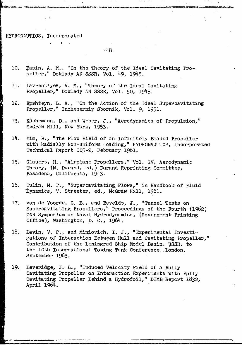
Figure 1 - Equivalence Between Vortex Sheath and SinkDisc Flows
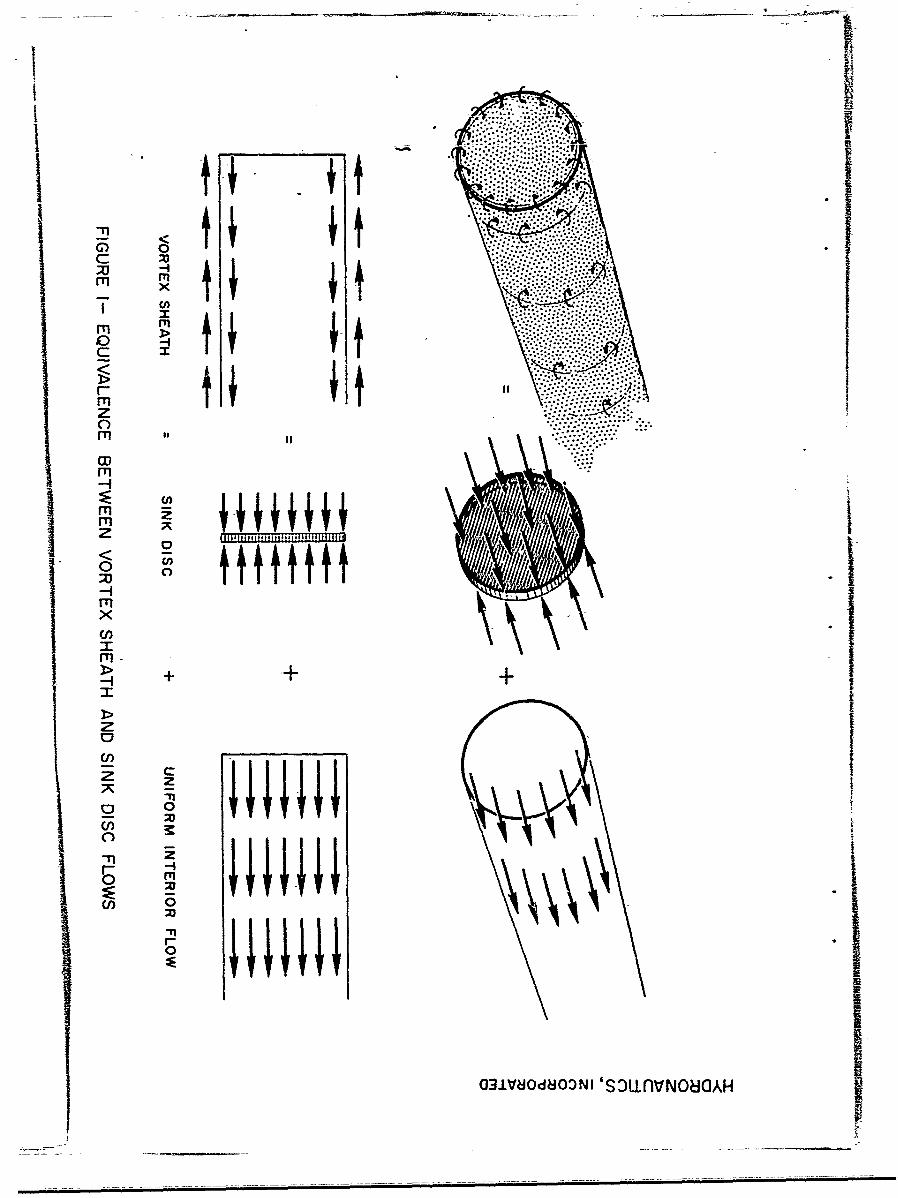
Figure 2 - Subcavitating Momentum Theory - Inflow Cavitation
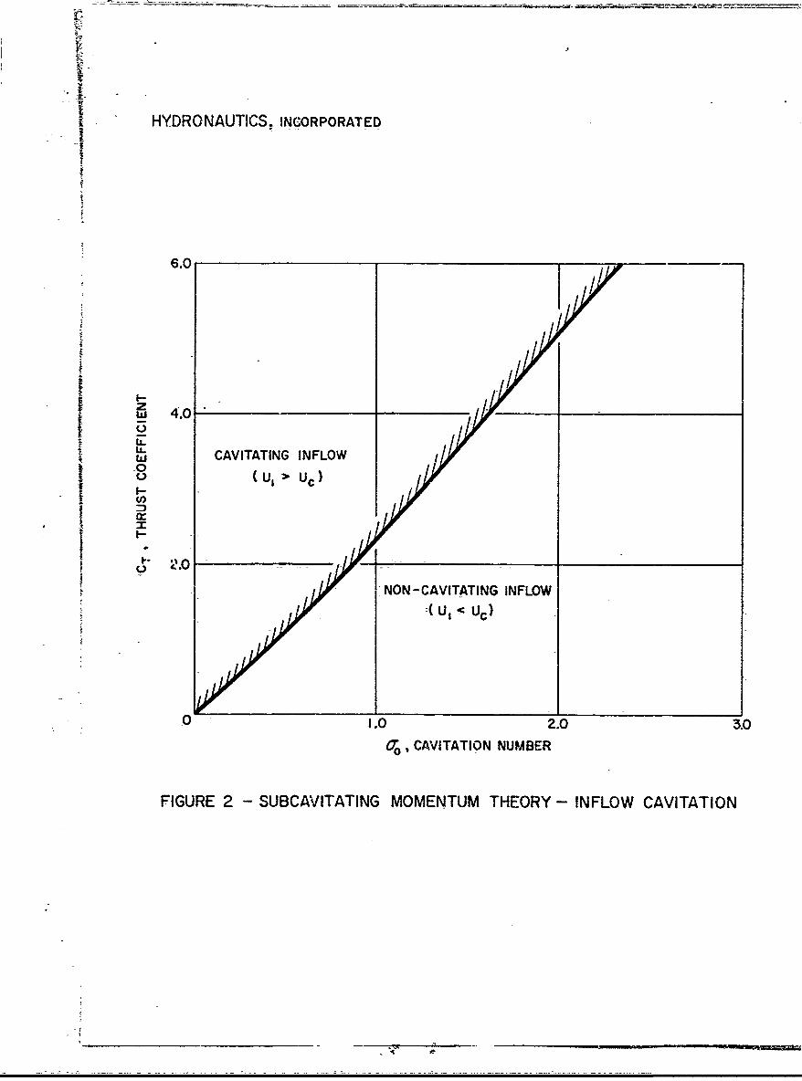
Figure 3 - Schematic Flows Past a Drag Disc and SupercavitatingPropellers
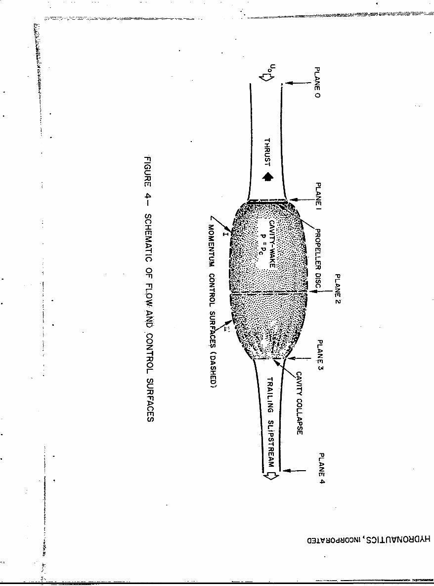
Figure 1 - Schematic of Flow and Control Surfaces
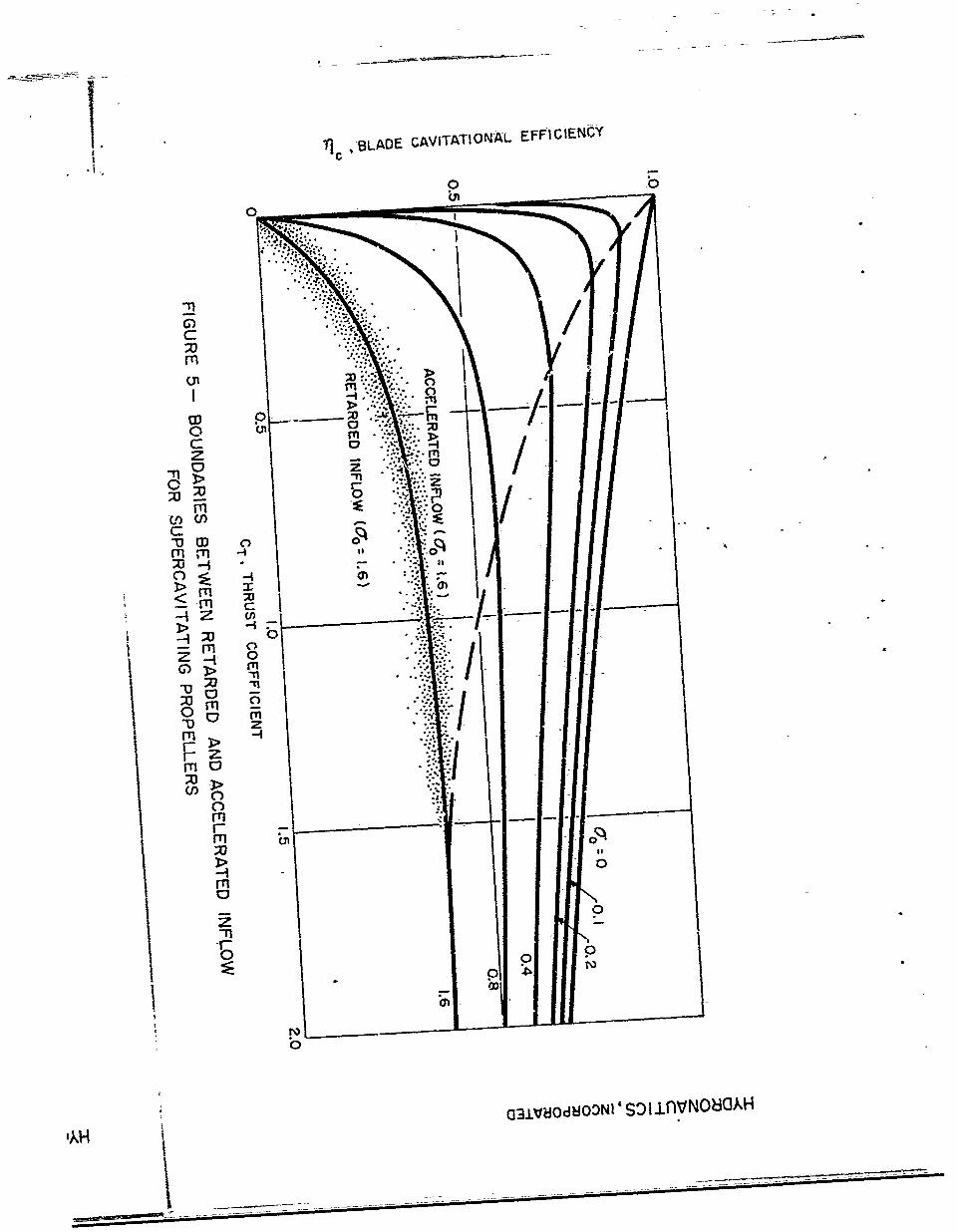
Figure 5 - Boundaries Between Retarded and AcceleratedInflow for Supercavitating Propellers
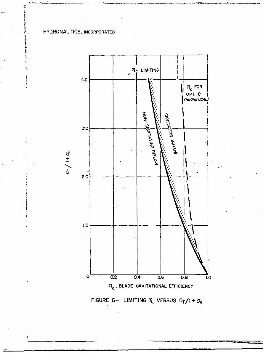
Figure 6 - Limiting Tic versus CVl + o°
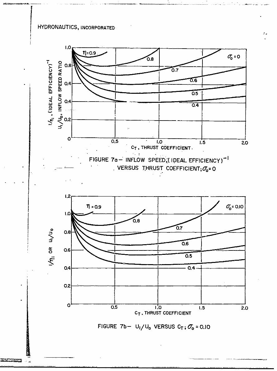
Figure 7a - Inflow Speed, (Ideal Efficiency) 1 versusThrust Coefficient; a = 0
Figure 7b - U 1/U- versus CT; Go = 0.10
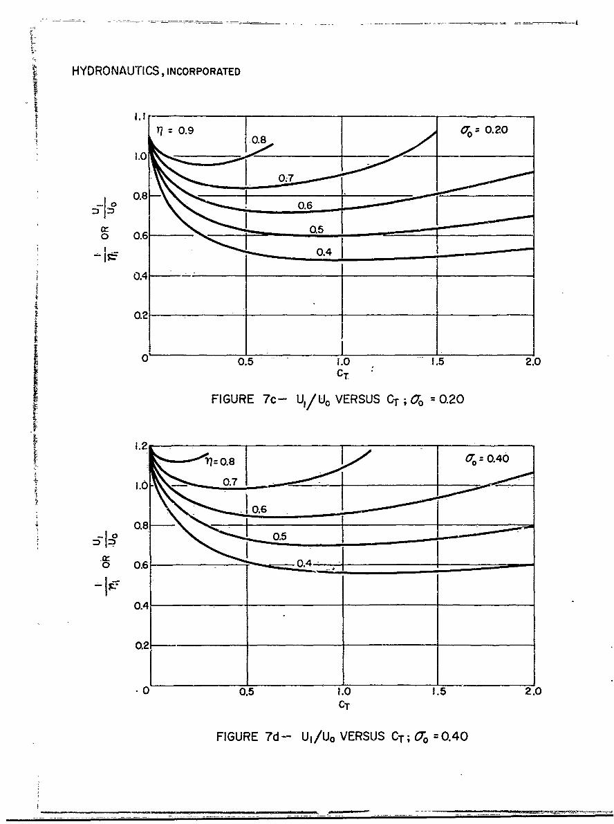
Figure 7c - U•/U 0 versus CT; a = 0.20
Figure 7d - Uj/U° versus CT; a = o.40
Figure 7e - Ui/U° vers.us CT; a° = 0.80
Figure 7f - U1/U° versus CT; a° = 1.60T 0
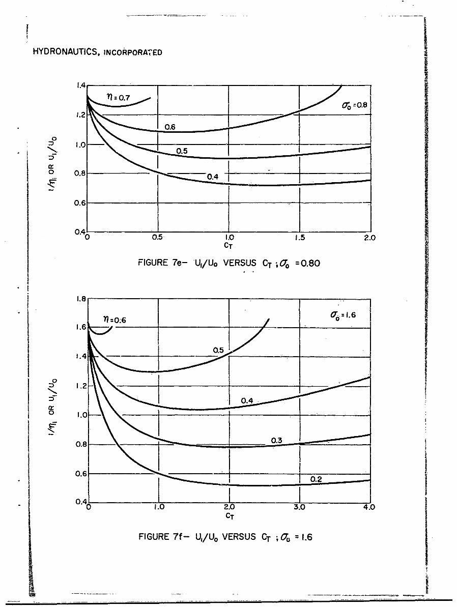
Figure 8 - Maximum Efficiency (Theory) versus CT forSupercavitating Propellers
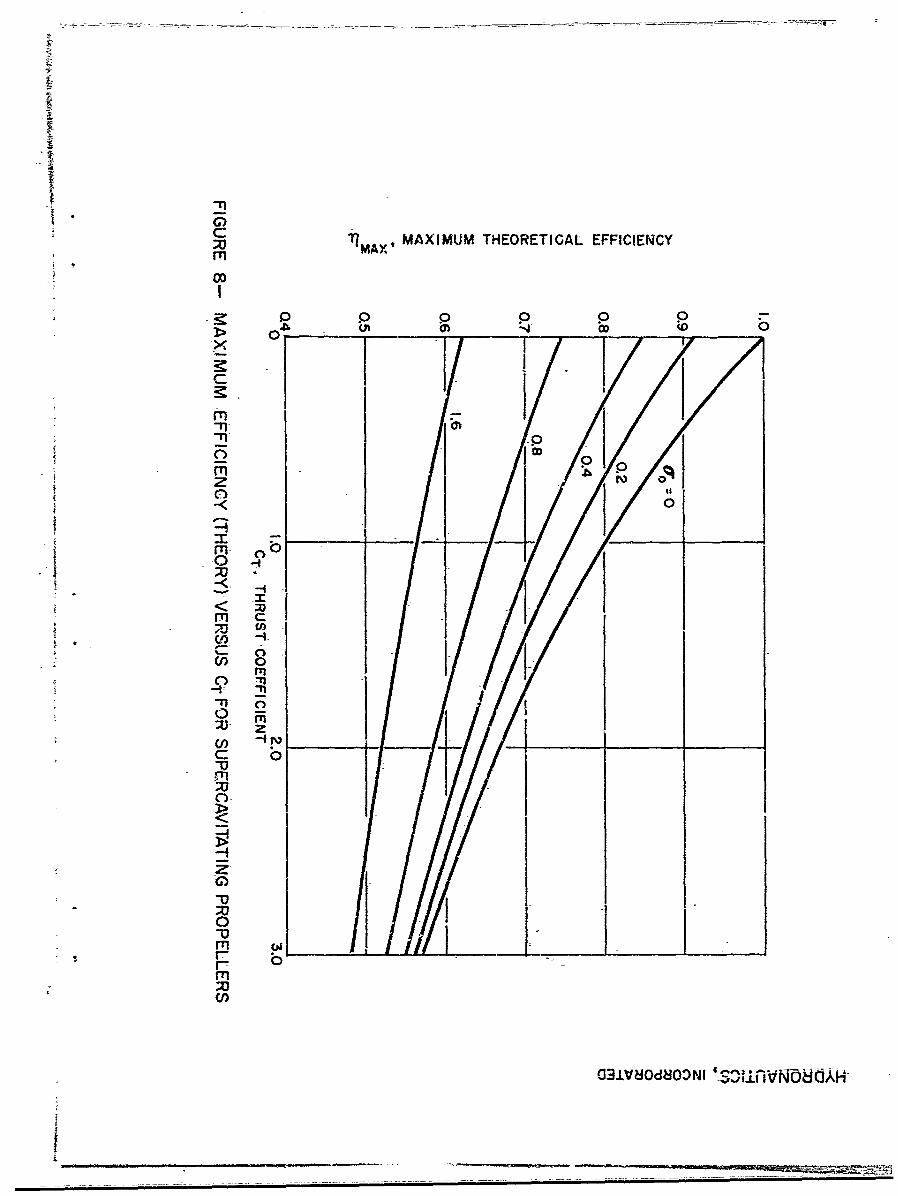
Figure 9 - Schematic of Assumed Supercavitating PropellerFlow, a = 00
HYDRONAUTICS, Incorporated
-v-
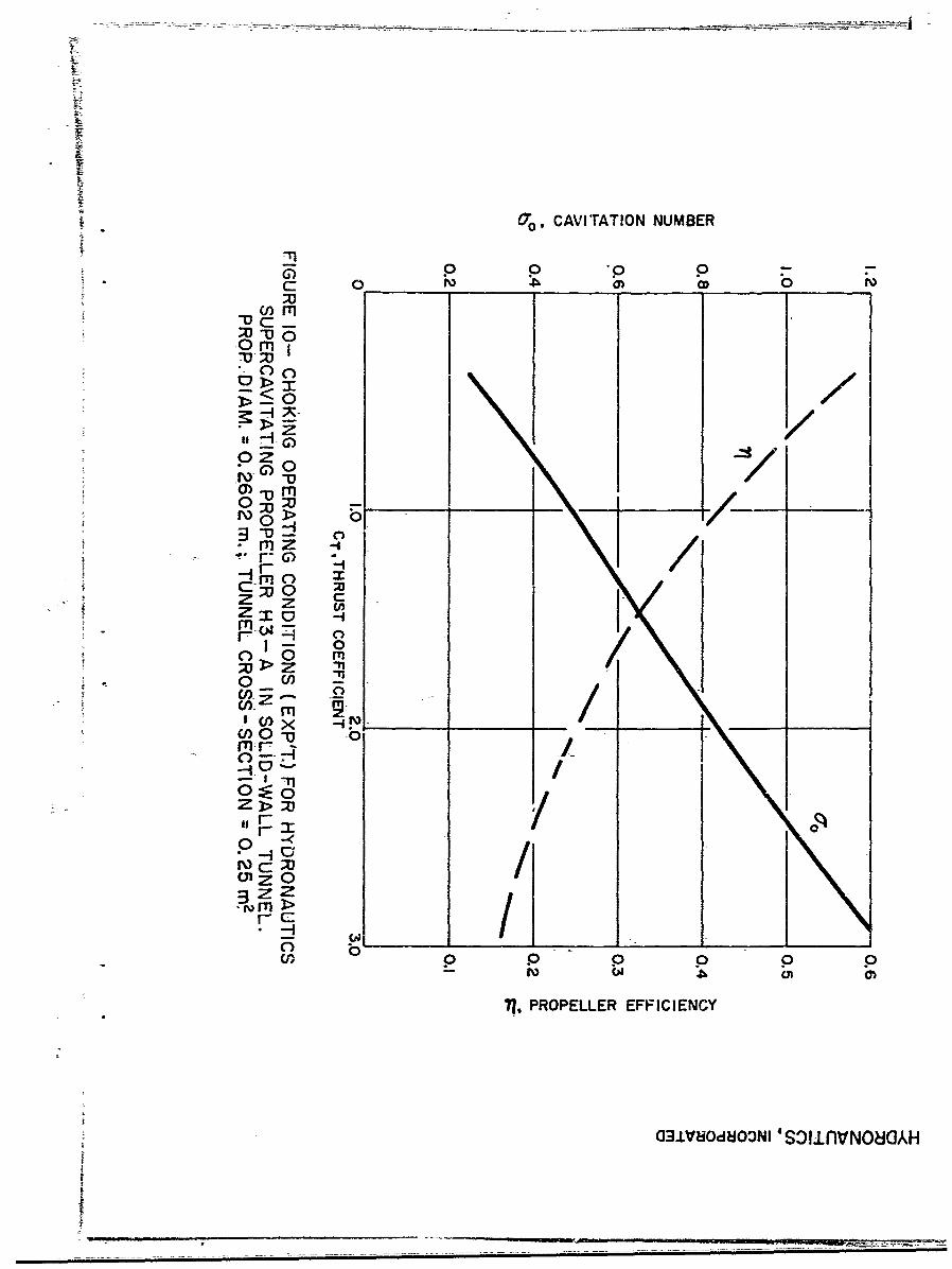
Figure 10 - Choking Operating Conditioris (Exp't) forHYDRONAUTICS Supercavitating Propeller H3-A inSolid-Wall Tunnel. Prop. Diam. = 0.2602m.;Tunnel Cross-Section = 0.25m2 .
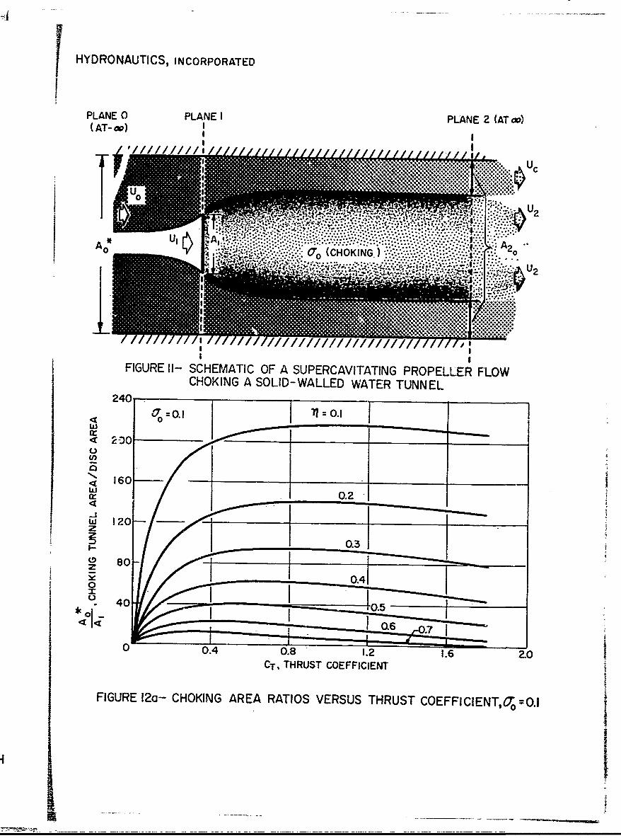
Figure 11 - Schematic of a Supercavitating Propeller FlowChoking a Solid-Walled Water Tunnel
Figure 12a - Choking Area Ratios versus Thrust Coefficient,a =0.1
0
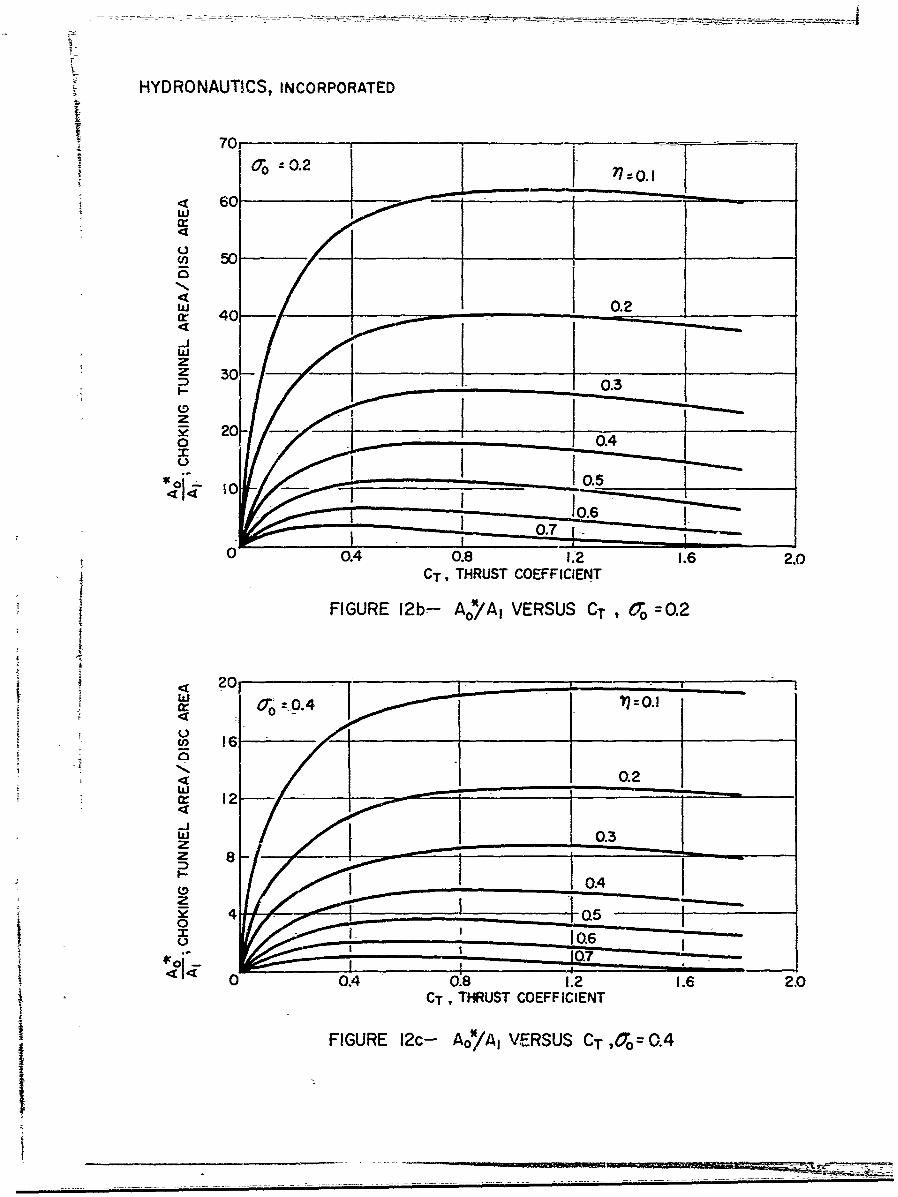
Figure 12b - A*/Ai versus CT, o =0.20o V o =
Figure 12c - A*/A, versus CT, % =o.40o
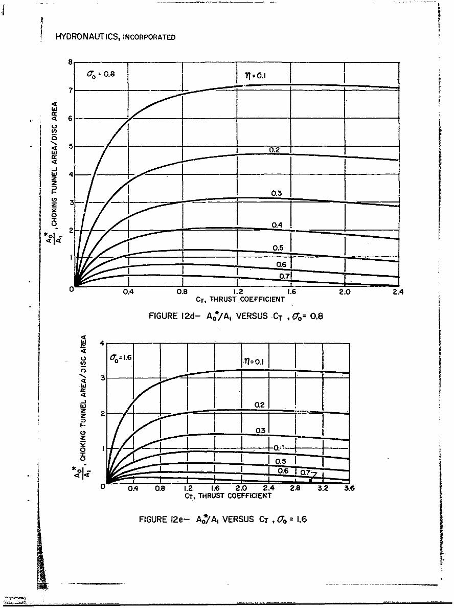
Figure 12d - Ao/A, versus CT, o = 0.8
Figure 12e - A*/A, versus CT 1.6.0T o
I

HYDRONAUTICS. Incorporated
-1-
INTRODUCTION
The supercavitating propeller was introduced into marine
technology by Soviet Acadamician V. L. Posdunine, References 1, 2.
and 3. Later, research at the David Taylor Model Basin, pa.rticu-
larly on the subject of efficient supercavitating blade sections,
led to the adoption in Western Countries of supercavitating
propellers for high speed planing craft and hydrofoil-boats, Ref-
erences 4 - 7. The use of such propellers is expanding at the
present time and with the increase in size and speeds of con-
templated hydrofoil craft they would seem to play an increasingly
more important role in marine technology. In an earlier paper,
Reference 8 the author has discussed the history, operating char-
acteristics, and mechanism of operation of supercavitating pro-
pellers. The present paper may be regarded as a companion to this
earlier work.
Our understanding of the hydrodynamics of supercavitating
propellers is quite imperfect. We have not quantitatively under-
stood well enough many aspects of their design and operation. Two
hydrodynamic effects have been particularly ignored or shrouded
in mystery. These are: (i) the interference between supercavi-
tating blades and their cavities, see Reference 8, and (ii) the
effect of the cavities on the inflow to the propeller. This
paper is specifically devoted to the latter effect.
It is important to have accurate knowledge of the inflow
speeds at the propeller disc in order that the effective angles
Sof attack at which the blade elements operate may be calculated.
-2-
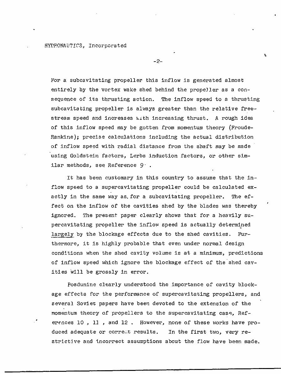
For a subcavitating propeller this inflow is generated almost
entirely by the vortex wake shed behind the propeller as a con-
sequence of its thrusting action. The inflow speed to a thrusting
subcavitating propeller is always greater than the relative free-
stream speed and increases v.ith increasing thrust. A rough idea
of this inflow speed may be gotten from momentum theory (Froude-
Rankine); precise calculations including the actual distribution
of inflow speed with radial distance from the shaft may be made
using Goldstein factors, Lerbs induction factors, or other sim-
ilar methods, see Reference 9•
it has been customary in this country to assume that the in-
flow speed to a supercavitating propeller could be calcu]ated ex-
actly in the same way as. for a subeavitating propeller. The ef-
fect on the inflow of the cavities shed by the blades was thereby
ignored. The present paper clearly shows that for a heavily su-
percavitating propeller the inflow speed is actually determined
largely by the blockage effects due to the shed cavities. Fur-
thermore, it is highly probable that even under normal design
conditions when the shed cavity volume is at a minimum, predictions
of inflow speed which ignore the blockage effect of the shed cav-
ities will be grossly in error.
Posdunine cl-early understood the importance of cavity block-
age effects for the performance of supercavitating propellers, and
several Soviet papers have been devoted to the extension of the
momentum theory of propellers to the supercavitating case, Ref-
erences 10 , 11 , and 12 . However, none of these works have pro-
duced adequate or correc.t results. In the first two, very re-
strictive and incorrect assumptions about the flow have been made.
4
T4Vnlhf%1TA TTMT/ic t - w-0 -.
-3-
Epshteyn, Reference 12, does in fact summarize the shortcomings
of these papers. He, himself, attempts an analysis with a minimum
of assumptions. His work fails for two reasons: he applies in-
I correctly the energy theorem in a non-moving system of coordinates
(his Equation 2.7), and he does not introduce the blade cavita-
I tional efficiency, 1c' into the analysis. In fact none of these
interesting Soviet papers takes this latter step. This must be
done, for without the introduction of such a parameter the prob-
lem of determining the inflow speed or the ideal propeller effi-
4 ciency remains, indeterminate. The blade cavitational efficiency
4 arises naturally in the analysis because the head rise across the
disc is not equal to the thrust loading as in subcavitating flow,
but to the ratio of thrust loading and blade cavltational effi-
ciency.
The primary objective of the present paper is to present an
4 adequate theory relating the net propeller efficiency and inflow
speed of an ideali2ed heavily supercavitating propeller to the
i thrust coefficient, cavitation number and blade cavitational effi-
4 ciency. This is done using momentum theory. The results clearly
show that the inflow speed to a heavily supercavitating propeller
I will very often be retarded, contrary to the Dredictions of the
* His Equation [2.8] is based on the assumption that induced
velocities exist only within the slipstream. This is clearlynot trUe unless the free stream cavitation number is zero(ao = 0), and even in this case Epshteyn's analysis is in-
correct except under those particular conditions when theasymptotic cavity diameter is finite. His results may in fact,when properly interpreted, be shown equal-to ours in thislatter very special case.
HYDRONAUTTICS, Incorporated
-4-
subcavitating propeller momentum -theory. It is also shown that
a maximum possible net efficiency exists for a heavily supercavita-
ting propeller; this"'m~ximum is a function of thrust loading and
cavitation number.
Further objectives of this paper are to discuss the general
characteristics of the flow behind the cavity and in the slip-
stream behind a supercavitating propeller and drag discs and to
discuss the effects of tunnel walls upon the propeller flow. This
is don6 and it is shown that the inflow speed to a supercavitating
propeller is not affected by tunnel boundaries even during opera-
tion between solid walls. However, tunnel choking can occur in
the latter circumstances and the momentum theory is applied to
its prediction.
THE MOMENTUM THEORY FOR SUBCAVITATING PROPELLERS
It is first of all useful to review the basis for the momen-
tum theory of subcavitating propellers as it is understood at the
present time, but not necessarily as it was originally conceived.
The thickness of the propeller blades is neglected so that they
may be thought of as vortex surfaces composed of continuous dis-
tributions of vortex lines. These lines must of course be con-
tinuo,,s in the fluid, so that they are shed from the blades into
che pi.opel3ier wake to form there one continuous trailing helical
sheet per blade. The space behind the propeller is thus to a
certain extent filled by shed vorticity. The latter may at each
point where it exists be vectorially decomposed into a longitudinal
and circumferential componernt, which induce, respectively, rota-
tional and axial velocitieis in the flow.
HYDRONAUTICS, Incorporated
-5-
If the number of blades becomes very large and the chord of
each very shirt, it becomes possible to represent the axial flow
field due to the propeller by consideration only of the effect
of the circumferential component of the shed vorticity. This
vorticity, in turn, may be thought of as comprising a continuous
distribution of concentric vortex-sheaths. These are of a radius
which contracts behind the propeller, but for light loadings this
contraction may be neglected. The propeller blades themselves
degenerate into a disc composed of essentially radial vortex
lines. These induce equal but opposite circumferential velocities
across the disc. The longitudinal shed vorticity induces angular
velocities which exactly cancels out the influence of the disc at
any point in front of or outside the propeller slipstream, where
the flow, in view of its irrotationality, cannot possess angular
momentum. The angular velocities just behind the disc are thus
half due to the longitudinal component of shed vorticity and half
due to the bound vorticity in the disc. The increase in angular
momentum at any point across the disc is in reacticn to and lin-
early related to the local torque on the blade system.
Simple momentum theories incorporate the axial flow system
as described above plus an assumed discontinuity in flow stagna-
tion pressure across the disc, but neglects the rotational flow
in the slipstream. This is a consistent procedure in the case
of the usual subcavitating propeller for the following reasons.
When viewed in a system rotating with the propeller, a static
pressure increase is caused across the disc proportional to the
difference in the squares of the circumferential velocities and
less the head loss due to frictional dissipation at the disc,
HYDFONAUTICS, Incorporated
-6-
the other components being continuous across the disc; this static
pressure increase may also be shown equal to the local net thrust
loading. When neglecting the rotational component of the flow
it therefore becomes necessary to account for the pressure in-
crease across the disc in terms of an imaginary increase in the
stagnation pressure of the axially symmetric flow in amount just
equal to the net thrust loading. The situation is more fully dis-
cussed in the next section of this paper, with particular emphasis
on the changes brought. about by supercavitating operation.
Another facet of the sheath representation which is of prac-
tical and theoretical importance concerns the relation between
the vortex sheath and so-called actuator or sink disc representa-
tion of the flow field. Consider a single vortex sheath of semi-
infinite length, which may also be thought of as a continuous
distribution of vortex rings of constant strength. .This vortex
sheath is exactly equivalent with regard to the flow field pro-
duced, to a sink disc just covering its open end, plus a uniform
flow within the cylinder formed by the sheath and disc, Refer-
ence 13 , pg. 56. The strength of this uniform flow is such as
to cause the velocity across th'e disc to be continuous.
Because of this equivalence, which is expressed schematically
in Figure 1, it is possible in the case of light loadings to rep-
resent the flow field caused by a given axially symmetric distri-
bution of thrust as that due to a sink disc whose radial strength
depends on the loading distribution. This has been done in prac-
tice, Reference 14 . It may further be noted that a vortex sheath
of finite length may be represented by tandem source-sink discs
plus the contained uniform flow.
HYDRONAUTICS, Incorporated
-7,-
The actuator disc rather than the vortex sheath picture is
usually taken as the starting point of the momentum theory. De-
spite the usual neglect of rotation, the idealization of the pro-
peller action introduced In the simple actuator disc model is
fair enough in portraying the propeller as a device functioning
continuously to accelerate fluid aft and to do useful- work as a
result of the reaction on the blades and shaft. The axial flow
field is asymmetric when viewed from the propeller plane by an oo-
server moving with the speed that prevails there. This asymmetry
has as a consequence that the total increase in flow momentum as
observed in the wake far downstream where the pressure has re-
turned to ambient is Just twice the increase in flow momentum as
observed at the propeller disc. The pressure just behind the
disc is, of course, greater than ambient and therein is stored
half of the momentum eventually to be delivered to the slipstream.
in view of continuity the flow velocity immnediately in front of
the disc is identical to the velocity just aft of it, but no work
having been done on those fluid elements which have yet to pass
through the disc, the increased momentum of the incoming flow has
been realized at the expense of the pressure, which is suitably
reduced.
In the absence of blade friction or form drag, the work done
on an element of the flow on passing through the disc is simply
"the pressure increase across the disc times the velocity of the
flow at the disc, say U1 , while the useful work done by the cor-
responding element of the propeller is simply the net thrust
loading times the absolute forward velocity of the propeller, say
Uo. The net thrust loading is also just equal to the head rise
Ii.m
HYDRONAUTICS, Incorporated
-8-
across the disc. The ideal efficiency is thus U o/U 1 . The pres-
sure increase across the actuator disc, which equals the local
net thrust loading, is also just equal to the gain in kinetic
energy represented by the acceleration of the flow from far up-
stream to far downstream. As noted earlier, thi- pressure rise
is also equal to the loss in rotational kinetic energy across
the disc. These last facts allow the derivation of the result
that the induced velocity at any point in the propeller disc is
normal to the resultant relative velocity of a blade section.
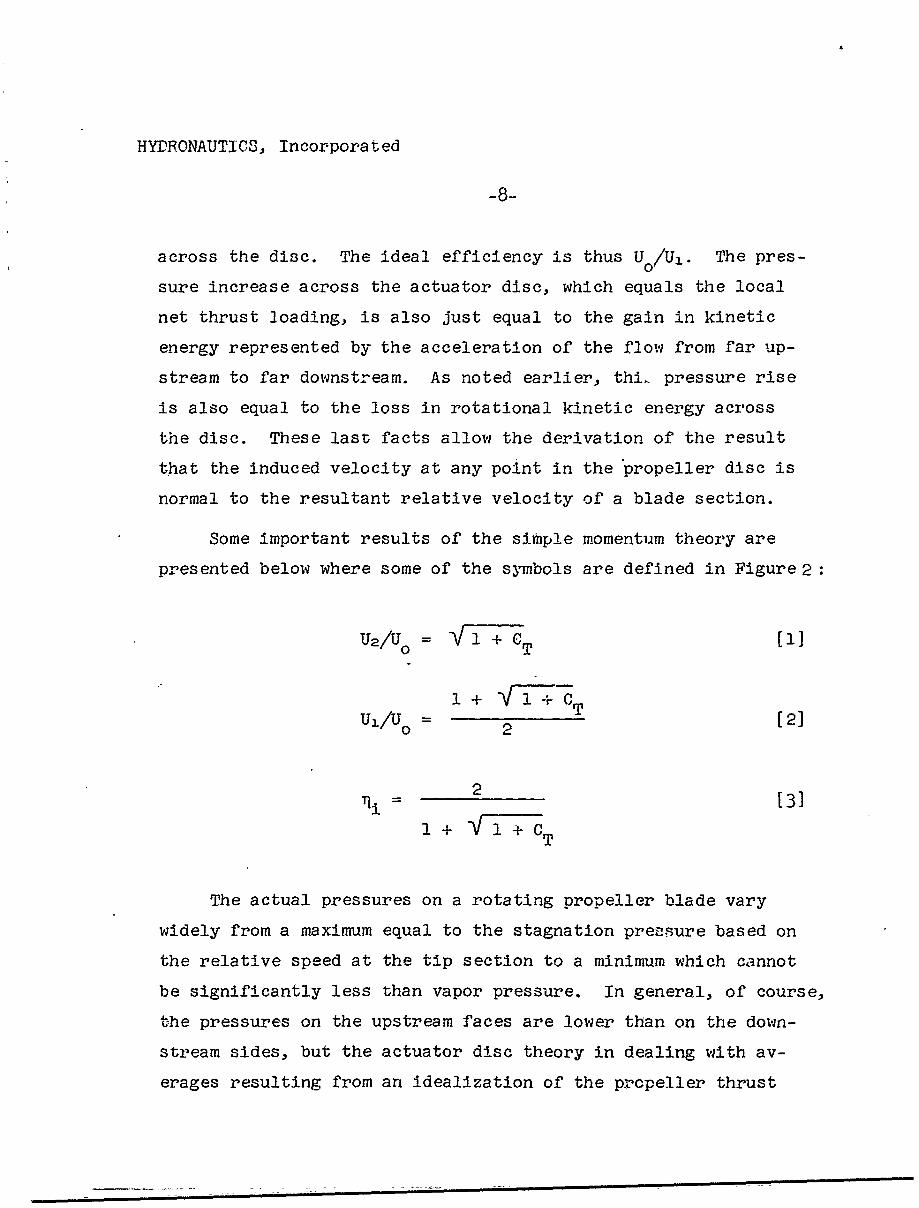
Some important results of the simple momentum theory are
presented below where some of the symbols are defined in Figure 2:
U2/uo VT1 + T ' 1VJ
1 + -\/1-+ -CT
U =/o 1 2 [2]2
2• [3]I + -•I+7T
The actual pressures on a rotating propeller blade vary
widely from a maximum equal to the stagnation pressure based on
the relative speed at the tip section to a minimum which cannot
be significantly less than vapor pressure. In general, of course,
the pressures on the upstream faces are lower than on the down-
stream sides, but the actuator disc theory in dealing with av-
erages resulting from an idealization of the propeller thrust
HYDRONAUTICS, Incorporated
distribution fails to provide significant information on the pos-
sibilities of blade cavitation. Nevertheless predictions of av-
erage pressures in the field around the propeller can be made, 3
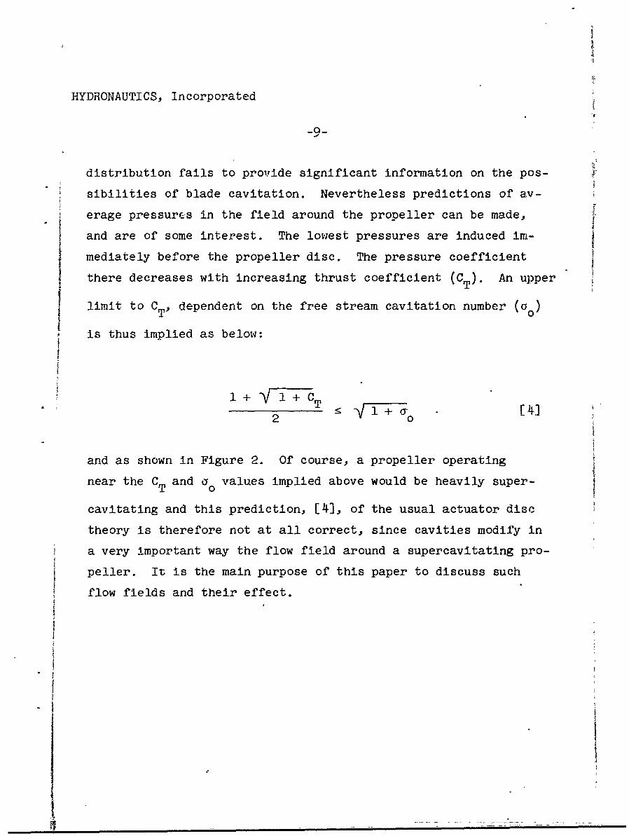
and are of some interest. The lowest pressures are induced im-
mediately before the propeller disc. The pressure coefficient I
there decreases with increasing thrust coefficient (C). An upperT
limit to CT, dependent on the free stream cavitation number (ao)
is thus implied as below:
1+ + C
2 o
and as shown in Figure 2. Of course, a propeller operatingnear the CT and a values implied above would be heavily super-
cavitating and this prediction, [1], of the usual actuator disc
theory is therefore not at all correct, since cavities modify in
a very important way the flow field around a supercavitating pro-
peller. It is the main purpose of this paper to discuss such
flow fields and their effect.
HYDRONAUT TS, Incorporated
-10-
THE MOMENTUM THEORY FOR SUPERCAVITATING PROPELLERS
The Head Rise Across the Disc in Supercavitating Flow
Cavities originate in the plane of the supercavitating pro-
peller and through blockage of the approaching flow cause its
speed to be greater immediately behind the disc than immediately
before it. These speeds, non-dimensionalized, themselves depend
upon the non-dimensional thrust loading(CT), the blade cavitation
efficiency (.9c), and the free stream cavitation number (o ).
These dependancies will be revealed later but it is first of all
crucial to specify the manner in which blade cavity drag alters
the relation between thrust loading and the stagnation pressure
rise across the disc.
The rotation which the flow experiences upon passing through
the propeller disc cannot be entirely neglected in, an analysis of
the propeller flow, even in the case of simple momentum theory.
It has already been mentioned that when viewed in a system rotat-
ing with the propeller, a static pressure increase is caused
across the disc proportional to the difference in the squares of
the circumferential velocities less head losses due to friction,
and that in the case of a subcavitating propeller this static
pressure increase may also be shown equal to the local net thrust
loading. Thus when the rotational component of the flow is "ne-
-glected" it becomes necessary to account for the head increase
across the disc in terms of an imaginary increase in the stagna-
tion pressure of the axially symmetric flow just equal to the net
thrust loading (T/A 1 ).
@ , • • -- am •- k •- • r_ __mm • • • •- -• ••-m
HYDRONAUTICS. Incorpora ted
-i!-
In. a supercavitating or separated flow, substantial cavity
or form drag acts on the flow while it passes through the disc
but without resulting in immediate dissipation which is assumed
to occur only at the end of the cavity in the region of cavity
collapse. Because the work done by the moving blades on the
fluid in overcoming blade cavity drag is not dissipated at the
disc, but appears there as a head rise, the net stagnation pres-
sure increase across the disc due to flow rotation is no longer
simply equal to the net thrust loading, but also depends upon the
blade efficiency - to the extent that the latter reflects the
blade losses due to cavity drag.
In discussing this further, it is useful to contrast again
the influences of friction and form drag. The effects on the head
rise across the disc of frictional blade drag and form drag such
as accompanies separation or cavitation are separate and distinct.
Their differing effects are the result of the dissipation which
is assumed to occur at the disc accompanying frictional drag, and
the absence of any such dissipation, specifically due to form
drag, in the flow between the disc and the region of cavity col-
lapse.
Thus the work done by the blades on the fluid passing through
the disc in overcoming frictional drag is assumed to be not mani-
fested at all as an increase in flow stagnation pressure-in conse-
quence of the assumed immediate dissipation of the work input. As
a result, the total increase in flow stagnation pressure across
the disc in the absence of form drag (as in the usual subcavitating
theory) is simply equal to the net thrust loading, and the results
HYDRONAUTICS, Incorpora ted
-12-
of actuator disc theory apply as long as the thrust is reduced by
the effect of friction drag to yield net thrust.
However, the work input to the fluid by the blades in over-
coming blade cavity drag is immediately and completely manifested
in a stagnation pressure rise. The total work input to the fluid,
neglecting frictional drag, is just the product of the head rise
across the disc (Ah) and the volume flow through the disc (UIAI).
The useful work done by the blades on the fluid oassing through
the disc (considering the propeller at rest) is just the product
of the net blade thrust (T) and the flow speed immediately before
the propeller (UI). If the blade cavitational. efficiency (N ) is
defined as the ratio of the useful work done by the blades on the
fluid passing through the disc to the work-c input to the blades,
then:
_ Useful Work Done on Fluid by Blaues T-U 1 [5]c Total Work Input to Fluid Ah-U1 A1
or
Ah = T [6]
* For this reason, the potential flow calculations of propeller
induced flow fields, based on blade spanwise circulation dis-tributions uncorrected for loss of thrust due to friction,tend slightly to exaggerate these flow fields.
HYDRONAUTICS, Incorporated
This result [61 is crucial'in the development of a proper mo-
mentum theory for supercavitating propellers or of other pro-
- pellers suffering ýarge form drag.
The same results given above may also be obtained in a more
formal mahner by treating the flow in a thin annular element
passing through the propeller disc as if it were the flow in a
"two-dimensional cascade, or by the application of an energy the-
brem to the flow within a proper moving control surface about the
supercavitating propeller-. In fact. Epshteyn in Reference 12
does apply such a theorem and [6] may be obtained from his Equa-
tion [2.4] by the substitution of TUI/Ac for his N3 and of AjU1
for his m.
The blade cavitational efficiency, 1c, is a complicated func-
ti6n of blade shape, effecti-ve advance coefficient, blade area
ratio, and other factors. It cannot of course be calculated from
momentum theory, and its accurate prediction is in fact quite dif-
ficult and outside the scope of this paper. It would seem useful,
however, to state here the well-known result allowing the calcu-
lation of the local blade cavitational efficiency in terms of the
cavity drag-lift ratio of the blade (D /L) and the effective ad-cvance ratio (ke).
I - (Dc/L0~
Sc 1 + (Dc/LX(/e) [7]
where, Axial Inflow Speed
e Blade Relative Rotational Speed [8]
-n w • B" I - • • m i •
HYDRONAUTICS, Incorporated
-14-
The Momentum Balance Across the Disc in Supercavitating Flow
A solid axi-symmetric obstacle producing drag in supercavi-
taring flow sheds a cavity whose length and maximum diameter in-
crease without bound as the cavitation number (ao) is reduced
toward zero. In the case of a supercavitating propeller, even
idealized to the actuator disc, it is not clear at the outset
what the characteristics are of the trailing cavity even in the
case of zero ao. The reason for this is that in producing thrust
the propeller creates a positive pressure field behind the disc
which tends to shorten the trailing cavity. We shall deduce later
on that for a - 0 the cavity must be infinite in length and that0
the diameter must also be unbounded except under certain special
conditions when the asymptotic cavity diameter is finite. For
a > 0 the trailing cavity must of course be of finite length and0
of finite maximum diameter. In fact,. the typical length of the
cavity behind a supercavitating propeller in open water under
usual operating conditions will hardly exceed one and a bIlf pro-
peller diameters.
We are not in what immediately follows concerned with the
detailed shape of the trailing cavity, but we have discussed it
briefly in order to prevent errors in the arrangement of the
* It is worthwhile to note that exaggerations of these lengths
may occur during testing in a water tunnel with solid wallsas a resi lt of tunnel blockage, and the cavity may at quitehigh cavitation numbers even extend down the entire lengthof the tunnel test section - a distance usually of manypropeller dJameters.
HYDRONAUTICS, Incorporated
-15-
momentum control surfaces - as, for example, would arise should
we assume that for a = 0 the cavity is always of infinite length
and of finite maximum diameter.
We assume that the propeller consists of a very large num-
ber of blades of very short chord. The rotation of the slipstream
behind the disc is taken into account in its effect on the "effec-
tive" pressure rise across the propeller disc, as discussed earlier,
but otherwise the flow is considered to be one-dimensional - as in
the usual actuator disc theory. A schematic of the flow being
considered, in the case of finite cavity length, is shown in Fig-
ure 3. The flow approaching the propeller is seen to be either
accelerated (narrowing stream tube), or decelerated (widening
stream tube) for sufficiently low thrusts in anticipation of future
results. Immediately behind the disc, the stream tube is seen rap-
idly to widen due to the blockage effect of the cavities shed by
the blades. Due to the same effect there is assumed to exist a
discontinuity in the axial velocity across •he disc. The cavity-
wake behind the propeller plane is filled with jets or sheets of
water flowing between the cavities or voids created by the blades.
The pressure in the wake is constant and equal to the cavity pres-
sure. The speed of the flow inside and on the cavity-wake is thus
constant. It is, however, greater than would be the speed of the
flow on a stationary cavity at the same cavitation number, since
a head increase has occurred across the disc as a result of the
flow rotation behind the propeller. As discussed earlier, the
work done as a result of the cavity drag experienced by the blades
remains in the slipstream since no dissipation of energy is assumed
Ii
HYRONAUTICS, Incorporated
-16-
to occur until the flow passes out of the cavity-wake through
the region of cavity collapse at the end of the cavity.
The momentum control surface best used to determine the in-
flow speed U1 is shown as a dashed line in Figure 4. It coincides
with plane 1, immediately before the disc, in its intersection
with the stream tube; it. coincides with the outer cavity wall be-
tween the propeller disc and plane 2, and then it coincides with
the latter in its intersection with the cavity-wake.
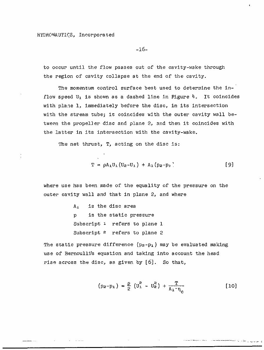
The net thrust, T, acting on the disc is:
T = pA 1U 1 (U2 -Ul) + A1 (P2 -P] [9]
where use has been made of the equality of the pressure on the
outer cavity wall and that in plane 2, and where
At is the disc area
p is the static pressure
Subscript 1 refers to plane 1
Subscript 2 refers to plane 2
The static pressure difference (P2-Pi) may be evaluated making
use of Bernoullis equation and taking into account the head
rise across the disc, as given by [6]. So that,
(p2-pI) 2 ( _ U2) + A T [10]- £ -2) +A.rc
YT D•RJ •^ Dl A UTI-, Incorpora ted
-17-
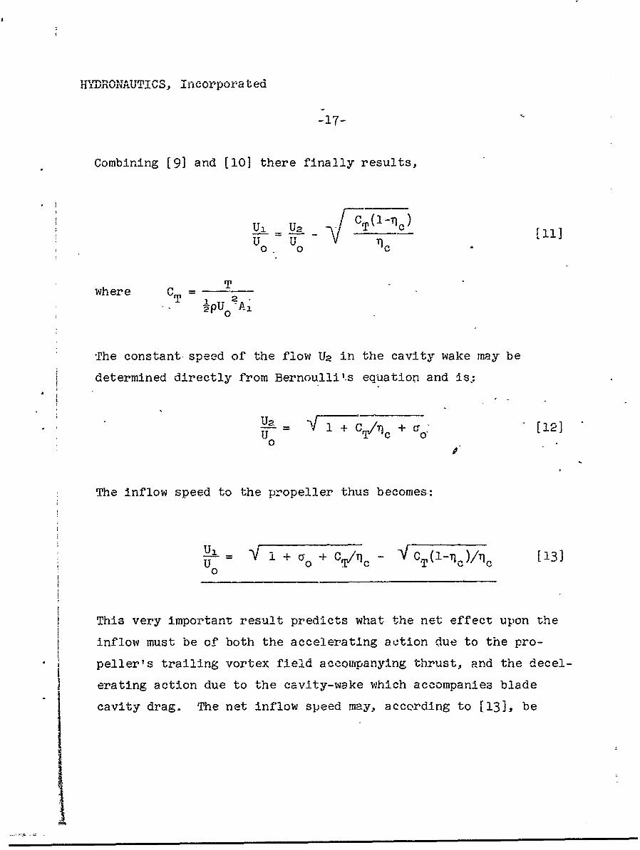
Combining [9] and [10] there finally results,
Ui_• =U_2 F CTi-ic)1]_ T c
U0 U0
where C T TT wpU A2
0
The constant speed of the flow U2 in the cavity wake may be
determined directly from Bernoulli'-s equation and is.:
U 2 V + C[/c + -12]U - 0
0
The inflow speed to the propeller thus becomes.:
U - / + a + C,,,/'ci - T(1--q)/ [13]SU 0 T-
0
This very important result predicts what the net effect upon the
inflow must be of both the accelerating action due to the pro-
peller's trailing vortex field accompanying thrust, and the decel-
erating action due to the cavity-wake which accompanies blade
cavity drag. The net inflow speed may, according to 113], be
Im
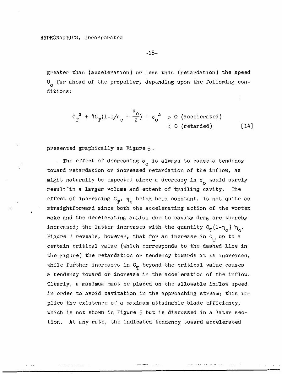
HYP•.VNAUTUICS, Incorpora ted
greater than (acceleration) or less than (retardation) the speed
U far ahead of the propeller, depending upon the following con-
ditions:
CT2 + 4CT(I-Ic + 2) + a° > 0 (accelerated)
< 0 (retarded) [14]
presented graphically as Figure 5.
The effect of decreasing a is always to cause a tendency0
toward retardation or increased retardation of the inflow, as
might naturally be expected since a decrease in a would surely
result'in a larger volume and extent of trailing cavity. The
effect of increasing CTV TC being held constant, is not quite as
straightforward since both the accelerating action of the vortex
wake and the decelerating action due to cavity drag are thereby
increased; the latter increases with the quantity CT(1-cn Zq c
Figure 7 reveals, however, that for an increase in CT up to a
certain critical value (which corresponds to the dashed line in
the Figure) the retardation or tendency towards it is increased,
while fu±ither increases in C beyond the critical value causes
a tendency toward or increase in the acceleration of the inflow.
Clearly, a maximum must be placed on the allowable inflow speed
in order to avoid cavitation in the approaching stream; this im-
plies the existence of a maximum attainable blade efficiency,
which is not shown in Figure 5 but is discussed in a later sec-
tion. At any rate, the indicated tendency toward accelerated
HYDRONAUTICS, Incorporated
-19-
inflow at high CT values probably does not occur in practice
since increasing CT (higher blade loading) must almost of neces-
sity be accompanied by decreasing 1c"
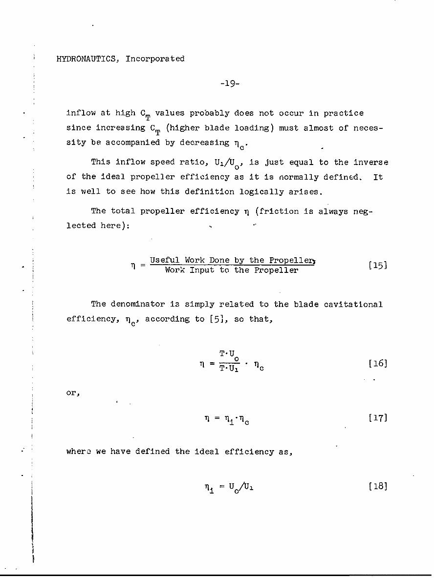
This inflow speed ratio, U1 /Uo, is just equal to the inverse
of the ideal propeller efficiency as it is normally defined. It
is well to see how this definition logically arises.
The total propeller efficiency Tj (friction is always neg-
lected here): -
=Useful Work Done by the Propeller F15]Work Input to the Propeller
The denominator is simply related to the blade cavitatlonal
efficiency, T c' according to [5], so that,
T.U
1T'U 0 Tic [16]
or,
S= '!-•c [ 17]
where we have defined the ideal efficiency as,
S= Oo/Uh [18]
HYDRONAUTICS, Incorporated
-20-
so that it represents the ratio of useful work done by the pio-
peller in thrusting motion to the useful work done by the blades
on the fluid, considering the propeller to be at rest and the
flow in motion toward it.
In the usual subcavitating momentum theory the ideal effi-
ciency always takes on values less than unity. In the present
case, however, the inflow may be retarded, and the ideal effi-
ciency will thus assuFr, values in excess of unity. This should
not be too disturbing, as it is well known that even subcavitating
propellers operating in strong wakes (regions of retarded flow)
may enjoy efficiencieý greater than unity. In blocking the on-
coming flow, the cavities on a supercavitating propeller create,
in a sense, a wake ahead of the propeller and in this way an in-
crease in ideal efficiency is caused at the expense of cavity
drag or blade efficiency.
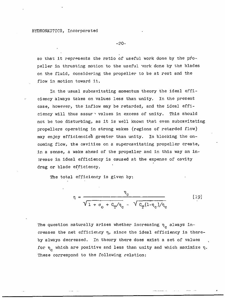
The total efficiency is given by:
1 TC [19]
fl + (Y + %"'~c V CTW -q A
The question naturally arises whether increasing ic always in-
creases the net efficierncy 1, since the ideal efficiency is there-
by always decreased. In theory there does exist a set of values
for -qc which are positive and less than unity and which maximize q.
These correspond to the following r.elation:
HYDRONAUTICS, Incorporated
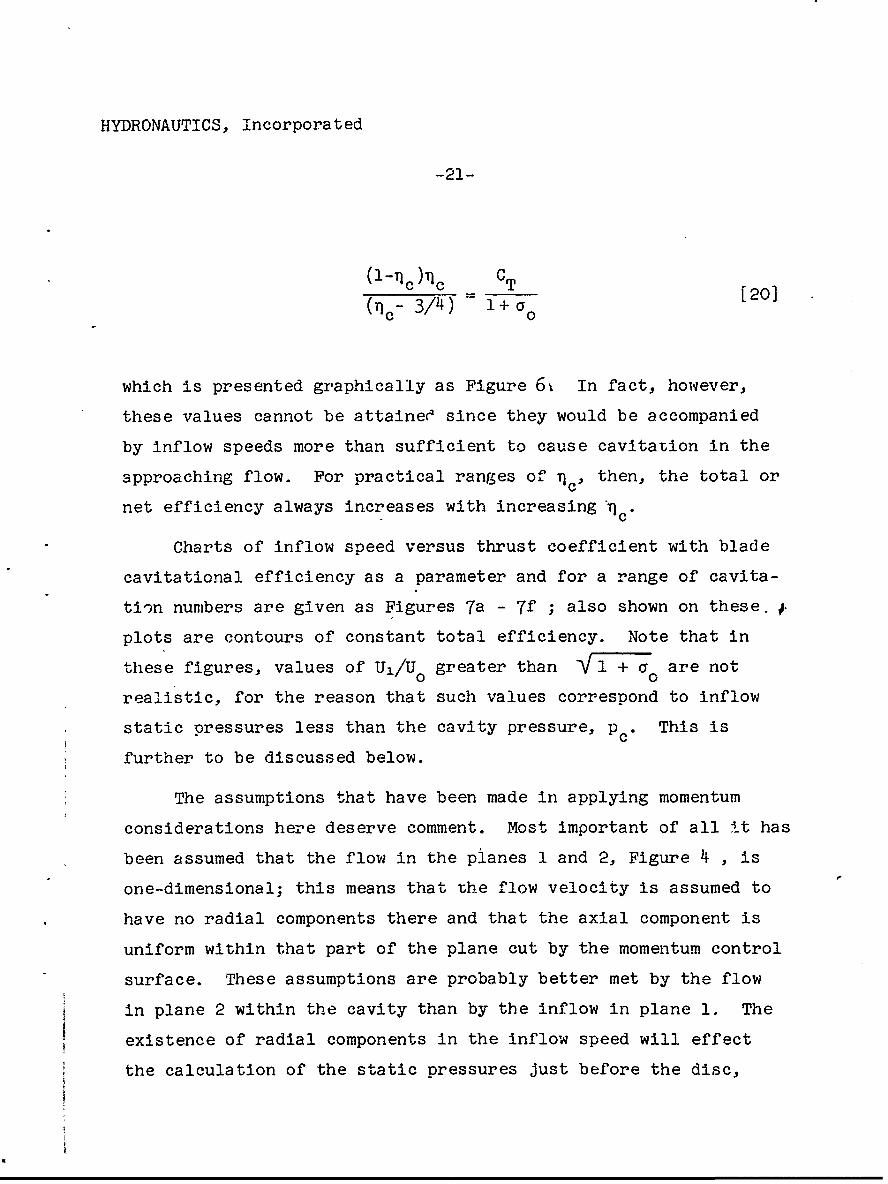
-21-
(1-ri ch )r T CT0(71 c- 3/4) 1 + a0 [0
which is presented graphically as Figure 6% In fact, however.,
these values cannot be attaineO since they would be accompanied
by inflow speeds more than sufficient to cause cavitation in the
approaching flow. For practical ranges of n c , then, the total or
net efficiency always increases with increasingnrC
Charts of inflow speed versus thrust coefficient with blade
cavitational efficiency as a parameter and for a range of cavita-
tion numbers are given as Figures 7a - 7f ; also shown on these. ~
plots are contours of constant total efficiency. Note that in
thles e figures, values of U1/U0 greater than W\1 TT7 are not0 0
rea'.listic, for the reason that such values correspond to inflow
static pressures less than the cavity pressure, p C This is
further to be discussed below.
The assumptions that have been made in applying momentum
considerations here deserve comment. Most important of all it has
been assumed that the flow in the planes 1 and 2, Figure 4j , is
one-dimensional; this means that the flow velocity is assumed to
nave no radial components there and that the axial component is
uniform within that part of the plane cut by the momentum control
surface. These assumptions are probably better met by the flow
in plane 2 within the cavity than by the inflow in plane 1. The
existence of radial components in the inflow speed will effect
the calculation of the st-atic pressures just before the disc,
HYDRONAUTICS, Incorpora ted
-22-
Equation [10], by a term proportional to the square of the radial
velocity. The other disturbance velocities due to the propeller
(axial and rotational) enter into the momentum balance at least
in terms which are proportional to their first powers, (the ro-
tational term enters through the fictitious increase in head
across the disc). The neglect of the squares of the radial veloc-
ity amounts then to the neglect of a second-order term, and is
best justified when the propeller is lightly loaded. The one-di-
mensional assumption regarding the uniformity of the axial com-
ponent of velocity, pressures, etc. is of a different kind, for
it does not even correspond to reality in the limiting case of a
very lightly loaded propeller. The reason for thi.s is that de-
sirable distributions of radial loading and correspond~ing inflow
speeds are quite non-uniform for all propeller loadings. Never-
theless, the predictions of momentum theory are highly useful in
the case of subcavitating propellers when corrected for finite
blade number because they may reasonably be applied separately to
each annular element, the interference between elements being
small. W.ýhether the same technique may as safely be applied to
a supercavitating propeller remains an open question. The pre-
dictions of the present momentum theory are thus best regarded as
gross. They would seem to be very valuable in so far as they de-
scribe some of the general features of supercavitating propeller
flows, but; their application in design would seem hazardous. Un-
fortunately, no better theory exists at the present time.
The assumption of large blade number made in this theory is
necessary to insure uniformity of the flow in the circumferential
direction and is not therefore additive to the one-dimensional
HYDRONAUTICS, Incorporated
-23-
assumption. The conditions under which reasonable circumferential
flow uniformity occurs should correspond to blade loadings such
that blade interference or cascade effects dominate the flow
through the blades. These blade interference effects are not
discussed in this report, but it is known that they dominate the
operating characteristics of supercavitating propellers for values
of advance coefficient somewhat higher than that corresponding to
maximum kt ( being fixed). in fact, these interference effects~t (0
are themselves responsible for the existence of a maximum k value.t
It seems not unlikely that blade interference effects are very im-
portant even at the design points of typical supercavitating pro-
pellers, so that inflow speeds there more likely correspond to
the present theory rather than the subcavitating predictions
usually used in design which would only apply were the influence
of the cavit"es upon the overall flow small.
An Estimate of Absolute Maximum Efficiency
The pressures in the flow approaching the propeller are less
than ambient in the case where the inflow is accelerated. In no
case, however, can these pressures attain values less than those
on the propeller blades. We know this to be true because in a
steady potential flow such as exists ahead of and around the screw
when the flow is viewed from a rotating coordinate system the
* For this reason, there is a tendency for the loss in liftcaused by blade interference to be made up at the designpoint by the higher blade angles of attack which result fromthe reduced inflow speeds.

HYDRONAUTICS, Incorpora ted
-24-
minimum as well as the maximum pressures must occur on bounding
surfaces. The momentum theory does not, however, take such con-
siderations into account, and as a result it allows predictions
of accelerated inflows which are in excess of those required to
cause cavitation in the approaching flow. These excessive in-
flows can however be avoided if restrictions are placed upon al-
lowable -values of blade cavitational efficiencies. These effi-
ciencies depend upon the details of the propeller configuration
(pitch, blade area ratio, loading distribution, and blade section
shape) and obviously cannot be estimated from momentum theory
considerations. Nevertheless, the restrictions derived from mo-
mentum theory must be realistic to the extent that the; real pro-
peller flow resembles the idealized version being 'onsidered.
The restrictions upon 71' allow an estimate to be made of absolutecmaximum net efficiency, 1max" as a function of C. and a , as
follows.
The maximum allowable- inflow velocity U just correspondsmaxto a pressure p c in the approacning stream, or,
Umax [21]
U 00
Upon the assumption that Umax = U max, and using [13], the fol-
lowing inequalitity results:
+ --~ T(~ ~c < V 7+[22]-\F-+ 0 +7A c0
HYDRONAUTICS, Incorpora ted
-25-
or, after some manipulation,
1o < (' ••(i+% 231~c Yl+C'TI4(l a 0 ) [3
Which may also be written,
i C'T 4(l-Tc)
i+ 0 < 'I f24)IIo ".c
The. limiting values of rc according to [23] are shown in Fig-
ure 6 and it may be seen that they are everywhere less than those
values of 'q for w.hich r, is a theoreti.cal maximum. This means
that the limiting values of no (Equation [23]) must correspond
to the absolute maximum net efficiencies. Thus,
U0
Timax 1 •c U1 [25]max -max
or,
=iax (1 + ao1 +%C/1 [26]
Curves f~or qa are given as Figure 8
max.
IJ
HYr0ONAUT I CS, Incorpora teu
-26-
It should carefully be kept in mind that these maximum
values are riot necessarily attainable in practice. Estimations
of actual attainable efficiency depend upon studies of the blade
elements themsatves, and it seems a matter of experience that
actual blade cavitational efficiencies and resulting net propeller
efficiencies are quite a bit less than the absolute maximum effi-
ciencies predicted here. It would therefore be unwise to base
real expectations upon the numbers implied by Figure 8
The Special Case of the Drag Disc
The momentum theory developed above applies not on]y to those
cases where net thrust is developed at the disc, but also when a
net drag force acts there. In fact it may apply in the special
case where no net force acts on the disc, but where at the same
time the blade cavitational efficiency has gone to zero.
A "pure drag" disc might consist in its simplest form of a
coarse screen inserted in a stream at sufficiently low cavitation
number, co, so that each wire or rod composing the screen indi-
vidually sheds a trailing cavity. Or it might be comprised of a
number of circular rods radiating from a rotating hub and shaft.
These are called "pure drag" discs because of the absence of cir-
culation on the element comprising the disc. In general, of
course, the disc might be composed of lifting alements of such
poor efficiency that a net drag actually results from their op-
eration.
No assumptions were made in the development of the momentum
theory for supercavitating flows which would restrict the validity
of the results to cases of positive thrust. The results therefore
HYTDRONAUTICS, Incorporated
-2Y-
apply equally to drag discs. The drag disc does not, however,
do useful work but rather has work done on It. As a result the
blade cavitational efficiency becomes negative. Since the thrust
is negative, too, the ratio CTc which appears in [13] and other
important relations, remains of the same sign as in the case of
posit. ve thrust. This is a manifestation of the fact that work
is done on the rotating blades, whether they are producing thrust
or drag, and that this work appears as an increase in the stagna-
tion pressure of the flow across the disc. However, the quanti-
ties CT and 1c do not always appear in ratio in expressions for
inflow, etc. so that some differences appear between the thrust
and drag cases. For example the inflow to a drag disc is always
retarded, in contrast to the case of a thrust disc where it may
be either accelerated or retarded. This may be shown by con-
sidering Equation [14] in a pertinent form:
CD2 - 4CD(l-I/Tc + o /2) + o02 > 0 (accelerated)
< 0 (retarded) [271
or,
(CD- Cyo)2 > 4CD TIc (28
0 < D8 1c
The d-ag on the disc is very likely to follow a law which applies
very well for other blunt bodies,
CD= CD(0) + a [29]
• I
14YPRONAUjTICS,- .... In o p r =U
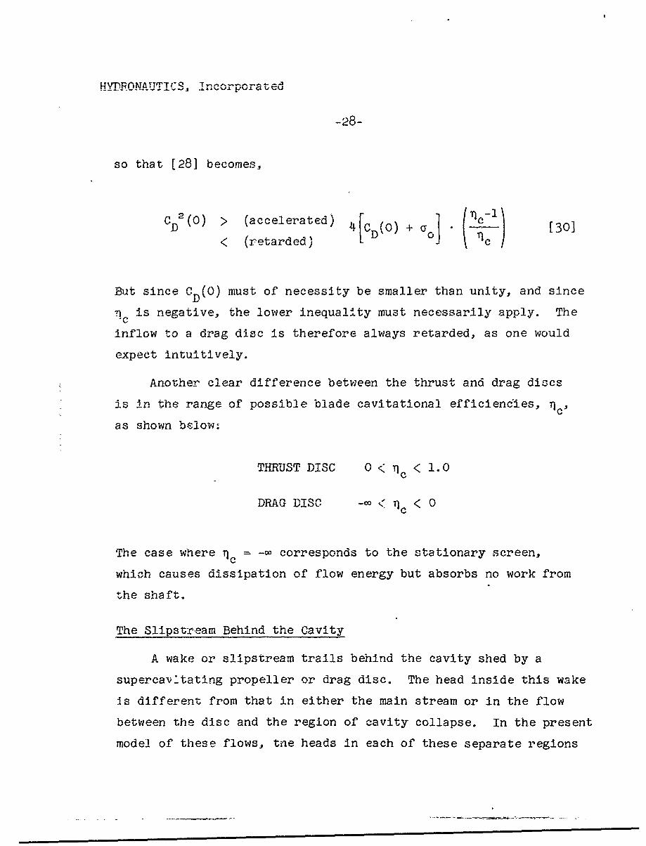
-28-
so that [28] becomes,
CD2(O) > (accelerated) 4 CD(O) + a (30]K (retarded) D
Bit since CD(O) must of necessity be smaller than unity, and since
•c is negative, the lower inequality must necessarily apply. The
inflow to a drag disc is therefore always retarded, as one would
expect intuitively.
Another clear difference between the thrust and drag discs
is in the range of possible blade cavitational efficiencdies, 1c'
as shown below:
THRUST DISC 0 < < 1.0
DRAG DISC -C < 7c < 0
The case where Tc = -c corresponds to the stationary screen,
which causes dissipation of flow energy but absorbs no work from
the shaft.
The Slipstream Behind the Cavity
A wake or slipstream trails behind the cavity shed by a
supercavitating propeller or drag disc. The head inside this wake
is different from that in either the main stream or in the flow
between the disc and the region of cavity collapse. In the present
model of these flows, tne heads in each of these separate regions
HYDRONAUTJTCS, Tncorpora ted
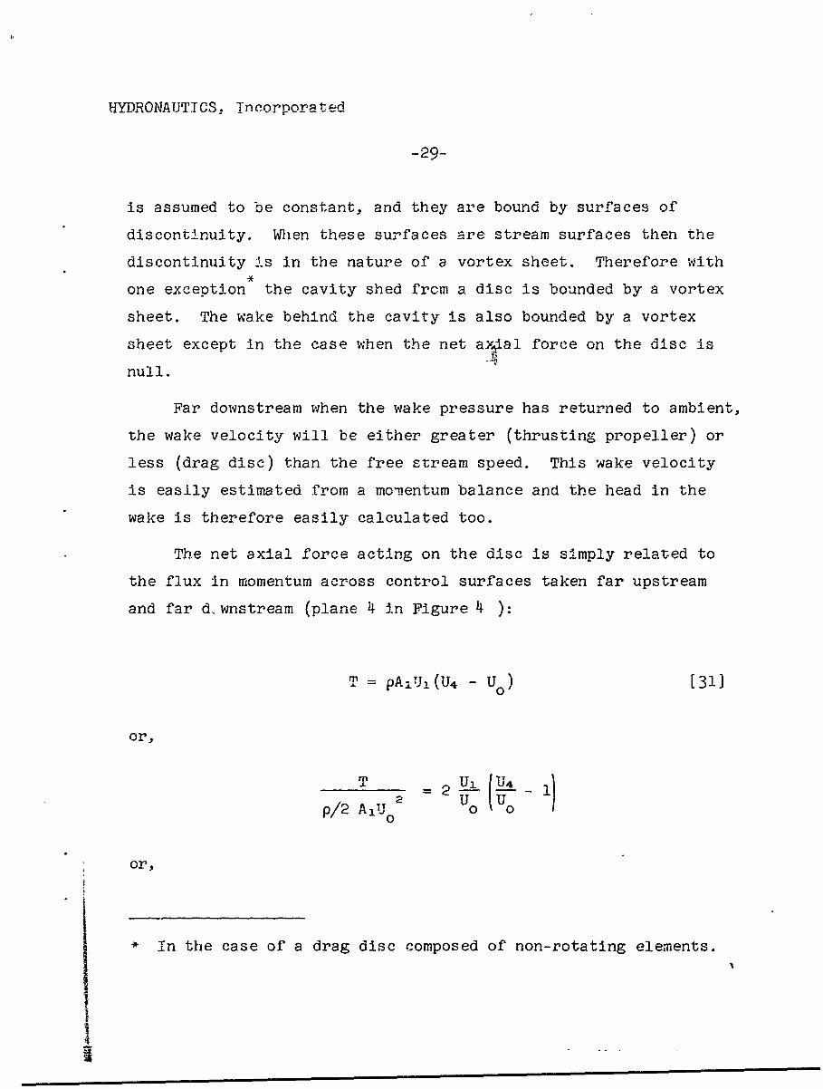
- 29-.
is assumed to be constant, and they are bound by surfaces of
discontinuity. When these surfaces are stream surfaces then the
discontinuity is in the nature of a vortex sheet. Therefore with
one exception the cavity shed from a disc is bounded by a vortex
sheet. The wake behind the cavity is also bounded by a vortex
sheet except in the case when the net ay~ial force on the disc is
null.
Far downstream when the wake pressure has returned to ambient,
the wake velocity will be either greater (thrusting propeller) or
less (drag disc) than the free stream speed. This wake velocity
is easily estimated from a momnentum balance and the head in the
wake is therefore easily calculated too.
The net axial force acting on the disc is simply related to
the flux in momentum across control surfaces taken far upstream
and far d. wnstream (plane 4 in Figure 4 ):
T = pAUi (W4 - Uo) [31]
or,
p/2 A 0Uo
or,
* In the case of a drag disc composed of non-rotating elements.
I
HYDRONAUTICS, Incorpora ted
-30-
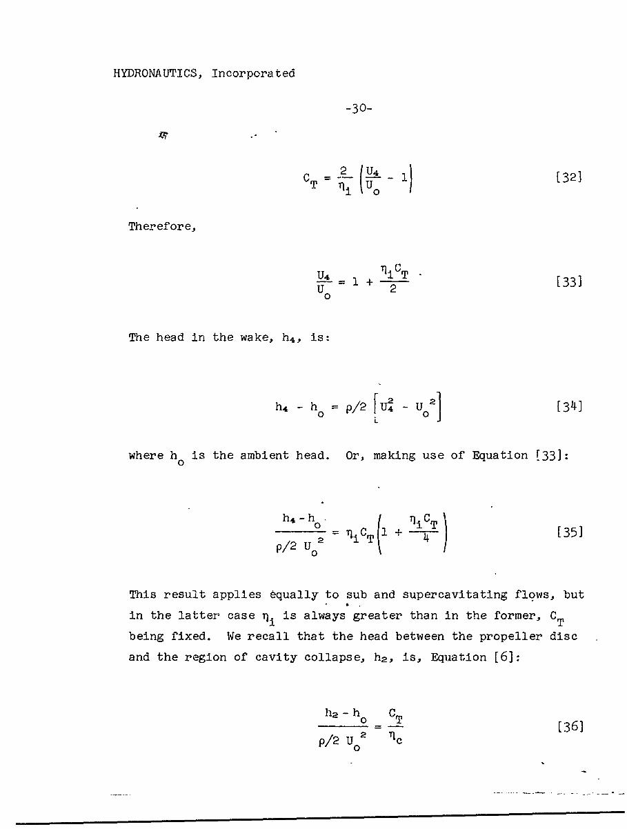
CT (•1 U[2
Therefore,
U4 _ 1i CT [33]U 2
The head in the wake, h 4 , is:
2 2]h -[op2IU 341L
where h is the ambient head. Or, making use of Equation [33]:0
h4 -h0
p 2 U 2 - niCT 1 + 4 [35]
This result applies equally to sub and supercavitating flows, but
in the latter case TI is always greater than in the former, CT
being fixed. We recall that the head between the propeller disc
and the region of cavity collapse, h 2 , is, Equation [6]:
ha -ho CT-0 T [361
p/2 U02 1c
• • m • •0
HYDRONAUTICS, Incorporated
-31-
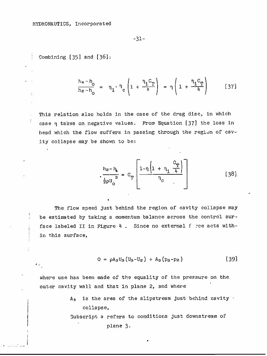
Combining [351 and [361:
o4- __CT ( iCT\h 2 -h h 0c 1 + T) = 1 1 + [37]
20
This relation also holds in the case of the drag disc, in which
case T1 takes on negative values. From Equation [37] the loss in
head which the flow suffers in passing through the region of cav-
ity collapse may be shown to be:
h2 -t 1______+ ___CT
- =C [38]
The flow speed just behind the region of cavity collapse may
be estimated by taking a momentum balance across the control sur-
face labeled II in Figure 4 . Since no external f -ce acts with-
in this surface,
0 = pAsU3S(Ua-U 2 ) + A3 (P 3 -P 2 ) [39]
where use has been made of the equality of the pressure on the
outer cavity wall and that in plane 2, and where
A3 is the area of the slipstream just behind cavity
collapse,
Subscript 3 refers to conditions just downstream of
plane 3.
HYDRONAUTICS, Incorporated
-32-
The static pressure difference (P3-P2) may be evaluated making
use of Bernoulli's equation and taking into account the loss in
head which occurs across the region of cavity collapse, so that,
(P3-Pa) = p/2(U22 -U3
2 ) - (h 2 -h 4 ) [40]
since h 4 = h3 .
Using Equation [38]:
P/2 U o2 U U 2 jC
and substituting in [39]:
2U_3 _2 _i 4 U 2 U 3k u.oTL c j Uo2
-or,
(__Ua = CT 71c [42]
Finally,
U3 U2 T - 43U U0 )c
0 0 c
HYDRONAUTICS, Incorporated
-33-
where u = I 1 + CT/Vc + a according to [12].where U/
This may be compared with the expression for the inflow speed,
Equation [ll]
U1 U2 CT(1-T)c)U o U o n•U0 U0 C
The difference between outflow and inflow speeds is thus given
by-
U3 o-U1 - y [T c TI 4c) [44]
In the case of retarded inflow to a propeller or a drag disc
(11 > 1 and rj > n c) the second term on the right is necessarily
smaller than the first and the outflow speed is thus greater
than the inflow. At the same time A3 < A,. This will clearly
also be the case for moderate accelerated inflow speeds. Only
for sufficiently large values of thrust coefficient, as given by
the upper inequality in the expression below, does the situation
become reversed;
T 1TI \ A3 > A,I 4 < ni
A3 < A1
4
HYDRONAUTICS, Incorpora ted
-34-
The substitution of reasonable numbers in [44] reveals that the
difference between the propeller or drag disc diameter and that
of the region of cavity collapse will normally not exceed 10 per-
cent.
The results obtained here for the slipstream characteristics
are reflected in Figure 3 , in which the general features of
typical flows associated with supercavitating propellers and drag
discs are illustrated.
The Special Case of the Infinite Length Cavity
Only when the cavitation number a is zero is it possible
for the trailing cavity to extend to infinity. The conditions
under which this occurs may be determined by comparing the re-
sults obtained previously for the inflow velocity with those ob-
tained under the assumption of infinite cavity length and finite
asymptotic cavity diameter. In this way we will conclude that
the cavity length is always infinite for a = 0 while the cavity0
maximum diameter is unbounded except in the particular limitingcase when U, = Uo. The flow is shown schematically as Figure.9-.
0
The net thrust, T, acting on the propeller is related to the
momentum flux so that,
T = pA2 jU2 (U2-U 0 ) [46]
where use has been made of the fact that P2 P0 and where
A2J is the cross-sectional area in plane 2 of the fluid Jets in-
side the cavity.
HYDRONAUTICS, Incorporated
-35-
An increase in head, Lh, occurs across the propeller disc
as a result of the rotation induced by the propeller behind it.
This head change is related to the propeller loading and blade
cavitational efficiency by [6],
A Thy p(Ua2 -tJ2)
where use has also been made of Bernoulli's equation, and where
U2 is the axial wake velocity everywhere behind the propeller.
Therefore,
U2_ + T [47]
0 0'C
As a result of wasted work being done by the propeller there
is a net flux o'" kinetic energy in the stream,
Energy Loss = pA2jU2s ½(U2 -Uo )2 [48
Considering the situation as seen by an observer at rest
relative to the propeller, its net; efficiency, -., becomes
"Useful Work T0UT) Useful Work + Energy Loss T-U + pA2 jUe (U2-U°2
[49]
SHYDRONAUTICS, Incorporated/
-36-
US0U2 )/2 [50]
or, using [47] and [17],
2
= = * Ti2 [51]1 + T l+cjq•o
URemembering that i -) , there finally results for the inflow,
0 ]iU° 2 7 l C~n [52]
This is seen to be a different result than obtained previously,
[13], without the assumption of infinite cavity length. However,
these two relations, [52] and [13], do yield the same prediction
of inflow speed when,
CT = 4 [53]
and in this case U- U=.
HYDRONAUTICS, Incorporated
-37-
A reduction c," thrust below the values given by [53] in re-
ducing the positive pressure field behind tno propeller, 1..ust in-
crease the cavity growth, 1c being held constant. We are there-
fore led to conclude that in the case of c = 0, values of thrust0
which lead to retarded inflow will result in unbounded cavity
diameters at infinity. At the same time thru.st values ieading to
accelerated inflows would result in cavities of finite length for
a = 0. However, we recall that such thrust values are not at-0 .V
tainable as they would cause the approach fl.w to cavitate.
The Effect of Tunnel Boundaries
It is very imporltant to understand the effect upon propeller
performance of the water tunnel boundaries. Measired character-
istics of subcavitating propellers tested between solid walls are
generally corrected according to theory developed from momentum
considerations, Reference 15; the same considerations show that
no corrections are necessary if the screo is tested in an open
or free jet on which ambient static pressures are maintained. It
is assumed, of course, that the measurement of the free stream
speed in the tunnel far ahead of the screw has not been affected
by the latter.
It is well known that tunnel boundaries can have a serious
effect upon the length of cavities trailing behind supercavitati1,.
bodies, Reference 16, pages 12-29, 12-43. 'Operation within a
free jet tends to shorten the cavity, while operating between
solid walls lengthens it. In fact, the resulting increase in
length may become.extreme. A cavity of infinite length will oc-
cur in a solid-walled tunnel at a cavitation number which may be
HYDRONAUTI CS, Incorporated"/
-38-
substantially greater than zero; the tunnel is then said to be
choked, and operation at reduced cavitation numbers is not pos-
sible.
Thus two questions naturally present themselves concerning
the operation of supercavitating propellers in water tunnels:
What corrections should be mad- to measured propeller character-
istics on account of the wall effects?; and, under what conditions
of operation of a supercavitating propeller will the flow in a
solid wall tunnel choke?
In order to answer the first question it need only be re-
called that the control surface which was earlier used (in con-
netion with the momentum balance from which the inflow speed was
predicted), did not extend to or involve th3 tunnel boundaries.
Therefore, the inflow speed, within the assumptions of the present
analysis., is not at all affected by tunnel boundaries, whether of
the solid wall or free jet type- at least up to the point where
chokd,,g occurs ..n a solid wall tunnel. This seems at first a
somewhat surprising conclusion, since the length and shape of the
shed cavity is certainly subject to wall effects. However, it
would appear that the requirement fcr constant pressure in the
flow behind the propeller, together with specified thrust loading
and blade cavitational efficiency,uniquely determine the inflow
speed - independent of the cavity shape. Of course, recognition
must be given to the pcssibility that the lift effectiveness and
efficiency of the sections are effected by changes in overall
cavity shape, so that the thrust and net efficiency of the pro-
neller might in this way change. Momentum considerations can not,
of course, comment on this latter subject. However, taking into
HYDRONAUTICS, Incorporated
-39-
account blade element considerations, it seems to us that serious
effects of this kind are unlikely to occur except under extreme
conditions (during tunnel choking, perhaps). Indeed, the only
known experiment designed to study the effect of supercavitating
propeller diameter upon its measured chai.. eristics has concluded
that no effects of screw size were present within the range of
sizes and operating conditions of the tests, Reference 17 •
As for choking, there exists no doubt that supercavJtating
propellers can choke the flow in a solid wall tunnel. I have ob-
served this phenomenon myself during tests of a two-bladed super-
cavitating propeller (HYDRONAUTICS Design H3-A) at the Swedish
State Shipbuilding Experimental Tank at Goteborg. The propeller
diameter was .26 meters and tests were conducted between solid
walls in a square test section 0.5 m x 0.5 m. From the test re-
sults, values of CT and q c have been estimated at which tunnel
choking occurred for four differe-it cavitation numbers (ao) and0
these are shown in Figure 10
Momentum considerations allow conditions for t1--mne! choking
to be estimated theoretically. It is only necessary to take a
mG.,erLum balance across planes cutting the tunnel test section
far upstream and far downstream, as shown in Figure 11. The pro-
peller thrust is given by:
T = pAiTJI(U 2 -U ) + pAo U (U -Uo) "+ A (p -po) [54]0 oc c 0 0 c 0
Continuity considerations require that,
-40-
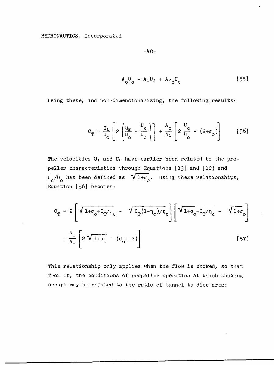
AU = A1 Uj + A2 oUc [55]
Using these, and non-dimensionalizing, the following results:
CT 1 ( + 2 -- (2+a)]CT 5 6]
The velocities U1 and U2 have earlier been related to the pro-
peiLler characteristics through Equat.ons [13] and [12] and
U /U has been defined as nrl+ýo. Using these relationships,co 00
Equation [561 becomes:
CT = 2 +aC l-IC-%±/m 0 T/1PZ1c [-f' -V aT 0CT, c V7CT(!-Tnc)/1ic l + nc 0+1
A1+ •[2 'Vr1+ (y 2)] [57]
This re.ationship only applies when the flow is choked, so that
from it, the conditions of propeller operation at which choking
occurs may be related to the ratio of tunnel to disc area:
WVT)PMA TT'PTfl5 I ~e
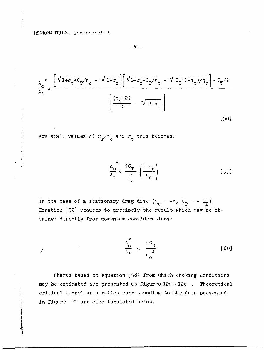
A" 1 C-L0c T•(]TTc)T. .]v,-"..
A1 [F +2)
20
[581
For small values of C,/qc anct o this becomes:
I*
A 4
A, (o f) [59]
In the case of a stationary drag disc (ric = -a; CT = CD),
Equation [59] reduces to precisely the result which may be ob-
tained directly from momentum oonsiderations:
A 4CF
Charts based on Equation [58] from which choking conditions
may be estimated are presented as Figures 12a - 12e Theoretical
critical tunnel area ratios corresponding to the data presented
in Figure 10 are also tabulated below.
SFiur
HYDRONAUTICS, Incorporated
-'T if
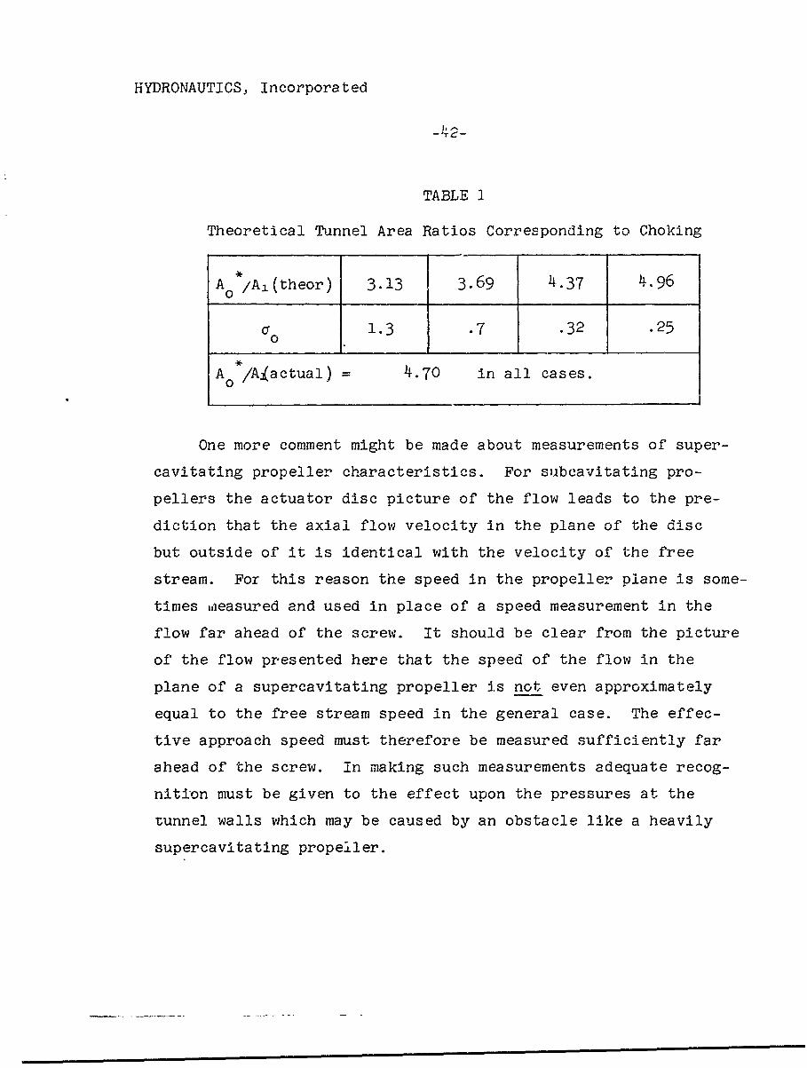
TABLE I
Theoretical Tunnel Area Ratios Corresponding to Choking
A /Al(theor) 3.13 3.69 4.37 4.96
S1.3 .7 .32 .25
A 0 /A~actual) = 4.70 in all cases.
One more comment might be made about measurements of super-
cavitating propeller characteristics. For subcavitating pro-
pellers the actuator disc picture of the flow leads to the pre-
diction that the axial flow velocity in the plane of the disc
but outside of it is identical with the velocity of the free
stream. For this reason the speed in the propeller plane is some-
times uleasured and used in place of a speed measurement in the
flow far ahead of the screw. It should be clear from the picture
of the flow presented here that the speed of the flow in the
plane of a supercavitating propeller is not even approximately
equal to the free stream speed in the general case. The effec-
tive approach speed must therefore be measured sufficiently far
ahead of the screw. In making such measurements adequate recog-
nition must be given to the effect upon the pressures at the
tunnel walls which may be caused by an obstacle like a heavily
supercavitating propeller.
HYDRONAUTIiCS, Incorporated
-43-
SUMMARY AND CONCLUSIONS
Based entirely on momentum and other simple consideratiors
a reasonably complete picture of the one-dimensional pressure and
velocity fields associated with heavily supercavitating propellers
and drag discs has been constructed. The results are summarized
in Figures 3 - 8 .
It is crucial in developing a useful momentum theory for
these flows to take into account the blade cavitational efficiency
(Tic) associated with the disc, since this quantity must be in-
fluential in determining the extent and volume of the cavities
shed by the blades. The opportunity to introduce this quantity
arises naturally since the head increase which occurs across the
disc may be shown to equal the ratio of thrust coefficient (CT)
and T c" It may also be shown, although this is not done here,
that this latter relation for the head increase across the disc
adequately takes into account the effect of the flow rotation
behind the disc.
A momentum balance for the flow within the momentum control
surface shown in FLgure 4 yields a relationship between the inflow
speed and CT, Tcs and a (free stream cavitation number). It is
shown that the flow is very often retarded while approaching a
heavily supercavitating propeller, so that the so-called ideal ef-
ficiency, rji, of such a propeller takes on values in excess •f
unity. The ideal efficiency actually increases with decreasing
blade cavitational efficiency; however, the net efficiency
(TI- *TI) at the same time decreases. This retardation causes a
reduction of thrust deduction, or even a change in its sign
References 8, 18, and 19.
HYDRONAUTICS, Incorporated
-44-
At zero free stream cavitation number (a = 0) the inflow
must always be retprded.
For positive values of a accelerated inflow speeds occur but
ar6 restricted in value by the necessity to maintain pressures in
the inflow higher than cavity pressure. Conditions corresponding
to the limiting inflow speed are estimated. It is shown that an
absolute maximum net efficiency exists corresponding to operation
at this limiting condition. It is noted that these maximum effi-
ciencies imply larger values of )c than have -been realized in
practice, so that they have not so far been approached.
Charts are provided in this report from which the inflow
speed may readily be estimated for use in predicting the perfor-
mance of heavily supercavitating propellers.
In an unbounded stream the cavity length is finite for
a > 0 and is infinite for a = 0. The cavity maximum diameter0 O
is shown in the latter case to be finite only when the inflow and
free stream speeds are identical.
In the case of cavities of finite length, a loss of head
occurs across the region of cavity collapse (plane 3 in Figure 4 )and formulae for the head in the wake are given. This is higher
than the free stream head for a thrusting propeller and lower for
a drag disc. The outflow speed just behind the region of cavity
,collapse is shown to be greater than the inflow speed for all
cases of retarded inflow and for moderate degrees of accelerated
inflow; for sufficiently large thrusts the reverse may be true.
Formulae are given for these outflow speeds.
HYDRONAUTICS, Incorpora ted
-45-
The effects of tunnel boundaries a.'e discussed. Jt is shown
that no corrections to inflow speed are required for a supercavi-
tating propeller operating either in an open jet or between solid
walls; this is somewhat in contrast to the case of the subcavi-
tating propeller for which inflow speeds must be corrected for
the presence of solid walls. The phenomena of tunnel choking is
discussed and momentum considerations are applied to the calcula-
tion of conditions for which infinite cavity length occurs at
positive non-zero (CF > 0) cavitation numbers during operation
between solid walls. A comparison between measured and predicted
values of the critical ratio of tunnel area to screw area is pre-
sented.
The results presented herein make it quite clear that the
distribution of flow velocities and pressure. which attend the
operation of a heavily supercavitating propeller will not at all
correspond to the predictions of theory for subcavitating pro-
pellers. The use of the latter predictions is thus unjustified.
Even for a relatively weakly supercavitating propeller it seems
prrblematical that predictions of inflow speed based on subcavi-
tating propeller theory are useful.
The present theory has assumed a propeller with an infinite
numbe- of blades and one-dimensional flow. These assumptifons are
briefly discussed herein. Phe conditions under which the p::e-
dictions of this theory reasonably apply are not clear, but when
the propeller blade elements operate at loadings such that blade
interference or cascade effects dominate the flow through the
blade, then it seems likely that the present theory provides a
I
HYDRONAUTICS, Incorpora ted
-46-
reasonable approximation to the general features of the real flow.
It would clearly be very useful to obtain some quantitative
experimental evidence relating to the details of the flow field
about supercavitating propellers or drag discs, such as are pre-
dicted by the present theory. It would be particularly useful to
obtain measurements of the inflow speed as a function of CT, V c$
and a
There remain many interesting questions concerning flows
past supercavitating propellers and drag discs which are left for
more elaborate theory to discuss. These include: What is the
relationship between the length of the cavity and CTV 71 c, and a ?;
what shape does the cavity boundary take?; what is the general
asymptotic shape of the cavity for a = 0?; does the flow speed
on the axis of symmetry change monotonically from far upstream to
the disc?; how are the predictions made here modified by a finite
number of blades?; and, what is the optimum distribution of span-
wise loading for a supercavitating propeller?
4
HYDRONAUTICS, Incorporated
-47-
REFERENCES
1. Posdunine, V L., "On the Working of Supercavitating ScrewPropellers," (in English!), Doklady AN SSSR, Vol. XXXIX,No. 8, 1943; Also, Transactions of the Institute of NavalArchitects, Vol. 86, 1944.
2. Posdunine, V. L., "The Construction and Performance ofSupercal'tating Propellers," Izv. OTN AN SSSR, Nos. 1-2, 1945.
3. Posdunine, V. L., "Basic Theory of the Construction andPerformance of Supercavitating Propellers," Izv. OTN AN SSSF,Nos. 10-11, 1945.
4. Tulin, M. P., and Burkar';, N. P., "Linearized Theory forFlows About Lifting Foils at ZEro Cavitation Number, DTMBReport C-638, February 1955.
5. Tachmindji, A. J., Morgan, W. B., Miller, M. L., andHecker, R., "The Design and Performance of SupercavitatingPropellers," DTMB Report C-807, February 1957.
6. Tachmindji, A. J., and Morgan, W. B., "The Design and Esti-mated Perfr:mance of a Series of Supercavitating Propellers,"Proceedings of the 2nd ONR Symposium on Naval Hydrodynamics,(Government Printing Office) Washlington, D. C., 1958.
7. Venning, E., -and Haberman, W. L., "Supercavitating PropellerPerformance," Transactions of the SNAME, Vol. '70, 1962.
8. Tulin, M. P., "Supercavitating Propeller - History, Operating
Characteristics, Mechanism of Operation," Proceedings of the4th (1962) ONR Symposium on Naval Hydrodynamics, (GovernmentPrinting Office) Washington, D. C., 1964.
9. Johnson, C. - A., "Comparison of Propeller Design Techniques,"Proceedings 4th (1962) ONR Symposium on Naval Hydrodynamics,(Government Printing Office) Washington, D. C., 1964.
I
HYDRONAUTICS, Incorporated
-48-
10. Basin, A. M., "On the Theory of the Ideal Cavitating Pro-peller,'" Doklady AN SSSR, Vol. 49, 1945.
11. -Lavrentlyev, V. M., "Theory of the Ideal CavitatingPropeller," Doklady AN SSSR, Vol. 50, 1945.
12. Epshteyn, L. A., "On the Action of the Ideal SupercavitatingPropeller," Inzhenerniy Sbornik, Vol. 9, 1951.
13. Kuichemann, D., and Weber, J., "Aerodynamics of Propulsion,,"McGraw-Hill, New York, 1953.
14. Yim, B., "The Flow Field of an Infinitely Bladed Propellerwith Radially Non-Uniform Loading," HYDRONAUTICS, IncorporatedTechnical Report 005-2, February 1961.
15. Glauert, H., "Airplane Propellers," Vol. IV, AerodynamicTheory, (N. Durand, ed.) Durand Reprinting Committee,Pasadena, California, 19413.
16. Tulin, M. P., "Supercavitating Flows," in Handbook of Fluid'Dynamics, V. Streeter, ed., McGraw Hill, 1961.
17. van de Voorde, C. B., anrd Esveldt, J.., "Tunnel Tests onSupercavitaoting Propellers, " Proceedings of the Fourth (1962)ONR Symposium on Naval Hydrodynamics, (Government PrintingOfficel), Washington, D. Ct,, 1964.
18. Bavin, "V. F., and Miniovich, I. J., "Experimental Investi-gations of Interaction Between Hull and Cavitating Propeller,"Contribution of the LeniZgrad Ship Model Basin, USSR, tothe 10th International Towing Tank Conference, -London,September 1963.
19. Beveridge, J. L., "Induced Velocity Field of a FullyCavitatlng Propeller on interaction Experiments with FullyCavitating Propeller Behind a Hydrofoil," DTMB Report 1832,April 1964.
T- CA- - --
ItI-. E)
_ _..
.....
m A0 x.4 i
2 +
cn
z
03VC8ON s,)nN0(A
-) -------
HYDRONAUTICS.- INCORPORATED
6.0
, 4.0
LL.w CAVITATING INFLOW
I-"cn
1' }.01
S NON-CAVITATING INFLOW
-( u, u
0 1.0 2.0 3.0
00- CAVITATION NUMBER
FIGURE 2 - SUBCAVITATING MOMENTUM THEORY - INFLOW CAVITATION
rno
CC
00
> -m
~--, 'U
GOG
zn
G3w8d8D s(0V~d1,
-- - ~-- - Nc-
ri00
-C-4
ClC
0 Cr4cn a-
I &.J~~r. rrci) .20~ G)~NA1n
Inca.
r- C:A.
03.itdO:N soinV08.-
YI BLADE CAVITATIONqAL EFF -ICIENCY
0.
oo 0z
C:
> 8
0M
0
00
~ I4 G 3 i V 8O d NO 3N l 's 3 Iiuf V N O 8 0 ,
t HYDRONAUTICS. INCORPORATED
?lc LIMITIN3
4.0I
I hFOR-, I
'tHEORE77CAL)
-3.O-
S~2.01.06
AI
0 0.2 0.4 0.6 -0.8 1.0
Tic, BLADE GAVITATIONAL EFFICIENCY
FIGURE 6- LIMITING' 71c VERSUS CT/I t g7o
tHYDRONAUTICS, INCORPORATED-
1.0
1- 0.T o~
z cr
w
0
0.5..2a
CT , THRUST COEFFICIfENT.
FIGURE 7a - INFLOW SPEED;( IDEAL EFFCIENCYF'------ VERSUS THRUST COEFFICIENT;0U 0
0.
0.8
0l 0.5 1.0 1.5 2.0CT, THRUST COEFFICIENT
FIGURE 7b- U,/U 0 VERSUS CT; 0-0 0.10
HYDRONAUTICS, INCORPORATED
0.82I00 0.056.-15 .
CTFIGURE 7c- U,/ Uo VERSUS CT; O' 0.20
1.00.
:5- ID0
0.4.4
.0 0.5 1.0 1.5 2.0CT
FIGURE 7d- U1/Uo VERSUS CT; go= Q040
HYDRONAUTICS, INCORPORATED
00
*1.
.000.5 5101. .
CT
FIGURE 7e- 'iJ/Uo VERSUS CT ;0 = 0.80
IIY =0__ __ __ __ 96___ _ __ _ 1.6__ _ __ _ _ _ _ __ _ _ _
1.6
0 _ _ _ _ _ _ _ _ _ _ _ _ _ _ __ _ _ __ _ __5
I _ _ _ _ _ _ _ _1.4_ _ _
0 _ ___ _
D 1.2 -_ __ __I __ __ __ _ __ __ __ __ __ __ __ _ __ __ __ _ __ __ __ __ _ __ __ __ _ __ __ __ __ _ __ __ ___0.4_ __
0 1. D . 4.0CT
FIGURE 7f - 1J1/U0 VERSUS Cr 0; 1.6
I. G), I T•MAX'MAXIMUM THEORETICAL EFFICIENCY
'--I'1
MAX
C
m
OD
( o N00
m p•
-4
".1
':1
o ob
<m
(1 0o -nI
-n-P1
-4N
-4Z
110___I.1 _ _ _ _OON _ _ _ _ _ . . . . ...
a31,8-d8OODNI
O3LidO~l'SLfV~A
cI
M-(DC
IV))
mC
bm
.............
03V8d1:N 'su..OO
O0, CAVITrATION NUMBER
p 0 p
0m
J- G) fC,0
o >, -51JM Z
r' G)c~
EZ~z
N M
01 RPLEREFCEC
0~.~~~ON 'SmtN8A
-;iC
-c/-- X
THYDRONAUTICS, INCORPORATED
PLANE 0 PLANE I PLANE 2 (AT oo)(AT-0)
UC
I: ' - -- - - - - -. .. ***
242
10 A01 A10
UU
0.
z
~~0.o
CT8HRS0CEFIIN
FIGRE 2o-CHKIN ARA ATIS VRSU TRUS COFFCIET0.4~0ImI400.
HYDRONAUTICS, INCORPORATED
701- _____
00' :0.2 fs.
c~6Cw
4r 4
w4z 30
z
lez u
0
12.
CTHRUST COEFFICIENT
FIGURE 1215- A/7AI VERSUS C, T 0 ro0.2
C 16
t 0.2w
w 0.3z Mow -,__
I- ___ _____ 0.4z0
0 0.4 0.,8 1.2 1.6 2.0CT, THRUST COEFFICIENT
FIGURE 12c- Ao*/A, VERSUS CT ,0o 0.4
HYDRONAUTICS, INCORPORATED
7 11wI
46
ui0.2jw4
zz
z 3-
u 0.4*0 2-
Q6
040.8 1.2 1.6 2.0 2.4CT, THRUST COEFFICIENT
FIGURE 12d- Ao/A, VERSUS -CT go=~ 0.8
w 4- _ _ _ __ _ _ _
go= 1.
-W
zz
0D. . . . .0 2 . . .CT.THRSTCOEFICE3
FIUEIez/ 1 VRU TO .
0.50 0.6 10
i Security, Classification
_DOCUMENT CONTROL-DATA - R&D"(Security claeslfication of title, body of abstract and indexing annotation iuet be entered when the overall report I. ceasitiod)
1. ORIGINATING ACTIVITY (Corpotat. author) ..... t .. mt iUt Z " "i --- , ......S ,.-,,., rLASST,.,..EDHYDHONAUTIfOS, Incorp-:-ated VO, STI- AUHoward 0ounty, Pindell School Road, 2b. -aou
laurel, Maryland.,. REPORT TITL.E
SUPERC.AlITATING PROPELLERS MOMENTJM THEORY
4. DESCRIPTIVE NOTES (Type of port and Inclukiv, date.)
Technical ReportS. AUTHOR(S) (Last name, Brtr nane, Initial)
Tulin, Marshall P.
REPORT DATE 78. TOTAL NO. OF PAGOS 7b. NO. Or REPS
September 1964- 69 19IIa. CONTRACT OR GRANT NO. 94. ORIMNATO0RS REPORT NUM[IEWS)Nonr-3435 (00) . .
S,.OTno.1 (o)Tech.ical Report 121-4.
C. 9b. OTHER ,•POT N•o S) (Any o -ternu-nre fhat may be.soalei.d
d.10. A V A IL AIILTY/LIMITATION kOTICES
I Id.-UPPLEMENTARY NOTES -12. SPONSORING MILITANY ACTIVITY'
Office or Naval Researchi Code 438
,3. ARSTRACT Based entirely on: momentum and other simple considerationsa reasonably complete picture of the one-dimensional pressure andvelocity fields associated with heavily supercavitating propellersard drag discs has been constructed.
it is shown that the flow is very often retarded vlhileapproaching a heavily supercavitating propeller, so that the so-called ideal efficiency of such a propeller takes on values in ex-cess of unity. The ideal efficiency actually inc-eases with de-creasing blade cavitational efficiency; however, the net efficiency8t the same time decreases. This retardation causes a reductionof thrust deduction, or etven a change in its sign. Charts areprovided from which the inflow speed may readily be estimated.
The effect of water tunnel boundaries are discussed,particularly the phenormena of choking.
FORM 17 hTO~F~TDD I JAN °4 1473 D,,JL.NSsSefurity Classification
Security Casfcto114. LINK A- LINK0 I LINK C
KEY WORDS ~-. LjI _ __ __ __ __ __ __ __ __ __ __ __ __ fOL WT ROLE WT R~OLF WT
I Supereavitation1'rop'ellersSupereavitatling PropellersMlomentumi TheoryThrust DeductionIdeal Efficiency
INSTRUCTIONS1. ORIGINATING ACTIVITY: Enter the name and address imposed by security classification, using standard statementsof the contractor, subcontractor. granteel, Department of De- such as:fense activity or other organization (coaj'orate author) Isun (1) "Quaifted requesters may obtain copies of thisthe report. report from DDC."2.L REPORT SECUIITY CLASSIFICATION: Enter the over- (2) "Foreign announcement and dissemination of thisall security classification of the report. Indidcate whether eotyD) sntatoio"Restricted Data" is includd. 'Marking is xo be in accord- rpr-yDCI o uhrzdance with appropriate security regulasti'ons. (3) "U. S. Governmnt* agencies may obtain copies of2b. GROUP. Automatic downgrading In specified In DoDD1 this report directly from DDC. Other qualified DDCrective 5200;lO and Armed Forces Industrial Manual, Entter use shall request throughthe group numbrer. Also, when appliciable, show that optionalmarkings have been used for Group 3 and Groiup 4 'as author- (4) "U. S. military agencies may obtain copies of thisized. report directly from DDC. Other qualified uisers,3. REPORT TITLE: Enter the comeplete report title In all shall r,.quast throughcapital le~ttes Titles in all .cases should be unclassified..9If a metaningful'title cannot bi-sellecled without-classifica- )tion. show'title classification in all capitals In parenthesis (5 All distribution of this report is controlled. Qual-immediately following the title. ified DDC users shall request through4. DESCRIPTIVE -NOTES:* If appropriate, enter the type of_______________ I
report. e6g. Interlm, progress,- summary, annual, or final. It the report has been furnishedlto the Office of TechnicalGivek the inclusive dae-hnaseii rprigpro s Services, Department of Com-merce,'for sale to the public. indi-covered. cate this fact and enter the price, If known.5. AUTHDIR(S): :Enter the name~s),of author(s) as shown on 1L SUiPPLEMENTARY NOTES: Use for additional explana-orinthe rep'ort. Ester last name, first-name, middile Initial.If military, show rank sand branch of service. The name of tYnts-the principal. auth~t is an absolute minimumt requirelmebt. 12. SPONSORING MILITARY ACTIVITY: Enter the name of6. REPCORT DATE: Enter the date of the report as day, the departmental, project office or laborstory sponsoring (pay-
mont, rst; r mnth, yer. f moe tan oe dte epeaa ng for) the research and development. Include add-elss.on the report, use date of publicatiou. 1 13. ABSTRACT: Enter an abstract giving a brief and factual
7a TTAL UMBR OFPAGE ri totl pae cunt ummry of the document indticative of the report. even though7a. DTA NUBER-F PGE&Thetota pae cunt It may also appear elsewhere in the body of the technical to-sho)uldiodllow no mal pagination procedures. L e., enter the par. If additional space In reqttired, a continuation sheet shall'number 6f~poges 4.ontaining inormation. be attached.76. NUMBER OF REFERENCES: Enter the total nwnbat of It is hilghly deslrnble that the abstract of classified reportsreferences cited in the report. be unclassified. Each Paragraph of the abstract shall end withSe. CONTRACT OR GRANT NUMBER. If appropriate, enter an Indication of the military security classification of the in-the applicable number of the contract or grant under which formation In the paragraph, represented as (Ts), (S). (C). or (U,).the report was written. There In no limitation on the length of the abstract. How-9b, Sa, & "~ PRtOJECT NUMBER Eater the appropriate ever. the suggested length in from.150 to 225 words.military department identification. such as projeict number, 14 OD:Kywrsaetcnclymaigu emsubproject ntamber, system numbers, task number, otc.14 MWOD:Kywrsaetcnalym nigutrs
or short phrases that- characterize a report and may be used as9a. ORIGINATOR'S REPORT NUMBER(S): Eater the offi- index entries for cataloging the report. Key worda m ust becial report-number by which the document will be Identified selected so that no security classification :iirequired. identi-and controlled by the originating activity. This -umber must fiers, such as equipment model designation, trade name. militarybe unique to this repomt project code name, geographic location, may be used as key9b. OTHER REPORT NUMBER(S): If th reor has bee words but will be followed by an indication of technical con-assigned any other report numbers (either by the origilnator text. The assignment of links, railes, and weights is optional.or by the spontsor), also enter this number(s).10. AVAILABILITY/LIMI1TATIN NOTICES: Enter any lira-
:itations. an further dissemination of the re~port, other than those
DD I AN 4 1473 (BAC t) tThOASS_- UIs KSecurity S-sfcta

HYDRONAUTICS, Incorporated
IDISTRIBUTION LIST
(Contract Nonr-3435(00))
Chief of Naval Research DirectorDepartment of the Navy U. S. Naval Research LaboratoryWashington 25, D. C. Washington 25, D. C.Attn: Codes 438 3 Attn: Code 2027 6
461 1463 1 Chief, Bureau of Naval Weapons466 1 Department of the Navy
Washington 25, D. C.Commanding Officer Attn: Codes RUTO-32 IOffice of Naval Research RRRE 1Branch Office RAAD 1.4_95 Summer Street RAAD-222 1
Boston 10, Massachusetts 1 DIS-42 1
Commanding Officer Chief- Bureau of ShipsOffice of Naval Research Department of the NavyBranch Office Washington 25, D. C.207 West 24th Street Attn: Codes 310 1New York 11, New York 1 312 1
335 1Commanding Officer 420 1Office of Naval Research 421 1.Branch Office 4-0 11030 East Green Street 442 1?asadena, California 2 449 1
436 2Commanding OfficerOffice of Naval Research Chief, Bureau of Yards and DocksBranch Office Department of the Navy1000 Geary Street Washington 25, D. C.San Francisco 9, California I Attn: Code D-400 1
Cormranding Officer CommanderOffice of Naval Research U. S. -Naval Ordnance Test StationBranch Office China Iake, California
Box 39, Navy No. 100 Attn: Code 753 1Fl-eet Post OfficeNew York, New York 25
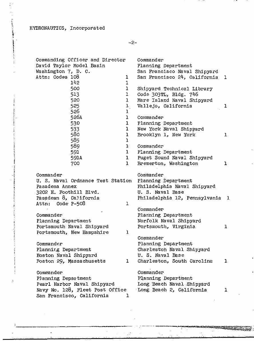
HYDRONAUTICS, Incorpora ted
Commanding Officer and Director CommanderDavid Taylor Model Basin Planning DepartmentWashington 7, D. C. San Francisco Naval ShipyardAttn: Codes 108 1 San Francisco 24, California 1
1.42 1500 1 Shipyard Technical Library513 1 Code 303TL, Bldg. 746520 1 Mare Island Naval Shipyard525 1 Vallejo, California 1526 1526A 1 Commander530 1 Planning Department533 1 New York Naval Shipyard580 1 Brooklyn 1, New York 1585 1589 1 Commander591 1 Planning Department591A 1 Puget Sound Naval Shipyard700 1 Bremerton, Washington 1
"Commander CommanderU. S. Naval Ordnance Test Station Planning .DepartmentPasadena Annex Philadelphia Naval Shipyard3202 E. Foothill Blvd. U. S. Naval BaseSPasadean 8, Ca ifornia Philadelphia 12, Pennsylvania 1
Attn: Code P-508 1Commander
Commander Planning DepartmentPlanning Department Norfolk Naval ShipyardPortsmouth Naval Shipyard Portsmouth, Virginia 1Portsmouth, New Hampshire 1
CommanderCommander Planning DepartmentPlanning Department Charleston Naval ShipyardBoston Naval Shipyard U. S. Naval BasePoston 29, Massachusetts 1 Charleston, South Carolina 1
Commander CommanderPlanning Department Planning DepartmentPearl Harbor Naval Shipyard Long 'Beach Naval -ShipyardNavy No. 128, Fleet Post Office -Long Beach 2, GaliftrniaSan Francisco, California 1

II
HYDRONAUTICS, Incorporated
-3- 1I
Commander U. S. Maritime Administr~ationPlanning Department GAO BuildingU. S. Naval Weapons Laboratory 441 G. Street, N. W. IDahlgren, Virginia 1 Washington, D. C.
Attn: Div. of Ship Design 1Commander Div. of Research 1U. S. Naval Ordnance LaboratoryWhite Oak, Maryland 3. Superintendent
U. S. Merchant Marine AcademyDr. A. V. Hershey Kings Point, Long Island,Computation and Exterior New York
Ballistics Laboratory Attn: CAPT L. S. McCreadyU. S. Naval Weapons Laboratory (Dept. of Engr.) 1Dahlgren, Virginia 1
Commanding Officer and DirectorSuperintendent U. S. Navy Mine Defense Lab.
U. S. Naval Academy Panama City, Florida 1Annapolis, MarylandAttn: Library 1 Commanding Officer
NROTC and Naval Adm. UnitSuperintendent Massachusetts Institute ofU. S. Naval Postgraduate School TechnologyMonterey, California 1 Cambridge 39, Massachusetts 1
Commandant b. S. Army TransportationU. S. Coast Guard Research and Dev. Command1300 E. Street, N. W. Fort Eustis, VirginiaWashington, D. C. 1 Attn: Marine Transport Dii. 1
Secretary Ship Structure Mr. J. B. ParkinsonCommittee National Aeronautics and
U. S. Coast Guard Headquarters Space Administration1300 E. Street, N. W. 1512 H. Street, N. W.Washington, D. C. 1 Washington 25, D. C. 1
CommanderMilitary Sea Trans. ServiceDepartment of the NavyWashington 25, D. C. 1

HYDRONAUTICS, Incorporated
-4-
Director DirectorLangley Research Center Scripps Institute of OceanographyLangley Station University of CaliforniaHampton, Virginia La Jolla, California 1Attn: Mr. I.E. Garrick 1
Mr. D.J. Marten 1 Professor M. L. AlbertsonDepartment of Civil Engineering
Director Colorado A and M CollegeEngineering Sciences Division Fort Collins, Colorado 1National Science Foundation1951 Constitution Ave., N. W. Professor J. E. CermakWashington 25, D. C. 1 Department of Civil Engineering
Colorado State UniversityDirector Fort Coilins, Colorado 1National Bureau of StandardsWashJngton 25, D. C. Professor W. R. SearsAttn: Fluid Mechanics Division Graduate School or Aeronautical
(Dr. G.B. Schubau'r) 1 EngineeringDr. G.H. Keulegan 1 Cornell UniversityDr. J.M. Franklin 1 Ithaca, New York 1
Defense Documentation Center State University of IowaCameron Station Iowa Institute of HydraulicAlexandria, Virginia 20 Research
Iowa City, IowaOffice of Technical Services Attn: Dr. H. Rouse 1Department of Commerce Dr. L. Landweber 1Washington 25, D. C. 1
Harvard UniversityCalifornia Institute of Cambridge 38, Massachusetts
Technology Attn: Professor G. BirkhoffPasadena 4, California (Dept. of Mathematics) 1Attni Professor M.S. Plesset 1 Professor G.F. Carrier
Professor T. Y. Wu 1 (Dept. of Mathematics) 1Professor A.J. Acosta 1
Massachusetts Institute ofUniversity of California TechnologyDepartment of Engineering Cambridge 39, MassachusettsLos Angeles 24, California Attn: Professor A.T. IppenAttn: Dr. A. Powell 1 (Dept of Naval Arch.
and Marine Engr.) 1

fYDRONAUTICS, Incorporated
-5--
University of Michigan Dr. G. F. WislicenusAnn Arbor, Michigan Ordnance Research LaboratoryAttn: Professor R.B. Couch Pennsylvania State University
(Dept. of Naval Arch.) 1 University Park, Pennsylvania 1Professor W.W. Willmarth Attn: Dr. M. Sevik I(Aero Engr. Dept.) 1
Professor h. C. DiPrimaDr. L. G. Straub, Director Department of MatbematicsSt. Anthony Falls Hydraulic Lab. Rensselaer Polytechnic InstituteUniversity of Minnesota Troy, New York 1Minneapolis 14, Minnesota 1Attn: Mr. J.N. Wetzel 1 Stevens Inst+tute of Technology
Professor B.Silberman I Davidson LaboratoryCastle Point Station
Professor J. J. Foody Hoboken, New JerseyEngineering Department Attn: Mr. D. Savitsky 1New York State University Mr. J. P. Breslin 1
Maritime College Mr. C. J. Henry 1Fort Schulyer, New York I Mr. S. Tsakonas 1
New York University Webb Institute of Navalinstitute of Mathematical Architecture
Sciences Crescent Beach Road25 Waverly Place Glen Cove, New YorkNew York 3, New York Attn: Professor E.V. Lewis 1Attn: Professor J. Keller 1 Technical Library 1
Professor J.J. Stoker 1Director
The Johns Hopkins University Woods Hole Oceanographic Inst.Department of Mechanical Engr. Woods Hole, Massachusetts IBaltimore 18, MarylandAttn: Professor S. Corrsin 1 Executive Director
Professor O.M. Phillips 2 Air Force Office ofScientific Research
Massachusetts Institute of Tech. Washington 25, D. C.Department of Naval Archi- Attn: Mechanics Branch 1
tecture and Marine Engr.Cambridge 39, Massachusetts CommanderAttn: Prof. M.A.Abkowitz 1 Wright Air Development Division
Aircraft LaboratoryWright-Patterson Air Force
Base, OhioAttn: Mr. W. Mykytow,
DDynamics Branch 1
I1

HYDRONAUTICS, Incorporated
Cornell Aeronautical Laboratory Skipsmodelltanken4455 Genesee Street Trondheim., NorwayBuffalo, New York Attn: Professor J.K. Lunde 1Attn: Mr. W. Targoff 1
Mr. R. White 1 Versuchsanstalt fur Wasserbauund Schiffbau
Massachusetts Institute of Tech. Schleuseninsel im TiergartenFluid Dynamics Research Lab. Berlin, GermanyCambridge 39, Massachusetts Attn: Dr. S. Schuste-, Dir. 1Attn: Professor H. Ashley I Dr. Grosse 1
Professor M. Landahl 1
Professor J. Dugundji 1 Technische HogeschoolInstitut voor Toegepaste
Hamburgische Schiffbau- WiskundeVersuchsanstalt Julianalaan 132Bramfelder Strasse 164 Delft, NetherlandsHamburg 33, Germany Attn: Professor R. Timman 1At-.,: Dr. H. W. Lerbs 1
Bureau D'Analyse et de RechercheInstitut fur Schiffbau der AppliqueesUniversitat Hamburg 47 Avenue Victor CressonLammersieth 90 Issy-Les-MoulineauxHamburg 33, Germany Seine, FranceAttn: Professor 0. Grim 1 Attn: Professor Siestrunck 1
Prof. K. Wieghardt 1Netherlands Ship Model Basin
Tr'ansportation Technical Wageningen, The NetherlandsResearch Institute Attn: Dr. Ir.J. D. Van Manen 11-1057, Mejiro-Cho, Toshima-KuTokyo, .,Japan 1 National Physical Laboratory
' Teddington, Middlesex, England,Max-Plack Institute fur Attn: Mr. A. Silverleaf,Stromung forschung Superintendent Ship Div. 1Bottingerstrasse 6/8 Head, Aerodynamics Div. 1Gottingen, GermanyAttn: Dr. H. Reichardt 1 Head, Aerodynamics Department
Royal Aircraft EstablishmentHydro-og Aerodynamisk Farnborough, Hants, EnglandLaboratorium Attn: Mr. M.O.W. Wolfe 2
Lyngby, DenmarkAttn: Prof. Carl Prohaska 1
Ii__
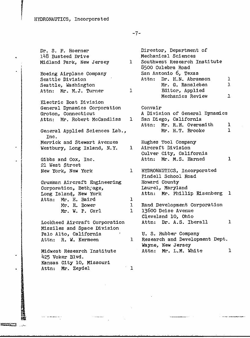
HYDRONAUTICS, Incorporated
-7-
Dr. S. F. Hoerner Director, Department of148 Busteed Drive Mechanical SciencesMidland Park, New Jersey 1 Southwest Research Institute
8500 Culebra RoadBoeing Airplane Company San Antonio 6, TexasSeattle Division Attn: Dr. H.N. Abramson 1Seattle, Washington Mr. G. Ransleben 1Attn: Mr. M.J. Turner 1 Editor, Applied
Mechanics ReviewElectric Boat DivisionGeneral Dynamics Corporation ConvairGroton, Connecticut A Division of General DynamicsAttn: Mr. Robert McCandliss 1 San Diego, California
Attn: Mr. R.H. OversmithGeneral Applied Sciences Lab., Mr. H.T. Brooke
Inc.Merrick and Stewart Avenues Hughes Tool CompanyWestbury, Long Island, N.Y. 1 Aircraft Division
Culver City, CaliforniaGibbs and Cox, Inc. Attn: Mr. M.S. Harned21 West StreetNew York, New York 1 HYDRONAUTICS, Incorporated
Pindell School RoadGrumman Aircraft Engineering Howard CountyCorporation, Bethpage, Laurel, MarylandLong Island, New York Attn: Mr. Pbillip Eisenberg 1Attn: Mr. E. Baird 1
Mr. E. Bower 1 Rand Development CorporationMr. W. P. Carl 1 13600 Deise Avenue
Cleveland 10, OhioLockheed Aircraft Corporation Attn: Dr. A.S. Iberall 1Missiles and Space DivisionPalo Alto, California U. S. Rubbeir CompanyAttn: R. W. Kermeen 1 Research and Development Dept.
Wayne, New JerseyMidwest Research Institute Attn: Mr. L.M. White425 Voker Blvd.Kansas City 10, MissouriAttn: Mr. Zeydel 1
IIYDRONAIPTICS, Incorporated
S•-8 -
Technical Research Group, Inc. Lockheed Aircraft CorporationRoute 110 California DivisionMelville, New York Hydrodynamics ResearchAttn: Dr. Jack Kotik I Burbank, California
Attn;, •r. Bill East IMr. C. WigleyFlat 102 National Research Council6-9 Charterhouse-Square Montreal RoadLondon, E.C. 1, England 1 Ottawa 2, Canada
Attn: Mr. E.S. TurnerAVCO CorporationLycoming Division The Rand Corporation1701 K. Street, N. W. 1700 Main StreetApt. 904 Santa Monica, CaliforniaWashington, D. C. Attn: Technical Library 1Attn: Mr. T.A. Duncan 1
Stanford UniversityMr. J. G. Baker Department of Civil EngineeringBaker Manufacturing Company Stanford, CaliforniaEvansville, Wisconsin 1 Attn: Dr. Byrne Perry
Dr. E. Y. Hsui1Curtis-Wright CorporationResearch Division Dr. Hirsh CohenTurbomachinery Division IBM Research CenterQuehanna, Pennsylvania P. 0. Box 218Attn: Mr. George H. Pedersen 1 Yorktown Heights, New York 1
Dr. Blaine R. Parkin Mr. David WellingerAiResearch Mar:ufacturing Corp. Hydrofoil Projects9851-9951 Sepulveda Boulevard Radio Corporation of AmericaLos Angeles 45, California 1 Burlington, Massachusetts 1
The Boeing Company Food Machinery CorporationAero-Space Division P. 0. Box 367Seattle 24., Washington San Jose, CaliforniaAttn, Mr. R.E. Bateman Attn: Mr. G. Tedrew 1
(Internal Mail Station46-74) i
- --

HYDRONAUTI'S, Incorporated
-9-
Dr. T. R. Goodman Professor BrunelleOceanics, Incorporated Department of Aeronautical Engr.Technical Industrial Park Princeton UniversityPlainview, Long Island, Princeton, New JerseyNew York 1
National Academy of ScienceCommanding Officer National Research CouncilOffice of Naval Research Committee on Undersea WarfareBranch Office 2101 Constitution Avenue230 N. Michigan Avenue Washington 25, D. C.Chicago 1, Illinois 1
Dr. Harvey BrooksProfessor J. William Holl School of Applied ScienceDept. of Aeronautical Engr. Harvard UniversityThe Pennsylvania State Univ. Cambridge, Massachusetts 1Ordnance Research LaboratoryP. 0. Box 30State College, Pennsylvania 1
II