Embed Size (px)
Citation preview

HYDROMETALLURGICAL PROCESSING OF LATERITIC NICKEL
ORES
A THESIS SUBMITTED TO
THE GRADUATE SCHOOL OF NATURAL AND APPLIED SCIENCES
OF
MIDDLE EAST TECHNICAL UNIVERSITY
BY
CANER HAKKI KÖSE
IN PARTIAL FULFILLMENT OF THE REQUIREMENTS
FOR
THE DEGREE OF MASTER OF SCIENCE
IN
METALLURGICAL AND MATERIALS ENGINEERING
AUGUST 2010

Approval of the thesis:
HYDROMETALLURGICAL PROCESSING OF LATERITIC NICKEL ORES
submitted by CANER HAKKI KÖSE in partial fulfillment of the requirements
for the degree of Master of Science in Metallurgical and Materials Engineering
Department, Middle East Technical University by,
Prof. Dr. Canan Özgen ____________
Dean, Graduate School of Natural and Applied Sciences
Prof. Dr. Tayfur Öztürk ____________
Head of Department, Metallurgical and Materials Engineering
Prof. Dr. Yavuz A. Topkaya ____________
Supervisor, Metallurgical and Materials Engineering Dept., METU
Examining Committee Members:
Prof. Dr. Naci Sevinç __________________
Metallurgical and Materials Engineering Dept., METU
Prof. Dr. Yavuz A. Topkaya __________________
Metallurgical and Materials Engineering Dept., METU
Prof. Dr. Abdullah Öztürk __________________
Metallurgical and Materials Engineering Dept., METU
Prof. Dr. İshak Karakaya __________________
Metallurgical and Materials Engineering Dept., METU
Prof. Dr. Çetin Hoşten __________________
Mining Engineering Dept., METU
Date: 18.08.2010

iii
Signature :
I hereby declare that all information in this document has been obtained
and presented in accordance with academic rules and ethical conduct. I
also declare that, as required by these rules and conduct, I have fully cited
and referenced all material and results that are not original to this work.
Name, Last name : Caner Hakkı Köse

iv
ABSTRACT
HYDROMETALLURGICAL PROCESSING OF LATERITIC NICKEL
ORES
Köse, Caner Hakkı
M.Sc., Department of Metallurgical and Materials Engineering
Supervisor: Prof. Dr. Yavuz A. Topkaya
August 2010, 178 pages
The objective of this thesis study is to recover nickel and cobalt at maximum
efficiency from column leach liquor of lateritic nickel ores existing in Gördes
region of Manisa by performing various hydrometallurgical methods under
the optimum conditions. This column leach solution of nontronite type
lateritic nickel ore was initially neutralized and purified from its basic
impurities by a two stage iron removal process under the optimum conditions
determined experimentally. Then, nickel and cobalt were precipitated in the
form of mixed hydroxide precipitate from the purified leach solution by a two
stage precipitation method called “MHP” and a manganese removal process
was carried out also under the optimum conditions determined. By decreasing
Mn concentration with this process to an acceptable level yielding at most
10% Mn in hydroxide precipitate, it was possible to produce a qualified MHP
product suitable to the current marketing and standard conditions.
v
As a result of this thesis study, the experiments conducted showed that by
recycle leaching with sulfuric acid about 81% of Ni and 63% of Co in the
lateritic nickel ore (9.72 kg Ni / ton of ore and 0.28 kg Co / ton of ore) could
be extracted as mixed hydroxide precipitate by MHP method. The MHP
product contains 41.9% Ni, 1.0% Co, 2.3% Mn, 0.06% Al, 1.5% Mg, 0.02%
Fe, 0.01% Cr, 0.25% Zn, 0.03% Cu and 4.73% S.
Keywords: Nickel, cobalt, nontronite, leach, MHP.

vi
ÖZ
LATERİTİK NİKEL CEVHERLERİN HİDROMETALURJİK PROSES
EDİLMESİ
Köse, Caner Hakkı
Yüksek Lisans, Metalurji ve Malzeme Mühendisliği Bölümü
Tez Yöneticisi: Prof. Dr. Yavuz A. Topkaya
Ağustos 2010, 178 sayfa
Bu tez çalışmasının amacı, Manisa’nın Gördes bölgesinde bulunan lateritik
nikel cevherlerinin kolon liç çözeltisinden en uygun koşullarda çeşitli
hidrometalurjik metotlar uygulayarak maksimum verimde nikel ve kobalt elde
etmektir. Nontronit tipte lateritik nikel cevherinin bu kolon liç çözeltisi ilk
başta nötrleştirilmiş ve iki aşamalı bir demir arıtma prosesi ile deneysel olarak
belirlenen en uygun şartlarda ana kirletenlerinden arındırılmıştır. Daha sonra,
yine belirlenen en uygun şartlarda nikel ve kobalt arıtılmış liç çözeltisinden
karışık hidroksit çökelek şeklinde “MHP” denen iki aşamalı bir çöktürme
metodu ile çöktürülmüş ve bir manganez arıtma prosesi gerçekleştirilmiştir.
Bu prosesle Mn konsantrasyonu kabul edilebilir düzeye düşürüp hidroksit
çökelekte en fazla %10 Mn sağlayarak, şu anki piyasaya ve standart koşullara
uygun kaliteli bir MHP ürünü üretmek mümkün olmuştur.

vii
Bu tez çalışmasının sonucu olarak, yürütülen deneyler sülfürik asitle olan
yeniden kazanımlı liç ile lateritik nikel cevherindeki yaklaşık %81 Ni ve %63
Co’nun (9,72 kg Ni / ton cevher ve 0,28 kg Co / ton cevher) karışık hidroksit
çökelek olarak MHP metodu ile elde edilebileceğini göstermiştir. MHP ürünü
%41,9 Ni, %1,0 Co, %2,3 Mn, %0,06 Al, %1,5 Mg, %0,02 Fe, %0,01 Cr,
%0,25 Zn, %0,03 Cu ve %4,73 S içerir.
Anahtar Kelimeler: Nikel, kobalt, nontronit, liç, MHP.

viii
To My Family

ix
ACKNOWLEDGEMENTS
I would like to express my deepest appreciation to my supervisor Prof. Dr.
Yavuz A. Topkaya for his kind supervision, guidance, assistance, criticism,
encouragements, patience, discipline and insight throughout this study.
I must express my special thanks to Kerime Güney for doing the chemical
analyses during this study. I am thankful to METU Metallurgical and Materials
Engineering Department for performing the X-ray analyses.
I wish to acknowledge the support for chemical analyses by XRF provided by
META Nikel Kobalt A.Ş. I also thank to METU Central Laboratory personnel for
conducting the DTA-TGA analyses.
Finally, I would like to express my deepest gratitude to Merve Ulum, Özer,
İbrahim Taner, Nesrin and Ali Yılmaz Köse for their endless love and support
during my life.
This study was supported by The Scientific and Technical Research Council
of Turkey (TÜBİTAK). Project No: 106M079.

x
TABLE OF CONTENTS
.............................................................................................................iv
............................................................................................................................vi
......................................................................................ix
..........................................................................................x
.................................................................................................xiii
..............................................................................................xvii
CHAPTERS
1 INTRODUCTION................................................................................................1
2 LITERATURE REVIEW.....................................................................................4
2.1 Nickel and Its Properties.................................................................................4
....................................................................6
............................................................................................10
....................................................................12
....................................................................................................15
.................................................................................15
..................................................................15
...............................................................................................19
................................23
....................................................................24
2.2 Uses and Consumption of Nickel
2.3 Origin of Nickel
2.7 Nickel Extraction Methods from Lateritic Nickel Ores
2.4 Nickel and Associated Minerals
2.5 Nickel Ores
2.6 Nickel Reserves
2.5.1 Sulfide Nickel Ores
2.5.2 Oxide (Lateritic) Nickel Ores
2.7.1 Pyrometallurgical Processes
ABSTRACT
ÖZ
ACKNOWLEDGEMENT
TABLE OF CONTENTS
LIST OF TABLES
LIST OF FIGURES
xi
..................................................................27
2.7.2.1 Caron Process.................................................................................29
..........................................30
2.7.2.3 Atmospheric Pressure Acid Leaching............................................36
....................43
.............................................................46
...........................................48
............................................49
.........................................................50
...................................................55
3 EXPERIMENTAL MATERIALS AND METHODS.......................................74
........................................................................................................74
..........................................................................................75
3.1.1.1 Physical Characterization...............................................................75
..............................................................76
3.1.1.3 Mineralogical Characterization......................................................77
3.2 Methods........................................................................................................79
....................................................................................79
................................................................80
..........................82
.....................................................85
................................................86
3.2.3.3 First Mixed Hydroxide Precipitation (MHP1) Experiments..........87
......88
......................................89
.................................................91
.........................................................................................91
4 RESULTS AND DISCUSSION........................................................................92
........................................................................................93
..............................................................................................94
.........................................................96
2.7.2.2 High Pressure Acid Leaching (HPAL)
4.1.2 Effect of Precipitation Temperature
4.1.1 Effect of pH
3.2.3 Downstream Nickel and Cobalt Recovery Experiments
3.2.2 Column Leaching Experiments
3.2.1 Material Sampling
2.8.5 Mixed Hydroxide Precipitation (MHP)
3.1.1 Nontronite Ore
2.8.4 Mixed Sulfide Precipitation (MSP)
2.8.3 Molecular Recognition Technology (MRT)
2.8.2 Ion Exchange (IX) and Resin-In-Pulp (RIP)
2.8.1 Direct Solvent Extraction (DSX)
2.7.2 Hydrometallurgical Processes
4.1 First Iron Removal
3.3 Chemical Analysis
3.1 Materials
2.8 Nickel Extraction Methods for Nickel Laterite Leach Liquors
3.1.1.2 Chemical Characterization
3.2.3.1 First Iron Removal Experiments
3.2.3.2 Second Iron Removal Experiments
3.2.3.4 Second Mixed Hydroxide Precipitation (MHP2) Experiments
3.2.3.5 Manganese Removal (MnR) Experiments
3.2.3.6 Magnesium Removal Experiments

xii
..............................................................98
.................................................................................103
...........................................................................................104
.......................................................110
............................................................112
............................................118
...........................................................................................119
......................................................123
............................................................125
........................................133
...........................................................................................134
..135
4.5 Manganese Removal (MnR).......................................................................145
...........................................................................................145
.......................................................147
............................................................148
5 CONCLUSIONS..............................................................................................154
REFERENCES.....................................................................................................158
APPENDICES
A. EXAMPLE OF PRECIPITATION RECOVERY CALCULATION.............173
B. EXAMPLE OF TOTAL EXTRACTION RECOVERY CALCULATION...175
4.4.1 Effect of pH
4.4.2 Effect of pH, Precipitation Temperature and Duration Combinations
4.5.1 Effect of pH
4.5.2 Effect of Precipitation Temperature
4.5.3 Effect of Precipitation Duration
4.3.3 Effect of Precipitation Duration
4.3.2 Effect of Precipitation Temperature
4.3.1 Effect of pH
4.2.3 Effect of Precipitation Duration
4.2.2 Effect of Precipitation Temperature
4.2.1 Effect of pH
4.1.3 Effect of Precipitation Duration
4.4 Second Mixed Hydroxide Precipitation (MHP2)
4.3 First Mixed Hydroxide Precipitation (MHP1)
4.2 Second Iron Removal

xiii
LIST OF TABLES
............................11
....................................................................13
.........................................20
...............................................21
.........................................22
.....................24
.....................................................54
....................................................68
........................75
...........................................76
..............77
...................................................91
..........................................94
......................................................97
.......................................................99
.....................................101
.............................................103
Average nickel content as wt% for some rock types [4]
TABLES
Precipitation recoveries with respect to precipitation duration at pH 2.50
and 90oC of precipitation temperature
Nickel bearing minerals [1, 4]
World nickel reserves as contained nickel [21]
Turkey nickel reserves, tons of ore [22, 23]
World nickel mine production, by country [24]
Elemental compositions (%) of some nickeliferous laterites with their
extraction methods used in nickel producing industries [25]
Typical MSP product composition [69]
Typical MHP product composition [69]
Physical analysis of the representative nontronite ore [99]
Wet screen analysis results of nontronite [99]
Chemical analyses of representative nontronite ore as wt% [99]
Chemical analysis of PLS stock by AAS
Precipitation recoveries with respect to pH of PLS at 90oC of precipitation
temperature and 2-hour precipitation duration
Precipitation recoveries with respect to precipitation temperature at pH
2.50 and 2-hour precipitation duration
Composition analysis of the precipitate produced from the PLS by the first
iron removal process at the optimum conditions
Chemical analysis by AAS of the new PLS stock produced by the first iron
removal process at the optimum conditions
Table 4.5
Table 4.4
Table 4.3
Table 4.2
Table 4.1
Table 3.4
Table 3.3
Table 3.2
Table 3.1
Table 2.8
Table 2.7
Table 2.6
Table 2.5
Table 2.4
Table 2.3
Table 2.2
Table 2.1

xiv
...................................105
...................................105
...................................105
...............................................110
....................................................113
........................115
....................................117
..............................................................................119
...............................................123
....................................................125
........................................127
...................128
..........................................................................132
..............134
Table 4.7
Precipitation recoveries with respect to pH of PLS at 90oC of precipitation
temperature and 1 hour of precipitation duration
Table 4.6
Precipitation recoveries with respect to pH of PLS at 70oC of precipitation
temperature and 1 hour of precipitation duration
Table 4.8
Precipitation recoveries with respect to pH of PLS at 25oC of precipitation
temperature and 1 hour of precipitation duration
Table 4.9
Precipitation recoveries with respect to precipitation temperature at pH
4.25 and 1 hour of precipitation duration
Table 4.10
Precipitation recoveries with respect to precipitation duration at pH 4.25
and 70oC of precipitation temperature
Table 4.11
Composition analysis of the precipitate produced from the PLS by the
second iron removal process at the optimum conditions
Table 4.12
Chemical analysis by AAS of the new PLS stock produced by the second
iron removal process at the optimum conditions
Table 4.13
Precipitation recoveries with respect to pH of the PLS and the volume of
the MgO slurry added at 50oC of precipitation temperature and 1 hour of
precipitation duration
Table 4.14
Precipitation recoveries with respect to precipitation temperature at pH
7.00 and 1 hour of precipitation duration
Table 4.15
Precipitation recoveries with respect to precipitation duration at pH 7.00
and 50oC of precipitation temperature
Table 4.16
Composition analysis of the mixed hydroxide precipitate produced from
the PLS by MHP1 at the optimum conditions
Table 4.17
Extraction and precipitation recoveries from the run of mine nontronite
ore (-2 cm) up to the saleable Ni-Co hydroxide product after the column
leach, the first and the second iron removal and the MHP1
Table 4.18
Chemical analysis by AAS of the new PLS stock produced by MHP1 at
the optimum conditions
Table 4.19
Precipitation recoveries with respect to pH of the leach liquor at 60oC of
precipitation temperature and 1 hour of precipitation duration

xv
..............................................................................136
......................................................138
....140
......................................144
..............................................................................146
..............................................................................147
.............................................................................................148
...............................................................................................149
...............................................................................................153
................................................................................173
............176
Table 4.20
Precipitation recoveries at pH 7.50 and 50oC of precipitation temperature
and at pH 7.75 and 60oC of precipitation temperature with respect to
precipitation duration
Table 4.21
Precipitation recoveries at pH 7.50 and 60oC of precipitation temperature
with respect to precipitation duration
Table 4.22
Composition analysis of the hydroxide precipitate produced from the
residual solution of the MHP1 by MHP2 at the optimum conditions
Table 4.23
Chemical analysis by AAS of the new residual leach solution stock
produced by MHP2 at the optimum conditions
Table 4.24
Precipitation recoveries of manganese and nickel with respect to pH of
the barren liquor at 50oC of precipitation temperature and 1 hour of
precipitation duration
Table 4.25
Precipitation recoveries of manganese and nickel from the barren solution
with respect to precipitation temperature at pH 8.50 and 1 hour of
precipitation duration
Table 4.26
Precipitation recoveries of manganese and nickel from the barren solution
with respect to precipitation duration at pH 8.50 and 50oC of precipitation
temperature
Table 4.27
Composition analysis of the manganese precipitate produced from the
barren solution by the manganese removal process at the optimum
conditions
Table 4.28
Chemical analysis by AAS of the solution which would be used as make-
up water for column or recycle leaching produced from the barren
solution by the manganese removal process operated at the optimum
conditions
Table A.1
Experimental data obtained from the AAS analysis of the PLS and XRF
analysis of the precipitate produced by the first iron removal at the
optimum conditions
Table B.1
Extraction and precipitation recoveries from the run of mine nontronite
ore (-2 cm) up to the saleable Ni-Co hydroxide product after the column
leach, the first and the second iron removal, MHP1 and MHP2

xvi
...........................................................................................177
................................................................................178
Table B.2
Total extraction recoveries of nickel from the run of mine nontronite ore
(-2 cm) up to the saleable Ni-Co hydroxide product with respect to
number of recycle leach of the precipitates produced by only the second
iron removal
Table B.3
Total extraction recoveries of nickel from the run of mine nontronite ore
(-2 cm) up to the saleable Ni-Co hydroxide product with respect to
number of recycle leach of the precipitates produced by the second iron
removal and MHP2

xvii
LIST OF FIGURES
Nickel use 2006 by sector (Pariser, 2007) [7]...........................................
First use of primary nickel in 2006 (Eramet Ni Research, INSG) [8]......
Nickel end use 2003 by (The Weinberg Group LLC, Inco) [9]................
Nickel prices between 1999 and 2010 [11]...............................................
World primary nickel balance 1990-2006 (INSG) [8]............................
World primary nickel production & consumption 2004-2009 (INSG)
[12]..........................................................................................................
Idealized section of a nickeliferous laterite formation [19]....................
Nickeliferous laterite profiles [17]..........................................................
World distributions of nickel resources [5].............................................
Laterite and sulfide type nickel ores in nickel pyrometallurgy..............
Caron Process.........................................................................................
HPAL process flow sheet.......................................................................
Flow diagram of atmospheric heap leach of laterites with 98% sulfuric
acid from Çaldağ [40].............................................................................
Flow diagram of atmospheric agitation leach of laterites [42]...............
Nickel extractions (%) as a function of sample iron content by 3M HCl
leaching [50]...........................................................................................
Bulong DSX circuit [72].........................................................................
Mixed sulfide precipitation (MSP) process general circuit [78].............
Sulfide precipitation selectivity graph [70]............................................
Mixed hydroxide precipitation selectivity graph [70]............................
Mixed hydroxide precipitation circuit after the heap leach [69]............
7
7
9
7
37
37
18
18
19
26
30
52
Figure 2.1
Figure 2.2
FIGURES
10
Figure 2.3
Figure 2.4
Figure 2.5
Figure 2.6
Figure 2.7
Figure 2.8
Figure 2.9
Figure 2.10
Figure 2.11
Figure 2.12
Figure 2.13
Figure 2.14
Figure 2.15
Figure 2.16
Figure 2.17
31
41
46
51
Figure 2.18
56
Figure 2.19
Figure 2.20
57
10

xviii
Pourbaix diagram for Fe-H2O system at 25oC [84]................................
Percent of nickel and cobalt losses with pH in the precipitate [89].......
An XRD graph of the produced solid MHP product using MgO as
neutralizing agent [92]............................................................................
Pourbaix diagram for Ni-H2O system at 25oC [84]................................
Pourbaix diagram for Co-H2O system at 25oC [84]...............................
Nickel, cobalt and manganese precipitation using MgO slurry as
neutralizing agent [92]............................................................................
DTA/TGA diagram of nontronite [99]...................................................
XRD pattern of nontronite......................................................................
Typical column leaching system............................................................
MHP process carried out in the thesis study...........................................
Downstream (neutralization, purification, MHP1, MHP2, manganese
and magnesium removal) experimental set-up.......................................
Precipitation recoveries (%) of nickel, cobalt and manganese with
respect to pH at 90oC of precipitation temperature and 2-hour
precipitation duration..............................................................................
Precipitation recoveries (%) of iron, aluminum and chromium with
respect to pH at 90oC of precipitation temperature and 2-hour
precipitation duration..............................................................................
Precipitation recoveries (%) of nickel and cobalt with respect to
precipitation temperature at pH 2.50 and 2-hour precipitation
duration...................................................................................................
Precipitation recoveries (%) of manganese, iron, aluminum and
chromium with respect to precipitation temperature at pH 2.50 and
2- hour precipitation duration.................................................................
Precipitation recoveries (%) of nickel and cobalt with respect to
precipitation duration at pH 2.50 and 90oC of precipitation
temperature.............................................................................................
Precipitation recoveries (%) of manganese, iron, aluminum and
chromium with respect to precipitation duration at pH 2.50 and 90oC of
precipitation temperature......................................................................
62
Figure 2.22
Figure 2.23
Figure 2.24
Figure 2.26
Figure 2.21
67
68
Figure 2.25
69
70
Figure 3.1
78
Figure 3.2
79
Figure 3.3
80
Figure 3.5
84
Figure 4.1
95
Figure 4.2
Figure 4.3
Figure 4.4
Figure 4.5
Figure 4.6
95
97
98
99
100
Figure 3.4
83
60

xix
XRD pattern of the precipitate produced from the PLS by the first iron
removal process at pH 2.50, 90oC of precipitation temperature and 2
hours of precipitation duration with addition of CaCO3 slurry............
Precipitation recoveries (%) of nickel, cobalt and manganese with
respect to pH at 90oC of precipitation temperature...............................
Precipitation recoveries (%) of iron, aluminum and chromium with
respect to pH at 90oC of precipitation temperature...............................
Precipitation recoveries (%) of nickel, cobalt and manganese with
respect to pH at 70oC of precipitation temperature...............................
Precipitation recoveries (%) of iron, aluminum and chromium with
respect to pH at 70oC of precipitation temperature...............................
Precipitation recoveries (%) of nickel, cobalt and manganese with
respect to pH at 25oC of precipitation temperature...............................
Precipitation recoveries (%) of iron, aluminum and chromium with
respect to pH at 25oC of precipitation temperature...............................
Precipitation recoveries (%) of nickel and cobalt with respect to
precipitation temperature at pH 4.25 and 1 hour of precipitation
duration.................................................................................................
Precipitation recoveries (%) of manganese, iron, aluminum and
chromium with respect to precipitation temperature at pH 4.25 and 1
hour of precipitation duration...............................................................
Precipitation recoveries (%) of nickel and cobalt with respect to
precipitation duration at pH 4.25 and 70oC of precipitation
temperature...........................................................................................
Precipitation recoveries (%) of manganese, iron, aluminum and
chromium with respect to precipitation duration at pH 4.25 and 70oC of
precipitation temperature......................................................................
XRD pattern of the precipitate produced from the PLS by the second
iron removal process at pH 4.25, 70oC of precipitation temperature and 1
hour of precipitation duration with addition of CaCO3 slurry.............
107
108
108
109
111
112
Figure 4.7
102
Figure 4.8
106
Figure 4.9
107
Figure 4.10
Figure 4.11
Figure 4.12
Figure 4.13
Figure 4.14
Figure 4.15
Figure 4.16
114
Figure 4.17
114
Figure 4.18
116

xx
Precipitation recoveries (%) of nickel, cobalt and manganese with
respect to pH at 50oC of precipitation temperature and 1 hour of
precipitation duration............................................................................
Precipitation recoveries (%) of nickel, cobalt and manganese at 50oC of
precipitation temperature with respect to stoichiometric amount of MgO
completely precipitating nickel, cobalt and manganese from the
PLS.......................................................................................................
Precipitation recoveries (%) of nickel, cobalt and manganese with
respect to precipitation temperature at pH 7.00 and 1 hour of
precipitation duration............................................................................
Precipitation recoveries (%) of nickel, cobalt and manganese with
respect to precipitation duration at pH 7.00 and 50oC of precipitation
temperature...........................................................................................
Total extraction recoveries (%) of Ni and Co from the crude laterite ore
to the hydroxide precipitate by MHP1 with respect to number of recycle
leach of the precipitates produced by second iron removal..................
XRD pattern of the mixed hydroxide precipitate produced from the
purified PLS by MHP1 at pH 7.00, 50oC of precipitation temperature
and 1 hour of precipitation duration with addition of fresh MgO
slurry.....................................................................................................
TGA and DTA diagram of the mixed hydroxide precipitate produced
from the purified PLS by MHP1 at pH 7.00, 50oC of precipitation
temperature and 1 hour of precipitation duration with addition of fresh
MgO slurry............................................................................................
Precipitation recoveries (%) of nickel, cobalt and manganese with
respect to pH at 60oC of precipitation temperature and 1 hour of
precipitation duration............................................................................
Precipitation recoveries (%) of nickel, cobalt and manganese at pH 7.50
and 50oC of precipitation temperature with respect to precipitation
duration.................................................................................................
Figure 4.19
120
Figure 4.20
Figure 4.21
Figure 4.22
Figure 4.23
Figure 4.24
121
124
126
129
130
Figure 4.25
Figure 4.26
Figure 4.27
131
135
137

xxi
Precipitation recoveries (%) of nickel, cobalt and manganese at pH 7.75
and 60oC of precipitation temperature with respect to precipitation
duration.................................................................................................
Precipitation recoveries (%) of nickel, cobalt and manganese at pH 7.50
and 60oC of precipitation temperature with respect to precipitation
duration using Ca(OH)2 slurry at MHP2..............................................
Total extraction recoveries (%) of Ni and Co from the crude laterite ore
to the hydroxide precipitate by MHP1 with respect to number of recycle
leach of the precipitates produced by second iron removal and
MHP2....................................................................................................
XRD pattern of the mixed hydroxide precipitate produced from the
residual solution by MHP2 at pH 7.50, 50oC of precipitation temperature
and 3 hours of precipitation duration with addition of fresh Ca(OH)2
slurry......................................................................................................
TGA and DTA diagram of the mixed hydroxide precipitate produced
from the residual leach solution by MHP2 at pH 7.50, 50oC of
precipitation temperature and 3 hours of precipitation duration with
addition of fresh Ca(OH)2 slurry...........................................................
XRD pattern of the manganese hydroxide precipitate produced from the
barren solution by manganese removal at pH 8.50, 50oC of precipitation
temperature and 1 hour of precipitation duration with addition of
Ca(OH)2 slurry......................................................................................
TGA and DTA diagram of the manganese hydroxide precipitate
produced from the barren solution by the manganese removal at pH
8.50, 50oC of precipitation temperature and 1 hour of precipitation
duration with addition of fresh Ca(OH)2 slurry....................................
DTA and TGA of manganese (III) oxide [102]....................................
Schematic diagram of nickel extraction recovery.................................
Figure 4.28
Figure 4.29
137
138
Figure 4.30
141
142
Figure 4.31
Figure 4.32
144
150
Figure 4.33
Figure 4.34
151
Figure 4.35
152
177
Figure B.1

1
CHAPTER 1
INTRODUCTION
Nickel has had a great importance throughout the history. Although Swedish
scientist Cronstedt discovered nickel in 1751, the usages of nickel alloys had
already been known for many years [1]. In the following century
developments and a large variety of corrosion, heat resistant and magnetic
alloys were discovered. Today, there is a large application of nickel in
stainless and alloy steel production, chemical industry, electrical equipment
and other fields which require a vast amount of nickel source.
Nickel-cobalt deposits are generally classified as sulfides, oxides, sulfosalts,
and arsenides [2]. However, among them there are two principal types of
nickel deposits that have taken more than 50 years experience to be processed
for nickel and also cobalt contents: sulfide deposits and oxide or laterite
deposits [3]. Nickel sulfide deposits mainly consist of pyrrhotite and
pentlandite, with or without accompanying chalcopyrite, and closely
associated with norite and peridotite whilst nickel laterite deposits occurring
as weathering mantles that overlie peridotite; the nickel silicate variety, and
serpentinite; the nickeliferous iron variety. The largest nickel sulfide deposits
in the world are located in Scandinavia, the neighboring Kola Peninsula in
Russia, Siberia and Canada in the Sudbury district, Ontario and in the
Thompson district, Manitoba. Smaller deposits of this type are scattered
2
throughout Canada and the United States. On the other hand, most of the
oxide nickel deposits, which are early major sources of nickel, are distributed
in New Caledonia, Australia, Cuba, Brazil, Colombia, Greece, Philippines and
Indonesia [4]. These nickel occurrences are explained in detail in the
subsequent sections.
In the western part of Turkey there are low-grade lateritic nickel ores. They
are generally found as limonitic laterites and, to a lesser extent, as nontronitic
laterites. Extraction of nickel from these low-grade lateritic ores or those
containing less than 2.0 wt% Ni has great importance by reason of the
shortage of high-grade nickel sources [5] in the Earth. In addition to nickel,
there is also cobalt, a valuable metal, which is present in lateritic layers of
nickel ores.
Methods of recovering nickel together with cobalt from lateritic nickel ores
are categorized as pyrometallurgical and hydrometallurgical methods. In
pyrometallurgical methods ore is passed through certain processes at high
temperatures; drying, calcination, roasting or reduction, smelting and
converting whereas hydrometallurgical methods consist of atmospheric
leaching (AL) and high pressure acid leaching (HPAL). There is also a
process combining pyrometallurgical and hydrometallurgical methods which
is called “Caron process”.
After leaching process by hydrometallurgical methods a downstream
processing of nickel laterite is required for nickel to be selectively recovered
from the solution with cobalt and produced as intermediate products while
certain elements such as iron and aluminum to be discarded. The main
downstream nickel recovery processes from leach liquors are generally
defined as mixed hydroxide precipitation (MHP), mixed sulfide precipitation
(MSP), molecular recognition technology (MRT), ion exchange (IX) and
resin-in-pulp method (RIP), and direct solvent extraction (DSX). Among

3
them, MHP and MSP are commercially proven techniques. Although MSP
has a greater history for winning nickel, today MHP has been taking an
ascending interest for the extraction of nickel and cobalt from nickeliferous
laterites because it has several advantages such as good production ability to
achieve a readily saleable product and it requires moderate cost equipments as
well as successful selective precipitation techniques used in purification and
precipitation stages together to obtain nickel and cobalt as a concentrate of
good economical quality.
The aim of this study was to recover nickel and cobalt as much as possible
from the leach liquor of nontronite type lateritic ore which was sampled from
Gördes in Manisa region of Turkey, while discarding impurities as much as
possible under the optimum conditions by using effective hydrometallurgical
methods. Iron purification, nickel and cobalt precipitation and manganese
removal experiments were carried out by using the column leach solution,
also called pregnant leach solution (PLS) that resulted from the sulfuric acid
[H2SO4] column leaching of the Gördes nontronite ore. After completing the
manganese removal experiments, magnesium removal process was also
investigated but not studied due to excessive slaked lime consumption in the
experiments which would yield an uneconomic process. Limestone [CaCO3],
magnesium oxide [MgO] and calcium hydroxide [Ca(OH)2] were used as
reactants in these experiments which were conducted at atmospheric pressure,
varying pH, precipitation temperature and precipitation duration to find out
the optimum conditions.
4
CHAPTER 2
LITERATURE REVIEW
2.1 Nickel and Its Properties
Nickel is one of the main elements in the Earth‟s crust and for about a century
it has been used commonly in the industries for the production of various
alloys, metal plating and stainless steels. Boldt stated that nickel does not
occur abundantly in the Earth‟s crust by the virtue of the fact that it ranks 24th
element among the 90-odd elements in the order of abundance in the Earth‟s
crust which contains about 0.008% nickel [4]. However, Alcock pointed out
that in the overall surface to core composition of the Earth after iron, oxygen,
magnesium, silicon and sulfur comprising more than 90% of the whole Earth,
nickel is the 6th
most abundant element by weight among the other elements
that together found not only in the Earth‟s crust but in the whole Earth [6]. It
composes probably as much as 3% whereas calcium, aluminum and cobalt are
the following elements that may exist in amounts about 0.2 to 0.6%. The
reason for the different nickel concentrations is that the interior sections of
our globe are considerable richer in nickel than is the crust and below a depth
of about 2900 kilometers the Earth‟s core consists of natural iron-nickel alloys
as in metallic meteorites containing from about 5% to over 50% nickel [4].
Nickel is a white silvery metal with a lustrous appearance. It has a chemical
symbol Ni with the atomic number of 28 and the atomic weight of 58.69

5
g/mol atom. Nickel is a face centered cubic element which confers perfect
ductility. It is a very stable metal with a relatively high density and melting
point of 8.908 g/cm3 and 1453
oC, respectively. Its strength is considerable and
its Mohs hardness is about 4.0. Nickel is also malleable; it can be easily
shaped into very thin plates. It is a transition element in d block, 4th
period
and 10th
group. The most common oxidation state of nickel is 2+ with various
Ni compounds. It can easily form an adherent oxide film. It is one of the main
ferromagnetic elements at room temperature. In the presence of a magnetic
field nickel changes in length as it contracts. However, it occurs below its
Curie point, 353oC at which the change from ferromagnetism to
paramagnetism takes place. It has also good conductivity of electricity and
heat.
Nickel is highly corrosion resistant against air, atmospheric or sea water and
non-oxidizing acids due to slowness of the oxidation reaction at these
conditions at normal temperatures and pressures. For that reason, it has been
used for centuries in coins, magnets, plating metals such as iron, brass and
other corrosion sensitive metals, or certain alloys and chemical apparatus. It is
readily deposited by electroplating. Nickel can form alloys both as solute and
solvent and it is also one of the main constituents of super alloys and
aerospace alloys. It increases strength, hardness, toughness and heat and
corrosion resistance when it is alloyed with other elements based on the
purity, temperature and the mechanical properties of the alloyed metal. Nickel
indicates catalytic behavior in several important reactions including
hydrogenation of vegetable oils, the formation of hydrocarbons and the
production of fertilizers.
The most important ore minerals of nickel are limonite, nontronite, garnierite
and pentlandite. Nickel is found in various forms when it substitutes for some
specific elements in the certain complexes. For example, in olivine, which is a
silicate of magnesium and iron, atoms of nickel may substitute for magnesium

6
or iron without distorting the lattice structure of the crystals and in goethite,
which is an iron ore, nickel atoms usually substitute for iron atoms in the
lattice structure by interstitial diffusion. Chemically, nickel is similar to iron
and cobalt, as well as copper. Nickel is able to form several compounds such
as sulfate, chloride, oxide and hydroxide and to react directly with carbon
monoxide to produce a binary carbonyl complex that is volatile at room
temperature.
2.2 Uses and Consumption of Nickel
Nickel is a very important element which has brought respected convenience
to our lives for many years. Nickel-containing materials have made
spectacular contributions to many aspects of modern technology for more
than two centuries. Modern bathrooms typically have nickel plated handles
and hinges, water faucets and shower heads. Razor blades comprise a small
amount of nickel in electric shavers. Furthermore, kitchens are filled with
nickel containing products. Pots, pans, stoves, electric stoves, their heating
units, refrigerators, sinks are all made of alloys that contain some amount of
nickel. By nickel and its alloys many applications become possible in
buildings, infrastructure, communications, energy supply, engineering,
automotive industry, transportation, chemical production, water treatment,
environmental protection and so on. The uses of nickel for various sectors are
illustrated in Figure 2.1. Nickel has long been used in many industrial and
commercial products including mostly stainless steel, coins, rechargeable
batteries, magnets, special alloys, jewelry and surgical wire, electrical guitar
strings and so forth. The typical first and end uses of nickel for various
applications are illustrated in Figure 2.2 and Figure 2.3. All these areas
depend on nickel‟s unique combination of properties such as high ductility
and strength, good thermal and electric conductivity and catalytic properties.

7
Tubular
9%
Non-allocated
7%
Other
5%
Engineering
23%
Electronic
14%Transport
19%
Metal Goods
16%
Building&
Construction
7%
3%43%
1%1%
8%
13%
8%17%
6%
Aerospace Jet Engines
Automative Diesel Turbo Chargers
CD & DVD Pressing
Medical/Dental Instruments & Hospital Equipments
Commercial Catering Equipment
Process Plant
Industrial & Marine Gas Turbines
Electroformed Screen Printing
Beer Kegs
Ni alloys
11%
Plating
9%
Stainless
64%
Ferrous
8%
Coinage
2%
Others
6%
Figure 2.2 First use of primary nickel in 2006 (Eramet Ni Research, INSG) [8].
Figure 2.1 Nickel use 2006 by sector (Pariser, 2007) [7].
Figure 2.3 Nickel *end use 2003 by (The Weinberg Group LLC, Inco) [9].
*End use critically depends on nickel, generally consists of nickel containing alloy that
significantly transforms either the production process or the end product

8
Nickel‟s ability of resistance to corrosion is one of its major properties
beneficiated in most of industries. Certain marine applications, oil, gas, power
and chemical industries use duplex stainless steel which contains about 7%
nickel because of severe environments endured. Copper-nickel alloys
enhancing resistance to corrosion are especially used in marine environments.
Cladding is an economical way of making a substance to resist to corrosion by
using these high Ni alloys. Nickel is cladded on pipes, valves and similar parts
provides long lasting use of equipments and protection. Furthermore, nickel
and its alloys resist heat. Its unique structure and good alloying ability permit
nickel to form a wide range of heat and creep resistant alloys that are
necessary materials in the steel, chemical, energy, transport and aerospace
industries. For a long time 80%Ni+20%Cr alloys have been produced as
heating components [10].
Nickel plays an important role in power supply and electronic equipments. Up
to date, nickel plates and nickel hydroxide have been used for several years in
Ni-Cd rechargeable batteries. Nickel alloys are able to absorb large amounts
of hydrogen which makes higher performance rechargeable nickel hydride
batteries used in cordless power tools, portable computers and mobile
electronic equipments. On the other hand, functions of electronic devices and
electromagnetic circuits in computers and communication equipments rely
mainly on the magnetic properties of nickel and its alloys. Coins, tokens,
special symbols or emblems are easily identified in vending machines due to
the electromagnetic response of the nickel alloys.
Recent developments have triggered the world markets to explore new nickel
supplies because of its increasing use and contribution to stainless and alloy
steel industries in which almost 80 percent of all nickel is used in the
production. The market review of nickel between 1999 and 2009 is illustrated
in Figure 2.4. Especially in 2007 nickel became a significant expensive source
which hit almost 55000 US$/ton.

9
Given its many essential uses and applications the decreasing nickel supply
will not meet the required world nickel consumption in future. There is a
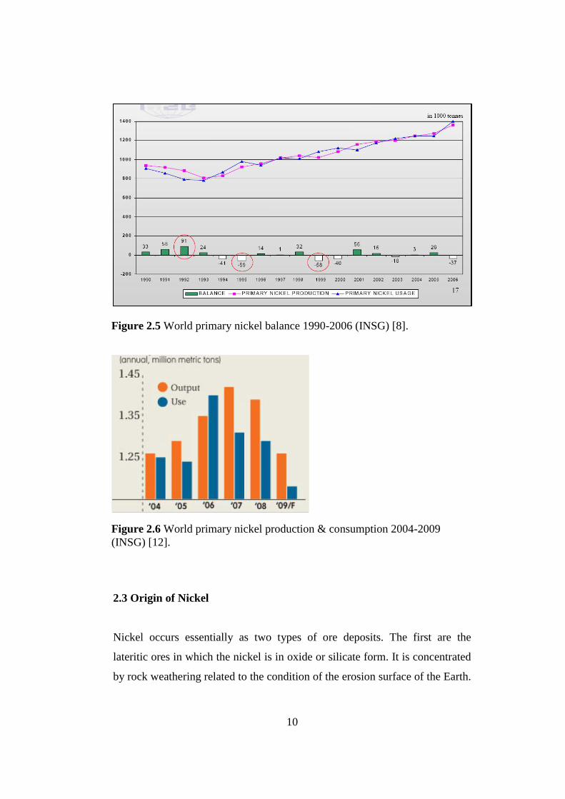
gradual increase in global nickel usage more than production. Figure 2.5
shows primary nickel production and usage from 1990 to 2006 based on the
International Nickel Study Group (INSG) statistics. It can be predicted that
the world nickel production and the consumption will not be much different
than each other, but there will always be a balance determined by the current
economy at that year. In 1995 and 1999 there was a lack of nickel production
whereas in 1992 nickel production was highly sufficient to meet all the nickel
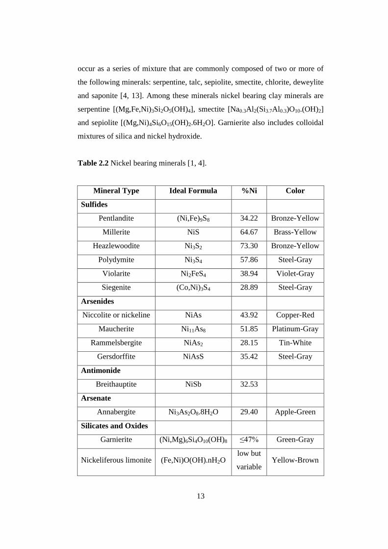
demands of the industries. According to the INSG study illustrated in Figure
2.6, the world primary nickel usage in 2008 was 1.39 million metric tons but
in 2009 the global economic crisis broken out which resulted in reduced
demand and nickel prices and the production of primary nickel dropped.
Although the economy directly affects the nickel usage, in future there will be
various new projects to contribute nickel stocks in order to satisfy increasing
demands of world nickel.
Figure 2.4 Nickel prices between 1999 and 2010 [11].
Date
US
$/t
on
10
Figure 2.6 World primary nickel production & consumption 2004-2009
(INSG) [12].
2.3 Origin of Nickel
Nickel occurs essentially as two types of ore deposits. The first are the
lateritic ores in which the nickel is in oxide or silicate form. It is concentrated
by rock weathering related to the condition of the erosion surface of the Earth.
Figure 2.5 World primary nickel balance 1990-2006 (INSG) [8].

11
Table 2.1 Average nickel content as wt% for some rock types [4].
The principal lateritic ores are nickeliferous limonite: (Fe,Ni)O(OH).nH2O
and garnierite: (Ni,Mg)6Si4O10(OH)8. The second are the sulfide ores where
nickel is associated with sulfur in various forms of nickel bearing minerals.
They occur in the rocks at depths of many thousand meters below the existing
surface of the Earth. In the sulfide ore deposits, nickel is found mainly as the
mineral pentlandite: (Ni,Fe)9S8. The two ore types become different from
each other in physical, mineralogical and chemical treatments of the deposit
to extract nickel from them. There are other types of ore deposits of nickel
such as arsenide, antimonide and arsenate but it is not economical to recover
nickel from these ores.
Most of the nickel occurrence as it is stated before is concentrated in the
Earth‟s core while the remaining nickel is scattered around the Earth‟s crust in
various amounts. There is a relationship between nickel content and certain
elements through the Earth‟s core. The higher the nickel contents the more
iron-magnesium and the less silicon-aluminum the rocks contain. Table 2.1
shows that the average nickel content climbs up as the iron content increases
and silica content of the igneous rocks decreases relatively [4].
Rock Nickel Iron Oxides
Plus Magnesia
Silica Plus
Magnesia
Peridotite 0.20 43.3 45.9
Gabbro 0.016 16.6 66.1
Diorite 0.004 11.7 73.4
Granite 0.0002 4.4 78.7

12
2.4 Nickel and Associated Minerals
The Earth‟s crust is composed of many different types of minerals forming
rocks. A large number of nickel bearing minerals are identified but relatively
few are economically feasible to be extracted industrially. In these minerals
nickel amounts always change because of substitution of one element for
another but this change does not affect the ideal formula of the composition.
Nickel substitutes essentially for iron (Fe) and magnesium (Mg) without
distorting the lattice structure of rock forming structure depending on the type
of mineralization. In certain minerals such as olivine, hypersthene, hornblende
and biotite nickel is replaced with magnesium. A good chemical reason for
the substitution of nickel for iron and magnesium is directly related to the
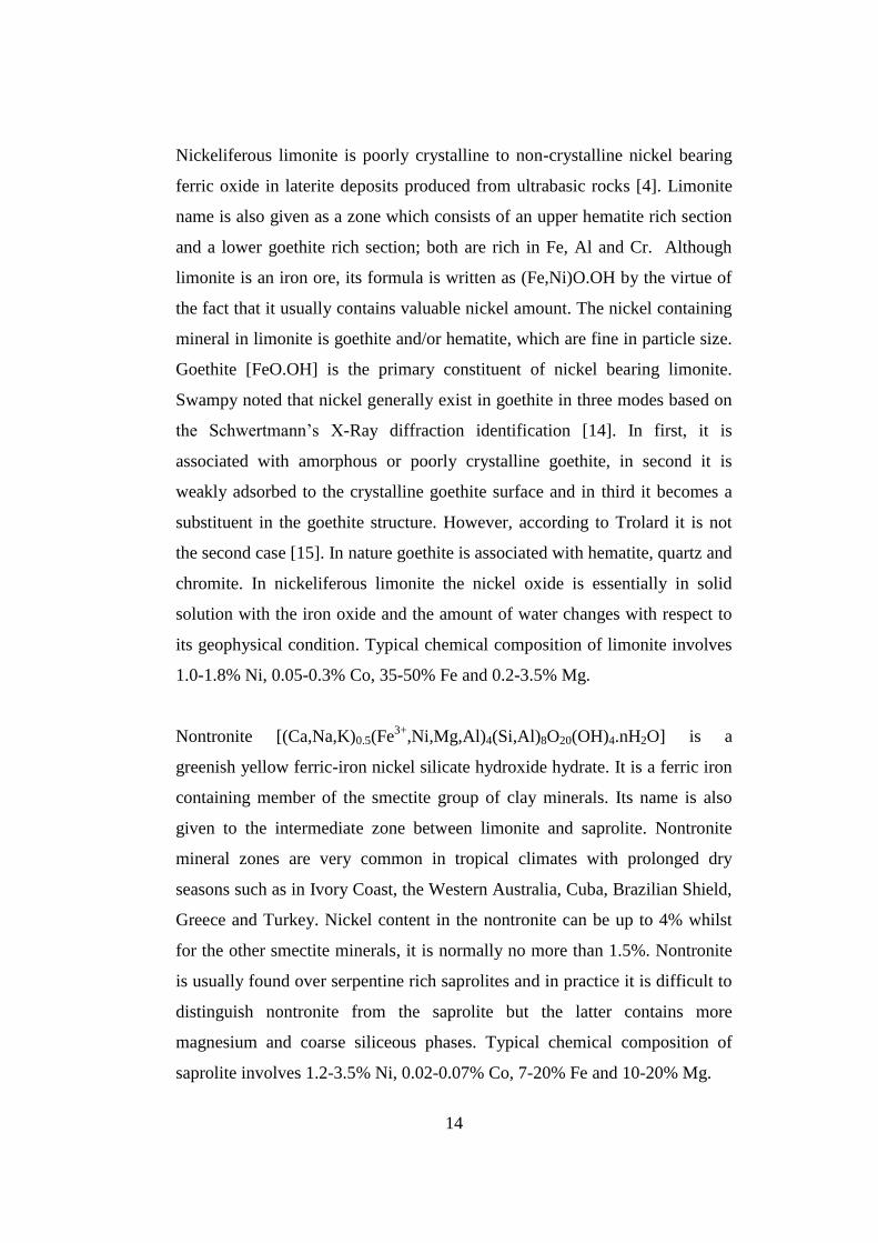
similar diameters of the divalent ions of all three elements [4]. Table 2.2
shows the chief nickel bearing minerals found in nickel deposits with their
chemical composition, nickel percentage and color [1, 4].
Pentlandite is the most common primary nickel sulfide mineral containing
25%-41% Ni [6]. It is very similar to pyrrhotite, iron sulfide, and almost
invariably found in nature together with a large amount of pyrrhotite.
Pyrrhotite, about 60% Fe and 40% S, is the most abundant sulfide mineral but
it does not necessarily involve nickel since nickel may not be present in its
composition. It has a formula written as Fen-1Sn. From place to place the
values of n change and the composition varies from FeS to any Fen-1Sn. It
generally carries some nickel in its crystal lattice by diffusion or substitution
of nickel atoms and replacing some iron atoms making pyrrhotites
nickeliferous in the diffusion site of the crystal [4]. The amount can be as high
as 1.5% Ni [6]. Furthermore, it is mostly magnetic which makes ores
susceptible to the magnetic ore prospecting and processing techniques.
Garnierite is the most common and abundant nickel carrier in laterite deposits
in the world. In fact, it is classified as Ni-Mg hydrosilicates which generally
13
occur as a series of mixture that are commonly composed of two or more of
the following minerals: serpentine, talc, sepiolite, smectite, chlorite, deweylite
and saponite [4, 13]. Among these minerals nickel bearing clay minerals are
serpentine [(Mg,Fe,Ni)3Si2O5(OH)4], smectite [Na0.3Al2(Si3.7Al0.3)O10.(OH)2]
and sepiolite [(Mg,Ni)4Si6O15(OH)2.6H2O]. Garnierite also includes colloidal
mixtures of silica and nickel hydroxide.
Table 2.2 Nickel bearing minerals [1, 4].
Mineral Type Ideal Formula %Ni Color
Sulfides
Pentlandite (Ni,Fe)9S8 34.22 Bronze-Yellow
Millerite NiS 64.67 Brass-Yellow
Heazlewoodite Ni3S2 73.30 Bronze-Yellow
Polydymite Ni3S4 57.86 Steel-Gray
Violarite Ni2FeS4 38.94 Violet-Gray
Siegenite (Co,Ni)3S4 28.89 Steel-Gray
Arsenides
Niccolite or nickeline NiAs 43.92 Copper-Red
Maucherite Ni11As8 51.85 Platinum-Gray
Rammelsbergite NiAs2 28.15 Tin-White
Gersdorffite NiAsS 35.42 Steel-Gray
Antimonide
Breithauptite NiSb 32.53
Arsenate
Annabergite Ni3As2O8.8H2O 29.40 Apple-Green
Silicates and Oxides
Garnierite (Ni,Mg)6Si4O10(OH)8 ≤47% Green-Gray
Nickeliferous limonite (Fe,Ni)O(OH).nH2O low but
variable Yellow-Brown
14
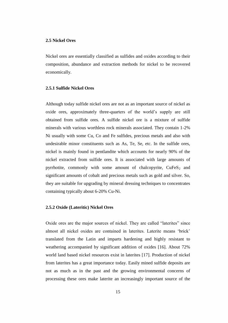
Nickeliferous limonite is poorly crystalline to non-crystalline nickel bearing
ferric oxide in laterite deposits produced from ultrabasic rocks [4]. Limonite
name is also given as a zone which consists of an upper hematite rich section
and a lower goethite rich section; both are rich in Fe, Al and Cr. Although
limonite is an iron ore, its formula is written as (Fe,Ni)O.OH by the virtue of
the fact that it usually contains valuable nickel amount. The nickel containing
mineral in limonite is goethite and/or hematite, which are fine in particle size.
Goethite [FeO.OH] is the primary constituent of nickel bearing limonite.
Swampy noted that nickel generally exist in goethite in three modes based on
the Schwertmann‟s X-Ray diffraction identification [14]. In first, it is
associated with amorphous or poorly crystalline goethite, in second it is
weakly adsorbed to the crystalline goethite surface and in third it becomes a
substituent in the goethite structure. However, according to Trolard it is not
the second case [15]. In nature goethite is associated with hematite, quartz and
chromite. In nickeliferous limonite the nickel oxide is essentially in solid
solution with the iron oxide and the amount of water changes with respect to
its geophysical condition. Typical chemical composition of limonite involves
1.0-1.8% Ni, 0.05-0.3% Co, 35-50% Fe and 0.2-3.5% Mg.
Nontronite [(Ca,Na,K)0.5(Fe3+
,Ni,Mg,Al)4(Si,Al)8O20(OH)4.nH2O] is a
greenish yellow ferric-iron nickel silicate hydroxide hydrate. It is a ferric iron
containing member of the smectite group of clay minerals. Its name is also
given to the intermediate zone between limonite and saprolite. Nontronite
mineral zones are very common in tropical climates with prolonged dry
seasons such as in Ivory Coast, the Western Australia, Cuba, Brazilian Shield,
Greece and Turkey. Nickel content in the nontronite can be up to 4% whilst
for the other smectite minerals, it is normally no more than 1.5%. Nontronite
is usually found over serpentine rich saprolites and in practice it is difficult to
distinguish nontronite from the saprolite but the latter contains more
magnesium and coarse siliceous phases. Typical chemical composition of
saprolite involves 1.2-3.5% Ni, 0.02-0.07% Co, 7-20% Fe and 10-20% Mg.
15
2.5 Nickel Ores
Nickel ores are essentially classified as sulfides and oxides according to their
composition, abundance and extraction methods for nickel to be recovered
economically.
2.5.1 Sulfide Nickel Ores
Although today sulfide nickel ores are not as an important source of nickel as
oxide ores, approximately three-quarters of the world‟s supply are still
obtained from sulfide ores. A sulfide nickel ore is a mixture of sulfide
minerals with various worthless rock minerals associated. They contain 1-2%
Ni usually with some Cu, Co and Fe sulfides, precious metals and also with
undesirable minor constituents such as As, Te, Se, etc. In the sulfide ores,
nickel is mainly found in pentlandite which accounts for nearly 90% of the
nickel extracted from sulfide ores. It is associated with large amounts of
pyrrhotite, commonly with some amount of chalcopyrite, CuFeS2 and
significant amounts of cobalt and precious metals such as gold and silver. So,
they are suitable for upgrading by mineral dressing techniques to concentrates
containing typically about 6-20% Cu-Ni.
2.5.2 Oxide (Lateritic) Nickel Ores
Oxide ores are the major sources of nickel. They are called “laterites” since
almost all nickel oxides are contained in laterites. Laterite means „brick‟
translated from the Latin and imparts hardening and highly resistant to
weathering accompanied by significant addition of oxides [16]. About 72%
world land based nickel resources exist in laterites [17]. Production of nickel
from laterites has a great importance today. Easily mined sulfide deposits are
not as much as in the past and the growing environmental concerns of
processing these ores make laterite an increasingly important source of the

16
world‟s nickel and cobalt. Furthermore, increasing developments and
improving technologies have been achieved in the methods of nickel
extraction from laterites. Laterites are the future resource of world nickel and
it is expected to raise over 50%, more than sulfide production, by 2012 [17].
Laterites contain about 1-3% Ni typically accompanied by some cobalt. They
have nearly 30 to 45% H2O as moisture and are chemically bound in
hydroxides. Unlike sulfides they have no fuel value. Sometimes, an upgrading
by screening and magnetic separation can be necessary for laterites which
usually contain boulders that may have no nickel value and typically
surrounded by very fine, loosely adhering nickeliferous material [18]. These
boulders may contain relatively high calcium oxide content, 18%, which has
to be removed as much as possible to prepare a suitable sulfuric acid heap or
agitation leaching feed which is further explained in Section 2.2.
Lateritic deposition is favored by warm conditions with abundant rainfall and
occurs when rocks are exposed to the atmosphere at the Earth‟s surface for a
long time, may be several centuries. It commences on peridotite which
gradually decomposes magnesium, iron, nickel, cobalt and other constituents
into solution with the help of the continued chemical and mechanical action of
air, water, heat and cold. The nickel content present in the rock is
accumulated into solution in the ground water and at greater depth
concentrated in a zone to such a degree that the resulting deposits can be
mined as a laterite nickel ore or be assessed as an abnormally high nickel belt
of the deposit. The degree of concentration to result in a nickel ore is pleasing
and satisfactory. The weathering process generally starts with peridotite
containing 0.25% Ni and continues in lateritic soils then finishes in deeper
zones of ultramafic rocks containing as much as 1.5% nickel ore, a promising
grade for mining and metallurgical treatment [4].

17
In the first part of the weathering, a chemical reaction between ground water
rich in carbon dioxide and the constituents of the igneous rock in some
regions occurs. Olivine in these regions of the rock is consumed by carbon
dioxide in water and decomposes magnesium and silica, most of nickel and
cobalt into solution. During this naturally occurring process, these elements
are leached and carried downward as iron is neutralized by reaction within
soil and precipitates as iron oxide near the Earth‟s surface, then the residue
left rich in iron with other minor constituents such as aluminum, chromium,
manganese, also some nickel and cobalt. Through the core of the Earth, nickel
and cobalt tend to precipitate as hydrous silicate in a zone or in cracks and
fractures of the rock as the pH of the solution rises. These places in which
nickel is higher in the precipitate than in the solution are important to prospect
for a nickel ore. Then, magnesium becomes rich in the remaining solution
when it flows deeper and accumulates in the bottom of the zone of
weathering. This typical process can be followed from Figure 2.7. Lateritic
formation causes various specific elements to accumulate and grade in
different layers with respect to the physical and the chemical condition of the
solution as it forms near the Earth‟s surface and becomes barren with very
little amounts of elements at the end of weathering zone. As it is illustrated in
Figure 2.7 these graded layers consist of an iron rich (hematitic) cap, a
nickeliferous limonite layer and altered-unaltered peridotite layers. The nickel
concentrations typically occur in one or more layers or in cracks within the
profile and most strongly found close to the bottom of the zone of weathering.
Complete separation of nickel, cobalt, iron or other elements into distinct
zones are never realized.
Each classified type of minerals is variable based on the profile of the
respected location. Figure 2.8 illustrates typical nickel laterite profiles
published in the literature. The thicknesses of individual layers are highly
variable and are influenced by faults extending upwards in the weathering

18
profile. It is also distinctive that some profiles contain more nontronite and
others more limonite.
Figure 2.7 Idealized section of a nickeliferous laterite formation [19].
Figure 2.8 Nickeliferous laterite profiles [17].
19
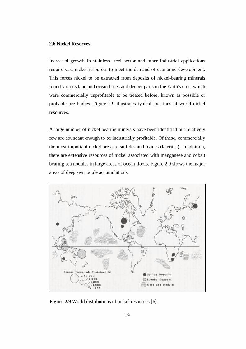
2.6 Nickel Reserves
Increased growth in stainless steel sector and other industrial applications
require vast nickel resources to meet the demand of economic development.
This forces nickel to be extracted from deposits of nickel-bearing minerals
found various land and ocean bases and deeper parts in the Earth's crust which
were commercially unprofitable to be treated before, known as possible or
probable ore bodies. Figure 2.9 illustrates typical locations of world nickel
resources.
A large number of nickel bearing minerals have been identified but relatively
few are abundant enough to be industrially profitable. Of these, commercially
the most important nickel ores are sulfides and oxides (laterites). In addition,
there are extensive resources of nickel associated with manganese and cobalt
bearing sea nodules in large areas of ocean floors. Figure 2.9 shows the major
areas of deep sea nodule accumulations.
Figure 2.9 World distributions of nickel resources [6].

20
World reserves of nickel deposits containing an average grade of 0.97% are
approximately 23 billion tons [20]. About 72% of total known nickel reserves,
12.6 billion tons, are oxide (lateritic) type of an average grade of 1.28% and
about 28% of the world nickel reserves, 10.4 billion tons, are sulfide type of
an average grade of 0.58%. The total contents of nickel metal in the world
reserves are approximately 220 million tons; about 160 million tons belong to
the lateritic type and about 60 million tons to the sulfide type. World reserves
of nickel deposits are given in Table 2.3 [21].
Table 2.3 World nickel reserves as contained nickel [21].
In the case of both nickel sulfide and nickel laterite, six countries; Australia,
New Caledonia, Russia, Cuba, Canada and Brazil account for 84% of the
known world reserves. But, the world's largest nickel deposit is present at
Country Proven Reserve (tons) Possible Reserve (tons)
United States - 150,000
Australia 24,000,000 27,000,000
Botswana 490,000 920,000
Brazil 4,500,000 8,300,000
Canada 4,900,000 15,000,000
China 1,100,000 7,600,000
Colombia 830,000 1,100,000
Cuba 5,600,000 23,000,000
Dominic Republic 720,000 1,000,000
Greece 490,000 900,000
Indonesia 3,200,000 13,000,000
New Caledonia 7,100,000 15,000,000
Philippines 940,000 5,200,000
Russia 6,600,000 9,200,000
South Africa 3,700,000 12,000,000
Venezuela 560,000 630,000
Zimbabwe 15,000 260,000
Other Countries 2,100,000 5,900,000

21
Goro in New Caledonia owned by Vale-Inco with a production capacity of
54000 t Ni/year as nickel oxide [17]. Furthermore, the global resources of
nickel in manganese nodules are estimated between 2 and 14 billion tons of
contained nickel [6].
In Turkey the mineralization of both sulfide and lateritic type is found. The
known principal nickel laterite reserves are in Eskişehir-Mihalıççık-
Yunusemre, Manisa-Turgutlu-Çaldağ, Manisa-Gördes and Uşak-Banaz and
sulfide reserves in Bitlis-Pancarlı, Bursa-Orhaneli-Yapköy and Sivas-Divriği-
Gümüş [22]. Of these, Eskişehir-Mihalıççık-Yunusemre, Manisa-Gördes and
Manisa-Çaldağ nickel laterite reserves have enough economic nickel value for
the extraction and processing the ore unless the nickel prices climb up the
limit by which the cut-off grade of the ore is determined. Turkey nickel
reserves are given in Table 2.4 [22, 23].
Region Proven
Reserve
Probable
Reserve
Possible
Reserve
Manisa ‐ Çaldağ 33,000,000 - ‐
Manisa ‐ Gördes 32,000,000 - ‐
Eskişehir-Yunusemre,
Mihalıççık - 86,625,000 -
Uşak-Banaz - 11,601,500 -
Bursa ‐ Yapköy - 82,000 81,000
Bitlis ‐ Pancarlı - ‐ 15,500
World nickel mine production shows a typical trend. It increased gradually
throughout the years parallel to the developments and innovations in the
nickel extraction methods. World mine production for various countries from
2002 to 2006 is shown in Table 2.5 [24]. It reached 1,580 Mt in 2006 whereas
it was 1,350 Mt in 2002. Since 1950, stainless steel production in the Western
World has been growing at an average rate of 6.0% per year. It requires new
Table 2.4 Turkey nickel reserves, tons of ore [22, 23].

22
projects to be worked and new mines to be opened to extract more nickel in
order to meet this growing steel industry production. Russia plays a
significant role in global nickel production.
Country Capacity (tons of nickel produced)
2002 2003 2004 2005 2006
Australia 188,000 191,000 187,000 189,000 185,000
Botswana 28,600 38,230 35,163 39,305 38,000
Brazil 45,456 44,928 51,886 74,198 82,492
Burma 10 10 10 10 10
Canada 189,297 163,244 186,694 199,932 233,461
China 53,700 61,000 75,600 72,700 82,100
Colombia 58,196 70,844 75,032 89,031 94,105
Cuba 71,342 74,018 71,945 73,753 75,000
Dominic Republic 38,859 45,253 46,000 53,124 46,526
Finland 3,120 3,640 3,700 3,386 2,985
Greece 22,670 21,410 21,700 23,210 21,670
Indonesia 143,000 144,000 136,000 135,000 140,000
Kazakhstan -- -- -- 193 200
Macedonia 5,149 5,555 5,300 8,100 10,900
Morocco 109 126 130 199 80
New Caledonia 99,841 112,013 119,199 111,939 102,986
Norway 2,052 169 181 342 362
Philippines 24,148 19,537 16,973 22,555 50,637
Russia 310,000 300,000 315,000 315,000 320,000
South Africa 38,546 40,842 39,851 42,392 41,599
Spain -- -- -- 5,398 6,400
Turkey -- 640 40 400 1350
Ukraine 2,000 2,000 2,000 6,000 12,000
Venezuela 18,600 20,700 20,468 20,000 20,000
Zimbabwe 8,092 9,517 9,776 8,556 8,825
World Wide Total 1,350,000 1,370,000 1,420,000 1,500,000 1,580,000
Table 2.5 World nickel mine production, by country [24].

23
2.7 Nickel Extraction Methods from Lateritic Nickel Ores
The processing of lateritic nickel ore is quite difficult and they are not suited
to most of the standard mineral extraction methods since the nickel content is
finely disseminated in the ore bodies preventing physical concentration of
nickel values by normal methods such as dressing. Hence, this renders the
processing of laterites expensive and numerous means have been sought for
many decades to reduce the costs of processing laterites. However, well
established mineral processing techniques such as magnetic separation and
flotation can be used for sulfide ores. It is possible to obtain a high percentage
of the valuable minerals in a relatively small quantity of material and to
discard the bulk of the waste with only a small loss of values. Today, either
wet or dry screening is used to reject the oversize of lateritic ores, less
weathered fragments containing nickel in small amount such as boulders of
relatively high calcium oxide content. Although no standard methods exist for
physically concentrating nickel in laterites, some efficient means can make it
possible to collect a considerable amount of valuable nickel content of oxide
ores. Up to now, the establishment of beneficiation techniques for laterite ores
has long been needed. There are increasing amounts of practiced flow sheets
to treat laterite nickel ores which are basically classified as pyrometallurgical
and hydrometallurgical processes. Most of pyrometallurgical processes use
traditional methods involving drying, calcining or/and reduction, roasting and
electric furnace smelting whereas hydrometallurgical processes practice
atmospheric pressure leach (AL), high pressure acid leach (HPAL) and Caron
process as explained in detail in the following sections.
It is important to process a low grade nickel containing material rather than
rich concentrate. Typical grades of laterite deposits are shown in Table 2.6
[25]. Most nickel mine output is the lower grade disseminated lateritic nickel
ore that could not impart an economical value in the past. But, now low grade
deposits can be treated economically and efficiently on account of the

24
availability of nickel extraction methods. Today, both pyrometallurgical and
hydrometallurgical processes are applied commercially to the recovery of
nickel and cobalt from lateritic nickel ores.
Place Cawse Moa Bay Murrin
Murrin Bulong
New
Caledonia
Source Limonite Limonite Nontronite Nontronite Saprolite
Process Hydro-
metallurgy
Hydro-
metallurgy
Hydro-
metallurgy
Hydro-
metallurgy
Pyro-
Metallurgy
Ni 1.0 1.3 1.2 1.1 2.5
Co 0.07 0.12 0.08 0.08 0.04
Fe 18 48 22 21 12
SiO2 421 9.0 42 43 47
Mg 1.6 0.55 3.7 4.6 15
Al 1.7 4.8 2.7 2.8 1.3
Mn 0.17 0.8 0.4 0.36 0.6
Cr 0.92 2.0 1.0 0.6 1.4
H2O Up to 10 >20 About 30 Up to 35
2.7.1 Pyrometallurgical Processes
Pyrometallurgy processes refer to a class of high temperature industrial
processes by which nickel and cobalt are extracted from raw materials and
refined to market specifications. Pyrometallurgical techniques usually care for
utilizing nickel ores containing high magnesium content and relatively low
iron content predominantly saprolitic type ores. High temperature requiring
processes typically involve drying, calcination/reduction, roasting and
smelting or electric furnace smelting. Pyrometallurgy generally produces a
ferronickel metal (Fe-Ni) or nickel sulfide matte, which are further refined to
recover pure metal. New developments in pyrometallurgy of nickel use new
physicochemical studies. They are classified as below [26]:
Table 2.6 Elemental compositions (%) of some nickeliferous laterites with
their extraction methods used in nickel producing industries [25].
1 Contains significant free silica

25
The top blown rotary converter process for conversion of nickel matte
to metallic nickel
The vacuum desulfurization process for removal of residual copper,
cobalt, and iron from crude nickel mattes by selective chlorination
The process for production of pure nickel, iron, and cobalt by
formation of volatile carbonyls under high pressure (70 atm) and their
separation by distillation and decomposition of carbonyls to metal
The process for upgrading of nickel laterites and deep sea manganese
nodules by solid state reduction or by segregation process.
The disadvantages of these processes include the requirement for higher grade
ores, some metal losses to discarded slags, substantial energy for the process,
sulfur (SO2) disposition problems and poor cobalt recoveries which in turn
leads to high production cost per ton of nickel produced. Pyrometallurgical
processes are energy intensive because all of the water content of the ore has
to be removed, all of the material has to be calcined and then melted in the
process to form an appropriate slag at approximately 1600oC [17]. Great
amount of mass follows a high temperature flow sheet to the end of the
process. Therefore, both hydrocarbon fuels; coal, oil, or naphtha and electric
power are required. In addition, in order to form a more easily heated liquid
slag which needs lower energy input compared to that for limonite ores at
high temperatures, ore must contain predominantly saprolite or lower iron and
higher magnesium content. In smelter, ores are smelted to produce either
ferronickel or matte. It depends on the SiO2/MgO ratio or the basicity of the
slag in the furnace. The slag composition in the range 1.8 to 2.2 SiO2/MgO
ratio is amenable for production of mattes while high melting slags of
SiO2/MgO ratio either <2 or >2.5 are better suited to produce ferronickel [17].
Slag melting point, viscosity and electrical conductivity are important
parameters and controlled by iron, magnesia and silica contents in the smelter.

26
With respect to sulfide and oxide type, nickel ores are passed through various
pyrometallurgical processes. Figure 2.10 shows typical pyrometallurgical
processes for laterites and sulfide type nickel ores.
The pyrometallurgical processes of nickel sulfides are similar to that of
copper sulfides. Iron and sulfur are eliminated by selective oxidation and
fluxing. The primary product is a Ni-Cu matte with low Fe (0.5-3%) and
certain S content (10-22%). A liquid nickel matte usually includes Ni3S2-
FeS-Cu2S, Ni3S2-Cu2S and Ni3S2-Ni [26]. Sulfur elimination from the
concentrate before or during the smelting stage is important to control matte
grade. It can be eliminated either by roasting or flash smelting. Capturing and
fixing SO2 gas is an environmental problem for the process. For this reason,
sulfur input is minimized by eliminating as much of iron sulfides as possible
before the pyrometallurgical stages. On the other hand, nickel oxides are
upgraded by screening, passed through drying, calcination and reduction
stages and sent to a smelter, become metal or matte product and slag is
removed. In the kiln operation followed by electric furnace smelting generally
Figure 2.10 Laterite and sulfide type nickel ores in nickel pyrometallurgy.
Pre-Smelting
FeNi alloy or matte
Converting & Refining
Smelting
Drying
Calcination & Reduction
NiCu matte
Laterite ore Sulfide type nickel ore
Roasting
Smelting
Converting
Refining

27
a Fe-Ni alloy of about 35-40% Ni is produced [27]. Separation of nickel from
refractory oxides is easier since there is a sufficient free energy difference
formed between nickel oxide and gangue components during the process. But
iron oxide is reduced while the reduction of nickel oxide. It means some iron
always exists in matte [28]. For the design of the cost effective processes
good separation of the ferronickel or matte from the gangue by smelting of all
of the low graded ore and coping with great metallurgical and equipment
obstacles, high water contents and high liquidus temperatures of slag and
metal phases are significant. Sridhar and Bell found that the impurity
elements could be discarded more selectively from mattes of low sulfur
content (28-32% S) than from mattes of higher sulfur content (40-44% S)
[29]. Depending on the suitability of the ore, availability and associated cost
of consumables such as electric power and gaseous fuels, pyrometallurgical
treatment of sulfide and/or laterite sources of nickel can provide an alternative
to hydrometallurgical treatment. Ferronickel production is 19% of the annual
new nickel output [27]. For profitable and favorable pyrometallurgical
operation nickel content requires to be greater than about 2%, Fe/Ni ratio and
moisture content to be low. Extensive energy requirement, off-gas treatment
via acid plants for SO2 fixation and impurity removal may affect the process
followed. For completeness, other extraction processes may be practiced.
2.7.2 Hydrometallurgical Processes
Hydrometallurgical routes may become more appropriate and economical for
the selected conditions when cost of energy rises and typical
pyrometallurgical methods become economically marginal and unattractive to
extract nickel from lateritic ores containing 0.95-1% nickel. Because
treatment of oxide ores containing as high as 50% total water content and
large amounts of high melting components requires substantial amounts of
energy. Furthermore, direct application of the above pyrometallurgical
methods to existing nickeliferous laterites can result in an undesirable process

28
because of the difficulty of melting the slag produced, poor metal-slag phase
condition and SO2 disposition problems. Combination or sequential
treatments of laterites involving hydrometallurgical and pyrometallurgical
routes can work out to extract nickel and cobalt from low grade nickel oxide
ores in a more economical and efficient way. Caron process is a good
example. It covers a variety of pyrometallurgical and leaching steps.
Hydrometallurgical processes propose direct solution of the nickel and cobalt
values by sulfuric, hydrochloric or nitric acid leaching or organic/inorganic
acid leaching. On the basis of the composition of a given laterite deposit,
chemical and mineralogical distributions of oxides in the laterites, improved
hydrometallurgical techniques increase selectivity of the methods over
pyrometallurgical routes as the worldwide production of nickel derived from
pyrometallurgical routes has been declining. Table 2.6 shows process types
with respect to elemental composition of the resource. Depending on
magnesia content and Ni/Fe ratio a hydro or pyrometallurgical extraction
process is chosen [25]. Ni/Fe ratio of laterite deposits exposed to
hydrometallurgical process is not as high as pyrometallurgical ones.
Therefore, these advantages lead hydrometallurgical processes to become
more applicable in mineral industry. Hydrometallurgical treatment of nickel
laterites is mainly divided into 2 groups: Atmospheric leaching (AL)
including heap leaching and agitation leaching and high pressure acid
leaching (HPAL). It also includes Caron process but it is not a complete
hydrometallurgical process to be counted in the group.
In recent years, heap leaching with diluted sulfuric acid at ambient
temperature has been studied and developed by many groups to achieve the
selectivity of nickel extraction over iron. Agatzini-Leonardou et al. has
succeeded a complete hydrometallurgical process by heap leaching Greek
laterites with diluted H2SO4 and subsequent purification and recovery steps as
the laterites were limonitic and smectitic and contained significant amounts of

29
low reactivity hematite together with goethite [30]. When nickel laterites are
predominantly of the limonitic type, low in magnesia and relatively high in
iron, pressure acid leaching (HPAL) looks attractive by the virtue of the fact
that it offers a recovery of 90% or more of both nickel and cobalt.
2.7.2.1 Caron Process
In Caron process nickel ore is dried, milled, calcined and selectively reduced
at about 700-750oC in a roaster to convert nickel and cobalt to their metallic
form. In these appropriate conditions nickel and cobalt are favorably reduced
to their metallic state whereas a small fraction of nickel bearing goethite is
reduced leading to an alloy of Fe-Ni-Co and a largely unreduced gangue
fraction. Next, the resulting product is selectively leached at low temperature,
about 25-45oC, atmospheric pressure and pH 10 with an ammonia-ammonium
carbonate (ammoniacal) solution to dissolve nickel and cobalt as ammine
complexes; Ni(II) and Co(II) ammines. Finally, ammonia is removed; nickel
carbonate is precipitated to be calcined to produce nickel oxide [25]. In
addition, cobalt is removed before nickel carbonate precipitation to produce
pure nickel. It is separated from nickel either by solvent extraction or sulfide
precipitation. In solvent extraction method the nickel ammine complex is
extracted and cobalt remains in the raffinate by an organic reagent. Then,
nickel is stripped with a higher concentrated ammonia solution from
extraction solution. About 75-85% Ni and 45-55% Co are usually extracted
depending on feed content [31]. Caron Process was first commercially tried
for the extraction of nickel and cobalt in ammoniacal solution in 1942 at
Nicaro, Cuba during the Second World War. It has several advantages. It is
useful for treating high limonitic ores or ores containing more limonitic
content. Ni/Co selectivity and a recyclable leaching reagent make process
preferable. However, it is not suitable for ores containing high amount of
saprolite since nickel and cobalt are stuck in a silicate matrix and are difficult
to reduce at operated temperature [17]. Furthermore, calcination and reduction

30
steps need high energy and following hydrometallurgical steps require
effective reagents. The recovery of nickel and especially cobalt is still lower
than full scale pyrometallurgical and HPAL processes. Although Caron
process has been limited because of these significant drawbacks, a lot of study
has been carried out to eliminate these disadvantages. A typical flow sheet of
Caron process is illustrated in Figure 2.11.
.
2.7.2.2 High Pressure Acid Leaching (HPAL)
A number of up-to-date hydrometallurgical processes have been being
improved for extraction of nickel and cobalt from nickeliferous laterite ores.
One of the most common and commercially used methods is high pressure
Figure 2.11 Caron Process.
Purification & Recovery
Calcination & Reduction
Milling
Drying
Laterite Ore
Ammoniacal Leaching
Ni & Co
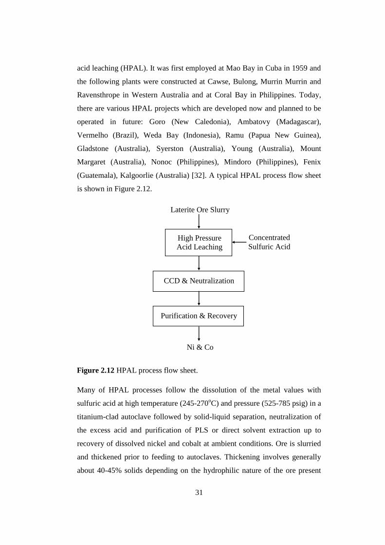
31
acid leaching (HPAL). It was first employed at Mao Bay in Cuba in 1959 and
the following plants were constructed at Cawse, Bulong, Murrin Murrin and
Ravensthrope in Western Australia and at Coral Bay in Philippines. Today,
there are various HPAL projects which are developed now and planned to be
operated in future: Goro (New Caledonia), Ambatovy (Madagascar),
Vermelho (Brazil), Weda Bay (Indonesia), Ramu (Papua New Guinea),
Gladstone (Australia), Syerston (Australia), Young (Australia), Mount
Margaret (Australia), Nonoc (Philippines), Mindoro (Philippines), Fenix
(Guatemala), Kalgoorlie (Australia) [32]. A typical HPAL process flow sheet
is shown in Figure 2.12.
Many of HPAL processes follow the dissolution of the metal values with
sulfuric acid at high temperature (245-270oC) and pressure (525-785 psig) in a
titanium-clad autoclave followed by solid-liquid separation, neutralization of
the excess acid and purification of PLS or direct solvent extraction up to
recovery of dissolved nickel and cobalt at ambient conditions. Ore is slurried
and thickened prior to feeding to autoclaves. Thickening involves generally
about 40-45% solids depending on the hydrophilic nature of the ore present
Figure 2.12 HPAL process flow sheet.
Laterite Ore Slurry
High Pressure
Acid Leaching
Concentrated
Sulfuric Acid
CCD & Neutralization
Purification & Recovery
Ni & Co

32
and the rheology of laterite ore slurries. At 250oC and 570 psi or 39 atm
pressure in the autoclave the nickeliferous minerals in the ore are almost
completely solubilized together with iron and aluminum. In literature, it has
been studied that HPAL is most amenable for ores containing 40 wt% iron or
greater. Below 40 wt% iron, lateritic ores start to consume higher amount of
acid and therefore they lose their preference for direct HPAL. The dissolved
iron is quickly precipitated as hematite or jarosite phase after passing goethite
metastable phase depending on the leaching conditions and aluminum
hydrolyses and precipitates as alunite phase at the high temperature and
pressure of the autoclave. General reactions in HPAL are illustrated in
Reactions 2.1 to 2.8 [33]:
(Fe,Ni)O.OH(s) + (Mg,Ni)2Si2O5(OH)4(s) + H2SO4(l) FeO.OH(s) + NiSO4(aq) + MgSO4(aq) +
SiO2(s) + H2O(l) (2.1)
NiO(s) + 2H+
(aq) Ni2+
(aq) + H2O(l) (2.2)
CoO(s) + 2H+
(aq) Co2+
(aq) + H2O(l) (2.3)
FeO.OH(s) + 3H+
(aq) Fe3+
(aq) + 2H2O(l) (2.4)
2Fe3+
(aq) + 3H2O(l) Fe2O3(s) + 6H+
(aq) (2.5)
6AlOOH(s) + 9H2SO4(s) 3Al2(SO4)3(aq) + 12H2O(l) (2.6)
Al2(SO4)3(aq) + 14H2O(l) 2(H3O)Al3(SO4)2(OH)6(s) + 5H2SO4(l) (2.7)
Al3+
(aq) + SO42-
(aq) + H2O(l) AlOHSO4(s) + H+
(aq) (2.8)
Hematite phase of iron causes scale formation inside the autoclave due to its
large insolubility in acidic solutions at this temperature. Liu pointed out that

33
the solubility of the laterite minerals in sulfuric acid decreases in the
following order: lizardite, goethite, maghemite, magnetite or hematite and
chromite [34]. The insolubility of hematite also lowers the nickel recovery
since nickel remains undissolved in the crystal structure of the hematite inside
the autoclave. However, iron hydrolysis as whatever phase it precipitates
regenerates acid and decreases the overall acid consumption of the HPAL
method. Typical acid consumption of HPAL process is from about 250 to 350
kg H2SO4 per ton of dry lateritic ore. The residual free acid is typically in the
range of 30-40 g/L. Then, the leach slurry is taken from the autoclave and the
residual solids are separated from the leach liquor by counter current
decantation (CCD). Next, the leach liquor is neutralized to discard ferric iron,
aluminum and chromium (III) and the soluble nickel and cobalt are selectively
recovered by subsequent processes. The nickel and cobalt present in the PLS
are either precipitated as the sulfides by H2S, carbonates or hydroxides by
MgO or extracted directly by solvent extraction techniques. There is always a
loss of nickel and cobalt value with the precipitation of solids on the leach
products. However, this is usually less than 1% of the grade of the leached ore
for both metals in continuous processes.
Nickel laterite ores with high MgO and Al content are not suitable for the
direct use in the HPAL process since they increase the acid consumption of
the HPAL process rendering an uneconomic extraction method. This is
mainly resulted from increasing reagent cost needed to maintain an extra acid
to overcome the negative effect of bisulfate ion (HSO4-) formation at high
temperature. However, in high iron containing nickel laterites such as
limonite it is not the case since high acid consumers, Al and Mg, are not
present to cause a significant extra acid requirement during the HPAL. As in
the literature there have been most of studies which followed an ore
separation procedure depending on their magnesium and iron content. By
separating laterite ore a low magnesium ore fraction and using in the HPAL
process and neutralizing leach solution by the remaining high magnesium ore

34
fraction, the HPAL process becomes less acid consuming and higher nickel-
cobalt extraction recovery is possible which makes the leaching more
economical. The process of treating separated laterite ores instead of direct
leaching is known as enhanced pressure acid leaching (EPAL). This was first
accomplished by Queneau and Chou and patented in 1976 [35]. They
combined the HPAL steps in which PLS from the HPAL process of low
magnesium containing laterite, limonite, was neutralized by mixing at high
temperature and pressure with PLS from the HPAL process of remaining high
magnesium containing laterite, saprolite. However, this process has the
drawback that it needs comparatively high pressure and temperature for the
neutralization step. Similarly, Lowenhaupt has patented an EPAL method in
which mixing of a low pressure leach of high magnesium ore with a HPAL of
low magnesium ore occurred [36]. In the method iron and aluminum were
precipitated as hematite and alunite after neutralization at greater than 1 atm
and high temperature to achieve adequate nickel extraction and proper settling
and filtration form.
A high extraction of nickel and cobalt is obtained by HPAL. Nickel is
extracted at least about 90% and as high as 95% or more and cobalt is as
much as 95% or more with about 5% to 10% iron extraction. It becomes more
profitable and economical by the treatment of limonite ores in the HPAL.
However, HPAL requires the use of titanium-lined or acid brick and lead-
lined (Moa Bay Project) autoclaves, flash tanks, associated equipment and
sophisticated materials of construction which imparts high investment and
capital cost and the need of regular maintenance to withstand the corrosion,
erosion and the abrasive effects of concentrated acid at high temperature and
pressure, which also contributes the cost of the process. In HPAL scale
formation is another problem to be considered by plant organizers. It can
necessitate regular descaling or seed recycle during plant operation [37]. On
the other hand, HPAL eliminates drying and calcination steps and yields to
lower energy requirement and higher metal recovery within 1 or 2 hours in the

35
operated autoclave compared to Caron process. As it is stated, the most
important drawback of the HPAL process is that it is restricted to treating
largely limonite type ores since leaching saprolite or clay type ores raises
sulfuric acid consumption which is the highest cost component in the HPAL
process. In addition, increasing acid consumption means increasing lime
consumption during the subsequent neutralization step. Up to 4% Mg has
usually been accepted the limit for economically treatable ore in the HPAL
[17]. Furthermore, the economical process also requires lower Al content due
to Al contamination in subsequent recovery steps; MHP or ammonia re-leach
steps. This is achieved by an addition of saline water containing sufficient
sodium content. At Cawse, the use of saline bore water resulted in low
aluminum extraction in PAL [37]. In a different manner, high acid consuming
ore, saprolite, without passing the HPAL process or any leaching step is
directly used in place of all or part of the limestone to neutralize residual
leach acid in the discharge of an autoclave. Chou et al. in 1978 enhanced the
neutralization capacity of high acid consuming ore by roasting below about
820oC [38]. He pointed out better utilization of sulfuric acid and decrease in
the consumption of limestone after the HPAL of limonite.
HPAL process has been continuing to be the most suitable direct nickel and
cobalt extraction process from laterites after the grinders and crushers of run
of mine since 1959. Excellent nickel and cobalt extractions were achieved
rapidly from different type of Ambatovy deposits typically about 97% for
both nickel and cobalt operating the autoclave at 36 hours of run time [39].
Recoveries up to 90% or more with leach times of between 1 and 2 days
makes HPAL more favorable among the others for the treatment of nickel
laterites up to date.

36
2.7.2.3 Atmospheric Pressure Acid Leaching
Atmospheric pressure acid leaching (AL) is principally grouped into in-situ
leaching, heap or dump leaching and agitation leaching or vat leaching while
atmospheric pressure leaching of laterites is carried out in one of the two
distinct processes which are heap (or column) leaching and agitation leaching
at atmospheric pressure and temperature up to 105oC either by organic or
inorganic acids.
Heap leaching with diluted sulfuric acid is the process that simply includes
piling raw ore into heaps varying in height (4-5m), passing a leaching solution
from the top of the heap to the bottom while it percolates down and collecting
effluent liquor, PLS, in a pond beneath the heap as necessary acid and water
are added into the pond. Typical flow diagram of atmospheric heap leach of
laterites from Çaldağ is shown in Figure 2.13. The collected PLS from Pond 3
is transported to a processing plant where the metal values are separated from
the PLS and nickel and cobalt recovered. Heap leaching needs extensive
leaching times over several months, perhaps years at ambient temperatures
and compared to the HPAL and EPAL processes the poor selectivity of nickel
over iron and magnesium becomes a problem for heap leaching processes.
However, nickel recoveries of up to 85% were achieved in between 40 and 80
days with less than 50% iron in leach liquor by Agatzini-Leonardou et al. [30,
41].
Agitation leaching is performed either at atmospheric pressure or under
pressure that the ore finely ground is leached by sulfuric acid in tanks where
the solids are dispersed into the leaching solution by gas injection or
mechanical agitation with a magnetic agitator. A flow diagram of agitation
leaching is shown in Figure 2.14. A solid concentration of about 25-30% in
both the limonite and saprolite slurries is most preferred [43]. In comparison
with the other methods, agitation leaching time is lower due to the higher
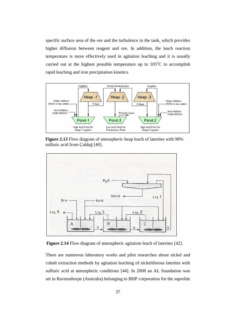
37
specific surface area of the ore and the turbulence in the tank, which provides
higher diffusion between reagent and ore. In addition, the leach reaction
temperature is more effectively used in agitation leaching and it is usually
carried out at the highest possible temperature up to 105oC to accomplish
rapid leaching and iron precipitation kinetics.
There are numerous laboratory works and pilot researches about nickel and
cobalt extraction methods by agitation leaching of nickeliferous laterites with
sulfuric acid at atmospheric conditions [44]. In 2008 an AL foundation was
set in Ravensthorpe (Australia) belonging to BHP corporation for the saprolite
Figure 2.13 Flow diagram of atmospheric heap leach of laterites with 98%
sulfuric acid from Çaldağ [40].
Figure 2.14 Flow diagram of atmospheric agitation leach of laterites [42].

38
ore containing higher than 6% magnesium while HPAL was built for the
limonite ore having less than 6% magnesium [45]. Atmospheric leaching at
lower temperature does not need expensive HPAL autoclaves as well as it is
able to extract significant nickel and cobalt in AL. Generally, cobalt
extraction is significantly less than that of nickel. It can result in 93 and 91%
nickel and cobalt recoveries, respectively as in Taylor and Cairns test work
for the Bulong project operated at 90-95oC and 3 hours [46]. According to
Curlook‟s agitation leach tests with highly serpentinized samples, at 80-
100oC, at pulp densities of 15-33% and acid addition of 800-1000 kg/t dry
ore, more than 90% extractions of nickel were obtained within one hour [44].
However, AL is not selective over iron and almost all the iron is leached
together with other metals from the solids, which yields a high acid
consumption and it requires a significant initial acid addition such as 1000
kg/t ore by the virtue of the fact that the iron sulfates do not hydrolyze at low
temperature. This can be seen in the heap leaching of the Çaldağ deposit from
which 79.4% of Ni, 82.7% of Co, 30.0% of Fe, 78.9% of Mn and 37.1% of Al
in solution were extracted [40]. In addition, at lower temperatures compared
to HPAL, a longer time is required to achieve similar extractions as well as
the more acid to ore ratio requirement. However, multi stage counter current
leaching of serpentinitic laterites can reduce the acid consumption down to
about 500-600 kg/t ore without affecting nickel and cobalt recoveries.
Meanwhile, the significant concentrations of soluble iron, manganese,
chromium, aluminum and arsenic which are likely to be found in PLS after
AL results in further difficulties in the subsequent purification and recovery
steps. They must be rejected selectively from PLS prior to the recovery steps
or nickel and cobalt must be selectively extracted from PLS. These processes
are explained in detail in the following sections.
In AL, iron is generally precipitated as goethite or another low sulfate
containing form of iron oxide or iron hydroxide while it is hematite in HPAL.
However, it converts to jarosite in the presence of sodium, alkaline metal and

39
ammonium ion content. General reactions in AL when goethite is formed are
illustrated in Reactions 2.1, 2.2 and 2.3 while jarosite is precipitated in
Reaction 2.9 [43].
Na+
(aq) + (Fe,Ni)O.OH(s) + (Mg,Ni)2Si2O5(OH)4(s) + H2SO4(l) NaFe3(SO4)2(OH)6(s) +
NiSO4(aq) + MgSO4(aq) + SiO2(s) + H2O(l) (2.9)
Jarosite is an unstable product and presence of jarosite in tailings potentially
causes an environmental problem. Metals which are precipitated with the
jarosite residues can dissolve into the soil and water attributed to the acid
regeneration of the reverse Reaction 2.9 although it occurs in a slow process.
Jarosite residue in waste stream is not environmentally acceptable.
Nonetheless, jarosite residues offer substantial values as fertilizer and assist
solid/liquid separation of the AL process. Arroyo et al. reported that
crystallinity of ammonium jarosite makes hydroxides, which are produced at
AL, easier to filter and settle thus resulting in less equipment for effective
separation while obtaining maximum metal recovery [47]. On the other hand,
forming jarosite rather than goethite decreases acid utilization because jarosite
formation leads to the loss of 0.5 mol H2SO4 per mole of iron compared to the
removal of iron in the goethite form. The removals of iron as jarosite and
goethite are illustrated in Reactions 2.10 to 2.11, respectively [48]. 1 mol acid
is produced per mole of iron precipitated in the jarosite formation whereas 1.5
mol acid is produced in the goethite formation.
0.5Na2(SO4)(aq) + 1.5Fe2(SO4)3(aq) + 6H2O(l) NaFe3(SO4)2(OH)6(s) + 3H2SO4(l) (2.10)
0.5Fe2(SO4)3(aq) + 2H2O(l) FeO(OH)(s) + 1.5H2SO4(l) (2.11)
As in the case of the HPAL process, saprolitic fraction of the ore can be
separated from the ore and leached at atmospheric condition in a different
place in order to improve the recovery of nickel and cobalt and to minimize

40
the acid consumption. Then, limonite fraction of the ore is used in sulfuric
acid pressure leaching which yields substantial extraction of the valuable
metals as it is explained in the previous section.
Sometimes, lateritic ores that have a substantial clay component need to be
pre-concentrated, pelletized or agglomerated prior to leaching on account of
poor percolation rate during the heap or column leaching process. Heap
permeability is critical. However, ore preparation and solid-liquid separation
are cost intensive areas of agitation leaching process and they become more
important for nickel bearing goethites. Duyvesteyn et al. reported that the
permeability of lateritic ore is largely controlled by the type of mineral
occurrence, mineral morphology and particle size [49]. In his previous patent
with Liu, it is pointed out that clay type saprolite indicated poor permeability
during filtration and he solved this problem by ore pre-treatment including ore
selection, size reduction and pelletization of the ore. In addition, Canterford
[50, 51] and Griffin et al. [52] reported that nickel is more readily extracted
from clay-like silicate ores such as smectite, nontronite or saprolite than
limonitic ores such as goethite ores. Figure 2.15 shows Canterford‟s analysis
on the nickel extraction as a function of sample iron content after 3M HCl
leaching [50]. Similar case was observed for sulfuric acid leaching but less
extraction recovery obtained. The lower iron content range leads to higher
amounts of nickel extracted. The reason of low extraction with high iron
content is related to the crystal structure and the acidity. The nickel in the
goethite cannot be sufficiently extracted as the acidity during the leach step is
not strong enough to break down the goethite structure.
Canterford also reported that particle size of the ore subjected to AL is crucial
to improve the extraction of nickel and cobalt depending on the content of the
ore. The amount of nickel and iron extracted can climb up by reducing the
particle size of the goethite sample whereas it marginally increases the
amount of nickel extracted from the silica and serpentine samples. Unless

41
conditions are sufficiently corrosive to give rise to decomposition to silica, the
structure of the clay does not change noticeably to affect the extraction; on the
contrary, grinding can be detrimental to downstream processing due to
improper settling conditions. Fine size usually enhances the leaching kinetics
and increases the liberation of nickel containing minerals to the solution.
However, nickel can be stuck or re-adsorbed by re-precipitated amorphous
silica while leaching minerals containing significant amounts of silica.
O‟Neill pointed out that coarser silicate ore brought about slightly lower
nickel extraction while the settling properties of the residue was better than
that from finely ground ore [53].
Atmospheric leaching of lateritic nickel ores generally takes advantage of
reductants to improve Co recovery, thus to increase overall benefit of the
process. Addition of sodium metabisulphite (Na2S2O5) into process water with
Figure 2.15 Nickel extractions (%) as a function of sample iron content by 3M
HCl leaching [50].

42
sulfuric acid used for leaching steps has a significant effect on cobalt
recovery. Purkiss has found out that the addition of 5 g/L sodium
metabisulphite into 75 g/L leach solution led to fast leaching of cobalt [54].
Cobalt is usually associated with limonite layer and predominantly found
together with manganese minerals: Mn(III) and Mn(IV) containing oxides and
hydroxides generally called asbolane and manganese nodules. In order to
dissolve Co into solution, it is required to reduce MnO2 to a soluble divalent
salt in acidic medium by passing SO2 or NO2 into the feed slurry of laterite
containing manganese minerals. By controlling the redox potential to
preferably between 700 and 900 mV cobalt recovery is improved as well as
ferrous ion formation minimized and chromate formation eliminated [37, 43].
It has been found by Canterford that the solubilisation of Mn and Co is
parallel to each other (Mn is a bit more) but both are extracted at a greater rate
than Ni [55]. In addition to improving cobalt recovery, decreasing redox
potential also accelerates AL of lateritic ores. Senanayake and Das have
reported that when the redox potential was decreased from an Eh value of 840
to 560 mV by adding SO2 through PLS at 90oC the nickel and iron extracted
from the limonite ore after 6h were increased from about 40% to 85% [56].
Roasting of laterites in air or gas mixtures of H2, CO and CO2 can be
beneficial to AL of lateritic nickel ores. McDonald and Whittington have
reported various studies about roasting of laterites prior to AL [45].
Kontopoulos [57], Sukla and Das [58, 59] noted that for saprolitic ores
roasting in air to convert goethite to hematite improves the reactivity and
neutralization capacity of serpentine minerals as it is discussed in the previous
section. Yorio et al. [60] also reported selectivity for nickel and cobalt over
iron during column leaching could be possible by ore roasting. However,
according to Canterford [51] and Panagiotopoulus et al. [61] it can promote a
detrimental effect on nickel recovery and it is only beneficial if the
temperature, ore/reductant molar ratio and reducing potential are carefully
controlled. One of the main problems of roasting or pre-reduction steps
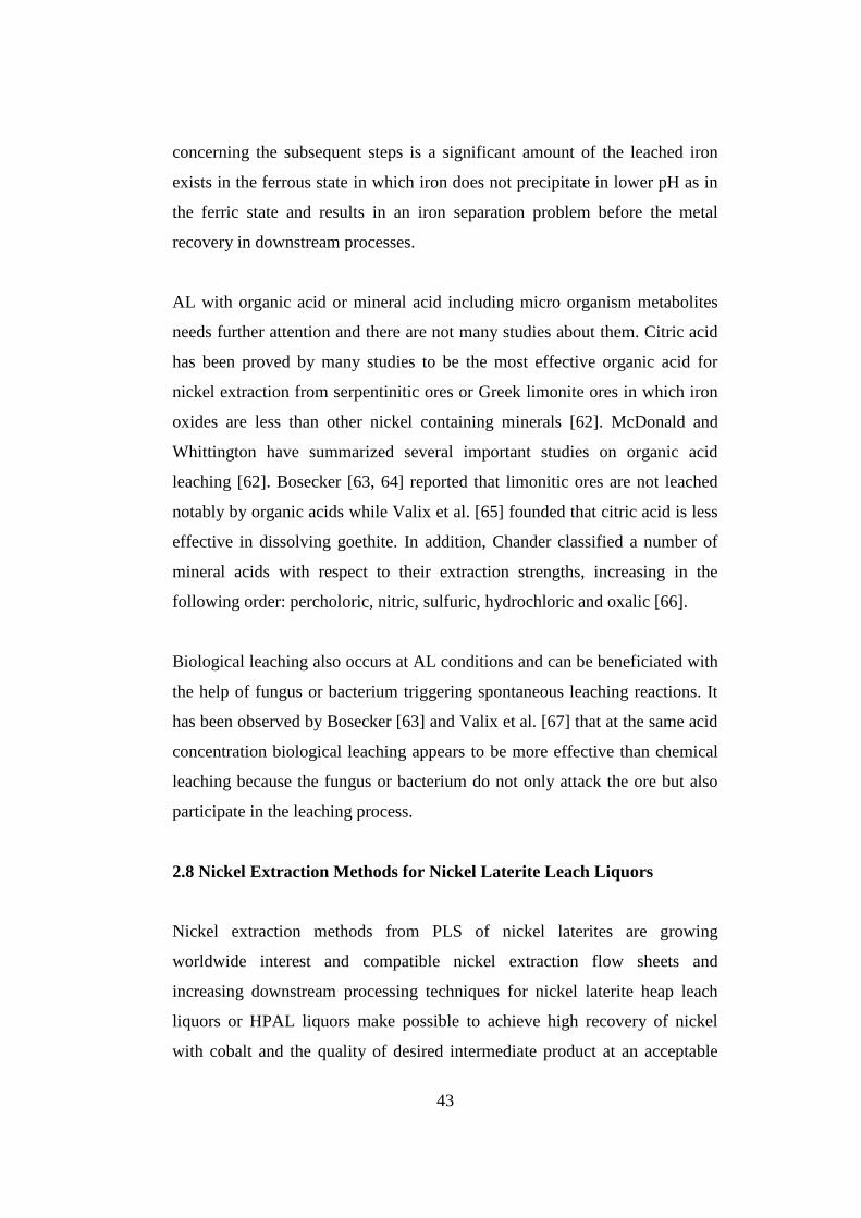
43
concerning the subsequent steps is a significant amount of the leached iron
exists in the ferrous state in which iron does not precipitate in lower pH as in
the ferric state and results in an iron separation problem before the metal
recovery in downstream processes.
AL with organic acid or mineral acid including micro organism metabolites
needs further attention and there are not many studies about them. Citric acid
has been proved by many studies to be the most effective organic acid for
nickel extraction from serpentinitic ores or Greek limonite ores in which iron
oxides are less than other nickel containing minerals [62]. McDonald and
Whittington have summarized several important studies on organic acid
leaching [62]. Bosecker [63, 64] reported that limonitic ores are not leached
notably by organic acids while Valix et al. [65] founded that citric acid is less
effective in dissolving goethite. In addition, Chander classified a number of
mineral acids with respect to their extraction strengths, increasing in the
following order: percholoric, nitric, sulfuric, hydrochloric and oxalic [66].
Biological leaching also occurs at AL conditions and can be beneficiated with
the help of fungus or bacterium triggering spontaneous leaching reactions. It
has been observed by Bosecker [63] and Valix et al. [67] that at the same acid
concentration biological leaching appears to be more effective than chemical
leaching because the fungus or bacterium do not only attack the ore but also
participate in the leaching process.
2.8 Nickel Extraction Methods for Nickel Laterite Leach Liquors
Nickel extraction methods from PLS of nickel laterites are growing
worldwide interest and compatible nickel extraction flow sheets and
increasing downstream processing techniques for nickel laterite heap leach
liquors or HPAL liquors make possible to achieve high recovery of nickel
with cobalt and the quality of desired intermediate product at an acceptable

44
cost. No matter how acid leaching is applied to a nickel laterite from which
PLS collected has to be processed by downstream operations such as excess
acid neutralization, iron precipitation, nickel-cobalt separation or
precipitations and final product recovery in order to succeed in a saleable
intermediate product or nickel-cobalt cathodes.
Until today, many groups have assessed the amenability of their ores to heap
leaching or HPAL and adapted various downstream nickel recovery processes
based on the ore conditions; location, type, tenor, mineralogy, etc. Various
factors such as high nickel and cobalt prices, increasing demand for nickel
metal and low sulfur and H2SO4 prices have encouraged the development of
new projects for processing nickel laterites. Most of substantial refinement of
process methods has been done for the development of nickel recovery from
HPAL discharged liquors but not as many for heap leach liquors. Direct
solvent extraction (DSX) has been adopted for nickel-cobalt separation by
some of the existing and the majority of the proposed sulfuric acid laterite
projects [68]. At the Bulong and the Goro circuits, clarified PLS has been
used in the DSX process. In downstream processes existence of soluble iron,
manganese, aluminum, chromium and magnesium in PLS always cause a
number of challenges and obstacles which have been tried up to now to be
diminished and overcome by the various studies. Mixed hydroxide
precipitation (MHP) and mixed sulfide precipitation (MSP) are compatible
recovery techniques which face these difficulties to provide appropriate
nickel-cobalt precipitation. MSP is the older nickel recovery method which
has already been used commercially at Moa Bay while pilot plant tests using
MHP started at Hazen Research in Colorado in April 1996 [37]. In MHP
nickel and cobalt are recovered from the PLS through the addition of calcined
magnesia after the purification stage or stages whereas in MSP nickel and
cobalt are precipitated as mixed sulfide precipitates by reaction with hydrogen
sulfide gas after partial neutralization stages or pre-reduction steps. Rather
than using these recovery methods, various laterite projects propose the use of
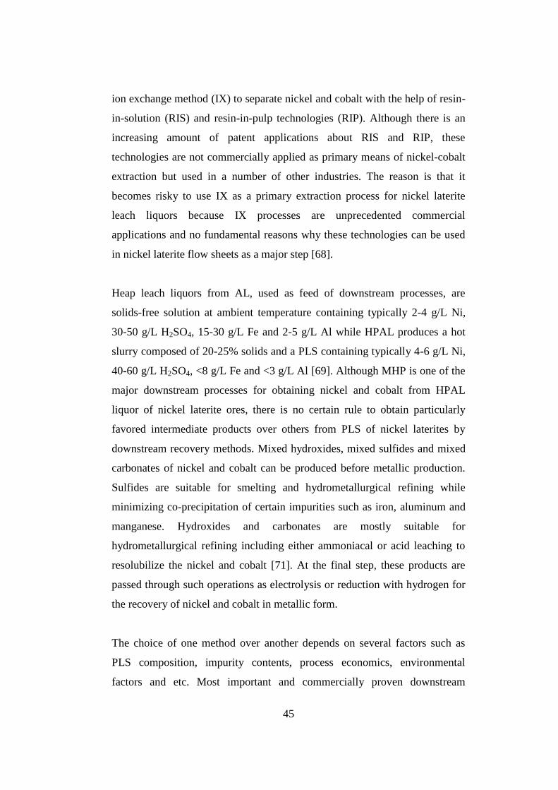
45
ion exchange method (IX) to separate nickel and cobalt with the help of resin-
in-solution (RIS) and resin-in-pulp technologies (RIP). Although there is an
increasing amount of patent applications about RIS and RIP, these
technologies are not commercially applied as primary means of nickel-cobalt
extraction but used in a number of other industries. The reason is that it
becomes risky to use IX as a primary extraction process for nickel laterite
leach liquors because IX processes are unprecedented commercial
applications and no fundamental reasons why these technologies can be used
in nickel laterite flow sheets as a major step [68].
Heap leach liquors from AL, used as feed of downstream processes, are
solids-free solution at ambient temperature containing typically 2-4 g/L Ni,
30-50 g/L H2SO4, 15-30 g/L Fe and 2-5 g/L Al while HPAL produces a hot
slurry composed of 20-25% solids and a PLS containing typically 4-6 g/L Ni,
40-60 g/L H2SO4, <8 g/L Fe and <3 g/L Al [69]. Although MHP is one of the
major downstream processes for obtaining nickel and cobalt from HPAL
liquor of nickel laterite ores, there is no certain rule to obtain particularly
favored intermediate products over others from PLS of nickel laterites by
downstream recovery methods. Mixed hydroxides, mixed sulfides and mixed
carbonates of nickel and cobalt can be produced before metallic production.
Sulfides are suitable for smelting and hydrometallurgical refining while
minimizing co-precipitation of certain impurities such as iron, aluminum and
manganese. Hydroxides and carbonates are mostly suitable for
hydrometallurgical refining including either ammoniacal or acid leaching to
resolubilize the nickel and cobalt [71]. At the final step, these products are
passed through such operations as electrolysis or reduction with hydrogen for
the recovery of nickel and cobalt in metallic form.
The choice of one method over another depends on several factors such as
PLS composition, impurity contents, process economics, environmental
factors and etc. Most important and commercially proven downstream

46
precipitation and recovery techniques to produce intermediate products are
MSP and MHP technologies. They both offer a conventional nickel laterite
downstream process to obtain the highest product grade with minimal
impurities. Environmental, safety and infrastructure aspects determine the
choice between them in the production of a hydroxide or a sulfide product.
These technologies are explained in detail in the following sections.
2.8.1 Direct Solvent Extraction (DSX)
DSX was first commercially operated at the Bulong circuits to recover nickel
from dilute leach liquor containing less than 4 g/L Ni using solvent extraction
process without the need of nickel precipitation. Donegan has defined
improved metallurgical performance of the Bulong DSX process at the time
of plant closure [72]. Initially it was unable to achieve design availability,
recovery and product quality at an appreciable cost by the SX process. After
subsequent development in optimization and successful modification in the
process, SX became applicable for a while (between 1999 and 2003) at
Bulong circuits. However, it was then failed to reach the projected production
levels and Bulong operations were stopped owing to the considerable
financial burden and operational problems in the Bulong industrial operation.
Bulong DSX circuit is shown in Figure 2.16.
Figure 2.16 Bulong DSX circuit [72].
NH3
H2SO4
PLS
Cobalt SX
Ni, Mg, Ca
Raffinate
Nickel SX
NH3
H2SO4
Mg, Ca
Co, Cu, Zn, Mn, (Mg)
Cobalt
Refinery
Co
cathode
Mn, Mg
NaHS
NaOH
Co, Cu, Zn sulfide
Cobalt
Precipitation
Ni
cathode
Na2SO4
Na2CO3
Nickel EW

47
The Bulong leach plant was composed of ore preparation, HPAL of PLS with
sulfuric acid, neutralization step, CCD and again solution neutralization step
to obtain a mildly acidic sulfate based PLS containing low levels of Fe, Al
and Cr. Firstly, PLS after the HPAL process and the neutralization step was
fed to cobalt solvent extraction (CoSX). Then, an organic substance
containing Cyanex 272 (C272) separated Co, Zn, Fe, Cu and Mn from Ni.
Next, the Co in the loaded strip liquor (LSL) was separated from Mn and Mg
by sulfide precipitation while Ni, Fe(III), Zn and Cu were co-precipitated.
Afterwards, the filtered sulfide product was sent to the processing in the
cobalt refinery to obtain Co cathode whereas the barren solution containing
Mn and Mg was discarded to the tailings. On the other hand, CoSX raffinate
was transferred to the nickel solvent extraction (NiSX) circuit where an
organic substance containing Versatic 10 (V10) separated Ni from Ca and
Mg. Finally, the Ni loaded organic strip passed through an electrowinning
step to accumulate Ni cathode.
In addition to Bulong‟s DSX process, there were other DSX routes studied
with various extractants such as Cyanex 272, versatic acid, hydroxyl oximes
and di-2-ethylhexylphosphoric acid (D2EHPA) proposed by many groups. In
one of them, Heckley and Ibana in May 2003 pointed out a novel separation
technique which was electrostatic pseudo liquid membrane (ESPLIM) [73].
This method combines the advantage of SX, liquid membrane and
electrostatic dispersion. Extraction and stripping occurred simultaneously in
ESPLIM while at the end of the process the separation of nickel and cobalt
was attempted.
In solvent extraction the aim is to separate pure NiSO4 and also CoSO4 from
impurities, typically Zn, Fe, Cu, etc. and make a further use of both nickel and
cobalt sulfate concentrates produced. The separation of NiSO4 with minimum
co-extraction of contaminants was achieved by Ritcey and Ashbrook in 1966
just using D2EHPA [74]. In order to extract nickel and cobalt more

48
selectively over other elements from the PLS best extractants must be found
and extractive features of the element must fit the SX condition; in other
words there must be more affinity for extraction and collection of nickel and
cobalt over others in the organic phase. Otherwise, DSX involves a number of
risks due to insufficient separation of nickel and cobalt from impurities.
Today most reagents used in DSX and SX circuits are usually Cyanex series:
Cyanex 272, 301, 302 and similar type organic phases.
2.8.2 Ion Exchange (IX) and Resin-In-Pulp (RIP)
Ion exchange or resin-in-pulp method is a new option among the others for
treatment of solutions after the leaching of nickel laterites. This method was
initially used for the recovery of uranium and gold, evolved from carbon-in-
pulp (CIP) process in which activated carbon is replaced with ion exchange
resin and followed by resin-in-pulp process [75]. In RIP, the PLS from AL or
HPAL stages is contacted with ion exchange resin which selectively loads the
nickel and cobalt from the pulp. According to Mendes and Berni [75], RIP is
composed of three different stages: adsorption, elution and regeneration.
Nickel and cobalt are selectively loaded in the adsorption stage.
RIP can be preferred instead of such conventional techniques as solvent
extraction and precipitation methods because of efficient recovery, selective
extraction of low concentrations of nickel and cobalt over an excess of
impurities, high mechanical strength, its operational simplicity, low losses
resulted from contamination by organic matter and etc. The use of IX based
systems for selective nickel extraction, especially from ferrous iron and
aluminum is an alternative option for nickel and cobalt recovery from the
leach pulp. Inversely, ferric iron, Fe(III), and Cu(II) can be removed and
loaded over nickel and cobalt from the leach pulp by an ion exchange resin.

49
Nowadays, a large number of ion exchange resins are available commercially
and are widely used in hydrometallurgy while cation exchange resin and
weakly acidic resins have been proposed and used for adsorption of nickel
and cobalt from hydrometallurgical process solutions. Furthermore, there are
various chelating resins found out which selectively adsorb nickel and cobalt,
such as bispicolylamine, aminophosphonic acid and amidoxime [76].
2.8.3 Molecular Recognition Technology (MRT)
Molecular recognition technology (MRT) applies “host guest” chemistry
which is a highly selective, non ion exchange system [77]. It utilizes metal
complexing compounds which are chemically bonded to solids such as silica
gel or polymer substrates called as SuperLig®. In MRT, the feed solution is
transferred to the column(s) and the desired ion is removed selectively from
the PLS. Willis noted an MRT SuperLig® product which selectively
accumulates nickel and cobalt at an acid concentration of approximately pH 1
[69]. The nickel accumulated is then eluted by using a 5M sulfuric acid
solution rendering an acidic nickel sulfate solution which is then crystallized
and recovered by centrifuging and producing a high purity product. Cobalt
can also be recovered in a similar manner as a cobalt sulfide, cobalt carbonate
or cobalt hydroxide.
The MRT process has various advantages. It has high selectivity, high binding
factors, and rapid reaction kinetics leading to a very efficient separation.
SuperLig® products can hold ions even when they are in extremely low
concentrations in the presence of very high levels of competing ions and even
in highly acidic and basic solutions [77]. However, laboratory and/or pilot test
work and a preliminary study are required for the economics of the process in
which low nickel and cobalt concentrations exist.

50
2.8.4 Mixed Sulfide Precipitation (MSP)
A range of downstream processing options have been developed for nickel
and cobalt recovery from heap and HPAL leach PLS. One of the most
commercially practiced options is mixed sulfide precipitation (MSP) which
has 50 years experience up to date. The precipitation of nickel and cobalt as
mixed sulfides with hydrogen sulfide gas has been successfully started in the
Mao Bay Plant in Cuba and soars to the Murrin-Murrin plant in Western
Australia and the Coral Bay Nickel plant in Philippines using a similar MSP
route. Moreover, today there are several MSP projects which have been
developed and planned to be worked in future. These are Syerston in
Australia, Weda Bay in Indonesia, Ambatovy in Madagascar, Gladstone in
Australia, Nonoc and Mindoro in Philippines.
Willis has discussed a suitable MSP route and summarized the general MSP
process flow sheet [69]. Figure 2.17 shows a general MSP circuit. It was
pointed out that MSP is highly selective for nickel and cobalt over iron,
aluminum, chromium and manganese although copper and zinc are reported
as minor impurities that can be tolerated in the mixed sulfide product. The
MSP process can be used for all laterite ores but it is especially well suited to
limonitic ores containing low nickel and high iron or aluminum content. In
addition, it is a better alternative to the MHP process for nickel laterite ores
containing a nickel to manganese ratio of less than 3:1. Hence, there is no
need to remove ferrous iron, aluminum, manganese and chromium before the
nickel and cobalt precipitation as in the MHP process. In the MSP process, a
lower nickel tenor renders less redissolving of the nickel-cobalt values of the
sulfide precipitates in the sulfuric acid. It means lower grade of the deposit
resulting in less loss of soluble values in the sulfide precipitation process.
MSP process is conducted either in an autoclave operated at up to 1034 kPa
and 121oC for about 10 to 30 minutes retention time or in a multi reactor at

51
about 200 to 400 kPa and 80 to 95oC for 60 to 90 minutes retention time. It is
possible to produce higher than 99% recovery in one pass [70].
Before the MSP reaction, the slurry from AL or HPAL is sent to the
thickeners for solid-liquid separation. The PLS from CCD wash circuit is sent
to a reduction stage if it is desired to remove copper from the mixed sulfide
product. Copper is selectively precipitated with hydrogen sulfide gas as
copper sulfide by carefully controlling redox conditions (at about 380 mV)
while ferric iron and hexavalent chromium, Fe3+
and Cr6+
, are reduced to
ferrous iron and trivalent chromium, Fe2+
and Cr3+
[69]. The chemistry of the
MSP process is better understood by the sulfide precipitation selectivity graph
which is illustrated in Figure 2.18.
Figure 2.17 Mixed sulfide precipitation (MSP) process general circuit [78].

52
- 6
- 4
- 3
- 2
- 1
- 0 -5
-4
-3
-2
-1
0
-55 -50 -45 -40 -35 -30 -25 -20 -15 -10 -5 0
- 5
7
Figure 2.18 shows the precipitation order of ions according to pH and S2-
ion
concentration of the PLS to be precipitated. The line of Fe2+
ion comes after
the lines of Ni2+
and Co2+
means that ferrous iron does not precipitate until the
substantial precipitation of nickel and cobalt. This is unwanted condition in
heap leach PLS since the Fe/Ni ratio is high in the PLS and iron will highly
remain in solution up to the following process steps without being
precipitated. It will both impure the MSP product and the recycle water for
heap leaching. This is also the case for the HPAL leach PLS. Therefore, an
extra iron removal or neutralization step is required for decreasing the iron
content. In the reduction step H2S is sent from the sulfide precipitation
reactor‟s vapor space and fresh supply [78]. After the reduction step,
discharge liquor flows to the neutralization step where free acid is neutralized
with limestone. The purpose of neutralization is to adjust the feed liquor pH to
achieve the optimum conditions for nickel and cobalt precipitation prior to
sulfide precipitation. It is recommended by Willis to neutralize the PLS by
limestone to pH 2.5-3.0 and 70-90oC [69]. At pH 2.5-3.0 most of the iron
(ferric) is precipitated which will result in less capital and operating costs for
hydrogen sulfide production because the ferric to ferrous iron reduction
Figure 2.18 Sulfide precipitation selectivity graph [70].
Log(S2-
) (Molar)
Log(M
n+)
(Mola
r)
pH

53
during sulfide precipitation significantly consume more hydrogen sulfide than
other reactions. On the other hand, an operating temperature between 70oC
and 90oC rather than ambient temperature favors fast reaction kinetics and
nullifies viscosity problems. In the acid neutralization reaction gypsum is
precipitated, Fe(III) decreased to a residual concentration of less than 200
mg/L and chromium removed to very low levels but aluminum is around 2000
mg/L. At these precipitation conditions, Ni and Co are co-precipitated in
minor amounts typically less than 0.5%. The discharge gypsum slurry is then
thickened and soluble nickel and cobalt are recovered if present by CCD
washing. The washed solids are disposed of as tails in the tailing pond.
After the neutralization reaction, fine recycled freshly precipitated sulfide is
added as seed to the overflow neutral solution then heated with steam and
directed to the sulfide precipitation step in autoclaves or MSP reactors. Seed
addition in the form of fine particles is necessary on account of avoiding
significant scaling of the process equipment such as agitator blades resulted
from insufficient seed surface area. Recycled H2S and additional amount from
the H2S plant are pumped to the respected autoclave or the reactor and metal
precipitation occurs on the surface of existing particles. Nickel and cobalt can
substantially be precipitated with H2S gas from a neutral solution at pH > 2.5
and a pre-defined H2S overpressure in the autoclave or the reactor vessel.
Under these conditions nickel become less than 30 mg/L in the residual
solution [69]. Willis underlined that with the addition of hydrogen sulfide
ferric iron, aluminum, chromium, manganese and magnesium are precipitated
while any Cr(VI), Mn(IV) and Fe(III) present are reduced to Cr(III), Mn(II)
and Fe(II), respectively. In addition, magnesia slurry or caustic soda can be
added to control the final pH of the solution in case sulfuric acid produced as
a product causes slow reaction kinetics and the solubility of MSP products
increases. In this step a higher nickel grade renders undesired loss of values
with H2SO4 produced in the residual solution as it is previously mentioned.

54
After the MSP product slurry is discharged and the vent gas cooled by steam
flashing, the dilute slurry of mixed sulfides is directed to the thickeners where
flocculants are added to decrease the losses which can be arisen from the fines
discarded with the overflow [78]. The thickener overflow can be rejected or
cleaned from impurities by precipitation of the heavy metals mostly Fe(II) and
the other polluting elements at a pH greater than that in the MSP step. Firstly,
Fe(II) is oxidized to Fe(III) by air injection and removed from the barren
solution at pH 2.0-2.5 and secondly, the same procedure is followed for
manganese except that manganese is precipitated at pH 8.5-9.0 as manganese
hydroxide The overflow slurry is then passed through a wash filtration and
used in the CCD wash circuit at pH 1.5-2.0 as a supply for make-up water.
The requirement of this final neutralization circuit is important to prevent
ferrous iron accumulation in the circuit due to the foregoing reduction step or
to satisfy the environmental regulations if the barren solution is discarded. In
this manner, most of the Mn and Mg remaining in the barren solution after Ni-
Co precipitation are removed. At the same time, the discharged slurry from
the thickener underflow is dried and bagged and shipped to the corresponding
refineries as in Moa and Coral Bay. Typical MSP product composition is
shown in Table 2.7 [69].
Component Unit Value
Nickel wt% (dry) 55-61
Cobalt wt% (dry) 3-6
Zinc wt% (dry) 2-6
Copper wt% (dry) 1-5
Manganese wt% (dry) < 0.1
Magnesium wt% (dry) < 0.1
Iron wt% (dry) < 0.8
Aluminum wt% (dry) < 0.1
Sulfur wt% (dry) 34-36
Moisture wt% 10-15
Table 2.7 Typical MSP product composition [69].

55
2.8.5 Mixed Hydroxide Precipitation (MHP)
Mixed hydroxide precipitation (MHP) is a well-established and inexpensive
method to recover nickel and cobalt as an intermediate product from the
solution containing soluble heavy metal ions. The intermediate product is
further processed before sale as a nickel compound or pure metal. A mixed
hydroxide precipitate can be precipitated from the PLS of nickeliferous
laterite by various downstream processing options to selectively recover
nickel and cobalt. Iron purification, nickel-cobalt precipitation and manganese
or magnesium removal operations make up these options for MHP to be an
applicable nickel-cobalt extraction process for nickeliferous laterites. These
techniques will be explained in great detail in the following pages. Although
the MHP processes in Cawse and Ravensthorpe were stopped due to the
economical reasons, today there is a wide range of developed MHP projects
which will be set to work in the near future. These are META Gördes in
Turkey, again Ravensthorpe in WA (First Quantum Minerals Ltd. is the new
owner of the project), Vermelho in Brazil, Ramu in Papua New Guinea and
Young, Mount Margaret and Kalgoorlie in WA.
Generally, an alkaline reagent is used to increase the solution pH to lower the
solubility of the metallic constituent and so giving rise to precipitation.
Caustic soda [NaOH], soda ash [Na2CO3], hydrated or slaked lime [Ca(OH)2],
magnesium hydroxide [Mg(OH)2] and magnesia [MgO] are commonly used
in MHP as precipitating agents. Magnesia is more frequently used to
precipitate nickel and cobalt. It is cheaper than caustic soda and soda ash and
does not give as much contaminated product as slaked lime. The mixed
hydroxide precipitate typically contains 15 to 25% Ni with 0.1 to 1% Co but
less than 40% Ni on dry basis [37, 69]. Main problem in MHP is that
hydroxide precipitate is commonly contaminated with Mn, Al, Ca and
unreacted MgO. In addition, in MHP process MgO consumption is an
important parameter for economics of the process. MHP is not very selective

56
for Ni and Co over Mn and preferably performed in two stages to control the
Mn flow in the circuit and also to obtain purer product. The electrochemical
mechanism of the MHP can be best followed by MHP selectivity graph which
is shown in Figure 2.19. As it is shown in the mentioned figure, Mn2+
and
Mg2+
precipitate after Ni2+
and Co2+
when pH increases. This results in
manganese and magnesium contamination in MHP product. The Fe2+
and
Zn2+
precipitation lines also show that there will be zinc and iron deportment
to the MHP product if they are present in PLS. The precipitation order is from
left to right and it starts with Fe3+
precipitation as pH increases.
Main issue of MHP is to add sufficient caustic calcined magnesia to
precipitate as much as nickel and cobalt while precipitating as low as
manganese and limiting magnesium contamination after iron removal process.
Hence, the nickel hydroxide intermediate product recovery process consists of
successful removal of iron, nickel and cobalt, and manganese and magnesium.
A typical MHP route proposed by Willis is shown in Figure 2.20.
-5
-4
-3
-2
-1
0
0 2 4 6 8 10 12 14
Log(M
n+)
(Mola
r)
pH
Figure 2.19 Mixed hydroxide precipitation selectivity graph [70].

57
Figure 2.20 Mixed hydroxide precipitation circuit after the heap leach [69].

58
Mixed hydroxide precipitation of PLS from the heap leach step is composed
of recycle leach, two-stage iron removal, two-stage nickel-cobalt precipitation
and manganese removal or following magnesium removal if required. It is a
bit different from the MHP for the HPAL process because two-stage iron
removal is not required for the PLS from the HPAL process which includes
less iron to be precipitated.
The MHP process for the PLS from the heap leach was selected to be
explained in detail rather than that from the HPAL on account of the fact that
a stock of the PLS from the column leach of Gördes nontronite was used in
the thesis study. Most of Fe, Al, Cr, As, Cu and Zn of PLS from the heap
leach are removed before Ni-Co precipitation. However, according to Willis‟s
MHP selectivity graph, Figure 2.19, Mn2+
cannot be removed before Ni-Co
precipitation and some Mn contamination of the MHP product must be
allowed in order to obtain desired Ni and Co grade of the MHP product since
Ni-Co precipitation is not possible practically without some Mn precipitation.
A recycle leach and iron removal stages are required to prepare the desired
quality of feed solution prior to precipitate mixed nickel-cobalt hydroxide
product. As in the case of Cawse plant, the contamination of the MHP product
by Fe, Al and Si can be prevented by following successful purification
operations. Otherwise, the presence of Al and Si causes low nickel recovery
in subsequent ammonia leaching step. The aim of recycle leach is to benefit
from the residual acid in the heap leach PLS to re-dissolve any Ni and Co
which are co-precipitated as hydroxides in both second stage iron removal and
second stage mixed hydroxide nickel-cobalt precipitation. The recycle leach is
usually carried out at higher temperatures than ambient temperature,
especially >50oC, and at sufficient sulfuric acid concentration, especially >20
g/L, in order to achieve both fast and increased Ni and Co recoveries up to 95-
100% [69]. During recycle leaching of Ni and Co, substantial quantities of
any Fe, Al, Mn and other hydroxides can also re-dissolve but it will not be a

59
problem unless exceeding the critical value and it is generally not the case
since all the significant quantities are precipitated in first iron removal and
first Ni-Co precipitation stage as well as most of Mn and Mg are rejected
from the circuit at the end of the process.
The iron content of nickeliferous laterites generally ranges from about 10% to
over 50% and 20-50% of this contained iron is dissolved by AL or heap
leaching [69, 79]. As it is given in the nickel extraction methods, pregnant
leach solutions from AL and HPAL typically include 15-30 g/L and <8 g/L
Fe, respectively. At pH 2.5-3.0 almost all iron content in heap leach liquor
tends to precipitate except for ferrous iron. Therefore, first of all, there must
be a purification stage or stages in MHP circuit for heap leach liquor prior to
precipitate nickel-cobalt product at pH 7.0-7.5 to reject most of the iron
soluble in PLS of nickeliferous laterites. However, as it is explained
previously, HPAL liquors do not include as much iron content as AL (heap)
liquors because iron is hydrolyzed and precipitated as hematite, Fe2O3,
leaving a lower residual iron soluble in PLS during pressure leaching. In
literature, it was reported that iron can be removed either by solvent extraction
or precipitation techniques in hydrometallurgy. There are numerous papers
which have published up to date explaining iron extraction techniques by
several organic solvents and di-2-ethylhexylphosphoric acid (D2EHPA)
whilst they are used in limited applications in industry [79, 80]. D2EHPA was
chosen by Agatzini et al. because of having certain advantages over other
organic solvents such as chemical stability, low solubility in water and good
loading and stripping characteristics [79]. On the other hand, iron elimination
from the leach solution by precipitation techniques consists of jarosite,
magnetite, hematite and goethite methods [80-83]. The Eh-pH Pourbaix
diagram of iron-water systems which is given in Figure 2.21 best describes
the iron precipitation mechanism in leach liquors. At ambient conditions, iron
is stable and soluble as either Fe3+
or Fe2+
ions up to certain pH values, 1.617
and 6.64, respectively [82].
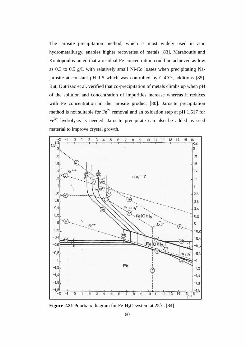
60
The jarosite precipitation method, which is most widely used in zinc
hydrometallurgy, enables higher recoveries of metals [83]. Maraboutis and
Kontopoulos noted that a residual Fe concentration could be achieved as low
as 0.3 to 0.5 g/L with relatively small Ni-Co losses when precipitating Na-
jarosite at constant pH 1.5 which was controlled by CaCO3 additions [85].
But, Dutrizac et al. verified that co-precipitation of metals climbs up when pH
of the solution and concentration of impurities increase whereas it reduces
with Fe concentration in the jarosite product [80]. Jarosite precipitation
method is not suitable for Fe2+
removal and an oxidation step at pH 1.617 for
Fe3+
hydrolysis is needed. Jarosite precipitate can also be added as seed
material to improve crystal growth.
Figure 2.21 Pourbaix diagram for Fe-H2O system at 25
oC [84].

61
Other than jarosite precipitation method, magnetite precipitation method is a
new commercial application while hematite precipitation method is a more
recent innovation in the zinc industry [83]. Among them, goethite
precipitation method is better for heap leach liquors of low grade
nickeliferous laterites since very low residual iron remains in solution as less
than 0.05 g/L, thickening and filtration properties of the goethite precipitate
are superior, high concentration of iron in the precipitate obtained and
stability of the precipitate is good without need of special equipment [79].
Zhang and Mei reported that at 90-95oC, pH 3-3.5, 3-4 hours reaction time
and addition of seed crystals, iron (ferric) ions can be removed from sulfate
solutions in readily filterable form by the goethite method [82]. The product
of the process is commonly FeOOH, the α-form of goethite [86].
The discharge slurry from the recycle leach is sent to iron removal stages in
Figure 2.20. The aim in iron removal is both to neutralize excess acid in the
heap leach PLS and to reject basic impurities such as iron and aluminum from
the solution by CaCO3 addition before nickel-cobalt precipitation. As it can be
seen in Figure 2.19, at pH 2.5 to 3.0 almost all ferric iron, Fe(III), can be
removed from PLS to a residual concentration of less than 200 mg/L [69] as
well as chromium and aluminum removed to low concentrations. Also, co-
precipitation of nickel and cobalt in this pH range is insignificant, typically
less than 0.5% of the precipitate as Willis noted. Similarly, Sarma et al.
reported that complete removal of iron and about 95% removal of silica can
be succeeded at about pH 3.5 by conducting the precipitation at 80-90oC for
one hour [87]. Gypsum, CaSO4.2H2O, is a precipitated product of the acid
neutralization reaction between sulfuric acid and limestone. Particularly,
limestone is used to give better dewatering properties to the precipitate than
slaked lime as well as it is a cheaper reagent [88].
Temperature and especially pH are the most important variables controlling
the iron precipitation mechanism which determines the degree of iron

62
0
1
2
3
4
5
6
7
2.00 2.50 3.00 3.50 4.00 4.50
pH
% L
oss
in
th
e p
rec
ipit
ate
Ni
Co
removal, nickel-cobalt losses, crystallinity of the precipitate and
sedimentation and filtration properties. An operating temperature between 70
and 95oC or the boiling temperature of the slurry is preferred to yield fast
reaction kinetics and to decrease the slurry viscosity, then better filtration
properties in the sequential filtration step. However, operations at ambient
temperature render poor reaction kinetics. Primary neutralization temperatures
at Ravensthorpe were kept at 95oC to enhance iron precipitation as jarosite
and to improve aluminum rejection [37]. It is important to note that aluminum
should be as low as possible, especially less than 50 mg/L by adjusting a pH
between 4.4 and 4.8 in order to satisfy the nickel-cobalt dissolution in the
following ammonia leaching step [69]. The reason for this is known that
aluminum presence in mixed hydroxide precipitate causes a gelatinous and
amorphous structure which hinders some of nickel and cobalt leaching and
makes them unrecoverable inside the unbroken bonds of the aluminum
hydroxide. In addition, co-precipitation of nickel and cobalt is significant at
this pH range compared to the first iron removal stage, typically 4-10% [69].
The increase of co-precipitation of nickel and cobalt with pH is shown in
Figure 2.22.
Figure 2.22 Percent of nickel and cobalt losses with pH in the precipitate [89].

63
Agatzini et al. reported that at pH 3.5, 99.9% of iron, 98.9% of aluminum and
99.1% of chromium were precipitated while only 3.5% nickel and 2.0%
cobalt co-precipitated based on the analyses of the precipitates [30].
Meanwhile, rate of pH change is an important factor for the quality of the
product. Agatzini et al. has also emphasized that during the precipitation
process by adding 20% CaO pulp, the pH increase rate was fixed to a low
value within a practical period of time up to 12 hours in order to prevent
supersaturation of iron, aluminum and chromium and the production of an
amorphous precipitate which causes deterioration in the filtration and settling
characteristics [30, 89].
Direct precipitation of iron and aluminum at a certain pH and temperature in a
single stage yields significant loss of values with impurities as well as
increased capacities of purification plant rendering an uneconomic process.
Thus, for a complete removal of iron, aluminum and other impurities and
minimum nickel and cobalt losses, iron removal process of MHP occurs in
two stages as in Figure 2.20. By carrying out two-stage iron purification
process for the leach liquors, with the limestone addition, most of the iron
content of PLS removed and the decreased load of the PLS is subjected to the
subsequent precipitation process for decreasing mainly its aluminum and
chromium and also the remaining iron contents to very small values while co-
precipitated nickel and cobalt hydroxide re-dissolve in the recycle leach. At
the same time, manganese dioxide, MnO2, or oxygen, O2, can be added as a
catalyst to convert ferrous iron to ferric iron if there is significant concentrate
of ferrous iron in the PLS. Ferric iron is then precipitated with various base
additions according to the following reactions [90]:
Fe2(SO4)3 + 6CaO + 3H2SO4 2Fe(OH)3 + 6CaSO4 (2.12)
Fe2(SO4)3 + 6CaCO3 + 3H2SO4 2Fe(OH)3 + 6CaSO4 + 6CO2 (2.13)
Fe2(SO4)3 + 6Na2CO3 + 3H2SO4 2Fe(OH)3 + 6Na2SO4 + 6CO2 (2.14)
Fe2(SO4)3 + 6NaOH 3Na2SO4 + 2Fe(OH)3 (2.15)

64
Aluminum and chromium can effectively be rejected from leach liquors at
higher than 95% during the iron removal process. Agatzini and Oustadakis
have reported that aluminum and chromium were precipitated as 99% and
97%, respectively at 95oC and 1 atm as easily filterable basic sulfate salts of
the jarosite-alunite type, with minor amount of nickel and cobalt co-
precipitated by gradually increasing the pH of the PLS to an equilibrium pH
value of 3.5 [89]. The remaining Al and Cr concentrations achieved after the
precipitation were lower than 200 ppm and 50 ppm, respectively while the
residual iron concentration was 30 ppm [30, 89]. The target pH primarily
depends on the desired residual aluminum concentration in solution.
After the iron removal stages the PLS is forwarded to mixed hydroxide
nickel-cobalt precipitation stages as seen in Figure 2.20. The reason for
performing two-stage nickel-cobalt precipitation is due to controlling the
extent of manganese contamination in the mixed hydroxide product. Nickel to
manganese ratio in the feed stream is very important for the MHP process to
be applicable in industry because MHP is not selective for high manganese
containing ores. In the first stage of MHP the solution is usually fixed to pH
7.0-7.5 at 50-80oC for two or three hours by the addition of freshly prepared
magnesia to achieve the maximum practical nickel and cobalt precipitation
possible as well as limiting the manganese content of the precipitated solids to
less than 5% and minimizing magnesium contamination [37, 69]. Willis noted
that at this pH range almost 90-95% of the nickel, cobalt, copper and zinc are
precipitated together with 15-35% manganese and nearly all the remaining
iron, aluminum and chromium in the PLS. This is also apparent in Figure
2.19. An operating temperature of higher than 50 or 60oC is preferred for
higher reaction kinetics while low temperature treatment yields slow kinetics.
Some magnesium can also be present in the form of unreacted magnesium
oxide in the MHP product depending on reactivity of magnesia used for pH
adjustment. When magnesia forms brucite, Mg(OH)2, in the precipitation
reaction, it acts as seed material for nickel precipitation. In Hazen Research
65
pilot plant built in Colorado in 1996, the mixed hydroxide precipitates
obtained were of poor quality attributed to mainly magnesium contamination.
It was found that caustic calcined magnesia is at its most reactive condition
when it is used dry and mixing with water for longer than a few minute
changes its reactivity and results in product contamination [37]. Magnesia
should not have any contact with air and used as dry or slurried with water
within a few minutes and consumed freshly. Furthermore, insufficient
magnesia leads to excess nickel passing to second stage precipitation,
increased slaked lime consumption, and losses attributed to additional
recycles [37]. However, instead of magnesia, caustic soda (sodium
hydroxide), hydrated lime (calcium hydroxide) or soda ash (sodium
carbonate) can be used as precipitating agent. Although they eliminate the
unreacted magnesium content of the MHP product and some provide more
quantitative recovery of nickel and cobalt, caustic soda is expensive, lime
results in gypsum contamination and the selectivity for nickel over manganese
is diminished by the use of soda ash. The discharge slurry from the first stage
of MHP (MHP1) is sent to a thickener and purified from soluble impurities by
wash filtration and solid MHP1 products become ready for ammoniacal re-
leach and refining while the overflow solution is directed to the second stage
of MHP (MHP2). In MHP2, the solution is typically fixed to pH 7.5-8.0 at 50-
80oC for one or two hours by addition of sufficient slaked lime to precipitate
all residual nickel and cobalt whereas 20-30% of the remaining manganese is
co-precipitated in the PLS coming from the first stage [69]. Willis pointed out
that at this pH range the precipitates generally contain 10-20% manganese but
final nickel and cobalt concentrations can be successfully decreased to less
than 5 ppm. The nickel and cobalt hydroxides in the precipitated solids after
the second MHP stage are re-dissolved together with manganese hydroxide by
the reaction with acidic PLS coming from the heap leach. The reason why the
second mixed hydroxide precipitate is not saleable as an intermediate product
is that marketing options restricts the manganese content to less than 10%.
Some Ni and Co values should be sacrificed in order to produce saleable

66
MHP product which contains less than limiting Mn content. Thus, the
optimum pH depends on the desired residual Ni and Co concentrations in the
remaining solution and the limited Mn content in the precipitate. Sist and
Demopoulos realized in the experiments that the concentration of Ni in the
aqueous phase (solubility) decreased with increasing pH and temperature
which control precipitation mechanism as in the iron removal process. It was
noted that increasing pH by one unit decreased the Ni concentration by a half
an order of magnitude while increasing temperature from 60oC to 70
oC
reduced Ni concentration by 50% [91].
Seed addition for both stages of MHP enhances product quality and settling
and filtration characteristics of precipitates by producing well-grown
crystalline particles. Precipitates formed by homogenous nucleation typically
causes small particles, low slurry pulp density, slow settling rates and high
impurity uptake. If seed is introduced, a substrate for the precipitation is
provided; heterogeneous nucleation occurs and improves the precipitate
properties [91]. In addition to produce more filterable high quality
precipitates, seed addition is expected to accelerate precipitation reaction, to
produce coarser precipitates and to suppress undesirable side reactions [92]. It
has been reported in the literature that the nickel hydroxide in the MHP
product can exist in one of the two phases, both crystallizing in a layered
hexagonal structure: α and β phases. The α-nickel hydroxide can be
represented by the general formula Ni(OH)2-xAn-
x/n . yH2O where x is 0.2-0.4
and A is chloride, nitrate, sulfate or carbonate, and y is 0.6-1 while the β–
nickel hydroxide is thermodynamically more stable and forming like a
mineral brucite structure without any hydrogen bonding between layers [93].
A similar α and β modifications of cobalt hydroxide, Co(OH)2, was also
studied by Rajamathi et al. [93]. A typical X-Ray diffraction graph of mixed
hydroxide precipitate produced by precipitating the purified PLS using MgO
pulp as a neutralizing agent is shown in Figure 2.23. The mineralogical phases
are theophrastite [Ni(OH)2], brucite [Mg(OH)2], a hydrated form of nickel

67
hydroxide and small quantities of silica (SiO2) while phases of cobalt and
manganese were not detected due to their low content in the mixed hydroxide
precipitate.
The typical MHP product composition is shown in Table 2.8 [69]. In addition
to know the chemical structure of the solid MHP product, aqueous
electrochemistry of Ni-Ni(OH)2 and Co-Co(OH)2 is important to determine
species which are stable during the precipitation reaction depending on pH
and oxidation-reduction potential of the solution liquor. Figure 2.24 and
Figure 2.25 show the Pourbaix diagrams for Ni-H2O and Co-H2O systems at
25oC, correspondingly. Between water lines, Ni
2+ and Co
2+ are stable up to
the pH values that projection of line 7 in Figure 2.24 and line 8 in Figure 2.25
intersect the pH axis between 6 and 7. At these points nickel and cobalt
become hydroxides, Ni(OH)2 and Co(OH)2, as long as pH does not exceed
about 12 and 13, respectively. In heap leach and iron purification stages at pH
<6 and at 200 to 600 mV ORP (Oxidation-Reduction Potential), nickel and
cobalt are soluble in PLS or solution liquors as divalent forms and are not
Figure 2.23 An XRD graph of the produced solid MHP product using MgO as
neutralizing agent [92].

68
precipitated unless pH becomes the pH for the commencement of the
hydrolysis reaction.
Component Unit Value
Nickel wt% (dry) 30-39
Cobalt wt% (dry) 2-5
Zinc wt% (dry) 1-4
Copper wt% (dry) 1-4
Manganese wt% (dry) 4-9
Magnesium wt% (dry) 3-5
Iron wt% (dry) < 0.5
Aluminum wt% (dry) < 0.5
Sulfur wt% (dry) 3-5
Moisture wt% 35-45
Figure 2.24 Pourbaix diagram for Ni-H2O system at 25
oC [84].
Table 2.8 Typical MHP product composition [69].
69
Thickener overflow solution after the second MHP stage in Figure 2.20 is
transferred to manganese removal. The aim in manganese removal is to reject
as much manganese as possible from the discharge liquors. As it is underlined
before, Willis noted that MHP process is not suitable for ores with high
manganese content, especially for ores having manganese to nickel ratio
greater than 1:3 and best applied to ores of higher nickel content and low iron
and aluminum content attributed to high nickel-cobalt losses with co-
precipitation [69]. Therefore, MHP is well suited to saprolitic ores and limited
to certain limonites. The reason why requiring low manganese content for
MHP process hides in high recovery percentages of manganese with nickel
and cobalt. This is apparent in Figure 2.26.
Figure 2.25 Pourbaix diagram for Co-H2O system at 25oC [84].

70
Oustadakis et al. used a synthetic solution without containing any impurities
such as iron, aluminum and chromium except for manganese to show the
precipitation of nickel and cobalt with respect to manganese co-precipitation
as a function of pH by addition of 20% MgO slurry. The precipitation of
nickel and cobalt was achieved as 99.9% and 99%, respectively while
manganese precipitation reached 80% by gradually raising and keeping the
pH of the leach liquor at a value of 9.0 at ambient temperature and pressure
[92]. The precipitate produced contained 25% Ni, 1.5% Co and 3% Mn, in
spite of the high manganese recovery in the precipitation because manganese
to nickel ratio in feed stream was less than 1:6 and manganese concentration
was 800 ppm which sufficiently met the requirement of MHP.
In contrast with Willis, Zhang et al. reported a study of two-stage manganese
removal from nickel laterite leach liquor in mixed hydroxide precipitation
circuit prior to nickel-cobalt precipitation [94]. It is claimed in the study that a
feasible way can be possible before MHP to partially discard soluble
%C
o2+,
Ni2
+ a
nd
Mn
2+ P
reci
pit
ati
on
Equilibrium pH
Figure 2.26 Nickel, cobalt and manganese precipitation using MgO slurry as
neutralizing agent [92].

71
manganese by oxidative precipitation at two neutralization steps with minimal
loss of nickel and cobalt. At the primary neutralization stage, pH 3 and 60oC-
80oC were tried but about 15% of the manganese in the leach liquor from
HPAL slurry was reported to be precipitated at 60oC with 3.8% SO2 in air and
leading to an insignificant co-precipitation of nickel and cobalt whereas the
higher temperature treatment (80oC) causes the slow mass transfer of oxygen
in air through the viscous slurry which hinders the manganese precipitation.
At the secondary stage, precipitation was conducted at pH 4.0 and 60oC with
the same sulfur dioxide concentrate but 56% of manganese was precipitated
with higher nickel and cobalt co-precipitations, 10% and 25%, respectively.
Next, the precipitate was sent to a recycle leaching stage to re-dissolve nickel
and cobalt using 30 g/L H2SO4 at 95oC. It was found out in the previous study
of Zhang et al, that the rate of oxidation of Mn(II) is slow at pH less than 3
and rises rapidly at pH higher than 4 [95]. Meanwhile, the introduction of
sulfur dioxide to the leach slurry, which is a reducing agent, gives rise to
chromate reduction and ferrous iron formation. However, the latter is not
desired in MHP. Thus, any ferrous iron is needed to be oxidized to ferric state
and precipitated prior to manganese oxidation.
Without operating pre-manganese purification stage as Zhang et al. suggested,
manganese usually accumulates in the circuit when the depleted solution is
recycled within the process or used as make-up water to heap leaching which
will adversely affect product quality. Typically, more than 50% of the
manganese remains in solution after two-stage nickel-cobalt precipitation
[69]. Furthermore, environmental regulations can necessitate removal of
aqueous manganese. Therefore, the overflow solution of the second MHP
stage is generally purified from most of its manganese content, generally less
than 100 ppm manganese left in solution by adjusting the solution pH to 8.5-
9.0 operating at 50-60oC for a time between half an hour and 2 hours and
precipitating manganese hydroxide [69]. Oxidation by air injection can be

72
required for the formation of manganese dioxide in order to achieve a residual
concentration of about 10 ppm.
Thickener overflow solution after the manganese precipitation in Figure 2.20
can be passed through magnesium removal process if there will be
magnesium accumulation in the MHP circuit. However, it is not a selective
process after pH 8.5 because consumption of reagent (slaked lime) is
excessive attributed to buffer effect. Magnesium can be present in solution
because of leaching magnesium from nickeliferous laterites and using
magnesia as a neutralizing agent in nickel-cobalt precipitation stage. In the
PLS resulting from heap leaching of hematitic/limonitic ores, magnesium
concentration is in the range of 6 g/L while for serpentinic ores it is in the
range of 50 g/L [41]. High soluble levels of magnesium can affect heap leach
performance such as double salt precipitation in the heap so that concentration
levels must be under control below certain levels [96]. The chemical
precipitation of magnesium, by calcium hydroxide, Ca(OH)2, from a leach
solution resulting from heap leaching of nickeliferous laterites with sulfuric
acid was studied by Karidakis et al. [97]. It was found that a minimum value
of pH 8.5 is required to precipitate higher than 97% magnesium from the
leach solution. Magnesium removal was achieved by using calcium hydroxide
in solid form and producing a precipitate comprising a mixture of magnesium
hydroxide [Mg(OH)2] and gypsum [CaSO4.2H2O]. Karidakis et al. also
reported that temperature and stoichiometric quantity of Ca(OH)2 are
significant variables in magnesium removal process. However, temperature
was effective on magnesium precipitation only when calcium hydroxide used
in stoichiometric quantity. The resulting final solution is a barren solution
containing only magnesium and calcium after iron removal, nickel-cobalt
precipitation and manganese removal processes. By removing magnesium as
a mixed hydroxide precipitate, the barren solution which contains 1-10 ppm
Mg can be recycled to the heap leaching stage and saved as process water in

73
the circuit and it also becomes possible to save the cost of waste disposal by
selling magnesium hydroxide precipitate with a market value.
As a conclusion, MHP process has been taking increasing attentions on
practical recovery of nickel and cobalt from leach solution of nickeliferous
laterites since it was invented. Ravensthorpe Nickel Operation will be
expected again to produce nickel intermediate product by MHP process after
HPAL and AL of nickel laterites [45] while META Gördes Project will start
to produce mixed hydroxide precipitate from Gördes within a few years [23].
A typical MHP processing route was also followed for the present thesis work
[98] after the extraction of nickel from lateritic ores at atmospheric pressure
with column and agitation leaching as reported [99, 100]. Commercialization
of MHP process will gain importance in future due to its bringing obvious
advantages into reality in extractive metallurgy of nickel.

74
CHAPTER 3
EXPERIMENTAL MATERIALS AND METHODS
3.1 Materials
A nontronite type lateritic ore was sampled from Gördes region in Manisa,
located in the western part of Turkey, and used for this thesis study.
Experiments were conducted by using stocks of pregnant leach solution, PLS,
resulting from column leaching of the nontronite ore. Column leaching of the
nontronite ore was done by a previous thesis study using dilute sulfuric acid
solutions at atmospheric conditions [99]. The sulfuric acid solutions were then
accumulated and stocked in order to use in iron removal, nickel-cobalt
precipitation, manganese and magnesium removal processes. Sodium
hydroxide and di–potassium oxalate monohydrate were used as a neutralizing
agent and a catalyst, respectively, for acid titration experiments to estimate
free acid content of the PLS. Limestone [CaCO3], magnesia [MgO] and
slaked lime [Ca(OH)2] were used as neutralizing and precipitating agents for
iron removal, nickel-cobalt precipitation and manganese and magnesium
removal experiments, correspondingly.
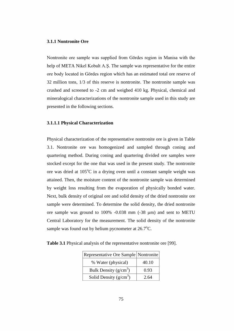
75
3.1.1 Nontronite Ore
Nontronite ore sample was supplied from Gördes region in Manisa with the
help of META Nikel Kobalt A.Ş. The sample was representative for the entire
ore body located in Gördes region which has an estimated total ore reserve of
32 million tons, 1/3 of this reserve is nontronite. The nontronite sample was
crushed and screened to -2 cm and weighed 410 kg. Physical, chemical and
mineralogical characterizations of the nontronite sample used in this study are
presented in the following sections.
3.1.1.1 Physical Characterization
Physical characterization of the representative nontronite ore is given in Table
3.1. Nontronite ore was homogenized and sampled through coning and
quartering method. During coning and quartering divided ore samples were
stocked except for the one that was used in the present study. The nontronite
ore was dried at 105oC in a drying oven until a constant sample weight was
attained. Then, the moisture content of the nontronite sample was determined
by weight loss resulting from the evaporation of physically bonded water.
Next, bulk density of original ore and solid density of the dried nontronite ore
sample were determined. To determine the solid density, the dried nontronite
ore sample was ground to 100% -0.038 mm (-38 µm) and sent to METU
Central Laboratory for the measurement. The solid density of the nontronite
sample was found out by helium pycnometer at 26.7oC.
Representative Ore Sample Nontronite
% Water (physical) 40.10
Bulk Density (g/cm3) 0.93
Solid Density (g/cm3) 2.64
Table 3.1 Physical analysis of the representative nontronite ore [99].

76
In addition, wet screen analysis of the dried representative nontronite sample
was carried out to determine particle size distributions of the nontronite. Wet
screen analysis was done by using an eight-sieve nest system that was
vibrated continuously until the water which was poured to the top came clear
from the bottom. After screening, all oversize and undersize particles in each
sieve were dried at 105oC and weighed. Screen analysis result of the
nontronite sample is shown in Table 3.2.
Size(mm) Weight (%) ∑ wt % oversize ∑ wt % undersize
+3.327 9.21 9.21 90.79
+2.362 2.09 11.30 88.70
+1.168 2.13 13.43 86.57
+0.589 3.87 17.30 82.70
+0.295 4.98 22.28 77.72
+0.147 9.24 31.52 68.48
+0.074 12.70 44.22 55.78
+0.038 15.44 59.66 40.34
-0.038 40.34 - -
∑ 100 - -
3.1.1.2 Chemical Characterization
The complete chemical analyses of the representative nontronite sample were
performed by using Inductively Coupled Plasma (ICP) and X-Ray
Fluorescence (XRF) methods. Particle size of dried sample used for the
chemical characterization was 100% -0.038 mm. Results of complete
chemical analyses of the representative nontronite ore are shown in Table 3.3.
Table 3.2 Wet screen analysis results of nontronite [99].
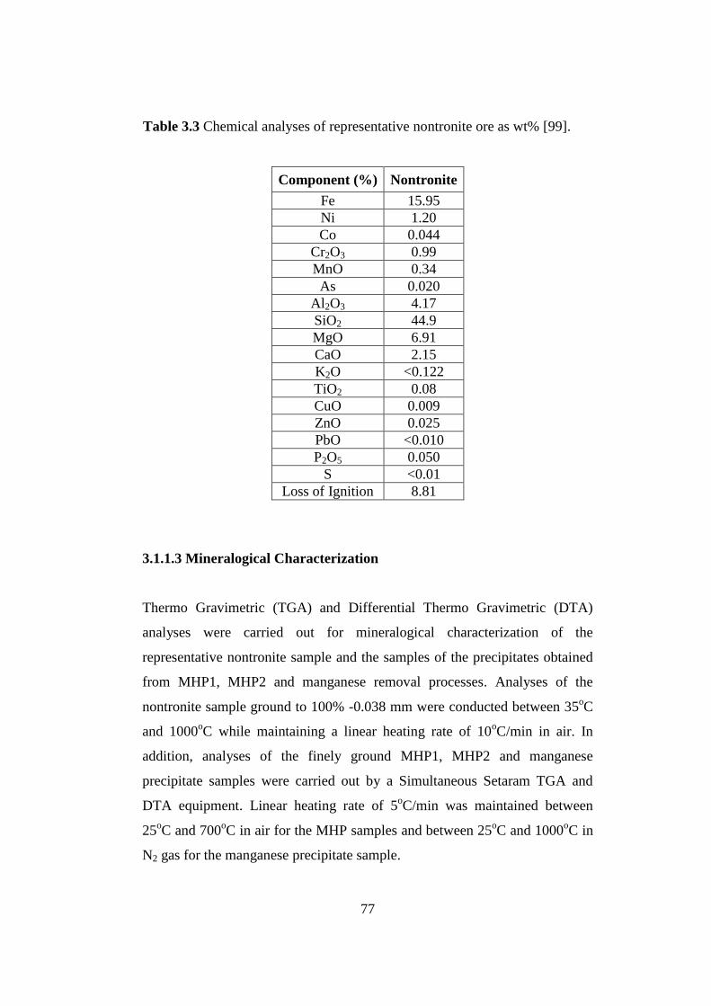
77
Component (%) Nontronite
Fe 15.95
Ni 1.20
Co 0.044
Cr2O3 0.99
MnO 0.34
As 0.020
Al2O3 4.17
SiO2 44.9
MgO 6.91
CaO 2.15
K2O <0.122
TiO2 0.08
CuO 0.009
ZnO 0.025
PbO <0.010
P2O5 0.050
S <0.01
Loss of Ignition 8.81
3.1.1.3 Mineralogical Characterization
Thermo Gravimetric (TGA) and Differential Thermo Gravimetric (DTA)
analyses were carried out for mineralogical characterization of the
representative nontronite sample and the samples of the precipitates obtained
from MHP1, MHP2 and manganese removal processes. Analyses of the
nontronite sample ground to 100% -0.038 mm were conducted between 35oC
and 1000oC while maintaining a linear heating rate of 10
oC/min in air. In
addition, analyses of the finely ground MHP1, MHP2 and manganese
precipitate samples were carried out by a Simultaneous Setaram TGA and
DTA equipment. Linear heating rate of 5oC/min was maintained between
25oC and 700
oC in air for the MHP samples and between 25
oC and 1000
oC in
N2 gas for the manganese precipitate sample.
Table 3.3 Chemical analyses of representative nontronite ore as wt% [99].

78
Plotted DTA/TGA diagram of the nontronite sample is shown in Figure 3.1.
In Figure 3.1, it is seen that around 100oC there was a weight loss and an
endothermic peak because of the evaporation of physically present water. On
heating up to 269oC, an endothermic reaction occurred together with a weight
loss attributed to the transformation of goethite into hematite shown in
reaction 3.1. On the other hand, the exothermic peak at 819oC was because of
the transformation of serpentine to forsterite [2MgO.SiO2].
2FeO.OH Fe2O3 + H2O (3.1)
X-Ray Diffraction (XRD) analysis was conducted on the representative
nontronite sample and the precipitates produced by the iron removal, the Ni-
Co precipitation and the manganese removal experiments with Rigaku
Multiflex Powder X-Ray diffractometer using Cu-Kα radiation. XRD pattern
of the representative nontronite sample is shown in Figure 3.2. It is apparent
that smectite, serpentine, goethite, hematite and quartz were present in
nontronite.
Figure 3.1 DTA/TGA diagram of nontronite [99].

79
3.2 Methods
3.2.1 Materials Sampling
Material sampling was carried out for the nontronite ore by using coning and
quartering method. In this method, aim was to homogenize the nontronite ore
and to obtain a representative sample of the nontronite ore, which would be
used in the subsequent experiments, by a special ore sampling technique. It
was carried out by firstly heaping the ore as a uniform cone shape then
smoothing the top part of the cone by putting a shovel on the top and turning
the shovel three or four rounds on the circumference of the cone base while
spreading the top part near the edges and making a circular form with uniform
thickness, i.e. truncated cone. After a uniform circular shape of the heaped ore
obtained, it was divided into four equal quarters and two opposite quarters
were taken and packed into bags. The remaining quarters were collected and
blended with the shovel then heaped into a uniform cone again. This
procedure was repeated until a desired sample weight was obtained.
Figure 3.2 XRD pattern of nontronite.

80
3.2.2 Column Leaching Experiments
Column leaching experiments were performed in order to observe heap
leaching behavior of the representative nontronite ore taken from the Gördes
region [99]. Schematic drawing of the column leaching experimental set-up is
shown in Figure 3.3.
The entire set-up for the leaching experiments was comprised of a number of
columns, each of which had a 100 mm internal diameter and 1.25 m height
mounted on a wall. A peristaltic pump was used for each column to render a
cycle of solution flow. A specific amount of sulfuric acid of 95-98% w/w
technical grade was added into a certain amount of deionized water then this
sulfuric acid solution was introduced to the top of the column with the help of
Figure 3.3 Typical column leaching system.

81
the pump. While the sulfuric acid solution percolated through the ore in the
column, the metal containing solution, PLS, collected in the reservoir which
was placed under the column.
At the beginning of the column leaching, solution analyses were carried out
once a week until the change in the acidity of the PLS became gradual, then
they were analyzed once a month. In titration procedure, free acid presented
in the PLS sample was determined by oxalate method in which di–potassium
oxalate monohydrate [K2C2O4.H2O] was used to prevent interfering elements
such as Fe from consuming hydroxide ions during titration. In the first step of
titration, 20 cc of potassium oxalate solution with a concentration of 280 g/L
was diluted by 5 cc of deionized water, then the pH of solution was waited to
be stabilized between pH 7.00 and 8.00 during magnetic stirring. After the
fixed pH of the solution was noted, 5 cc of PLS sample was added to the
solution while the pH decreased to a certain value between 2.00 and 4.00. In
the second step of titration, the solution was titrated with 0.2M sodium
hydroxide [NaOH] solution in order for the decreased pH of the solution to
return back to the noted initial pH value. Prior to each titration, pH electrode
was calibrated using pH 7.00 buffer and oxidation-reduction potentials (ORP)
of PLS samples were determined by Pt–Ag/AgCl (saturated with KCl)
electrode. These ORP values could then be converted into the Standard
Hydrogen Electrode (SHE) potential by adding 198 mV. At the end of the
leaching period, the leach residue was unloaded from the column and washed
for several times in a bowl with addition of new fresh water, which was
continued for 7 days. Then, the leach residue was dried at 105°C for at least 2
days in a drying oven. Finally, the dried leach residue was ground to a fine
size and sent to ICP and XRF analyses to find out the extraction values of
metals from the leach residue.
In the column leaching of nontronite ore, preliminary leaching behavior of the
representative nontronite ore was determined by conducting an experiment at

82
1/1 kg/L for solid/liquid ratio (1 kg of as-received nontronite ore per 1 L of
leaching solution in the reservoir), 100 g/L for sulfuric acid concentration and
330 mL/hour (1000 L/day/m2) for solution flow rate. At these constant
conditions, 3 similar column leaching experiments of the nontronite ore were
conducted for about 3 months with 85.5% Ni extraction [99]. Then, about 22
L PLS was collected by mixture of the pregnant leach solutions of these
experiments. This PLS was stocked in a sealed plastic container.
3.2.3 Downstream Nickel and Cobalt Recovery Experiments
This thesis study started with using the stock of the PLS, obtained as it is
stated above, in downstream nickel and cobalt recovery (MHP) experiments
including neutralization and iron removal, nickel-cobalt precipitation and
manganese and magnesium removal stages. This typical MHP process carried
out in the study is shown briefly in Figure 3.4. It is important to note that
recycle leach was not studied and Mg removal was only investigated after Mn
precipitation and it was found to be effective by the addition of Ca(OH)2
slurry up to the pH value of 10.00, but it was not found an economic process
due to the consumption of excessive amount of slaked lime. At the end of the
MHP process, the solution purified from heavy metals became the solution
which could be re-used as process water in the plant, especially in thickeners.
Typical experimental set-up used in the experiments is shown in Figure 3.5.
All the downstream purification and nickel and cobalt recovery experiments
were carried out in 250 and/or 500 mL glass balloons with 4 necks. A
condenser, a contact thermometer and a pH electrode were placed in the three
available necks, while the reagents in the slurry form and seeds of precipitated
solids were added through the feed neck.

83
From this line the thesis study started
Figure 3.4 MHP process carried out in the thesis study.
The dashed line indicates the process which was not studied but proposed for the future work.

84
After the precipitation experiments, each PLS was filtered through circle
ashless filter paper (Wathman No 42/110mm) which was placed onto a
Buchner funnel with a 1000 mL Pyrex flask. An acid resistant vacuum pump
connected to the Pyrex flask was used for filtering process. Then, the
precipitated solid was washed on the filter paper with enough deionized water
and dried at 105°C for at least a day in a drying oven, while the filtrate was
stocked in a bottle. At the end of each experiment, the filtrate obtained was
sent for AAS analyses and the precipitate was analyzed at XRF or AAS units.
Precipitation recovery calculations were carried out using precipitate weights
Figure 3.5 Downstream (neutralization, purification, MHP1, MHP2, manganese
and magnesium removal) experimental set-up.

85
and solution volumes as well as AAS and XRF analyses data of the
experiments.
3.2.3.1 First Iron Removal Experiments
Iron removal from the PLS by NaOH and CaCO3 additions were studied. The
experiments with NaOH yielded satisfying results but CaCO3 was chosen
since limestone is cheaper and more readily available. Therefore, a slurry of
25% w/w CaCO3 was prepared by using 25 g pure CaCO3 powder (~14 µm)
(Merck 2066) which was mixed with 100 mL deionized water by a magnetic
stirrer in a beaker at room conditions. 100 mL PLS samples taken from the
PLS stock were used in each experiment. With the help of 5 mL pipette, the
prepared homogeneous slurry of CaCO3 was added into 100 mL PLS which
was agitated with a magnetic stirrer in a 250 mL glass balloon. It was also
necessary to add the slurry of CaCO3 in a very slow manner drop by drop into
the PLS, which took about 45-50 minutes while the pH gradually changed and
was carefully controlled to prevent supersaturation of iron, aluminum and
chromium in solution and the production of an amorphous precipitate which
could deteriorate the filtration and settling characteristics. The first parameter
to study was the variation of pH at fixed temperature (90oC) and precipitation
duration (2 hours). After the pH was decided to be the optimum, it was fixed
for the subsequent experiments in which temperature and duration were
studied and the same procedure was followed for precipitation temperature
and duration optimization in turn. All the experiments were started after
heating the solution and adding the required amount of the slurry of CaCO3
into the heated solution. Furthermore, to keep pH at desired value during the
experiments, a required amount of CaCO3 slurry was also added. When the
experiments were ended, each PLS was filtered through the above mentioned
filter paper and the precipitated solid was washed and dried at 105°C for at
least a day in a drying oven. Finally, the filtrates were sent to AAS analyses
whereas the precipitates were sent to XRF analyses.

86
3.2.3.2 Second Iron Removal Experiments
The same procedure was followed as in the first iron removal experiments.
For the second iron removal experiments, a new stock of PLS which was
prepared by conducting the first iron removal process again at the optimum
conditions was to be produced. For this purpose, 40 experiments were carried
out using 100 mL PLS samples taken from the PLS stock and adding 48 mL
CaCO3 slurry (25% w/w) into solution in each experiment to maintain pH
2.50 at 90oC of precipitation temperature and 2 hours of precipitation
duration. These optimum conditions were previously decided after studying
various conditions (pH, temperature and duration) in the first iron removal
experiments. As a result of these experiments, Ni, Co and Fe analyses of the
neutralized and partially purified pregnant leach solutions and produced
precipitates were conducted for controlling purposes and each neutralized
PLS was collected in a container for the second iron removal and the
following MHP experiments. Totally, a new stock of 2.75 L neutralized PLS
was collected. Metal concentration values in this new stock of PLS were
determined by AAS analyses. Furthermore, the free acidity, density and ORP
values of the produced stock of the PLS were measured.
Second iron removal experiments were conducted by using 50 mL of PLS
samples taken from the stock of the neutralized PLS and applying the same
procedure as in the first iron removal experiments at higher pH values by
adding CaCO3 slurry (12.5% w/w) into solution with a pipette drop by drop in
a slow manner (in 45 minute). In the first set of experiments, different pH
values of the PLS were studied at different precipitation temperatures (25oC,
70oC, 90
oC) and fixed precipitation duration (1 hour). Then, pH value of the
PLS was set to 4.25 by adding the required amount of CaCO3 slurry into
solution and experiments at various temperatures were studied at 1 hour of
precipitation duration. In the final set of experiments, precipitation duration
was studied at fixed pH (4.25) and precipitation temperature (70oC).

87
3.2.3.3 First Mixed Hydroxide Precipitation (MHP1) Experiments
For the first mixed hydroxide precipitation (MHP1) experiments, a new stock
of PLS which was prepared by conducting the second iron removal process
again on the remaining stock of the neutralized PLS at the optimum
conditions had to be produced. For this purpose, 7 experiments were carried
out using 250 mL PLS samples from the stock and adding 27.25 mL CaCO3
slurry (12.5% w/w) into solution to maintain pH 4.25 at 70oC of precipitation
temperature and 1 hour of precipitation duration. These optimum conditions
were previously decided after studying various conditions (pH, temperature
and duration) in the second iron removal experiments. As a result of the
experiments, Ni, Co, Fe, Cr, Al, Mn and Mg analyses of the purified pregnant
leach solutions and precipitates were conducted for controlling purposes and
each purified PLS was collected in a container for the first mixed hydroxide
precipitation experiments. Totally, a new stock of 1.75 L purified PLS was
collected. Metal concentration values in this stock of PLS were determined by
AAS analyses. Furthermore, the free acidity, density and ORP values of the
new stock of PLS were measured.
The MHP1 experiments were conducted by using 50 mL of PLS samples
taken from the new stock of purified PLS in which the first and second iron
removal processes had been completed. Procedure in MHP1 experiments was
similar to the first and second iron removal experiments except that the
precipitating reagent was very fine powder of magnesia (98-100.5% MgO) in
Merck 5862 quality. The magnesia which was kept away from CO2 and
moisture of air in a sealed container was used freshly in slurry form by mixing
it with deionized water using a magnetic stirrer in a beaker at room
temperature just before each experiment. In order to prepare the slurry, 0.50 g
MgO was added into 50 mL deionized water (1% w/w slurry) contained in a
beaker. The prepared slurry was slowly added drop by drop in 30-40 minutes
with the help of a 5 mL pipette. First set of experiments were conducted at

88
fixed precipitation temperature (50oC) and precipitation duration (1 hour) to
determine the amount of MgO which would be added to precipitate nickel and
cobalt in the solution as much as possible, while keeping the manganese
precipitation below a certain value. To find the optimum pH condition for the
MHP1, the volume of MgO slurry added was controlled after a stoichiometric
calculation in order to precipitate desired Ni and Co, instead of conducting
experiments directly following pH change due to the difficulties experienced
in controlling the pH during the precipitation. Therefore, MgO slurry volume
was carefully changed between 7.0 mL and 12 mL in the first set of
experiments. In the second set of experiments, different precipitation
temperatures were studied at fixed 10 mL MgO slurry volume and the
optimum condition for the temperature was determined. In the final set of
experiments, precipitation duration was studied at the fixed MgO slurry
addition (10 mL) and precipitation temperature (50oC).
3.2.3.4 Second Mixed Hydroxide Precipitation (MHP2) Experiments
For the second mixed hydroxide precipitation (MHP2) experiments, a new
stock of solution which was prepared by conducting MHP1 again on the
remaining stock of the purified PLS at the optimum conditions had to be
produced. For this purpose, 5 experiments were carried out using 250 mL
solution samples taken from the stock of the purified PLS in which the first
and second iron removal process had been completed by adding 40 mL MgO
slurry (1% w/w) into solution to maintain pH 7.00 at 50oC of precipitation
temperature and 1 hour of precipitation duration. These optimum conditions
were previously decided after studying various conditions (pH, temperature
and duration) in MHP1 experiments. As a result of the experiments, Ni, Co,
Fe, Cr, Al, Mn and Mg analyses of the residual leach solutions and
precipitates were conducted for controlling purposes and each residual
solution was collected in a container for the second mixed hydroxide
precipitation experiments. Totally, a stock of 1.25 L residual solution was

89
collected. Metal concentration values in this new residual solution stock were
also determined by AAS analyses. Furthermore, the free acidity, density and
ORP values of the new solution stock were measured.
MHP2 experiments were conducted by using 50 mL of solution samples taken
from the new stock of solution in which the first and second iron removal and
also MHP1 had been completed. Procedure in MHP2 experiments was similar
to MHP1 experiments except that the precipitating reagent was very fine
powder of slaked lime [Ca(OH)2>96%, CaCO3≤3%] of Merck 2027 quality.
The slaked lime which was kept away from air in a sealed container was used
freshly in slurry form by mixing 0.50 g Ca(OH)2 with 50 mL deionized water
with a magnetic stirrer in a beaker at room temperature before each
experiment. The slaked lime slurry (1% w/w) prepared in the beaker was
slowly added drop by drop in 30-40 minutes with the help of a 5 mL pipette.
First set of experiments were started at fixed precipitation temperature (60oC)
and precipitation duration (1 hour) to determine the amount of Ca(OH)2 which
would be needed to precipitate expected amount of elements. Second set of
experiments were done at fixed pH (7.50) and precipitation temperature
(50oC) and continued at another fixed pH (7.75) and precipitation temperature
(60oC). In the final set of experiments, precipitation duration was studied at
fixed pH (7.50) and precipitation temperature (60oC).
3.2.3.5 Manganese Removal (MnR) Experiments
For the manganese removal experiments, a new stock of solution was
prepared by conducting MHP2 on the remaining stock of the residual solution
of MHP1 at the optimum conditions. For this purpose, 2 experiments were
carried out using 400 mL solution samples taken from the remaining stock of
the solution in which the first and second iron removal and MHP1 had been
completed by adding 57.4 mL slaked lime slurry (1% w/w) into solution to
maintain pH 7.50 at 50oC of precipitation temperature and 3 hours of

90
precipitation duration. These optimum conditions were previously decided
after studying various conditions (pH, temperature and duration) in MHP2
experiments. As a result of the experiments, Ni, Co, Mn and Mg analyses of
the residual solutions and precipitates were conducted for controlling
purposes and each residual solution was collected in a container for the
manganese removal experiments. Totally, a new stock of 800 mL residual
solution was obtained. Metal concentration values in this solution stock were
determined by AAS analyses. Furthermore, the free acidity, density and ORP
values of the new solution stock were measured.
Manganese removal experiments were conducted by using 50 mL of solution
samples taken from the new stock of solution in which the first and second
iron removal and MHP1 and MHP2 processes had been completed. Procedure
in the manganese removal experiments was similar to MHP2 experiments
such that the precipitating reagent was slaked lime, the same used in the
MHP2 process. Likewise, slaked lime was used freshly in slurry form by
mixing it with deionized water using a magnetic stirrer in a beaker at room
temperature before each experiment. 10 g Ca(OH)2 was added into 50 mL
deionized water for the preparation of the slurry in the beaker. The prepared
slurry (20% w/w) was slowly added again drop by drop in 30-40 minutes with
the help of a 5 mL pipette. First set of experiments were started at fixed
precipitation temperature (50oC) and precipitation duration (1 hour) to
determine the amount of Ca(OH)2 which would be added to precipitate
expected amount of elements. Second set of experiments were carried out at
fixed pH (8.50) and precipitation duration (1 hour). In the final set of
experiments, precipitation duration was studied at fixed pH (8.50) and
precipitation temperature (50oC).

91
3.2.3.6 Magnesium Removal Experiments
A limited number of experiments were also done in order to precipitate Mg
from the remaining solution. For this purpose a solution purified of Fe, As,
Cr, Al and gone through MHP1 and MHP2 as well as Mn purification process
at the optimum conditions determined was used. The precipitating reagent
was again Ca(OH)2. The experimental results indicated that the consumption
of reagent was excessive due to buffering effect. So, it was decided not to
report the magnesium precipitation results within the content of this study.
3.3 Chemical Analysis
The chemical analyses of PLS were conducted by using AAS method while
dried and ground fine solid precipitates were generally analyzed using XRF
and AAS methods. The chemical analysis of the PLS stock used throughout
this study is shown in Table 3.4. In addition, analyses of the precipitates
produced at the optimum conditions by the first-second iron removal, MHP1-
MHP2 and manganese removal experiments were carried out by AAS and wet
chemical analyses methods.
Table 3.4 Chemical analysis of PLS stock by AAS.
Components of PLS Concentration (ppm)
Ni 4800
Co 114
Fe 38600
Fe2+
0.34
Mg 16750
Al 3950
Ca 104
Mn 620
Cr 1060
As 46
Zn 31.5
Cu 3.8
H2SO4 14600

92
CHAPTER 4
RESULTS AND DISCUSSIONS
Typical MHP process carried out in this study is shown briefly in Figure 3.4.
The MHP process was repeated twice by doing more than 200 experiments
and studying various parameters to find the optimum conditions in each stage
to recover nickel and cobalt in a saleable form of hydroxide from the PLS
which was previously produced by the column leaching of the nontronite ore.
The MHP process followed during the thesis study was composed of two-
stage neutralization and iron purification, a two-stage nickel-cobalt
precipitation and a manganese removal processes. Although any recycle leach
was not studied, it was put into the MHP circuit and assumed that at least 95%
nickel-cobalt extraction recoveries were achieved. Each stage started after the
results of the experiments in the previous stage were gathered and the new
stock of PLS was produced at the optimum conditions determined as it was
explained in Chapter 3. The promising results obtained from the MHP process
showed that hydrometallurgical processing of lateritic nickel ores was feasible
and MHP, a new integrated nickel recovery method from the leach solution at
atmospheric condition, resulted in great advantages for the recovery of nickel
and cobalt from the low grade laterite ores both efficiently and economically.
In the study, it was observed that the results of the MHP process conducted
were very similar to those found in the literature.

93
The AAS analysis of 22 L of PLS stock is shown in Table 3.4. In this solution
stock, 14.6 g/L residual free acid was present. The ORP (or SHE) value and
the density of the PLS stock were 675 mV (or 873 mV) and 1.24 g/cm3,
respectively. To compare, as it is stated in Chapter 1, Willis reported that PLS
produced from heap leaching at ambient temperature contains typically 2000-
4000 ppm Ni, 30000-50000 ppm H2SO4, 15000-30000 ppm Fe and 2000-
5000 ppm Al [69] while Agatzini et al. noted that a typical composition of the
PLS from heap leaching of Greek low-grade nickeliferous laterites with
sulfuric acid is made up of 5000 ppm Ni, 300 ppm Co, 23000 ppm Fe, 6000
ppm Al, 1000 ppm Cr, 1000 ppm Mn and 8000 ppm Mg [30]. Most of these
concentration values reported are very close to the values given in Table 3.4
except that sulfuric acid concentration is more than twice in Willis’s report
due to higher acid consumers (Al and Mg) in the ore composition.
Furthermore, the concentration of Fe and Mg are less and Al is higher in some
degree in Agatzini’s paper attributed to the typical Greek laterite in which
iron and magnesium oxides are less and aluminum oxides greater than that
were found in the nontronite ore used in the study. The results of the first and
the second iron removal, MHP1-MHP2 and the manganese removal
experiments are given in detail and interpreted in the following parts.
4.1 First Iron Removal
In the first iron removal experiments, the optimum conditions were
investigated to remove as much iron and other impurities as possible together
with H2SO4 from the PLS using 25% w/w CaCO3 slurry as both neutralizing
and precipitating agent provided that very small amounts of nickel and cobalt
were lost to the precipitate (<0.5%). The main aim was to neutralize acid and
precipitate iron as much as possible, because Fe was the impurity of the
highest quantity in the PLS and it could be precipitated at lower pH, without
losing notable nickel and cobalt to the precipitate. Also, aluminum and
chromium were partially precipitated.
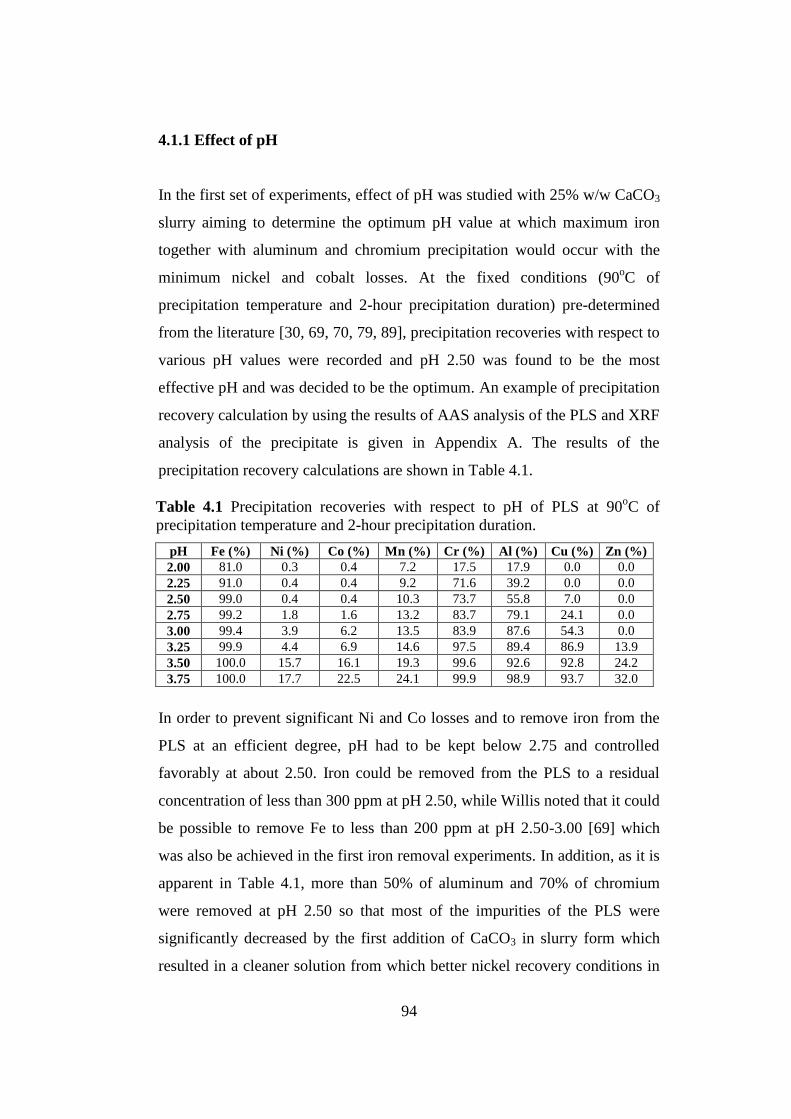
94
4.1.1 Effect of pH
In the first set of experiments, effect of pH was studied with 25% w/w CaCO3
slurry aiming to determine the optimum pH value at which maximum iron
together with aluminum and chromium precipitation would occur with the
minimum nickel and cobalt losses. At the fixed conditions (90oC of
precipitation temperature and 2-hour precipitation duration) pre-determined
from the literature [30, 69, 70, 79, 89], precipitation recoveries with respect to
various pH values were recorded and pH 2.50 was found to be the most
effective pH and was decided to be the optimum. An example of precipitation
recovery calculation by using the results of AAS analysis of the PLS and XRF
analysis of the precipitate is given in Appendix A. The results of the
precipitation recovery calculations are shown in Table 4.1.
In order to prevent significant Ni and Co losses and to remove iron from the
PLS at an efficient degree, pH had to be kept below 2.75 and controlled
favorably at about 2.50. Iron could be removed from the PLS to a residual
concentration of less than 300 ppm at pH 2.50, while Willis noted that it could
be possible to remove Fe to less than 200 ppm at pH 2.50-3.00 [69] which
was also be achieved in the first iron removal experiments. In addition, as it is
apparent in Table 4.1, more than 50% of aluminum and 70% of chromium
were removed at pH 2.50 so that most of the impurities of the PLS were
significantly decreased by the first addition of CaCO3 in slurry form which
resulted in a cleaner solution from which better nickel recovery conditions in
Table 4.1 Precipitation recoveries with respect to pH of PLS at 90oC of
precipitation temperature and 2-hour precipitation duration.
pH Fe (%) Ni (%) Co (%) Mn (%) Cr (%) Al (%) Cu (%) Zn (%)
2.00 81.0 0.3 0.4 7.2 17.5 17.9 0.0 0.0
2.25 91.0 0.4 0.4 9.2 71.6 39.2 0.0 0.0
2.50 99.0 0.4 0.4 10.3 73.7 55.8 7.0 0.0
2.75 99.2 1.8 1.6 13.2 83.7 79.1 24.1 0.0
3.00 99.4 3.9 6.2 13.5 83.9 87.6 54.3 0.0
3.25 99.9 4.4 6.9 14.6 97.5 89.4 86.9 13.9
3.50 100.0 15.7 16.1 19.3 99.6 92.6 92.8 24.2
3.75 100.0 17.7 22.5 24.1 99.9 98.9 93.7 32.0

95
0
10
20
30
40
50
60
70
80
90
100
1.50 2.00 2.50 3.00 3.50 4.00
0
5
10
15
20
25
30
1.50 2.00 2.50 3.00 3.50 4.00
subsequent ammonia leaching step after MHP would be possible. The
graphical presentations of the precipitation recoveries of Ni, Co, Mn, Fe, Al
and Cr with respect to pH at 90oC of precipitation temperature and 2-hour
precipitation duration are given in Figures 4.1 and 4.2.
Figure 4.1 Precipitation recoveries (%) of nickel, cobalt and manganese with
respect to pH at 90oC of precipitation temperature and 2-hour precipitation
duration.
Ni2+
Co2+
Mn2+
% N
i2+,
Co
2+a
nd
Mn
2+ P
reci
pit
ati
on
Reco
veri
es
Equilibrium pH
Equilibrium pH
% F
e3+,
Al3
+a
nd
Cr
3+ P
rec
ipit
ati
on
Recov
erie
s
Fe3+
Cr3+
Al3+
Figure 4.2 Precipitation recoveries (%) of iron, aluminum and chromium with
respect to pH at 90oC of precipitation temperature and 2-hour precipitation
duration.

96
At pH 2.50 the precipitation recoveries of nickel and cobalt were below 1%
and that of iron was about 99% which satisfied the desired conditions. After
pH 2.50, there was a gradual increase in the loss of nickel and cobalt while
more than 3% of Ni and 6% of Co in solution lost between pH 3.00 and 3.25
and there was a sharp increase beyond pH 3.25. Almost all of iron, most of
which was in ferric state in the PLS was precipitated up to pH 2.50 by the
addition of CaCO3 slurry. Agatzini and Oustadakis reported that at pH 2.50,
90.2% of iron, 60.9% of Al and 65.1% of Cr were precipitated with only 2.4%
Ni and 1.70% Co losses by the addition of MgO slurry with water (100gpl)
and seed of jarosite precipitate into a feed leach liquor solution at 95oC [89].
More or less the values obtained at pH 2.50 are close to the percentages in the
Agatzini and Oustadakis’s paper with less nickel and cobalt precipitation
values determined. At pH 3.50, 100% of Fe, 92.6% of Al, and 99.6% of Cr
were precipitated which were similar to the values reported by Agatzini et al.
[30]. But, both Ni-Co losses more than 5% were not desirable and should not
be allowed to be lost in the precipitate. Thus, pH 2.50 was decided to be the
optimum pH for the first iron precipitation.
4.1.2 Effect of Precipitation Temperature
In the second set of experiments, the precipitation temperatures between 25oC
and 90oC were studied at pH 2.50 and 2-hour precipitation duration using
25% w/w CaCO3 slurry to determine the optimum precipitation temperature
and to check the pre-determined temperature in the first set whether it was the
optimum precipitation temperature. Results of the second set of experiments
are given in Table 4.2. It was observed that there was a distinct increase in the
precipitation of all the metals depending on the rising precipitation
temperature.

97
0.0
0.1
0.2
0.3
0.4
0.5
0.6
0.7
0.8
0.9
1.0
20 30 40 50 60 70 80 90 100
In the graphical forms, the presentations of the precipitation recoveries of Ni,
Co, Mn, Fe, Al and Cr with respect to precipitation temperature are given in
Figures 4.3 and 4.4. So, 90oC of precipitation temperature was decided to be
the optimum precipitation temperature to achieve maximum iron precipitation
with insignificant Ni and Co losses as well as yielding fast reaction kinetics
and decreasing slurry viscosity for better filtration properties of precipitate. It
was also checked that the experiments in the first set of experiments had been
carried out at the optimum precipitation temperature. On the other hand, as it
is stated in Chapter 2, operations at ambient temperature cause poor reaction
kinetics leading to time consuming reactions for desired recoveries. Thus,
precipitation temperatures between 70 and 95oC, or at the boiling temperature
of the PLS were preferred to study more to obtain the required conditions
above.
Table 4.2 Precipitation recoveries with respect to precipitation temperature at
pH 2.50 and 2-hour precipitation duration.
T
oC Fe (%) Ni (%) Co (%) Mn (%) Cr (%) Al (%) Cu (%)
25 5.8 0.0 0.1 7.5 63.3 0.0 0.0
50 21.3 0.1 0.2 8.1 67.7 36.5 0.0
75 77.5 0.1 0.3 9.4 68.5 45.4 0.0
90 99.0 0.4 0.4 10.3 73.7 55.8 7.0
Figure 4.3 Precipitation recoveries (%) of nickel and cobalt with respect to
precipitation temperature at pH 2.50 and 2-hour precipitation duration.
Ni2+
Co2+
% N
i2+a
nd
Co
2+ P
recip
ita
tio
n R
eco
verie
s
Precipitation Temperature (oC)

98
0
10
20
30
40
50
60
70
80
90
100
20 30 40 50 60 70 80 90 100
4.1.3 Effect of Precipitation Duration
In the third set of experiments, the precipitation durations between 0.5 and 4
hours were studied at pH 2.50 and 90oC of precipitation temperature using
25% w/w CaCO3 slurry aiming to determine the optimum precipitation
duration at which maximum iron together with aluminum and chromium
precipitation would occur provided that nickel and cobalt losses were
minimized. As it is stated in Chapter 2, precipitation duration is generally
between 90 and 180 minutes combined residence time [69]. Therefore, 2
hours had been chosen as the precipitation duration in the first set of
experiments and now it was also tested whether it was the optimum for the
specified condition; pH 2.50 and 90oC of precipitation temperature.
Precipitation recoveries with respect to precipitation duration resulted from
the experiments at pH 2.50 and 90oC of precipitation temperature are shown
in Table 4.3. In the graphical form, the precipitation recoveries of Ni, Co, Mn,
Fe, Al and Cr with respect to precipitation duration are shown in Figures 4.5
and 4.6.
Figure 4.4 Precipitation recoveries (%) of manganese, iron, aluminum and
chromium with respect to precipitation temperature at pH 2.50 and 2-hour
precipitation duration.
Fe3+
%
Mn
2+, F
e3+, A
l3+a
nd
Cr3
+ P
rec
ipit
ati
on
Rec
ov
erie
s
Precipitation Temperature (oC)
Cr3+
Al3+
Mn2+

99
0
2
4
6
8
10
12
0.0 0.5 1.0 1.5 2.0 2.5 3.0 3.5 4.0
In order to attain the desired iron, aluminum and chromium precipitations and
sufficient reaction time for metal precipitations and bassanite crystallization,
the precipitation duration had to be long enough. However, it was also needed
to yield minimum nickel and cobalt losses to the precipitate. Therefore, 2
hours of precipitation duration was chosen as the optimum since about 99% of
iron and less than 0.5% of nickel and cobalt could be precipitated as well as
approximately 74% of chromium and 56% of aluminum precipitated at the
first stage of iron removal. In addition, CaCO3 slurry addition rate was kept
low within precipitation duration to prevent supersaturation of Fe, Al and Cr.
Duration
(hour) Fe (%) Ni (%) Co (%) Mn (%) Cr (%) Al (%) Cu (%)
0.5 87.0 0.2 0.4 7.9 66.9 22.9 0.0
1.0 93.7 0.2 0.4 8.1 67.5 23.3 1.4
1.5 98.3 0.3 0.4 8.2 68.3 53.5 1.7
2.0 99.0 0.4 0.4 10.3 73.7 55.8 7.0
4.0 99.6 11.2 4.4 11.3 89.1 89.3 13.6
Table 4.3 Precipitation recoveries with respect to precipitation duration at pH
2.50 and 90oC of precipitation temperature.
Figure 4.5 Precipitation recoveries (%) of nickel and cobalt with respect to
precipitation duration at pH 2.50 and 90oC of precipitation temperature.
Precipitation Duration (hour)
% N
i2+a
nd
Co
2+ P
recip
ita
tio
n R
eco
verie
s
Co2+
Ni2+

100
At the end of the third set of experiments, the optimum conditions for the first
iron removal step were finally determined as pH 2.50, 90oC of precipitation
temperature and 2 hours of precipitation duration. At these conditions, the
amount of CaCO3 slurry consumed was 48 cc (12 g CaCO3 / 100 cc PLS)
(120 kg CaCO3 / m3 PLS) and the weight of the precipitate after the first iron
removal was 24.5 g for 100 cc PLS. Free acidity of PLS was reduced from
14.6 g/L to 1.4 g/L according to Reaction 4.1 by consuming 5 cc 25% w/w
CaCO3 slurry (1.25 g CaCO3 / 100 cc PLS) (12.5 kg CaCO3 / m3 PLS) (0.95
kg CaCO3 / kg H2SO4).
After the first iron removal step, about 91% of arsenic, 7% of copper, 10% of
manganese and 3% of magnesium were also precipitated together with great
amount of iron, while the amount of calcium in solution was determined to be
increased because of the addition of CaCO3 as slurry. The precipitate analysis
Figure 4.6 Precipitation recoveries (%) of manganese, iron, aluminum and
chromium with respect to precipitation duration at pH 2.50 and 90oC of
precipitation temperature.
% M
n2
+, F
e3+, A
l3+a
nd
Cr3
+ P
rec
ipit
ati
on
Rec
ov
erie
s
Precipitation Duration (hour)
0
10
20
30
40
50
60
70
80
90
100
0.0 0.5 1.0 1.5 2.0 2.5 3.0 3.5 4.0
Fe3+
Cr3+
Al3+
Mn2+
CaCO3(s) + H2SO4 CaSO4 + CO2(g) + H2O (4.1)
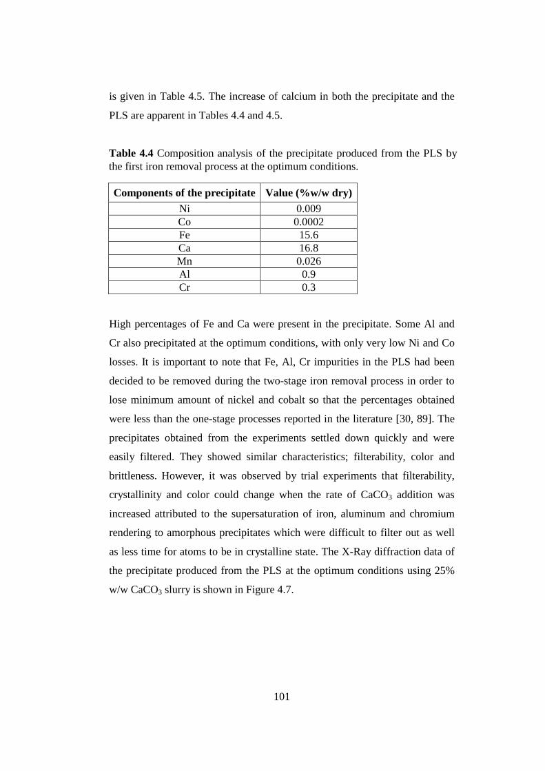
101
is given in Table 4.5. The increase of calcium in both the precipitate and the
PLS are apparent in Tables 4.4 and 4.5.
High percentages of Fe and Ca were present in the precipitate. Some Al and
Cr also precipitated at the optimum conditions, with only very low Ni and Co
losses. It is important to note that Fe, Al, Cr impurities in the PLS had been
decided to be removed during the two-stage iron removal process in order to
lose minimum amount of nickel and cobalt so that the percentages obtained
were less than the one-stage processes reported in the literature [30, 89]. The
precipitates obtained from the experiments settled down quickly and were
easily filtered. They showed similar characteristics; filterability, color and
brittleness. However, it was observed by trial experiments that filterability,
crystallinity and color could change when the rate of CaCO3 addition was
increased attributed to the supersaturation of iron, aluminum and chromium
rendering to amorphous precipitates which were difficult to filter out as well
as less time for atoms to be in crystalline state. The X-Ray diffraction data of
the precipitate produced from the PLS at the optimum conditions using 25%
w/w CaCO3 slurry is shown in Figure 4.7.
Table 4.4 Composition analysis of the precipitate produced from the PLS by
the first iron removal process at the optimum conditions.
Components of the precipitate Value (%w/w dry)
Ni 0.009
Co 0.0002
Fe 15.6
Ca 16.8
Mn 0.026
Al 0.9
Cr 0.3

102
The main mineralogical phase was bassanite [CaSO4.0.5H2O] and other
phases were gypsum [CaSO4.2H2O], hematite [Fe2O3] and goethite [α-
FeOOH] together with some calcite [CaCO3] and katoite [Ca3Al2(OH)12].
Iron, mostly in ferric state, precipitated as goethite and hematite from the PLS
since ferric iron precipitates from the solution resulted from the CaCO3 slurry
addition as in Reactions 4.2 and 4.3. Mostly bassanite was formed and for
higher moles of H2O, gypsum was precipitated.
3CaCO3(s) + Fe2(SO4)3 + 2.5H2O 3CaSO4.0.5H2O(s) + 2FeOOH(s) + 3CO2(g) (4.2)
3CaCO3(s) + Fe2(SO4)3 + 1.5H2O 3CaSO4.0.5H2O(s) + Fe2O3(s) + 3CO2(g) (4.3)
Figure 4.7 XRD pattern of the precipitate produced from the PLS by the first
iron removal process at pH 2.50, 90oC of precipitation temperature and 2 hours
of precipitation duration with addition of CaCO3 slurry.
1. CaSO4.0.5H2O-Bassanite
2. CaSO4.2H2O-Gypsum
3. Fe2O3-Hematite 4. α-FeOOH-Goethite
5. CaCO3-Calcite
6. Ca3Al2(OH)12-Katoite
0
500
1000
1500
2000
2500
3000
3500
4000
0 10 20 30 40 50 60 70
2 Theta (deg.)
1
1
2,4 3,4 3
2
2
2
1
1
5 6 4
1
2
6
2,5
1,3
4
1,6
3
5
1 1 1
Inte
nsi
ty (
Cou
nts
)

103
Components of PLS Concentration (ppm)
Ni 3450
Co 82
Fe 290
Fe2+
0.08
Mg 11750
Al 1260
Ca 162
Mn 401
Cr 202
As 3
Zn 22.7
Cu 2.6
H2SO4 1400
The main peaks, which correspond to [CaSO4.0.5H2O], were sharper and with
greater intensity, compared with other peaks which displayed lower intensity
and higher peak width. The differences between phases caused by the
differences in the degree of crystallinity of the products and some phases such
as bassanite rendered a better-crystallized compound. Furthermore, there were
no nickel, cobalt, manganese and chromium containing phases detected which
was attributed to their low content in the precipitate as seen in Table 4.4. At
the end of the first iron removal process, a new PLS stock which would be
used in the second iron removal process was produced by carrying out the
first iron removal at the optimum conditions. The AAS analysis of the new
stock of 2.75 L neutralized PLS is illustrated in Table 4.5. In the PLS stock,
1.4 g/L free acid was present. The ORP (or SHE) value and the density of the
PLS stock were 475 mV (or 673 mV) and 1.08 g/cm3, respectively.
4.2 Second Iron Removal
In the second iron removal experiments, the optimum conditions were studied
to remove the remaining aluminum (Al3+
), chromium (Cr3+
) and iron (Fe3+
)
Table 4.5 Chemical analysis by AAS of the new PLS stock produced by the
first iron removal process at the optimum conditions.

104
completely from the new PLS with some but minimum amount of nickel and
cobalt losses to the precipitate which would be regained during the recycle
leach. The aim of the second iron removal experiments was to precipitate all
the remaining impurities, except Mn2+
and Mg2+
, in the PLS by adding CaCO3
slurry into the neutralized and partially purified PLS without much caring for
nickel and cobalt losses to the precipitate unless they were excess. Because
after the second iron removal, all the expected decreased impurity levels in
the PLS had to be achieved.
4.2.1 Effect of pH
In the first set of experiments, pH variations were studied in the range of 3.50-
5.25 aiming to determine the optimum pH value at which the maximum
aluminum, chromium and iron precipitation would occur with the minimum
nickel and cobalt losses with addition of the required amount of CaCO3 slurry
(12.5% w/w). At the fixed conditions (90, 70 and 25oC of precipitation
temperature and 1 hour of precipitation duration) pre-determined from the
literature [30, 69, 70, 79, 89], precipitation recoveries with respect to various
pH values were recorded. The results are shown in Tables 4.6, 4.7 and 4.8.
From these precipitation recoveries, it is apparent that to achieve the
maximum aluminum, chromium and iron precipitation together with the
minimum nickel and cobalt losses, pH 4.25 was found to be the best and
decided to be the optimum at 70oC of precipitation temperature. At 90
oC of
precipitation temperature, aluminum, chromium and iron precipitation
recoveries were all around 99-100% except that at pH 3.50, precipitation
recoveries of aluminum and chromium were both 88%, whereas nickel and
cobalt losses were higher than 10%. However, when the precipitation
temperature was reduced to 70oC, the losses decreased whereas there was a
small reduction in the recoveries of aluminum, chromium and iron. In order to
purify the solution from the aluminum, chromium and iron impurities, pH had
to be minimum 4.25 at 70oC of precipitation temperature. Otherwise, the PLS

105
would not be purified completely and there would always be some aluminum,
chromium and iron concentrations higher than 5-10 ppm in the PLS after the
purification stage. As it also is apparent in Figure 2.19, aluminum and
chromium precipitations started at around pH 4.00. Thus, at pH 4.25, 70oC of
precipitation temperature was chosen as the optimum in order to obtain at
least 99% Fe, Al and Cr precipitations with minimum nickel (17%) and cobalt
(25%) losses.
On the other hand, the experiments carried out at room temperature showed
that the precipitation recoveries were low for the impurities but less for nickel
and cobalt losses at the same pH conditions. At pH 4.25 and 25oC of
pH Fe (%) Ni (%) Co (%) Mn (%) Cr (%) Al (%) Cu (%) Zn (%)
3.50 98.6 10.5 15.9 9.9 87.7 87.9 74.8 21.0
4.00 99.6 15.5 26.1 22.0 99.5 98.7 98.7 55.0
4.25 99.8 25.6 48.8 24.7 99.6 99.7 99.9 71.2
4.50 99.9 44.7 53.6 26.8 99.8 99.9 99.9 73.7
4.75 99.9 60.1 66.6 27.4 99.9 99.9 99.9 74.0
5.00 99.9 73.5 77.5 33.1 99.9 99.9 99.9 75.0
5.25 100.0 84.0 87.6 36.8 99.9 99.9 99.9 78.2
Table 4.6 Precipitation recoveries with respect to pH of PLS at 90oC of
precipitation temperature and 1 hour of precipitation duration.
Table 4.7 Precipitation recoveries with respect to pH of PLS at 70oC of
precipitation temperature and 1 hour of precipitation duration.
pH Fe (%) Ni (%) Co (%) Mn (%) Cr (%) Al (%) Cu (%) Zn (%)
3.25 94.7 6.5 12.9 3.6 84.7 84.5 18.0 12.2
3.50 95.6 7.5 13.2 5.7 97.4 94.6 18.9 19.8
4.25 99.5 17.2 24.9 13.0 99.6 99.7 33.2 31.1
4.50 99.8 24.1 25.7 21.9 99.8 99.9 86.6 43.9
4.75 99.9 53.3 54.1 23.2 99.9 99.9 99.9 72.7
Table 4.8 Precipitation recoveries with respect to pH of PLS at 25oC of
precipitation temperature and 1 hour of precipitation duration.
pH Fe (%) Ni (%) Co (%) Mn (%) Cr (%) Al (%) Cu (%) Zn (%)
4.25 69.4 0.7 8.8 4.8 82.4 82.4 19.6 7.1
4.75 82.7 26.8 23.1 21.5 99.9 99.6 63.6 38.9
5.25 95.8 28.6 28.1 22.0 99.9 99.7 99.9 70.9

106
0
10
20
30
40
50
60
70
80
90
100
3.00 3.50 4.00 4.50 5.00 5.50 6.00
precipitation temperature, iron precipitation recovery was 69% with less than
1% of nickel and 9% of cobalt losses, while at the same pH and 70oC of
precipitation temperature, it was about 100% with 17% of nickel and 25% of
cobalt losses. The reason of the less precipitation recoveries at 25oC of
precipitation temperature lies in poor reaction kinetics and increased slurry
viscosity. Willis pointed out this condition that operation at ambient
temperature is possible but the kinetics is slow [69]. More reaction time was
required for the experiments at ambient temperature. Figures 4.8-4.13 display
the graphical presentations of the precipitation recoveries of Ni, Co, Mn, Fe,
Al and Cr with respect to pH at different temperatures.
Figure 4.8 Precipitation recoveries (%) of nickel, cobalt and manganese with
respect to pH at 90oC of precipitation temperature.
Mn2+
Equilibrium pH
% N
i2+,
Co
2+a
nd
Mn
2+ P
reci
pit
ati
on
Reco
veri
es
Co2+
Ni2+

107
86
88
90
92
94
96
98
100
3.00 3.50 4.00 4.50 5.00 5.50 6.00
0
10
20
30
40
50
60
3.00 3.50 4.00 4.50 5.00 5.50 6.00
Figure 4.9 Precipitation recoveries (%) of iron, aluminum and chromium
with respect to pH at 90oC of precipitation temperature.
% N
i2+,
Co
2+a
nd
Mn
2+ P
reci
pit
ati
on
Reco
veri
es
Equilibrium pH
Fe3+
Cr3+
Al3+
Figure 4.10 Precipitation recoveries (%) of nickel, cobalt and manganese
with respect to pH at 70oC of precipitation temperature.
Equilibrium pH
% F
e3+,
Al3
+a
nd
Cr
3+ P
rec
ipit
ati
on
Recov
erie
s
Co2+
Ni2+
Mn2+

108
82
84
86
88
90
92
94
96
98
100
3.00 3.50 4.00 4.50 5.00 5.50 6.00
0
5
10
15
20
25
30
35
3.00 3.50 4.00 4.50 5.00 5.50 6.00
Figure 4.11 Precipitation recoveries (%) of iron, aluminum and chromium
with respect to pH at 70oC of precipitation temperature.
Figure 4.12 Precipitation recoveries (%) of nickel, cobalt and manganese with
respect to pH at 25oC of precipitation temperature.
Equilibrium pH
% F
e3+,
Al3
+a
nd
Cr
3+ P
rec
ipit
ati
on
Recov
erie
s Fe3+
Cr3+
Al3+
Equilibrium pH
% N
i2+,
Co
2+a
nd
Mn
2+ P
reci
pit
ati
on
Reco
veri
es
Co2+
Ni2+
Mn2+

109
0
10
20
30
40
50
60
70
80
90
100
3.00 3.50 4.00 4.50 5.00 5.50 6.00
As seen in Figures 4.8 through 4.13, at pH 4.25 and 70oC of precipitation
temperature, 99.5% of iron, 99.7% of aluminum and 99.6% of chromium
precipitation recoveries were exactly fulfilled the required conditions of the
second iron removal process with 17.2% of nickel and 24.9% of cobalt lost
compared to other recovery values at different pH and temperatures.
However, when complete purification of iron, aluminum and chromium
impurities in PLS was tried to be achieved, it was observed that there was
much loss of nickel and cobalt in the precipitate. Agatzini and Oustadakis
reported that at pH 3.50, 96.4% of iron, 97.1% of aluminum and 93.3% of
chromium precipitated with only 3.5% of nickel and 2.0% of cobalt losses
[89]. In the study of Agatzini and Oustadakis, the lower values of nickel and
cobalt losses than the values obtained from the present experiments are
believed to be due to applying one-stage iron removal process at a lower pH
and the use of MgO slurry as neutralizing agent in the mentioned study.
However, these nickel and cobalt losses would be recovered during the
recycle leach from the precipitate which was produced in small quantities.
Figure 4.13 Precipitation recoveries (%) of iron, aluminum and chromium
with respect to pH at 25oC of precipitation temperature.
Equilibrium pH
% F
e3+,
Al3
+a
nd
Cr
3+ P
rec
ipit
ati
on
Recov
erie
s
Fe3+
Cr3+
Al3+

110
The second iron removal step at above pH 4.25 was not thought to be feasible
because co-precipitation is significant. As it is stated in Chapter 2, Willis
noted that co-precipitation of nickel and cobalt (4-9% Ni-Co in solution
precipitated) is considerable at pH range between 4.4 and 4.8 compared to the
first iron removal stage [69, 70]. The increase of co-precipitation of nickel
and cobalt with pH is also shown in Figure 2.22. The losses are less than the
obtained values due to the experiments being conducted in a continuous
process in the Willis’s study. Willis also reported that the aluminum should be
less than 50 mg/L after the second iron removal step in order to satisfy the
desired nickel-cobalt dissolution from MHP in the following ammonia
leaching step. This was achieved by reducing the aluminum concentration to
3.6 mg/L with addition of the required amount of CaCO3 slurry (13.6 g/L)
into the PLS up to pH 4.25 at the second iron removal process.
4.2.2 Effect of Precipitation Temperature
In the second set of experiments, the precipitation temperatures between 25oC
and 90oC were studied at pH 4.25 by fixing the addition of 12.5% w/w CaCO3
slurry for 1 hour of precipitation duration to specify the optimum precipitation
temperature at which the maximum residual aluminum, chromium and iron
precipitation would occur with the minimum nickel and cobalt losses. Results
of the experiments are given in Table 4.9.
As seen in Table 4.9, similar to Table 4.2, there was a distinct increase in the
precipitation recoveries with the increasing precipitation temperature at pH
4.25 and 1 hour of precipitation duration. Above 50oC of precipitation
Table 4.9 Precipitation recoveries with respect to precipitation temperature at
pH 4.25 and 1 hour of precipitation duration.
T
oC Fe (%) Ni (%) Co (%) Mn (%) Cr (%) Al (%) Cu (%) Zn (%)
25 69.4 0.7 8.8 4.8 82.4 82.4 19.6 7.1
50 97.3 3.7 19.7 5.5 89.5 88.1 29.4 15.7
70 99.5 17.2 24.9 13.0 99.6 99.7 33.2 31.1
90 99.8 25.6 48.8 24.7 99.6 99.7 99.9 71.2

111
0
10
20
30
40
50
20 30 40 50 60 70 80 90 100
temperature, iron precipitation and above 70oC of precipitation temperature,
aluminum and chromium precipitations became greater than 97% where as
more than 4% nickel and 20% cobalt losses for the former and more than 17%
nickel and 25% cobalt losses for the latter were obtained.
The graphical presentations of the precipitation recoveries of Ni, Co, Mn, Fe,
Al and Cr with respect to precipitation temperature are given in Figure 4.14
and 4.15.
At 50oC of precipitation temperature, although the loss of nickel and cobalt
was decreased desirably the required levels of iron, aluminum and chromium
removal were not achieved and more than 5-10 ppm iron, aluminum and
chromium were left in the purified PLS. Therefore, 70oC of precipitation
temperature was decided to be the optimum precipitation temperature to
achieve at least the desired iron, aluminum and chromium precipitation with
some but minimum nickel and cobalt losses as well as better reaction kinetics,
less viscous slurry and better filtration properties of the precipitate. On the
Figure 4.14 Precipitation recoveries (%) of nickel and cobalt with respect to
precipitation temperature at pH 4.25 and 1 hour of precipitation duration.
Co2+
Ni2+
% N
i2+a
nd
Co
2+ P
recip
ita
tio
n R
eco
verie
s
Precipitation Temperature (oC)

112
other hand, as it is apparent in Figure 4.15, purification of impurities at 90oC
of precipitation temperature resulted in the highest precipitation recoveries,
faster reaction kinetics and excellent filtration properties of the precipitate.
However, it was not selected to be the optimum because of nickel and cobalt
losses being higher than 25% and 48%, respectively.
4.2.3 Effect of Precipitation Duration
In the third set of experiments, the precipitation durations between 0.5 and 1.5
hours were studied at pH 4.25 and 70oC of precipitation temperature using
12.5% w/w CaCO3 slurry aiming to determine the optimum precipitation
duration at which maximum residual aluminum, chromium and iron
precipitation would occur with minimum nickel and cobalt losses.
Precipitation recoveries with respect to precipitation duration obtained from
the experiments at pH 4.25 and 70oC of precipitation temperature are shown
in Table 4.10.
Figure 4.15 Precipitation recoveries (%) of manganese, iron, aluminum and
chromium with respect to precipitation temperature at pH 4.25 and 1 hour of
precipitation duration.
Precipitation Temperature (oC)
% M
n2+, F
e3+, A
l3+a
nd
Cr3
+ P
rec
ipit
ati
on
Rec
ov
erie
s
0
10
20
30
40
50
60
70
80
90
100
20 30 40 50 60 70 80 90 100
Cr3+
Fe3+
Al3+
Mn2+

113
Iron, aluminum and chromium precipitation recoveries were higher than 95%
whereas around 30% of copper and zinc and more than 10% of manganese
were precipitated from the PLS with more than 5% of nickel and 1% of cobalt
were lost in the precipitate. Although precipitation duration is generally
between 90 and 180 minutes as it is stated in Willis’ report [69], 60 minutes
of precipitation duration was selected as the optimum since more losses of
nickel and cobalt were observed in more than 1 hour of precipitation duration,
while the iron precipitation recovery was stable at 99-100% for both 1.0 and
1.5 hours of precipitation durations. On the other hand, the precipitation
durations of less than 1 hour resulted in iron precipitation recoveries of less
than 99%, which was not desired in the last stage of the iron removal since at
least 99% of iron precipitation (<5 ppm in PLS) had to be achieved from the
PLS for a clean solution which would be used in the MHP process. Figures
4.16 and 4.17 illustrate the graphical presentations of the precipitation
recoveries of nickel, cobalt, manganese, iron, aluminum and chromium with
respect to precipitation duration. As can be seen from the figures, there was
not a significant change in the precipitation recoveries according to
precipitation duration except those of nickel and cobalt which increased more
with the increasing precipitation duration.
At the end of the third set of experiments, the optimum conditions were
finally chosen as pH 4.25, 70oC of precipitation temperature and 1 hour of
precipitation duration for the second iron removal stage. At these conditions,
the amount of CaCO3 slurry consumed was 5.45 cc (0.681 g CaCO3 / 50 cc
PLS) (13.6 kg CaCO3 / m3 PLS) and the weight of the precipitate after the
second iron removal was, 1.4 g / 50 cc , 11% of the precipitate weight
produced from 50 cc PLS by the first iron removal. It is important to note that
Duration
(hour) Fe (%) Ni (%) Co (%) Mn (%) Cr (%) Al (%) Cu (%) Zn (%)
0.5 95.6 5.9 1.5 11.2 99.1 99.1 30.1 29.5
1.0 99.5 17.2 24.9 13.0 99.6 99.7 33.2 31.1
1.5 99.7 18.9 26.6 20.9 99.9 99.9 34.5 34.5
Table 4.10 Precipitation recoveries with respect to precipitation duration at
pH 4.25 and 70oC of precipitation temperature.

114
in contrast to the first iron removal, the loss of nickel and cobalt in the
precipitate produced by the second iron removal had to be recovered from the
precipitate by performing recycle leaching.
Figure 4.16 Precipitation recoveries (%) of nickel and cobalt with respect to
precipitation duration at pH 4.25 and 70oC of precipitation temperature.
Figure 4.17 Precipitation recoveries (%) of manganese, iron, aluminum and
chromium with respect to precipitation duration at pH 4.25 and 70oC of
precipitation temperature.
% N
i2+a
nd
Co
2+ P
recip
ita
tio
n R
eco
verie
s
Precipitation Duration (hour)
Ni2+
0
5
10
15
20
25
30
0.0 0.5 1.0 1.5 2.0
Co2+
Precipitation Duration (hour)
Fe3+
0
10
20
30
40
50
60
70
80
90
100
0.0 0.5 1.0 1.5 2.0
Al3+
Cr3+
Mn2+
% M
n2
+, F
e3+, A
l3+a
nd
Cr3
+ P
rec
ipit
ati
on
Rec
ov
erie
s

115
Free acidity of PLS was reduced from 1.4 g/L to 0.2 g/L by consuming 0.50
cc 12.5% w/w CaCO3 slurry (0.063 g CaCO3 / 50 cc PLS) (1.25 kg CaCO3 /
m3 PLS) (1.04 kg CaCO3 / kg H2SO4). After the second iron removal process,
33.2% of copper, 31.1% of zinc, 13% of manganese and 38.9% of magnesium
in PLS were precipitated while calcium in solution was increased, as in the
first stage, to 870 ppm because of the addition of CaCO3 slurry. The
precipitate analysis is given in Table 4.11. The increase of calcium content in
both the precipitate and the PLS is apparent in Tables 4.11 and 4.12.
Relatively, high percentages of Ca and Al were present in the precipitate as
well as some Ni and Fe precipitated at the optimum conditions selected, with
low Cr, Co and Mn percentages. It is important to note that all important
impurities like Fe, Cr and Al, except for Mn and Mg in the PLS had been
rejected to the precipitate and each mentioned impurity was decreased to less
than 5 ppm in the PLS.
In the second iron removal process, it was initially planned to study the
oxidation of ferrous iron (Fe2+
) in the PLS to ferric iron (Fe3+
) by introducing
air into solution. Since the analysis of the ferrous iron in the PLS after the
column leaching showed that it was present in very small amounts in the PLS
as seen in Table 3.4, it was not considered necessary to use air throughout the
iron removal process.
Table 4.11 Composition analysis of the precipitate produced from the PLS by
the second iron removal process at the optimum conditions.
Components of the precipitate Value (%w/w dry)
Ni 2.12
Co 0.073
Fe 1.03
Ca 12.8
Mn 0.19
Al 4.5
Cr 0.72

116
0
1000
2000
3000
4000
5000
6000
7000
8000
0 10 20 30 40 50 60 70
The precipitates resulted from the experiments settled down quickly and were
easily filtered. They showed similar characteristics of filterability, color and
brittleness. It was observed that the color of the precipitate was lighter than
the precipitate produced in the first iron removal process. Furthermore, the
rate of CaCO3 slurry addition during the experiments was controlled to
prevent supersaturation of iron, aluminum and chromium leading to
amorphous precipitates which would be difficult to filter out.
The X-Ray diffraction data of the precipitate produced from the PLS at the
optimum conditions using 12.5% w/w CaCO3 pulp as precipitating agent is
shown in Figure 4.18.
Figure 4.18 XRD pattern of the precipitate produced from the PLS by the
second iron removal process at pH 4.25, 70oC of precipitation temperature and
1 hour of precipitation duration with addition of CaCO3 slurry.
1
1
1,6
1
1
1,3
1,6
2,4
3,4,8 4
3 1 6 5,7
1
7 7,8 6,8 5
7
2,5 4,7,8
3
8
1,7,8 2
1. CaSO4.0.5H2O-Bassanite
2. CaSO4.2H2O-Gypsum 3. Fe2O3-Hematite
4. α-FeOOH-Goethite
5. CaCO3-Calcite 6. Ca3Al2(OH)12-Katoite
7. Al(OH)3-Bayerite
8. Ni(OH)2-Theophrastite
Inte
nsi
ty (
Cou
nts
)
2 Theta (deg.)

117
Components of PLS Concentration (ppm)
Ni 2713
Co 58.5
Fe 1.38
Fe2+
0
Mg 6815
Al 3.6
Ca 870
Mn 332
Cr 0.77
As 0
Zn 14.9
Cu 1.62
H2SO4 200
The main mineralogical phase was still bassanite [CaSO4.0.5H2O] and other
phases were gypsum [CaSO4.2H2O], hematite [Fe2O3] and goethite [α-
FeOOH] together with some calcite [CaCO3] and katoite [Ca3Al2(OH)12].
Bassanite was a better-crystallized phase than others. The difference from the
first iron removal process is that there were also Al and Ni containing
products present as bayerite [Al(OH)3] and theophrastite [Ni(OH)2],
respectively. The main peaks, which correspond to [CaSO4.0.5H2O], were
again sharper and with greater intensity, compared with other peaks
displaying lower intensity and higher peak width such as the peaks of
hematite and goethite. Also, there were no Co, Mn and Cr containing phases
detected because of their low content in the precipitate as seen in Table 4.11.
At the end of the second iron removal process, a new PLS stock which would
be used in the MHP process was produced by carrying out the second iron
removal process at the optimum conditions. The AAS analysis of the new
1.75 L PLS stock is illustrated in Table 4.12. In the PLS stock, 0.2 g/L free
acid was present. The ORP (or SHE) value and the density of the PLS stock
were 257 mV (or 455 mV) and 1.05 g/cm3, respectively. Prior to MHP
experiments, the Ni/Mn ratio was calculated as 8.17.
Table 4.12 Chemical analysis by AAS of the new PLS stock produced by the
second iron removal process at the optimum conditions.

118
There was very little iron and aluminum left in the PLS. This would give an
important advantage to the following steps otherwise the presence of iron and
aluminum in the precipitate could suppress re-leaching of nickel and cobalt
from the precipitates produced at the MHP processes [101]. In the iron
removal, seed recycle was also studied and the performance of the process
was little enhanced with the seed additions of 5%, 10% and 15% w/w of the
precipitate produced at the optimum condition.
4.3 First Mixed Hydroxide Precipitation (MHP1)
In the MHP experiments, the optimum conditions were studied in order to
precipitate as much nickel and cobalt as possible with minimum amount of
manganese in a mixed saleable hydroxide form from the PLS after the second
iron removal stage. Most especially, the objective of the MHP experiments
was to find a proper way to precipitate almost all nickel and cobalt from the
PLS and to leave less than 10 ppm [69] nickel in solution providing that small
amount of manganese was present in the precipitate being not higher than
10%. However, it was a trade off process. Therefore, it was decided to
perform MHP process in two stages in order to control the extent of
manganese contamination in the mixed hydroxide product. The reason for
aiming minimum manganese precipitation, which is described earlier in
Chapter 2, is that nickel to manganese ratio in feed stream and resulted
manganese in mixed hydroxide product are crucial for MHP process to be
applicable in industry because MHP precipitate is further treated to separately
recover nickel and cobalt at a satisfactory purity. Hence, MHP is not selective
for high manganese containing ores. The nontronite ore treated in this study
had a low manganese content of 0.34 wt%. Likewise, Willis noted that MHP
is best applied to ores with low manganese content in which
nickel/manganese ratio is greater than 3:1 [69]. For this reason, this ratio had
been taken into consideration before MHP1 experiments started and it was
3.53:1 in the ore and 8.17:1 in the PLS. In MHP1 experiments, the most

119
important parameter to control was manganese precipitation recovery which
had to be kept as low as possible since there would be no way for manganese
to be discarded from MHP1 precipitate to satisfy 10%. At the same time,
nickel and cobalt precipitation had to be above at least 90% for the feasible
process. In addition, it was also desired an MHP1 product in which there
would be no magnesium contamination due to unreacted magnesium oxide.
4.3.1 Effect of pH
In the first set of experiments, pH was typically adjusted to in the range of pH
7.00-7.50 with 1% w/w freshly slurried reactive magnesia (in milk form). The
objective was to determine the optimum pH value at which maximum
practical Ni and Co precipitation would occur providing that Mn
contamination could not exceed 10% in the precipitate. At the fixed
conditions (50oC of precipitation temperature and 1 hour of precipitation
duration) pre-determined from the literature [69, 70, 92, 101], precipitation
recoveries with respect to various pH values recorded when 5.0-15.0 cc MgO
slurry was added and pH 7.00 was found to be the most effective pH and was
decided to be the optimum. The results are shown in Table 4.13.
Table 4.13 Precipitation recoveries with respect to pH of the PLS and the
volume of the MgO slurry added at 50oC of precipitation temperature and 1
hour of precipitation duration.
MgO slurry
Addition (cc) pH Ni (%) Co (%) Mn (%) Cr (%)
5.0 6.63 47.3 40.7 14.2 34.3
6.0 6.74 56.8 46.9 15.5 74.0
7.0 6.84 71.2 92.4 17.3 77.1
8.0 6.88 78.9 96.1 25.1 77.3
9.0 6.94 84.2 97.2 32.2 83.6
10.0 7.00 89.6 97.4 40.4 86.0
11.0 7.05 94.7 98.9 61.4 87.9
12.0 7.10 95.7 99.3 67.3 96.3
13.0 7.44 98.6 99.4 98.0 98.7
15.0 7.52 99.6 99.9 98.8 100.0

120
0
10
20
30
40
50
60
70
80
90
100
6.0 6.2 6.4 6.6 6.8 7.0 7.2 7.4 7.6 7.8 8.0
The graphical demonstration of the precipitation recoveries of Ni, Co and Mn
with respect to pH at 50oC of precipitation temperature and 1 hour of
precipitation duration is given in Figure 4.19.
With increasing pH of the PLS, the amount of nickel and cobalt precipitated
as hydroxide were increased. However, with this increase in pH, it was
observed that manganese and chromium precipitations also increased and
contaminated the MHP1 product. Chromium contamination was not important
due to very low chromium concentration (0.77 ppm) in the PLS. But, the
manganese contamination was very important. Therefore, in order to prevent
unfavorable manganese precipitation partially and to achieve at least about
90% nickel and cobalt precipitation, the amount of 1% w/w MgO slurry
which would be added was decided to be 10 cc (0.10 g MgO / 50 cc PLS) (2
kg MgO / m3 PLS) leading to pH 7.00.
In the other sets of the experiments of MHP1, the fixed 10 cc MgO slurry
volume would be used to maintain manganese precipitation low and attain the
Figure 4.19 Precipitation recoveries (%) of nickel, cobalt and manganese
with respect to pH at 50oC of precipitation temperature and 1 hour of
precipitation duration.
% N
i2+, C
o2
+ a
nd
Mn
2+ P
rec
ipit
ati
on
Reco
veri
es
Equilibrium pH
Co2+
Ni2+
Mn2+

121
0
10
20
30
40
50
60
70
80
90
100
0.50 0.60 0.70 0.80 0.90 1.00 1.10 1.20 1.30 1.40 1.50
desired nickel-cobalt precipitation recoveries. The graphical demonstration of
the precipitation recoveries of Ni, Co, and Mn with respect to stoichiometric
amount of magnesium oxide is given in Figure 4.20. It is important to note
that the selected 10 cc caustic calcined magnesium oxide slurry volume was
94% of the theoretical amount of magnesium oxide being determined by
stoichiometric reactions to completely precipitate nickel, cobalt and
manganese from the PLS while the stoichiometric reactions are Reactions 4.4,
4.5 and 4.6, respectively. The MgO slurry theoretically needed for the
complete precipitation was 9.20 cc for nickel, 0.20 cc for cobalt and 1.21 cc
for manganese according to these reactions, if the efficiency of the
magnesium oxide was assumed to be 100%.
Furthermore, as pH of the PLS was increased, precipitation with the caustic
calcined magnesia was expected to give rise to the dissolution of magnesium
to form soluble magnesium oxide as in Reactions 4.4, 4.5 and 4.6 to result in a
desired nickel-cobalt product containing no magnesium. However, as it is
Figure 4.20 Precipitation recoveries (%) of nickel, cobalt and manganese at
50oC of precipitation temperature with respect to stoichiometric amount of
MgO completely precipitating nickel, cobalt and manganese from the PLS.
Co2+
Ni2+
Mn2+
% N
i2+, C
o2+ a
nd
Mn
2+ P
rec
ipit
ati
on
Reco
veri
es
Multiple of the Stoichiometric Amount of MgO

122
pointed out in the literature [101], all the products contained some levels of
magnesium. White reported that the efficiency of the magnesium oxide is
around 70-90%. Thus, in order for the complete precipitation of nickel, cobalt
and manganese from the PLS, the addition amount of magnesium oxide was
required to be around 11.8-15.2 cc. But, 10 cc was selected due to the
undesired manganese precipitation at these volumes.
It was observed and exampled by White that adding freshly slurried caustic
magnesium oxide to the solution could precipitate a high amount of nickel
and cobalt with a minor amount of manganese in solution [101]. However, if
the amount of MgO slurry is not correctly adjusted and overdosed the
selectivity decreases. Therefore, the MgO slurry volume was controlled
during the experiments instead of directly following pH change to prevent
overdosing of magnesium oxide. Otherwise, it would result in significantly
less selectivity of nickel and cobalt precipitation over manganese precipitation
as well as magnesium contamination. As White pointed out, it can be
preferable to think of the reaction as a solid-solution exchange between
magnesium as magnesium oxide and nickel together with cobalt and
manganese rather than supposing the precipitation as being a pH adjustment
similar to nickel exchange with copper in sulfide matte leaching [37]. In one
of the examples White noted that when the MgO slurry was added until the
pH of the PLS became within the range of 5.6 to 8.8 [101], this yielded 88.4%
of nickel, 83.7% of cobalt and 57.8% of manganese precipitation recoveries.
The process mentioned was not selective for nickel and cobalt precipitation
over manganese. On the other hand, as seen in Figure 4.20, the manganese
precipitation recoveries, obtained from MHP1 experiments, were much lower
compared to the values that White recorded because it was believed to be the
one-stage MHP used in the White’s study in which addition of the MgO slurry
NiSO4 + MgO + H2O MgSO4(s) + Ni(OH)2(s)
CoSO4 + MgO + H2O MgSO4(s) + Co(OH)2(s)
MnSO4 + MgO + H2O MgSO4(s) + Mn(OH)2(s) (4.6)
(4.5)
(4.4)

123
was overdosed leading to pH 7.52. In contrast to overdosing magnesia,
insufficient magnesia can also result in a problem where excess nickel passes
to second stage MHP, slaked lime consumption is raised and losses attributed
to additional recycles will result. Furthermore, White reported that the
substantial proportion of nickel and cobalt in solution precipitated is
composed of most preferably about 90% of the nickel and cobalt in solution,
respectively, while the minor proportion of manganese is composed of from
about 5% to about 15% of the manganese in solution. Although the preferable
nickel and cobalt precipitation recoveries in the MHP1 experiments were
achieved as seen in Table 4.13 and Figure 4.19, the manganese precipitation
recoveries were higher than the preferred ones except for the first two
experiments leading to less than 60% of nickel and cobalt precipitation
recoveries. The reason was believed to be the discontinuous MHP circuit
followed in the laboratory scale. However, the precipitate produced at pH
7.00 comprised still less than 10% manganese as seen in Table 4.16.
4.3.2 Effect of Precipitation Temperature
The precipitation temperatures between 50oC and 70
oC were studied at pH
7.00 and 1 hour of precipitation duration using 1% w/w freshly slurried
reactive magnesia as precipitating agent aiming to determine the optimum
precipitation temperature at which maximum practical Ni and Co precipitation
would occur providing that Mn contamination was minimum and could not
exceed 10% in the precipitate. Results of the experiments are given in Table
4.14 and in the graphical form Figure 4.21 shows the precipitation recoveries
of Ni, Co and Mn with respect to precipitation temperature at pH 7.00 and 1
hour of precipitation duration.
Table 4.14 Precipitation recoveries with respect to precipitation temperature at
pH 7.00 and 1 hour of precipitation duration.
T
oC Ni (%) Co (%) Mn (%)
50 89.6 97.4 40.4
60 91.2 98.2 52.0
70 97.7 98.3 80.8

124
All the precipitation recoveries were increasing with the increase in
precipitation temperature. Because of the high manganese precipitation
recoveries obtained, the precipitation temperature was decided to be kept as
low as possible and 50oC was selected as the optimum. Agatzini et al. studied
nickel-cobalt precipitation using MgO pulp at ambient temperature [92].
However, filterability of precipitate was negatively affected and the kinetics
became slow leading to a reaction time more than a day at the ambient
temperature precipitation. Willis also reported this condition in MHP1 as in
the iron removal processes and recommended an operating temperature
greater than 60oC for the fast reaction kinetics of the precipitation [69]. In
addition, it was observed from the MHP1 experiments that at pH 7.00,
increasing the temperature from 50oC to 60
oC reduced the nickel
concentration by 15% and from 60oC to 70
oC by 74%. Meantime, the
manganese precipitation recovery abruptly increased from 40% to 80% with
the increasing precipitation temperature while there was a gradual increase in
the nickel and cobalt precipitation recoveries. Therefore, 50oC of precipitation
temperature would be the right choice for the minimum manganese
Figure 4.21 Precipitation recoveries (%) of nickel, cobalt and manganese
with respect to precipitation temperature at pH 7.00 and 1 hour of
precipitation duration.
% N
i2+, C
o2
+ a
nd
Mn
2+ P
rec
ipit
ati
on
Reco
veri
es Ni2+
0
10
20
30
40
50
60
70
80
90
100
30 40 50 60 70 80 90
Co2+
Mn2+
Precipitation Temperature (oC)

125
precipitation required at MHP1 as nickel and cobalt precipitation recoveries
were in the range of 90-100%. White pointed out that the precipitation
temperature is preferably from about 30oC to about 90
oC, but a temperature of
about 50oC is especially suitable [101].
4.3.3 Effect of Precipitation Duration
In the third set of experiments, the precipitation durations between 0.5 and 1.5
hours were investigated at pH 7.00 and 50oC of precipitation temperature
using 1% w/w freshly slurried reactive magnesia as precipitating agent in
order to determine the optimum precipitation duration at which the maximum
practical nickel and cobalt precipitations would occur from the PLS with the
minimum manganese contamination leading to not exceeding 10% Mn in the
precipitate. The results of the experiments are shown in Table 4.15.
In the literature, reaction durations between 1 and 9 hours are recommended
to achieve a substantial precipitation of the nickel and cobalt in solution with
precipitation of a minor proportion of the manganese in solution [101].
Precipitation duration is preferably from 1 to 6 hours and most preferably
from 3 to 5 hours to allow enough time for reaction of magnesium oxide to
proceed substantially. In this study, 1 hour of precipitation duration was
decided to be the optimum in order to achieve at least about 90% nickel and
cobalt precipitation recoveries while manganese precipitation was kept at less
than 10% Mn in the precipitate in spite of about 40% Mn in solution being
precipitated. Willis pointed out that in the first stage of Ni-Co precipitation
15-35% Mn in solution precipitated, yielding <5% Mn in product [70]. On the
Table 4.15 Precipitation recoveries with respect to precipitation duration at
pH 7.00 and 50oC of precipitation temperature.
Duration
(hour) Ni (%) Co (%) Mn (%)
0.5 85.4 97.0 35.4
1.0 89.6 97.4 40.4
1.5 91.6 97.5 45.1

126
0
10
20
30
40
50
60
70
80
90
100
0.0 0.5 1.0 1.5 2.0
other hand, the reason to maintain at least 90% nickel and cobalt precipitation
recoveries was attributed to producing a saleable hydroxide product without
losing much nickel and cobalt. As it is stated in Chapter 2, some nickel and
cobalt values should be sacrificed in order to produce saleable MHP product
which contains less than limiting manganese content. Mg contamination was
also considered and not allowed to be higher than 2%. In the graphical form,
the presentation of the precipitation recoveries of Ni, Co and Mn with respect
to precipitation duration is given in Figure 4.22.
The decrease in the precipitation duration resulted in both nickel and cobalt
precipitation recoveries to be slightly decreased but leading to nickel
precipitation recovery of less than 90% which was out of the purpose of
MHP1. It has been reported that if the residence time is less than 1 hour,
incomplete dissolution of magnesium oxide occurs and the solid precipitate
recovered is contaminated with magnesium oxide [101]. Therefore, 0.5 hour
of precipitation duration was not decided to be the optimum while 1.5 hours
of precipitation duration resulted in higher manganese precipitation recovery
Figure 4.22 Precipitation recoveries (%) of nickel, cobalt and manganese
with respect to precipitation duration at pH 7.00 and 50oC of precipitation
temperature.
Mn2+
Ni2+
Co2+
% N
i2+, C
o2
+ a
nd
Mn
2+ P
rec
ipit
ati
on
Reco
veri
es
Precipitation Duration (hour)

127
which would decrease the selectivity of the MHP process over manganese and
the precipitate would contain higher levels of precipitated impurities.
At the end of the third set of experiments, the optimum conditions were
finally chosen as pH 7.00, 50oC of precipitation temperature and 1 hour of
precipitation duration for the first mixed hydroxide precipitation. At these
conditions, the weight of the precipitate produced by MHP1 was 0.29 g. Free
acidity of PLS was reduced from 0.2 g/L to 0 g/L according to Reaction 4.7
by consuming 0.41 cc 1% w/w MgO slurry (0.004 g MgO / 50 cc PLS) (0.08
kg MgO / m3 PLS).
After MHP1, about 90% of nickel, 97% of cobalt, 40% of manganese, 86% of
chromium, 99% of zinc and about 100% of copper in solution were
precipitated at the optimum conditions. The precipitate analysis is given in
Table 4.16. The increased nickel and cobalt contents in the precipitate and the
decrease of these elements in the PLS resulting from the MHP1 process are
apparent in Tables 4.16 and 4.18, respectively.
H2SO4 + MgO MgSO4 + H2O (4.7)
Table 4.16 Composition analysis of the mixed hydroxide precipitate produced
from the PLS by MHP1 at the optimum conditions.
Components of the precipitate Value (%w/w dry)
Ni 41.91
Co 1.0
Fe 0.024
Ca 1.44
Mn 2.31
Mg 1.50
Al 0.06
Cr 0.011
Zn 0.25
Cu 0.03
S 4.73
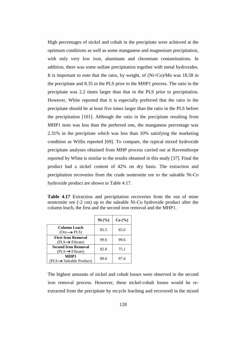
128
High percentages of nickel and cobalt in the precipitate were achieved at the
optimum conditions as well as some manganese and magnesium precipitation,
with only very low iron, aluminum and chromium contaminations. In
addition, there was some sulfate precipitation together with metal hydroxides.
It is important to note that the ratio, by weight, of (Ni+Co)/Mn was 18.58 in
the precipitate and 8.35 in the PLS prior to the MHP1 process. The ratio in the
precipitate was 2.2 times larger than that in the PLS prior to precipitation.
However, White reported that it is especially preferred that the ratio in the
precipitate should be at least five times larger than the ratio in the PLS before
the precipitation [101]. Although the ratio in the precipitate resulting from
MHP1 tests was less than the preferred one, the manganese percentage was
2.31% in the precipitate which was less than 10% satisfying the marketing
condition as Willis reported [69]. To compare, the typical mixed hydroxide
precipitate analyses obtained from MHP process carried out at Ravensthorpe
reported by White is similar to the results obtained in this study [37]. Final the
product had a nickel content of 42% on dry basis. The extraction and
precipitation recoveries from the crude nontronite ore to the saleable Ni-Co
hydroxide product are shown in Table 4.17.
The highest amounts of nickel and cobalt losses were observed in the second
iron removal process. However, these nickel-cobalt losses would be re-
extracted from the precipitate by recycle leaching and recovered in the mixed
Table 4.17 Extraction and precipitation recoveries from the run of mine
nontronite ore (-2 cm) up to the saleable Ni-Co hydroxide product after the
column leach, the first and the second iron removal and the MHP1.
Ni (%) Co (%)
Column Leach
(Ore PLS) 85.5 65.0
First Iron Removal
(PLS Filtrate) 99.6 99.6
Second Iron Removal
(PLS Filtrate) 82.8 75.1
MHP1
(PLS Saleable Product) 89.6 97.4

129
hydroxide precipitate as MHP1 product. As it is stated in Chapter 2, Willis
reported that by dissolving the solids produced in the second iron removal and
MHP2 by the required amount of sulfuric acid solutions (greater than 20 g/L)
at an operating temperature of higher than 50oC and 1-2 hours of precipitation
duration, 95-100% nickel and cobalt recoveries from the precipitates can be
attained [69]. Therefore, by maintaining at least 95% of Ni-Co extraction
recoveries from the precipitates produced in the second iron removal by
recycle leaching with sulfuric acid, about 75% of Ni and 62% of Co could
totally be extracted from the nontronite ore by MHP1 (9 kg Ni / ton of ore and
0.27 kg Co / ton of ore). An example of total extraction recovery calculation
is given in Appendix B. Total extraction recoveries of nickel and cobalt with
respect to number of recycle leach of the precipitates are shown in Figure
4.23. After the third recycle leaching, total extraction recoveries would
become constant. Total extraction recoveries would be further increased by
recycle leaching of the precipitates produced by MHP2 which will be reported
in the following part.
Figure 4.23 Total extraction recoveries (%) of Ni and Co from the crude
laterite ore to the hydroxide precipitate produced by the MHP1with respect to
number of recycle leach of the precipitates produced by the second iron
removal.
Co
0
10
20
30
40
50
60
70
80
90
100
0 1 2 3 4 5
Ni
Number of Recycle Leach
To
tal
% o
f N
i a
nd
Co
Ex
tracti
on
fro
m t
he N
on
tro
nit
e

130
0
500
1000
1500
2000
2500
0 10 20 30 40 50 60 70
The precipitates from the MHP1 experiments showed favorable settling and
filtration properties. It was observed that the color of the PLS after the
addition of the magnesium oxide slurry changed from green to slightly brown.
If the slurry was too green there would be insufficient nickel precipitation
giving rise to metal losses and if the slurry was too brown there would be too
much manganese precipitation leading to product contamination [37]. The X-
Ray diffraction data of the mixed hydroxide precipitate produced from the
PLS at the optimum conditions using 1% w/w fresh MgO slurry as
precipitating agent is shown in Figure 4.24.
The main mineralogical phases were theophrastite [Ni(OH)2], theophrastite
magnesian [3Ni(OH)2] and nickel hydroxide hydrate [3Ni(OH)2.2H2O]. Other
Figure 4.24 XRD pattern of the mixed hydroxide precipitate produced from
the purified PLS by MHP1 at pH 7.00, 50oC of precipitation temperature and 1
hour of precipitation duration with addition of fresh MgO slurry.
Inte
nsi
ty (
Cou
nts
)
2 Theta (deg.)
1. Ni(OH)2-Theophrastite
2. 3Ni(OH)2-Theophrastite Magnesian
3. 3Ni(OH)2.2H2O-Nickel Hydroxide Hydrate 4. Mg(OH)2-Brucite
5. SiO2-Silica
6. MnO(OH)-Groutite
1,6
1,2,6
1,2
4,6
4,5
5
3 3,6
2
3
4
5
5
5
5

131
Sample temperature/°C 50 100 150 200 250 300 350 400 450 500 550 600
HeatFlow/mW
-18
-16
-14
-12
-10
-8
-6
-4
#TG/%
-25.0
-22.5
-20.0
-17.5
-15.0
-12.5
-10.0
-7.5
-5.0
-2.5
0.0
Delta: -11.4537%
Delta: -13.9158%
Exo TGA
DTA
Total Weight Loss: -25.3695%
phases were brucite [Mg(OH)2], groutite [MnOOH] and silica [SiO2]. The
main peaks, matching with [Ni(OH)2] and [3Ni(OH)2], were sharper and with
greater intensity compared with other peaks which indicated lower intensity
and greater peak width. Mineralogical phases of other components were not
detected due to their low content in the mixed hydroxide precipitate. As seen
in Figure 4.24, the crystallinity of the phases were not well developed and not
as good as of the products from the iron removal processes since the addition
rate of the precipitating agent, i.e. fresh magnesium oxide slurry, was higher
in order to maintain good magnesia reactivity with the components of the PLS
leading to less time for the ordering of the atoms and the molecules in the
mixed precipitate. TGA and DTA analysis of the produced mixed hydroxide
precipitate is shown in Figure 4.25.
The weight loss (11.4%) up to 100oC was most probably due to the removal
of physically bonded water whereas the weight loss (13.9%) up to 400oC and
Figure 4.25 TGA and DTA diagram of the mixed hydroxide precipitate
produced from the purified PLS by MHP1 at pH 7.00, 50oC of precipitation
temperature and 1 hour of precipitation duration with addition of fresh MgO
slurry.

132
Components of PLS Concentration (ppm)
Ni 260
Co 1.4
Fe 0
Mg 7046
Al 0
Ca 725
Mn 182
Cr 0.10
Zn 0.15
Cu 0
H2SO4 0
the heat absorbance at 360oC were most likely to be due to the
dehydroxylation reaction of hydroxides and the water taken away from
[Ni(OH)2], [3Ni(OH)2] and [3Ni(OH)2.2H2O] and [Mg(OH)2] according to
Reactions 4.8, 4.9, 4.10 and 4.11, respectively [92].
At the end of MHP1 study, a new PLS stock which would be used in MHP2
was produced by carrying out MHP1 at the optimum conditions. The AAS
analysis of the new 1.25 L PLS stock is illustrated in Table 4.18
In the PLS stock there was no free acid present and before MHP2, Ni/Mn
ratio was 1.43. The ORP (or SHE) value and the density of the PLS stock
were 220 mV (or 418 mV) and 1.04 g/cm3, respectively. In addition, the very
small amounts of iron, aluminum, chromium and copper remaining in the PLS
Ni(OH)2 NiO + H2O (4.8)
3Ni(OH)2 3NiO + 3H2O (4.9)
3Ni(OH)2.2H2O 3Ni(OH)2 + 2H2O (4.10)
Mg(OH)2 MgO + H2O (4.11)
Table 4.18 Chemical analysis by AAS of the new PLS stock produced by
MHP1 at the optimum conditions.

133
after the second iron removal was almost completely removed from the PLS
during MHP1. Now, the PLS was a residual leach liquor solution containing
small amounts of some ions of elements as expressed in Table 4.18.
4.4 Second Mixed Hydroxide Precipitation (MHP2)
In the MHP2, which is called scavenging nickel precipitation, the optimum
conditions were studied in order to precipitate residual nickel completely from
the residual solution with some but the minimum amount of manganese in a
mixed hydroxide form which would be re-dissolved in the recycle leach for
recovery of nickel and cobalt. Since the residual solution contained significant
amounts of nickel, MHP2 was found to be necessary to gain the nickel loss
from the liquor. Therefore, a non-selective precipitation of nickel was decided
to be carried out using hydrated lime slurry as the precipitating agent.
Magnesium oxide slurry was not selected since it was not targeted to produce
saleable hydroxide product as in MHP1. In addition, there is no study reported
in the literature in which magnesium oxide slurry is used in MHP2. The
purpose of the MHP2 experiments was to find an appropriate way to
precipitate almost all the remaining nickel together with cobalt from the
residual leach liquor leaving less than 10 ppm nickel in the solution by adding
1% w/w Ca(OH)2 slurry into the residual solution without considering
manganese limitation unless it was much more than expected (>10% in the
precipitate). In contrast to MHP1, in MHP2 the most important parameter was
the nickel precipitation recovery which had to be maintained as high as
possible because there was no other further step for the nickel to be recovered
from the leach liquor. Simultaneously, manganese precipitation recovery had
to be low by the virtue of the fact that manganese would be re-leached from
the precipitate together with nickel and cobalt during the recycle leach leading
to an increased load of manganese in the MHP circuit.

134
4.4.1 Effect of pH
In the first set of experiments, pH was typically kept in the range of pH 7.50-
8.50 with 1% w/w of freshly slurried slaked (hydrated) lime aiming to
determine the optimum pH value at which maximum practical nickel
precipitation would be achieved providing that manganese contamination
could not be so much giving rise to an undesired increase in manganese
concentration in the MHP circuit.
At the fixed conditions (60oC of precipitation temperature and 1 hour of
precipitation duration) pre-determined from the literature [69, 70, 92, 101],
precipitation recoveries with respect to various pH values were recorded as
the volume of the slaked lime slurry was changed. The results are shown in
Table 4.19 and Figure 4.26 displays the graphical presentation of the
precipitation recoveries of Ni, Co and Mn with respect to pH at 60oC of
precipitation temperature and 1 hour of precipitation duration.
Optimum pH depends on the desired residual nickel and cobalt concentrations
in the remaining solution and the desired manganese content in the
precipitate. After pH 7.75, nickel and cobalt precipitation recoveries became
almost 100% but more than 90% of manganese precipitated yielding to an
undesired manganese concentration in the precipitate. The manganese
increase with pH especially between pH 7.50 and 8.00 is also seen in Figure
4.26. Thus, the optimum pH was decided to be less than pH 8.00. Although at
pH 7.50, the manganese precipitation recovery was desirable while nickel
pH Ni (%) Co (%) Mn (%)
7.50 91.6 92.7 29.0
7.75 99.9 100.0 90.9
8.00 99.9 100.0 99.4
8.50 99.9 100.0 100.0
Table 4.19 Precipitation recoveries with respect to pH of the leach liquor at
60oC of precipitation temperature and 1 hour of precipitation duration.

135
precipitation recovery was about 92%, this percentage could be increased up
to 97-100% without so much manganese precipitation by conducting MHP2
at a different precipitation temperature and duration combination which will
be explained in the following parts.
As it is stated in Chapter 2, Sist and Demopoulos reported that the solubility
of nickel in the aqueous phase decreased with increasing pH [91], so effecting
the precipitation mechanism as in the iron removal process which can be also
be concluded from Figure 4.26.
4.4.2 Effect of pH, Precipitation Temperature and Duration
Combinations
In the second set of experiments, different pH, precipitation temperature and
duration combinations were investigated. Firstly at pH 7.50 and 50oC of
precipitation temperature, and secondly at pH 7.75 and 60oC of precipitation
Figure 4.26 Precipitation recoveries (%) of nickel, cobalt and manganese
with respect to pH at 60oC of precipitation temperature and 1 hour of
precipitation duration.
% N
i2+, C
o2
+ a
nd
Mn
2+ P
rec
ipit
ati
on
Reco
veri
es
Equilibrium pH
Mn2+
0
10
20
30
40
50
60
70
80
90
100
7.00 7.50 8.00 8.50 9.00
Ni2+
Co2+
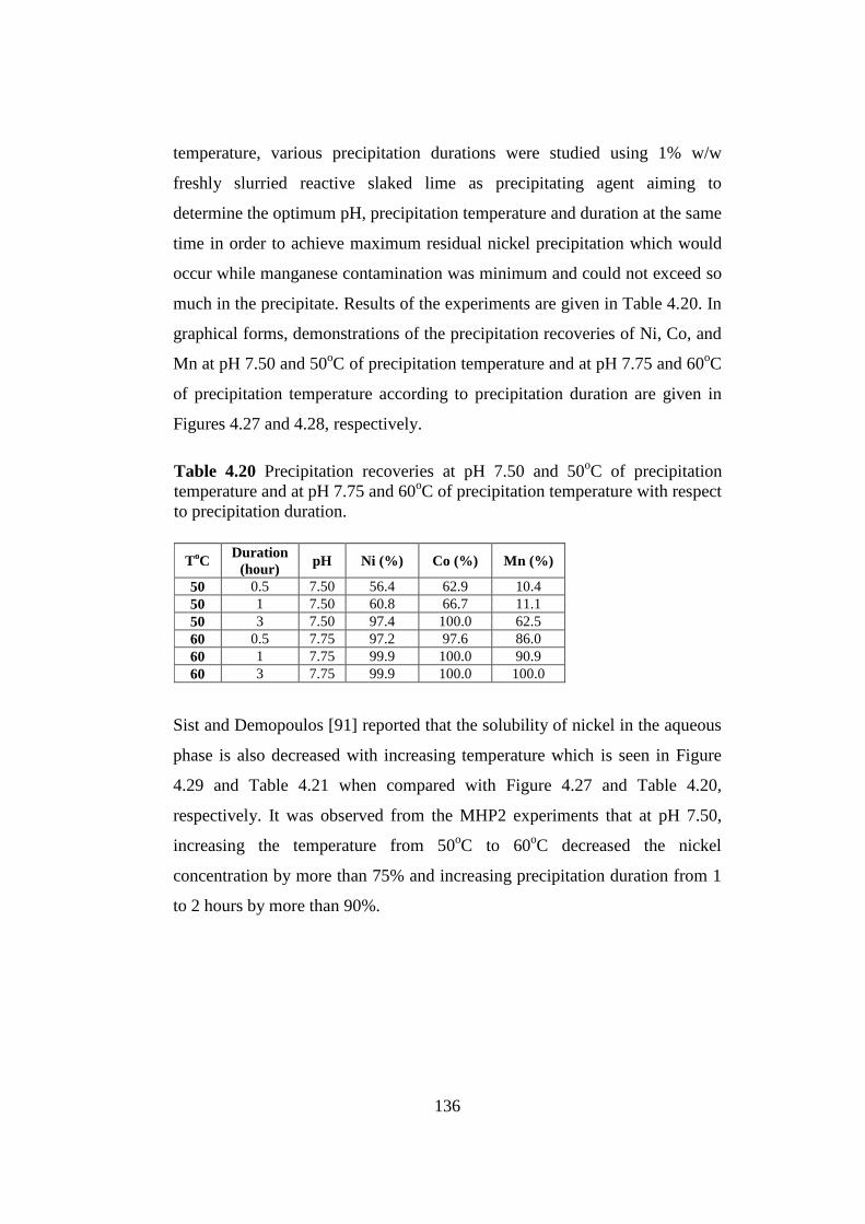
136
temperature, various precipitation durations were studied using 1% w/w
freshly slurried reactive slaked lime as precipitating agent aiming to
determine the optimum pH, precipitation temperature and duration at the same
time in order to achieve maximum residual nickel precipitation which would
occur while manganese contamination was minimum and could not exceed so
much in the precipitate. Results of the experiments are given in Table 4.20. In
graphical forms, demonstrations of the precipitation recoveries of Ni, Co, and
Mn at pH 7.50 and 50oC of precipitation temperature and at pH 7.75 and 60
oC
of precipitation temperature according to precipitation duration are given in
Figures 4.27 and 4.28, respectively.
Sist and Demopoulos [91] reported that the solubility of nickel in the aqueous
phase is also decreased with increasing temperature which is seen in Figure
4.29 and Table 4.21 when compared with Figure 4.27 and Table 4.20,
respectively. It was observed from the MHP2 experiments that at pH 7.50,
increasing the temperature from 50oC to 60
oC decreased the nickel
concentration by more than 75% and increasing precipitation duration from 1
to 2 hours by more than 90%.
ToC
Duration
(hour) pH Ni (%) Co (%) Mn (%)
50 0.5 7.50 56.4 62.9 10.4
50 1 7.50 60.8 66.7 11.1
50 3 7.50 97.4 100.0 62.5
60 0.5 7.75 97.2 97.6 86.0
60 1 7.75 99.9 100.0 90.9
60 3 7.75 99.9 100.0 100.0
Table 4.20 Precipitation recoveries at pH 7.50 and 50oC of precipitation
temperature and at pH 7.75 and 60oC of precipitation temperature with respect
to precipitation duration.
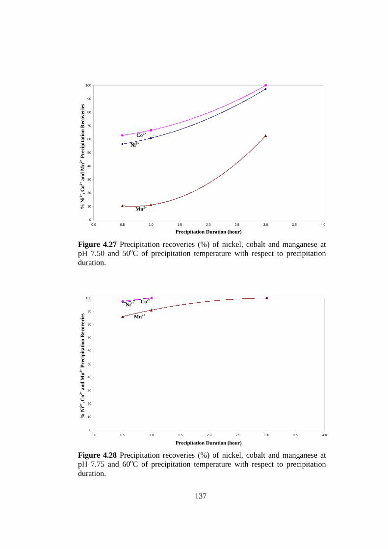
137
0
10
20
30
40
50
60
70
80
90
100
0.0 0.5 1.0 1.5 2.0 2.5 3.0 3.5 4.0
0
10
20
30
40
50
60
70
80
90
100
0.0 0.5 1.0 1.5 2.0 2.5 3.0 3.5 4.0
Figure 4.27 Precipitation recoveries (%) of nickel, cobalt and manganese at
pH 7.50 and 50oC of precipitation temperature with respect to precipitation
duration.
Figure 4.28 Precipitation recoveries (%) of nickel, cobalt and manganese at
pH 7.75 and 60oC of precipitation temperature with respect to precipitation
duration.
% N
i2+, C
o2
+ a
nd
Mn
2+ P
rec
ipit
ati
on
Reco
veri
es
Precipitation Duration (hour)
Precipitation Duration (hour)
% N
i2+, C
o2
+ a
nd
Mn
2+ P
rec
ipit
ati
on
Reco
veri
es
Ni2+
Co2+
Mn2+
Mn2+
Ni2+
Co2+

138
In the final set of experiments, the precipitation duration was studied at a
fixed pH (7.50) and precipitation temperature (60oC) before deciding the
optimum conditions. The results of the experiments are shown in Table 4.21
and Figure 4.29 illustrates the graphical presentation of the precipitation
recoveries of Ni, Co and Mn with respect to precipitation duration.
Mn2+
concentration in the residual solution was abruptly decreased after 1
hour of precipitation duration while Ni2+
and Co2+
precipitation recoveries
from the residual solution gradually increased between 90% and 100%. But,
at least 95% nickel precipitation recovery was required in MHP2 stage to
Duration
(hour) Ni (%) Co (%) Mn (%)
1.0 91.6 92.7 29.0
1.5 99.7 95.2 78.9
2.0 99.9 100.0 89.9
Table 4.21 Precipitation recoveries at pH 7.50 and 60oC of precipitation
temperature with respect to precipitation duration.
Figure 4.29 Precipitation recoveries (%) of nickel, cobalt and manganese at
pH 7.50 and 60oC of precipitation temperature with respect to precipitation
duration.
% N
i2+, C
o2+ a
nd
Mn
2+ P
rec
ipit
ati
on
Reco
veri
es
Ni2+
0
10
20
30
40
50
60
70
80
90
100
0.0 0.5 1.0 1.5 2.0 2.5
Co2+
Mn2+
Precipitation Duration (hour)

139
decrease nickel loss to a minimum. Thus, 1.5 hours of precipitation duration
was selected to achieve the desired minimum Ni concentration (10 ppm) in
the residual solution at pH 7.50 and 60oC of precipitation temperature while
taking about 79% Mn in solution into the precipitate.
At the end of the MHP2 experiments, in order to achieve less than 10 ppm Ni
in the residual solution while minimum amount of manganese precipitated
without much contaminating the MHP2 product and undesired manganese
accumulation in the MHP circuit, the optimum conditions were determined to
be at pH 7.50, 3 hours of precipitation duration and 50oC of precipitation
temperature or 1.5 hours of precipitation duration and 60oC of precipitation
temperature. From among the two conditions, 3 hours of precipitation
duration and 50oC of precipitation temperature were preferred attributed to
leading to less manganese precipitation recovery as seen in Tables 4.20 and
4.21. At the chosen condition, the amount of Ca(OH)2 slurry consumed was
2.7 cc (0.027 g Ca(OH)2 / 50 cc residual solution) (0.54 kg Ca(OH)2 / m3
residual solution) and the weight of the precipitate produced was, 0.05 g / 50
cc, 17% of the precipitate weight by MHP1. It is important to note that in
contrast to MHP1, the nickel in the precipitate produced in less amounts had
to be recovered by recycle leaching providing that at least 95% Ni together
with Co extraction recoveries from the precipitates would be attained.
After MHP2, about 97% of nickel, 100% of cobalt, 63% of manganese and
less than 0.5% of magnesium in solution were precipitated at the optimum
conditions chosen (pH 7.50, 50oC of precipitation temperature, 3 hours of
precipitation duration). The precipitate analysis is given in Table 4.22. Nickel
content as well as manganese, calcium and sulfur was relatively high in the
precipitate. But, the MHP2 product contained 11.4% Mn. According to Willis,
second stage MHP product typically contains 10-20%Mn [70]. At MHP2,
there was calcium sulfate precipitation as bassanite due to the reaction
between calcium hydroxide and metal sulfates left in the residual solution

140
after MHP1 as in Reactions 4.12, 4.13, 4.14 and 4.15. The decrease of nickel,
cobalt and manganese in the residual solution resulting from these reactions at
MHP2 is also apparent in Table 4.23.
As seen in Reaction 4.14, manganese in the solution was oxidized by oxygen
in air to form typical manganese oxides which are manganite and groutite and
became Mn3+
in the precipitate from Mn2+
in the solution. The ratio of
(Ni+Co)/Mn was 2.23 in the precipitate and 1.44 in the PLS prior to the
MHP2 process. Although the mixed hydroxide product had a nickel content of
about 25% on dry basis, MHP2 was not selective over manganese for the
recovery of nickel. According to Zhang et al., MHP intermediates remain
contaminated with manganese and must be further refined in the downstream
process [95]. Furthermore, the precipitate was contaminated with calcium
sulfate resulting in an economically valueless product according to marketing
conditions. However, the mixed hydroxide products at the end of MHP2
would be sent to the recycle leach stream where the nickel and cobalt values
were re-dissolved from the mixed precipitates by sulfuric acid leaching while
Table 4.22 Composition analysis of the hydroxide precipitate produced from
the residual solution of the MHP1 by MHP2 at the optimum conditions.
Components of the precipitate Value (%w/w dry)
Ni 25.32
Co 0.14
Mn 11.4
Mg 1.9
Cr 0.010
Ca 11.6
Zn 0.008
S 11.13
Ca(OH)2 (s) + Ni(SO)4 (aq) CaSO4 (s) + Ni(OH)2 (s) (4.12)
Ca(OH)2 (s) + Co(SO)4 (aq) CaSO4 (s) + Co(OH)2 (s) (4.13)
2Ca(OH)2 (s) + 2Mn(SO)4 (aq) + 1/2O2 (g) 2CaSO4 (s) + 2MnOOH(s) + H2O(l) (4.14)
Ca(OH)2 (s) + Mg(SO)4 (aq) CaSO4 (s) + Mg(OH)2 (s) (4.15)

141
0
10
20
30
40
50
60
70
80
90
100
0 1 2 3 4 5
achieving at least 95% of leach extraction recovery for nickel. Therefore,
most of the loss of nickel in the residual solution was recovered by MHP2 and
the recycle leaching while some calcium and manganese would go into
solution. Total extraction recoveries of nickel and cobalt with respect to
number of recycle leach of the precipitates produced by both the second iron
removal and MHP2 are shown in Figure 4.30. An example of total extraction
recovery calculation including recycle leach of precipitates produced by
second iron removal and MHP2 is given in Appendix B.
By maintaining recycle leaching with sulfuric acid at a desired efficiency,
about 81% of Ni and 63% of Co could totally be extracted from the nontronite
ore by MHP1 (9.72 kg Ni / ton of ore and 0.28 kg Co / ton of ore) after the
fourth recycle leaching. These total extraction recoveries are higher and more
close to the column leach extraction recoveries (86% Ni and 65% Co) if it is
compared to the total extraction recoveries including no recycle leaching or
recycle leaching of the precipitates produced by only the second iron removal
as seen in Figures 4.23. About 63% of Ni and 47% of Co in the nontronite
Ni
Figure 4.30 Total extraction recoveries (%) of Ni and Co from the crude
laterite ore to the hydroxide precipitate produced by the MHP1 with respect to
number of recycle leach of the precipitates produced by the second iron
removal and MHP2.
To
tal
% o
f N
i a
nd
Co
Ex
tracti
on
fro
m t
he N
on
tro
nit
e
Number of Recycle Leach
Co

142
0
500
1000
1500
2000
2500
3000
3500
4000
4500
5000
0 10 20 30 40 50 60 70
(7.56 kg Ni / ton of ore and 0.21 kg Co / ton of ore) were extracted by MHP
without any recycle leaching.
The precipitates from the MHP2 experiments also showed favorable settling
and filtration properties. It was observed that the color of the residual solution
after the addition of the hydrated lime slurry changed from light green to dark
green and light brown which was believed to be the indicator for the
contamination of the mixed hydroxide product due to the insoluble calcium
sulfate. The X-Ray diffraction data of the mixed hydroxide precipitate
produced by MHP2 at the optimum conditions using 1% w/w fresh Ca(OH)2
slurry as precipitating agent is shown in Figure 4.31.
Figure 4.31 XRD pattern of the mixed hydroxide precipitate produced from
the residual solution by MHP2 at pH 7.50, 50oC of precipitation temperature
and 3 hours of precipitation duration with addition of fresh Ca(OH)2 slurry.
1. CaSO4.0.5H2O-Bassanite 2. Ni(OH)2-Theophrastite
3. 3Ni(OH)2-Theophrastite Magnesian
4. NiSO4.6H2O-Nickel Hexahydrite 5. Ca3Mn(SO4)2(OH)6.3H2O-Despujolsite
6. Ca(OH)2-Portlandite
7. MnO(OH)-Groutite 8. γ-MnOOH-Manganite
9. MgSO4.6H2O-Hexahydrite
10. Mg(OH)2-Brucite
2 Theta (deg.)
Inte
nsi
ty (
Cou
nts
)
1
1,5
1
1
2,3 2 2,3
9
5
5
6
7 4,9
9
10
10 4,6
9
8
1,7
6 7,8
5 5
6
1
7
8 2,3
10 4,9

143
The main mineralogical phase was bassanite as in the iron removal stages,
which was formed in the mixed hydroxide product because precipitation with
calcium hydroxide brings about the formation of an insoluble calcium sulfate
precipitate resulting in contamination of the mixed hydroxide product [101].
Other phases were groutite [MnOOH], manganite [γ-MnOOH], despujolsite
[Ca3Mn(SO4)2(OH)6.3H2O], hexahydrite [MgSO4.6H2O], theophrastite,
theophrastite magnesian, nickel hexahydrite, brucite and portlandite
[Ca(OH)2]. The main peaks belonging to bassanite and some peaks matching
to groutite, manganite, despujolsite and hexahydrite were sharper and with
greater intensity while other peaks belonging to the all phases except for
bassanite showed lower intensity and greater peak width. XRD pattern of the
MHP2 precipitate showed that some Ni, Mg and Mn precipitated in sulfate-
hydrate form while the others were in hydroxide forms except for bassanite.
Furthermore, as in MHP1, a mineralogical phase of cobalt was not detected
due to its low content in the mixed hydroxide precipitate. TGA and DTA
analysis of the produced mixed hydroxide precipitate is shown in Figure 4.32.
The weight loss (9.0%) up to 120oC was most probably due to the removal of
physically bound water while the weight loss (8.3%) up to 400oC and the heat
absorbance at 310oC and 395
oC were most likely to be due to the
dehydroxylation reactions of hydroxides: groutite, manganite, theophrastite,
theophrastite magnesian, portlandite and brucite and the water taken away
from bassanite, hexahydrite, nickel hexahydrite and despujolsite.
At the end of MHP2, a new solution stock which would be used in the
manganese precipitation process was produced by conducting MHP2 at the
optimum conditions. The AAS analysis of the new 800 mL residual solution
stock is illustrated in Table 4.23.

144
Components of PLS Concentration (ppm)
Ni 6.5
Co 0
Mg 6731
Ca 726
Mn 65.4
Cr 0
Zn 0.07
Sample temperature/°C 50 100 150 200 250 300 350 400 450 500 550 600
HeatFlow/mW
-14
-12
-10
-8
-6
-4
-2
0
#TG/%
-18
-16
-14
-12
-10
-8
-6
-4
-2
0
Delta: -9.0448%
Delta: -8.3497%
Exo
Total Weight Loss: -17.3945%
DTA
TGA
In the solution stock, there were only magnesium, calcium and manganese left
with some nickel and very small amount of zinc after MHP2. Therefore, the
residual solution stock was now called barren solution. The ORP (or SHE)
value and the density of the barren solution were 210 mV (or 408 mV) and
1.0 g/cm3, respectively.
Figure 4.32 TGA and DTA diagram of the mixed hydroxide precipitate
produced from the residual leach solution by MHP2 at pH 7.50, 50oC of
precipitation temperature and 3 hours of precipitation duration with addition of
fresh Ca(OH)2 slurry.
Table 4.23 Chemical analysis by AAS of the new residual leach solution stock
produced by MHP2 at the optimum conditions.

145
4.5 Manganese Removal (MnR)
In the manganese removal experiments, the optimum conditions were studied
to precipitate the remaining manganese completely from the barren solution
with some magnesium using slaked lime slurry as precipitating agent in order
to eliminate manganese from the MHP circuit and also discharge liquors to be
able to use within the process as make-up water for heap (column) or recycle
leaching. After the two-stage nickel-cobalt precipitation (MHP1-MHP2), 20%
of the manganese remained in the solution. However, Willis reported that
generally more than 50% of the manganese is left in the liquor after the two
MHP stages [69]. Although the amount of the manganese precipitated after
MHP1-MHP2 in this study was higher than that reported in the literature, it
was not a problem because in MHP1, 55% of the manganese remained in the
solution and it did not exceed 10% Mn in the precipitate which was saleable
and suitable to the marketing conditions.
It was aimed in the manganese removal experiments that less than 5 ppm
residual manganese would be achieved in the barren solution by adding fresh
20% w/w Ca(OH)2 slurry into the solution. Therefore, the most important
parameter in this last step of the MHP process was the manganese
precipitation recovery which had to be kept as high as possible. Otherwise,
manganese would accumulate in the circuit and adversely affecting the
product quality.
4.5.1 Effect of pH
In the first set of experiments, pH was kept in the range of 8.00-9.00 with
20% w/w freshly slurried slaked lime to determine the optimum pH value at
which maximum practical manganese precipitation would be attained. At the
fixed conditions (50oC of precipitation temperature and 1 hour of precipitation
duration) pre-determined from the literature [69, 70, 94, 95], precipitation

146
recoveries with respect to various pH values were recorded. When 0.4 cc
Ca(OH)2 slurry was added, pH 8.50 obtained was found to be the most
effective pH and was decided to be the optimum. The results are shown in
Table 4.24
Manganese precipitation increased with pH between pH 7.50 and 8.50, so at
pH 8.50, 100% Mn precipitation was achieved yielding a desired manganese
concentration less than 1 ppm in the solution. As it is stated in Chapter 2, a
considerable manganese precipitation starts at pH 8.00 and continues between
pH 8.00 and 10.00 whereas the molarity of manganese changes as it is
apparent in Figure 2.19. It is important to note that the amount of the slaked
lime slurry to maintain pH 9.00 at 50oC for 1 hour of precipitation was 7.7 cc
(1.54 g / 50 cc barren solution) while it was around 0.1-0.4 cc for the
precipitation at pH 8.00 and 8.50, respectively. This showed that the amount
of the precipitating agent to increase pH from 8.50 to 9.00 was about 24 times
higher than the amount to attain pH 8.50 from 8.00. For this reason, pH 9.00
was not selected as the optimum for the manganese removal attributed to the
excessive consumption in the amount of the precipitating agent in spite of
100% Mn precipitation satisfied. The reason for the high consumption was
believed to be the buffering effect at this pH range.
According to Willis, the residual solution after the two MHP stages is
typically adjusted to pH 8.50-9.00 at 50-60oC of precipitation temperature and
0.5-2 hours of precipitation duration to achieve a residual manganese
concentration of <100 ppm by precipitating manganese hydroxide [69, 70]. In
addition, a residual concentration of about 10 ppm Mn can be achieved by air
pH Mn (%) Ni (%)
8.00 63.1 98.5
8.50 99.8 100.0
9.00 100.0 100.0
Table 4.24 Precipitation recoveries of manganese and nickel with respect to
pH of the barren liquor at 50oC of precipitation temperature and 1 hour of
precipitation duration.

147
injection by utilizing 10-20% oxygen. In this study during manganese
removal experiments, air could also be injected for manganese oxidation.
However, it was not found necessary because it was believed that the spiral
movement of the magnetic stirrer during manganese precipitation experiments
enabling required oxygen in the air to take part in the precipitation reaction
(Reaction 4.14). Zhang et al. studied the effect of pH on the kinetics of Mn2+
oxidation and reported that the oxidation of Mn2+
with O2 is slow but strongly
pH dependent as the pH increases above 4.50 [95]. As a result of the
manganese oxidation while pH of the solution was increased from 7.50, Mn3+
was formed in groutite and manganite from Mn2+
in the solution.
4.5.2 Effect of Precipitation Temperature
In the second set of experiments, the precipitation temperatures between 50oC
and 70oC were studied at pH 8.50 and 1 hour of precipitation duration using
20% w/w freshly slurried slaked lime aiming to specify the optimum
precipitation temperature at which maximum practical Mn precipitation
would occur. Results of the experiments are shown in Table 4.25.
There was a small increase in precipitation recovery of manganese with
increases in the precipitation temperature while the residual nickel (6.5 ppm)
was totally precipitated from the barren solution. Since a precipitation
temperature at which 100% manganese precipitation recovery first attained
from the solution was required when precipitation temperature was increased,
50oC was selected as the optimum precipitation temperature for the
manganese removal. Although higher temperatures could also be selected for
Table 4.25 Precipitation recoveries of manganese and nickel from the barren
solution with respect to precipitation temperature at pH 8.50 and 1 hour of
precipitation duration.
T
oC Mn (%) Ni (%)
50 99.8 100.0
60 100.0 100.0
70 100.0 100.0

148
100% Mn precipitation recovery, they were out of selection due to
unnecessary heating above 50oC for the same manganese precipitation
recovery needed. In addition, Zhang et al. reported that the oxidative
precipitation of Mn2+
with air occurs at the temperature range of 25-80oC at
pH 6.00 [95]. However, for oxidative manganese precipitation at pH <3.50, a
precipitation temperature above 60oC is not recommended since it leads to the
slow mass transfer of oxygen in air through the viscous slurry at relatively
high temperature [94]. On the other hand, an operating temperature less than
50oC resulted in slower reaction kinetics of 100% manganese precipitation
and negatively affected the filterability of precipitate.
4.5.3 Effect of Precipitation Duration
In the final set of experiments, the precipitation durations between 0.5 and 1.5
hours were studied at pH 8.50 and 50oC of precipitation temperature using
20% w/w freshly slurried Ca(OH)2 as precipitating agent in order to find out
the optimum precipitation duration at which 100% manganese precipitation
recovery would be achieved from the PLS at the desired conditions. The
results of the experiments are shown in Table 4.26.
As in the precipitation temperature, there was a small increase in precipitation
recovery of manganese with increases in the precipitation duration, while the
residual nickel and manganese were almost completely depleted from the
barren solution during the waiting time to bring pH from 7.50 to 8.50 at 50oC
of temperature. The same option as in the previous set was also applied to
Table 4.26 Precipitation recoveries of manganese and nickel from the barren
solution with respect to precipitation duration at pH 8.50 and 50oC of
precipitation temperature.
Duration
(hour) Mn (%) Ni (%)
0.5 97.0 100.0
1.0 99.8 100.0
1.5 100.0 100.0

149
select the optimum precipitation duration. Therefore, 1 hour of precipitation
duration was decided to be the optimum due to attaining 100% Mn at first.
At the end of the third set of experiments, the optimum conditions were
finally chosen at pH 8.50, 50oC of precipitation temperature and 1 hour of
precipitation duration for the manganese removal. At these conditions, the
weight of the precipitate produced by the manganese removal process was
about 0.05 g and the amount of Ca(OH)2 slurry consumed was 0.4 cc (0.080 g
Ca(OH)2 / 50 cc barren solution) (1.6 kg Ca(OH)2 / m3 barren solution). After
the manganese removal, only calcium and magnesium were left in the barren
solution. The precipitate analysis is given in Table 4.27. Manganese, calcium,
magnesium and sulfur were the main constituents of the precipitate. As it is
apparent in Table 4.27, there was a small amount of nickel loss in the
manganese precipitate which would be insignificant in the economic view of
the process.
The precipitates from the manganese removal experiments showed favorable
settling and filtration properties as in the previous precipitation processes. It
was observed that the color of the barren solution after the addition of the
calcium hydroxide slurry changed from transparent to white which was
believed to be due to the unreacted calcium hydroxide solid suspended in the
solution. The precipitate produced was also white in color.
Table 4.27 Composition analysis of the manganese precipitate produced from
the barren solution by the manganese removal process at the optimum
conditions.
Components of the precipitate Value (%w/w dry)
Ni 0.65
Mn 6.53
Mg 2.8
Zn 0.01
Ca 14.8
S 10.0

150
0
500
1000
1500
2000
2500
3000
0 10 20 30 40 50 60 70
The X-Ray diffraction data of the manganese hydroxide precipitate produced
from the barren solution at the optimum conditions using 20% w/w fresh
Ca(OH)2 slurry is shown in Figure 4.33.
The main mineralogical phase was bassanite as in MHP2 and the iron removal
stages by the virtue of the fact that the precipitation with calcium hydroxide
gives rise to the formation of an insoluble calcium sulfate precipitate leading
to the contamination of the hydroxide product. The formation of bassanite can
also be predicted from high calcium and sulfur concentration in the precipitate
shown in Table 4.27. Other phases were groutite, manganite, despujolsite,
Figure 4.33 XRD pattern of the manganese hydroxide precipitate produced
from the barren solution by manganese removal at pH 8.50, 50oC of
precipitation temperature and 1 hour of precipitation duration with addition of
Ca(OH)2 slurry.
2 Theta (deg.)
Inte
nsi
ty (
Cou
nts
)
5
1
1,5
1 1,3
2
3,6
4 7
2,3 4
5
5
6
1
2
3
6,7
4
2,7
7
1
1. CaSO4.0.5H2O-Bassanite
2. Ni(OH)2-Theophrastite
3. α-MnOOH-Groutite 4. γ-MnOOH-Manganite
5. Ca3Mn(SO4)2(OH)6.3H2O-Despujolsite
6. Ca(OH)2-Portlandite
7. Mg(OH)2-Brucite
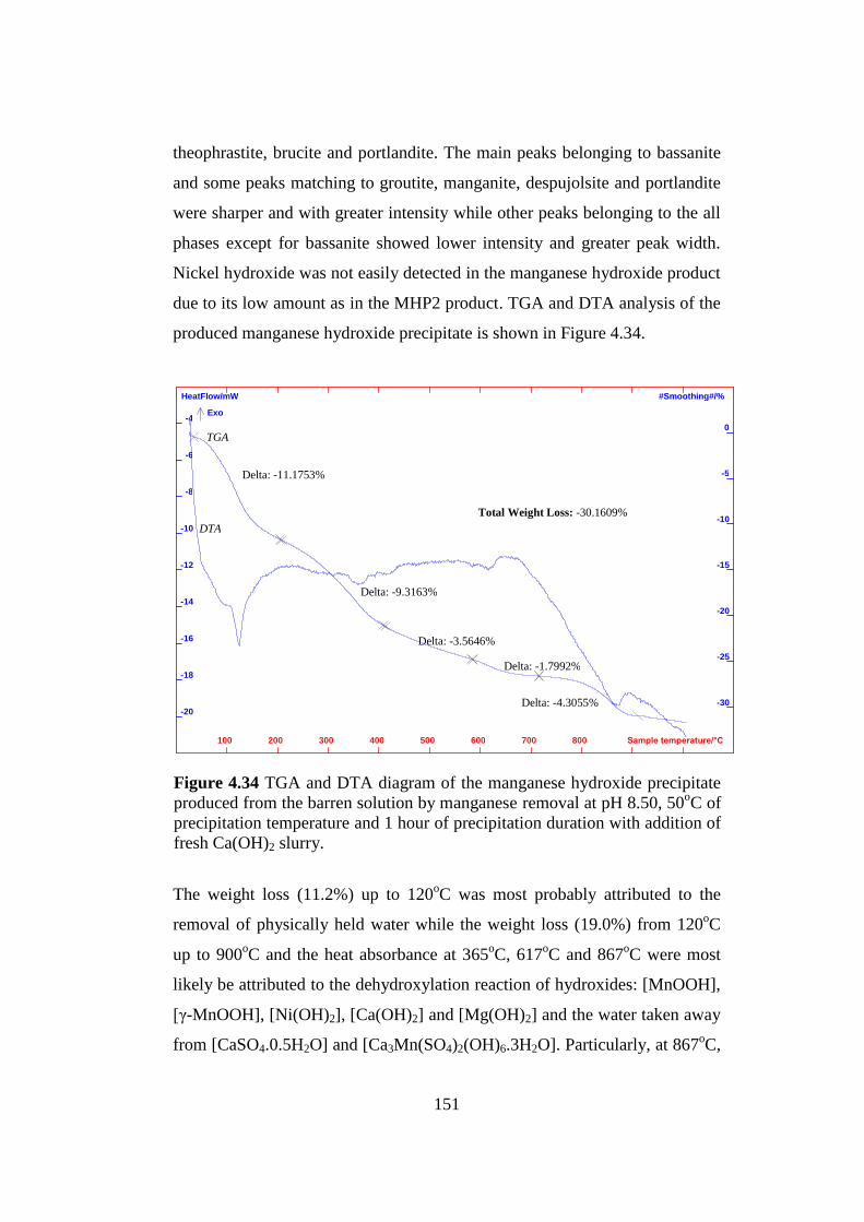
151
Sample temperature/°C 100 200 300 400 500 600 700 800
HeatFlow/mW
-20
-18
-16
-14
-12
-10
-8
-6
-4
#Smoothing#/%
-30
-25
-20
-15
-10
-5
0
Delta: -11.1753%
Delta: -9.3163%
Delta: -3.5646%
Delta: -1.7992%
Delta: -4.3055%
Exo
TGA
DTA
Total Weight Loss: -30.1609%
theophrastite, brucite and portlandite. The main peaks belonging to bassanite
and some peaks matching to groutite, manganite, despujolsite and portlandite
were sharper and with greater intensity while other peaks belonging to the all
phases except for bassanite showed lower intensity and greater peak width.
Nickel hydroxide was not easily detected in the manganese hydroxide product
due to its low amount as in the MHP2 product. TGA and DTA analysis of the
produced manganese hydroxide precipitate is shown in Figure 4.34.
The weight loss (11.2%) up to 120oC was most probably attributed to the
removal of physically held water while the weight loss (19.0%) from 120oC
up to 900oC and the heat absorbance at 365
oC, 617
oC and 867
oC were most
likely be attributed to the dehydroxylation reaction of hydroxides: [MnOOH],
[γ-MnOOH], [Ni(OH)2], [Ca(OH)2] and [Mg(OH)2] and the water taken away
from [CaSO4.0.5H2O] and [Ca3Mn(SO4)2(OH)6.3H2O]. Particularly, at 867oC,
Figure 4.34 TGA and DTA diagram of the manganese hydroxide precipitate
produced from the barren solution by manganese removal at pH 8.50, 50oC of
precipitation temperature and 1 hour of precipitation duration with addition of
fresh Ca(OH)2 slurry.

152
the endothermic peak was believed to be the dehydroxylation reaction of
[MnOOH] and [γ-MnOOH] since a similar peak is present in the DTA-TGA
of manganese (III) oxide which is shown in Figure 4.35.
Figure 4.35 DTA and TGA of manganese (III) oxide [102].

153
Components of PLS Concentration (ppm)
Ni 0
Mg 6703
Ca 727
Mn 0.13
Zn 0
At the end of the manganese removal, the final barren solution which would
be now used as make-up water for column or recycle leaching was produced.
The AAS analysis of this solution is given in Table 4.28. The ORP (or SHE)
value and the density of the solution after the manganese removal were 190
mV (or 388 mV) and 1.0 g/cm3, respectively.
There were only magnesium and calcium left in the barren solution which
would be accumulated in the circuit by means of recirculating the solution
through the recycle leach after the manganese removal. Magnesium can also
be removed from the MHP circuit by precipitation with the addition of fresh
Ca(OH)2 slurry if required and as long as it is economical. However, if the
equilibrium concentration of magnesium in the circuit does not adversely alter
product quality, then magnesium removal can be excluded.
Table 4.28 Chemical analysis by AAS of the solution which would be used as
make-up water for column or recycle leaching produced from the barren
solution by the manganese removal process operated at the optimum
conditions.
154
CHAPTER 5
CONCLUSIONS
Nickel and cobalt could be recovered efficiently in a saleable mixed
hydroxide precipitate form from the PLS produced by column leaching of
nontronite ore originating from Manisa-Gördes. A typical MHP process was
followed in this study and promising results were obtained very similar to
those presented in the literature. The age long experimental work has proven
that iron extracted into solution by column leaching could successfully be
rejected from PLS together with aluminum and chromium by a two-stage iron
removal process. At each stage, a slurry of CaCO3 could be used which is the
most suitable and the cheapest precipitating and neutralizing agent for iron
removal process. Nickel and cobalt losses in the precipitate produced by the
second iron removal and MHP2 were required to be regained by means of the
recycle leach.
After the neutralization of the PLS and the first iron removal stage by the
addition of CaCO3 slurry, a high proportion of ferric iron and arsenic could be
substantially precipitated while aluminum and chromium partially precipitated
from solution. In the second iron removal stage, the residual iron, aluminum
and chromium were almost completely removed from the PLS with some but
minimum amount of nickel and cobalt losses to the precipitate. Therefore, the
impurities contaminating the PLS such as Fe, Cr, Al and As could be

155
diminished to less than 5-10 ppm each in solution. The experiments of the
iron removal have shown that as a result of the neutralization of the PLS
obtained from the column leaching of the nontronitic laterite ore and the
purification of the PLS from Fe, As, Al and Cr at two stages by the addition
of CaCO3 slurry, the expected results existing in the literature could
practically be achieved for a nontronitic type laterite ore.
The method of the two-stage precipitation of nickel and cobalt as mixed
hydroxide products from the remaining solution cleaned from most of the
impurities has appeared to be the most appropriate method for the extraction
of nickel and cobalt from the leach liquor. For MHP1, the precipitation with
fresh MgO slurry gave very effective results whereas for MHP2, fresh
Ca(OH)2 slurry used led to the desired conditions in which nickel and cobalt
could efficiently be recovered with the minimum amount of manganese. The
analyses of MHP1 and MHP2 experimental products showed that MHP1 was
a saleable nickel-cobalt hydroxide with very good quality, while the mixed
hydroxide precipitate resulting from MHP2 was of poor quality and was not
qualified for the marketing conditions. Therefore, nickel and cobalt in the
MHP2 precipitate was required to be recovered by re-leaching methods and
recycled back to the MHP circuit to regain losses. By maintaining recycle
leaching with sulfuric acid at a desired efficiency for the precipitates produced
by the second iron removal and MHP2, high extraction recoveries of nickel
and cobalt from the nontronite ore could be achievable by the MHP process
carried out. About 81% of Ni and 63% of Co in the lateritic nickel ore (9.72
kg Ni / ton of ore and 0.28 kg Co / ton of ore) could be extracted as mixed
hydroxide precipitate by MHP with recycle leaching. This hydroxide product
contained about 42% Ni, 1% Co, 2% Mn and 2% Mg.
After the two-stage MHP, a manganese removal stage was required because
the equilibrium concentration of manganese in the circuit would negatively
affect the product quality. After the manganese removal, a magnesium
156
removal could also be followed to reject magnesium from MHP circuit if it
was needed to decrease magnesium accumulation in the circuit. However, the
experimental results indicated that the consumption of Ca(OH)2 slurry was
excessive due to the buffering effect which would yield an uneconomic
process. At the end of the MHP process, the solution which was almost free of
metals could be used as make-up water for heap or recycle leaching.
For the future work, following suggestions can be made:
1. The problems due to high CO2 emission at 90oC and high amount of
solid waste in the form of precipitate produced at low pH (2.50) in the
first iron removal, possible solutions should be considered and a
remedy should be found for the disposals of gaseous and solid wastes
of the first iron removal in accordance with the environmental
regulations.
2. First iron removal at ambient conditions needs to be studied to attain
the same or better precipitation recoveries with less amount of heat
energy consumed providing that filtration and settling properties of the
precipitate are not negatively affected.
3. A mechanical agitator can be used instead of a magnetic stirrer for
more homogeneous mixing of solution with the slurry of CaCO3 and a
different type or shape of container can be found for the iron removal
process to decrease the losses of precipitate to a minimum on the
inside wall of the container.
4. Precipitation of iron, aluminum and chromium from the pregnant
leach solution at the second iron removal stage with less nickel and
cobalt losses to the precipitate needs to be studied by adding seeds of
the precipitate into the solution.
5. Recycle leach of precipitates produced by second iron removal and
MHP2 with sulfuric acid should be investigated experimentally and at
least 95% nickel-cobalt extraction recoveries from the precipitates
157
should be aimed for achieving maximum recoveries of nickel and
cobalt as mixed hydroxide product from the crude nontronite ore.
6. In MHP1, the same or greater precipitation recoveries of nickel and
cobalt with less amount of manganese precipitating from the purified
PLS by addition of fresh MgO slurry should be further investigated
and volume of MgO slurry added into solution during MHP1 should
be controlled instead of pH control as in the other processes to achieve
desired precipitation recoveries. In addition, MgO slurry should be
used freshly within 2 or 3 minutes.
7. In MHP2, a different precipitating agent (CaO, CaCO3, etc.) and seed
addition of MHP2 precipitate can be studied at different conditions
such as pH, precipitation temperature and duration to achieve better
nickel and cobalt recoveries and/or less amount of manganese
precipitated.
8. Manganese removal before MHP can be investigated to reject
manganese from the circuit prior to nickel-cobalt precipitation and to
attain a desired purer mixed hydroxide product containing no or very
small amount of manganese.
9. Purification of residual leach solution from magnesium in an
economic manner should be investigated so as to use the residual
solution as make-up water for heap or recycle leaching in the circuit
without leading to any considerable magnesium accumulation.
10. Pilot plant testing and feasibility studies of MHP process developed in
this thesis study should be carried out to see the applicability and
workability of MHP executed.
158
REFERENCES
[1] S. J. Rosenberg, “Nickel and Its Alloys”, U. S. National Bureau of
Standards Monograph 106, Institute for Materials Research, Washington, D.
C., pp. 1-9, May 1968.
[2] M. Cempel and G. Nickel “Nickel: A Review of Its Sources and
Environmental Toxicology”, Polish J. of Environ. Stud., Vol. 15, No. 3, pp.
375-382, 2006.
[3] B. Mason, Principles of Geochemistry, John Wiley and Sons Ltd., New
York, Chapman and Hall Ltd., London, 1952.
[4] J. R. Boldt and P. Queneau (Ed.), The Winning of Nickel; Its Geology,
Mining, and Extractive Metallurgy, Longmans Canada Ltd., Toronto, pp. 25-
78, 1967.
[5] H. Y. Lee, S. G. Kim and J. K. Oh, “Electrochemical Leaching of Nickel
from Low-Grade Laterites”, Hydrometallurgy, Vol. 77, pp. 263–268, 2005.
[6] R. A. Alcock, “The Character and Occurrence of Primary Resources
Available to the Nickel Industry”, in G. P. Tyroler and C. A. Landolt (Eds.),
Extractive Metallurgy of Nickel and Cobalt, The Metallurgical Society,
Warrendale, pp. 67-90, 1988.

159
[7] H. H. Pariser, Alloy Metals and Steel Market Research, Xanten, Germany,
(May 2007), in Safe Use of Nickel in the Workplace, a Guide for Health
Maintenance of Workers Exposed to Nickel, Its Compounds and Alloys,
Third Addition, 2008.
[8] S. Tollin, “Outlook for Global Nickel Market in 2007-2008”, 2007 China
International Nickel and Cobalt Forum, Ningbo, People’s Republic of China,
INSG, November 2007.
[9] Product Stewardship, Inco 2003 Social Responsibility Report, Retrieved
from
http://www.valeinco.com/developments/reports/Social/2003/product_steward
ship, Accessed 18 May 2009.
[10] P., Cutler, “Where Nickel is Used”, Nickel Institute, Technical
Information Centre, Nickel Institute Reprint Series, No. 14048, Reprinted
from Materials World, September 1998, Retrieved from
http://www.nickelinstitute.org/index.cfm/ci_id/16/la_id/1.html,
Accessed 21 May 2009.
[11] London Metal Exchange, Free Data Service, Nickel Prices, Retrieved
from https://secure.lme.com/Data/community/Dataprices_pricegraphs.aspx, as
Accessed 17 July 2010.
[12] T., Stundza, “Nickel Supply Expected to Exceed Demand by 80000
Metric Tons”, Purchasing, Retrieved from
http://www.purchasing.com/index.asp?layout=article, Accessed 28 April 2009
.

160
[13] J. A. Proenza, J. F. Lewis, S. Galí, E. Tauler, M. Labrador, J. C.
Melgarejo, F. Longo and G. Bloise, “Garnierite Mineralization from Falcondo
Ni-Laterite Deposit (Dominican Republic)”, Revista de la Sociedad Española
de Mineralogía, Macia no.9, Septiembre 2008.
[14] Y. V. Swamy, B. B. Kar and J. K. Mohanty, “Physico-Chemical
Characterization and Sulphatization Roasting of Low-Grade Nickeliferous
Laterites”, Hydrometallurgy, Vol. 69, pp. 89-98, 2003.
[15] F. Trolard, G. Bourrie, E. Jeanroy, A. J. Herbillon and H. Martin, “Trace
Metals in Natural Iron Oxides From Laterites”, A Study Using Selective
Kinetic Extraction, Geochimica et Cosmochimica Acta, Vol. 59, pp. 1285–
1297, 1995.
[16] R. Maignien, “Background, Definition and Scope of the Problem”,
Review of Research on Laterites, Natural Resources Research IV, UNESCO,
Paris, pp. 11-16, 1966.
[17] A. D. Dalvi, W. G. Bacon and R. C. Osborne, “The Past and the Future
of Nickel Laterites”, PDAC 2004 International Convention, Trade Show and
Investors Exchange, March 2004.
[18] S. Agatzini-Leonardou, I. G. Zafiratos and D. Spathis, “Beneficiation of
a Greek Serpentinic Nickeliferous Ore Part I. Mineral Processing”,
Hydrometallurgy, Vol. 74, pp. 259–265, 2004.
[19] H. J. Roorda and J. M. A. Hermans, “Energy Constraints in the
Extraction of Nickel from Sulfide Ores (I)”, Erzmetall, Vol. 34, No.2, pp. 82-
88, 1981.

161
[20] M. Ellias, “Global Lateritic Nickel Resources”, Presentation at the New
Caledonian Nickel Conference, Le Meridien Hotel, Noumea, 25 June 2001.
[21] “Nickel Report 2008”, U.S. Geological Survey, Mineral Commodity
Summaries, Jan. 2008.
[22] T. C. Başbakanlık Devlet Planlama Teşkilatı, “Sekizinci Kalkınma Planı
(2001–2005)”, Madencilik Özel İhtisas Komisyonu, Metal Madenler Alt
Komisyonu, Diğer Metal Madenler Çalışma Grubu Raporu, 2001.
[23] M. Yeşil, “Gördes Nickel Cobalt HPAL Project”, The 2nd
Euro Nickel
Conference, The Bloomsbury Hotel, London, 18-19 March 2010.
[24] “Minerals Yearbook 2006 – Nickel”, U.S. Geological Survey, Mineral
Commodity Summaries, 2008.
[25] D. L. Matthew, The Solvent Extraction Behaviour of Chromium with Bis
(2,4,4-trimethylpentyl) Phosphinic Acid (Cyanex [R] 272), Ph.D. Thesis,
Curtin University of Technology, Western Australian School of Mines, 2003.
[26] H. H. Kellogg, Y. K. Rao and S. W. Marcuson, “Pyrometallurgy”,
Annual Review of Physical Chemistry, Vol. 27, pp. 387-406, 1976.
[27] R. R. Moskalyk and A.M. Anfantazi, “Nickel Laterite Processing and
Electrowinning Practice”, Minerals Engineering, Vol. 15, pp. 593-605, 2002.
[28] A. A. Bustos, S. W. Ip, G. O’Connell, G. H. Kaiura and J. M. Toguri,
“Converting Simulation at Falconbridge Limited”, in G. P. Tyroler and C. A.
Landolt (Eds.), Extractive Metallurgy of Nickel and Cobalt, The Metallurgical
Society, Warrendale, pp. 335-354, 1988.

162
[29] R. Sridhar and M. C. Bell, Physical Chemistry of Process Metallurgy:
the Richardson Conference, J. H. E. Jeffes, R. J. Tait (Eds.), Inst. Min.
Metall., London, pp. 117-125, 1973.
[30] S. Agatzini-Leonardou, P. E. Tsakiridis, P. Oustadakis, T. Karidakis and
A. Katsiapi, “Hydrometallurgical Process for the Separation and Recovery of
Nickel from Sulphate Heap Leach Liquor of Nickeliferous Laterite Ores”,
Minerals Engineering, Vol. 22, pp. 1181-1192, 2009.
[31] A.N. Nikoloski, M.J. Nicol and J.F. Fittock, "The Passivation of Iron
During the Leaching of Pre-reduced Laterites in Ammoniacal Solutions",
Proceedings of the 6th International Symposium on Electrochemistry in
Mineral and Metal Processing (203rd Electrochemical Society Meeting),
Paris, France, 27 April-2 May 2003.
[32] B. I. Whittington and D. Muir, “Pressure Acid Leaching of Nickel
Laterites: A Review”, Mineral Processing and Extractive Metallurgy Review,
Vol. 21, pp. 527-599, 2000.
[33] D. Georgiou and V. G. Papangelakis, “Sulphuric Acid Pressure Leaching
of a Limonitic Laterite: Chemistry and Kinetics”, Hydrometallurgy, Vol. 49,
pp. 23-46, 1998.
[34] K. Liu, Q. Chen and H. Hu, “Comparative Leaching of Minerals by
Sulphuric Acid in a Chinese Ferruginous Nickel Laterite Ore”,
Hydrometallurgy, Vol. 98, pp. 281-286, 2009.
[35] P. B. Queneau and E. C. Chou, “High Temperature Neutralization of
Laterite Leach Slurry”, US Patent 1976/3991159, 1976.

163
[36] E. H. Lowenhaupt, J. E. Litz and D. L. Howe, “Method of Recovering
Nickel from Laterite Ores”, US Patent 1985/4548794, 1985.
[37] D. T. White, “Commercial Development of Magnesia Mixed Hydroxide
Process for Recovery of Nickel and Cobalt from Laterite Leach Solutions”, in
J. J. Budac, R. Fraser, I. Mihaylov, V.G. Papangelakis, D. J. Robinson (Eds.),
Hydrometallurgy of Nickel and Cobalt 2009, Proceedings of the 39th
Annual
Hydrometallurgy Meeting, CIM, Ontario, Canada, pp. 351-367, 2009.
[38] E. C. J. Chou, C. B. Barlow and D. K. Huggins, “Roast Neutralization
Leach Technique for the Treatment of Laterite Ore”, US Patent
1978/4097575, 1978.
[39] M. J. Collins, K. R. Buban, P. C. Holloway, I. M. Masters and R.
Raudsepp, “Ambatovy Laterite Ore Preparation Plant and High Pressure Acid
Leach Pilot Plant Operation”, in J. J. Budac, R. Fraser, I. Mihaylov, V.G.
Papangelakis, D. J. Robinson (Eds.), Hydrometallurgy of Nickel and Cobalt
2009, Proceedings of the 39th
Annual Hydrometallurgy Meeting, CIM,
Ontario, Canada, pp. 499-510, 2009.
[40] A. Oxley, N. Şirvancı and S. Purkiss, “Çaldağ Nickel Laterite
Atmospheric Heap Leach Kinetics”, XXIII Int. Min. Proc. Congress, İstanbul,
Turkey, pp. 1511-1514, 2006.
[41] S. Agatzini-Leonardou and D. Dimaki, “Heap Leaching of Poor Nickel
Laterites by Sulphuric Acid at Ambient Temperature”, Hydrometallurgy’94,
Institution of Mining and Metallurgy, Chapman and Hall, London, pp. 193-
208, 1994.

164
[42] N. Panagiotopoulos and A. Kontopoulos, “Atmospheric Pressure Sulfuric
Acid Leaching of Low-Grade Hematitic Laterites”, in G. P. Tyroler and C. A.
Landolt (Eds.), Extractive Metallurgy of Nickel and Cobalt, The Metallurgical
Society, Warrendale, pp. 447-459, 1988.
[43] C. A. Chamberlain, O. J. C. Czerny, H. Liu and T. H. Muller,
“Atmospheric Acid Leach Process for Laterites”, WO 2009/018619 A1, 2009.
[44] W. Curlook, “Direct Atmospheric Leaching of Highly Serpentinized
Saprolitic Nickel Laterite Ores with Sulphuric Acid”, US Patent 2002/
6379637, 2002.
[45] R.G. McDonald and B.I. Whittington, “Atmospheric Acid Leaching of
Nickel Laterites Review: Part I. Sulphuric Acid Technologies”,
Hydrometallurgy, Vol. 91, pp. 35-55, 2008.
[46] A. Taylor and D. Cairns, “Technical Development of the Bulong Laterite
Treatment Project”, ALTA 1997 Nickel/Cobalt Pressure Leaching and
Hydrometallurgy Forum, ALTA Metallurgical Services, Melbourne, 1997.
[47] J. C. Arroyo, J. D. Gillaspie, D. A. Neudorf and E. M. Weenink,
“Method for Leaching Nickeliferous Laterite Ores”, US Patent 2002/6379636
B2, 2002.
[48] H. Liu, J. D. Gillaspie, C. A. Lewis, D. Neudorf and S. Barnett,
“Atmospheric Pressure Leach Process for Lateritic Nickel Ore”, US Patent
2005/0226797 A1, 2005.
[49] W. P. C. Duyvesteyn, H. Liu and M. J. Davis, “Heap Leaching of Nickel
Containing Ore”, US Patent 2001/6312500, 2001.

165
[50] J. H. Canterford, “Mineralogical Aspects of the Extractive Metallurgy of
Nickeliferous Laterites”, The Aus. I.M.M. Conference, North Queensland,
1978.
[51] J. H. Canterford, “The Sulphation of Oxidized Nickel Ores”, in D. J. I.
Evans, R. S. Shoemaker and H. Veltman (Eds.), International Laterite
Symposium, Society of Mining Engineers, American Institute of Mining,
Metallurgical, and Petroleum Engineers Inc. (SME-AIME), New York, pp.
636-677, 1979.
[52] A. Griffin, P. Nofal, G. Johnson and H. Evans, “Laterites- Squeeze or
Ease”, ALTA 2002 Nickel/Cobalt-8, ALTA Metallurgical Services,
Melbourne, p. 18, 2002.
[53] C. E. O'Neill, “Leaching Nickeliferous Silicate Ores with Hydrochloric
Acid”, Canadian Patent 1024353, 1978.
[54] S. A. R. Purkiss, “Heap Leaching Base Metals from Oxide Ores”, World
Patent 2004/031422 A1, 2004.
[55] J. H. Canterford, “Cobalt Extraction and Concentration from Manganese
Wad by Leaching and Precipitation”, Hydrometallurgy, Vol. 12, pp. 335-354,
1984.
[56] G. Senanayake and G. K. Das, “A Comparative Study of Leaching
Kinetics of Limonitic Laterite and Synthetic Iron Oxides in Sulfuric Acid
Containing Sulfur Dioxide”, Hydrometallurgy, Vol. 72, pp. 59–72, 2004.
[57] A. Kontopoulos, “Recovery of Nickel and Cobalt from Laterites by
Leaching with Sulphuric Acid at Atmospheric Pressure”, French Patent
2459295, 1981.
166
[58] L. B. Sukla and R. P. Das, “Leaching Behavior of Sukinda Lateritic
Nickel Ore with Sulphuric Acid”, Transactions of the Institute of Mining and
Metallurgy, Section C, Vol. 95, pp. C53–C55, 1986.
[59] L. B. Sukla and R. P. Das, “Kinetics of Nickel Dissolution from Roasted
Laterites”, Transactions of the Indian Institute of Metals, Vol. 40, pp. 351-
353, 1987.
[60] C. Yorio, E. Betancourt, R. Vivas and J. Rus, “Ni, Co Recovery Study
and Fe by Acid Leaching in Columns”, Revista de Metalurgia, Vol. 42, pp.
41-48, 2006.
[61] N. Panagiotopoulos, S. Agatzini and A. Kontopoulos, “Extraction of
Nickel and Cobalt from Laterites by Atmospheric Pressure Sulfuric Acid
Leaching”, 115th TMS-AIME Annual Meeting, The Metallurgical Society,
Warrendale, PA Paper No. A86–30, 1986.
[62] R.G. McDonald and B.I. Whittington, “Atmospheric Acid Leaching of
Nickel Laterites Review: Part II. Chloride and Bio-Technologies”,
Hydrometallurgy, Vol. 91, pp. 56-69, 2008.
[63] K. Bosecker, “Leaching of Lateritic Nickel Ores with Heterotrophic
Microorganisms”, in R. W. Lawrence, R. M. R. Branion and H. G. Ebner
(Eds.), Proceedings of the 6th International Symposium on
Biohydrometallurgy, Elsevier, Amsterdam, pp. 367-382, 1985.
[64] K. Bosecker, “Bioleaching of Non-Sulfide Minerals with Heterotrophic
Microorganisms”, in G. Durand, L. Bobichon and J. Florent (Eds.),
Proceedings of the 8th International Biotechnology Symposium, Société
Française de Microbiologie, Paris, pp. 1106–1118, 1988.

167
[65] M. Valix, J. Y. Tang and W. H. Cheung, “The Effects of Mineralogy on
the Biological Leaching of Nickel Laterite Ores”, Minerals Engineering, Vol.
14, pp. 1629-1635, 2001a.
[66] S. Chander, “Atmospheric Pressure Leaching of Nickeliferous Laterites
in Acidic Media”, Transactions of the Indian Institute of Metals, Vol. 35, pp.
366-371, 1982.
[67] M. Valix, F. Usai and R. Malik, “Fungal Bio-Leaching of Low Grade
Laterite Ores”, Minerals Engineering, Vol. 14, pp. 197-203, 2001c.
[68] J. H. Canterford, “Acid Leaching of Laterites in Australia: Where Have
We Been and Where Are We Going?”, in J. J. Budac, R. Fraser, I. Mihaylov,
V.G. Papangelakis, D. J. Robinson (Eds.), Hydrometallurgy of Nickel and
Cobalt 2009, Proceedings of the 39th
Annual Hydrometallurgy Meeting, CIM,
Ontario, Canada, pp. 511-522, 2009.
[69] B. Willis, “Downstream Processing Options for Nickel Laterite Heap
Leach Liquors”, Proceedings of ALTA 2007 Nickel/Cobalt Conference,
ALTA Metallurgical Services, Rendezvous Observation City Hotel, Perth,
Australia, 21-23 May 2007.
[70] B. Willis, “Trends in PAL Down Stream Recovery Options”,
Proceedings of Alta 2008 Nickel/Cobalt Conference, ALTA Metallurgical
Services, Melbourne, Australia, 2008.
[71] R. Mean, K. Mayhew, L. O’Connor and T. Williams, “Nickel and Cobalt
Recovery from Mesaba Concentrate”, ALTA 2009 Nickel/Cobalt Conference,
ALTA Metallurgical Services, Sheraton Hotel, Perth, Australia, 25-27 May
2009.

168
[72] S. Donegan, “Direct Solvent Extraction of Nickel at Bulong Operations”,
Minerals Engineering, Vol.19, pp. 1234–1245, 2006.
[73] P. S. Heckley and D. C. Ibana, “Extraction and Separation of Nickel and
Cobalt by Electrostatic Pseudo Liquid Membrane”, Membrane Technology,
pp. 8-11, May 2003.
[74] G. M. Ritcey and A. W. Ashbrook, “Separation of Nickel and Cobalt in
Ammoniacal Solution by Liquid-Liquid Extraction”, Transactions of the
Institute of Mining and Metallurgy, Section C, Vol. 78, pp. C5-C63, 1969.
[75] F. D. Mendes and T. V. Berni, “Process for Recovery of Nickel and
Cobalt from an Ion-Exchange Resin Eluate and Product”, World Patent
2008/080209 A1, 2008.
[76] Z. Zainol, The Development of a Resin-in-Pulp Process for the Recovery
of Nickel and Cobalt from Laterite Leach Slurries, Ph.D. Thesis, Murdoch
University, 2005.
[77] R. L. Bruening, J. B. Dale, N. E. Izatt and S. R. Izatt, “Commercial
Separations in the Copper Industry Using Molecular Recognition Technology
(MRT)”, in C. Young, A. Alfantazi, C. Anderson, A. James, D. Dreisinger
and B. Harris (Eds.), Hydrometallurgy 2003: Proceedings of the Fifth
International Symposium Honoring Professor Ian M. Ritchie, Vol. 1:
Leaching and Solution Purification, TMS, Warrendale, pp. 729-740, 2003.
[78] N. Molina, “Nickel and Cobalt Sulphide Precipitation a Proven Method
of Selective Metal Precipitation in Laterite Process Flowsheets”, in J. J.
Budac, R. Fraser, I. Mihaylov, V.G. Papangelakis, D. J. Robinson (Eds.),
Hydrometallurgy of Nickel and Cobalt 2009, Proceedings of the 39th
Annual
Hydrometallurgy Meeting, CIM, Ontario, Canada, pp. 271-281, 2009.

169
[79] S. Agatzini, A. Kontopoulos, P. Maraboutis and A. Xenidis, “Removal of
Iron from Iron–Nickel–Cobalt Solutions by Precipitation and Solvent
Extraction Techniques”, in J. E. Dutrizac and A. J. Monhemius (Eds.), Iron
Control in Hydrometallurgy, Ellis Horwood, Chichester, UK, pp. 353–373,
1986.
[80] J. E. Dutrizac and A. J. Monhemius (Eds.), Iron Control in
Hydrometallurgy, Ellis Horwood, Chichester, UK, 1986.
[81] M. R. C. Ismael and J. M. R. Carvalho, “Iron Recovery from Sulphate
Leach Liquors in Zinc Hydrometallurgy”, Minerals Engineering, Vol. 16, pp.
31-39, 2003.
[82] W. Zhang and G. Mei “Study on Several Important Hydrometallurgical
Methods of Fe Removal from Zn, Mn, Cu, Ni, Co etc”, Sohn International
Symposium “Advanced Processing of Metals and Materials”, TMS, Vol. 6,
pp. 425–430, 2006.
[83] C. Arslan and F. Arslan, “Thermochemical Review of Jarosite and
Goethite Stability Regions at 25 and 95oC”, Turkish J. Eng. Environ. Sci, Vol.
27, pp. 45-52, 2003.
[84] M. Pourbaix, Atlas of Electrochemical Equilibria in Aqueous Solutions,
Oxford, Pergamon Press, New York, pp. 313, 325 and 333, 1966.
[85] P. Maraboutis and A. Kontopoulos, “Jarosite Precipitation from Iron-
Nickel-Cobalt Sulfate Solutions”, in G. P. Tyroler and C. A. Landolt (Eds.),
Extractive Metallurgy of Nickel and Cobalt, The Metallurgical Society,
Warrendale, pp. 479-492, 1988.

170
[86] P. T. Davey and T. R. Scott, “Removal of Iron from Leach Liquors by
the Goethite Process”, Hydrometallurgy, Vol. 2, pp. 25-33, 1976.
[87] P. V. R. B. Sarma, K. S. Rao, K. C. Nathsarma and G. Roychoudhury,
“Processing of Nickel-and Cobalt-Containing Leach Liquors Obtained from
Different Raw Materials”, Hydrometallurgy, Vol. 19, pp. 83-93, 1987.
[88] N. J. Bolin and J. E. Sundkvist, “Two-Stage Precipitation Process of Iron
and Arsenic from Acid Leaching Solutions”, Trans. Nonferrous Met. Soc.
China, Vol. 18, pp. 1513-1517, 2008.
[89] S. Agatzini-Leonardou and P. Oustadakis, “Removal of Aluminum and
Chromium from Leach Liquors Produced by Sulphuric Acid Leaching of
Nickel Oxide Ores”, in G. Önal, S. Atak, A. Güney, M. Celik, A. Yüce (Eds.),
Proceedings of IX Balkan Mineral Processing Congress, İstanbul, Turkey, pp.
525-529, September 11-13, 2001.
[90] I. De Michelis, F. Ferella, F. Beolchini and F. Vegliò, “Reducing Acid
Leaching of Manganiferous Ore: Effect of the Iron Removal Operation on
Solid Waste Disposal”, Waste Management, Vol. 29, pp.128-135, 2009.
[91] C. Sist and G. P. Demopoulos, “Nickel Hydroxide Precipitation from
Aqueous Sulfate Media”, JOM, Vol. 55, pp. 42-46, 2003.
[92] P. Oustadakis, S. Agatzini-Leonardou and P. E. Tsakiridis, “Nickel and
Cobalt Precipitation from Sulphate Leach Liquor Using MgO Pulp as
Neutralizing Agent”, Minerals Engineering, Vol. 19, pp. 1204-1211, 2006.
[93] M. Rajamathi and P. V. Kamath, “On the Relationship between α-Nickel
Hydroxide and the Basic Salts of Nickel”, Journal of Power Sources, Vol. 70,
pp. 118-121, 1998.
171
[94] W. Zhang, D. Muir, D. Collinson and D. J. Robinson, “Manganese
Removal from Nickel Laterite Mixed Hydroxide Precipitation Circuit by
Oxidative Precipitation with SO2/Air”, in J. J. Budac, R. Fraser, I. Mihaylov,
V.G. Papangelakis, D. J. Robinson (Eds.), Hydrometallurgy of Nickel and
Cobalt 2009, Proceedings of the 39th
Annual Hydrometallurgy Meeting, CIM,
Ontario, Canada, pp. 221-230, 2009.
[95] W. Zhang, P. Singh and D. Muir, “Oxidative Precipitation of Manganese
with SO2/O2 and Separation from Cobalt and Nickel”, Hydrometallurgy,
Vol.63, pp. 127-135, 2002.
[96] M. L. Steemson and M. E. Smith, “The Development of Nickel Laterite
Heap Leach Projects”, ALTA 2009 Nickel/Cobalt Conference, ALTA
Metallurgical Services, Sheraton Hotel, Perth, Australia, 25-27 May 2009.
[97] T. Karidakis, S. Agatzini-Leonardou and P. Neou-Syngouna, “Removal
of Magnesium from Nickel Laterite Leach Liquors by Chemical Precipitation
Using Calcium Hydroxide and the Potential Use of the Precipitate as a Filler
Material”, Hydrometallurgy, Vol. 76, pp. 105-114, 2005.
[98] Y. Topkaya and C. H. Köse, “Column Leaching of Nontronitic Laterite
and Recovery of Nickel and Cobalt from Pregnant Leach Solution”, Poster
Presentation at COM 2009, Hydrometallurgy of Nickel and Cobalt 2009, 39th
Annual Hydrometallurgy Meeting, Ontario, Canada, 23-26 August 2009.
[99] E. Büyükakıncı, Extraction of Nickel from Latertic Ores, M.S. Thesis,
METU, January 2008.
[100] E. Büyükakıncı and Y. A. Topkaya, “Extraction of Nickel from
Lateritic Ores at Atmospheric Pressure with Agitation Leaching”,
Hydrometallurgy, Vol. 97, pp. 33-38, 2009.

172
[101] D. T. White, “Selective Precipitation of Nickel and Cobalt”, US Patent
2002/6409979 B1, 2002.
[102] G. Liptay, Atlas of Thermoanalytical Curves (TG-, DTG-, DTA-Curves
Measured Simultaneously), Heyden and Son, London, New York, Vol. 2,
1971.

173
APPENDIX A
EXAMPLE OF PRECIPITATION RECOVERY CALCULATION
Precipitation recovery values were calculated by putting experimental data
into Equation A.1 given below.
Results of AAS analysis of the PLS and XRF analysis of the precipitate
produced from the PLS by the first iron removal at pH 2.50, 90oC of
precipitation temperature and 2 hours of precipitation duration are indicated in
Table A.1.
PLS (mg/L)
Vol.
(cc) Ni Co Fe Mn Cr Al Cu
100 4800 114 38600 620 1060 3950 3.8
Table A.1 Experimental data obtained from the AAS analysis of the PLS and
XRF analysis of the precipitate produced by the first iron removal at the
optimum conditions.
Precipitate
Wt.
(mg)
Ni
(%)
Co
(%)
Fe
(%)
Mn
(%)
Cr
(%)
Al
(%)
Cu
(%)
24500 0.0086 0.0002 15.59 0.0261 0.3187 0.9 1.08
x 10–4
Precipitation
Recovery of Metal
Metal % in precipitate x Weight (mg) of precipitate
Metal (mg) in PLS x Volume (cc) of PLS x 10-3
= (A.1)

174
According to the experimental data and Equation A.1, the precipitation
recoveries from the PLS at the first iron removal done at the optimum
conditions were calculated as follows:
(A.2) 0.44101004800
245000.0086(%) Ni ofRecovery
3
(A.3) 44.010100114
245000.0002(%) Co ofRecovery
3
(A.4) 96.981010038600
2450015.59(%) Fe ofRecovery
3
(A.5) 32.1010100620
245000.0261(%)Mn ofRecovery
3
(A.6) 66.73101001060
245000.3187(%)Cr ofRecovery
3
(A.7) 55.82101003950
245000.9(%) Al ofRecovery
3
(A.8) 6.96101003.8
24500101.08(%)Cu ofRecovery
3
4

175
MHP1in (%) Metal ofRecovery ion Precipitat :P
Filtrate PFe2in Left PLSin Metal of % :M2
Filtrate PFelin Left PLSin Metal of % :M1
Metal ofRecovery Leach Column (%) :CL
Metal ofRecovery Extraction Total TE
(B.1) 100PM2M1CL TE
M
M
APPENDIX B
EXAMPLE OF TOTAL EXTRACTION RECOVERY CALCULATION
Total extraction recovery values of metals from the ore to the product were
calculated by putting metal extraction recovery values found at each stage into
Equation B.1 given below.
The extraction and precipitation recoveries from the crude nontronite ore to
the saleable Ni-Co hydroxide product found by using the experimental data
obtained from each hydrometallurgical process carried out at the optimum
conditions are shown in Table B.1. By substituting the extraction and
precipitation recovery values of nickel at each stage into Equation B.1, total
extraction recovery of nickel was calculated as follows:
(B.2) 63.18 100100
89.6
100
82.8
100
99.6
100
85.5TENi

176
(B.3) 73.46TE
100100
89.6
100
82.8
100
99.6
100
95
100
82.8-100
100
99.6
100
85.5100
100
89.6
100
82.8
100
99.6
100
85.5TE
Ni
Ni
However, in Equation B.1 recycle leaching of the precipitates produced in
second iron removal and MHP2 is not taken into consideration. Therefore, the
exact recovery value should be more than 63.2%. In order to find the exact
value of total extraction recovery of nickel, recycle leach recoveries of nickel
from the precipitates produced by second iron removal and MHP2 should be
accounted and added to the value found in Equation B.2. A schematic
diagram is given in Figure B.1 to show the extraction and precipitation
recoveries of nickel at each stage including recycle leach. As it is seen from
Figure B.1, it is assumed that 95% of nickel in the precipitates produced by
second iron removal and MHP2 is recovered by recycle leach.
Just after the first recycle leach of the precipitate produced by the second iron
removal, the total extraction recovery of nickel was calculated without
considering any recycle leach of nickel from MHP2 precipitate as follows:
Table B.1 Extraction and precipitation recoveries from the run of mine
nontronite ore (-2 cm) up to the saleable Ni-Co hydroxide product after the
column leach, the first and the second iron removal, MHP1 and MHP2.
Ni (%) Co (%)
Column Leach
(Ore PLS) 85.5 65.0
First Iron Removal (PFe1)
(PLS Filtrate) 99.6 99.6
Second Iron Removal (PFe2)
(PLS Filtrate) 82.8 75.1
MHP1
(PLS Saleable Product) 89.6 97.4
MHP2
(Leach Solution Precipitate) 97.4 100.0

177
TENi Number of Recycle
Leach
63.18 0
73.46 1
75.13 2
75.41 3
75.45 4
Then, after succeeding second, third and fourth recycle leaching the
precipitates, total extraction recovery would become approximately 75% of
nickel in the ore (9 kg Ni / ton of ore). The total extraction recoveries of
nickel with respect to number of recycle leach of the precipitates produced by
second iron removal are tabulated and shown in Table B.2.
Figure B.1 Schematic diagram of nickel extraction recovery.
Recycle Leach ENi = 95%
First Iron
Removal
ENi = 99.6%
Column Leach
ENi = 85.5%
Second Iron
Removal
ENi = 82.8%
MHP1
ENi = 89.6%
MHP2
ENi = 97.4%
Manganese
Removal
S S
S
S
Mixed Hydroxide
Precipitate
S
S
P
P
P P
P
S
S: Solution P: Precipitate
ENi: Extraction or precipitation recovery of nickel
Ore
Leach Residue
Leach
Residue
Table B.2 Total extraction recoveries of nickel from the run of mine
nontronite ore (-2 cm) up to the saleable Ni-Co hydroxide product with
respect to number of recycle leach of the precipitates produced by only the
second iron removal.

178
TENi Number of Recycle
Leach
63.18 0
78.47 1
80.54 2
80.85 3
80.90 4
By following the same principle, after the first recycle leach of the precipitate
produced by the second iron removal and MHP2, the total extraction recovery
of nickel was calculated now considering all recycle leaching as follows:
(B.4) 78.47TE
100100
89.6
100
82.8
100
99.6
100
95
100
97.4
100
89.6100
100
82.8
100
99.6
100
85.5
100100
89.6
100
82.8
100
99.6
100
95
100
82.8-100
100
99.6
100
85.5100
100
89.6
100
82.8
100
99.6
100
85.5TE
Ni
Ni
By completing second, third and fourth recycle leaching the precipitates, total
extraction recovery would become about 81% of nickel in the ore (9.72 kg Ni
/ ton of ore). The extraction recoveries of nickel with respect to number of
recycle leach of the precipitates produced by the second iron removal and
MHP2 are tabulated and shown in Table B.3.
As can be seen from Table B.2 and Table B.3, the total extraction recovery of
nickel increased as more recycle leaching of precipitates produced not only by
the second iron removal but also MHP2. Therefore, continuous recycle
leaching of the precipitates produced by both the second iron removal and
MHP2 carried out in the study would improve significantly the nickel and
also the cobalt extraction recoveries.
Table B.3 Total extraction recoveries of nickel from the run of mine
nontronite ore (-2 cm) up to the saleable Ni-Co hydroxide product with
respect to number of recycle leach of the precipitates produced by the second
iron removal and MHP2.