Embed Size (px)
Citation preview
APPENDIX E
Hydrogeology Study for a Proposed 100MW Wind Energy Project, Kajiado District, Kenya
Report Prepared for
Kipeto Energy Limited
March 2012
Hydrogeology Study for a Proposed 100MW Wind Energy Project, Kajiado District, Kenya
Prepared for:
Kipeto Energy Limited
14 Riverside, Riverside Drive, Westlands
P. O. Box 8366 – 00200
Nairobi, Kenya
Prepared by:
Eliud Wamwangi, Reg. Geologist P. O. Box 667 – 00517
NAIROBI
March 2012
Compiled by:
Mr. Eliud Wamwangi
Registered Geologist
TABLE OF CONTENTS
1 EXECUTIVE SUMMARY .............................................................. 5
2 INTRODUCTION ........................................................................ 6
2.1 Description of the Site ........................................................................... 6
2.2 Objectives of the Study .......................................................................... 6
3 ASSESSMENT METHODOLOGY ................................................... 7
3.1 Desktop study ........................................................................................ 7
3.2 Field Survey Methodology ..................................................................... 7
3.2.1 Reconnaissance survey .................................................................................... 7
3.2.2 Geophysical survey .......................................................................................... 7
4 BASELINE HYDROGEOLOGICAL CONDITIONS .............................. 9
4.1 Geology ................................................................................................. 9
4.1.1 Introduction ..................................................................................................... 9
4.1.2 Geology of Project Area ................................................................................... 9
4.2 Hydrogeology ...................................................................................... 11
4.2.1 Introduction ................................................................................................... 11
4.2.2 Hydrogeology of the Project area ................................................................... 11
4.2.3 Results of Geophysics..................................................................................... 13
5 POTENTIAL IMPACTS ON HYDROGEOLOGY .............................. 19

6 ASSESSMENT OF IMPACTS ...................................................... 20
7 PROPOSED MITIGATION MEASURES ........................................ 21
7.1 Mitigation Measures during Construction Phase ................................. 21
7.2 Mitigation Measures during Operational Phase ................................... 21
8 ENVIRONMENTAL MANAGEMENT PLAN (EMP) ....................... 22
9 CONCLUSIONS ARISING FROM THE STUDY .............................. 23
9.1 Conclusion ........................................................................................... 23
9.2 Monitoring requirements .................................................................... 23
10 GAPS IN KNOWLEDGE AND UNCERTAINTIES ......................... 24
11 APPENDICES ......................................................................... 25
KipetoHydrogeologyStudy Page5
1 EXECUTIVE SUMMARY
This Report presents the results of a baseline study of the Hydrogeology of Kipeto area in Kajiado North District of Kajiado County. It is a part of the Environmental Impact Assessment (EIA) Study for the proposed Kipeto Wind Energy Project.
Kipeto area is a highland volcanic plain and plateau standing above the lower Athi plains to the east and the Rift Valley to the west. The project targets to produce about 100 Megawatts of electricity through construction of up to 67 wind turbines.
This report also outlines the sensitivity of the baseline environment in relation to the proposed project and the potential impacts that may emanate due to it. Mitigation measures are recommended in order to ensure that the potential adverse impacts of the proposed wind energy development on the environment are mitigated.
The report identifies the leakage of hydro-carbon compounds as the key potential contaminant of groundwater in the project area. This is primarily during the construction phase when several vehicles and heavy machinery will be on site.
Mitigation measures recommended include storage of hydro-carbon compounds and chemicals in bunded areas of sufficient capacity. Refueling of vehicles and machinery should take place only in designated areas under strict protocol. Where necessary, construction machinery will be re-fuelled onsite by means of a mobile fuel bowser with experienced personnel. This will be done only at designated, bunded area of hard-standing that is situated a minimum of 50m from surface water bodies.
However, it is recommended that routine checks are carried out around the wind turbine sites to ensure that any leakage of oil/petroleum from the maintenance vehicles does not go undetected. A spill kit will be located within the sub-station building to ensure that any minor leaks of oil are cleaned up immediately on detection.
Chapter Eight presents the elements of an Environmental Management Plan which if strictly followed during the construction phase the long-term negative impacts of implementation of the Wind Farm Project will be slight and neutral on the hydrogeological environment.
KipetoHydrogeologyStudy Page6
2 INTRODUCTION
2.1 Description of the Site
This Report is part of an Environmental Impact Assessment (EIA) Study of Kipeto area where a Wind Energy Project is proposed. The project area is located in Kipeto/Oloyiankalani Sub-location, Keekonyokie Location of Ngong Division, Kajiado North district in Kajiado County. The relatively high altitude of the Kipeto area makes it ideal for a wind energy project due to the good windy conditions that prevail there. The area is a highland volcanic plateau with a north-south orientation. It lies between the lower lying Athi plains to the east and the Rift Valley System to the west. The project targets to produce about 100 Megawatts of electricity at the project’s maturity.
The report is a hydrogeological review of the project area carried out to determine the potential environmental impact to the aquifer systems in the area as a result of the implementation of the proposed Wind Energy Project. The results also indicate the groundwater potential to indicate prospects of successful borehole development that could be an important source of water during the project construction phase.
This report also looks at the baseline hydrogeological environment, the sensitivity of this baseline environment in relation to the proposed project and the potential impacts that may emanate due to it. Mitigation measures are recommended in order to ensure that the potential adverse impacts of the proposed project on this environment are mitigated.
2.2 Objectives of the Study
The objectives of the hydrogeological study are as follows:
· To identify the hydrogeology that exists in the project area;
· To assess the sensitivity of the hydrogeology in the subject area with respect to the proposed wind energy development;
· To identify potential impacts on the hydrogeological environment associated with the proposed development;
· To identify any constraints posed by the existing hydrogeological environment to the proposed development; and
· To recommend appropriate mitigation measures in order to ensure that the potential impact of the proposed windmill farm development is slight and neutral.

KipetoHydrogeologyStudy Page7
3 ASSESSMENT METHODOLOGY
3.1 Desktop study
The desktop study involved an analysis of various documents available, this included base maps, topographical maps and geological maps of Kajiado area.
The following data sources were reviewed and used during this assessment.
· “Geology of the Kajiado Area” by Geological Survey of Kenya and authored by Matheson, F. J. (with geological map and borehole well data);
· Topographical Map Sheet 161/1 – Loodo Ariak by Survey of Kenya;
· Review of existing borehole records within the project area;
· Borehole Completion Reports from the Ministry of Water and Irrigation.
The geological formations underlying the site were identified from the available 1:125,000 geological series map and borehole log data obtained from Borehole Completion Reports. Based on the analysis of the topography, geology and structural geology, the potential risk to underlying aquifer systems and their contamination with consequent adverse impact on the groundwater were assessed.
3.2 Field Survey Methodology
3.2.1 Reconnaissance survey
A site reconnaissance to record observations and features of significance was done on 10th of May 2011. Pertinent site information was gathered to determine how and where the proposed development can affect the local environment. The following information was therefore gathered:
· The general topography and drainage pattern of the project area;
· The Soil types and geology;
· Potential nearby receptors of contamination, such as rivers, streams, wells, service ducts, and residential areas;
· Observation of significant features such as caves, faults, etc.
3.2.2 Geophysical survey
Intensive field work was carried out between the 11th and 18th of July 2011 that included geophysical survey of random sites spread out in the project area. This involved execution of vertical electrical soundings (VES) using an ABEM SAS300B Terrameter. VES measurements were executed at an expanding Schlumberger array, with electrode spread of up to AB/2=130m.

KipetoHydrogeologyStudy Page8
The basic principles of resistivity method, is that the electrical properties of rocks in the upper part of the earth’s crust are determined by lithology, porosity and the degree of pore space saturation and the salinity of the pore water. These factors contribute to the resistivity of a material (the reciprocal of the electrical conductivity). The nature of the subsurface geological formation and the depth to the base rock and aquifers can thus be determined.

KipetoHydrogeologyStudy Page9
4 BASELINE HYDROGEOLOGICAL CONDITIONS
4.1 Geology
4.1.1 Introduction
The general geology of the project area comprises of Tertiary volcanic rocks which overlay the Archaean Basement System where they form an unconformity. The volcanic rocks are associated with the formation of the Rift Valley system on the western side of the project area. The extrusion of the various layers of volcanic rocks took place in the Pliocene to Miocene period which is associated with the most active period of the rift faulting. The Basement System is part of the metamorphic Mozambique Belt that stretches from Mozambique in the south through Tanzania, Kenya and into Ethiopia to the north.
The project area lies in the Ol Doinyo Narok plateau at an altitude ranging between 1850 and 2035 meters above mean sea level. The area has many faults and most run parallel to the Rift System in a north-south trend.
4.1.2 Geology of Project Area
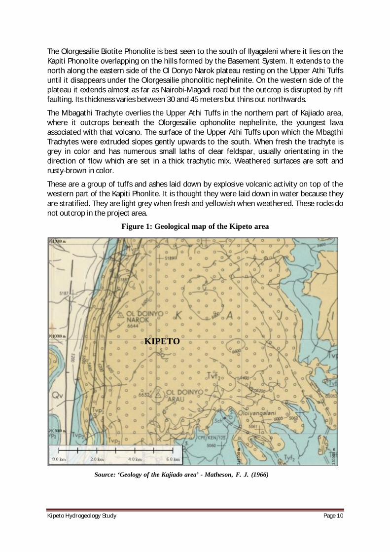
The geology of Kipeto area is composed of a generally thin layer of black cotton soil which is underlain by agglomerates of tuffs, trachytes and phonolites. Most of the area is covered by Ol Doinyo Narok Agglomerates which grades into Kerichwa Valley tuffs in the northern part of the project area. Figure 1 illustrates the surface geology. Below is the geologic succession of the area:
· Soils of recent age;
· Ol Doinyo Narok Agglomerates and Kerichwa Valley Tuff;
· Olorgesailie Volcanic Series;
· Mbagathi Trachyte;
· Upper Athi Tuffs;
· Kapiti Phonolite;
· Basement System.
The Ol Doinyo Narok Agglomerates and Kerichwa Valley Tuff occupy the same horizon. The Ol Doinyo Narok Agglomerate outcrops on the plateau of the same name and thins out to the north, forming lower ground before passing laterally into the Kerichwa Valley Tuff which extends as far as Nairobi. The Kerichwa valley Tuff consists of tuffs which are subordinate in the Ol Doinyo Narok Agglomerate. Both lava and lahar flows are enclosed within this agglomerate.
KipetoHydrogeologyStudy Page10
The Olorgesailie Biotite Phonolite is best seen to the south of Ilyagaleni where it lies on the Kapiti Phonolite overlapping on the hills formed by the Basement System. It extends to the north along the eastern side of the Ol Donyo Narok plateau resting on the Upper Athi Tuffs until it disappears under the Olorgesailie phonolitic nephelinite. On the western side of the plateau it extends almost as far as Nairobi-Magadi road but the outcrop is disrupted by rift faulting. Its thickness varies between 30 and 45 meters but thins out northwards.
The Mbagathi Trachyte overlies the Upper Athi Tuffs in the northern part of Kajiado area, where it outcrops beneath the Olorgesailie ophonolite nephelinite, the youngest lava associated with that volcano. The surface of the Upper Athi Tuffs upon which the Mbagthi Trachytes were extruded slopes gently upwards to the south. When fresh the trachyte is grey in color and has numerous small laths of clear feldspar, usually orientating in the direction of flow which are set in a thick trachytic mix. Weathered surfaces are soft and rusty-brown in color.
These are a group of tuffs and ashes laid down by explosive volcanic activity on top of the western part of the Kapiti Phonlite. It is thought they were laid down in water because they are stratified. They are light grey when fresh and yellowish when weathered. These rocks do not outcrop in the project area.
Figure 1: Geological map of the Kipeto area
Source: ‘Geology of the Kajiado area’ - Matheson, F. J. (1966)
KIPETO
KipetoHydrogeologyStudy Page11
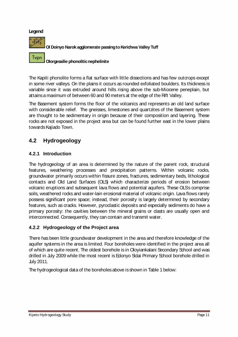
Legend
Ol Doinyo Narok agglomerate passing to Kerichwa Valley Tuff
Olorgesailie phonolitic nephelinite
The Kapiti phonolite forms a flat surface with little dissections and has few outcrops except in some river valleys. On the plains it occurs as rounded exfoliated boulders. Its thickness is variable since it was extruded around hills rising above the sub-Miocene peneplain, but attains a maximum of between 60 and 90 meters at the edge of the Rift Valley.
The Basement system forms the floor of the volcanics and represents an old land surface with considerable relief. The gneisses, limestones and quartzites of the Basement system are thought to be sedimentary in origin because of their composition and layering. These rocks are not exposed in the project area but can be found further east in the lower plains towards Kajiado Town.
4.2 Hydrogeology
4.2.1 Introduction
The hydrogeology of an area is determined by the nature of the parent rock, structural features, weathering processes and precipitation patterns. Within volcanic rocks, groundwater primarily occurs within fissure zones, fractures, sedimentary beds, lithological contacts and Old Land Surfaces (OLS) which characterize periods of erosion between volcanic eruptions and subsequent lava flows and potential aquifers. These OLS's comprise soils, weathered rocks and water-lain erosional material of volcanic origin. Lava flows rarely possess significant pore space; instead, their porosity is largely determined by secondary features, such as cracks. However, pyroclastic deposits and especially sediments do have a primary porosity: the cavities between the mineral grains or clasts are usually open and interconnected. Consequently, they can contain and transmit water.
4.2.2 Hydrogeology of the Project area
There has been little groundwater development in the area and therefore knowledge of the aquifer systems in the area is limited. Four boreholes were identified in the project area all of which are quite recent. The oldest borehole is in Oloyiankalani Secondary School and was drilled in July 2009 while the most recent is Edonyo Sidai Primary School borehole drilled in July 2011.
The hydrogeological data of the boreholes above is shown in Table 1 below:
KipetoHydrogeologyStudy Page12
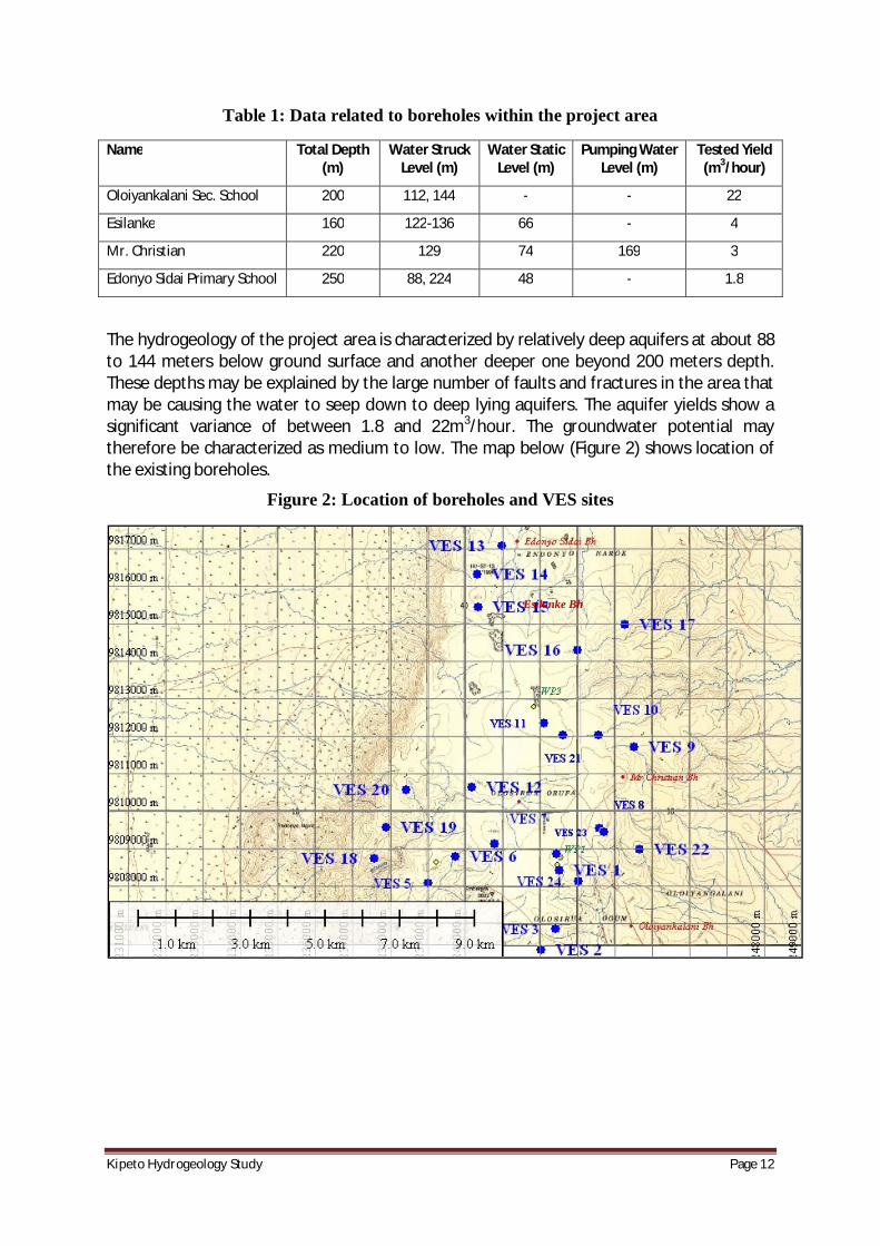
Table 1: Data related to boreholes within the project area
Name Total Depth (m)
Water Struck Level (m)
Water Static Level (m)
Pumping Water Level (m)
Tested Yield (m3/hour)
Oloiyankalani Sec. School 200 112, 144 - - 22
Esilanke 160 122-136 66 - 4
Mr. Christian 220 129 74 169 3
Edonyo Sidai Primary School 250 88, 224 48 - 1.8
The hydrogeology of the project area is characterized by relatively deep aquifers at about 88 to 144 meters below ground surface and another deeper one beyond 200 meters depth. These depths may be explained by the large number of faults and fractures in the area that may be causing the water to seep down to deep lying aquifers. The aquifer yields show a significant variance of between 1.8 and 22m3/hour. The groundwater potential may therefore be characterized as medium to low. The map below (Figure 2) shows location of the existing boreholes.
Figure 2: Location of boreholes and VES sites
Esilanke Bh
KipetoHydrogeologyStudy Page13
4.2.3 Results of Geophysics
The interpreted geophysical data indicates that the general area in which the wind energy project is going to be constructed has the following characteristics:
· The subsurface geological formations are highly fractured and most of the layers have true resistivity of less than 100 Ohm-meter.
· There are wet zones between 20 and 40 meters below ground level and deeper aquifers of between 100 and 150 meters below ground level.
· The upper sub-surface geology is vulnerable to the infiltration of hydro-carbon pollutants in the event of leakage of petroleum hydrocarbons from heavy vehicles operating in the project area during construction which could lead to the local aquifer systems being contaminated.
· Drilling of boreholes in the project area could be a source of water for the construction phase of the project though a number of boreholes would be necessary due to the relatively low yields expected from them.
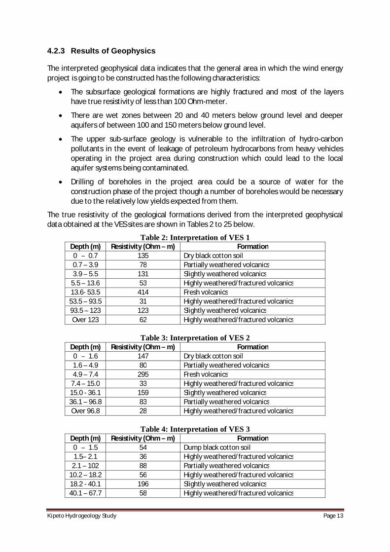
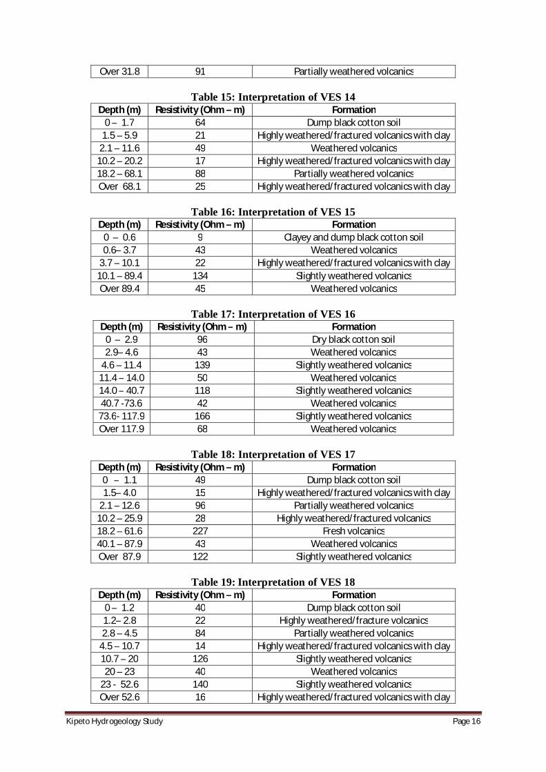
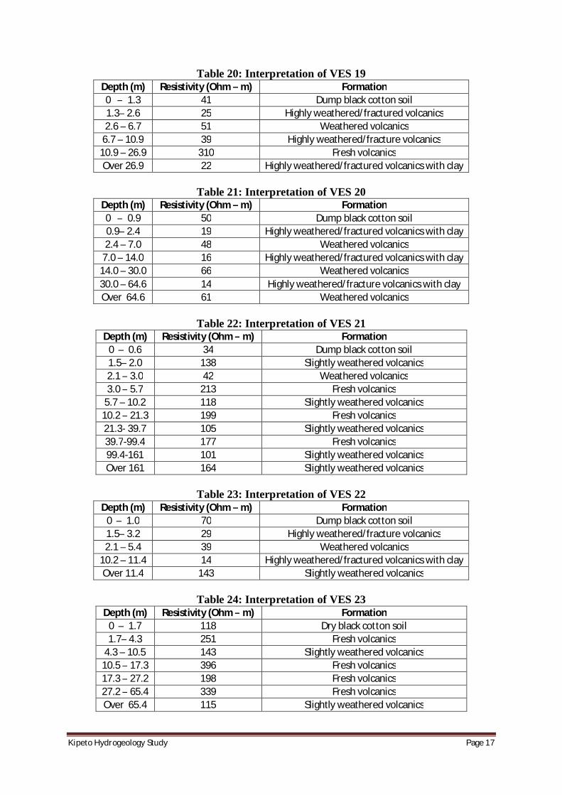
The true resistivity of the geological formations derived from the interpreted geophysical data obtained at the VES sites are shown in Tables 2 to 25 below.
Table 2: Interpretation of VES 1 Depth (m) Resistivity (Ohm – m) Formation 0 – 0.7 135 Dry black cotton soil 0.7 – 3.9 78 Partially weathered volcanics 3.9 – 5.5 131 Slightly weathered volcanics
5.5 – 13.6 53 Highly weathered/fractured volcanics 13.6- 53.5 414 Fresh volcanics 53.5 – 93.5 31 Highly weathered/fractured volcanics 93.5 – 123 123 Slightly weathered volcanics Over 123 62 Highly weathered/fractured volcanics
Table 3: Interpretation of VES 2
Depth (m) Resistivity (Ohm – m) Formation 0 – 1.6 147 Dry black cotton soil 1.6 – 4.9 80 Partially weathered volcanics 4.9 – 7.4 295 Fresh volcanics
7.4 – 15.0 33 Highly weathered/fractured volcanics 15.0 - 36.1 159 Slightly weathered volcanics 36.1 – 96.8 83 Partially weathered volcanics Over 96.8 28 Highly weathered/fractured volcanics
Table 4: Interpretation of VES 3
Depth (m) Resistivity (Ohm – m) Formation 0 – 1.5 54 Dump black cotton soil 1.5– 2.1 36 Highly weathered/fractured volcanics
2.1 – 102 88 Partially weathered volcanics 10.2 – 18.2 56 Highly weathered/fractured volcanics 18.2 - 40.1 196 Slightly weathered volcanics 40.1 – 67.7 58 Highly weathered/fractured volcanics
KipetoHydrogeologyStudy Page14
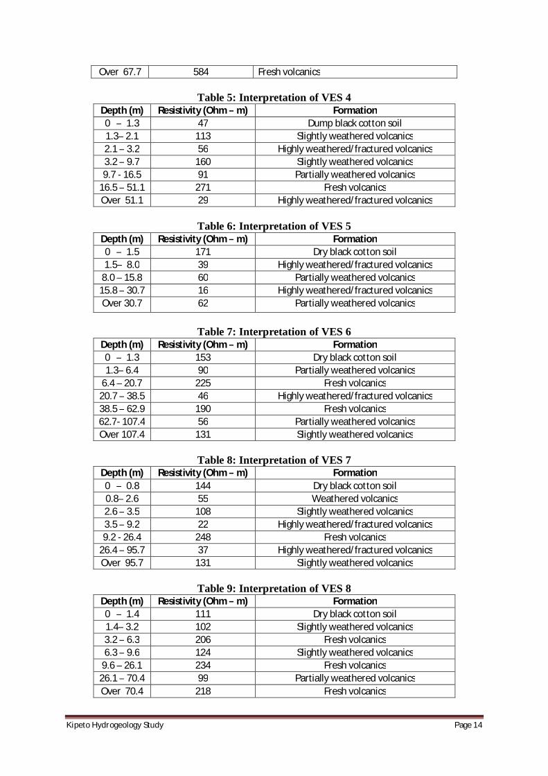
Over 67.7 584 Fresh volcanics
Table 5: Interpretation of VES 4 Depth (m) Resistivity (Ohm – m) Formation 0 – 1.3 47 Dump black cotton soil 1.3– 2.1 113 Slightly weathered volcanics 2.1 – 3.2 56 Highly weathered/fractured volcanics 3.2 – 9.7 160 Slightly weathered volcanics 9.7 - 16.5 91 Partially weathered volcanics
16.5 – 51.1 271 Fresh volcanics Over 51.1 29 Highly weathered/fractured volcanics
Table 6: Interpretation of VES 5
Depth (m) Resistivity (Ohm – m) Formation 0 – 1.5 171 Dry black cotton soil 1.5– 8.0 39 Highly weathered/fractured volcanics
8.0 – 15.8 60 Partially weathered volcanics 15.8 – 30.7 16 Highly weathered/fractured volcanics Over 30.7 62 Partially weathered volcanics
Table 7: Interpretation of VES 6
Depth (m) Resistivity (Ohm – m) Formation 0 – 1.3 153 Dry black cotton soil 1.3– 6.4 90 Partially weathered volcanics
6.4 – 20.7 225 Fresh volcanics 20.7 – 38.5 46 Highly weathered/fractured volcanics 38.5 – 62.9 190 Fresh volcanics 62.7- 107.4 56 Partially weathered volcanics Over 107.4 131 Slightly weathered volcanics
Table 8: Interpretation of VES 7
Depth (m) Resistivity (Ohm – m) Formation 0 – 0.8 144 Dry black cotton soil 0.8– 2.6 55 Weathered volcanics 2.6 – 3.5 108 Slightly weathered volcanics 3.5 – 9.2 22 Highly weathered/fractured volcanics 9.2 - 26.4 248 Fresh volcanics
26.4 – 95.7 37 Highly weathered/fractured volcanics Over 95.7 131 Slightly weathered volcanics
Table 9: Interpretation of VES 8
Depth (m) Resistivity (Ohm – m) Formation 0 – 1.4 111 Dry black cotton soil 1.4– 3.2 102 Slightly weathered volcanics 3.2 – 6.3 206 Fresh volcanics 6.3 – 9.6 124 Slightly weathered volcanics
9.6 – 26.1 234 Fresh volcanics 26.1 – 70.4 99 Partially weathered volcanics Over 70.4 218 Fresh volcanics
KipetoHydrogeologyStudy Page15
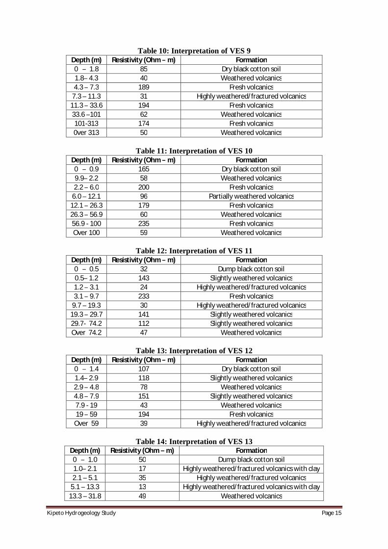
Table 10: Interpretation of VES 9 Depth (m) Resistivity (Ohm – m) Formation 0 – 1.8 85 Dry black cotton soil 1.8– 4.3 40 Weathered volcanics 4.3 – 7.3 189 Fresh volcanics
7.3 – 11.3 31 Highly weathered/fractured volcanics 11.3 – 33.6 194 Fresh volcanics 33.6 –101 62 Weathered volcanics 101-313 174 Fresh volcanics 0ver 313 50 Weathered volcanics
Table 11: Interpretation of VES 10
Depth (m) Resistivity (Ohm – m) Formation 0 – 0.9 165 Dry black cotton soil 9.9– 2.2 58 Weathered volcanics 2.2 – 6.0 200 Fresh volcanics
6.0 – 12.1 96 Partially weathered volcanics 12.1 – 26.3 179 Fresh volcanics 26.3 – 56.9 60 Weathered volcanics 56.9 - 100 235 Fresh volcanics Over 100 59 Weathered volcanics
Table 12: Interpretation of VES 11
Depth (m) Resistivity (Ohm – m) Formation 0 – 0.5 32 Dump black cotton soil 0.5– 1.2 143 Slightly weathered volcanics 1.2 – 3.1 24 Highly weathered/fractured volcanics 3.1 – 9.7 233 Fresh volcanics
9.7 – 19.3 30 Highly weathered/fractured volcanics 19.3 – 29.7 141 Slightly weathered volcanics 29.7- 74.2 112 Slightly weathered volcanics Over 74.2 47 Weathered volcanics
Table 13: Interpretation of VES 12
Depth (m) Resistivity (Ohm – m) Formation 0 – 1.4 107 Dry black cotton soil 1.4– 2.9 118 Slightly weathered volcanics 2.9 – 4.8 78 Weathered volcanics 4.8 – 7.9 151 Slightly weathered volcanics 7.9 - 19 43 Weathered volcanics 19 – 59 194 Fresh volcanics
Over 59 39 Highly weathered/fractured volcanics
Table 14: Interpretation of VES 13 Depth (m) Resistivity (Ohm – m) Formation 0 – 1.0 50 Dump black cotton soil 1.0– 2.1 17 Highly weathered/fractured volcanics with clay 2.1 – 5.1 35 Highly weathered/fractured volcanics
5.1 – 13.3 13 Highly weathered/fractured volcanics with clay 13.3 – 31.8 49 Weathered volcanics
KipetoHydrogeologyStudy Page16
Over 31.8 91 Partially weathered volcanics
Table 15: Interpretation of VES 14 Depth (m) Resistivity (Ohm – m) Formation
0 – 1.7 64 Dump black cotton soil 1.5 – 5.9 21 Highly weathered/fractured volcanics with clay
2.1 – 11.6 49 Weathered volcanics 10.2 – 20.2 17 Highly weathered/fractured volcanics with clay 18.2 – 68.1 88 Partially weathered volcanics Over 68.1 25 Highly weathered/fractured volcanics with clay
Table 16: Interpretation of VES 15
Depth (m) Resistivity (Ohm – m) Formation 0 – 0.6 9 Clayey and dump black cotton soil 0.6– 3.7 43 Weathered volcanics
3.7 – 10.1 22 Highly weathered/fractured volcanics with clay 10.1 – 89.4 134 Slightly weathered volcanics Over 89.4 45 Weathered volcanics
Table 17: Interpretation of VES 16
Depth (m) Resistivity (Ohm – m) Formation 0 – 2.9 96 Dry black cotton soil 2.9– 4.6 43 Weathered volcanics
4.6 – 11.4 139 Slightly weathered volcanics 11.4 – 14.0 50 Weathered volcanics 14.0 – 40.7 118 Slightly weathered volcanics 40.7 -73.6 42 Weathered volcanics
73.6- 117.9 166 Slightly weathered volcanics Over 117.9 68 Weathered volcanics
Table 18: Interpretation of VES 17
Depth (m) Resistivity (Ohm – m) Formation 0 – 1.1 49 Dump black cotton soil 1.5– 4.0 15 Highly weathered/fractured volcanics with clay
2.1 – 12.6 96 Partially weathered volcanics 10.2 – 25.9 28 Highly weathered/fractured volcanics 18.2 – 61.6 227 Fresh volcanics 40.1 – 87.9 43 Weathered volcanics Over 87.9 122 Slightly weathered volcanics
Table 19: Interpretation of VES 18
Depth (m) Resistivity (Ohm – m) Formation 0 – 1.2 40 Dump black cotton soil 1.2– 2.8 22 Highly weathered/fracture volcanics 2.8 – 4.5 84 Partially weathered volcanics
4.5 – 10.7 14 Highly weathered/fractured volcanics with clay 10.7 – 20 126 Slightly weathered volcanics 20 – 23 40 Weathered volcanics
23 - 52.6 140 Slightly weathered volcanics Over 52.6 16 Highly weathered/fractured volcanics with clay
KipetoHydrogeologyStudy Page17
Table 20: Interpretation of VES 19 Depth (m) Resistivity (Ohm – m) Formation 0 – 1.3 41 Dump black cotton soil 1.3– 2.6 25 Highly weathered/fractured volcanics 2.6 – 6.7 51 Weathered volcanics
6.7 – 10.9 39 Highly weathered/fracture volcanics 10.9 – 26.9 310 Fresh volcanics Over 26.9 22 Highly weathered/fractured volcanics with clay
Table 21: Interpretation of VES 20
Depth (m) Resistivity (Ohm – m) Formation 0 – 0.9 50 Dump black cotton soil 0.9– 2.4 19 Highly weathered/fractured volcanics with clay 2.4 – 7.0 48 Weathered volcanics
7.0 – 14.0 16 Highly weathered/fractured volcanics with clay 14.0 – 30.0 66 Weathered volcanics 30.0 – 64.6 14 Highly weathered/fracture volcanics with clay Over 64.6 61 Weathered volcanics
Table 22: Interpretation of VES 21
Depth (m) Resistivity (Ohm – m) Formation 0 – 0.6 34 Dump black cotton soil 1.5– 2.0 138 Slightly weathered volcanics 2.1 – 3.0 42 Weathered volcanics 3.0 – 5.7 213 Fresh volcanics
5.7 – 10.2 118 Slightly weathered volcanics 10.2 – 21.3 199 Fresh volcanics 21.3- 39.7 105 Slightly weathered volcanics 39.7-99.4 177 Fresh volcanics 99.4-161 101 Slightly weathered volcanics Over 161 164 Slightly weathered volcanics
Table 23: Interpretation of VES 22
Depth (m) Resistivity (Ohm – m) Formation 0 – 1.0 70 Dump black cotton soil 1.5– 3.2 29 Highly weathered/fracture volcanics 2.1 – 5.4 39 Weathered volcanics
10.2 – 11.4 14 Highly weathered/fractured volcanics with clay Over 11.4 143 Slightly weathered volcanics
Table 24: Interpretation of VES 23
Depth (m) Resistivity (Ohm – m) Formation 0 – 1.7 118 Dry black cotton soil 1.7– 4.3 251 Fresh volcanics
4.3 – 10.5 143 Slightly weathered volcanics 10.5 – 17.3 396 Fresh volcanics 17.3 – 27.2 198 Fresh volcanics 27.2 – 65.4 339 Fresh volcanics Over 65.4 115 Slightly weathered volcanics

KipetoHydrogeologyStudy Page18
Table 25: Interpretation of VES 24 Depth (m) Resistivity (Ohm – m) Formation 0 – 1.5 47 Dump black cotton soil 1.5– 3.0 44 Weathered volcanics 3.0 – 5.5 105 Slightly weathered volcanics
5.5 – 13.3 34 Highly weathered/fractured volcanics 13.3 – 46.3 402 Fresh volcanics Over 46.3 51 Weathered volcanics
KipetoHydrogeologyStudy Page19
5 POTENTIAL IMPACTS ON HYDROGEOLOGY
The potential impacts on the groundwater environment as a result of implementation of the proposed Wind Energy Project, in the absence of suitable mitigation measures, are decreased:
· Groundwater quality as a result of leakage of hydro-carbon compounds and other chemicals from storage areas and from site vehicles/machinery and subsequent direct percolation to the groundwater regime.
· Groundwater quality due to washing of leaked hydro-carbon compounds into surface drainage channels and eventual percolation into the groundwater regime.
These potential impacts are associated with the construction phase as there will be very little movement of vehicles and machinery during the operational phase.
KipetoHydrogeologyStudy Page20
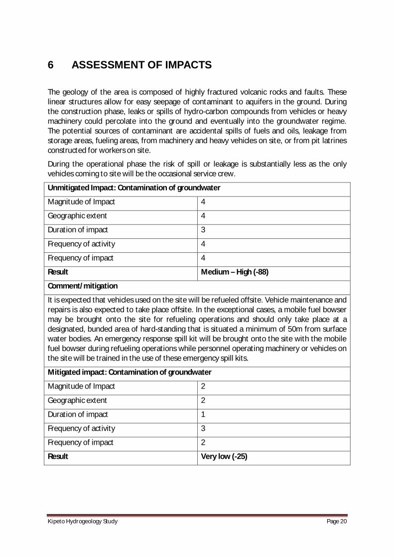
6 ASSESSMENT OF IMPACTS
The geology of the area is composed of highly fractured volcanic rocks and faults. These linear structures allow for easy seepage of contaminant to aquifers in the ground. During the construction phase, leaks or spills of hydro-carbon compounds from vehicles or heavy machinery could percolate into the ground and eventually into the groundwater regime. The potential sources of contaminant are accidental spills of fuels and oils, leakage from storage areas, fueling areas, from machinery and heavy vehicles on site, or from pit latrines constructed for workers on site.
During the operational phase the risk of spill or leakage is substantially less as the only vehicles coming to site will be the occasional service crew.
Unmitigated Impact: Contamination of groundwater
Magnitude of Impact 4
Geographic extent 4
Duration of impact 3
Frequency of activity 4
Frequency of impact 4
Result Medium – High (-88)
Comment/mitigation
It is expected that vehicles used on the site will be refueled offsite. Vehicle maintenance and repairs is also expected to take place offsite. In the exceptional cases, a mobile fuel bowser may be brought onto the site for refueling operations and should only take place at a designated, bunded area of hard-standing that is situated a minimum of 50m from surface water bodies. An emergency response spill kit will be brought onto the site with the mobile fuel bowser during refueling operations while personnel operating machinery or vehicles on the site will be trained in the use of these emergency spill kits.
Mitigated impact: Contamination of groundwater
Magnitude of Impact 2
Geographic extent 2
Duration of impact 1
Frequency of activity 3
Frequency of impact 2
Result Very low (-25)

KipetoHydrogeologyStudy Page21
7 PROPOSED MITIGATION MEASURES
7.1 Mitigation Measures during Construction Phase
The following mitigation measures are proposed to ensure that the construction of the proposed Wind Farm Development does not result in a noticeable or significant negative impact on the groundwater environment.
The refueling of vehicles/machinery will be expected to be done offsite. Where necessary, construction machinery will be re-fuelled onsite by means of a mobile fuel bowser (comprising a double skinned tank) accompanied by trained personnel. Refueling operations will only take place at a designated, bunded area of hard-standing that is situated a minimum of 50m from surface water bodies. A spill tray and an emergency response spill kit will be brought onto the site with the mobile fuel bowser during refueling operations. Site personnel operating machinery or vehicles on the site will be trained in the use of emergency spill kits. The spill tray will be placed beneath the fill point of the vehicle and the emergency response spill kit will be used in the event of an accidental spill.
In order to minimize any adverse impact on the underlying subsurface strata from material spillages, all oils, solvents and paints used during construction will be stored within specially constructed bunded areas or suitable bunded lockable storage containers. Filling and draw-off points will be located entirely within the bunded area(s). Drainage from the bunded area(s) shall be diverted for collection and safe disposal.
Strict supervision of contractors will be adhered to so as to ensure that all plant and equipment utilized onsite is in good working condition. Any equipment not meeting the required standard will not be permitted for use within the site. This will minimize the risk of soils, subsoil and bedrock becoming contaminated through site activity.
7.2 Mitigation Measures during Operational Phase
The volume of traffic is expected to significantly decrease after the construction phase and full operation of the wind turbines commences. The only vehicles expected will be those bringing the maintenance crew and therefore there will be a decreased risk of spillage and leakage of oils, fuels and other contaminants from these vehicles.
However, it is recommended that routine checks are carried out around the wind turbine sites to ensure that any leakage of oil/petroleum from the maintenance vehicles does not go undetected. A spill kit will be located within the depot to ensure that any minor leaks of oil are cleaned up immediately on detection.

KipetoHydrogeologyStudy Page22
8 ENVIRONMENTAL MANAGEMENT PLAN (EMP)
The purpose of an EMP is to ensure that social and environmental impacts, risks and liabilities identified during the EIA process are effectively managed during the construction and operation phase of the project. The EMP specifies the mitigation and management measures to which the proponent is committed, and shows how the organizational capacity and resources to implement these measures will be mobilized. The EMP also shows how mitigation and management measures will be scheduled.
The EMP for the hydrogeological environment will therefore be a part of the whole project EMP dealing with all the environmental components of the Wind Farm Project.

KipetoHydrogeologyStudy Page23
9 CONCLUSIONS ARISING FROM THE STUDY
9.1 Conclusion
From the data obtained from this study, it may be concluded that there is potential negative impact to the hydrogeological environment from leakage or accidental spill of oils/petroleum products or other chemicals stored at the project site. It is therefore necessary to put in place mitigation measures to reduce or neutralize the adverse effects. These have been highlighted in Chapter 7. Monitoring will also be required.
9.2 Monitoring requirements
Monitoring required during the construction phase will comprise monitoring of nearby surface water quality in order to ensure that the proposed works do not adversely impact on its quality via soil erosion. The site supervisor will conduct routine monitoring by visual means to ensure that the site works (vehicles, equipment and fuel/chemical storage areas) are not adversely impacting on the soils and geological environment.

KipetoHydrogeologyStudy Page24
10 GAPS IN KNOWLEDGE AND UNCERTAINTIES
The limited number of boreholes in the area means that the variation of the hydrogeological condition of the project area could not be derived. With sufficient data it would have been possible to derive groundwater potential maps, groundwater flow maps, among others. This would have been even more important due to the high variance shown in the yields of the existing boreholes.
This report indicates that boreholes could be drilled in the project area as sources of water for construction purposes but the yields cannot be ascertained. This means their adequacy as the source of water for construction is also not certain.
KipetoHydrogeologyStudy Page25
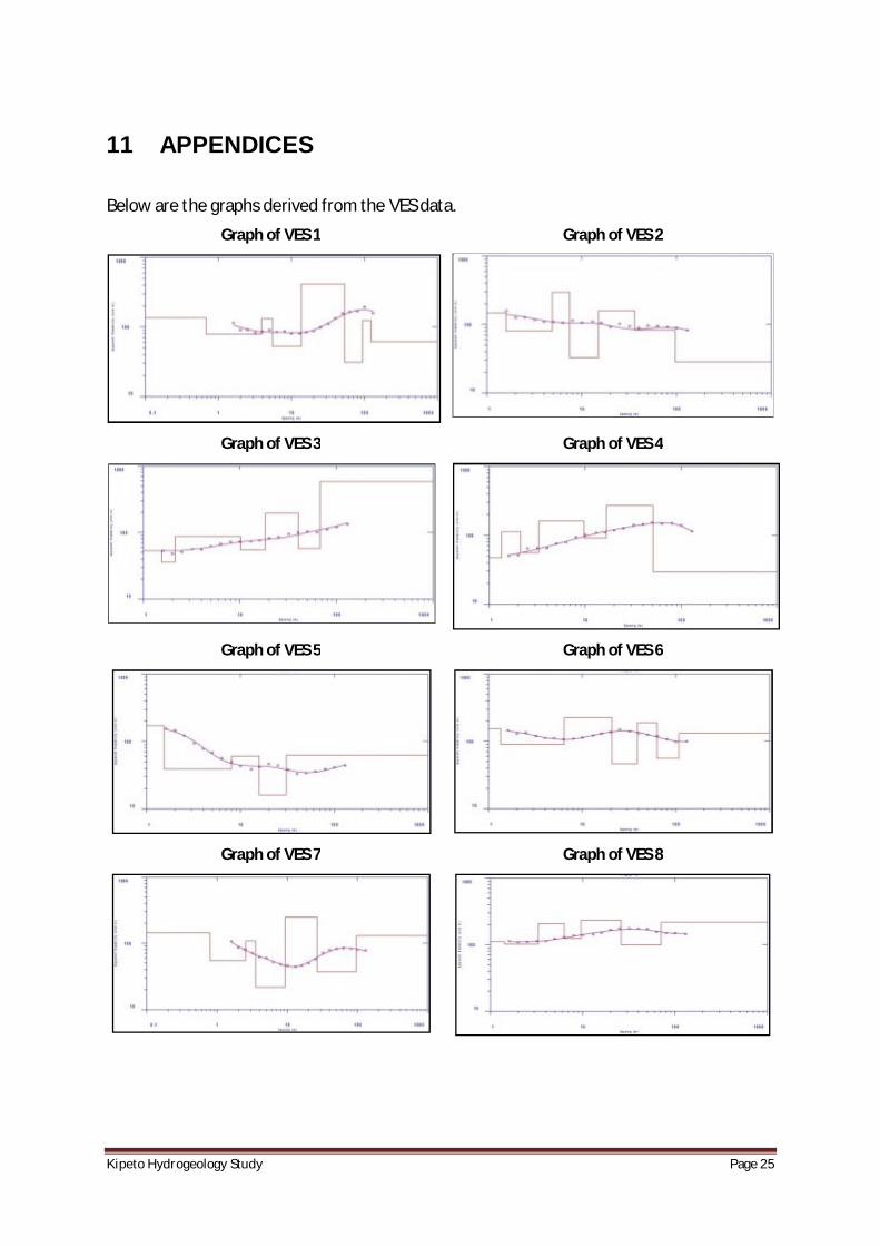
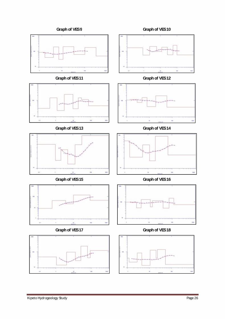
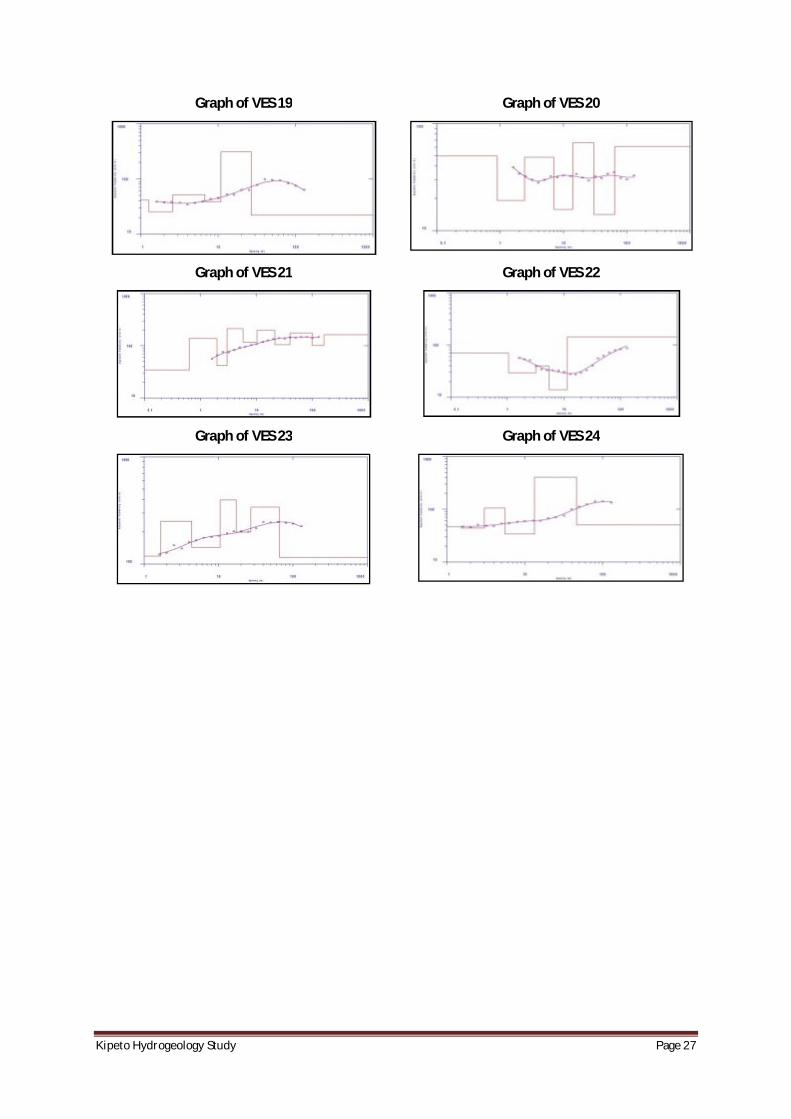
11 APPENDICES
Below are the graphs derived from the VES data.
Graph of VES 1
Graph of VES 2
Graph of VES 3
Graph of VES 4
Graph of VES 5
Graph of VES 6
Graph of VES 7
Graph of VES 8
KipetoHydrogeologyStudy Page26
Graph of VES 9
Graph of VES 10
Graph of VES 11
Graph of VES 12
Graph of VES 13
Graph of VES 14
Graph of VES 15
Graph of VES 16
Graph of VES 17
Graph of VES 18
KipetoHydrogeologyStudy Page27
Graph of VES 19
Graph of VES 20
Graph of VES 21
Graph of VES 22
Graph of VES 23
Graph of VES 24