Embed Size (px)
Citation preview
Hydrogeological & Geophysical Investigations
Igara African Devine Church,
Walatsi Location, Nambale District
Busia County
***********
September, 2012
CONSULTANT:
Sebastian Namwamba
(Registered Hydrogeologist; Licence No. WD/WP/32)
EARTHS SCOPE-GEO HYDRO SERVICES
Water, Sanitation and Environmental Engineering
P. O. Box 17783-00100
NAIROBI
Cell-phone: 0720-438377
Signed: Date
Report No. 42/2012
HHyyddrrooggeeoollooggiiccaall && GGeeoopphhyyssiiccaall IInnvveessttiiggaattiioonnss AAffrriiccaann DDeevviinnee CChhuurrcchh IIggaarraa,, BBuussiiaa CCoouunnttyy,, KKeennyyaa..
EEaarrtthhss SSccooppee GGeeoo--HHyyddrroo SSeerrvviicceess OOccttoobbeerr 22001122,, PPaaggee ii
SUMMARY
Introduction
This report presents the results of hydrogeological and geophysical investigations to
evaluate groundwater resources for Igara Devine Church in Walatsi Location, Nambale
District of Busia County, Kenya.
Climate
The climate in the area is mainly humid type, with a bi-modal rainfall pattern. Long rains
are experienced in March to July while short rains occur in August to October. The main
source of rainfall over Igara region is the Lake Victoria. It occurs in form of either
convectional or frontal rainfall. The mean annual rainfall ranges between 1100 and 2700
mm. The mean maximum and minimum temperatures in the area are given as 27oC and
15oC respectively. Evaporation is relatively low and increases from less than 1400 mm to
1800 mm per year.
Geology
The regional geology of the investigated area is dominated by the Basement System
Complex which can be divided into two groups: - (a) The Basement Complex rocks,
(sedimentary in origin) and the (b) The undeformed post- Basement formations. The
geology of the investigated site include, the recent deposits which include lateric iron
stone resulting to production of thick red soils. These are underlain by the Kavirondian
series rocks consisting of feldspathic grits, conglomerates, shale and siltstones. Granites
are the major intrusives in the area.
Geophysical Fieldwork
Geophysical fieldwork was executed on 30th
September 2012. The resistivity method was
used for the present investigations. Geophysical measurements were used to determine the
thickness of the underlying layers, their potential as aquifers, and the expected quality of
groundwater in these formations .One vertical electrical soundings were executed on
selected points
Conclusions
From the present study it is concluded that the prospects for sufficient groundwater for use
at the chuch and the neighboring community are good, based on the geological and
hydrogeological evidence gathered.
Recommendations for Drilling
Excavation of a shallow well is recommended for this area though a borehole would be
more fissible to supply the big population in this area.
Alternatively drilling of a Borehole to a maximum 60 m was recommended in this church
compound. The site was shown to Mr. William Ashitiva-0710418718, George Wafula-
07156692 and Ms Mary Opech-0725950574 an elder in the area.
The borehole should be drilled at 8‟‟ diameter and installed with 6" diameter uPVC casings
and screens with high % open surface area. Recommendations are given for borehole
construction and completion methods. The importance of correct and comprehensive
techniques in this particular aspect cannot be over-emphasized. Generally, the water
quality is expected to be good.

HHyyddrrooggeeoollooggiiccaall && GGeeoopphhyyssiiccaall IInnvveessttiiggaattiioonnss AAffrriiccaann DDeevviinnee CChhuurrcchh IIggaarraa,, BBuussiiaa CCoouunnttyy,, KKeennyyaa..
EEaarrtthhss SSccooppee GGeeoo--HHyyddrroo SSeerrvviicceess OOccttoobbeerr 22001122,, PPaaggee iiii
Monitoring
Regular monitoring should be instituted and maintained in the borehole in order to keep
track of groundwater levels. A piezometer should be installed in the borehole to be able to
monitor the water level in the well.
Drilling
A groundwater drilling permit will have to be obtained from the Water Apportionment
Board of the Ministry of Water and Irrigation.
Additional recommendations for borehole drilling, installation, development and
testpumping are given in Appendix 1
.
HHyyddrrooggeeoollooggiiccaall && GGeeoopphhyyssiiccaall IInnvveessttiiggaattiioonnss AAffrriiccaann DDeevviinnee CChhuurrcchh IIggaarraa,, BBuussiiaa CCoouunnttyy,, KKeennyyaa..
EEaarrtthhss SSccooppee GGeeoo--HHyyddrroo SSeerrvviicceess OOccttoobbeerr 22001122,, PPaaggee iiiiii
TABLE OF CONTENTS
1. INTRODUCTION ............................................................................................................................................... 1
1.1. BACKGROUND ............................................................................................................................................. 1 1.2. SCOPE OF THE WORKS ................................................................................................................................ 1 1.3. REPORTING REQUIREMENTS ........................................................................................................................ 2
2. BACKGROUND INFORMATION ................................................................................................................... 3
2.1. LOCATION ................................................................................................................................................... 3 2.2. VEGETATION AND CLIMATE ........................................................................................................................ 3 2.3. TOPOGRAPHY AND DRAINAGE .................................................................................................................... 3 2.4. EXISTING WATER SUPPLY AND DEMAND .................................................................................................... 3
3. GEOLOGY .......................................................................................................................................................... 5
3.1. REGIONAL GEOLOGY .................................................................................................................................. 5 3.1.1. Precambrian .......................................................................................................................................... 5 3.1.2. Cretaceous ............................................................................................................................................. 5 3.1.3. Tertiary .................................................................................................................................................. 5 3.1.4. Pleistocene to Recent............................................................................................................................. 6
3.2. GEOLOGICAL ROCK FORMATIONS ............................................................................................................... 6 3.2.1. Pleistocene and Recent Deposits ........................................................................................................... 6 3.2.2. Older Rocks ........................................................................................................................................... 6 3.2.3. Kavirondian System ............................................................................................................................... 6 3.2.4. Nyanzian System .................................................................................................................................... 7 3.2.5. Basement System ................................................................................................................................... 7
3.3. GEOLOGY OF THE INVESTIGATED SITE ........................................................................................................ 7
4. HYDROGEOLOGY ........................................................................................................................................... 9
4.1. GROUNDWATER OCCURRENCE ................................................................................................................... 9 4.2. BASEMENT AQUIFER OCCURRENCE ............................................................................................................ 9 4.3. WEATHERING AND ITS SIGNIFICANCE IN AQUIFER OCCURRENCE .............................................................. 10
4.3.1. The Collapsed Zone ............................................................................................................................. 10 4.3.2. Saprolite .............................................................................................................................................. 10 4.3.3. Saprock ................................................................................................................................................ 10 4.3.4. Bedrock ............................................................................................................................................... 10 4.3.5. Regolith ............................................................................................................................................... 11
4.4. HYDROGEOLOGY OF THE IGARA AREA ...................................................................................................... 11 4.5. BOREHOLE DATA ...................................................................................................................................... 12 4.6. GROUNDWATER QUALITY ......................................................................................................................... 12
5. GEOPHYSICAL INVESTIGATION METHODS ......................................................................................... 13
5.1. RESISTIVITY METHOD ............................................................................................................................... 13 5.2. BASIC PRINCIPLES ..................................................................................................................................... 13 5.3. VERTICAL ELECTRICAL SOUNDING (VES) ................................................................................................ 14
6. FIELDWORK AND RESULTS ....................................................................................................................... 15
6.1. FIELDWORK ............................................................................................................................................... 15 6.2. INTERPRETATION RESULTS ....................................................................................................................... 15
7. CONCLUSIONS AND RECOMMENDATIONS .......................................................................................... 17
7.1. CONCLUSIONS FIELDWORK ....................................................................................................................... 17 7.2. RECOMMENDATIONS ................................................................................................................................. 17
8. REFERENCES .................................................................................................................................................. 18

HHyyddrrooggeeoollooggiiccaall && GGeeoopphhyyssiiccaall IInnvveessttiiggaattiioonnss AAffrriiccaann DDeevviinnee CChhuurrcchh IIggaarraa,, BBuussiiaa CCoouunnttyy,, KKeennyyaa..
EEaarrtthhss SSccooppee GGeeoo--HHyyddrroo SSeerrvviicceess OOccttoobbeerr 22001122,, PPaaggee iivv
FIGURES
Figure 1:Site and Borehole/Shallow Well location map of the Investigated Area ................................................. 4 Figure 2: Geological Map of the Study Area (After Beicip- Malmaison – France 1987) ...................................... 8 Figure 3:Vertical Electrical Sounding Interpretation for Igara VES 1 ................................................................ 16
TABLES
Table 1: Borehole-C7011 .......................................................................................................................................... 12 Table 2: GPS Co-ordinates of the VES Location.................................................................................................... 15 Table 3: Interpretation Results for Igara Devine Church ..................................................................................... 15 Table 4: Interpretation Results for Igara Devine Church ..................................................................................... 15
AAPPPPEENNDDIICCEESS
Appendix 1:Drilling ................................................................................................................................................... 20
HHyyddrrooggeeoollooggiiccaall && GGeeoopphhyyssiiccaall IInnvveessttiiggaattiioonnss AAffrriiccaann DDeevviinnee CChhuurrcchh IIggaarraa,, BBuussiiaa CCoouunnttyy,, KKeennyyaa..
EEaarrtthhss SSccooppee GGeeoo--HHyyddrroo SSeerrvviicceess OOccttoobbeerr 22001122,, PPaaggee vv
LIST OF ABBREVIATIONS AND GLOSSARY OF TERMS
ABBREVIATIONS: (NOTE: SI spellings used throughout).
EC Electrical Conductivity (in micro Seimens/centimetre)
km kilometres
m metres
m amsl metres above mean sea level
m bgl metres below ground level
ppm parts per million, equivalent to mg/l
swl static water level (in m bgl) (the piezometric level or water table, see
below)
TDS Total Dissolved Solids (ppm)
wsl water struck level (in m bgl)
GLOSSARY OF TERMS:
Aquifer A geological formation or structure which transmits water
and which may supply water to wells, boreholes or springs.
Confined Confined aquifers are those in which the piezometric level is higher
(i.e., at a greater elevation relative to sea level) than the elevation at
which the aquifer was encountered.
Intercalated Interbedded - a lava flow may occur between layers of sediment, or
vice-versa.
Recharge The general term indicating the process of transport of water from
surface sources (i.e., from rivers or rainfall) to groundwater storage.
Volcanics Here used as a general term describing geological material of
volcanic origin.
HHyyddrrooggeeoollooggiiccaall && GGeeoopphhyyssiiccaall IInnvveessttiiggaattiioonnss AAffrriiccaann DDeevviinnee CChhuurrcchh IIggaarraa,, BBuussiiaa CCoouunnttyy,, KKeennyyaa..
EEaarrtthhss SSccooppee GGeeoo--HHyyddrroo SSeerrvviicceess OOccttoobbeerr 22001122,, PPaaggee 11
11.. IINNTTRROODDUUCCTTIIOONN
11..11.. BBaacckkggrroouunndd
Earths Scope Geo- Hydro Services Water Ltd. was commissioned by African Devine
Church to carry out borehole/Shallow well site investigations at their church in Walatsi
Location, Igara area of Nambale District, Busia County in WATSAN Program. The
fieldwork was carried out from 30th
September 2012.
The Client requires detailed information on prospects of drilling production Shallow well/
boreholes. The objective of the present study is to assess the availability of groundwater,
to recommend borehole drilling sites and comment on aspects of depth to potential
aquifers, aquifer availability and type, possible yields and water quality. For this purpose
all available hydrogeological information of the areas have been analyzed, and a
geophysical surveys done.
The investigations involved hydrogeological, geophysical field investigations and a detailed
desk study in which the available relevant geological and hydrogeological data were
collected, analyzed, collated and evaluated within the context of the Client's requirements.
The data sources consulted were mainly in four categories:
a) Published Master Plans.
b) Geological and Hydrogeological Reports and Maps.
c) Ministry of Water and Irrigation Borehole Completion records.
d) Technical reports of the area by various organizations.
11..22.. SSccooppee ooff tthhee WWoorrkkss
The scope of works includes:
(i) Site visits to familiarize with the project areas. Identify any issues that might
hinder the implementation of works in any of the areas and report to the Head of
Groundwater Investigation in the Ministry.
(ii) To obtain, study and synthesize background information including the geology,
hydrogeology and existing borehole data, for the purpose of improving the quality
of assessment and preparing comprehensive hydrogeological reports,
(iii) To carry out hydrogeological evaluation and geophysical investigations in
the selected sites in order to determine potential for groundwater and
appropriateness of drilling boreholes at the sites.
(iv) To prepare hydrogeological survey reports in conformity with the provisions of
the rules and procedure outlined by the Water Resources Management Authority,
including the following:
Site Name, Location and GPS readings
Geology and hydrogeology
Present sources and status of the existing water supply
Existing borehole data information.
Geophysical data and analysis
HHyyddrrooggeeoollooggiiccaall && GGeeoopphhyyssiiccaall IInnvveessttiiggaattiioonnss AAffrriiccaann DDeevviinnee CChhuurrcchh IIggaarraa,, BBuussiiaa CCoouunnttyy,, KKeennyyaa..
EEaarrtthhss SSccooppee GGeeoo--HHyyddrroo SSeerrvviicceess OOccttoobbeerr 22001122,, PPaaggee 22
Conclusions and recommendations, including the groundwater potential of
the investigated sites, name and location of the site recommended for drilling,
recommended maximum drilling depth in metres and appropriate drilling
method
11..33.. RReeppoorrttiinngg RReeqquuiirreemmeennttss
The format of writing the Hydrogeological Investigations Report, as described out in the
Second Schedule of the Water Resources Management Rules, 2007. Such a report must
consider the following (verbatim): -
1. Name and details of applicant
2. Location and description of proposed Activity
3. Details of climate
4. Details of geology and hydrogeology
5. Details of neighbouring boreholes, including location, distance from proposed
borehole or boreholes, number and construction details, age, current status and
use, current abstraction and use.
6. Description and details (including raw and processed data) of prospecting
methods adopted, e.g. remote sensing, geophysics, geological and or
hydrogeological cross sections. Hydrogeological characteristics and analysis, to
include but not necessarily be limited to, the following:
a. Aquifer transmissivity
b. Borehole specific capacities
c. Storage coefficient and or specific yield
d. Hydraulic conductivity
e. Groundwater flux
f. Estimated mean annual recharge, and sensitivity to external factors
7. Assessment of water quality and potential infringement of National standards
8. Assessment of availability of groundwater
9. Analysis of the reserve
10. Impact of proposed activity on aquifer, water quality, other abstractors,
including likelihood of coalescing cones of depression and implications for
other groundwater users in any potentially impacted areas
11. Recommendations for borehole development, to include but not limited to, the
following:
a. Locations of recommended borehole(s) expressed as a coordinate(s)
and indicated on a sketch map
b. Recommendations regarding borehole or well density and minimum
spacing in the project area
c. Recommended depth and maximum diameter
d. Recommended construction characteristics, e.g. wire-wound screen,
grouting depth
e. Anticipated yield
12. Any other relevant information (e.g. need to monitor neighbouring boreholes
during tests).
This report is written so as to cover each of the above, insofar as data limitations allow.
The report also includes maps, diagrams, tables and appendices as appropriate.
HHyyddrrooggeeoollooggiiccaall && GGeeoopphhyyssiiccaall IInnvveessttiiggaattiioonnss AAffrriiccaann DDeevviinnee CChhuurrcchh IIggaarraa,, BBuussiiaa CCoouunnttyy,, KKeennyyaa..
EEaarrtthhss SSccooppee GGeeoo--HHyyddrroo SSeerrvviicceess OOccttoobbeerr 22001122,, PPaaggee 33
22.. BBAACCKKGGRROOUUNNDD IINNFFOORRMMAATTIIOONN
22..11.. LLooccaattiioonn
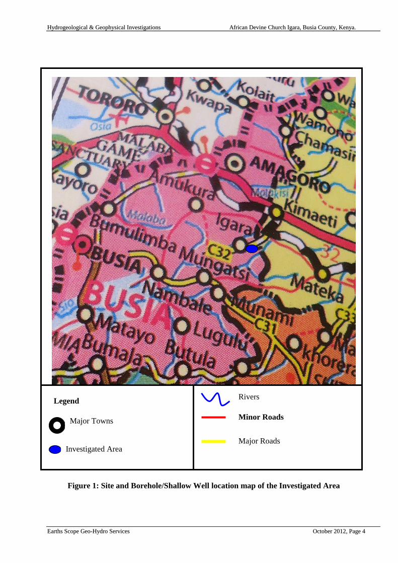
The site is located in Igara area, along the Lupida-Mungatsi road in the western part of the
country in Busia County. The approximate location of the site is defined by co-ordinates
36 N 0651558/UTM 0058356. The location of the site is shown on Figure 1.
22..22.. VVeeggeettaattiioonn aanndd CClliimmaattee
The vegetation in the area is natural moist forest vegetation, comprising riverine
vegetation along rivers and thick bushes and woodland with dense under growth in the
undulating plains. Agriculture is extensive and has led to depletion of natural forest.
Several cash crop are grown in the area, the major cash crop being sugarcane. Others,
include maize, bean, sorghum and cassava. The area is generally humid, with average
annual rainfall in the range 1100-2700 mm. The mean maximum and minimum
temperature are in the range of 26-28 o
C and 14-16 oC respectively. The area is generally
classified as fairly warm.
22..33.. TTooppooggrraapphhyy aanndd DDrraaiinnaaggee
The area is generally undulating and characterized by broad flat topped divides and long
gentle valley slopes. Over most of the area the altitude ranges between 1400 - 1470 a msl.
The area is bounded on one side by one tributary draining into river Nzoia. The Nzoia
river is confined to the out crop of the Kisama - Igara Granite. While its valley is a mature
one, the river flows over a rocky bed which is undergoing excavation at the present day.
22..44.. EExxiissttiinngg WWaatteerr SSuuppppllyy aanndd DDeemmaanndd
Currently the Igara area has one borehole which was drilled by KEFINCO with numerous
shallow wells in the vicinity at a radius of 2 km.
The water demand for the community around Igara is about 10 m3 per day.
HHyyddrrooggeeoollooggiiccaall && GGeeoopphhyyssiiccaall IInnvveessttiiggaattiioonnss AAffrriiccaann DDeevviinnee CChhuurrcchh IIggaarraa,, BBuussiiaa CCoouunnttyy,, KKeennyyaa..
EEaarrtthhss SSccooppee GGeeoo--HHyyddrroo SSeerrvviicceess OOccttoobbeerr 22001122,, PPaaggee 44
Figure 1: Site and Borehole/Shallow Well location map of the Investigated Area
Legend
Major Towns
Investigated Area
Rivers
Minor Roads
Major Roads
HHyyddrrooggeeoollooggiiccaall && GGeeoopphhyyssiiccaall IInnvveessttiiggaattiioonnss AAffrriiccaann DDeevviinnee CChhuurrcchh IIggaarraa,, BBuussiiaa CCoouunnttyy,, KKeennyyaa..
EEaarrtthhss SSccooppee GGeeoo--HHyyddrroo SSeerrvviicceess OOccttoobbeerr 22001122,, PPaaggee 55
33.. GGEEOOLLOOGGYY
33..11.. RReeggiioonnaall GGeeoollooggyy
The regional geology can be found in GIBSON A.B (1954), report No. 26. The geological
history of the area can be followed from the Precambrian era, which is represented by the
metamorphic rocks of the „Basement System. The regional metamorphism was followed
by various cycles of erosion, faulting and graben formation, deposition of continental
sediments and volcanic activity.
33..11..11.. PPrreeccaammbbrriiaann
During this period, vast successions of sediments accumulated in a geosynclinal structure
that covered most of the present Central and Eastern Africa. Towards the end of the era, a
period of regional folding and metamorphism occurred. This large-scale tectonic activity
subjected the original rocks to high temperatures and pressures, which caused partial
melting. This was followed by re-crystallization and growth of new minerals. Depending
on the parent material and the prevailing pressures and temperatures, various types of
granites, gneisses and schists were formed.
Due to the tectonic events that followed their creation, the metamorphosed rocks were
intensely folded, tilted, and dissected by intrusive granitic dykes and domes. In addition,
granitization processes resulted in the formation of granulites and migmatites.
33..11..22.. CCrreettaacceeoouuss
During the Cretaceous, there existed a peneplain which is represented by a chain of high
points of uniform elevation in the Nandi highlands (Osorongai T.S., 7,006 ft.; Sumayat,
7,005 ft.), and continues south of the present area at similar level .The age of this
peneplain is thought to be Cretaceous and it has been correlated with the Kisii Highlands
peneplain some 160 km further south. This was followed by along period of erosion and
emplacement of minor intrusion
33..11..33.. TTeerrttiiaarryy
This is the period of Mt Elgon volcanic eruption, at the time of commencement of activity
the Basement surface possessed more or less the present characters. The volcanics of
mount Elgon never spread very far south or east beyond its present position. Below the
volcanic lavas were the sediments named the Bugishu series believed to be of Middle
Tertiary.
HHyyddrrooggeeoollooggiiccaall && GGeeoopphhyyssiiccaall IInnvveessttiiggaattiioonnss AAffrriiccaann DDeevviinnee CChhuurrcchh IIggaarraa,, BBuussiiaa CCoouunnttyy,, KKeennyyaa..
EEaarrtthhss SSccooppee GGeeoo--HHyyddrroo SSeerrvviicceess OOccttoobbeerr 22001122,, PPaaggee 66
33..11..44.. PPlleeiissttoocceennee ttoo RReecceenntt
This period was dominated by further evolution of the majority of the rivers. These areas
are now on or below the level of the End-Tertiary Peneplain which lies some 100 to 190
m below the sub Miocene surface. Its presence is suggested by the plateau gravels,
consisting of well rounded quartz pebbles further away from the river, prominent
superficial deposits from weathered and eroded rock surfaces. Black valley soils and
lateritic soils are good example of the recent formations.
33..22.. GGeeoollooggiiccaall RRoocckk ffoorrmmaattiioonnss
There are three main rock formations that have been identified in the study area. These
are described in chronological order here below.
33..22..11.. PPlleeiissttoocceennee aanndd RReecceenntt DDeeppoossiittss
These are presented by river terraces and plateau gravels, black valley soils, laterite and
an often deep soil cover. River deposits consist of broad belts of marshy black, valley
soils and occur in the valleys of many rivers. This type of river deposits is especially the
characteristic of the Kavirondian terrain. In Basement area small alluvial sand and gravel
deposits are more common. More so the terrace gravel consisting of ungraded, rounded,
water-worn pebbles up to 6 inch diameter, mostly of agglomeratic type but with some
derived from granitic and the Basement gneiss might be found along some rivers e.g.
river Malakisi. The laterites is widespread and occur on all the rock type examined. The
quartz gravel of 1 foot thick band floats occurs at varying depth mostly over the north –
east of the area below the brown and red sandy soils. A deep soil cover has formed over
much of the area. The decomposition of Tertiary volcanics produces a rich dark red-
brown soils regarded best for agricultural purposes. The remainder of the area is covered
by somewhat lighter coloured sandy soils on the peneplain, with exception of the area of
gneissose leuco-granite which has a cover of highly quartzose acid soil but little removed
from freshly disintegrated rock and of little agricultural value.
33..22..22.. OOllddeerr RRoocckkss
Underlying the Pleistocene and Recent deposits, are the older rocks divided into two:- (a)
the Kavirondian System and (b) Nyanzian System.
33..22..33.. KKaavviirroonnddiiaann SSyysstteemm
The Kavirondian rocks are poorly exposed except in the valley of river Nzoia. In both the
arenaceous and the argillaceous members faint banding is recognizable at times, graded
bedding is sometime apparent and on occasion current –bedding also. Owing to the
proximity of granitic contacts to the sediments of the Nzoia valley, they have seldom
escaped contact metamorphic effects, and the development of the flakes of red brown
biotite is common. The so called “talcy” clays of the Bungoma area are derived by the
break down of Kavirondian rocks.
HHyyddrrooggeeoollooggiiccaall && GGeeoopphhyyssiiccaall IInnvveessttiiggaattiioonnss AAffrriiccaann DDeevviinnee CChhuurrcchh IIggaarraa,, BBuussiiaa CCoouunnttyy,, KKeennyyaa..
EEaarrtthhss SSccooppee GGeeoo--HHyyddrroo SSeerrvviicceess OOccttoobbeerr 22001122,, PPaaggee 77
33..22..44.. NNyyaannzziiaann SSyysstteemm
Rocks of the Nyanzian System are exposed over a relatively small area and consist of
sheared, but otherwise unaltered, rhyollite with some small tuff. The main outcrop occurs
as a narrow band bounded by faults, on or near the crest of the Nandi escarpment and
continues into the area to the south. This band continues as numerous lenticular
discontinuous thrust sheets in the area of the Broderick Falls area. Nyanzian rocks or their
equivalents have not previously been found in contact with rocks of the Basement System
in Kenya or Tanzania.
33..22..55.. BBaasseemmeenntt SSyysstteemm
The Basement System rocks of the area do not show the diversity of high grade
metamorphic type which characterizes other areas of Basement System rocks surveyed in
Kenya. They consist of schist gneiss and migmatites derived from an original sedimentary
succession, which has been transformed by regional metamorphism and recrystallisation
during orogenic earth movements into foliated quartz and feldspar rich rocks with
variable amount of biotite and/or hornblende, locally abundant epidote and more rarely
garnet. Originally pure qurtzose sand stone now occur as granular quartzites, with small
amounts of muscovites, and originally less pure sandstone are now presented by quartz-
mica schists. Hornblende schists and garnetiferous hornblende schist are believed to
represent original basic intrusives. Granitic sheet and vein intrusions and pegmatite vein
are common, especially in the south of the area. Some degree of granitisation has affected
all the basement system rocks of the area, with the exception of the quartzite and related
rocks.
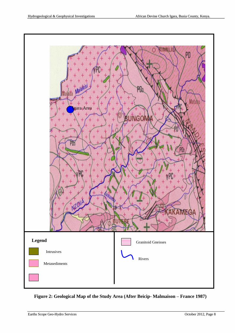
33..33.. GGeeoollooggyy ooff tthhee IInnvveessttiiggaatteedd SSiittee
The area is overlain by recent deposits of eroded and decayed hard capping of lateritic
iron stone resulting to production of a thick mantle of heavy red soil. Beneath this is high-
level gravel deposits. This is underlain by the Kavirondian Series which consist of the
sediments of felspathic grits, conglomerates, shale and siltstone. The Kavirondian series
has been heavily intruded by a complex of intrusions. These intrusion are granites of
several distinct types. The granites are part of Kitosh Batholith, whose outcrop covers
very considerable tracts of the country north of the Nzoia river. These rocks are usually
porphyritic, coarse-grained, hornblende-biotite granite -the Kisama –Igara granite, which
frequently form characteristic tors, of which Bukaiya and Nyenyese hills are example.
HHyyddrrooggeeoollooggiiccaall && GGeeoopphhyyssiiccaall IInnvveessttiiggaattiioonnss AAffrriiccaann DDeevviinnee CChhuurrcchh IIggaarraa,, BBuussiiaa CCoouunnttyy,, KKeennyyaa..
EEaarrtthhss SSccooppee GGeeoo--HHyyddrroo SSeerrvviicceess OOccttoobbeerr 22001122,, PPaaggee 88
Figure 2: Geological Map of the Study Area (After Beicip- Malmaison – France 1987)
Igara Area
Legend
Rivers
Granitoid Gneisses
Intrusives
Metasediments
HHyyddrrooggeeoollooggiiccaall && GGeeoopphhyyssiiccaall IInnvveessttiiggaattiioonnss AAffrriiccaann DDeevviinnee CChhuurrcchh IIggaarraa,, BBuussiiaa CCoouunnttyy,, KKeennyyaa..
EEaarrtthhss SSccooppee GGeeoo--HHyyddrroo SSeerrvviicceess OOccttoobbeerr 22001122,, PPaaggee 99
44.. HHYYDDRROOGGEEOOLLOOGGYY
The hydrogeology of an area is normally intimately dependent upon the nature of the parent
rock, structural features, weathering processes, recharge mechanism and the form and
frequency of precipitation. The midland environment of Western Kenya area offers a
reasonable groundwater potential. The relatively high rainfall, and the gently peneplain
surface south of Elgon and west of the Nandi escarpment are all favorable characteristics to
ground water occurrence.
44..11.. GGrroouunnddwwaatteerr OOccccuurrrreennccee
Given that suitable storage media exist below ground, the mechanisms by which water
must reach it also affect aquifer potential. Obviously, if no rainfall or riverflow is able to
percolate to a sandy weathered Basement aquifer due to the presence of an aquitard
(impermeable layer) probably clay, the actual potential is very low. If rainfall is low, the
volume of water, which may eventually percolate to a suitable aquifer, is likely to be
relatively small, and possibly mineralized due to high evaporation.
Percolation is dependent on soil structure, vegetation coverage and the erosion state of the
parent rock. Rocks which weather to clayey soils will naturally inhibit percolation (such
as „black cotton‟ soils); conversely, the sandy soils resulting from the erosion of some
Basement System rocks are eminently suited to deep swift percolation.
Recharge is the term applied to the whole mechanism, and includes all the aspects of
parent geology, effective rainfall and percolation. Some aquifer systems are recharged by
water falling a substantial distance away.
Generally there are two types of aquifers that exist within the Basement System rock.
These include those associated with fault and fracture feature and weathered rocks
overlying compact or fresh rock.
44..22.. BBaasseemmeenntt AAqquuiiffeerr OOccccuurrrreennccee
Aquifers associated with fault and fracture features are better than the weathered rock
aquifers overlying compact or fresh rock. These latter aquifers, located in the regolith, are
highly variable in terms of potential yields. This is because the physical transmission of
water within the aquifer body itself is dependent upon the total clay fraction present after
weathering of the parent rock which itself depends on the chemical constitutes of the
parent rock and the mechanism of weathering.
Faults and fractures associated with major movements of the earth‟s crust and often
accompanied by tectonic activity, lead to the formation of coarser material. This, together
with the larger volume of potential storage brought about by the fault, leads to rather
better potential yields, especially where a borehole is sited so as to intersect fault features
at depth.
HHyyddrrooggeeoollooggiiccaall && GGeeoopphhyyssiiccaall IInnvveessttiiggaattiioonnss AAffrriiccaann DDeevviinnee CChhuurrcchh IIggaarraa,, BBuussiiaa CCoouunnttyy,, KKeennyyaa..
EEaarrtthhss SSccooppee GGeeoo--HHyyddrroo SSeerrvviicceess OOccttoobbeerr 22001122,, PPaaggee 1100
44..33.. WWeeaatthheerriinngg aanndd iittss SSiiggnniiffiiccaannccee iinn AAqquuiiffeerr OOccccuurrrreennccee
Different zones may be identified in the weathering profile of an area. These are detailed
below.
44..33..11.. TThhee CCoollllaappsseedd ZZoonnee
This may show marked lateral variation but is general sandy on watershed areas with
illuviated clay near the base and sometimes a „stone line‟; on valley slopes, colluvial
material accumulates and in valley bottoms, secondary clay minerals predominate. Slope
bottom laterites may also occur which can result in perched water tables. Permeabilities
vary in accordance with lithology on watersheds. The collapsed zone normally occurs
above the water table.
44..33..22.. SSaapprroolliittee
This is covered by the collapsed zone and is mainly composed of more coarsely
disintegrated and less altered rock material. It is derived by situ weathering from the
bedrock but is disaggregated. Permeability commonly increases at lower levels due to a
lesser development of secondary clay minerals.
44..33..33.. SSaapprroocckk
This is weathered bedrock. It resembles the bedrock zone and is the most important local
aquifer type. Fracture permeability generally increased as a result of weathering (as
compared with fresh bedrock) unless in filled by illuviated clay minerals.
44..33..44.. BBeeddrroocckk
This includes the variably fractured fresh bedrock and the saprock or weathered bedrock.
The saprock-fresh bedrock junction is generally transitional or even fluctuating in banded
sequences. Fracture systems are related either to decompression or to tectonic forces. The
former tend to be sub-horizontal with a decreasing frequency with depth. The latter tend
to be sub-vertical and are often in zonal concentrations. Since tectonic fracturing in
Basement rocks has occurred on several occasions over a long time span and often with
reactivation of old fractures, clear recognition of age or differentiation of shear and tensile
conditions is not to be expected.
Fissure permeability is assumed to correlate to some degree with frequency of fracture
occurrence, with a further assumption that both parameters will decrease with depth.
However, the few detailed studies do not always present comparable features, variations
being probably due to limitations of the database. Fracture distribution probably reflects
fracture systems mainly of decompression type. Fracture sealing in the weathered bedrock
profile is known to occur, probably by clay illuviation, and may result in an increasing
HHyyddrrooggeeoollooggiiccaall && GGeeoopphhyyssiiccaall IInnvveessttiiggaattiioonnss AAffrriiccaann DDeevviinnee CChhuurrcchh IIggaarraa,, BBuussiiaa CCoouunnttyy,, KKeennyyaa..
EEaarrtthhss SSccooppee GGeeoo--HHyyddrroo SSeerrvviicceess OOccttoobbeerr 22001122,, PPaaggee 1111
permeability with depth. Fracture occurrence and permeability in the main bedrock may
show an inverse relationship of depth to permeability with large data set. The depth-
permeability relationships at individual borehole sites are obviously affected by the dip of
tectonic fracture zones.
44..33..55.. RReeggoolliitthh
The regolith consists of the collapsed zone and the saprolite. Since weathering is most
effective in the vadose zone and the zone of water table fluctuations, there is a tendency
to develop subdivisions into an upper and lower saprolite relative to current (or previous)
water levels. This is in addition sometimes to a basal brecciated zone where rock
fragmentation is largely unaccompanied by mineralogical changes.
In regions of moderate to high annual rainfall (>600 mm/year), the water table is typically
at shallow levels (<10-15 m) and the regolith aquifer provides the main storage for deep
boreholes as well as both storage and transmissivity for wells and shallow boreholes.
The collapsed zone has developed from the underlying saprolite by further dissolution
and leaching, combined with other formative processes: chemical, physical and
biological. The surface material is typically sandy on watershed areas where these overlie
quartz- rich rocks but changes to sandy clays and clay (montmorrillonite) in valley bottom
lands. The surface sands have high infiltration capacities, which decrease markedly in any
underlying illuviated clay horizons.
Saprolite is derived from in situ weathering and is disaggregated. An upper saprolite may
be distinguished by higher proportions of the more advanced minerals combined with the
earlier forms of secondary clay minerals (smectites). The boundary with the underlying
saprock may be sharp (against coarser-grained, massive rock) or transitional (against
banded or finer-grained rocks)
.
44..44.. HHyyddrrooggeeoollooggyy ooff tthhee IIggaarraa AArreeaa
The type of rainfall is convenctional, which is the major characteristic of Lake Victoria
Basin. The major river is Nzoia river and is very largely drained by its tributaries and sub
tributaries notably Lisumu, Kisama, Viratsi, Siga and Suludhi river. Groundwater
recharge is mainly by direct percolation and precipitation. Groundwater in this area
occurs within the perched water table resting on resistant bands of pegmatitic granite in
pervious weathered biotite granite, weathered and fractured Basement System rocks
overlying the fresh Basement system rock of granitic origin. In places where Basement
rocks are banded, groundwater is expected to be found within weathered or fractured
bands. Recharge is also expected to be via lateral flow over a long distance in well
developed joint system which may offer free passage to water. The weathered zone
immediately below the overburden is saturated and may contain promising amounts of
ground water as a result of damming by other minor intrusives.
It is thus expected that the groundwater potential in the area is medium with the
promising aquifer being the contact zone between the sediments and the underlying
HHyyddrrooggeeoollooggiiccaall && GGeeoopphhyyssiiccaall IInnvveessttiiggaattiioonnss AAffrriiccaann DDeevviinnee CChhuurrcchh IIggaarraa,, BBuussiiaa CCoouunnttyy,, KKeennyyaa..
EEaarrtthhss SSccooppee GGeeoo--HHyyddrroo SSeerrvviicceess OOccttoobbeerr 22001122,, PPaaggee 1122
Basement, and also weathered and fractured Basement. In this area groundwater resources
are evenly and widely distributed.
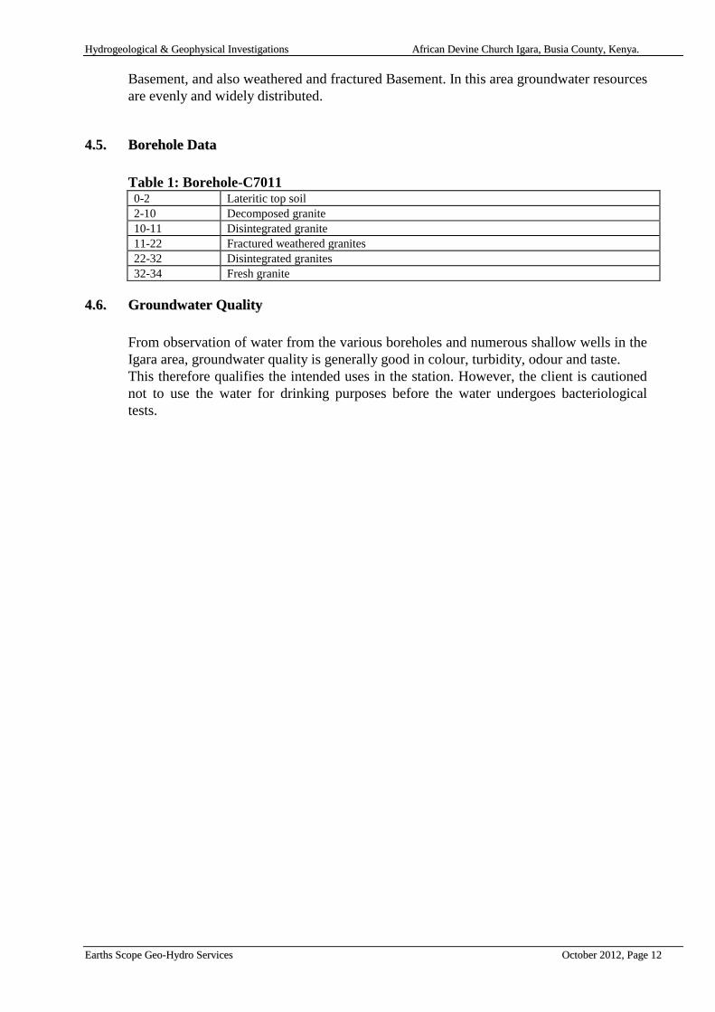
44..55.. BBoorreehhoollee DDaattaa
Table 1: Borehole-C7011 0-2 Lateritic top soil
2-10 Decomposed granite
10-11 Disintegrated granite
11-22 Fractured weathered granites
22-32 Disintegrated granites
32-34 Fresh granite
44..66.. GGrroouunnddwwaatteerr QQuuaalliittyy
From observation of water from the various boreholes and numerous shallow wells in the
Igara area, groundwater quality is generally good in colour, turbidity, odour and taste.
This therefore qualifies the intended uses in the station. However, the client is cautioned
not to use the water for drinking purposes before the water undergoes bacteriological
tests.
HHyyddrrooggeeoollooggiiccaall && GGeeoopphhyyssiiccaall IInnvveessttiiggaattiioonnss AAffrriiccaann DDeevviinnee CChhuurrcchh IIggaarraa,, BBuussiiaa CCoouunnttyy,, KKeennyyaa..
EEaarrtthhss SSccooppee GGeeoo--HHyyddrroo SSeerrvviicceess OOccttoobbeerr 22001122,, PPaaggee 1133
55.. GGEEOOPPHHYYSSIICCAALL IINNVVEESSTTIIGGAATTIIOONN MMEETTHHOODDSS
Investigations of the groundwater resources at Igara African Devine Church included the
use of geophysical techniques to probe the sub-surface. A variety of methods are available
to assist in the assessment of geological sub-surface conditions. The main emphasis of the
fieldwork undertaken was to determine the thicknesses and composition of the sub-surface
formations and to identify water-bearing zones.
This information was principally obtained in the field using vertical electrical soundings
(VES) and horizontal resistivity profiling with the TSP Resistivity Meter.
The VES probes the resistivity layering below the site of measurement. This method is
described below.
55..11.. RReessiissttiivviittyy MMeetthhoodd
Vertical electrical soundings (VES) were carried out to probe the condition of the sub-
surface and to confirm the existence of deep groundwater. The VES investigates the
resistivity layering below the site of measurement. This technique is described below.
55..22.. BBaassiicc PPrriinncciipplleess
The electrical properties of rocks in the upper part of the earth's crust are dependent upon
the lithology, porosity, the degree of pore space saturation and the salinity of the pore water.
Saturated rocks have lower resistivities than unsaturated and dry rocks. The higher the
porosity of the saturated rock, or the higher the salinity of the saturating fluids, the lower the
resistivity. The presence of clays and conductive minerals also reduces the resistivity of the
rock.
The resistivity of earth materials can be studied by measuring the electrical potential
distribution produced at the earth's surface by an electric current that is passed through the
earth.
The resistance R of a certain material is directly proportional to its length L and
cross-sectional area A, expressed as:
R = Rs * L/A (in Ohm)
Where Rs is known as the specific resistivity, characteristic of the material and independent
of its shape or size.
With Ohm's Law,
R = dV/I (Ohm)
HHyyddrrooggeeoollooggiiccaall && GGeeoopphhyyssiiccaall IInnvveessttiiggaattiioonnss AAffrriiccaann DDeevviinnee CChhuurrcchh IIggaarraa,, BBuussiiaa CCoouunnttyy,, KKeennyyaa..
EEaarrtthhss SSccooppee GGeeoo--HHyyddrroo SSeerrvviicceess OOccttoobbeerr 22001122,, PPaaggee 1144
Where dV is the potential difference across the resistor and I is the electric current through
the resistor. The specific resistivity may be determined by:
Rs = (A/L) * (dV/I) (in Ohm m)
55..33.. VVeerrttiiccaall EElleeccttrriiccaall SSoouunnddiinngg ((VVEESS))
When carrying out a resistivity sounding, current is led into the ground by means of two
electrodes. With two other electrodes, situated near the centre of the array, the potential
field generated by the current is measured.
From the observations of the current strength and the potential difference, and taking into
account the electrode separations, the ground resistivity can be determined.
During a resistivity sounding, the separation between the electrodes is step-wise increased
(in what is known as a Schlumberger Array), thus causing the flow of current to penetrate
greater depths. When plotting the observed resistivity values against depth on double
logarithmic paper, a resistivity graph is formed, which depicts the variation of resistivity
with depth. This graph can be interpreted with the aid of a computer, and the actual
resistivity layering of the subsoil is obtained. The depths and resistivity values provide the
hydrogeologist with information on the geological layering and thus the occurrence of
groundwater.
HHyyddrrooggeeoollooggiiccaall && GGeeoopphhyyssiiccaall IInnvveessttiiggaattiioonnss AAffrriiccaann DDeevviinnee CChhuurrcchh IIggaarraa,, BBuussiiaa CCoouunnttyy,, KKeennyyaa..
EEaarrtthhss SSccooppee GGeeoo--HHyyddrroo SSeerrvviicceess OOccttoobbeerr 22001122,, PPaaggee 1155
66.. FFIIEELLDDWWOORRKK AANNDD RREESSUULLTTSS
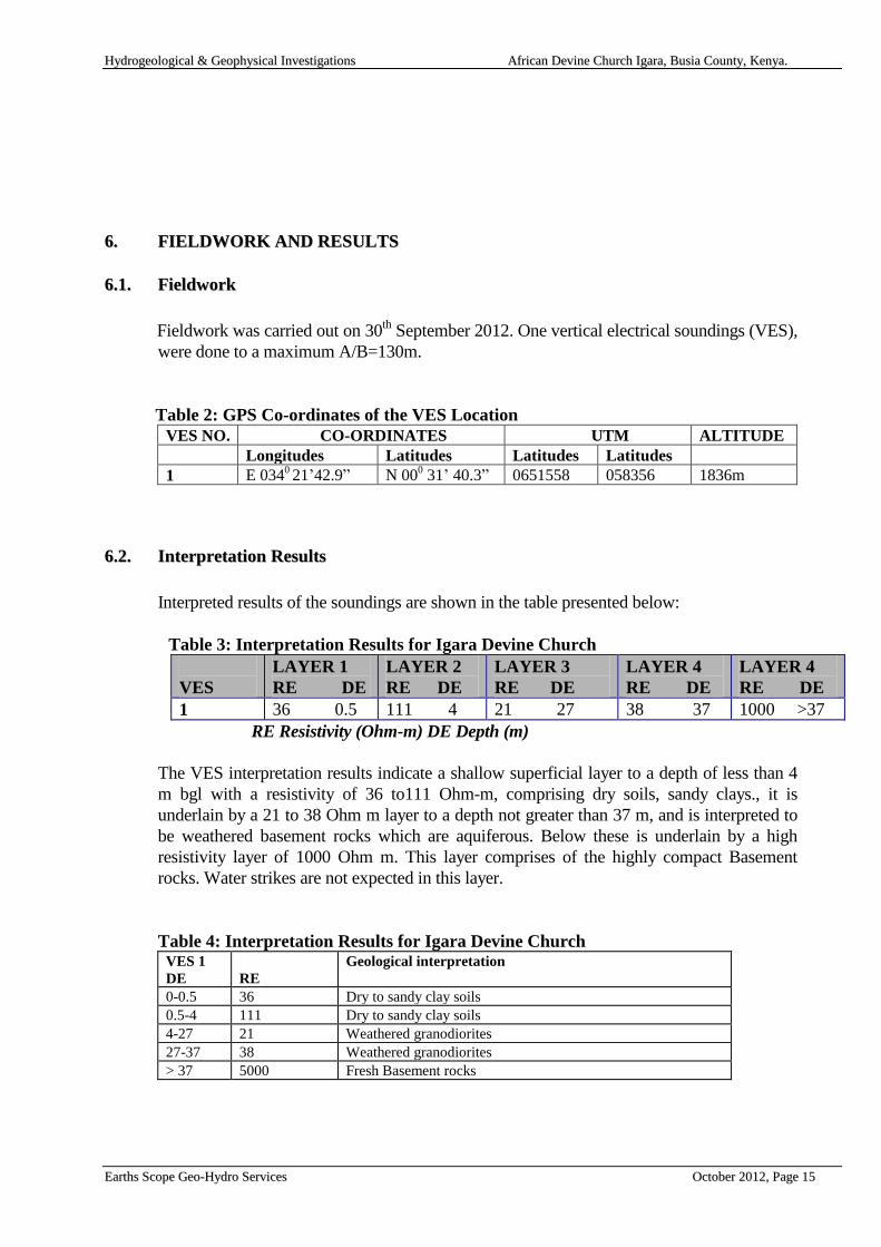
66..11.. FFiieellddwwoorrkk
Fieldwork was carried out on 30th
September 2012. One vertical electrical soundings (VES),
were done to a maximum A/B=130m.
Table 2: GPS Co-ordinates of the VES Location
VES NO. CO-ORDINATES UTM ALTITUDE
Longitudes Latitudes Latitudes Latitudes
1 E 0340 21‟42.9” N 00
0 31‟ 40.3” 0651558 058356 1836m
66..22.. IInntteerrpprreettaattiioonn RReessuullttss
Interpreted results of the soundings are shown in the table presented below:
Table 3: Interpretation Results for Igara Devine Church
VES
LAYER 1
RE DE
LAYER 2
RE DE
LAYER 3
RE DE
LAYER 4
RE DE
LAYER 4
RE DE
1 36 0.5 111 4 21 27 38 37 1000 >37
RE Resistivity (Ohm-m) DE Depth (m)
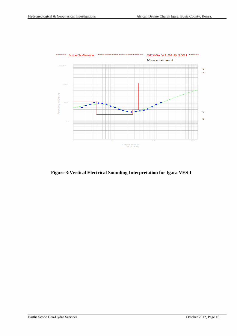
The VES interpretation results indicate a shallow superficial layer to a depth of less than 4
m bgl with a resistivity of 36 to111 Ohm-m, comprising dry soils, sandy clays., it is
underlain by a 21 to 38 Ohm m layer to a depth not greater than 37 m, and is interpreted to
be weathered basement rocks which are aquiferous. Below these is underlain by a high
resistivity layer of 1000 Ohm m. This layer comprises of the highly compact Basement
rocks. Water strikes are not expected in this layer.
Table 4: Interpretation Results for Igara Devine Church VES 1
DE
RE
Geological interpretation
0-0.5 36 Dry to sandy clay soils
0.5-4 111 Dry to sandy clay soils
4-27 21 Weathered granodiorites
27-37 38 Weathered granodiorites
> 37 5000 Fresh Basement rocks
HHyyddrrooggeeoollooggiiccaall && GGeeoopphhyyssiiccaall IInnvveessttiiggaattiioonnss AAffrriiccaann DDeevviinnee CChhuurrcchh IIggaarraa,, BBuussiiaa CCoouunnttyy,, KKeennyyaa..
EEaarrtthhss SSccooppee GGeeoo--HHyyddrroo SSeerrvviicceess OOccttoobbeerr 22001122,, PPaaggee 1166
Figure 3:Vertical Electrical Sounding Interpretation for Igara VES 1
HHyyddrrooggeeoollooggiiccaall && GGeeoopphhyyssiiccaall IInnvveessttiiggaattiioonnss AAffrriiccaann DDeevviinnee CChhuurrcchh IIggaarraa,, BBuussiiaa CCoouunnttyy,, KKeennyyaa..
EEaarrtthhss SSccooppee GGeeoo--HHyyddrroo SSeerrvviicceess OOccttoobbeerr 22001122,, PPaaggee 1177
77.. CCOONNCCLLUUSSIIOONNSS AANNDD RREECCOOMMMMEENNDDAATTIIOONNSS
77..11.. CCoonncclluussiioonnss FFiieellddwwoorrkk
The investigated area is located in a hydrogeological zone which is characterized by
medium groundwater potential. Aquifers encountered between 10 and 60 metres are
expected to yield about 1to 5 m3/hr of water for domestic purposes. Deeper aquifers are
not expected below this depth.
Water strikes at moderate depths may occur, due to probably tapping of perched water
tables resting on resistant bands of pegmatitic gneiss in pervious weathered biotite gneiss;
the granites in the area might have a well developed joint system than usual, which may
be assumed to afford free passage to water or between the regolith and the fresh
Basement rock.
77..22.. RReeccoommmmeennddaattiioonnss
In view of the above it is recommended that:
- A shallow Well be excavated to a depth of 20-25 m bgl
- If the shallow Well is not very productive then a Borehole be drilled
- As an alternative an 8" diameter borehole be drilled to a depth of about 60 m. The
yield will be in the order of 1 to 5 m3/hr.
- The borehole should be installed with high quality uPVC casings and screens.
- A monitoring piezometer should be installed in the borehole to enable monitoring
of the water level in the well.
- A master meter should be installed to record the amount of water abstracted from
the borehole.
- The most suitable location for the Shallow Well/Borehole was shown to the Mr.
William Ashitiva, Mr. George Wafula and M/s Mary Opech all residents and
church members of the African Devine Church Igara.
Appendix 1 gives additional recommendations on the construction and completion of a
borehole.
HHyyddrrooggeeoollooggiiccaall && GGeeoopphhyyssiiccaall IInnvveessttiiggaattiioonnss AAffrriiccaann DDeevviinnee CChhuurrcchh IIggaarraa,, BBuussiiaa CCoouunnttyy,, KKeennyyaa..
EEaarrtthhss SSccooppee GGeeoo--HHyyddrroo SSeerrvviicceess OOccttoobbeerr 22001122,, PPaaggee 1188
88.. RREEFFEERREENNCCEESS
A.B GIBSON, 1952,Geology of the Broderick Falls Area
C STANSFIELD HITCHEN, 1937,Geological Survey Of Kenya of No.2 Mining
Area, - KAVIRONDO
JONES M J., 1985, The Weathered Zone Aquifers of the Basement Complex
areas of Africa. Q.J eng. Geol. London. Vol. 18 pp 35-46.

HHyyddrrooggeeoollooggiiccaall && GGeeoopphhyyssiiccaall IInnvveessttiiggaattiioonnss AAffrriiccaann DDeevviinnee CChhuurrcchh IIggaarraa,, BBuussiiaa CCoouunnttyy,, KKeennyyaa..
EEaarrtthhss SSccooppee GGeeoo--HHyyddrroo SSeerrvviicceess OOccttoobbeerr 22001122,, PPaaggee 1199
APPENDICES
HHyyddrrooggeeoollooggiiccaall && GGeeoopphhyyssiiccaall IInnvveessttiiggaattiioonnss AAffrriiccaann DDeevviinnee CChhuurrcchh IIggaarraa,, BBuussiiaa CCoouunnttyy,, KKeennyyaa..
EEaarrtthhss SSccooppee GGeeoo--HHyyddrroo SSeerrvviicceess OOccttoobbeerr 22001122,, PPaaggee 2200
Appendix 1:Drilling
Drilling Technique
Drilling should be carried out with an appropriate tool - either percussion or rotary
machines will be suitable, though the latter are considerably faster. Geological rock samples
should be collected at 2 metre intervals. Struck and rest water levels and if possible,
estimates of the yield of individual aquifers encountered, should also be noted.
Well Design
The design of the well should ensure that screens are placed against the optimum aquifer
zones. The final design should be made by an experienced hydrogeologist.
Casing and Screens
The well should be cased and screened with good quality material. Owing to the shallow
depth of the boreholes, it is recommended to use uPVC casings and screens of high open
surface area.
We strongly advise against the use of torch-cut steel well-casing as screen. In general, its
use will reduce well efficiency (which leads to lower yield), increase pumping costs through
greater drawdown, increase maintenance costs, and eventually reduction of the potential
effective life of the well.
Gravel Pack
The use of a gravelpack is recommended within the aquifer zone, because the aquifer could
contain sands or silts which are finer than the screen slot size. An 8" diameter borehole
screened at 6" will leave an annular space of approximately 1", which should be sufficient.
Should the slot size chosen be too large, the well will pump sand, thus damaging the
pumping plant, and leading to gradual `siltation' of the well. The slot size should be in the
order of 1.5 mm. The grain size of the gravel pack should be an average 2 - 4 mm.
Well Construction
Once the design has been agreed, construction can proceed. In installing screen and casing,
centralizers at 6 metre intervals should be used to ensure centrality within the borehole.
This is particularly important for correct insertion of artificial gravel pack all around the
screen. After installation, gravel packed sections should be sealed off top and bottom with
clay (2 m).
HHyyddrrooggeeoollooggiiccaall && GGeeoopphhyyssiiccaall IInnvveessttiiggaattiioonnss AAffrriiccaann DDeevviinnee CChhuurrcchh IIggaarraa,, BBuussiiaa CCoouunnttyy,, KKeennyyaa..
EEaarrtthhss SSccooppee GGeeoo--HHyyddrroo SSeerrvviicceess OOccttoobbeerr 22001122,, PPaaggee 2211
The remaining annular space should be backfilled with an inert material, and the top five
metres grouted with cement to ensure that no surface water at the well head can enter the
well bore and cause contamination.
Well Development
Once screen, pack, seals and backfill have been installed, the well should be developed.
Development aims at repairing the damage done to the aquifer during the course of drilling
by removing clays and other additives from the borehole walls. Secondly, it alters the
physical characteristics of the aquifer around the screen and removes fine particles.
We do not advocate the use of overpumping as a means of development since it only
increases permeability in zones which are already permeable. Instead, we would
recommend the use of air or water jetting, or the use of the mechanical plunger, which
physically agitates the gravel pack and adjacent aquifer material. This is an extremely
efficient method of developing and cleaning wells.
Well development is an expensive element in the completion of a well, but is usually
justified in longer well-life, greater efficiencies, lower operational and maintenance costs
and a more constant yield. Within this frame the pump should be installed at least 2 m
above the screen, certainly not at the same depth as the screen.
Well Testing
After development and preliminary tests, a long-duration well test should be carried
out. Well tests have to be carried out on all newly-completed wells, because apart from
giving an indication of the quality of drilling, design and development, it also yields
information on aquifer parameters which are vital to the hydrogeologist.
A well test consists of pumping a well from a measured start level (Water Rest Level -
(WRL) at a known or measured yield, and simultaneously recording the discharge rate and
the resulting drawdowns as a function of time. Once a dynamic water level (DWL) is
reached, the rate of inflow to the well equals the rate of pumping. Usually the rate of
pumping is increased step wise during the test. The results of the test will enable a
hydrogeologist to calculate the optimum pumping rate, the pump installation depth, and the
drawdown for a given discharge rate.
HHyyddrrooggeeoollooggiiccaall && GGeeoopphhyyssiiccaall IInnvveessttiiggaattiioonnss AAffrriiccaann DDeevviinnee CChhuurrcchh IIggaarraa,, BBuussiiaa CCoouunnttyy,, KKeennyyaa..
EEaarrtthhss SSccooppee GGeeoo--HHyyddrroo SSeerrvviicceess OOccttoobbeerr 22001122,, PPaaggee 2222
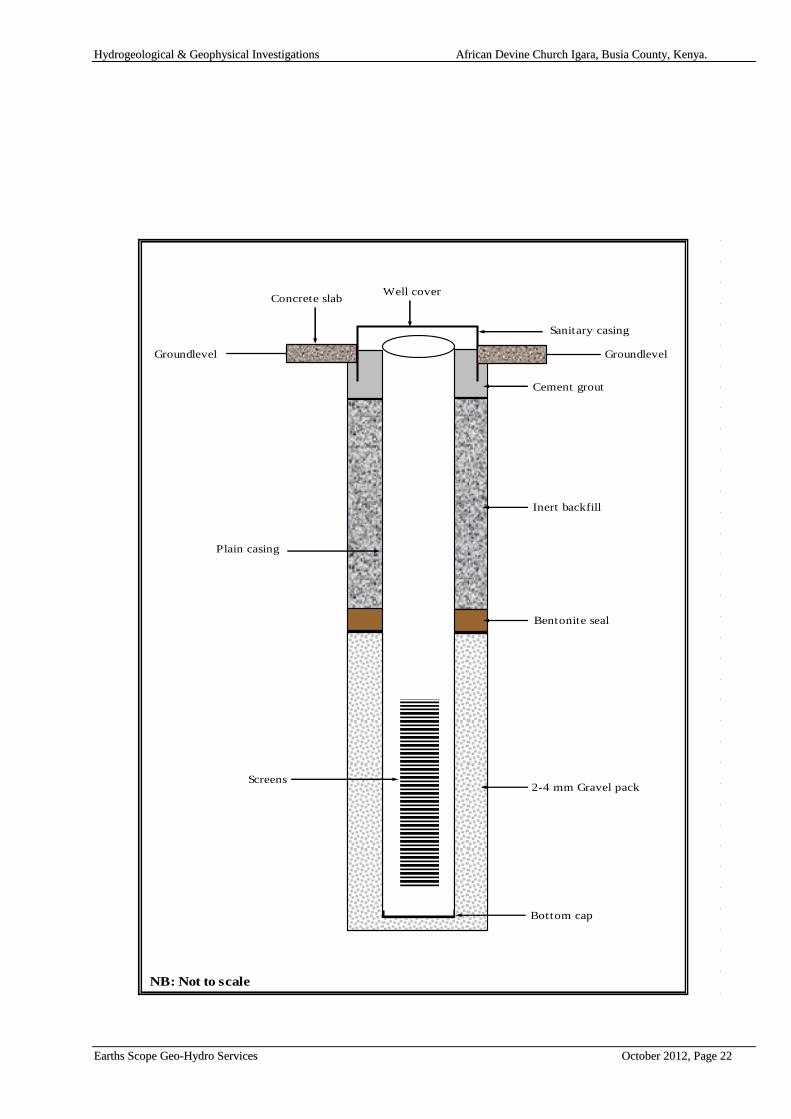
NB: Not to scale
Groundlevel
Cement grout
Inert backfill
Bentonite seal
2-4 mm Gravel pack
Bottom cap
Groundlevel
Concrete slab Well cover
Plain casing
Sanitary casing
Screens
Schematic Design for Borehole completion

HHyyddrrooggeeoollooggiiccaall && GGeeoopphhyyssiiccaall IInnvveessttiiggaattiioonnss AAffrriiccaann DDeevviinnee CChhuurrcchh IIggaarraa,, BBuussiiaa CCoouunnttyy,, KKeennyyaa..
EEaarrtthhss SSccooppee GGeeoo--HHyyddrroo SSeerrvviicceess OOccttoobbeerr 22001122,, PPaaggee 2233
Schematic Design for Borehole Completion