Embed Size (px)
Citation preview
SOUTH COAST AIR QUALITY MANAGEMENT DISTRICT
METHOD 6.2
DETERMINATION OF HYDROGEN SULFIDE
OFFICE OF OPERATIONS TECHNICAL SERVICES DIVISION
MARCH 1989
METHOD 6.2
DETERMINATION OF HYDROGEN SULFIDE
TABLE OF CONTENTS
Section 1. Overview 1.1 Principle 1.2 Applicability 1.3 Range and Sensitivity 1.4 Interferences 1.5 Precision and Accuracy 2. Field Procedures
2.1 Sampling Apparatus
2.2 Sampling Reagents
2.3 Preliminary Determinations
2.4 Sample Collection Train Preparation
2.5 Pretest Leak Check
2.6 Meter Calibration
2.7 Sampling Train Operations
2.8 Sample Handling
3. Laboratory Procedures
3.1 Apparatus
3.2 Reagents
3.3 Pretest Determination
3.4 Preparation of Sample Collection Train
3.5 Leak Check
3.6 Sample Recovery
3.7 Sample Analysis
3.8 Calculations 3.9 Calibrations 4. Engineering Calculations 4.1 Dry Gas Volume 4.2 Concentration of H2S
4.3 Mass Emiss
METHOD 6.2
DETERMINATION OF HYDROGEN SULFIDE
Section 1 of 4
1. Overview
1.1 Principle
Hydrogen sulfide (H2S) is collected from a source
in a series of standard Greenburg-Smith impingers
and absorbed in pH 4.0 cadmium sulfate (CdSO4)
solution to form cadmium sulfide (CdS), which
then is measured iodometrically. An impinger
containing hydrogen peroxide (H2O2) removes
sulfur dioxide (SO2) as an interfering species.
If SO2 is known to be absent, the first impinger
containing 3 percent H2O2 may be eliminated.
1.2 Applicability
This method determines the hydrogen sulfide
content of effluent gas streams.
1.3 Range and Sensitivity
6.2-1
For one cubic meter of sample, the lower limit of
detection is several mg/m3 (several ppm). The
upper limit is 1000 mg/m3 (700 ppm), which can be
extended by increasing the quantity of CdSO4
solution in the impingers.
1.4 Interferences
If a compound that reduces iodine or oxidizes
iodide ion is collected in the cadmium sulfate
impingers, it will interfere in this procedure.
SO2, in concentrations of several hundred mg/m3,
is eliminated by the H202. This can be increased
by adding more H202 solution. Thiols precipitate
with H2S. In the absence of H2S, only co-traces
of thiols are collected. Carbon oxysulfide at a
concentration of 20 percent does not interfere.
Certain carbon-containing compounds react with
iodine and produce recurring end points.
Entrained H2O2 produces a negative interference
equivalent to 100 percent of that of an equimolar
quantity of H2S. Avoid entrainment of H2O2 into
the CdSO4 impingers by inserting an empty
Greenburg-Smith impinger after the peroxide
impinger. The empty impinger should be modified
6.2-2
by replacing the tip with 13 mm (1/2 in.) inside
diameter glass tube extending to 13 mm (1/2 in.)
from the bottom of the flask.
1.5 Precision and Accuracy
Collaborative testing has shown the within-
laboratory coefficient of variation to be 2.2
percent and the overall coefficient of variation
to be 5 percent. The method bias was shown to be
-4.8 percent when only H2S was present.
The above figures are based on EPA Method 11,
using midget impingers. Precision and accuracy
using Greenburg-Smith impingers are not
available.
6.2-3
METHOD 6.2
DETERMINATION OF HYDROGEN SULFIDE
Section 2 of 4
2. Field Procedures
2.1 Sampling Apparatus
2.1.1 Sampling Train
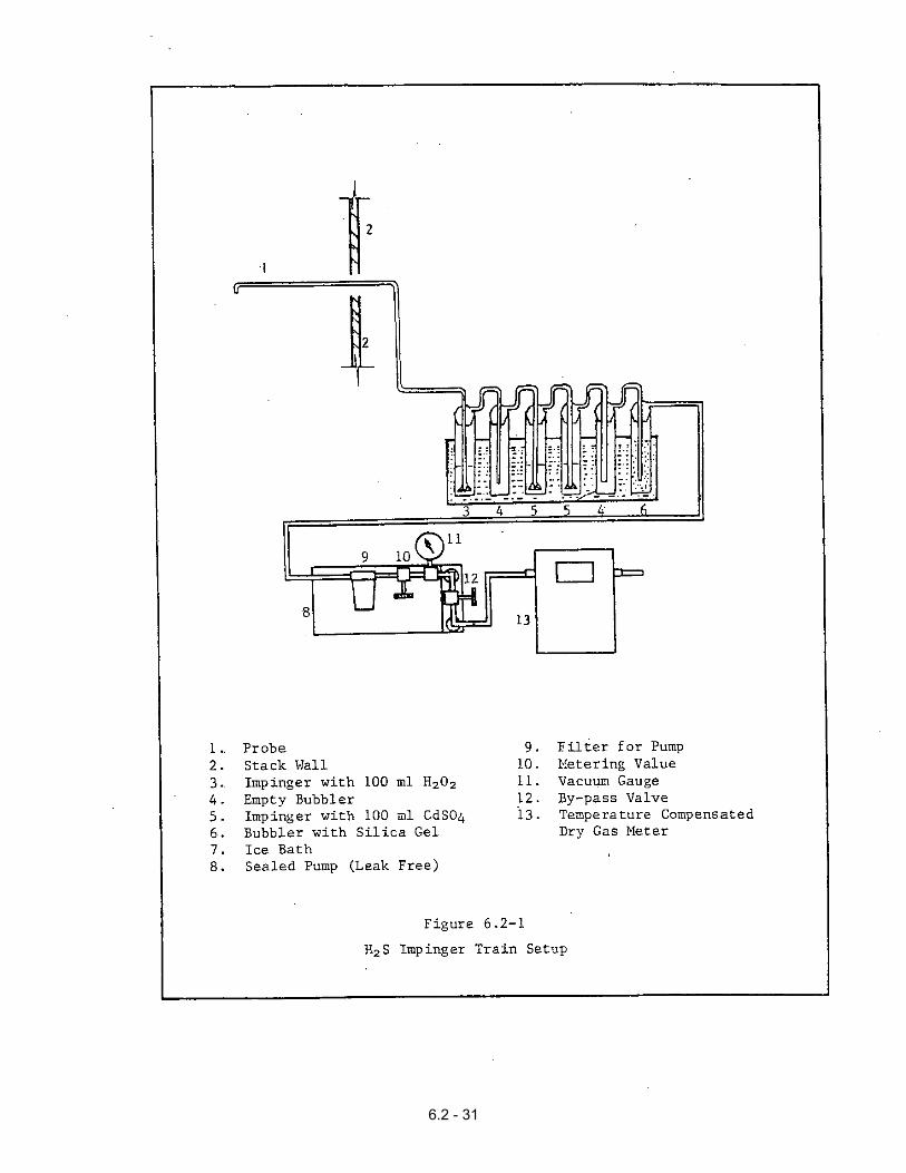
A schematic of the sampling train used in
this method is shown in Figure 6.2-1. The
sampling train has the following
components:
a. Sampling Probe
Use glass or stainless steel probe for
sampling standard exhaust stacks. For
sampling a pressurized fuel line,
connect the sampling train directly
with 6 to 7 mm (1/4 in.) Teflon or
equivalent tubing.
6.2-4
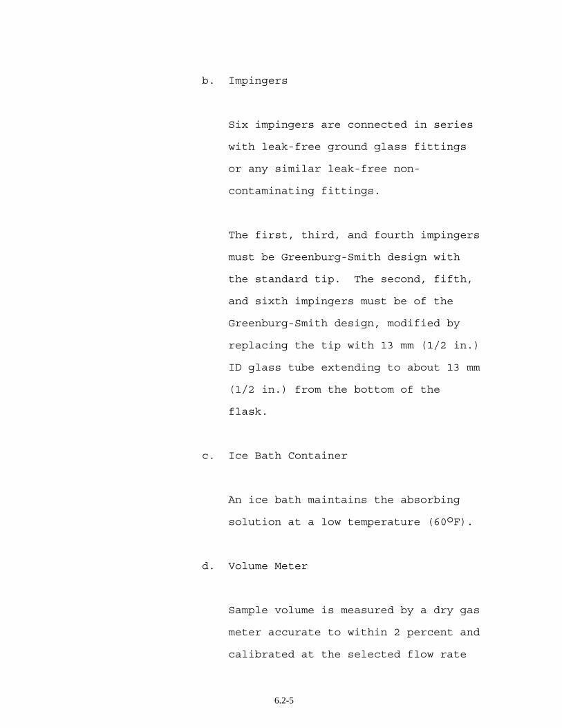
b. Impingers
Six impingers are connected in series
with leak-free ground glass fittings
or any similar leak-free non-
contaminating fittings.
The first, third, and fourth impingers
must be Greenburg-Smith design with
the standard tip. The second, fifth,
and sixth impingers must be of the
Greenburg-Smith design, modified by
replacing the tip with 13 mm (1/2 in.)
ID glass tube extending to about 13 mm
(1/2 in.) from the bottom of the
flask.
c. Ice Bath Container
An ice bath maintains the absorbing
solution at a low temperature (60oF).
d. Volume Meter
Sample volume is measured by a dry gas
meter accurate to within 2 percent and
calibrated at the selected flow rate
6.2-5
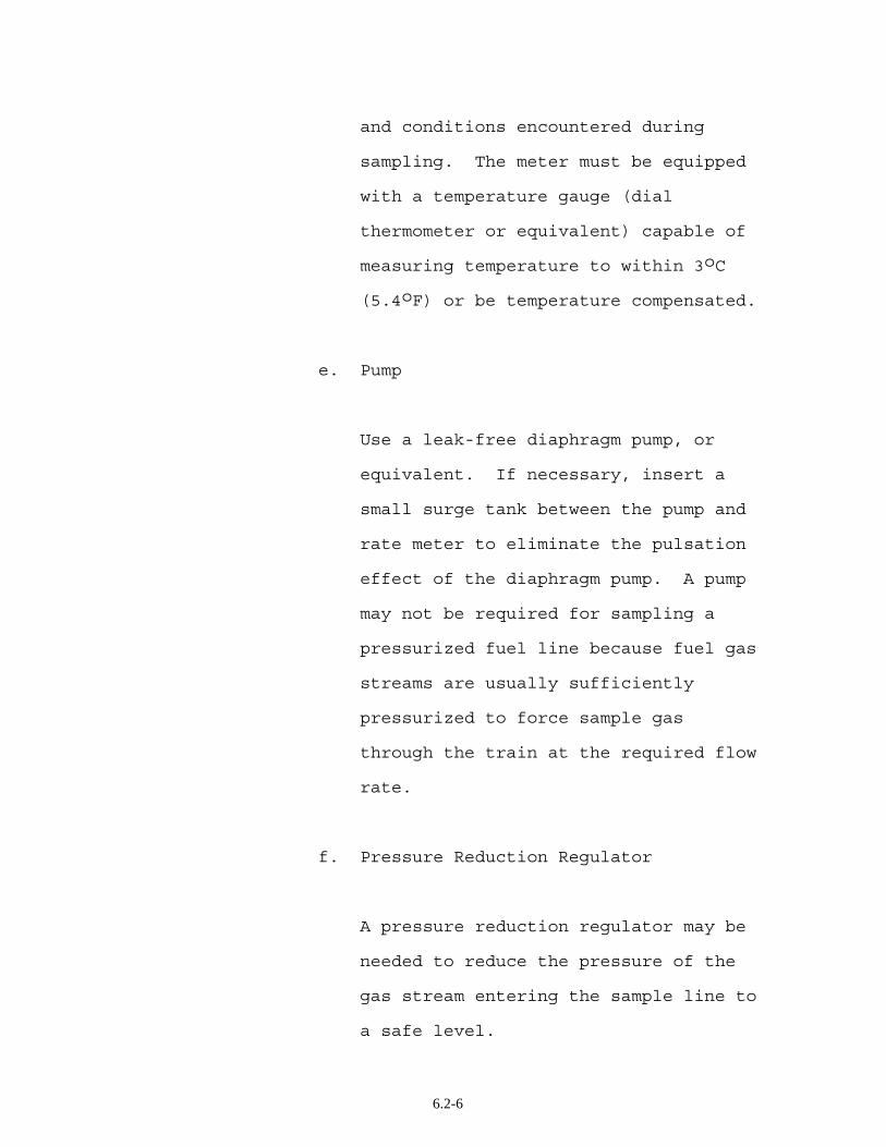
and conditions encountered during
sampling. The meter must be equipped
with a temperature gauge (dial
thermometer or equivalent) capable of
measuring temperature to within 3oC
(5.4oF) or be temperature compensated.
e. Pump
Use a leak-free diaphragm pump, or
equivalent. If necessary, insert a
small surge tank between the pump and
rate meter to eliminate the pulsation
effect of the diaphragm pump. A pump
may not be required for sampling a
pressurized fuel line because fuel gas
streams are usually sufficiently
pressurized to force sample gas
through the train at the required flow
rate.
f. Pressure Reduction Regulator
A pressure reduction regulator may be
needed to reduce the pressure of the
gas stream entering the sample line to
a safe level.
6.2-6
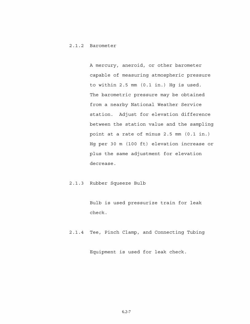
2.1.2 Barometer
A mercury, aneroid, or other barometer
capable of measuring atmospheric pressure
to within 2.5 mm (0.1 in.) Hg is used.
The barometric pressure may be obtained
from a nearby National Weather Service
station. Adjust for elevation difference
between the station value and the sampling
point at a rate of minus 2.5 mm (0.1 in.)
Hg per 30 m (100 ft) elevation increase or
plus the same adjustment for elevation
decrease.
2.1.3 Rubber Squeeze Bulb
Bulb is used pressurize train for leak
check.
2.1.4 Tee, Pinch Clamp, and Connecting Tubing
Equipment is used for leak check.
6.2-7
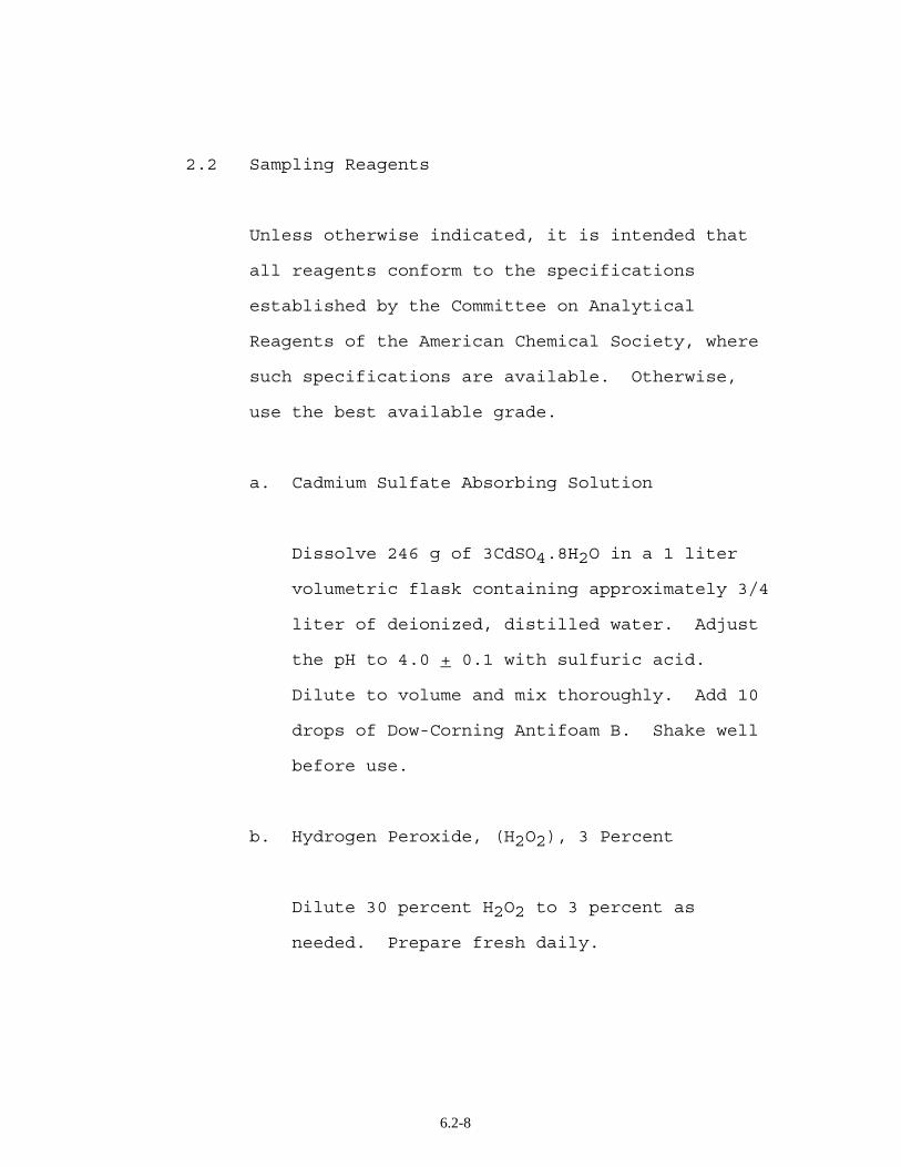
2.2 Sampling Reagents
Unless otherwise indicated, it is intended that
all reagents conform to the specifications
established by the Committee on Analytical
Reagents of the American Chemical Society, where
such specifications are available. Otherwise,
use the best available grade.
a. Cadmium Sulfate Absorbing Solution
Dissolve 246 g of 3CdSO4.8H2O in a 1 liter
volumetric flask containing approximately 3/4
liter of deionized, distilled water. Adjust
the pH to 4.0 + 0.1 with sulfuric acid.
Dilute to volume and mix thoroughly. Add 10
drops of Dow-Corning Antifoam B. Shake well
before use.
b. Hydrogen Peroxide, (H2O2), 3 Percent
Dilute 30 percent H2O2 to 3 percent as
needed. Prepare fresh daily.
6.2-8
c. Water
Use deionized, distilled water to conform to
ASTM specifications D1193-77, Type 3. At the
option of the analyst, the KMnO4 test for
oxidizable organic matter may be omitted when
high concentrations of organic matter are not
expected to be present. Reference to water
throughout this method implies deionized,
distilled water.
d. Silica Gel
Indicating type, 6 to 17 mesh dried at 175oC
(350oF). Silica gel may be used as received.
e. Crushed Ice or Dry Ice Pellets
f. Stopcock Grease
2.3 Preliminary Determinations
If the gas stream is homogeneous, the sampling
point in the duct shall be either at the centroid
or at a point no closer to the wall than 1.0 m
(3.3 ft), unless otherwise specified by the
6.2-9
Executive Officer. If there is an uneven
distribution of H2S concentration in the
effluent, traverse sampling is required.
2.4 Sample Collection Train Preparation
Assemble the sampling train with the six
impingers in series, as shown in Figure 6.2-1.
Place 100 ml of 3 percent H2O2 solution in the
first impinger. Leave the second impinger empty.
Place 100 ml of the cadmium sulfate absorbing
solution in both the third and fourth impingers.
Leave the fifth impinger empty. Place a known
weight of silica gel in the sixth impinger. If a
high concentration of H2S is known to be present
in the effluent gas stream, place 200 ml of CdSO4
solution in both the third and fourth impingers.
In case of sewage gas sampling, a few extra
impingers with CdSO4 solution should be available
as back-up. Place the impinger assembly in an
ice bath container and add water and ice to the
bath. Add more ice during the run, if needed.
During the preparation and assembly of the train
cover all openings where contamination can occur
6.2-10
until just prior to assembly or until sampling is
about to begin.
The impingers containing CdSO4 solution should
always be covered with aluminum foil to avoid
exposure to direct sunlight. Reserve 200 ml of
absorbing solution as a blank.
2.5 Pretest Leak Check
Follow the basic procedures outlined in Method
5.1. If a pressurized fuel line is sampled,
follow this leak check procedure.
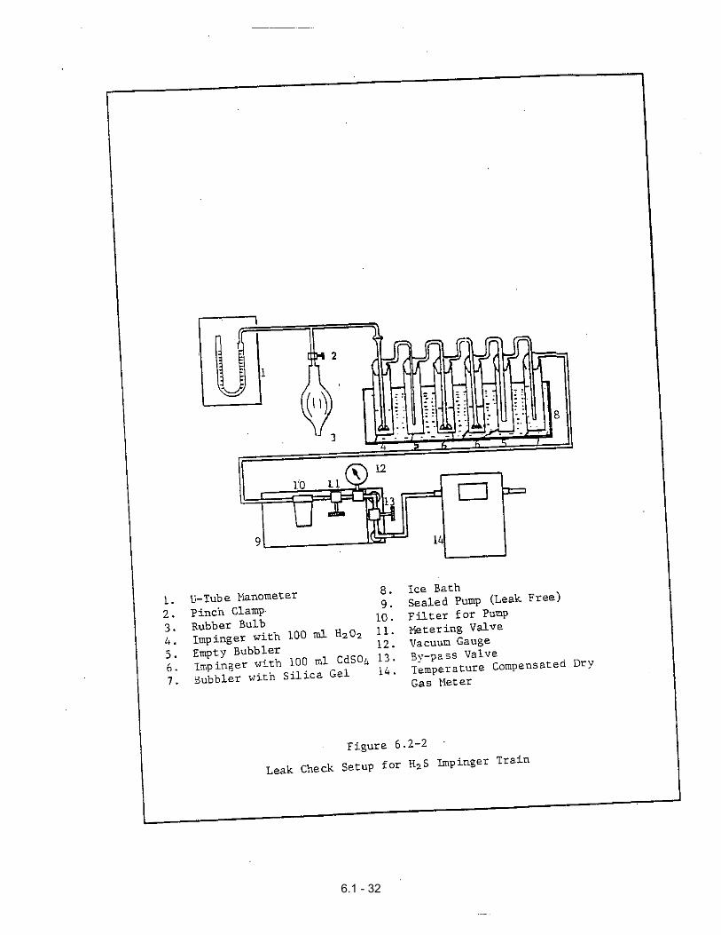
Connect the rubber bulb and magnehelic gauge to
the first impinger, as shown in Figure 6.2-2.
Close the dry gas meter outlet. Pressurize the
train to 25 cm water pressure with the bulb and
close off the tubing connected to the rubber
bulb. The train must hold a 25 cm water pressure
with not more than a 1 cm drop in pressure in a 1
minute interval. Stopcock grease is acceptable
for sealing ground glass joints.
After the leak check, purge the connecting line
between the sampling valve and the first impinger
by disconnecting the line from the first
6.2-11
impinger, opening the sample valve, and allowing
the fuel gas to flow throughout for a minute or
two. Close the valve and reconnect the line.
2.6 Meter Calibration
See Method 5.1., Section 2.
2.7 Sampling Train Operation
Follow the basic procedure outlined in Method
5.1. The sampling rate should be about 0.015
m3/min. (0.5 cfm). If component changes become
necessary during a run, a leak check should be
performed immediately before and after the
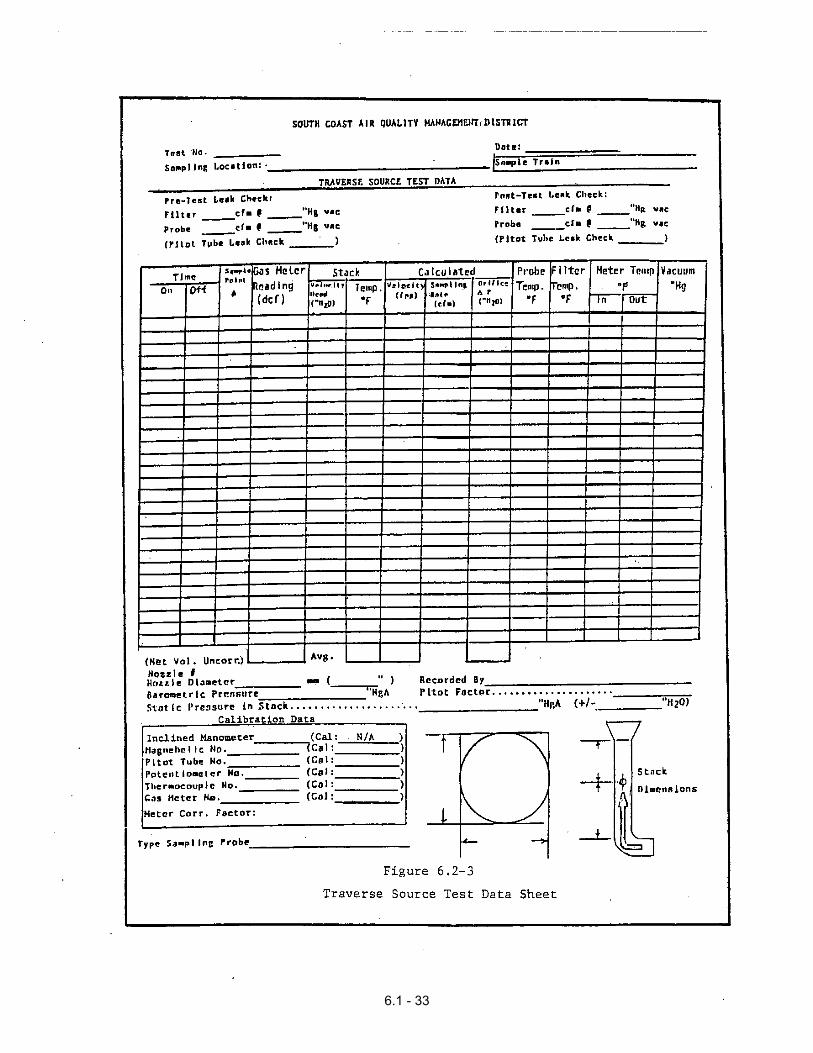
change. Record data on a form such as shown in
Figure 6.2-3.
In case of fuel line sampling adjust the sampling
valve to obtain a rate of approximately 0.015
m3/min. (0.5 cfm). Maintain a constant flow rate
(+ 10 percent) and a pressure below 25 cm water
during the test. Record the meter temperature
and initial meter reading.
Sample for 30 minutes or until the CdSO4 solution
in the fourth impinger turns pale yellow,
6.2-12
whichever occurs first. Obtain a minimum of 15
ft3 of sample and stop the pump. In case of fuel
line sampling, close the sampling valve. Record
the final volume and temperature readings.
Conduct a leak check and meter calibration as
described in Sections 2.5 and 2.6 above.
2.8 Sample Handling
Remove the probe from the duct. In case of fuel
line sampling disconnect the impinger train from
the sampling line. Purge the train at a rate of
0.5 cfm with clean ambient air for 15 minutes to
ensure that all H2S is removed from the H2O2.
For sample recovery, cap the open ends of the
impinger train and move it to a clean area away
from heat sources.
6.2-13
METHOD 6.2
DETERMINATION OF HYDROGEN SULFIDE
Section 3 of 4
3. Laboratory Procedures
3.1 Apparatus
3.1.1 Sample Collection Train Preparation
A schematic of the sampling train used in
this method is shown in Figure 6.2-1. See
Section 2.1.1.
3.1.2 Sample Recovery
a. Graduated Cylinder with Stopper
500 ml (1000 ml if necessary).
b. Sample Containers
Leak-free polyethylene bottles, 500 ml
capacity (1000 ml, 2000 ml if
necessary).
6.2-14
c. Policeman
Rubber or plastic.
d. Wash Bottle
e. Gloves, Waterproof
To be worn at all times when working
with CdSO4 solutions.
f. Balance
Accurate to 0.5 g.
3.1.3 Analysis
a. Iodine Flask
Glass stoppered, 500 ml.
b. Pipets
Several of each size; 10, 25, 50 ml,
100 ml, preferably wide-mouth.
6.2-15
c. Graduated Cylinders
10 ml, 250 ml.
d. Burets
25 ml, 50 ml.
e. Gloves, Waterproof
To be worn at all times when working
with CdSO4 solution.
3.2 Reagents
Unless otherwise indicated, it is intended that
all reagents conform to the specifications
established by the Committee on Analytical
Reagents of the American Chemical Society, where
such specifications are available. Otherwise,
use the best available grade.
3.2.1 Sample Collection Train Preparation
See Section 2.4.
6.2-16
3.2.2 Sample Recovery
a. Water
See Section 2.2 c.
3.2.3 Analysis
a. Iodine Solution, 0.1N
Dissolve 24 g of potassium iodide (KI)
in 30 ml of water. Add 12.7 g of
resublimed iodine (I2) to the KI
solution. Shake the mixture until the
iodide is completely dissolved. If
possible, let the solution stand
overnight in the dark. Slowly dilute
the solution to 1 liter with water,
with swirling. Filter the solution if
it is cloudy. Store solution in a
brown-glass reagent bottle.
b. Sodium Thiosulfate Solution, 0.05N
Dissolve 12.5 g of sodium thiosulfate
pentahydrate (Na2S2O3·5H2O) or 7.9 g
6.2-17
of anhydrous sodium thiosulfate
(Na2S2O3) in 1 liter of water and add
0.01 g of anhydrous sodium carbonate
(Na2CO3) and 0.4 ml of chloroform
(CHCl3) to stabilize. Mix thoroughly
by shaking, or by aerating with
nitrogen for approximately 15 minutes
and store in a glass-stoppered reagent
bottle overnight before
standardization. Standardize as in
Section 3.9.
c. Hydrochloric Acid (HCl), Concentrated
d. Starch Indicator Solution
Suspend 10 g of soluble starch in 100
ml of water and add 15 g of potassium
hydroxide (KOH) pellets. Stir until
dissolved. Dilute with 900 ml of
water and let stand for 1 hour.
Neutralize the alkali with
concentrated HCl, using an indicator
paper similar to Alkacid test ribbon.
Add 2 ml of glacial acetic acid as a
preservative. Alternately, a
commercial preparation may be used as
6.2-18
an indicator solution if it passes the
following test.
Test starch indicator solution for
decomposition by titrating, with 0.01
N iodine solution, 4 ml of starch
solution in 200 ml of water that
contains 1 g KI. If more than 4 drops
of the 0.01 N iodine solution are
required to obtain the blue color, a
fresh solution must be prepared.
3.3 Pretest Preparation
Check all equipment and reagents for readiness
before proceeding with the following procedures.
Prepare the cadmium sulfate, iodine, and
thiosulfate solutions at least one day in advance
of the test.
3.4 Preparation of Sample Collection Train
See Section 2.4.
6.2-19
3.5 Leak Check
The sample collection train may be leak checked
in the laboratory after assembly using the field
procedure in Section 2.5.
3.6 Sample Recovery
Proceed with sample recovery on the same day that
the sample train is returned to the laboratory.
Otherwise cap the openings and protect the train
from light inside a cooler.
Note whether the silica gel is expended and if
the train or its components are sealed.
Note and record any unusual appearance of the
train and its contents. Weigh each impinger plus
contents to the nearest 0.5 g and record these
weights.
Shake the impingers well, and pour the contents
into a graduated 500 ml cylinder (1000 ml if
necessary). Loosen the remaining yellow
precipitate using a rubber or plastic policeman
aided by a water wash bottle. Quantitatively
6.2-20
transfer all the cadmium solution to the cylinder
and dilute to the nearest 100 ml mark. Stopper
the cylinder and shake well. Transfer the sample
to a container. Rinse the cylinder with a known
volume of water, add this rinse to the sample,
and record the total volume. Seal the container,
mark the level of the liquid, and label the
container to clearly identify its contents.
Dilute 200 ml of the reagent blank
proportionately in a graduated cylinder. Stopper
the cylinder and mix well. Transfer the blank to
a container. Seal the container, mark the level
of the liquid, and label the container to clearly
identify its contents.
3.7 Sample Analysis
Stir the sample rapidly with a magnetic stirrer.
While stirring, take a 100 ml (maximum) aliquot
from the middle of the sample with a wide-mouth
pipet. The sample aliquot may be decreased for
higher concentrations of H2S, but must produce at
least a 5 ml difference between sample and blank
titration. Transfer the aliquot to an iodine
flask and add 100 ml of water.
6.2-21
Pipet 10.0 ml of 0.1N iodine solution to the
sample. Add 10 ml of concentrated HCl. Stopper
the iodine flask, swirl, and store in a dark
place for 30 minutes.
Titrate the excess iodine, using standardized
0.05N thiosulfate solution. Add four drops of
starch solution after the iodine becomes light
yellow. Slowly complete the titration to a
colorless end point. Record the volume (VS) of
thiosulfate solution to the nearest 0.05 ml.
Repeat the procedure with another sample aliquot
and average the titration values. Results
should agree to 0.2 ml.
Analyze the reagent blank using the same
procedure and aliquot sizes. Calculate the
average blank titration values (VB) and record.
3.8 Calculations
Carry out calculations retaining at least one
decimal figure more than that of the acquired
data. Round off results only after the final
calculation.
6.2-22
3.8.1 Normality of the Thiosulfate Solution
Normality of the Standard (0.05 N)
Thiosulfate Solution:
0.05000 N x 25.0 ml N = ------------------- Vs
where:
0.05000 N = The normality of the
dichromate standard
25.0 = The volume of dichromate
standard used, ml
Vs = Volume of Na2S2O3 used, ml
Phenylarsine oxide solution may replace
thiosulfate solution. Consult the
literature.
3.8.2 Total H2S in the Sample, mg
H2S = (VB-VS) x AF x 17.04 x N
6.2-23
where:
VS = Average volume used to
titrate sample CdSO4, ml
VB = Average volume used to
titrate blank CdSO4, ml
AF = Aliquot factor; total volume
divided by aliquot volume
17.04 = H2S, g-eq.
N = Normality of standardized
thiosulfate solution
(made to approximately
0.05N)
3.9 Calibration
3.9.1 Thiosulfate Standardization
Dry approximately 5 g of potassium
dichromate (primary-standard grade) in an
oven at 100oC for 1 hour. Cool in a
desiccator. Weigh 2.452 g of the dry
dichromate into a 1 liter volumetric flask
6.2-24
and dissolve in about 500 ml of water.
Dilute to 1 liter with water and mix
thoroughly.
Pipet exactly 25.0 ml of the solution into
a 500 ml iodine flask. Add 100 ml of
water, 3 g of solid KI and 10 ml of
concentrated HCl. Stopper the flask.
Swirl once and place in the dark for 5
minutes. Dilute the solution in each
flask with 200 ml with water and titrate
with the 0.05 N sodium thiosulfate until
the brown color is almost discharged. Add
3 ml of starch indicator and titrate to a
green end point. Record the volume used
to the nearest 0.02 ml. Repeat this
procedure using another standard aliquot.
Values must be within 0.05 ml. If they
are, average the results. If not, repeat
the procedure.
Substitute 25 ml of water for the standard
solution, and repeat this procedure.
Record the volumes used to the nearest
0.02 ml. Blank values must agree to
within 0.05 ml. If they do, average the
blank values. Subtract the volume of
6.2-25
sodium thiosulfate required for the blank
titration from the volume required for the
standard titration. Record the net volume
of thiosulfate solution used (Vs).
Calculate the normality, N, using the
equation in Section 3.8.1. Repeat the
standardization each week, or after each
test series, whichever time is longer.
6.2-26
METHOD 6.2
DETERMINATION OF HYDROGEN SULFIDE
Section 4 of 4
4. Engineering Calculations
4.1 Dry Gas Volume
Correct the sample volume measured by the dry gas
meter to standard conditions 15oC (60oF) and 760
mm Hg.
Vm(std) = VmY[(Tstd/Tm) (Pbar/Pstd)]
where:
Vm(std) = Volume at standard conditions of gas
sample through the dry gas meter, dscm
Vm = Volume of gas sample through the dry
gas meter at meter conditions, m3
Tstd = Absolute temperature at standard
conditions, 288oK
6.2-27
Tm = Average absolute dry gas meter
temperature, oK
Pbar = Barometric pressure at the sampling
site, mm Hg
Pstd = Absolute pressure at standard
conditions, 760 mm Hg
Y = Dry gas meter calibration factor
4.2 Concentration of H2S
Calculate the concentration of H2S in the gas
stream at standard conditions using the following
equation:
C H2S = K[(VITNI-VTTNT) sample - (VITNI-VTTNT) blank]·AF/Vm(std)
where (metric units): C H2S = Concentration of H2S at standard conditions, mg/dscm
6.2-28
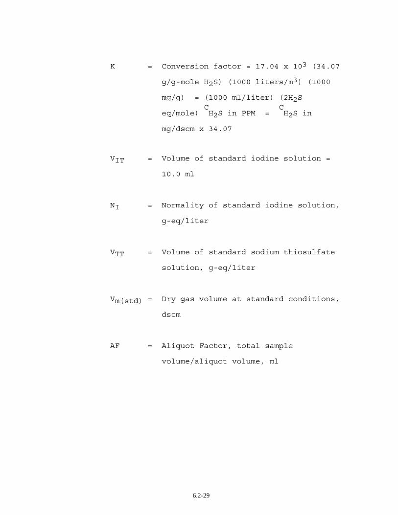
K = Conversion factor = 17.04 x 10³ (34.07 g/g-mole H2S) (1000 liters/m3) (1000 mg/g) = (1000 ml/liter) (2H2S C C eq/mole) H2S in PPM = H2S in mg/dscm x 34.07
VIT = Volume of standard iodine solution =
10.0 ml
NI = Normality of standard iodine solution,
g-eq/liter
VTT = Volume of standard sodium thiosulfate
solution, g-eq/liter
Vm(std) = Dry gas volume at standard conditions,
dscm
AF = Aliquot Factor, total sample
volume/aliquot volume, ml
6.2-29
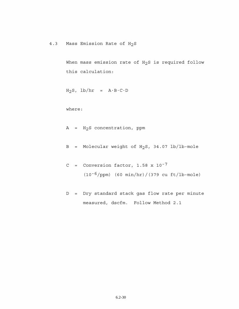
4.3 Mass Emission Rate of H2S
When mass emission rate of H2S is required follow
this calculation:
H2S, lb/hr = A·B·C·D
where:
A = H2S concentration, ppm
B = Molecular weight of H2S, 34.07 lb/lb-mole
C = Conversion factor, 1.58 x 10⁻⁷
(10-6/ppm) (60 min/hr)/(379 cu ft/lb-mole)
D = Dry standard stack gas flow rate per minute
measured, dscfm. Follow Method 2.1
6.2-30
6.2 - 31
6.1 - 32
6.1 - 33