Embed Size (px)
Citation preview

This paper is published as part of the high-profile series of PCCP special issues on Alternative Fuel Technologies.
Guest edited by Joachim Maier (MPI Guest edited by Joachim Maier (MPI Stuttgart), Dirk Guldi (Universität Erlangen-Nürnberg), and Adriano Zecchina (University of Torino), and published in selected 2007 print issues of PCCP, all papers are collected online on a dedicated website:
www.rsc.org/pccp/altfuel
Visit the website for both cutting edge research papers and authoritative review articles by leaders in a range of fields of critical importance to the world today
Publ
ishe
d on
09
May
200
7. D
ownl
oade
d by
New
Yor
k U
nive
rsity
on
07/1
0/20
14 2
2:06
:54.
View Article Online / Journal Homepage / Table of Contents for this issue
Hydrogen storage: the remaining scientific and technological challenges
Michael Felderhoff,*aClaudia Weidenthaler,*
aRittmar von Helmolt
band
Ulrich Eberleb
Received 31st January 2007, Accepted 17th April 2007
First published as an Advance Article on the web 9th May 2007
DOI: 10.1039/b701563c
To ensure future worldwide mobility, hydrogen storage in combination with fuel cells for on-
board automotive applications is one of the most challenging issues. Potential solid-state solutions
have to fulfil operating requirements defined by the fuel cell propulsion system. Important
requirements are also defined by customer demands such as cost, overall fuel capacity, refuelling
time and efficiency. It seems that currently none of the different storage solid state materials can
reach the required storage densities for a hydrogen-powered vehicle. New strategies for storage
systems are necessary to fulfil the requirements for a broad introduction of automotive fuel cell
powertrains to the market. The combination of different storage systems may provide a possible
solution to store sufficiently high amounts of hydrogen.
1. Introduction
One of the most crucial points concerning the implementation
of hydrogen-based propulsion systems is the on-board storage
of hydrogen. Although showing some drawbacks such as
higher cost and lower energy density compared to a gasoline
or diesel tank, hydrogen storage is much closer to automotive
cost and performance figures than a large-scale battery system.
Additionally, for some methods (in particular liquid hydrogen
LH2 and compressed gaseous CGH2), refuelling is possible in
less than 5 min, compared to the recharging times of many
hours for high-voltage batteries. Utilizing other hydrogen
storage techniques, refuelling times of less than 1 h are
achievable. Thus, the application of hydrogen and fuel cells
as electrical energy source has attracted researchers for a long
time. However, even after large efforts have been made both in
the scientific and industrial world during the last 10 years, a
ubiquitous solution for the on-board storage of hydrogen has
not yet been found. The specific requirements of different
applications such as vehicles, portable or stationary devices
need the development of completely different hydrogen sto-
rage approaches. The physical storage methods of hydrogen
under cryogenic temperatures or high-pressures (35 to
70 MPa) can only be used in systems where larger amounts
of hydrogen in the range of several kg have to be stored. The
related technology elements are too complex for incorporation
into consumer electronics products or power tools. In these
cases only chemical methods for the storage and release of
hydrogen from metal hydrides or from hydrolysis reactions
with complex hydrides can be used. In recent years, a very
large number of publications dealing with the different storage
methods have been published. Often the implementation of a
storage method into technical systems is even more an en-
gineering challenge than a question of the hydrogen storage
capacity of the utilized materials or the storage density of the
system. Long-term storage, heat conductivity problems, heat
management or the kinetics of the reloading and deloading
processes of metal hydrides are only some examples. Some of
these problems, often ignored in the literature, are discussed in
this review.
The PEM type (proton exchange or polymer electrolyte
membrane) fuel cell, originally invented in 1962 by General
Electric, was used during NASA’s Gemini space missions.
New electrolyte materials for this type of fuel cell offered the
possibility of a more compact and lightweight fuel cell system
and respective propulsion system. During the 1990s, several
car companies began to develop the PEM fuel cell for passen-
ger car propulsion systems. At that time, the motivation for
the development was mainly based on emissions reduction.
Very similar to pure battery-electric vehicles, all emissions
occur during fuel production, whereas the only local waste
product generated during driving is just water vapour. Though
power densities have already significantly increased over re-
cent years, fuel cells still are not fully competitive with today’s
high-performance internal combustion engines. But recently,
the power density of this kind of drivetrain became sufficient
for the propulsion of a wide variety of passenger car archi-
tectures. Now, cost reduction, robustness and durability have
to be addressed, as well as the issue of hydrogen storage. A
consensus within the automotive industry has emerged that
fuel cells and hydrogen are the ultimate long-term technology
solution; but to achieve full-scale commercialisation, technical
improvements are still required. In the meantime, continuous
improvements in internal combustion engines, and transition
technologies (such as the hybridization of powertrains), and
the introduction of renewable fuels (such as ethanol or syn-
thetic fuels produced from biomass) are beginning to diversify
the portfolio of powertrain and fuel options.
Since most of the world’s car manufacturers invest in
extensive research activities in hydrogen storage and PEM
aMax-Planck-Institut fur Kohlenforschung, Kaiser-Wilhelm Platz 1,45470 Mulheim/Ruhr, Germany. E-mail: [email protected]; [email protected]
bGM Fuel Cell Activities, Hydrogen & Fuel Cell Research Strategy(Europe), IPC MK-01, 65423 Ruesselsheim, Germany. E-mail:[email protected]; [email protected]
This journal is �c the Owner Societies 2007 Phys. Chem. Chem. Phys., 2007, 9, 2643–2653 | 2643
INVITED ARTICLE www.rsc.org/pccp | Physical Chemistry Chemical Physics
Publ
ishe
d on
09
May
200
7. D
ownl
oade
d by
New
Yor
k U
nive
rsity
on
07/1
0/20
14 2
2:06
:54.
View Article Online
fuel cell developments, the main focus of this review is on
hydrogen storage methods for automotive applications under
the boundary conditions of a fuel cell drivetrain. The concept of
hydrogen internal combustion engines (ICE) shall be men-
tioned just briefly. Although having some advantages concern-
ing infrastructure implications (dual-fuel engines—gasoline and
hydrogen—are feasible), and technology maturity, there exist
significant challenges regarding vehicle efficiencies and the H2
supply rates from the storage system to the IC engine. A fuel
cell powertrain has a 36% efficiency in the European Driving
Cycle (i.e. GM HydroGen3, 4.6 kg H2, 400 km range), the
corresponding diesel engine shows EDC efficiency values of
22%. That translates reciprocally into a higher fuel consump-
tion for the diesel–IC variant. To ensure the same vehicle range,
a hypothetical hydrogen-powered IC engine (assuming the
same efficiency as the conventional variant) would thus require
a storage system about 1.65 times larger than the one of a fuel
cell system. A similar relationship and a similar factor applies
for the hydrogen rate that the tank system has to supply to the
powertrain. Both points are very difficult to tackle: first, the
available space for the tank system on board of the vehicle is
very limited. Second, a higher extraction rate poses an even
more unfavourable heat management challenge on the hydro-
gen system. Also, the heat management challenge during
refueling is significantly more demanding for an IC engine
when a re-filling time of less than 5 min is targeted. Both heat
management issues will be addressed and discussed in detail in
the next section. For those reasons in general (and efficiency,
respectively, fuel consumption in particular), most car manu-
facturers concentrate their efforts on hydrogen fuel cell vehicles.
2. On-board hydrogen storage options by physical
methods
Before discussing different storage options, it has to be made
clear that all values for gravimetric and volumetric energy
densities may correspond either to (a) just a materials ap-
proach or (b) a systems approach including all required
components and mounts. The definitions for both approaches
(a) and (b) should not be confused. From an automotive
perspective, the second approach is preferable; also the target
values provided by the US Department of Energy (DOE) are
developed and published on that systems basis.1,2
In this section, conventional methods, as well as the frame-
work and pre-conditions for pure solid-state and hybrid
storage technologies will be discussed in detail. The material-
based issues will be addressed extensively in the following
sections.
At present, there are two major physical options for on-
board hydrogen storage:
(1) CGH2 compressed gaseous hydrogen (35–70 MPa and
room temperature).
(2) Cryogenic (LH2 liquid hydrogen at 20 to 30 K,
0.5–1 MPa).
In the past, both options (1) and (2) have been implemented
by the automotive industry in many prototype vehicles. For
being competitive in range to conventional gasoline or diesel-
based systems, typically 4–7 kg of hydrogen have to be stored
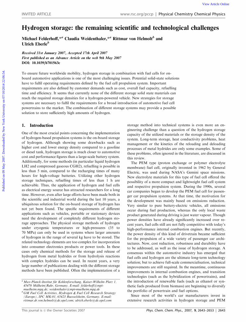
on board. This remains a serious issue for the vehicle integra-
tion since the density of hydrogen is rather low (Fig. 1), even
when compressed to 70 MPa. Furthermore, cylindrical vessels
are required for these two and most of the other types of
storage systems. In existing vehicle architectures, without
modifications, there is no space for hydrogen storage modules
which could provide sufficient range. Thus, rear body mod-
ifications are necessary to integrate the hydrogen tank. In an
extreme case, one could even imagine concepts where the car is
built around the hydrogen storage device. In other cases, for
vehicle packaging reasons, the fuel storage comprises not only
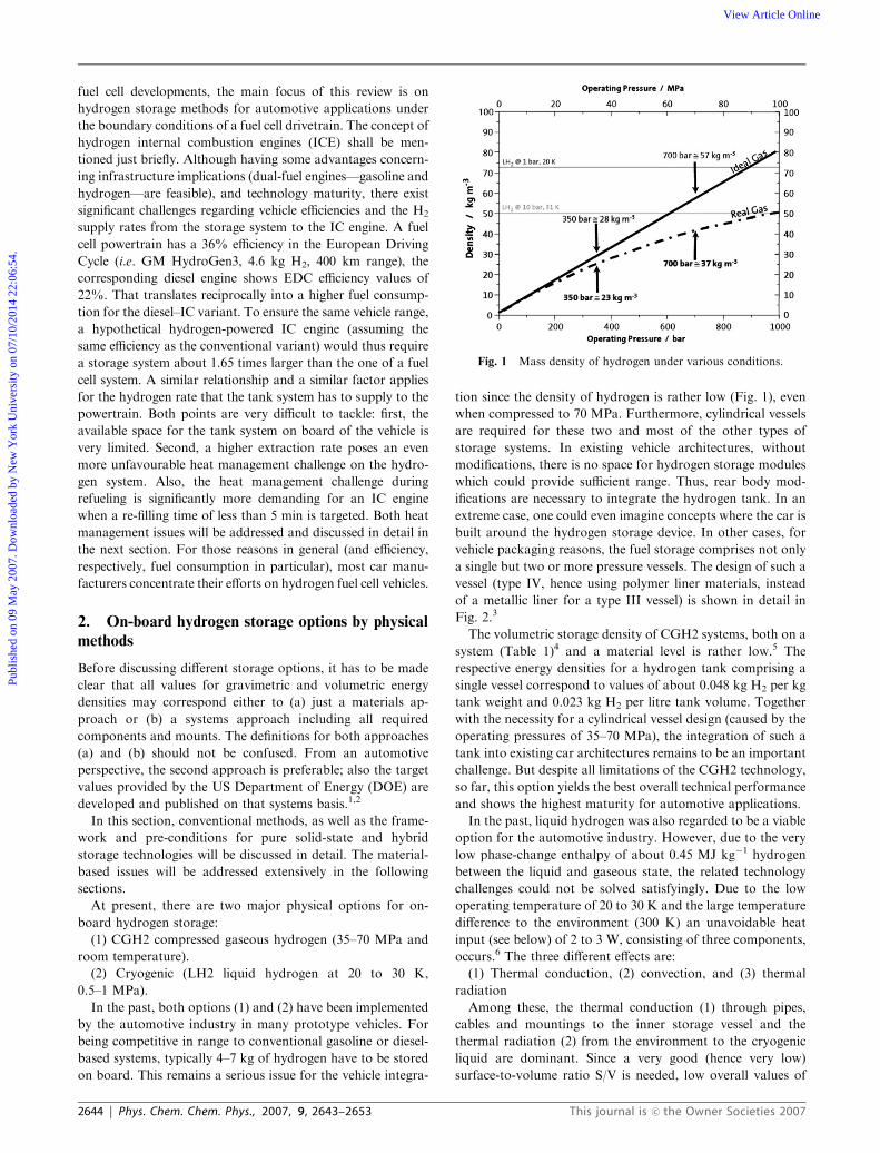
a single but two or more pressure vessels. The design of such a
vessel (type IV, hence using polymer liner materials, instead
of a metallic liner for a type III vessel) is shown in detail in
Fig. 2.3
The volumetric storage density of CGH2 systems, both on a
system (Table 1)4 and a material level is rather low.5 The
respective energy densities for a hydrogen tank comprising a
single vessel correspond to values of about 0.048 kg H2 per kg
tank weight and 0.023 kg H2 per litre tank volume. Together
with the necessity for a cylindrical vessel design (caused by the
operating pressures of 35–70 MPa), the integration of such a
tank into existing car architectures remains to be an important
challenge. But despite all limitations of the CGH2 technology,
so far, this option yields the best overall technical performance
and shows the highest maturity for automotive applications.
In the past, liquid hydrogen was also regarded to be a viable
option for the automotive industry. However, due to the very
low phase-change enthalpy of about 0.45 MJ kg�1 hydrogen
between the liquid and gaseous state, the related technology
challenges could not be solved satisfyingly. Due to the low
operating temperature of 20 to 30 K and the large temperature
difference to the environment (300 K) an unavoidable heat
input (see below) of 2 to 3 W, consisting of three components,
occurs.6 The three different effects are:
(1) Thermal conduction, (2) convection, and (3) thermal
radiation
Among these, the thermal conduction (1) through pipes,
cables and mountings to the inner storage vessel and the
thermal radiation (2) from the environment to the cryogenic
liquid are dominant. Since a very good (hence very low)
surface-to-volume ratio S/V is needed, low overall values of
Fig. 1 Mass density of hydrogen under various conditions.
2644 | Phys. Chem. Chem. Phys., 2007, 9, 2643–2653 This journal is �c the Owner Societies 2007
Publ
ishe
d on
09
May
200
7. D
ownl
oade
d by
New
Yor
k U
nive
rsity
on
07/1
0/20
14 2
2:06
:54.
View Article Online
heat flows can only be achieved when working with cylindrical
tank structures (compare to CGH2). Due to their even further
unfavourable ratio for the same hydrogen capacity, so called
conformable tanks with more complex shapes show inherently
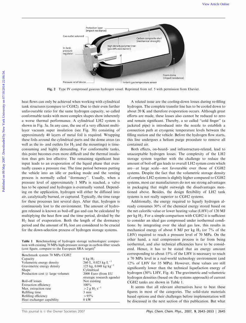
a worse thermal performance. A cylindrical LH2 system is
shown in Fig. 3a. In any case, the use of a very efficient multi-
layer vacuum super insulation (see Fig. 3b) consisting of
approximately 40 layers of metal foil is required. Wrapping
these foils around the cylindrical parts and the dome areas (as
well as the in- and outlets for H2 and the mountings) is time-
consuming and highly demanding. For conformable tanks,
this point becomes even more difficult and the thermal insula-
tion thus gets less effective. The remaining significant heat
input leads to an evaporation of the liquid phase that even-
tually causes a pressure rise. The time period between putting
the vehicle into an idle or parking mode and the venting
process is normally called ‘‘dormancy’’. Usually, when a
pressure level of approximately 1 MPa is reached, a valve
has to be opened and hydrogen is eventually vented. Depend-
ing on the application, hydrogen will either be diffused into
air, catalytically burned, or captured. Typically, the time range
for these processes last several days. After that, hydrogen is
continuously lost to the environment. The amount of hydro-
gen released is known as boil-off gas and can be calculated by
multiplying the heat flow and the time period, divided by the
H2 heat of evaporation. Both the length of the dormancy
period and the amount of H2 lost are considered to be crucial
for the down-selection process of hydrogen storage systems.
A related issue are the cooling-down losses during re-filling
hydrogen. The complete transfer line has to be cooled down to
about 20 K and therefore evaporation occurs. Although great
efforts are made, these losses also cannot be reduced to zero
and remain significant. Thereby, a so called ‘‘cold finger’’ (a
jacketed pipe) is introduced into the nozzle to establish a
connection path at cryogenic temperature levels between the
filling station and the vehicle. Before the hydrogen flow starts,
this line undergoes a helium purge procedure to remove all
contained air.
Both effects, on-board- and infrastructure-related, lead to
unacceptable hydrogen losses. The complexity of the LH2
storage system together with the challenge to reduce the
amount of boil-off gas leads to overall LH2 system costs which
are—at large scale—not favourable over those of CGH2
systems. Despite the fact that the volumetric storage density
of complete LH2 systems is slightly higher compared to CGH2
systems, most car manufacturers do not see strong advantages
in packaging that might outweigh the disadvantages men-
tioned above. Besides, the design flexibility of LH2 tank
systems is not really superior to CGH2 systems.
Additionally, the energy required to liquefy hydrogen al-
ready consumes 30% of the chemical energy stored based on
the net calorific value or lower heating value (LHV) of 120 MJ
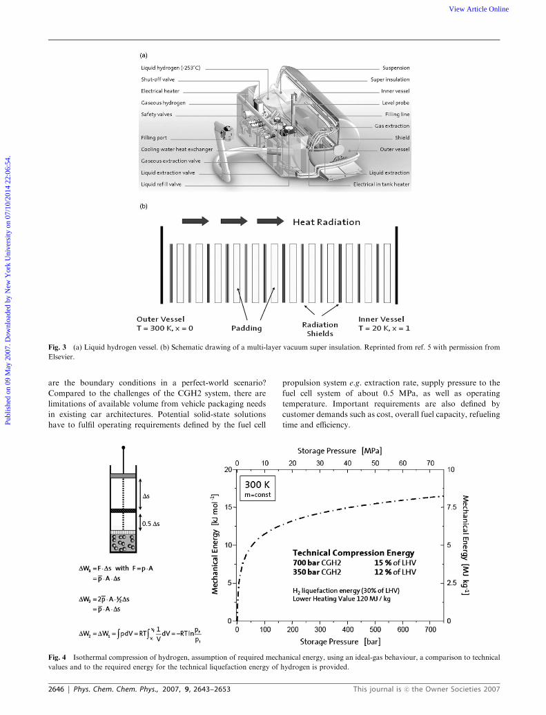
per kg H2. For a simple comparison with CGH2 it is sufficient
to consider an ideal gas compressed under isothermal condi-
tions: by integrating over the ideal gas law, this results in
mechanical energy of about 8 MJ per kg H2 (or 7% of the
LHV) required to reach a pressure level of 70 MPa. On the
other hand, a real compression process is far from being
isothermal, and also technical efficiencies have to be consid-
ered. Hence, it has to be stated that an energy amount
corresponding to about 15% of the LHV is necessary to reach
a 70 MPa level in a real-world technology environment (and
12% of LHV for 35 MPa). However, these values are still
significantly lower than the technical liquefaction energy of
hydrogen (30% LHV, Fig. 4). The gravimetric and volumetric
hydrogen densities (based on the systems approach) of current
CGH2 tanks are shown in Table 1.
It seems that all relevant alternatives have to beat these
figures in most of the categories. The solid-state materials
based options and their challenges before implementation will
be discussed in the next section of this publication. But what
Fig. 2 Type IV compressed gaseous hydrogen vessel. Reprinted from ref. 5 with permission from Elsevier.
Table 1 Benchmarking of hydrogen storage technologies: compar-ison with existing 70 MPa high-pressure storage in carbon-fiber vessels(cost figure, compare to the European SRA target)4
Benchmark system 70 MPa CGH2Capacity 6 kg H2
Volumetric energy density 260 L, 0.023 kg L�1
Gravimetric energy density 125 kg, 0.048 kg kg�1
Shape CylindricalProduction cost @ large volumes 2000 Euro (from EU
strategic research agenda)Boil-off losses Not existingExtraction efficiency 100%Max. extraction rate 42 g H2 s
�1
Refilling time 3 minRefilling efficiency 495%Heat exchanger capability 0 kW
This journal is �c the Owner Societies 2007 Phys. Chem. Chem. Phys., 2007, 9, 2643–2653 | 2645
Publ
ishe
d on
09
May
200
7. D
ownl
oade
d by
New
Yor
k U
nive
rsity
on
07/1
0/20
14 2
2:06
:54.
View Article Online
are the boundary conditions in a perfect-world scenario?
Compared to the challenges of the CGH2 system, there are
limitations of available volume from vehicle packaging needs
in existing car architectures. Potential solid-state solutions
have to fulfil operating requirements defined by the fuel cell
propulsion system e.g. extraction rate, supply pressure to the
fuel cell system of about 0.5 MPa, as well as operating
temperature. Important requirements are also defined by
customer demands such as cost, overall fuel capacity, refueling
time and efficiency.
Fig. 3 (a) Liquid hydrogen vessel. (b) Schematic drawing of a multi-layer vacuum super insulation. Reprinted from ref. 5 with permission from
Elsevier.
Fig. 4 Isothermal compression of hydrogen, assumption of required mechanical energy, using an ideal-gas behaviour, a comparison to technical
values and to the required energy for the technical liquefaction energy of hydrogen is provided.
2646 | Phys. Chem. Chem. Phys., 2007, 9, 2643–2653 This journal is �c the Owner Societies 2007
Publ
ishe
d on
09
May
200
7. D
ownl
oade
d by
New
Yor
k U
nive
rsity
on
07/1
0/20
14 2
2:06
:54.
View Article Online
3. Physisorption
3.1 Introduction
For the condensation of hydrogen weak van der Waals inter-
actions of hydrogen molecules are the driving forces. The heat
of condensation (0.9 kJ mol�1 H2) of hydrogen is rather low.
This is reflected by the low boiling point of hydrogen (20.4 K).
Physisorption of hydrogen on surfaces is dominated by
slightly stronger van der Waals interactions between hydrogen
molecules and the surface of the adsorbent. The heat of
adsorption for porous materials is in the range of about
4–10 kJ mol�1 H2.7 Interactions between hydrogen molecules
are only of importance at temperatures between the boiling
point and the critical temperature (33.25 K)8 of hydrogen.
Only in this temperature range, a liquid phase can be expected.
A potentially very high hydrogen uptake inside pores as a
result of capillary condensation is therefore considered to be
impossible. For this reason and since the van der Waals forces
are rather weak, no significant amount of hydrogen can be
stored at ambient temperature and pressure. Physisorption
results in the formation of a hydrogen monolayer on the
adsorbent surface due to the stronger interaction of the
hydrogen with the surface.9 Adsorption at a temperature equal
or higher than the boiling point (20.4 K) of hydrogen thus only
leads to the adsorption in a monolayer.10 Hence, a multi-layer
coverage at 77 K (or even at room temperature) cannot really
be expected because storage temperatures are far above the
boiling point of liquid hydrogen.11 This is indicated by the fact
that hydrogen adsorption isotherms are typically showing the
shape of a Langmuir isotherm (i.e. monolayer adsorption).12
For a monolayer coverage at 77 K, the mass of hydrogen
adsorbed under saturation conditions is generally propor-
tional to the specific surface area determined by the BET
method.9,13 As an example, graphene sheets with a specific
surface area of 1315 m2 g�1, adsorb a maximum amount of 2
wt% of hydrogen.9 The excess amount of hydrogen adsorbed
at 77 K from the gas phase in saturation is thus 1.5 (�0.5) �10�3 wt% m�2 g.
3.2 Carbon materials
The intrinsic properties of carbon materials, i.e. their low
densities, high porosities and high specific surface areas make
them interesting as adsorbents for hydrogen. In the 1990s
extraordinary high hydrogen uptakes for different carbon
materials were published by several groups. Hydrogen adsorp-
tion capacities up to 10 wt% due to condensation of hydrogen
inside narrow single wall nanotubes (SWNT) were reported,
even at ambient conditions.14,15 Unfortunately, the reproduc-
tion of these spectacular high uptake capacities by other
groups failed. Instead uptake capacities of only one third of
the reported ones were observed, and only at cryogenic
temperatures.16 For graphitic nanofibers capacities of about
67 wt% had been reported.17,18 However, those very promis-
ing capacities of graphitic nanofibers could never be con-
firmed,19–22 and may be attributed to erroneous
measurements.
Even though the early reports on hydrogen uptake of
carbon materials, as mentioned above, were very promising,
in the following only relatively low uptakes could be ob-
served.13,23–26 For SWNT a hydrogen capacity below 1 wt%
was achieved at 80 bar and room temperature.16 At lower
pressure of about 2 MPa only 0.1 wt% uptake was found.26
Low capacities were also measured for activated carbons
(maximum capacity 1.6 wt%) close to ambient conditions.
Zuttel et al. investigated the hydrogen storage capacity of
more than 60 carbon samples at room temperature.27 Depend-
ing on the type of graphite and the specific surface areas of the
carbon materials, the reversible storage capacity ranged from
0.04–0.46 wt%.
There are very controversial reports concerning the influ-
ence of micropore volume, size of micropores and surface area
on the hydrogen uptake. Even though there is a broad range of
hydrogen uptake for a wide variety of porous and nanostruc-
tured carbons, correlations between the sorption capacity,
specific surface area and/or micropore volume are reported.
A very comprehensive study on hydrogen adsorption of more
than 30 different porous materials (carbons, silica, alumina,
and MOFs) with respect to the specific surface area, total pore
volume and micropore volume was recently published.28 The
systematic analysis of all data obtained at 77 K and 0.1 MPa
indicates a clear dependence of the H2 uptake on the size of the
micropores and the micropore volume. In general, the hydro-
gen uptake seems to be limited by the adsorbate density, the
pore structure of the adsorbent, and the pore volume of the
narrowest pores. Materials with very high pore volumes do not
necessarily adsorb much hydrogen. This is assigned to lower
interaction energy of hydrogen in wide pores compared with
smaller micropores. Hydrogen storage is dominated by small
pores with a narrow size distribution and therefore a certain
scatter (dependent on the pore size distribution) of the storage
capacities around the general proportional trend line is ob-
served.29 Small pores (o1 nm) are most efficient for hydrogen
storage while mesopores (420 nm) do not contribute much to
the excess hydrogen capacity.
Hydrogen storage in carbon nanostructures close to ambi-
ent conditions seems to be limited to values far below those set
as a requirement of the DOE and the automotive industry due
to physical reasons. Unfortunately, there is no way to over-
come the fundamental laws of physics and it is thus futile to
claim higher capacities than theoretically possible.
So far, there are only limited possibilities of increasing the
adsorption capacities to fulfil the requirements for mobile
applications. One possible strategy to increase the hydrogen
uptake is the adjustment of the physical conditions for the
storage process. The physical procedures are either to decrease
the adsorption temperature to about 80 K, and/or to increase
the hydrogen pressure. Another way is to tune the properties
of the adsorbent which is mainly limited to an increase of the
surface area and/or an increase of the micropore volume of the
adsorbent.
3.3 Metal–organic frameworks (MOFs)
Metal–organic frameworks (MOFs) appeared as highly pro-
mising storage materials for hydrogen. These materials com-
bine both high surface areas and large micropore volumes. In
1989 Hoskins and Robson proposed a new class of solid
This journal is �c the Owner Societies 2007 Phys. Chem. Chem. Phys., 2007, 9, 2643–2653 | 2647
Publ
ishe
d on
09
May
200
7. D
ownl
oade
d by
New
Yor
k U
nive
rsity
on
07/1
0/20
14 2
2:06
:54.
View Article Online
polymeric materials later known as MOFs.30 Inorganic build-
ing units are connected by organic linkers such as carboxylates
forming a 3D network. One of the most prominent members
with a structure consisting of four Zn4O(CO2)6 units con-
nected by benzene rings is called MOF-5.31 Four ZnO4 tetra-
hedra are joined by benzene dicarboxylate linkers resulting in
a 3D cubic framework with interconnected pores. The high
microporosity and a very high specific surface area make
MOFs interesting for physisorption processes. In early studies,
hydrogen uptakes of 1.98 wt% at 77 K and 0.1 MPa for
[Zn3(bpdc)3bpy] � 4DMF �H2O and 1.74 wt% for
[Co3(bpdc)3bpy] � 4DMF �H2O were reported.32 Higher up-
takes of 2.47 wt% at 1 bar and 77 K were obtained for
Cu–MOF (MOF-505).33 Actually, for MOF-5 exhibiting a
very high specific BET surface area of 2296 m2 g�1 an uptake
of 5.1 wt% at 5 MPa and 77 K could be independently
reproduced.34
Recently, for MOF-177 with a framework of zinc acetate
units linked by 1,3,5-benzenetribenzoate (BTB) with an esti-
mated Langmuir surface area of 4500 m2 g�1,35 a storage
capacity of 7.5 wt% at 7 MPa and 77 K was measured.36 This
is by far one of the highest surface areas and therewith the
highest hydrogen storage capacity for MOFs. The capacities
are even better than for high-performance activated carbons
such as AX-21 and Maxsorb MSC-30. Not only the surface
area but also the nature of organic linkers and the inorganic
units seem to have an influence on the storage capacity of the
MOFs at low pressures (before the saturation value of the
isotherm is reached).
3.4 Hydrogen storage in zeolites
The crystal structure of zeolites is defined by channels and
cavities which, if they are interconnected, form a pore system
large enough for diffusion of molecules or ions. Zeolites
possess large micropore volumes making them potential can-
didates for the storage of hydrogen. For zeolites two ways for
storing hydrogen are discussed: encapsulation and adsorp-
tion.37 The process first involves the diffusion of hydrogen
molecules into channels and cages (voids) of the structure. One
of the very first proposing zeolites as material for the encap-
sulation of hydrogen was Fraenkel.38,39 In the following years,
many different ion-exchanged zeolites were tested as potential
hydrogen storage materials.40–42 Trapping hydrogen is only
possible by increasing temperature and/or pressure. Under
ambient conditions, the molecules stay entrapped in the voids
by diffusion limitation. Vitillo et al. give a survey on zeolites
studied for the encapsulation of hydrogen.37 The uptake of
hydrogen by adsorption is below 0.5 wt% at ambient condi-
tions and below 2 wt% at 77 K and elevated pressures. The
authors calculated the maximum amount of hydrogen stored
either by encapsulation or by adsorption. Geometric con-
straints such as, for example, available volume and framework
flexibility restrict the hydrogen storage capacities of zeolites to
2.86 wt%. The theoretical calculations are supported by
experimental results. Unfortunately, almost no hydrogen can
be stored at room temperature and even at cryogenic tem-
peratures, the capacities are low. The influence of the frame-
work structure and the type of exchangeable cations on the
capacity was the topic of several publications. For all systems,
at low hydrogen loadings, the cell volume of the zeolite
decreases due to attractive forces between adsorbent and
adsorbate. After reaching a minimum, the volume increases
with increasing loading. This is due to a complete filling of the
free volume of the zeolite. Even starting with different geome-
tries, the filling curves all follow the same trend. The nature of
the extra framework cations seems to have an influence on the
hydrogen uptake.43 For zeolite A and RHO pore blocking by
large cations is the factor restricting the uptake of hydrogen.
More open structures as zeolite X and Y show no pore
blocking effects. However the highest uptake, observed for
Ca-exchanged zeolite X is about 2.2 wt% at 77 K and 1.5
MPa. Li-containing low silica zeolites show a capacity of 1.5
wt% at 77 K and 0.1 MPa.44 However, even though at first
glance microporous zeolites seemed to be promising materials
for hydrogen storage, the capacities and experimental require-
ments are unfavorable to make them real storage materials.
3.5 Summary of physisorption
As this short review of the literature shows, there is much
experimental evidence for the very limited hydrogen adsorp-
tion capacity of carbon materials, MOFs or zeolites close to
ambient conditions, confirming the theoretical limitations due
to physical reasons. It is a moot question whether it is
advisable to put too much effort in further detailed investiga-
tions of the hydrogen uptake of carbon materials at room
temperature. Even materials with higher surface areas are far
from providing sufficiently high storage capacities of more
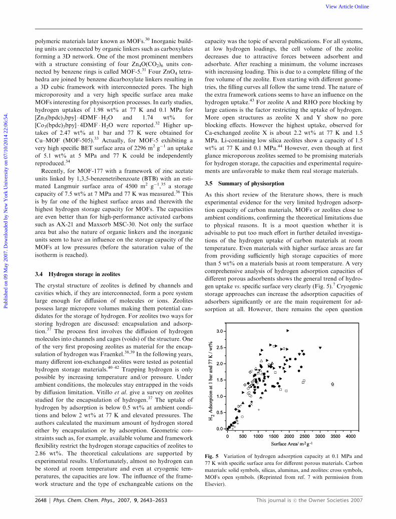
than 5 wt% on a materials basis at room temperature. A very
comprehensive analysis of hydrogen adsorption capacities of
different porous adsorbents shows the general trend of hydro-
gen uptake vs. specific surface very clearly (Fig. 5).7 Cryogenic
storage approaches can increase the adsorption capacities of
adsorbers significantly or are the main requirement for ad-
sorption at all. However, there remains the open question
Fig. 5 Variation of hydrogen adsorption capacity at 0.1 MPa and
77 K with specific surface area for different porous materials. Carbon
materials: solid symbols, silicas, aluminas, and zeolites: cross symbols,
MOFs open symbols. (Reprinted from ref. 7 with permission from
Elsevier).
2648 | Phys. Chem. Chem. Phys., 2007, 9, 2643–2653 This journal is �c the Owner Societies 2007
Publ
ishe
d on
09
May
200
7. D
ownl
oade
d by
New
Yor
k U
nive
rsity
on
07/1
0/20
14 2
2:06
:54.
View Article Online
whether extremely low temperatures necessary for adsorption
of hydrogen fulfil the requirements for a reasonable energy
balance of the storage process, especially at the site of the
filling station. Another challenge, as for any solid state absor-
ber, is the kinetics of both dehydrogenation and rehydrogena-
tion processes and the related engineering burden to achieve
re-filling times shorter than 5 min.
A problem which is very often ignored concerns the techni-
cal problem of heat released by the storage process. A simple
calculation shows the inherent challenges of hydrogen adsorp-
tion using a liquid-nitrogen based heat exchanger to ensure an
operating temperature of 77 K. The heat of adsorption of
hydrogen on a surface is, depending on the adsorbent, in the
range between 4–10 kJ mol�1 H2. During the storage process
of 6 kg H2 heat in the order of magnitude of 12–30 MJ is
produced. When keeping the operating temperature constant,
this large amount of heat can only be removed by the
evaporation of liquid nitrogen. For nitrogen, the heat of
vaporization is 5.6 kJ mol�1 N2. To remove the heat released
during the adsorption of hydrogen high amounts of liquid
nitrogen are necessary. For 4 kJ mol�1 H2, 2200 mol N2
corresponding to 80 kg liquid nitrogen are required. About
200 kg of liquid nitrogen would be necessary if the heat of
adsorption would be close to the higher values. This extremely
large quantity of liquid nitrogen required for cooling purposes
causes severe engineering challenges. Therefore, more sophis-
ticated heat management technologies and tank operating
strategies (compared to a conventional 77 K LN2 dewar) are
required to provide a technically convenient way for storing
acceptable amounts of hydrogen. On a materials basis, about
10 wt% excess hydrogen capacity (at 77 K and 20 bar) and a
volumetric hydrogen density of minimum 35 g L�1 are needed
for such a system.
4. Hydrogen storage in chemical hydrides
4.1 Introduction
Chemical and metal hydrides exhibit an impressive volumetric
hydrogen density on a materials basis.5 To be competitive with
the very short refueling times of about two minutes for a
gasoline or diesel-based propulsion system, hydrogen based
systems have to overcome engineering challenges. Considering
a 6 kg H2 tank system (Table 1) utilizing a solid state absorber
M with an enthalpy of formation DH of about 20 MJ kg�1 H2
(typical for many hydrides), a thermal load of 120 MJ would
has to be compensated during refuelling:
MþH2 !MH2 þ DH
This leads to an average heat exchanger power of more than
600 kW. Such a high-performance device is not imaginable to
be installed on-board a vehicle due to cost, volume and weight
reasons. Typically, values less than 100 kW would be reason-
able for an automotive application. Assuming the driving
operating mode under full load, it is necessary to guarantee
a H2 supply rate of 2 g s�1 to the fuel cell propulsion. This
involves a heat management challenge of about 40 kW to be
supplied to the tank system.
Another restriction is that many solid state absorber sys-
tems, in particular many hydride systems, require operating
pressures of just below or above 10 MPa (at least during
refuelling). Hence an additional pressure container made of
advanced components such as carbon composites is necessary.
The perfect metal hydride system for an automotive applica-
tion store has to store more than 6 wt% hydrogen near room
temperature and with an equilibrium pressure of approxi-
mately 1 MPa. From the van’t Hoff equation the reaction
enthalpy and equilibrium pressure can easily be calculated
using the standard entropy of 130 J mol�1 K�1 for H2. At an
equilibrium pressure of 1 MPa of hydrogen the reaction
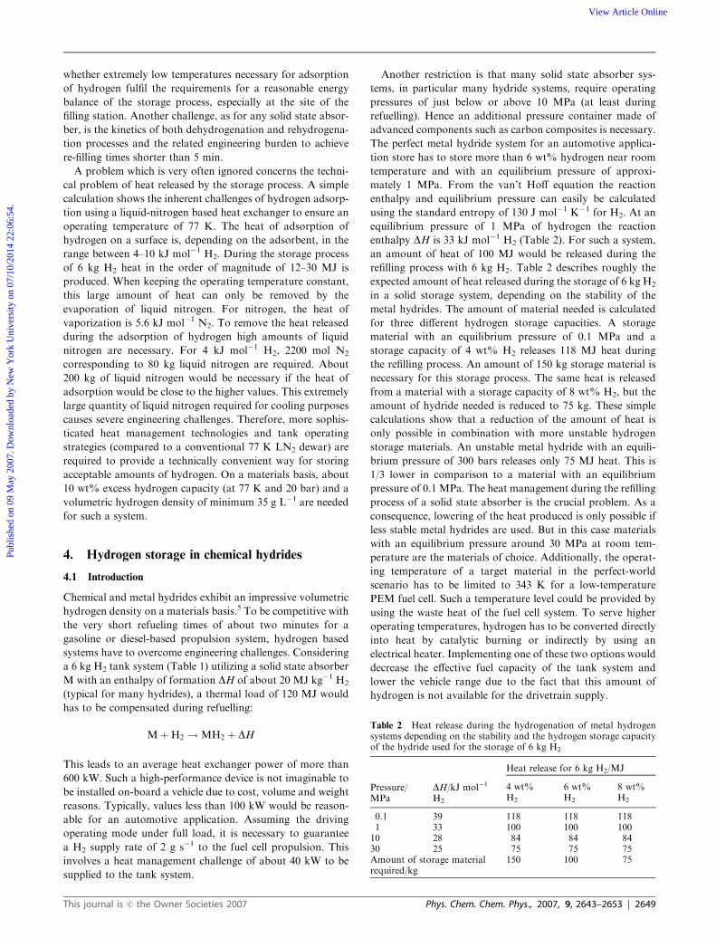
enthalpy DH is 33 kJ mol�1 H2 (Table 2). For such a system,
an amount of heat of 100 MJ would be released during the
refilling process with 6 kg H2. Table 2 describes roughly the
expected amount of heat released during the storage of 6 kg H2
in a solid storage system, depending on the stability of the
metal hydrides. The amount of material needed is calculated
for three different hydrogen storage capacities. A storage
material with an equilibrium pressure of 0.1 MPa and a
storage capacity of 4 wt% H2 releases 118 MJ heat during
the refilling process. An amount of 150 kg storage material is
necessary for this storage process. The same heat is released
from a material with a storage capacity of 8 wt% H2, but the
amount of hydride needed is reduced to 75 kg. These simple
calculations show that a reduction of the amount of heat is
only possible in combination with more unstable hydrogen
storage materials. An unstable metal hydride with an equili-
brium pressure of 300 bars releases only 75 MJ heat. This is
1/3 lower in comparison to a material with an equilibrium
pressure of 0.1 MPa. The heat management during the refilling
process of a solid state absorber is the crucial problem. As a
consequence, lowering of the heat produced is only possible if
less stable metal hydrides are used. But in this case materials
with an equilibrium pressure around 30 MPa at room tem-
perature are the materials of choice. Additionally, the operat-
ing temperature of a target material in the perfect-world
scenario has to be limited to 343 K for a low-temperature
PEM fuel cell. Such a temperature level could be provided by
using the waste heat of the fuel cell system. To serve higher
operating temperatures, hydrogen has to be converted directly
into heat by catalytic burning or indirectly by using an
electrical heater. Implementing one of these two options would
decrease the effective fuel capacity of the tank system and
lower the vehicle range due to the fact that this amount of
hydrogen is not available for the drivetrain supply.
Table 2 Heat release during the hydrogenation of metal hydrogensystems depending on the stability and the hydrogen storage capacityof the hydride used for the storage of 6 kg H2
Pressure/MPa
DH/kJ mol�1
H2
Heat release for 6 kg H2/MJ
4 wt%H2
6 wt%H2
8 wt%H2
0.1 39 118 118 1181 33 100 100 10010 28 84 84 8430 25 75 75 75Amount of storage materialrequired/kg
150 100 75
This journal is �c the Owner Societies 2007 Phys. Chem. Chem. Phys., 2007, 9, 2643–2653 | 2649
Publ
ishe
d on
09
May
200
7. D
ownl
oade
d by
New
Yor
k U
nive
rsity
on
07/1
0/20
14 2
2:06
:54.
View Article Online
The hydrogen content of more than 6 wt% excludes all
interstitial metal hydrides (LaNi5, TiFe) as storage materials,
because of their low storage capacities. On the other hand,
materials with high hydrogen content (MgH2) have high
decomposition temperatures which cannot be reached with a
PEM fuel cell.
An often proposed way out of this dilemma is the decom-
position of hydrogen-rich compounds such as sodium boro-
hydride, ammonia borane, or alane. Although these compounds
might be quite different, the challenges regarding their utiliza-
tion are similar. These days, the automotive industry has
evaluated these materials to be not viable for three or four
reasons, respectively:
(1) Inherent system complexity concerning the handling of
the decomposition process and the storage of the waste
material on-board.
(2) Infrastructure implications (a fuel cartridge capable of
storing 5 kg of hydrogen would weigh at least 50 kg when a
10% material storage density is assumed. Furthermore, the
vessel itself and other system components would add weight
and volume.
(3) Recycling and energy issues: typically, the waste material
ends in a deep thermodynamic sink, therefore in most cases no
reasonable cost- and energy-effective recycling process exists.
(4) Safety issues when a storage material is operated far
from its equilibrium conditions (may not apply to all concepts
mentioned above).
Since the first publication from Bogdanovic and Schwick-
ardi about Ti-doped NaAlH445 new research activities in
hydrogen storage systems have started. Complex metal hy-
drides, amides and thermodynamic tailored systems are now
the focus of research.
4.2 Borohydrides
Complex borohydrides, as for example the most commonly
used NaBH4, are materials with high hydrogen content (10.8
wt% for NaBH4). However, most of the borohydrides show
unfavourable thermodynamic properties and therefore cannot
be used as reversible hydrogen storage materials under accep-
table technical conditions. The thermal decomposition tem-
perature of NaBH4 around 673 K is much too high for PEM-
fuel cell applications (eqn (1)).
NaBH4 �!400 �C
NaHþ Bþ 1:5H2 ð1Þ
Compared to the complex aluminium hydride compounds the
thermal decomposition of complex borohydrides occurs in a
one step mechanism without the formation of any intermedi-
ate complex. The final products of the decomposition are
binary metal hydrides and elemental boron. Sometimes poly-
nuclear boron hydrides are formed. The formation of traces of
boron hydrogen compounds (BH3 or the dimerization product
B2H6) during the thermal decomposition can be a problem,
due to poisoning of the fuel cell catalyst and the destruction of
the membrane. Alternatively to the thermal decomposition
complex sodium, borohydrides can be used for the production
of hydrogen in a hydrolysis reaction with water.46,47 In this
case half of the released hydrogen originates from the water
and increases the hydrogen capacity of the whole system. Low
amounts of sodium hydroxide stabilize the NaBH4–water
solution and this mixture can be stored for a long time without
decomposition. For the decomposition a catalyst such as a Ru
compound is necessary. The final product of the hydrolysis of
NaBH4 is sodium metaborate NaBO2 (eqn (2)). The solubility
of NaBO2 in water is only 26 g/100 ml at 293 K, whereas
NaBH4 has a solubility of 55 g/100 ml at 293 K. To prevent
precipitation from the solution and blocking of active sides of
the catalyst, the NaBH4 concentration used must be lower
than the maximum solubility of the metaborate.48 A typical
composition of a commercial NaBH4 aqueous solution (Mil-
lennium Cell) is 20% NaBH4 and 1% NaOH for stabilization
of the solution. This low concentration of NaBH4 reduces the
storage capacity to 4 wt% for the whole hydride system.
NaBH4 þ 2H2O! 4H2 þNaBO2 ð2Þ
One significant barrier to the broad introduction of NaBH4 as
a hydrogen releasing material is the high price for the desorbed
hydrogen and the regeneration of the hydride from the
metaborate solution. The metaborate NaBO2 is a thermody-
namic sink with a heat of formation of DH=�1058 kJ mol�1.
For NaBH4 the heat of formation DH is �191 kJ mol�1. The
DDH for the preparation of NaBH4 starting from NaBO2 is
about 900 kJ mol�1. This energy amount is required for the
regeneration process in terms of chemical or other types of
energy and makes the process quite expensive. In practice the
NaBO2 is dissolved in water and cannot regenerate to NaBH4
in a water solution. A high additional amount of energy is
necessary for boiling off the water and drying the metaborate.
One additional problem could be the residue of sodium
hydroxide in the reaction mixture. Different studies for the
regeneration of NaBH4 from the NaBO2 or Na2B4O7 have
been published. At temperatures between 623–973 K and
hydrogen pressures of 7 MPa the reaction of NaBO2 with
MgH2 or MgSi regenerates NaBH4. Depending on the reac-
tion time, up to 98% yield can be obtained.49 Starting from a
boron oxide compound, NaBH4 can be prepared by the
reduction with MgH2 in a ball-milling process.50 The regen-
eration processes of NaBH4 are not clean processes. The by-
products MgO and/or SiO2 have to be separated and regen-
erated. However, all these regeneration processes are far away
from any industrial application. From all these disadvantages
it seems that NaBH4 is an interesting hydrogen carrier materi-
al for very special applications. But the high price and the
impossibility of an on-board rehydrogenation of the material
excludes the material for automotive applications. One other
interesting application of NaBH4–water solution is the usage
and development of the direct boron hydride fuel cell, where
the direct anodic oxidation of borohydride provides a more
negative potential than a H2 PEM fuel cell.51 However, there
are still ongoing research activities in this field.
4.3 Complex aluminium hydrides
Complex aluminium hydrides are attractive materials for
hydrogen storage because of their high hydrogen content,
reaching more than 10 wt% in LiAlH4 on a materials basis.
Complex aluminium hydrides are used in thermal decomposi-
tion reactions for the production of hydrogen. None of the
complex aluminium hydrides can be used in water solutions
2650 | Phys. Chem. Chem. Phys., 2007, 9, 2643–2653 This journal is �c the Owner Societies 2007
Publ
ishe
d on
09
May
200
7. D
ownl
oade
d by
New
Yor
k U
nive
rsity
on
07/1
0/20
14 2
2:06
:54.
View Article Online
like NaBH4, because all these materials react vigorously with
water and other protic solvents.
Most of the complex aluminium hydrides decompose in a
three step mechanism as shown for sodium aluminium hydride
in eqn (3). During the decomposition, Al metal and the
hexahydride Na3AlH6 as intermediate product are observed.
In the case of NaAlH4 the temperature of the second decom-
position step is too high for any usage in combination with
low-temperature PEM fuel cells with a working temperature
around 353 K. This reduces the usable hydrogen content to 3.6
wt% for the NaAlH4. Sometimes, like for Mg(AlH4)2 the
intermediate product cannot be observed and the product of
the decomposition is the alkaline or alkaline earth metal
hydride.
Apart from the hydrogen content of the complex systems
the thermodynamics of these materials is more important.
Unfortunately most of the known complex aluminium hy-
drides have unfavourable thermodynamic properties for re-
versible de- and rehydrogenation. For example, the first
decomposition step from the tetrahedral LiAlH4 to the octa-
hedral Li3AlH6 complex hydride is exothermic, which means
that LiAlH4 is a thermodynamically metastable material at
room temperature with an equilibrium pressure far away from
technical conditions.52,53 Because the decomposition is kineti-
cally hindered, LiAlH4 can be handled under normal condi-
tions. It has been shown that LiAlH4 decomposes slowly at
room temperature or immediately under the influence of a
catalyst.54 The same reasons excluded Mg(AlH4)2 as a rever-
sible hydrogen storage material. It decomposes in a one step
reaction to MgH2 and Al releasing the theoretical amount of 7
wt% of hydrogen. The decomposition enthalpy of this materi-
al is in the range of 0 kJ mol�1 Mg(AlH4)2 which again is much
too low for a reversible material.55–57
3NaAlH4 !Na3AlH6 þ 2Alþ 3H2
Na3AlH6 ! 3NaHþAlþ 1:5H2
3NaH! 3Naþ 1:5H2
ð3Þ
At present NaAlH4 is the only important reversible complex
metal hydride with high hydrogen content (5.6 wt% for the
first two decomposition steps), a decomposition temperature
near the working temperature of a PEM fuel cell and potential
low prices for the compounds NaH and Al metal, which are
the basic materials for the preparation of NaAlH4. To improve
the kinetics of the decomposition and the more important
rehydrogenation the reaction must be catalysed by addition of
titanium compounds. Starting from NaH, Al and TiCl3 as
catalyst and ball-milling under hydrogen pressure, refilling
times lower than 10 min for more than 90% of the hydrogen
content can be achieved.58 But temperatures of 403 K and
10 MPa of hydrogen are necessary. With other transition
metal chlorides e.g. ScCl3 or CeCl3 higher reversible hydrogen
contents and lower rehydrogenation times can be reached.59,60
But in all cases catalyst amounts in the range of 2–4 mol% and
hydrogen pressures around 10 MPa are necessary.
In combination with a PEM fuel cell NaAlH4 can release
hydrogen only from the first decomposition step, when the
waste heat of the fuel cell is used for heating up the alanate
tank. To overcome this problem, high-temperature PEM fuel
cells (i.e. based on polybenzimidazole membranes) could be
used.61 If such a novel membrane could be operated at
temperatures up to 473 K (and would show the same 353 K
performance values of current Nafion-related membranes), the
excess heat from the fuel cell could be used to generate
hydrogen from material from both decomposition steps of
the NaAlH4 material. At a working temperature of 423 K the
dissociation pressure of the first step is 6 MPa and 0.3 MPa for
the second step.62 These values would be high enough to
provide a sufficient supply pressure for the fuel cell system.
The other main challenge is the heat release during the filling
process of a deloaded material as stated in the introduction of
this chapter.
4.4 Lithium amide/imide
Other interesting hydrogen storage systems with high hydro-
gen content are the amide/imide compounds of the light
elements. Starting from Li3N this material can store two moles
of hydrogen with a theoretical capacity of more than 10 wt%
on a materials basis (eqn (4)).63
Li3Nþ 2H2 ! Li2 NHþ LiHþH2 ! LiNH2 þ 2LiH ð4Þ
Over a temperature range from 373 up to 523 K 9.3 wt% of
hydrogen can be achieved. But the equilibrium pressure of this
material is very low with only 0.15 MPa at a temperature of
528 K. During the last few years extensive investigations have
shown that the amide, hydride and composition of the mixture
can be varied over a wide range of elements and compositions.
One other interesting example is the ternary Li–Mg–N–H
system.64,65 According to eqn (5) this system can reversible
desorb and absorb 2 mol of hydrogen, with a theoretical
hydrogen storage capacity of 5.5 wt%. In reality, hydrogen
storage capacities around 4.5 wt% at temperatures up to 473
K for the reloading and deloading process are observed.
MgðNH2Þ2 þ 2LiH ! Li2MgN2H2 þ 2H2 ð5Þ
The equilibrium pressure was determined from a van’t Hoff
plot to be 0.1 MPa close to 360 K. This is much closer to
technical requirements, but it does not fit with the working
conditions of a conventional state-of-the-art PEM fuel cell
which needs a hydrogen pressure of approximately 0.5 MPa.
One important issue related to applications of the amide/
imide system in combination with a fuel cell is the production
of small amounts of ammonia during the decomposition step.
Ammonia reacts with the acid groups of the fuel cell mem-
brane and therefore reduces the proton conductivity of the
system.66 On the other hand, a fuel cell system is not very
tolerant towards ammonia contaminations since the pH value
of the fuel cell is shifted and therefore its operating conditions
are altered unfavourably. The order of magnitude of the
ammonia impurities in the desorbed H2 gas from the Li–N–H
system with ammonia was estimated via Raman spectroscopy
to be 0.1% at any temperature up to 673 K in a closed
system.67 Recently it was found that NH3 concentrations of
180 ppm at 453 K and 720 ppm at 513 K were produced during
the self-decomposition of amides formed by the reaction of the
educts in the system: 2 LiNH2 + MgH2.68
This journal is �c the Owner Societies 2007 Phys. Chem. Chem. Phys., 2007, 9, 2643–2653 | 2651
Publ
ishe
d on
09
May
200
7. D
ownl
oade
d by
New
Yor
k U
nive
rsity
on
07/1
0/20
14 2
2:06
:54.
View Article Online
4.5 Thermodynamic tailored systems
Thermodynamic tailoring is a well known chemical concept to
stabilize or destabilize hydride systems. With the addition of a
second component new reaction pathways with different ther-
modynamic properties are opened. One typical example is the
2:1 mixture of LiBH4 and MgH2, which decomposes accord-
ingly to eqn (6) to lithium hydride and magnesium boride.69
2 LiBH4 þMgH2 ! 2LiHþMgB2 þ 4H2 ð6Þ
LiBH4 contains more than 18 wt% of hydrogen on a materials
basis, but the decomposition temperature is in the range of
653 K and the laws of thermodynamics do not allow the
hydrogenation of the mixture LiH + B after a thermal
decomposition of the boron hydride under acceptable
technical conditions. With the addition of MgH2 to the
lithium borohydride the right side of the reaction is stabilized
or, in other words, LiBH4 is destabilized. The result is a
reduction of the decomposition enthalpy for the system about
25 kJ mol�1 of H2 in comparison to the pure LiBH4. The
decomposition temperature is still too high and the equili-
brium pressure still too low for a technical application. This
example shows in principle how the thermodynamics of a
metal hydride system can be influenced with the addition of a
second compound. Once again the heat effect is still important
for a thermodynamically tailored system and the same heat as
that in alanates is released if such a system will meet the
technical requirements.
4.6 Aluminium hydride, AlH3
A thermodynamic unstable but kinetically stabilized hydrogen
storage material is AlH3 with a hydrogen storage capacity of
10 wt% on a materials basis. This is twice the storage capacity
of Ti-doped NaAlH4. Above 373 K the H2 evolution of
undoped AlH3 is high enough to exceed the flow target for a
50 kW fuel cell.70 But the main problem of AlH3 is the
regeneration of the material. AlH3 cannot be prepared in a
direct synthesis starting from Al metal and hydrogen under
reasonable technical conditions. Regeneration must be done
outside the tank system using conventional organometallic
syntheses. Such reaction pathways are expensive and excluded
AlH3 for wide use in automotive applications.
4.7 Conclusion: hydrides
For all known solid state materials it must be noted that the
heat production during the refilling process poses a severe
challenge that due to thermodynamic restrictions may be
difficult to be overcome. This heat depends only on the
amount of stored hydrogen and is from a first approximation
independent of the solid material. A lower heat amount is
combined with a more unstable metal hydride system and as a
result the operating pressure inside the tank system must be
much higher.
The ‘‘right’’ solid state material for hydrogen storage for the
automotive application is unknown to date. The target mate-
rial has to offer better properties in most (but not in all)
categories than the competing CGH2 technology. In particu-
lar, a higher volumetric density on a systems level and a lower
operating pressure compared to 70 MPa would be highly
anticipated. For different applications and requirements, a
large variety of solid state materials are available. Irreversible
materials, like NaBH4, which produce hydrogen through
hydrolysis reactions have their uses in niche applications. They
will probably not be used in large-scale automotive applica-
tions due to the infrastructure and recycling implications. In
this case, reversible storage compounds are the materials of
choice. Apart from the more than 30 years old classical metal
hydrides, none of the systems with higher hydrogen content
have reached maturity for commercial applications. Ongoing
research on the known systems and the search for new
materials as well as engineering aspects are important to bring
solid state hydrogen storage materials into the market.
5. Summary
It seems that currently none of the different storage solid state
materials can reach the required storage densities for a fuel-cell
powered vehicle. The state-of-the-art 70 MPa CGH2 technol-
ogy has been established as the benchmark by the automotive
industry. The development of storage systems which combine
chemical and physical methods, so-called hybrid approaches
(i.e. the combination of a classical hydride with a 35 MPa
pressure vessel), are potential solutions. What are the lessons
to be learned from the properties of the known material classes
and are therefore the objectives for future research:
(1) Heat of formation has to be reduced to as low as
thermodynamically possible.
(2) Operating temperature should be limited to 343 K.
(3) Operating pressure should be limited to values less than
5 MPa for cryogenic temperatures or elevated temperatures
(up to 343 K).
(4) Operating pressure should be less than 35 MPa for
room-temperature applications using low DH hydrides.
These points should be used as orientation values for any
breakthrough materials. If such a target material could be
discovered, it would simplify the automotive packaging chal-
lenges significantly, especially when addressing an optimized
trade-off between the integration of the storage system into an
existing mass-production architecture and the consideration of
a purpose-built vehicle optimized for hydrogen as a fuel.
References
1 U. Eberle, G. Arnold and R. von Helmolt, J. Power Sources, 2006,154, 456–460.
2 Grand Challenge for Basic and Applied Research in HydrogenStorage 2003 (http://www.eere.energy.gov/hydrogenandfuelcells/pdfs/1_milliken_final.pdf).
3 Quantum Technologies, Inc., Irvine.4 SRA Strategic Research Agenda of the European Hydrogen andFuel Cell Technology Platform (https://www.hfpeurope.org/).
5 R. von Helmolt and U. Eberle, J. Power Sources, 2007, 165,833–843.
6 J. Zhang, T. S. Fisher, P. V. Ramachandran, J. G. Gore and I.Mudawar, J. Heat Transfer, 2005, 127, 1391–1399.
7 K. M. Thomas, Catal. Today, 2007, 120, 389–398.8 W. B. Leung, N. H. March and H. Motz, Phys. Lett. A, 1976, 56,425–426.
9 A. Zuttel, Naturwissenschaften, 2004, 91, 157–172.10 S. Brunauer, P. H. Emmett and E. Teller, J. Am. Chem. Soc., 1938,
60, 309–319.11 L. Zhou, Renew. Sust. Energ. Rev., 2005, 9, 395–408.
2652 | Phys. Chem. Chem. Phys., 2007, 9, 2643–2653 This journal is �c the Owner Societies 2007
Publ
ishe
d on
09
May
200
7. D
ownl
oade
d by
New
Yor
k U
nive
rsity
on
07/1
0/20
14 2
2:06
:54.
View Article Online
12 D. K. Ross, Vacuum, 2006, 80, 1084–1089.13 R. Strobel, J. Garche, P. T. Moseley, L. Lorissen and G. Wolf, J.
Power Sources, 2006, 159, 781–801.14 A. C. Dillon, K. M. Jones, T. A. Bekkedahl, C. H. Klang, D. S.
Bethune, C. H. Klang, D. S. Bethune and M. J. Heben, Nature,1997, 386, 377–379.
15 Y. Ye, C. C. Ahn, C. Witham, B. Fultz, J. Liu, A. G. Rinzler, D.Colbert, K. A. Smith and R. E. Smally, Appl. Phys. Lett., 1999, 74,2307–2309.
16 M. Becher, M. Haluska, M. Hirscher, A. Quintel, V. Skakalova, U.Dettlaff-Weglikovska, X. Chen, M. Hulman, Y. Choi, S. Roth, V.Meregalli, M. Parinello, R. Strobel, L. Jorissen, M. M. Kappes, J.Fink, A. Zuttel, I. Stepanek and P. Bernier, C. R. Physique, 2003,4, 1055–1062.
17 A. Chambers, C. Park, R. T. K. Baker and N. M. Rodriguez, J.Phys. Chem. B, 1998, 102, 4253–4256.
18 C. Park, P. E. Anderson, A. Chambers, C. D. Tan, R. Hidalgo andN. M. Rodriguez, J. Phys. Chem. B, 1999, 103, 10572–10581.
19 M. Hirscher, M. Becher, M. Haluska, U. Dettlaff-Weglikowska, A.Quintel, G. S. Duesberg, Y. M. Choi, P. Downes, M. Hulman, S.Roth, I. Stepanek and P. Bernier, Appl. Phys., 2001, A72,129–132.
20 M. Hirscher, M. Becher, M. Haluska, A. Quintel, V. Skakalova, Y.M. Choi, U. Dettlaff-Weglikowska, S. Roth, I. Stepanek, P.Bernier, A. Leonhardt and J. Fink, J. Alloys Compd., 2002,330–332, 654–658.
21 M. Hirscher, M. Becher, M. Haluska, F. v. Zeppelin, X. H. Chen,U. Dettlaff-Weglikowska and S. Roth, J. Alloys Compd., 2003,356–357, 433–437.
22 M. Hirscher and M. Becher, J. Nanosci. Nanotechnol., 2003, 3,3–17.
23 Y. P. Zhou, K. Feng, Y. Sun and L. Zhou, Chem. Phys. Lett.,2003, 380, 526–529.
24 S. Orimo, A. Zuttel, L. Schlapbach, G. Majer, T. Fukunaga and H.Fujii, J. Alloys Compd., 2003, 356–357, 716–719.
25 G. G. Tibbett, G. P. Meisner and C. H. Olk, Carbon, 2001, 39,2291–2301.
26 A. Anson, M. Benham, J. Jagiello, M. A. Callejas, A. M. Benito,W. K. Maser, A. Zuttel, P. Sudan and M. T. Martinez, Nanotech-nology, 2005, 15, 1503–1508.
27 A. Zuttel, P. Sudan, P. Mauron, T. Kiyobayashi, C. Emmeneggerand L. Schlapbach, Int. J. Hydrogen Storage, 2002, 27, 203–212.
28 M. G. Nijkamp, J. E. M. J. Raaymakers, A. J. van Dillen and K. P.de Jong, Appl. Phys. A, 2001, 72, 619–623.
29 Y. Gogotsi, R. K. Dash, G. Yushin, T. Yildirim, G. Laudisio andJ. E. Fischer, J. Am. Chem. Soc., 2005, 127, 16006–16007.
30 B. F. Hoskins and R. Robson, J. Am. Chem. Soc., 1989, 111,5962–5964.
31 O. M. Yaghi, M. O’Keeffe, N. W. Ockwig, H. K. Chae, M.Eddaoudi and J. Kim, Nature, 2003, 423, 705–714.
32 J. Y. Lee, L. Pan, S. R. Kelly, J. Jagiello, T. J. Emge and J. Li, Adv.Mater., 2005, 17, 2703.
33 B. Chen, N. W. Ockwig, A. R. Millward, D. S. Contreras and O.M. Yaghi, Angew. Chem., Int. Ed., 2005, 44, 4745–4749.
34 B. Panella, M. Hirscher, H. Puttner and U. Muller, Adv. Funct.Mater., 2006, 16, 520–524.
35 H. K. Chae, D. Y. Siberio-Perez, J. Kim, Y. B. Go, M. Eddaoudi,A. J. Matzger, M. O’Keeffe and O. M. Yaghi, Nature, 2004, 427,523–527.
36 A. G. Wong-Foy, A. J. Matzger and O. M. Yaghi, J. Am. Chem.Soc., 2006, 128, 3494–3495.
37 J. G. Vitillo, G. Ricchiardi, G. Spoto and A. Zecchina, Phys.Chem. Chem. Phys., 2005, 7, 3948–3954.
38 D. Fraenkel and J. Shabtai, J. Am. Chem. Soc., 1977, 99,7074–7076.
39 D. Fraenkel, J. Chem. Soc., Faraday Trans., 1981, 77, 2029–2039.40 J. H. Yoon and N. H. Heo, J. Phys. Chem., 1992, 96, 4997–5000.41 J. Weitkamp, M. Fritz and S. Ernst, Int. J. Hydrogen Energy, 1995,
20, 967–970.42 L. Regli, A. Zecchina, J. G. Vitillo, D. Cocina, G. Spoto, C.
Lamberti, K. P. Lillerud, U. Olsbye and S. Bordiga, Phys. Chem.Chem. Phys., 2005, 7, 3197–3203.
43 H. W. Langmi, D. Book, A. Walton, S. R. Johnson, M. M. Al-Mamouri, J. D. Speight, P. P. Edwards, I. R. Harris and P. A.Anderson, J. Alloys Compd., 2005, 404–406, 637–641.
44 Y. W. Li and R. T. Yang, J. Phys. Chem. B, 2006, 110,17175–17181.
45 B. Bogdanovic and M. Schwickardi, J. Alloys Compd., 1997,253–254, 1–9.
46 S. C. Amendola, S. L. Sharp-Goldman, M. Saleem Janjua, N. C.Spencer, M. T. Kelly, P. J. Petillo and M. Binder, Int. J. HydrogenEnergy, 2000, 25, 969–975.
47 J.-H. Wee, J. Power Sources, 2006, 155, 329–339.48 Y. Shang and R. Chen, Energy Fuels, 2006, 20, 2142–2148.49 Y. Kojima and T. Haga, Int. J. Hydrogen Energy, 2003, 28,
989–993.50 Z. P. Li, N. Morigazaki, B. H. Liu and S. Suda, J. Alloys Compd.,
2003, 349, 232–236.51 Z. P. Li, B. H. Liu, K. Arai and S. Suda, J. Alloys Compd., 2005,
404–406, 648–652.52 J. A. Dilts and E. C. Ashby, Inorg. Chem., 1972, 11, 1230–1236.53 P. Claudy, B. Bonnetot, J. M. Lettoffe and G. Turck, Thermochim.
Acta, 1978, 27, 213–221.54 T. N. Dymova, D. P. Aleksandrov, V. N. Konoplev, T. A. Silina
and A. S. Sizareva, Russ. J. Coord. Chem., 1994, 20, 279–285.55 P. Claudy, B. Bonnetot and J. M. Lettoffe, J. Therm. Anal., 1979,
15, 119–128.56 M. Mamatha, B. Bogdanovic, M. Felderhoff, A. Pommerin, W.
Schmidt, F. Schuth and C. Weidenthaler, J. Alloys Compd., 2006,407, 78–86.
57 Y. Kim, E.-K. Lee, J.-H. Shim, Y. W. Cho and K. B. Yoon, J.Alloys Compd., 2006, 422, 283–287.
58 J. M. Bellosta von Colbe, M. Felderhoff, B. Bogdanovic, F. Schuthand C. Weidenthaler, Chem. Commun., 2005, 4732–4734.
59 B. Bogdanovic, M. Felderhoff, A. Pommerin, F. Schuth and N.Spielkamp, Adv. Mater., 2006, 18, 1198–1201.
60 T. Wang, J. Wang, A. D. Ebner and J. A. Ritter, J. Alloys Compd.,2006, DOI: 10.1016/j.jallcom.2006.10.072.
61 J. O. Jensen, Q. Li, R. He. C. Pan and N. J. Bjerrum, J. AlloysCompd., 2005, 404–406, 653–656.
62 B. Bogdanovic, R. A. Brand, A. Marjanovic, M. Schwickardi andJ. Tolle, J. Alloys Compd., 2000, 302, 36–58.
63 P. Cheng, Z. Xiong, J. Luo, J. Lin and K. L. Tan, Nature, 2002,420, 302–304.
64 Y. Nakamori and S. Orimo, Mater. Sci. Eng., B, 2004, 108, 48–50.65 Z. Xiong, J. Hu, G. Wu, P. Chen, W. Luo, K. Gross and J. Wang,
J. Alloys Compd., 2005, 398, 235–239.66 F. A. Uribe, S. Gottesfeld and T. A. Zawodzinski, J. Electrochem.
Soc., 2002, 149, A293–A296.67 S. Hino, T. Ichikawa, N. Ogita, M. Udagawa and H. Fujii, Chem.
Commun., 2005, 3038–3040.68 W. Luo and K. Stewart, J. Alloys Compd., 2006, DOI: 10.1016/
j.jallcom.2006.09.057.69 J. J. Vajo, S. L. Skeith and F. Mertens, J. Phys. Chem. B, 2005,
109, 3719–3722.70 J. Graetz and J. J. Reilly, Scr. Mater., 2007, 56, 835–839.
This journal is �c the Owner Societies 2007 Phys. Chem. Chem. Phys., 2007, 9, 2643–2653 | 2653
Publ
ishe
d on
09
May
200
7. D
ownl
oade
d by
New
Yor
k U
nive
rsity
on
07/1
0/20
14 2
2:06
:54.
View Article Online