Embed Size (px)
Citation preview
Journal of Electronic Materials, Vol. 21, No. 1, 1992
Hydrogen Fluoride Vapor Etching for Pre-Epi Silicon Surface Preparation
ROBERT MCINTOSH, TUNG-SHENG KUAN and EDOUARD DEFRESART*
IBM T. J. Watson Research Center P.O. Box 218, Yorktown Heights, NY 10598
Hydrogen fluoride vapor etching of silicon dioxide was studied for its applicability to the preparation of silicon surfaces for low temperature epitaxy. The etching behavior of hydrogen fluoride vapor with and without added water vapor was studied qualita- tively by observing changes in hydrophobicity, and quantitatively using ellipsometry. Epi films grown on vapor-treated surfaces were evaluated using transmission electron microscopy and by fabricating polysilicon-emitter diodes. It was found that complete removal of the silicon dioxide monolayer closest to the wafer surface proceeded much more slowly than etching of a bulk oxide layer. A mechanism for the reaction of HF and SiO2 is proposed, in which the etching of a bulk film takes place in a thin aqueous layer on the oxide surface, while the removal of the final monolayer of oxide takes place as a gas-solid reaction.
Key words: Hydrogen fluoride vapor, silicon epitaxy
I. INTRODUCTION
There has been increased interest within the past few years in the use of anhydrous HF vapor clean- ing in silicon processing. Several HF vapor etching systems are on the market or are being developed. 1,2 Miki et al. a studied the etching characteristics of HF vapor under conditions of extremely low moisture content (<1 vppm). It was concluded that the re- action was triggered by trace water on the oxide surface, and proceeded according to the stoichiom- etry given by Holmes & Snell 4 for HF-water vapor mixtures:
SiO2 + 6HF -* H~SiF~ + 2H20
H2SiF6--* SiF4 + 2HF
HF vapor etching has been proposed as a replace- ment for aqueous hydrofluoric acid etching for sev- eral processes, including precleaning for silicon ep- itaxial growth. The preclean step is particularly important for low temperature epitaxy (LTE) when no prebake is used. In this case the native oxide must be completely removed and the silicon surface must be hydrogen terminated. ~ The etching of patterned substrates is more difficult than bare substrates, since an oxide surface is hydrophilic and the re- maining acid is more difficult to remove.
The purpose of this work was to evaluate HF va- por as a preclean for LTE deposition. The etch rate behavior of bulk thermal and CVD oxides was stud- ied using ellipsometry. Native oxide etching was studied with ellipsometry and by observing the dewet behavior of etched surfaces. LTE films were depos- ited on HF vapor-etched surfaces, and the LTE
*Present Address: Motorola Corp., Phoenix, AZ. (Received August 23, 1991; revised October 14, 1991)
0361-5235/1992/1401.05755.00�9 TMS
quality evaluated using transmission electron mi- croscopy and diode measurements.
II. E X P E R I M E N T A L
A commercially available system was used for this study. Anhydrous hydrogen fluoride was supplied from a cylinder at flows of 10 to 500 standard cm3/ min (SCCM). A carrier stream of 6-30 liters/min (SLM) dry nitrogen was used as the carrier gas. Water vapor was introduced into the etch chamber by passing a separate nitrogen stream over a vessel of DI water at room temperature. This stream had a relative humidity of 60-70%. Using this system, HF concentrations of 1-15% and water vapor con- centrations of 0-2% (volume) were studied. All etching was done at 23 ~ C.
Silicon substrates were cleaned using the RCA clean not more than 6 hours before etching. For epi characterization, the epi films were deposited in a UHV-CVD system at 550 ~ C. A control wafer, which received the standard 10:1 hydrofluoric acid etch just prior to deposition, was included in each run. For electrical characterization of the epi films, ther- mal oxide was grown on p-type epi at 850 ~ C. Win- dows were defined using conventional lithography and wet etched. Polysilicon was then deposited, im- planted with arsenic, and annealed. Contact to the n-side was through patterned metal on the front- side; backside blanket metal was used for the p-side contact.
III. R E S U L T S
A. Wet Vapor Etching
When water vapor was included in the etch gas mixture, The etching of bulk thermal and CVD ox-
57

58 McIntosh, Kuan and DeFresart
ides was extremely rapid at the HF concentrations studied. Figure 1 shows the etch rate of thermal and CVD low temperature oxide (LTO) in 1.2% HF and 0.5% H20 (by volume). It can be seen tha t the etch is very rapid after an initial incubation period dur- ing which little or no etching takes place. Both the steady-state etch rate and the incubation time are strong functions of the oxide origin, the LTO etch- ing much faster than the thermal. The ratio of the etch rates is roughly what would be expected in a liquid etch, with the LTO etch rate twice tha t of thermal oxide. The steady-state thermal etch rate is itself quite high, 6 nm/sec, compared to an etch rate of 0.8 nm/sec in 10:1 aqueous hydrofluoric acid.
The incubation time was longer for thermal oxide if the oxide was etched within 1 hour after being removed from the oxidation furnace. In that case the incubation time ranged from 7 to 10 sec, as opposed to 5 sec for an older thermal oxide.
Using the process conditions shown for Fig. 1 (1.2% HF, 0.5% H20), some etch of the native oxide took place after 5 sec of etching, as measured by ellip- sometry. A hydrophobic surface, however, was only obtained after at least 25 sec of etching, i.e. an equivalent of 110 nm of thermal oxide etch. For etch times of 5-25 sec, varying conditions of partial hy- drophobicity could be observed, ranging from sur- faces which partially dewetted to surfaces on which only a few drops of water remained after a DI water dip. For greatly increased HF and vapor concentra- tions hydrophobic surfaces were produced after shorter etch times: i.e. 5 sec for a process with 3.4% HF and 0.3% H20. This last condition resulted in a thermal oxide etch of 40 nm.
In the native oxide etching work the cleanliness of the surface was found to play a major role in HF vapor etching. Wafers which were etched 1 day or longer after RCA cleaning became hydrophobic un- der much more mild conditions than wafers cleaned
- 2 0
- 3 0 \
co - 4 0 �9
+ Thermal SiO 2 \ \ �9 ~_(D - - 5 0 A CVD SiO 2
- 6 0
- 7 0 IOOSC'CM~'F'ISLM'N2"2S~M~20 ' ' i , , , i ,
0 2 4 6 8 O
Etch Time, Sac.
Fig. 1 -- Thickness removal vs etch time for thermal and low- temperature cvd oxide. Water vapor was added to the etching ambient by adding a 2 SLM nitrogen stream into which water had been evaporated. The final etch condition was 1.2% HF and 0.5% H20.
the same day. This effect could be reversed by giv- ing the wafers another RCA clean. As cleanliness is crucial to the LTE process, all results given here are for wafers which were etched less than 6 hours after RCA cleaning.
Polysilicon emitter diodes were used to evaluate epi films deposited on substrates which were etched in a vapor HF concentration of 3.4% and a water vapor concentration of 0.3%. Table I shows forward ideality factors at +0.5 V for 20, 40 and 60 sec pre- cleans using this process, plus the aqueous 10:1 hy- drofluoric acid dip control wafer. It can be seen tha t while the diode characteristics improve for longer vapor etch times, even the 60 sec etch produces a diode with significantly higher nonideal forward current than tha t produced using the HF .dip. The 60 sec etch in this process is equivalent to an etch of 600 nm of bulk thermal oxide.
B. Dry Vapor Etching
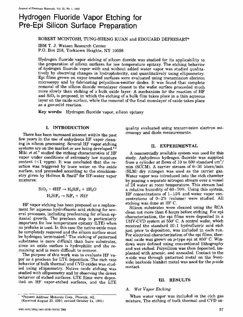
The etch characteristics of anhydrous HF with no water vapor were studied at very high concentra- tions of HF. The etch rate of bulk oxides was ex- tremely sensitive to trace moisture levels. At HF concentrations above 4%, an extremely rapid, un- controlled etch of bulk oxide took place under cer- tain conditions. This etch could be prevented by in- creasing the total gas flow (HF + N2). With increased gas flow the bulk oxide etch rate was much slower, in the range of 2 -5 nm/min . The conditions of HF concentration and total flow under which fast or slow etching took place are plotted in Fig. 2, which is similar to the "all e tch/no etch" plot of Ohmi9 It was also found that a strong nitrogen prepurge was necessary to prevent the uncontrolled etch.
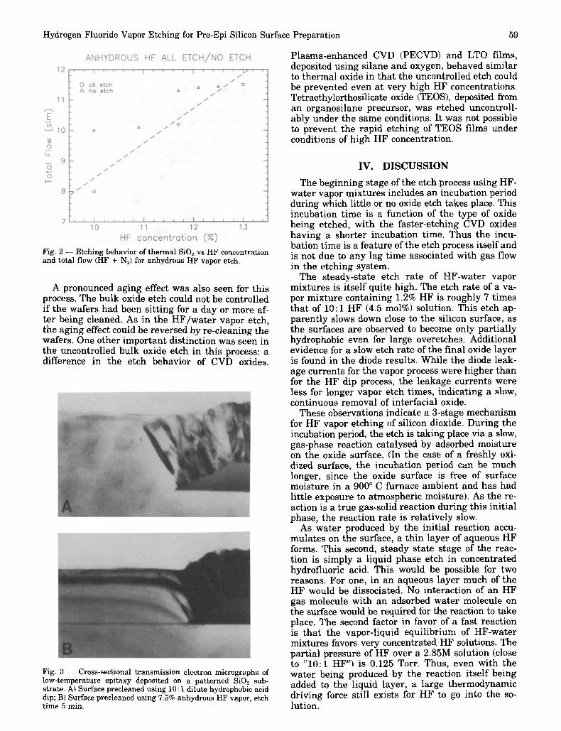
By adjusting flow and prepurge conditions during the etch it was possible to expose thermal oxides to 7.5% HF without bulk etch occurring. Under these conditions some etching of the native oxide in the bare silicon areas did take place. Figure 3 shows a cross-sectional transmission electron micrograph of a low temperature epi film deposited on a patterned oxide substrate after a 5 min, 7.5% HF etch, as well as a sample in which the standard hydrofluoric acid dip preclean was used. It can be seen tha t while the epi shows good crystalline quality, some interfacial oxide is visible at the epi-substrate interface, while none is visible at the epi-substrate interface of the hydrofluoric acid dip control sample.
Table I. Ideal i ty Factors for Po lys i l i con Emitter Diodes Fabr icated on L o w - T e m p e r a t u r e Epi taxy
for Var ious Pre-Epi taxy Surface Cleans. HF V a p o r C o n c e n t r a t i o n w a s 3.4%, wi th a Water V a p o r
Content o f 0.3%.
Ideality factor V = 0.5V
HF vapor, 5 sec 1.30 HF vapor, 40 sec 1.28 HF vapor, 60 sec 1.20 10:1 DHF dip 1.10
Hydrogen Fluoride Vapor Etching for Pre-Epi Silicon Surface Preparation 59
Plasma-enhanced CVD (PECVD) and LTO films, deposited using silane and oxygen, behaved similar to thermal oxide in that the uncontrolled etch could be prevented even at very high HF concentrations. Tetraethylorthosilicate oxide (TEOS), deposited from an organosilane precursor, was etched uncontroll- ably under the same conditions. It was not possible to prevent the rapid etching of TEOS films under conditions of high HF concentration.
Fig. 2 - - Etching behavior of thermal SiO2 vs HF concentration and total flow (HF + N2) for anhydrous HF vapor etch.
A pronounced aging effect was also seen for this process. The bulk oxide etch could not be controlled if the wafers had been sitting for a day or more af- ter being cleaned. As in the H F / w a t e r vapor etch, the aging effect could be reversed by re-cleaning the wafers. One other important distinction was seen in the uncontrolled bulk oxide etch in this process: a difference in the etch behavior of CVD oxides.
Fig. 3 - - Cross-sectional transmission electron micrographs of low-temperature epitaxy deposited on a patterned SiO2 sub- strate. A) Surface precleaned using 10:1 dilute hydrophobic acid dip; B) Surface precleaned using 7.5% anhydrous HF vapor, etch time 5 min.
IV. DISCUSSION
The beginning stage of the etch process using HF- water vapor mixtures includes an incubation period during which little or no oxide etch takes place. This incubation t ime is a function of the type of oxide being etched, with the faster-etching CVD oxides having a shorter incubation time. Thus the incu- bation time is a feature of the etch process itself and is not due to any lag time associated with gas flow in the etching system.
The steady-state etch rate of HF-water vapor mixtures is itself quite high. The etch rate of a va- por mixture containing 1.2% HF is roughly 7 times that of 10:1 HF (4.5 mol%) solution. This etch ap- parently slows down close to the silicon surface, as the surfaces are observed to become only partially hydrophobic even for large overetches. Additional evidence for a slow etch rate of the final oxide layer is found in the diode results. While the diode leak- age currents for the vapor process were higher than for the HF dip process, the leakage currents were less for longer vapor etch times, indicating a slow, continuous removal of interfacial oxide.
These observations indicate a 3-stage mechanism for HF vapor etching of silicon dioxide. During the incubation period, the etch is taking place via a slow, gas-phase reaction catalysed by adsorbed moisture on the oxide surface. (In the case of a freshly oxi- dized surface, the incubation period can be much longer, since the oxide surface is free of surface moisture in a 900 ~ C furnace ambient and has had little exposure to atmospheric moisture). As the re- action is a true gas-solid reaction during this initial phase, the reaction rate is relatively slow.
As water produced by the initial reaction accu- mulates on the surface, a thin layer of aqueous HF forms. This second, steady state stage of the reac- tion is simply a liquid phase etch in concentrated hydrofluoric acid. This would be possible for two reasons. For one, in an aqueous layer much of the HF would be dissociated. No interaction of an HF gas molecule with an adsorbed water molecule on the surface would be required for the reaction to take place. The second factor in favor of a fast reaction is that the vapor-liquid equilibrium of HF-water mixtures favors very concentrated HF solutions. The partial pressure of HF over a 2.85M solution (close to r HF") is 0.125 Torr. Thus, even with the water being produced by the reaction itself being added to the liquid layer, a large thermodynamic driving force still exists for HF to go into the so- lution.

60
The behavior of the dry HF vapor etching can also seen as conforming to liquid-phase behavior. A slow etch is initially catalysed by the presence of trace moisture on the oxide surface or in the etching en- vironment. Where the total gas flow is high enough to evaporate off the water produced by the initial reaction, the process becomes self-dessicating (the etching and the evaporation being immeasurably slow, cooling due to evaporation is not a factor). If enough moisture exists in the system initially, or if the moisture produced during the incubation period accumulates, the etch enters the liquid phase. Since no water vapor is present in the incoming bulk gas, there is a large driving force toward very high con- centrations of HF in the liquid. Thus once the liquid layer is formed the etching takes place extremely rapidly.
As mentioned above, the etch rate of the oxide at the oxide-silicon interface is much less than that of bulk oxide. This would indicate that the final stage of the etching reaction is a gas-phase reaction. The most likely explanation for this slowing down of the etch is surface tension. It was seen in this study that the surfaces show intermediate conditions of hydro- phobicity as the native oxide is being etched. It is probable that as the liquid layer etches through the oxide at the silicon surface, the surface tension changes to a point where the liquid layer breaks up before the oxide is completely etched. Thus the etch of the final monolayers of oxide is limited by gas-phase kinetics. This would explain why the complete native oxide removal required for device- quality LTE is not achieved under the conditions studied in this work.
Some information on the role of carbon in vapor HF etching can be inferred from this study. An ag- ing effect is seen which is reversible by repeating the RCA clean process, whose primary effect on the surface is not a change in bonding of hydrogen or water but the removal of organic contamination. The aging effects seen in both wet and dry vapor etching would most likely be the result of a removable con- taminant, and organic contamination on bare sili- con surfaces has been extensively documented. The behavior of CVD oxides in dry HF supports this the- ory. LTO and PECVD films, deposited from a re- action of silane and oxygen, etch very slowly in high concentrations of HF vapor if the total gas flow is high enough, as is the case with thermal oxide. TEOS oxide, deposited from an organic precursor, etches very rapidly in dry HF vapor under the same con-
McIntosh, Kuan and DeFresart
ditions, even if the oxide has received a high-tem- perature anneal. The contaminant which would dif- ferentiate the deposited oxides is not water but carbon. This indicates that organic contaminants, either from the oxide precursor or adsorbed from the environment on the silicon surface, catalyse the re- action between the silicon dioxide surface and gas- eous hydrogen fluoride. This brings about a more rapid onset of the liquid stage of the reaction in the case of bulk oxides, and also causes native oxide to be removed completely even under conditions in which the liquid layer is not present.
IV. CONCLUSIONS
Based on data from this study, a mechanism for HF vapor etching has been proposed, with the etch proceeding in 3 stages: an initial gas-phase stage; a fast, liquid phase stage; and a final gas phase etch of the oxide closest to the silicon surface. The ac- cumulation of water from the initial gas-phase etch results in the onset of a very fast liquid-phase etch. Close to the silicon surface the liquid layer breaks up, and the etch reaction reverts to slower, gas-phase kinetics. Thus, while a silicon surface with less than 1 monolayer of oxide is readily achieved without significantly affecting an adjacent bulk oxide, the complete removal of oxide is more difficult. Organic contamination is believed to catalyse the gas-phase reaction of silicon dioxide with HF vapor.
ACKNOWLEDGEMENTS
The authors are very grateful to John Ott for his assistance in microscopy and sample preparation. In addition we wish to acknowledge Siegfried Mader, Carol Stanis, and Joseph Blum for many helpful discussions.
VI. REFERENCES 1. R. Novak and P. Thompson, Presented at Semicon Europa,
Zurich, 1989. 2. Advantage Production Technology Inc., Preliminary Product
Information. 3. N. Miki, H. Kikuyama, M. Maeno, J. Murota and T. Ohmi,
IEEE Trans. Electron Devices, 37, 107 (1988). 4. P. J. Holmes and J. E. Snell, Microelectron. Reliab. 5, 337
(1966). 5. B. S. Meyerson, F. J. Himpsel and K. J. Uram, Appl. Phys.
Lett. 57, 1034 (1990).