Embed Size (px)
Citation preview
I
I
N A S A - C R - 7 2 0 3 3
HYDRODYNAMIC JOURNAL BEARING PROGRAM
QUARTERLY P R O G R E S S R E P O R T NO. 2 For Period : July 2 9 , 1965 Thru O c t o b e r 2 9 , 1965
J. D. McHUGH, H. E. N I C H O L S , W. D. C. RICHARDS, and H. C. L E E
p r e p a r e d f o r
N A T I O N A L AERONAUTICS A N D SPACE A D M I N I S T R A T I O N
CONTRACT N A S 3 - 6 4 7 9
SPACE P O W E R A N D PROPULSION SECTION MISSILE A N D SPACE D I V I S I O N
G E N E R A L @ ELECTRIC C I N C I N N A T I , OHIO 45215 .
https://ntrs.nasa.gov/search.jsp?R=19670002021 2020-04-09T20:10:03+00:00Z
Roquosts for copios of this wort should bo roford to:
National Aeronautics and Space Administration , Scientific and Technical Information Division
Attention: USS-A Washington, D.C. 20546
NOTICE This roport was proparod as an account of Govommont sponrond we&. Noihor tho Unitod Stator, nor tho National Aoronautics and Spaco Administration (NASA), nor any porron acting on bohalf of NASA
A) Makos any warranty or npnsontation, oxprossod or impliod, with respect to tho accuracy, complotonoss, or' usofulness of tho information contained in this nport, or that tho US. of any information, apparatus, mothod, or procosr disclosod in this nport may not irrfringo privatoly owned rights; or
B.) Assumes any liabilities with nspoct to tho US. of, or for damagos resulting from tho use of any infor- motion, apparatus, mothod or procoss disclosod in this nport.
As usod abovo, .parson acting on bohalf of NASA' includos m y omploym or controctor of NASA, or omploy.. of such con= tractor, to tho oxtent that such omployoo or contractor of NASA, or omploym of such controdor proparos, dissominatmr, or providos QCCOSS to, any information purguant A his omploymnt or contract with NASA, or his omploymont with such contractor.
HYDRODYNAMIC JOURNAL BEARING PROGRAM ~
QUARTERLY PROGRESS REPORT NO. 2
C o v e r i n g the Period J u l y 29, 1965 through O c t o b e r 29, 1965
I J. D. McHugh and H. E . N i c h o l s W. D. C . R i c h a r d s and H. C. Lee
A p p r o v e d by E . Schnetzer, Manager
D e v e l o p m e n t E n g i n e e r i n g
Prepared for
NATIONAL AERONAUTICS AND SPACE ADMINISTRATION
Contract NAS 3-6479
A p r i l 18, 1966
Technical M a n a g e m e n t NASA - L e w i s Research C e n t e r
N u c l e a r P o w e r Technology B r a n c h Joseph P. Joyce, Technical Manager
WSEARCH AND DEVELOPMENT CENTER SPACE POWER AND PROPULSION SECTION
M I S S I L E AND SPACE D I V I S I O N CINCINNATI, OHIO 45215
I
I * TABLE OF CONTENTS
ABSTRACT. . . . . . . . . . . . . . . . . . . . . . . . . . . . . ,
SUMMARY . . . . . . . . . . . . . . . . . . . . . . . . . . . . . . Forecast . . . . . . . . . . . . . . . . . . . . . . . . . . .
I INTRODUCTION. . . . . . . . . . . . . . . . . . . . . . . . . . . . I. MECHANICAL DESIGN AND TESTING . . . . . . . . . . . . . . . . . . . I
1 Test Rig Design and Procurement. . . . . . . . . . . . . . . . Testing Sub-Tasks. . . . . . . . . . . . . . . . . . . . . . .
11. ANALYSIS OF ROTOR - BEARING RESPONSE. . . . . . . . . . . . . . . . BEARING CONSTANTS. . . . . . . . . . . . . . . . . . . . . . .
I
~
1
I I DYNAMIC ANALYSIS . . . . . . . . . . . . . . . . . . . . . . .
Stability Analysis. . . . . . . . . . . . . . . . . . . . Response Calculations . . . . . . . . . . . . . . . . . .
COMPUTER PROGRAM . . . . . . . . . . . . . . . . . . . . . . . Stability Analysis. . . . . . . . . . . . . , . . . . . . Rotor Response Calculations . . . . . . . . . . . . . . .
APPENDIXES. . . . . . . . . . . . . . . . . . . . . . . . . . . . . A - NOMENCLATURE . . . . . . . . . . . . . . . . . . - . . . . B - ROTOR RESPONSE COMPUTER PROGRAM. . . . . . . . . . . . . .
Input Information . . . . . . . . . . . . . . . . . . Output Format . . . . . . . . . . . . . . . . . . . . Program Listing . . . . . . . . . . . . . . . . . . .
C - ROTOR RESPONSE EXAMPLES. . . . . . . . . . . . . . . . . . D - LISTING OF INPUT CARDS FOR EXAMPLES. . . . . . . . . . . . E - INFLUENCE COEFFICIENTS FOR UNIFORM ROTOR . . . . . . . . .
Page - iv
v
vi i
viii
9
11
13
17
18 23
25
27
29
30
33
34
37
39
51
59
66
REFERENCES. . . . . . . . . . . . . . . . . . . . . . . . . . . . . 69
I
I
z
F i g u r e
1
2
3
4
5
6
7
8
9
10
LIST OF ILLUSTRATIONS
TITLE - PAGE NO.
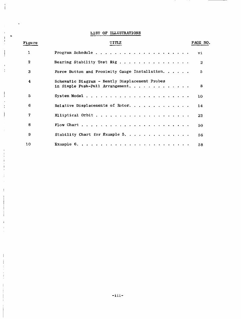
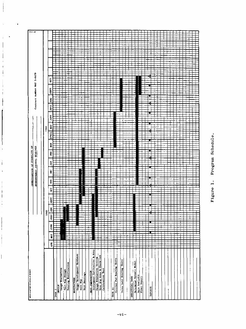
Program Schedule . . . . . . . . . . . . . . . . . . . . v i
Bearing Stabi l i ty Test Rig . . . . . . . . . . . . . . . 2
Force Button and Proximity Gauge Instal lat ion. . . . . . 5
Schematic Diagram - Bently Displacement Probes i n Simple Push-Pull Arrangement. . . . . . . . . . . . . 8
System Model . . . . . . . . . . . . . . . . . . . . . . 10
Relative Displacements of Rotor. . . . . . . . . . . . . 14
E l l ip t i ca l Orbit . . . . . . . . . . . . . . . . . . . . 22
F l o w c h a r t . . . . . . . . . . . . . . . . . . . . . . . 50
Stabi l i ty Chart f o r Example 5. . . . . . . . . . . . . . 56
. . . . . . . . . . . . . . . . . . . . . . . Example 6 . 58
ABSTRACT
A computer program i s presented which p r e d i c t s r o t o r response and
threshold of i n s t a b i l i t y f o r a symmetrical ro tor -bear ing conf igu ra t ion
and given bear ing spr ing and damping c o e f f i c i e n t s . The program a l s o
c a l c u l a t e s the bear ing spr ing and damping c o e f f i c i e n t from experimental ly
obtained f l u i d f i l m f o r c e s and r o t o r displacements. These c o e f f i c i e n t s
apply t o bear ings of s i m i l a r geometry and a r e independent of t he test
r o t o r conf igura t ion .
I
The test r i g f o r t h e experimental p a r t of t h i s program has been
designed and i s i n manufacture. Also, bench t e s t i n g of t h e Bent ly
proximity probes f o r improved accuracy i s under way.
- iv-
SUMMARY
I
I
During t h e present Quar te r ly repor t ing per iod , work has progressed
i n the design and procurement of t he new t e s t r i g components, i n t he
check-out t e s t i n g of Bently gages, and i n ro tor -bear ing response a n a l y s i s ,
A l l d e t a i l e d manufacturing drawings of t h e new test r i g , ins t rumenta t ion ,
and support s t r u c t u r e have been completed, and p a r t s are p resen t ly be ing
manufactured. In add i t ion , instrumentat ion has been assembled f o r check-
ou t t e s t i n g of Bently gages us ing t h e p re sen t ly e x i s t i n g test r i g , and t h i s
t e s t i n g i s underway.
To guide test planning and f o r t h e purpose of gene ra l i z ing experimen-
t a l l y ob ta ined bear ing dynamic c h a r a c t e r i s i t i c s , a rotor . response computer
program has been w r i t t e n and checked-out. This program makes i t p o s s i b l e
t o p r e d i c t ro tor -bear ing response f o r a r b i t r a r y r o t o r s i f t he bear ing
dynamic c h a r a c t e r i s t i c s and r o t o r conf igura t ion are known. The experimental
r o t o r response d a t a can be used t o obta in bear ing dynamic c h a r a c t e r i s t i c s
through use of t he program. The l a t t e r d a t a w i l l be genera l , applying t o
any ro tor -bear ing system having dynamically s imilar bear ings t o those tested.
The computer program i s completely descr ibed, inc luding input and output
data and program l i s t i n g . Several examples a r e worked out demonstrating
t h e u s e of t h e d i f f e r e n t program opt ions.
The program schedule i s shown i n Figure 1.
-V-
I
t
I I I ! ! ! ! I ! I ! ! ! ! ! ! ! ! ! I / / I I ! ! ! ! I I ! ! ! ! ! ! ! ! ! ! ! ! ! ! ! m
t ' i i i i i i i i i i i i ihi y! i i i i i i i i i i i i i i i i i i i i i i i i i i i i i i i i I
- v i -
I
Forecast
During t h e next Q u a r t e r l y repor t ing pe r iod , t he gage eva lua t ion t e s t i n g
w i l l cont inue t o completion, along with check-out and c a l i b r a t i o n of fo rce
gages and t h e determinat ion of loader-bear ing torque by experimental t e s t i n g .
A l l test hardware w i l l be procured.
- v i i -
I
I
INTRODUCTION
The Space Power and
Research and Development
Propuls ion Sec t ion , i n coopera t ion w i t h t h e
Center of t h e General Electric Company, has
been under c o n t r a c t s i n c e A p r i l 29, 1965 t o the Nat iona l Aeronautics
and Space Adminis t ra t ion f o r t h e des ign , f a b r i c a t i o n , and t e s t i n g of
j o u r n a l bear ings which possess c h a r a c t e r i s t i c s , e.g. s t a b i l i t y under
z e r o r a d i a l load, r equ i r ed f o r use i n space power sys t ems . Require-
ments i nc lude long term unattended ope ra t ion under z e r o "g" cond i t ions
us ing low kinematic v i s c o s i t y l u b r i c a n t s such as potassium a t temper-
a t u r e s from 600°F t o 1200 F. 0
The program rep resen t s a con t inua t ion of work c a r r i e d ou t under
c o n t r a c t NAS 3-211 (Reported i n r e p o r t NASA-CR-54039), and involves the
t e s t i n g and e v a l u a t i o n of two bea r ings , t h e f o u r pivoted-pad and the three-
lobe bea r ings , under cond i t ions of angular and t r ansve r se l i n e a r m i s -
a l ignment , and non-rigid bear ing supports. Bearing t e s t i n g s h a l l begin
a f t e r t h e bear ing test assembly, inc luding in s t rumen ta t ion , has demonstrated
t h e a b i l i t y t o o b t a i n t h e r equ i r ed d a t a w i t h a ccep tab le accuracy.
The program is p r i m a r i l y experimental , and is p a r a l l e l e d by a n a l y t i c a l
s t u d i e s . These a n a l y t i c a l i n v e s t i g a t i o n s w i l l compare t h e p h y s i c a l testing
of bea r ing parameters w i th r e s u l t s based on t h e o r e t i c a l assumptions.
g o a l of such experiments i s t o gene ra l i ze the var ious bear ing parameters
t he reby ex tending the use fu lness of the r e s u l t s as des ign t o o l s . The
exper imenta l t o o l of t h i s program i s a r o t a t i o n a l speed test assembly
comprised of a r o t o r and two test bear ings which pe rmi t s i n t e r c h a n g e a b i l i t y
of b e a r i n g s and r o t o r . The l u b r i c a n t w i l l be d i s t i l l e d water, temperature-
The
- v i i i -
I
, * con t ro l l ed t o s imula te the kinematic v i s c o s i t y of potassium.
behavior of the r o t a t i n g s h a f t w i l l be measured w i t h non-contacting
Bent ly inductance gages.
The s t a b i l i t y
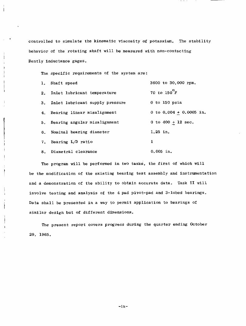
The s p e c i f i c requirements of the s y s t e m are:
1. Shaf t speed 3600 t o 30,000 rpm.
2. I n l e t l u b r i c a n t temperature 70 t o 150°F
3. I n l e t l u b r i c a n t supply pressure 0 t o 150 p s i a
4. Bearing l i n e a r misalignment
5 ~ Bearing angular misalignment
6. Nominal bear ing diameter 1.25 in .
0 t o 0.004 + 0.0005 i n .
0 t o 400 + 12 sec.
-
-
7. Bearing L/D r a t i o 1
8. D i a m e t r a l c learance 0,005 in .
The program w i l l be performed i n two t a s k s , t h e f i r s t of which w i l l
be t h e mod i f i ca t ion of the e x i s t i n g bearing test assembly and ins t rumenta t ion
and a demonstrat ion of t h e a b i l i t y t o ob ta in accu ra t e da t a . Task I1 w i l l
involve t e s t i n g and a n a l y s i s of the 4 pad pivot-pad and 3-lobed bear ings .
D a t a s h a l l be presented i n a way t o permit a p p l i c a t i o n t o bear ings of
s imi la r des ign bu t of d i f f e r e n t dimensions.
The p resen t r e p o r t covers progress dur ing the q u a r t e r ending October
29, 1965.
-ix-
I. MECHANICAL DESIGN AND TESTING
I
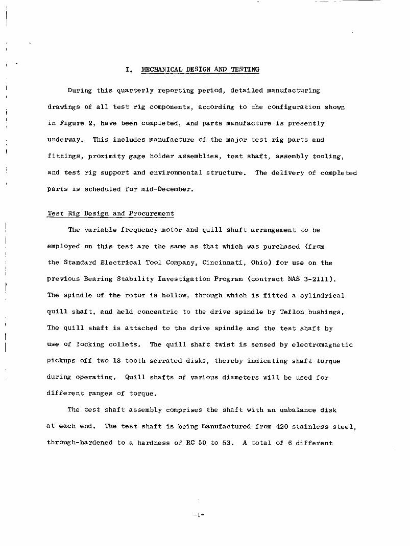
During t h i s q u a r t e r l y r epor t ing per iod , d e t a i l e d manufacturing
drawings of a l l test r i g components, according t o t h e conf igu ra t ion shown
i n F igure 2, have been completed, and p a r t s manufacture i s p r e s e n t l y
underway. This i nc ludes manufacture of t h e major test r i g p a r t s and
f i t t i n g s , p roximi ty gage ho lde r assemblies, test s h a f t , assembly t o o l i n g ,
and test r i g suppor t and environmental s t r u c t u r e . The d e l i v e r y of completed
p a r t s i s scheduled f o r mid-December.
Tes t R i g Design and Procurement
The v a r i a b l e frequency motor and q u i l l s h a f t arrangement t o be
employed on t h i s test are the same as t h a t which was purchased (from
t h e Standard Elec t r ica l Tool Company, C inc inna t i , Ohio) for use on the
p rev ious Bearing S t a b i l i t y I n v e s t i g a t i o n Program ( c o n t r a c t NAS 3-2111).
The s p i n d l e of t h e r o t o r is hollow, through which is f i t t e d a c y l i n d r i c a l
q u i l l s h a f t , and he ld concen t r i c t o t h e d r i v e s p i n d l e by Teflon bushings.
The q u i l l s h a f t is a t t ached t o the d r ive s p i n d l e and t h e test s h a f t by
use of locking c o l l e t s . The q u i l l s h a f t t w i s t is sensed by e lec t romagnet ic
pickups off two 18 t o o t h serrated d i s k s , thereby i n d i c a t i n g s h a f t torque
du r ing ope ra t ing . Q u i l l s h a f t s of various d iameters w i l l be used f o r
d i f f e r e n t ranges of torque.
The test s h a f t assembly comprises t h e s h a f t w i t h an unbalance d i s k
a t each end. The tes t s h a f t i s being manufactured from 420 s t a i n l e s s steel ,
through-hardened t o a hardness of RC 50 t o 53. A t o t a l of 6 d i f f e r e n t
-1 -
Electric Drive Motor
Torque Pickups
Unbalance Discs
Air In (Probes)
JlO77-2
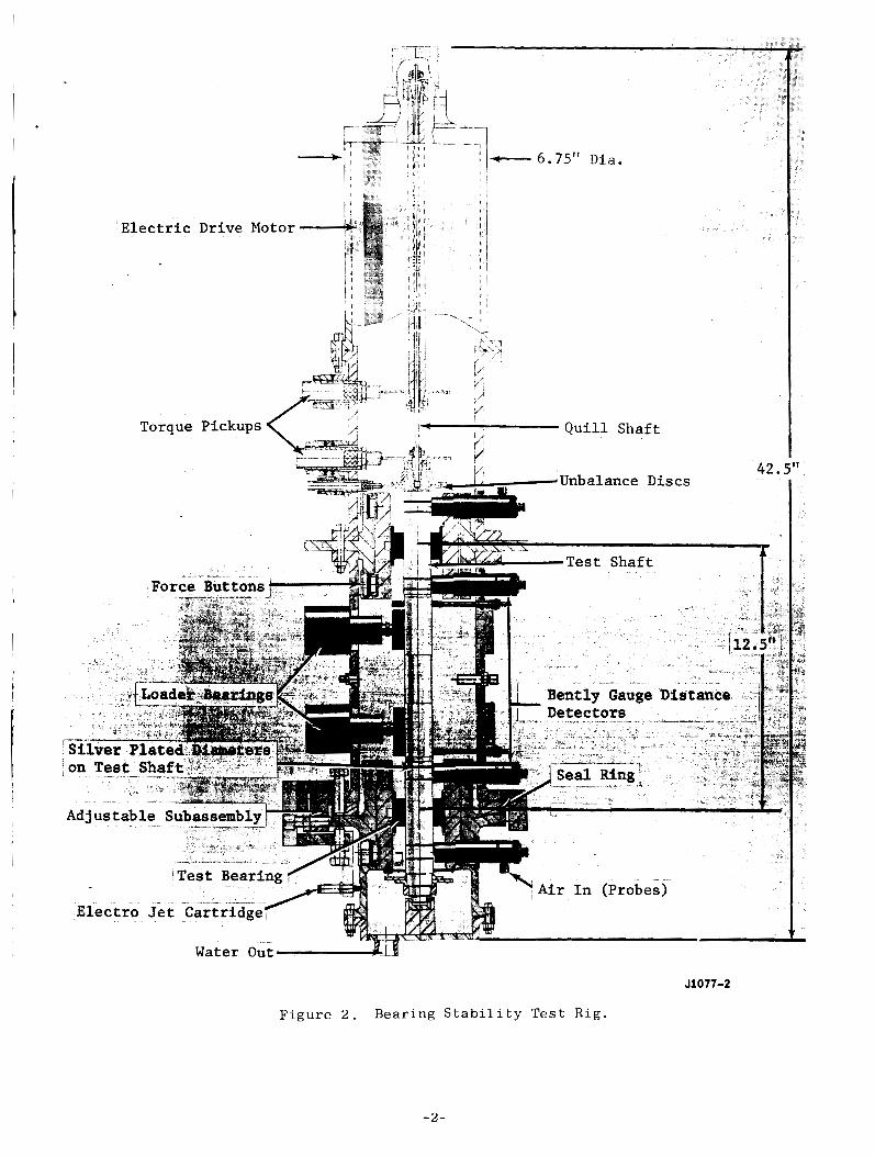
F i g u r e 2 . B e a r i n g S t a b i l i t y T e s t R i g .
-2-
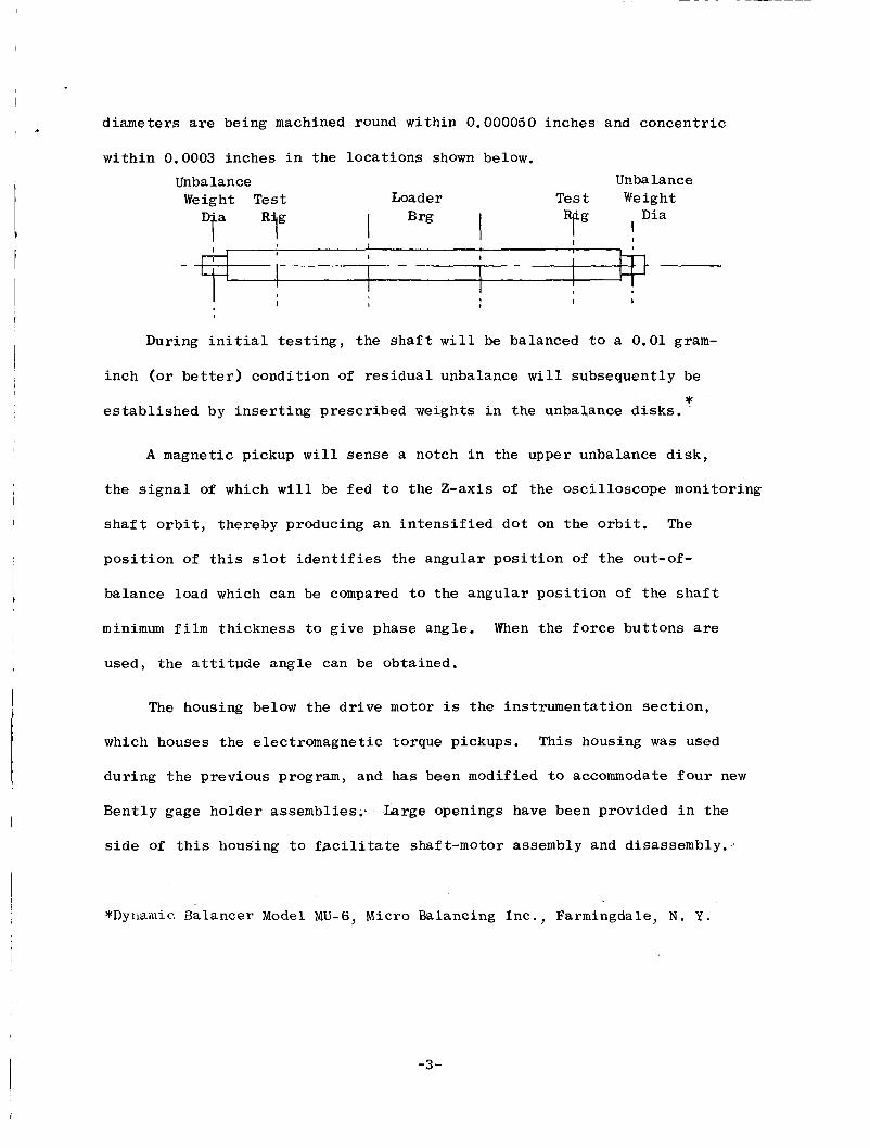
diameters are being machined round within 0.000050 inches and concen t r i c . with in 0.0003 inches i n the loca t ions shown below.
Unbalance Unbalance We i g h t T e s t Loader T e s t Weight
Dta "il" I Brg I I I 1
- I I I I I
I
During i n i t i a l t e s t i n g , t he s h a f t w i l l be balanced t o a 0.01 gram-
inch (or b e t t e r ) cond i t ion of r e s i d u a l unbalance w i l l subsequent ly be *
e s t a b l i s h e d by i n s e r t i n g prescr ibed weights i n the unbalance d i s k s . '
A magnetic pickup w i l l sense a notch i n the upper unbalance d i s k ,
t h e s i g n a l of which w i l l be f e d t o the Z-axis of t h e osc i l l o scope monitoring
s h a f t o r b i t , thereby producing a n i n t e n s i f i e d d o t on the o r b i t . The
p o s i t i o n of t h i s s l o t i d e n t i f i e s t h e angular p o s i t i o n of t h e out-of-
balance load which can be compared t o the angu la r p o s i t i o n of the s h a f t
minimum f i l m t h i ckness t o g ive phase angle. When the f o r c e but tons are
used, t h e a t t i t u d e angle can be obtained.
The housing below the d r i v e motor i s the ins t rumenta t ion s e c t i o n ,
which houses the e lec t romagnet ic torque pickups. This housing w a s used
dur ing t h e prev ious program, and has been modified t o accommodate f o u r new
Bent ly gage holder assemblies: Large openings have been provided i n t h e
side of t h i s housing t o facil i tate shaf t-motor assembly and disassembly.,.
*Dyuamic. Balancer Model M U - 6 , Micro Balancing Inc . , Farmingdale, N . Y .
-3-
The main tes t r i g assembly, suppor t ing the test bear ings , s h a f t ,
l oade r bear ings , and shaf t p o s i t i o n sens ing gages is f a b r i c a t e d e n t i r e l y
of 316 s t a i n l e s s steel, and is mounted i n t h e t e s t r i g suppor t s t r u c t u r e
from i ts upper f l ange . Both test bearings are supported i n the test
r i g as fo l lows . The t e s t bea r ing is mounted i n a c l o s e - f i t t i n g s l e e v e
( i n n e r bea r ing housing) and is t i g h t l y secured a g a i n s t r o t a t i o n or
a x i a l motion by a set-screw. T h i s inner bea r ing housing is equipped
with water l u b r i c a n t f eed duc t ing , and an annulus t o d i s t r i b u t e t he
l u b r i c a n t around the bea r ing (Figure 2). Also, the housing provides
f o r three i n t e r n a l thermocouples and a l u b r i c a n t p re s su re t a p . T h i s
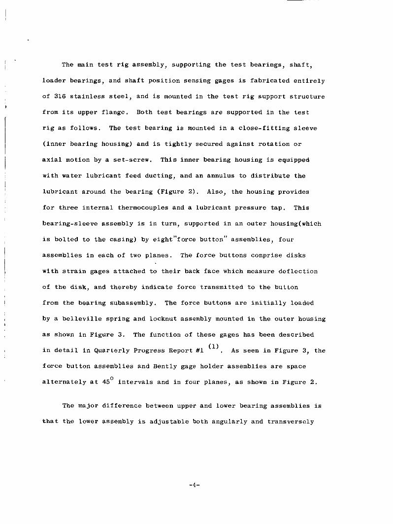
bear ing-s leeve assembly is i n tu rn , supported i n an o u t e r housing(which
i s b o l t e d t o t h e cas ing) by e igh t” fo rce but ton” assemblies, fou r
assembl ies i n each of two p lanes . The f o r c e bu t tons comprise d i s k s
w i t h s t r a i n gages a t t a c h e d t o t h e i r back f a c e which measure d e f l e c t i o n
of t he d i s k , and thereby i n d i c a t e fo rce t r a n s m i t t e d t o the but ton
from the bear,ing subassembly. The fo rce bu t tons are i n i t i a l l y loaded
by a b e l l e v i l l e s p r i n g and locknut assembly mounted i n the o u t e r housing
as shown i n F igure 3 . The func t ion of t hese gages has been descr ibed
i n d e t a i l i n Q u a r t e r l y Progress Report #1 (I).
f o r c e bu t ton assemblies and Bently gage holder assembl ies are space
a l t e r n a t e l y a t 45 i n t e r v a l s and i n four p lanes , as shown i n F igure 2 .
A s seen i n F igure 3, the
0
The major d i f f e r e n c e between upper and lower bear ing assemblies i s
t h a t t he lower assembly i s a d j u s t a b l e both angu la r ly and t r a n s v e r s e l y
-4-
I , ’
Outer Cas
I I -
Displacement Sensor
Holder ( 4 )
iii m Outer Bearina l i l Housing
n- Bellvil le Spring
- Bently Gauge Assembly
Sensor ( 4 )
Instrumentation Locations
1 Side .Load
J1077-3
Figure 3. Force Button and Proximity Gauge Installation.
-5-
by adjustment of t h e s e v e r a l holding clamps shown i n F igure 2 . Four f l a t s
are machined on t h e Q.D. of t h e lower housing t o accommodate f o u r
contac t ing- type p o s i t i o n gages*.
Seve ra l flow p o r t s have been provided i n t h e w a l l of t h e bear ing housings
i n s i d e t h e t es t r i g t o accommodate t h e flow and c o l l e c t i o n of water i n t h e
lower sump reg ion of t h e t es t r ig . The o v e r a l l assembly is being manu-
f a c t u r e d wi th s t anda rd t o l e r a n c e s on a l l r abbe t d iameters (+ 0.001 inch)
s i n c e t h e h igh p r e c i s i o n alignment i s obta ined a f t e r assembly of t h e t e s t
r i g . S i d e loads are imposed on the tes t s h a f t by u s e of two p i s t o n a c t u a t e d
p a r t i a l - a r c loade r bear ings which were used on t h e prev ious test program
(NAS 3-2111).
-
I n a d d i t i o n t o t h e above hardware manufacture, a c r i t i c a l speed a n a l y s i s
is be ing performed t o a i d i n e s t a b l i s h i n g t h e d e t a i l e d t e s t p lan (avoid ing
c r i t i c a l speed o p e r a t i n g reg ions) employing s e v e r a l assumed cons t an t va lues
of bea r ing s t i f f n e s s and f o r c e gage s t i f f n e s s .
T e s t i n g Sub-Tasks
The major e f f o r t he re cont inues i n c a r r y i n g o u t t h e var ious sub- tasks
desc r ibed i n d e t a i l i n Reference 1.
I n v e s t i g a t i o n has continued on p o t e n t i a l methods t o reduce t h e s e n s i t i v i t y
of t h e B e n t l y gages t o minute flaws or inhomogeneities i n t h e s t a i n l e s s
* E l e c t r o j e t Gage C a r t r i d g e - Model #59-230-113, S h e f f i e l d Corp, Dayton 1, Ohio.
-6-
s tee l test s h a f t . Various m a t e r i a l s have been p l a t e d on t h e s h a f t s u r f a c e
i n t h e v i c i n i t y of t h e Bently gages, with t h e r e s u l t that a 0.005 inch
t h i c k s i l v e r p l a t e has been selected f o r t h e f i n a l test s h a f t . The
p l a t i n g th i ckness is uniform t o a dev ia t ion of less that 1% of nominal
p l a t i n g th i ckness . T h i s t e s t i n g of var ious p l a t i n g s is being done i n
a bench se t -up us ing a n e x i s t i n g s h a f t from the previous Bearing S t a b i l i t y
Program.
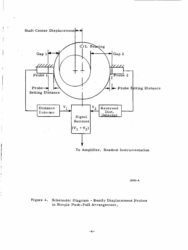
Bently gages a re being c a l i b r a t e d a g a i n s t the s i l v e r p l a t e d s h a f t .
These gages w i l l be used i n a push-pull o r opposed arrangement such
t h a t symmetrical e f f e c t s , such as those due t o uniform temperature
expansion or c e n t r i f u g a l growth of the t e s t s h a f t , w i l l be cance l l ed .
Increased s e n s i t i v i t y is a l s o ob ta ined without f u r t h e r s i g n a l ampli-
f i c a t i o n . A simple form of t h i s push-pull arrangement is shown schemat i ca l ly
i n F igu re 4.
-7 -
I
t *
I I I
Shaft Center Disp lacement H
Distance I3 c t e ctro 1-
I
v2 R e v e r s e d Dist.
Detector . S ignal S u m m e r
Distance
To Amplif ier , Readout Instrumentat ion
J1052-4
Figure 4 . Schemat i c D iag ram - Bently Digplacement P r o b e s in Simple Push -pu l l A r r a n g e m e n t .
-8-
11. ANALYSIS OF RWOR - BEARING RESPONSE
I
I
The present c o n t r a c t has as i t s o b j e c t i v e t o provide experimental
d a t a l ead ing t o t h e proper s e l e c t i o n and s i z i n g of bear ing type for app l i ca t ion
t o Rankine cyc le power systems f o r space app l i ca t ions us ing l i q u i d potassium
as the l u b r i c a n t . The d a t a must be general ized so a s t o apply t o dynamically
s i m i l a r bear ings of d i f f e r e n t dimensions. Besides providing e c c e n t r i c i t y
r a t i o and non-dimensional torque v a r i a t i o n w i t h Sommerfeld and Reynolds
numbers, which comes d i r e c t l y from the measurements, non-dimensional bear ing
dynamic c h a r a c t e r i s t i c s and f r a c t i o n a l frequency whir l ( s t a b i l i t y ) th resholds
must be provided. I n planning t e s t s p red ic t ions of expected r o t o r response
and t h e s t a b i l i t y th reshold a r e required. I n reduct ion of t he test d a t a
means f o r gene ra l i z ing t h e less d i r e c t information, namely, t h e dynamic
c h a r a c t e r i s t i c of a given bear ing, must be e s t ab l i shed . A computer program
h a s been w r i t t e n and checked out which accomplishes t h e s e two tasks. The
bear ing- ro tor response ana lys i s which fol lows i s t h e b a s i s f o r t h i s computer
program.
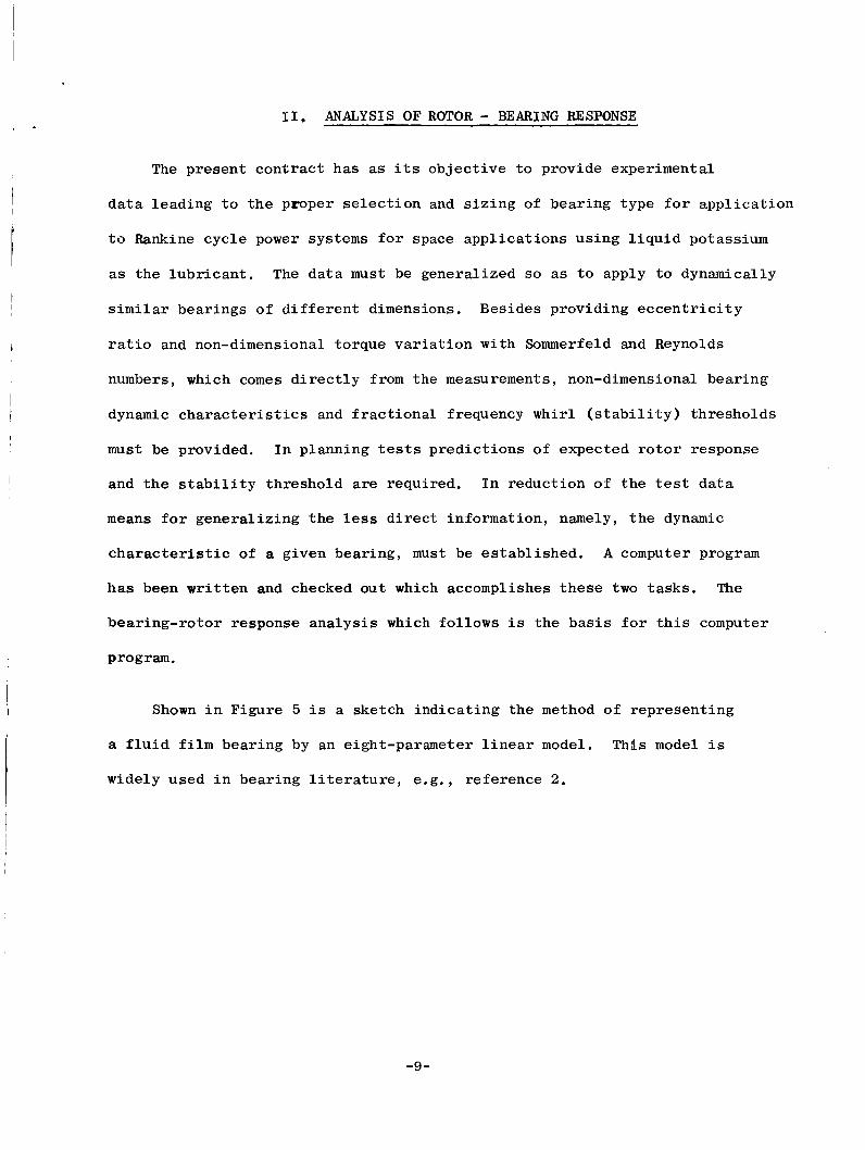
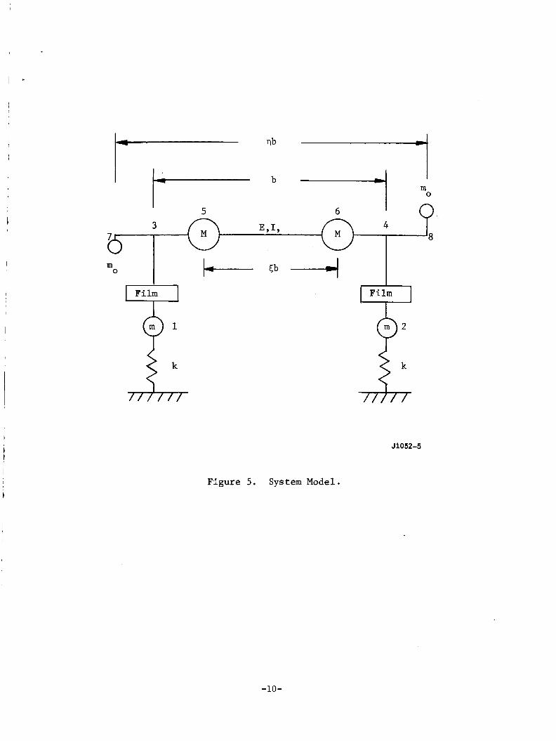
Shown i n Figure 5 i s a ske tch i n d i c a t i n g the method of r ep resen t ing
a f l u i d f i l m bear ing by an eight-parameter l i n e a r model. Thds model i s
widely used i n bear ing l i t e r a t u r e , e.g. , re fe rence 2.
-9-
I i -
I m 0
5 6 I n I I 3 EYIY 4
5 6 I
3 EYIY 4
m 0
Film Q 9' 1,
Film Lr'
Figure 5. System Model.
o2
J1052-5
-10-
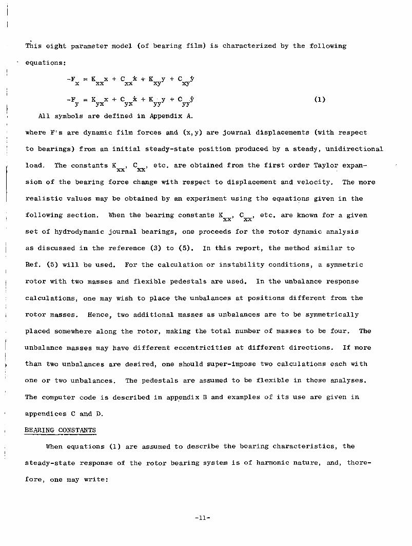
This e i g h t parameter model (of bear ing f i lm) i s cha rac t e r i zed by t h e fol lowing
equat ions:
-F = K X + C k + K y + C p X xx xx XY Xy
-F = K x C C k + K y + C . 9 Y YX Y* YY YY
A l l symbols are def ined i n Appendix A.
where F ’ s a r e dynamic f i l m f o r c e s and (x ,y) a r e j o u r n a l displacements ( w i t h r e spec t
t o bea r ings ) from an i n i t i a l s t eady- s t a t e p o s i t i o n produced by a s teady , u n i d i r e c t i o n a l
load.
s i o n of t h e bear ing f o r c e change wi th respec t t o displacement and v e l o c i t y . The more
r e a l i s t i c va lues may be obtained by an experiment u s ing t h e equat ions given i n t h e
The cons t an t s KXX, Cxx, e t c . a r e obtained from t h e f i r s t o rde r Taylor expan-
etc. are known f o r a given xx’ cxx’ fo l lowing sec t ion . When the bear ing cons tan ts K
se t of hydrodynamic jou rna l bear ings, one proceeds f o r t h e rotor dynamic a n a l y s i s
as d iscussed i n t h e re ference (3) t o ( 5 ) . In this r e p o r t , t h e method similar t o
Ref. (5) w i l l be used, For t h e c a l c u l a t i o n or i n s t a b i l i t y cond i t ions , a symmetric
r o t o r wi th t w o masses and f l e x i b l e pedes t a l s are used. I n t h e unbalance response
c a l c u l a t i o n s , one may wish t o p l ace t h e unbalances a t p o s i t i o n s d i f f e r e n t from the
r o t o r masses.
placed somewhere along t h e r o t o r , making the t o t a l number of masses t o be four . The
unbalance masses may have d i f f e r e n t e c c e n t r i c i t i e s at d i f f e r e n t d i r e c t i o n s . I f more
than two unbalances are des i r ed , one should super-impose two c a l c u l a t i o n s each wi th
one or two unbalances. The pedes t a l s a r e assumed t o be f l e x i b l e i n these analyses.
Hence, two add i t iona l masses a s unbalances are t o be symmetrically
The computer code i s descr ibed i n appendix B and examples of i t s use are given i n
appendices C and D.
BEARING CONSTANTS
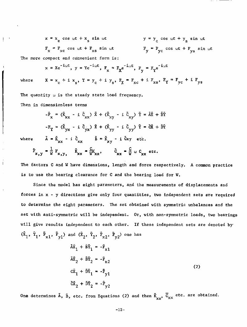
When equa t ions (1) a r e assumed t o descr ibe t h e bear ing c h a r a c t e r i s t i c s , t h e
s t e a d y - s t a t e response of t h e r o t o r bear ing system i s of harmonic na tu re , and, there-
f o r e , one may w r i t e :
-11-
X
- + i Fxsr Fy = F + i F X = x + i x Y = y , + i y , , F x - F x c C S’ YC YS
where
The q u a n t i t y w i s t h e s teady s t a t e load frequency.
Then i n dimensionless terms
-F = (”, - i Ex,) X + (k - i E ? = E + E
- - i t )i+(ii - i E ) ? = E + i j ? X XY XY
Yx YY YY -Fy - ‘Eyx
t The f a c t o r s C and W have dimensions, l ength and fo rce r e spec t ive ly . A common p r a c t i c e
i s t o use t h e bear ing c learance f o r C and t h e bear ing load f o r W. I
Since t h e model has e i g h t parameters, and t h e measurements of displacements and
f o r c e s i n x - y d i r e c t i o n s g ive only four q u a n t i t i e s , two independent se ts are requi red
t o determine t h e e i g h t parameters.
s e t wi th ant i -symmetr ic w i l l be independent.
w i l l g ive r e s u l t s independent t o each other .
(Z1Y f l y Fxl, yl I and (g2, t2, ?x2y y2 ) one has
The s e t obtained wi th symmetric unbalances and the
O r , wi th non-symmetric loads , two bear ings
I f t h e s e independent sets a r e denoted by.
El + El = -Fxl
z2 + E2 = -Fx2
CX, + El = -F
EZ2 + E2 = -F
Y l
Y2 -
One de termines A, B y e tc . from Equations (2) and then k Cxx e tc . are obtained- xx’
-12-
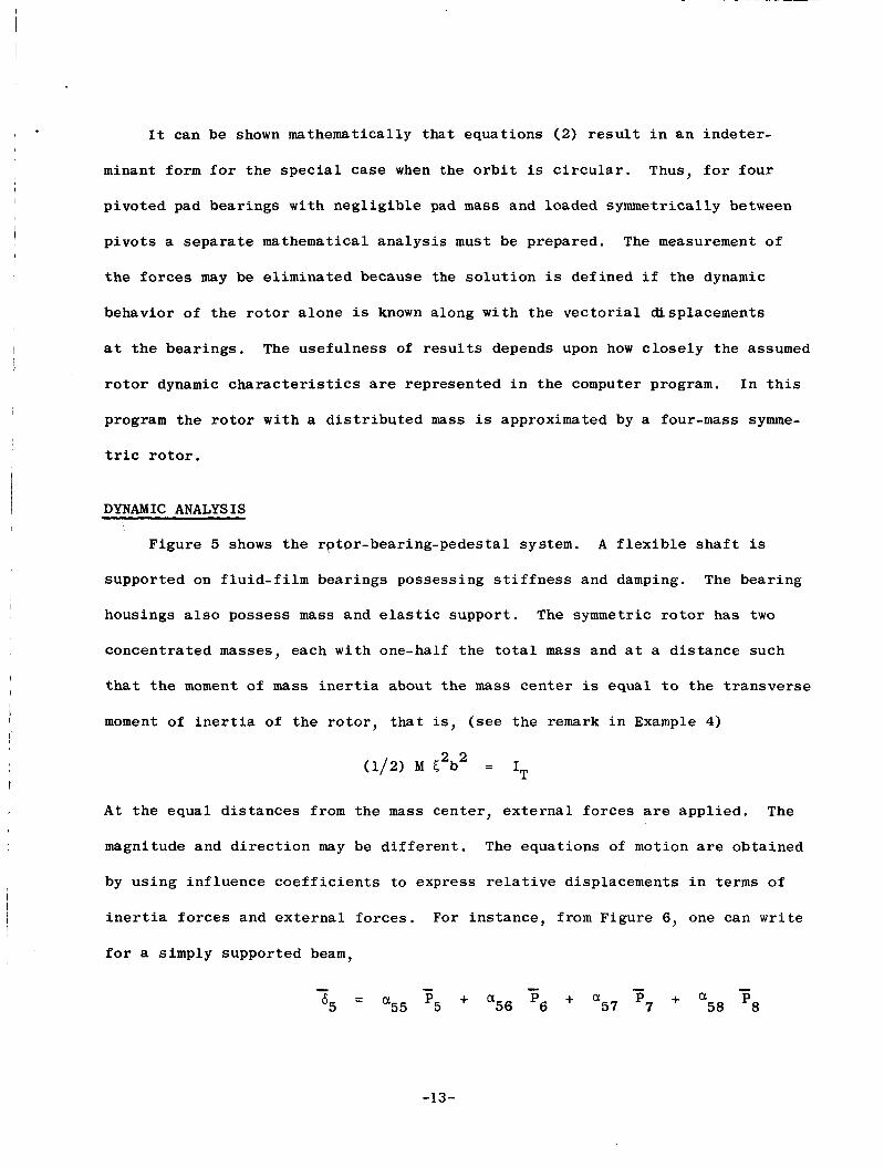
I t can be shown mathematically t h a t equat ions (2) r e s u l t i n a n i n d e t e r -
minant form f o r the s p e c i a l case when the o r b i t is c i rcu lar . Thus, f o r f o u r
p ivoted pad bear ings wi th n e g l i g i b l e pad m a s s and loaded symmetrically between
p i v o t s a s e p a r a t e mathematical a n a l y s i s must be prepared. The measurement of
t h e f o r c e s may be e l imina ted because the s o l u t i o n is def ined i f the dynamic
behavior of t h e r o t o r a l o n e i s known along wi th the v e c t o r i a l displacements
a t t h e bea r ings . The use fu lness of r e s u l t s depends upon how c l o s e l y the assumed
r o t o r dynamic c h a r a c t e r i s t i c s are represented i n the computer program. I n t h i s
program the r o t o r w i th a d i s t r i b u t e d mass is approximated by a four-mass symme-
t r i c r o t o r .
DYNAMIC ANALYSIS
Figure 5 shows t h e rp tpr -bear ing-pedes ta l sys t em. A f l e x i b l e s h a f t is
suppor ted on f l u i d - f i l m bear ings possessing s t i f f n e s s and damping. The bea r ing
housings a l s o possess mass and e l a s t i c suppor t . The symmet r i c r o t o r has two
concent ra ted masses, each w i t h one-half t h e t o t a l mass and a t a d i s t a n c e such
t h a t the moment of mass i n e r t i a about the mass c e n t e r is equal t o t h e t r a n s v e r s e
moment of i n e r t i a of the r o t o r , that is, (see t h e remark i n Example 4)
(1/2) M C2b2 = IT t
A t t he equa l d i s t a n c e s from the mass cen te r , e x t e r n a l f o r c e s are app l i ed . The
magnitude and d i r e c t i o n may be d i f f e r e n t . The equat ions of motion are obta ined
by u s i n g in f luence c o e f f i c i e n t s t o e x p r e s s r e l a t i v e displacements i n terms of
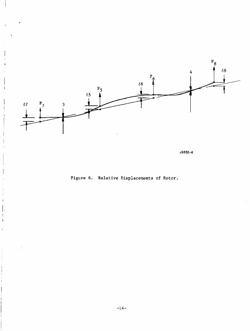
i n e r t i a f o r c e s and e x t e r n a l f o r c e s . For in s t ance , from Figure 6 , one can write
f o r a simply suppor ted beam,
-13-
67 p7 3 c
J1052-6
Figure 6. Relative Displacements of Rotor.
-14-
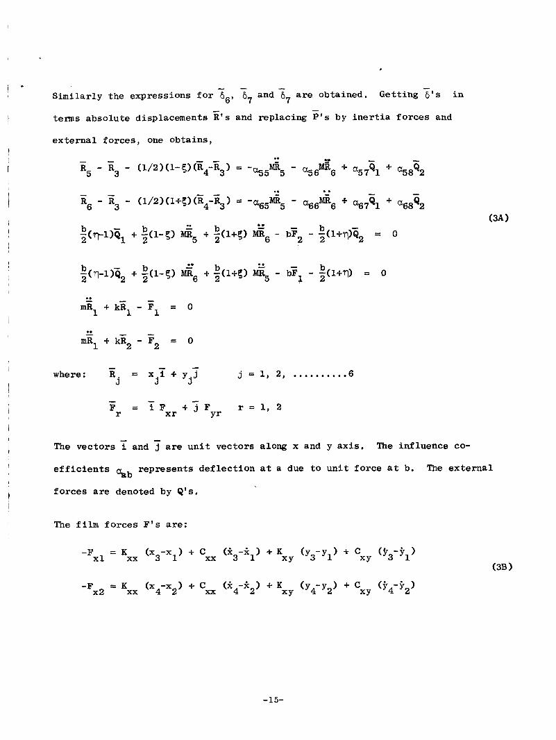
- - Simi la r ly the express ions f o r 6 6 and % a r e obtained. Get t ing ~ I S i n 6' 7 7
terms absolu te displacements E ' s and replacing P's by i n e r t i a f o r c e s and
e x t e r n a l f o r c e s , one ob ta ins ,
-
- .* - - R5 - R3 - (1/2)(1-5)(E4-z3) = -%5G5 - %6d.6 $. a5761 4. cs8Q2
R6 - R3 - (1/2)(l+5)G4-X3) = -as5bdfi5 - a66N1R6 + a67G1 4. a68Q2
- (q- l )Ql - b 4. ~ ( 1 - 5 ) Mii5 '* + 3(1+PJ b b ii6 - bF2 - b - :(l+?-?q2 = 0 2
- .. .. - -
- where : R = x.y + y . 5
j J J j = 1, 2, .......... 6
- - F = i Fxr + 2 F r = l , 2 r Y r
The vec to r s
ef f i c i e n t s aab rep resen t s d e f l e c t i o n a t a due t o u n i t f o r c e a t b.
f o r c e s are denoted by e ' s .
and 7 are u n i t vec tors along x and y a x i s . The in f luence co-
The ex terna l
The film f o r c e s F ' s are:
-15-
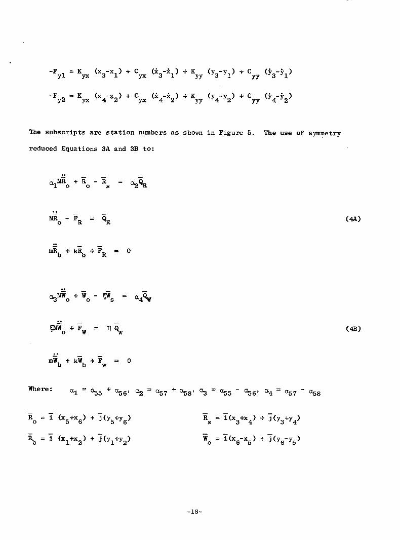
The subscripts are s tat ion numbers a s shown i n Figure 5 .
reduced Equations 3A and 3B to:
The use of symmetry
.. QpGo .I- iio - fis = a4%
gniioJ-Fw = q $ ..
-16-
tJ = z (x4-x3) + j(y -y ) s 4 3
GR = (Qxl+Qx2) + j(QxlWx2) \ = ~(Q~,-Q~Q + ~(Q,,-Q~,) CR = T ( F ~ ~ + F ~ ~ ) + j (F +F ) F = i (Fx2-Fxl) + 5 (Fy2-Fyl) Yl Y2 W
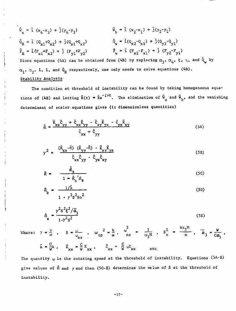
Since equations (4A) can be obtained from ( 4 B ) by replacing a3, a4, E , 7 , and
a19 a2, 1, 1, and Q
Stability Analysis
by W
respectively, one only needs to solve equations (4B). R
The condition at threshold of instability can be found by taking homogeneous equa- - -ivt
tions of ( 4 B ) and letting k(t) * Re
determinant of scalerjequations gives (in dimensionless quantities)
. The elimination of ‘and fi and the vanishing b’ 0
ii E + E it - E xy ii yx - e kx xx yy xx yy
c + e xx YY
1’ - 6$--d3, 1 / i
2 2 2 % - 1 - y S S n
2 2 2
1-7 s Y s 5: /c3
2 2 & =
V Where: 7 = - o , s = L , w ns
C E = - k = i k , - c = - K C xx w ‘xx ’ xx w wcxx etc.
The quantity w is the rotating speed at the threshold of instability.
give values of R and 7 and then ( 5 C - E ) determines the value of S at the threshold of
instability.
Equations ( S A - B )
-17-
Res pons e Calcu la t ions
I f t h e e x t e r n a l fo rces , q1 (t) and '6 ( t) , ar,e unbalance fo rces , one may 2 .
write
Where m
e c c e n t r i c i t i e s by tj0 and t j l
i s unbalance mass, E, x, i + y7 j , g8 = x i + y,j, and denot ing the unbalance 0 8
The ang le i s the phase l a g of is from 4 . 7' Here it i s noted tha t ,
T o t a l r o t o r mass = 2(M + mo) I~ = ~ 2 ) b2 (M 5 2 + moT 2
I n a d d i t i o n t o equat ions ( 3 ) , one has .. .. ii7 - E3 - 1/2(1-7)(ii4-ii3) = -a 75 M i 5 - a 76 M i 6 + $177ij1 + (u7&
ii, - iiq - l/2(l+q)(ii4-i$) = 'a85 G5 .. - a 8 6 6 6 + "8761 + a8862
a2Mii0 + ii 4 - iis = a5$
a 4 ~ , + i q - Tws = a66w
(8)
Noting t h e s y m e t r y , - - aZ7 etc . , one ob ta ins .. ( 9A)
(9B) ..
a5 a77 a78
a6 - a77 - a78
Where
-
ii = ( X 7 t X 8 ) r + (y +y ) j 4 7 8
i = (x8-x7) i + (y -y ) 3 q 8 7
Again, equat ion (9B) reduces t o equat ion (9A) when a4, a63
a2, as , OR and 1 r e spec t ive ly .
and (9B) g ives
and T are rep laced by
The s u b s t i t u t i o n of equat ions (6) i n t o equat ions (4B) .?
-18-
S i m i l a r l y four more equat ions are obtained from equat ions ( 4 A ) and ( 9 A ) wi th QR = i7G8. The unbalance f o r c e s may be expressed as real p a r t s o f :
Therefore , t he s o l u t i o n s take t h e form,
g (t) = eiwt fi (t) = ; , - i w t
E = X"l + yj
G = uz + v;
Where - -
x = x + x C S
Y = yc + i ys
U = u + i u C S
V = vc + i v S
-19-
~
The substitutions of equations (11) and (12) into equations (10B) and the elimin-
ation process gives, in complex terms,
and therefore
1 (us-ub) = - a, [ (E-&) Qu - B Q, ] A
1 (Vs-Vb) = - % [ E Qu - (A-6,) 6 ] A V
R R G us/c = 2 - (us-ub>/c f 1, G4/G3 G3 U
v /c = R1R4G2 (vs-vb)/c + '4 lG3 G3 S
-
I ['lov + Fv + sm 'lVq/(C a,, 5 s;
#3 2 t J / C = -
Where
1 = ( L E ) (5-6)- ii 5
6 = G ~ G ~ / G ~
L+ = G,G4/G3
-20-
G1 = R R + R2R3 1 5
2 P
1 4 2
G2 = C (1-S )
G3 =-G1 + R R G
G4 = vRl + R3&4
R1 = 1 - S 2 - S 2 [ ( l - s 2 ) + Sf $?/($E6)] n m n
2 R2 = 5 sm @&4/&6 - 5 )
'3 5 ' : / a3 + sn 2 2 SL (.'1;14/66 - 1)/63
R 4 = 1 - S 2 m
- 2 2 - Rg - 7 srn/c$j
2 2 n
2 2 m
S2 = mu /k.
S = M a 3 w
s = moa,w
a4 = W/Q4
2 P -
= F i + F 3 Y
F = I (Fx2 - FXl) + 3 (Fy2 - Frl) = F I + F,j W U
where X = x + i x and y ( t ) = Ye'iwt
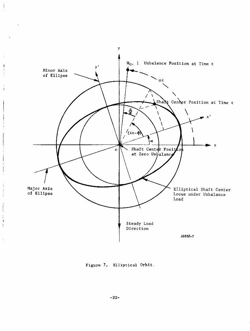
Y = y, + y s i , t he pa th of t he jou rna l cen te r i s an e l l i p s e , and, t he re fo re , t h e r e e x i s t s
I 1
C S
- i w t When t h e s o l u t i o n i s i n the form x ( t ) = Xe
major a x i s making angle a! with X a x i s such t h a t (Fig. 7 )
x ' ( t ) = a cos (u t - Q)
y ' ( t ) = b s i n ( w t - Q)
x' = x cos (y + y s i n a!
y' y cos c - x s i n Q
-21-
Y
1 Mo, 1 Unbalance Position at Time t
Minor Axis
Elliptical Shaft Center of Ellipse Locus under Unbalance
Steady Load Direct ion
I
JlO52-7
Figure 7, E l l i p t i c a l Orbit.
-22-
@Y) s i n ( w J t - 2 2
Y = j Y c + Ys
yC X
0- S
C
- where tan $bX = x and tan 8, = Ys
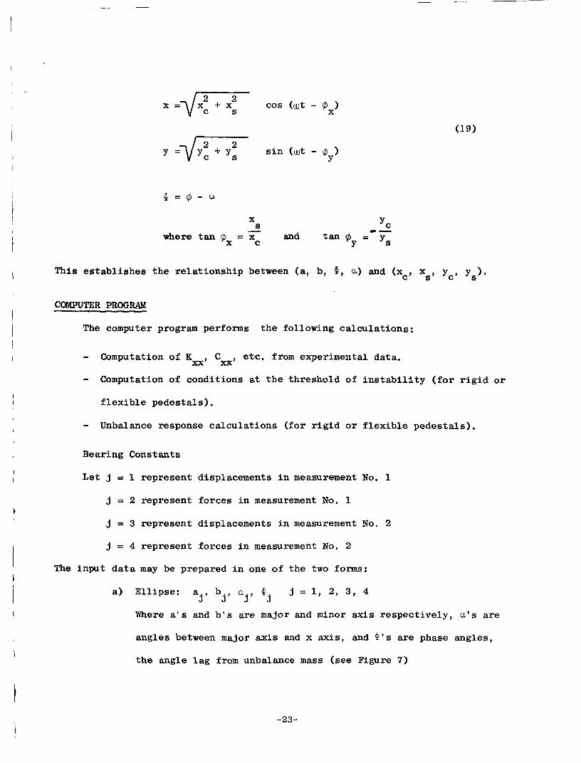
This e s t a b l i s h e s t h e r e l a t ionsh ip between (a, b, *, u) and (xc, xs, yc, ys).
COMPUTER PROGRAM
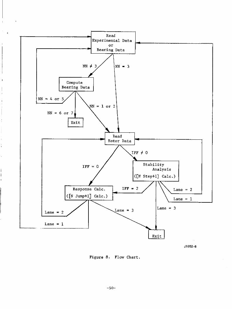
The computer program performs the following ca l cu la t ions :
- Computation of Kxx, Cxx, etc. from experimental data.
- Computation of cond3tions a t t h e threshold of i n s t a b i l i t y ( f o r r i g i d o r
f l e x i b l e pedes ta l s ) .
- Unbalance response ca lcu la t ions ( f o r r i g i d o r f l e x i b l e pedes t a l s ) ,
Bearing Constants
L e t j 5 1 represent displacements i n measurement No. 1
j = 2 represent forces i n measurement No. 1
j = 3 represent displacements i n measurement No. 2
j = 4 represent forces i n measurement No. 2
The input d a t a may be prepared i n one of t he two forms:
a) E l l ip se : a b aj, Qj j = 1, 2, 3, 4 3' j'
Where a ' s and b ' s a re major and minor ax i s respec t ive ly , a ' s are
angles between major ax i s and x axis , and Q's a re phase angles,
t he angle l a g from unbalance mass (see Figure 7)
-23-
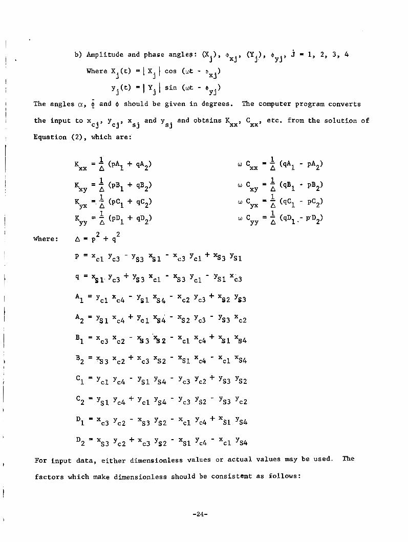
b) Amplitude and phase angles : ( X j ) , aXj , ( Y j ) , j = 1, 2, 3 , 4 y j '
@Xj)
"y j )
mere X . ( t ) = I xj I cos (u t - y j ( t ) = ) yj I s i n (u t -
J
The angles a, and @ should be given i n degrees. The computer program conver t s
and y and ob ta ins Kxx, Cxx, e t c . from t h e s o l u t i o n of s j s j
t he inpu t t o x c j s Y c j ¶ x
Equation (2) , which are:
= - 1 (qA1 - PA2) 'xx A
1 XY A
1 Y X A
1 YY A
w C
w c w C
= - (qB1 - pB2)
= - (qC1 - pC2)
= - (qD1 .- pD2)
where :
For inpu
2 2 A = p + q
p = x - x c l yc3 - 3 3 "Sl c3 y c 1 + xs3 YS1
q = xs1Jc3 + ys3 x c l - xs3 yc1 - Ysr xc3
A1 = yc1 xc4 - Ysl "s4 - xc2 yc3 + xs2 ys3
A2 - YSl xc4 + Ycl "s4 - xs2 yc3 - ys3 xc2
B 1 = x x - x x + x
B2 = $3 xc2 + xc3 xs2 - xsl xc4 - x c l xs4
- yc1 yc4 - YSl ys4 - yc3 yc2 + ys3 ys2
c2 - Ysl yc4 + yc1 ys4 - yc3 ys2 - ys3 yc2
Dl - yc2 - xs3 3 2 - x c l yc4 + xsl ys4
c3 3 2 - xsl yc4 - x c l ys4
-
c3 c2 - % 3 ' % 2 c l c4 Sl xs4
-
-
-
+ X s 3 yc2 D2 = x
d a t a , e i t h e r dimensionless values o r a c t u a l v
-24-
l u may b
f a c t o r s which make dimensionless should be c o n s i s t e n t a s fol lows:
U d . The
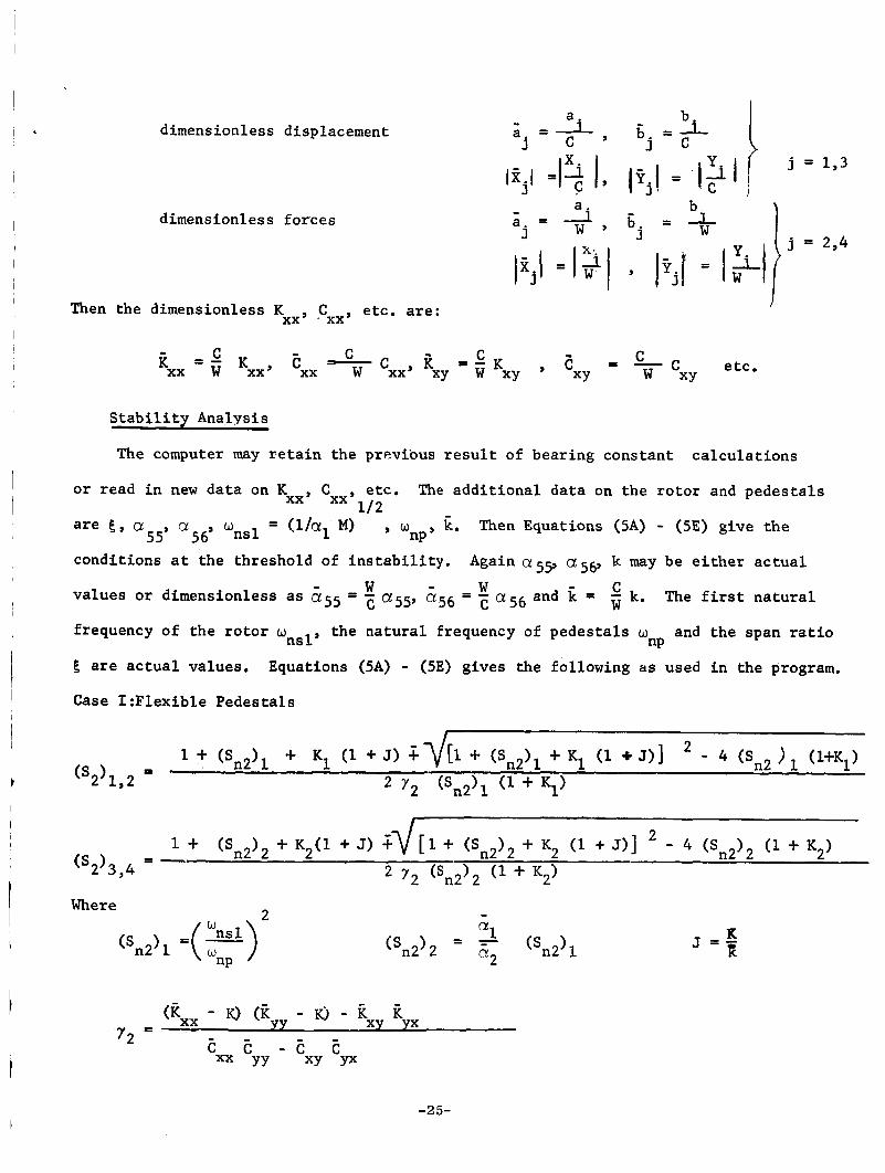
dimensionless displacement
dimensionless f o r c e s
I
Then the dimensionless K e tc . are: xx’ CXX’
S t a b i l i t y Analysis
The computer may r e t a i n the previous r e s u l t of bear ing cons t an t c a l c u l a t i o n s
I o r read i n new d a t a on K
are 6
condi t ions a t the threshold of i n s t a b i l i t y .
va lues o r dimensionless as ass = ; ass, a 5 6 = c “56 and
frequency of t h e r o t o r w
6 are a c t u a l values .
Case I :F lex ib le Pedes t a l s
etc. The a d d i t i o n a l d a t a on t h e r o t o r and p e d e s t a l s I xx’ cxx’l/2
= (l/cxl M) , w E. Then Equations (5A) - (5E) g ive t h e a55’ a56s W n s l nP’
Again CY,^^, a56’ k may be e i t h e r a c t u a l
W W C 1
= w k. The f i r s t n a t u r a l I
t he n a t u r a l frequency of p e d e s t a l s w and t h e span r a t i o ns l ’ nP
Equations (5A) - (5E) gives the fol lowing as used i n the program.
1
I Where
-25-
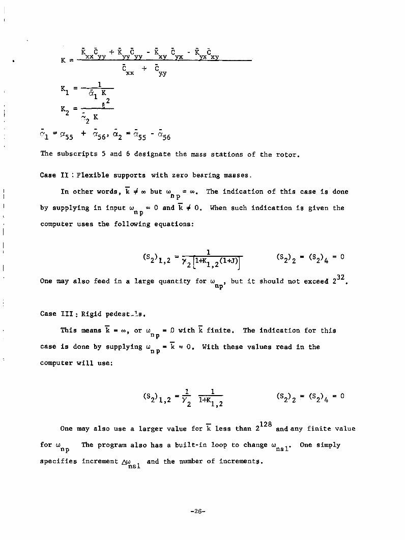
i7 E +it E - k E -it E xx yy xy yx yx xy K = E + E xx Y-Y
The s u b s c r i p t s 5 and 6 des igna te the mass s t a t i o n s of t he r o t o r . I
I Case I1 : F l e x i b l e supports w i th zero bearing masses.
I I n o t h e r words, # m but w = Q). The i n d i c a t i o n of t h i s case i s done f i P
= 0 and 'i; # 0. I
I by supplying i n input w
computer uses the following equat ions:
When such i n d i c a t i o n i s given the " P
(s2)1,2 = Y* t 32 , One may a l s o feed i n a l a r g e quan t i ty for w but i t should not exceed 2 . "P'
I Case I11 : Rigid pedest-Is .
This means = W , o r w = ,O with E f i n i t e . The i n d i c a t i o n f o r t h i s - "P
n P case is done by supplying w
computer w i l l use:
= k = 0. With these va lues read i n the
128 One may a l s o use a l a r g e r value f o r < less than 2
"P
and any f i n i t e va lue
f o r w
s p e c i f i e s increment AW and the number of increments.
The program a l s o has a b u i l t - i n loop t o change wnsl. One simply
n s 1
-26-

Rotor Response Calculations
After additional input data on the unbalances are read in, the computer
calculates the unbalance response using equations (13) - (16). This part
also has a built-up loop f o r u so that many different W may be used. The
quantity Wnsl will not be used (only the initial value will be used).
unbalance data are; q , E77, 978, z57, z58, Wms1, 60, g1, @,a, Au and NJ where
The -
= v1/(m0a5) , m is the unbalance mass (one of the two), 5 ' s the unbalance Oms1 0
eccentricities, 41 the phase angle lag in degree of 8 fram 5 , Ao. the increment 1 0
of the driving frequency, NJ the number of steps, and a ' s the influence co-
efficient.
from the equations given in Appendix E
If the rotor is uniform in cross section, the a l s may be obtained
The computational results are converted into elliptical terms using,
1 -1 j g
( e ) a = 1 tan j j
1 j x cos a j + Ys sin a! s. -1 Uj = tan x cos aj + yc sin a! C j j j
2 2 2 2
j j j j d = x + x + Yc + Y, C S j
-27 -
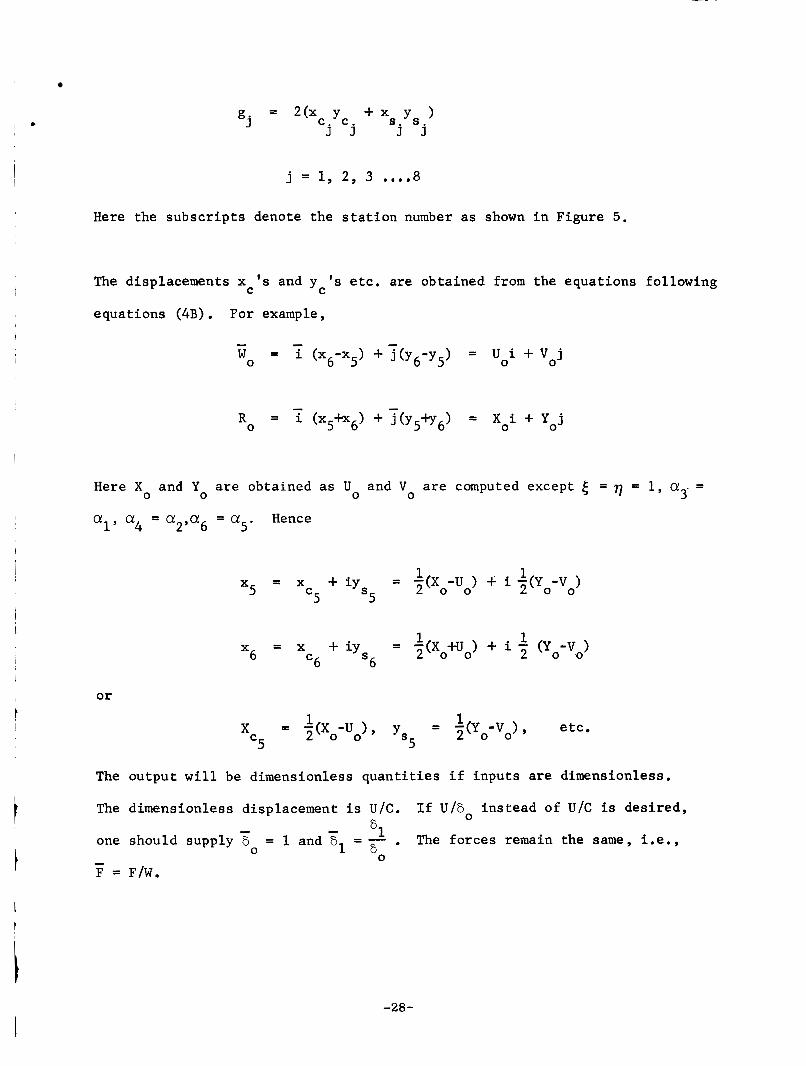
j = 1, 2, 3 .... 8 Here the subscripts denote the station number as shown in Figure 5 .
The displacements x ' s and y ' s etc. are obtained from the equations following
equations (4B). For example C C
- w = i (x -x ) +3(y6-y5) = uoi + v j 0 6 5 0
- R = i (x5+x6) + 3(y5+y6) = x i + Y j
0 0 0
Here X and Y are obtained as U 0 0 0
and V are computed except 6 = q = 1, a .. = 0 3
a = a ,a = a Hence 4 2 6 5'
1 1 x = x + iy = -(x -u ) t' i ~ ( y -v ) 5 C 5 S 5 2 0 0 0 0
or t
The
The
one
F = -
1 1 2 0 0 x = x + iy = -(X +u ) + i (yo-v0)
6 S '6 6
1 = -(Y 1 -V ), etc. xc = -(X -u > ¶ Y, 2 0 0 5 2 0 0 5
output will be dimensionless quantities if inputs are dimensionless.
dimensionless
should supply
F/W.
displacement is U/C. If U/6 instead of U/C is desired,
6
0
61 . The forces remain the same, i.e., = 1 and F1 = - - - 0 0 6
-28-
APPENDIX A
NOMENCLATURE
-29 -
a
A
b
b
B
C
C
D
E
F
i
i
I
j
j
-
IT - j
k
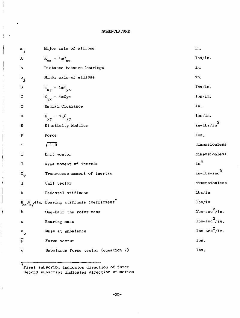
NOMENCLATUFLE
Major a x i s of e l l i p s e
K xx - idxx
Distance between bear ings
Minor a x i s of e l l i p s e
K - i w C XY YX
K - iwCyx YX
Radial Clearance
K - iwcyy YY
E l a s t i c i t y Modulus
Force
/xi? Un i t vec to r
Area moment of i n e r t i a
Transverse moment of i n e r t i a
Unit vec to r
Pedes t a l s t i f f ness *
K ,K etc. Bearing s t i f f n e s s c o e f f i c i e n t = xy’
M One-half the r o t o r mass
m Bearing mass
m Mass a t unbalance
P Force vec to r
0 -
- q Unbalance f o r c e vec tor (equat ion 7)
i n .
l b s / in .
i n
i n .
l b s / in .
l b s / in .
i n .
l b s / in .
3 in- l b s / i n
lb s .
dimens i o n l e s s
dimensionless
i n
in- lbs-sec
4
2
dimens i o n l e s s
l b s / i n
l b s / i n
lbs -sec 2 / i n .
lbs -sec 2 / i n .
lbs-sec 2 / i n .
l b s .
l b s .
* F i r s t s u b s c r i p t i n d i c a t e s d i r e c t i o n of f o r c e Second s u b s c r i p t i n d i c a t e s d i r e c t i o n of motion
-30-
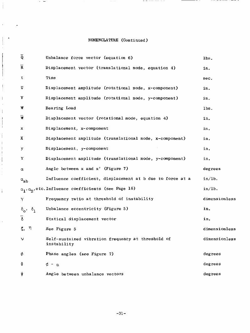
I . NOMENCLATURE (Continued) ~
- Q Unbalance f o r c e vec to r (equation 6)
R Displacement vec to r ( t r a n s l a t i o n a l m o d e , equa t ion 4)
t Time
I -
W Bearing Load ,
W Displacement vec to r ( r o t a t i o n a l mode, equat ion 4)
X Displacement, x- component
X Displacement amplitude ( t r a n s l a t i o n a l mode, x-component)
Y D i s p 1 a cemen t , y- component
Y Displacement amplitude ( t r a n s l a t i o n a l mode, y-component)
U Angle between x and x' (Figure 7)
aab In f luence c o e f f i c i e n t , displacement a t b due t o f o r c e a t a
, a , etc . In f luence c o e f f i c i e n t s (see Page 16) al 2
Y Frequency r a t i o a t threshold of i n s t a b i l i t y
Unbalance e c c e n t r i c i t y (Figure 5 ) 60, 6, - 6 S t a t i c a l displacement vec to r
5 , q See Figure 5
V Se l f - sus t a ined v i b r a t i o n frequency a t th reshold of i n s t a b i l i t y
@ Phase ang le s (see Figure 7)
l b s .
i n .
sec.
i n .
i n
l b s .
i n .
i n .
i n ,
i n .
i n .
degrees
i n / l b .
i n / lb .
d imens ionless
in .
i n .
d i m e n s i on 1 e s s
dimensionless
degrees
degrees
degrees
@ @ - a
Jr Angle between unbalance vec tors
-31-
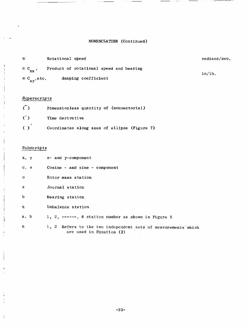
NOMENCLATURE (Continued)
I W Rota t iona l speed
t Product of r o t a t i o n a l speed and bear ing cxx’
, W C etc. damping c o e f f i c i e n t XY’
S u p e r s c r i p t s
(-- 1 Dimensionless q u a n t i t y Of (nonvector ia l ) I
1 ( * ) Time d e r i v a t i v e t
0 Coordinates along axes of e l l i p s e (Figure 7)
S u b s c r i p t s
x9 Y x- and y-component I I c , s Cosine - and s i n e - component
0 Rotor mass s t a t i o n
S Journa l s t a t i o n
b Bearing s t a t i o n
I
Unbalance s t a t i o n
~ 8 s t a t i o n number a s shown i n Figure 5
L i a , b 1, 2 , ------
n 1, 2 Refers t o t h e two independent sets of measurements which I a r e used i n Equation (2)
rad ians /se c .
i n / lb .
-32-
i
APPENDIX B
ROTOR RESPONSE COMPUTER PROGRAM
-33-
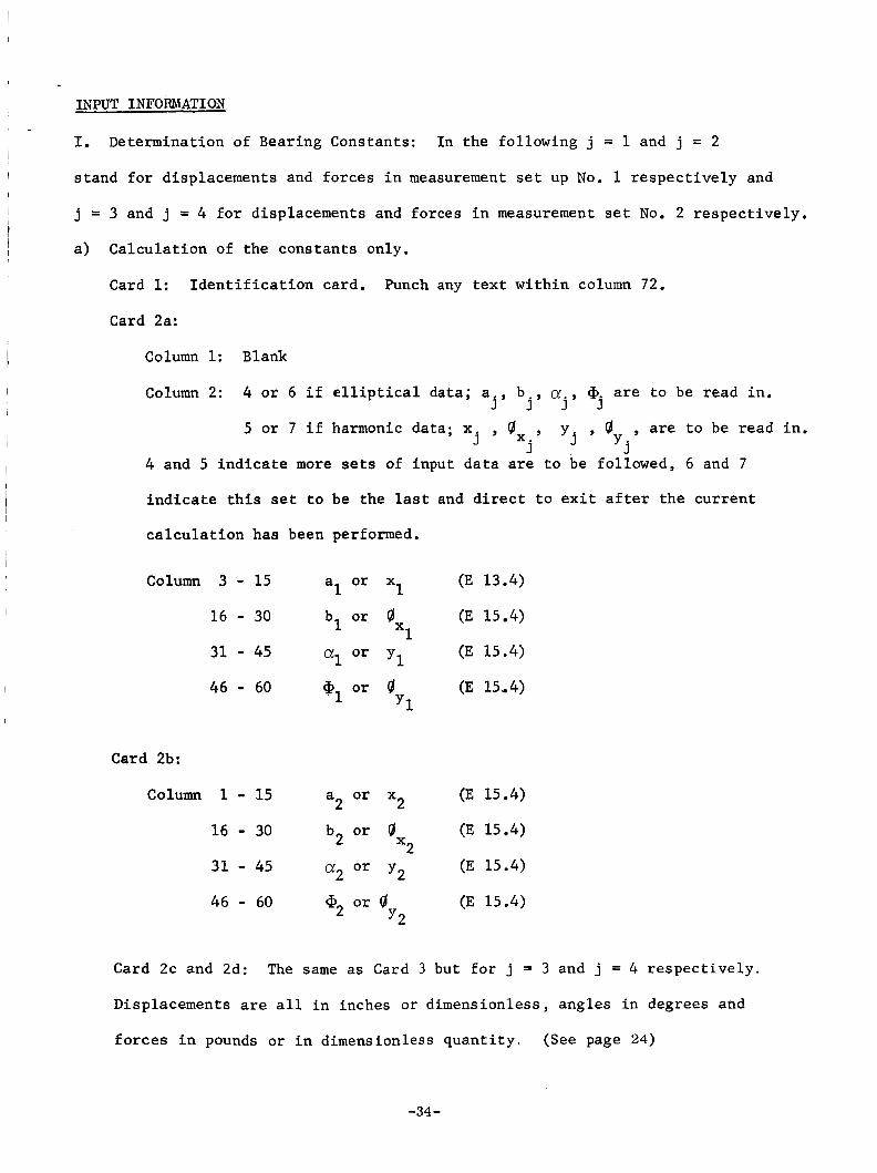
IKPUT INFORMATION
I. Determination of Bearing Constants:
stand for displacements and forces in measurement set up No. 1 respectively and
j = 3 and j = 4 for displacements and forces in measurement set No. 2 respectively.
In the following j = 1 and j = 2 I
I I a) Calculation of the constants only, l
I Card 1: Identification card. Punch any text within column 72.
I Column 1: Blank
Column 2: 4 or 6 if elliptical data; a b , a . , @. are to be read in. j ' j J J
, 9' , are to be read in. 'j 'j
5 or 7 if harmonic data; x , Ox , j j
4 and 5 indicate more sets of input data are to be followed, 6 and 7
indicate this set to be the last and direct to exit after the current
I calculation has been performed.
(E 13.4) 1 a or x 1 Column 3 - 15 16 - 30 bl or 0 (E 15.4)
Xl I
(E 15.4) y1 31 - 45 al or
46 - 60 G1 or 0 (E 15.4) Y1
Card 2b:
(E 15.4)
16 - 30 b2 or Qx (E 15.4)
(E 15.4) 31 - 45 a2 or
46 - 60 a2 or 9' (E 15.4)
2 a or x 2 Column 1 - 15
2
y2
y2
Card 2c and 2d: The same as Card 3 but for j = 3 and j = 4 respectively.
Displacements are all in inches or dimensionless, angles in degrees and
forces in pounds or in dimensionless quantity. (See page 24)
-34 -
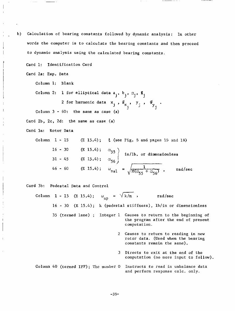
I I . b) Ca lcu la t ion of bear ing cons t an t s followed by dynamic a n a l y s i s : In o t h e r
words t h e computer is t o c a l c u l a t e the bear ing cons t an t s and then proceed
t o dynamic a n a l y s i s us ing t h e ca l cu la t ed bear ing cons t an t s .
i I I
Card 1: I d e n t i f i c a t i o n Card
Card 2a: Exp. Data
I
Column 1: Blank
Column 2: 1 f o r e l l i p t i c a l d a t a a j , b j , a . , P ~j
2 for harmonic d a t a x , ox , y,. , . j j J 'j
column 3 - 60: t he same as case (a)
, Card 2b, 2c, 2d: t he same as case (a)
Card 3a: Rotor Data
Column 1 - 15 (E 15.4) ; 5 (see Fig . 5 and pages 15. and 18)
i n / l b . o r dimensionless 16 - 30
a56 ) 31 - 45 (E 15.4) ;
I
I Card 3b: Pedes t a l Data and Control
Column 1 - 15 (E 15.4); w = - 4 z , r ad / sec np
i 16 - 30 (E 15.4) ; k (pedes ta l s t i f f n e s s ) , l b / i n o r dimensionless
t
35 (termed l ane ) ; In t ege r 1 Causes t o r e t u r n t o t h e beginning of t h e program a f t e r t h e end of present c ompu t a t ion .
2 Causes t o r e t u r n t o reading i n new r o t o r da t a . (Used when t h e bear ing cons t an t s remain t h e same).
3 Direc ts t o e x i t a t t h e end of t h e computation (no more input t o fo l low) .
Column 40 (termed IFF); The number 0 I n s t r u c t s t o read i n unbalance d a t a and perform response c a l c . only.
-35-
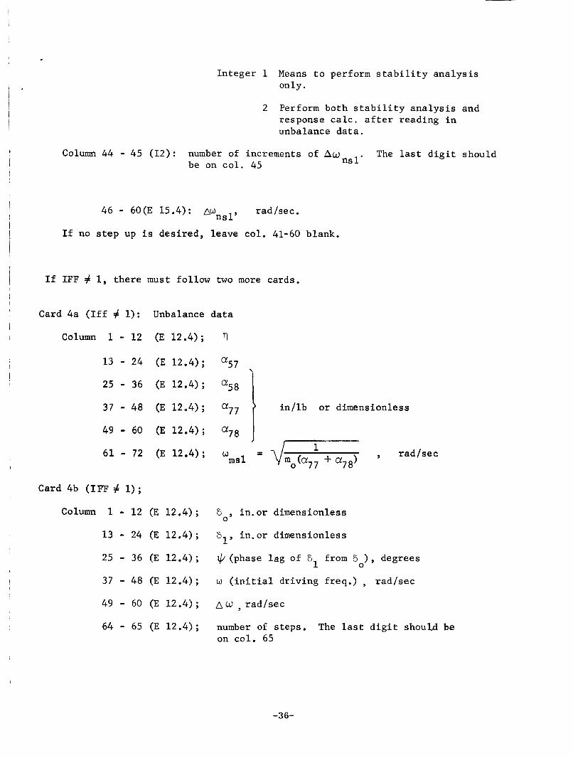
In t ege r 1 Means t o perform s t a b i l i t y a n a l y s i s only.
2 Perform both s t a b i l i t y a n a l y s i s and response c a l c . a f t e r reading i n unbalance d a t a .
Column 44 - 45 (12): number of increments of Aw be on c o l . 45 n s l ' The last d i g i t should
46 - 60(E 15.4): Awnsly rad /sec .
I f no s t e p up i s des i r ed , leave col . 41-60 blank.
I f IFF # 1, t h e r e must fol low two more cards.
Card 4a ( I f f # 1): Unbalance
Column 1 - 12 (E 12.4) ;
13 - 24 (E 12.4);
25 - 36 (E 12.4);
37 - 48 (E 12.4);
49 - 60 (E 12.4) ;
61 - 72 (E 12.4);
Card 4b ( IFF # 1) ;
Column 1 - 12 (E 12.4) ;
13 - 24 (E 12.4) ;
25 - 36 (E 12.4);
37 - 48 (E 12.4) ;
49 - 60 (E 12.4) ;
64 - 65 (E 12.4) ;
da ta
rl
a5 7
a58 ] i n / l b o r dimensionless
a7 8
= d-+a,,, , r ad / sec
a77 1 w m s l
E o , in .or dimensionless
61, in . o r dimensionless
$' (phase l a g of 6
w ( i n i t i a l , d r iv ing f req . ) , r ad / sec
A w rad / sec
from "), degrees 1
number of s teps . on co l . 65
The las t d i g i t s h o u u be
-36-
I I
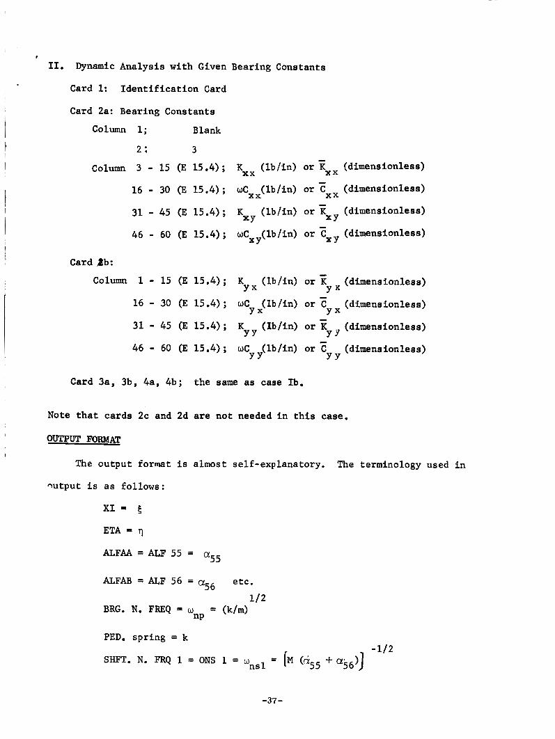
11. Dynamic Analysis with Given Bearing Constants
Card 1: Identification Card I . ~
Card 2a: Bearing Constants
Column 1; Blank
2; 3 I I I
I Column 3 - 15 (E 15.4) ; K (lb/in) or T i x x (dimensionless) 16 - 30 (E 15.4) ; (dimensionless)
31 - 45 (E 15.4) ; K (lb/in) or (dimensionless)
46 - 60 (E 15.4); wCxy(lb/in) or (dimensionless)
xx wCXx (lb /in) or Ex I XY XY
I XY
Card Bb:
Column 1 - 15 (E 15.4); K (lb/in) or x (dimensionless)
16 - 30 (E 15.4) ; WC (lb/in) or c (dimensionless)
31 - 45 (E 15.4) ; K (Ib/in) or (dimensionless)
46 - 60 (E 15.4); WC (lb/in) or (dimensionless)
Y X Y X
Y x Y X
Y Y Y Y
Y Y Y Y
I Card 3a, 3b, 4a, 4b; the same as case Ib.
Note that cards 2c and 2d are not needed in this case.
0U" FORMAT I
The output format is almost self-explanatory. The terminology used in
wtput is as follows:
XI = .g
ALFAA = ALF 55 = a55
ALFAB = ALF 56 - - a56
BRG. N. FREQ = w
etc.
1/2 = (k/m) nP
PED. spring = k
-37-
I . - 1/2
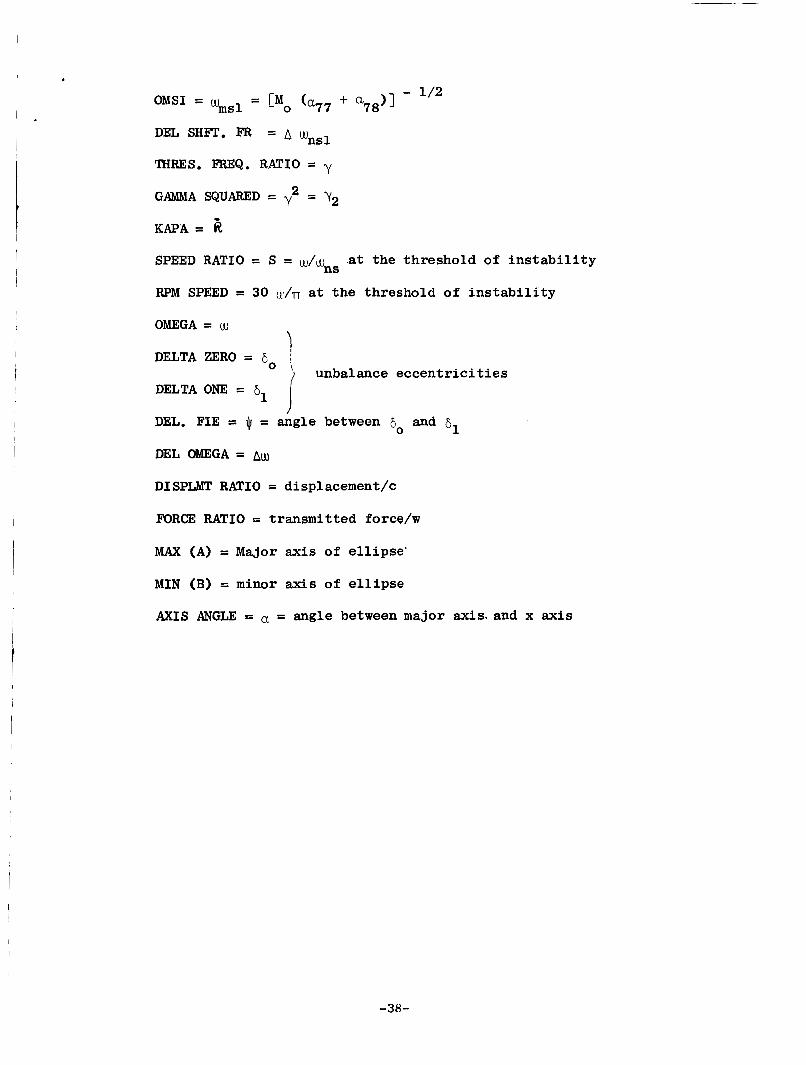
OMS1 = wmsl = Po (a7? +
DEL SHFT. F’R = A wnSl THRES. FREQ. RATIO = y
GAMMA SQUARED = y2 = Y2
K A P A = 8, SPEED RATIO = S =
RPM SPEED = 30 t k d n a t the threshold of ins tab i l i ty
at the threshold of ins tab i l i ty W/uUnS
OMEGA = w
DELTA ZERO = 6,
DELTA ONE =
DEL. FIE = Jr = angle between 8
unbalance eccentr ic i t ies
0
61 I and ijl
DEL OMEGA = &J
DISPLMT RATIO = displacement/c
FORCE RATIO = transmitted forcdw
MAX (A) = Major axis of e l l ipse ’
MIN (B) = minor axis of e l l i p s e
AXIS ANGLE = a = angle between major axis. and x axis
i
-38-
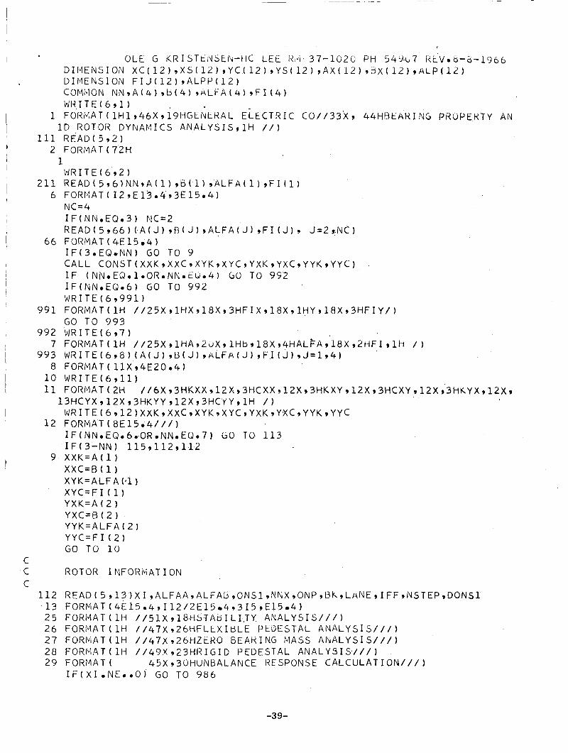
C C C
OLE G KKISTtI lSEh-t1C LkE I<,VI 37-1(326 PH 5 4 4 . ~ , 7 Kk.V.6-6-1966 DIIVIENSION X C ( 1 2 ) , X S ( 1 2 ) , Y C ( 1 2 ) ~ Y S ( l 2 ) ~ A X ( l Z ) ~ ~ X ( l Z ) ~ ~ L P ( l ~ ) DIMENSlON F I J ( l Z ) , A L P P ( l Z ) COMMON N N , A ( 4 ) 9 b ( 4 ) , A L F A ( 4 ) 9 F I ( 4 ) W R I T E ( 6 , l )
1 FOriMAT ( 1H1,46X, 19HGENti lAL ELECTRIC C 0 / / 3 3 X 9 44HHEkR.I NG PROPERTY AN I D ROTOR DYNAMICS A N A L Y S I S g l H / / I
111 R E A D ( 5 9 2 ) 2 FORMAT ( 7 2 H
1JR I T E ( 6 9 2 1 1
2 1 1 R E A U ( 5 , 6 ) N N , A ( l ) , ~ ( l ) ~ ~ L ~ ~ ( l ) ~ F I ( l ) 6 FORP.IAT( IZ,E1304,3E15.4)
NC=4 IF(NN.EQ.3) NC=2 R E A D ( 5 , 6 6 ) ( A ( J ) , O ( J ) , A L F ~ ( J ) , F I ( J ) , J = 2 r N C ) FORMAT ( 4E 1 5 4 1 IF(3.EQ.NN) GO T O 9 C A L L C O N S T ( X X K , X X C , X Y K , X Y C , Y X K , Y X K , Y X C , Y Y K , Y Y C ) I F (NN.EO.l.OR.NN.EU.4) GO T O 9 9 2 IF(NN.EQ.6) GO T O 9 9 2 W R I T k ( 6 , 9 9 1 )
GO T O 9 9 3 WRITE ( 6 97 1
66
991 FORMAT(1H / / 2 5 X ~ 1 H X ~ 1 8 X ~ 3 H F I X ~ 1 8 X , 1 H Y , 1 " F I Y / )
9 9 2
9 9 3 W R I T E ( 6 , 8 ) ( A ( J ) , U ( J ) , A L F H o , F I ( J ) , J = 1 , 4 ) 7 FORMAT( 1H / / 2 5 X , 1 H A , Z ~ X , l H b , 1 8 X , 4 H A L i A , 1 8 X , 2 " 1 , l H / )
8 FORFIAT( l l X 9 4 E 2 0 . 4 ) 10 W R I T E ( 6 9 1 1 ) 11 FORMAT(2H / / 6 X , 3 H K X X , 1 2 X , 3 H C X X , 1 2 X , 3 " C X Y , l 2 X , 3 H C X Y , l 2 X , 3 H ~ Y X , l 2 X ,
13HCYX912X 93HKYY ,12X,3HCYY ,1H / I W R I T E ( 6 , 1 2 ) X X K , X X C , X Y K , X Y C , Y X K , Y X C , Y Y K , Y Y C
1 2 FORMAT(8E15 .4 / / / ) IF(NN.EQ.6.0R.NN.EW.7) GO TO 1 1 3 I F ( 3 - N N ) 115,112,112
9 X X K = A ( l ) X X C = R ( 1 1 XYK=ALFA( , l ) X Y C = F I ( l ) YXK=A ( 2 1 Y X C = B ( 2 1 Y Y K = A L F A ( 2 ) Y Y C = F I ( 2 ) GO TO 10
ROTOR I NFORb'iAT I ON
1 2 READ(5 ,13 )X I ,ALFA ,ALFAb,ONSl, INX,ONP,B~,LHNE,IFF,NSTEPIDONS 1 3 2 5 FORMAT(1H / /51X,18HSTAUIL I%TY A N A L Y S I S / / / ) 2 6 FORMAT(1H / /47X926HFLLXIBL' i PtDESTAL A N A L Y S I S / / / ) 27 FORMAT ( 1 H / /47X,26HZtHO GEARING MASS A N A L Y S I S / / / ) 2 8 FORIYAT(1H / / 4 9 Y , 2 3 H K I G I D PEDESTAL A N A L Y S I S / / / ) 2 9 FORMAT( 45X,30HUNBALANCE RESPONSE CALCULATION/ / / )
FORPIAT ( 4 E 1 5 - 4 I 1 2 / 2 E 1 5 4 9 3 I 5 9 E15 4 1
I F ( X I o N E . * O ) GO T O 9 8 6
-39-
73 FORMAT ( 7 X ,2HX I 9 ‘ 9 x 9 5HALFAA 98X,95HALFAE3 9 6 X 9 1 0 H l 3 R G 0 h ~ F K E u 9 4 X 9 9HPLD.sPK
-40-
-41-
-42-
i
c C
-43-
-44-
! -
' c
I C
-45-
-46-
c
-47 -
715
4 5 I
46
t 47
i 48
1 9 4 3
I
I 987 I 113
16 1 % I
, 113 61
-48-
i 100
, I 62
I 63 6 4
-49-
c Read Experiment a1 Data
o r Bearing Data
4.
Compute Bearing Data
1
Compute Bearing Data
1
IFF
I I
S t a b i l i t y
([N Step+l] Calc.)
Ana l y s i s
F b Response Calc. IFF :T ([N Jump+l] Calc.)
Lane = 2 / \ 3
I
Lane = 2
Lane = 3
1 I Exit I J1052-8
Figure 8. Flow Chart.
-50-
APPENDIX C
ROTOR RESPONSE EXAMPLES
-51-
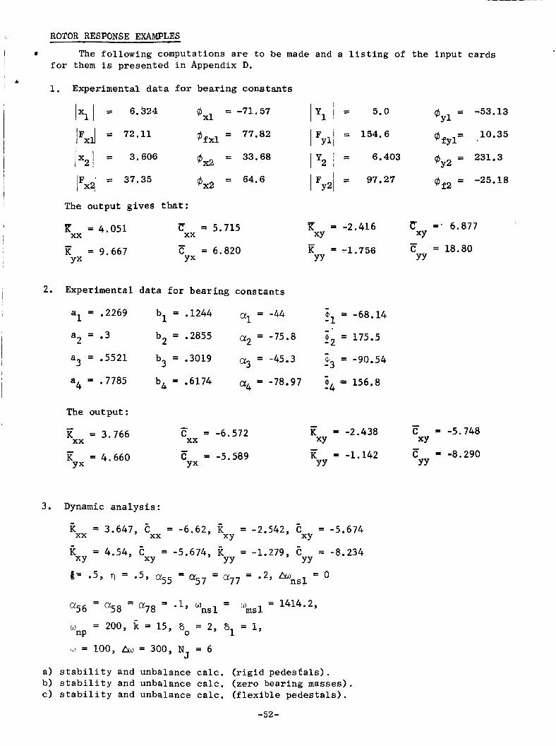
I ROTOR RESPONSE EXAMPLES
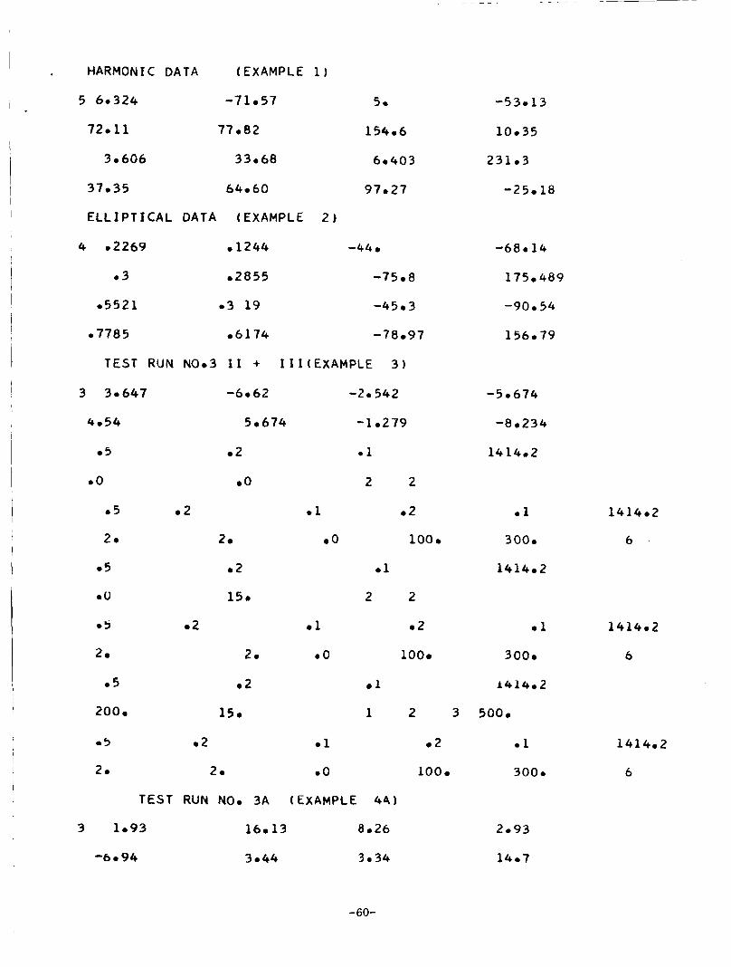
I The following computations are to be made and a listing of the input cards I for them is
1. Experimental data for bearing constants
presented in Appendix D. I
Ixl I = 6.524 GXl = -71.57
lFxd = 72.11 qjfxl = 77.82
= 33.68 jx2/ = 3.606 I
@X2
@x2 = 64.6 IFXd = 37*35
The output gives that:
C = 5.715
= 9.66? C = 6.820
xx R = 4.051 xx - YX YX
2. Experimental da ta f o r bearing constants
al = .2269 bl = .1244 a1 = -44
a3 = .5521 b3 = .3019 a3 = -45.3
a = .3 b2 = .2855 a2 = -75.8 2
Iy1 I = 5.0 @Y1 = -53*13
I Fyll = 154*6 @fyl *
I y2 I = 6*403 @Y2 = 231*3
L 10.35
I Fy21 = 97.27 of2 = -25.18
R = -2.416 ZT =- 6.877 XY XY
YY YY = 18.80 -
K = -1.756
- 21 = -68.14 - i2 = 175.5 - t3 = -90.54 -
a4 = .7785 bh = .6174 a4 -78.97 - “4:- 156.8
The output: - = -2.438 C = -5.748
K = -1.142 C = -8.290
- - XY
YY YY
C = -6.572 - xx XY K = 3.766 xx - -
K = 4.660 c = -5.589 YX YX
3. Dynamic ana lys i s :
k = 3.647, E = -6.62, -2.542, E = -5.674
E = 4.54, E = -5.674, k -1.279, E = -8.234 xx xx XY XY
XY XY YY YY - - - 6= 05, rl = 05, a55 - a57 - a77 - 02, hnsl = 0
- w = 1414.2, - - m s 1
w 200, = 15, a0 2, a1 = 1,
a56 - a58 - a78 = 0 ) - ns 1
nP = 100, h*, = 300, NJ 6
a) stability and unbalance calc. (rigid pedesfals). b) stability and unbalance calc. (zero bearing masses). c) stability and unbalance calc. (flexible pedestals).
-52-
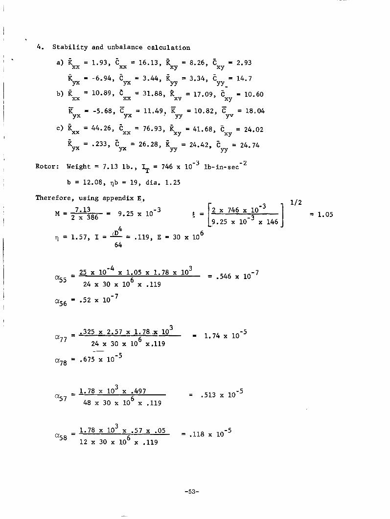
4. Stab i l i ty and unbalance calculation 4
a) kxx = 1.93, = 16.13, k = 8.26, e = 2.93 XY XY
YY yy-
xx
R = -6.94, C = 3.44, R = 3.34, 7: = 14.7
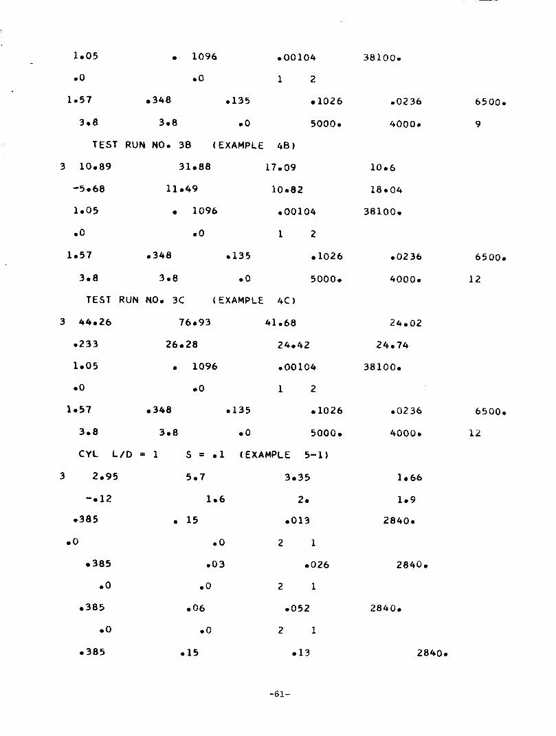
b) i? = 10.89, c = 31.88, a = 17.09, = 10.60
K = -5.68, E 11.49, E 10.82, E = 18.04
YX Yx
XY XY
YX YX . YY YV
XY XY
xx xx -
c) Rxx = 44.26, = 76.93, l? = 41.68, = 24.02 xx
.233, E = 26.28, R 24.42, E = 24.74 Yx YY YY YX
Rotor: Weight = 7.13 l b . , IT = 746 x lb-in-sec - 2
b = 12.08, vb = 19, dia. 1.25
Therefore, using appendix E ,
= 1.05 1 2 746 9.25 x x 146
M = 2 7*13 x 386 = 9.25 E = [
6 4
64 7 1.57, I z-3 TD .119, E = 30 x 10
3 = .546 - 25 x x 1.05 x 1.78 x 10
6 -
24 x 30 x 10 x .119
= 1.74 - .325 x 2.57 x 1.78.~ lo3 6 24 x 30 x 10 x.119 a77 -
3 = .513 - 1.78 x 10 x .497 -
6 a57 48 x 30 x 10 x .119
-53-
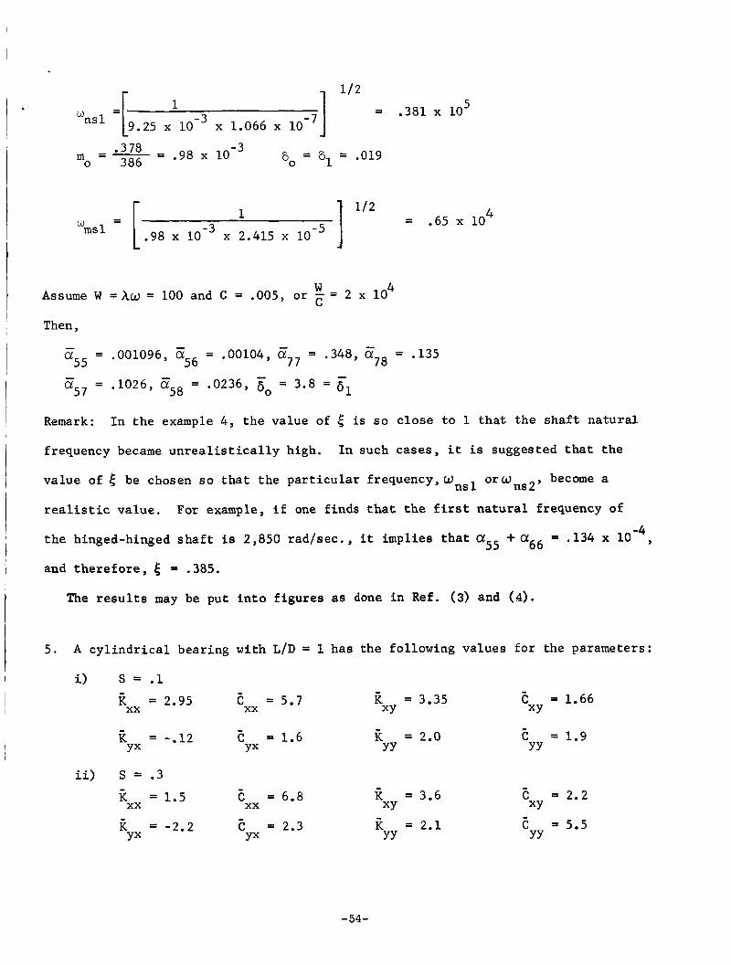
5 = .381 x LO 1 u2 1
ns 1 =[9.25 x x 1.066 x w
8, = 61 = .019 m = - = *378 .98 o 386
4 = .65 x 10 I m s l = [ .98 10-3 2.415 10-5
1 w
4 Assume W = Xu = 100 and C = .005, o r = 2 x 10
Then,
- a55 = .001096, 6!56 = .00104, z7, = .348, 6!78 = .135
a57 = .1026, z58 = .0236, 6 = 3.8 = 61 - -
0
Remark:
frequency became u n r e a l i s t i c a l l y high.
I n t h e example 4 , t h e va lue of 5 i s so c l o s e t o 1 t h a t t h e s h a f t n a t u r a l
In such cases, i t is suggested t h a t t h e
v a l u e of 5 be chosen so t h a t t h e p a r t i c u l a r f requency,Onsl o r a n s 2 , become a
realistic v a l u e .
t h e hinged-hinged s h a f t i s 2,850 r a d / s e c . , it implies t h a t c X ~ ~ +a66 = ,134 x 10
and t h e r e f o r e , 5 = .385.
For example, i f one f inds that the f i r s t n a t u r a l frequency of
-4 ,
The r e s u l t s may be put i n t o f i g u r e s as done i n Ref. (3) and (4).
5 . A c y l i n d r i c a l bear ing wi th L/D = 1 h a s t h e fol lowing va lues f o r the parameters:
i) S = .1 - - K = 3.35 E = 1.66
K = 2.0 c = 1.9
XY E = 5.7
XY K = 2.95 xx xx - - - -
YY C = 1.6
YY K = -.12
YX YX
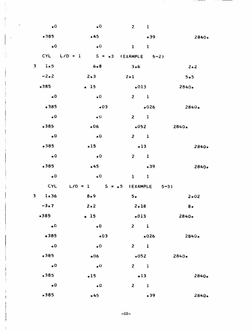
ii) S = .3 - K = 1.5 xx
- C = 6.8
xx - K = -2.2 E = 2.3
YX YX
- K = 3.6
K = 2.1 XY
YY -
e = 2.2 XY - c = 5.5 YY
-54-
I
I
iii) S = .5 - - - -
C = 8.9 K = 5.0 c = 2.0 K = 1.36
K = -3.7 E = 2.2 = 2.18 E = 8.0
xx XY XY
YX YX YY YY
xx
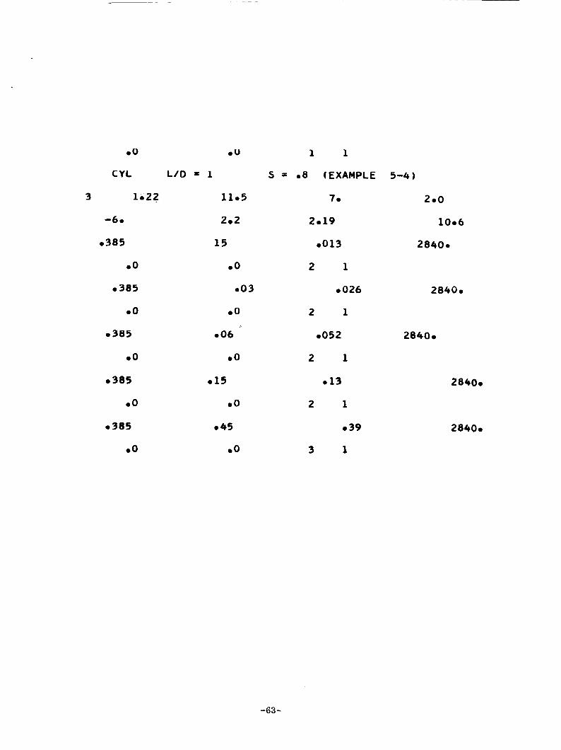
i v ) S = .8 - - -
C = 11.5 K = 7.0 E = 2.0 xx XY XY
YX YX YY YY
K = 1.22
K = -6.0 c = 2.2 K = 2.19 e = 10.6
xx - - -
a)
b)
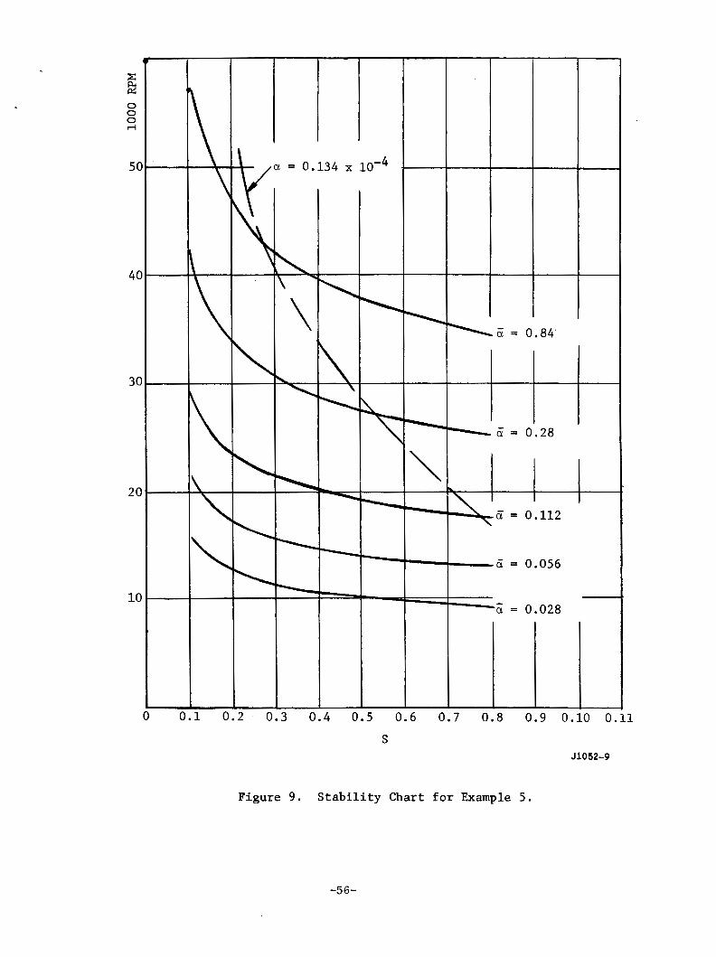
Make a s t a b i l i t y c h a r t f o r t h e bearing.
A 7.13 l b r o t o r has t h e f i r s t n a t u r a l frequency of 2,850 r ad / sec wi th
hinged-hinged ends. -Find speeds a t t h e th re sho ld of i n s t a b i l i t y . Assume
-8 C = ,0015, D = 1.25, LI. = 12 x 10 . -4
Knowing the n a t u r a l frequency of the r o t o r , one f i n d s a 55 + a66 = .134 x 10
compute 5 = .385 us ing t h e formulas i n Appendix E.
and
With va r ious va lues of 6, a s t a b i l i t y c h a r t (Fig. 9) i s obtained. Then the l i n e
-4 f o r a = .135 x 10 i s c ros s p l o t t e d a s shown by a do t t ed l i n e (Figure 9),
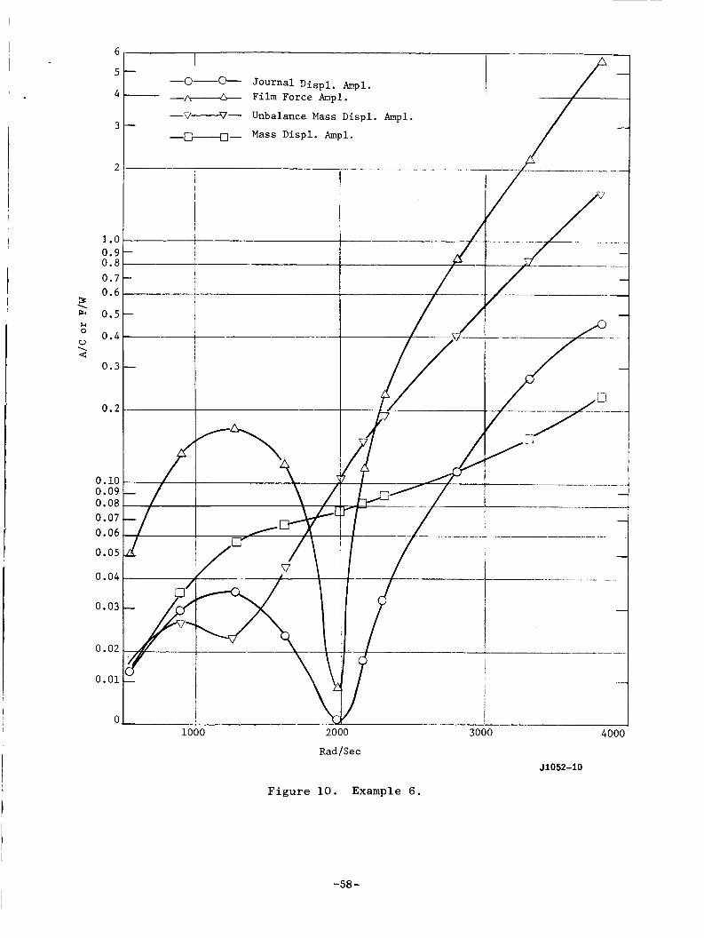
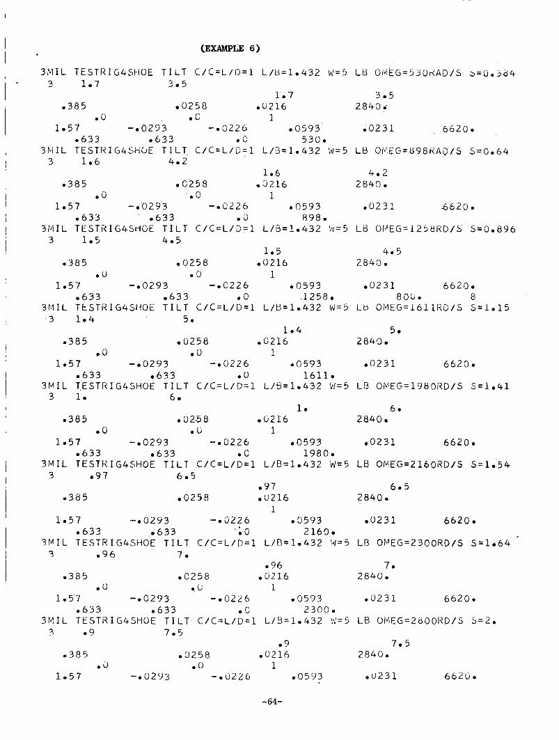
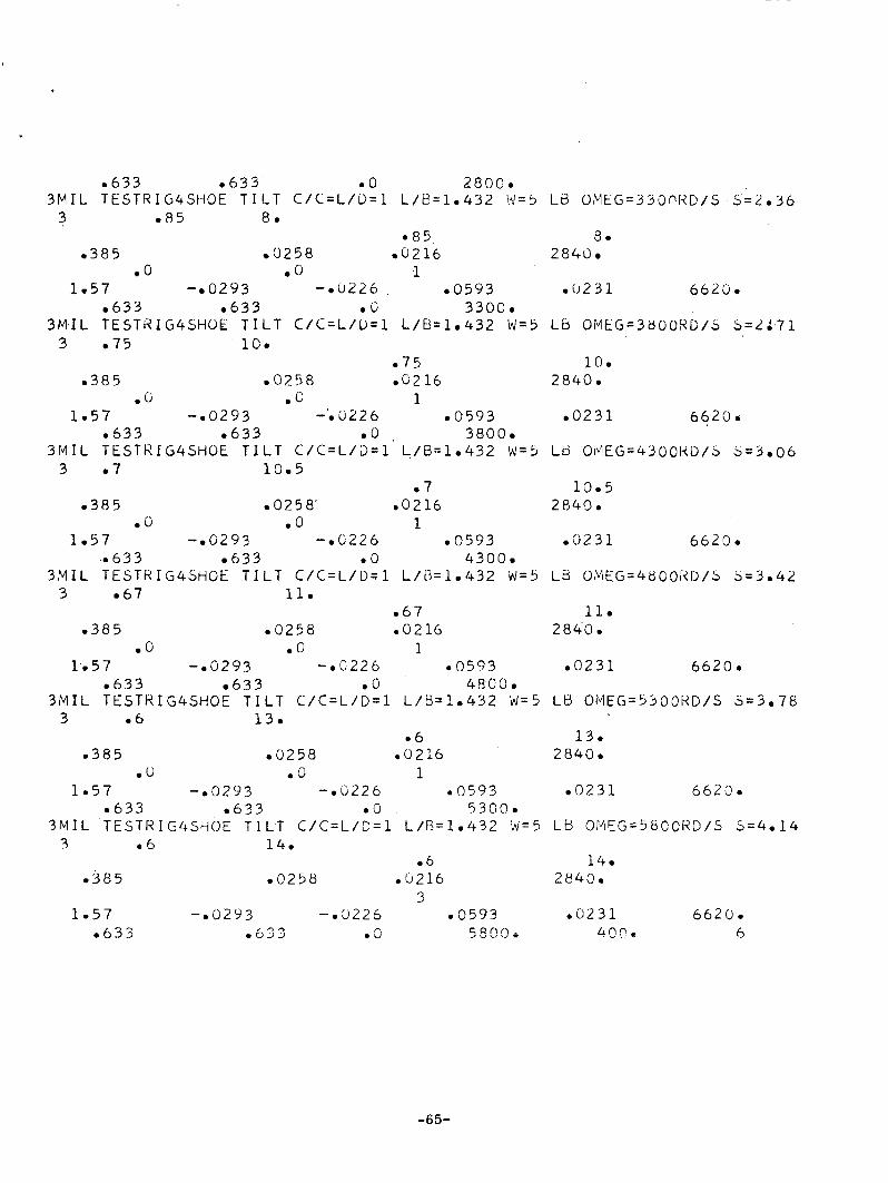
6. A t e s t r i g has the fo l lowing s p e c i f i c a t i o n s :
Rotor: Weight = 7 l b s . , b = 12.5, D = 1.25", f i r s t c r i t i c a l speed = 2,840 Rad/sec.
Bearings: 80 0 4 shoe t i l t i n g pads, L/D = 1, C'/C = 1
CD = .003", u. = 8.3 x 10 -8 1bs.-sec. / in . 2
Load: 5 l b s .
Unbalance Mass: Weight = .378 l b s .
E c c e n t r i c i t y = .00095"
q b = 19"
Make response c a l c u l a t i o n s f o r 500 4 w < 4000
Inpu t P repa ra t ion :
M = .00875 , a = 1/Mun2 = .141 x - w - as5 + a56 = .47
-55-
4 t
= 0.134 x
I I
T
% 15 = 0.84
d = 0.056
- - c1 = 0.028
0 .1 0 .2 0.3 0.4 0.5 0.6 0.7 0.8 0.9 0. .o 0.
S J1052-9
.1
Figure 9 . S t a b i l i t y Chart for Example 5.
-56-
I
{ (1 - E2I2 + (1- - El2 [ 2 - (1 - C;) b3 Using a = - 48EI
One g e t s C; = .385
Hence -
0 1 ~ ~ = .0258
-
a77 = .0593
- = .0216
- = -.0226
- c~~~ = ,0231
6/CR = .633
For bearing parameters, one may use data given i n A i r Force Technical Report,
AFAPL-TR-65-45.
of Sommerfeld number.
There the spr ing and damping coe f f i c i en t s a r e p lp t t ed as a funct ion
For t h i s example,
S = .00713w
Thus, f o r a given w, and E a r e obtained.
The r e s u l t s may be p lo t t ed a s i n Figure 10.
-57-
I .
6
5
4
3
2
1.0 0.9 0.8 0.7 0.6
s LW 0.5
0.4
0.3
\
t-l 0
U \ 4
0.2
0.10 0.09 0.08 0.07 0.06
0.05
0.04
0.03
0.02
0.01
0
~ __ P - -0-* Journal D i sp l . b p i .
- -- Film Force Ampl.
-V+- Unbalance Mass Displ . Ampl.
- 0 4 - Mass Displ . Ampl. - /
1000 2000
Rad/Sec
Figure 10. Example 6 .
3000
JlO52-10
-58 -

APPENDIX D
LISTING OF INPUT CARDS FOR EXAMPLES
-59-
I HARMON IC DATA (EXAMPLE 1 )
3.606 33.68 6.403 231.3
I . 5 6.324 -7 1. 57 5. -53.13
72.11 77.82 154.6 10.35
a5521 03 19 -45.3 -90.54
e7785 a 6 1 7 4 -78.97 156.79
I I
T E S T R U N NO03 I 1 + III(EXAMPLE 3 )
I 3 3.647 -6.62 -2.542 -5.674
I
I I 4.54 5.674 -1 0 2 7 9 -8.234
05
.O
01 1414.2
2 2
e5 02 .I 02
2. 2. 00 100.
05 02 01
.O 15. 2 2
0 5 02 e 1 02
2. 2 . .O 100.
.5 0 2 01
200. 15. 1 2 3
* 3 .2 0 1 02
2. 2. 00 100.
TEST RUN NO. 3 A (EXAMPLE 44)
3 1.93 16.13 8.26
-be 94 3.44 3.34
e 1
300.
1414.2
01
300.
1414.2
500.
01
300.
2.93
14.7
1414.2
6
1414.2
6
1414.2
6
-60-
1.05 1096 bo0104
00 b o 1 2
1.57 348 0135 1026
3.8 308 00 5 0 0 0 0
TEST RUN NO. 38 (EXAMPLE 48)
3 10.89 31.88 17.09
-5 68 11.49 10.82
1.05 1096 e00104
.O .O 1 2
1057 e 3 4 8 e135 1026
3.8 308 .O 5000.
TEST RUN NO0 3C (EXAMPLE 4 C )
3 44.26 76.93 41 e68
a233 26.28 24.42
1.05 0 1096 000104
.O 00 1 2
1.57 348 e135 e1026
3.8 3.8 .O 5000.
C Y L L /D = 1 S = e 1 (EXAMPLE 5-11
3 2.95 5.7 3.35 -. 12 1.6 2.
m385 0 15 e013
.O 00 2 1
385 0 0 3 a026
.O .O 2 1
e385 06 0052
00 e o 2 1
-385 015 13
38100.
e0236 65000
4000. 9
1006
18.04
38100.
6 5 0 0 0 e0236
40000 12
24002
24.74
38100.
e 0 2 3 6 65000
40000 12
1.66
1.9
2840.
2840.
-61-
I
00 .O 2 1
m385 .45 . 39
.O .O 1 1
CYL L I D = 1 S = e3 (EXAMPLE 5-21
3 1.5 6.8 3.6
-2.2 2.3 2.1
e385
.O . 385
.O
0 3 8 5
.O
e385
.O
0 3 8 5
.O
C Y L
3 1.36
-3.7
.3a5
00
305
00
m385
00
0 3 8 5
00
e385
15 m013
.O 2 1
m03 e026
.O 2 1
e06 e052
.O 2 1
a 1 5 13
.O 2 1
45 0 39
.O 1 1
L/O = 1 s = 0 5 (EXAMPLE 5-3 1
8.9 5.
2.2 2018
1 5 0013
e o 2 1
a 0 3 0026
.O 2 1
06 m052
00 2 1
a 1 5 13
.O 2 1
m45 . 39
2840.
2.2
5.5
2840.
2840.
2840.
2840.
2840.
2.02
0.
2840.
2840.
2840.
2840.
2840.
-62-
.O .U
CYL L/D = 1 s =
3 1.22 11.5
-6 0 2.2
e385 15
.O .O
0385 003
00 .O
1 1
0 8 (EXAMPLE
7.
2.19
e013
2 1
e026
2 1
e385 e 0 6 e052
00 00 2 1
e 385 015 013
00 .O 2 1
e 385 045 0 39
.O .O 3 1
5-4 1
2.0
10.6
2840.
2840.
2840.
2840.
2840.
-63-
I I
(EXAMPLE 6 )
3 M I L TESTRIG4SHOE T I L T C / C = L / I ) = l L / U = l a 4 3 2 W=5 Ltj 014EG=550kAD/S b = Q a 3 6 4 3 l a 7 3 a 5
l e 7 3.5 a385 e 0 2 5 8 aG216 2840.
a O e G 1 1.57 - a 0 2 9 3 -a0226 a0593 a 0 2 3 1 6 6 2 0 a
a633 a 6 3 2 a U 530. 3 M I L TESTItIG4SHUE T I L T C / C Z L / D = l L/c1=1a432 W=5 LB @tv “EG=898KAQ/S S=Oe64
3 l a 6 4.2 1 a6 4.2
a385 aC258 0 3 2 1 6 284’3 a a 0 a 0 1
l a 5 7 - a 0 2 9 3 -aC226 a0593 e 0 2 3 1 6 6 2 0 . a 6 3 3 a633 e d 8 9 8 .
3 M I L TEST21G4SHOF T I L T C / C = L / D = l L / 3 = 1 a 4 3 2 \,,1=5 LB Ot’EG=1258KD/b 5=Oe896 3 l e 5 4.5
l e 5 4.5 a385 a 0 2 5 8 0 0 2 1 6 2840.
a U a 0 1 l a 5 7 - a 0 2 9 3 -aC226 e0593 e 0 2 3 1 6620.
e633 a 6 3 3 e 0 1258. 80ba a 3 M I L TkSTRIG4StiOE T I L T C / C = L / D = l L / B = l e 4 3 2 biz5 LU O M E G = 1 6 1 1 R C / S 5 = 1 e 1 5
3 l a 4 5 e l e 4 5e
a385 0 0 2 5 8 a 0 2 1 6 2840. a I ) a 0 1
l a 5 7 -a0293 - e 0 2 2 6 a 0 5 9 3 a 0 2 3 1 6620. 0 6 3 3 a6433 a O 1611.
3 M I L TESTRIG4SHOE T I L T C / C = L / D = l L / B = l a 4 3 2 b!=5 Lf3 OP”EG=1980RD/S 5 ~ 1 . 4 1 3 l a 6a
l a 60 a385 a a25 8 ,0216 2840.
e 0 a 6 1 1 a 5 7 - a 0 2 9 3 - a 0 2 2 6 e 0 5 3 3 a 0 2 3 1 6620.
e 6 3 3 a633 e C 1980. 3 M I L TESTKIG4SHOE T I L T C / C = L / D = l L / B = l a 4 3 2 W=C, LB OPEG=2160RD/S S = l a 5 4
3 a 9 7 h a 5 a 9 7 6.5
0385 a C 2 5 8 a0216 2840. 1
l a 5 7 - a 0 2 9 3 - a 3 2 2 6 e 3 5 3 3 a 0 2 3 1 6 6 2 0 a a 6 3 3 a 6 3 3 -; G 2160.
3 P I L TESTRIG4SHOE T I L T C / C = L / D = l L / R = l e 4 3 2 V = 5 LR OvEG=2300RD/S Sz1.64 3 a 9 6 7 a
e36 7 a e385 e 0 2 5 8 e9216 2840.
e U e b 1 l a 5 7 - e 0 2 9 3 -a0226 a0533 e 0 2 3 1 6620.
e 6 3 3 a633 a 0 2300. 3 l 4 I L TESTHIG4SHOE T I L T C / C = L / D = 1 L / B = l a 4 3 2 !!=5 LB O M E G = 2 0 0 0 R D / S 5 = 2 a 3 a 9 7.5
a 9 7.5 , 385 e0258 a 0 2 1 6 2 8 4 0 -
e d a 0 1 l a 5 7 - a 0 2 9 3 - a U l Z 6 e0593 a 0 2 3 1 6620.
-64-
a633 m633 a 0 2890. 3 M I L TESTRIG4SHOE T I L T C / C = L / D = l L / U = l a 4 3 2 \*1=5 L B O M E G = 3 3 0 ~ K D / 5 . 5 = L a 3 6
3 a 8 5 8 . e85 B a
a385 0 0 2 5 8 0 0 2 1 6 2 8 4 0 a 0 a 0 1
1.57 - a 0 2 9 3 - m u 1 2 6 a0593 m ( ~ 2 3 1 6620. e633 a 6 3 3 a 0 3300.
3 M I L TESTHIG4SHOk T I L T C / C = L / U = l L / B = l m 4 3 2 W=5 LiJ OMIiG=3800SD/S S=L:71 3 a75 10.
a75 10. a 3 8 5 a 0 2 5 8 aC216 2 8 4 0 .
a 0 m 0 1 1 - 5 7 - a 0 2 9 3 -'a 0 2 2 6 a0533 a 0 2 3 1 6620.
a 6 3 3 a633 a O 3800. 3 M I L TtSTKIG4SHOE T I L T C / C = L / D = l L / B = l a 4 3 2 W=!J LB OI~ 'EG=4300K0/5 5=3aO6
3 a 7 10.5 a7 13.5
- 3 8 5 aO258. e0216 2840. a 0 a 0 1
1.57 - a 0 2 9 3 - a 0 2 2 6 a 0 5 9 3 a 0 2 3 1 6620. a633 a633 a 0 4300.
3 M I L TESTKIG4SHOE T I L T C / C = L / D = l L / U = l a 4 3 2 d = 5 LB OMEG=4BCORD/b 5 = 3 a 4 2 3 a 6 7 11.
a67 11. a385 a0258 00216 2 8 4 0 -
a 0 m G 1 l a 5 7 -a0293 -mC226 a 0 5 9 3 a 0 2 3 1 6 6 2 0 a
ah33 a 6 3 3 m0 4 8 0 0 a 3 M I L TESTKIG4SHOE T I L T C / C = L / D = l L / B = l a 4 3 2 W=5 LB OMEG=5300RD/S 5 = 3 a 7 8
3 a6 13. m6 13.
a385 ma258 e0216 2840. a 0 a 0 1
1.57 -a0293 -aC226 a 0 5 9 3 a 0 2 3 1 6623. a633 a 6 3 3 m0 5300.
3 M I L TESTRIG4SHOE T I L T C / C = L / D = l L / B = l a 4 3 2 N = 5 L e OMFG=58CGHD/S 5 = 4 a 1 4 7 a6 14.
a 6 14.
3 l a 5 7 -aG293 -a3226 a 0 5 9 3 a 0 2 3 1 6620.
a633 a 6 3 3 mu n 5 5 c ) o i A . n ? , h
- 3 8 5 a 0 2 5 8 ab216 2 8 4 0 a
-65-
APPENDIX E
I N n U E N C E COEFFICIENTS FOR UNIFORM ROTOR
-66-
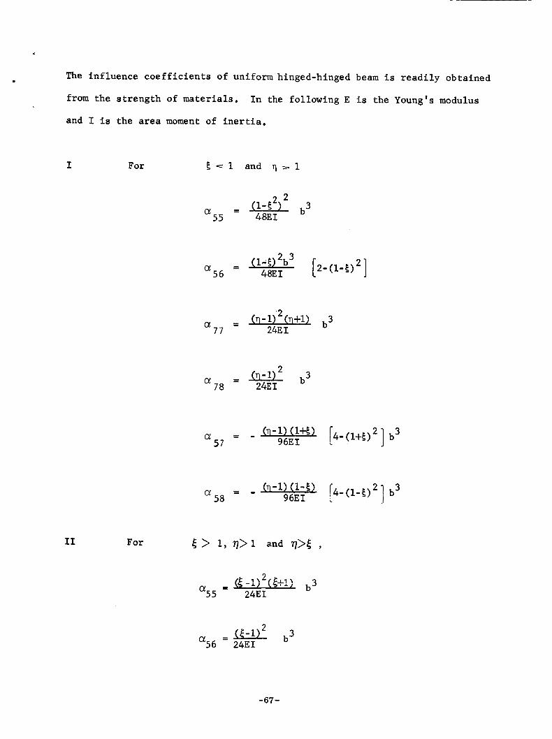
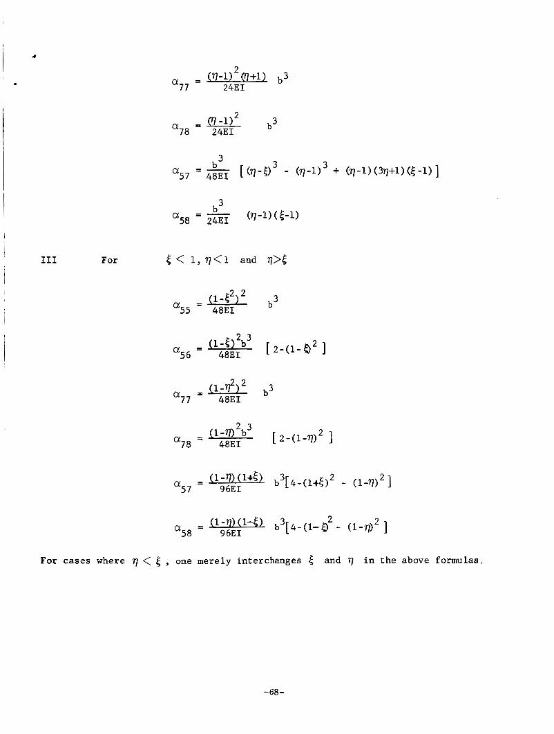
The in f luence c o e f f i c i e n t s of uniform hinged-hinged beam i s r e a d i l y obta ined
from the s t r e n g t h of materials.
. In the fol lowing E i s the Young's modulus
l and I i s t h e area moment of i n e r t i a .
~ I For 5 - = 1 and 7 - 1
I1 For
2 2 - (1-5 b3 - 55 48EI a
f 2- (1-5) '1 - (1-0 2b3 - 56 48EI a
- - (n - 1 j2 (n+i) b3 77 24E I a
- - 78 24E I a!
c4- (1-5) '1 b3 - (n-1) (1-5) - - 58 96EI a
-67-
4
L
I
- b3[4-(i-5) 2 - ( l - ~ ) ~ ] a58 - 96EI
For cases where r] < 6 one merely interchanges 4 and 77 in the above formulas.
-68-
REFERENCE S
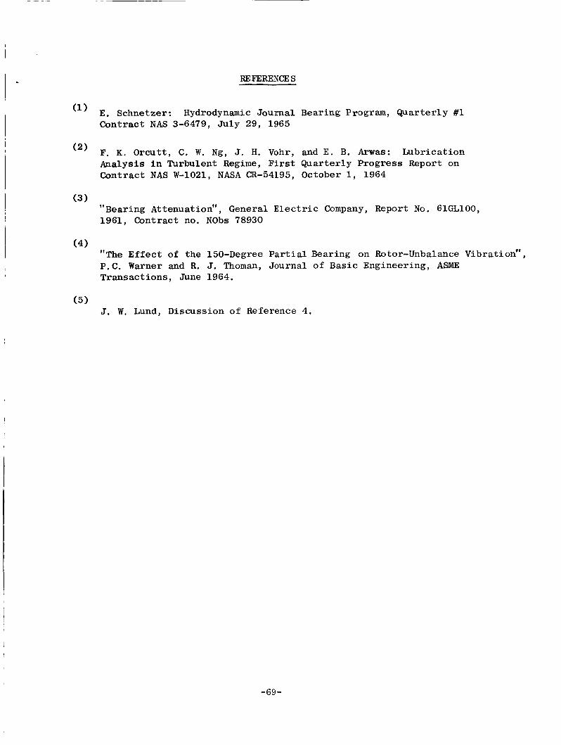
E. Schnetzer: Hydrodynamic Journal Contract NAS 3-6479, Ju ly 29, 1965
(2) F. K. Orcu t t , C, W. Ng, J. H. Vohr, Analys is i n Turbulent Regime, F i r s t Contract NAS W-1021, NASA CR-54195,
Bearing Program, Quar t e r ly #1
and E. B. Arwas: Lubr ica t ion Quar te r ly Progress Report on October 1, 1964
Bearing Attenuation", General E l e c t r i c Company, Report No. 61GL100, 11 (3 1
1961, Contract no. NObs 78930
(4) "The E f f e c t of t he 150-Degree P a r t i a l Bearing on Rotor-Unbalance Vibration", P.C. Warner and R. J. Thoman, Journal of Basic Engineering, ASME Transact i ons , June 1964.
(5) J. W. Lund, Discussion of Reference 4.
-69-
DISTRIBUTION LIST FOR QUARTERLY REPORTS CONTRACT NAS 3-6479
National Aeronautics & Space Administration NASA-Lewis Research Center Washington, D. C. 20546 21000 Brookpark Road ATTN: S.V. Manson, Code RNP Cleveland, Ohio 44135
National Aeronautics & Space Administration ATTN: Henry Slone M.S. 500-201
Washington, D. C. 20546 ATTN: Dr. F. Schulman, Code RNP
NASA-Lewis Research Center 21000 Brookpark Road Cleveland, Ohio 44135 ATTN: Dr. B. Lubarsky M.S. 500-201
NASA-Lewis Research Center 21000 Brookpark Road Cleveland, Ohio 44135 ATTN: R.L. Cummings M.S. 500-201
NASA-Lewis Research Center 21000 Brookpark Road Cleveland, Ohio 44135 ATTN: Ruth Weltmann M.S. 500-309
NASA-Lewis Research Center 21000 Brookpark Road Cleveland, Ohio 44135 ATTN: J.J. Weber M.S. 3-19
NASA-Lewis Research Center 21000 Brookpark Road Cleveland Ohio 44135 ATTN: Joseph P. Joyce M.S. 500-201
NASA-Lewis Research Center 21000 Brookpark Road Cleveland, Ohio 44135 ATTN: James Dunn M.S. 500-201
NASA-Lewis Research Center 21000 Brookpark Road Cleveland, Ohio 44135
NASA-Lewis Research Center 21000 Brookpark Road Cleveland, Ohio 44135 ATTN: Warner Stewart M.S. 5-9
NASA-Lewis Research Center 21000 Brookpark Road Cleveland, Ohio 44135 ATTN: Edmond Bisson M.S. 5-3
NASA-lewis Research Center 21000 Brookpark Road Cleveland, Ohio 44135 A'ITN: Dorothy Morris M.S. 3-7
NASA-Lewis Research Center 21000 Brookpark Road Cleveland, Ohio 44135 ATTN: J.E. Dilley M.S. 500-309
National Aeronautics & Space Administration
Jet Propulsion Laboratory California Institute of Technology 4800 Oak Grove Drive Pasadena, California 91103
(2 1 ATTN: John W. Stearns
National Aeronautics & Space
Scientific & Technical Information
P.O. Box 5700 Bethesda, Maryland 20014 (2 + Repro.)
Administration
Agency
National Aeronautics & Space ATTN: Report Control Office M.S. 5-5 Administration
NASA-Lewis Research Center 150 Pic0 Boulevard 21000 Brookpark Road Santa Monica, California 90406 Cleveland, Ohio 44135 ATTN: John Keeler ATTN: William J. Anderson M.S. 6-1
Western Operations Office
-70-
Contract NAS 3-6479
Aeronautical Systems Division Wright Patterson Air Force Base Dayton, Ohio 45433 ATTN: George Sherman - API
Aeronautical Systems Division Wright Patterson Air Force Base Dayton, Ohio 45433 ATTN: Charles Armbruster - ASRMFP-1
Aeronautical Systems Division Wright Patterson Air Force Base Dayton, Ohio 45433 ATTN: John Morris - ASRCNL-2 U.S. Atomic Energy Commission Germantown, Maryland 20767 ATTN: Col. E.L. Douthett
U.S. Atomic Energy Commission Germantown, Maryland 20767 ATTN: Herbert D. Rochen
U.S. Atomic Energy Commission Germantown, Maryland 20767 ATTN: Dr. Nicholas Grossman
Chief, Engineering Department
Air University Library Maxwell Air Force Base, Alabama ATTN: Director
U.S. Atomic Energy Commission Technical Information Service Extension P.O. Box 62 Oak Ridge, Tennessee 37831
Oak Ridge National Laboratory Post Office Box Y Oak Ridge, Tennessee 37831 ATTN: H.W. Savage
Office of Naval Research Washington, D. C. 20546 ATTN: S. Doroff - Code 438
Armed Services Technical Information Agency Arlington Hall Station Arlington, Virginia 22212
Aerojet-General Corporation Technic a1 Library Building 2015, Department 2410 P.O. Box 1947 Sacramento 9, California
Aerojet-General Corporation Azusa, California 91703 AT": Robert Gordon
SNAP 8/Program Director
Aero-jet General Corporation Azusa, California 91703 A"N: John Marick
AiResearch Manufacturing Company Sky Harbor Airport 402 South 35th Street Phoenix, Arizona AWN: Librarian
AiResearch Manufacturing Company Sky Harbor Airport 402 South 35th Street Phoenix, Arizona ATTN: Robert Gruntz
AiResearch Manufacturing Company Sky Harbor Airport 402 South 35th Street Phoenix, Arizona ATTN: George Wheeler
Atomics International Division of NAA Canoga Park, California ATTN: L.M. Flower
The Barden Corporation Research Precision Division Danbury, Connecticut ATTN: Mrs. Bernice P. Tucos
The Barden Corporation Research Precision Division Danbury, Connecticut ATTN: Technical Library
M.S.A. Research Foundation Callery, Pennsylvania ATTN: G.E. Kennedy
-71 -
Contract NAS 3-6479
Battelle Memorial Institute 505 King Avenue Columbus, Ohio 43201 ATTN: C.M. Allen
The Franklin Institute Benjamin Franklin Parkway at 20th Street Philadelphia, Pennsylvania 19103 AT“: William Shuggarts
General Electric Company Missile & Space Vehicle Department 3198 Chestnut Street Philadelphia, Pennsylvania 19101 ATTN: Edward Ray
Mechanical Technology, Inc. 968 Albany-Shaker Road Latham, New York ATTN: Eli Arwas
Pratt & Whitney Aircraft Division United Aircraft Corporation East Hartford, Connecticut 06108 ATTN: Dr. William Lueckel
Eng. Bldg. 2-H
Pratt & Whitney Aircraft Division United Aircraft Corporation East Hartford, Connecticut 06108 ATTN: R . P. Shenchenko Pratt & Whitney Aircraft Division United Aircraft Corporation East Hartford, Connecticut 06108 ATTN: Karl A. Domeisen
Exp. Eng. Eng. 1-F
Rocketdyne Division of North American Aviation, Inc. 6633 Canoga Avenue Canoga Park, California 91303 ATTN: Robert Spies
Southwest Research Institute 8500 Culebra Road San Antonio, Texas 78206 ATTN: Dr. R.A. Benton
UAC Library United Aircraft Research Laboratories Gake 5 R , Silver Lane East Hartford, Connecticut 06108
Westinghoqse Electric Corporation Research Laboratories Pittsburgh, Pennsylvania 15236 ATTN: Mr. J. Boyd
Westinghouse Electric Corporation Aerospace Division Advanced Mach in e Systems Group Lima, Ohio ATTN: Allen King
The Franklin Institute Benjamin Franklin Parkway at 20th St. Philadelphia, Pennsylvania 19103 ATTN: Otto Decker
North American Aviation Atomics International P.O. Box 309 Canoga Park, California 91304 ATTN: Director, Liquid Metals
Information Center
Mechanical Technology, Inc. 968 Albany-Shaker Road Latham, New York Attention: Dr. Beno Sternlicht
Sundstrand Aviation - Denver A Division of Sundstrand Corporation Denver, Colorado 80221 ATTN: P.H. Stahlhuth
-72-